
Vivado Design Suite User
Guide
Design Flows Overview
Vivado Design Suite
UG892 (v2022.1) April 20, 2022
See all versions
of this document
Xilinx is creating an environment where employees, customers, and
partners feel welcome and included. To that end, we’re removing non-
inclusive language from our products and related collateral. We’ve
launched an internal initiative to remove language that could exclude
people or reinforce historical biases, including terms embedded in our
software and IPs. You may still find examples of non-inclusive
language in our older products as we work to make these changes and
align with evolving industry standards. Follow this link for more
information.

Table of Contents
Chapter 1: Vivado System-Level Design Flows...............................................4
Navigating Content by Design Process.................................................................................... 5
Industry Standards-Based Design............................................................................................ 5
Design Flows................................................................................................................................ 6
RTL-to-Bitstream Design Flow................................................................................................... 8
Alternate RTL-to-Bitstream Design Flows.............................................................................. 11
Chapter 2: Understanding Use Models.............................................................14
Vivado Design Suite Use Models............................................................................................. 14
Working with the Vivado Integrated Design Environment (IDE)........................................ 15
Working with Tcl........................................................................................................................ 17
Understanding Project Mode and Non-Project Mode..........................................................19
Using Third-Party Design Software Tools...............................................................................23
Interfacing with PCB Designers...............................................................................................24
Chapter 3: Using Project Mode............................................................................. 26
Project Mode Advantages........................................................................................................ 27
Creating Projects....................................................................................................................... 28
Understanding the Flow Navigator.........................................................................................30
Performing System-Level Design Entry..................................................................................34
Working with IP......................................................................................................................... 36
Creating IP Subsystems with IP Integrator............................................................................44
Logic Simulation........................................................................................................................ 48
Running Logic Synthesis and Implementation......................................................................53
Viewing Log Files, Messages, Reports, and Properties.........................................................58
Opening Designs to Perform Design Analysis and Constraints Definition........................61
Device Programming, Hardware Verification, and Debugging...........................................71
Using Project Mode Tcl Commands........................................................................................ 72
Chapter 4: Using Non-Project Mode...................................................................75
Non-Project Mode Advantages................................................................................................76
Reading Design Sources...........................................................................................................77
UG892 (v2022.1) April 20, 2022 www.xilinx.com
Design Flows Overview 2

Working with IP and IP Subsystems....................................................................................... 78
Running Logic Simulation........................................................................................................ 79
Running Logic Synthesis and Implementation......................................................................79
Generating Reports...................................................................................................................80
Using Design Checkpoints....................................................................................................... 80
Performing Design Analysis Using the Vivado IDE............................................................... 80
Using Non-Project Mode Tcl Commands............................................................................... 82
Chapter 5: Source Management and Revision Control
Recommendations...................................................................................................85
Interfacing with Revision Control Systems............................................................................ 85
Revision Control Philosophy from 2020.2 Onwards..............................................................85
Revision Control Philosophy Pre 2020.2................................................................................. 86
Other Files to Revision Control................................................................................................89
Output Files to Optionally Revision Control...........................................................................90
Managing Hardware Manager Projects and Sources...........................................................91
Appendix A: Additional Resources and Legal Notices............................. 92
Xilinx Resources.........................................................................................................................92
Solution Centers........................................................................................................................ 92
Documentation Navigator and Design Hubs.........................................................................92
References..................................................................................................................................93
Training Resources....................................................................................................................94
Revision History.........................................................................................................................94
Please Read: Important Legal Notices................................................................................... 95
UG892 (v2022.1) April 20, 2022 www.xilinx.com
Design Flows Overview 3

Chapter 1
Vivado System-Level Design Flows
This user guide provides an overview of working with the Vivado
®
Design Suite to create a new
design for programming into a Xilinx
®
device. It provides a brief descripon of various use
models, design features, and tool opons, including preparing, implemenng, and managing the
design sources and intellectual property (IP) cores.
The Vivado Design Suite oers mulple ways to accomplish the tasks involved in Xilinx device
design, implementaon, and vericaon. You can use the tradional register transfer level (RTL)-
to-bitstream FPGA design ow, as described in RTL-to-Bitstream Design Flow. You can also use
system-level integraon ows that focus on intellectual property (IP)-centric design and C-based
design, as described in Alternate RTL-to-Bitstream Design Flows.
Design analysis and vericaon is enabled at each stage of the ow. Design analysis features
include logic simulaon, I/O and clock planning, power analysis, constraint denion and ming
analysis, design rule checks (DRC), visualizaon of design logic, analysis and modicaon of
implementaon results, programming, and debugging.
The following documents and QuickTake videos provide addional informaon about Vivado
Design Suite ows:
• Vivado Design Suite QuickTake Video: Vivado Design Flows Overview
• Vivado Design Suite Tutorial: Design Flows Overview (UG888)
• Vivado Design Suite QuickTake Video: Geng Started with the Vivado IDE
• Xilinx Video Training: UltraFast Vivado Design Methodology
The enre soluon is integrated within a graphical user interface (GUI) known as the Vivado
Integrated Design Environment (IDE). The Vivado IDE provides an interface to assemble,
implement, and validate the design and the IP. In addion, all ows can be run using Tcl
commands. Tcl commands can be scripted or entered interacvely using the Vivado Design Suite
Tcl shell or using the Tcl Console in the Vivado IDE. You can use Tcl scripts to run the enre
design ow, including design analysis, or to run only parts of the ow.
Related Information
RTL-to-Bitstream Design Flow
Alternate RTL-to-Bitstream Design Flows
Chapter 1: Vivado System-Level Design Flows
UG892 (v2022.1) April 20, 2022 www.xilinx.com
Design Flows Overview 4

Navigating Content by Design Process
Xilinx
®
documentaon is organized around a set of standard design processes to help you nd
relevant content for your current development task. All Versal
®
ACAP design process Design
Hubs and the Design Flow Assistant materials can be found on the Xilinx.com website. This
document covers the following design processes:
• System and Soluon Planning: Idenfying the components, performance, I/O, and data
transfer requirements at a system level. Includes applicaon mapping for the soluon to PS,
PL, and AI Engine. Topics in this document that apply to this design process include:
• Design Flows
• RTL-to-Bitstream Design Flow
• Alternate RTL-to-Bitstream Design Flows
• Hardware, IP, and Plaorm Development: Creang the PL IP blocks for the hardware
plaorm, creang PL kernels, funconal simulaon, and evaluang the Vivado
®
ming,
resource use, and power closure. Also involves developing the hardware plaorm for system
integraon. Topics in this document that apply to this design process include:
• Accelerated Kernel Flows
• System Integraon and Validaon: Integrang and validang the system funconal
performance, including ming, resource use, and power closure. Topics in this document that
apply to this design process include:
• Running Logic Simulaon
• Logic Simulaon
• Board System Design: Designing a PCB through schemacs and board layout. Also involves
power, thermal, and signal integrity consideraons. Topics in this document that apply to this
design process include:
• Xilinx Plaorm Board Support
• Board Files
Industry Standards-Based Design
The Vivado Design Suite supports the following established industry design standards:
• Tcl
• AXI4, IP-XACT
Chapter 1: Vivado System-Level Design Flows
UG892 (v2022.1) April 20, 2022 www.xilinx.com
Design Flows Overview 5

• Synopsys design constraints (SDC)
• Verilog, VHDL, VHDL-2008, SystemVerilog
• SystemC, C, C++
The Vivado Design Suite soluon is nave Tcl based with support for SDC and Xilinx design
constraints (XDC) formats. Extensive Verilog, VHDL, and SystemVerilog support for synthesis
enables easier FPGA adopon. Vivado High-Level Synthesis (HLS) enables the use of nave C, C+
+, or SystemC languages to dene logic. Using standard IP interconnect protocol, such as AXI4
and IP-XACT, enables faster and easier system-level design integraon. Support for these
industry standards also enables the electronic design automaon (EDA) ecosystem to beer
support the Vivado Design Suite. In addion, many new third-party tools are integrated with the
Vivado Design Suite.
Design Flows
The following gure shows the high-level design ow in the Vivado Design Suite. Xilinx
®
Design
Hubs provide links to documentaon organized by design tasks and other topics. On the Xilinx
website, see the Design Hubs page.
Chapter 1: Vivado System-Level Design Flows
UG892 (v2022.1) April 20, 2022 www.xilinx.com
Design Flows Overview 6
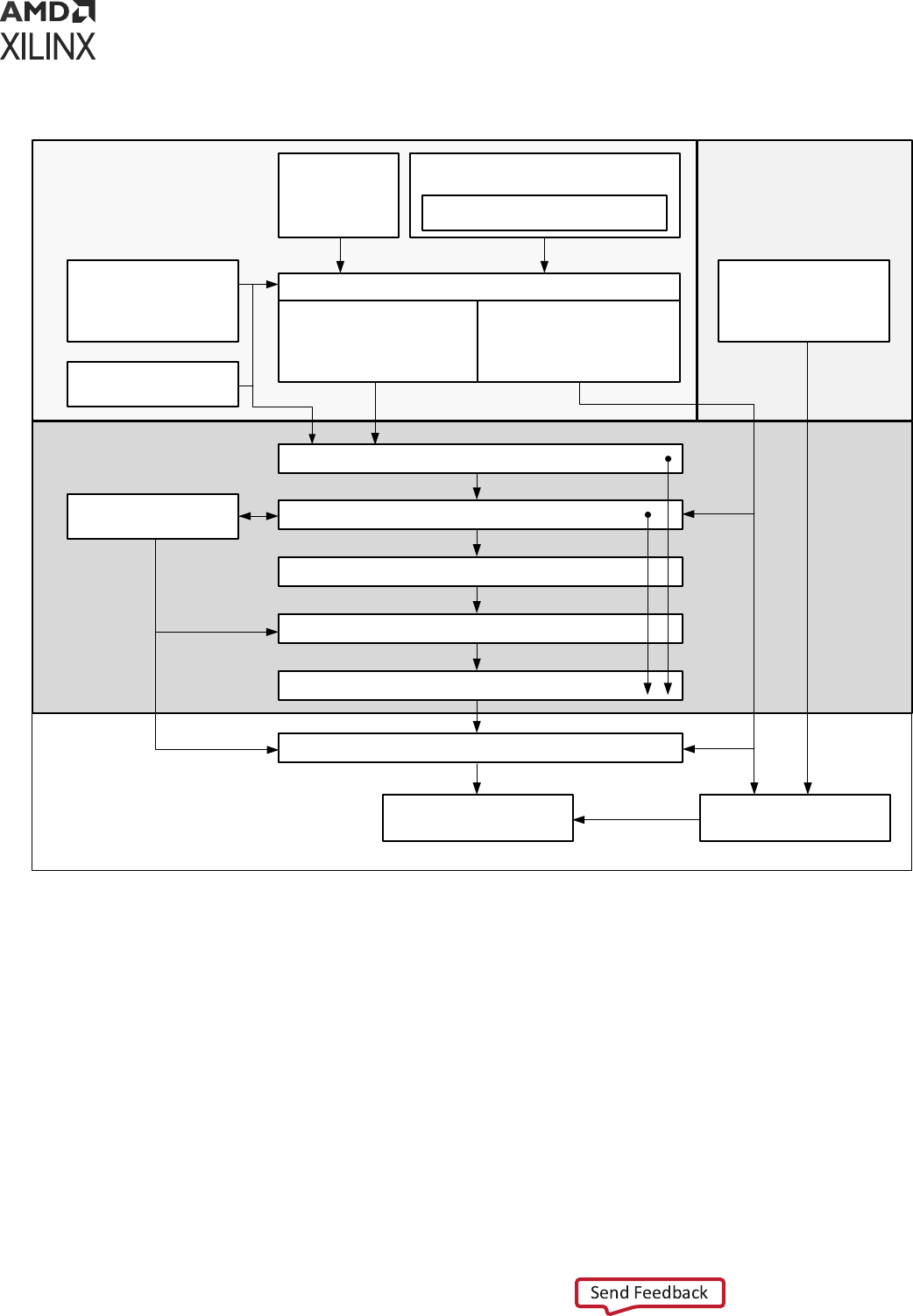
Figure 1: System-Level Design Flow for FPGAs and SoCs
Hardware Bring-Up and Validation
Software DevelopmentSystem Design Entry
Configuring Xilinx
®
and
Third-Party IP
Development Software
and Processor OS
IP Packager – IP Integrator
Configuring IP
Subsystems
Embedded Processor Design
RTL
Development
Implementation
Logic Simulation
Dynamic Function
eXchange
Assign Logical and Physical Constraints
Logic Synthesis
Implementation
Timing Closure and Design Analysis
Generate Bitstream, Programming, and Debug
Processor Boot and Debug
Export to Vitis Software
Development Platform
C-Based Design
with High-Level
Synthesis
Model-Based Design with
MATLAB
®
and Simulink
®
Software
Vitis™ Model Composer
X15150-063021
Chapter 1: Vivado System-Level Design Flows
UG892 (v2022.1) April 20, 2022 www.xilinx.com
Design Flows Overview 7

RTL-to-Bitstream Design Flow
RTL Design
You can specify RTL source les to create a project and use these sources for RTL code
development, analysis, synthesis and implementaon. Xilinx supplies a library of recommended
RTL and constraint templates to ensure RTL and XDC are formed opmally for use with the
Vivado Design Suite. Vivado synthesis and implementaon support mulple source le types,
including Verilog, VHDL, SystemVerilog, and XDC. For informaon on creang and working with
an RTL project, see this link in the Vivado Design Suite User Guide: System-Level Design Entry
(UG895).
The UltraFast Design Methodology Guide for Xilinx FPGAs and SoCs (UG949) focuses on proper
coding and design techniques for dening hierarchical RTL sources and Xilinx design constraints
(XDC), as well as providing informaon on using specic features of the Vivado Design Suite, and
techniques for performance improvement of the programmed design.
IP Design and System-Level Design Integration
The Vivado Design Suite provides an environment to congure, implement, verify, and integrate
IP as a standalone module or within the context of the system-level design. IP can include logic,
embedded processors, digital signal processing (DSP) modules, or C-based DSP algorithm
designs. Custom IP is packaged following IP-XACT protocol and then made available through the
Vivado IP catalog. The IP catalog provides quick access to the IP for conguraon, instanaon,
and validaon of IP. Xilinx IP ulizes the AXI4 interconnect standard to enable faster system-level
integraon. Exisng IP can be used in the design either in RTL or netlist format. For more
informaon, see the Vivado Design Suite User Guide: Designing with IP (UG896).
IP Subsystem Design
The Vivado IP integrator environment enables you to stch together various IP into IP
subsystems using the AMBA
®
AXI4 interconnect protocol. You can interacvely congure and
connect IP using a block design style interface and easily connect enre interfaces by drawing
DRC-correct connecons similar to a schemac. Connecng the IP using standard interfaces
saves me over tradional RTL-based connecvity. Connecon automaon is provided as well as
a set of DRCs to ensure proper IP conguraon and connecvity. These IP block designs are then
validated, packaged, and treated as a single design source. Block designs can be used in a design
project or shared among other projects. The IP integrator environment is the main interface for
embedded design and the Xilinx evaluaon board interface. For more informaon, see the Vivado
Design Suite User Guide: Designing IP Subsystems Using IP Integrator (UG994).
Chapter 1: Vivado System-Level Design Flows
UG892 (v2022.1) April 20, 2022 www.xilinx.com
Design Flows Overview 8

I/O and Clock Planning
The Vivado IDE provides an I/O pin planning environment that enables I/O port assignment
either onto specic device package pins or onto internal die pads, and provides tables to let you
design and analyze package and I/O-related data. Memory interfaces can be assigned
interacvely into specic I/O banks for opmal data ow. You can analyze the device and design-
related I/O data using the views and tables available in the Vivado pin planner. The tool also
provides I/O DRC and simultaneous switching noise (SSN) analysis commands to validate your
I/O assignments. For more informaon, see the Vivado Design Suite User Guide: I/O and Clock
Planning (UG899).
Xilinx Platform Board Support
In the Vivado Design Suite, you can select an exisng Xilinx evaluaon plaorm board as a target
for your design. In the plaorm board ow, all of the IP interfaces implemented on the target
board are exposed to enable quick selecon and conguraon of the IP used in your design. The
resulng IP conguraon parameters and physical board constraints, such as I/O standard and
package pin constraints, are automacally assigned and proliferated throughout the ow.
Connecon automaon enables quick connecons to the selected IP. For more informaon see
this link in the Vivado Design Suite User Guide: System-Level Design Entry (UG895).
Synthesis
Vivado synthesis performs a global, or top-down synthesis of the overall RTL design. However,
by default, the Vivado Design Suite uses an out-of-context (OOC), or boom-up design ow to
synthesize IP cores from the Xilinx IP Catalog and block designs from the Vivado IP integrator.
You can also choose to synthesize specic modules of a hierarchical RTL design as OOC modules.
This OOC ow lets you synthesize, implement, and analyze design modules of a hierarchical
design, IP cores, or block designs, out of the context of, or independent from the top-level
design. The OOC synthesized netlist is stored and used during top-level implementaon to
preserve results and reduce runme. The OOC ow is an ecient technique for supporng
hierarchical team design, synthesizing and implemenng IP and IP subsystems, and managing
modules of large complex designs. For more informaon on the out-of-context design ow, see
Out-of-Context Design Flow.
The Vivado Design Suite also supports the use of third-party synthesized netlists, including EDIF
or structural Verilog. However, IP cores from the Vivado IP Catalog must be synthesized using
Vivado synthesis, and are not supported for synthesis with a third-party synthesis tool. There are
a few excepons to this requirement, such as the memory IP for 7 series devices. Refer to the
data sheet for a specic IP for more informaon.
Note: The ISE Netlist format (NGC) is supported for 7 series devices. It is not supported for UltraScale™
and later devices.
Chapter 1: Vivado System-Level Design Flows
UG892 (v2022.1) April 20, 2022 www.xilinx.com
Design Flows Overview 9

Related Information
Out-of-Context Design Flow
Design Analysis and Simulation
The Vivado Design Suite lets you analyze, verify, and modify the design at each stage of the
design process. You can run design rule and design methodology checks, logic simulaon, ming
and power analysis to improve circuit performance. This analysis can be run aer RTL
elaboraon, synthesis, and implementaon. For more informaon, see the Vivado Design Suite
User Guide: Design Analysis and Closure Techniques (UG906).
The Vivado simulator enables you to run behavioral and structural logic simulaon of the design
at dierent stages of the design ow. The simulator supports Verilog and VHDL mixed-mode
simulaon, and results can be displayed in a waveform viewer integrated in the Vivado IDE. You
can also use third-party simulators that can be integrated into and launched from the Vivado IDE.
Refer to Running Logic Simulaon for more informaon.
Related Information
Running Logic Simulaon
Placement and Routing
When the synthesized netlist is available, Vivado implementaon provides all the features
necessary to opmize, place and route the netlist onto the available device resources of the
target part. Vivado implementaon works to sasfy the logical, physical, and ming constraints
of the design.
For challenging designs the Vivado IDE also provides advanced oorplanning capabilies to help
drive improved implementaon results. These include the ability to constrain specic logic into a
parcular area, or manually placing specic design elements and xing them for subsequent
implementaon runs. For more informaon, see the Vivado Design Suite User Guide: Design
Analysis and Closure Techniques (UG906).
Hardware Debug and Validation
Aer implementaon, the device can be programmed and then analyzed with the Vivado logic
analyzer, or within the standalone Vivado Lab Edion environment. Debug signals can be
idened in the RTL design, or inserted aer synthesis and are processed throughout the ow.
You can add debug cores to the RTL source les, to the synthesized netlist, or in an implemented
design using the using the Engineering Change Order (ECO) ow. You can also modify the nets
connected to a debug probe, or route internal signals to a package pin for external probing using
the ECO ow. For more informaon, see the Vivado Design Suite User Guide: Programming and
Debugging (UG908).
Chapter 1: Vivado System-Level Design Flows
UG892 (v2022.1) April 20, 2022 www.xilinx.com
Design Flows Overview 10

Alternate RTL-to-Bitstream Design Flows
The Vivado Design Suite also supports several alternate design ows, as described in the
following secons. Each of these ows is derived from the RTL-to-bitstream ow, so the
implementaon and analysis techniques described above also apply to these other design ows.
Accelerated Kernel Flows
The Xilinx
®
Vis™ unied soware plaorm introduces acceleraon use cases into Vivado
®
ows. In this design methodology, Vivado is used to create a plaorm which is consumed by the
Vis soware plaorm to add accelerated kernels. The hardware design is comprised of the
plaorm and the accelerators. In this case, the nal bitstream is created by the Vis soware
plaorm because the complete design is not visible in Vivado. For more informaon on plaorm
creaon, see Vis Unied Soware Plaorm Documentaon: Applicaon Acceleraon Development
(UG1393).
Embedded Processor Design
A slightly dierent tool ow is needed when creang an embedded processor design. Because
the embedded processor requires soware in order to boot-up and run eecvely, the soware
design ow must work in unison with the hardware design ow. Data hand-o between the
hardware and soware ows, and validaon across these two domains is crical for success.
Creang an embedded processor hardware design involves the IP integrator of the Vivado
Design Suite. In a Vivado IP integrator block design, you instanate, congure, and assemble the
processor core and its interfaces. The IP Integrator enforces rules-based connecvity and
provides design assistance. Aer it is compiled through implementaon, the hardware design is
exported to Xilinx Vis™ for use in soware development and validaon. Simulaon and debug
features allow you to simulate and validate the design across the two domains.
The Vis Design Suite is Xilinx's unied soware suite that includes compilers for all embedded
applicaons and accelerated applicaons on Xilinx plaorms. Vis supports developing in higher
level languages, leverages open source libraries, and supports domain specic development
environments.
VIDEO:
For training videos on the Vivado IP integrator and the embedded processor design ow, see the
Vivado Design Suite QuickTake Video: Targeng Zynq Devices Using Vivado IP Integrator.
The embedded processor design ow is described in the following resources:
• Vivado Design Suite User Guide: Embedded Processor Hardware Design (UG898)
• Vivado Design Suite Tutorial: Embedded Processor Hardware Design (UG940)
• UltraFast Embedded Design Methodology Guide (UG1046)
Chapter 1: Vivado System-Level Design Flows
UG892 (v2022.1) April 20, 2022 www.xilinx.com
Design Flows Overview 11

Model-Based Design Using Model Composer
Model Composer is a model-based graphical design tool that enables rapid design exploraon
within the MathWorks MATLAB
®
and Simulink
®
products and accelerates the path to producon
for Xilinx devices through automac code generaon. For informaon, see the Model Composer
User Guide (UG1262).
Model-Based DSP Design Using Xilinx System
Generator
The Xilinx System Generator tool, which is installed as part of the Vivado Design Suite, can be
used for implemenng DSP funcons. You create the DSP funcons using System Generator as a
standalone tool, and then package your System Generator design into an IP module that can be
included in the Vivado IP catalog. From there, the generated IP can be instanated into your
Vivado design as a submodule. For more informaon, see the Vivado Design Suite User Guide:
Model-Based DSP Design Using System Generator (UG897).
High-Level Synthesis C-Based Design
The C-based High-Level Synthesis (HLS) tools within the Vivado Design Suite enable you to
describe various DSP funcons in the design using C, C++, and SystemC. You create and validate
the C code with the Vivado HLS tools. Use of higher-level languages allows you to abstract
algorithmic descripons, data type, specicaon, etc. You can create “what-if” scenarios using
various parameters to opmize design performance and device area.
HLS lets you simulate the generated RTL directly from its design environment using C-based test
benches and simulaon. C-to-RTL synthesis transforms the C-based design into an RTL module
that can be packaged and implemented as part of a larger RTL design, or instanated into an IP
integrator block design.
VIDEO:
For various training videos on Vivado HLS, see the Vivado High-Level Synthesis video tutorials
available from the Vivado Design QuickTake Video Tutorials page on the Xilinx website.
The HLS tool ow and features are described in the following resources:
• Vivado Design Suite User Guide: High-Level Synthesis (UG902)
• Vivado Design Suite Tutorial: High-Level Synthesis (UG871)
Dynamic Function Exchange Design
Dynamic funcon exchange (DFx) allows porons of a running Xilinx device to be recongured in
real-me with a paral bitstream, changing the features and funcons of the running design. The
recongurable modules must be properly planned to ensure they funcon as needed for
maximum performance.
Chapter 1: Vivado System-Level Design Flows
UG892 (v2022.1) April 20, 2022 www.xilinx.com
Design Flows Overview 12

The DFx ow requires a strict design process to ensure that the recongurable modules are
designed properly to enable glitch-less operaon during paral bitstream updates. This includes
reducing the number of interface signals into the recongurable module, oorplanning device
resources, and pin placement; as well as adhering to special DFx DRCs. The device programming
method must also be properly planned to ensure the conguraon I/O pins are assigned
appropriately.
VIDEO: Informaon on the DFx ow is available from the Vivado Design Suite QuickTake Video: DFx.
The DFx tool ow and features are described in the following resources:
• Vivado Design Suite User Guide: Dynamic Funcon eXchange (UG909)
• Vivado Design Suite Tutorial: Dynamic Funcon eXchange (UG947)
Hierarchical Design
Hierarchical Design (HD) ows enable you to paron a design into smaller, more manageable
modules to be processed independently. The hierarchical design ow involves proper module
interface design, constraint denion, oorplanning, and some special commands and design
techniques. For more informaon, see the Vivado Design Suite User Guide: Hierarchical Design
(UG905).
Using a modular approach to the hierarchical design lets you analyze modules independent of the
rest of the design, and reuse modules in the top-down design. A team of users can iterate on
specic secons of a design, achieving ming closure and other design goals, and reuse the
results.
There are several Vivado features that enable a hierarchical design approach, such as the
synthesis of a logic module outside of the context (OOC) of the top-level design. You can select
specic modules, or levels of the design hierarchy, and synthesize them OOC. Module-level
constraints can be applied to opmize and validate module performance. The module design
checkpoint (DCP) will then be applied during implementaon to build the top-level netlist. This
method can help reduce top-level synthesis run me, and eliminate re-synthesis of completed
modules.
Chapter 1: Vivado System-Level Design Flows
UG892 (v2022.1) April 20, 2022 www.xilinx.com
Design Flows Overview 13

Chapter 2
Understanding Use Models
Vivado Design Suite Use Models
RECOMMENDED: Before beginning your rst design with the Vivado
®
tools, review the informaon in
the Vivado Design Suite User Guide: Geng Started (UG910).
Just as the Vivado supports many dierent design ows, the tools support several dierent use
models depending on how you want to manage your design and interact with the Vivado tools.
This secon will help guide you through some of the decisions that you must make about the use
model you want to use for interacng with the Vivado tools.
Some of these decisions include:
• Are you a script or command-based user; or do you prefer working through a graphical user
interface (GUI)? See Working with the Vivado Integrated Design Environment (IDE) and
Working with Tcl.
• Do you want the Vivado Design Suite to manage the design sources, status, and results by
using a project structure; or would you prefer to quickly create and manage a design yourself?
See Understanding Project Mode and Non-Project Mode.
• Do you want to congure IP cores and contain them within a single design project for
portability; or establish a remote repository of congured IP cores outside of the project for
easier management across mulple projects?
• Are you managing your source les inside a revision control system? See Interfacing with
Revision Control Systems.
• Are you using third-party tools for synthesis or simulaon? See Using Third-Party Design
Soware Tools.
Related Information
Working with the Vivado Integrated Design Environment (IDE)
Working with Tcl
Understanding Project Mode and Non-Project Mode
Using Third-Party Design Soware Tools
Chapter 2: Understanding Use Models
UG892 (v2022.1) April 20, 2022 www.xilinx.com
Design Flows Overview 14

Working with the Vivado Integrated Design
Environment (IDE)
The Vivado Integrated Design Environment (IDE) can be used in both Project Mode and Non-
Project Mode. The Vivado IDE provides an interface to assemble, implement, and validate your
design and IP. Opening a design loads the current design netlist, applies design constraints, and
ts the design onto the target device. The Vivado IDE allows you to visualize and interact with
the design as shown in the following gure.
Figure 2: Opening the Implemented Design in the Vivado IDE
When using Project Mode, the Vivado IDE provides an interface called Flow Navigator, that
supports a push-buon design ow. You can open designs aer RTL elaboraon, synthesis, or
implementaon and analyze the design, make changes to constraints, logic or device
conguraon, and implementaon results. You can also use design checkpoints to save the
current state of any design. For more informaon on the Vivado IDE, see the Vivado Design Suite
User Guide: Using the Vivado IDE (UG893).
Chapter 2: Understanding Use Models
UG892 (v2022.1) April 20, 2022 www.xilinx.com
Design Flows Overview 15

VIDEO: For more informaon, see the Vivado Design QuickTake Video: Geng Started with the Vivado
IDE.
Launching the Vivado IDE on Windows
Select Start → All Programs → Xilinx Design Tools → Vivado <version> → Vivado <version>.
Note: You can also double-click the Vivado IDE shortcut icon on your desktop.
Figure 3: Vivado IDE Desktop Icon
TIP: You can right-click the Vivado IDE shortcut icon, and select Properes to update the Start In eld.
This makes it easier to locate the project le, log les, and journal les, which are wrien to the launch
directory.
Launching the Vivado IDE from the Command Line
on Windows or Linux
Enter the following command at the command prompt:
vivado
When you enter this command, it automacally runs vivado -mode gui to launch the Vivado
IDE. If you need help, type vivado -help.
TIP:
To add the Vivado tools path to your current shell/command prompt, run
settings64.bat or
settings64.sh
from the
<install_path>/Vivado/<version>
directory.
When launching the Vivado Design Suite from the command line, change directory to your
project directory so that the Vivado tool will write its log and journal les to your project
directory. This makes it easy to locate and review these les as needed.
RECOMMENDED:
Launch the Vivado Design Suite from your project directory to make it easier to locate
the project le, log les, and journal les, which are wrien to the launch directory.
Launching the Vivado IDE from the Vivado Design
Suite Tcl Shell
When the Vivado Design Suite is running in Tcl mode, enter the following command at the Tcl
command prompt to launch the Vivado IDE:
start_gui
Chapter 2: Understanding Use Models
UG892 (v2022.1) April 20, 2022 www.xilinx.com
Design Flows Overview 16

Working with Tcl
All supported design ows and use models can be run using Tcl commands. You can use Tcl
scripts to run the enre design ow, including design analysis and reporng, or to run parts of
the design ow, such as design creaon and synthesis. You can use either individual Tcl
commands or saved scripts of Tcl commands.
If you prefer working directly with Tcl commands, you can interact with your design using a
Vivado Design Suite Tcl shell, using the Tcl Console from within the Vivado IDE. For more
informaon about using Tcl and Tcl scripng, see the Vivado Design Suite User Guide: Using Tcl
Scripng (UG894) and Vivado Design Suite Tcl Command Reference Guide (UG835). For a step-by-
step tutorial that shows how to use Tcl in the Vivado tools, see the Vivado Design Suite Tutorial:
Design Flows Overview (UG888).
For more informaon on using a Tcl-based approach using either the Project Mode or Non-
Project Mode, see Understanding Project Mode and Non-Project Mode.
Related Information
Using Project Mode
Using Non-Project Mode
Launching the Vivado Design Suite Tcl Shell
Use the following command to invoke the Vivado Design Suite Tcl Shell either at the Linux
command prompt or within a Windows Command Prompt window:
vivado -mode tcl
Note: On Windows, you can also select Start → All Programs → Xilinx Design Tools → Vivado <version> →
Vivado <version> Tcl Shell.
Launching the Vivado Tools Using a Batch Tcl Script
You can use the Vivado tools in batch mode by supplying a Tcl script when invoking the tool. Use
the following command either at the Linux command prompt or within a Windows Command
Prompt window:
vivado -mode batch -source <your_Tcl_script>
Note: When working in batch mode, the Vivado tools exit aer running the specied script.
Chapter 2: Understanding Use Models
UG892 (v2022.1) April 20, 2022 www.xilinx.com
Design Flows Overview 17

Using the Vivado IDE with a Tcl Flow
When working with Tcl, you can sll take advantage of the interacve GUI-based analysis and
constraint denion capabilies in the Vivado IDE. You can open designs in the Vivado IDE at
any stage of the design cycle, as described in Performing Design Analysis Using the Vivado IDE.
You can also save the design database at any me as a checkpoint le, and open the checkpoint
later as described in Using Design Checkpoints.
Related Information
Performing Design Analysis Using the Vivado IDE
Using Design Checkpoints
Using Xilinx Vivado Store
The Xilinx
®
Vivado Store enables you to download Tcl apps, board les, and example designs
from Xilinx's public GitHub repository. The download path for both boards and example designs
can be dened in your Tool→Sengs. Third-pares can also contribute to these repositories by
subming GitHub pull requests. For more informaon on subming, please refer to the
documentaon on the GitHub for the following repositories:
• Xilinx/XilinxTclStore
• Xilinx/XilinxBoardStore
• Xilinx/XilinxCEDStore
Xilinx Tcl Apps
The Xilinx Tcl Store is an open source repository of Tcl code designed primarily for use in FPGA
designs with the Vivado Design Suite. The Tcl Store provides access to mulple scripts and
ulies contributed from dierent sources, which solve various issues and improve producvity.
You can install Tcl scripts and also contribute Tcl scripts to share your experse with others. For
more informaon on working with Tcl scripts and the Xilinx Tcl Store, see the Vivado Design Suite
User Guide: Using Tcl Scripng (UG894).
Board Files
Board les dene external connecvity for Vivado. Board les informaon is available in the IP
integrator when you select a board, as opposed to a part, when creang the project. Board
interfaces can be enabled in the IP integrator by selecng the appropriate interface in the Boards
tab in Vivado. For more informaon, see Vivado Design Suite User Guide: Designing IP Subsystems
using IP Integrator (UG994) and Integrated Interlaken up to 150G LogiCORE IP Product Guide
(PG169).
Chapter 2: Understanding Use Models
UG892 (v2022.1) April 20, 2022 www.xilinx.com
Design Flows Overview 18

Example Design
Example designs are available in Vivado to demonstrate a parcular funconality. By hosng
example designs on GitHub, they are updated asynchronously to the Vivado release. Example
designs are accessed through the new project wizard when installed through the Xilinx Vivado
Store.
Understanding Project Mode and Non-Project
Mode
The Vivado Design Suite has two primary use models: Project Mode and Non-Project Mode.
Both Project Mode and Non-Project Mode can be developed and used through either the Vivado
IDE, or through Tcl commands and batch scripts. However, the Vivado IDE oers many benets
for the Project Mode, such as the Flow Navigator graphical workow interface. Tcl commands are
the simplest way to run the Non-Project Mode.
Project Mode
The Vivado Design Suite takes advantage of a project based architecture to assemble, implement,
and track the state of a design. This is referred to as Project Mode. In Project Mode, Vivado tools
automacally manage your design ow and design data.
TIP:
The key advantage of Project Mode is that the Vivado Design Suite manages the enre design process,
including dependency management, report generaon, data storage, etc.
When working in Project Mode, the Vivado Design Suite creates a directory structure on disk in
order to manage design source les, either locally or remotely, and manage changes and updates
to the source les.
Note: Certain operang systems (for example, Microso Windows) restrict the number of characters (such
as 256) that can be used for the le path and le name. If your operang system has such a limitaon,
Xilinx recommends that you create projects closer to the drive root to keep le paths and names as short
as possible.
The project infrastructure is also used to manage the automated synthesis and implementaon runs, track
run status, and store synthesis and implementaon results and reports. For example:
• If you modify an HDL source aer synthesis, the Vivado Design Suite idenes the current results as
out-of-date, and prompts you for re-synthesis.
•
If you modify design constraints, the Vivado tools prompt you to either re-synthesize, re-implement, or
both.
•
Aer roung is completed, the Vivado tool automacally generates ming, DRC, methodology, and
power reports.
Chapter 2: Understanding Use Models
UG892 (v2022.1) April 20, 2022 www.xilinx.com
Design Flows Overview 19

• The enre design ow can be run with a single click within the Vivado IDE.
For detailed informaon on working with projects, see Chapter 3: Using Project Mode.
Related Information
Using Project Mode
Non-Project Mode
Alternavely, you can choose an in-memory compilaon ow in which you manage sources and
the design process yourself, known as Non-Project Mode. In-memory compilaon enables
project sengs to be applied to Non-Project based designs. In Non-Project Mode, you manage
design sources and the design process yourself using Tcl commands or scripts. The key advantage
is that you have full control over each step of the ow.
When working in Non-Project Mode, source les are read from their current locaons, such as
from a revision control system, and the design is compiled through the ow in memory. You can
run each design step individually using Tcl commands. You can also use Tcl commands to set
design parameters and implementaon opons.
You can save design checkpoints and create reports at any stage of the design process. Each
implementaon step can be tailored to meet specic design challenges, and you can analyze
results aer each design step. In addion, you can open the Vivado IDE at any point for design
analysis and constraints assignment.
In Non-Project Mode, each design step is controlled using Tcl commands. For example:
• If you modify an HDL le aer synthesis, you must remember to rerun synthesis to update the
in-memory netlist.
• If you want a ming report aer roung, you must explicitly generate the ming report when
roung completes.
• Design parameters and implementaon opons are set using Tcl commands and parameters.
• You can save design checkpoints and create reports at any stage of the design process using
Tcl.
As the design ow progresses, the representaon of the design is retained in memory in the
Vivado Design Suite. Non-Project Mode discards the in-memory design aer each session and
only writes data to disk that you instruct it to. For more informaon on Non-Project Mode, see
Chapter 4: Using Non-Project Mode.
Related Information
Using Non-Project Mode
Chapter 2: Understanding Use Models
UG892 (v2022.1) April 20, 2022 www.xilinx.com
Design Flows Overview 20

Feature Differences
In Project Mode, the Vivado IDE tracks the history of the design and stores pernent design
informaon. However, because many features are automated, you have less control in the default
ow. For example, only a standard set of report les is generated with each run. However,
through Tcl commands or scripng, you have access to customize the ow and features of the
tool in Project Mode.
The following automated features are only available when using Project Mode:
• Out-of-the-box design ow
• Easy-to-use, push-buon interface
• Powerful Tcl scripng language for customizaon
• Source le management and status
• Automacally generated standard reports
• Storage and reuse of tool sengs and design conguraon
• Experimentaon with mulple synthesis and implementaon runs
• Run results management and status
Non-Project Mode, is more of a compilaon methodology where you have complete control over
every acon executed through a Tcl command. This is a fully customizable design ow suited to
specic designers looking for control and batch processing. All of the processing is done in
memory, so no les or reports are generated automacally. Each me you compile the design,
you must dene all of the sources, set all tool and design conguraon parameters, launch all
implementaon commands, and generate report les. This can be accomplished using a Tcl run
script, because a project is not created on disk, source les remain in their original locaons and
design output is only created when and where you specify. This method provides you with all of
the power of Tcl commands and full control over the enre design process. Many users prefer
this batch compilaon style interacon with the tools and the design data.
The following table summarizes the feature dierences between Project Mode and Non-Project
Mode.
Table 1: Project Mode versus Non-Project Mode Features
Flow Element Project Mode Non-Project Mode
Design Source File Management Automatic Manual
Flow Navigation Guided Manual
Flow Customization Unlimited with Tcl commands Unlimited with Tcl commands
Reporting Automatic Manual
Analysis Stages Designs and design checkpoints Designs and design checkpoints
Chapter 2: Understanding Use Models
UG892 (v2022.1) April 20, 2022 www.xilinx.com
Design Flows Overview 21

Command Differences
Tcl commands vary depending on the mode you use, and the resulng Tcl run scripts for each
mode are dierent. In Non-Project Mode, all operaons and tool sengs require individual Tcl
commands, including seng tool opons, running implementaon commands, generang
reports, and wring design checkpoints. In Project Mode, wrapper commands are used around
the individual synthesis, implementaon, and reporng commands.
For example, in Project Mode, you add sources to the project for management using the
add_files Tcl commands. Sources can be copied into the project to maintain a separate version
within the project directory structure or can be referenced remotely. In Non-Project Mode, you
use the read_verilog, read_vhdl, read_xdc, and read_* Tcl commands to read the
various types of sources from their current locaon.
In Project Mode, the launch_runs command launches the tools with precongured run
strategies and generates standard reports. This enables consolidaon of implementaon
commands, standard reporng, use of run strategies, and run status tracking. However, you can
also run custom Tcl commands before or aer each step of the design process. Run results are
automacally stored and managed within the project. In Non-Project Mode, individual commands
must be run, such as opt_design, place_design, and route_design.
Many Tcl commands can be used in either mode, such as the reporng commands. In some cases,
Tcl commands are specic to either Project Mode or Non-Project Mode. Commands that are
specic to one mode must not be mixed when creang scripts. For example, if you are using the
Project Mode you must not use base-level commands such as synth_design, because these
are specic to Non-Project Mode. If you use Non-Project Mode commands in Project Mode, the
database is not updated with status informaon and reports are not automacally generated.
Note: Project Mode includes GUI operaons, which result in a Tcl command being executed in most cases.
The Tcl commands appear in the Vivado IDE Tcl Console and are also captured in the vivado.jou le.
You can use this le to develop scripts for use with either mode.
The following gure shows the dierence between Project Mode and Non-Project Mode Tcl
commands.
Chapter 2: Understanding Use Models
UG892 (v2022.1) April 20, 2022 www.xilinx.com
Design Flows Overview 22

Figure 4: Project Mode and Non-Project Mode Commands
create_project …
add_files …
import_files …
…
launch_run synth_1
wait_on_run synth_1
open_run synth_1
report_timing_summary
launch_run impl_1
wait_on_run impl_1
open_run impl_1
report_timing_summary
launch_run impl_1 –to_step_write_bitstream
wait_on_run impl_1
read_verilog …
read_vhdl …
read_ip …
read_xdc …
read_edif …
…
synth_design …
report_timing_summary
write_checkpoint
opt_design
write_checkpoint
place_design
write_checkpoint
route_design
report_timing_summary
write_checkpoint
write_bitstream
GUI Tcl Script Tcl Script
Project Mode
Non-Project Mode
X12974-070621
Using Third-Party Design Software Tools
Xilinx has strategic partnerships with several third-party design tool suppliers. The following
soware soluons include synthesis and simulaon tools only.
Running Logic Synthesis
The Xilinx FPGA logic synthesis tools supplied by Synopsys and Mentor Graphics are supported
for use with the Vivado Design Suite. In the Vivado Design Suite, you can import the synthesized
netlists in structural Verilog or EDIF format for use during implementaon. In addion, you can
use the constraints (SDC or XDC) output by the logic synthesis tools in the Vivado Design Suite.
Chapter 2: Understanding Use Models
UG892 (v2022.1) April 20, 2022 www.xilinx.com
Design Flows Overview 23

All Xilinx IP and Block Designs use Vivado Synthesis. Use of third party synthesis for Xilinx IP or
IP integrator block designs is not supported, with a few excepons, such as the memory IP for 7
series devices. Refer to the data sheet for a specic IP for more informaon.
Running Logic Simulation
Logic simulaon tools supplied by Mentor Graphics, Cadence, Aldec, and Synopsys are integrated
and can be launched directly from the Vivado IDE. Netlists can also be produced for all supported
third-party logic simulators. From the Vivado Design Suite, you can export complete Verilog or
VHDL netlists at any stage of the design ow for use with third-party simulators. In addion, you
can export structural netlists with post-implementaon delays in standard delay format (SDF) for
use in third-party ming simulaon. The Vivado Design Suite also generates simulaon scripts for
enterprise users. Using the scripts and compiled libraries, enterprise users can run the simulaon
without the Vivado Design Suite environment.
VIDEO: For more informaon, see the Vivado Design Suite QuickTake Video: Simulang with Cadence IES
in Vivado and Vivado Design Suite QuickTake Video: Simulang with Synopsys VCS in Vivado.
Note: Some Xilinx IP provides RTL sources in only Verilog or VHDL format. Aer synthesis, structural
netlists can be created in either language.
Interfacing with PCB Designers
The I/O planning process is crical to high-performing systems. Printed circuit board (PCB)
designers are oen concerned about the relaonship and orientaon of the FPGA on the PCB.
These large ball grid array (BGA) devices are oen the most dicult roung challenge a PCB
designer faces. Addional concerns include crical interface roung, locaon of power rails, and
signal integrity. A close collaboraon between FPGA and PCB designers can help address these
design challenges. The Vivado IDE enables the designer to visualize the relaonship between the
physical package pins and the internal die pads to opmize the system-level interconnect.
The Vivado Design Suite has several methods to pass design informaon between the FPGA,
PCB, and system design domains. I/O pin conguraon can be passed back and forth using a
comma separated value (CSV) spreadsheet, RTL header, or XDC le. The CSV spreadsheet
contains addional package and I/O informaon that can be used for a variety of PCB design
tasks, such as matched length connecons and power connecons. An I/O Buer Informaon
Specicaon (IBIS) model can also be exported from the Vivado IDE for use in signal integrity
analysis on the PCB.
For more informaon see:
• Vivado Design Suite User Guide: I/O and Clock Planning (UG899)
• Vivado Design Suite QuickTake Video: I/O Planning Overview
Chapter 2: Understanding Use Models
UG892 (v2022.1) April 20, 2022 www.xilinx.com
Design Flows Overview 24


Chapter 3
Using Project Mode
In Project Mode, the Vivado
®
Design Suite creates a project directory structure and
automacally manages your source les, constraints, IP data, synthesis and implementaon run
results, and reports. In this mode, the Vivado Design Suite also manages and reports on the
status of the source les, conguraon, and the state of the design.
In the Vivado IDE, you can use the Flow Navigator (shown in the following gure) to launch
predened design ow steps, such as synthesis and implementaon. When you click Generate
Bitstream or Generate Device Image for Versal
®
ACAP, the Vivado IDE ensures that the design is
synthesized and implemented with the most current design sources and generates a bitstream
le. The environment provides an intuive push buon design ow and also oers advanced
design management and analysis features. Runs are launched with wrapper Tcl scripts that
consolidate the various implementaon commands and automacally generates standard reports.
You can use various run strategies to address dierent design challenges, such as roung density
and ming closure. You can also simultaneously launch mulple implementaon runs to see
which will achieve the best results.
Note: Run strategies only apply to Project Mode. In Non-Project Mode, all direcves and command opons
must be set manually.
You can run Project Mode using the Vivado IDE or using Tcl commands or scripts. In addion,
you can alternate between using the Vivado IDE and Tcl within a project. When you open or
create projects in the Vivado IDE, you are presented with the current state of the design, run
results, and previously generated reports and messages. You can create or modify sources, apply
constraints and debug informaon, congure tool sengs, and perform design tasks.
RECOMMENDED:
Project Mode is the easiest way to get acquainted with features of the Vivado tools
and Xilinx
®
recommendaons.
Vivado has the unique capability to open the design at various stages of the design ow. You can
open designs for analysis and constraints denion aer RTL elaboraon, synthesis, and
implementaon. When you open a design, the Vivado tools compile the netlist and constraints
against the target device and show the design in the Vivado IDE. Aer you open the design, you
can use a variety of analysis and reporng features to analyze the design using dierent criteria
and viewpoints. You can also apply and save constraint and design changes. For more
informaon, see Vivado Design Suite User Guide: Design Analysis and Closure Techniques (UG906).
Chapter 3: Using Project Mode
UG892 (v2022.1) April 20, 2022 www.xilinx.com
Design Flows Overview 26

Figure 5: Flow Navigator in the Vivado IDE
Project Mode Advantages
Project Mode has the following advantages:
• Automacally manages project status, HDL sources, constraint les, IP cores and block
designs.
• Generates and stores synthesis and implementaon results
• Includes advanced design analysis capabilies, including cross probing from implementaon
results to RTL source les
• Automates seng command opons using run strategies and generates standard reports
• Supports the creaon of mulple runs to congure and explore available constraint or
command opons
Chapter 3: Using Project Mode
UG892 (v2022.1) April 20, 2022 www.xilinx.com
Design Flows Overview 27

Creating Projects
The Vivado Design Suite supports dierent types of projects for dierent design purposes. For
example, you can create a project with RTL sources or synthesized netlists from third-party
synthesis providers. You can also create empty I/O planning projects to enable device exploraon
and early pin planning. The Vivado IDE only displays commands relevant to the selected project
type.
In the Vivado IDE, the Create Project wizard walks you through the process of creang a project.
The wizard enables you to dene the project, including the project name, the locaon in which to
store the project, the project type (for example, RTL, netlist, and so forth), and the target part.
You can add dierent types of sources, such as RTL, IP, Block designs, XDC or SDC constraints,
simulaon test benches, DSP modules from System Generator as IP, or Vivado High-Level
Synthesis (HLS), and design documentaon. When you select sources, you can determine
whether to reference the source in its original locaon or to copy the source into the project
directory. The Vivado Design Suite tracks the me and date stamp of each le and report status.
If les are modied, you are alerted to out-of-date source or design status. For more informaon,
see this link in the Vivado Design Suite User Guide: System-Level Design Entry (UG895).
CAUTION!
The Windows operang system has a 260 character limit for path lengths which can aect the
Vivado tools. To avoid this issue, use the shortest possible names and directory locaons when creang
projects, dening IP or managed IP projects, or creang block designs.
Different Types of Projects
The Vivado Design Suite allows for dierent design entry points depending on your source le
types and design tasks. Following are the dierent types of projects you can use to facilitate
those tasks:
• RTL Project: You can add RTL source les and constraints, congure IP with the Vivado IP
catalog, create IP subsystems with the Vivado IP integrator, synthesize and implement the
design, and perform design planning and analysis.
• Post-Synthesis Project: You can import third-party netlists, implement the design, and
perform design planning and analysis.
• I/O Planning Project: You can create an empty project for use with early I/O planning and
device exploraon prior to having RTL sources.
• Imported Project: You can import exisng project sources from the ISE Design Suite, Xilinx
Synthesis Technology (XST), or Synopsys Synplify.
• Example Project: You can explore several example projects, including example Zynq
®
-7000
SoC or MicroBlaze™ embedded designs with available Xilinx evaluaon boards.
Chapter 3: Using Project Mode
UG892 (v2022.1) April 20, 2022 www.xilinx.com
Design Flows Overview 28

• DFx: You can dynamically recongure an operang FPGA design by loading a paral bitstream
le to modify recongurable regions of the device.
Managing Source Files in Project Mode
In Project Mode, source management is performed by the project infrastructure. The Vivado IDE
manages dierent types of sources independently, including RTL design sources, IP, simulaon
sources, and constraint sources. It uses the concept of a source set to enable mulple versions of
simulaon or design constraints sets. This enables you to manage and experiment with dierent
sets of design constraints in one design project. The Vivado IDE also uses the same approach for
simulaon, enabling management of module-level simulaon sets for simulang dierent parts of
the design.
When adding sources, you can reference sources from remote locaons or copy sources locally
into the project directory structure. Sources can be read from any network accessible locaon.
With either approach, the Vivado IDE tracks the me and date stamps on the les to check for
updates. If source les are modied, the Vivado IDE changes the project status to indicate
whether synthesis or implementaon runs are out of date. Sources with read-only permissions
are processed accordingly.
When adding sources in the Vivado IDE, RTL les can oponally be scanned to look for include
les or other global source les that might be in the source directory. All source le types within
a specied directory or directory tree can be added with the File → Add Sources command. The
Vivado IDE scans directories and subdirectories and imports any le with an extension matching
the set of known sources types.
Aer sources are added to a project, the compilaon order and logic hierarchy is derived and
displayed in the Sources window. This can help you to idenfy malformed RTL or missing
modules. The Messages window shows messages related to the RTL compilaon, and you can
cross probe from the messages to the RTL sources. In addion, source les can be enabled and
disabled to allow for control over conguraon.
Using Remote, Read-Only Sources
The Vivado Design Suite can ulize remote source les when creang projects or when read in
Non-Project Mode. Source les can be read-only, which compiles the les in memory but does
not allow changes to be saved to the original les. Source les can be saved to a dierent
locaon if required.
Archiving Projects
In the Vivado IDE, the File → Project → Archive command creates a ZIP le for the enre project,
including the source les, IP, design conguraon, and oponally the run result data. If the
project uses remote sources, the les are copied into the project locally to ensure that the
archived project includes all les.
Chapter 3: Using Project Mode
UG892 (v2022.1) April 20, 2022 www.xilinx.com
Design Flows Overview 29
Creating a Tcl Script to Recreate the Project
In the Vivado IDE, the File → Project → Write Tcl command creates a Tcl script you can run to
recreate the enre project, including the source les, IP, and design conguraon. You can check
this script into a source control system in place of the project directory structure.
Working with a Revision Control System
Many design teams use source management systems to store various design conguraons and
revisions. There are mulple commercially available systems, such as Revision Control System
(RCS), Concurrent Versions System (CVS), Subversion (SVN), ClearCase, Perforce, Git, BitKeeper,
and many others. The Vivado tools can interact with all such systems. The Vivado Design Suite
uses and produces les throughout the design ow that you can manage with a revision control
system. For more informaon on working with revision control soware, refer to Source
Management and Revision Control Recommendaons.
VIDEO: For informaon on best pracces when using revision control systems with the Vivado tools, see
the Vivado Design Suite QuickTake Video: Using Vivado Design Suite with Revision Control.
Understanding the Flow Navigator
The Flow Navigator (shown in the following gure) provides control over the major design
process tasks, such as project conguraon, synthesis, implementaon, and bitstream generaon.
The commands and opons available in the Flow Navigator depend on the status of the design.
Unavailable steps are grayed out unl required design tasks are completed.
Chapter 3: Using Project Mode
UG892 (v2022.1) April 20, 2022 www.xilinx.com
Design Flows Overview 30


The Flow Navigator (shown in the following gure) diers when working with projects created
with third-party netlists. For example, system-level design entry, IP, and synthesis opons are not
available.
Figure 7: Flow Navigator for Third-Party Netlist Project
As the design tasks complete, you can open the
resulng designs to analyze results and apply
constraints. In the Flow Navigator, click Open Elaborated Design, Open Synthesized Design, or
Open Implemented Design. For more informaon, see Opening Designs to Perform Design
Analysis and Constraints Denion.
When you open a design, the Flow Navigator shows a set of commonly used commands for the
applicable phase of the design ow. Selecng any of these commands in the Flow Navigator
opens the design, if it is not already opened, and performs the operaon. For example, the
following gure shows the commands related to synthesis.
Chapter 3: Using Project Mode
UG892 (v2022.1) April 20, 2022 www.xilinx.com
Design Flows Overview 32


Performing System-Level Design Entry
Automated Hierarchical Source File Compilation and
Management
The Vivado IDE Sources window (shown in the following gure) provides automated source le
management. The window has several views to display the sources using dierent methods.
When you open or modify a project, the Sources window updates the status of the project
sources. A quick compilaon of the design source les is performed and the sources appear in
the Compile Order view of the Sources window in the order they will be compiled by the
downstream tools. Any potenal issues with the compilaon of the RTL hierarchy are shown as
well as reported in the Message window. For more informaon on sources, see this link in the
Vivado Design Suite User Guide: System-Level Design Entry (UG895).
TIP: If you explicitly set a module as the top module, the module is retained and passed to synthesis.
However, if you do not explicitly set a top module, the Vivado tools select the best possible top module
from the available source les in the project. If a le includes syntax errors and does not elaborate, this le
is not selected as the top module by the Vivado tools.
Constraints and simulaon sources are organized into sets. You can use constraint sets to
experiment with and manage constraints. You can launch dierent simulaon sessions using
dierent simulaon source sets. You can add, remove, disable, or update any of the sources. For
more informaon on constraints, see the Vivado Design Suite User Guide: Using Constraints
(UG903). For more informaon on simulaon, see the Vivado Design Suite User Guide: Logic
Simulaon (UG900).
Chapter 3: Using Project Mode
UG892 (v2022.1) April 20, 2022 www.xilinx.com
Design Flows Overview 34

Figure 9: Hierarchical Sources View Window
RTL Development
The Vivado IDE includes helpful features to assist with RTL development:
• Integrated Vivado IDE Text Editor to create or modify source les
• Automac syntax and language construct checking across mulple source les
• Language templates for copying recommended example logic constructs
• Find in Files feature for searching template libraries using a variety of search criteria
• RTL elaboraon and interacve analysis
• RTL design rule checks
• RTL constraints assignment and I/O planning
Chapter 3: Using Project Mode
UG892 (v2022.1) April 20, 2022 www.xilinx.com
Design Flows Overview 35
RTL Elaboration and Analysis
When you open an elaborated RTL design, the Vivado IDE compiles the RTL source les and
loads the RTL netlist for interacve analysis. You can check RTL structure, syntax, and logic
denions. Analysis and reporng capabilies include:
• RTL compilaon validaon and syntax checking
• Run checks to ensure your RTL is compliant with the UltraFast Methodology rules
• Netlist and schemac exploraon
• Design rule checks
• Early I/O pin planning using an RTL port list
• Ability to select an object in one view and cross probe to the object in other views, including
instanaons and logic denions within the RTL source les
For more informaon on RTL development and analysis features, see the Vivado Design Suite User
Guide: System-Level Design Entry (UG895). For more informaon on RTL-based I/O planning, see
the Vivado Design Suite User Guide: I/O and Clock Planning (UG899).
Timing Constraint Development and Verification
The Vivado IDE provides a Timing Constraints wizard to walk you through the process of creang
and validang ming constraints for the design. The wizard idenes clocks and logic constructs
in the design and provides an interface to enter and validate the ming constraints in the design.
It is only available in synthesized and implemented designs, because the in-memory design must
be clock aware post-synthesis. For more informaon, see the Vivado Design Suite User Guide:
Using Constraints (UG903).
TIP:
The Vivado Design Suite only supports Synopsys design constraints (SDC) and Xilinx design
constraints (XDC). It does not support Xilinx user constraints les (UCF) used with the ISE Design Suite nor
does it directly support Synplicity design constraints. For informaon on migrang from UCF format to
XDC format, see this link in the ISE to ISE to Vivado Design Suite Migraon Guide (UG911).
Working with IP
The Vivado Design Suite provides an IP-centric design ow that lets you congure, implement,
verify, and integrate IP modules to your design from various design sources. The tool also
provides an extensible IP catalog that includes Xilinx LogiCORE™ IP that can be congured and
veried as a standalone module or within the context of a system-level design. For more
informaon, see the Vivado Design Suite User Guide: Designing with IP (UG896).
Chapter 3: Using Project Mode
UG892 (v2022.1) April 20, 2022 www.xilinx.com
Design Flows Overview 36

You can also package custom IP using the IP-XACT protocol and make it available through the
Vivado IP catalog. Xilinx IP uses the AMBA
®
AXI4 interconnect standard to enable faster system-
level integraon. Exisng IP can be added to a design as either RTL source or a netlist.
The available methods to work with IP in a design are as follows:
• Use the managed IP ow to customize IP and generate output products, including a
synthesized design checkpoint (DCP) to preserve the customizaon for use in the current and
future releases. For more informaon, see this link in the Vivado Design Suite User Guide:
Design Flows Overview (UG892).
• Use IP in either Project or Non-Project modes by imporng or reading the created Xilinx core
instance (XCI) le. This is the recommended method for large projects with many team
members.
• Access the IP catalog from a project to customize and add IP to a design. Store the IP les
either local to the project, or save them externally from the project. This is the recommended
method for small team projects.
Configuring IP
The Vivado IP catalog (shown in the following gure) lets you browse the available IP for the
target device in the current project. The catalog shows version and licensing informaon about
each IP and provides the applicable data sheet.
The Vivado IP catalog displays either Included or Purchase under the License column in the IP
catalog. The following denions apply to IP oered by Xilinx:
• Included: The Xilinx End User License Agreement includes Xilinx LogiCORE™ IP cores that are
licensed within the Xilinx Vivado Design Suite soware tools at no addional charge.
• Purchase: The Core License Agreement applies to fee-based Xilinx LogiCORE IP, and the Core
Evaluaon License Agreement applies to the evaluaon of fee-based Xilinx IP.
Chapter 3: Using Project Mode
UG892 (v2022.1) April 20, 2022 www.xilinx.com
Design Flows Overview 37

Figure 10: Vivado IP Catalog
This license status informaon is available for IP cores used in a project using Report IP Status by
selecng Reports → Report IP Status. For addional informaon on how to obtain IP licenses, see
the Xilinx IP Licensing page.
Xilinx and its partners provide addional IP cores that are not shipped as part of the default
Vivado IP Catalog. For more informaon on the available IP, see the Intellectual Property page on
the Xilinx website.
You can double-click any IP to launch the Conguraon wizard to instanate an IP into your
design. Aer conguring the IP, a Xilinx Core Instance (.xci) le is created. This le contains all
the customizaon opons for the IP. From this le the tool can generate all output products for
the IP. These output products consist of HDL for synthesis and simulaon, constraints, possibly a
test bench, C modules, example designs, etc. The tool creates these les based upon the
customizaon opons used.
Chapter 3: Using Project Mode
UG892 (v2022.1) April 20, 2022 www.xilinx.com
Design Flows Overview 38

Generating IP Output Products
IP output products are created to enable synthesis, simulaon, and implementaon tools to use a
specic conguraon of the IP. While generang output products, a directory structure is set up
to store the various output products associated with the IP. The folders and les are fairly self-
explanatory and should be le intact. The Vivado Design Suite generates the following output
products:
• Instanaon template
• RTL source les and XDC constraints
• Synthesized design checkpoint (default)
• Third-party simulaon sources
• Third-party synthesis sources
• Example design (for applicable IP)
• Test bench (for applicable IP)
• C Model (for applicable IP)
TIP: In Project Mode, missing output products are automacally generated during synthesis, including a
synthesized design checkpoint (DCP) le for the out-of-context ow. In Non-Project Mode, the output
products must be manually generated prior to global synthesis.
For each IP customized in your design, you should generate all available output products,
including a synthesized design checkpoint. Doing so provides you with a complete representaon
of the IP that can be archived or placed in revision control. If future Vivado Design Suite versions
do not include that IP, or if the IP has changed in undesirable ways (such as interface changes),
you have all the output products required to simulate, and to use for synthesis and
implementaon with future Vivado Design Suite releases.
Using IP Core Containers
The oponal Core Container feature helps simplify working with revision control systems by
providing a single le representaon of an IP. By enabling this opon, you can store IP
conguraon les (XCI) and output products in a single, binary IP core container le (XCIX) rather
than a loose directory structure. The XCIX le is similar to the XCI le and works in a similar way
in the tool. For more informaon on using IP core containers, see the Vivado Design Suite User
Guide: Designing with IP (UG896).
Chapter 3: Using Project Mode
UG892 (v2022.1) April 20, 2022 www.xilinx.com
Design Flows Overview 39

Out-of-Context Design Flow
By default, the Vivado Design Suite uses an out-of-context (OOC) design ow to synthesize IP
from the IP catalog, and block designs from the Vivado IP integrator. This OOC ow lets you
synthesize, implement, and analyze design modules in a hierarchical design, IP cores, or block
designs, independent of the top-level design. The OOC ow reduces design cycle me, and
eliminates design iteraons, leng you preserve and reuse synthesis results.
IP cores that are added to a design from the Vivado IP catalog default to use the out-of-context
ow. For more informaon, see this link in the Vivado Design Suite User Guide: Designing with IP
(UG896). Block designs created in the Vivado IP integrator also default to the OOC ow when
generang output products. For more informaon, see this link in the Vivado Design Suite User
Guide: Designing IP Subsystems Using IP Integrator (UG994).
The Vivado Design Suite also supports global synthesis and implementaon of a design, in which
all modules, block designs, and IP cores, are synthesized as part of the integrated top-level
design. You can mark specic modules or IP for out-of-context synthesis, and other modules for
inclusion in the global synthesis of the top-level design. In the case of a block design from Vivado
IP integrator, the enre block design can be specied for OOC synthesis, or you can specify OOC
synthesis for each individual IP, or per IP used in the block design. When run in global mode,
Vivado synthesis has full visibility of design constraints. When run in OOC mode, esmated
constraints are used during synthesis.
The Vivado synthesis tool also provides a cache to preserve OOC synthesis results for reuse in
other designs that use the same IP customizaon. This can signicantly speed synthesis of large
complex designs.
A design checkpoint (DCP) is created for OOC IP or modules, which contains the synthesized
netlist and design constraints. OOC modules are seen as black boxes in the top-level design unl
the synthesized design is open and all the elements are assembled. Before the top-level
synthesized design is opened, resource ulizaon and analysis of the top-level design may not
include netlist or resource informaon from the OOC modules, or black boxes, and so will not
provide a complete view of the design.
IMPORTANT!
To obtain more accurate reports, you should open and analyze the top-level synthesized
design, which will include all the integrated OOC modules.
The OOC ow is supported in Vivado synthesis, implementaon, and analysis. For more
informaon refer to this link in the Vivado Design Suite User Guide: Synthesis (UG901). OOC
synthesis can also be used to dene a hierarchical design methodology and a team design
approach as dened in the Vivado Design Suite User Guide: Hierarchical Design (UG905).
Chapter 3: Using Project Mode
UG892 (v2022.1) April 20, 2022 www.xilinx.com
Design Flows Overview 40

IP Constraints
Many IP cores contain XDC constraint les that are used during Vivado synthesis and
implementaon. These constraints are applied automacally in both Project Mode and Non-
Project Mode if the IP is customized from the Vivado IP catalog.
Many IP cores reference their input clocks in these XDC les. These clocks can come either from
the user through the top level design, or from other IP cores in the design. By default, the Vivado
tools process any IP clock creaon and any user-dened top-level clock creaon early. This
process makes these clocks available to the IP cores that require them. Refer to this link in Vivado
Design Suite User Guide: Designing with IP (UG896) for more informaon.
Validating the IP
You can verify Vivado IP by synthesizing the IP and using behavioral or structural logic
simulaon, and by implemenng the IP module to validate ming, power, and resource
ulizaon. Typically, a small example design is used to validate the standalone IP. You can also
validate the IP within the context of the top-level design project. Because the IP creates
synthesized design checkpoints, this boom-up vericaon strategy works well either
standalone or within a project.
Many of the Xilinx IP delivered in the Vivado IP catalog have an example design. You can
determine if an IP comes with an example design by selecng the IP from the IP Sources area of
the Manage IP or RTL project and see if the Open IP Example Design is selectable, as shown in
the following gure. This can also be done using Tcl by examining the SUPPORTED_TARGETS
property of the IP.
Chapter 3: Using Project Mode
UG892 (v2022.1) April 20, 2022 www.xilinx.com
Design Flows Overview 41

Figure 11: Opening an Example Design
Use the Open IP Example Design right-click menu command for a selected IP to create an
example design to validate the standalone IP within the context of the example design project.
For more details on working with example designs and IP output products, refer to the Vivado
Design Suite User Guide: Designing with IP (UG896).
Some IP deliver test benches with the example design, which you can use to validate the
customized IP funconality. You can run behavioral, post synthesis, or post-implementaon
simulaons. You can run either funconal or ming simulaons. In order to perform ming/
funconal simulaons you will need to synthesize/implement the example design. For specic
informaon on simulang an IP, refer to the product guide for the IP. For more detail on
simulaon, refer to the Vivado Design Suite User Guide: Logic Simulaon (UG900).
Using Memory IP
Addional I/O pin planning steps are required when using Xilinx memory IP. Aer the IP is
customized, you then assign the top-level I/O ports to physical package pins in either the
elaborated or synthesized design in the Vivado IDE.
All of the ports associated with each memory IP are grouped together into an I/O Port Interface
for easier idencaon and assignment. A Memory Bank/Byte Planner is provided to assist you
with assigning Memory I/O pin groups to Byte lanes on the physical device pins.
Chapter 3: Using Project Mode
UG892 (v2022.1) April 20, 2022 www.xilinx.com
Design Flows Overview 42

For more informaon, see this link in the Vivado Design Suite User Guide: I/O and Clock Planning
(UG899).
If you have memory IP in your design, see the following resources:
• For details on simulaon, see the UltraScale Architecture-Based FPGAs Memory IP LogiCORE IP
Product Guide (PG150).
• For an example of simulang memory IP with a MicroBlaze™ processor design, see the
Reference System: Kintex-7 MicroBlaze System Simulaon Using IP Integrator (XAPP1180).
Packaging Custom IP and IP Subsystems
The Vivado Design Suite lets you package custom IP or block designs into IP to list in the Vivado
IP catalog for use in designs or in the Vivado IP integrator. You can package IP from a variety of
sources, such as from a collecon of RTL source les, a Vivado IP integrator block design, or an
enre Vivado Design Suite project.
The locaon of the packaged IP can be added to the IP Repository secon of the Sengs dialog
box which can be accessed through Tools → Sengs menu in the Vivado IDE. Aer a repository
of one or more IP has been added, the IP core(s) from the repository will be shown in the IP
Catalog.
TIP:
Before packaging your IP HDL, ensure its correctness by simulang and synthesizing to validate the
design.
There are mulple ways to congure the IP and make it available for use within the Vivado IP
catalog and IP integrator. For example, the Create and Package IP wizard takes you step-by-step
through IP packaging and lets you package IP from a project, a block design, or a specied
directory. You can also create and package a new template AXI4 peripheral for use in embedded
processor designs.
IMPORTANT!
Ensure that the desired list of supported device families is dened properly while creang
the custom IP denion. This is especially important if you want your IP to be used with mulple device
families.
For more informaon, see the Vivado Design Suite User Guide: Creang and Packaging Custom IP
(UG1118) and Vivado Design Suite Tutorial: Creang, Packaging Custom IP (UG1119).
Chapter 3: Using Project Mode
UG892 (v2022.1) April 20, 2022 www.xilinx.com
Design Flows Overview 43

Upgrading IP
With each release of the Vivado Design Suite, new IP versions are introduced. It is recommended
that you upgrade the IP used in your designs at each new release. However, you can also use the
older version as a stac IP that is already congured and synthesized to avoid introducing any
unnecessary changes into your design. To use the stac version of an exisng IP, all of the output
products must have been previously generated for the IP, and no changes to those generated
output les will be possible. For more informaon refer to this link in the Vivado Design Suite User
Guide: Designing with IP (UG896).
To report on the current status of the IP in a design, you can use the report_ip_status Tcl
command. If changes are needed, you can selecvely upgrade the IP in the design to the latest
version. A change log for each IP details the changes made and lists any design updates that are
required. For example, top-level port changes are occasionally made in newer IP versions, so
some design modicaon might be required. If the IP version has changed in the latest release,
the version used in the design becomes locked and must be used as a stac IP with the available
output products, or must be updated to support the current release. Locked IP are reported as
locked, and appear with a lock symbol in the Sources window of the Vivado IDE.
Creating IP Subsystems with IP Integrator
The Vivado IP integrator enables the creaon of Block Designs (.bd), or IP subsystems with
mulple IP stched together using the AXI4 interconnect protocol. The IP Integrator lets you
quickly connect IP cores to create domain specic subsystems and designs, including embedded
processor-based designs using Zynq
®
UltraScale+™ MPSoC, Zynq
®
-7000 SoC, and MicroBlaze™
processors. It can instanate High-Level Synthesis modules from Vivado HLS, DSP modules from
System Generator, and custom user-dened IP as described in Packaging Custom IP and IP
Subsystems.
Chapter 3: Using Project Mode
UG892 (v2022.1) April 20, 2022 www.xilinx.com
Design Flows Overview 44
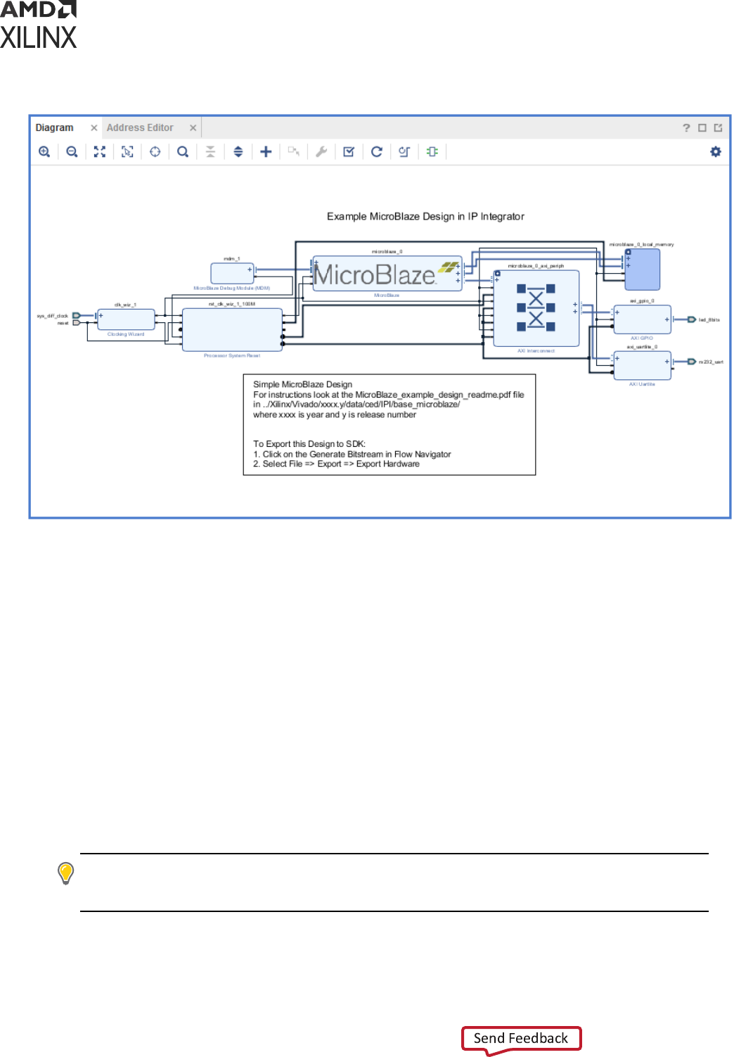
Figure 12: Vivado IP Integrator
Using Vivado IP integrator you can drag and drop IP onto the design canvas, connect AXI
interfaces with one wire, and place ports and interface ports to connect the IP subsystem to the
top-level design. These IP block designs can also be packaged as sources (.bd) and reused in
other designs. For more informaon, see the Vivado Design Suite User Guide: Designing IP
Subsystems Using IP Integrator (UG994) or Vivado Design Suite User Guide: Embedded Processor
Hardware Design (UG898).
Related Information
Packaging Custom IP and IP Subsystems
Building IP Subsystems
The interacve block design capabilies of the Vivado IP integrator make the job of conguring
and assembling groups of IP easy.
TIP:
If you prefer to work with a Tcl script, it is suggested to create the block design interacvely using the
Vivado IDE and then capture and edit the script as needed to recreate the block design. The IP integrator
can create a Tcl script to re-create the current block design in memory.
Chapter 3: Using Project Mode
UG892 (v2022.1) April 20, 2022 www.xilinx.com
Design Flows Overview 45

Block Design Containers
Block design containers allow a block diagram to reference a secondary block diagram. This
enables a design to be paroned into several block diagrams. Block design containers also
support several instances of child block diagrams in a parent block diagram. In this manner, a
logic can be replicated even if each instance has dierent parametrizaon. For more informaon
on block design containers, see Vivado Design Suite User Guide: Designing IP Subsystems using IP
Integrator (UG994).
Referencing RTL Modules in Block Designs
The Module Reference feature of the Vivado IP Integrator lets you quickly add a module or enty
denion from a Verilog or VHDL source le directly into your block design. This provides a
means of quickly adding RTL modules without having to go through the process of packaging the
RTL as an IP to be added through the Vivado IP catalog. The Module Reference ow is quick, but
does not oer the benets of the working through the IP catalog. Both ows have the benets
and associated limitaons. Refer to this link in Vivado Design Suite User Guide: Designing IP
Subsystems Using IP Integrator (UG994) for more informaon.
Designer Assistance
To expedite the creaon of a subsystem or a design, the IP integrator oers Block Automaon
and Connecon Automaon. The Block Automaon feature can be used to congure a basic
processor-based design and some complex IP subsystems, while the Connecon Automaon
feature can be used to automacally make repeve connecons to dierent pins or ports of the
design. IP integrator also supports all the Xilinx evaluaon boards in the Plaorm Board Flow, as
described below in Using the Plaorm Board Flow. This lets the Connecon Automaon feature
connect the I/O ports of the design to components on the target board. Designer assistance also
helps with dening and connecng clocks and resets. Using Designer Assistance not only
expedites the design process but also helps prevent unintended design errors.
Related Information
Using the Plaorm Board Flow
Using the Platform Board Flow
The Vivado Design Suite is board aware and can automacally derive I/O constraints and IP
conguraon data from included board les. Through the board les, the Vivado Design Suite
knows the various components present on the target boards and can customize and congure an
IP to be connected to a parcular board component. Several 7 series, Zynq
®
-7000 SoC, and
UltraScale™ device boards are currently supported. You can download support les for partner-
developed boards from the partner websites or from the Xilinx Vivado Store.
Chapter 3: Using Project Mode
UG892 (v2022.1) April 20, 2022 www.xilinx.com
Design Flows Overview 46

The IP integrator shows all the component interfaces on the target board in a separate tab called
the Board tab. You can use this tab to connect to the desired components through the Designer
Assistance feature. All the I/O constraints are automacally generated as a part of using this
feature.
You can also generate board les for custom boards and add the repository that contains the
board le to a project. For more informaon on generang a custom board le, see this link in the
Vivado Design Suite User Guide: System-Level Design Entry (UG895).
Validating IP Subsystems
IP integrator runs basic design rule checks in real me as the design is being assembled.
However, there is sll a potenal for design errors, such as the frequency on a clock pin may be
set incorrectly. The tool can catch these types of errors by running a more thorough design
validaon. You can run design validaon by selecng Tools → Validate Design or through the Tcl
command validate_bd_design.
The Validate Design command applies design rule checks on the block design and reports
warnings and/or errors found in the design. You can cross-probe the warnings and/or errors from
the Messages window to locate objects in the block diagram. Xilinx recommends validang a
block design to catch errors that would otherwise be found later in the design ow.
Running design validaon also runs Parameter Propagaon on the block design. Parameter
Propagaon enables IP integrator to automacally update the parameters associated with a
given IP based on its context and its connecons in the design. You can package custom IP with
specic parameter propagaon rules, and IP integrator applies these rules as the block diagram is
generated and validated. See this link in Vivado Design Suite User Guide: Designing IP Subsystems
Using IP Integrator (UG994) for more informaon.
Generating Block Design Output Products
Aer the block design or IP subsystem has been created, you can generate the block design
including all source codes, necessary constraints for the IP cores, and the structural netlist of the
block design. You can generate the block design by right-clicking on the block design (in the
Sources window) and selecng Generate Output Products from the pop-up menu. In the Vivado
Design Suite Flow Navigator you can also select IP Integrator → Generate Block Design.
There are two modes of OOC supported for block designs in the Vivado Design Suite: Out of
context per Block design and Out of context per IP. Refer to Out-of-Context Design Flow for
more informaon.
Related Information
Out-of-Context Design Flow
Chapter 3: Using Project Mode
UG892 (v2022.1) April 20, 2022 www.xilinx.com
Design Flows Overview 47

Integrating the Block Design into a Top-Level Design
An IP integrator block design can be integrated into a higher-level design or it can be the highest
level in the design hierarchy. To integrate the IP Integrator design into a higher-level design,
instanate the block design as a module in the higher-level HDL le.
You can perform a higher-level instanaon of the block design by selecng the block design in
the Vivado IDE Sources window and selecng Create HDL Wrapper. This generates a top-level
HDL le for the IP Integrator sub-system. See this link in the Vivado Design Suite User Guide:
Designing IP Subsystems Using IP Integrator (UG994) for more informaon.
Logic Simulation
The Vivado Design Suite has several logic simulaon opons for verifying designs or IP. The
Vivado simulator, integrated into the Vivado IDE, allows you to simulate the design, add and view
signals in the waveform viewer, and examine and debug the design as needed.
Figure 13: Simulation at Various Points in the Design Flow
Design
Entry
RTL Simulation
(Recommended before
proceeding to Synthesis
and implementation)
Implementation
Post Implementation
functional simulation
Post Implementation timing
simulation (Verilog only)
Synthesis
Post Synthesis functional
simulation
Post Synthesis timing
Simulation(Verilog only)
Testbench
Stimulus
Unisim
Unifast
Libraries used
for Timing
simulation
Libraries used for
Functional/RTL
simulation
SecureIP
Simprim
(verilog
only)
SecureIP
X14050-
010320
Chapter 3: Using Project Mode
UG892 (v2022.1) April 20, 2022 www.xilinx.com
Design Flows Overview 48

You can use the Vivado simulator to perform behavioral and structural simulaon of designs as
well as full ming simulaon of implemented designs. The previous gure shows all the places
where Vivado simulaon could be used for funconal and ming simulaon. You can also use
third-party simulators by wring Verilog or VHDL netlists, and SDF les from the elaborated,
synthesized, or implemented design. The Vivado IDE lets you congure and launch simulators
from Mentor Graphics, Synopsys, Cadence, and Aldec. For more informaon, see this link in the
Vivado Design Suite User Guide: Logic Simulaon (UG900).
Simulation Flow Overview
The following are some key suggesons related to simulang in the Vivado Design Suite. Many of
these ps are described in greater detail in the text that follows, or in Vivado Design Suite User
Guide: Logic Simulaon (UG900).
1. Run behavioral simulaon before proceeding with synthesis and implementaon. Issues
idened early will save me and money.
2. Infer logic wherever possible. Instanang primives adds signicant simulaon runme cost.
3. Always set the Target Language to Mixed unless you do not have a mixed mode license for
your simulator.
4. Turn o the waveform viewer when not in use to improve simulaon performance.
5. In the Vivado simulator, turn o debug during xelab for a performance boost.
6. In the Vivado simulator, turn on mul-threading to speed up compile me.
7. When using third-party simulators, always target supported versions. For more informaon,
see the Vivado Design Suite User Guide: Release Notes, Installaon, and Licensing (UG973).
8. Make sure incremental compile is turned on when using third-party simulators.
9. Use the Xilinx Tcl command export_simulation to generate batch scripts for selected
simulators.
10. Generate simulaon scripts for individual IP, BDs, and hierarchical modules as well as for the
top-level design.
11. If you are targeng a 7 series device, use UNIFAST libraries to improve simulaon
performance.
Note: The UNIFAST libraries are not supported for UltraScale device primives.
Compiling Simulation Libraries
Vivado delivers precompiled simulaon libraries for use with the Vivado simulator, as well as
precompiled libraries for all the stac les required by Xilinx IP. When simulaon scripts are
created, they reference these precompiled libraries.
Chapter 3: Using Project Mode
UG892 (v2022.1) April 20, 2022 www.xilinx.com
Design Flows Overview 49

When using third-party simulators, you must compile Xilinx simulaon libraries prior to running
simulaon, as explained in the Vivado Design Suite User Guide: Logic Simulaon (UG900). This is
especially true if your design instanates VHDL primives or Xilinx IP, the majority of which are
in VHDL form. The simulaon tool will return “library binding” failures if you do not precompile
simulaon libraries.
You can run the compile_simlib Tcl command to compile the Xilinx simulaon libraries for
the target simulator. You can also issue this command from the Vivado IDE by selecng Tools →
Compile Simulaon Libraries.
IMPORTANT! Simulaon libraries are pre-compiled and provided for use with the Vivado simulator.
However, you must manually compile the libraries for use with a third-party simulator. Refer to this link in
the Vivado Design Suite User Guide: Logic Simulaon (UG900) for more informaon.
Simulation Time Resolution
Xilinx recommends that you run simulaons using a resoluon of 1 ps. Some Xilinx primive
components, such as MMCM, require a 1 ps resoluon to work properly in either funconal or
ming simulaon.
TIP: Because most of the simulaon me is spent in delta cycles, there is no signicant simulator
performance gain by using coarser resoluon with the Xilinx simulaon models.
There is no need to use a ner resoluon, such as femtoseconds (fs) as some simulators will
round the numbers while others will truncate the numbers.
Functional Simulation Early in the Design Flow
Use funconal or register transfer level (RTL) simulaon to verify syntax and funconality. This
rst pass simulaon is typically performed to verify the RTL or behavioral code and to conrm
that the design is funconing as intended.
With larger hierarchical designs, you can simulate individual IP, block designs, or hierarchical
modules before tesng your complete design. This simulaon process makes it easier to debug
your code in smaller porons before examining the larger design. When each module simulates
as expected, create a top-level design test bench to verify that your enre design funcons as
planned. Use the same test bench again for the nal ming simulaon to conrm that your
design funcons as expected under worst-case delay condions.
RECOMMENDED:
At this stage, no ming informaon is provided. Xilinx recommends performing
simulaon in unit-delay mode to avoid the possibility of a race condion.
You should use synthesizable HDL constructs for the inial design creaon. Do not instanate
specic components unless necessary. This allows for:
• More readable code
Chapter 3: Using Project Mode
UG892 (v2022.1) April 20, 2022 www.xilinx.com
Design Flows Overview 50

• Faster and simpler simulaon
• Code portability (the ability to migrate to dierent device families)
• Code reuse (the ability to use the same code in future designs)
TIP: You might need to instanate components if the components cannot be inferred.
Instanaon of components can make your design code architecture specic.
Using Structural Netlists for Simulation
Aer synthesis or implementaon, you can perform netlist simulaon in funconal or ming
mode. The netlist simulaon can also help you with the following:
• Idenfy post-synthesis and post-implementaon funconality changes caused by:
○ Synthesis aributes or constraints that create mismatches (such as full_case and
parallel_case)
○
UNISIM aributes applied in the Xilinx Design Constraints (XDC) le
○ Dierences in language interpretaon between synthesis and simulaon
○ Dual-port RAM collisions
○ Missing or improperly applied ming constraints
○ Operaon of asynchronous paths
○ Funconal issues due to opmizaon techniques
• Sensize ming paths declared as false or mul-cycle during STA
• Generate netlist switching acvity to esmate power
• Idenfy X state pessimism
For netlist simulaon, you can use one or more of the libraries shown in the following table.
Table 2: Use of Simulation Library
Library Name Description
VHDL Library
Name
Verilog Library
Name
UNISIM Functional simulation of Xilinx primitives UNISIM UNISIMS_VER
UNIMACRO Functional simulation of Xilinx macros UNIMACRO UNIMACRO_VER
UNIFAST Fast simulation library UNIFAST UNIFAST_VER
Chapter 3: Using Project Mode
UG892 (v2022.1) April 20, 2022 www.xilinx.com
Design Flows Overview 51

The UNIFAST library is an oponal library that you can use during funconal simulaon to speed
up simulaon runme. UNIFAST libraries are supported for 7 series devices only. UltraScale and
later device architectures do not support UNIFAST libraries, because all the opmizaons are
incorporated in the UNISIM libraries by default. For more informaon on Xilinx simulaon
libraries, see this link in the Vivado Design Suite User Guide: Logic Simulaon (UG900).
Primives/elements of the UNISIM library do not have any ming informaon except the clocked
elements. To prevent race condions during funconal simulaon, clocked elements have a
clock-to-out delay of 100 ps. Waveform views might show spikes and glitches for combinatorial
signals, due to lack of any delay in the UNISIM elements.
Timing Simulation
Xilinx supports ming simulaon in Verilog only. You can export a netlist for ming simulaon
from an open synthesized or implemented design using the File → Export → Export Netlist
command in the Vivado IDE, or by using the write_verilog Tcl command.
The Verilog system task $sdf_annotate within the simulaon netlist species the name of the
standard delay format (SDF) le to be read for ming delays. This direcve is added to the
exported netlist when the -sdf_anno opon is enabled on the Netlist tab of the Simulaon
Sengs dialog box in the Vivado IDE. The SDF le can be wrien with the write_sdf
command. The Vivado simulator automacally reads the SDF le during the compilaon step.
TIP:
The Vivado simulator supports mixed-language simulaon, which means that if you are a VHDL user,
you can generate a Verilog simulaon netlist and instanate it from the VHDL test bench.
Many users do not run ming simulaon due to high run me. However, you should consider
using full ming simulaon because it is the closest method of modeling hardware behavior. If
your design does not work on hardware, it is much easier to debug the failure in simulaon, as
long as you have a ming simulaon that can reproduce the failure.
If you decide to skip ming simulaon, you should make sure of the following:
• Ensure that your STA constraints are absolutely correct. Pay special aenon to excepons.
• Ensure that your netlist is exactly equivalent to what you intended through your RTL. Pay
special aenon to any inference-related informaon provided by the synthesis tool.
Simulation Flow
The Vivado Design Suite supports both integrated simulaon, which allows you to run the
simulator from within the Vivado IDE, and batch simulaon, which allows you to generate a
script from the Vivado tools to run simulaon on an external vericaon environment.
Chapter 3: Using Project Mode
UG892 (v2022.1) April 20, 2022 www.xilinx.com
Design Flows Overview 52

Integrated Simulation
The Vivado IDE provides full integraon with the Vivado simulator, and all supported third-party
simulators. In this ow, the simulator is called from within the Vivado IDE, and you can compile
and simulate the design easily with a push of a buon, or with the launch_simulation Tcl
command.
IMPORTANT! The
launch_simulation
command launches integrated simulaon for project-based
designs. This command does not support Non-Project Mode.
For informaon on the steps involved in seng up the integrated simulaon ow, see this link in
the Vivado Design Suite User Guide: Logic Simulaon (UG900).
Batch Simulation
RECOMMENDED: If your vericaon environment has a self-checking test bench, run simulaon in batch
mode. There is a signicant runme cost when you view simulator waveforms using the integrated
simulaon.
For batch simulaon, the Vivado Design Suite provides the export_simulation Tcl command
to generate simulaon scripts for supported simulators, including the Vivado simulator. You can
use the scripts generated by export_simulation directly or use the scripts as a reference for
building your own custom simulaon scripts.
The export_simulation command creates separate scripts for each stage of the simulaon
process (compile, elaborate, and simulate) so that you can easily incorporate the generated
scripts in your own vericaon ow. For more informaon about generang scripts for batch
simulaon, see this link in the Vivado Design Suite User Guide: Logic Simulaon (UG900).
Running Logic Synthesis and Implementation
Logic Synthesis
Vivado synthesis enables you to congure, launch, and monitor synthesis runs. The Vivado IDE
displays the synthesis results and creates report les. You can select synthesis warnings and
errors from the Messages window to highlight the logic in the RTL source les.
Chapter 3: Using Project Mode
UG892 (v2022.1) April 20, 2022 www.xilinx.com
Design Flows Overview 53

You can launch mulple synthesis runs concurrently or serially. On a Linux system, you can
launch runs locally or on remote servers. With mulple synthesis runs, Vivado synthesis creates
mulple netlists that are stored with the Vivado Design Suite project. You can open dierent
versions of the synthesized netlist in the Vivado IDE to perform device and design analysis. You
can also create constraints for I/O pin planning, ming, oorplanning, and implementaon. The
most comprehensive list of DRCs is available aer a synthesized netlist is produced, when clock
and clock logic are available for analysis and placement.
For more informaon, see the Vivado Design Suite User Guide: Synthesis (UG901).
Note: Launching mulple jobs simultaneously on the same machine can exhaust memory, resulng in
random Vivado crashes. Ensure to reserve enough memory for all jobs running on a single machine.
Implementation
Vivado implementaon enables you to congure, launch, and monitor implementaon runs. You
can experiment with dierent implementaon opons and create your own reusable strategies
for implementaon runs. For example, you can create strategies for quick run mes, improved
system performance, or area opmizaon. As the runs complete, implementaon run results
display and report les are available.
You can launch mulple implementaon runs either simultaneously or serially. On a Linux system,
you can use remote servers. You can create constraint sets to experiment with various ming
constraints, physical constraints, or alternate devices. For more informaon, see the Vivado
Design Suite User Guide: Implementaon (UG904) and Vivado Design Suite User Guide: Using
Constraints (UG903).
TIP:
You can add Tcl scripts to be sourced before and aer synthesis, any stage of implementaon, or
bitstream generaon using the
tcl.pre
and
tcl.post
les. For more informaon, see the Vivado
Design Suite User Guide: Using Tcl Scripng (UG894).
Note: Launching mulple jobs simultaneously on the same machine can exhaust memory, resulng in
random Vivado crashes. Ensure to reserve enough memory for all jobs running on a single machine.
Configuring Synthesis and Implementation Runs
When using Project Mode, various sengs are available to control the features of synthesis and
implementaon. These sengs are passed to runs using run strategies, which you set in the
Sengs dialog box. A run strategy is simply a saved set of run conguraon parameters. Xilinx
supplies several pre-dened run strategies for running synthesis and implementaon, or you can
apply custom run sengs. In addion, you can use separate constraint sets for synthesis and
implementaon.
For informaon on modifying sengs, see this link to the Vivado Design Suite User Guide:
Synthesis (UG901) and see this link in the Vivado Design Suite User Guide: Implementaon (UG904).
Chapter 3: Using Project Mode
UG892 (v2022.1) April 20, 2022 www.xilinx.com
Design Flows Overview 54
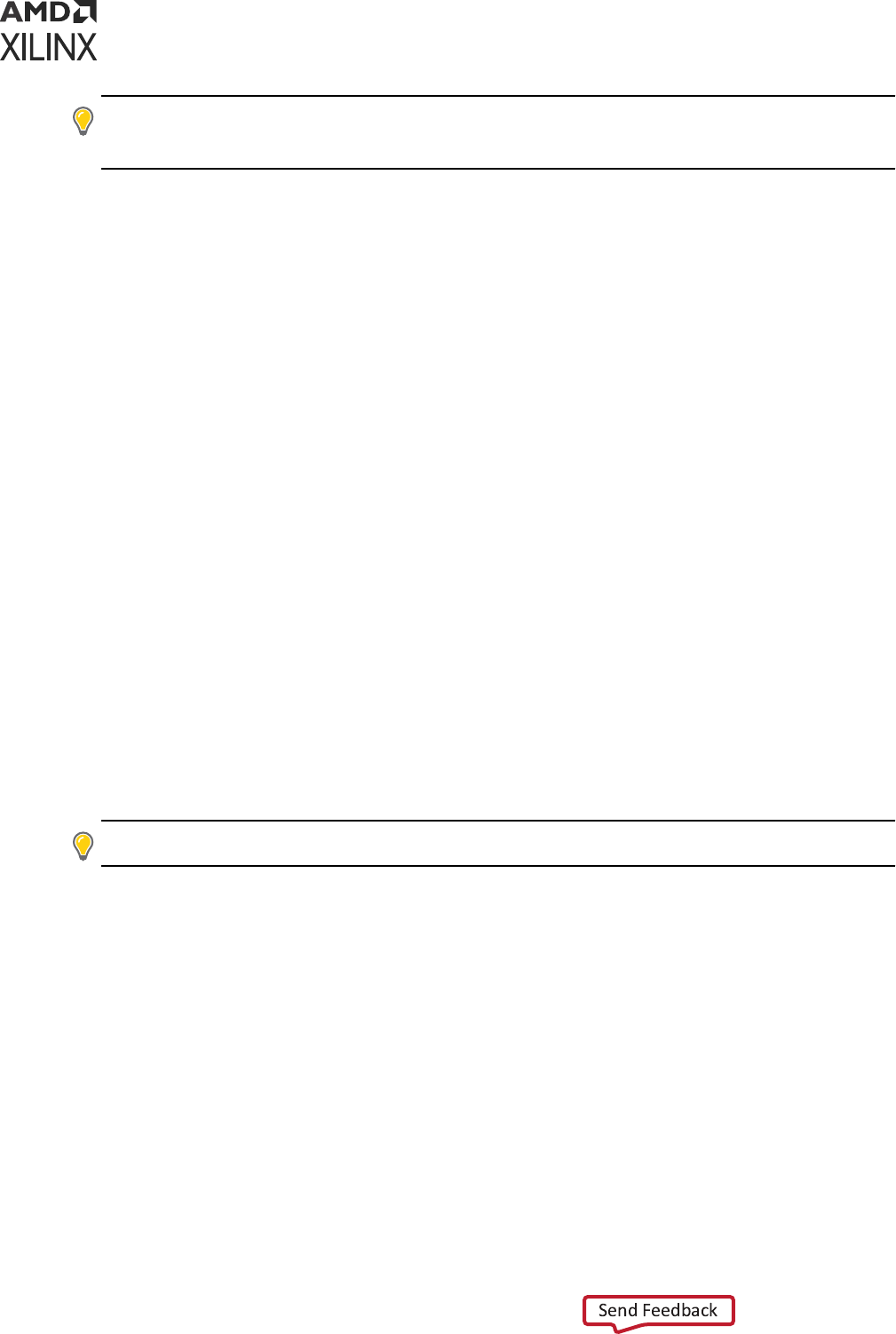
TIP: You can create an out-of-context module run to synthesize the Vivado Design Suite IP in the project. If
you generate a design checkpoint for the IP, the default behavior is to create an out-of-context run for
each IP in the design.
Creating and Managing Runs
Aer the synthesis and implementaon sengs are congured in the Sengs dialog box, you
can launch synthesis or implementaon runs using any of the following methods:
• In the Flow Navigator, select Run Synthesis, Run Implementaon, or Generate Bitstream or
Generate Device Image for Versal ACAP.
• In the Design Runs window, select a run, right-click, and select Launch Runs. Alternavely,
you can click the Launch Selected Runs buon.
• Select Flow → Run Synthesis, Flow → Run Implementaon, or Flow → Generate Bitstream or
Generate Device Image for Versal ACAP.
You can create mulple synthesis or implementaon runs to experiment with constraints or tool
sengs. To create addional runs:
1. In the Flow Navigator, right-click Synthesis or Implementaon.
2. Select Create Synthesis Runs or Create Implementaon Runs.
3. In the Create New Runs wizard (see the following gure), select the constraint set and target
part.
If more than one synthesis run exists, you can also select the netlist when creang
implementaon runs. You can then create one or more runs with varying strategies, constraint
sets, or devices. There are several launch opons available when mulple runs exist. You can
launch selected runs sequenally or in parallel on mulple local processors.
TIP:
You can congure and use remote hosts on Linux systems only.
Chapter 3: Using Project Mode
UG892 (v2022.1) April 20, 2022 www.xilinx.com
Design Flows Overview 55

Figure 14: Creating Multiple Synthesis and Implementation Runs
Managing Runs with the Design Runs Window
The Design Runs windows (shown in the following gure) displays run status and informaon and
provides access to run management commands in the popup menu. You can manage mulple
runs from the Design Runs window. When mulple runs exist, the acve run is displayed in bold.
The Vivado IDE displays the design informaon for the acve run. The Project Summary, reports,
and messages all reect the results of the acve run.
The Vivado IDE opens the acve design by default when you select Open Synthesized Design or
Open Implemented Design in the Flow Navigator. You can make a run the acve run using the
Make Acve popup menu command. The Vivado IDE updates results to reect the informaon
about the newly designated acve run. Double-click any synthesized or implemented run to open
the design in the Vivado IDE.
Figure 15: Design Runs Window
Chapter 3: Using Project Mode
UG892 (v2022.1) April 20, 2022 www.xilinx.com
Design Flows Overview 56

Resetting Runs
In the Flow Navigator, you can right-click Synthesis or Implementaon, and use the following
popup menu commands to reset runs. For more informaon, see this link in the Vivado Design
Suite User Guide: Implementaon (UG904).
• Reset Runs resets the run to its original state and oponally deletes generated les from the
run directory.
• Reset to Previous Step resets the run to the listed step.
TIP: To stop an in-process run, click the Cancel buon in the upper right corner of the Vivado IDE.
Launching Runs on Remote Clusters
To launch runs on remote Linux hosts, you can directly access a load sharing facility (LSF) server
farm. Vivado allows all cluster commands to be congured through Tcl. For more informaon, see
Using Remote Hosts and Compute Clusters Appendix in the Vivado Design Suite User Guide:
Implementaon (UG904).
Performing Implementation with Incremental
Compile
You can specify the incremental compile ow when running Vivado implementaon to facilitate
small design changes. Incremental compile can reduce place and route run mes and preserve
exisng implementaon results depending on the scope of the change and the amount of ming-
crical logic that is modied.
You can specify the Set Incremental Compile opon in the Implementaon Sengs dialog box in
the Vivado IDE, or by using the Set Incremental Compile command from the right-click menu of
the Design Runs window. You can also use the read_checkpoint Tcl command with the -
incremental opon, and point to a routed design checkpoint to use as a reference. For more
informaon, see this link in the Vivado Design Suite User Guide: Implementaon (UG904).
Closing Timing Using Intelligent Design Runs
Intelligent design runs (IDR) uses a mul-stage run approach to automacally close ming on a
design. This ow can be invoked in the GUI by right clicking on implementaon run in the design
runs window and selecng "Close Timing Using Intelligent Design Runs" or in Tcl, by creang a
new run using the IDR ow and properly seng the reference run. For informaon on Intelligent
design runs, see Chapter 8 of Vivado Design Suite User Guide: Design Analysis and Closure
Techniques (UG906).
Chapter 3: Using Project Mode
UG892 (v2022.1) April 20, 2022 www.xilinx.com
Design Flows Overview 57

Implementing Engineering Change Orders (ECOs)
Engineering change orders (ECOs) are modicaons to an implemented design, with the intent to
minimize impact to the original design. The Vivado Design Suite provides an ECO ow, which lets
you modify an exisng design checkpoint to implement changes, run reports on the changed
netlist, and generate the required bitstream les.
The advantage of the ECO ow is fast turn-around me by taking advantage of the incremental
place and route features of the Vivado tool. The Vivado IDE provides a predened layout to
support the ECO ow. Refer to this link in the Vivado Design Suite User Guide: Implementaon
(UG904) for more informaon.
Viewing Log Files, Messages, Reports, and
Properties
Viewing Log Files
In the Log window (shown in the following gure), you can click the dierent tabs to view the
standard output for Synthesis, Implementaon, and Simulaon. This output is also included in the
vivado.log le that is wrien to the Vivado IDE launch directory.
Figure 16: Viewing Log Files
Chapter 3: Using Project Mode
UG892 (v2022.1) April 20, 2022 www.xilinx.com
Design Flows Overview 58

Viewing Messages
In the Messages window (shown in the following gure), messages are categorized according to
design step and severity level: Errors, Crical Warnings, Warnings, Info, and Status. To lter
messages, select the appropriate check boxes in the window header. You can expand the
message categories to view specic messages. You can click the Collapse All icon to show only
the main design steps. This enables beer navigaon to specic messages. Many messages
include links that take you to logic lines in the RTL les. For more informaon, including
advanced ltering techniques, see this link in the Vivado Design Suite User Guide: Using the Vivado
IDE (UG893).
Figure 17: Viewing Messages
Viewing Reports
In the Reports window (shown in the following gure), several standard reports are generated
using the launch_runs Tcl commands. You can double-click any report to display it in the
Vivado IDE Text Editor. You can also create custom reports using Tcl commands in the Tcl
Console or using report strategies. For more informaon, see this link and this link in the Vivado
Design Suite User Guide: Using the Vivado IDE (UG893) and see this link and this link in Vivado
Design Suite User Guide: Design Analysis and Closure Techniques (UG906).
Figure 18: Viewing Reports
Chapter 3: Using Project Mode
UG892 (v2022.1) April 20, 2022 www.xilinx.com
Design Flows Overview 59
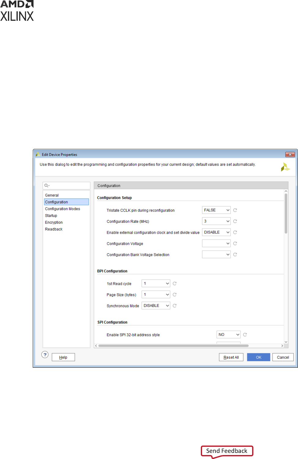
Viewing or Editing Device Properties
With the elaborated, synthesized, or implemented design open, you can use the Tools → Edit
Device Properes command to open the Edit Device Properes dialog box (shown in the
following gure) in which you can view and set device conguraon and bitstream-related
properes. This command is available only when a design is open. For informaon on each
property, see the link in the Vivado Design Suite User Guide: Programming and Debugging (UG908).
For informaon on seng device conguraon modes, see this link in the Vivado Design Suite
User Guide: I/O and Clock Planning (UG899).
Note: The Edit → Device Properes is only available when a design is open.
Figure 19: Viewing Device Properties
Chapter 3: Using Project Mode
UG892 (v2022.1) April 20, 2022 www.xilinx.com
Design Flows Overview 60

Opening Designs to Perform Design Analysis
and Constraints Definition
You can perform design analysis and assign constraints aer RTL elaboraon, aer synthesis, or
aer implementaon. To idenfy design issues early, you can perform design analysis prior to
implementaon, including ming simulaon, resource esmaon, connecvity analysis, and
DRCs. You can open the various synthesis or implementaon run results for analysis and
constraints assignment. This is known as opening the design.
When you open the design, the Vivado IDE compiles the netlist and applies physical and ming
constraints against a target part. You can open, save, and close designs. When you open a new
design, you are prompted to close any previously opened designs in order to preserve memory.
However, you are not required to close the designs, because mulple designs can be opened
simultaneously. When you open a synthesized design, the Vivado IDE displays the netlist and
constraints. When you open an implemented design, the Vivado IDE displays the netlist,
constraints, and implementaon results. The design data is presented in dierent forms in
dierent windows, and you can cross probe and coordinate data between windows.
Aer opening a design, many analysis and reporng features are available in the Vivado IDE. For
example, you can analyze device resources in the graphical windows of the internal device and
the external physical package. You can also apply and analyze ming and physical constraints in
the design using the Netlist, Device, Schemac, or Hierarchy windows. For more informaon, see
the Vivado Design Suite User Guide: Design Analysis and Closure Techniques (UG906) and Vivado
Design Suite User Guide: Using Constraints (UG903).
Note: If you make constraint changes while the design is open, you are prompted to save the changes to
the original XDC source les or to create a new constraint set. For more informaon, see this link in the
Vivado Design Suite User Guide: System-Level Design Entry (UG895).
Opening an Elaborated RTL Design
When you open an elaborated design, the Vivado Design Suite expands and compiles the RTL
netlist and applies physical and ming constraints against a target part. The dierent elements of
the elaborated design are loaded into memory, and you can analyze and modify the elements as
needed to complete the design. For more informaon, see this link in the Vivado Design Suite User
Guide: System-Level Design Entry (UG895).
Chapter 3: Using Project Mode
UG892 (v2022.1) April 20, 2022 www.xilinx.com
Design Flows Overview 61

The Vivado Design Suite includes linng DRCs and checking tools that enable you to analyze
your design for logic correctness. You can make sure that there are no logic compilaon issues,
no missing modules, and no interface mismatches. In the Messages window, you can click links in
the messages to display the problem lines in the RTL les in the Vivado IDE Text Editor. In the
Schemac window, you can explore the logic interconnects and hierarchy in a variety of ways.
The Schemac window displays RTL interconnects using RTL-based logic constructs. You can
select logic in the Schemac window and see specic lines in the RTL les in the Vivado IDE Text
Editor. For more informaon, see this link in the Vivado Design Suite User Guide: System-Level
Design Entry (UG895).
Note: There is no FPGA technology mapping during RTL elaboraon.
Constraints that are dened on specic logic instances within the logic hierarchy, such as
registers, might not be resolvable during RTL elaboraon. The logic names and hierarchy
generated during elaboraon might not match those generated during synthesis. For this reason,
you might see constraint mapping warnings or errors when elaborang the RTL design, if you
have these types of constraints dened. However, when you run synthesis on the design, these
issues are resolved.
Using the I/O planning capabilies of the Vivado IDE, you can interacvely congure and assign
I/O Ports in the elaborated RTL design and run DRCs. When possible, it is recommended that
you perform I/O planning aer synthesis. This ensures proper clock and logic constraint
resoluon, and the DRCs performed aer synthesis are more extensive. For more informaon,
see Vivado Design Suite User Guide: I/O and Clock Planning (UG899).
TIP:
When you select the Report DRC command, the Vivado IDE invokes a set of RTL and I/O DRCs to
idenfy logic issues such as asynchronous clocks, latches, and so forth. For more informaon, see this link
in the Vivado Design Suite User Guide: System-Level Design Entry (UG895).
To open an elaborated design, use one of the following methods:
• In the RTL Analysis secon of the Flow Navigator, select Open Elaborated Design.
• In the Flow Navigator, right-click RTL Analysis, and select New Elaborated Design from the
popup menu.
• Select Flow → Open Elaborated Design.
The following gure shows the default view layout for an open elaborated RTL design. Noce the
logic instance that was cross-selected from the schemac to the specic instance in the RTL
source le and within the elaborated RTL netlist.
Chapter 3: Using Project Mode
UG892 (v2022.1) April 20, 2022 www.xilinx.com
Design Flows Overview 62
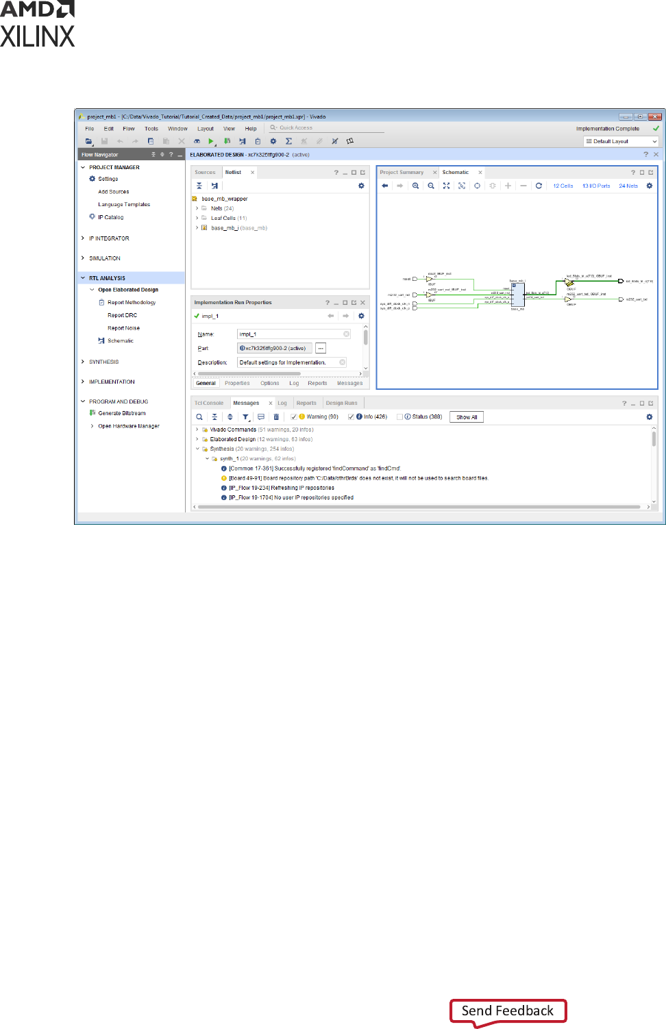
Figure 20: Elaborated RTL Design View Layout
Opening a Synthesized Design
When you open a synthesized design, the Vivado Design Suite opens the synthesized netlist and
applies physical and ming constraints against a target part. The dierent elements of the
synthesized design are loaded into memory, and you can analyze and modify these elements as
needed to complete the design. You can save updates to the constraints les, netlist, debug
cores, and conguraon.
In a synthesized design, you can perform many design tasks, including early ming, power, and
ulizaon esmates that can help you determine if your design is converging on desired targets.
You can explore the design in a variety of ways using the windows in the Vivado IDE. Objects are
always cross-selected in all other windows. You can cross probe to problem lines in the RTL les
from various windows, including the Messages, Schemac, Device, Package, and Find windows.
The Schemac window allows you to interacvely explore the logic interconnect and hierarchy.
You can also apply ming constraints and perform further ming analysis. In addion, you can
interacvely dene physical constraints for I/O ports, oorplanning, or design conguraon. For
more informaon, see the Vivado Design Suite User Guide: Design Analysis and Closure Techniques
(UG906).
Chapter 3: Using Project Mode
UG892 (v2022.1) April 20, 2022 www.xilinx.com
Design Flows Overview 63

Using the I/O planning capabilies of the Vivado IDE, you can interacvely congure and assign
I/O ports in the synthesized design and run DRCs. Select the Run DRC command to invoke a
comprehensive set of DRCs to idenfy logic issues. For more informaon, see this link in the
Vivado Design Suite User Guide: I/O and Clock Planning (UG899) and see this link in Vivado Design
Suite User Guide: Design Analysis and Closure Techniques (UG906).
You can congure and implement debug core logic in the synthesized design to support test and
debug of the programmed device. In the Schemac or Netlist windows, interacvely select
signals for debug. Debug cores are then congured and inserted into the design. The core logic
and interconnect is preserved through synthesis updates of the design when possible. For more
informaon, see this link in the Vivado Design Suite User Guide: Programming and Debugging
(UG908).
To open a synthesized design, use one of the following methods:
• In the Synthesis secon of the Flow Navigator, select Open Synthesized Design.
• In the Flow Navigator, right-click Synthesis, and select New Synthesized Design from the
popup menu.
• Select Flow → Open Synthesized Design.
• In the Design Runs view, double-click the run name.
The following gure shows the default view layout for an open synthesized design.
Chapter 3: Using Project Mode
UG892 (v2022.1) April 20, 2022 www.xilinx.com
Design Flows Overview 64
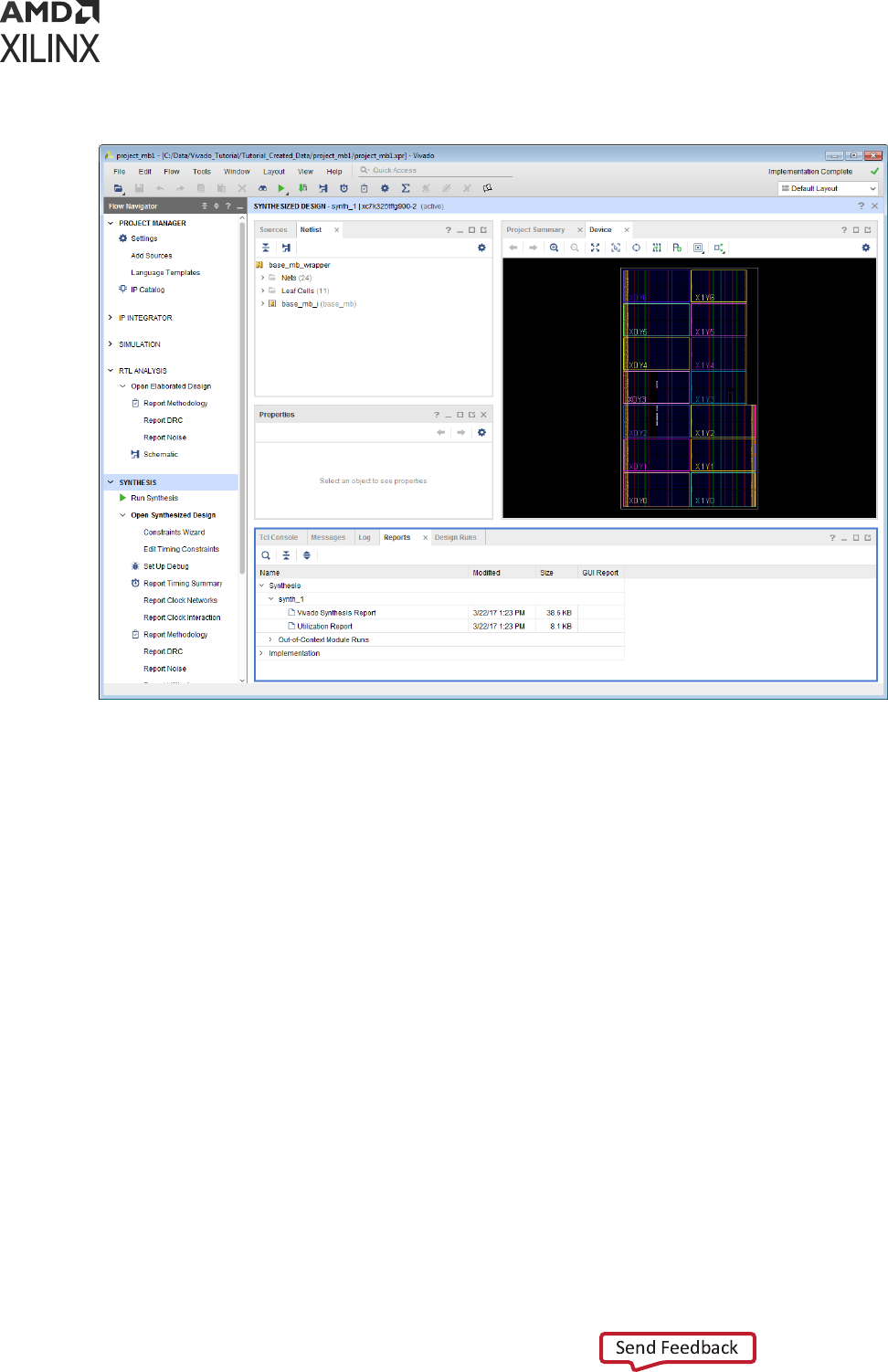
Figure 21: Synthesized Design View Layout
Opening an Implemented Design
When you open an implemented design in the Flow Navigator, the Vivado IDE opens the
implemented netlist and applies the physical and ming constraints used during implementaon,
placement, and roung results against the implemented part. The placed logic and routed
connecons of the implemented design are loaded into memory, and you can analyze and modify
the elements as needed to complete the design. You can save updates to the constraints les,
netlist, implementaon results, and design conguraon. Because the Vivado IDE allows for
mulple implementaon runs, you can select any completed implementaon run to open the
implemented design.
In an implemented design, you can perform many design tasks, including ming analysis, power
analysis, and generaon of ulizaon stascs, which can help you determine if your design
converged on desired performance targets. You can explore the design in a variety of ways using
the windows in the Vivado IDE. Selected objects are always cross-selected in all related
windows. You can cross probe to lines in the source RTL les from various windows, including
the Messages, Schemac, Device, Package, and Find windows. The Schemac window allows
Chapter 3: Using Project Mode
UG892 (v2022.1) April 20, 2022 www.xilinx.com
Design Flows Overview 65
you to interacvely explore the logic interconnect and hierarchy. You can also apply ming
constraints and perform further ming analysis. In addion, you can interacvely apply
oorplanning or design conguraon constraints and save the constraints for future runs. For
more informaon, see the Vivado Design Suite User Guide: Design Analysis and Closure Techniques
(UG906).
In the Device window, you can explore the placement or the roung results by toggling the
Roung Resources buon . As you zoom, the amount of detail shown in the Device window
increases. You can interacvely alter placement and roung as well as design conguraon, such
as look-up table (LUT) equaons and random access memory (RAM) inializaon. You can also
select results in the Device or Schemac windows to cross probe back to problem lines in the
RTL les. In the Schemac window, you can interacvely explore the logic interconnect and
hierarchy. For more informaon, see the Vivado Design Suite User Guide: Design Analysis and
Closure Techniques (UG906).
To open an implemented design, use one of the following methods:
• In the Implementaon secon of the Flow Navigator, click Open Implemented Design.
• Select Flow → Open Implemented Design.
• In the Design Runs view, double-click the run name.
TIP:
Because the Flow Navigator reects the state of the acve run, the Open Implemented Design
command might be disabled or greyed out if the acve run is not implemented. In this case, use the
Implementaon popup menu in the Flow Navigator to open an implemented design from any of the
completed implementaon runs.
The following gure shows the default layout view for an open implemented design.
Note: The Device window might display placement only or roung depending on the state the window was
in when it was last closed. In the Device window, click the Roung Resources buon to toggle the view to
display only placement or roung.
Chapter 3: Using Project Mode
UG892 (v2022.1) April 20, 2022 www.xilinx.com
Design Flows Overview 66

Figure 22: Implemented Design View Layout
Updating Out-of-Date Designs
During the design process, source les or constraints oen require modicaon. The Vivado IDE
manages the dependencies of these les and indicates when the design data in the current
design is out of date. For example, changing sengs, such as the target part or acve constraint
set, can make a design out of date. As source les, netlists, or implementaon results are
updated, an out-of-date message is displayed in the design window banner of an open
synthesized or implemented design to indicate that the run is out of date (shown in the following
gure). Click the associated more info link to view which aspects of the design are out of date.
Chapter 3: Using Project Mode
UG892 (v2022.1) April 20, 2022 www.xilinx.com
Design Flows Overview 67

Figure 23: Design Out-of-Date and Reload Banner
From the design window banner, use any of the following acons to resolve an out-of-date
design:
• Click More Info, and click the Force up-to-date link in the Out-of-Date Due to window that
appears.
Force up-to-date resets the NEEDS_REFRESH property on the acve synthesis or
implementaon runs as needed to force the runs into an up-to-date state. The associated Tcl
command is shown in the following sample code:
set_property NEEDS_REFRESH false [get_runs synth_2]
Note: Use this command to force designs up to date when a minor design change was made, and you do
not want to refresh the design.
• Click Reload to refresh the in-memory view of the current design, eliminang any unsaved
changes you made to the design data.
• Click Close Design to close the out-of-date design.
Using View Layouts to Perform Design Tasks
When a design is open, several default view layouts (shown in the following gure) are provided
to enable you to more easily work on specic design tasks, such as I/O planning, oorplanning,
and debug conguraon. Changing view layouts simply alters the windows that are displayed,
which enables you to focus on a parcular design task. You can also create custom view layouts
using the Save Layout As command.
Note: Default view layouts are available only when a design is open.
Chapter 3: Using Project Mode
UG892 (v2022.1) April 20, 2022 www.xilinx.com
Design Flows Overview 68
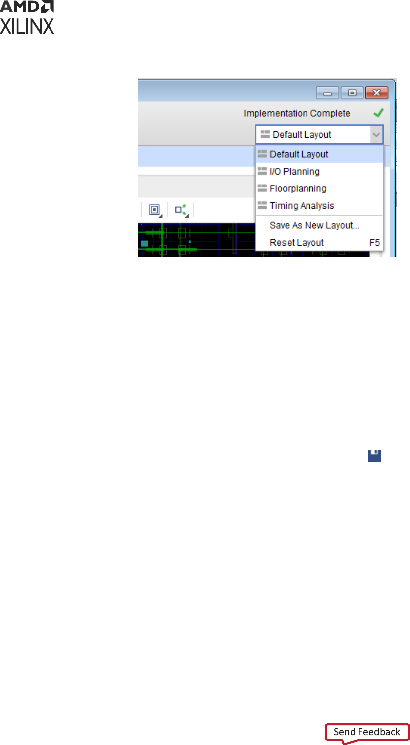
Figure 24: Selecting a View Layout
Saving Design Changes
In the Vivado IDE, you interacvely edit the acve design in memory. It is important to save the
design when you make changes to constraints, netlists, and design parameters, such as power
analysis characteriscs, hardware conguraon mode parameters, and debug conguraon. For
changes made while interacvely eding an open design, you can save the changes either back
to your original XDC constraint les or to a new constraint set as described in the following
secons.
Saving Changes to Original XDC Constraint Files
To save any changes you made to your design data back to your original XDC constraint les,
select File → Constraints → Save, or click the Save Constraints buon
.
The Save Constraints command saves any changes made to the constraints, debug cores and
conguraon, and design conguraon sengs made in the open design. The Vivado IDE
aempts to maintain the original le format as much as possible. Addional constraints are
added at the end of the le. Changes to exisng constraints remain in their original le locaons.
Saving Changes to a New Constraint Set
To save changes to the design to a new constraint set, select File → Constraints → Save As to
create a new constraint le.
This saves any changes while preserving your original constraints source les. The new constraint
set includes all design constraints, including all changes. This is one way to maintain your original
XDC source les. You can also make the new constraint set the acve constraint set, so that it is
automacally applied to the next run or when opening designs.
Chapter 3: Using Project Mode
UG892 (v2022.1) April 20, 2022 www.xilinx.com
Design Flows Overview 69
Closing Designs
You can close designs to reduce the number of designs in memory and to prevent mulple
locaons where sources can be edited. In some cases, you are prompted to close a design prior
to changing to another design representaon. To close individual designs, do either of the
following:
• In the design tle bar, click the close buon (X).
• In the Flow Navigator, right-click the design, and select Close.
Analyzing Implementation Results
When you open an implemented design, placement and roung results are displayed in the
Device window. In the Timing Results window, you can select ming paths to highlight the
placement and roung for the selected path in the Device window. You can also interacvely edit
placement and roung to achieve design goals and change design characteriscs, such as LUT
equaons, RAM inializaon, and phase-locked loop (PLL) conguraon. For more informaon,
see this link in the Vivado Design Suite User Guide: Implementaon (UG904).
IMPORTANT! Changes are made on the in-memory version of the implemented design only. Reseng the
run causes changes to be lost. To save the changes, use the Save Checkpoint command, as described in
Saving Design Changes to Design Checkpoints.
Related Information
Saving Design Changes to Design Checkpoints
Running Timing Analysis
The Vivado IDE provides a graphical way to congure and view ming analysis results. You can
experiment with various types of ming analysis parameters using Tools → Timing commands.
You can use the Clock Networks and Clock Interacon report windows to view clock topology
and relaonships. You can also use the Slack Histogram window to see an overall view of the
design ming performance. For more informaon, see this link in the Vivado Design Suite User
Guide: Design Analysis and Closure Techniques (UG906).
In addion, the Vivado IDE has many ming analysis opons available through the Tcl Console
and SDC constraint opons. Many standard report Tcl commands are available to provide
informaon about the clock structure, logic relaonships, and constraints applied to your design.
For more informaon, see the Vivado Design Suite Tcl Command Reference Guide (UG835), or type
help report_*.
Chapter 3: Using Project Mode
UG892 (v2022.1) April 20, 2022 www.xilinx.com
Design Flows Overview 70

Running Reports: DRC, Power, Utilization Analysis
The Vivado IDE provides a graphical way to congure and view power, ulizaon, and DRC
analysis results. The report_power command lets you experiment with power parameters and
quickly esmate power at any stage of the design. The report_utilization command lets
you analyze the ulizaon stascs of various types of device resources. The
report_design_analysis command lets you analyze crical path characteriscs and the
complexity of the design to help idenfy and analyze problem areas that are prone to roung
congeson and ming closure issues. The report_drc command let you congure and run a
comprehensive set of DRCs to idenfy problems that must be solved prior to generang the
bitstream for the design.
In the Vivado IDE, report results are provided with links to select problem areas or oending
objects. In addion, many reports can write an RPX le to save the report results in an interacve
report le that can be reloaded into memory, with links to design objects. Reloading the report
reconnects the object links so that cross-selecon between the report in the Vivado IDE and the
design is enabled. For more informaon, see the Vivado Design Suite User Guide: Design Analysis
and Closure Techniques (UG906), or refer to the report_xxx commands in the Vivado Design
Suite Tcl Command Reference Guide (UG835).
Report strategies enable you to dene groups of reports and associate all the reports with a
parcular run. Report strategies can be created by using Tools→Sengs→Strategies→Report
Strategies. Individual reports can be specied for each step of a run. Report strategy is a property
of a run. Seng report strategy on the run generates all specied reports when the run is
launched.
Device Programming, Hardware Verification,
and Debugging
In the Vivado IDE, the Vivado logic analyzer includes many features to enable vericaon and
debugging of the design. You can congure and implement IP debug cores, such as the Integrated
Logic Analyzer (ILA) and Debug Hub core, in either an RTL or synthesized netlist. Opening the
synthesized or implemented design in the Vivado IDE enables you to select and congure the
required probe signals into the cores. You can launch the Vivado logic analyzer on any run that
has a completed bitstream le for performing interacve hardware vericaon. In addion, you
can create programming bitstream les for any completed implementaon run. Bitstream le
generaon opons are congurable. Launch the Vivado device programmer to congure and
program the part. You can launch the Vivado logic analyzer directly from the Vivado IDE for
further analysis of the roung or device resources. For more informaon, see this link in the
Vivado Design Suite User Guide: Programming and Debugging (UG908).
Chapter 3: Using Project Mode
UG892 (v2022.1) April 20, 2022 www.xilinx.com
Design Flows Overview 71

Implementing Engineering Changes (ECOs) for
Debugging
Engineering change orders (ECOs) are modicaons to an implemented design. The Vivado
Design Suite provides an ECO ow that lets you implement changes to an exisng design
checkpoint (DCP) and generate updated bitstream les. Aer implemenng an ECO on the
design, you might also need to modify, add, or delete debug cores or probes to the implemented
design. Refer to this link in the Vivado Design Suite User Guide: Programming and Debugging
(UG908) for informaon on the debug ECO ow.
Using Project Mode Tcl Commands
The following table shows the basic Project Mode Tcl commands that control project creaon,
implementaon, and reporng.
TIP: The best way to understand the Tcl commands involved in a design task is to run the command in the
Vivado IDE and inspect the syntax in the Tcl Console or the
vivado.jou
le.
Table 3: Basic Project Mode Tcl Commands
Command Description
create_project Creates the Vivado Design Suite project. Arguments include project name and location, design
top module name, and target part.
add_files Adds source files to the project. These include Verilog (.v), VHDL (.vhd or .vhdl), SystemVerilog
(.sv), IP and System Generator modules (.xco or .xci), IP Integrator subsystems (.bd), and
XDC constraints (.xdc or .sdc).
Individual files can be added, or entire directory trees can be scanned for legal sources and
automatically added to the project.
Note: The .xco file is no longer supported in UltraScale device designs.
set_property
Used for multiple purposes in the Vivado Design Suite. For projects, it can be used to define VHDL
libraries for sources, simulation-only sources, target constraints files, tool settings, and so forth.
import_files Imports the specified files into the current file set, effectively adding them into the project
infrastructure. It is also used to assign XDC files into constraints sets.
launch_runs
launch_runs -to_step
Starts either synthesis or implementation and bitstream generation. This command encompasses
the individual implementation commands as well as the standard reports generated after the run
completes. It is used to launch all of the steps of the synthesis or implementation process in a
single command, and to track the tools progress through that process. The -to_step option is
used to launch the implementation process, including bitstream generation, in incremental steps.
wait_on_run
Ensures the run is complete before processing the next commands in a Tcl script.
open_run Opens either the synthesized design or implemented design for reporting and analysis. A design
must be opened before information can be queried using Tcl for reports, analysis, and so forth.
close_design Closes the in-memory design.
start_gui
stop_gui
Opens or closes the Vivado IDE with the current design in memory.
Chapter 3: Using Project Mode
UG892 (v2022.1) April 20, 2022 www.xilinx.com
Design Flows Overview 72

Note: This document is not a complete reference for the available Tcl commands. Instead, see the
Vivado Design Suite Tcl Command Reference Guide (UG835).
Project Mode Tcl Script Examples
The following examples show a Tcl script for an RTL project and a netlist project. The rst
example script, run_bft_kintex7_project.tcl, is available in the Vivado Design Suite
installaon at:
<install_dir>/Vivado/2020.2/examples/Vivado_Tutorial
You can source these scripts from the Vivado Tcl shell, or the Tcl Console inside of the Vivado
IDE.
RTL Project Tcl Script
# run_bft_kintex7_project.tcl
# BFT sample design
#
# NOTE: Typical usage would be "vivado -mode tcl -source
run_bft_kintex7_project.tcl"
# To use -mode batch comment out the "start_gui" and "open_run impl_1" to
save time
#
create_project project_bft ./Tutorial_Created_Data/project_bft -part
xc7k70tfbg484-2
add_files {./Sources/hdl/FifoBuffer.v ./Sources/hdl/async_fifo.v ./
Sources/hdl/bft.vhdl}
add_files -fileset sim_1 ./Sources/hdl/bft_tb.v
add_files ./Sources/hdl/bftLib
set_property library bftLib [get_files {./Sources/hdl/bftLib/round_4.vhdl \
./Sources/hdl/bftLib/round_3.vhdl ./Sources/hdl/bftLib/round_2.vhdl ./
Sources/hdl/bftLib/round_1.vhdl \
./Sources/hdl/bftLib/core_transform.vhdl ./Sources/hdl/bftLib/
bft_package.vhdl}]
import_files -force
import_files -fileset constrs_1 -force -norecurse ./Sources/
bft_full_kintex7.xdc
# Mimic GUI behavior of automatically setting top and file compile order
update_compile_order -fileset sources_1
update_compile_order -fileset sim_1
# Launch Synthesis
launch_runs synth_1
wait_on_run synth_1
open_run synth_1 -name netlist_1
# Generate a timing and power reports and write to disk
report_timing_summary -delay_type max -report_unconstrained -
check_timing_verbose \
-max_paths 10 -input_pins -file ./Tutorial_Created_Data/project_bft/
syn_timing.rpt
report_power -file ./Tutorial_Created_Data/project_bft/syn_power.rpt
# Launch Implementation
launch_runs impl_1 -to_step write_bitstream
wait_on_run impl_1
# Generate a timing and power reports and write to disk
# comment out the open_run for batch mode
Chapter 3: Using Project Mode
UG892 (v2022.1) April 20, 2022 www.xilinx.com
Design Flows Overview 73

open_run impl_1
report_timing_summary -delay_type min_max -report_unconstrained -
check_timing_verbose \
-max_paths 10 -input_pins -file ./Tutorial_Created_Data/project_bft/
imp_timing.rpt
report_power -file ./Tutorial_Created_Data/project_bft/imp_power.rpt
# comment out the for batch mode
start_gui
Netlist Project Tcl Script
# Kintex-7 Netlist Example Design
#
# STEP#1: Create Netlist Project, add EDIF sources, and add constraints
#
create_project -force project_K7_netlist ./Tutorial_Created_Data/
project_K7_netlist/ -part xc7k70tfbg676-2
# Property required to define Netlist project
set_property design_mode GateLvl [current_fileset]
add_files {./Sources/netlist/top.edif}
import_files -force
import_files -fileset constrs_1 -force ./Sources/top_full.xdc
#
# STEP#2: Configure and Implementation, write bitstream, and generate
reports
#
launch_runs impl_1
wait_on_run impl_1
launch_runs impl_1 -to_step write_bitstream
wait_on_run impl_1
open_run impl_1
report_timing_summary -delay_type min_max -report_unconstrained -
check_timing_verbose \
-max_paths 10 -input_pins -file ./Tutorial_Created_Data/project_K7_netlist/
imp_timing.rpt
report_power -file ./Tutorial_Created_Data/project_K7_netlist/imp_power.rpt
#
# STEP#3: Start IDE for design analysis
#
start_gui
Chapter 3: Using Project Mode
UG892 (v2022.1) April 20, 2022 www.xilinx.com
Design Flows Overview 74

Chapter 4
Using Non-Project Mode
This chapter highlights the dierences between Non-Project Mode and Project Mode. To fully
understand Non-Project Mode in the Vivado
®
Design Suite, you should be familiar with Project
Mode as described in Using Project Mode.
In Non-Project Mode, you use Tcl commands to compile a design through the enre ow. In this
mode, an in-memory project is created to let the Vivado
®
tools manage various properes of a
design, but the project le is not wrien to disk, and the project status is not preserved.
TIP: An in-memory project is also generated in Non-Project Mode for the Vivado tool to use. However, it is
not preserved as part of the design.
Tcl commands provide the exibility and power to set up and run your designs and perform
analysis and debugging. Tcl commands can be run in batch mode, from the Vivado Design Suite
Tcl shell, or through the Vivado IDE Tcl Console. Non-Project Mode enables you to have full
control over each design ow step, but you must manually manage source les, reports, and
intermediate results known as design checkpoints. You can generate a variety of reports, perform
DRCs, and write design checkpoints at any stage of the implementaon process.
Unlike Project Mode, Non-Project Mode does not include features such as runs infrastructure,
source le management, or design state reporng. Each me a source le is updated, you must
rerun the design manually. Default reports and intermediate les are not created automacally in
this mode. However, you can create a wide variety of reports and design checkpoints as needed
using Tcl commands. In addion, you can sll access the GUI-based design analysis and
constraints assignment features of the Vivado IDE. You can open either the current design in
memory or any saved design checkpoint in the Vivado IDE.
When you launch the Vivado IDE in Non-Project Mode, the Vivado IDE does not include Project
Mode features such as the Flow Navigator, Project Summary, or Vivado IP catalog. In Non-
Project Mode, you cannot access or modify synthesis or implementaon runs in the Vivado IDE.
However, if the design source les reside in their original locaons, you can cross probe to design
objects in the dierent windows of the Vivado IDE. For example, you can select design objects
and then use the Go To Instanaon, Go To Denion, or Go To Source commands to open the
associated RTL source le and highlight the appropriate line.
IMPORTANT!
Some of the features of Project Mode, such as source le and run results management,
saving design and tool conguraon, design status, and IP integraon, are not available in Non-Project
Mode.
Chapter 4: Using Non-Project Mode
UG892 (v2022.1) April 20, 2022 www.xilinx.com
Design Flows Overview 75

You must write reports or design checkpoints to save the in-memory design as it progresses. The
design checkpoint (DCP) refers to a le that is an exact representaon of the in-memory design.
You can save a design checkpoint aer each step in the design ow, such as post synthesis, post
opmizaon, post placement. The DCP le can be read back into the Vivado Design Suite to
restore the design to the state captured in the checkpoint le.
You can also open a DCP in the Vivado IDE to perform interacve constraints assignment and
design analysis. Because you are viewing the acve design in memory, any changes are
automacally passed forward in the ow. You can also save updates to new constraint les or
design checkpoints for future runs.
While most Non-Project Mode features are also available in Project Mode, some Project Mode
features are not available in Non-Project Mode. These features include source le and run results
management, saving design and tool conguraon, design status, and IP integraon. On the
other hand, you can use Non-Project mode to skip certain processes, thereby reducing the
memory footprint of the design, and saving disk space related to projects.
Related Information
Using Project Mode
Non-Project Mode Advantages
Non-Project Mode enables you to have full control over each design ow step. You can take
advantage of a compile-style design ow.
In this mode, you manage your design manually, including:
• Manage HDL Source les, constraints, and IP
• Manage dependencies
• Generate and store synthesis and implementaon results
The Vivado Design Suite includes an enre suite of Vivado Tcl commands to create, congure,
implement, analyze, and manage designs as well as IP. In Non-Project Mode, you can use Tcl
commands to do the following:
• Compile a design through the enre ow
• Analyze the design and generate reports
Chapter 4: Using Non-Project Mode
UG892 (v2022.1) April 20, 2022 www.xilinx.com
Design Flows Overview 76

Reading Design Sources
When using Non-Project Mode, the various design sources are read into the in-memory design
for processing by the implementaon tools. Each type of Vivado Design Suite source le has a
read_* Tcl command to read the les, such as read_verilog, read_vhdl, read_ip,
read_edif, or read_xdc. Sources must be read each me the Tcl script or interacve ow is
started.
TIP: Because there is no project structure to add the les or import the les into, you should not use the
add_files
or
import_files
Tcl commands to add les to a non-project based design.
Managing Source Files
In Non-Project Mode, you manage source les manually by reading the les into the in-memory
design in a specic order. This gives you full control over how to manage the les and where les
are located. Sources can be read from any network accessible locaon. Sources with read-only
permissions are processed accordingly.
Working with a Revision Control System
Many design teams use source management systems to store various design conguraons and
revisions. There are mulple commercially available systems, such as Revision Control System
(RCS), Concurrent Versions System (CVS), Subversion (SVN), ClearCase, Perforce, Git, BitKeeper,
and many others. The Vivado tools can interact with all such systems. The Vivado Design Suite
uses and produces les throughout the design ow that you may want to manage under revision
control.
Working with revision control soware is simple when using the Non-Project mode. The designer
checks out the needed source les into a local directory structure. The sources are then
instanated into a top-level design to create the design. New source les might also need to be
created and read into the design using various read_* Tcl commands. The design les are
passed to the Vivado synthesis and implementaon tools. However, the source les remain in
their original locaons. The checked-out sources can be modied interacvely, or with Tcl
commands during the design session using appropriate code editors. Source les are then
checked back into the source control system as needed. Design results, such as design
checkpoints, analysis reports, and bitstream les, can also be checked in for revision
management. For more informaon on working with revision control soware, see Chapter 5:
Source Management and Revision Control Recommendaons.
VIDEO:
For informaon on best pracces when using revision control systems with the Vivado tools, see
the Vivado Design Suite QuickTake Video: Using Vivado Design Suite with Revision Control.
Chapter 4: Using Non-Project Mode
UG892 (v2022.1) April 20, 2022 www.xilinx.com
Design Flows Overview 77

Using Third-Party Synthesized Netlists
The Vivado Design Suite supports implementaon of synthesized netlists, such as when using a
third-party synthesis tool. The external synthesis tool generates a Verilog or EDIF netlist and a
constraints le, if applicable. These netlists can be used standalone or mixed with RTL les in
either Project Mode or Non-Project Mode.
Working with IP and IP Subsystems
In Non-Project Mode, output products must be generated for the IP or block designs prior to
launching the top-level synthesis. You can congure IP to use RTL sources and constraints, or use
the OOC netlist from a synthesized design checkpoint as the source in the top-level design. The
default behavior is to generate an OOC design checkpoint for each IP.
In Non-Project Mode, you can add IP to your design using any of the following methods:
• IP generated using the Vivado IP catalog (.xci format or .xcix format for core container)
If the out-of-context design checkpoint le exists in the IP directory, it is used for
implementaon and a black box is inserted for synthesis. If a design checkpoint le does not
exist in the IP directory, the RTL and constraints sources are used for global synthesis and
implementaon.
• Use Tcl commands to congure and generate the IP or block design.
Using Tcl ensures that the IP is congured, generated, and synthesized with each run.
IMPORTANT!
When using IP in Project Mode or Non-Project Mode, always use the XCI le not the DCP
le. This ensures that IP output products are used consistently during all stages of the design ow. If the IP
was synthesized out-of-context and already has an associated DCP le, the DCP le is automacally used
and the IP is not re-synthesized. For more informaon, see this link in the Vivado Design Suite User Guide:
Designing with IP (UG896).
For more informaon, see this link in the Vivado Design Suite User Guide: Designing with IP
(UG896), or this link in the Vivado Design Suite User Guide: Designing IP Subsystems Using IP
Integrator (UG994).
Chapter 4: Using Non-Project Mode
UG892 (v2022.1) April 20, 2022 www.xilinx.com
Design Flows Overview 78

Running Logic Simulation
The Vivado simulator, integrated with the Vivado IDE, allows you to simulate the design, and
view signals in the waveform viewer, and examine and debug the design as needed. The Vivado
simulator is a fully integrated mixed-mode simulator with analog waveform display capabilies.
Using the Vivado simulator, you can perform behavioral and structural simulaon of designs and
full ming simulaon of implemented designs.
You can also use third-party simulators to write the Verilog, VHDL netlists, and SDF format les
from the open design. You can launch the Mentor Graphics ModelSim and Questa simulators
from the Vivado IDE. For more informaon, see this link in the Vivado Design Suite User Guide:
Logic Simulaon (UG900).
Running Logic Synthesis and Implementation
In Non-Project Mode, each implementaon step is launched with a congurable Tcl command,
and the design is compiled in memory. The implementaon steps must be run in a specic order,
as shown in the Non-Project Mode Tcl Script Example. Oponally, you can run steps such as
power_opt_design or phys_opt_design as needed. Instead of run strategies, which are
only supported in Project Mode, you can use various commands to control the tool behavior. For
more informaon, see the Vivado Design Suite User Guide: Implementaon (UG904).
It is important to write design checkpoints aer crical design steps for design analysis and
constraints denion. With the excepon of generang a bitstream, design checkpoints are not
intended to be used as starng points to connue the design process. They are merely snapshots
of the design for analysis and constraint denion.
TIP:
Aer each design step, you can launch the Vivado IDE to enable interacve graphical design analysis
and constraints denion on the acve design, as described in Performing Design Analysis Using the
Vivado IDE.
Related Information
Non-Project Mode Tcl Script Example
Performing Design Analysis Using the Vivado IDE
Chapter 4: Using Non-Project Mode
UG892 (v2022.1) April 20, 2022 www.xilinx.com
Design Flows Overview 79

Generating Reports
With the excepon of the vivado.log and vivado.jou reports, reports must be generated
manually with a Tcl command. You can generate various reports at any point in the design
process. For more informaon, see the Vivado Design Suite Tcl Command Reference Guide (UG835)
or Vivado Design Suite User Guide: Implementaon (UG904).
Using Design Checkpoints
Design checkpoints enable you to take a snapshot of your design in its current state. The current
netlist, constraints, and implementaon results are stored in the design checkpoint. Using design
checkpoints, you can:
• Restore your design if needed
• Perform design analysis
• Dene constraints
• Proceed with the design ow
You can write design checkpoints at dierent points in the ow. It is important to write design
checkpoints aer crical design steps for design analysis and constraints denion. You can read
design checkpoints to restore the design, which might be helpful for debugging issues. The
design checkpoint represents a full save of the design in its current implementaon state. You
can run the design through the remainder of the ow using Tcl commands. However, you cannot
add new sources to the design.
Note: You can also use the write_checkpoint <file_name>.dcp and read_checkpoint
<file_name>.dcp Tcl commands to write and read design checkpoints. To view a checkpoint in the
Vivado IDE, use the open_checkpoint <file_name>.dcp Tcl command. For more informaon, see
the Vivado Design Suite Tcl Command Reference Guide (UG835).
Performing Design Analysis Using the Vivado
IDE
In Non-Project Mode, you can launch the Vivado IDE aer any design step to enable interacve
graphical design analysis and constraints denion on the acve design.
Chapter 4: Using Non-Project Mode
UG892 (v2022.1) April 20, 2022 www.xilinx.com
Design Flows Overview 80

Opening the Vivado IDE From the Active Design
When working in Non-Project Mode, use the following commands to open and close the Vivado
IDE on the acve design in memory:
• start_gui opens the Vivado IDE with the acve design in memory.
• stop_gui closes the Vivado IDE and returns to the Vivado Design Suite Tcl shell.
CAUTION! If you exit the Vivado Design Suite from the GUI, the Vivado Design Suite Tcl shell closes and
does not save the design in memory. To return to the Vivado Design Suite Tcl shell with the acve design
intact, use the
stop_gui
Tcl command rather than the exit command.
Aer each stage of the design process, you can open the Vivado IDE to analyze and operate on
the current design in memory (shown in the following gure). In Non-Project Mode, some of the
project features are not available in the Vivado IDE, such as the Flow Navigator, Project
Summary, source le access and management, and runs. However, many of the analysis and
constraint modicaon features are available in the Tools menu.
IMPORTANT! Be aware that any changes made in the Vivado IDE are made to the acve design in
memory and are automacally applied to downstream tools.
Figure 25: Opening Vivado IDE with the Active Design
Chapter 4: Using Non-Project Mode
UG892 (v2022.1) April 20, 2022 www.xilinx.com
Design Flows Overview 81

Saving Design Changes to the Active Design
Because you are acvely eding the design in memory, changes are automacally passed to
downstream tools for the remainder of the Vivado IDE Tcl session. This enables you to reect the
changes in the acve design and to save the changes for future aempts. Select File → Export →
Export Constraints to save constraints changes for future use. You can use this command to
write a new constraints le or override your original le.
Note: When you export constraints, the write_xdc Tcl command is run. For more informaon, see the
Vivado Design Suite Tcl Command Reference Guide (UG835).
Opening Design Checkpoints in the Vivado IDE
You can use the Vivado IDE to analyze designs saved as design checkpoints. You can run a design
in Non-Project Mode using Tcl commands (synth_design, opt_design,
power_opt_design, place_design, phys_opt_design, and route_design), store the
design at any stage, and read it in a Vivado IDE session. You can start with a routed design,
analyze ming, adjust placement to address ming problems, and save your work for later, even if
the design is not fully routed. The Vivado IDE view banner displays the open design checkpoint
name.
Saving Design Changes to Design Checkpoints
You can open, analyze, and save design checkpoints. You can also save changes to a new design
checkpoint:
• Select File → Checkpoint → Save to save changes made to the current design checkpoint.
• Select File → Checkpoint → Write to save the current state of the design checkpoint to a new
design checkpoint.
Using Non-Project Mode Tcl Commands
The following table shows the basic Non-Project Mode Tcl commands. When using Non-Project
Mode, the design is compiled using read_verilog, read_vhdl, read_edif, read_ip,
read_bd, and read_xdc type commands. The sources are ordered for compilaon and passed
to synthesis. For informaon on using the Vivado Design Suite Tcl shell or using batch Tcl scripts,
see Working with Tcl.
Note: This document is not a complete reference for the available Tcl commands. Instead, see the Vivado
Design Suite Tcl Command Reference Guide (UG835) and Vivado Design Suite User Guide: Using Tcl Scripng
(UG894).
Chapter 4: Using Non-Project Mode
UG892 (v2022.1) April 20, 2022 www.xilinx.com
Design Flows Overview 82

Table 4: Basic Non-Project Mode Tcl Commands
Command Description
read_edif Imports an EDIF or NGC netlist file into the Design Source fileset of the current project.
read_verilog Reads the Verilog (.v) and System Verilog (.sv) source files for the Non-Project Mode session.
read_vhdl Reads the VHDL (.vhd or .vhdl) source files for the Non-Project Mode session.
read_ip Reads existing IP (.xci or .xco) project files for the Non-Project Mode session. For Vivado IP
(.xci), the design checkpoint (.dcp) synthesized netlist is used to implement the IP if the netlist
is in the IP directory. If not, the IP RTL sources are used for synthesis with the rest of the top-level
design. The .ngc netlist is used from the .xco IP project.
Note: The .xco file is no longer supported in UltraScale device designs.
read_checkpoint
Loads a design checkpoint into the in-memory design.
read_xdc Reads the .sdc or .xdc format constraints source files for the Non-Project Mode session.
read_bd Reads existing IP Integrator block designs (.bd) for the Non-Project session.
set_param
set_property
Used for multiple purposes. For example, it can be used to define design configuration, tool
settings, and so forth.
link_design Compiles the design for synthesis if netlist sources are used for the session.
synth_design Launches Vivado synthesis with the design top module name and target part as arguments.
opt_design Performs high-level design optimization.
power_opt_design Performs intelligent clock gating to reduce overall system power. This is an optional step.
place_design Places the design.
phys_opt_design Performs physical logic optimization to improve timing or routability. This is an optional step.
route_design Routes the design.
report_* Runs a variety of standard reports, which can be run at different stages of the design process.
write_bitstream Generates a bitstream file and runs DRCs.
write_checkpoint Saves the design at any point in the flow. A design checkpoint consists of the netlist and
constraints with any optimizations at that point in the flow as well as implementation results.
start_gui
stop_gui
Opens or closes the Vivado IDE with the current design in memory.
Related Information
Working with Tcl
Non-Project Mode Tcl Script Example
The following example shows a Tcl script for the BFT sample design included with the Vivado
Design Suite. This example shows how to use the design checkpoints for saving the database
state at various stages of the ow and how to manually generate various reports. This example
script, run_bft_kintex7_project.tcl, is available in the Vivado Design Suite installaon
at:
<install_dir>/Vivado/2020.2/examples/Vivado_Tutorial
Chapter 4: Using Non-Project Mode
UG892 (v2022.1) April 20, 2022 www.xilinx.com
Design Flows Overview 83

You can source the script from the Vivado Tcl shell, or the Tcl Console inside of the Vivado IDE.
# run_bft_kintex7_batch.tcl
# bft sample design
# A Vivado script that demonstrates a very simple RTL-to-bitstream non-
project batch flow
#
# NOTE: typical usage would be "vivado -mode tcl -source
run_bft_kintex7_batch.tcl"
#
# STEP#0: define output directory area.
#
set outputDir ./Tutorial_Created_Data/bft_output
file mkdir $outputDir
#
# STEP#1: setup design sources and constraints
#
read_vhdl -library bftLib [ glob ./Sources/hdl/bftLib/*.vhdl ]
read_vhdl ./Sources/hdl/bft.vhdl
read_verilog [ glob ./Sources/hdl/*.v ]
read_xdc ./Sources/bft_full_kintex7.xdc
#
# STEP#2: run synthesis, report utilization and timing estimates, write
checkpoint design
#
synth_design -top bft -part xc7k70tfbg484-2
write_checkpoint -force $outputDir/post_synth
report_timing_summary -file $outputDir/post_synth_timing_summary.rpt
report_power -file $outputDir/post_synth_power.rpt
#
# STEP#3: run placement and logic optimzation, report utilization and
timing estimates, write checkpoint design
#
opt_design
place_design
phys_opt_design
write_checkpoint -force $outputDir/post_place
report_timing_summary -file $outputDir/post_place_timing_summary.rpt
#
# STEP#4: run router, report actual utilization and timing, write
checkpoint design, run drc, write verilog and xdc out
#
route_design
write_checkpoint -force $outputDir/post_route
report_timing_summary -file $outputDir/post_route_timing_summary.rpt
report_timing -sort_by group -max_paths 100 -path_type summary -file
$outputDir/post_route_timing.rpt
report_clock_utilization -file $outputDir/clock_util.rpt
report_utilization -file $outputDir/post_route_util.rpt
report_power -file $outputDir/post_route_power.rpt
report_drc -file $outputDir/post_imp_drc.rpt
write_verilog -force $outputDir/bft_impl_netlist.v
write_xdc -no_fixed_only -force $outputDir/bft_impl.xdc
#
# STEP#5: generate a bitstream
#
write_bitstream -force $outputDir/bft.bit
Chapter 4: Using Non-Project Mode
UG892 (v2022.1) April 20, 2022 www.xilinx.com
Design Flows Overview 84

Chapter 5
Source Management and Revision
Control Recommendations
Interfacing with Revision Control Systems
The methodologies for source management and revision control can vary depending on user and
company preference, as well as the soware used to manage revision control. This secon
describes some of the fundamental methodology choices that design teams need to make to
manage their acve design projects. Specic recommendaons on using the Vivado
®
Design
Suite with revision control systems are provided later in this secon. Throughout this secon, the
term manage refers to the process of checking source versions in and out using a revision control
system.
Vivado generates many intermediate les as it compiles a design. This chapter denes the
minimum set of les necessary to recreate the design. In some cases, you might want to keep
intermediate les to improve compile me or simplify their analysis. You can always oponally
manage addional les.
Revision Control Philosophy from 2020.2
Onwards
In 2020.2, signicant improvements are made to the Vivado project directory structure to
improve the ability to interact with the revision control systems. For new projects created in
2020.2, an addional project directory called project.gen is automacally created in the
project directory. This directory stores all output products created by the IP and Block Diagram
(BD). The result of this change is that the project.srcs directory contains only the sources
used to create the design. Moving forward, endorse a ow with the following behavior:
1. Create the project and add all the sources to the project
2. Manage project.xpr le
3. Manage project.srcs directory
Chapter 5: Source Management and Revision Control Recommendations
UG892 (v2022.1) April 20, 2022 www.xilinx.com
Design Flows Overview 85

4. Test your methodology. Revision control holds good depending on how well you test and
maintain your methodology. Ideally, to ensure no les are missed and the design rebuilds
completely from design sources using a script, the design would be regressed at a regular
cadence. By rebuilding the design regularly, any issues with the revision control methodology
can be caught and addressed in a mely manner.
The project can be re-created by restoring the project.srcs directory and project.xpr le.
Opening the project.xpr le and proceeding with synthesis and implementaon ows.
Separang the output IP and BD output products from the project.srcs directory.
Revision Control Philosophy Pre 2020.2
The overall philosophy for revision controlling a design is to recreate the design from its sources
using a Tcl script. The following steps outline how this is achieved:
1. Use a scripted ow for revision control. Scripted ows enable repeatability, the design can be
recreated by sourcing the Tcl script.
2. Keep source les external to the project. Ideally, the source les are kept outside of the
Vivado build directory. This helps to ensure separaon of the source les and the tool
generated les.
3. Revision control the source repository. All sources should be managed by the revision control
system. It is important to note that when Vivado is using the source les, they should be
writable.
4. Generate a script to recreate the design. Non-project ows are, by denion, scripted ows
because the design is compiled strictly using Tcl commands. You would manually create this
Tcl script. A project ow can be driven from the Vivado IDE or through a project based Tcl
script. The recommendaon is to use Tcl commands to recreate a project ow.
5. Revision control the script. Once the script is created, it is important to manage this le as a
source too. As the design changes, this script is updated accordingly to accommodate new
sources or to capture new design conguraons. It is important that this script is managed
like any other design source.
6. Test your methodology. Revision control holds good depending on how well you test and
maintain your methodology. Ideally, to ensure no les are missed and the design rebuilds
completely from design sources using a script, the design would be regressed at a regular
cadence. By rebuilding the design regularly, any issues with the revision control methodology
can be caught and addressed in a mely manner.
The subsequent secons of this chapter describe how this revision control philosophy should be
applied to the scripted project ows. Non-project ow users should be aware of exactly which
les are sources and which les are generated by the ow. They are also, rebuilding the design
from scratch on each design iteraon.
Chapter 5: Source Management and Revision Control Recommendations
UG892 (v2022.1) April 20, 2022 www.xilinx.com
Design Flows Overview 86
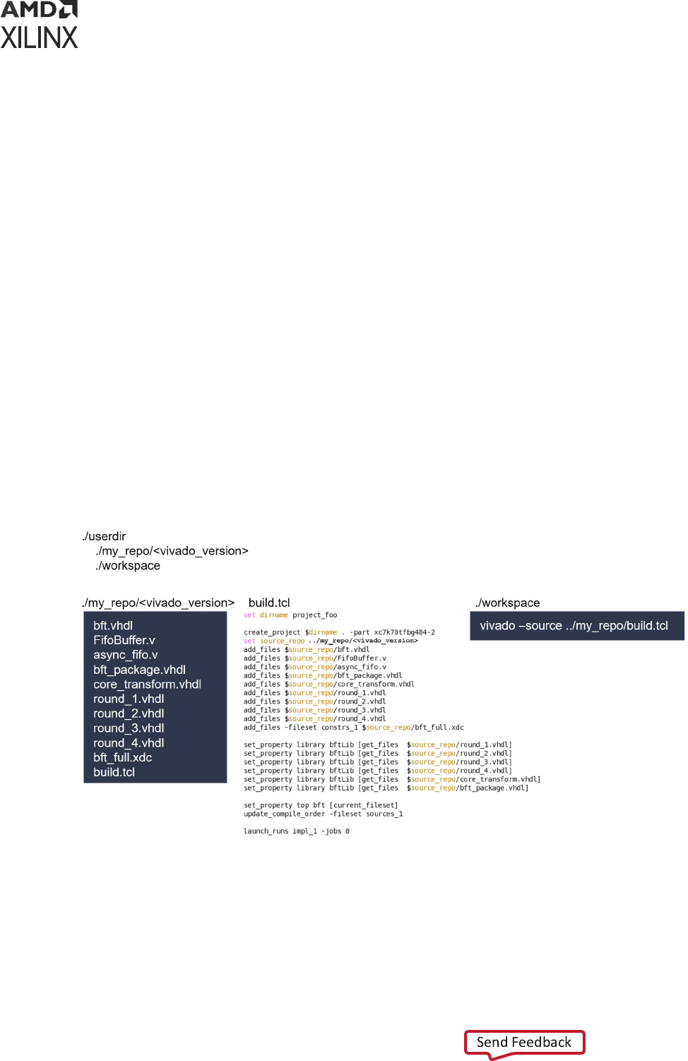
Generating a Script to Recreate a Design
For a project ow, a script to recreate your design can be generated manually or by using the
write_project_tcl command. The advantages of manually creang this script is that it
remains short and well organized, but it could potenally miss some project sengs and fail to
recreate the complete design. Alternavely, the write_project_tcl script is robust in
ensuring all les are captured appropriately. But its versality results in a more complicated and
more verbose script. Regardless of how this script is generated, it must be maintained as the
design evolves.
Note: write_project_tcl recreates the design as originally created by the user. For designs using IP
integrator, propagated parameters do not reect in the recreated design unl validate_bd_design is
run.
Revision Controlling Projects with Only RTL Sources
An example of revision controlling an enrely RTL based design is shown in the following gure.
In this case, there is a dened repository where all the RTL sources reside along with the script to
rebuild the design. The script references the sources and rebuilds the design into your
workspace. Sourcing the script from the workspace directory reproduce the complete design.
Figure 26: Example of Revision Controlling
Chapter 5: Source Management and Revision Control Recommendations
UG892 (v2022.1) April 20, 2022 www.xilinx.com
Design Flows Overview 87

Revision Controlling Xilinx IP
The Xilinx
®
IP repository resides in the Vivado install area. For each IP there is a
component.xml le that contains the VLNV of the IP and all the user customizable parameters
for the IP. The parametrized RTL and associated IP constraints also reside in the IP repository.
When you customize an IP, an XCI le is generated that contains the user desired parameters for
the IP. When you generate the output products for an IP, the RTL and associated constraints are
copied from the IP repository to the project directory and customized using the parameters
specied in the XCI le. Thus, for a given version of Vivado, because the IP repo resides in the
install area, an XCI le is the only le necessary to recreate the design. In this case, the XCI le
should be managed by the revision control system and referenced in the script used to
regenerate the design.
Note: Projects created prior to 2020.2, the IP output products are wrien to the project.srcs directory
where the XCI le is residing. In order to facilitate a clear delineaon between project sources and output
products, for any new projects created using 2020.2, a project.gen directory is automacally created in
parallel to the project.srcs directory. All IP output products are wrien to the project.gen
directory.
Managing Custom IP Repositories
When you package a custom IP and share it among several projects, you should use a custom IP
repository. In this case, the project used to create and package the custom IP should be revision
controlled following the methodology specied in this chapter. The packaged IP with the
component.xml le should reside in a custom revision controlled IP repository managed by
you. The project that uses the IP should contain a pointer to your custom IP repository and an
XCI le with the desired customizaons applied to the IP. The script to recreate the project
should set the IP repository to the custom IP repository path and add the XCI le as a source to
the project. When the project is recreated, similar to a project with Xilinx IP, Vivado would copy
the RTL and constraints from your custom IP repository to your local project directory and
applies the parameters from the XCI le. The XCI les along with your custom IP repository are
sucient to regenerate the complete project.
Revision Controlling Block Diagrams
Block diagrams (BD) can contain instances of IPs from Xilinx repositories, IPs from custom IP
repositories, references to RTL, or block design containers (references to other BDs). When a BD
is validated, the customizaon of a single IP can aect how connected IPs are customized. The
process of applying parameters from one IP to connected IP is coined parameter propagaon and
occurs when the BD is validated. To revision control a BD, the enre BD directory in the
project.srcs should be managed by the revision control system. The directory contains the
BD le, the XCI les for the IP post-parameter propagaon and some meta data les.
Chapter 5: Source Management and Revision Control Recommendations
UG892 (v2022.1) April 20, 2022 www.xilinx.com
Design Flows Overview 88

Note: Projects created prior to 2020.2, the BD output products are wrien to the project.srcs
directory where the BD le is residing. In order to help facilitate a clear delineaon between project
sources and output products, for any new projects created using 2020.2, a project.gen directory is
automacally be created in parallel to the project.srcs directory. All BD output products are wrien to
the project.gen directory. In turn, this signicantly reduces the size of the BD directory from previous
Vivado releases.
In the case of block design containers, there is a BD directory in the project.srcs directory
for each BD source in the design. If there are several instances of a block design container on a
parent BD, each instance of the block design container is generated in the project.gen
directory. Each block design container instance, even though derived from the same source BD,
can be unique due to parameter propagaon. Therefore, the instances of the each block design
containers reside in the project.gen directory, but the source from which they are all derived
reside in the project.srcs directory. Any BD directories that reside in the project.srcs
directory should be fully revision controlled.
Note: Projects created in 2020.2, IP and BD output products are no longer wrien to the project.srcs
directory. The project.srcs directory should contain the bare minimum number of sources necessary
to recreate the project with the excepon of les that are referenced from directories external to the
project. The cleanup of the project.srcs directory should tremendously improve the delimitaon
between les that are necessary to be revision controlled and tool generated les.
Note: To view the dierences between two versions of a block diagram, see Vivado Design Suite User Guide:
Designing IP Subsystems using IP Integrator (UG994) to learn more about the diffbd (check spelling) ulity.
Other Files to Revision Control
The project manages many other types of les required to rebuild a design. Following are a few
examples:
• XDC les containing design constraints
• Simulaon test benches
• HLS IP
• Pre/post Tcl hook scripts used for synthesis or implementaon
• Incremental compile DCPs
• ELF les
These les reside in the project.srcs directory or the project.util directory. It is
important to manage these les to accurately reproduce your design. Rounely rebuilding your
designs from your revision control system should help you catch any of these les that you could
inadvertently miss in your build script.
Chapter 5: Source Management and Revision Control Recommendations
UG892 (v2022.1) April 20, 2022 www.xilinx.com
Design Flows Overview 89

Output Files to Optionally Revision Control
Following is a list of addional les you may consider revision controlling:
• Simulaon scripts for third-party simulators generated by export_simulation. Because
these are typically hand-o les between design and vericaon, you might want to snapshot
them at dierent stages of the design process.
• XSA les. These are hardware hand-o les between Vivado and Vis™ soware plaorm.
• Bitsteams/PDIs.
• LTX les for hardware debug
• Intermediate DCP les created during the ow
• IP output products. These are usually considered output products, but if you do not want to
upgrade an IP when migrang between Vivado releases, then you must manage the output
les. Vivado only provides one version of each IP per release. If the IP you are using is
updated between Vivado releases then there are only two choices:
○ Upgrade the IP to the latest version in the latest Vivado release. This may cause you to
change your design to accommodate IP RTL changes.
○ Revision control the output products of the IP. The IP will be locked in the newer version of
Vivado because you will not be able to re-customize the IP. But, this allows you to carry the
IP forward to a future release because you are essenally capturing all the RTL sources for
the IP.
Archiving Designs
The archive_design command can compress your enre project into a zip le. This command
has several opons for storing sources and to run results. Essenally, the enre project is copied
locally in the memory and then zipped into a le on the disk while leaving the original project
intact. This command also copies any remote source into the archive.
This feature is useful for sending your design descripon to another person or to store as a self
contained enty. You might also need to send your version of vivado_init.tcl if you are
using this le to set specic parameters or variables that aect the design. For more informaon,
see the following resources:
• Vivado Design Suite User Guide: System-Level Design Entry (UG895)
• Vivado Design Suite QuickTake Video: Creang Dierent Types of Projects
• Vivado Design Suite QuickTake Video: Managing Sources with Projects
Chapter 5: Source Management and Revision Control Recommendations
UG892 (v2022.1) April 20, 2022 www.xilinx.com
Design Flows Overview 90

Managing Hardware Manager Projects and
Sources
Project .bit le and .ltx les are the primary output les required for using the Vivado Design
Suite Debug and Programming features in Vivado hardware manager. Xilinx recommends you
manage these les under revision control if you want to use this project in Vivado Lab Edion.
When Using Vivado Design Suite Projects
The project_name.hw directory in your Vivado Design Suite project stores informaon about
custom dashboards, trigger, capture condions, waveform conguraon les etc created as part
of using the Debug and Programming in the Vivado hardware manager. Xilinx recommends you
manage the project_name.hw directory in your Vivado Design Suite project under revision
control. This also helps if you want to hand o this project to be used in Vivado Lab Edion.
Managing Vivado Lab Edition Sources
Xilinx recommends you manage the project directory that was created for the project in Vivado
Lab Edion under revision control. The hw_* directories in the Lab Edion project directory
stores informaon about custom dashboards, trigger, capture condions, waveform conguraon
les, etc., in the Vivado hardware manager as part of using the Debug and Programming.
The .lpr le in the Lab Edion project directory is the project le that you need to manage
under revision control. The enre project can be recreated by opening this project le, provided
that the hw_* directory are at their original locaons.
Chapter 5: Source Management and Revision Control Recommendations
UG892 (v2022.1) April 20, 2022 www.xilinx.com
Design Flows Overview 91

Appendix A
Additional Resources and Legal
Notices
Xilinx Resources
For support resources such as Answers, Documentaon, Downloads, and Forums, see Xilinx
Support.
Solution Centers
See the Xilinx Soluon Centers for support on devices, soware tools, and intellectual property
at all stages of the design cycle. Topics include design assistance, advisories, and troubleshoong
ps.
Documentation Navigator and Design Hubs
Xilinx
®
Documentaon Navigator (DocNav) provides access to Xilinx documents, videos, and
support resources, which you can lter and search to nd informaon. To open DocNav:
• From the Vivado
®
IDE, select Help → Documentaon and Tutorials.
• On Windows, select Start → All Programs → Xilinx Design Tools → DocNav.
• At the Linux command prompt, enter docnav.
Xilinx Design Hubs provide links to documentaon organized by design tasks and other topics,
which you can use to learn key concepts and address frequently asked quesons. To access the
Design Hubs:
• In DocNav, click the Design Hubs View tab.
• On the Xilinx website, see the Design Hubs page.
Appendix A: Additional Resources and Legal Notices
UG892 (v2022.1) April 20, 2022 www.xilinx.com
Design Flows Overview 92

Note: For more informaon on DocNav, see the Documentaon Navigator page on the Xilinx website.
References
These documents provide supplemental material useful with this guide:
1. Vis Model Composer User Guide (UG1483)
2. Vivado Design Suite User Guide: High-Level Synthesis (UG902)
3. UltraScale Architecture-Based FPGAs Memory IP LogiCORE IP Product Guide (PG150)
4. AXI BFM Cores LogiCORE IP Product Guide (PG129)
5. Reference System: Kintex-7 MicroBlaze System Simulaon Using IP Integrator (XAPP1180)
6. Vivado Design Suite Tcl Command Reference Guide (UG835)
7. Vivado Design Suite Tutorial: High-Level Synthesis (UG871)
8. Vivado Design Suite Tutorial: Design Flows Overview (UG888)
9. Vivado Design Suite User Guide: Using the Vivado IDE (UG893)
10. Vivado Design Suite User Guide: Using Tcl Scripng (UG894)
11. Vivado Design Suite User Guide: System-Level Design Entry (UG895)
12. Vivado Design Suite User Guide: Designing with IP (UG896)
13. Vis Model Composer User Guide (UG1483)
14. Vivado Design Suite User Guide: Embedded Processor Hardware Design (UG898)
15. Vivado Design Suite User Guide: I/O and Clock Planning (UG899)
16. Vivado Design Suite User Guide: Logic Simulaon (UG900)
17. Vivado Design Suite User Guide: Synthesis (UG901)
18. Vivado Design Suite User Guide: Using Constraints (UG903)
19. Vivado Design Suite User Guide: Implementaon (UG904)
20. Vivado Design Suite User Guide: Hierarchical Design (UG905)
21. Vivado Design Suite User Guide: Design Analysis and Closure Techniques (UG906)
22. Vivado Design Suite User Guide: Programming and Debugging (UG908)
23. Vivado Design Suite User Guide: Dynamic Funcon eXchange (UG909)
24. Vivado Design Suite User Guide: Geng Started (UG910)
25. ISE to Vivado Design Suite Migraon Guide (UG911)
26. Vivado Design Suite Tutorial: Embedded Processor Hardware Design (UG940)
Appendix A: Additional Resources and Legal Notices
UG892 (v2022.1) April 20, 2022 www.xilinx.com
Design Flows Overview 93

27. Vivado Design Suite Tutorial: Dynamic Funcon eXchange (UG947)
28. UltraFast Design Methodology Guide for Xilinx FPGAs and SoCs (UG949)
29. Vivado Design Suite User Guide: Release Notes, Installaon, and Licensing (UG973)
30. Vivado Design Suite User Guide: Designing IP Subsystems Using IP Integrator (UG994)
31. UltraFast Embedded Design Methodology Guide (UG1046)
32. Vivado Design Suite User Guide: Creang and Packaging Custom IP (UG1118)
33. Vivado Design Suite Tutorial: Creang, Packaging Custom IP (UG1119)
34. Vivado Design Suite Documentaon
Training Resources
Xilinx provides a variety of training courses and QuickTake videos to help you learn more about
the concepts presented in this document. Use these links to explore related training resources:
1. Designing FPGAs Using the Vivado Design Suite 1 Training Course
2. Designing FPGAs Using the Vivado Design Suite 2 Training Course
3. Vivado Design Suite QuickTake Video: Vivado Design Flows Overview
4. Vivado Design Suite QuickTake Video: Geng Started with the Vivado IDE
5. Vivado Design Suite QuickTake Video: Targeng Zynq Devices Using Vivado IP Integrator
6. Vivado Design Suite QuickTake Video: Paral Reconguraon in Vivado Design Suite
7. Vivado Design Suite QuickTake Video: Simulang with Cadence IES in Vivado
8. Vivado Design Suite QuickTake Video: Simulang with Synopsys VCS in Vivado
9. Vivado Design Suite QuickTake Video: I/O Planning Overview
10. Vivado Design Suite QuickTake Video: Using Vivado Design Suite with Revision Control
11. Vivado Design Suite QuickTake Video: Creang Dierent Types of Projects
12. Vivado Design Suite QuickTake Video: Managing Sources with Projects
13. Vivado Design Suite QuickTake Video: Managing Vivado IP Version Upgrades
14. Vivado Design Suite QuickTake Video Tutorials
Revision History
The following table shows the revision history for this document.
Appendix A: Additional Resources and Legal Notices
UG892 (v2022.1) April 20, 2022 www.xilinx.com
Design Flows Overview 94

Section Revision Summary
04/20/2022 Version 2022.1
General Updates Editorial updates only. No technical content updates.
Please Read: Important Legal Notices
The informaon disclosed to you hereunder (the "Materials") is provided solely for the selecon
and use of Xilinx products. To the maximum extent permied by applicable law: (1) Materials are
made available "AS IS" and with all faults, Xilinx hereby DISCLAIMS ALL WARRANTIES AND
CONDITIONS, EXPRESS, IMPLIED, OR STATUTORY, INCLUDING BUT NOT LIMITED TO
WARRANTIES OF MERCHANTABILITY, NON-INFRINGEMENT, OR FITNESS FOR ANY
PARTICULAR PURPOSE; and (2) Xilinx shall not be liable (whether in contract or tort, including
negligence, or under any other theory of liability) for any loss or damage of any kind or nature
related to, arising under, or in connecon with, the Materials (including your use of the
Materials), including for any direct, indirect, special, incidental, or consequenal loss or damage
(including loss of data, prots, goodwill, or any type of loss or damage suered as a result of any
acon brought by a third party) even if such damage or loss was reasonably foreseeable or Xilinx
had been advised of the possibility of the same. Xilinx assumes no obligaon to correct any
errors contained in the Materials or to nofy you of updates to the Materials or to product
specicaons. You may not reproduce, modify, distribute, or publicly display the Materials
without prior wrien consent. Certain products are subject to the terms and condions of
Xilinx's limited warranty, please refer to Xilinx's Terms of Sale which can be viewed at hps://
www.xilinx.com/legal.htm#tos; IP cores may be subject to warranty and support terms contained
in a license issued to you by Xilinx. Xilinx products are not designed or intended to be fail-safe or
for use in any applicaon requiring fail-safe performance; you assume sole risk and liability for
use of Xilinx products in such crical applicaons, please refer to Xilinx's Terms of Sale which can
be viewed at hps://www.xilinx.com/legal.htm#tos.
AUTOMOTIVE APPLICATIONS DISCLAIMER
AUTOMOTIVE PRODUCTS (IDENTIFIED AS "XA" IN THE PART NUMBER) ARE NOT
WARRANTED FOR USE IN THE DEPLOYMENT OF AIRBAGS OR FOR USE IN APPLICATIONS
THAT AFFECT CONTROL OF A VEHICLE ("SAFETY APPLICATION") UNLESS THERE IS A
SAFETY CONCEPT OR REDUNDANCY FEATURE CONSISTENT WITH THE ISO 26262
AUTOMOTIVE SAFETY STANDARD ("SAFETY DESIGN"). CUSTOMER SHALL, PRIOR TO USING
OR DISTRIBUTING ANY SYSTEMS THAT INCORPORATE PRODUCTS, THOROUGHLY TEST
SUCH SYSTEMS FOR SAFETY PURPOSES. USE OF PRODUCTS IN A SAFETY APPLICATION
WITHOUT A SAFETY DESIGN IS FULLY AT THE RISK OF CUSTOMER, SUBJECT ONLY TO
APPLICABLE LAWS AND REGULATIONS GOVERNING LIMITATIONS ON PRODUCT
LIABILITY.
Appendix A: Additional Resources and Legal Notices
UG892 (v2022.1) April 20, 2022 www.xilinx.com
Design Flows Overview 95

Copyright
© Copyright 2012-2022 Xilinx, Inc. Xilinx, the Xilinx logo, Alveo, Arx, Kintex, Kria, Spartan,
Versal, Vis, Virtex, Vivado, Zynq, and other designated brands included herein are trademarks of
Xilinx in the United States and other countries. AMBA, AMBA Designer, Arm, ARM1176JZ-S,
CoreSight, Cortex, PrimeCell, Mali, and MPCore are trademarks of Arm Limited in the EU and
other countries. MATLAB and Simulink are registered trademarks of The MathWorks, Inc. All
other trademarks are the property of their respecve owners.
Appendix A: Additional Resources and Legal Notices
UG892 (v2022.1) April 20, 2022 www.xilinx.com
Design Flows Overview 96
