
Windham Weaponry, Inc. (WWI) will warranty all firearms manufactured by
WWI against any and all manufacturer’s defects in material and workmanship
which affect reasonable operaon for the lifeme of the firearm to the
purchaser. This warranty is transferable from the original purchaser to a
subsequent buyer.
Warranty is established by registering online at:
hp://www.windhamweaponry.com
or by phone with our Customer Service department at 855-808-1888.
Warranty claims may be made by contacng Customer Service, either in
wring or by phone for a Return Authorizaon number prior to delivering the
unloaded firearm to Windham Weaponry, Inc., 999 Roosevelt Trail, Windham,
Maine 04062, freight prepaid by the purchaser. Firearms and ammunion must
be shipped separately. No COD shipments will be accepted.
WWI will repair or replace only those parts determined to be defecve by the
factory. This warranty does not apply to normal wear and tear of any parts or
protecve finishes.
The following are specifically excluded from coverage under this warranty and
will cause said warranty to become null and void:
Damage or malfuncon resulng from accident, negligence, misuse or
unauthorized repair or alteraon; barrel obstrucon; use of ammunion other
than NATO and/or SAAMI specificaon new producon ammunion; use of any
hand loaded, reloaded, imported or factory re-manufactured ammunion;
failure to provide reasonable and necessary maintenance as described in the
Operator’s Manual accompanying the firearm; rust or corrosion; use of
replacement parts other than parts authorized by WWI for use in WWI firearms;
any unauthorized repair or any alteraon, including of a cosmec nature,
performed on the firearm by an individual, organizaon, company or enty other
than WWI; unreasonable or excessive use of the firearm.
Any finished products that are not assembled at our facilies, or are assembled
using imported or used parts. This includes complete rifle kits, upper receivers,
lower receivers, barrel assemblies, etc.
No implied warranes of any kind are made herein. Limited Lifeme Warranty
does not apply to any accessory items.
WWI assumes no liability for accidental or consequenal damages. Some
states do not allow the exclusion or limitaon of accidental or consequenal
damages and therefore this limitaon may not apply to you.
TRANSFERABLE LIMITED LIFETIME WARRANTY*
Windham Weaponry • 999 Roosevelt Trail • P.O. Box 1900 • Windham, ME 04062
Telephone: 207 893 2223 • Fax: 207 893 1623 • Sales Line: 855 808 1888
E-mail: info@windhamweaponry.com www.windhamweaponry.com
ACTIVATING YOUR WARRANTY
As soon as possible upon receipt of your Windham Weaponry Firearm, go online, or call, to
acvate your Transferable Limited Lifeme Warranty.
See: www.windhamweaponry.com / or call Toll-Free: 855-808 1888
Follow the Instrucons on the Website Warranty Page. Your Windham Weaponry Firearm’s
Warranty will be in effect upon compleon of these steps.
The Windham Weaponry Team thanks you for your purchase of this fine rifle, and we hope
you will enjoy it safely for many years. If you need parts, service or advice concerning your rifle,
we are never more than a phone call away, and will be pleased to help you.
© August 2016 - Windham Weaponry Inc., Windham, Maine USA Windham Weaponry Part No: MAN-OP-AR
“The Quality Goes In Before The Rifle Goes Out”
Covers All Windham Weaponry AR15 Type Semi-Automac
Models With Either Aluminum or Carbon Fiber Receivers
Windham Weaponry Part No: MAN-OP-AR
THE U.S.A.
MADE IN
ALWAYS USE THE CORRECT AMMUNITION FOR YOUR PARTICULAR FIREARM!
Windham Weaponry Barrels have permanent markings that indicate the proper caliber and chamber-
ing. Always refer to the BARREL markings when selecng ammunion for your firearm. Use only
factory ammunion manufactured to U.S. industry standards. Failure to use the proper caliber
ammunion can damage your firearm, and may cause injury or death.
* U.S. Customers Only

WARNING!WARNING! IF THIS FIREARM IS CARELESSLY OR IMPROPERLY HANDLED,
UNINTENTIONAL DISCHARGE COULD RESULT AND COULD CAUSE
INJURY, DEATH, OR DAMAGE TO PROPERTY.
WARNING!
WARNING! THIS WEAPON COULD CHAMBER A ROUND IF IT IS
DROPPED OR JARRED WITH A LOADED MAGAZINE IN PLACE AND
WITH THE BOLT CARRIER ASSEMBLY LOCKED TO THE REAR.
WARNING!
WARNING! BE SURE CAM PIN IS INSTALLED IN THE BOLT GROUP. IF IT
ISN’T, THE RIFLE CAN STILL FIRE AND WILL EXPLODE!
WARNING!
WARNING! IF THERE IS WATER IN THE BARREL, DO NOT FIRE THE RIFLE.
IT COULD EXPLODE!
CAUTION! USE ONLY CLEAN, DRY, HIGH QUALITY COMMERCIALLY MANU-
FACTURED AMMUNITION WHICH IS APPROPRIATE TO THE CALIBER OF
YOUR FIREARM. WINDHAM WEAPONRY DOES NOT RECOMMEND THE
USE OF REMANUFACTURED OR HAND LOADED AMMUNITION
BECAUSE IT MAY DAMAGE YOUR RIFLE.
CAUTION! IF THE RIFLE STOPS FIRING (A MISFIRE) WITH A LIVE ROUND IN
THE CHAMBER OF A HOT BARREL, REMOVE THE ROUND FAST! HOW-
EVER, IF YOU CANNOT REMOVE IT WITHIN 10 SECONDS, REMOVE
MAGAZINE AND WAIT 15 MINUTES WITH THE RIFLE POINTING IN A
SAFE DIRECTION SO YOU WON’T BE HURT BY A POSSIBLE ROUND
“COOKING-OFF” (I.E. THE ROUND DETONATING FROM THE HEAT OF
THE BARREL). ALWAYS KEEP YOUR FACE AWAY FROM THE EJECTION
PORT WHILE CLEARING A HOT CHAMBER.
CAUTION! IF RIFLE’S BOLT FAILS TO UNLOCK, AND YOU TRY TO FREE IT BY
TAPPING THE BUTTSTOCK ON THE GROUND WHILE PULLING ON THE
CHARGING HANDLE, KEEP YOURSELF CLEAR OF THE MUZZLE! PLACE
THE SAFETY SELECTOR LEVER ON SAFE.
CAUTION! IF YOU HEAR A NOTICEABLE DIFFERENCE IN SOUND OR RECOIL
DURING FIRING, STOP FIRING! EITHER CONDITION COULD INDICATE AN
INCOMPLETE POWDER BURN AND/OR A BULLET STUCK IN THE BORE.
BEWARE OF DANGEROUS PROCEDURES!
CAREFULLY READ THIS INSTRUCTION MANUAL PRIOR TO LOADING AND
FIRING THIS FIREARM. FOLLOW ALL INSTRUCTIONS ON THE PROPER
HANDLING AND SAFE USE OF THIS FIREARM!
ALWAYS HANDLE your firearm as if it were loaded.
NEVER POINT your firearm at anything you do not intend to shoot.
KNOW YOUR TARGET and beyond.
USE EYE & EAR PROTECTION when shoong.
DO NOT TOUCH the trigger unless you are ready to fire.
DO NOT RELY on the firearm’s safety - it should only be considered a supplement to safe
firearm handling.
NEVER LEAVE a loaded firearm unaended.
ONLY USE AMMUNITION designed for your firearm. Failure to use the proper caliber
ammunion can damage your firearm and may result in injury or death.
ONLY USE QUALITY commercial ammunion that is in good condion. Using corroded,
lacquer coated, damaged, hand loaded, steel or aluminum cased ammunion may void
the warranty, and may cause injury or death.
BE SURE YOUR FIREARM is unloaded and the bolt is open before handing it to others.
DO NOT HANDLE FIREARMS while impaired or the influence of alcohol or drugs.
DO NOT ALLOW others to handle or shoot your rifle if they have not read the safety
guidelines in this manual.
DO TAKE a firearms safety course!
RIFLE SPECIFIC WARNINGS:
BOLT CAM PIN must be installed or rifle will suffer catastrophic failure when fired. Injury or
death may result.
IF THERE IS WATER, too much oil, or an obstrucon in the barrel, do not fire. It may
explode and cause injury or death to you or those around you.
DO NOT DROP your firearm, it may discharge. A firearm dropped on its bu may chamber
a round.
DO NOT EXCHANGE bolt assemblies from one rifle to another. While Windham Weaponry
rifles and bolts are machined with great care, and are interchangeable with other
Windham Weaponry bolts, we do not recommend exchanging bolts - parcularly those
from other manufacturers, without first checking for proper headspacing with a Field
Gauge or Go/No-Go Gauge for .223 Rem. /5.56mm NATO - or gauges appropriate to the
caliber of your rifle.
BE SAFE WORKING WITH YOUR FIREARM!
BEFORE INSPECTION OR MAINTENANCE, be sure to clear the rifle. Do not pull the trigger
unl the rifle has been cleared. Inspect the firing chamber to ensure that it is empty
and the magazine has been removed.
DO NOT KEEP ammunion near your work area.
ONLY THE FACTORY or a qualified gunsmith should service, repair or modify your firearm in
any way.
CAUTIONS REGARDING TOXINS & PARTS:
CLEANING, DISCHARGING, HANDLING of your firearm and ammunion may result in
exposure to lead - a toxic and hazardous substance. Wash hands thoroughly aer
exposure.
TO AVOID INJURY to your eyes, use care and wear safety glasses when removing and
installing spring-loaded parts of your firearm.
FOLLOW ALL INSTRUCTIONS ON THE
PROPER HANDLING AND SAFE USE OF THIS FIREARM!
Windham Weaponry • Windham Business Park
999 Roosevelt Trail • P.O. Box 1900 • Windham, ME 04062
Telephone: 207 893 2223 • Fax: 207 893 1623 • Sales Line: 855 808 1888
E-mail: info@windhamweaponry.com WWW.WINDHAMWEAPONRY.COM
ALWAYS FOLLOW THE RULES OF SAFE GUN HANDLING!

TABLE OF CONTENTS
CAREFULLY READ THIS INSTRUCTION MANUAL
PRIOR TO LOADING AND FIRING THIS FIREARM.
FOLLOW ALL INSTRUCTIONS ON THE PROPER
HANDLING AND SAFE USE OF THIS FIREARM!
About Your Windham Weaponry Rifle 2
Rifle Features & Controls - Locaon 2
Familiarize Yourself With Your Rifle 3
Range Safety Checks - Before You Fire! 6
Loading A Magazine 6
Preparing To Fire 7
Chambering A Round From An Open Bolt 7
Chambering A Round From A Closed Bolt 8
Firing The Rifle 8
If The Rifle Stops Firing - Immediate Acons 9
If The Rifle Stops Firing - Remedial Acons 9
Barrel Break-in Procedures 9
Understanding Your Sight Adjustments 10
The Dual Aperture Rear Sight 11
25 Meter Zeroing Procedures 11
Rifle Disassembly, Cleaning & Maintenance 12
Cleaning Bolt, Bolt Carrier & Components 16
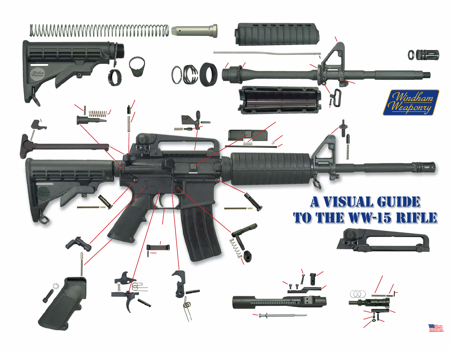
A Visual Guide To The WW-15 Rifle 18
Inspecon, Cleaning & Lubricaon 22
Cleaning The Bore 22
Magazine Disassembly & Cleaning 27
Informaon on the .308 Caliber Rifle 28
Informaon on the 7.62x39mm Caliber Rifle 30
Informaon on the .300 Blackout Caliber Rifle 32
Troubleshoong Problems / Soluons 33
Shipping Rifles For Service 36
This manual is based upon the U.S.
Gov’t. Issue Manual for M16 A2
Rifles, and includes maintenance
procedures for all Windham
Weaponry semi-automac firearms
with either Aluminum or Carbon Fiber
Receivers.
Windham Weaponry is steadfast in
its goal to produce the finest AR15
type rifle and carbine possible, and we
encourage our customers to follow
further developments on our website.
www.windhamweaponry.com
The Windham Weaponry Team
thanks you for your purchase of this
fine rifle, and we hope you will enjoy it
safely for many years. If you need
parts, service or advice concerning
your rifle, we are never more than a
phone call away, and will be pleased to
help you.
In the meanme, we encourage you
to shoot safely, to enjoy the great
outdoors, and to provide us feedback
in our quest to produce the finest
rifles in the world.
Thanks, from the
Windham Weaponry Team
YOUR WARRANTY
Your Transferable Lifeme Warranty
is printed in full on the back cover of
this manual. As soon as possible upon
receipt of your Windham Weaponry
firearm, go online, or call, to acvate
your warranty. See:
www.windhamweaponry.com
or call Toll-Free: 855-808 1888
Follow the Instrucons on the
website warranty page. Your firearm’s
warranty will be in effect upon
compleon of these steps.
Pg. 2
• This operang manual covers Windham Weaponry models chambered for a wide
variety of ammunion calibers. Be sure that you only use ammunion of the caliber
marked on the barrel of your rifle. These are lightweight, gas operated, air-cooled,
magazine fed rifles that operate in semi-automac mode (meaning that each me the
trigger is pulled, a single round will fire, unl the magazine is empty.
• On all models, the upper and lower receivers are easily opened for cleaning and
inspecon. Upper and lower receivers are machined from forged 7075 T6 aircra
aluminum or molded of 40% carbon fiber content polymer composite.
• Most Windham Weaponry models feature fully adjustable rear sights and elevaon
adjustable front sights. Some models are designed to allow the owner to add their
own choice of front and rear sights (e.g. Windham Weaponry SRC & Varmint
Exterminator models).
• Barrels on Windham Weaponry models are chrome lined 4150 chrome moly
vanadium 11595E steel or 416R grade stainless steel. They are 100% air gauged, bore
scoped, head spaced and buon rifled - right hand twist with 6 lands and grooves.
Refer to barrel markings for twist rate and caliber.
• Windham Weaponry models are supplied with 6 posion telescoping bustocks or
fixed style bustocks.
• Most forends are ribbed and vented to allow heat dissipaon. Carbines feature M4
double heat shield design forends.
• All models feature vercal pistol grips and detachable magazines. Standard magazine
capacity is 30 rounds (depending on State regulaons), but all AR-15/M-16 type
magazines of capacies from 5 to 40 rounds as well as c-drum magazines will fit and
funcon in Windham Weaponry models.
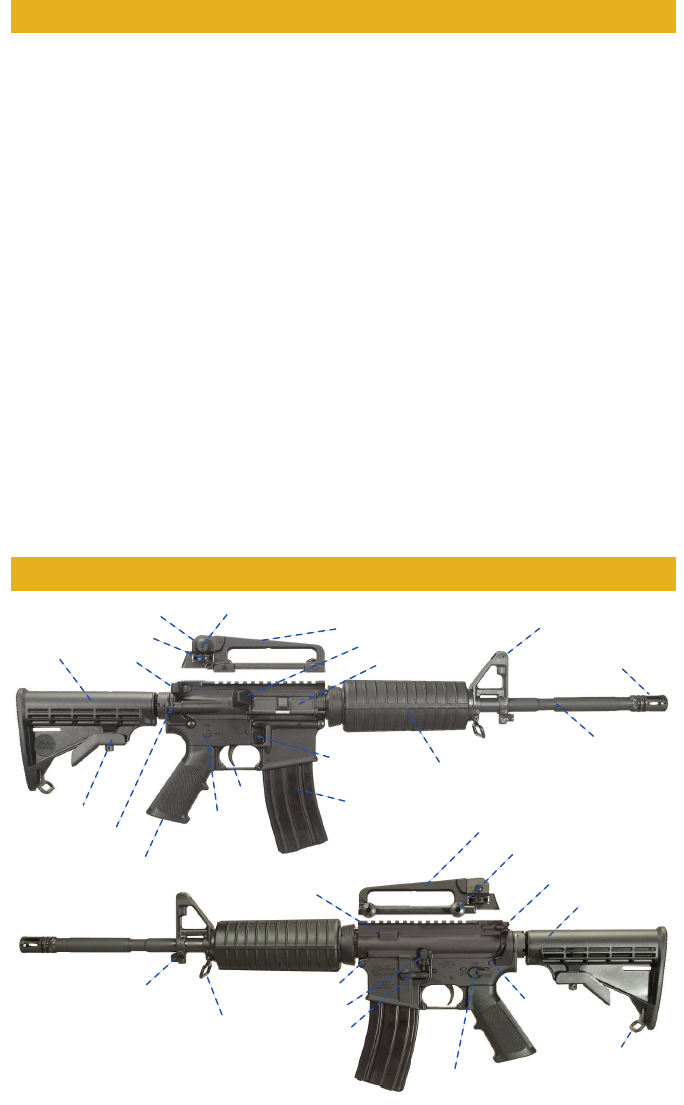
RIFLE FEATURES & CONTROLS
ABOUT YOUR WINDHAM WEAPONRY RIFLE
Pg.
2
Rear Sight Windage Knob
Rear Sling Loop
M4 Profile Barrel
A2 Flash Hider
Spent Brass Deflector
M4 Double Heat Shield Handguards
Bayonet Lug
Front Sling Swivel
A4 Removable Carry Handle
A4 Removable Carry Handle
Carry Handle Locking Knobs
Charging Handle
Charging
Handle
Pistol Grip
Safety Selector Lever
6 Posion Telestock
6 Posion
Tel es to ck
Tel e s tock Latc h
Rear Sight Elevaon Wheel
Dual Aperture Rear Sight
Flat Top Upper Receiver
30 Rd. Magazine
Magazine Release
Buon
Forward Assist Knob
Trigger
Receiver
Safety
Indicator
Ejecon Port Cover
A2 Front Sight Assembly
Take do wn
Pin
Pivot Pin
Bolt Catch
Magazine
Catch
ALWAYS FOLLOW THE RULES OF SAFE GUN HANDLING!
FAMILIARIZE YOURSELF WITH YOUR NEW WINDHAM WEAPONRY RIFLE.
THEN FOLLOW THESE STEPS TO PREPARE TO USE THE RIFLE.
ALWAYS ASSUME THE GUN YOU ARE HANDLING IS LOADED.
POINT THE RIFLE IN A SAFE DIRECTION!
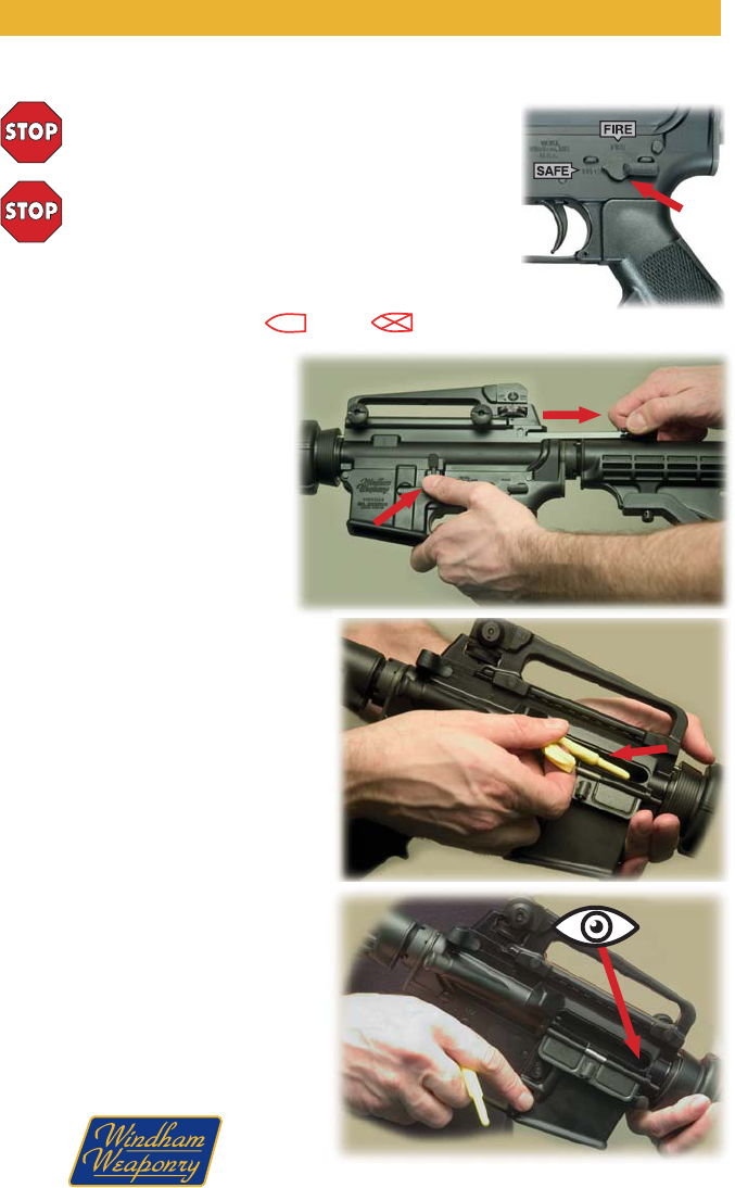
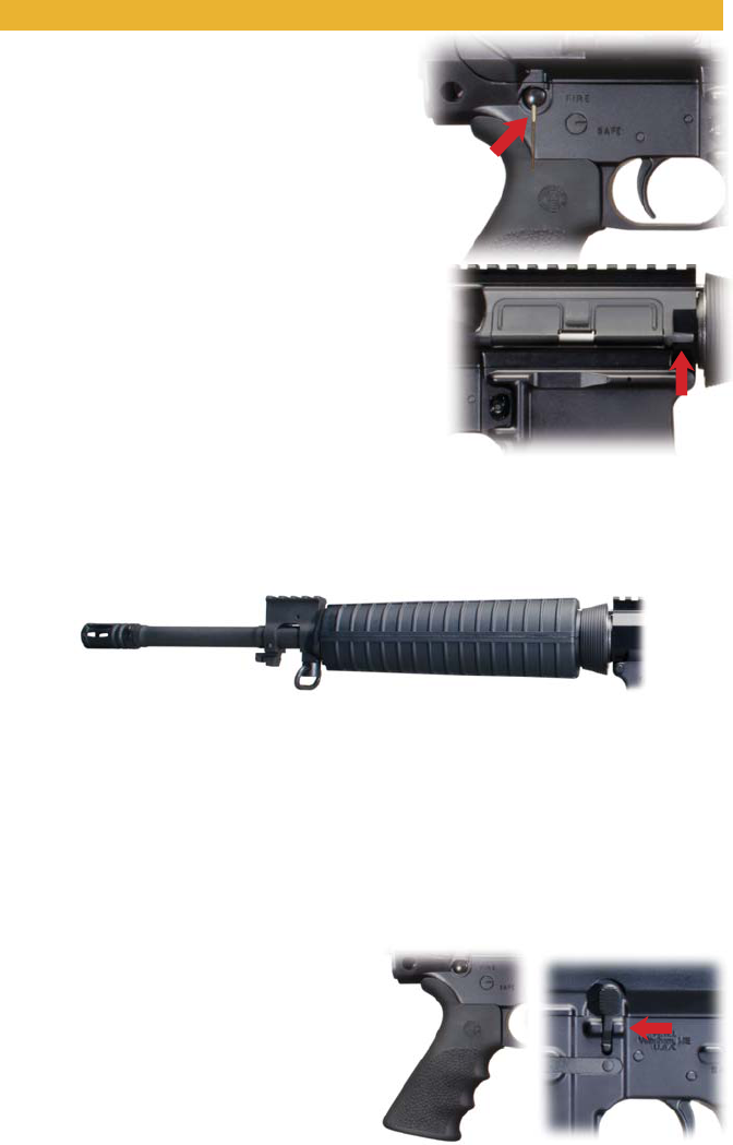
Place safety selector lever on SAFE. NOTE: If the rifle is
not cocked, the safety selector lever cannot be pointed
toward SAFE.
A
Fig. 1
Fig. 2
Fig. 3
Fig. 4
B
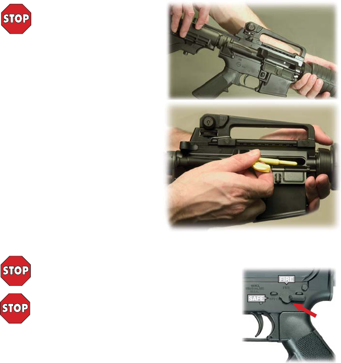
1. To lock bolt open, pull charging
handle rearward (A - Fig. 2). Press boom
of bolt catch and allow bolt to move
forward unl it engages bolt catch (B - Fig.
2). Return charging handle to its forward
posion.
If you haven’t done so before, now
place safety selector lever on SAFE (as
shown in Fig.1)
2. Remove chamber plug/tool (Fig. 3).
NOTE: The chamber plug/tool should remain
in the chamber when the rifle is not in use, or in
storage.
Look into the upper receiver and firing
chamber to ensure there is no ammunion in
the rifle (Fig. 4).
Note: Be sure a magazine is not inserted in
the rifle.
3. Once you are sure the firing chamber is
empty, and the safety selector lever is on SAFE,
you can press the upper poron of the bolt
catch, or pull the charging handle all the way to
the rear and release to allow the bolt to move
forward.
Pg. 3
NOTE: Safety Markings are enhanced in Fig. 1 for easy idenficaon.
Note also: Safety Markings on Carbon Fiber Receivers are icons
rather than words: FIRE = SAFE =
THE RIFLE IS NOW “CLEAR”.
Pg. 4
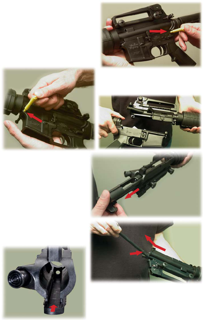
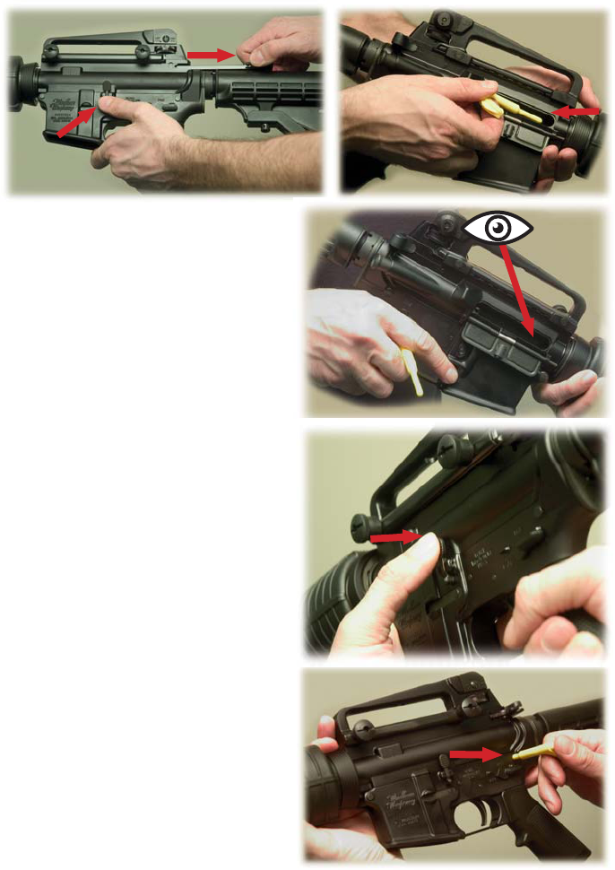
4. Using your chamber plug/tool (or a punch)
push the takedown pin in as far as it will go. Then
pull on the head of the pin (from the right side of
the rifle) unl it stops (Fig. 5).
5. Push the front pivot pin in as far as it will go
(Fig. 6) - then separate the upper and lower
receivers (Fig. 7).
6. Pull the charging handle back unl it
stops. The bolt carrier assembly will come
out with it (Fig. 8).
Li the bolt carrier back and up unl it
is clear of the upper receiver.
NOTE: Observe how the carrier key fits
within the slot in the boom of the
charging handle.
7. To remove the charging handle, pull
it to the rear unl it stops. Then li the
charging handle up, allowing the side tabs
to clear the cutouts in the upper receiver
(Fig. 9).
Fig. 5
Fig. 6
Fig. 7
Fig. 8
Fig. 9
Fig. 9A
Side tabs on
charging handle
must clear the cutouts in
the aluminum upper
receiver for removal and
reinseron.
Slide charging
handle straight
in or out of the
carbon fiber
upper receiver.
NOTE: On the Carbon Fiber lower receivers, the
Takedown Pin is within molded recesses, and will
require the Safety Tool, a punch or some similar
tool to reach it and push it in.
NOTE: On the Carbon Fiber upper receivers, the Charging
Handle simply slides straight in or out of the upper
receiver. There are no “cutouts” in the charging handle
track as in the aluminum receiver (see Fig. 9A)
CAUTION: Because of this, if you hold the Carbon Fiber
receiver vercally (with barrel up), the Charging Handle
and Bolt Carrier can fall out and possibly be damaged.
Tabs
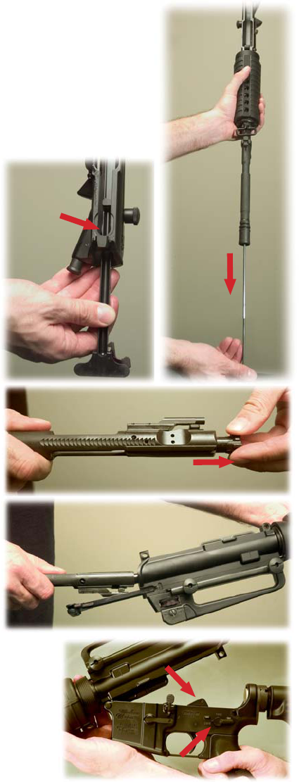
8. Run a cleaning patch with oil through the barrel. Always pull your
cleaning rod from chamber to muzzle (Fig. 10).
9. Run a dry patch through the barrel (again, always from chamber to
muzzle).
10. Visually inspect the barrel to make sure it is free of any debris or
obstrucons.
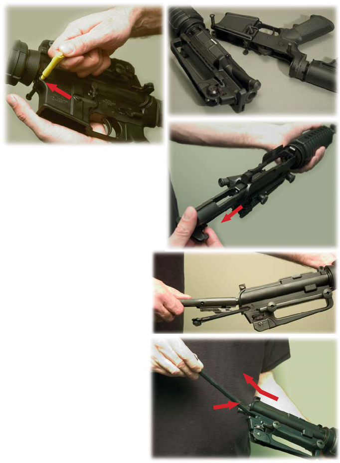
11. To reassemble your rifle, follow the preceding steps (1 thru 7) in
reverse order.
NOTE: When installing the charging
handle, remember that the tabs on the
side of the handle need to drop into
corresponding cutouts in the channel
within the upper receiver (Fig. 11).
NOTE: When installing the bolt
carrier assembly, the bolt must be
pulled all the way forward before
being inserted in the upper receiver
(Fig. 12).
The bolt carrier can then be
reinserted in the upper receiver. The
gas key must fit into the channel in the
charging handle. Then, both charging
handle and carrier can slide into
receiver (Fig. 13).
With the upper receiver
reassembled, it can then be joined to
the lower receiver.
NOTE: When pivong the rifle
closed, the hammer should be in the
cocked (down) posion (Fig. 14). The
safety can then be moved to the SAFE
posion.
12. Pull the charging handle to the
rear and insert the chamber plug/tool
into the chamber. Then ease the
charging handle and bolt carrier
forward, and latch the charging handle
in place.
Pg. 5
YOUR RIFLE IS NOW READY
TO TAKE TO THE RANGE.
Fig. 10
Fig. 11
Fig. 12
Fig. 13
Fig. 14
Hammer
Safety
Remember: On the Carbon Fiber
upper receiver, the charging handle
slides straight into the receiver. There
are no “cutouts” as in the aluminum
receiver.
1. Pull charging handle to the rear, remove chamber plug, and release charging handle. Place
selector lever on SAFE. Pull trigger. HAMMER SHOULD NOT FALL.
2. Place selector lever in FIRE posion, point rifle in a safe direcon, and pull trigger. HAMMER
SHOULD FALL.
3. Hold trigger to the rear, pull charging handle to the rear and release charging handle. Then
release pressure on the trigger with a slow, smooth moon, without hesitaons or stops, unl the
trigger is fully forward. YOU SHOULD HEAR A CLICK AND THE HAMMER SHOULD NOT FALL.
4. Repeat the FIRE posion test FIVE TIMES (Step 2 above). The rifle must not malfuncon during
any of these five tests.
WARNING: IF THE RIFLE MALFUNCTIONS DURING ANY OF THESE FIVE TESTS,
CONTACT THE FACTORY FOR TECHNICAL SUPPORT. Call Toll Free: 1-855-808-1888
RANGE SAFETY CHECKS - BEFORE YOU FIRE!
1. USE ONLY QUALITY AMMUNITION THAT IS APPROPRIATE TO THE CALIBER MARKED ON THE
BARREL OF YOUR RIFLE. Brass cased ammunion is recommended.
CAUTION! DO NOT USE AMMUNITION THAT IS DENTED, SCRATCHED,
CORRODED, OR DAMAGED.
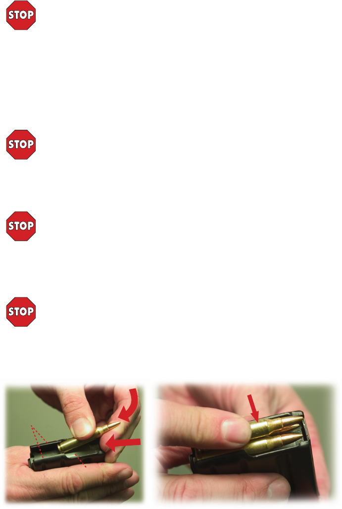
2. Insert a cartridge between the feed lips of the magazine with the bullet p forward. Push the
cartridge down unl it is held by the magazine feed lips (as shown Arrow A - Fig. 15).
3. Then slide the cartridge backward to seat it against the inside back of the magazine (Arrow B -
Fig. 15). Place the next cartridge on top of the previous one and repeat steps 2 & 3 unl desired
number of cartridges are loaded into the magazine (Fig. 16).
CAUTION! DO NOT LOAD LIVE AMMUNITION INTO YOUR MAGAZINE UNTIL YOU
ARE READY TO SHOOT.
NOTE: AR15/M16 type magazines will hold various capacies of ammunion - anywhere
from 5 to 100 cartridges - but all funcon in the same manner. Do not try to force more cartridges
into a magazine than it was designed to hold.
Note also that .223/5.56 magazines can also be used with .300 Blackout ammunion in rifles
chambered & barreled for that caliber. Always be sure the ammunion you use matches the caliber
marking on the barrel of your rifle.
ALWAYS ASSUME THE RIFLE YOU ARE HANDLING IS LOADED, AND POINT IT IN A SAFE
DIRECTION! WHEN PERFORMING THIS SAFETY CHECK, MAKE SURE THERE IS NO MAGAZINE IN
THE RIFLE.
SAFETY SELECTOR FUNCTION CHECK: Perform this safety funcon check to ensure that the safety
selector lever works properly.
LOADING A MAGAZINE
Magazine
Follower
Feed
Lips
A
B
Fig. 15 Fig. 16
Pg. 6
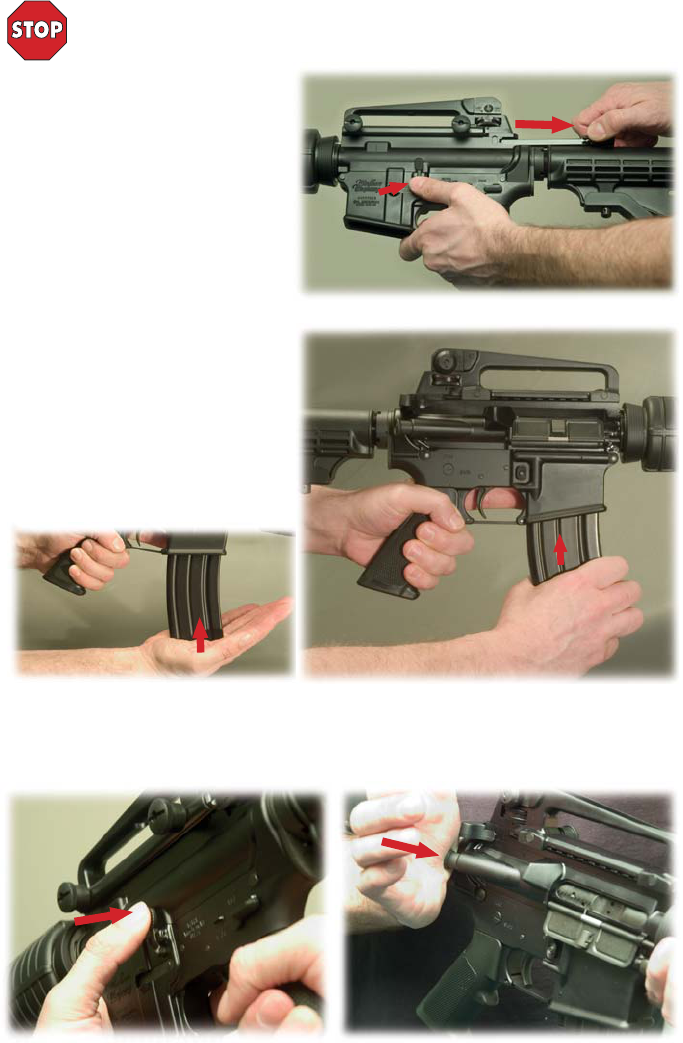
Pull charging handle to the rear and lock
bolt carrier back by depressing the boom
of the bolt catch. Slide the charging handle
forward unl it latches onto the upper
receiver. Move the safety selector to the
SAFE posion (Fig. 17).
Push a magazine up into the magazine
well unl the magazine catch engages and
holds the magazine in place (Fig. 18).
To ensure that the magazine is seated
completely in the magazine well, slap up
on the boom of the magazine (Fig. 18A).
PREPARING TO FIRE
ALWAYS PRACTICE SAFE FIREARMS HANDLING! ASSUME THE RIFLE YOU ARE
HANDLING IS LOADED!
ALWAYS USE EYE AND EAR PROTECTION FOR SAFETY WHEN SHOOTING!
CHAMBERING A ROUND FROM AN OPEN BOLT
INSERTING A MAGAZINE
With a magazine inserted, press upper poron of the bolt catch (Fig. 19). Bolt should spring
forward - chambering a round. Or, you can pull back on the charging handle and release.
Then tap the forward assist to ensure bolt is fully forward and locked (Fig. 20).
Fig. 17
Fig. 18
Fig. 19 Fig. 20
Fig. 18A
Pg. 7
Pg. 8
KEEP YOUR FINGER OFF THE TRIGGER UNTIL YOU ARE READY TO FIRE THE
RIFLE.
CHAMBERING A ROUND FROM A CLOSED BOLT
CAUTION! ALWAYS POINT THE MUZZLE IN A SAFE DIRECTION!
FIRING THE RIFLE
The rifle is now loaded, a round is chambered, the safety selector lever should be in
the safe posion.
Fig. 21 Fig. 22
Fig.23
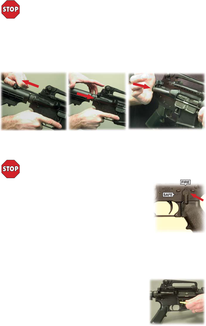
Insert a loaded magazine into the magazine well unl the magazine catch engages and holds the
magazine. Slap up on the boom of the magazine to ensure it is seated correctly.
Pull charging handle fully to the rear (Fig. 21).
Release charging handle. Never “ride” the charging handle forward. The charging handle and bolt
assembly should slide forward from the pressure of the acon spring to chamber a round (Fig. 22).
Then tap the forward assist to ensure bolt is fully forward and locked (Fig. 23). Now move the
safety selector to the SAFE posion.
1. Aim at your target.
2. Move safety selector lever from SAFE to FIRE (Fig. 24).
3. Squeeze the trigger – release trigger pressure.
4. The rifle will eject the spent cartridge and chamber another in
preparaon for the next shot. This is called firing in “semi-automac mode”.
One round will be fired with each pull of the trigger, and the rifle will
automacally reload, unl the magazine is empty.
NOTE: Aer the last round is fired, the bolt carrier will lock in the rear posion. You can then push
the magazine release buon to drop out the empty magazine*, insert a fresh magazine, release the
bolt catch, and a new round will automacally be chambered in preparaon for the next shot.
If you stop firing the rifle before the magazine is empty:
1. Move safety to SAFE posion.
2. Remove magazine.
3. Lock bolt to the rear (to remove live round from the chamber).
4. Visually inspect the chamber to ensure that it is empty.
*For California approved models, use the chamber plug/tool to
depress the bullet buon to drop out the empty magazine (Fig. 25).
Fig. 24
Fig. 25
To fire the rifle:

Pg. 9
IF THE RIFLE STOPS FIRING - IMMEDIATE ACTIONS
IF THE RIFLE STOPS FIRING - REMEDIAL ACTIONS
BARREL BREAK-IN PROCEDURES
IF THE RIFLE FAILS TO FIRE WHEN THE TRIGGER IS SQUEEZED...
1. Keep the rifle safely pointed downrange for 30 seconds.
2. Remove the magazine.
3. Lock the bolt to the rear (take note if a live round is ejected).
4. Place safety selector in safe posion.
5. Visually inspect the chamber to ensure that the chamber is empty!
A. If a live round was ejected when clearing the rifle, inspect the round for evidence of
possible ammo failure.
B. If a live round was not ejected, reinsert the magazine in the magazine well unl the
magazine catch engages and holds the magazine securely in place. Press bolt catch to chamber a
round and resume firing.
1. Remove the magazine.
2. Lock the bolt to the rear.
3. Place safety selector in safe posion and visually check that the chamber is empty.
4. Visually inspect the bore or insert a cleaning rod in the bore to ensure there is not a bullet stuck
in the bore.
*If a bullet is stuck in the barrel, do not aempt to remove it. Contact Windham Weaponry for
Technical Support. Call: 1-855-808-1888
WARNING! If your rifle stops firing with a live round in the chamber of a hot barrel,
remove the round FAST! However, if you cannot remove it within 10 seconds, remove the
magazine and wait 15 minutes with the rifle poinng in a safe direcon! This way you won’t
get hurt by a possible round “cooking off” (meaning a round may detonate unexpectedly
from being exposed to the heat of the rifle’s firing chamber). Always be sure to keep your face away
from the ejecon port while clearing a hot chamber.
If your rifle sll fails to fire, check the troubleshoong secon of this manual.
CHROME LINED BARRELS
First run a dry patch down the bore to remove any oil le in the barrel as it came from the factory.
Barrel Break-in Procedures for Chrome Lined Barrels (regardless of caliber) require firing
approximately 100 rounds of good quality brass cased ammunion. Then clean the barrel thoroughly
according to the instrucons in this Operators Manual (Page 22), and your rifle will be ready for the
range or the hunt.
STAINLESS STEEL BARRELS
First run a dry patch down the bore to remove any oil le in the barrel as it came from the factory.
Fire one shot, then clean the barrel - repeat this one shot & clean process 5 mes. Fire three shots,
then clean the barrel. Fire five shots, then clean the barrel, and your stainless steel barrel will be well
broken in.
IF YOU HEAR A NOTICEABLE DIFFERENCE IN SOUND OR RECOIL DURING
FIRING, STOP FIRING! EITHER CONDITION COULD INDICATE AN
INCOMPLETE POWDER BURN AND/OR A STUCK BULLET IN THE BORE.*
Pg. 10
THE FRONT SIGHT IS ADJUSTABLE FOR ELEVATION
THE REAR SIGHT IS ADJUSTABLE FOR WINDAGE AND ELEVATION
IMPACT
1.2 cm (1/2”)
4.8 cm (1 7/8”)
9.6 cm (3 3/4”)
14.4 cm (5 3/4”)
DISTANCE
25 meters
100 meters
200 meters
300 meters
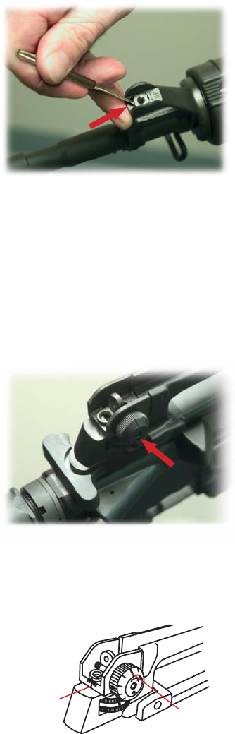
FRONT SIGHT ADJUSTMENT: To adjust elevaon,
depress detent and rotate post using a firing pin,
punch or the specifically designed front sight
adjustment tool. To raise strike of bullet, rotate post
in the direcon of arrow marked up (clockwise) (Fig.
26).
Reverse the direcon of rotaon to lower strike of
bullet. Each of the 4 graduaons (notches) moves
the point of impact of bullet as indicated below.
Elevaon adjustments at front sight post (A2 four
posion) - one “click” equals:
Fig. 26
Fig. 27
For Carbine Sight Radius*:
IMPACT
0.83 cm (3/8”)
3.5 cm (1 3/8”)
6.5 cm (2 5/8”)
10.0 cm (4”)
DISTANCE
25 meters
100 meters
200 meters
300 meters
For Rifle Sight Radius*:
IMPACT
0.5 cm (1/4”)
2.75 cm (1”)
5.5 cm (2 1/4”)
8.5 cm (3 1/4”)
DISTANCE
25 meters
100 meters
200 meters
300 meters
Turning the windage knob clockwise will move
bullet impact to the right. Turning the windage knob
counter-clockwise will move bullet impact to the le
(Fig. 27).
Once the rifle is zeroed, the rear sight is
adjustable for elevaon when firing at distances of
300 - 600 meters (A4 sights) or 300 - 800 meters (A2
sights).
Windage adjustments - one “click” equals:
For Carbine Sight Radius*:
IMPACT
0.33 cm (1/8”)
1.5 cm (1/2”)
2.5 cm (1”)
4.0 cm (1 1/2”)
DISTANCE
25 meters
100 meters
200 meters
300 meters
For Rifle Sight Radius*:
Front Sight Detent
Windage Knob
*Sighng Data from Army Marksmanship manual.
25 meters = 27 yards + 1 . (82 .) 100 meters = 109 yards + 1 . (328 .)
NOTE: On Carbon Fiber Upper Receivers, the Picanny rail is .040” higher than on aluminum receivers. It
may therefore be necessary to use a .040” taller front sight post if raising your exisng front sight post
doesn’t allow sighng in accuracy. Taller front sight posts are available on our website:
www.windhamweaponry.com (Part number: 9349056-MOD)
*AII the above values have been rounded off. To
remember your correct zero windage, note locaon
of windage scale and windage knob pointer (heavy
mark on outside of knob). Once you have established
your correct zero windage leave your windage scale
and windage knob pointer on these sengs at all
mes.
UNDERSTANDING YOUR SIGHT ADJUSTMENTS
Windage
Scale
Windage
Knob
Pointer
Pg. 11
THE DUAL APERTURE REAR SIGHT
25 METER ZEROING PROCEDURES
ADJUSTABLE FOR ELEVATION & WINDAGE
By following the steps below and establishing a zero at 25 meters, your rifle sights will be set with a
300-meter balesight (these instrucons apply to a 16” Bbl. Carbine).
1. Do not move front sight post at this me. It was set at the factory and should be very close to
your zero.
2. The unmarked (smaller) aperture should be flipped up - see figure 29 above.
3. Center the rear sight aperture by turning the windage knob le or right (this is called
“mechanical zero windage”.
4. Rotate elevaon knob in the down
direcon (counter-clockwise - Fig. 30) to
boom out the rear sight. This is called
“mechanical zero elevaon” for the rear sight
on all Carbines, and applies whether you have
the A2 Sight (Fixed Carry Handle Carbine) or
the A4 Sight (Removable Carry Handle).
On rifles with a rifle length sighng radius like our 20 inch Gov’t Model, you move the rear
elevaon up one click from the boomed posion for A2 Sights and two clicks to the “Z” mark on the
A4 Carry Handle Sights.
From this point on, the rear sight elevaon knob should not be moved. Any changes in elevaon
required in the following zeroing steps are made to the front sight post only.
5. Carefully aim and fire at the center of the target bulls-eye.
6. If your shot group is not in the center of the bulls-eye, calculate the required “clicks” necessary
to move your next shot group into the bulls-eye using the elevaon and windage values in the
“Understanding Your Sight Adjustment” secon on the previous page. Remember that any changes in
elevaon are made by moving the front sight post only.
A. In order to raise your next shot group, rotate the front sight post clockwise. In order to lower
your next shot group, rotate the front sight post counterclockwise.
B. Changes in windage are made with the windage knob. To move the shot group to the le, turn
the windage knob counterclockwise. To move the shot group to the right, turn the windage knob
clockwise.
Short Range (0-200 meters)
Normal Range - A2 Sights: 300-800 meters
A4 Sights: 300-600 meters
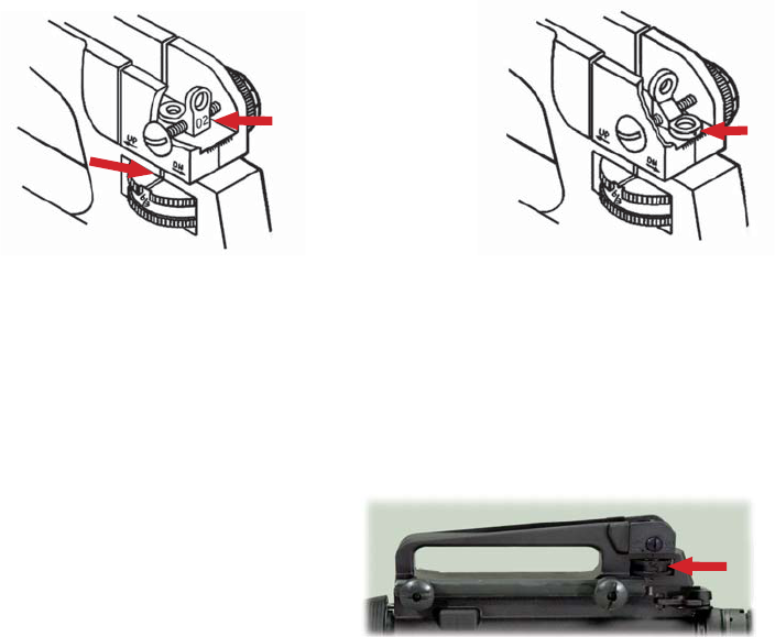
SHORT RANGE - The “02” (larger) aperture is
used for 0-200 meters range. As shown below,
the sight is set for 0 - 200 meters. This larger
aperture is only used when the rear sight is all
the way down. In other words, the 300-meter
mark is aligned with the mark on the le side of
the receiver (Fig. 28).
NORMAL RANGE - The aperture is
unmarked and used for most firing situaons. It
is used in conjuncon with the elevaon knob
for 300, 400, 500, 600, 700, and 800 meter
targets with A2 sights (Fig. 29).
With A4 carry handle sights, ranges are 300,
400, 500, 600 meters.
A2 sights -
A4 sights -
1 min. elevaon
1/2 min. windage
1/2 min. elevaon
1/2 min. windage
A2 elevaon wheels
are marked 8/3
A4 elevaon wheels
are marked 6/3
Fig. 29Fig. 28
Fig. 30
Pg. 12
25 METER ZEROING PROCEDURES (connued)
THE RIFLE IS NOW SAFE TO TRANSPORT
FROM THE RANGE.
7. Carefully aim and fire another group at the center of the target bulls-eye.
8. Repeat steps 5 and 6, if required.
9. When your group is on target, your sight is now “calibrated” for balesight zero. If your rifle has
a rifle length sight radius, move the elevaon knob back down to the 6/3 posion for A4 removable
carry handles, or 8/3 for A2s fixed carry handles. The range scale’s 300-meter mark should now be
aligned with the corresponding index above the elevaon wheel.
1. Clear the rifle to ensure the chamber is
empty (Fig. 31).
2. Place safety in the safe posion.
3. Pull the charging handle to the rear and
insert the chamber plug/tool into the chamber.
Then ease the charging handle and bolt forward
and latch in place (Fig. 32).
Fig. 31
ONCE YOU ARE FINISHED
AT THE RANGE...
Fig. 32
RIFLE DISASSEMBLY, CLEANING & MAINTENANCE
ALWAYS FOLLOW THE RULES OF SAFE GUN HANDLING!
ALWAYS ASSUME THE GUN YOU ARE HANDLING
IS LOADED.
POINT THE RIFLE IN A SAFE DIRECTION!
Place the safety selector lever on SAFE (Fig.33).
NOTE: If the rifle is not cocked, the safety selector lever
cannot be pointed toward SAFE.
A NOTE REGARDING CARBON FIBER RECEIVERS:
Because of very minor dimensional differences, you cannot assemble
an Aluminum Upper Receiver Assembly onto a Carbon Fiber Lower
Receiver Assembly. Use of force to assemble these components will cause damage. Conversely, do not
aempt to aach a Carbon Fiber Upper Receiver Assembly onto an Aluminum Lower Receiver Assembly.
There are also minor differences between the Carbon Fiber model’s barrel nut and that of Aluminum
receivered models. Barrel Nut threading is different on Carbon Fiber models, and we also use Locte on
Carbon Fiber Barrel Nuts, so aempng to remove a Carbon Fiber Barrel Nut can cause damage to the
Carbon Fiber Upper Receiver, and may void your warranty. This Carbon Fiber Barrel Nut difference limits
the number of accessory forends that can be mounted to the Carbon Fiber rifle. Call Windham
Weaponry Technical Assistance if you have quesons on this.
Fig. 33
RIFLE DISASSEMBLY, CLEANING & MAINTENANCE (Connued)
A
Fig. 34
Fig. 35
Fig. 36
B
1. To lock the bolt open, pull the charging handle rearward (A - Fig. 34). Press the boom of the
bolt catch and allow the bolt to move forward unl it engages the bolt catch (B - Fig. 34). Return the
charging handle to its forward posion.
If you haven’t done so before, place the safety selector lever on SAFE
.
2. Remove the chamber plug/tool (Fig. 35).
Look into the upper receiver and firing
chamber to ensure there is no ammunion in
the rifle (Fig. 36).
NOTE: Be sure a magazine is not inserted
in the rifle.
3. Once you are sure the firing chamber is
empty, and the safety selector lever is on
SAFE, you can press the upper poron of the
bolt catch, or pull the charging handle all the
way to the rear and release to allow the bolt
to move forward (Fig 37).
THE RIFLE IS NOW “CLEAR”.
Fig. 37
Fig. 38
4. Using your chamber plug/tool (or a punch)
push the takedown pin in as far as it will go.
Then pull on the head of the pin (from the right
side of the rifle) unl it stops (Fig. 38).
5. Push the pivot pin in as far as it will go (Fig.
39) - then separate the upper and lower
receivers (Fig. 40).
REMEMBER: Carbon Fiber lower receivers will
require a tool to reach the Takedown Pin.
Pg. 13
Pg. 14
Fig. 39
Fig. 40
Fig. 41
Fig. 43
Side tabs on
charging handle
must clear the cutouts in
the aluminum upper
receiver for removal and
reinseron.
Fig. 42
REMEMBER: On the Carbon Fiber upper
receivers, the Charging Handle simply
slides straight into the receiver. There are
no “cutouts” as in the aluminum receiver.
The Charging Handle can fall out and
potenally be damaged.
6. Pull the charging handle back. The bolt
carrier assembly will come out with it (Fig. 41).
Li the bolt carrier back and up unl it is clear
of the upper receiver.
NOTE: Observe how the carrier key fits
within the slot in the boom of the charging
handle (Fig. 42).
7. To remove charging handle, pull it to
the rear unl its side tabs clear the cutouts
in the upper receiver (Fig. 43).
RIFLE DISASSEMBLY, CLEANING & MAINTENANCE (Connued)
RIFLE DISASSEMBLY, CLEANING & MAINTENANCE (Connued)
Fig. 44
Fig. 46
Fig. 47
Fig. 45
Fig. 48
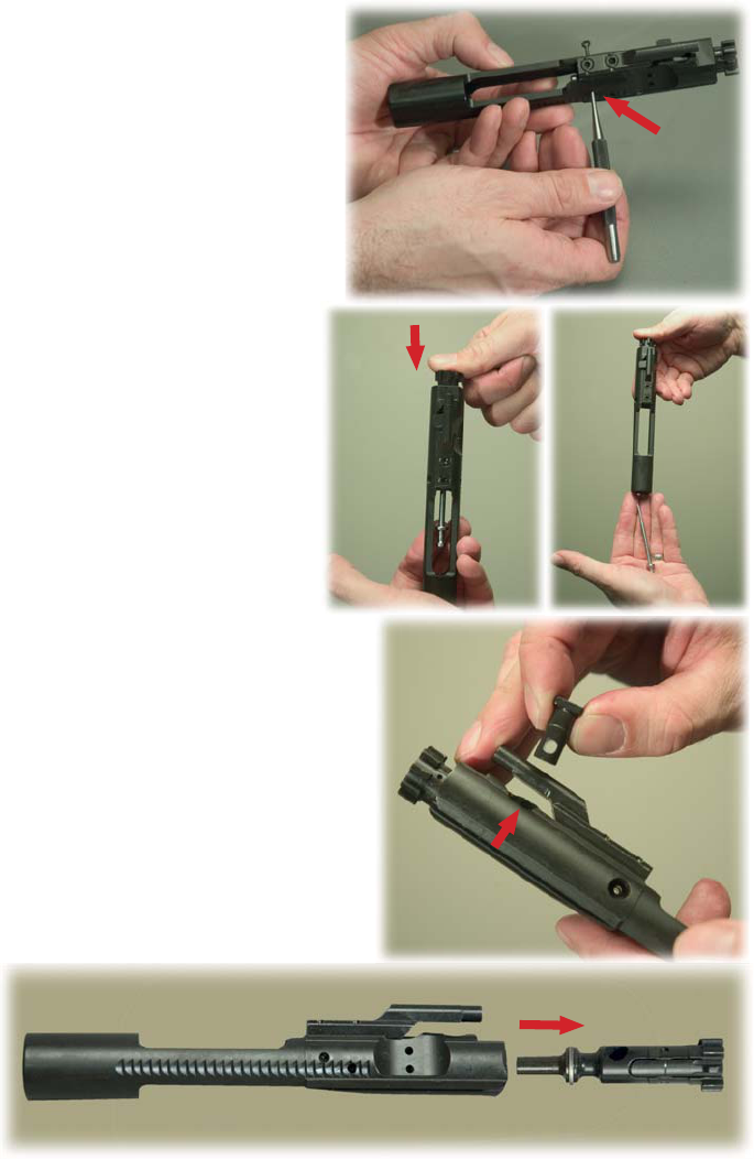
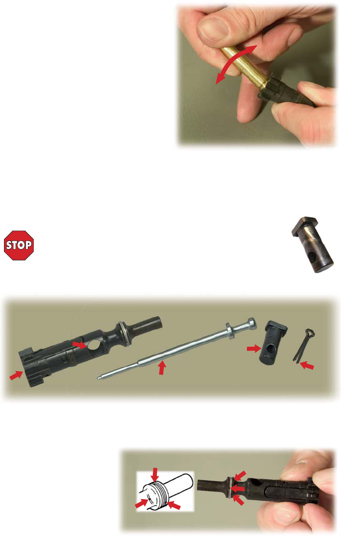
8. Remove the firing pin retaining pin (Fig. 44)
NOTE: Do not open or close the split end of
the firing pin retaining pin, and NEVER
substute a common coer pin on
reassembly.
9. Push the bolt in to locked posion
within the bolt carrier (Fig. 45).
10. Drop the firing pin out of rear of the
bolt carrier (Fig. 46).
11. With the bolt pushed into the locked
posion, remove the cam pin by rotang 1/4
turn and liing out (Fig. 47).
NOTE: If you have a .308 rifle, the cam pin pulls
straight out. See .308 Addendum Secon.
12. Remove the bolt assembly from the bolt
carrier by pulling it straight out (Fig. 48).
Pg. 15
Pg. 16
RIFLE DISASSEMBLY, CLEANING & MAINTENANCE (Connued)
CLEANING THE BOLT, BOLT CARRIER & COMPONENTS
Fig. 49 Fig. 50
Fig. 51
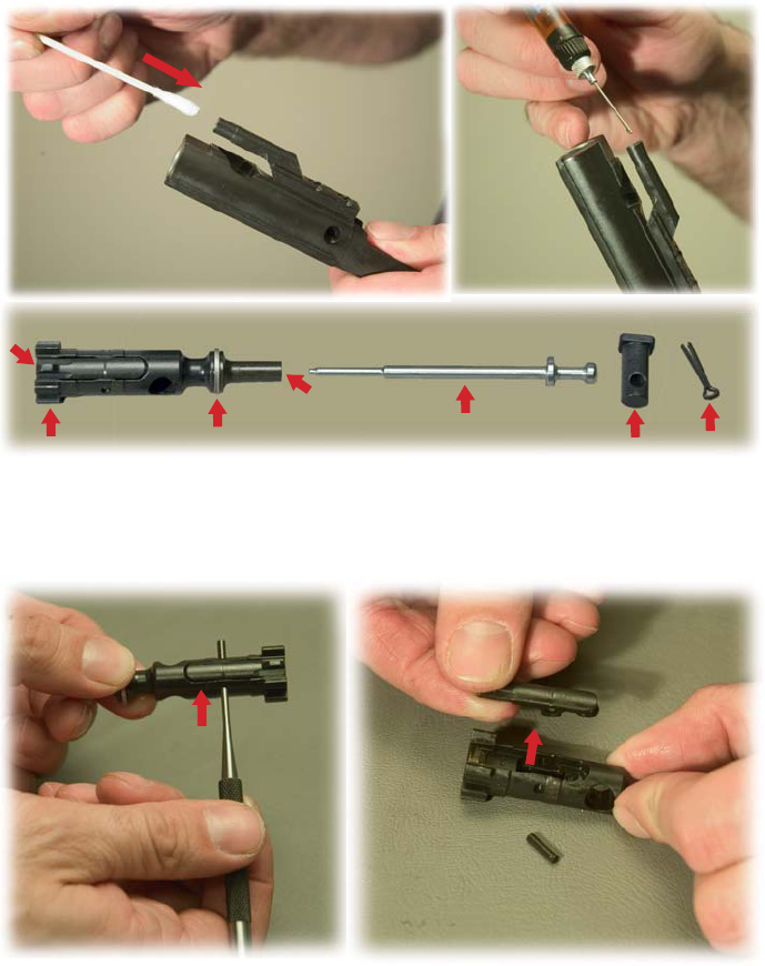
13. Once the bolt carrier has been disassembled...
A. Clean the gas key on top of the bolt carrier with a pipe cleaner or Q-p (Fig. 49). Lightly oil the
gas key (Fig. 50). Clean carbon and powder residue from vent holes and outer and inner surfaces of
the bolt carrier. Use a bore brush - wet with CLP - to clean carbon and powder residue from around
the gas tube.
B. Clean and inspect the bolt, cam pin, firing pin and firing pin retaining pin thoroughly. Clean the
bolt locking lugs, bolt rings, firing pin, firing pin hole and cam pin (Fig. 51).
Fig. 52 Fig. 53
14. Remove extractor pin by pushing it out with the p of the firing pin or a punch. Take care not to
damage the firing pin, or lose the extractor pin (Fig. 52).
15. Remove the extractor with its spring, insert and o-ring (Fig. 53).
CAUTION: It is unlikely, but if the extractor spring should pop out of its recess, reset the spring by
pressing it back in its recess with a punch as shown in Fig. 55 (on next page).
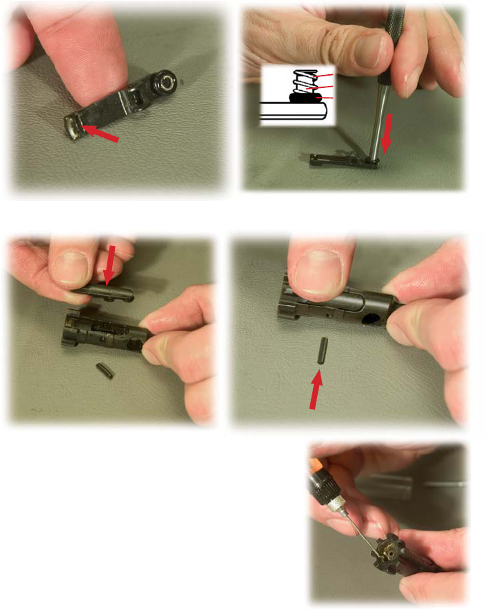
Fig. 57
Fig. 55
17. Reinsert extractor in bolt (Fig. 56). Press extractor down to reinsert extractor pin (Fig. 57).
16. Check the extractor, extractor spring, insert and o-ring. If the extractor is chipped, or if the lip
that engages the cartridge rim has broken edges, the extractor should be replaced. Check that the
rubber insert is inside the extractor spring. Clean off any carbon buildup or powder residue (Fig. 54).
Use CLP to clean any carbon buildup or powder residue in the extractor pocket/channel of the bolt.
Use a pipe cleaner and CLP to clean the firing pin channel of carbon buildup and powder residue.
NOTE*: Extractor assembly has a rubber insert within the spring. Be sure not to lose it. If the spring
comes loose, put the large end of spring in the extractor and seat it with a punch (Fig.55).
Rubber Insert
O-ring
Fig. 54
Look for chips/broken edges
Fig. 56
Extractor Spring
NOTE: Windham Weaponry does not recommend disassembly
of the ejector for cleaning. You can ensure that your rifle ejects
empty cases efficiently by following these lubricaon steps on a
regular basis.
18. With the bolt removed from the bolt carrier, hold it in your
hand as shown with bolt face and ejector up. Lubricate the
ejector with a few drops of CLP (Fig. 58).
LUBRICATING THE EJECTOR
Fig. 58
RIFLE DISASSEMBLY, CLEANING & MAINTENANCE (Connued)
CLEANING THE BOLT, BOLT CARRIER & COMPONENTS (connued)
*Components in .308 and 7.62 rifles differ slightly. There is no
rubber insert ulized in the .308. There is no o-ring ulized in the
7.62x39 rifle.
Pg. 17
“The Quality Goes In
Before The Rifle Goes Out”
For Parts Call Toll Free: 1-855-808-1888 - or Order Online: www.windhamweaponry.com
Complete AR Rifles...
and Everything to Keep Them Complete.
ALUMINUM
TRIGGER
GUARD ASSY.
P/N: 8448587
TRIGGER
GUARD
SPRING PIN
P/N: MS16562-129
TRIGGER SPRING
P/N: 8448593
HAMMER/TRIGGER PIN
P/N: 8448609
HAMMER/TRIGGER PIN
P/N: 8448609
HAMMER SPRING
P/N: 8448611
DISCONNECTOR AR
P/N: 8448635-AR
DISCONNECTOR
SPRING
P/N: 8448594
PISTOL GRIP
P/N: 9349127
PISTOL GRIP SCREW
P/N: AN501D416-18
PISTOL GRIP WASHER
P/N: MS35335-61
SAFETY DETENT
P/N: 8448631
SAFETY DETENT SPRING
P/N: 8448516
© Windham Weaponry, Inc. 2016
TRIGGER AR
P/N: 8448592-AR
HAMMER W. J PIN AR
P/N: 9349110-AR
TAKEDOWN PIN
P/N: 8448584
TAKEDOWN
PIN DETENT
P/N: 8448585
TAKEDOWN PIN
DETENT SPRING
P/N: 8448586
PIVOT PIN
DETENT SPRING
P/N: 8448586
PIVOT PIN
DETENT
P/N: 8448585
PIVOT PIN
P/N: 8448621
CHARGING
HANDLE
LATCH
P/N: 8448519
CHARGING HANDLE
SPRING PIN
P/N: 8448521
CHARGING HANDLE SPRING
P/N: 8448520
CHARGING HANDLE ASSEMBLY
P/N: 8448517
BUFFER RETAINER
P/N: 8448582
BUFFER RETAINER
SPRING
P/N: 8448583
A4 CARRY HANDLE GROUP
WITH 300-600 M REAR SIGHT
P/N: 12951011
TELESTOCK
PLATE
P/N: 9390021
TELESTOCK
LOCKING RING
P/N: 9390020
TELESTOCK KIT
P/N: KIT-TELESTK
BUFFER SPRING P/N: 9390022
CARBINE BUFFER
P/N: 1005-914-4578
DELTA RING
P/N: 8448712
WELD SPRING
P/N: 8448555
SNAP RING
P/N: MS16626-1137
EJECTION PORT COVER
P/N: 8448525
EJECTION PORT
COVER ROD C-CLIP
P/N: MS16632-3012
EJECTION PORT COVER SPRING
P/N: 8448532
EJCT. PORT COVER ROD
P/N: 8448533
BARREL NUT
P/N: 9349054BBLN
BARREL EXTENSION
P/N: 9349054-W2BE
HANDGUARD CAP
P/N: HCAP-RDHVYM4
MAGAZINE CATCH
P/N: 8448638
MAGAZINE CATCH
SPRING
P/N: 8448637
MAGAZINE CATCH BUTTON
P/N: 8448636
BOLT ASSY. COMPLETE
P/N: 8448509
EXTRACTOR CARTRIDGE
P/N: 8448512
BOLT
GASRINGS (3)
P/N: KIT-GASRINGS
MAGAZINES
30 / 20 / 10 / 5 ROUND
BOLT CARRIER
WITH KEY
P/N: 8448505
M16 BOLT CARRIER ASSEMBLY
P/N: 8448501
BOLT CARRIER KEY
P/N: 8448506
BOLT CAM PIN
P/N: 8448502
BOLT CATCH
PLUNGER
P/N: 8448634
BOLT CATCH SPRING PIN
P/N: MS16562-119
BOLT CATCH
P/N: 8448628
BOLT CATCH PLUNGER
SPRING P/N: 8448633
FIRING PIN-M16
P/N: 8448503
FIRING PIN
RETAINING PIN
P/N: 8448504
GAS KEY SCREWS (2)
P/N: 8448508
FRONT SIGHT POST
P/N: 9349056
FRONT SIGHT POST DETENT
P/N: 8448573
FRONT SIGHT POST DETENT SPRING
P/N: 8448574
SLING SWIVEL
P/N: 8448571
FRONT SIGHT TAPER PIN (2)
P/N: 8448575
SLING SWIVEL RIVET
P/N: 8448697
FRONT
SIGHT
BASE
A2 FLASH
SUPPRESSOR
P/N: 9349051
CRUSH WASHER
FOR A2 FLASH
SUPPRESSOR
P/N: 12991533
BARREL ASSEMBLY W. M4 CUTAWAY
CARBINE GAS TUBE P/N: 1005-914-3504
GAS TUBE SPRING PIN P/N: MS16562-106
FORWARD ASSIST
ASSEMBLY - ROUND
P/N: 9349086
FORWARD ASSIST
SPRING
P/N: 8448540
FORWARD ASSIST
SPRING PIN
P/N: MS16562-121
DUAL HEATSHIELD HANDGUARDS
P/N: DS4-HANDGUARD
M4 PROFILE CHROME LINED 16” BARREL
4150 CHROME MOLY VANADIUM 11595E STEEL
SAFETY SELECTOR AR
P/N: 9381367-AR
EJECTOR SPRING
P/N: 8448516
EJECTOR CARTRIDGE
P/N: 8448515
EJECTOR SPRING PIN
P/N: MS16562-98
EXTRACTOR PIN
P/N: 8448513
EXTRACTOR SPRING INSERT
P/N: 8448755-INSERT
EXTRACTOR SPRING
P/N: 8448755
EXTRACTOR “O”RING
P/N: 8448755-ORING
RIFLE DISASSEMBLY, CLEANING & MAINTENANCE will connue on Page 20
Pg. 18
Pg. 19
The U.S.A.
Made in
Pg. 20
RIFLE DISASSEMBLY, CLEANING & MAINTENANCE (Connued)
19. Place an empty .223 case, or a dummy
round, under the lip of the extractor. With a
rocking moon, press the case down against the
ejector. The ejector is spring loaded, so you will
feel some resistance. Press on the case unl it
stops against the bolt face. Rock the case back and
forth several mes to work the CLP lubricant into
the ejector and its spring. Relubricate the ejector,
and repeat the rocking moon several mes. Once
the spring acon of the ejector is smooth and
strong, dry off any excess lubricant (Fig. 59).
LUBRICATING THE EJECTOR (connued):
Fig. 59
CAUTION: The bolt should not have any cracks or fractures - especially in the cam pin hole area.
The bolt face should not have any ping - especially around the firing pin hole. If this ping is found,
the bolt must be replaced.
• The cam pin should not be cracked or excessively worn. If so, replace it.
NOTE: In as lile as 100 rounds, normal wear on a Cam Pin can show an indented paern where
the Bolt and Cam Pin interact. This is not a crack, or a dangerous situaon. Real cracks in the Cam Pin
however, can cause a catastrophic failure.
LUBRICATION BEFORE REASSEMBLY:
Fig. 60
Ping?
Worn?
Bent?
Too Blunt?
Too Sharp?
Cracks?
Fractures?
If Cam Pin
is cracked,
replace it.
Do not spread.
BOLT CARRIER GROUP: Apply a LIGHT COATING OF CLP to firing pin and firing pin recess (hole) in
bolt, the extractor and its pin, and inner surfaces of the bolt carrier. GENEROUSLY LUBRICATE the
outside areas of the bolt body and cam pin, and the slide and cam pin areas of the bolt carrier.
STAGGER GAS RINGS: Gaps in
the 3 gas rings should be evenly
spaced around the bolt body (120°
apart) to stop gas loss (Fig. 61).
Fig. 61
Gas Ring Gap
• The firing pin should not be worn, bent, or too blunt or too sharp.
If the firing pin retaining pin is bent or worn, replace it. NEVER spread the legs of the firing pin
retaining pin apart, and never use a common coer pin as a substute (Fig. 60).
INSPECTIONS BEFORE REASSEMBLY:
Cam Pin
showing
normal wear.
e
ar.
WARNING: IF THE CAM PIN IS MISSING,
DO NOT FIRE THE RIFLE!
IT WILL HAVE A CATASTROPHIC FAILURE!
Pg. 21
RIFLE DISASSEMBLY, CLEANING & MAINTENANCE (Connued)
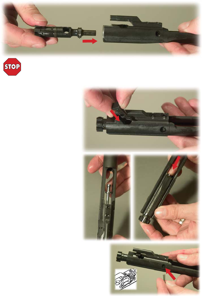
NOW INSERT BOLT INTO CARRIER:
Fig. 62
WARNING: Regarding swapping bolts between rifles, while Windham Weaponry rifles
and bolts are machined with great care, and are interchangeable with other Windham
Weaponry bolts, we do not recommend exchanging bolts - parcularly those from other
manufacturers, without first checking for proper headspacing with a Field Gauge or
Go/No-Go Gauge for .223 Rem./5.56mm NATO.
Fig. 63
Fig. 65
Fig. 66
Fig. 64
INSERT CAM PIN:
Insert cam pin into carrier and hole in
bolt body (Fig. 63).
NOTE: The cam pin should only fit
into the bolt from one side. If it doesn’t
slip in easily, turn bolt body 180° within
the carrier and try again. Aer cam pin
is inserted, turn it 90°. This allows for
the inseron of the firing pin.
INSERT FIRING PIN:
Drop firing pin into back end of bolt
carrier (Fig. 64) and seat by pushing in
all the way (Fig. 65).
INSERT FIRING PIN RETAINING PIN:
Insert firing pin retaining pin into the
firing pin retaining pin hole in the side of
the carrier as shown (Fig.66).
NOTE: In the cutaway drawing, the
firing pin retaining pin sits behind the
large shoulder of the firing pin. The test
for correct posioning is that the firing
pin should not fall out when bolt carrier
group is turned upside down.
Now that the bolt carrier is fully
reassembled, move the bolt in and out
of the carrier to ensure that the cam pin retains the
bolt in the carrier and that the cam pin moves freely
in the cam pin track.
Tap the rear of the bolt carrier on a solid surface to
ensure that the firing pin and its retaining pin is
installed properly.
Now lightly lubricate the bolt carrier assembly and
charging handle assembly.
Pg. 22
RIFLE DISASSEMBLY, CLEANING & MAINTENANCE (Connued)
These steps have been adapted from the US Gov’t. Manual and involve the
use of the standard issue M16 cleaning kit. You can achieve comparable results
with any high quality rifle cleaning kit. Be sure your kit includes a quality
cleaning rod; patch holder; coon flannel bore patches; pipe cleaners; a small
toothbrush; brass wire bristle bore and chamber brushes; and a
Cleaner/Lubricant/Preservave (CLP). If you use an ammonia based solvent
while cleaning a chrome lined barrel, do not let it sit in the bore for more than
10 minutes. This will cause premature deterioraon of the chrome lining. The
toothbrush is for cleaning parts and dislodging dirt. Pipe cleaners or Q-ps are
for cleaning the gas key, gas tube and other hard to reach areas.
CLEANING THE BORE:
ALWAYS CLEAN FROM CHAMBER TOWARDS THE MUZZLE AND ALWAYS
PULL THE BORE BRUSH THROUGH THE BORE
The bore of your Windham Weaponry rifle has lands and grooves called
rifling. Rifling makes the bullet spin very fast as it moves down the bore and
down range. Because it twists so quickly, it is difficult to push a new, sff bore
brush through the bore. You will find it much easier to pull your bore brush
through the bore. Also, because the brush will clean beer if the bristles follow
the grooves (called tracking), you want the bore brush to be allowed to turn as
you pull it through.
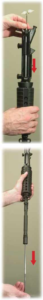
1. Swab out the bore with a patch moistened with CLP.
2. If using a mul-piece military cleaning rod, aach three rod secons
together but leave each one about two turns short of being ght (Fig. 67).
3. Aach the bore brush. The rod and bore brush will twist as you pull it
through - following the path of the rifling. NEVER reverse the direcon of the
bore brush while it is in the bore.
4. Point the muzzle down. Hold the upper receiver in one hand while
inserng the end of the rod without the brush into the firing chamber. Let the
rod fall straight through the bore. About 2-3 inches will be scking out of the
muzzle at this point.
5. Aach the handle secon of the cleaning rod to the end of the rod
scking out of the muzzle (Fig. 68).
6. Pull the brush through the bore and out the muzzle.
7. Aer one pull, take off the handle secon and repeat the process.
8. Send a patch through the bore once in a while to help clean out the crud
that the brush is geng loose. You can use the same technique as described
above to save me. Just replace the bore brush with the rod p (patch holder)
and a wet patch. Drop it through. You won’t need to aach the handle to pull
only a patch through. If you leave the rods loose again, the patch will “track” in
the rifling as before. Remember - always have the bore wet with cleaner before
trying to pull a brush through.
Fig. 68
Fig. 67
Aach
Handle
- Pull
Through
Bore
Brush,
or Patch
&
Three
Rod
Secons
Drop
Through
NOTE: You can safely use any cleaning, lubricang or powder/copper solvents
on Carbon Fiber receiver rifles that you would on rifles with aluminum
receivers.
Pg. 23
REMOVING THE HANDGUARDS
LUBRICATION OF UPPER RECEIVER & BARREL
CLEANING THE UPPER RECEIVER
Fig. 70
Fig. 69
1. Using CLP, clean all areas of the upper receiver
(inside and out) to remove powder fouling, corrosion
and dirt.
NOTE: Never use a wire brush or any type of
abrasive to clean the aluminum upper receiver - you
could scratch and damage the anodized finish. A
toothbrush can be effecve to loosen dirt buildup,
and won’t scratch the receiver.
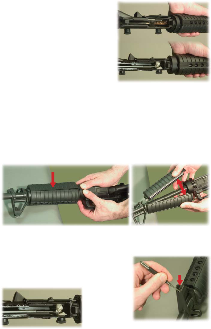
2. Clean the chamber by moistening the larger
chamber brush with CLP, and use plunge strokes and
clockwise rotaons (Fig. 69).
NOTE: Do not push the larger poron of the
chamber brush into the bore.
3. Swab out the chamber and bore to remove
contaminated CLP, carbon buildup and powder fouling. Wipe all components clean and dry, and
inspect for any excessive wear, corrosion or mechanical damage. Replace any worn or defecve parts
before your next shoong session. Contact Windham Weaponry toll free at 1-855-808-1888 for parts
needs, or consult with a qualified gunsmith.
RIFLE DISASSEMBLY, CLEANING & MAINTENANCE (Connued)
1. UPPER RECEIVER: Lightly lubricate the inside of upper receiver, the bore and chamber (using
the cleaning rod and a patch), the outer surfaces of the barrel and front sight, and surfaces under the
handguards. Take special care to clean and lubricate the locking lugs just outside the firing chamber.
The forward assist should also be lightly lubed inside the
receiver and checked for funcon (Fig. 72).
2. FRONT SIGHT DETENT: Depress the detent, and apply
two or three drops of CLP to it. Depress the detent several
mes to work the lubricant down into the spring (Fig. 73).
Fig. 72
Fig. 71
Fig. 73
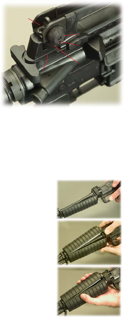
1. To remove the handguards, pull delta ring towards you, gently tap handguards on the edge of
your work surface on the seam where the handguards come together (Fig. 70). The handguards will
separate and can now be removed (Fig.71).
NOTE: On VEX & .308 Hunter Models with Laminate Wooden Forends, the Handguards are split
vercally rather than horizontally. Removal procedure is similar to that shown below.
If your rifle has a free floang handguard, it is not recommended to remove it for barrel cleaning.
You can clean/lubricate the barrel through venng slots or from the open end with a cleaning rod and
a wet patch.
Pg. 24
LUBRICATION OF UPPER RECEIVER & BARREL (connued)
RIFLE DISASSEMBLY, CLEANING & MAINTENANCE (Connued)
Fig. 74
Windage
Knob
Adjustable Rear Sight on A4 Removable Carry Handle
Elevaon
Dial
Windage
Screw
Boom of Elevaon Screw
Sha & Detent Spring Hole
(remove carry handle for access)
Detent
Spring
Hole
3. ADJUSTABLE REAR SIGHT:
NOTE: Make a note of how far you
move the sights so they can be returned
to their original posion aer
compleng this lubricaon procedure
(Fig. 74).
MOVING PARTS: Use one or two
drops of CLP. Rotate these parts to
ensure lubricant is spread evenly above
and below the elevaon knob /
elevaon screw sha / windage knob
(maximum five clicks le or right) /
windage screw / detent holes.
ELEVATION SCREW SHAFT: Remove
A4 carry handle to lubricate the
elevaon screw (or, if you have an A2
fixed carry handle upper receiver, look
inside the upper). Put two or three
drops of CLP on boom of elevaon screw sha and in elevaon detent spring hole. Rotate the
elevaon dial back and forth a few mes while keeping upper receiver upside down.
AFTER LUBING REAR SIGHT: Reset your correct zero windage and your balesight zero. Refer to
the secon within this manual about seng balesight zero. Noce the rear sight comes down when
the “6/3 or 8/3” is aligned with the mark on the le side of the receiver. You will feel a “click" when
the “6/3 or 8/3” first lines up with the mark. Carry your rifle with the “6/3 or 8/3” aligned with the
mark. Keep the sight on 300 meters to keep dirt and water out of sight mechanism and protect the
sight from damage.
IF YOU GET THE REAR SIGHT WET: Clean it as soon as possible to avoid the onset of rust and
corrosion.
REINSTALLING THE HANDGUARDS
1. Insert the first half of the handguard into the handguard cap.
Then pull the delta ring back and insert rear part of the handguard
onto the delta ring as shown (Fig. 75).
2. Now insert the second half of the handguard into the
handguard cap and pull back the delta ring and slide the rear of the
handguard onto the delta ring as shown (Fig. 76).
Fig. 75
Fig. 76
Fig. 77
3. Then squeeze the rear of the handguard halves as shown unl
they snap into the delta ring. (Fig.77).
NOTE: The two halves of standard issue rifle and carbine length
handguards are idencal, and so can be installed either on top or
boom. Remember that Wood Forend Sets are split vercally, not
horzontally, and are mirror image parts. When re-installing, posion
the cooling vents on the upper side of the barrel.
Pg. 25
INSTALLING THE CHARGING HANDLE
LOWER RECEIVER DISASSEMBLY
RIFLE DISASSEMBLY, CLEANING & MAINTENANCE (Connued)
Fig. 78
Fig. 79
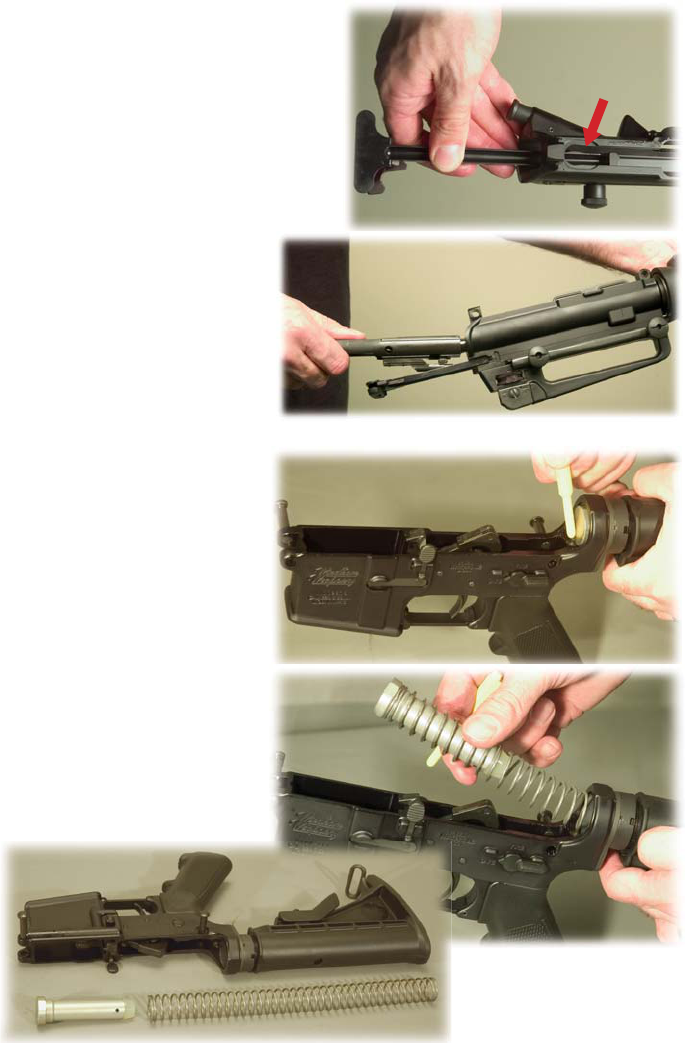
1. With the hammer cocked,
depress buffer retainer with chamber
plug tool or punch to release buffer
and spring (Fig. 80).
NOTE: Hammer must be cocked to
allow clearance for removal of buffer
and spring.
CAUTION: The buffer is under
tension from the acon spring.
2. Pull buffer and acon spring out
for cleaning (Fig. 81).
NOTE: Windham Weaponry does
not recommend any further
disassembly of rifle components or
subsystems. If you need further service
or parts, consult the factory or a
qualified gunsmith.
Fig. 80
Fig. 82
Fig. 81
1. INSTALL THE CHARGING HANDLE: Insert the
charging handle into the upper receiver and align
the tabs on the charging handle with the
corresponding slots in the upper receiver.
Then push the charging handle down into the
charging handle groove and slide it part way
forward (Fig. 78).
REMEMBER: On Carbon Fiber upper receivers,
the Charging Handle simply slides straight into the
receiver - there are no “cutouts” as in the
aluminum upper receiver.
2. INSTALL THE BOLT CARRIER: Pull
the bolt to the “out” posion in the
carrier. As you install the bolt carrier,
align the gas key with the channel in the
charging handle. Then push the bolt
carrier and charging handle all the way
forward unl the bolt carrier is flush
with the back of the upper receiver and
the charging handle latches in place
(Fig. 79).
Pg. 26
LOWER RECEIVER GROUP: lightly lubricate inside the lower receiver extension (buffer tube), as
well as the buffer and acon spring.
Generously lubricate the takedown and pivot pins and their detents, all moving parts inside the
lower receiver and their pins.
CLEANING THE LOWER RECEIVER
LUBRICATION OF THE LOWER RECEIVER ASSEMBLY
RIFLE DISASSEMBLY, CLEANING & MAINTENANCE (Connued)
Fig. 83
Fig. 84
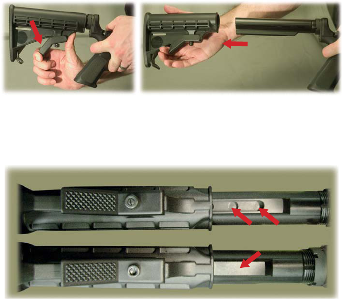
NOTE: Some Windham Weaponry rifles sold as “Ban Compliant Models” in the States of New York,
Conneccut, Massachuses, and New Jersey have permanently extended (fixed length) telestocks.
The length of pull cannot be changed as the receiver extension is longer than on an adjustable
telestock. See the differences noted in Fig. 84A below. The Ban Compliant stock will not have the
machined adjustment recesses found on the adjustable telestock.
DO NOT aempt to adjust the length of, or disassemble, the Ban Compliant stock as you will
damage it.
Fig. 84A
Underside View - Adjustable Length Telestock
Recesses for 6 adjustment posions
No Recesses - not adjustable
Underside View - Fixed Length Ban Compliant Stock
1. Using CLP, or a quality gun cleaner, clean all areas on the lower receiver of any powder fouling,
corrosion and dirt. Use of a toothbrush will avoid scratching the finish - NEVER use a wire brush.
2. Clean any dirt from the trigger mechanism. Carefully clean the magazine release buon and the
cavity for the magazine catch on the le side of the receiver. Inspect and clean the bolt catch
mechanism and lower receiver’s takedown and pivot pins. Clean the buffer, acon spring, and inside
the lower receiver extension (also called the buffer tube). A cloth aached to the cleaning rod and
patch holder can be used to wipe inside the buffer tube. Note that Windham Weaponry uses
Commercial Specificaon Buffer Tubes on Telestocked models. Cleaning procedures are similar for Mil.
Spec. & A2 (solid stock) models.
3. If the rifle has been used in dirty or muddy condions, clean out the vent hole in the telestock
receiver extension (or the vent screw in the A2 solid bustock) with a pipe cleaner or piece of wire to
ensure that the vent hole is clear.
4. Clean telestock or bustock as necessary. The telestock latch can be pulled down to remove the
stock (as shown in Figures 83 & 84). Clean the 6 posion lock holes, and lightly lube the receiver
extension and latch mechanism to ensure proper telescoping acon. A2 solid bustocks may require
cleaning and lubricaon of storage compartment door latch and hinge.
Pg. 27
To clean and lubricate the magazine, use a cleaning rod with a cleaning patch aached to clean and
lubricate the inside of the magazine body.
Lightly lubricate the spring, and reassemble the magazine in the reverse order of the steps
above.
CAUTION: Make sure the magazine is unloaded before disassembly.
To disassemble a magazine for cleaning or lubricaon, follow these steps:
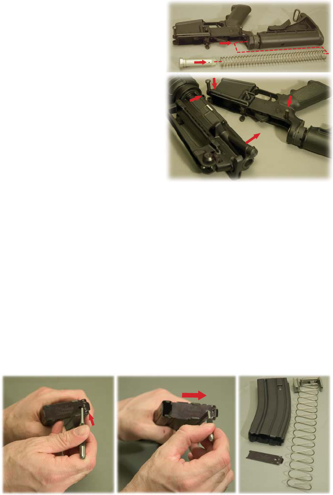
1. Pry up the back edge of the baseplate with a punch to release the base catch tabs from the
magazine body (Fig. 87).
2. Slide the baseplate clear of the body (Fig. 88).
CAUTION: The magazine spring will be under tension and may pop out.
3. The magazine spring may get caught on the tabs that hold the baseplate in place. As you pull the
spring out of the magazine body, move the spring back and forth so that it will not get hung up on the
tabs. Figure 89 shows disassembled magazine components.
NOTE: Do not remove the follower from spring.
MAGAZINE DISASSEMBLY
MAGAZINE CLEANING
MAGAZINE DISASSEMBLY & CLEANING
Fig. 87 Fig. 88 Fig. 89
Fig. 85
Fig. 86
JOIN THE UPPER & LOWER RECEIVERS:
1. Posion upper receiver so that receiver
pivot pin can slide into forward lug of upper
receiver.
2. Push pivot pin in, close upper receiver
completely onto lower (with hammer cocked).
3. Push in rear takedown pin (Fig. 86).
A NOTE REGARDING CARBON FIBER RECEIVERS:
Because of very minor dimensional differences,
you cannot assemble an Aluminum Upper Receiver
Assembly onto a Carbon Fiber Lower Receiver
Assembly. Use of force to assemble these
components will cause damage. Conversely, do not
aempt to aach a Carbon Fiber Upper Receiver Assembly onto an Aluminum Lower Receiver Assembly.
There are also minor differences between the Carbon Fiber model’s barrel nut and that of Aluminum
receivered models. Barrel Nut threading is different on Carbon Fiber models, and we also use Locte on
Carbon Fiber Barrel Nuts, so aempng to remove a Carbon Fiber Barrel Nut can cause damage to the
Carbon Fiber Upper Receiver, and may void your warranty. This Carbon Fiber Barrel Nut difference limits
the number of accessory forends that can be mounted to the Carbon Fiber rifle. Call Windham
Weaponry Technical Assistance if you have quesons on this.
LOWER RECEIVER REASSEMBLY:
Insert acon spring and buffer. You may have
to “wiggle” the acon spring past the buffer
detent as you insert it (Fig. 85).
2
3
1

Pg. 28
ADDENDUM: INFORMATION ON .308 CALIBER RIFLES
What’s Different about the .308 Caliber Rifles
The first, and most important point regarding your Windham Weaponry .308 Caliber Rifle is that you
should follow all the same maintenance procedures shown elsewhere in this Windham Weaponry
Operang and Safety Manual. The .308 Caliber Rifle funcons and maintenance procedures are all the
same as our .223/5.56mm caliber rifles, and should be followed as shown in the various secons of this
Manual.
Below, you’ll find the minor differences that set the .308 Caliber Rifles apart from our .223/5.56mm
models. If you have any quesons regarding maintenance, services or you need parts for your .308
Rifle, please call Toll-Free: 1-855-808 1888, and we will be happy to help.
ALWAYS USE THE CORRECT AMMUNITION FOR YOUR PARTICULAR FIREARM!
Windham Weaponry Barrels have permanent markings that indicate the proper caliber and chamber-
ing. Always refer to the BARREL markings when selecng ammunion for your firearm. Use only factory
ammunion manufactured to U.S. industry standards. Failure to use the proper caliber ammunion can
damage your firearm, and may cause injury or death.
• Buffer & Acon Spring: These parts are specific to the .308. The Buffer is shorter, and the Acon
Spring has a few less coils than an AR, but removal and maintenance are the same. The Telescoping
Bustock is the same as an AR, and the Buffer and Acon Spring funcon in exactly the same way.
• Trigger Guard: On the .308 SRC, the Trigger Guard is an integral machined aluminum part of the
Lower Receiver, and does not swivel down from the Lower Receiver.
• Receivers: On the .308, the receivers are CNC machined
from 7075 T6 Aircra Aluminum Forgings large enough to
contain the caliber specific - and unique - bolt carrier and bolt.
The lower receiver has machined sockets each side behind the
pistol grip that are intended for Quick Detach sling swivels
similar to that supplied on the barrel’s gas block. This feature
offers mulple sling aachment points.
• Bolt & Bolt Carrier: The bolt carrier, bolt assembly, cam
pin, and firing pin are unique, and caliber specific to the .308.
Other internal parts however, such as Gas Key, Gas Key Screws,
and Firing Pin Retaining Pin, are standard “AR” parts.
.308 Caliber SRC - Model R16FTT-308
.308 Caliber Timbertec Camo SRC
Model R16FTT-308-C3
Just a few of the various Windham Weaponry
.308 Caliber models are shown above.
.308 Hunter - Model R18FFTWS-2-308
• Caliber: This rifle is designed - and chambered for - the .308 Winchester round, but it is
important to note that it will also chamber and safely fire the common 7.62 x 51mm round. The
Magazine supplied with this rifle works equally well with either cartridge.
NOTE: There is no Extractor Spring Insert like .223 rifles in the
.308, and in disassembling the .308 Carrier, the Cam Pin pulls
straight out rather than rotang 1/4 turn as on .223 assemblies.
Pg. 29
ADDENDUM: INFORMATION ON .308 CALIBER RIFLES
• A CAUTION ABOUT PARTS INTERCHANGEABILITY: The Windham Weaponry .308 SRC has been
developed as a unique product offering, and its parts and components are not intended, or designed,
to fit any other manufacturer’s .308 rifles regardless of any apparent similarity.
Owners should never aempt to use other manufacturer’s parts on or in the Windham Weaponry
.308 SRC. To do so could cause damage to your rifle, possibly inflict injury on the shooter or those in
the vicinity of the shooter, and could void your warranty.
If you have any quesons about your Windham Weaponry .308 SRC, or any of its parts or
components, or quesons about adding any aermarket accessories to the rifle, please call the
Windham Weaponry Customer Service / Technical Line - Toll Free (1-855-808-1888) between 8:30
AM and 5:00 PM (Eastern Standard Time) Monday through Friday. Or, quesons can be E-mailed to:
info@windhamweaponry.com and we will respond promptly.
• Pivot & Takedown Pins: The Pivot Pin is longer than
an AR type, but held within the Lower with standard AR
Detent and Spring. The Takedown Pin is an AR part, and is
retained within the Lower by a standard AR Detent and
Spring, but is held in place by the Pistol Grip just like the
Safety parts rather than from the rear of the Lower like on
an AR.
• Hammer & Trigger: The Hammer, Trigger, their
Springs and Pins, are all AR type parts, and funcon just as
in an AR-15 rifle.
• Hogue Beavertail Pistol Grip: This is a quality
aermarket part that while not specific to only the
.308 SRC, is nevertheless very well suited for it. It fits
larger hands a bit beer, and its “beavertail
backstrap” snugly fits the Lower Receiver and
provides beer padding for the webbing between
the thumb and index finger with the slightly heavier
recoil of the .308 cartridge.
• Bolt Catch Screw: The aachment of the Bolt
Catch on the .308 Lower Receiver is different than
on AR lowers. A special Allen head pin/screw (with 1/16” socket) is used to hold the Bolt Catch in
place. The funcon and operaon of the Bolt Catch are idencal to the AR type rifle.
• Ejecon Port Cover & Ejecon Port Cover Rod: The
Ejecon Port Cover is larger than on an AR in accordance with
the larger .308 cartridges, and the Ejecon Port Cover Rod is
not retained with a C-clip as on an AR, but rather fits in a blind
hole so it won’t slide out to the rear. Forward movement of
the rod is stopped by the Barrel Nut.
• BARREL: Windham Weaponry .308 barrels can range
from 16.5” to 20“ and are turned in Medium Profile and
Fluted versions. They all are Chrome Lined in the Bore &
Chamber, and machined from Chrome Moly Vanadium 11595E Steel. They are generally fied with an
A2 Type Flash Suppressor specific to the .308 caliber (threaded 5/8ths x 24 tpi), but may also have a
plain crowned muzzle. Rifling for .308 models is 1 turn in 10” - Right Hand Twist - 6 Lands & Grooves
The break-in procedure for this Chrome Lined Barrel is similar to the AR type rifles. We recommend
breaking the rifle in with any good quality brass cased ammunion - approximately 100 rounds. Then
clean the barrel thoroughly, and its ready for the range or the hunt.
Pg. 30
ADDENDUM: INFORMATION ON .308 CALIBER RIFLES
• .308 Gas Block: While idencal in funcon to the units
found on .223 rifles , this gas block has been machined to
receive the Quick Detach Push Buon Sling Swivel shown
here to offer rapid adjustment of sling posions, and ease in
stripping down the rifle for cleaning or maintenance
operaons. The Picanny Rail on the Gas Block is on the
same plane as the Upper Receiver for opmum sight
funcon.
• .308 Quesons?: Feel free to call our Customer Service
or Tech Support Line Toll Free any me between 8:30 AM
and 5:00 PM E.S.T.: 1-855-808-1888
• Charging Handle: Longer, and specific to the .308, the Charging Handle is machined from 7075 T6
aluminum like its AR counterpart and the Latch, Latch Spring and Spring Pin are also standard AR parts.
ADDENDUM: INFORMATION ON 7.62x39 CAL. RIFLES
Again, we stress in this Operang
Manual that you should follow all the same
maintenance procedures shown for our .223 /
5.56mm models. The 7.62 x 39mm SRC funcons and maintenance procedures are all the same and
should be followed as shown in the various secons of this Manual.
On the next page, we will idenfy the minor differences that set the 7.62 x 39mm Caliber Rifles apart
from our .223/5.56mm models. If you have any quesons regarding maintenance, service or you need
parts for your 7.62 x 39mm Rifle, please call Toll-Free: 1-855-808 1888 and we will be happy to help.
Windham Weaponry
7.62x39mm Caliber SRC
(Model R16M4FTT-762)
ALWAYS USE THE CORRECT AMMUNITION FOR YOUR PARTICULAR FIREARM!
Windham Weaponry Barrels have permanent markings that indicate the proper caliber and chamber-
ing. Always refer to the BARREL markings when selecng ammunion for your firearm. Use only factory
ammunion manufactured to U.S. industry standards. Failure to use the proper caliber ammunion can
damage your firearm, and may cause injury or death.
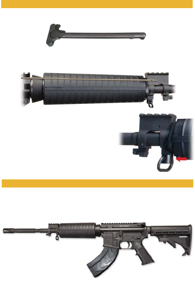
• Handguards & Gas Tube: The Handguards are mid-length, and removal or installaon is idencal
to shorter AR type parts. The Gas Tube is also a mid-length unit (shown superimposed over the
handguards in this photo). Its gas impingement system funcon, any cleaning / maintenance
procedures, are idencal to the AR.
Pg. 31
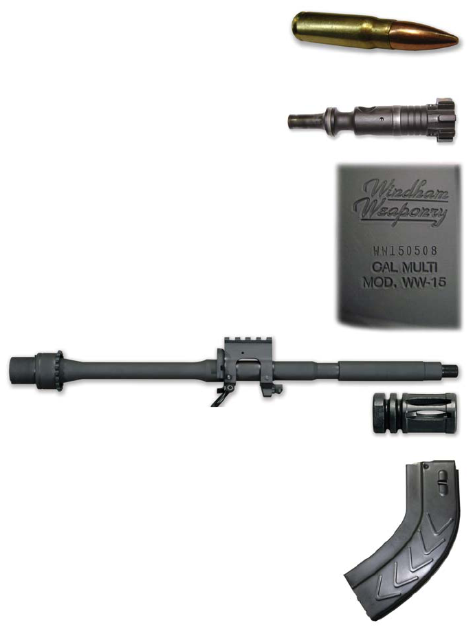
What’s Different about the 7.62x39mm Caliber Rifles
Case length 38.70 mm (1.524 in)
Overall length 56.00 mm (2.205 in)
• Flash Hider: We use the same A2 “Birdcage” type Flash Hider as found on
our .308 rifles. Threading is ⅝-24.
• 7.62 x 39mm Magazine: Shipped with the Windham Weaponry 7.62 x 39mm SRC
is a 30 Round AR Paern Magazine designed specifically to hold that round. Note that
you should not aempt to load more than 30 Rounds into this magazine as it could
cause reliability issues.
7.62 x 39 Magazines of other capacies are available (10 Rd / 5 Rd), and will fit and
funcon in this rifle. Addional magazines can be ordered by calling 1-855-808-1888 or
on line at www.windhamweaponry.com
• A Cauon About Parts Interchangeability: The Windham Weaponry 7.62 x
39mm SRC has been developed as a unique product offering, and its parts
and components are not intended, or designed, to fit any other
manufacturer’s 7.62 x 39mm rifles regardless of any apparent similarity.
Owners should never aempt to use other manufacturer’s parts on or in
the Windham Weaponry 7.62 x 39mm SRC. To do so could cause damage to
your rifle, possibly inflict injury on the shooter or those in the vicinity of the
shooter, and could void your warranty.
• 7.62 x 39mm Quesons?: If you have any quesons about your Windham Weaponry 7.62 x
39mm SRC, or any of its parts or components, or quesons about adding any aermarket accessories
to the rifle, please call the Windham Weaponry Customer Service / Technical Line - Toll Free
(1-855-808-1888) between 8:30 AM and 5:00 PM (Eastern Standard Time) Monday through Friday. Or,
quesons can be E-mailed to: info@windhamweaponry.com and we will respond promptly.
• Caliber: This rifle is designed and chambered for the 7.62 x 39mm cartridge. This is the world
famous ammunion used most commonly in the Russian
designed “AK47”. We recommend using brass cased
ammunion and, although it may seem obvious, DO NOT
aempt to fire .223 Rem / 5.56mm ammunion in this rifle.
• Bolt: Due to the larger case diameter, the Bolt and
Extractor are unique - and caliber specific - to the Windham
Weaponry 7.62 x 39mm SRC. This Bolt is idenfied by the 3
rings machined into the body behind the lugs. Internal Bolt
Carrier parts however, such as Gas Key, Gas Key Screws, Firing
Pin and Firing Pin Retaining Pin, are standard “AR” parts.
Note: The 7.62 bolt does not use the extractor o-ring
commonly found in .223 rifles
• Receivers: On the 7.62 x 39mm SRC, the receivers are CNC
machined from 7075 T6 Aircra Aluminum Forgings - just the same as
our .223 Rem / 5.56mm rifles. They are however marked differently than
our .223 / 5.56mm lower receivers, and are stamped with “Mul” so
that we can ulize them for a variety of calibers. Internal Receiver parts
such as the Hammer, Trigger, their Springs and Pins, Buffer and Buffer
Spring, etc. are all AR type parts, and funcon just as in an AR-15 rifle.
• Barrel / Gas Block: The Barrel on the 7.62 x 39mm SRC is
chambered and bored for the 7.62 x 39mm cartridge. Rifling twist rate is
1 in 9.5”, right hand twist with 4 lands and grooves. The Gas Block/Front
Sight Base is funconally idencal to the units found on AR rifles and the
Mil. Std. 1913 Rail is on the same plane as the Upper Receiver for
opmum sight funcon.
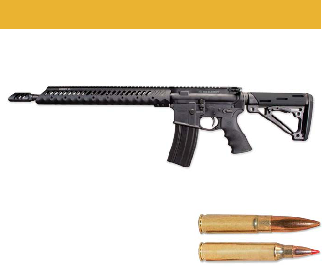
Pg. 32
ADDENDUM: INFORMATION ON
.300 BLACKOUT CALIBER RIFLES
Windham Weaponry
.300 Blackout Caliber Rifle
(Model R16SFSDHHT-300)
ALWAYS USE THE CORRECT AMMUNITION FOR YOUR PARTICULAR FIREARM!
Windham Weaponry Barrels have permanent markings that indicate the proper caliber and chamber-
ing. Always refer to the BARREL markings when selecng ammunion for your firearm. Use only factory
ammunion manufactured to U.S. industry standards. Failure to use the proper caliber ammunion can
damage your firearm, and may cause injury or death.
As with our .308 and 7.62 rifles, you
should follow all the same maintenance
procedures shown for our .223 / 5.56mm
models. The .300 Blackout funcons and maintenance procedures are all the same and should be
followed as shown in the various secons of this Manual.
• Caliber: This rifle is designed and chambered for the .300 Blackout cartridge. It will also chamber
and fire the 7.62 x 35mm cartridge. We always recommend using brass cased ammunion. DO NOT
aempt to fire .223 Rem. / 5.56mm ammunion in this rifle.
Compare the two cartridges at right.
• Bolt: Because the case bases are the same dimensions,
the Bolt and Extractor are the same as our .223/5.56mm rifle.
• Receivers: On the .300 Blackout Rifle, the receivers are
CNC machined from 7075 T6 Aircra Aluminum Forgings -
just as our .223 Rem / 5.56mm rifles. The Upper Receiver is laser engraved .300 Blackout for safety
and quick idenficaon. The Lower Receiver is marked “Mul” so that we can ulize them for a
variety of calibers. Internal Receiver parts such as the Hammer, Trigger, their Springs and Pins, Buffer
and Buffer Spring, etc. are all AR type parts, and funcon just as in an AR-15 rifle.
• Barrel / Gas Block: The Barrel on .300 Blackout Rifle is machined in a medium profile, and
chambered and bored for the .300 Blackout cartridge. Rifling twist rate is 1 in 7”, right hand twist. The
Gas Block/Front Sight Base is funconally idencal to the units found on AR rifles.
• Muzzle Brake: We use a Diamondhead “T” Brake on our .300 Blackout Rifle. Threading is ⅝-24.
Other similarly threaded brakes and flash hiders designed for .30 caliber rifles may be compable.
• .300 Blackout Magazine: The .300 Blackout Rifle accepts AR Paern Magazines. We ship the rifle
with one 30 Round Magazine - other capacity magazines are available.
BE VERY CAREFUL not to mix magazines filled with .300 Blackout ammunion with .223 magazines.
• A Cauon About Parts Interchangeability: Owners should not aempt to use other
manufacturer’s parts on or in the Windham Weaponry .300 Blackout Rifle. To do so could cause
damage to your rifle, possibly inflict injury on the shooter or those in the vicinity of the shooter, and
could void your warranty.
If you have any quesons regarding maintenance of the .300 Blackout Caliber Rifles, or you need
parts for your .300 Blackout, please call Toll-Free: 1-855-808 1888 and we will be happy to help.
.300 Blackout
.223 Rem.
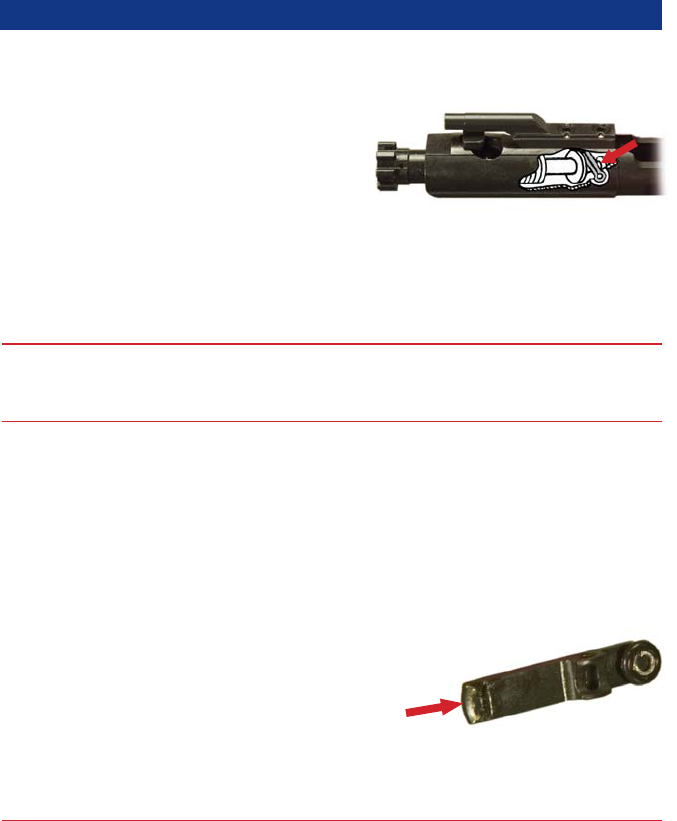
Pg. 33
TROUBLESHOOTING - PROBLEMS & SOLUTIONS
Fig. 90
Move selector lever to fire.
Assemble correctly - retaining pin must be
posioned behind large shoulder on firing pin.
Remove bolt & firing pin. With pipe cleaner, clean
out hole in bolt face. Clean firing pin. Lubricate &
reassemble.
Remove & discard. Use only fresh, clean
ammunion appropriate to the caliber marked on
the barrel of your rifle.
Clean bolt & locking lugs in firing chamber. Replace
bolt if necessary, or consult with the factory or a
qualified gunsmith.
Replace the extractor spring and insert.
Possible stuck round. If possible, remove the
upper receiver from the lower. Clear the weapon.
Push out round with cleaning rod from muzzle
end.
Clean firing chamber & bolt locking lugs.
Remove bolt, disassemble extractor.
Clean extractor, lip, & related
areas of bolt.
Remove bolt, disassemble extractor. Clean &
lubricate.
Remove & replace extractor.
Disassemble & clean magazine box, follower &
spring.
Replace defecve magazine.
Remove excess ammunion.
Remove buffer & spring. Clean, lubricate &
reinstall.
PROBLEM: CHECK FOR: WHAT TO DO:
Rifle will not
fire...
Bolt will not
easily unlock...
Bolt will not
extract...
Rifle will
not feed
ammunion...
Selector lever on safe.
Improper assembly of firing
pin.
Too much oil, or fouling in
firing pin recess.
Defecve ammunion.
Dirty or burred bolt.
Weak or broken extractor
spring.
Dirty or corroded
ammunion.
Carbon in firing chamber.
Fouling or carbon in
extractor recess or lip.
Frozen extractor.
Broken extractor.
Dirty magazine.
Defecve magazine.
Too many rounds in
magazine.
Acon of buffer assembly is
restricted.
Fig. 91
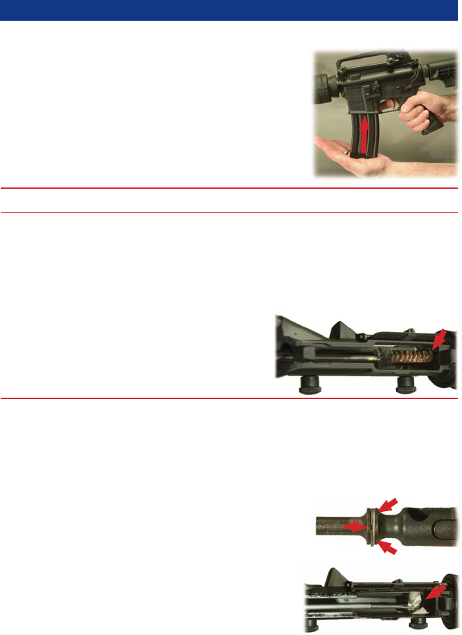
Pg. 34
Fig. 92
PROBLEM: CHECK FOR: WHAT TO DO:
Rifle will
not feed
ammunion...
Double feed...
Rifle will not
chamber a
round...
Short recoil...
Magazine not fully seated.
Defecve magazine.
Dirty or corroded
ammunion.
Damaged ammunion.
Carbon or fouling in
chamber area or in barrel
locking lugs.
Restricted movement of bolt
carrier group.
Gaps in bolt gas rings aligned
correctly.
Carbon or dirt in carrier key
or on outside of gas tube.
Underpowered ammunion.
Loose gas key.
TROUBLESHOOTING - PROBLEMS & SOLUTIONS (connued)
Fig. 93
Fig. 94
Fig. 95
Slap up on the boom of the magazine to ensure it
is seated correctly in the magazine well. Then pull
down on the
magazine to
ensure the
magazine catch
is properly
engaged with
the magazine.
Replace defecve magazine.
Clean the ammunion, or remove & discard. Use
only fresh, clean ammunion appropriate to the
caliber marked on the barrel of your rifle.
Replace damaged ammunion.
Clean firing chamber area & bolt locking lugs.
Remove bolt carrier. Clean & lubricate all
components. Before pung bolt back in, make
sure gas tube fits into carrier key, and that the
carrier moves freely.
Gaps in the 3 gas rings should be staggered 120°
around the bolt body to ensure proper gas
pressure.
Clean these areas.
Use newly manufactured, quality ammunion.
Contact Customer Service toll free at:
1-855-808-1888
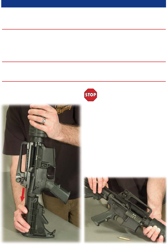
Pg. 35
PROBLEM: CHECK FOR: WHAT TO DO:
Bolt fails to
lock aer last
round...
Selector lever
binds...
Failure to
eject...
Bolt carrier
“hang up”...
Dirty or corroded bolt catch.
Faulty magazine.
Needs oil.
Obstrucon under trigger.
Hammer posion.
Frozen or sff ejector.
Round jammed between
bolt and charging handle.
TROUBLESHOOTING - PROBLEMS & SOLUTIONS (connued)
Clean bolt catch.
Replace defecve magazine.
Lubricate with CLP.
Clean or flush out lower receiver & lubricate.
The safety selector will only rotate when the
hammer is in the cocked posion.
Lubricate ejector with CLP and use a punch to
work ejector in and out of bolt face.
With rifle pointed in a safe direcon...
1. Remove magazine.
2. Push in on boom of the bolt catch.
3. Pull charging handle to the rear. If the bolt
carrier does not lock to the rear, while pulling the
charging handle rearward, bang the bustock on a
solid surface (Fig. 96).
4. Once the bolt is locked to the rear, place the
safety selector in the safe posion.
5. Push the charging handle forward and the
round should become dislodged (Fig. 97).
Inspect that round, and discard if damaged.
CAUTION:
Aer round is removed, bolt is under
tension.
NOTE: If this procedure fails, use a secon of
cleaning rod to push bolt fully to rear through the
ejecon port.
Fig. 96
Fig. 97
NOTE: If the problem sll persists, see the short recoil soluons.
NOTE: If the problem sll persists, call Customer Service toll free at: 1-855-808-1888
WARNING: Keep clear of muzzle.

Pg. 36
PROBLEM: CHECK FOR: WHAT TO DO:
Double feed...
TROUBLESHOOTING - PROBLEMS & SOLUTIONS (connued)
SHIPPING RIFLES FOR SERVICE
With rifle pointed in a safe
direcon...
1. Remove magazine.
2. Push in on boom of the bolt catch.
3. Pull charging handle to the rear and lock the
bolt carrier in place.
4. Place the safety selector in the SAFE posion.
5. Rounds should fall out of the rifle through the
magazine well.
6. Visually inspect to ensure that all rounds are
clear from the rifle.
Inspect and discard any damaged ammunion.
For Owners Within The United States... CONTACT CUSTOMER SERVICE:
Tel: 207 893 2223 • Sales Line: 855 808 1888 • E-mail: info@windhamweaponry.com
RETURNS FOR SERVICE: Should your Windham Weaponry Firearm require service, it should be
returned to the Windham Weaponry factory.
• Call or E-mail the Customer Service Dept. for authorizaon and shipping instrucons.
• ENSURE THAT THE FIREARM IS UNLOADED.
• DO NOT SHIP ANY AMMUNITION.
• Do not aempt to ship a Firearm via US Postal Service (only Federally Licensed Dealers may ship
Firearms by Postal Service).
• Enclose a leer which includes your full name and street address (no P.O. Boxes), dayme
telephone number, e-mail address, the serial number of the firearm, and details of problem
experienced (stang the brand and type of ammunion used when the problem occurred), or work
desired. We recommended that you insure your shipment.
• Record the serial number before shipping, in case you wish to check on the repair status of your
Firearm.
• Please remove all custom parts and accessories, such as stocks, special sights and scopes, or slings
from your firearm before returning.
• Place the Firearm in its original case or in a similar secure container, and pack it snugly.
• The package must NOT bear any markings which indicate the identy of the contents.
This Operang and Safety Instrucon Manual should always be kept with
your Windham Weaponry firearm. If the rifle is sold, the manual should be
transferred to the new owner.
Model: ____________________________________________________________
Serial Number: ______________________________________________________
Sold To: ____________________________________________________________
Date Sold: __________________________________________________________
