Blade Cleaning and Assembly
9649 Cordless Colour Pro Clipper Kit
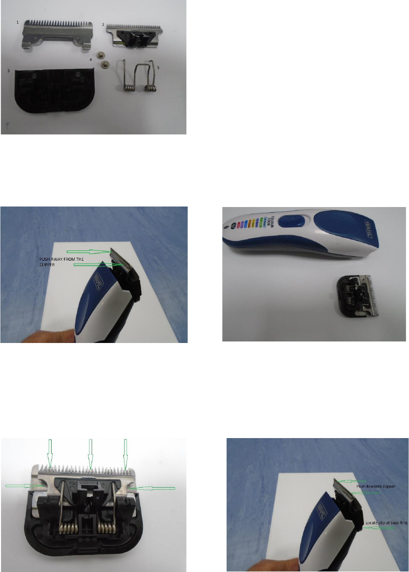
1
2
3
4
5
Removing the Blade:
1 Press your thumbs against the teeth of the blade and push away from the clipper (Fig B)
2 The blade assembly will come away from the clipper as a complete unit (Fig C)
WARNING - the blade screws (Fig A4) should NEVER be removed
Fig B Fig C
Cleaning and Oiling the Blade Assembly
1 Once the blade has been removed use a soft brush to clean away and hair or dirt.
2 Oil the blade with a drop of oil in the 5 positions shown in Fig D
3 Wipe away any excess oil
4
Fig D Fig E
Trouble Shooting
1
2 Oiling should be carried out at first use and after every cut - ensure excess oil is wiped away.
3
Tension Spring
Top Blade and Black Blade Cam Follower
Fig A - Blade Assembly Parts List
Bottom Blade
Blade assembly mount
Screws
Replace the blade, the clip on the bottom of the blade assembly should be located in the bottom of
the clipper housing, then push the top of the blade back towards the clipper. Fig E
If your clipper is no longer cutting correctly, snagging the hair or has become load / noisy please follow
the steps above to clean and oil the blade.
Clipper not holding charge - a dry, dirty and stiff blade will drastically reduce the run time of the
clipper - clean and oil regularly.
U:\Departments\Service\Returns Analysis\Products\9649-017 Colour Pro Cordless\Pictures-9469\9649 Blade
Assembly Data Sheet
Blade Cleaning and Assembly
9649 Cordless Colour Pro Clipper Kit
4
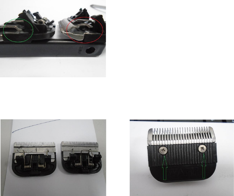
5 If you have removed the blade screws (Fig A4) you should follow the instructions below.
1 Remove blade from clipper (see Removing the blade above)
2 Check the Blade tension Spring is mounted correctly (Fig F)
Fig F
Removing and Re-fitting the Blade Tension Spring
1
2
Fig G Fig H
3
4 Re-fit the Top Blade under the 2 spring arms
5 Oil and re-fit the blade to the clipper.
Should your clipper continue to be noisy or not cutting correctly after cleaning and oiling, you should
follow the instructions below for checking the Tension spring (Part Fig A5)
Checking the Blade Tension Spring or Assembling the Blade after the Blade Screws have
been Removed
The Top Blade (Fig A2) should be seated as circled in
Green in Fig F there should be no gap, as circled in Red in
Fig F.
Should there be a gap the tension spring will need to be
re-mounted correctly
First remove the Top blade from the blade assembly, lift the two arms of the tension spring off of the
black blade cam follower and slide out the Top Blade (Fig A2)
The blade on the right in Fig G shows the Tension Spring in the wrong place, the blade on the left is
how it should look.
To re-fit the tension spring first remove the blade screws as shown in Fig H, then locate the centre
part of the spring under the bottom blade, as seen on the left in Fig G, and re-fit the screws. (the
spring will be under tension making this process a little tricky)
U:\Departments\Service\Returns Analysis\Products\9649-017 Colour Pro Cordless\Pictures-9469\9649 Blade
Assembly Data Sheet
