Driver’s Handbook
Volvo 9700 US/CAN
B13R
Foreword
This manual contains information concerning the operation and function
of the Volvo 9700 US/Can bus with version 2 of the multiplex electrical
system. The information in this manual applies to vehicles built January
2009 and later. Please keep this manual in the vehicle at all times.
Note: Illustrations in this manual are used for reference only and may
differ slightly from the actual vehicle. However, key components
addressed in this document are represented as accurately as possible.
The National Highway Traffic Safety Administration (NHTSA) and
Prevost should be informed immediately if you believe that the vehicle
has a defect that could cause a crash, injury or death.
Contact NHTSA by calling the Auto Safety Hotline at 1 (888) 327-4236,
by writing to NHTSA, U.S. Department of Transportation, Washington,
DC 20590, by TTY at 1 (800) 424-9153, or visit their website at
www.nhtsa.dot.gov.
Volvo Bus Corporation
Göteborg, Sweden
Order number: PV776-88913775
© 2009 Volvo Bus Corporation, Göteborg, Sweden
All rights reserved. No part of this publication may be reproduced, stored
in retrieval system, or transmitted in any forms by any means, electronic,
mechanical, photocopying, recording or otherwise, without the prior
written permission of Volvo Bus Corporation

Contents
Introduction .......................................................................................... 1
Driver’s Responsibility ........................................................................ 1
Keys ..................................................................................................... 2
Entering the Bus .................................................................................. 3
Main Power Switch ............................................................................. 3
Emergency Stop ................................................................................... 3
Protection Against Battery Discharge ................................................. 4
Doors and Hatches ............................................................................... 5
Doors ................................................................................................... 5
Opening from Inside ....................................................................... 5
Closing ............................................................................................ 6
Hatches ................................................................................................ 7
9700 US/CAN (with Wheel Chair Lift) ......................................... 8
9700 US/CAN (without Wheel Chair Lift) .................................... 9
Roof Hatches ..................................................................................... 10
Driver’s Position ................................................................................. 11
Driver’s Position ................................................................................ 11
Driver’s Seat ................................................................................. 12
Horn .............................................................................................. 12
Dashboard ..................................................................................... 13
Instruments and Controls ................................................................. 14
Faults and Warnings .......................................................................... 14
Accelerator Pedal Deactivated ...................................................... 14
STOP Message .............................................................................. 15
Warning Message .......................................................................... 15
Information Message .................................................................... 15
Instrumentation .................................................................................. 16
Types of Instruments ..................................................................... 16
Instrument Panel Lamps and Symbols ......................................... 21
Light Switch ................................................................................. 23
Switches ............................................................................................. 24
Main Switch .................................................................................. 24
Emergency Stop ............................................................................ 24
Kneeling ........................................................................................ 25
Level Control ................................................................................ 26

Increasing Load on the Driving Axle (trailing axle lift) ............... 27
Traction Control System (TCS) .................................................... 27
Differential Lock .......................................................................... 28
Hill Start Assistance ..................................................................... 28
Passenger Compartment Lighting ................................................. 29
Night Lighting .............................................................................. 29
Half-light ...................................................................................... 29
Driver Compartment Lighting ...................................................... 29
Passengers’ Individual Lighting ................................................... 30
Rear Door Lighting ....................................................................... 30
Position Lights .............................................................................. 30
Lighting Strip ................................................................................ 30
Destination Sign Lighting ............................................................. 31
Electrically Heated Rear Mirrors .................................................. 31
Driver’s Window Heating ............................................................. 31
Driver’s Blower ............................................................................ 32
Central Locking ............................................................................ 32
Sun Blind ...................................................................................... 32
Driver’s Window ........................................................................... 32
Activation of the Toilet ................................................................. 33
Audio System ............................................................................... 33
Opening the Doors from the Outside ............................................ 33
Middle Door ................................................................................. 33
Emergency Window in use Indicator Lamp ................................. 34
Switches in the Electrical Center .................................................. 34
Controls ............................................................................................. 35
Starting Switch ............................................................................. 35
Adjusting External Rear-view Mirrors ......................................... 35
Door Brake .................................................................................... 36
Steering Wheel Adjustment .......................................................... 37
Direction Indicator, Dipped/full Beam Changer ........................... 38
Windscreen Wipers, Windscreen/headlight Washer ..................... 39
Transmission ...................................................................................... 40
Transmission, I-shift ..................................................................... 40
Retarder ............................................................................................. 41
Retarder Overheating .................................................................... 42
Transmission Overheating ............................................................ 43
Brakes ................................................................................................ 44

Parking Brake ............................................................................... 44
Blocking Valve .............................................................................. 45
Service Brakes .............................................................................. 46
Destination sign control ..................................................................... 49
A/C Controller ................................................................................... 49
Interior Equipment ............................................................................ 50
Interior Equipment ............................................................................ 50
Toilet ............................................................................................. 51
Passengers’ panel .......................................................................... 52
Audiovisual System ............................................................................ 53
Audiovisual System ........................................................................... 53
Audiovisual Controller ................................................................. 54
Video System ................................................................................ 54
Audio System ............................................................................... 54
Emergency and Safety Equipment ................................................... 55
Overview ........................................................................................... 55
Fire Extinguisher .......................................................................... 55
Warning Triangle .......................................................................... 56
First-aid Cushion .......................................................................... 56
Tire Inflation Valve ....................................................................... 56
External Air Supply Connection ................................................... 57
Jack ............................................................................................... 57
Toolbox ......................................................................................... 58
Engine Control Box in Engine Bay .............................................. 59
Emergency Exits ................................................................................ 60
Doors ............................................................................................ 60
Windows ....................................................................................... 60
Ceiling, Roof Hatches ................................................................... 61
Starting and Driving .......................................................................... 62
Checking Before Driving .................................................................. 62
Checking Warning Lights ............................................................. 63
Daily Inspection ................................................................................ 63
Engine ........................................................................................... 63
Steering Servo/hydraulic Fan ........................................................ 64
Coolant .......................................................................................... 64
Washer Fluid ................................................................................. 64
Refuelling ..................................................................................... 65

Engine Block Heater .................................................................... 65
Starting the Engine ............................................................................ 66
Starting .......................................................................................... 66
Checks After the Engine Has Been Started. ................................. 67
Idling (programming) ................................................................... 68
Cruise Control ............................................................................... 69
Retarder ........................................................................................ 70
Power Steering ................................................................................... 72
Exhaust Aftertreatment System ......................................................... 73
Some Advice for Driving ................................................................... 74
Safe Driving ....................................................................................... 74
Economy Driving .............................................................................. 75
Driving in Cold Weather .................................................................... 76
If Something Happens ....................................................................... 77
Safety ................................................................................................. 77
If the Engine is Not Working ............................................................. 78
Punctures ........................................................................................... 78
Punctured Air Bellows ...................................................................... 78
Towing ............................................................................................... 79
Fire ..................................................................................................... 80
Releasing the Parking Brake ............................................................. 81
Release the Parking Brake with Air from the Bus Tires. .............. 81
Mechanical Releasing of the Parking Brake ................................. 82
Regarding Disc Brakes ................................................................. 82
Changing the Batteries ...................................................................... 83
Rapid Charging .................................................................................. 84
Starting Assistance ............................................................................ 84
Battery Cut-off Switch ...................................................................... 85
Bulb Replacement ............................................................................. 86
Headlamps .................................................................................... 86
Rear Lights ................................................................................... 86
Xenon Lights ................................................................................ 87
Licence Plate Lighting .................................................................. 87
Fuses and Relays (chassis) ................................................................ 88
Relays ........................................................................................... 88
Fuses ............................................................................................. 90
Fuses and relays (body) ..................................................................... 93
Relays ........................................................................................... 93

Fuses ............................................................................................. 94
Technical Data .................................................................................... 96
Technical Specification ...................................................................... 96
Bulbs ............................................................................................. 97
Type Plates ......................................................................................... 98
Identification Plate ........................................................................ 98
Vehicle Identification (VIN) ......................................................... 99
Engine ........................................................................................... 99
Transmission ................................................................................. 99
Rear Axle ...................................................................................... 99
Retarder ........................................................................................ 99
Service Intervals .............................................................................. 100
Safety Information
IMPORTANT: Before driving this vehicle,
be certain that you have read and that
you fully understand each and every step
of the driving and handling information
in this manual. Be certain that you fully
understand and follow all safety warnings.
IT IS IMPORTANT THAT THE
FOLLOWING INFORMATION BE
READ, UNDERSTOOD AND ALWAYS
FOLLOWED.
The following types of advisories are used
throughout this manual:
DANGER
Danger indicates an unsafe practice that
could result in serious personal injury or
death. A danger advisory banner is in
white type on a black background with
a black border.
WARNING
Warning indicates an unsafe practice that
could result in personal injury. A warning
advisory banner is in black type on a
gray background with a black border.
CAUTION
Caution indicates an unsafe practice that
could result in damage to the product. A
caution advisory is in black type on a
white background with a black border.
Note: Note indicates a procedure, practice,
or condition that must be followed in order
for the vehicle or component to function in
the manner intended.

Introduction 1
Driver’s Responsibility
•
As the driver, you are responsible for
the safety and comfort of the passengers
during the journey. Therefore, do not
drive the bus before you have read this
driver’s manual. You must be familiar
with all the indicators and warning
lights and know what to do if something
unexpected happens.
•
As the driver of the vehicle, you should
be aware of the vehicle weight and
loading capacity. See instructions on
warning stickers, the vehicle registration
book and on the identification plate.
•
As the driver of the vehicle, it is your
responsibility to foresee any hazards
that could threaten your passengers.
•
It is also your responsibility to ensure
that all the safety equipment of the bus
is in place. Therefore check regularly
the working order of safety belts,
emergency door opening, door sensitive
edges, fire extinguishers and first aid
equipment.
•
The brakes on the bus are operated by
compressed air. Never drive if the air
pressure is too low or if you discover
other problems with the brakes.
•
Pay attention to any steering faults. The
vehicle can be steered even if the power
steering is not working, although the
steering will be heavy.
•
Never crawl under the bus if it is
supported by a jack. Use approved
vehicle supports or a solid pallet in case
of punctures or wheel changes.
•
Lifting devices and supports should
stand securely on a horizontal surface.
The wheels that are not to be lifted
should be blocked to ensure that the
vehicle will not start to move.
•
Re-tighten the wheel nuts after
approximately 200 km (125 mi) if the
wheels have been removed.
•
Tighten the wheel nuts every 6 months
regardless of whether the wheels have
been removed or not.
•
Follow the recommended service and
maintenance programme to maintain
the bus’s condition and safety.
•
Pay attention to exhaust and fuel smells.
Any leaks should be taken care of
immediately at the garage.
•
The bus tires and rims should be
approved for the intended load and
speed in accordance with current legal
requirements.

2 Introduction
Keys
The following keys are delivered with the
bus:
1 Ignition key
2 Glove compartment key
3 Door, luggage compartment hatch and
toilet
4 Service hatch square key
5 Electric centre compartment key
6 Side glove compartment key
7 Fuel filler cap key
There may be alternative versions of the
keys, depending on the types of locks that
are fitted.
T0015481
Note: Note the number of the ignition key to
facilitate ordering of spare keys.
T0013333
Introduction 3
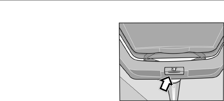
Entering the Bus
To open the front door:
•
turn the key in the lock to the horizontal
position
•
turn the knob to the vertical position
•
push the pneumatic door opening button
The button for the pneumatic opening of the
first door is placed in the door handle.
Note: In case of total or partial emptying of
the door pneumatic system, open the door by
pushing the right side of the door.
T8012405
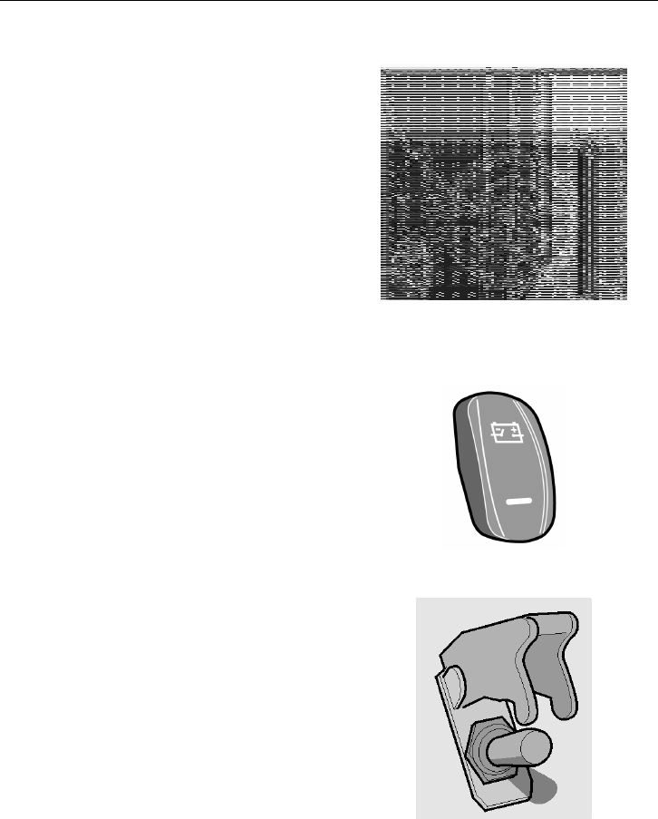
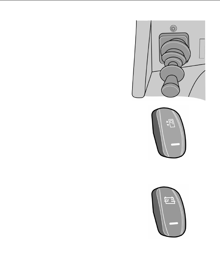
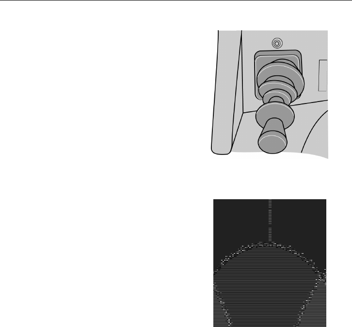
Main Power Switch
Is located on the dashboard. Always turn
off the power supply with the main switch
before leaving the bus.
Note: Never turn off the main switch while
the engine is running.
T0012043
Emergency Stop
An emergency switch is located on the left
side of the dashboard. Depending on the
market specification, the emergency switch
may disconnect the bus electrical power
supply, cut off the fuel supply and activate
the hazard warning lights.
Note: Only use the emergency cut out in an
emergency situation.
T0009170

4 Introduction
Protection Against Battery Discharge
In order to prevent battery discharge while
the bus is standing, the Volvo 9700 bus is
equipped with a function that disconnects the
supply to major electrical consumers such
as: the kitchenette, electric heaters, some
external lighting etc.
Power to these consumers is switched off
around 30 seconds after the engine is shut
down, and it is then switched back on once
the engine is started and its revolutions reach
at least 1000 rpm for 10 seconds.
Doors and Hatches 5
Doors
The Volvo 9700 bus could be equipped
with up to two single-leaf doors opening
outwards. The doors are normally operated
by pneumatic cylinders.
The doors may be equipped with a system
protecting passengers from being trapped
in the doorway during opening or closing,
this system has sensors measuring the air
pressure in the door system.
Note: In the case of excessive drop of the
door pneumatic system air pressure, the
“Door failure” warning lamp lights in the
lower right corner of the bus instrument
cluster.
T0012008
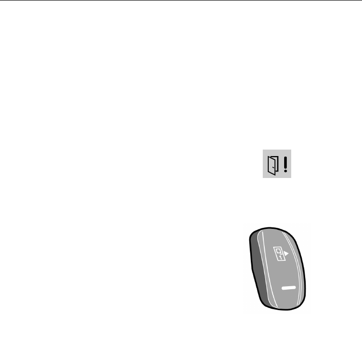
Opening from Inside
There are two buttons for door opening on
the right hand side of the driver’s dashboard.
These buttons are numbered accordingly.
Pushing the button causes the door to open.
The button indicator lamp is lit when the
door is open.
Note: Before closing the door/doors ensure
that there are no passengers standing in the
doorway.
T3018176
6 Doors and Hatches
Closing
Proceed as follows:
1 Move the gear selector into neutral
position
2 Engage the parking brake
3 Turn on the switch that activates the
door opening push-button in the door
handle
4 Open the door
5 Turn off the power supply with the main
switch
6 Leave the bus and close the door using
the push-button in the door handle
7 Lock the door with the key
Note: After locking the door with the key,
the push-button in the door handle becomes
inactive.
After turning off the power supply with
the main power switch, the light above
the entrance door remains on for about 90
seconds.
If the button activating the button in the
handle for opening the door is not switched
on, in order to enter the bus again, the
emergency valve must be used.
T5014881
T1008555
Button for outside opening of the
door
T0012043

Doors and Hatches 7
Hatches
If any of the bus hatches are open or not
properly closed, a “hatch open” symbol will
appear on the instrument panel display.
Note: The engine cannot be started unless
the engine hatch is closed.
Note: With the engine hatch open, the
engine can be started by means of a button in
the control box. See: “Engine Control Box
in Engine Bay” page 59
T3018116
The configuration of the service and luggage
compartment hatches depends on the bus
variant. Possible variants are shown below.
The description refers to items located
behind the hatch.
8 Doors and Hatches
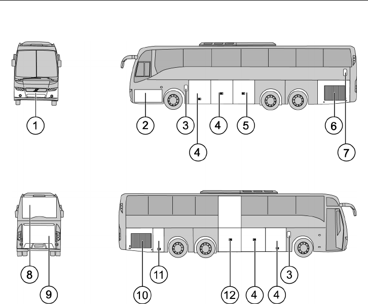
9700 US/CAN (with Wheel Chair Lift)
T0015488
1 External air valve, towing point, spare
wheel
2 Battery box, battery cut-off switch,
main fuses, washer fluid reservoir
3 Fuel filler
4 Luggage compartment hatch
5 Wheel chair lift mechanism
6 Radiator
7 Coolant filler
8 DPF
9 Engine
10 Auxiliary heater
11 Waste tank
12 Wheel chair lift
Doors and Hatches 9
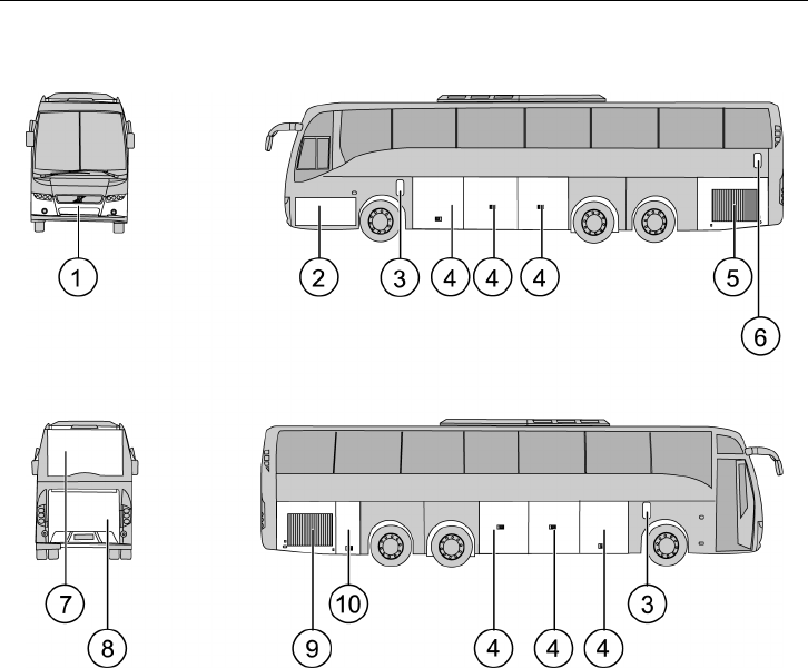
9700 US/CAN (without Wheel Chair Lift)
T0015489
1 External air valve, towing point, spare
wheel
2 Battery box, battery cut-off switch,
main fuses, washer fluid reservoir
3 Fuel filler
4 Luggage compartment
5 Radiator
6 Coolant filler
7 DPF
8 Engine
9 Auxiliary heater
10 Waste tank
10 Doors and Hatches
Roof Hatches
The Volvo 9700 bus is equipped with roof
hatches manually operated.
Manually operated hatches are opened by the
handles on each side of the hatch.
Note: When the A/C is activated in the bus
its hatches should be closed, since the air
coming in from outside may interfere with
the operation of the equipment controlling
the temperature inside the bus.
Note: Make sure that the hatches are closed
when it’s raining and when you leave the bus
for a longer period of time.
T8010110
Driver’s Position 11
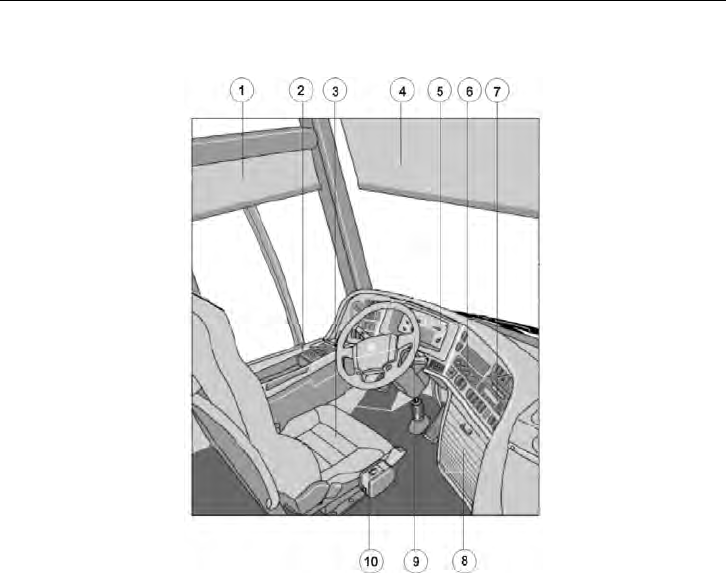
Driver’s Position
T0015299
1 Side sun visor
2 Side Panel
3 Driver’s seat
4 Front sun visor
5 Dashboard, instrument cluster
6 Controller, AC
7 Controllers, audiovisual system
8 Locker, audio equipment
9 Steering wheel
10 Gear selector
12 Driver’s Position
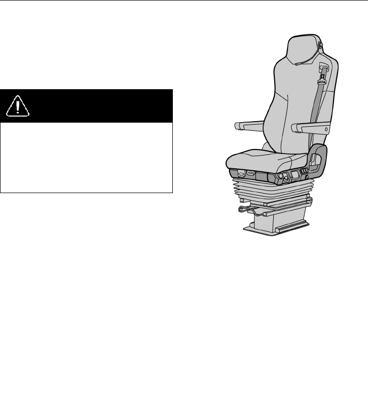
Driver’s Seat
The Volvo 9700US/CAN bus is equipped
with driver’s seat type National.
For more information see separated
instructions“Driver’s seat”.
DANGER
Adjusting seat position or fastening a
seat belt should only be performed when
the vehicle is stationary. Attempting this
while the vehicle is moving may lead
to an accident, causing serious personal
injury or death.
Note: The safety belt should not be twisted
or blocked when properly fastened.
Note: Before adjusting, check whether there
are any objects in front of the seat or behind
it, that could hinder adjustment.
T8010545
Horn
The Volvo 9700US/CAN bus is equipped
with one electrical horn (diaphragm) and
one operated by compressed air. Pushing the
central part of the steering wheel activates
the electrical horn, while pushing one of the
two small buttons beneath activates the air
horn.
Note: Remember that the use of horns is
subject to regulations.
Driver’s Position 13
Dashboard
T0015385
1 Emergency stop
2 Light switch
3 Parking Brake
4 Light for driver’s position
5 Over speed
6 Front sun visor
7 Instrument cluster
8 Emergency Windows Open warning
9 Destination sign light
10 AC controller
11 Video Player DVD
12 Wheel chair lift warning
13 Wheel chair lift
14 Audio controller
15 Toilet devices
16 Driver’s fan
17 Audio system
18 Central lock
19 Middle door
20 Position lights
21 Service first door
22 Door lock
23 Night light under seats
24 Interior lights
25 Reading light
26 Night light
27 Display control stalk, wipers and
washers control stalk
28 Retarder
29 Steering wheel adjustment pedal
30 Air inlet
31 Control stalk at the steering wheel,
direction indicators and cruise control
32 Traction control system
33 Hill start auxiliary
34 Bogie
35 Bus level
36 Kneeling
37 Main switch
38 Mirror heater
39 Mirror adjustment
40 12V Output
41 24V Output

14 Instruments and Controls
Faults and Warnings
There are three different types of signals that
give the driver all the necessary information
on the vehicle:
•
STOP message
•
warning message
•
information message
Above the display there are three lamps (for
information, warning and STOP messages),
that alert the driver’s attention when
necessary.
Messages with appropriate symbols are
shown automatically on the display.
Several messages can be active
simultaneously. A new message will
only replace the current message on the
display if it is of higher priority. This means
that the display always shows the message
with the highest priority.
For more detailed information about display
functions, see the separate Operating
Instruction “Display”.
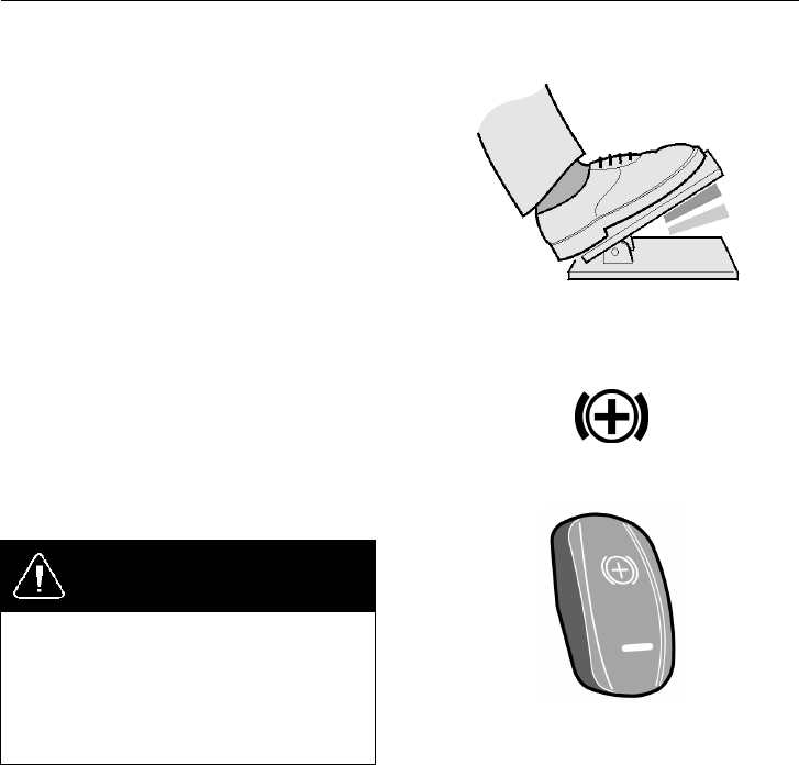
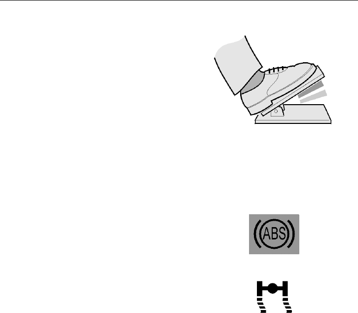
Accelerator Pedal Deactivated
The bus is fitted with prioritized brake
function.
This function deactivates a request for
acceleration if both the accelerator pedal and
the foot brake pedal or parking brake have
been activated simultaneously.
The accelerator pedal remains deactivated
until it is reset, which occurs once the pedal
has been fully released.
For additional information on this function,
see the separate Operating Instruction
“Display”.
T0013511
Instruments and Controls 15
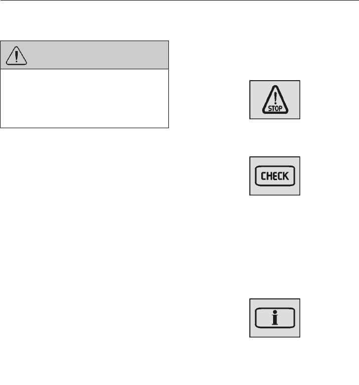
STOP Message
WARNING
If this lamp lights while driving, stop
the bus immediately and turn off the
engine. Continuing to drive may severely
endanger the vehicle, the driver and/or
passengers.
Note: If the STOP message appears while
the engine is running, it is accompanied by
activation of the audible warning buzzer.
T3014364
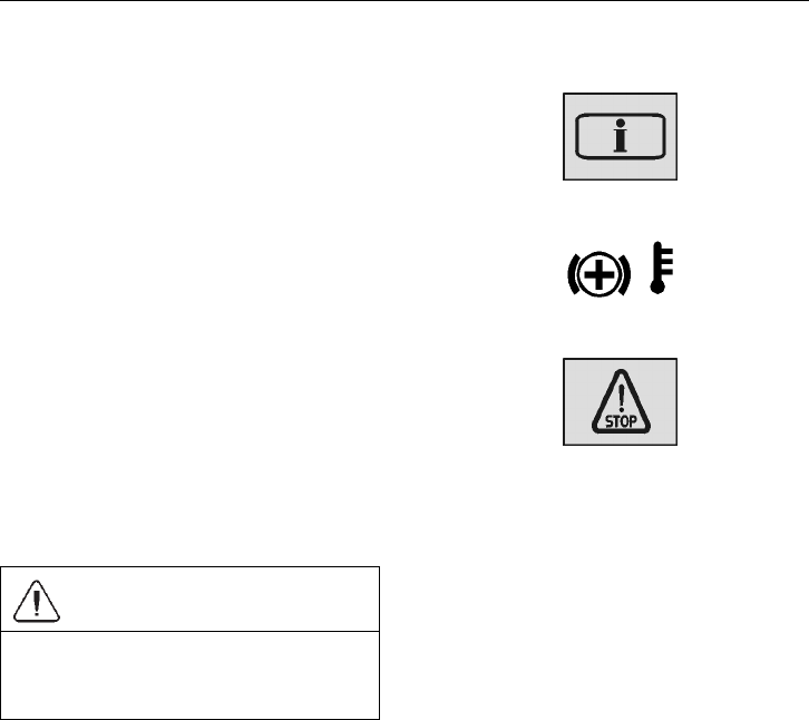
Warning Message
If this lamp lights, the vehicle must be
taken to a workshop for repair as soon as
possible. There is no immediate danger
of the vehicle breaking down, and under
normal circumstances it should be possible to
complete the journey. This lamp is also used
to draw the driver’s attention to problems
other than vehicle failures, e.g. as a warning
in the case of an open luggage compartment
hatch.
T3014365
Information Message
Simultaneously with this lamp lighting up,
a new message is shown on the display.
The fact that this lamp lights up does not
mean that there is something wrong with
the vehicle. This lamp may for example
illuminate to draw the driver’s attention to
low fuel level.
T3014366
16 Instruments and Controls
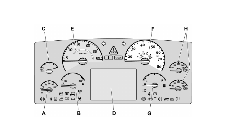
Instrumentation
T0015634
Types of Instruments
A Engine oil pressure gauge
B Coolant temperature gauge
C Turbo pressure gauge
D For the display, see the separate
Operating Instruction “Display”
E Tachometer
F Speedometer
G Fuel gauge
H Air pressure gauge for brakes
Instruments and Controls 17
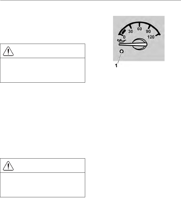
Oil Pressure Gauge (A)
The oil pressure gauge indicates the engine
oil pressure. While driving with a warm
engine, the pointer should show 3–5 bar
(40–70 psi).
CAUTION
The bus must not be driven when the
pointer is in the red zone! Failure to stop
the vehicle immediately may result in
engine damage.
Note: It is possible that the pointer will
move slightly into the red zone when the
engine is idling while it is warm. This does
not present any danger as long as the pointer
rises above 3 bar (40 psi) when the engine
speed increases.
The following will be indicated if the oil
pressure in the engine drops too low:
– warning lamp (1) lights,
– STOP– lamp lights
– the acoustic signal sounds (if the engine
is running)
CAUTION
If the warning light comes on while
driving; stop the engine and locate the
cause! Failure to do may result in engine
damage.
T0015288
1 Warning lamp, red
18 Instruments and Controls
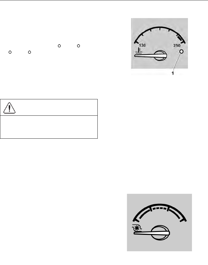
Engine Coolant Temperature Gauge (B)
This gauge indicates the temperature in the
engine’s coolant system. Under normal
driving conditions, the pointer should stay
just below the red zone (normal operating
temperature is between 80
C (176 F) and
100
C (212 F).
The engine is fitted with overheating
protection, that reduces the engine power
output to 50% if the temperature reaches the
red zone. The bus can still be driven even
after activation of the overheating protection.
CAUTION
The bus must not be driven if the
temperature rises even higher as this can
result in damage to the engine.
An indicator signals when the cooling system
temperature is too high.
– warning lamp (1) lights
– STOP– lamp lights
– the acoustic signal sounds (if the engine
is running)
T0015289
1 Warning lamp, red
Turbo Pressure Gauge (C)
The turbo pressure gauge indicates the
pressure in the intake manifold. A high
turbo pressure increases fuel consumption.
This gauge helps you drive in the most
economical manner. When driving on level
roads at constant speed, the pointer should
remain still within the green zone.
T0011983
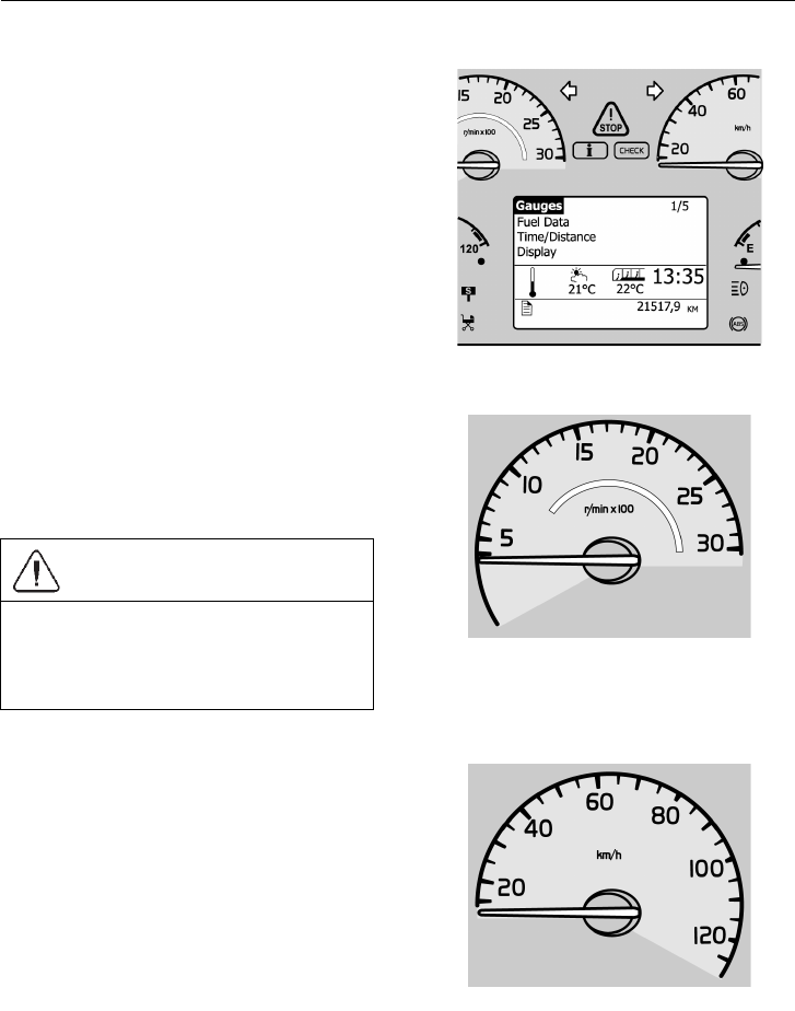
Instruments and Controls 19
Display (D)
The display consists of the main menu
and several submenus with their relevant
functions. For additional information, see
the separate Operating Instruction “Display”.
T0012082
Tachometer (E)
The tachometer scale is divided into three
zones. During normal driving you should
stay within the green zone, which gives the
best fuel economy.
CAUTION
Avoid operating the vehicle with the
tachometer in the red zone. Such high
engine speeds can result in damage to the
engine and the transmission.
T0011984
Speedometer (F)
The speedometer indicates the speed of the
bus in mph. For some markets, speedometers
are also available that indicate speed both in
mph and km/h.
T0011985
20 Instruments and Controls
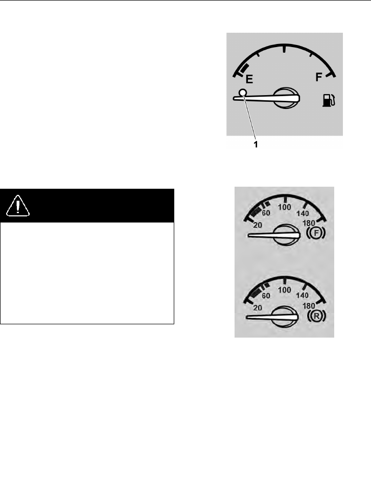
Fuel Gauge (G)
The fuel gauge shows the amount of fuel in
the tank. The red zone and the warning lamp
(1) give a warning of low fuel level.
The display gives considerable information
on the fuel situation, i.e. fuel consumption,
A to B information and remaining fuel.
For more information, see separate driver
instructions “Display”.
T0011986
Air Pressure Gauge for Brakes (H)
DANGER
Stop the bus immediately if any of the
warning lamps illuminate! A warning
lamp will illuminate if there is an
excessive pressure drop in the braking
system. Investigate the cause of the fall
in pressure. Failure to do so may result
in failure of the vehicles brakes that may
cause an accident, leading to serious
personal injury or death.
If the engine remains switched off for a long
time, the compressed air pressure may fall
to a level which will prevent the bus being
started immediately. The warning lamp
remains lit until the pressure in the braking
system rises to a sufficiently high level. If
the compressed air in the braking system has
been completely exhausted, it may take quite
a long time before the pressure starts to rise.
During driving, the gauge pointer should
remain within the green zone, but it can
temporarily drop below that zone during
braking.
T0015292
F. Air Pressure, front brake circuit
R. Air pressure, rear brake circuit
Instruments and Controls 21
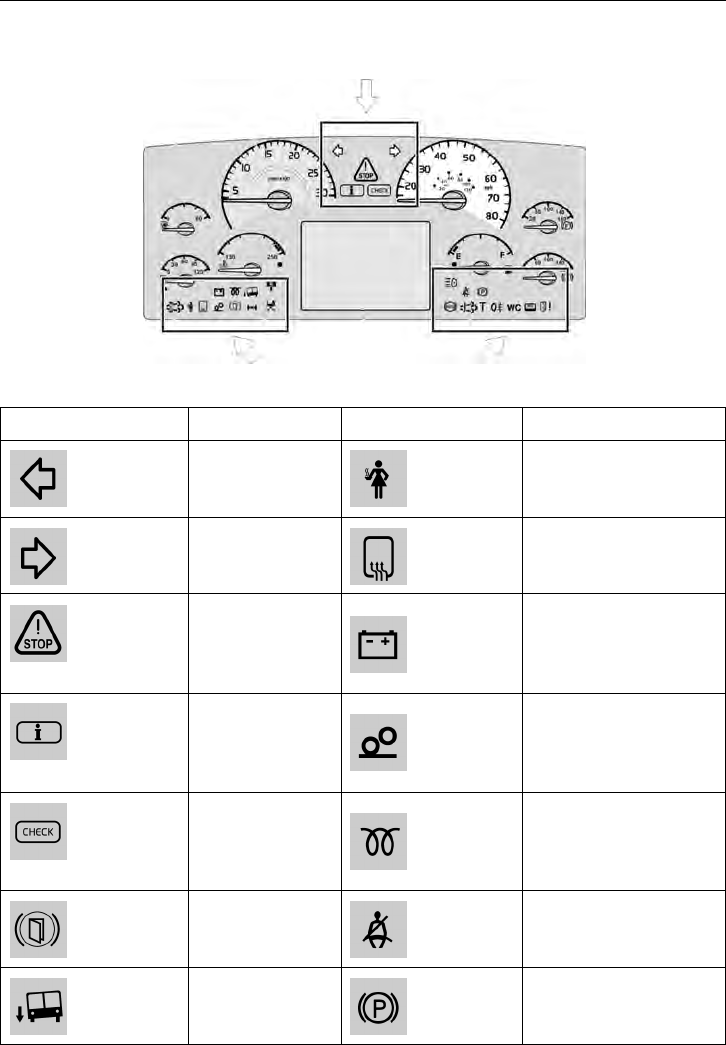
Instrument Panel Lamps and Symbols
T0015293
Symbol Meaning Symbol Meaning
Left indicator on Service personnel
Right indicator
on
Screen / mirrors heating
activated
If there is a
problem with
the bus you must
stop.
Battery not charging
Information
message
The switch for
increasing load on
the drive axle (bogie
lift) of the bogie is on
Check Pre-heating on
Door brake
activated
Safety belt reminder
Kneeling
activated (for
easier access)
Parking brake applied
22 Instruments and Controls
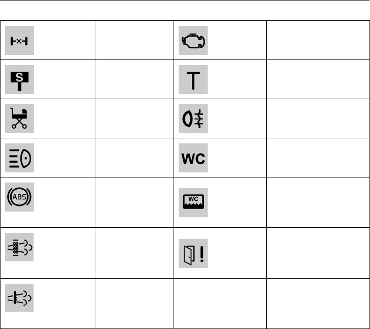
Differential lock
activated
OBD – On-Board
Diagnostics
Stop at the next
lay-by
Check the tachograph
Entering or
exiting the bus
with a pram
Rear fog lights are on
Main beam WC engaged
ABS not
functioning
WC tank full
T0015482
DPF
Regeneration
Required
Fault in the door
T0015483
High Exhaust
System
Temperature
(HEST)
Instruments and Controls 23
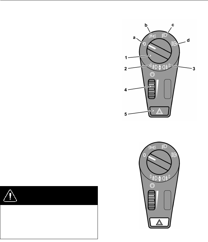
Light Switch
a Lights off or automatic activation of
dipped beam
b Parking lights
c Dipped beam
d Auxiliary spotlights
1 Lighting switch
Pressing the switch turns the front fog
lights on and off. Pulling it turns the
rear fog lights on and off.
2 Indication (repeater) lamp, front fog
light
3 Indicator light, fog light, rear
4 Instrument lighting rheostat
5 Hazard warning lights
T0012036
Hazard Warning Lights
Pressing this switch in will turn on all the bus
hazard warning lights (both sets of direction
indicators). The hazard warning lights will
work even if both the ignition and power
supply are turned off (with the main power
switch).
DANGER
Use the hazard warning lights if the bus
is stopped in a manner that may put other
road users at risk. Failure to do so may
lead to an accident, resulting in serious
personal injury or death.
T0014325
24 Instruments and Controls
Switches
The number of switches depends on the bus
specification.
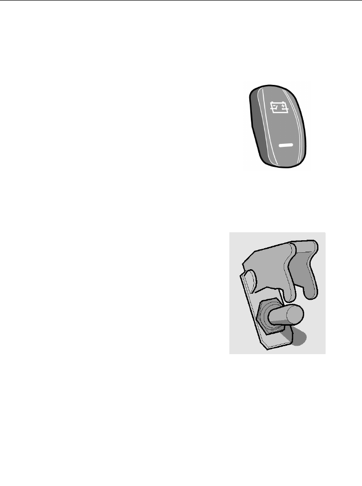
Main Switch
The bus is equipped with a main power
switch. By switching off the main power
before leaving the bus, all the major electrical
consumers are switched off, which helps to
preserve sufficient battery capacity to enable
subsequent bus starting. The main switch
does not cut off the power supply to the
clocks and auxiliary heater.
Note: Never turn off the main switch while
the engine is running.
T0012043
Emergency Stop
Note: Only use the emergency cut out in
an emergency situation; to switch off the
electrical feed in normal conditions use only
the main switch.
When the emergency stop is activated the
following occurs (can vary from country to
country):
•
air is exhausted from the door system
•
engine is stopped
•
power supply to the main electrical
consumers is cut off
•
fuel supply to the engine is cut off and
so is outflow of fuel from the tanks
•
hazard lights are switched on
•
lights above the doors are switched on
Activate the emergency cut out by lifting
the cover upwards and pressing up the
switch. When the cover is closed the power
switch automatically is pressed down to the
disconnected position.
T0009170
Instruments and Controls 25
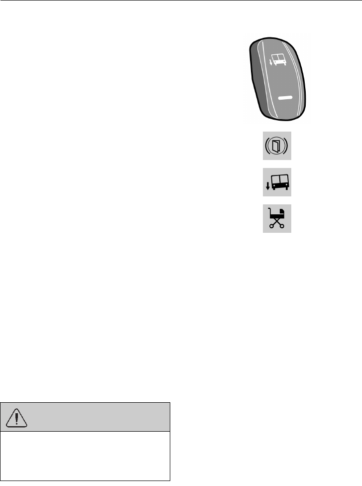
Kneeling
This switch allows the right-hand side of the
bus to be lowered (kneeling) to a level that
facilitates passenger entry and exit.
There are two possible operating modes for
the kneeling switch:
1 The bus lowers while the kneeling
switch is depressed. After reaching
the lowest level, i.e. entry/exit level,
kneeling stops and the switch can be
released. Releasing the switch prior to
reaching the lowest level causes the bus
to return to the normal ride height.
2 Pressing the switch once lowers the bus
to its lowest level for entry/exit.
When kneeling function is active, three
icons in the instrument cluster lit and a
blinking lamp is activated at the door as
well a acoustic signal
Various ways to resume normal riding
height:
•
pressing the upper part of the switch
•
closing the doors
•
starting the bus and accelerating beyond
5 km/h (3 mph) road speed (only buses
without door brake)
•
restarting the engine
Conditions for kneeling:
•
engine running (vehicle stopped)
•
without extra step
WARNING
Ensure that the bus can kneel without the
risk of trapping passengers’ feet between
the door sill and the kerb. Failure to do so
may result in serious personal injury.
T0012054
T0011996
T0011993
T0011994
26 Instruments and Controls
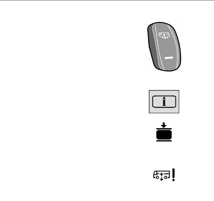
Level Control
The ground clearance of the bus can be
adjusted with this switch.
•
to lower the bus press the lower part of
the switch, e.g. while passing under a
low bridge.
•
to raise the bus press the upper part of
the switch, e.g. while driving onto a
ferry.
Note: Levelling control should only be used
temporarily. During normal driving the
switch must be in the middle position.
When the bus reaches the selected level a
symbol and INFO lamp are shown on the
display panel.
The suspension system attempts to keep the
bus at the required height irrespective of the
load. Any faults in the system are indicated
by a symbol and INFO lamp on the display
panel.
Note: The speed of the bus must not exceed
30 km/h (20 mph) in the high position or 5
km/h (3 mph) in the low position. If this
happens a warning message and warning
signal are sent.
T0012058
T3014366
T0012224
Low pressure in the air suspension
system
T0012467
Fault in the air suspension system
Instruments and Controls 27
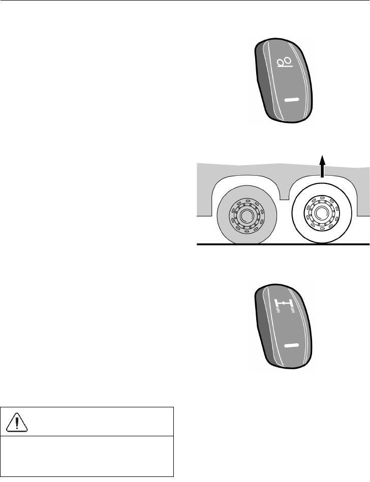
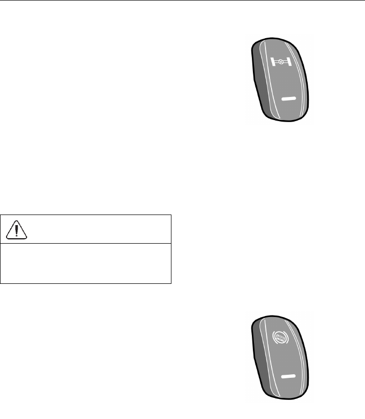
Increasing Load on the Driving Axle (trailing axle lift)
The drive axle load is increased by pressing
this switch. Increase in drive axle load is
often an advantage when moving on slippery
surfaces.
Pressing this switch increases the load on
the driving axle by removing the suspension
load on the trailing (non-driving) axle.
The unweighting continues until one of
the following takes place:
•
speed of the bus rises above 30 km/h
(20 mph)
•
the switch is pressed again
T0012046
T6009559
Traction Control System (TCS)
The TCS system automatically reduces the
driving torque of the engine if the drive
wheels start to spin.
At speeds below 40 km/h (25 mph) the TCS
system also acts as an automatic differential
brake, braking the driving wheel that begins
to spin.
For more information, see separate driver
instructions “EBS”.
CAUTION
Turn off the TCS before towing. Failure
to do so may result in damage to the
system components.
T0012059
28 Instruments and Controls
Differential Lock
Differential lock allows drive axle shafts
to be connected together. The wheels then
rotate at the same speed, which makes
driving on slippery surfaces easier.
The differential lock is only to be used on
slippery surfaces. Engage as soon as the bus
is on the slippery surface. It can be coupled
in during driving, at any speed, but will not
actually engage until the bus is travelling at
less than 15 km/h (10 mph).
Do not forget to disengage the differential
lock when you have left the slippery surface!
For more information, see separate driver
instructions “EBS”.
CAUTION
The differential lock is only to be used on
slippery surfaces. Other uses may result
in damage to the drive axle.
T0012041
3 stage switch for the
manual/automatic coupling of the
differential lock.
Hill Start Assistance
This function helps the driver to pull away
on inclines by holding the bus still until the
required torque at the wheels is applied.
This function’s mode of operation depends
on whether the bus is equipped with
a manual or automatic transmission.
Additional information, see separate
Operating Instruction “EBS”.
T0012045
Instruments and Controls 29
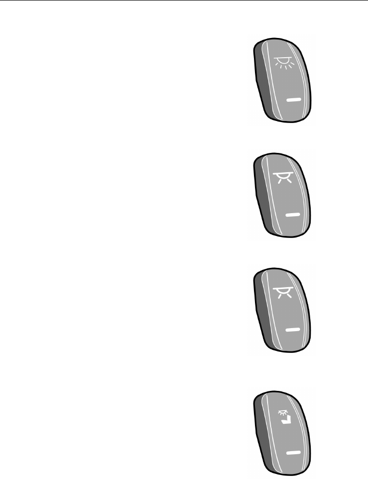
Passenger Compartment Lighting
This switch turns on the passenger
compartment lighting as follows:
Press one time— half of the lamps lights up.
Press two times-all the passenger
compartment lighting lights up.
Press and hold by 3 seconds — to turn off
passenger compartment lighting.
T1008556
Night Lighting
This switch has two positions, on and off.
Activation of the night lighting turns on the
lamps illuminating the gangway, which are
located under the seats.
When the night lighting is on, the passenger
compartment lighting level is dimmed to
30% regardless of the positions of the other
switches.
T1008549
Half-light
Switches on small blue lights.
Press once — to turn on only the blue lights
in the passenger compartment.
Press twice — to turn on the blue lights in
the driver’s compartment.
Press three times — to turn on all the blue
lights.
Press and hold for 3 seconds — to turn off
all the blue lights.
T1008549
Driver Compartment Lighting
This switch has three positions as follows:
Position I — or bottom position, all lighting
is off.
Position II — or middle position, the lighting
is off if the door is close, but the lighting is
on if the door is open.
Position III — or top position, the lighting
turns on without any restriction.
T1008557
30 Instruments and Controls
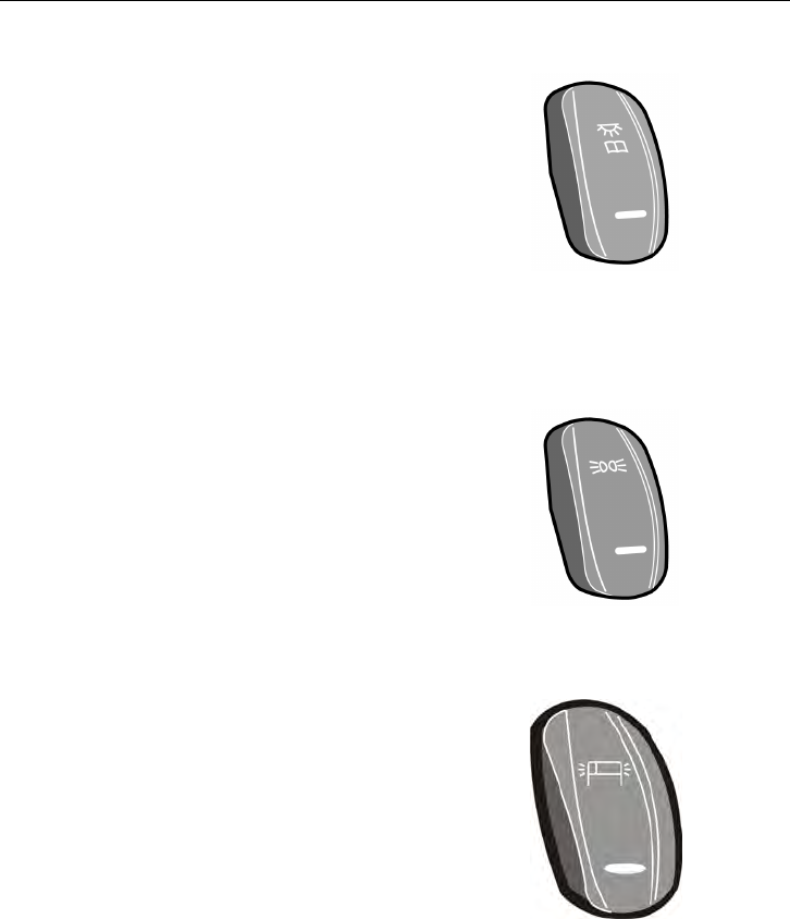
Passengers’ Individual Lighting
Enabling/disabling of the passengers’
individual lightning. Lamps are located in
the panels above the passenger seats. See
“Passengers’ panel” page 52.
Position I - or bottom position all lamps are
turned on, which is useful for example when
checking whether all bulbs are OK
Position II - or middle position all lamps are
turned off.
Position III — or top position every
passenger can individually turn on the
lighting with the push-button on the panel.
T1008548
Rear Door Lighting
When this button is activated, the entrance
lighting of the rear door switches on when
it is open.
In some buses there is a double-position
control. It operates as follows:
Position I — the light switches on when the
door is open.
Position II — the lighting switches on when
reverse gear is selected.
T3019957
Position Lights
This switches allows to make signs with
position lights
If the position lights are off, press and hold
the switch to turn on the position lights.
If the positions lights are on, press and hold
the switch to turn off the position lights.
Press and depress and so on for position
lights blinking
T0015279
Lighting Strip
9700 DOT bus is equipped with a lighting
strip mounted along the luggage racks.
These stripes lights 100% on when the main
switch is turned on, but when the parking
brake is released, the stripes lights 50%.
Instruments and Controls 31
Destination Sign Lighting
This switch has three positions as follows:
Position I — or bottom position, destination
sign lighting is off.
Position II — or middle position, destination
sign lighting turns on when parking lights
are on.
Position III — or top position, lighting turns
on when the ignition switch is in position II.
T1008545
Electrically Heated Rear Mirrors
Pressing the button switches on the heating
for 8 minutes.
In buses for the Scandinavian market, this
button operates as follows: One brief press
of the button (less than 1 second) switches
on the heating for 8 minutes. Pressing for
longer than 1 second switches on the heating
permanently until the button is pressed again.
Heating can be used to remove water droplets
and ice from the mirror glass. Make sure the
mirrors are free of mist or ice when driving.
Note: On some buses this switch, besides
heating the rear-view mirrors, also switches
on heating of the driver’s window and front
door window.
T1008551
Driver’s Window Heating
Pressing the button switches on the heating
for 8 minutes. Pressing the button again
switches off the heating.
T1008580
32 Instruments and Controls
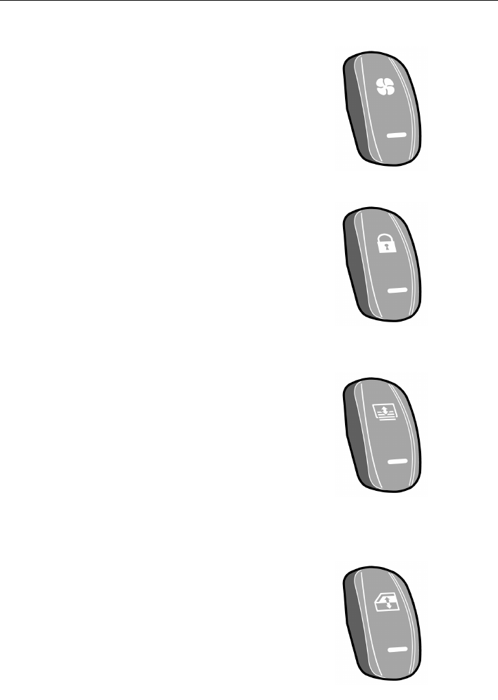
Driver’s Blower
Switch for the driver’s blower.
It turns on/off two small fans located on the
top of the driver’s and guide’s places. Push
the switch to turn on both fans and push
again to turn off.
T1008550
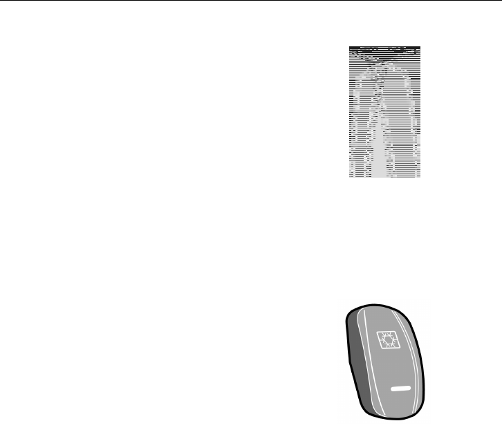
Central Locking
This switch locks/unlocks all luggage
compartment hatches.
Additionally this switch turns on the luggage
compartment lights (Luggage compartment
lighting turns off after 10 minutes of luggage
hatches stills opened).
T1008543
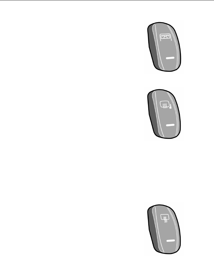
Sun Blind
This switch facilitates lowering and raising
of the front sun blind as follows:
•
Lowering — Press at the bottom to
low the sun blind, depress to stop the
movement.
•
Raising — Press at the top to raise
the sun blind, depress to stop the
movement.
T3018180
Driver’s Window
This switch facilitates lowering and raising
of the driver’s window.
T3018172
Instruments and Controls 33
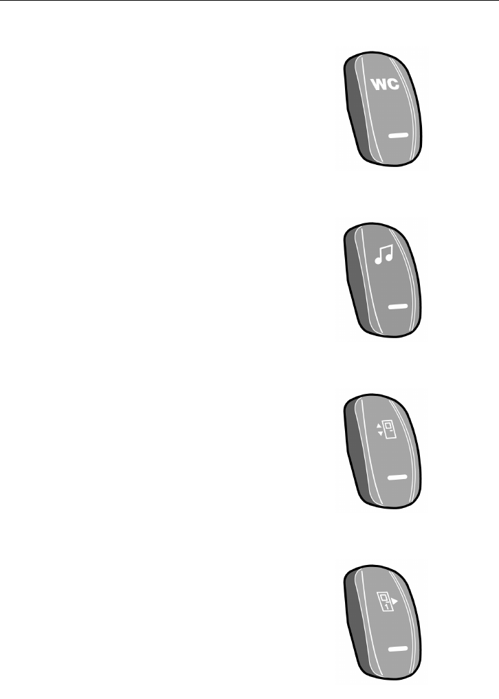
Activation of the Toilet
Activates the power for the toilet and
disengages the lock.
T3018183
Audio System
Once the control is activated, the audio and
video system is enable.
T0015523
Opening the Doors from the Outside
Allows for the opening of the doors using
the external push-button.
Note: Always press this button on leaving
the bus.
T1008555
Middle Door
Allows for the opening of the middle door
for the wheel chair.
T3018176
34 Instruments and Controls
Emergency Window in use Indicator Lamp
This lamp lights up to indicate that one of
the emergency windows has been opened.
T0015524
Switches in the Electrical Center
The Volvo 9700 bus is equipped with
additional push button switches in the
electrical distribution box.
Air Conditioning Test.
Using this switch the driver can check if the
air condition is working.
T3018175
Instruments and Controls 35
Controls
Starting Switch
The ignition switch has four positions:
0 Stop position.
I Intermediate position. In this position
certain electrical devices can be used
according to customer requirements.
II Drive position. Between positions II
and III there is a spring-return position
for preheating.
III Start position. Spring-return.
Note: Removing the key from the starting
switch activates the steering lock.
Note: The key can only be removed from the
starting switch when it is in the stop position.
Note: Do not remove the key from the
starting switch while driving or when the bus
is being towed!
Note: Always remove the key from the
starting switch when leaving the bus.
T0014333
Adjusting External Rear-view Mirrors
Both rear-view mirrors are adjusted using
the same switch. The switch can be turned
to one of the two positions (adjustment of
the right or left mirror). The arrow shows
which of the mirrors has been selected. The
selected mirror is adjusted by moving the
switch in the appropriate direction.
Note: Rear-view mirrors should be adjusted
before starting to drive.
T0014718

36 Instruments and Controls
Door Brake
The door brake can be activated in various
ways, depending on its design and customer
requirements. The door brake is activated
at speeds below 5 km/h (3 mph) if any of
the/specified doors are opened. In the event
that the door brake is activated, its indicator
light comes on the instrument panel.
Note: The door brake does not engage if the
brake system registers poor traction when the
bus is stopping on a slippery surface. This
prevents the bus skidding when stopping on
a slippery surface.
Door Brake Deactivation
1 The accelerator must not be active (fully
release the accelerator)
2 Doors/The specified door(s) must be
completely closed.
3 The accelerator must be activated again
(depress the accelerator again)
In the event that, due to the bus stopping
on a slippery surface, the brake system
has not activated the door brake, you must
brake again (in a place where no slippery
surface is detected) to enable this brake to
be reactivated.
Instruments and Controls 37
General Door Brake Deactivation
Depending on the design, the electrical
distribution box may also be equipped
with a disabling switch (bypass switch).
This switch deactivates the door brake
independently of the other functions.
Note: This switch should only be used in the
event that the bus cannot be transferred in
the normal manner. The door brake should
normally be always on, i.e. the bus must not
be able to move until the doors are closed.
T1008554
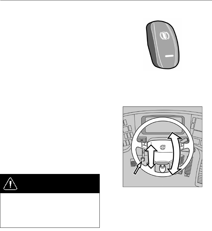
Steering Wheel Adjustment
Both the steering wheel height and its tilt
allow of continuous adjustment.
Adjust the steering wheel as follows:
•
depress the pedal to which the arrow
points
•
Setting the steering wheel
•
after releasing the pedal the steering
wheel is locked in its new position.
DANGER
Steering wheel adjustments should only
be performed while the bus is stationary.
Adjustments with the vehicle is moving
may lead to an accident, resulting in
serious personal injury or death.
T6010216
38 Instruments and Controls
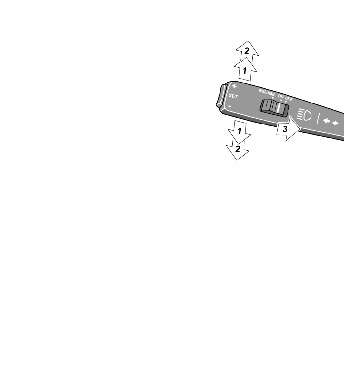
Direction Indicator, Dipped/full Beam Changer
1 Location of point of resistance.
When making manoeuvres requiring
only slight movements of the steering
wheel (changing lanes, overtaking),
move the stalk up or down and hold
it there. After releasing the stalk, it
will immediately return to its neutral
position.
2 Move the stalk beyond the pressure
point.
The direction indicators will continue to
flash until the stalk is manually moved
back to the neutral position, or the
steering wheel is returned to the straight
ahead position after the turn.
3 Main beam “flash”.
Pull the stalk towards the steering wheel
(until you feel slight resistance).
The main beam will stay lit until the
stalk is released.
Main/dipped beam switching (lights
on).
Pull the stalk towards the steering wheel
beyond the “flashing point” and release
it. Each time you do this, the headlamps
will toggle between main and dipped
beam.
In addition, engine idling speed can be
controlled with this stalk. See: “Low Idle
Adjustment” page 68
T0012077
Instruments and Controls 39
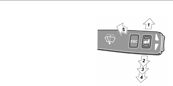
Windscreen Wipers, Windscreen/headlight Washer
Note: This stalk also provides control of
the display, for additional information about
display control, see the separate Operation
Instruction “Display”.
1 Interval wiping
Used when driving in mist or drizzle
conditions.
The wipers make one sweep every 10
seconds. To reduce the time between
sweeps, move the stalk to the normal
position, and then, after the desired time
interval, back to the interval wiping
position. This permits the wiping
interval to be set to any value between
1 and 10 seconds.
2 Flick wipe position.
If you want the wiper to make only
one or two strokes (e.g. drizzle), move
the lever to the flick wipe position and
keep it there with your finger. The
wipers will stop in parking position
after releasing the lever.
3 Windscreen wipers, normal speed.
4 Windscreen wipers, high speed.
5 Windscreen washers + headlight
washers.
Moving the stalk to this position will
also activate the windscreen wipers,
which will make an additional 2-3
sweeps after the stalk has been released.
The headlight washers and windscreen
washers have a common fluid reservoir.
T0012079
40 Instruments and Controls
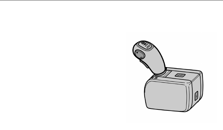
Transmission
Transmission, I-shift
The bus may be fitted with an I-shift
automatic transmission.
Both clutch operation and gear shifts are
performed fully automatically. If necessary
the gears can be changed manually.
By pressing the FOLD button and tilting the
lever downwards to the position where the
lever is on a level with the seat, extra room
may be created for the driver.
For more information, see separate driver
instructions “I-shift”.
T4021276
Instruments and Controls 41
Retarder
The transmission has an integrated retarder,
which helps to brake the bus reducing
the load on the brakes as a result. It
is automatically engaged by the initial
movement of the foot brake pedal, even
before the wheel brakes are engaged.
Note: The retarder brakes only the driving
wheels. If the bus is fitted with the
Anti-Lock Brake system (ABS), the retarder
is automatically disengaged on any signs of
the wheels locking. When the retarder is
active, its symbol is shown on the display.
The retarder can be disabled by pressing its
switch on the dashboard.
Note: Under normal driving conditions, the
retarder should not be disabled.
DANGER
Avoid using the retarder on slippery roads
because of the risk of locking the wheels
and skidding (the retarder brakes only the
driving wheels). Failure to do so may
lead to an accident, resulting in serious
personal injury or death.
T0009004
T3018117
T1008547
42 Instruments and Controls
Retarder Overheating
If the retarder remains engaged for a long
time (e.g. during a long downhill stretch) it
may overheat, causing an increase in retarder
oil temperature.
The first indication of retarder overheating
is the white “INFO” lamp lighting and the
temperature symbol showing up on the
display. If this happens, select a lower gear
and make greater use of the main brakes.
If the temperature continues to rise, the red
“STOP” lamp will light and there will be an
increase in the temperature accompanying
the symbol on the display. Stop the bus as
soon as possible and select neutral, i.e. N. To
increase the circulation of the coolant run the
engine at higher idle until the temperature
returns to the normal level.
CAUTION
Do not switch off the engine before the
temperature is back to normal. Failure to
do so may result in component damage.
T3014366
T3008844
T3014364
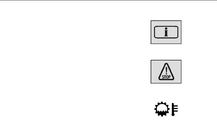
Instruments and Controls 43
Transmission Overheating
If the transmission overheats, the white
“INFO” lamp will light and the display will
show a red symbol.
If the temperature rises further, the red
“STOP” lamp will light. Slow down and stop
the bus as soon as it is safe to do so. Contact
Service for advice.
T3014366
T3014364
T0008817
44 Instruments and Controls
Brakes
Parking Brake
The parking brake acts on the drive wheels.
When the hand control is in the forward
position with the compressed air system
charged and the blocking valve depressed,
the parking brake is released.
When the parking brake hand control is
moved backwards, the parking brake is
gradually applied. It is fully applied when
the hand control is in its backmost, locked
position.
To release the parking brake hand control
from the locked position, lift the ring
upwards and move the lever forwards.
DANGER
Never leave the bus without engaging
the parking brake. Failure to do so will
prevent the bus from staying stationary
leading to an accident that may result in
seriously personal injury or death.
DANGER
If the warning lamp lights while driving,
stop the bus immediately. Failure to due
so may result in serious personal injury
or death.
DANGER
Never start driving while the brake system
warning lamp is still lit. Failure to due
so may result in serious personal injury
or death.
T5014881
Instruments and Controls 45
Emergency Brake
To use the parking brake as an emergency
brake, move the lever gradually backwards to
the parking position. Keep the catch pulled
in all the time, or the control will fasten in
the locked position.
Note: The parking brake is only to be used
for parking or as an emergency brake in case
of malfunction of the foot brake system. The
parking brake only brakes the drive wheels,
the braking distance will be longer than
when using the foot brake. There is also an
increased risk of skidding because only the
drive wheels are used for braking.
T5014881
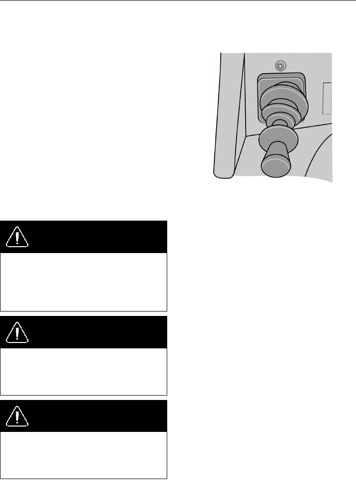
Blocking Valve
If the brake system at any point in time
is emptied of air, for example by the bus
standing parked for a longer time period, the
parking brake cannot be released.
To release the parking brake you must first
start the engine and wait until the brake
system warning light has gone out. Then
press the locking valve.
Even if the hand lever for the parking brake
has been moved to the forward position, the
brake will not be released until the blocking
valve has been pressed in.
T0015484
46 Instruments and Controls
Service Brakes
The bus is equipped with an EBS brake
system (Electronically-controlled Braking
System). This system monitors and controls
brake operation. For additional information
concerning the EBS system, refer to the
separate Operating Instruction “EBS”.
If the main brakes are used without care
when driving down steep and long inclines,
they will heat up very quickly to extreme
temperatures. The low speed that is generally
the rule in such cases means that the brakes
are not cooled as efficiently as when driving
on level roads.
When driving downhill, in the first instance
use the retarder brake, and only supplement
this with the main brakes as necessary. For
additional information about the retarder, see
“Retarder” page 70.
If you have to use the footbrake while
driving downhill, do not pump the brakes,
as this will only use up compressed air.
Brake sufficiently hard, and then release the
brake pedal completely, or just to the pedal
position where only the retarder is engaged.
Heat builds up very quickly in the brakes,
causing increased wear of the brake linings
and reduced brake efficiency.
This system has a reserve pneumatic system.
The main purpose of the EBS system is to
increase road traffic safety by shortening
braking distances.
T0009004
Dark zone — only retarder
Light zone — retarder and foot
brake
T0009682
T3008834
Instruments and Controls 47
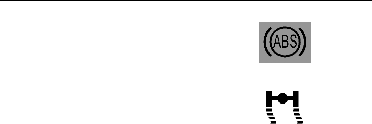
EBS controls the ABS and ASR braking
forces. It is fitted only on buses with disc
brakes. ABS is a part of the EBS system
and works completely automatically. The
ABS (Anti-lock Brake System) prevents the
wheels from locking up during braking. In
case of ABS failure, the appropriate symbol
appears on the instrument panel.
Note: ABS efficiency is limited. Remember,
that on slippery surfaces ABS will not
shorten the braking distance significantly. It
can nevertheless help in avoiding obstacles
during braking.
T0009682
T3008834
48 Instruments and Controls
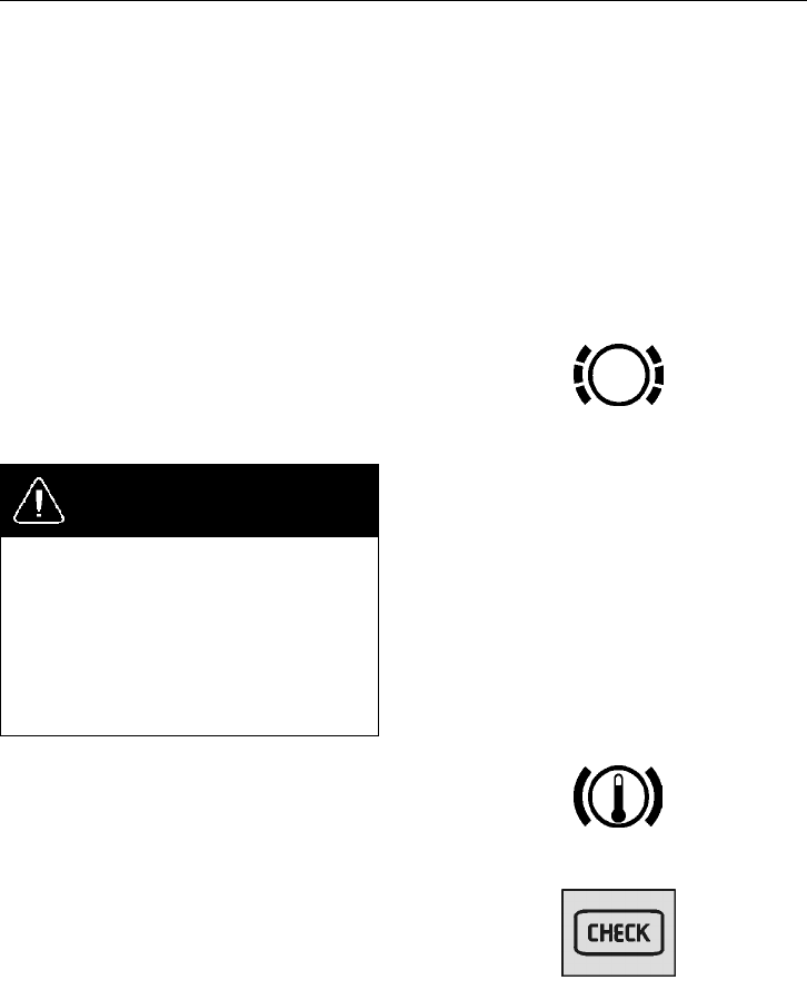
Compensating for Differences in the Wear of the Brake Pads
If the brake pads on one of the axles wear
down faster than those on the other, braking
force is redistributed so that a greater portion
of the braking force is applied to the wheels
on the axle with less wear.
Note: This function activates when braking
lightly. During hard braking the braking
force is distributed so as to achieve the most
efficient braking.
When the thickness of the brake pads is
reduced to 20% of the thickness of new pads,
a warning symbol is shown on the display.
T5013668
DANGER
When brake pad warning symbol is
displayed, immediately proceed to the
nearest service station to replace the brake
pads with new ones. Driving any further
with worn out brake pads may lead to
losing control of the vehicle and cause
an accident resulting in serious personal
injury or death.
Brake temperature High Warning
If the temperature of the brakes increases too
much, the “CHECK” lamp lights, and the
relevant symbol is shown on the display.
Note: If the temperature is allowed to rise
further, maintaining the same braking force
will require increased pressure on the brake
pedal.
T5013670
T3014365
Instruments and Controls 49
Destination sign control
The Volvo 9700 bus is equipped with a high
definition destination sign.
Use instructions:
•
Destination text: Press the select button
up to the D letter appears in the display.
Insert the destination text code using
the buttons of units, tens and hundreds
(for example D001)
•
Extra text: Press the select button up
to the E letter appears into the display.
Insert the extra text code using the
buttons of units, tens and hundreds (for
example E002).
•
Departure time: Insert the time into
the display in E (Normally E001 is
reserved).
Press the button up to the S letter
appears, adjust the hour with button H
and minutes with button M.
Destination sign will be updated 4 seconds
after.
For more information see separated
instructions “Destination sign”.
T0015271
A/C Controller
The Volvo 9700 bus is equipped with an AC
controller to maintain a constant temperature
inside the bus.
For more detailed information, see separate
instructions “AC controller”
T0015295
50 Interior Equipment
Interior Equipment
T0015326
To enhance travel comfort, the bus may be
fitted with additional interior equipment
such as:
1 Toilet
2 Monitors
Interior Equipment 51
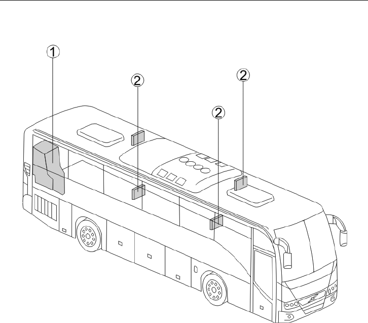
Toilet
The bus is equipped with a toilet, located
on the right-hand side at the rear of the
vehicle. Pressing a switch on the dashboard
enables the toilet to be used, by releasing
its central lock and switching on the toilet
power supply.
While the toilet is occupied (after locking
the door) a sign lights up in the passenger
compartment.
In the toilet compartment there is an
emergency push-button with backlight. After
it has been pressed, the toilet indicator lamp
flashes on the dashboard.
For additional information and instructions
regarding the servicing and maintenance
of the toilet, see the separate Operating
Instructions “Shades toilet”.
T3018183
T0015272
52 Interior Equipment
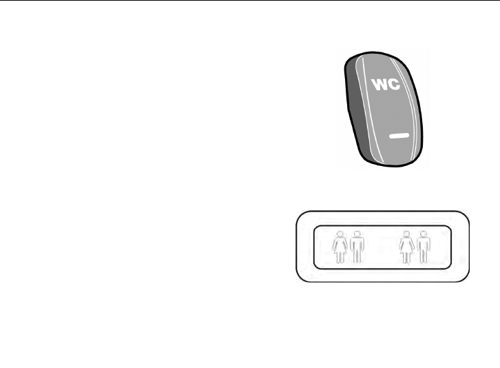
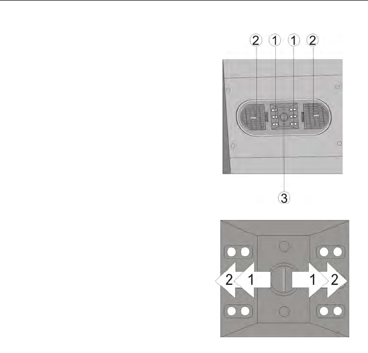
Passengers’ panel
Above every pair of passenger seats there is
a passenger panel. On each panel there is:
1 Reading lights
2 Passenger’s blowers
3 Half light led
T0015273
Push-button:
1 Right reading light (to turn on push the
button to the right, pushing again the
light turns off)
2 Left reading lights (to turn on push
button to the left, pushing again the
light turns off)
T0015296

Audiovisual System 53
Audiovisual System
T0015327
To enhance the comfort of the passengers
during journeys, the Volvo 9700 bus is
equipped with an audiovisual system, whose
main components are:
1 Loudspeakers in the luggage racks
2 CD, DVD player
3 Driver’s loudspeakers
4 LCD monitors

54 Audiovisual System
Audiovisual Controller
The Volvo 9700 could be equipped with
main unit, giving the driver complete control
of the system. See separate Operating
Instruction: “Blaupunkt Sound & Vision ”.
T0015281
Video System
There are four LCD monitors in the bus.
They are activated by selecting the VIDEO
signal source on the audiovisual controller.
See separate Operating Instruction.
“Blaupunkt Sound & Vision”.
Audio System
The main elements of the audio system are:
•
radio with the tape or CD player
•
CD changer
•
loudspeakers
Emergency and Safety Equipment 55
Overview
As the driver you must always be familiar
with the location of the emergency equipment
in the bus, and how to use it.
It is essential that all emergency equipment
is checked on a regular basis to make sure
that it is in working condition and in place.
The location of the safety equipment and its
scope can vary, depending on the regulations
in the country in question. Therefore make
sure that you know where the equipment is
and check that nothing is missing.
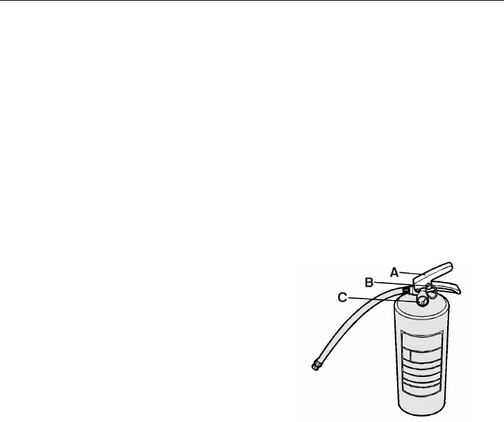
Fire Extinguisher
The fire extinguisher is located in the front
of the bus (most often mounted under
dashboard on the right-hand side).
The fire extinguisher can be used to put out
fires in volatile fluids, wood, fabric, paper
and electrical equipment. Check regularly
that the pressure gauge indicator is in the
green zone.
How to use the fire extinguisher:
1 Remove the fire extinguisher from its
holder.
2 Hold the extinguisher by its handle with
one hand, and pull the safety pin with
the other.
3 Point the rubber hose at the heart of the
fire and press the trigger.
T0008196
A Trigger
B Safety pin
C Pressure gauge
56 Emergency and Safety Equipment
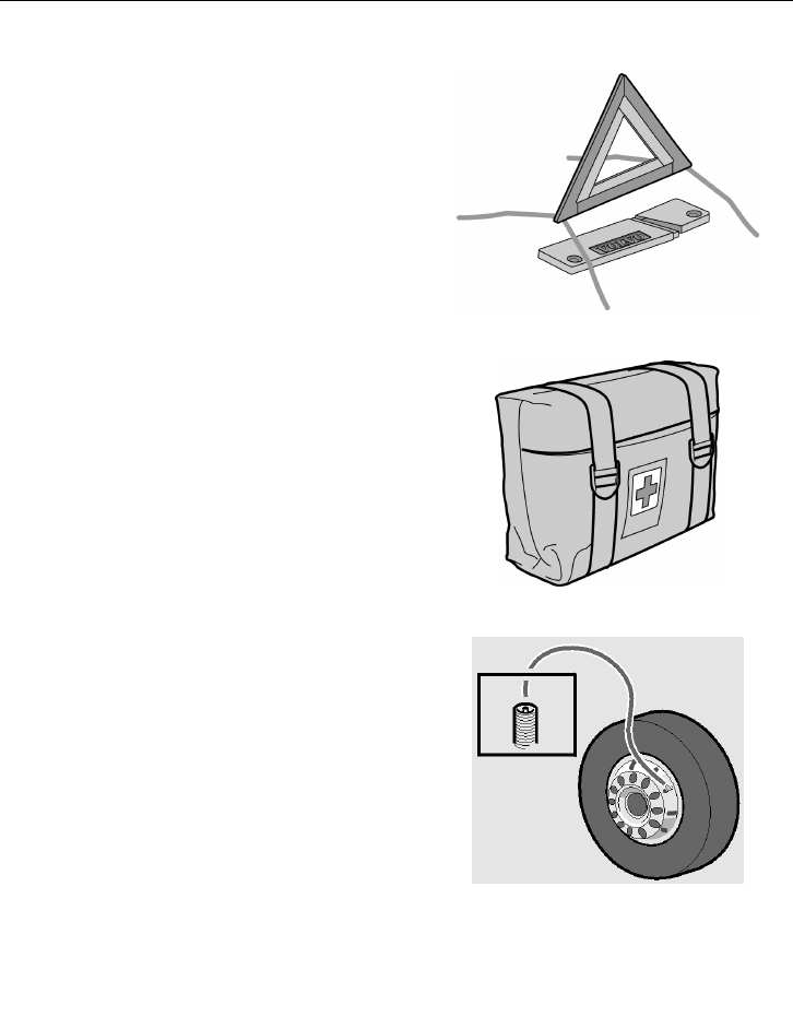
Warning Triangle
The warning triangle is located either in the
toolbox, or in a holder to the right of the
driver.
The warning triangle is used whenever a
fault forces the bus to stop in a hazardous
location. Switch on the hazard warning
lights and place the warning triangle at a
distance stipulated by the traffic regulations
of the country in question.
T8011683
First-aid Cushion
The first aid kit contains basic first aid
materials.
For location of the first aid kit: see the
markings inside the bus.
T1008716
Tire Inflation Valve
Tyre inflation valve may be used to:
•
inflate a tire using the bus pneumatic
system
•
release the parking brake with air from
a tire
Its main use is to release the parking brake
in a situation when the bus cannot supply its
own air, e.g. engine breakdown.
The bus toolbox contains a hose that connects
between the tire and the tire inflation valve.
The tire inflation valve is located next to the
driver’s seat or inside the first service hatch.
T0009182
Emergency and Safety Equipment 57
External Air Supply Connection
Behind the first service hatch or in the
driver’s panel beneath the window there is a
valve to which an external air supply can be
connected. This is used when parking the
bus overnight, to prevent emptying of the air
system.
T0015390
Jack
The bus is fitted with special jacking points
to comply with safety regulations. For
detailed information concerning the use
of the jack and changing wheels, see the
separate Operating Instruction “Jacking
points and puncture”
DANGER
Always ensure that the bus is standing on
a level surface and chock the wheels so it
cannot move . Failure to do so may result
in serious personal injury or death.
Note: The jack supplied with the bus should
be only be used to lift the bus to change a
wheel.
T0015345

58 Emergency and Safety Equipment
Toolbox
The toolbox and tools can be purchased
from your local dealer. A complete toolbox
contains:
Toolbox
Jack (2 units) 3124497
Adaptor for the jack 3178753
Wheel wrench 9521826
Towing kit 205465449
Hammer
962207
Pumping hose 942868
Warning triangle 3176488
Key for the hatches 70319047
Female key 70344906
Male key 70344905
Pliers 962042
Adjustable spanner 755
Screwdriver with bits 978201
Spare wheel wrench 1062412
Winch handle 1590997
Extension for pumping valve 1621456
Socket wrench 19/24 mm 8189085
Jack extension 1586079
Jack extension 1577686
Wheel wrench extension 20592217
Tool bag 1577384
Wheel chocks (2 off) 8158698
Emergency and Safety Equipment 59
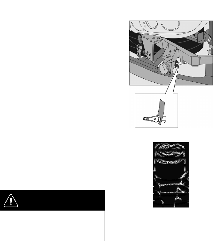
Engine Control Box in Engine Bay
The engine control box is located behind the
engine hatch in the back of the bus. It is used
only in conjunction with servicing.
WARNING
When working in the engine bay, the
switch (1) must be in position 0.
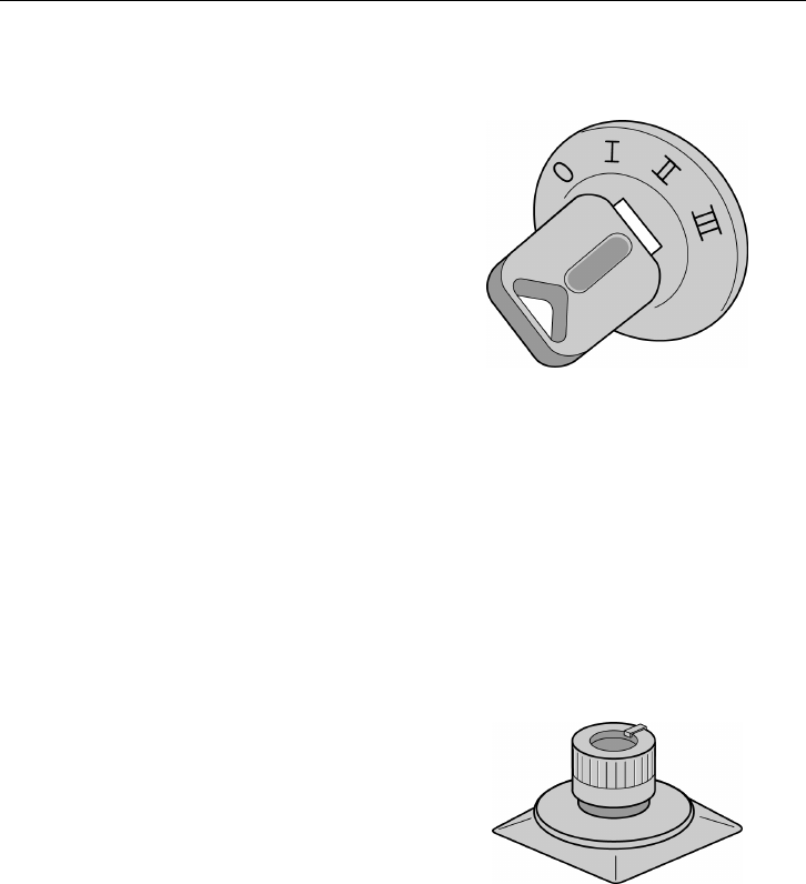
The control box has three controls:
1 Start enable switch
When the switch is turned to position
1, the engine can be started from either
the start button on the control box,
or the key ignition on the dashboard.
When the switch is turned to position 0,
the engine cannot be started from the
engine bay, nor from the dashboard.
2 Start button
When switch (1) is turned to position 1,
pressing this button starts the engine.
To allow the engine to be started from
the control box in the engine bay,
the transmission must be in neutral
position (N), and the ignition key in the
“DRIVE” position.
3 Emergency stop button
To stop the engine press the red button.
T2023998
60 Emergency and Safety Equipment
Emergency Exits
Doors
There is a valve for emergency door opening
above the door. Turning the knob cuts off the
compressed air supply to the door.
After turning the valve knob and hence
cutting off the compressed air supply to the
door, a warning lamp lights up and a buzzer
sounds. To return the compressed air system
to its normal state, turn the knob back to
its initial position and press the appropriate
door button on the dashboard.
T8009617
Windows
There are windows to be used as exit in case
of emergency. These windows can be opened
easily with a mechanism. These windows
have stickers with the text “Emergency exit”.
Note: To exit the bus:
1.- Pull the red bar located at the bottom of
the each emergency window
2.- Push and hold the window with both
hands
3.- Leave carefully
T0015286

Emergency and Safety Equipment 61
Ceiling, Roof Hatches
To open the roof hatch in case of emergency,
pull the hatch release handle and push the
hatch upwards.
T8010110
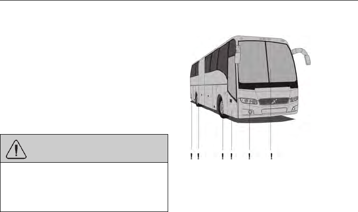
62 Starting and Driving
Checking Before Driving
Before starting the bus and driving off,
check the sensitive edges on the doors. If
the door leaf during opening encounters an
obstacle, the door should stop. If the door
leaf encounters an obstacle during closing,
the door should open again. It should not be
possible to open the doors by hand while the
engine is running.
WARNING
Make sure that the sensitive edges on the
door work prior to vehicle use. Failure
to do so may lead to personal injury of
passengers.
Make sure that:
•
all hatches are closed
•
all the lighting is working properly
•
the windscreen wipers/washers are
working properly
•
safety equipment is in place
•
the direction indicators and horn are
working properly
•
the air pressure in the tires is in order
(using a hammer) and nothing has got
stuck between the back twin wheels.
•
destination information and line number
are correct
•
the emergency opening system for the
doors is working properly.
T0015270
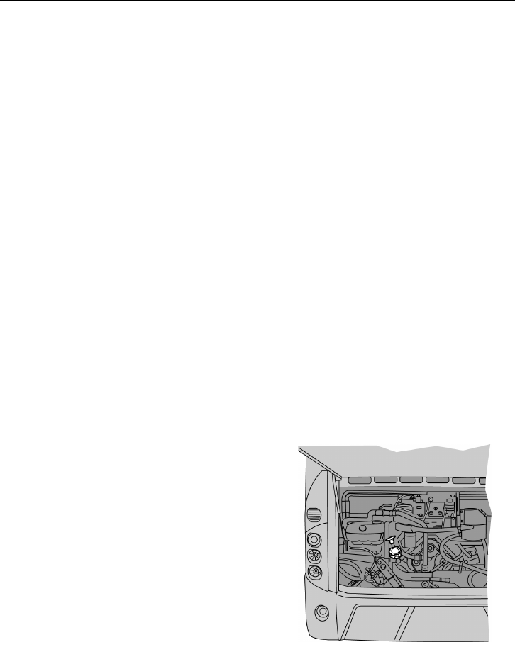
Starting and Driving 63
Checking Warning Lights
When the key is in position I, the control
system checks that all the warning lamps are
working properly.
All the warning lamps and the warning LEDs
in the meters are lit for about 5 seconds.
ABS/The ABS system indicator lamp will
light up for slightly longer than the others.
If it continues to be lit then a fault has been
detected in the ABS system./EBS system
discovered
Daily Inspection
Engine oil level, as well as the servofluid and
coolant levels in the bus should be checked
on a daily basis. The checks are carried out
with the engine warm, but switched off.
Note: It is a good idea to do these checks
after a tour as the engine is then at normal
operating temperature.
All tanks are located in the back of the bus.
Engine
When checking the oil level:
•
position the bus on level ground.
•
if the engine is cold, let it idle for 1-2
minutes
•
turn the engine off. Wait at least 2
minutes before carrying out the check
•
remove the dipstick and wipe it with a
clean cloth
•
check the oil level with the dipstick.
The oil level should be between MAX
and MIN
•
top up if necessary.
T2024562
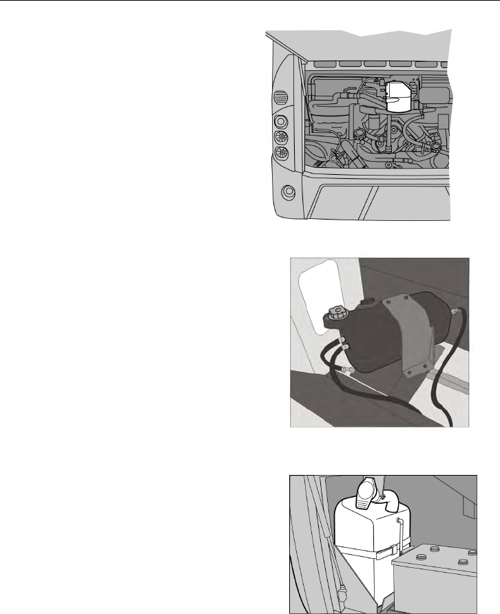
64 Starting and Driving
Steering Servo/hydraulic Fan
Check that the oil level is between the MAX
and MIN markings on the reservoir (B). Top
up if necessary.
T0015486
Coolant
Check that the coolant level is between the
MAX and MIN markings on the reservoir
(A). Top up if necessary.
The reservoir is located over the radiator
hatch on the rear left side of the bus.
T0015269
Washer Fluid
Check the level of the washer fluid in the
reservoir. Top up if necessary.
Note: In winter use appropriate fluid with
lower freezing temperature.
T2024567
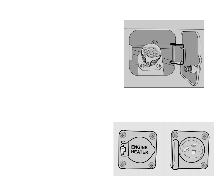
Starting and Driving 65
Refuelling
Open the flap and the fuel filler cover. Insert
the end of the fuel hose into the filler neck.
Fill up the tank. After filling up the tank,
remove the fuel pipe and put it back on the
pump. Close the fuel filler cover and the flap.
Volvo 9700 buses have two tanks with 400
liter (105 gallons) capacity each one.
To open the filler cap press it hard with the
whole palm until its catch releases.
Note: Use only fuel that meets the
manufacturer’s specifications. Avoid spilling
fuel on to painted surfaces. Refuel only at
designated places.
T2022265
Engine Block Heater
An electric engine block heater can be
installed for keeping the coolant hot when
the vehicle is parked. The heater is mounted
through the side of the engine block with the
heater coils in the coolant jacket. The heater
does not interfere with normal operation and
can be permanently installed.
The heater runs on 120V and has an easily
accessible plug, located on the right side of
the engine compartment. The plug will hook
up to a normal extension cable.
T0015492
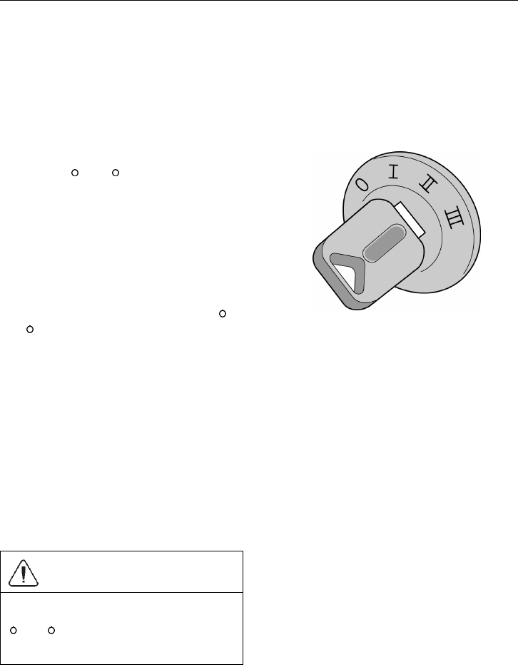
66 Starting and Driving
Starting the Engine
Starting
When starting the engine, the parking brake
must be engaged and the gear selector must
be in neutral, i.e. N.
Starting a Cold Engine
When starting the engine at temperatures
of around 10
C (50 F) and below, the air
entering the engine should be heated. To
prevent wear and possible damage to the
engine when it is cold, gradually bring it up
to operating temperature before operating
at high engine speeds or full load. After
starting and before moving the vehicle run
the engine at 800 to 1000 rpm for 3 to 5
minutes. Operate at partial engine load
until the coolant temperature reaches 75
C
(167
F).
Proceed as follows:
Turn the ignition key to the position between
II and III. This starts the preheating, which
can take up to about 50 seconds, depending
on the temperature of the coolant. The
indicator lamp is lit during preheating. Once
the lamp has extinguished and the needle
of the temperature gauge has moved off its
lower stop, the engine can be started.
Do not race the engine when it is cold. This
could damage the engine.
CAUTION
Do not let a cold engine run faster than
1000 rpm in very low temperatures (< -20
C (-4 F)). Failure to do so may cause
internal engine damage.
T0014333

Starting and Driving 67
Starting a Hot Engine
Start directly by turning the key to the start
position.
Stopping the Engine
To shut down the engine, turn the key to the
STOP position. In an emergency situation
the engine can be shut down by using the
emergency stop, see “Emergency Stop” page
24.
Note: Before turning off engine. If the
engine has run at high temperature for a
significant time before it is shut down, let the
engine run at idle for 3 minutes to cool the
engine off to avoid heat soak.
Checks After the Engine Has Been Started.
The coolant level warning lamp will stay lit
for a few seconds after the engine has started.
The parking brake warning lamp is lit when
the parking brake is engaged. After releasing
the parking brake, the lamp should remain lit
until the pressure increases to about 540 kPa
(78 psi). The footbrake warning lamp and
the “STOP” lamp should remain lit until the
pressure in the compressed air tanks reach a
sufficiently high level.
DANGER
Do not drive the vehicle until the warning
lamps have gone out, as the brake system
needs the correct air pressure to work
properly. Failure to do so may lead to
an accident, resulting in serious personal
injury or death.
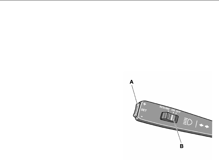
68 Starting and Driving
Idling (programming)
The engine idling speed is 575–625 rpm.
Keeping the idling speed constant is the
task of the electronic control system, which
makes manual adjustment unnecessary.
When the bus is stationary, the idling speed
can be temporarily raised to 1200 rpm.
Low Idle Adjustment
Before you start to adjust the idling speed,
the engine must be warmed up to operating
temperature. The bus must be stationary
with the engine idling.
•
switch (B) must be in the ON position
•
the idling speed is increased by pressing
the “+” side of the SET button (A). Each
press on this button gives an increase
of 10 rpm.
•
if the idling speed becomes too high, it
can be reduced by pressing the “–” side
of the SET button. Each press gives a
decrease of 10 rpm.
Note: The change in idling speed is only
temporary. After pressing a pedal, engaging
a gear or releasing the parking brake, the
idling speed will return to its manufacturer
settings.
If new programming of idling rpm is
required, keep your foot on the brake pedal
and turn off the engine when the new engine
rpm has been set.
Note: If the engine does not “run
smoothly” at the default programmed by the
manufacturer, please visit a Volvo workshop.
T0012078
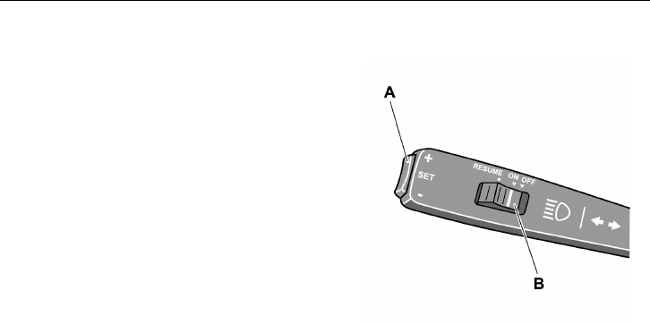
Starting and Driving 69
Cruise Control
Cruise control is activated by moving the
switch (B) to the ON position.
When the bus reached the desired speed,
press the “+” or “–” side of the SET button
(A). The set speed is increased or decreased
by pressing the “+” or “–” side of the switch
respectively.
If the speed is temporarily increased, e.g. for
overtaking, the vehicle will return to the set
speed when the accelerator is released.
Cruise control is deactivated if:
•
the brake pedal is depressed
•
the retarder stalk is moved to another
position
•
the switch (B) is moved to its OFF
position
After cruise control has been switched off,
the most recent set speed can be restored by
moving the switch (B) to RESUME. This
however does not apply if cruise control has
been deactivated by moving switch (B) to its
OFF position.
T0012078
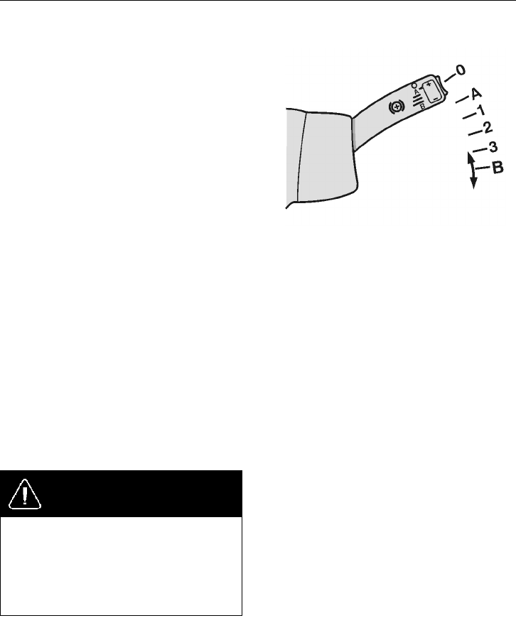
70 Starting and Driving
Retarder
The function of the retarder is to supplement
the main brake, and it acts as an additional
brake. This function may be based on
an engine brake, or a transmission brake
together with the VEB (Volvo Engine
Brake), which is an exhaust brake combined
with a compression brake.
When the retarder stalk is in its (A) position,
depressing the brake pedal will engage both
the footbrake and the auxiliary brake. This
mode is called “brake blending”, and means
that the brake system decides how great a
contribution to the total braking force will
come from the auxiliary brake, and how
much from the footbrake. It allows for
optimal use of the auxiliary brake.
In other situations (1-3) the bus is braked
by the additional brake as soon as the
accelerator pedal is released. The braking
force is increased by moving the lever down
and decreased by moving the lever up.
Note: The retard function works together
with the EBS system. See the separate driver
instructions for “EBS”.
DANGER
Avoid using the retarder on slippery roads
because of the risk of locking the wheels
and skidding (the retarder brakes only the
driving wheels). Failure to do so may
lead to an accident, resulting in serious
personal injury or death.
T0010263
The (B) position of the stalk is only
present in buses fitted with I-shift.
For additional information, see
the separate Operating Instruction
“I-shift”.
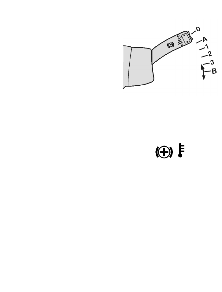
Starting and Driving 71
Speed Limiting
When the bus is driven downhill with the
stalk in position (A), the retarder acts as a
speed limiter. When the bus has reached the
desired speed, lightly press the "+" or "–"
side of the SET button (A). The retarder will
maintain the speed of the bus at the setting it
had when the SET button was pressed.
The set speed can be increased or decreased
by pressing the plus (+) or minus (-) side of
the SET button. Each pressing of the switch
increases or decreases the speed by 1 km/h.
If the switch is held in, the speed is adjusted
by 1 km/h for each second it is held in.
Note: Buses that have a retard switch instead
of a retard lever do not have this function.
T0010263
Use the SET button on the retard
switch to control the speed
limitation.
Combined Cruise Control and Speed Limitation
If the bus is equipped with cruise control
(see “Cruise Control” page 69), the cruise
control system will work together with the
retarder. The stalk of the retarder should be
in position (A).
With cruise control active. While driving
downhill with the cruise control active, the
retarder will be engaged if the road speed
exceeds the set speed by 5 km/h (3 mph).
This overspeed value can be modified by
means of the +/- button to any value in the
range 3–15 km/h (2– 9 mph).
Note: The retarder is automatically
deactivated if there is a risk for wheel
locking.
Note: If the symbol for high retarder
temperature is displayed, a lower gear
range must be selected to cool it down. See
separate Operating Instruction “Display”.
T3008844
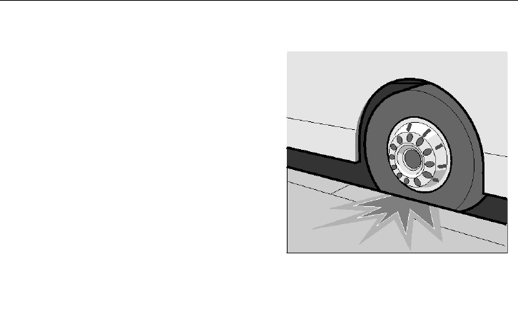
72 Starting and Driving
Power Steering
If the wheel is blocked on one side, against
a kerb for example, drive carefully forward
and turn the steering wheel to allow the bus
to move away from the kerb. Never try to
force the wheels to turn.
Do not attempt to turn the bus by using
excessive force on the steering wheel.
Using excessive force on the steering wheel
increases pressure in the power steering
system, causing risk of overheating that may
damage the oil pump.
If the power steering is malfunctioning it
may feel as if the steering gear was blocked,
this is however not the case, but steering the
bus requires the use of much greater force.
T0008960
Starting and Driving 73
Exhaust Aftertreatment System
Volvo 9700 has an exhaust aftertreatment
system which includes a Diesel Particulate
Filter (DPF). The DPF reduces soot and
particulate emissions into the atmosphere.
The DPF takes the place of the standard
muffler. Soot and other particulate matter
are collected by a filter where it is eventually
oxidized using a regeneration process.
Vehicles equipped with a DPF require the
use of EO-O Premium Plus (or VDS-4)
specification high performance diesel engine
oil and Ultra Low Sulfur Diesel (ULSD) fuel.
If the icon “DPF Regeneration
Required”lights on, means that the
diesel particulate filter is becoming full and
regeneration is needed; the icon flashes
when the filter is full, maintain uninterrupted
highway speed for an automatic regeneration
or move the vehicle to a safe location and
initiated a parked regeneration.
The icon “High Exhaust System
Temperature” lights on when a parked
regeneration is initiated. It also indicates
high exhaust gas temperature during an speed
regeneration. When the high exhaust system
temperature icon is light on, do not park
or operate the vehicle near people, or any
flammable materials, vapors, or structures.
For more information about Exhaust
Aftertreatment System, see separated
instruction “Exhaust Aftertreatment
System”.
Note: It is important to enable regeneration
as soon as possible to avoid engine
problems. Long—term engine operation
with regeneration disabled will result in
a loss of engine performance including
horsepower, torque and speed derates.
T0015360
T0015482
T0015483

74 Some Advice for Driving
Safe Driving
1 After starting, and regularly while
driving, check that the instruments are
giving their normal readings. If any
warning lamp lights while driving, stop
the bus and investigate the cause.
2 Never race a cold engine! Avoid idling
for long periods.
3 Never cover the radiator! The
thermostat keeps the temperature
constant regardless of ambient
conditions. Check the coolant level
regularly and use always the correct
type of coolant. Check also hoses/pipes
and tensioning of the belts. Do not
drive with a leaking cooling or heating
system.
4 Never drive off before the brake system
warning lamps have extinguished.
Do not forget the parking brake.
The ABS/EBS indicator lamps may
light, but this only indicates that the
ABS/EBS system is malfunctioning.
5 If one of the front wheels is blocked
sideways, never try to force it to turn by
applying excessive force to the steering
wheel.
6 While driving downhill and for gradual
braking use the retarder function. When
driving in slippery conditions take
special care, or disable the retarder
function altogether.
7 When driving on slippery surfaces, e.g.
in snow or heavy rain, reduce speed and
avoid rapid steering wheel movements.
Brake and accelerate gently, to make
the journey as safe as possible for
the passengers. Driving in slippery
conditions requires extra caution when
there are strong side winds. Side winds
can produce a lifting force acting on the
front axle.

Some Advice for Driving 75
Economy Driving
As the driver, you are the most important
link in the chain for getting the best overall
driving economy.
1 Warm up the engine as quickly
as possible. A warm engine and
transmission uses less fuel than a cold
one (and there is less wear).
2 Treat the accelerator pedal gently.
Do not “pump” the accelerator pedal.
Pumping increases fuel consumption
without increasing the speed. A
turbo pressure gauge helps you drive
economically.
3 High speeds increase fuel
consumption since, among other
things, air resistance increases sharply
with increase of speed. Strong side and
head winds increase fuel consumption
even more.
4 Timely and correct servicing will
keep the bus in good condition. This
will also contribute to preserving low
fuel consumption.

76 Some Advice for Driving
Driving in Cold Weather
Before driving in cold weather conditions
(ambient temperature +40
F[5 C] or
below), pay attention to the following points:
1 The cooling system must be protected
against freezing.
2 The washer fluid tank must be filled
with winter liquid.
3 Batteries must be in good condition.
In low temperatures, the capacity of
batteries to deliver current, e.g. when
starting the engine, drops. Make
sure that the poles of the batteries
are thoroughly clean, with the cable
terminals properly tightened and
covered with grease, and that there is
the correct amount of electrolyte in
every cell.
4 Engine oil, as well as transmission and
rear axle oil, must have the correct
viscosity.
Fill up the tanks with winter fuel. This
reduces the risk of wax settling in the
fuel system. If this has already happened,
change the fuel filters and fill up the tanks
with winter fuel. Keep the tanks as full as
possible.
The compressed air system is particularly
sensitive to low temperatures. Excessive
condensation in the primary tank indicates
that the air drier is not working properly.
Drain the tank and change the desiccator
cartridge in the air drier. If none of these
measures help, use an external heating
source to thaw out the system.

If Something Happens 77
Safety
CAUTION
Always make passenger safety your first
priority !
If something unexpected happens you should
always proceed as follows:
1 Stop the bus in a place which is safe for
the passengers, and where the bus itself
does not constitute an obstacle for other
road users.
2 Open the doors. If necessary use the
emergency valve which is placed in the
vicinity of the door.
3 Let the passengers out.
4 Set the ignition key in position 0.
5 Turn off the power with the main
switch, see “Main Switch” page 24.
6 If necessary, use the emergency stop,
see “Emergency Stop” page 24.
7 If necessary, switch on the warning
lights, see “Hazard Warning Lights”
page 23.
8 Place a warning triangle behind the bus.
Remember that the distance between
the warning triangle and the vehicle
depends on local regulations.
9 Call the service centre and describe the
problem.

78 If Something Happens
If the Engine is Not Working
If the engine refuses to start, check that:
1 The cover of the emergency switch is
folded down.
2 The main power switch on the
dashboard is set to on.
3 The gear selector is in the neutral
position, i.e. N.
4 The parking brake is engaged.
5 The switch in the control box in the
engine bay is turned towards 1.
The engine cannot be started when the
battery voltage is too low (below 18 V).
The engine cannot be started if either the
engine hatch or the front service hatch is
open. In that case the display will show an
appropriate symbol. Close the hatch before
trying to start the engine.
T3018116
Punctures
There are several safety requirements that
need to be considered in the event of a
punctured tire. For detailed information
concerning wheel changing, see the separate
Operating Instruction “Jacking points and
puncture”.
Punctured Air Bellows
In the event of puncture of any of the
suspension air bellows, the speed must be
reduced to 20 km/h (12 mph) and the bus
taken to the nearest service facility.
If Something Happens 79
Towing
CAUTION
Failure to disconnect the driveshaft,
remove the drive axle shaft(s) or lift the
drive wheels off the ground before towing
or pushing the vehicle, can cause serious
transmission damage.
Note: TCS should be turned off if one of the
axles is raised during towing.
For all long distance towing, assure that the
tow vehicle has the necessary equipment to
reach the front axle, per Bus specifications.
Refer to “Technical Specification” page 96
for more information. It may be necessary
for the tow vehicle to attach an air supply
to the bus during towing. Two positions
for attaching are available, one in the front
and another in the rear of the bus. See the
accompanying illustrations for the general
locations.
Towing or moving the bus for short distances
can also be performed using a towing rod or
bar. Refer to the accompanying illustration
for attaching point location.
W1000252
Front Air Supply Connection
Location
W1000251
Rear Air Supply Connection
Location
T8012390
Place for towing bar attachment
(front)
80 If Something Happens
After mechanically releasing the parking
brake, the bus cannot be braked either with
the main brake or with the parking brake.
Block the wheels or connect to the tow
vehicle, so that the bus cannot start moving
after the parking brake has been released.
Towing requires either the drive shaft or
both drive shafts to be removed, because
otherwise the transmission may be damaged
due to insufficient lubrication.
If the bus has stopped in a unsuitable place
and needs to be moved, it can be towed up to
200 meters (656 ft.) before removal of the
drive shaft/drive shafts.
For, punctures, the tire must be repaired
before towing begins.
Fire
In the event of fire, the STOP lamp lights
up in the engine bay, an audible signal is
emitted and a symbol appears on the display.
DANGER
Shut down the engine immediately!
Failure to due so may keep the radiator
fan running which impels air into the
engine bay and fans the fire. This may
result in serious personal injury or death.
T0012298
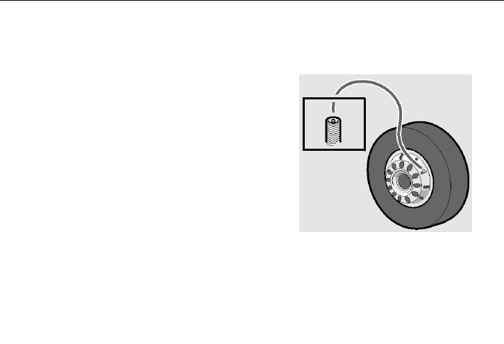
If Something Happens 81
Releasing the Parking Brake
Release the Parking Brake with Air from the Bus Tires.
1 To prevent the bus from moving, block
its wheels or attach it to a tow vehicle.
2 Connect the clamp head of the tire
inflation hose to the valve of one of the
tires.
3 Move the parking brake control to the
drive position.
4 While pressing the other end of the tire
inflation hose against the pump nipple,
press in the blocking valve. Now the
brake system is filled with the air from
the tire. Filling can be interrupted as
soon as the air flow stops.
Note: Chock the wheels to prevent the bus
from moving when releasing the parking
brake.
T0009182
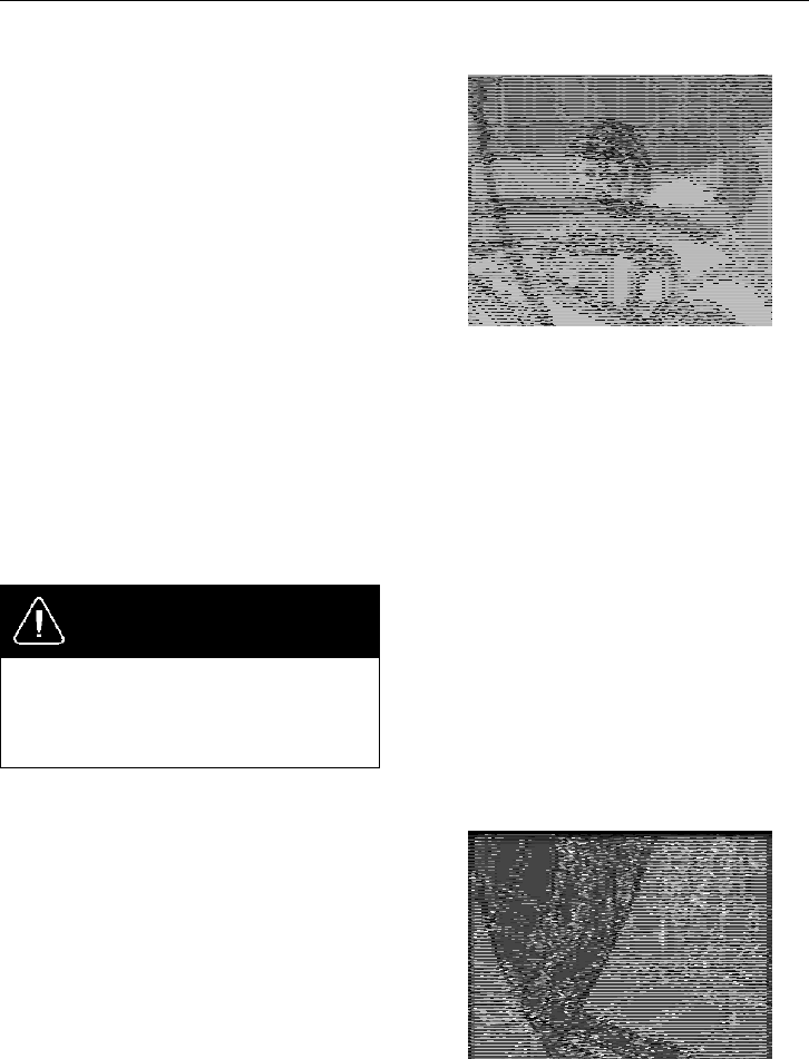
82 If Something Happens
Mechanical Releasing of the Parking Brake
1 By blocking the wheels, make sure
that the bus will not start rolling after
releasing the parking brake.
2 On both drive shaft brake cylinders
there are release bolts. Screw them
out until a red plastic button appears
out from the center of the bolt. The
brakes are then released. This requires
around 45 rotations. Use the designated
spanner from the toolkit or the sleeve
and locking handle.
3 The bus can now be towed. Towing
should be performed using a properly
equipped tow vehicle that can reach
the front axle, since the bus is now
completely without brakes.
Note: Do not forget to reset the bolts to their
original position and attach the plastic cover
after towing has been completed.
DANGER
Chock the wheels to prevent the bus from
moving when releasing the parking brake.
Failure to do so may result in serious
personal injury or death.
T5014634
Regarding Disc Brakes
The brake cylinder is fitted with a release
screw, which does not protrude from the
cylinder during manual release. When
starting to release the parking brake, a
red peg emerges from the centre of the
nut. It is fully out after three turns. Full
compression of the parking brake spring
requires approximately 45 turns. Whenever
possible try always to fill the parking brake
cylinders with air. It makes it easier to turn
the nuts of the release mechanisms.
T5014635
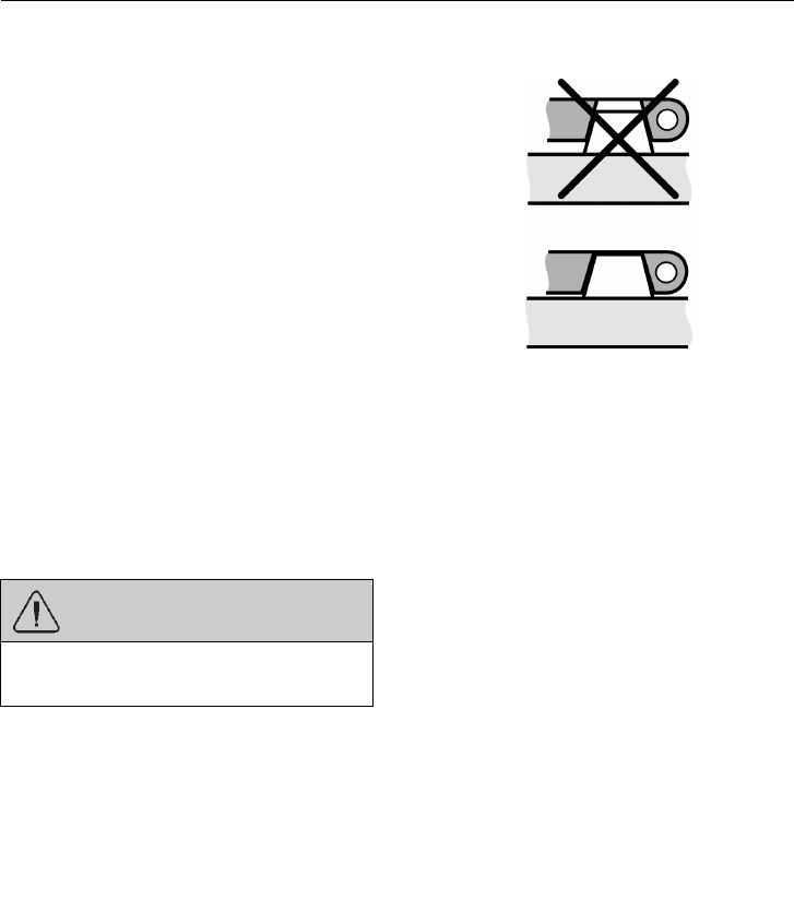
If Something Happens 83
Changing the Batteries
When changing batteries, both batteries
should have the same capacity and be of the
same age. When connecting batteries correct
polarity must be observed.
To change a battery:
•
turn off the power with the main switch
•
disconnect the cable terminal from the
negative pole of the battery
•
disconnect the cable terminal from the
positive pole of the battery
•
change the battery
•
clean the cable terminals and both poles
of the battery
•
connect the positive cable terminal to
the battery pole
•
connect the negative cable terminal to
the battery pole
•
apply an anti-corrosive agent to the
poles with terminals
WARNING
Incorrect connection will seriously
damage the electrical system.
If a cable clamp has been incorrectly
installed, the battery terminal must be
reamed to give a sufficiently large mating
surface when correctly installed. Incorrect
installation entails a high risk of oxidation
in the space between the top of the battery
terminal and the battery cable clamp.
T3019198
Top: Mounted incorrectly, terminal
not bottoming on the pole.
Bottom: Mounted correctly,
terminal bottoming on the pole.
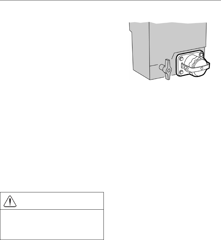
84 If Something Happens
Rapid Charging
The bus is equipped with a socket for an
external power supply, located next to the
battery box. Before rapid charging, the main
switch should be turned off to protect the bus
power consumers from power surges.
Note: The rapid charge connector is not
dimensioned for starting assistance.
Note: Only use the rapid charging socket
when the batteries are partially discharged.
If the batteries are completely discharged,
disconnect them from the bus system and
connect directly to a battery charging device.
T0014730
Starting Assistance
In the event that the batteries are unable to
start the engine, auxiliary batteries can be
used to help in starting. These batteries are
connected in parallel with the ordinary bus
batteries.
Note: Note the polarity. Plus to plus and
minus to minus.
CAUTION
Battery chargers with a start boost feature
must not be used for starting assistance.
Failure to do so may cause damage to the
electrical system.
If Something Happens 85
Battery Cut-off Switch
The battery cut-off switch is located next
to the batteries and is there to completely
cut off the bus power supply. To prevent
battery discharge when the bus is standing
for 24 hours or more, turn the battery cut-off
switch to the OFF position.
T0014428
CAUTION
Always switch off the power with the
cut-off switch when charging the batteries
and when connecting an auxiliary
batteries to start the engine.
CAUTION
Before using the battery cut-off switch,
the power must always be switched off
using the main switch on the dashboard.
Failure to do so may cause damage to the
electrical system.
Note: After using the battery cut-off switch,
it may be necessary to re-enter the radio
code.
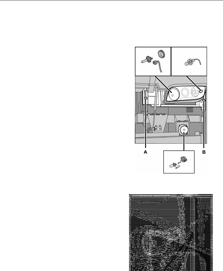
86 If Something Happens
Bulb Replacement
Headlamps
•
lift the front bumper
•
Loosen the securing screws (A) and
(B), delicately lower the lamp module
and tilt it open
•
disconnect power supply cables
•
remove the bulb
Note: Replace it with a new 24 V bulb of the
same type and power rating.
T8012393
Rear Lights
•
Unscrew the five screws securing the
cover
•
replace the bulb
•
before fitting the lamp check whether it
is working properly
Note: Make sure that the bulb is replaced
with a new 24 V bulb of the same type and
power rating.
T3019941

If Something Happens 87
Xenon Lights
DANGER
Xenon lights should only be serviced
at an authorized service facility. Never
try to repair the lights on your own.
Ignition voltage in xenon bulbs is
28,000 V. Servicing these lights without
the necessary knowledge and service
information may result in serious personal
injury or death.
Licence Plate Lighting
Replace the licence plate light bulbs as
follows:
•
Unscrew the screws securing the lamp
housing
•
replace the bulb
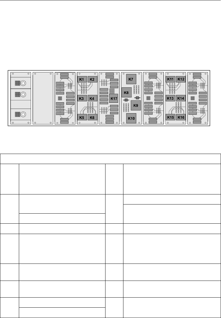
88 If Something Happens
Fuses and Relays (chassis)
The fuse and relay box is located at the front
of the bus.
Relays
T0012034
Relays
K1
VECU (Vehicle Electronic Control
Unit),
EECU (Electronic Engine Control
Unit)
K11 Start inhibit relay
Starting signal, starter motor
Reversed +15
K2
1
Battery warning
K12
1
Luggage compartment lighting
(alternative)
K3 Self-holding relay, ECS K13
Emergency stop
K4
1
TECU (Transmission Electronic
Control Unit)
GSECU (gear selector electronic
control unit) I-shift transmission
K14
1
Trailing axle
K5
1
Manual transmission EGS
K15
1
RECU (retarder control unit)
K6
1
Manual transmission EGS
K16
1
RECU (retarder control unit)
Baggage hold lighting
K7
Starting signal, starter (alternative)
K17 Ignition relay (+15)

If Something Happens 89
Relays
Inverting relay, neutral signal (only
automatic transmissions)
K8
1
VECU (Vehicle Electronic Control
Unit),
EECU (Electronic Engine Control
Unit)
K48
2
Preheating relay
K9
Interval relay, windscreen wiper
motor
K51
3
Main power supply relay
K10
1
Inverting relay, neutral signal (only
automatic transmissions)
1
Depends on version.
2
This is located on the engine bay bracket near the emergency stop.
3
This is located in a steel box next to the battery box.

90 If Something Happens
Fuses
T0012035
Fuses
F1 5A
ECS (electronic controlled
suspension)
F35 25A
LCM (lighting control
module)
F2 10A
BIC (instrument), control
switch
F36 25A
LCM (lighting control
module)
F3 15A
Starting signal, starter
motor
F37 25A
LCM (lighting control
module)
F4 20A
EBS (electronic brake
system)
F38 5A Reversed +15
F5 5A Horn F39
1
25A
Exhaust emissions
cleaning control unit
5A
Emergency release of
parking brake
F6
30A
Ignition switch (Early
version)
F40
—
Spare
20A Radio
F7
1
15A
TECU (transmission
electronic control unit),
GSECU (gear selector
electronic control unit)
transmission I-shift
F41
1
—
Spare
F8
1
5A
GECU (gear selector
electronic control unit)
I-shift
F42 5A
Emergency stop switch,
main switch

If Something Happens 91
Fuses
F9 5A
Starting switch, engine
compartment
F43
—
Spare
F10 5A Fire Alarm F44 25A
LCM (lighting control
module)
F11
1
10A Dynafleet (option) F45 25A
LCM (lighting control
module)
F12 5A
Supply, main switch (+30)
to body-builder outlet
F46 25A
LCM (lighting control
module)
F13 5A Spare F47 5A
Side position lamp,
right-hand side
F14 5A
BBM (Body Builder
Module)
F48 5A
Side position lamp,
left-hand side
F15 15A
EECU (Electronic Engine
Control Unit), Control
valve * (1)
1
, radiator fan,
preheating relay
F49 5A Fuel shut-off valve
F16 5A
VECU (vehicle control
unit)
F50
1
10A
RECU (retarder control
unit)
20A
Radio, 24–12 V (+30)
converter
F17 5A Lighting switch F51
2
—
Spare
F18 5A Alternator 1, 2, 3 F52
1
10A Baggage hold lighting
10A
PCM (Powertrain Control
Module)
F19
1
10A Preheating relay
F53
1
5A
Trailing axle, dehydrator
heater
F20 10A
EBS (electronic brake
system control unit)
F54 5A
Engine hatch/luggage
compartment hatch
F21 15A Wiper motor, windscreen F55 10A
VCB (Volvo
Compression Brake),
EPG (Exhaust Pressure
Governor), radiator
solenoid valve, fuel bleed
pump, preheating relay

92 If Something Happens
Fuses
Preheating relay
5A
Dehydrator heaterF22 5A
TECU (transmission
electronic control
unit), Voith automatic
transmission
F56
10A Engine brake
F23 5A ACC F57 5A Ignition key/Start switch
F24 5A
BIC (instrument panel),
OBD
F58 5A Gas tank control unit
F25 15A Wiper motor, headlights F59 10A
TECU (transmission
electronic control unit),
Voith automatic gearbox
F26 5A
ECS (electronic controlled
suspension)
F60 10A
TECU (Transmission
Electronic Control
Unit), ZF automatic
transmission/gearbox
F27 10A Manual gearbox, EGS F61 10A Baggage hold lighting
5A Dimmed interior lighting
F28 10A
RECU (retarder control
unit)
F62
—
Spare
5A Starter motor relay
F29 5A
Power from the ignition
(+15) to body electrical
system connector
F63
—
Spare
5A
Radio, 24–12 V (+15)
converter
2
F30
20A Fuel heater
F64
—
Spare
F31 5/10 A
Hydraulic oil level,
hydraulic oil filter, exhaust
emissions cleaning control
unit
F80
3
150 A Main battery fuse (B+)
F32 5A Tachograph F81 80A
Power supply main fuse
(+30)
F33 5A BIC (instrument) F93 5A Alternator
F34 10A Tachograph
1
Depends on version.
2
Loose fuse holder next to it.
3
This is located in a steel box next to the battery box.
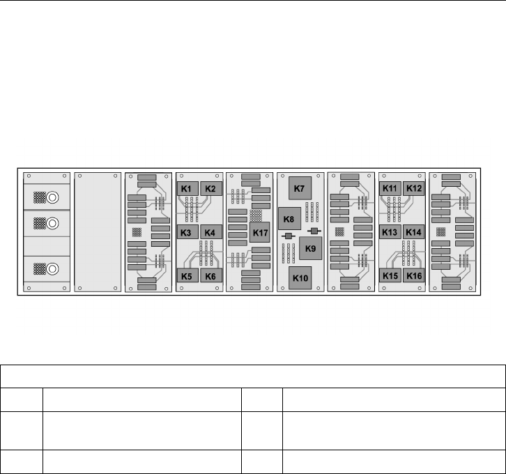
If Something Happens 93
Fuses and relays (body)
The fuse and relay box is located at the front
of the bus.
Relays
T0012034
Relays
K1 Flat screens K4 Defroster, speed 1
K2
Over speed control 95 km/h [59
mph]
K5 Defroster, speed 2
K3 Flat screens K6 Defroster, speed 3
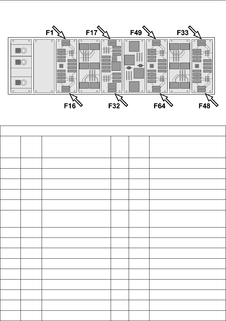
94 If Something Happens
Fuses
T0012035
Fuses
F1 3A
Power Master ID
F33 3A Relays
F2 5A
Transcom
F34 5A Light under seats
F3 20A Audio & Video 12V F35 10A Park Pilot
F4 F36 30A Auxiliary Heater
F5 30A Floor IO B Module F37
F6 5A Climate IO a Module F38 15A CECM B
F7
F39 15A Dashboard converter cigarette
output
F8 F40 5A Middle door, I/O A Module
F9 5A Climate Unit I/O A F41 5A Pressure switch
F10 5A Defroster Flap F42 5A Dashboard, I/O A Module
F11 5A Red Led Switches F43
F12 20A Defroster F44 15A 24 VCD output in Dashboard
F13 30A Roof Left IO B Module F45 30A 24 VCD output in driver side
F14 7.5A Destination Sign control F46
F15 F47
F16 F48 5A Webasto Timer

If Something Happens 95
Fuses
F17 3A
Over Speed warning, relay
K2
F49 5A Control Panel air
F18 7.5A Toilet I/O B Module F50
F19 20A Electric Window F51 5A Destination sign (+15)
F20 F52
F21 15A Roof Left I/O B Module F53 15A DRC Air Conditioning
F22 3A
Emergency Window
Signal
F54
3A Audio & Video (+15)
F23 F55
F24 5A Webasto Timer F56 5A Time & Temperature Display
F25 5A Copilot TD7 F57 5A Power +15 TD7
F26 F58 7.5A Roof Hatch Front
F27 F59 7.5A Roof Hatch Rear
F28 20A Audio & Video 24 volts F60
F29 F61 15A Electrical Binder
F30 7.5A Toilet I/O B Module F62 5A Webasto Timer
F31 F63
F32 F64
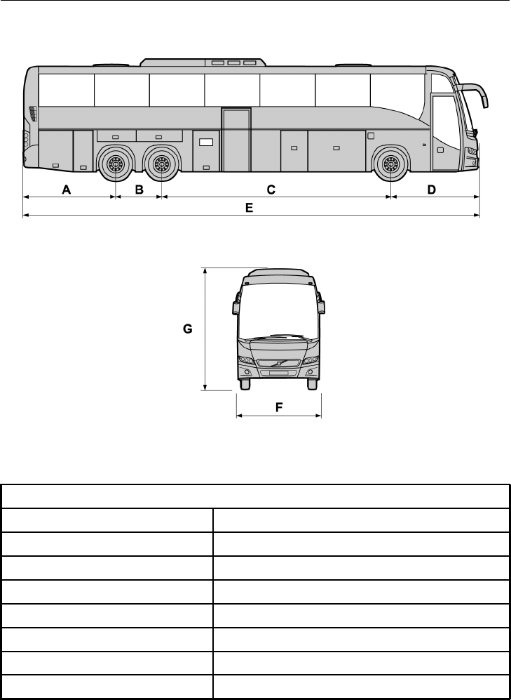
96 Technical Data
Technical Specification
T8012396
Technical Specification
3-axle 13.7m
A 2,780 mm (109 in.)
B 1400 mm (55 in.)
C 6660 mm (262 in.)
D 2,850 mm (112 in.)
E 13,690 mm (539 in.)
F 2600 mm (102 in.)
G 3671 mm (145 in.)

Technical Data 97
Bulbs
Light Rated Power Volvo p/n
Main beam 70 W 990037
Dipped beam 70 W 990037
Direction indicator, front 21 W 982558
Direction indicator, rear 21 W 982558
Fog lamps, front 70 W 990037
Side marker 5W 19926
Fog, rear
21 W 967708
Reversing 21 W 967708
Licence plate 5W 19926
Side direction indicator 21 W 967708
Entrance
5W 967709
Engine bay 21 W 967708

98 Technical Data
Type Plates
The vehicle identification number (VIN) is
marked on an identification plate on the bus.
Identification Plate
Within its inside border, the identification
plate is subdivided into a legal requirement
section, as well as three boxes for the chassis
number, drive and wheelbase. These latter
are not used for buses, only for lorries. The
identification plate is located by the driver’s
seat and contains the following information:
•
G.V.W.R (Gross vehicle weight rating),
is the maximum allowable total weight
of the vehicle.
•
G.A.W.R (Gross axle weight rating), is
the maximum distributed weight that
may be supported by an axle VIN is the
same number that can be found on the
frame member.
•
Tires dimensions.
•
Rims dimensions
•
Cold inflation pressure, is the inflation
pressure of the tires before the vehicle
is driven and the tires warmed up.
•
VIN is the same number that can be
found on the frame member.
T0015663

Technical Data 99
Vehicle Identification (VIN)
This is stamped on the chassis at the
right-hand front end of the vehicle, i.e. in
the wheel arch in front of or behind the front
axle.
Example: YV3R7G62151106335
YV3 Manufacturer
R7
Chassis version
G6 Engine version
2
Brake system
1 Check figure
5
Model year
1 Assembly factory
106335
Chassis number
Engine
Type designation, component number and
serial number are punched on the top of
engine block near the injector pump.
Transmission
The type designation and serial number are
punched on the top of the transmission.
Rear Axle
The plate is on the right-hand side of the rear
axle housing.
Retarder
Serial number and version are stamped on
rear left side of retarder housing.

100 Technical Data
Service Intervals
Regular servicing in accordance with the
special service schedule is required to
maintain the bus to its original specifications
throughout its service life.
Carry out all servicing and maintenance
of the bus at a Volvo workshop or, for
Prevost support vehicles, in Prevost service
center/provider.
These workshops have the trained personnel,
special tools and necessary service literature
that are vital in ensuring high quality of
servicing. This quality also depends on the
use of Volvo Original Spares, which are of
identical quality to the components installed
at the Volvo works.
For service intervals, see the separate service
literature.
When washing the bus, only use agents
that are intended for this purpose. See
also: Operating Instruction “Interior
maintenance”.

Volvo Bus Corporation
Göteborg, Sweden
PV776-88913775 English USA.02.2009
