
NAVSTAR GLOBAL POSITIONING SYSTEM
INTERFACE SPECIFICATION
IS-GPS-200
Revision D
IRN-200D-001
7 March 2006
Navstar GPS Space Segment/Navigation User Interfaces
Deputy System Program Director
GPS JOINT PROGRAM OFFICE
Headquarters
Space and Missile Systems Center (SMC)
Navstar GPS Joint Program Office (SMC/GP)
2420 Vela Way, Suite 1866
El Segundo, CA 90245-4659
U.S.A.
By
ARINC Engineering Services, LLC
2250 E. Imperial Highway, Suite 450
El Segundo, CA 90245
U.S.A.
Cage Code: 0VYX1
DISTRIBUTION STATEMENT A. APPROVED FOR PUBLIC RELEASE; DISTRIBUTION IS UNLIMITED
IS-GPS-200D
7 Dec 2004
ii
(This page intentionally left blank.)

IRN-200D-001
IS-GPS-200D
7 Mar 2006
iii
REVISION RECORD
REV DESCRIPTION
DOCUMENT
DATE
APPROVED
NC
Initial Release
25 Jan 1983
A
Incorporates IRN-200NC-001, IRN-200NC-002, and IRN-
200NC-003
25 Sep 1984
B
Incorporates IRN-200A-001A
30 Nov 1987
C Incorporates IRN-200B-001 thru IRN-200B-007 10 Oct 1993
C Re-formatted in Microsoft Word 6.0 in GEMS compatible format 10 Oct 1993 12 Jan 1996
C Changed distribution status to Public Release 25 Sep 1997 20 Oct 1997
D
Incorporates IRN-200C-001 thru IRN-200C-005R1, change ICD-
GPS-200 to IS-GPS-200, introduce and specify the requirements of
Improved Clock and Ephemeris (ICE) message for L2 C signal, and
other additional updates
7 Dec 2004
23 Nov 2004
IRN-200D-001 Adds additional PRN sequences to Section 6 7 Mar 2006 9 Mar 2006
IS-GPS-200D
7 Dec 2004
iv
(This page intentionally left blank.)

IRN-200D-001
IS-GPS-200D
7 Mar 2006
v
Page Revision Record
Pages
Revision Pages Revision
i IRN-200D-001
ii D
iii IRN-200D-001
iv D
v IRN-200D-001
vi D
vii - xi IRN-200D-001
xii - xiii D
xiv - xvi IRN-200D-001
1 – 5 D
6 IRN-200D-001
7 – 17 D
18 IRN-200D-001
19 – 56 D
56a – 56l IRN-200D-001
57 – 193 D
IS-GPS-200D
7 Dec 2004
vi
(This page intentionally left blank.)

IRN-200D-001
IS-GPS-200D
7 Mar 2006
vii
TABLE OF CONTENTS
1. SCOPE.....................................................................................................................................................................1
1.1 Scope ...............................................................................................................................................................1
1.2 IS Approval and Changes................................................................................................................................1
2. APPLICABLE DOCUMENTS..............................................................................................................................3
2.1 Government Documents..................................................................................................................................3
2.2 Non-Government Documents..........................................................................................................................3
3. REQUIREMENTS .................................................................................................................................................5
3.1 Interface Definition .........................................................................................................................................5
3.2 Interface Identification ....................................................................................................................................5
3.2.1 Ranging Codes ......................................................................................................................................5
3.2.1.1 P-Code.........................................................................................................................................6
3.2.1.2 Y-Code ........................................................................................................................................6
3.2.1.3 C/A-Code ....................................................................................................................................6
3.2.1.4 L2 CM-Code (IIR-M, IIF, and subsequent blocks).....................................................................6
3.2.1.5 L2 CL-Code (IIR-M, IIF, and subsequent blocks) ......................................................................6
3.2.1.6 Non-Standard Codes .................................................................................................................11
3.2.2 NAV Data............................................................................................................................................11
3.2.3 L1/L2 Signal Structure ........................................................................................................................12
3.3 Interface Criteria............................................................................................................................................14
3.3.1 Composite Signal ................................................................................................................................14
3.3.1.1 Frequency Plan..........................................................................................................................14
3.3.1.2 Correlation Loss ........................................................................................................................14
3.3.1.3 Carrier Phase Noise...................................................................................................................14
3.3.1.4 Spurious Transmissions.............................................................................................................14
3.3.1.5 Phase Quadrature.......................................................................................................................15
3.3.1.6 User-Received Signal Levels ....................................................................................................15
3.3.1.7 Equipment Group Delay............................................................................................................17
3.3.1.7.1 Group Delay Uncertainty ................................................................................................17
3.3.1.7.2 Group Delay Differential ................................................................................................17
3.3.1.8 Signal Coherence.......................................................................................................................17
3.3.1.9 Signal Polarization ....................................................................................................................17
3.3.2 PRN Code Characteristics ...................................................................................................................18
3.3.2.1 Code Structure...........................................................................................................................18

IRN-200D-001
IS-GPS-200D
7 Mar 2006
viii
3.3.2.2 P-Code Generation ....................................................................................................................20
3.3.2.3 C/A-Code Generation................................................................................................................30
3.3.2.4 L2 CM-/L2 CL-Code Generation..............................................................................................35
3.3.3 Navigation Data...................................................................................................................................38
3.3.3.1 Navigation Data Modulation (L2 CM)......................................................................................38
3.3.3.1.1 Forward Error Correction................................................................................................38
3.3.4 GPS Time and SV Z-Count.................................................................................................................40
4. NOT APPLICABLE.............................................................................................................................................43
5. NOT APPLICABLE.............................................................................................................................................45
6. NOTES...................................................................................................................................................................47
6.1 Acronyms ......................................................................................................................................................47
6.2 Definitions.....................................................................................................................................................51
6.2.1 User Range Accuracy..........................................................................................................................51
6.2.2 SV Block Definitions ..........................................................................................................................51
6.2.2.1 Developmental SVs...................................................................................................................51
6.2.2.2 Operational SVs ........................................................................................................................51
6.2.2.2.1 Block II SVs....................................................................................................................51
6.2.2.2.2 Block IIA SVs.................................................................................................................51
6.2.2.2.3 Block IIR SVs .................................................................................................................52
6.2.2.2.4 Block IIR-M SVs ............................................................................................................52
6.2.2.2.5 Block IIF SVs..................................................................................................................52
6.2.3 Operational Interval Definitions..........................................................................................................52
6.2.3.1 Normal Operations ....................................................................................................................52
6.2.3.2 Short-term Extended Operations ...............................................................................................52
6.2.3.3 Long-term Extended Operations ...............................................................................................52
6.2.4 GPS Week Number .............................................................................................................................53
6.2.5 L5 Civil Signal ....................................................................................................................................53
6.3 Supporting Material.......................................................................................................................................53
6.3.1 Received Signals .................................................................................................................................53
6.3.2 Extended Navigation Mode (Block II/IIA)..........................................................................................55
6.3.3 Block IIA Mode (Block IIR/IIR-M)....................................................................................................56
6.3.4 Autonomous Navigation Mode ...........................................................................................................56
6.3.5 PRN Code sequences expansion ....................................................................................................... 56a
6.3.5.1 Additional C/A-code PRN sequences ..................................................................................... 56a
6.3.5.2 Additional P-Code PRN sequences.........................................................................................56b

IRN-200D-001
IS-GPS-200D
7 Mar 2006
ix
6.3.5.2.1 Additional P-code Generation.......................................................................................56b
6.3.5.3 Additional L2 CM-/L2 CL-Code PRN sequences....................................................................56i
10. APPENDIX I. LETTERS OF EXCEPTION...................................................................................................57
10.1 Scope ...........................................................................................................................................................57
10.2 Applicable Documents ................................................................................................................................57
10.3 Letters of Exception ....................................................................................................................................57
20. APPENDIX II. GPS NAVIGATION DATA STRUCTURE FOR DATA, D(t) ...........................................65
20.1 Scope ...........................................................................................................................................................65
20.2 Applicable Documents. ...............................................................................................................................65
20.2.1 Government Documents....................................................................................................................65
20.2.2 Non-Government Documents............................................................................................................65
20.3 Requirements...............................................................................................................................................67
20.3.1 Data Characteristics...........................................................................................................................67
20.3.2 Message Structure .............................................................................................................................67
20.3.3 Message Content ...............................................................................................................................81
20.3.3.1 Telemetry Word ......................................................................................................................81
20.3.3.2 Handover Word (HOW)..........................................................................................................81
20.3.3.3 Subframe 1 ..............................................................................................................................83
20.3.3.3.1 Subframe 1 Content.......................................................................................................83
20.3.3.3.2 Subframe 1 Parameter Characteristics ..........................................................................86
20.3.3.3.3 User Algorithms for Subframe 1 Data ..........................................................................86
20.3.3.4 Subframes 2 and 3...................................................................................................................93
20.3.3.4.1 Content of Subframes 2 and 3.......................................................................................93
20.3.3.4.2 Subframe 2 and 3 Parameter Characteristics.................................................................95
20.3.3.4.3 User Algorithm for Ephemeris Determination..............................................................95
20.3.3.4.4 NMCT Validity Time..................................................................................................101
20.3.3.5 Subframes 4 and 5.................................................................................................................102
20.3.3.5.1 Content of Subframes 4 and 5.....................................................................................102
20.3.3.5.2 Algorithms Related to Subframe 4 and 5 Data............................................................117
20.3.4 Timing Relationships ......................................................................................................................126
20.3.4.1 Paging and Cutovers..............................................................................................................126
20.3.4.2 SV Time vs. GPS Time .........................................................................................................126
20.3.4.3 Speed of Light .......................................................................................................................126
20.3.4.4 Data Sets................................................................................................................................127
20.3.4.5 Reference Times....................................................................................................................130
IRN-200D-001
IS-GPS-200D
7 Mar 2006
x
20.3.5 Data Frame Parity............................................................................................................................133
20.3.5.1 SV/CS Parity Algorithm........................................................................................................133
20.3.5.2 User Parity Algorithm ...........................................................................................................133
30. APPENDIX III. GPS NAVIGATION DATA STRUCTURE FOR CNAV DATA, D
C
(t)..........................137
30.1 Scope .........................................................................................................................................................137
30.2 Applicable Documents. .............................................................................................................................137
30.2.1 Government Documents..................................................................................................................137
30.2.2 Non-Government Documents..........................................................................................................137
30.3 Requirements.............................................................................................................................................139
30.3.1 Data Characteristics.........................................................................................................................139
30.3.2 Message Structure ...........................................................................................................................139
30.3.3 Message Content .............................................................................................................................139
30.3.3.1 Message Type 10 and 11 Ephemeris and Health Parameters ...............................................155
30.3.3.1.1 Message Type 10 and 11 Ephemeris and Health Parameter Content.........................155
30.3.3.1.2 Message Type 10 and 11 Ephemeris Parameter Characteristics .................................158
30.3.3.1.3 User Algorithm for Determination of SV Position......................................................158
30.3.3.2 Message Types 30 Through 37 SV Clock Correction Parameters. .......................................163
30.3.3.2.1 Message Type 30 Through 37 SV Clock Correction Parameter Content....................163
30.3.3.2.2 Clock Parameter Characteristics .................................................................................163
30.3.3.2.3 User Algorithms for SV Clock Correction Data .........................................................163
30.3.3.2.4 SV Clock Accuracy Estimates ....................................................................................165
30.3.3.3 Message Type 30 Ionospheric and Group Delay Correction Parameters ..............................168
30.3.3.3.1 Message Type 30 Ionospheric and Group Delay Correction Parameter Content........168
30.3.3.4 Message Types 31, 12, and 37 Almanac Parameters.............................................................171
30.3.3.4.1 Almanac Reference Week...........................................................................................171
30.3.3.4.2 Almanac Reference Time............................................................................................171
30.3.3.4.3 SV PRN Number.........................................................................................................171
30.3.3.4.4 Signal Health (L1/L2/L5)............................................................................................171
30.3.3.4.5 Midi Almanac Parameter Content...............................................................................172
30.3.3.4.6 Reduced Almanac Parameter Content.........................................................................172
30.3.3.5 Message Type 32 Earth Orientation Parameters (EOP) ........................................................175
30.3.3.5.1 EOP Content ...............................................................................................................175
30.3.3.6 Message Type 33 Coordinated Universal Time (UTC) Parameters ......................................179
30.3.3.6.1 UTC Parameter Content..............................................................................................179
30.3.3.6.2 UTC and GPS Time ....................................................................................................179
IRN-200D-001
IS-GPS-200D
7 Mar 2006
xi
30.3.3.7 Message Types 34, 13, and 14 Differential Correction Parameters ......................................181
30.3.3.7.1 Differential Correction Parameters Content................................................................181
30.3.3.7.2 DC Data Packet...........................................................................................................181
30.3.3.7.3 Application of Clock-Related DC Data.......................................................................184
30.3.3.7.4 Application of Orbit-Related DC Data........................................................................184
30.3.3.7.5 SV Differential Range Accuracy Estimates ................................................................186
30.3.3.8 Message Type 35 GPS/GNSS Time Offset...........................................................................187
30.3.3.8.1 GPS/GNSS Time Offset Parameter Content ...............................................................187
30.3.3.8.2 GPS and GNSS Time ..................................................................................................187
30.3.3.9 Message Types 36 and 15 Text Messages.............................................................................188
30.3.4 Timing Relationships ......................................................................................................................189
30.3.4.1 Paging and Cutovers..............................................................................................................189
30.3.4.2 SV Time vs. GPS Time .........................................................................................................190
30.3.4.3 Speed of Light .......................................................................................................................190
30.3.5 Data Frame Parity............................................................................................................................191
30.3.5.1 Parity Algorithm....................................................................................................................191

IS-GPS-200D
7 Dec 2004
xii
LIST OF FIGURES
Figure 3-1.
Generation of P-, C/A-Codes and Modulating Signals ...................................................................19
Figure 3-2. X1A Shift Register Generator Configuration..................................................................................21
Figure 3-3. X1B Shift Register Generator Configuration..................................................................................22
Figure 3-4. X2A Shift Register Generator Configuration..................................................................................23
Figure 3-5. X2B Shift Register Generator Configuration..................................................................................24
Figure 3-6. P-Code Generation..........................................................................................................................26
Figure 3-7. P-Code Signal Component Timing .................................................................................................27
Figure 3-8. G1 Shift Register Generator Configuration ....................................................................................31
Figure 3-9. G2 Shift Register Generator Configuration ....................................................................................32
Figure 3-10. Example C/A-Code Generation ......................................................................................................33
Figure 3-11. C/A-Code Timing Relationships.....................................................................................................34
Figure 3-12. L2 CM-/L2 CL-Code Timing Relationships...................................................................................36
Figure 3-13. L2 CM/L2 CL Shift Register Generator Configuration ..................................................................37
Figure 3-14. Convolutional Encoder ...................................................................................................................39
Figure 3-15. Convolutional Transmit/Decoding Timing Relationships...............................................................39
Figure 3-16. Time Line Relationship of HOW Message.....................................................................................42
Figure 6-1. User Received Minimum Signal Level Variations (Example, Block II/IIA/IIR)............................54
Figure 10-1. Letters of Exception. .......................................................................................................................59
Figure 20-1. Data Format ....................................................................................................................................69
Figure 20-2. TLM and HOW Formats.................................................................................................................82
Figure 20-3. Sample Application of Correction Parameters................................................................................92
Figure 20-4. Ionospheric Model ........................................................................................................................123
Figure 20-5. Example Flow Chart for User Implementation of Parity Algorithm.............................................135
Figure 30-1. Message Type 10 - Ephemeris 1 ...................................................................................................141
Figure 30-2. Message Type 11 - Ephemeris 2 ...................................................................................................142
Figure 30-3. Message Type 30 - Clock, IONO & Group Delay........................................................................143
Figure 30-4. Message Type 31 - Clock & Reduced Almanac ...........................................................................144
Figure 30-5. Message Type 32 - Clock & EOP.................................................................................................145
Figure 30-6. Message Type 33 - Clock & UTC.................................................................................................146
Figure 30-7. Message Type 34 - Clock & Differential Correction....................................................................147
Figure 30-8. Message Type 35 - Clock & GGTO .............................................................................................148
Figure 30-9. Message Type 36 - Clock & Text .................................................................................................149
Figure 30-10. Message Type 37 - Clock & Midi Almanac .................................................................................150
IS-GPS-200D
7 Dec 2004
xiii
Figure 30-11.
Message Type 12 - Reduced Almanac..........................................................................................151
Figure 30-12. Message Type 13 – Clock Differential Correction .......................................................................152
Figure 30-13. Message Type 14 – Ephemeris Differential Correction................................................................153
Figure 30-14. Message Type 15 - Text................................................................................................................154
Figure 30-15. Reduced Almanac Packet Content ................................................................................................174
Figure 30-16. Differential Correction Data Packet..............................................................................................182

IRN-200D-001
IS-GPS-200D
7 Mar 2006
xiv
LIST OF TABLES
Table 3-I.
Code Phase Assignments ..................................................................................................................7
Table 3-II. Code Phase Assignments (IIR-M, IIF, and subsequent blocks only)................................................9
Table 3-III. Signal Configuration.......................................................................................................................13
Table 3-IV. Composite L1 Transmitted Signal Phase ........................................................................................16
Table 3-V. Received Minimum RF Signal Strength .........................................................................................16
Table 3-VI. P-Code Reset Timing......................................................................................................................28
Table 3-VII. Final Code Vector States.................................................................................................................29
Table 6-I Additional C/A-/P-Code Phase Assignments................................................................................ 56c
Table 6-II. Additional L2 CM-/L2 CL-Code Phase Assignments ...................................................................56i
Table 20-I. Subframe 1 Parameters ...................................................................................................................87
Table 20-II. Ephemeris Data Definitions ............................................................................................................94
Table 20-III. Ephemeris Parameters.....................................................................................................................96
Table 20-IV. Elements of Coordinate Systems ....................................................................................................97
Table 20-V. Data IDs and SV IDs in Subframes 4 and 5..................................................................................105
Table 20-VI. Almanac Parameters .....................................................................................................................107
Table 20-VII. NAV Data Health Indications .......................................................................................................109
Table 20-VIII. Codes for Health of SV Signal Components.................................................................................110
Table 20-IX. UTC Parameters............................................................................................................................113
Table 20-X. Ionospheric Parameters .................................................................................................................114
Table 20-XI. IODC Values and Data Set Lengths (Block II/IIA) .....................................................................128
Table 20-XII. IODC Values and Data Set Lengths (Block IIR/IIR-M/IIF)........................................................129
Table 20-XIII. Reference Times ...........................................................................................................................132
Table 20-XIV. Parity Encoding Equations............................................................................................................134
Table 30-I. Message Types 10 and 11 Parameters...........................................................................................159
Table 30-II. Elements of Coordinate System ....................................................................................................161
Table 30-III. Clock Correction and Accuracy Parameters .................................................................................164
Table 30-IV. Group Delay Differential Parameters............................................................................................168
Table 30-V. Midi Almanac Parameters.............................................................................................................173
Table 30-VI. Reduced Almanac Parameters.......................................................................................................174
Table 30-VII. Earth Orientation Parameters .........................................................................................................176
Table 30-VIII. Application of EOP Parameters .....................................................................................................177
Table 30-IX. UTC Parameters............................................................................................................................180
Table 30-X. Differential Correction Parameters.................................................................................................183
IRN-200D-001
IS-GPS-200D
7 Mar 2006
xv
Table 30-XI.
GPS/GNSS Time Offset Parameters.............................................................................................188
Table 30-XII. Message Broadcast Intervals.........................................................................................................189

IRN-200D-001
IS-GPS-200D
7 Mar 2006
xvi
(This page intentionally left blank.)

IS-GPS-200D
7 Dec 2004
1
1. SCOPE
1.1 Scope
. This Interface Specification (IS) defines the requirements related to the interface between the Space
Segment (SS) of the Global Positioning System (GPS) and the navigation User Segment (US) of the GPS for radio
frequency (RF) link 1 (L1) and link 2 (L2).
1.2 IS Approval and Changes
. ARINC Engineering Services, LLC has been designated the Interface Control
Contractor (ICC), and is responsible for the basic preparation, approval, distribution, retention, and Interface Control
Working Group (ICWG) coordination of the IS in accordance with GP-03-001. The Navstar GPS Joint Program
Office is the necessary authority to make this IS effective. The Joint Program Office (JPO) administers approvals
under the auspices of the Configuration Control Board (CCB), which is governed by the appropriate JPO Operating
Instruction (OI). Military organizations and contractors are represented at the CCB by their respective segment
member. All civil organizations and public interest are represented by the Department of Transportation
representative of the GPS JPO.
A proposal to change the approved version of this IS can be submitted by any ICWG participating organization to
the GPS JPO and/or the ICC. The ICC is responsible for the preparation of the change paper and change
coordination, in accordance with GP-03-001. The ICC prepares the change paper as a Proposed Interface Revision
Notice (PIRN) and is responsible for coordination of PIRNs with the ICWG. The ICWG coordinated PIRN must be
submitted to the GPS JPO CCB for review and approval.
The ICWG review period for all Proposed Interface Revisions Notices (PIRNs) is 45 days after receipt by individual
addressees. A written request to extend the review period may be submitted to the ICC for consideration.
IS-GPS-200D
7 Dec 2004
2
(This page intentionally left blank.)

IS-GPS-200D
7 Dec 2004
3
2. APPLICABLE DOCUMENTS
2.1 Government Documents
. The following documents of the issue specified contribute to the definition of the
interfaces between the GPS Space Segment and the GPS navigation User Segment, and form a part of this IS to the
extent specified herein.
Specifications
Federal
None
Military
None
Other Government Activity
None
Standards
Federal
None
Military
None
Other Publications
GP-03-001
14 Nov 2003
GPS Interface Control Working Group Charter
2.2 Non-Government Documents
. The following documents of the issue specified contribute to the definition of
the interfaces between the GPS Space Segment and the GPS Navigation User Segment and form a part of this IS to
the extent specified herein.
Specifications
None
Other Publications
None
IS-GPS-200D
7 Dec 2004
4
(This page intentionally left blank.)

IS-GPS-200D
7 Dec 2004
5
3. REQUIREMENTS
3.1 Interface Definition
. The interface between the GPS Space Segment (SS) and the GPS navigation User
Segment (US) includes two RF links, L1 and L2. Utilizing these links, the space vehicles (SVs) of the SS shall
provide continuous earth coverage signals that provide to the US the ranging codes and the system data needed to
accomplish the GPS navigation (NAV) mission. These signals shall be available to a suitably equipped user with
RF visibility to an SV.
3.2 Interface Identification
. The carriers of L1 and L2 are typically modulated by one or more bit trains, each of
which normally is a composite generated by the modulo-2 addition of a pseudo-random noise (PRN) ranging code
and the downlink system data (referred to as NAV data).
3.2.1 Ranging Codes
. Three PRN ranging codes are transmitted: the precision (P) code which is the principal
NAV ranging code; the Y-code, used in place of the P-code whenever the anti-spoofing (A-S) mode of operation is
activated; and the coarse/acquisition (C/A) code which is used for acquisition of the P (or Y) code (denoted as P(Y))
and as a civil ranging signal. Code-division-multiple-access techniques allow differentiating between the SVs even
though they may transmit at the same frequencies. The SVs will transmit intentionally "incorrect" versions of the
C/A and the P(Y) codes where needed to protect the users from receiving and utilizing anomalous NAV signals as
a result of a malfunction in the SV's reference frequency generation system. These two "incorrect" codes are termed
non-standard C/A (NSC) and non-standard Y (NSY) codes.
For Block IIR-M, IIF, and subsequent blocks of SVs, two additional PRN ranging codes are transmitted. They are
the L2 civil-moderate (L2 CM) code and the L2 civil-long (L2 CL) code. The SVs will transmit intentionally
"incorrect" versions of the L2 CM and L2 CL codes where needed to protect the users from receiving and utilizing
anomalous NAV signals as a result of a malfunction in the SV's reference frequency generation system. These
"incorrect" codes are termed non-standard L2 CM (NSCM) and non-standard L2 CL (NSCL) codes. The SVs shall
also be capable of initiating and terminating the broadcast of NSCM and/or NSCL code(s) independently of each
other, in response to CS command.

IRN-200D-001
IS-GPS-200D
7 Mar 2006
6
3.2.1.1 P-Code
. The PRN P-code for SV ID number i is a ranging code, P
i
(t), of 7 days in length at a chipping
rate of 10.23 Mbps. The 7 day sequence is the modulo-2 sum of two sub-sequences referred to as X1 and X2
i
; their
lengths are 15,345,000 chips and 15,345,037 chips, respectively. The X2
i
sequence is an X2 sequence selectively
delayed by 1 to 37 chips thereby allowing the basic code generation technique to produce a set of 37 mutually
exclusive P-code sequences of 7 days in length. Of these, 32 are designated for use by SVs and 5 are reserved for
other purposes (e.g. ground transmitters, etc.). Assignment of these code phase segments by SV-ID number (or
other use) is given in Table 3-I. Additional PRN P-code sequences with assigned PRN numbers are provided in
Section 6.3.5.2, Table 6-I
3.2.1.2 Y-Code
. The PRN Y-code is used in place of the P-code when the A-S mode of operation is activated.
3.2.1.3 C/A-Code
. The PRN C/A-Code for SV ID number i is a Gold code, G
i
(t), of 1 millisecond in length at a
chipping rate of 1023 Kbps. The G
i
(t) sequence is a linear pattern generated by the modulo-2 addition of two sub-
sequences, G1 and G2
i
, each of which is a 1023 chip long linear pattern. The epochs of the Gold code are
synchronized with the X1 epochs of the P-code. As shown in Table 3-I, the G2
i
sequence is a G2 sequence
selectively delayed by pre-assigned number of chips, thereby generating a set of different C/A-codes. Assignment
of these by GPS PRN signal number is given in Table 3-I. Additional PRN C/A-code sequences with assigned PRN
numbers are provided in Section 6.3.5.1, Table 6-I
3.2.1.4 L2 CM-Code (IIR-M, IIF, and subsequent blocks)
. The PRN L2 CM-code for SV ID number i is a ranging
code, C
M,i
(t), which is 20 milliseconds in length at a chipping rate of 511.5 Kbps. The epochs of the L2 CM-code
are synchronized with the X1 epochs of the P-code. The C
M,i
(t) sequence is a linear pattern which is short cycled
every count of 10230 chips by resetting with a specified initial state. Assignment of initial states by GPS PRN
signal number is given in Table 3-II. Additional PRN L2 CM-code sequence pairs are provided in Section 6.3.5.3,
Table 6-II
3.2.1.5 L2 CL-Code (IIR-M, IIF, and subsequent blocks)
. The PRN L2 CL-code for SV ID number i is a ranging
code, C
L,i
(t), which is 1.5 seconds in length at a chipping rate of 511.5 Kbps. The epochs of the L2 CL-code are
synchronized with the X1 epochs of the P-code. The C
L,i
(t) sequence is a linear pattern which is generated using the
same code generator polynomial as the one used for C
M,i
(t). However, the C
L,i
(t) sequence is short cycled by
resetting with a specified initial state every code count of 767250 chips. Assignment of initial states by GPS PRN
signal number is given in Table 3-II. Additional PRN L2 CL-code sequence pairs are provided in Section 6.3.5.3,
Table 6-II

IS-GPS-200D
7 Dec 2004
7
Table 3-I. Code Phase Assignments (sheet 1 of 2)
Code Phase Selection
Code Delay
Chips
SV
ID
No.
GPS PRN
Signal
No.
C/A(G2
i
)**** (X2
i
) C/A P
First
10 Chips
Octal*
C/A
First
12 Chips
Octal
P
1
2
3
4
5
6
7
8
9
10
11
12
13
14
15
16
17
18
19
1
2
3
4
5
6
7
8
9
10
11
12
13
14
15
16
17
18
19
2 ⊕ 6
3 ⊕ 7
4 ⊕ 8
5 ⊕ 9
1 ⊕ 9
2 ⊕ 10
1 ⊕ 8
2 ⊕ 9
3 ⊕ 10
2 ⊕ 3
3 ⊕ 4
5 ⊕ 6
6 ⊕ 7
7 ⊕ 8
8 ⊕ 9
9 ⊕ 10
1 ⊕ 4
2 ⊕ 5
3 ⊕ 6
1
2
3
4
5
6
7
8
9
10
11
12
13
14
15
16
17
18
19
5
6
7
8
17
18
139
140
141
251
252
254
255
256
257
258
469
470
471
1
2
3
4
5
6
7
8
9
10
11
12
13
14
15
16
17
18
19
1440
1620
1710
1744
1133
1455
1131
1454
1626
1504
1642
1750
1764
1772
1775
1776
1156
1467
1633
4444
4000
4222
4333
4377
4355
4344
4340
4342
4343
⏐
⏐
⏐
⏐
⏐
⏐
⏐
⏐
4343
* In the octal notation for the first 10 chips of the C/A code as shown in this column, the first
digit (1) represents a "1" for the first chip and the last three digits are the conventional octal
representation of the remaining 9 chips. (For example, the first 10 chips of the C/A code for
PRN Signal Assembly No. 1 are: 1100100000).
** C/A codes 34 and 37 are common.
*** PRN sequences 33 through 37 are reserved for other uses (e.g. ground transmitters).
**** The two-tap coder utilized here is only an example implementation that generates a limited set
of valid C/A codes.
⊕ = "exclusive or"
NOTE: The code phase assignments constitute inseparable pairs, each consisting of a specific C/A
and a specific P code phase, as shown above.

IS-GPS-200D
7 Dec 2004
8
Table 3-I. Code Phase Assignments (sheet 2 of 2)
Code Phase Selection
Code Delay
Chips
SV
ID
No.
GPS PRN
Signal
No.
C/A(G2
i
)**** (X2
i
) C/A P
First
10 Chips
Octal*
C/A
First
12 Chips
Octal
P
20
21
22
23
24
25
26
27
28
29
30
31
32
***
***
***
***
***
20
21
22
23
24
25
26
27
28
29
30
31
32
33
34**
35
36
37**
4 ⊕ 7
5 ⊕ 8
6 ⊕ 9
1 ⊕ 3
4 ⊕ 6
5 ⊕ 7
6 ⊕ 8
7 ⊕ 9
8 ⊕ 10
1 ⊕ 6
2 ⊕ 7
3 ⊕ 8
4 ⊕ 9
5 ⊕ 10
4 ⊕ 10
1 ⊕ 7
2 ⊕ 8
4 ⊕ 10
20
21
22
23
24
25
26
27
28
29
30
31
32
33
34
35
36
37
472
473
474
509
512
513
514
515
516
859
860
861
862
863
950
947
948
950
20
21
22
23
24
25
26
27
28
29
30
31
32
33
34
35
36
37
1715
1746
1763
1063
1706
1743
1761
1770
1774
1127
1453
1625
1712
1745
1713
1134
1456
1713
4343
⏐
⏐
⏐
⏐
⏐
⏐
⏐
⏐
⏐
⏐
⏐
⏐
⏐
⏐
⏐
⏐
4343
* In the octal notation for the first 10 chips of the C/A code as shown in this column, the first
digit (1) represents a "1" for the first chip and the last three digits are the conventional
octal representation of the remaining 9 chips. (For example, the first 10 chips of the C/A
code for PRN Signal Assembly No. 1 are: 1100100000).
** C/A codes 34 and 37 are common.
*** PRN sequences 33 through 37 are reserved for other uses (e.g. ground transmitters).
**** The two-tap coder utilized here is only an example implementation that generates a limited
set of valid C/A codes.
⊕ = "exclusive or"
NOTE: The code phase assignments constitute inseparable pairs, each consisting of a specific C/A
and a specific P code phase, as shown above.

IS-GPS-200D
7 Dec 2004
9
Table 3-II. Code Phase Assignments (IIR-M, IIF, and subsequent blocks only) (sheet 1 of 2)
Initial Shift Register State (Octal) End Shift Register State (Octal)
SV
ID
No.
GPS PRN
Signal
No.
L2 CM L2 CL L2 CM * L2 CL **
1
2
3
4
5
6
7
8
9
10
11
12
13
14
15
16
17
18
19
1
2
3
4
5
6
7
8
9
10
11
12
13
14
15
16
17
18
19
742417664
756014035
002747144
066265724
601403471
703232733
124510070
617316361
047541621
733031046
713512145
024437606
021264003
230655351
001314400
222021506
540264026
205521705
064022144
624145772
506610362
220360016
710406104
001143345
053023326
652521276
206124777
015563374
561522076
023163525
117776450
606516355
003037343
046515565
671511621
605402220
002576207
525163451
552566002
034445034
723443711
511222013
463055213
667044524
652322653
505703344
520302775
244205506
236174002
654305531
435070571
630431251
234043417
535540745
043056734
731304103
412120105
267724236
167516066
771756405
047202624
052770433
761743665
133015726
610611511
352150323
051266046
305611373
504676773
272572634
731320771
631326563
231516360
030367366
713543613
232674654
* Short cycled period = 10230
** Short cycled period = 767250
*** PRN sequences 33 through 37 are reserved for other uses (e.g. ground transmitters).
NOTE: There are many other available initial register states which can be used for other signal
transmitters including any additional SVs in future.

IS-GPS-200D
7 Dec 2004
10
Table 3-II. Code Phase Assignments (IIR-M, IIF, and subsequent blocks only) (sheet 2 of 2)
Initial Shift Register State (Octal) End Shift Register State (Octal)
SV
ID
No.
GPS PRN
Signal
No.
L2 CM L2 CL L2 CM * L2 CL **
20
21
22
23
24
25
26
27
28
29
30
31
32
***
***
***
***
***
20
21
22
23
24
25
26
27
28
29
30
31
32
33
34
35
36
37
120161274
044023533
724744327
045743577
741201660
700274134
010247261
713433445
737324162
311627434
710452007
722462133
050172213
500653703
755077436
136717361
756675453
435506112
266527765
006760703
501474556
743747443
615534726
763621420
720727474
700521043
222567263
132765304
746332245
102300466
255231716
437661701
717047302
222614207
561123307
240713073
365636111
143324657
110766462
602405203
177735650
630177560
653467107
406576630
221777100
773266673
100010710
431037132
624127475
154624012
275636742
644341556
514260662
133501670
641733155
730125345
000316074
171313614
001523662
023457250
330733254
625055726
476524061
602066031
012412526
705144501
615373171
041637664
100107264
634251723
257012032
703702423
* Short cycled period = 10230
** Short cycled period = 767250
*** PRN sequences 33 through 37 are reserved for other uses (e.g. ground transmitters).
NOTE: There are many other available initial register states which can be used for other signal
transmitters including any additional SVs in future.

IS-GPS-200D
7 Dec 2004
11
3.2.1.6 Non-Standard Codes
. The NSC, NSCM, NSCL, and NSY codes, used to protect the user from a
malfunction in the SV's reference frequency system (reference paragraph 3.2.1), are not for utilization by the user
and, therefore, are not defined in this document.
3.2.2 NAV Data
. The NAV data, D(t), includes SV ephemerides, system time, SV clock behavior data, status
messages and C/A to P (or Y) code handover information, etc. The 50 bps data is modulo-2 added to the P(Y)-
and C/A- codes; the resultant bit-trains are used to modulate the L1 and L2 carriers. For a given SV, the data train
D(t), if present, is common to the P(Y)- and C/A- codes on both the L1 and L2 channels. The content and
characteristics of the NAV data, D(t), are given in Appendix II of this document.
For Block IIR-M, Block IIF, and subsequent blocks of SVs, civil navigation (CNAV) data, D
C
(t), also includes SV
ephemerides, system time, SV clock behavior, status messages, etc. The D
C
(t) is a 25 bps data stream which is
coded by a rate ½ convolutional coder. When selected by ground command, the resulting 50 sps symbol stream is
modulo-2 added to the L2 CM-code; the resultant bit-train is combined with L2 CL-code using chip by chip time-
division multiplexing method (i.e. alternating between L2 CM ⊕ data and L2 CL chips); the multiplexed bit-train is
used to modulate the L2 carrier. The content and characteristics of the CNAV data, D
C
(t), are given in Appendix III
of this document.
During the initial period of Block IIR-M SVs operation, prior to Initial Operational Capability of L2 C signal, Block
IIR-M may modulo-2 add the NAV data, D(t), to the L2 CM-code instead of CNAV data, D
C
(t). Moreover, the
NAV data, D(t), can be used in one of two different data rates which are selectable by ground command. D(t) with a
data rate of 50 bps can be commanded to be modulo-2 added to the L2 CM-code, or D(t) with a symbol rate of 50
symbols per second (sps) (rate ½ convolutional encode of a 25 bps NAV data) can be commanded to be modulo-2
added to the L2 CM-code. The resultant bit-train is combined with L2 CL-code using chip by chip time-division
multiplexing method (i.e. alternating between L2 CM ⊕ data and L2 CL chips). This multiplexed bit-train is used to
modulate the L2 carrier.

IS-GPS-200D
7 Dec 2004
12
3.2.3 L1/L2 Signal Structure
. The L1 consists of two carrier components which are in phase quadrature with each
other. Each carrier component is bi-phase shift key (BPSK) modulated by a separate bit train. One bit train is the
modulo-2 sum of the P(Y)-code and NAV data, D(t), while the other is the modulo-2 sum of the C/A-code and the
NAV data, D(t). For Block II/IIA and IIR, the L2 is BPSK modulated by only one of those two bit trains; the bit
train to be used for L2 modulation is selected by ground command. A third modulation mode is also selectable on
the L2 channel by ground command: it utilizes the P(Y)-code without the NAV data as the modulating signal. For
a particular SV, all transmitted signal elements (carriers, codes and data) are coherently derived from the same on-
board frequency source.
For Block IIR-M, Block IIF, and subsequent blocks of SVs, the L2 consists of two carrier components. One carrier
component is BPSK modulated by the bit train which is the modulo-2 sum of the P(Y)-code with or without NAV
data D(t), while the other is BPSK modulated by any one of three other bit trains which are selectable by ground
command. The three possible bit trains are: (1) the modulo-2 sum of the C/A-code and D(t); (2) the C/A-code with
no data and; (3) a chip-by-chip time multiplex combination of bit trains consisting of the L2 CM-code with D
C
(t)
and the L2 CL-code with no data. The L2 CM-code with the 50 sps symbol stream of D
C
(t) is time-multiplexed
with L2 CL-code at a 1023 kHz rate as described in paragraph 3.2.2. The first L2 CM-code chip starts
synchronously with the end/start of week epoch.
During the initial period of Block IIR-M SVs operation, prior to Initial Operational Capability of L2 C signal, Block
IIR-M may modulo-2 add the NAV data, D(t), to the L2 CM-code instead of CNAV data, D
C
(t). In such
configuration, the data rate of D(t) may be 50 bps (i.e. without convolution encoding) or it may be 25 bps. The D(t)
of 25 bps shall be convolutionally encoded resulting in 50 sps.
The different configuration and combination of codes/signals specified in this section are shown in Table 3-III.

IS-GPS-200D
7 Dec 2004
13
Table 3-III. Signal Configuration
L1 L2**
SV Blocks
In-Phase* Quadrature-Phase* In-Phase* Quadrature-Phase*
Block II/IIA/IIR
P(Y) ⊕ D(t) C/A ⊕ D(t)
P(Y) ⊕ D(t)
or
P(Y)
or
C/A ⊕ D(t)
Not Applicable
Block IIR-M***
P(Y) ⊕ D(t) C/A ⊕ D(t)
P(Y) ⊕ D(t)
or
P(Y)
L2 CM ⊕ D(t) with L2 CL
or
L2 CM ⊕ D′(t) with L2 CL
or
C/A ⊕ D(t)
or
C/A
Block IIR-M/IIF
P(Y) ⊕ D(t) C/A ⊕ D(t)
P(Y) ⊕ D(t)
or
P(Y)
L2 CM ⊕ D
C
(t) with L2 CL
or
C/A ⊕ D(t)
or
C/A
Notes: 1) The configuration identified in this table reflects only the content of Section 3.2.3 and does not
show all available codes/signals on L1/L2.
2) It should be noted that there are no flags or bits in the navigation message to directly indicate
which signal option is broadcast for L2 Civil (L2 C) signal.
⊕ = “exclusive-or” (modulo-2 addition)
D(t) = NAV data at 50 bps
D′(t) = NAV data at 25 bps with FEC encoding resulting in 50 sps
D
C
(t) = CNAV data at 25 bps with FEC encoding resulting in 50 sps
* Terminology of “in-phase” and “quadrature-phase” is used only to identify the relative phase
quadrature relationship of the carrier components (i.e. 90 degrees offset of each other).
** The two carrier components on L2 may not have the phase quadrature relationship. They may be
broadcast on same phase (ref. Section 3.3.1.5).
*** Possible signal configuration for Block IIR-M only during the initial period of Block IIR-M SVs
operation, prior to Initial Operational Capability of L2 C signal. See paragraph 3.2.2.

IS-GPS-200D
7 Dec 2004
14
3.3 Interface Criteria
. The criteria specified in the following define the requisite characteristics of the SS/US
interface for the L1 and L2.
3.3.1 Composite Signal
. The following criteria define the characteristics of the composite signals.
3.3.1.1 Frequency Plan
. The signals shall be contained within two 20.46-MHz bands centered about L1 and L2.
The carrier frequencies for the L1 and L2 signals shall be coherently derived from a common frequency source
within the SV. The nominal frequency of this source -- as it appears to an observer on the ground -- is 10.23 MHz.
The SV carrier frequency and clock rates -- as they would appear to an observer located in the SV -- are offset to
compensate for relativistic effects. The clock rates are offset by
∆
f/f = -4.4647E-10, equivalent to a change in the
P-code chipping rate of 10.23 MHz offset by a
∆
f = -4.5674E-3 Hz. This is equal to 10.22999999543 MHz. The
nominal carrier frequencies (f
0
) shall be 1575.42 MHz, and 1227.6 MHz for L1 and L2, respectively.
3.3.1.2 Correlation Loss
. Correlation loss is defined as the difference between the SV power received in a 20.46
MHz bandwidth and the signal power recovered in an ideal correlation receiver of the same bandwidth. On the L1
and L2 channels, the worst case correlation loss occurs when the carrier is modulated by the sum of the P(Y) code
and the NAV data stream. For this case, the correlation loss apportionment shall be as follows:
1. SV modulation imperfections 0.6 dB
2. Ideal UE receiver waveform distortion 0.4 dB
(due to 20.46 MHz filter)
3.3.1.3 Carrier Phase Noise
. The phase noise spectral density of the unmodulated carrier shall be such that a phase
locked loop of 10 Hz one-sided noise bandwidth shall be able to track the carrier to an accuracy of 0.1 radians rms.
3.3.1.4 Spurious Transmissions
. In-band spurious transmissions shall be at least 40 dB below the unmodulated L1
and L2 carriers over the allocated 20.46 MHz channel bandwidth.

IS-GPS-200D
7 Dec 2004
15
3.3.1.5 Phase Quadrature
. The two L1 carrier components modulated by the two separate bit trains (C/A-code plus
data and P(Y)-code plus data) shall be in phase quadrature (within ±100 milliradians) with the C/A signal carrier
lagging the P signal by 90 degrees. Referring to the phase of the P carrier when P
i
(t) equals zero as the "zero phase
angle", the P(Y)- and C/A-code generator output shall control the respective signal phases in the following manner:
when P
i
(t) equals one, a 180-degree phase reversal of the P-carrier occurs; when G
i
(t) equals one, the C/A carrier
advances 90 degrees; when the G
i
(t) equals zero, the C/A carrier shall be retarded 90 degrees (such that when G
i
(t)
changes state, a 180-degree phase reversal of the C/A carrier occurs). The resultant nominal composite transmitted
signal phases as a function of the binary state of only the two modulating signals are as shown in Table 3-IV.
For Block IIR-M, IIF, and subsequent blocks of SVs, phase quadrature relationship between the two L2 carrier
components can be the same as for the two L1 carrier components as described above. However, for the L2 case,
the civil signal carrier component is modulated by any one of three (IIF) or four (IIR-M) different bit trains as
described in paragraph 3.2.3. Moreover, the two L2 carrier components can be in same phase. The resultant
composite transmitted signal phases will vary as a function of the binary state of the modulating signals as well as
the signal power ratio and phase quadrature relationship. Beyond these considerations, additional carrier
components in Block IIR-M, IIF, and subsequent blocks of SVs will result in composite transmitted signal phase
relationships other than the nominal special case of Table 3-IV.
For Block IIF, the crosstalk between the C/A, when selected, and P(Y) signals shall not exceed –20 dB in the L1 and
L2. The crosstalk is the relative power level of the undesired signal to the desired reference signal.
3.3.1.6 User-Received Signal Levels
. The SV shall provide L1 and L2 navigation signal strength at end-of-life
(EOL), worst-case, in order to meet the minimum levels specified in Table 3-V. The minimum received power is
measured at the output of a 3 dB
i
linearly polarized user receiving antenna (located near ground) at worst normal
orientation, when the SV is above a 5-degree elevation angle. The received signal levels are observed within the in-
band allocation defined in para. 3.3.1.1.
The Block IIF SV shall provide L1 and L2 signals with the following characteristic: the L1 off-axis power gain
shall not decrease by more than 2 dB from the Edge-of-Earth (EOE) to nadir, nor more than 10 dB from EOE to 20
degrees off nadir, and no more than 18 dB from EOE to 23 degrees off nadir; the L2 off-axis power gain shall not
decrease by more than 2 dB from EOE to nadir, and no more than 10 dB from EOE to 23 degrees off nadir; the
power drop off between EOE and ±23 degrees shall be in a monotonically decreasing fashion.
Additional related data is provided as supporting material in paragraph 6.3.1.

IS-GPS-200D
7 Dec 2004
16
Table 3-IV. Composite L1 Transmitted Signal Phase ** (Block II/IIA and IIR SVs Only)
Code State
Nominal Composite L1
Signal Phase*
P C/A
0°
-70.5°
+109.5°
180°
0
1
0
1
0
0
1
1
* Relative to 0, 0 code state with positive angles leading and negative angles lagging.
** Based on the composite of two L1 carrier components with 3 dB difference in the power levels of the two.
Table 3-V. Received Minimum RF Signal Strength
Signal
SV Blocks Channel
P(Y) C/A or L2 C
L1 -161.5 dBW -158.5 dBW
II/IIA/IIR
L2 -164.5 dBW -164.5 dBW
L1 -161.5 dBW -158.5 dBW
IIR-M/IIF
L2 -161.5 dBW -160.0 dBW
or

IS-GPS-200D
7 Dec 2004
17
3.3.1.7 Equipment Group Delay
. Equipment group delay is defined as the delay between the signal radiated output
of a specific SV (measured at the antenna phase center) and the output of that SV's on-board frequency source; the
delay consists of a bias term and an uncertainty. The bias term is of no concern to the US since it is included in the
clock correction parameters relayed in the NAV data, and is therefore accounted for by the user computations of
system time (reference paragraphs 20.3.3.3.3.1, 30.3.3.2.3). The uncertainty (variation) of this delay as well as the
group delay differential between the signals of L1 and L2 are defined in the following.
3.3.1.7.1 Group Delay Uncertainty
. The effective uncertainty of the group delay shall not exceed 3.0 nanoseconds
(two sigma).
3.3.1.7.2 Group Delay Differential
. The group delay differential between the radiated L1 and L2 signals (i.e. L1
P(Y) and L2 P(Y), L1 P(Y) and L2 C) is specified as consisting of random plus bias components. The mean
differential is defined as the bias component and will be either positive or negative. For a given navigation payload
redundancy configuration, the absolute value of the mean differential delay shall not exceed 15.0 nanoseconds.
The random variations about the mean shall not exceed 3.0 nanoseconds (two sigma). Corrections for the bias
components of the group delay differential are provided to the US in the Nav message using parameters designated
as T
GD
(reference paragraph 20.3.3.3.3.2) and Inter-Signal Correction (ISC) (reference paragraph 30.3.3.3.1.1).
3.3.1.8 Signal Coherence
. All transmitted signals for a particular SV shall be coherently derived from the same
on-board frequency standard; all digital signals shall be clocked in coincidence with the PRN transitions for the P-
signal and occur at the P-signal transition speed. On the L1 channel the data transitions of the two modulating
signals (i.e., that containing the P(Y)-code and that containing the C/A-code), L1 P(Y) and L1 C/A, shall be such
that the average time difference between the transitions does not exceed 10 nanoseconds (two sigma).
3.3.1.9 Signal Polarization
. The transmitted signal shall be right-hand circularly polarized (RHCP). For the
angular range of ±14.3 degrees from boresight, L1 ellipticity shall be no worse than 1.2 dB for Block II/IIA and
shall be no worse than 1.8 dB for Block IIR/IIR-M/IIF SVs. L2 ellipticity shall be no worse than 3.2 dB for Block
II/IIA SVs and shall be no worse than 2.2 dB for Block IIR/IIR-M/IIF over the angular range of ±14.3 degrees from
boresight.

IRN-200D-001
IS-GPS-200D
7 Mar 2006
18
3.3.2 PRN Code Characteristics
. The characteristics of the P-, L2 CM-, L2 CL-, and the C/A-codes are defined
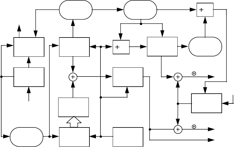
below in terms of their structure and the basic method used for generating them. Figure 3-1 depicts a simplified
block diagram of the scheme for generating the 10.23 Mbps P
i
(t) and the 1.023 Mbps G
i
(t) patterns (referred to as P-
and C/A-codes respectively), and for modulo-2 summing these patterns with the NAV bit train, D(t), which is
clocked at 50 bps. The resultant composite bit trains are then used to modulate the signal carriers.
3.3.2.1 Code Structure
. The P
i
(t) pattern (P-code) is generated by the modulo-2 summation of two PRN codes,
X1(t) and X2(t - iT), where T is the period of one P-code chip and equals (1.023 x 10
7
)
-1
seconds, while i is an
integer from 1 through 37. This allows the generation of 37 unique P(t) code phases (identified in Table 3-I) using
the same basic code generator.
The linear G
i
(t) pattern (C/A-code) is the modulo-2 sum of two 1023-bit linear patterns, G1 and G2
i
. The latter
sequence is selectively delayed by an integer number of chips to produce many different G(t) patterns (defined in
Table 3-I).
The C
M,i
(t) pattern (L2 CM-code) is a linear pattern which is reset with a specified initial state every code count of
10230 chips. Different initial states are used to generate different C
M,i
(t) patterns (defined in Table 3-II).
The C
L,i
(t) pattern (L2 CL-code) is also a linear pattern but with a longer reset period of 767250 chips. Different
initial states are used to generate different C
L,i
(t) patterns (defined in Table 3-II).
For a given SV-ID, two different initial states are used to generate different C
L,i
(t) and C
M,i
(t) patterns.
Section 6.3.5 provides a selected subset of additional P-, L2 CM-, L2 CL-, and the C/A-code sequences with
assigned PRN numbers.
IS-GPS-200D
7 Dec 2004
19
Figure 3-1. Generation of P-, C/A-Codes and Modulating Signals
Z-
COUNTER
RESET
COMMAND
GENERATOR
X1 CODE
GENERATOR
CODE
SELECT
DEVICE
X2 CODE
GENERATOR
RECLOCKING
DEVICE
10.23 MHz
FREQUENCY
SOURCE
GOLD CODE
GENERATOR
EPOCH
RESET
EPOCH
DETECT
EPOCH
RESET
EPOCH
DETECT
10
20
X1 EPOCH
DATA
ENCODER
D(t)
P
i
(t) D(t)
P
i
(t)
FORMATTED
DATA
P
i
(t)
X2
i
(t)
X1(t)
G
i
(t)
REMOTE
COMMAND
Z-COUNT
1.023
MHz
1 KHz
50 Hz
G
i
(t) D(t)

IS-GPS-200D
7 Dec 2004
20
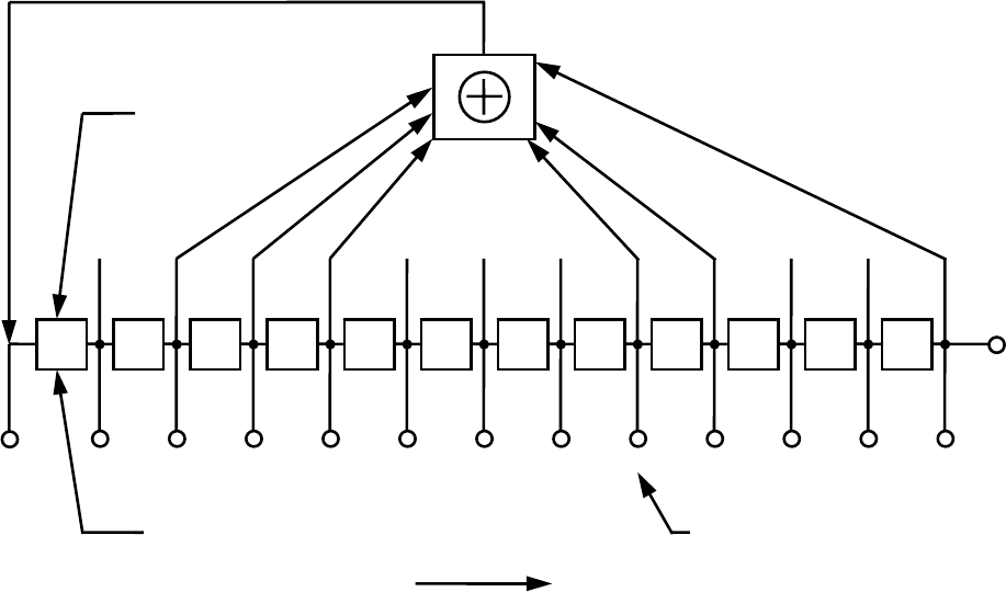
3.3.2.2 P-Code Generation
. Each P
i
(t) pattern is the modulo-2 sum of two extended patterns clocked at 10.23 Mbps
(X1 and X2
i
). X1 itself is generated by the modulo-2 sum of the output of two 12-stage registers (X1A and X1B)
short cycled to 4092 and 4093 chips respectively. When the X1A short cycles are counted to 3750, the X1 epoch is
generated. The X1 epoch occurs every 1.5 seconds after 15,345,000 chips of the X1 pattern have been generated.
The polynomials for X1A and X1B, as referenced to the shift register input, are:
X1A: 1 + X
6
+ X
8
+ X
11
+ X
12
, and
X1B: 1 + X
1
+ X
2
+ X
5
+ X
8
+ X
9
+ X
10
+ X
11
+ X
12
.
Samples of the relationship between shift register taps and the exponents of the corresponding polynomial,
referenced to the shift register input, are as shown in Figures 3-2, 3-3, 3-4 and 3-5.
The state of each generator can be expressed as a code vector word which specifies the binary sequence constant of
each register as follows: (a) the vector consists of the binary state of each stage of the register, (b) the stage 12
value appears at the left followed by the values of the remaining states in order of descending stage numbers, and
(c) the shift direction is from lower to higher stage number with stage 12 providing the current output. This code
vector convention represents the present output and 11 future outputs in sequence. Using this convention, at each
X1 epoch, the X1A shift register is initialized to code vector 001001001000 and the X1B shift register is initialized
to code vector 010101010100. The first chip of the X1A sequence and the first chip of the X1B sequence occur
simultaneously in the first chip interval of any X1 period.
The natural 4095 chip cycles of these generating sequences are shortened to cause precession of the X1B sequence
with respect to the X1A sequence during subsequent cycles of the X1A sequence in the X1 period. Re-
initialization of the X1A shift register produces a 4092 chip sequence by omitting the last 3 chips (001) of the
natural 4095 chip X1A sequence. Re-initialization of the X1B shift register produces a 4093 chip sequence by
omitting the last 2 chips (01) of the natural 4095 chip X1B sequence. This results in the phase of the X1B
sequence lagging by one chip for each X1A cycle in the X1 period.
The X1 period is defined as the 3750 X1A cycles (15,345,000 chips) which is not an integer number of X1B
cycles. To accommodate this situation, the X1B shift register is held in the final state (chip 4093) of its 3749th
cycle. It remains in this state until the X1A shift register completes its 3750th cycle (343 additional chips). The
completion of the 3750th X1A cycle establishes the next X1 epoch which re-initializes both the X1A and X1B shift
registers starting a new X1 cycle.
IS-GPS-200D
7 Dec 2004
21
Figure 3-2. X1A Shift Register Generator Configuration
1
0
2
0
3
0
4
1
5
0
6
0
7
1
8
0
9
0
10
1
11
0
12
0
STAGE
NUMBERS
INITIAL
CONDITIONS
SHIFT DIRECTION
0 1 2 3 4 5 6 7 8 9
10 11 12
OUTPUT
TAP
NUMBERS
POLYNOMIAL X1A:
1 + X
6
+ X
8
+ X
11
+ X
12
IS-GPS-200D
7 Dec 2004
22
Figure 3-3. X1B Shift Register Generator Configuration
1
0
2
0
3
1
4
0
5
1
6
0
7
1
8
0
9
1
10
0
11
1
12
0
STAGE
NUMBERS
INITIAL
CONDITIONS
SHIFT DIRECTION
0 1 2 3 4 5 6 7 8 9
10
11 12
OUTPUT
TAP
NUMBERS
POLYNOMIAL X1B:
1 + X
1
+ X
2
+ X
5
+ X
8
+ X
9
+ X
10
+ X
11
+ X
12
IS-GPS-200D
7 Dec 2004
23
Figure 3-4. X2A Shift Register Generator Configuration
1
1
2
0
3
1
4
0
5
0
6
1
7
0
8
0
9
1
10
0
11
0
12
1
STAGE
NUMBERS
INITIAL
CONDITIONS
SHIFT DIRECTION
0 1 2 3 4 5 6 7 8 9
10
11 12
OUTPUT
TAP
NUMBERS
POLYNOMIAL X2A:
1 + X
1
+ X
3
+ X
4
+ X
5
+ X
7
+ X
8
+ X
9
+ X
10
+ X
11
+ X
12
IS-GPS-200D
7 Dec 2004
24
Figure 3-5. X2B Shift Register Generator Configuration
1
0
2
0
3
1
4
0
5
1
6
0
7
1
8
0
9
1
10
0
11
1
12
0
STAGE
NUMBERS
INITIAL
CONDITIONS
SHIFT DIRECTION
0 1 2 3 4 5 6 7 8 9
10
11 12
OUTPUT
TAP
NUMBERS
POLYNOMIAL X2B:
1 + X
2
+ X
3
+ X
4
+ X
8
+ X
9
+ X
12
IS-GPS-200D
7 Dec 2004
25
The X2
i
sequences are generated by first producing an X2 sequence and then delaying it by a selected integer
number of chips, i, ranging from 1 to 37. Each of the X2
i
sequences is then modulo-2 added to the X1 sequence
thereby producing up to 37 unique P(t) sequences.
The X2A and X2B shift registers, used to generate X2, operate in a similar manner to the X1A and X1B shift
registers. They are short-cycled, X2A to 4092 and X2B to 4093, so that they have the same relative precession rate
as the X1 shift registers. X2A epochs are counted to include 3750 cycles and X2B is held in the last state at 3749
cycle until X2A completes its 3750th cycle. The polynomials for X2A and X2B, as referenced to the shift register
input, are:
X2A: 1 + X
1
+ X
3
+ X
4
+ X
5
+ X
7
+ X
8
+ X
9
+ X
10
+ X
11
+ X
12
, and
X2B: 1 + X
2
+ X
3
+ X
4
+ X
8
+ X
9
+ X
12
.
(The initialization vector for X2A is 100100100101 and for X2B is 010101010100).
The X2A and X2B epochs are made to precess with respect to the X1A and X1B epochs by causing the X2 period
to be 37 chips longer than the X1 period. When the X2A is in the last state of its 3750th cycle and X2B is in the
last state of its 3749th cycle, their transitions to their respective initial states are delayed by 37 chip time durations.
At the beginning of the GPS week, X1A, X1B, X2A and X2B shift registers are initialized to produce the first chip
of the week. The precession of the shift registers with respect to X1A continues until the last X1A period of the
GPS week interval. During this particular X1A period, X1B, X2A and X2B are held when reaching the last state
of their respective cycles until that X1A cycle is completed (see Table 3-VI). At this point, all four shift registers
are initialized and provide the first chip of the new week.
Figure 3-6 shows a functional P-code mechanization. Signal component timing is shown in Figure 3-7, while the
end-of-week reset timing and the final code vector states are given in Tables 3-VI and 3-VII, respectively.
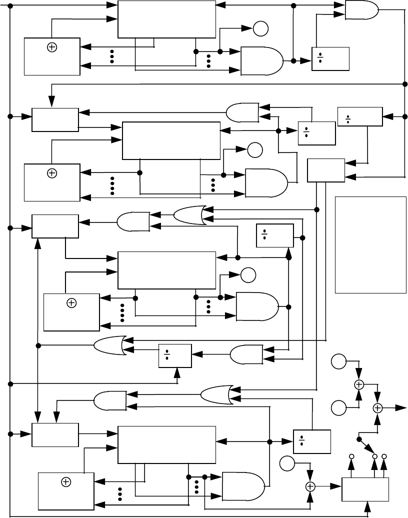
IS-GPS-200D
7 Dec 2004
26
Figure 3-6. P-Code Generation
X1A
REGISTER
C
I
1 6
12
R
4093
DECODE
4092
DECODE
4092
DECODE
4093
DECODE
C
CLOCK
CONTROL
3750
Z-COUNTER
403,200
X1B
REGISTER
C
I
1
12
R
X2A
REGISTER
C
I
1
12
R
X2B
REGISTER
C
I
1 2
12
R
7 DAY
RESET
SHIFT
REGISTER
A
1, 2, 5, 8,
9, 10, 11, 12
1, 3, 4, 5, 7,
8, 9, 10, 11, 12
2, 3, 4,
8, 9, 12
6, 8, 11, 12
A
CLOCK
CONTROL
B
3749
3750
37
C
3749
B
CLOCK
CONTROL
1
i
10.23 MHz
C -
CLOCK
I - INPUT
R -
RESET TO
INITIAL
CONDITIONS
ON NEXT
CLOCK
REGISTER
INPUTS
X1
EPOCH
SET X1A EPOCH
RESUME
HALT
SET X1B
EPOCH
END/WEEK
HALT
START/WEEK
ENABLE
X2
EPOCH
RESUME
HALT
END/WEEK
SET X2B
EPOCH
X2
SET X2A
EPOCH
X1
X2
i
Pi
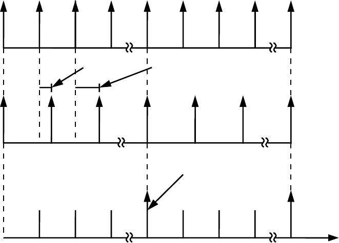
IS-GPS-200D
7 Dec 2004
27
Figure 3-7. P-Code Signal Component Timing
0 1 2 3 0 1 2 3 0
X1 EPOCHS
X2 EPOCHS *
TIME
37 Chips 74 Chips
P Epoch
0
1.5 sec 3.0 sec 4.5 sec 7 days 14 days
* Does not include any offset due to PRN delay.
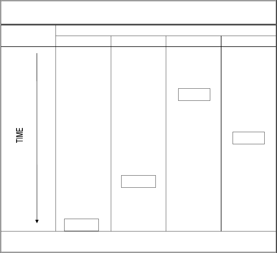
IS-GPS-200D
7 Dec 2004
28
Table 3-VI. P-Code Reset Timing
(Last 400 µsec of 7-day period) **
Code Chip
X1A-Code X1B-Code X2A-Code X2B-Code
1 345 1070 967
• • • •
• • • •
• • • •
3023 3367
4092
3989
• • • •
• • • •
• • • •
3127 3471 4092
4093
• • • •
• • • •
• • • •
3749
4093
4092 4093
• • • •
• • • •
• • • •
4092*
4093 4092 4093
* Last Chip of Week.
** Does not include any X2 offset due to PRN delay.

IS-GPS-200D
7 Dec 2004
29
Table 3-VII. Final Code Vector States
Code Chip Number Vector State
Vector State for 1st Chip
following Epoch
4091 100010010010
X1A
4092 000100100100
001001001000
4092 100101010101
X1B
4093 001010101010
010101010100
4091 111001001001
X2A
4092 110010010010
100100100101
4092 000101010101
X2B
4093 001010101010
010101010100
NOTE: First Chip in each sequence is output bit whose leading edge occurs simultaneously with the epoch.

IS-GPS-200D
7 Dec 2004
30
3.3.2.3 C/A-Code Generation
. Each G
i
(t) sequence is a 1023-bit Gold-code which is itself the modulo-2 sum of two
1023-bit linear patterns, G1 and G2
i
. The G2
i
sequence is formed by effectively delaying the G2 sequence by an
integer number of chips. The G1 and G2 sequences are generated by 10-stage shift registers having the following
polynomials as referred to in the shift register input (see Figures 3-8 and 3-9).
G1 = X
10
+ X
3
+ 1, and
G2 = X
10
+ X
9
+ X
8
+ X
6
+ X
3
+ X
2
+ 1.
The initialization vector for the G1 and G2 sequences is 1111111111. The G1 and G2 shift registers are initialized
at the P-coder X1 epoch. The G1 and G2 registers are clocked at 1.023 MHz derived from the 10.23 MHz P-coder
clock. The initialization by the X1 epoch phases the 1.023 MHz clock to insure that the first chip of the C/A code
begins at the same time as the first chip of the P-code.
The effective delay of the G2 sequence to form the G2
i
sequence may be accomplished by combining the output of
two stages of the G2 shift register by modulo-2 addition (see Figure 3-10). However, this two-tap coder
implementation generates only a limited set of valid C/A codes. Table 3-I contains a tabulation of the G2 shift
register taps selected and their corresponding P-code X2
i
and PRN signal numbers together with the first several
chips of each resultant PRN code. Timing relationships related to the C/A code are shown in Figure 3-11.
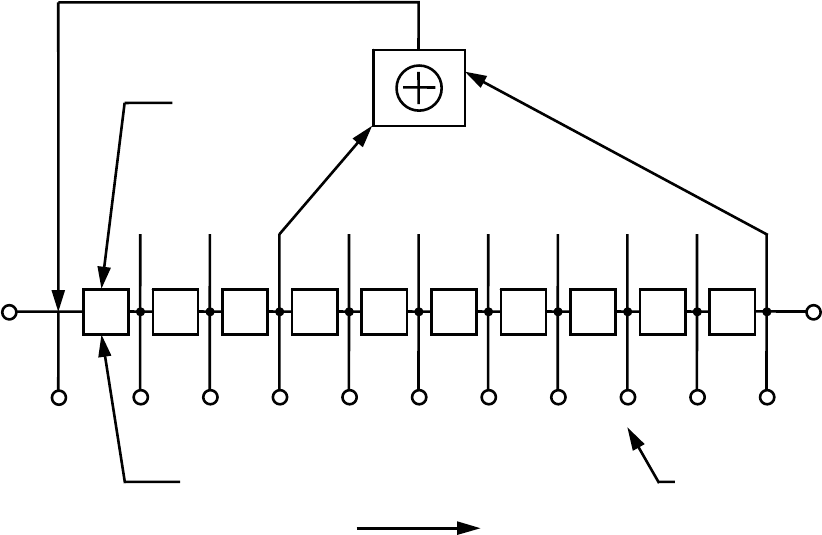
IS-GPS-200D
7 Dec 2004
31
Figure 3-8. G1 Shift Register Generator Configuration
1
1
2
1
3
1
4
1
5
1
6
1
7
1
8
1
9
1
10
1
STAGE
NUMBERS
INITIAL
CONDITIONS
SHIFT DIRECTION
0 1 2 3 4 5 6 7 8 9
10
OUTPUT
TAP
NUMBERS
POLYNOMIAL G1:
1 + X
3
+ X
10
INPUT
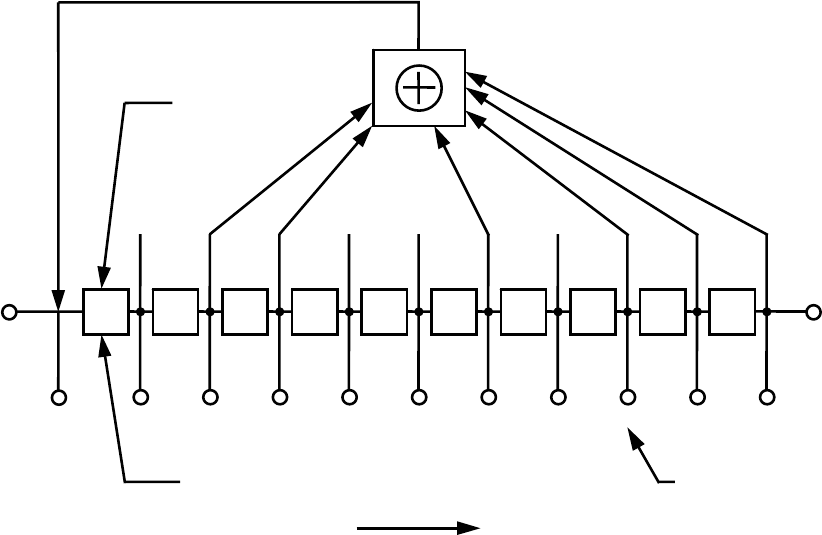
IS-GPS-200D
7 Dec 2004
32
Figure 3-9. G2 Shift Register Generator Configuration
1
1
2
1
3
1
4
1
5
1
6
1
7
1
8
1
9
1
10
1
STAGE
NUMBERS
INITIAL
CONDITIONS
SHIFT DIRECTION
0 1 2 3 4 5 6 7 8 9
10
OUTPUT
TAP
NUMBERS
POLYNOMIAL G2:
1 + X
2
+ X
3
+X
6
+ X
8
+ X
9
+ X
10
INPUT
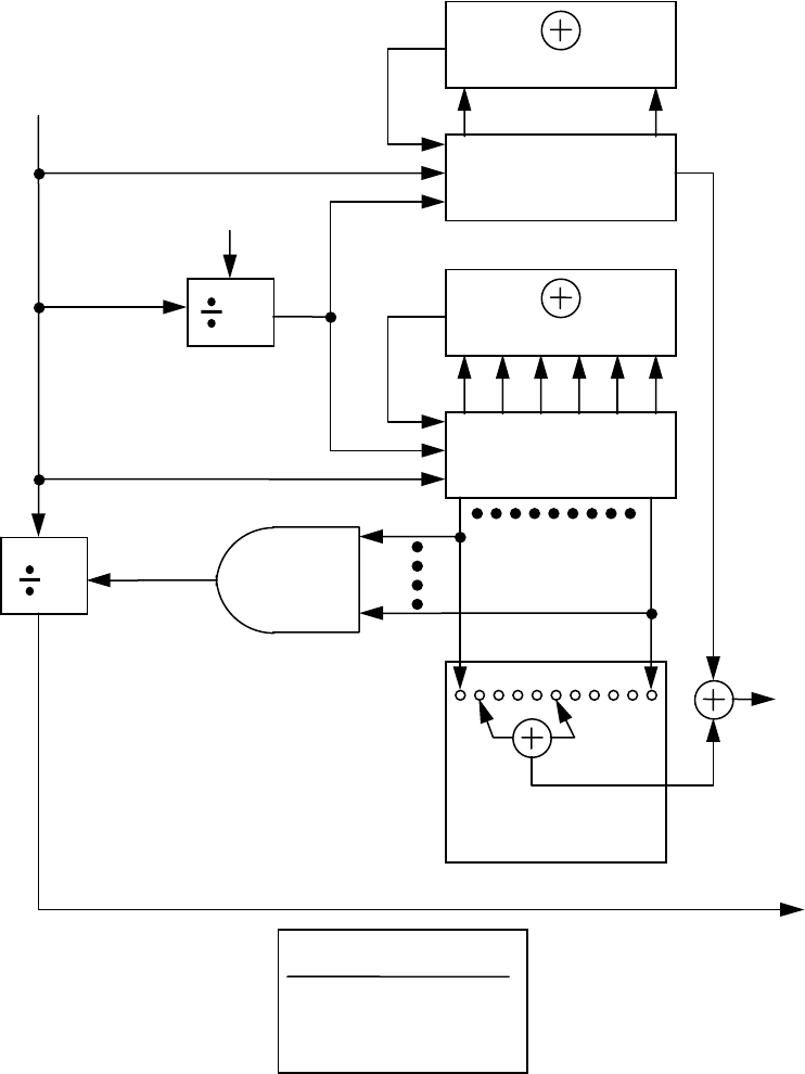
IS-GPS-200D
7 Dec 2004
33
Figure 3-10. Example C/A-Code Generation
10
S
C
I
C
S
I
G1
REGISTER
2 3 6 8 9 10
G2
REGISTER
3
10
10.23 MHz
SYNCH
X1 EPOCH
20
SYNCH
G EPOCH
1 Kbps
1023
DECODE
50 bps TO DATA ENCODER
PHASE SELECT
LOGIC
G2
i
G1
REGISTER INPUTS
C - CLOCK
I - INPUT
S - SET ALL ONES
G
i
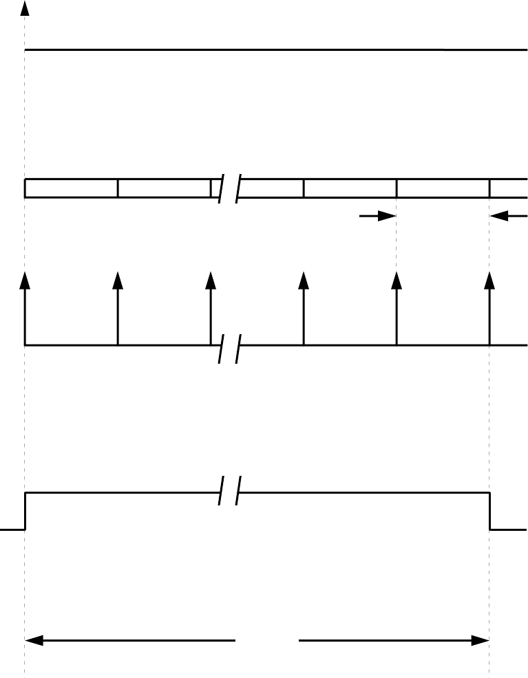
IS-GPS-200D
7 Dec 2004
34
Figure 3-11. C/A-Code Timing Relationships
1023
etc.
X1 Epoch @ 2/3 bps
0 1 2 18 19 0
1 msec
1023 BIT Gold Code @ 1023 Kbps
1023
1023 1023 1023
Gold Code Epochs @ 1000/sec
Data @ 50 cps
20 msec

IS-GPS-200D
7 Dec 2004
35
3.3.2.4 L2 CM-/L2 CL-Code Generation
. Each C
M,i
(t) pattern (L2 CM-code) and C
L,i
(t) pattern (L2 CL-code) are
generated using the same code generator polynomial each clocked at 511.5 Kbps. Each pattern is initiated and
reset with a specified initial state (defined in Table 3-II). C
M,i
(t) pattern is reset after 10230 chips resulting in a
code period of 20 milliseconds, and C
L,i
(t) pattern is reset after 767250 chips resulting in a code period of 1.5
seconds. The L2 CM and L2 CL shift registers are initialized at the P-coder X1 epoch. The first L2 CM-code
chip starts synchronously with the end/start of week epoch. Timing relationships related to the L2 CM-/L2 CL-
codes are shown in Figure 3-12.
The maximal polynomial used for L2 CM- and L2 CL-codes is 1112225171 (octal) of degree 27. The L2 CM and
L2 CL code generator is conceptually described in Figure 3-13 using modular-type shift register generator.
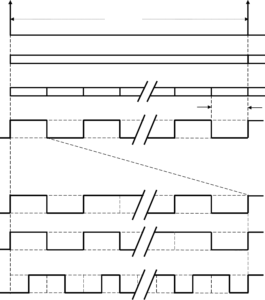
IS-GPS-200D
7 Dec 2004
36
Figure 3-12. L2 CM-/L2 CL-Code Timing Relationships
End/start of week
X1 Epoch @ 2/3 bps
1.5 second
767250 Chips
767250 BIT L2 CL-Code @ 511.5 Kbps
10230
10230 BIT L2 CM-Code @ 511.5 Kbps
10230 10230 10230 10230 10230 10230
1 2
4
3
73
74
75
0
etc.
etc.
20 msec
1
Data @ 50 cps
L2 CM @ 511.5 Kbps
L2 C @ 1023 Kbps
L2 CL @ 511.5 Kbps
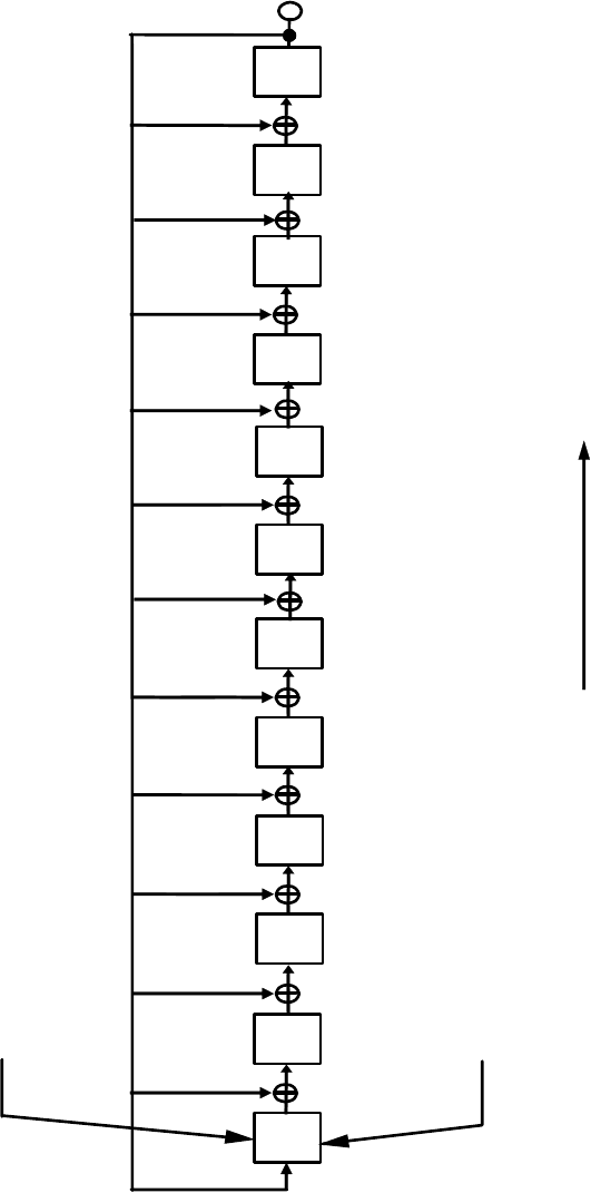
IS-GPS-200D
7 Dec 2004
37
DELAY
NUMBERS
SHIFT DIRECTION
OUTPU
T
INITIAL CONDITIONS ARE A FUNCTION OF PRN AND CODE PERIOD (MODERATE/LONG)
1 3 1 1 3 3
2 3
3 2 2 3
POLYNOMIAL:
1 + X
3
+ X
4
+X
5
+ X
6
+ X
9
+ X
11
+ X
13
+ X
16
+ X
19
+ X
21
+ X
24
+ X
27
Figure 3-13. L2 CM/L2 CL Shift Register Generator Configuration

IS-GPS-200D
7 Dec 2004
38
3.3.3 Navigation Data
. The content and format of the NAV data, D(t), and the CNAV data, D
C
(t), are given in
Appendices II and III, respectively, of this document.
3.3.3.1 Navigation Data Modulation (L2 CM)
. For Block IIR-M, Block IIF, and subsequent blocks of SVs, the
CNAV bit train, D
C
(t), is rate ½ encoded and, thus, clocked at 50 sps. The resultant symbol sequence is then
modulo-2 added to the L2 CM-code. During the initial period of Block IIR-M SVs operation, prior to Initial
Operational Capability of L2 C signal, and upon ground command, the NAV bit train, D(t), at one of two data rates,
may be modulo-2 added to the L2 CM-code instead of CNAV data, D
C
(t), as further described in Section 3.2.2.
3.3.3.1.1 Forward Error Correction
. The CNAV bit train, D
C
(t), will always be Forward Error Correction (FEC)
encoded by a rate 1/2 convolutional code. For Block IIR-M, the NAV bit train, D(t), can be selected to be
convolutionally encoded. The resulting symbol rate is 50 sps. The convolutional coding will be constraint length 7,
with a convolutional encoder logic arrangement as illustrated in Figure 3-14. The G1 symbol is selected on the
output as the first half of a 40-millisecond data bit period.
Twelve-second navigation messages broadcast by the SV are synchronized with every eighth of the SV's P(Y)-code
X1 epochs. However, the navigation message is FEC encoded in a continuous process independent of message
boundaries (i.e. at the beginning of each new message, the encoder registers illustrated in Figure 3-14 contains the
last six bits of the previous message).
Because the FEC encoding convolves successive messages, it is necessary to define which transmitted symbol is
synchronized to SV time, as follows. The beginning of the first symbol that contains any
information about the first
bit of a message will be synchronized to every eighth X1 epoch (referenced to end/start of week). The users’
convolutional decoders will introduce a fixed delay that depends on their respective algorithms (usually 5 constraint
lengths, or 35 bits), for which they must compensate to determine system time from the received signal. This
convolutional decoding delay and the various relationships with the start of the data block transmission and SV time
are illustrated in Figure 3-15.
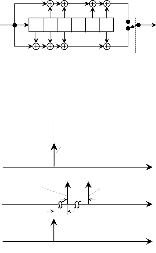
IS-GPS-200D
7 Dec 2004
39
Figure 3-14. Convolutional Encoder
Figure 3-15. Convolutional Transmit/Decoding Timing Relationships
G1 (171 OCTAL)
G2 (133 OCTAL)
DATA INPUT
(25 BPS)
SYMBOL
CLOCK
OUTPUT SYMBOLS
(50 SPS)
(ALTERNATING G1/G2)
USER’S DECODING DELAY
DOWNLINK DELAY
LATER
ENCODED DATA BLOCK
TRANSMITTED ON L2
EARLY
SV 12 SECOND EPOCHS
ENCODED
DATA BLOCK
RECEIVED
BY USER
DATA BLOCK
DECODED BY
USER

IS-GPS-200D
7 Dec 2004
40
3.3.4 GPS Time and SV Z-Count
. GPS time is established by the Control Segment and is referenced to
Coordinated Universal Time (UTC) as maintained by the U.S. Naval Observatory (UTC(USNO)) zero time-point
defined as midnight on the night of January 5, 1980/morning of January 6, 1980. The largest unit used in stating
GPS time is one week defined as 604,800 seconds. GPS time may differ from UTC because GPS time shall be a
continuous time scale, while UTC is corrected periodically with an integer number of leap seconds. There also is an
inherent but bounded drift rate between the UTC and GPS time scales. The OCS shall control the GPS time scale to
be within one microsecond of UTC (modulo one second).
The NAV data contains the requisite data for relating GPS time to UTC. The accuracy of this data during the
transmission interval shall be such that it shall relate GPS time (maintained by the MCS of the CS) to UTC
(USNO) within 90 nanoseconds (one sigma). This data is generated by the CS; therefore, the accuracy of this
relationship may degrade if for some reason the CS is unable to upload data to a SV. At this point, it is assumed
that alternate sources of UTC are no longer available, and the relative accuracy of the GPS/UTC relationship will
be sufficient for users. Range error components (e.g. SV clock and position) contribute to the GPS time transfer
error, and under normal operating circumstances (two frequency time transfers from SV(s) whose navigation
message indicates a URA of eight meters or less), this corresponds to a 97 nanosecond (one sigma) apparent
uncertainty at the SV. Propagation delay errors and receiver equipment biases unique to the user add to this time
transfer uncertainty.
IS-GPS-200D
7 Dec 2004
41
In each SV the X1 epochs of the P-code offer a convenient unit for precisely counting and communicating time.
Time stated in this manner is referred to as Z-count, which is given as a 29-bit binary number consisting of two
parts as follows:
a. The binary number represented by the 19 least significant bits of the Z-count is referred to as the time of
week (TOW) count and is defined as being equal to the number of X1 epochs that have occurred since the
transition from the previous week. The count is short-cycled such that the range of the TOW-count is
from 0 to 403,199 X1 epochs (equaling one week) and is reset to zero at the end of each week. The TOW-
count's zero state is defined as that X1 epoch which is coincident with the start of the present week. This
epoch occurs at (approximately) midnight Saturday night-Sunday morning, where midnight is defined as
0000 hours on the UTC scale which is nominally referenced to the Greenwich Meridian. Over the years the
occurrence of the "zero state epoch" may differ by a few seconds from 0000 hours on the UTC scale since
UTC is periodically corrected with leap seconds while the TOW-count is continuous without such
correction. To aid rapid ground lock-on to the P-code signal, a truncated version of the TOW-count,
consisting of its 17 most significant bits, is contained in the hand-over word (HOW) of the L1 and L2 NAV
data (D(t)) stream; the relationship between the actual TOW-count and its truncated HOW version is
illustrated by Figure 3-16.
b. The ten most significant bits of the Z-count are a modulo 1024 binary representation of the sequential
number assigned to the current GPS week (see paragraph 6.2.4). The range of this count is from 0 to 1023
with its zero state being defined as the GPS week number zero and every integer multiple of 1024 weeks,
thereafter (i.e. 0, 1024, 2048, etc.).
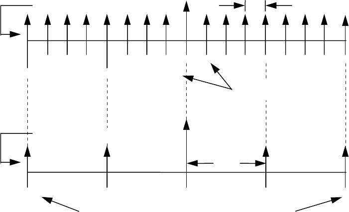
IS-GPS-200D
7 Dec 2004
42
Figure 3-16. Time Line Relationship of HOW Message
403,192 403,196 403,199
P(Y)-CODE EPOCH
(END/START OF WEEK)
10 2 3 4 5 6 7 8
100,799 10 2 3
X1 EPOCHS 1.5 sec
DECIMAL EQUIVALENTS
OF ACTUAL TOW COUNTS
SUBFRAME EPOCHS
DECIMAL EQUIVALENTS OF HOW-MESSAGE TOW COUNTS
NOTES:
1. TO AID IN RAPID GROUND LOCK-ON THE HAND-OVER WORD (HOW ) OF EACH
SUBFRAME CONTAINS A TRUNCATED TIME-OF-WEEK (TOW) COUNT
2.
THE HOW IS THE SECOND WORD IN EACH SUBFRAME (REFERENCE
PARAGRAPH 20.3.3.2).
3.
THE HOW-MESSAGE TOW COUNT CONSISTS OF THE 17 MSBs OF THE
ACTUAL TOW COUNT AT THE START OF THE NEXT SUBFRAME.
4.
TO CONVERT FROM THE HOW-MESSAGE TOW COUNT TO THE ACTUAL TOW
COUNT AT THE START OF THE NEXT SUBFRAME, MULTIPLY BY FOUR.
5.
THE FIRST SUBFRAME STARTS SYNCHRONOUSLY WITH THE END/START OF
WEEK EPOCH.
6 sec
IS-GPS-200D
7 Dec 2004
43
4. NOT APPLICABLE
IS-GPS-200D
7 Dec 2004
44
(This page intentionally left blank.)
IS-GPS-200D
7 Dec 2004
45
5. NOT APPLICABLE
IS-GPS-200D
7 Dec 2004
46
(This page intentionally left blank.)

IS-GPS-200D
7 Dec 2004
47
6. NOTES
6.1 Acronyms
AI - Availability Indicator
AODO - Age of Data Offset
A-S - Anti-Spoofing
Autonav - Autonomous Navigation
BPSK - Bi-Phase Shift Key
CDC - Clock Differential Correction
CNAV - Civil Navigation
cps - cycles per second
CRC - Cyclic Redundancy Check
CS - Control Segment
DC - Differential Correction
DN - Day Number
EAROM - Electrically Alterable Read-Only Memory
ECEF - Earth-Centered, Earth-Fixed
ECI - Earth-Centered, Inertial
EDC - Ephemeris Differential Correction
EOE - Edge-of-Earth
EOL - End of Life
ERD - Estimated Range Deviation
FEC - Forward Error Correction
GGTO - GPS/GNSS Time Offset
GNSS - Global Navigation Satellite System
GPS - Global Positioning System
HOW - Hand-Over Word
ICC - Interface Control Contractor
ID - Identification
IERS - International Earth Rotation and Reference Systems Service
IS-GPS-200D
7 Dec 2004
48
IODC - Issue of Data, Clock
IODE - Issue of Data, Ephemeris
IRM - IERS Reference Meridian
IRP - IERS Reference Pole
IS - Interface Specification
ISC - Inter-Signal Correction
LSB - Least Significant Bit
LSF - Leap Seconds Future
L2 C - L2 Civil Signal
L2 CL - L2 Civil-Long Code
L2 CM - L2 Civil-Moderate Code
MCS - Master Control Station
MSB - Most Significant Bit
NAV - Navigation
NDUS - Nudet Detection User Segment
NMCT - Navigation Message Correction Table
NSC - Non-Standard C/A-Code
NSCL - Non-Standard L2 CL-Code
NSCM - Non-Standard L2 CM-Code
NSY - Non-Standard Y-code
OBCP - On-Board Computer Program
OCS - Operational Control System
PRN - Pseudo-Random Noise
RF - Radio Frequency
RMS - Root Mean Square
SA - Selective Availability
SEP - Spherical Error Probable
sps - symbols per second
IS-GPS-200D
7 Dec 2004
49
SS - Space Segment
SV - Space Vehicle
SVN - Space Vehicle Number
TBD - To Be Determined
TBS - To Be Supplied
TLM - Telemetry
TOW - Time Of Week
UE - User Equipment
URA - User Range Accuracy
URE - User Range Error
US - User Segment
USNO - U.S. Naval Observatory
UTC - Coordinated Universal Time
WGS 84 - World Geodetic System 1984
WN - Week Number
WN
e
- Extended Week Number
IS-GPS-200D
7 Dec 2004
50
(This page intentionally left blank.)

IS-GPS-200D
7 Dec 2004
51
6.2 Definitions
6.2.1 User Range Accuracy
. User range accuracy (URA) is a statistical indicator of the ranging accuracies
obtainable with a specific SV. URA is a one-sigma estimate of the user range errors in the navigation data for the
transmitting satellite. It includes all errors for which the Space and Control Segments are responsible. It does not
include any errors introduced in the user set or the transmission media. While the URA may vary over a given
subframe fit interval, the URA index (N) reported in the NAV message corresponds to the maximum value of URA
anticipated over the fit interval.
6.2.2 SV Block Definitions
. The following block definitions are given to facilitate discussion regarding the
capability of the various blocks of GPS satellites to support the SV-to-US interface.
6.2.2.1 Developmental SVs
. The original concept validation satellites developed by Rockwell International and
designated as satellite vehicle numbers (SVNs) 1-11 are termed "Block I" SVs. These SVs were designed to provide
3-4 days of positioning service without contact from the CS. These SVs transmitted a configuration code of 000
(reference paragraph 20.3.3.5.1.4). There are no longer any active Block I SVs in the GPS constellation. The last
Block I SV was decommissioned in 1995.
6.2.2.2 Operational SVs
. The operational satellites are designated Block II, Block IIA, Block IIR, Block IIR-M and
Block IIF SVs. Characteristics of these SVs are provided below. Modes of operation for these SVs and accuracy of
positioning services provided are described in paragraphs 6.3.2 through 6.3.4. These SVs transmit configuration
codes as specified in paragraph 20.3.3.5.1.4. The navigation signal provides no direct indication of the type of the
transmitting SV.
6.2.2.2.1 Block II SVs
. The first block of full scale operational SVs developed by Rockwell International are
designated as SVNs 13-21 and are termed "Block II" SVs. These SVs were designed to provide 14 days of
positioning service without contact from the CS.
6.2.2.2.2 Block IIA SVs
. The second block of full scale operational SVs developed by Rockwell International are
designated as SVNs 22-40 and are termed "Block IIA" SVs. These SVs are capable of providing 60 days of
positioning service without contact from the CS.

IS-GPS-200D
7 Dec 2004
52
6.2.2.2.3 Block IIR SVs
. The block of operational replenishment SVs developed by Lockheed Martin are
designated as SVNs 41-61 and are termed "Block IIR" SVs. These SVs have the capability of storing at least 60
days of navigation data with current memory margins, while operating in a IIA mode, to provide positioning service
without contact from the CS for that period. (Contractual requirements for these SVs specify transmission of correct
data for only 14 days to support short-term extended operations while in IIA mode.) The IIR SV will provide a
minimum of 60 days of positioning service without contact from the CS when operating in autonomous navigation
(Autonav) mode.
6.2.2.2.4 Block IIR-M SVs
. The subset of operational replenishment SVs developed by Lockheed Martin which
are “Modernized” configuration of “Block IIR” SVs are termed “Block IIR-M”.
6.2.2.2.5 Block IIF SVs
. The block of operational replenishment SVs developed by Boeing are designated as SVNs
62-73 and are termed “Block IIF” SVs. This is the first block of operational SVs that transmit the L5 Civil signal.
These SVs will provide at least 60 days of positioning service without contact from the CS.
6.2.3 Operational Interval Definitions
. The following three operational intervals have been defined. These labels
will be used to refer to differences in the interface definition as time progresses from SV acceptance of the last
navigation data upload.
6.2.3.1 Normal Operations
. The SV is undergoing normal operations whenever the fit interval flag (reference
paragraph 20.3.3.4.3.1) is zero.
6.2.3.2 Short-term Extended Operations
. The SV is undergoing short-term extended operations whenever the fit
interval flag is one and the IODE (reference paragraph 20.3.4.4) is less than 240.
6.2.3.3 Long-term Extended Operations
. The SV is undergoing long-term extended operations whenever the fit
interval flag is one and the IODE is in the range 240-255.

IS-GPS-200D
7 Dec 2004
53
6.2.4 GPS Week Number
. The GPS week numbering system is established with week number zero (0) being
defined as that week which started with the X1 epoch occurring at midnight UTC(USNO) on the night of January 5,
1980/ morning of January 6, 1980. The GPS week number continuously increments by one (1) at each end/start of
week epoch without ever resetting to zero. Users must recognize that the week number information contained in the
Nav Message may not necessarily reflect the current full GPS week number (see paragraphs 20.3.3.3.1.1,
20.3.3.5.1.5, 20.3.3.5.2.4, and 30.3.3.1.1.1).
6.2.5 L5 Civil Signal
. L5 is the GPS downlink signal at a nominal carrier frequency of 1176.45 MHz. The L5
signal is only available on Block IIF and subsequent blocks of SVs and the signal is specified/described in a separate
and different interface control document.
6.3 Supporting Material
6.3.1 Received Signals
. The guaranteed minimum user-received signal levels are defined in paragraph 3.3.1.6.
As additional supporting material, Figure 6-1 illustrates an example variation in the minimum received power of the
near-ground user-received L1 and L2 signals from Block II/IIA/IIR SVs as a function of SV elevation angle.
Higher received signals levels can be caused by such factors as SV attitude errors, mechanical antenna alignment
errors, transmitter power output variations due to temperature variations, voltage variations and power amplifier
variations, and due to a variability in link atmospheric path loss. For Block II/IIA and IIR SVs, the maximum
received signal levels as a result of these factors is not expected to exceed -155.5 dBW and -153.0 dBW,
respectively, for the P(Y) and C/A components of the L1 channel, nor -158.0 dBW for either signal on the L2
channel. For Block IIR-M and IIF SVs, the maximum received signal levels as a result of these factors is not
expected to exceed -155.5 dBW and -153.0 dBW, respectively, for the P(Y) and C/A components of the L1 channel
and L2 channel. In addition, due to programmable power output capabilities of Block IIR-M and IIF SVs, under
certain operational scenarios, individual signal components of Block IIR-M/IIF SVs may exceed the previously
stated maximum but are not expected to exceed -150 dBW.
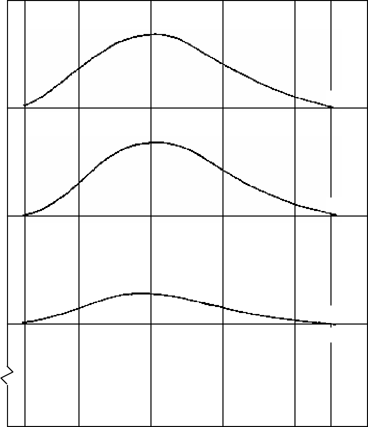
IS-GPS-200D
7 Dec 2004
54
Figure 6-1. User Received Minimum Signal Level Variations (Example, Block II/IIA/IIR)
0
o
5
o
20
o
40
o
60
o
80
o
100
o
90
o
USER ELEVATION ANGLE (DEG)
RECEIVED POWER AT 3dB
i
LINEARLY POLARIZED ANTENNA (dBW)
C/A - L
1
P - L
1
P - L
2
or
C/A - L
2
-158.5
-161.5
-164.5
-155.5

IS-GPS-200D
7 Dec 2004
55
6.3.2 Extended Navigation Mode (Block II/IIA)
. The Block II and IIA SVs are capable of being uploaded by the
CS with a minimum of 60 days of navigation data to support a 60 day positioning service. Due to memory
retention limitations, the Block II SVs may not transmit correct data for the entire 60 days but are guaranteed to
transmit correct data for at least 14 days to support short-term extended operations. Under normal conditions the CS
will provide daily uploads to each SV, which will allow the SV to maintain normal operations as defined in
paragraph 6.2.3.1 and described within this IS. During normal operations, the SVs will have a user range error that
is at or below a level required to support a positioning accuracy of 16 meters spherical error probable (SEP). In
addition, the almanac data, UTC parameters and ionospheric data will be maintained current to meet the accuracy
specified in this IS.
If the CS is unable to upload the SVs (the CS is unavailable or the SV is unable to accept and process the upload),
each SV will individually transition to short-term extended operations and eventually to long-term extended
operations (based on time from each SV's last upload) as defined in paragraphs 6.2.3.2 and 6.2.3.3, and as further
described throughout this IS. As time from upload continues through these three operational intervals, the user
range error of the SV will increase, causing a positioning service accuracy degradation. The rate of accuracy
degradation is slow over the short-term extended operations interval, such that at the end of this interval
(approximately 14 days after upload) the US will be able to achieve a positioning accuracy of 425 meters SEP. The
rate of accuracy degradation increases in the long-term extended interval, such that by the 180th day after the last
upload, the positioning errors will have grown to 10 kilometers SEP. During these intervals the URA will continue
to provide the proper estimate of the user range errors.
During short-term and long-term extended operations (approximately day 2 through day 62 after an upload), the
almanac data, UTC parameters and ionospheric data will not be maintained current and will degrade in accuracy
from the time of last upload.

IS-GPS-200D
7 Dec 2004
56
6.3.3 Block IIA Mode (Block IIR/IIR-M)
. The Block IIR/IIR-M SVs, when operating in the Block IIA mode, will
perform similarly to the Block IIA SVs and have the capability of storing at least 60 days of navigation data, with
current memory margins, to provide positioning service without contact from the CS for that period (through
short-term and long-term extended operations). (Contractual requirements for these SVs specify transmission of
correct data for only 14 days to support short-term extended operations while in IIA mode.) Under normal
conditions, the CS will provide daily uploads to each SV, which will allow the SV to maintain normal operations as
defined in paragraph 6.2.3.1 and described within this IS.
If the CS is unable to upload the SVs (the CS is unavailable or the SV is unable to accept and process the upload),
each SV will individually transition to short-term extended operations and eventually to long-term extended
operations (based on time from each SV’s last upload) as defined in paragraph 6.2.3.2 and 6.2.3.3, and as further
described throughout this IS. As time from upload continues through these three operational intervals, the user
range error (URE) of the SV will increase, causing a positioning service accuracy degradation.
6.3.4 Autonomous Navigation Mode
. The Block IIR/IIR-M and Block IIF SV, in conjunction with a sufficient
number of other Block IIR/IIR-M or Block IIF SVs, operates in an Autonav mode when commanded by the CS.
Each Block IIR/IIR-M/IIF SV in the constellation determines its own ephemeris and clock correction parameters via
SV-to-SV ranging, communication of data, and on-board data processing which updates data uploaded by the CS.
In the Autonav mode the Block IIR/IIR-M/IIF SV will maintain normal operations as defined in paragraph 6.2.3.1
and as further described within this IS, and will have a URE of no larger than 6 meters, one sigma for Block IIR/IIR-
M. URE of 6 meters, one sigma, is expected to support 16 meter SEP accuracy under a nominal position dilution of
precision. If the CS is unable to upload the SVs, the Block IIR/IIR-M/IIF SVs will maintain normal operations for
period of at least 60 days after the last upload.
In the Autonav mode, the almanac data, UTC parameters and ionospheric data are still calculated and maintained
current by the CS and uploaded to the SV as required. If the CS is unable to upload the SVs, the almanac data,
UTC parameters and ionospheric data will not be maintained current and will degrade in accuracy from the time of
the last upload.

IRN-200D-001
IS-GPS-200D
7 Mar 2006
56a
6.3.5 PRN Code sequences expansion
. The additional PRN sequences provided in this section are for information
only. The additional PRN sequences identified in this section are not applicable to Block II/IIA, IIR/IIR-M, IIF
SVs. In addition, the current valid range for GPS PRN signal number for C/A- and P-code is 1 – 37 as specified
in Table 3-I. The PRN sequences provided in this section are for other L1/L2 signal applications, such as Satellite
Based Augmentation System (SBAS) satellite signals, and potential use in the future by GPS.
6.3.5.1 Additional C/A-code PRN sequences. The PRN C/A-code is described in Section 3.2.1.3 and 36 legacy
C/A-code sequences are assigned by SV-ID number in Table 3-I. An additional set of 173 C/A-code PRN
sequences are selected and assigned with PRN numbers in this section as shown in Table 6-I. Among the 173
additional sequences; PRN numbers 38 through 63 are reserved for future GPS SVs; PRN numbers 64 through 119
are reserved for future Ground Based Augmentation System (GBAS) and other augmentation systems; PRN
numbers 120 through 158 are reserved for SBAS; and PRN numbers 159 through 210 are reserved for other Global
Navigation Satellite System (GNSS) applications. For GPS application, the CNAV data, D
c
(t), will be modulo-2
added to the C/A-code sequences of PRN numbers 38 through 63. Any assignment of a C/A-code PRN number and
its code sequence for any additional SV and/or other L1/L2 signal applications, such as SBAS satellite signals, will
be selected from the sequences of Table 6-I and will be approved, controlled, and managed by the GPS JPO.
It should be noted that, in Table 6-I, the C/A-code sequences are identified by “G2 Delay” and “Initial G2 Setting”
which is not as same as the method used in Table 3-I. The two-tap coder implementation method referenced and
used in Table 3-I is not used in Table 6-I due to its limitation in generating C/A-code sequences. The “G2 Delay”
specified in Table 6-I may be accomplished by using the “Initial G2 Setting” as the initialization vector for the G2
shift register of Figure 3-9.

IRN-200D-001
IS-GPS-200D
7 Mar 2006
56b
6.3.5.2 Additional P-Code PRN sequences
. The PRN P-code set of 37 mutually exclusive sequences are described
in Section 3.2.1.1, and assignment of these code segments by SV-ID number is given in Table 3-I. An additional set
of 173 P-code PRN sequences are described in this section. Among the 173 additional sequences; PRN numbers 38
through 63 are reserved for future GPS SVs; PRN numbers 64 through 119 are reserved for future GBAS and other
augmentation systems; and PRN numbers 120 through 210 are reserved for other future applications. For GPS
application, the CNAV data, D
c
(t), which may include additional future military message types, will be modulo-2
added to the P-code sequences of PRN numbers 38 through 63. The P-code PRN numbers and their code sequences
defined in Table 6-I are not for general use and will be approved, controlled, and managed by the GPS JPO.
6.3.5.2.1 Additional P-code Generation. The generation of 37 mutually exclusive P-code PRN sequences are
described in Section 3.3.2.2. The additional set of 173 P-code PRN sequences are generated by circularly shifting
each of the original 37 sequences (over one week) by an amount corresponding to 1, 2, 3, 4, or 5 days. The
additional sequences are therefore time shifted (i.e. offset) versions of the original 37 sequences. These offset P-
code PRN sequences, P
i
(t), are described as follows:
P
i
(t) = P
i-37x
(t – xT),
where i is an integer from 38 to 210, x is an integer portion of (i-1)/37, and T is defined to equal 24 hours.
As an example, P-code sequence for PRN 38 would be the same sequence as PRN 1 shifted 24 hours into a week
(i.e. 1
st
chip of PRN 38 at beginning of week is the same chip for PRN 1 at 24 hours after beginning of week). The
complete list of the additional P-code PRN assignment is shown in Table 6-I. Any assignment of a P-code PRN
number and its code sequence for any additional SV and/or other L1/L2 signal applications will be selected from the
sequences of Table 6-I.

IRN-200D-001
IS-GPS-200D
7 Mar 2006
56c
Table 6-I Additional C/A-/P-Code Phase Assignments (sheet 1 of 6)
C/A P
PRN
Signal
No. *
G2 Delay
(Chips)
Initial G2
Setting
(Octal)**
First 10 Chips
(Octal)**
X2 Delay
(Chips)
P-code
Relative Delay
(Hours) ***
First 12 Chips
(Octal)
38
39
40
41
42
43
44
45
46
47
48
49
50
51
52
53
54
55
56
57
58
59
60
61
62
63
67
103
91
19
679
225
625
946
638
161
1001
554
280
710
709
775
864
558
220
397
55
898
759
367
299
1018
0017
0541
1714
1151
1651
0103
0543
1506
1065
1564
1365
1541
1327
1716
1635
1002
1015
1666
0177
1353
0426
0227
0506
0336
1333
1745
1760
1236
0063
0626
0126
1674
1234
0271
0712
0213
0412
0236
0450
0061
0142
0775
0762
0111
1600
0424
1351
1550
1271
1441
0444
0032
1
2
3
4
5
6
7
8
9
10
11
12
13
14
15
16
17
18
19
20
21
22
23
24
25
26
P
1
(t-24)
P
2
(t-24)
P
3
(t-24)
P
4
(t-24)
P
5
(t-24)
P
6
(t-24)
P
7
(t-24)
P
8
(t-24)
P
9
(t-24)
P
10
(t-24)
P
11
(t-24)
P
12
(t-24)
P
13
(t-24)
P
14
(t-24)
P
15
(t-24)
P
16
(t-24)
P
17
(t-24)
P
18
(t-24)
P
19
(t-24)
P
20
(t-24)
P
21
(t-24)
P
22
(t-24)
P
23
(t-24)
P
24
(t-24)
P
25
(t-24)
P
26
(t-24)
3373
3757
3545
5440
4402
4023
4233
2337
3375
3754
3544
3440
5402
2423
5033
2637
3135
5674
4514
2064
5210
2726
5171
2656
5105
2660
* PRN sequences 38 through 63 are reserved for GPS.
** In the octal notation for the first 10 chips of the C/A-code or the initial settings as shown in this table,
the first digit (1/0) represents a "1" or “0”, respectively, for the first chip and the last three digits are
the conventional octal representation of the remaining 9 chips. (For example, the first 10 chips of the
C/A code for PRN Signal Assembly No. 38 are: 1111110000).
*** P
i
(t-N): P-code sequence of PRN number i shifted by N hours. See Section 6.3.5.2.1.

IRN-200D-001
IS-GPS-200D
7 Mar 2006
56d
Table 6-I Additional C/A-/P-Code Phase Assignments (sheet 2 of 6)
C/A P
PRN
Signal
No.
G2 Delay
(Chips)
Initial G2
Setting
(Octal)**
First 10 Chips
(Octal)**
X2 Delay
(Chips)
P-code
Relative Delay
(Hours) ***
First 12 Chips
(Octal)
64
65
66
67
68
69
70
71
72
73
74
75
76
77
78
79
80
81
82
83
84
85
86
87
88
89
90
91
92
93
94
95
729
695
780
801
788
732
34
320
327
389
407
525
405
221
761
260
326
955
653
699
422
188
438
959
539
879
677
586
153
792
814
446
0254
1602
1160
1114
1342
0025
1523
1046
0404
1445
1054
0072
0262
0077
0521
1400
1010
1441
0365
0270
0263
0613
0277
1562
1674
1113
1245
0606
0136
0256
1550
1234
1523
0175
0617
0663
0435
1752
0254
0731
1373
0332
0723
1705
1515
1700
1256
0377
0767
0336
1412
1507
1514
1164
1500
0215
0103
0664
0532
1171
1641
1521
0227
0543
27
28
29
30
31
32
33
34
35
36
37
1
2
3
4
5
6
7
8
9
10
11
12
13
14
15
16
17
18
19
20
21
P
27
(t-24)
P
28
(t-24)
P
29
(t-24)
P
30
(t-24)
P
31
(t-24)
P
32
(t-24)
P
33
(t-24)
P
34
(t-24)
P
35
(t-24)
P
36
(t-24)
P
37
(t-24)
P
1
(t-48)
P
2
(t-48)
P
3
(t-48)
P
4
(t-48)
P
5
(t-48)
P
6
(t-48)
P
7
(t-48)
P
8
(t-48)
P
9
(t-48)
P
10
(t-48)
P
11
(t-48)
P
12
(t-48)
P
13
(t-48)
P
14
(t-48)
P
15
(t-48)
P
16
(t-48)
P
17
(t-48)
P
18
(t-48)
P
19
(t-48)
P
20
(t-48)
P
21
(t-48)
5112
4667
2111
5266
4711
4166
2251
5306
4761
2152
5247
5736
2575
3054
3604
3520
5472
4417
2025
3230
5736
4575
2054
3204
3720
5572
4457
4005
2220
3332
3777
3555
** In the octal notation for the first 10 chips of the C/A-code or the initial settings as shown in this table,
the first digit (1/0) represents a "1" or “0”, respectively, for the first chip and the last three digits are
the conventional octal representation of the remaining 9 chips. (For example, the first 10 chips of the
C/A code for PRN Signal Assembly No. 38 are: 1111110000)
*** P
i
(t-N): P-code sequence of PRN number i shifted by N hours. See Section 6.3.5.2.1.

IRN-200D-001
IS-GPS-200D
7 Mar 2006
56e
Table 6-I Additional C/A-/P-Code Phase Assignments (sheet 3 of 6)
C/A P
PRN
Signal
No.
G2 Delay
(Chips)
Initial G2
Setting
(Octal)**
First 10 Chips
(Octal)**
X2 Delay
(Chips)
P-code
Relative Delay
(Hours) ***
First 12 Chips
(Octal)
96
97
98
99
100
101
102
103
104
105
106
107
108
109
110
111
112
113
114
115
116
117
118
119
120
121
122
123
124
125
264
1015
278
536
819
156
957
159
712
885
461
248
713
126
807
279
122
197
693
632
771
467
647
203
145
175
52
21
237
235
0260
1455
1535
0746
1033
1213
0710
0721
1763
1751
0435
0735
0771
0140
0111
0656
1016
0462
1011
0552
0045
1104
0557
0364
1106
1241
0267
0232
1617
1076
1517
0322
0242
1031
0744
0564
1067
1056
0014
0026
1342
1042
1006
1637
1666
1121
0761
1315
0766
1225
1732
0673
1220
1413
0671
0536
1510
1545
0160
0701
22
23
24
25
26
27
28
29
30
31
32
33
34
35
36
37
1
2
3
4
5
6
7
8
9
10
11
12
13
14
P
22
(t-48)
P
23
(t-48)
P
24
(t-48)
P
25
(t-48)
P
26
(t-48)
P
27
(t-48)
P
28
(t-48)
P
29
(t-48)
P
30
(t-48)
P
31
(t-48)
P
32
(t-48)
P
33
(t-48)
P
34
(t-48)
P
35
(t-48)
P
36
(t-48)
P
37
(t-48)
P
1
(t-72)
P
2
(t-72)
P
3
(t-72)
P
4
(t-72)
P
5
(t-72)
P
6
(t-72)
P
7
(t-72)
P
8
(t-72)
P
9
(t-72)
P
10
(t-72)
P
11
(t-72)
P
12
(t-72)
P
13
(t-72)
P
14
(t-72)
3444
3400
5422
2433
3037
5635
2534
5074
4614
2124
5270
2716
5165
4650
2106
5261
2752
5147
4641
2102
5263
2713
3167
3651
3506
5461
4412
2027
5231
2736
** In the octal notation for the first 10 chips of the C/A-code or the initial settings as shown in this table,
the first digit (1/0) represents a "1" or “0”, respectively, for the first chip and the last three digits are
the conventional octal representation of the remaining 9 chips. (For example, the first 10 chips of the
C/A code for PRN Signal Assembly No. 38 are: 1111110000)
*** P
i
(t-N): P-code sequence of PRN number i shifted by N hours. See Section 6.3.5.2.1.

IRN-200D-001
IS-GPS-200D
7 Mar 2006
56f
Table 6-I Additional C/A-/P-Code Phase Assignments (sheet 4 of 6)
C/A P
PRN
Signal
No.
G2 Delay
(Chips)
Initial G2
Setting
(Octal)**
First 10 Chips
(Octal)**
X2 Delay
(Chips)
P-code
Relative Delay
(Hours) ***
First 12 Chips
(Octal)
126
127
128
129
130
131
132
133
134
135
136
137
138
139
140
141
142
143
144
145
146
147
148
149
150
151
152
153
154
155
886
657
634
762
355
1012
176
603
130
359
595
68
386
797
456
499
883
307
127
211
121
118
163
628
853
484
289
811
202
1021
1764
0717
1532
1250
0341
0551
0520
1731
0706
1216
0740
1007
0450
0305
1653
1411
1644
1312
1060
1560
0035
0355
0335
1254
1041
0142
1641
1504
0751
1774
0013
1060
0245
0527
1436
1226
1257
0046
1071
0561
1037
0770
1327
1472
0124
0366
0133
0465
0717
0217
1742
1422
1442
0523
0736
1635
0136
0273
1026
0003
15
16
17
18
19
20
21
22
23
24
25
26
27
28
29
30
31
32
33
34
35
36
37
1
2
3
4
5
6
7
P
15
(t-72)
P
16
(t-72)
P
17
(t-72)
P
18
(t-72)
P
19
(t-72)
P
20
(t-72)
P
21
(t-72)
P
22
(t-72)
P
23
(t-72)
P
24
(t-72)
P
25
(t-72)
P
26
(t-72)
P
27
(t-72)
P
28
(t-72)
P
29
(t-72)
P
30
(t-72)
P
31
(t-72)
P
32
(t-72)
P
33
(t-72)
P
34
(t-72)
P
35
(t-72)
P
36
(t-72)
P
37
(t-72)
P
1
(t-96)
P
2
(t-96)
P
3
(t-96)
P
4
(t-96)
P
5
(t-96)
P
6
(t-96)
P
7
(t-96)
3175
5654
2504
5060
2612
3127
5671
4516
4065
4210
4326
4371
2356
5345
4740
2142
5243
2703
5163
4653
4107
4261
4312
2525
3070
5616
2525
3070
3616
3525
** In the octal notation for the first 10 chips of the C/A-code or the initial settings as shown in this table,
the first digit (1/0) represents a "1" or “0”, respectively, for the first chip and the last three digits are
the conventional octal representation of the remaining 9 chips. (For example, the first 10 chips of the
C/A code for PRN Signal Assembly No. 38 are: 1111110000)
*** P
i
(t-N): P-code sequence of PRN number i shifted by N hours. See Section 6.3.5.2.1.

IRN-200D-001
IS-GPS-200D
7 Mar 2006
56g
Table 6-I Additional C/A-/P-Code Phase Assignments (sheet 5 of 6)
C/A P
PRN
Signal
No.
G2 Delay
(Chips)
Initial G2
Setting
(Octal)**
First 10 Chips
(Octal)**
X2 Delay
(Chips)
P-code
Relative Delay
(Hours) ***
First 12 Chips
(Octal)
156
157
158
159
160
161
162
163
164
165
166
167
168
169
170
171
172
173
174
175
176
177
178
179
180
181
182
183
184
185
463
568
904
670
230
911
684
309
644
932
12
314
891
212
185
675
503
150
395
345
846
798
992
357
995
877
112
144
476
193
0107
1153
1542
1223
1702
0436
1735
1662
1570
1573
0201
0635
1737
1670
0134
1224
1460
1362
1654
0510
0242
1142
1017
1070
0501
0455
1566
0215
1003
1454
1670
0624
0235
0554
0075
1341
0042
0115
0207
0204
1576
1142
0040
0107
1643
0553
0317
0415
0123
1267
1535
0635
0760
0707
1276
1322
0211
1562
0774
0323
8
9
10
11
12
13
14
15
16
17
18
19
20
21
22
23
24
25
26
27
28
29
30
31
32
33
34
35
36
37
P
8
(t-96)
P
9
(t-96)
P
10
(t-96)
P
11
(t-96)
P
12
(t-96)
P
13
(t-96)
P
14
(t-96)
P
15
(t-96)
P
16
(t-96)
P
17
(t-96)
P
18
(t-96)
P
19
(t-96)
P
20
(t-96)
P
21
(t-96)
P
22
(t-96)
P
23
(t-96)
P
24
(t-96)
P
25
(t-96)
P
26
(t-96)
P
27
(t-96)
P
28
(t-96)
P
29
(t-96)
P
30
(t-96)
P
31
(t-96)
P
32
(t-96)
P
33
(t-96)
P
34
(t-96)
P
35
(t-96)
P
36
(t-96)
P
37
(t-96)
5470
4416
4025
4230
4336
2375
5354
2744
5140
4642
4103
2263
5313
2767
5151
2646
3101
5662
4513
2067
3211
3726
3571
3456
3405
3420
5432
4437
2035
5234
** In the octal notation for the first 10 chips of the C/A-code or the initial settings as shown in this table,
the first digit (1/0) represents a "1" or “0”, respectively, for the first chip and the last three digits are
the conventional octal representation of the remaining 9 chips. (For example, the first 10 chips of the
C/A code for PRN Signal Assembly No. 38 are: 1111110000)
*** P
i
(t-N): P-code sequence of PRN number i shifted by N hours. See Section 6.3.5.2.1.

IRN-200D-001
IS-GPS-200D
7 Mar 2006
56h
Table 6-I Additional C/A-/P-Code Phase Assignments (sheet 6 of 6)
C/A P
PRN
Signal
No.
G2 Delay
(Chips)
Initial G2
Setting
(Octal)**
First 10 Chips
(Octal)**
X2 Delay
(Chips)
P-code
Relative Delay
(Hours) ***
First 12 Chips
(Octal)
186
187
188
189
190
191
192
193
194
195
196
197
198
199
200
201
202
203
204
205
206
207
208
209
210
109
445
291
87
399
292
901
339
208
711
189
263
537
663
942
173
900
30
500
935
556
373
85
652
310
1665
0471
1750
0307
0272
0764
1422
1050
1607
1747
1305
0540
1363
0727
0147
1206
1045
0476
0604
1757
1330
0663
1436
0753
0731
0112
1306
0027
1470
1505
1013
0355
0727
0170
0030
0472
1237
0414
1050
1630
0571
0732
1301
1173
0020
0447
1114
0341
1024
1046
1
2
3
4
5
6
7
8
9
10
11
12
13
14
15
16
17
18
19
20
21
22
23
24
25
P
1
(t-120)
P
2
(t-120)
P
3
(t-120)
P
4
(t-120)
P
5
(t-120)
P
6
(t-120)
P
7
(t-120)
P
8
(t-120)
P
9
(t-120)
P
10
(t-120)
P
11
(t-120)
P
12
(t-120)
P
13
(t-120)
P
14
(t-120)
P
15
(t-120)
P
16
(t-120)
P
17
(t-120)
P
18
(t-120)
P
19
(t-120)
P
20
(t-120)
P
21
(t-120)
P
22
(t-120)
P
23
(t-120)
P
24
(t-120)
P
25
(t-120)
5067
2611
5126
4671
4116
2265
5310
2766
5151
2646
3101
3662
5513
4467
4011
4226
4331
4376
2355
5344
4740
2142
5243
2703
5163
** In the octal notation for the first 10 chips of the C/A-code or the initial settings as shown in this table,
the first digit (1/0) represents a "1" or “0”, respectively, for the first chip and the last three digits are
the conventional octal representation of the remaining 9 chips. (For example, the first 10 chips of the
C/A code for PRN Signal Assembly No. 38 are: 1111110000)
*** P
i
(t-N): P-code sequence of PRN number i shifted by N hours. See Section 6.3.5.2.1.

IRN-200D-001
IS-GPS-200D
7 Mar 2006
56i
6.3.5.3 Additional L2 CM-/L2 CL-Code PRN sequences
. The PRN L2 CM-code and L2 CL-code are described in
Sections 3.2.1.4 and 3.2.1.5, respectively, and 37 L2 CM-/L2 CL-code sequence pairs are assigned by SV-ID
number in Table 3-II. An additional set of 80 L2 CM-/L2 CL-code PRN sequence pairs are selected and assigned
with PRN numbers in this section as shown in Table 6-II. Among the 80 additional sequences, PRN numbers 38
through 63 are reserved for future GPS SVs, and PRN numbers 159 through 210 are reserved for other GNSS
applications. PRN allocations do not exist for numbers 64 through 158 for L2 CM-/L2 CL-code. Any assignment
of a L2 CM-/L2 CL-code PRN number and its code sequence pair for any additional SV and/or other L2 signal
applications will be selected from the sequences of Table 6-II and will be approved, controlled, and managed by
the GPS JPO.
Table 6-II. Additional L2 CM-/L2 CL-Code Phase Assignments (sheet 1 of 3)
Initial Shift Register State (Octal) End Shift Register State (Octal)
PRN
Signal
No. ***
L2 CM L2 CL L2 CM * L2 CL **
38
39
40
41
42
43
44
45
46
47
48
49
50
51
52
53
54
55
56
57
58
59
60
61
62
63
771353753
226107701
022025110
402466344
752566114
702011164
041216771
047457275
266333164
713167356
060546335
355173035
617201036
157465571
767360553
023127030
431343777
747317317
045706125
002744276
060036467
217744147
603340174
326616775
063240065
111460621
101232630
132525726
315216367
377046065
655351360
435776513
744242321
024346717
562646415
731455342
723352536
000013134
011566642
475432222
463506741
617127534
026050332
733774235
751477772
417631550
052247456
560404163
417751005
004302173
715005045
001154457
453413162
637760505
612775765
136315217
264252240
113027466
774524245
161633757
603442167
213146546
721323277
207073253
130632332
606370621
330610170
744312067
154235152
525024652
535207413
655375733
316666241
525453337
114323414
755234667
526032633
602375063
463624741
673421367
703006075
746566507
444022714
136645570
645752300
656113341
015705106
002757466
100273370
304463615
054341657
333276704
750231416
541445326
316216573
007360406
112114774
042303316
353150521
044511154
244410144
562324657
027501534
521240373
* Short cycled period = 10230
** Short cycled period = 767250
*** PRN sequences 38 through 63 are reserved for GPS.

IRN-200D-001
IS-GPS-200D
7 Mar 2006
56j
Table 6-II. Additional L2 CM-/L2 CL-Code Phase Assignments (sheet 2 of 3)
Initial Shift Register State (Octal) End Shift Register State (Octal)
PRN
Signal
No.
L2 CM L2 CL L2 CM * L2 CL **
159
160
161
162
163
164
165
166
167
168
169
170
171
172
173
174
175
176
177
178
179
180
181
182
183
184
185
186
187
188
189
190
604055104
157065232
013305707
603552017
230461355
603653437
652346475
743107103
401521277
167335110
014013575
362051132
617753265
216363634
755561123
365304033
625025543
054420334
415473671
662364360
373446602
417564100
000526452
226631300
113752074
706134401
041352546
664630154
276524255
714720530
714051771
044526647
605253024
063314262
066073422
737276117
737243704
067557532
227354537
704765502
044746712
720535263
733541364
270060042
737176640
133776704
005645427
704321074
137740372
056375464
704374004
216320123
011322115
761050112
725304036
721320336
443462103
510466244
745522652
373417061
225526762
047614504
034730440
453073141
425373114
427153064
310366577
623710414
252761705
050174703
050301454
416652040
050301251
744136527
633772375
007131446
142007172
655543571
031272346
203260313
226613112
736560607
011741374
765056120
262725266
013051476
144541215
534125243
250001521
276000566
447447071
000202044
751430577
136741270
257252440
757666513
044547544
707116115
412264037
223755032
403114174
671505575
606261015
223023120
370035547
516101304
044115766
704125517
406332330
506446631
743702511
022623276
704221045
372577721
105175230
760701311
737141001
227627616
245154134
040015760
002154472
301767766
226475246
733673015
602507667
753362551
746265601
036253206
* Short cycled period = 10230
** Short cycled period = 767250

IRN-200D-001
IS-GPS-200D
7 Mar 2006
56k
Table 6-II. Additional L2 CM-/L2 CL-Code Phase Assignments (sheet 3 of 3)
Initial Shift Register State (Octal) End Shift Register State (Octal)
PRN
Signal
No.
L2 CM L2 CL L2 CM * L2 CL **
191
192
193
194
195
196
197
198
199
200
201
202
203
204
205
206
207
208
209
210
207164322
262120161
204244652
202133131
714351204
657127260
130567507
670517677
607275514
045413633
212645405
613700455
706202440
705056276
020373522
746013617
132720621
434015513
566721727
140633660
533654510
377016461
235525312
507056307
221720061
520470122
603764120
145604016
051237167
033326347
534627074
645230164
000171400
022715417
135471311
137422057
714426456
640724672
501254540
513322453
606512137
734247645
415505547
705146647
006215430
371216176
645502771
455175106
127161032
470332401
252026355
113771472
754447142
627405712
325721745
056714616
706035241
173076740
145721746
465052527
202512772
701234023
722043377
240751052
375674043
166677056
123055362
707017665
437503241
275605155
376333266
467523556
144132537
451024205
722446427
412376261
441570172
063217710
110320656
113765506
* Short cycled period = 10230
** Short cycled period = 767250

IRN-200D-001
IS-GPS-200D
7 Mar 2006
56l
(This page intentionally left blank.)

IS-GPS-200D
7 Dec 2004
57
10. APPENDIX I. LETTERS OF EXCEPTION
10.1 Scope
. Approval of this document, as well as approval of any subsequent changes to the document, can be
contingent upon a "letter of exception". This appendix depicts such "letters of exception" when authorized by the
GPS JPO.
10.2 Applicable Documents
. The documents listed in Section 2.0 shall be applicable to this appendix.
10.3 Letters of Exception
. Any letter of exception which is in force for the revision of the IS is depicted in Figure
10-1.
IS-GPS-200D
7 Dec 2004
58
(This page intentionally left blank.)

IS-GPS-200D
7 Dec 2004
59
Lockheed Martin Space Systems Company
Space & Strategic Missiles
Valley Forge Operations
P.O. Box 8555 Philadelphia, PA 19101
26 May 2003
GPS IIR-CM-MOD-147
SMC/CZK
2420 VELA WAY, SUITE 1467
LOS ANGELES AFB CA 90245-4659
Attention: Mr. David Smith
Subject: GPS Block IIR Modernization Contract F04701-00-C-0006
Review and approval of ICD-GPS-PIRN-200C-007B, dated 08 November 2003, post 9
April 2003 CCB (L2C = -160).
Reference: 1) PCOL# 03-012, dated 22 May 03; F04701-00-C-0006; REQUEST FOR IMPACTS
DUE TO IMPLEMENTING PROPOSED CHANGES TO PIRN-200C-007
REVISION B
Dear Mr. Smith:
Lockheed Martin Space Systems Company has been asked to review and comment on changes made to
ICD-GPS-PIRN-200C-007B at the JPO CCB boarded on or about 09 April 2003. It is our understanding
that the ONLY change made to the 08 November 2002 of the subject ICD is L2C for IIR-M SVs changed
from –161.4 dBW to –160.0 dBW.
Based on that change, Lockheed Martin takes exception to IIR-M L2 C signal power specified in Table 3-
III. Per Lockheed Martin contract requirements as specified in SS-SS-500, Rev. A, dated 14 May 2001,
LMSSC calculates links using:
• 0-dBi circularly polarized user receiving antenna (located) near ground when the SV is above a 5°
elevation angle
• Atmospheric loss of 0.5 dB at edge of earth
• Assumes SV antenna gains are averaged about azimuth
Using the assumptions as specified in paragraph 3.3.1.6 of PIRN-200C-007B, the GPS IIRM SVs provide
a minimum receive signal of -161.4 dBW for L2 C signal. Lockheed Martin therefore takes exception to -
160 dBW for L2C of PIRN-200c-007B. Formal request for cost and schedule impacts should come
through the JPO Contracting Officer.
To change from -161.4 dBW to -160.0 dBW would have to be analyzed and coordinated between
Lockheed Martin and ITT. If such a change were technically possible, there would be impacts to L-Band
level testing, SV level testing, test scripts, Specs, OOH, and various ICDs. These impacts would be in
both cost and schedule.
Figure 10-1. Letters of Exception.

IS-GPS-200D
7 Dec 2004
60
GPS IIR-CM-MOD-147
Page 2
Currently, there is an ongoing effort between Lockheed Martin, Boeing, Arinc, Aerospace, and the JPO
concerning signal flexibility under the ConOps study. Lockheed Martin recommends, based on the
outcome and direction of this effort, that an impact to the ICD-200 change be included in the resulting
request for ROMs for Flex Power implementation.
Note that if Lockheed Martin has taken earlier exception to a change in any requirements in a previous
revision of this document, Lockheed Martin continues to take exception to that change. A letter explicitly
stating that the exception is no longer valid will accomplish the retraction of an exception.
Should you have any questions, please contact Martin O’Connor at (610) 354-7866 for technical
concerns, or the undersigned at (610) 354-7989 for contractual matters.
Very truly yours,
LOCKHEED MARTIN CORPORATION
Signature on file
Brent B. Achee II
GPS Block IIR Deputy Program Director
xc: Capt. K. Eggehorn
Mary Guyes
Soon Yi, ARINC
J. Windfelder, DCMC
Figure 10-1. Letters of Exception (continued).

IS-GPS-200D
7 Dec 2004
61
Lockheed Martin Space Systems Company
Space & Strategic Missiles
Valley Forge Operations
P.O. Box 8555 Philadelphia, PA 19101
27 September 2004
GPS IIR-CM-3023, Rev A
ARINC
2250 E. Imperial Highway, Suite 450
El Segundo, CA 90245-3546
Attention: Mr. Soon K. Yi
Subject: Review of IS-GPS-200 Rev D
Reference: 1) Contract F04701-89-C-0073
2) IS-GPS-200D, dated 09 July 2004
Dear Mr. Yi:
Lockheed Martin Space Systems Company has reviewed the subject version of IS-GPS-200D, dated 09
July 2004. It is Lockheed Martin’s understanding that the JPO and ARINC are in the process of
incorporating major changes to ICD-200C, eliminating multiple Letters of Exception, and change the
Interface Control Document to an Interface Specification (IS). With this in mind, Lockheed Martin is
rescinding all previous letters of exception:
1. GPS IIR-CM-1046, dated 17 August 1994
2. GPS IIR-CM-MOD-0097, dated 08 May 2002
3. GPS IIR-CM-2837, dated 26 May 2003
4. GPS IIR-CM-MOD-0177, dated 16 March 2004
Lockheed Martin would like to establish this correspondence for the review of IS-GPS-200 as the
baseline letter of exception. Lockheed Martin is taking exception to:
1. L2CNAV
2. IIR-M L2C Signal Power, as defined in Table 3-V
The original Letter of Exception, dated 09 September 2004 listed IODC as an exception. Lockheed
Martin has been able to verify this exception no longer exists. This revision to the LOE should therefore
be used in it’s place. Specific reasoning for these exceptions are documented in the attached table.
Lockheed Martin is also submitting technical comments identified herein. If this document is approved at
JPO CCB, LMSSC will expect a letter from JPO requesting cost and schedule impacts to implement these
out-of-scope requirements on the IIR and IIR-M contracts.
Per discussions with ARINC, telecons with the JPO, and the IS-200D review directions, it is Lockheed
Martin’s understanding that the once this document is Configuration Controlled by the JPO, ICD-200 will
be removed from Lockheed Martin’s contract with the government and replace with IS-200. The
approved IS-200 will contain this LOE and Lockheed Martin will be notified in writing as to changes that
occurred as part of the CCB process for concurrence to said changes
Figure 10-1. Letters of Exception (continued).

IS-GPS-200D
7 Dec 2004
62
Should you have any questions, please contact Marty O’Connor at (610) 354-7866 for technical concerns,
or the undersigned at (610) 354-2569 for contractual matters.
Very truly yours,
LOCKHEED MARTIN CORPORATION
Signature on file
Paul E. Ruffo, CPCM
Manager of Contracts
GPS Block IIR, IIR-M, III
xc: Mary Guyes
A. Trader
J. Windfelder, DCMA
Capt. Brian Knight
Figure 10-1. Letters of Exception (continued).
IS-GPS-200D
7 Dec 2004
63
Figure 10-1. Letters of Exception (continued).
IS-GPS-200D
7 Dec 2004
64
Figure 10-1. Letters of Exception (continued).

IS-GPS-200D
7 Dec 2004
65
20. APPENDIX II. GPS NAVIGATION DATA STRUCTURE FOR DATA, D(t)
20.1 Scope
. This appendix describes the specific GPS navigation (NAV) data structure denoted as D(t). When
transmitted as part of the NAV data, D(t), the specific data structure of D(t) shall be denoted by data ID number 2,
represented by the two-bit binary notation as 01.
20.2 Applicable Documents
.
20.2.1 Government Documents
. In addition to the documents listed in paragraph 2.1, the following documents of
the issue specified contribute to the definition of the NAV data related interfaces and form a part of this Appendix
to the extent specified herein.
Specifications
None
Standards
None
Other Publications
None
20.2.2 Non-Government Documents
. In addition to the documents listed in paragraph 2.2, the following
documents of the issue specified contribute to the definition of the NAV data related interfaces and form a part of
this Appendix to the extent specified herein.
Specifications
None
Other Publications
None
IS-GPS-200D
7 Dec 2004
66
(This page intentionally left blank.)

IS-GPS-200D
7 Dec 2004
67
20.3 Requirements
20.3.1 Data Characteristics
. The data stream shall be transmitted by the SV on the L1 and L2 channels at a rate of
50 bps. In addition, upon ground command, the data stream shall be transmitted by the Block IIR-M SV on the
L2 CM channel at a rate of 25 bps using FEC encoding resulting in 50 sps.
20.3.2 Message Structure
. As shown in Figure 20-1, the message structure shall utilize a basic format of a 1500
bit long frame made up of five subframes, each subframe being 300 bits long. Subframes 4 and 5 shall be
subcommutated 25 times each, so that a complete data message shall require the transmission of 25 full frames.
The 25 versions of subframes 4 and 5 shall be referred to herein as pages 1 through 25 of each subframe. Each
subframe shall consist of ten words, each 30 bits long; the MSB of all words shall be transmitted first.
Each subframe and/or page of a subframe shall contain a telemetry (TLM) word and a handover word (HOW), both
generated by the SV, and shall start with the TLM/HOW pair. The TLM word shall be transmitted first,
immediately followed by the HOW. The latter shall be followed by eight data words. Each word in each frame
shall contain parity (reference Section 20.3.5).
Block II and IIA SVs are designed with sufficient memory capacity for storing at least 60 days of uploaded NAV
data. However, the memory retention of these SVs will determine the duration of data transmission. Block IIR SVs
have the capability, with current memory margin, to store at least 60 days of uploaded NAV data in the Block IIA
mode and to store at least 60 days of CS data needed to generate NAV data on-board in the Autonav mode.
Alternating ones and zeros will be transmitted in words 3 through 10 in place of the normal NAV data whenever the
SV cannot locate the requisite valid control or data element in its on-board computer memory. The following
specifics apply to this default action: (a) the parity of the affected words will be invalid, (b) the two trailing bits of
word 10 will be zeros (to allow the parity of subsequent subframes to be valid -- reference paragraph 20.3.5), (c) if
the problem is the lack of a data element, only the directly related subframe(s) will be treated in this manner, (d) if
a control element cannot be located, this default action will be applied to all subframes and all subframes will
indicate ID = 1 (Block II/IIA only) (i.e., an ID-code of 001) in the HOW (reference paragraph 20.3.3.2) (Block
IIR/IIR-M and IIF SVs indicate the proper subframe ID for all subframes). Certain failures of control elements
which may occur in the SV memory or during an upload will cause the SV to transmit in non-standard codes (NSC
and NSY) which would preclude normal use by the US. Normal NAV data transmission will be resumed by the SV
whenever a valid set of elements becomes available.
IS-GPS-200D
7 Dec 2004
68
Block II/IIA SVs are uploaded with a minimum of 60 days of NAV data. However, the EAROM retentivity for
Block II SVs is designed and guaranteed for only 14 days. Therefore, Block II SV memory is most likely to fail
sometime during long-term extended operations after repeated write operations. In the case of memory failure, the
SV will transmit alternating ones and zeros in word 3-10 as specified in the above paragraph. The EAROM
retentivity for Block IIA SVs is designed and guaranteed for at least 60 days.
The memory retentivity for the Block IIR/IIR-M/IIF SVs is designed and guaranteed for at least 60 days.
Although the data content of the SVs will be temporarily reduced during the upload process, the transmission of
valid NAV data will be continuous. The data capacity of specific operational SVs may be reduced to accommodate
partial memory failures.
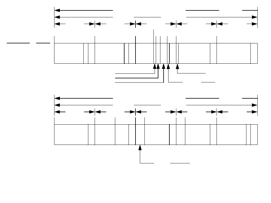
IS-GPS-200D
7 Dec 2004
69
*** RESERVED
P = 6 PARITY BITS
t = 2 NONINFORMATION BEARING BITS USED FOR PARITY COMPUTATION (SEE PARAGRAPH 20.3.5)
C = TLM BITS 23 AND 24 WHICH ARE RESERVED
DIRECTION OF DATA FLOW FROM SV MSB FIRST
150 BITS 3 SECONDS
WORD 1 WORD 2 WORD 3 WORD 4 WORD 5
1 316191121
SUBFRAME
NO.
PAGE
NO.
1N/A
TLM
22 BITS
C
HOW
22 BITS
tP
WN
10
BITS
C/A OR P ON L2 - 2 BITS
URA INDEX - 4 BITS
SV HEALTH - 6 BITS
71
73 77 83
2 MSBs IODC - 10 BITS TOTAL
L2 P DATA FLAG - 1 BIT
23 BITS***
P
24 BITS***
P
PP
DIRECTION OF DATA FLOW FROM SV MSB FIRST
150 BITS 3 SECONDS
WORD 6 WORD 7 WORD 8 WORD 9 WORD 10
151 181 211 241 271
1N/A
24 BITS***
P P P P P16
BITS***
T
GD
8 BITS
8 LSBs IODC - 10 BITS TOTAL
t
oc
16 BITS
219197
a
f2
8
BITS
a
f1
16 BITS
a
f0
22 BITS
t
Figure 20-1. Data Format (sheet 1 of 11)
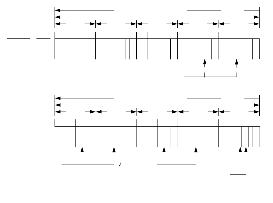
IS-GPS-200D
7 Dec 2004
70
P = 6 PARITY BITS
t = 2 NONINFORMATION BEARING BITS USED FOR PARITY COMPUTATION (SEE PARAGRAPH 20.3.5)
C = TLM BITS 23 AND 24 WHICH ARE RESERVED
DIRECTION OF DATA FLOW FROM SV MSB FIRST
150 BITS 3 SECONDS
WORD 1 WORD 2 WORD 3 WORD 4 WORD 5
1 316191121
SUBFRAME
NO.
PAGE
NO.
2N/A
P P P P P
TLM
22 BITS
HOW
22 BITS
C t
IODE
8
BITS
C
rs
16 BITS
10769
∆n
16 BITS
8
BITS
24 BITS
MSBs LSBs
M
0
- 32 BITS TOTAL
DIRECTION OF DATA FLOW FROM SV MSB FIRST
150 BITS 3 SECONDS
WORD 6 WORD 7 WORD 8 WORD 9 WORD 10
151 181 211 241 271
2N/A
P P P P P
MSBs LSBs
e - 32 BITS TOTAL
C
UC
16 BITS
8
BITS
24 BITS
C
US
16 BITS
8
BITS
167 227
MSBs LSBs
- 32 BITS TOTAL
24 BITS
t
oe
16 BITS
287
t
FIT INTERVAL FLAG - 1 BIT
AODO - 5 BITS
A
Figure 20-1. Data Format (sheet 2 of 11)
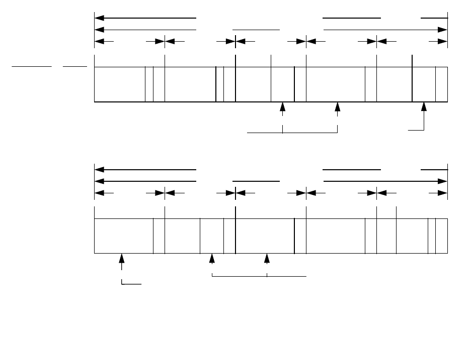
IS-GPS-200D
7 Dec 2004
71
P = 6 PARITY BITS
t = 2 NONINFORMATION BEARING BITS USED FOR PARITY COMPUTATION (SEE PARAGRAPH 20.3.5)
C = TLM BITS 23 AND 24 WHICH ARE RESERVED
DIRECTION OF DATA FLOW FROM SV MSB FIRST
150 BITS 3 SECONDS
WORD 1 WORD 2 WORD 3 WORD 4 WORD 5
1 316191121
SUBFRAME
NO.
PAGE
NO.
3N/A
P P P P PC
TLM
22 BITS
t
HOW
22 BITS
C
ic
16 BITS
8
BITS
77
24 BITS
C
is
16 BITS
8
BITS
137
MSBs LSBs
Ω
0
- 32 BITS TOTAL
i
0
- 32 BITS TOTAL
•
Ω
DIRECTION OF DATA FLOW FROM SV MSB FIRST
150 BITS 3 SECONDS
WORD 6 WORD 7 WORD 8 WORD 9 WORD 10
151 181 211 241 271
3N/A
P P P P P24 BITS
C
rc
16 BITS
8
BITS
24 BITS
24 BITS
t
IODE
8
BITS
IDOT
14
BITS
279
LSBs
i
0
- 32 BITS TOTAL
MSBs LSBs
ω - 32 BITS TOTAL
Figure 20-1. Data Format (sheet 3 of 11)
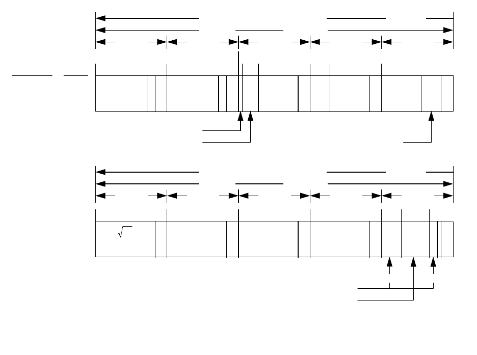
IS-GPS-200D
7 Dec 2004
72
P = 6 PARITY BITS
t = 2 NONINFORMATION BEARING BITS USED FOR PARITY COMPUTATION (SEE PARAGRAPH 20.3.5)
C = TLM BITS 23 AND 24 WHICH ARE RESERVED
NOTE: PAGES 2, 3, 4, 5, 7, 8, 9 & 10 OF SUBFRAME 4 HAVE THE SAME FORMAT AS PAGES 1 THROUGH 24 OF SUBFRAME 5
DIRECTION OF DATA FLOW FROM SV MSB FIRST
150 BITS 3 SECONDS
WORD 1 WORD 2 WORD 3 WORD 4 WORD 5
131
61
91 121
SUBFRAME
NO.
PAGE
NO.
5
1
THRU
24
P P P P PC
TLM
22 BITS
t
HOW
22 BITS
63 69
e
16 BITS
99
t
oa
8
BITS
δ
i
16 BITS
•
Ω
16 BITS
8
BITS
SV HEALTH
DATA ID - 2 BITS
SV ID - 6 BITS
DIRECTION OF DATA FLOW FROM SV MSB FIRST
150 BITS 3 SECONDS
WORD 6 WORD 7 WORD 8 WORD 9 WORD 10
151 181 211 241 271
5
1
THRU
24
P P P P P
A
24 BITS
Ω
0
24 BITS
ω
24 BITS
M
0
24 BITS
279 290
t
8 MSBs 3 LSBs
a
f0
- 11 BITS TOTAL
a
f1
- 11 BITS TOTAL
Figure 20-1. Data Format (sheet 4 of 11)
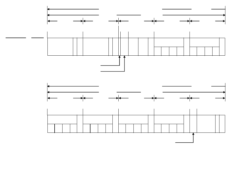
IS-GPS-200D
7 Dec 2004
73
** RESERVED FOR SYSTEM USE
*** RESERVED
P = 6 PARITY BITS
t = 2 NONINFORMATION BEARING BITS USED FOR PARITY COMPUTATION (SEE PARAGRAPH 20.3.5)
C = TLM BITS 23 AND 24 WHICH ARE RESERVED
DIRECTION OF DATA FLOW FROM SV MSB FIRST
150 BITS 3 SECONDS
WORD 1 WORD 2 WORD 3 WORD 4 WORD 5
131
61
91 121
SUBFRAME
NO.
PAGE
NO.
525
P P PPP
TLM
22 BITS
C
HOW
22 BITS
t
63 69
DATA ID - 2 BITS
SV (PAGE) ID - 6 BITS
t
oa
8
BITS
WN
a
8
BITS
SV HEALTH
6 BITS/SV
SV
1
SV
2
SV
3
SV
4
SV HEALTH
6 BITS/SV
SV
5
SV
6
SV
7
SV
8
DIRECTION OF DATA FLOW FROM SV MSB FIRST
150 BITS 3 SECONDS
WORD 6 WORD 7 WORD 8 WORD 9 WORD 10
151 181 211 241
271
525
P P P P P
SV HEALTH
6 BITS/SV
SV
9
SV
10
SV
11
SV
12
SV HEALTH
6 BITS/SV
SV
13
SV
14
SV
15
SV
16
SV HEALTH
6 BITS/SV
SV
17
SV
18
SV
19
SV
20
SV HEALTH
6 BITS/SV
SV
21
SV
22
SV
23
SV
24
6 BITS ***
277
16 BITS **
t
Figure 20-1. Data Format (sheet 5 of 11)

IS-GPS-200D
7 Dec 2004
74
** RESERVED FOR SYSTEM USE
*** RESERVED
P = 6 PARITY BITS
t = 2 NONINFORMATION BEARING BITS USED FOR PARITY COMPUTATION (SEE PARAGRAPH 20.3.5)
C = TLM BITS 23 AND 24 WHICH ARE RESERVED
DIRECTION OF DATA FLOW FROM SV MSB FIRST
150 BITS 3 SECONDS
WORD 6 WORD 7 WORD 8 WORD 9 WORD 10
151 181 211 241 271
4
P P P P P
1, 6, 11,
16 & 21
24 BITS*** 24 BITS*** 24 BITS***
249
8***
BITS
16
BITS***
t22 BITS**
DIRECTION OF DATA FLOW FROM SV MSB FIRST
150 BITS 3 SECONDS
WORD 1 WORD 2 WORD 3 WORD 4 WORD 5
131
61
91 121
SUBFRAME
NO.
PAGE
NO.
4
1, 6, 11,
16 & 21
P P P P PC
TLM
22 BITS
HOW
22 BITS
t
63 69
16
BITS***
24 BITS*** 24 BITS***
DATA ID - 2 BITS
SV (PAGE) ID - 6 BITS
Figure 20-1. Data Format (sheet 6 of 11)
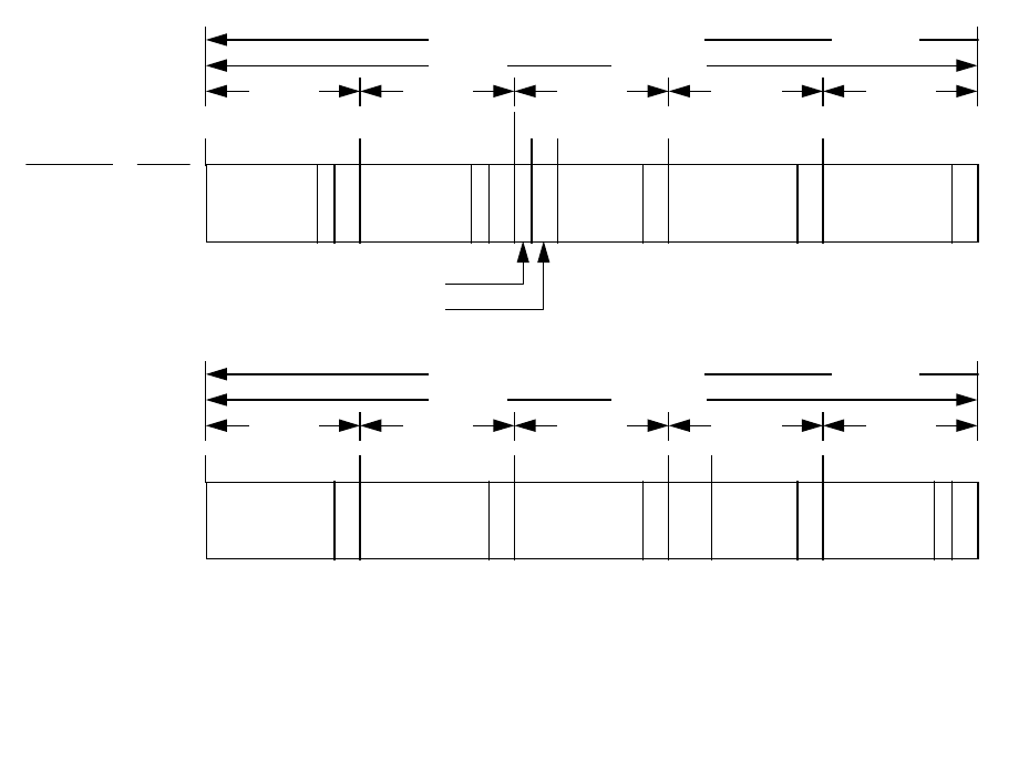
IS-GPS-200D
7 Dec 2004
75
** RESERVED FOR SYSTEM USE
*** RESERVED
P = 6 PARITY BITS
t = 2 NONINFORMATION BEARING BITS USED FOR PARITY COMPUTATION (SEE PARAGRAPH 20.3.5)
C = TLM BITS 23 AND 24 WHICH ARE RESERVED
DIRECTION OF DATA FLOW FROM SV MSB FIRST
150 BITS 3 SECONDS
WORD 6 WORD 7 WORD 8 WORD 9 WORD 10
151 181 211 241 271
4
P P P P P
12, 19, 20,
22, 23 & 24
24 BITS*** 24 BITS*** 24 BITS***
249
8***
BITS
16 BITS**
t22 BITS**
DIRECTION OF DATA FLOW FROM SV MSB FIRST
150 BITS 3 SECONDS
WORD 1 WORD 2 WORD 3 WORD 4 WORD 5
131
61
91 121
SUBFRAME
NO.
PAGE
NO.
4
12, 19, 20,
22, 23 & 24
P P P P PC
TLM
22 BITS
HOW
22 BITS
t
63 69
16
BITS***
24 BITS*** 24 BITS***
DATA ID - 2 BITS
SV (PAGE) ID - 6 BITS
Figure 20-1. Data Format (sheet 7 of 11)
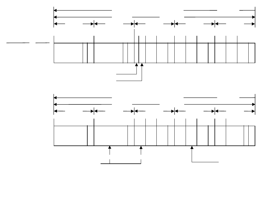
IS-GPS-200D
7 Dec 2004
76
** RESERVED FOR SYSTEM USE
P = 6 PARITY BITS
t = 2 NONINFORMATION BEARING BITS USED FOR PARITY COMPUTATION (SEE PARAGRAPH 20.3.5)
C = TLM BITS 23 AND 24 WHICH ARE RESERVED
DIRECTION OF DATA FLOW FROM SV MSB FIRST
150 BITS 3 SECONDS
WORD 6 WORD 7 WORD 8 WORD 9 WORD 10
151 181 211 241 271
4
P P P P P
18
A
1
24 BITS 24 BITS
8
BITS
t
ot
8
BITS
WN
t
8
BITS
219 227
∆t
LS
8
BITS
8
BITS
DN
8
BITS
249 257
∆t
LSF
8
BITS
t
279
14
BITS**
WN
LSF
MSBs LSBs
A
0
- 32 BITS TOTAL
DIRECTION OF DATA FLOW FROM SV MSB FIRST
150 BITS 3 SECONDS
WORD 1 WORD 2 WORD 3 WORD 4 WORD 5
131
61
91 121
SUBFRAME
NO.
PAGE
NO.
418
P P P P P
TLM
22 BITS
HOW
22 BITS
Ct
63 69 77
α
0
8
BITS
α
1
8
BITS
99 107
α
2
8
BITS
α
3
8
BITS
β
0
8
BITS
129 137
β
1
8
BITS
β
2
8
BITS
β
3
8
BITS
DATA ID - 2 BITS
SV (PAGE) ID - 6 BITS
Figure 20-1. Data Format (sheet 8 of 11)
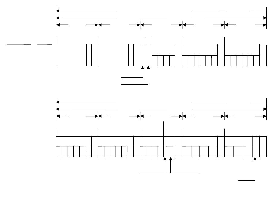
IS-GPS-200D
7 Dec 2004
77
** RESERVED FOR SYSTEM USE
P = 6 PARITY BITS
t = 2 NONINFORMATION BEARING BITS USED FOR PARITY COMPUTATION (SEE PARAGRAPH 20.3.5)
C = TLM BITS 23 AND 24 WHICH ARE RESERVED
DIRECTION OF DATA FLOW FROM SV MSB FIRST
150 BITS 3 SECONDS
WORD 1 WORD 2 WORD 3 WORD 4 WORD 5
131
61
91 121
SUBFRAME
NO.
PAGE
NO.
425
P P PPP
TLM
22 BITS
HOW
22 BITS
Ct
63 69
DATA ID - 2 BITS
SV (PAGE) ID - 6 BITS
A-SPOOF &
SV CONFIG
SV
1
SV
2
SV
3
SV
4
SV
10
SV
5
SV
6
SV
7
SV
8
SV
9
A- SPOOF &
SV CONFIG
SV
16
SV
11
SV
12
SV
13
SV
14
SV
15
A- SPOOF &
SV CONFIG
DIRECTION OF DATA FLOW FROM SV MSB FIRST
150 BITS 3 SECONDS
WORD 6 WORD 7 WORD 8 WORD 9 WORD 10
151 181 211 241 271
4
P P P P P
25
SV
22
SV
17
SV
18
SV
19
SV
20
SV
21
A- SPOOF &
SV CONFIG
SV
28
SV
23
SV
24
SV
25
SV
26
SV
27
A- SPOOF &
SV CONFIG
A-SPOOF &
SV CONFIG
SV
29
SV
30
SV
31
SV
32
227
229
SV
25
2 BITS **
SV
26
SV
27
SV
28
SV
29
SV HEALTH
6 BITS/SV
t
SV HEALTH
6 BITS/SV
SV
30
SV
31
SV
32
SV HEALTH - 6 BITS
4 BITS **
Figure 20-1. Data Format (sheet 9 of 11)
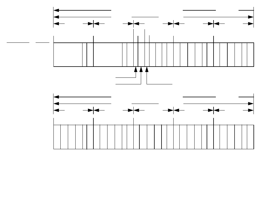
IS-GPS-200D
7 Dec 2004
78
P = 6 PARITY BITS
t = 2 NONINFORMATION BEARING BITS USED FOR PARITY COMPUTATION (SEE PARAGRAPH 20.3.5)
C = TLM BITS 23 AND 24 WHICH ARE RESERVED
DIRECTION OF DATA FLOW FROM SV MSB FIRST
150 BITS 3 SECONDS
WORD 1 WORD 2 WORD 3 WORD 4 WORD 5
61
SUB
FRAME
NO.
PAGE
NO.
4
13
131 91121
P P P P PC
TLM
22 BITS
HOW
22 BITS
t
63
69
DATA ID - 2 BITS
SV (PAGE) ID - 6 BITS
DIRECTION OF DATA FLOW FROM SV MSB FIRST
150 BITS 3 SECONDS
WORD 6 WORD 7 WORD 8 WORD 9 WORD 10
4
151 181 211 241 271
P P P P P
13
71
E
R
D
3
4
L
S
B
S
E
R
D
4
6
B
I
T
S
AVAILABILITY INDICATOR - 2 BITS
E
R
D
5
6
B
I
T
S
E
R
D
6
6
B
I
T
S
E
R
D
7
2
M
S
B
S
E
R
D
7
4
L
S
B
S
E
R
D
8
6
B
I
T
S
E
R
D
9
6
B
I
T
S
E
R
D
1
0
6
B
I
T
S
E
R
D
1
1
2
M
S
B
S
E
R
D
1
6
B
I
T
S
E
R
D
2
6
B
I
T
S
E
R
D
3
2
M
S
B
S
E
R
D
2
7
4
L
S
B
S
E
R
D
2
8
6
B
I
T
S
E
R
D
2
9
6
B
I
T
S
E
R
D
3
0
6
B
I
T
S
E
R
D
2
3
4
L
S
B
S
E
R
D
2
4
6
B
I
T
S
E
R
D
2
5
6
B
I
T
S
E
R
D
2
6
6
B
I
T
S
E
R
D
2
7
2
M
S
B
S
E
R
D
1
9
4
L
S
B
S
E
R
D
2
0
6
B
I
T
S
E
R
D
2
1
6
B
I
T
S
E
R
D
2
2
6
B
I
T
S
E
R
D
2
3
2
M
S
B
S
t
E
R
D
1
5
4
L
S
B
S
E
R
D
1
6
6
B
I
T
S
E
R
D
1
7
6
B
I
T
S
E
R
D
1
8
6
B
I
T
S
E
R
D
1
9
2
M
S
B
S
E
R
D
1
1
4
L
S
B
S
E
R
D
1
2
6
B
I
T
S
E
R
D
1
3
6
B
I
T
S
E
R
D
1
4
6
B
I
T
S
E
R
D
1
5
2
M
S
B
S
Figure 20-1. Data Format (sheet 10 of 11)
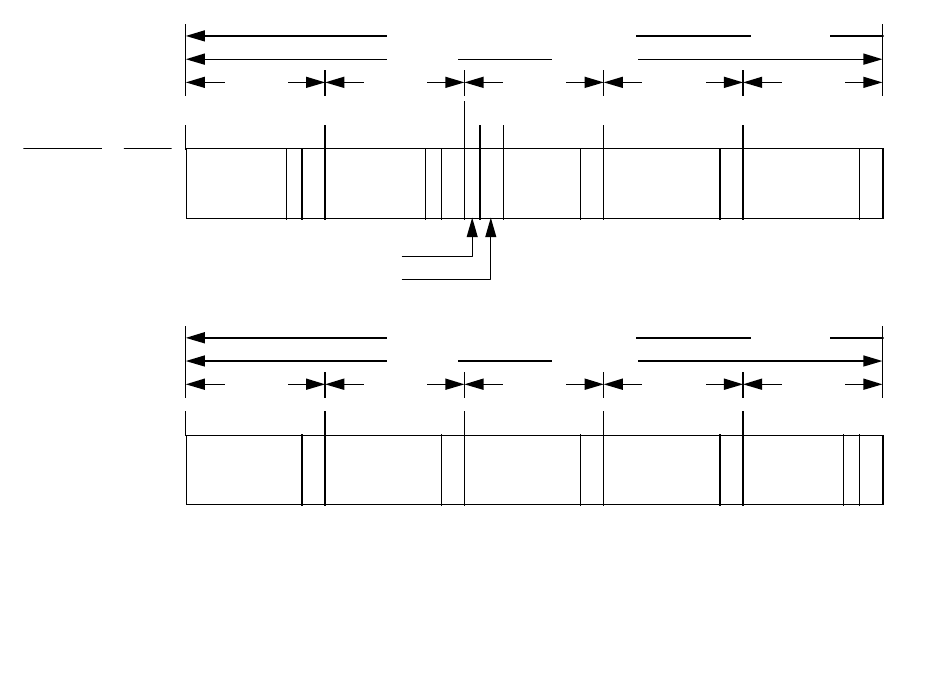
IS-GPS-200D
7 Dec 2004
79
** THE INDICATED PORTIONS OF WORDS 3 THROUGH 10 OF PAGES 14 AND 15 ARE RESERVED FOR SYSTEM USE, WHILE
THOSE OF PAGE 17 ARE RESERVED FOR SPECIAL MESSAGES PER PARAGRAPH 20.3.3.5.1.10
P = 6 PARITY BITS
t = 2 NONINFORMATION BEARING BITS USED FOR PARITY COMPUTATION (SEE PARAGRAPH 20.3.5)
C = TLM BITS 23 AND 24 WHICH ARE RESERVED
DIRECTION OF DATA FLOW FROM SV MSB FIRST
150 BITS 3 SECONDS
WORD 1 WORD 2 WORD 3 WORD 4 WORD 5
131
61
91 121
SUBFRAME
NO.
PAGE
NO.
4
14, 15
& 17**
P P P P PC
TLM
22 BITS
HOW
22 BITS
t
63 69
16
BITS**
24 BITS** 24 BITS**
DATA ID - 2 BITS
SV (PAGE) ID - 6 BITS
DIRECTION OF DATA FLOW FROM SV MSB FIRST
150 BITS 3 SECONDS
WORD 6 WORD 7 WORD 8 WORD 9 WORD 10
151 181 211 241 271
4
P P P P P
14, 15
& 17**
24 BITS** 24 BITS** 24 BITS** 24 BITS** 22 BITS** t
Figure 20-1. Data Format (sheet 11 of 11)
IS-GPS-200D
7 Dec 2004
80
(This page intentionally left blank.)

IS-GPS-200D
7 Dec 2004
81
20.3.3 Message Content
. The format and contents of the TLM word and the HOW, as well as those of words three
through ten of each subframe/page, are described in the following subparagraphs. The timing of the subframes and
pages is covered in Section 20.3.4.
20.3.3.1 Telemetry Word
. Each TLM word is 30 bits long, occurs every six seconds in the data frame, and is the
first word in each subframe/page. The format shall be as shown in Figure 20-2. Bit 1 is transmitted first. Each
TLM word shall begin with a preamble, followed by the TLM message, two reserved bits, and six parity bits. The
TLM message contains information needed by the authorized user and by the CS, as described in the related SS/CS
interface documentation.
20.3.3.2 Handover Word (HOW)
. The HOW shall be 30 bits long and shall be the second word in each
subframe/page, immediately following the TLM word. A HOW occurs every 6 seconds in the data frame. The
format and content of the HOW shall be as shown in Figure 20-2. The MSB is transmitted first. The HOW begins
with the 17 MSBs of the time-of-week (TOW) count. (The full TOW count consists of the 19 LSBs of the 29-bit Z-
count). These 17 bits correspond to the TOW-count at the X1 epoch which occurs at the start (leading edge) of the
next following subframe (reference paragraph 3.3.4).
Bit 18 is an "alert" flag. When this flag is raised (bit 18 = "1"), it shall indicate to the unauthorized user that the
SV URA may be worse than indicated in subframe 1 and that he shall use that SV at his own risk.
Bit 19 is an anti-spoof (A-S) flag. A "1" in bit-position 19 indicates that the A-S mode is ON in that SV.
Bits 20, 21, and 22 of the HOW provide the ID of the subframe in which that particular HOW is the second word;
the ID code shall be as follows:
Subframe
ID Code
1 001
2 010
3 011
4 100
5 101
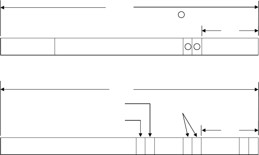
IS-GPS-200D
7 Dec 2004
82
Figure 20-2. TLM and HOW Formats
Preamble
1 2 3 4 5 6 7 8 9 10 11 12 13 14 15 16 17 18 19 20 21 22 23 24 25 26 27 28 29 30
1 0 0 0 1 0 1 1
TLM Message
TLM Word
MSB LSB
Parity
= Reserved Bits
1
1 1
TOW-Count Message
(Truncated)
1 2 3 4 5 6 7 8 9 10 11 12 13 14 15 16 17 18 19 20 21 22 23 24 25 26 27 28 29 30
Sub-
frame
ID
HOW
MSB LSB
Parity
Solved for bits to preserve
parity check with zeros in
bits 29 and 30
00
Anti-Spoof Flag
“Alert” Flag

IS-GPS-200D
7 Dec 2004
83
20.3.3.3 Subframe 1
. The content of words three through ten of subframe 1 are defined below, followed by related
algorithms and material pertinent to use of the data.
20.3.3.3.1 Subframe 1 Content
. The third through tenth words of subframe 1 shall each contain six parity bits as
their LSBs; in addition, two non-information bearing bits shall be provided as bits 23 and 24 of word ten for parity
computation purposes. The remaining 190 bits of words three through ten shall contain the clock parameters and
other data described in the following.
The clock parameters describe the SV time scale during the period of validity. The parameters in a data set shall
be valid during the interval of time in which they are transmitted and shall remain valid for an additional period of
time after transmission of the next data set has started. The timing information for subframes, pages, and data sets
is covered in Section 20.3.4.
20.3.3.3.1.1 Transmission Week Number
. The ten MSBs of word three shall contain the ten MSBs of the 29-bit Z-
count as qualified herein. These ten bits shall be a modulo 1024 binary representation of the current GPS week
number at the start of the data set transmission interval (see paragraph 3.3.4(b)). The GPS week number increments
at each end/start of week epoch. For Block II SVs in long-term extended operations, beginning approximately 28
days after upload, the transmission week number may not correspond to the actual GPS week number due to curve
fit intervals that cross week boundaries.
20.3.3.3.1.2 Code(s) on L2 Channel
. Bits 11 and 12 of word three shall indicate which code(s) is (are) commanded
ON for the L2 channel, as follows:
00 = Reserved,
01 = P code ON,
10 = C/A code ON.

IS-GPS-200D
7 Dec 2004
84
20.3.3.3.1.3 SV Accuracy
. Bits 13 through 16 of word three shall give the URA index of the SV (reference
paragraph 6.2.1) for the unauthorized user. Except for Block IIR/IIR-M SVs in the Autonav mode, the URA index
(N) is an integer in the range of 0 through 15 and has the following relationship to the URA of the SV:
URA INDEX
URA (meters)
0 0.00 < URA ≤ 2.40
1 2.40 < URA ≤ 3.40
2 3.40 < URA ≤ 4.85
3 4.85 < URA ≤ 6.85
4 6.85 < URA ≤ 9.65
5 9.65 < URA ≤ 13.65
6 13.65 < URA ≤ 24.00
7 24.00 < URA ≤ 48.00
8 48.00 < URA ≤ 96.00
9 96.00 < URA ≤ 192.00
10 192.00 < URA ≤ 384.00
11 384.00 < URA ≤ 768.00
12 768.00 < URA ≤ 1536.00
13 1536.00 < URA ≤ 3072.00
14 3072.00 < URA ≤ 6144.00
15 6144.00 < URA (or no accuracy prediction is available - unauthorized users are
advised to use the SV at their own risk.)
For each URA index (N), users may compute a nominal URA value (X) as given by:
• If the value of N is 6 or less, X = 2
(1 + N/2)
,
• If the value of N is 6 or more, but less than 15, X = 2
(N - 2)
,
• N = 15 shall indicate the absence of an accuracy prediction and shall advise the unauthorized
user to use that SV at his own risk.
For N = 1, 3, and 5, X should be rounded to 2.8, 5.7, and 11.3 meters, respectively.
For Block IIR/IIR-M SVs in the Autonav mode, the URA shall be defined to mean “no better than X meters”, with “X”
as defined above for each URA index

IS-GPS-200D
7 Dec 2004
85
20.3.3.3.1.4 SV Health
. The six-bit health indication given by bits 17 through 22 of word three refers to the
transmitting SV. The MSB shall indicate a summary of the health of the NAV data, where
0 = all NAV data are OK,
1 = some or all NAV data are bad.
The five LSBs shall indicate the health of the signal components in accordance with the codes given in paragraph
20.3.3.5.1.3. The health indication shall be given relative to the "as designed" capabilities of each SV (as
designated by the configuration code - see paragraph 20.3.3.5.1.4). Accordingly, any SV which does not have a
certain capability will be indicated as "healthy" if the lack of this capability is inherent in its design or if it has
been configured into a mode which is normal from a user standpoint and does not require that capability.
Additional SV health data are given in subframes 4 and 5. The data given in subframe 1 may differ from that
shown in subframes 4 and/or 5 of other SVs since the latter may be updated at a different time.
20.3.3.3.1.5 Issue of Data, Clock (IODC)
. Bits 23 and 24 of word three in subframe 1 shall be the two MSBs of the
ten-bit IODC term; bits one through eight of word eight in subframe 1 shall contain the eight LSBs of the IODC.
The IODC indicates the issue number of the data set and thereby provides the user with a convenient means of
detecting any change in the correction parameters. Constraints on the IODC as well as the relationship between the
IODC and the IODE (issue of data, ephemeris) terms are defined in paragraph 20.3.4.4.
Short-term and Long-term Extended Operations
. Whenever the fit interval flag indicates a fit interval greater than
4 hours, the IODC can be used to determine the actual fit interval of the data set (reference section 20.3.4.4).
20.3.3.3.1.6 Data Flag for L2 P-Code
. When bit 1 of word four is a "1", it shall indicate that the NAV data stream
was commanded OFF on the P-code of the L2 channel.

IS-GPS-200D
7 Dec 2004
86
20.3.3.3.1.7 Estimated Group Delay Differential
. Bits 17 through 24 of word seven contain the L1-L2 correction
term, T
GD
, for the benefit of "L1 only" or "L2 only" users; the related user algorithm is given in paragraph
20.3.3.3.3.
20.3.3.3.1.8 SV Clock Correction
. Bits nine through 24 of word eight, bits one through 24 of word nine, and bits
one through 22 of word ten contain the parameters needed by the users for apparent SV clock correction (t
oc
, a
f2
,
a
f1
, a
f0
). The related algorithm is given in paragraph 20.3.3.3.3.
20.3.3.3.2 Subframe 1 Parameter Characteristics
. For those parameters whose characteristics are not fully defined
in Section 20.3.3.3.1, the number of bits, the scale factor of the LSB (which shall be the last bit received), the
range, and the units shall be as specified in Table 20-I.
20.3.3.3.3 User Algorithms for Subframe 1 Data
. The algorithms defined below (a) allow all users to correct the
code phase time received from the SV with respect to both SV code phase offset and relativistic effects, (b) permit
the "single frequency" (L1 or L2) user to compensate for the effects of SV group delay differential (the user who
utilizes both frequencies does not require this correction, since the clock parameters account for the induced
effects), and (c) allow the "two frequency" (L1 and L2) user to correct for the group propagation delay due to
ionospheric effects (the single frequency user may correct for ionospheric effects as described in paragraph
20.3.3.5.2.5).

IS-GPS-200D
7 Dec 2004
87
Table 20-I. Subframe 1 Parameters
Parameter
No. of
Bits**
Scale
Factor
(LSB)
Effective
Range***
Units
Code on L2
Week No.
L2 P data flag
SV accuracy
SV health
T
GD
IODC
t
oc
a
f2
a
f1
a
f0
2
10
1
4
6
8*
10
16
8*
16*
22*
1
1
1
1
2
-31
2
4
2
-55
2
-43
2
-31
604,784
discretes
week
discrete
(see text)
discretes
seconds
(see text)
seconds
sec/sec
2
sec/sec
seconds
* Parameters so indicated shall be two's complement, with the sign bit (+ or -) occupying the MSB;
** See Figure 20-1 for complete bit allocation in subframe;
*** Unless otherwise indicated in this column, effective range is the maximum range attainable with
indicated bit allocation and scale factor.

IS-GPS-200D
7 Dec 2004
88
20.3.3.3.3.1 User Algorithm for SV Clock Correction
. The polynomial defined in the following allows the user to
determine the effective SV PRN code phase offset referenced to the phase center of the antennas (∆t
sv
) with respect
to GPS system time (t) at the time of data transmission. The coefficients transmitted in subframe 1 describe the
offset apparent to the two-frequency user for the interval of time in which the parameters are transmitted. This
estimated correction accounts for the deterministic SV clock error characteristics of bias, drift and aging, as well as
for the SV implementation characteristics of group delay bias and mean differential group delay. Since these
coefficients do not include corrections for relativistic effects, the user's equipment must determine the requisite
relativistic correction. Accordingly, the offset given below includes a term to perform this function.
The user shall correct the time received from the SV with the equation (in seconds)
t = t
sv
- ∆t
sv
(1)
where
t = GPS system time (seconds),
t
sv
= effective SV PRN code phase time at message transmission time (seconds),
∆t
sv
= SV PRN code phase time offset (seconds).
The SV PRN code phase offset is given by
∆t
sv
= a
f0
+ a
f1
(t - t
oc
) + a
f2
(t - t
oc
)
2
+ ∆t
r
(2)
where
a
f0
, a
f1
and a
f2
are the polynomial coefficients given in subframe 1, t
oc
is the clock data reference time in
seconds (reference paragraph 20.3.4.5), and ∆t
r
is the relativistic correction term (seconds) which is given
by
∆t
r
= F e A sin E
k
.
The orbit parameters (e,
A , E
k
) used here are described in discussions of data contained in subframes 2 and 3,
while F is a constant whose value is
F =
2
c
2 µ−
= - 4.442807633 (10)
-10
meter
sec
,

IS-GPS-200D
7 Dec 2004
89
where
µ = 3.986005 x 10
14
meters
second
3
2
= value of Earth's universal gravitational parameters
c = 2.99792458 x 10
8
meters
second
= speed of light.
Note that equations (1) and (2), as written, are coupled. While the coefficients a
f0
, a
f1
and a
f2
are generated by
using GPS time as indicated in equation (2), sensitivity of t
sv
to t is negligible. This negligible sensitivity will allow
the user to approximate t by t
SV
in equation (2). The value of t must account for beginning or end of week
crossovers. That is, if the quantity t - t
oc
is greater than 302,400 seconds, subtract 604,800 seconds from t. If the
quantity t - t
oc
is less than -302,400 seconds, add 604,800 seconds to t.
The control segment will utilize the following alternative but equivalent expression for the relativistic effect when
estimating the NAV parameters:
∆t
r
=
−
•
→→
2
2
RV
c
where
→
R
is the instantaneous position vector of the SV,
→
V
is the instantaneous velocity vector of the SV, and
c is the speed of light. (Reference paragraph 20.3.4.3).
It is immaterial whether the vectors
→
R
and
→
V
are expressed in earth-fixed, rotating coordinates or in earth-centered,
inertial coordinates.

IS-GPS-200D
7 Dec 2004
90
20.3.3.3.3.2 L1 - L2 Correction
. The L1 and L2 correction term, T
GD
, is initially calculated by the CS to account
for the effect of SV group delay differential between L1 P(Y) and L2 P(Y) based on measurements made by the SV
contractor during SV manufacture. The value of T
GD
for each SV may be subsequently updated to reflect the actual
on-orbit group delay differential. This correction term is only for the benefit of "single-frequency" (L1 P(Y) or L2
P(Y)) users; it is necessitated by the fact that the SV clock offset estimates reflected in the a
f0
clock correction
coefficient (see paragraph 20.3.3.3.3.1) are based on the effective PRN code phase as apparent with two frequency
(L1 P(Y) and L2 P(Y)) ionospheric corrections. Thus, the user who utilizes the L1 P(Y) signal only shall modify the
code phase offset in accordance with paragraph 20.3.3.3.3.1 with the equation
(∆t
SV
)
L1P(Y)
= ∆t
SV
- T
GD
where T
GD
is provided to the user as subframe 1 data. For the user who utilizes L2 P(Y) only, the code phase
modification is given by
(∆t
SV
)
L2P(Y)
= ∆t
SV
- γT
GD
where, denoting the nominal center frequencies of L1 and L2 as f
L1
and f
L2
respectively,
γ = (f
L1
/f
L2
)
2
= (1575.42/1227.6)
2
= (77/60)
2
.
The value of T
GD
is not equal to the mean SV group delay differential, but is a measured value that represents the
mean group delay differential multiplied by 1/(1- γ). That is,
T
GD
=
1
1-
γ
(t
L1P(Y)
- t
L2P(Y)
)
where t
LiP(Y)
is the GPS time the i
th
frequency P(Y) signal (a specific epoch of the signal) is transmitted from the SV
antenna phase center.

IS-GPS-200D
7 Dec 2004
91
20.3.3.3.3.3 Ionospheric Correction
. The two frequency (L1 P(Y) and L2 P(Y)) user shall correct for the group
delay due to ionospheric effects by applying the relationship:
- 1
PR - PR
PR
L1P(Y)L2P(Y)
γ
γ
=
where
PR = pseudorange corrected for ionospheric effects,
PR
i
= pseudorange measured on the channel indicated by the subscript.
and γ is as defined in paragraph 20.3.3.3.3.2. The clock correction coefficients are based on "two frequency"
measurements and therefore account for the effects of mean differential delay in SV instrumentation.
20.3.3.3.3.4 Example Application of Correction Parameters
. A typical system application of the correction
parameters for a user receiver is shown in Figure 20-3. The ionospheric model referred to in Figure 20-3 is
discussed in paragraph 20.3.3.5.2.5 in conjunction with the related data contained in page 18 of subframe 4. The
c
ERD
term referred to in Figure 20-3 is discussed in paragraph 20.3.3.5.2.6 in conjunction with the related data
contained in page 13 of subframe 4.
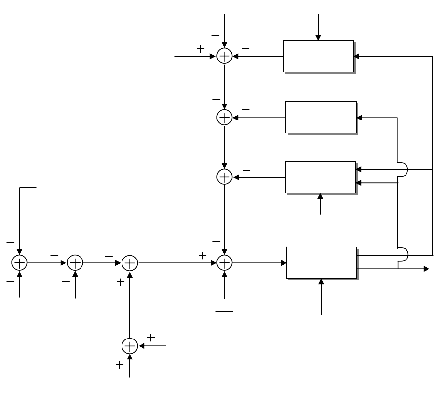
IS-GPS-200D
7 Dec 2004
92
Figure 20-3. Sample Application of Correction Parameters
CLOCK
CORRECTION
POLYNOMIAL
TROPOSPHERIC
MODEL
IONOSPHERIC
MODEL*
FILTER AND
COORDINATE
CONVERTER
CODE PHASE OFFSET
- TRUE SV CLOCK EFFECTS
- EQUIPMENT GROUP DELAY
DIFFERENTIAL EFFECTS
- RELATIVISTIC EFFECTS
PATH DELAY
- GEOMETRIC
- TROPOSHERIC
- IONOSPHERIC*
PSEUDORANGE
DIVIDED BY THE
SPEED OF LIGHT
- RANGE DATA FROM
OTHER SATELLITES
- CALIBRATION DATA
- AUXILIARY SENSOR
USER POSITION,
VELOCITY, and
TIME (CLOCK BIAS)
ESTIMATE OF SV
TRANSMISSION TIME
a
f0
, a
f1
, a
f2
, t
oc
USER CLOCK BIAS
GPS TIME
GPS TIME
* SINGLE FREQUENCY USER ONLY
** OPTIONAL
T
GD
*
∆ t
r
∆
t
SV
T
tropo
T
iono
c
ERD
**
α
n
,
β
n

IS-GPS-200D
7 Dec 2004
93
20.3.3.4 Subframes 2 and 3
. The contents of words three through ten of subframes 2 and 3 are defined below,
followed by material pertinent to the use of the data.
20.3.3.4.1 Content of Subframes 2 and 3
. The third through tenth words of subframes 2 and 3 shall each contain
six parity bits as their LSBs; in addition, two non-information bearing bits shall be provided as bits 23 and 24 of
word ten of each subframe for parity computation purposes. Bits 288 through 292 of subframe 2 shall contain the
Age of Data Offset (AODO) term for the navigation message correction table (NMCT) contained in subframe 4
(reference paragraph 20.3.3.5.1.9). The remaining 375 bits of those two subframes shall contain the ephemeris
representation parameters of the transmitting SV.
The ephemeris parameters describe the orbit during the curve fit intervals described in section 20.3.4. Table 20-II
gives the definition of the orbital parameters using terminology typical of Keplerian orbital parameters; it shall be
noted, however, that the transmitted parameter values are such that they provide the best trajectory fit in Earth-
Centered, Earth-Fixed (ECEF) coordinates for each specific fit interval. The user shall not interpret intermediate
coordinate values as pertaining to any conventional coordinate system.
The issue of ephemeris data (IODE) term shall provide the user with a convenient means for detecting any change in
the ephemeris representation parameters. The IODE is provided in both subframes 2 and 3 for the purpose of
comparison with the 8 LSBs of the IODC term in subframe 1. Whenever these three terms do not match, a data set
cutover has occurred and new data must be collected. The timing of the IODE and constraints on the IODC and
IODE are defined in paragraph 20.3.4.4.
Any change in the subframe 2 and 3 data will be accomplished with a simultaneous change in both IODE words.
The CS shall assure that the t
oe
value, for at least the first data set transmitted by an SV after an upload, is different
from that transmitted prior to the cutover (reference paragraph 20.3.4.5).
A "fit interval" flag is provided in subframe 2 to indicate whether the ephemerides are based on a four-hour fit
interval or a fit interval greater than four hours (reference paragraph 20.3.3.4.3.1).
The AODO word is provided in subframe 2 to enable the user to determine the validity time for the NMCT data
provided in subframe 4 of the transmitting SV. The related algorithm is given in paragraph 20.3.3.4.4.

IS-GPS-200D
7 Dec 2004
94
Table 20-II. Ephemeris Data Definitions
M
0
∆n
e
A
Ω
0
i
0
ω
Ω
•
IDOT
C
uc
C
us
C
rc
C
rs
C
ic
C
is
t
oe
IODE
Mean Anomaly at Reference Time
Mean Motion Difference From Computed Value
Eccentricity
Square Root of the Semi-Major Axis
Longitude of Ascending Node of Orbit Plane at Weekly Epoch
Inclination Angle at Reference Time
Argument of Perigee
Rate of Right Ascension
Rate of Inclination Angle
Amplitude of the Cosine Harmonic Correction Term to the Argument of Latitude
Amplitude of the Sine Harmonic Correction Term to the Argument of Latitude
Amplitude of the Cosine Harmonic Correction Term to the Orbit Radius
Amplitude of the Sine Harmonic Correction Term to the Orbit Radius
Amplitude of the Cosine Harmonic Correction Term to the Angle of Inclination
Amplitude of the Sine Harmonic Correction Term to the Angle of Inclination
Reference Time Ephemeris (reference paragraph 20.3.4.5)
Issue of Data (Ephemeris)

IS-GPS-200D
7 Dec 2004
95
20.3.3.4.2 Subframe 2 and 3 Parameter Characteristics. For each ephemeris parameter contained in subframes 2
and 3, the number of bits, the scale factor of the LSB (which shall be the last bit received), the range, and the units
shall be as specified in Table 20-III.
The AODO word (which is not an ephemeris parameter) is a five-bit unsigned term with an LSB scale factor of
900, a range from 0 to 31, and units of seconds.
20.3.3.4.3 User Algorithm for Ephemeris Determination
. The user shall compute the ECEF coordinates of position
for the phase center of the SVs’ antennas utilizing a variation of the equations shown in Table 20-IV. Subframes 2
and 3 parameters are Keplerian in appearance; the values of these parameters, however, are produced by the CS via
a least squares curve fit of the predicted ephemeris of the phase center of the SVs’ antennas (time-position
quadruples; t, x, y, z expressed in ECEF coordinates). Particulars concerning the periods of the curve fit, the
resultant accuracy, and the applicable coordinate system are given in the following subparagraphs.
20.3.3.4.3.1 Curve Fit Intervals
. Bit 17 in word 10 of subframe 2 is a "fit interval" flag which indicates the curve-
fit interval used by the CS in determining the ephemeris parameters, as follows:
0 = 4 hours,
1 = greater than 4 hours.
The relationship of the curve-fit interval to transmission time and the timing of the curve-fit intervals is covered in
section 20.3.4.

IS-GPS-200D
7 Dec 2004
96
Table 20-III. Ephemeris Parameters
Parameter No. of Bits** Scale Factor (LSB) Effective Range*** Units
IODE
C
rs
∆n
M
0
C
uc
e
C
us
A
t
oe
C
ic
Ω
0
C
is
i
0
C
rc
ω
Ω
•
IDOT
8
16*
16*
32*
16*
32
16*
32
16
16*
32*
16*
32*
16*
32*
24*
14*
2
-5
2
-43
2
-31
2
-29
2
-33
2
-29
2
-19
2
4
2
-29
2
-31
2
-29
2
-31
2
-5
2
-31
2
-43
2
-43
0.03
604,784
(see text)
meters
semi-circles/sec
semi-circles
radians
dimensionless
radians
meters
seconds
radians
semi-circles
radians
semi-circles
meters
semi-circles
semi-circles/sec
semi-circles/sec
* Parameters so indicated shall be two's complement, with the sign bit (+ or -) occupying the MSB;
** See Figure 20-1 for complete bit allocation in subframe;
*** Unless otherwise indicated in this column, effective range is the maximum range attainable with
indicated bit allocation and scale factor.

IS-GPS-200D
7 Dec 2004
97
Table 20-IV. Elements of Coordinate Systems (sheet 1 of 2)
µ = 3.986005 x 10
14
meters
3
/sec
2
WGS 84 value of the earth's gravitational constant for
GPS user
Ω
•
e
= 7.2921151467 x 10
-5
rad/sec WGS 84 value of the earth's rotation rate
A =
()
2
A Semi-major axis
n
0
=
3
A
µ
Computed mean motion (rad/sec)
t
k
= t - t
oe
* Time from ephemeris reference epoch
n = n
0
+ ∆n Corrected mean motion
M
k
= M
0
+ nt
k
Mean anomaly
M
k
= E
k
- e sin E
k
Kepler's Equation for Eccentric Anomaly (may be solved
by iteration) (radians)
⎭
⎬
⎫
⎩
⎨
⎧
ν
ν
=ν
−
k
k
1
k
cos
sin
tan
True Anomaly
()
()( )
⎪
⎭
⎪
⎬
⎫
⎪
⎩
⎪
⎨
⎧
−−
−−
=
−
kk
kk
2
1
Ecose1 / eEcos
Ecose1 /Esine1
tan
* t is GPS system time at time of transmission, i.e., GPS time corrected for transit time (range/speed of light).
Furthermore, t
k
shall be the actual total time difference between the time t and the epoch time t
oe
, and must
account for beginning or end of week crossovers. That is, if t
k
is greater than 302,400 seconds, subtract
604,800 seconds from t
k
. If t
k
is less than -302,400 seconds, add 604,800 seconds to t
k
.

IS-GPS-200D
7 Dec 2004
98
Table 20-IV. Elements of Coordinate Systems (sheet 2 of 2)
⎭
⎬
⎫
⎩
⎨
⎧
ν+
ν+
=
−
k
k
1
k
cose1
cose
cosE
Eccentric Anomaly
Φ
k
= ν
k
+ ω Argument of Latitude
δu
k
= c
us
sin2Φ
k
+ c
uc
cos2Φ
k
Argument of Latitude Correction
δr
k
= c
rs
sin2Φ
k
+ c
rc
cos2Φ
k
Radius Correction
δi
k
= c
is
sin2Φ
k
+ c
ic
cos2Φ
k
Inclination Correction
u
k
= Φ
k
+ δu
k
Corrected Argument of Latitude
r
k
= A(1 - e cosE
k
) + δr
k
Corrected Radius
i
k
= i
0
+ δi
k
+ (IDOT) t
k
Corrected Inclination
x
k
′ = r
k
cosu
k
y
k
′ = r
k
sinu
k
Ω
k
= Ω
0
+ (
Ω
•
-
Ω
•
e
) t
k
-
Ω
•
e
t
oe
Corrected longitude of ascending node.
x
k
= x
k
′cosΩ
k
- y
k
′cosi
k
sinΩ
k
y
k
= x
k
′sinΩ
k
+ y
k
′cosi
k
cosΩ
k
z
k
= y
k
′sini
k
}
Second Harmonic Perturbations
}
Earth-fixed coordinates.
}
Positions in orbital plane.

IS-GPS-200D
7 Dec 2004
99
20.3.3.4.3.2 Parameter Sensitivity. The sensitivity of the SV's antenna phase center position to small
perturbations in most ephemeris parameters is extreme. The sensitivity of position to the parameters
A , C
rc
and
C
rs
is about one meter/meter. The sensitivity of position to the angular parameters is on the order of 10
8
meters/semicircle, and to the angular rate parameters is on the order of 10
12
meters/semicircle/second. Because of
this extreme sensitivity to angular perturbations, the value of π used in the curve fit is given here. π is a
mathematical constant, the ratio of a circle's circumference to its diameter. Here π is taken as
π = 3.1415926535898.
20.3.3.4.3.3 Coordinate Systems
.
20.3.3.4.3.3.1 ECEF Coordinate System.
The equations given in Table 20-IV provide the SV's antenna phase
center position in the WGS 84 ECEF coordinate system defined as follows:
Origin* = Earth's center of mass
Z-Axis** = The direction of the IERS (International Earth Rotation and Reference Systems Service)
Reference Pole (IRP)
X-Axis = Intersection of the IERS Reference Meridian (IRM) and the plane passing through the
origin and normal to the Z-axis
Y-Axis = Completes a right-handed, Earth-Centered, Earth-Fixed orthogonal coordinate system
* Geometric center of the WGS 84 Ellipsoid
** Rotational axis of the WGS 84 Ellipsoid

IS-GPS-200D
7 Dec 2004
100
20.3.3.4.3.3.2 Earth-Centered, Inertial (ECI) Coordinate System. In an ECI coordinate system, GPS signals
propagate in straight lines at the constant speed c* (reference paragraph 20.3.4.3). A stable ECI coordinate system
of convenience may be defined as being coincident with the ECEF coordinate system at a given time t
0
. The x, y, z
coordinates in the ECEF coordinate system at some other time t can be transformed to the x′, y′, z′ coordinates in the
selected ECI coordinate system of convenience by the simple** rotation:
x′ = x cos(θ) – y sin(θ)
y′ = x sin(θ) + y cos(θ)
z′ = z
where
θ =
Ω
•
e
(t – t
0
)
* The propagation speed c is constant only in a vacuum. The gravitational potential also has a small
effect on the propagation speed, but may be neglected by most users.
** Neglecting effects due to polar motion, nutation, and precession which may be neglected by most users
for small values of (t – t
0
).
20.3.3.4.3.4 Geometric Range
. The user shall account for the geometric range (D) from satellite to receiver in an
ECI coordinate system. D may be expressed as,
D = |
→
r
(t
R
) -
→
R
(t
T
)|
where
t
T
and t
R
are the GPS system times of transmission and reception, respectively,
and where,
→
R
(t
T
) = position vector of the GPS satellite in the selected ECI coordinate system at time t
T
,
→
r
(t
R
) = position vector of the receiver in the selected ECI coordinate system at time t
R
.

IS-GPS-200D
7 Dec 2004
101
20.3.3.4.4 NMCT Validity Time. Users desiring to take advantage of the NMCT data provided in page 13 of
subframe 4 shall first examine the AODO term currently provided in subframe 2 of the NAV data from the
transmitting SV. If the AODO term is 27900 seconds (i.e., binary 11111), then the NMCT currently available
from the transmitting SV is invalid and shall not be used. If the AODO term is less than 27900 seconds, then the
user shall compute the validity time for that NMCT (t
nmct
) using the ephemeris t
oe
parameter and the AODO term
from the current subframe 2 as follows:
OFFSET = t
oe
[modulo 7200]
if OFFSET = 0, then t
nmct
= t
oe
- AODO
if OFFSET > 0, then t
nmct
= t
oe
- OFFSET + 7200 - AODO
Note that the foregoing computation of t
nmct
must account for any beginning or end of week crossovers; for
example,
if t* - t
nmct
> 302,400 then t
nmct
= t
nmct
+ 604,800
if t* - t
nmct
< -302,400 then t
nmct
= t
nmct
- 604,800
* t is GPS system time at time of transmission.
Users are advised that different SVs will transmit NMCTs with different t
nmct
and that the best performance will
generally be obtained by applying data from the NMCT with the latest (largest) t
nmct
. As a result, users should
compute and examine the t
nmct
values for all visible and available SVs in order to find and use the NMCT with the
latest t
nmct
. If the same latest (largest) t
nmct
is provided by two or more visible and available SVs, then the NMCT
from any SV with the latest t
nmct
may be selected and used; however, the estimated range deviation (ERD) value
provided by the selected NMCT for the other SVs with the same t
nmct
shall be set to zero if those SVs are used in
the positioning solution. It should be noted that the intended positioning solution accuracy improvement will not be
obtained if the data from two different NMCTs are applied simultaneously or if the data from a given NMCT is
applied to just a subset of the SVs used in the positioning solution (i.e., mixed mode operation results in potentially
degraded solution accuracy).
It should be noted that the NMCT information shall be supported by the Block IIR SV only when operating in the
IIA like mode of operation including the Autonav Test mode.

IS-GPS-200D
7 Dec 2004
102
20.3.3.5 Subframes 4 and 5. Both subframe 4 and 5 are subcommutated 25 times each; the 25 versions of these
subframes are referred to as pages 1 through 25 of each subframe. With the possible exception of "reserved for
system use" pages and explicit repeats, each page contains different specific data in words three through ten. As
shown in Figure 20-1, the pages of subframe 4 utilize seven different formats, while those of subframe 5 use two.
The content of words three through ten of each page is described below, followed by algorithms and material
pertinent to the use of the data.
20.3.3.5.1 Content of Subframes 4 and 5
. Words three through ten of each page contain six parity bits as their
LSBs; in addition, two non-information bearing bits are provided as bits 23 and 24 of word ten in each page for
parity computation purposes. The data contained in the remaining bits of words three through ten of the various
pages in subframes 4 and 5 are described in the following subparagraphs.
IS-GPS-200D
7 Dec 2004
103
A brief summary of the various data contained in each page of subframes 4 and 5 is as follows:
a. Subframe 4:
• Pages 1, 6, 11, 16 and 21: (reserved);
• Pages 2, 3, 4, 5, 7, 8, 9 and 10: almanac data for SV 25 through 32 respectively;
• Pages 12, 19, 20, 22, 23 and 24: (reserved);
• Page 13: NMCT;
• Pages 14 and 15: reserved for system use;
• Page 17: special messages;
• Page 18: ionospheric and UTC data;
• Page 25: A-S flags/SV configurations for 32 SVs, plus SV health for SV 25
through 32.
b. Subframe 5:
• Pages 1 through 24: almanac data for SV 1 through 24;
• Page 25: SV health data for SV 1 through 24, the almanac reference time, the
almanac reference week number.

IS-GPS-200D
7 Dec 2004
104
20.3.3.5.1.1 Data ID and SV ID. The two MSBs of word three in each page shall contain data ID. Data ID number
two (denoted by binary code 01) denotes the NAV data structure of D(t) which is described in this Appendix.
Future data IDs will be defined as necessary.
As shown in Table 20-V, the data ID is utilized to provide one of two indications: (a) for those pages which are
assigned to contain the almanac data of one specific SV, the data ID defines the data structure utilized by that SV
whose almanac data are contained in that page; and (b) for all other pages, the data ID denotes the data structure of
the transmitting SV.
The SV ID is given by bits three through eight of word three in each page as shown in Table 20-V. Specific IDs
are reserved for each page of subframes 4 and 5. The SV IDs are utilized in two different ways: (a) for those
pages which contain the almanac data of a given SV, the SV ID is the same number that is assigned to the PRN code
phase of that SV (reference Table 3-I), and (b) for all other pages the SV ID assigned in accordance with Table 20-V
serves as the "page ID". IDs 1 through 32 are assigned to those pages which contain the almanac data of specific
SVs (pages 1-24 of subframe 5 and pages 2-5 and 7-10 of subframe 4). The "0" ID (binary all zeros) is assigned to
indicate a dummy SV, while IDs 51 through 63 are utilized for pages containing other than almanac data of a
specific SV. The remaining IDs (33 through 50) are unassigned.
Pages which carry the same SV ID (e.g., in subframe 4, pages 1, 6, 11, 16 and 21 carry an ID of 57, while pages 12
and 24 are designated by an ID of 62) may not be considered to contain identical data. The data in the pages with
the same SV ID can be different.

IS-GPS-200D
7 Dec 2004
105
Table 20-V. Data IDs and SV IDs in Subframes 4 and 5
Subframe 4 Subframe 5
Page
Data ID SV ID* Data ID SV ID*
1
2
3
4
5
6
7
8
9
10
11
12
13
14
15
16
17
18
19
20
21
22
23
24
25
Note(2)
Note(1)
Note(1)
Note(1)
Note(1)
Note(2)
Note(1)
Note(1)
Note(1)
Note(1)
Note(2)
Note(2)
Note(2)
Note(2)
Note(2)
Note(2)
Note(2)
Note(2)
Note(2)
Note(2)
Note(2)
Note(2)
Note(2)
Note(2)
Note(2)
57
25
26
27
28
57
29
30
31
32
57
62
52
53
54
57
55
56
58 Note(3)
59 Note(3)
57
60 Note(3)
61 Note(3)
62
63
Note(1)
Note(1)
Note(1)
Note(1)
Note(1)
Note(1)
Note(1)
Note(1)
Note(1)
Note(1)
Note(1)
Note(1)
Note(1)
Note(1)
Note(1)
Note(1)
Note(1)
Note(1)
Note(1)
Note(1)
Note(1)
Note(1)
Note(1)
Note(1)
Note(2)
1
2
3
4
5
6
7
8
9
10
11
12
13
14
15
16
17
18
19
20
21
22
23
24
51
* Use "0" to indicate "dummy" SV. When using "0" to indicate dummy SV, use the data ID of the transmitting
SV.
Note 1: Data ID of that SV whose SV ID appears in that page.
Note 2: Data ID of transmitting SV.
Note 3: SV ID may vary (except for IIR/IIR-M/IIF SVs).

IS-GPS-200D
7 Dec 2004
106
20.3.3.5.1.2 Almanac Data. Pages 1 through 24 of subframe 5, as well as pages 2 through 5 and 7 through 10 of
subframe 4 contain the almanac data and a SV health word for up to 32 SVs (the health word is discussed in
paragraph 20.3.3.5.1.3). The almanac data are a reduced-precision subset of the clock and ephemeris parameters.
The data occupy all bits of words three through ten of each page except the eight MSBs of word three (data ID and
SV ID), bits 17 through 24 of word five (SV health), and the 50 bits devoted to parity. The number of bits, the
scale factor (LSB), the range, and the units of the almanac parameters are given in Table 20-VI. The algorithms
and other material related to the use of the almanac data are given in paragraph 20.3.3.5.2.
The almanac message for any dummy SVs shall contain alternating ones and zeros with valid parity.
The almanac parameters shall be updated by the CS at least once every 6 days while the CS is able to upload the
SVs. If the CS is unable to upload the SVs, the accuracy of the almanac parameters transmitted by the SVs will
degrade over time.
For Block II and IIA SVs, three sets of almanac shall be used to span at least 60 days. The first and second sets will
be transmitted for up to six days each; the third set is intended to be transmitted for the remainder of the 60 days
minimum, but the actual duration of transmission will depend on the individual SV's capability to retain data in
memory. All three sets are based on six-day curve fits that correspond to the first six days of the transmission
interval. For Block IIR/IIR-M and IIF SVs, multiple sets of almanac parameters shall be uploaded to span at least
60 days.

IS-GPS-200D
7 Dec 2004
107
Table 20-VI. Almanac Parameters
Parameter
No. of
Bits**
Scale
Factor
(LSB)
Effective
Range***
Units
e
t
oa
δ
i
****
Ω
•
A
Ω
0
ω
M
0
a
f0
a
f1
16
8
16*
16*
24
24*
24*
24*
11*
11*
2
-21
2
12
2
-19
2
-38
2
-11
2
-23
2
-23
2
-23
2
-20
2
-38
602,112
dimensionless
seconds
semi-circles
semi-circles/sec
meters
semi-circles
semi-circles
semi-circles
seconds
sec/sec
* Parameters so indicated shall be two's complement with the sign bit (+ or -) occupying the MSB;
** See Figure 20-1 for complete bit allocation in subframe;
*** Unless otherwise indicated in this column, effective range is the maximum range attainable with
indicated bit allocation and scale factor;
**** Relative to i
0
= 0.30 semi-circles.

IS-GPS-200D
7 Dec 2004
108
20.3.3.5.1.3 SV Health. Subframes 4 and 5 contain two types of SV health data: (a) each of the 32 pages which
contain the clock/ephemeris related almanac data provide an eight-bit SV health status word regarding the SV
whose almanac data they carry, and (b) the 25th page of subframe 4 and of subframe 5 jointly contain six-bit health
status data for up to 32 SVs.
The three MSBs of the eight-bit health words indicate health of the NAV data in accordance with the code given in
Table 20-VII. The six-bit words provide a one-bit summary of the NAV data's health status in the MSB position in
accordance with paragraph 20.3.3.3.1.4. The five LSBs of both the eight-bit and the six-bit words provide the
health status of the SV's signal components in accordance with the code given in Table 20-VIII. A special
meaning is assigned, however, to the "6 ones" combination of the six-bit health words in the 25th page of
subframes 4 and 5: it indicates that "the SV which has that ID is not available and there may be no data regarding
that SV in that page of subframes 4 and 5 that is assigned to normally contain the almanac data of that SV"
(NOTE: this special meaning applies to the 25th page of subframes 4 and 5 only
). The health indication shall be
given relative to the "as designed" capabilities of each SV (as designated by the configuration code -- see paragraph
20.3.3.5.1.4). Accordingly, any SV which does not have a certain capability will be indicated as "healthy" if the
lack of this capability is inherent in its design or it has been configured into a mode which is normal from a user
standpoint and does not require that capability.
Additional SV health data are given in subframe 1. The data given in subframes 1, 4, and 5 of the other SVs may
differ from that shown in subframes 4 and/or 5 since the latter may be updated at a different time.
The eight-bit health status words shall occupy bits 17 through 24 of word five in those 32 pages which contain
almanac data for individual SVs. The six-bit health status words shall occupy the 24 MSBs of words four through
nine in page 25 of subframe 5 plus bits 19 through 24 of word 8, the 24 MSBs of word 9, and the 18 MSBs of word
10 in page 25 of subframe 4.
The predicted health data will be updated at the time of upload when a new almanac has been built by the CS. The
transmitted health data may not correspond to the actual health of the transmitting SV or other SVs in the
constellation.

IS-GPS-200D
7 Dec 2004
109
Table 20-VII. NAV Data Health Indications
Bit Position in Page
137 138 139
Indication
0
0
0
0
1
1
1
1
0
0
1
1
0
0
1
1
0
1
0
1
0
1
0
1
ALL DATA OK
PARITY FAILURE -- some or all parity bad
TLM/HOW FORMAT PROBLEM -- any departure from standard format (e.g.,
preamble misplaced and/or incorrect, etc.), except for incorrect Z-count, as
reported in HOW
Z-COUNT IN HOW BAD -- any problem with Z-count value not reflecting
actual code phase
SUBFRAMES 1, 2, 3 -- one or more elements in words three through ten of
one or more subframes are bad
SUBFRAMES 4, 5 -- one or more elements in words three through ten of one
or more subframes are bad
ALL UPLOADED DATA BAD -- one or more elements in words three
through ten of any one (or more) subframes are bad
ALL DATA BAD -- TLM word and/or HOW and one or more elements in any
one (or more) subframes are bad

IS-GPS-200D
7 Dec 2004
110
Table 20-VIII. Codes for Health of SV Signal Components
MSB LSB Definition
0 0 0 0 0
0 0 0 0 1
0 0 0 1 0
0 0 0 1 1
0 0 1 0 0
0 0 1 0 1
0 0 1 1 0
0 0 1 1 1
0 1 0 0 0
0 1 0 0 1
0 1 0 1 0
0 1 0 1 1
0 1 1 0 0
0 1 1 0 1
0 1 1 1 0
0 1 1 1 1
1 0 0 0 0
1 0 0 0 1
1 0 0 1 0
1 0 0 1 1
1 0 1 0 0
1 0 1 0 1
1 0 1 1 0
1 0 1 1 1
1 1 0 0 0
1 1 0 0 1
1 1 0 1 0
1 1 0 1 1
1 1 1 0 0
1 1 1 0 1
1 1 1 1 0
1 1 1 1 1
All Signals OK
All Signals Weak*
All Signals Dead
All Signals Have No Data Modulation
L1 P Signal Weak
L1 P Signal Dead
L1 P Signal Has No Data Modulation
L2 P Signal Weak
L2 P Signal Dead
L2 P Signal Has No Data Modulation
L1 C Signal Weak
L1 C Signal Dead
L1 C Signal Has No Data Modulation
L2 C Signal Weak
L2 C Signal Dead
L2 C Signal Has No Data Modulation
L1 & L2 P Signal Weak
L1 & L2 P Signal Dead
L1 & L2 P Signal Has No Data Modulation
L1 & L2 C Signal Weak
L1 & L2 C Signal Dead
L1 & L2 C Signal Has No Data Modulation
L1 Signal Weak*
L1 Signal Dead
L1 Signal Has No Data Modulation
L2 Signal Weak*
L2 Signal Dead
L2 Signal Has No Data Modulation
SV Is
Temporarily Out (Do not use this SV during current pass)**
SV Will Be
Temporarily Out (Use with caution)**
Spare
More Than One Combination Would Be Required To Describe Anomalies (Not including those
marked with “**”)
* 3 to 6 dB below specified power level due to reduced power output, excess phase noise, SV attitude, etc.
** See definition above for Health Code 11111.

IS-GPS-200D
7 Dec 2004
111
20.3.3.5.1.4 Anti-Spoof (A-S) Flags and SV Configurations. Page 25 of subframe 4 shall contain a four-bit-long
term for each of up to 32 SVs to indicate the A-S status and the configuration code of each SV. The MSB of each
four-bit term shall be the A-S flag with a "1" indicating that A-S is ON. The three LSBs shall indicate the
configuration of each SV using the following code:
Code
SV Configuration
001 “Block II/IIA/IIR” SV (A-S capability, plus flags for A-S and "alert" in HOW; memory
capacity as described in paragraph 20.3.2).
010 “Block IIR-M” SV
011 “Block IIF” SV
Additional codes will be assigned in the future, should the need arise.
These four-bit terms shall occupy bits 9 through 24 of word three, the 24 MSBs of words four through seven, and
the 16 MSBs of word eight, all in page 25 of subframe 4.
Since the anti-spoof information is updated by the CS at the time of upload, the anti-spoof data may not correspond
to the actual anti-spoof status of the transmitting SV or other SVs in the constellation.

IS-GPS-200D
7 Dec 2004
112
20.3.3.5.1.5 Almanac Reference Week. Bits 17 through 24 of word three in page 25 of subframe 5 shall indicate
the number of the week (WN
a
) to which the almanac reference time (t
oa
) is referenced (see paragraphs 20.3.3.5.1.2
and 20.3.3.5.2.2). The WN
a
term consists of eight bits which shall be a modulo 256 binary representation of the
GPS week number (see paragraph 6.2.4) to which the t
oa
is referenced. Bits 9 through 16 of word three in page 25 of
subframe 5 shall contain the value of t
oa
which is referenced to this WN
a
.
20.3.3.5.1.6 Coordinated Universal Time (UTC) Parameters
. The 24 MSBs of words six through nine plus the
eight MSBs of word ten in page 18 of subframe 4 shall contain the parameters related to correlating UTC time with
GPS time. The bit length, scale factors, ranges, and units of these parameters are given in Table 20-IX. The
related algorithms are described in paragraph 20.3.3.5.2.4.
The UTC parameters shall be updated by the CS at least once every six days while the CS is able to upload the
SVs. If the CS is unable to upload the SVs, the accuracy of the UTC parameters transmitted by the SVs will
degrade over time.
20.3.3.5.1.7 Ionospheric Data
. The ionospheric parameters which allow the "L1 only" or "L2 only" user to utilize
the ionospheric model (reference paragraph 20.3.3.5.2.5) for computation of the ionospheric delay are contained in
page 18 of subframe 4. They occupy bits 9 through 24 of word three plus the 24 MSBs of words four and five. The
bit lengths, scale factors, ranges, and units of these parameters are given in Table 20-X.
The ionospheric data shall be updated by the CS at least once every six days while the CS is able to upload the
SVs. If the CS is unable to upload the SVs, the ionospheric data transmitted by the SVs may not be accurate.

IS-GPS-200D
7 Dec 2004
113
Table 20-IX. UTC Parameters
Parameter
No. of
Bits**
Scale
Factor
(LSB)
Effective
Range***
Units
A
0
A
1
∆ t
LS
t
ot
WN
t
WN
LSF
DN
∆ t
LSF
32*
24*
8*
8
8
8
8****
8*
2
-30
2
-50
1
2
12
1
1
1
1
602,112
7
seconds
sec/sec
seconds
seconds
weeks
weeks
days
seconds
* Parameters so indicated shall be two's complement with the sign bit (+ or -) occupying the MSB;
** See Figure 20-1 for complete bit allocation in subframe;
*** Unless otherwise indicated in this column, effective range is the maximum range attainable with
indicated bit allocation and scale factor;
**** Right justified.

IS-GPS-200D
7 Dec 2004
114
Table 20-X. Ionospheric Parameters
Parameter
No. of
Bits**
Scale
Factor
(LSB)
Effective
Range***
Units
α
0
α
1
α
2
α
3
β
0
β
1
β
2
β
3
8*
8*
8*
8*
8*
8*
8*
8*
2
-30
2
-27
2
-24
2
-24
2
11
2
14
2
16
2
16
seconds
sec/semi-circle
sec/(semi-circle)
2
sec/(semi-circle)
3
seconds
sec/semi-circle
sec/(semi-circle)
2
sec/(semi-circle)
3
* Parameters so indicated shall be two's complement with the sign bit (+ or -) occupying the MSB;
** See Figure 20-1 for complete bit allocation in subframe;
*** Unless otherwise indicated in this column, effective range is the maximum range attainable with
indicated bit allocation and scale factor.

IS-GPS-200D
7 Dec 2004
115
20.3.3.5.1.8 Special Messages. Page 17 of subframe 4 shall be reserved for special messages with the specific
contents at the discretion of the Operating Command. It shall accommodate the transmission of 22 eight-bit ASCII
characters. The requisite 176 bits shall occupy bits 9 through 24 of word three, the 24 MSBs of words four through
nine, plus the 16 MSBs of word ten. The eight MSBs of word three shall contain the data ID and SV ID, while bits
17 through 22 of word ten shall be reserved for system use. The remaining 50 bits of words three through ten are
used for parity (six bits/word) and parity computation (two bits in word ten). The eight-bit ASCII characters shall
be limited to the following set:
Alphanumeric Character
ASCII Character Code (Octal)
A - Z A - Z 101 - 132
0 - 9 0 - 9 060 - 071
+ + 053
- - 055
. (Decimal point) . 056
' (Minute mark) ' 047
° (Degree sign) ° 370
/ / 057
Blank Space 040
: : 072
" (Second mark) " 042

IS-GPS-200D
7 Dec 2004
116
20.3.3.5.1.9 NMCT. Page 13 of subframe 4 shall contain the NMCT data appropriate to the transmitting SV. Each
NMCT contains a two-bit availability indicator (AI) followed by 30 slots which may contain up to 30 valid six-bit
ERD values. The layout of these 31 data items is as shown in Figure 20-1.
The two-bit AI in bits 9 and 10 of word three of page 13 of subframe 4 provide the user with the following
information.
AI
Navigation Message Correction Table Availability
00 The correction table is unencrypted and is available to both authorized and unauthorized users.
01 The correction table is encrypted and is available only to authorized users (normal mode).
10 No correction table available for either authorized or unauthorized users.
11 Reserved.
Each one of the 30 six-bit ERD slots in bits 11 through 24 of word three, bits 1 through 24 of words four through
nine, and bits 1 through 22 of word ten of page 13 of subframe 4 will correspond to an ERD value for a particular
SV ID. There are 31 possible SV IDs that these ERD slots may correspond to, ranging from SV ID 1 to SV ID 31.
SV ID 32 is not a valid SV ID for any of the slots in an NMCT. The correspondence between the 30 ERD slots
and the 31 possible SV IDs depends on the SV ID of the particular transmitting SV in accordance with the
following two rules: 1) the CS shall ensure via upload that no SV shall transmit an NMCT containing an ERD
value which applies to its own SV ID, and 2) the CS shall ensure via upload that all ERD values shall be
transmitted in ascending numerical slot order of the corresponding SV ID. To illustrate: the SV operating as SV
ID 1 will transmit (in order) ERD values which correspond to SV ID 2 through SV ID 31 in ERD slots 1 through
30 respectively, while the SV operating as SV ID 31 will transmit ERD values which correspond to SV ID 1
through SV ID 30 in ERD slots 1 through 30 respectively.
Each ERD value contained in an NMCT ERD slot shall be represented as a six-bit two’s complement field with the
sign bit occupying the MSB and an LSB of 0.3 meters for an effective range of ±9.3 m. A binary value of
“100000” shall indicate that no valid ERD for the corresponding SV ID is present in that slot.

IS-GPS-200D
7 Dec 2004
117
20.3.3.5.2 Algorithms Related to Subframe 4 and 5 Data. The following algorithms shall apply when interpreting
Almanac, Coordinated Universal Time, Ionospheric Model, and NMCT data in the NAV message.
20.3.3.5.2.1 Almanac
. The almanac is a subset of the clock and ephemeris data, with reduced precision. The user
algorithm is essentially the same as the user algorithm used for computing the precise ephemeris from the one
subframe 1, 2, and 3 parameters (see Table 20-IV). The almanac content for one SV is given in Table 20-VI. A
close inspection of Table 20-VI will reveal that a nominal inclination angle of 0.30 semicircles is implicit and that
the parameter δ
i
(correction to inclination) is transmitted, as opposed to the value computed by the user. All other
parameters appearing in the equations of Tables 20-IV, but not included in the content of the almanac, are set to
zero for SV position determination. In these respects, the application of the Table 20-IV equations differs between
the almanac and the ephemeris computations.
The user is cautioned that the sensitivity to small perturbations in the parameters is even greater for the almanac
than for the ephemeris, with the sensitivity of the angular rate terms over the interval of applicability on the order
of 10
14
meters/(semicircle/second). An indication of the URE provided by a given almanac during each of the
operational intervals is as follows:
Almanac Ephemeris URE
(estimated by analysis)
Operational Interval
1 sigma (meters)
Normal 900
*
,†
Short-term Extended 900 - 3,600*
Long-term Extended 3600 - 300,000
*
* URE values generally tend to degrade quadratically over time. Larger errors may be encountered
during eclipse seasons and whenever a propulsive event has occurred.
†
After the CS is unable to upload the SVs, URE values for the SVs operating in the Autonav mode
tend to degrade quadratically such that the URE will approach 300,000 meters 1 sigma at 180
days.

IS-GPS-200D
7 Dec 2004
118
20.3.3.5.2.2 Almanac Reference Time. Within each upload, the CS shall ensure that all t
oa
values in subframes 4
and 5 shall be the same for a given almanac data set and shall differ for successive data sets which contain changes
in almanac parameters or SV health. In addition, the Block IIR/IIR-M SVs will also ensure that, based on a valid
CS upload, all t
oa
values in subframes 4 and 5 will be the same for a given almanac data set and will differ for
successive data sets which contain changes in almanac parameters.
Note that cutover to a new upload may continue to indicate the same t
oa
values in subframes 4 and 5 as prior to the
cutover but the new almanac data set may contain changes in almanac parameters or SV health. Note also that
cutover to a new upload may occur between the almanac pages of interest and page 25 of subframe 5 (reference
paragraph 20.3.4.1), and thus there may be a temporary inconsistency between t
oa
, in the almanac page of interest,
and in word 3 of page 25 of subframe 5. The t
oa
mismatch signifies that this WN
a
may not apply to the almanac of
interest and that the user must not apply almanac data until the pages with identical values of t
oa
are obtained.
Normal and Short-term Extended Operations
. The almanac reference time, t
oa
, is some multiple of 2
12
seconds
occurring approximately 70 hours after the first valid transmission time for this almanac data set (reference
20.3.4.5). The almanac is updated often enough to ensure that GPS time, t, shall differ from t
oa
by less than 3.5
days during the transmission period. The time from epoch t
k
shall be computed as described in Table 20-IV,
except that t
oe
shall be replaced with t
oa
.
Long-term Extended Operations
. During long-term extended operations or if the user wishes to extend the use
time of the almanac beyond the time span that it is being transmitted, one must account for crossovers into time
spans where these computations of t
k
are not valid. This may be accomplished without time ambiguity by
recognizing that the almanac reference time (t
oa
) is referenced to the almanac reference week (WN
a
), both of which
are given in word three of page 25 of subframe 5 (see paragraph 20.3.3.5.1.5).

IS-GPS-200D
7 Dec 2004
119
20.3.3.5.2.3 Almanac Time Parameters. The almanac time parameters shall consist of an 11-bit constant term (a
f0
)
and an 11-bit first order term (a
f1
). The applicable first order polynomial, which shall provide time to within 2
microseconds of GPS time (t) during the interval of applicability, is given by
t = t
sv
- ∆t
sv
where
t = GPS system time (seconds),
t
sv
= effective SV PRN code phase time at message transmission time (seconds),
∆t
sv
= SV PRN code phase time offset (seconds).
The SV PRN code phase offset is given by
∆t
sv
= a
f0
+ a
f1
t
k
where the computation of t
k
is described in paragraph 20.3.3.5.2.2, and the polynomial coefficients a
f0
and a
f1
are
given in the almanac. Since the periodic relativistic effect is less than 25 meters, it need not be included in the
time scale used for almanac evaluation. Over the span of applicability, it is expected that the almanac time
parameters will provide a statistical URE component of less than 135 meters, one sigma. This is partially due to
the fact that the error caused by the truncation of a
f0
and a
f1
may be as large as 150 meters plus 50 meters/day
relative to the t
oa
reference time.
During extended operations (short-term and long-term) the almanac time parameter may not provide the specified
time accuracy or URE component.
20.3.3.5.2.4 Coordinated Universal Time (UTC)
. Page 18 of subframe 4 includes: (1) the parameters needed to
relate GPS time to UTC, and (2) notice to the user regarding the scheduled future or recent past (relative to NAV
message upload) value of the delta time due to leap seconds (∆t
LSF
), together with the week number (WN
LSF
) and
the day number (DN) at the end of which the leap second becomes effective. "Day one" is the first day relative to
the end/start of week and the WN
LSF
value consists of eight bits which shall be a modulo 256 binary representation
of the GPS week number (see paragraph 6.2.4) to which the DN is referenced. The user must account for the
truncated nature of this parameter as well as truncation of WN, WN
t
, and WN
LSF
due to rollover of full week
number (see paragraph 3.3.4(b)). The CS shall manage these parameters such that, when ∆t
LS
and ∆t
LSF
differ, the
absolute value of the difference between the untruncated WN and WN
LSF
values shall not exceed 127.

IS-GPS-200D
7 Dec 2004
120
Depending upon the relationship of the effectivity date to the user's current GPS time, the following three different
UTC/GPS-time relationships exist:
a. Whenever the effectivity time indicated by the WN
LSF
and the DN values is not in the past (relative to
the user's present time), and
the user's present time does not fall in the time span which starts at six hours prior to
the effectivity time and ends at six hours after the effectivity time, the UTC/GPS-time relationship is given by
t
UTC
= (t
E
- ∆t
UTC
) [modulo 86400 seconds]
where t
UTC
is in seconds and
∆t
UTC
= ∆t
LS
+ A
0
+ A
1
(t
E
- t
ot
+ 604800 (WN - WN
t
)), seconds;
t
E
= GPS time as estimated by the user after correcting t
SV
for factors
described in paragraph 20.3.3.3.3 as well as for selective availability
(SA) (dither) effects;
∆t
LS
= delta time due to leap seconds;
A
0
and A
1
= constant and first order terms of polynomial;
t
ot
= reference time for UTC data (reference 20.3.4.5);
WN = current week number (derived from subframe 1);
WN
t
= UTC reference week number.
The estimated GPS time (t
E
) shall be in seconds relative to end/start of week. During the normal and short-term
extended operations, the reference time for UTC data, t
ot
, is some multiple of 2
12
seconds occurring approximately
70 hours after the first valid transmission time for this UTC data set (reference 20.3.4.5). The reference time for
UTC data (t
ot
) shall be referenced to the start of that week whose number (WN
t
) is given in word eight of page 18 in
subframe 4. The WN
t
value consists of eight bits which shall be a modulo 256 binary representation of the GPS
week number (see paragraph 6.2.4) to which the t
ot
is referenced. The user must account for the truncated nature of
this parameter as well as truncation of WN, WN
t
, and WN
LSF
due to rollover of full week number (see paragraph
3.3.4(b)). The CS shall manage these parameters such that the absolute value of the difference between the
untruncated WN and WN
t
values shall not exceed 127.

IS-GPS-200D
7 Dec 2004
121
b. Whenever the user's current time falls within the time span of six hours prior to the effectivity time to six
hours after the effectivity time, proper accommodation of the leap second event with a possible week number transition
is provided by the following expression for UTC:
t
UTC
= W[modulo (86400 + ∆t
LSF
- ∆t
LS
)], seconds;
where
W = (t
E
- ∆t
UTC
- 43200)[modulo 86400] + 43200, seconds;
and the definition of ∆t
UTC
(as given in 20.3.3.5.2.4a above) applies throughout the transition period. Note that
when a leap second is added, unconventional time values of the form 23:59:60.xxx are encountered. Some user
equipment may be designed to approximate UTC by decrementing the running count of time within several
seconds after the event, thereby promptly returning to a proper time indication. Whenever a leap second event is
encountered, the user equipment must consistently implement carries or borrows into any year/week/day counts.
c. Whenever the effectivity time of the leap second event, as indicated by the WN
LSF
and DN values, is in
the "past" (relative to the user's current time), and
the user’s current time does not fall in the time span as given
above in 20.3.3.5.2.4b, the relationship previously given for t
UTC
in 20.3.3.5.2.4a above is valid except that the
value of ∆t
LSF
is substituted for ∆t
LS
. The CS will coordinate the update of UTC parameters at a future upload so as
to maintain a proper continuity of the t
UTC
time scale.

IS-GPS-200D
7 Dec 2004
122
20.3.3.5.2.5 Ionospheric Model. The "two frequency" (L1 and L2) user shall correct the time received from the SV
for ionospheric effect by utilizing the time delay differential between L1 and L2 (reference paragraph 20.3.3.3.3.3).
The "one frequency" user, however, may use the model given in Figure 20-4 to make this correction. It is estimated
that the use of this model will provide at least a 50 percent reduction in the single - frequency user's RMS error due
to ionospheric propagation effects. During extended operations, or for the SVs in the Autonav mode if the CS is
unable to upload the SVs, the use of this model will yield unpredictable results.
20.3.3.5.2.6 NMCT Data
. For each SV, the ERD value in the NMCT is an estimated pseudorange error. Each ERD
value is computed by the CS and represents the radial component of the satellite ephemeris error minus the speed of
light times the satellite clock error. The satellite ephemeris and clock errors are computed by subtracting the
broadcast from current estimates. Therefore, the ERD value may be used as follows to correct the user's measured
pseudorange:
PR
c
= PR – ERD
where,
PR
c
= pseudorange corrected with the ERD value from the NMCT
PR = measured pseudorange
Note that as described above, the ERD values are actually error estimates rather than differential corrections and so
are subtracted rather than added in the above equation.

IS-GPS-200D
7 Dec 2004
123
The ionospheric correction model is given by
()
⎪
⎪
⎭
⎪
⎪
⎬
⎫
⎪
⎪
⎩
⎪
⎪
⎨
⎧
≥∗∗
<
⎥
⎥
⎦
⎤
⎢
⎢
⎣
⎡
⎟
⎟
⎠
⎞
⎜
⎜
⎝
⎛
+−+∗∗
=
−
−
57.1 x , 100.5F
57.1x ,
24
x
2
x
1)AMP(100.5F
T
9
42
9
iono
(sec)
where
T
iono
is referred to the L1 frequency; if the user is operating on the L2 frequency, the correction term must
be multiplied by γ (reference paragraph 20.3.3.3.3.2),
⎪
⎭
⎪
⎬
⎫
⎪
⎩
⎪
⎨
⎧
=<
≥φα
=
∑
=
0AMP ,0AMP if
0AMP ,
AMP
3
0n
n
mn
(sec)
()
PER
50400 -t 2
x
π
=
(radians)
⎪
⎭
⎪
⎬
⎫
⎪
⎩
⎪
⎨
⎧
=<
≥φβ
=
∑
=
72,000PER ,000,72PER if
000,72PER ,
PER
3
0n
n
mn
(sec)
F = 1.0 + 16.0 [0.53 - E]
3
and α
n
and β
n
are the satellite transmitted data words with n = 0, 1, 2, and 3.
Figure 20-4. Ionospheric Model (Sheet 1 of 3)

IS-GPS-200D
7 Dec 2004
124
Other equations that must be solved are
φ
m
= φ
i
+ 0.064cos(λ
i
- 1.617) (semi-circles)
φ
ψ
+
λ
=
λ
i
u
i
cos
sinA
(semi-circles)
⎪
⎭
⎪
⎬
⎫
⎪
⎩
⎪
⎨
⎧
−=φ−<φ
+=φ+>φ
≤φψ+φ
=φ
0.416 then ,416.0 if
0.416 then ,416.0 if
0.416 cosA,
ii
ii
iu
i
(semi-circles)
0.022 -
0.11 E
0137.0
+
=ψ
(semi-circles)
t = 4.32 (10
4
) λ
i
+ GPS time (sec)
where
0 ≤ t < 86400: therefore, if t ≥ 86400 seconds, subtract 86400 seconds;
if t < 0 seconds, add 86400 seconds.
Figure 20-4. Ionospheric Model (Sheet 2 of 3)

IS-GPS-200D
7 Dec 2004
125
The terms used in computation of ionospheric delay are as follows:
• Satellite Transmitted Terms
α
n
- the coefficients of a cubic equation representing the amplitude of the vertical
delay (4 coefficients - 8 bits each)
β
n
- the coefficients of a cubic equation representing the period of the model
(4 coefficients - 8 bits each)
• Receiver Generated Terms
E - elevation angle between the user and satellite (semi-circles)
A - azimuth angle between the user and satellite, measured clockwise positive from
the true North (semi-circles)
φ
u
- user geodetic latitude (semi-circles) WGS-84
λ
u
- user geodetic longitude (semi-circles) WGS-84
GPS time - receiver computed system time
• Computed Terms
X - phase (radians)
F - obliquity factor (dimensionless)
t - local time (sec)
φ
m
- geomagnetic latitude of the earth projection of the ionospheric intersection
point (mean ionospheric height assumed 350 km) (semi-circles)
λ
i
- geodetic longitude of the earth projection of the ionospheric intersection point
(semi-circles)
φ
i
- geodetic latitude of the earth projection of the ionospheric intersection point
(semi-circles)
ψ - earth's central angle between the user position and the earth projection of
ionospheric intersection point (semi-circles)
Figure 20-4. Ionospheric Model (Sheet 3 of 3)

IS-GPS-200D
7 Dec 2004
126
20.3.4 Timing Relationships. The following conventions shall apply.
20.3.4.1 Paging and Cutovers
. At end/start of week (a) the cyclic paging of subframes 1 through 5 shall restart
with subframe 1 regardless of which subframe was last transmitted prior to end/start of week, and (b) the cycling of
the 25 pages of subframes 4 and 5 shall restart with page 1 of each of the subframes, regardless of which page was
the last to be transmitted prior to the end/start of week. Cutovers to newly updated data for subframes 1, 2, and 3
occur on frame boundaries (i.e., modulo 30 seconds relative to end/start of week). Newly updated data for
subframes 4 and 5 may start to be transmitted with any of the 25 pages of these subframes.
20.3.4.2 SV Time vs. GPS Time
. In controlling the SVs and uploading of data, the CS shall allow for the
following timing relationships:
a. Each SV operates on its own SV time;
b. All time-related data in the TLM word and the HOW shall be in SV-time;
c. All other data in the NAV message shall be relative to GPS time;
d. The acts of transmitting the NAV message shall be executed by the SV on SV time.
20.3.4.3 Speed of Light
. The speed of light used by the CS for generating the data described in the above
paragraphs is
c = 2.99792458 x 10
8
meters per second
which is the official WGS-84 speed of light. The user shall use the same value for the speed of light in all
computations.

IS-GPS-200D
7 Dec 2004
127
20.3.4.4 Data Sets. The IODE is an 8 bit number equal to the 8 LSBs of the 10 bit IODC of the same data set. The
following rules govern the transmission of IODC and IODE values in different data sets: (1) The transmitted
IODC will be different from any value transmitted by the SV during the preceding seven days; (2) The transmitted
IODE will be different from any value transmitted by the SV during the preceding six hours. The range of IODC
will be as given in Table 20-XI for Block II/IIA SVs and Table 20-XII for Block IIR/IIR-M/IIF SVs.
Cutovers to new data sets will occur only on hour boundaries except for the first data set of a new upload. The first
data set may be cut-in (reference paragraph 20.3.4.1) at any time during the hour and therefore may be transmitted
by the SV for less than one hour. During short-term operations, cutover to 4-hour sets and subsequent cutovers to
succeeding 4-hour data sets will always occur modulo 4 hours relative to end/start of week. Cutover from 4-hour
data sets to 6-hour data sets shall occur modulo 12 hours relative to end/start of week. Cutover from 12-hour data
sets to 24-hour data sets shall occur modulo 24 hours relative to end/start of week. Cutover from a data set
transmitted 24 hours or more occurs on a modulo 24-hour boundary relative to end/start of week.
The start of the transmission interval for each data set corresponds to the beginning of the curve fit interval for the
data set. Each data set remains valid for the duration of its curve fit interval.
Normal Operations
. The subframe 1, 2, and 3 data sets are transmitted by the SV for periods of two hours. The
corresponding curve fit interval is four hours. SVs operating in the Autonav mode will deviate. They will transmit
subframe 1, 2, and 3 data sets for periods of one hour. The corresponding curve-fit interval will be four hours.
Short-term and Long-term Extended Operations
. The transmission intervals and curve fit intervals with the
applicable IODC ranges are given in Tables 20-XI and 20-XII.

IS-GPS-200D
7 Dec 2004
128
Table 20-XI. IODC Values and Data Set Lengths (Block II/IIA)
Days
Spanned
Transmission Interval
(hours)
(Note 4)
Curve Fit
Interval
(hours)
IODC Range
(Note 1)
1
2-14
15-16
17-20
21-27
28-41
42-59
60-63
2
4
6
12
24
48
72
96
4
6
8
14
26
50
74
98
(Note 2)
(Note 2)
240-247
248-255, 496 (Note 3)
497-503
504-510
511, 752-756
757
Note 1: For transmission intervals of 6 hours or greater, the IODC values shown will be transmitted in
increasing order.
Note 2: IODC values for blocks with 2- or 4-hour transmission intervals (at least the first 14 days after
upload) shall be any numbers in the range 0 to 1023 excluding those values of IODC that
correspond to IODE values in the range 240-255, subject to the constraints on re-transmission
given in paragraph 20.3.4.4.
Note 3: The ninth 12-hour data set may not be transmitted.
Note 4: The first data set of a new upload may be cut-in at any time and therefore the transmission interval
may be less than the specified value.

IS-GPS-200D
7 Dec 2004
129
Table 20-XII. IODC Values and Data Set Lengths (Block IIR/IIR-M/IIF)
Days
Spanned
Transmission Interval
(hours)
(Note 5)
Curve Fit
Interval
(hours)
IODC Range
1
2-14
15-16
17-20
21-62
2 (Note 4)
4
6
12
24
4
6
8
14
26
(Note 2)
(Note 2)
240-247 (Note 1)
248-255, 496 (Note 1) (Note 3)
497-503, 1021-1023
Note 1: For transmission intervals of 6 and 12 hours, the IODC values shown will be transmitted in
increasing order.
Note 2: IODC values for blocks with 1-, 2- or 4-hour transmission intervals (at least the first 14 days after
upload) shall be any numbers in the range 0 to 1023 excluding those values of IODC that
correspond to IODE values in the range 240-255, subject to the constraints on re-transmission
given in paragraph 20.3.4.4.
Note 3: The ninth 12-hour data set may not be transmitted.
Note 4: SVs operating in the Autonav mode will have transmission intervals of 1 hour per paragraph
20.3.4.4.
Note 5: The first data set of a new upload may be cut-in at any time and therefore the transmission interval
may be less than the specified value.

IS-GPS-200D
7 Dec 2004
130
20.3.4.5 Reference Times. Many of the parameters which describe the SV state vary with true time, and must
therefore be expressed as time functions with coefficients provided by the Navigation Message to be evaluated by
the user equipment. These include the following parameters as functions of GPS time:
a. SV time,
b. Mean anomaly,
c. Longitude of ascending node,
d. UTC,
e. Inclination.
Each of these parameters is formulated as a polynomial in time. The specific time scale of expansion can be
arbitrary. Due to the short data field lengths available in the Navigation Message format, the nominal epoch of the
polynomial is chosen near the midpoint of the expansion range so that quantization error is small. This results in
time epoch values which can be different for each data set. Time epochs contained in the Navigation Message and
the different algorithms which utilize them are related as follows:
Epoch
Application Algorithm Reference
t
oc
20.3.3.3.3.1
t
oe
20.3.3.4.3
t
oa
20.3.3.5.2.2 and 20.3.3.5.2.3
t
ot
20.3.3.5.2.4
Table 20-XIII describes the nominal selection which will be expressed modulo 604,800 seconds in the Navigation
Message.
IS-GPS-200D
7 Dec 2004
131
The coefficients of expansion are obviously dependent upon choice of epoch, and thus the epoch time and
expansion coefficients must be treated as an inseparable parameter set. Note that a user applying current
navigation data will normally be working with negative values of (t-t
oc
) and (t-t
oe
) in evaluating the expansions.
The CS shall assure that the t
oe
value, for at least the first data set transmitted by an SV after a new upload, is
different from that transmitted prior to the cutover (see paragraph 20.3.4.4). As such, when a new upload is cutover
for transmission, the CS shall introduce a small deviation in the t
oe
resulting in the t
oe
value that is offset from the
hour boundaries (see Table 20-XIII). This offset t
oe
will be transmitted by an SV in the first data set after a new
upload cutover and the second data set, following the first data set, may also continue to reflect the same offset in
the t
oe
.
When the t
oe
, immediately prior to a new upload cutover, already reflects a small deviation (i.e. a new upload
cutover has occurred in the recent past), then the CS shall introduce an additional deviation to the t
oe
when a new
upload is cutover for transmission.
A change from the broadcast reference time immediately prior to cutover is used to indicate a change of values in
the data set. The user may use the following example algorithm to detect the occurrence of a new upload cutover:
DEV = t
oe
[modulo 3600]
If DEV ≠ 0, then a new upload cutover has occurred within past 4 hours.

IS-GPS-200D
7 Dec 2004
132
Table 20-XIII. Reference Times
Hours After First Valid Transmission Time
Fit Interval (hours) Transmission
Interval (hours)
t
oc
(clock)
t
oe
(ephemeris)
t
oa
(almanac)
t
ot
(UTC)
4 2* 2 2
6 4 3 3
8 6 4 4
14 12 7 7
26 24 13 13
50 48 25 25
74 72 37 37
98 96 49 49
122 120 61 61
146 144 73 73
144 (6 days) 144 70 70
> 144 (6 days) > 144 70 70
* Some SVs will have transmission intervals of 1 hour per paragraph 20.3.4.4.

IS-GPS-200D
7 Dec 2004
133
20.3.5 Data Frame Parity. The data signal shall contain parity coding according to the following conventions.
20.3.5.1 SV/CS Parity Algorithm
. This algorithm links 30-bit words within and across subframes of ten words
using the (32,26) Hamming Code described in Table 20-XIV.
20.3.5.2 User Parity Algorithm
. As far as the user is concerned, several options are available for performing data
decoding and error detection. Figure 20-5 presents an example flow chart that defines one way of recovering data
(d
n
) and checking parity. The parity bit D
30
*
is used for recovering raw data. The parity bits D
29
*
and D
30
*
, along
with the recovered raw data (d
n
) are modulo-2 added in accordance with the equations appearing in Table 20-XIV
for D
25
. . . D
30
, which provide parity to compare with transmitted parity D
25
. . . D
30
.

IS-GPS-200D
7 Dec 2004
134
Table 20-XIV. Parity Encoding Equations
D
1
= d
1
⊕ D
30
D
2
= d
2
⊕ D
30
D
3
= d
3
⊕ D
30
• •
• •
• •
• •
D
24
= d
24
⊕ D
30
D
25
= D
29
⊕ d
1
⊕ d
2
⊕ d
3
⊕ d
5
⊕ d
6
⊕ d
10
⊕ d
11
⊕ d
12
⊕ d
13
⊕ d
14
⊕ d
17
⊕ d
18
⊕ d
20
⊕ d
23
D
26
= D
30
⊕ d
2
⊕ d
3
⊕ d
4
⊕ d
6
⊕ d
7
⊕ d
11
⊕ d
12
⊕ d
13
⊕ d
14
⊕ d
15
⊕ d
18
⊕ d
19
⊕ d
21
⊕ d
24
D
27
= D
29
⊕ d
1
⊕ d
3
⊕ d
4
⊕ d
5
⊕ d
7
⊕ d
8
⊕ d
12
⊕ d
13
⊕ d
14
⊕ d
15
⊕ d
16
⊕ d
19
⊕ d
20
⊕ d
22
D
28
= D
30
⊕ d
2
⊕ d
4
⊕ d
5
⊕ d
6
⊕ d
8
⊕ d
9
⊕ d
13
⊕ d
14
⊕ d
15
⊕ d
16
⊕ d
17
⊕ d
20
⊕ d
21
⊕ d
23
D
29
= D
30
⊕ d
1
⊕ d
3
⊕ d
5
⊕ d
6
⊕ d
7
⊕ d
9
⊕ d
10
⊕ d
14
⊕ d
15
⊕ d
16
⊕ d
17
⊕ d
18
⊕ d
21
⊕ d
22
⊕ d
24
D
30
= D
29
⊕ d
3
⊕ d
5
⊕ d
6
⊕ d
8
⊕ d
9
⊕ d
10
⊕ d
11
⊕ d
13
⊕ d
15
⊕ d
19
⊕ d
22
⊕ d
23
⊕ d
24
Where
d
1
, d
2
, ..., d
24
are the source data bits;
the symbol
is used to identify the last 2 bits of the previous word of the subframe;
D
25
, D
26
, ..., D
30
are the computed parity bits;
D
1
, D
2
, ..., D
29
, D
30
are the bits transmitted by the SV;
⊕ is the "modulo-2" or "exclusive-or" operation.
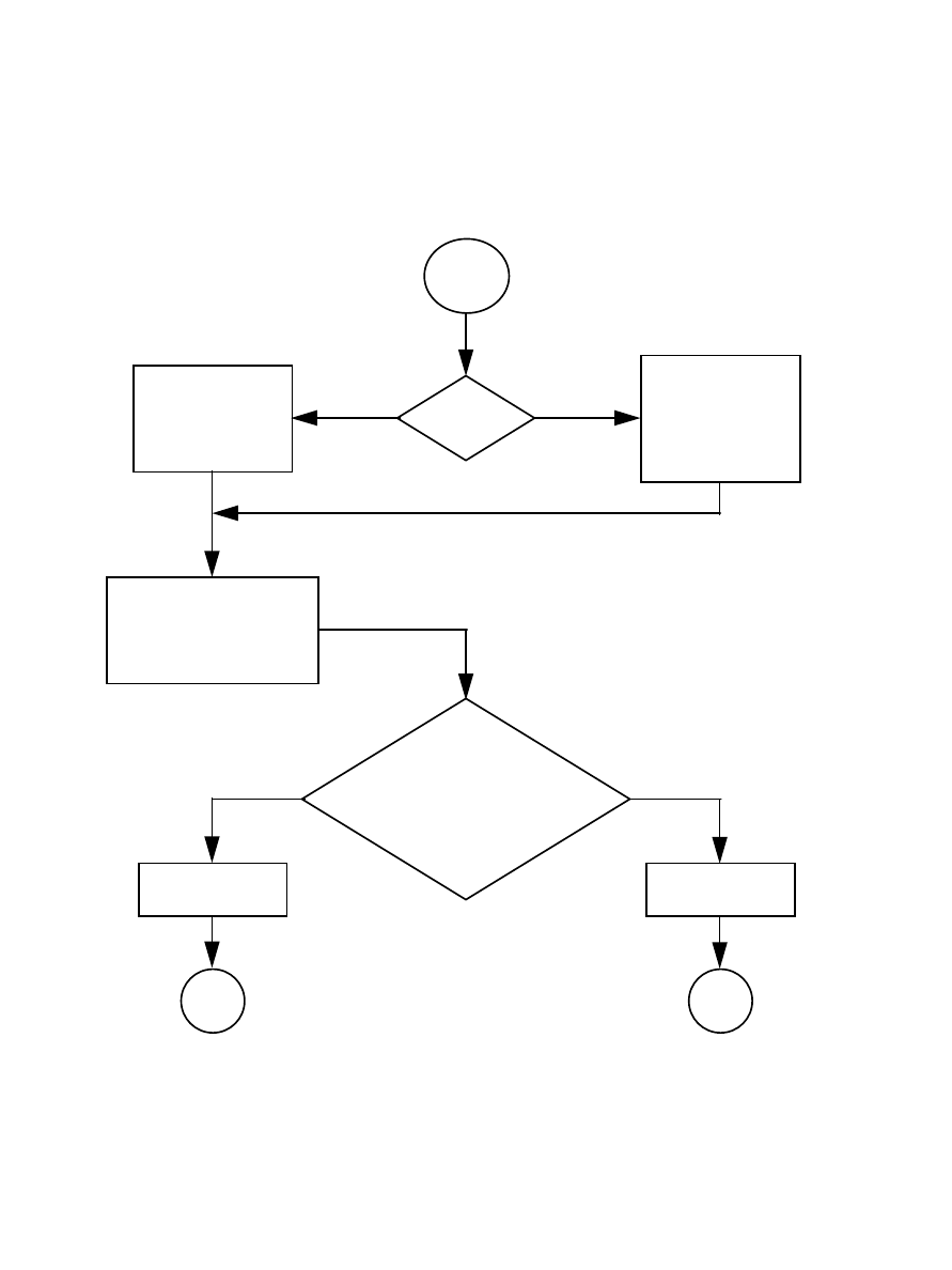
IS-GPS-200D
7 Dec 2004
135
ENTER
IS D
30
= 1?
*
COMPLEMENT
D
1
. . . D
24
TO OBTAIN
d
1
. . . d
24
DO NOT
COMPLEMENT
D
1
. . . D
24
TO OBTAIN
d
1
. . . d
24
SUBSTITUTE d
1
. . . d
24
,
D
29
& D
30
INTO
PARITY EQUATIONS
(TABLE 20-XIV)
**
ARE COMPUTED
D
25
. . . D
30
EQUAL TO CORRESPONDING
RECEIVED
D
25
. . . D
30
?
PARITY CHECK
FAILS
PARITY CHECK
PASSES
FAIL
EXIT
PASS
EXIT
YES NO
YESNO
Figure 20-5. Example Flow Chart for User Implementation of Parity Algorithm
IS-GPS-200D
7 Dec 2004
136
(This page intentionally left blank.)

IS-GPS-200D
7 Dec 2004
137
30. APPENDIX III. GPS NAVIGATION DATA STRUCTURE FOR CNAV DATA, D
C
(t)
30.1 Scope
. This appendix describes the specific GPS CNAV data structure denoted as D
C
(t).
30.2 Applicable Documents
.
30.2.1 Government Documents
. In addition to the documents listed in paragraph 2.1, the following documents of
the issue specified contribute to the definition of the CNAV data related interfaces and form a part of this Appendix
to the extent specified herein.
Specifications
None
Standards
None
Other Publications
None
30.2.2 Non-Government Documents
. In addition to the documents listed in paragraph 2.2, the following
documents of the issue specified contribute to the definition of the CNAV data related interfaces and form a part of
this Appendix to the extent specified herein.
Specifications
None
Other Publications
None
IS-GPS-200D
7 Dec 2004
138
(This page intentionally left blank.)

IS-GPS-200D
7 Dec 2004
139
30.3 Requirements.
30.3.1 Data Characteristics
. The CNAV data, D
C
(t), is a higher precision representation and nominally contains
more accurate data than the NAV data, D(t), described in Appendix II. Also, the CNAV data stream uses a different
parity algorithm.
Users are advised that the CNAV data, D
C
(t), described in this appendix and the NAV data, D(t), described in
Appendix II, should not be mixed in any user algorithms or applications. Each of the two data sets should be treated
as a set and used accordingly.
30.3.2 Message Structure
. As shown in Figures 30-1 through 30-14, the CNAV message structure utilizes a basic
format of twelve-second 300-bit long messages. Each message contains a Cyclic Redundancy Check (CRC) parity
block consisting of 24 bits covering the entire twelve-second message (300 bits) (reference Section 30.3.5).
Message type 0 (zero) is defined to be the default message. In the event of message generation failure, the SV shall
replace each affected message type with the default message type. In the event that a particular message is not
assigned (by the CS) a particular message type for broadcast, the SV shall generate and broadcast the default
message type in that message slot.
Currently undefined and unused message types are reserved for future use.
30.3.3 Message Content
. Each message starts with an 8-bit preamble – 10001011, followed by a 6-bit PRN number
of the transmitting SV, a 6-bit message type ID with a range of 0 (000000) to 63 (111111), and the 17-bit message
time of week (TOW) count. When the value of the message TOW count is multiplied by 6, it represents SV time in
seconds at the start of the next 12-second message. An “alert” flag, when raised (bit 38 = “1”), indicates to the user
that the SV URA and/or the SV User Differential Range Accuracy (UDRA) may be worse than indicated in the
respective message types, and the SV should be used at the user’s own risk. For each default message (Message
Type 0), bits 39 through 276 shall be alternating ones and zeros and the message shall contain a proper CRC parity
block.
IS-GPS-200D
7 Dec 2004
140
(This page intentionally left blank.)
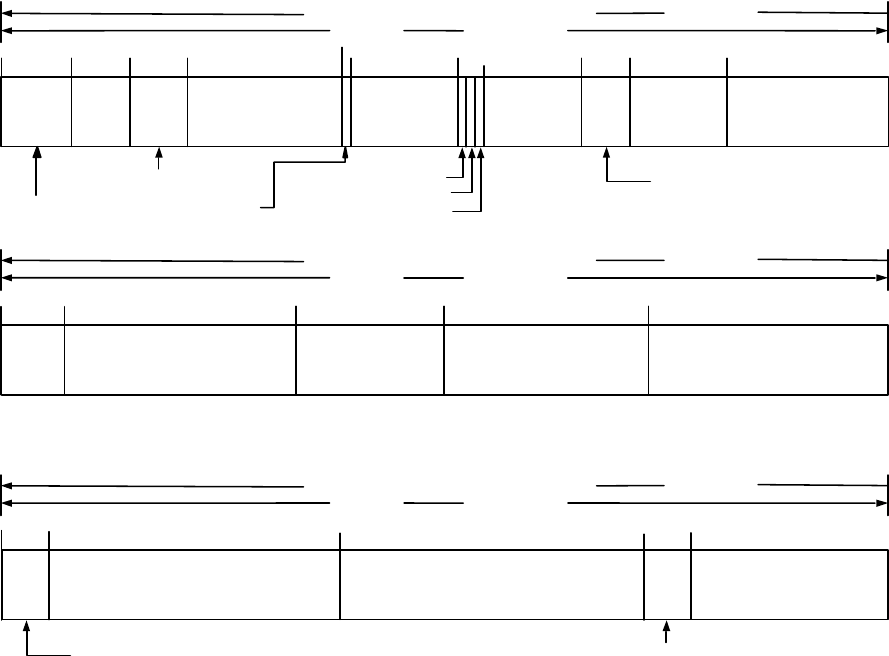
IS-GPS-200D
7 Dec 2004
141
8 BITS
MESSAGE TYPE ID
6
BITS
PREAMBLE
PRN
6
BITS
MESSAGE
TOW COUNT*
17 BITS
"ALERT" FLAG - 1 BIT
9
21
15 39
L5 HEALTH - 1 BIT
71
URA
oe
INDEX
55
66
150
DIRECTION OF DATA FLOW FROM SV
MSB FIRST
100 BITS
4 SECONDS
173
25 BITS
206
1
23 BITS
272
M
0-n
28 MSBs
CRC
24 BITS
277
38
52
* MESSAGE TOW COUNT = 17 MSB OF ACTUAL TOW COUNT AT START OF NEXT 12-SECOND MESSAGE
t
oe
11 BITS
RESERVED – 5 BITs
239
L2 HEALTH - 1 BIT
L1 HEALTH - 1 BIT
101
17 BITS
201
5
BITS
A
•
∆
n
0
•
∆
n
0
t
op
11 BITS
82
19 MSBs
∆A
133
33 BITS
e
n
ω
n
33 BITS
13BITS
WN
n
108
M
0-n
5 LSBs
DIRECTION OF DATA FLOW FROM SV
MSB FIRST
100 BITS
4 SECONDS
DIRECTION OF DATA FLOW FROM SV
MSB FIRST
100 BITS
4 SECONDS
7 LSBs
∆A
Figure 30-1. Message Type 10 - Ephemeris 1
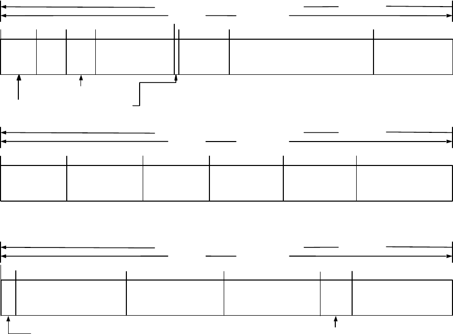
IS-GPS-200D
7 Dec 2004
142
8 BITS
MESSAGE TYPE ID
6
BITS
PREAMBLE
PRN
6
BITS
MESSAGE
TOW COUNT*
17 BITS
"ALERT" FLAG - 1 BIT
9
21
15 39
148
DIRECTION OF DATA FLOW FROM SV
MSB FIRST
100 BITS
4 SECONDS
164
17 BITS
204
1
16 BITS
270
c
rs-n
21 MSBs
CRC
24 BITS
277
38
50
* MESSAGE TOW COUNT = 17 MSB OF ACTUAL TOW COUNT AT START OF NEXT 12-SECOND MESSAGE
t
oe
RESERVED
7 BITS
228
101
15 BITS
201
∆ Ω
•
i
0-n
- DOT
c
is-n
11 BITS
83
18 MSBs
133
24 BITS
c
rc-n
15 LSBs
116
c
rs-n
- 3 LSBs
DIRECTION OF DATA FLOW FROM SV
MSB FIRST
100 BITS
4 SECONDS
DIRECTION OF DATA FLOW FROM SV
MSB FIRST
100 BITS
4 SECONDS
33 BITS
Ω
0-n
i
0-n
i
0-n
16 BITS
c
ic-n
180
249
21 BITS
c
us-n
21 BITS
c
uc-n
Figure 30-2. Message Type 11 - Ephemeris 2
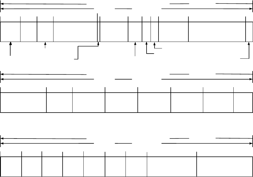
IS-GPS-200D
7 Dec 2004
143
154 167
10 BITS
209
13 BITS
257
ISC
L5Q5
13 BITS
CRC
24 BITS
277
* MESSAGE TOW COUNT = 17 MSB OF ACTUAL TOW COUNT AT START OF NEXT 12-SECOND MESSAGE
RESERVED
20 BITS
233
101
13 BITS
201
a
f2-n
ISC
L1C/A
ISC
L2C
128
8 BITS
17 LSBs
118
DIRECTION OF DATA FLOW FROM SV
MSB FIRST
100 BITS
4 SECONDS
DIRECTION OF DATA FLOW FROM SV
MSB FIRST
100 BITS
4 SECONDS
a
f1-n
13 BITS
ISC
L5I5
180
249
α
0
8BITS
13 BITS
T
GD
141
193
α
1
8 BITs
α
2
8 BITS
α
3
217 225
8 BITS
β
0
8 BITS
β
1
8 BITS
β
2
8 BITS
β
3
241
8 BITS
MESSAGE TYPE ID
6
BITS
PREAMBLE
PRN
6
BITS
MESSAGE
TOW COUNT*
17 BITS
"ALERT" FLAG - 1 BIT
9
21
15 39
DIRECTION OF DATA FLOW FROM SV
MSB FIRST
100 BITS
4 SECONDS
1
38
50
t
op
11 BITS
98
11 BITS
t
oc
a
f1-n
– 3 MSBs
5
BITS
26 BITS
a
f0-n
55 58 72
URA
oc2
INDEX - 3 BITS
61
URA
oc1
INDEX - 3 BITS
URA
oc
INDEX
Figure 30-3. Message Type 30 - Clock, IONO & Group Delay
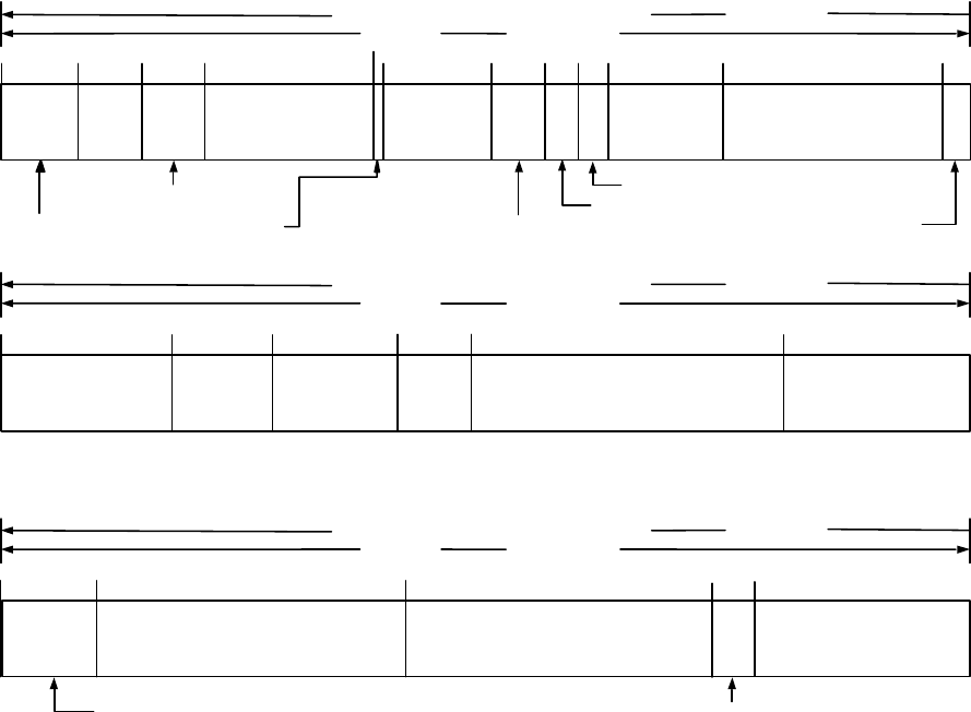
IS-GPS-200D
7 Dec 2004
144
149
10 BITS
31 BITS
273
Reduced Almanac
Packet 2
21 MSBs
CRC
24 BITS
277
* MESSAGE TOW COUNT = 17 MSB OF ACTUAL TOW COUNT AT START OF NEXT 12-SECOND MESSAGE
RESERVED
4
BITS
101
8 BITS
201
a
f2-n
t
oa
Reduced Almanac
Packet 1
128
17 LSBs
118
DIRECTION OF DATA FLOW FROM SV
MSB FIRST
100 BITS
4 SECONDS
DIRECTION OF DATA FLOW FROM SV
MSB FIRST
100 BITS
4 SECONDS
a
f1-n
180
13 BITS
WN
a-n
141
Reduced Almanac Packet 2
10 LSBs
31 BITS
Reduced Almanac
Packet 3
242
31 BITS
Reduced Almanac
Packet 4
211
8 BITS
MESSAGE TYPE ID
6
BITS
PREAMBLE
PRN
6
BITS
MESSAGE
TOW COUNT*
17 BITS
"ALERT" FLAG - 1 BIT
9
21
15 39
DIRECTION OF DATA FLOW FROM SV
MSB FIRST
100 BITS
4 SECONDS
1
38
50
t
op
11 BITS
98
11 BITS
t
oc
a
f1-n
– 3 MSBs
5
BITS
26 BITS
a
f0-n
55 58 72
URA
oc2
INDEX - 3 BITS
61
URA
oc1
INDEX - 3 BITS
URA
oc
INDEX
Figure 30-4. Message Type 31 - Clock & Reduced Almanac
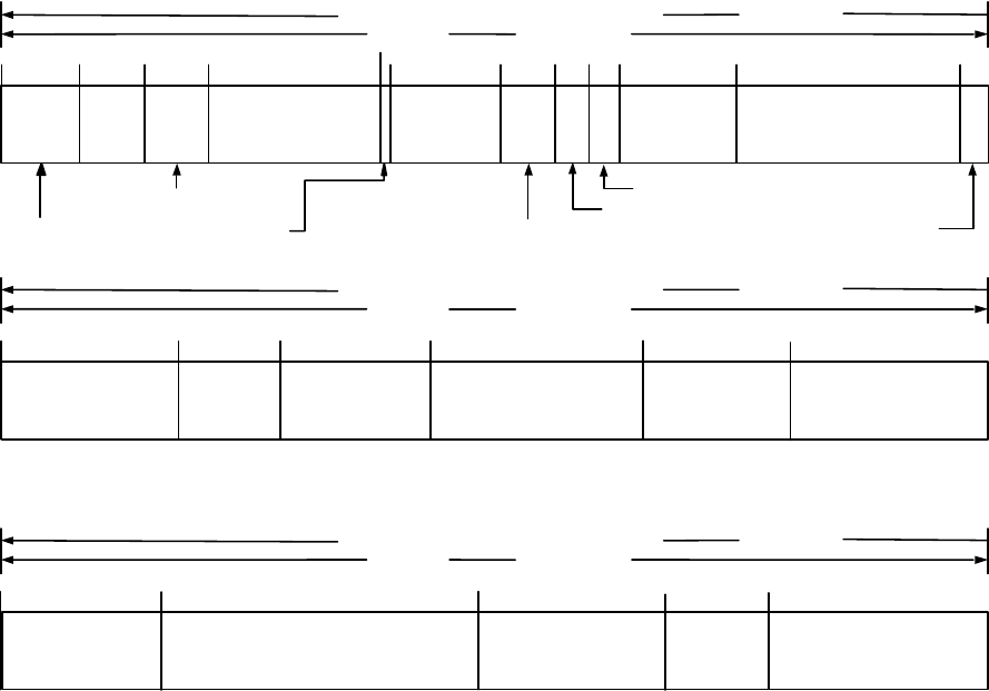
IS-GPS-200D
7 Dec 2004
145
165
10 BITS
21 BITS
266
PM-Y
15 BITS
CRC
24 BITS
277
* MESSAGE TOW COUNT = 17 MSB OF ACTUAL TOW COUNT AT START OF NEXT 12-SECOND MESSAGE
RESERVED
11 BITS
101
15 BITS
201
a
f2-n
PM-X
PM-Y
128
17 LSBs
118
DIRECTION OF DATA FLOW FROM SV
MSB FIRST
100 BITS
4 SECONDS
DIRECTION OF DATA FLOW FROM SV
MSB FIRST
100 BITS
4 SECONDS
a
f1-n
144
21 BITS
PM-X
180
31 BITS
∆UT1
247
19 BITS
216
•
•
∆
UT1
•
8 BITS
MESSAGE TYPE ID
6
BITS
PREAMBLE
PRN
6
BITS
MESSAGE
TOW COUNT*
17 BITS
"ALERT" FLAG - 1 BIT
9
21
15 39
DIRECTION OF DATA FLOW FROM SV
MSB FIRST
100 BITS
4 SECONDS
1
38
50
t
op
11 BITS
98
11 BITS
t
oc
a
f1-n
– 3 MSBs
5
BITS
26 BITS
a
f0-n
55 58 72
URA
oc2
INDEX - 3 BITS
61
URA
oc1
INDEX - 3 BITS
URA
oc
INDEX
16 BITS
t
EOP
Figure 30-5. Message Type 32 - Clock & EOP
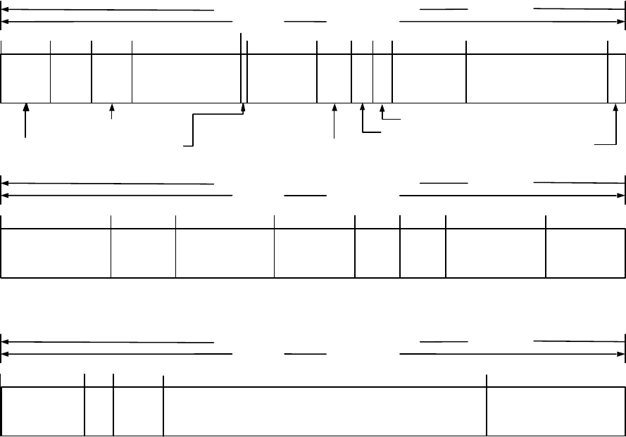
IS-GPS-200D
7 Dec 2004
146
144
10 BITS
16 BITS
226
WN
ot
13 BITS
CRC
24 BITS
277
* MESSAGE TOW COUNT = 17 MSB OF ACTUAL TOW COUNT AT START OF NEXT 12-SECOND MESSAGE
RESERVED
51 BITS
101
8 BITS
201
a
f2-n
∆
t
LS
t
ot
128
17 LSBs
118
DIRECTION OF DATA FLOW FROM SV
MSB FIRST
100 BITS
4 SECONDS
DIRECTION OF DATA FLOW FROM SV
MSB FIRST
100 BITS
4 SECONDS
a
f1-n
188
16 BITS
A
0-n
164
13 BITS
WN
LSF
214
8 BITS
∆t
LSF
7BITS
A
2-n
13 BITS
A
1-n
172157
218
4
BITS
DN
8 BITS
MESSAGE TYPE ID
6
BITS
PREAMBLE
PRN
6
BITS
MESSAGE
TOW COUNT*
17 BITS
"ALERT" FLAG - 1 BIT
9
21
15 39
DIRECTION OF DATA FLOW FROM SV
MSB FIRST
100 BITS
4 SECONDS
1
38
50
t
op
11 BITS
98
11 BITS
t
oc
a
f1-n
– 3 MSBs
5
BITS
26 BITS
a
f0-n
55 58 72
URA
oc2
INDEX - 3 BITS
61
URA
oc1
INDEX - 3 BITS
URA
oc
INDEX
Figure 30-6. Message Type 33 - Clock & UTC
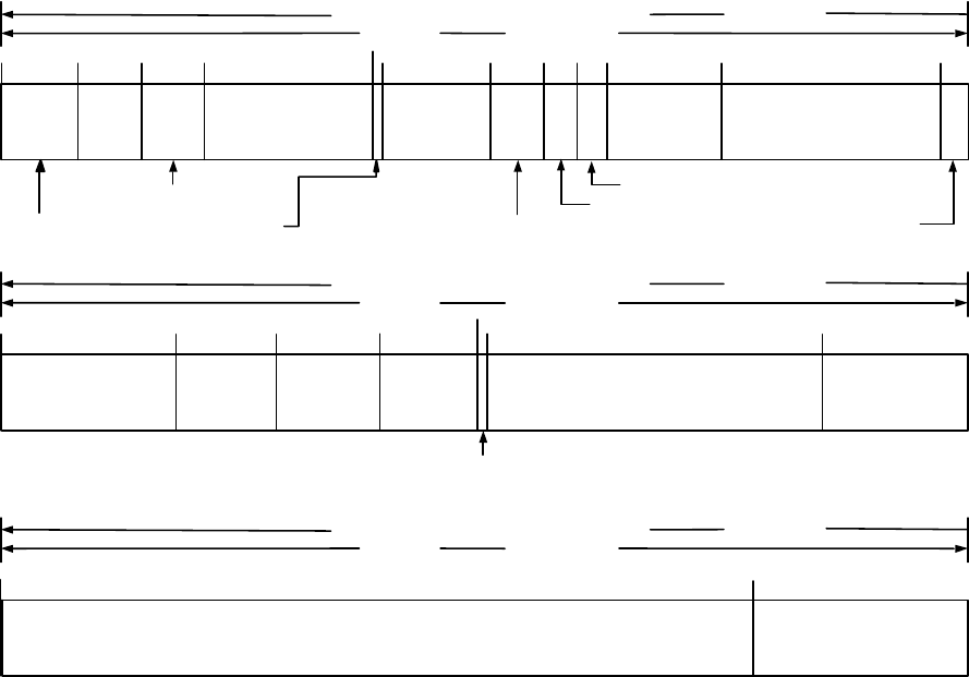
IS-GPS-200D
7 Dec 2004
147
139
10 BITS
EDC
16 MSBs
CRC
24 BITS
277
* MESSAGE TOW COUNT = 17 MSB OF ACTUAL TOW COUNT AT START OF NEXT 12-SECOND MESSAGE
CDC = Clock Differential Correction
EDC = Ephemeris Differential Correction
101
201
a
f2-n
128
17 LSBs
118
DIRECTION OF DATA FLOW FROM SV
MSB FIRST
100 BITS
4 SECONDS
DIRECTION OF DATA FLOW FROM SV
MSB FIRST
100 BITS
4 SECONDS
a
f1-n
185
11 BITS
t
op-D
76 LSBs
EDC
34 BITS
CDC
8 BITS
MESSAGE TYPE ID
6
BITS
PREAMBLE
PRN
6
BITS
MESSAGE
TOW COUNT*
17 BITS
"ALERT" FLAG - 1 BIT
9
21
15 39
DIRECTION OF DATA FLOW FROM SV
MSB FIRST
100 BITS
4 SECONDS
1
38
50
t
op
11 BITS
98
11 BITS
t
oc
a
f1-n
– 3 MSBs
5
BITS
26 BITS
a
f0-n
55 58 72
URA
oc2
INDEX - 3 BITS
61
URA
oc1
INDEX - 3 BITS
URA
oc
INDEX
150
151
11 BITS
t
OD
DC DATA TYPE – 1 BIT
Figure 30-7. Message Type 34 - Clock & Differential Correction
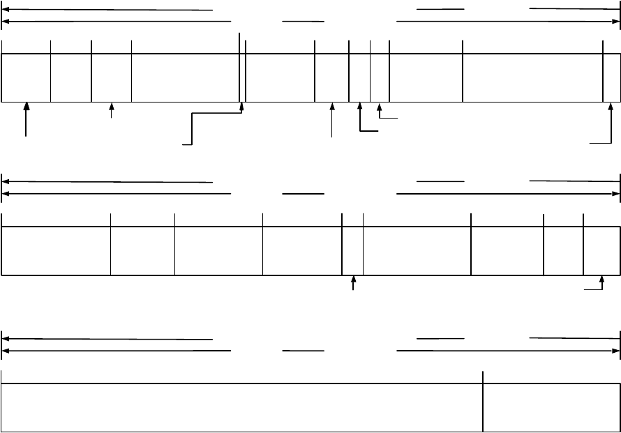
IS-GPS-200D
7 Dec 2004
148
142
10 BITS
13 BITS
RESERVED
7BITS
CRC
24 BITS
277
* MESSAGE TOW COUNT = 17 MSB OF ACTUAL TOW COUNT AT START OF NEXT 12-SECOND MESSAGE
RESERVED
76 BITS
101
7 BITS
201
a
f2-n
A
2GGTO
A
1GGTO
128
17 LSBs
118
DIRECTION OF DATA FLOW FROM SV
MSB FIRST
100 BITS
4 SECONDS
DIRECTION OF DATA FLOW FROM SV
MSB FIRST
100 BITS
4 SECONDS
a
f1-n
194
14 BITS
t
0GGTO
187
16 BITS
A
0GGTO
13 BITS
WN
GGTO
174 155
8 BITS
MESSAGE TYPE ID
6
BITS
PREAMBLE
PRN
6
BITS
MESSAGE
TOW COUNT*
17 BITS
"ALERT" FLAG - 1 BIT
9
21
15 39
DIRECTION OF DATA FLOW FROM SV
MSB FIRST
100 BITS
4 SECONDS
1
38
50
t
op
11 BITS
98
11 BITS
t
oc
a
f1-n
– 3 MSBs
5
BITS
26 BITS
a
f0-n
55 58 72
URA
oc2
INDEX - 3 BITS
61
URA
oc1
INDEX - 3 BITS
URA
oc
INDEX
158
GNSS ID – 3 BITS
Figure 30-8. Message Type 35 - Clock & GGTO
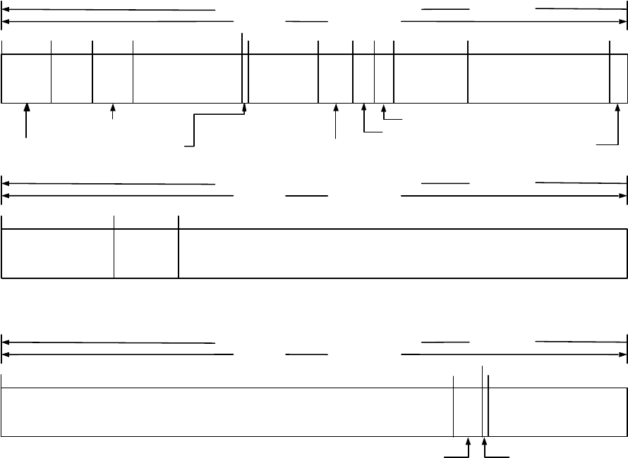
IS-GPS-200D
7 Dec 2004
149
10 BITS
CRC
24 BITS
277
* MESSAGE TOW COUNT = 17 MSB OF ACTUAL TOW COUNT AT START OF NEXT 12-SECOND MESSAGE
RESERVED – 1 BIT
101
201
a
f2-n
128
17 LSBs
118
DIRECTION OF DATA FLOW FROM SV
MSB FIRST
100 BITS
4 SECONDS
DIRECTION OF DATA FLOW FROM SV
MSB FIRST
100 BITS
4 SECONDS
a
f1-n
71 LSBs
TEXT PAGE
TEXT MESSAGE (18 8-BIT CHAR)
73 MSBs
TEXT MESSAGE
(
18 8-BIT CHAR
)
272
276
4
BITS
8 BITS
MESSAGE TYPE ID
6
BITS
PREAMBLE
PRN
6
BITS
MESSAGE
TOW COUNT*
17 BITS
"ALERT" FLAG - 1 BIT
9
21
15 39
DIRECTION OF DATA FLOW FROM SV
MSB FIRST
100 BITS
4 SECONDS
1
38
50
t
op
11 BITS
98
11 BITS
t
oc
a
f1-n
– 3 MSBs
5
BITS
26 BITS
a
f0-n
55 58 72
URA
oc2
INDEX - 3 BITS
61
URA
oc1
INDEX - 3 BITS
URA
oc
INDEX
Figure 30-9. Message Type 36 - Clock & Text
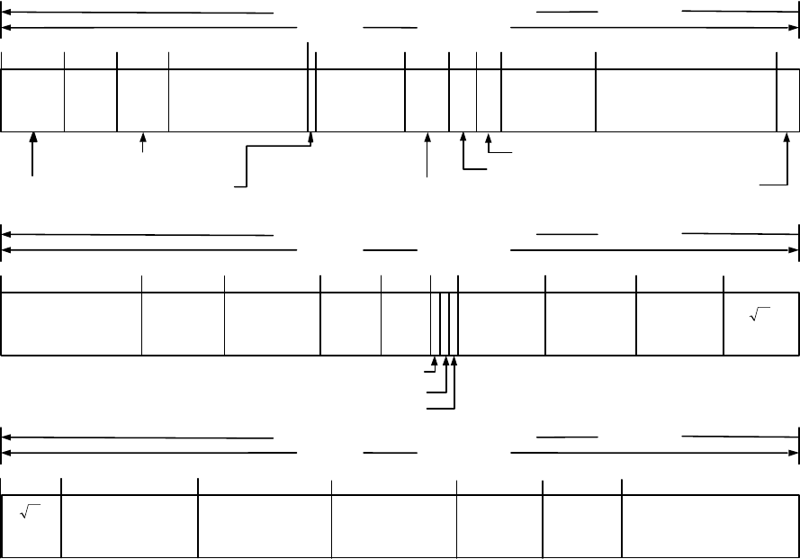
IS-GPS-200D
7 Dec 2004
150
10 BITS
240
10 MSBs
CRC
24 BITS
277
* MESSAGE TOW COUNT = 17 MSB OF ACTUAL TOW COUNT AT START OF NEXT 12-SECOND MESSAGE
11 BITS
101
11 BITS
201
a
f2-n
δ
i
17 LSBs
118
DIRECTION OF DATA FLOW FROM SV
MSB FIRST
100 BITS
4 SECONDS
DIRECTION OF DATA FLOW FROM SV
MSB FIRST
100 BITS
4 SECONDS
a
f1-n
191
169
16 BITS
Ω
0
16 BITS
ω
11 BITS
e
1
41
8 BITS
WN
a-n
t
oa
13 BITS
A
180
128
224
7 LSBs
M
0
8 BITS
MESSAGE TYPE ID
6
BITS
PREAMBLE
PRN
6
BITS
MESSAGE
TOW COUNT*
17 BITS
"ALERT" FLAG - 1 BIT
9
21
15 39
DIRECTION OF DATA FLOW FROM SV
MSB FIRST
100 BITS
4 SECONDS
1
38
50
t
op
11 BITS
98
11 BITS
t
oc
a
f1-n
– 3 MSBs
5
BITS
26 BITS
a
f0-n
55 58 72
URA
oc2
INDEX - 3 BITS
61
URA
oc1
INDEX - 3 BITS
URA
oc
INDEX
11 BITS
Ω
•
A
208
16 BITS
256
a
f0
267
L5 HEALTH – 1 BIT
L2 HEALTH – 1 BIT
L1 HEALTH – 1 BIT
149
6BITS
PRN
a
155 158
10 BITS
a
f1
Figure 30-10. Message Type 37 - Clock & Midi Almanac
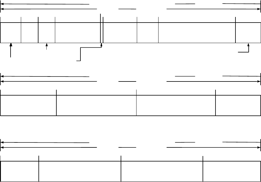
IS-GPS-200D
7 Dec 2004
151
8 BITS
MESSAGE TYPE ID
6
BITS
PREAMBLE
PRN
6
BITS
MESSAGE
TOW COUNT*
17 BITS
"ALERT" FLAG - 1 BIT
9
21
15 39
153
DIRECTION OF DATA FLOW FROM SV
MSB FIRST
100 BITS
4 SECONDS
1
31 BITS
215
Reduced Almanac
Packet 5
17 MSBs
CRC
24 BITS
277
38
* MESSAGE TOW COUNT = 17 MSB OF ACTUAL TOW COUNT AT START OF NEXT 12-SECOND MESSAGE
WN
a-n
101
201
Reduced Almanac
Packet 4
13 BITS
91
10 MSBs
122
21 LSBs
DIRECTION OF DATA FLOW FROM SV
MSB FIRST
100 BITS
4 SECONDS
DIRECTION OF DATA FLOW FROM SV
MSB FIRST
100 BITS
4 SECONDS
8 BITS
t
oa
Reduced Almanac
Packet 2
184
31 BITS
Reduced Almanac
Packet 1
60
52
31 BITS
Reduced Almanac
Packet 3
31 BITS
Reduced Almanac
Packet 6
246
31 BITS
Reduced Almanac
Packet 7
Reduced Almanac Packet 2
14 LSBs
Reduced Almanac
Packet 5
Figure 30-11. Message Type 12 - Reduced Almanac
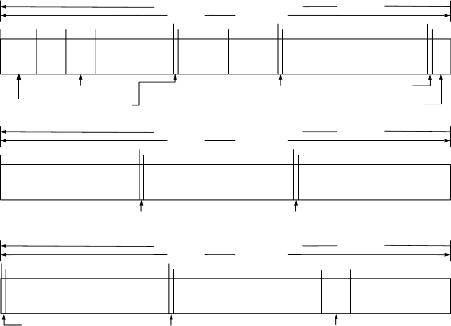
IS-GPS-200D
7 Dec 2004
152
8 BITS
MESSAGE TYPE ID
6
BITS
PREAMBLE
PRN
6
BITS
MESSAGE
TOW COUNT*
17 BITS
"ALERT" FLAG - 1 BIT
9
21
15 39
DIRECTION OF DATA FLOW FROM SV
MSB FIRST
100 BITS
4 SECONDS
1
CRC
24 BITS
277
38
50
* MESSAGE TOW COUNT = 17 MSB OF ACTUAL TOW COUNT AT START OF NEXT 12-SECOND MESSAGE
CDC = Clock Differential Correction
t
op-D
RESERVED
6
BITS
101
11 BITS
30 LSBs
DIRECTION OF DATA FLOW FROM SV
MSB FIRST
100 BITS
4 SECONDS
DIRECTION OF DATA FLOW FROM SV
MSB FIRST
100 BITS
4 SECONDS
11 BITS
t
OD
CDC
34 BITS
CDC
CDC - 4 MSBs
34 BITS
CDC
62
61
97
96
DC DATA TYPE – 1 BIT
DC DATA TYPE – 1 BIT
132
131
DC DATA TYPE – 1 BIT
167
166
DC DATA TYPE – 1 BIT
34 BITS
CDC
202
201
DC DATA TYPE – 1 BIT
34 BITS
CDC
237
236
DC DATA TYPE – 1 BIT
34 BITS
CDC
271
Figure 30-12. Message Type 13 – Clock Differential Correction
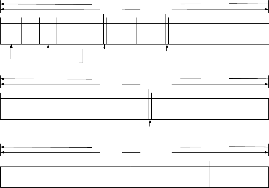
IS-GPS-200D
7 Dec 2004
153
8 BITS
MESSAGE TYPE ID
6
BITS
PREAMBLE
PRN
6
BITS
MESSAGE
TOW COUNT*
17 BITS
"ALERT" FLAG - 1 BIT
9
21
15 39
DIRECTION OF DATA FLOW FROM SV
MSB FIRST
100 BITS
4 SECONDS
1
CRC
24 BITS
277
38
50
* MESSAGE TOW COUNT = 17 MSB OF ACTUAL TOW COUNT AT START OF NEXT 12-SECOND MESSAGE
EDC = Ephemeris Differential Correction
t
op-D
RESERVED
30 BITS
101
201
11 BITS
53 LSBs
DIRECTION OF DATA FLOW FROM SV
MSB FIRST
100 BITS
4 SECONDS
DIRECTION OF DATA FLOW FROM SV
MSB FIRST
100 BITS
4 SECONDS
11 BITS
t
OD
EDC
39 MSBs
EDC
46 MSBs
46 LSBs
EDC
EDC
247
62
61
DC DATA TYPE – 1 BIT
155
154
DC DATA TYPE – 1 BIT
Figure 30-13. Message Type 14 – Ephemeris Differential Correction
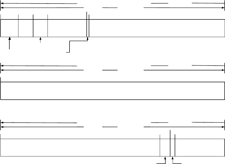
IS-GPS-200D
7 Dec 2004
154
8 BITS
MESSAGE TYPE ID
6
BITS
PREAMBLE
PRN
6
BITS
MESSAGE
TOW COUNT*
17 BITS
"ALERT" FLAG - 1 BIT
9
21
15 39
DIRECTION OF DATA FLOW FROM SV
MSB FIRST
100 BITS
4 SECONDS
1
CRC
24 BITS
277
38
* MESSAGE TOW COUNT = 17 MSB OF ACTUAL TOW COUNT AT START OF NEXT 12-SECOND MESSAGE
TEXT MESSAGE (29 8-BIT CHAR)
RESERVED – 2 BITS
101
201
62 MSBs
DIRECTION OF DATA FLOW FROM SV
MSB FIRST
100 BITS
4 SECONDS
DIRECTION OF DATA FLOW FROM SV
MSB FIRST
100 BITS
4 SECONDS
70 LSBs
TEXT PAGE
TEXT MESSAGE (29 8-BIT CHAR)
BITS 63-162
TEXT MESSAGE
(
29 8-BIT CHAR
)
271
275
4
BITS
Figure 30-14. Message Type 15 - Text

IS-GPS-200D
7 Dec 2004
155
30.3.3.1 Message Type 10 and 11 Ephemeris and Health Parameters.
30.3.3.1.1 Message Type 10 and 11 Ephemeris and Health Parameter Content
. The contents of the SV health,
ephemeris representation and accuracy parameters in message types 10 and 11 are defined below, followed by
material pertinent to the use of the data. Message type 10 in conjunction with message type 11, provide users with
the requisite data to calculate SV position. The general format of message types 10 and 11 consist of data fields for
reference time tags, a set of gravitational harmonic correction terms, rates and rate corrections to quasi-Keplerian
elements, and an accuracy indicator for ephemeris-related data.
The ephemeris parameters in the message type 10 and type 11 describe the orbit of the transmitting SV during the
curve fit interval of three hours. The nominal transmission interval is two hours, and shall coincide with the first
two hours of the curve fit interval. The period of applicability for ephemeris data coincides with the entire three-
hour curve fit interval. Table 30-I gives the definition of the orbital parameters using terminology typical of
Keplerian orbital parameters; it is noted, however, that the transmitted parameter values are expressed such that
they provide the best trajectory fit in Earth-Centered, Earth-Fixed (ECEF) coordinates for each specific fit interval.
The user shall not interpret intermediate coordinate values as pertaining to any conventional coordinate system.
Any change in the Message Type 10 and 11 ephemeris data will be accomplished with a simultaneous change in the
t
oe
value. The CS will assure that the t
oe
value, for at least the first data set transmitted by an SV after an upload, is
different from that transmitted prior to the cutover. See Section 20.3.4.5 for additional information regarding t
oe
.
30.3.3.1.1.1 Transmission Week Number
. Bits 39 through 51 of message type 10 shall contain 13 bits which are a
modulo-8192 binary representation of the current GPS week number at the start of the data set transmission interval
(see paragraph 6.2.4). These 13 bits are comprised of 10 LSBs that represent the ten MSBs of the 29-bit Z-count as
qualified in paragraph 20.3.3.3.1.1, and 3 MSBs which are extra bits that extend the range of transmission week
number from 10 to 13 bits.

IS-GPS-200D
7 Dec 2004
156
30.3.3.1.1.2 Signal Health (L1/L2/L5). The three, one-bit, health indication in bits 52 through 54 of message type
10 refers to the L1, L2, and L5 signals of the transmitting SV. The health of each signal is indicated by:
0 = Signal OK,
1 = Signal bad or unavailable.
The predicted health data will be updated at the time of upload when a new data set has been built by the CS. The
transmitted health data may not correspond to the actual health of the transmitting SV.
Additional SV health data are given in the almanac in messages types 12, 31, and 37. The data given in message
type 10 may differ from that shown in other messages of the transmitting SV and/or other SVs since the latter may
be updated at a different time.
30.3.3.1.1.3 Data Predict Time of Week
. Bits 55 through 65 of message type 10 shall contain the data predict time
of week (t
op
). The t
op
term provides the epoch time of week of the state estimate utilized for the prediction of
satellite quasi-Keplerian ephemeris parameters.

IS-GPS-200D
7 Dec 2004
157
30.3.3.1.1.4 SV Accuracy. Bits 66 through 70 of message type 10 shall contain the ephemeris User Range
Accuracy (URA
oe
) index of the SV for the unauthorized (non-Precise Positioning Service) user. URA
oe
index shall
provide the ephemeris-related user range accuracy index of the SV as a function of the current ephemeris message
curve fit interval. While the ephemeris-related URA may vary over the ephemeris message curve fit interval, the
URA
oe
index (N) in message type 10 shall correspond to the maximum URA
oe
expected over the entire curve fit
interval.
The URA
oe
index is a signed, two’s complement integer in the range of +15 to –16 and has the following
relationship to the ephemeris URA:
URA
oe
Index URA
oe
(meters)
15 6144.00 < URA
oe
14 3072.00 < URA
oe
≤ 6144.00
13 1536.00 < URA
oe
≤ 3072.00
12 768.00 < URA
oe
≤ 1536.00
11 384.00 < URA
oe
≤ 768.00
10 192.00 < URA
oe
≤ 384.00
9 96.00 < URA
oe
≤ 192.00
8 48.00 < URA
oe
≤ 96.00
7 24.00 < URA
oe
≤ 48.00
6 13.65 < URA
oe
≤ 24.00
5 9.65 < URA
oe
≤ 13.65
4 6.85 < URA
oe
≤ 9.65
3 4.85 < URA
oe
≤ 6.85
2 3.40 < URA
oe
≤ 4.85
1 2.40 < URA
oe
≤ 3.40
0 1.70 < URA
oe
≤ 2.40
-1 1.20 < URA
oe
≤ 1.70
-2 0.85 < URA
oe
≤ 1.20
-3 0.60 < URA
oe
≤ 0.85
-4 0.43 < URA
oe
≤ 0.60
-5 0.30 < URA
oe
≤ 0.43
-6 0.21 < URA
oe
≤ 0.30
-7 0.15 < URA
oe
≤ 0.21
-8 0.11 < URA
oe
≤ 0.15
-9 0.08 < URA
oe
≤ 0.11
-10 0.06 < URA
oe
≤ 0.08
-11 0.04 < URA
oe
≤ 0.06
-12 0.03 < URA
oe
≤ 0.04
-13 0.02 < URA
oe
≤ 0.03
-14 0.01 < URA
oe
≤ 0.02
-15 URA
oe
≤ 0.01
-16 No accuracy prediction available—use at own risk

IS-GPS-200D
7 Dec 2004
158
30.3.3.1.2 Message Type 10 and 11 Ephemeris Parameter Characteristics. For each ephemeris parameter contained
in message types 10 and 11, the number of bits, the scale factor of the least significant bit (LSB) (which is the last
bit received), the range, and the units are as specified in Table 30-I. See Figures 30-1 and 30-2 for complete bit
allocation in message types 10 and 11.
30.3.3.1.3 User Algorithm for Determination of SV Position
. The user shall compute the ECEF coordinates of
position for the SV’s antenna phase center (APC) utilizing a variation of the equations shown in Table 30-II. The
ephemeris parameters are Keplerian in appearance; however, the values of these parameters are produced by the CS
via a least squares curve fit of the predicted ephemeris of the SV APC (time-position quadruples: t, x, y, z expressed
in ECEF coordinates). Particulars concerning the applicable coordinate system are given in Sections 20.3.3.4.3.3
and 20.3.3.4.3.4.
The sensitivity of the SV’s position to small perturbations in most ephemeris parameters is extreme. The sensitivity of
position to the parameters A, C
rc-n
, and C
rs-n
is about one meter/meter. The sensitivity of position to the angular
parameters is on the order of 10
8
meters/semi-circle, and to the angular rate parameters is on the order of 10
12
meters/semi-circle/second. Because of this extreme sensitivity to angular perturbations, the value of π used in the curve
fit is given here. π is a mathematical constant, the ratio of a circle’s circumference to its diameter. Here π is taken as
3.1415926535898.

IS-GPS-200D
7 Dec 2004
159
Table 30-I. Message Types 10 and 11 Parameters (1 of 2)
Parameter
No. of
Bits**
Scale
Factor
(LSB)
Effective
Range***
Units
Week No.
SV accuracy
Signal health
(L1/L2/L5)
t
op
A ****
A
∆n
0
∆n
0
M
0-n
e
n
ω
n
Data predict time of week
Semi-major axis difference at
reference time
Change rate in semi-major
axis
Mean Motion difference from
computed value at reference
time
Rate of mean motion
difference from computed
value
Mean anomaly at reference
time
Eccentricity
Argument of perigee
13
5*
3
11
26*
25*
17*
23*
33*
33
33*
1
1
300
2
-9
2
-21
2
-44
2
-57
2
-32
2
-34
2
-32
604,500
0.03
weeks
(see text)
(see text)
seconds
meters
meters/sec
semi-circles/sec
semi-circles/sec
2
semi-circles
dimensionless
semi-circles
* Parameters so indicated are two’s complement, with the sign bit (+ or -) occupying the MSB;
** See Figure 30-1 for complete bit allocation in Message Type 10;
*** Unless otherwise indicated in this column, effective range is the maximum range attainable with
indicated bit allocation and scale factor.
**** Relative to A
REF
= 26,559,710 meters.
•
•

IS-GPS-200D
7 Dec 2004
160
Table 30-I. Message Types 10 and 11 Parameters (2 of 2)
Parameter
No. of
Bits**
Scale
Factor
(LSB)
Effective
Range***
Units
t
oe
Ω
0-n
****
*****
i
0-n
i
0-n
–DOT
C
is-n
C
ic-n
C
rs-n
C
rc-n
C
us-n
C
uc-n
Ephemeris data reference time of week
Reference right ascension angle
Rate of right ascension difference
Inclination angle at reference time
Rate of inclination angle
Amplitude of the sine harmonic correction
term to the angle of inclination
Amplitude of the cosine harmonic
correction term to the angle of inclination
Amplitude of the sine correction term to
the orbit radius
Amplitude of the cosine correction term to
the orbit radius
Amplitude of the sine harmonic correction
term to the argument of latitude
Amplitude of the sine harmonic correction
term to the argument of latitude
11
33*
17*
33*
15*
16*
16*
24*
24*
21*
21*
300
2
-32
2
-44
2
-32
2
-44
2
-30
2
-30
2
-8
2
-8
2
-30
2
-30
604,500 seconds
semi-circles
semi-circles/sec
semi-circles
semi-circles/sec
radians
radians
meters
meters
radians
radians
* Parameters so indicated are two’s complement, with the sign bit (+ or -) occupying the MSB;
** See Figure 30-1 and Figure 30-2 for complete bit allocation in Message Types 10 and 11;
*** Unless otherwise indicated in this column, effective range is the maximum range attainable with
indicated bit allocation and scale factor.
**** Ω
0-n
is the right ascension angle at the weekly epoch (Ω
0-w
) propagated to the reference time at the rate
of right ascension {Ω
REF
Table 30-II }.
***** Relative to Ω
REF
= -2.6 x 10
-9
semi-circles/second.
∆ Ω
•
•
•

IS-GPS-200D
7 Dec 2004
161
Table 30-II. Elements of Coordinate System (part 1 of 2)
Element/Equation Description
µ = 3.986005 x 10
14
meters
3
/sec
2
Ω
e
= 7.2921151467 x 10
-5
rad/sec
A
0
= A
REF
+ ∆A
*
A
k
= A
0
+ (A) t
k
n
0
=
3
0
A
µ
t
k
= t – t
oe
**
∆n
A
= ∆n
0
+½ ∆n
0
t
k
n
A
= n
0
+ ∆n
A
M
k
= M
0
+ n
A
t
k
M
k
= E
k
– e
n
sin E
k
ν
k
= tan
-1
⎭
⎬
⎫
⎩
⎨
⎧
ν
ν
k
k
cos
sin
= tan
-1
()
()( )
⎪
⎭
⎪
⎬
⎫
⎪
⎩
⎪
⎨
⎧
−−
−−
knnk
knk
2
n
E cos e 1 / e E cos
E cos e 1 / E sin e 1
E
k
= cos
-1
⎭
⎬
⎫
⎩
⎨
⎧
ν+
ν+
kn
kn
cose1
cose
WGS 84 value of the earth’s gravitational constant for GPS user
WGS 84 value of the earth’s rotation rate
Semi-Major Axis at reference time
Semi-Major Axis
Computed Mean Motion (rad/sec)
Time from ephemeris reference time
Mean motion difference from computed value
Corrected Mean Motion
Mean Anomaly
Kepler’s equation for Eccentric Anomaly (radians)
(may be solved by iteration)
True Anomaly
Eccentric Anomaly
* A
REF
= 26,559,710 meters
**
t is GPS system time at time of transmission, i.e., GPS time corrected for transit time (range/speed of light).
Furthermore, t
k
shall be the actual total difference between the time t and the epoch time t
oe
, and must account
for beginning or end of week crossovers. That is if t
k
is greater than 302,400 seconds, subtract 604,800
seconds from t
k
. If t
k
is less than -302,400 seconds, add 604,800 seconds to t
k
.
•
•
•
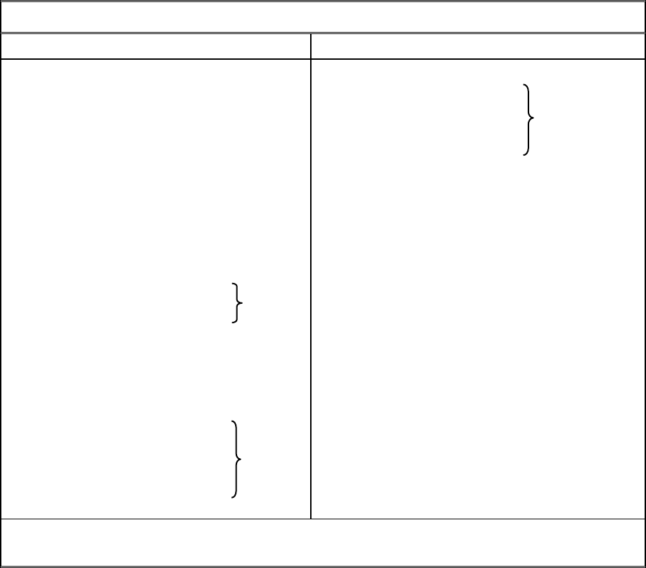
IS-GPS-200D
7 Dec 2004
162
Table 30-II. Elements of Coordinate System (part 2 of 2)
Element/Equation *
Description
Φ
k
= ν
k
+ ω
n
δu
k
= C
us-n
sin2Φ
k
+ C
uc-n
cos2Φ
k
δr
k
= C
rs-n
sin2Φ
k
+ C
rc-n
cos2Φ
k
δi
k
= C
is-n
sin2Φ
k
+ C
ic-n
cos2Φ
k
u
k
= Φ
k
+ δu
k
r
k
= A
k
(1 – e
n
cos E
k
) + δr
k
i
k
= i
o-n
+ (i
o-n
-DOT)t
k
+ δi
k
x
k
' = r
k
cos u
k
y
k
' = r
k
sin u
k
Ω = Ω
REF
+ ∆Ω ***
Ω
k
= Ω
0-n
+ ( Ω − Ω
e
) t
k
– Ω
e
t
oe
x
k
= x
k
' cos Ω
k
− y
k
' cos i
k
sin Ω
k
y
k
= x
k
' sin Ω
k
+ y
k
' cos i
k
cos Ω
k
z
k
= y
k
' sin i
k
Argument of Latitude
Argument of Latitude Correction
Radial Correction
Inclination Correction
Corrected Argument of Latitude
Corrected Radius
Corrected Inclination
Positions in orbital plane
Rate of Right Ascension
Corrected Longitude of Ascending Node
Earth-fixed coordinates of SV antenna phase center
*** Ω
REF
= −2.6 x 10
-9
semi-circles/second.
Second Harmonic
Perturbations
•
•
•
•
• •
•

IS-GPS-200D
7 Dec 2004
163
30.3.3.2 Message Types 30 Through 37 SV Clock Correction Parameters.
30.3.3.2.1 Message Type 30 Through 37 SV Clock Correction Parameter Content
. The clock parameters in any one
of message types 30 through 37 describe the SV time scale during the period of validity. The clock parameters in a
data set shall be valid during the interval of time in which they are transmitted and shall remain valid for an
additional period of time after transmission of the next data set has started.
The general format of message types 30 through 37 includes data fields for SV clock correction coefficients. Any
one of message types 30 through 37 in conjunction with message types 10 and 11 provide users with the requisite
data to correct SV time and to calculate SV position precisely. In general, any message type 30’s (i.e. 30-39) will
provide SV clock correction parameters as described in this section.
30.3.3.2.1.1 SV Clock Correction
. Any one of message types 30 through 37, Figure 30-3 through Figure 30-10,
contains the parameters needed by the users for apparent SV clock correction. Bits 61 to 71 contain t
oc
, clock data
reference time of week. Bits 72 to 127 contain SV clock correction coefficients. The related algorithm is given in
paragraph 20.3.3.3.3.1.
30.3.3.2.1.2 Data Predict Time of Week
. Bits 39 through 49 of message types 30 through 37 shall contain the data
predict time of week (t
op
). The t
op
term provides the epoch time of week of the state estimate utilized for the
prediction of SV clock correction coefficients.
30.3.3.2.2 Clock Parameter Characteristics
. The number of bits, the scale factor of the LSB (which is the last bit
received), the range, and the units of clock correction parameters shall be as specified in Table 30-III.
30.3.3.2.3 User Algorithms for SV Clock Correction Data
. The algorithms defined in paragraph 20.3.3.3.3.1 allow
all users to correct the code phase time received from the SV with respect to both SV code phase offset and
relativistic effects. However, since the SV clock corrections of equations in paragraph 20.3.3.3.3.1 are estimated by
the CS using dual frequency L1 and L2 P(Y) code measurements, the single-frequency L1 or L2 user and the dual-
frequency L1 C/A – L2 C users must apply additional terms to the SV clock correction equations. These terms are
described in paragraph 30.3.3.3.1.

IS-GPS-200D
7 Dec 2004
164
Table 30-III. Clock Correction and Accuracy Parameters
Parameter
No. of
Bits**
Scale
Factor
(LSB)
Effective
Range***
Units
t
oc
URA
oc
Index
URA
oc1
Index
URA
oc2
Index
a
f2-n
a
f1-n
a
f0-n
Clock Data Reference Time of Week
SV Clock Accuracy Index
SV Clock Accuracy Change Index
SV Clock Accuracy Change Rate Index
SV Clock Drift Rate Correction Coefficient
SV Clock Drift Correction Coefficient
SV Clock Bias Correction Coefficient
11
5*
3
3
10*
20*
26*
300
2
-60
2
-48
2
-35
604,500
seconds
(see text)
(see text)
(see text)
sec/sec
2
sec/sec
seconds
* Parameters so indicated are two’s complement, with the sign bit (+ or -) occupying the MSB;
** See Figure 30-3 through 30-10 for complete bit allocation in Message types 30 to 37;
*** Unless otherwise indicated in this column, effective range is the maximum range attainable with
indicated bit allocation and scale factor.

IS-GPS-200D
7 Dec 2004
165
30.3.3.2.4 SV Clock Accuracy Estimates. Bits 50 through 54, and 55 through 57, and 58 through 60 of message
types 30 through 37 shall contain the URA
oc
Index,URA
oc1
Index, and URA
oc2
Index, respectively, of the SV
(reference paragraph 6.2.1) for the unauthorized user. The URA
oc
Index together with URA
oc1
Index and URA
oc2
Index shall give the clock-related user range accuracy of the SV as a function of time since the prediction (t
op
) used
to generate the uploaded clock correction polynomial terms.
The user shall calculate the clock-related URA with the equation (in meters);
URA
oc
= URA
ocb
+ URA
oc1
(t – t
op
) for t-t
op
< 93,600 seconds
URA
oc
= URA
ocb
+ URA
oc1
(t – t
op
) + URA
oc2
(t – t
op
– 93,600)
2
for t-t
op
> 93,600 seconds
where
t = GPS time (must account for beginning or end of week crossovers),
t
op
= time of week of the state estimate utilized for the prediction of satellite clock correction parameters.
The CS shall derive URA
ocb
at time t
op
which, when used together with URA
oc1
and URA
oc2
in the above equations,
results in the minimum URA
oc
that is greater than the predicted URA
oc
during the entire duration up to 14 days after
t
op
.

IS-GPS-200D
7 Dec 2004
166
The user shall use the broadcast URA
oc
Index to derive URA
ocb
. The index is a signed, two’s complement integer in
the range of +15 to –16 and has the following relationship to the clock-related user derived URA
ocb
:
URA
oc
Index URA
ocb
(meters)
15 6144.00 < URA
ocb
14 3072.00 < URA
ocb
≤ 6144.00
13 1536.00 < URA
ocb
≤ 3072.00
12 768.00 < URA
ocb
≤ 1536.00
11 384.00 < URA
ocb
≤ 768.00
10 192.00 < URA
ocb
≤ 384.00
9 96.00 < URA
ocb
≤ 192.00
8 48.00 < URA
ocb
≤ 96.00
7 24.00 < URA
ocb
≤ 48.00
6 13.65 < URA
ocb
≤ 24.00
5 9.65 < URA
ocb
≤ 13.65
4 6.85 < URA
ocb
≤ 9.65
3 4.85 < URA
ocb
≤ 6.85
2 3.40 < URA
ocb
≤ 4.85
1 2.40 < URA
ocb
≤ 3.40
0 1.70 < URA
ocb
≤ 2.40
-1 1.20 < URA
ocb
≤ 1.70
-2 0.85 < URA
ocb
≤ 1.20
-3 0.60 < URA
ocb
≤ 0.85
-4 0.43 < URA
ocb
≤ 0.60
-5 0.30 < URA
ocb
≤ 0.43
-6 0.21 < URA
ocb
≤ 0.30
-7 0.15 < URA
ocb
≤ 0.21
-8 0.11 < URA
ocb
≤ 0.15
-9 0.08 < URA
ocb
≤ 0.11
-10 0.06 < URA
ocb
≤ 0.08
-11 0.04 < URA
ocb
≤ 0.06
-12 0.03 < URA
ocb
≤ 0.04
-13 0.02 < URA
ocb
≤ 0.03
-14 0.01 < URA
ocb
≤ 0.02
-15 URA
ocb
≤ 0.01
-16 No accuracy prediction available—use at own risk
The user may use the upper bound value in the URA
ocb
range corresponding to the broadcast index, thereby
calculating the maximum URA
oc
that is equal to or greater than the CS predicted URA
oc
, or the user may use the
lower bound value in the range which will provide the minimum URA
oc
that is equal to or less than the CS predicted
URA
oc
.

IS-GPS-200D
7 Dec 2004
167
The transmitted URA
oc1
Index is an integer value in the range 0 to 7. URA
oc1
Index has the following relationship to
the URA
oc1
:
URA
oc1
=
N
2
1
(meters/second)
where
N = 4 + URA
oc1
Index
The transmitted URA
oc2
Index is an integer value in the range 0 to 7. URA
oc2
Index has the following relationship to
the URA
oc2
:
URA
oc2
=
N
2
1
(meters/second
2
)
where
N = 25 + URA
oc2
Index

IS-GPS-200D
7 Dec 2004
168
30.3.3.3 Message Type 30 Ionospheric and Group Delay Correction Parameters.
30.3.3.3.1 Message Type 30 Ionospheric and Group Delay Correction Parameter Content
. Message type 30
provides SV clock correction parameters (ref. Section 30.3.3.2) and ionospheric and group delay correction
parameters. Bits 128 through 192 of message type 30 provide the group delay differential correction terms for L1,
L2, and L5 signal users. Bits 193 through 256 provide the ionospheric correction parameters for single frequency
user. The following algorithms shall apply when interpreting the correction parameters in the message.
30.3.3.3.1.1 Estimated L1-L2 Group Delay Differential
. The group delay differential correction terms, T
GD
,
ISC
L1C/A
, ISC
L2C
for the benefit of single frequency L1 P, L1 C/A, L2 P, L2 C users and dual frequency L1/L2 users
are contained in bits 128 through 166 of message type 30 (see Figure 30-3 for complete bit allocation). The bit
length, scale factors, ranges, and units of these parameters are given in Table 30-IV. The bit string of
“1000000000000” shall indicate that the group delay value is not available. The related algorithm is given in
paragraphs 30.3.3.3.1.1.1 and 30.3.3.3.1.1.2.
Table 30-IV. Group Delay Differential Parameters ****
Parameter
No. of
Bits**
Scale Factor
(LSB)
Effective
Range***
Units
T
GD
ISC
L1C/A
ISC
L2C
13*
13*
13*
2
-35
2
-35
2
-35
seconds
seconds
seconds
* Parameters so indicated are two’s complement with the sign bit (+ or -) occupying the MSB;
** See Figure 30-3 for complete bit allocation in Message type 30;
*** Effective range is the maximum range attainable with indicated bit allocation and scale factor;
**** The bit string of “1000000000000” will indicate that the group delay value is not available.

IS-GPS-200D
7 Dec 2004
169
30.3.3.3.1.1.1 Inter-Signal Group Delay Differential Correction. The correction terms, T
GD
, ISC
L1C/A
and ISC
L2C
,
are initially provided by the CS to account for the effect of SV group delay differential between L1 P(Y) and L2
P(Y), L1 P(Y) and L1 C/A, and between L1 P(Y) and L2 C, respectively, based on measurements made by the SV
contractor during SV manufacture. The values of T
GD
and ISCs for each SV may be subsequently updated to reflect
the actual on-orbit group delay differential. For maximum accuracy, the single frequency L1 C/A user must use the
correction terms to make further modifications to the code phase offset in paragraph 20.3.3.3.3.1 with the equation:
(∆t
SV
)
L1C/A
= ∆t
SV
- T
GD
+ ISC
L1C/A
where T
GD
(see paragraph 20.3.3.3.3.2) and ISC
L1C/A
are provided to the user as Message Type 30 data, described in
paragraph 30.3.3.3.1.1. For the single frequency L2 C user, the code phase offset modification is given by:
(∆t
SV
)
L2C
= ∆t
SV
- T
GD
+ ISC
L2C
where, ISC
L2C
is provided to the user as Message Type 30 data.
The values of ISC
L1C/A
and ISC
L2C
are measured values that represent the mean SV group delay differential between
the L1 P(Y)-code and the L1 C/A- or L2 C-codes respectively as follows,
ISC
L1C/A
= t
L1P(Y)
- t
L1C/A
ISC
L2C
= t
L1P(Y)
- t
L2C
.
where, t
Lix
is the GPS time the i
th
frequency x signal (a specific epoch of the signal) is transmitted from the SV
antenna phase center.

IS-GPS-200D
7 Dec 2004
170
30.3.3.3.1.1.2 L1 /L2 Ionospheric Correction. The two frequency (L1 C/A and L2 C) user shall correct for the
group delay and ionospheric effects by applying the relationship:
GD
12
A/C1L12C2LA/C1L12C2L
T c
1
)ISCISC( c )PRPR(
PR −
γ−
γ−+γ−
=
where,
PR = pseudorange corrected for ionospheric effects,
PR
i
= pseudorange measured on the channel indicated by the subscript,
ISC
i
= inter-signal correction for the channel indicated by the subscript (see paragraph 30.3.3.3.1.1),
T
GD
= see paragraph 20.3.3.3.3.2,
c = speed of light,
and where, denoting the nominal center frequencies of L1 and L2 as f
L1
and f
L2
respectively,
γ
12
= (f
L1
/f
L2
)
2
= (1575.42/1227.6)
2
= (77/60)
2
.
30.3.3.3.1.2 Ionospheric Data
. The ionospheric parameters which allow the “L1 only” or “L2 only” user to utilize
the ionospheric model for computation of the ionospheric delay are contained in Message Type 30. The “one
frequency” user should use the model given in paragraph 20.3.3.5.2.5 to make this correction for the ionospheric
effects. The bit lengths, scale factors, ranges, and units of these parameters are given in Table 20-X.
The ionospheric data shall be updated by the CS at least once every six days while the CS is able to upload the
SVs. If the CS is unable to upload the SVs, the ionospheric data transmitted by the SVs may not be accurate.

IS-GPS-200D
7 Dec 2004
171
30.3.3.4 Message Types 31, 12, and 37 Almanac Parameters. The almanac parameters are provided in any one of
message types 31, 37, and 12. Message type 37 provides Midi almanac parameters and the reduced almanac
parameters are provided in either message type 31 or type 12. The SV shall broadcast both message types 31
(and/or 12) and 37. However, the reduced almanac parameters (i.e. message types 31 and/or 12) for the complete set
of SVs in the constellation will be broadcast by a SV using shorter duration of time compared to the broadcast of the
complete set of Midi almanac parameters (i.e. message type 37). The parameters are defined below, followed by
material pertinent to the use of the data.
30.3.3.4.1 Almanac Reference Week
. Bits 39 through 51 of message type 12, and bits 128 through 140 of message
types 31 and 37 shall indicate the number of the week (WN
a-n
) to which the almanac reference time (t
oa
) is
referenced (see paragraph 20.3.3.5.2.2). The WN
a-n
term consists of 13 bits which shall be a modulo-8192 binary
representation of the GPS week number (see paragraph 6.2.4) to which the t
oa
is referenced. Bits 52 through 59 of
message type 12, and bits 141 to 148 of message types 31 and 37 shall contain the value of t
oa
, which is referenced
to this WN
a-n
.
30.3.3.4.2 Almanac Reference Time
. See paragraph 20.3.3.5.2.2.
30.3.3.4.3 SV PRN Number
. Bits 149 through 154 of message type 37 and bits 1 through 6 in each packet of
reduced almanac shall specify PRN number of the SV whose almanac or reduced almanac, respectively, is provided
in the message or in the packet.
30.3.3.4.4 Signal Health (L1/L2/L5)
. The three, one-bit, health indication in bits 155, 156, and 157 of message type
37 and bits 29,30 and 31 of each packet of reduced almanac refers to the L1, L2, and L5 signals of the SV whose
PRN number is specified in the message or in the packet. For each health indicator, a “0” signifies that all
navigation data are okay and “1” signifies that some or all navigation data are bad. The predicted health data will be
updated at the time of upload when a new reduced almanac has been built by the CS. The transmitted health data
may not correspond to the actual health of the transmitting SV or other SVs in the constellation.

IS-GPS-200D
7 Dec 2004
172
30.3.3.4.5 Midi Almanac Parameter Content. Message type 37, Figure 30-10, provides Midi almanac data for a SV
whose PRN number is specified in the message. The number of bits, the scale factor (LSB), the range, and the
units of the almanac parameters are given in Table 30-V. The user algorithm is essentially the same as the user
algorithm used for computing the precise ephemeris as specified in Table 20-IV. Other parameters appearing in the
equations of Table 20-IV, but not provided by the Midi almanac with the reference values, are set to zero for SV
position determination. See paragraph 20.3.3.5.2.3 for almanac time parameters.
30.3.3.4.6 Reduced Almanac Parameter Content
. Message type 31, Figure 30-4, provides SV clock correction
parameters (ref. Section 30.3.3.2) and reduced almanac data packets for 4 SVs. Message type 12, Figure 30-11,
contains reduced almanac data packets for 7 SVs.
30.3.3.4.6.1 Reduced Almanac Data
. Message type 31 or 12 contains reduced almanac data and SV health words
for SVs in the constellation. The reduced almanac data of a SV is broadcast in a packet of 31 bits long, as described
in Figure 30-15. The reduced almanac data are a subset of the almanac data which provide less precise ephemeris.
The reduced almanac data values are provided relative to pre-specified reference values. The number of bits, the
scale factor (LSB), the range, and the units of the reduced almanac parameters are given in Table 30-VI. The
algorithms and other material related to the use of the reduced almanac data are given in Section 30.3.3.4.6.2.
The reduced almanac parameters shall be updated by the CS at least once every 3 days while the CS is able to
upload the SVs. If the CS is unable to upload the SVs, the accuracy of the reduced almanac parameters transmitted
by the SVs will degrade over time.
30.3.3.4.6.2 Reduced Almanac Packet
. The following shall apply when interpreting the data provided in each
packet of reduced almanac (see Figure 30-15).
30.3.3.4.6.2.1 Reduced Almanac
. The reduced almanac data is provided in bits 7 through 28 of each packet. The
data from a packet along with the reference values (see Table 30-VI) provide ephemeris with further reduced
precision. The user algorithm is essentially the same as the user algorithm used for computing the precise ephemeris
from the parameters of the message types 10 and 11 (see paragraph 30.3.3.1.3 and Table 30-II). Other parameters
appearing in the equations of Table 30-II, but not provided by the reduced almanac with the reference values, are set
to zero for SV position determination.

IS-GPS-200D
7 Dec 2004
173
Table 30-V. Midi Almanac Parameters
Parameter
No. of
Bits**
Scale
Factor
(LSB)
Effective
Range***
Units
t
oa
e
δ
i
****
Ω
•
A
Ω
0
ω
M
0
a
f0
a
f1
8
11
11*
11*
17
16*
16*
16*
11*
10*
2
12
2
-16
2
-14
2
-33
2
-4
2
-15
2
-15
2
-15
2
-20
2
-37
602,112
seconds
dimensionless
semi-circles
semi-circles/sec
meters
semi-circles
semi-circles
semi-circles
seconds
sec/sec
* Parameters so indicated shall be two's complement with the sign bit (+ or -) occupying the MSB;
** See Figure 30-10 for complete bit allocation in message type 37;
*** Unless otherwise indicated in this column, effective range is the maximum range attainable with
indicated bit allocation and scale factor;
**** Relative to i
0
= 0.30 semi-circles.
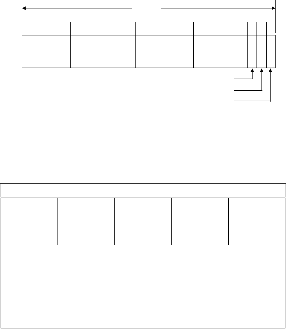
IS-GPS-200D
7 Dec 2004
174
Figure 30-15. Reduced Almanac Packet Content
Table 30-VI. Reduced Almanac Parameters *****
Parameter No. of Bits Scale Factor (LSB) Effective Range **
Units
δ
A
***
Ω
0
Φ
0
****
8 *
7 *
7 *
2
+9
2
-6
2
-6
**
**
**
meters
semi-circles
semi-circles
* Parameters so indicated shall be two’s complement with the sign bit (+ or -) occupying the MSB;
** Effective range is the maximum range attainable with indicated bit allocation and scale factor;
*** Relative to A
ref
= 26,559,710 meters;
**** Φ
0
= Argument of Latitude at Reference Time = M
0
+ ω;
***** Relative to following reference values:
e = 0
δ
i
= +0.0056 semi-circles (i = 55 degrees)
Ω = -2.6 x 10
-9
semi-circles/second.
31 BITS
PRN
a
6 BITS
δ
A
8 BITS
Ω
0
7 BITS
Φ
0
7 BITS
L1 HEALTH
L2 HEALTH
L5 HEALTH
1 7 15 22 31 30 29
* See Figures 30-4 and 30-11 for complete bit allocation in the
respective messages.
•

IS-GPS-200D
7 Dec 2004
175
30.3.3.5 Message Type 32 Earth Orientation Parameters (EOP). The earth orientation parameters are provided in
message type 32. The parameters are defined below, followed by material pertinent to the use of the data.
30.3.3.5.1 EOP Content
. Message type 32, Figure 30-5, provides SV clock correction parameters (ref. Section
30.3.3.2) and earth orientation parameters. The EOP message provides users with parameters to construct the ECEF
and ECI coordinate transformation (a simple transformation method is defined in Section 20.3.3.4.3.3.2). The
number of bits, scale factors (LSBs), the range, and the units of all EOP fields of message type 32 are given in Table
30-VII.
30.3.3.5.1.1 User Algorithm for Application of the EOP
. The EOP fields in the message type 32 contain the EOP
needed to construct the ECEF-to-ECI coordinate transformation. The user computes the ECEF position of the SV
antenna phase center using the equations shown in Table 30-II. The coordinate transformation, for translating to the
corresponding ECI SV antenna phase center position, is derived using the equations shown in Table 30-VIII. The
coordinate systems are defined in Section 20.3.3.4.3.3
An ECI postion,
R
eci
, is related to an ECEF position, R
ecef
, by a series of rotation matrices as following:
R
ecef
= [A][B][C][D] R
eci
where the rotation matrices, A, B, C, and D, represent the effects of Polar Motion, Earth Rotation, Nutation and
Precession, respectively. The message type 32 specifies the EOP parameters used in the construction of the Polar
Motion, A, and Earth Rotation, B, matrices.
The rotation matrices, A, B, C and D are specified in terms of elementary rotation matrices, R
i
(α), where α is a
positive rotation about the i
th
-axis ordinate, as follows:
() ()
α
−α
⎡⎤⎡⎤
⎢⎥⎢⎥
⎢⎥⎢⎥
α= α α α=
⎢⎥⎢⎥
⎢⎥⎢⎥
−α α α α
⎣⎦⎣⎦
1 0 0 cos() 0 sin()
R0cos()sin(),R 010
12
0 sin() cos() sin() 0 cos()
()
αα
⎡⎤
⎢⎥
⎢⎥
α=− α α
⎢⎥
⎢⎥
⎣⎦
cos ( ) sin( ) 0
R sin( ) cos( ) 0
3
001
The user shall compute the Inertial-to-Geodetic rotation matrix, ABCD using the equations shown in Table 30-VIII.

IS-GPS-200D
7 Dec 2004
176
Table 30-VII. Earth Orientation Parameters
Parameter
No. of
Bits**
Scale
Factor
(LSB)
Effective
Range***
Units
t
EOP
PM_X
†
PM_X
PM_Y
††
PM_Y
∆UT1
†††
∆UT1
†††
EOP Data Reference Time
X-Axis Polar Motion Value
at Reference Time.
X-Axis Polar Motion Drift at
Reference Time.
Y-Axis Polar Motion Value
at Reference Time.
Y-Axis Polar Motion Drift at
Reference Time.
UT1-UTC Difference at
Reference Time.
Rate of UT1-UTC
Difference at Reference
Time
16
21*
15*
21*
15*
31*
19*
2
4
2
-20
2
-21
2
-20
2
-21
2
-24
2
-25
604,784
1
7.8125 x 10
-3
1
7.8125 x 10
-3
64
7.8125 x 10
-3
seconds
arc-seconds
arc-seconds/day
arc-seconds
arc-seconds/day
seconds
seconds/day
* Parameters so indicated are two’s complement, with the sign bit (+ or -) occupying the MSB;
** See Figure 30-5 for complete bit allocation in Message type 32;
*** Unless otherwise indicated in this column, effective range is the maximum range attainable with
indicated bit allocation and scale factor.
†
Represents the predicted angular displacement of instantaneous Celestial Ephemeris Pole with respect to
semi-minor axis of the reference ellipsoid along Greenwich meridian.
††
Represents the predicted angular displacement of instantaneous Celestial Ephemeris Pole with respect to
semi-minor axis of the reference ellipsoid on a line directed 90° west of Greenwich meridian.
†††
With zonal tides restored.
•
•
•

IS-GPS-200D
7 Dec 2004
177
Table 30-VIII. Application of EOP Parameters (Part 1 of 2)
Element/Equation Description
TDT = t +
s
51 .184
J.E.D. = TDT expressed in days of 86400 sec
−
π
⎡⎤
°°
=+
⎢⎥
°
⎣⎦
J.E.D. 2451545
g 357.528 35999.05
180 36525
()
s
0. 001658sin g 0.0167sin g
J.B.D. J.E.D.
86400s
+
=+
−
=
J.B.D. 2451545
T
36525
′′ ′′ ′′
ζ= + +
23
2306 .2181 T 0 .30188 T 0 .017998 T
′′ ′′ ′′
=++
23
z 2306 . 2181 T 1 . 09468 T 0 . 018203 T
′′ ′′ ′′
θ= − −
23
2004 . 3109 T 0 . 42665 T 0 . 041833 T
()
()
()
=−− θ −
ζ
oo
DR 90 zR R90
313
°
′′′ ′′ ′′
ε= − −
′′
+
2
23 26 21 . 448 46 . 815 T 0 .00059 T
3
0 .001813 T
()
()
()
=−ε+∆ε −∆ψ εCR ( )R R
131
Compute Terrestrial Dynamical Time relative to GPS
Time t
Compute Julian Ephemeris Date
Compute Mean Anomaly of Earth in its orbit, g
Compute Julian Date in Barycentric Dynamical Time
Compute time from J2000 Julian Epoch in Julian
Centuries
Compute Precession Fundamental Angles at time t
Calculate Precession Matrix at time, t
Compute Mean Obliquity,
ε
, at time t
Compute Nutation Matrix at time, t

IS-GPS-200D
7 Dec 2004
178
Table 30-VIII. Application of EOP Parameters (Part 2 of 2)
Element/Equation Description
106 5
11
sin
ijj
ij
aeE
ψ
==
⎛⎞
∆=
⎜⎟
⎝⎠
∑∑
††
64 5
11
cos
ijj
ij
beE
ε
==
⎛⎞
∆=
⎜⎟
⎝⎠
∑∑
††
UT1 = UTC + ∆UT1 + ∆UT1 (t – t
EOP
)
−
=
=
J.D. 2451545
T
U
36525
where J.D. UT1 expressed in days of 86400 sec
⎛⎞
+
⎜⎟
π
⎜⎟
α= +
⎜⎟
⎜⎟
−
⎜⎟
+−×
⎝⎠
hm s
UT1 6 41 50 .54841
2
s
8640184.812866T
U
h
24
s2s63
0 .093104T 6 . 2 10 T
UU
α=α+∆
ψ
ε+∆εcos( )
()
=αBR
3
A = R
2
(-x
p
) R
1
(-y
p
)
where x
p
= PM_X + PM_X (t – t
EOP
)
y
p
= PM_Y + PM_Y (t – t
EOP
)
=
⎡⎤⎡⎤⎡⎤⎡⎤
⎣⎦⎣⎦⎣⎦⎣⎦
ABCD A B C D
Nutation in Longitude
Nutation in Obliquity
Compute Universal Time at time t
Compute Universal Time from J2000 Julian Epoch
in Julian Centuries
Compute Mean Greenwich Hour Angle
Compute True Greenwich Hour Angle
Compute Rotation Matrix at time, t
Compute Polar Motion Matrix at time, t
Compute Inertial-to-Geodetic Rotation matrix, ABCD
t is GPS system time at time of transmission, i.e., GPS time corrected for transit time (range/speed of light).
††
The Nutation in Longitude and the Nutation in Obliquity are as described in The Astronomical Almanac (1983),
pp. S23-S26, evaluated at time T.
•
•
•

IS-GPS-200D
7 Dec 2004
179
30.3.3.6 Message Type 33 Coordinated Universal Time (UTC) Parameters. Message type 33, Figure 30-6, contains
the UTC parameters. The contents of message type 33 are defined below, followed by material pertinent to the use
of the UTC data.
30.3.3.6.1 UTC Parameter Content
. Message type 33 provides SV clock correction parameters (ref. Section
30.3.3.2) and also, shall contain the parameters related to correlating UTC (USNO) time with GPS Time. The bit
lengths, scale factors, ranges, and units of these parameters are given in Table 30-IX. See Figure 30-6 for complete
bit allocation in message type 33.
The parameters relating GPS time to UTC (USNO) shall be updated by the CS at least once every three days while
the CS is able to upload the SVs. If the CS is unable to upload the SVs, the accuracy of the UTC parameters
transmitted by the SVs will degrade over time.
30.3.3.6.2 UTC and GPS Time
. Message type 33 includes: (1) the parameters needed to relate GPS Time to
UTC(USNO), and (2) notice to the user regarding the scheduled future or recent past (relative to Nav message
upload) value of the delta time due to leap seconds (∆t
LSF
), together with the week number (WN
LSF
) and the day
number (DN) at the end of which the leap second becomes effective. Information required to use these parameters
to calculate t
UTC
is in paragraph 20.3.3.5.2.4 except the following definition of ∆t
UTC
shall be used.
∆t
UTC
= ∆t
LS
+ A
0-n
+ A
1-n
(t
E
– t
ot
+ 604800 (WN – WN
ot
)) + A
2-n
(t
E
– t
ot
+ 604800 (WN – WN
ot
))
2
seconds

IS-GPS-200D
7 Dec 2004
180
Table 30-IX. UTC Parameters
Parameter
No. of
Bits**
Scale
Factor
(LSB)
Effective
Range***
Units
A
0-n
A
1-n
A
2-n
∆t
LS
t
ot
WN
ot
WN
LSF
DN
∆t
LSF
Bias coefficient of GPS time scale
relative to UTC time scale
Drift coefficient of GPS time scale
relative to UTC time scale
Drift rate correction coefficient of
GPS time scale relative to UTC time
scale
Current or past leap second count
Time data reference Time of Week
Time data reference Week Number
Leap second reference Week Number
Leap second reference Day Number
Current or future leap second count
16*
13*
7*
8*
16
13
8
4****
8*
2
-35
2
-51
2
-68
1
2
4
1
1
1
1
604,784
Seconds
sec/sec
sec/sec
2
seconds
seconds
weeks
weeks
days
seconds
* Parameters so indicated shall be two's complement with the sign bit (+ or -) occupying the MSB;
** See Figure 30-6 for complete bit allocation;
*** Unless otherwise indicated in this column, effective range is the maximum range attainable with
indicated bit allocation and scale factor;
**** Right justified.

IS-GPS-200D
7 Dec 2004
181
30.3.3.7 Message Types 34, 13, and 14 Differential Correction Parameters. Differential Correction (DC)
parameters are provided either in message types 34 or in types 13 and 14. These parameters provide users with sets
of correction terms that apply to the clock and ephemeris data transmitted by
other SVs. DC parameters are grouped
in packets, as described in the next sections. The availability of these message types is subject to the control and
determination of the CS.
30.3.3.7.1 Differential Correction Parameters Content
. Message type 34 provides SV clock correction parameters
(ref. Section 30.3.3.2) and also, shall contain DC parameters that apply to the clock and ephemeris data transmitted
by another SV. One message type 34, Figure 30-7, shall contain 34 bits of clock differential correction (CDC)
parameters and 92 bits of ephemeris differential correction (EDC) parameters for one SV other than the transmitting
SV. Bit 150 of message type 34 shall be a DC Data Type indicator that indicates the data type for which the DC
parameters apply. Zero (0) signifies that the corrections apply to CNAV data, D
c
(t), and one (1) signifies that the
corrections apply to NAV data, D(t).
Message types 13 and 14 together also provide DC parameters. Message type 13, Figure 30-12, shall contain CDC
parameters applicable to 6 SVs and message type 14, Figure 30-13, shall contain EDC parameters applicable to 2
SVs. There shall be a DC Data Type indicator preceding each CDC or EDC packet. The content of an individual
data packet is depicted in Figure 30-16. The number of bits, scale factors (LSB), the range, and the units of all fields
in the DC packet are given in Table 30-X.
30.3.3.7.2 DC Data Packet
. Each DC data packet contains: corrections to SV clock polynomial coefficients
provided in any one of the message types 30 to 37 of the corresponding SV; corrections to quasi-Keplerian elements
referenced to t
OD
of the corresponding SV; and User Differential Range Accuracy (UDRA) and UDRA indices that
enable users to estimate the accuracy obtained after corrections are applied. Each DC packet is made up of two
different segments. The first segment contains 34 bits for the CDC parameters and the second segment contains 92
bits of EDC parameters totaling 126 bits. The CDC and EDC parameters form an indivisible pair and users must
utilize CDC and EDC as a pair. Users must utilize CDC and EDC data pair of same t
op-D
and of same t
OD
.
30.3.3.7.2.1 Differential Correction Data Predict Time of Week
. The DC data predict time of week (t
op-D
) provides
the epoch time of week, in increments of 300 seconds (i.e. five minutes), at which the prediction for the associated
DC data was performed.
•

IS-GPS-200D
7 Dec 2004
182
30.3.3.7.2.2 Time of Differential Correction Data. The time of DC data, t
OD
, specifies the reference time of week,
in increments of 300 seconds (i.e., five minutes) relative to the GPS week, for the associated CDC and EDC data.
30.3.3.7.2.3 SV PRN Identification
. The PRN ID of both CDC and EDC of Figure 30-16 identifies the satellite to
which the subject 126-bit differential correction packet data applies (by PRN code assignment). A value of all ones
“11111111” in any PRN ID field shall indicate that no DC data is contained in the remainder of the data block. In
this event, the remainder of the data block shall be filler bits, i.e., alternating ones and zeros beginning with one.
Figure 30-16. Differential Correction Data Packet
CDC = Clock Differential Correction
MSB LSB
1 9
EDC = Ephemeris Differential Correction
MSB LSB
1 9
i
.
12 BITS
12 BITS
23
PRN ID
.
8 BITS
α
.
14 BITS
36
β
.
14 BITS
UDRA
.
5 BITS
δ
a
f0
.
13 BITS
δ
a
f1
.
8 BITS
5 BITS
63
PRN ID
.
8 BITS
γ
.
15 BITS
22 34
30
MSB
LSB
37
52
.
12 BITS
MSB
LSB
Ω
64
76
A
88
92
UDRA
•

IS-GPS-200D
7 Dec 2004
183
Table 30-X. Differential Correction Parameters
Parameter
No. of
Bits**
Scale
Factor
(LSB)
Effective
Range***
Units
PRN ID
δa
f0
δa
f1
UDRA
∆α
∆β
∆γ
∆i
∆Ω
∆A
UDRA
SV Clock Bias Correction
SV Clock Drift Correction
User Differential Range
Accuracy Index
Alpha Correction to Ephemeris
Parameters
Beta Correction to Ephemeris
Parameters
Gamma Correction to Ephemeris
Parameters
Angle of Inclination Correction
Angle of Right Ascension
Correction
Semi-Major Correction
Change Rate of User Differential
Range Accuracy Index.
8
13*
8*
5*
14*
14*
15*
12*
12*
12*
5*
2
-35
2
-51
2
-34
2
-34
2
-32
2
-32
2
-32
2
-9
see text
seconds
seconds/second
see text
dimensionless
dimensionless
semi-circles
semi-circles
semi-circles
meters
see text
* Parameters so indicated are two’s complement, with the sign bit (+ or -) occupying the MSB;
** See Figure 30-7, 11 and 12 for complete bit allocation in Message types 34, 13 and 14;
*** Unless otherwise indicated in this column, effective range is the maximum range attainable with
indicated bit allocation and scale factor.
•

IS-GPS-200D
7 Dec 2004
184
30.3.3.7.3 Application of Clock-Related DC Data. The SV PRN code phase offset, uncorrected by clock correction
coefficient updates, is given by equation 2 in paragraph 20.3.3.3.3.1 (see para. 30.3.3.2.3). If the matched pair of
DC data for the subject SV is available, the user may apply clock correction coefficient update values by;
∆t
sv
= (a
f0
+ δa
f0
) + (a
f1
+ δa
f1
)(t − t
oc
) + a
f2
(t − t
oc
)
2
+ ∆t
r
,
where δa
f0
and δa
f1
, (see Table 30-X), are given in message types 34 or 13, and all other terms are as stated in
paragraph 20.3.3.3.3.1. Clock-related DC data shall not be applied to any SV transmitting clock correction
parameters message(s) containing a t
op
value greater than the t
op-D
value of messages types 34 or 13 containing the
clock-related DC data.
30.3.3.7.4 Application of Orbit-Related DC Data
. The DC data packet includes corrections to parameters that
correct the state estimates for ephemeris parameters transmitted in the message types 10 and 11 (broadcast by the
SV to which the DC data packet applies). The user will update the ephemeris parameters utilizing a variation of the
algorithm expressed in the following equations. The user will then incorporate the updated quasi-Keplerian element
set in all further calculations of SV position, as represented by the equations in Table 30-II (see para. 30.3.3.1.3).
Ephemeris-related DC data shall not be applied to any SV transmitting message types 10 and 11 containing a t
op
value greater than the t
op-D
value of message types 34 or 14 containing the ephemeris-related DC data.
The user will construct a set of initial (uncorrected) elements by:
A
i
= A
0
e
i
= e
n
i
i
= i
0-n
Ω
i
= Ω
0-n
α
i
= e
n
cos(ω
n
)
β
i
= e
n
sin(ω
n
)
γ
i
= M
0-n
+ ω
n

IS-GPS-200D
7 Dec 2004
185
where A
0
, e
n
, i
0-n
, Ω
0-n
, ω
n
and M
0-n
are obtained from the applicable SV’s message types 10 and 11 data. The terms
α
i
, β
i
, and γ
i
form a subset of stabilized ephemeris elements which are subsequently corrected by ∆α, ∆β and
∆γ⎯the values of which are supplied in the message types 34 or 14 — as follows:
α
c
= α
i
+ ∆α
β
c
= β
i
+ ∆β
γ
c
= γ
i
+ ∆γ
The quasi-Keplerian elements are then corrected by
A
c
= A
i
+ ∆A
e
c
= (α
c
2
+ β
c
2
)
1/2
i
c
= i
i
+ ∆i
Ω
c
= Ω
i
+ ∆Ω
ω
c
= tan
-1
(β
c
/α
c
)
M
0-c
= γ
c
− ω
c
+ ∆M
0
where ∆A, ∆i and ∆Ω are provided in the EDC data packet of the message type 34 or 14 and ∆M
0
is obtained from
∆M
0
= −3
c
A
2
µ
[(t
oe
) − (t
OD
)].
The corrected quasi-Keplerian elements above are applied to the user algorithm for determination of antenna phase
center position in Section 30.3.3.1.3, Table 30-II.

IS-GPS-200D
7 Dec 2004
186
30.3.3.7.5 SV Differential Range Accuracy Estimates. The UDRA
op-D
and UDRA shall give the differential user
range accuracy for the SV. It must be noted that the two parameters provide estimated accuracy after both clock and
ephemeris DC are applied. The UDRA and UDRA indices are signed, two’s complement integers in the range of
+15 to –16 and has the following relationship:
Index Value UDRA
op-D
(meters) UDRA (10
-6
m/sec)
15 6144.00 < UDRA
op-D
6144.00
14 3072.00 < UDRA
op-D
≤ 6144.00 3072.00
13 1536.00 < UDRA
op-D
≤ 3072.00 1536.00
12 768.00 < UDRA
op-D
≤ 1536.00 768.00
11 384.00 < UDRA
op-D
≤ 768.00 384.00
10 192.00 < UDRA
op-D
≤ 384.00 192.00
9 96.00 < UDRA
op-D
≤ 192.00 96.00
8 48.00 < UDRA
op-D
≤ 96.00 48.00
7 24.00 < UDRA
op-D
≤ 48.00 24.00
6 13.65 < UDRA
op-D
≤ 24.00 13.65
5 9.65 < UDRA
op-D
≤ 13.65 9.65
4 6.85 < UDRA
op-D
≤ 9.65 6.85
3 4.85 < UDRA
op-D
≤ 6.85 4.85
2 3.40 < UDRA
op-D
≤ 4.85 3.40
1 2.40 < UDRA
op-D
≤ 3.40 2.40
0 1.70 < UDRA
op-D
≤ 2.40 1.70
-1 1.20 < UDRA
op-D
≤ 1.70 1.20
-2 0.85 < UDRA
op-D
≤ 1.20 0.85
-3 0.60 < UDRA
op-D
≤ 0.85 0.60
-4 0.43 < UDRA
op-D
≤ 0.60 0.43
-5 0.30 < UDRA
op-D
≤ 0.43 0.30
-6 0.21 < UDRA
op-D
≤ 0.30 0.21
-7 0.15 < UDRA
op-D
≤ 0.21 0.15
-8 0.11 < UDRA
op-D
≤ 0.15 0.11
-9 0.08 < UDRA
op-D
≤ 0.11 0.08
-10 0.06 < UDRA
op-D
≤ 0.08 0.06
-11 0.04 < UDRA
op-D
≤ 0.06 0.04
-12 0.03 < UDRA
op-D
≤ 0.04 0.03
-13 0.02 < UDRA
op-D
≤ 0.03 0.02
-14 0.01 < UDRA
op-D
≤ 0.02 0.01
-15 UDRA
op-D
≤ 0.01 0.005
-16 No accuracy prediction available—use at own risk
For any time, t
k
, other than t
op-D
, UDRA is found by,
UDRA = UDRA
op-D
+ UDRA (t
k
– t
op-D
)
•
•
•
•

IS-GPS-200D
7 Dec 2004
187
30.3.3.8 Message Type 35 GPS/GNSS Time Offset. Message type 35, Figure 30-8, contains the GPS/Global
Navigation Satellite System (GNSS) Time Offset (GGTO) parameters. The contents of message type 35 are defined
below. The validity period of the GGTO shall be 1 day as a minimum.
30.3.3.8.1 GPS/GNSS Time Offset Parameter Content
. Message Type 35 provides SV clock correction parameters
(ref. Section 30.3.3.2) and also, shall contain the parameters related to correlating GPS time with other GNSS time.
Bits 155 through 157 of message type 35 shall identify the other GPS like navigation system to which the offset data
applies. The three bits are defined as follows;
000 = no data available,
001 = Galileo,
010 = GLONASS,
011 through 111 = reserved for other systems.
The number of bits, the scales factor (LSB), the range, and the units of the GGTO parameters are given in Table 30-
XI. See Figure 30-8 for complete bit allocation in message type 35.
30.3.3.8.2 GPS and GNSS Time
. The GPS/GNSS-time relationship is given by,
t
GNSS
= t
E
– (A
0GGTO
+ A
1GGTO
(t
E
– t
otGGTO
+ 604800 (WN – WN
otGGTO
) + A
2GGTO
(t
E
– t
otGGTO
+ 604800 (WN – WN
otGGTO
))
2
)
where t
GNSS
is in seconds, t
E
and WN are as defined in Section 20.3.3.5.2.4, and the remaining parameters are as
defined in Table 30-XI.

IS-GPS-200D
7 Dec 2004
188
Table 30-XI. GPS/GNSS Time Offset Parameters
Parameter
No. of
Bits**
Scale
Factor
(LSB)
Effective
Range***
Units
A
0GGTO
A
1GGTO
A
2GGTO
t
otGGTO
WN
otGGTO
GNSS ID
Bias coefficient of GPS time scale
relative to GNSS time scale
Drift coefficient of GPS time scale
relative to GNSS time scale
Drift rate correction coefficient of
GPS time scale relative to GNSS
time scale
Time data reference Time of Week
Time data reference Week Number
GNSS Type ID
16*
13*
7*
16
13
3
2
-35
2
-51
2
-68
2
4
2
0
604,784
seconds
sec/sec
sec/sec
2
seconds
weeks
see text
* Parameters so indicated shall be two's complement with the sign bit (+ or -) occupying
the MSB;
** See Figure 30-8 for complete bit allocation;
*** Unless otherwise indicated in this column, effective range is the maximum range
attainable with indicated bit allocation and scale factor.
30.3.3.9 Message Types 36 and 15 Text Messages
. Text messages are provided either in message type 36, Figure
30-9, or type 15, Figure 30-14. The specific contents of text message will be at the discretion of the Operating
Command. Message type 36 can accommodate the transmission of 18 eight-bit ASCII characters. Message type 15
can accommodate the transmission of 29 eight-bit ASCII characters. The requisite bits shall occupy bits 39 through
270 of message type 15 and bits 128 through 275 of message type 36. The eight-bit ASCII characters shall be
limited to the set described in paragraph 20.3.3.5.1.8.

IS-GPS-200D
7 Dec 2004
189
30.3.4 Timing Relationships. The following conventions shall apply.
30.3.4.1 Paging and Cutovers
. Broadcast system of messages is completely arbitrary, but sequenced to provide
optimum user performance. Message types 10 and 11 shall be broadcast at least once every 48 seconds. All other
messages shall be broadcast in-between, not exceeding the maximum broadcast interval in Table 30-XII. Message
type 15 will be broadcast as needed, but will not reduce the maximum broadcast interval of the other messages.
Type 15 messages that are longer than one page will not necessarily be broadcast consecutively.
Table 30-XII. Message Broadcast Intervals
Message Data Message Type Number Maximum Broadcast Intervals
†
Ephemeris 10 & 11 48 sec
Clock Type 30’s 48 sec
ISC, IONO 30 * 288 sec
Reduced Almanac 31* or 12 20 min**
Midi Almanac 37 120 min**
EOP 32* 30 min
UTC 33* 288 sec
Diff Correction 34* or 13 & 14 30 min***
GGTO 35* 288 sec
Text 36* or 15 As needed
* Also contains SV clock correction parameters.
** Complete set of SVs in the constellation.
*** When Differential Corrections are available.
†
The intervals specified are maximum. As such, the broadcast intervals may be shorter than the
specified value.

IS-GPS-200D
7 Dec 2004
190
30.3.4.2 SV Time vs. GPS Time. In controlling the SVs and uploading of data, the CS shall allow for the
following timing relationships:
a. Each SV operates on its own SV time;
b. All time-related data (TOW) in the messages shall be in SV-time;
c. All other data in the Nav message shall be relative to GPS time;
d. The acts of transmitting the Nav messages shall be executed by the SV on SV time.
30.3.4.3 Speed of Light
. The speed of light used by the CS for generating the data described in the above
paragraphs is
c = 2.99792458 x 10
8
meters per second
which is the official WGS-84 speed of light. The user shall use the same value for the speed of light in all
computations.

IS-GPS-200D
7 Dec 2004
191
30.3.5 Data Frame Parity. The data signal contains parity coding according to the following conventions.
30.3.5.1 Parity Algorithm
. Twenty-four bits of CRC parity will provide protection against burst as well as random
errors with a probability of undetected error ≤ 2
-24
= 5.96×10
-8
for all channel bit error probabilities ≤ 0.5. The
CRC word is calculated in the forward direction on a given message using a seed of 0. The sequence of 24 bits
(p
1
,p
2
,...,p
24
) is generated from the sequence of information bits (m
1
,m
2
,...,m
276
) in a given message. This is done by
means of a code that is generated by the polynomial
()
∑
=
=
24
0i
i
i
XgXg
where
otherwise 0
24,23,18,17,14,11,10,7,6,5,4,3,1,0ifor 1g
i
=
==
This code is called CRC-24Q. The generator polynomial of this code is in the following form (using binary
polynomial algebra):
()( )()
XpX1Xg +=
where p(X) is the primitive and irreducible polynomial
()
1XXXXXXXXXXXp
357891112131723
++++++++++=
When, by the application of binary polynomial algebra, the above g(X) is divided into m(X)X
24
, where the
information sequence m(X) is expressed as
()
1k
1
2
2k1kk
XmXmXmmXm
−
−−
+⋅⋅⋅+++=
IS-GPS-200D
7 Dec 2004
192
The result is a quotient and a remainder R(X) of degree < 24. The bit sequence formed by this remainder represents
the parity check sequence. Parity bit p
i
, for any i from 1 to 24, is the coefficient of X
24-i
in R(X).
This code has the following characteristics:
1) It detects all single bit errors per code word.
2) It detects all double bit error combinations in a codeword because the generator polynomial g(X) has a
factor of at least three terms.
3) It detects any odd number of errors because g(X) contains a factor 1+X.
4) It detects any burst error for which the length of the burst is ≤ 24 bits.
5) It detects most large error bursts with length greater than the parity length r = 24 bits. The fraction of
error bursts of length b > 24 that are undetected is:
a) 2
-24
= 5.96 × 10
-8
, if b > 25 bits.
b) 2
-23
= 1.19 × 10
-7
, if b = 25 bits.
IS-GPS-200D
7 Dec 2004
193
(This page intentionally left blank.)
