
D E P L O Y M E N T G U I D E
Load Balancing Microsoft Skype
For Business
v1.1.2
Deployment Guide
NOTE: This guide has been archived and is no longer being maintained. While the content is still valid for the
particular software versions mentioned, it may refer to outdated software that has now reached end-of-life. For
more information please contact support@loadbalancer.org.

Contents
1. About this Guide................................................................................................................................................................................................................................................................ 5
2. Loadbalancer.org Appliances Supported................................................................................................................................................................................................... 5
3. Loadbalancer.org Software Versions Supported................................................................................................................................................................................. 5
4. Microsoft SFB Software Versions Supported........................................................................................................................................................................................ 5
5. Microsoft SFB & Loadbalancer.org.................................................................................................................................................................................................................. 5
6. Microsoft Skype For Business............................................................................................................................................................................................................................. 6
Skype For Business Editions............................................................................................................................................................................................................................................6
Standard Edition..................................................................................................................................................................................................................................................... 6
Enterprise Edition................................................................................................................................................................................................................................................. 6
7. Skype For Business Server Roles...................................................................................................................................................................................................................... 6
8. Load Balancing Skype For Business.............................................................................................................................................................................................................. 8
Load Balancing Methods Supported........................................................................................................................................................................................................................8
DNS Load Balancing.......................................................................................................................................................................................................................................... 8
Hardware Load Balancing (HLB)............................................................................................................................................................................................................. 8
Hybrid Load Balancing (DNS & HLB).................................................................................................................................................................................................. 9
This Guide.................................................................................................................................................................................................................................................................... 9
Loadbalancer.org Appliance Considerations......................................................................................................................................................................................................9
Load Balancer Deployment Mode......................................................................................................................................................................................................... 9
Persistence (aka Server Affinity).......................................................................................................................................................................................................... 10
TCP Timeout Settings.................................................................................................................................................................................................................................... 10
SSL Termination................................................................................................................................................................................................................................................... 10
Load Balancer High Availability............................................................................................................................................................................................................... 10
9. Edge Environment.......................................................................................................................................................................................................................................................... 11
Edge Servers...................................................................................................................................................................................................................................................................................11
ICE STUN & TURN...................................................................................................................................................................................................................................................................11
Edge Topology................................................................................................................................................................................................................................................................................11
Edge Servers IP Addresses....................................................................................................................................................................................................................... 12
Direct Server Access....................................................................................................................................................................................................................................... 12
Edge Server Certificates....................................................................................................................................................................................................................................................12
Reverse Proxy...............................................................................................................................................................................................................................................................................12
Options for the Reverse Proxy................................................................................................................................................................................................................ 13
Reverse Proxy Certs......................................................................................................................................................................................................................................... 13
10. Load Balanced Ports/Protocols...................................................................................................................................................................................................................... 13
Front End Servers.....................................................................................................................................................................................................................................................................13
Director Servers.........................................................................................................................................................................................................................................................................14
Edge Servers (Internal Interface)...............................................................................................................................................................................................................................14
Edge Servers (External Interface).............................................................................................................................................................................................................................14
Access (SIP) Service........................................................................................................................................................................................................................................ 14
Web Conferencing Service........................................................................................................................................................................................................................ 15
Audio/Visual Service......................................................................................................................................................................................................................................... 15
11. Skype For Business Topology Builder........................................................................................................................................................................................................ 15
12. DNS Configuration..................................................................................................................................................................................................................................................... 17
Internal clients..............................................................................................................................................................................................................................................................................17
2
© Copyright Loadbalancer.org • www.loadbalancer.org • sales@loadbalancer.org

External clients............................................................................................................................................................................................................................................................................18
13. Server SSL Certificates......................................................................................................................................................................................................................................... 18
Internal Servers...........................................................................................................................................................................................................................................................................18
Edge Server....................................................................................................................................................................................................................................................................................19
Reverse Proxy..............................................................................................................................................................................................................................................................................20
14. Deployment Architecture..................................................................................................................................................................................................................................... 21
Loadbalancer.org SFB test Environment – Overview...............................................................................................................................................................................21
Front End Pool – the Details..........................................................................................................................................................................................................................................22
Director Pool – the Details..............................................................................................................................................................................................................................................23
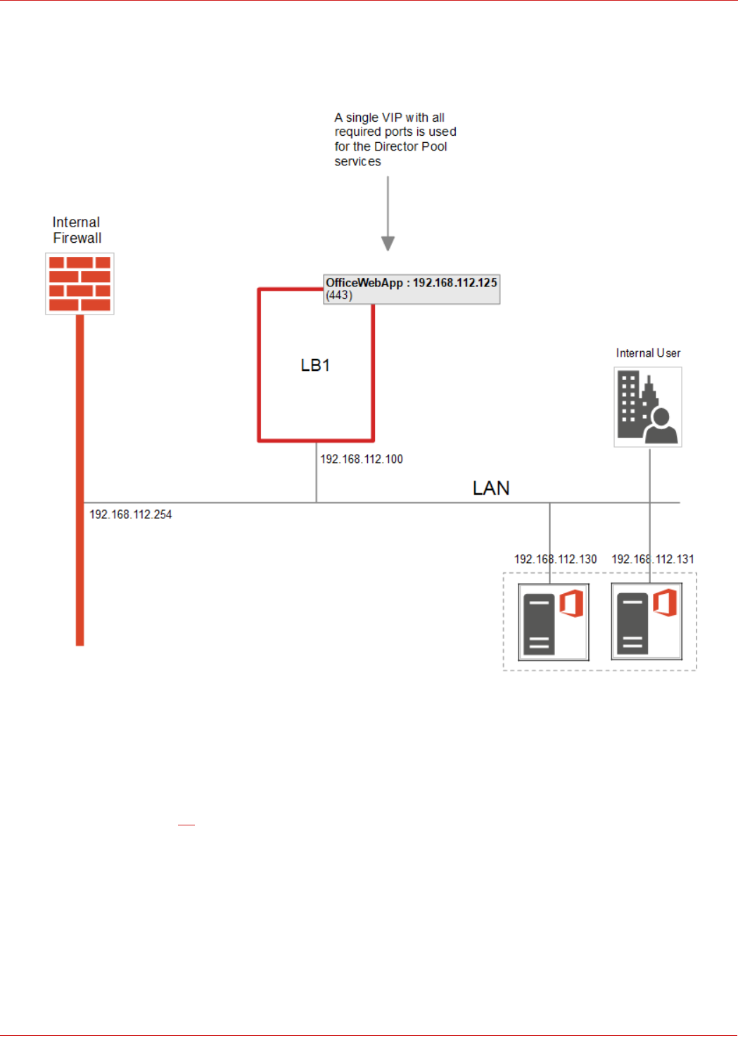
Office Web Applications Server – The Details.............................................................................................................................................................................................24
Internal Edge – the Details.............................................................................................................................................................................................................................................25
External Edge – the Details............................................................................................................................................................................................................................................26
Reverse Proxy – Use an Additional Loadbalancer.org Appliance (LB3)................................................................................................................................27
Reverse Proxy – Use LB2 in the DMZ as the Reverse Proxy.........................................................................................................................................................28
15. Loadbalancer.org Appliance – the Basics............................................................................................................................................................................................ 29
Virtual Appliance Download & Deployment....................................................................................................................................................................................................29
Initial Network Configuration........................................................................................................................................................................................................................................29
Accessing the Web User Interface (WebUI)..................................................................................................................................................................................................30
HA Clustered Pair Configuration.................................................................................................................................................................................................................................31
16. Internal Appliance Configuration for SFB (LB1).............................................................................................................................................................................. 32
STEP 1 – Configure Layer 7 Global Settings..................................................................................................................................................................................................32
STEP 2 – Configuring the Load Balanced Front End Services.....................................................................................................................................................32
Virtual Services (VIPs) Required.......................................................................................................................................................................................................... 32
Configuring the Fe-Pool VIP.................................................................................................................................................................................................................... 33
Configuring the Fe-Pool-Ws-Int VIP................................................................................................................................................................................................ 34
Configuring the Fe-Pool-Ws-Ext-8080 VIP............................................................................................................................................................................. 35
Configuring the Fe-Pool-Ws-Ext-4443 VIP............................................................................................................................................................................. 37
STEP 3 – Configuring the Load Balanced Director Services.........................................................................................................................................................38
Virtual Services (VIPs) Required.......................................................................................................................................................................................................... 38
Configuring the Dir-Pool VIP................................................................................................................................................................................................................... 38
Configuring the Dir-Pool-Ws-Int VIP............................................................................................................................................................................................... 40
Configuring the Dir-Pool-Ws-Ext-8080 VIP............................................................................................................................................................................. 41
Configuring the Dir-Pool-Ws-Ext-4443 VIP............................................................................................................................................................................ 43
STEP 4 – Configuring the Load Balanced Office Web Application Servers.....................................................................................................................44
Virtual Services (VIPs) Required.......................................................................................................................................................................................................... 44
STEP 5 – Configuring the Load Balanced Edge Pool Services (Internal)...........................................................................................................................46
Virtual Services (VIPs) Required.......................................................................................................................................................................................................... 46
Configuring the Edge-Int-TCP VIP.................................................................................................................................................................................................... 46
Configuring the Edge-Int-UDP VIP................................................................................................................................................................................................... 47
STEP 6 – Finalizing the Configuration..................................................................................................................................................................................................................49
17. DMZ Appliance Configuration for SFB (LB2).................................................................................................................................................................................... 49
STEP 1 – Configure Layer 7 Global Settings..................................................................................................................................................................................................49
STEP 2 – Configuring the Load Balanced Edge Pool Services (External).........................................................................................................................49
Virtual Services (VIPs) Required.......................................................................................................................................................................................................... 49
Configuring the Edge-Ext-Access VIP.......................................................................................................................................................................................... 50
3
© Copyright Loadbalancer.org • www.loadbalancer.org • sales@loadbalancer.org

Configuring the Edge-Ext-Web VIP................................................................................................................................................................................................... 51
Configuring the Edge-Ext-Av-TCP VIP.......................................................................................................................................................................................... 52
Configuring the Edge-Ext-Av-UDP VIP........................................................................................................................................................................................ 54
STEP 3 – Finalizing the Configuration..................................................................................................................................................................................................................55
18. Testing & Validation................................................................................................................................................................................................................................................. 55
Client connections bypass the load balancer...............................................................................................................................................................................................55
Taking Skype for Business Servers Offline......................................................................................................................................................................................................55
Testing External URL's via Reverse Proxy.........................................................................................................................................................................................................56
Microsoft Skype For Business Testing Tool....................................................................................................................................................................................................56
Skype for Business Debugging Tools...................................................................................................................................................................................................................56
Verifying Candidate Selection using Snooper......................................................................................................................................................................... 56
Wireshark Protocol Analyzer.........................................................................................................................................................................................................................................57
19. Technical Support...................................................................................................................................................................................................................................................... 57
20. Further Documentation..................................................................................................................................................................................................................................... 57
21. Conclusion........................................................................................................................................................................................................................................................................ 58
22. Appendix......................................................................................................................................................................................................................................................................... 59
1 – Clustered Pair Configuration – Adding a Slave Unit.......................................................................................................................................................................59
2 – Configuring a Loadbalancer.org Appliance as a Reverse Proxy...........................................................................................................................................61
Generating the CSR & SSL Certificate........................................................................................................................................................................................... 61
Importing the Certificate into the Load Balancer................................................................................................................................................................ 65
Appliance Network Configuration...................................................................................................................................................................................................... 65
Configuring Reverse Proxy VIPs & RIPs....................................................................................................................................................................................... 66
23. Document Revision History............................................................................................................................................................................................................................. 73
4
© Copyright Loadbalancer.org • www.loadbalancer.org • sales@loadbalancer.org
1. About this Guide
This guide details the steps required to configure a load balanced Microsoft Skype For Business (SFB) environment
utilizing Loadbalancer.org appliances. It covers the configuration of the load balancers and also any Microsoft Skype For
Business configuration changes that are required to enable load balancing.
For more information about initial appliance deployment, network configuration and using the Web User Interface
(WebUI), please also refer to the relevant Administration Manual:
• v7 Administration Manual
• v8 Administration Manual
2. Loadbalancer.org Appliances Supported
Due to the number of Virtual Services (VIPs) required for SFB, the Enterprise R16 & R20 are not supported. All other
models can be used with SFB as listed below:
Discontinued Models Current Models *
Enterprise VA Enterprise MAX
Enterprise R320 Enterprise 10G
Enterprise 40G
Enterprise Ultra
Enterprise VA MAX
Enterprise AWS
* For full specifications of these models please refer to: http://www.loadbalancer.org/products/hardware
3. Loadbalancer.org Software Versions Supported
• V7.6.4 and later
4. Microsoft SFB Software Versions Supported
• Microsoft Skype for Business – all versions
5. Microsoft SFB & Loadbalancer.org
Deploying Microsoft SFB with Loadbalancer.org appliances enables organizations to create a feature rich highly resilient
solution that ensures that wherever staff are located and however they connect, they can depend on a platform that
allows seamless communications wherever and whenever needed using the communications medium of their choice.
Loadbalancer.org appliances are configured to present a series of Virtual Services (VIPs). These VIPs become the
connection points for internal and external clients. The appliance is then able to distribute requests to the Skype For
Business Servers that make up the various pools.
5
© Copyright Loadbalancer.org • www.loadbalancer.org • sales@loadbalancer.org

6. Microsoft Skype For Business
Skype for Business, formerly known as Microsoft Lync Server, is a unified communications (UC) platform that integrates
common channels of business communication including instant messaging (IM), VoIP (voice over IP), file transfer, Web
conferencing, voice mail and email.
Skype For Business Editions
Standard Edition
Standard Edition enables many of the features of SFB to run on a single server. This enables the key requirements of
SFB but at a much lower cost - ideally suited to smaller companies. Standard Edition does not support the high
availability features that are included with Enterprise Edition.
Enterprise Edition
Enterprise Edition supports many more users through scalability and distribution of Server Roles. The various roles
(Front End, Director, Edge, Mediation etc.) are distributed across multiple servers which are then deployed in load
balanced server pools to provide high availability and resilience.
7. Skype For Business Server Roles
System functionality is split into multiple roles as shown in the following table. For the Standard edition, all roles are
installed on a single server, for the Enterprise edition, roles can be distributed across multiple servers depending on the
number of end-users, server performance and HA requirements. The table also summarizes the scalability, HA & co-
location (if applicable) options for each role.
Role Details
Front End Server Purpose: As the core server role, the Front End Server runs many Skype For Business services.
This role along with the back-end SQL server are the minimum required roles for Skype For
Business.
scalability: A Front End Pool can have up to 12 servers and support up to 80,000 users.
High Availability: Use a pool of servers with load balancing
Note: Microsoft does not recommend a Front End Pool with 2 Front End
Servers as explained here
Back End Server Purpose: The back-end SQL Server hosts various databases to keep track of Skype For
Business's configuration and state information.
High Availability: Use clustering/Mirroring techniques.
Director Server Purpose: This is an optional role and is recommended when either:
a) Edge Servers are deployed. In this scenario, the Director authenticates the external users,
and then passes their traffic on to internal servers. this relieves Front End pool servers from the
6
© Copyright Loadbalancer.org • www.loadbalancer.org • sales@loadbalancer.org

overhead of performing authentication of these users. It also helps insulate internal Front End
pools from malicious traffic such as denial-of-service attacks. If this occurs, this traffic ends at
the Director.
b) If multiple Front End pools are deployed at a central site. In this scenario, all authentication
requests go first to the Director, which then routes them to the correct Front End pool.
scalability: One Director for every 12,000 users who will access a site remotely.
(Microsoft recommend a minimum of 2 Director Servers for high availability).
High Availability: Use a pool of servers with load balancing
Edge Server Purpose: Enables users to communicate and collaborate with users outside the organization’s
firewalls without using VPNs. These external users can include the organization’s own users
who are currently working off-site, users from federated partner organizations, and outside
users (i.e. users without an AD account in this or any federated organization) who have been
invited to join conferences hosted on your Skype For Business Server deployment. This role
also enables connectivity to public IM connectivity services, including Windows Live, AOL, and
Yahoo!.
scalability: One Edge Server for every 12,000 users who will access a site remotely. (Microsoft
recommend a minimum of 2 Edge Servers for high availability).
High Availability: Use a pool of servers with load balancing
Note: Please refer to page 11 for additional information on the Edge
environment.
Mediation Server Purpose: Enables Enterprise Voice and dial-in conferencing. Mediation Server translates
signaling and, in some configurations, media between your internal Skype For Business Server
infrastructure and a public switched telephone network (PSTN) gateway, IP-PBX, or a Session
Initiation Protocol (SIP) trunk.
scalability: A dedicated Mediation Server supports up to 1500 calls. Co-located with a Front
End Server, it supports up to 150 calls.
High Availability: Use a pool of servers with load balancing
Co-location: By default this role is co-located with the Front End Server, but can also be
deployed separately – this is recommended for larger deployments with a higher number of
calls.
Persistent Chat
Server
Purpose: Persistent chat enables users to participate in multiparty, topic-based conversations
that persist over time. The Persistent Chat Front End Server runs the persistent chat service.
The Persistent Chat Back End Server stores the chat history data, and information about
categories and chat rooms.
scalability: Each server supports up to 20,000 users. Up to 4 persistent chat servers can be
deployed to support up to 80,000 users.
High Availability: Use a pool of servers with DNS round robin
Source: https://technet.microsoft.com/en-gb/library/dn951397.aspx#Anchor_7
7
© Copyright Loadbalancer.org • www.loadbalancer.org • sales@loadbalancer.org

Video Interop Server
This Role was added
in Skype for Business
Purpose: Video Interop Server is a new role in Skype for Business Server 2015. It enables you
to integrate your Skype for Business Server deployment with certain third-party VTC (Video
Teleconferencing System) solutions. A VIS acts as an intermediary between a 3rd party
teleconference system and a Skype for Business Server deployment.
High Availability: Use a pool of servers with DNS round robin
Source: https://technet.microsoft.com/en-gb/library/dn951409.aspx
8. Load Balancing Skype For Business
Note: It's highly recommended that you have a working Skype For Business environment first before
implementing the load balancer.
Load Balancing Methods Supported
Microsoft Skype for Business supports two types of load balancing:
• DNS load balancing
• Hardware Load Balancing (HLB)
DNS Load Balancing
With DNS load balancing, when the Lync or Skype for Business client queries DNS for the pool members IP addresses,
all member addresses are returned. Then, the client attempts to establish a TCP connection to one of the IP addresses.
If that fails, the client tries the next IP address in the cache. If the TCP connection succeeds, the client negotiates TLS
to connect to the Front End Server. If it gets to the end without a successful connection, the user is notified that no
servers running Skype for Business are available at the moment. It's not possible to use DNS load balancing for client to
server HTTP/HTTPS traffic because these are session state oriented protocols. In this case a Hardware Load Balancer
must be used.
Hardware Load Balancing (HLB)
Using a hardware or virtual loadbalancer (e.g. VMware or Hyper-V) for all services has the following advantages:
1. Rapid failed Pool member removal
• Proactive Intelligent server health-checking permits rapid automatic failed server removal from a pool
2. Simplified server maintenance
• This can be done at the HLB and requires no temporary DNS changes to remove the server from the pool
3. Supports server failover in the following scenarios (DNS load balancing does not):
• Federation with organizations that are running versions of Office Communications Server released prior to
Lync Server 2010
• Instant message exchange with users of public instant messaging (IM) services AOL and Yahoo!, in
addition to XMPP-based providers and servers, such as Google Talk
8
© Copyright Loadbalancer.org • www.loadbalancer.org • sales@loadbalancer.org

4. Supports server failover for the following Exchange 2010 and earlier UM functionality (DNS load balancing does
not):
• Playing their Enterprise Voice voice mail on their phone
• Transferring calls from an Exchange UM Auto Attendant
Hybrid Load Balancing (DNS & HLB)
It's also possible to use a mix of DNS and hardware load balancing if preferred, provided that the HLB is used for HTTP/
HTTPS Web Services traffic.
This Guide
The configuration presented in this manual uses hardware load balancing for all protocols. This provides a simpler,
clearer setup and enables all load balanced services to be configured in a consistent manner using the same
management interface. Using a hardware loadbalancer also enables real time Skype Server monitoring as mentioned
above which ensures user sessions are always passed to a healthy server and failed servers and marked as offline.
Loadbalancer.org Appliance Considerations
Load Balancer Deployment Mode
The following Loadbalancer.org modes are used in this guide:
1) Layer 7 SNAT Mode
In this mode, when the Loadbalancer.org appliance receives a request from the client it will create a second connection
to the real server with the source address becoming a load balancer IP (In this guide this is set to be the VIPs own
address). This creates two connections as described below:
SFB Client <----> Appliance
&
Appliance <----> SFB Server
Note: In this guide, single arm Layer 7 SNAT mode is used for all services except the internal &
external Edge A/V UDP services and the external A/V TCP service.
2) Layer 4 NAT Mode
For Layer 4 NAT mode, unlike layer 7 SNAT mode, the client source IP address is maintained right through to the
servers (i.e. it's transparent).
9
© Copyright Loadbalancer.org • www.loadbalancer.org • sales@loadbalancer.org

Note: In this guide, single arm Layer 4 NAT mode is used for the internal & external Edge A/V UDP
services and the external A/V edge TCP service.
Note: For more details of these modes, please refer to the Administration Manual
Note: Layer 4 DR (Direct Return) mode aka Direct Server Return (DSR) is not supported Skype for
Business.
Persistence (aka Server Affinity)
Most SFB protocols are configured using source IP address persistence with a 20 minute timeout. For Web Services, if
only SFB & Lync 2013 front-end/director servers are used, no persistence is required. if you still have any Lync 2010 Front
End Servers in your deployment, you'll need to use cookie based persistence on the load balancer. The requirements for this
are explained in the relevant sections (page 32 & 38) later in this guide.
TCP Timeout Settings
The TCP idle time-out should be set to be at least 20 minutes. This value should be above the Maximum SIP
connection idle timeout which is typically set to 20 minutes. In this guide, TCP related idle timeouts are set to 20
minutes.
SSL Termination
This is required when there are still 2010 Front End Servers in the deployment - to enable cookie based persistence to
be configured on the load balancer. Or, when the load balancer in the DMZ or an additional dedicated appliance is used
as the Reverse Proxy.
Note: Please refer to page 27 for details on using an additional Loadbalancer.org appliance as the
Reverse Proxy. Please refer to page 28 for details on using the appliance in the DMZ as the reverse
proxy.
Load Balancer High Availability
Loadbalancer.org recommend that load balancer appliances are deployed in pairs for high availability. In
this guide a single unit is deployed first, adding a secondary slave unit is covered in section 1 of the
Appendix on page 59.
10
© Copyright Loadbalancer.org • www.loadbalancer.org • sales@loadbalancer.org

9. Edge Environment
Edge Servers
Edge Servers send and receive network traffic to external users for the services offered by your internal Skype for
Business Server deployment. To do this successfully, each Edge Server runs the following services:
• Access Edge service (SIP): Provides a single, trusted connection point for both outbound and inbound Session
Initiation Protocol (SIP) traffic
• Web Conferencing Edge service (PSOM): Enables external users to join meetings that are hosted on your
internal Skype for Business Server environment
• A/V Edge service (SRTP/SRTCP): Makes audio, video, application sharing and file transfer available to external
users
• XMPP Proxy service (XMPP): Accepts and sends extensible messaging and presence protocol (XMPP)
messages to and from configured XMPP Federated partners
ICE STUN & TURN
Edge Servers are combined ICE, TURN and STUN servers. ICE is a protocol that is used to find & establish media paths
for a call. As for SIP, where there is a SIP server (the Front End Server) and a SIP client (the Lync/SFB Client), for ICE
there is an ICE server (the Edge Server) and an ICE Client (the Lync/SFB Client). ICE uses two other Protocols to find
and establish a suitable media path for a call, these Protocols are:
• STUN (Session Traversal Utilities for NAT)
• TURN (Traversal Using Relays around NAT)
The key difference between these protocols is:
• STUN: the media travels directly between both endpoints in a call (the NAT device is considered an endpoint)
• TURN: the media will be proxied using the TURN server (Edge Server) between both endpoints in a call
Source: Simple Understanding of Media Traversal in Lync / Skype for Business
Other useful Microsoft sources:
Lync Deep Dive: Edge Media Connectivity with ICE
Troubleshoot media flows in Skype for Business across online, server and hybrid
Edge Topology
Edge Servers can be configured to use a single IP address with distinct ports for each service (5061, 444 & 443 by
default), or can use distinct IP addresses for each service, but use the same default port which is TCP 443 (the traffic is
not HTTPS; it's still SIP, PSOM & SRTP/SRTCP). Microsoft recommends separate IP addresses for each service, all
listening on Port 443.
11
© Copyright Loadbalancer.org • www.loadbalancer.org • sales@loadbalancer.org
Note: For the 3 x IP scenario, clients don't connect on port 5061, only on 443. Port 5061 is only used
for federation, & server to server communication.
Edge Servers IP Addresses
Number of Edge Servers per pool Number of required IP addresses for hardware load balancing
2 3 (1 per VIP) + 6
3 3 (1 per VIP) + 9
4 3 (1 per VIP) + 12
Source: Edge Server environmental requirements in Skype for Business Server 2015
Direct Server Access
Once the media session is established, traffic goes directly from the client to the Edge Server and does not pass via the
load balancer. To achieve this, the Edge Server returns its external IP address in the first UDP packet of a media session,
the client then sends subsequent UDP traffic directly to that IP address instead of through the load balancer. Source: A/
V Edge and Publicly routable IP addresses
Edge Server Certificates
the Internal Edge can use a private certificate from the internal corporate CA, the External Edge requires a certificate
from a public CA.
Important Note: All Edge Servers must have the same certificate with the same private key for the
Media Relay Authentication service. This applies to both the Internal Edge and the External Edge.
Reverse Proxy
A Reverse Proxy is an essential component of an edge deployment. A reverse proxy allows external users to:
• Connect to meetings or dial-in conferences using simple URLs
• Download meeting content
• Expand distribution groups
• Get user-based certificates for client certificate based authentication
• Download files from the Address Book Server, or to submit queries to the Address Book Web Query service
• Obtain updates to client and device software
12
© Copyright Loadbalancer.org • www.loadbalancer.org • sales@loadbalancer.org
• Enable mobile devices to automatically discover Front End Servers offering mobility services
• Enable push notifications from Office 365 to mobile devices
Options For The Reverse Proxy
The options for the Reverse Proxy include:
• Microsoft TMG 2010 (now discontinued), for configuration guidelines click here
• Microsoft IIS with AAR (Application Request Routing), for configuration details click here
• Deploy a dedicated Loadbalancer.org appliance – Please refer to page for 27 more information
• Defining additional VIPs on the load balancer in the DMZ - Please refer to page 28 for more information
Reverse Proxy Certs
When generating the certificate for the Front End Server External Web Services, the SAN for the External Director Web
Services can also be added so that the certificate can be used for both purposed.
Note: For more information on generating the CSR & certificate for External Web Services and also
installing the certificate on the Reverse Proxy, please refer to section 2 of the appendix on page 61.
10. Load Balanced Ports/Protocols
Front End Servers
Port Protocols Use
80 TCP/HTTP Internal Web Services
135 TCP/DCOM/RPC Various DCOM based operations
443 TCP/HTTPS Internal Web Services
444 TCP/HTTPS Used for HTTPS communication between the Focus (the Skype for
Business Server component that manages conference state) and the
individual servers.
448 TCP/TURN Used for call admission control by the Skype for Business Server Bandwidth
Policy Service
5061 TCP/TLS/MTLS/SIP Various SIP based communication
5070 TCP/SIP/TLS
Used by the Mediation Server for incoming requests from the Front End Server
to the Mediation Server
13
© Copyright Loadbalancer.org • www.loadbalancer.org • sales@loadbalancer.org

Note: This port is only required if Mediation Server is co-
located
5071 TCP/SIP/MTLS
Used for incoming SIP requests for the Response Group application
5072 TCP/SIP/MTLS
Used for incoming SIP requests for Attendant (dial in conferencing)
5073 TCP/SIP/MTLS
Used for incoming SIP requests for the Skype for Business Server
Conferencing Announcement service (that is, for dial-in conferencing)
5075 TCP/SIP/MTLS Used for incoming SIP requests for the Call Park application
5076 TCP/SIP Used for incoming SIP requests for the Audio Test service
5080 TCP Used for call admission control by the Bandwidth Policy service for A/V
Edge TURN traffic
4443 TCP/HTTPS External Web Services – from Reverse Proxy
8080 TCP/HTTP External Web Services – from Reverse Proxy
Director Servers
Port Protocols Use
443 TCP/HTTPS
Internal Web Services
444 TCP/HTTPS
Inter-server communication between Front End and Director
5061 TCP/TLS/MTLS/SIP
Internal SIP communications between servers and for client connections
4443 TCP/HTTPS
External Web Services – from Reverse Proxy
8080 TCP/HTTP
External Web Services – from Reverse Proxy
Edge Servers (Internal Interface)
Port Protocols Use
443 TCP/STUN Audio/Visual service
3478 UDP/STUN Audio/Visual service
5061 TCP/MTLS/SIP Access (SIP proxy) service
5062 TCP/MTLS/SIP Audio/Visual authentication service
Edge Servers (External Interface)
Access (SIP) Service
14
© Copyright Loadbalancer.org • www.loadbalancer.org • sales@loadbalancer.org
Port Protocols Use
443 TCP/TLS/STUN/SIP Access (SIP proxy) service
5061 TCP/MTLS/SIP Access (SIP proxy) service
5269 TCP/XMPP Access (XMPP Proxy) service
Web Conferencing Service
Port Protocols Use
443 TCP/TLS/STUN/SIP Web Conferencing
Audio/Visual Service
Port Protocols Use
443 TCP/TLS/STUN/SIP Access (SIP proxy), Web Conferencing, Audio/Visual services
3478 UDP/STUN Audio/Visual service
Sources:
Ports and Protocols for Internal Server
Edge Server environmental requirements in Skype for Business Server 2015
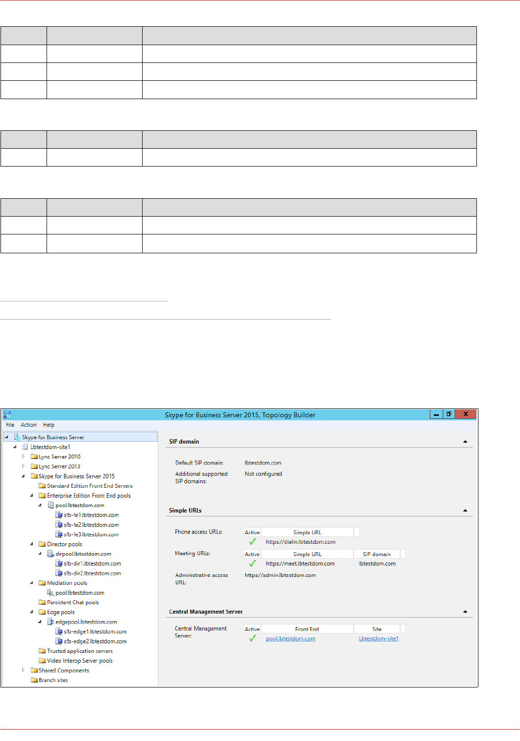
11. Skype For Business Topology Builder
The image below shows the topology of the test environment:
15
© Copyright Loadbalancer.org • www.loadbalancer.org • sales@loadbalancer.org
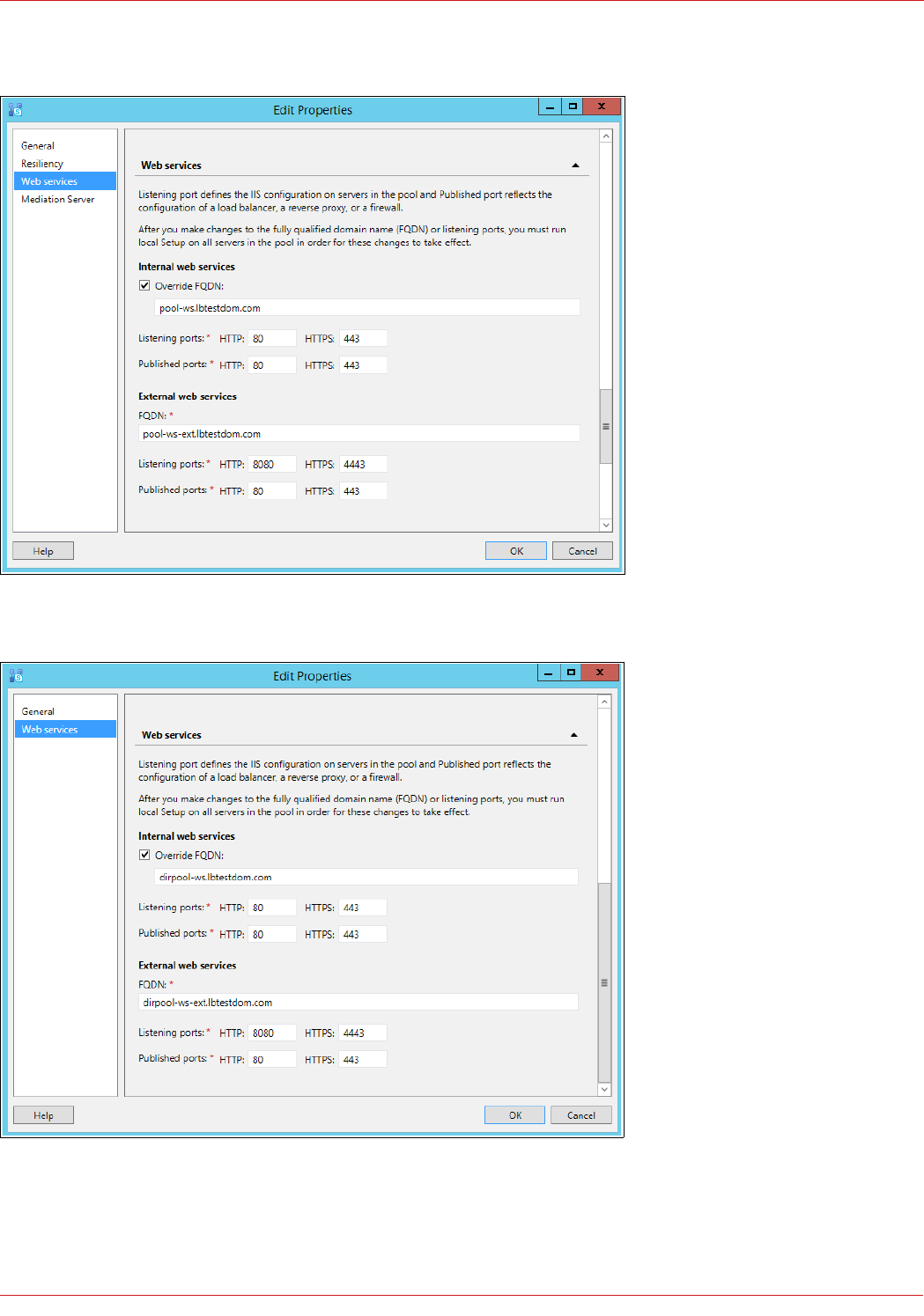
The image below shows the Front End Pool Web Services configuration:
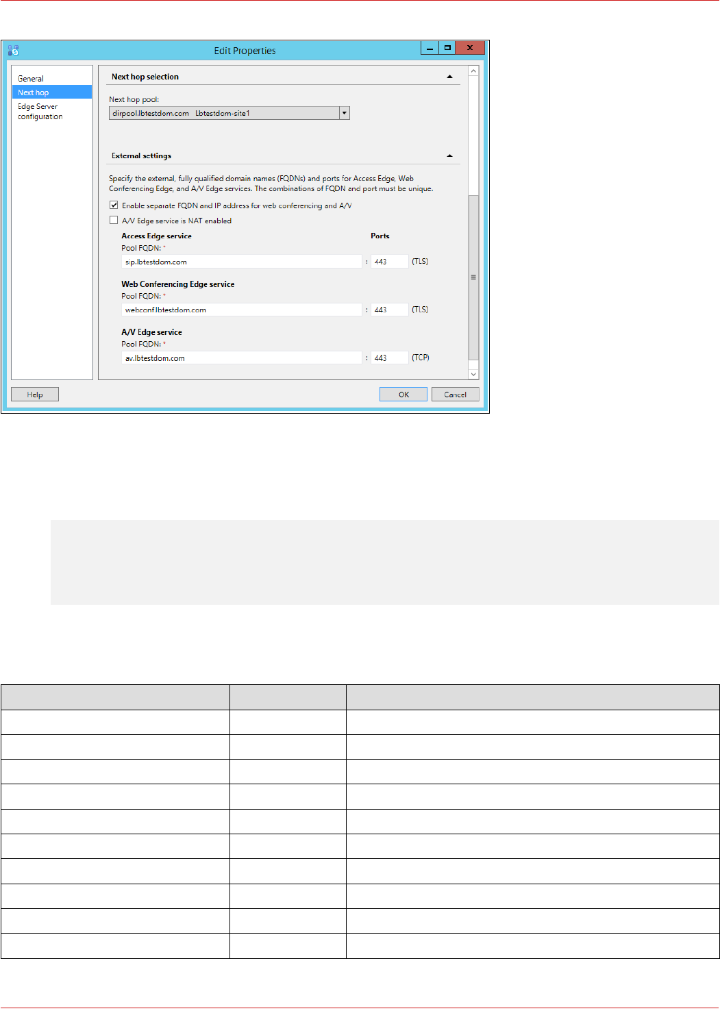
The image below shows the Director Pool Web Services configuration:
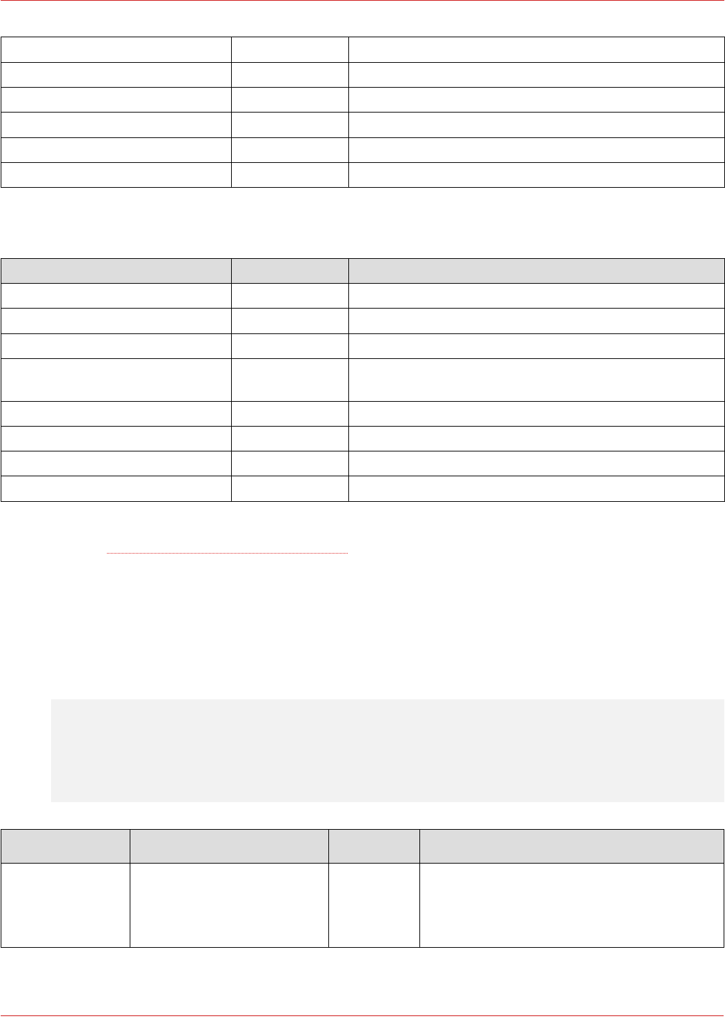
The image below shows the Edge Pool external configuration:
16
© Copyright Loadbalancer.org • www.loadbalancer.org • sales@loadbalancer.org
12. DNS Configuration
The internal and external DNS settings used for the test environment are shown below:
Note: Microsoft recommends pointing External Web Services at Director Servers if these are in your
deployment.
Internal clients
FQDN IP Address Comment
pool.lbtestdom.com 192.168.112.110
sfb-fe1.lbtestdom.com 192.168.112.51
sfb-fe2.lbtestdom.com 192.168.112.52
sfb-fe3.lbtestdom.com 192.168.112.57
dirpool.lbtestdom.com 192.168.112.120
sfb-dir1.lbtestdom.com 192.168.112.55
sfb-dir2.lbtestdom.com 192.168.112.55
edgepool.lbtestdom.com 192.168.112.140
sfb-edge1.lbtestdom.com 172.24.7.1
sfb-edge2.lbtestdom.com 172.24.7.2
17
© Copyright Loadbalancer.org • www.loadbalancer.org • sales@loadbalancer.org
meet.lbtestdom.com 192.168.112.111 Points to the internal Front End Web Services
dialin.lbtestdom.com 192.168.112.111 Points to the internal Front End Web Services
admin.lbtestdom.com 192.168.112.111 Points to the internal Front End Web Services
pool-ws.lbtestdom.com 192.168.112.111 Points to the internal Front End Web Services
dirpool-ws.lbtestdom.com 192.168.112.121 Points to the internal Director Web Services
lyncdiscoverinternal.lbtestdom.com 192.168.112.111 Points to the internal Director Web Services
External clients
FQDN IP Address Comment
sip.lbtestdom.com 10.200.50.100
webconf.lbtestdom.com 10.200.50.110
av.lbtestdom.com 10.200.50.120
pool-ws-ext.lbtestdom.com 10.200.50.160 Points to the Reverse Proxy/External Front End Web
Services
dirpool-ws-ext.lbtestdom.com 10.200.50.161 Points to the Reverse Proxy/External Director Web Services
lyncdiscover.lbtestdom.com 10.200.50.161 Points to the Reverse Proxy/External Director Web Services
meet.lbtestdom.com 10.200.50.161 Points to the Reverse Proxy/External Director Web Services
dialin.lbtestdom.com 10.200.50.161 Points to the Reverse Proxy/External Director Web Services
Useful Reference: DNS requirements for Skype for Business
13. Server SSL Certificates
Internal Servers
Note: Certificates for internal servers can be exported/imported from one server to another (if the
Private key is marked as exportable) or requested/assigned on each server – here the key does not
need to be exportable.
Server / Role Certificate CA Subject Name / Subject Alternate Name
Front End
(shows server sfb-
fe1 as an example)
Default Internal SN : pool.lbtestdom.com
SAN: sfb-fe1.lbtestdom.com
SAN : pool.lbtestdom.com
18
© Copyright Loadbalancer.org • www.loadbalancer.org • sales@loadbalancer.org

Internal Web Services Internal SN : pool-ws.lbtestdom.com
SAN : pool-ws.lbtestdom.com
SAN : lyncdiscoverinternal.lbtestdom.com
SAN : meet.lbtestdom.com
SAN : dialin.lbtestdom.com
SAN : admin.lbtestdom.com
External Web Services Internal SN : pool-ws-ext.lbtestdom.com
SAN : pool-ws-ext.lbtestdom.com
SAN : lyncdiscover.lbtestdom.com
SAN : meet.lbtestdom.com
SAN : dialin.lbtestdom.com
Director
(shows server sfb-
dir1 as an example)
Default Internal SN : dirpool.lbtestdom.com
SAN: sfb-dir1.lbtestdom.com
SAN : dirpool.lbtestdom.com
Internal Web Services Internal SN : dirpool-ws-ext.lbtestdom.com
SAN : dirpool-ws-ext.lbtestdom.com
SAN : lyncdiscoverinternal.lbtestdom.com
SAN : meet.lbtestdom.com
SAN : dialin.lbtestdom.com
SAN : admin.lbtestdom.com
External Web Services Internal SN : dirpool-ws-ext.lbtestdom.com
SAN : dirpool-ws-ext.lbtestdom.com
SAN : lyncdiscover.lbtestdom.com
SAN : meet.lbtestdom.com
SAN : dialin.lbtestdom.com
Useful Reference: Environmental requirements for Skype for Business Server 2015 – Certs
Edge Server
Note: The edge servers MUST have the same certificate/private key. This is required for the A/V
authentication service and applies to both the internal and external edge.
19
© Copyright Loadbalancer.org • www.loadbalancer.org • sales@loadbalancer.org

Server / Role Certificate CA Subject Name / Subject Alternate Name
Edge Internal Internal SN : edgepool.lbtestdom.com
SAN : edgepool.lbtestdom.com
Edge External External * SN : sip.lbtestdom.com
SAN : sip.lbtestdom.com
SAN : webconf.lbtestdom.com
SAN : dialin.lbtestdom.com
Useful Reference: Edge Server environmental requirements in Skype for Business Server 2015 – Certs
Reverse Proxy
Server / Role Certificate CA Subject Name / Subject Alternate Name
Reverse Proxy External * SN : pool-ws-ext.lbtestdom.com
SAN : pool-ws-ext.lbtestdom.com
SAN : dirpool-ws-ext.lbtestdom.com
SAN : lyncdiscover.lbtestdom.com
SAN : meet.lbtestdom.com
SAN : dialin.lbtestdom.com
Useful Reference: Certificate summary - Reverse proxy in Lync Server 2013
* For the lab, the internal CA was used
20
© Copyright Loadbalancer.org • www.loadbalancer.org • sales@loadbalancer.org
14. Deployment Architecture
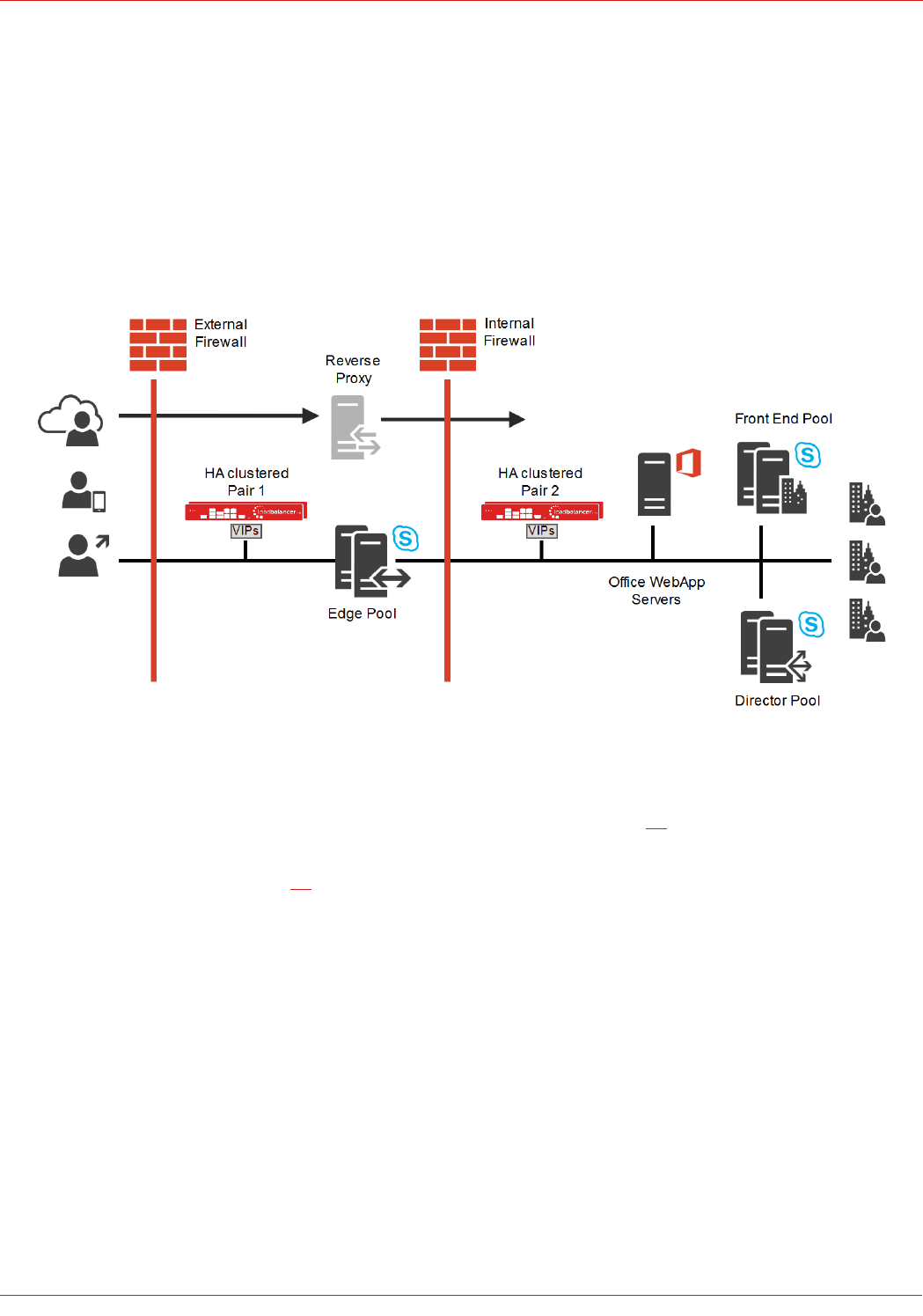
Loadbalancer.org SFB test Environment – Overview
Main Components:
• Load Balancer LB1 – Used to load balance the Internal Edge, the Director Servers and the Front End Servers (A
Clustered Pair of appliances is recommended for HA – please refer to page 59)
• Load Balancer LB2 – Used to load balance the External Edge (A Clustered Pair of appliances is recommended
for HA – please refer to page 59)
• Front End Pool with multiple Front End Servers
◦ Includes the co-located Mediation Server
• Director Pool with multiple Director Servers
• Edge Pool with Multiple Edge Servers
• Office WebApp Server(s)
• Reverse Proxy
21
© Copyright Loadbalancer.org • www.loadbalancer.org • sales@loadbalancer.org
EXTERNAL
NETWORK
PERIMETER NETWORK (DMZ)
INTERNAL
NETWORK
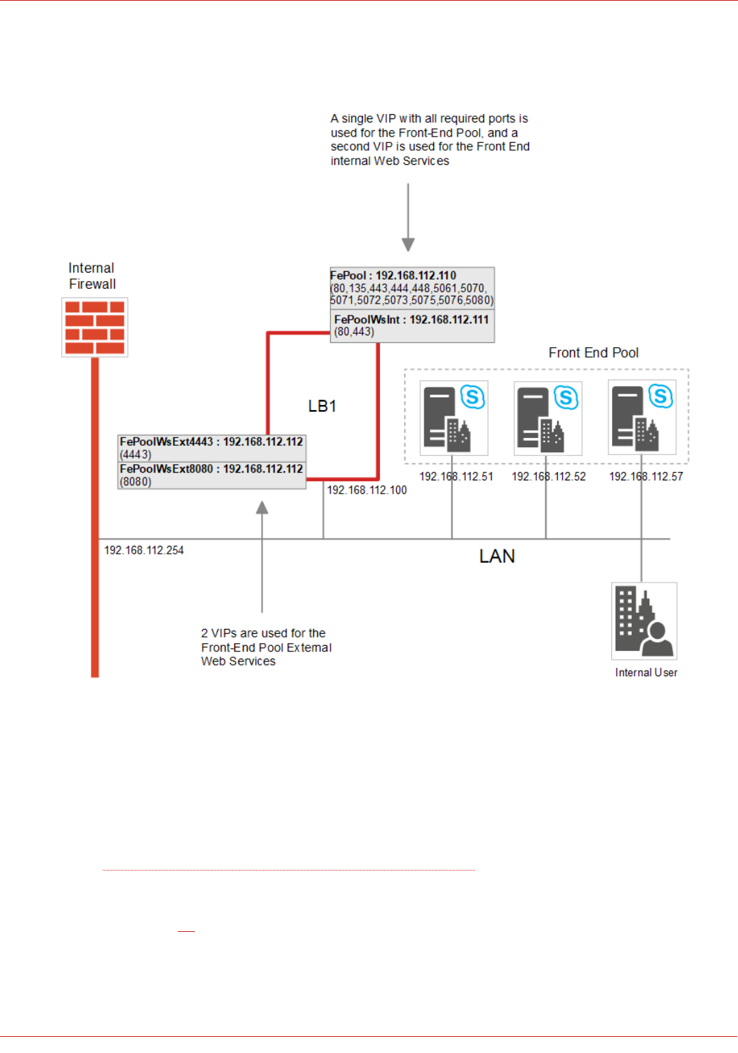
Front End Pool – the Details
NOTES:
• Microsoft recommends a minimum of 3 Front End servers in a pool
• Clients must be able to access the VIPs and the Front End Servers directly
Source: Skype for Business Client Registration Process through HLB
• Services are deployed using Layer 7 SNAT mode
• Please refer to page 32 for detailed steps on creating the Front End VIPs shown above (grey boxes)
22
© Copyright Loadbalancer.org • www.loadbalancer.org • sales@loadbalancer.org
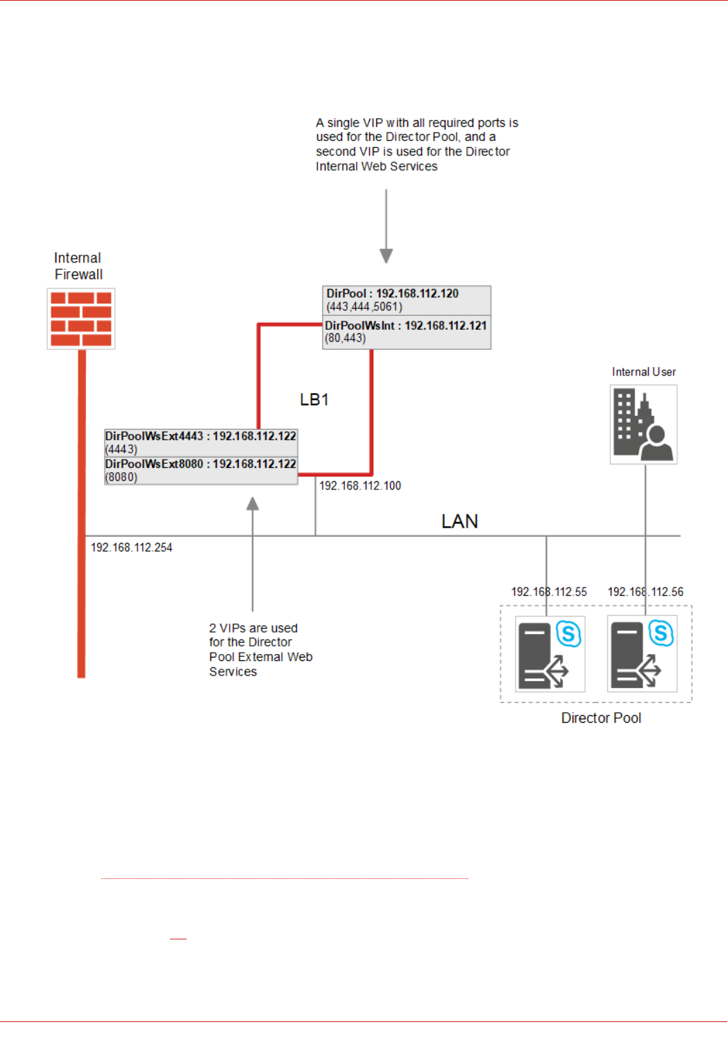
Director Pool – the Details
NOTES:
• Clients must be able to access the VIPs and the Director Servers directly
Source: Skype for Business Client Registration Process through HLB
• Load balanced services are deployed using Layer 7 SNAT mode
• Please refer to page 38 for detailed steps on creating the Director VIPs shown above (grey boxes)
23
© Copyright Loadbalancer.org • www.loadbalancer.org • sales@loadbalancer.org
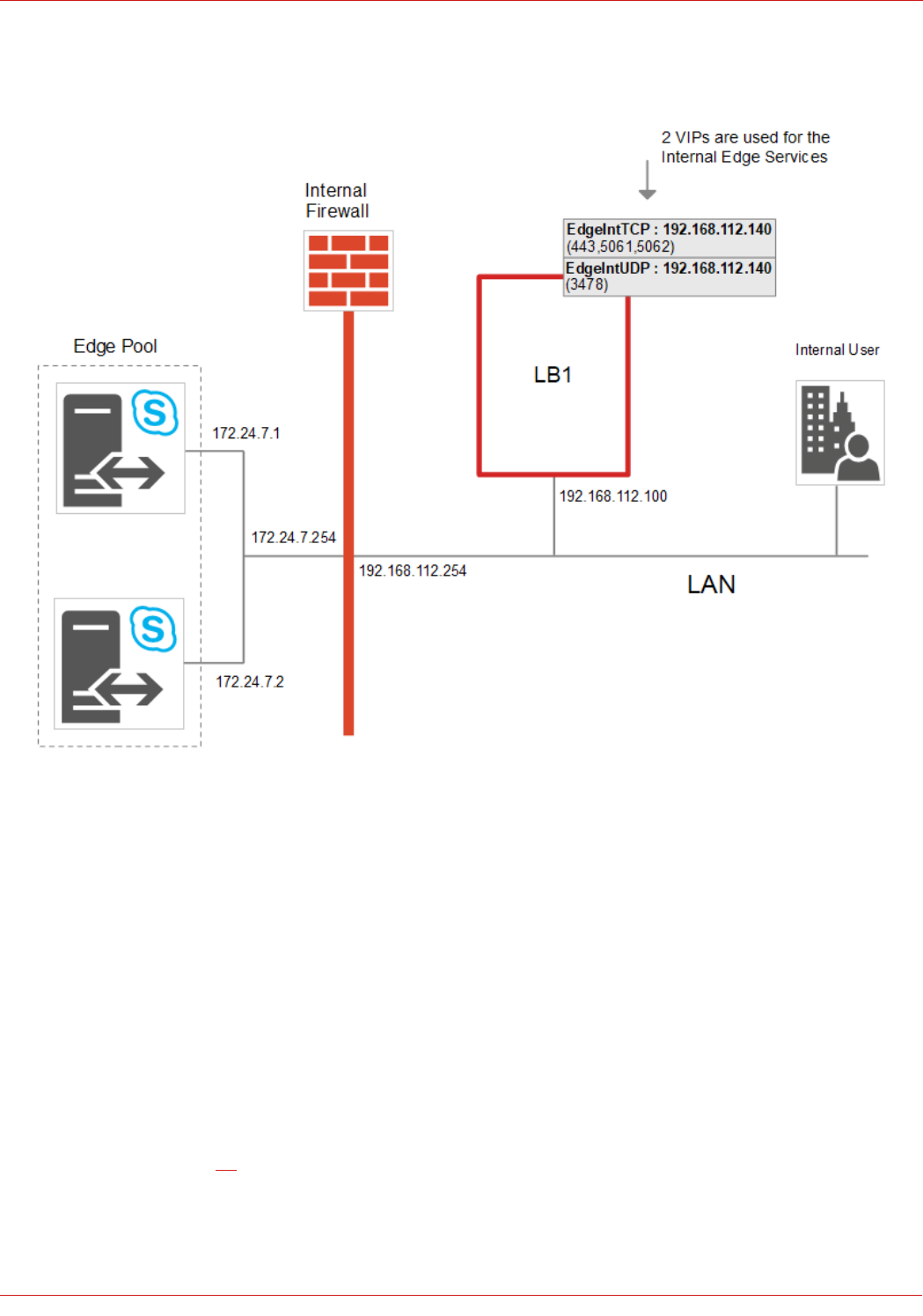
Internal Edge – the Details
NOTES:
• Internal clients must be able to access the Edge Servers via the load balanced VIP and also directly. To allow internal
SFB/Lync Clients to access the Edge Servers directly, static routes are added to the internal test clients:
netsh interface ipv4 add route 172.24.7.0/24 "Lan" 192.168.112.254
• To allow Edge Server return traffic to reach internal clients, static routes are added to each Edge Server:
netsh interface ipv4 add route 192.168.64.0/18 "Internal" 172.24.7.254
• A default gateway is not set on the internal interface of the Edge Servers, this should be configured on the external
interface only
• Load balanced services are deployed using Layer 7 SNAT mode and Layer 4 NAT mode
• Please refer to page 46 for detailed steps on creating the Internal Edge VIPs shown above (grey boxes)
25
© Copyright Loadbalancer.org • www.loadbalancer.org • sales@loadbalancer.org
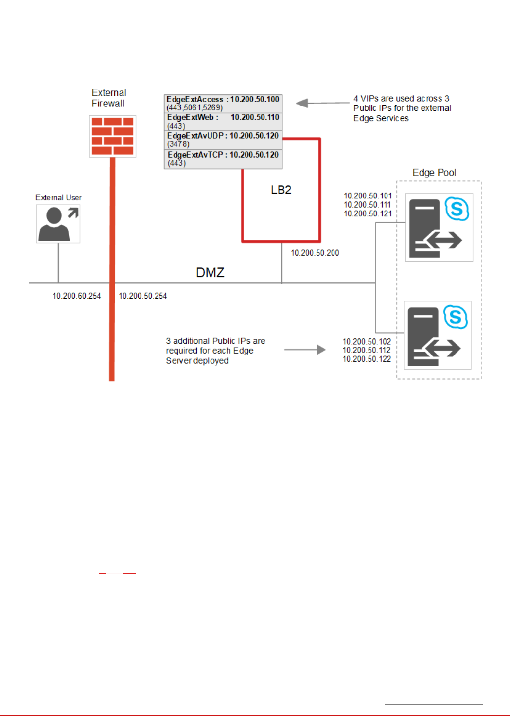
External Edge – the Details
NOTES:
• 10.200.xxx.xxx addresses are used to depict public IP's
• External clients must be able to access the Edge Servers via the load balanced VIPs and also directly
• External test clients have their default gateway set as the external router/firewall (10.200.60.254)
• Microsoft recommend that 3 Public IP's are used for the external edge services rather than a single IP with
different ports for each service, please refer to this URL
• In a production deployment Public IP addresses are required for the 3 Edge Service VIPs and also for each
corresponding service on the real servers. In the above example this means a total of 9 public IP addresses,
please refer to this URL
• The default gateway of the Edge Servers is set to be the load balancer – set this on the external NIC, do not set
a default gateway on the internal NIC
• The default gateway of the load balancer is set to be the external router/firewall
• Load balanced services are deployed using Layer 7 SNAT mode and Layer 4 NAT mode
• Please refer to page 49 for detailed steps on creating the Edge External VIPs shown above (grey boxes)
26
© Copyright Loadbalancer.org • www.loadbalancer.org • sales@loadbalancer.org
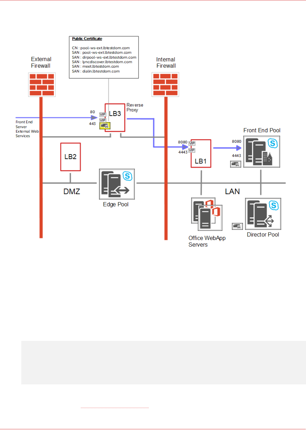
Reverse Proxy – Use an Additional Loadbalancer.org Appliance (LB3)
• VIPs are shown for Front End Server External Web Services, similar VIPs are also configured for the Director
Server External Web Services (if applicable)
• The Reverse Proxy (LB3) redirects port 80 to 8080 and port 443 to 4443
• The Reverse Proxy acts as an SSL bridge, it terminates SSL using the public signed certificate and then re-
encrypts the traffic using the private certificate on the Front End and Director Servers
• The Reverse Proxy forwards requests to the VIPs on LB1, LB1 then proxies these requests to the Front End &
Director Servers
Note: Alternatively, you can forward requests directly to the Front End / Director Servers if preferred
rather than via LB1. In this case the 4 x External Web Services VIPs on LB1 (FePoolWsExt4443,
FePoolWsExt8080, DirPoolWsExt4443, DirPoolWsExt8080) would not be required.
• Depending on your network topology, the appliance's routing configuration may need to be changed to prevent DMZ
bridging. Please contact support@loadbalancer.org for assistance
27
© Copyright Loadbalancer.org • www.loadbalancer.org • sales@loadbalancer.org

• Please refer to page 61 for details on configuring a Loadbalancer.org appliance as a Reverse Proxy
Reverse Proxy – Use LB2 in the DMZ as the Reverse Proxy
• VIPs are shown for Front End Server External Web Services, similar VIPs are also configured for the Director
Server External Web Services (if applicable)
• The Reverse Proxy (LB2) redirects port 80 to 8080 and port 443 to 4443
• The Reverse Proxy acts as an SSL bridge, it terminates SSL using the public signed certificate and then re-
encrypts the traffic using the private certificate on the Front End and Director Servers
• The Reverse Proxy forwards requests to the VIPs on LB1, LB1 then proxies these requests to the Front End &
Director Servers
Note: Alternatively, you can forward requests directly to the Front End / Director Servers if preferred
rather than via LB1. In this case the 4 x External Web Services VIPs on LB1 (FePoolWsExt4443,
FePoolWsExt8080, DirPoolWsExt4443, DirPoolWsExt8080) would not be required.
28
© Copyright Loadbalancer.org • www.loadbalancer.org • sales@loadbalancer.org

• The appliance spans multiple network zones. VLANs can be defined to help secure this traffic. If this
configuration does not meet your security policies, a separate Reverse Proxy device should be used. An
example of this using a dedicated Loadbalancer.org appliance as the Reverse Proxy is shown on page 27
• Depending on your network topology, the appliance's routing configuration may need to be changed to prevent DMZ
bridging. Please contact support@loadbalancer.org for assistance
• Please refer to page 61 for details on configuring a Loadbalancer.org appliance as a Reverse Proxy
15. Loadbalancer.org Appliance – the Basics
Virtual Appliance Download & Deployment
A fully featured, fully supported 30 day trial is available if you are conducting a PoC (Proof of Concept) deployment. The
VA is currently available for VMware, Virtual Box, Hyper-V, KVM and XEN and has been optimized for each Hypervisor. By
default, the VA is allocated 1 CPU, 2GB of RAM and has an 8GB virtual disk. The Virtual Appliance can be downloaded
here.
Note: The same download is used for the licensed product, the only difference is that a license key file
(supplied by our sales team when the product is purchased) must be applied using the appliance's
WebUI.
Note: Please refer to the Administration Manual and the ReadMe.txt text file included in the VA download
for more detailed information on deploying the VA using various Hypervisors.
Initial Network Configuration
The IP address, subnet mask, default gateway and DNS settings can be configured in several ways as detailed below:
Method 1 - Using the Network Setup Wizard at the console
After boot up, follow the instructions on the console to configure the IP address, subnet mask, default gateway and DNS
settings.
Method 2 - Using the WebUI
Using a browser, connect to the WebUI on the default IP address/port: http://192.168.2.21:9443
To set the IP address & subnet mask, use: Local Configuration > Network Interface Configuration
To set the default gateway, use: Local Configuration > Routing
To configure DNS settings, use: Local Configuration > Hostname & DNS
29
© Copyright Loadbalancer.org • www.loadbalancer.org • sales@loadbalancer.org

Accessing the Web User Interface (WebUI)
1. Browse to the following URL: https://192.168.2.21:9443/lbadmin/
(replace with your IP address if it's been changed)
* Note the port number → 9443
2. Login to the WebUI:
Username: loadbalancer
Password: loadbalancer
Note: To change the password , use the WebUI menu option: Maintenance > Passwords.
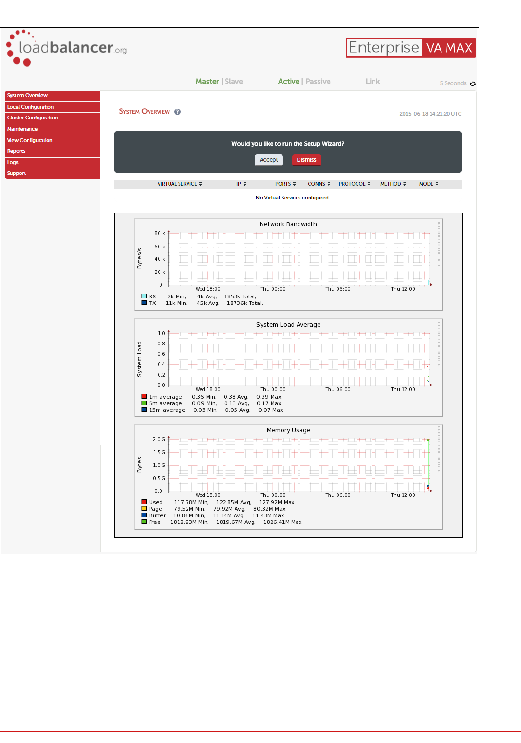
Once logged in, the WebUI will be displayed as shown below:
30
© Copyright Loadbalancer.org • www.loadbalancer.org • sales@loadbalancer.org
HA Clustered Pair Configuration
Loadbalancer.org recommend that load balancer appliances are deployed in pairs for high availability. In this guide a
single unit is deployed first, adding a secondary slave unit is covered in section 1 of the Appendix on page 59.
31
© Copyright Loadbalancer.org • www.loadbalancer.org • sales@loadbalancer.org
16. Internal Appliance Configuration for SFB (LB1)
This section covers the configuration of the Internal LAN based load balancer appliance.
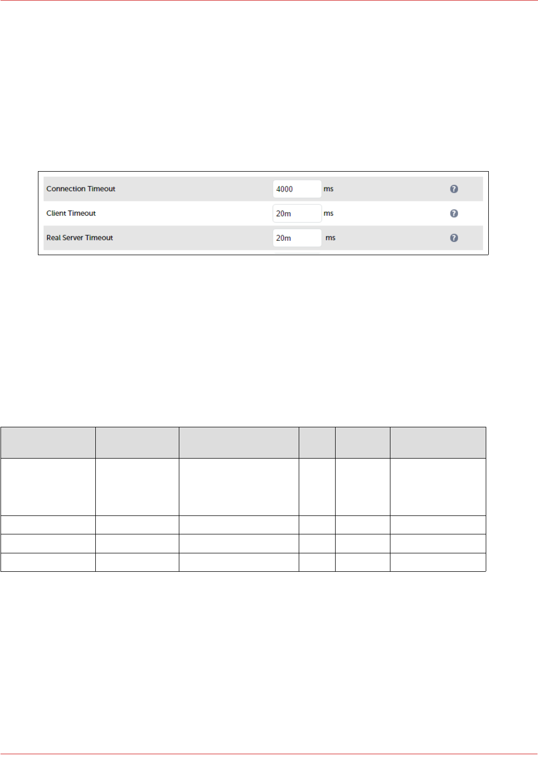
STEP 1 – Configure Layer 7 Global Settings
To configure the TCP timeouts required by Skype For Business, HAProxy's client and server timeouts must be changed
from their default values of 43 seconds and 45 seconds respectively to 20 minutes. To do this follow the steps below:
1. Using the WebUI, navigate to: Cluster Configuration > Layer 7 – Advanced Configuration
2. Change Client Timeout to 20m as shown above (i.e. 20 minutes)
3. Change Real Server Timeout to 20m as shown above (i.e. 20 minutes)
4. Click the Update button to save the settings
STEP 2 – Configuring the Load Balanced Front End Services
Virtual Services (VIPs) Required
VIP Name (Label) IP Address Port(s) Layer Layer 7
Protocol
Persistence
Method
FePool 192.168.112.110 80, 135, 443, 444, 448,
5061, 5070, 5071, 5072,
5073, 5075, 5076,
5080
7 TCP Source IP address
FePoolWsInt 192.168.112.111 80, 443 7 TCP Source IP address
FePoolWsExt8080 192.168.112.112 8080 7 HTTP None or cookie *
FePoolWsExt4443 192.168.112.112 4443 7 TCP None or cookie *
* If you want to use cookie based persistence (this is normally only required if you still have any Lync 2010 Front End Servers
in your deployment), make sure that you comply with the following Microsoft requirements when configuring the VIP:
• Set Persistence Mode to HTTP Cookie
• Set HTTP Cookie Name to MS-WSMAN
• Clear the Cookie Max Idle Duration field
• Clear the Cookie Max life Duration field
32
© Copyright Loadbalancer.org • www.loadbalancer.org • sales@loadbalancer.org
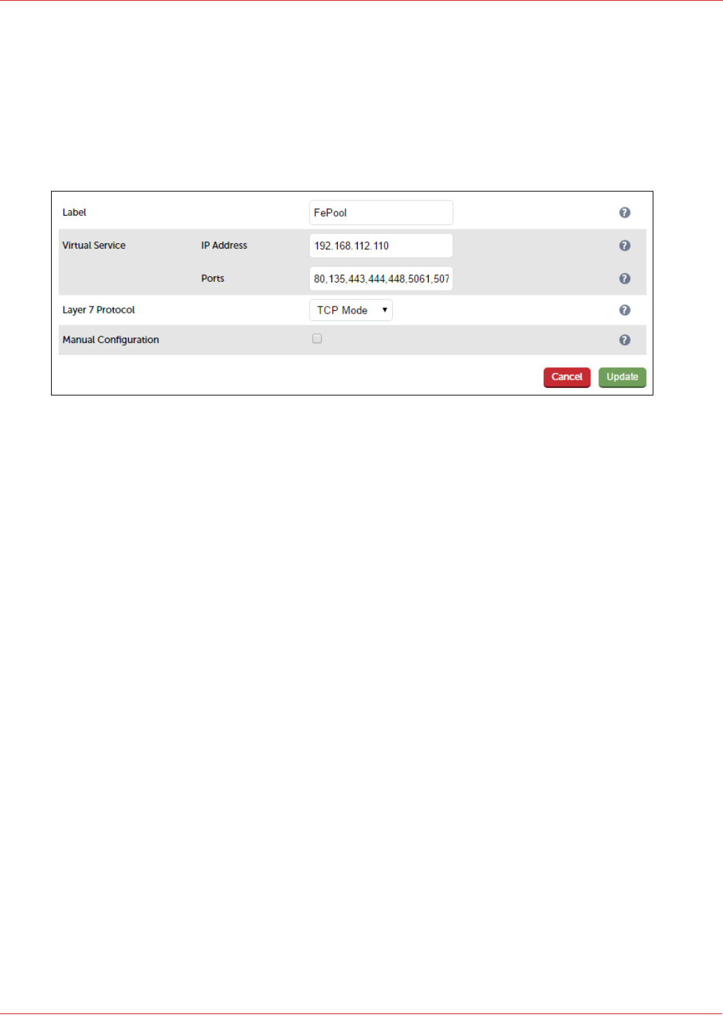
Configuring The Fe-Pool VIP
Create the VIP:
1. Using the WebUI, navigate to: Cluster Configuration > Layer 7 – Virtual Service and click Add a New Virtual
Service
2. Enter the following details:
3. Enter an appropriate label for the VIP, e.g. FePool
4. Set the Virtual Service IP address field to the required IP address, e.g. 192.168.112.110
5. Set the Virtual Service Ports field to the following port list:
80,135,443,444,448,5061,5070,5071,5072,5073,5075,5076,5080
6. Set Layer 7 Protocol to TCP Mode
7. Click Update
8. Now click Modify next to the newly created VIP
9. In the Persistence section, click the Advanced button to show more options
10. Ensure Persistence Mode is set to Source IP
11. Change Persistence Timeout to 20 (i.e. 20 minutes)
12. In the Health Checks section, click Advanced to expand the section
13. Set the Check Port field to 5061
14. In the Other section, click Advanced to expand the section
15. Enter the VIP address in Set Source Address, e.g. 192.168.112.110
16. Click Update
Define the Real Servers for the VIP just created:
1. Using the WebUI, navigate to: Cluster Configuration > Layer 7 – Real Servers and click Add a new Real Server
next to the newly created VIP
2. Enter the following details:
33
© Copyright Loadbalancer.org • www.loadbalancer.org • sales@loadbalancer.org
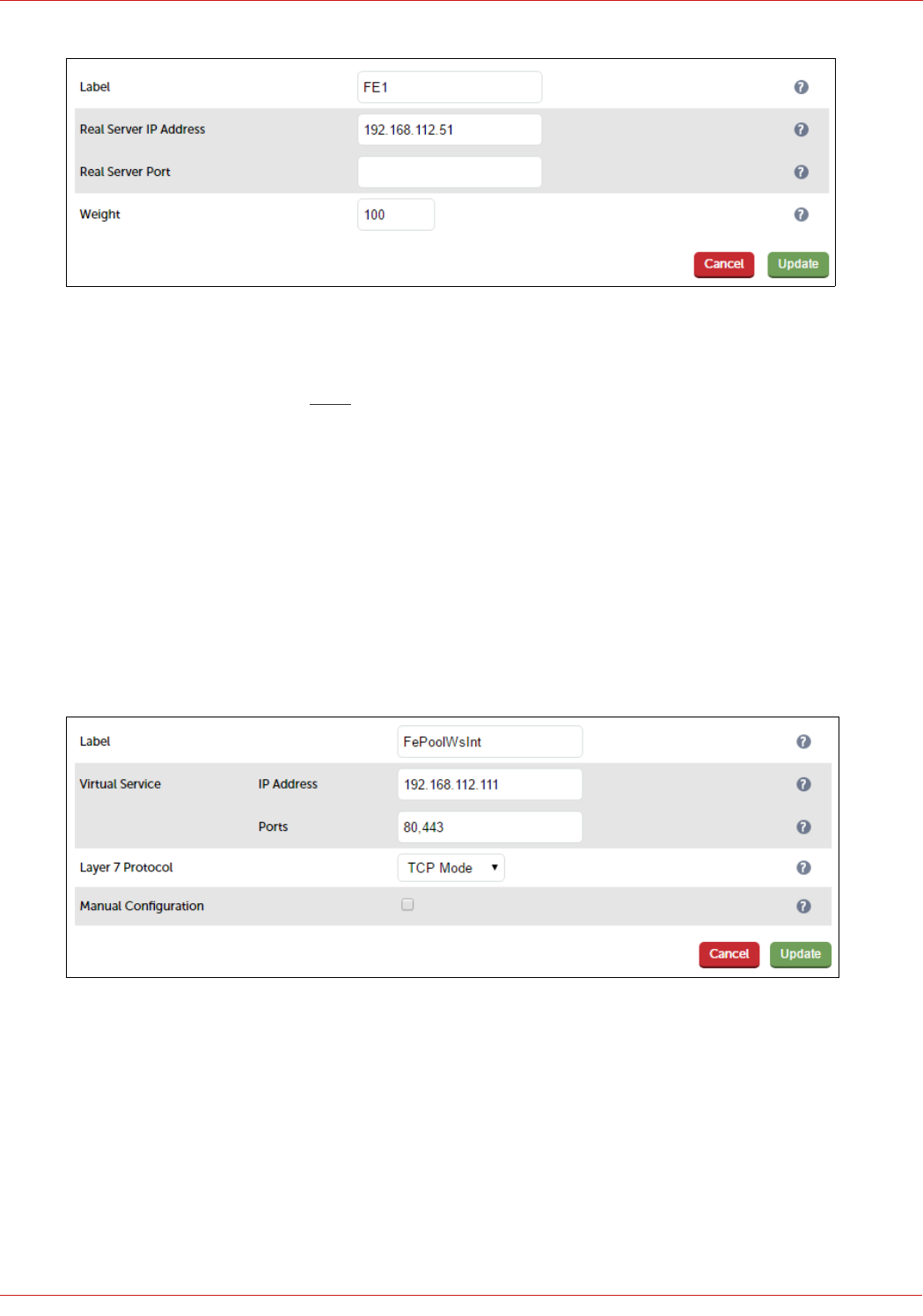
3. Enter an appropriate label for the RIP, e.g. FE1
4. Change the Real Server IP Address field to the required IP address, e.g. 192.168.112.51
5. Leave the Real Server Port field blank as shown above
6. Click Update
7. Repeat the above steps to add your other Front End Server(s)
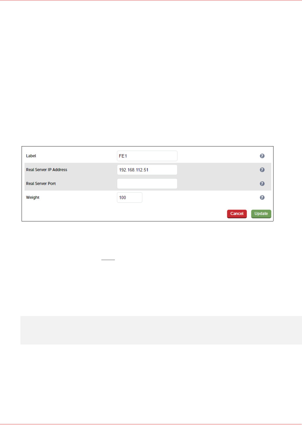
Configuring The Fe-Pool-Ws-Int VIP
Create the VIP:
1. Using the WebUI, navigate to: Cluster Configuration > Layer 7 – Virtual Services and click Add a New Virtual
Service
2. Enter the following details:
3. Enter an appropriate label for the VIP, e.g. FePoolWsInt
4. Set the Virtual Service IP address field to the required IP address, e.g. 192.168.112.111
5. Set the Virtual Service Ports field to the following ports 80,443
6. Set Layer 7 Protocol to TCP Mode
7. Click Update
8. Now click Modify next to the newly created VIP
9. In the Persistence section, click the Advanced button to show more options
34
© Copyright Loadbalancer.org • www.loadbalancer.org • sales@loadbalancer.org
10. Ensure Persistence Mode is set to Source IP
11. Change Persistence Timeout to 20 (i.e. 20 minutes)
12. In the Health Checks section, click Advanced to expand the section
13. Set the Check Port field to 5061
14. In the Other section, click Advanced to expand the section
15. Enter the VIP address in Set Source Address, e.g. 192.168.112.111
16. Click Update
Define the Real Servers for the VIP just created:
1. Using the WebUI, navigate to: Cluster Configuration > Layer 7 – Real Servers and click Add a new Real Server
next to the newly created VIP
2. Enter the following details:
3. Enter an appropriate label for the RIP, e.g. FE1
4. Change the Real Server IP Address field to the required IP address, e.g. 192.168.112.51
5. Leave the Real Server Port field blank as shown above
6. Click Update
7. Repeat the above steps to add your other Front End Server(s)
Configuring The Fe-Pool-Ws-Ext-8080 VIP
Note: This VIP is not required if you forward Reverse Proxy traffic directly to the Front End Servers.
Create the VIP:
1. Using the WebUI, navigate to: Cluster Configuration > Layer 7 – Virtual Service and click Add a New Virtual
Service
2. Enter the following details:
35
© Copyright Loadbalancer.org • www.loadbalancer.org • sales@loadbalancer.org
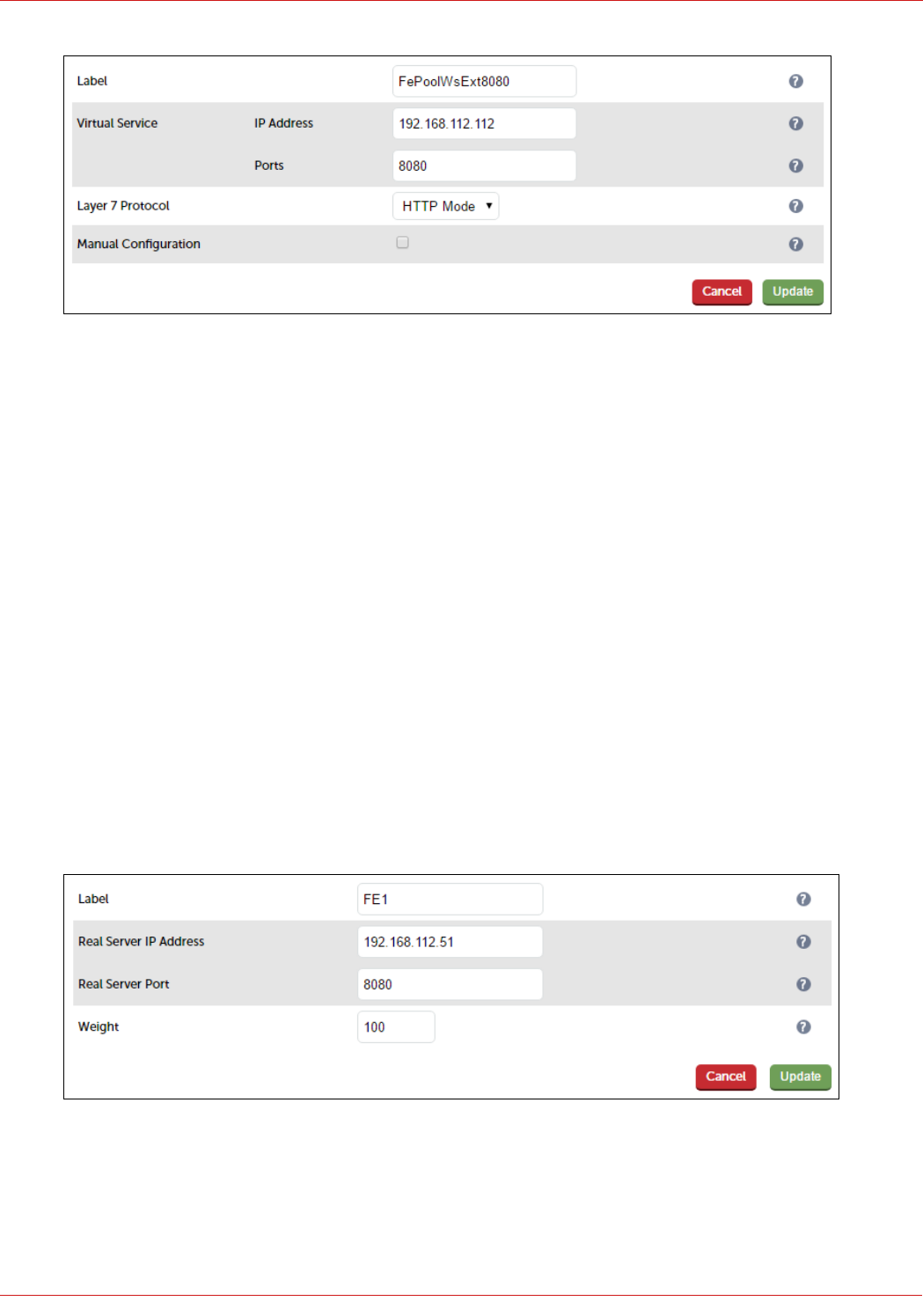
3. Enter an appropriate label for the VIP, e.g. FePoolWsExt8080
4. Set the Virtual Service IP address field to the required IP address, e.g. 192.168.112.112
5. Set the Virtual Service Ports field to 8080
6. Set Layer 7 Protocol to HTTP Mode
7. Now click Modify next to the newly created VIP
8. Ensure that Persistence Mode is set to None
9. In the Health Checks section, click Advanced to expand the section
10. Set the Check Port field to 5061
11. In the Other section, click Advanced to expand the section
12. Enter the VIP address in Set Source Address, e.g. 192.168.112.112
13. Click Update
Define the Real Servers for the VIP just created:
1. Using the WebUI, navigate to: Cluster Configuration > Layer 7 – Real Servers and click Add a new Real Server
next to the newly created VIP
2. Enter the following details:
3. Enter an appropriate label for the RIP, e.g. FE1
4. Change the Real Server IP Address field to the required IP address, e.g. 192.168.112.51
5. Set the Real Server Port field to 8080
36
© Copyright Loadbalancer.org • www.loadbalancer.org • sales@loadbalancer.org
6. Click Update
7. Repeat the above steps to add your other Front End Server(s)
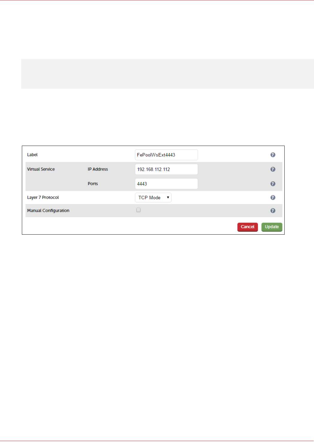
Configuring The Fe-Pool-Ws-Ext-4443 VIP
Note: This VIP is not required if you forward Reverse Proxy traffic directly to the Front End Servers.
Create the VIP:
1. Using the WebUI, navigate to: Cluster Configuration > Layer 7 – Virtual Service and click Add a New Virtual
Service
2. Enter the following details:
3. Enter an appropriate label for the VIP, e.g. FePoolWsExt4443
4. Set the Virtual Service IP address field to the required IP address, e.g. 192.168.112.112
5. Set the Virtual Service Ports field to 4443
6. Set Layer 7 Protocol to TCP Mode
7. Click Update
8. Now click Modify next to the newly created VIP
9. Ensure that Persistence Mode is set to None
10. In the Health Checks section, click Advanced to expand the section
11. Set the Check Port field to 5061
12. In the Other section, click Advanced to expand the section
13. Enter the VIP address in Set Source Address, e.g. 192.168.112.112
14. Click Update
Define the Real Servers for the VIP just created:
1. Using the WebUI, navigate to: Cluster Configuration > Layer 7 – Real Servers and click Add a new Real Server
next to the newly created VIP
37
© Copyright Loadbalancer.org • www.loadbalancer.org • sales@loadbalancer.org
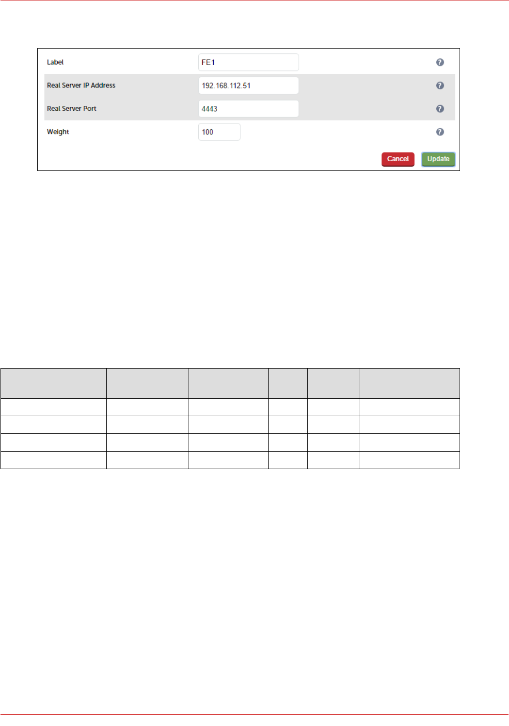
2. Enter the following details:
3. Enter an appropriate label for the RIP, e.g. FE1
4. Change the Real Server IP Address field to the required IP address, e.g. 192.168.112.51
5. Set the Real Server Port field to 4443
6. Click Update
7. Repeat the above steps to add your other Front End Server(s)
STEP 3 – Configuring the Load Balanced Director Services
Virtual Services (VIPs) Required
VIP Name (Label) IP Address Port(s) Layer Layer 7
Protocol
Persistence Method
DirPool 192.168.112.120 443, 444, 5061 7 TCP Source IP address
DirPoolWsInt 192.168.112.121 80, 443 7 TCP Source IP address
DirPoolWsExt8080 192.168.112.122 8080 7 HTTP None or cookie *
DirPoolWsExt4443 192.168.112.122 4443 7 TCP None or cookie *
* If you want to use cookie based persistence (this is normally only required if you still have any Lync 2010 Director Servers in
your deployment), make sure that you comply with the following Microsoft requirements when configuring the VIP:
• Set Persistence Mode to HTTP Cookie
• Set HTTP Cookie Name to MS-WSMAN
• Clear the Cookie Max Idle Duration field
• Clear the Cookie Max life Duration field
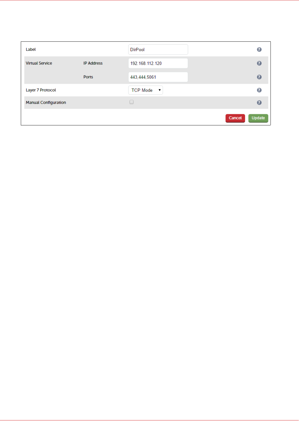
Configuring The Dir-Pool VIP
Create the VIP:
1. Using the WebUI, navigate to: Cluster Configuration > Layer 7 – Virtual Service and click Add a New Virtual
38
© Copyright Loadbalancer.org • www.loadbalancer.org • sales@loadbalancer.org
Service
2. Enter the following details:
3. Enter an appropriate label for the VIP, e.g. DirPool
4. Set the Virtual Service IP address field to the required IP address, e.g. 192.168.112.120
5. Set the Virtual Service Ports field to 443,444,5061
6. Set Layer 7 Protocol to TCP Mode
7. Click Update
8. Now click Modify next to the newly created VIP
9. In the Persistence section, click the Advanced button to show more options
10. Ensure Persistence Mode is set to Source IP
11. Change Persistence Timeout to 20 (i.e. 20 minutes)
12. In the Health Checks section, click Advanced to expand the section
13. Set the Check Port field to 5061
14. In the Other section, click Advanced to expand the section
15. Enter the VIP address in Set Source Address, e.g. 192.168.112.120
16. Click Update
Define the Real Servers for the VIP just created:
1. Using the WebUI, navigate to: Cluster Configuration > Layer 7 – Real Servers and click Add a new Real Server
next to the newly created VIP
2. Enter the following details:
39
© Copyright Loadbalancer.org • www.loadbalancer.org • sales@loadbalancer.org
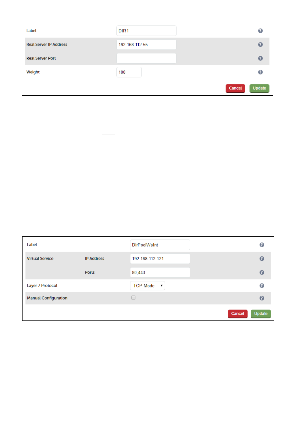
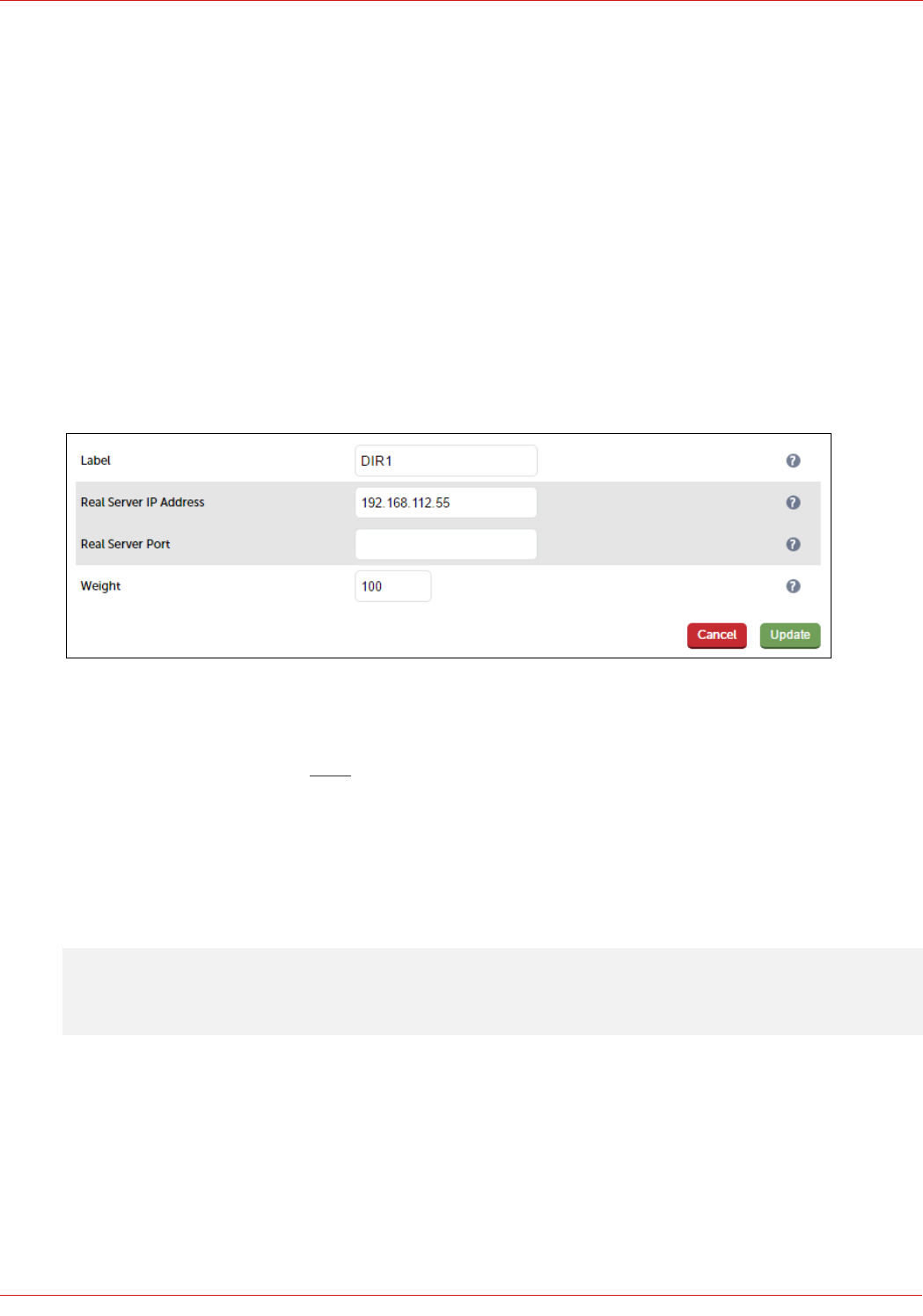
3. Enter an appropriate label for the RIP, e.g. DIR1
4. Change the Real Server IP Address field to the required IP address, e.g. 192.168.112.55
5. Leave the Real Server Port field blank as shown above
6. Click Update
7. Repeat the above steps to add your other Director Server(s)
Configuring The Dir-Pool-Ws-Int VIP
Create the VIP:
1. Using the WebUI, navigate: to Cluster Configuration > Layer 7 – Virtual Services and click Add a New Virtual
Service
2. Enter the following details:
3. Enter an appropriate label for the VIP, e.g. DirPoolWsInt
4. Set the Virtual Service IP address field to the required IP address, e.g. 192.168.112.121
5. Set the Virtual Service Ports field to the following ports 80,443
6. Set Layer 7 Protocol to TCP Mode
7. Click Update
8. Now click Modify next to the newly created VIP
9. In the Persistence section, click the Advanced button to show more options
40
© Copyright Loadbalancer.org • www.loadbalancer.org • sales@loadbalancer.org
10. Ensure Persistence Mode is set to Source IP
11. Change Persistence Timeout to 20 (i.e. 20 minutes)
12. In the Health Checks section, click Advanced to expand the section
13. Set the Check Port field to 5061
14. In the Other section, click Advanced to expand the section
15. Enter the VIP address in Set Source Address, e.g. 192.168.112.121
16. Click Update
Define the Real Servers for the VIP just created:
1. Using the WebUI, navigate to: Cluster Configuration > Layer 7 – Real Servers and click Add a new Real Server
next to the newly created VIP
2. Enter the following details:
3. Enter an appropriate label for the RIP, e.g. DIR1
4. Change the Real Server IP Address field to the required IP address, e.g. 192.168.112.55
5. Leave the Real Server Port field blank as shown above
6. Click Update
7. Repeat the above steps to add your other Director Server(s)
Configuring The Dir-Pool-Ws-Ext-8080 VIP
Note: This VIP is not required if you forward Reverse Proxy traffic directly to the Director Servers.
Create the VIP:
1. Using the WebUI, navigate to: Cluster Configuration > Layer 7 – Virtual Service and click Add a New Virtual
Service
2. Enter the following details:
41
© Copyright Loadbalancer.org • www.loadbalancer.org • sales@loadbalancer.org
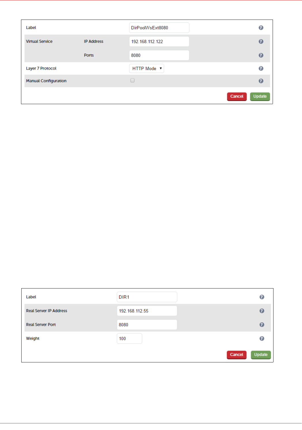
3. Enter an appropriate label for the VIP, e.g. DirPoolWsExt8080
4. Set the Virtual Service IP address field to the required IP address, e.g. 192.168.112.122
5. Set the Virtual Service Ports field to 8080
6. Set Layer 7 Protocol to HTTP Mode
7. Now click Modify next to the newly created VIP
8. Ensure that Persistence Mode is set to None
9. In the Health Checks section, click Advanced to expand the section
10. Set the Check Port field to 5061
11. In the Other section, click Advanced to expand the section
12. Enter the VIP address in Set Source Address, e.g. 192.168.112.122
13. Click Update
Define the Real Servers for the VIP just created:
1. Using the WebUI, navigate to: Cluster Configuration > Layer 7 – Real Servers and click Add a new Real Server
next to the newly created VIP
2. Enter the following details:
3. Enter an appropriate label for the RIP, e.g. DIR1
4. Change the Real Server IP Address field to the required IP address, e.g. 192.168.112.55
5. Set the Real Server Port field to 8080
42
© Copyright Loadbalancer.org • www.loadbalancer.org • sales@loadbalancer.org
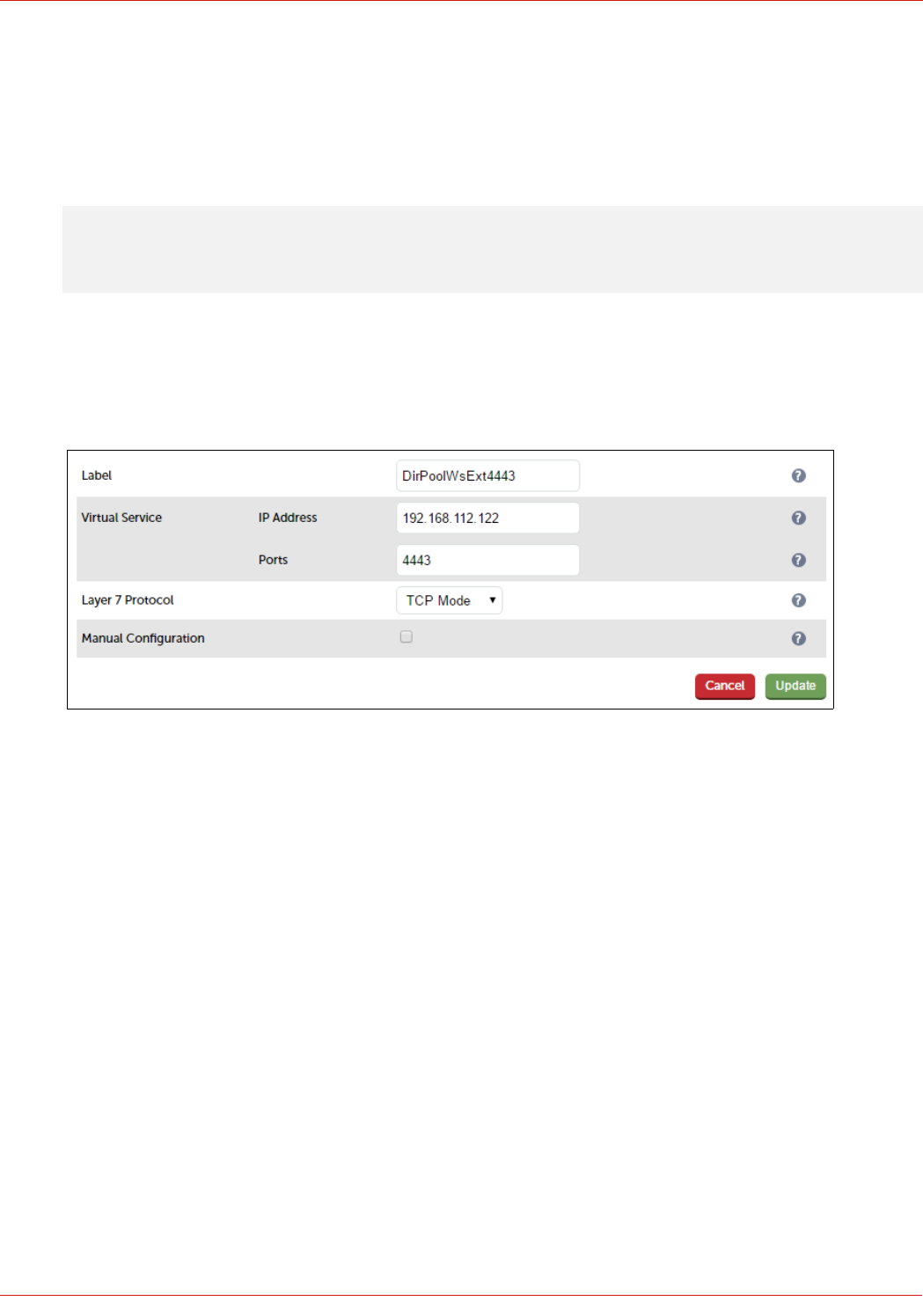
6. Click Update
7. Repeat the above steps to add your other Director Server(s)
Configuring The Dir-Pool-Ws-Ext-4443 VIP
Note: This VIP is not required if you forward Reverse Proxy traffic directly to the Director Servers.
Create the VIP:
1. Using the WebUI, navigate to: Cluster Configuration > Layer 7 – Virtual Service and click Add a New Virtual
Service
2. Enter the following details:
3. Enter an appropriate label for the VIP, e.g. FePoolWsExt4443
4. Set the Virtual Service IP address field to the required IP address, e.g. 192.168.112.122
5. Set the Virtual Service Ports field to 4443
6. Set Layer 7 Protocol to TCP Mode
7. Click Update
8. Now click Modify next to the newly created VIP
9. Ensure that Persistence Mode is set to None
10. In the Health Checks section, click Advanced to expand the section
11. Set the Check Port field to 5061
12. In the Other section, click Advanced to expand the section
13. Enter the VIP address in Set Source Address, e.g. 192.168.112.122
14. Click Update
Define the Real Servers for the VIP just created:
1. Using the WebUI, navigate to: Cluster Configuration > Layer 7 – Real Servers and click Add a new Real Server
43
© Copyright Loadbalancer.org • www.loadbalancer.org • sales@loadbalancer.org
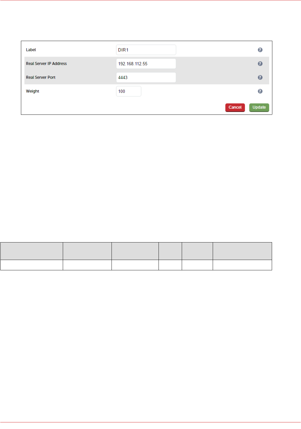
next to the newly created VIP
2. Enter the following details:
3. Enter an appropriate label for the RIP, e.g. DIR1
4. Change the Real Server IP Address field to the required IP address, e.g. 192.168.112.55
5. Set the Real Server Port field to 4443
6. Click Update
7. Repeat the above steps to add your other Director Server(s)
STEP 4 – Configuring the Load Balanced Office Web Application Servers
Virtual Services (VIPs) Required
The table below shows the VIP that must be created:
VIP Name (Label) IP Address Port(s) Layer Layer 7
Protocol
Persistence Method
OffceWebApp 192.168.112.125 443 7 TCP Source IP address
Create the VIP:
1. Using the WebUI, navigate to: Cluster Configuration > Layer 7 – Virtual Services and click Add a New Virtual
Service
2. Enter the following details:
44
© Copyright Loadbalancer.org • www.loadbalancer.org • sales@loadbalancer.org
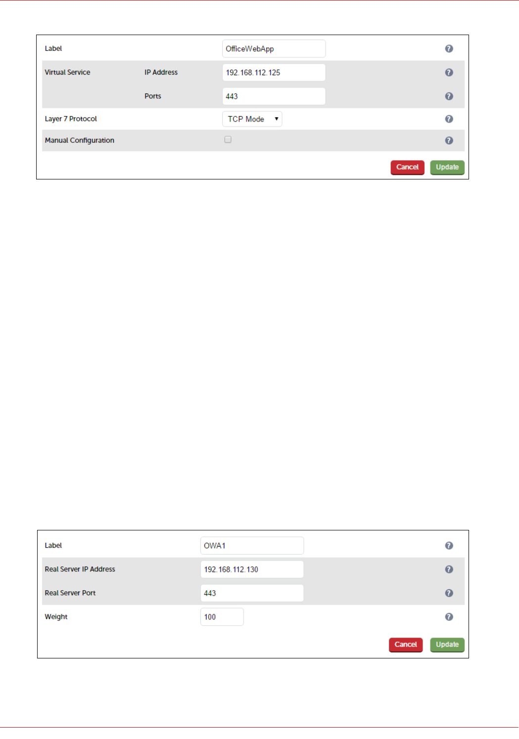
3. Enter an appropriate label for the VIP, e.g. OfficeWebApp
4. Set the Virtual Service IP address field to the required IP address, e.g. 192.168.112.125
5. Set the Virtual Service Ports field to the following port 443
6. Set Layer 7 Protocol to TCP Mode
7. Click Update
8. Now click Modify next to the newly created VIP
9. In the Persistence section, click the Advanced button to show more options
10. Ensure Persistence Mode is set to Source IP
11. Change Persistence Timeout to 20 (i.e. 20 minutes)
12. In the Other section, click Advanced to expand the section
13. Enter the VIP address in Set Source Address, e.g. 192.168.112.125
14. Click Update
Define the Real Servers for the VIP just created:
1. Using the WebUI, navigate to: Cluster Configuration > Layer 7 – Real Servers and click Add a new Real Server
next to the newly created VIP
2. Enter the following details:
3. Enter an appropriate label for the RIP, e.g. OWA1
45
© Copyright Loadbalancer.org • www.loadbalancer.org • sales@loadbalancer.org
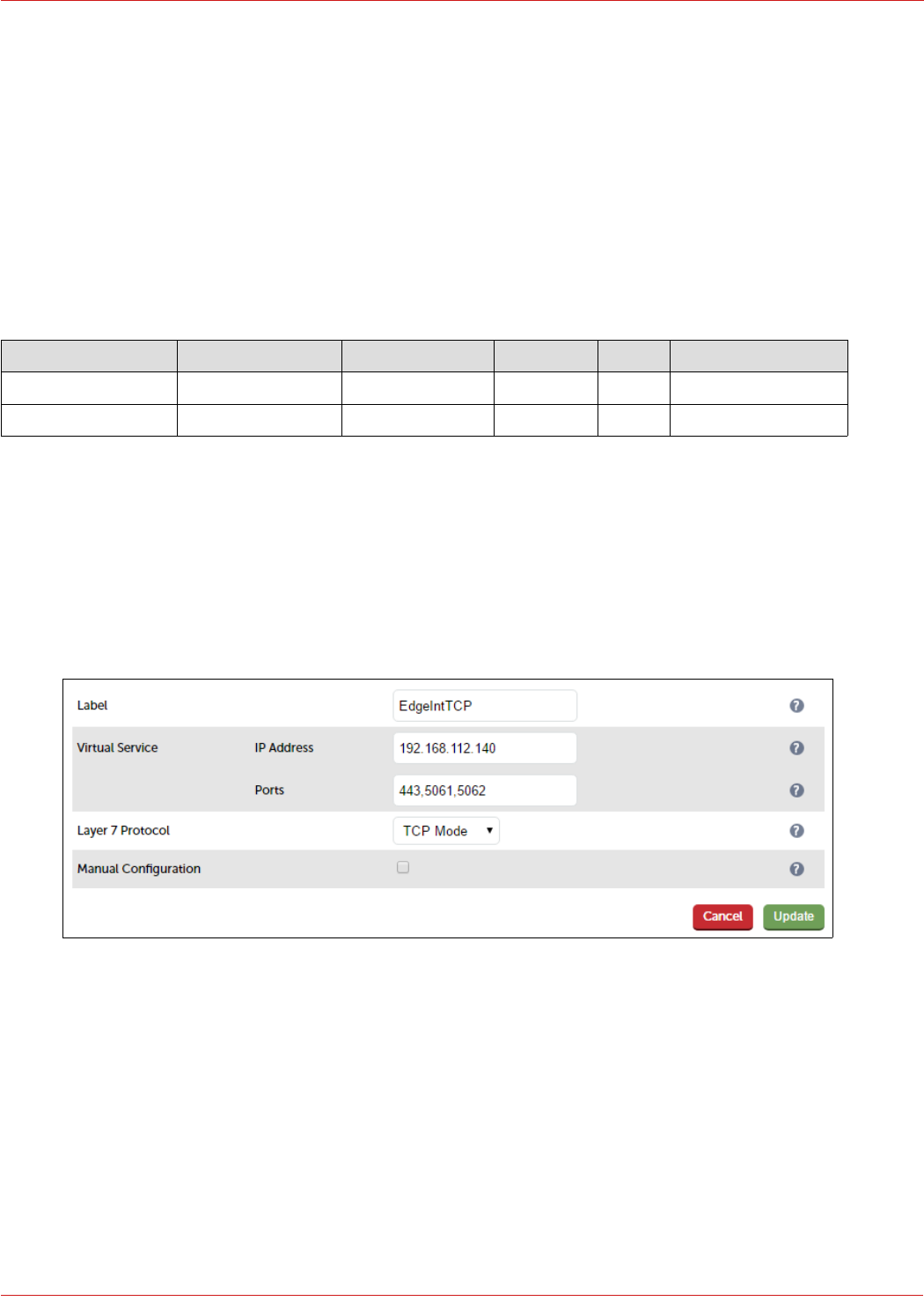
4. Change the Real Server IP Address field to the required IP address, e.g. 192.168.112.130
5. Set the Real Server port to 443
6. Click Update
7. Repeat the above steps to add your other Office Web App Server(s)
STEP 5 – Configuring the Load Balanced Edge Pool Services (Internal)
Virtual Services (VIPs) Required
VIP Name (Label) IP Address Port Protocol Layer Persistence Method
EdgeIntTCP 192.168.112.140 443, 5061, 5062 TCP 7 Source IP address
EdgeIntUDP 192.168.112.140 3478 UDP 4 Source IP address
Configuring The Edge-Int-TCP VIP
Create the VIP:
1. Using the WebUI, navigate to: Cluster Configuration > Layer 7 – Virtual Services and click Add a New Virtual
Service
2. Enter the following details:
3. Enter an appropriate label for the VIP, e.g. EdgeIntTCP
4. Change the Virtual Service IP address field to the required IP address, e.g. 192.168.112.140
5. Set the Virtual Service Ports field to 443,5061,5062
6. Leave Protocol set to TCP Mode
7. Click Update
8. Now click Modify next to the newly created VIP
9. In the Persistence section, click the Advanced button to show more options
10. Ensure Persistence Mode is set to Source IP
46
© Copyright Loadbalancer.org • www.loadbalancer.org • sales@loadbalancer.org
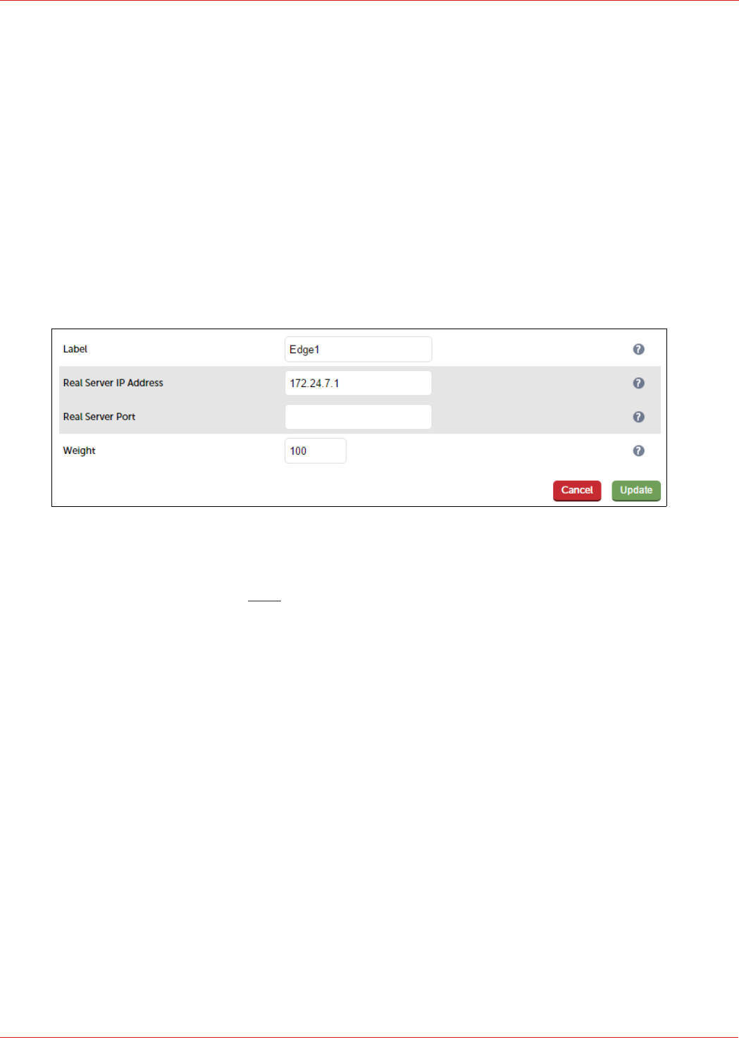
11. Change Persistence Timeout to 20 (i.e. 20 minutes)
12. In the Health Checks section, click Advanced to expand the section
13. Set the Check Port field to 5061
14. In the Other section, click Advanced to expand the section
15. Enter the VIP address in Set Source Address, e.g. 192.168.112.140
16. Click Update
Define the Real Servers for the VIP just created:
1. Using the WebUI, navigate to: Cluster Configuration > Layer 7 – Real Servers and click Add a new Real Server
next to the newly created VIP
2. Enter the following details:
3. Enter an appropriate label for the RIP, e.g. Edge1
4. Change the Real Server IP Address to the required IP address, e.g. 172.24.7.1
5. Leave the Real Server Port field blank as shown above
6. Click Update
7. Repeat the above steps to add your other Edge Server(s)
Configuring The Edge-Int-UDP VIP
Create the VIP:
1. Using the WebUI, navigate to: Cluster Configuration > Layer 4 – Virtual Services and click Add a New Virtual
Service
2. Enter the following details:
47
© Copyright Loadbalancer.org • www.loadbalancer.org • sales@loadbalancer.org
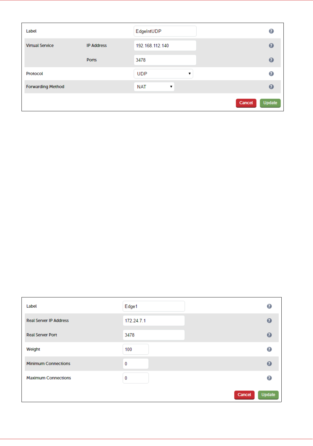
3. Enter an appropriate label for the VIP, e.g. EdgeIntUDP
4. Change the Virtual Service IP address field to the required IP address, e.g. 192.168.112.140
5. Set the Virtual Service Ports field to 3478
6. Set Protocol to UDP
7. Set Forwarding Method to NAT
8. Click Update
9. Now click Modify next to the newly created VIP
10. Ensure that Persistent is enabled (ticked)
11. Change Persistence Timeout to 1200
12. Ensure that Check Type is set to ping server
13. Click Update
Define the Real Servers for the VIP just created:
1. Using the WebUI, navigate to: Cluster Configuration > Layer 4 – Real Servers and click Add a new Real Server
next to the newly created VIP
2. Enter the following details:
3. Enter an appropriate label for the RIP, e.g. Edge1
48
© Copyright Loadbalancer.org • www.loadbalancer.org • sales@loadbalancer.org
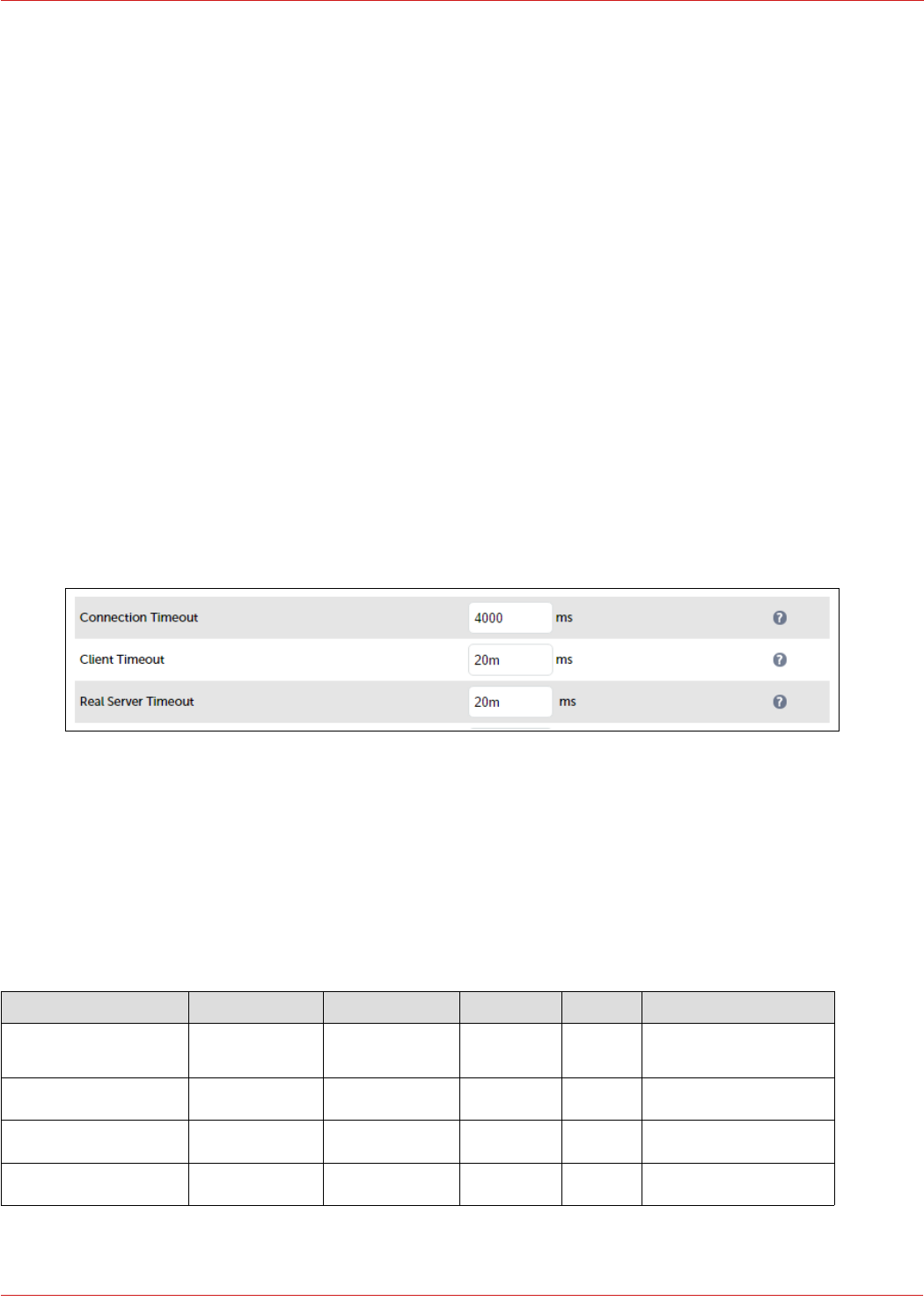
4. Change the Real Server IP Address to the required IP address, e.g. 172.24.7.1
5. Set the Real Server Port field to 3478
6. Click Update
7. Repeat the above steps to add your other Edge Server(s)
STEP 6 – Finalizing the Configuration
To apply the new settings for the Layer 7 based VIPs , HAProxy must be restarted as follows:
1. Navigate to: Maintenance > Restart Services and click Restart HAProxy
17. DMZ Appliance Configuration for SFB (LB2)
This section covers the configuration of the external DMZ based load balancer appliance.
STEP 1 – Configure Layer 7 Global Settings
To configure the TCP timeouts required by Skype For Business, HAProxy's client and server timeouts must be changed
from their default values of 43 seconds and 45 seconds respectively to 20 minutes. To do this follow the steps below:
1. Using the WebUI, navigate to: Cluster Configuration > Layer 7 – Advanced Configuration
2. Change Client Timeout to 20m as shown above (i.e. 20 minutes)
3. Change Real Server Timeout to 20m as shown above (i.e. 20 minutes)
4. Click the Update button to save the settings
STEP 2 – Configuring the Load Balanced Edge Pool Services (External)
Virtual Services (VIPs) Required
VIP Name (Label) IP Address Port Protocol Layer Persistence Method
EdgeExtAccess 10.20.50.100 443, 5061,
5269
TCP 7 Source IP address
EdgeExtWeb 10.20.50.110 443 TCP 7 Source IP address
EdgeExtAvTCP 10.20.50.120 443 TCP 4 Source IP address
EdgeExtAvUDP 10.20.50.120 3478 UDP 4 Source IP address
49
© Copyright Loadbalancer.org • www.loadbalancer.org • sales@loadbalancer.org
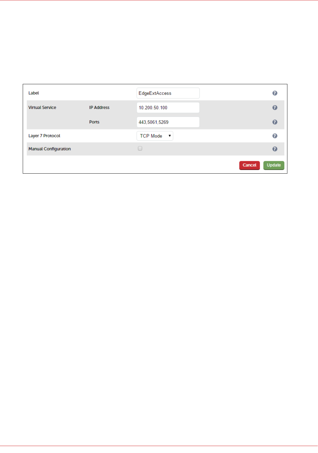
Configuring The Edge-Ext-Access VIP
Create the VIP:
1. Using the WebUI, navigate to: Cluster Configuration > Layer 7 – Virtual Services and click Add a New Virtual
Service
2. Enter the following details:
3. Enter an appropriate label for the VIP, e.g. EdgeExtAccess
4. Change the Virtual Service IP address field to the required IP address, e.g. 10.200.50.100
5. Set the Virtual Service Ports field to 443,5061,5269
6. Set Layer 7 Protocol to TCP Mode
7. Click Update
8. Now click Modify next to the newly created VIP
9. In the Persistence section, click the Advanced button to show more options
10. Ensure Persistence Mode is set to Source IP
11. Change Persistence Timeout to 20 (i.e. 20 minutes)
12. In the Other section, click Advanced to expand the section
13. Enter the VIP address in Set Source Address, e.g. 10.200.50.100
14. Click Update
Define the Real Servers for the VIP just created:
1. Using the WebUI, navigate to: Cluster Configuration > Layer 7 – Real Servers and click Add a new Real Server
next to the newly created VIP
2. Enter the following details:
50
© Copyright Loadbalancer.org • www.loadbalancer.org • sales@loadbalancer.org
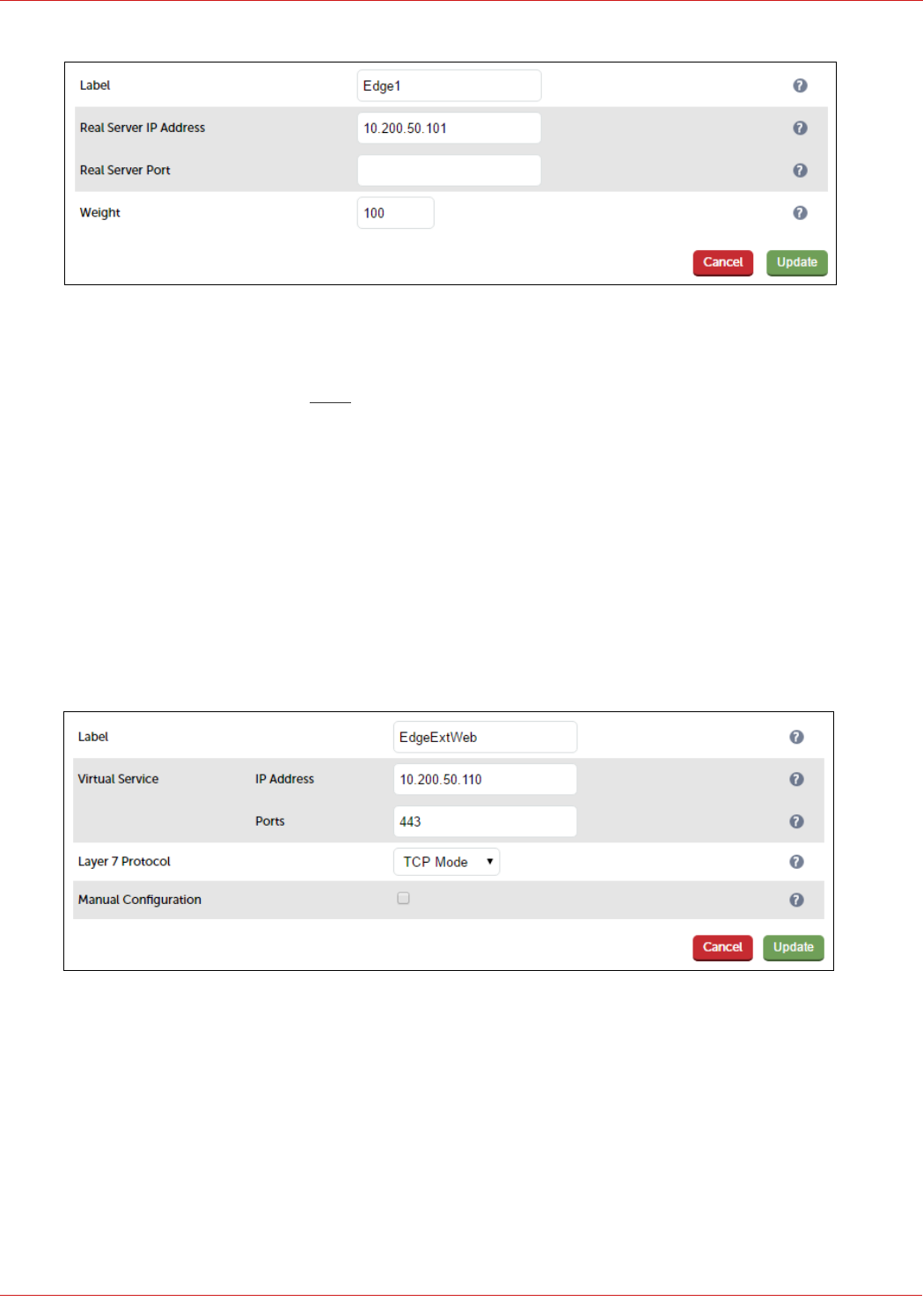
3. Enter an appropriate label for the RIP. e.g. Edge1
4. Change the Real Server IP Address field to the required address, e.g. 10.200.50.101
5. Leave the Real Server Port field blank as shown above
6. Click Update
7. Repeat the above steps to add your other Edge Server(s)
Configuring The Edge-Ext-Web VIP
Create the VIP:
1. Using the WebUI, navigate to: Cluster Configuration > Layer 7 – Virtual Services and click Add a New Virtual
Service
2. Enter the following details:
3. Enter an appropriate label for the VIP, e.g. EdgeExtWeb
4. Change the Virtual Service IP address field to the required IP address, e.g. 10.200.50.110
5. Set the Virtual Service Ports field to 443
6. Set Layer 7 Protocol to TCP Mode
7. Click Update
8. Now click Modify next to the newly created VIP
9. In the Persistence section, click the Advanced button to show more options
51
© Copyright Loadbalancer.org • www.loadbalancer.org • sales@loadbalancer.org
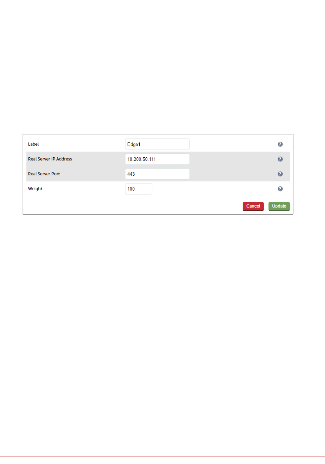
10. Ensure Persistence Mode is set to Source IP
11. Change Persistence Timeout to 20 (i.e. 20 minutes)
12. In the Other section, click Advanced to expand the section
13. Enter the VIP address in Set Source Address, e.g. 10.200.50.110
14. Click Update
Define the Real Servers for the VIP just created:
1. Using the WebUI, navigate to: Cluster Configuration > Layer 7 – Real Servers and click Add a new Real Server
next to the newly created VIP
2. Enter the following details:
3. Enter an appropriate label for the RIP. e.g. Edge1
4. Change the Real Server IP Address field to the required address, e.g. 10.200.50.111
5. Set the Real Server Port to 443
6. Click Update
7. Repeat the above steps to add your other Edge Server(s)
Configuring The Edge-Ext-Av-TCP VIP
Create the VIP:
1. Using the WebUI, navigate to: Cluster Configuration > Layer 4 – Virtual Services and click Add a New Virtual
Service
2. Enter the following details:
52
© Copyright Loadbalancer.org • www.loadbalancer.org • sales@loadbalancer.org
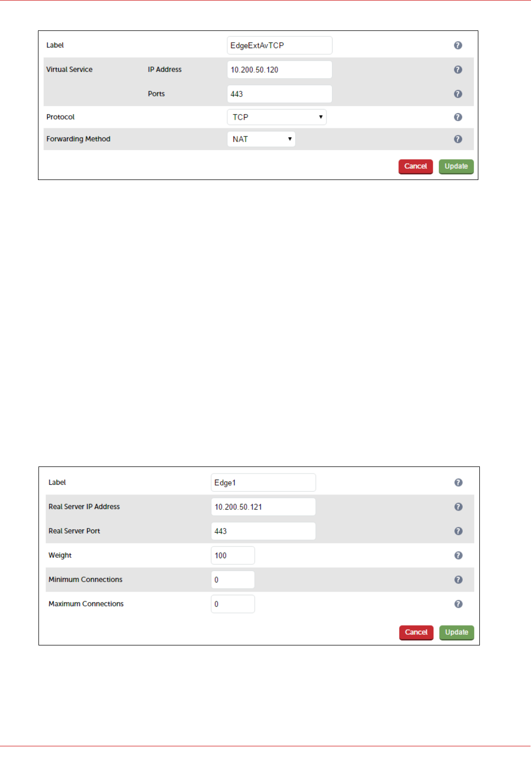
3. Enter an appropriate label for the VIP, e.g. EdgeExtAvTCP
4. Change the Virtual Service IP address field to the required IP address, e.g. 10.200.50.120
5. Set the Virtual Service Ports field to 443
6. Set Protocol to TCP
7. Set Forwarding Method to NAT
8. Click Update
9. Now click Modify next to the newly created VIP
10. Change Persistent timeout to 1200 (i.e. 20 minutes)
11. Click Update
Define the Real Servers for the VIP just created:
1. Using the WebUI, navigate to: Cluster Configuration > Layer 4– Real Servers and click Add a new Real Server
next to the newly created VIP
2. Enter the following details:
3. Enter an appropriate label for the RIP. e.g. Edge1
4. Change the Real Server IP Address field to the required address, e.g. 10.200.50.121
5. Set the Real Server Port to 443
53
© Copyright Loadbalancer.org • www.loadbalancer.org • sales@loadbalancer.org
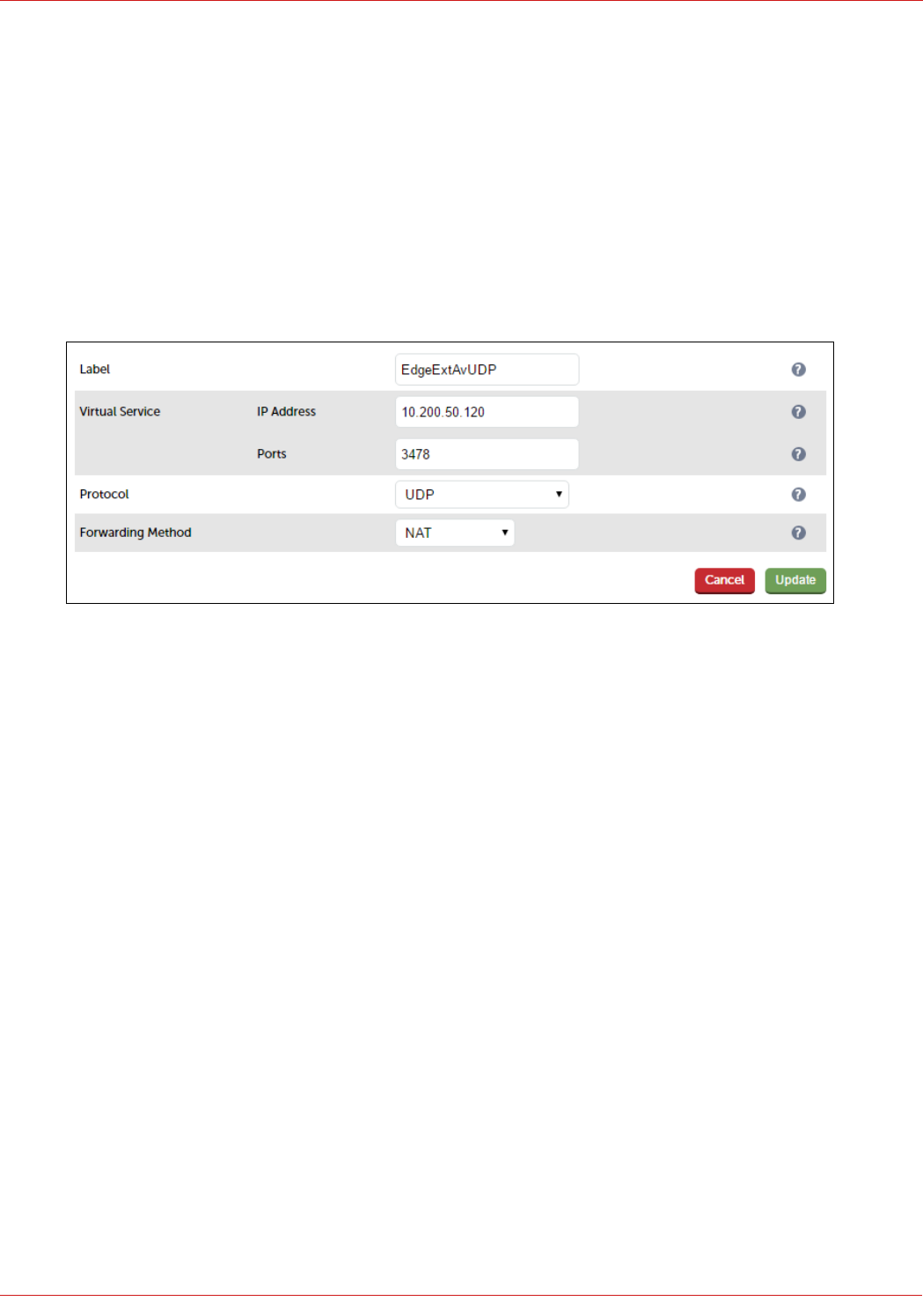
6. Click Update
7. Repeat the above steps to add your other Edge Server(s)
Configuring The Edge-Ext-Av-UDP VIP
Create the VIP:
1. Using the WebUI, navigate to: Cluster Configuration > Layer 4 – Virtual Services and click Add a New Virtual
Service
2. Enter the following details:
3. Enter an appropriate label for the VIP, e.g. EdgeExtAvUDP
4. Change the Virtual Service IP address field to the required IP address, e.g. 10.200.50.120
5. Set the Virtual Service Ports field to 3478
6. Set Protocol to UDP
7. Set Forwarding Method to NAT
8. Click Update
9. Now click Modify next to the newly created VIP
10. Change Persistence Timeout to 20 (i.e. 20 minutes)
11. Click Update
Define the Real Servers for the VIP just created:
1. Using the WebUI, navigate to: Cluster Configuration > Layer 7 – Real Servers and click Add a new Real Server
next to the newly created VIP
2. Enter the following details:
54
© Copyright Loadbalancer.org • www.loadbalancer.org • sales@loadbalancer.org
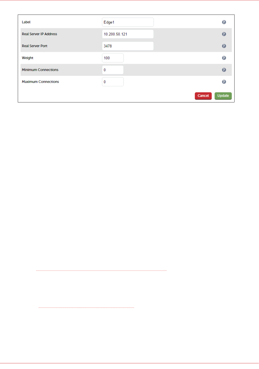
3. Enter an appropriate label for the RIP. e.g. Edge1
4. Change the Real Server IP Address field to the required address, e.g. 10.200.50.121
5. Set the Real Server Port to 3478
6. Click Update
7. Repeat the above steps to add your other Edge Server(s)
STEP 3 – Finalizing the Configuration
To apply the new settings for the Layer 7 based VIPs , HAProxy must be restarted as follows:
1. Navigate to: Maintenance > Restart Services and click Restart HAProxy
18. Testing & Validation
Client connections bypass the load balancer
It's important to remember that client connections can be via the load balancer and also direct to the Skype for
Business server.
Internal Servers: In an HLB only configuration, both web traffic and initial SIP traffic are passed though HLB, however
unlike the web traffic which always pass though the HLB, there is a need for the SIP traffic to flow directly to the FE
servers. Source: Skype for Business Client Registration Process through HLB
Edge Servers: Once the media session is established, traffic goes directly from the client to the Edge Server and does
not pass via the load balancer. To achieve this, the Edge Server returns its external IP address in the first UDP packet of
a media session, the client then sends subsequent UDP traffic directly to that IP address instead of through the load
balancer. Source: A/V Edge and Publicly routable IP addresses
Taking Skype for Business Servers Offline
As mentioned above, client connections can be direct to the Skype Servers. In this case, taking a server offline using
only the load balancer will have no effect. Therefore, a two step approach must be used:
55
© Copyright Loadbalancer.org • www.loadbalancer.org • sales@loadbalancer.org

1. Run the following Skype for Business commands on the server you want to take offline:
Get-CsPoolFabricState -PoolFqdn <PoolFQDN>
If this cmdlet shows any missing replicas, then run the following cmdlet to recover the pool before you apply
any patches:
Reset-CsPoolRegistrarState -ResetType QuorumLossRecovery
Now run the following cmdlet to moves all services to other Front End Servers in the pool, and takes this server
offline:
Invoke-CsComputerFailOver -ComputerName <Front End Server to be patched>
2. Take the server offline (Drain) using System Overview in the load balancer's WebUI – this will ensure that
existing connections can continue until closed, new connections that pass via the load balancer will be directed
to a different Front End server.
Source: Patch or update Front End Servers in Skype for Business Server 2015
Testing External URL's via Reverse Proxy
It's important to verify that the Web Services related URL's are working correctly through the Reverse Proxy. This is
covered in this Microsoft article.
Microsoft Skype For Business Testing Tool
The Microsoft SFB/Lync/OCS Server Remote Connectivity Analyzer tool is a useful Web-based Microsoft tool designed
to help IT Administrators troubleshoot their Skype For Business deployments. It's available at the following link:
https://testconnectivity.microsoft.com/
Skype for Business Debugging Tools
Skype for Business Server 2015, Debugging Tools are provided to help IT Administrators with troubleshooting
deployments of Skype for Business Server 2015. The collection of tools includes: Snooper, CLSLogger &
CLSScenarioEdit.psm1.
Verifying Candidate Selection Using Snooper
Skype For Business looks for the optimum path for client communication. Direct communication is preferred over
relaying (using the Edge Servers), UDP is preferred over TCP. Client logs can be viewed in snooper to check that
optimum paths are being used.
Client logs are located in the users profile in the following location: …..\AppData\Local\Microsoft\Office\16.0\Lync\
Tracing\Lync-UccApi-0.UccApilog
Example
Internal client: 192.168.64.7
External Client: 10.200.60.58
56
© Copyright Loadbalancer.org • www.loadbalancer.org • sales@loadbalancer.org
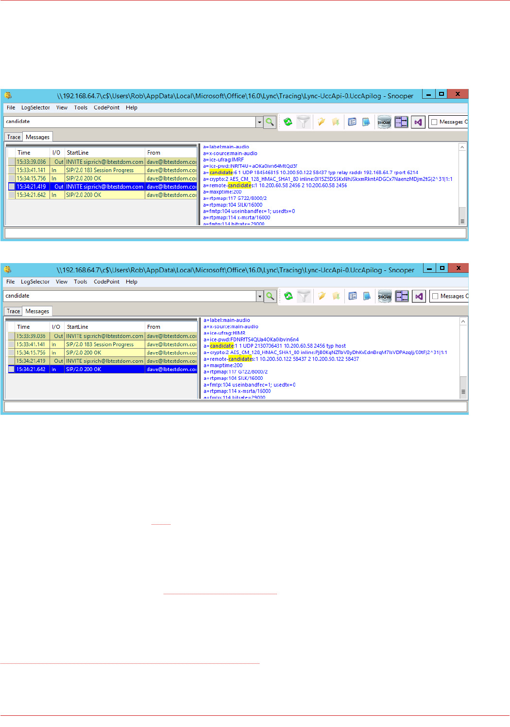
Edge Server A/V service: 10.200.50.122
Search for “candidate” to verify path selection:
These screen shots show that the optimum path has been selected for an external client to internal client. This is the
host IP address of the external client to the internal client via the Edge Server over UDP.
Wireshark Protocol Analyzer
Wireshark is an excellent tool that can be used to analyze network traffic when diagnosing any network related issues.
Wireshark is available for download here.
19. Technical Support
If you have any questions regarding the appliance or would like assistance designing your deployment, please don't
hesitate to contact our support team: support@loadbalancer.org.
20. Further Documentation
The Administration Manual contains much more information about configuring and deploying the appliance. It's available here:
http://pdfs.loadbalancer.org/loadbalanceradministrationv8.pdf
57
© Copyright Loadbalancer.org • www.loadbalancer.org • sales@loadbalancer.org

21. Conclusion
Loadbalancer.org appliances provide a very cost effective solution for highly available load balanced Microsoft Skype For
Business Server environments.
58
© Copyright Loadbalancer.org • www.loadbalancer.org • sales@loadbalancer.org
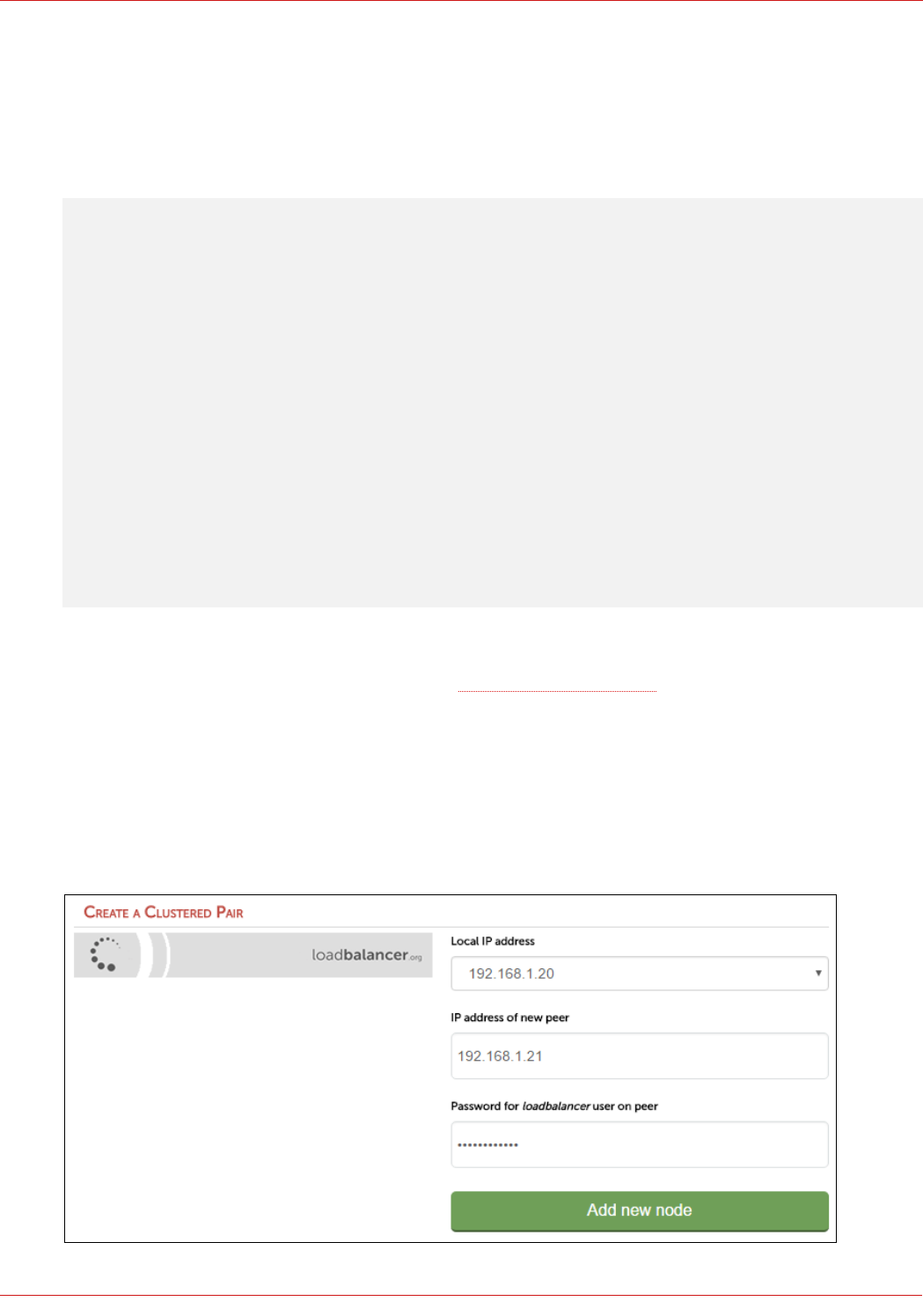
22. Appendix
1 – Clustered Pair Configuration – Adding a Slave Unit
If you initially configured just the master unit and now need to add a slave - our recommended procedure, please refer
to the relevant section below for more details:
Note: A number of settings are not replicated as part of the master/slave pairing process and
therefore must be manually configured on the slave appliance. These are listed below:
• Hostname & DNS settings
• Network settings including IP addresses, bonding configuration and VLANs
• Routing configuration including default gateways and static routes
• Date & time settings
• Physical – Advanced Configuration settings including Internet Proxy IP address & port, Firewall
table size, SMTP relay and Syslog Server
• SNMP settings
• Graphing settings
• Firewall Script & Firewall Lockdown Script settings
• Software updates
Version 7:
Please refer to Chapter 8 – Appliance Clustering for HA in the v7 Administration Manual
Version 8:
To add a slave node – i.e. create a highly available clustered pair:
• Deploy a second appliance that will be the slave and configure initial network settings
• Using the WebUI, navigate to: Cluster Configuration > High-Availability Configuration
59
© Copyright Loadbalancer.org • www.loadbalancer.org • sales@loadbalancer.org
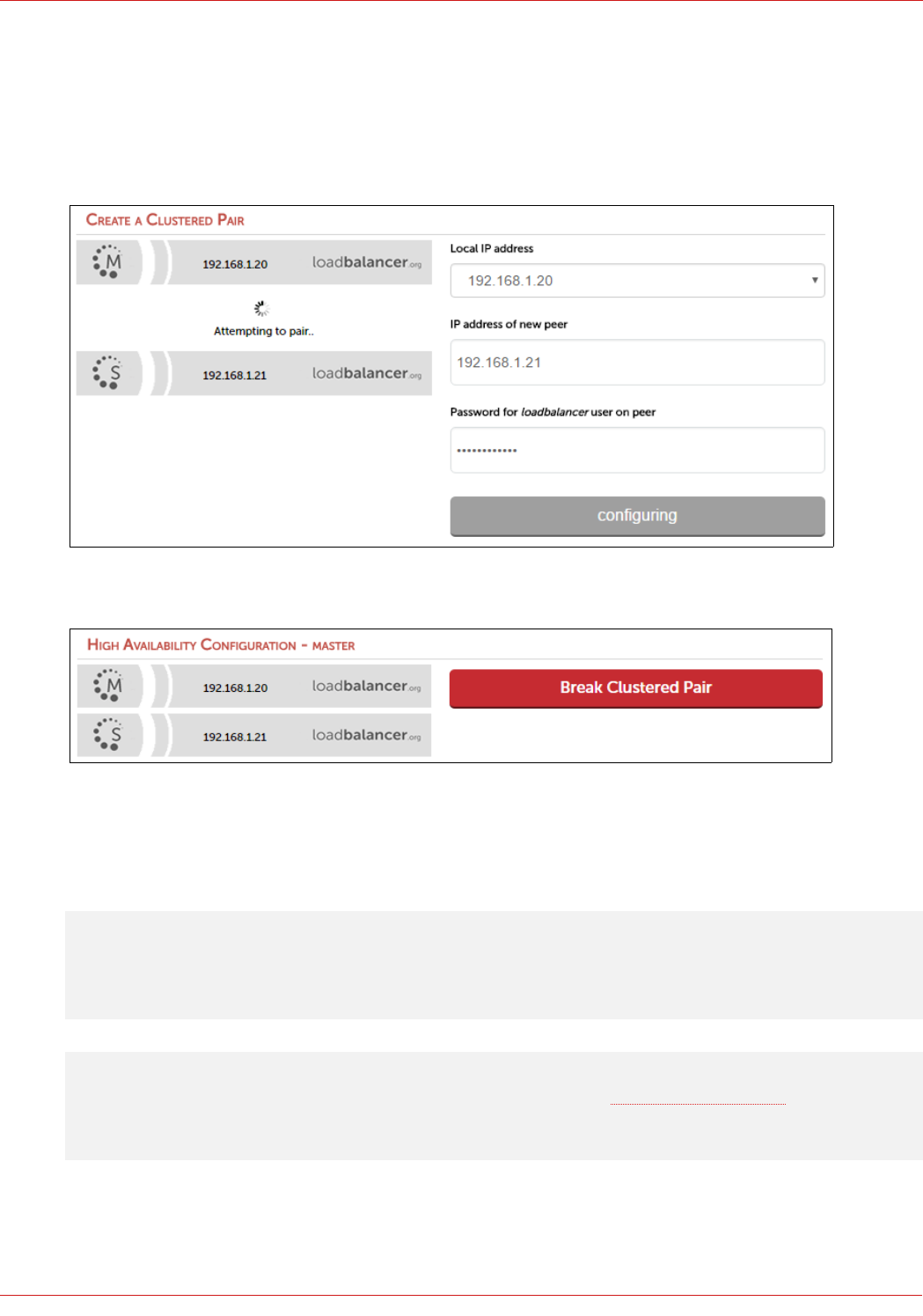
• Specify the IP address and the loadbalancer users password (the default is 'loadbalancer') for the slave (peer)
appliance as shown above
• Click Add new node
• The pairing process now commences as shown below:
• Once complete, the following will be displayed:
• To finalize the configuration, restart heartbeat and any other services as prompted in the blue message box at
the top of the screen
Note: Clicking the Restart Heartbeat button on the master appliance will also automatically restart
heartbeat on the slave appliance.
Note: Please refer to chapter 9 – Appliance Clustering for HA in the Administration Manual for more
detailed information on configuring HA with 2 appliances.
60
© Copyright Loadbalancer.org • www.loadbalancer.org • sales@loadbalancer.org
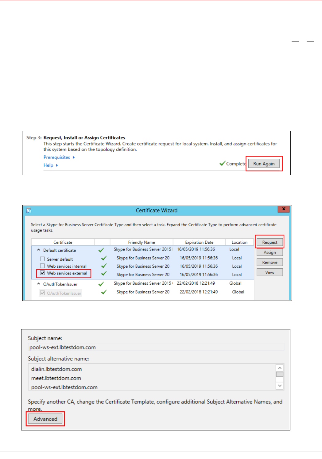
2 – Configuring a Loadbalancer.org Appliance as a Reverse Proxy
A Loadbalancer.org appliance can be configured as a Reverse Proxy. This can be achieved either by defining VIPs on a
separate dedicated appliance, or on the appliance in the DMZ (LB2). These scenarios are illustrated on page 27 & 28.
In both cases a public certificate is required for the External Web Services. One of the Front End Servers can be used to
generate a CSR (which includes the Director Server SAN requirements), the signed certificate from the CA is then
imported into the Front End Server. This certificate along with the Private Key is then exported as a PFX certificate
ready for import into the load balancer.
Generating The CSR & SSL Certificate
1. On one of the Front End Servers open the Skype for Business Deployment Wizard
2. Click Run Again under Step 3: Request, Install or Assign Certificates
3. Select Web services external as shown below, then click Request
4. Enter the appropriate details on the Certificate Request screen, then click Advanced
61
© Copyright Loadbalancer.org • www.loadbalancer.org • sales@loadbalancer.org
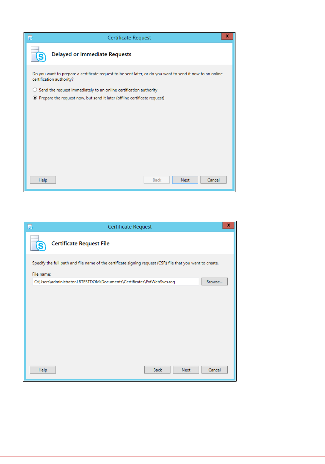
5. Select the Prepare the Request now, but send it later (offline certificate request) option
6. Click Next
7. Enter a appropriate path and name for the CSR
8. Click Next
9. Click Next on the Specify Alternate Certificate Template screen
62
© Copyright Loadbalancer.org • www.loadbalancer.org • sales@loadbalancer.org
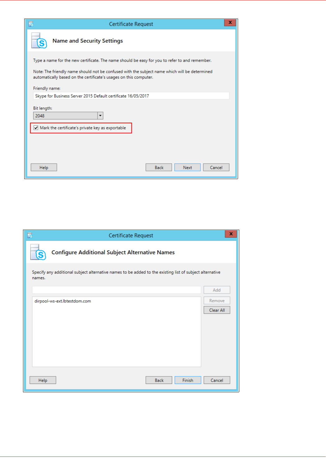
10. Ensure that Mark the certificate's private key as exportable is checked
11. Click Next
12. Add the FQDN for the Director Pool External Web Services as an additional SAN (if applicable)
13. Click Finish
14. At the Certificate Request main screen click Next
63
© Copyright Loadbalancer.org • www.loadbalancer.org • sales@loadbalancer.org
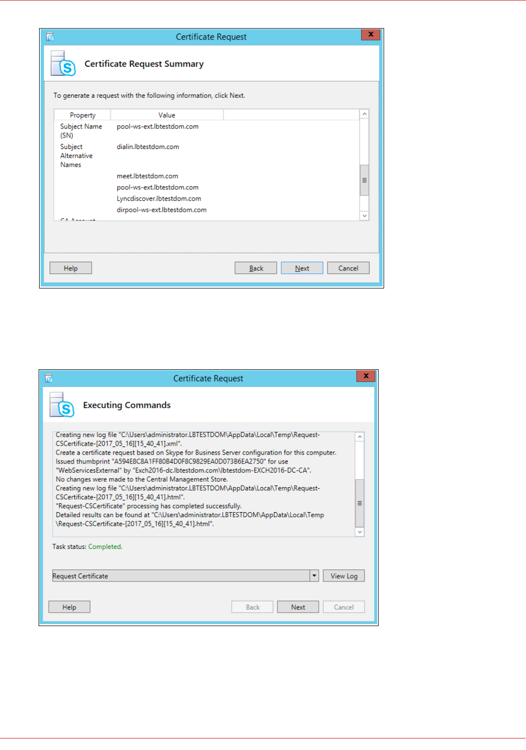
15. Verify the details in the Certificate Request Summary screen
16. Click Next
17. The green Completed task status message will be displayed if the process is successful
18. Click Next
19. The CSR will now be saved in the location specified previously
20. Click View or open the file and copy/paste the text into your chosen CA's request form
64
© Copyright Loadbalancer.org • www.loadbalancer.org • sales@loadbalancer.org
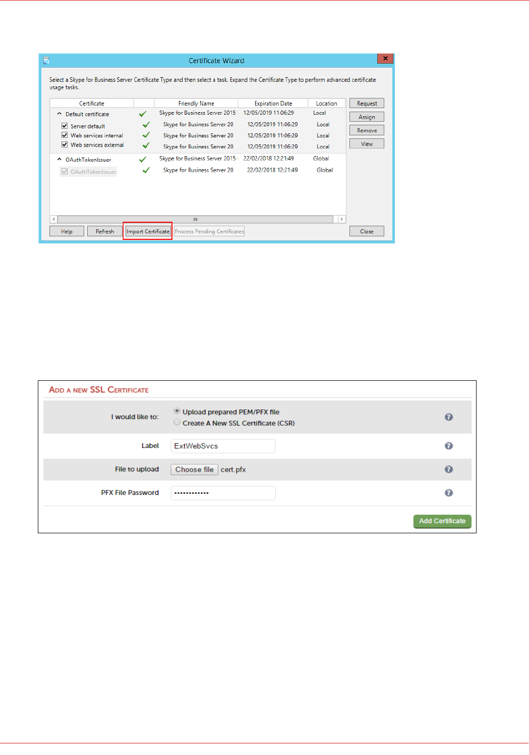
21. Once the certificate is received from the CA, return to the Certificate Wizard main screen
22. Click Import Certificate
23. Specify the location of the certificate, click Next to complete the import
24. Finally export the certificate and private key in pfx format ready for import into the appliance
Importing The Certificate Into The Load Balancer
1. Using the WebUI, navigate to: Cluster Configuration > SSL Certificate
2. Enter a suitable Label , e.g. ExtWebSvcs
3. Browse to and select the .pfx certificate file
4. Enter the password
5. Click Add Certificate
Appliance Network Configuration
If an additional appliance is used as the Reverse Proxy, you can use a one-arm or two-arm configuration depending on
your network topology. Any appliance interface can be used, but typically eth0 would be used for a one-arm deployment
and eth0 & eth1 would be used for a two-arm deployment.
65
© Copyright Loadbalancer.org • www.loadbalancer.org • sales@loadbalancer.org
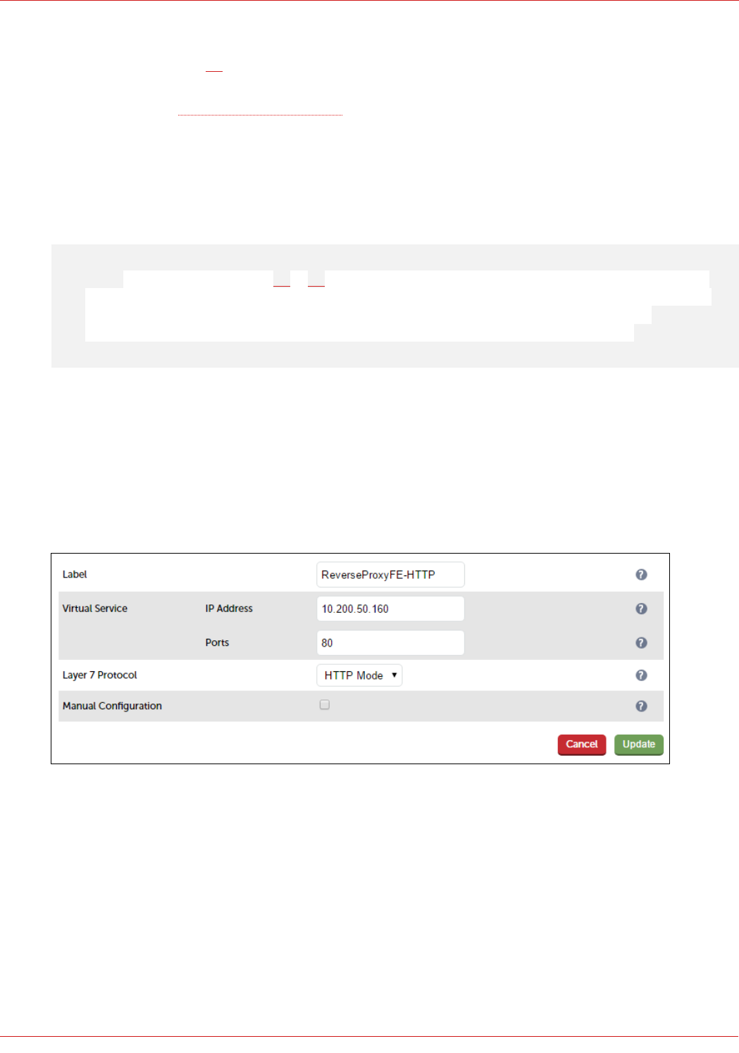
If the load balancer in the DMZ (LB2 in this guide) will also be used as a Reverse Proxy, a second interface must be
configured as illustrated on page 28. VLANs can then be defined to isolate and secure the traffic.
In addition, depending on your network topology, the appliance's routing configuration may need to be changed to prevent
DMZ bridging. Please contact support@loadbalancer.org for assistance
Configuring Reverse Proxy VIPs & RIPs
This example shows Reverse Proxy VIPs & RIPs for the Front End Server External Web Services. VIPs & RIPs for the
External Director Web Services should be defined in a similar way if these are also required.
Note: As mentioned on pages 27 & 28, the Loadbalancer.org Reverse Proxy can either send traffic to
LB1 and then on to the Front End Servers, or directly to the Front End Servers. OPTION 1 below shows
traffic being forwarded to the 2 x External Web Services VIPs on LB1 (FePoolWsExt8080 &
FePoolWsExt4443), OPTION 2 shows traffic being sent directly to the Front End Servers.
OPTION 1 – Forward Traffic to the VIPs on LB1 (i.e. FePoolWsExt8080 & FePoolWsExt4443)
Create the HTTP VIP:
1. Using the WebUI, navigate to: Cluster Configuration > Layer 7 – Virtual Service and click Add a New Virtual
Service
2. Enter the following details:
3. Enter an appropriate label for the VIP, e.g. ReverseProxyFE-HTTP
4. Set the Virtual Service IP address field to the required IP address, e.g. 10.200.50.160
5. Set the Virtual Service Ports field to 80
6. Set Layer 7 Protocol to HTTP Mode
7. Click Update
8. Now click Modify next to the newly created VIP
9. Change Persistence Mode to None
10. Click Update
66
© Copyright Loadbalancer.org • www.loadbalancer.org • sales@loadbalancer.org
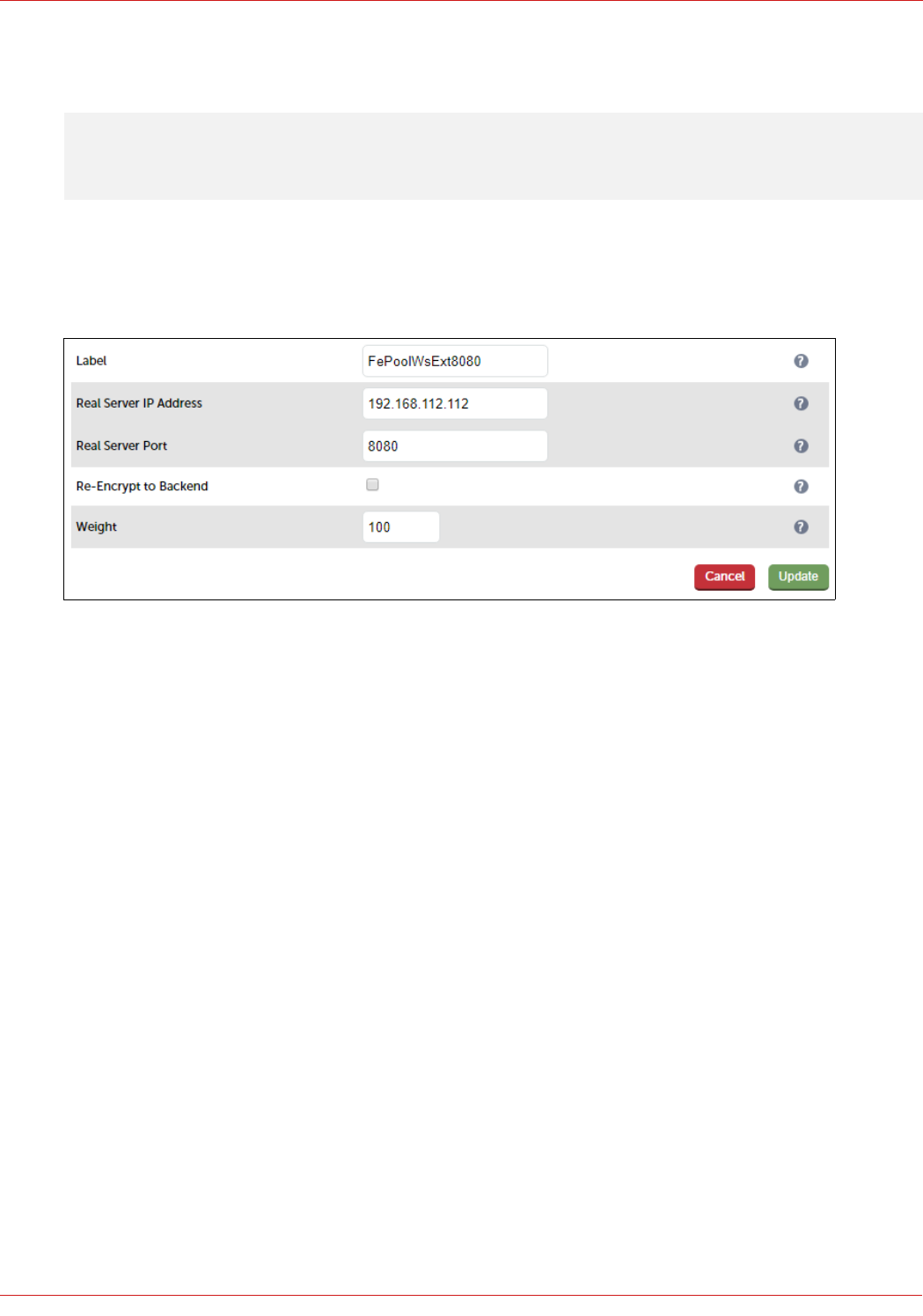
Define the Real Server for the VIP just created:
Note: In this scenario, there is only one RIP – the VIP FePoolWsExt8080 on LB1.
1. Using the WebUI, navigate to: Cluster Configuration > Layer 7 – Real Servers and click Add a new Real Server
next to the newly created VIP
2. Enter the following details:
3. Enter an appropriate label for the RIP, e.g. FePoolWsExt8080
4. Change the Real Server IP Address field to the required IP address, e.g. 192.168.112.112 (this is the IP address
for the FePoolWsExt8080 VIP on LB1, only this single RIP needs to be defined)
5. Set the Real Server Port field to 8080
6. Leave Layer 7 Protocol set to HTTP Mode
7. Click Update
Create the SSL Termination VIP using the newly Uploaded Certificate
1. Using the WebUI, navigate to: Cluster Configuration > SSL Termination and click Add a New Virtual Service
2. Enter the following details:
67
© Copyright Loadbalancer.org • www.loadbalancer.org • sales@loadbalancer.org
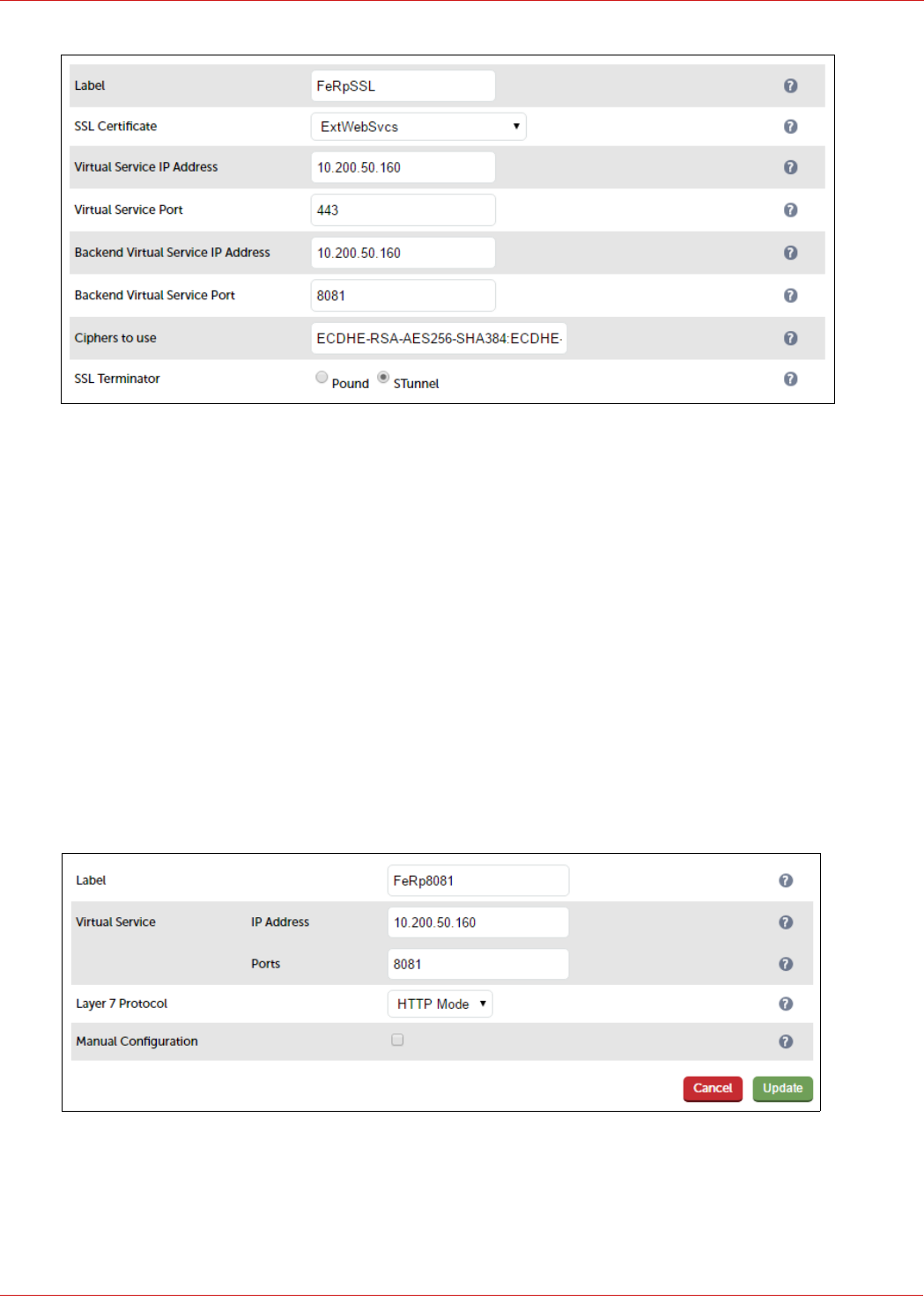
3. Enter an appropriate label for the VIP, e.g. FeRpSSL
4. Select the Certificate uploaded previously – ExtWebSvcs
5. Set the Virtual Service IP address field to the required IP address, e.g. 10.200.50.160
6. Set the Virtual Service Ports field to 443
7. Set the Backend Virtual Service IP address field to the required IP address, e.g. 10.200.50.160
8. Set the Backend Virtual Service Ports field to 8081 (this can be any suitable free port, the Backend Virtual
Service (created below) listens on this port)
9. Click Update
Create the SSL Backend VIP
1. Using the WebUI, navigate to: Cluster Configuration > Layer 7 – Virtual Service and click Add a New Virtual
Service
2. Enter the following details:
3. Enter an appropriate label for the VIP, e.g. FeRp8081
4. Set the Virtual Service IP address field to the required IP address, e.g. 10.200.50.160
5. Set the Virtual Service Ports field to 8081
68
© Copyright Loadbalancer.org • www.loadbalancer.org • sales@loadbalancer.org
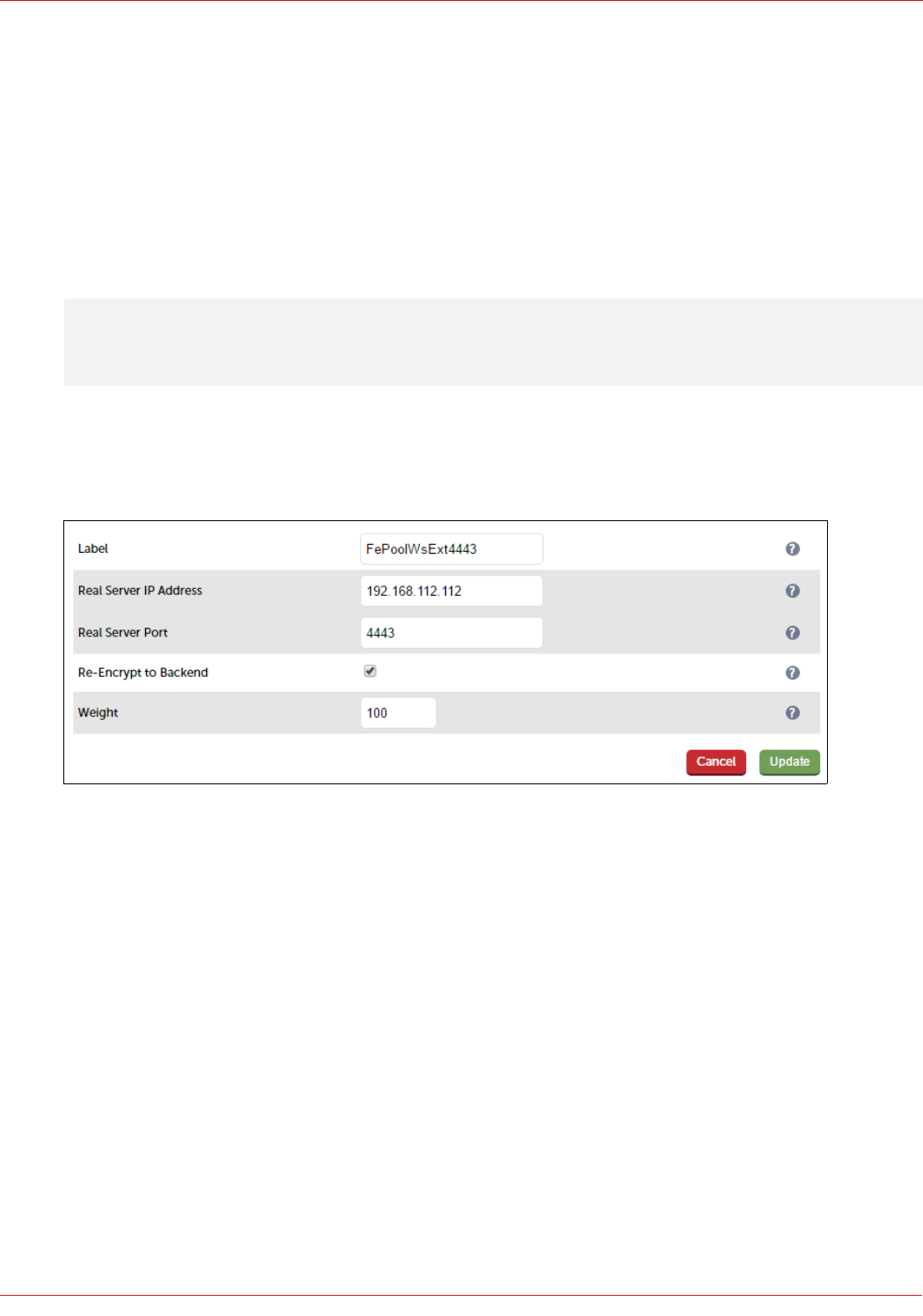
6. Set Layer 7 Protocol to HTTP Mode
7. Click Update
8. Now click Modify next to the newly created VIP
9. Change Persistence Mode to None
10. Click Update
Define the Real Server for the VIP just created:
Note: In this scenario, there is only one RIP – VIP FePoolWsExt4443 on LB1.
1. Using the WebUI, navigate to: Cluster Configuration > Layer 7 – Real Servers and click Add a new Real Server
next to the newly created VIP
2. Enter the following details:
3. Enter an appropriate label for the RIP, e.g. FePoolWsExt4443
4. Change the Real Server IP Address field to the required IP address, e.g. 192.168.112.112 (this is the IP address
for the FePoolWsExt4443 VIP on LB1, only this single RIP needs to be defined)
5. Set the Real Server Port field to 4443
6. Enable (tick) the Re-Encrypt to Backend check box
7. Click Update
OPTION 2 – Forward Traffic Directly to the Front End Servers
Create the HTTP VIP:
11. Using the WebUI, navigate to: Cluster Configuration > Layer 7 – Virtual Service and click Add a New Virtual
Service
12. Enter the following details:
69
© Copyright Loadbalancer.org • www.loadbalancer.org • sales@loadbalancer.org
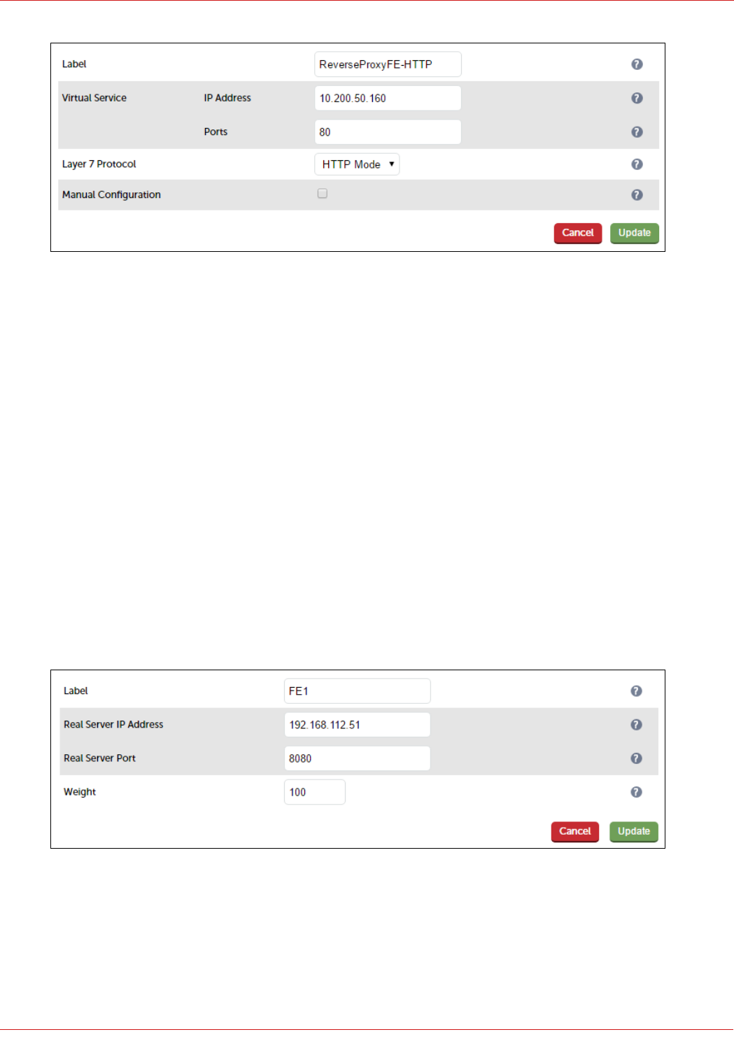
13. Enter an appropriate label for the VIP, e.g. ReverseProxyFE-HTTP
14. Set the Virtual Service IP address field to the required IP address, e.g. 10.200.50.160
15. Set the Virtual Service Ports field to 80
16. Set Layer 7 Protocol to HTTP Mode
17. Click Update
18. Now click Modify next to the newly created VIP
19. Change Persistence Mode to None
20. In the Health Checks section, click Advanced to expand the section
21. Set Check Port to 5061
22. Click Update
Define the Real Server for the VIP just created:
1. Using the WebUI, navigate to: Cluster Configuration > Layer 7 – Real Servers and click Add a new Real Server
next to the newly created VIP
2. Enter the following details:
3. Enter an appropriate label for the RIP, e.g. FE1
4. Change the Real Server IP Address field to the required IP address, e.g. 192.168.112.51
5. Set the Real Server Port field to 8080
6. Click Update
70
© Copyright Loadbalancer.org • www.loadbalancer.org • sales@loadbalancer.org
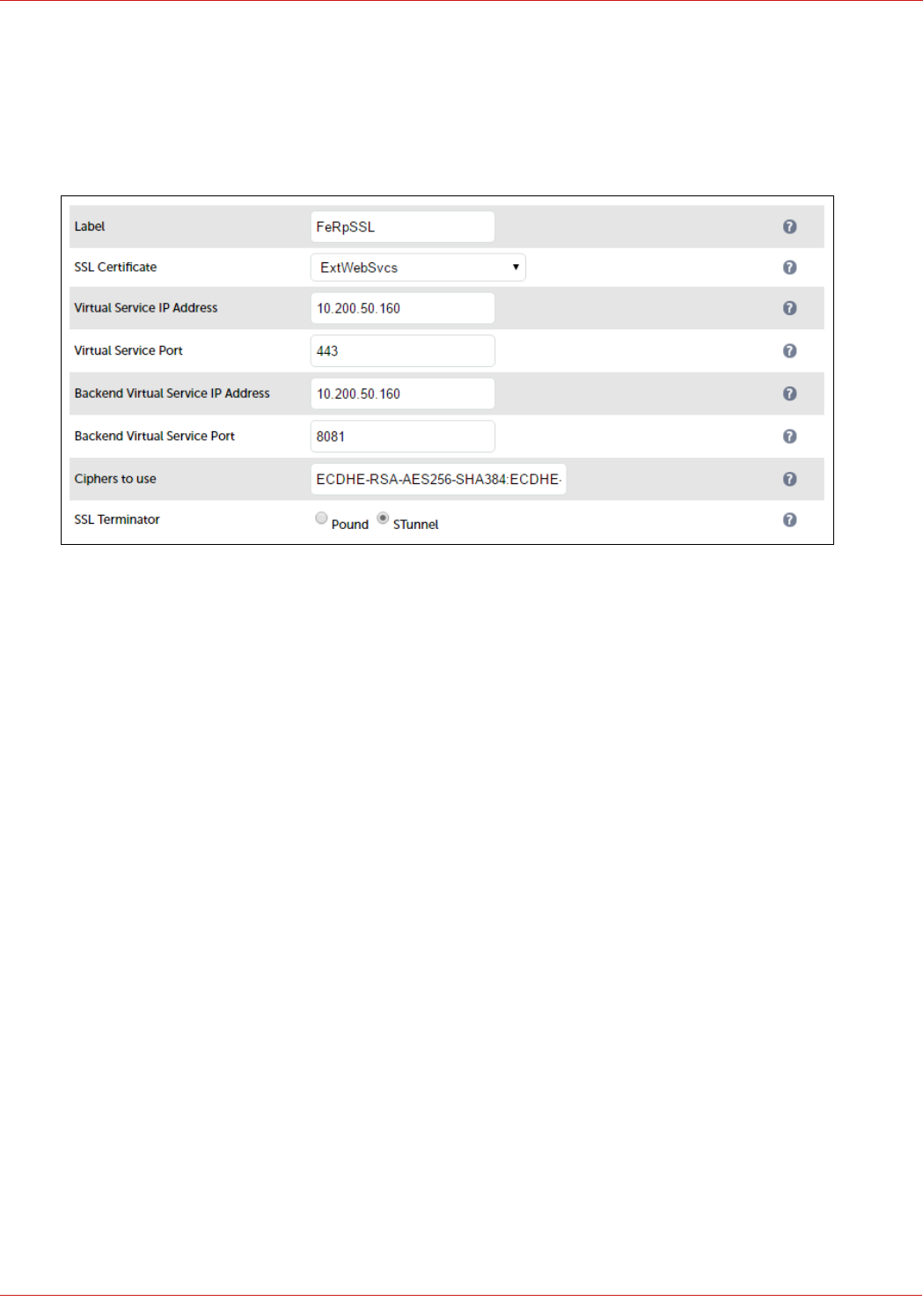
7. Repeat for your other Front End Server(s)
Create the SSL Termination VIP using the newly Uploaded Certificate
1. Using the WebUI, navigate to: Cluster Configuration > SSL Termination and click Add a New Virtual Service
2. Enter the following details:
3. Enter an appropriate label for the VIP, e.g. FeRpSSL
4. Select the Certificate uploaded previously – ExtWebSvcs
5. Set the Virtual Service IP address field to the required IP address, e.g. 10.200.50.160
6. Set the Virtual Service Ports field to 443
7. Set the Backend Virtual Service IP address field to the required IP address, e.g. 10.200.50.160
8. Set the Backend Virtual Service Ports field to 8081 (this can be any suitable free port, the Backend Virtual
Service (created below) listens on this port)
9. Click Update
Create the SSL Backend VIP
1. Using the WebUI, navigate to: Cluster Configuration > Layer 7 – Virtual Service and click Add a New Virtual
Service
2. Enter the following details:
71
© Copyright Loadbalancer.org • www.loadbalancer.org • sales@loadbalancer.org
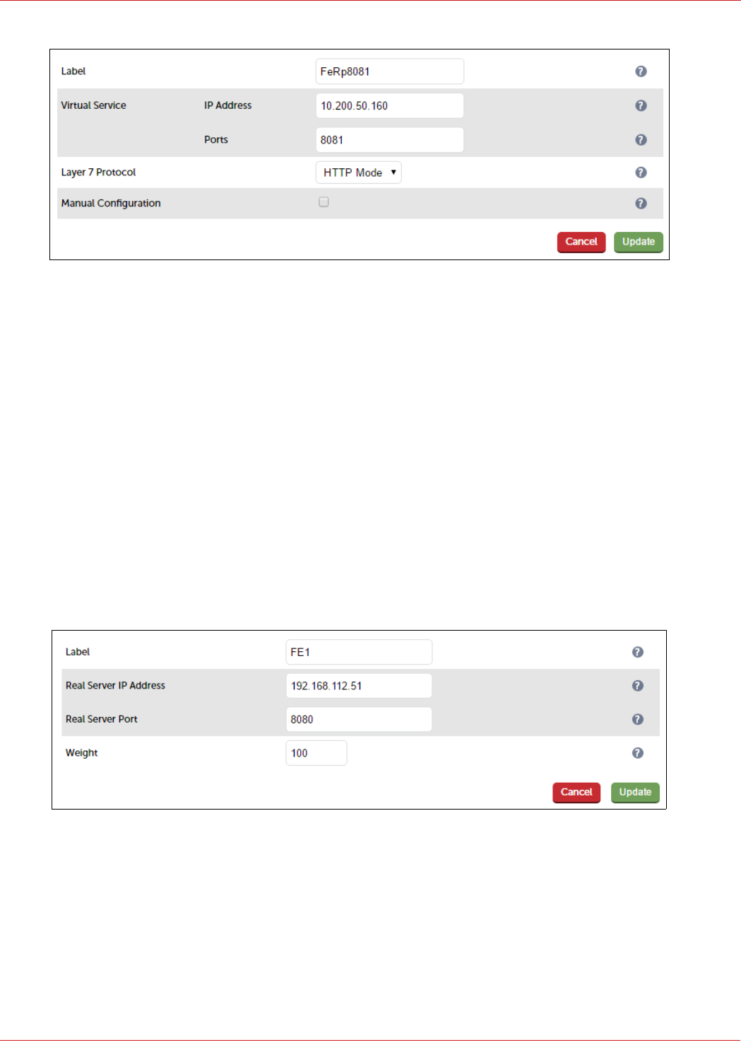
3. Enter an appropriate label for the VIP, e.g. FeRp8081
4. Set the Virtual Service IP address field to the required IP address, e.g. 10.200.50.160
5. Set the Virtual Service Ports field to 8081
6. Set Layer 7 Protocol to HTTP Mode
7. Click Update
8. Now click Modify next to the newly created VIP
9. Change Persistence Mode to None
10. Click Update
Define the Real Server for the VIP just created:
1. Using the WebUI, navigate to: Cluster Configuration > Layer 7 – Real Servers and click Add a new Real Server
next to the newly created VIP
2. Enter the following details:
3. Enter an appropriate label for the RIP, e.g. FE1
4. Change the Real Server IP Address field to the required IP address, e.g. 192.168.112.51
5. Set the Real Server Port field to 4443
6. Enable (tick) the Re-Encrypt to Backend check box
7. Click Update
8. Repeat the above steps to add your other Front End Server(s)
72
© Copyright Loadbalancer.org • www.loadbalancer.org • sales@loadbalancer.org

23.Document Revision History
Version Date Change Reason for Change Changed By
1.1.0 17 October 2019 Styling and layout General styling updates RJC
1.1.1 15 July 2020 New title page
Updated Canadian contact
details
Revised instructions for setting
source address and health
check port settings
Branding update
Change to Canadian contact
details
Changes to the appliance WebUI
AH
1.1.2 26 August 2020 Amended instructions for
configuring persistence settings
Changes to the appliance WebUI AH
73
© Copyright Loadbalancer.org • www.loadbalancer.org • sales@loadbalancer.org

About Loadbalancer.org
Loadbalancer.org’s mission is to ensure that its clients’ businesses are never interrupted. The load balancer
experts ask the right questions to get to the heart of what matters, bringing a depth of understanding to each
deployment. Experience enables Loadbalancer.org engineers to design less complex, unbreakable solutions - and
to provide exceptional personalized support.
United Kingdom
Loadbalancer.org Ltd.
Compass House, North Harbour
Business Park, Portsmouth, PO6 4PS
UK:+44 (0) 330 380 1064
sales@loadbalancer.org
support@loadbalancer.org
Canada
Loadbalancer.org Appliances Ltd.
300-422 Richards Street, Vancouver,
BC, V6B 2Z4, Canada
TEL:+1 866 998 0508
sales@loadbalancer.org
support@loadbalancer.org
United States
Loadbalancer.org, Inc.
4550 Linden Hill Road, Suite 201
Wilmington, DE 19808, USA
TEL: +1 833.274.2566
sales@loadbalancer.org
support@loadbalancer.org
Germany
Loadbalancer.org GmbH
Tengstraße 2780798,
München, Germany
TEL: +49 (0)89 2000 2179
sales@loadbalancer.org
support@loadbalancer.org
© Copyright Loadbalancer.org • www.loadbalancer.org
