
1 | Diamond Kote Building Products Application Guide 6.18
IMPORTANT:
PLEASE READ BEFORE YOU BEGIN
INSTALLATION. Before installing any
projects with Diamond Kote Building
Products, it is highly recommended the
entire installation guide is reviewed.
INDEX:
02 PRIOR TO INSTALL
02 GENERAL GUIDELINES
03
INSULATED SHEATHINGS
03 MOISTURE
03 WEATHER-RESISTANT BARRIER
04 STUD SPACING
04 GAPS + SEALANTS
04 TOUCH-UP PAINT GUIDELINES
04-05 TRIM
06 FLASHING, WINDOW
S, DOORS
& OPENINGS
07 WHERE TO FASTEN
07-08 ALTERNATIVE FASTENING
09-10 RIGIDMOUNT APPLICATION
11 PRO-POST WRAP
12
KICK-OUT & SPACER FLASHING
13 BRICK LEDGE FLASHING
14 TRADITIONAL LAP APPLICATION
15-16 RIGIDSTACK APPLICATION
17
RIGIDSHAKE | STRAIGHT EDGE
APPLICATION
18
RIGIDSHAKE | STAGGERED EDGE
APPLICATION
19 OCTAGON + SCALLOPS
20 OCTAGON APPLICATION
21 SCALLOP APPLICATION
22-23
OUTSIDE + INSIDE CORNER
APPLICATION
24-25
NAIL FIN TRIM APPLICATION
26 ARCH TRIM
26 ROSETTES
27-30 BOARD + BATTEN APPLICATION
31-32 VERTICAL SIDING APPLICA
TION
33-34 LAP INSTALLED VERTICALLY
34-36 FASCIA APPLICATION
3
6-38 SOFFIT APPLICATION
APPLICATION GUIDE
Click on the chapter heading to go directly to a
specic section.

2 | Diamond Kote Building Products Application Guide 6.18
PRIOR TO INSTALLATION
• Inspect product for any issues before
installing. (breakage, surface defects,
foreign objects, color inconsistency or
color correctness)
• Do not install questionable product.
• Report any problems you may have to
your dealer BEFORE installing.
STORAGE
It is important to properly store all Diamond
Kote
®
products for protection.
• Store siding at on a dry, clean and well
supported surface. Protect material from
direct exposure to weather.
• Do not store directly on the ground.
• Diamond Kote
®
4-Packs and 2-Packs
are not waterproof. All products must be
kept dry and covered at all times.
• Product may come in long, heavy
sections, which requires proper handling.
• Carry shrinkwrapped bundles to
desired location before opening to
avoid damaging the painted surface.
• Don't carry in a at position.
• Pick up product from the center to avoid
marring the surface of items below.
• Only carry multiple pieces of siding:
face-to-face or back-to-back.
• Do not slide pre-nished siding material
across each other.
• Support the product when you cut large
pieces.
• Sealed product could become saturated
if not protected during storage.
• If the product becomes saturated, do not
install until it dries out completely.
GENERAL GUIDELINES
**Note: DO NOT USE STAPLES.
Minimum 6" clearance must be maintained
between siding and nish grade.
• Siding applied adjacent to porches,
patios, walks, roof lines, etc. must have a
1" clearance above any surface.
• 3/8" clearance should be left between
siding and horizontal ashings.
• All exposed wood substrate must be
primed and painted to prevent moisture
intrusion and water buildup.
• Best practice for blind or exposed nailing
is to use only 316 stainless steel nails
within 15 miles of the seacoast. Beyond
15 miles, either 304 stainless steel or
hot-dipped galvanized is acceptable.
• See Alternate Fastening Options for
fastening lap siding to SIP, ICF and Steel
Frame assemblies.
(PG 10)
• Adequate drying time must be allowed
prior to enclosing the wall cavity when
using wet blown cellulose insulation.
• With wet blown cellulose insulation, the
insulation must not be in direct contact
with the siding and it will need time to
dry, a minimum of 24 hours or longer if
specied by the insulation manufacturer.
• Diamond Kote
®
Building Products should
be cut in a manner to avoid marring the
nished face.
• It is recommended to face the board up
when using a combination blade power
miter saw.
• Do NOT force or spring siding into place.
Where siding butts window trim, door
casing, masonry, etc., leave a 3/16" gap
and caulk. DO NOT caulk butt joints.
• Seal all gaps with a paintable sealant
that meets ASTM-C92
0 Specication,
it is recommended to use DAP SpecLine
92
0.
• Use drip-cap ashing above all
horizontal trim to ensure a weather-
tight installation. 1" drip cap is available
in all Diamond Kote colors.
STORE UNDERCOVER
PROPER HANDLING

3 | Diamond Kote Building Products Application Guide 6.18
INSULATED SHEATHINGS
Diamond Kote
®
Building Products may be
installed over low-compression rigid foam
or exterior gypsum sheathings.
The following precautions must be followed:
• Nailable structural sheathing must be
behind the insulated sheathing.
• Make sure to brace the wall accordingly
to the required international and other
building codes.
• For rigid foam sheathing up to 1" thick,
siding may be nailed directly to the foam
sheathing unless a drainage plane is
required by the local building code. Nail
length must be increased to ensure a
minimum 1-1/2" fastener penetration
into the structural framing.
Note: Diamond Kote
®
Building Products
may also be installed in compliance with
category 8140-Exterior wall siding and
sheathing for Wildland Urban Interface
applications atop LP
®
FlameBlock
®
sheathing. Refer to FlameBlock
®
installation
instructions and product data sheets.
All Diamond Kote
®
Building Products may
be installed as exterior siding in Wildland
Urban Interface applications. It can be
installed over one layer 5/8" Type X gypsum
sheathing applied behind the exterior
covering or cladding on the exterior side of
the framing. They may also be installed over
the exterior portion of a 1-hour re-resistive
exterior wall that has been assembly
designed for exterior re exposure which
also includes assemblies using the gypsum
panel and sheathing products listed in the
Gypsum Association Fire Resistance Design
Manual.
• For rigid foam sheathing that is greater
than 1", a minimum 1-1/2" thick by
3-1/2" wide vertical strapping or furring
strip must be installed over the sheathing
to provide a solid, level nailing base
for the siding. The strapping must be
securely fastened to structural framing
spaced no greater than 16" o.c. with a
minimum fastener penetration of 1-1/2".
• Diamond Kote
®
Building Products will not
assume any responsibility for conditions
arising from the use of foam sheathing or
damage.
MOISTURE
• Moisture and vapor control are critical
elements of proper housing design.
• Check local building codes for application
procedures for handling moisture and
moisture vapor in your area.
• Do not apply engineered wood siding to
a structure having excessive moisture
conditions such as drying concrete or
plaster or wet blown cellulose insulation.
• If conditions exist, the building should be
well ventilated to ensure the substrate is
completely dry prior to siding.
• Siding must not be applied to any green
or crooked structural framing members.
• Do not apply siding over rain-soaked or
buckled sheathing materials.
• We recommend protection for your
home from rainfall with gutters and
downspouts. Always be sure that your
drainage system is free of debris and
working properly.
WEATHER-RESISTANT BARRIER
• It is required to have a water-resistant,
properly breathable barrier behind the
siding.
• When integrating ashing with a water-
resistive barrier (WRB), be sure to follow
the WRB installation instructions.
• Diamond Kote
®
Building Products will
not assume responsibility for water
penetration.
• Consult local building codes for more
details.
TRIM & FASCIA 190, 440, 540 & 2000 SERIES
INSTALLATION
• Trim ends may lightly touch adjacent trim edges around windows and doors only. Re-prime and paint all cut ends.
• When installing trim around windows and over window anges, be sure to follow the window manufacturer’s installation
instructions.
• All openings must be properly sealed and ashed in a manner that prevents moisture intrusion or buildup. Flashing may be
sealed to the water-resistive barrier by using adhesive ashing or housewrap tape. (See ALL diagrams)
• When trim is installed adjoining vinyl siding, install Z-ashing with a 4 inch upper leg between horizontal trim and J-channel.
(See diagram 8a)
• Horizontal trim or bands shall be ashed with a sloped metal Z-ashing to redirect water away from the wall assembly.
GENERAL REQUIREMENTS (CONTINUED)
7a
7b
Windows, Doors and Openings
7c
7d
7e
LP SmartSide Trim & Fascia
7
Housewrap
Flap
Head
Flashing
Jamb
Flashing
Sill
Flashing
Window
Flashing
Housewrap
Tape

4 | Diamond Kote Building Products Application Guide 6.18
STUD AND SPACING
• Diamond Kote
®
Building Products must
be applied over sheathed walls into studs
spaced no greater than 16" on center.
• When installing over masonry walls,
the wall must be furred out with wood
framing spaced 16" on center and with
a adequate thickness to accept the full
length of the recommended nail.
GAPS AND SEALANTS
Note: DO NOT apply sealant to butt joints.
• Seal all gaps with a paintable sealant
that meets ASTM C92
0 Specication.
• We recommend the DAP
®
Spec Line 920
Check out the application instructions
for the manufactured sealant or view
our
Proper Caulking Techniques Video.
TOUCH-UP PAINT GUIDELINES
Before starting, read all label instructions
and warnings. Diamond Kote
®
touch-up
paint is intended for use on Diamond Kote
®
pre-nished products only. We cannot
guarantee the performance of Diamond
Kote
®
touch-up paint on products not
originally pre-nished with Diamond Kote
®
.
Only apply paint to bare area. DO NOT
APPLY PAINT OVER PAINT. *Do not allow
touch-up paint to freeze. Keep container
from freezing.*
For Touch- Up Paint, please do the following:
• Paint all exposed cut edges of siding
surfaces including drip edges.
• Apply a small amount of touch-up paint
using the provided foam brush to seal all
cut edges.
• Avoid getting touch-up paint on the face
of the boards and try not to apply more
paint than what is needed.
• Thoroughly paint all the bottom edges of
siding especially the cut ends next to the
roof line. Touch-up paint all exposed face
nails.
• Cotton swabs are recommended for
touch-up painting on the nished face of
products.
• Follow the Diamond Kote
®
application/
maintenance instructions and/or watch
the Diamond Kote Touch-Up Paint Best
Practices Video.
PAINT CARE
• Stir touch-up paint for ten minutes
before use. Heavier pigments in the paint
settle to the bottom requiring the paint
to be thoroughly mixed before use and
cleaned up with water after.
SURFACE PREP
• Surface must be clean and dry. Test the
color on a sample piece or hidden area of
the siding/trim before applying. Do NOT
fan out or try to blend the paint.
• Allow 24 hours dry time. Touch up nail
heads or small imperfections by using a
cotton swab to dot the desired area.
TRIM
• Trim should be thick enough so the
siding does not extend beyond the face
of the trim.
• Trim and fascia are not designed for
siding/structural applications. It should
not be used as a structural member in
construction (trellis, railing, fencing,
decking, decking trim or sills.)
• Trim must be applied so it will not allow
moisture intrusion or water buildup.
• LP
®
Lap and Panel siding is not designed
and/or manufactured to be used as trim
or fascia. LP
®
SmartSide
®
trim and fascia
are available in a variety of dimensions.
CONTINUED ON NEXT PAGE
5 | Diamond Kote Building Products Application Guide 6.18
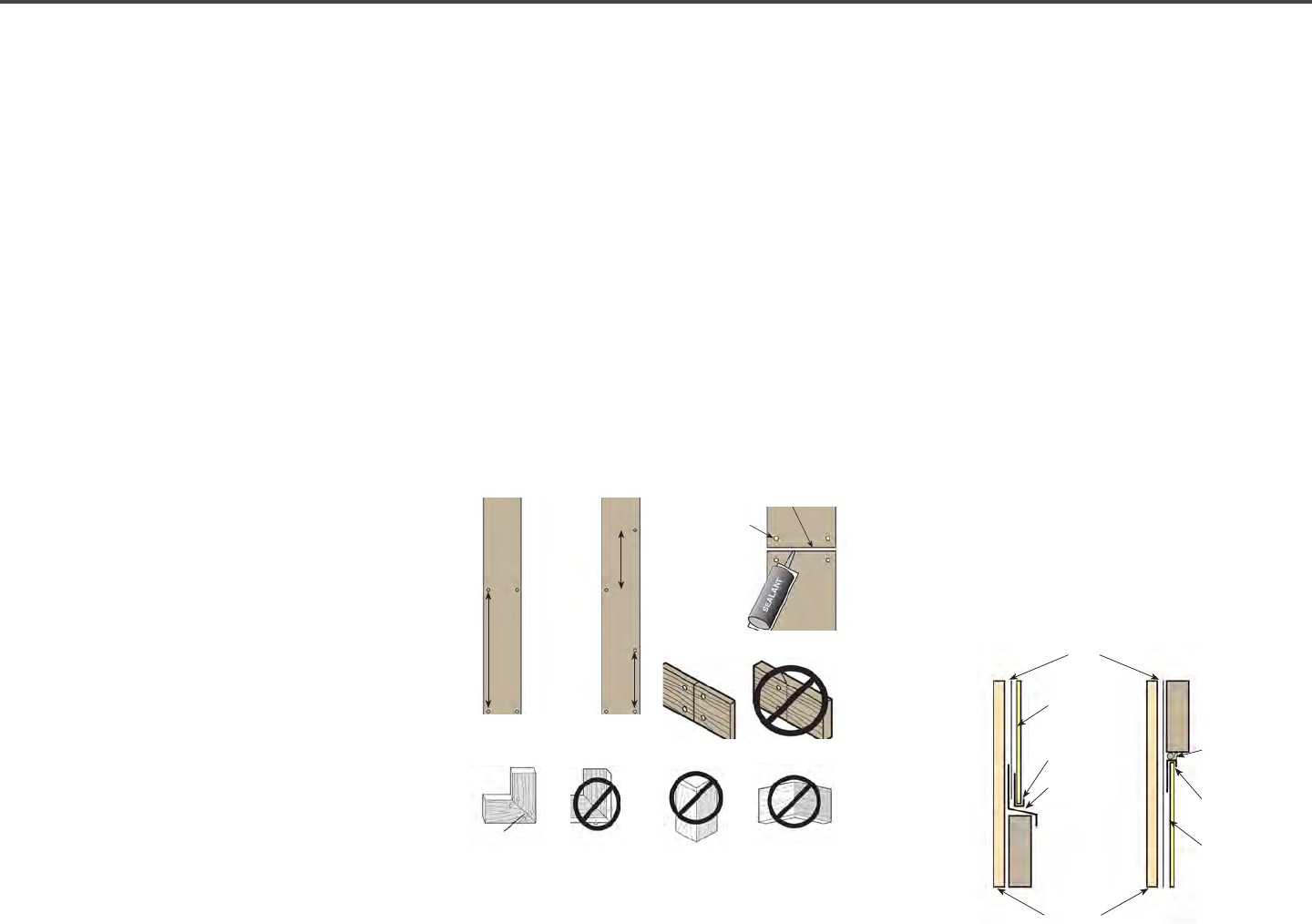
TRIM | FASTENER INFORMATION
• Fastener length: Long enough to fully
penetrate structural framing or wood
structural panels and structural framing
a minimum of 1".
• Fastener placement: 3/8" from ends and
edges, when framing support allows.
• Fastener spacing: Must be fastened with
two nails at both ends, with additional
fasteners spaced a maximum of 24
inches o.c. along the length of the board,
or with additional fasteners spaced a
max. of 12 inches o.c. along alternating
edges the length of the board.
• Fastener quantity: For trim under 7
inches wide use a minimum of 2 nails per
width. For trim 7 to 12 inches wide use
a minimum of 3 nails per width. For trim
over 12 inches wide use a minimum of 4
nails per width.
• Where edges of trim meet siding material,
windows, etc., leave a min. 3/16 inch
space to allow for proper sealing.
Provide increased spacing along the
trim if specied by the siding application
instructions.
CUTTING
• A ne-tooth carbide tipped blade is
recommended for the cleanest cut.
• Trim and fascia are manufactured with
a special edge coating which reduces
moisture-related issues.
• Don't rip and/or route the trim and fascia,
as it will leave the edges unprotected.
• If the trim/fascia materials are ripped
you must take special care to prime,
paint and seal all exposed wood ber as
described in the nishing section.
• Do not miter trim ends or edges. 45
degree diagonal cuts of trim ends around
door and window opening is acceptable,
as well as joining.
(See below)
BUTT JOINTS FOR TRIM
• Ends and butt joints require a 3/16 inch
space and seal with a high quality non-
hardening paintable long-life sealant.
Joints may lightly touch around windows
and doors only.
• Butt joints require 4 nails with 2 nails on
either side of the joint at each edge.
TRIM ADJOINING WITH OTHER MATERIALS
• Trim with Stucco, Brick or Cultured Stone:
it is important to use a capillary break so
moisture absorbed into the stucco, brick
/cultured stone can not transfer into the
trim. Avoid direct contact between the
trim and stucco, brick or cultured stone.
• Separate with a min. 3/8-inch space
and a high-quality sealant
(backer rod may
be required as per the sealant manufacturers
instructions). Additional space may be
required by the manufacturer of the
stucco, brick or cultured stone cladding.
• Other types of material like aluminum
ashing can be used to separate the
trim from the stucco, brick or cultured
stone but dissimilar materials should be
properly spaced to allow for dierent
rates of thermal or moisture movement.
• Apply sloped Z-ashing over horizontal
trim so water can be redirected to the
outer surface of the wall.
TRIM & FASCIA 190, 440, 540 & 2000 SERIES
INSTALLATION
LP SmartSide Trim Adjoining Vinyl Siding:
• Install vinyl siding meeting standards of manufacturers
installation instructions and/or the Vinyl Siding Instutute’s
Manual.
• Horizontally adjoined trim and vinyl J-channel or utility trim:
Install sloped Z-ashing with a minimum 4 inch upper leg.
(See diagram 8a)
• Vertically adjoined trim and vinyl J-channel - J-channel should t
snug to trim.
• Do not caulk between trim and J-channel or utility trim.
• Install the trim according to the LP SmartSide Trim and Fascia
application instructions.
GENERAL REQUIREMENTS (CONTINUED)
LP® SmartSide® Trim Adjoining Other Materials
8a
8b
LP SmartSide Trim Adjoining Stucco, Brick or Cultured Stone:
When using LP SmartSide trim with stucco, brick or cultured stone,
it is important to use a capillary break so moisture absorbed into
the stucco, brick or cultured stone cannot transfer into the trim.
• Avoid Direct Contact between the trim and stucco, brick or
cultured stone.
• Separate with a minimum 3/8-inch space and a high-quality
sealant (backer rod may be required as per the sealant
manufacturers instructions). Additional space may be required
by the manufacturer of the stucco, brick or cultured stone
cladding. (See diagram 8b)
• Other types of impervious material such as aluminum ashing
can be used to separate the trim from the stucco, brick or
cultured stone but the dissimilar materials should be properly
spaced to allow for dierent rates of thermal or moisture-related
movement.
• Apply sloped Z-ashing over horizontal trim so water that may
get behind adjoining cladding can be redirected to the outer
surface of the wall.
• Install the trim according to the LP SmartSide Trim and Fascia
application instructions.
• Install the stucco, brick or cultured stone cladding in a manner
consistent with the manufacturers installation instructions.
LP SmartSide Trim & Fascia
8
WRB
Sheathing
Stucco, Brick
or Cultured
Sonte
Casing Bead
Sloped
Z-Flashing
(do not caulk)
Casing Bead
Stucco, Brick
or Cultured
Sonte
Backer Rod
and Sealant
TRIM & FASCIA 190, 440, 540 & 2000 SERIES
PREPARATION
• Minimum 6 inches clearance must be maintained between trim
and nished grade. (See diagram 2a)
• Trim applied adjacent to roofs, porches, patios, sidewalks, etc.
must have a clearance of at least 1 inch above any surface where
water might collect. The surface must be sloped or otherwise
designed to provide proper drainage so the trim is at no time
directly exposed to standing water. (See diagram 2b)
• A non-corrosive drip-edge must be applied at bottom edge of
roong where it meets the fascia. (See diagrams 2c and 9c)
• In a horizontal brick frieze or band board application where the
trim meets the masonry leave a 3/8 inch minimum airspace and
ash between the trim and the masonry. (See diagram 2d)
GENERAL REQUIREMENTS (CONTINUED)
• For the cleanest cut and longer blade life, a ne-tooth carbide
tipped blade is recommended.
• Trim and fascia are manufactured with a special edge coating
which reduces moisture-related issues. Do not rip and/or rout
the trim and fascia, as it will leave the edges unprotected. If the
trim or fascia materials are ripped you must take special care to
prime, paint and seal all exposed wood ber as described in the
nishing section.
• Climb cut the surface of the trim and fascia such that the rotation
of the blade cuts downward on the primed or prenished
surface.
• Do not miter trim ends or edges. 45 degree diagonal cuts of trim
ends around door and window opening is acceptable, as well as
joining. (See diagram 2e)
2a
C
UTTING
2b
2c
2d
2e
General Information (continued)
Cutting
LP SmartSide Trim & Fascia
2
Paint
TRIM & FASCIA 190, 440, 540 & 2000 SERIES
INSTALLATION
• Butt joints: Ends and butt joints require a 3/16 inch space
and seal with a high quality non-hardening paintable long-life
sealant. Joints may lightly touch around windows and doors
only. Butt joints require four (4) nails with two nails on either side
of the joint at each edge. (See diagrams 4a, 5a and 5b)
GENERAL REQUIREMENTS (CONTINUED)
Alternative Fastening Option - Trim Nails
• Common or box nails provide superior resistance to fastener pull-through. In Hurricane-Prone Regions or locations where
negative wind loads are a concern, box or common nails should be used. Trim nails may be used in other locations with
the following cautions: Do not overdrive or counter sink the fastener, nail ush with the surface of trim. Trim nails shall be
installed per the length, placement, spacing and quantity requirements listed in this document. Detachment of trim is not
covered by the LP SmartSide limited warranty whether common, box, or trim nails are used.
Alternative Fastening Option over Wood Structural Panels - Sheathing Only Attachment:
• Wood structural panels must be a minimum 7/16 Category with an APA Trademark that contains the consensus Standard
DOC PS 1 or PS 2.
• Fastener Type:
− Ring-shank nail − Shank diameter = 0.091 inch
− Hot-dipped galvanized (ASTM A153) or equal − Head diameter = 0.200 inch
• Fastener Length:
− Fastener shall be long enough to fully penetrate through wood structural panel sheathing and extend by at least
1/4 inch
• Fastener Placement and Quantity:
− Must be consistent with the LP® SmartSide® Trim and Fascia Application Instructions.
• Strictly adhered to all other aspects of the LP® SmartSide® Trim and Fascia Application Instructions.
• Detachment of trim is not covered by LP SmartSide limited warranty whether fasteners penetrate studs or sheathing only
attachment is used.
Alternative Fastening Option - Attaching Trim as Batten Strips
• Attachment of trim as batten strips where the trim is unable to be attached into wood structural panels and structural
framing a minimum of 1 inch will require additional support from a construction adhesive. First, use hot-dipped galvanized
ring-shanked nails no smaller than 0.091 inch shank diameter to attach the trim suciently to secure the trim to the
structure while the construction adhesive completes its curing process. Second, use an exterior grade construction adhesive
that meets the following specications.
Construction Adhesive Specications:
− Minimum bond strength: 300 psi
− Minimum application temperature: 40° F
− Paintable grade
Alternative Fastening Option - Installing Over Insulated Sheathings
LP SmartSide Trim and Fascia may be installed over low-compression rigid foam or exterior gypsum.
The following precautions must be followed:
• Adequate bracing of the wall in accordance with the International Codes or other ruling building code is required.
• For rigid foam sheathing up to 1 inch (25.4 mm) thick, trim may be nailed directly to the foam sheathing unless a drainage
plane is required by the local building code. Nail length must be increased to ensure a minimum 1-1/2 inches (38.1 mm)
fastener penetration into the structural framing.
• For rigid foam sheathing greater than 1 inch (25.4 mm) thick, a minimum 1-1/2 inches (38.1 mm) thick by 3-1/2 inches
(88.9 mm) wide vertical strapping or furring strip must be installed over the sheathing to provide a solid, level nailing base
for the trim. The strapping must be securely fastened to structural framing spaced no greater than 16 inches o.c. (406 mm)
with a minimum nail penetration of 1-1/2 inches (38.1 mm) and a maximum nail spacing no greater than the width of the
siding.
Louisiana-Pacic assumes no responsibility for any damage or condition arising from the use of rigid foam or exterior
gypsum.
5b5a
Fastening Instructions (continued)
LP SmartSide Trim & Fascia
5
DO NOT use scarf joints
TRIM & FASCIA 190, 440, 540 & 2000 SERIES
INSTALLATION
• Butt joints: Ends and butt joints require a 3/16 inch space
and seal with a high quality non-hardening paintable long-life
sealant. Joints may lightly touch around windows and doors
only. Butt joints require four (4) nails with two nails on either side
of the joint at each edge. (See diagrams 4a, 5a and 5b)
GENERAL REQUIREMENTS (CONTINUED)
Alternative Fastening Option - Trim Nails
• Common or box nails provide superior resistance to fastener pull-through. In Hurricane-Prone Regions or locations where
negative wind loads are a concern, box or common nails should be used. Trim nails may be used in other locations with
the following cautions: Do not overdrive or counter sink the fastener, nail ush with the surface of trim. Trim nails shall be
installed per the length, placement, spacing and quantity requirements listed in this document. Detachment of trim is not
covered by the LP SmartSide limited warranty whether common, box, or trim nails are used.
Alternative Fastening Option over Wood Structural Panels - Sheathing Only Attachment:
• Wood structural panels must be a minimum 7/16 Category with an APA Trademark that contains the consensus Standard
DOC PS 1 or PS 2.
• Fastener Type:
− Ring-shank nail − Shank diameter = 0.091 inch
− Hot-dipped galvanized (ASTM A153) or equal − Head diameter = 0.200 inch
• Fastener Length:
− Fastener shall be long enough to fully penetrate through wood structural panel sheathing and extend by at least
1/4 inch
• Fastener Placement and Quantity:
− Must be consistent with the LP® SmartSide® Trim and Fascia Application Instructions.
• Strictly adhered to all other aspects of the LP® SmartSide® Trim and Fascia Application Instructions.
• Detachment of trim is not covered by LP SmartSide limited warranty whether fasteners penetrate studs or sheathing only
attachment is used.
Alternative Fastening Option - Attaching Trim as Batten Strips
• Attachment of trim as batten strips where the trim is unable to be attached into wood structural panels and structural
framing a minimum of 1 inch will require additional support from a construction adhesive. First, use hot-dipped galvanized
ring-shanked nails no smaller than 0.091 inch shank diameter to attach the trim suciently to secure the trim to the
structure while the construction adhesive completes its curing process. Second, use an exterior grade construction adhesive
that meets the following specications.
Construction Adhesive Specications:
− Minimum bond strength: 300 psi
− Minimum application temperature: 40° F
− Paintable grade
Alternative Fastening Option - Installing Over Insulated Sheathings
LP SmartSide Trim and Fascia may be installed over low-compression rigid foam or exterior gypsum.
The following precautions must be followed:
• Adequate bracing of the wall in accordance with the International Codes or other ruling building code is required.
• For rigid foam sheathing up to 1 inch (25.4 mm) thick, trim may be nailed directly to the foam sheathing unless a drainage
plane is required by the local building code. Nail length must be increased to ensure a minimum 1-1/2 inches (38.1 mm)
fastener penetration into the structural framing.
• For rigid foam sheathing greater than 1 inch (25.4 mm) thick, a minimum 1-1/2 inches (38.1 mm) thick by 3-1/2 inches
(88.9 mm) wide vertical strapping or furring strip must be installed over the sheathing to provide a solid, level nailing base
for the trim. The strapping must be securely fastened to structural framing spaced no greater than 16 inches o.c. (406 mm)
with a minimum nail penetration of 1-1/2 inches (38.1 mm) and a maximum nail spacing no greater than the width of the
siding.
Louisiana-Pacic assumes no responsibility for any damage or condition arising from the use of rigid foam or exterior
gypsum.
5b5a
Fastening Instructions (continued)
LP SmartSide Trim & Fascia
5
3/8" from ends
and edges
3/16" Space
TRIM & FASCIA 190, 440, 540 & 2000 SERIES
PREPARATION
• Moisture control and moisture vapor control are critical elements of proper housing design and construction. Check your
local building codes for application procedures for handling moisture and water vapor in your area.
• Follow all applicable building code specications relating to prevention of moisture intrusion into the wall assembly. LP
SmartSide trim and fascia is a wood product, and, as with all wood products, must be kept free from excessive moisture.
Lack of proper ventilation; exposure to constant or repetitive sources of water such as sprinklers, condensation, inadequate
ashing; improper sealing; or failure to follow common building practices that prevent moisture intrusion into the wall
system may cause damage, and products subject to such treatment will be excluded from warranty coverage.
• As with all wood products, do not apply engineered wood trim and fascia to a structure having excessive moisture
conditions such as drying concrete, plaster, or wet blown cellulose insulation. If such conditions exist, the building should be
well ventilated to allow it to dry prior to the application of the trim and fascia.
• Gutters with kick-out ashing and eave drip edge are recommended for control of roof water run o.
GENERAL REQUIREMENTS (CONTINUED)
• Apply nails to meet the specications in the General Application
Equipment section in this document. (See diagram 3c)
• For edge-nailing, all nail holes must be pre-drilled. Do not
attempt to edge nail without pre-drilling.
(See diagrams 6e and 6f)
• Fastener length: Long enough to fully penetrate structural
framing or wood structural panels and structural framing a
minimum of 1 inch.
(See diagram 4a)
• Fastener placement: 3/8 inch from ends and edges, when
framing support allows.
• Fastener spacing: Trim must be fastened with two nails at both
ends, with additional fasteners spaced a maximum of 24 inches
o.c. along the length of the board, or with two nails at both ends,
with additional fasteners spaced a maximum of 12 inches o.c.
along alternating edges the length of the board.
(See diagram 4b)
• Fastener quantity: For trim under 7 inches wide use a minimum
of 2 nails per width. For trim 7 to 12 inches wide use a minimum
of 3 nails per width. For trim over 12 inches wide use a minimum
of 4 nails per width.
• Where edges of trim meet siding material, windows, doors or
other nished openings, leave a minimum 3/16 inch space to
allow for proper sealing. Provide increased spacing along the
trim if specied by the siding application instructions.
• Do not miter corner joints of band boards, fascia, corner trim,
etc. (See diagram 2e)
4a
C
UTTING
4b
Moisture Control
Fastening Instructions
INSTALLATION
LP SmartSide Trim & Fascia
4
24" Max
12" Max
12" Max
Never nail into
edges without
pre-drilling
Do not miter
edges
Never nail into
edges without
pre-drilling
Fastener
spacing
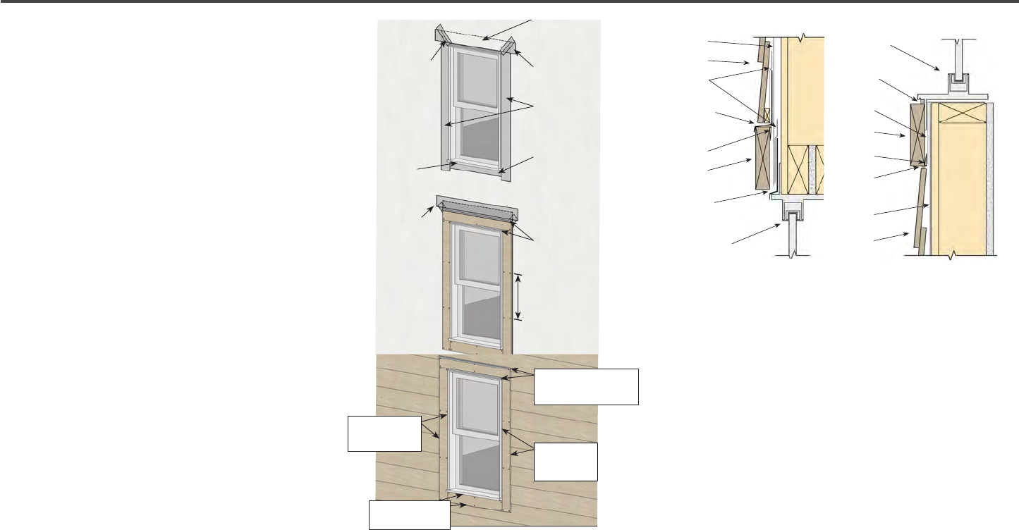
6 | Diamond Kote Building Products Application Guide 6.18
FLASHING FOR
WINDOWS, DOORS + OPENINGS
• Trim ends may lightly touch adjacent
trim edges around windows and doors
only. Paint all cut ends.
• When installing trim around windows and
over window anges, be sure to follow
the window manufacturer's installation
instructions.
• All openings must be properly sealed
and ashed in a manner that prevents
moisture intrusion or buildup.
• Siding or trim applied adjacent to
porches, patios, walks, etc. must have
a clearance of at least 1" above any
surface.
• Flashing may be sealed to the water-
resistive barrier by using adhesive
ashing or housewrap tape. (See ALL
diagrams in middle column)
• The surface must be sloped or otherwise
designed to provide proper drainage so
the siding is at no time directly exposed
to standing water.
• Horizontal trim or bands shall be ashed
with a sloped metal Z-ashing to redirect
water away from the wall assembly.
CONTINUED ON NEXT PAGE
TRIM & FASCIA 190, 440, 540 & 2000 SERIES
INSTALLATION
• Trim ends may lightly touch adjacent trim edges around windows and doors only. Re-prime and paint all cut ends.
• When installing trim around windows and over window anges, be sure to follow the window manufacturer’s installation
instructions.
• All openings must be properly sealed and ashed in a manner that prevents moisture intrusion or buildup. Flashing may be
sealed to the water-resistive barrier by using adhesive ashing or housewrap tape. (See ALL diagrams)
• When trim is installed adjoining vinyl siding, install Z-ashing with a 4 inch upper leg between horizontal trim and J-channel.
(See diagram 8a)
• Horizontal trim or bands shall be ashed with a sloped metal Z-ashing to redirect water away from the wall assembly.
GENERAL REQUIREMENTS (CONTINUED)
7a
7b
Windows, Doors and Openings
7c
7d
7e
LP SmartSide Trim & Fascia
7
Housewrap
Flap
Head Flashing
Jamb Flashing
Still Flashing
Window Flange
Housewrap
Tape
TRIM & FASCIA 190, 440, 540 & 2000 SERIES
INSTALLATION
• Trim ends may lightly touch adjacent trim edges around windows and doors only. Re-prime and paint all cut ends.
• When installing trim around windows and over window anges, be sure to follow the window manufacturer’s installation
instructions.
• All openings must be properly sealed and ashed in a manner that prevents moisture intrusion or buildup. Flashing may be
sealed to the water-resistive barrier by using adhesive ashing or housewrap tape. (See ALL diagrams)
• When trim is installed adjoining vinyl siding, install Z-ashing with a 4 inch upper leg between horizontal trim and J-channel.
(See diagram 8a)
• Horizontal trim or bands shall be ashed with a sloped metal Z-ashing to redirect water away from the wall assembly.
GENERAL REQUIREMENTS (CONTINUED)
7a
7b
Windows, Doors and Openings
7c
7d
7e
LP SmartSide Trim & Fascia
7
Adhesive
Flashing
Z-Flashing
(do not caulk)
Nails 24" o.c.
max
Shim window
and door trim
so it is installed
on level wall
plane
TRIM & FASCIA 190, 440, 540 & 2000 SERIES
INSTALLATION
• Trim ends may lightly touch adjacent trim edges around windows and doors only. Re-prime and paint all cut ends.
• When installing trim around windows and over window anges, be sure to follow the window manufacturer’s installation
instructions.
• All openings must be properly sealed and ashed in a manner that prevents moisture intrusion or buildup. Flashing may be
sealed to the water-resistive barrier by using adhesive ashing or housewrap tape. (See ALL diagrams)
• When trim is installed adjoining vinyl siding, install Z-ashing with a 4 inch upper leg between horizontal trim and J-channel.
(See diagram 8a)
• Horizontal trim or bands shall be ashed with a sloped metal Z-ashing to redirect water away from the wall assembly.
GENERAL REQUIREMENTS (CONTINUED)
7a
7b
Windows, Doors and Openings
7c
7d
7e
LP SmartSide Trim & Fascia
7
WRB
Siding
Adhesive
Flashing
Z-Flashing
3/8" min.
space (do
not caulk)
Shim
Trim
Z-Flashing 3/8"
min. space
(do not caulk)
Top of Window
Bottom of Window
Sealant 3/16"
min. space
Sill Flashing
Trim
Shim
Sealant 3/16"
min. space
WRB
Siding
TRIM & FASCIA 190, 440, 540 & 2000 SERIES
INSTALLATION
• Trim ends may lightly touch adjacent trim edges around windows and doors only. Re-prime and paint all cut ends.
• When installing trim around windows and over window anges, be sure to follow the window manufacturer’s installation
instructions.
• All openings must be properly sealed and ashed in a manner that prevents moisture intrusion or buildup. Flashing may be
sealed to the water-resistive barrier by using adhesive ashing or housewrap tape. (See ALL diagrams)
• When trim is installed adjoining vinyl siding, install Z-ashing with a 4 inch upper leg between horizontal trim and J-channel.
(See diagram 8a)
• Horizontal trim or bands shall be ashed with a sloped metal Z-ashing to redirect water away from the wall assembly.
GENERAL REQUIREMENTS (CONTINUED)
7a
7b
Windows, Doors and Openings
7c
7d
7e
LP SmartSide Trim & Fascia
7
Z-Flashing 3/8" min.
space (do not caulk)
Sealant
3/16"
min. space
Sealant 3/16"
min. space
Sealant 3/16"
min. space

7 | Diamond Kote Building Products Application Guide 6.18
WHERE TO FASTEN - SIDING
• Fasteners will be exposed on the siding
located immediately below window sills,
fascia boards, and horizontal trim.
• Fasteners below window sill shall be
spaced a maximum of 8" on center.
• Face nailing may be required as
necessary in order to obtain satisfactory
installations. Blind fasten 3/4" down
from the TOP edge.
• For installation with or without wood
structural panels, joints must occur over
stud locations.
• Best practice for blind or exposed nailing
is to use only 316 stainless steel nails
within 15 miles of the seacoast. Beyond
15 miles, either 304 stainless steel or
hot dipped galvanized is acceptable.
• Nail at all special framing members
around openings.
Note: Nails MUST penetrate framing
members when available at least 1-1/2".
Nail from the center of the siding toward
the ends, or from one end to the other end.
NEVER nail from the ends of the siding
toward the middle.
• Shim siding at studs as needed, to avoid
drawing siding against uneven walls.
• When installing siding over up to 1" rigid
foam sheathing be careful not to drive
fasteners so hard as to compress the
foam and distort surface of the siding.
Note: DO NOT OVERDRIVE FASTENERS.
Head should seat rmly to face of siding,
but not be overdriven to distort the siding
surface.
For info on fastening any of the decorative
shape products in high wind speed areas,
please refer to ICC-ES Report ESR-1301.
• The transverse windload design values
in table 4 of the APA Product Report PR-
N124 may be used when the following
fasteners specications are met.
ALTERNATIVE FASTENING OPTION:
FOR WOOD STRUCTURAL PANELS + 24"
O.C. STUD SPACING OR SIP ASSEMBLIES
The sheathing must be a min. 7/16 inch
thickness with APA rating. The Engineered
Wood Association™ contains the consensus
standard DOC PS2.
Note: Must be fastened with either corrosion
resistant screws or corrosion resistant ring
shank nails.
• Minimum 6d (0.091 inch shank diameter)
hot-dip galvanized ring shank nail with
a 0.200 inch diameter head, spaced a
maximum of 8 in. O.C.
ALTERNATIVE FASTENING OPTION:
OVER I.C.F ASSEMBLIES
• Minimum #8 hot-dip galvanized tapered
head self-drilling screw with a 0.270"
diameter head.
• Minimum penetration of 3/8" beyond the
thickness of the nailing ange.
Note: Larger screws may be required by the
I.C.F. Manufacturer based on the following
minimum withdrawal requirements.
• Keep a minimum withdrawal value of
I.C.F. nailing ange must be 50 lbs. with
a maximum 12" o.c. screw spacing.
• Keep a minimum withdrawal value of
I.C.F. nailing ange must be 31 lbs. with
a maximum 6" o.c. screw spacing.
Snug
CONDITION CORRECTION
Flush
Visible ber
Countersunk
1
⁄16 -
1
⁄8"
Countersunk more
than
1
⁄8"
OK
Paint
Apply sealant
Apply sealant &
re-nail
OK
8 | Diamond Kote Building Products Application Guide 6.18
ALTERNATIVE FASTENING OPTION:
OPTIONS OVER CORROSION
RESISTANT STEEL STUD FRAMING
Keep a minimum withdrawal value of steel
framing must be 50 lbs.
• Refer to the framing manufacturer’s
evaluation report.
38 Series Precision lap must be fastened
with the following:
• Steel stud spacing a maximum spacing of
16” on center
• Minimum #8 hot-dipped galvanized
tapered head self-drilling screw with
0.270” diameter head.
• Keep a min. of 5 threads beyond the
combined thickness of the siding and
framing.
• Minimum steel framing thickness
0.032”/ 20 gauge.
Figure 1F
Figure 1E Figure 1D
OUTSIDE CORNER
DETAIL
INSIDE CORNER
DETAIL
BOTTOM COURSE
DETAIL
GAP 3/16"
AND SEAL
GAP 3/16"
AND SEAL
Starter Strip
Figure 1B
Figure 1C
Figure 1
4" min. ashing
1" min. clearance
from roong
Trim
Min.
3/16" gap
Paint bottom
edges
Figure 1A
ROOF FLASHING DETAIL
JOINT TREATMENT OVER OPENINGS
Vapor Retarder
Breathable weather
resistant barrier
9 | Diamond Kote Building Products Application Guide 6.18
RIGIDMOUNT™
Ensure the penetration is sealed and/or
ashed properly by integrating it into the
weather-resistive barrier. RigidMount
™
trim
should extend beyond the face of the siding.
Watch our RigidMount
™
Installation Video.
APPLICATION
• Start by preparing for the application
needed. Some cutting maybe necessary
for tment of your specic situation.
• Cuts should always be re-sealed with
touch up paint.
• A jigsaw works best for cutting, be sure
to cut from the back to keep the nished
surface intact.
• Set the mount into position and mark the
weather resistive barrier by using the
nail holes (about 1/2" above the built in
ashing) and the outside edges of the
ange.
• Remove the mount and slit the weather
resistive barrier horizontally (slightly
wider than the top ange across those
marks) creating a ap in the weather
resistive barrier.
• Next install the RigidMount
™
by slipping
the top of the nailing ange under the
weather resistive barrier ap.
• Set the mount at the correct elevation,
level and then fasten the RigidMount
™
to
the wall lling every hole in nail ange.
• Hand driven galvanized roong nails are
recommended for fastening, such as
1-3/4" Maze STORMGUARD
®
.
• Place the adhesive ashing tape over the
top of the RigidMount
™
ange making
sure to cover nailing holes.
• Fold the ap down and seal the slit in the
weather resistive barrier with compatible
building tape.
• This single fashion installation helps
shed bulk water out and away from the
structure.
• Install siding around the mount and
leave the proper spacing between the
RigidMount placement ange and the
siding.
(Min. 3/16")
• Note that the top course of siding should
be cut 3/8" above the built in ashing as
measured from the face of the siding.
• Make sure to seal cut edges of siding
with provided touch-up paint. This area
should be left uncaulked.
• Finish by applying sealant, starting
approximately 3/4" in from the top
corner and then working your way out,
down the side, and across the bottom.
• Also seal the space between the wall
penetrating material and the RigidMount
™
cut out.
• DAP
®
Spec Line 920 sealant which
meets ASTM-C92
0 Specication is
recommended.
TRIM & FASCIA 190, 440, 540 & 2000 SERIES
INSTALLATION
• If framing around an existing column, be sure to use pressure
treated lumber in all locations that may be touching concrete,
masonry or decking. Provide adequate framing support for the
trim to be properly fastened. (See diagram 11a)
• Be sure to use proper ashing with a minimum 4 inch upper leg.
A secondary water-resistive barrier is recommended as well.
• Maintain a 3/8 inch space, and do not caulk, between trim and
ashing. (See diagram 11b)
• Maintain a minimum 1 inch clearance between LP SmartSide
products and any surface where water might collect.
(See diagram 11b)
• Fasten all trim over 11 inches wide a maximum of every 6
inches o.c. around the perimeter and every 12 inches o.c.
along intermediate supports. For trim under 11 inches wide,
fastener placement and quantity must be consistent with LP®
SmartSide® Trim and Fascia Application Instructions.
(See diagram 11b)
• Be sure to prime and paint all expose substrate surfaces and cuts.
• TRIM MUST NOT BE IN DIRECT CONTACT WITH MASONRY,
CONCRETE, BRICK, STONE, STUCCO OR MORTAR.
GENERAL REQUIREMENTS (CONTINUED)
• Trim mounting blocks should extend beyond the face of the siding.
• Prime and paint all cut ends, edges and holes.
On-site assembled:
• Use metal Z-ashing with a minimum 4 inch upper leg over the top side of trim mounting block. Leave a minimum 3/8 inch
space above Z-ashing and do not caulk. (See diagram 11d)
• Properly integrate the Z-ashing with the housewrap. (See diagram 11c)
• Apply fasteners meeting the specications in this document.
Pre-assembled:
• Properly integrate the built-in placement ange and ashing with the housewrap. (See diagram 11c)
• Fasten the built-in-placement ange to the framing meeting the pre-assembled trim mounting block manufacturer’s
instructions.
• When installing pre-assembled trim mounting blocks, leave proper spacing at the two sides and bottom between the
built-in-placement ange and the siding (minimum 3/16 inch). Seal these spaces with sealant. (See diagram 11d)
• Seal the space between the wall-penetrating material or xture and the mounting block cut-out. (See diagram 11d)
11a
C
UTTING
11b
11c 11d
6” o.c.
Column Application
Mounting Blocks for Exterior Fixtures
LP SmartSide Trim & Fascia
11
Housewrap
Flap
Adhesive
Flashing
Housewrap
Tape
Min. 3/16"
space with
sealant
Min. 3/8" space
(do not caulk)
Min. 3/16"
space with
sealant
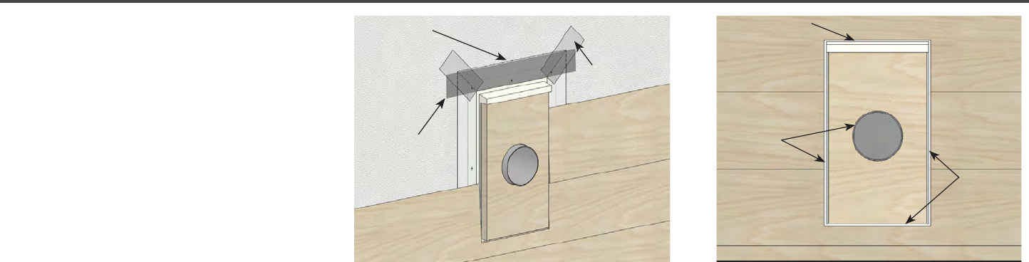
10 | Diamond Kote Building Products Application Guide 6.18
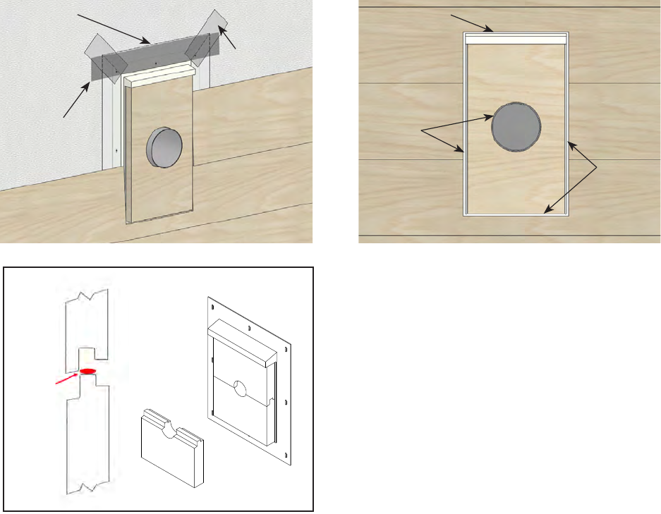
RIGIDMOUNT™ SPLIT BLOCK
• After preparing the RigidMount
™
Split
Block as detailed above, remove the
loose lower half of the mount
(set this
aside until later).
• Feed the pipe or other application
through the rectangular ange hole.
• For remodel applications it may be
necessary to cut the bottom of the
placement ange to slip this over certain
items.
• Install the RigidMount
™
Split Block as you
would the rest of the mounts.
(see pg. 6)
• Then, install the lower half of the Split
Block by applying a small bead of color
matching sealant to the joint as shown
below.
• Next, slide the bottom half of the block
back up until the joint is tight.
• No fasteners should be needed to secure
lower half of Split Block.
TRIM & FASCIA 190, 440, 540 & 2000 SERIES
INSTALLATION
• If framing around an existing column, be sure to use pressure
treated lumber in all locations that may be touching concrete,
masonry or decking. Provide adequate framing support for the
trim to be properly fastened. (See diagram 11a)
• Be sure to use proper ashing with a minimum 4 inch upper leg.
A secondary water-resistive barrier is recommended as well.
• Maintain a 3/8 inch space, and do not caulk, between trim and
ashing. (See diagram 11b)
• Maintain a minimum 1 inch clearance between LP SmartSide
products and any surface where water might collect.
(See diagram 11b)
• Fasten all trim over 11 inches wide a maximum of every 6
inches o.c. around the perimeter and every 12 inches o.c.
along intermediate supports. For trim under 11 inches wide,
fastener placement and quantity must be consistent with LP®
SmartSide® Trim and Fascia Application Instructions.
(See diagram 11b)
• Be sure to prime and paint all expose substrate surfaces and cuts.
• TRIM MUST NOT BE IN DIRECT CONTACT WITH MASONRY,
CONCRETE, BRICK, STONE, STUCCO OR MORTAR.
GENERAL REQUIREMENTS (CONTINUED)
• Trim mounting blocks should extend beyond the face of the siding.
• Prime and paint all cut ends, edges and holes.
On-site assembled:
• Use metal Z-ashing with a minimum 4 inch upper leg over the top side of trim mounting block. Leave a minimum 3/8 inch
space above Z-ashing and do not caulk. (See diagram 11d)
• Properly integrate the Z-ashing with the housewrap. (See diagram 11c)
• Apply fasteners meeting the specications in this document.
Pre-assembled:
• Properly integrate the built-in placement ange and ashing with the housewrap. (See diagram 11c)
• Fasten the built-in-placement ange to the framing meeting the pre-assembled trim mounting block manufacturer’s
instructions.
• When installing pre-assembled trim mounting blocks, leave proper spacing at the two sides and bottom between the
built-in-placement ange and the siding (minimum 3/16 inch). Seal these spaces with sealant. (See diagram 11d)
• Seal the space between the wall-penetrating material or xture and the mounting block cut-out. (See diagram 11d)
11a
C
UTTING
11b
11c 11d
6” o.c.
Column Application
Mounting Blocks for Exterior Fixtures
LP SmartSide Trim & Fascia
11
front
sealant
Housewrap
Flap
Adhesive
Flashing
Housewrap
Tape
TRIM & FASCIA 190, 440, 540 & 2000 SERIES
INSTALLATION
• If framing around an existing column, be sure to use pressure
treated lumber in all locations that may be touching concrete,
masonry or decking. Provide adequate framing support for the
trim to be properly fastened. (See diagram 11a)
• Be sure to use proper ashing with a minimum 4 inch upper leg.
A secondary water-resistive barrier is recommended as well.
• Maintain a 3/8 inch space, and do not caulk, between trim and
ashing. (See diagram 11b)
• Maintain a minimum 1 inch clearance between LP SmartSide
products and any surface where water might collect.
(See diagram 11b)
• Fasten all trim over 11 inches wide a maximum of every 6
inches o.c. around the perimeter and every 12 inches o.c.
along intermediate supports. For trim under 11 inches wide,
fastener placement and quantity must be consistent with LP®
SmartSide® Trim and Fascia Application Instructions.
(See diagram 11b)
• Be sure to prime and paint all expose substrate surfaces and cuts.
• TRIM MUST NOT BE IN DIRECT CONTACT WITH MASONRY,
CONCRETE, BRICK, STONE, STUCCO OR MORTAR.
GENERAL REQUIREMENTS (CONTINUED)
• Trim mounting blocks should extend beyond the face of the siding.
• Prime and paint all cut ends, edges and holes.
On-site assembled:
• Use metal Z-ashing with a minimum 4 inch upper leg over the top side of trim mounting block. Leave a minimum 3/8 inch
space above Z-ashing and do not caulk. (See diagram 11d)
• Properly integrate the Z-ashing with the housewrap. (See diagram 11c)
• Apply fasteners meeting the specications in this document.
Pre-assembled:
• Properly integrate the built-in placement ange and ashing with the housewrap. (See diagram 11c)
• Fasten the built-in-placement ange to the framing meeting the pre-assembled trim mounting block manufacturer’s
instructions.
• When installing pre-assembled trim mounting blocks, leave proper spacing at the two sides and bottom between the
built-in-placement ange and the siding (minimum 3/16 inch). Seal these spaces with sealant. (See diagram 11d)
• Seal the space between the wall-penetrating material or xture and the mounting block cut-out. (See diagram 11d)
11a
C
UTTING
11b
11c 11d
6” o.c.
Column Application
Mounting Blocks for Exterior Fixtures
LP SmartSide Trim & Fascia
11
Min. 3/16"
space with
sealant
Min. 3/8" space
(do not caulk)
Min. 3/16"
space with
sealant
11 | Diamond Kote Building Products Application Guide 6.18
PRO-POST WRAP™
Pro-Post Wraps are NOT engineered for
structural load-bearing use. These are
designed for decorative wraps around
structural and non-structural nominal 4x4,
4x6, and 6x6 posts.
• Ensure that areas above brick or stone
ledges are properly ashed before
installing wraps.
• A min. 3/8" clearance should be
maintained between Pro-Post Wraps
and metal ashings and a minimum 1"
clearance must be maintained between
Pro-Post Wrap™ and concrete or decks.
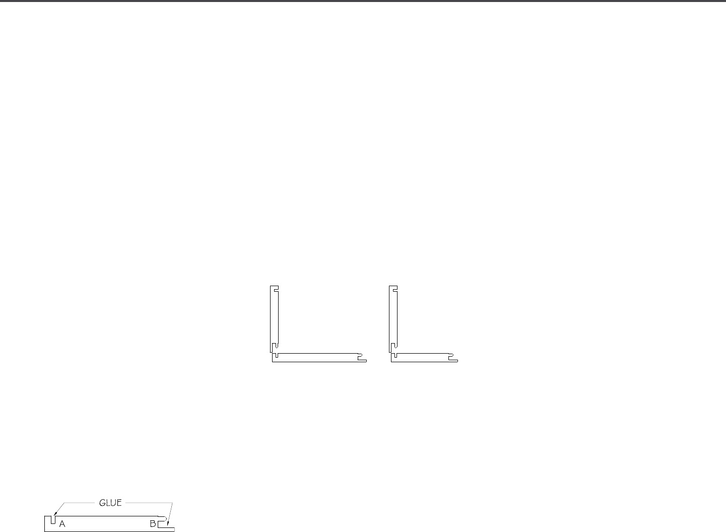
PREPARE INSTALLATION:
• Glue all joints with a high quality, fast
set, weather resistive adhesive. Be sure
to keep glue warm for proper spread
rates.
• Use adhesive with minimum shear
strength of no less than 300 psi, as
tested in accordance with ASTM D905
Standard Test Method for Strength
Properties of Adhesive Bonds in Shear by
Compression Loading. We recommend
DAP
®
Rapid Fuse Wood Adhesive.
• Special care must be taken when
assembling an 4x6 Pro-Post Wraps.
• Please note details on proper gluing.
• Measure each post locations separately
as there may be variance from post to
post.
INSTALLATION
• Begin by cutting all four sides to the
desired length.
• Be sure to repaint all cut ends of the Pro-
Post Wrap™ with Diamond Kote
®
touch-
up paint before assembly.
• Start with two boards and begin
assembling by applying an even bead of
the supplied glue, about 1/8", to Groove
A on one board and then Groove B on
the other board this will create an "L"
shaped piece.
• When assembling the 4x6 post be sure
to glue Groove B on the 4" board and
Groove A on the 6" board. Assemble so
the 4" board is the top of the "L" and the
6" board is the bottom of the "L".
• Working quickly, assemble the pieces
and clamp as necessary using bar clamps
to bring the joints together tightly. Apply
enough pressure to secure tment being
careful not to break edges of trim.
• Repeat this step in order to create a
second "L".
• Next, glue Groove A and Groove B on
one of the "L" shaped pieces.
• Join the two "L" shaped pieces around
the post to be wrapped creating a 4-
sided post wrap. Clamp as necessary
using bar clamps to bring the joints
tightly together. Leave the clamps
installed until the glue sets (approx.
5-10 min.)
• Installations in cold temperatures or dry
climates may require longer clamping
times. Position the wrap on the post for
best appearance and plumb as needed.
• Begin fastening on the side that is in
the most direct contact with the post.
Be careful to keep the nails away from
the structural post mounting hardware.
Fasten around the post, with one nail
minimum, at the top and bottom on all 4
sides. Touch up paint all the nail heads.
• You can complete the installation with a
site built trim ring. The best practice is to
keep LP
®
SmartSide
®
trims 3/8" above
ashings and/or 1" above concrete
or decks. Trim rings constructed of
PVC trim are recommended for areas
close to grade. Items installed without
the proper clearances to grade may
not be covered under manufacturers
warranties.
• Watch the Diamond Kote
®
Pro-Post
Wrap Installation Video.
4" x 6" 6" x 6"
4" x 4"
or
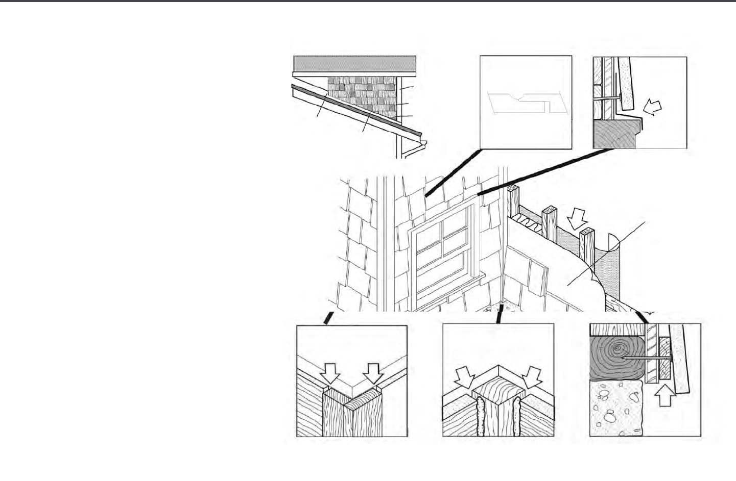
12 | Diamond Kote Building Products Application Guide 6.18
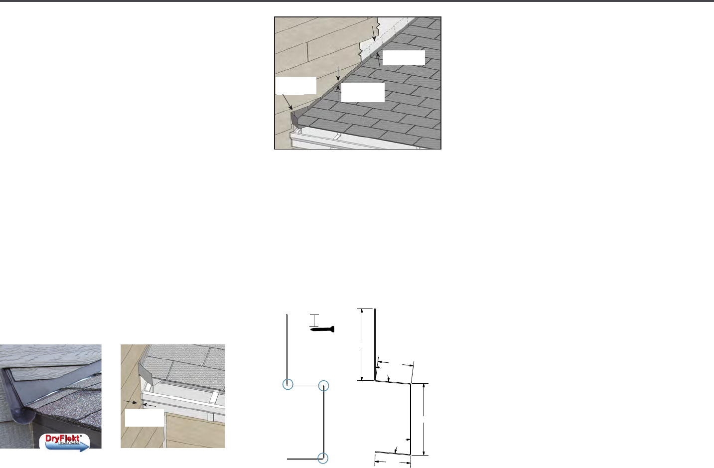
KICK-OUT FLASHING
Note: DO NOT extend the siding or trim into
the kick-out ashing or gutter cut siding.
• Install kick-out ashing to direct the
water into the gutter.
• A recommended product would be the
DryFlekt
®
Kick-Out Diverters.
• Install step ashing with minimum 4"
upper leg.
• Properly integrate ashing with the
secondary water-resistive barrier.
• Use DryFlekt
®
house wrap, ashing tape,
z-ashing, or other items as needed to
maintain the counter ashing principle.
• Maintain the proper clearance between
the end of the gutter and the adjoining
wall to allow for proper maintenance of
the siding.
• Paint ALL exposed cut edges; Roof to
wall details.
SPACER FLASHING INSTALLATION
GENERAL
• Spacer Flashing is designed to allow for
the minimum clearance requirements
for proper spacing between siding
materials and roong, decks, driveways,
or sidewalks.
SPACER INSTALL:
• Spacer Flashing can be installed with
side "D" in moderate contact, or slightly
gapped from the roong, deck, driveway,
or sidewalk.
• It is recommended to close the open
end of the Spacer Flashing by making
approximately 1" deep cuts on the
bends (circled in Spacer Diagram) in
from the end of the piece. Then bend the
tabs created from those cuts inward in
this order: B, D, then C.
• Fasten through side "A" to the wall every
12-16" on center. Place fastener ¾"
down from the top of side "A".
• Properly integrate ashing with the
secondary water-resistive barrier.
• Use house wrap, ashing tape, or other
items as needed to maintain the counter
ashing principle.
• When installing siding, it's important
to retain 3/8" minimum clearance
between the siding panels and side
"B" of the Spacer Flashing and DO
NOT caulk.
TRIM & FASCIA 190, 440, 540 & 2000 SERIES
PREPARATION
• Properly installed ashing materials will help direct water away
from common water collecting areas.
• All ashing material shall be metal or another durable material
that under normal outdoor environmental conditions will last for
a period of not less than 50 years.
• All ashing materials must have a minimum 4 inch upper leg.
Add a 4 inch wide adhesive ashing to ashing legs less than
4 inches.
• Properly integrate ashing with the secondary WRB. Use
housewrap, ashing tape, kick-out ashing, step ashing,
Z-ashing, drip edge, gutters or other items as needed to
maintain the counter-ashing principle.
• Install kick-out ashing to direct the water into the gutter.
(See diagram 3a)
• Install step ashing that has a minimum 4 inch upper leg.
(See diagram 3a)
• Maintain a minimum 1 inch clearance between the end of the
gutter and the adjoining wall to allow for proper maintenance of
the siding. (See diagram 3b)
• Do not extend the siding or trim into the kick-out ashing or
gutter.
• Prime and paint ALL exposed cut edges of siding and trim.
GENERAL REQUIREMENTS (CONTINUED)
• FASTENERS: Minimum 8d (0.113 inch diameter shank), hot-dipped galvanized or stainless steel nail with a 0.270 inch
diameter head. Apply and treat nailing errors as specied by these instructions. (See diagram 3c)
• SEALANT: Use an exterior-quality, non-hardening, paintable sealant. Use Class 25 or higher exterior sealant meeting the
ASTM C920 Standard for Specication for Elastomeric Joint Sealants. Follow the sealant manufacturer’s instructions for
application.
• PAINT: Exterior-quality 100% acrylic latex paint, specially formulated for use on wood and engineered wood substrates, is
highly recommended. Semi-gloss or satin nish oil or alkyd paints are acceptable. For at alkyd paint, please check with the
coating manufacturer for their recommendations for use on composite wood siding.
3a
C
UTTING
3b
3c
Water Run-O Control
General Application Equipment
WRB
LP SmartSide Trim & Fascia
3
4" min.
step ashing
1" min.
clearance
Kick-out
ashing
ROOF FLASHING DETAIL
TRIM & FASCIA 190, 440, 540 & 2000 SERIES
PREPARATION
• Properly installed ashing materials will help direct water away
from common water collecting areas.
• All ashing material shall be metal or another durable material
that under normal outdoor environmental conditions will last for
a period of not less than 50 years.
• All ashing materials must have a minimum 4 inch upper leg.
Add a 4 inch wide adhesive ashing to ashing legs less than
4 inches.
• Properly integrate ashing with the secondary WRB. Use
housewrap, ashing tape, kick-out ashing, step ashing,
Z-ashing, drip edge, gutters or other items as needed to
maintain the counter-ashing principle.
• Install kick-out ashing to direct the water into the gutter.
(See diagram 3a)
• Install step ashing that has a minimum 4 inch upper leg.
(See diagram 3a)
• Maintain a minimum 1 inch clearance between the end of the
gutter and the adjoining wall to allow for proper maintenance of
the siding. (See diagram 3b)
• Do not extend the siding or trim into the kick-out ashing or
gutter.
• Prime and paint ALL exposed cut edges of siding and trim.
GENERAL REQUIREMENTS (CONTINUED)
• FASTENERS: Minimum 8d (0.113 inch diameter shank), hot-dipped galvanized or stainless steel nail with a 0.270 inch
diameter head. Apply and treat nailing errors as specied by these instructions. (See diagram 3c)
• SEALANT: Use an exterior-quality, non-hardening, paintable sealant. Use Class 25 or higher exterior sealant meeting the
ASTM C920 Standard for Specication for Elastomeric Joint Sealants. Follow the sealant manufacturer’s instructions for
application.
• PAINT: Exterior-quality 100% acrylic latex paint, specially formulated for use on wood and engineered wood substrates, is
highly recommended. Semi-gloss or satin nish oil or alkyd paints are acceptable. For at alkyd paint, please check with the
coating manufacturer for their recommendations for use on composite wood siding.
3a
C
UTTING
3b
3c
Water Run-O Control
General Application Equipment
WRB
LP SmartSide Trim & Fascia
3
1" min.
clearance
2.00
1.00
2.00
1.00
95°
85°
A
B
C
D
Spacer Diagram
3/4"
13 | Diamond Kote Building Products Application Guide 6.18
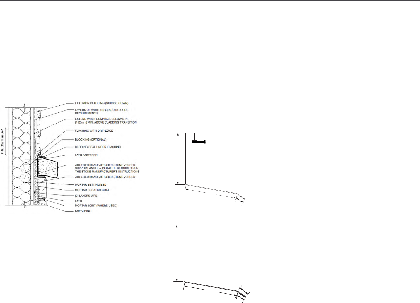
BRICK LEDGE FLASHING INSTALLATION
GENERAL
• Brick Flashing is designed to protect
the structure from water penetration by
ashing behind the siding and shed water
away from the house at the transition
where siding and stone or brick meet.
• Brick Ledge Flashing should be installed
as shown in MVMA diagram.
• It is recommended to use bedding sealant
under side "B" of the ashing. DAP
®
Spec
Line 920 Sealant is recommended.
• Verify installation requirements with
brick or adhered concrete masonry
veneer manufacturer.
• Fasten through side "A" to the wall every
12-16" on center. Place fastener ¾"
down from the top of side "A".
• Properly integrate ashing with the
secondary water-resistive barrier.
• Use house wrap, ashing tape, or other
items as needed to maintain the counter
ashing principle. See the MVMA diagram
above.
• When installing siding, it's important
to retain 3/8" minimum clearance
between the siding panels and side
"B" of the Brick Ledge Flashing and DO
NOT caulk.
C
B
A
Brick Ledge Diagram
3/4"
MVMA Diagram
2.00
2.12
.38
.31

14 | Diamond Kote Building Products Application Guide 6.18
TRADITIONAL LAP APPLICATION
SPACER CLIPS
• Hook clip to top of the rst row of siding.
• Slide siding down into clip shelf.
• Follow the manufacturer’s directions
for nailing and then strike the clip with
hammer to knock it o.
Note: Spacer clip is intended for alignment
and spacing only. It's not intended to
support the weight of the siding. Break
o clips before siding is completely nailed
tight.
JOINT PREPARATIONS H-MOLDING
Note: H-Moldings DO NOT space the board
for expansion. H-Moldings are designed to
cover the expansion gap.
• Leave a 1/4" gap between the siding
pieces. 3/16" gap plus the thickness of
H-Molding web equals 1/4".
• Apply both adjoining pieces of the
siding, fasten along the entire length
(except for the ends) with the required
gap. Be sure to butt the factory painted
ends of the board over the stud.
• Then, slide the H-Molding in place, from
the bottom of the siding up, with the
notched end of the molding down.
Slightly bend outward on the anges to
help the H-Molding slide into place. (See
Figure 2a)
• Finish fastening by nailing both pieces of
siding at the end of the siding. Angle the
nails slightly to hit the stud.
• At butt joints, fasteners should be driven
3/4" down from the top and 3/8" in from
the ends.
• Fasteners below a window sill need to be
spaced a maximum of 8" o.c. Fasteners
will be exposed on the siding located
immediately below window sills, fascia
boards, and horizontal trim.
• When attaching siding, avoid nailing
closer than 1-1/2" from the end of
the board so the power nail does not
penetrate the nail n of Diamond Kote
®
Trim.
Figure 2a
Bend slightly
outward on the
anges
Install with
this end down

15 | Diamond Kote Building Products Application Guide 6.18
RIGIDSTACK
™
APPLICATION
• Apply RigidStack™ siding over properly
prepared walls.
(see general information)
• Diamond Kote
®
RigidStack™ is installed
as a blind fastened technique.
• It can be installed by starting with a
RigidStack Metal Starter Strip, or by
stacking onto a Diamond Kote
®
Starter
Board.
• Begin by installing Diamond Kote
®
Nail
Fin Outside Corners and Nail Fin Trim.
• Next, install the appropriate starter
material being sure to keep the bottom
of the RigidStack™ at least 6" from
nished grade.
INSTALL RIGIDSTACK
™
USING
STARTER BOARD
Starter Board can be installed at or below
nished grade. Best practice is to install this
with FastenMaster Cortex
®
Hidden Fastening
System for PVC. Install Starter Board using
Cortex Hidden Fastening System in the
following manner:
Be sure to snap a level line as this will set
the exact placement for the rst course of
RigidStack™ siding.
(Figure 2b)
• If the board is 6-12" wide, use three
Cortex fasteners at every framing
member.
• If the board is less than 6" wide,
use two Cortex
®
fasteners at every
framing member. For more info refer to
CertainTeed
®
Restoration Millwork
®
installation instructions.
• Using the Cortex
®
setting tool, set the
Cortex
®
fasteners perpendicular to the
trim board, spaced a max. of 16" o.c.
• Using a standard 18V cordless impact
drill, drive the fastener to the pre-set
level below the trim surface.
• Place the PVC trim plug into the hole with
the trim-surface-side up and gently tap
until it is ush with the trim board.
• Finish by painting the plugs with Diamond
Kote
®
touch-up paint and a cotton swab.
INSTALL USING RIGIDSTACK
METAL STARTER STRIP
• The bottom edge of RigidStack™ Metal
Starter Strip should be installed at the
foundation along the sill plate or up to
1-1/8" below this to properly hold the
bottom of RigidStack™ in place.
• Placement may vary as required by
course layout.
(see Figure 2c)
• Snap a level chalk line 3-3/8" above
the bottom of where the rst course of
siding will start. Align the TOP of the
Metal Starter Strip on the chalk line.
RigidStack™ Metal Starter Strip will set
the exact placement for the 1st course
of RigidStack™.
• Fasten the RigidStack™ Metal Starter
Strip every 12-16" on center.
With RigidStack siding, the butt joints are RE-
QUIRED to be covered with a joint molding. See
Figure 11D
Joint moldings DO NOT space the board for
expansion!
Leave a 3/16” -1/4” gap between siding pieces.
The thickness of the joint molding spline should
be added to the 3/16" gap on runs exceeding
32’.
8. The best method is to apply both adjoining
pieces of RigidStack fastening along the entire
length except for the ends, with the required
gap.
9. Then slide the joint molding in place, from the
top of the siding down, with the notched end of
the molding down.
10. Finish fastening by nailing both pieces of siding
at the end of the siding into the stud.
Figure 11D
StarterBoard can be installed at or below finished
grade. Best practice is to install this with Fasten-
Master Cortex® Hidden fastening system for PVC trim.
For more information see CertainTeed Restoration
Millwork installation instructions.
APPLICATION
WSS RigidStack
Apply siding over properly prepared walls (see
General Information)
WSS RigidStack is intended to be installed blind
fastened and can be installed by starting with a
RigidStack metal starter strip - or - by stacking
onto a WSS StarterBoard.
1. Begin by Installing WSS outside corners and
trims.
2. Next install the appropriate starter material be-
ing sure to keep the bottom of the WSS Rigid-
Stack at least 6” from finished grade.
For StarterBoard install begin here:
Figure 11A
Be sure to snap a level line as this StarterBoard will
set the exact placement for the 1st course of Rigid-
Stack. (see figure 11A)
If the board is 6"–12" wide, use 3 Cortex fasteners
at every framing member.
If the board is less than 6" wide, use 2 Cortex
fasteners at every framing member.
Figure 2b
The bottom edge of RigidStack metal starter
strip should be installed at the foundation along
the sill plate or up to1-1/8” below this to
properly hold the bottom of RigidStack in place.
Placement may vary as required by course lay-
out. (see figure 11B)
Snap a level chalk line 3-3/8” above the bottom of
where the first course of siding will start. Align the
TOP of the metal starter strip on the chalk line.
RigidStack metal starter strip will set the exact
placement for the 1st course of RigidStack.
Fasten the RigidStack metal starter strip every 12-
16” o.c.
For metal starter strip install begin here:
Figure 11B
Install StarterBoard using the recommended Cortex
Concealed Fastening System in the following manner:
Using the Cortex setting tool, set the Cortex fasten-
ers perpendicular to the trim board, spaced a maxi-
mum of 16" o.c. Using a standard 18V cordless im-
pact drill, drive the fastener to the pre-set level be-
low the trim surface. Place the PVC trim plug into the
hole with the trim-surface-side up, and gently tap
until it is flush with the trim board. Finish by painting
the plugs with Diamond Kote touch up paint and a
cotton swab.
5. Fasten the siding by nailing through the nailing
line (about 3/4” from top edge of siding) at
EACH STUD LEAVING NO MORE THAN 16 in. BE-
TWEEN NAILS. Begin nailing at one end of the
siding and work toward the other end to prevent
rippling of the siding. Do not countersink nail
heads.
6. Then install subsequent courses of siding so that
the plastic spline fits over the top edge of the
previously installed piece of siding.
7. The butt joints between adjacent siding pieces
must be located over the middle of a stud.
Make sure that the spline is firmly seated to the
top of the previous course BEFORE and DURING
nailing to ensure the material lines up at the butt
joints and at course lines at the corners.
3. Now install the first course of siding so that the
plastic spline fastened into the back of the sid-
ing fits over the beveled edge of the starter
board (Figure 11A) or into the metal starter strip
as shown in (Figure 11B).
4. LEAVE A 3/16” GAP WHERE SIDING BUTTS
AGAINST TRIM TO ALLOW FOR EXPANSION. See
Figure 11C.
Figure 11C
Figure 2c
CONTINUED ON NEXT PAGE
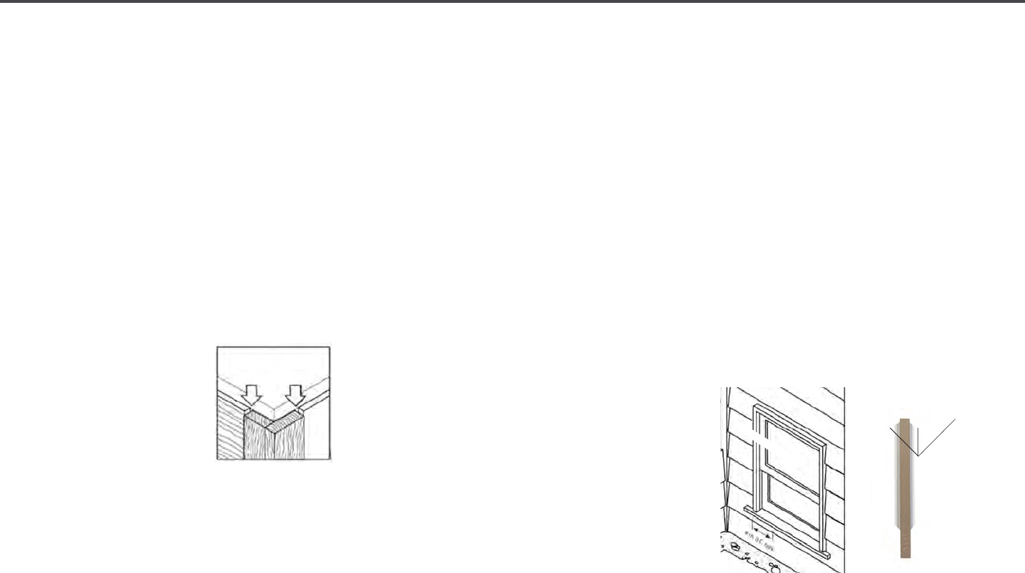
16 | Diamond Kote Building Products Application Guide 6.18
RIGIDSTACK™ INSTALLATION
• Now install the rst course of siding so
that the plastic spline fastened into the
back of the siding ts over the beveled
edge of the starter board
(Figure 2b) or
into the Metal Starter Strip, as shown in.
(Figure 2c; both on pg 12)
Note: Leave a 3/16" gap where siding
butts against trim to allow for expansion.
• When attaching siding, avoid nailing
closer than 1-1/2" from the end of the
board to avoid penetration of the power
nails into the nail n.
• Fasten the siding by nailing through the
nail line
(about 3/4"
from top edge of siding)
at each stud, leaving
no more than 16"
between nails.
• Begin nailing at one
end of the siding and
work toward the other end to prevent
rippling of the siding. Do not countersink
nail heads.
• Then, install subsequent courses of
siding so that the plastic spline ts over
the top edge of the previously installed
piece of siding.
• Make sure that the spline is rmly seated
to the top of the previous course by
pushing in and slightly down on the face,
BEFORE and DURING nailing, to ensure
the material lines up at the butt joints
and at course lines at the corners.
• At some point during the installation it
may be necessary to remove the spline
from the back of RigidStack™ in order to
make the courses line up at corners or to
adjust for an out of level wall. Removal
of the spline is not uncommon and
does not void the substrate or nish
warranty. To remove the spline grasp
it using a pliers at rst, then with your
hand. Wiggle it back and forth while
pulling upwards, continue until the entire
spline is removed.
RIGIDSTACK JOINT PREPARATIONS
USING H-MOLDINGS
• When using RigidStack™ siding the butt
joints are REQUIRED to be covered with
an H-Molding.
(Figure 2f)
H-Moldings DO NOT automatically space
the board for expansion. They're designed
to cover the expansion gap.
• Leave a 1/4" gap between siding pieces.
3/16" gap plus thickness of H-Molding
web equals 1/4".
• The butt joints between adjacent siding
pieces must be located over the middle
of a stud.
• Best method is to apply both adjoining
pieces of RigidStack™ fastening along
the entire length except for the butt joint
ends.
• Slide the H-Molding in place from
the bottom of the siding, with the
notched end of the molding down.
Bending slightly outward on the anges
rst will help the H-Molding slide into
place more easily.
(Figure 2f)
• Finish fastening by nailing, both pieces
of siding at the end of the siding and
angle the nails slightly to hit the stud.
• At butt joints, fasteners should be driven
3/4" down from the top and 3/8" in from
the ends.
• Fasteners below window sill need to be
spaced a maximum of 8" o.c. Fasteners
will be exposed on the siding located
immediately below window sills, fascia
boards, and horizontal trim.
Watch the RigidStack Installation Video.
GAP 3/16"
AND SEAL
Figure 2e
Bend slightly outward
on the anges
Install with this
end down
Figure 2f
8" on center
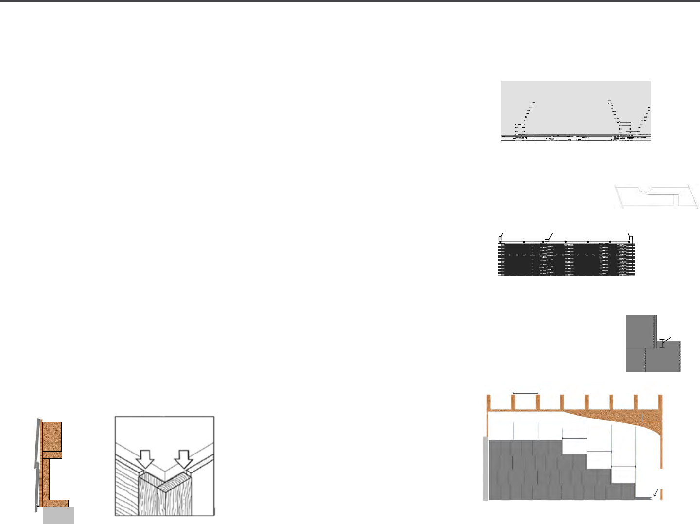
17 | Diamond Kote Building Products Application Guide 6.18
RIGIDSHAKE™ | STRAIGHT EDGE
APPLICATION 7", 9" & 12"
• Apply the siding over properly prepared
walls. (see general guidelines pg. 2)
• It is REQUIRED to use nailable structural
sheathing.
• Diamond Kote
®
RigidShake™ products
can be installed blind fastened.
• Start installation with a RigidStack™
Metal Starter Strip or by overlapping a
previous course of lap siding (2-1/16"
minimum) or by over lapping the top of
Starter Board.
(Figure 3)
• It is recommended to use the Metal
Starter Strip when starting with the
Straight Edge RigidShake.
(see Figure 3a)
• WORK installations LEFT TO RIGHT.
• Trim left edge so the that siding section
ts against corner board, with a 3/16"
gap
(see Figure 3b)
• Butt joint seams are not required to land
on studs.
• Starting from left, level and install the
rst course of shakes so that the plastic
spline, fastened into the back of the
siding, ts over the beveled edge of the
siding, or into the metal starter strip.
• Do NOT place fasteners into bottoms of
grooves or shiplaps.
• Fasten the siding by nailing through
the nailing line 3/4" down from the
top of panel, into the sheathing and/or
framing with one of the below options.
• For screws, fasten 12" o.c. use a
minimum #8 corrosion resistant tapered
head wood screw.
(see Figure 3c)
• For nails, fasten 8" o.c. use a minimum
6d (0.09" shank diameter) corrosion
resistant ring shank nail.
(see Figure 3d)
• Continue row, working left to right.
Overlap shiplap butt ends without any
gap.
(see Figure 3e)
• Start subsequent courses in same
manner, but trim each course to create
the eect of staggered joints.
• Best appearance is obtained by trimming
the second course starter piece 16"
shorter than the rst course, and
trimming the third course starter piece
32" shorter than the rst.
• Repeat this same sequence every 3
courses.
• Shim siding at studs, as needed, to avoid
drawing siding against uneven walls.
(see
Figure 3)
• Then, install subsequent courses of
siding so that the plastic spline ts over
the top edge of the previously installed
piece of siding.
(see Figure 3f)
Outside Corner
Figure 3b
GAP 3/16"
AND SEAL
The bottom edge of RigidStack metal starter
strip should be installed at the foundation along
the sill plate or up to1-1/8” below this to
properly hold the bottom of RigidStack in place.
Placement may vary as required by course lay-
out. (see figure 11B)
Snap a level chalk line 3-3/8” above the bottom of
where the first course of siding will start. Align the
TOP of the metal starter strip on the chalk line.
RigidStack metal starter strip will set the exact
placement for the 1st course of RigidStack.
Fasten the RigidStack metal starter strip every 12-
16” o.c.
For metal starter strip install begin here:
Figure 11B
Install StarterBoard using the recommended Cortex
Concealed Fastening System in the following manner:
Using the Cortex setting tool, set the Cortex fasten-
ers perpendicular to the trim board, spaced a maxi-
mum of 16" o.c. Using a standard 18V cordless im-
pact drill, drive the fastener to the pre-set level be-
low the trim surface. Place the PVC trim plug into the
hole with the trim-surface-side up, and gently tap
until it is flush with the trim board. Finish by painting
the plugs with Diamond Kote touch up paint and a
cotton swab.
5. Fasten the siding by nailing through the nailing
line (about 3/4” from top edge of siding) at
EACH STUD LEAVING NO MORE THAN 16 in. BE-
TWEEN NAILS. Begin nailing at one end of the
siding and work toward the other end to prevent
rippling of the siding. Do not countersink nail
heads.
6. Then install subsequent courses of siding so that
the plastic spline fits over the top edge of the
previously installed piece of siding.
7. The butt joints between adjacent siding pieces
must be located over the middle of a stud.
Make sure that the spline is firmly seated to the
top of the previous course BEFORE and DURING
nailing to ensure the material lines up at the butt
joints and at course lines at the corners.
3. Now install the first course of siding so that the
plastic spline fastened into the back of the sid-
ing fits over the beveled edge of the starter
board (Figure 11A) or into the metal starter strip
as shown in (Figure 11B).
4. LEAVE A 3/16” GAP WHERE SIDING BUTTS
AGAINST TRIM TO ALLOW FOR EXPANSION. See
Figure 11C.
Figure 11C
Bottom Course Detail
Figure 3a
Shiplap Butt Ends
Figure 3e
1"
Minimum
Overlap
Figure 3f
2-1/8"
Screw Placement 12" o.c. Detail
Figure 3c
3/4"
1-1/4"
1-1/4"
Straight Edge Application
Figure 3
Mark Stud Locations
16" or 24" o.c. Framing
Nailable
Structural
Sheathing
HOUSE WRAP
2 1/16" lap siding
starter or lap siding
16"
Oset
16"
Oset
Trim Board
16"
Oset
Nail Placement 8" o.c. Detail
Figure 3d
3/4"
1-1/4"
1-1/4"
2-1/8”Siding
-or-
MetalStarterStrip
NailableStructural
Sheathing
markstudlocations
9-5/8”exposure
16”offset
16”offset
16”offset
Trimboard
16” or 24” o.c. framing
¾”
1-¼”
1”
¾”
1”
1-¼”
2-1/8”
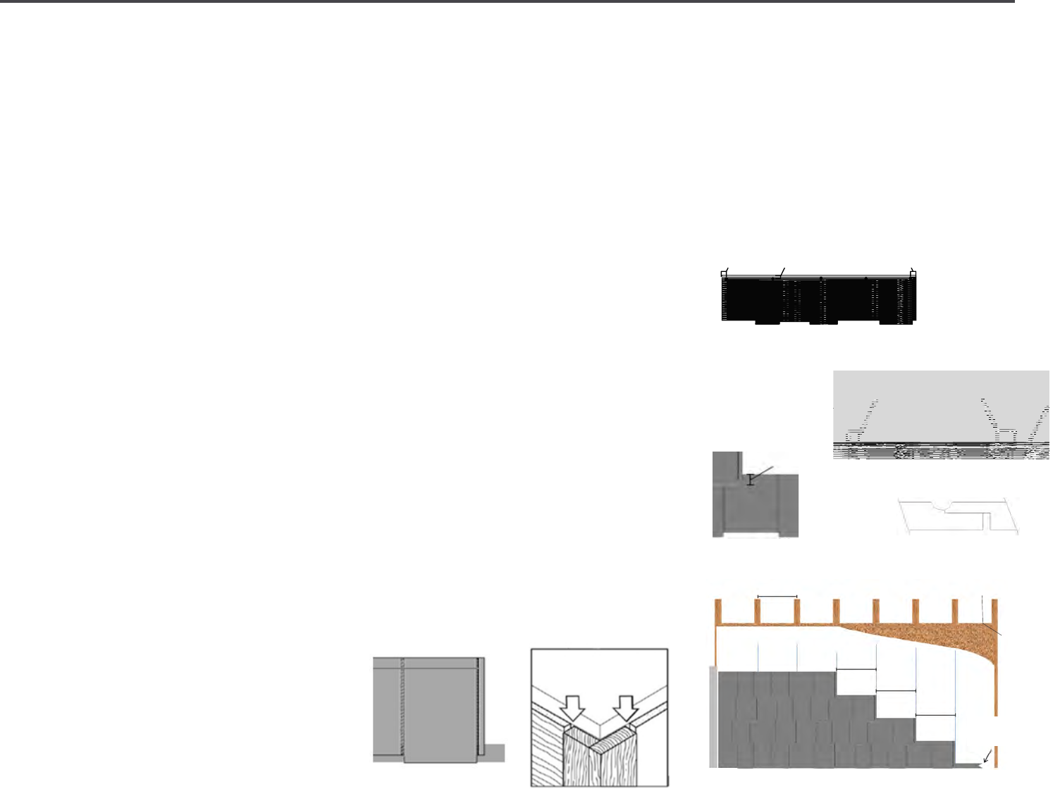
18 | Diamond Kote Building Products Application Guide 6.18
RIGIDSHAKE™ | STAGGERED EDGE
APPLICATION 7", 9" & 12"
• Apply the siding over properly prepared
walls. (see general guidelines on page 2)
• It is REQUIRED to use nailable structural
sheathing.
• Diamond Kote
®
RigidShakes can be
installed blind fastened.
• Work installations left to right. Start
installation by overlapping the previous
course of lap siding.
(see Figure 4)
• If not installing over lap siding the
preferred way to begin is to rst
install a row of straight shakes then all
subsequent rows of staggered shakes.
(See page 15 for starting Straight RigidShakes).
• DO NOT CUT OFF THE BOTTOM FACTORY
END OF STAGGERED SHAKES TO START
A 'STRAIGHT' ROW! THIS PRACTICE
WILL VOID SUBSTRATE WARRANTY.
• An optional starting method is to use
a 3/8" x 2-1/16" piece of same color
lap siding as a starter shim, as this will
partially show because of the staggered
bottom edge.
• Cut this at a 30 degree bevel and paint all
cut edges. Install keeping the factory
painted edge down.
(see Figure 4a)
• Trim left edge so that siding section ts
against the corner board, with a 3/16"
gap.
(see Figure 4b)
• Butt joint seams are not required to land
on studs.
• Starting from left, level and install the rst
course of Diamond Kote
®
RigidShake™
so the bottom edge is ush with the shim.
Do NOT place fasteners into bottoms of
grooves or shiplaps.
• Fasten 3/4" down from the top of the
panel, into sheathing and/or framing
with one of the below options.
• For screws, fasten 12" on center using a
minimum #8 corrosion resistant tapered
head wood screw.
(see Figure 4c)
• For nails, fasten 8" on center using a
minimum of 6d
(0.09" shank diameter)
corrosion resistant ring shank nail.
(see
Figure 4d)
• Continue row, working left to right.
Overlap shiplap butt ends without any
gap.
(see Figure 4e)
• Start subsequent courses in same
manner but trim each course to create
the eect of staggered joints.
• Best appearance is obtained by trimming
second course starter piece 16" shorter
than the rst course and trimming the
third course starter piece 32" shorter
than the rst. Repeat this same sequence
every three courses.
(see Figure 4)
• Shim siding at studs, as needed, to avoid
drawing siding against uneven walls.
• Then install subsequent courses of
siding so that the plastic spline ts over
the top edge of the previously installed
piece of siding.
(see Figure 4f)
Bottom Course Detail
Figure 4a
Outside Corner
Figure 4b
GAP 3/16"
AND SEAL
Shiplap butt ends
Figure 4e
Minimum Overlap
Figure 4f
2-1/8"
HOUSE WRAP
Staggered Edge Application Figure 4
2
1
/16" Siding
Mark Stud Locations
16" or 24" o.c. Framing
Nailable
Structural
Sheathing
16"
Oset
16"
Oset
16"
Oset
Nail Placement 8" o.c. Detail
Figure 4d
3/4"
1"1"
1"
Screw Placement 12" o.c. Detail
Figure 4c
3/4"
1"
2-1/8”Siding
-or-
MetalStarterStrip
NailableStructural
Sheathing
markstudlocations
9-5/8”exposure
16”offset
16”offset
16”offset
Trimboard
1”
¾”
1-¼”
16” or 24” o.c. framing
2-1/8”
¾”
1-¼”
1”
Trim Board
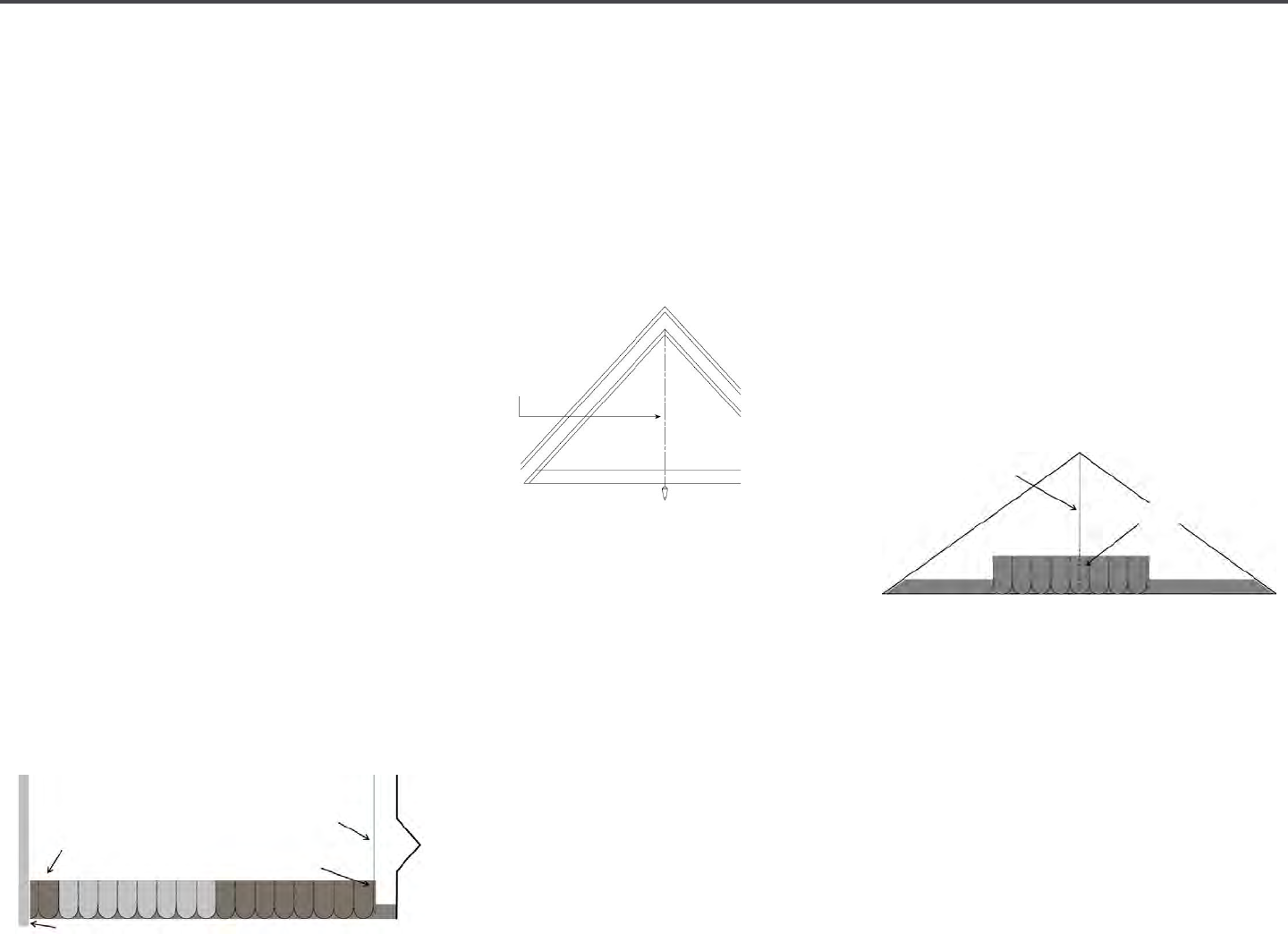
19 | Diamond Kote Building Products Application Guide 6.18
OCTAGONS + SCALLOPS APPLICATION
Prior to installation: Find the center of the
gable or wall so that shapes will be visually
centered. For best nished appearance,
gable installations should end with a single
Scallop or Octagon at the peak.
STRAIGHT WALL APPLICATION
• Begin by measuring the length of the
wall between the corner trims.
• Next, divide length of wall by two to nd
the center of the wall.
• Mark the center of the wall.
• The easiest layout for the Octagons or
Scallops to be visually centered on the
wall, is to start so that a keyway lands
over the center of wall mark.
• Calculate the layout of full panels from
the center mark and make a mark on the
wall (full panels measure 48").
• Measure from the trim to the mark so
that siding section ts against corner
board, with a 3/16" gap.
• Trim left side of a panel to t and begin
installation.
GABLE APPLICATION
• Start by dropping a plumb line to nd
the center of the gable. Mark this line.
• Next measure the height of the gable
(in inches) on this line. For Octagons
divide by 9-5/8". For Scallops divide by
7-3/4".
• The purpose of this simple equation is
to nd out the number of courses or
rows.
• Then, divide the height of the gable by
the size of the exposure of the prole
that will be installed.
• Example: 64" gable height with scallops.
(64"÷ 7.75" = 8.25 - Eight is an even number, do
not worry about the decimal, center on a keyway
to start.)
• If the answer is an even number, center
the rst course of Scallop or Octagons
on a keyway.
• If the answer is an odd number, center
the rst course on a Scallop or Octagon.
• Begin by locating the rst piece relative
to the centerline of the gable. The panel
may be positioned anywhere along its
length, as long as the keyway or shingle
face is centered.
Layout of Scallops and Octagons from Center of Wall Mark
Siding section
tted with 3/16"
gap at trim
Center of Wall Mark
Keyway lands over
center mark
Trim Board
Siding shaded to help show panel
Center of Wall Mark
Center of Scallop
Drop a plumb line to
nd center of gable
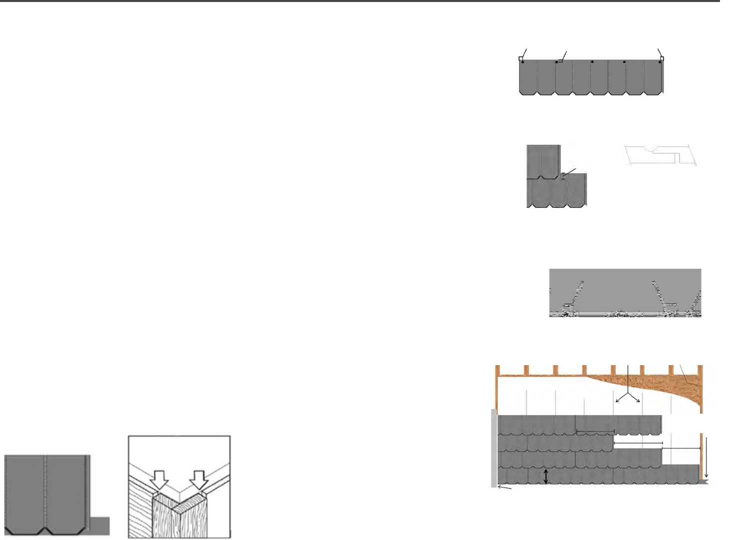
20 | Diamond Kote Building Products Application Guide 6.18
HISTORIC COLLECTION | OCTAGON
APPLICATION
• Apply the siding over properly prepared
walls. (see general guidelines pg 2)
• It is REQUIRED to use nailable structural
sheathing.
• Diamond Kote
®
Octagons can be installed
blind fastened.
• Start installation by overlapping a
previous course of lap siding or with a
starter strip.
(see Figure 5)
• It is recommended to use a 3/8" x
2-1/16" piece of same color lap siding as
a starter strip, as this will partially show
because of the angled bottom edge. Rip
this at a 30 degree angle, paint all cut
edges and install keeping the factory
painted edge down.
(see Figure 5a)
• For octagons installation, starting left to
right. Trim left edge so that the siding
section ts against corner board, with a
3/16" gap.
(see Figure 5b)
• Butt joint seams are not required to land
on studs.
• Do NOT place fasteners into bottoms of
grooves or shiplaps.
• Fasten the siding by 3/4" down from
the top of panel, into sheathing and/or
framing with one of the below options.
• For screws, fasten 12" on center use a
minimum #8 corrosion resistant tapered
head wood screw.
(see Figure 5c)
• For nails, fasten 8" on center use a
minimum of 6d (0.09" shank diameter)
corrosion resistant ring shank nail.
(see Figure 5d)
• Continue row, working left to right.
Overlap shiplap butt ends without any
gap.
(see Figure 5e)
• Then install subsequent courses of
siding overlapping previously installed
piece of siding a minimum of 2-1/8".
(see Figure 5f)
• Oset each course to aect staggered
joints.
• Best appearance is installing second
course starter piece 21" shorter than
the rst course. (see Figure 5)
• Start the third course starter piece
27" shorter than the 2nd course.
(see Figure 5)
• Repeat this same sequence every three
courses. Shim siding at studs, as needed,
to avoid drawing siding against uneven
walls.
•
Bottom Course Detail
Figure 5a
Outside Corner
Figure 5b
GAP 3/16"
AND SEAL
Shiplap butt ends
Figure 5e
Minimum
Overlap
2
1
/8"
Octagon Application - Figure 5
Siding or
2 1/8" Starter Strip
Trim Board
21" Oset
Mark Stud Locations
16" or 24" o.c. Framing
HOUSE WRAP
9 5/8" Maximum Exposure
27" Oset
21" Oset
Nailable Structural
Sheathing
Screw Placement 12" o.c. Detail
Figure 5c
3/4"
1"
1"
Nail Placement 8" o.c. Detail
Figure 5d
3/4"
1"
1"
Figure 5f
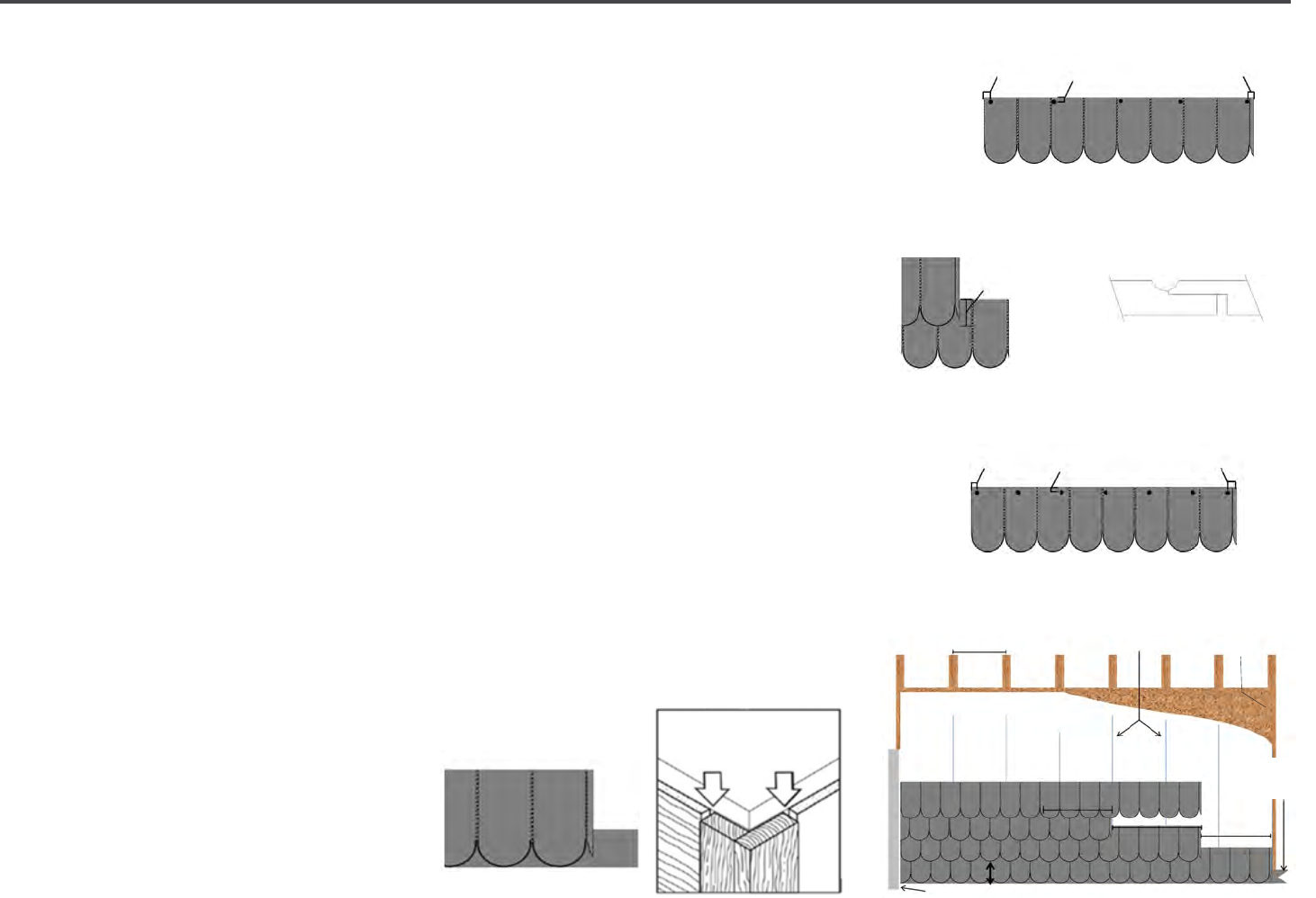
21 | Diamond Kote Building Products Application Guide 6.18
HISTORIC COLLECTION | SCALLOP
APPLICATION
Apply siding over properly prepared walls.
(see general guidelines page 2)
• It is REQUIRED to use Nailable structural
sheathing. Scallops can be installed
blind fastened.
• Scallops can be installed by starting
with a starter strip or by overlapping a
previous course of lap siding
(4" minimum).
(see Figure 6)
• For scallops, start installation left to
right. It is recommended to use a 3/8"
x 4" piece of same color lap siding as a
starter shim, as this will partially show
because of the rounded bottom edge.
(see Figure 6a)
• Trim left edge so that siding section ts
against corner board, with a 3/16" gap.
(see Figure 6b)
• Butt joint seams are not required to land
on studs.
• Starting from left, level and install the
rst course of Scallops so bottom edge
is ush with the shim. Do NOT place
fasteners into bottoms of grooves or
shiplaps.
• Fasten 3/4" down from the top of panel,
into sheathing and/or framing with one
of the below options.
• For screws, fasten 12" on center use a
minimum #8 corrosion resistant tapered
head wood screw. (see Figure 6c)
• For nails, fasten 8" no center use a
minimum of 6d (0.09" shank diameter)
corrosion resistant ring shank nail.
(see Figure 6d)
• Continue row, working left to right.
Overlap shiplap butt ends without any
gap.
(see Figure 6e)
• Start subsequent courses in the same
manner by overlapping courses a
minimum of 4".
(see Figure 6f)
• Best appearance is obtained by installing
second course starter piece 21" shorter
than the rst course.
(see Figure 6)
• Start the 3rd course starter piece 27"
shorter than the 2nd course. (Figure 6)
• Repeat this sequence every 3 courses.
Shim siding at studs, as needed, to avoid
drawing siding against uneven walls.
Bottom Course Detail
Figure 6a
Outside Corner
Figure 6b
GAP 3/16"
AND SEAL
Minimum
Overlap
Figure 6f
4"
Nail Placement 8" o.c. Detail
Figure 6d
Scallops Application Figure 6
Siding -or-
4" Starter Strip
Trim Board
21" Oset
Mark Stud Locations
16" or 24" o.c. Framing
HOUSE WRAP
7 ¾" Maximum Exposure
27" Oset
21" Oset
Nailable Structural
Sheathing
Shiplap butt ends
Figure 6e
Screw Placement 12" o.c. Detail
Figure 6c
3/4"
1"1"
3/4"
1"1"

22 | Diamond Kote Building Products Application Guide 6.18
OUTSIDE + INSIDE CORNER
WITH NAIL FIN APPLICATION
It is recommended to install corners
with nailing n over nailable structural
sheathing. Some face nailing may be
required if nailable sheathing is not
present.
• Apply corners over properly prepared
walls.
(see general guidelines pg 2)
• Diamond Kote
®
Outside and Inside
Corners with Nail Fin are designed to
be installed blind nailed through the
attached nail ns to help complete a
hidden fastener install.
• Install corners and trims rst before
beginning ins tallation of the siding
products. Start by carefully removing
the corners from protective shipping
packaging. Do not cut packaging on
face of material.
• Avoid drawing corners against uneven or
out of square walls. Before installation
make sure that the foundation or
foundation coverings do not project
beyond the plane of the wall.
• Shim as necessary to avoid potential to
split corners lengthwise.
FINGER JOINTS
• 10' Corners are manufactured with a
random nger jointed trim board. For
aesthetic purposes it is recommended
to attempt to turn, ip, and/or cut o
corners in order to reduce the visibility
of the nger joints around high trac
areas of the building. 16' corners DO
NOT contain nger joints.
CUTTING
• Measure and mark corners for length
typically 1/2" - 3/4" lower than the
bottom course of siding.
• Cut outside corners carefully to avoid
marring the nished surface, 4" corners
can be cut utilizing power compound
miter saws. 6" corners typically require
cutting by hand or by circular saw.
• It is recommended to cover the bed of
circular saws with tape or protective
coverings to avoid marring the nished
surfaces.
SEALING
• Cotton swabs are recommended for
touch-up painting on the nished face
of products. Paint and/or seal ALL cut
ends and edges of corners.
(see Figure 7a)
NOT RECOMMENDED to use pneumatic
roong, or siding nail guns to install
trim with nailing n.
• When attaching siding, avoid nailing
closer than 1-1/2" from the end of
the board so the power nail does not
penetrate the nail n of Diamond Kote
®
Trims.
• Use hand driven galvanized roong nails
for installation on Corner.
• 1-3/4" StormGuard Ring shank nails
from Maze Nails are recommended.
• When installing inside and outside
corners over
(up to) 1" rigid foam
sheathing, be careful not to drive nails
so hard as to compress the foam and
distort the n. Nail length must be
increased to ensure penetration of the
wood substrate.
Figure 7a
CONTINUED ON NEXT PAGE

23 | Diamond Kote Building Products Application Guide 6.18
OUTSIDE + INSIDE CORNER
WITH NAIL FIN APPLICATION
INSTALLATION
• Hold outside and inside corners with
nailing n up to the wall, level, plumb
and set it to the correct height before
nailing.
• Alternate nailing through the n in the
provided holes on both sides of the
corner.
• Fasten EVERY 3RD HOLE. (Figure 7b)
• DO NOT OVERDRIVE NAILS.
• Nail heads should be set rmly to the
face of n, but should not be overdriven
to distort or damage the n surface.
STACKING:
• FOR 2 CORNERS, ONE JOINT: Lightly
butt painted cut ends together and leave
a 3/16" gap where the top corner meets
the sot.
• FOR 3 OR MORE CORNERS 2+ JOINTS:
Leave a 1/8" gap between painted cut
ends and apply a small bead of color
matched sealant by back caulking during
assembly. Leave a 3/16" gap where the
top corner meets the sot.
Figure 7b
Correct
Nailing
Pattern

24 | Diamond Kote Building Products Application Guide 6.18
TRIM WITH NAIL FIN APPLICATION
• Apply trim over properly prepared walls.
(general guidelines page 2)
• It's recommended to install Diamond
Kote
®
Trim with Nail Fin over nailable
structural sheathing.
• If nailable sheathing is not present, some
face nailing may be required.
GENERAL
• Trim with nail n is designed to be blind
nailed through the attached nailing n
and with clip to help complete a hidden
fastener installation.
• Install the outside corners and trim rst
before installation of siding products.
• Start by carefully removing trim from
protective shipping packaging.
• Do not cut packaging on face of material.
Avoid drawing trim against uneven or
out of plane surfaces. Shim as necessary
to ensure acceptable trim joints.
CUTTING
• It is recommended to cut the trim with
nail n face up and to utilizing power
compound miter saws.
• Align edge of trim without attached n
against fence.
• When cutting by circular saw, it is
recommended to cut face down.
• Be careful to avoid marring the nished
surfaces.
SEALING
• Paint and/or seal ALL cut ends and edges
of trim. (Figure 7a pg. 17) Cotton swabs are
recommended for touch-up painting on
the nished face.
TRIM NAILING REQUIREMENTS
• Hand-driven galvanized roong nails are
recommended for installing trim with
nailing n.
(1-3/4" StormGuard
®
Ring shank
nails from Maze Nails are recommended).
NOT RECOMMENDED to use pneumatic
roong, or siding nail guns to install trim
with nailing n.
• When attaching siding, avoid nailing
closer than 1-1/2" from the end of
the board so the power nail does not
penetrate the nail n.
• When installing trim over up to 1" rigid
foam sheathing, be careful not to drive
nails so hard as to compress the foam
and distort the n.
OPTION 1: TRIM CLIPS & NAIL FIN TRIM
• Position the clips, tight on the sides and
bottom of the item to be trimmed out
and leave a 3/8" gap between clips and
top of item. Nail through the clips into
substrate.
• Place clips no greater than 16" o.c.
around the item. Then measure and cut
the trim to length.
• Cut trim for windows/other openings as
shown Fig. 7C.
• Place trim on wall; make
sure the edge with the kerf
and dado is faced towards
the clips. Starting at one
end of the trim align and
slide the rst clip into the
kerf side of the trim. Using a
slight up and down motion
continue rotating the trim into position
with the trim clips. Hold the trim with
nail n against the wall, level, plumb
and set it to the correct height before
nailing it. Make sure to leave a proper
gap between trim and windows shown in
Fig. A
(pg 21)
• Make sure that you do not overdrive
nails. Fasten EVERY 3RD HOLE.
• Nail head should set rmly to the face of
the n, but be careful to not overdrive to
distort or damage the surface.
• Shim at trim intersections as needed
to establish ush and tight joints. Then
apply sealant.
Figure 7c
CONTINUED ON NEXT PAGE
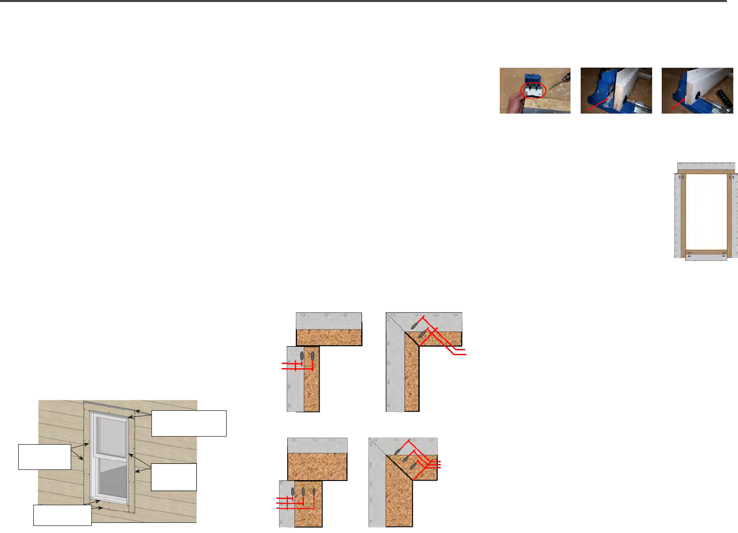
25 | Diamond Kote Building Products Application Guide 6.18
OPTION 2: POCKET HOLE JOINERY &
NAIL FIN TRIM
• Follow these steps to assemble the Nail
Fin Trim by screwing the trim together
using a pocket hole joinery and then
installing the trim on the wall as a
unitized frame.
• The advantage with this option is that
the trim joints will be tighter, and should
not require shimming to keep them ush.
• Joints may be assembled with either 45°
miters or butt & pass methods.
POCKET HOLE REQUIRED EQUIPMENT:
• Pocket hole jig w/drill bit
• 2" Pocket screws (exterior grade)
• Portable pocket hole jigs are readily
available from retail suppliers.
INSTALL:
• Measure and cut the trim pieces to
the proper length as normal, then
touch up paint all cut ends. Be sure to
add the proper gap amount to your
measurements.
(Fig. A)
• Please follow the tool manufactures
instructions by setting up the jig and
drill. From our experience best results
are obtained by setting the jig for 1"
material and the drill depth gauge for
¾" material using 2" screws. Because
manufactures dier, nd the settings
that work best for you. Experiment on a
test piece rst.
• Follow the hole placement diagrams
below for your situation. Drill 2 holes for
4" trim and 3 holes for 6" trim. Place the
holes from the edge of the material at
the dimensions shown for each joint to
join the material together.
Proper hole placement is important for
screw holding power. Caution: drilling too
close to the edge may cause material to
split.
• Using a scrap piece of the nail n,
approximately 2" x 3.5" (circled), will help
keep the trim clamped securely in the jig
while drilling.
(See Fig. B, C, & D)
• After all four joints are drilled begin
assembling the frame.
(Fig. E)
• Follow recommendations
from the manufacturer on
installing screws with the
trim face down. Take care
to protect the pre-nished
surface from damage during
assembly.
• With the pieces of trim
assembled, take the unitized frame
to the desired area on the wall, t the
trim frame to the opening leaving the
required gap between trim and opening.
(Fig. A) Level the trim frame and fasten
through the nailing n lling every 3rd
hole. Nail heads should set rmly to
the face of the n, but be careful to not
overdrive to distort or damage the n
surface.
• Make sure that you do not overdrive
nails. Fasten EVERY 3RD HOLE. We
recommend using 1-3/4" StormGuard
®
Ring shank nails from Maze Nails.
• Apply sealant as shown on Fig. A
• Watch the Pocket Hole Joinery Video.
4" Trim 45° miters
4" Trim Butt & Pass
3/4"
2-1/4"
1"
1-1/2"
6" Trim Butt & Pass
6" Trim 45° miters
2-1/4"
3/4"
3-3/4"
3"
1-1/2"
4-1/2"
Fig. B Fig. C Fig. D
TRIM & FASCIA 190, 440, 540 & 2000 SERIES
INSTALLATION
• Trim ends may lightly touch adjacent trim edges around windows and doors only. Re-prime and paint all cut ends.
• When installing trim around windows and over window anges, be sure to follow the window manufacturer’s installation
instructions.
• All openings must be properly sealed and ashed in a manner that prevents moisture intrusion or buildup. Flashing may be
sealed to the water-resistive barrier by using adhesive ashing or housewrap tape. (See ALL diagrams)
• When trim is installed adjoining vinyl siding, install Z-ashing with a 4 inch upper leg between horizontal trim and J-channel.
(See diagram 8a)
• Horizontal trim or bands shall be ashed with a sloped metal Z-ashing to redirect water away from the wall assembly.
GENERAL REQUIREMENTS (CONTINUED)
7a
7b
Windows, Doors and Openings
7c
7d
7e
LP SmartSide Trim & Fascia
7
Z-Flashing 3/8" min.
space (do not caulk)
Sealant
3/16"
min. space
Sealant 3/16"
min. space
Sealant 3/16"
min. space
Fig. A
Fig. E

26 | Diamond Kote Building Products Application Guide 6.18
ARCH TRIM INSTALLATION
GENERAL
• It's recommended to install arched trims
around the opening before cutting or
installing the sides or bottom trim.
• Read and understand instructions.
• Carefully remove trim from protective
packaging.
• Place the Arched Trim over the arched
area and center it so the bottom ends
are level.
FASTENING:
• Fastener length needs to be long enough
to fully penetrate structural framing or
wood structural panels and structural
framing a minimum of 1 inch.
• Minimum hot-dipped galvanized nail
with a full round head is required, ring
shank fasteners are recommended.
• Trim must be fastened with two nails
at both ends, with additional fasteners
spaced a maximum of 24 inches o.c.
along the length of the board.
FLASHING:
• Flashing is required to protect the top
edge of trim from weather.
• It's recommended to ash along the top
of trim utilizing a bendable head ashing
such as ASTRO Flashing, or similar.
(go
to: astroplastics.com/products/astro-ashing/)
• Follow all head ashing manufactures
installation guidelines.
• All ashing materials should have
a minimum 4 inch upper leg. Add a
minimum 4 inch wide adhesive ashing
to ashing legs less than 4 inches.
• When integrating ashing with a water-
resistive barrier (WRB), be sure to follow
the WRB installation instructions.
FINISHING:
• Install siding around the Diamond Kote
®
Arched Trim leaving the proper gap,
and sealing joints as required by the
manufacturer.
ROSETTES
FASTENING PLACEMENT:
• Fasten Rosettes with a minimum of 2
fasteners placed at alternating edges
3/8" from ends and edges.
FASTENER TYPE:
• Fastener length needs to be long enough
to fully penetrate structural framing or
wood structural panels and structural
framing a minimum of 1 inch.
• Minimum hot-dipped galvanized nail
with a full round head is required, ring
shank fasteners are recommended.
3/8”
3/8”
3/8”
3/8”
3/8"
3/8"
3/8"
3/8"
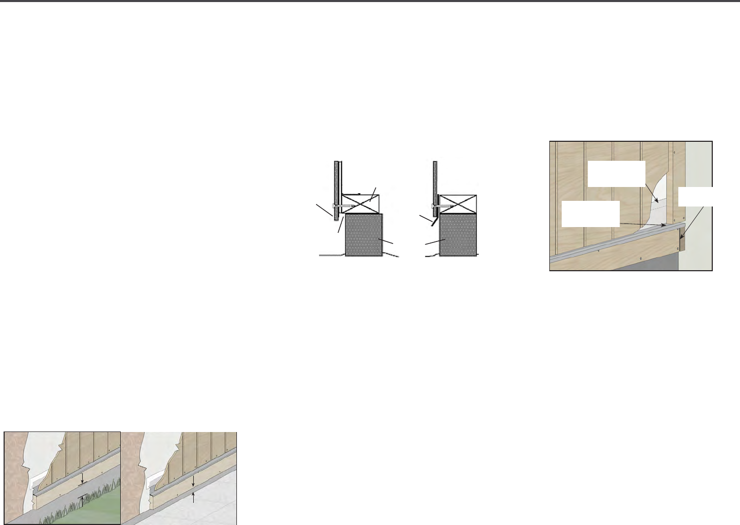
27 | Diamond Kote Building Products Application Guide 6.18
4'X8',9',10' BOARD & BATTEN PANEL
At the time of manufacture, siding meets
or exceeds the performance standards set
forth in ICC-ES-AC321 and has achieved
code recognition under ESR-1301, CCNC
11826, APA recognition under PR-N124,
and HUD recognition under HUD-MR-1318.
(
For copies of ESR-1301, call LP Support at 1-800-
648-6893 or go to apawood.org.)
• Minimum 6 inch clearance must be
maintained between siding and nish
grade.
• Siding applied adjacent to porches,
patios, walks, etc. must have a clearance
of at least 1 inch above any surface.
• Minimum 1 inch clearance at intersection
with roof line.
• Apply siding in a manner that prevents
moisture intrusion and water buildup.
• All exposed wood substrate must
be sealed in a manner that prevents
moisture intrusion and water buildup.
• LP
®
does not recommend LP
®
SmartSide
®
Panel for use in ICF and SIP assemblies.
• If used, LP
®
will not warrant for buckling
and shrinkage. However, balance of
warranty does remain intact.
• Do not use staples.
• Siding must not be in direct contact with
masonry, concrete, brick, stone, stucco,
or mortar.
HORIZONTAL TRIM
• Properly integrate ashing with siding,
WRB and vertical trim.
• At corners, allow the end of the trim to
overlap the end of the adjoining trim.
Leave a 3/16 inch space and seal with
sealant.
STUD AND SPACING
• Diamond Kote
®
Building Products must
be applied over sheathed walls into studs
spaced no greater than 16" on center.
• Installations over masonry walls, the wall
must be furred out with wood framing
spaced 16" on center and with adequate
thickness to accept the full length of the
recommended nail.
TRIM & FASCIA 190, 440, 540 & 2000 SERIES
INSTALLATION
• Trim must extend beyond the face of the siding. Trim may be
installed directly to the sheathing, or directly over the siding.
• Horizontal trim: properly integrate ashing with siding, WRB
and vertical trim. At corners, allow the end of the trim to overlap
the end of the adjoining trim. Leave a 3/16 inch space and seal
with sealant. (See diagram 6a)
• Vertical corners directly to sheathing: allow for proper spacing
between the trim edge and siding. Corner trim edge may
lightly touch adjacent trim edge. Follow siding manufacturer’s
application instructions. (See diagrams 6b and 6c)
• Vertical corners over siding: the width of the trim must overlap
the siding by a minimum of 2 inches. Sealant between the trim
and siding is not required for this application. Allow for proper
spacing at the corner between perpendicular siding pieces.
Corner trim edge may lightly touch adjacent trim edge. Follow
siding manufacturer’s application
instructions. (See diagram 6d)
• OPTIONAL Pre-assembled vertical corners: cut vertical
corner pieces to size with clearance requirements in mind. Set
perpendicular corner pieces and pre-drill fastening holes a
minimum of every 24 inches o.c. Fasten into pre-drilled holes with
proper nails or screws. (See diagrams 6e and 6f)
GENERAL REQUIREMENTS (CONTINUED)
6a
6b
6f
Corners
6e
6c 6d
LP SmartSide Trim & Fascia
6
Z-Flashing with
3/8" Space
3/16" with
Sealant
WRB ap or
ashing tape
©2014Louisiana-PacificCorporation.Allrightsreserved.L P, SmartSide,SilverTechandSmartFinish
areregisteredtrademarksofLouisiana-PacificCorporation.PrintedinU.S.A.
NOTE:Louisiana-PacificCorporationperiodicallyupdatesandrevisesitsproductinformation.
Toverifythatthisversioniscurrent,call800-450-6106.
LPZB05121/14
Cal.Prop65Warning:Use of this product may result in
exposure to wood dust, known to the State of California
to cause cancer.
. . U S P
Figure 9
Foracopyofthewarrantyorforinstallationandtechnicalsupport,visitthe
LPSmartSideproductsupportWebsiteat:
orforadditionalsupportcall800-450-6106.
www.lpsmartside.com
LPpanelsidingsareacceptedbytheStateofCaliforniaascategory
8140-ExteriorwallsidingandsheathingforWildlandUrbanInterface
(WUI)applications.ForWUIcompliance,installLPpanelsidingsin
accordancewithLouisiana-Pacific’sprintedinstallationinstructions
withtheadditionoffireretardantseal(ULListedfirecaulk,nominal
¼”bead)intheverticaljointandnailingpatternof3”OCperimeter
nailing/8”OCfieldnailing.LookfortheCaliforniaStateFireMarshal
Officelabelonoursiding.
TheLouisiana-PacificCorporation(“LP”)LPSmartSideSiding(the
“Products”)limitedwarranty(the“Warranty”)appliesonlyto
structuresonwhichtheProductshavebeenapplied,finishedand
maintainedinaccordancewiththepublishedapplication,finishing
andmaintenanceinstructionsineffectatthetimeofapplication.
Thefailuretofollowsuchapplication,finishingormaintenance
instructionswillvoidtheWarrantyastotheportionoftheProducts
affectedbythevariance(the“AffectedProducts”).
LPassumesnoliabilityforanylossordamagesustainedbythe
AffectedProductsand
ise
xpresslyreleasedbythepurchaserorowner
fromanysuchlossorliability.
AnymodificationoftheWarranty’sapplication,finishingor
maintenancerequirementsisvoidandunenforceableunlessapproved
inwritingpriortoapplicationbytheSidingGeneralManagerorhis
designeeandamemberoftheLPLegalDepartment.
WARRANTY REMEDIES ARE NOT AVAILABLE IF
REQUIREMENTS ARE NOT FOLLOWED.
G, F D W
Figure 8
S M N C M
Figure 7A Figure 7B
HORIZONTAL BELTLINE JOINTS
Figure 6
LP SS P S J D
(cont.)
Extend siding
below sill plate
Sill plate
Minimum of 1/8"w
or ashing between
siding and masonry
Masonry
foundtation
Flashing
Sill plate
SIDING MUST NOT
CONTACT MASONRY
TRIM & FASCIA 190, 440, 540 & 2000 SERIES
PREPARATION
• Minimum 6 inches clearance must be maintained between trim
and nished grade. (See diagram 2a)
• Trim applied adjacent to roofs, porches, patios, sidewalks, etc.
must have a clearance of at least 1 inch above any surface where
water might collect. The surface must be sloped or otherwise
designed to provide proper drainage so the trim is at no time
directly exposed to standing water. (See diagram 2b)
• A non-corrosive drip-edge must be applied at bottom edge of
roong where it meets the fascia. (See diagrams 2c and 9c)
• In a horizontal brick frieze or band board application where the
trim meets the masonry leave a 3/8 inch minimum airspace and
ash between the trim and the masonry. (See diagram 2d)
GENERAL REQUIREMENTS (CONTINUED)
• For the cleanest cut and longer blade life, a ne-tooth carbide
tipped blade is recommended.
• Trim and fascia are manufactured with a special edge coating
which reduces moisture-related issues. Do not rip and/or rout
the trim and fascia, as it will leave the edges unprotected. If the
trim or fascia materials are ripped you must take special care to
prime, paint and seal all exposed wood ber as described in the
nishing section.
• Climb cut the surface of the trim and fascia such that the rotation
of the blade cuts downward on the primed or prenished
surface.
• Do not miter trim ends or edges. 45 degree diagonal cuts of trim
ends around door and window opening is acceptable, as well as
joining. (See diagram 2e)
2a
C
UTTING
2b
2c
2d
2e
General Information (continued)
Cutting
LP SmartSide Trim & Fascia
2
Water
Resistive
Barrier
Sheathing
1" min.
TRIM & FASCIA 190, 440, 540 & 2000 SERIES
PREPARATION
• Minimum 6 inches clearance must be maintained between trim
and nished grade. (See diagram 2a)
• Trim applied adjacent to roofs, porches, patios, sidewalks, etc.
must have a clearance of at least 1 inch above any surface where
water might collect. The surface must be sloped or otherwise
designed to provide proper drainage so the trim is at no time
directly exposed to standing water. (See diagram 2b)
• A non-corrosive drip-edge must be applied at bottom edge of
roong where it meets the fascia. (See diagrams 2c and 9c)
• In a horizontal brick frieze or band board application where the
trim meets the masonry leave a 3/8 inch minimum airspace and
ash between the trim and the masonry. (See diagram 2d)
GENERAL REQUIREMENTS (CONTINUED)
• For the cleanest cut and longer blade life, a ne-tooth carbide
tipped blade is recommended.
• Trim and fascia are manufactured with a special edge coating
which reduces moisture-related issues. Do not rip and/or rout
the trim and fascia, as it will leave the edges unprotected. If the
trim or fascia materials are ripped you must take special care to
prime, paint and seal all exposed wood ber as described in the
nishing section.
• Climb cut the surface of the trim and fascia such that the rotation
of the blade cuts downward on the primed or prenished
surface.
• Do not miter trim ends or edges. 45 degree diagonal cuts of trim
ends around door and window opening is acceptable, as well as
joining. (See diagram 2e)
2a
C
UTTING
2b
2c
2d
2e
General Information (continued)
Cutting
LP SmartSide Trim & Fascia
2
Water
Resistive
Barrier
6" min.
Sheathing
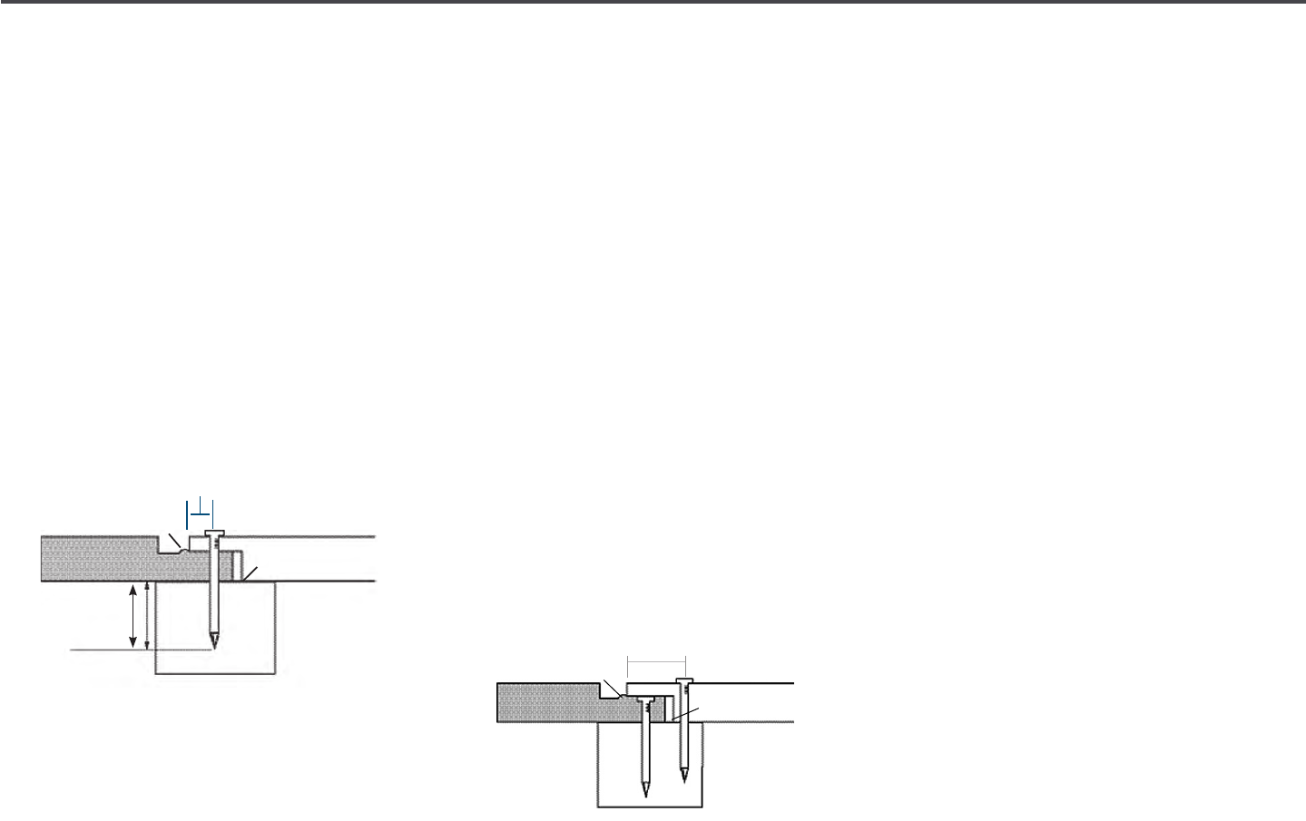
28 | Diamond Kote Building Products Application Guide 6.18
4'X8',9',10' BOARD & BATTEN PANEL
NAILING INSTRUCTIONS
• In braced wall assemblies, use minimum
6d hot-dip galvanized nails for 38 and
76 Series panels
(0.113 inch shank diameter,
0.270 head diameter) and minimum 8d
for 190 Series panels (0.131 inch shank
diameter, 0.290 head diameter) for 190
Series panels.
• Do not use electroplated fasteners.
• Refer to your local building code to verify
the minimum allowable fastener size.
• Penetrate structural framing or wood
structural panels and structural framing
a minimum of 1-1/2 inch.
For 76 and 190 Series panels:
• Single nailing for 76 and 190 series
meets wall bracing requirements.
• To meet the equivalent 3/8 inch shear
wall design values, double nailing
procedures must be used.
• It may be necessary to angle drive the
second nail in order to penetrate the
framing. Seal nails driven below the
surface.
• Shear values for panels applied directly
to studs shall be no greater than noted in
Table 1 of the ICC-ES Report ESR-1301
or Table 1 of APA PR-N 124.
• Not warranted for application on SIP and
ICF assemblies.
For 38 Series panels:
• Procedure is to double nail in order to
meet the wall bracing requirements and
5/16 inch shear wall design values.
CAUTION
• 38 and 76 Series panels must be
installed on 16 inch O.C. framing only.
When installing on 24 inch O.C. framing,
190 Series panels are required.
• Back of panel must not come in contact
with masonry/concrete foundation.
• Do not force siding into place.
• Maintain the illustrated 1/8 inch space
behind the joint to allow for expansion
while the panel equilibrates with the
local environment.
• LP
®
SmartSide
®
Panel siding must not
be attached by stapling.
• Install panels in light contact to the
edge of alignment bead.
(see Figure 1 and
Figure 2 far left column) Do not install over
alignment bead.
• Climb cut the surface of the siding
such that the rotation of the blade cuts
downward on the primed or pre-nished
surface.
• Where siding butts window trim, door
casings and masonry, etc. leave a 3/16
inch gap and seal.
Nailing Instructions
-
DO
• Primeandpaintallexposedsurfacesincludingalldrip
edgesorwherewaterwillhang.
Finishing Instructions
Applicationinstructions(cont.)
-
-
-
Trim
DO NOT USE
HANDLE PREFINISHED LP SMARTSIDE PRODUCTS WITH
EXTREMECAREDURINGSTORAGEANDAPPLICATION.TOUCH
UP ANY DAMAGE TO THE FINISH THAT MAY OCCUR DURING
APPLICATIONPERPREFINISHERSSPECIFICATIONS.
Alignment bead
3/8 inch from edge
1/8 inch gap
Nail penetration
min. 1-1/2 inch
Single row
of nails
CONTINUED ON NEXT PAGE
Double row
of nails
1/8 inch gap
1 inch from edge
Alignment bead

29 | Diamond Kote Building Products Application Guide 6.18
INSULATED SHEATHINGS
• LP
®
SmartSide
®
Panel siding may be
installed over low-compression rigid
foam or exterior gypsum.
These precautions must be followed:
• Adequate bracing of the wall in
accordance with International Codes or
other ruling building code is required.
• For rigid foam sheathing up to 1 inch
(25.4 mm) thick, siding may be nailed
directly to the foam sheathing unless
a drainage plane is required by the
local building code. Nail length must be
increased to ensure a minimum 1-1/2"
(38.1 mm) fastener penetration into the
structural framing.
• For rigid foam sheathing greater than 1"
(25.4 mm), a minimum 1-1/2" (38.1 mm)
thick by 3-1/2"
(88.9 mm) wide vertical
strapping or furring strip must be
installed over the sheathing to provide
a solid, level nailing base for the siding.
The strapping must be securely fastened
to structural framing, spaced no greater
than 16" on center
(406 mm), with a
minimum nail penetration of 1-1/2" on
center
(38.1 mm) and a maximum nail
spacing no greater than the width of the
siding.
• LP
®
will assume no responsibility for any
damage or condition arising from the
use of rigid foam or exterior gypsum.
Applicationinstructions(cont.)
1 in. Roof & Chimney Clearance
Figure 4
LP SmartSide Panel Siding Joint Details
LAPPED HORIZONTAL WALL JOINT
HORIZONTAL WALL JOINTS
Figure 5A
Figure 5B
Figure 5C
• Shearvaluesforpanelsapplieddirectlytostudsshallbenogreater
thannotedinTable1oftheICC-ESReportESR-1301orTable1of
APAPR-N124.
•NotwarrantedforapplicationonSIPandICFassemblies.
CAUTION
• 38and76Seriespanelsmustbeinstalledon16in.O.C.framing
only.Wheninstallingon24in.O.C.framing,190Seriespanelsare
required.
• Backsideofpanelmustnotcomeincontactwithmasonryor
concretefoundation.
• Donotforcesidingintoplace.Maintaintheillustrated
1
/
8
in.space
behindthejointtoallowforexpansionwhilethepanelequilibrates
withthelocalenvironment.
• LP®SmartSide®Panelsidingmustnotbeattachedbystapling.
• DONOTINSTALLOVERALIGNMENTBEAD.Installpanelsinlight
contacttotheedgeofalignmentbead.(seeFigure1andFigure2)
• Climbcutthesurfaceofthesidingsuchthattherotationoftheblade
cutsdownwardontheprimedorprenishedsurface.
• Wheresidingbuttswindowtrim,doorcasingsandmasonry,etc.leave
a3/16in.gapandseal.
InsulatedSheathings
LPSmartSideSidingsmaybeinstalledoverlow-compressionrigid
foamorexteriorgypsum.Thefollowingprecautionsmustbefollowed:
a) AdequatebracingofthewallinaccordancewiththeInternational
Codesorotherrulingbuildingcodeisrequired.
b) Forrigidfoamsheathingupto1"(25.4mm)thick,sidingmaybe
naileddirectlytothefoamsheathingunlessadrainageplane
isrequiredbythelocalbuildingcode.Naillengthmustbein-
creasedtoensureaminimum1-1/2”(38.1mm)fastenerpenetra-
tionintothestructuralframing.
c)
Forrigidfoamsheathinggreaterthan1in.(25.4mm),aminimum
1-1/2in.(38.1mm)thickby3-1/2in.(88.9mm)wideverticalstrap-
pingorfurringstripmustbeinstalledoverthesheathingtoprovide
asolid,levelnailingbaseforthesiding.Thestrappingmustbe
securelyfastenedtostructuralframingspacednogreaterthan16
in.O.C.(406mm)withaminimumnailpenetrationof1-1/2in.(38.1
mm)andamaximumnailspacingnogreaterthanthewidthofthe
siding.
Louisiana-Pacicwillassumenoresponsibilityforanydamageor
conditionarisingfromtheuseofrigidfoamorexteriorgypsum.
Nail 3/8 inch from edge
12 inch max.
eld nailing
6 inch max.
perimeter nailing
6 inch min.
ground clearance
6 inch max.
perimeter nailing
Do not let panel
contact masonry
Foundation
Snug
CONDITION CORRECTION
Flush
Visible ber
Countersunk
1
⁄16 -
1
⁄8"
Countersunk more
than
1
⁄8"
OK
Paint
Apply sealant
Apply sealant &
re-nail
OK
Applicationinstructions(cont.)
1 in. Roof & Chimney Clearance
Figure 4
LP SmartSide Panel Siding Joint Details
LAPPED HORIZONTAL WALL JOINT
HORIZONTAL WALL JOINTS
Figure 5A
Figure 5B
Figure 5C
• Shearvaluesforpanelsapplieddirectlytostudsshallbenogreater
thannotedinTable1oftheICC-ESReportESR-1301orTable1of
APAPR-N124.
•NotwarrantedforapplicationonSIPandICFassemblies.
CAUTION
• 38and76Seriespanelsmustbeinstalledon16in.O.C.framing
only.Wheninstallingon24in.O.C.framing,190Seriespanelsare
required.
• Backsideofpanelmustnotcomeincontactwithmasonryor
concretefoundation.
• Donotforcesidingintoplace.Maintaintheillustrated
1
/
8
in.space
behindthejointtoallowforexpansionwhilethepanelequilibrates
withthelocalenvironment.
• LP®SmartSide®Panelsidingmustnotbeattachedbystapling.
• DONOTINSTALLOVERALIGNMENTBEAD.Installpanelsinlight
contacttotheedgeofalignmentbead.(seeFigure1andFigure2)
• Climbcutthesurfaceofthesidingsuchthattherotationoftheblade
cutsdownwardontheprimedorprenishedsurface.
• Wheresidingbuttswindowtrim,doorcasingsandmasonry,etc.leave
a3/16in.gapandseal.
InsulatedSheathings
LPSmartSideSidingsmaybeinstalledoverlow-compressionrigid
foamorexteriorgypsum.Thefollowingprecautionsmustbefollowed:
a) AdequatebracingofthewallinaccordancewiththeInternational
Codesorotherrulingbuildingcodeisrequired.
b) Forrigidfoamsheathingupto1"(25.4mm)thick,sidingmaybe
naileddirectlytothefoamsheathingunlessadrainageplane
isrequiredbythelocalbuildingcode.Naillengthmustbein-
creasedtoensureaminimum1-1/2”(38.1mm)fastenerpenetra-
tionintothestructuralframing.
c)
Forrigidfoamsheathinggreaterthan1in.(25.4mm),aminimum
1-1/2in.(38.1mm)thickby3-1/2in.(88.9mm)wideverticalstrap-
pingorfurringstripmustbeinstalledoverthesheathingtoprovide
asolid,levelnailingbaseforthesiding.Thestrappingmustbe
securelyfastenedtostructuralframingspacednogreaterthan16
in.O.C.(406mm)withaminimumnailpenetrationof1-1/2in.(38.1
mm)andamaximumnailspacingnogreaterthanthewidthofthe
siding.
Louisiana-Pacicwillassumenoresponsibilityforanydamageor
conditionarisingfromtheuseofrigidfoamorexteriorgypsum.
Prime and paint
bottom drip edges
Trim
4 in. min.
vertical ashing
1 in. min. clearance
from roong
1 IN. ROOF & CHIMNEY CLEARANCE
©2014Louisiana-PacificCorporation.Allrightsreserved.L P,SmartSide,SilverTechandSmartFinish
areregisteredtrademarksofLouisiana-PacificCorporation.PrintedinU.S.A.
NOTE:Louisiana-PacificCorporationperiodicallyupdatesandrevisesitsproductinformation.
Toverifythatthisversioniscurrent,call800-450-6106.
LPZB05121/14
Cal.Prop65Warning:Use of this product may result in
exposure to wood dust, known to the State of California
to cause cancer.
. . U S P
Figure 9
Foracopyofthewarrantyorforinstallationandtechnicalsupport,visitthe
LPSmartSideproductsupportWebsiteat:
orforadditionalsupportcall800-450-6106.
www.lpsmartside.com
LPpanelsidingsareacceptedbytheStateofCaliforniaascategory
8140-ExteriorwallsidingandsheathingforWildlandUrbanInterface
(WUI)applications.ForWUIcompliance,installLPpanelsidingsin
accordancewithLouisiana-Pacific’sprintedinstallationinstructions
withtheadditionoffireretardantseal(ULListedfirecaulk,nominal
¼”bead)intheverticaljointandnailingpatternof3”OCperimeter
nailing/8”OCfieldnailing.LookfortheCaliforniaStateFireMarshal
Officelabelonoursiding.
TheLouisiana-PacificCorporation(“LP”)LPSmartSideSiding(the
“Products”)limitedwarranty(the“Warranty”)appliesonlyto
structuresonwhichtheProductshavebeenapplied,finishedand
maintainedinaccordancewiththepublishedapplication,finishing
andmaintenanceinstructionsineffectatthetimeofapplication.
Thefailuretofollowsuchapplication,finishingormaintenance
instructionswillvoidtheWarrantyastotheportionoftheProducts
affectedbythevariance(the“AffectedProducts”).
LPassumesnoliabilityforanylossordamagesustainedbythe
AffectedProductsand
ise
xpresslyreleasedbythepurchaserorowner
fromanysuchlossorliability.
AnymodificationoftheWarranty’sapplication,finishingor
maintenancerequirementsisvoidandunenforceableunlessapproved
inwritingpriortoapplicationbytheSidingGeneralManagerorhis
designeeandamemberoftheLPLegalDepartment.
WARRANTY REMEDIES ARE NOT AVAILABLE IF
REQUIREMENTS ARE NOT FOLLOWED.
G, F D W
Figure 8
S M N C M
Figure 7A Figure 7B
HORIZONTAL BELTLINE JOINTS
Figure 6
LP SS P S J D (cont.)
Siding (4ft. x 8ft.)
3/8 inch gap
Sloped ashing with
4 in. vertical leg
2 in. x 10 in. band board
Filler Board
Siding (4ft. x 8ft.)
HORIZONTAL BELTLINE JOINTS
©2014Louisiana-PacificCorporation.Allrightsreserved.L P,SmartSide,SilverTechandSmartFinish
areregisteredtrademarksofLouisiana-PacificCorporation.PrintedinU.S.A.
NOTE:Louisiana-PacificCorporationperiodicallyupdatesandrevisesitsproductinformation.
Toverifythatthisversioniscurrent,call800-450-6106.
LPZB05121/14
Cal.Prop65Warning:Use of this product may result in
exposure to wood dust, known to the State of California
to cause cancer.
. . U S P
Figure 9
Foracopyofthewarrantyorforinstallationandtechnicalsupport,visitthe
LPSmartSideproductsupportWebsiteat:
orforadditionalsupportcall800-450-6106.
www.lpsmartside.com
LPpanelsidingsareacceptedbytheStateofCaliforniaascategory
8140-ExteriorwallsidingandsheathingforWildlandUrbanInterface
(WUI)applications.ForWUIcompliance,installLPpanelsidingsin
accordancewithLouisiana-Pacific’sprintedinstallationinstructions
withtheadditionoffireretardantseal(ULListedfirecaulk,nominal
¼”bead)intheverticaljointandnailingpatternof3”OCperimeter
nailing/8”OCfieldnailing.LookfortheCaliforniaStateFireMarshal
Officelabelonoursiding.
TheLouisiana-PacificCorporation(“LP”)LPSmartSideSiding(the
“Products”)limitedwarranty(the“Warranty”)appliesonlyto
structuresonwhichtheProductshavebeenapplied,finishedand
maintainedinaccordancewiththepublishedapplication,finishing
andmaintenanceinstructionsineffectatthetimeofapplication.
Thefailuretofollowsuchapplication,finishingormaintenance
instructionswillvoidtheWarrantyastotheportionoftheProducts
affectedbythevariance(the“AffectedProducts”).
LPassumesnoliabilityforanylossordamagesustainedbythe
AffectedProductsand
ise
xpresslyreleasedbythepurchaserorowner
fromanysuchlossorliability.
AnymodificationoftheWarranty’sapplication,finishingor
maintenancerequirementsisvoidandunenforceableunlessapproved
inwritingpriortoapplicationbytheSidingGeneralManagerorhis
designeeandamemberoftheLPLegalDepartment.
WARRANTY REMEDIES ARE NOT AVAILABLE IF
REQUIREMENTS ARE NOT FOLLOWED.
G, F D W
Figure 8
S M N C M
Figure 7A Figure 7B
HORIZONTAL BELTLINE JOINTS
Figure 6
LP SS P S J D (cont.)
Interior Finish
Siding
Code Approved Breathable
Water-Resistive Barrier
Sloped ashing with 4 in.
vertical leg
Trim
Nail n (do not damage)
Space window/door per
manufacturer's instruction
GAP, FLASH DOORS & WINDOWS
Applicationinstructions(cont.)
1 in. Roof & Chimney Clearance
Figure 4
LP SmartSide Panel Siding Joint Details
LAPPED HORIZONTAL WALL JOINT
HORIZONTAL WALL JOINTS
Figure 5A
Figure 5B
Figure 5C
• Shearvaluesforpanelsapplieddirectlytostudsshallbenogreater
thannotedinTable1oftheICC-ESReportESR-1301orTable1of
APAPR-N124.
•NotwarrantedforapplicationonSIPandICFassemblies.
CAUTION
• 38and76Seriespanelsmustbeinstalledon16in.O.C.framing
only.Wheninstallingon24in.O.C.framing,190Seriespanelsare
required.
• Backsideofpanelmustnotcomeincontactwithmasonryor
concretefoundation.
• Donotforcesidingintoplace.Maintaintheillustrated
1
/
8
in.space
behindthejointtoallowforexpansionwhilethepanelequilibrates
withthelocalenvironment.
• LP®SmartSide®Panelsidingmustnotbeattachedbystapling.
• DONOTINSTALLOVERALIGNMENTBEAD.Installpanelsinlight
contacttotheedgeofalignmentbead.(seeFigure1andFigure2)
• Climbcutthesurfaceofthesidingsuchthattherotationoftheblade
cutsdownwardontheprimedorprenishedsurface.
• Wheresidingbuttswindowtrim,doorcasingsandmasonry,etc.leave
a3/16in.gapandseal.
InsulatedSheathings
LPSmartSideSidingsmaybeinstalledoverlow-compressionrigid
foamorexteriorgypsum.Thefollowingprecautionsmustbefollowed:
a) AdequatebracingofthewallinaccordancewiththeInternational
Codesorotherrulingbuildingcodeisrequired.
b) Forrigidfoamsheathingupto1"(25.4mm)thick,sidingmaybe
naileddirectlytothefoamsheathingunlessadrainageplane
isrequiredbythelocalbuildingcode.Naillengthmustbein-
creasedtoensureaminimum1-1/2”(38.1mm)fastenerpenetra-
tionintothestructuralframing.
c)
Forrigidfoamsheathinggreaterthan1in.(25.4mm),aminimum
1-1/2in.(38.1mm)thickby3-1/2in.(88.9mm)wideverticalstrap-
pingorfurringstripmustbeinstalledoverthesheathingtoprovide
asolid,levelnailingbaseforthesiding.Thestrappingmustbe
securelyfastenedtostructuralframingspacednogreaterthan16
in.O.C.(406mm)withaminimumnailpenetrationof1-1/2in.(38.1
mm)andamaximumnailspacingnogreaterthanthewidthofthe
siding.
Louisiana-Pacicwillassumenoresponsibilityforanydamageor
conditionarisingfromtheuseofrigidfoamorexteriorgypsum.
BUTT & FLASH LAP
Siding
Blocking
Sloped ashing
with 4 in. vertical leg
3/8 in.
min. gap
Blocking
1 in. min.
overlap
3/8 in.
min. gap
HORIZONTAL WALL JOINTS
Applicationinstructions(cont.)
1 in. Roof & Chimney Clearance
Figure 4
LP SmartSide Panel Siding Joint Details
LAPPED HORIZONTAL WALL JOINT
HORIZONTAL WALL JOINTS
Figure 5A
Figure 5B
Figure 5C
• Shearvaluesforpanelsapplieddirectlytostudsshallbenogreater
thannotedinTable1oftheICC-ESReportESR-1301orTable1of
APAPR-N124.
•NotwarrantedforapplicationonSIPandICFassemblies.
CAUTION
• 38and76Seriespanelsmustbeinstalledon16in.O.C.framing
only.Wheninstallingon24in.O.C.framing,190Seriespanelsare
required.
• Backsideofpanelmustnotcomeincontactwithmasonryor
concretefoundation.
• Donotforcesidingintoplace.Maintaintheillustrated
1
/
8
in.space
behindthejointtoallowforexpansionwhilethepanelequilibrates
withthelocalenvironment.
• LP®SmartSide®Panelsidingmustnotbeattachedbystapling.
• DONOTINSTALLOVERALIGNMENTBEAD.Installpanelsinlight
contacttotheedgeofalignmentbead.(seeFigure1andFigure2)
• Climbcutthesurfaceofthesidingsuchthattherotationoftheblade
cutsdownwardontheprimedorprenishedsurface.
• Wheresidingbuttswindowtrim,doorcasingsandmasonry,etc.leave
a3/16in.gapandseal.
InsulatedSheathings
LPSmartSideSidingsmaybeinstalledoverlow-compressionrigid
foamorexteriorgypsum.Thefollowingprecautionsmustbefollowed:
a) AdequatebracingofthewallinaccordancewiththeInternational
Codesorotherrulingbuildingcodeisrequired.
b) Forrigidfoamsheathingupto1"(25.4mm)thick,sidingmaybe
naileddirectlytothefoamsheathingunlessadrainageplane
isrequiredbythelocalbuildingcode.Naillengthmustbein-
creasedtoensureaminimum1-1/2”(38.1mm)fastenerpenetra-
tionintothestructuralframing.
c)
Forrigidfoamsheathinggreaterthan1in.(25.4mm),aminimum
1-1/2in.(38.1mm)thickby3-1/2in.(88.9mm)wideverticalstrap-
pingorfurringstripmustbeinstalledoverthesheathingtoprovide
asolid,levelnailingbaseforthesiding.Thestrappingmustbe
securelyfastenedtostructuralframingspacednogreaterthan16
in.O.C.(406mm)withaminimumnailpenetrationof1-1/2in.(38.1
mm)andamaximumnailspacingnogreaterthanthewidthofthe
siding.
Louisiana-Pacicwillassumenoresponsibilityforanydamageor
conditionarisingfromtheuseofrigidfoamorexteriorgypsum.
Siding
Framing (band joist,
truss chord ect)
Wall framing
1 in. min.
overlap
LAPPED HORIZONTAL WALL JOINT
©2014Louisiana-PacificCorporation.Allrightsreserved.L P,SmartSide,SilverTechandSmartFinish
areregisteredtrademarksofLouisiana-PacificCorporation.PrintedinU.S.A.
NOTE:Louisiana-PacificCorporationperiodicallyupdatesandrevisesitsproductinformation.
Toverifythatthisversioniscurrent,call800-450-6106.
LPZB05121/14
Cal.Prop65Warning:Use of this product may result in
exposure to wood dust, known to the State of California
to cause cancer.
. . U S P
Figure 9
Foracopyofthewarrantyorforinstallationandtechnicalsupport,visitthe
LPSmartSideproductsupportWebsiteat:
orforadditionalsupportcall800-450-6106.
www.lpsmartside.com
LPpanelsidingsareacceptedbytheStateofCaliforniaascategory
8140-ExteriorwallsidingandsheathingforWildlandUrbanInterface
(WUI)applications.ForWUIcompliance,installLPpanelsidingsin
accordancewithLouisiana-Pacific’sprintedinstallationinstructions
withtheadditionoffireretardantseal(ULListedfirecaulk,nominal
¼”bead)intheverticaljointandnailingpatternof3”OCperimeter
nailing/8”OCfieldnailing.LookfortheCaliforniaStateFireMarshal
Officelabelonoursiding.
TheLouisiana-PacificCorporation(“LP”)LPSmartSideSiding(the
“Products”)limitedwarranty(the“Warranty”)appliesonlyto
structuresonwhichtheProductshavebeenapplied,finishedand
maintainedinaccordancewiththepublishedapplication,finishing
andmaintenanceinstructionsineffectatthetimeofapplication.
Thefailuretofollowsuchapplication,finishingormaintenance
instructionswillvoidtheWarrantyastotheportionoftheProducts
affectedbythevariance(the“AffectedProducts”).
LPassumesnoliabilityforanylossordamagesustainedbythe
AffectedProductsandisexpresslyreleasedbythepurchaser
orowner
from
anysuchlossorliability.
AnymodificationoftheWarranty’sapplication,finishingor
maintenancerequirementsisvoidandunenforceableunlessapproved
inwritingpriortoapplicationbytheSidingGeneralManagerorhis
designeeandamemberoftheLPLegalDepartment.
WARRANTY REMEDIES ARE NOT AVAILABLE IF
REQUIREMENTS ARE NOT FOLLOWED.
G, F D W
Figure 8
S M N C M
Figure 7A Figure 7B
HORIZONTAL BELTLINE JOINTS
Figure 6
LP SS P S J D (cont.)
4 FT. X 8 FT. UNGROOVED SHIPLAP PANEL
scant face width
SPACE JOINT 1-8 IN
Refer to nailing instructions
1/8 in. gap
1/8 in. gap
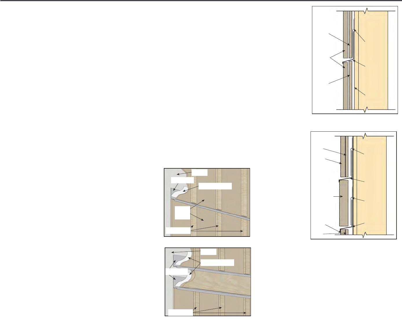
30 | Diamond Kote Building Products Application Guide 6.18
ALTERNATIVE FASTENING OPTION:
ATTACHING TRIM AS BATTEN STRIPS
• In cases where trim/batten strips
are fastened just into the structural
sheathing, attachment will require
additional support from a construction
adhesive.
• First, secure the trim to the structure
while the construction adhesive
completely cures, using hot-dipped
galvanized ring-shanked nails no smaller
than 0.091 inch shank diameter.
• Second, use an exterior grade
construction adhesive that meets the
following specications.
Construction Adhesive Specications:
• Minimum bond strength: 300 psi
• Minimum application temperature: 40° F
• Paintable grade
INSTALLATION
• When attaching trim as batten strips,
follow the Fastening Instructions section
in this document.
• Exception: When using trim less than 3
inches wide as battens, apply only one
nail per width, a maximum of every 36
inches vertically.
• When batten strips are applied over
panel siding at vertical joints, sealant is
not required.
• When batten strips are applied to walls
with horizontal panel joints, do not run
battens over the panel joint and ashing.
Terminate the trim battens above and
below the horizontal panel joint to allow
for proper spacing and ashing.
(See
diagrams 10a and 10b)
• When batten strips are applied to walls
with horizontal band boards be sure to
properly ash above and below the band
board. Leave a minimum 3/8 inch space
between the ends of the batten strips and
the band board. Prime and paint all cut
ends and exposed substrate. Z-ashing
installed below the band board must
cover the top ends of the batten strips
below.
(See diagrams 10c and 10d)
TRIM & FASCIA 190, 440, 540 & 2000 SERIES
INSTALLATION
• When attaching trim as batten strips, follow the Fastening Instructions section in this document.
− Exception: When using trim less than 3 inches wide as battens, apply one nail per width, a maximum of every
36 inches vertically.
• When batten strips are applied over panel siding at vertical joints, sealant is not required.
• When batten strips are applied to walls with horizontal panel joints, do not run battens over the panel joint and ashing.
Terminate the trim battens above and below the horizontal panel joint to allow for proper spacing and ashing.
(See diagrams 10a and 10b)
• When batten strips are applied to walls with horizontal band boards be sure to properly ash above and below the band
board. Leave a minimum 3/8 inch space between the ends of the batten strips and the band board. Prime and paint all cut
ends and exposed substrate. Z-ashing installed below the band board must cover the top ends of the batten strips below.
(See diagrams 10c and 10d)
GENERAL REQUIREMENTS (CONTINUED)
10a
10c
Board and Batten
10b
10d
LP SmartSide Trim & Fascia
10
WRB Flap
or Adhesive
Flashing
Sloped
Z-Flashing
WRB
Panel
Batten
Panel
Panel
Batten
Band Board
Panel
Batten
WRB Flap
or Adhesive
Flashing
Sloped
Z-Flashing
WRB Flap
or Adhesive
Flashing
Sloped
Z-Flashing
WRB
WRB
Adhesive Flashing
Adhesive Flashing
Z-Flashing
Z-Flashing
Trim Battens
Trim Battens
Panel
Siding
10a
10c
10b
10d

31 | Diamond Kote Building Products Application Guide 6.18
6 in.
6 in. minimum
Figure 10A
Figure 10B
Figure 10
Figure 10E Figure 10D
Figure 10C
INSTALLATION DIAGRAM
VERTICAL SIDING APPLICATION
• LP
®
SmartSide
®
38 Series Strand
Substrate Vertical Siding for Board &
Batten applications, according to the
following requirements.
• Siding must be installed over a minimum
7/16 Category wood structural panels
with an APA Trademark that contains the
consensus Standard DOC PS 1 or PS 2.
• Except with LP
®
FlameBlock
®
Fire-Rated
OSB Sheathing.
• Vertical Siding or Batten may only
span one plate-to-plate. Due to plate
shrinkage, each vertical application is
not to span beyond one oor to ceiling
distance, or one oor to top of gable
distance.
(See Figures 4 & 5)
• Vertical Siding SHALL NOT be installed
horizontally. Battens must be a minimum
0.5 x 2.5 inches actual size.
• Must be installed over a non-compressible
drainable housewrap to provide drainage
behind siding.
• Touch-up paint all cut/exposed ends.
• Vertical Siding must be spaced a
minimum of 3/16"
(See Figure 3) Sealant is
not required in any vertical joint covered
by Batten & backed by a WRB.
Minimum Fastener Type for Vertical Siding:
• Corrosion Resistant: (ASTM A153) Hot-
dipped galvanized or stainless steel
• Ring Shank: Shank diameter = 0.091
inch, Head diameter = 0.221 inch, Length
= fastener shall be long enough to fully
penetrate structural panel sheathing.
Ensure that the ring shanks of the nail
fully engage the wood structural panel
wall sheathing.
• Caution: Choose a fastener length that
will not damage wiring or other utilities
in the exterior wall assembly
Fastener Placement for Vertical Siding:
Maximum 3/8 inch from ends and edges
(Figure 2)
Fastener Spacing for Vertical Siding:
Fastened a maximum of 6 o.c. along the
perimeter
(Figure 2)
6 in.
6 in. minimum
Figure 10A
Figure 10B
Figure 10
Figure 10E Figure 10D
Figure 10C
Gap
3
/
16
in. and seal
Gap
3
/
16
in.
and seal
6 in.
12 in.
6 in.
6 in. minimum
Vapor Retarder
Figure 10A
Figure 10B
Figure 10
Figure 10E Figure 10D
Figure 10C
Breathable
water-resistant
barrier
10e
bottom course detail
panel joint
10f
ground clearance
10c
Shiplap Edge Panel
6 in. minimum
Paint
If required
by code
Caulk
10a 10b
CONTINUED ON NEXT PAGE
alternate inside corner details
Vertical
Siding
4" Wide Adhesive Flashing
Sloped Metal Z-Flashing
Floor Sheathing
Wall Sheathing
Water-Resistive
Barrier
Vertical
Siding
Figure 4 Figure 5
Trim/Batten
Figure 3
Trim/Batten
Vertical Siding min.
3/16" space
Water-Resistive Barrier
Wall Sheathing
Fastener
Batten
Vertical
Siding
12" o.c. max
3/8" max.
from ends
and edges
3/8" max.
from ends
and edges
6" o.c. max
Figure 1 Figure 2
Two Story - One Floor to Ceiling
Horizontal Joint between oors
Floor Framing
Trim/Batten
One Story
One Plate-to-Plate

32 | Diamond Kote Building Products Application Guide 6.18
VERTICAL SIDING APPLICATION continued
Minimum Fastener Type for Batten:
• Corrosion Resistant - (ASTM A153) Hot-
dipped galvanized or stainless steel
• Ring Shank nails provide superior
resistance to fastener pull-through.
• In Hurricane-Prone Regions or locations
where negative wind loads are a concern,
ring shank nails should be used.
Trim nails may be used in other locations
with the following cautions:
• Do not overdrive or countersink the
fastener, nail ush with the surface of
batten.
• Batten nails shall be installed per the
length, placement, spacing and quantity
requirements listed in this document.
• Detachment of Batten is not covered by
the LP
®
SmartSide
®
limited warranty
whether ring shank or trim nails are used
• Shank diameter= 0.091 inch, Head
diameter= 0.221 inch, Length = fastener
shall be long enough to fully penetrate
Vertical Siding.
• Caution: Choose a fastener length that
won't damage wiring or other utilities in
the exterior wall assembly.
Fastener Placement for Battens:
• Maximum 3/8 inch from ends and edges
(See Figure 1 pg. 27)
Fastener Spacing for Battens:
• Fastened with two nails at both ends, with
additional fasteners spaced a maximum
of 12 inches o.c. along alternating edges
the length of the batten
(Figure 1 pg. 27)
• Do not bridge oors with Vertical Siding
or Battens. Create a horizontal joint
between oors.
(Figure 4 pg. 27)
• Vertical Siding must be applied in a
manner that will not allow moisture
intrusion or water buildup.
• Refer to LP
®
Strand Panel Siding
Instructions and LP
®
Trim and Fascia
Instructions for additional application
information.
LAP SIDING INSTALLED VERTICALLY
• LP
®
Strand Lap may be installed Vertically
for Board & Batten or Board-on-Board
applications, according to the following
requirements.
• Siding must be installed over a minimum
7/16 Category wood structural panel
with an APA Trademark that contains
the consensus Standard DOC PS 1 or PS
2, or LP
®
FlameBlock
®
Fire-Rated OSB
Sheathing.
• Lap Siding installed vertical/batten may
only span one plate-to-plate. Due to
expected plate shrinkage, each vertical
application is not to span beyond one
oor to ceiling distance, or one oor to
top of gable distance.
(Figure 5 & 6)
• Battens must be a minimum 0.5 x 2.5
inches actual size.
• Siding must be installed over a non-
compressible drainable housewrap to
provide drainage behind siding.
• Touch-up paint all cut/exposed ends.
• The edges of Lap Siding installed
vertically must be spaced a minimum
of 3/16 inch from each other. Spacing
cannot exceed the distance that will
allow a minimum 1 inch of bearing
surface for the overlapping piece of Lap
Siding.
(See Figure 3 & 4 on pg. 29)
• Sealant is not required in any vertical
joint covered by Lap Siding or Batten
and backed by a water-resistive barrier.
CONTINUED ON NEXT PAGE
Two Story - One Floor to Ceiling
Horizontal Joint between oors
One Story
One Plate-to-Plate
Lap Siding installed
vertically
4" Wide Adhesive Flashing
Min. 3/8" space with
Sloped Metal Z-Flashing
Floor Sheathing
Wall Sheathing
Water-Resistive
Barrier
Floor Framing
Batten or Lap
siding Vertically
Lap Siding installed
vertically
Batten or Lap
siding Vertically
Figure 5
Figure 6
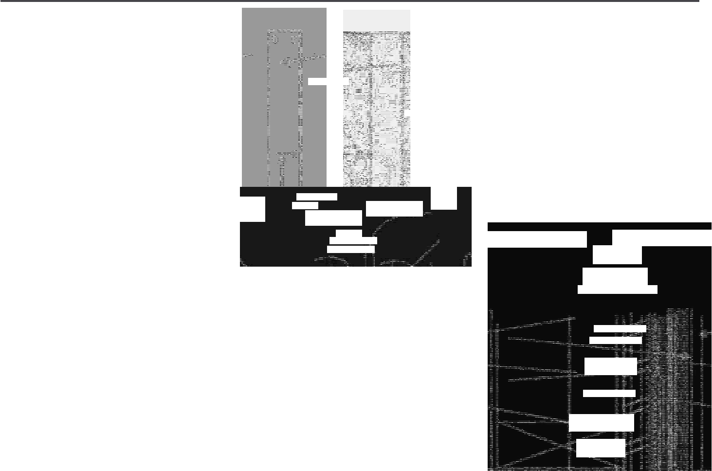
33 | Diamond Kote Building Products Application Guide 6.18
LAP SIDING
INSTALLED VERTICALLY continued
Minimum Fastener Type:
• Corrosion Resistant= (ASTM A153) Hot-
dipped Galvanized or stainless steel
• Ring Shank: Shank diameter= 0.092
inch, Length= fastener shall be long
enough to fully penetrate structural
panel sheathing.
• Ensure that the ring shanks of the nail
fully engages the wood structural panel
wall sheathing.
• Caution: The length of fastener should
be chosen to reduce possible damage
to wiring or other utilities in the exterior
wall assembly
Fastener Placement:
• 3/8 inch from ends and edges (Figure 2)
Fastener Spacing:
• Fastened with two nails at both ends,
with additional fasteners spaced a max
of 12 inches o.c. along alternating edges
(See Figure 2)
Minimum Fastener Type for Batten:
• Corrosion Resistant= (ASTM A153) Hot-
dipped galvanized or stainless steel
• Ring Shank nails provide superior
resistance to fastener pull-through.
• In Hurricane-Prone Regions or locations
where negative wind loads are a concern,
ring shank nails should be used.
• Trim nails may be used in other locations
with the following cautions:
• Do not overdrive or countersink the
fastener, nail ush with the surface of
batten. Detachment of battens is not
covered by the LP
®
SmartSide
®
limited
warranty whether ring shank or trim nails
are used.
• Shank diameter = 0.092 inch, Head
diameter = 0.221 inch, Length = fastener
shall be long enough to fully penetrate Lap
Siding. Caution: The length of fastener
should be chosen to reduce possible
damage to wiring or other utilities in the
exterior wall assembly.
Fastener Placement for Battens:
• 3/8 inch from ends and edges (Figure 1)
Fastener Spacing for Battens:
• Fastened with two nails at both ends,
with additional fasteners spaced a max.
of 12 inches o.c. along alternating edges
the length of the batten
(Figure 1)
• Do not bridge oors with Lap Siding
installed vertically or Battens.
• Create a horizontal joint between oors.
Horizontal joint must be ashed with
Sloped Metal Z-ashing. (Figure 5)
CONTINUED ON NEXT PAGE
Batten
Lap Siding
Installed
vertically
12" o.c. max
3/8" from ends
and edges
3/8" max.
from ends
and edges
6" o.c. max
Figure 1
Figure 2
Figure 3
Figure 4
Batten Attachment
Lap Siding Attachment
min. 3/16"
batten
lap siding installed
vertically
min. 1"
bearing
surface
WRB
Wall Sheathing
Fastener
min. 1"
bearing
surface
lap siding
installed vertically
Two Story - One Floor to Ceiling
Horizontal Joint between oors
One Story
One Plate-to-Plate
Lap Siding installed
vertically
4" Wide Adhesive Flashing
Min. 3/8" space with
Sloped Metal Z-Flashing
Floor Sheathing
Wall Sheathing
Water-Resistive
Barrier
Floor Framing
Batten or Lap
siding Vertically
Lap Siding installed
vertically
Batten or Lap
siding Vertically
Figure 5
Figure 6
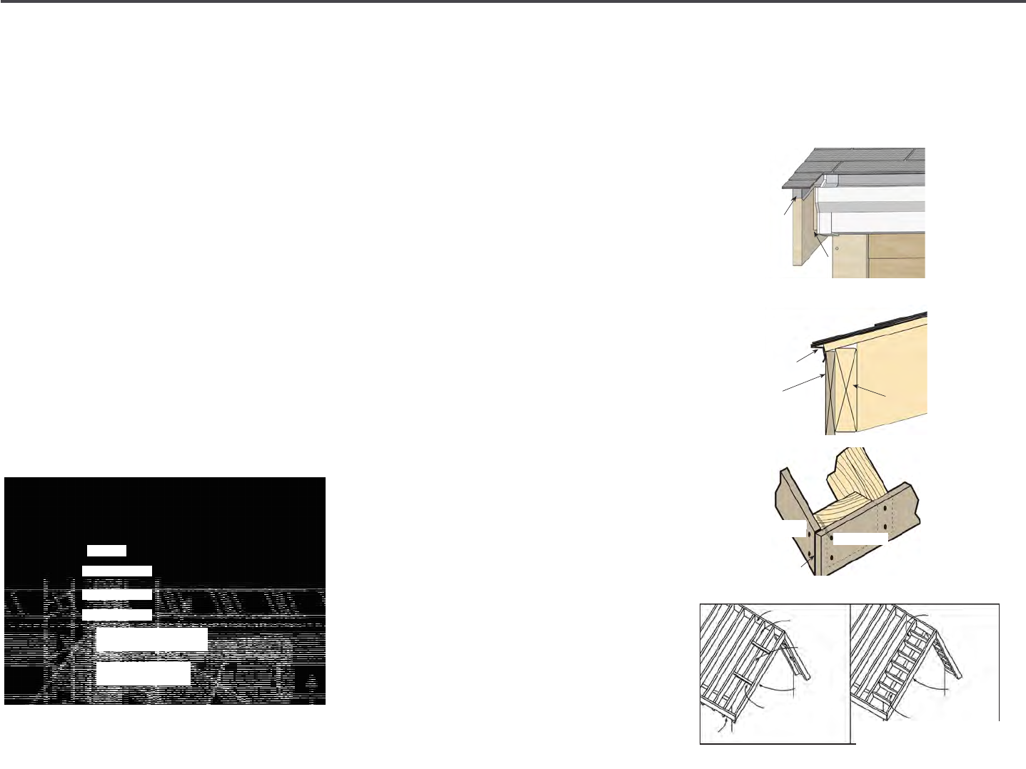
34 | Diamond Kote Building Products Application Guide 6.18
LAP SIDING
INSTALLED VERTICALLY continued
• Lap Siding installed vertically must be
applied in a manner that will not allow
moisture intrusion or water buildup.
• When using LP
®
SmartSide
®
siding with
other siding products like stucco, brick
or cultured stone veneers, it is important
to use a capillary break so moisture
absorbed into those veneers cannot
be transferred into SmartSide siding.
Separate SmartSide siding from veneers
with min. 3/8" space for horizontal joints
and 3/8" for vertical joints, use sealant.
Backer rod may be required by the
sealant manufacturer.
(Figure 7 & 8)
• All other requirements of the LP
®
Lap
Siding Instructions and Trim and Fascia
Instructions must be followed.
FASCIA APPLICATION
Trim may be installed as fascia, without sub
fascia, if it is 440 Series or larger and the
following specications are met:
• Trim and Fascia must be greater than
5 inches wide. Maximum roof truss or
rafter spacing of 24 inches on-center.
• If trim is installed directly to outlookers
on an overhanging rake, the outlookers
must be installed edgewise and must
be spaced no wider than 24 inches o.c.
(Diagram 9d)
• 190 Series Trim and Fascia products
MUST BE supported with solid wood
sub-fascia.
• Trim and Fascia are not designed for
structural applications and cannot be
used in the structural design of a roof
assembly.
• Exposed ying or suspended barge, rake
or fascia tails are not covered under the
LP
®
SmartSide
®
trim limited warranty if
trim is extended beyond the protection
of the roof system.
• If LP
®
SmartSide
®
trim is extended
beyond the protection of the roof
system, cap the top of the trim with a
metal coping that is integrated with the
roong system.
(Diagram 9a)
• Install drip-edge to prevent water
buildup behind fascia and trim.
(Diagrams
2c and 9b)
AT CORNERS: (See diagram 9c)
• All joints must be supported by framing.
• Do not nail from the face of one trim
member into the edge of another.
• Do not miter cut the corner joint.
TRIM & FASCIA 190, 440, 540 & 2000 SERIES
INSTALLATION
• Trim may be installed as fascia, without sub-fascia, if it is 440
Series or larger and the following specications are met:
- Trim and Fascia must be greater than 5 inches wide.
-Maximum roof truss or rafter spacing of 24 inches
on-center.
• If trim is installed directly to outlookers on an overhanging rake,
the outlookers must be installed edgewise and must be spaced
no wider than 24 inches o.c. (See diagram 9d)
• 190 Series trim and fascia products MUST BE supported with
solid wood sub-fascia.
• Trim and Fascia are not designed for structural applications and
cannot be used in the structural design of a roof assembly.
• Exposed ying or suspended barge, rake or fascia tails are not
covered under the LP SmartSide trim limited warranty if trim
is extended beyond the protection of the roof system. If LP
SmartSide trim is extended beyond the protection of the roof
system, cap the top of the trim with a metal coping that is
integrated with the roong system. (See diagram 9a)
• Install drip-edge to prevent water buildup behind fascia and
trim. (See diagrams 2c and 9b)
AT CORNERS: (See diagram 9c)
• All joints must be supported by framing.
• Do not nail from the face of one trim member into the edge of
another.
• Do not miter cut the corner joint.
GENERAL REQUIREMENTS (CONTINUED)
9a
9b
Fascia and Rake Boards
9c
9c
LP SmartSide Trim & Fascia
9
TRIM & FASCIA 190, 440, 540 & 2000 SERIES
PREPARATION
• Minimum 6 inches clearance must be maintained between trim
and nished grade. (See diagram 2a)
• Trim applied adjacent to roofs, porches, patios, sidewalks, etc.
must have a clearance of at least 1 inch above any surface where
water might collect. The surface must be sloped or otherwise
designed to provide proper drainage so the trim is at no time
directly exposed to standing water. (See diagram 2b)
• A non-corrosive drip-edge must be applied at bottom edge of
roong where it meets the fascia. (See diagrams 2c and 9c)
• In a horizontal brick frieze or band board application where the
trim meets the masonry leave a 3/8 inch minimum airspace and
ash between the trim and the masonry. (See diagram 2d)
GENERAL REQUIREMENTS (CONTINUED)
• For the cleanest cut and longer blade life, a ne-tooth carbide
tipped blade is recommended.
• Trim and fascia are manufactured with a special edge coating
which reduces moisture-related issues. Do not rip and/or rout
the trim and fascia, as it will leave the edges unprotected. If the
trim or fascia materials are ripped you must take special care to
prime, paint and seal all exposed wood ber as described in the
nishing section.
• Climb cut the surface of the trim and fascia such that the rotation
of the blade cuts downward on the primed or prenished
surface.
• Do not miter trim ends or edges. 45 degree diagonal cuts of trim
ends around door and window opening is acceptable, as well as
joining. (See diagram 2e)
2a
C
UTTING
2b
2c
2d
2e
General Information (continued)
Cutting
LP SmartSide Trim & Fascia
2
Metal
Coping
1" Gutter Clearance
2x6
Blocking
Rafter
3/16" space with sealant
Trim Board
Trim Board
9d
TRIM & FASCIA 190, 440, 540 & 2000 SERIES
INSTALLATION
• Trim may be installed as fascia, without sub-fascia, if it is 440
Series or larger and the following specications are met:
- Trim and Fascia must be greater than 5 inches wide.
-Maximum roof truss or rafter spacing of 24 inches
on-center.
• If trim is installed directly to outlookers on an overhanging rake,
the outlookers must be installed edgewise and must be spaced
no wider than 24 inches o.c. (See diagram 9d)
• 190 Series trim and fascia products MUST BE supported with
solid wood sub-fascia.
• Trim and Fascia are not designed for structural applications and
cannot be used in the structural design of a roof assembly.
• Exposed ying or suspended barge, rake or fascia tails are not
covered under the LP SmartSide trim limited warranty if trim
is extended beyond the protection of the roof system. If LP
SmartSide trim is extended beyond the protection of the roof
system, cap the top of the trim with a metal coping that is
integrated with the roong system. (See diagram 9a)
• Install drip-edge to prevent water buildup behind fascia and
trim. (See diagrams 2c and 9b)
AT CORNERS: (See diagram 9c)
• All joints must be supported by framing.
• Do not nail from the face of one trim member into the edge of
another.
• Do not miter cut the corner joint.
GENERAL REQUIREMENTS (CONTINUED)
9a
9b
Fascia and Rake Boards
9c
9c
LP SmartSide Trim & Fascia
9
Ridge
1st Common
Rafter
Barge
Rafter
2x or 4x
Outlookers
Fascia
End/
Verge
Rafter
1st Common
Rafter
Barge
Rafter
A ladder of outlookers the same
dimension as rafters at 24" o.c. max
9c
9b
9a
Drip-edge
Fascia
Sub-Fascia
CONTINUED ON NEXT PAGE
WRB
Wall Sheathing
Lap Siding
Batten
Min. 3/8" space with
sloped Metal Z-Flashing
Stucco, Brick or
culutred stone
Horizontal
Transition Joint
Vertical
Transiton Joint
Figure 7
Figure 8
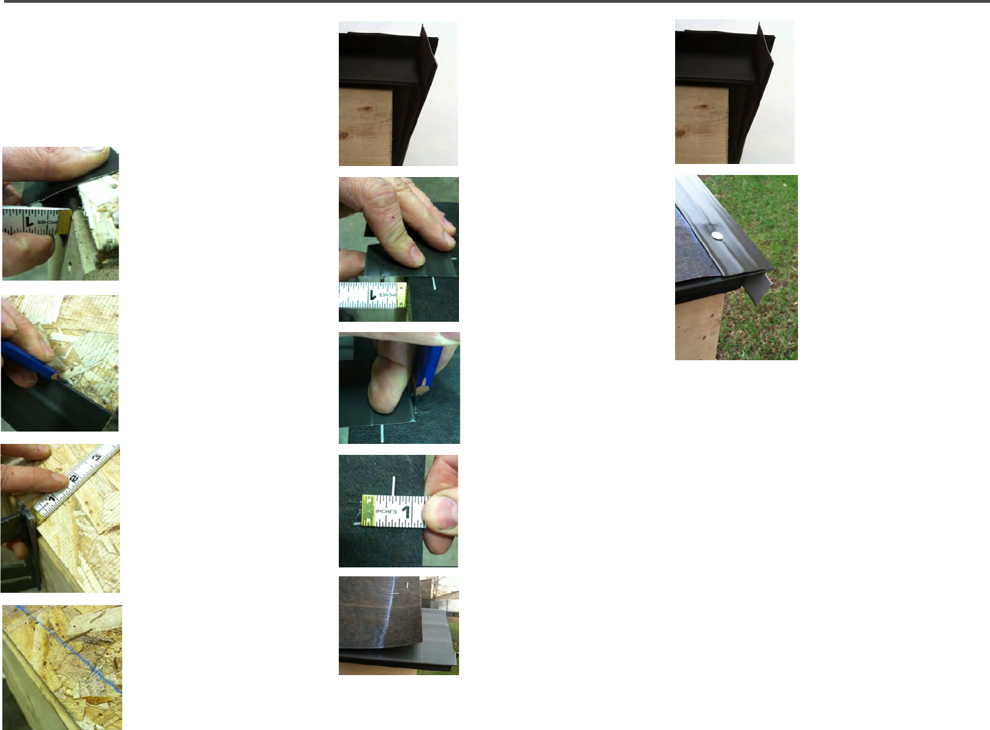
35 | Diamond Kote Building Products Application Guide 6.18
FASCIA APPLICATION continued
These steps show the correct procedure for
installing roof edge products to facilitate
easy installation of the LP
®
SmartSide
®
Sot and Fascia.
Depending on the
situation you will need
to use your discretion
to install Sot or Fascia
rst.
STEP 1: Hold the metal
roof edge up to the eave
edge of the roof line.
Keep the top edge of the
metal on the plane of
the sheathing, slide the
metal roof edge up or
down the roof until a 5/8"
measurement is achieved
perpendicularly out from
the Fascia to the inside
of the bend in the metal
roof edge.
Continue to hold it in this
position.
STEP 2: While in the
same position as Step 1,
mark the top edge of the
metal roof edge on the
roof sheathing.
STEP 3:
Take the distance of
the mark from Step 2
measure the edge of the
roof to the mark on the
opposite of the eave.
Snap a chalk line from
end to end for reference.
STEP 4: Install the metal
roof edge by aligning to
the chalk line and fasten.
Be sure excess material
hangs over past the ends
of the roof corners, gable
or eave intersection.
Trim the edge of the
metal roof once it is
installed on the gable
ends or around the
corners
(for hip roof lines).
STEP 5: For hip roof lines,
repeat steps 1 through
3 for the other sides of
the roof system and then
skip to Step 10.
STEP 6: Install roong
underlayment.
STEP 7: For gable ends,
hold the metal roof edge
up to the gable edge of
the roof line. Keep the top edge of the metal
roof edge on the plane of the sheathing.
Then slide the metal
roof edge in or out from
the edge of the roof until
5/8" measurement is
achieved from the fascia
to the inside of the bend
in the metal roof edge.
Continue to hold it in
this position.
STEP 8: While holding
it in position, mark the
edge of the metal roof
edge onto the roof
underlayment.
STEP 9: Measure and
then mark the distance
from the edge of the
roof at the top end of the gable and snap a
chalk line from the bottom to the top. The
metal roof edge on the eave will be trimmed
later
(Approx. 2")
STEP 10: Next trim the metal roof edge
on the eave so that it ts with the metal
roof edge going up the gable or around
the corner for hip roof lines. Leaving the
installed piece longer than necessary.
(Approx. 2") Trim AFTER the Fascia is added.
CONTINUED ON NEXT PAGE
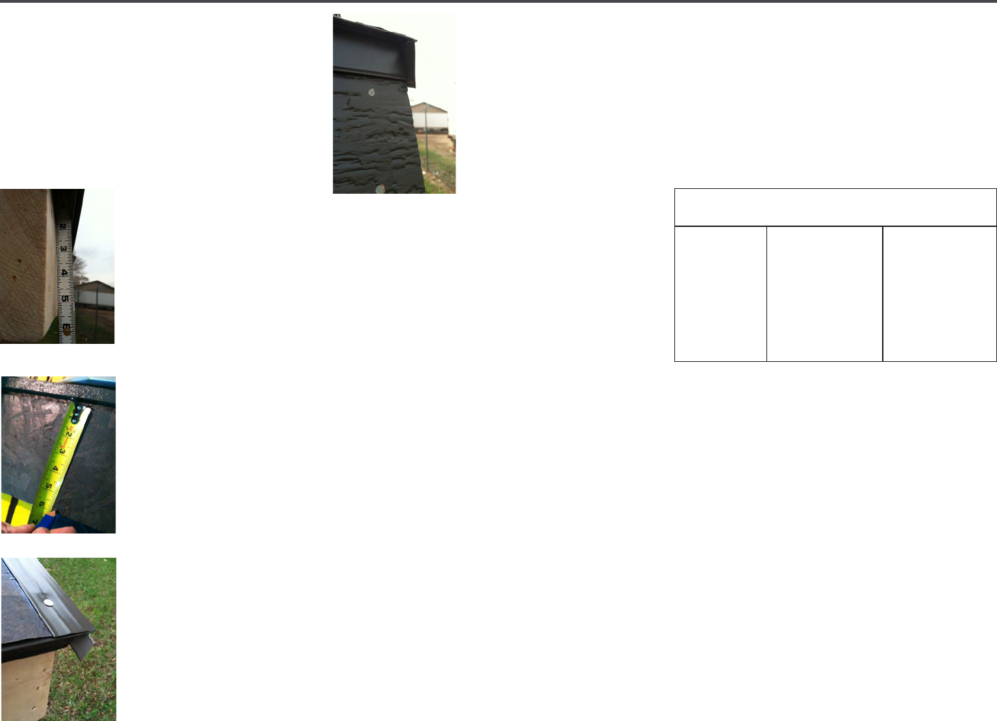
36 | Diamond Kote Building Products Application Guide 6.18
FASCIA APPLICATION continued
STEP 11: Install the metal drip edge up the
gable end using the chalk line as a reference
and fasten. Be sure to overhang excess
material
(Approx. 2") Note: This will need
to be trimmed AFTER the LP
®
SmartSide
®
Fascia is installed.
STEP 12: Next lift up on
the metal roof edge on the
eave end and slide your
ruler up until it bumps the
top of the inside. Record
the measurement where
the bottom of the sub-
fascia ends.
STEP 13: Measure and
mark the LP
®
SmartSide
®
Fascia from Step 12 at the
recorded measurement.
It is important that this
measurement be pulled
from the dado as shown.
Rip the Fascia to width,
and use Diamond Kote
®
touch-up paint on all cut
edges.
STEP 14: Cut the fascia
to length and paint all cut
edges. Start by installing
the Fascia on the eaves.
First lift up on the metal
roof edge and slip the
Fascia behind the metal.
Make sure to fasten the
fascia every 24" o.c.
maximum. Use Diamond
Kote
®
touch-up paint on
all face nails.
STEP 15: Install the
gable end Fascia or/
other sides of a hip roof.
Finish by trimming the
excess metal roof edge o of the corners.
STEP 16: After nishing the Fascia, the next
step is adding the Sot if it is not already
installed.
SOFFIT APPLICATION
• Architectural Collection Vented Cut-To-
Width (CTW) sot provides a minimum
of 10 square inches per lineal foot of
ventilation.
• Recommended spans for open and
closed sots are given in Table 1. The
recommendations in Table 1 for open
Sots also apply to combined roof/
ceiling construction.
• Panels are assumed continuous over two
or more spans with the long dimension
or strength axis across supports for both
applications.
• In open and closed sot construction,
protect panel edges against direct
exposure to the weather with LP
®
SmartSide
®
Trim and Fascia.
• Apply the Sot in a manner that prevents
moisture intrusion and water build-up.
All openings, other than the vents, must
be sealed, caulked, and/or ashed.
• SOFFIT MUST NOT BE IN DIRECT
CONTACT WITH MASONRY, CONCRETE,
BRICK, STONE, STUCCO OR MORTAR.
INSTALLATION
• Panels must be installed perpendicular
to supports.
• Minimum size framing should be nominal
2" x 4"
• All panel edges must be supported or
backed by solid framing.
• Consult your local building code for
open sot applications.
• When installing Sot with Sot
Channel, it is highly recommended
to double up framing members at all
sot joints and seams.
TABLE 1 - LP
®
SmartSide
®
CTW, Vented CTW and Sot Panels
(Long Dimension Across Supports)
Maximum Span
(inches)
All Edges Supported
24
24
24
Nominal Panel
Thickness
Precision Series
38 Series SmartSide sot
Precision Series 76
and 190 Series SmartSide
sot
Foundations 76 Series
LP SmartSide sot
Nail Size + Type
6d (0.099") nonstaining,
hot-dipped galvanized
box
8d (0.113") nonstaining,
hot-dipped galvanized box
8d (0.113") nonstaining,
hot-dipped galvanized box
CONTINUED ON NEXT PAGE
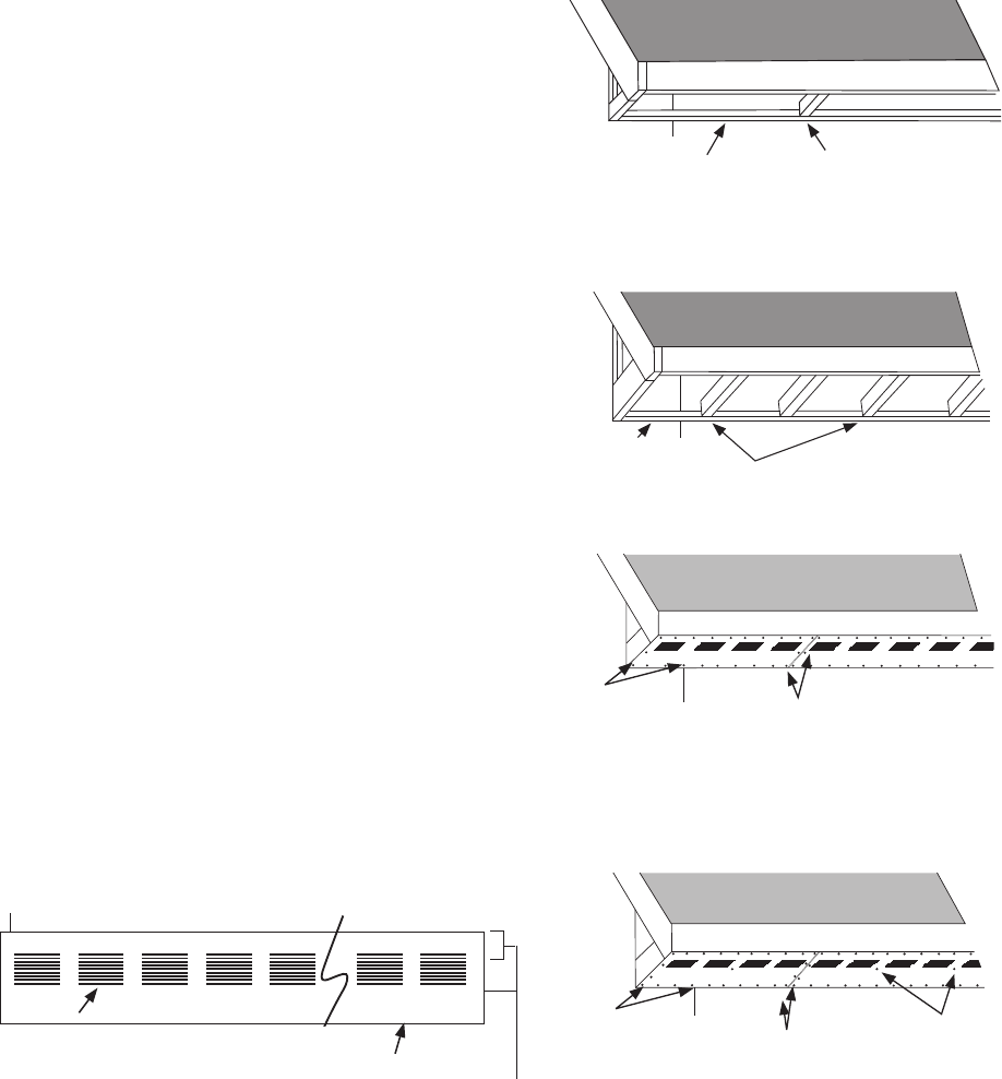
37 | Diamond Kote Building Products Application Guide 6.18
SOFFIT APPLICATION continued
• Space nails 6" o.c. at panel edges and
12" o.c. at intermediate supports. Do
not use staples.
• When installing the Architectural
Collection vented sot, avoid cutting
through the vented areas. If it cannot
be avoided, take special precautions to
avoid damage to spokes within the vent.
• Avoid diagonal cuts through the vented
areas. If necessary all sot edges must
be supported or backed by solid framing.
• Use construction adhesive to attach
spokes within the cut area of the vent to
solid framing.
• Exhaust ducts shall terminate not less
than 3' in any direction from openings
in vented sot. Refer to your local code.
• The spokes within the vent may warp
slightly during acclimation to the local
environment. This condition is only
temporary and the spokes will straighten.
• In closed sot applications factory
manufactured Cut-To-Width sot is
approved.
• Field prepared Cut-To-Width sot
should comply with local building codes.
SOFFIT CHANNEL OPTION
• When using 16' sot, space the end
and/or edge joints 1/4" then install
Sot Channel.
• When using 8' sot, space the end and
edge joints 3/16" then install Sot
Channel.
• When fastening at the sot ends and
edges fasten as close to the Sot
Channel as possible and angle fasteners
slightly to ensure penetration into
framing members.
CAULKING OPTION
• When using 8' sot, space the end and
edge joints 3/16" then caulk.
• When using 16' sot, space the end and
edge joints 3/16" then caulk.
LP
®
SmartSide
®
Sot products are not
designed for and are not suitable for
use as siding or trim other than Smooth
Foundations Sot.
GAPS + SEALANTS
• Seal all gaps with a high-quality, non
hardening, paintable sealant.
• Follow the sealant manufacturer's
instructions for application or watch
caulking video on our YouTube Channel.
FIGURE 3: VENTED SOFFIT
10 openings per vent each vent
measures 8" long by 3.5" wide
4" between vents
All vent groups, +/- 1/16" from specied
1-15/16" +/- 1/4" between ends & vents
3" +/- 1/16" between vent
and fascia edge
FIGURE 4: 12 IN. CUT TO WIDTH
SOFFIT FRAMING DIAGRAM
LP
®
Fascia to be used with sub fascia
Install 2 x framing on
wall to fasten perimeter
of the sot every
Install 2 x framing on
wall to fasten perimeter
of the sot every
24" o.c. Intermediate
framing is NOT required
FIGURE 5: 16 IN. AND 24 IN. CUT
TO WIDTH SOFFIT FRAMING DIAGRAM
Install 2 x framing
on wall to fasten
perimeter of the sot
Install framing 24" o.c. to
support and fasten sot
24" o.c. intermediate
framing is required for 16
in. and 24
"sot
LP
®
Fascia to be used with sub fascia
FIGURE 6: 12 IN. CUT TO WIDTH
SOFFIT NAILING DIAGRAM
LP
®
Fascia to be used with sub fascia
(Nails
enlarged
to show
detail)
Fasten every 6". o.c.
along perimeter
Install framing to support and fasten
seams. Gap 3/16" and caulk joint.
If H-Molding option is selected,
add the thickness of the web to the
gap allowing a net 3/16" space
for expansion.
24" o.c. intermediate
framing is NOT required
for 12
" sot
FIGURE 7: 16 IN. + 24 IN. CUT TO WIDTH
NAILING FRAMING DIAGRAM
LP
®
Fascia to be used with sub fascia
(Nails
enlarged
to show
detail)
Fasten every 6". o.c. along
perimeter
Support and fasten seams over
maximum 24" o.c. framing. Gap
3/16" and caulk joint. If H-Molding
option is selected, add the thickness
of the web to the gap allowing a net
3/16" space for expansion
.
Fasten at panel
center into required
intermediate 24" o.c.
framing
