
HYDRAULIC SHEET PILE
DRIVER
OPERATORS MANUAL
MODELS:
C6CSD, C8CSD
C10CSD
“Use Genuine NPK Parts”
© Copyright 2020 NPK Construction Equipment, Inc. www.npkce.com SD000-9605B Hyd Sheet
Pile Driver Operators Manual 4-20
7550 Independence Drive
Walton Hills, OH 44146-5541
Phone (440) 232-7900
Toll-free (800) 225-4379
Fax (440) 232-6294

CONTENTS
- 1 -
SAFETY ..................................................................................................................................... 3
FORWARD ................................................................................................................................ 5
SHEET PILE DRIVER APPLICATIONS ..................................................................................... 5
MAINTENANCE ......................................................................................................................... 6
STANDARD PRACTICES................................................................................................ 6
CARRIER COMPATIBILITY ....................................................................................................... 7
SPECIFICATIONS ..................................................................................................................... 8
C6CSD ............................................................................................................................ 9
C8CSD .......................................................................................................................... 10
C10CSD ........................................................................................................................ 11
SHEET PILE DRIVER STRUCTURE ........................................................................................12
C6CSD THROUGH C10CSD SHEET PILE DRIVERS ................................................... 12
SHEET PILE DRIVER SERIAL NUMBER LOCATION ..............................................................15
HYDRAULIC INSTALLATION ...................................................................................................16
NPK HYDRAULIC INSTALLATION KITS ....................................................................... 16
HYDRAULIC LINES....................................................................................................... 16
SHUT-OFF VALVES ...................................................................................................... 16
RETURN OIL ................................................................................................................. 17
PREVENTION OF CONTAMINATION ........................................................................... 18
CHANGING THE FILTER ELEMENT AND HYDRAULIC OIL ......................................... 18
CONTROL VALVES ...................................................................................................... 19
CONTROL SYSTEM FOR CLAMP CYLINDER .............................................................. 20
HYDRAULIC QUICK DISCONNECTS ........................................................................... 21
NPK APPROVED CONNECTION QUICK DISCONNECTS ........................................... 22
PRECAUTIONS ............................................................................................................ 22
MECHANICAL INSTALLATION ................................................................................................24
MAINTENANCE AND INSPECTION .........................................................................................25
DAILY MAINTENANCE ................................................................................................. 25
SEMI-ANNUAL MAINTENANCE ................................................................................... 26
REPLACE BEARING LUBRICATION OIL .......................................................... 26
TWENTY HOUR INSPECTION ..................................................................................... 27
JAW TOOTH PLATE (CHUCK) INSPECTION ............................................................... 28
RUBBER MOUNT INSPECTION ................................................................................... 28
HOSE CONNECTIONS ................................................................................................. 29
LUBRICANT TERMS AND DEFINITIONS ................................................................................30
OIL CAPACITY SPECIFICATIONS ...........................................................................................32
LOWER FRAME ............................................................................................................ 32
BEFORE OPERATION .............................................................................................................33
DECIDE IF SWIVEL LOCK FEATURE WILL BE USED .................................................. 33
OPERATION .............................................................................................................................34
PRE-CHECKS ............................................................................................................... 34
CHECK FASTENERS FOR PROPER TIGHTNESS .......................................... 34
JAW TOOTH PLATE (CHUCK) INSPECTION ................................................... 34
RUBBER MOUNT INSPECTION ....................................................................... 34
HOSE CONNECTIONS ..................................................................................... 35
CHECK SHUT-OFF VALVE POSITION ............................................................. 35
SHEET/PILE DRIVING AND EXTRACTING .................................................................. 36
SWIVEL FEATURE ............................................................................................ 36
CHUCKING THE SHEET PILE ...................................................................................... 38
LIFT THE SHEET PILE .................................................................................................. 38
POSITIONING THE SHEET PILE .................................................................................. 39
PILE DRIVING OPERATION ......................................................................................... 40
PULLING OPERATION ................................................................................................. 41

CONTENTS
- 2 -
OPERATIONAL PRECAUTIONS ..............................................................................................42
STORAGE OF THE SHEET PILE DRIVER ...............................................................................43
WARRANTY REGISTRATION FOR NEW UNITS .....................................................................44
WARRANTY STATEMENTS .....................................................................................................45
NOTES AND RECORDS ..........................................................................................................47

NPK
- 3 -
SAFETY
Safety notices in NPK Instruction Manuals follow ISO and ANSI standards for
safety warnings:
DANGER (red) notices indicate an imminently hazardous situation
which, if not avoided, will result in death or serious injury.
WARNING (orange) notices indicate a potentially hazardous situation
which, if not avoided, could result in death or serious injury.
CAUTION (yellow) notices indicate a potentially hazardous situation,
which, if not avoided, may result in minor or moderate injury.
ATTENTION (blue) notices in NPK Instruction Manuals are an NPK
standard to alert the reader to situations which, if not avoided, could
result in equipment damage.
1. Operators and service personnel must read, understand and comply with the NPK
INSTRUCTION MANUAL.
2. Keep personnel and bystanders clear of the SHEET PILE DRIVER while in
operation.
3. Do not operate the SHEET PILE DRIVER without an impact resistant shield
between the SHEET PILE DRIVER and the operator.
4. The SHEET PILE DRIVER must not be operated unless the operator is in full
control of the carrier. Operate the SHEET PILE DRIVER from the operator’s seat
only.
5. Match the SHEET PILE DRIVER size to carrier according to NPK
recommendations. See the CARRIER MACHINE COMPATIBILITY section of this
manual.
6. Service personnel must be cautious handling pins and bushings when exchanging
the bucket for the SHEET PILE DRIVER. The carrier machine operator must move
the stick or boom only when directed by service personnel.
7. If it is necessary to hammer the boom pins in or out, beware of flying metal chips.
Eye protection be worn!
8. Do not operate the SHEET PILE DRIVER if the hydraulic oil temperature exceeds
180° F (80° C), or at higher than specified flow rates.
9. Be especially cautious around hydraulic lines. Hydraulic oil can be extremely HOT!
Avoid skin contact with hydraulic oil! It can cause severe burns!
10. Protect hands and body from hydraulic fluids under pressure. Escaping high
pressure fluid can penetrate the skin, causing serious injury. Avoid the hazard by
relieving the pressure form the hydraulic system before disconnecting any lines.
Search for leaks with a piece of cardboard or other object. If an accident occurs,
seek medical attention immediately! Hydraulic fluid injected into the skin
must be surgically removed immediately or gangrene may result!

NPK
- 4 -
SAFETY
11. Make daily visual inspections of all fasteners, boom pins, hoses, etc.
12. Do not make any alterations to the SHEET PILE DRIVER without authorization from
NPK Engineering.
13. Use only NPK supplied replacement parts. NPK specifically disclaims any
responsibility for bodily injury or SHEET PILE DRIVER damage that results from the
use of parts not sold or approved by NPK.
14. Be careful when you torque fasteners. An overstressed or damaged component
may fail.
15. Use the proper lifting equipment and tools when handling or servicing the SHEET
PILE DRIVER or components.
16. Important safety and operating decals are included with each SHEET PILE DRIVER
and HYDRAULIC INSTALLATION KIT. Keep them clean and visible. NPK will
replace decals free of charge as needed.

NPK
- 5 -
FORWARD
This manual has been written to give the necessary instructions for operating,
maintaining, and servicing the NPK Sheet Pile Driver. Read this manual before start-
up.
For help with any problems encountered, or additional information, contact your NPK
authorized Distributor.
Use replacement parts sold by NPK only. NPK is not responsible for failures resulting
from alterations not approved by NPK or substitution of parts not sold by NPK. Do not
operate the Sheet Pile Driver underwater without instructions from NPK Engineering.
SHEET PILE DRIVER APPLICATIONS
The excavator mounted Sheet Pile Driver is a mobile, self-contained unit that operates
anywhere a boom can reach. This versatile attachment reaches to the top of piling and
sheeting for driving or extracting in the toughest of conditions and in rough terrain areas.
APPLICATIONS INCLUDE:
• DRIVING PILE, SHEET.
• EXTRACTION OF PILING AND SHEETING.

NPK
- 6 -
MAINTENANCE
STANDARD PRACTICES
Maintenance of and repairs to the SHEET PILE DRIVER should be performed by an
experienced service technician, thoroughly familiar with all standard practices and
procedures, and most importantly, all safety precautions. The following is a review of
common standard practices to be followed when working with hydraulic equipment, and
is not meant to be all-inclusive. Rather, this review is presented as a reminder as to
some of the unique characteristics of hydraulic equipment.
• The prevention of foreign contaminant damage is critical when working with hydraulic
equipment. Protect exposed holes and parts to guard against entry of contaminants.
Install metal or plastic plugs/caps where applicable to prevent entry of debris into the
hydraulic system.
• Mark the location and position of mating parts as an aid to re-assembly. Mark
corresponding parts uniquely to reflect their relationship, including proper location,
position, orientation, and/or alignment.
DO:
• During assembly, observe all markings made during disassembly, and all
corresponding features of mating parts to ensure proper location, position, orientation
and alignment.
• During disassembly of a sub-assembly, place removed components on a clean, dry
surface, in proper relative position as an aid in re-assembly.
• Always inspect threaded areas on components. Repair or replace as required.
Never apply uncured thread adhesive to a fastener that has cured adhesive on it.
Clean the fastener and the threaded bore. A tap and die may be helpful for this task.
Be sure to remove loose debris from the threaded bore.
• Use care to avoid scratches, nicks, dents, or other damage to machined surfaces of
mating components.
• When securing a component, always tighten cap screws gradually in an opposing
pattern, applying the specific torque.
• Grease can be used to temporarily hold a part in place while the abutting part is
placed into position.
• Always use common sense and exercise standard safety precautions when working
with all tools and equipment required to maintain, repair or troubleshoot the SHEET
PILE DRIVER.

NPK
- 7 -
CARRIER COMPATIBILITY
These carrier weight ranges are intended as a guideline only. Other factors, such as
stick length, counterweights, undercarriage, etc., must be taken into consideration.
Mounting a Compactor that is too heavy for the carrier machine is inefficient. The result
is an inadequate amount of downforce which can be dangerous and can damage the
carrier. Verify the carrier stability with the Compactor before transport or operation.
Mounting a Compactor that is too small for the carrier machine can damage the unit and
void the Warranty.
Consult NPK, if there is uncertainty whether the compactor model is compatible.
COMPACTOR/DRIVER
RECOMMENDED CARRIER WEIGHT
MODEL
lb.
(kg)
C6CSD
16,000 - 42,000
(7,000 - 19,000)
C8CSD
30,000 - 65,000
(14,000 - 29,500)
C10CSD
60,000 - 100,000
(27,000 - 45,000)
(Specifications subject to change without notice.)

NPK
- 8 -
SPECIFICATIONS
MODEL
CYCLES
OIL FLOW
OIL FLOW
OIL FLOW
PER
(standard)
(low flow option)
(high flow option)
MINUTE
gpm
(lpm)
gpm
(lpm)
gpm
(lpm)
C6CSD
2,200
33
(125)
25.5
(97)
N/A
C8CSD
2,200
43
(160)
CONTACT NPK
N/A
C10CSD
2,200
51
(210)
CONTACT NPK
N/A
MODEL
IMPULSE
OPERATING
RELIEF VALVE
FORCE
PRESSURE₁
PRESSURE SETTING
2
lbf
(kgf)
psi
(bar)
psi
(bar)
C6CSD*
16,000
(7,300)
1800-2300
(125-160)
2600
(180)
C8CSD*
24,000
(11,000)
2000-2500
(140-170)
2600
(180)
C10CSD*
34,000
(15,450)
2000-2500
(140-170)
2600
(180)
* The carrier circuit relief valve settings should be a minimum of 200psi (14 bar) above the sheet driver
relief settings.
1. Operating pressures shown are with a standard hydraulic motor. Operating pressures will be different
with optional hydraulic motors.
2. Relief pressure setting shown is for a standard hydraulic motor. For a relief with different motor options,
contact NPK at 1-800-225-4379.
(Specifications subject to change without notice.)
MODEL
CHUCK CYLINDER
CHUCK CYLINDER
OIL FLOW
OP. PRESSURE
gpm
(lpm)
psi
(bar)
C6CSD
3 - 5
(11 - 20)
3045
(210)
C8CSD
3 - 5
(11 - 20)
3045
(210)
C10CSD
3 - 5
(11 - 20)
3045
(210)
NPK
- 9 -
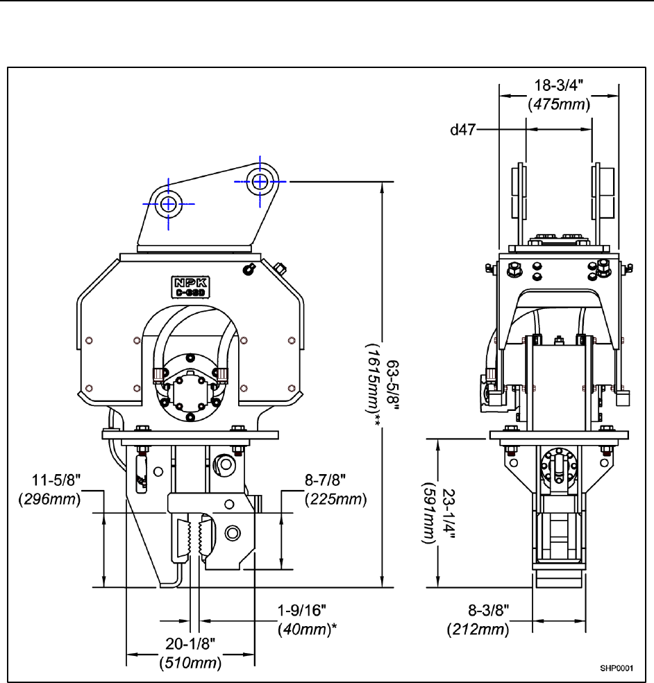
SPECIFICATIONS
C6CSD
DIMENSION d47: variable
* = Maximum opening
** = Subject to change
WORKING WEIGHT: 2150 lbs. (975 kg)
NPK
- 10 -
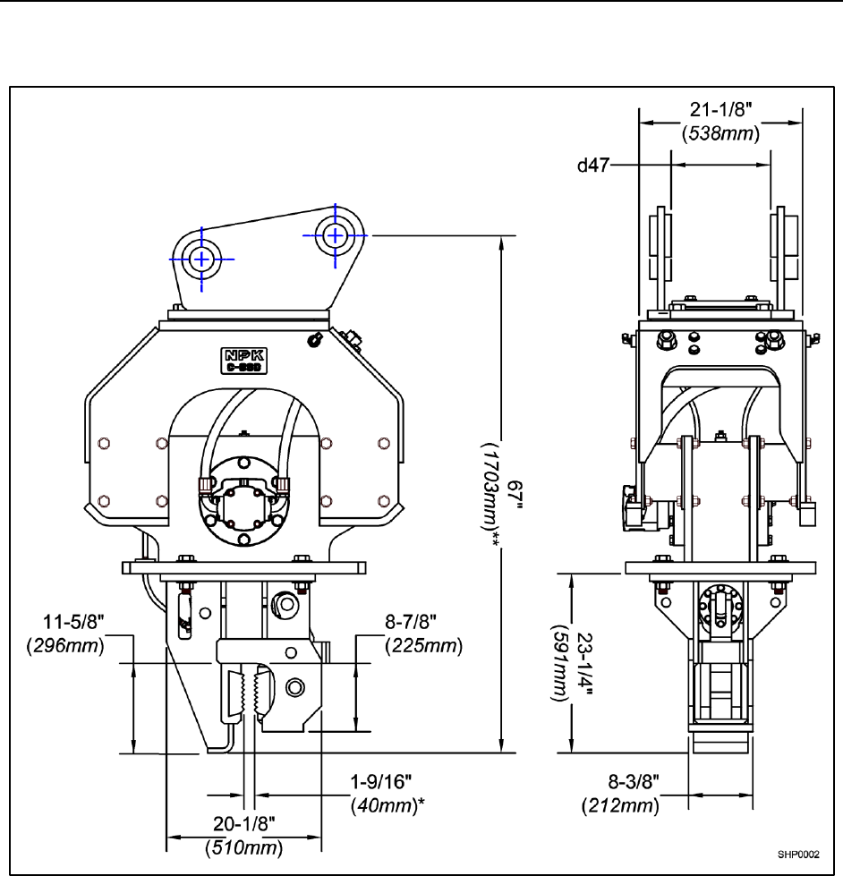
SPECIFICATIONS
C8CSD
DIMENSION d47: variable
* = Maximum opening
** = Subject to change
WORKING WEIGHT: 2750 lbs. (1250 kg)
NPK
- 11 -
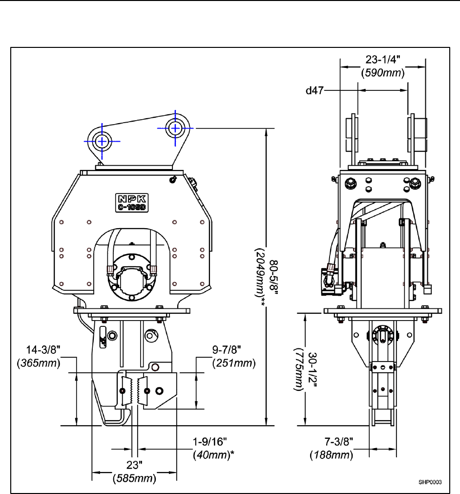
SPECIFICATIONS
C10CSD
DIMENSION d47: variable
* = Maximum opening
** = Subject to change
WORKING WEIGHT: 4130 lbs. (1875 kg)

NPK
- 12 -
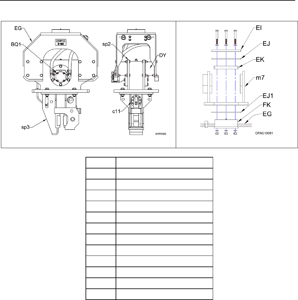
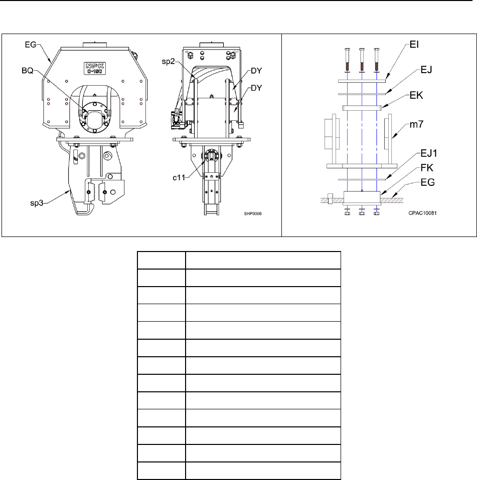
SHEET PILE DRIVER STRUCTURE
C6CSD THROUGH C10CSD SHEET PILE DRIVERS
The C6CSD through C10CSD SHEET PILE DRIVERS consist of a top bracket, an
upper frame, a lower frame and a cylinder assembly. The C6CSD, C8CSD and
C10CSD SHEET PILE DRIVERS are available with a fixed or a swivel top bracket.
The C6CSD and C8CSD upper frame is mounted to the lower frame with (4) bolt-on
rubber mounts. C10CSD models use (8) rubber mounts. The rubber mounts reduce
the amount of vibration being transmitted to the excavator.
The lower frame contains an eccentric weight suspended on roller bearings and spun by
a hydraulic motor. The cylinder assembly is bolted to the lower frame. The upper frame
also contains a bolt-on hydraulic manifold.
MODEL C6CSD
SWIVEL
ITEM
DESCRIPTION
BQ
HYDRAULIC MOTOR
c11
CYLINDER ASSEMBLY
DY
RUBBER MOUNT
EG
UPPER FRAME
EI
THRUST COVER
EJ
UPPER THRUST PLATE
EJ1
LOWER THRUST PLATE
EK
THRUST BEARING
FK
SWIVEL HUB (weld-on)
m7
TOP BRACKET
sp2
LOWER FRAME
sp3
CYLINDER CASE
NPK
- 13 -
SHEET PILE DRIVER STRUCTURE
C6CSD THROUGH C10CSD SHEET PILE DRIVERS
MODEL C8CSD
SWIVEL
ITEM
DESCRIPTION
BQ1
HYDRAULIC MOTOR
c11
CYLINDER ASSEMBLY
DY
RUBBER MOUNT
EG
UPPER FRAME
EI
THRUST COVER
EJ
UPPER THRUST PLATE
EJ1
LOWER THRUST PLATE
EK
THRUST BEARING
FK
SWIVEL HUB (weld-on)
m7
TOP BRACKET
sp2
LOWER FRAME
sp3
CYLINDER CASE
NPK
- 14 -
SHEET PILE DRIVER STRUCTURE
C6CSD THROUGH C10CSD SHEET PILE DRIVERS
MODEL C10CSD
SWIVEL
ITEM
DESCRIPTION
BQ
HYDRAULIC MOTOR
c11
CYLINDER ASSEMBLY
DY
RUBBER MOUNT
EG
UPPER FRAME
EI
THRUST COVER
EJ
UPPER THRUST PLATE
EJ1
LOWER THRUST PLATE
EK
THRUST BEARING
FK
SWIVEL HUB (weld-on)
m7
TOP BRACKET
sp2
LOWER FRAME
sp3
CYLINDER CASE
NPK
- 15 -
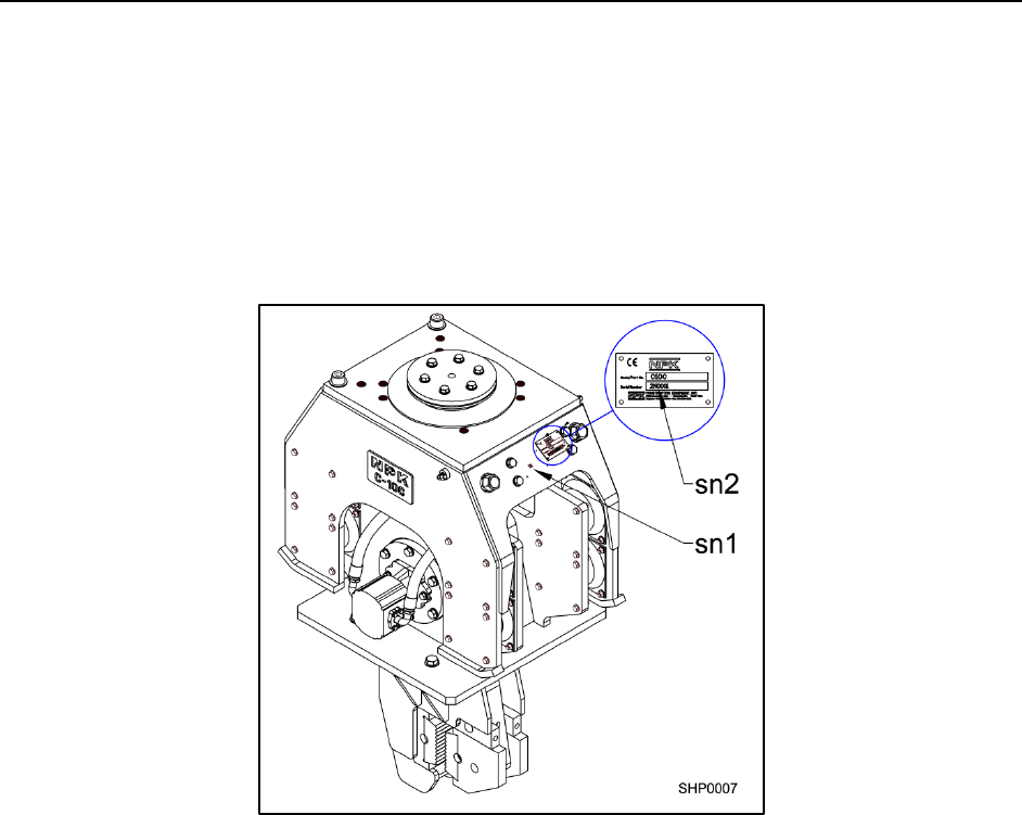
SHEET PILE DRIVER SERIAL NUMBER
LOCATION
The serial number of your unit is required any time that you are placing a parts order or
requiring technical assistance. Failure to use the serial number when ordering parts,
may result in receiving the incorrect parts, resulting in additional cost and down time.
The serial number will be comprised of the following sequence of numbers and letters:
0N-0000.
The location described below is between the inlet and outlet hydraulic ports on the
upper frame.
The serial number tag (sn2) can be found on the upper frame assembly. Additionally,
the serial number (sn1) is stamped below the serial number tag on the upper frame
assembly.
NPK
- 16 -
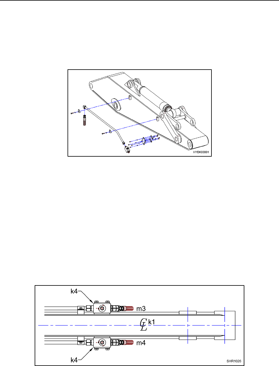
HYDRAULIC INSTALLATION
NPK HYDRAULIC INSTALLATION KITS
NPK Hydraulic Installation Kits are available for virtually all compatible backhoe and
excavator models. The kits include all parts and complete instructions for the hydraulic
installation, including valves, electrical or manual controls, hoses and fittings, boom and
stick piping and clamps.
See your NPK dealer for details or call NPK direct at 1-800-225-4379.
HYDRAULIC LINES
Typically, the pressure line is arranged on the left side of the boom and the return line is
on the right side.
SHUT-OFF VALVES
Most NPK Hydraulic Installation Kits use two shut-off valves (k4) on the dipper stick (k1)
of the carrier. These valves control the hydraulic oil going to the pressure side (m3) and
returning (m4) from the Compactor/Driver. (NOTE: Some smaller carriers utilize a
check valve on the return side.)
NPK
- 17 -
HYDRAULIC INSTALLATION
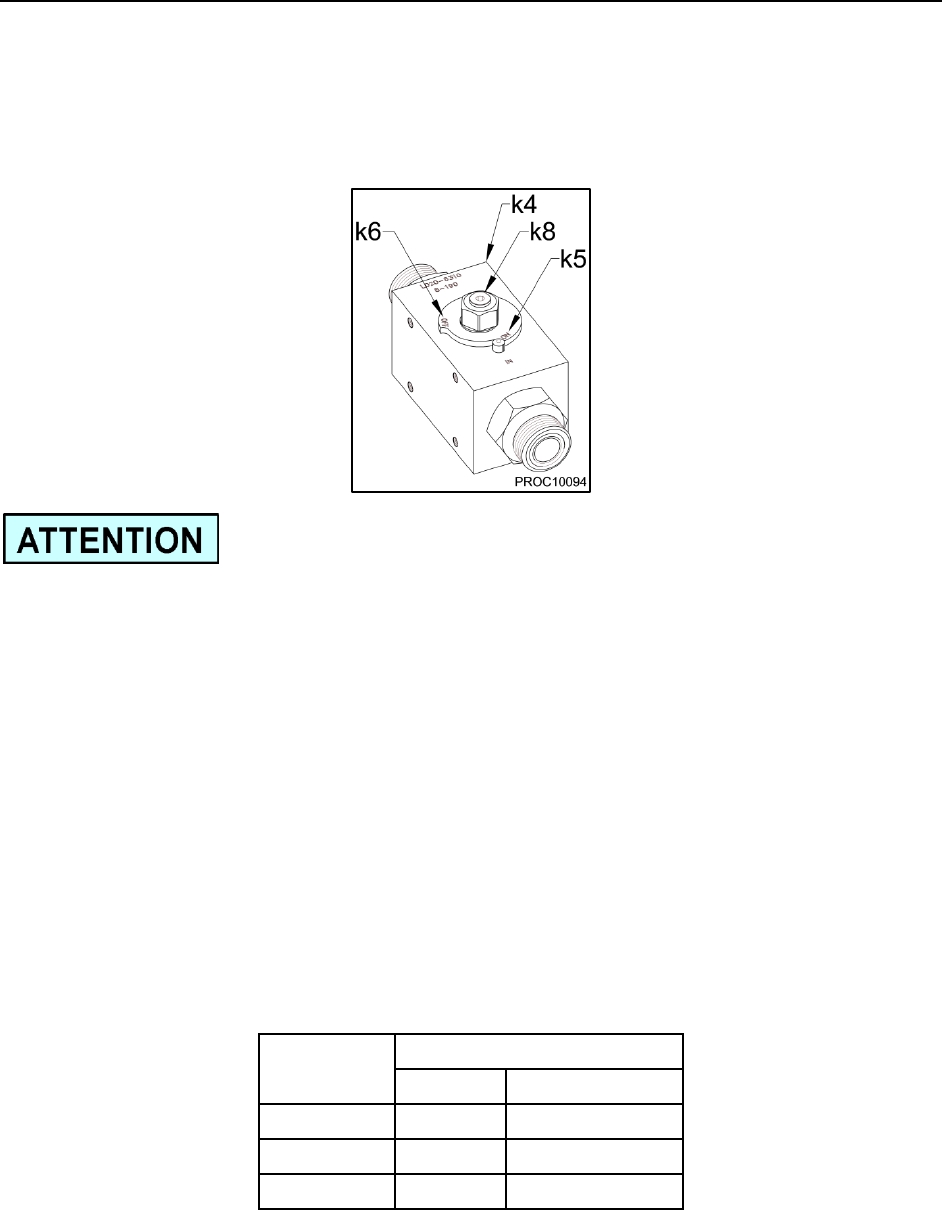
SHUT-OFF VALVES
Pressure test ports (k8) are located in the shut-off valves (and check valves). Each
shut-off valve has an “ON” (k5) and an “OFF” (k6) position.
NOTE: When operating the NPK Compactor/Driver on a carrier with a return line shut-
off valve, be sure the valve is turned to the “ON” position to prevent damage to the
Compactor/Driver’s hydraulic motor.
RETURN OIL
The return line must be routed correctly and sized large enough to handle the oil flow
without creating excessive back pressure. The return oil MUST NOT go through a
control valve. It must be connected directly to the carrier’s hydraulic reservoir via the oil
cooler and return filter (or an NPK filter, if supplied).
To prevent failure of the hydraulic motor shaft seals, motor shaft or motor thrust plates,
the return line back pressure must not exceed 150 psi (10 bar). See the
“TROUBLESHOOTING”, MEASURING BACK PRESSURE section of the
INSTRUCTION MANUAL.
MODEL
MINIMUM LINE SIZE
in.
(mm)
C6CSD
1.00
(25.40)
C8CSD
1.25
(31.75)
C10CSD
1.25
(31.75)

NPK
- 18 -
HYDRAULIC INSTALLATION
PREVENTION OF CONTAMINATION
1. A SHEET PILE DRIVER is harder on oil than using a bucket, so the oil is apt to
deteriorate and breakdown sooner. Neglect of the oil system can not only damage
the SHEET PILE DRIVER, but also cause problems in the carrier which could
result in damaged components. Care should be taken to check for contamination
of the oil and to change it if it is found contaminated. Oil sampling at regular
intervals is highly recommended.
❖ When the hydraulic oil shows low viscosity and bubbles, this indicates that the oil
is deteriorated. If the oil is dark brown and gives off an offensive odor, it is
severely deteriorated. Change the oil immediately!
❖ When the oil is clouded, or the oil filter often becomes clogged, it indicates that the
oil is contaminated. Change the oil immediately!
❖ To change the contaminated hydraulic oil, drain the hydraulic system completely
and clean components. Do not mix new oil with the old!
2. Do not allow any contamination to mix with the oil. Take special care in preventing
contamination from entering the hydraulic system through the hose or tube
connection when changing the SHEET PILE DRIVER with the bucket.
3. Low oil level will cause heat build-up, resulting in deterioration of the oil. Also, it
may cause cavitation due to air mixing with the oil, leading to a damaged
compactor/driver and carrier components. Keep the oil at the proper level at all
times.
4. Do not use the SHEET PILE DRIVER at an operating temperature higher than
180°F (80°C). The proper operating oil temperature range is between 120°F
(50°C) and 180°F (80°C). Since contaminated cooler fins causes reduced
efficiency of the cooler, keep the cooler fins clean at all times. Check the hydraulic
oil cooling system to be sure it is working effectively. The use of a heat gun is the
best way to evaluate if the cooler is working properly.
5. Water in the hydraulic oil will lead to damage of the SHEET PILE DRIVER and
carrier. Drain off water and foreign matter from the hydraulic tank at specified
intervals. When out of service, the SHEET PILE DRIVER should be stored
indoors.
CHANGING THE FILTER ELEMENT AND HYDRAULIC OIL
Change the filter element and hydraulic oil at the intervals described in the operation
manual of the backhoe or excavator, when using a hydraulic implement. Another
method is to set up an oil sampling schedule and change accordingly.
NPK
- 19 -
HYDRAULIC INSTALLATION
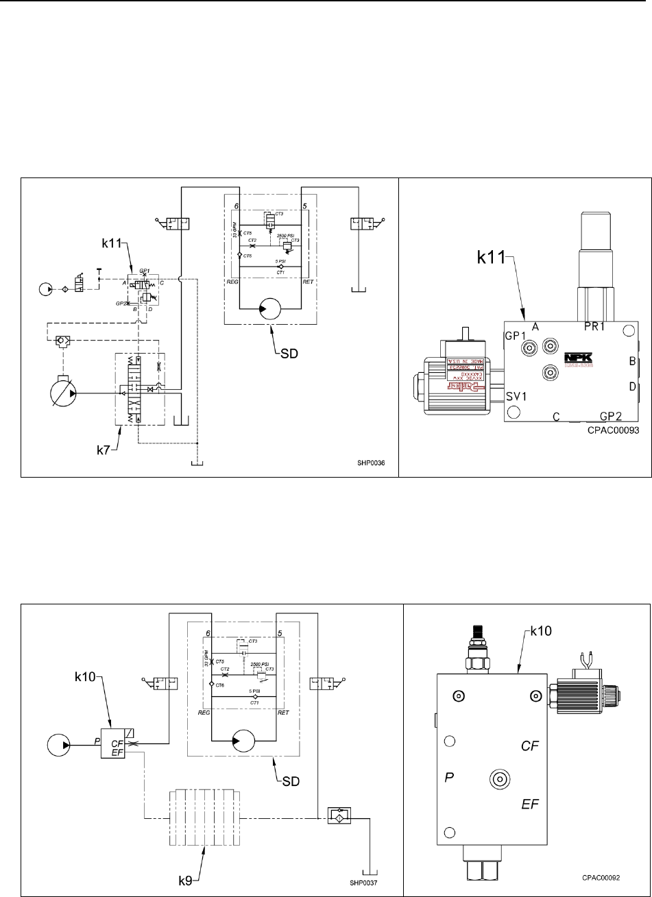
CONTROL VALVES
One of two types of control systems are used, depending upon the backhoe or
excavator used:
1. CONTROL SYSTEM USING THE EXCAVATOR AUXILIARY VALVE
This type of installation uses an existing excavator auxiliary valve (k7) to operate the
NPK Sheet Pile Driver (SD). Additional parts, such as mechanical linkage, hydraulic
pilot control valves (k11), etc., are furnished in the NPK HYDRAULIC INSTALLATION
KIT.
2. CONTROL SYSTEM USING THE NPK MULTIVALVE
For excavators not equipped with an auxiliary or spare valve section as part of the
control valve bank (k9), the NPK HYDRAULIC INSTALLATION KIT typically includes
a solenoid operated, priority valve (k10) to operate the NPK Sheet Pile Driver (SD).
The NPK MULTIVALVE is specifically designed for the operation of boom mounted
attachments.
NPK
- 20 -
HYDRAULIC INSTALLATION
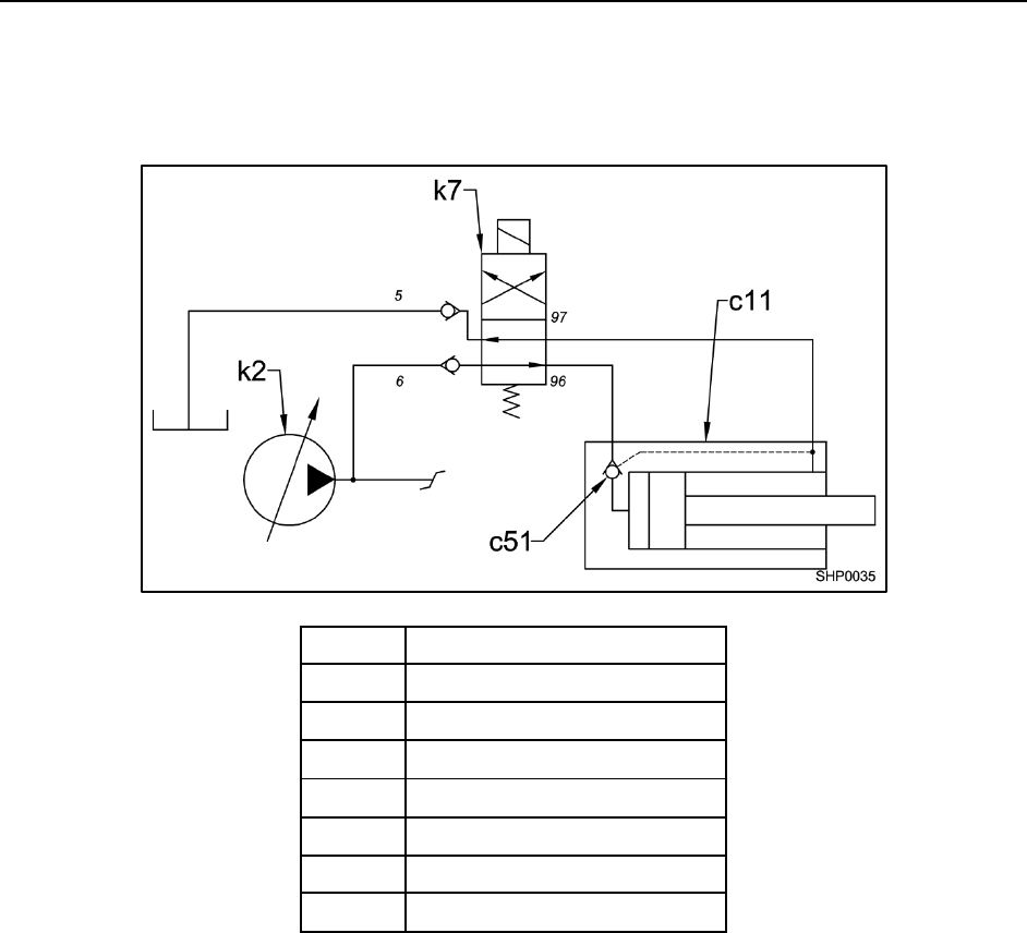
CONTROL SYSTEM FOR CLAMP CYLINDER
Below is a sample hydraulic circuit for the clamp cylinder.
c11
CYLINDER ASSEMBLY
c51
BALL CHECK VALVE
k2
HYDRAULIC PUMP
k7
CONTROL VALVE
5
RETURN PORT
6
PRESSURE PORT
96
EXTEND PORT
97
RETRACT PORT
For further details or hydraulic kits, contact NPK for assistance at 800-225-4379.
NPK
- 21 -
HYDRAULIC INSTALLATION
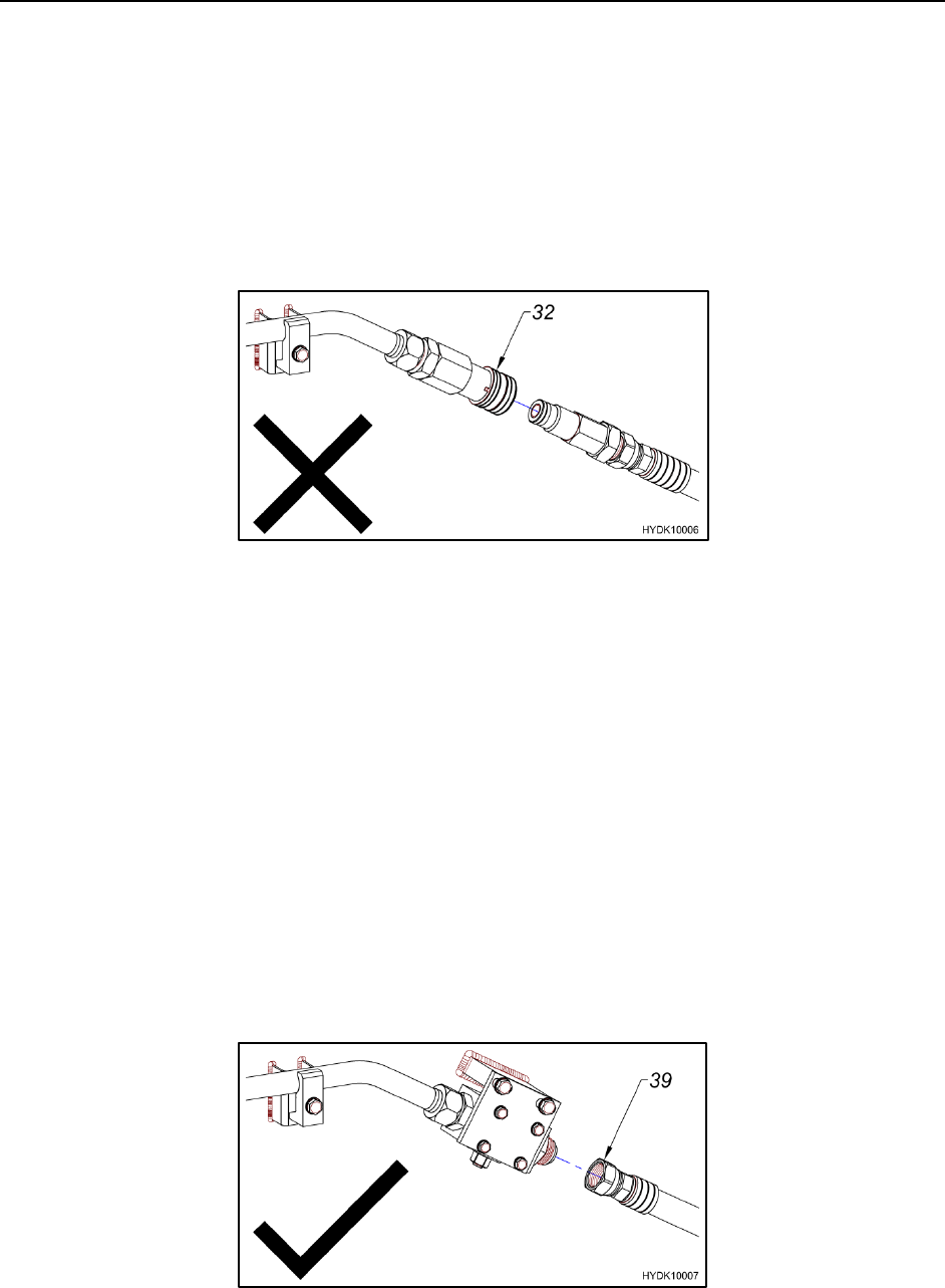
HYDRAULIC QUICK DISCONNECTS
NPK recommends against the use of non-NPK quick disconnects on hydraulic circuits
operating NPK Products, including Compactor/Drivers for the following reasons:
1. Compactor/Driver operation can cause internal pieces of a non-NPK quick
disconnect (32) to disintegrate. These pieces can migrate into the Compactor/Driver
hydraulic motor, causing damage.
2. If quick disconnects are used when the Compactor/Driver is removed from the
carrier, the disconnects should be capped to keep them clean. If this is not done,
contamination in the disconnect will be flushed into the Compactor/Driver when
reconnected, also causing damage.
3. Quick disconnects create a restriction in the hydraulic circuit. NPK
Compactor/Drivers are back pressure sensitive. Restrictions can cause damage to
the hydraulic motor.
4. The pressure required to operate the Compactor/Driver, plus the restriction of the
quick disconnects may push older, low pressure carriers to the limit of their hydraulic
system, interfering with Compactor/Driver Operation.
5. Quick disconnect restrictions can cause unnecessary heating of the carrier’s
hydraulic system.
NPK encourages the use of a standard hose and fitting connection (39). It is
recommended that when the Compactor/Driver is removed from the carrier, the tube
ends and hose fittings should be capped and plugged to keep them clean.
NPK
- 22 -
HYDRAULIC INSTALLATION
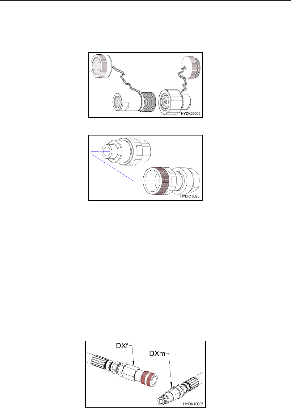
NPK APPROVED CONNECTION QUICK DISCONNECTS
NPK approved quick disconnects are available. They are properly sized for compactor
operation.
ROFLEX COUPLING
STUCCHI COUPLING
Contact your dealer for additional information.
PRECAUTIONS
If hydraulic quick disconnects are used with the NPK Compactor/Driver, it is
recommended that the following precautions be followed:
1. Make sure the quick disconnects are sized properly for your application.
2. Periodic inspection of both male and female ends is recommended to ensure that
the quick disconnects are in good working condition. Failure to inspect couplers
may result in pieces from a damaged or failed quick disconnect to be injected into
the Compactor/Driver hydraulic motor or the carrier’s hydraulic system.
3. Check for dirt, dust and debris on both the male (DXm) and female (DXf) ends of the
quick disconnect before coupling them together.

NPK
- 23 -
HYDRAULIC INSTALLATION
PRECAUTIONS
4. Be sure that the couplers are completely seated together (38).
5. When replacing couplers, be sure that the couplers are replaced as a set (male and
female). Do not use one new end and one used end.
NPK
- 24 -
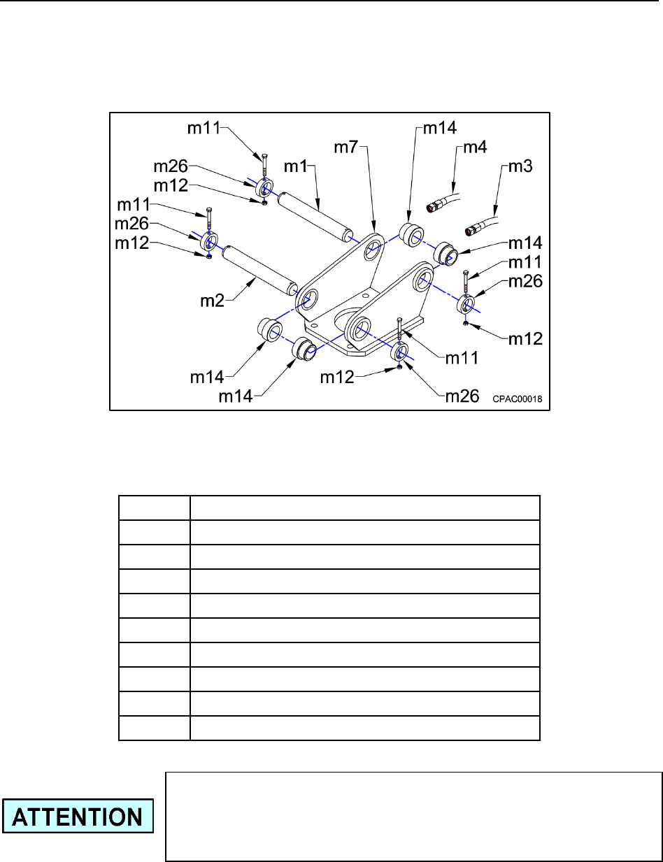
MECHANICAL INSTALLATION
NPK MOUNTING INSTALLATION KITS include the parts required to adapt the NPK
Sheet Pile Driver to the stick or arm of the carrier. Custom adapter brackets and quick
attach brackets are available. Shown below is a typical NPK mounting kit. Mounting
kits are machine specific. Contact the NPK Sales Department for additional information.
See the FASTENER TORQUE section of the NPK Instruction Manual for top bracket
bolt torque.
ITEM
DESCRIPTION
m1
STICK PIN
m2
LINK PIN
m3
HYDRAULIC HOSE ASSEMBLY (pressure)
m4
HYDRAULIC HOSE ASSEMBLY (return)
m7
TOP BRACKET
m11
HEX HEAD CAP SCREW
m12
HEX NUT
m14
BOOM PIN BUSHING
m26
BOOM PIN COLLAR
When mounting or removing the Sheet Pile Driver from the
carrier, the hydraulic lines must be handled carefully and
sealed to prevent contamination from entering the
compactor or the carrier hydraulic system.

NPK
- 25 -
MAINTENANCE AND INSPECTION
DAILY MAINTENANCE
• C6CSD, C8CSD and C10CSD Sheet Pile Drivers use oil lubrication for the
bearings, which may require semi-annual maintenance.
• Periodically check all fasteners and tighten as necessary. The hydraulic motor
bolts require thread adhesive.
• Periodically check the rubber mounts for deterioration or cracking. Wash oil or
grease from the rubber surface.
• Oil leakage out of the eccentric housing (sp2) or lower frame vent (EN) is an
indication of hydraulic motor shaft seal failure.
• Inspect eccentric (roller) bearings if they become noisy. Noisy bearings could be
an indication of insufficient lubrication.
• Do not operate the Sheet Pile Driver if the carrier hydraulic reservoir temperature
exceeds 180°F (80°C).
NPK
- 26 -
MAINTENANCE AND INSPECTION
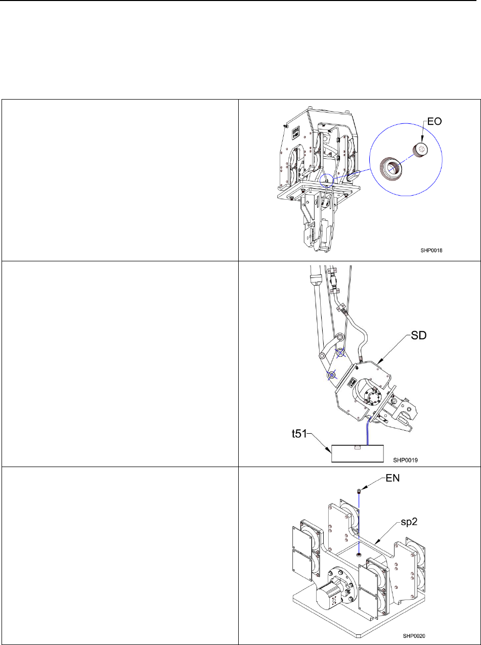
SEMI-ANNUAL MAINTENANCE
REPLACE BEARING LUBRICATION OIL
C6CSD, C8CSD and C10CSD Sheet Pile Drivers:
1. Remove the drain plug (EO) from the
eccentric housing (lower frame).
2. Tip the Sheet Pile Driver (SD) up on
end and pour the oil into a container
(t51) suitable for disposal.
3. Set the Sheet Pile Driver flat.
Remove the fill plug (EN) from the top
of the eccentric housing or lower
frame (sp2).
NPK
- 27 -
MAINTENANCE AND INSPECTION
SEMI-ANNUAL MAINTENANCE
REPLACE BEARING LUBRICATION OIL
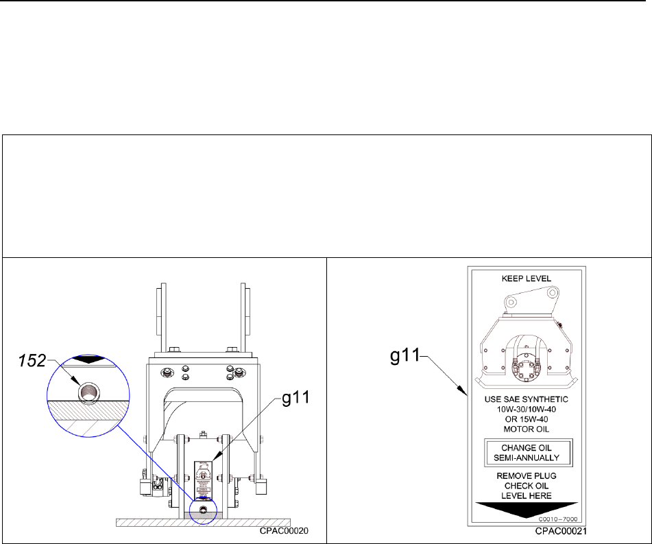
C6CSD, C8CSD and C10CSD Sheet Pile Drivers:
4. Fill the Sheet Pile Driver to the bottom of the oil drain port (152). Use 10W-30 or
10W-40 synthetic motor oil. The use of a 15W-40 motor oil is also acceptable. See
the oil level decal (g11) below. Re-install the drain plug.
See “OIL CAPACITY” – LOWER FRAME”, page 32.
TWENTY HOUR INSPECTION
1. Complete and send the warranty registration to NPK when the unit is delivered to the
customer (see warranty registration instructions).
2. After the first 20 hours of operation, inspect all fasteners and tighten as needed.
NPK
- 28 -
MAINTENANCE AND INSPECTION
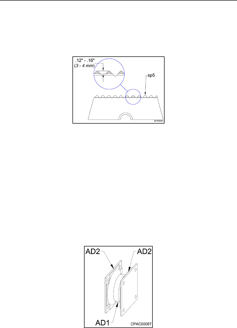
JAW TOOTH PLATE (CHUCK) INSPECTION
Check for jaw tooth wear.
If the chuck (sp5) is worn more than .12” to .16” (3 – 4 mm) and the sheet pile slips out
easily, replace the chuck jaws.
RUBBER MOUNT INSPECTION
The rubber mounts will eventually need replacing due to the hours of use or operator
abuse. The mounts are designed to work in a temperature range of 0° to 160°F
(-18° to 70°C). Below 0°F (-18°C), the rubber mounts become very stiff and not as
effective in reducing vibration. Above 160°F (70°C), the rubber mount material
becomes too soft and wears fast. Excessive down force on the Sheet Pile Driver,
overstretches the rubber and can lead to early mount failure. Petroleum products and
solvents will degrade the rubber.
Cracks may appear in the body of the rubber (AD1) or where the rubber bonds to the
metal plates (AD2). Light surface “checking” due to age is acceptable. If cracks
propagate into the body of the rubber, the mount must be replaced immediately. If the
crack is located at the rubber to metal plate bond, and is over 4 inches (100 mm) long,
or 1-1/2 inches (38 mm) deep, the mount must also be replaced.
NPK
- 29 -
MAINTENANCE AND INSPECTION
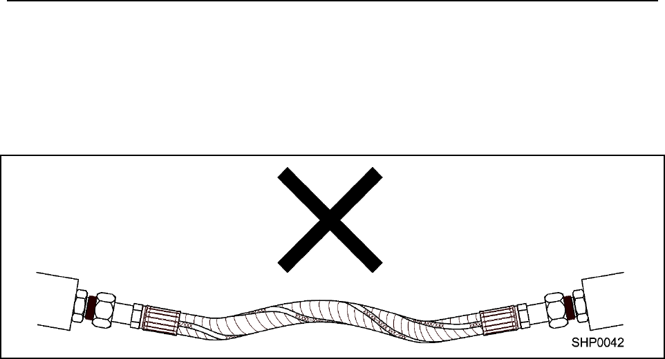
HOSE CONNECTIONS
Check the hose connections.
Make sure the hose connections are torqued properly and that the hoses are not
twisted.

NPK
- 30 -
LUBRICANT TERMS AND DEFINITIONS
TERM
DEFINITION
ADHESIVE
The ability of grease, gear lubricant or oil to cling to metal.
ANTI WEAR AGENTS
Used to help combat metal-to-metal contact, thus reducing
wear.
CAVITATION
Air pockets in the oil circuit (as at the pump inlet).
COHESIVE
The ability of grease, gear lube or oil to cling to itself, thus
resisting tearing apart.
CONSISTENCY
Consistency of grease is its hardness or firmness. It is
determined by the depth in millimeters to which the cone of
a penetrometer sinks into a sample under specified
conditions. Consistency of grease may be influenced by
the type and amount of thickener, viscosity of oil, working
and other factors.
CONTAMINATION
Foreign material that could damage a part.
FILM STRENGTH
Film strength is defined as the tendency of oil molecules to
cling together. It is the ability of those molecules to resist
separation under pressure between two metals and to hold
these metal surfaces apart.
FORCE
A push or pull acting upon a body. In a hydraulic cylinder,
it is the product of the pressure on the fluid, multiplied by
the effective area of the cylinder piston. It is measured in
pounds or tons.
FRICTION
The resistance to fluid flow in a hydraulic system. (An
energy loss in terms of power output.)
GALLING
Surface damage on mating, moving metal parts due to
friction. A severe form of adhesive wear.
LUBRICATION
Use of a substance (grease, oil, etc.) to reduce friction
between parts or objects that move against each other.
NLGI
A rating given to a grease from the National Lubricating
Grease Institute. This rating determines the hardness of
the grease and goes from a 000 to a 6 rating. Most
greases are NLGI #2 rated.

NPK
- 31 -
LUBRICANT TERMS AND DEFINITIONS
TERM
DEFINITION
OILINESS
Oiliness is measured of the coefficient of friction of a
lubricant. Oiliness or lubricity depends on the adhering
characteristics of an oil. It is determined by the attraction
between the molecules of the oil and the molecules of
another material. Of two oils having the same viscosity but
different degrees of fluid friction, the one with the lower
friction index has the higher degree of oiliness.
PITTING
(Gears or Bearings) A type of surface damage occurring
under repeated loading of two parts in rolling or sliding
contact. A form of surface fatigue.
PUMP
A device which converts mechanical force into hydraulic
fluid power. Basic design types are gear, vane, and piston
units.
RACE
A channel in the inner or outer ring of an anti-friction
bearing in which the balls or rollers roll.
RESERVOIR
A container for keeping a supply of working fluid in a
hydraulic system.
ROLLER BEARING
An inner or outer race upon which hardened steel rollers
operate.
SPLINE
Splines are multiple keys in the general form of internal
and external gear teeth, used to prevent relative rotation of
cylindrically-fitted parts.
VIBRATION
A quivering or trembling motion.
VISCOSITY
Is the actual SAE weight of the product. Example: motor
oils come in 10, 20, 30, 40, 50 and 15/40 SAE weight. The
viscosity designation of a lubricant indicates its internal
resistance to flow.

NPK
- 32 -
OIL CAPACITY SPECIFICATIONS
LOWER FRAME
MODEL
quart
(liter)
C6CSD
3.2
(3.0)
C8CSD
3.6
(3.4)
C10CSD
9.6
(9.0)
Capacities shown are approximate.
NPK
- 33 -
BEFORE OPERATION
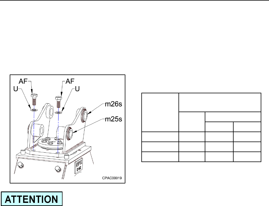
DECIDE IF SWIVEL LOCK FEATURE WILL BE USED
The swivel lock bolts (AF) and washers (U) that are found on models equipped with the
swivel feature are factory assembled hand tight only. If using the swivel lock feature,
these bolts must be loosened then tightened to the specified torque below (also see the
“FASTENER TORQUE” section of the NPK Instruction Manual) before operating the
Compactor/Driver in the “fixed mode”.
MODEL
TOP BRACKET
SWIVEL LOCK
BOLT
TORQUE
DIA.
ft. lbs.
(Nm)
C6CSD
1-1/4"
1350
(1830)
C8CSD
1-1/4"
1350
(1830)
C10CSD
1-1/4"
1350
(1830)
If these bolts are overtightened, the stick pin (m26s) and link pin (m25s) bores may
become misaligned. Loosen these bolts and torque to the proper value. Also, these
bolts must be installed on the stick pin side of the bracket or the link pin side of the
bracket. DO NOT install one at each pin side of the bracket.

NPK
- 34 -
OPERATION
PRE-CHECKS
CHECK FASTENERS FOR PROPER TIGHTNESS
See “NPK Sheet Pile Driver Instruction Manual” for proper fastener torque.
JAW TOOTH PLATE (CHUCK) INSPECTION
Check for jaw tooth wear.
If the chuck (sp5) is worn more than .12” to .16” (3 – 4 mm) per side and the sheet pile
slips out easily, replace the chuck jaws.
RUBBER MOUNT INSPECTION
The rubber mounts will eventually need replacing due to the hours of use or operator
abuse. The mounts are designed to work in a temperature range of 0° to 160°F
(-18° to 70°C). Below 0°F (-18°C), the rubber mounts become very stiff and not as
effective in reducing vibration. Above 160°F (70°C), the rubber mount material
becomes too soft and wears fast. Excessive down force on the Sheet Pile Driver,
overstretches the rubber and can lead to early mount failure. Petroleum products and
solvents will degrade the rubber.
Cracks may appear in the body of the rubber (AD1) or where the rubber bonds to the
metal plates (AD2). Light surface “checking” due to age is acceptable. If cracks
propagate into the body of the rubber, the mount must be replaced immediately. If the
crack is located at the rubber to metal plate bond, and is over 4 inches (100 mm) long,
or 1-1/2 inches (38 mm) deep, the mount must also be replaced.
NPK
- 35 -
OPERATION
PRE-CHECKS
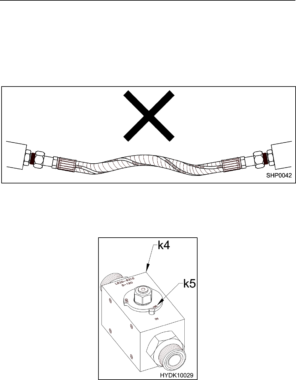
HOSE CONNECTIONS
Check the hose connections.
Make sure the hose connections are torqued properly and that the hoses are not
twisted.
CHECK SHUT-OFF VALVE POSITION
Make sure the shut-off valves (k4), if supplied, are in the “ON” (k5) position.

NPK
- 36 -
OPERATION
SHEET/PILE DRIVING AND EXTRACTING
SWIVEL FEATURE
A free-turning swivel top (m7) is provided on models C6CSD, C8CSD and C10CSD
NPK Sheet Pile Drivers. The self-aligning swivel feature minimizes carrier repositioning.
The cylinder clamp assembly (sp3) can align to the job from any carrier position, over a
wide range of boom positions. The excavator can be positioned over, parallel or
perpendicular to the trench if necessary.
The swivel can be locked in place either parallel or perpendicular to the boom.
88 – Line of Sheeting

NPK
- 37 -
OPERATION
The NPK Vibratory Sheet Pile Driver derives its power source from the excavator on
which it is mounted. High efficiency is achieved through a combination of forces
developed by the sheet pile driver and carrier machine: impulse force, vibration and
downforce. A direct drive hydraulic motor rotates an eccentric mass at high speed to
produce impulse force and vibration.
Static downpressure from the excavator, plus the weight of the sheet pile driver,
produces downforce into the sheet being driven. As the compactor is pressed against
the material, the hydraulic pressure to the motor will rise.
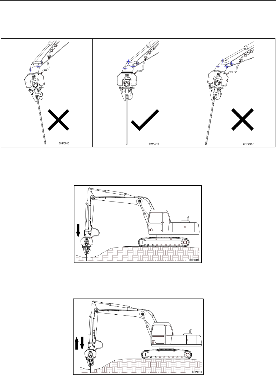
For best results, the rubber mounts, which isolate the lower frame from the upper frame,
should be deflected no greater than one-half diameter, see below.
The rubber mounts (DY) should not be deflected so far that the upper frame (EG)
contacts the baseplate (bp1) of the lower frame. Do not overstress the rubber
mounts by applying heavy down pressure and pulling or pushing (ironing) with
the stick.
Fig. 1
(Deflection less than one-half of the rubber mount diameter.)
Fig. 2
(Upper frame hitting baseplate.)
NPK
- 38 -
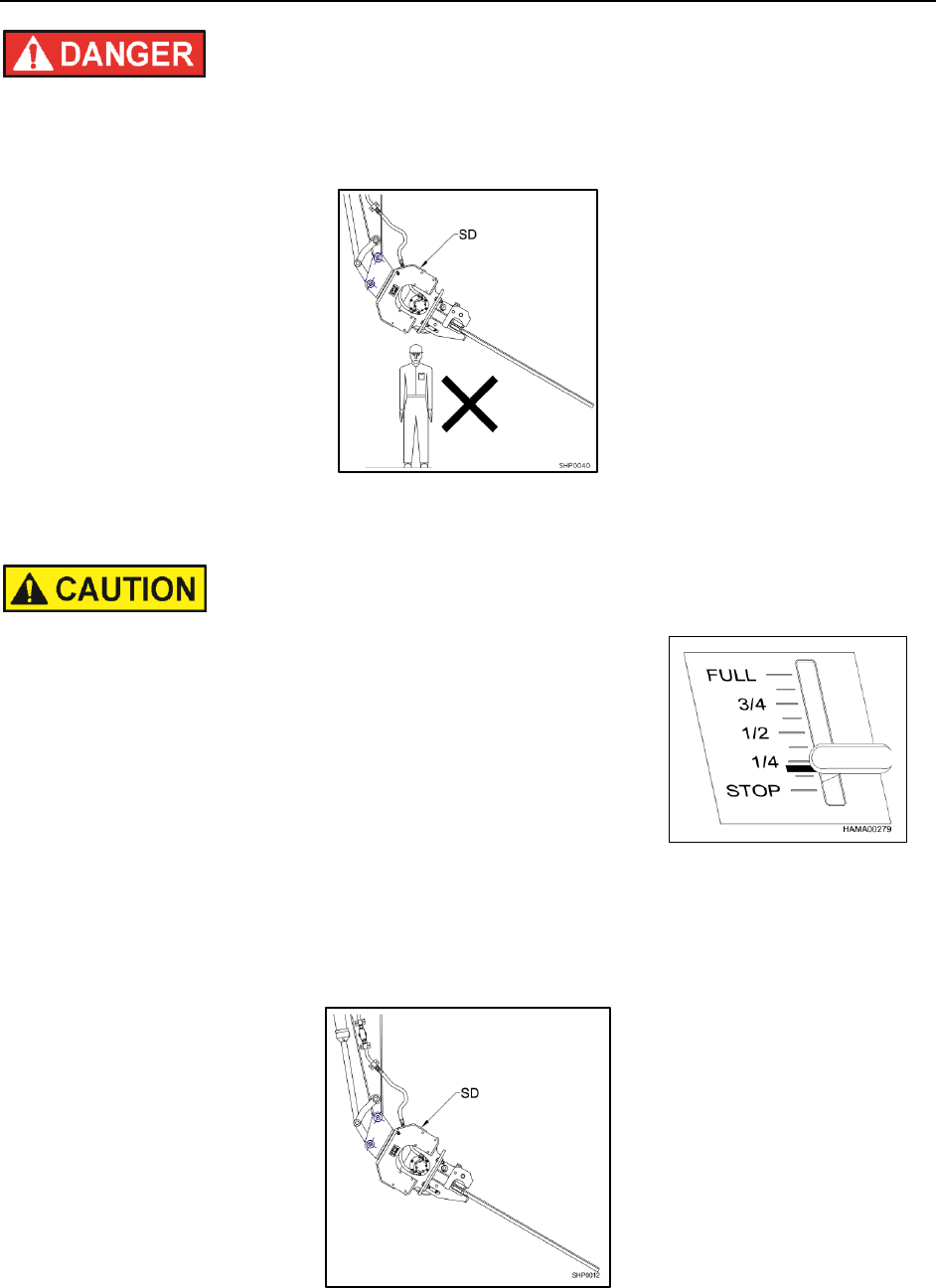
OPERATION
Keep personnel and bystanders clear of the SHEET PILE DRIVER (SD) while in
operation. NO ONE should be under the unit!
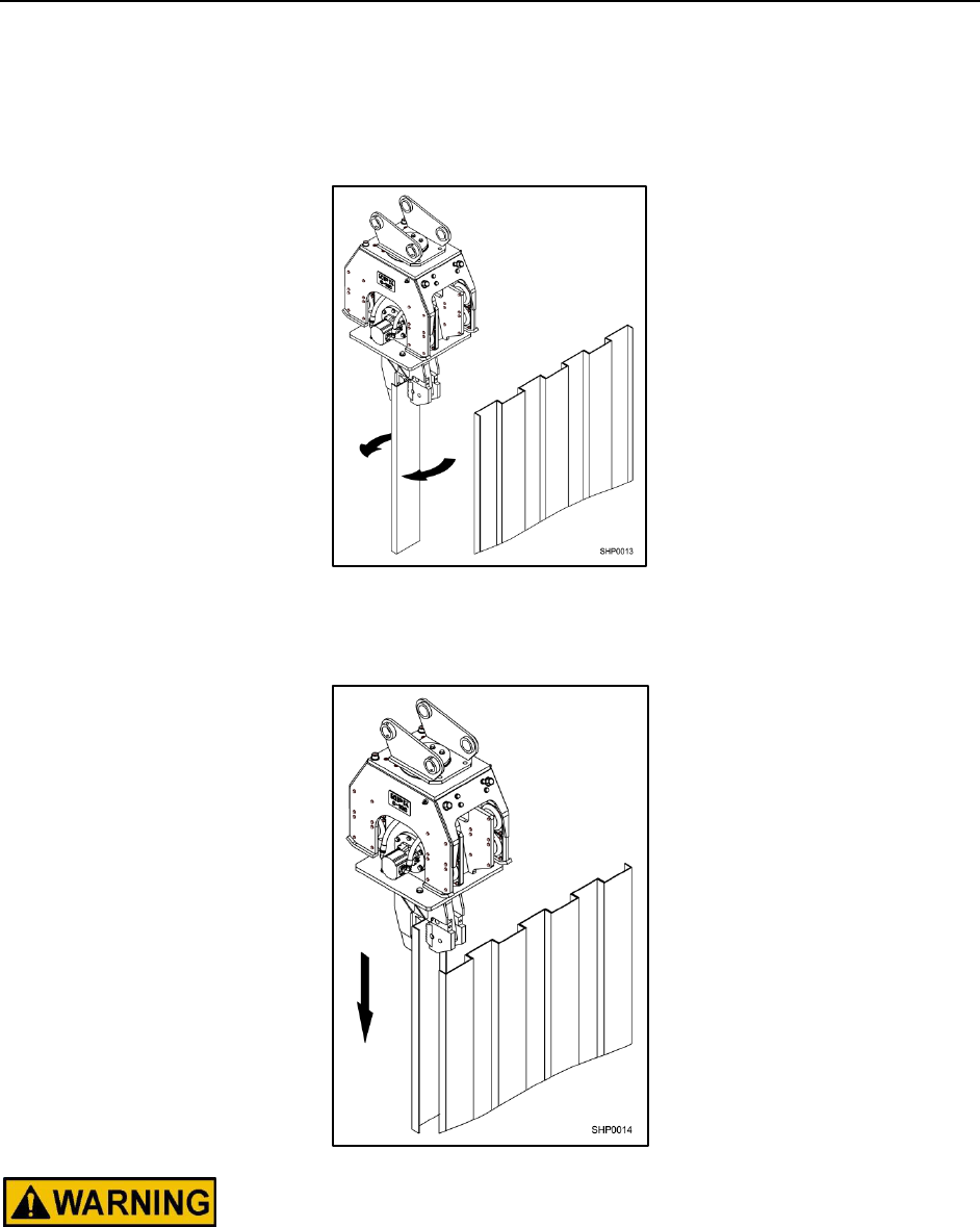
CHUCKING THE SHEET PILE
1. Turn the sheet pile driver frame manually until it is
positioned in parallel to the sheet pile. Then chuck the
sheet pile.
2. Attempting to chuck a sheet pile quickly at full throttle,
will cause a jerky, unsmooth movement of the Sheet
Pile Driver. It is much safer and more efficient to chuck
a sheet pile slowly at low throttle until the sheet pile is
securely clamped.
LIFT THE SHEET PILE
1. Do not lift the sheet pile too fast, as it may cause bending.
NPK
- 39 -
OPERATION
POSITIONING THE SHEET PILE
1. Using a pipe that is approximately 6 ft. (1.5 m) long or other suitable means, turn the
sheet pile into position.
2. Insert the sheet pile into the last one installed, then drive it vertically with appropriate
force.
NOTE: Before starting to push a sheet pile, make sure it is securely chucked.
NPK
- 40 -
OPERATION
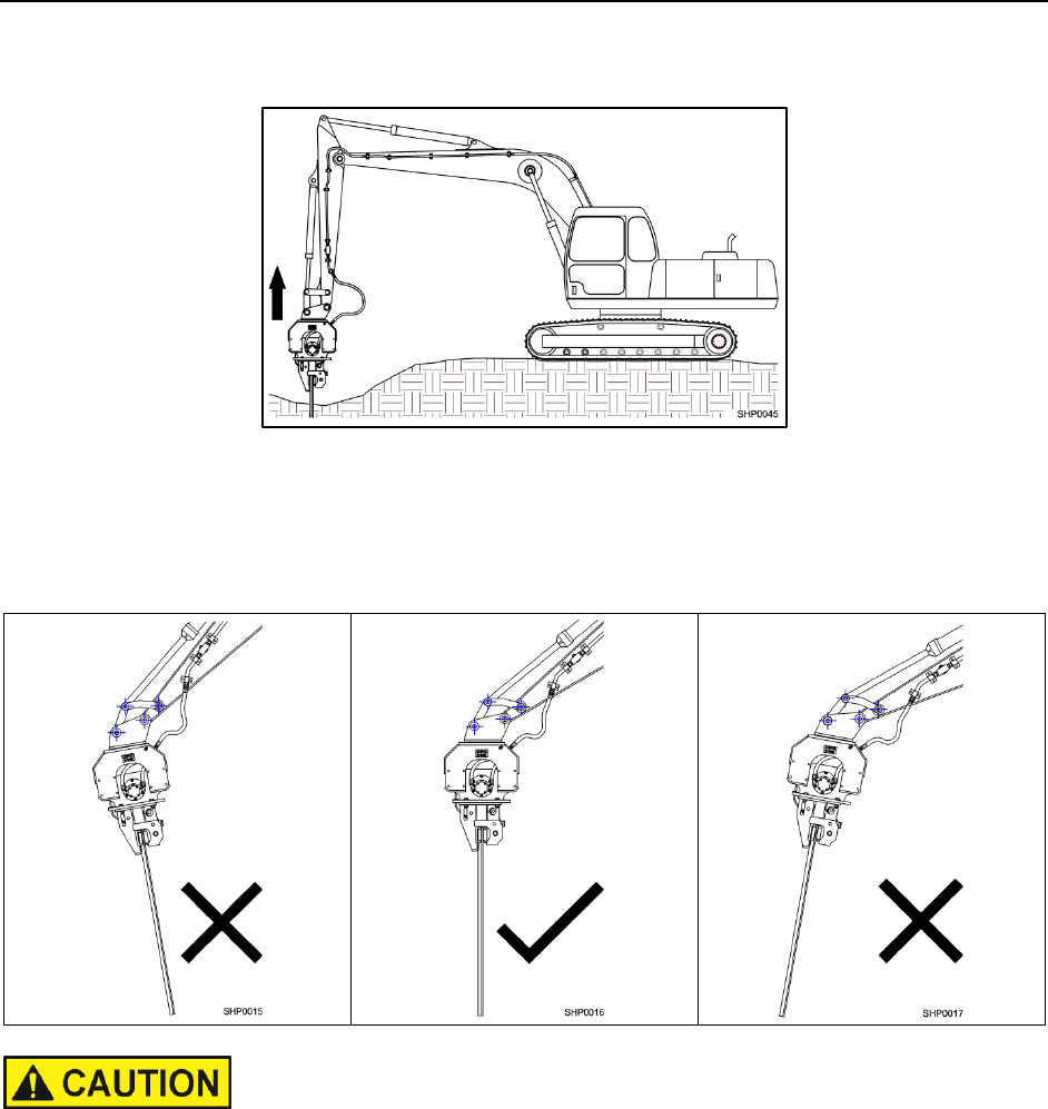
PILE DRIVING OPERATION
1. Make sure the sheet pile is in a vertical position.
2. If the speed of the sheet pile slows as it is going into the earth, give it proper
pressing force in the vertical direction by operating the excavator to give it the
vibrating speed that suits the nature of the soil so as to force the pile to drive into the
soil faster.
3. If the sheet pile will not go in after being driven half way into soil, pull it up some,
then try to drive it again. By repeating this cycle a few times, the sheet pile can be
driven through in most cases.
NPK
- 41 -
OPERATION
PULLING OPERATION
Piles can be pulled out, in a way similar to that for driving, by giving an appropriate
pulling force to the sheet piles in the vertical direction. Do not use excessive or
unevenly distributed pulling force as the sheet pile in the chuck may be damaged.
Make sure the sheet pile is in a vertical position.
Make sure the sheet pile is securely chucked. Slipped pile during the pulling operation
can be very dangerous. If a longer pulling time is required, recheck the pile as needed
for safety.

NPK
- 42 -
OPERATIONAL PRECAUTIONS
1. Before starting operation, level and sufficiently compact the operation ground to
prevent the excavator from falling down.
2. Do not touch the Sheet Pile Driver and hydraulic hoses during operation.
3. Do not use the Sheet Pile Driver for loading.
4. Hold a single sheet pile at a time. Holding more than one sheet pile simultaneously
is hazardous.
5. Do not operate the hydraulic motor in other cases than sheet pile driving and pulling.
6. Watch for oil leaks.
NPK
- 43 -
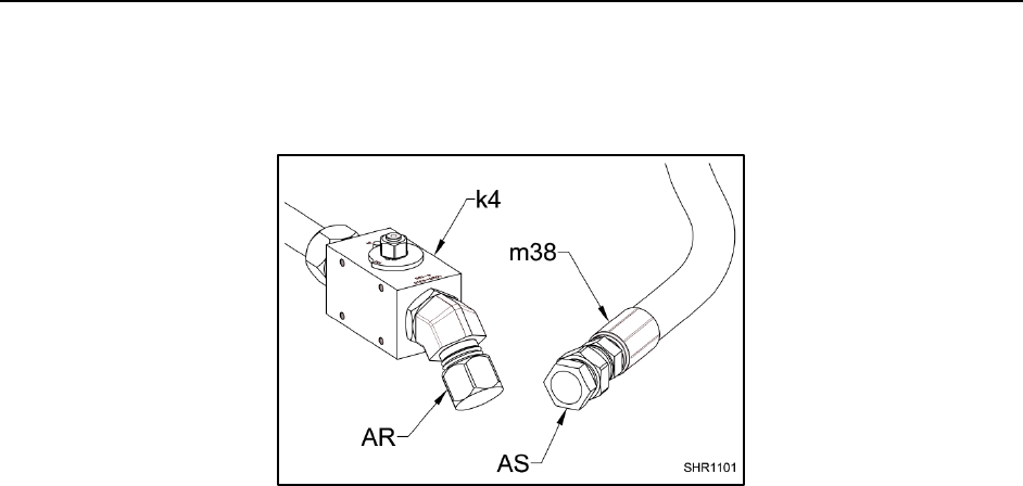
STORAGE OF THE SHEET PILE DRIVER
1. Make sure all whip hoses that connect the Sheet Pile Driver to the carrier are
plugged (AS) and all hose (38) connections are capped (AR). Turn the shut-off
valves (k4) to the “OFF” position.
2. If the unit is stored outdoors, cover with a waterproof tarp.

NPK
- 44 -
WARRANTY REGISTRATION FOR NEW UNITS
Complete and send to NPK after installation or complete on line at www.npkce.com.
Online warranty registration can be done by the dealer or the end user.
The registration can be done in any of the following ways:
1. Mailed to:
NPKCE
7550 Independence Dr.
Walton Hills Ohio 44146
2. Faxed: 440-232-6294(U.S.) (+1)(440)232-6294(outside U.S.)
3. Completed online at :
www.npkce.com
The online registration can be done by the dealer or the end user.
Dealers:
• In the tool bar click on DEALERS.
• Using your user name and password, log into the system.
• At the left of the next page click on REGISTRATION.
• Complete the fields with an orange diamond next to them.
• At the bottom of this area, click the START REGISTRATION box and continue.
• If the registration is completed online, there is no need to mail or fax the warranty
registration.
End users / non NPK dealers
• In the tool bar click on DEALERS
• You do NOT need to fill in user name and password.
• In the left column, click on the REGISTRATION.
• Complete the fields with an orange diamond next to them.
• At the bottom of this area, click the START REGISTRATION box and continue.
• If the registration is completed online, there is no need to mail or fax the warranty
registration.
NPK
- 45 -
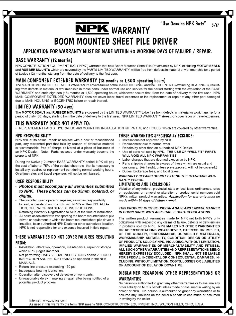
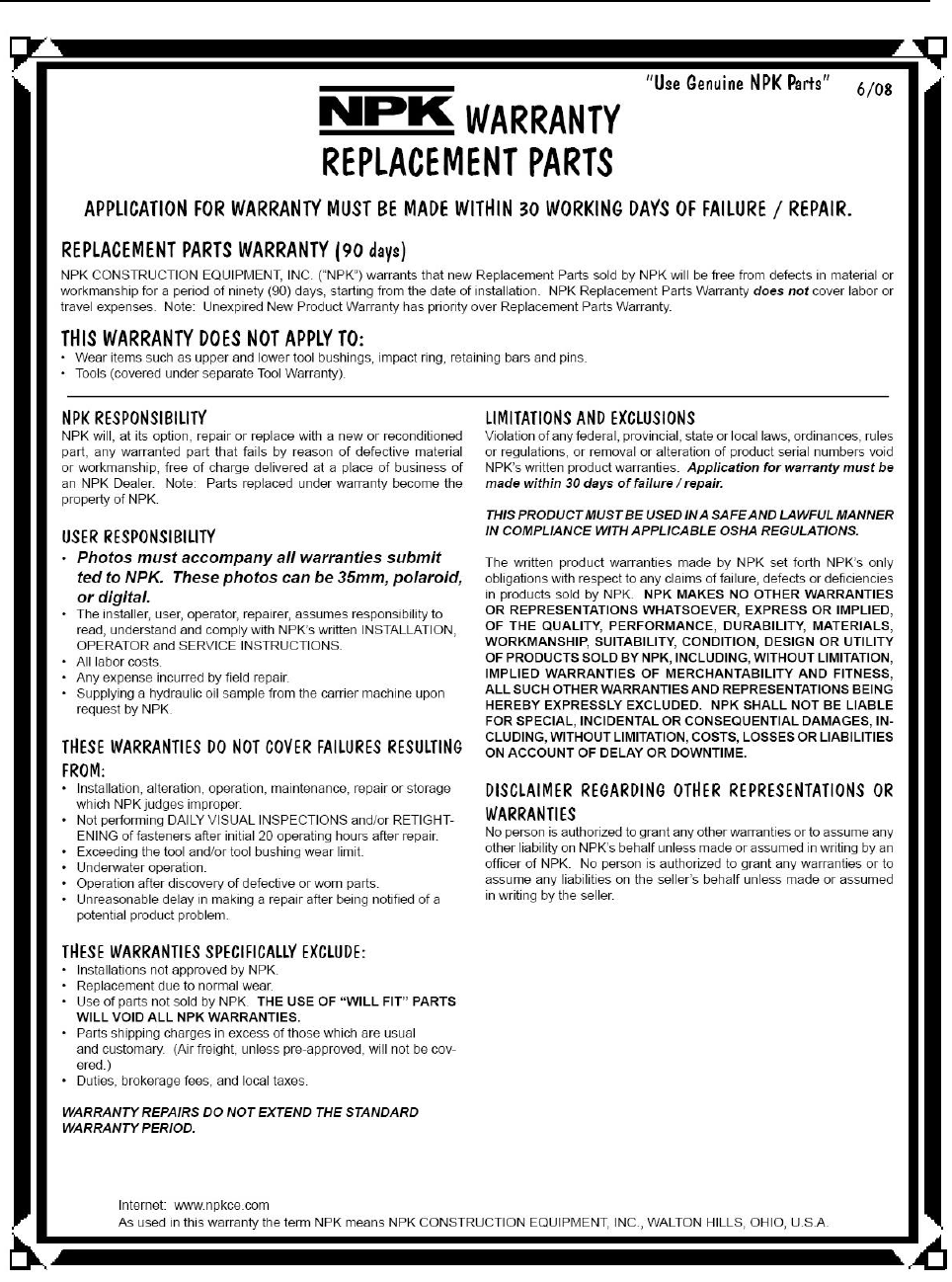
WARRANTY STATEMENTS
NPK
- 46 -
WARRANTY STATEMENTS

NPK
- 47 -
NOTES AND RECORDS
NPK COMPACTOR/DRIVER MODEL NUMBER _________________
SERIAL NUMBER ________________
NPK INSTALLATION KIT NUMBER __________________________
CARRIER MANUFACTURER
MODEL NUMBER
SERIES
SERIAL NUMBER
DATE OF INSTALLATION _________________
DATE OF 20 HOUR INSPECTION __________ WARRANTY REGISTRATION SENT ❑

