
-1-
Wireless Weather Station
Instruction Manual
Page
1. Introduction ....................................................................................................................2
2. Inventory of contents ....................................................................................................2
Feature of the base station ............................................................................................2
Feature of wind sensor ..................................................................................................2
Feature of rain sensor ....................................................................................................3
3. Set up guide ...................................................................................................................3
3.1 Battery install ............................................................................................................
3
3.2 Mounting ...................................................................................................................6
4. LCD overview .................................................................................................................8
4.1 LCD overview ............................................................................................................
8
4.2 Weather forecasting ................................................................................................. 9
4.3 Weather forecast tendency indicator ...................................................................10
4.4 Storm warning indicator ........................................................................................10
5. Program modes ...........................................................................................................11
5.1 Quick display mode ................................................................................................
11
5.2 Setting mode ...........................................................................................................12
5.3 History mode ...........................................................................................................12
5.4 Alarm mode .............................................................................................................13
5.5 Min/Max mode .........................................................................................................15
6. Problems and interference with operation................................................................16
7. Specication ...............................................................................................................17
This Operation Manual is part of this product and should be kept in a safe place for
future reference. It contains important notes on setup and operation.
-2-
1. Introduction
Thank you for purchasing this Professional Weather Center Designed for everyday use,
the weather station will prove to be an asset of great value for your personal use in the
home or office. Please read this instruction manual thoroughly to fully understand the
correct operation of your weather station and benet from its unique features.
2. Inventory of contents
1) Base station
2) WH1 sensor including thermo-hygro sensor, rain sensor, wind sensor
3) Instruction manual
4
)
2 adjustable hoops (to x the mast to your desired location)
The received data is continuously updated to bring you the latest weather information on
the base station’s LCD. The outdoor thermo-hygro sensors is the main data communication
unit since both the wind and rain sensors are connected to the thermo-hygro sensor for
operating power and rely on it to communicate to the base station. Weather data sent from
the thermo-hygro sensor is transmitted through wireless link.
Additional equipment (not included)
1. 3 Fresh AA 1.5V LR6 Alkaline batteries.
2. 2 Fresh AA 1.5V LR6 Alkaline batteries.
Feature of the base station:
● Indoor and outdoor temperature display in degrees Fahrenheit or Celsius (user
selectable)
● Indoor and outdoor relative humidity displays
● Barometric pressure reading in inHg or hPa, absolute or relative (user selectable)
● Detailed display of rainfall data in 1 hour, 24 hours, one week, one month and total since
last reset. (user selectable in mm or inch)
● Wind speed in mph, km/h, m/s, knots or Beaufort (user selectable)
● Wind chill temperature display
● Dew point temperature display
-3-
● Weather forecast display by weather icons (sunny, cloudy, rainy)
● Weather forecast tendency arrow
● Storm warning alarm
● Display of extensive weather data, in all cases with programmable alarm functions for
certain weather conditions as well as records of all minimum and maximum values along
with time and date of their recordings
● Supper bright green LED back light
● DCF Radio controlled time and date with manual setting option
● 12 or 24 hour time display
● Perpetual calendar
● Time zone setting
● Automatic daylight saving time function based on Germany DST system ( for those users
using the clock outside the time zone of Germany, the DST automatic change time will
be delayed or triggered earlier according to the time zone difference accordingly)
● Wall hanging or free standing
● Synchronized instant reception for outdoor weather data as well as radio controlled time
signal
Features of wind sensor
The wind sensor measures wind speed and sends the data to thermo-hygro sensor, which
in turn transmits the data to the base station.
Feature of rain sensor
The rain sensor measures the rainfall and sends the data to thermo-hygro sensor, which
in turn transmits the data to the base station. Operating power is taken from the thermo-
hygro sensor by a cable connection
3. Set up Guide
3.1 Battery install
-4-
Note: To avoid operating problems, please take note of battery polarity before/when
inserting any Alkaline Batteries. Use good quality Alkaline Batteries and avoid
rechargeable batteries. Since the radio controlled time receiver is built inside the
sensor, please do not put the sensor close to area with mass metal or obvious
shielding objects around.
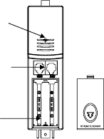
1)Pull away the shower proof casing of the thermo-hygro sensor to reveal the two sockets
(for the wind sensor and rain sensor)
2)Connect the attached cables of wind and rain sensors to the corresponding sockets
of the thermo-hygro sensor by clicking them into place. Make sure that rain and wind
sockets not swapped when plugging the phone jacket.
3)Open the base station’s battery cover located at the back of the unit and insert 3 x AA,
1.5V Alkaline batteries into the battery compartment and close the battery cover
4)Open the battery cover of the thermo-hygro sensor located below the two sockets and
insert 2 x AA, 1.5V Alkaline batteries and close the cover
Every time the thermo-hygro sensor is powered up (for example after a change of
batteries), the LED indicator will light up for 4 seconds (if no LED light up or is lighted
permanently, make sure the battery is inserted the correct way or a proper reset is
happened). After the thermo-hygro sensor is powered up, the sensor will transmit weather
LED Indicato
r
Sensor Sockets
Battery
Compartment
Battery cover
Thermo-hygro Sensor
Setting up using batterie
s

-5-
data for 24s, and then the sensor will start radio controlled time reception. During the RCC
time reception period (maximum 5 minutes), no weather data will be transmitted. The LED
indicator will be blinking 5 times once RCC signal was synchronized and the LED indicator
will not light during any future regular RCC reception routines. Regular RF link will be
established once RCC reception routine is nished.
When the base station is powered up, a short beep will sound and all LCD segments
will light up for about 3 seconds before it enters into learning mode to learn the sensors
security code.
Note: DO NOT PRESS ANY KEY during the rst 10 minutes learning period or before
radio controlled time is displayed on the receiver. After both outdoor weather data and
radio controlled time are displayed you can place your remote sensor outdoors and set
your time (if no RCC reception is possible). If there is no temperature reading in the indoor
station, make sure the units are within range of each other or repeat the battery installation
procedure. If a key is pressed before the weather station receives the temperature signal,
you will need to follow the battery installation procedure again. Please wait minimum
10seconds before re-insert the battery again to make a proper reset for both
transmitter and receiver.
Note : If a battery change on the transmitter side happened, the base station will be
resynchronized to the transmitter again within the next 3 hours. If you want to shorten the
receiving data time, the base station has to re-install the battery so that it can have the
new security code learnt right way, but the previous weather data and alarm value settings
in base station will be lost.
Note for Radio Controlled Time DCF:
The time and date display is based on the signal provided by the highly accurate
government operated atomic clock. The outdoor sensor will continue to scan for the
radio controlled time signal each day despite it being manually set. If reception has been
unsuccessful, then the radio controlled time icon will not appear but reception will still be
attempted continually. If reception has been successful, the received time and date will
overwrite the manually set time and date.
-6-
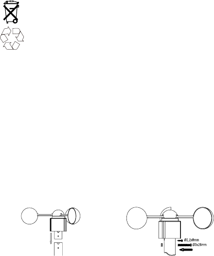
Note:
When batteries require replacement for the base station, the low battery indicator
will light up on the LCD.
Please participate in the preservation of the environment by properly
disposing of all used-up batteries and accumulators at designated disposal
points. Never dispose of batteries in a re as this may cause explosion, risk
of re or leakage of dangerous chemicals and fumes
3.2 Mounting
1) Base station
With one foldable leg at the back of the unit, the base station can be placed onto any at
surface or wall mounted at the desired location by the hanging holes also at the back of the
unit. It is important to check that outdoor sensor data can be received before permanently
mounting any of the units
2) Remote sensor
For accurate results, the remote sensor mast should be securely mounted onto a
horizontal surface and in an open area away from trees or other coverings where rainfall or
wind speed may be reduced causing inaccurate reading
a). mounting the wind sensor onto a master
Firstly, check that the wind-fan can rotate freely before xing the unit. The wind sensor
should now be mounted using the screw onto a mast provided to allow the wind to travel
around the sensor unhindered from all directions.
Front Back
-7-
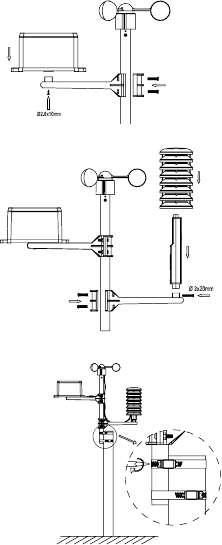
b.) Mounting the rain sensor
c.)Mounting the thermo-hygro sensor same as rain sensor
d.) Fix the whole set to a pole with the two adjustable hoops.
-7-
-8-
Once the wind sensor and rain sensor are xed onto the mast, connect the cable to the
corresponding thermo-hygro sensor socket.
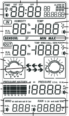
4. LCD overview
4.1 LCD overview
The following illustration shows the full segments of the LCD for description purposes only
and will not appear like this during normal operation and use.
1
2
3
4
5
6
7
8
9
10
11
12
13
16
14
15
17
18
19
20
21
22
23
24
25
26
27
28
29
30
-9-
1. Time
2. Alarm on indicator
3. Day of week/ time zone / history
4. Date
5. Indoor temperature display
6. Indoor humidity display
7. Indoor temperature and humidity low
alarm and high alarm
8. Temperature display unit
9. General indoor alarm icon
11. Wind chill and dew point
temperature display
12. Outdoor temperature and humidity
display
13. Outdoor temperature and humidity
low alarm and high alarm
14. Temperature display unit
15. General outdoor alarm icon
16. Weather forecast icon
17. Weather tendency indicator
18. Pressure unit (relative or absolute)
19. Pressure with 24 hour history graph
Pressure low alarm and high alarm
21. Pressure display unit (inHg or hPa)
22. Pressure alarm on indicator
23. Wind speed display unit (m/s, km/h,
knots, chill mph, bft)
24. Wind speed high alarm
25. Wind alarm on indicator
26. Rainfall display unit (mm/in)
27. Rainfall 1h, 24h, week, month or total
hour display
28. Rainfall alarm on indicator
29. Radio controlled time version DCF
Radio controlled time icon
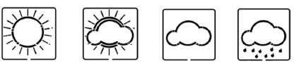
4.2 Weather forecasting
Sunny Partly Cloudy Cloudy Rainy
The four weather icons Sunny, partly Cloudy, Cloudy and Rainy represent the weather
forecasting. For every sudden or signicant change in air pressure, the weather icons will
update accordingly to represent the change in weather.
30.
10. MIN/MAX information
20.
-10-
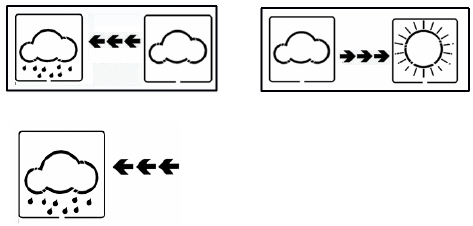
4.3 Weather forecast tendency indicator
The weather tendency indicators arrow is located between the weather icons to show
the air pressure tendency and provide a forecast of the weather to be expected by the
decreasing or increasing air pressure. The rightward arrow means that the air pressure is
increasing and the weather is expected to become better. The leftward arrow means that
the air pressure is decreasing and the weather is expected to become worse.
The change of weather forecast icon is in accord to the relationship between current
relative pressure and the pressure change since last twelve hours. If the weather is
changing, weather tendency indicator (animated arrows) will be ashing. And after the next
three hours if weather conditions have become stable, the arrows will x indicating a stable
condition happened.
Examples of changing weather icons:
4.4 Storm warning indicator
The storm threshold can be set to suit the user’s requirement for storm forecasting from
storm forecasting will be activated, the clouds with rain icon and tendency arrows will ash
for 3 hours indicating the storm warning feature has been activated.
3-9hPa (default 4hPa). When there is a fall over pressure threshold within 3 hours, the
-11-
Notes to pressure sensitivity setting for weather forecasting:
The pressure threshold can be set to suit the user’s requirement for weather forecasting
from 2-4hPa (default 2hPa). For areas that experience frequent changes in air pressure
requires a higher setting compared to an area where the air pressure is stagnant. For
example if 4hPa is selected, then there must be a fall or rise in air pressure of at least
4hPa before the weather station will register this as a change in weather.
5.Program Mode
The base station has ve keys for easy operation: SET key, + key, ALARM key, HISTORY
key and MIN/MAX key. And there are ve program modes available: Quick Display Mode,
Setting Mode, Alarm Mode
,
History Mode and Min/Max Mode.
The program mode can be exited at any time by either pressing the HISTORY key, or
waiting for the 10-second time-out to take effect.
5.1 Quick Display Mode
- While in Normal Mode, press the SET key to enter the Quick Display Mode as follow:
1. Outdoor Temperature / Wind chill / Dew point (press the + key or MIN/MAX key shifts
the display between outdoor temperature, wind chill and dew point)
2. Absolute pressure / Relative pressure (press the + key or MIN/MAX key shifts the
display between the absolute pressure and relative pressure)
3. Wind speed / Gust speed (press the + key or MIN/MAX key shifts the display
between the wind speed and gust speed)
4. 1 hour/ 24 hour / week/ month / total rainfall quantity (press the + key or MIN/MAX
key shifts the display between the selectable rainfall quantities), while display the
rainfall total quantity, pressing the SET key for two seconds will reset the rainfall total
value to zero and the time recording to current time.
- Press the SET key to accept the change and advance to the next display mode.
Continue to press the SET key to toggle through the display mode until return to the
normal Mode
-12-
5.2 Setting Modes
- Press the SET key for 3 second while in normal mode to enter the normal Setting mode
- Press the SET key to select the following setting in sequence :
1.Time Zone Setting
2.12/24 hour format
3.Manual time setting (hours/minutes)
4.Calendar setting(year /month/ date, weekday will be calculated thus no need to set
weekday)
5.Temperature display unit degree Celsius or Fahrenheit
6.Air pressure display units in hPa or inHg
7.Relative pressure setting from 919.0hPa – 1080.0hPa (default 1013.2hPa)
8.Pressure threshold setting (default 2hPa)
9.Storm threshold setting (default 4hPa)
10.Wind speed and gust display units in km/h, mph, m/s, knots, bft
11.Rainfall display units in mm or inch
- In the setting modes, press + key or min/max key to select the units or scrolls the value.
Holding the + key or min/max key for 3 second will increase/decrease digits in great
steps.
- Press HISTORY key or key idle 10 second, the setting mode will return to Normal Mode
Note: Please set the units rstly before change units’ value. During change of units setting,
the previous set value will be changed according to the new units. However it might cause
resolution loss due to its internal calculation algorithm.
5.3 History Modes
- While in Normal Mode, press the HISTORY key to enter the History Mode.
- In the History Mode, press the + key to select the record over the past 24hours at
increments of -3 hours,
- -6 hours, -9 hours, -12 hours, -15 hours, -18 hours, -21 hours, -24 hours
- Press the HISTORY key or key idle 10 second to return to Normal Mode
-13-
5.4 Alarm Modes
- While in Normal Mode press the ALARM key to enter the High Alarm Mode
- Press the ALARM key again to enter Low Alarm mode
Remark: after the initial pressing of ALARM key, the display will be refreshed to show
current high, low alarm values. Normal alarm value will be displayed only for those
already activated, all other not activated values will be displayed with “- - -“or “- -“instead.
- Press the ALARM key again to return the Normal Mode
- In the High Alarm Mode press the SET key to select the following alarm modes:
1. Time alarm (at low alarm setting mode, the same time alarm setting sequence will
repeat)
2. Indoor humidity high alarm
3. Indoor temperature high alarm
4. Outdoor humidity high alarm
5. Outdoor temperature high alarm
6. Wind chill high alarm
7. Dew point high alarm
8. Pressure high alarm
9. Wind speed high alarm
10. Gust speed high alarm
11. 1Hour rain high alarm
12. 24 hour rain high alarm
- In the Low Alarm Mode press the SET key to select the following alarm modes:
1.Time alarm (at high alarm setting mode, the same time alarm setting sequence will
repeat)
2. Indoor humidity low alarm
3. Indoor temperature low alarm
4. Outdoor humidity low alarm
5. Outdoor temperature low alarm
6. Wind chill low alarm
7. Dew point low alarm
8. Pressure low alarm
-14-
- In the alarm modes, Press + key to changes or scrolls the value upward, or press min/
max key to change or scrolls the alarm value downward. Hold the + key or min/max key for
3 second to change the number in great step. Press the ALARM key to choose the alarm
on or off (if alarm is enabled, the speaker icon on the LCD will be turned on indicating the
alarm function has been enabled). Press the SET key to toggle through each alarm mode
until it returns to the normal display mode.
- Press HISTORY key or key idle 10 second at any time, the alarm mode will return to
Normal Mode
Canceling the Temperature Alarm While Sounding
a. When a set weather alarm condition has been triggered, that particular alarm will sound
for 120 second and ash until the weather condition doesn’t meet the user set level.
Press any key to mute the alarm. When weather alarm condition was activated again
within 10 minutes, alarm will not sound but will continue to ash until weather conditions
have become more steady. This feature is useful to avoid repeated triggering for the
same alarm value.
b. The alarm will reactivate automatically once the value has fallen below the set value.
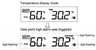
The outdoor weather alarm
When a set outdoor weather alarm has been triggered, it will ash on the LCD display and
the general outdoor alarm icon and high/low alarm icon will ash accordingly. For example,
in outdoor temperature display mode, when dew point high alarm is triggered DEW POINT
icon will ash along with general outdoor alarm icon and high alarm icon ashing, telling
that the current alarm source is from dew point.
-15-
5.5 Min/Max Mode
- While in Normal Mode, press the min/max key to enter the maximum mode,
- press min/max key again to enter the minimum mode
- Press min/max key again to return the Normal Mode
- In the maximum reading Mode, press the + key to display the following maximum values
together with the time and date stamp when these values were recorded, if press SET
key in the following individual minimum value will be reset to current reading together
with the current time and date.
1.Indoor humidity maximum
2.Indoor temperature maximum
3.Outdoor humidity maximum
4.Outdoor temperature maximum
5.Wind chill temperature maximum
6.Dew point temperature maximum
7.Pressure maximum
8.Wind speed maximum
9.Gust speed maximum
10.1Hour rain maximum
11.24 hour rain maximum
12.Week rainfall maximum
13.Month rainfall maximum
-In the minimum reading Mode, press the + key to display the following minimum values
together with the time and date at which these values were recorded, if press SET key in
the following individual maximum value will be reset to current reading together with the
current time and date.
1. Indoor humidity minimum
2. Indoor temperature minimum
3. Outdoor humidity minimum
4. Outdoor temperature minimum
5. Wind chill temperature minimum
6. Dew point temperature minimum
7. Pressure minimum

-16-
- Press the HISTORY key or key idle 10 second, the Min/Max mode will return to Normal
Mode
6.Problems and interference with operation
Problem & cause Remedy
Distance between transmitters and
receiver too long
Reduce distance between transmitters and
receiver to receive signal
High shielding materials between
the units (thick walls, steel, concrete,
isolating aluminum foil and etc.)
Find a different location for sensors and/or
receiver. See also item ‘transmission range’
below
Interference from other sources (e.g.
wireless radio, headset, speaker, etc.
operating on the same frequency)
Find a different location for the sensors and/
or base station. Neighbors using electrical
devices operation on the same signal
frequency can also cause interference with
reception
No reception after adding extension
cables
Find a new location for the sensors and/or
base station.
Poor contrast LCD or no reception or
low batteries in sensors or receiver
Change batteries
Temperature, humidity, or air pressure
is incorrect.
Check/replace batteries. If multiple remote
sensors are in use, check location with
corresponding “boxed numbers”. Or move
away from sources of heat/cold. Adjust
relative air pressure to a value from a
reliable source (TV radio, etc.).
-17-
7. Specications
Outdoor data
Transmission distance in open eld : 150meter max.
Frequency : 433MHz or 868MHz (selected by solder option)
Temperature range : -40
℃
to +65
℃
(show OFL if outside range)
Resolution : 0.1
℃
Measuring range rel. humidity : 1%
~
99%
Rain volume display : 0 - 9999mm (show OFL if outside range)
Resolution : 0.3mm (if rain volume < 1000mm)
1mm (if rain volume > 1000mm)
Wind speed : 0~180km/h (show OFL if outside range)
Measuring interval thermo-hygro sensor : 48 sec
Water proof level : IPX3
Indoor data
Pressure / temperature : 48 sec
Indoor temperature measure range : 0
℃
to +60
℃
(reading range: -20
℃
to +65
℃
)
Resolution : 0.1
℃
Measuring range rel. humidity : 1%
~
99%
Resolution : 1%
Measuring range air pressure : 919hPa – 1080hPa
Resolution/Accuracy : 0.1hPa / 1.5hPa
Alarm duration : 120 sec
Power consumption
Base station : 3XAA 1.5V LR6 Alkaline batteries
Remote sensor : 2xAA 1.5V LR03 Alkaline batteries
Battery life : Minimum 12 months for base station
Minimum 24 months for thermo-hygro sensor
