
WOLF BRAND SCOOTERS
USER’S MANUAL
Instructions to Users
Blaze and Blaze II ModelsInstructions to Users
Precautions .................................................................................... 1
Vehicle Identification Number and Engine Number ..................... 2
Brief Introduction to your vehicle ................................................. 3
Technical Specifications ............................................................... 6
Instrument cluster ........................................................................ 10
Left control switches ................................................................. 11
Right control switches ................................................................. 12
Ignition switch ............................................................................ 13
Seat storage lock and Fuel tank .................................................. 14
Vehicle Operation ...................................................................... 16
Environmental protection device ................................................ 17
Vehicle Load ............................................................................... 18
Tool kit (included) ....................................................................... 18
Operating Instructions
Basic vehicle checks and maintenance levels ............................. 19
Kick starting the engine .............................................................. 23
Electric starting the engine .......................................................... 24
Parking the vehicle ....................................................................... 25
Service and Maintenance
Regular Service and Maintenance .............................................. 26
Requirements on Service and Maintenance ................................ 26
Service and Maintenance during break-in Period ....................... 27
Precautions you should take during the break-in period ............. 27
Contents of Level 1 Service and Maintenance ............................ 28
Contents of Level 2 Service and Maintenance ............................ 28
Contents of Level 3 Service and Maintenance ............................ 28
Service and Maintenance of the Carburetor ................................ 29
Checking and changing the engine oil ........................................ 30
Service and Maintenance of the Spark Plug ................................ 31
Service and Maintenance of the Air Filter ................................... 32
Adjusting the throttle ................................................................... 33
Service and Maintenance of the Front Brake .............................. 34
Service and Maintenance of the Rear Brake ............................... 35
Checking the brake light switches ............................................... 36
Adjusting the idle speed .............................................................. 36
Service and Maintenance of the Front and Rear Tires ................ 37
Service and Maintenance of the Environmental Protection Device
..................................................................................................... 39
Service and Maintenance of the battery ...................................... 40
Service and Maintenance of the fuse ........................................... 41
Service and Maintenance of the horn .......................................... 41
Storage of the vehicle .................................................................. 42
Service and Maintenance Interval Table ..................................... 43
Service and Maintenance Interval Table for Lubricated Parts .... 44
Common Faults and Troubleshooting............................................. 45
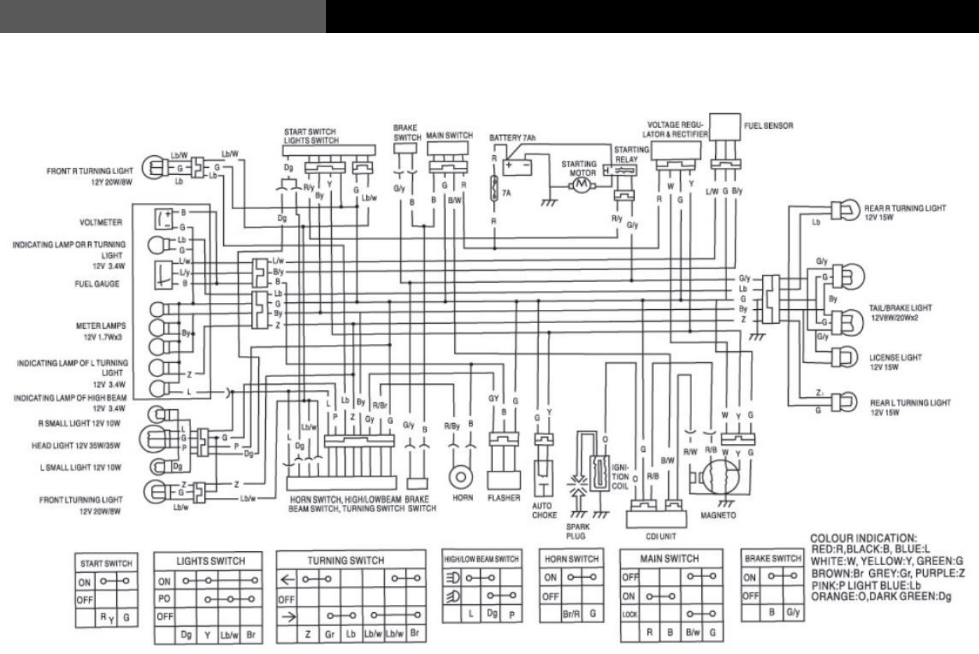
Schematic Wiring Diagram ............................................................. 49

1
USER’S MANUAL
Instructions to Users
Please read this User’s Manual carefully before operating this
vehicle!
Warning
* Please observe all traffic laws and regulations.
* All users must have a valid driver’s license. Operating a vehicle with a 150cc sized engine (the Blaze II) may require extra licensing
endorsements. Please check your local motor vehicle laws to be sure.
* NEVER hang anything on the handlebars while operating the vehicle
* Always wear a helmet, eye protection, and gloves for your safety.
* This vehicle is for road use only.
* Always be aware that the exhaust and muffler will become hot when operating your vehicle. Do not touch the exhaust assembly during or
shortly after operating the vehicle as not to burn yourself.
* For your safety, always wear the appropriate clothing and footwear while operating your vehicle.
Caution
* Please check the accessories and various documents delivered with the vehicle according to the packing list.
* Strictly follow the listed weight limit of the vehicle.
* Do not modify any part of the vehicle. Modifying the vehicle can decrease the engine life, the reliability of your vehicle and compromise
your safety.
* Only premium fuel should be used in the vehicle. (90+ octane) Otherwise, the engine performance and fuel economy, may be compromised,
and the service life of the vehicle will be shortened. Use of lesser rated fuel will void the engine coverage of your warranty.
* All repairs and required service must be completed at a Wolf Brand Scooters authorized service center. All required service must be done to
the vehicle following the published service intervals to maintain the vehicle’s warranty.
* Not completing required service will void your warranty.
Suggestion
* This manual provides important information regarding the vehicle. If the vehicle is transferred to any other person, this manual should be
transferred together with the vehicle.
2
Instructions to Users
USER’S MANUAL
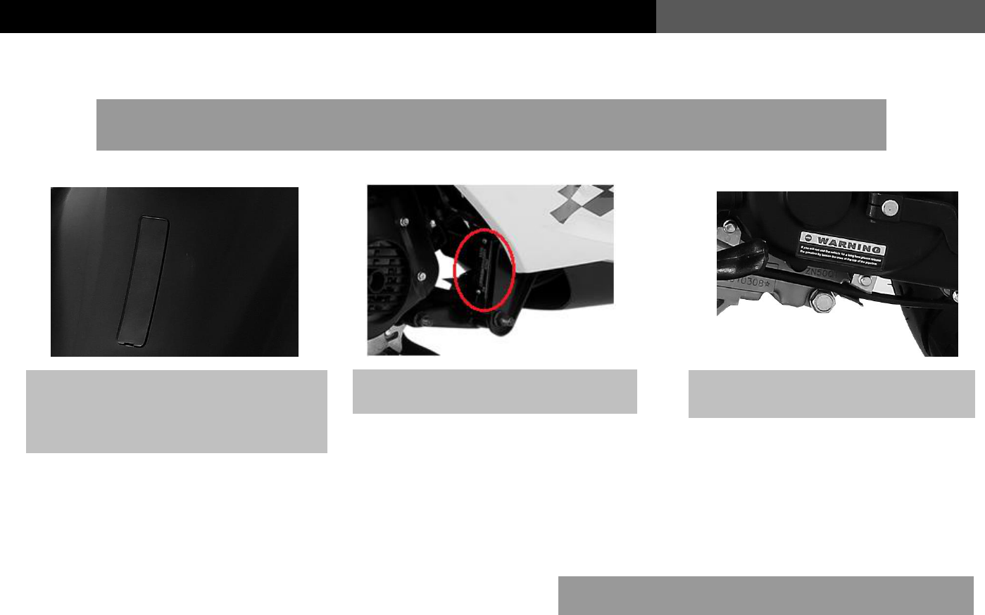
Vehicle Identification Number (VIN) and Engine Number
The Vehicle Identification Number (VIN), Engine Number and Quality Certificate, are used to obtain the
registration and license plate for your new vehicle.
Please note your vehicles specific numbers for future
reference here:
Vin:
Engine Number:
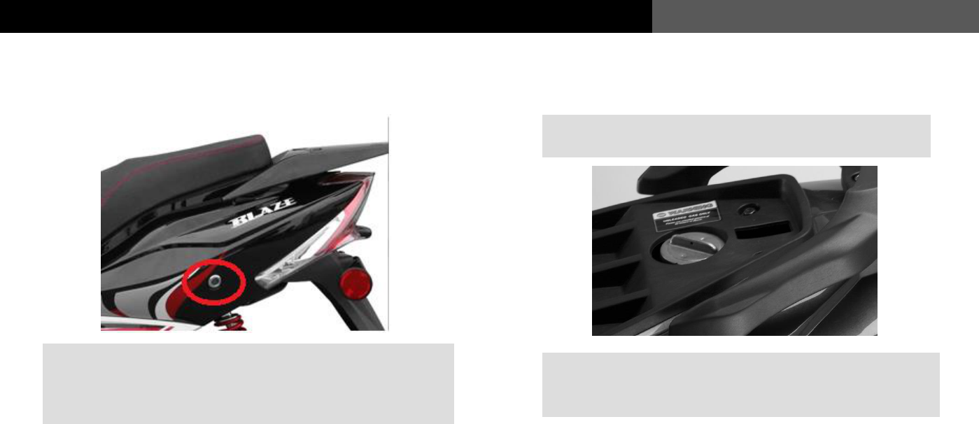
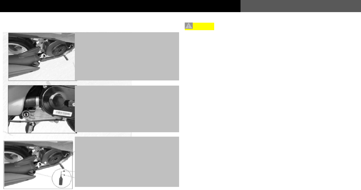
Vehicle Identification Number (VIN) is
printed on the vertical tube of the frame.
Behind this small cover on the “knee
board”.
The product nameplate is riveted on
the right lower part of the frame.
The Engine Number is printed on the
left lower part of the crankcase.
3
USER’S MANUAL
Instructions to Users
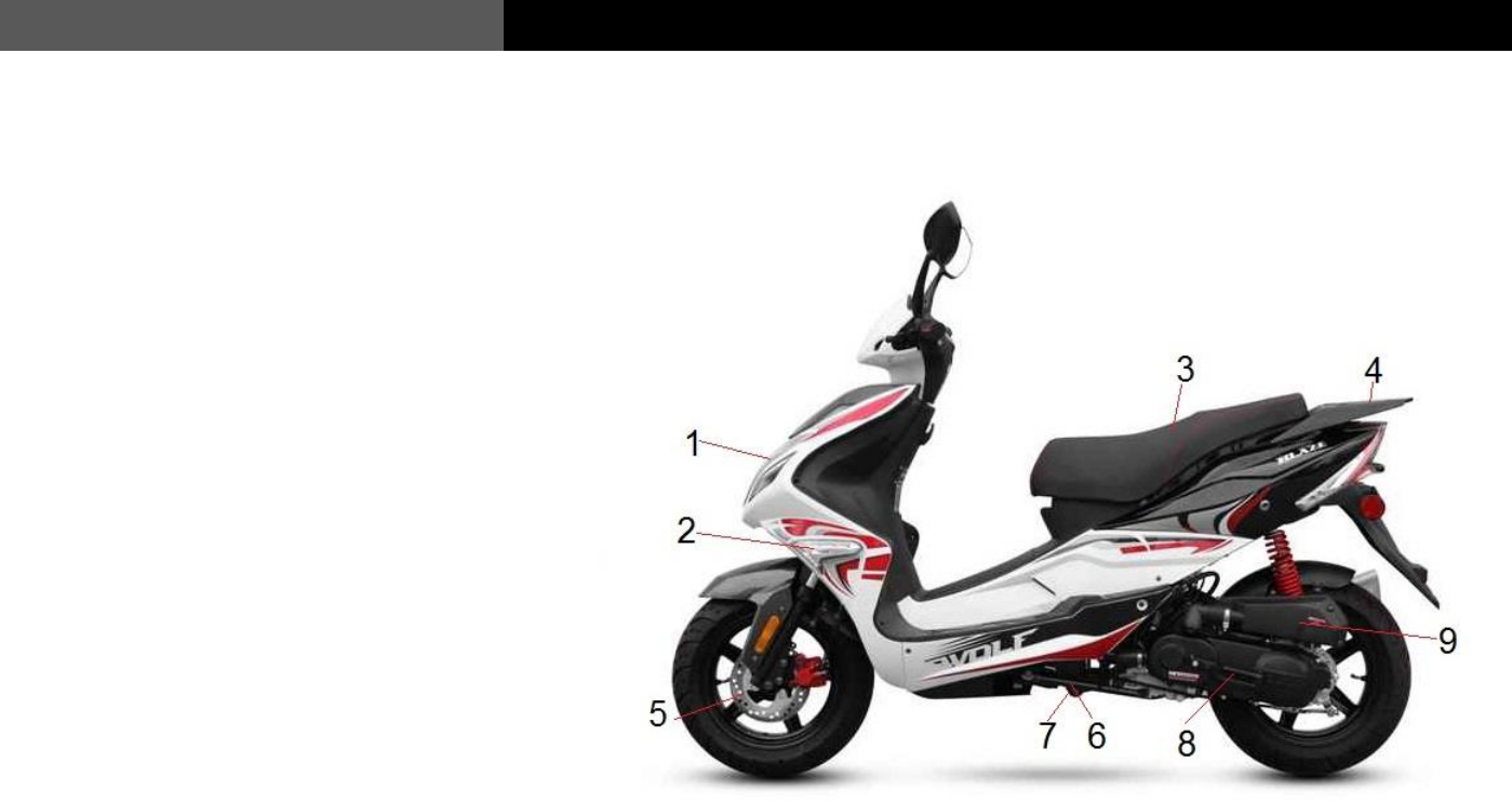
A Brief Introduction to the vehicle
1. Headlight
2. Left front turn signal
3. Seat cushion and storage
4. Rear luggage carrier
5. Disc brake
6. Side stand
7. Center stand
8. Kick Start
9. Air filter assembly
4
Instructions to Users
USER’S MANUAL
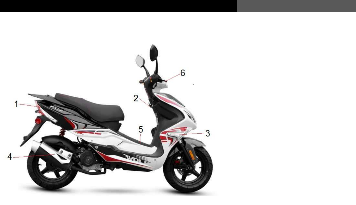
1. Tail light/ Brake light
2. Helmet hook
3. Right front turn signal
4. Muffler
5. Battery
6. Front brake lever
A Brief Introduction to the vehicle
5
USER’S MANUAL
Instructions to Users
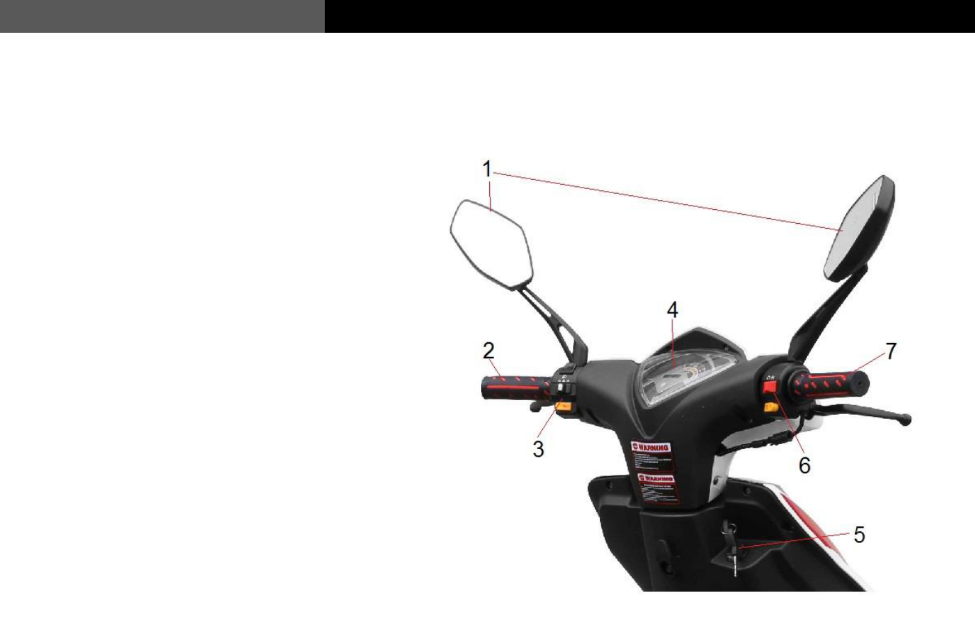
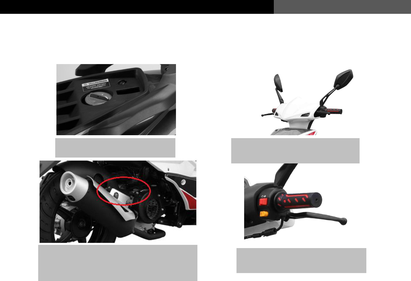
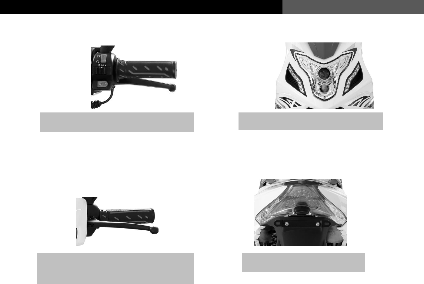
1. Rearview mirrors
2. Left grip
3. Left switch assembly
4. Instrument cluster
5. Ignition
6. Right switch assembly
7. Throttle grip
A Brief Introduction to the vehicle
6
Instructions to Users
USER’S MANUAL
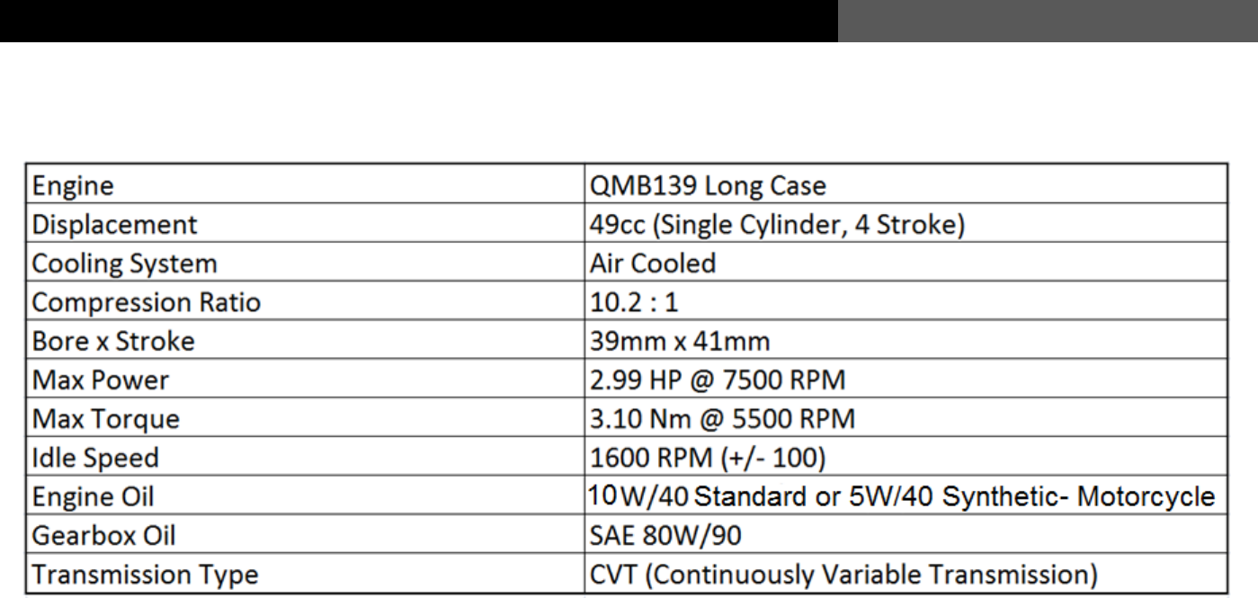
Technical Specifications
Blaze (49cc)
7
USER’S MANUAL
Instructions to Users
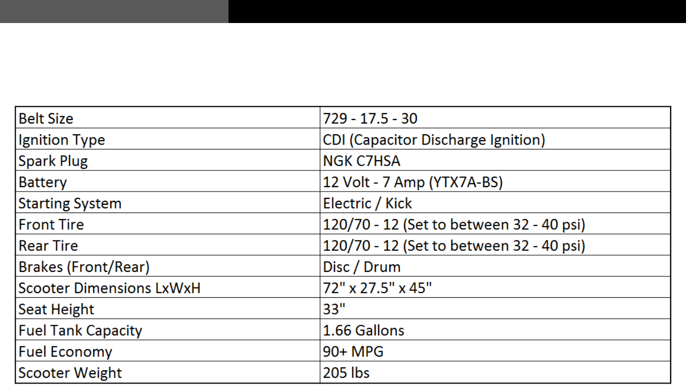
Technical Specifications
Blaze (49cc)
8
Instructions to Users
USER’S MANUAL
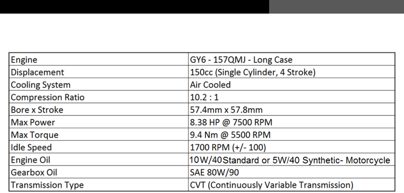
Technical Specifications
Blaze II (150cc)
9
USER’S MANUAL
Instructions to Users
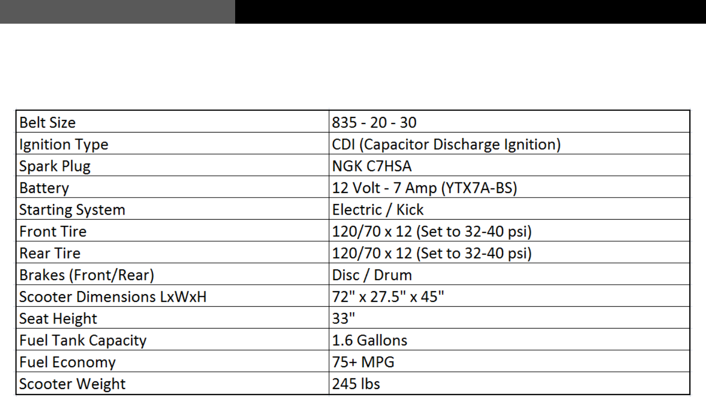
Technical Specifications
Blaze II (150cc)
10
Instructions to Users
USER’S MANUAL
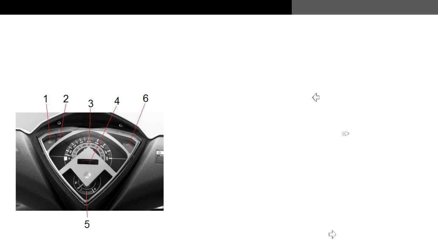
Instrument cluster
1 Left turn indicator lamp:
When the turning indicator lamp “ ” flashes, it indicates that the
“left turn signal” is on.
2 High beam indicator lamp:
When the blue high beam indicator lamp “ ” is on, it indicates that the
headlight is operating in “High Beam” mode
3 Speedometer:
It indicates the current speed of the vehicle.
4 Odometer:
Records the vehicles accumulated miles.
5 Fuel gauge:
Indicates how much fuel is in the fuel tank of the vehicle.
6 Right turn indicator lamp:
When the right turning indicator lamp “ ” flashes, it indicates that
The “right turn signal” is on.
11
USER’S MANUAL
Instructions to Users
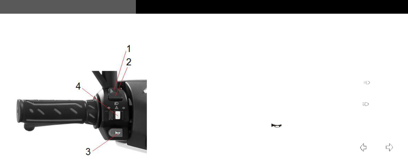
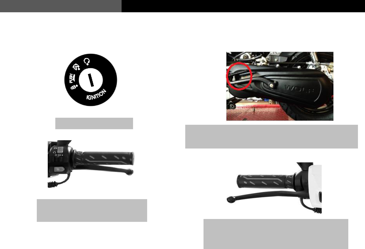
Left switch assembly
1 High beam headlamp switch:
To use the “High beam lamp”, turn the switch to the upper “ ”. position
2 Low beam headlamp switch:
To use the “Low beam lamp”, turn the switch to the lower “ ”. Position.
3 Horn button:
To use the horn, press the “ ” button.
4 Turn signal switch:
When making a turn with the vehicle, move this switch to “ ” or “ ” to
signal to other motorists that you are turning left or right. When you complete
your turn, press the center white button to switch the turn signal off.
12
Instructions to Users
USER’S MANUAL
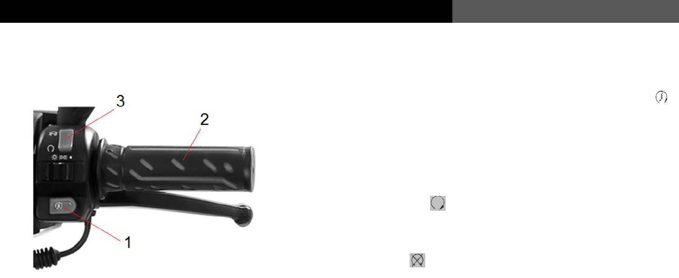
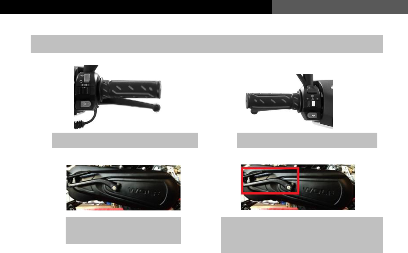
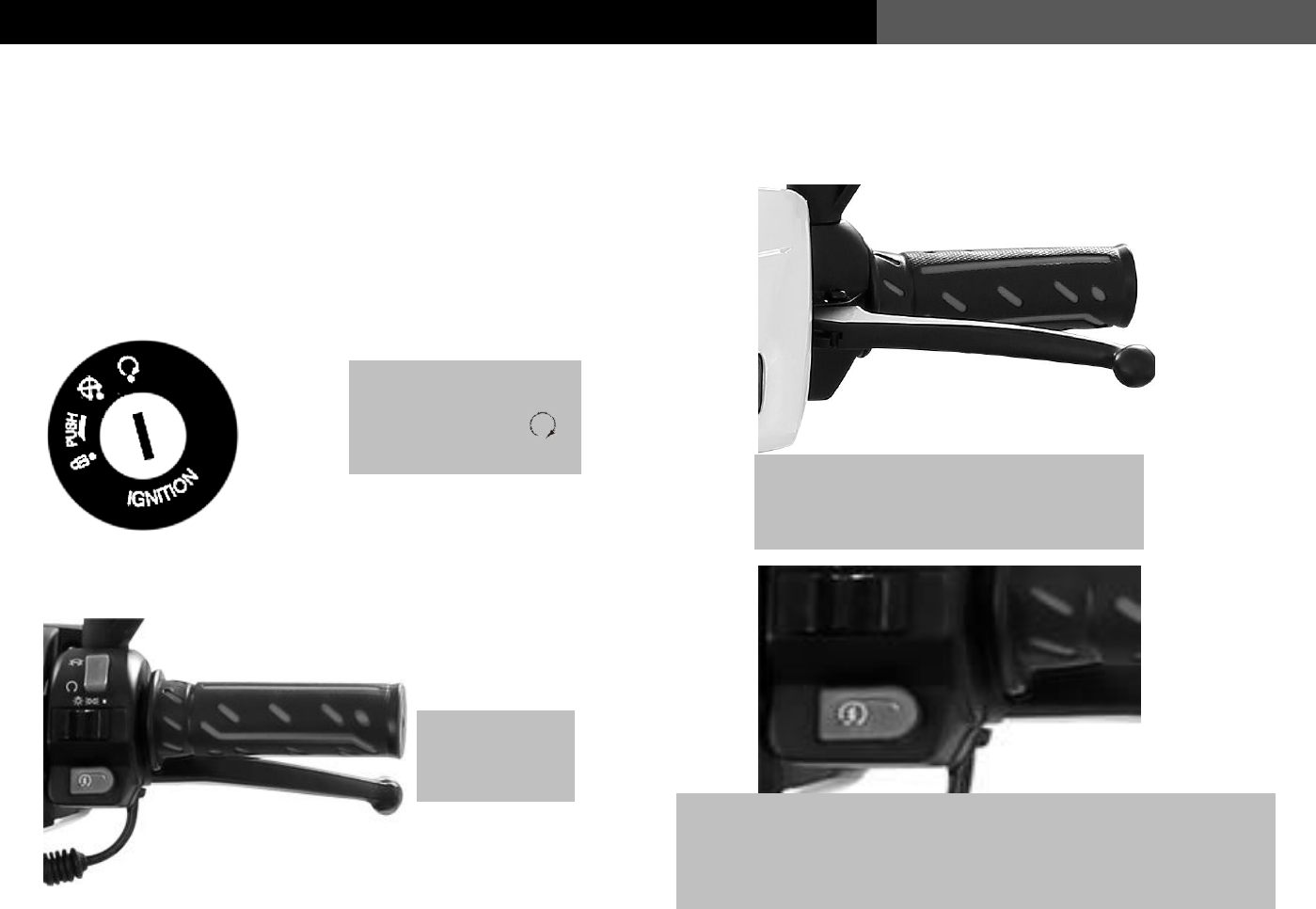
Right switch assembly
1 Electric start button:
This is pressed when you want to start the vehicle. Press the yellow “ ”
button while holding in brake levers.
2 Throttle grip:
When the engine is on, twist to accelerate.
3 The Cut Off or Run /Stop Switch:
Electrical power for the engine is turned on when the switch is set to
The position marked “ ”
This switch must be set to this position for the engine to start and run
Electrical power for the engine is turned off when the switch is set to the
position marked “ ” The engine will turn off when this switch is set to
this position
13
USER’S MANUAL
Instructions to Users
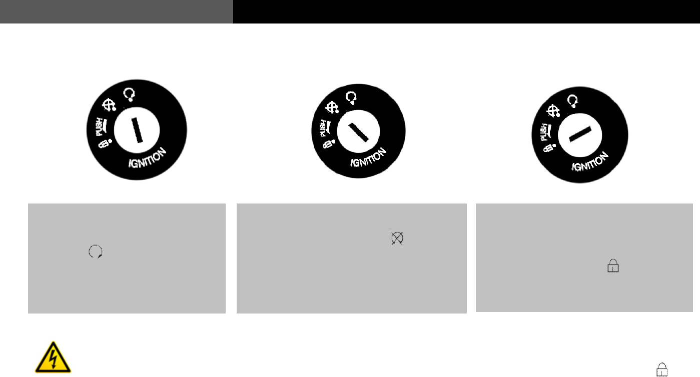
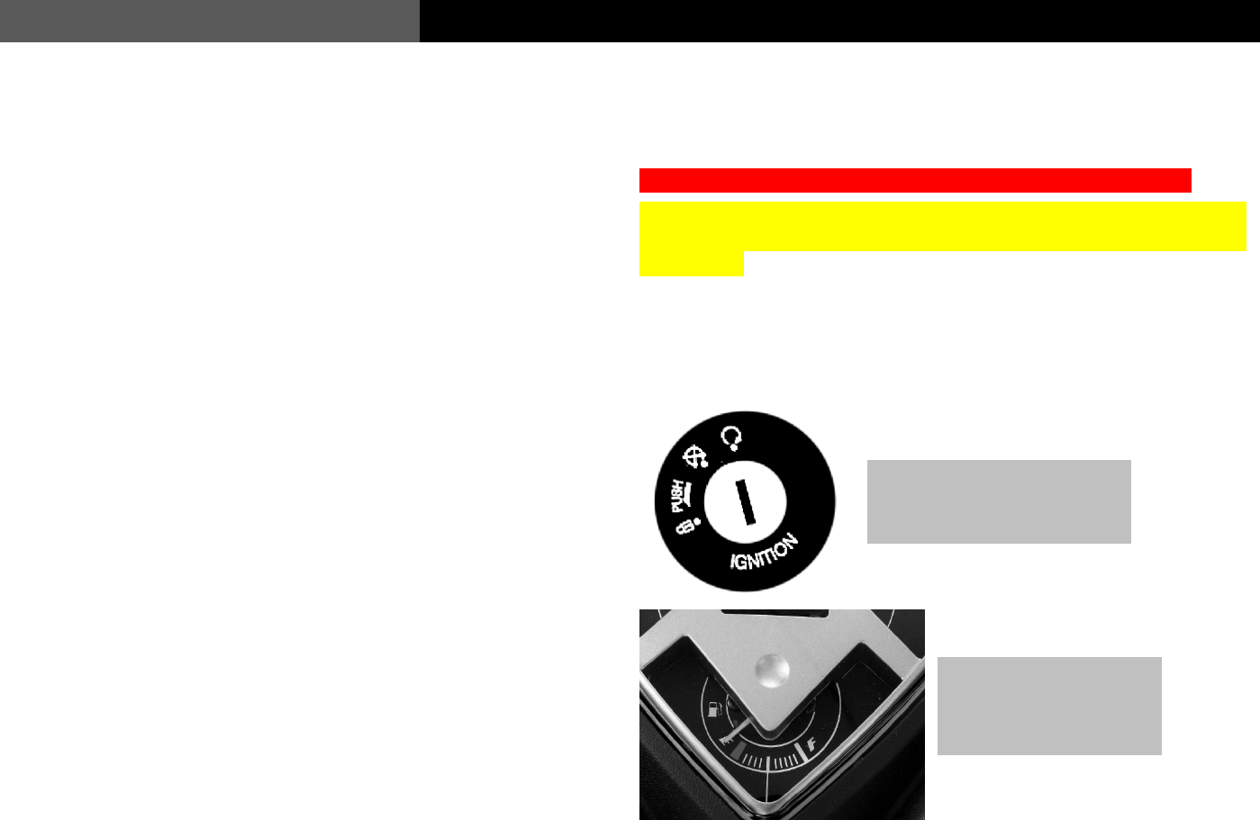
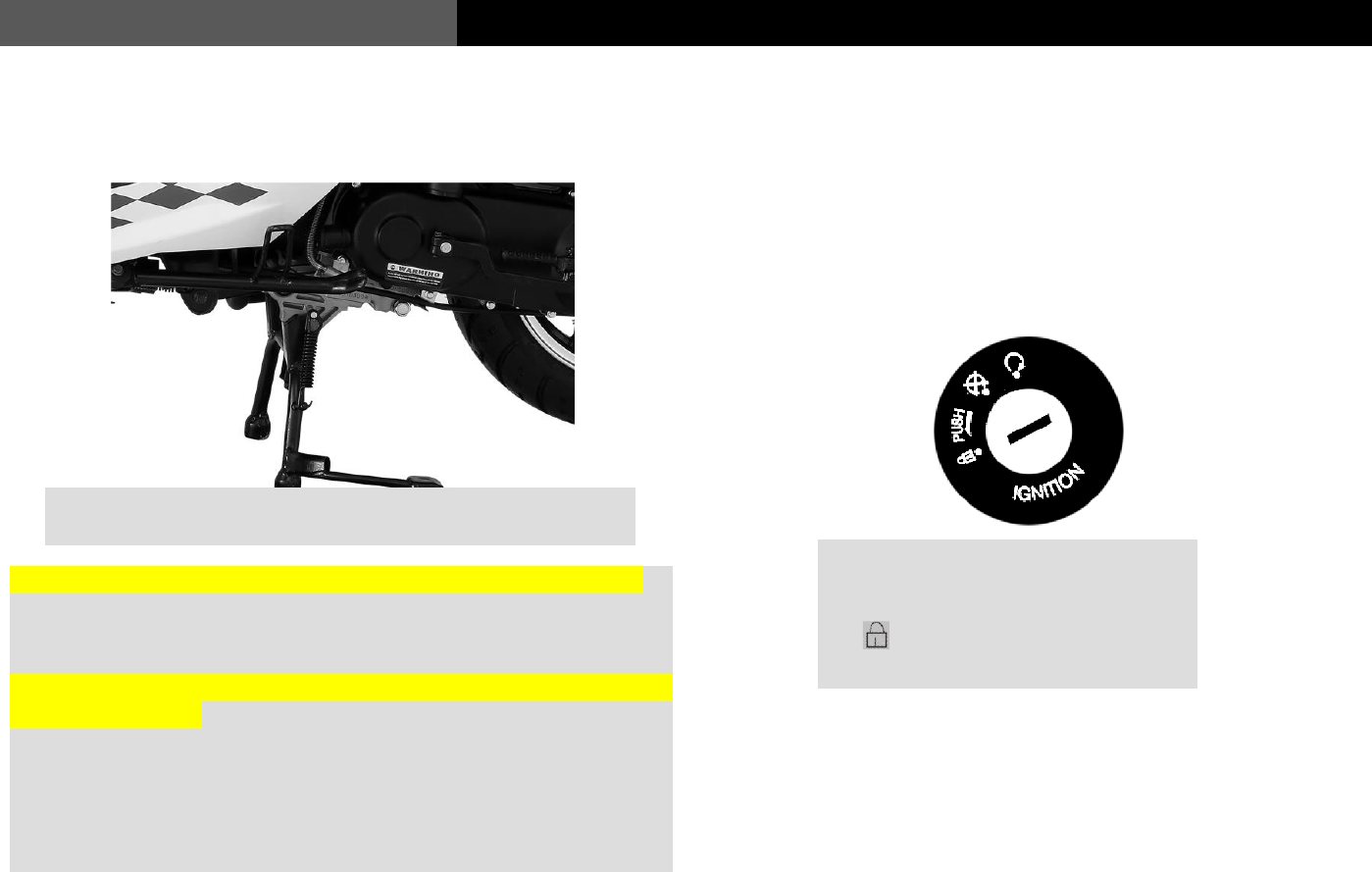
Ignition
When the vehicle is parked, as described in detail #3, turn the Ignition lock switch to “ ” to
lock the steering to help prevent the vehicle from being stolen
1) Ignition On:
Insert the key and turn the ignition
lock to “ ” this will turn the
vehicle electrical system on.
.
2) Ignition Off:
Turn the ignition lock to “ ” to turn the
vehicle electrical system off. The
vehicle key can now be removed.
3) Steering lock:
When stopped, turn the handle bars
all the way to the left, push the key
inwards and turn to “ ” to lock the
steering. The key can then be
removed.
14
Instructions to Users
USER’S MANUAL
Seat Storage lock
Fuel tank
Opening the fuel tank: Twist cap counter clockwise
90 degrees and remove.
Seat: Insert the ignition lock key into the seat lock and
turn it clockwise to open the seat cushion. This will give
you access to the under-seat storage bin and the fuel
tank cap
Closing the fuel tank: Insert the fuel cap in the fuel
tank opening aligning the tabs on the cap with the
notches in the tank neck and turn it clockwise.
15
USER’S MANUAL
Instructions to Users
Warning
* Do not over fill or “top off” the fuel tank.
* Gasoline vapors are flammable. The vehicle should be turned off before opening the fuel tank cap. Fuel should be dispensed in a
well-ventilated location.
* While dispensing fuel, smoking is strictly forbidden nor should it be done close to any open flame or spark. Before refueling, ground
yourself by touching any metal part of the vehicle. This will dissipate any static electricity present and prevent static sparks that could
ignite any fuel vapors that will be present during refueling.
Caution
* Only 90 + Octane rated fuel should be used.
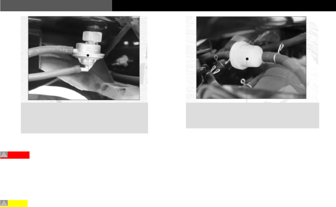
Bolt on Fuel valve or “switch”, this valve is opened by the
vacuum pressure produced by the engine, it allows fuel to
enter the carburetor via gravity. It closes when the engine
turns off.
Fuel filter: This is positioned in the main fuel line; the
fuel passes through here between the fuel tank and the
carburetor to ensure clean fuel is entering the carburetor.
16
Instructions to Users
USER’S MANUAL
Vehicle Operation
All Wolf Brand Scooters use the dry, centrifugal clutch and belt driven CVT (Continuously Variable Transmission). If there is
an issue with the clutch, belt or variator, take your vehicle to an authorized Wolf Brand Scooter dealership for service.
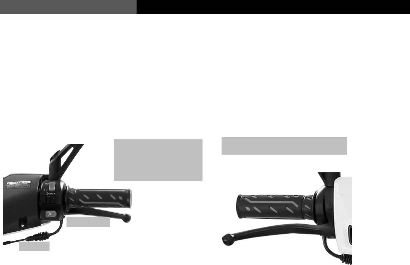
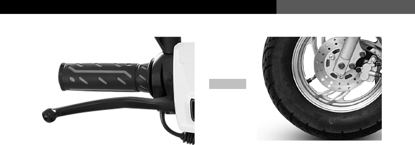
Front brake: This is the right lever when you’re
sitting on the vehicle. It is a disc brake.
Rear brake: This is the left lever when you’re
sitting on the vehicle. It is a drum brake.
Automatic clutch: The CVT assembly
allows smooth acceleration without the
need for gear changes.
Kick Starter: This is used for manually starting the
engine. The vehicle must be on the main stand, the
ignition must be on and the brake levers applied while
you kick start the engine.
17
USER’S MANUAL
Instructions to Users
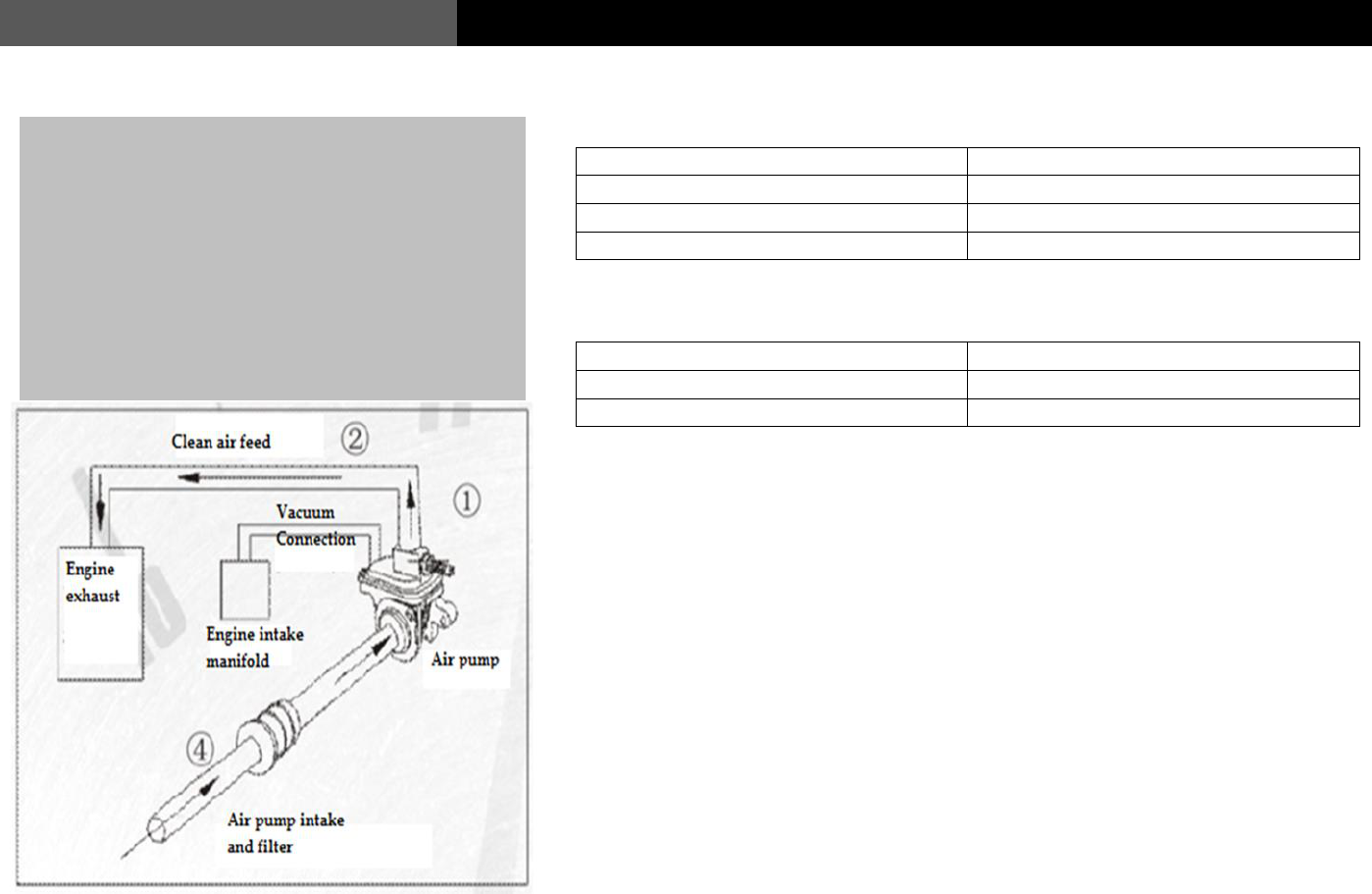
Environmental protection device
Emission Standards of Motorcycles (Stage III , under the running mode)
Unit: g/km
Emitted pollutants
Two-wheel vehicle
CO
2.0
HC
0.8
NOx
0.15
Emission Standards of Mopeds (Stage III , under the running mode)
Unit: g/km
Emitted pollutants
Two-wheel vehicle
CO
1.0
HC + NOx
1.2
Limits of exhaust pollutants of motorcycle/mopeds under idle conditions
In case of idle type approval test, the volume concentration of emitted CO is
≤3.8%; and the volume concentration of emitted HC is ≤800×10-6;
In case of Production consistency check test, the volume concentration of emitted
CO is ≤4.0%; and the volume concentration of emitted HC is ≤1000×10-6.
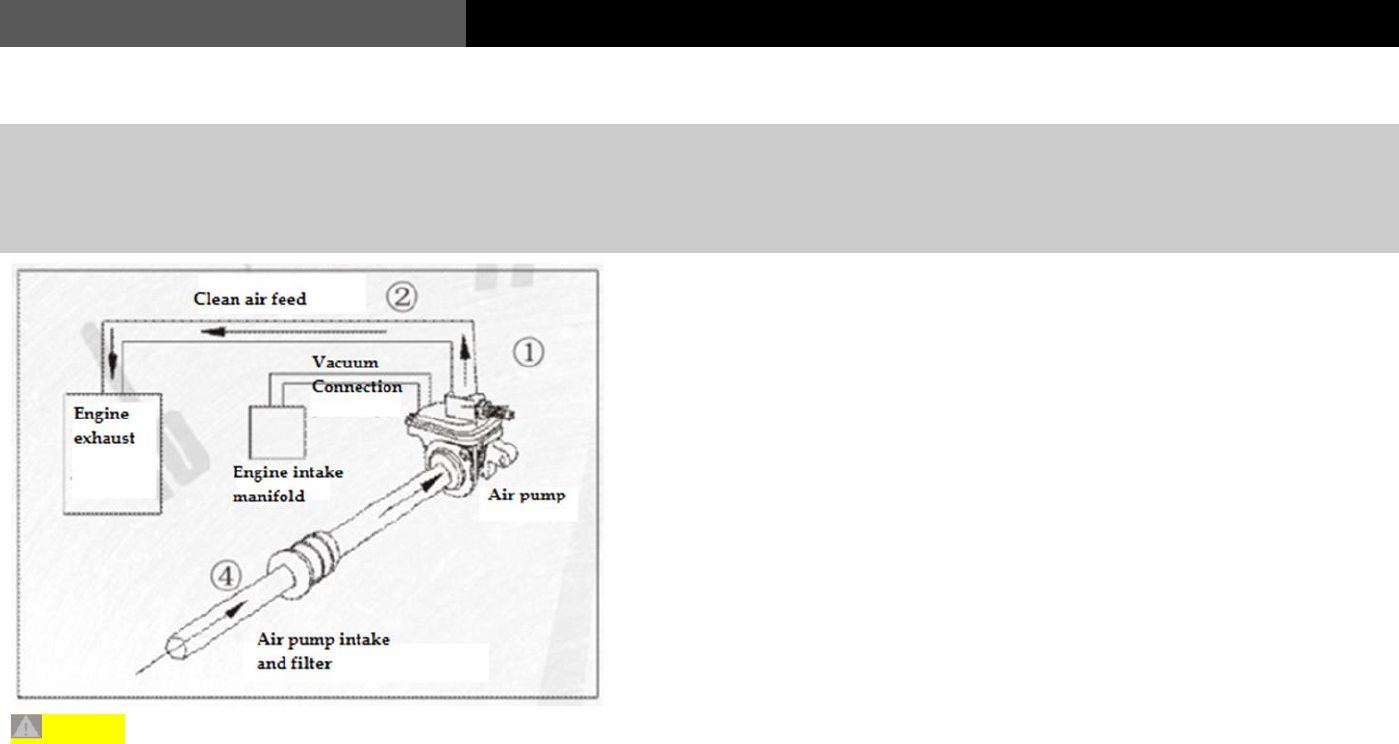
The environmental protection device is mainly a two-in-one air
compensating valve (air pump) combining a one-way leaf valve
and a secondary air control valve. By making use of the engines
vacuum pulsation, the air pump controls the amount of air
needed to enter the exhaust port through the one-way leaf valve
and the secondary air control valve. This fresh air enters the
exhaust passage of the engine under the action of the air pump.
Unburned fuel vapor discharged from the engine in its exhaust
is then consumed. Thusly this device reduces the exhaust
pollution of the vehicle, and ensures that the vehicles exhaust
meets National Stage III emission standards.
18
Instructions to Users
USER’S MANUAL
Vehicle Load
The vehicles maximum load of 330 lbs. must be strictly
observed. Otherwise, the safety and stability of the vehicle
may be compromised. This weight limit includes Rider,
passenger, their gear, and any luggage.
* Belongings in the seat storage bucket must be secured to
prevent their shifting while the vehicle is in motion.
* NEVER hang anything from the handle bars while operating
the vehicle. This will dangerously compromise the handling
of the vehicle
* The load of the rear carrier must not exceed 12 lbs.
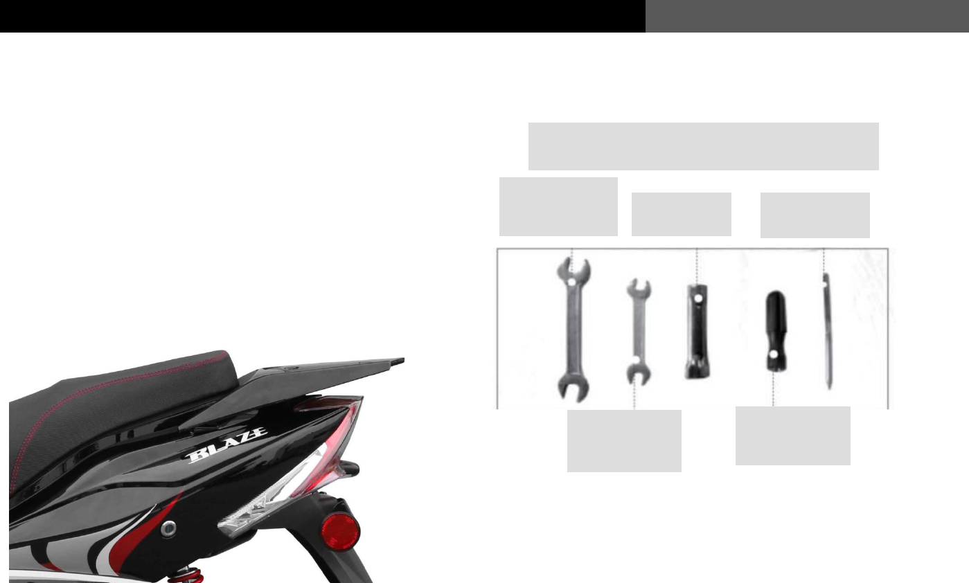
Tool kit (Included)
Common service and maintenance tools are delivered together with the
vehicle.
The tool kit will be found in the under-seat
storage bucket.
13×15
Double-ended
spanner
Spark plug
socket
Double-ended
screw driver
Double-ended
screw driver
holder
8×10
Double-ended
spanner
19
USER’S MANUAL
Basic Vehicle Checks and Maintenance Levels:
There are regular checks that you should do on your vehicle on a
regular basis to ensure that the vehicle is always safe to use and to
keep it in good condition. Keeping it in good condition will also help
in maintaining the vehicles optimal performance.
1. When starting the engine after it’s been sitting for more than a
few hours and after cleaning the vehicle, start the engine, and let
it run at idle for several minutes.
2. Check for any fluid leaks.
3. Check for any loose connections.
4. Check to ensure that all lights are working.
Different levels of maintenance and service will be taken for different odometer
readings and performance conditions of the vehicle:
The very first oil change should be done between 300~500 miles to replace the
“break-in” oil with fresh oil. The valve clearances should be checked and
adjusted if necessary.
Level 1: Service and Maintenance: Odometer reading 1000~1500 miles. Oil
change, valve checking/adjusting and lubricate any necessary parts and check
nuts and bolts and secure if necessary. (See the Service and Maintenance section
for more details).
Level 2: Service and Maintenance: Odometer reading 2000~2500 miles. Oil
change, valve checking/adjusting and lubricate any necessary parts and check
nuts and bolts and secure if necessary. (See the Service and Maintenance section
for more details).
Level 3: Service and Maintenance: Odometer reading 3000~3500 miles. Oil
change, valve checking/adjusting and lubricate any necessary parts and check
nuts and bolts and secure if necessary. Disassemble necessary parts and check
for any hidden hazards/wear.
Oil changes and basic service should be done every 1000 miles.
**ALL WORK SHOULD BE DONE AT AN AUTHORIZED WOLF
DEALERSHIP TO ENSURE THE WARRANTY DOES NOT GET
VOIDED**
Pre-operation vehicle checks
Before running the vehicle, please follow the following steps to check it, and
ensure your driving safety.
Turn the ignition on and
ensure all turn signals and
other lights are working.
Check the fuel gauge to
ensure you have enough
gas to get to your
destination.
20
USER’S MANUAL
Ensure you have enough gas for your trip
and ensure the gas cap is secured properly.
Check your steering by moving from left to
right. The handlebar should move easily and
smoothly with no play or binding.
Place the vehicle on the main stand and check the oil
level. Always make sure the vehicle has enough oil.
See the “Service and Maintenance” section for how to
make this check
Check that the throttle grip rotates smoothly
and freely. If not, the throttle cable may need
replacing.
21
USER’S MANUAL
Check for any fluid leaks under the
engine.
Check the pressure of the front tire. Set it to between 32 and 40
P.S.I. Check for abnormal wear on the tire tread and side walls.
Check air pressure when tires are cold
Check the terminals on the battery to
ensure they are clean and tight.
Check the pressure of the rear tire. Set it to between 32 and 40
P.S.I. Check for abnormal wear on the tire tread and side walls.
Check air pressure when tires are cold
22
USER’S MANUAL
The throttle grip should have a slight amount of free
play in it. About 10-20 mm (0.393-0.787 inch)
Check that the head light, turn signals and
indictor lamps work properly.
Check that the rear brake lever has the correct
amount of free play in it. About 20-30 mm
(0.787-1.181 inch)
Check that the tail light and brake lights
work properly.
23
USER’S MANUAL
Operating Instructions
Using the kick starter
1)Turn the ignition on.
3) Pull out the foot lever, place your foot on it and push firmly and
quickly all the way down. Let the arm return to its horizontal
position before you try to kick start it again. Repeat this motion.
2) The vehicle should be put on the main
stand and you need to hold the brake levers
to allow the engine to start.
4) Twist the throttle slightly to allow more gas flow as
you kick the engine over. Once started, let the engine
warm up before revving the engine to a higher RPM.
24
Operating Instructions
USER’S MANUAL
Using the Electric Starter
The duration of each electric startup attempt should not
exceed 5 seconds, and the interval between attempts should
never be less than 10 seconds. If 3 startup attempts fail
consecutively, the vehicle must be checked.
First, insert the key into
the ignition switch lock,
and turn it to the “ ”
position.
Apply either the
front brakes…
… or apply the rear brakes, these will
activate a starter safety switch and the
engine will turn over
While holding the brake handles, push the electric start button
with your right thumb. Twist the accelerator a small amount with
your right hand to add an appropriate amount of fuel and the
engine will start
25
USER’S MANUAL
Operating Instructions
Parking the vehicle
To lock the steering column, turn the
handlebars all the way to the left, push
the key inwards and turn the ignition to
the “ ” position to prevent the vehicle
from being stolen easily.
You should turn your engine off before using either of these stands.
Using the side stand:
Holding the vehicle upright, you use your foot to put the side stand
down. Once all the way down, you can then lean the vehicle onto it.
NOTE: With this side stand down, a safety switch is activated and the
vehicle will not start
Using the main stand:
Holding the vehicle upright, place your left hand on the left-hand grip
and your right hand on the rear rack. Keeping the vehicle vertical, you
put your right foot on the main stand and press down while pulling up
with your right hand.
When you need to park the vehicle, you have 2 different
methods to support it, the side stand, or the main stand.

26
Common Faults and Troubleshooting
USER’S MANUAL
Regular Service and Maintenance
Throughout the life of the vehicle, usage will inevitably cause
wear of its mechanical parts. Regular maintenance will prolong
the life of the vehicle.
Requirements on Service and Maintenance
1. Keep the engine clean, make sure there are no fluid leaks
2. Confirm that the automatic clutch does not show any
indication of slipping on acceleration or that it makes any
abnormal noise. Also confirm that your throttle operates
smoothly and without binding.
3. Ensure that the brakes work well and meet necessary
requirements. Check that the wheels spin freely once
brakes are released and that there is no friction noise when
brakes are not on.
4. The front forks and rear shock absorbers should compress
and rebound smoothly. Check for leaks around the seals.
5. The air pressure of the tires should be set to the required
P.S.I.
6. Check for loose electrical connections throughout the
vehicle.
7. All mechanical parts should be lubricated.
8. The cable connections to the battery terminals should be
clean and tight and the battery should be secured properly
within the vehicles battery box.
9. Any corrosion on any metal parts should be taken care of as
soon as possible to prevent spreading.
Service and Maintenance during the break in period
How a new vehicle is broken in directly affects the service life of
the vehicle. Within the first 500 miles of a new vehicles life, the
driving speed should not exceed 30 MPH, and the rider should
vary their speed regularly.

27
USER’S MANUAL
Common Faults and Troubleshooting
Precautions you should follow during the break-in period of a
new vehicle
1. Within the break-in period, replace the oil every 300 miles, and
clean the oil filter screen.
2. Regularly check for loose electrical connections, and tighten if
found.
3. Regularly check whether the engine, drive train and braking
system overheat, and whether there is enough lubricating oil on
each lubricated part. If any overheating occurs, the reason should
be found and rectified immediately.
4. Regularly check the tightness of the drive belt, the free travel of
the front and rear brakes, throttle grip and the handle bar
movement. Adjust them if necessary.
5. Within the break-in period, ride the vehicle only when the engine
is warmed up. First run it at low speed for 1~2 miles, and then
run it at higher speeds.
6. To reduce vibration and impact loads, the vehicle should run on a
level road with good road conditions whenever possible.
7. During the break-in period, carrying any unnecessary weight
should be avoided. Otherwise, the drive train will wear faster.
8. Try to avoid heavy braking and braking for long periods of time.
9. Strictly control the speed of the vehicle, varying the speed
regularly while riding.
Contents of Level 1 Service and Maintenance
Level 1 Service and Maintenance should be performed every
500~1000 miles. Its main contents are as follows:
1. Drain oil and refill to correct level with the correct weight
motorcycle oil. Standard 15W-40 or synthetic 5w-40.
2. Adjust the travel of the front brake handle to 10mm~20mm
(0.394-0.787 inch), and adjust the rear brake handle to
20mm~30mm (0.787-1.181 inch).
3. Adjust the travel of the throttle cable to 2mm~6mm (0.078-0.236
inch), and lubricate the throttle grip and the throttle cable.
4. Clean the carburetor, fuel tank, oil filter screen and air filter.
5. Adjust the idle speed of the carburetor.
6. Remove the carbon deposits on the spark plug, and adjust the
electrode gap of the spark plug to 0.025” or 0.6mm~0.7mm.
7. Remove the battery and charge it.
8. Check and tighten all bolts and nuts of all exposed parts.
9. Check the tightness of all connections of the electrical system.
10. Adjust the engine valve lash: intake valve to 0.03-0.05mm
(0.001-0.002 inch); and the exhaust valve to 0.05-0.07mm
(0.002-0.003 inch).
11. Store the vehicle in the best possible conditions.

28
Common Faults and Troubleshooting
USER’S MANUAL
Contents of Level 2 Service and Maintenance
Level 2 Service and Maintenance should be performed every
2000~4000 miles:
1. Drain oil and refill to correct level with the correct weight
motorcycle oil. Standard 15w-40 or synthetic 5w-40
2. Disassemble the top end cylinder assembly of the engine.
Inspect for excessive wear and remove any carbon deposits
from parts such as, the piston, piston rings, and cylinder head.
Lubricate and reassemble.
3. Check the wear of the clutch friction lining, the rear brake
shoes, and front brake pads. Replace as needed.
4. Clean the carburetor, air filter, fuel tank, fuel filter, etc.
Replace if needed
5. Clean the upper and lower bearings of the steering column and
re-pack with grease.
6. Clean and lubricate all the cables on the vehicle and replace if
any fraying or excessive wear is seen.
7. Flush the transmission and check all components and refill
with new oil.
Contents of Level 3 Service and Maintenance
Level 3 Service and Maintenance should be performed every
5000~8000 miles.
1. Drain oil and refill to correct level with the correct weight
motorcycle oil. Standard 15w-40 or synthetic 5w-40
2. Ensure the emissions system is working correctly.
3. Ensure the electric start system is working.
4. Check the front and rear automatic clutches and the drive system
for normal operation.
5. Check whether there are any cracks, erosion, or serious wear on
each gear tooth of the rear transmission box.
6. Disassemble the top end cylinder assembly of the engine. Inspect
for excessive wear and remove any carbon deposits from the
parts therein. Check the clearance between the piston and the
cylinder wall, and the smaller head of the crank connecting rod
and the piston pin.
7. Ensure the front and rear shocks are in good condition and their
mounts are in good condition.
8. Ensure the fuel system is running cleanly. Inspect all fuel and
vacuum lines for wear and replace the fuel filter
9. Check the instruments and the electric system and ensure normal
operation.
10. Disassemble the vehicle and check the steering column, engine
mounts and other substantial parts and make sure there is enough
lubrication and that you don’t find any excessive wear.

29
USER’S MANUAL
Common Faults and Troubleshooting
Service and Maintenance for the Carburetor
For maximum performance and reliability, it is important the
carburetor is adjusted properly. Failure to do so will affect starting;
idle, as well as the overall vehicles performance.
The carburetor should be serviced and maintained as follows:
1. Regularly check all connections and fittings on the carburetor.
A poor fit between the intake manifold and carburetor can
result in hard starting, poor performance and lower gas
mileage.
2. Check the rubber fuel lines for signs of weathering. If any
cracks or deterioration are found, replace them.
3. Start and drive your vehicle often. Gasoline left sitting for a long
period of time will start to break down, becoming “stale”. The
longer a vehicle sits the more likely the carburetor is to develop
issues due to stale fuel contamination.
4. If the vehicle is to be stored for any length of time longer than 2
weeks, the fuel in the carburetor bowl and fuel tank must be
drained from the vehicle into an approved container for use
elsewhere. Failure to do so will result in a contaminated,
"clogged” carburetor. This will cause hard starting and poor
performance. The carburetor will then have to removed and
thoroughly cleaned or, as in many cases, replaced.
Draining the fuel is quite simple. You will find a length of fuel
line running from the bottom of the carburetor to a bracket on the
frame. In that bracket, there will be a brass screw plug that when
removed will allow fuel to drain out of the carburetor bowl. Fuel can
be easily syphoned from the fuel tank.
30
Common Faults and Troubleshooting
USER’S MANUAL
Check and Replacement of Lubricating Oil
Caution
Checking and Replacing Engine Oil
To ensure an accurate reading when checking the engine oil, place the vehicle on the
center main stand. Only check the oil level after the engine has been shut off for at
least 5 minutes. Be aware the engine, exhaust and engine oil will be extremely hot if
the engine has been running. It is recommended you allow the engine to cool for at
least 30 minutes after a long drive before checking.
-Remove oil cap. Note if there is oil on the dipstick. A lack of oil on the dipstick
indicates a low oil level.
-Wipe the dipstick clean and insert into engine. Quickly withdraw the dipstick and
note the oil level. If there is no oil on the dipstick, oil will need to be added.
-Note the color of the oil. Very black oil indicates the oil must be drained and replaced.
-To drain the engine oil, loosen the 17mm oil drain plug on the bottom right hand side
of the engine, directly underneath the black engine shroud.
-Allow oil to drain completely. Not allowing all the oil to drain will result in residual oil
left in the crankcase which will alter the amount needed to fill the engine.
-Inspect oil filter and clean if necessary.
-Reattach oil drain plug with spring and filter installed.
-Fill with ~750mL (25 oz.) of 15W-40 (or 5W-40 if synthetic) engine oil through the oil
dipstick opening.
-Insert dipstick and withdraw to verify correct oil level.
-Tighten dipstick and inspect for leaks.
With the vehicle on the center kick stand,
unscrew the oil dipstick and wipe clean
with a rag. Insert the dipstick, pull out,
and check the level and color of the oil.
The oil level should always be between
the upper and lower oil level markings on
the dipstick.
Following the service intervals in this
manual, drain and replace the oil as
necessary. The 17mm bolt on the bottom
of the engine needs to be removed to
drain the oil. Be sure to clean the mesh
filter screen before reinstallation.
After the engine has drained completely,
reinstall the mesh screen into the spring.
Place the spring into the drain plug and
reattach to the engine. Refill the engine
with oil.
Lower oil level marking
Upper oil level marking
31
USER’S MANUAL
Common Faults and Troubleshooting
Service and Maintenance of the Spark Plug
Remove the spark plug from the engine. If the color of the insulator
skirt of the spark plug is brown it indicates that the carburetor is
adjusted properly. Any signs of buildup on the plug should be noted
as this could be a sign of an incorrect carburetor adjustment.
Cleaning the Spark Plug
Inspect the spark plug for carbon buildup. If there are noticeable
deposits or wear on the spark plug, replace.
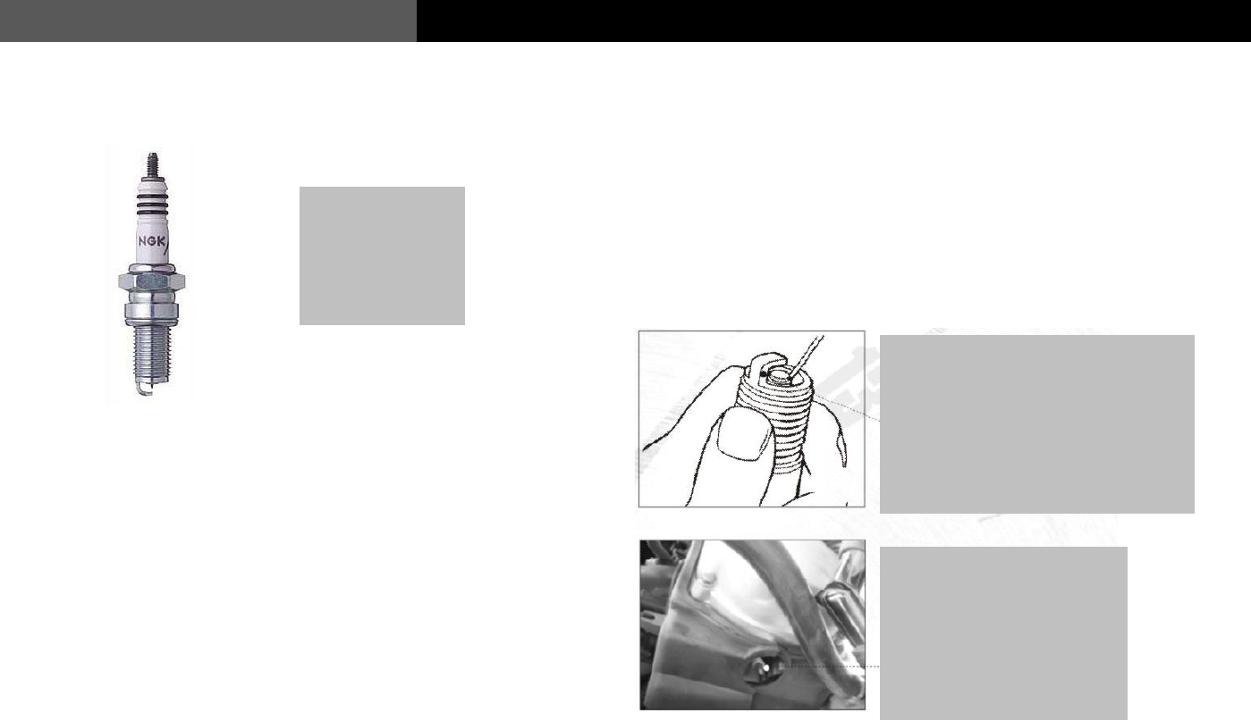
It is normal for the
spark plug to be
light brown. This
indicates a proper
air fuel mixture.
Correct spark plug gap helps fuel
economy and performance.
Incorrectly gapped spark plugs can
lead to hard starting and poor
performance. Always replace the
spark plug with the original NGK
replacement.
When removing and
tightening the spark plug, be
sure to use the correctly
sized socket. Improper
removal can result in spark
plug damage that can result
in costly repairs.
Check the electrode
gap of the spark plug
with a gauge and
adjust the gap to 0.025
inches.
32
Common Faults and Troubleshooting
USER’S MANUAL
Service and Maintenance for the Air Filter
When dust builds up in the filter element of the air filter assembly, it
results in an increased resistance to air flow through the air intake
system. This leads to an overly rich fuel/air mixture that can reduce
power and increase fuel consumption. It is important the air filter be
cleaned or replaced on a regular basis. Riding in dusty conditions will
require more frequent filter maintenance.
Caution
* Do not use the following cleaning agents to clean paper filter
elements: Gasoline, low ignition-point solvent, acid, alkaline or
organic volatile oil.
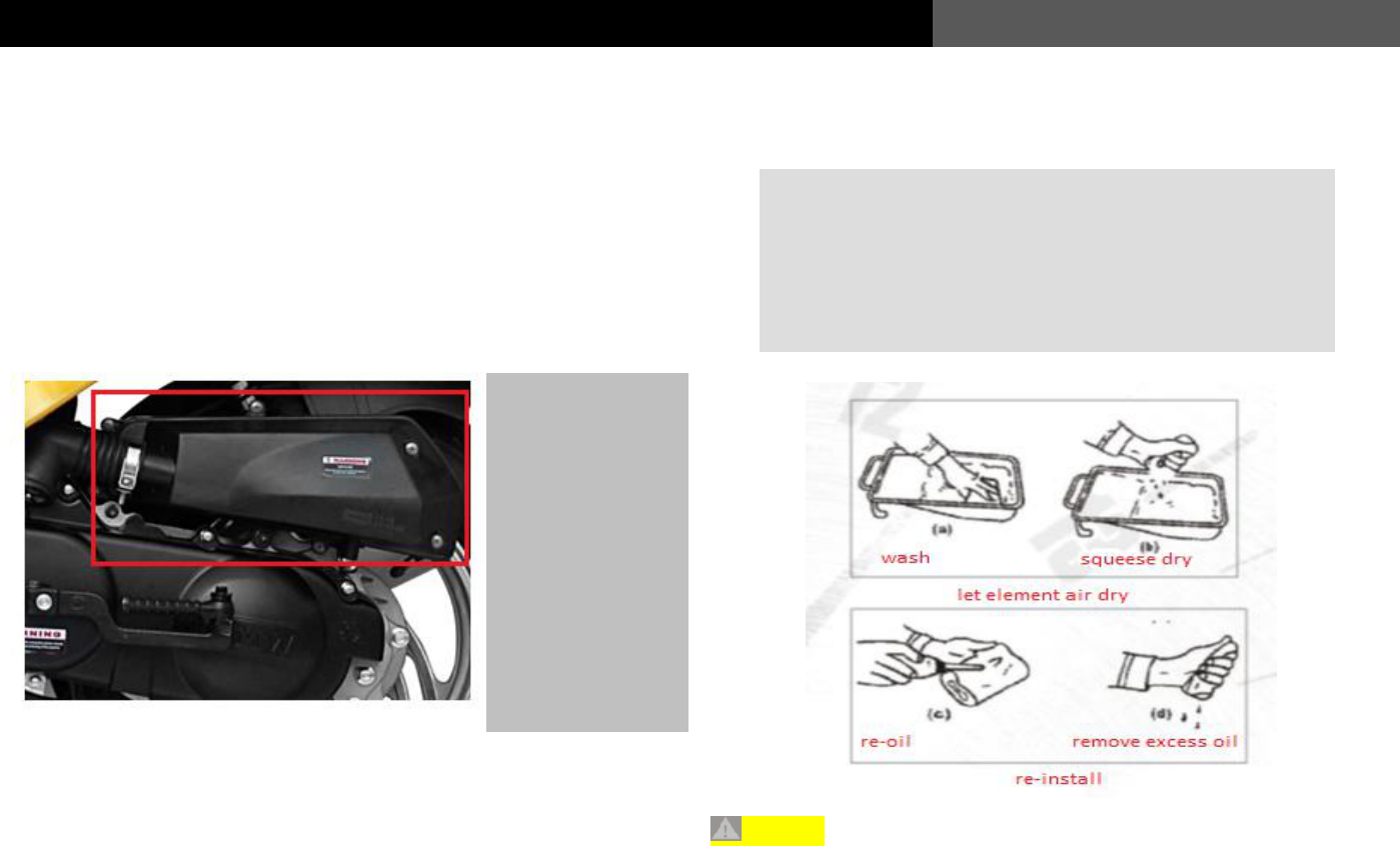
Take off the screws
for the air filter
cover, and remove
the air filter cover.
Check whether there
is dust and dirt on
the sponge of the
filter element.
Remove the air filter
and wipe off the dust
inside the air filter
with clean and dry
cloth.
Paper based filters are a disposable item and just need to be
replaced. You can find them at your Wolf Brand dealership
Foam or cloth filter elements can be cleaned and reused
numerous times. You can wash them in warm water and a
simple detergent. Once dry you must treat them with a light
oil before reinstallation for them to filter correctly.
33
USER’S MANUAL
Common Faults and Troubleshooting
Adjustment of the throttle grip
Check whether the free travel of the throttle is within the specified
range and adjust it if necessary. Please follow the following steps to
adjust the free travel.
1. First, loosen the locking nut.
2. Spinning the regulator will extend or shorten the free travel of
the throttle.
3. When the desired setting is reached, tighten the locking nut and
slide the protective covering back over the regulator.
Service and Maintenance for the Front Brake
Most models use a front disc brake, which features high heat
dissipation and increases performance.
Adjustment of the front disc brake
1. Place the vehicle on the main stand.
2. Adjust the regulating nut of the front brake to adjust the free
travel of the front braking handgrip to 1/4 – ½ Inch.
1/4 -
The throttle grip should work
smoothly. Any signs of
sticking or binding should be
addressed prior to riding the
vehicle.
Adjuster
Locking nut
Adjust the free travel of the front braking
handgrip to ¼ and ½ inch.
34
Common Faults and Troubleshooting
USER’S MANUAL
Service and Maintenance for the Front Brake
* Check the travel of the brake lever when applied. Excessive
travel could indicate worn pads or air in the brake fluid. Either of
which need to be addressed prior to riding.
* Check for the wear on the front disc rotor. Any signs of warping
or irregularities in the surface of the brake rotor can cause vibration,
and lower braking force. This can dangerously increase the stopping
distance of the vehicle. Replace when needed.
Disc brake
35
USER’S MANUAL
Common Faults and Troubleshooting
Service and Maintenance for the Rear Brake
Adjustment of the rear drum brake:
* First, use the main stand to prop up the rear wheel of the vehicle
and then adjust the free travel of the rear brake by screwing in or
out the nut on the end of the rear brake cable.
* Apply the rear brake several times. Each time the brake should
release freely without binding or sticking. Rotate the rear wheel
assembly to check whether the wheel rotates freely.
* Always keep the cables and fittings clean and free of debris.
Keeping the cables lubricated will improve service life.
When applying the rear brake, ensure the wheel stops
spinning within the recommend free travel. On rear brake
cable equipped models, turn the brake adjustment fitting at
the bottom of the cable clockwise to tighten the cable and
reduce free travel. If you run out of adjustment, please
take your vehicle in to an authorized service center for
servicing.
Use the support to prop up the vehicle, and adjust the free
travel of the rear brake between ¼- ½ inch.
36
Common Faults and Troubleshooting
USER’S MANUAL
Adjustment of the rear braking light
* It is important to always check the vehicle lights and make sure
they are properly functioning prior to using the vehicle. The
brake light can be inspected with the ignition turned to the on
position, and the left and right brake handle compressed.
Adjustment of the idle speed
If the vehicle stalls out during normal operation due to the engine
speed being low, the idle speed can be adjusted:
* Before adjusting the idle, make sure the engine has reached
normal operating temperature.
* Place vehicle on the main stand. While the vehicle is running
adjust the idle until the specified RPM is set.
In order to gain access to the brake switches the left and
right-side controls must be removed as well as the brake
handles. This can be performed at your local authorized
service center.
Adjust the idle speed screw here. Turning clockwise will
raise the idle; counter clockwise will lower the idle.
Rear braking
light switch
Front braking
light switch
37
USER’S MANUAL
Common Faults and Troubleshooting
Service and Maintenance for Front and Rear Tires
Prior to riding always inspect the tires. Make sure the front and rear
tire are filled to their recommended pressure. Proper tire inflation
increases riding comfort and the stability of the vehicle while
prolonging the service life of the tires.
Tire specification/air
pressure
Front
wheel
120/70-12 32-40PSI
Rear
wheel
120/70-12 32-40PSI
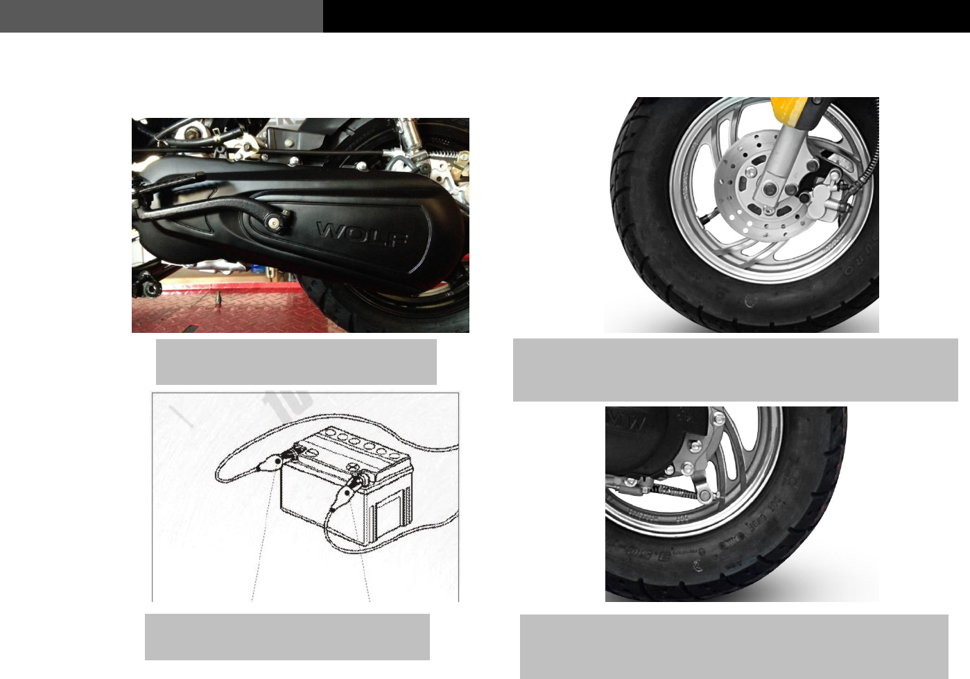
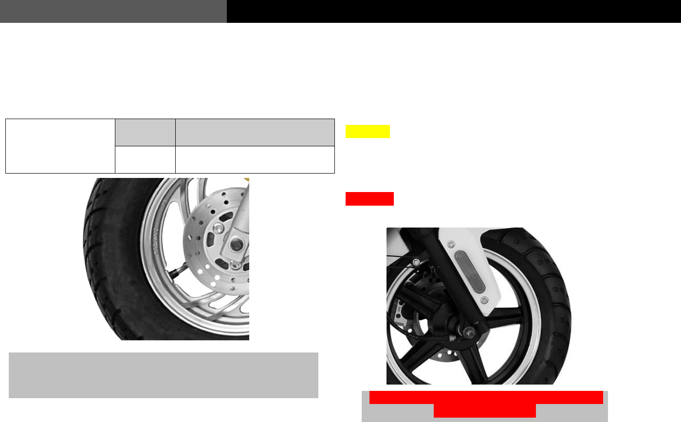
Removal and Installation of Front Wheel
* With the engine off, place the vehicle on the center kickstand.
* Remove the nut off the front wheel bolt. Slide the bolt out while
making sure to retain all hardware including wheel spacers, and
speedometer hub.
Caution:
* Do not use the front brake with the wheel removed.
* Check the front brake Master Cylinder fluid level and top off if
needed. Verify that the wheel spins freely with no brake drag.
Warning:
* Always re-torque the front wheel nut to 40-50 ft. lbs.
Check the air pressure of the tire and visually inspect the rubber
tire and rim for excessive wear or defects. If there are any issues,
the tire should be replaced at a local authorized service center.
Failure to properly torque the front wheel nut can
lead to serious injury!
38
Common Faults and Troubleshooting
USER’S MANUAL
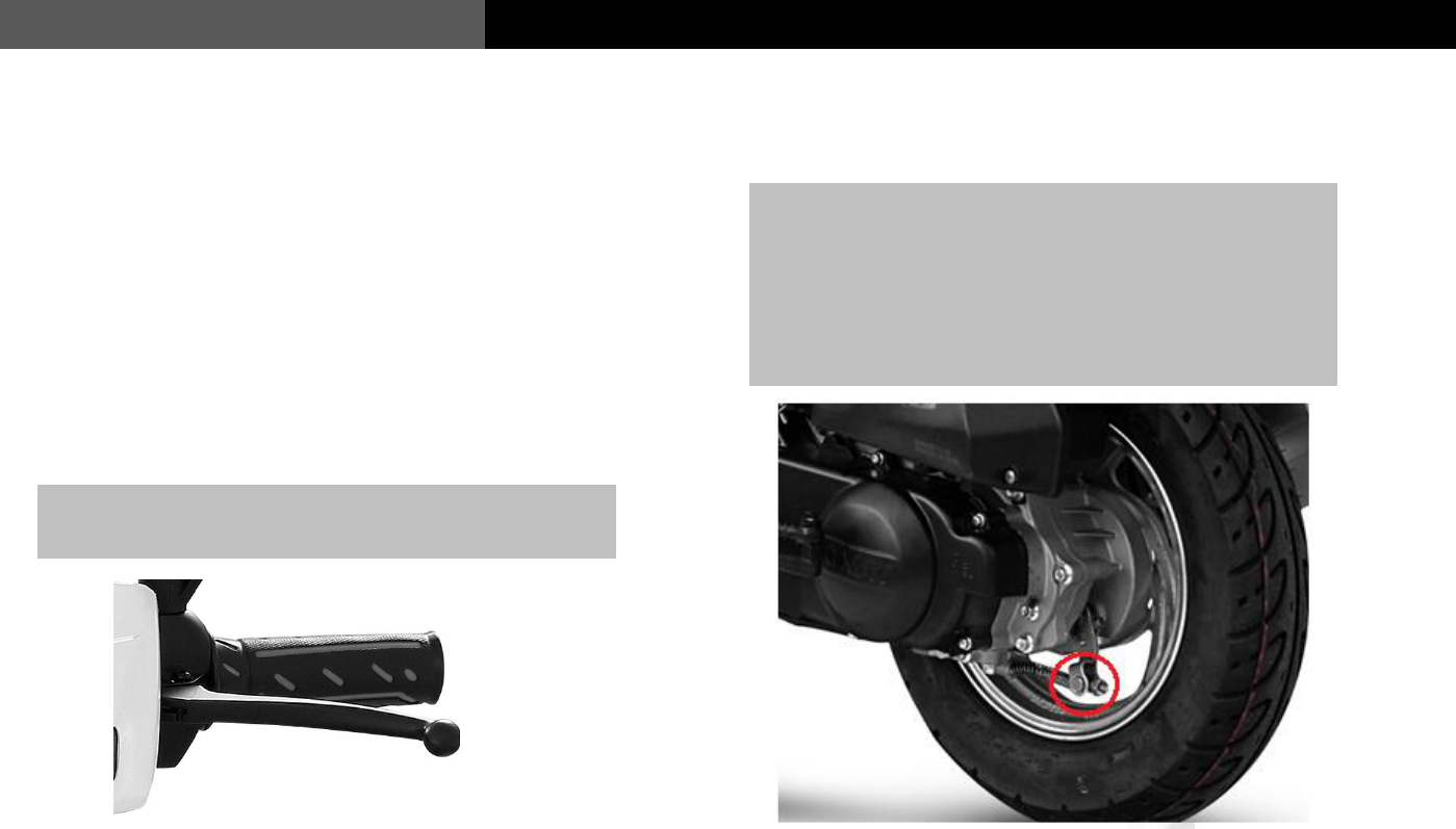
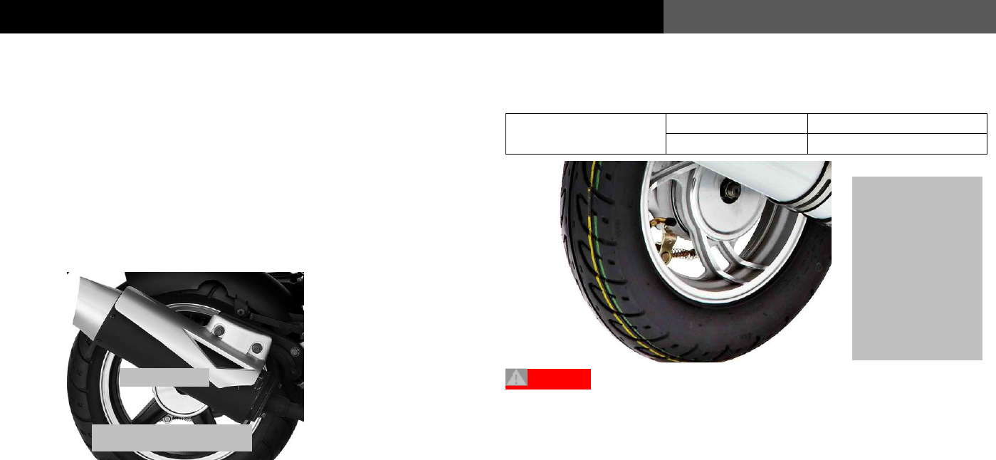
Removal and Replacement of the Rear Wheel
* Turn the engine off.
* Place vehicle on center stand and remove muffler.
* Loosen the rear wheel nut, and remove the rear wheel.
Installation precautions:
* Torque the rear wheel nut to 40-50ft lbs. and reinstall muffler.
* Verify the rear brake is adjusted properly.
If the tread depth in the middle of the tire reaches the following limits
the tire must be replaced immediately.
Minimum limit of
tread depth
Front wheel
2.0mm (0.079”)
Rear wheel
2.0mm (0.079”)
Warning:
* Low tire pressure will increase the rolling resistance of the
vehicle, increase fuel consumption, and wear the tire
prematurely. In more severe cases is can lead to flat tires. Always
check tire pressure prior to riding.
* Excessive tire pressure will cause uneven tire wear, increase the
risk for blow outs, and decrease vehicle stability.
Muffler
Rear wheel shaft nut
Check the tread
wear depth of the
tires and inspect
the sidewalls for
damage. If any
abnormalities are
found, the tire
must be replaced
immediately.
39
USER’S MANUAL
Common Faults and Troubleshooting
Service and Maintenance for the Environmental Protection Device
Vehicle operators must conduct regular service and maintenance of the environmental protection system to ensure the best performance of the
assembly. With proper and regular service and maintenance, we can promptly eliminate faults, prolong the service life of the environmental
protection system, reduce the maintenance costs, and realize the goal of being environmental-friendly by reducing your vehicles fuel
consumption.
Caution
The carburetor of the environmental protection device must be
serviced and maintained by a professional motorcycle repair shop or
the dealer’s after-sales service personnel (make sure not to adjust the
carburetor without authorization)
1 Regularly check whether there is any aging, air leakage or
damage on the intake negative pressure hose and the intake
plastic hose. If any, replace the intake negative pressure hose and
the intake plastic hose.
2 Regularly check the working conditions of the air pump of the
environmental protection device. If the air pump is blocked or
cannot work properly, replace the air pump of the environmental
protection device.
3 Regularly check the air filter. If any dust or dirt exists on the air
filter, the air flow will be reduced, thus changing the
concentration of the gas mixture, and increasing fuel
consumption. Therefore, it must be changed.
4. Regularly check the clamp for the intake vacuum hose, the
clamp for the clean air feed, and the mounting bolt for the metal
air pump intake pipe. If they are loose, tighten them.
40
Common Faults and Troubleshooting
USER’S MANUAL
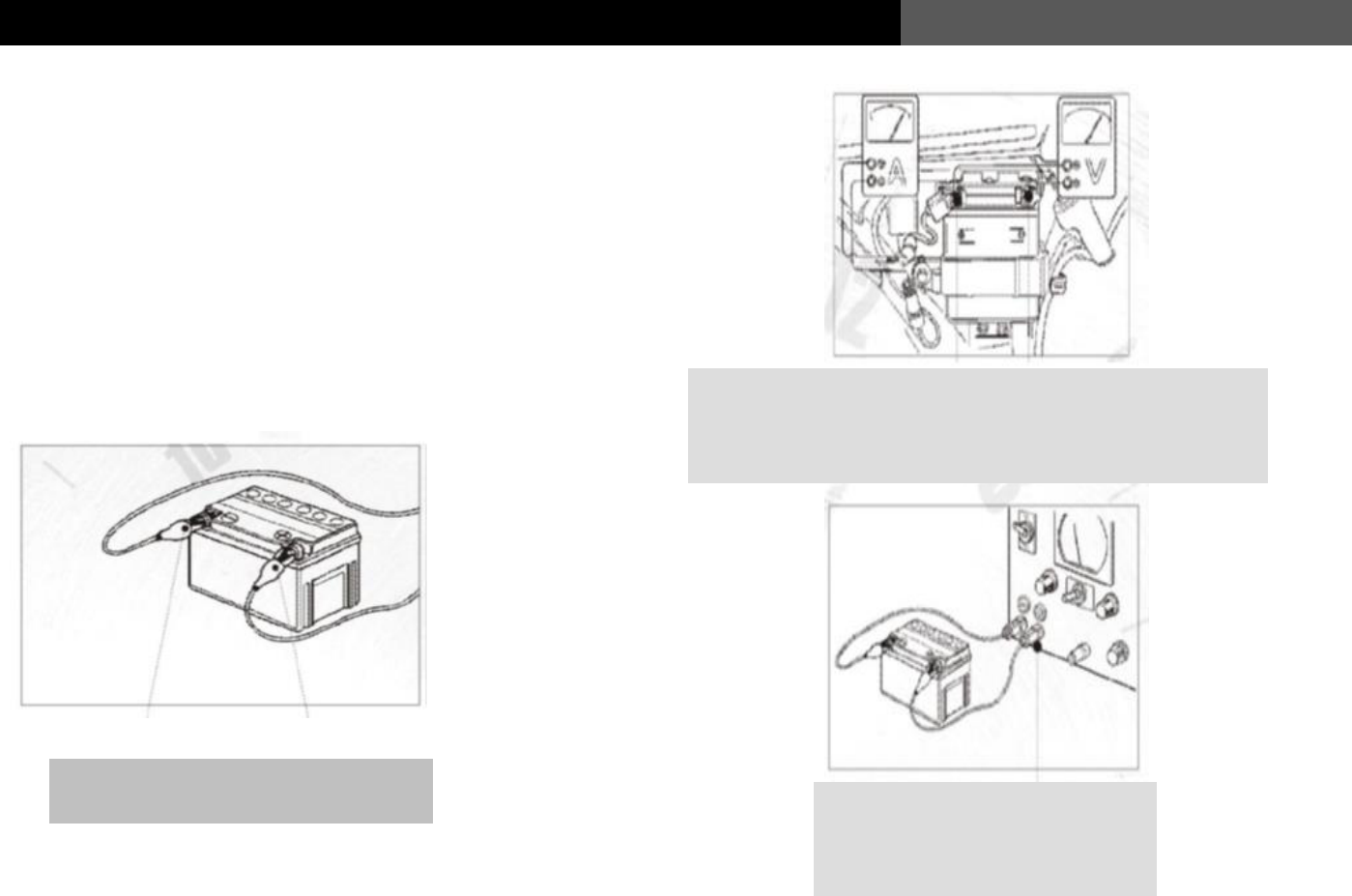
Service and Maintenance for the battery
In this model, the battery is mounted under the floor mat. For the first
500 to 1000 miles of the vehicle, the battery should be serviced and
maintained as follows:
1. Keep the battery poles clean of corrosion.
2. Make sure the positive and negative electrode connections are
not loose.
3. If the vehicle is not going to be used for more than 2 weeks, the
battery should be disconnected and maintained on a trickle
charger.
Make sure the positive and negative
electrode connections are clean and tight.
When checking the voltage of the battery, a reading of less
than 12 volts is not normal. You should also “load test” the
battery to determine if the battery needs to be replaced. or just
charged. This can be done at most auto parts stores
If your battery is showing a voltage
level less than 12v, and passes a
“load test” place it on a battery
charger.
41
USER’S MANUAL
Common Faults and Troubleshooting
Service and Maintenance for the Fuse
The fuse is connected in series to the battery. If there is a sudden
power surge or issue within the electrical system, the fuse will
automatically break to protect the battery and other electrical
components.
Caution
* In the event of a blown fuse, the cause should be found right
away as it is indicative that there may be a more serious
electrical problem present. In this situation, please bring the
vehicle to your authorized WOLF Brand Scooters dealer for
service.
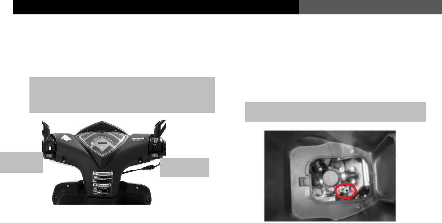
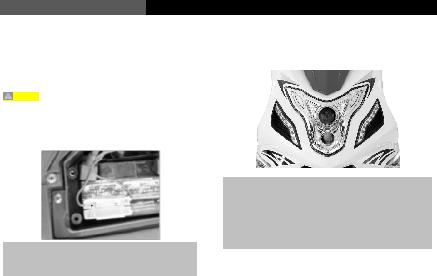
Service and Maintenance for the Horn
Over time the horn may need to be adjusted. By removing the front
panel, you can access the horn and adjustment screw.
If the entire electrical system of the vehicle is not functioning,
check the fuse first. A blown fuse will cause all electrical
components including the electric start to stop functioning.
If the horn sound becomes weak or isn’t working at all, remove the
front cover, and use a multi-meter to measure the voltage of the horn
circuit. You must do this with the ignition turned on. and it should
measure 12 Volts DC. If that is the reading you find, you should then
use the adjustment screw in the middle of the horn to get the correct
horn sound. If you do not get a read from the multi-meter on the horn
circuit, you should have the vehicle checked out by your local WOLF
Brand Scooter Dealer.

42
Common Faults and Troubleshooting
USER’S MANUAL
Storage of the Vehicle
For vehicles that will needs to be parked for more than one month, the
following steps should be taken:
* Drain all the fuel from the fuel tank and the carburetor. The Fuel
system can be completely drained by running the engine until it
stalls after draining the fuel tank. This will not only empty the
carburetor of any fuel that might become “stale” but the fuel
lines as well.
* Remove spark plug. Pour 5mL of clean lubricating oil into the
cylinder. Use the kick-starting arm to turn the motor over several
times to evenly distribute the lubricating oil throughout the
cylinder and combustion chamber. Re-install the spark plug.
* Remove the battery, and store it in a dry, dark, and climate
controlled environment, also place it on a trickle charger.
* Wash the vehicle clean and dry with soft cloth or chamois. Wax
the painted surfaces, and apply a film of anti-rust oil to the
chrome surface.
* Inflate the front and rear tire to the correct P.S.I.
* Cover the vehicle, and park it in a well-ventilated, dark dry,
clean, place, far away from any hazardous substances such as
flammable material or corrosive chemicals.
Re-use after Storage
* Clean the vehicle. Replace the engine oil if vehicle has been
stored for more than 4 months, regardless of mileage.
* Check the battery.
* Refill the fuel tank with fresh gas.
* Perform an inspection on the vehicles brakes, lights, tires, and
check for any fluid leaks.
43
USER’S MANUAL
Common Faults and Troubleshooting
Service and Maintenance Interval Table
Service and Maintenance scheduling is based on the vehicles odometer reading If the vehicle is being used in harsh conditions or under heavier
than normal loads for long periods of time, the service and maintenance interval should be appropriately shortened.
Service Type
Item
Odometer
Interval
500 Miles
1000 Miles
2000 Miles
3000 Miles
Remarks
Fuel system
C
C
C
C
Items marked ※
※ can only be
serviced and
maintained by
authorized Wolf
Brand Scooter
service center.
When driving in an
extremely humid
or dusty
environment, the
service and
maintenance
interval should be
appropriately
shortened.
Fuel filter
C
C
C
C
Throttle cable
A
A/C
A/C
A/C
※※
Carburetor
C
C
C
C
Air filter
C
C
C
C
Spark plug gap
A/C
A/C
A/C
A/C
※※
Valve lash
A
A
A
A
Engine oil
R
R
R
R
Oil filter screen
C
C
C
C
※※
Timing chain
I
A
A
A
Carburetor idling
A
A
A
A
※※
Drive belt
-
A
R
R
Battery
B
B
B
B
Brake shoe
I
A
A
R
※※
Braking system
A
A
A
R
Brake light switch
A
A
A
A
Lighting system
I
I
I
I
※※
Clutch
I
I
I
I
※※
Shock absorber
I
I
A
A
Nuts and bolts
G
G
G
G
Front and rear tire
hardware
I
I
I
I

44
Common Faults and Troubleshooting
USER’S MANUAL
Service and Maintenance Interval Table for Lubricated Parts
Name
Type
Odometer reading
500
1000
2000
4000
8500
10500
15000
20000
Engine oil
SAE 15W-40 (5W-40
if synthetic)
R
R
R
R
R
R
R
R
Brake Cables
Multipurpose
lithium-based
lubricating grease
-
-
R
R
R
R
R
R
Brake fluid
DOT3 or DOT4
-
R
-
Lubricating oil for
front shock absorber
Lubricating grease
for shock absorber
-
I
I
I
I
I
I
I
Tachometer gear
Multipurpose
lithium-based
lubricating grease
-
I
R
I
R
I
Steering gear
Multipurpose
lithium-based
lubricating grease
-
I
-
R
-
Bearings for front
and rear wheels
Multipurpose
lithium-based
lubricating grease
-
I
R
I
R
R
Rear braking swing
arm
Multipurpose
lithium-based
lubricating grease
-
I
-
I
-
I-Inspection R-Replacement T- Addition

45
USER’S MANUAL
Common Faults and Troubleshooting
Trouble shooting common faults
Fault system
Fault
Causes
Troubleshooting
Fuel system
Engine won’t start
Fuel not entering the carburetor.
Check the fuel lines.
The fuel is not flowing from the tank.
Clean the tank and replace fuel shut off valve.
The vacuum lines are pinched or leak.
Check vacuum lines and replace if needed.
The fuel line is clogged.
Replace fuel lines.
The vacuum line is blocked.
Unblock the vacuum lines.
The vehicle is difficult
to start or there is an
observable loss of fuel
economy
The carburetor is blocked.
Clean or replace the carburetor.
The air/fuel mixture is not correct.
Readjust the mixing ratio and concentration of
the carburetor.
The carburetor leaks.
Clean the carburetor or replace the carburetor
float.
The fuel filter is blocked.
Clean the fuel filter.
The throttle of the carburetor is worn.
Replace the throttle.
The fuel is bad.
Replace the fuel.
The air vent of the fuel tank is blocked.
Remove blockage in air vent of the fuel tank.
Low fuel.
Add fuel to the fuel tank.
Air
intake/exhaust
system
The vehicle is difficult
to start.
The Air filter element is blocked.
Clean the air filter.
The air filter leaks.
Replace the air filter.
The air filter is dirty.
Clean the air filter.
The air filter housing leaks.
Repair or change the air filter housing.
Too much carbon build up at the exhaust port.
Clean the carbon build up at the exhaust port.
The exhaust port leaks.
Replace the cylinder head.
The muffler is blocked.
Replace the muffler.

46
Common Faults and Troubleshooting
USER’S MANUAL
Fault system
Fault
Causes
Troubleshooting
EPA Device
Emitted pollutants
exceed applicable
standards
Too much carbon is built up at the secondary
air intake port.
Clean the carbon buildup at the secondary air
intake port.
The air pump is blocked or damaged.
Replace the air pump.
The air pump filter is blocked or damaged.
Replace the air pump filter.
The intake rubber hose is leaking.
Replace the intake rubber hose.
The clamp is loose or damaged.
Replace the clamp.
Ignition system
Weak spark or no spark
There is carbon buildup on the spark plug.
Clean the carbon buildup on the spark plug.
The spark plug gap is not gapped to specs.
Adjust the gap to 0.6mm~0.7mm
The insulation part of the spark plug is
damaged.
Replace the spark plug.
Short-circuit of the ignition coil
Replace the ignition coil.
C.D.I is faulty.
Replace C.D.I.
The stator is faulty.
Replace the stator.
The connection of the ignition system is loose.
Check each connection.
Engine
The engine is difficult
to start and or won’t
idle.
The cylinder head is leaking.
Replace the cylinder head.
The valves are not adjusted properly.
Adjust the valves to .003 inches.
The valves are bent.
Replace the valves.

47
USER’S MANUAL
Common Faults and Troubleshooting
Fault system
Fault
Causes
Troubleshooting
Engine
Compression ratio is
too high.
There is carbon buildup in the combustion
chamber and on the top of the piston.
Clean the carbon buildup in the combustion
chamber and on the top of the piston.
Excessive noise
coming from engine.
The valves are not adjusted properly.
Re-adjust the valve clearance.
The air valve is broken.
Replace the air valve.
The cylinder and piston are worn out.
Replace the damaged internal engine parts.
The cylinder pressure is
too low.
The cylinder, rings, valves, piston could be
damaged.
Replace the cylinder, piston, piston rings.
Excessive smoke from
muffler.
The piston ring could be damaged.
Replace the piston rings.
Oil leaking past the valves.
Replace the valve seals.
There is wearing on the piston or cylinder
wall.
Replace the piston or cylinder.
The cylinder head
leaks.
The valves need to be re-seated.
Re-Dress the valves and valve seats.
Front Wheel
The front wheel
vibrates.
The front shock absorber is damaged.
Replace the front shock absorber.
The front wheel is damaged.
Replace the front wheel.
The triple tree is bent.
Replace the triple tree.
The front wheel is improperly mounted.
Replace the front tire.
The front wheel bearings are worn out or
damaged.
Replace the front wheel bearings.
The front wheel has
play in it.
The front wheel is damaged.
Replace the front wheel.
The front wheel nut is loose.
Tighten the front wheel nut to specs.
The tire pressure is too low.
Increase the tire pressure.
The front wheel bolt is loose.
Tighten the front wheel nut to specs.

48
Common Faults and Troubleshooting
USER’S MANUAL
Fault system
Fault
Causes
Troubleshooting
Rear Wheel
The rear wheel vibrates
The rear wheel is damaged.
Replace the rear wheel.
The tire pressure is too low.
Increase the tire pressure.
The rear wheel nut is loose.
Tighten the rear wheel nut to specs.
Suspension
system
The shock absorber no
longer rebounds
The spring of the shock absorber is worn out.
Replace the spring of the shock absorber.
The shock absorber is improperly adjusted.
Re-adjust the shock absorber.
Braking system
Poor braking
performance
The master cylinder has air in it.
Bleed the brake lines.
The front brake pads are worn out.
Replace the brake pads or brake shoes.
The brake shoes are worn out.
Contaminated or old brake fluid.
Adjust brake cable.
Flush and bleed brake lines.
Lighting system
The head light will not
turn on
The head light bulb is burnt out.
Replace the headlight bulb.
The headlight switch is faulty.
Inspect headlight switch wires or replace.
The connecting plug is loose.
Check the plug connector.
The fuse is burnt out.
Replace the fuse.
The battery is faulty.
Charge or replace battery.
Stator issues
Check stator connections or replace.
49
USER’S MANUAL
Common Faults and Troubleshooting
