Parts Included
Additional Product
Needed - Sold
Seperately
Tools Required
HermanMiller
Mora
™
System Plinth Base and Base Cabinet
Installation and Disassembly for Recycling
Instructions
How to assemble your Plinth and Base
Cabinet
CH. TTF Drawer Case
CH. TTF Door Case
CH. Plinth Base
CH. Ganging Hardware
Power Driver
Level
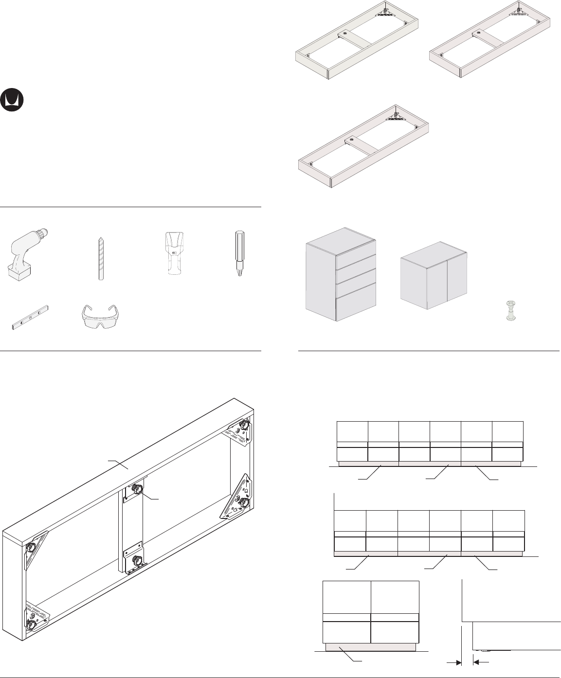
Stand Alone Plinth Base
(Inset Both ends)
Outside Plinth Base
(Inset Right or Le)
Full Plinth Base
(No Inset)
Step 1
Step 2
Phillips Bit
Stud Finder
Drill Bit
Safety Glass
. Turn all glides completely in.
Stand Alone Plinth Base
Outside Plinth Base
Outside Plinth Base
Outside Plinth Base
Full Plinth Base
Full Plinth Base
Full Plinth Base
Open End
Open End
Open End
Wall
Glide
Front
. Arrange Plinths in proper locations in run. There should be /”
overhang on each end of run unless end cabinet is positioned up against
wall. For stand alone unit, center cabinet over plinth. Back of Plinth should
be attached to wall. It has more visible joint seams and an indicator hole.
/” Overhang
HermanMiller for Healthcare Assembly Instructions1
1BJ2K5 rev C
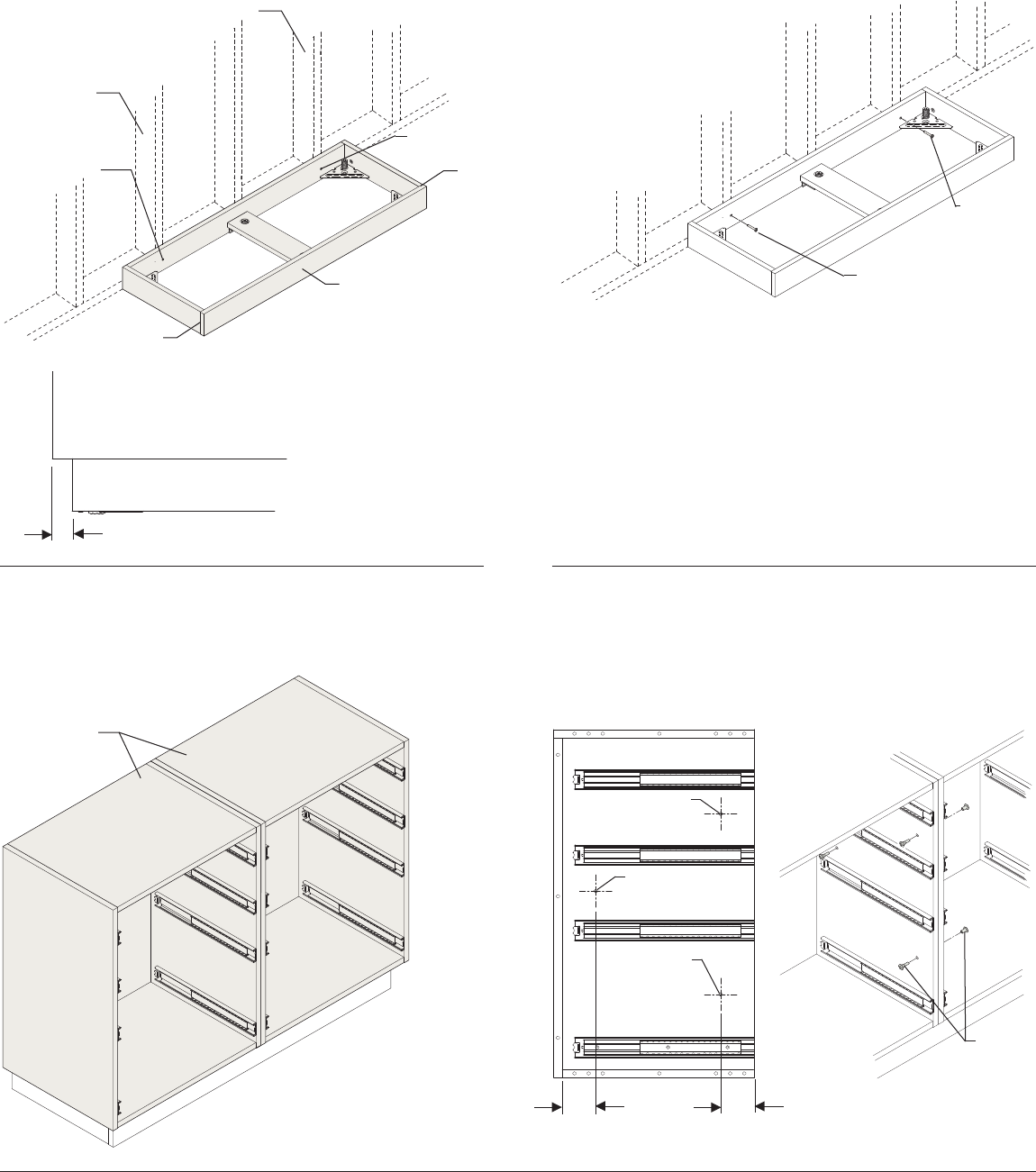
Step 4
. Drill holes through mating side panels, at front of cabinet ( toward
top and toward bottom) and at back in middle of cabinet. Holes should
be inset “ from front edge of side panel and ” from back inside surface of
back panel.
. Attach cabinets together with Clamping Screws in ganging hardware
pack CH.
Step 3
. Place plinth against wall. Keep in mind when positioning, that cabinet
will overhang ends of plinth by /” (end of run and stand alone)((shown)).
Make sure front of plinth is facing outward.
. Level plinth.
. Locate wall studs. Drill clearance holes in back side of plinth at stud
locations.
. Secure plinth to wall with sheet metal screws (not provided).
. Remove drawers TTF Drawer Case from Base Cabinet.
. Position Base Cabinets onto plinths. For Stand Alone Plinth (shown):
ends of cabinets overhang plinth by /”.
Base Cabinet
Drill Hole
Drill Hole
Drill Hole
Wall Stud
Wall Stud
Clearance Hole
Clearance Hole
Sheet Metal Screw
Sheet Metal
Screw
/”
”
”
Clamping
Screw
Front
Seam
Seam
HermanMiller for Healthcare Assembly Instructions2
1BJ2K5 rev C
HermanMiller for Healthcare Assembly Instructions3
1BJ2K5 rev C
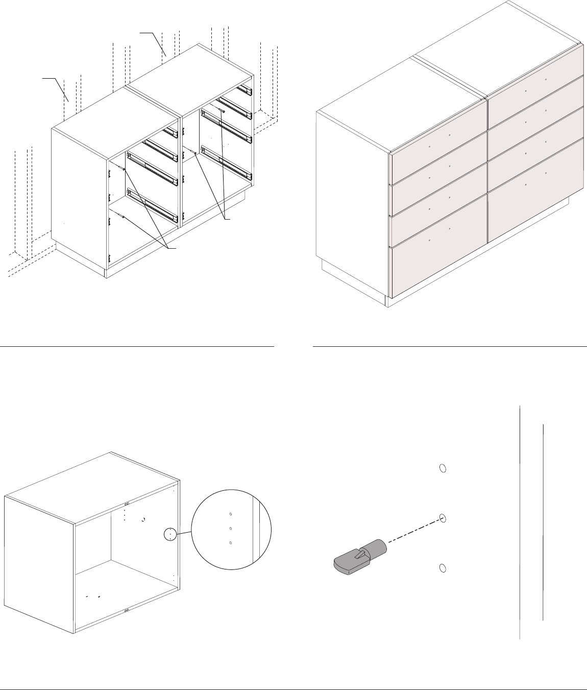
Step 5
Step 6
. Return drawers and/or doors to cabinets.
. Remove Doors And Shelf From Case. Shelf pin hardware pack qty per
DS, DF, DD and FD cabinet options (” wide and under)
. Insert Shelf Pins Into Holes On Side Panels. Flat Side up.
. Locate wall studs in wall. Drill clearance holes per cabinet through back
of cabinet at stud locations.
. Secure cabinets to wall with two ” sheet metal screws (not provided) per
cabinet.
Wall Stud
Wall Stud
” Sheet Metal Screw
” Sheet Metal
Screw
HermanMiller for Healthcare Assembly Instructions4
1BJ2K5 rev C
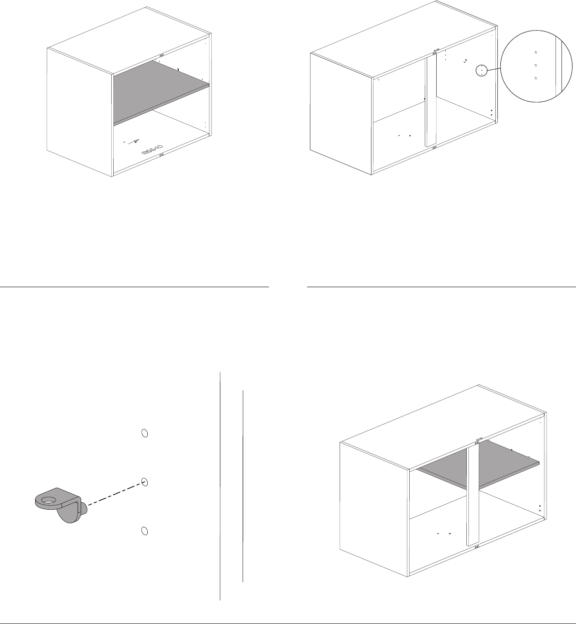
. Set Shelf Onto Pins.
Step 7
. Shelf pin hardware pack qty per DD and FD cabinet options (” wide to
” wide – only cabinets with a center vertical support) require () seperate
xed shelf pins
. Insert Shelf Pins Into Holes On Side Panels. Flat Side up. . Set Shelf Onto Back Pins First Then Lower Onto Front Clips.
HermanMiller for Healthcare Assembly Instructions5
1BJ2K5 rev C
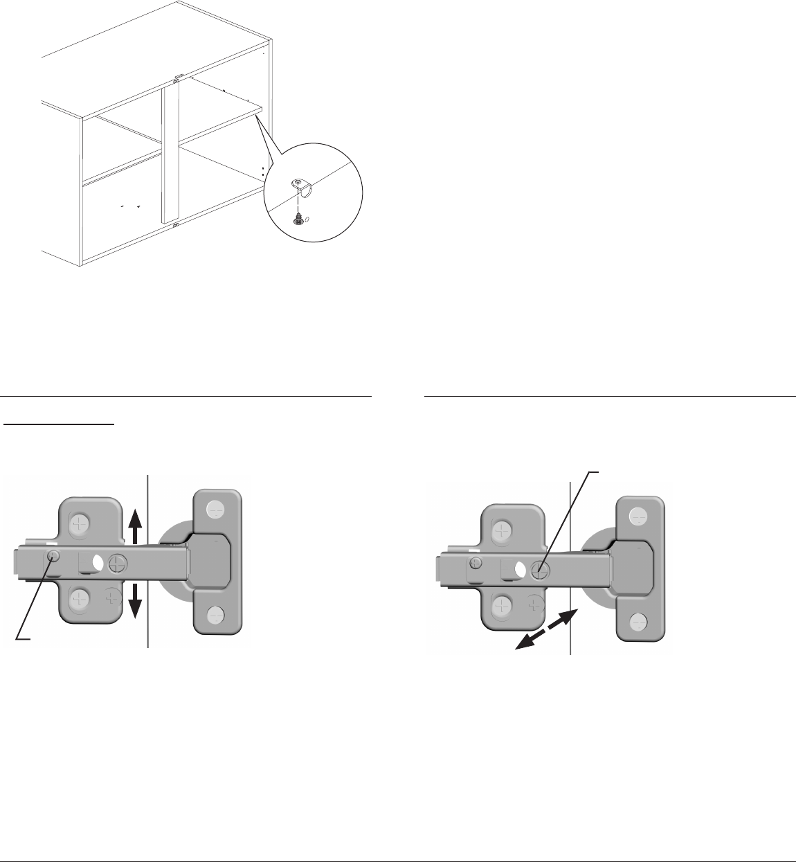
Hinge Adjustment:
The bottom surface of the door should be flush with the bottom of the cabinet
frame. To adjust door up, turn cam screw clockwise on right hinge. To adjust
door down, turn cam screw clockwise on le hinge. Adjust both hinges on
each door as necessary until proper door height is set.
To adjust door up/down:
Cam Screw
To adjust door(s) le or right and or to tilt door(s) le or right, use lateral
adjustment screw in hinge arm. Adjust screws in both upper and lower
hinges to move SCREW doors le or right, or adjust screw in one hinge to
tilt door le or right. Turning screw(s) clockwise moves door towards hinged
side. Counter-clockwise to move door away from hinged side. Turn counter-
clockwise for opposite door movement.
To adjust door le/right:
Lateral Adjustment Screw
. Shelf Will Rest Into Pockets On Bottom Of Shelf And Will Need To Be
Secured With () Screws.
. Repeat Steps For Second Shelf.
. Reinstall Doors To Case.
HermanMiller for Healthcare Assembly Instructions6
1BJ2K5 rev C
Disassembly and Recycling:
Materials Identication and Segregation:
Where possible, plastic components are marked with ASTM recycling
codes. Use these codes to identify material type for recycling. Non marked
components should be treated as mixed plastic. Ferrous metals can be
identied using a small magnet for recycling. Non-ferrous metals should be
separated and recycled separately.
To disassemble product, reverse the above installation steps.
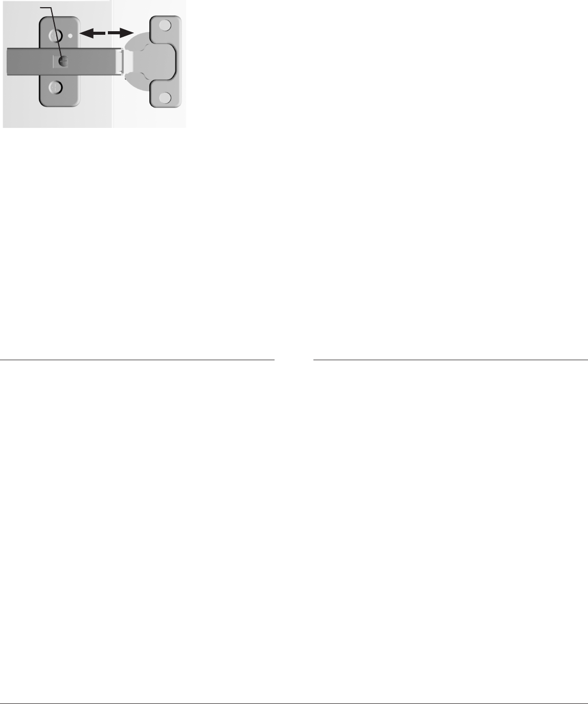
The front surface of a door should be flush with any adjacent doors and
drawer fronts. Also the gap between the door and the sides of the cabinet
should have a uniform gap. Turn screw clockwise to move door closer to side
panels. Counter-clockwise to move door farther away from side panels.
To adjust door in/out:
Screw
