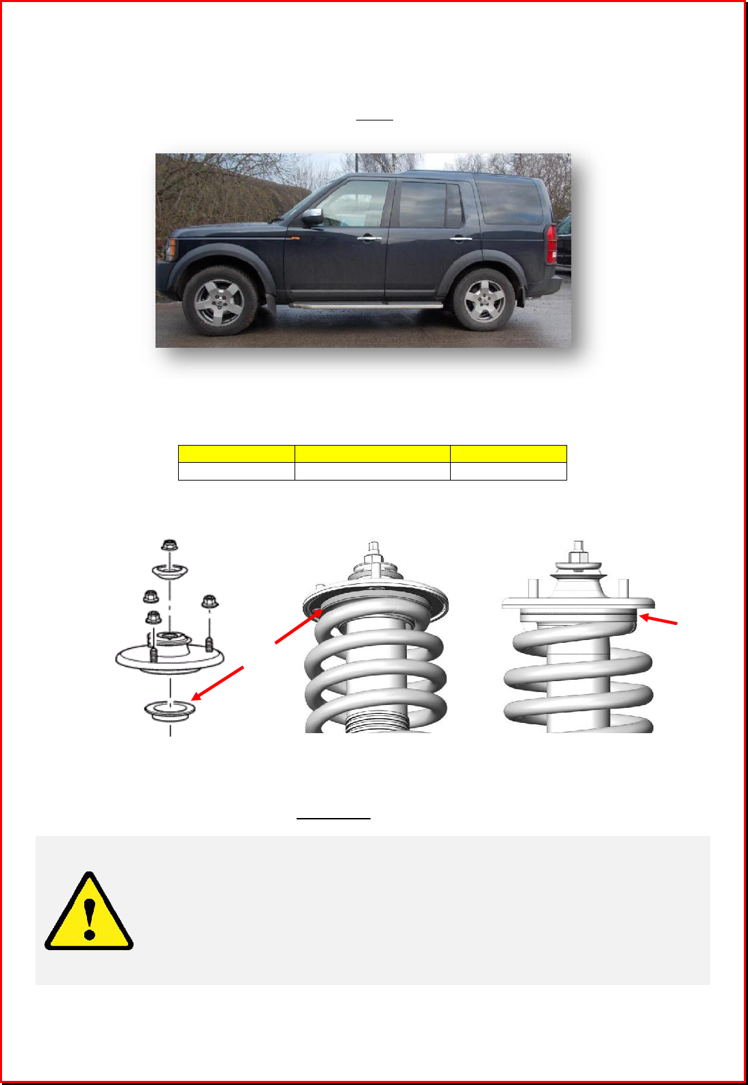
Coil Spring Conversion Kit
Land Rover Discovery 3
Thank you for your purchase of a coil spring conversion kit from Dunlop
Systems and Components Limited, suitable for the Land Rover
Discovery 3 vehicle (Model years 2004 – 2009). Please follow the
instructions in this manual carefully in order to ensure correct and safe
installation.
*
*
*
*
*
*
S
S
A
A
F
F
E
E
T
T
Y
Y
P
P
R
R
E
E
C
C
A
A
U
U
T
T
I
I
O
O
N
N
S
S
*
*
*
*
*
*
NEVER work beneath a vehicle supported only by a jack. ALWAYS use axle stands.
Wear eye protection and gloves throughout the installation process.
Y
Y
O
O
U
U
R
R
K
K
I
I
T
T
Your kit comprises of the following items…
Front Strut Rear Strut Disarm Kit and Instructions
Part No. 03139A-AA Part No. 03140A-AA Part No. 03296A-EA
Quantity: 2 Quantity: 2 Quantity: 1
I
I
N
N
T
T
R
R
O
O
D
D
U
U
C
C
T
T
I
I
O
O
N
N
© 2014 Dunlop Systems and Components Ltd, Central Boulevard, Prologis Park, Exhall, Coventry CV6 4QJ.
Tel.
+44 (0)2476 889900
email.
sales@dunlopsystems.com
03292A
2
Installation of the coil spring kit is a three-stage process…
1. Removal of Standard Air Struts
2. Fitting of Coil Spring Struts
3. Preparation of the vehicle for use with coil struts via a ‘Disarm Module’
The following tools are required…
15mm Spanner Top Mounting Nuts, All Struts
12mm Spanner Air Supply Fitting Nut
21mm Spanner Bottom Bolt Head, All Struts
24mm Socket Bottom Bolt Nut, All Struts
18mm Socket Toe Link Bolt Head
Torque Wrench Tighten to specified torque
Each installation stage is detailed in the following subsections. Except where indicated
otherwise, follow the same procedure for both the front struts and the rear struts.
1. Raise the vehicle and support the axle on stands
2. Remove the road wheel at the ‘corner’ from which the first strut is to be removed
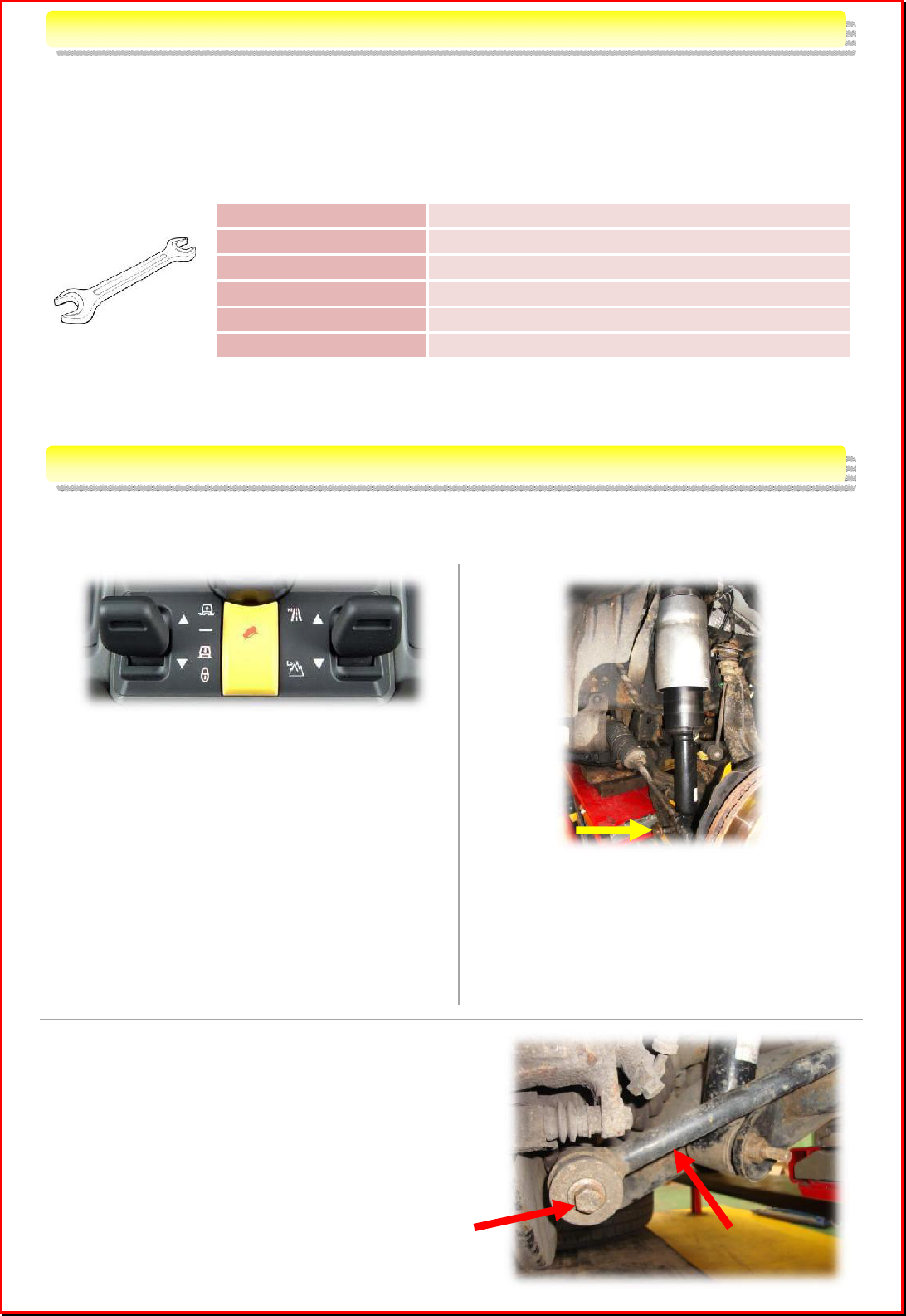
3.
If an official
Land Rover
air suspension
diagnostic system is available, use it at
this point to depressurize the air
suspension system. If the diagnostic
system is not available, invoke vehicle
‘Access Mode’ (i.e. lower the vehicle) via
the ‘Air Suspension Switch’ located on
the centre console: Switch-on the
ignition (there is no need to start the
engine) and press the left-side switch
downwards. This action will release
most of the compressed air from within
the system.
4.
Disconnect the air strut assembly at the
lower end from the vehicle suspension
arm by unscrewing and removing the
long bolt
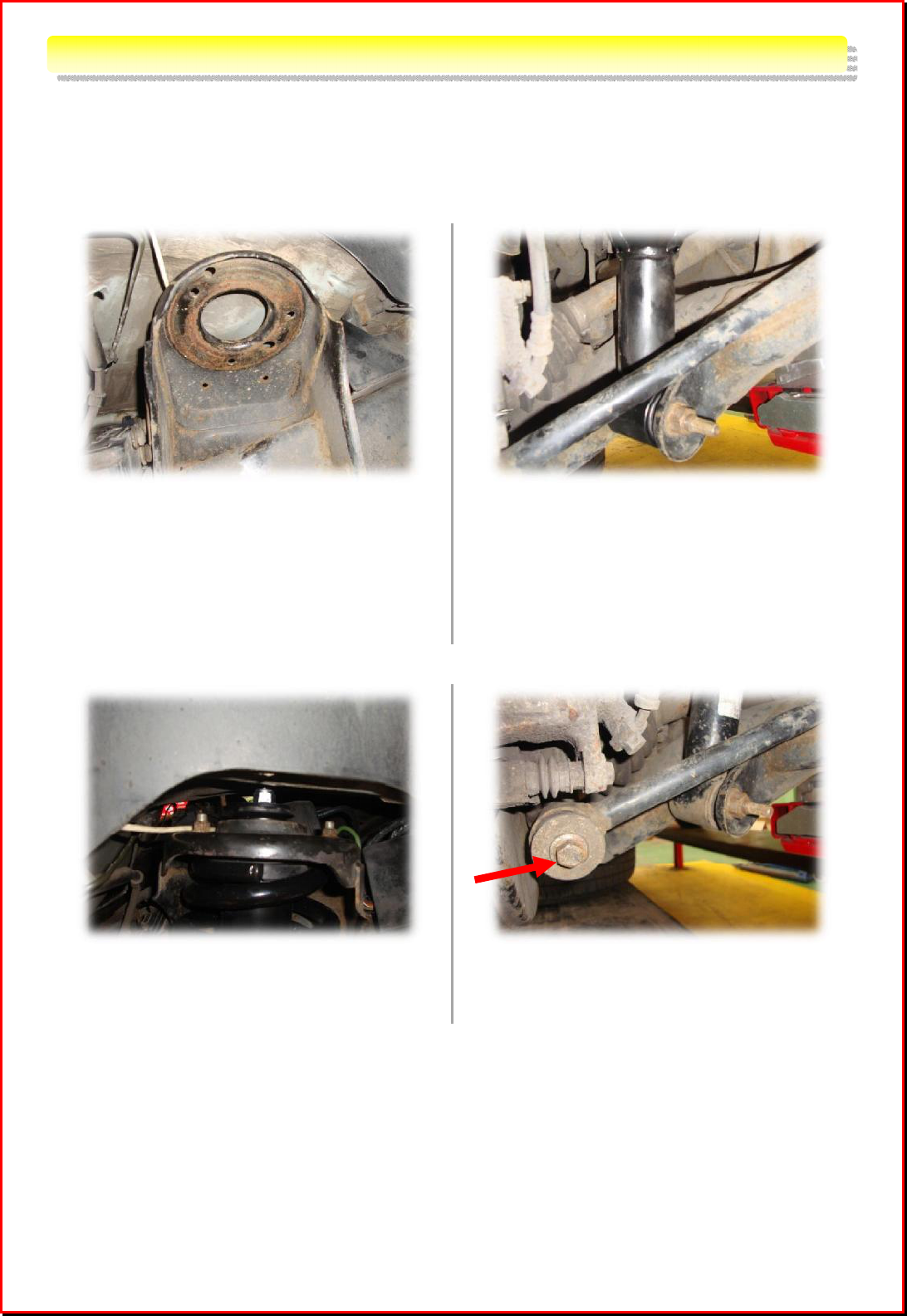
5. (Rear of Vehicle Only) A ‘Toe Link Arm’
extends across the strut near the bottom end.
This presents an obstruction to removal of the
strut and therefore it is necessary to move it
clear temporarily. Unscrew and remove the
bolt A, and push the rod away from the base of
the strut.
S
S
T
T
A
A
G
G
E
E
1
1
:
:
R
R
E
E
M
M
O
O
V
V
A
A
L
L
O
O
F
F
S
S
T
T
A
A
N
N
D
D
A
A
R
R
D
D
A
A
I
I
R
R
S
S
T
T
R
R
U
U
T
T
S
S
F
F
I
I
T
T
T
T
I
I
N
N
G
G
I
I
N
N
S
S
T
T
R
R
U
U
C
C
T
T
I
I
O
O
N
N
S
S
Toe Link Arm
A
3
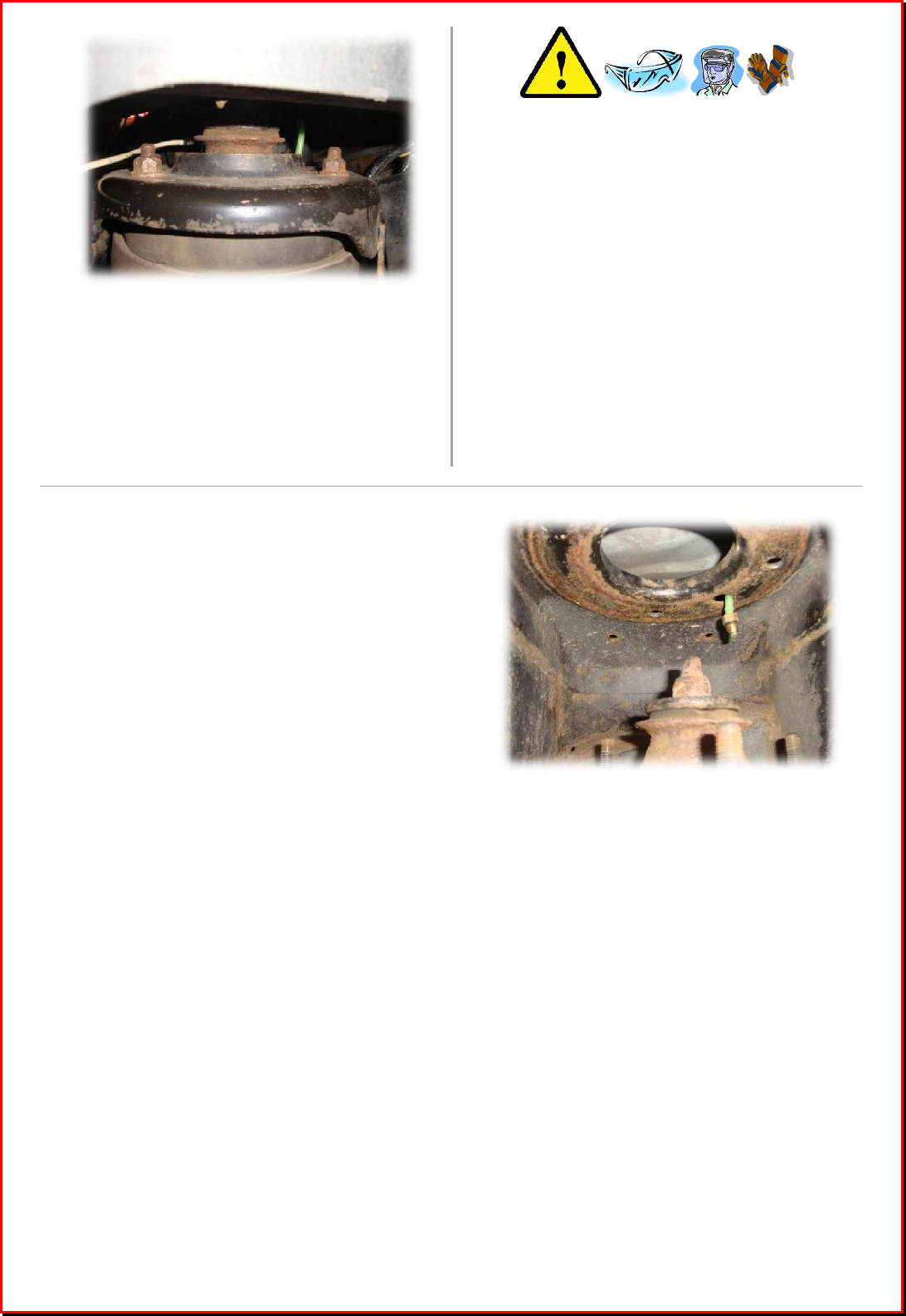
CAUTION!
* Potential for Violent Decompression *
The air suspension system contains
compressed air…
¼ Wear gloves and eye protection
¼
Use a full-face visor if available
6.
Remove the three nuts that attach the top
of the strut to the bracket on the chassis.
This will free the strut and so take care to
support the weight until the air line is
disconnected.
7.
Manual
Depressurization…
SLOWLY AND CAREFULLY loosen the nut
that secures the air tube to the strut. As an
additional precaution, do this with the face as
far as possible from the site of the nut. Stop
loosening the nut as soon as air is heard to
escape and wait until all of the air has been
released from the strut before proceeding
further.
8. Fully disconnect the air fitting from the strutIf
the air tubes are to be left in place on the
vehicle, close-off their exposed ends in order
to prevent ingress of water and/or
contaminants
4
1. Hold the strut at the fitting site and find the correct orientation, in which…
a. the three threaded pins in the top plate align with the holes through which they are to
pass and
b. the shock absorber ‘eye’ housing aligns with the slot on the lower suspension arm
vacated by removal of the air strut
2.
Manoeuvre
the strut upwards until the
three pins in the top plate pass through
the corresponding holes in the chassis
housing, at the same time ensuring that
the shock absorber eye housing lines-up
with its fastening location in the lower
arm. Secure the strut loosely at the top
via 3-off M10 x 1.5mm nuts.
3.
Manoeuvre
the damper ‘eye’ housing into
position against the lower arm bracket,
align the holes, slide the bolt through,
affix the nut and tighten to torque 300Nm
(221lbf.ft)
4.
Tighten the three
nuts
at the top of the
strut to torque 63Nm ± 10% (46.5lbf.ft ±
10%) in order to secure it to the chassis
housing
5.
(
Rear of Vehicle Only
)
Reattach the Toe
Link Arm via bolt A. Tighten to torque
175Nm (129lbf.ft).
6. Refit the road wheel and tighten the wheel nuts to torque 140Nm (103lbf.ft)
S
S
T
T
A
A
G
G
E
E
2
2
:
:
F
F
I
I
T
T
T
T
I
I
N
N
G
G
O
O
F
F
C
C
O
O
I
I
L
L
S
S
P
P
R
R
I
I
N
N
G
G
S
S
T
T
R
R
U
U
T
T
S
S
A
5
** VERY IMPORTANT NOTE – RIDE HEIGHT AFTER STRUT FITTING **
After fitting the coil spring struts, the vehicle should ride slightly higher than when fitted with
standard air struts. This maintains the load-carrying capacity of the vehicle. However, in
certain isolated cases, the ride height will be lower at the rear compared to when fitted with air
struts. The photograph below shows an example...
In such cases it is necessary to remove the rear struts in order to fit an additional part
(spacer) to each of them and then to refit the struts. The following standard Land Rover parts
are required...
Part Number
Decription
Quantity
RNG500060
SPACER, 13.5mm
2
The rear strut assembly includes an existing spacer, located as indicated by Figures A and B
below...
Figure A
Top of Rear Strut as
Supplied – Exploded View
Figure
B
Top of Rear Strut as
Supplied
Figure
C
Rear Strut with additional
Spacer Fitted
The additional spacer must be fitted alongside the existing one, as shown by Figure C.
** CAUTION **
The coil spring is placed under load when the strut is manufactured. Use of
appropriate tooling is required during disassembly in order to ensure that this
load is released in a safe and efficient manner. In addition, the spring will
need to be re-loaded when the strut is reassembled.
It is strongly recommended that both disassembly and reassembly of
each strut is carried out by a qualified vehicle technician equipped
with suitable tools.
SPACER
TWO
SPACERS
6
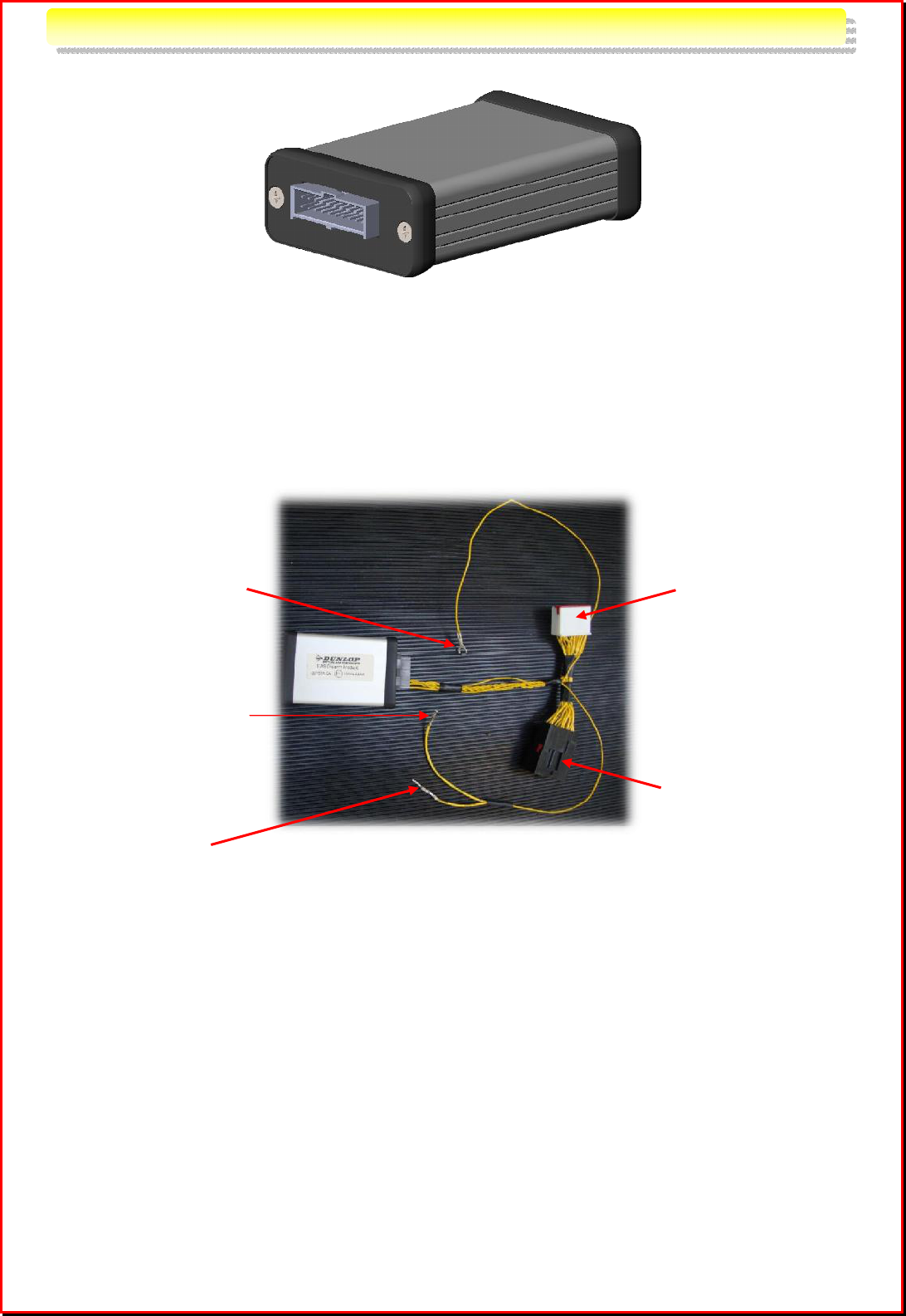
‘Disarm Module’
With the coil spring struts in place, the final stage is to suspend the activity of the air
suspension system control unit using the ‘Disarm Module’ (illustrated above) and electrical
harness provided. This module must be permanently connected into the vehicle harness, as
described in this section.
The photograph below shows the electrical harness and module, and indicates the connections
to be made…
S
S
T
T
A
A
G
G
E
E
3
3
:
:
‘
‘
D
D
I
I
S
S
A
A
R
R
M
M
M
M
O
O
D
D
U
U
L
L
E
E
’
’
Connect
t
o existing
vehicle air suspension
control module
Connect vehicle harness
connector to this socket
(as removed from air
suspension module)
Connect t
o existing
ground stud on vehicle
Connect to pin
numbered 16 on existing
vehicle diagnostics
(‘OBDII’) Connector
Join to existing battery
supply wire removed
from existing vehicle
diagnostics (‘OBDII’)
Connector
7
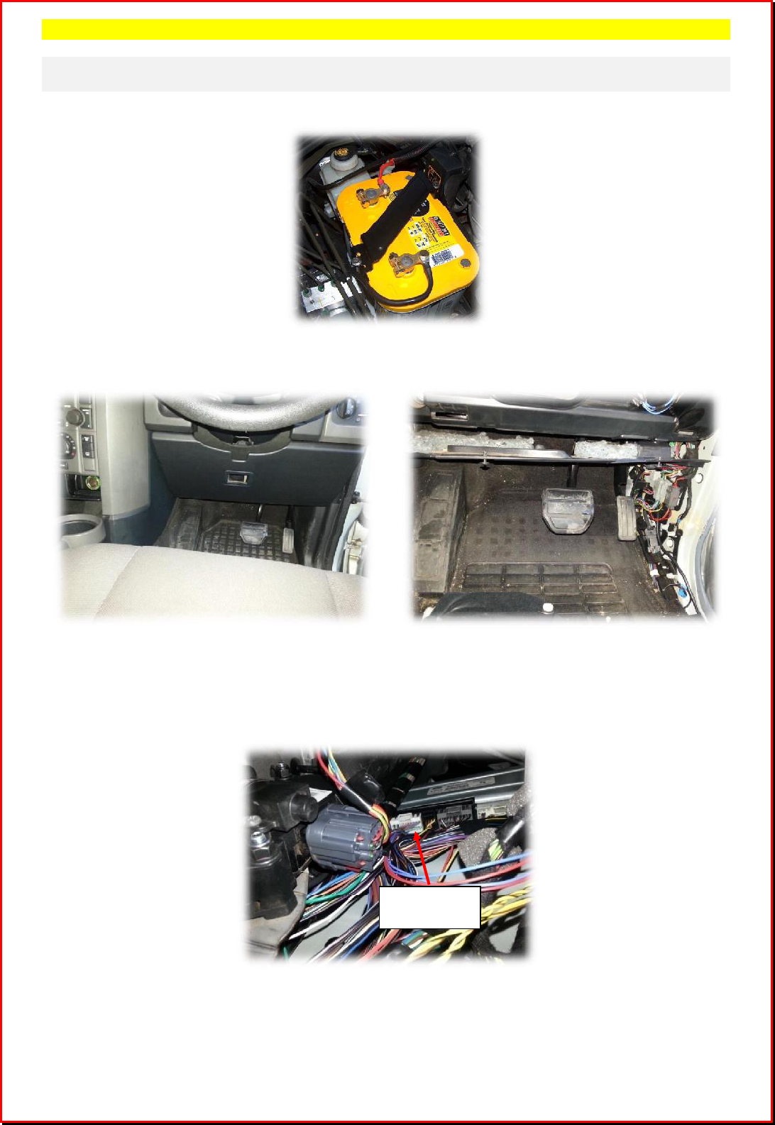
Procedure
Note that the following procedure refers to right hand drive vehicles – the procedure
is mirrored for left hand drive models.
1. !! VERY IMPORTANT !! Disconnect the vehicle battery...
2. Remove panelling from the footwell at the right hand side of the vehicle, as shown below.
This will provide for access to the air suspension system control unit.
Vehicle Footwell, Right-hand Side Vehicle Footwell, Right-hand Side,
Panelling Removed
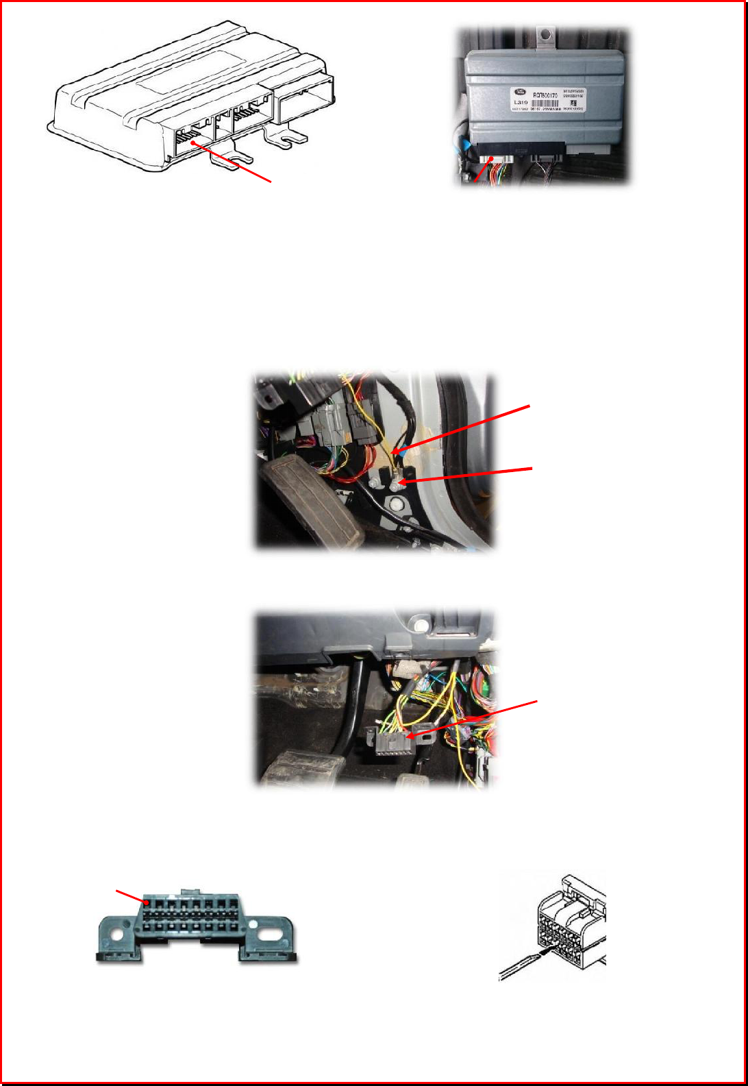
3. The control unit is positioned against the inside wall of the vehicle, as indicated in the
photograph below. Unplug the white connector from the underside of the unit, as shown
on this photograph and overleaf.
Unplug this
Connector
8
4. Plug the white connector of the coil spring kit harness into the air suspension control
module socket vacated in the previous step
5. Locate the white connector of the vehicle harness unplugged in step 2 and plug this into
the black socket of the coil spring kit harness
6. Connect the coil spring kit harness wire with a ring termination to an existing vehicle
ground stud, for example as shown here...
7. Unscrew and temporarily remove the existing vehicle diagnostics (‘OBDII’) connector...
8. Locate pin #16 of the diagnostics connector. Using a fine screwdriver or similar fine-
ended implement, lift the tab associated with this pin and pull out the (green-coloured)
wire from it.
Pin
#
16 is located top left when
the
connector is viewed as shown
To remove a wire from the connector, lift
the tab associated with it as indicated here
Existing vehicle
diagnostics (‘OBDII’)
connector, shown
temporarily disconnected
from seat
Remove 20
-
pin white connector
from position indicated
Existing Vehicle
Ground Stud
Coil Kit Harness
Wire with Ring
Terminal
Pin #16
9
9. Locate the wire of the coil spring kit harness that terminates with a small socket. Attach
this socket to the pin (#16) of the vehicle diagnostics connector vacated in the previous
step.
10. Slide heat shrink over the remaining loose wire of the coil spring kit harness, which
terminates with a pin. Attach this wire to the existing (green-coloured) wire of the vehicle
harness which was pulled-out of the diagnostics connector in step 8. Slide the heat shrink
to cover the exposed metal parts of the new connection and apply heat to establish it in
position...
Coil spring harness wire
attached to
(green) vehicle harness wire previously
removed from disgnoatics connector
Heat shrink applied to connceted wires
as shown left
11. Re-fit the vehicle diagnostics (‘OBDII’) connector
12. Using the cable zip ties provided, secure the coil spring kit module in a suitable place close
to the vehicle air suspension module.
13. Re-fit all of the panelling removed in step 2
14. Reconnect the vehicle battery
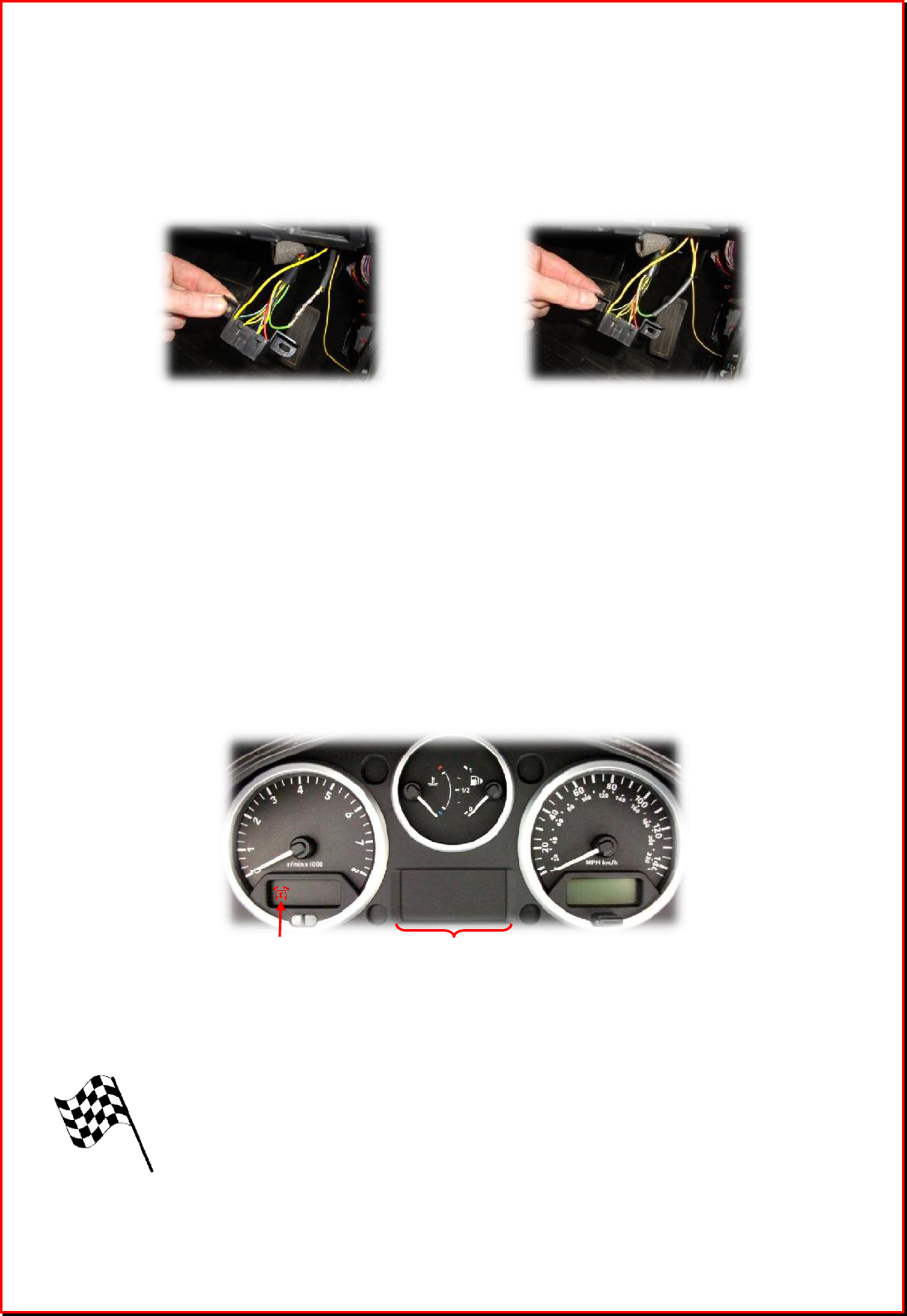
15. Insert the vehicle ignition key and select postion II / ON – Do not start the engine.
Confirm that the air suspension warning lamp (at position ① below) has extinguished and
that there are no error messages / warning symbols displayed on the centre console liquid
crystal display (②). Wait for a minimum of 10 seconds.
The vehicle is now ready to be operated with coil spring suspension
①
②
(Symbol shown as it
would appear if warning
lamp were illuminated)
