~ 1 ~
POWRTOUCH CARAVAN MOVERS
REMOTE CONTROL CARAVAN MOVER FAMILY
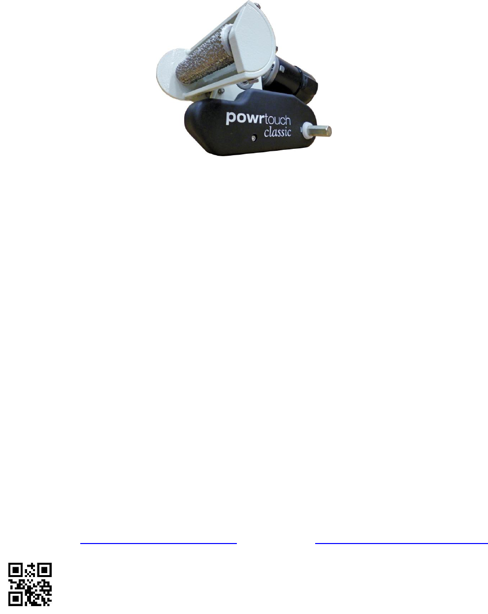
POWRTOUCH CLASSIC
INSTRUCTIONS for the Installation, Operation, Use,
Safety & Maintenance of the Powrtouch Classic
IF YOU HAVE PURCHASED DIRECT FROM POWRTOUCH your proof of purchase will state
your unique Powrtouch Classic Serial Numbers. Please write them on the front of this
document for your convenience.
IF YOU HAVE PURCHASED FROM ANOTHER SUPPLIER then they should register your
information with Powrtouch (ALWAYS ASK YOUR SUPPLIER TO MAKE SURE THAT THIS
HAS BEEN DONE).
PLEASE NOTE THAT YOUR POWRTOUCH CLASSIC GUARANTEE IS NOT
AUTOMATICALLY TRANSFERABLE TO A SECOND OWNER
see Section 5 – Paragraph 5.1 of this document.
BEFORE CONTACTING POWRTOUCH WITH A FAULT OR GUARANTEE ENQUIRY
PLEASE PAY SPECIAL ATTENTION TO SECTION 4 OF THIS DOCUMENT.
CUSTOMER NAME:……………………………………………………………………….……..
POWRTOUCH CLASSIC SERIAL No: CL/..…………………………………………………..
ELECTRONICS SERIAL No: CDFM/…………………………………………………………...
Truma Limited
Powrtouch – A Truma Brand
2000 Park Lane, Dove Valley Park, Foston, South Derbyshire, DE65 5BG United Kingdom
TELEPHONE: +44 (0)1283 587900 FAX: +44 (0)1283 587910
WEBSITE: www.powrtouch.com EMAIL: info@powrtouch.com
TWITTER: www.twitter.com/powrtouchuk FACEBOOK: www.facebook.com/powrtouchuk
ISSUE 5
~ 2 ~
CONTENTS
SECTION 1 – USING YOUR POWRTOUCH CLASSIC SAFELY
1.1 Safety Checks Required Prior to Using Your Powrtouch Classic
1.2 Emergency Switch Off/Stop
1.3 Safety and Technical Awareness
SECTION 2 – OPERATION OF YOUR POWRTOUCH CLASSIC
2.1 Powrtouch Classic Operation
2.2 Switching On the Powrtouch
2.3 Switching On the Handset
2.4 Handset Battery Replacement
2.5 Engagement of the Rollers On To the Tyres
2.6 Moving the Caravan (Handset Operation)
2.7 Decreasing and Increasing Speed
2.8 Precision Control of the Caravan Using the Electronic Soft Start Function
2.9 Retraction of the Rollers from the Tyres
2.10 Switching Off the Handset
2.11 Mapping Instructions
SECTION 3 – DIY FITTING INSTRUCTIONS (FOR UK SPEC CARAVANS ONLY)
3.1 Receiving Your Powrtouch Classic
3.2 Tooling & Equipment Required
3.3 Installing Your Powrtouch Classic
3.4 Checking Chassis Depth
3.5 Special Mounting Plates
3.6 Mechanical Assembly
3.7 Electrical Assembly
3.8 Connecting to the Caravan Battery
SECTION 4 – LOOKING AFTER YOUR POWRTOUCH CLASSIC
4.1 Cleaning Your Powrtouch Classic
4.2 Cleaning the Drive Rollers
SECTION 5 – GUARANTEE & FAULT FINDING
5.1 Powrtouch Classic Guarantee
5.2 Reporting a Fault with your Powrtouch Classic
5.3 Electronics Control Box (ECB) - LED Status
5.4 Checking the Charge State of Your 12 Volt Battery
5.5 Fault Finding on Your Powrtouch Classic
~ 3 ~
SECTION 1 – USING YOUR POWRTOUCH CLASSIC SAFELY
1.1 SAFETY CHECKS REQUIRED PRIOR TO USING YOUR POWRTOUCH CLASSIC
PLEASE READ CAREFULLY:
Before moving the caravan with the Powrtouch Classic, for safety reasons it should always be
tested first, to do this turn on the Powrtouch Classic at the Isolation switch – DO NOT PUT
THE ROLLERS ON TO THE TYRES. With the rollers off the tyres check the handset functions
drive the rollers correctly. Once this test has been satisfactorily completed only then should
you engage the rollers to the tyres and commence to move the caravan.
IF IN DOUBT CONTACT POWRTOUCH
1.2 EMERGENCY SWITCH OFF/STOP
NB. In the unlikely event of the Powrtouch Classic malfunctioning, the system can be switched
off by pressing either D or F buttons on the handset. Then turn off the Powrtouch Classic at the
Isolation switch and remove the key. DO NOT switch the Powrtouch Classic back on before
consulting a qualified Powrtouch Engineer.
1.3 SAFETY & TECHNICAL AWARENESS
Please read the following instructions and technical information carefully and become familiar
with the various components and controls prior to assembly and/or operation. Safety must
always be the first consideration in fitting and operation. Failure to comply with these
instructions could invalidate your Powrtouch guarantee. If you are in any doubt about the
assembly or operation of the product consult a qualified Powrtouch Engineer, for which contact
details are shown on the front cover.
• The Powrtouch Classic Caravan Mover (except handset) is a 12volt DC powered device
and it should not under any circumstances be powered by any other power source than
a 12volt DC leisure battery. NB. Using the Powrtouch Classic with the caravan
connected to the 240volt mains could cause damage to the caravan internal
charging system.

~ 4 ~
• The 12volt leisure battery MUST be fully charged and in good condition to enable the
Powrtouch Classic to operate to its full performance specification – to check your
battery see Section 5 Paragraph 5.4 of this instruction manual.
• The handset is powered by a 9volt DC battery (PP3 or equivalent).
• The wiring and cabling supplied by Powrtouch for the installation of the Powrtouch
Classic are to the correct voltage and current rating, under NO circumstance should any
other wiring or cabling be used unless supplied by Powrtouch or written approval is
given for their use. If cutting motor cables (not recommended) these should be kept of
equal length, no cable joining system should be used to lengthen them.
• When the Powrtouch Classic is switched on and/or in use there will be 12volts at the
two battery terminals on the Electronics Control Box (ECB). Under no circumstance
should any metal object be allowed to touch these terminals.
• The Powrtouch Classic is not a caravan jacking point and should never be used as
such.
• The Powrtouch Classic is not a brake or braking system and should never be used as
such. When stopped always apply the caravan handbrake and remove the rollers from
the tyres.
• Be aware that the Powrtouch Classic adds weight to the caravan and the corresponding
weight of your mover must be considered when calculating your payload. If in doubt the
MTPLM of the caravan should be checked on a calibrated weighbridge.
• Never allow children or persons unfamiliar with the use of the Powrtouch Classic to
operate the unit.
• When operating the Powrtouch Classic, please ensure that no object (e.g. Body parts,
clothing, hair or any other objects carried on the body) can become trapped by any
moving parts of the mover (e.g. rollers).
SECTION 2 – OPERATION OF YOUR POWRTOUCH CLASSIC
2.1 POWRTOUCH CLASSIC OPERATION:
Carry out the Powrtouch Classic pre-movement safety checks as Section 1 Paragraph 1.1;
also ensure that the caravan is safe to move and that there are no obstructions to prevent the
engagement of the drive rollers to the caravan tyres.
2.2 SWITCHING ON THE POWRTOUCH CLASSIC
The Powrtouch Classic control system is switched on by inserting the key into the isolation
switch and then turning the key clockwise, the isolation switch is usually situated in the sealed
area of the caravan battery box. When the control board is switched on the unit first initialises,
and then looks/waits for the welcome/coding signal from the handset. The green light should
illuminate on the ECB situated in the caravan. (See Section 5 Paragraph 5.3)
NOTE: When the Powrtouch Classic is not in use it MUST always be turned off at the Isolation
Switch and the key removed. If left switched on it will stay live for 20 minutes (approx.) before
the ECB will go in to a hibernation mode. The ECB can only be reinitialised by the following: -
1) Turning off the isolation switch.
2) Remove the key from the switch.
3) Wait for a minimum of 20 seconds.
4) Then reinsert the isolation switch key and turn on.
5) Turn on the handset and use the Powrtouch Classic.
~ 5 ~
WHEN NOT IN USE ALWAYS SWITCH IT OFF AND REMOVE THE KEY
2.3 SWITCHING ON THE HANDSET
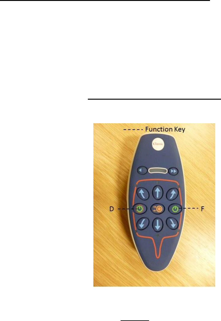
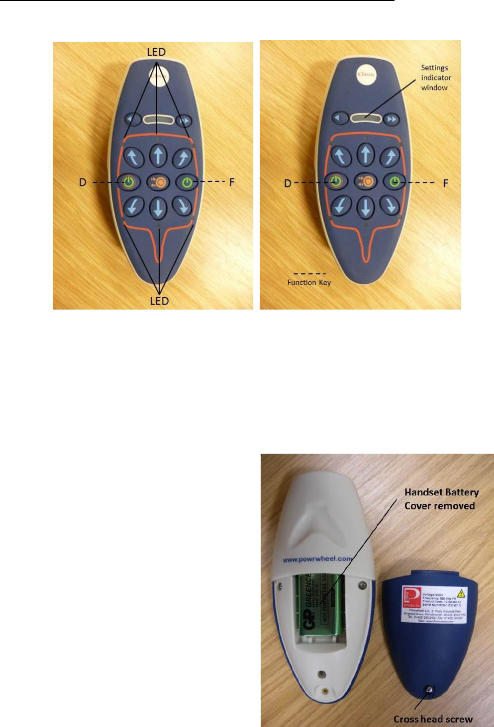
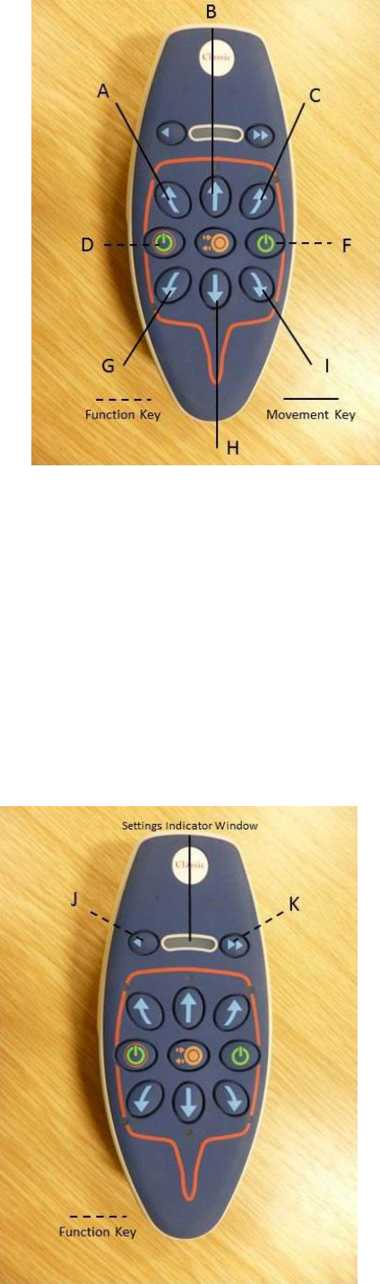
To switch on the handset press and release both D and F buttons at the same time. The LED
array will illuminate in the settings indicator window. Once it is ready to operate then one
green LED on the extreme right of the settings indicator window will remain on. If the top row &
bottom row of Red LED’s flash alternating, then this in an indication that the handset battery
voltage is low and the battery should be changed as soon as possible.
2.4 HANDSET BATTERY REPLACEMENT
To replace the handset battery the first step
is to remove the small cross head screw on
the back of the handset. When the small
cross head screw is removed the battery
box cover can be taken off providing
access to the battery. The battery can then
be removed from its connections and a
new battery can be installed and the cover
replaced. The battery required is a 9volt
DC PP3 (mn1604) or equivalent. NB. The
use of rechargeable batteries is not
recommended.
~ 6 ~
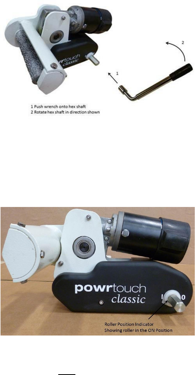
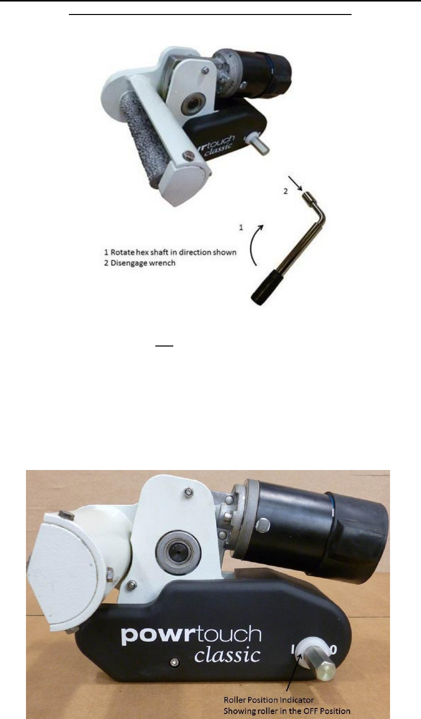
2.5 ENGAGEMENT OF THE ROLLERS ONTO THE TYRES
Engagement of the Rollers on to the Tyres Using the Supplied Wrench
To engage the rollers onto the tyres, locate the wrench onto the hexshaft (see picture above)
and turn in the direction shown, after 200 degrees the over locking cam system will lock the
rollers in the engaged position. On the Powrtouch Classic models the start position for the
wrench should be as low as possible to the ground with the handle pointing away from the
rollers. Always take great care with this operation as the over locking cam system together with
its return spring require some force to move the rollers into position against the tyres. This
operation only needs to be done from one side of the caravan as the Classic is fitted with a
Powrbar as standard. Your Powrtouch fitter or supplier will show you how to carry out this
operation safely.
If in doubt consult a qualified Powrtouch Engineer. NB. Always check that BOTH rollers
are fully engaged on to the tyres of the caravan before removing the handbrake.
Once the Rollers are engaged ONLY then disengage the handbrake when you are ready
to use the Powrtouch Classic.
- 6 -
~ 7 ~
2.6 MOVING THE CARAVAN (HANDSET OPERATION)
The caravan can be moved as required by pressing buttons A, B, C, G, H or I. The caravan will
move in the direction of the arrows printed on these buttons. Pressing opposite button A and I
or C and G will make the caravan rotate on its axis. The Electronics Control System also has a
continuous movement capability in that if button B is being pressed then buttons A or C can be
used, alternatively if button H is pressed then buttons G or I can be used, using this sequence
will allow the Powrtouch to redirect the caravan without stopping the forward or backward
motion.
Please note that the speed settings will always default to MAXIMUM – Speed changes
can only be made when the caravan is stationary.
2.7 DECREASING AND INCREASING SPEED
~ 8 ~
When the handset is first switched on the settings indicator window will always show an
illuminated green LED to the extreme right-hand side of the window and this is the default
position of maximum speed (100%). The speed can be decreased by pressing button J, each
time this button is pressed the speed will decrease by 25% and the green LED will move in the
window to indicate the speed setting selected. NB. The minimum speed setting is 25%. As the
speed decreases the torque decreases in the same ratio i.e. 50% speed is 50% torque. This
function of using a slow speed with lower torque setting is designed to maintain the
caravan/trailer’s manoeuvrability in very restricted and/or confined spaces.
If the Powrtouch in not at its maximum speed then the speed can be increased in 25%
increments by pressing button K. When changing the speed of the Powrtouch, the illuminated
green LED will move (a maximum four stages) from the left to the right of the meter; when the
LED is positioned at the extreme right of the display this indicates the Powrtouch has returned
to the maximum speed setting. The speed can only be changed when the caravan is not
moving.
2.8 PRECISION CONTROL OF THE CARAVAN USING THE ELECTRONIC SOFT START
FUNCTION
By utilising its very effective Electronic Soft Start System the Powrtouch Classic can easily
move the caravan a distance of 1mm at a time. This small movement can be achieved by
pressing and quickly releasing a direction button (stabbing the button), this facility makes
attaching the caravan to the tow ball of the car a very simple operation. Reducing the speed
will also give greater control of the caravan when using the soft start in this way. It is
recommended that a good practice session should be carried out on level ground and in an
open space before any difficult manoeuvres are undertaken.
~ 9 ~
2.9 RETRACTION OF THE ROLLERS FROM THE TYRES
ALWAYS ENSURE THE CARAVAN/TRAILER HANDBRAKE IS ON BEFORE
DISENGAGING THE ROLLERS FROM THE TYRES
Retraction of the Rollers Off the Tyres Using the Supplied Wrench
Always ensure that the handbrake is ON prior to removing the rollers away from the tyres. To
retract the rollers off the tyres locate the wrench onto the hexshaft (see picture above) and turn
in the direction shown, after 200 degrees the over locking cam system will lock the rollers away
from the tyres. The correct retraction start position for the wrench will be the opposite of the
engagement positions as shown in Section 2.5. Always take great care with this operation as
the return spring will remove the rollers with some force that can snatch the wrench from your
hand and damage the system. Your Powrtouch fitter or supplier will show you how to carry out
this operation safely.
If in doubt consult a qualified Powrtouch Engineer.
~ 10 ~
2.10 SWITCHING OFF THE UNIT
The handset does not need to be turned off manually except in the case of an emergency (See
Section 1 Paragraph 1.2). If the handset is left unused for 3 mins approximately it will
automatically turn itself off. However, once you have finished using the Powrtouch Classic
caravan mover, ensure the unit is switched OFF with the isolation switch and the key is
removed.
2.11 MAPPING (Tuning/Coding) INSTRUCTIONS – Given for Information ONLY
All electronics systems are supplied with the handset mapped (tuned/coded) to the ECB,
should you require to map or remap the system the sequence is as follows: Using the plastic
needle provided (attached under the hinged lid of the ECB) press the remap button through the
small hole (labelled ‘R’) in the lid of the box, this enables the control board to search for a
signal. Then switch on the handset, and it will transmit a welcome mapping signal to the
control board and the system will automatically code.
~ 11 ~
SECTION 3 – DIY FITTING INSTRUCTIONS
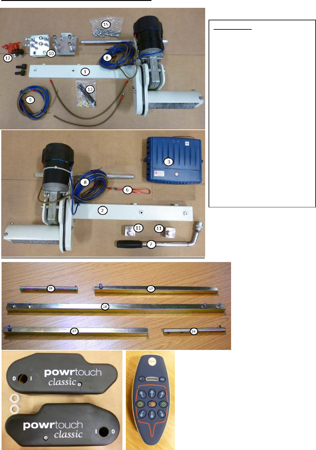
Key To Parts
1 – Left Hand Unit
2 – Right Hand Unit
3 – Electronics Control Box (ECB)
6 – Handset Lanyard
7 – Wrench
8 – Motor Wires
9 – Battery Wire Set
10 – Clamp Set
11 – Stop Blocks
12 – Isolator Switch With Key
13 – Spare Motor Crimps
15 – Screw Set
16 – Inter Shafts
17 – Powrbar Outer Sections
18 – Powrbar Centre Section
Centre Bar (not shown)
Side Covers
Electronics Handset
Fig 2. Pictures Showing
Component Parts

~ 12 ~
SECTION 3 – DIY FITTING INSTRUCTIONS
3.1 RECEIVING YOUR POWRTOUCH CLASSIC
When unpacking the box there is a checklist of the components for the mover. Please check
that all parts have been received before commencing the installation work (See Fig 2 showing
component parts). If in doubt, please contact a qualified Powrtouch Engineer. Contact details
are on the front page of this document.
3.2 TOOLING AND EQUIPMENT REQUIRED
To install the Powrtouch the following tooling and equipment will be required (not supplied):
• 10mm Socket & Ring Spanner
• 13mm Socket & Ring Spanner
• 17mm Socket & Ring Spanner
• Power Drill with 3mm & 10 mm Drill Bits suitable for wood
• 25mm Hole Saw for Plastic (for fitting isolation switch)
• Various Screwdrivers
• Multi-Purpose Silicone Sealant
• Lighting as necessary
• Trolley Jack or Axle Stands (for raising unit into position)
• Support Blocks, Wheel Chocks for Safety (to ensure the caravan cannot move
during the fitting operation)
• Torque Wrench
• Safety Goggles
3.3 INSTALLING THE POWRTOUCH CLASSIC
NB. – VERY IMPORTANT: BEFORE COMMENCING, PLEASE ENSURE THAT THE
CARAVAN IS DISCONNECTED FROM IT’S 12 VOLT D.C. LEISURE BATTERY SUPPLY
AND ANY OTHER ELECTRICAL SUPPLIES (INCLUDING 240 VOLT MAINS).
All electronic and electrical controls of the system are carried out by the Electronics Control
Box (ECB) and isolation switch; please note the ECB has an inbuilt safety thermal fuse (set at
90 deg C). Should this fuse operate it will automatically reset itself when the system cools to
an acceptable temperature.
The Isolation Switch must be accessible at all times when parking and moving the
caravan/trailer, please be aware of this when selecting the location for the switch (See Section
3 Paragraph 3.8).
Please check that the tyres are of the same size and design (preferably from the same
manufacturer) and not over worn (fitting to new or nearly new tyres is the best option). It should
be noted that as the caravan tyres wear, the roller to tyre gap will increase, this could allow the
Powrtouch rollers to slip when driving the tyres, should this occur, the Powrtouch will require
adjustment. Also ensure the tyre pressures are correct to the manufacturer’s recommendation
prior to commencing the fitting of a Powrtouch. Also check that the chassis is in good
condition without any damage and free from rust or corrosion etc.
Ensure that the handbrake is in the ON position before the caravan is raised using the front
steadies and Jockey Post/Wheel, the back steadies are then lowered to make sure the
caravan is fully stabilised and no forward or backward movement can occur.
All work MUST be carried out to ensure personal safety.
~ 13 ~
3.4 CHECKING THE CHASSIS DEPTH
The Powrtouch Classic is designed to fit on standard chassis depths of 209mm. If you have a
150mm chassis you will require drop plates & extra-long U Bolts.
3.5 SPECIAL MOUNTING PLATES
On some recently manufactured caravans (in particular Hymer) special mounting plates may
be required. These plates can be supplied (for a small additional cost) and are fitted by nuts
and bolts using pre-drilled holes in the chassis. Once these plates are fitted then the
mechanical assembly of the unit will proceed as detailed below.
3.6 MECHANICAL ASSEMBLY
For safety reasons it is recommended that the fitting of the Powrtouch Classic should
be undertaken on a flat hard standing. Before raising the caravan, ensure the handbrake is
on and then it can be raised as required (using trolley jack and/or axle stands) and secured in
position using the caravan steadying legs with supporting blocks and wheel wedges as
necessary; it is then helpful to lay down a ground sheet. Remove all items from the packaging
onto the protective sheet. Ensure both rollers are in the DISENGAGED position, as the unit will
not fit correctly otherwise. Loosely assemble the left-hand motor unit, right hand motor unit and
alignment tube and place under the caravan/trailer.
Wherever possible the Single Axle Powrtouch Classic should be fitted in front of the
caravan/trailer road wheels, if this is not possible then it is acceptable to fit the unit behind the
road wheels.
Using appropriate support blocks raise the loosely assembled unit into an approximate
position, fit the clamps and U-Bolts (see Fig 3) to the chassis (do not tighten at this point).
Adjust to the correct place using the 20mm wooden spacer provided between the tyre and the
drive roller (on each side of the trailer). Please note the wood spacer blocks should be a sliding
fit between the tyre and the coarse drive roller.
Also adjust the position of the drive rollers in relation to the tyres by sliding the motor units on
the alignment tube until the maximum amount of roller is in contact with the tyre tread without
any part of the unit fouling the tyre or chassis. It is advisable to leave a minimum 10mm gap
between the Powrtouch Classic unit and the inside wall of the tyre, this is to allow for the
expansion of the tyre when the rollers are engaged. Before tightening the u bolts to the
recommended 35 ft lbs tighten the alignment tube pinch bolts and lock nuts making sure the
alignment tube is approximately centralised; it is then advisable to check the roller / tyre gaps
again. The assembly should then be secured by tightening the u bolts to the recommended
torque of 35 ft lbs using a torque wrench.
Check both the above alignments at least once during the process and on completion.
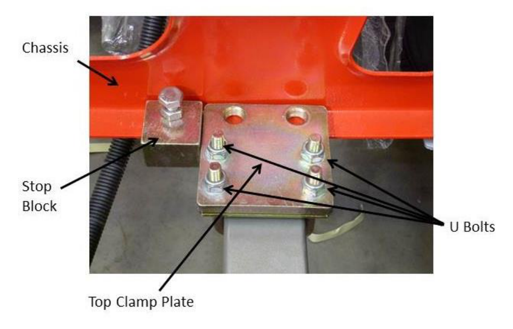
Once the motor assemblies are completed the stop blocks should now be fitted on the chassis
in a position directly behind the Powrtouch clamping plates to ensure that the motor
assemblies do not slide along the chassis away from the tyres when the drive rollers are
engaged to the tyres (see Fig. 3). Once correctly positioned they can be tightened using the
locking bolt and nut with a torque wrench spanner set at 35 ft lbs.
~ 14 ~
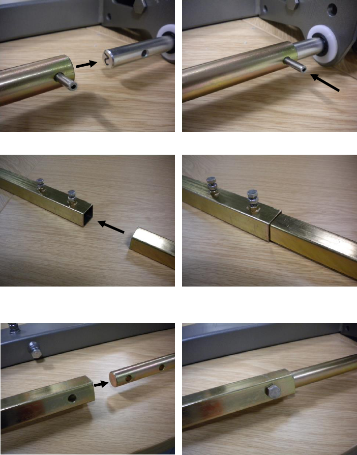
FIG 3: CLAMP ASSEMBLY WITH STOP BLOCK
~ 15 ~
Powrbar Installation
The Powrbar installation kit, as detailed in Fig 2
Slide the inter shafts over the inner section of the engagement shafts
Tap the 5mm dia spirol pin through securing the shaft in place.
Slide the outer square sections into the centre Powrbar section and leave the pinch bolts loose
Span the caravan with the loosely assembled square sections and slide the ends over the
inter shafts.
Tighten all bolts and nuts to secure.
Be sure that the Powrbar or Centre Bar does not foul any other system, such as the
brake cables, water tanks etc.
~ 16 ~
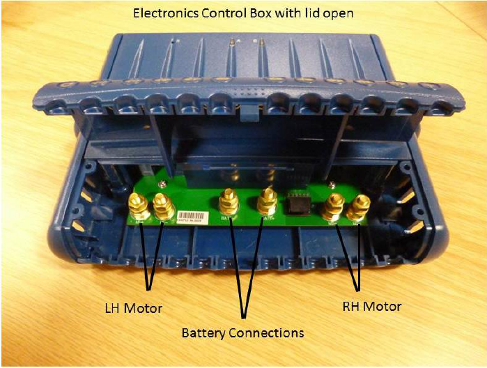
3.7 ELECTRICAL ASSEMBLY
AGAIN - PLEASE ENSURE THAT THE BATTERY AND MAINS LEAD ARE BOTH
DISCONNECTED FROM THE CARAVAN BEFORE COMMENCING INSTALLATION.
NB. The terms right hand (UK Nearside) and left hand (UK Offside) referred to on the
electronics control box are determined by standing in front of the caravan (at the hitch) facing
the caravan.
The recommended site for the Electronics Control Box (ECB) is inside the caravan in the dry
(bedding) locker behind the battery box. The ECB should be screwed to the floor using the
screws provided. Please note some caravans have under floor cables and/or pipes,
checks must be made to ensure it is safe to drill. If safe to do so then drill four 10mm
diameter holes in the floor approximately 150mm from the control box for the motor wires to be
fed into the caravan. Start routing the wires from the motor, remembering to leave a small
amount of slack cable near the motors to allow for their movement when the drive rollers are
engaged. The motor wires (two each) can now to be routed along the underside of the caravan
floor using the P clips provided (securing of the cables can be made with a suitable staple gun
and the correct size staples – not provided). Care should be taken to ensure that the cabling is
securely fitted so that no chafing can occur and that it does not sag. Also ensure cables do not
make contact with the steel chassis (unless suitable cable clips are used – not provided). If the
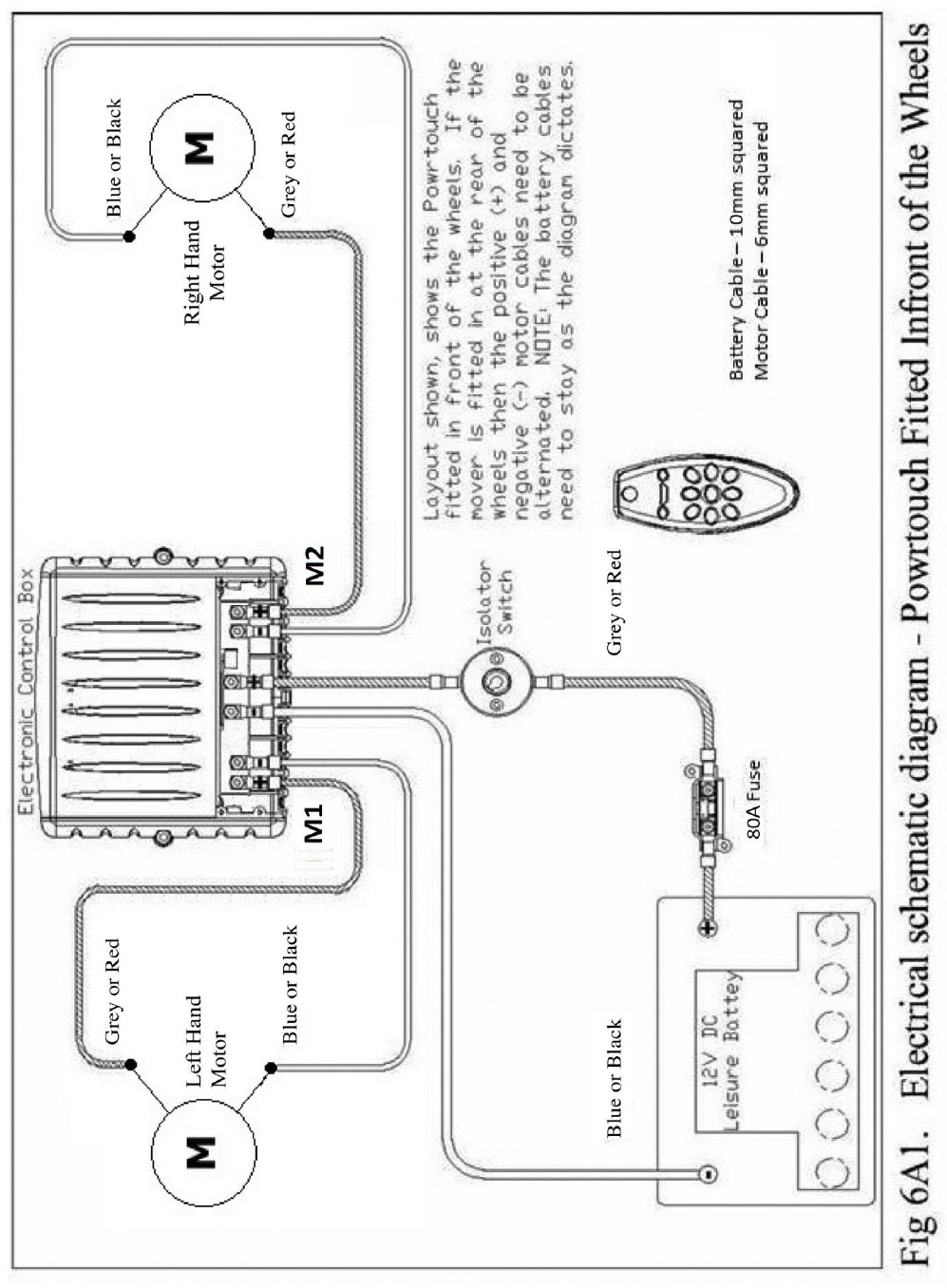
Powrtouch is fitted in front of the wheels, then the ECB should be wired as shown below IN Fig
6A1.
Should the Powrtouch Classic be fitted behind the wheels then the motor wires for Motor 1
(LH) should be wired to M2 and the motor wires for Motor 2 (RH) should be wired to M1. The
polarity of M1 & M2 should be reversed from the positions shown in Fig 6A1.
~ 17 ~
~ 18 ~

~ 19 ~
Any excess motor cable should then be coiled up (secure with cable ties as necessary) in a
convenient position inside the caravan/trailer When coiling the motor cables please ensure that
the coils are kept as far away from the electronics box and aerial as possible. It is
recommended that motor cables should NOT be cut to ensure that: -
1) They are of equal length.
2) Should the Powrtouch Classic be removed and refitted to a new or different caravan
then the cables can easily be reused.
Please ensure the battery is in good condition (See Section 5 Paragraph 5.4), a fully charged
leisure battery MUST be used and can be either a lead acid or gel type (Please note that car
batteries are not suitable to operate Powrtouch Movers.) An 85-Ampere hour battery is
recommended for optimum operation of the Powrtouch Classic. Smaller batteries may be
utilised, but mover performance may be reduced. The aerial (thin black cable) should be let
through the caravan/trailer floor directly next to the ECB (drill a small 3mm hole as required)
and then run in a straight line away from the ECB and all motor cables. The aerial should be
clipped in place with the last 25mm (1 ins.) of the cable left dangling down. Under no
circumstances should the length of the aerial be changed either by cutting or extending by
splicing into it.
3.8 CONNECTING TO THE CARAVAN BATTERY
Please be aware of the need for access to the isolation switch when parking your
caravan/trailer. The switch should also be fitted to be in an accessible position whilst
the unit is in operation.
The Powrtouch is supplied with an inline switch which allows the isolation of the electrical
control box from the Battery. The suggested location for the fitting of this switch is in the sealed
side compartment within the battery box (see NOTE below), usually beneath the 240volt
mains connector. The reason for this location is to ensure that the Powrtouch isolation key will
obstruct the use of the 240-volt AC mains connector; under no circumstances should the
Powrtouch be operated while the caravan is connected to the 240volt AC supply. Drill a 25mm
hole with the hole-saw and the two 5mm clearance holes for the fixing nuts and bolts, when the
holes are drilled install the switch and tighten up the nuts and bolts.
The electronics control box & isolation switch & inline fuse MUST NOT be located in the
battery box or any compartments containing gas bottles. This is due to risk of explosion
caused by leaking gas and a spark generated by the electronics, isolation switch or
fuse.
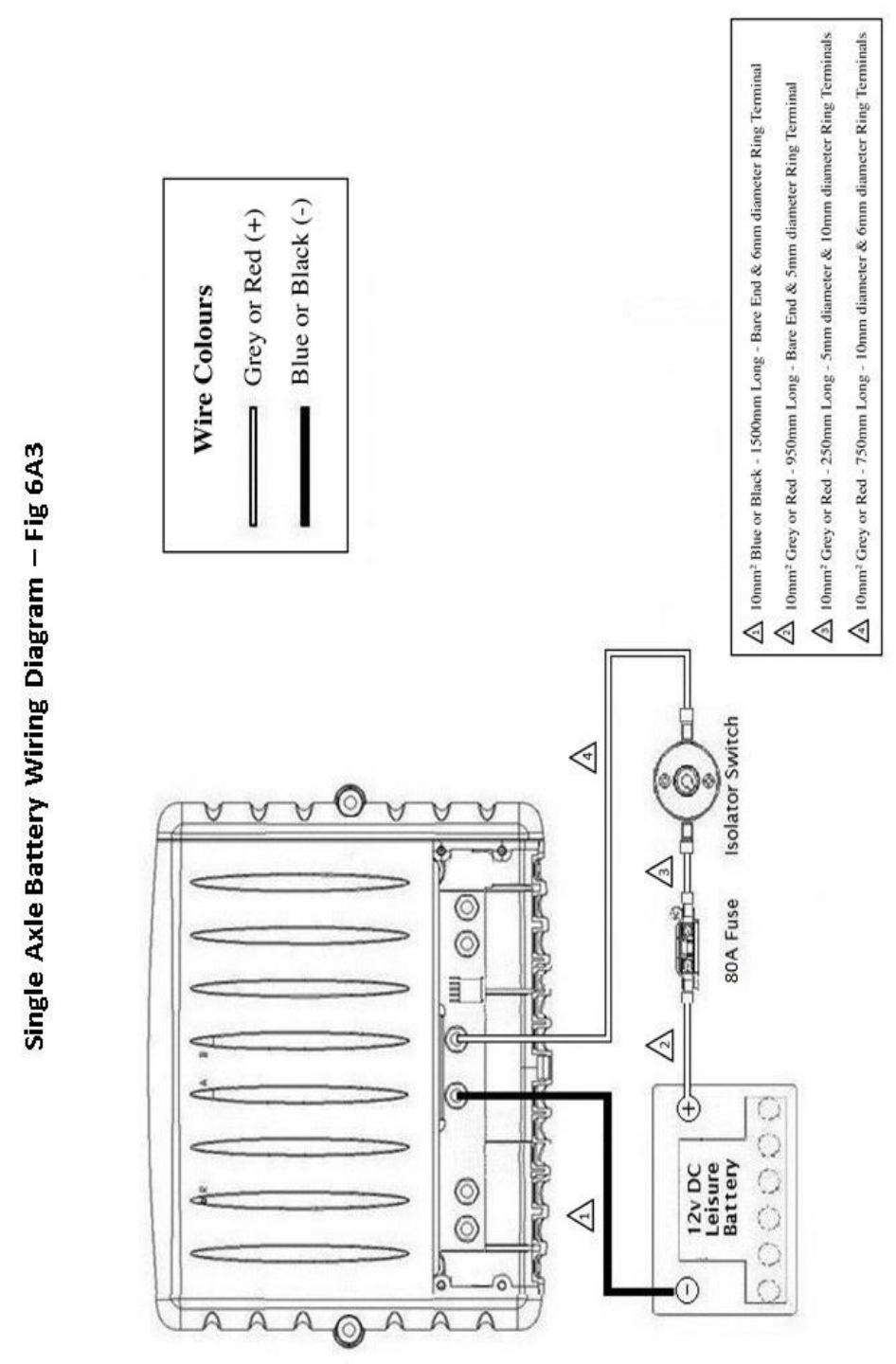
The 10mm
2
battery cables are provided correctly terminated for their application and the length
of these cables must not be altered in any way. The battery cables have to pass through 10mm
dia. drilled holes in the battery box to gain access to the caravan.
(Cable 1) The negative battery cable, 1500mm Blue (Bare end – M6 ring terminal) is
connected directly from the negative terminal of the caravan battery to the negative terminal of
the ECB. NB. Starting from the non-terminated (bare end) this part of the cable must be
connected to the battery.
(Cable 2) The positive battery cable, 1000mm Brown (Bare end – M5 ring terminal) is used
to connect the positive terminal of the battery to one terminal of the inline fuse positioned in the
caravan. This fuse is provided to protect the ECB from overload or misuse. NB. Starting from
the non-terminated (bare end) this part of the cable must be connected to the battery.
(Cable 3) The 250mm Brown cable (M5 ring terminal – M8 ring terminal) connects the free
terminal of the inline fuse to a terminal of the isolation switch.
(Cable 4) The 750mm Brown cable (M8 ring terminal – M6 ring terminal) then connects the
second terminal of the isolation switch to the positive connection on the ECB. Once connected
these cables will then need to be securely fitted using the ‘P’ clips provided.
~ 20 ~
When making the connections to the battery it is recommended that connections are
made to the electronics and isolator switch before connecting to the battery. Please
ensure that their polarities are correct (Brown Cables to Positive and Blue Cables to
Negative). Should they be connected incorrectly then this will result in damage to the
electronics box.
All remaining cables can then be connected to the ECB ensuring that they are fitted in
accordance with Fig 6A1. The electrical assembly is now complete. Check the roller rotation
corresponds to the handset controls. Any hole(s) drilled for motor wires to access the caravan
should now be sealed with the silicon sealant to prevent ingress of damp or water. The
Powrtouch Classic side covers can now be fitted by securely pushing into place.
Fitting the Side Covers
1) Push the cover into position and then lock in place by turning the securing bolt clockwise.
2) Place the arrowed indicator over the hex shaft and push into position ensuring the arrow is
pointing to the ‘0’ position.
If you are unsure about the installation consult a Qualified Powrtouch Engineer
Telephone: 01283 587900

~ 21 ~
SECTION 4 – LOOKING AFTER YOUR POWRTOUCH
4.1 CLEANING THE POWRTOUCH CLASSIC
It is recommended that after your Powrtouch Classic has been fitted the mechanical assembly
would benefit from being sprayed with a light coating of wax oil (this could be repeated on an
annual basis) by doing this you will be giving the mover better protection from water and rust
and potentially prolonging its life well beyond its full 5-year guarantee. If necessary, it can be
washed with clean water but under no circumstance should a pressure washer be used on a
Powrtouch Classic system. We recommend that your Powrtouch is cleaned, and lubricated
with a motorcycle chain lubricant, or similar, once every 5 – 6 months. Please refer to our
website support pages for instructions.
4.2 CLEANING THE ROLLERS
Ensure that the rollers are kept clean; this can be undertaken by washing with a hard brush.
For safety reasons it is recommended that the isolation switch is turned off and the key
removed prior to cleaning the rollers.
Also check that no stones or other debris are trapped in any part of the mechanism.
SECTION 5 – GUARANTEE & FAULT FINDING
5.1 GUARANTEE
A NEW Powrtouch Classic is covered by a FIVE YEAR no quibble parts and labour guarantee.
(DIY fitting is a parts only 5 year guarantee.)
NB. IT IS AT THE COMPANY’S DISCRETION WHETHER THIS GUARANTEE IS
TRANSFERABLE TO A SECOND OWNER, AND A CHARGE WILL BE MADE FOR ANY
AGREED TRANSFER. PLEASE CONTACT POWRTOUCH SALES TEAM FOR FURTHER
INFORMATION.
NB. Our guarantee covers reasonable use of the mover, it does NOT cover damage caused by
misuse. The guarantee cannot cover any malfunction caused by the fitting of the mover if the
fitting has been done on a DIY basis or purchased from/fitted by a non-approved dealer or
agent. Any unauthorised modifications, use of non-original Powrtouch spare parts or failure to
respect the installation or operating instructions will render this guarantee null and void.
Powrtouch reserve the right to make a call out and/or repair charge for any work required to
be undertaken to rectify faults that are outside of the company’s control,
e.g. caravan battery failure, incorrect or poor fitting, misuse, accidental damage etc.
5.2 REPORTING A FAULT
ALWAYS ENSURE THAT YOUR BATTERY IS FULLY CHARGED AND IF YOU ARE IN
DOUBT ABOUT BATTERY STATUS USING THE BATTERY GAUGE ON YOUR CARAVAN
CHECK WITH THE VOLTAGE CHART SECTION 5 PARAGRAPH 5.4.
PLEASE PAY SPECIAL ATTENTION TO TESTING THE BATTERY UNDER LOAD.
TO CARRY OUT THESE CHECKS THE CARAVAN MUST BE DISCONNECTED FROM ITS
240 VOLT SUPPLY.

~ 22 ~
Before you call Powrtouch to report a fault you should have the serial number of your
Powrtouch available, as you will be asked for this information. It allows a Powrtouch Engineer
to locate the full manufacturing status of the mover and be able to advise you accordingly.
Also, before reporting a fault you are requested to check through the fault-finding list Section 5
Paragraph 5.5 to see if any of them can solve the problem. Failure to comply to this may result
in you be asked to carry out some of these tests, thus delaying action to repair if required.
5.3 ELECTRONICS CONTROL BOX - LED STATUS
LED Status Array in Use
Red
Light
Green
Light
Power Up Normal
OFF
ON
Incoming Data Transmission
ON
OFF
Awaiting Configuration
FLASH
FLASH
Alternating
LED Status Array - Fault
Diagnosis
PCB Over Heat
FLASH
Low Caravan Battery Voltage
FLASH
Over Current on MOSFET Drive
FLASH
FLASH
Together
5.4 CHECKING THE CHARGE STATUS OF A 12 VOLT BATTERY
APPROX CHARGE
STATE
VOLTMETER READING
(No Load)
HYDROMETER READING
100%
12.7 v or over
1.27
75%
12.5 v
1.23
50%
12.4 v
1.20
25%
12.2 v
1.17
Discharged
12.0 v
1.10
Please Note: Voltage readings should be taken at least 4 hours (and could be up to 12 hours
depending upon charging rates) after recharging to obtain an accurate reading.
The above figures are for the battery when under no load, if a battery is on the point of failing
or not fully charged then the only test that will determine this is to take the readings under
load (drop test). This can be achieved by using the Powrtouch mover with the rollers
engaged to the tyres and driving both rollers forwards or backwards, if the reading drops to
12 volts or less the safety cut out on the ECB will stop the Powrtouch to prevent damage to
the battery. However, this is an indication of insufficient battery voltage to drive the
Powrtouch caused by an under charged or failing battery.
PLEASE BEAR SAFETY IN MIND AND THAT BEING IN THE CARAVAN WATCHING THE
METER YOU DO NOT DAMAGE THE CARAVAN BY RUNNING INTO AN OBSTRUCTION.
The above voltages are accurate at 25 degrees centigrade. In temperatures less than this the
battery performance and output decreases by 1.25% per degree.

~ 23 ~
5.5 FAULT FINDING CHART
ADDITIONAL INFORMATION TO NOTE
1. To the best of our knowledge these instructions were accurate at the date of publication.
2. Wherever the Powrtouch Classic is fitted this should be done in accordance with the local
standards applicable to the installation of a remote-controlled caravan moving system.
Truma Limited
Powrtouch – a Truma brand
2000 Park Lane, Dove Valley Park, Foston, South Derbyshire, DE65 5BG United Kingdom
TELEPHONE: +44 (0)1283 587900 FAX: +44 (0)1283 587910
WEBSITE: www.powrtouch.com EMAIL: in[email protected]
TWITTER: www.twitter.com/powrtouchuk
Symptom of Fault
Possible Fault and Method of Correction
Unit fails to operate
Reset the ECB by turning off the isolation switch
and removing the key for at least 20 seconds and
then turning on again. The green light on the ECB
should be illuminated.
Unit fails to operate –
seems completely dead –
Red Light flashing on ECB
Over heating - remove isolation key and leave 20
minutes to see if the thermal fuse will reset itself,
RED LIGHT WILL STOP FLASHING and the ECB
should not feel hot.
Unit fails to operate –
seems completely dead
Check that the green light is illuminated on the
electronics if not check that the in-line fuse is not
broken and 12volts DC is getting to the ECB.
Unit fails to operate or
operates intermittently
Check the battery voltage of the handset is
correct at 9.5 volts. If the 2 rows of Red LED’s
flash, then this is a sign the handset battery is low
Unit fails to operate or
moves intermittently
Badly connected or corroded battery terminals,
check battery terminals are clean and connected
as required.
Unit fails to operate or
moves intermittently –
Green light flashing on ECB
Caravan battery low - check voltage of battery
(see battery voltages chart Section 5 Paragraph
5.4). Charge or renew caravan battery.
Caravan fails to move or
moves intermittently
Caravan battery low - with the rollers engaged
move the caravan and check the voltage drop on
the caravan battery meter. If this drops below 12
volts, it is advisable to have the battery tested by
an accredited supplier, then as necessary charge
or renew caravan battery.
Rollers slip on wheels
Disengage rollers from the tyres and the gap
should be 20mm approx. Also check the tyre
treads are not badly worn and the tyre pressures
are correct.
IF IN DOUBT CONSULT A POWRTOUCH ENGINEER - TEL: 01283 587900
