
Rearview Mirror
Back-Up Camera
Model No.: PKC0RG
Owner’s Manual
and Warranty Information
DC 12V
M
Read these instructions completely before using this product.
Retain this Owner’s Manual for future reference.
FEATURES
3.5 in. LCD color monitor displays view from the rear of the vehicle•
Adjustable camera angle•
Camera activates automatically when the vehicle is shifted into reverse•
Weatherproof camera with 120° viewing angle•
Reduces the danger of harm or damage due to overseen objects•
Objects visible 3 feet and beyond•
6
6b
7
1
5
6c
6d
6e
6a
9
3
4
2
8
DC 12V
M
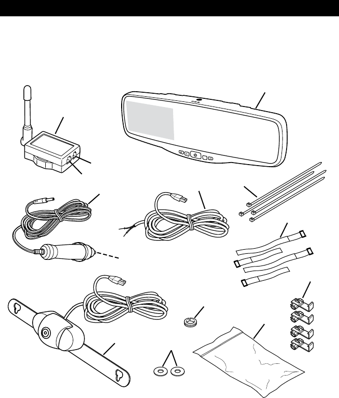
Legend
Transmitter1.
Transmitter Power Port2.
Camera Port3.
Mirror/Display Monitor4.
Transmitter Power Cord5.
Hardware Bag6.
6a) Ties
6b) Hook and Loop Straps
6c) Wire Connectors
6d) Plastic Grommet
6e) Washers
Camera7.
1A Fuse8.
Cigarette Lighter/Accessory Socket Power Cord9.
INSTALLATION
Some states or local governments may have regulations or laws that restrict the
use of anything that might impair the clear view of a license plate. Check local laws for
compliance.
For the Back-Up Camera to be properly installed, it must be wired into the vehicle’s
taillight harness. If you are not comfortable or knowledgeable with 12-volt DC wiring, have the
system professionally installed.
These instructions are only meant as a general guide due to the number of
dierent makes and models of vehicles. For vehicle-specic questions, contact your vehicle’s
manufacturer.
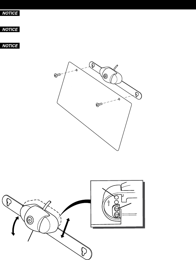
Remove the screws that hold the license plate to the vehicle.1.
Position the camera mounting plate behind the license plate.2.
Insert the screws through the license plate and the camera mounting plate. If your hardware is not 3.
the correct length, use the supplied hardware.
UP
1
2
3
Legend
Camera1.
Screw Holes2.
Camera Adjusting Screws3.
Adjust the camera as required:4.
• Toadjustthecameraangle,tiltthecameratoanyofthefivepositions.
• To adjust the camera height, remove the camera adjusting screws, move the camera to line up
with the desired holes and install the camera adjusting screws. Make sure the arrows on the
back of the camera are pointing upward.
Install the license plate screws to secure the camera to the vehicle.5.
Determinewhicharethepositive(+)andnegative(-)wiresforthereverselightsonthevehicle.6.
Youcanuseeithertheright-orleft-sidereverselightwires.Forhelplocatingthevehicle’sreverse
lightcircuit,contactyourvehicle’smanufacturerforvehicle-specicwiringdiagrams.
Removethevehicle’snegative(-)batterycable.7.
Oncetheproperwiresforthereverselightshavebeendetermined,thetransmitterwiresmust8.
besplicedintothevehiclewiresusingthesuppliedwireconnectors.Ifyouchoosetowire
thetransmitterusingadifferentmethod,youmustbeknowledgeablein12-voltDCelectrical
practices.
+
2
3
7
6
8
4
3
5
1
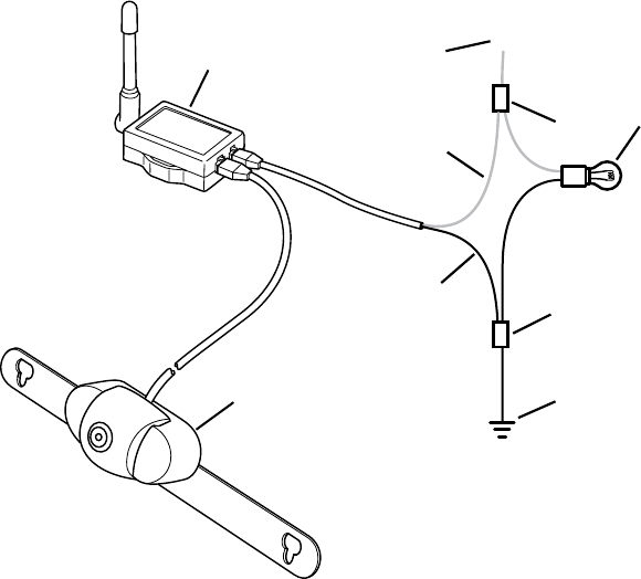
Legend
Transmitter1.
Positive (+) Wire from Reverse Light2.
Wire Connector3.
Reverse Light4.
Negative (-) Wire from Reverse Light5.
Negative (-) Transmitter Power Wire (Black)6.
Positive (+) Transmitter Power Wire (Red)7.
Camera8.
Theredpositive(+)wirefromthetransmittersplicesintothepositive(+)wirefromthereverse9.
lightsandtheblacknegative(-)wirefromthetransmittersplicesintothenegative(-)wirefrom
thereverselights.
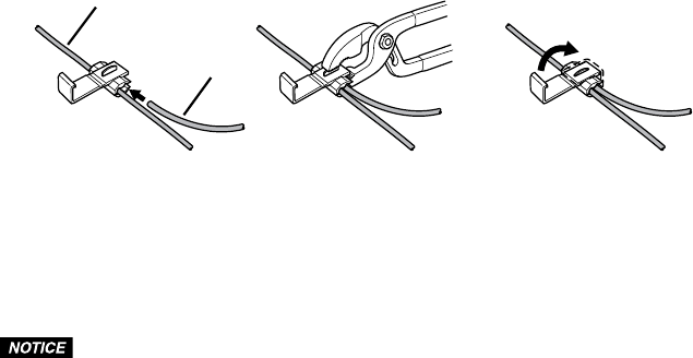
Positiontheconnectoraroundthevehiclewireyouaresplicinginto.10.
Slidetheappropriatewirefromthetransmitterintotheconnector.11.
2
1
Legend
WirefromVehicle1.
WirefromTransmitter2.
Crimpthemetalclampusingaplierstoensureagoodconnectionandthenclosethelockofthe12.
wireconnector.Dothisforboththepositive(+)andnegative(-)wiresfromthereverselight.
Mountthetransmitterinanareawherethewirefromthecameracanbepluggedintoit.13.
Reconnectthevehicle’snegative(-)batterycable.14.
Plugthetransmitterpowercordplugintothetransmitterpowerport.15.
Depending on your vehicle type, it may be necessary to drill a hole to route the
camera wire. Before you drill a hole you MUST CHECK WHAT IS BEHIND THE DRILLING
LOCATION. If there are any vehicle components, like electrical parts or fuel system
components, behind the drilling location, you must take precaution not to damage them.
Routethewirefromthecameratothetransmitter.Somevehiclesmayhaveaholetoroutethe16.
camerawirethrough;forexample,theholeforthewiresforthelicenseplatelight.
Ifyouneedtodrillahole,useahalfinch(1/2"[13mm])drilltodrillthehole.Installtheplastic17.
grommetinthehole.Youmustusethegrommettopreventtheedgeoftheholefromdamaging
thecamerawire.
Insertthecamerawirethroughthegrommetandrouteittothetransmitter.18.
Plugthecamerawireplugintothetransmittercameraportandsecurethewirewithwiretiesif19.
needed.
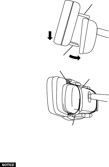
1
2
4
3
5
Legend
Spring-LoadedUpperBracket1.
LowerBracket2.
StrapMountingSlot3.
UpperStrap4.
LowerStrap 5.
Make sure you have the correct sides of the hook and loop straps facing each other
before installing them into the strap mounting slot. Once installed in the slot they are very
difficult to remove.
Installtheupperandlowerstrapsintothemountingslotsonthebackofthemirror,makingsure20.
youhavethecorrectsidesofthestrapsfacingeachother.
Placetheupperspring-loadedbracketontopofthemirror.21.
Whilesupportingtheexistingrearviewmirror,pushdownandslidethelowerbracketunderthe22.
mirror.
23. Usingthestraps,securethemirrortotheexistingrearviewmirror.
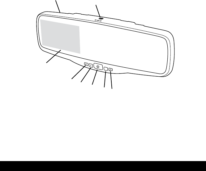
Legend
RearviewMirror1.
12-voltDCPowerInputPort2.
ParkingGuidelineON/OFFButton3.
MenuButton4.
PowerButton5.
Minus(-)Button6.
Plus(+)Button7.
LCDBack-UpCameraDisplay 8.
Route and secure all wires as needed.24.
OPERATION
Testing the Back-Up Camera System
Plugthe12-voltDCpowerplugintotheportonthetopofthemirror.1.
Plugthe12-voltDCpoweradapterintoacigarettelighter/accessorysocket.Routethewiresso2.
theywillnotobstructyourvisionwhendriving.
Pressthepowerbutton.Theicononthebuttonwillbeilluminatedwhenpowerison.3.
Withtheparkbrakeapplied,turnthevehicleignitionswitchtotheONposition.Donotstartthe4.
vehicle.
Shiftthevehicletoreversetopowerthetransmitter.Theimagefromthecamerashoulddisplay5.
ontheBack-UpCamerascreenonthemirror.
Iftheimagedoesnotdisplay,checkyourconnectionsandmakesurethecameraviewisnot6.
obstructed.
Adjust Display Settings
Pressthemenubuttontoenterthemenuscreen.1.
Continuepressingthemenubuttontoselectbrightness,contrastorcoloroftheLCD.2.
Usetheplus(+)orminus(-)buttontoincreaseordecreasethescreenvalues.3.
Toexitthemenuscreen,scrolltoexitandpresseithertheplus(+)orminus(-)button.4.
Todisplaytheparkingguidelines,presstheparkingguidelineON/OFFbutton.Thiswillshow5.
parkingguidelinesonthedisplay.
PressingtheparkingguidelineON/OFFbuttonagainwillremovetheguidelines.6.
1
8
2
7
6
5
4
3
DC 12V
M

CARE AND MAINTENANCE
Storage
StorethisBack-UpCamerasysteminacool,dryareaandkeepitawayfromdirectsunlight,heat,
excessivehumidityanddampness.
Cleaning
Donotcleanorwipethecameraordisplaywithsolventsorchemicalmaterials.Ifnecessary,remove
dirtorstainsusingasoftclothdampenedwithamilddetergentsolution.
Fuse Replacement
Turnthecaponthetipofthepowerplugcounterclockwise.1.
Removethecap,centerpinandfuse.2.
Replacethefusewithanew1-ampfuse.3.
Replacethecenterpinandcap.Turnthecapclockwise.4.
SPECIFICATIONS
Camera
CurrentConsumption(withTransmitter)
<160 mA
Pixels
640x480
Transmitter
Frequency 2468 MHz
RFTransmissionDistance >262ft(80m)
Display
LCDDisplayScreenSize 3.5in.(89mm)
PowerCordFuse 1A
FCC INFORMATION
Changes or modications to this equipment not expressly approved by the
party responsible for compliance could void the user’s authority to operate the equipment.
This equipment has been tested and found to comply with the limits for a Class
B digital device, pursuant to Part 15 of the FCC Rules. These limits are designed to provide
reasonable protection against harmful interference in a residential installation. This
equipment can radiate radio frequency energy and, if not installed and used in accordance
with the instructions, may cause harmful interference to radio communications. However,
there is no guarantee that interference will not occur in a particular installation. If this
equipment does cause harmful interference to radio or television reception, which can be
determined by turning the equipment o and on, the user is encouraged to try to correct the
interference by one or more of the following measures:
Reorient or relocate the transmitter.•
Increase the separation between the equipment and monitor.•
Connect the equipment into an outlet on a circuit dierent from that to which the monitor is •
needed.
Consult the dealer or an experienced radio/TV technician for help.•
ThisdevicecomplieswithPart15oftheFCCRules.Operationissubjecttothefollowingtwo
conditions:(1)thisdevicemaynotcauseharmfulinterference,and(2)thisdevicemustacceptany
interferencereceived,includinginterferencethatmaycauseundesiredoperationofdevice.The
manufacturerisnotresponsibleforanyradioorTVinterferencecausedbyunauthorizedmodications
tothisequipment.Suchmodicationscouldvoidtheuser’sauthoritytooperatethisequipment.
PEAK BACKUP CAMERAS
BACKUP CAMERA SYSTEMS
