
Technical News July 27, 2017
If you have any questions concerning this procedure, contact
Access Technologies Technical Support, at 1-800-422-6489 Option 3.
Cover Page Tech Tip: TTxxxxxx
TECH TIP
MC521 PRO CONTROLLER
SLIDE DOOR
Installation and Operation Manual
Prepared by: Jeff Bonas Engineer: Tony Ranaudo, Len Pursell Tech Tip: TT170727
CN: _________ RDW: ________ Reference Tech Tip: ________
Engineering Document Number: ________
Summary Information
Product Information
Bifold Swing Accessories Operators / Drives Sensors
Slide Class 2 Controls Panels / Hardware
Tech Tip Classification
Adjustment Customer Complaints FAQs Retrofit/Upgrade Instructions
Installation Clarifications Service Design Change Description
Release Action
Level 1 - Does not impact maintenance or operation of door. (Only Safety/Liability and Engineering need to sign.)
Level 2 - Full sign off required.
Release Information (initial and date)
Safety/Liability _________________________
Engineering _________________________
Technical Support _________________________
Field Operations _________________________
Quality _________________________

If you have any questions concerning this procedure, contact
Access Technologies Technical Support, at 1-800-422-6489 Option 3.
Page 1 of 1 Tech Tip: TT170727
MC521 PRO CONTROLLER
SLIDE DOOR
Installation and Operation Manual
Attached is the revised MC521 Pro Controller Manual:
MC521 Pro Controller Installation and Operation Manual (204066)
Rev. F, for automatic sliding doors)
Included in the revised manuals are the following:
Settings for Monitored Presence Sensors
Updated Wiring Diagrams including monitored presence sensors
Android MC521 Toolbox Troubleshooting enhancements for monitored
presence sensors
Android MC521 Toolbox Troubleshooting Output Control Mode

Stanley Part Number 204066
REV F 12.2016
Copyright 2016, Stanley Access Technologies, LLC.
Prohibition on Copying: Any unauthorized reproduction, disclosure or distribution of copies by
any person of any portion of this work may be a violation of copyright law of the United States
of America and other countries, could result in the awarding of statutory damages of up to
$250,000 (17 USC 504) for infringement, and may result in further civil and criminal penalties.
All rights reserved.
MC521 Pro Controller
Installation and Operation Manual
204066
INCLUDES INSTRUCTIONS FOR
DURA-GLIDE™ 2000/3000, 5200/5300,
DURA-GUARD™ DURA-STORM™ AND DURA-MAX™ 5400-SERIES
AUTOMATIC SLIDE DOOR SYSTEMS

GENERAL DESCRIPTION
Intended Use
This manual provides installaon instrucons, wiring instrucons, and tune-in instrucons for the MC521 Pro
Controller. It includes instrucons for Dura-Glide™ 2000/3000, 5200/5300, Dura-Guard™, Dura-Storm™, and Dura-
Max™ 5400-Series, Automac Slide door systems.
On Dura-Glide sliding doors, the MC521 Pro Controller replaces the MC521 or both the microprocessor control
box and the interface board on older models. The door acvaon devices (SU-100 moon sensors, carpets, push
plates, etc.), lock, funcon switch, doorway holding beams, and door posion switches previously connected to the
interface board must be connected to the MC521 Pro Controller.
Aachment 1 illustrates the MC521 Pro Controller controls and indicators. Aachment 2 illustrates system wiring
for Dura-Glide series sliders.
Applicability
This manual is applicable to the Dura-Glide series sliding doors used on Dura-Glide™ 2000/3000, 5200/5300,
Dura-Guard™, Dura-Storm™, and Dura-Max™ 5400-Series, Automac Slide door systems. Instrucons for
connecng oponal accessories are not provided in this manual.
Table of Contents
General Description ........................................................................................................... 2
Intended Use ............................................................................................................................................. 2
Applicability ............................................................................................................................................... 2
Prerequisites .............................................................................................................................................. 3
Precautions ................................................................................................................................................3
Installation Instructions .................................................................................................... 3
Installing the MC521 Pro Controller ............................................................................................... 3
Wiring Instructions ............................................................................................................ 3
Evaluating Power Requirements ........................................................................................................ 3
Connecting Main Power Wiring ........................................................................................................ 4
Connecting Accessories (As Applicable) ......................................................................................... 4
Tune-In Instructions ........................................................................................................... 4
Tuning In the MC521 Pro Controller Using a Handheld Device ........................................... 5
Tuning In the MC521 Pro Controller Using Pushbuttons ....................................................... 9
Final Tune-In Adjustments ................................................................................................................13
Spare Parts List ................................................................................................................. 14
Attachments ..................................................................................................................... 15
Attachment 1 - MC521 Pro Controls and Indicators ...............................................................15
Attachment 2 - MC521 Pro System Wiring Diagram .............................................................17
Attachment 3 - MC521 Pro Terminal Block Connections TB1-TB7 ...................................28
Attachment 4 - ANSI/BHMA and UL Compliance Requirements for Sliding Doors ..29
Attachment 5 - Handheld Device Troubleshooting Aid ........................................................31
Attachment 6 - Handheld Device Troubleshooting Screen Descriptions ....................... 32
Attachment 7 - MC521 Pro Troubleshooting Aid ....................................................................34
Attachment 8 - Recommended Values for Dierent/Weights Types of Slide Door ....35
Attachment 9 - Fine Tuning Slide Doors .....................................................................................36
1
Copyright 2016, Stanley Access Technologies, LLC.
All rights reserved. Reproduction
in whole or in part without the express written permission of Stanley is prohibited.
12.28.2016
2 Document # 204066 REV F • www.stanleyaccess • 1.800.7.ACCESS

MC521 PRO Control Box
12.28.2016
1.800.7.ACCESS • www.stanleyaccess.com • Document # 204066 REV F 3
Copyright 2016, Stanley Access Technologies, LLC. All rights reserved. Reproduction
in whole or in part without the express written permission of Stanley is prohibited.
Prerequisites
Special Items Required:
• Stanley Access Technologies document No. 203957, “SU-100 Moon Sensor Installaon and Operaon” (if
installed).
• SU-100 tune-in remote control (if SU-100 Moon Sensor is installed).
• Stanley Access Technologies document No. 203768, “Stanguard
TM
Threshold Sensor Installaon and Operaon”
(if installed).
• Optex X Zone T or X Zone ST manufacturer’s installaon and tune-in instrucons (if installed).
• Hotron HR100 ST manufacturer’s installaon and tune-in instrucons (if installed).
• For a list of compable handheld devices; visit: hp://www.stanleyaccess.com
Select Door Service > Technician Mobile Downloads > Android Apps. Select Compable Handheld Devices Document.
• Bluetooth adapter or cable to connect compable handheld device to MC521 Pro Controller.
• Degreaser.
• Instrucons for any other device to be wired into the MC521 Pro Controller.
Precautions
All ANSI/BHMA and UL Requirements in Attachment 4 must be met before the door is put into operation.
INSTALLATION INSTRUCTIONS
Installing the MC521 Pro Controller
NOTE: This manual covers new door installaons in which the MC521 Pro is factory-installed and wired.
WIRING INSTRUCTIONS
Evaluating Power Requirements
• ENSURE power source is a dedicated 115 VAC, 50/60 Hz source with 20A circuit rang. If four operators are
used, the source should have a 30A rang.
• ENSURE no more than four operators will be connected to one circuit.
• ENSURE power source is not shared with other equipment, i.e., cash registers, EAS systems, or other electro-
magnec interference generators.
2
3
MC521 PRO Control Box
4 Document # 204066 REV F • www.stanleyaccess.com • 1.800.7.ACCESS
Copyright 2016, Stanley Access Technologies, LLC.
All rights reserved. Reproduction
in whole or in part without the express written permission of Stanley is prohibited.
12.28.2016
Connecting Main Power Wiring
Warning: To prevent injury to personnel, incoming electrical power to the header must be deenergized before
connecng electrical service to the control box.
Warning: All electrical wiring must conform to Naonal Electrical Code Requirements.
1. DEENERGIZE incoming electrical power to header.
2. Refer to Aachment 2, and, using wire nuts, CONNECT incoming line, neutral, and ground wires
to the controller power harness.
3. IF adhesive wire clamps will be used, DEGREASE metal surfaces on inside of header cover
where clamps will mount.
4. SECURE wiring to top of the header track tube, and ENSURE the following:
• All wires are clear of belts and belt brackets.
• Header cover opens and closes without interference.
Connecting Accessories (As Applicable)
Refer to Aachments 2 and 3, and CONNECT any of the following subsystems to the MC521 Pro Controller:
• Funcon switch (rotary, rocker and “POWER” switch wiring).
• Stanguard
TM
threshold sensor.
• Doorway holding beam(s).
• Breakout switch.
• Solenoid lock.
• SU-100 moon sensor(s) wiring (refer to Stanley Document #203957).
• Optex X Zone T and X Zone ST Sensor(s) wiring.
• Push plate wiring.
• Door posion switch closed contact (with door closed).
• Hotron HR100 ST Sensor(s) wiring.
TUNE-IN INSTRUCTIONS
Warning: The door path must be free of objects and remain clear unl the First Install Sequence (FIS) is
complete. During this sequence the sensors are inacve and the door has no SAFETY. To stop the door, turn
power off or put the doors into breakout.
NOTE:
1. Tune In: The MC521 Pro Controller can be tuned-in using a handheld device or using the pushbuon
switches located on the controller. Tune-in using a handheld device is the preferred method.
2. Status Codes: During normal operaon, the digital display indicates status codes. The “UP” and “DOWN”
pushbuon switches can be used to enter and display data values. The user interface values are shown in
Tables 2 through 4.
4
MC521 PRO Control Box
12.28.2016
1.800.7.ACCESS • www.stanleyaccess.com • Document # 204066 REV F 5
Copyright 2016, Stanley Access Technologies, LLC. All rights reserved. Reproduction
in whole or in part without the express written permission of Stanley is prohibited.
3. Solenoid Lock: If a solenoid lock is installed with no lock circuit board (new style), set Lock Logic to the actual
lock type (Fail Safe or Fail Secure). If a Fail Safe or Fail Secure Lock is being installed with a lock circuit board
(old style), the Lock Logic must be set to Fail Secure.
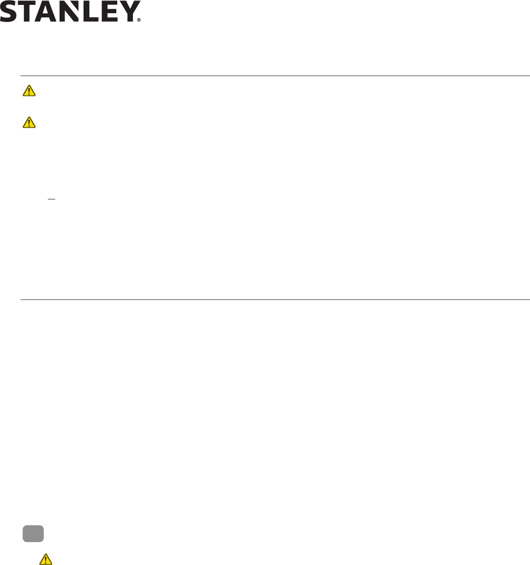
4. Handing: Manually open door nong rotaon of belt pulleys. If counter clockwise (CCW) use right hand during
FIS. If clockwise (CW) use le hand during FIS. See gure below.
5. FIS: The rst installaon sequence (FIS) is used to perform the inial conguraon. Upon compleon of FIS,
all setup parameters are stored in non-volale memory. Subsequent power cycles will reload the congura-
on parameters that were congured during FIS.
6. Decimal points on digital display are encoder 1 signals.
7. Aer changing values, the values must be saved in EEPROM by cycling the door to full open.
PULLEY ROTATES CCW
WHILE OPENING
USE RIGHT HAND IN FIS
PULLEY ROTATES CW
WHILE OPENING
USE LEFT HAND IN FIS
RIGHT HAND
LEFT HAND
HANDING
Tuning In the MC521 Pro Controller Using a Handheld Device
NOTE: The following steps provide instrucons for tuning the MC521 Pro Controller using a handheld device.
MC521 applicaon soware is required. Connect the handheld device to the MC521 Pro Controller, turn on header
POWER switch, and perform the following steps.
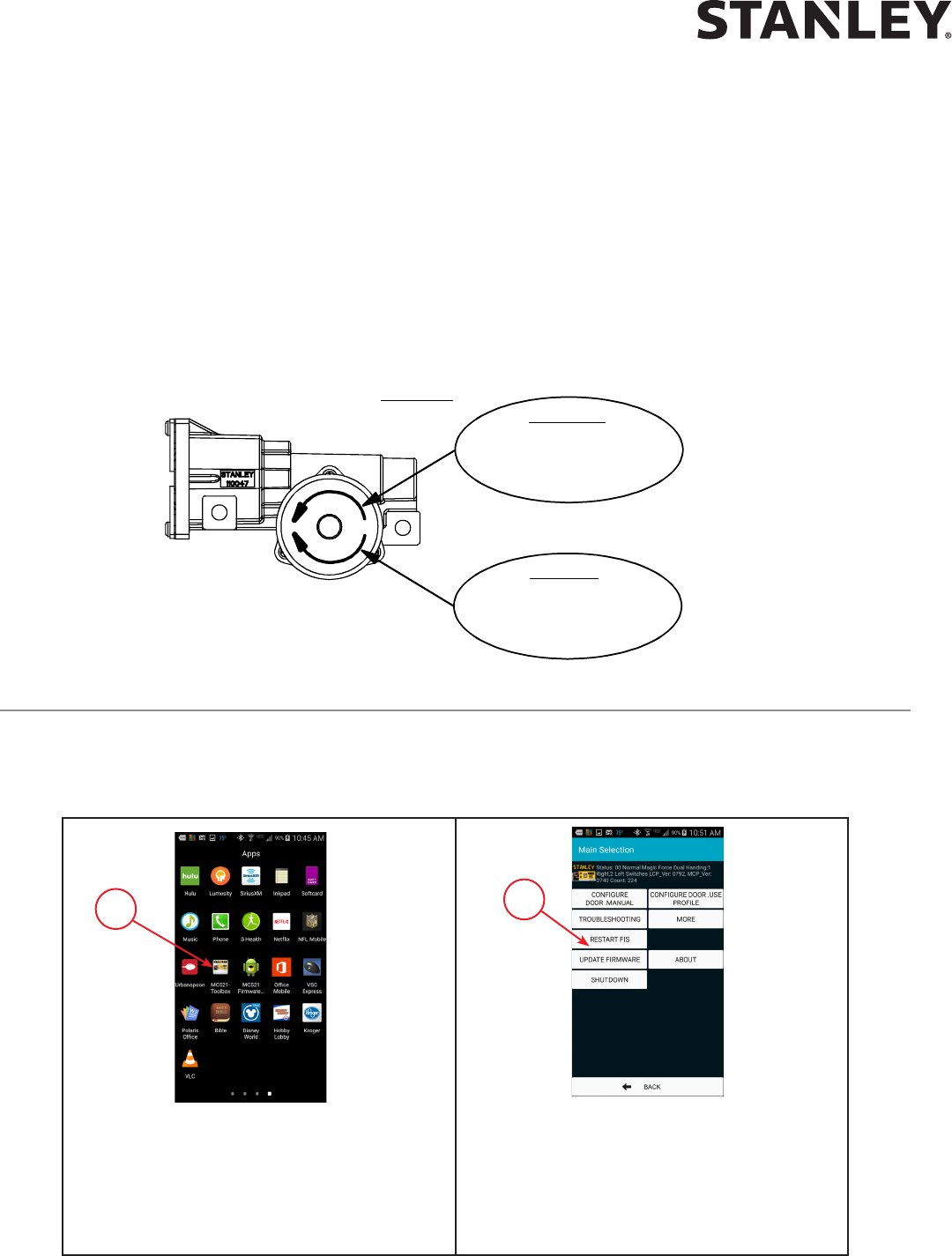
Step 1: Select MC521 Toolbox from the list
of applicaons.
Step 2: Select RESTART FIS on the Main
selecon menu. (FIS = First Install
Sequence).
NOTE: Firmware is the soware
revision. Cycles are door
cycles in memory.
1
2

MC521 PRO Control Box
6 Document # 204066 REV F • www.stanleyaccess.com • 1.800.7.ACCESS
Copyright 2016, Stanley Access Technologies, LLC.
All rights reserved. Reproduction
in whole or in part without the express written permission of Stanley is prohibited.
12.28.2016
Step 3: Select Duraglide.
Step 4: Select applicable Switch Type, Motor
Setup, and Motor Handing.
Step 5: If addional conguraon is needed,
press CONFIGURE DOOR.
Step 6: Congure addional sengs and press
UPDATE aer each seng has been
changed. Once completed, press
BACK to go back to the Main
selecon menu.
Step 7: Press BEGIN AUTOCONFIGURE.
Step 8: Press NEXT.
3
4
5
6
7
8
MC521 PRO Control Box
12.28.2016
1.800.7.ACCESS • www.stanleyaccess.com • Document # 204066 REV F 7
Copyright 2016, Stanley Access Technologies, LLC. All rights reserved. Reproduction
in whole or in part without the express written permission of Stanley is prohibited.
10
11
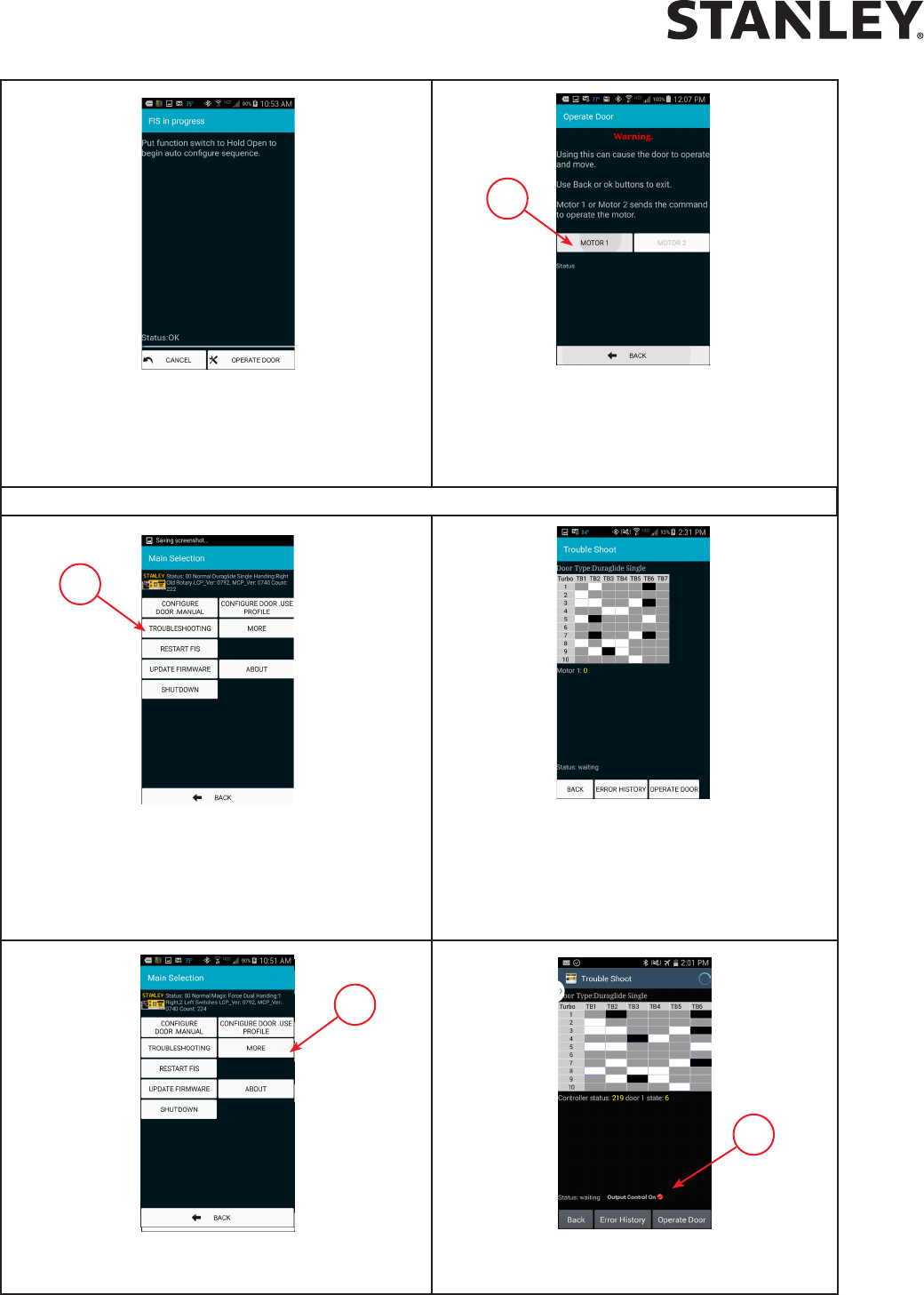
Step 9: Put door fucon switch to Hold Open
then immediately back to Closed. The
same funcon can be done remotely
from the Handheld by pressing Operate.
Step 10: For all doors except cart doors press
MOTOR 1 to operate and have door(s)
move. For cart doors, press MOTOR 2
when conguring the second door.
Step 11: If the door is not operang correctly
select TROUBLESHOOTING to enter the
Troubleshoong menu.
Step 12: View the I/O grid to verify the sensors
and inputs. Dark indicates input/
output contact is closed. Light
indicates input/output contact is
open. Gray never changes.
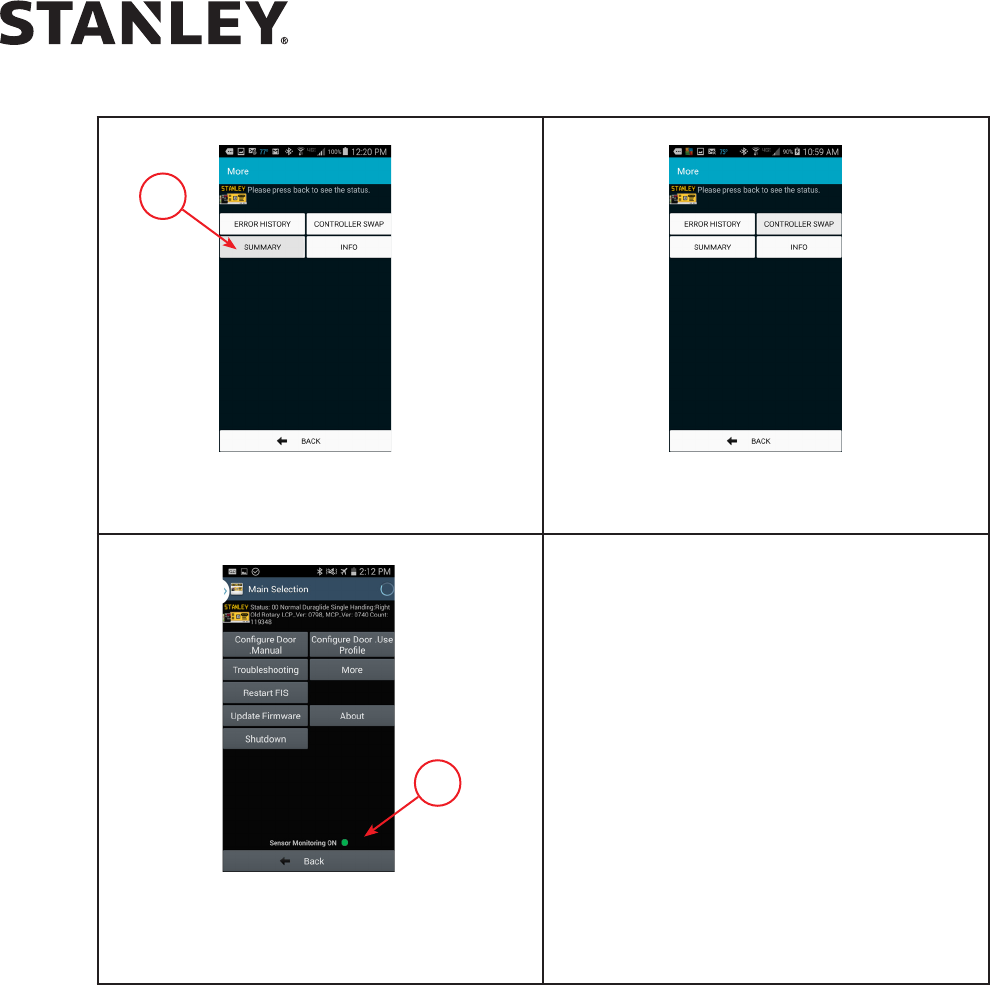
Step 13: Press MORE to access more funcons.
Step 14: Output Control On displayed. See
Aachment 6 for more informaon.
13
14
**After performing Step 9 or 10, the door opens fully, delays and then closes fully. The MC521 Pro displays 00 when FIS is completed.**
MC521 PRO Control Box
8 Document # 204066 REV F • www.stanleyaccess.com • 1.800.7.ACCESS
Copyright 2016, Stanley Access Technologies, LLC.
All rights reserved. Reproduction
in whole or in part without the express written permission of Stanley is prohibited.
12.28.2016
15
Step 17: Sensor Monitoring On displayed
when congured for monitored
sensors.
Step 15: Press Summary lto view all
current sengs.
Step 16: Review the informaon on the
Summary lisng.
17

MC521 PRO Control Box
12.28.2016
1.800.7.ACCESS • www.stanleyaccess.com • Document # 204066 REV F 9
Copyright 2016, Stanley Access Technologies, LLC. All rights reserved. Reproduction
in whole or in part without the express written permission of Stanley is prohibited.
Tuning In the MC521 Pro Controller Using the Controller Pushbuttons
NOTE:
1. To change the INDEX:
Hold ENTER switch while pressing UP or DOWN to get to desired INDEX.
2. To change a VALUE:
Unlock the keypad by seng index 99 to value 00.
Aer the desired INDEX is selected, release ENTER and within 2.5 seconds press UP or DOWN to get the
desired VALUE. (If the UP or DOWN buons are not pressed within 2.5 seconds of releasing the ENTER buon,
the display will change from the VALUE back to the STATUS.)
3. To display STATUS CODE:
A few seconds aer the VALUE is selected, the display indicates the STATUS CODE.
4. To show the INDEX and VALUE.
To show the INDEX, hold ENTER. Once ENTER is released the display will show the VALUE of that INDEX.
5. Read the descripons enrely before performing each step. Check the INDEX and VALUE aer each step.
6. To STORE CHANGES in permanent memory:
Cycling door open one me will store changes.
7. To LOCK keypad:
Lock keypad by seng index 99 to value 01 or by turning power OFF and then ON.
8. To ACCESS the door cycle counter funcon:
a. Ensure that the keypad is locked by seng index 99 to 01.
b. Ensure that the index is set to any index but 99.
c. Press the up or down key to access the door cycle counter.
The display will show “dc” followed by four pairs of digits, followed by “dc”.
Example: If the Door count was 12345678 cycles the controller will display “dc” “12” “34” “56” “78” “dc”.
MC521 PRO Control Box
10 Document # 204066 REV F • www.stanleyaccess.com • 1.800.7.ACCESS
Copyright 2016, Stanley Access Technologies, LLC.
All rights reserved. Reproduction
in whole or in part without the express written permission of Stanley is prohibited.
12.28.2016
Table 1. FIS Procedure using Pushbuttons
Step Description Display
Index Value Status Code
1 Set Funcon switch to Closed.
2 Turn power on.
3 Unlock keypad. 99 00 00
4 Restart FIS. 96 01 A0
5 Select door type: Slide, 01 single motor or 02 dual motor. 00 01 (single)
02 (dual)
6 Select handing: 00 Right or 01 Le.
Manually open door and note rotation of belt pulleys.
If counterclockwise (CCW) use right hand during FIS.
If clockwise (CW) use left hand during FIS.
01
00 (right)
01 (le)
A0
7 Accept FIS. Display will go to A1. 03 01 A1
8 Make changes: Funcon switch
01 Rocker or 00 Rotary. The INDEX will start at 00.
11 01 (Rocker)
00 (Rotary)
A1
9 Select Lock Logic: Lock Logic, 00 = Fail Safe; 01 = Fail Secure.
NOTE: For locks with circuit board, set to 01 Fail Secure. For
locks with no circuit board, set to Fail Safe or Fail Secure.
07
00 (Fail Safe)
01 (Fail Secure)
10
Warnning: During this sequence the sensors are inactive and the
door has NO SAFETY. To stop the door, TURN POWER OFF or PUT
THE DOOR INTO BREAKOUT.
Function Switch: Switch to OPEN, momentarily, then CLOSED/
LOCKED. The door opens fully, delays and then closes
fully. The MC521 Pro displays A2 when FIS is completed.
A2
11 Lock keypad. 99 01 00
12 Final Tune in.
Table 2. Index List
Index Description
00-89 Sengs Values, see Table 3.
90-95 Reserved.
96 Command – Restart FIS. Entering “01” will cause FIS to restart.
97 Firmware – Entering “01” will display “FE” followed by two pairs of digits followed by “FE”. For example,
if the rmware was 0609 the controller will display “FE” “06” “09” “FE”.
98 Command – Restart auto conguraon. Entering “01” will cause auto conguraon.
99 Command – Lock. Entering “01” will lock all value inputs except this index. This prevents inadvertent
changes to input values. Values may be unlocked by entering “00” in this index.
Index 98 sets the Control Box to “A1” keeping all previous values and then relearns the encoder count.

MC521 PRO Control Box
12.28.2016
1.800.7.ACCESS • www.stanleyaccess.com • Document # 204066 REV F 11
Copyright 2016, Stanley Access Technologies, LLC. All rights reserved. Reproduction
in whole or in part without the express written permission of Stanley is prohibited.
Table 3. Settings
Index Min.
Value
Max
Value
Description Defaults
Single Dual
00 05 35 Open speed, increment by 1. 25 25
01 05 18 Close speed, revoluons per second. 12 12
02 03 10 Check speed, revoluons per second. 04 04
03 10 99 Open check length. 35 35
04 10 99 Close check length. 30 30
05 00 99 Reduced open posion, percent of full opening (00=full open, 99=full close). 01 01
06 01 99 Hold open delay (0 to 25 sec.). 06 06
07 00 03
Lock Logic, 00 = Fail Safe, 01 = Fail Secure, 02 = Dura-Max Fail Safe,
03 = Dura-Max Fail Secure.
NOTE: For locks with circuit board, set to 01 Fail Secure. For locks
with no circuit board, set to Fail Safe or Fail Secure.
01 01
08 05 75 Open torque, percent of full scale. 25 40
09 00 75 Close torque, percent of full scale. 25 15
10 00 75 Check torque, percent of full scale. 25 10
11 00 01 Dura-Glide funcon switch type: 00=double pole rotary, 01=rocker. 01 01
12 00 01 2S Operaon, 0=o, 1=on. 00 00
13 01 60 Obstrucon Time Delay (.01 – 1.5 sec). 20 40
14 20 60 Open Acceleraon, (larger value=faster acceleraon). 60 60
15 20 60 Open Braking, (larger value=increased braking).
20=No open braking.
54 54
16 20 60 Close Acceleraon, (larger value=faster acceleraon). 20 20
17 20 60 Close Braking, (larger value=increased braking).
20=No close braking.
40 40
18 00 02 00 = O (Delay Egress), 01 = 15 sec. delay, 02 = 30 sec. delay. 00 00
19* 00 05
00 - Monitored 2 Sensors - Threshold Zone Control (The threshold
zone is enabled and disabled by the MC521 Pro).
01 - Monitored 4 Sensors - Threshold Zone Control (The threshold
zone is enabled and disabled by the MC521 Pro).
02 - Monitored StanGuard™(not recommended for
Telescopic Doors).
03 - Monitored 2 Sensors.
04 - Non-Monitored Sensors.
05 - Monitored 4 Sensors.
02 02
20 00 01
00 - Non-Monitored Optex OS-12C.
01 - Photo Beam Pro and Monitored Optex OS-12C T.
01 01
21* 01 50 Lock Delay (0.1 – 5.0 sec). 01 01
Continued on following page.
NOTE: Door must be cycled open for changes to be stored in permanent memory.
* Not currently available on Palm.

MC521 PRO Control Box
12 Document # 204066 REV F • www.stanleyaccess.com • 1.800.7.ACCESS
Copyright 2016, Stanley Access Technologies, LLC.
All rights reserved. Reproduction
in whole or in part without the express written permission of Stanley is prohibited.
12.28.2016
Table 3. Settings (continued)
22 00 64 Open Stop.
Distance (1/8” increments) from full open the door will stop.
06 06
24 00 01 Access Control Pro.
00 = o, 01 = on.
00 00
25 00 03 Press Time, 00 = least amount, 03 = most amount of pressing.
Aer obstrucon meout, the number of seconds the door presses
at Full Closed.
00 00
28 00 20 Open Check Boost. Transion speed from braking to check. 02 02
29 00 20 Close Check Boost. Transion speed from braking to check. 02 02
Status Code Description Remediation IF Necessary
00 Normal operaon—All OK
0b Obstrucon
20 Breakout
33 System error See aachment 7
34 Internal Communicaon Error – Type 1 See aachment 7
35 Motor Drive Failure Replace Controller
36 Internal Communicaon Error – Type 2 See aachment 7
A0 First installaon sequence (FIS)
A1 Auto-conguraon sequence
A2 Auto-conguraon conrmaon sequence
b1 Encoder error
Ld Lock Down (Shear Lock Energized)
db Output Control See Aachment 6, Sheet 2 of 2
dc Display door cycle counter
dE Delayed Egress
dL Shear Lock De-Energized
E1 Upper hold beam sensor error Verify sensor wiring and safety logic seng
E3 Door length error Re-do rst installaon sequence (FIS)
F0 Inside Monitored sensor failure Verify sensor wiring and safety logic seng
F1 Outside Monitored sensor failure Verify sensor wiring and safety logic seng
F2 Upper Photo Beam Pro sensor failure Check transmier, receiver, and hold beam type
F3 Lower Photo Beam Pro sensor failure Check transmier, receiver, and hold beam type
ho Door held open Check sensors and hold beam type
Table 4. Status Codes

MC521 PRO Control Box
12.28.2016
1.800.7.ACCESS • www.stanleyaccess.com • Document # 204066 REV F 13
Copyright 2016, Stanley Access Technologies, LLC. All rights reserved. Reproduction
in whole or in part without the express written permission of Stanley is prohibited.
Table 5. Door States
Door State Description
00 Door State is Closed
02 Door State is Opening
03 Open Braking
04 Door State is in Open Check
06 Door State is Full Open
07 Door State is Closing
09 Door State is in Close Check
15 Door State is in Open Stop
16 Door State is in Recycle or Obstrucon While Closing
17 Door State is in Close Press
NOTE: If the current status code is “Normal operaon—All OK”, the MC521 Pro will show the current door state.
Otherwise, the MC521 Pro alternates between showing the current status code and the door state.
Final Tune-In Adjustments
1. Refer to ANSI A156.10, “American Naonal Standard for Power Operated Doors,” and aachment 4 and
DETERMINE ANSI and UL door operang requirements.
2. IF Stanguard
TM
threshold sensor is installed, refer to Stanley Access Technologies document No. 203768,
“Stanguard
TM
Threshold Sensor Installaon and Operaon,” and TUNE-IN Stanguard
TM
threshold sensor.
Ensure that the JP200 Jumper is properly installed for StanGuard
TM
Sensors.
3. IF SU-100 moon sensor(s) are installed, refer to Stanley Access Technologies document No. 203957,
“SU-100 Moon Sensor Installaon and Operaon,” and TUNE-IN SU-100 moon sensor(s).
4. IF Optex X Zone T or X Zone ST Sensors are installed, refer to the manufacturer’s installaon and tune-in instrucons.
5. To ensure that all sengs have been stored in EEPROM memory, turn power OFF and then back ON.
Repeat step 1 above.
6. If Hotron HR100 ST Sensors are installed, refer to the manufacturer’s installaon and tune-in instrucons.
7. Verify that the correct Safety Logic has been selected for Sensor Monitoring and that the JP200 is in the
correct posion.
8. DO NOT remove JP200 when Stanguard™ is installed. X Zone T, X Zone ST and HR100 ST monitored sensors
require JP200 to be removed.

MC521 PRO Control Box
14 Document # 204066 REV F • www.stanleyaccess.com • 1.800.7.ACCESS
Copyright 2016, Stanley Access Technologies, LLC.
All rights reserved. Reproduction
in whole or in part without the express written permission of Stanley is prohibited.
12.28.2016
Table 6. Spare Parts List
Description Part Number
MC521 Pro Controller, includes 4 terminal blocks 314117
MC521 Pro Controller Manual 204066
Harness, Rocker Switch to Control Box, 98 inches 414098
Harness, Rocker Switch to Control Box, 180 inches 414099
Harness, Holding Beam to Control Box, 24 inches 414106
Harness, Rotary Switch to Control Box, 180 inches 414107-1
Harness, Rotary Switch to Control Box, 480 inches 414107-2
Harness, Power, 18 inches 415000
Harness, Encoder Cable Adapter, 12 inches 415001
Harness, Solenoid Lock, 67 inches (See Note) 516922-1
Harness, Solenoid Lock, 124 inches (See Note) 516922-2
Harness, Solenoid Lock Pigtail 516921
Power Supply 24VDC 516871
Terminal Block Plug, 10 position 714055
Bluetooth Adapter Kit
314215
For a list of compatible handheld devices; vist :
http://www.stanleyaccess.com
Select Door Service > Technician Mobile Downloads > Android Apps.
Select Compatible Handheld Devices Document.
Compatible Handheld Device
For a list of compatible handheld devices; vist :
http://www.stanleyaccess.com
Select Door Service > Technician Mobile Downloads > Android Apps.
Select Compatible Handheld Devices Document.
Harness, motor, 14 feet 413362
Harness, motor, 17 feet 413362-1
Harness, line connect, 6 feet 412544
Harness, line connect, 10 feet 412545
Harness, Rocker Switch to Control Box, 252 inches 414126
Harness, Solenoid Lock Power Signal, 264 inches 516823-4
Harness Motor Extension, 42 inches 411746
Counter, External Accessory 413787
MC521 Comm Extension Retro Kit, 6 feet 313995
MC521 Comm Extension Retro Kit, 40 feet 313996
Harness, Encoder Extension 40 inches 415079
NOTE: When replacing a solenoid lock harness, solenoid lock pigtail harness 516921 is required for solenoid locks that do not have a pigtail.
MC521 PRO Control Box
12.28.2016
1.800.7.ACCESS • www.stanleyaccess.com • Document # 204066 REV F 15
Copyright 2016, Stanley Access Technologies, LLC. All rights reserved. Reproduction
in whole or in part without the express written permission of Stanley is prohibited.
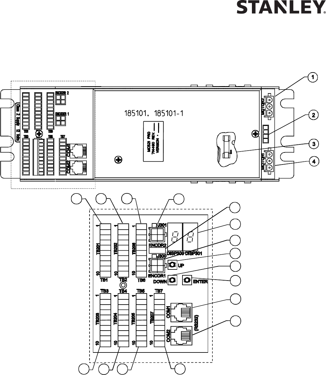
Attachment 1
MC521 Pro Controls and Indicators
(Sheet 1 of 2)
NOTE: See next page for indicators and descriptions
DETAILA
9
10
11
12
13
14
15
16
5
6
8
7
17
18
19
SEEDETAILA
JP200
20

MC521 PRO Control Box
16 Document # 204066 REV F • www.stanleyaccess.com • 1.800.7.ACCESS
Copyright 2016, Stanley Access Technologies, LLC.
All rights reserved. Reproduction
in whole or in part without the express written permission of Stanley is prohibited.
12.28.2016
Attachment 1
MC521 Pro Controls and Indicators
(Sheet 2 of 2)
ITEM CONTROL/INDICATOR DESCRIPTION
1 Motor 2 Connector P402 Motor No. 2 connector.
2 Power Connector J500
Connecon point for incoming line, neutral, and common
power wiring.
3 Fuse F500 Controller fuse-- 5 Amp, 250V
4 Motor 1 Connector P401 Motor No. 1 connector.
5 Terminal Block Connector TB1 Connecon point for solenoid lock control.
6 Terminal Block Connector TB2 Connecon point for funcon switch (rotary or rocker).
7 Terminal Block Connector TB6
Includes spare I/O and AUX DC supply. Do not populate TB6 unl
further noce.
8 Encoder 2 Connector J301 Not used.
9 Two Digit Display
Displays Controller Status. Also serves as the display for tune-in
by pushbuon switches and indicates encoder movement.
10 Encoder 1 Connector J300 Connecon point for motor encoder No. 1.
11 Up Pushbuon Switch SW300
Used for manual setup and tuning of door when PDA is
not available.
12 Down Pushbuon Switch SW301
Used for manual setup and tuning of door when PDA is
not available.
13 Enter Pushbuon Switch SW302
Used for manual setup and tuning of door when PDA is
not available.
14 COM1 Jack RS232 COM1 connector. Connecon point for PDA harness.
15 COM2 Jack RS232 COM2 connector. Not used.
16 Terminal Block Connector TB7
Includes RS485 and AUX DC supply. Do not populate TB7 unl
further noce.
17 Terminal Block Connector TB5
Connecon point for side-screen sensor and closed-posion
switch.
18 Terminal Block Connector TB4
Connecon point for inside sensor, outside sensor and
push plate.
19 Terminal Block Connector TB3
Connecon point for Stanguard
TM
, doorway holding beam, and
breakout switch. Using jumper wires across TB3 terminals 1 to
5 and 2 to 6, internal transformer supplies power to mulple
external sensors.
20 Jumper JP200
Jumper needs to be installed for all Stanguard
TM
installaons.
Jumper needs to be removed for X Zone T, X Zone ST,
HR100 C T and some other Monitored Sensors.
MC521 PRO Control Box
12.28.2016
1.800.7.ACCESS • www.stanleyaccess.com • Document # 204066 REV F 17
Copyright 2016, Stanley Access Technologies, LLC. All rights reserved. Reproduction
in whole or in part without the express written permission of Stanley is prohibited.
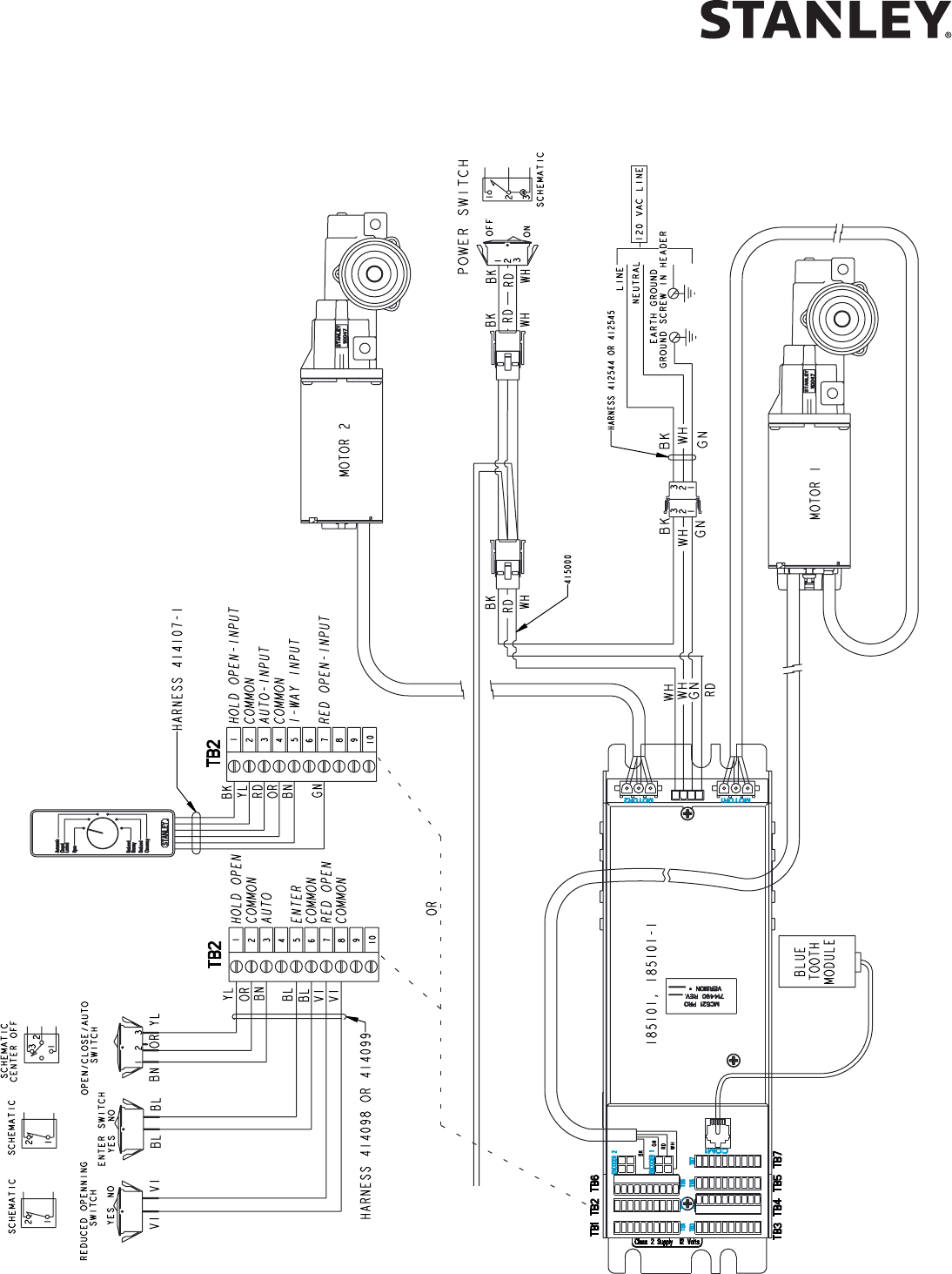
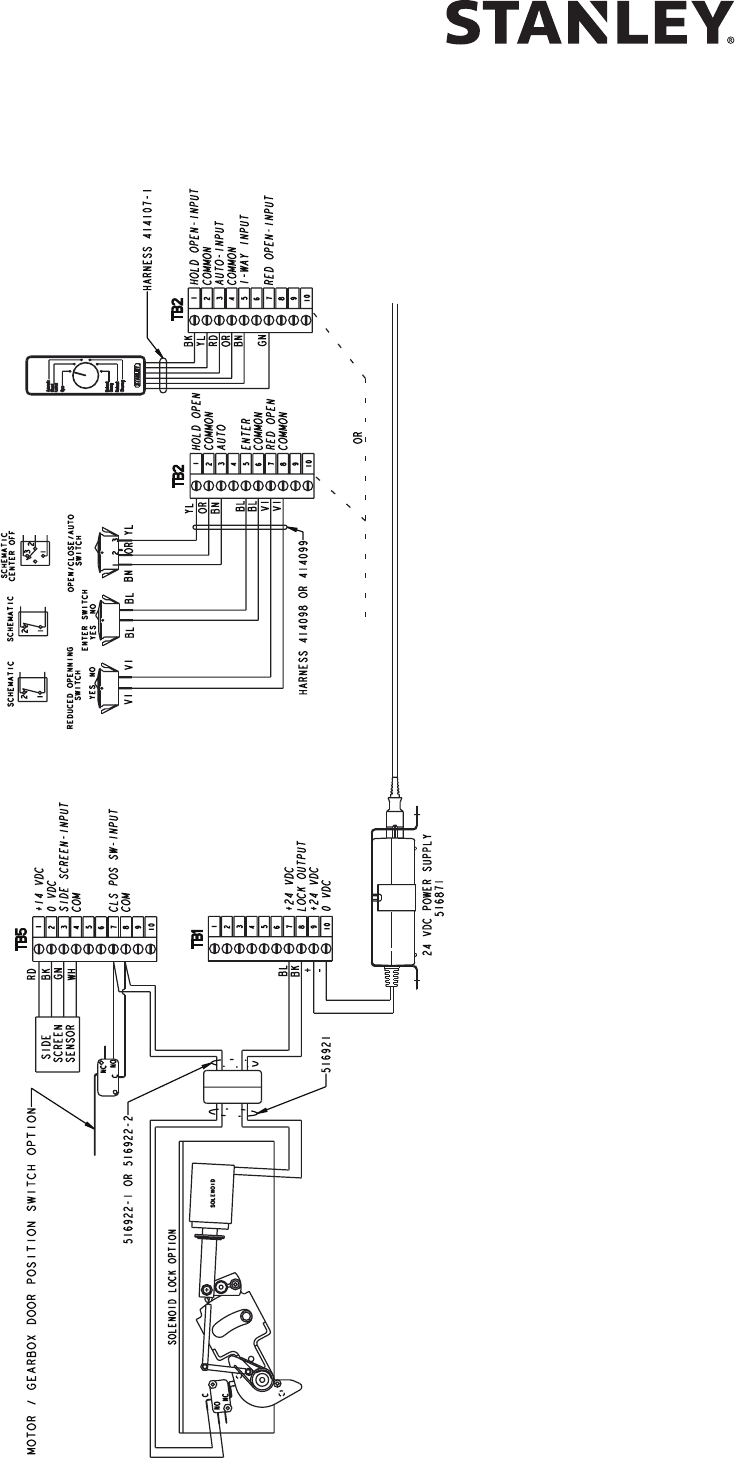
Attachment 2
MC521 Pro System Wiring Diagram
(Sheet 1 of 10)
T0 SHEET 3
MC521 PRO Control Box
18 Document # 204066 REV F • www.stanleyaccess.com • 1.800.7.ACCESS
Copyright 2016, Stanley Access Technologies, LLC.
All rights reserved. Reproduction
in whole or in part without the express written permission of Stanley is prohibited.
12.28.2016
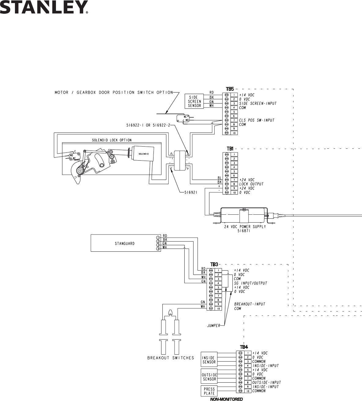
Attachment 2
MC521 Pro System Wiring Diagram
(Sheet 2 of 10)
MC521 PRO Control Box
12.28.2016
1.800.7.ACCESS • www.stanleyaccess.com • Document # 204066 REV F 19
Copyright 2016, Stanley Access Technologies, LLC. All rights reserved. Reproduction
in whole or in part without the express written permission of Stanley is prohibited.
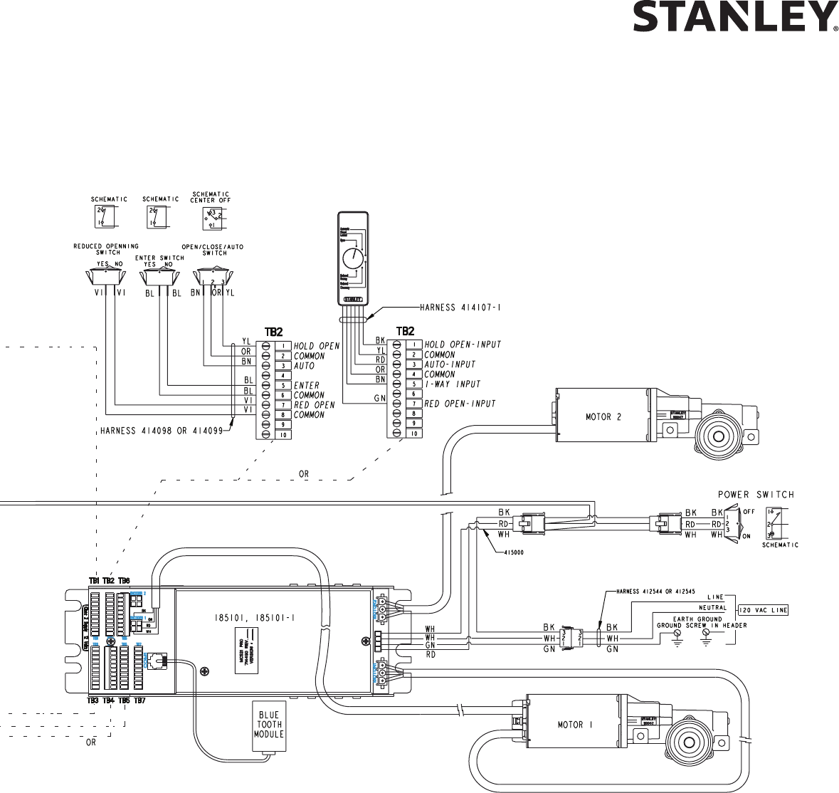
Attachment 2
MC521 Pro System Wiring Diagram
(Sheet 3 of 10)
T0 SHEET 1
MC521 PRO Control Box
20 Document # 204066 REV F • www.stanleyaccess.com • 1.800.7.ACCESS
Copyright 2016, Stanley Access Technologies, LLC.
All rights reserved. Reproduction
in whole or in part without the express written permission of Stanley is prohibited.
12.28.2016
Attachment 2
MC521 Pro System Wiring Diagram
(Sheet 4 of 10)
MC521 PRO Control Box
12.28.2016
1.800.7.ACCESS • www.stanleyaccess.com • Document # 204066 REV F 21
Copyright 2016, Stanley Access Technologies, LLC. All rights reserved. Reproduction
in whole or in part without the express written permission of Stanley is prohibited.
Attachment 2
MC521 Pro System Wiring Diagram
(Sheet 4 of 10, continued)
MC521 PRO Control Box
22 Document # 204066 REV F • www.stanleyaccess.com • 1.800.7.ACCESS
Copyright 2016, Stanley Access Technologies, LLC.
All rights reserved. Reproduction
in whole or in part without the express written permission of Stanley is prohibited.
12.28.2016
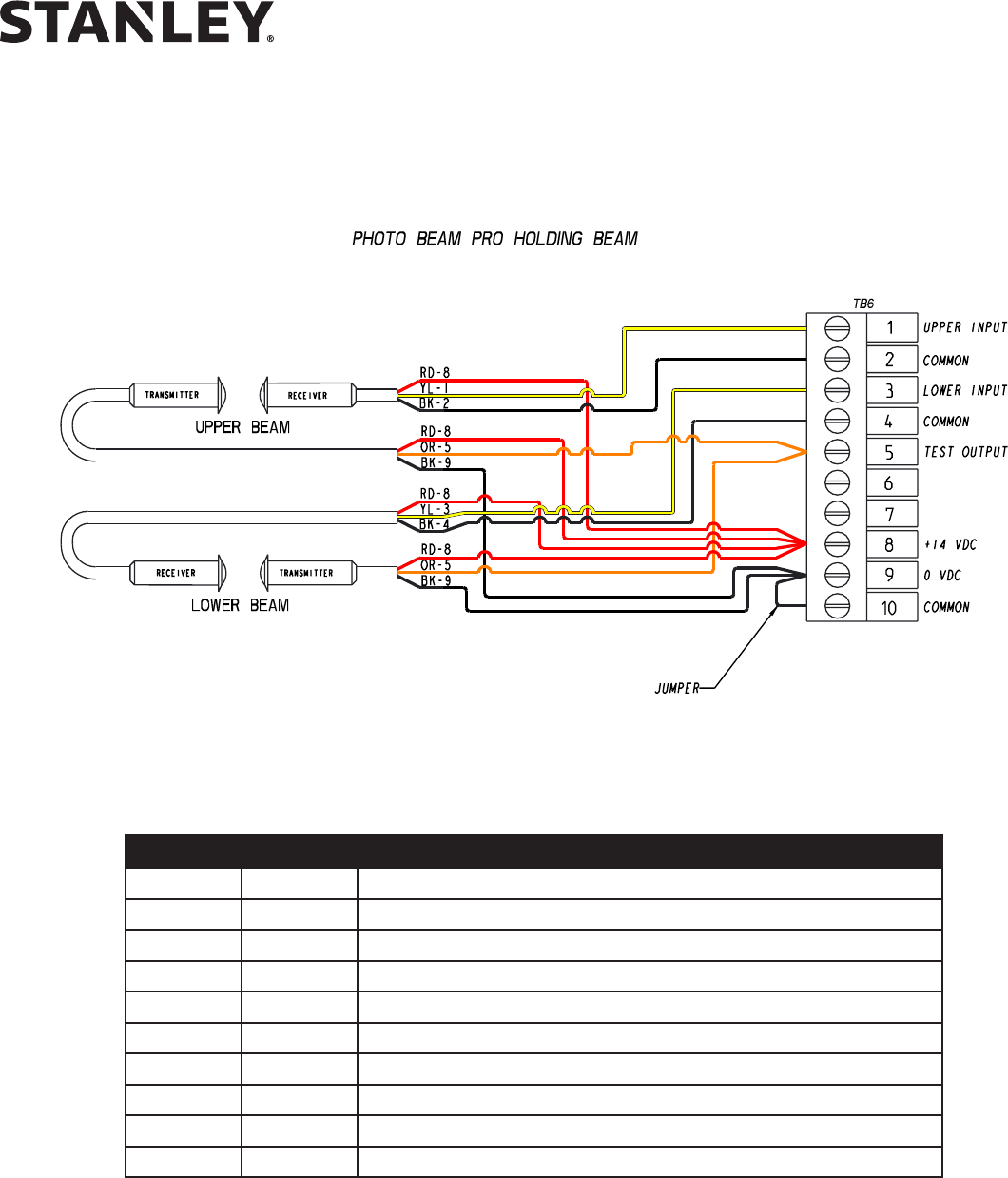
Attachment 2
MC521 Pro System Wiring Diagram
(Sheet 5 of 10)
TB6 COLOR DUAL HOLDING BEAM WIRING
1 YL OUTPUT UPPER RECEIVER
2 BK (-) UPPER RECEIVER
3 YL OUTPUT LOWER RECEIVER
4 BK (-) LOWER RECEIVER
5 OR TRANSMITTER CONTROL LOWER AND UPPER
6 -- NO CONNECTION
7 -- NO CONNECTION
8 RD (+) ALL RECEIVERS AND TRANSMITTERS
9 BK (-) LOWER AND UPPER TRANSMITTERS, JUMPER TO TB6-10
10 BK JUMPER FROM TB6-9
MC521 PRO Control Box
12.28.2016
1.800.7.ACCESS • www.stanleyaccess.com • Document # 204066 REV F 23
Copyright 2016, Stanley Access Technologies, LLC. All rights reserved. Reproduction
in whole or in part without the express written permission of Stanley is prohibited.
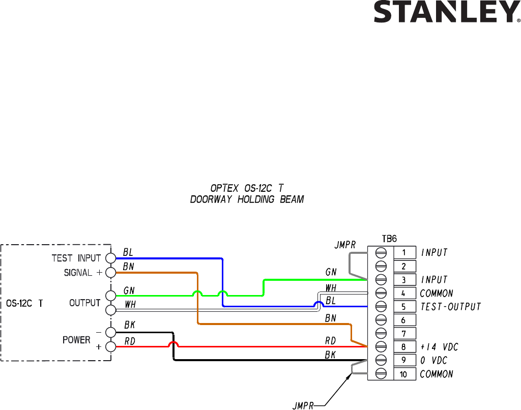
Attachment 2
MC521 Pro System Wiring Diagram
(Sheet 6 of 10))
Program the OS-12 CT set to “D” - Acve High / N.C.
On the MC521 Pro set Index 20 to Value 01 (Hold Beam Pro).
MC521 PRO Control Box
24 Document # 204066 REV F • www.stanleyaccess.com • 1.800.7.ACCESS
Copyright 2016, Stanley Access Technologies, LLC.
All rights reserved. Reproduction
in whole or in part without the express written permission of Stanley is prohibited.
12.28.2016
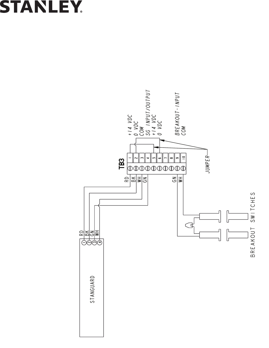
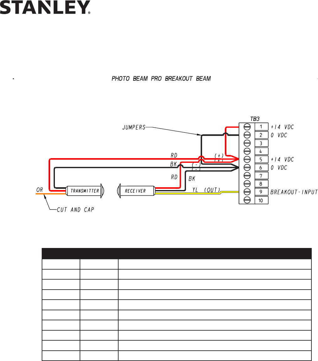
Attachment 2
MC521 Pro System Wiring Diagram
(Sheet 7 of 10)
TB3 COLOR PHOTO BEAM PRO BREAKOUT BEAM
1 RD JUMPER FROM TB3-5
2 BK JUMPER FROM TB3-6
3 -- NO CONNECTION
4 -- NO CONNECTION
5 RD JUMPER FROM TB3-1, (+) RECEIVER AND TRANSMITTER
6 BK JUMPER FROM TB3-2, (-) RECIEVER AND TRANSMITTERS\
7 -- NO CONNECTION
8 -- NO CONNECTION
9 YL OUTPUT RECEIVER
10 -- NO CONNECTION
MC521 PRO Control Box
12.28.2016
1.800.7.ACCESS • www.stanleyaccess.com • Document # 204066 REV F 25
Copyright 2016, Stanley Access Technologies, LLC. All rights reserved. Reproduction
in whole or in part without the express written permission of Stanley is prohibited.
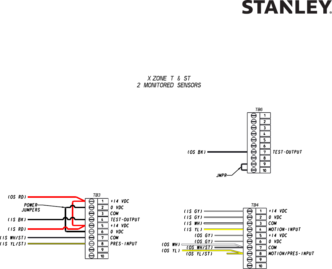
Attachment 2
MC521 Pro System Wiring Diagram
(Sheet 8 of 10)
X Zone ST
Key DIP Switch sengs: 10 and 11 DOWN; 12, 14 and 15 UP.
MC521 Pro
Remove JP200.
Set index 19 to Value = 00 (Sensor Monitoring with Threshold Control).
X Zone T
Key DIP Switch sengs: 11 and 12 DOWN; 13 and 15 UP.
MC521 Pro
Remove JP200.
Set index 19 to Value = 03 (Sensor Monitoring).
MC521 PRO Control Box
26 Document # 204066 REV F • www.stanleyaccess.com • 1.800.7.ACCESS
Copyright 2016, Stanley Access Technologies, LLC.
All rights reserved. Reproduction
in whole or in part without the express written permission of Stanley is prohibited.
12.28.2016
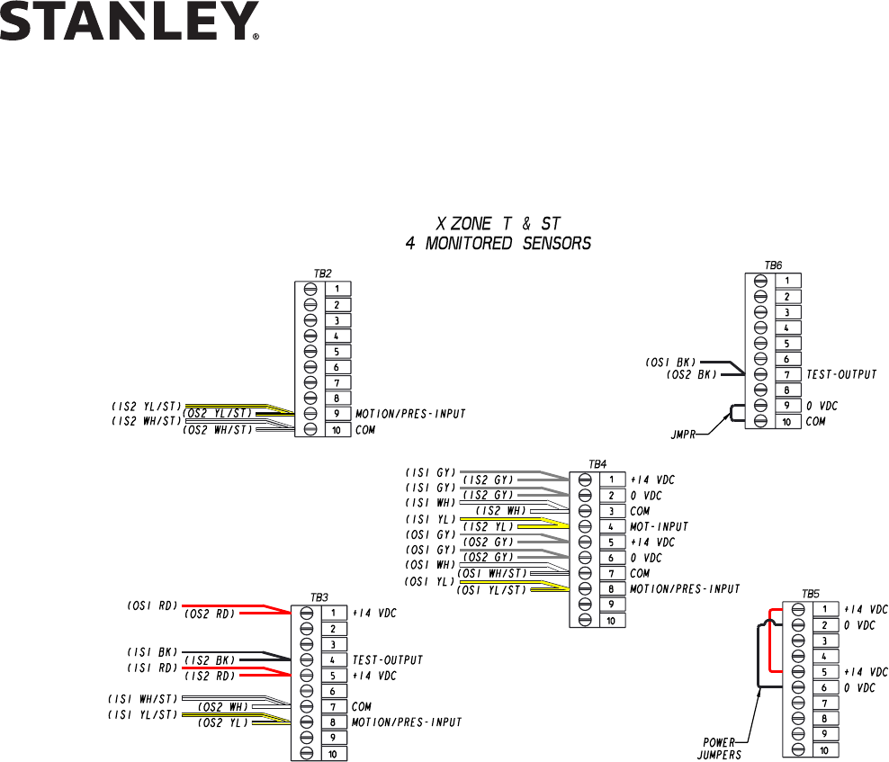
Attachment 2
MC521 Pro System Wiring Diagram
(Sheet 9 of 10)
X Zone ST
Key DIP Switch sengs: 10 and 11 DOWN; 12, 14 and 15 UP.
MC521 Pro
Remove JP200.
Set index 19 to Value = 01 (Monitored 4 Sensors - Threshold Zone Control).
X Zone T
Key DIP Switch sengs: 11 and 12 DOWN; 13 UP and 15 UP.
MC521 Pro
Remove JP200.
Set index 19 to Value = 05 (Monitored 4 Sensors).
MC521 PRO Control Box
12.28.2016
1.800.7.ACCESS • www.stanleyaccess.com • Document # 204066 REV F 27
Copyright 2016, Stanley Access Technologies, LLC. All rights reserved. Reproduction
in whole or in part without the express written permission of Stanley is prohibited.
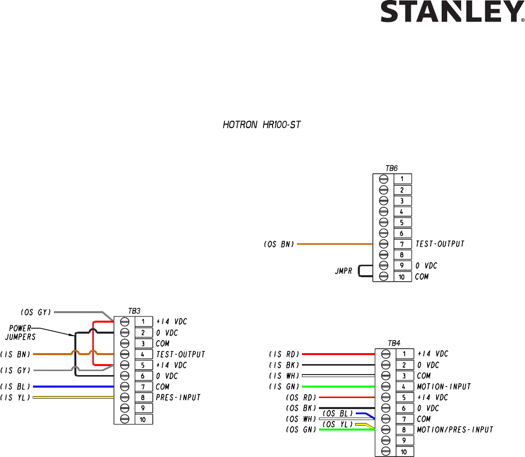
Attachment 2
MC521 Pro System Wiring Diagram
(Sheet 10 of 10)
HR100 ST
Recommended DIP Switch sengs:
DIP Switch X: (2, 3, 4, 5, 6, 7 and 8 = UP) (1=DOWN).
DIP Switch Y: (1, 2, and 4 = UP) (5 and 6 = DOWN).
{UP = OFF} {DOWN = ON}
MC521 Pro Sengs
Remove JP200.
Set index 19 to Value = 03 (Sensor Monitoring).
MC521 PRO Control Box
28 Document # 204066 REV F • www.stanleyaccess.com • 1.800.7.ACCESS
Copyright 2016, Stanley Access Technologies, LLC.
All rights reserved. Reproduction
in whole or in part without the express written permission of Stanley is prohibited.
12.28.2016
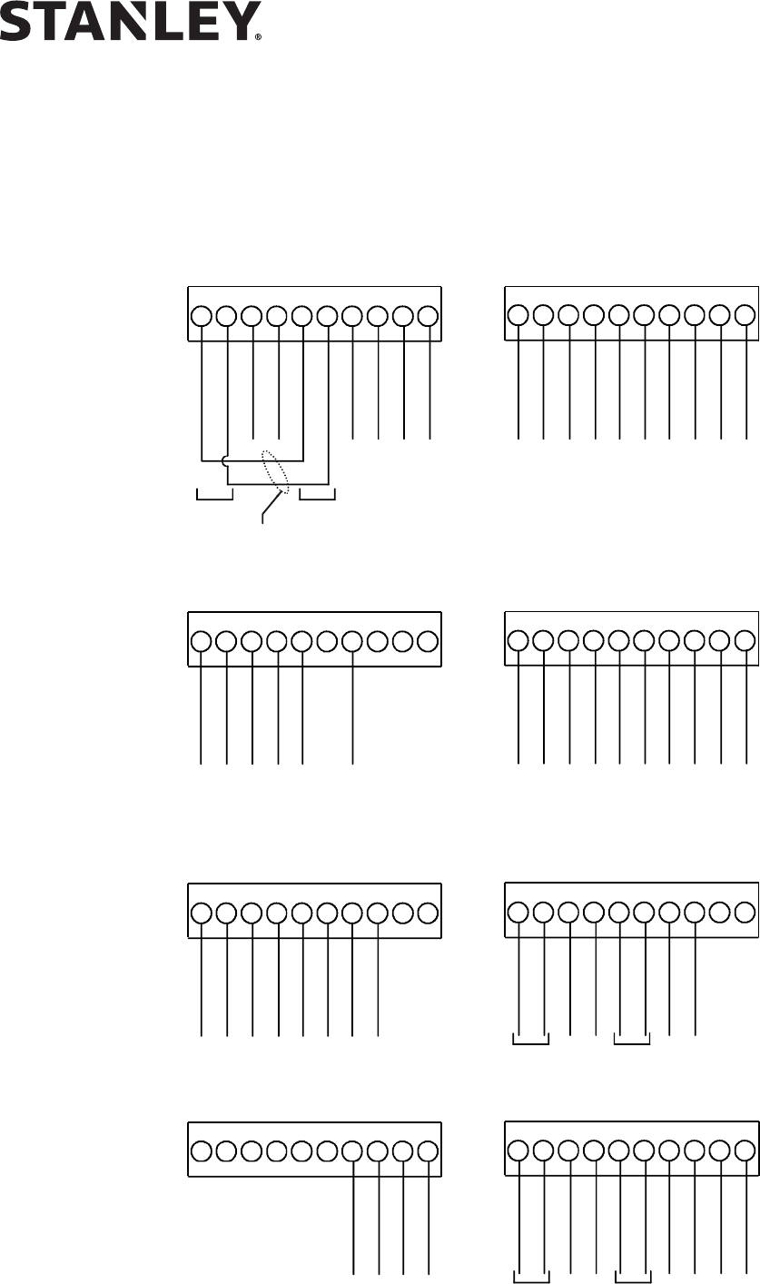
Attachment 3
MC521 Pro Terminal Block Connections -- TB1 through TB7
(Sheet 1 of 1)
NOTES
1. REMOVE IF EXTERNAL POWERSUPPLYISUSED.
2. TB6HAS SPAREI/O ANDAUX DC SUPPLY.
3. TB7HAS RS485AND AUXDCSUPPLY.
1
2
3
4
5
6
7
8
9
10
1
2
3
4
5
6
7
8
9
10
1
2
3
4
5
6
7
8
9
10
1
2
3
4
5
6
7
8
9
10
1
2
3
4
5
6
7
8
9
10
1
2
3
4
5
6
7
8
9
10
1
2
3
4
5
6
7
8
9
10
1
2
3
4
5
6
7
8
9
10
TB1
TB2
(ROCKERSWITCHWIRING)
TB2
(ROTARYSWITCHWIRING)
TB3
TB4TB5
TB6
TB7
SOLENOID LOCK (BL)
SOLENOID LOCK (BK)
24 VDC +
VDC -
HOLD OPEN POSITION (YL)
COMMON (OR)
AUTOMATICPOSITION(BN)
COMMON
ENTER-ONEWAY (BL)
COMMON (BL)
REDUCEDOPEN(VI)
COMMON (VI)
HOLD OPEN POSITION (BK)
COMMON (YL)
AUTOMATICPOSITION(RD)
COMMON (OR)
ENTER-ONEWAY (BN)
REDUCEDOPEN(GN)
COMMON (WH)
STANGUARD(GN)
14 VDC +
VDC -
COMMON (WH)
OPTEXHOLDING BEAM (GN)
BREAKOUT (GN)
COMMON (WH)
COMMON (WH)
INSIDE SENSOR
14 VDC +(RD)
VDC -(BK)
COMMON (WH)
OUTSIDESENSOR(GN)
PUSH PLATE
COMMON
EXT+
EXT-
SIDE SCREEN SENSOR (GN)
COMMON (WH)
14 VDC +
VDC -
CLOSED POSITION SWIT
CH
COMMON
PHOTO BEAM PRO UPPER RCVR
PHOTO BEAM PRO LOWER RCVR
PHOTO BEAM PRO TEST OUTPUT
OUT_SPARE2
14 VDC +
VDC -
14 VDC +
VDC -
RS485 +
RS485 -
VDC -
14 VDC +
POWER
INPUT
EXT-
INT-
SEENOTE1
SEENOT
E
3
SEENOTE2
COMMON
COMMON
COMMON
COMMON
COMMON
COMMON
RS485 +
RS485 -
INT-
EXT-
EXT-
INT-
EXT+
EXT-
EXT+
EXT-
0
0
0
0
0
0
0
TB7 SEE NOTE 3

MC521 PRO Control Box
12.28.2016
1.800.7.ACCESS • www.stanleyaccess.com • Document # 204066 REV F 29
Copyright 2016, Stanley Access Technologies, LLC. All rights reserved. Reproduction
in whole or in part without the express written permission of Stanley is prohibited.
Attachment 4
ANSI/BHMA and UL Compliance Requirements for Sliding Doors
(Sheet 1 of 2)
Final adjustment and proper operaon of the door system must be and shall be performed in the eld.
NOTE: These instrucons are for informaonal purposes and do not substute for review against the current
revision of the referenced standards. Where a requirement exists in mulple standards, such as the ANSI/BHMA
standard and the UL standard, the more restricve condion applies. Other local codes and re codes likely exist,
and must also be followed.
ANSI/BHMA A156.10 Sliding Door Systems
Sliding door systems must be installed and adjusted for compliance with the current version of ANSI/BHMA
A156.10, “American Naonal Standard for Power Operated Pedestrian Doors”.
Crical aspects of the installaon for compliance with A156.10 include:
• Control mat size, layout, molding height, acve areas and sensivity.
• Sensor paern size, sensivity, and funcon.
• Knowing Act guidelines and secondary acvang zone.
• Entrapment protecon rules including door speeds, forces, and me delays.
• Signage. (Decals and applicaon instrucons are provided with the door system.)
UL 325 Compliance
All power operated door systems must be installed in compliance with the current edion of UL 325, “Standard for
Safety for Door, Drapery, Gate, Louver, and Window Operators and Systems”.
Wiring
1. To reduce the risk of electric shock proper and reliable grounding is mandatory. See Main Power Wiring instruc-
ons and Wiring Diagrams in this guide for grounding techniques.
2. Permanent wiring is to be employed as required by the Naonal Electrical Code and/or local codes.
3. Connecon of external devices is shown in the wiring diagrams and terminal block layouts elsewhere in this
guide. Refer to these gures for proper wiring of external devices to ensure compliance with UL 325.
Knowing Act
Doors acvated by a manual switch (Knowing Act switch in ANSI/BHMA terms) must have the switch installed
in a locaon from which operaon of the door can be observed by the person operang the switch.

MC521 PRO Control Box
30 Document # 204066 REV F • www.stanleyaccess.com • 1.800.7.ACCESS
Copyright 2016, Stanley Access Technologies, LLC.
All rights reserved. Reproduction
in whole or in part without the express written permission of Stanley is prohibited.
12.28.2016
Attachment 4
ANSI/BHMA and UL Compliance Requirements for Sliding Doors
(Sheet 2 of 2)
To ensure that a sliding door operates in accordance with UL 325 entrapment protecon criteria the following must
be established:
• Manual opening force (sliding doors without breakout) or breakout force with power on or o must be less
then 50 lbf (222.4 N).
• Closing force must be less than 30 lbf (133.4 N).
• A closing sliding door must not develop kinec energy in excess of 2.5 -lbf (3.39 J). This is achieved by proper
seng of the closing speed. See secon entled “Closing Speed”.
• Maximum recommended door weight:
• Dura-Glide 5000 Series = 150 lbs (70 kg) per panel.
• Dura-Glide/Dura-Guard/Dura-Storm and similar 2000/3000 Series = 220 lbs (100 kg) per panel.
• IS10000/Double Diamond and similar Industrial Series = 300 lbs (90 kg) per panel
Closing Speed
Closing speed is measured over a travel distance of 2 or 3 feet. On smaller bi-part doors there may only be
2 feet of movement before the door system enters close-check (latch check). The me measurement should
start once the door has achieved closing speed, usually 6 inches from full open. Mark this point on the oor
with tape or other object. Measure from this point 2 or 3 feet toward the closed posion and mark the next
point. Use a stopwatch to measure the me it takes for the sliding panel to travel this distance during
normal closing cycles. Make sure the door system is not braking or entering close-check during the
measurement. Repeat the measurement 3 mes and use the average value. The allowed me for a
sliding panel to cover this distance during the closing cycle is given in the table below.
Door Weight
(pounds)
Closing Time (seconds)
2 foot measurement
Closing Time (seconds)
3 foot measurement
160 or less 2.0 3.0
161 to 180 2.1 3.2
181 to 200 2.2 3.3
201 to 220 2.3 3.5
221 to 240 2.4 3.7
241 to 260 2.5 3.8
261 to 280 2.6 4.0
281 to 300 2.7 4.1
MC521 PRO Control Box
12.28.2016
1.800.7.ACCESS • www.stanleyaccess.com • Document # 204066 REV F 31
Copyright 2016, Stanley Access Technologies, LLC. All rights reserved. Reproduction
in whole or in part without the express written permission of Stanley is prohibited.
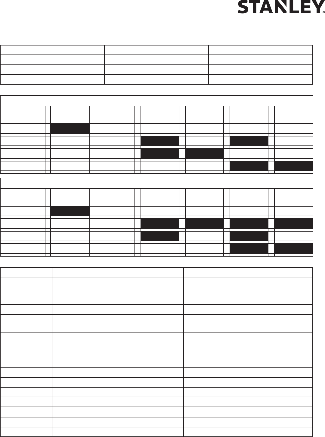
Attachment 5 -- Handheld Device Troubleshooting Aid (Sheet 1 of 1)
Terminal and Pin Descripon State
TB1-8 Solenoid Lock Output Dark = Unlocked
w/o PCB, fail secure Dark = Unlocked
w/o PCB, fail safe Dark = Locked
Rotary Function Switch States for TB2
Hold
Open
Closed
Locked
Automac One Way Reduced Reduced
One Way
TB2-1
TB2-3
TB2-5 Don’t Care Don’t Care
TB2-7
Rocker Function Switch States for TB2
Hold
Open
Closed
Locked
Automac One Way Reduced Reduced
One Way
TB2-1
TB2-3
TB2-5 Don’t Care Don’t Care
TB2-7 Don’t Care Don’t Care
Terminal and Pin Descripon State
TB3-4 Stanguard
TM
Input/Output Dark = triggered or detecng
TB3-8 & TB4-8
Holding Beam Input &
Outside Sensor (connected internally)
Dark = detecng
TB3-9 Breakout Input Dark = no breakout
TB4-4 & TB4-9
Inside Sensor Input &
Push Plate Input (connected internally)
Dark = detecng
TB4-8 & TB3-8
Outside Sensor &
Holding Beam Input (connected internally)
Dark = detecng
TB4-9 & TB4-4
Push Plate Input &
Inside Sensor Input (connected internally)
Dark = detecng
TB5-3 Side Screen Sensor Input Dark = detecng
TB5-7 Closed-Door Posion Switch Input Dark = closed
TB5-10 Spare
TB6-1 Photo Beam Pro Upper Holding Beam Dark = unobstructed White = detecng
TB6-3
Photo Beam Pro Lower Holding Beam
Dark = unobstructed White = detecng
TB6-5 Photo Beam Pro Test Output Dark = tesng
TB6-7

MC521 PRO Control Box
32 Document # 204066 REV F • www.stanleyaccess.com • 1.800.7.ACCESS
Copyright 2016, Stanley Access Technologies, LLC.
All rights reserved. Reproduction
in whole or in part without the express written permission of Stanley is prohibited.
12.28.2016
TB1-8 = Solenoid Lock Output
TB2-1 = Hold Open Funcon Switch Input
TB2-3 = Automac Funcon Switch Input
TB2-5 = Enter/One Way Funcon Switch Input
TB2-7 = Reduced Open Funcon Switch Input
TB2-9 = Reduced Open/One Way Funcon Switch Input
TB3-4 = Stanguard
TM
Input/Output or
Monitored Inside Sensor Test Output
TB3-8 = Holding Beam Input or
Monitored Inside Sensor Presence Input
TB3-9 = Breakout Input
TB4-4 = Inside Sensor Input
TB4-8 = Outside Sensor Input
TB4-9 = Push Plate Input
TB5-3 = Side Screen Sensor Input
TB5-7 = Closed-Door Posion Switch Input
TB5-10
TB6-1 = Photo Beam Pro Upper Holding Beam
TB6-3 = Photo Beam Pro Lower Holding Beam
TB6-5 = Photo Beam Pro Test Output
TB6-7 = Monitored Outside Sensor Test Output
Attachment 6
Handheld Device Troubleshooting Screen Descriptions
(Sheet 1 of 2)

MC521 PRO Control Box
12.28.2016
1.800.7.ACCESS • www.stanleyaccess.com • Document # 204066 REV F 33
Copyright 2016, Stanley Access Technologies, LLC. All rights reserved. Reproduction
in whole or in part without the express written permission of Stanley is prohibited.
Attachment 6
Handheld Device Troubleshooting Screen Descriptions
(Sheet 2 of 2)
Output Control Mode
The Output Control allows the user to run the MC521 Pro Control Box in a debug mode.
The Output Control is located on the MC521 Troubleshoong Screen.
The MC521 Pro rmware needs to be above 7.97 for the Toolbox to have Output Control
Mode funconality.
The MC521 Pro displays “db” to indicate that the control box is in the debug state.
The funcon switch must be selected to Closed/Locked or Hold Open in order to use
the Output Control Mode.
Output Control Mode can also be used when the MC521 Pro control box is in “A0”.
1. Select TROUBLESHOOTING on the Main selecon menu.
2. Press and hold the output that is to be controlled.
TOGGLE/PULSE should appear.
The Output Control Mode is enabled when the Red “LED” indicator is ON.
3. Press TOGGLE or PULSE. In 1 second, the output will change state or pulse.
The inputs on the troubleshoong are live and indicate their present state.
When Output Control Mode is ON, the Turbo funconality is automacally acvated.
The MC521 Pro will me out aer 5 minutes when there is no acvity from the
MC521 Toolbox. The Output Control Mode can be turned OFF by changing the funcon
switch to a seng other than Closed/Locked or Hold Open. The Output Control Mode
is OFF when the text and Red “LED” indicator are hidden from the Troubleshoot screen.
4. Refer to the Tech Tip Library for addional instrucons.

MC521 PRO Control Box
34 Document # 204066 REV F • www.stanleyaccess.com • 1.800.7.ACCESS
Copyright 2016, Stanley Access Technologies, LLC.
All rights reserved. Reproduction
in whole or in part without the express written permission of Stanley is prohibited.
12.28.2016
Attachment 7
MC521 Pro Troubleshooting Aid
(Sheet 1 of 1)
Symptom Remedy
Door does not close and/or
Status code displays ho
Use best pracces to troubleshoot using handheld device and
provided wiring diagrams.
Check hold beam type (index 20) Optex hold beams should be
set to “Optex” and Photo Beam Pro hold beams should be set
to “Photo Beam Pro.”
Reference latest Photo Beam Pro Troubleshoong Tech Tip.
Handheld will not update rmware Controller is not displaying 00. Re-FIS the door.
Door hits Open Stop/full open bumper Increase the Open Stop parameter (index 22).
Door does not close fully (1-2”open) Increase close press me (index 25).
Door moon is not the same as the MC521 for
the same sengs
Parameters value for the MC521 Pro are not the same as
MC521. Refer to Table 3.
Status code displays E1 Verify sensor wiring and safety logic seng.
Status code displays E3
Check mechanical issues, components.
Increase obstrucon me and torque sengs. Verify compli-
ance with ANSI/BHMA standards.
Re-do rst installaon sequence (FIS).
Status code displays E4-E9 Verify sensor wiring and safety logic seng.
Status code displays F0-F1 Verify sensor wiring and safety logic seng.
Status code displays F2-F3
Check hold beam type (index 20) Optex hold beams should be
set to “Optex” and Photo Beam Pro hold beams should be set
to “Photo Beam Pro.”
Reference latest Photo Beam Pro Troubleshoong Tech Tip.
Door moves slowly on one cycle.
Status code displays 33 or 34 or 36 momentarily
(3 seconds).
Note it. No acon required.
Door moves slowly on several cycles.
Status code displays 33 or 34 or 36 on
slow cycles.
1. Reset Power.
2. If code does not clear, Call Tech Support.

MC521 PRO Control Box
12.28.2016
1.800.7.ACCESS • www.stanleyaccess.com • Document # 204066 REV F 35
Copyright 2016, Stanley Access Technologies, LLC. All rights reserved. Reproduction
in whole or in part without the express written permission of Stanley is prohibited.
Attachment 8
Recommended Values for Different/Weights Types of Slide Door
Index Description Slide Doors
125 LB
Single Motor
Single Slide
350 LB
Single Motor
Bi-Part - LPH
100 LB
Single Motor
Bi-part
600 LB
Double Diamond
or Equiv.
Dura-Max
00 Open Speed 35 25 35 35 30
01 Close Speed 12 12 12 12 12
02 Check Speed 4 4 4 4 4
03 Open Check Length 35 35 35 40 35
04 Close Check Length 20 30 23 30 30
05 Reduced Open 1 1 1 50 50
06 Hold-open delay 15 15 15 15 15
07 Lock Logic
08 Open torque, percent of full torque 50 25 25 60 30
09 Close torque, percent of full torque 25 25 20 7 20
10 Check torque, percent of full torque 25 25 30 7 20
11 Dura-Glide Funcon Switch Type
12 2S Operaon
13 Obstrucon Time 50 50 50 100 60
14 Open Acceleraon Slope 60 50 60 60 50
15 Open Braking Slope 54 54 54 54 48
16 Close Acceleraon Slope 20 20 20 20 20
17 Close Braking Slope 50 50 20 50 20
18 Delay Egress
19 Safety Logic
20 Hold Beam Type 00-Optex
01-Photo
Beam pro
00-Optex
01-Photo
Beam pro
00-Optex
01-Photo
Beam pro
00-Optex
01-Photo
Beam pro
00-Optex
01-Photo
Beam pro
21 Open Stop 6 6 6 6 4
28 Close Press Time 1 1 1 1 1
29 Open Check Boost 2 2 2 2 2
MC521 PRO Control Box
36 Document # 204066 REV F • www.stanleyaccess.com • 1.800.7.ACCESS
Copyright 2016, Stanley Access Technologies, LLC.
All rights reserved. Reproduction
in whole or in part without the express written permission of Stanley is prohibited.
12.28.2016
Attachment 9
Fine Tuning Slide Doors
(Sheet 1 of 2)
Tuning the Stanley Automatic Door
Match your actual door to one from the list of doors described in the aachment. Start by installing these sengs.
Use the guide below to make adjustments to these sengs.
If the door:
OPENS TOO SLOWLY
If it is too slow
If it is too slow
Increase Open Speed. Maximum seng is 35
Increase Open Torque
Increase Open Acceleration
** Open Torque is also used to set the door open force.
** Open Speeds and Force must comply with UL and ANSI/BHMA 156.10 requirements.
HITS THE OPEN STOP
Increase Open Stop to 8 and Open Check Length to 45
Increase Open Brake unl there is good braking.
Increase or decrease Open Check Boost unl there is good moon
entering and in Open Check.
When the door braking and moon are under control, reduce the Open Check length as desired.
CLOSES TOO SLOWLY
If it is too slow
If it is too slow
Increase Close Speed to 16
Increase Close Torque
Increase Close Acceleration
**Close Torque is also used to set the door closing force. Close Speed and Close Force cannot exceed the
value specied by ANSI/BHMA 156.10.

MC521 PRO Control Box
12.28.2016
1.800.7.ACCESS • www.stanleyaccess.com • Document # 204066 REV F 37
Copyright 2016, Stanley Access Technologies, LLC. All rights reserved. Reproduction
in whole or in part without the express written permission of Stanley is prohibited.
If the door:
HITS THE CLOSE STOP too hard
Set Close Check Length to 50. Set Close Press to 1 and test.
Increase the Close Brake seng unl there is good braking.
Increase or decrease Close Check Boost unl there is smooth moon
entering and in Close Check.
STALLS during opening without any
mechanical reason. . .
Connues to stall and it seems
to happen at the transion
from Open Brake to Open Check
Increase Obstruction Time from .5 seconds to 1.0 seconds
Make small increases to Open Brake Boost.
SPEEDS UP during Open Check
Open Check Boost is set too high. Reduce it one count at a me unl
door moon is suitable.
STALLS during closing without any
obvious reason. . .
Connues to stall and it seems to
happen at the transion to Close
Check
Increase Obstruction Time
Increase Close Check Boost one count at a me
SPEEDS UP during Close Check
Close Check Boost is set too high. Reduce Close Check Boost one count at
a me unl door moon is suitable.
Attachment 9
Fine Tuning Slide Doors
(Sheet 2 of 2)
Tuning the Stanley Automatic Door (Continued).
Match your actual door to one from the list of doors described in the aachment. Start by installing these
sengs. Use the guide below to make adjustments to these sengs.
Stanley Access Technologies
65 Scott Swamp Road
Farmington, CT 06032
Document # 204066 REV F • www.stanleyaccess.com • 1.800.7.ACCESS
