NEP-ZL105645
12.2019_REV 7
INSTALLATION
OPERATION &
MAINTENANCE
NEPTUNE
Series 560
“dia-PUMP”

WARNING
LOCKOUTS ARE REQUIRED BEFORE
SERVICING THIS EQUIPMENT.
READ INSTRUCTION SERVICE
MANUALS FOR DETAILS.
SAFETY INSTRUCTIONS:
Shut off/Lockout pump Power before Servicing,
bleed Pressure / Chemical off, etc.

WARNING
Please read thoroughly before installation, operation or maintenance of any Neptune pump
EQUIPMENT MISUSE HAZARD
Equipment misuse can cause the equipment to rupture, malfunction and result in serious injury.
• This equipment is for professional use only.
• Read all instruction manuals, tags, and labels before operating the equipment.
• Use the equipment only for its intended use.
• Do not alter or modify this equipment.
• Be certain all operators of this equipment have been trained for safe working practices, understand it's limitations, and wear safety
goggles and or equipment when required.
• Do not exceed the maximum working pressure of the system as mentioned on the pump tag.
• Do not use the pump head or the suction or discharge piping to pull the equipment.
• Do not move pressurized pump.
• Use fluids or cleaning agents for cleaning that are compatible with the pump parts. Read the fluid and cleaning agent manufactures
warnings and also refer to the material compatibility chart
• Comply with all applicable local, state and national safety regulations.
• Do not allow pump to run dry.
PRESSURIZED EQUIPMENT HAZARD
Spray from leaks or ruptured components can splash fluid in the eyes or on the skin and cause serious injury.
• Shut off the pump and depressurize before performing any maintenance.
• Do not tamper with or perform unspecified alteration of this device.
• Use only pipe, hose, and hose fittings rated for maximum rated pressure of the pump or the pressure at which the pressure relief
valve is set at.
• Always wear protective clothing, face shield, safety glasses and gloves when working on or near your metering pump.
• Additional precautions should be taken depending on the solution being pumped. Refer to SDS precautions from your solution
supplier.
• Do not stop or deflect fluid leaks with your hand, body, glove, or rag.
• Tighten all fluid connections before operating the equipment.
• Replace worn, damaged, or loose parts immediately.
• Before performing any maintenance requiring pump head and or valve (wetted parts) disassembly, be sure to relieve pressure from
the piping system and where hazardous process chemicals are present.
• Make the pump safe to handle for the personal and the environment by cleaning and chemically neutralizing the pump as
appropriate.
• Wear protective clothing and use proper tools as appropriate to avoid any injury.
• If the diaphragm has failed, process chemical may have contaminated the pump hydraulic oil. Handle with appropriate care. Clean
the pump and replace oil as necessary. Discard the contaminated oil as per the local code.
• If the diaphragm fails in a double diaphragm pump, pressurized process chemical can be present in the Neptune leak detection
vacuum system. Take proper care to clean and handle them.
FIRE AND EXPLOSION HAZARD
Improper grounding, poor air ventilation, open flames, or sparks can cause a hazardous condition and result in fire or explosion and serious injury.
• Ground the equipment. See motor installation instruction for grounding procedure.
• Do not pump non recommended flammable or explosive fluids.
• Static electricity may generate by fluid moving through pipes and hoses. A static spark could be produced by high fluid flow rate.
Earthing of the pump is a must.
• Provide fresh air ventilation to avoid the possible build up of flammable fumes from the process chemicals.
• Keep the pump area free of debris, including cleaning agent, rags, and any flammable material.
• Follow the cleaning agent and other cleaning recommendations as mentioned in the operation and instruction manuals.
• Use cleaning agent with the highest possible flash point to clean the pump parts if needed.
• If there is any static sparking while using the equipment, stop operation at once. Identify and correct the problem before starting up
the pump.
TOXIC FLUID HAZARD
Hazardous fluids or toxic fumes can cause serious injury or death if splashed in eyes or on the skin, swallowed, or inhaled.
• Know the specific hazards of the fluid you are using. Read the fluid manufactures warnings.
• Store hazardous fluid in an approved container. Dispose of hazardous fluid according to all local, state and national guidelines.
• Wear the appropriate protective clothing, gloves, eyewear and respirator.
• Pipe and dispose of the exhaust air safely. If diaphragm fails, the fluid may be exhausted along with the air in mechanical
diaphragm pump. Also oil vapor may breathe out of the air breather installed on the gear box.
SOUND HAZARD
The sound pressure level of the pump may exceed 80dBA in some of the pumps.
• Observe all safety precautions when operating the pump within close proximity for extended periods by wearing hearing
protectors.
• Extended exposure to elevated sound levels will result in permanent loss of hearing acuteness, tinnitus, tiredness, stress, and
other effects such as loss of balance and awareness.
MECHANICAL HAZARD
The pump may shake or vibrate during operation.
TABLE OF CONTENTS
SECTION
PARAGRAPH
PAGE
I
—
General Description
1
—
Warranty
2
—
Parts Ordering Instructions.
3
II
—
Installation instructions
4
1.0
General
4
2.0
Suction Piping
6
3.0
Discharge Piping
6
4.0
Adjustment of internal Relief Valve
6
5.0
Installation Outdoors
8
6.0
Start Up Procedure - Flooded Suction
8
7.0
Start Up - Suction lift
8
8.0
Start Up After Suction Has Run Dry
8
III
—
Normal Maintenance
9
9.0
Maintenance
9
10.0
Check Valves
10
11.0
Procedure for Replacing Control Rod
10
O-Ring and Sealing Plate
O-Ring
12.0
Procedure for Replacing Diaphragm
10
IV
13.0
Motor Operating Conditions
11
V
—
TroubleShooting Chart.
12
VI
Parts list
14
14.0
Parts list for Standard Series 560
14
"dia-PUMP" with Metal Pump Head
VII
Drawings
18
PVC and KYNAR head option
20
APPENDIX
Double Diaphragm Option
21
1
SECTION I
GENERAL DESCRIPTION
The Neptune Series 560 “dia-PUMP” is a reliable metering pump of the hydraulically actuated diaphragm type.
Under constant conditions of temperature, pressure, and capacity adjustment settings, a plus or minus range of 1 %
metered discharge volume is maintained.
A plunger reciprocating at a fixed stroke displaces hydraulic fluid, which actuates a flexible, chemically inert, Teflon
®
diaphragm to create pumping action. The capacity of the pump is regulated by controlling the volume of hydraulic
fluid, which bypasses the diaphragm cavity.
Capacity adjustment can be made manually or automatically by instrument signal.
Metering accuracy is maintained by a control rod, which allows hydraulic fluid replacement and air venting
automatically with each stroke, while also taking into account temperature changes of the hydraulic fluid. Metering
accuracy is also insured by the use of double ball check valves on the suction and discharge ends of the pump.
PLEASE READ THE INSTRUCTION MANUAL COMPLETELY BEFORE INSTALLING THE PUMP.
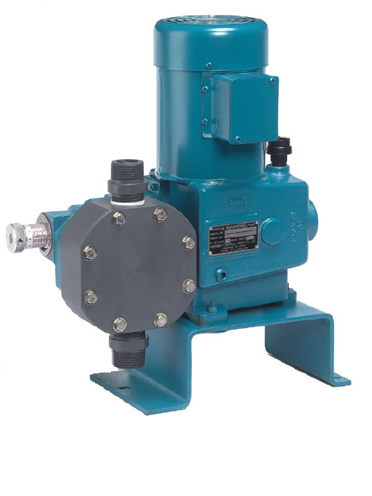
SERIES 560 “dia-PUMP”
PVC (N5) HEAD WITH
INTEGRAL TEFC MOTOR

2
LIMITED WARRANTY
All Neptune Pumps are tested at the factory prior to shipment. Each part used in their construction has been carefully
checked for workmanship.
If the pump is installed properly, Neptune Chemical Pump Company warrants to the purchaser of this product for a
period of thirty six months from the date of first use or eighteen months from shipment, whichever occurs first, this
product shall be free of defects in material and/or workmanship, as follows:
1. Neptune Chemical Pump Company will replace, at no charge, any part that fails due to a defect in material and/or
workmanship during the warranty period, FOB our factory, North Wales, Pennsylvania. To obtain warranty service,
you must get an RMA number to return the defective parts to the factory for examination, freight pre-paid.
2. This warranty period does not cover any product or product part, which has been subject to accident, misuse,
abuse or negligence. Neptune Chemical Pump Company shall only be liable under this warranty if the product is
used in the manner intended by the manufacturer as specified in the written instructions furnished with this
product.
Any express warranty not provided in this warranty document, and any remedy for breach of contract that, but for this
provision, might arise by implication or operation of law, is hereby excluded and disclaimed. Under no circumstances
shall Neptune Chemical Pump Company be liable to purchaser or any other person for any charge for labor, repairs,
or parts, performed or furnished by others, nor for any incidental consequential damages, whether arising out of
breach of warranty, express or implied, a breach of contract or otherwise. Except to the extent prohibited by
applicable law, any implied warranty of merchantability and fitness for a particular purpose are expressly limited in
duration to the duration of this limited warranty.
Some states do not allow the exclusion or limitation of incidental or consequential damages, or allow limitations on
how long any implied warranty lasts, so the above limitations may not apply to you. This warranty gives you specific
legal rights, and you may have other rights, which may vary from state to state.
IMPORTANT
SHOULD IT BE NECESSARY TO SEND THE PUMP TO THE FACTORY FOR REPAIR OR MAINTENANCE
REBUILDING; DRAIN ALL OIL AND CHEMICAL FROM PUMP BEFORE SHIPPING. FAILURE TO DO SO CAN
CAUSE EXTENSIVE DAMAGE TO THE MOTOR.
1
SEE IMPORTANT NOTICE - RETURN GOODS AUTHORIZATION
IMPORTANT NOTICE
RETURN GOODS AUTHORIZATION
(1) All equipment returned to Neptune Chemical Pump Company requires proper Returned
Goods Authorization Number (RGA) and tags.
(2) All equipment returned to the factory for repair or service must first be thoroughly flushed
and have all chemical contact areas neutralized.
(3) All equipment which has been in contact with chemicals must be accompanied by a copy
of the chemical product material Safety Data Sheet (SDS).
(4) Failure to comply with the above instructions will result in equipment being returned to
sender, freight collect, without service.
3
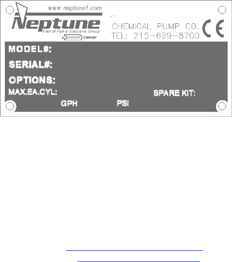
PARTS ORDERING INSTRUCTIONS
The complete model number and serial number of the pump must be furnished to insure prompt and
accurate parts service. These numbers are found on the name plate (sample below) located on the side
of the pump. Refer to Section VII for complete parts lists.
Send all orders or inquiries for parts to:
Email: orders.nept[email protected]
Website: www.psgdover.com/neptune
4
SECTION II
INSTALLATION INSTRUCTIONS
1.0 GENERAL
1.0.1 When unpacking a pump or chemical feed system, be certain that no parts are thrown away.
Examine the equipment for possible damage. If damage has occurred, file claim with the common
carrier within 24 hours. Neptune will assist in estimating the repair costs.
1.0.2 The ‘‘dia-PUMP’’ should be located so as to avoid an ambient temperature above 120°F, 50°C.
Free air circulation is important when considering the location of the pump.
1.0.3 The ‘‘dia-PUMP’’ should be located on a level surface. Three mounting holes are provided to
anchor the pump securely to the mounting surface. PVC head pumps must be mounted on riser,
which needs to be secured on the surface.
1.0.4 Neptune recommends a 4” to 6” inch clearance above mounting surface to allow access to the
Valve Stack. Please refer to model and valve location prior to installation.
1.0.5 All piping to the pump should be supported to prevent stress on the pump input and output fittings.
1.0.6 Before connecting the pump, make sure that all fittings are completely clean by flushing thoroughly.
Any foreign matter entering the pump can damage the internal parts and severely limit the life of the
pump.
1.0.7 A ‘‘Y’’ STRAINER MUST BE INSTALLED IN THE SUCTION LINE OF THE PUMP TO INSURE
AGAINST FOREIGN MATTER ENTERING THE PUMP. ALL SUCTION LIFT APPLICATIONS
REQUIRE A FOOT VALVE STRAINER TO PREVENT LOSS OF PRIME, AND TO PREVENT
FOREIGN MATERIAL FROM ENTERING THE PUMP.
1.0.8 Shut-off valves and unions should be placed in the suction and discharge lines to facilitate servicing
the pump.
1.0.9 Care should be exercised when piping to PVC head pumps. In cases where vibration or stress is
unavoidable, flexible connections should be used.
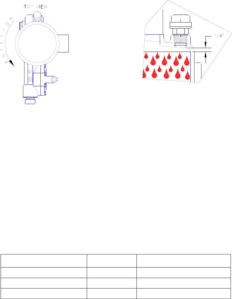
1.0.10 The electrical supply to the pump must match the motor name plate characteristics. The motor
rotation is counter clockwise when viewed from the top of the motor, looking down on the pump.
(See Figure 1 on page #5).
1.0.11 Discharge Piping should be the same size or larger than the discharge connection. Suction Piping
should be one size larger than the suction connection. Limit the total length of the suction line to 3-4
feet suction lift or 6-7 feet flooded suction. Minimum bends, elbows, or other restrictions.
Important
On single phase integral motors, the rotation is set at the factory and must not be changed.
On three phase integral motors, rotation is determined by noting the fan rotation.
Pump body is grounded to earth. Ground connection MUST penetrate to bare metal. Ground
to be clearly marked.
Check external pressure relief valve setting.
On some flange mounted motors, the motor rotation may be viewed by removing the cap plug on the
side of the flange. There is no viewing port or coupling access on the close-coupled flange mount
motors. Rotation is checked by removing the oil fill plug and observing the gear. Correct rotation is
indicated by the gear teeth moving downward away from the oil fill hole.
Please note Figure 1 on page #5 indicating the correct rotation. (An arrow on the gear box also
indicates proper rotation). Operation with the incorrect rotation will damage the pump and motor.
5
1.0.9 (Continued)
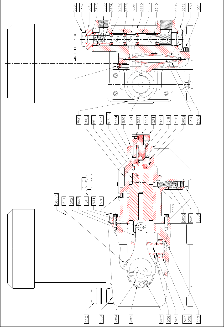
1.0.11 Set capacity knob to zero and remove Air Bleed Plug from the top of Oil Chamber, refer to drawings 5670 (Page
19) for the location of plug (#512). Fill gear box and pump by pouring the hydraulic fluid supplied through the fill
opening at the rear of the pump. Pour fluid in slowly until it has reached the correct level per figure above. Do
not over fill as this can cause damage to the motor.
Allow a few minutes for the hydraulic fluid make its way into the pump chamber and then recheck fluid Level,
reinstall Air Bleed Plug.
The hydraulic fluid supplied by Neptune is:
EP Gear Oil, ISO #68, consult the parts listing in the back of this manual for the Neptune part
number.
Heavier hydraulic fluid is supplied by Neptune for Hi Pressure Systems is EP SAE 90.
1.0.12 Please note that this manual describes both metal head pumps (Material Code N1, N3 or N4) and PVC head
pump (Material Code N5) or KYNAR head (Material Code N8). The figure number references used throughout
the manual are for the metal head pumps. The metal pumps are shown on drawing 5670 on page #18. The
comparable PVC and KYNAR head pump parts are shown on the New Style PVC and KYNAR Head drawing
on page #20.
Alternate Oils For Standard
Mfg.
Alternate High Pressure Oils
Mobil Gear #626
Mobil Oil
Mobil Gear #629
Sun EP #68
Sun Oil
Sun Oil #220
Meropa #68
Texaco
Meropa #220
FIGURE 1
6
2.0 SUCTION PIPING
2.0.1 The suction piping to the pump must be absolutely air tight. It is suggested that the suction piping be tested with
low air pressure and a soap solution to assure that no leaks exist.
2.0.2 Neptune recommends that the "dia-PUMP" be operated with a flooded suction, as this will facilitate start up and
increase the service life of the pump. It is, however, possible to operate the ‘‘dia-PUMP’’ with a suction lift of up to 5
feet, if absolutely necessary. A foot valve strainer must be used on this type of application.
2.0.3 It is highly recommended that all solution tanks be purchased with a low level cut off switch or low level alarm and
cut off switch to prevent the pump from running dry. OPERATION AGAINST A DRY SYSTEM WILL CAUSE
DAMAGE TO THE PUMP DIAPHRAGM AND REDUCE THE OPERATING LIFE OF THE PUMP.
3.0 DISCHARGE PIPING
3.0.1 It is recommended that the ‘‘dia-PUMP’’ operate against a minimum discharge pressure of 50 psig. An
anti-siphon spring is supplied loose with the pump. If 50 psig back pressure is not provided by the
application, the anti-siphon spring (FIG. #5666*) should be installed on the pin under the vent plug (FIG.
#5604*). Installation of the anti-siphon spring artificially creates a discharge head.
An external Back Pressure valve should be used with PVC or KYNAR head pumps.
*Refer to part list on page #14
4.0 ADJUSTMENT OF INTERNAL RELIEF VALVE
4.0.1 All Neptune Series 560 dia-PUMPs are supplied with an internally pre-set relief valve. THIS
RELIEF VALVE IS SET AT 175 PSI AND IS DESIGNED TO PROTECT THE PUMP SHOULD
A DISCHARGE PRESSURE BEYOND THE RATED LIMIT OF THE PUMP OCCUR. If a customer
order specifies a relief valve setting above those indicated above, the specified setting will be set at the
factory. All pumps are tagged with the relief valve setting used by the factory.
To protect the external piping system, it is recommended that a relief valve as manufactured by
Neptune Chemical Pump Company, or equal, be placed in the discharge line of the pump. It is further
recommended that this relief valve be piped into return of the tank with clear PVC tubing so that it can
be determined if the solution is by-passing through the valve and returning to the tank, indicating a line
blockage.
Drawing 5670 on page#18, illustrates the location of the Internal Relief Valve (FIG. #5648 through
#5652).
The drawing shows a passage connecting the hydraulic fluid reservoir with the hydraulic fluid side of the
diaphragm.
The passage is interrupted by the Relief Valve Ball (FIG. #5648) which is backed up by a Relief Valve
Spring (FIG. #5650).
If, during the pump operation, the pressure on the hydraulic fluid side of the pump exceeds the set
pressure of the internal relief valve, the ball is forced from its seat allowing the hydraulic fluid to flow
back to the reservoir.
7
4.0.2 To reset the relief valve to a higher pressure, instructions are as follows:
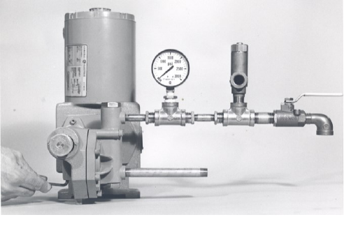
4.0.21 Connect a test set-up as shown in Figure IV below.
4.0.22 Start and run the pump until all air is relieved from the discharge liquid (hand valve open).
4.0.23 Remove Relief Valve Plug (Fig. #5651).
4.0.24 Close hand valve; pressure gauge should read 175 psi, depending on pump model.
4.0.25 Use the 1/4” Allen Wrench to adjust spring tension by turning Relief Valve Adjusting Screw
(FIG. #5652).
(1) To increase pressure, turn Relief Valve Adjusting Screw (Fig. #5652) in.
(2) To decrease pressure, turn Relief Valve Adjusting Screw (Fig.#5652) out.
4.0.26 After resetting or adjusting pressure, replace Relief Valve Plug (Fig. #5651).
CAUTION
Never turn Relief Valve Adjusting Screw (Fig. #5652) completely in.
Do not attempt to set the internal relief valve more than 200 psi in excess of name plate rating.
4.0.3 Parts required to test or adjust Relief Valve Pressure.
1 Pc.
1/2” x1/4” reducer bushing
1 Pc.
1/2” street elbow
3 Pcs.
1/2” pipe nipple 2” long
1 Pc.
1/2” hand valve
2 Pcs.
1/2” tee
1 Pc.
3/4” MNPT X 5/8” hose (fitting)
1 Pc.
5/8” hose, as required
1 Pc.
1/4” pressure gauge (minimum gauge pressure 500 psi)
1 Pc.
Allen wrench 1/4”
1 Pc.
External relief valve (optional)
NOTE
The above parts must have a working pressure rating above the required set pressure.
FIGURE IV
8
5.0 INSTALLATION OUTDOORS
The “dia-pump” is a totally enclosed pump which can be used outdoors or indoors. When installed outdoors, make sure that
the pump is protected against extremes of nature as follows:
5.0.1. Running of the pump when exposed to tropical sunshine, with ambient temperature above 90ºF (32ºC) would
cause excessive oil and motor temperatures. The pump should be shaded and located in such a way as to permit
ample air circulation.
5.0.2 Under cold conditions, the pump should be insulated and a heater should be supplied in order to maintain the
hydraulic fluid at an ambient temperature above 30ºF (-1ºC).
6.0 START-UP PROCEDURE-FLOODED SUCTION
The following start-up procedure is complete and does repeat instructions on filling the gear box and pump.
6.0.1 Flooded Suction: Refer to Section II, Paragraph 1.0.11. for instructions on filling gear box with hydraulic fluid.
NOTE: Refer to Paragraph 12.3 (page#11) for special start-up instructions after replacing diaphragm.
6.0.2 After having let pump stand for 30 minutes and having rechecked fluid level, set pump capacity indicator at
approximately 30%. Be certain that pump suction and discharge lines are open.
6.0.3 Make certain that pumping chamber is flooded by loosening Vent Plug (FIG.#5604) and allowing solution to
appear. Then tighten discharge vent plug. This procedure will also allow air to vent from pumping chamber. THE
“dia-PUMP” WILL NOT FUNCTION IF AIR IS TRAPPED IN THE HYDRAULIC FLUID OR LIQUID PUMP
CHAMBERS. Start Pump.
6.0.4 The pump is now ready for “on line” service.
6.0.5 You may calculate what the desired capacity is, as a percentage of either the maximum capacity rating
on the pump data plate, or the nominal capacity at the required system pressure.
7.0 START-UP PROCEDURE SUCTION LIFT
7.0.1 If the “dia-PUMP” is to be used where suction lift is required, A FOOT VALVE STRAINER MUST BE
INSTALLED on the end of the suction line. A pipe tee is installed on the top end of the suction line with
one leg to the pump suction, one leg to the suction line and one leg pointing straight up and valved.
Open valve and force prime pump and piping with water. Start pump.
WARNING: Beware of application where water is not compatible with chemical to be pumped.
Example: Never force prime when pumping acid or oil based products.
8.0 START-UP AFTER SUCTION HAS RUN DRY
In applications where the suction tank does not have a low level cutoff interconnected into the pump motor circuit,
the pump may occasionally run dry. THIS MUST BE AVOIDED BECAUSE DAMAGE TO THE PUMP CAN
RESULT AND THE SERVICE LIFE WILL BE SIGNIFICANTLY REDUCED WHEN THE PUMP IS ALLOWED TO
RUN WITH A DRY LIQUID END.
Before restarting a pump that has run dry and which has not been damaged by running dry, follow the procedure
in Paragraph 6.0 through 6.0.3 of Section II

9
SECTION III
NORMAL MAINTENANCE
9.0 MAINTENANCE
Under normal conditions, the “dia-PUMP” does not require any significant amount of maintenance. It is advised
that periodic visual observations be made of the oil level to make sure that it is within limit (see fig 1, page#5).
The liquid end of the pump should also be inspected for leakage. These observations should be made regularly,
at least every 48 hours.
The hydraulic fluid should be drained and replaced TWICE a year, using the drain plug (FIG #510, page#18) on
the side of the pump. This change can be scheduled with the normal factory maintenance at seasonal periods.
Recommended Maintenance Schedule
Weekly Interval
• Check oil level
• Check for leaks
• Check ground connection for corrosion
• Clean pump surfaces and surrounding area of dust and debris
First 250 hours of operation
• Change oil
Every 4000 hours or six months
• Change oil
• Clean inlet piping strainer & check external pressure relief valve
• Replace worm shaft oil seal
• If equipped, check coupling insert. Replace if necessary.
• Tighten all fasteners
Annual
• Clean check valves. Replace O-rings.
• Replace diaphragm
• If equipped, replace coupling insert.
• Replace rolling element bearings
• Replace O-rings
• Replace check valves
10
10.0 CHECK VALVES: REMOVING, CLEANING, AND REPLACING
The “dia-PUMP” incorporates a unique check valve design whereas the discharge and suction piping NEED
NOT be disturbed in order to service the valves. Should the valves need cleaning, remove as follows:
NOTE: For PVC or KYNAR heads, the connection piping have to be removed.
CAUTION: Do not over tighten PVC Suction and discharge valves, as the PVC material is not able to withstand
excessive force and can fail. Teflon paste is an excellent thread lubricant and may be applied.
11.0.0 PROCEDURE FOR REPLACING CONTROL ROD “O” RING (fig. #2334) AND SEALING PLATE “O” RING
(FIG. #516-C on Page#18).
11.0.1 Remove hydraulic fluid from gearbox.
11.0.2 Remove indicator plate (FIG. #520) by removing two indicator plate screws (FIG. #521).
11.0.3 Remove control rod assembly with control rod attached (FIG. #524, #523, and #5615) by turning counter
clockwise until threads are disengaged, then pull out.
NOTE: Some pump models may have O-ring on sealing nut, refer to FIG. #5699 if O-ring is needed or
requires replacement.
11.0.4 Use an 11/16" Hex socket on the sealing nut (FIG. #526) and screw out of pump in a counter clockwise
direction. Then, remove sealing plate (FIG. #5602) using a small brass hook to pull loose.
11.0.5 Replace control rod O-ring (FIG. #2334) and/or sealing plate O-ring (FIG. #516-C).
11.0.6 When replacing sealing plate, be careful not to shear the sealing plate O-ring (FIG. #516-C).
11.0.7 Replace balance of parts and fill pump with hydraulic fluid per previous instructions.
11.0.8 Follow start-up procedure as if starting a new pump.
12.0.0 Procedure for replacing Diaphragm on Pumps with metal head models.
12.0.1 Removal of pump head and replacement of diaphragm.
12.0.2 Remove drain plug (FIG. #510), and drain hydraulic fluid.
12.0.3 Remove long and short pump head bolts (FIG. #551). Lift pump head (FIG.#5660) away from pump.
12.0.4 Remove and examine Teflon diaphragm (FIG. #2310). Remove and examine the liquid side diaphragm backup
plate (FIG. #2330).
12.0.5 Replace with new part, if required. When replacing the Teflon diaphragm, be certain to line it up properly with
the sealing grooves.
12.0.6 To reassemble, reverse the above procedure. Reassembly is facilitated by laying the pump on its side. Be
certain to tighten all the bolts evenly. Tighten to 25 ft. lbs.
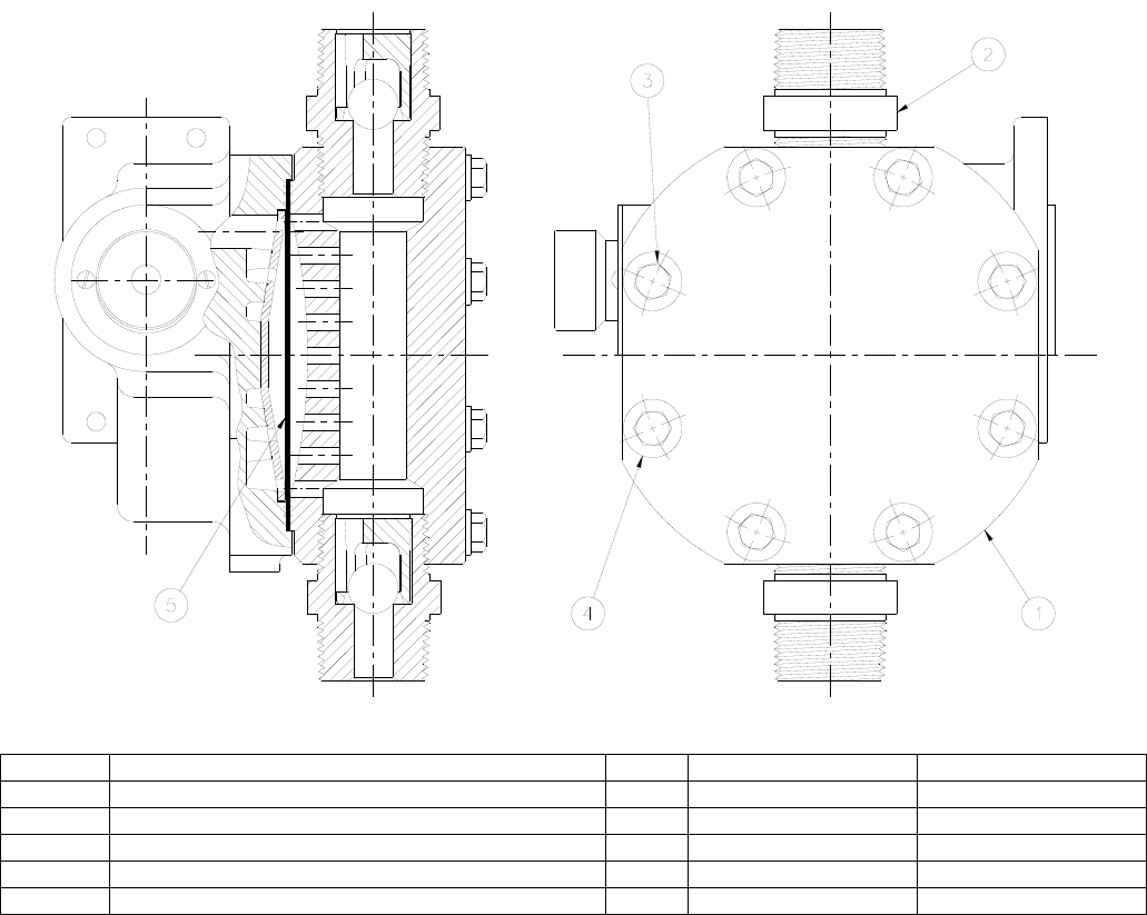
12.1.0 Removal of pump head and replacement of diaphragm on PVC head model. (Refer to Drawing on
Page#20).
12.1.1 Loosen (8) bolts (FIG#3). Lift pump head (FIG. #1) away from pump.
12.1.2 Remove and examine Teflon diaphragm (FIG. #5).
12.1.3 Replace with new Teflon diaphragm, if required. When replacing the Teflon diaphragm, be certain to line it up
properly with the sealing grooves.
12.0.4 To reassemble, reverse the above procedure. Reassembly is facilitated by laying the pump on its side. Be
certain to tighten all bolts evenly. Tighten to 10 ft. Ibs.
11
12.3.0 Start-up instructions after replacing diaphragm.
12.3.1 Fill gearbox with oil (leaving 1/4" - 1/2" inches of air space). Using warm oil is best.
12.3.2 Refer steps at 6.0 (START UP PROCEDURE- FLOODED SUCTION) ON PAGE #8.
12.3.3 Remove anti-siphon spring under discharge cap (to be replaced after pump start up if needed).
12.3.4 Run pump at 0% to allow pump to warm up. (Start pumping on test bench or testing area.)
(Liquid supply is required-water is recommended.)
12.3.5 Start up at a low percentage Try 20% for about 15 minutes then increase to 40% for 15 minutes and repeat for
60%-80%-100%.
12.3.6 Recheck for proper sealing and test for required pump capacity.
12.3.7 Pump is now ready for hook-up to system.
SECTION IV
MOTOR OPERATING CONDITIONS
13.0 The standard Series 560 "dia-PUMP" is supplied with 1/3 HP, single phase, capacitor start, totally enclosed
fan-cooled motor as an integral part of the pump itself.
The normal temperature rise for this motor is 40°C above ambient temperature and, thus, it might appear
that the motor is operating at a higher than normal temperature. This situation is normal and should not
cause concern.
As a precaution against motor overheating, it is recommended that the pump be located where adequate
ventilation is available. It is also highly RECOMMENDED THAT A MOTOR STARTER WITH THE PROPER
OVERLOAD PROTECTION BE SUPPLIED AS AN ADDITIONAL SAFETY DEVICE.
12
SECTION V
TROUBLESHOOTING CHART
Symptom
Cause
Remedy
1. Pump Motor Will Not
Operate.
A. Blown Fuse.
Check for short circuit or overload.
B. Low liquid level in tank (where low
level cut-off is used).
Fill tank.
C. Broken wire.
Locate and repair.
D. Low voltage.
Check for too light wiring.
E. Oil “frozen” in pump.
Thaw out.
*2. Pump Does Not
Deliver Rated Capacity
A. Starved suction.
Replace suction piping with larger size, or
increase suction head.
B. Leaky suction piping.
Pressure test, repair or replace defective
piping.
C. Excessive suction lift.
Rearrange equipment location to reduce
suction lift.
D. Liquid too close to boiling point.
Lower temperature or increase suction head
pressure slightly.
E. Air or gas trapped in oil or chemical
solution.
Decrease capacity to 20% for 7 minutes,
then increase to 100% for 7 minutes.
F. Worn or dirty valves or seats, or
both.
Clean or replace.
G. Viscosity of liquid too high.
(1) Reduce viscosity by heating or other
means.
(2) Increase size of suction piping.
(3) Increase suction pressure slightly
H. Insoluble materials, crystallization or
solids settling.
Limit solution strength to 5% by weight.
Flush and clean solution tank periodically.
Suction connection should be 2" - 4" from
bottom of solution tank.
I. Low discharge pressure.
A minimum discharge pressure of
50 psi is required to insure proper capacity
control.
J. Air in hydraulic or chemical systems.
Bleed system.
13
Symptom
Cause
Remedy
*3. Pump delivers
erratically.
A. Leaky suction line.
Repair or replace piping.
B. Worn or dirty valves seats, or both.
Clean or replace suction & discharge
Valve assemblies.
C. Excessive excursion of ball from
valve seats (indicated by ball
chatter).
Increase back pressure (install anti-siphon
spring).
D. Insufficient suction pressure.
Increase suction pressure. Raise tank level.
E. Liquid too close to boiling point.
Reduce temperature or raise suction
pressure.
F. Leaky system relief valve.
Repair or replace relief valve.
G. Low hydraulic fluid
Add hydraulic fluid.
4. Motor Overheats.
A. Power supply does not match motor.
Check power supply against motor
nameplate data.
B. Overload caused by operating pump
beyond rated capacity.
Check operating pressure against pump
manufacturer’s data plate maximum rating.
5. Noisy Operation
(1) In Pump
A. Pump Valves.
Valves must move to open and close, and
they will make a clicking noise as they
operate. These noises are sometimes
amplified by natural resonances in piping
system. They are usually indications of
normal valve functioning.
(2) In Gear Reducer
A. Pounding noise at high discharge
pressure.
Fluid compressibility causes reversal of load
on gears at end of pressure stroke. Not
considered detrimental.
6. Oil level overflows
Reservoir.
A. Flexible diaphragm punctured.
Replace diaphragm and hydraulic fluid (drive
lubricant) if contaminated.
*Note: A diaphragm change may be needed for symptoms #2 & #3
14
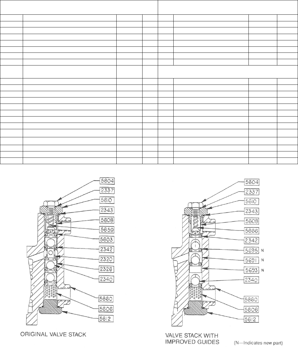
* Silicone Sealant may be substituted for Gasket “N” indicates parts per new version
Valve stacks of all Series 560 (except PVC models) have been improved by the attention of close tolerance ball guides which
allow for better accuracy and higher pressure performance.
Improved stack arrangements are shown in the figures on page #15.
Parts are currently furnished only for the improved version. When ordering replacement seats for an original valve stack
design, order the ball guides (FIG. #5691) and spacer (FIG. #5693). Installing these parts and discarding the old spacers (FIG.
#2320 and FIG. #2326) will upgrade the pump to the Improved valve arrangement. (Refer to the drawing on page#15)
If seats are not replaced, it is not necessary to change the spacers and ball guides. If seats are replaced (the new seals are of a
different thickness) the ball guides and spacers must be replaced.
SECTION VI
PARTS LIST
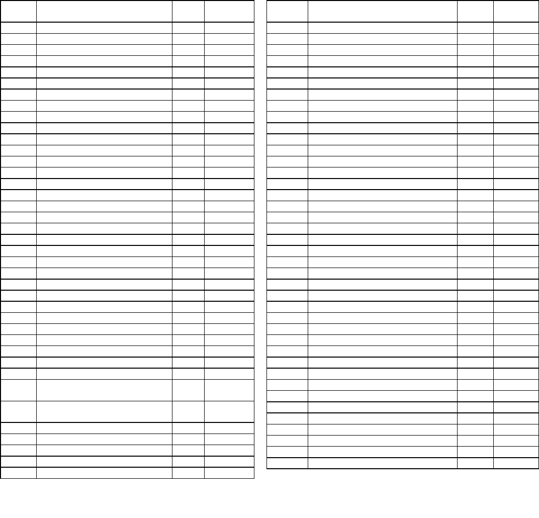
14.0 PARTS LIST FOR STANDARD SERIES 560 "DIA-PUMP" WITH METAL PUMP HEAD (REFER TO DRAWING #5670)
FIG.
NO.
DESCRIPTION
QTY.
PART
NO.
501
Worm Gear 37 SPM*
1
000164
Worm Gear 72 SPM*
1
000166
Worm Gear 117 SPM*
1
000163
Worm Gear 144 SPM*
1
002818
502
Connecting Rod
1
000167
506
Worm 37 SPM
1
000170
Worm 72 SPM
1
000172
Worm 117 SPM
1
000169
Worm 144 SPM
1
002817
507
Bearing Cup
1
100179
508
Bearing Cone
1
100180
509
Worm Spring Pin
1
100181
510
Drain Plug
1
100182
511
Connecting Rod Pin
1
100183
512
Fill Plug
1
000191
516-C
Sealing Plate O-Ring
1
100186
519
Control Rod Spring Pin
1
100189
520
Indicator Plate
1
000188
521
Indicator Plate Screws
2
100190
522
Control Knob Set Screw
1
100191
523
Control Rod Positioner
1
000189
524
Control Knob Assembly
1
002071
525
Capacity Indicator Scale
1
100192
526
Sealing Nut
1
002069
530
Pipe Plug
1
100196
534
Pump Body Cap Screws
4
100293
551
Screw 5/16 x 1 1/4” lg. (N1)
8
100205
Screw 5/16 x 1” lg. (N3, N4)
8
100206
557
Hydraulic Fluid (2 qts.) ISO68
1
003089
590
Gasket or Sealer
1
106290
2309
Pump Body Side Backup Plate
1
000387
2310
Teflon Diaphragm
1
000388
2330
Pump Head Back Up Plate
(N1, N3)
1
000406
Pump Head Back Up Plate
(N4)
1
000407
2334
Control Rod O-Ring
1
100323
2337
Vent Plug O-Ring
1
100325
2340
Valve Balls (N1, N3)
4
100078
Valve Balls (N4)
4
100079
2342
Valve Seat O-Ring
4
100327
FIG.
NO.
DESCRIPTION
QTY.
PART
NO.
2343
Discharge & Suction Cap O-Rings
2
100328
5002
Shaft Retainer Assembly*
1
002722
5004
Thrust Washers
3-4
100252
5025
Shaft Retainer Screws
3
100254
5601
Gear Box
1
000296
5602
Sealing Plate
1
000307
5604
Vent Plug (N1, N3)
1
000308
Vent Plug (N4)
1
000309
5606
Suction Spacer (N1, N3)
1
000310
Suction Spacer (N4)
1
000311
5608
Discharge Spacer (N1, N3)
1
000312
Discharge Spacer (N4)
1
000313
5610
Discharge Cap (N1, N3)
1
000303
Discharge Cap (N4)
1
000304
5612
Suction Cap (N1, N3)
1
000301
Suction Cap (N4)
1
000302
5614
Piston 2”
1
000314
5615
Control Rod
1
000315
5648
Relief Valve Ball
1
100201
5650
Relief Valve Spring 1/3 & 1/2 HP
1
100276
Relief Valve Spring 3/4 & 1 HP
1
106428
5651
Relief Valve Plug
1
108044
5652
Relief Valve Adjusting Screw
1
100277
5660
Pump Head (N1)
1
000298
Pump Head (N3)
1
000299
Pump Head (N4)
1
000300
5663
Pump Body R.H.
1
000297
5666
Anti-Siphon Spring (N1, N3)
1
000340
Anti-Siphon Spring (N4)
1
000341
5668-A
Std. Motor Assembly 37 SPM**
1
002404
Std. Motor Assembly 72 SPM**
1
002405
Std. Motor Assembly 117 SPM**
1
002406
5691
Ball Guide (N1, N3)
3
001260
Ball Guide (N4)
3
001261
5693
Stack Spacer (N1, N3)
1
002828
Stack Spacer (N4)
1
002829
5695
Valve Seat (N1, N3)
4
002831
Valve Seat (N4)
4
002832
5697
Gasket or Sealer* Oil Head
1
106292
5699
Sealing Nut O-Ring
1
100417
** Includes Part Nos. 506, 508 and 509. 1/2-1-115-60-TEFC-CAP-48Y.
N
N
N
15
15.0.1 PARTS LIST FOR SERIES.560 "dia-PUMP"
FOR OLD STYLE PVC HEAD
Pump Serial Number < or = 147994
FOR NEW STYLE PVC HEAD REFFER DWG. PAGE#20
Pump Serial Number > or = 147995
Fig #
Description
Part#
Qty
Fig#
Description
Part#
Qty
2337
Vent Plug/cross Connection “0" Ring
100325
2
5619
Head Retainer Plate (SS)
000319
1
1
Liquid (Pump) Head
004159
1
5621
Pump Head Diaphragm Chamber
000318
1
2
Check Valve Assemblies
004165
2
5622
Pump Head Backup Plate
000330
1
3
Hex Head Cap Screws
107766
8
5623
Vent Plug
000331
1
4
Flat Washers
106857
8
5624
Valve Seat
000332
2
5625
Discharge Cap
000321
1
5626
Suction Cap
000322
1
FOR NEW STYLE KYNAR HEAD REFER DWG PAGE#20
Pump Serial Number > or = 147995
5627
Anti-Siphon Spring
000339
1
5628
Discharge & Suction Cap "0" Ring
100274
2
1
Liquid (Pump) Head
004160
1
5630
Valve Seat "0" Ring
100273
2
2
Check Valve Assemblies
004166
2
5633
Spacer
000325
4
3
Hex Head Cap Screws
107766
8
5635
Washer
100069
2
4
Flat Washers
106857
8
5638
Upper Spacer
000334
1
5639
Spacer
000336
1
5642
Suction Ball Retainer & Spacer
000338
1
5643
Valve Body Screw - 5/16" x 4 1/2" Lg.
100249
2
5645
Valve Body Screw - 5/16" x 2 1/4" Lg.
100279
6
5646
Valve Body Screw - 1/4" x 2 1/4" Lg.
108100
2
5649
Valve Ball
100275
2
5667
Valve Body Assembly
002188
1
PARTS ORDERING INSTRUCTIONS
Note: For prompt entry of parts orders: your order must include both model and serial numbers.
16
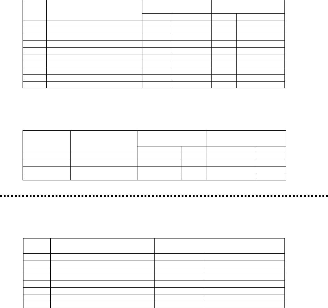
15.0.2 RECOMMENDED SPARE PARTS:
IMPORTANT: When ordering spare parts, please show MODEL NUMBER AND SERIAL NUMBER of pump for which
parts are being ordered. This information can be found on a stainless steel nameplate riveted to the side of the pump.
Recommended Spare Parts (for metal head “dia-PUMP”). It is recommended that the following parts be kept in stock
for a pump:
Kit #002719 - Fits all
Kit NO.002720 - Fits all
FIG. #
DESCRIPTION
“N1/N3" Models
"N4" Models
Qty
Part NO.
Qty
Part NO.
516-C
Sealing Plate "0" Ring
2
100186
2
100186
2310
Teflon Diaphragm
1
000388
1
000388
2334
Control Rod "0" Ring
2
100323
2
100323
2337
Vent Plug "0" Ring
2
100325
2
100325
2340
Valve Ball (316SS) or
4
100078
-
Valve Ball (C-20)
-
4
100079
2342
Valve Seat 0" Ring
8
100327
8
100327
2343
Discharge & Suction cap "0" Ring
4
100328
4
100328
5695
Valve Seat (316SS) or
4
002831
-
Valve Seat (C-20)
4
002832
15.0.3 RECOMMENDED SPARE PARTS FOR PVC and KYNAR HEAD "dia-PUMP"
Pump Serial Number > or = 147995
See PVC and Kynar Head Option on Page 20
FIG. #
DESCRIPTION
Kit #004384 for PVC
Head
Kit #004385 for KYNAR
Head
Part #
Qty.
Part #
Qty.
5 (Page#20)
Teflon Diaphragm
000388
1
000388
1
2 (Page#20)
Check Valve Assembly
004165
2
004166
2
516-C (Page#18)
Sealing Plate "0" Ring
100186
2
100186
2
2334 (Page#18)
Control Rod "0" Ring
100323
2
100323
2
Recommended Spare Parts (for PVC head "dia-PUMP). OLD STYLE (BEFORE JUNE 2004)
Pump Serial Number < or = 147994
FIG. #
DESCRIPTION
Kit #002721 - Fits all "N5" OLD Models
Qty
Part #.
516-C
Sealing Plate .0" Ring
2
100186
2310
Teflon Diaphragm
1
000388
2334
Control Rod .0" Ring
2
100323
5624
Vent Plug "0" Ring
2
100322
5628
Discharge & Suction cap “0" Ring
4
100274
5629
Vent Plug “0" Ring
2
100272
5630
Valve Seat “0" Ring
4
100273
5649
Valve Ball Ceramic
2
100275
PARTS ORDERING INSTRUCTIONS
Note: For prompt entry of parts orders: your order must include both model and serial numbers.

17
15.0.4 PARTS FOR "dia..PUMP" ORDERED WITH OTHER THAN STANDARD INTEGRALLY MOUNTED MOTOR
(REFER TO DRAWING #000911 on page#19)
The following groups of parts are sometimes referred to as a motor conversion set. These parts allow the "dia-
PUMP to accept any standard 56C frame motor.
FIG. #
DESCRIPTION
OTY.
PART #
506
Worm 37 SPM
1
000170
Worm 72 SPM
1
000172
Worm 117 SPM
1
000169
Worm 144 SPM
1
002817
507
Bearing Cup
1
100179
508
Bearing Cone
1
100180
509
Worm Spring Pin
1
100181
558
Motor Flange Adapter
1
000227
559
Worm Shaft
1
000228
560
Lovejoy Coupling
1
100053
561
Oil Seal
1
100214
562
Adapter to Gear Box Bolts
4
100215
563
Adapter to Motor Bolts
4
100216
564
Lock Washer
4
100217
565
Coupling Key
2
100218
566
Lock Washer
4
100219
Silicone Sealant
1
PARTS ORDERING INSTRUCTIONS
Note: For prompt entry of part orders, your order must include both model number and serial number
18
Drawing 5670
SERIES 500 "dia PUMP"
SECTION VII
DRAWINGS

19
DRAWING #000911
DRAWING # FALP
20
PVC AND KYNAR HEAD OPTION
This sheet describes the parts, which are unique to the 560 pumps with the PVC and Kynar Heads.
Item No.
Description
Qty
PVC Part No.
Kynar Part No.
1
Liquid Head (Pump Head)
1
004159
004160
2
Check Valve Assemblies
2
004165
004166
3
Hex Head Cap Screws
8
107766
107766
4
Flat washers
8
106857
106857
5
Diaphragm
1
000388
000388
21
APPENDIX
ADDENDUM: Special instructions for Series 500, 500-A & 560 “dia-PUMPs” with Double Diaphragm
THEORY OF OPERATION
VACUUM AIR FROM INTERMEDIATE SPACE
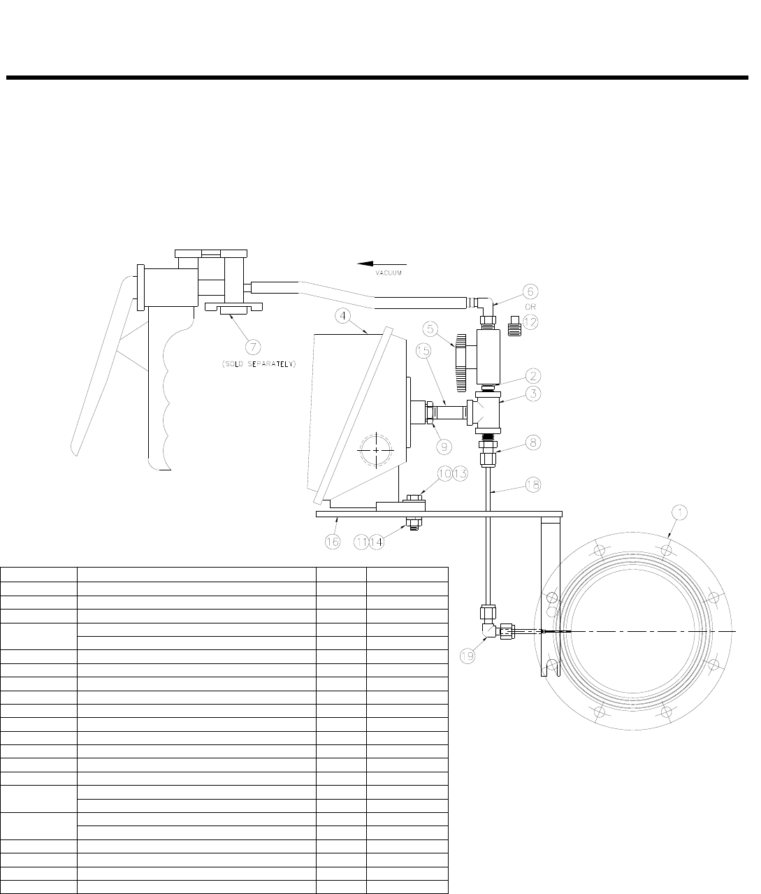
1.0.6 Open valve Item No. 5 (Figure 2).
1.0.7 To remove air, attach the vacuum pump with a
hose connection Item No. 6 to the valve Item
No. 5 (Figure 5) and pump until resistance is
felt, for normal operating conditions.
The instructions below are for Neptune’s optional Double
Diaphragm Kit which is available for the Neptune Series
560 “dia-PUMPs”.
Use of a double diaphragm allows diaphragm to be
monitored and provides an early warning upon failure of
either diaphragm allowing repairs to be made before
process fluid mix with the pump hydraulic fluid.
Neptune’s double diaphragm is a kit which may be
retrofitted to any pump currently in service or may be
installed on a new pump at the factory.
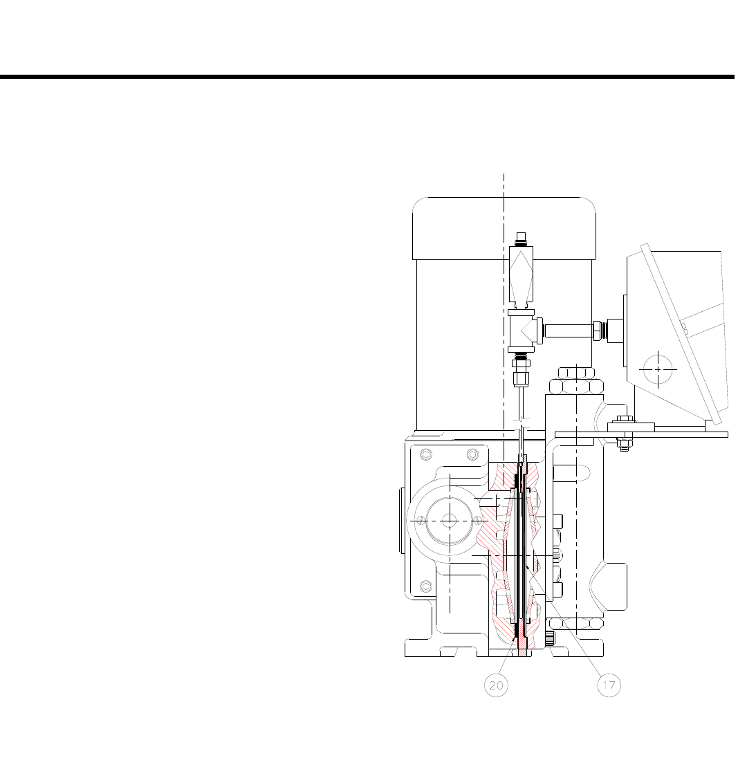
Figure 1 illustrates a Double Diaphragm Assembly. An
intermediate plate is located between the oil and liquid
heads with one diaphragm on each side of the
intermediate plate. The Intermediate Plate is connected
to a rupture alarm or pressure switch via a capillary
system. The area between the diaphragms is
evacuated. Rupture in either diaphragm produces an
increase in volume and, therefore, a pressure increase,
which can be sensed by a pressure switch for alarm
purposes.
DISASSEMBLY OF INTERMEDIATE PLATE
1.0.0 Shut pump off and disconnect suction and dis-
charge piping. Remove drain plug and drain
hydraulic fluid from the gearbox.
1.0.1 Remove 8 Screws and remove the liquid head
assembly. Some hydraulic oil and process fluid
will spill out when the head is removed.
1.0.2 The intermediate plate, which is between the
pump heads can be removed easily.
1.0.3 Remove the rupture alarm (pressure switch) and
clean the capillary system.
1.0.4 Replace one or both diaphragms if needed.
1.0.5 To reassemble reverse above procedure. Be
certain that parts align properly.
DOUBLE DIAPHRAGM OPTION
FIGURE 1
22
APPENDIX
ADDENDUM: Special instructions for Series 500, 500-A & 560 “dia-PUMPs” with Double Diaphragm
1.0.8 Close valve Item No. 5
1.0.9 Remove the vacuum pump. Plug valve Item No. 5 with a 316SS pipe plug Item No. 12
1.0.10 Reinstall the Pump
1.0.11 Follow procedure in Neptune Standard Operating and Instruction Manual for Initial Pump Startup
NOTE: Neptune furnishes a Mityvac
vacuum pump from
Mityvac
No. 6810 automotive test kit available at
many automotive parts stores. (Unit furnished by Neptune is less gage and automotive adapters)
ITEM NO.
DESCRIPTION
QTY.
PART NO.
1
INTERMEDIATE PLATE ASSEMBLY
1
003180
2
1/8 NPT NIPPLE
1
101475
3
1/8 NPT TEE
1
101898
4
PRESSURE SWITCH, NEMA 4
1
107021
PRESSURE SWITCH, NEMA 7
1
107022
5
VALVE
1
106599
6
HOSE CONNECTOR
1
WA170782
7
VACUUM PUMP (SOLD SEPARATELY)
1
108233
8
TUBE CONNECTOR, 1/8 NPT STRAIGHT
1
WD170746
9
1/4 X 1/8 NPT REDUCER BUSHING
1
101804
10
1/4-20 X 1" LG. HEX HEAD SCREW
2
100159
11
1/4-20 HEX NUT
2
100448
12
1/8 NPT PIPE PLUG, 316SS
1
101859
13
1/4" FLAT WASHER
2
108426
14
1/4" LOCK WASHER
2
100169
15
1/8 NPT NIPPLE (FOR METAL HEADS)
1
101477
1/8 NPT NIPPLE (FOR PLASTIC HEADS)
1
101479
16
BRACKET ASSEMBLY
1
003577
BRACKET ASSEMBLY (FOR DUPLEX)
1
003600
17
DIAPHRAGM
1
000388
18
VACUUM TUBE
1
004433
19
TUBE CONNECTOR, 1/8 NPT ELBOW
1
104614
20
TEFLON WASHER
1
003173
DOUBLE DIAPHRAGM OPTION
FIGURE 2

MAINTENANCE LOG
Spare Parts Kit #____________________________________________________________
NEPTUNE CHEMICAL PUMP CO. Tel.: 215-699-8700 • FAX: 215-699-0370
DATE
SERVICED BY
MAINTENANCE PERFORMED
Pump Model___________________________
Strokes Per Minute______________________
Piston Diameter________________________
Serial #_______________________________
Maximum Flow________________________
Maximum Pressure_____________________
Revision 1
Revision 2
Revision 3 8-10-2012
Revision 4 2-14-2013
Revision 5, ECN-3255 (5/18/2015)
Revision 6, (3/13/2018)
© Copyright 2011 Neptune Chemical Pump Company, Printed in U.S.A NEP-ZL105645
