Hydrovar Pump Control
INSTALLATION, OPERATION AND MAINTENANCE MANUAL
INSTRUCTION MANUAL
IM223R06
2
1 Important Safety Instructions ........................................................................................................................................ 4
2 System Design................................................................................................................................................................... 5
2.1 Pressure tank ................................................................................................................................................................ 6
3 Product Overview ............................................................................................................................................................ 7
3.1 Hardware congurations ............................................................................................................................................. 7
3.2 Operation modes ......................................................................................................................................................... 7
3.2.1 Actuator (for single pump operation only!) .................................................................................................... 7
3.2.2 Controller ............................................................................................................................................................ 7
3.2.3 Cascade Relay .................................................................................................................................................... 7
3.2.4 Cascade Serial/Synchron .................................................................................................................................. 8
4 Model Number ................................................................................................................................................................10
5 Technical Data .................................................................................................................................................................12
5.1 General technical data ..............................................................................................................................................13
5.2 EMC requirements (Electromagnetic compatibility) .............................................................................................14
6 Dimensions and Weights ..............................................................................................................................................15
7 Additional Components ................................................................................................................................................ 17
7.1 Cable glands provided ............................................................................................................................................. 17
7.2 Assembly Instructions – All models.......................................................................................................................... 18
8 Electrical Installation and Wiring ................................................................................................................................19
8.1 Equipment protection ...............................................................................................................................................19
8.2 EMC- electromagnetic compatibility ....................................................................................................................... 21
8.3 Recommended Wire Types .......................................................................................................................................22
8.4 Wiring and connections ............................................................................................................................................ 22
8.4.1 Input voltage terminals ....................................................................................................................................23
8.4.2 Motor connection .............................................................................................................................................24
8.4.3 Power unit..........................................................................................................................................................24
8.4.3.1 Solo run (Hand Mode) ........................................................................................................................25
8.4.3.2 Addressing ........................................................................................................................................... 27
8.4.4 Control unit ....................................................................................................................................................... 28
INDEX
3
9 Programming ................................................................................................................................................................... 35
9.1 Display – Control panel of the Master / Single Inverter ........................................................................................35
9.2 Function of the push buttons ...................................................................................................................................35
9.3 Basic Drive Display ....................................................................................................................................................36
9.4 Software parameters ................................................................................................................................................. 36
00 MAIN MENU ..........................................................................................................................................................37
20 SUBMENU STATUS ...............................................................................................................................................40
40 SUBMENU DIAGNOSTICS .................................................................................................................................. 43
60 SUBMENU SETTINGS...........................................................................................................................................44
0100 SUBMENU BASIC SETTINGS .......................................................................................................................... 44
0200 SUBMENU CONF INVERTER ..........................................................................................................................47
0300 SUBMENU REGULATION ................................................................................................................................ 52
0400 SUBMENU SENSOR .........................................................................................................................................54
0500 SUBMENU SEQUENCE CNTR ........................................................................................................................56
0600 SUBMENU ERRORS .........................................................................................................................................60
0700 SUBMENU OUTPUTS ......................................................................................................................................61
0800 SUBMENU REQUIRED VALUES ......................................................................................................................62
0900 SUBMENU OFFSET .......................................................................................................................................... 64
1000 SUBMENU TEST RUN ......................................................................................................................................66
1100 SUBMENU SETUP ............................................................................................................................................67
1200 SUBMENU RS485-INTERFACE .......................................................................................................................67
10 Failure Messages ..........................................................................................................................................................69
10.1 Basic Inverter ..........................................................................................................................................................69
10.2 Master / Single Inverter ........................................................................................................................................70
10.3 Internal errors.........................................................................................................................................................73
11 Maintenance .................................................................................................................................................................75
12 Programming Flow Chart ........................................................................................................................................... 76
Limited Warranty ...............................................................................................................................................................80
INDEX
4
DANGER
Section 1
Important: Read all safety information prior to installation of the Controller.
NOTE
This is a SAFETY ALERT SYMBOL. When you see this symbol on the controller, pump or in this
manual, look for one of the following signal words and be alert to the potential for personal
injury or property damage. Obey all messages that follow this symbol to avoid injury or death.
Indicates an imminently hazardous situation which, if not avoided, will result in death or
serious injury.
Indicates a potentially hazardous situation which, if not avoided, could result in death or
serious injury.
Indicates a potentially hazardous situation which, if not avoided, may result in minor or
moderate injury.
Used without a safety alert symbol indicates a potentially hazardous situation which, if
not avoided, could result in property damage.
NOTE Indicates special instructions which are very important and must be followed.
NOTE
All operating instructions must be read, understood, and followed by the operating personnel. Xylem
Inc. accepts no liability for damages or operating disorders which are the result of non-compliance with
the operating instructions.
1. This manual is intended to assist in the installation, operation and repair of the system and must be kept with
the system.
2. Installation and maintenance MUST be performed by properly trained and qualied personnel.
3. Review all instructions and warnings prior to performing any work on the system.
4. Any safety decals MUST be left on the controller and/or pump system.
5. The system MUST be disconnected from the main power supply before removing the cover or
attempting any operation or maintenance on the electrical or mechanical part of the system.
Failure to disconnect electrical power before attempting any operation or maintenance can result
in electrical shock, burns, or death.
6. When in operation, the motor and pump could start unexpectedly and cause serious injury.
Section 1A
Review Hydrovar components and ensure that all parts are included. Inspect all components supplied for
shipping damage.
Included Hydrovar components:
1. Hydrovar motor mount variable 4. 4 Attachment brackets, (bottom hook,
speed drive extender, and screws)
2. Pressure transducer with cable 5. Precision screwdriver.
3. Conduit plate caps and reducers 6. Instruction and Operation Manual
Hazardous
voltage
DANGER
Hazardous
Pressure
CAUTION
! SAFETY INSTRUCTIONS
WARNING
CAUTION
CAUTION
5
Hazardous
Pressure
CAUTION
Section 2
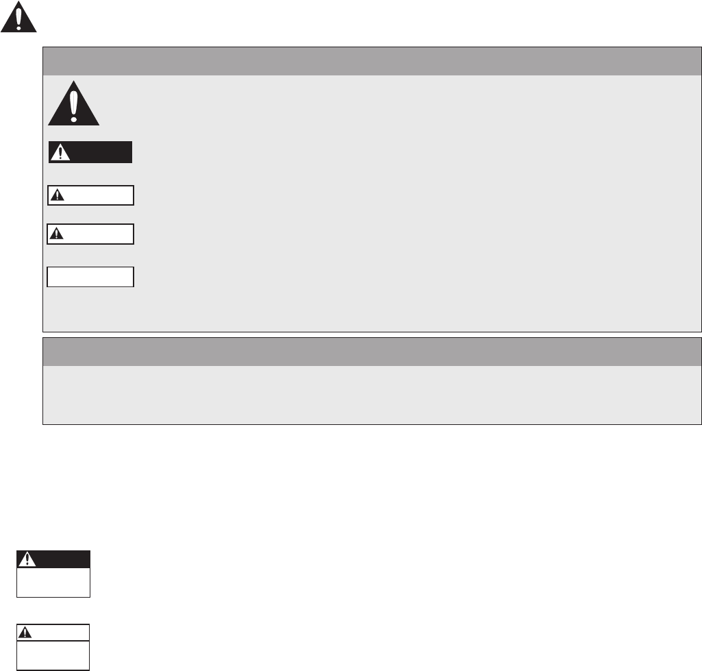
The following diagrams show typical single and multi-pump systems using the HYDROVAR Variable Speed Drive.
Connect directly to water supply. Use of a low suction pressure switch is recommended.
NOTE
Systems MUST be designed by qualied technicians only and meet all applicable state and local code re-
quirements.
Single Pump Layout Multi-Pump Layout
(1) pump with HYDROVAR (4) gate valve (7) pressure gauge
(2) diaphragm tank (5) check valve or ball valve (8) pressure transducer
(3) fusible disconnect (6) low suction pressure switch (9) pressure relief valve
General
NOTE
All plumbing work must be performed by a qualied technician. Always follow all local, state and provincial
codes.
A proper installation requires a pressure relief valve, a ¼" female N.P.T. threaded tting for the pressure sensor,
and properly sized pipe. Piping should be no smaller than the pump discharge and/or suction connections.
Piping should be kept as short as possible. Avoid the use of unnecessary ttings to minimize friction losses.
Some pump and motor combinations supplied with this system can create dangerous pressure.
Select pipe and ttings according to your pipe suppliers’ recommendation. Consult local codes for
piping requirements in your area.
All joints must be airtight. Use Teon tape or another type of pipe sealant to seal threaded connections. Use
caution when using thread sealant as any excess that gets inside the pipe may plug the pressure sensor.
Galvanized ttings or pipe should never be connected directly to the stainless steel discharge head or casing as
galvanic corrosion may occur. Barb type connectors should always be double clamped.
1
445
4
67 7
8
9
2
4 45
1
8
4 45
1
8
6
7
4 45
1
8
3
2
4
9
7
SYSTEM DESIGN

6
Pressure Tank, Pressure Relief Valve and Discharge Piping
Use only “pre-charged” tanks on this system. Do not use galvanized tanks. Select an area that is always above
34º F (1.1º C) in which to install the tank, pressure sensor and pressure relief valve. If this is an area where a water
leak or pressure relief valve blow-off may damage property, connect a drain line to the pressure relief valve. Run
the drain line from the pressure relief valve to a suitable drain or to an area where water will not damage
property.
Pressure Tank, System Pressure
Sizing – A diaphragm tank (not included) is used to cushion the pressure system during start-up and shut-down.
It should be sized to at least 20% of the total capacity of your pump. Example: If your pump is sized for 100 GPM
then size your tank for at least 20 gal. total volume, not draw down. Pre-charge your bladder tank to 15-20 PSI
below your system pressure. The controller is pre-set for 50 PSI at the factory. Therefore a 35-40 PSI pre-charge in
your tank would be required. Use the higher tank pre-charge setting if the system drifts over 5 PSI at a constant
ow rate. NOTE: Pre-charge your tank before lling with water!
CAUTION
Maximum working pressure of HydroPro diaphragm tank is 125 psi.
Installing the Pressure Sensor
The pressure sensor requires a ¼" FNPT tting for installation. Install the pressure sensor with the electrical
connector pointing up to avoid clogging the pressure port with debris. Install the pressure sensor in a straight
run of pipe away from elbows or turbulence. For optimum pressure control install the pressure sensor in the
same straight run of pipe as the pressure tank. Ensure the pressure sensor is within 10 feet of the pressure tank.
Installing the pressure sensor far away from the pressure tank may result in pressure oscillations. Do not install
the pressure sensor in a location where freezing can occur. A frozen pipe can cause damage to the pressure
sensor.
The pressure sensor cable is 30' as standard. The cable can be shortened for a cleaner installation. Longer cable
lengths are available, consult factory. Maximum recommended pressure sensor cable length is 300 feet. Avoid
leaving a coil of pressure sensor cable as this can induce unwanted transient voltages and noise into the system.
Do not run the pressure sensor cable alongside the input or output wiring. Maintain a distance of at least 8”
between the pressure sensor cable and input or output wiring.
WARNING
Discharge pressure within the piping system prior to removing pressure transducer or disconnecting any part
of the piping system. Open a valve until pressure on an external gauge reads 0 psi.
Hazardous
Pressure
CAUTION
SYSTEM DESIGN

7
Section 3
3.1 Hardware Congurations
The HYDROVAR variable speed drive consists of two separate components: the power unit and the control card.
In its basic conguration (consisting of only the power unit) the HYDROVAR can be used as a Basic Inverter. In
that conguration the HYDROVAR can be used as a sequence pump in a multi pump system, or as a simple soft
starter for single pump applications.
By extending this Basic controller with the additional control card, the HYDROVAR is able to work in different
modes and can be used for multipump applications.
Three types of drives are available. They are each capable of different levels of control. They are:
Master controller:
• Full variable speed controller of itself in a single pump conguration, with more features than the Single
controller
• Full variable speed control of the attached motor and up to 7 additional Master or Basic controllers.
• Full variable speed control of the attached motor and on/off, xed speed control of up to 5 additional pumps.
(This requires an additional relay card.)
Basic controller:
• Single pump soft start control
• Full variable speed control when connected to a Master controller
Single controller:
• Full variable speed control of a single pump with fewer features than the Master controller
3.2 Modes of Operation
3.2.1 Actuator (for single pump operation only!)
In this mode the HYDROVAR operates as an actuator with external speed signal or switching between 2
programmed frequencies by using the corresponding digital input. For this application the HYDROVAR
operates like a standard frequency converter when an external controller is used.
NOTE
This mode can only be programmed with a Master or Single controller, and is for single pump systems
only.
3.2.2 Controller
This mode should be selected if only one HYDROVAR pump is in operation and there is no connection to
any other HYDROVAR via RS485 interface.
→ Typical single pump operation
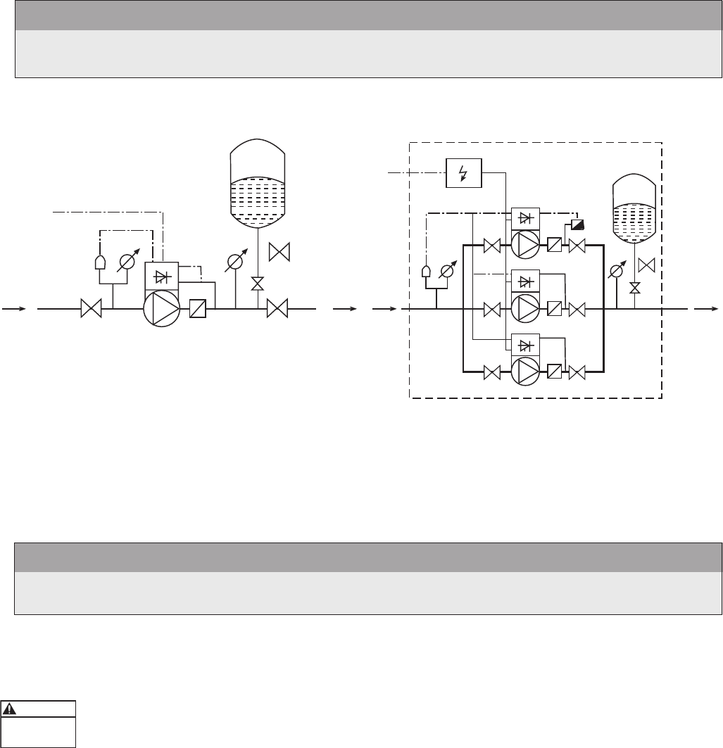
3.2.3 Cascade Relay
One pump is tted with a HYDROVAR Master controller and up to 5 xed speed pumps can be switched ON
and OFF on demand. For this purpose an additional Relay Card with 5 relays is used in the Master controller.
Separate motor starters are needed for each motor relay, because the relays in the HYDROVAR are control
contacts only.
Lead/Lag switching of the xed speed pumps to provide even wear and achieve even operating hours can
be programmed in this mode.
This conguration is a cost effective alternative compared with other solutions using VFD’s on each pump,
but additional equipment is required, and you only have xed speed control of the pumps.
PRODUCT OVERVIEW
8
Application Example
Booster sets up to 6 pumps where only one pump is speed controlled by the HYDROVAR and the others are
xed speed (1 HYDROVAR Master Inverter+5 xed speed). This should be the standard conguration when
the additional Relay Card is used.
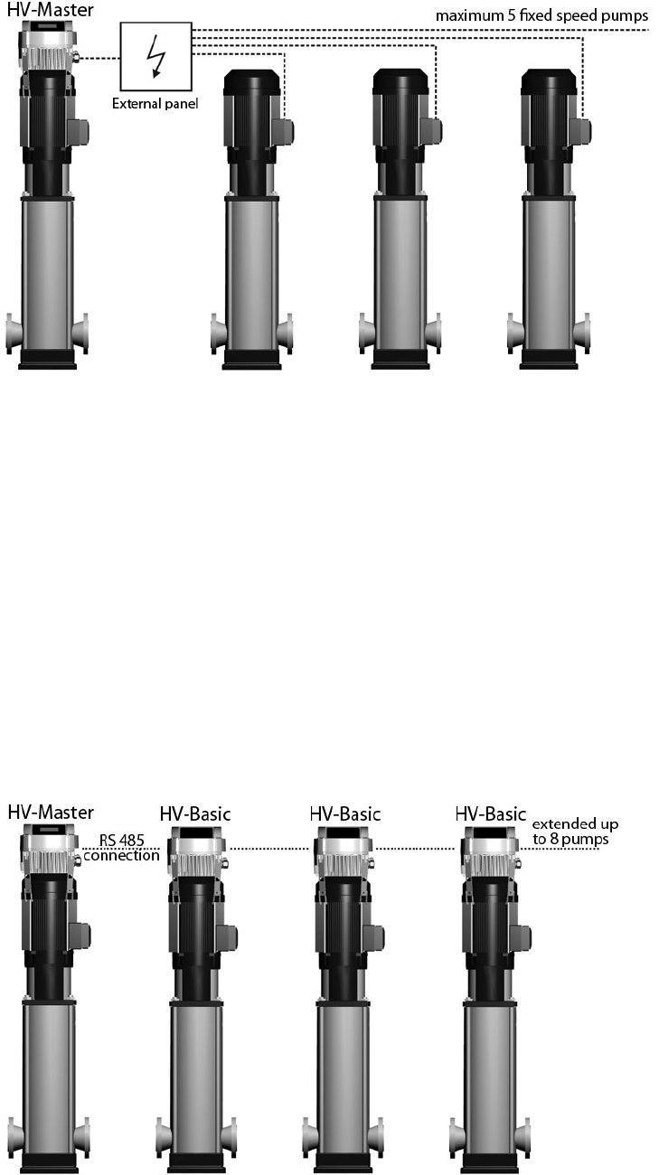
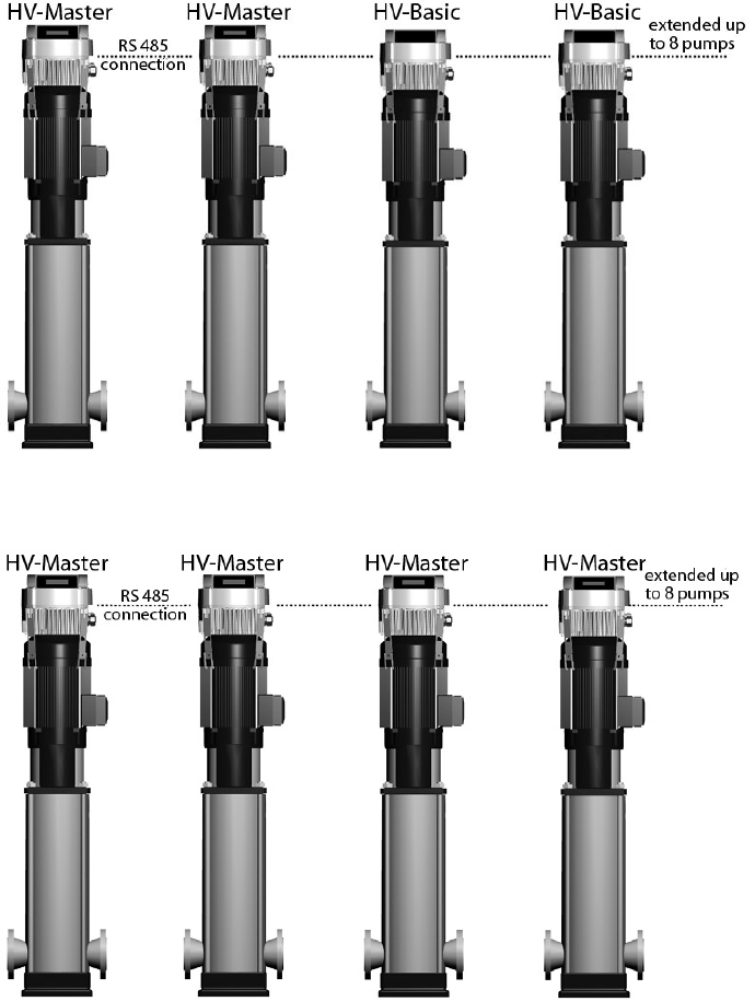
3.2.4 Cascade Serial and Cascade Synchron
In these modes each of the pumps is equipped with a HYDROVAR unit. All units are connected and
communicate via the RS485 interface.
At least one Master controller is used. The other pumps can be controlled by Basic or Master drives. The
Master controller continually reads the status and failures of the Basic controllers. All failures are indicated on
the master unit, including the date and time.
The Master controller has complete control of all pumps in the system, including automatic alternation of the
lead and lag pumps, which provides even wear and achieves even operating hours for each pump.
If the control card of a Master controller fails, each of the Basic controllers can be manually started by an
external switch (manual operation) for “emergency operation” of the system.
Application Example
Each pump, (up to 8 pumps), is equipped with a HYDROVAR unit. At least one Master controller will be
connected to up to seven Basic controllers. All units are connected via the serial interface (RS485).
The combination of the different HYDROVAR units that are used in a multi-pump-system depends on the
system requirements (i.e. in a 6 pump system 2 or more Master controllers can be used to increase reliability,
and up to 4 Basic controllers
without control card.
Minimum requirement: 1
Master controller and the other
pumps equipped with Basic
controllers.
PRODUCT OVERVIEW
9
To increase the reliability of a system, (in the event of a Master controller failure) a second Master controller
can be used.
Full-featured possibility: Each pump is equipped with a Master controller.
In this mode it is possible to run all pumps in cascade serial mode and synchronous mode as well.
This conguration allows each pump to become the lead pump. This also ensures a proper operation if one
Master controller fails. In this case another HYDROVAR takes control. This ensures that the operating hours of
each pump will be the same to ensure even wear of the pumps.
PRODUCT OVERVIEW

10
Section 4
Hydrovar Variable Speed Drive Type and Catalog Number
Hydrovar Example Product Code
HV M 3 4 20 0
Filter (optional): Standard = 0, (no lter)
Residential = B
HP Rating: 02 = 2 03 = 3 05 = 5
07 = 7.5 10 = 10 15 = 15
Volts: 2 = 230V 4 = 460V
Phase: 1 = Single Phase 3 = 3 Phase
Type: M - Master
S - Single
B - Basic
Series: HV
The following applies to this example:
HV - Hydrovar Variable Speed Drive
M - Master Drive, (full control and communications)
3 - 3 Phase input power
4 - 460 Volt input power
20 - 20 Horsepower rated
Blank: Standard Commercial Filter, (not residential)
MODEL NUMBER CODE

11
Section 4 (continued)
Hydrovar Product Numbering Chart
MODEL NUMBER CODE
Voltage Phase Normal Duty HP Drive Type Model Number
230 V 1
2
MASTER HVM1202
BASIC HVB1202
SINGLE HVS1202
3
MASTER HVM1203
BASIC HVB1203
SINGLE HVS1203
460 V 3
3
MASTER HVM3403
BASIC HVB3403
SINGLE HVS3403
5
MASTER HVM3405
BASIC HVB3405
SINGLE HVS3405
7.5
MASTER
HVM3407
BASIC HVB3407
SINGLE HVS3407
10
MASTER HVM3410
BASIC HVB3410
SINGLE HVS3410
15
MASTER HVM3415
BASIC HVB3415
SINGLE HVS3415
12
Section 5
TECHNICAL DATA
Hydrovar Power Supply
Rated Output Voltage Limits 48-62 HZ
Rated Current
Input
Recommended
Line Protection
Maximum
Wire Size
Cat #* HP V Amps Amps AWG
HVM1202 2
1 Ph, 220-240V -10%,
+15%
14 20 14
HVM1203 3 20 25 10
HVM3403 3
3 Ph, 380-460V
+-15%
7.6 10 14
HVM3405 5 11.4 15 14
HVM3407 7.5 15.1 20 12
HVM3410 10 19.6 20 10
HVM3415 15 27.8 30 8
* Listed catalog numbers are for master drives. Details also apply to corresponding basic and single units.
Hydrovar Output to the Motor
Rated Output Voltage Limits 48-62 HZ Rated Current Output Motor Connection Wires
Cat #* HP V Amps AWG
HVM1202 2
3 Ph, 240V
7 14
HVM1203 3 10 14
HVM3403 3
3 Ph, 480V
5.7 14
HVM3405 5 9 14
HVM3407 7.5 13.5 14
HVM3410 10 17 12
HVM3415 15 23 10
13
5.1 General Technical Data
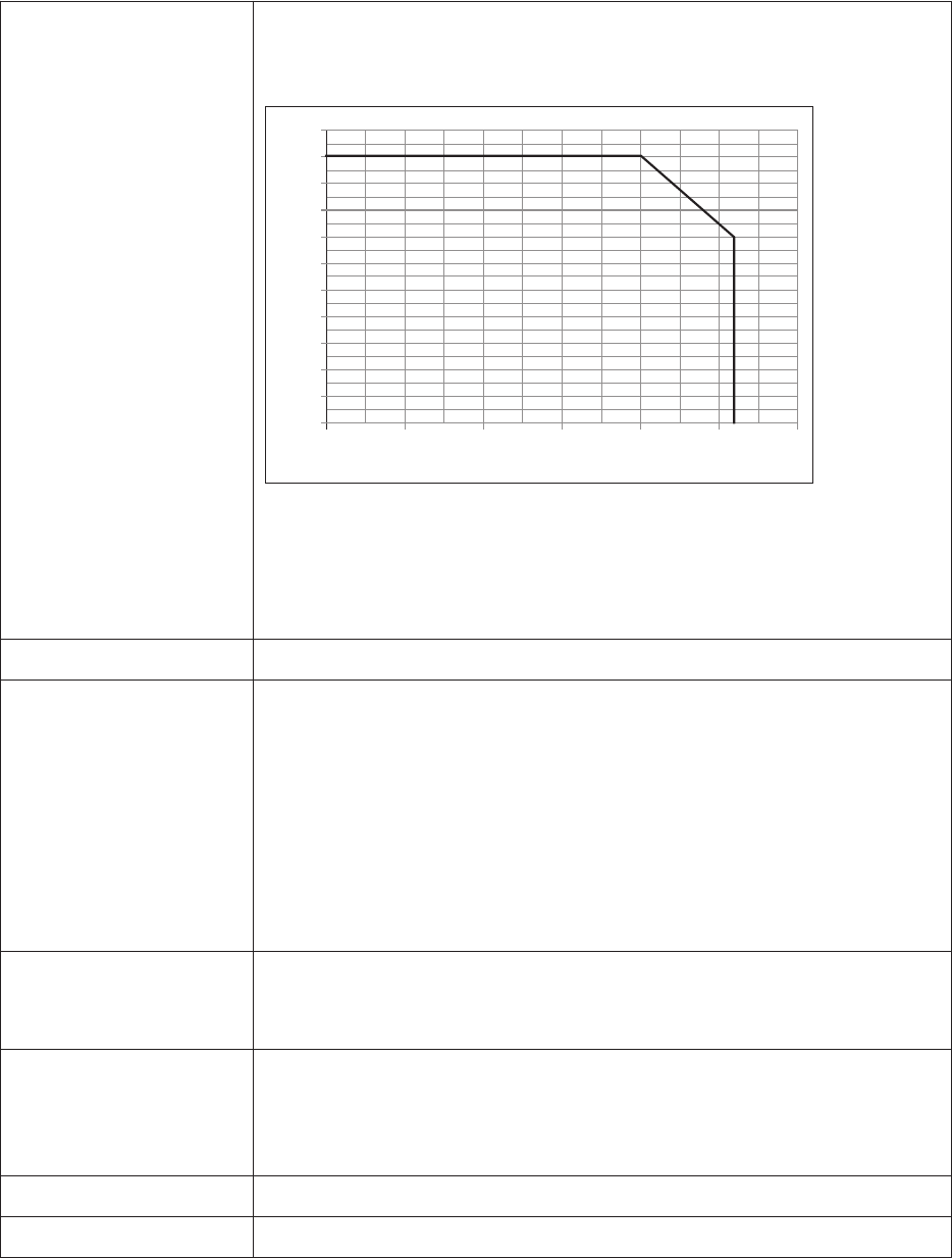
Ambient temperature: 0° C ... +40° C, 32º F... +104º F
At higher temperatures reduce the output current as shown below or
upsize to the next largest HYDROVAR.
The enclosure rating of the HYDROVAR is NEMA 1 however, please note
the following:
• Protect the HYDROVAR from direct sunlight!
• Indoor installation only.
Storage temperature: -25° C ... +55° C, -10º F ... +130º F
Humidity: RH maximum 50% at 104º F, unlimited
RH maximum 90% at 70º F, maximum 30 days per year
75% average per year (class F)
Condensation is not allowed and will void warranty!
During long periods of inactivity or shutdown, the HYDROVAR should
remain connected to the power supply but turned off to prevent
inadvertant pump run. This will maintain power to the internal heater and
reduce internal condensation.
Air pollution: The air may contain dry dust as found in workshops where there is
excessive dust due to machines. Excessive amounts of dust, acids,
corrosive gases, salts etc. are not permitted
Altitude: Maximum 1000 m, 3280 feet above sea level.
At sites over 1000 m above sea level, the maximum output power should
be de-rated by 1% for every additional 100 m. For installations higher
than 2000 m above sea level, please contact your local distributor.
Class of protection: NEMA 1 (Indoor use only)
Certications: CE, UL, C-Tick, cUL
0
10
20
30
40
50
60
70
80
90
100
110
0102030405
06
0
Maximum Ambient Temperature (ºC)
Maximum Output Current (%)
TECHNICAL DATA

14
5.2 EMC Requirements (Electromagnetic Compatibility)
The EMC requirements depend on the intended use.
Class B environment (EN 61800-3: Class C2)
Environment that includes domestic premises, it also includes establishments directly connected without in-
termediate transformers to a low-voltage power supply network which supplies buildings used for domestic
purposes. Examples of class B environments include houses, apartments, commercial premises or ofces in a
residential building.
CAUTION: The relevant EMC regulations for which the HYDROVAR was tested in class B environments is based
on the restricted use of the product and the following limitations:1) the drive voltage is less than 1000 V; 2) it
is neither a plug in device nor a movable device and, 3) when used in the class B environment, it is intended to
be installed and utilized by technicians with the necessary training and skills required for installing and/or using
power drive systems, including specic training with respect to EMC requirements.
Class A environment (EN 61800-3: Class C3)
Environment that includes all establishments other than those directly connected to a low voltage power supply
network which supplies buildings used for domestic purposes e.g. Industrial areas, technical areas of any build-
ing fed from a dedicated transformer are typical examples of class A environment locations.
The HYDROVAR complies with the general EMC regulations and is tested according to the following
standards: EN 61800-3/2004
EN 55011 (2002) Disturbance voltages / Disturbance eld strength
First environment Second Environment
– class B / class C2 – class A / class C3
Disturbance voltages OK OK
Disturbance eld strength * OK
* Warning - In a domestic environment, this product may cause radio interference, in which case supplementary mitigation measures
may be required.
EN 61000-4-2 (2001) Electrostatic discharge
EN 61000-4-3 (2002) Electromagnetic eld immunity test
EN 61000-4-4 (2001) Burst immunity test
EN 61000-4-5 (2001) Surge immunity test
EN 61000-4-6 (1996) Immunity of conducted RF-Disturbance
TECHNICAL DATA
15
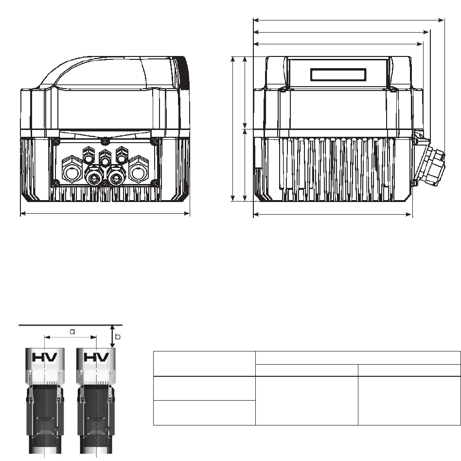
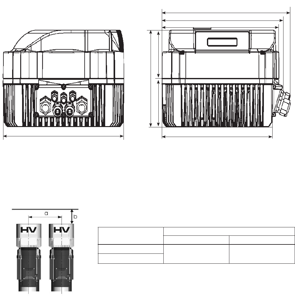
Section 6
HVM1202, HVM1203, HVM3403, 3405
All dimensions in inches! Drawings are not to scale!
Dimensions are nominal
Type
Weight [lbs]
Basic Master / Single
2, 3 HP
1 Ph
8.8 9.7
3, 5 HP
3 Ph
a … minimum center-distance between HYDROVARs 12"
b … header space for maintenance 12"
7.4
7.9
8.9
3.353.35
6.7
7.9
8.2
DIMENSIONS AND WEIGHTS
16
HVM3407, HVM3410, HVM3415
All dimensions in inches! Drawings are not to scale!
Dimensions are nominal
Type
Weight [lbs]
Basic Master / Single
7.5, 10, 15 HP
16.9 17.8
3 Ph
a … minimum centre-distance between HYDROVARs 17"
b … minimum header space for maintenance 12"
9.4
10.2
10.9
3.35
3.35
6.7
9.9
10.2
DIMENSIONS AND WEIGHTS
17
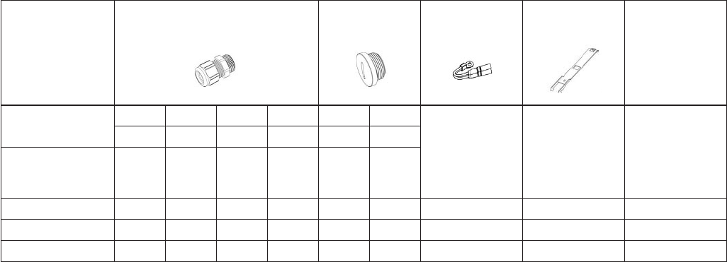
Section 7
7.1 Cable Glands Provided
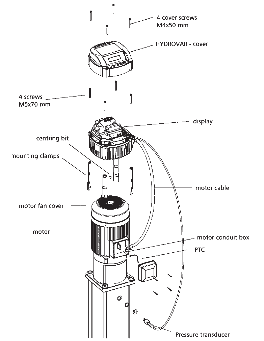
7.2 Assembly Instructions – All models
To remove the HYDROVAR cover, loosen the 4 fastening screws.
• Verify that there is no liquid on the unit before you open the cover.
• The HYDROVAR is installed on the motor fan cover using the mounting brackets, the four screws and the rel-
evant washers.
• Center the HYDROVAR and tighten the four screws holding the brackets.
• Tighten each screw until the two bottom teeth in the brackets start to grip the fan cover.
• After the electrical components are connected, the top cover of the HYDROVAR can be mounted and tight-
ened by the four fastening screws.
• Ensure the integrity of the ground wire connection. Failure to properly ground the controller or motor will cre-
ate an electrical shock hazard.
• Ensure HYDROVAR cover gasket is in place before tightening the cover screws.
• Ensure cable glands are properly installed and close conduit openings that are not being used with conduit
plugs.
ADDITIONAL COMPONENTS
Included
components
Cable gland
and lock nut
Conduit
plugs
Thermistor
Mounting
clamps
Centring - bit
Gland sizer
M M M M M M
12 16 20 25 12 16
Cable
size
AWG
#8-#1 4,5-10 7-1 3 9-17
2.015- 2.022 2 (3) 2 2 3 1 1 4 1
4.022- 4.040 2 (3) 2 2 3 1 1 4 1
4.055- 4.110 2 (3) 2 2 3 1 1 4 1
( ) maximum available cable entries
18
7.2 Assembly Instructions – All models (continued)
ADDITIONAL COMPONENTS

19
Section 8
NOTE
All installations and maintenance must be performed by properly trained and qualied
personnel. Use personal protection equipment.
NOTE
In case of a failure, the electrical power must be disconnected or switched off. Wait at least 5
minutes for capacitor discharge before servicing the HYDROVAR. Shock, burns or death are
possible hazards if the capacitor discharges during maintenance, repair, or assembly.
8.1 Equipment Protection
Follow state, and local codes for proper equipment protection.
Applicable: • proper grounding
• AC and DC Ground Fault Circuit Interrupter (GFCI)
Proper grounding:
• Please note that leakage to ground can occur due to the capacitors in the input lter.
• A suitable protection unit has to be selected (according local regulations).
Ground Fault Circuit Interrupter (GFCI):
• When using a GFCI, make sure that it also releases in the event of a short circuit inside the DC-part of the HY-
DROVAR to ground!
• single phase HYDROVAR => use pulse sensitive GFCI's
• three phase HYDROVAR => use AC/DC sensitive GFCI's
• The GFCI should be installed according to local regulations!
Fuses:
• Use Very fast acting Class T fuses
• Bussman T-tron type JJN and JJS fuses are acceptable (or equal)
Internal equipment protection:
• The Hydrovar has internal protections against the following malfunctions: short circuit; under and over-voltage,
overload and the overheating of the electronic components.
External protective devices:
• Additional protective functions like motor overheat and low water protection are controlled by separate equip-
ment.
ELECTRICAL INSTALLATION AND WIRING
20
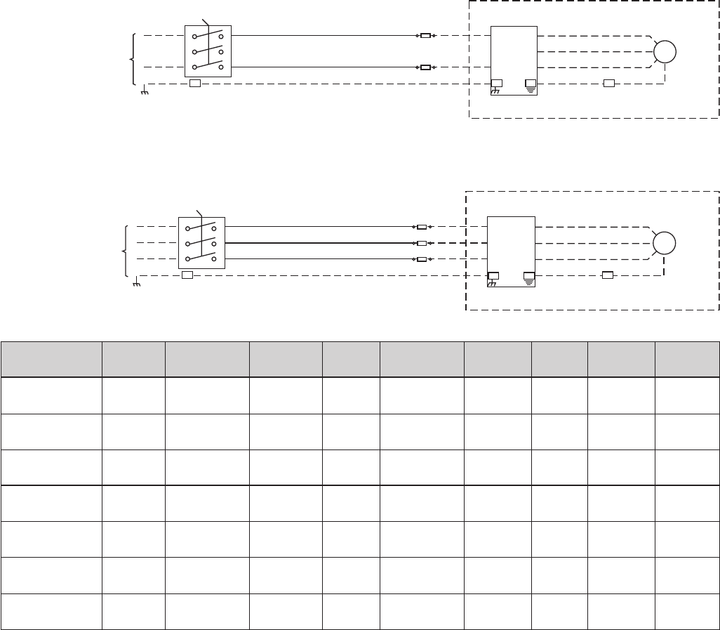
Fused Disconnect Box:
GND
L1
L2
1
3
5
2
4
6
SINGLE
PHASE
CU
STOMER SUPPLIED
VOLTAGE
DISCONNECT
FUSE BLOCK
12 AWG
12 AWG
HYDROVAR
GND
PE
L1
L2
L3
U
V
W
16 AWG
GND
MTR
MOTOR
CUSTOMER SUPPLIED
GND
L1
L3
1
3
5
2
4
6
THREE
PHASE
CUSTOMER SUPPLIED
VOLTAGE
DISCONNECT
FUSE BLOCK
12 AWG
12 AWG
HYDROVAR
GND
PE
U1
V1
W1
U2
V2
W2
16 AWG
GND
MTR
MOTOR
CUSTOMER SUPPLIED
L2
12 AWG
ELECTRICAL INSTALLATION AND WIRING
Disconnect
Part Number
Input
Voltage
Disconnect
HP / AMP
Rating
Wire
Range
Tightening
Torque
Fuse
Supplier
AMP
Rating
Part
Number
Voltage
Rating
HFD512C1 230/1/60 OT25F3 2 HP / 25A
#18-
8AWG
7 IN/LB Bussman 20 KTK-R-20 600V
HFD512E1 230/1/60 OT40F3 3 HP / 40A
#18-
8AWG
7 IN/LB Bussman 30 KTK-R-30 600V
HFD534A1 460/3/60 OT16F3 3 HP / 16A
#18-
8AWG
7 IN/LB Bussman 10 KTK-R-10 600V
HFD534B1 460/3/60 OT16F3 3 HP / 16A
#18-
8AWG
7 IN/LB Bussman 15 KTK-R-15 600V
HFD534C1 460/3/60 OT25F3 3 HP / 25A
#18-
8AWG
7 IN/LB Bussman 20 KTK-R-20 600V
HFD534C2 460/3/60 OT25F3 3 HP / 25A
#18-
8AWG
7 IN/LB Bussman 20 KTK-R-20 600V
HFD534E2 460/3/60 OT40F3 3 HP / 40A
#18-
8AWG
7 IN/LB Bussman 30 KTK-R-30 600V
NOTE: Recommended protection (not included with drive only). This fused disconnect is available as part of the PHV series packaged
Hydrovar, see price book.
21
8.2 EMC – Electromagnetic Compatibility
To ensure electromagnetic compatibility the following points must be observed for cable installation:
Control Cables
General Recommendations
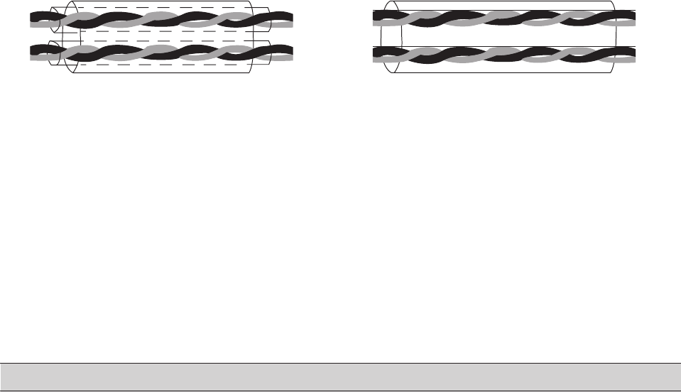
Use shielded cables, temperature rated at 60º C (140º F) or above:
• Control cables must be multi-core cables with a braided copper wire screen.
Double Shielded Single Shielded
Example: JAMAK by Draka NK Cables Example: NOMAK by Draka NK Cables
• The screen must be twisted together into a bundle not longer than ve times its width and connected to
terminal X1-1 (for digital and analog I/O cables) or to either X1-28 or X1-32 (for RS485 cables).
Route control cables to minimize radiation to the cable:
• Route as far away as possible from the input power and motor cables (at least 20 cm (8 in)).
• Where control cables must cross power cables make sure they are at an angle as near 90º as possible.
• Stay at least 20 cm (8 in) from the sides of the drive.
Use care in mixing signal types on the same cable:
• Do not mix analog and digital input signals on the same cable.
• Run relay-controlled signals as twisted pairs (especially if voltage > 48 V). Relay-controlled signals using
less than 48 V can be run in the same cables as digital input signals.
NOTE! Never mix 24 VDC and AC power signals in the same cable.
Motor Wires
To ensure the EMC compatibility and minimize noise level and leakage currents, use the shortest possible mo-
tor wires. Use shielded wires only if the total length exceeds 6 feet.)
Line Reactors
Line reactors are available as an option and should be mounted between the HYDROVAR and the main fuse.
The Line reactor should be as close to the HYDROVAR as possible, (max. 12").
Advantages:
• more efcient
• reduction of harmonic currents
For the following applications additional line reactors are strongly recommended:
• high short circuit currents
• compensation-plants without a coil
• asynchronous motors which are responsible for a voltage drop >20% of the line voltage
EMC Summary
• Install proper grounds according to local codes and regulations
• Do not install the power wires in parallel to control wires
• Use screened control cables
• Connect both ends of the motor wire screen to ground
• Connect only one end of the control wire screen to ground
• Motor wires should be as short as possible
ELECTRICAL INSTALLATION AND WIRING
22
8.3 Recommended Wire Types
For maximum 40º C ambient temperature, recommend use of 75º C wire of the following types:
RHW, THHW, THW, THWN, XHHW, USE, ZW.
8.4 Wiring and Connections
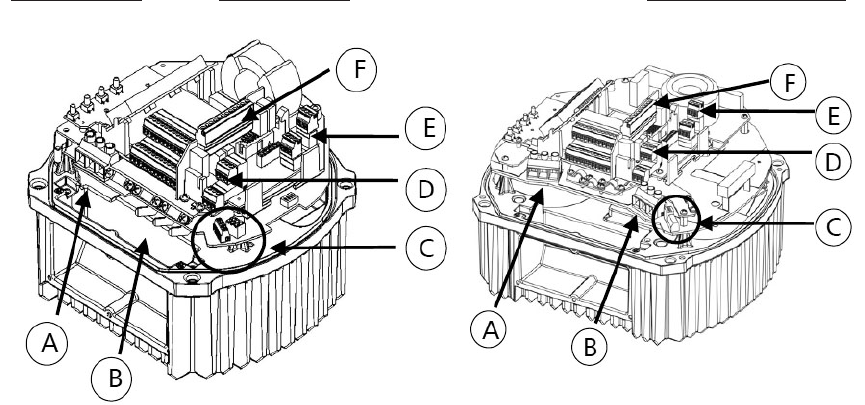
Remove the screws holding the top cover of the HYDROVAR.
Lift off the top cover. The following parts can be seen on a HYDROVAR Master / Single Drive:
1 Ph / 2, 3 HP 3 Ph / 3, 5 HP 3 Ph / 7.5, 10, 15 HP
(A) Power supply (B) Motor connections (C) Terminal block:
- START/STOP
(D) RS-485 Interface (E) Status-Relays - SOLORUN (hand mode)
- User interface - RS-485 Interface
- Internal interface (F) Optional Relay Card
ELECTRICAL INSTALLATION AND WIRING
23
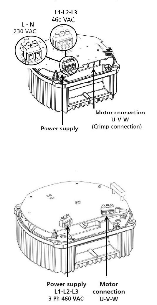
8.4.1 Input Voltage Terminals
The power supply is connected to the power section:
Terminal L + N (230 VAC, single-phase)
Terminal L1+ L2 + L3 (460 VAC, three-phase)
2, 3 HP / 1Ø 3, 5 HP / 3Ø
7.5, 10, 15 HP / 3Ø
ELECTRICAL INSTALLATION AND WIRING
24
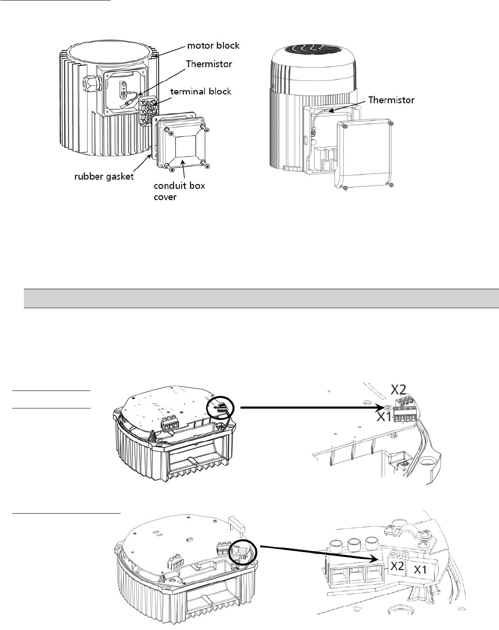
8.4.2 Motor Connection
Attaching the Thermistor
Method A : Method B :
1. Remove conduit box cover
2. Attach the thermistor (Method A or B)
3. Replace the terminal block, if necessary
4. Wire the motor according to the motor manufacturer's instructions.
NOTE! The thermistor must be attached to the motor. This is required to measure the motor temperature!
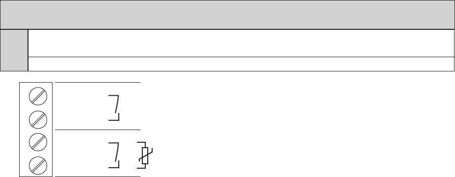
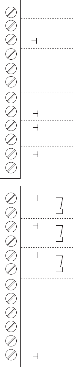
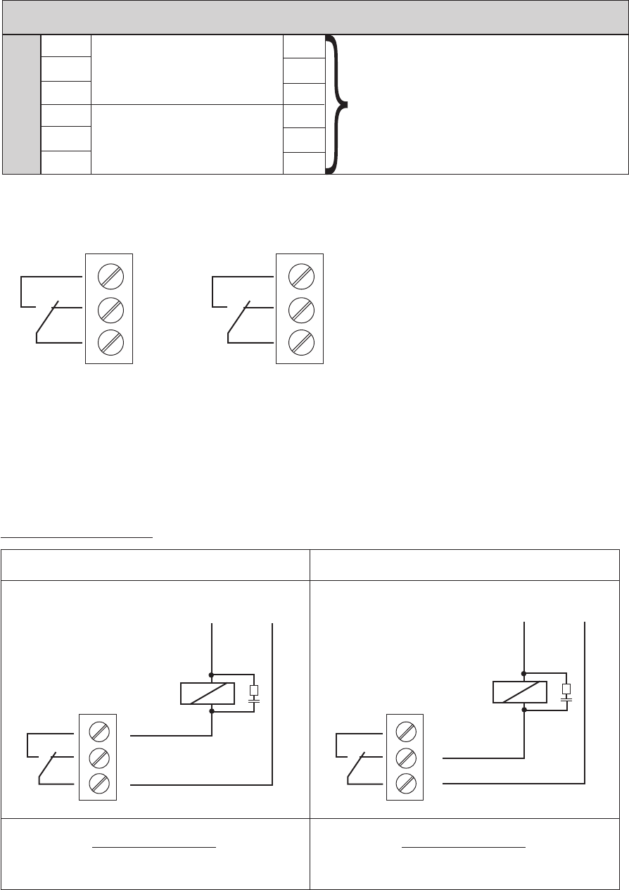
8.4.3 Power Unit
The basic drive has two control terminal blocks.
HVB 1202, 1203
HVB 3403, 3405
HVB 3407, 3410, 3415
ELECTRICAL INSTALLATION AND WIRING
25
X1 Control terminals – power unit
PTC Terminals have Jumper between them.
Remove jumper and attach Thermistor leads
SL SOLO RUN (Hand Mode)
SL
SOLO RUN (Hand Mode)
SL
PTC
START/STOP via Thermistor
PTC
To protect the motor against thermal overload, a thermistor should be connected to the drive at the terminals la-
beled PTC. This input can also be attached to an external ON / OFF switch when using the HYDROVAR as a Basic
drive. Either the thermistor or on/off switch must be closed between X1/PTC or the drive will stop running! A low
water switch or other protective device can also be connected to these terminals!
If these terminals are not used, they must be jumpered, otherwise the HYDROVAR will not start.
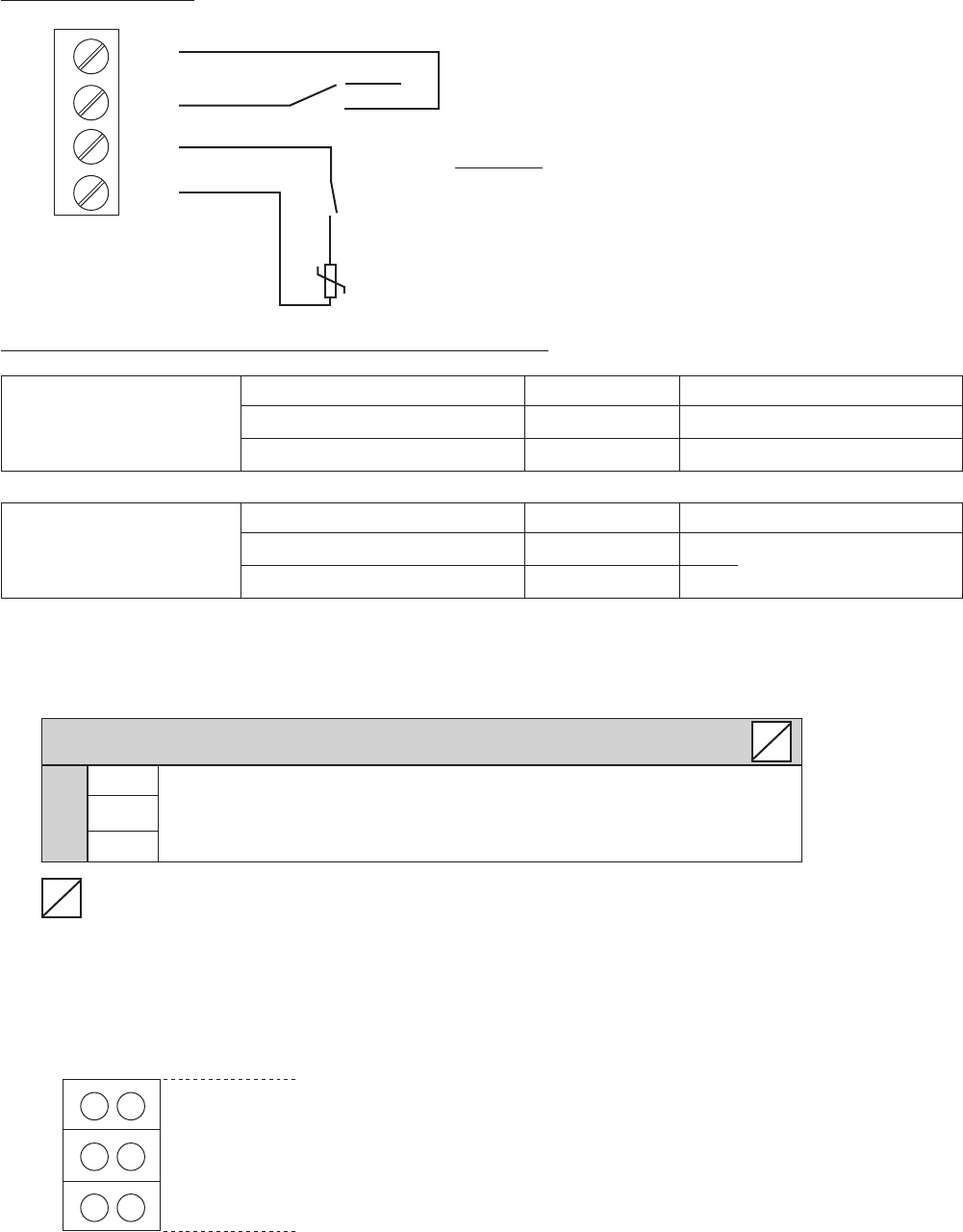
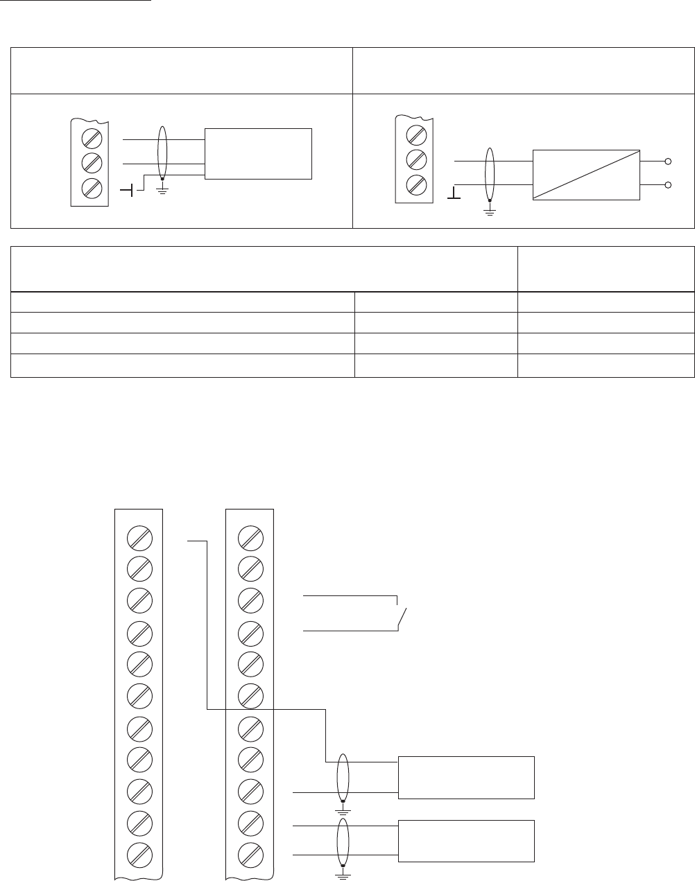
8.4.3.1 Solo Run (Hand Mode)
Terminals X1/SL are used to enable a Basic drive (when used in a multi-pump application) when the commu-
nication from the Master drive fails, or if the Master drive itself fails, or to use the Basic drive as a soft-starter.
• If the circuit is open between the two X1/SL terminals, the HYDROVAR works in standard operation as
controlled by a Master drive.
• When contact between the two X1/SL terminals is closed, (contact between X1/PTC terminals must also
be closed), the HYDROVAR starts up to the pre-selected Max Frequency, (set via xed speed, (parameter
0245) using ramps 1 and 2 or the fast ramps FminA and FminD).
A manual override switch can be placed between the 2 X1/SL terminals. When the circuit is open, the drive
will work with the Master. When it is closed, the drive will operate manually.
X1
ELECTRICAL INSTALLATION AND WIRING
26
Connection Example
External switch to enable the
SOLO RUN (Hand Mode)
Example:
Low water or other
emergency off switch
Thermistor
(mounted in the motor terminal box)
Recommended connections of external protective devices:
Basic drive Thermistor X1/PTC
Emergency switch X1/PTC As described above
Low water switch X1/PTC
Master drive Thermistor X1/PTC As described above
External release X3/7-8
On the control card
Low water switch X3/11-12
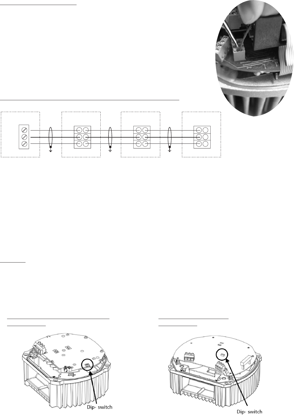
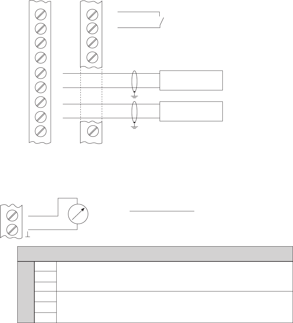
When the HYDROVAR is used as a Basic drive in a multi-pump system, the X2 terminals on the power unit are
used for the serial RS-485 connection to the other HYDROVAR units in the system. (Note: Internal interface is
not available on Single Inverters!)
X2 RS485-Interface – Power Unit
X2/ SIO - Internal SIO-interface: SIO-
Internal interface
SIO+ Internal SIO-interface: SIO+
for multi-pump-systems
GND GND, electronic ground
……. Terminals not available for HYDROVAR Single drives
The internal RS-485 Interface on the power unit is used for the communication between up to 8 HYDROVARs
in a multi-pump system (minimum 1 Master drive). Use the same terminals to continue on to the next
HYDROVAR if required. Terminals X4/4-6 can also be used for RS-485 communication on all Master drives.
X2
GND
SIO + RS485 – internal interface
SIO -
X1
SL
SL
PTC
PTC
SW 1
Auto
Manual
S
S
}
ELECTRICAL INSTALLATION AND WIRING
27
Terminating Control Wires:
- Use recommended cable type (see section 8.2)
- Strip the end of the wire aproximately 1/4"
- Push down the orange wedges using a small screwdriver
- Insert the stripped wire
- Remove the screwdriver to complete the connection
- To remove, push down the orange wedges and pull out the wire!
Connection Example Using One Master and Three Basic Drives:
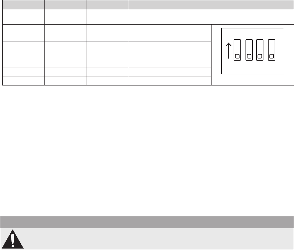
8.4.3.2 Addressing
When using the cascade serial/synchron mode in a multi-pump-application (where more than drive is used),
each drive must be addressed correctly.
Master drive – The address of the Master drive is set using the Hydrovar software. Dip switches are used to
program the Basic drives to a specic address. On all Master drives the dip switches must be set to address 1
(default setting, see below).
Basic Drive – When using a Basic drive in a Multi-pump-system the dip switches must be set to the appropri-
ate address for each drive in the system. The addresses for the Basic drives start after the last address of the
nal Master drive in the system. The S1 switchbank is located on the lower board behind the control panel.
(See pictures below for locations.)
Example:
Multi-pump-system with 3 Master and 4 Basic drives
• Set address 1-3 for the Master Inverters via appropriate software parameters (See submenu CONF
INVERTER [0100] or submenu RS485-INTERFACE [1200])
• Address 4-7 for the Basic Inverters via dip-switches
The pre-selected address also denes the initial pump sequence.
HVB 1202 / 1203, HVB 3403 / 3405 HVB 3407 / 3410 / 3415
Basic Inverter Basic Inverter
GND
SIO +
SIO -
GND
SIO +
SIO -
GND
SIO +
SIO -
GND
SIO +
SIO -
6
5
4
X4
X2 X2 X2
HYDROVAR Master Inverter
Control Card
HYDROVAR Basic Inverter
Power Unit
HYDROVAR Basic Inverter
Power Unit
HYDROVAR Basic Inverter
Power Unit
ELECTRICAL INSTALLATION AND WIRING
28
Setting the correct address on Basic drives:
• The HYDROVAR must be disconnected from power supply for at least 5 minutes before removing the top
cover!
• Use the dip-switch on the power unit. (See picture above!)
• Set the desired address for each HYDROVAR
E.g. Address 4 -> switch 1 is set to OFF
switch 2 and 3 are set to ON
• Mount the cover on the HYDROVAR and tighten the four fastening screws
• Reconnect HYDROVAR to power supply
8.4.4 Control Terminals
All control wires connected to the control-unit must be screened (See section 8.2 for recommended wire types).
External voltage free contacts must be suitable for switching <10 VDC.
NOTE
If unscreened control wires are used, signal interference may occur and could interfere with
the function of the HYDROVAR.
Do not connect the control card ground to other voltage potentials. All electronic ground terminals and GND of
the RS 485-interface are connected internally.
ON
1 2 3 4
ELECTRICAL INSTALLATION AND WIRING
Switch 1 Switch 2 Switch 3 Address
OFF OFF OFF
Address 1 (default setting)
(Required setting for the use with control card)
OFF OFF ON Address 2
OFF ON OFF Address 3
OFF ON ON Address 4
ON OFF OFF Address 5
ON OFF ON Address 6
ON ON OFF Address 7
ON ON ON
Address 8
Switch 4 not used!

29
X3 Digital and Analogue I/O
X3/ 1 GND, electronic ground
2 Actual value current input sensor 1 0-20mA / 4-20mA [Ri=50Ω]
3 Power supply for external sensors 24VDC, ** max. 100mA
4 Actual value current input sensor 2 0-20mA / 4-20mA [Ri=50Ω]
5 Actual value voltage input sensor 2 *DI 2 0-10 VDC
6 Actual value voltage input sensor 1 *DI 1 0-10 VDC
7 External ON/OFF (E-Stop) *** Switch or jumper
8 GND, electronic ground
9 Congurable digital input 1 Switch between DI 1
10 GND, electronic ground and DI 2
11 Low water *** Switch or jumper
12 GND, electronic ground
13 Voltage signal input (required value 1) (Offset) 0-10VDC
14 GND, electronic ground
15 Voltage signal input (required value 2) *Dig 3
(Offset)
0-10VDC
16 GND, electronic ground
17 GND, electronic ground
18 Current signal input (required value 1) (Offset) 0-20mA / 4-20mA
[Ri=50Ω]
19 +10V internal ref. for analogue output 10,00VDC, max. 3mA
20 Analogue output 1 0-10VDC, max. 2mA
21 Analogue output 2 4-20mA
22 GND, electronic ground
23 Current signal input (required value 2) (Offset) 0-20mA / 4-20mA [Ri=50Ω]
24 +24V power supply for control inputs 24VDC, ** max. 100mA
* Terminals 5 and 6 can be used as actual value voltage input and also as digital input. Also the
voltage signal input on terminal X3/15 can be used as digital input.
** X3/3 and X3/24 → maximum 100mA
*** Must be connected through a switch or a jumper
(Offset) These terminals can be used as required value or offset signal input. Conguration: see
submenu REQUIRED VALUES [0800] and submenu OFFSET [0900].
ELECTRICAL INSTALLATION AND WIRING
30
Additional power supply ** max. 100 mA
Current signal input (required val. 2) 0-20mA / 4-20mA [Ri=50Ω]
To determine the required value or the offset
Analogue output 2 4-20mA
Analogue output 1 0-10 VDC
Current signal input (required val. 1) 0-20mA / 4-20mA [Ri=50Ω]
To determine the required value or the offset
Voltage signal input (required value 2) 0-10 VDC *DIG 4
To determine the required value or the offset
Voltage signal input (required value 1) 0-10 VDC
To determine the required value or the offset
Low water
incoming pressure switch or water level switch required (or jumper)
Congurable digital input 1 DIG 1
for switching between 2 required values or sensors
External ON/OFF (E-Stop) (Connect through switch or jumper)
Actual-value-voltage input sensor 1 0-10 VDC *DIG 2
Actual-value-voltage input sensor 2 0-10 VDC *DIG 3
Actual-value-current input sensor 2 0-20mA / 4-20mA [Ri=50Ω]
Sensor supply voltage ** maximum 100 mA
Actual value current input sensor 1 0-20mA / 4-20mA [Ri=50Ω]
Ground
* Terminals X3/5 and 6 can be used as actual value voltage input and also as digital input. Also the
voltage signal input on terminal X3/15 can be used as digital input.
** X3/3 and X3/24 → Σ maximum 100mA
X3X3
24 +24V
23
22
21
20
19 +10V
18
17
16
15
14
13
12
11
10
9
8
7
6
5
4
3 +24V
2
1
ELECTRICAL INSTALLATION AND WIRING
31
Connection Examples:
• Sensor–Actual-value-signal Input
Connecting a 3-wire transducer
Connecting an active actual-value-signal
(e.g. standard pressure transducer)
Possible Connections: Standard Pressure
Transducer:
Actual-value-signal input 0/4-20mA X3/4 … Sensor 2
+24VDC sensor supply X3/3 brown
Actual-value-signal input 0/4-20mA X3/2 … Sensor 1 white
Ground X3/1 screen / shield
• Switching between two individual sensors
External switching between two sensors by closing digital input 1 (X3/9-10). How to program see SUBMENU
SENSORS [0400].
X3
3
2
1
4-20mA
X3
4-20mA
~
3
2
1
X3
X3
24
23
22
21
20
19
18
17
16
15
14
12
11
10
9
8
7
6
5
4
3
2
Sensor 1
4-20mA
Sensor 2
4-20mA
Digital Input 1
ELECTRICAL INSTALLATION AND WIRING
32
}
}
• Switching between two different required values
External switching between two connected required value signals (e.g.: between voltage and current signal
input) by closing digital input 1 (X3/9-10).
In ACTUATOR mode the drive can switch between two different frequencies from the digital inputs. The
input signals (current or voltage) will be proportional to the frequency.
(For programming see SUBMENU REQUIRED VALUES [0800].)
• Actual value – Frequency Indicator
e.g. to display the actual motor frequency
How to program see SUBMENU OUTPUTS [0700].
Possible connections:
Analogue output 1 (0-10V): X3/20
Analogue output 2 (4-20mA): X3/21
X4 RS485-Interface
X4/ 1 User SIO-Interface: SIO-
User interface
2 User SIO-Interface: SIO+
for external communication
3 GND, electronic ground
4 Internal SIO-Interface: SIO-
Internal interface between Hydrovars
5 Internal SIO-Interface: SIO+
for multi-pump systems
6 GND, electronic ground
X3
X3
22
21
20
19
18
17
16
15
14
10
9
8
7
2
0 - 10V
0/4 - 20mA
Digital Input 1 (to switch between
required value 1 and
required value 2)
Required Value 1
- external current signal
Required Value 2
- external voltage signal
X3
20 or 21
ELECTRICAL INSTALLATION AND WIRING
33
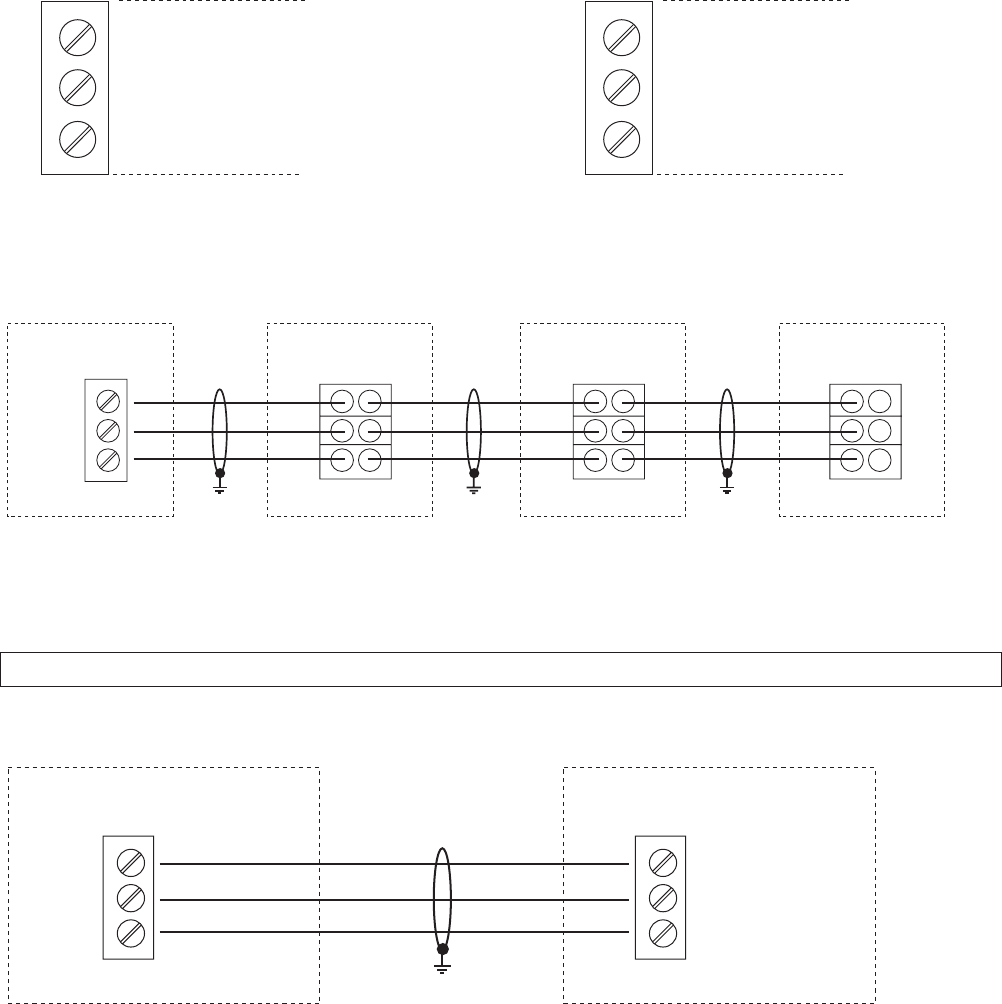
RS-485 – Internal interface RS-485 - User interface
The internal RS-485 Interface is used for communicating between up to 8 HYDROVARs in a multi-pump
application. This connection uses terminals X4/4-6 on the control card, or terminals X2/1-3 on the power unit.
(Example: using one master and three basic drives.)
Using the RS-485 – User interface on the control card, one or more HYDROVAR can communicate by stan-
dard Modbus-protocol with an external control device (e.g. PLC). This interface can be used for controlling the
HYDROVAR with external devices. Also available on HYDROVAR Single drives.
Do not use the internal interface for communicating with Modbus!
X4
X4
6 GND
5 SIO +
4 SIO -
3 GND
2 SIO +
1 SIO -
GND
SIO +
SIO -
GND
SIO +
SIO -
GND
SIO +
SIO -
GND
SIO +
SIO -
6
5
4
X4
X2 X2 X2
HYDROVAR Master Inverter
Control Card
HYDROVAR Basic Inverter
Power Unit
HYDROVAR Basic Inverter
Power Unit
HYDROVAR Basic Inverter
Power Unit
GND
SIO +
SIO -
3
2
1
X4
HYDROVAR User Interface
GND
SIO +
SIO -
PLC
ELECTRICAL INSTALLATION AND WIRING
34
X5 Status-Relays
X5/ 1 CC
2 Status Relay 1 NC
[Max. 250VAC] [250mA]
3 NO
[Max. 220VDC] [250mA]
4 CC
[Max. 30VDC] [2A]
5 Status Relay 2 NC
6 NO
Status Relay 1 Status Relay 2
Notice:
Do not transmit any voltage or
electronic noise on these contacts.
Status Relay 1 is programmed for "Pump Run" when closed between terminals 1 and 3.
Status Relay 2 is programmed for "Fault" when closed between 4 and 5.
Factory setting: The output relays are used to signal pump-running or fault-signal.
See connection example below (To program see parameters
CONF REL 1 [0715] and CONF REL 2 [0720]).
Connection examples:
Pump Run Signal Fault Signal
X5/ 1 and 3 closed: X5/ 4 and 5 closed:
- motor run indication - signals a fault/error
X5X5
6 NO
5 NC
4 CC
3 NO
2 NC
1 CC
X5
X5
6
5
4
3
2
1
Ext. 250VAC / 220VDC Ext. 250VAC / 220VDC
ELECTRICAL INSTALLATION AND WIRING
35
Section 9
NOTE
Read and follow the operating instructions carefully before programming to avoid incorrect
settings which will cause drive errors! All programming must be completed by qualied
technicians!
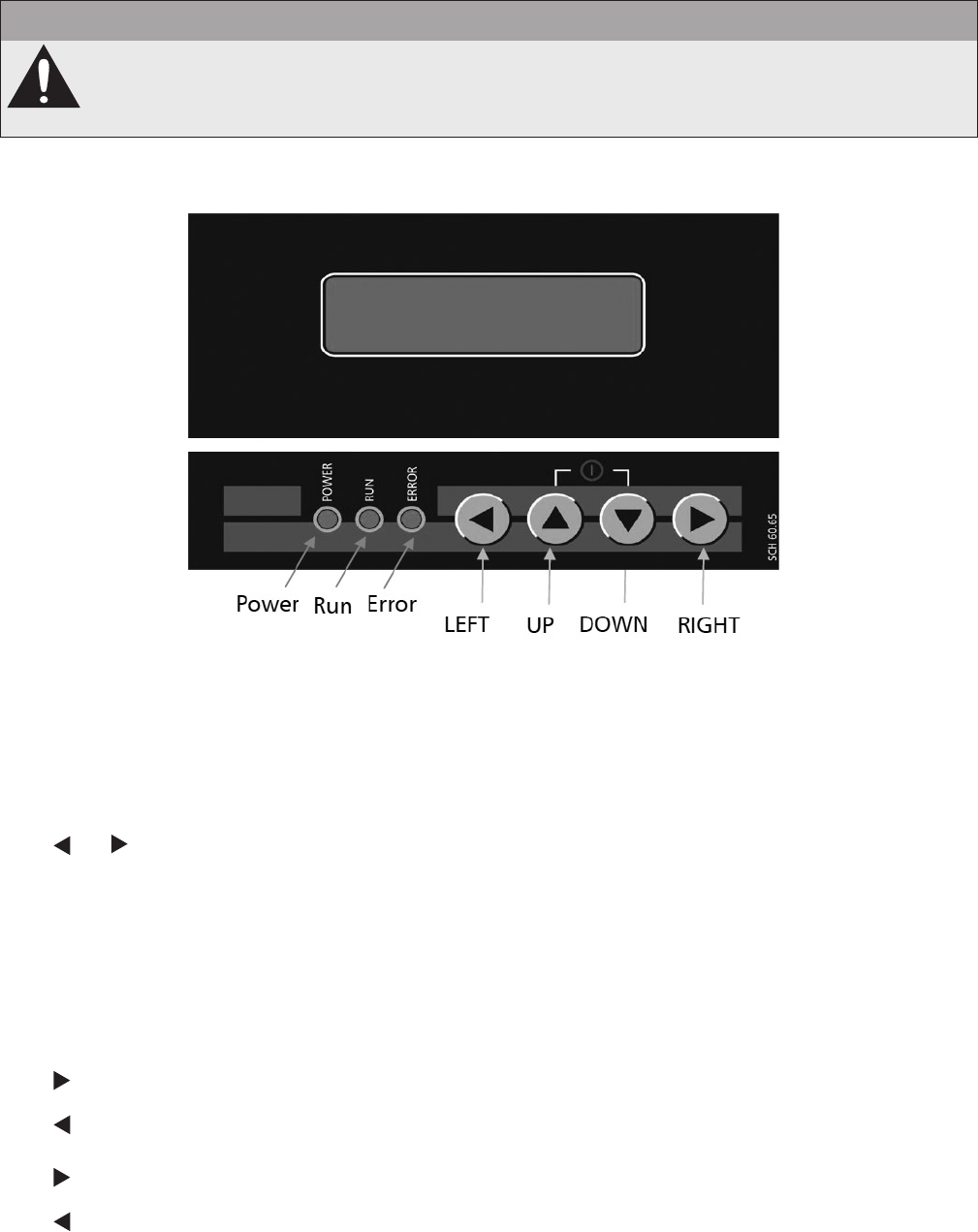
9.1 Display – Control Panel of the Master / Single Drive
9.2 Function of the Push Buttons
▲ Start the HYDROVAR
▼ Stop the HYDROVAR
and Reset: pressing both buttons simultaneously for 5 seconds
▲ Increase a value / selection in the submenu
▼ Decrease a value / selection in the submenu
▲ + short ▼ Scroll slower
▼ + short ▲ Scroll faster
Tap: enter submenu / Next parameter in the menu
Tap: leave submenu / Previous parameter in the menu
Press and hold: Select a specic action
Press and hold: Back to the main menu
PROGRAMMING
36
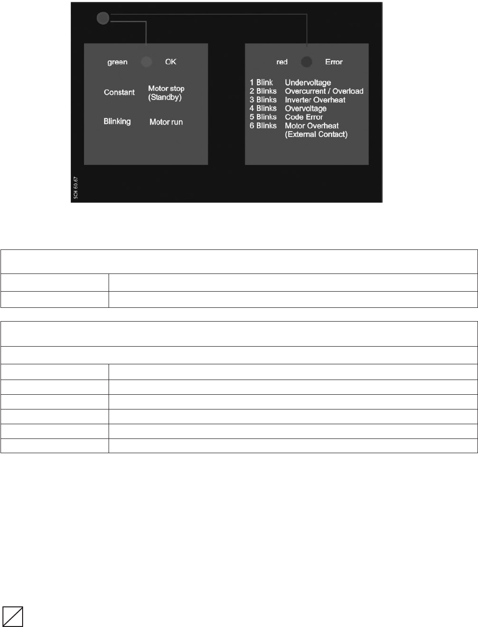
9.3 Basic Drive Display
Status LED - green
Constant Motor stopped (Standby)
Blinking Motor run
Error LED - red
The type of error is indicated by the number of blinks of the red ERROR LED.
1 blink Undervoltage
2 blinks Overcurrent / Overload
3 blinks Drive thermal overload
4 blinks Overvoltage
5 blinks Code Error
6 blinks Motor thermal overload (external contact is open)
For detailed information see chapter 11 Failure messages.
9.4 Software parameters
In the following chapters all parameters of the main menu and submenus are listed. The upper window
shows the factory setting and the line below the possible range of settings. The general parameter descrip-
tion is written for the HYDROVAR Master Inverter (Full featured HYDROVAR including the high level control card
which also supports the optional modules like the optional Relay Card and all specic software features).
When using a HYDROVAR Single drive there are fewer software features available than with the HYDROVAR
Master drive. All parameters which are not active for the HYDROVAR Single drive are marked with the following
symbol:
… Parameter not available for HYDROVAR Single drive
PROGRAMMING
S
37
Parameters which are available on all HYDROVAR drives are marked with the following symbol:
… “global” parameter (available on all HYDROVAR drives)
NOTICE! All changes are saved automatically and will not be lost with the removal of power supply!
00 00 MAIN MENU
The 1st windows, REQUIRED VALUE [02] and EFFECTIVE REQUIRED VALUE [03], depend on parameter
MODE [0105]. The differences within the windows in the various modes are shown below:
a) Active MODE [0105] = Controller (Default setting)
XYLEM XX.X Hz
1st window display in Controller mode
STOP X.XX PSI
This window shows the current run status of the drive.
ON Running Stop the HYDROVAR by pressing ▼
STOP Manually stopped Start the HYDROVAR by pressing ▲
OFF E-Stop (X3/7-8) is open To start the HYDROVAR close E-Stop or bridge terminal X3/7-8
b) For Active MODE [0105] = Cascade Relay, Cascade Serial, or Cascade Synchron
* ADR X PX XX.X Hz
Display for cascade serial and cascade relay modes
STOP X.XX PSI
This window shows the drive status.
* Indicates which HYDROVAR controls the system. The parameters are described further below:
ADR X Pump address, (1, 2, 3.....8)
Cascade relay mode: Indicates the number of pumps that are running
P X
(ex. P3 …. Master + 2 xed speed pumps are running)
Cascade serial/synchron mode: Indicates where the drive is in the existing sequence.
G
S
PROGRAMMING
38
ON Running Stop the HYDROVAR by pressing ▼
STOP Manually stopped Start the HYDROVAR by pressing ▲
OFF E-Stop (X3/7-8) is open
To start the HYDROVAR close E-Stop circuit or bridge terminal
X3/7-8
Parameters 02 and 03 for Modes: Controller, Cascade Relay, Cascade Serial, Cascade Synchron
02
02 REQUIRED VAL
Set the desired required value with ▲ or ▼
D1 X.XX PSI
The current REQUIRED VALUE and its source (D1 in this example) are displayed.
The available sources are listed below:
D1 internal - required value 1 (set by parameter 0820)
D2 internal - required value 2 (set by parameter 0825)
U1 required value 1 - voltage signal input (Connected to X3/13)
U2 required value 2 - voltage signal input (Connected to X3/15)
I1 required value 1 – current signal input (Connected to X3/18)
I2 required value 2 – current signal input (Connected to X3/23)
03
03 EFF REQ VAL
Effective required value
D1 X.XX PSI
Shows the calculated required value based on ACTUAL VALUE INCREASE (0505), ACTUAL VALUE DE-
CREASE (0510) and LIFT AMOUNT (0330). If the required value is inuenced by an offset signal (SUBMENU
OFFSET [0900]) the current active required value is also shown in this window.
Example: Multi-pump-application with two pumps
REQUIRED VALUE [02]: 75.00 PSI
ACT. VALUE INCREASE [0505]: 10.00 PSI
ACT. VALUE DECREASE [0510]: 5.00 PSI
-> REQ VAL EFF [03]: 80.00 PSI
The second pump will increase system pressure to 80.00 PSI.
c) Parameters 02 and 03 for Active MODE [0105] = Actuator
Frequency XX.X Hz
Display in Mode actuator
STOP X.XX PSI
If parameter MODE [0105] is set to Actuator, the parameter REQUIRED VALUE [02] will change to ACTUAL.
FREQ. and is equivalent to parameter [0830]. This allows the HYDROVAR to run to up to two pre-selected
frequencies to manually control the drive.
02
02 ACTUAT. FRQ.
Set the desired frequency with either ▲ or ▼
D1 XX.X Hz
Use this parameter to program the drive to up to 2 set frequencies. Requires programming parameter
0805, 0810, and 0815. To manually set the frequency use parameters ACTUATOR FREQUENCY 1 (0830)
and ACTUATOR FREQUENCY 2 (0835).
G
PROGRAMMING
39
Parameter [03] is not used in Mode: Actuator
04
04 START VALUE
Regulation Restart Value
OFF
Possible settings: 0 – 99 % – OFF
This parameter denes the restart value after the pump has stopped in % of the required value.
E.g. REQUIRED VALUE [02]: 50.0 PSI
START VALUE [04]: 80 % --> 40.0 PSI
If the pump system has reached the required pressure of 50.0 PSI and meets demand the HYDROVAR
shuts off the pump. When demand increases, and the pressure drops the pump starts. If a START VALUE
[04] of 80% has been selected the pump won’t start until the pressure drops below 40 PSI, (80% of 50 PSI).
The following parameters in the main-menu are valid for all selected modes:
05
05 LANGUAGE
Language selection
ENGLISH
Possible settings: To select the desired language press ▲ or ▼
The information on the display and all parameters are available in various languages. Scroll up and down
through the available options.
The following two parameters set the current date and time. This is useful for tracking timing of failure mes-
sages.
06
06 DATE
Current date
DD.MM.YYYY
Set the date by pressing for approx. 3 sec.
to set current DAY / MONTH / and YEAR.
07
07 TIME
Current time
HH:MM
Set the time by pressing for approx. 3 sec.
to set current HOUR and MINUTE.
G
S
S
PROGRAMMING
40
08
08 AUTO - START
Auto Start
ON
Possible settings: ON – OFF
Select ON with ▲ or OFF with the ▼ button.
If AUTO-START = ON the HYDROVAR starts automatically after reconnecting power following interruption.
If AUTO-START = OFF the HYDROVAR will not start automatically after reconnecting power following
interruption.
After reconnection of the power supply the following message is shown: AUTO START = OFF
XYLEM XX.X Hz
Press ▲ to restart the HYDROVAR.
STOP X.XX PSI
09
09 OPERAT. TIME
Operating hours
0000 h.
Total operating hours. To reset to 0 see parameter CLR OPERAT. [1135].
20 20 SUBMENU STATUS Status of all units within a pump group
Use this submenu to check the status (including failures and motor hours) of all connected units.
21
21 STATUS UNITs
Status of all units
00000000
This parameter gives a quick overview about the run status of the connected drives.
• In Cascade serial/synchron mode the status of all (max. 8) connected units is shown
(1=running / 0=stopped)
• In Cascade relay mode the status of the 5 Relay- switching contacts is shown.
E.g. Mode – Cascade serial/synchron
21 STATUS UNITs
Unit 1, 2 and 5 are running
11001000
E.g. Mode – Cascade relay
21 STATUS UNITs
Relay Contact 1 and 3 are closed
10100 - - -
G
G
G
G
S
PROGRAMMING
41
22
22 SELECT DEVICE
Select device
* 1 *
Possible settings: 1-8
Check the current status, the motor hours and the most recent failures of any given drive. The drive selec-
tion is determined by the current selected mode [105]. Select desired unit by pressing ▲ or ▼.
CASCADE SERIAL/SYNCHRON:
The selection species the address of the HYDROVAR units
E.g. Device 1 -> Master Inverter with pre-selected address 1
Device 2 -> Basic Inverter with pre-selected address 2
Device 3 -> Basic Inverter with pre-selected address 3
To set the address on a Basic Inverter, see chapter addressing.
To set the address on a Master Inverter, see parameter [106] or submenu [1200] RS485-Interface.
Mode CASCADE RELAY:
Device Enabled By
1 Master Inverter
2 xed speed pump Relay 1 X10: 1
3 xed speed pump Relay 2 X10: 2
4 xed speed pump Relay 3 X10: 3
5 xed speed pump Relay 4 X10: 4
6 xed speed pump Relay 5 X10: 5
7 not used
8 not used
23
23 STATUS DEVICE
Status of the selected device
Stopped
Possible messages: Running, Stopped, Disabled, OFF, Preparing (Mode Casc. Serial/Synchr)
relay on, relay off (Mode: Cascade Relay)
Solorun, Faulted (all Modes)
Shows the status of the device
Mode CASCADE RELAY:
relay_on -> Relay contact is closed -> xed-speed-pump is running
relay_off -> Relay contact is opened -> xed-speed-pump is stopped
Mode CASCADE SERIAL/SYNCHRON:
running -> Pump is running
stopped -> Pump is stopped
disabled -> Pump is disabled by an external input.
(Stopped with buttons or disabled with parameter ENABLE DEVICE [24]) or by external
on/off contact open
preparing -> A new unit is connected to the multi-pump system and Data is being transferred
solo run -> Solorun (Hand Mode) is activated (XSL closed)
faulted -> A failure has occurred on the current unit
S
G
S
PROGRAMMING

42
G
G
24
24 ENABLE DEVICE
Enable – Disable of the selected device
Enable
Possible settings: Enable - Disable
Allows the drive to be be enabled or disabled by an external switch between X3 7 and 8. (Either in cascade
relay / serial / synchron or controller mode).
25
25 MOTOR HOURS
Runtime of the selected drive
XXXXX h
Total number of hours the motor has run. To reset see parameter CLR MOTORH. [1130].
Error memory
All errors, including those occuring on Basic Inverters are saved on the Master Inverter in this menu. The
errors saved in this menu include the failure message text of the drive where the failure happened, and the
date and time when the failure occurred. (For more information about errors, see chapter 10 failure mes-
sages.)
26
26 1st ERROR
Most recent error on the selected drive
ERROR XX
Message: ERROR XX, FAILURE TEXT, DATE, TIME
Press ▲ or ▼ to scroll up or down!
27
27 2nd ERROR
2nd most recent error on the selected drive
ERROR XX
Message: ERROR XX, FAILURE TEXT, DATE, TIME
Press ▲ or ▼ to scroll up or down!
28
28 3rd ERROR
3rd most recent error on the selected drive
ERROR XX
Message: ERROR XX, FAILURE TEXT, DATE, TIME
Press ▲ or ▼ to scroll up or down!
29
29 4th ERROR
4th most recent error on the selected drive
ERROR XX
Message: ERROR XX, FAILURE TEXT, DATE, TIME
Press ▲ or ▼ to scroll up or down!
30
30 5th ERROR
5th most recent error on the selected drive
ERROR XX
Message: ERROR XX, FAILURE TEXT, DATE, TIME
Press ▲ or ▼ to scroll up or down!
G
G
G
G
G
S
PROGRAMMING
43
G
G
G
G
G
G
40
40 SUBMENU
DIAGNOSTICS
41
41 PROD. DATE
Production date of the HYDROVAR (Master/Single only)
XX.XX.XXXX
In the following parameters the current temperature, voltage and frequency of the chosen HYDROVAR can
be monitored during operation of the unit. These parameters are read only!
42
42 SEL. INVERTER
Select the desired unit
* 1 *
Possible settings: 1-8
43
43 TEMP. INVERTER
Temperature of the selected unit
XX % XX°C
The current value determines the temperature inside the selected HYDROVAR and is shown in °C and also
in percent of the maximum allowed temperature.
44
44 CURR. INVERTER
Current of the selected unit
XXX %
This value determines the output current of the HYDROVAR in percent to the maximum rated current
output.
45
45 VOLT. INVERTER
Input Voltage of the selected unit
XXX V
This value displays the input voltage supplied to the HYDROVAR.
46
46 OUTPUT FREQ.
Output frequency of the selected unit
XX.X Hz
This value displays the output frequency generated by the HYDROVAR.
47
47 VER. INVERTER
Software version of the selected drive
01
This parameter displays the software version of the BASIC drive (located on the main board).
Possible indications:
00 All power sizes (2-15 HP) prior production 05/2008
01 Sizes HV 2 - 5 HP - related to control board software V01.3
02 Sizes HV7.5 - 15 - related to control board software V01.3
PROGRAMMING
44
60 60 SUBMENU SETTINGS
NOTE
Carefully read these instructions before changing the remaining parameters. Improper
settings can cause the drive to malfunction.
These parameters can be changed during operation. Therefore they should be changed only by trained
and qualied technicians. It is recommended to stop the HYDROVAR by pressing ▼ in the main menu
before changing parameters in submenues.
61
61 PASSWORD
enter password (0066 = Default) by pressing ▲ or ▼
0000
NOTICE! If the submenu is opened with the correct password it will remain open for a period of 10 min-
utes without entering the password again to access the secondary menu.
61 PASSWORD
Conrm by pressing and the rst window of the sub menu is shown
0066
62
62 JOG 0.0Hz
Both current output frequency and actual value are shown.
X.XX PSI
• By pressing ▲ or ▼ in this menu, the drive switches from control via external input (transducer) to manual
frequency control.
• Use the ▲ and ▼ buttons to change output frequency and pump speed to achieve the desired pressure
and ow.
• If this value becomes 0.00 Hz the HYDROVAR stops.
• Exit this menu by pressing or , and the HYDROVAR returns to the previously selected mode.
0100
0100 SUBMENU BASIC
SETTINGS
0105
0105 MODE
Select the operating mode
Controller
Possible settings: Controller, Cascade Relay, Cascade Serial, Cascade Synchron, Actuator
PROGRAMMING

45
Controller (Default Setting):
Select this mode when only one HYDROVAR Master/Single Drive is used and there is no connection to any
other HYDROVAR via RS-485 interface.
Cascade Serial:
Selected if multiple HYDROVAR controlled pumps operate together via the RS-485 interface.
The standard application for this mode is a multi-pump system with up to 8 pumps, each controlled by a
HYDROVAR Master Drive or a combination of Master and Basic Drives. Advantages: reliability, lead/lag for
balanced usage and wear and tear, automatic alternation in the event of a drive failure (duty standby).
Cascade Synchron:
The Synchronous Controller mode is similar to cascade serial mode. The difference is that all pumps in the
multi pump system run at the same frequency.
Advantages: In the synchronous mode the pumps can operate in a better efciency range and the system
may provide additional energy savings compared to standard Cascade Serial mode.
Actuator: (For single pump operation only!)
Actuator mode is used if a xed speed setting is required or an external speed signal is connected to con-
trol the speed of the drive.
In this mode, the HYDROVAR does not control the set value but runs the connected motor at a frequency
proportional to the input signal from the analogue input, or is programmed on the HYDROVAR. The follow-
ing input signals can be used:
X3/13: Voltage signal input (Required value 1) 0-10V 0 - MAX.FREQ.[0245]
X3/15: Voltage signal input (Required value 2) 0-10V 0 - MAX.FREQ.[0245]
X3/18: Current signal input (Required value 1) 4-20mA 0 - MAX.FREQ.[0245]
0-20mA 0 - MAX.FREQ.[0245]
X3/23: Current signal input (Required value 2) 4-20mA 0 - MAX.FREQ.[0245]
0-20mA 0 - MAX. FREQ. [0245]
• Manual switching between the analogue inputs can be controlled by the corresponding digital inputs.
• The frequency varies along the programmed Ramps 1 (accelerating) and 2 (decelerating). The functions
thermal protection and external ON/OFF remain active.
• The functions “External ON/OFF”, “Motor Overheat”, “Lack of water” and all other internal protections still
work.
S
S
PROGRAMMING
46
In actuator mode the drive can work with pre-selected frequencies for manual control of the HYDROVAR.
Two different frequencies can be set in the submenu REQUIRED VALUES [0800]. Switch between these
frequencies using parameter SW REQ. VAL [0815].
0106
0106 PUMP ADDR.
Select desired address for the Master Inverter
* 1 *
Possible settings: 1-8
Set desired address on each Master Inverter and press button for approximately 3 seconds and the
following messages will appear:
Addressing
->
1220 PUMP ADDR.
or
1220 PUMP ADDR.
Addressing * 1 * - 1 -
Address Set Address failed - retry
When using Master and Basic drives together in a multi-pump system the Basic Inverters have separate ad-
dresses. For detailed Information see chapter 8.4.3.2 Addressing.
0110
0110 SET PASSW.
Set Password by pressing ▲ or ▼
0066
Possible settings: 0000 - 9999
Caution: Resetting the password is not recommended! However, the pre-set password (0066) can be
changed. After the password has been changed, the new password should be recorded where multiple
people have access to it.
0115
0115 LOCK FUNCT.
Change with ▲ or ▼
OFF
Possible settings: ON - OFF
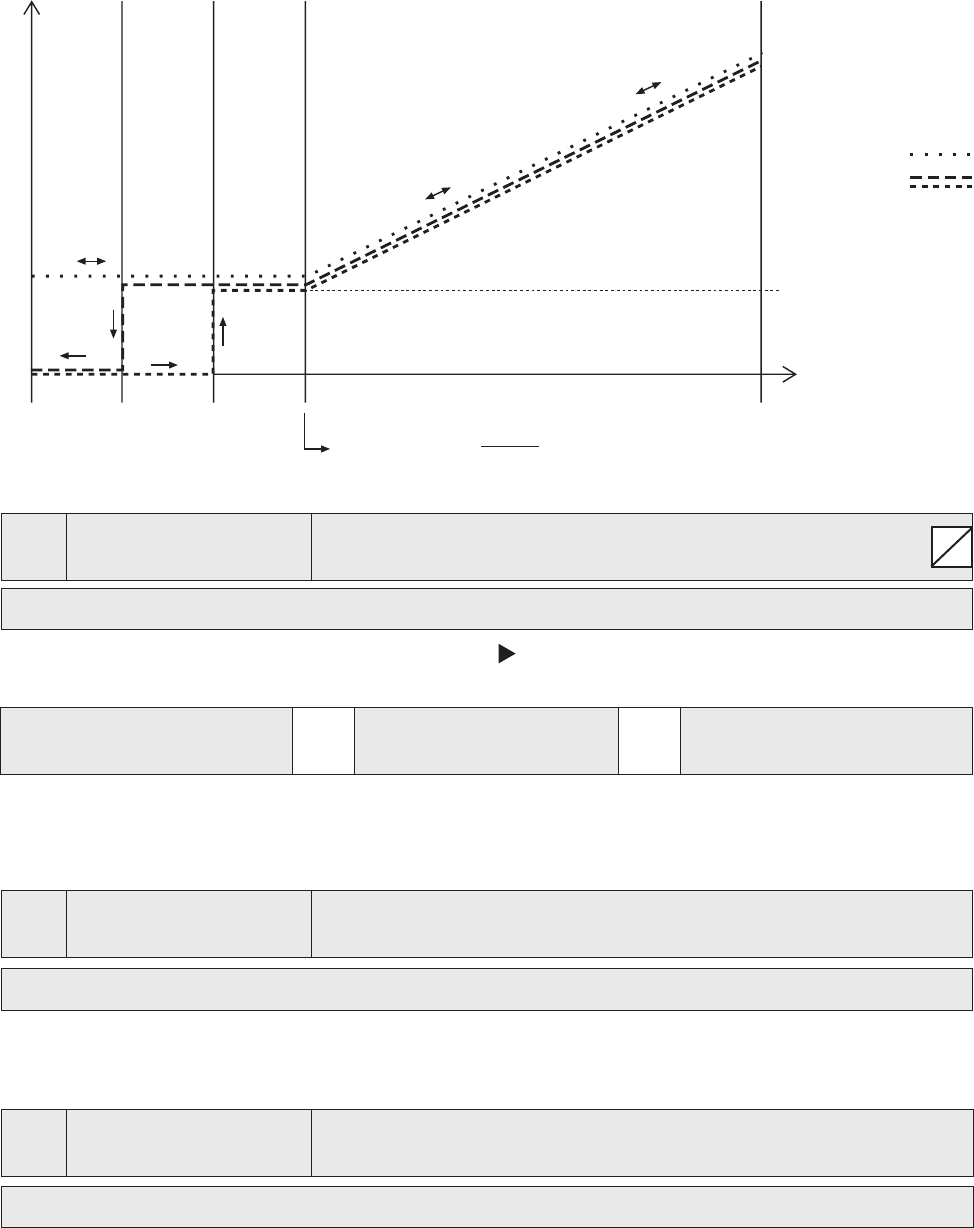
f[Hz] 1/3 2/3 3/3
OF ON
0Vdc
0mA
4mA
10Vdc
20mA
20mA
= signal range *
f min
+ zeropoint
f max
fmin
fmax
[0255] f ->min
[0255] f ->0
range of control
S
PROGRAMMING
47
G
S
G
S
OFF: All parameters in the MAIN menu (only) can be changed without entering the password.
ON: If the LOCK FUNCTION is activated, no changes can be made in any parameter without rst entering
the password. The HYDROVAR can be started and stopped with the up/down arrows. To change the set
value, the LOCK FUNCTION must be set to OFF.
0120
0120 DISP. CONTR.
Display Contrast
75 %
Possible settings: 10 – 100%
Can be adjusted between 10 - 100%, to improve the display.
0125
0125 DISP. BRIGHT
Display Brightness
100 %
Possible settings: 10 – 100%
The backlight intensity of the display can be adjusted.
0200
0200 SUBMENU CONF
INVERTER
0202
0202 SOFTWARE
Software version of the control board
HV V01.3
0202
0202 SW RD V01.0 Software version of the Remote display (RD) (not available) and
HV V01.3 the control board (HV)
0203
0203 SET VER.INV
Activate additional settings. Contact factory to use.
sel:01 act:01
Possible settings: 00 - 02
Activates skip frequency parameter and current limit functions. These functions are not commonly used,
and may have undesirable effects. They should only be used to solve application problems in the eld.
Press and hold the right arrow for 5 seconds to activate the function, and "Done" is displayed.The following
parameters [0285], [0286], [0290] and [0291] are added to the parameter list.)
Setting 00: all units with production date prior 05/2008
Setting 01: Basic 2 - 5 HP (on control board software V01.3)
Setting 02: Basic 7.5 - 15 HP (on control board software V01.3)
0205
0205 MAX. UNITS
Maximum number of units
06
Possible settings: 1 - 8
Select: The maximum number of units that can be set up as a multi-pump system.
0210
0210 INVERTER
Selection of the HYDROVAR address for parameterizing
ALL
Possible settings: ALL, 1-8
G
PROGRAMMING
48
If several HYDROVAR Master Inverters and even Basic Inverters are connected via the RS-485 interface, the
parameters in SUMBENU [200] can be entered on one unit and will be carried over to the other units in the
group. If programming only one unit press the button for 3 seconds and then choose the unit (1-8) for
which the parameters are being entered.
Select “ALL” to program all the units simultaneously.
Caution, if you select "ALL" the new settings will be copied to all units!
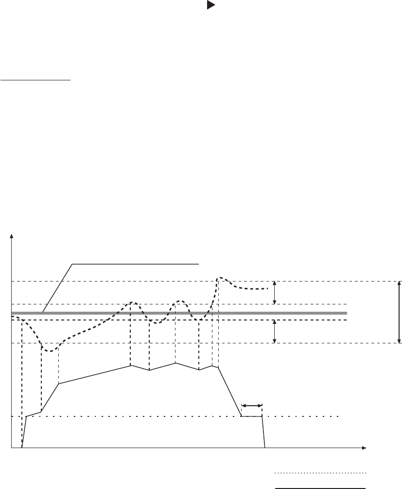
Ramp settings:
• The ramps inuence the rate of change in speed.
• The fast ramps 1 and 2 control the rate of acceleration and deceleration of the drive when the system
pressure is outside the hysteresis window, set at Parameter (0310). Default = 4 seconds. The ramps
should be lengthened, (increased) up to 15 seconds for higher horsepower drives to avoid overload er-
ror.
• The slow ramps 3 and 4 determine the acceleration/deceleration rates of the drive when the pressure is
within the hysteresis window. (Default = 70 sec.)
• The Ramps FminA and FminD are used for start-up and shut off. These parameters allow faster accel-
eration and deceleration and should be used for applications where pumps shouldn’t operate below a
determined frequency for a certain time. (to prevent damages or decrease wear) To adjust the Ramps,
press ▲ or ▼.
RA: Ramp F
min
acceleration Actual Value
RD: Ramp F
min
deceleration Output Frequency
R1: Ramp 1 – speed ramp fast increase
R2: Ramp 2 – speed ramp fast decrease
R3: Ramp 3 – speed ramp slow increase
R4: Ramp 4 – speed ramp slow decrease
set rated REQUIRED VALUE [02]
MIN FREQ [0250]
FMIN TIME [0260]
Time
RA
R3
R1
R3
R3
R3
R4 R4 R4
R4
R2
RD
Set HYSTERESIS [0315] in %
Set HYSTERESIS [0315] in %
WINDOW [0310]
setting in %
of the required
PROGRAMMING

49
G
G
G
0215
0215 RAMP 1
Ramp 1: Fast acceleration time
4 sec
Possible settings: 1 – 250 (1000) sec
• Rapid acceleration may cause an error (OVERLOAD) during drive startup.
• Slow acceleration may cause a drop in outgoing pressure during startup.
0220
0220 RAMP 2
Ramp 2: Fast acceleration time
4 sec
Possible settings: 1 – 250 (1000) sec
• Rapid deceleration may cause error (OVERVOLTAGE).
• Slow deceleration may generate over pressure.
0225
0225 RAMP 3
Ramp 3: Slow acceleration time
70 sec
Possible settings: 1 – 1000 sec
• Rapid acceleration may lead to oscillation and/or an error (OVERLOAD).
• Slow acceleration may cause a drop in outgoing pressure during varying demand.
0230
0230 RAMP 4
Ramp 4: Slow acceleration time
70 sec
Possible settings: 1 – 1000 sec
• Rapid deceleration may lead to pump oscillation.
• Slow deceleration may cause pressure uctuations during varying demand.
0235
0235 RAMP F
MIN
A
Ramp F
min
acceleration
2.0 sec
Possible settings: 1.0 – 25.0 sec
Acceleration rate during startup until MIN. FREQUENCY [0250] is reached. Beyond the minimum frequency,
RAMP1 [0215] (fast acceleration ramp) applies.
• Rapid acceleration may cause error (OVERLOAD) during drive startup.
0240
0240 RAMP F
MIN
D
Ramp F
min
deceleration
2.0 sec
Possible settings: 1.0 – 25.0 sec
Deceleration rate applied when the drive has dropped below the MIN. FREQUENCY [0250].
• Rapid deceleration may cause error (OVERVOLTAGE)
G
G
G
PROGRAMMING
50
G
G
G
G
G
0245
0245 MAX. FRQ.
Maximum frequency
60 Hz
Possible settings: 30.0 – 70.0 Hz
This parameter determines the maximum frequency output to the motor. This should be set to the motor
nominal frequency. Default is 60 Hz.
Settings higher than motor nominal frequency may overload the motor! Settings of 10%
above nominal frequency increase power consumption by 33%
0250
0250 MIN. FRQ.
Minimum frequency
20.0 Hz
Possible settings: 0.0 – f
max
At operation below MIN. FREQUENCY (0250) the HYDROVAR operates with the fast ramps F
min
A and D,
(0235/0240).
The pump type and application should be considered when setting MIN. FREQ. For
submersible applications the min. frequency must be set to ~30Hz.
0255
0255 CONF. F
MIN
Operation at minimum frequency
f -> 0
Possible settings: f->0 or f->f
min
f->0: After reaching the required pressure with no demand the frequency drops to the selected MINIMUM
FREQUENCY [0250] and the HYDROVAR will continue to run for the selected F
MIN
TIME [0260]. After this
time the HYDROVAR will stop automatically.
f->f
min
: The pump will never stop automatically. The frequency will only drop down to the selected MINI-
MUM FREQUENCY [0250]. To stop the pump the external ON/OFF (E-stop) must be opened or the ▼
(Stop) button must be pressed.
Applications: circulation systems
Caution: The setting f->f
min
can overheat the pump if there is no ow through the pump.
Use when there is a bypass line for circulation pumps!
0260
0260 F
MIN
TIME
Delay time before shut off below MIN. FREQ.
0 s
Possible settings: 0 – 100 sec
After running below MIN. FREQ.for this selected time, the pump will stop if parameter CONFIG. FMIN
[0255] is set to f -> 0.
0265
0265 BOOST
Motor starting voltage in % of connected supply voltage
5 %
Possible settings: 0 – 25% of the input voltage
This parameter determines the characteristics of the voltage/frequency curve. In particular, it refers to the
voltage increase during startup as a percentage of the nominal voltage. This setting should be kept as low
as possible to protect the motor from thermal overload at lower frequencies. If the boost is set too low, a
failure (OVERLOAD) may occur because the starting current is too high.
PROGRAMMING
51
G
G
G
0270
0270 KNEE FRQ.
Knee frequency
60.0 Hz
Possible settings: 30.0 – 90.0 Hz
This parameter determines the frequency at which the HYDROVAR generates its maximum output voltage
(value of the connected input voltage). For standard applications this frequency should be set to MAX.
FRQ. [0245] (Default Setting 60Hz).
CAUTION
This parameter should rarely be adjusted! Incorrect setting can cause an overload error and
damage to the motor. Contact factory before changing.
0275
0275 POWER REDUCT.
Reduction of the maximum output current
OFF
Possible settings: OFF, 85%, 75%, 50%
If a motor with lower nominal power is used, the maximum output current should be adjusted accordingly.
The reduction of the maximum output current also affects the overload-detection!
HV Horsepower
Output current [A]
OFF = 100% 85% 75% 50%
230V, 2 HP 7 5.95 5.25 3.5
230V, 3 HP 10 8.50 7.50 5.00
460V, 3 HP 5.7 4.85 4.28 2.85
460V, 5 HP 7.3 6.21 5.48 3.65
460V, 7.5 HP 13.5 11.48 10.13 6.75
460V, 10 HP 17 14.45 12.75 8.5
460V, 15 HP 23 19.55 17.25 11.5
0280
0280 SEL. SW. FRQ.
Selection of the switching frequency
Auto
Possible settings: Auto, 8 kHz, 4 kHz
• Auto (default setting)
In standard operation the HYDROVAR works with a switching frequency of 8 kHz in order to reduce the
noise level. At rising temperature inside the HYDROVAR the switching frequency is decreased to 4 kHz
automatically.
• 8 kHz - Selection with lowest noise level, but without decrease at rising temperature.
• 4 kHz - Reduce the temperature in the HYDROVAR
PROGRAMMING
52
G
G
G
G
0285
0285 SKIPFRQ CTR
Skip frequency start point
0.0 Hz
Possible settings: f
min
- f
max
0286
0286 SKIPFRQ RNG
Skip frequency range
0.0 Hz
Possible settings: 0.0 – 5.0 Hz
0290
0290 CURR. LIMIT
Current limit functionality
OFF
Possible settings: OFF - ON
0291
0291 CURR. LIMIT
Current limit
100 %
Possible settings: 10.0 - 100 %
Previous parameters [0285] - [0291] are limited for power ratings starting from 7.5kW with production date
05/08 and control board software V01.3 → otherwise they are not visible and therefore not active.
0300
0300 SUBMENU
REGULATION
0305
0305 JOG 0.0Hz
Both the current output frequency and actual value are shown.
X.XX PSI
• By pressing ▲ or ▼ in this menu, the internal controller of the HYDROVAR is deactivated and it changes
to manual mode.
• Using the ▲ and ▼ buttons any constant speed can be set without further control to achieve the set
point!
• If this value becomes 0.00 Hz the HYDROVAR stops.
• As soon as the window is left by pressing or , the HYDROVAR returns to the selected mode.
0310
0310 WINDOW
Hysteresis Window
5%
Possible settings: 0 – 100% of required value
• Determines the width of the set point hysteresis window.
• For steep pump-curves and closed loop systems ~20-30%.
0315
0315 HYSTERESIS
Hysteresis for ramp switching
80%
Possible settings: 0 – 100%
• Determines the percentage of the hysteresis window, at which the ramps change from slow to fast.
• For an accurate control (without automatic shut-off) ~99%, e.g. constant ow control.
PROGRAMMING
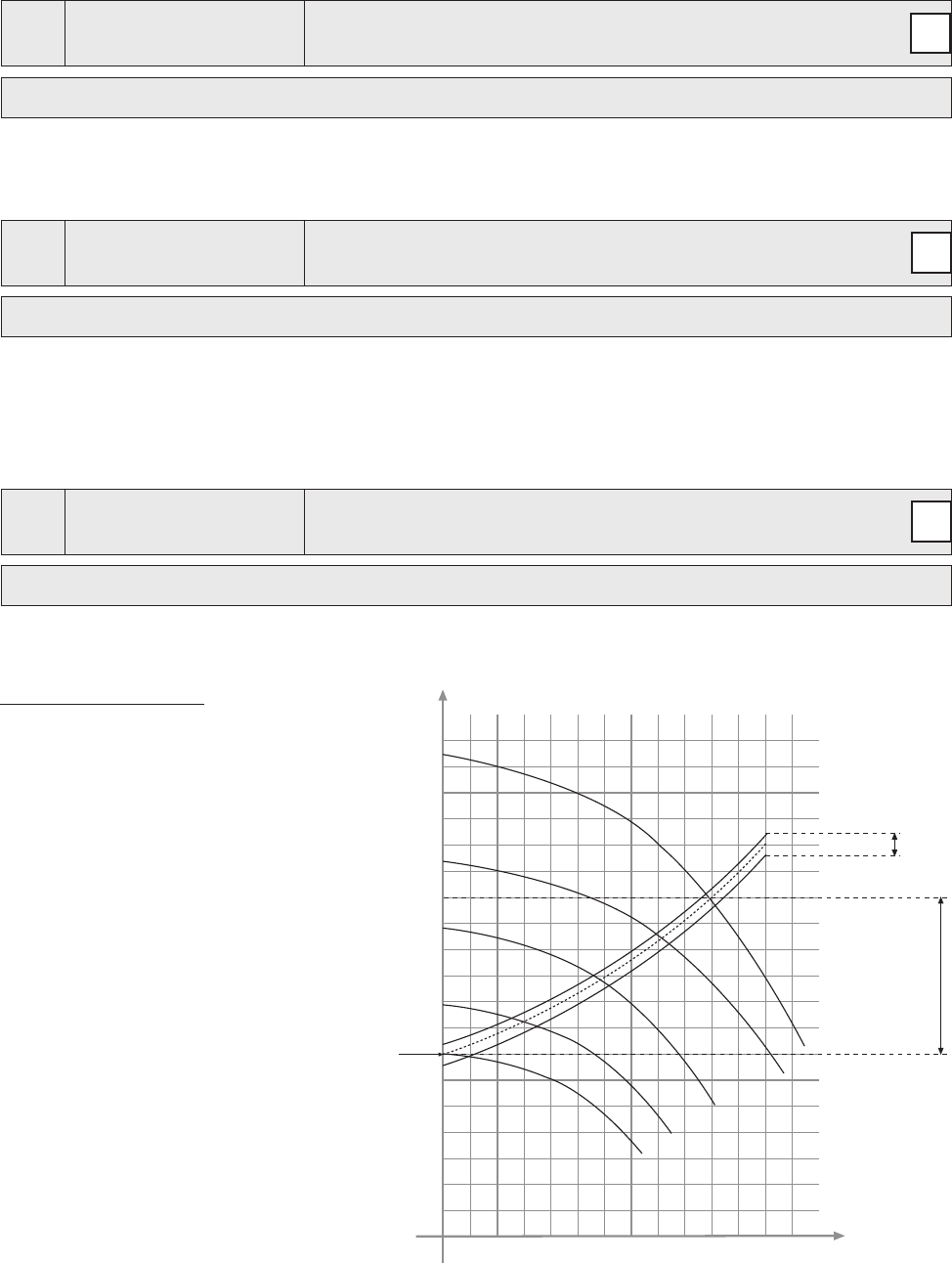
53
G
G
H
Q
A
C
0
1
2
3
4
B
f = 100%
%f
%f
%f
G
0320
0320 REG. MODE
Regulation mode
normal
Possible settings: normal, inverse
Normal: Speed is increased with falling actual value signals. (e.g.: control at constant output pressure)
Inverse: Speed is reduced with falling actual value signal. (e.g.: control at constant suction pressure or at
constant level on the suction side)
0325
0325 FRQ. LIFT
Frequency limit for required lift value
30.0 Hz
Possible settings: 0.0 Hz – 70.0 Hz
Control according to a system curve (increase of the set pressure, depending on the ow rate/speed to
cover friction losses).
The setting determines the output-frequency where the set pressure starts to be increased. The right set-
ting should be equal to the frequency when the pump reaches the set pressure at zero ow (Can be deter-
mined by using the JOG MODE [0305]).
0330
0330 LIFT AMOUNT
Lift amount for required lift value
0.0 %
Possible settings: 0.0 – 200.0%
This value states how much the set value should be continually increased, till the maximum speed (maxi-
mum volume) is reached.
Application Example:
1) Enter the set pressure (see main menu
parameter REQ. VAL [02]).
2) Find out the frequency where set pres-
sure is reached at zero demand (use JOG
MODE [0305]) and set the value in param-
eter FREQU. LIFTING.
3) Set desired lift at maximum speed in % of
the set pressure in the parameter LIFT-
AMOUNT [0330].
A … set pressure
B … window
C … lift intensity in % of set pressure
PROGRAMMING
54
0400
0400 SUBMENU
SENSOR
In this submenu all actual value sensors which are connected to the HYDROVAR can be congured, (up to
two transducers with current output or voltage signal output).
Two different transducer types can not be used because the conguration is the same for all connected
sensors. Transducers must be always the same type.
0405
0405 DIMENS. UNIT
Dimension unit
PSI
Possible settings: bar, psi, m
3
/h, g/min, mH2O, ft, °C, °F, l/sec, l/min, m/sec, …, %
Choose the desired Dimension Unit by pressing ▲ or ▼.
When DIMENSION UNIT, you must also change the SENSOR RANGE [0420] according to the new DIMEN-
SION UNIT!
0410
0410 CONF SENSOR
Selection of the sensor
Sensor 1
Possible settings: - Sensor 1 - Sensor 2 - Auto
- Switch Dig 1 - Switch Dig 2 - Switch Dig 3 - Switch Dig 4
- Auto Lower - Auto Higher - (Sensor 1 – Sensor 2)
This parameter determines how the connected sensors are used and which one is active. It is also possible
to measure the difference of two connected sensors or to congure an automatic switchover in case of a
faulty sensor.
Sensor 1 is constantly active.
Sensor 1 0/4-20mA signal ……. connected to X3/2 and X3/3 (+24V)
0-10V signal ……. connected to X3/6 and X3/3 (+24V)
Sensor 2 is constantly active.
Sensor 2 0/4-20mA signal ……. connected to X3/4 and X3/3 (+24V)
0-10V signal ……. connected to X3/5 and X3/3 (+24V)
Auto Automatic switch over in case of a faulty transducer.
Switch Dig1 Manual switching by closing digital input 1 (X3/9-10)
Switch Dig2 Manual switching by closing digital input 2 (X3/6-GND)
Switch Dig3 Manual switching by closing digital input 3 (X3/5-GND)
Switch Dig4 Manual switching by closing digital input 4 (X3/15-GND)
Auto Lower
The sensor with the lower actual value (or available sensor in case of a faulty
sensor) is used automatically
Auto Higher
The sensor with the higher actual value (or available sensor in case of a faulty
sensor) is used automatically
Sens.1 – Sens.2 The difference between connected sensors is taken as actual value
PROGRAMMING

55
0415
0415 SENSOR TYPE
Selection of the sensor type and input terminal
4 – 20mA
Possible settings: - analog I 4-20mA - analog I 0-20mA - analog U 0-10V
For choosing the correct sensor input.
Sensor type: Terminals:
- analog I 4-20mA
The actual value is represented by a current
X3/2 -> Sensor 1
- analog I 0-20mA
signal connected to following terminals:
* X3/4 -> Sensor 2
- analog U 0-10V
The actual value is given from a voltage signal
X3/6 -> Sensor 1
connected to following terminals:
* X3/5 -> Sensor 2
* … Sensor 2 is not available for the Single Inverter conguration
0420
0420 SENS. RANGE
Sensor range
20mA = 300 PSI
Possible settings: 0.00 – 10000
Determines the end value (=20mA or 10V) of the connected sensor.
The maximum sensor range -> 20mA = 100% of the sensor range.
Example:
300 PSI pressure sensor => 20mA = 300 PSI
0425
0425 SENS. CURVE
Sensor curve
linear
Possible settings: linear, quadratic
Internal calculation based on the actual value.
Possible setting and its application:
• Linear: Pressure control, differential pressure control, level, temperature and ow control (inductive or
mechanical).
• Quadratic: Flow control using an orice plate together with a differential pressure sensor.
0430
0430 SENS 1 CAL 0
Sensor 1 zero point calibration
0% = actual value
Possible settings: - 10% up to +10%
This parameter is used to calibrate the minimum value of Sensor 1. After setting the dimension unit and the
sensor range the zero point for this sensor can be adjusted. Adjustable range between -10 % and +10 %.
0435
0435 SENS 1 CAL X
Sensor 1 upper range value calibration
0% = actual value
Possible settings: - 10% up to +10%
To set the calibration for the upper range value of sensor 1. After setting the dimension unit and sensor
range, the upper range value can be adjusted between -10 and +10%.
PROGRAMMING
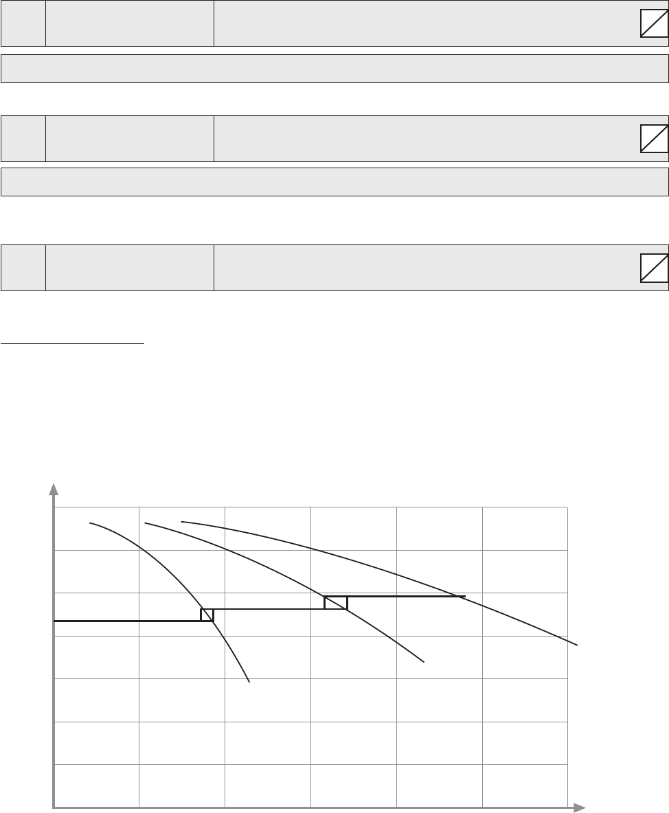
56
S
S
S
H
Q
0
0
P 1 P 1+2 P 1 +2+3
0440
0440 SENS 2 CAL 0
Sensor 2 zero point calibration
0% = actual value
Possible settings: - 10% up to +10%
Zero point calibration for Sensor 2, for explanation see Parameter 0430.
0445
0445 SENS 2 CAL X
Sensor 2 upper range value calibration
0% = actual value
Possible settings: - 10% up to +10%
Upper range calibrations for Sensor 2, for explanation see Parameter 0435.
0500
0500 SUBMENU
SEQUENCE CNTR.
This submenu denes parameters for multi-pump systems.
Application Example:
1) Lead pump reaches its ENABLE FREQUENCY [0515]
2) Actual value falls and reaches the cut in-value of the 1st assist pump Cut in-value = REQUIRED VALUE
[02] – ACT. VAL. DEC. [0510] → the 1st assist pump is switched on automatically
3) After the start up the new required value is calculated in the following way:
NEW REQUIRED VALUE = REQ. VAL. [02] – ACT. VAL. DEC [0510] + ACT. VAL. INC. [0505].
The new required value is shown in the main menu as parameter EFF. REQ. VAL. [03].
PROGRAMMING

57
G
G
G
S
S
S
S
S
Calculations of the new required value for multi pump applications:
k ... number of active pumps (k >1)
p = p
set
+ (k-1)*[lift value – fall value]
• Lift value = Fall value ⇒ Pressure constant independent of how many pumps are in operation
• Lift value > Fall value ⇒ Pressure rises when assist pump switches on
• Lift value < Fall value ⇒ Pressure falls when assist pump switches on
The following 3 parameters are responsible for starting the assist pumps and to calculate the new required
value.
0505
0505 ACT. VAL. INC.
Lift value
5 PSI
Possible settings: 0.00 – to the pre selected sensor range
0510
0510 ACT. VAL. DEC.
Drop value
2 PSI
Possible settings: 0.00– to the pre selected sensor range
0515
0515 ENABLE FRQ
Enable frequency for the next drive
48.0 Hz
Possible settings: 0.0 – 70.0 Hz
Sets the frequency for the next pump to turn on. If a pump in the system reaches this frequency and the
system pressure drops below the REQUIRED VALUE [02] - ACTUAL VALUE DECREASE [0510], the next
pump is started.
0520
0520 ENABLE DLY
Enable delay time (for cascade relay only!)
5 sec
Possible settings: 0 – 100 sec
Delay, in seconds, after the current pump reaches the enable frequency, before the next pump turns on.
0525
0525 SW DELAY
Switch delay (for cascade relay only!)
5 sec
Possible settings: 0 – 100 sec
Delay time between two switching actions of the x speed pump. The parameter prevents the system re-
peated switching actions caused by varying demand.
PROGRAMMING

58
S
S
S
S
S
0530
0530 DISABLE FRQ
Disable frequency (for cascade relay only!)
30 Hz
Possible settings: 0.0 – 120.0 Hz
The frequency to switch off the xed speed pumps in cascade relay-mode.
If the Master Inverter goes below that frequency for longer than the pre-selected DISABLE DLY [0535] and
the system pressure is higher than the EFFECTIVE REQ. VALUE [03] (REQUIRED VALUE [02] + ACTUAL VAL.
INC [0505]), the rst assist pump stops.
0535
0535 DISABLE DLY
Disable delay time (for cascade relay only!)
5 sec
Possible settings: 0 – 100 sec
Delay time before switching off the assist pumps in cascade relay mode.
0540
0540 DROP FRQ
Drop frequency (for cascade relay only!)
42 Hz
Possible settings: 0.0 – 70.0 Hz
This parameter is used to prevent the system from pressure hammers. Before a following pump starts up,
the Master Inverter will drop to the selected frequency. If the DROP FREQUENCY is reached, the follow-up-
pump gets released and the Master Inverter will continue with normal operation.
0545
0545 OVERVALUE
Overvalue (for cascade relay only!)
OFF
Possible settings: OFF – pre selected sensor range
If this selected value is reached, an immediate shut-off of the xed speed pumps is executed.
E.g. REQUIRED VALUE [02]: 70 PSI
OVERVALUE [0545]: 100 PSI
If three pumps are running (1 Master Inverter + 2 xed speed pumps) and a system pressure of 100 PSI is
reached, one after another assist pump is switched off.
This parameter prevents the system against overpressure in case the HYDROVAR has been parameterized
incorrectly.
0550
0550 OVERVAL DLY
Overvalue delay (for cascade relay only!)
0 sec
Possible settings: 0.0 – 10.0 sec
Delay time to switch off an assist pump in case the actual value exceeds the OVERVALUE [0545] limit.
PROGRAMMING

59
G
S
G
G
G
S
S
S
0555
0555 SWITCH INTV Switch interval for lead / lag alternation
24 hours (for cascade serial / synchron only!)
Possible settings: 0 – 250 hours
This parameter allows an automatic change over of the master pump and the assist pumps, to provide
even wear and achieve even operating hours of the pumps.
The switch interval is used for HYDROVAR Master Inverters only (connected via the RS-485 interface) by us-
ing operation mode Cascade Serial or Cascade Synchron.
Synchronous Control
By using the synchronous control mode all pumps in the system maintain the set pressure by running at the
same frequency.
The 2nd pump starts, when the 1st pump reaches the ENABLE FRQ. [0515] and the system pressure drops
below ACTU. VAL. DEC. [0510] -> both pumps will run synchronously.
The assist pump will stop, when the frequency drops below the set SYNCHR. LIMIT [0560]. This function
creates a hysteresis effect which prevents the assist pump against a frequent on/off operation.
To determine the correct setting:
• Start the rst pump in JOG Mode [62]; Increase the frequency till you reach the required value. Check the
frequency ( = f0 ) at zero consumption
• Set the synchronous limit (f0 + 2..3 Hz)
• Set the synchronous window between 1 or 2 Hz (depending on the pump curve and set point).
0560
0560 SYNCHR. LIM.
Frequency limit for synchronous control
0.0 Hz
Possible settings: 0.0 Hz - Max. frequency
This parameter is used for switching off the rst assist pump in synchronous mode. If the frequency of both
pumps drops below this selected value, the rst assist pump stops.
0565
0565 SYNCHR. WND.
Frequency window for synchronous control
2.0 Hz
Possible settings: 0.0 – 10 Hz
Frequency limit for switching off the next assist pump.
E.g. switching off the 3RD PUMP:
All 3 pumps are running at a frequency < SYNCHR. LIM. [0560] + SYNCHR. WIN. [0565]
Or: switching off the 4TH PUMP:
All 4 pumps are running at a frequency < SYNCHR. LIM. [0560] + 2x SYNCHR. WIN. [0565]
0570
0570 MSTPRIORITY
Master priority (for cascade serial / synchron only!)
ON
Possible settings: ON - OFF
This parameter determines the alternation order when Master and Basic Inverters are used within one sys-
tem. In such a case you have to select if either the master or the Basic Inverters should be switched on rst.
PROGRAMMING
60
G
G
ON - all Master Inverters in the system start (unless it is stopped manually or by a failure) before the rst
Basic Inverter runs.
For example: Address 1-3.......Master Inverters
Address 4-8……Basic Inverters
Switching order: Adr 1 Adr 2 Adr 3 Adr 4 Adr 5 Adr 6 Adr 7 Adr 8
Master Master Master Basic Basic Basic Basic Basic
OFF - One master (which controls the overall system) is running. With rising consumption all Basic Inverters
are turned on before other Masters run.
Switching order: Adr 1 Adr 4 Adr 5 Adr 6 Adr 7 Adr 8 Adr 2 Adr 3
Master Basic Basic Basic Basic Basic Master Master
0600
0600 SUBMENU
ERRORS
0605
0605 MIN. THRESH.
Minimum threshold limit
disabled
Possible settings: disabled - max. SENSOR RANGE
• An adjusted value >0.00 has to be reached within the programmed DELAY TIME [0610]
• If this value can’t be reached, the HYDROVAR stops with the failure message ”MIN. THRESHOLD ERROR”.
• To disable the minimum threshold limit, press ▼ till “disabled” is shown on the display.
0610
0610 DELAY - TIME
Minimum threshold limit delay time
2 Sec
Possible settings: 1 – 100 sec
Delay time to switch-off the HYDROVAR if the actual value drops below the minimum threshold limit or a
connected external low water protection at terminals X3/11-12 has been opened.
Notice: The minimum threshold function is also active during start up of the pump! Therefore the delay
time has to be set higher than the duration that is needed, to reach a value above the limit.
0615
0615 ERROR RESET
Automatic error reset
ON
Possible settings: ON – OFF
ON: Allows an automatic restart for 5 times in case of a failure. If the failure is still active after the 5th restart,
the HYDROVAR will shut off and the appropriate error message is shown.
The internal counter of the automatic error reset is decreased by 1 after each operating hour, so if an error
could be reset after 3 restarts, there are 3 further restarts possible after one hour, 4 after two hours and 5
automatic restarts after 3 operating hours. A manual reset can be done by switching an external ON/OFF
(X3/7-8) contactor.
PROGRAMMING
61
S
S
Not all errors can be reset automatically. (For detailed information see chapter 10 failure messages)
OFF: if the ERROR RESET is set to OFF, each failure is shown on the display directly must be reset manually.
0700
0700 SUBMENU
OUTPUTS
0705
0705 ANALOG OUT1
Analogue output 1
Output Frequency
Analogue output 0 – 10V = 0 - 100% Terminal: X3/20
Possible settings: - Actual value
- Output frequency (0 - f
max
)
0710
0710 ANALOG OUT2
Analogue output 2
Actual value
Possible settings: Actual Value, Output frequency
Analogue output 4 – 20mA = 0 - 100% Terminal: X3/21
Possible settings: - Actual value
- Output frequency (0 - f
max
)
0715
0715 CONF REL 1
Conguration of the status relay 1 (X5/1-2-3)
Running
0720
0720 CONF. REL 2
Conguration of the status relay 2 (X5/4-5-6)
Errors
Possible settings: Power, Errors, Warnings, StandBy, Errorreset, Errors of Basics, Warnings+Basics
Cong. Explanation of status Action if status=YES
Power HYDROVAR is connected to power supply
Relay 1: X5/ 1-3 closed
Relay 2: X5/ 4-6 closed
Running Motor is running
Relay 1: X5/ 1-3 closed
Relay 2: X5/ 4-6 closed
Errors An error is indicated on the HYDROVAR Relay 1: X5/ 1-2 closed
(incl. power failure) Relay 2: X5/ 4-5 closed
Warnings A warning is indicated on the HYDROVAR
Relay 1: X5/ 1-2 closed
Relay 2: X5/ 4-5 closed
StandBy
Pump is manually turned off or E-stop activated, Relay 1: X5/ 1-3 closed
no error/warning is indicated and HYDROVAR doesn’t run Relay 2: X5/ 4-6 closed
Errorreset
If Parameter ERRORRESET [0615] is activated and a Relay 1: X5/ 1-3 closed
Warning occurs 5 times -> Error -> Relay 2: X5/ 4-6 closed
Error of
A failure is indicated at least on one Basic drive
Relay 1: X5/ 1-2 closed
Basics Relay 2: X5/ 4-5 closed
Warnings A warning is indicated on the Master or Relay 1: X5/ 1-2 closed
+ Basics at least one Basic drive Relay 2: X5/ 4-5 closed
PROGRAMMING
62
S
S
S
0800
0800 SUBMENU
REQUIRED VALUES
0805
0805 C.REQ.VAL 1
Conguration required value 1
digital
Possible settings: - digital - analog U 0-10V
- analog I 0-20mA - analog I 4-20mA
Digital
The internal required value 1 is used.
Setting in the main menu in Parameter 02 or parameter [0820].
analog U=0 – 10V
The required value 1 is determined by the value of a voltage signal
(0 – 10V) connected to terminals X3/13- X3/14 (GND).
The required value 1 is determined by the value of a current signal
analog I=0 – 20mA (4 – 20mA or 0 – 20mA) connected to terminals X3/18- X3/17
(GND).
Notice: If the incoming current signal drops below 4mA (4-20mA
analog I=4 – 20mA setting), a warning message is shown on the display. If the failure is
still active after 20 seconds, an error message will be shown.
The changeover between the 1st and the 2nd required value can be done either internally or externally via
the digital inputs. With the following parameters the source of the required values and the change over can
be congured.
0810
0810 C.REQ.VAL 2
Conguration required value 2
OFF
Possible settings: - OFF - digital - analog U 0-10V
- analog I 0-20mA - analog I 4-20mA
OFF Required value 2 is not used.
digital
The internal required value 2 is used.
Setting in the main menu in Parameter 02 or Parameter [0825].
analog U 0 – 10V
The required value 2 is determined by the value of a voltage
signal (0 – 10V) connected to terminals X3/15- X3/16 (GND).
The required value 2 is determined by the value of a current
analog I 0 – 20mA signal (4 – 20mA or 0 – 20mA) connected to terminals
X3/23- X3/22 (GND).
Notice: If the incoming current signal falls below 4mA (4-20mA
analog I 4 – 20mA setting), a warning message is shown on the display. If the failure is
still active after 20 seconds, an error message will be shown.
PROGRAMMING

63
S
0815
0815 SW REQ. VAL
Switching between required value 1 and 2
Setpoint 1
Possible settings: - Setpoint 1 - Setpoint 2
- Switch Dig 1 - Switch Dig 2
- Switch Dig 3 - Switch Dig 4
Setpoint 1: Only required value 1 is active (No switching possible)
Setpoint 2: Only required value 2 is active (No switching possible)
Switch Dig 1: Manual switching by closing digital input 1 (X3/9-10)
Switch Dig 2: Manual switching by closing digital input 2 (X3/6-10)
Switch Dig 3: Manual switching by closing digital input 3 (X3/5-10)
Switch Dig 4: Manual switching by closing digital input 4 (X3/15-16)
0820
0820 REQ.VAL.1
Required value 1 (digital)
XX.X PSI
Possible settings: 0.0 – to the pre selected sensor range
0825
0825 REQ.VAL.2
Required value 2 (digital)
XX.X PSI
Possible settings: 0.0 – to the pre selected sensor range
Set the desired required value with either ▲ or ▼.
This pre-selected required value is active in all modes except Actuator if parameter C.REQ.VAL.1 [0805] or
C.REQ.VAL.2 [0810] is set to digital, and parameter SW REQ.VAL. [0815] is set to setpoint 1/2 or the RE-
QUIRED VALUE 1/2 is selected via digital input.
This pre-selected required value could also be taken over in the main menu with parameter REQUIRED
VAL. [02] if the current required value is active.
0830
0830 ACTUAT.FRQ 1
Required frequency 1 for actuator
XX.X Hz
Possible settings: 0.0 – MAX. FREQ. [0245]
0835
0835 ACTUAT.FRQ 2
Required frequency 2 for actuator
XX.X Hz
Possible settings: 0.0 – MAX. FREQ. [0245]
Set the frequency with either ▲ or ▼.
The selected frequency in this parameter is only active in the actuator mode if parameter C.REQ.VAL.1
[0805] or C.REQ.VAL.2 [0810] is set to digital, and parameter SW REQ.VAL [0815] is set to setpoint 1/2 or
the ACTUATOR FREQUENCY 1/2 is selected via digital input.
PROGRAMMING

64
S
S
S
S
S
S
S
S
0900 0900 SUBMENU OFFSET
The Offset function allows for a change in setpoint based on a separate process parameter, (ex., ow rate).
Use of this function is not recommended. Contact factory for further information.
0905
0905 OFFS. INPUT
Selection of the Offset Input
OFF
Possible settings: OFF analog U1 0-10V analog U2 0-10V
analog I1 0-20mA / 4-20mA analog I2 0-20mA / 4-20mA
0907
0907 OFFSET RANGE
Representation of the sensor range
100
Possible settings: 0 – 10000
The Offset Range can be set to a number between 0 and 10000. Its value depends on the maximum range
of the connected offset sensor.
E.g.: 300 PSI sensor can be set as range: 300; 3000; 30000
The higher the offset range the higher the resolution on the signal input.
0910
0910 LEVEL 1
Offset active between 0 and LEVEL 1
0
Possible settings: 0 – OFFSET RANGE
0912
0912 OFFSET X1
Offset signal value
0
Possible settings: 0 – LEVEL 1
Designation of the x – coordinate as absolute value.
0913
0913 OFFSET Y1
Desired value
0.00 PSI
Possible settings: 0 – standardization of the sensor
Desired value; designation of the y – coordinate as absolute value.
0915
0915 LEVEL 2
Offset active between LEVEL 2 and OFFSET RANGE
100
Possible settings: LEVEL 1 – OFFSET RANGE
0917
0917 OFFSET X2
Offset signal value
100
Possible settings: LEVEL 2 – OFFSET RANGE
Designation of the x – coordinate as absolute value.
PROGRAMMING
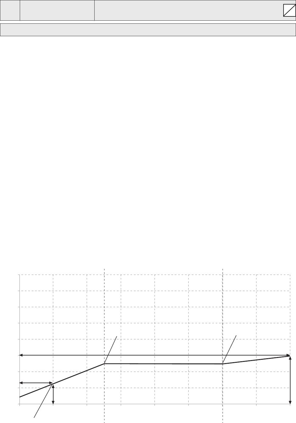
65
S
0918
0918 OFFSET Y2
Desired value
0.00 PSI
Possible settings: 0 – standardization of the sensor
Desired value; designation of the y – coordinate as absolute value.
Example for using the Offset function:
Constant pressure system with required value of 70 PSI.
Additionally a ow sensor is connected to the Offset input.
Parameter [907] - Offset Range = 300 (maximum range of ow sensor = 70 GPM)
System requirement 1:
5 bar constant pressure while the ow rate is between 20 GPM and 50 GPM.
Below 20 GPM the pressure should be decreased to maximum 36 PSI at a ow rate of 8 GPM.
Settings:
Parameter [0910] - Level 1 = 50 = 20 GPM (rst limit where the offset function is active)
Parameter [0912] - Offset X1 = 20 = 8 GPM (xed point according the requirements)
Parameter [0913] - Offset Y1 = 2.5 = 36 PSI (max. allowed pressure at this ow rate)
System requirement 2:
70 PSI constant pressure while the ow rate is between 20 GPM and 50 GPM.
Above the 50 GPM the pressure should be increased with the limitation to have maximum 87 PSI at maxi-
mum ow rate of 16m³/h.
Settings:
Parameter [915] - Level 2 = 120 = 50 GPM (second limit where the offset function is active)
Parameter [917] - Offset X2 = 160 = 16m³/h (xed point according the requirements)
Parameter [918] - Offset Y2 = 6 = 87 PSI (required pressure at this ow rate)
PROGRAMMING
2 m
3
/h
5 m
3
/h 12 m
3
/h
OFFSET X2
OFFSET X1
OFFSET Y1
OFFSET Y2
Level 1 Level 2
Offset
020406080 100 120 140 160
0
2
4
6
8
10
12
14
16
Required Value
Required
66
S
G
G
G
G
1000
1000 SUBMENU
TEST RUN
1005
1005 TEST RUN
Automatic test run
after 100 hrs
Possible settings: OFF – 100 h.
The Automatic Test Run starts the pump when it has not run for the number of hours set.
Test Run Time, Frequency and Boost can be selected in the parameters below.
To disable the automatic test run, press ▼ until “OFF” appears on the display.
The test run is only active when the HYDROVAR is stopped because of low/no demand and external
ON/OFF (E-stop) contact (X3/7-8) is closed!
1010
1010 TESTRUN FRQ.
Frequency for manual and automatic test run
30.0 Hz
Possible settings: 0 – Fmax
1015
1015 TESTR. BOOST Setting the motor starting voltage boost in %
10.0 % of rated input voltage
Possible settings: 0 – 25% of maximum input voltage
1020
1020 TESTRUN TIME
Test Run time
5 sec
Possible settings: 0-180 sec.
1025
1025 SEL. DEVICE
Select Inverter for manual test run
01
Possible settings: 01-08
1030
1030 TESTRUN MAN
Manual Test Run, Conrm test run for selected unit
Press 3 sec.
Perform a manual Test Run for one selected unit. (Even xed speed pumps in Cascade Relay Mode can be
included in the test run function.)
By pressing button for approximately 3 seconds a test run will be started.
PROGRAMMING

67
1100 1100 SUBMENU SETUP
1110
1110 FACTORY SET
Restores the HV to factory setting
USA
Possible settings: EUROPE, USA
To restore the HYDROVAR to factory settings select Europe or USA.
For reset press button until “DONE” appears.
1120
1120 PASSWORD 2
Enter password by pressing ▲ or ▼
0000
The below mentioned parameters are available after entering the correct password!
For more information, contact your local distributor!
1125
1125 CLR ERRORS Clear error memory of selected unit
UNIT X or on ALL units (Cascade Serial/Synchron)
Possible settings: 1 – 8, ALL
To clear the error memory either (1-8) for one specic unit or ALL for all units, can be selected.
For reset press button till “RESET” appears.
1130
1130 CLR MOTORH. Clear motor hours for selected unit
UNIT X or on ALL units (Cascade Serial/Synchron)
Possible settings: 1 – 8, ALL
Set desired unit where the Motor Hours should be cleared (or ALL) and press button until “RESET”
appears.
1135
1135 CLR OPERAT.
Clear operation time
Press 3 sec.
The operation time indicates the total time the HYDROVAR is already connected to power supply. For reset
the operation time of the current HYDROVAR press button till “RESET” appears.
1200
1200 SUBMENU
RS485-INTERFACE
User Interface
The following 3 Parameters are necessary for communication between the HYDROVAR and an external
device (e.g. PLC) via standardized Modbus-protocol. Set desired address, Baudrate and Format according
to the system requirements.
1205
1205 ADDRESS
Set desired address for the user interface
1
Possible settings: 1 - 247
PROGRAMMING
68
S
1210
1210 BAUDRATE
Baudrate for user interface
9600
Possible settings: 1200, 2400, 4800, 9600, 14400, 19200, 38400
1215
1215 FORMAT
Format for user interface
RTU N81
Possible settings: RTU N81, RTU N82, RTU E81, RTU O81,
ASCII N72, ASCII E71, ASCII O71
Internal Interface
If several Master Inverters are connected via the internal RS-485 interface (maximum 8 / using cascade se-
rial mode) each HYDROVAR needs its own allocated pump-address number (1-8). Each address may only
be used once!
1220
1220 PUMP ADDR.
Select desired address for the Master Inverter
1
Possible settings: 1 - 8
Set desired address for the current Master Inverter and press button for approximately 3 seconds and
the following messages will appear:
Addressing
->
1220 PUMP ADDR.
or
1220 PUMP ADDR.
Addressing * 1 * - 1 -
Address Set Address failed - retry
When using Master and Basic Inverters together in a multi-pump system the Basic Inverters require a
separate address.
For detailed Information see chapter 8.4.3.2 Addressing.
PROGRAMMING
69
Section 10
NOTE
If the HYDROVAR is stopped by an error (warning), the HYDROVAR and the motor remain
under voltage. Before any work is carried out on the electrical or mechanical part of the
system, the HYDROVAR must be disconnected from power supply for at least 5 minutes.
Difference between warnings and errors:
• Warnings are shown on the display and indicated by the red failure LED. If a warning is active and the cause is
not remedied within 20 seconds an error will be shown and the HYDROVAR stops. Note: Not all warnings will
result in an error.
• Errors are indicated on the HYDROVAR display and by the red failure LED on the control panel. In case of an
error the connected motor is stopped immediately. All errors are shown in plain text and saved in the error
memory including date and time when the failure occurred.
The following information describes the errors which can occur on the HYDROVAR (on the Master/Single and the
Basic Inverter). Additionally the possible countermeasures to reset these errors are described.
• Please note that an automatic error-reset can be activated in SUBMENU ERRORS to reset an occurred failure
automatically for 5 times. For more information about this function see parameter ERROR-RESET [0615].
• All error signals and warnings can be indicated via the two status-relays on terminals X5/1-2-3 or X5/4-
5-6 depending on the conguration. (How to program see parameter CONF REL 1 [0715] and CONF REL 2
[0720].)
10.1 Basic Inverter
The Basic Hydrovar (power unit only), may indicate the following errors by the red LED:
Red LED Code Error Probable Cause
1 blink UNDERVOLTAGE DC is too low
2 blinks
OVERCURRENT or Current rise at the output too high or
OVERLOAD current limit is reached
3 blinks INVERTER OVERHEAT Excessive temperature inside the HYDROVAR
4 blinks OVERVOLTAGE Excessive DC voltage
5 blinks CODE ERROR Internal error
6 blinks
MOTOR OVERHEAT PTC in the conduit box has reached its release
EXTERNAL CONTACT temperature or external contact is open
To reset the CODE ERROR and the OVERCURRENT ERROR, cut power
Reset:
supply for > 60 seconds.
To reset all other errors open/close the START/STOP_PTC input (X1/PTC) on
the power unit.
If the Basic Inverter is used in combination with a Master Inverter, each failure can be indicated on the
Master Inverter too and will be saved in the failure memory including date and time when the failure appeared.
Indication on the Master Inverter: For detailed failure information on the
ERR. Basic Addr. X specic unit, SUBMENU STATUS [20] has to be entered and the affected
device has to be selected with it’s pump address!
If a Master Inverter is used in such a system, the errors which occurred on the Basic Inverter can be reset by
the Master without interfering with the operation of the other HYDROVAR units in the system (also valid for
automatic Error-reset).
FAILURE MESSAGES

70
10.2 Master / Single Inverter
Each error is shown on the display in plain text and saved in the error memory.
The errors can be reset automatically (depending on the setting in parameter ERROR-RESET [0615]) or manually
in following ways:
• cutting the power supply for > 60 seconds
• pressing and simultaneously for about 5 seconds
• open and close the External ON/OFF (Terminals X3/7-8)
No error-message on the display
Error Probable Cause Measure
no AUTOSTART after Parameter AUTOSTART [08] is Check parameter AUTOSTART [08]
power failure set to “OFF”
No operation when system Pressure higher than the start Check parameter START VALUE [04]
pressure < set pressure value or REGULATION MODE and/or REGULATION MODE [0320]
has been changed to INVERSE.
Error-message on the display
Error Probable Cause Measure
• check connection-terminals of the
OVERCURRENT
Current rise at the output
HYDROVAR
ERROR 11
too high
• check the connection-terminal of
the motor and the motor-cable
• check the windings of the motor
Reset:
• The power supply for >60 seconds.
• Automatic Error-reset not possible for this failure!
FAILURE MESSAGES

71
Error Probable Cause Measure
• Check Parameter RAMP 1/2 [0215 /
0220] (too short) and BOOST [0265]
(too low)
OVERLOAD Power limit of the HYDROVAR • Check motor connection, cable and
ERROR 12 is exceeded power supply
• Pump blocked
• Motor turns in the wrong direction
• MAX. FREQUENCY [0245] too high
• Parameter RAMP 2 [0220] too fast
OVERVOLTAGE
DC voltage too high
• Power supply too high
ERROR 13 • Voltage peaks too high (Solution: Line
lters)
INVERT. OVERHEAT Excessive temperature inside
• Improper cooling
ERROR 14 the HYDROVAR
• Contamination of the motor vents
• Ambient temperature too high
An external protective device
• Close X1/PTC if there is no external
connected to terminal X1/PTC
protective device connected.
THERMO MOT/EXT
has released (e.g. PTC which is
• Close external on/off switch if
ERROR 15
connected has reached its
connected to these terminals.
release temperature).
• For detailed information, see
chapter 8.4.3.
• Check power supply under full load.
PHASELOSS One phase of the power supply
– Check if phase failure at the input.
ERROR 16 has been lost.
• Check circuit breakers
• Visual inspection of points at the
input terminals.
• Supply voltage too low
UNDERVOLTAGE DC voltage • Phase failure at the input
• Asymmetry of the phase imbalance
• Check if the addressing of Basic
Inverter [DIP SW.] has been done
The communication between
correctly.
COMM LOST
the Power Unit and the control
• Check if each unit has its own pump
card is lost.
address.
• Check if the connection from
control card to the power unit is
made properly (ribbon cable).
• Cut off power supply for > 60 seconds.
Reset:
• Manual reset by closing external ON/OFF (Terminals X3/7-8)
• Manual reset by pressing and simultaneously for about 5 seconds
• Auto-reset possible if ERROR-RESET [0615] is set to ON
FAILURE MESSAGES
72
S
S
• Incoming pressure or minimum level
too low
LACK OF WATER
Low water contact • Bridge X3/11-12, if there is no ext.
ERROR 21
(X3/11-12) is opened low water protection
(only active if motor is running) • Adjust Parameter DELAY TIME [0610]
if the failure happens only for a
short time
Reset: • Automatically if low water contact (X3/11-12) is closed!
Dened value of parameter • Check booster unit, adjust
MIN. THRESHOLD MIN.THRESHOLD [0605] was parameter DELAY TIME [0610]
ERROR 22 not reached during the • Parameter ERROR RESET [0615] set
preselected DELAY-TIME [0610] to ON, to enable 5 restarts
Sensor signal on terminals
• ACTUAL VALUE signal (pressure
FAILURE SENSOR 1
X3/2 <4mA
transducer) faulty
Active Sensor:
• Poor connection
ACT. VAL. SENSOR 1
WARNING (20 sec.)-> ERROR
• Sensor or cable fault
ERROR 23
Non-active sensor: WARNING
• check conguration of the sensors
in submenu SENSORS [0400]
Sensor signal on terminals
• ACTUAL VALUE signal (pressure
FAILURE SENSOR 2
X3/2 <4mA
transducer) faulty
Active Sensor:
• Poor connection
ACT. VAL. SENSOR 2
WARNING (20 sec.)-> ERROR
• Sensor or cable fault
ERROR 24
Non-active sensor: WARNING
• check conguration of the sensors
in submenu SENSORS [0400]
Current signal input of required
• Check external analogue signal on
SETPOINT 1 I<4mA
values is active, but no signal
terminals X3/17-18
4-20mA is connected
• Check conguration of the required
SETPOINT 1 I<4mA
WARNING (20 sec.)-> ERROR
values in Submenu REQUIRED
ERROR 25
VALUES [0800]
Current signal input of required
• Check external analogue signal on
SETPOINT 2 I<4mA
values is active, but no signal
terminals X3/22-23
4-20mA is connected
• Check conguration of the required
SETPOINT 2 I<4mA
WARNING (20 sec.)-> ERROR
values in Submenu REQUIRED
ERROR 26
VALUES [0800]
• Cut off power supply for > 60 seconds.
Reset:
• Manual reset by closing external ON/OFF (Terminals X3/7-8)
• Manual reset by pressing and simultaneously for about 5 seconds
• Auto-reset possible if ERROR-RESET [0615] is set to ON
FAILURE MESSAGES
73
10.3 Internal Errors
To remove the following errors cut the power supply for >60 seconds. If the error message is still shown on the
display, contact customer service and provide a detailed description of the error.
Internal errors
Error-message on the display - red LED on
ERROR 1
EEPROM-ERROR Reset - after repeated error-message
(data block malfunction) ⇒ change control card
• Check push buttons,
Button error
• Display-board may be defective
ERROR 4
(e.g.: jammed key)
• Assure drive cover securely attached
to base with no interference (pinched
wires, debris, etc.)
ERROR 5
EPROM-error Reset - after repeated error-message
(Checksum error) ⇒ change control card
ERROR 6
Program error: Reset - after repeated error-message
Watchdog error ⇒ change control card
ERROR 7
Program error: Reset - after repeated error-message
Processor pulse error ⇒ change control card
• Check installation of cables,
connection of the screen and
CODE ERROR
Code error: balanced power supply.
invalid processor command • Check earth/ground.
• Install additional inductances for
the signal-cables (e.g. ferrites).
Examples:
Booster Unit
Problem: HYDROVAR will not stop
Cause: Check:
• Demand exceeds pump capacity • Check pipes and valves
• Pre-charge pressure in pressure tank • Set WINDOW [0310] (< 10%) and
• Incorrect setting of WINDOW and HYSTERESIS [0315] (80-50%)
RAMP HYSTERESIS • Set RAMP 2 [0220] to 4...13 sec.
• Shut down ramp too slow • MINIMUM FREQUENCY [0250] should be
• Suction line too long activated for pressure increase at 0 demand
FAILURE MESSAGES

74
Control on Constant Flow
Problem: Control Fluctuations
Cause: Check:
• Increase WINDOW [0310] and set
Control characteristics are set too low HYSTERESIS [0315] to 99% to control with
RAMP 3 and 4.
Circulating Pump
Problem: Oscillation of the motor speed
Cause: Check:
• Increase RAMP 3 [0225] and 4 [0230]:
Control settings too fast
100...200sec.
• WINDOW [0310] (20%) and HYSTERESIS [0315]
(99%).
Problem: ACTUAL VALUE can't be maintained
Cause: Check:
HYSTERESIS is set too big HYSTERESIS [0315]: 90-99%
General
Problem: Pressure uctuations, analogue signal not constant
Solution: • Check cables and connection of the screen
• Check earth connection of the transmitter cable
• Use screened cables
FAILURE MESSAGES

75
Section 11 – Maintenance
The HYDROVAR does not require any special maintenance. However, the cooling fan and the vents should be
free of dust. Also the temperature around the unit should be checked from time to time.
All modications must be done by qualied personnel! For mounting and repairs, only qualied service
technicians should attempt.
Disconnecting:
The HYDROVAR must be disconnected from the power supply for at least 5 minutes before any work can be
carried out. Consider pump and motor instructions. Always wear your personal protection equipment.
For further information, please contact your distributor!
MAINTENANCE
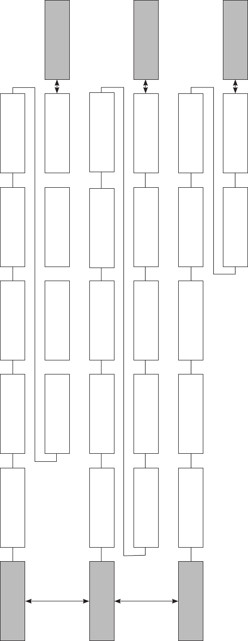
76
Section 12
0 MAIN MENU
20 SUBMENU
STATUS
0 MAIN MENU
XYLEM xx.x Hz
50 PSI
2 REQUIRED VAL
50 PSI
6 DATE
xx-xx-20xx
22 SELECT DEVICE
* 01 *
42 SEL. INVERTER
* 01 *
27 2ND ERROR
NO ERROR
28 3RD ERROR
NO ERROR
29 4TH ERROR
NO ERROR
30 5TH ERROR
NO ERROR
21 STATUS UNITS
00000000
41 PROD. DATE
xx-xx-xxxx
26 1ST ERROR
NO ERROR
3 EFF REQ VAL
50 PSI
7 TIME
xx:xx
23 STATUS DEVICE
running
43 TEMP. INVERTER
x: xx % xx Cº
4 START VALUE
OFF
8 AUTO-START
OFF
24 ENABLE DEVICE
enabled
44 CURR. INVERTER
x: xx %
46 OUTPUT FREQ
x: xx.x Hz
5 LANGUAGE
ENGLISH
9 OPERAT. TIME
xxxxx:xx
25 MOTOR HOURS
xxxxx:xx
45 VOLT. INVERTER
x: xxx V
47 VER. INVERTER
x: xx
20 SUBMENU
STATUS
40 SUBMENU
DIAGNOSTICS
40 SUBMENU
DIAGNOSTICS
PROGRAMMING FLOW CHART
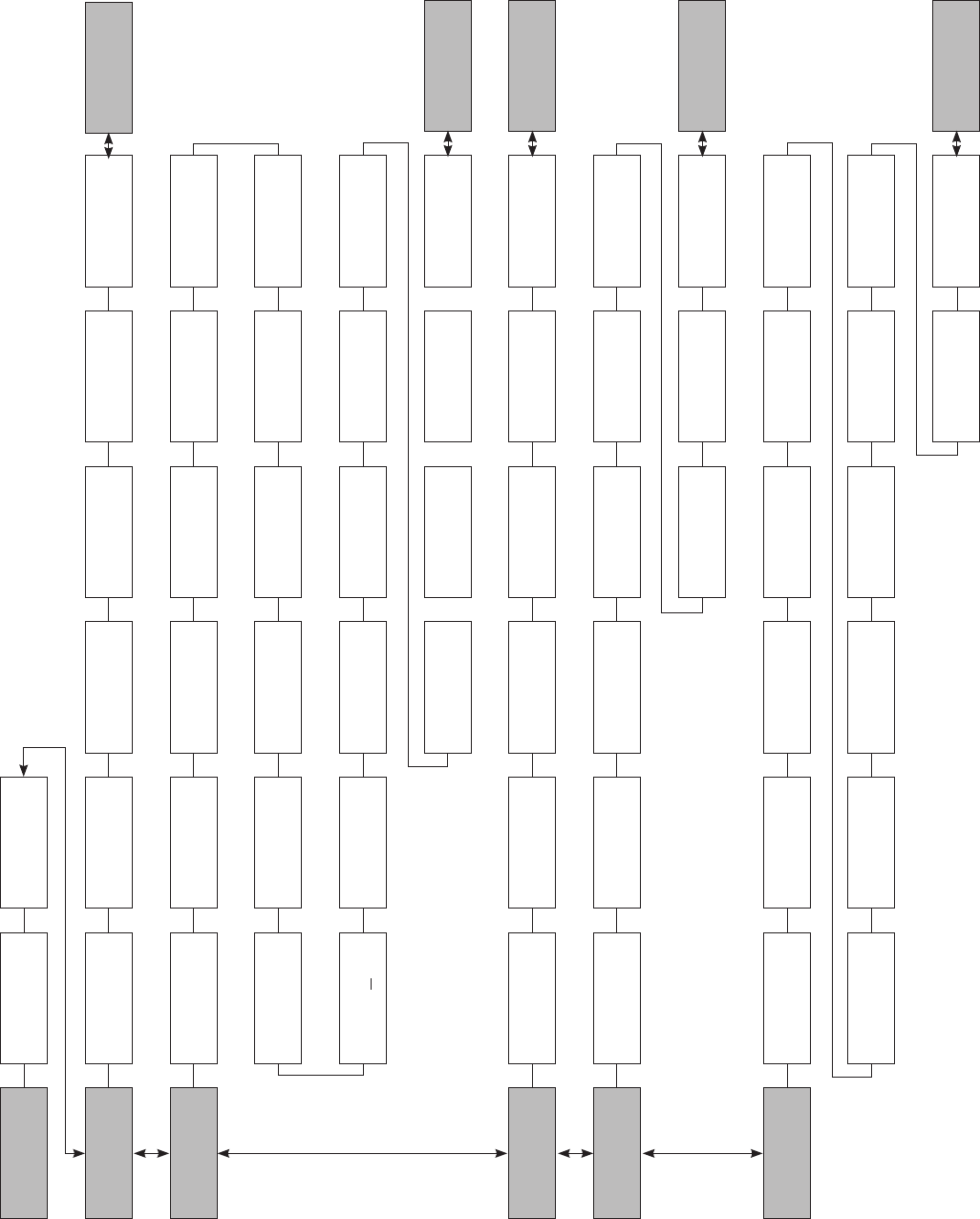
77
PROGRAMMING FLOW CHART
Section 12 (continued)
100 SUBMENU
BASIC SETTINGS
200 SUBMENU
CONF INVERTER
300 SUBMENU
REGULATION
400 SUBMENU
SENSOR
500 SUBMENU
SEQUENCE CNTR
100 SUBMENU
BASIC SETTINGS
60 SUBMENU
SETTINGS
200 SUBMENU
CONF INVERTER
300 SUBMENU
REGULATION
400 SUBMENU
SENSOR
500 SUBMENU
SEQUENCE CNTR
61 PASSWORD
0000
105 MODE
Controller
202 SOFTWARE
HV V01.3
205 MAX. UNITS
6
210 INVERTER
ALL
215 RAMP 1
4 sec
225 RAMP 3
70 sec
260 FMIN TIME
0 sec
265 BOOST
5 %
310 WINDOW
10 %
510 ACT.VAL.DEC
2 PSI
540 DROP FREQ
42.0 Hz
410 CONF SENSOR
Sensor 1
315 HYSTERESIS
80 %
515 ENABLE FREQ
48 Hz
545 OVERVALUE
disabled
415 SENSOR TYPE
analog I 4-20mA
320 REG. MODE
normal
520 ENABLE DLY
5 sec
550 OVERVAL DLY
0 sec
420 SENS. RANGE
300 PSI
325 FRQ. LIFT
30.0 Hz
525 SWITCH DLY
2 sec
555 SWITCH INTV
24 hours
425 SENS. CURVE
linear
330 LIFT AMOUNT
0.0 %
530 DISABLE FRQ
30.0 Hz
560 SYNCH.LIM.
0.0 Hz
565 SYNCH.WIN.
2 Hz
570 MSTPRIORITY
ON
430 SENS1 CAL 0
0 % = x,xx PSI
440 SENS2 CAL 0
0 % = x,xx PSI
435 SENS1 CAL X
0 % = xx,xx PSI
445 SENS2 CAL X
0 % = xx,xx PSI
285 SKIPFRQ CTR
0.0 Hz
270 KNEE FREQ.
60 Hz
286 SKIPFRQ RNG
60 Hz
275 POWER RED.
OFF
290 CURR. LIMIT
OFF
280 SEL.SW.FRQ.
Auto
291 CURR. LIMIT
100 %
230 RAMP 4
70 sec
235 RAMP FMIN A
2 sec
240 RAMP FMIN D
2 sec
245 MAX. FREQ
60 Hz
250 MIN. FREQ
20 Hz
220 RAMP 2
4 sec
203 SET VER INV
sel. 01 act. 01
106 PUMP ADDR
1
110 SET PASSW.
0066
115 LOCK FUNCT.
0066
120 DISP. CONTR.
75 %
125 DISP. BRIGHT
100 %
62 JOG Hz
50 PSI
305 JOG Hz
50 PSI
505 ACT.VAL.INC
5 PSI
535 DISABLE DLY
5 sec
405 DIMENS. UNIT
PSI
255 CONF. FMIN
F > 0
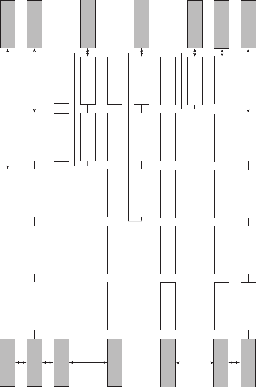
78
1000 SUBMENU
TESTRUN
800 SUBMENU
REQUIRED VALUES
700 SUBMENU
OUTPUTS
1000 SUBMENU
TESTRUN
1100 SUBMENU
SETUPS
1100 SUBMENU
SETUPS
605 MIN.THRESH.
disabled
705 ANALOG OUT1
Output frequency
1005 TESTRUN
100 hours
610 DELAY TIME
2 sec
1010 TESTRUN FREQ.
30 Hz
710 ANALOG OUT2
Actual value
810 C.REQ.VAL.2
OFF
1120 PASSWORD 2
0000
907 OFFS.INPUT
100
1210 BAUDRATE
9600
1215 FORMAT
RTU N81
830 ACTUAT.FRQ1
0.0 Hz
1220 PUMP ADDR
1
835 ACTUAT.FRQ2
0.0 Hz
805 C.REQ.VAL.1
digital
1110 FACTORY SET
USA
905 OFFS.INPUT
OFF
1205 ADDRESS
1
615 ERROR RESET
ON
1015 TESTR.BOOST
10 %
715 CONF REL 1
Running
815 SW REQ.VAL
Setpoint 1
1125 CLR ERRORS
ALL
910 LEVEL 1
0
915 LEVEL 2
100
1020 TESTR.TIME
5 sec
720 CONF REL 2
Errors
820 REQ.VAL.1
50 PSI
1130 CLR MOTORH.
ALL
912 OFFSET X1
0
917 OFFSET X2
100
1025 SEL.DEVICE
01
1030 TESTRUN MAN
Press > 3 sec
825 REQ.VAL.2
50 PSI
1135 CLR OPERAT.
Press > 3 sec
913 OFFSET Y1
0 PSI
918 OFFSET Y2
0 PSI
800 SUBMENU
REQUIRED VALUES
600 SUBMENU
ERRORS
600 SUBMENU
ERRORS
700 SUBMENU
OUTPUTS
1200 SUBMENU
RS485-INTERFACE
1200 SUBMENU
RS485-INTERFACE
900 SUBMENU
OFFSET
900 SUBMENU
OFFSET
PROGRAMMING FLOW CHART
Section 12 (continued)
79
NOTES

© 2016 Xylem Inc. IM223 Revision 6 March 2016
Xylem Inc.
2881 East Bayard Street Ext., Suite A
Seneca Falls, NY 13148
Phone: (800) 453-6777
Fax: (888) 322-5877
COMMERCIAL WARRANTY
For goods sold to commercial buyers, Seller warrants the goods sold to Buyer hereunder (with the exception of membranes, seals, gaskets,
elastomer materials, coatings and other “wear parts” or consumables all of which are not warranted except as otherwise provided in the quotation or
sales form) will be (i) be built in accordance with the specications referred to in the quotation or sales form, if such specications are expressly made
a part of this Agreement, and (ii) free from defects in material and workmanship for a period of one (1) year from the date of installation or twelve
(12) months from the date of shipment (which date of shipment shall not be greater than eighteen (18) months after receipt of notice that the goods
are ready to ship), whichever shall occur rst, unless a longer period is specied in the product documentation (the “Warranty”).
Except as otherwise required by law, Seller shall, at its option and at no cost to Buyer, either repair or replace any product which fails to conform
with the Warranty provided Buyer gives written notice to Seller of any defects in material or workmanship within ten (10) days of the date when any
defects or non-conformance are rst manifest. Under either repair or replacement option, Seller shall not be obligated to remove or pay for the
removal of the defective product or install or pay for the installation of the replaced or repaired product and Buyer shall be responsible for all other
costs, including, but not limited to, service costs, shipping fees and expenses. Seller shall have sole discretion as to the method or means of repair
or replacement. Buyer’s failure to comply with Seller’s repair or replacement directions shall terminate Seller’s obligations under this Warranty and
render the Warranty void. Any parts repaired or replaced under the Warranty are warranted only for the balance of the warranty period on the parts
that were repaired or replaced. Seller shall have no warranty obligations to Buyer with respect to any product or parts of a product that have been:
(a) repaired by third parties other than Seller or without Seller’s written approval; (b) subject to misuse, misapplication, neglect, alteration, accident,
or physical damage; (c) used in a manner contrary to Seller’s instructions for installation, operation and maintenance; (d) damaged from ordinary
wear and tear, corrosion, or chemical attack; (e) damaged due to abnormal conditions, vibration, failure to properly prime, or operation without ow;
(f) damaged due to a defective power supply or improper electrical protection; or (g) damaged resulting from the use of accessory equipment not
sold or approved by Seller. In any case of products not manufactured by Seller, there is no warranty from Seller; however, Seller will extend to Buyer
any warranty received from Seller’s supplier of such products.
THE FOREGOING WARRANTY IS EXCLUSIVE AND IN LIEU OF ANY AND ALL OTHER EXPRESS OR IMPLIED WARRANTIES, GUARANTEES,
CONDITIONS OR TERMS OF WHATEVER NATURE RELATING TO THE GOODS PROVIDED HEREUNDER, INCLUDING WITHOUT LIMITATION ANY
IMPLIED WARRANTIES OF MERCHANTABILITY AND FITNESS FOR A PARTICULAR PURPOSE, WHICH ARE HEREBY EXPRESSLY DISCLAIMED AND
EXCLUDED. EXCEPT AS OTHERWISE REQUIRED BY LAW, BUYER’S EXCLUSIVE REMEDY AND SELLER’S AGGREGATE LIABILITY FOR BREACH OF
ANY OF THE FOREGOING WARRANTIES ARE LIMITED TO REPAIRING OR REPLACING THE PRODUCT AND SHALL IN ALL CASES BE LIMITED
TO THE AMOUNT PAID BY THE BUYER FOR THE DEFECTIVE PRODUCT. IN NO EVENT SHALL SELLER BE LIABLE FOR ANY OTHER FORM OF
DAMAGES, WHETHER DIRECT, INDIRECT, LIQUIDATED, INCIDENTAL, CONSEQUENTIAL, PUNITIVE, EXEMPLARY OR SPECIAL DAMAGES,
INCLUDING BUT NOT LIMITED TO LOSS OF PROFIT, LOSS OF ANTICIPATED SAVINGS OR REVENUE, LOSS OF INCOME, LOSS OF BUSINESS, LOSS
OF PRODUCTION, LOSS OF OPPORTUNITY OR LOSS OF REPUTATION.
