
Service Notes
1
Service Notes
Before You Begin
This manual provides instructions for Meritor
WABCO’s System Saver Series single cartridge air
dryers. Before you begin procedures:
1. Read and understand all instructions and
procedures before you begin to service
components.
2. Read and observe all Caution and Warning
safety alerts that precede instructions or
procedures you will perform. These alerts help
to avoid damage to components, serious
personal injury, or both.
3. Follow your company’s maintenance and
service, installation, and diagnostics
guidelines.
4. Use special tools when required to help avoid
serious personal injury and damage to
components.
Safety Alerts, Torque Symbol
and Notes
Access Product and Service
Information on our Web Site
Enter meritorwabco.com in your browser’s
address box for quick access to our web site. At
our home page, click on literature to access our
publications.
meritorwabco.com
To Order Information by Phone
Call ArvinMeritor’s Customer Service Center at
800-535-5560 to order the following item.
O
Drivetrain Plus
TM
by ArvinMeritor Technical
Electronic Library on CD. Features product
and service information on most Meritor,
ZF Meritor and Meritor WABCO products.
$20. Order TP-9853.
WARNING
A Warning alerts you to an
instruction or procedure
that you must follow
exactly to avoid serious
personal injury.
CAUTION
A Caution alerts you to an
instruction or procedure
that you must follow
exactly to avoid damage to
components.
A torque symbol alerts you
to tighten fasteners to a
specified torque value.
NOTE
A Note provides
information or suggestions
that help you correctly
service a component.

Table of Contents
Section 1: Introduction
System Overview . . . . . . . . . . . . . . . . . . . . . . . . . . . . . . . . . . . . . . . . . . . . . . . . . . . . . . . . . . . . . . . . . . . . . .1
Air Dryer Documentation
Air Dryer Identification
How the Air Dryer Works . . . . . . . . . . . . . . . . . . . . . . . . . . . . . . . . . . . . . . . . . . . . . . . . . . . . . . . . . . . . . . .2
Air Dryer Cycle . . . . . . . . . . . . . . . . . . . . . . . . . . . . . . . . . . . . . . . . . . . . . . . . . . . . . . . . . . . . . . . . . . . . . . . .3
Air Dryer Components . . . . . . . . . . . . . . . . . . . . . . . . . . . . . . . . . . . . . . . . . . . . . . . . . . . . . . . . . . . . . . . . .4
Dryer Identification . . . . . . . . . . . . . . . . . . . . . . . . . . . . . . . . . . . . . . . . . . . . . . . . . . . . . . . . . . . . . . . . . . . .5
Description of Components
Section 2: Troubleshooting & Testing
Routine Maintenance . . . . . . . . . . . . . . . . . . . . . . . . . . . . . . . . . . . . . . . . . . . . . . . . . . . . . . . . . . . . . . . . . . .9
Maintenance Tips
Troubleshooting . . . . . . . . . . . . . . . . . . . . . . . . . . . . . . . . . . . . . . . . . . . . . . . . . . . . . . . . . . . . . . . . . . . . . .10
System Tests . . . . . . . . . . . . . . . . . . . . . . . . . . . . . . . . . . . . . . . . . . . . . . . . . . . . . . . . . . . . . . . . . . . . . . . .13
Heater Resistance
Leak Test
Air Pressure Checks
Operational Test for System Saver Series Air Dryers — Regeneration and Purge Style
Pressure-Controlled Check Valve Test — Regeneration Style Only . . . . . . . . . . . . . . . . . . . . . . . . . . . .14
Section 3: Installing Replacement Parts
Replacement Requirements . . . . . . . . . . . . . . . . . . . . . . . . . . . . . . . . . . . . . . . . . . . . . . . . . . . . . . . . . . . .15
Component Replacement . . . . . . . . . . . . . . . . . . . . . . . . . . . . . . . . . . . . . . . . . . . . . . . . . . . . . . . . . . . . . .16
Desiccant Cartridge
Outlet Check Valve Assembly . . . . . . . . . . . . . . . . . . . . . . . . . . . . . . . . . . . . . . . . . . . . . . . . . . . . . . . . . . .17
Heater Assembly
Turbo Cut-Off Valve Assembly . . . . . . . . . . . . . . . . . . . . . . . . . . . . . . . . . . . . . . . . . . . . . . . . . . . . . . . . . .18
Regeneration Valve Assembly . . . . . . . . . . . . . . . . . . . . . . . . . . . . . . . . . . . . . . . . . . . . . . . . . . . . . . . . . .19
Purge Valve Assembly . . . . . . . . . . . . . . . . . . . . . . . . . . . . . . . . . . . . . . . . . . . . . . . . . . . . . . . . . . . . . . . . .20
Pressure-Controlled Check Valve (PCCV) . . . . . . . . . . . . . . . . . . . . . . . . . . . . . . . . . . . . . . . . . . . . . . . . . .21
Bypass Valve
Pressure Relief Valve . . . . . . . . . . . . . . . . . . . . . . . . . . . . . . . . . . . . . . . . . . . . . . . . . . . . . . . . . . . . . . . . . .22
Purge Silencer (Muffler) . . . . . . . . . . . . . . . . . . . . . . . . . . . . . . . . . . . . . . . . . . . . . . . . . . . . . . . . . . . . . . .23
Air Dryer Assembly
Testing the Meritor WABCO System Saver Series Air Dryer . . . . . . . . . . . . . . . . . . . . . . . . . . . . . . . . . .24
Appendix I: Glossary
Basic Air System/Air Dryer Terms . . . . . . . . . . . . . . . . . . . . . . . . . . . . . . . . . . . . . . . . . . . . . . . . . . . . . . .25
Appendix II: Application Information
General Requirements . . . . . . . . . . . . . . . . . . . . . . . . . . . . . . . . . . . . . . . . . . . . . . . . . . . . . . . . . . . . . . . . .26
Operating Environment Requirements
System Saver Series Installation Criteria . . . . . . . . . . . . . . . . . . . . . . . . . . . . . . . . . . . . . . . . . . . . . . . . .27
Appendix III: Special Applications
Holset E-Type Compressor Systems . . . . . . . . . . . . . . . . . . . . . . . . . . . . . . . . . . . . . . . . . . . . . . . . . . . . .28
ECON Valve . . . . . . . . . . . . . . . . . . . . . . . . . . . . . . . . . . . . . . . . . . . . . . . . . . . . . . . . . . . . . . . . . . . . . . . . .29
Alcohol Evaporator . . . . . . . . . . . . . . . . . . . . . . . . . . . . . . . . . . . . . . . . . . . . . . . . . . . . . . . . . . . . . . . . . . .31
Combo Tank Installation for Regeneration-Style Air Dryers . . . . . . . . . . . . . . . . . . . . . . . . . . . . . . . . . .32
Combo Tank Installation for Regeneration-Style Air Dryers . . . . . . . . . . . . . . . . . . . . . . . . . . . . . . . . . .33
Meritor WABCO System Saver Series Single Cartridge Air Dryer
Component Replacement Guide — Dedicated Purge . . . . . . . . . . . . . . . . . . . . . . . . . . . . . . . . . . .34
Meritor WABCO System Saver Series Single Cartridge Air Dryer
Component Replacement Guide . . . . . . . . . . . . . . . . . . . . . . . . . . . . . . . . . . . . . . . . . . . . . . . . . . . .35

Section 1
Introduction
MM-34
Revised 11-02 Page 1
Section 1Introduction
System Overview
Maintenance Manual 34 contains troubleshooting
steps and service information for the Meritor
WABCO System Saver Series (1000, 1200 and
1800) single cartridge air dryers.
NOTE:
If you have a System Saver TWIN air dryer,
use Maintenance Manual 35.
Air Dryer Documentation
TP-92116, Installing the Meritor WABCO System
Saver Series Air Dryer, provides complete
installation instructions.
PB-96134 contains a complete listing of air dryer
replacement parts.
TP-97101 is a troubleshooting guide. There is also
a poster-sized troubleshooting guide, TP-9772,
available.
TP-9672, Air Dryer Application Guide, provides
an in-depth look at System Saver Series air
dryer applications.
T-20102V, Air System Troubleshooting video
Stopping With Air and T-97105V, System Saver
1200 videotapes are also available.
To order literature, contact ArvinMeritor’s
Customer Service Center, 800-535-5560.
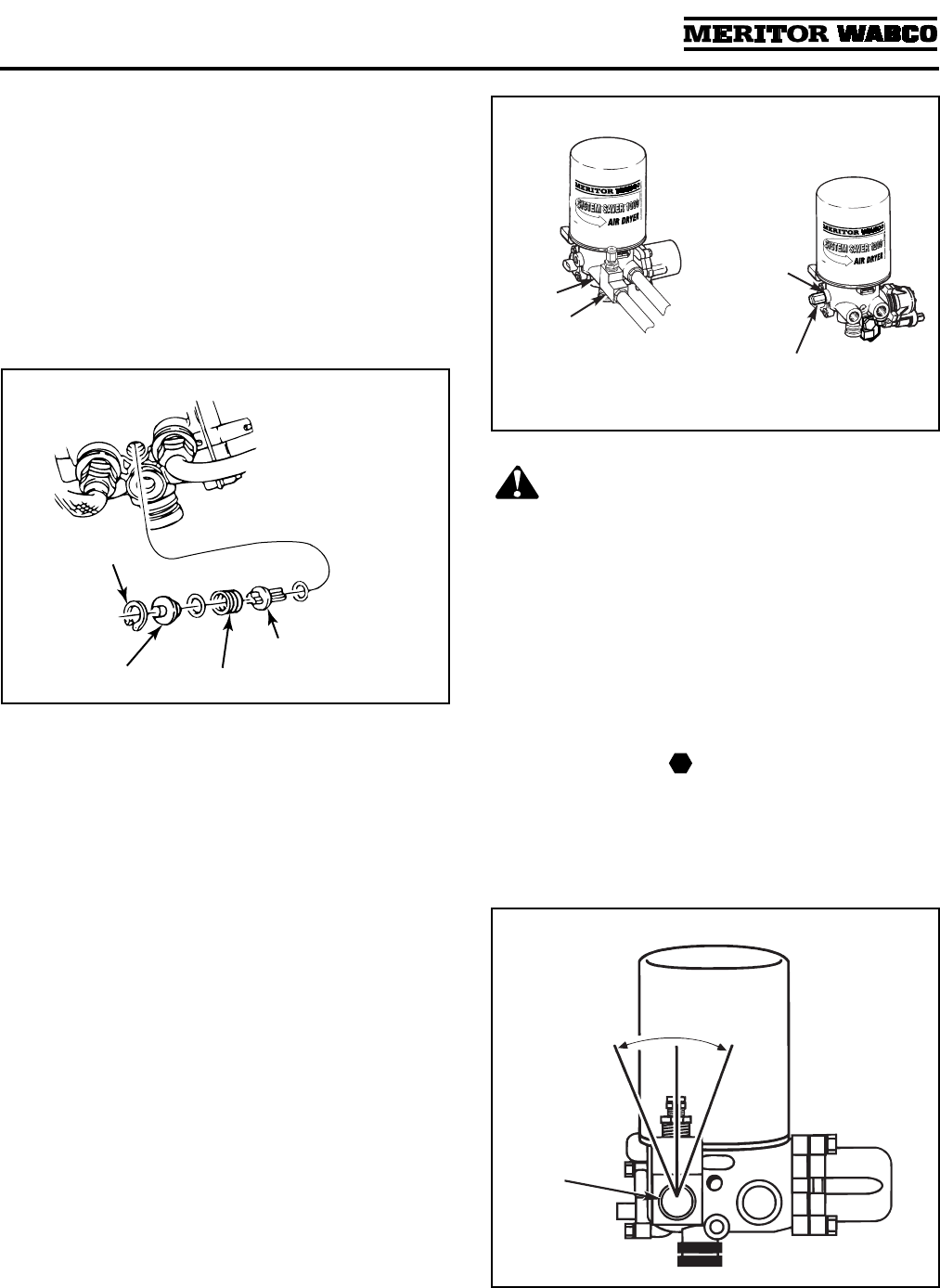
Air Dryer Identification
Alphabetical designations of the System Saver
Series family of air dryers have specific meanings:
P Indicates an external purge tank is used for
desiccant regeneration
U Indicates discharge line — unloaded
compressor
E Indicates a Holset style compressor function
G Indicates integral governor for air compressor
control
UP Indicates discharge line — unloaded
compressor (with external purge tank)
System Saver 1200/1800:
System regeneration
valve assembly on side of dryer
System Saver 1200E:
Tubing and banjo fitting at
front of dryer
System Saver 1200P/1800P:
Uses dedicated purge
tank. Port 22 drilled and tapped
System Saver 1200U/1800U:
Small regeneration
hole visible in back of Port 1 when fitting is
removed. No spring in turbo cut-off valve
assembly.
System Saver 1200UP/1800UP:
Port 22 drilled and
tapped. Small regeneration hole visible at back of
Port 1 when fitting is removed. No spring in turbo
cut-off valve assembly. Dedicated purge tank.
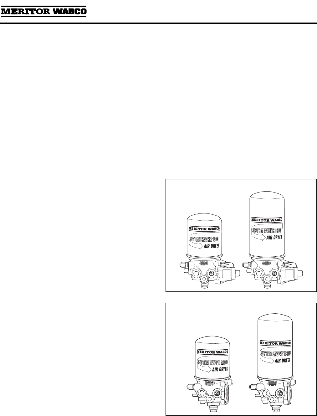
The air dryer base is the same for both the 1200
and 1800 Series air dryers, however the 1800
Series canister is 3.2 inches taller than the 1200.
This larger canister contains 50% more desiccant,
which makes the 1800 ideal for applications calling
for frequent starts, stops and long compressor
cycles. System Saver 1200 and System Saver 1800
Series air dryers are illustrated in
Figure 1.1
.
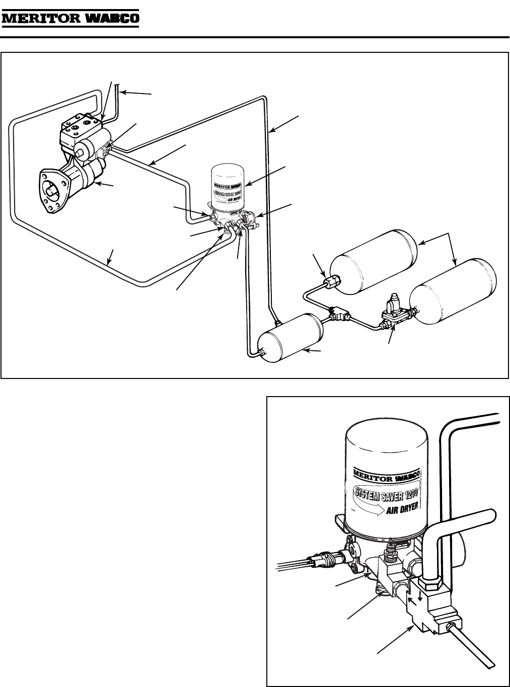
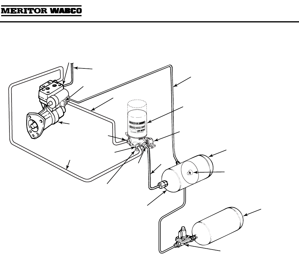
System Saver 1200P and System Saver 1800P,
which are used with a dedicated purge tank, are
illustrated in
Figure 1.2
.
Figure 1.1
Figure 1.2
Section 1
Introduction
MM-34
Page 2 Revised 11-02
How the Air Dryer Works
During system pressure build-up, compressed air
passes into the air dryer where the filter system
removes contaminants and passes the air into the
drying stage.
Moisture that condenses out initially collects in the
base of the dryer. Moisture-laden air passes
through the desiccant bed in the air dryer
cartridge and is dried. When the compressor
unloads, the water is expelled and dried air flows
back through the dryer, drying the desiccant for
the next cycle.
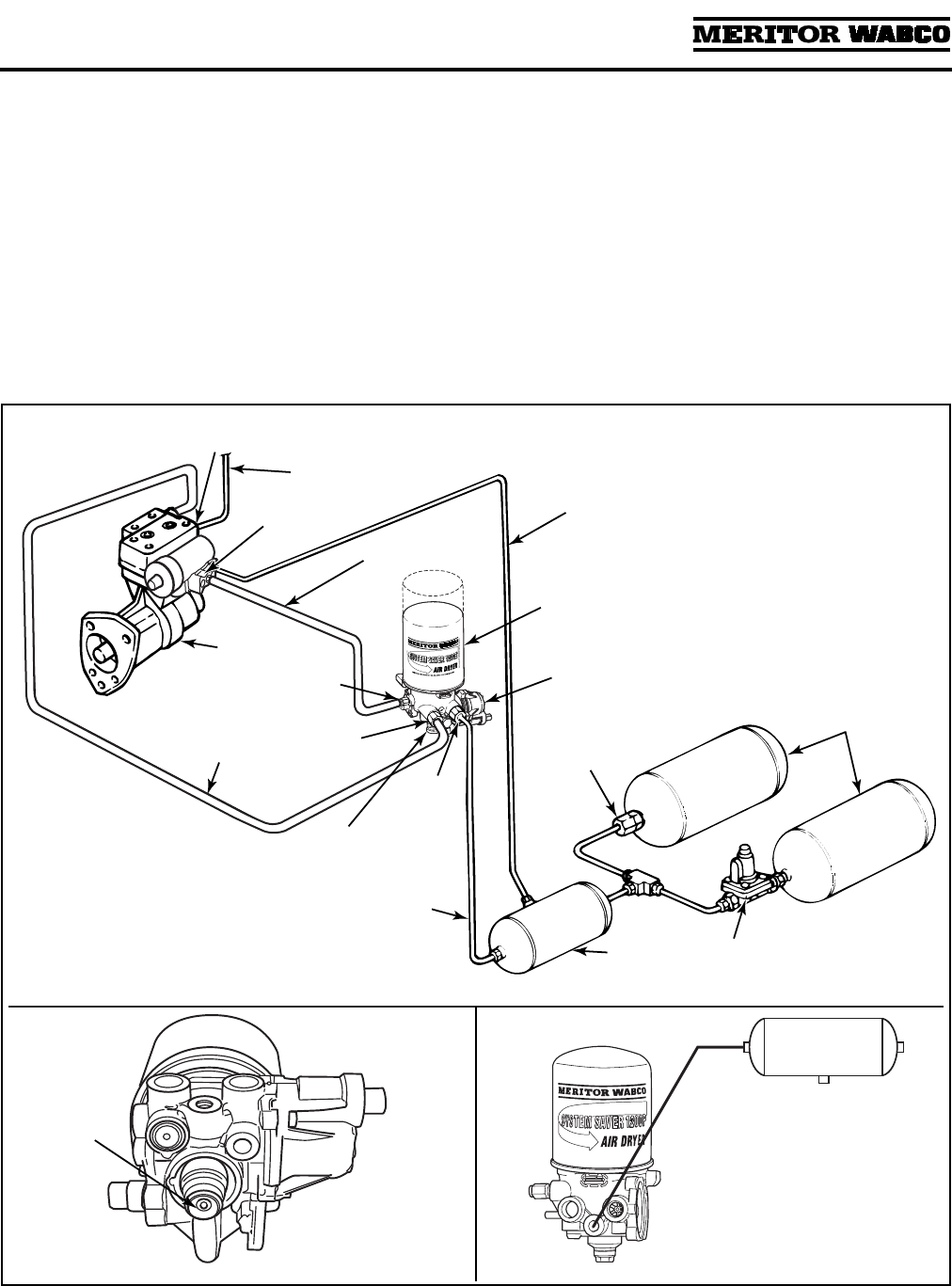
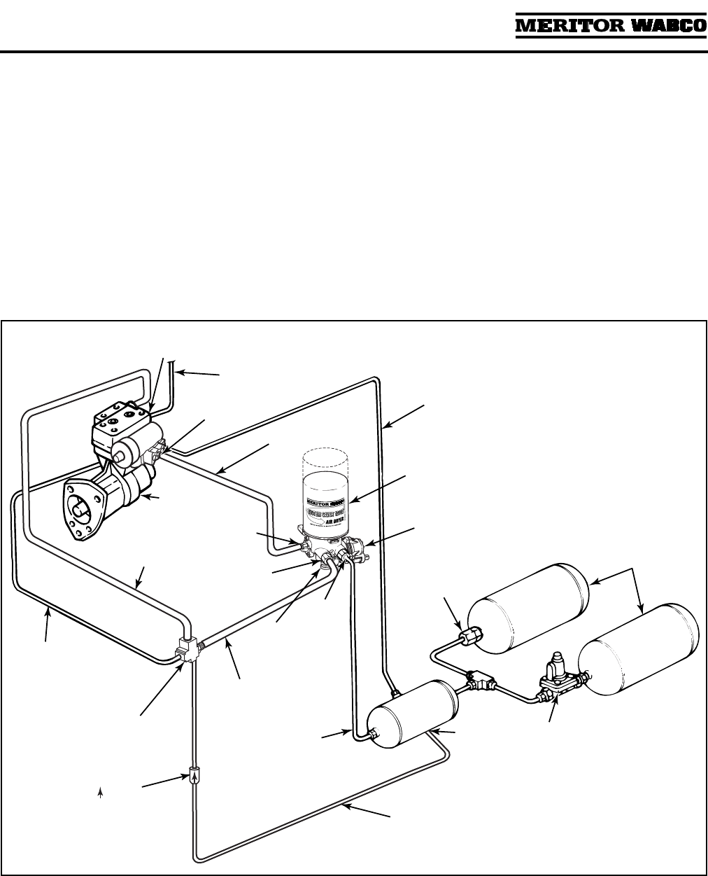
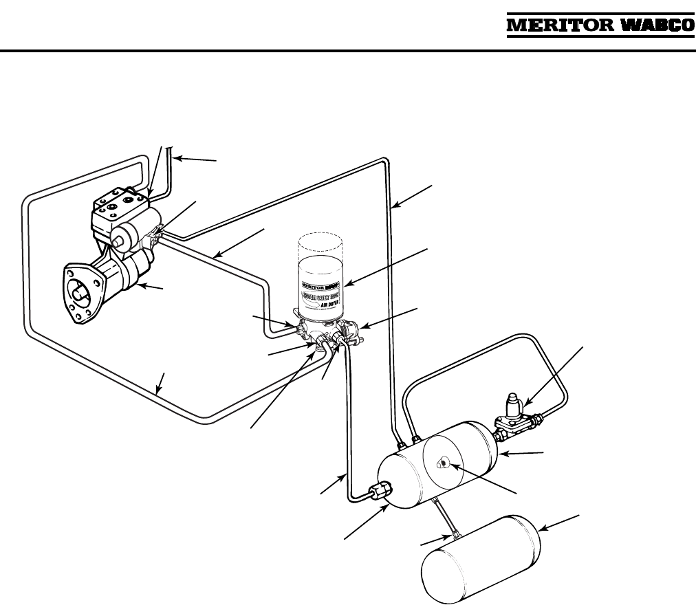
A typical Meritor WABCO System Saver 1200 or
1800 Series air dryer installation is illustrated in
Figure 1.3
. Illustrations for Combo Tank
installations appear in Appendix III, Special
Applications.
Figure 1.3
1002141c
PURGE
VALVE
(EXHAUST)
COMPRESSOR
DISCHARGE
LINE
COMPRESSOR
CONTROL
(PURGE) PORT
COMPRESSOR
INTAKE LINE
PRESSURE-
CONTROLLED
CHECK VALVE
SUPPLY
TANK
SYSTEM
RESERVOIRS
ONE-WAY
CHECK
VALVE
DRYER
OUTLET
PORT
SYSTEM SAVER SERIES
REGENERATION
STYLE AIR DRYER
DRYER
INLET
PORT
UNLOADER
LINE
RESERVOIR
TO GOVERNOR
LINE
1800
1200
SUPPLY
LINE
PURGE
TANK
PURGE
VALVE
(EXHAUST)
P Series with dedicated
purge tank.
Bottom view
of air dryer.
REGENERATION
VALVE
GOVERNOR
UNLOADER
PORT
Section 1
Introduction
MM-34
Revised 11-02 Page 3
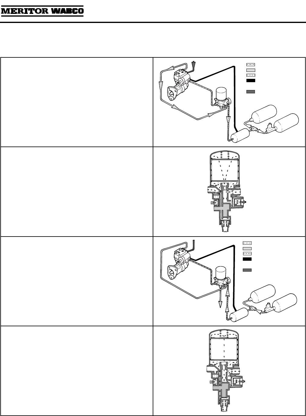
Air Dryer Cycle
A single cartridge air dryer cycle is illustrated below.
The governor turns the compressor on when
supply tank pressure drops below cut-in pressure
(approximately 100 psi).
Compressed air passes into the air dryer at the
inlet port:
O
Moisture-laden air and contaminants pass
through the desiccant.
O
Moisture is retained by desiccant; moisture also
collects in the base of the dryer.
The governor turns the compressor off when
system reaches cut-out pressure (approximately
120 psi).
When the compressor unloads, the purge valve
opens:
O
Dryer purges, expels water collected in dryer
base.
O
Regeneration valve opens:
— Dry system air flows back through the dryer.
10 psi taken from supply and secondary
tanks.
— Back flow dries desiccant, preparing it for
the next cycle.
1002142a
CONTROL
“WET” AIR
“DRY” AIR
CONTROL/DRY
LINES
ENGINE TURBO
BOOST PRESSURE
1002143a
1002145a
CONTROL
“WET” AIR
“DRY” AIR
CONTROL/DRY
LINES
ENGINE TURBO
BOOST PRESSURE
1002144a
Section 1
Introduction
MM-34
Page 4 Revised 11-02
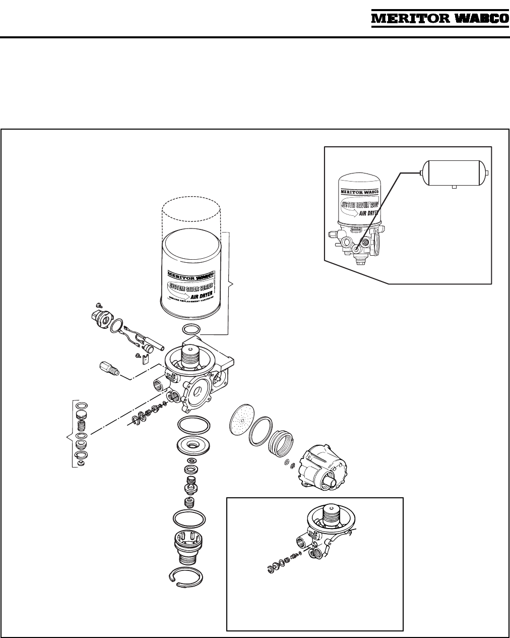
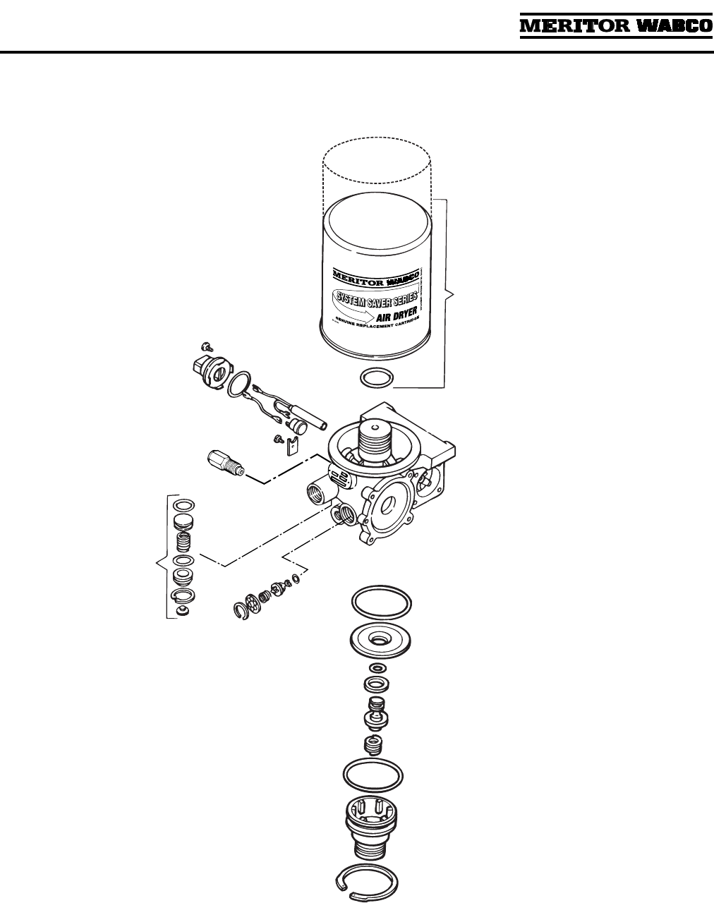
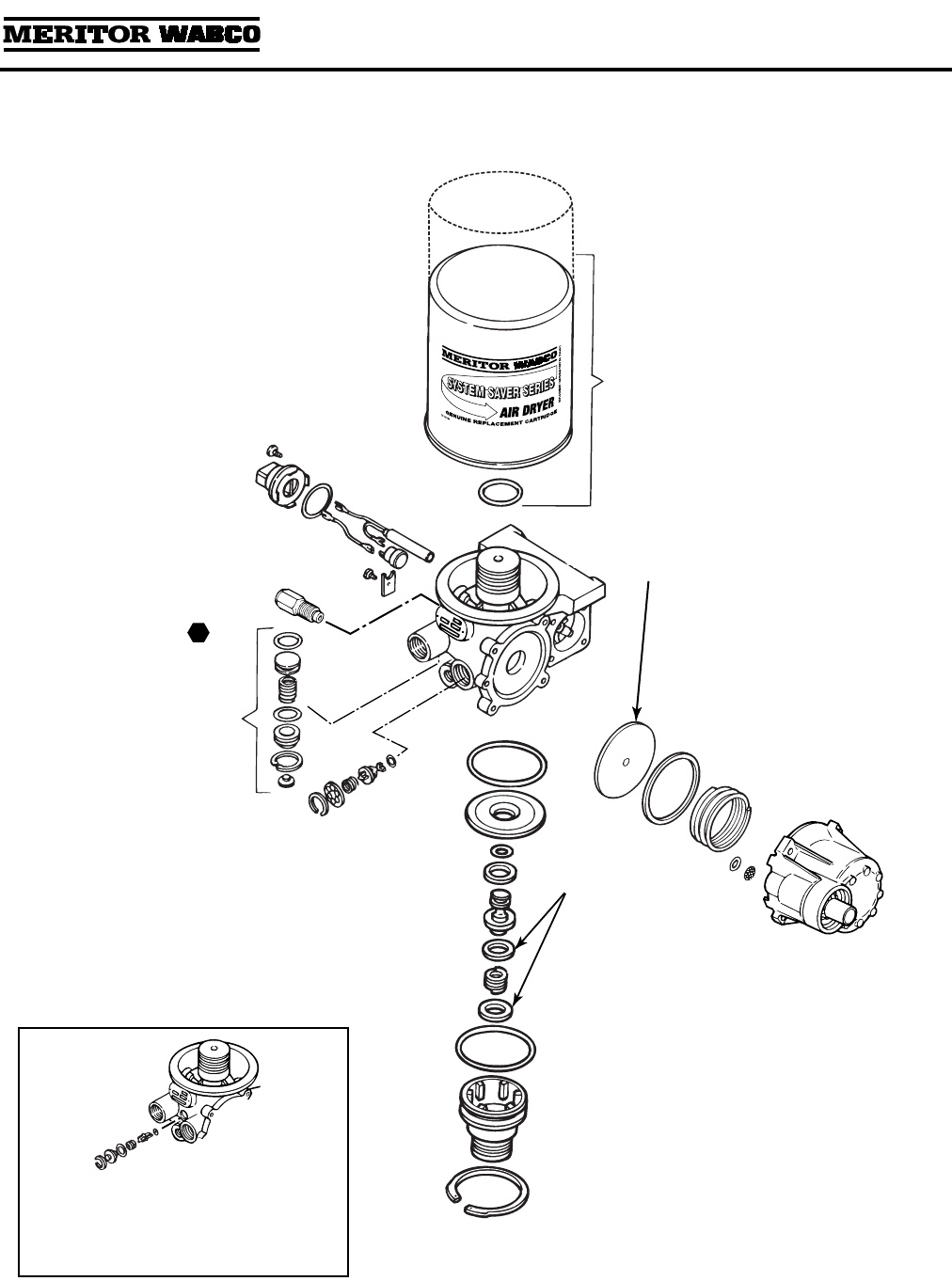
Air Dryer Components
Meritor WABCO single cartridge air dryers contain
replaceable component parts. Air dryer
components are illustrated in
Figure 1.4
. Refer to
Section 3 for instructions.
NOTE:
For information about System Saver E air
dryers and components, refer to Appendix I and
Appendix II. For special applications, refer to
Appendix III.
Figure 1.4
1002146b
SYSTEM SAVER 1200 OR 1800
DESICCANT CARTRIDGE
PRESSURE
RELIEF
VALVE
PURGE
VALVE
ASSEMBLY
REGENERATION VALVE ASSEMBLY
(FOR REGENERATION STYLE AIR
DRYERS)
O-RING
12- OR 24-VOLT
HEATER ASSEMBLY
1200
1800
PURGE
TANK
Port 22 drilled
and tapped for
dedicated purge
style.
BYPASS VALVE
ASSEMBLY
Bypass valve is used on dryers with
date codes earlier than 0894.
1200 Series air dryers do not use
bypass valve.
TURBO
CUT-OFF
VALVE
ASSEMBLY
OUTLET
CHECK
VALVE
ASSEMBLY
Section 1
Introduction
MM-34
Revised 11-02 Page 5
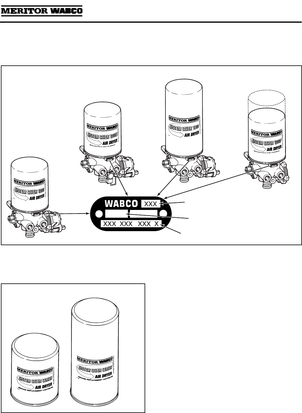
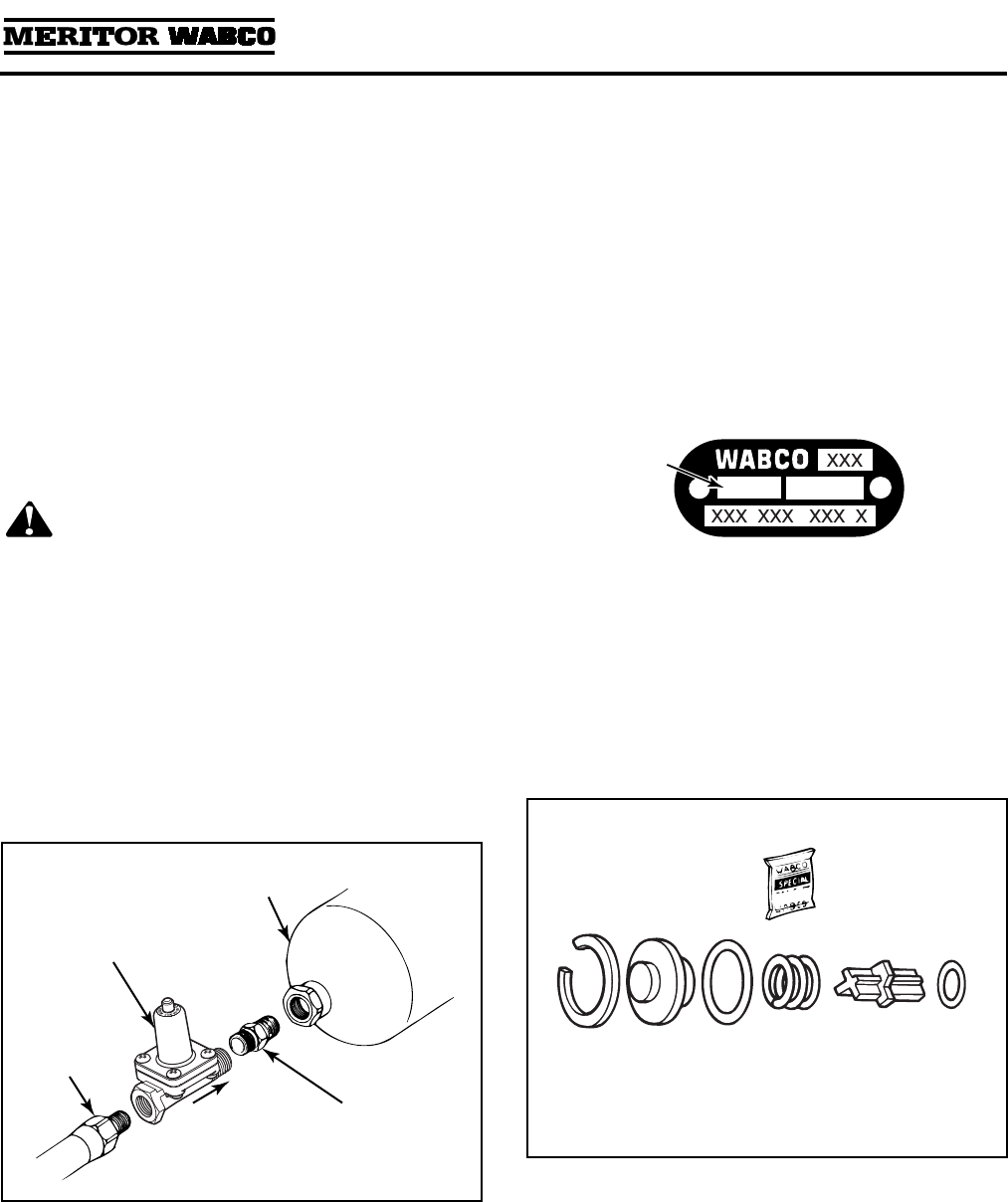
Dryer Identification
The identification tag on the face of the dryer provides important information about the air
dryer — information you will need when servicing or replacing components.
Figure 1.5
.
Description of Components
Replacement components for single canister air dryers are described below.
Figure 1.5
1696
1002147b
SYSTEM
SAVER
1000/1200/1200U
DATE CODE
FIRST 2 DIGITS = BUILD WEEK
LAST 2 DIGITS = BUILD YEAR
MANUFACTURING
LOCATION CODE
SYSTEM
SAVER
1800/1800U
SYSTEM
SAVER
1200E
PART
NUMBER
SYSTEM
SAVER
1200P/1200UP
OR
1800P/1800UP
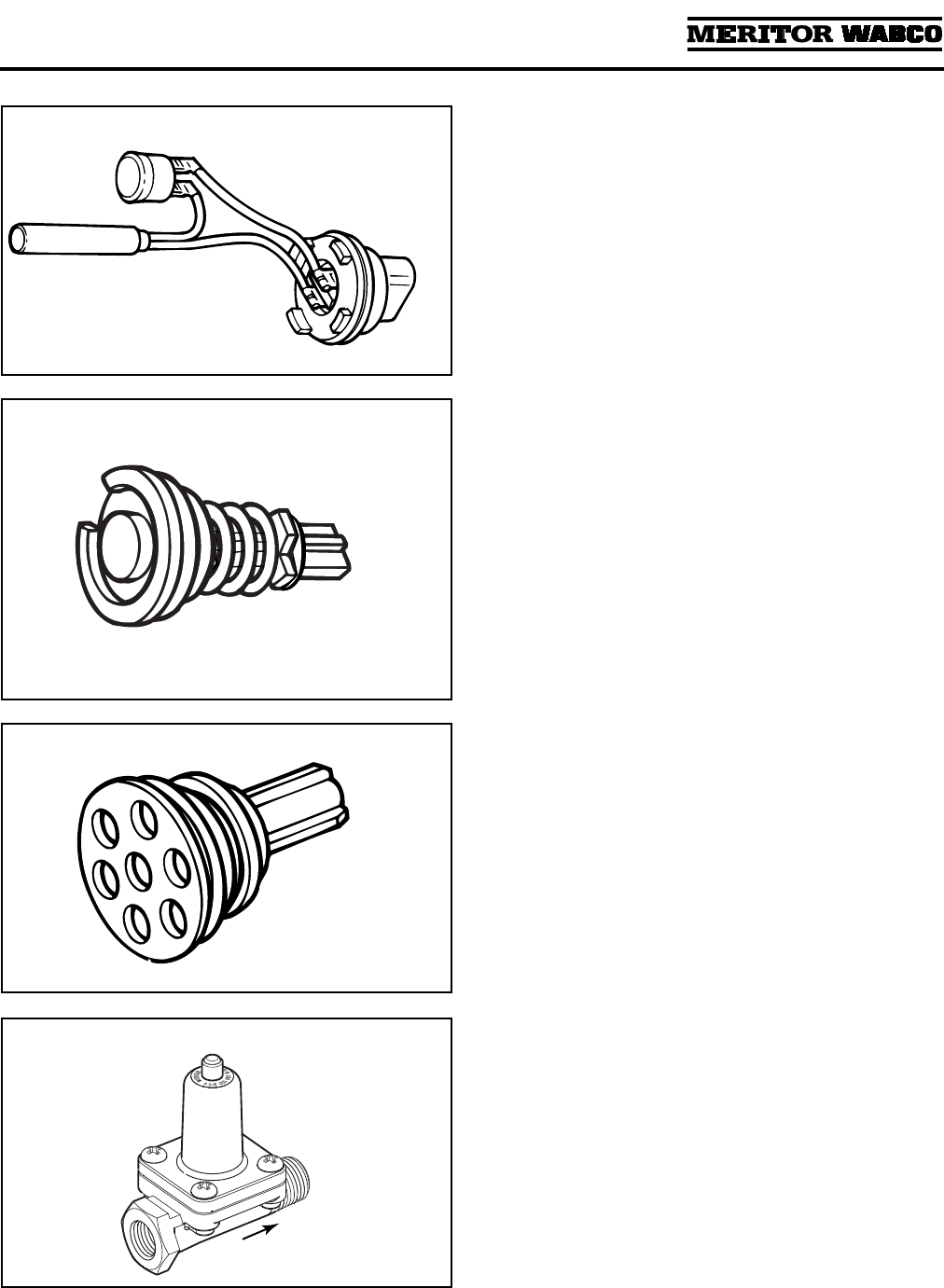
Figure 1.6
Desiccant Cartridge:
A cylindrical steel housing
containing the filter elements and desiccant
needed to filter and dry system air.
Spin-on/spin-off design allows quick and easy
maintenance. The System Saver 1800 Series
cartridge is 3.2-inches taller than the 1200 Series
cartridge.
Figure 1.6
.
1002148b
1800
1200
Section 1
Introduction
MM-34
Page 6 Revised 11-02
Figure 1.7
Heater:
Located in the air dryer base, the heater
prevents water that collects in the air dryer from
freezing. It consists of a cylindrical resistive-type
heating element and a small circular thermostat.
Heater is available for 12- and 24-volt air dryers.
Figure 1.7
.
1002149a
HEATER MAY BE STAINLESS
STEEL CLAD OR CERAMIC
Figure 1.8
For 1000 Series dryers with date code 0894 or earlier.
Bypass Valve:
A valve located between the inlet
and outlet ports of the dryer. It allows air to flow
into the dryer and go directly to the outlet port,
bypassing the desiccant cartridge. The 1200,
1200E Series and 1000 Series with date codes
later than 0894 do not use a bypass valve.
Figure 1.8
.
1002150a
Figure 1.9
Outlet Check Valve:
A valve located in the outlet
port (port 21) of the air dryer. It prevents air from
flowing back through the air dryer and escaping
out the purge valve during a compressor unload
cycle.
Figure 1.9
.
1002151a
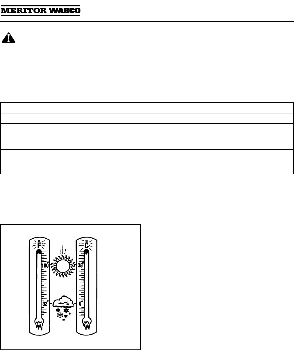
Figure 1.10
Pressure-Controlled Check Valve (PCCV):
Used
with System Saver Series regeneration style air
dryers. The PCCV is usually mounted on the
secondary air tank in place of an inlet check
valve. It lets air backflow from the secondary
tank to the supply tank as long as system
pressure remains between the normal cut-in
and cut-out range of the governor. It allows
additional air volume for generation during the
air dryer purge cycle. Not used with “P” style air
dryers.
Figure 1.10
.
1002152b
AIR FLOW
DIRECTION
Section 1
Introduction
MM-34
Revised 11-02 Page 7
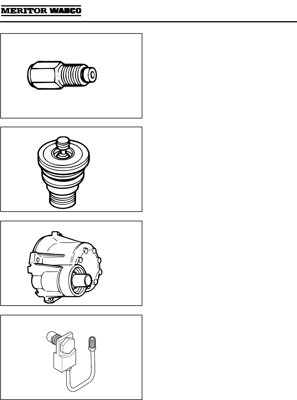
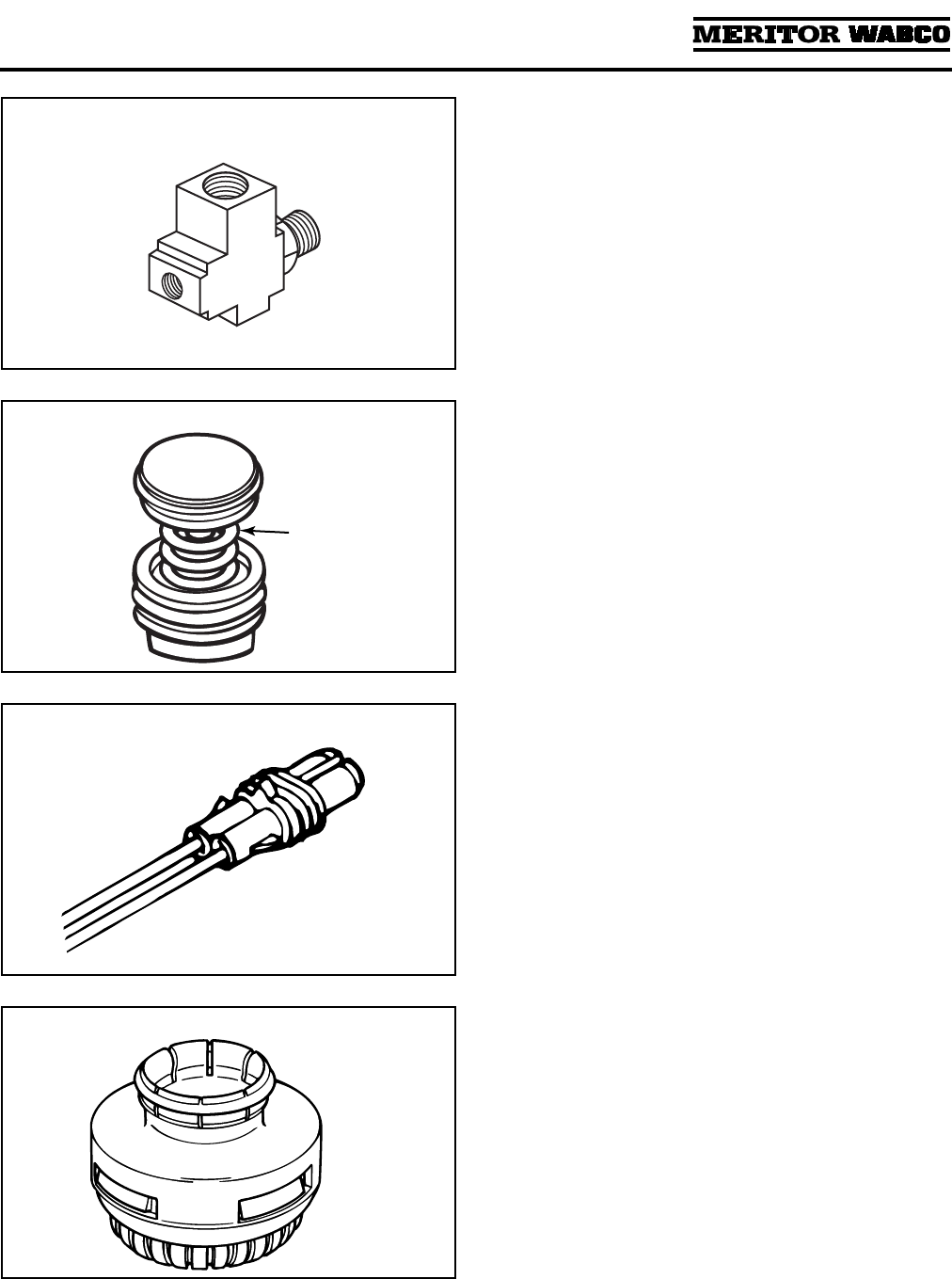
Figure 1.11
Pressure Relief Valve:
A valve that protects the
air dryer from over-pressurization. On dryers
with date codes earlier than 2295, it is installed
in the inlet port of the dryer (port 1) using a
Street-Tee fitting. On dryers with date codes later
than 2295, the pressure relief valve is attached
directly to the air dryer.
Figure 1.11
.
1002153a
Figure 1.12
Purge Valve:
A valve located on the bottom of
the air dryer base that remains open during a
compressor unload cycle. It allows collected
moisture, condensation, and contamination to
be expelled from the air dryer during a purge
cycle.
Figure 1.12
.
1002154a
Figure 1.13
Regeneration Valve:
The valve that controls
regeneration of the desiccant. It allows air from
the supply and secondary tanks to bypass the
outlet check valve. The air expands and
backflushes moisture off of the desiccant, then
out through the dryer’s purge valve.
Figure 1.13
.
Not used with “P” style dryers.
1002155a
Figure 1.14
ECON Valve Replacement Part:
This valve is
used on System Saver Series 1200E single
cartridge air dryers used with Holset E-type
compressors.
Section 1
Introduction
MM-34
Page 8 Revised 11-02
Figure 1.15
ECON Valve:
This valve must be installed if
System Saver 1000 or 1200 Series air dryers
NOT DESIGNATED E are used with Holset E-type
compressors. This valve is not required on
System Saver 1200 E air dryers.
Figure 1.16
Turbo Cut-off Valve:
A valve located in the inlet
port of the air dryer. It closes the path between
the air compressor and the air dryer purge valve
during compressor unload. This prevents a loss
of turbocharger boost pressure during a
compressor unload cycle, thereby maintaining
boost pressure for maximum engine
horsepower.
Figure 1.14
.
There is no spring in the turbo cut-off valve
assemblies used on U Series air dryers.
The System Saver E Series air dryers use a
special turbo cut-off valve. Refer to the air dryer
parts book PB-96134 for part number
information.
1002156a
TOP
SPRING
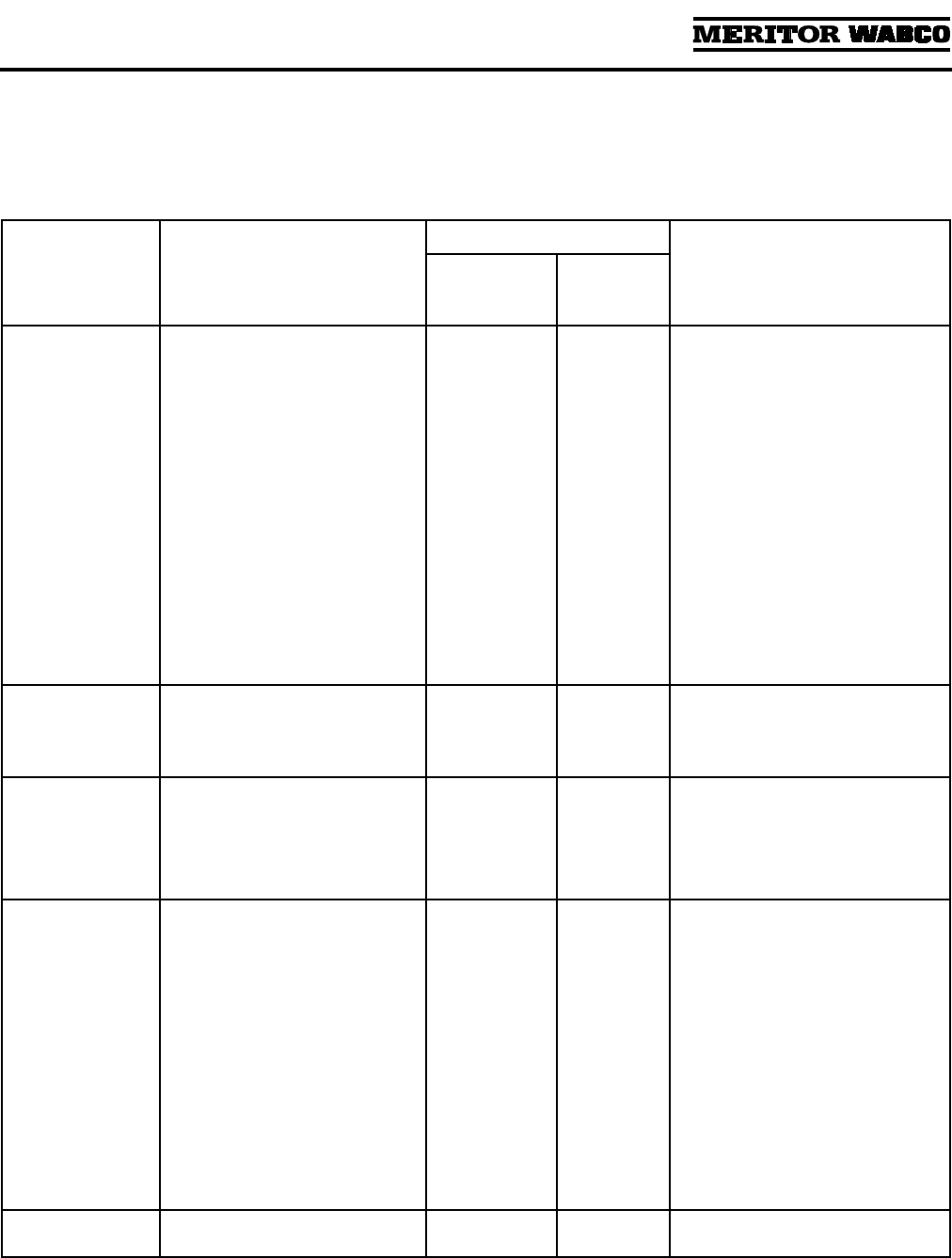
Figure 1.17
Heater Power Harness:
Twelve-inch cable with
Metri-Pack plug provides electrical connection to
air dryer heating unit.
Figure 1.17
.
1002157a
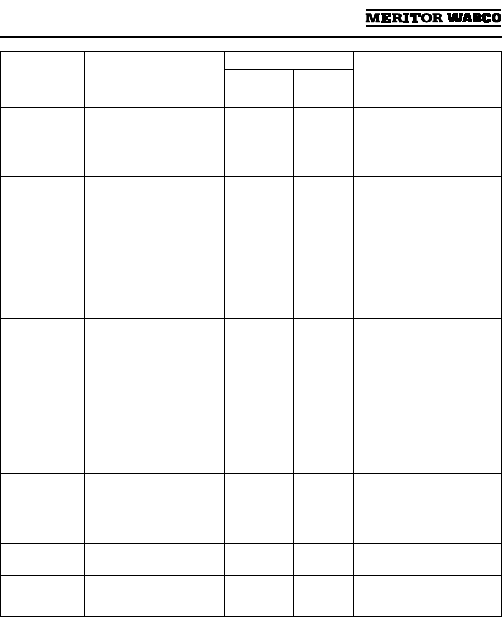
Figure 1.18
Purge Silencer:
Optional part for all Meritor
WABCO air dryers. It is used to reduce the noise
level of an air dryer purge.
Figure 1.18
.
1002158
Section 2
Troubleshooting & Testing
MM-34
Revised 11-02 Page 9
Section 2Troubleshooting & Testing
WARNING
To prevent serious eye injury, always wear safe
eye protection when you perform vehicle
maintenance or service.
Routine Maintenance
To keep your Meritor WABCO air dryer operating efficiently, the following routine maintenance is
recommended.
Maintenance Tips
The Meritor WABCO air dryer will provide years of reliable service, even under adverse operating
conditions. To provide additional protection against the harmful effects of extreme heat or cold, here are
a few helpful tips.
Meritor WABCO air dryer components are installed in the air dryer at the factory and are designed to last
for the life of the dryer. Under some operating conditions, however, a replacement may be required. Refer
to Section 3 for replacement guide instructions.
Interval Required Action
Weekly. Ensure dryer purges when compressor unloads.
Weekly, or as recommended by the manufacturer. Drain purge tank (dedicated purge tank dryers).
Weekly, or as recommended by the manufacturer,
whichever is most frequent.
Check for moisture in the system by opening the
drain cock slowly.
O
Every 2-3 years, or more often depending on usage,
vocation, and condition of compressor.
O
Whenever compressor is rebuilt.
Replace the desiccant cartridge.
Figure 2.1
Dedicated Purge Tank
Optimum mounting location for the dedicated
purge tank is
ABOVE
the air dryer.
Extreme Heat
Make sure the compressor discharge line is
long enough to keep inlet air below 175°F
(80°C). (Refer to Operating Environment
Requirements in Appendix II.)
Extreme Cold
Make sure the air dryer heater is in good
working order by running a heater resistance
test. Refer to Heater Resistance in this section.
Check the line from the governor to port 4 of the
dryer for oil and/or water. Keep this line clean to
help prevent freezing.
1002159a
Section 2
Troubleshooting & Testing
MM-34
Page 10 Revised 11-02
Troubleshooting
Conditions you may experience, and suggested
solutions, appear in the following System Saver
Series Air Dryer Troubleshooting table.
NOTE:
The exploded view of the System Saver
single canister air dryer in Section 1 illustrates the
location of components in the dryer.
Condition Possible Cause
Conditions May Occur In:
Solution
Regeneration
Style Air
Dryers
Dedicated
Purge Tank
Air Dryers
Dryer leaks from
purge valve during
compressor
loaded cycle. The
leak may cause
excessive
compressor
cycling or prevent
the system from
building air
pressure.
Purge valve frozen open (cold
weather operation).
Debris under purge valve seat,
such as particles from fittings or
air inlet line.
Purge valve washer installed
upside-down.
Wrong air line connected to dryer
port 4 (unloader port).
Purge valve snap ring not fully
seated in groove.
Yes Yes Check heater. Repair/replace if
necessary. Make sure governor to
dryer port 4 line is free of water/oil.
Remove and inspect purge valve
and clean water/oil from top of
piston.
Disassemble and clean purge valve.
Remove cartridge and clean dryer
sump area.
Ensure lip on aluminum washer
faces
DOWN
, away from dryer.
Verify correct air line installation
and correct as needed.
Seat snap ring fully into groove.
Slight leak from
purge valve. After
several hours, the
supply tank may
be empty.
Outlet check valve not seating or
regeneration valve not shutting
off regeneration airflow.
Yes No Remove, inspect, and clean outlet
check valve and regeneration valve
diaphragm. Replace if worn or
damaged.
Regeneration
cycle too long
(more than
30 seconds),
accompanied by
loss of pressure in
the supply tank.
Outlet check valve not seating.
Regeneration valve not shutting
off regeneration airflow.
Yes
Yes
Yes
No
Inspect and replace outlet check
valve as needed.
Replace regeneration valve.
Regeneration
cycle too short
(less than
10 seconds).
High air system demands during
compressor unloaded cycle.
Pressure-controlled check valve
not installed in system or not
working properly.
One-way check valve installed in
system reservoir instead of, or
with, pressure-controlled check
valve.
Regeneration valve not working.
Air governor not working
properly.
Yes
Yes
Yes
Yes
Yes
Yes
No
No
No
Yes
Increase air system capacity or
reduce air demands.
Check and replace pressure-
controlled check valve as needed.
Remove one-way check valve. Make
sure pressure-controlled check
valve is installed correctly.
Remove regeneration valve and
clean oil from diaphragm. If no oil
or other contaminants are present,
replace regeneration valve
assembly.
Inspect per manufacturer’s
instructions and repair/replace as
needed.
Water in purge
tank
Block in purge tank line. N/A Yes Clear blockage. Replace desiccant
cartridge.

Section 2
Troubleshooting & Testing
MM-34
Revised 11-02 Page 11
No regeneration
cycle. No airflow
from purge valve
after initial purge
blast (dryer
decompression).
Air dryer not connected to supply
tank or connections reversed at
dryer.
Regeneration valve not working.
One-way check valve installed in
supply tank.
Alcohol evaporator installed
between dryer and supply tank.
Blocked line/pinched line from
purge tank.
Yes
Yes
Yes
Yes
No
No
No
No
No
Yes
Verify proper dryer installation per
system diagram.
Replace regeneration valve.
Remove one-way check valve.
Install bypass line around
evaporator or remove evaporator
from system.
Clear/repair line.
Air dryer does not
purge when
compressor
unloads (no blast
of air from purge
valve).
Air line between governor and air
dryer port 4 kinked or plugged.
Purge valve stuck closed.
Air governor not working
properly.
Cut-out pressure never achieved
by air compressor.
Yes
Yes
Yes
Yes
Yes
Yes
Yes
Yes
Repair air line.
Replace purge valve.
Inspect air governor. Repair/replace
per manufacturer’s instructions.
Check for air leaks in system and
repair as needed. If no leaks in
system, check compressor output.
Repair/replace per manufacturer’s
instructions.
Air dryer purges
too often, perhaps
as frequently as
every 15 seconds,
accompanied by
excessive cycling
of the compressor.
Leak in line between governor
and dryer port 4.
Leak in line between supply tank
and governor.
Excessive air system leaks.
Excessive air system demands.
Outlet check valve not seating.
Regeneration valve not shutting
off properly.
Air governor has less than 16 psi
range.
Leaking air compressor
unloader(s).
Yes
Yes
Yes
Yes
Yes
Yes
Yes
Yes
No
Yes
Yes
Yes
Yes
No
Yes
Yes
Repair air line.
Repair air line.
Repair leaks.
Increase air system capacity or
reduce air demand.
Inspect and replace outlet check
valve as needed.
Replace regeneration valve.
Replace air governor.
Inspect compressor. Repair/replace
per manufacturer’s instructions.
Air flows out of
purge valve entire
time compressor
is unloaded.
Turbo cut-off valve not sealing.
NOTE:
With U Series air dryers
the compressor unloads through
the dryer, so a steady flow of air
is normal.
Yes No Replace turbo cut-off valve.
Rapid “spitting” of
air from purge
valve in small
amounts.
Frequency varies
with engine speed.
Holset E-type compressor used,
but no Econ valve installed.
Compressor not completely
unloading when cut-out pressure
is reached.
Yes
Yes
Yes
Yes
Install Econ valve to provide
make-up air to compressor.
Inspect compressor. Repair/replace
per manufacturer’s instructions.
Air leak at turbo
cut-off valve vent.
Hole burned in
piston.
Temperature of air coming into
dryer is too high — not enough
cooling takes place before dryer
inlet.
Yes Yes Move dryer farther from
compressor. Add additional
compressor discharge line before
air dryer. Add cooling coil or heat
exchanger before air dryer.
NOTE:
Inlet air temperature must
not exceed 175°F (80°C).
Condition Possible Cause
Conditions May Occur In:
Solution
Regeneration
Style Air
Dryers
Dedicated
Purge Tank
Air Dryers
Section 2
Troubleshooting & Testing
MM-34
Page 12 Revised 11-02
Air leak at turbo
cut-off valve vent.
Lip seal installed upside-down on
piston. Lip must face UP (towards
dryer).
Valve bore worn excessively.
Yes
Yes
Yes
Yes
Install lip seal correctly.
Inspect valve bore for wear. If a new
turbo cut-off valve does not seal in
a clean, lubricated bore, replace the
air dryer.
Air dryer frozen
(water collecting
in base of dryer is
freezing).
No electrical power to heater
connector.
Low voltage to heater connector.
Heater assembly not working.
Wrong voltage air dryer used; i.e.,
12-volt air dryer used in a 24-volt
system.
Yes
Yes
Yes
Yes
Yes
Yes
Yes
Yes
Yes
Yes
Check for a blown fuse. Repair
heater circuit.
NOTE:
There must be power to the
heater connector the entire time the
vehicle’s ignition is
ON
.
Repair cause of low voltage, such
as poor electrical ground, bad
connections, corroded wire splices,
etc.
Replace heater assembly.
Replace with correct voltage air
dryer.
No air pressure
build-up in
system.
Air dryer not plumbed correctly
(connections reversed).
Wrong air line connected to dryer
port 4.
Air governor not working
properly.
Air system leaks, such as
compressor discharge line, air
dryer, reservoirs, brake or
suspension valves, etc.
Air dryer leaks from purge valve.
Yes
Yes
Yes
Yes
Yes
Yes
Yes
Yes
Yes
Yes
Ensure compressor discharge line
is plumbed to air dryer port 1, and
air dryer port 21 is connected to
vehicle’s supply tank.
Ensure dryer port 4 line is
connected to the “UNL” port of the
air governor.
Inspect governor per
manufacturer’s instructions. Repair
or replace as needed.
Locate leak(s) and repair.
Refer to purge valve conditions
listed in this chart.
Water in tanks;
often following
aftermarket
installation or
when dryer is a
replacement for a
competitive brand.
Pressure-controlled check valve
not installed in correct tank or not
installed at all.
Pressure-controlled check valve
properly installed, but one-way
check valve not removed.
Yes
Yes
No
No
Install pressure-controlled check
valve in secondary tank.
Remove one-way check valve so
that only the pressure-controlled
check valve is installed between the
secondary tank and supply tank.
Water, oil, or
sludge in air
system tanks.
Desiccant contaminated with oil. Yes Yes Replace desiccant. Inspect
compressor per manufacturer’s
instructions.
Water in system
tanks, everything
else checks out
okay.
Dryer not suitable for application. Yes Yes Review application guidelines. For
assistance, call ArvinMeritor’s
Customer Service Center at
800-535-5560.
Condition Possible Cause
Conditions May Occur In:
Solution
Regeneration
Style Air
Dryers
Dedicated
Purge Tank
Air Dryers
Section 2
Troubleshooting & Testing
MM-34
Revised 11-02 Page 13
System Tests
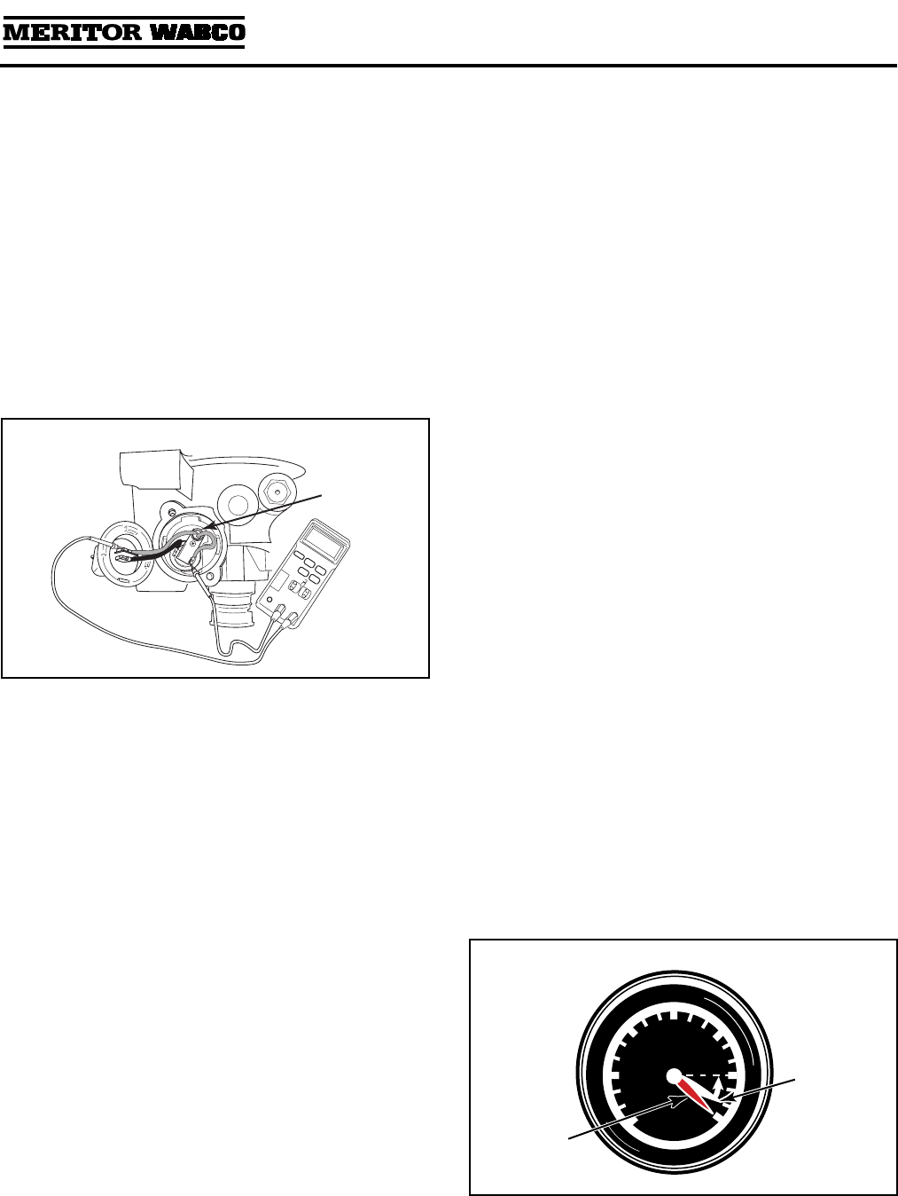
Heater Resistance
To avoid damaging components, Meritor WABCO
recommends performing this resistance check
with the heater in place.
1. Set volt-ohmmeter to ohms.
2. Disconnect vehicle harness at the heater.
3. Remove the two screws holding the external
components in place.
4. With wires connected and properly secured,
touch one probe to each heater element lead.
5. Measure the resistance. Acceptable resistance
is:
O 12 Volt: 1.0-2.0 ohms
O 24 Volt: 5.0-7.0 ohms
If resistance is less than 1.0 ohm for a 12-volt
or 5.0 ohms for a 24-volt system, replace the
heater.
6. Reinstall components and vehicle harness.
Leak Test
1. Drain air from all system tanks.
2. Close reservoir draincocks.
3. Start the vehicle. Allow air system pressure to
build while engine idles.
4. When the system reaches cut-out pressure
there will be a purge, or strong blast of air,
followed by a mild flow which will last
10-25 seconds.
5. Shut off the engine.
6. Apply a soap solution to each connection that
contains pressurized air. Check the
connections to see if soap solution bubbles.
No Soap Bubbles: Connections are sealed
properly.
Soap Bubbles Appear: Connections are NOT
sealed properly.
To repair improperly sealed connections:
1. Drain all reservoirs.
2. Remove leaking connection.
3. Inspect the connectors and ports for damaged
threads or cracks. Replace if necessary.
4. Apply pipe sealant to the connection.
NOTE: Repeat leak test until all connections are
sealed.
Air Pressure Checks
NOTE: When checking air pressure during these
tests, do not rely on cab air gauges for accurate
readings. Install a calibrated air gauge (accurate to
within 1 psi) in the secondary air tank for making
determinations about the continued use or
replacement of equipment.
Operational Test for System Saver
Series Air Dryers — Regeneration
and Purge Style
1. Check compressor loaded and unloaded cycle.
When the compressor is in the loaded cycle,
air pressure will build to approximately 120 psi
(cut-out pressure). When the compressor
reaches the unloaded cycle, the air dryer will
purge, initiating regeneration of the air dryer.
Figure 2.2
HEATER
Figure 2.3
PSI
20
40
60
80
100
110
120
1002161a
Primary
Air Supply
(Red)
Secondary
Air Supply
(White)
Section 2
Troubleshooting & Testing
MM-34
Page 14 Revised 11-02
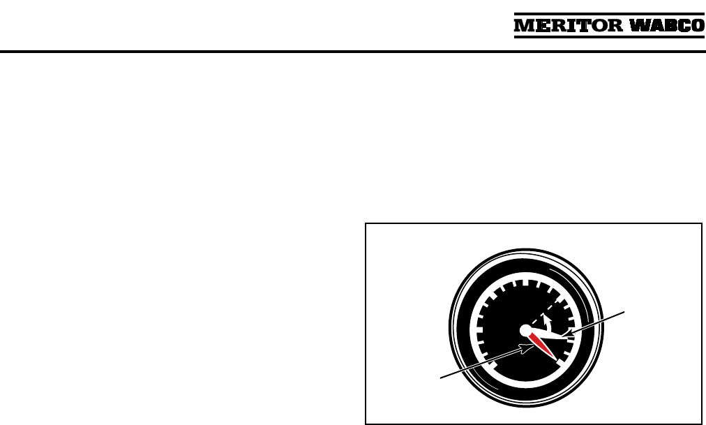
2. During the regeneration cycle, which lasts
from 10-25 seconds, supply and secondary
tanks will drop approximately 10 psi in
pressure. Check the secondary air gauge on
the vehicle dash panel to verify this drop.
NOTE: A 10 psi drop in pressure in the
secondary air system is normal for Meritor
WABCO System Saver Series regeneration
style air dryers. There should be no visible
pressure drop for P Series dryers. If there is a
visible pressure drop (P Series dryer), perform
a check valve leak test on the system check
valves.
Step 3 applies to regeneration style air dryers only.
3. If there is no drop in pressure, one of the
following conditions may apply:
O Pressure-controlled check valve not
installed, or installed on wrong air tank.
O Pressure-controlled check valve installed to
a one-way check valve, instead of in place of
a one-way check valve.
O There is another check valve located
between the air dryer and the secondary air
tank, usually at the supply tank.
O Secondary air gauge not plumbed to the
secondary air system. Use a calibrated air
gauge in the secondary tank to check air
pressure.
— Make the necessary installation changes
or repairs and repeat the operational test.
O If the secondary pressure drops 25 psi or
more during the regeneration cycle — and
there are no other air-operated components
using air during this cycle — there are air
leaks or other air system problems.
— Identify and repair all air leaks and air
system problems.
— Clean the Regeneration and Outlet Check
valves.
— Disconnect the compressor line from the
air dryer (Dryer Port 4). Check the
compressor and governor per the
manufacturer’s recommendation.
Pressure-Controlled Check Valve
Test — Regeneration Style Only
1. Turn off the engine after the air system reaches
cut-out pressure (approximately
120 psi) and the air compressor has unloaded.
2. Drain the supply tank down to 80 psi or lower.
3. Check the secondary tank air gauge. It should
read 95 ± 5 psi.
NOTE: A drop from 120 to 95 ± 5 psi during
this test is normal for vehicles equipped with
the System Saver Series air dryer and a
pressure-controlled check valve.
4. If the secondary tank air gauge reading is less
than 90 psi:
O Pressure-controlled check valve may be
installed backwards (arrow on valve must
point toward host reservoir). Make
necessary corrections and retest.
O Check for leaks in the secondary air system.
Identify and repair any leaks.
5. If the secondary tank air gauge reading does
not change — or the reading does not drop
below 100 psi:
O Pressure-controlled check valve not
installed, or installed on wrong air tank.
O Pressure-controlled check valve installed TO
a one-way check valve, rather than IN PLACE
OF a one-way check valve.
O There is another check valve located
between the air dryer and the secondary air
tank, usually at the supply tank.
O Secondary air gauge not plumbed to the
secondary air system. Use a calibrated air
gauge in the secondary tank to check air
pressure.
— Make the necessary installation changes
or repairs and repeat the operational
test.
Figure 2.4
PSI
20
40
60
80
95
110
120
1002162a
Primary
Air Supply
(Red)
Secondary
Air Supply
(White)
Section 3
Installing Replacement Parts
MM-34
Revised 11-02 Page 15
Section 3Installing Replacement Parts
WARNING
To prevent serious eye injury, always wear safe
eye protection when you perform vehicle
maintenance or service.
Remove all pressure from the air system before
you disconnect any component, including the
desiccant cartridge. Pressurized air can cause
serious personal injury.
Park the vehicle on a level surface. Block the
wheels to prevent the vehicle from moving.
Serious personal injury can result.
Replacement Requirements
Before replacing any air dryer component, make
sure the air compressor and air governor are
working properly. Repair or replace these parts, if
necessary. Check the entire air system for leaks,
and repair as necessary. When draining air tanks
before servicing the air dryer, check for water
and/or oil that may have accumulated in the tanks.
Water and/or oil in the air tanks could indicate a
problem with the dryer or compressor.
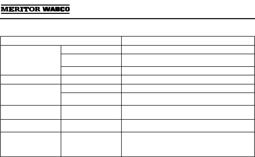
Replacement Requirements
Component When to Replace Why
Desiccant Cartridge Every two to three years. Preventative maintenance.
When compressor is replaced. Contaminated cartridge.
Water in supply tank. Saturated or contaminated cartridge, high duty
cycle (wrong application of air dryer).
Bypass Valve (dryers with
date codes earlier than
0894)
Valve leaking, inlet to outlet. Cut O-ring, bad seat.
Heater Assembly Water collecting in air dryer is freezing —
electrical power to dryer is O.K.
Heater assembly not working (internal short or
open circuit).
Outlet Check Valve Air continues to flow from purge valve after
purge cycle, but stops flowing when the
compressor load cycle begins.
Valve is stuck in the open position, or not
functioning properly.
No pressure build-up in system, everything
else is O.K.
Valve is stuck in closed position.
Purge Valve No purge cycle when compressor unloads —
normal pressure at dryer control port 4
(governor port).
Valve is stuck in the closed position, or not
functioning properly.
Air flows from purge valve during
compressor’s load cycle — no pressure at dryer
control port.
Valve is stuck in the open position, or not
functioning properly.
Turbo Cut-Off Valve Air flows from purge valve during compressor
unload cycle after purge cycle, and flow is
noticeably stronger at high engine RPM,
especially under load.
Turbo cut-off valve leaking.
No pressure build-up in system — high
compressor discharge line pressure.
Valve stuck in closed position.
Regeneration Valve Regeneration cycle continues after compressor
begins, and secondary tank pressure drops
15 psi or more.
Regeneration valve allowing too much air to
come back into cartridge.
Purge cycle is too short (5 seconds or less) —
pressure-controlled check valve is O.K., no leak
in governor control line.
Regeneration valve not allowing enough air to
come back into cartridge.
Air dryer purges — but no regeneration, no
check valve between air dryer and supply tank,
and purge valve has not closed.
Regeneration valve not allowing any air to
come back into cartridge.
Pressure-Controlled
Check Valve
Regeneration cycle too short; may result in
water in tank.
Valve checks (stops airflow) too high.
Section 3
Installing Replacement Parts
MM-34
Page 16 Revised 11-02
NOTE: When replacing air dryer components, use
only Meritor WABCO replacement parts.
The exploded view of the air dryer in Section 1
shows the location of the various air dryer
components.
Component Replacement
WARNING
To prevent serious eye injury, always wear safe
eye protection when you perform vehicle
maintenance or service.
Remove all pressure from the air system before
you disconnect any component, including the
desiccant cartridge. Pressurized air can cause
serious personal injury.
Park the vehicle on a level surface. Block the
wheels to prevent the vehicle from moving.
Support the vehicle with safety stands. Do not
work under a vehicle supported only by jacks.
Jacks can slip and fall over. Serious personal injury
can result.
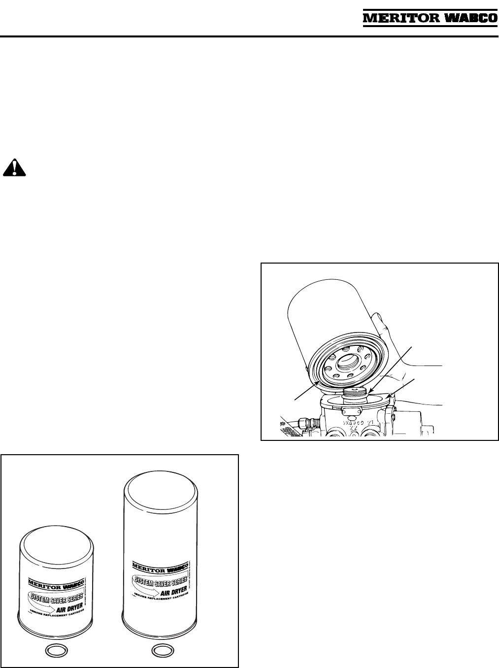
Desiccant Cartridge
1. Replacement kit contains one cartridge and
one O-ring. Figure 3.1.
NOTE: Replacement cartridges are marked
“System Saver Series.”
2. Loosen and remove the old cartridge. Use
strap wrench if necessary.
3. Remove and discard O-ring from dryer base.
4. Inspect and clean seal seat. Repair any minor
damage.
NOTE: If seats are damaged so badly that a
tight seal cannot be maintained, replace the air
dryer.
5. Lubricate and install new O-ring on stem.
6. Lubricate cartridge seal.
7. Thread replacement cartridge onto the base
until the seal touches the base. Then, tighten
the cartridge ONE addition turn. DO NOT
OVERTIGHTEN. Figure 3.2.
Figure 3.1
1002163b
1800
1200
Figure 3.2
1002164a
SEAL
SEAL SEAT
O-RING
Section 3
Installing Replacement Parts
MM-34
Revised 11-02 Page 17
Outlet Check Valve Assembly
1. Review Figure 3.3 to make sure you have all of
the parts required to replace the outlet check
valve.
Use the grease included with the replacement
kit to lubricate the O-ring seal.
2. Remove the snap ring, washer, spring, valve
body and O-ring.
3. Clean and inspect the valve bore. If the bore is
damaged so that a tight seal cannot be
maintained, replace the air dryer.
4. Install the new O-ring on the valve body.
Figure 3.4.
5. Apply a thin layer of grease to the valve bore
and the O-ring.
6. Install the new valve body with its long end in
the bore.
7. Install the new spring with its small end
around the “Y”-shaped fins on the valve body.
8. Install the new washer and the new snap ring
to hold the components in place.
Heater Assembly
1. Review Figure 3.5 to make sure you have all of
the parts required to replace the heater
assembly.
2. Disconnect the plug.
3. Remove the screws, receptacle and O-ring
from the base to access the retainer screw.
4. Remove the retainer screw and then remove
the entire heater assembly.
5. Install the new element and thermostat in their
cavities.
Figure 3.3
Figure 3.4
1002165a
1002166a
SNAP RING
WASHER
SPRING
O-RING
VALVE
BODY
Figure 3.5
1002167a
Section 3
Installing Replacement Parts
MM-34
Page 18 Revised 11-02
NOTE: For dryers with date codes of 0894 or
earlier, follow the special instructions in the
replacement kit to complete the installation.
6. Install the new retainer and screw to hold the
element and the thermostat in place.
7. Install the new O-ring and receptacle and
fasten them in place with the screws.
Figure 3.6.
Turbo Cut-Off Valve Assembly
NOTE: E Series air dryers use a different turbo
cut-off valve assembly. Refer to PB-96134 for
information.
1. Review Figure 3.7 to make sure you have all of
the parts required to replace the turbo cut-off
valve.
Use the grease included with the replacement
kit to lubricate O-rings and seals.
2. Remove the snap ring. The cover and spring
may fall out of the bore when the snap ring is
removed.
3. Remove the desiccant cartridge as described
above. Use a wooden stick to push the piston,
spring and cover out of the bore. Figure 3.8.
4. Clean and inspect the valve bore. If the bore is
damaged so that a tight seal cannot be
maintained, replace the air dryer. Figure 3.8.
5. Install new lip seal on piston. Seal lip must
face up (toward top of piston).
6. Install new O-ring on cover.
7. Apply a thin layer of grease to the valve bore
and the O-rings.
8. Install the new piston with flat side toward
dryer.
9. Install the new spring, cover and snap ring to
hold the components in place.
10. Install plug.
11. Replace the desiccant cartridge.
Figure 3.6
1002168a
O-RING
HEATERTHERMOSTAT
RECEPTACLE
Figure 3.7
Figure 3.8
Spring not used in
U Series air dryers.
1002170a
PISTON
SPRING
COVER
Section 3
Installing Replacement Parts
MM-34
Revised 11-02 Page 19
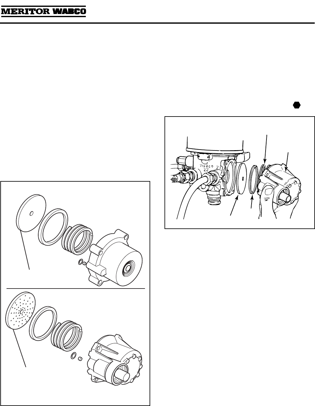
Regeneration Valve Assembly
The regeneration valve assembly kit contains two
different diaphragms to service the regeneration
valve assembly for System Saver 1000, 1200 or
1800 air dryers. Use the correct diaphragm for the
style of regeneration valve housing as indicated in
the sketches below. Use of the incorrect part will
result in unsatisfactory purging of the desiccant
cartridge and may result in excess water in the air
system.
1. Review Figure 3.9 to make sure you have all of
the parts required to replace the regeneration
valve. Use the grease included with the
replacement kit to lubricate O-rings and seals.
2. Remove the four mounting bolts and the valve
housing assembly. When you remove the
housing, the spring and cap will fall out.
3. Remove the rubber diaphragm.
4. Clean and inspect the diaphragm lip groove. If
the groove is damaged so that a tight seal
cannot be maintained, replace the air dryer.
5. Install the new diaphragm with its lip in the
groove. DO NOT GREASE THE DIAPHRAGM.
6. Install the new spring and cap with the cap lip
facing out. Install the valve housing assembly
with the new lubricated O-ring and filter over
the orifice. Install the new mounting bolts and
tighten to 53 lb-in (6 N•m). Figure 3.10.
Figure 3.9
INCLUDED IN KIT
The smooth diaphragm is
used with the smooth,
cylindrical Regeneration
Valve Housing.
INCLUDED IN KIT
The speckled/dotted diaphragm
is used with the finned/ribbed
die cast Housing.
Only one diaphragm is used per assembly.
DO NOT GREASE THE DIAPHRAGM.
Figure 3.10
T
1002172a
DIAPHRAGM
SPRING
VALVE
HOUSING
ASSEMBLY
CAP
Section 3
Installing Replacement Parts
MM-34
Page 20 Revised 11-02
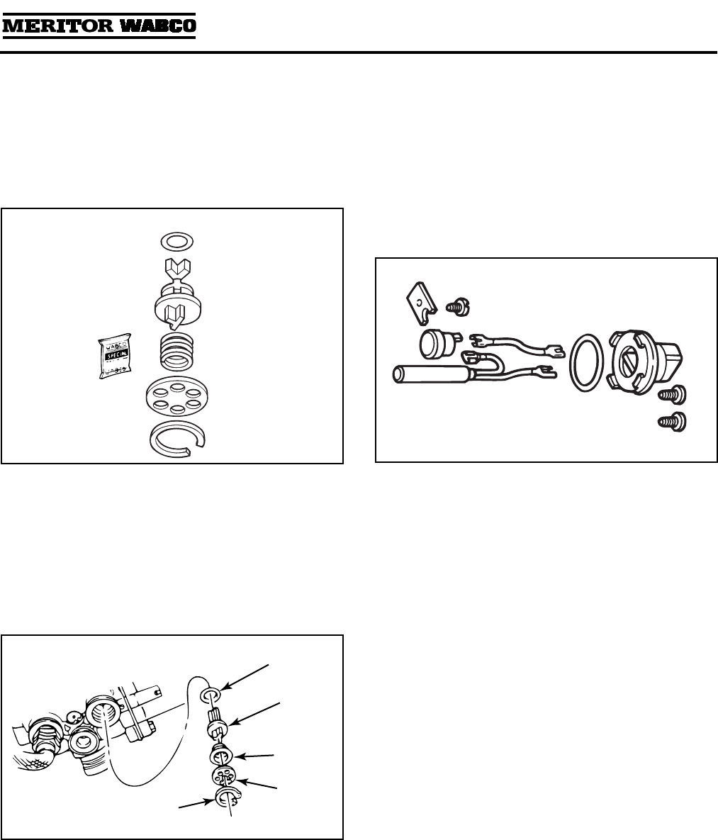
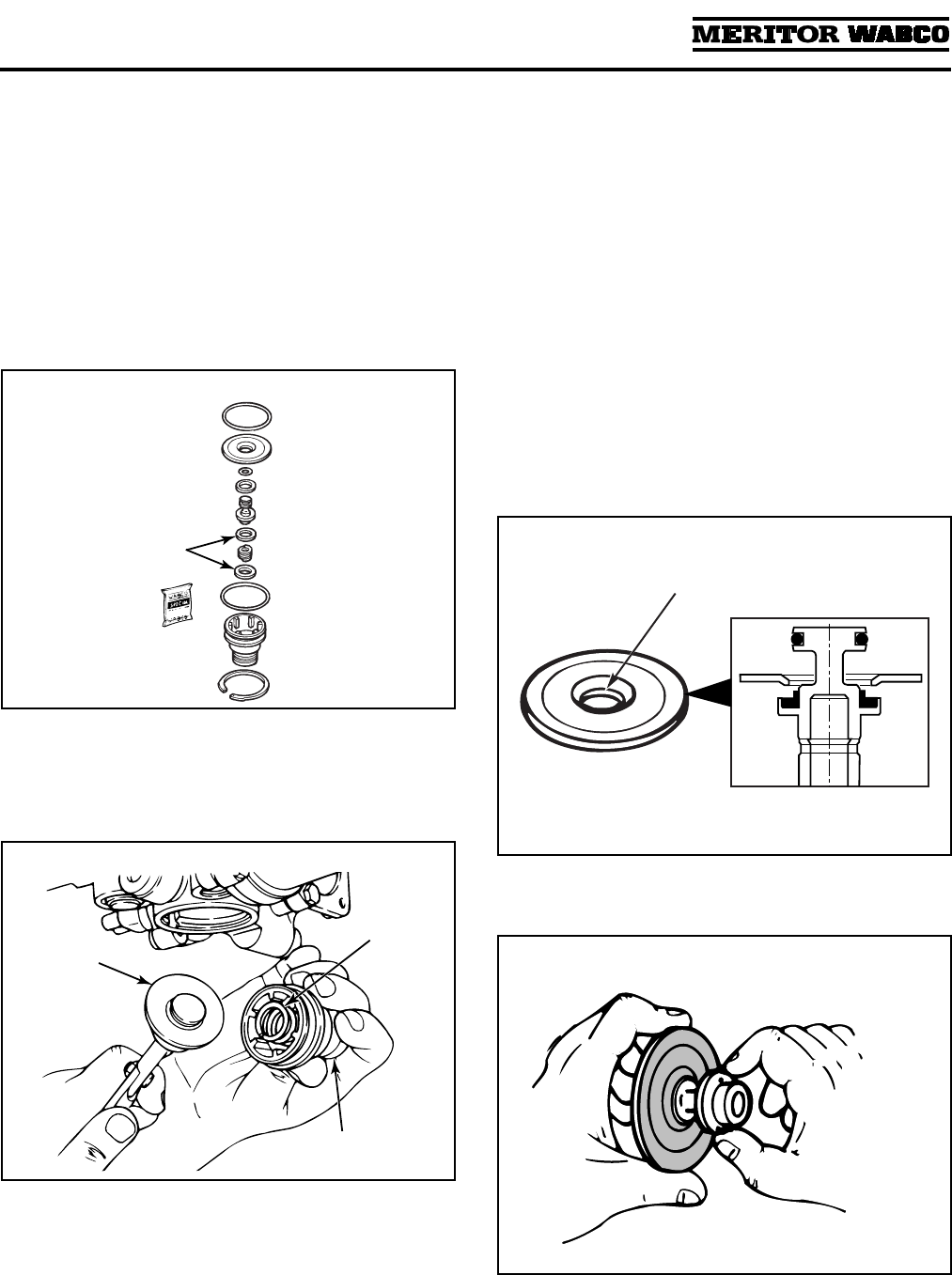
Purge Valve Assembly
1. Review Figure 3.11 to make sure you have all
of the parts required to replace the purge valve.
Use the grease included with the replacement
kit to lubricate O-rings and seals. Do not
grease the rubber seat.
If shims are included in the replacement kit,
they must be installed above and below the
spring. If they are not included, they are not
needed.
2. Remove the snap ring, valve head and spring.
3. Remove the piston assembly from the base.
Figure 3.12.
4. Remove washer and O-rings from the base.
5. Clean and inspect the valve bore. If the bore is
damaged so that a tight seal cannot be
maintained, replace the air dryer.
6. Apply a thin layer of grease to the valve bore
and to all O-rings (use the grease included
with replacement kit).
7. Install new washer and O-ring in dryer base
and on valve head.
8. Assemble piston assembly:
O Install O-ring in groove on piston head.
O Install piston seat in groove on piston base.
O Install washer on piston.
NOTE: Lip on washer must face piston seat.
Figure 3.13.
9. Install washer on piston assembly. Figure 3.14.
Figure 3.11
Figure 3.12
1002173b
METAL
SHIMS
(IF REQUIRED)
1002174a
SPRING
VALVE HEAD
PISTON
ASSEMBLY
Figure 3.13
Figure 3.14
1002175b
LIP
1002176a
Section 3
Installing Replacement Parts
MM-34
Revised 11-02 Page 21
10. Install spring in valve head; fit valve head
assembly into bore.
NOTE: If shims are included in the
replacement kit, they must be installed above
and below the spring. If they are not included,
they are not needed.
11. Install snap ring to hold the valve head in
place.
NOTE: Make sure snap ring is fully seated or
assembly will leak from the purge valve.
Pressure-Controlled Check
Valve (PCCV)
WARNING
Remove all air pressure from the tank before you
remove the pressure-controlled check valve.
Pressurized air can cause serious personal injury.
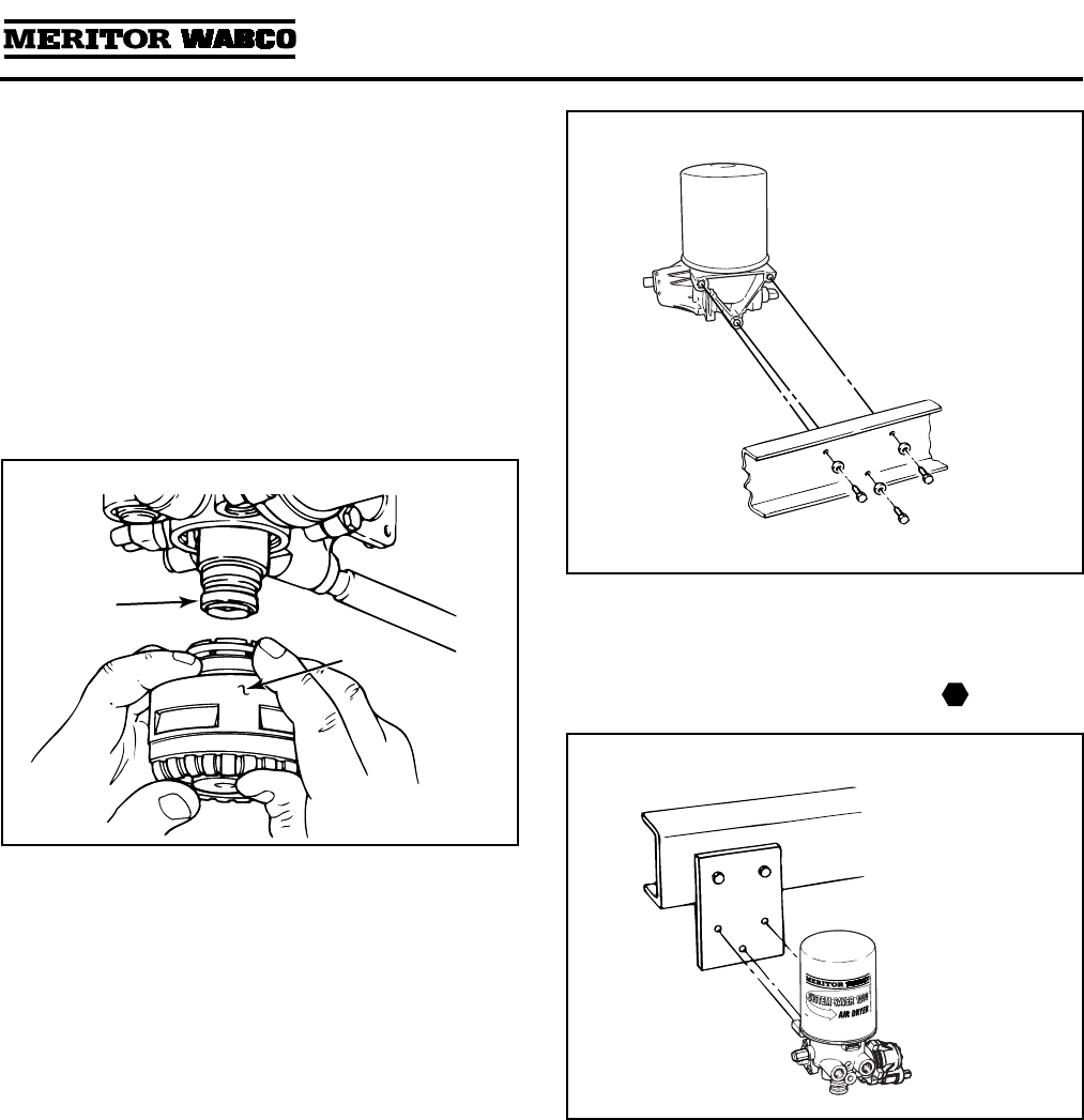
1. Before replacing, look at the arrow on this
valve. You must install the valve so that the
arrow faces the tank on which it is installed.
Figure 3.15.
NOTE: New style valves have the hex nipple
pipe fitting installed.
2. Disconnect the air line from the
pressure-controlled check valve and remove
the valve from the tank and hex nipple pipe
fitting.
3. Install the new valve.
O Whatever orientation (up or down) the valve
is in when it is tight is acceptable, as long as
the arrow is pointing in the right direction.
4. Apply pipe sealant to the fittings and connect
the air line to the PC check valve.
5. Test the installation for proper operation.
(Refer to Testing the Meritor WABCO System
Saver Series Air Dryer in this section.)
Bypass Valve
NOTE: Used only on dryers with date codes of
0894 or earlier.
1. Review Figure 3.16 to make sure you have all
of the parts required to replace the bypass
valve.
Use the grease included with the replacement
kit to lubricate O-rings and seals.
2. Remove the snap ring, cover, spring and
valve body.
3. Clean and inspect the valve bore. If the bore
is damaged so that a tight seal cannot be
maintained, then replace the air dryer.
Figure 3.15
1002177b
PRESSURE-CONTROLLED
CHECK VALVE
TANK
HEX NIPPLE
PIPE FITTING
Arrow on
bottom of
valve must
face tank.
AIR LINE
Figure 3.16
0894
DATE
CODE
1002179a
SNAP
RING
O-RING
VALVE
BODY
SPRING
O-RING
COVER
Section 3
Installing Replacement Parts
MM-34
Page 22 Revised 11-02
4. Install the new O-rings on the new valve body
and cover.
5. Apply a thin layer of grease to the valve bore
and the O-rings.
6. Install the new valve body with its long end in
the bore. Figure 3.17.
7. Install the new spring so it fits around the
“Y”-shaped fins on the valve body.
8. Install the new cover and the new snap ring to
hold the components in place.
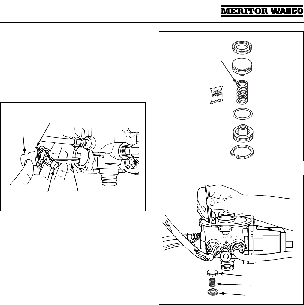
Pressure Relief Valve
NOTE: If you plan to replace the Street-Tee fitting,
refer to TP-9557, Pressure Relief Valve Installation,
for instructions. This publication is available from
Meritor WABCO, 800-535-5560.
1. Remove the old valve from the dryer.
If your dryer uses a bypass valve (date code of
2295 or earlier), the pressure relief valve will
be installed with a Street-Tee fitting at the
front (Port 1) of the dryer. On dryers with date
codes later than 2295, the pressure relief valve
is located at the side of the dryer (Port 31).
Figure 3.18.
2. Unscrew and remove the old pressure relief
valve. Figure 3.18.
WARNING
For Street-Tee installations, install the pressure
relief valve in the UP position, or within 30° of
vertical. Figure 3.19. If not installed in the correct
position, serious personal injury and damage can
result.
3. Screw the replacement valve into the
Street-Tee fitting or the dryer base, depending
on the model air dryer you have.
Do not exceed torque of 30 lb-ft (40.8 N•m) for
3/8-inch thread, or 65 lb-ft (88.4 N•m) for
1/2-inch thread.
NOTE: The threads on the replacement
pressure relief valve provided by Meritor
WABCO are coated with sealant. They do not
require any additional sealant.
Figure 3.17
1002180a
SNAP
RING
VALVE
BODY
SPRING
COVER
Figure 3.18
Figure 3.19
1002181b
PORT 1
PRESSURE
RELIEF VALVE IN
STREET-TEE FITTING
PORT 31
PRESSURE
RELIEF VALVE
T
1002182a
PORT 1
± 30°
Section 3
Installing Replacement Parts
MM-34
Revised 11-02 Page 23
Purge Silencer (Muffler)
NOTE: This is an optional part designed to reduce
dryer purge noise level.
1. Remove retainer ring. Remove old silencer
from purge valve head. Do not damage purge
valve head.
2. Clean purge valve head.
3. Install replacement silencer firmly onto purge
valve head until fully seated. Secure with
retainer ring. Figure 3.20.
Air Dryer Assembly
NOTE: This procedure is for removing and
replacing a unit. For instructions on an initial
installation, refer to TP-92116, Installing the
Meritor WABCO System Saver Air Dryer.
1. Drain all pressure from the air system.
Disconnect all air lines.
Use markers to label the lines for proper
reinstallation.
2. Disconnect the heater electrical plug from the
heater receptacle.
3. Remove the three mounting bolts. Remove the
air dryer from its mounting location.
Figure 3.21.
4. Attach the new unit to the frame or mounting
bracket with new mounting capscrews and
washers. Tighten the capscrews to 22 to
30 lb-ft (30-40 N•m). Figure 3.22.
5. Connect heater electrical plug to heater
receptacle.
6. Reconnect all system air lines.
7. Test the installation for proper operation.
(Refer to Testing the Meritor WABCO System
Saver Series Air Dryer which follows.)
Figure 3.20
1002183a
PURGE
VALVE
HEAD
SILENCER
Figure 3.21
Figure 3.22
1002184b
T
1002185b

Section 3
Installing Replacement Parts
MM-34
Page 24 Revised 11-02
Testing the Meritor WABCO
System Saver Series Air Dryer
1. Turn off the engine after the air system
reaches cut-out pressure (approximately
120 psi) and the air compressor has unloaded.
2. Drain the primary air tank(s) down to 80 psi
or lower.
3. Check the secondary tank air gauge. It should
read 95 ± 5 psi. This drop from cut-out
pressure to 95 ± 5 psi for this particular test is
normal for vehicles equipped with any Meritor
WABCO single cartridge air dryer and the
pressure-controlled check valve.
4. If the secondary tank air gauge reading is
less than 90 psi, check to see if the
pressure-controlled check valve is installed
backwards. If so, install correctly and re-test.
If not, check for air leaks in the secondary air
system. If no significant air leaks are found,
then replace the valve and re-test.
5. If the secondary tank air gauge reading
does not change, or the reading does not fall
below 100 psi, then check for one of the
possibilities listed above in Step 4. If none
of those possibilities is found, then the
pressure-controlled check valve may be
shutting off at 100 psi or higher. Replace the
valve and retest.
NOTE: When checking air pressures during
these procedures, do not rely on cab air
gauges for accurate readings. Install a
calibrated air gauge (accurate to within 1 psi)
in the secondary air tank for making
determinations about the continued use or
replacement of any equipment.

Appendix I
Glossary
MM-34
Revised 11-02 Page 25
Appendix IGlossary
Basic Air System/Air Dryer Terms
Air Compressor A device that pumps air to and builds air pressure in an air system.
Air Dryer A device that cools, filters, and dries the air delivered by an air
compressor.
Air Governor A device that controls the operation of the air compressor by constantly
monitoring air pressure in the supply tank of the air system. The air
governor initiates the compressor load cycle when “cut-in” pressure is
realized, and initiates the compressor unload cycle when the “cut-out”
pressure is reached. The air governor also controls the air dryer by
sending an air signal (at the beginning of the compressor unload cycle)
to the control port of the air dryer, initiating the purge cycle. When this
air signal is removed by the governor (at the beginning of the
compressor load cycle), the purge valve closes and the drying cycle
begins.
Compressor Load Cycle The time during which the air compressor is building air pressure in an
air system.
Compressor Unload Cycle The time during which the air compressor is idling and is not building air
pressure in an air system.
Cut-In Pressure The pressure level in the air system supply tank which triggers the
compressor load cycle.
Cut-Out Pressure The pressure level in the air system supply tank which triggers the
compressor unload cycle.
Dedicated Purge Tank A separate air tank used exclusively for holding air used in an air drying
cycle. This tank eliminates the need for a regeneration valve. Optimum
mounting location for the dedicated purge tank is ABOVE the air dryer.
Desiccant A granular substance that has a high affinity for water and is used to
retain moisture from the air stream flowing through the air dryer
cartridge.
Discharge Line — An unloader or air discharge line used to dump unused air to
Unloaded Compressor atmosphere once system has reached cut-out pressure.
Drying Cycle The time during which the air dryer cools, filters, and removes moisture
from the air delivered by the air compressor. The drying cycle begins
and ends the same as the compressor load cycle.
Purge The initial blast of air (decompression) from the air dryer purge valve at
the beginning of the unload cycle of the air compressor.
Purge Cycle The time during which the air dryer is undergoing purge and
regeneration. This cycle starts at the beginning of the compressor
unload cycle and normally ends well before the beginning of the
compressor load cycle.
Regeneration The mild backflow of air through the air dryer and out the purge valve
that begins immediately after the purge and lasts normally 10 to
25 seconds. This backflow of air from the air system and through the air
dryer removes moisture from the desiccant cartridge and readies the air
dryer for the next compressor load cycle.
Appendix II
Application Information
MM-34
Page 26 Revised 11-02
Appendix IIApplication Information
WARNING
To prevent serious eye injury, always wear safe
eye protection when you perform vehicle
maintenance or service.
General Requirements
NOTE: For complete installation and operating
requirements, refer to TP-9672, Air Dryer
Application Guidelines.
O Compressor discharge line should have a
continual downhill run to the air dryer. There
should be no water traps (low points or kinks) in
the line before or after the dryer.
O Mount air dryer so that there is no direct splash
or spray from a wheel.
O For maximum operating efficiency, mount
dedicated purge tank ABOVE the air dryer.
O Keep air dryer at least 12 inches from any
heat-producing sources like exhaust manifolds
or pipes, transmissions, etc.
O Make sure there are no valves or other devices
in the dryer-to-supply-tank line to prohibit or
restrict the flow of air back from the supply tank
to the air dryer.
O Feed purge valve by a direct line from the air
governor.
Operating Environment
Requirements
Discharge Line:
O Diameter from compressor to air dryer
1/2-inch i.d. minimum
O Length from compressor to air dryer
Determined by temperature of air at the inlet
port of the air dryer. At normal vehicle
operating temperature, length must be
sufficient to keep temperature BELOW 175°F
(80°C).
O Recommendations for discharge lines:
— 21 cfm and under: To minimize the
likelihood of a discharge line blockage
during cold climate operation, it is
recommended that for discharge lines
exceeding 9 feet in length, a minimum of
3 feet of 1/2-inch thick closed-cell
polyethylene pipe insulation be used at the
connection to the air dryer.
— Over 21 cfm: 10 feet/20 feet — use copper
pipe or stainless steel braided teflon tubing
for minimum of first 10 feet.
Operating Parameter Requirement
Temperature
(ambient operating
range)
–40°F to 175°F (–40°C to 80°C)
Electrical Power
(for heater and solenoid/
timer power)
12 or 24 volts available
Thermostat Range
(On/Off temp)
45°F, 86°F (7°C, 30°C)
Appendix II
Application Information
MM-34
Revised 11-02 Page 27
System Saver Series Installation Criteria
Operating Parameters Requirements
Pressure requirements
Maximum pressure 140 psi
Minimum governor cut-out
pressure
115 psi
Governor range 15 to 25 psi (cut-out — cut-in)
Flow capacity
Compressor rating 25 cfm maximum
Compressor on-time
Normal running 2 minutes maximum
Occasional (three times per
day maximum)
7 minutes
Compressor unloaded
time
Minimum for purge cycle 20 seconds
Maximum duty cycle
Compressor on-time ÷ total
running time
30%
Discharge line
Temperature at inlet port
determines required length
and diameter.
To minimize the likelihood of a discharge line blockage during
cold climate operation, it is recommended that for discharge lines
exceeding 9 feet in length, a minimum of 3 feet of 1/2-inch thick
closed-cell polyethylene pipe insulation be used at the connection
to the air dryer.
Appendix III
Special Applications
MM-34
Page 28 Revised 11-02
Appendix IIISpecial Applications
Holset E-Type Compressor
Systems
When a System Saver Series air dryer is used with
a Holset E-type compressor system, an external
Econ valve is used. Figure A.1.
On the 1200E Series, an integral Econ function
eliminates the need for the external Econ valve.
Figure A.2.
If you are currently using a System Saver Series
air dryer WITHOUT an Econ valve, and your
application requires one, Meritor WABCO
recommends installing the System Saver 1200E.
Figure A.1
PURGE
VALVE
(EXHAUST)
COMPRESSOR
DISCHARGE
LINE
COMPRESSOR
COMPRESSOR
INTAKE LINE
PRESSURE-
CONTROLLED
CHECK VALVE
SUPPLY
TANK
SYSTEM
RESERVOIRS
ONE-WAY
CHECK
VALVE
DRYER
INLET
PORT
UNLOADER
LINE
RESERVOIR
TO GOVERNOR
LINE
1800
1200
ECON
VALVE
CHECK VALVE
(FLOW DIRECTION)
BACKFEED
LINE
SUPPLY
LINE
SIGNAL
LINE
COMPRESSOR
DISCHARGE
LINE
DRYER
OUTLET
PORT
REGENERATION
VALVE
GOVERNOR
CONTROL
(PURGE)
PORT
SYSTEM SAVER SERIES
REGENERATION
STYLE AIR DRYER
UNLOADER
PORT
Appendix III
Special Applications
MM-34
Revised 11-02 Page 29
ECON Valve
Meritor WABCO recommends the ECON valve be
mounted in the air system away from the dryer.
This helps prevent dryer freeze-up. Refer to the
vehicle manufacturer’s manual for installation
instructions.
To replace an ECON valve that is mounted directly
to the air dryer, follow these instructions.
1. Unscrew and remove all of the lines from the
Econ valve at the air dryer inlet port.
Figure A.3.
Figure A.2
1002187b
PURGE
VALVE
(EXHAUST)
COMPRESSOR
DISCHARGE
LINE
COMPRESSOR
CONTROL
(PURGE)
PORT
COMPRESSOR
INTAKE LINE
PRESSURE-
CONTROLLED
CHECK VALVE
SUPPLY
TANK
SYSTEM
RESERVOIRS
ONE-WAY
CHECK
VALVE
SYSTEM SAVER 1200E AIR DRYER
WITH REGENERATION AND TURBO
CUT-OFF — ECON VALVE NOT REQUIRED
DRYER
INLET
PORT
UNLOADER
LINE
RESERVOIR
TO GOVERNOR
LINE
1200E
DRYER
OUTLET
PORT
REGENERATION
VALVE
GOVERNOR
UNLOADER
PORT
Figure A.3
1002186b
ECON
VALVE
PRESSURE
RELIEF VALVE
ASSEMBLY
PORT 1
Appendix III
Special Applications
MM-34
Page 30 Revised 11-02
2. Unscrew and remove the Econ valve from the
air dryer inlet port No. 1. Save fitting for
reinstallation.
3. Install the replacement Econ valve.
O Apply a good quality teflon paste pipe
sealant, like Loctite
®
PST 567, on male
threads of the replacement Econ valve.
4. Reconnect the lines to the Econ valve at air
dryer inlet port (Port 1).
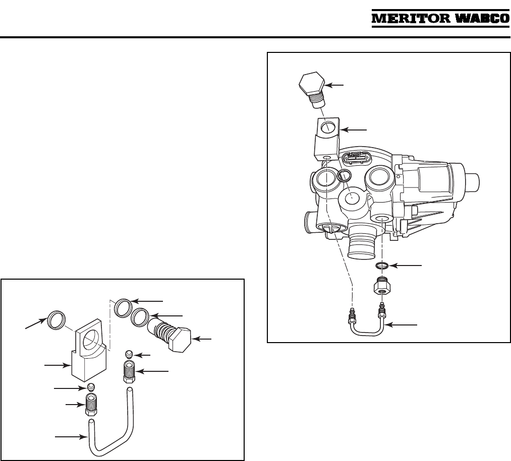
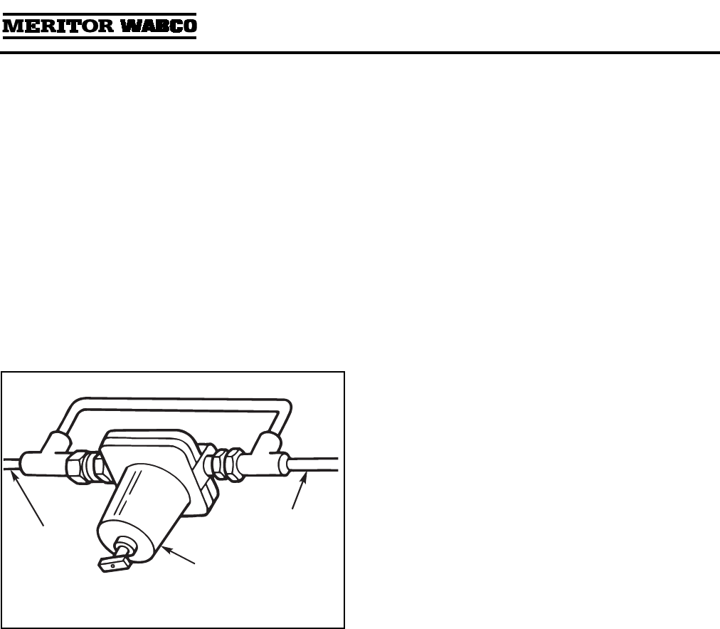
To replace the Econ valve assembly on Meritor
WABCO System Saver 1200E air dryers, follow
these instructions.
1. Remove the Econ valve assembly.
A. Using a flare wrench, loosen the
compression nuts on each end of the
U-shaped tube. Figures A.4 and A.5.
B. Loosen and remove the restricted-flow nut
on the air dryer.
C. Remove the metal washer.
D. Using a wrench, loosen and remove the
Econ valve from the banjo fitting.
E. Remove the banjo fitting and metal
washer.
F. Clean the valve surface area thoroughly
before replacement.
2. Install the replacement Econ valve assembly.
A. Install the metal washer on the
restricted-flow nut.
B. Install the restricted-flow nut on the air
dryer.
C. Position the metal washer and banjo fitting
on the Econ valve port.
D. Loosely fit the U-shaped tube into the
banjo fitting and restricted-flow nut. Make
sure the tube is fully seated.
E. Install and hand-tighten the compression
nuts on each end of the U-shaped tube.
F. Lubricate and install the O-ring on the
Econ valve.
G. Install the Econ valve into the banjo fitting.
H. Torque the Econ valve and all nuts to
specifications.
Figure A.4
METAL
WASHER
COMPRESSION
FEMALE
NUT
COMPRESSION
FEMALE
NUT
ECON
VALVE
METAL
WASHER
O-RING
TUBE
BANJO
FITTING
Figure A.5
ECON
VALVE
WASHER
TUBE
BANJO
FITTING
Appendix III
Special Applications
MM-34
Revised 11-02 Page 31
Alcohol Evaporator
Check the vehicle’s air system for an alcohol
evaporator.
NOTE: Typically, an alcohol evaporator will be
installed in the line between the air dryer and the
supply (wet) tank. Common installations are on
the truck’s firewall, on a frame rail and behind the
cab. However, an alcohol evaporator can also be
found at other locations.
1. Check the vehicle’s air system to determine if
an alcohol evaporator is installed.
2. If an alcohol evaporator is installed in the air
system, check for a bypass line connected to
the evaporator. Figure A.6.
3. If a bypass line is connected to the evaporator;
check to see if a check valve is installed in the
bypass line. If check valve is installed:
O Remove the check valve from the bypass
line,
O Remove the bypass line and
O Replace the bypass line with 1/4-inch
nylon line.
Figure A.6
1002188a
LINE FROM
AIR DRYER
ALCOHOL
EVAPORATOR
LINE TO
SUPPLY TANK
Appendix III
Special Applications
MM-34
Page 32 Revised 11-02
Combo Tank Installation for Regeneration-Style Air Dryers
PURGE
VALVE
(EXHAUST)
COMPRESSOR
DISCHARGE
LINE
COMPRESSOR
COMPRESSOR
INTAKE LINE
PRESSURE-
CONTROLLED
CHECK VALVE
*
SUPPLY
TANK
(WET)
SYSTEM
RESERVOIR
INTERNAL
CHECK
VALVE
DRYER
INLET
PORT
UNLOADER
LINE
RESERVOIR
TO GOVERNOR
LINE
1800
1200
SYSTEM
RESERVOIR
CHECK
VALVE
SUPPLY
LINE
DRYER
OUTLET
PORT
REGENERATION
VALVE
GOVERNOR
*
ALTERNATE PCCV LOCATION
WITH COMBO RESERVOIR
CONTROL
(PURGE) PORT
SYSTEM SAVER SERIES
REGENERATION
STYLE AIR DRYER
UNLOADER
PORT
Appendix III
Special Applications
MM-34
Revised 11-02 Page 33
Combo Tank Installation for Regeneration-Style Air Dryers
PURGE
VALVE
(EXHAUST)
COMPRESSOR
DISCHARGE
LINE
COMPRESSOR
COMPRESSOR
INTAKE LINE
PRESSURE-
CONTROLLED
CHECK VALVE
*
SUPPLY
TANK
(WET)
SYSTEM
RESERVOIR
INTERNAL
CHECK
VALVE
DRYER
INLET
PORT
UNLOADER
LINE
1800
1200
SYSTEM
RESERVOIR
SUPPLY
LINE
DRYER
OUTLET
PORT
*
ALTERNATE PCCV LOCATION
WITH COMBO RESERVOIR
GOVERNOR
UNLOADER
PORT
CONTROL
(PURGE) PORT
SYSTEM SAVER SERIES
REGENERATION
STYLE AIR DRYER
RESERVOIR
TO GOVERNOR
LINE
REGENERATION
VALVE
Appendix III
Special Applications
MM-34
Page 34 Revised 11-02
Meritor WABCO System Saver Series Single Cartridge Air Dryer
Component Replacement Guide — Dedicated Purge
O-RING
HEATER ASSEMBLY
DESICCANT CARTRIDGE
PRESSURE RELIEF VALVE
PURGE VALVE ASSEMBLY
OUTLET CHECK
VALVE ASSEMBLY
TURBO CUT-OFF
VALVE ASSEMBLY
1800
1200
Spring not used with U Series dryers.
Appendix III
Special Applications
MM-34
Revised 11-02 Page 35
Meritor WABCO System Saver Series Single Cartridge Air Dryer
Component Replacement Guide
BYPASS VALVE
ASSEMBLY
Bypass valve is used on dryers with
date codes earlier than 0894.
1002189a
O-Ring
Do not grease
diaphragm.
1200 Series air dryers do not use
bypass valve.
HEATER ASSEMBLY
• Disconnect plug.
• Remove old assembly.
• Install replacement element and
thermostat.
— Install retainer and screw to
secure.
• Install replacement O-ring and
receptacle.
— Fasten in place with
screws.
DESICCANT CARTRIDGE
• Remove old cartridge.
• Lube and install O-ring.
• Install replacement cartridge.
T
PRESSURE RELIEF VALVE
• Unscrew and remove old valve.
• Screw replacement valve into
dryer or Street-Tee fitting.
• Do not exceed recommended
torque. See Pressure Relief
Valve in Section 3.
REGENERATION
VALVE ASSEMBLY —
REGENERATION STYLE
DRYERS ONLY
• Remove old assembly and
diaphragm.
• Clean diaphragm lip groove.
• Install replacement.
diaphragm and assembly.
PURGE VALVE ASSEMBLY
• Remove old assembly.
• Clean valve bore.
• Grease valve bore.
• Install replacement assembly.
1800
1200
*
E Series dryers use a different style
turbo cut-off valve (see Parts Book
PB-96134).
**
Spring not used with U Series dryers.
NOTE: If shims are included in the
replacement kit, install one above
and one below the spring.
OUTLET CHECK
VALVE ASSEMBLY
• Remove old
assembly.
• Clean valve bore.
• Install replacement
O-ring in bore.
Then, grease O-ring
and bore.
TURBO CUT-OFF
VALVE ASSEMBLY
*
• Remove snap ring.
• Remove desiccant
cartridge.
• Use a wooden stick to
push pistion, spring and
cover out of the bore.
• Clean bore (if bore is
badly damaged,
replace the air dryer).
• Install replacement
assembly.
• Replace desiccant
cartridge.
* *
SHIMS
(IF REQUIRED)


Meritor WABCO
Vehicle Control Systems
3331 West Big Beaver Road, Suite 300
Troy, MI 48084 USA
800-535-5560
meritorwabco.com
Information contained in this publication was in effect at the time the publication was approved for
printing and is subject to change without notice or liability. Meritor WABCO reserves the right to revise
the information presented or discontinue the production of parts described at any time.
Copyright 2002 Maintenance Manual 34
ArvinMeritor, Inc. Revised 11-02
All Rights Reserved Printed in the USA 16579/24240
