LIFT CORP.
11921 Slauson Avenue.
Santa Fe Springs, CA. 90670
(800) 227-4116
BMR-35
BMR-44
BMR-55
BMR-66
MAINTENANCE
MANUAL
C MAXON Lift Corp. 1997
M-94-21
REV. B
NOV. 1997

LIFT CORP.
11921 Slauson Ave.
Santa Fe Springs, CA. 90670
CUSTOMER SERVICE:
TELEPHONE (562) 464-0099 TOLL FREE (800) 227-4116
FAX: (888) 771-7713
WARRANTY POLICY & PROCEDURE
NOTE: Check with Customer Service for updated versions
of Manuals on an annual basis.
NEW LIFTGATE W ARRANTY
Term of Warranty: 2 Years from Date of In-Service
Type of Warranty: Full Parts and Labor
MAXON agrees to replace any components which are found to be defective during the first 2
years of service, and will reimburse for labor based on MAXON’s Liftgate Warranty Flat Rate Labor
Schedule. (Call MAXON Customer Service for a copy).
All claims for warranty must be received within 30 Days of the repair date, and include the
following information:
1. Liftgate Model Number
2. Liftgate Serial Number
3. Detailed Description of Problem
4. Corrective Action Taken, and Date of Repair.
5. Parts used for Repair, Including MAXON Part Number(s).
6. MAXON R.M.A. # and/or Authorization # if applicable (see below).
7. Person contacted at MAXON if applicable.
All warranty repairs must be performed by an authorized MAXON warranty station. For major
repairs, MAXON Customer Service must be notified and an “Authorization Number” obtained. Major
repairs would generally be considered repairs made to the structural assembly of the liftgate and/or
repairs not outlined in the MAXON Liftgate Warranty Flat Rate Schedule.
Major components (i.e. hydraulic pumps, cylinders, valves, or failed structural parts) must be
returned, freight pre-paid, prior to the claim being processed. To ensure timely processing of these
warranty claims, an R.M.A. (Returned Merchandise Authorization) number must be obtained from
MAXON Customer Service prior to the return of any defective part. Defective Parts must be returned
within 60 days of the claim date for consideration to:
MAXON Lift Corp.
16205 Distribution Way, Cerritos, CA 90703
Attn: RMA#__
MAXON’s warranty policy does not include the reimbursement for travel time, towing, vehicle
rental, service calls, oil, batteries, defects due to misuse or abuse, or loss of income due to downtime.
Fabrication of parts, which are available from MAXON, are also not covered.
MAXON’s Flat Rate Labor Schedule takes into consideration the time required for diagnosis of a
problem.
PURCHASE PART WARRANTY
Term of Warranty: 1 Year from Date of Purchase
Type of Warranty: Part Replacement
MAXON will guarantee all returned genuine replacement parts upon receipt and inspection of
parts and invoice.
Table of Contents
WARNING ............................................................................................. PAGE 4
SERVICE TIME CHART........................................................................ PAGE 5
FOLDING CYLINDER REPLACEMENT ............................................... PAGE 6
LIFT CYLINDER BLEEDING................................................................. PAGE 7
LIFT CYLINDER REPLACEMENT ........................................................ PAGE 8
RUNNER REPLACEMENT ................................................................. PAGE 13
HYDRAULIC OVERRIDE LOCK ......................................................... PAGE 18
RELIEF VALVE PRESSURE SETTING .............................................. PAGE 19
PUMP VALVE OPERATION ................................................................ PAGE 21
OIL CHANGE INSTRUCTIONS .......................................................... PAGE 23
SOLENOID CHECK ............................................................................ PAGE 24
SWITCH AND HARNESS REPLACEMENT ....................................... PAGE 25
TROUBLESHOOTING.............................................PAGE 30
PLATFORM WILL NOT RAISE, MOTOR WON’T RUN ...................... PAGE 31
PLATFORM WILL NOT PICK UP RATED CAPACITY ........................ PAGE 32
PLATFORM RAISES HALFWAY & STOPS ........................................ PAGE 33
PLATFORM LOWERS UNEVEN ........................................................ PAGE 34
PLATFORM WILL NOT CLOSE .......................................................... PAGE 35
PLATFORM FOLDING SPEED ADJUSTMENT .................................. PAGE 37
PLATFORM WILL NOT UNFOLD ....................................................... PAGE 38
PLATFORM RAISES INSTEAD OF FOLDING ................................... PAGE 39
TROUBLESHOOTING GRAVITY DOWN................PAGE 40
PLATFORM WILL NOT RAISE, MOTOR RUNS................................. PAGE 41
PLATFORM WILL NOT LOWER ......................................................... PAGE 42
PLATFORM LOWERS SLOWLY......................................................... PAGE 43
TROUBLESHOOTING POWER DOWN..................PAGE 44
PLATFORM WILL NOT RAISE, MOTOR RUNS................................. PAGE 45
PLATFORM WILL NOT LOWER ......................................................... PAGE 46
PLATFORM LOWERS SLOWLY......................................................... PAGE 47

11921 Slauson Ave. Santa Fe Springs, CA. 90670 (800) 227-4116 FAX (888) 771-7713
PAGE 4
1. Read the Maintenance Manual and understand it thoroughly before any maintenance of
this unit is done.
2. Read the YELLOW urgent warning decal on the side of the vehicle close to the unit before
operating.
3. If decals are dirty, clean them. If decals are defaced or missing, replace them. Free replace-
ments are available from the manufacturer. See information at the end of the Warnings
4. Be aware that the safety and location of other people or objects should be considered
before operation of this unit. Stand to one side of platform while operating this unit.
5. Do not stand under, or have any foreign object under the Platform when lowering. Be sure
that the lowering of the Platform and/or Flipover will miss your feet!
6. Keep fingers, hands, arms, legs, and feet clear of moving parts when operating this unit.
7. If during your maintenance procedure, it becomes necessary to ride the platform, keep your
feet and any foreign objects clear of the rear edge of the platform. Otherwise your feet or
the foreign objects could become trapped between the edge of the platform and the vehicle
bed.
8. Inspect all Roll Pins monthly, to insure that they are not broken. Replace if broken.
9. Inspect all hydraulic hoses and fittings annually. Check for cracks and deterioration, and
replace if necessary.
10. Disconnect battery when replacing parts or servicing.
11. Do not allow children to ride, play with, or operate this unit.
12. In the event of an emergency while operating the unit, release the toggle switch and the unit
will stop immediately.
13. A properly installed Lift should operate smoothly and the only noise during the operation of
this unit should be from the Pump Unit during the raising of the Platform. Any scraping,
grating or audible indications of rough operation will need investigating. The cause will need
resolving before any further deterioration of performance occurs.
14. Use only Maxon Authorized Parts for replacement. Replacement parts should be ordered
from:
MAXON LIFT CORP. Parts Department
11921 Slauson Ave., Santa Fe Springs, Ca. 90670
Phone: (800) 227-4116
WARNING
11921 Slauson Ave. Santa Fe Springs, CA. 90670 (800) 227-4116 FAX (888) 771-7713
PAGE 5
SERVICE TIME CHART
DEMROFREPEBOTECIVRESDEMROFREPEBOTECIVRES
DEMROFREPEBOTECIVRES
DEMROFREPEBOTECIVRESDEMROFREPEBOTECIVRES
.D'QEREMIT.D'QEREMIT
.D'QEREMIT
.D'QEREMIT.D'QEREMIT
)SRUOH(
REDNILYCTFILEGNAHCREDNILYCTFILEGNAHC
REDNILYCTFILEGNAHC
REDNILYCTFILEGNAHCREDNILYCTFILEGNAHC
EDISTHGIREDISTHGIR
EDISTHGIR
EDISTHGIREDISTHGIR00.200.2
00.2
00.200.2
EDISTFELEDISTFEL
EDISTFEL
EDISTFELEDISTFEL05.105.1
05.1
05.105.1
REDNILYCRESOLCMROFTALPEGNAHCREDNILYCRESOLCMROFTALPEGNAHC
REDNILYCRESOLCMROFTALPEGNAHC
REDNILYCRESOLCMROFTALPEGNAHCREDNILYCRESOLCMROFTALPEGNAHC 00.100.1
00.1
00.100.1
ROTOMEGNAHCROTOMEGNAHC
ROTOMEGNAHC
ROTOMEGNAHCROTOMEGNAHC 05.005.0
05.0
05.005.0
DIONELOSROTOMEGNAHCDIONELOSROTOMEGNAHC
DIONELOSROTOMEGNAHC
DIONELOSROTOMEGNAHCDIONELOSROTOMEGNAHC 05.005.0
05.0
05.005.0
ETELPMOC,KCAPREWOPEGNAHCETELPMOC,KCAPREWOPEGNAHC
ETELPMOC,KCAPREWOPEGNAHC
ETELPMOC,KCAPREWOPEGNAHCETELPMOC,KCAPREWOPEGNAHC 00.100.1
00.1
00.100.1
EVLAVEGDIRTRACNAELC/EGNAHCEVLAVEGDIRTRACNAELC/EGNAHC
EVLAVEGDIRTRACNAELC/EGNAHC
EVLAVEGDIRTRACNAELC/EGNAHCEVLAVEGDIRTRACNAELC/EGNAHC 05.005.0
05.0
05.005.0
RIOVRESERPMUPEGNAHCRIOVRESERPMUPEGNAHC
RIOVRESERPMUPEGNAHC
RIOVRESERPMUPEGNAHCRIOVRESERPMUPEGNAHC 05.105.1
05.1
05.105.1
REZILAUQEEDIREGNAHCREZILAUQEEDIREGNAHC
REZILAUQEEDIREGNAHC
REZILAUQEEDIREGNAHCREZILAUQEEDIREGNAHC 05.005.0
05.0
05.005.0
EVLAVFEILERLANRETXEEGNAHCEVLAVFEILERLANRETXEEGNAHC
EVLAVFEILERLANRETXEEGNAHC
EVLAVFEILERLANRETXEEGNAHCEVLAVFEILERLANRETXEEGNAHC 05.005.0
05.0
05.005.0
YLBMESSAHCTIWSS/OEGNAHCYLBMESSAHCTIWSS/OEGNAHC
YLBMESSAHCTIWSS/OEGNAHC
YLBMESSAHCTIWSS/OEGNAHCYLBMESSAHCTIWSS/OEGNAHC 05.005.0
05.0
05.005.0
REKAERBTIUCRICEGNAHCREKAERBTIUCRICEGNAHC
REKAERBTIUCRICEGNAHC
REKAERBTIUCRICEGNAHCREKAERBTIUCRICEGNAHC 05.005.0
05.0
05.005.0
)RENNURREP(SGNIRAEBRELLORROSRELLOREGNAHC)RENNURREP(SGNIRAEBRELLORROSRELLOREGNAHC
)RENNURREP(SGNIRAEBRELLORROSRELLOREGNAHC
)RENNURREP(SGNIRAEBRELLORROSRELLOREGNAHC)RENNURREP(SGNIRAEBRELLORROSRELLOREGNAHC 05.105.1
05.1
05.105.1
NOITCESNIAMMROFTALPEGNAHCNOITCESNIAMMROFTALPEGNAHC
NOITCESNIAMMROFTALPEGNAHC
NOITCESNIAMMROFTALPEGNAHCNOITCESNIAMMROFTALPEGNAHC 00.200.2
00.2
00.200.2
NOITCESGNIDLOFMROFTALPEGNAHCNOITCESGNIDLOFMROFTALPEGNAHC
NOITCESGNIDLOFMROFTALPEGNAHC
NOITCESGNIDLOFMROFTALPEGNAHCNOITCESGNIDLOFMROFTALPEGNAHC 00.100.1
00.1
00.100.1
)HCAE(YLBMESSANIAHCTROPPUSMROFTALPECALPER)HCAE(YLBMESSANIAHCTROPPUSMROFTALPECALPER
)HCAE(YLBMESSANIAHCTROPPUSMROFTALPECALPER
)HCAE(YLBMESSANIAHCTROPPUSMROFTALPECALPER)HCAE(YLBMESSANIAHCTROPPUSMROFTALPECALPER 05.005.0
05.0
05.005.0
SGNIRAEBEGNIHNOITCESGNIDLOFECALPERSGNIRAEBEGNIHNOITCESGNIDLOFECALPER
SGNIRAEBEGNIHNOITCESGNIDLOFECALPER
SGNIRAEBEGNIHNOITCESGNIDLOFECALPERSGNIRAEBEGNIHNOITCESGNIDLOFECALPER 05.105.1
05.1
05.105.1
SNIPEGNIHNOITCESGNIDLOFECALPERSNIPEGNIHNOITCESGNIDLOFECALPER
SNIPEGNIHNOITCESGNIDLOFECALPER
SNIPEGNIHNOITCESGNIDLOFECALPERSNIPEGNIHNOITCESGNIDLOFECALPER 57.057.0
57.0
57.057.0
)EDISREP(SNIPEGNIHNIAMECALPER)EDISREP(SNIPEGNIHNIAMECALPER
)EDISREP(SNIPEGNIHNIAMECALPER
)EDISREP(SNIPEGNIHNIAMECALPER)EDISREP(SNIPEGNIHNIAMECALPER 05.005.0
05.0
05.005.0
.SGNRBEGNIHMROFTALPNIAMECALPER.SGNRBEGNIHMROFTALPNIAMECALPER
.SGNRBEGNIHMROFTALPNIAMECALPER
.SGNRBEGNIHMROFTALPNIAMECALPER.SGNRBEGNIHMROFTALPNIAMECALPER
EDISREPEDISREP
EDISREP
EDISREPEDISREP00.100.1
00.1
00.100.1
SEDISHTOBSEDISHTOB
SEDISHTOB
SEDISHTOBSEDISHTOB05.105.1
05.1
05.105.1
)HCAE(SESOHCILUARDYHLANRETXEEGNAHC)HCAE(SESOHCILUARDYHLANRETXEEGNAHC
)HCAE(SESOHCILUARDYHLANRETXEEGNAHC
)HCAE(SESOHCILUARDYHLANRETXEEGNAHC)HCAE(SESOHCILUARDYHLANRETXEEGNAHC 52.052.0
52.0
52.052.0
RENNURNIESOHREDNILYCRESOLCEGNAHCRENNURNIESOHREDNILYCRESOLCEGNAHC
RENNURNIESOHREDNILYCRESOLCEGNAHC
RENNURNIESOHREDNILYCRESOLCEGNAHCRENNURNIESOHREDNILYCRESOLCEGNAHC 00.200.2
00.2
00.200.2
)EDISREP(REDNILYCTFILDEELB)EDISREP(REDNILYCTFILDEELB
)EDISREP(REDNILYCTFILDEELB
)EDISREP(REDNILYCTFILDEELB)EDISREP(REDNILYCTFILDEELB 05.105.1
05.1
05.105.1
ERUSSERPEVLAVFEILERDNAPMUPTESERERUSSERPEVLAVFEILERDNAPMUPTESER
ERUSSERPEVLAVFEILERDNAPMUPTESER
ERUSSERPEVLAVFEILERDNAPMUPTESERERUSSERPEVLAVFEILERDNAPMUPTESER 05.005.0
05.0
05.005.0
SSENRAHHCTIWSELGGOTRENNUREGNAHCSSENRAHHCTIWSELGGOTRENNUREGNAHC
SSENRAHHCTIWSELGGOTRENNUREGNAHC
SSENRAHHCTIWSELGGOTRENNUREGNAHCSSENRAHHCTIWSELGGOTRENNUREGNAHC 05.205.2
05.2
05.205.2
SSENRAHEVLAVKCOLREDNILYCEGNAHCSSENRAHEVLAVKCOLREDNILYCEGNAHC
SSENRAHEVLAVKCOLREDNILYCEGNAHC
SSENRAHEVLAVKCOLREDNILYCEGNAHCSSENRAHEVLAVKCOLREDNILYCEGNAHC 05.105.1
05.1
05.105.1
11921 Slauson Ave. Santa Fe Springs, CA. 90670 (800) 227-4116 FAX (888) 771-7713
PAGE 6
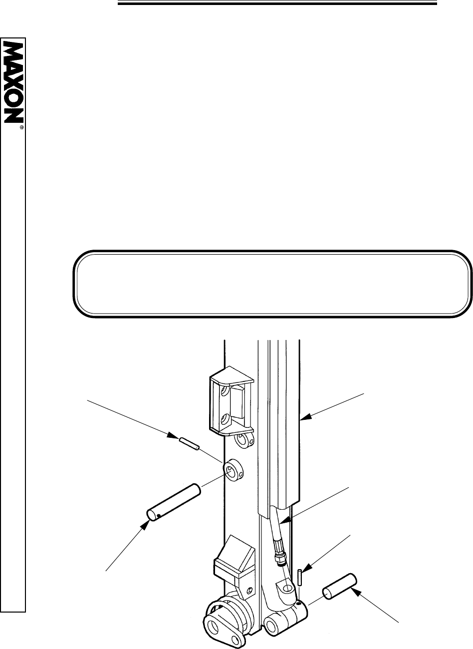
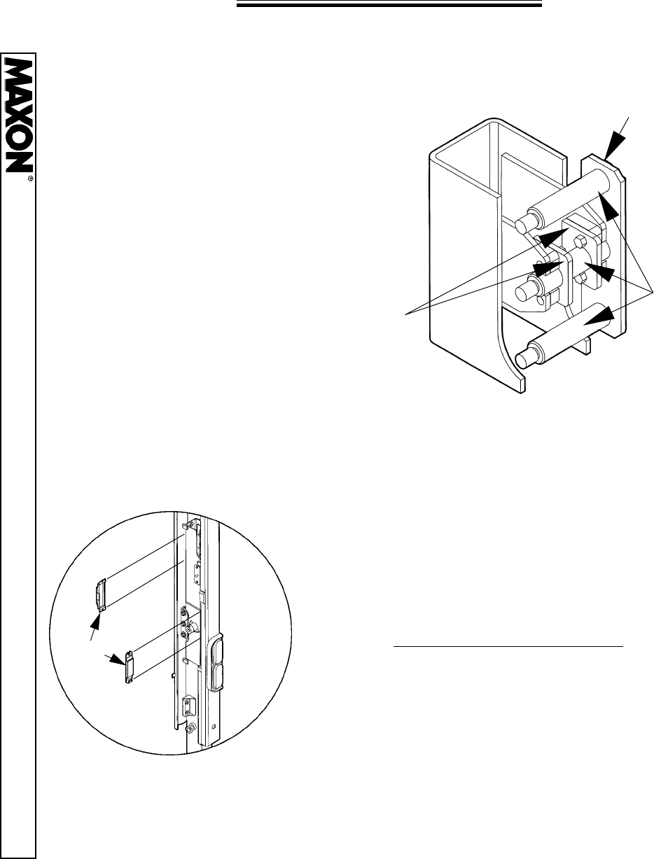
FOLDING CYLINDER REPLACEMENT
1. Lower the Platform to the ground.
2. Disconnect and plug the Hydraulic Hose from the lower part of the Cylinder
(for cleanliness).
3. Remove the Lower Roll Pin from the Inside Coupling and then remove the
Lower Cylinder Pin.
4. Remove the Upper Roll Pin from the Runner Weldment and then remove
the Upper Cylinder Pin.
5. Replace the Cylinder and reverse these steps for re-assembly.
NOTE:
Be sure the new Cylinder has a 1-3/4” Outside Diameter Rod
End. This will ensure that the correct cylinder is being used.
HYDRAULIC
HOSE
UPPER ROLL PIN
UPPER
CYLINDER PIN
LOWER
CYLINDER PIN
LOWER ROLL PIN
RUNNER
WELDMENT
11921 Slauson Ave. Santa Fe Springs, CA. 90670 (800) 227-4116 FAX (888) 771-7713
PAGE 7
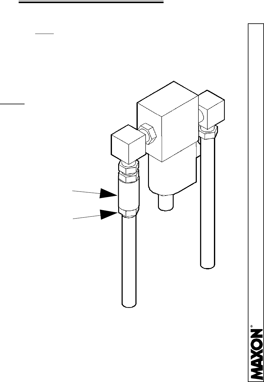
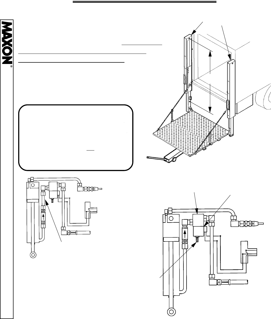
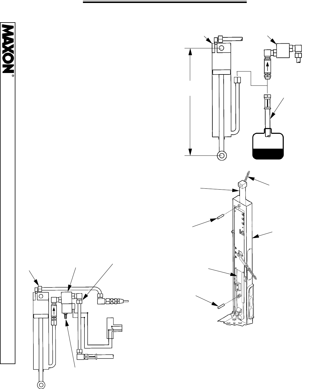
LIFT CYLINDER BLEEDING
NOTE: This operation must be performed in a location where the maximum
distance of 60” between the ground and the vehicle bed may be obtained.
1. Lower the opened platform to the ground.
2. Loosen, but do not disconnect
the Cylinder Fitting from the
Pressure Compensated Flow
Control Valve, located at the top of
both Lift Cylinders.
3. Activate the “RAISE” switch
for approximately one second
and then release the switch.
Wait ten seconds and repeat.
Repeat this procedure until
there is no air leaking from the
loosened fittings, then tighten
those fittings.
4. Raise and lower the platform to see if
the unit operates smoothly. If so, raise,
fold, and store the Platform.
Pressure Compensated
Flow Control Valve
Cylinder Fitting
11921 Slauson Ave. Santa Fe Springs, CA. 90670 (800) 227-4116 FAX (888) 771-7713
PAGE 8
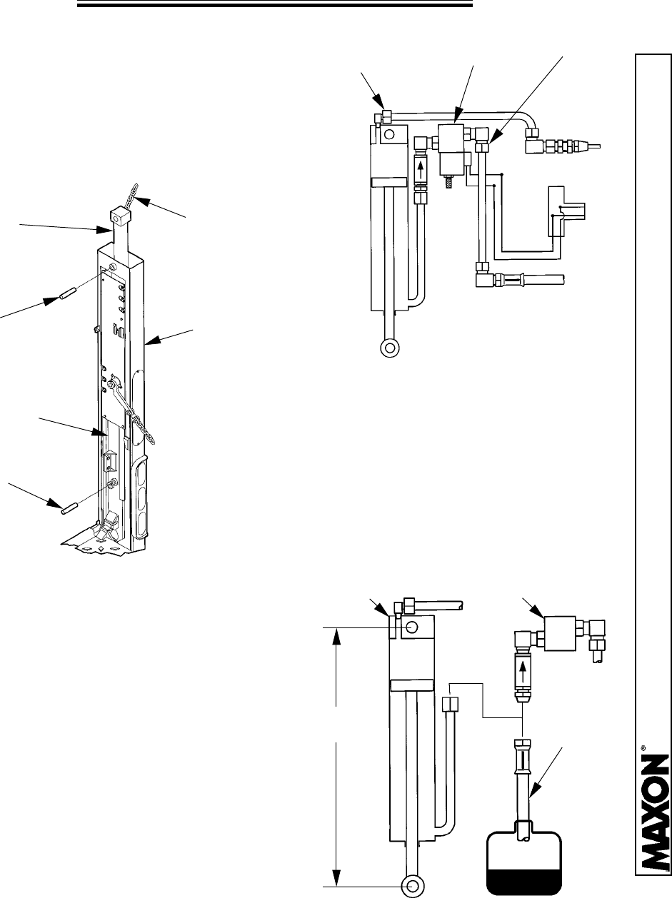
LIFT CYLINDER REPLACEMENT
1.
Raise the open Platform about 20” above
the ground. Place a jack under the Platform
and raise an additional 3” or 4”. Measure the
distance between the Cylinder Pins and
record this distance for later use.
2. Remove the Column Cover from the top
of the Column.
?
COLUMN
COVERS
NOTE:
If your unit was one of the first in
production, it came equipped with an
Extension Tube Assembly (shown
below Left). If so, skip Step 3 and go to
Step 9. If your unit has no Extension
Tube Assembly (shown below Right),
then proceed with Step 3.
EXTENSION
TUBE
VALVE
BLOCK
COIL
NUT
LOCK VALVE
& COIL
3. Remove the Coil Nut from the
Lock Valve & Coil. Slide off the
Coil and unscrew the Valve
Cartridge (screwed into the
Valve Block). Remove the bolts
(if any), that secure the Valve
Block to the Column.
11921 Slauson Ave. Santa Fe Springs, CA. 90670 (800) 227-4116 FAX (888) 771-7713
PAGE 9
VALVE
BLOCK
NUT
4. Remove the Nut from the Elbow on the top
of the Cylinder. Loosen, but do not remove the
Nut on the Elbow of the Valve Block.
NUT
5. Remove the Roll Pin & Pin that fastens the
Rod End of the Lift Cylinder to the Runner
Assembly. Using a device such as a Chain
Hoist, hold the Lift Cylinder while removing the
upper Roll Pin & Pin. Remove the Lift Cylinder
from the top of the Column.
CHAIN
HOIST
LIFTING
CYLINDER
COLUMN
RUNNER
ASSEMBLY
PIN
PIN
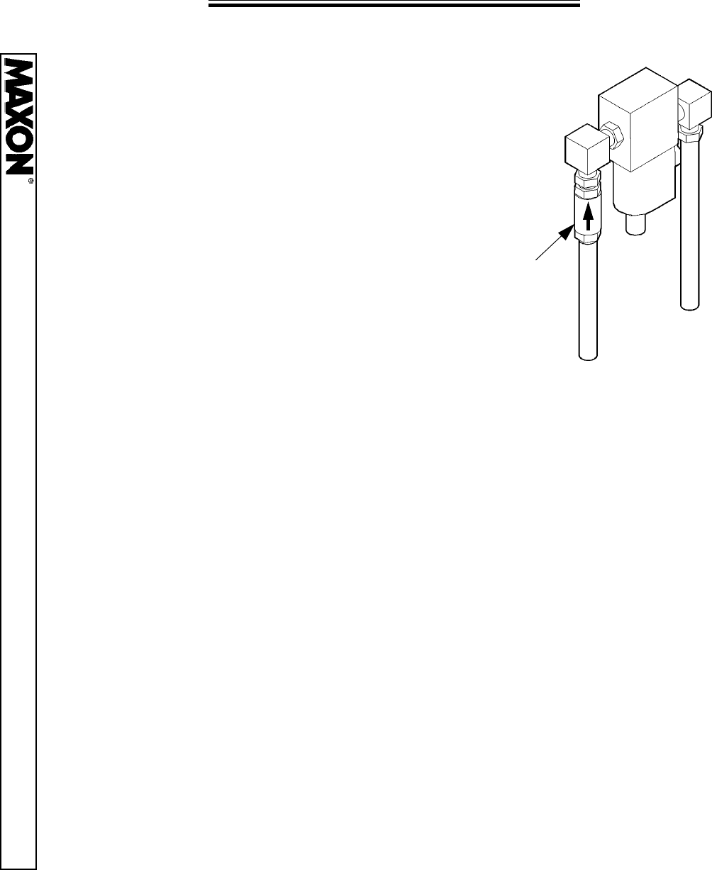
6. Remove the Plug from the
compression fitting on the New Lift
Cylinder. Fasten a Drain Hose with a
1/4” NPT Female end to the
compression fitting. Place the other
end of the Hose in a 1 gallon
container for bleeding. Pull the Rod
End of the Cylinder until the distance
between the Pins are the same as
measured in Step 1. Re-attach the
Hyd. Lock Valve and Pressure Comp.
Valve with all their fittings.
NOTE: Be sure the arrow on the
Pressure Comp. Valve is pointing up.
LIFT
CYLINDER
DRAIN
HOSE
HYD. LOCK,
PRESS. COMP.
VALVE
LIFT CYLINDER REPLACEMENT
?
11921 Slauson Ave. Santa Fe Springs, CA. 90670 (800) 227-4116 FAX (888) 771-7713
PAGE 10
LIFT CYLINDER REPLACEMENT
CHAIN
HOIST
LIFTING
CYLINDER
COLUMN
RUNNER
ASSEMBLY
PIN
PIN
7. Lower the New Lift Cylinder
through the top of the Column.
Fasten at the top with the Pin &
Roll Pin. Then fasten at the Rod
End of the Cylinder with the Pin &
Roll Pin.
VALVE
BLOCK
CYLINDER
NUT
NUT
8. Re-connect the Nut to the Elbow on top of
the Cylinder. Re-install the Valve Cartridge,
Coil, and Coil Nut to the Hyd. Lock Valve.
Re-attach the Hyd. Lock Valve to the Column
(if needed). Re-connect the Cylinder Nut to
the Hyd. Lock Valve.
COIL
NUT
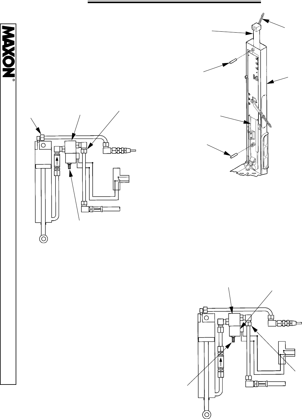
FOR UNITS SHIPPED IN EARLY 1994
9. Remove the Coil Nut from the Lock
Valve & Coil. Slide off the Coil and
unscrew the Valve Cartridge (screwed
into the Valve Block). Remove the bolts
(if any), that secure the Valve Block to
the Column. Loosen, but do not remove
the Nut on the Elbow of the Valve Block.
VALVE
BLOCK
COIL
NUT
LOCK VALVE
& COIL
NUT
11921 Slauson Ave. Santa Fe Springs, CA. 90670 (800) 227-4116 FAX (888) 771-7713
PAGE 11
LIFT CYLINDER REPLACEMENT
CHAIN
HOIST
LIFTING
CYLINDER
COLUMN
RUNNER
ASSEMBLY
PIN
PIN
10. Remove the Roll Pin & Pin that
fastens the Rod End of the Lift
Cylinder to the Runner Assembly.
Using a device such as a Chain
Hoist, hold the Lift Cylinder while
removing the upper Roll Pin & Pin.
Remove the Lift Cylinder from the
top of the Column.
VALVE
BLOCK
PRESSURE
COMP. VALVE
ELBOW
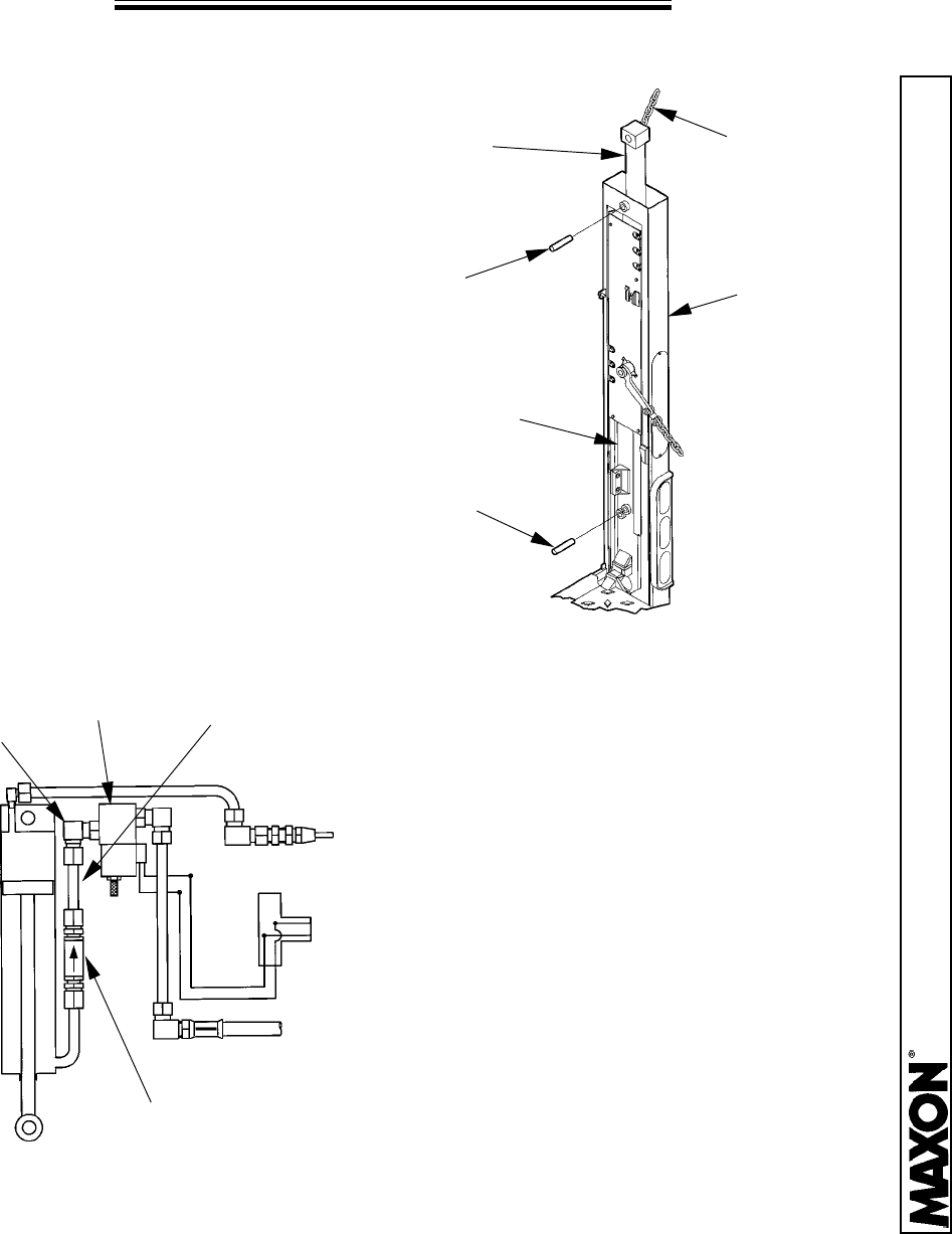
11. Remove the Tubing &
Connectors and discard them.
Remove the Elbow from the
Valve Block and replace it with
a new Elbow, #6M x 1/4 NPT
(P/N 260164). Fasten the
Pressure Comp. Valve to the
new Elbow. NOTE: Be sure
the arrow on the Pressure
Comp. Valve is pointing up.
TUBING &
CONNECTORS
11921 Slauson Ave. Santa Fe Springs, CA. 90670 (800) 227-4116 FAX (888) 771-7713
PAGE 12
LIFT CYLINDER REPLACEMENT
CHAIN
HOIST
LIFTING
CYLINDER
COLUMN
RUNNER
ASSEMBLY
PIN
PIN
13. Lower the New Lift Cylinder
through the top of the Column.
Fasten at the top with the Pin &
Roll Pin. Then fasten at the Rod
End of the Cylinder with the Pin &
Roll Pin.
VALVE
BLOCK
CYLINDER
NUT
NUT
14. Re-connect the Nut to the Elbow on top
of the Cylinder. Re-install the Valve
Cartridge, Coil, and Coil Nut to the Hyd. Lock
Valve. Re-attach the Hyd. Lock Valve to the
Column (if needed). Re-connect the Cylinder
Nut to the Hyd. Lock Valve.
COIL
NUT
12. Remove the Plug from the
compression fitting on the New Lift
Cylinder. Fasten a Drain Hose with a
1/4” NPT Female end to the
compression fitting. Place the other
end of the Hose in a 1 gallon
container for bleeding. Pull the Rod
End of the Cylinder until the distance
between the Pins are the same as
measured in Step 1. Re-attach the
Hyd. Lock Valve and Pressure Comp.
Valve with all their fittings.
NOTE: Be sure the arrow on the
Pressure Comp. Valve is pointing up.
LIFT
CYLINDER
DRAIN
HOSE
HYD. LOCK,
PRESS. COMP.
VALVE
?
11921 Slauson Ave. Santa Fe Springs, CA. 90670 (800) 227-4116 FAX (888) 771-7713
PAGE 13
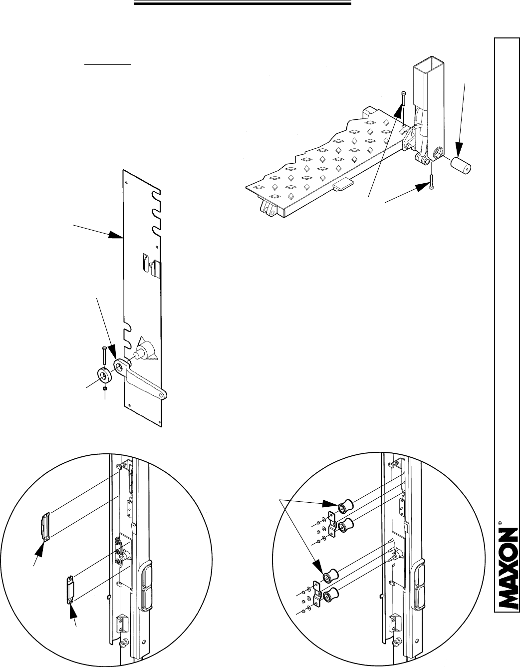
RUNNER REPLACEMENT
REMOVE OLD RUNNERS
1. Lower the opened Platform and let it rest on a
stand approximately 25” off of the ground. Be sure to
allow access to a forklift to position the Runner.
2. Remove the Bolts, Pins, Chain Arms, and
Covers from the Runners and Platform.
3. Use a Forklift to slide the Platform forward,
towards the cab of the vehicle approximately
6”, or enough to clear the Platform away from
the Runner Brackets. Raise the Runners
about 6” and slide the Platform away from the
cab far enough to create a workplace to
remove the Runners.
PINS
BOLTS
CHAIN
ARMS
COVER
4. Lower the Runners to the ground. Remove
the Upper and Lower Pad Assemblies, and
the two Tandem Assemblies.
TANDEM
ASSEMBLY
UPPER
PAD
LOWER
PAD
11921 Slauson Ave. Santa Fe Springs, CA. 90670 (800) 227-4116 FAX (888) 771-7713
PAGE 14
RUNNER REPLACEMENT
5. Remove the Pins from the old Runner,
(two Pins on the R.H. Runner, and one Pin
on the L.H. Runner). Do not remove the
Upper Cylinder Pin at this time. Activate the
Control Switch to the “UP” position to fully
retract the Lift Cylinders.
RUNNER
PINS
6. R.H. COLUMN ONLY remove the
Switch Mounting Bracket. Remove the
terminals from the Switch and release
the electric cable from the clamp
inside the hole.
SWITCH
MOUNTING
BRACKET
CABLE
CLAMP
COVER
7. Remove the Spring Guard and
Harness in the channel of the Runner
Assembly. Remove the Hose from the
Closing Cylinder. Remove the 1” Dia.
Pin from the Rod End of the Closing
Cylinder and place the Closing
Cylinder aside.
CLOSING
CYLINDER
HOSE
SPRING
GUARD
NOTE:
If the Bed Height of the Vehicle is 54”
or more from the Ground, go to Step 9.
11921 Slauson Ave. Santa Fe Springs, CA. 90670 (800) 227-4116 FAX (888) 771-7713
PAGE 15
RUNNER REPLACEMENT
VALVE
BLOCK
COIL
NUT
LOCK VALVE
& COIL
8. Remove the Column Cover from the top
of the Column. Remove the Coil Nut from
the Lock Valve & Coil. Slide off the Coil
and unscrew the Valve Cartridge (screwed
into the Valve Block). Remove the bolts (if
any), that secure the Valve Block to the
Column.
Remove the Nut from the Elbow on
the top of the Cylinder. Loosen, but do not
remove the Nut on the Elbow of the Valve
Block.
Using a device such as a
Chain Hoist, hold the Lift Cylinder
while removing the upper Roll Pin &
Pin. Raise the Cylinder until the Rod
End of the Cylinder clears the top of
the Runner.
9. Grasp the lower end of the Runner and
pull towards the centerline of the vehicle.
The Runner should be free of the Column
by now. Repeat for the other side.
COLUMN
RUNNER
DIRECTION
OF PULL
11921 Slauson Ave. Santa Fe Springs, CA. 90670 (800) 227-4116 FAX (888) 771-7713
PAGE 16
RUNNER REPLACEMENT
INSTALL NEW RUNNERS
10. Remove the remaining parts of
the two Tandem Roller Assemblies
from the Old Runners and place
them on the New Runners. The
remaining parts for each Tandem
Assembly consist of: (1) Roller
Bracket Weldment, (3) Roller Axles,
and (2) Mounting Brackets.
ROLLER BRACKET
WELDMENT
ROLLER
AXLES
MOUNTING
BRACKET
12. Replace the Upper and Lower Pads
on the front and back of the Runner.
PADS
13. FOR R.H. RUNNER ONLY,tiea10ft.
piece of wire to the electrical cable that
was removed from the Switch. Insert the
opposite end of the wire through the
bottom of the Runner and bring it out
through the Switch opening in the Runner.
11. Position the New Runner into the Column.
Replace the Rollers on the Roller Axles and
fasten them with the Washers and Nuts. Be
certain the Roller Axels are positioned against
the Roller Bracket Weldment so they don’t rotate on the Bracket.
14. If the Lifting Cylinders were detached from the Column, replace them and
fasten them back to the top of the Column with the Pin and Roll Pin. Tighten
or replace any hydraulic fittings you may have removed from the top of the
Cylinder. Replace the Cover on the Column.
11921 Slauson Ave. Santa Fe Springs, CA. 90670 (800) 227-4116 FAX (888) 771-7713
PAGE 17
RUNNER REPLACEMENT
RUNNER
PINS
15. Activate the “DOWN” switch on the
Control Panel to extend the Cylinders.
Attach the Lifting Cylinder to the Runner
with the Pin and Roll Pin.
On the R.H.
Runner only, attach the fixed end of the
Closing Cylinder to the Runner with the Pin
and Roll Pin. Re-attach the Spring Guard
and Harness to the Runner.
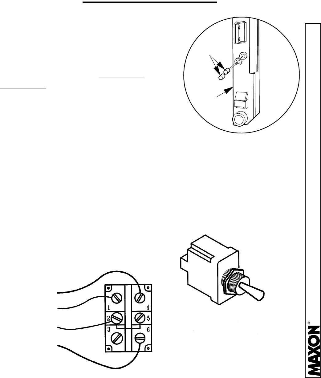
16. Pull the electrical cables through the Switch Mounting Bracket hole and
tighten the Cable Clamp inside the Runner. Replace the wires to the switch
per the diagram below. Replace the Switch Mounting Bracket to the R.H.
Runner and re-connect the Hose to the Closing Cylinder.
17. Re-assemble the Platform to the Runners in reverse order.
RED
BLK
GRN
WHT
11921 Slauson Ave. Santa Fe Springs, CA. 90670 (800) 227-4116 FAX (888) 771-7713
PAGE 18
HYDRAULIC OVERRIDE LOCK
In the event that the BMR Column Lift will not lower, you will need to
disengage both of the Hydraulic Override Locks. There is one located at the
top of each Column.
To disengage, you must pull down on the Coil Nut and twist until it locks
into place. To re-engage you must twist the Coil Nut and release. It will spring
back into the original “Locked” position. Be sure to re-engage the Override
Locks before moving the vehicle.
COIL NUT
PULL DOWN AND
TWIST TO
DISENGAGE THE
LOCK

11921 Slauson Ave. Santa Fe Springs, CA. 90670 (800) 227-4116 FAX (888) 771-7713
PAGE 19
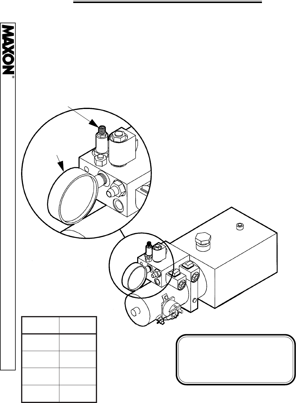
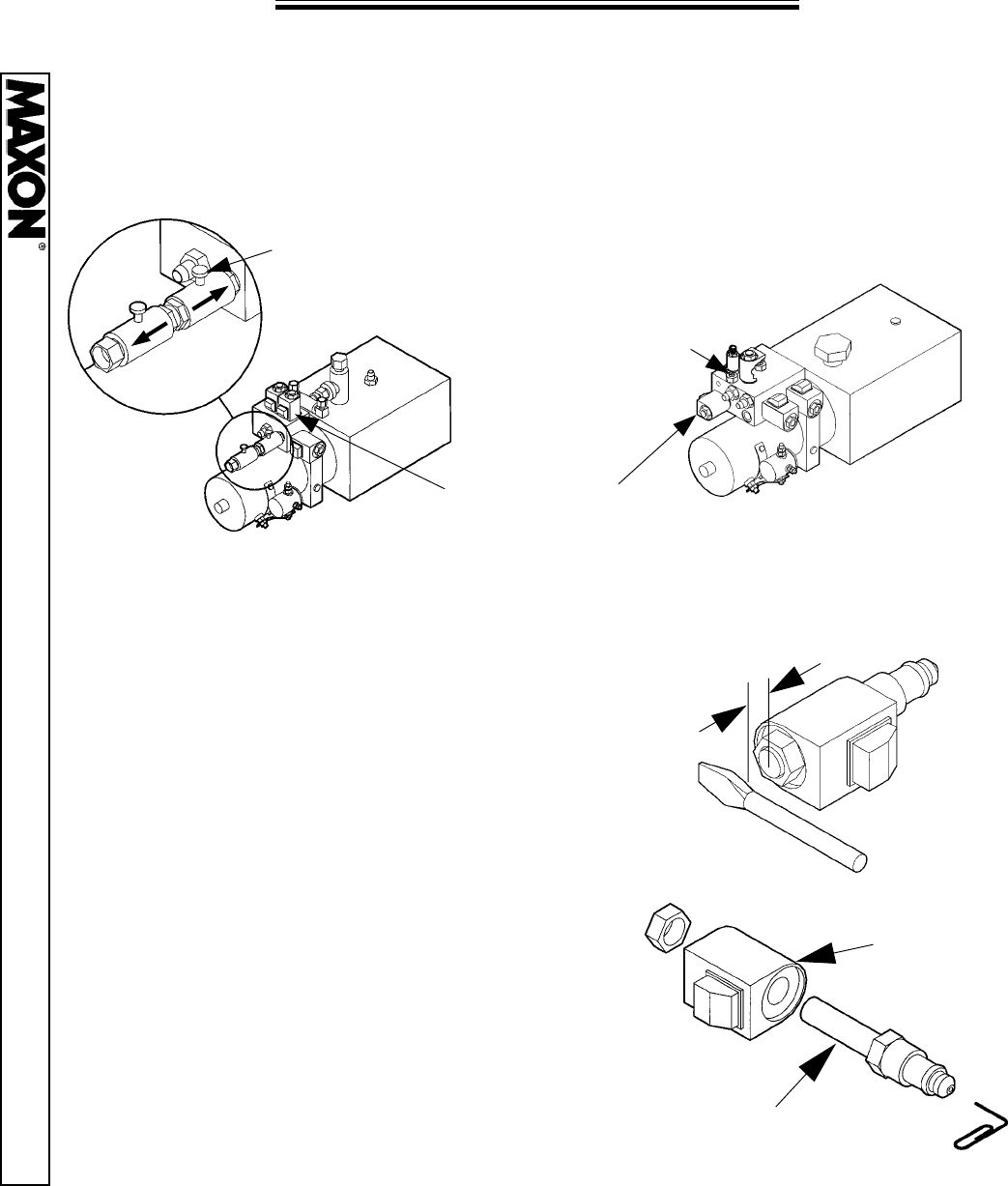
RELIEF VALVE PRESSURE SETTING
The Relief Valve pressure is set at the factory. If adjustment is needed,
use the following instructions to set the pressure per the table below.
1. For better access, remove the two
screws which fasten the Relief Valve
Assembly to the back of the Pump Box.
Remove the Hose from the Tee Fitting.
2. Attach a 0-3000 PSI gauge to the Tee Fitting.
Actuate the Control Switch to the “Raise” position.
Turn the Relief Valve Adjustment Screw to the
proper setting.
(Hint: Adjust the setting to approximately 300 psi
below the desired pressure, and slowly raise the
pressure until you reach the recommended
pressure shown in the table below.
SCREWS
TEE FITTING
HOSE
0-3000 PSI GUAGE
ADJUSTMENT
SCREW
OLD STYLE RELIEF VALVE
WARNING!
Setting the pressure higher than
recommended could result in
damage to your unit.
LEDOMLEDOM
LEDOM
LEDOMLEDOM.I.S.P.I.S.P
.I.S.P
.I.S.P.I.S.P
53-RMB53-RMB
53-RMB
53-RMB53-RMB05710571
0571
05710571
44-RMB44-RMB
44-RMB
44-RMB44-RMB00810081
0081
00810081
55-RMB55-RMB
55-RMB
55-RMB55-RMB00120012
0012
00120012
66-RMB66-RMB
66-RMB
66-RMB66-RMB00420042
0042
00420042
11921 Slauson Ave. Santa Fe Springs, CA. 90670 (800) 227-4116 FAX (888) 771-7713
PAGE 20
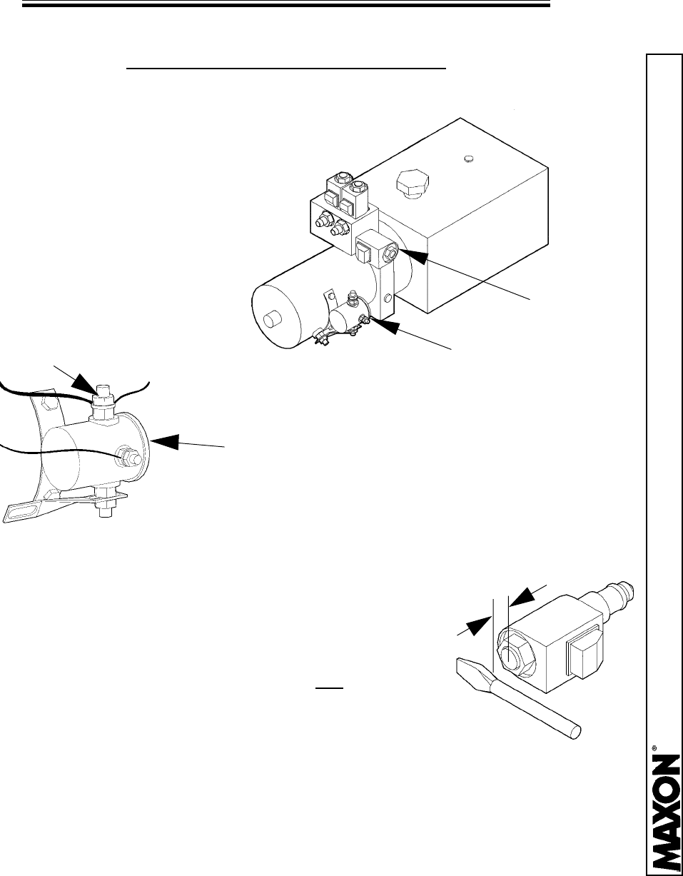
RELIEF VALVE PRESSURE SETTING
NEW STYLE RELIEF VALVE
The Relief Valve pressure is set at the factory. If adjustment is needed,
use the following instructions to set the pressure per the table below.
1. Attach a 0-3000 PSI gauge to the Pressure Port.
Actuate the Control Switch to the “Raise” position. Turn
the Relief Valve Adjustment Screw to the proper setting.
(Hint: Adjust the setting to approximately
300 psi below the desired pressure, and
slowly raise the pressure until you reach
the recommended pressure shown in
the table below.
RELIEF VALVE
ADJUSTMENT SCREW
3000 PSI
GAUGE
WARNING!
Setting the pressure higher
than recommended could
result in damage to your unit.
LEDOMLEDOM
LEDOM
LEDOMLEDOM.I.S.P.I.S.P
.I.S.P
.I.S.P.I.S.P
53-RMB53-RMB
53-RMB
53-RMB53-RMB05710571
0571
05710571
44-RMB44-RMB
44-RMB
44-RMB44-RMB00810081
0081
00810081
55-RMB55-RMB
55-RMB
55-RMB55-RMB00120012
0012
00120012
66-RMB66-RMB
66-RMB
66-RMB66-RMB00420042
0042
00420042
11921 Slauson Ave. Santa Fe Springs, CA. 90670 (800) 227-4116 FAX (888) 771-7713
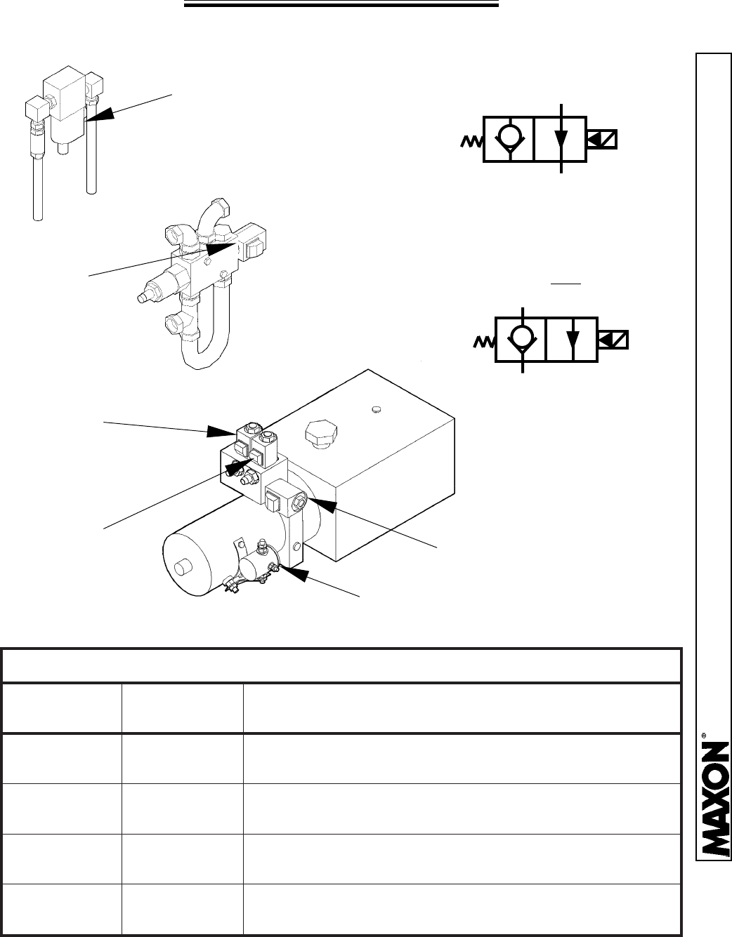
PAGE 21
PUMP VALVE OPERATION
OLD STYLE PUMP
“D” Valves
Located inside the
top of each Column
“C” Valve
Located in
Pump Box
“B” Valve
Lifting Port
“A” Valve
Folding Port
“E” Valve
4-Way Valve
“M” Valve
Motor Solenoid
IN
OUT
OUT
IN
FREE FLOW OUT
FREE FLOW IN
VALVES A,B,C, or D, Energized
VALVES A,B,C, or D, Not Energized
STINUNWODYTIVARGDLO-NOITAREPODIONELOSSTINUNWODYTIVARGDLO-NOITAREPODIONELOS
STINUNWODYTIVARGDLO-NOITAREPODIONELOS
STINUNWODYTIVARGDLO-NOITAREPODIONELOSSTINUNWODYTIVARGDLO-NOITAREPODIONELOS
NOITCNUFNOITCNUF
NOITCNUF
NOITCNUFNOITCNUF
DNAMMOC
DIONELOSDIONELOS
DIONELOS
DIONELOSDIONELOS
DEZIGRENE
NOITCAGNITLUSERNOITCAGNITLUSER
NOITCAGNITLUSER
NOITCAGNITLUSERNOITCAGNITLUSER
ESIARESIAR
ESIAR
ESIARESIARMM
M
MM
,evlaVfeileRurhttroP"B"morfswolfliO;snurrotoM,evlaVfeileRurhttroP"B"morfswolfliO;snurrotoM
,evlaVfeileRurhttroP"B"morfswolfliO;snurrotoM
,evlaVfeileRurhttroP"B"morfswolfliO;snurrotoM,evlaVfeileRurhttroP"B"morfswolfliO;snurrotoM
srednilyCtfiLotsevlaV"D"urht,rezilauqEediRurht
REWOLREWOL
REWOL
REWOLREWOLE&,D,C,BE&,D,C,B
E&,D,C,B
E&,D,C,BE&,D,C,B
liogniwolla,neposevlaV"D&,C,B";stfihsevlaV"E"liogniwolla,neposevlaV"D&,C,B";stfihsevlaV"E"
liogniwolla,neposevlaV"D&,C,B";stfihsevlaV"E"
liogniwolla,neposevlaV"D&,C,B";stfihsevlaV"E"liogniwolla,neposevlaV"D&,C,B";stfihsevlaV"E"
riovreseRehtotsrednilyCtfiLmorfnruterot
DLOFDLOF
DLOF
DLOFDLOF
MROFTALP
E&ME&M
E&M
E&ME&M
ot"A"troPmorfswolfliO,stfihsevlaV"E";snurrotoMot"A"troPmorfswolfliO,stfihsevlaV"E";snurrotoM
ot"A"troPmorfswolfliO,stfihsevlaV"E";snurrotoM
ot"A"troPmorfswolfliO,stfihsevlaV"E";snurrotoMot"A"troPmorfswolfliO,stfihsevlaV"E";snurrotoM
.rednilyCdloFeht
NEPONEPO
NEPO
NEPONEPO
MROFTALP
AA
A
AA
ehtmorfnruterotliogniwolla,snepoevlaV"A"ehtmorfnruterotliogniwolla,snepoevlaV"A"
ehtmorfnruterotliogniwolla,snepoevlaV"A"
ehtmorfnruterotliogniwolla,snepoevlaV"A"ehtmorfnruterotliogniwolla,snepoevlaV"A"
.riovreseRehtotrednilyCgnidloF
11921 Slauson Ave. Santa Fe Springs, CA. 90670 (800) 227-4116 FAX (888) 771-7713
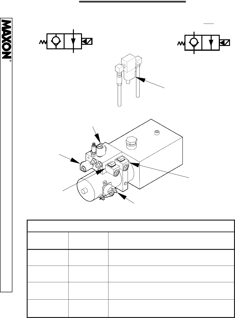
PAGE 22
PUMP VALVE OPERATION
NEW STYLE PUMP
“D” Valves
Located inside the
top of each Column
IN
OUT
OUT
IN
FREE FLOW OUT
FREE FLOW IN
VALVES A,B,C, or D, Energized
VALVES A,B,C, or D, Not Energized
“C” Valve
“B” Valve
Lifting Port
“A” Valve
Folding Port
“E” Valve
4-Way Valve
“M” Valve
Motor Solenoid
STINUNWODYTIVARGWEN-NOITAREPODIONELOSSTINUNWODYTIVARGWEN-NOITAREPODIONELOS
STINUNWODYTIVARGWEN-NOITAREPODIONELOS
STINUNWODYTIVARGWEN-NOITAREPODIONELOSSTINUNWODYTIVARGWEN-NOITAREPODIONELOS
NOITCNUFNOITCNUF
NOITCNUF
NOITCNUFNOITCNUF
DNAMMOC
DIONELOSDIONELOS
DIONELOS
DIONELOSDIONELOS
DEZIGRENE
NOITCAGNITLUSERNOITCAGNITLUSER
NOITCAGNITLUSER
NOITCAGNITLUSERNOITCAGNITLUSER
ESIARESIAR
ESIAR
ESIARESIARMM
M
MM
ediRurht,troP"B"morfswolfliO;snurrotoMediRurht,troP"B"morfswolfliO;snurrotoM
ediRurht,troP"B"morfswolfliO;snurrotoM
ediRurht,troP"B"morfswolfliO;snurrotoMediRurht,troP"B"morfswolfliO;snurrotoM
srednilyCtfiLotsevlaV"D"urht,rezilauqE
REWOLREWOL
REWOL
REWOLREWOLD&,C,BD&,C,B
D&,C,B
D&,C,BD&,C,B
nruterotliogniwolla,neposevlaV"D&,C,B"nruterotliogniwolla,neposevlaV"D&,C,B"
nruterotliogniwolla,neposevlaV"D&,C,B"
nruterotliogniwolla,neposevlaV"D&,C,B"nruterotliogniwolla,neposevlaV"D&,C,B"
riovreseRehtotsrednilyCtfiLmorf
DLOFDLOF
DLOF
DLOFDLOF
MROFTALP
E&ME&M
E&M
E&ME&M
morfswolfliO,stfihsevlaV"E";snurrotoMmorfswolfliO,stfihsevlaV"E";snurrotoM
morfswolfliO,stfihsevlaV"E";snurrotoM
morfswolfliO,stfihsevlaV"E";snurrotoMmorfswolfliO,stfihsevlaV"E";snurrotoM
.rednilyCdloFehtot"A"troP
NEPONEPO
NEPO
NEPONEPO
MROFTALP
AA
A
AA
morfnruterotliogniwolla,snepoevlaV"A"morfnruterotliogniwolla,snepoevlaV"A"
morfnruterotliogniwolla,snepoevlaV"A"
morfnruterotliogniwolla,snepoevlaV"A"morfnruterotliogniwolla,snepoevlaV"A"
.riovreseRehtotrednilyCgnidloFeht
11921 Slauson Ave. Santa Fe Springs, CA. 90670 (800) 227-4116 FAX (888) 771-7713
PAGE 23
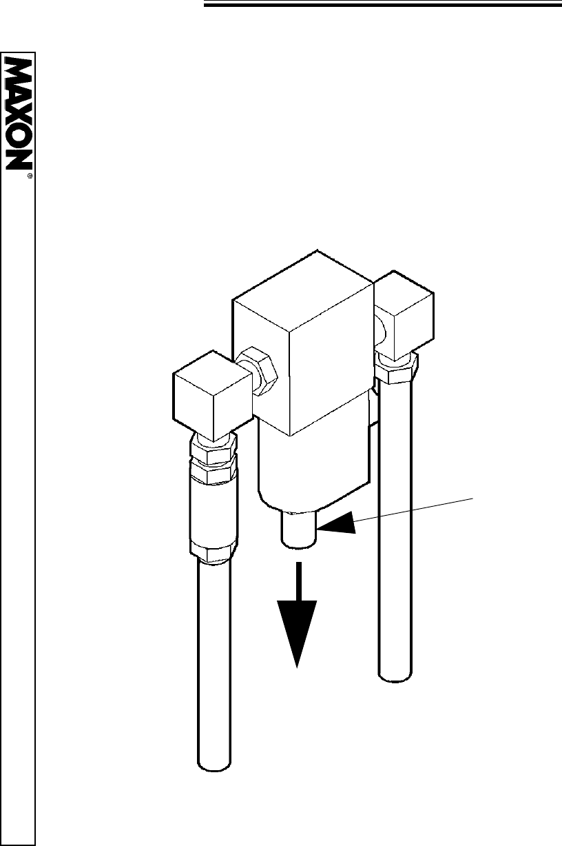
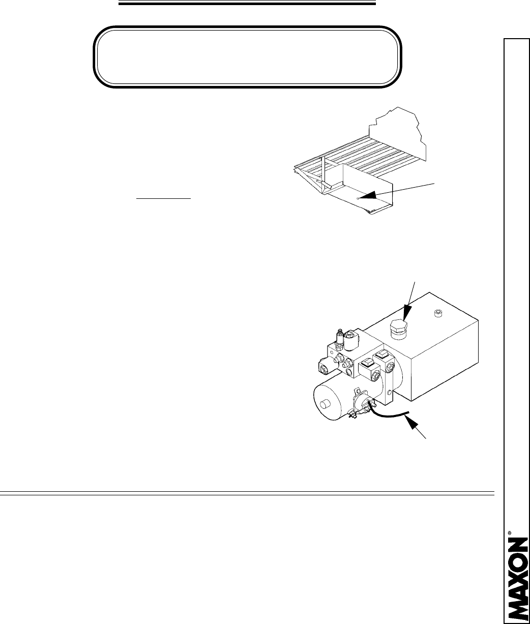
OIL CHANGE INSTRUCTIONS
1. Place an empty 3 Gallon Container under
the Drain Plug.
NOTE:
Determine if your unit is Gravity Down or Power Down
before choosing the method of oil change.
GRAVITY DOWN UNITS
2. Remove the Drain Plug and activate the
switch to “Lower” the
unfolded Platform
3. Replace the Drain Plug. Remove the
Filler/Breather Cap and fill the Reservoir to within 1” from the top.
4. Replace the Filler/Breather Cap.
POWER DOWN UNITS
DRAIN
PLUG
1. Place an empty 3 Gallon Container under the Drain Plug.
WHITE
WIRE
2. Raise the Platform and remove the Drain Plug.
3. Remove the “White Wire” from the Motor
Solenoid and activate the switch to “Lower”
the Platform.
4. Replace the Drain Plug and White Wire.
Remove the Filler/Breather Cap and fill the Reservoir
to within 1” from the top.
5. Replace the Filler/Breather Cap.
FILLER/BREATHER
CAP
OIL SPECIFICATIONS
Grade ISO - (32)
Gravity, API - 29.5 Degrees
Pour Point, F - (-54 Degrees)
VISCOSITY
@ 40 Degrees C - 31.2 cSt
@ 100 Degrees C - 6.2 cSt
VISCOSITY INDEX - 154 VI
Flash Point, F - 325 Degrees
11921 Slauson Ave. Santa Fe Springs, CA. 90670 (800) 227-4116 FAX (888) 771-7713
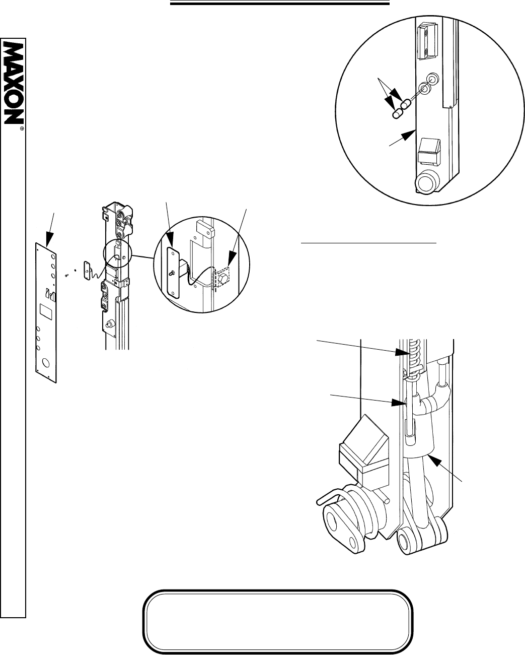
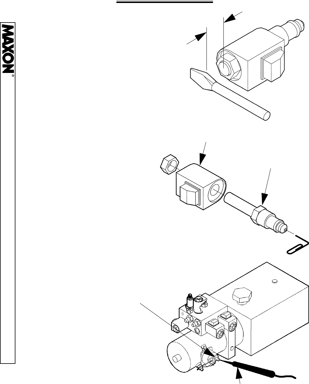
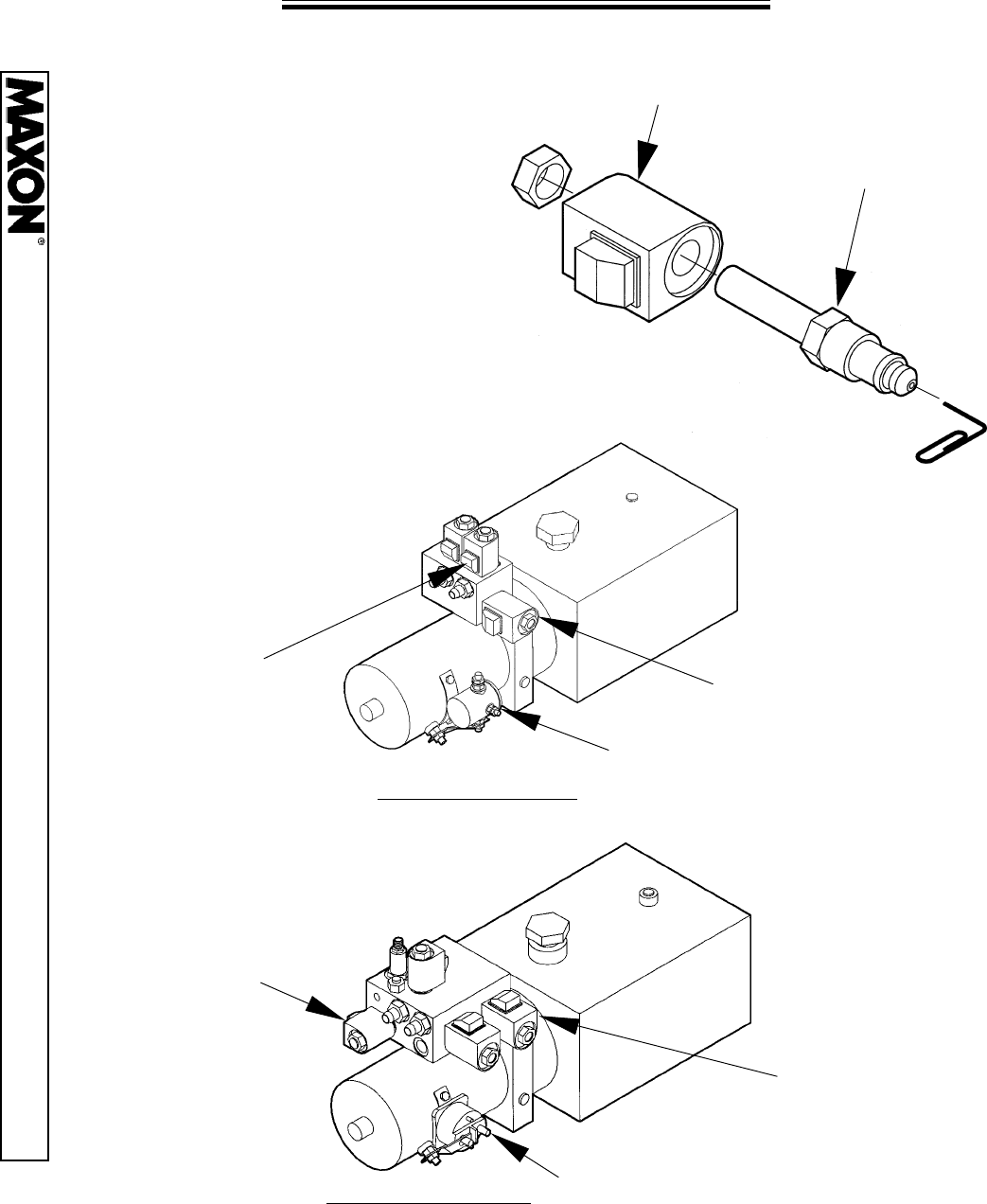
PAGE 24
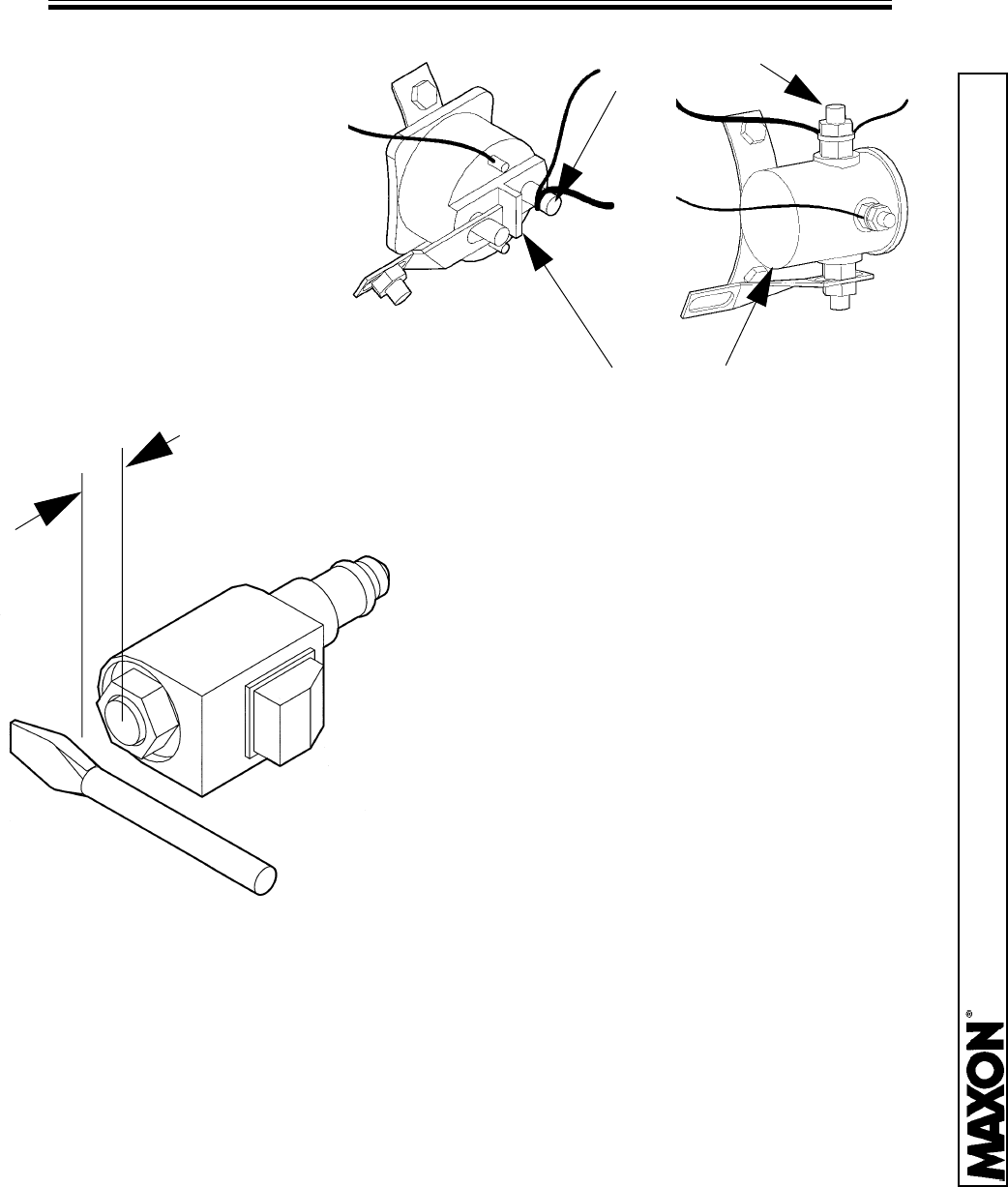
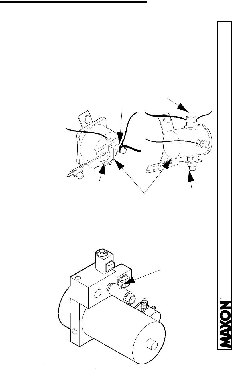
SOLENOID CHECK
To check the Solenoids for power,
hold a screwdriver approximately 1/4”
from the top nut of the Solenoid and
energize the unit. If the Solenoid is
good, it will draw the screwdriver to the
nut through a magnetic force.
To check the valve itself,
remove the Valve Coil from the
Valve Cartridge. Using a paper clip,
push on the Plunger inside the
Valve Cartridge. It should move
freely approximately 1/8”.
Inspect O-Ring and wash the
Cartridge in solvent to remove any
foreign substances inside the
Cartridge. If Plunger still does not
move freely (approx. 1/8”), then
replace the Valve Cartridge.
To check the Motor Solenoid
for power, place a 12 volt test lamp
on the Solenoid Battery Terminal.
1/4”
VALVE COIL
VALVE CARTRIDGE
BATTERY CABLE
TERMINAL
12 VOLT TEST LAMP
11921 Slauson Ave. Santa Fe Springs, CA. 90670 (800) 227-4116 FAX (888) 771-7713
PAGE 25
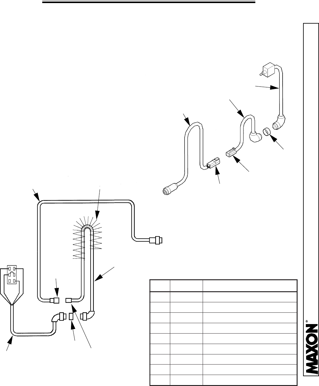
SWITCH AND HARNESS REPLACEMENT
Remove the existing Harness/Switch Assembly and replace it with the
3-Piece Cable Assembly as shown.
The first piece of cable runs from
inside the Runner Switch to the bottom of
the Runner. The second piece of cable
runs from the bottom of the Runner,
through the Spring Guard and out through
the bottom of the Column. The third piece
of cable runs through the channel inside
the Column, over the top, and out the
bottom of the Column to the Pump Box.
1
2
3
4,6
5,7
8
3
1
8
2
4,6
5,7
TO PUMP BOX
SPRING GUARD
* NOT SHOWN
METIMETI
METI
METIMETI.ONTRAP.ONTRAP
.ONTRAP
.ONTRAP.ONTRAPNOITPIRCSEDNOITPIRCSED
NOITPIRCSED
NOITPIRCSEDNOITPIRCSED
11
1
11925062925062
925062
925062925062YLBMESSAELBAC&HCTIWSYLBMESSAELBAC&HCTIWS
YLBMESSAELBAC&HCTIWS
YLBMESSAELBAC&HCTIWSYLBMESSAELBAC&HCTIWS
22
2
22335062335062
335062
335062335062YLBMESSAELBACGNIXELFYLBMESSAELBACGNIXELF
YLBMESSAELBACGNIXELF
YLBMESSAELBACGNIXELFYLBMESSAELBACGNIXELF
33
3
33435062435062
435062
435062435062YLBMESSAELBACNMULOCYLBMESSAELBACNMULOC
YLBMESSAELBACNMULOC
YLBMESSAELBACNMULOCYLBMESSAELBACNMULOC
44
4
44535062535062
535062
535062535062NIP4GULP-ROTCENNOCNIP4GULP-ROTCENNOC
NIP4GULP-ROTCENNOC
NIP4GULP-ROTCENNOCNIP4GULP-ROTCENNOC
55
5
55635062635062
635062
635062635062ELCATPECER-ROTCENNOCELCATPECER-ROTCENNOC
ELCATPECER-ROTCENNOC
ELCATPECER-ROTCENNOCELCATPECER-ROTCENNOC
66
6
66735062735062
735062
735062735062GULP,EGDEWGNIKCOLGULP,EGDEWGNIKCOL
GULP,EGDEWGNIKCOL
GULP,EGDEWGNIKCOLGULP,EGDEWGNIKCOL
77
7
77835062835062
835062
835062835062ELCATPECER,EGDEWGNIKCOLELCATPECER,EGDEWGNIKCOL
ELCATPECER,EGDEWGNIKCOL
ELCATPECER,EGDEWGNIKCOLELCATPECER,EGDEWGNIKCOL
88
8
88397352397352
397352
397352397352DAERHT-LLA,RETPADADAERHT-LLA,RETPADA
DAERHT-LLA,RETPADA
DAERHT-LLA,RETPADADAERHT-LLA,RETPADA
9*9*
9*
9*9*578062578062
578062
578062578062LOOTLAVOMERTDLOOTLAVOMERTD
LOOTLAVOMERTD
LOOTLAVOMERTDLOOTLAVOMERTD
11921 Slauson Ave. Santa Fe Springs, CA. 90670 (800) 227-4116 FAX (888) 771-7713
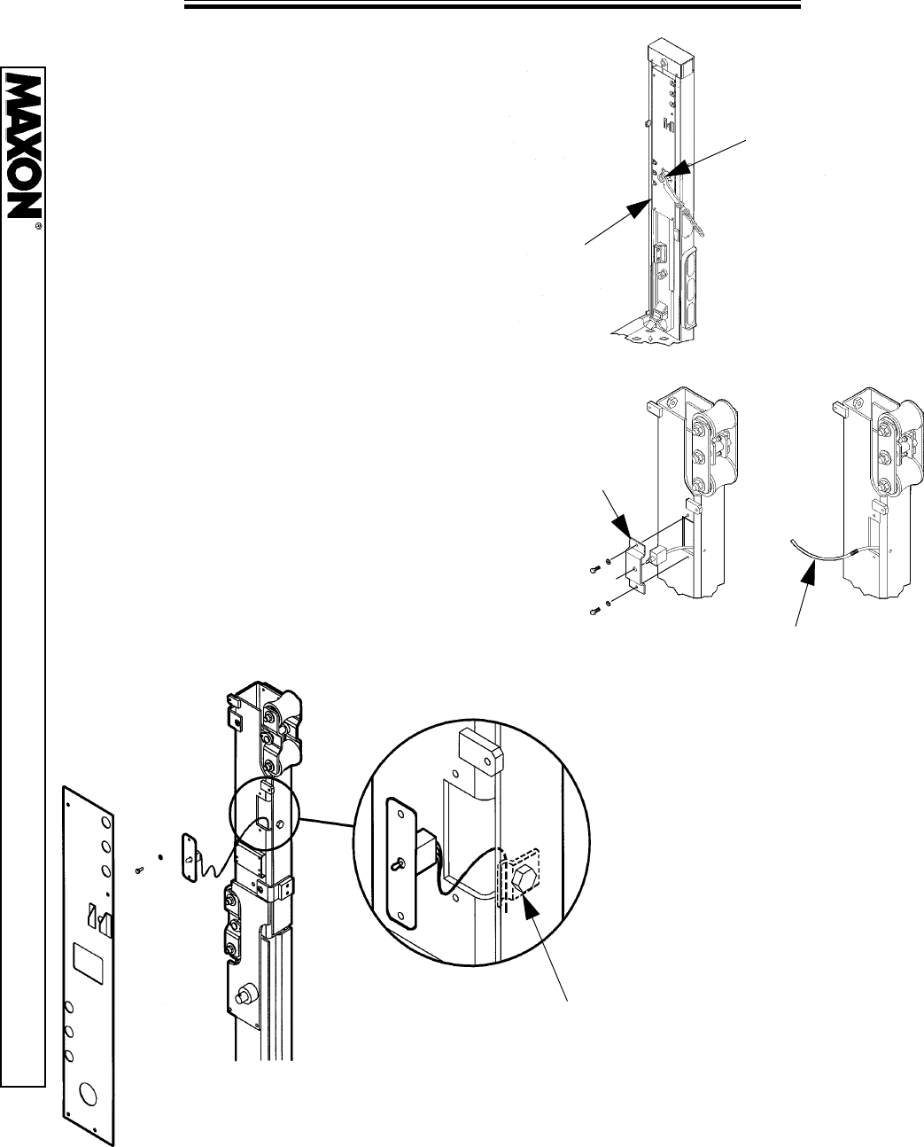
PAGE 26
SWITCH AND HARNESS REPLACEMENT
1.
Lower the Platform to the ground.
Remove the Tear Drop Assembly and the
Cover from the curb side Column.
2. Remove the Switch Plate from the
Runner Assembly, and remove the wires
from the Switch. Attach a rope or cable
(at least 20 ft. in length) to the end of the
wires from the Switch. This will become
the “Fishing Rope”, and will be used to
pull the new cable through the same route
as the original wiring.
3. Located inside the
Switch Mounting hole is a
cable clamp. Loosen, but
do not remove the nut
that fastens the clamp to
the Runner Assembly.
COVER PLATE
TEAR DROP &
CHAIN ASSEMBLY
FISHING ROPE
SWITCH
PLATE
CABLE CLAMP
11921 Slauson Ave. Santa Fe Springs, CA. 90670 (800) 227-4116 FAX (888) 771-7713
PAGE 27
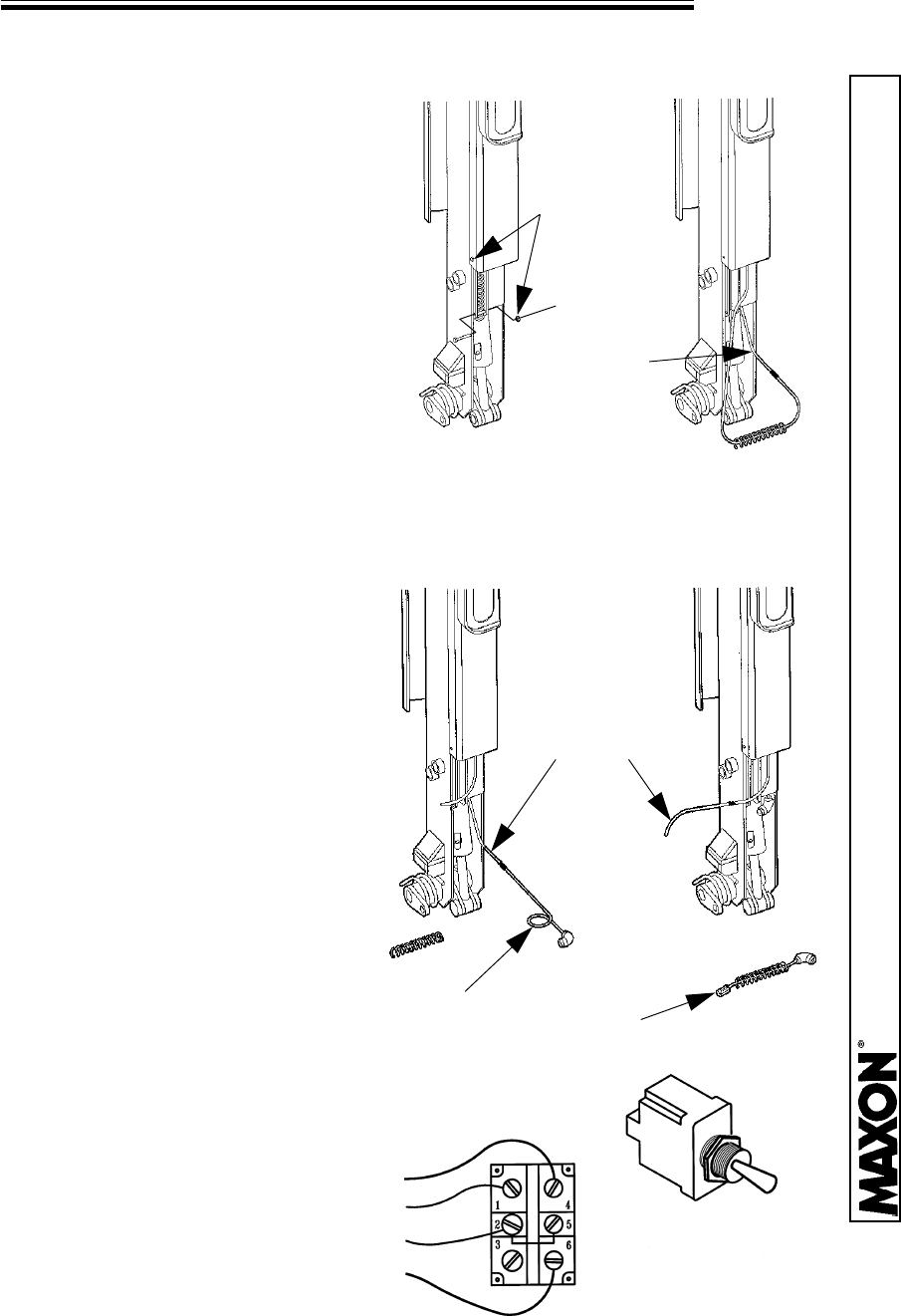
SWITCH AND HARNESS REPLACEMENT
4.
Remove the fitting from the lower port
of the Closing Cylinder. Remove the
opposite end of the hose from the bottom
of the Column. Remove the two bolts that
secure the Spring Guard to the unit. One
is located at the bottom of the Column,
the other is located between the bottom
two coils of the Spring Guard. This will
also remove a cable clamp. Set these
aside for re-assembly. The Spring Guard,
5. Remove the cable from the
fishing rope and attach the Switch
and Cable Assembly (P/N 260529
less the Switch), to the fishing
rope. Pull the rope back up
through the Runner and out the
Switch Mounting hole until the
cable is exposed. Leaving enough
slack in the cable to wire the
Switch properly, tighten the cable
clamp located just inside the
Switch Mounting hole and re-wire
the Switch per the diagram below.
Re-assemble the Switch Plate
and Cover Plate. Attach the
fishing rope to the exposed end of
the cable.
Hose Assembly, and Cable should pull out as one unit. Pull down on the cable
inside the Runner until the fishing rope is exposed.
FISHING
ROPE
P/N 260529
P/N 260533
SWITCH
RED
BLK
GRN
WHT
FISHING
ROPE
REMOVE
2 BOLTS
11921 Slauson Ave. Santa Fe Springs, CA. 90670 (800) 227-4116 FAX (888) 771-7713
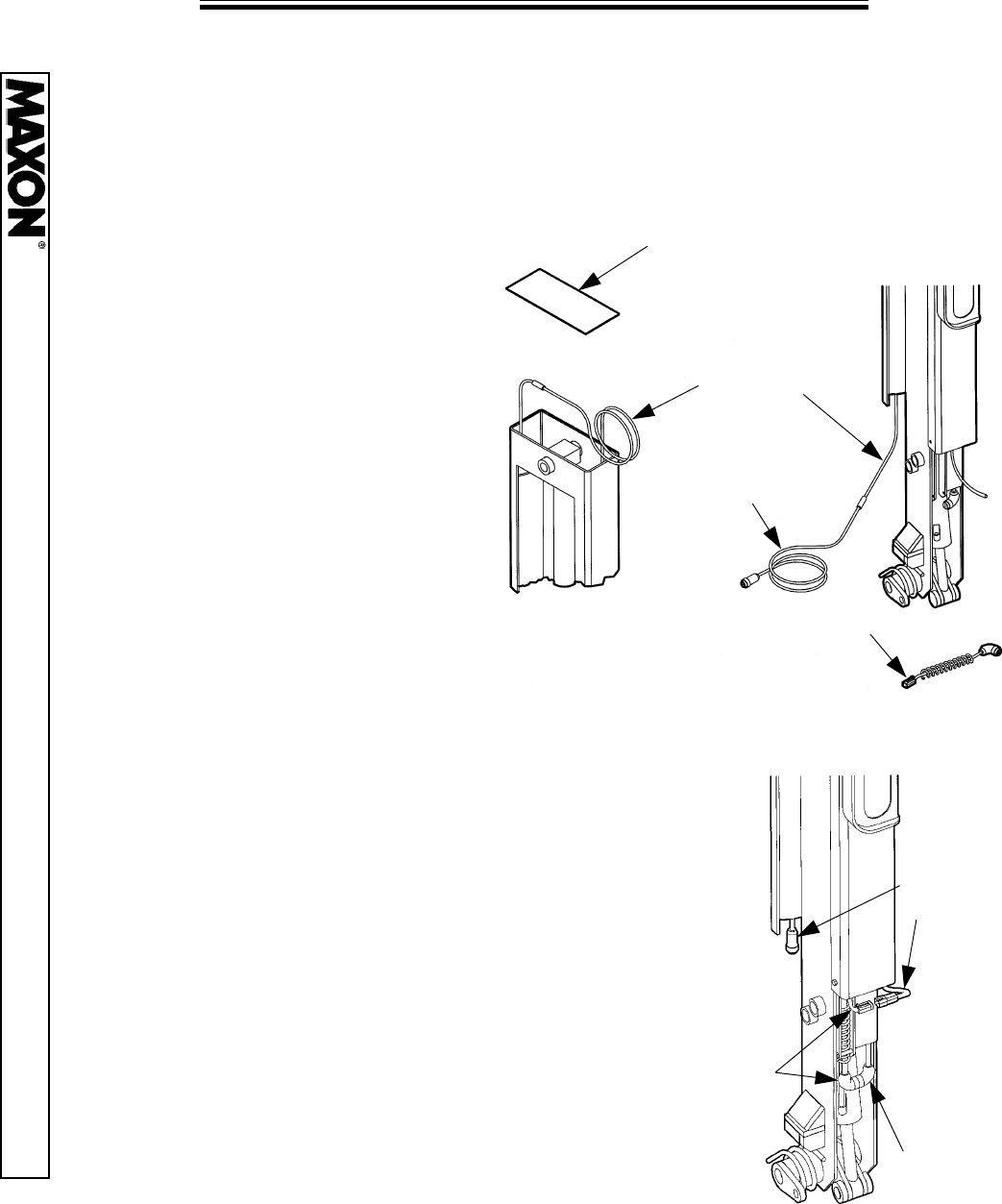
PAGE 28
SWITCH AND HARNESS REPLACEMENT
6.
Remove the middle light from a 3 light Column, or the top light on a 2 light
Column. Inside the light mounting hole near the top, loosen but do not remove
the nut that fastens the clamp to the Column, so that the cable will slide freely
through the clamp.
7. Remove the Cover from the
top of the Column. Pull the side
of the harness attached to the
fishing rope in an upward
direction until the splice is
exposed. Move to the ground
and continue pulling the harness
in a downward direction until the
splice is again exposed.
Remove the old cable and
attach the Column Cable
8. Place the Flexing Cable Assembly (P/N 260533),
and the Closing Cylinder Hose through the Spring
Guard. NOTE: Be sure the Flexing Cable is located
on the Platform side of the Spring Guard, and is
parallel, not twisted with the hydraulic hose.
Replace the Spring Guard in the Runner Channel
with the bolts, clamp and plastic tube that was
removed earlier. After attaching the Switch Cable to
the Flexing Cable, pull the Connector-Plug end of
the Flexing Cable snug through the top of the
Spring Guard. Tighten the clamp that secures the
Spring to the Runner. Replace the Closing Cylinder
hose and make the proper connections for the
Flexing Cable and the Column Cable.
Assembly (P/N 260534 less the Connector-Receptacle).
Pull the new cable through in reverse order. Replace the
Cover on the Column. Tighten the clamp in the light
mounting hole and replace the Light.
COVER PLATE
FISHING
ROPE
P/N 260534
P/N 260533
FLEXING
CABLE
SWITCH
CABLE
COLUMN
CABLE
11921 Slauson Ave. Santa Fe Springs, CA. 90670 (800) 227-4116 FAX (888) 771-7713
PAGE 29
SWITCH AND HARNESS REPLACEMENT
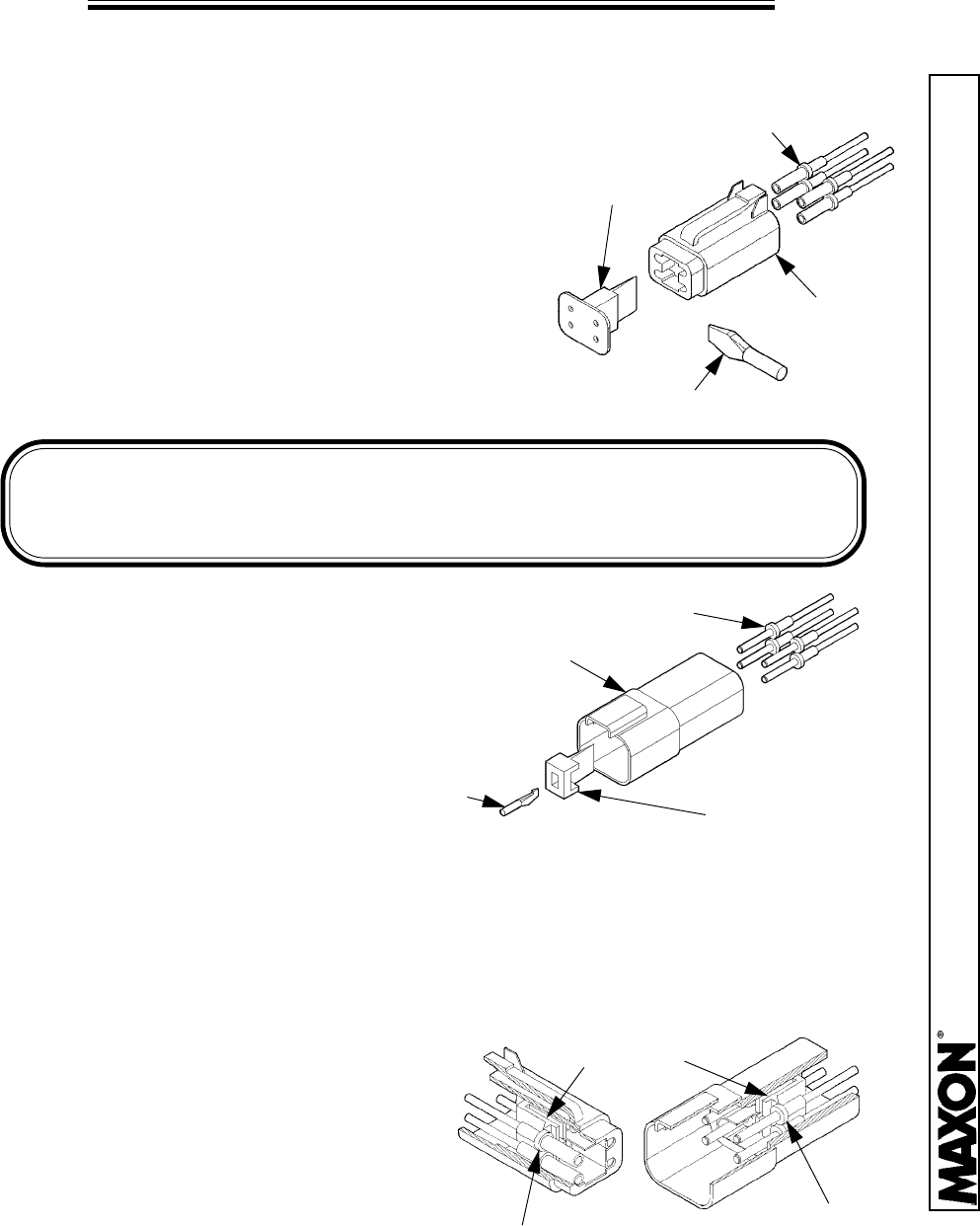
INSTALLATION OF CONTACTS
Use the DT Removal Tool (P/N 260875),
to pry between the lip of the Locking Wedge
and the Connector Plug. Then twist, popping
the Wedge free. The Locking Wedge can now
be easily removed. Push the Socket Contacts
through the Rear Seal of the Connector Plug
until it snaps into a locked position. Place the
Locking Wedge back into the origional
position and push it against the Connector
Plug.
Slide the DT Removal Tool
(P/N 260875), into the center slot
of the Locking Wedge. Rotate the
Removal Tool to grab the Wedge
from the inside and pull out with a
sharp tug. The Locking Wedge
can now be easily removed. Push
the Socket Contacts through the
Rear Seal of the Connector Plug until it snaps into a locked position. Place
the Locking Wedge back into the origional position and push it against the
Connector Receptacle.
IMPORTANT!
When placing the Contacts into the plugs and receptacles, be sure
the wire colors will match the mating plug or receptacle wire colors.
SOCKET
CONTACTS
LOCKING
WEDGE PLUG
CONNECTOR
PLUG
REMOVAL TOOL
LOCKING
WEDGE
RECEPTACLE
PIN
CONTACTS
CONNECTOR
RECEPTACLE
REMOVAL
TOOL
REMOVAL OF CONTACTS
After removing the Locking
Wedge of either the Plug or the
Receptacle, insert the DT Removal
Tool between the Contacts and the
Locking Finger. Gently push the
Locking Finger away from the
Contact while pulling the Contact and
wire free from the rear.
LOCKING
FINGER
PIN
CONTACTS
SOCKET
CONTACTS

11921 Slauson Ave. Santa Fe Springs, CA. 90670 (800) 227-4116 FAX (888) 771-7713
PAGE 30
TROUBLESHOOTING
11921 Slauson Ave. Santa Fe Springs, CA. 90670 (800) 227-4116 FAX (888) 771-7713
PAGE 31
PLATFORM WILL NOT RAISE, MOTOR WON’T RUN
1.
Check the Pump Motor
Solenoid for 12 Volts of
power from the battery. If
there is no power to the
Solenoid, check the
Battery Cables for
damage, and the Battery
for a charge. Replace or
recharge as needed.
2. Check the Solenoids in the Pump
Box and Columns for power. With the
control switch activated in the “UP”
position, only the Pump Motor Solenoid
should be energized. If any other
Solenoid is energized while in the “UP”
mode, there is damaged or improper
wiring in the Solenoids, Control Box, or
Switches. Disconnect the Runner
Switch electrical cable (4-Pin
Connector), from the Control Box and
activate the “UP” switch mounted
outside the vehicle. If the platform
raises, then the short is in the Runner
Switch Cable.
3. Check for structural damage to the liftgate. Visually inspect for improper
bending of structures that could prevent normal operation.
BATTERY CABLE
TERMINAL
PUMP MOTOR
SOLENOID
SCREWDRIVER WILL BE
MAGNETICALLY PULLED TO
AN ENERGIZED SOLENOID
1/4”
OLD STYLE
NEW STYLE
11921 Slauson Ave. Santa Fe Springs, CA. 90670 (800) 227-4116 FAX (888) 771-7713
PAGE 32
PLATFORM WILL NOT PICK UP RATED CAPACITY
1. Check the Battery Cables for damage, and the Battery for a charge.
Replace or recharge as needed. The use of a Voltage Load Tester is
recommended.
2. Check for structural damage to the liftgate. Visually inspect for improper
bending of structures that could prevent normal operation.
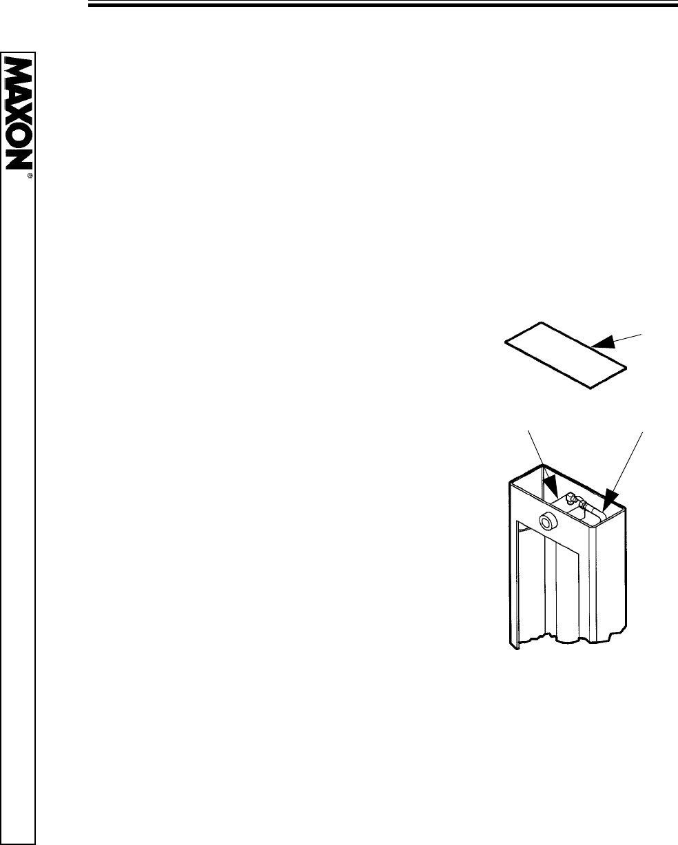
3. Check the Hydraulic Cylinders as follows:
GRAVITY DOWN UNITS: Lower the
Platform to the ground. Remove the hose
from the Top Port of each Cylinder. Raise the
Platform and see if any oil sprays out of the
fitting. If so, the Piston Seals are worn and
need replacing.
POWER DOWN UNITS: Raise the
Platform to bed height. Remove the hose
from the Top Port of each Cylinder. Raise the
Platform and see if a continuous flow of oil
escapes from the fitting. If so, the Piston
Seals are worn and need replacing.
COVER
HOSE
CYLINDER
4. Verify the correct Relief Valve Pressure Setting. Refer to the Relief Valve
Pressure Setting page for proper procedures.
11921 Slauson Ave. Santa Fe Springs, CA. 90670 (800) 227-4116 FAX (888) 771-7713
PAGE 33
PLATFORM RAISES HALFWAY & STOPS
1. Check the hydraulic fluid level in the Reservoir.
GRAVITY DOWN UNITS: Lower the Platform to the ground. Fill the Reservoir
to about 1” from the top. Do not overfill as this causes spillage.
POWER DOWN UNITS: Raise the Platform to bed height. Fill the Reservoir to
about the middle. Do not overfill as this causes spillage.
2. Check the Battery Cables for damage, and the Battery for a charge.
Replace or recharge as needed. The use of a Voltage Load Tester is
recommended. Check the Circuit Breaker. Reset or replace as needed.
3. Check for structural damage to the liftgate. Visually inspect for improper
bending of structures that could prevent normal operation. Be sure the unit
has been properly lubricated to prevent binding. Lubricate or replace worn
parts.
4. A worn Pump or clogged Pump Filter
can cause the unit to lift slowly. Check
the Pump Filter located in the
Reservoir. A worn pump will be
extremly noisy. Replace as necessary.
5. Check the Pressure Compensation
Valves located at the top of each
Column. They may be partially
plugged.
PUMP FILTER
PRESSURE
COMPENSATION
VALVE
11921 Slauson Ave. Santa Fe Springs, CA. 90670 (800) 227-4116 FAX (888) 771-7713
PAGE 34
PLATFORM LOWERS UNEVEN
1.
Lower the Platform to the ground and
remove the Pressure Compensation
Valves located at the top of each
Column. Disassemble and clean each
valve. Reinstall, or replace as necessary
using the thread Sealant Instructions on
the inside back cover of this manual.
PRESSURE
COMPENSATION
VALVE
2. Drain all the Hydraulic Oil from the Reservoir. Install a Filter Kit
(P/N 260578), between the “C” Valve and the Reservoir. Instructions
on how to do this (M-95-27), are included in the Kit. Clean or replace
the Filter if the Filter Kit is already installed.
11921 Slauson Ave. Santa Fe Springs, CA. 90670 (800) 227-4116 FAX (888) 771-7713
PAGE 35
PLATFORM WILL NOT CLOSE
1. Check the hydraulic fluid level in the Reservoir.
GRAVITY DOWN UNITS: Lower the Platform to the ground. Fill the Reservoir
to about 1” from the top. Do not overfill as this causes spillage.
POWER DOWN UNITS: Raise the Platform to bed height. Fill the Reservoir to
about the middle. Do not overfill as this causes spillage.
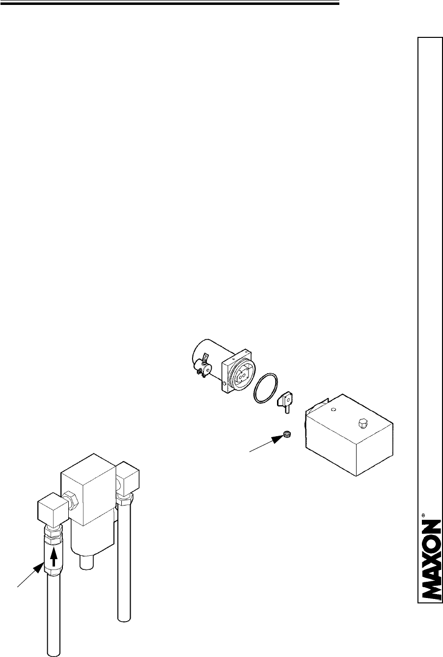
2. Check the Motor Solenoid (“M”)
for power by placing a 12 Volt Test
Lamp on terminal “A”. If nothing
registers on the Test Lamp, the
Battery or Battery Cables are
faulty. Check the Motor Solenoid
(“M”) itself by placing the 12 Volt
Test Lamp on terminal “B”. If
nothing registers on the Test
Lamp, replace the Motor Solenoid.
If power does register on the Test
Lamp, replace the Motor.
TERMINAL “A”
BATTERY CABLE
TERMINAL
PUMP MOTOR
SOLENOID (“M”)
TERMINAL
“B”
GREEN
WIRE
WHITE
WIRE
Continued Next Page
3. If the unit has an Emergency Hand Pump attached, be sure the proper
valves are closed. Refer to the Decal on the Pump for proper operation.
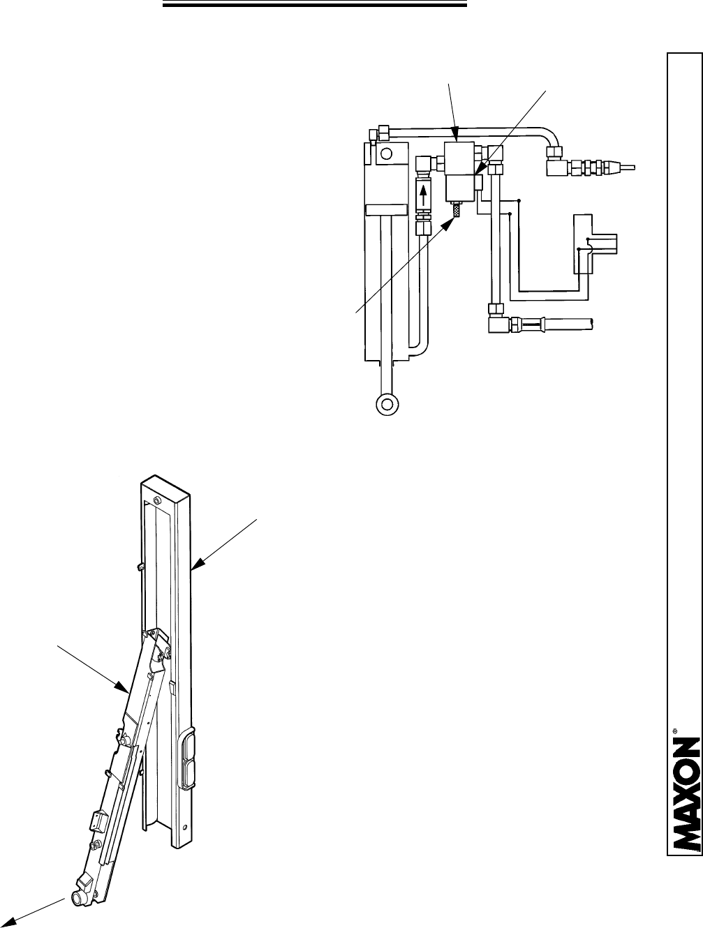
4. Check the Flow Control Valve.
This valve should be open. Adjust
as necessary for speed.
FLOW
CONTROL
VALVE
TERMINAL
“B”
WHITE WIRE
11921 Slauson Ave. Santa Fe Springs, CA. 90670 (800) 227-4116 FAX (888) 771-7713
PAGE 36
PLATFORM WILL NOT CLOSE
5. Check the “E” Valve, remove
the Valve Coil from the Valve
Cartridge. Using a paper clip,
push on the Plunger inside the
Valve Cartridge. It should move
freely approximately 1/8”. Inspect
O-Ring and wash the Cartridge in
solvent to remove any foreign
substances inside the Cartridge.
If Plunger still does not move
freely (approx. 1/8”), then replace
the Valve Cartridge.
VALVE COIL
VALVE CARTRIDGE
“A” Valve
Folding Port
“M” Valve
Motor Solenoid
“A” Valve
Folding Port
“E” Valve
4-Way Valve
“M” Valve
Motor Solenoid
“E” Valve
4-Way Valve
OLD STYLE PUMP
NEW STYLE PUMP
11921 Slauson Ave. Santa Fe Springs, CA. 90670 (800) 227-4116 FAX (888) 771-7713
PAGE 37
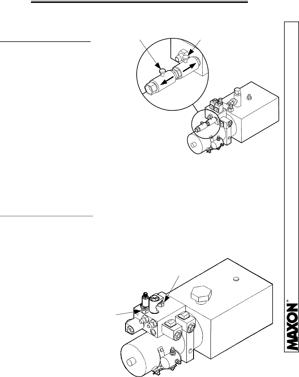
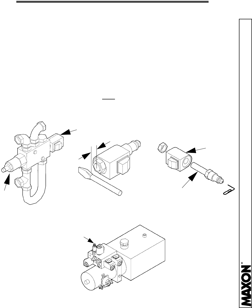
PLATFORM FOLDING SPEED ADJUSTMENT
OLD STYLE PUMP
NEW STYLE PUMP
1.
The speed settings for the
Closing Cylinder are regulated by
the Flow Control Valves located on
the “A” Port. Each Valve has an
arrow on it indicating the direction
of flow it regulates. The Valve that
points away from the Pump
controls the closing speed. The
Valve that points toward the Pump controls the
opening speed.
2. Turn the Valves clockwise to decrease the speed.
Turn the Valves counter-clockwise to increase the speed.
CLOSING SPEED
ADJUSTMENT
OPENING SPEED
ADJUSTMENT
1. The speed settings for the Closing Cylinder are regulated by the Pressure
Relief Needle Valves located on the Manifold Block. Each Valve has either an
“O” (open), or “C” (close) on it indicating the direction of flow it regulates.
2. Turn the “O” Valve clockwise
to decrease the speed. Turn the
“C” Valve clockwise to increase
the speed.
“C” VALVE
“O” VALVE
11921 Slauson Ave. Santa Fe Springs, CA. 90670 (800) 227-4116 FAX (888) 771-7713
PAGE 38
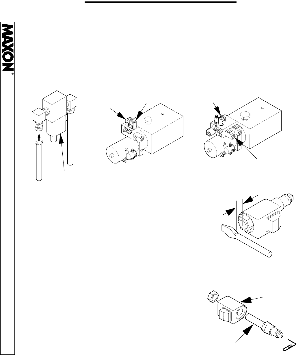
PLATFORM WILL NOT UNFOLD
“A” PORT FLOW
CONTROL VALVE
1. The flow of hydraulic oil may be restricted. Check the following:
a. OLD STYLE PUMP, turn the “A” Port Flow Control Valve nearest the
Reservoir in a counter-clockwise direction to open the valve.
b. NEW STYLE PUMP, adjust the “O” Pressure Relief Valve to open the valve.
OLD STYLE PUMP NEW STYLE PUMP
“O” PRESSURE
RELIEF VALVE
“A” SOLENOID
VALVE
1/4”
2. Check the “A” Solenoid Valve Coil for power.
Place a screwdriver about 1/4” from the “A”
Solenoid and energize the unit. If the screwdriver
is not drawn to the energized solenoid the
solenoid must be repaired or replaced.
3. Remove the Valve Coil from the Valve
Cartridge. Using a paper clip, push on the
Plunger inside the Valve Cartridge. It should
move freely approximately 1/8”. Inspect O-Ring
and wash the Cartridge in solvent to remove any
foreign substances inside the Cartridge. If
Plunger still does not move freely (approx. 1/8”),
then replace the Valve Cartridge.
VALVE
COIL
VALVE CARTRIDGE
4. Check the folding pivot points for damage or corrosion. Steam clean if
necessary. Replace bushings if necessary.
11921 Slauson Ave. Santa Fe Springs, CA. 90670 (800) 227-4116 FAX (888) 771-7713
PAGE 39
PLATFORM RAISES INSTEAD OF FOLDING
1/4”
2. Check the “E” Solenoid Valve Coil for power. Place
a screwdriver about 1/4” from the “E” Solenoid and
activate the “FOLD” function on the switch. If the
screwdriver is drawn to the energized solenoid and the
unit wants to Raise instead of Fold, the solenoid must
be repaired or replaced. If the “E” Valve is
not
energized during the “FOLD” operation of the switch,
check the electrical connections.
OLD STYLE PUMPS ONLY
“M” Valve
Motor Solenoid
“E” Valve
4-Way Valve
1. Check the Pump Motor Solenoid
for 12 Volts of power from the
battery. If there is no power to the
Solenoid, check the Battery Cables
for damage, and the Battery for a
charge. The use of a Voltage Load
Tester is recommended. Replace or
recharge as needed.
USE VOLTAGE
LOAD TESTER
HERE
GREEN
WIRE
WHITE
WIRE
“M” Valve
Motor Solenoid
3. Disconnect the Runner Switch electrical cable (4-Pin Connector), from the
Control Box and activate the “FOLD” switches mounted outside the vehicle. If
the platform folds, then the short is in the Runner Switch Cable. Repair or
replace the Harness.

11921 Slauson Ave. Santa Fe Springs, CA. 90670 (800) 227-4116 FAX (888) 771-7713
PAGE 40
TROUBLESHOOTING
GRAVITY DOWN
11921 Slauson Ave. Santa Fe Springs, CA. 90670 (800) 227-4116 FAX (888) 771-7713
PAGE 41
PLATFORM WILL NOT RAISE, MOTOR RUNS
1. Check the hydraulic fluid level in the Reservoir. Lower the opened Platform
to the ground. Fill the Reservoir to about 1” from the top. Do not overfill as this
causes spillage.
2. Check the Relief Valve for contamination or defective operation. Lower the
Platform to the ground.
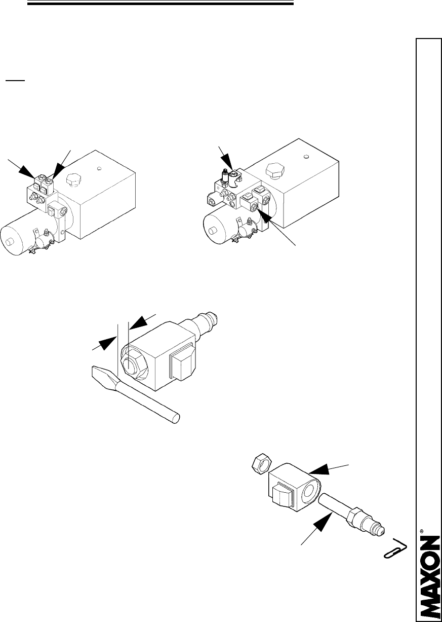
OLD STYLE PUMP: Check the “C” Valve to see if it is stuck in the open
position. Place a screwdriver about 1/4” from end of solenoid. It should be
magnetically drawn to the Solenoid only when the switch is activated in the
“DOWN” position. Remove the “C” Valve body and clean or replace as
necessary. Remove the Relief Valve and clean or replace.
1/4”
VALVE
COIL
VALVE CARTRIDGE
“C”
VALVE
RELIEF
VALVE
NEW STYLE PUMP: Remove the Relief Valve and clean or replace.
RELIEF VALVE
3. Adjust the pressure per the “Relief Valve Pressure Setting” page.
11921 Slauson Ave. Santa Fe Springs, CA. 90670 (800) 227-4116 FAX (888) 771-7713
PAGE 42
PLATFORM WILL NOT LOWER
1. Check the Battery Cables for damage, and the Battery for a charge.
Replace or recharge as needed. The use of a Voltage Load Tester is
recommended.
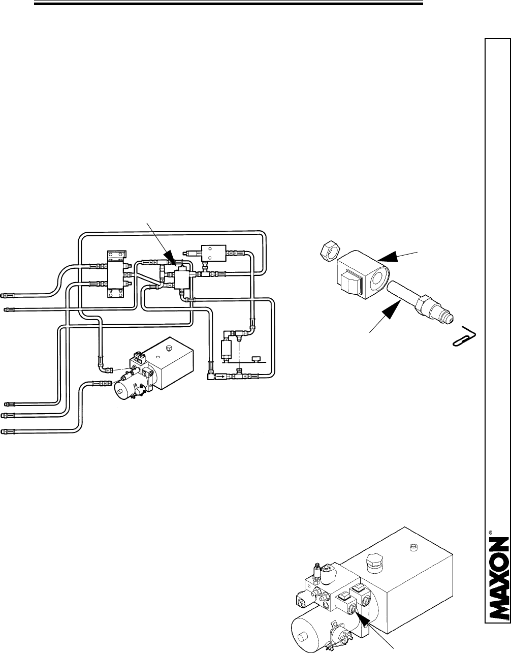
2. Check the two “D” Solenoid Valve Coils (located at the top of each
Column), and the “B” and “C” Valve Coils (located in the Pump Box), for
power.
1/4”
VALVE
COIL
VALVE CARTRIDGE
Place a screwdriver about 1/4” from the Solenoid and
energize the unit. If the screwdriver is not drawn to
the energized solenoid the solenoid must be repaired
or replaced.
SOLENOID
“B”
SOLENOID
“B”
SOLENOID
“D”
SOLENOID
“C”
SOLENOID
“C”
3. To clean the Valve, remove the Valve Coil
from the Valve Cartridge. Using a paper clip,
push on the Plunger inside the Valve
Cartridge. It should move freely approximately
1/8”. Inspect O-Ring and wash the Cartridge in
solvent to remove any foreign substances
inside the Cartridge. If Plunger still does not
move freely (approx. 1/8”), then replace the
Valve Cartridge.
11921 Slauson Ave. Santa Fe Springs, CA. 90670 (800) 227-4116 FAX (888) 771-7713
PAGE 43
PLATFORM LOWERS SLOWLY
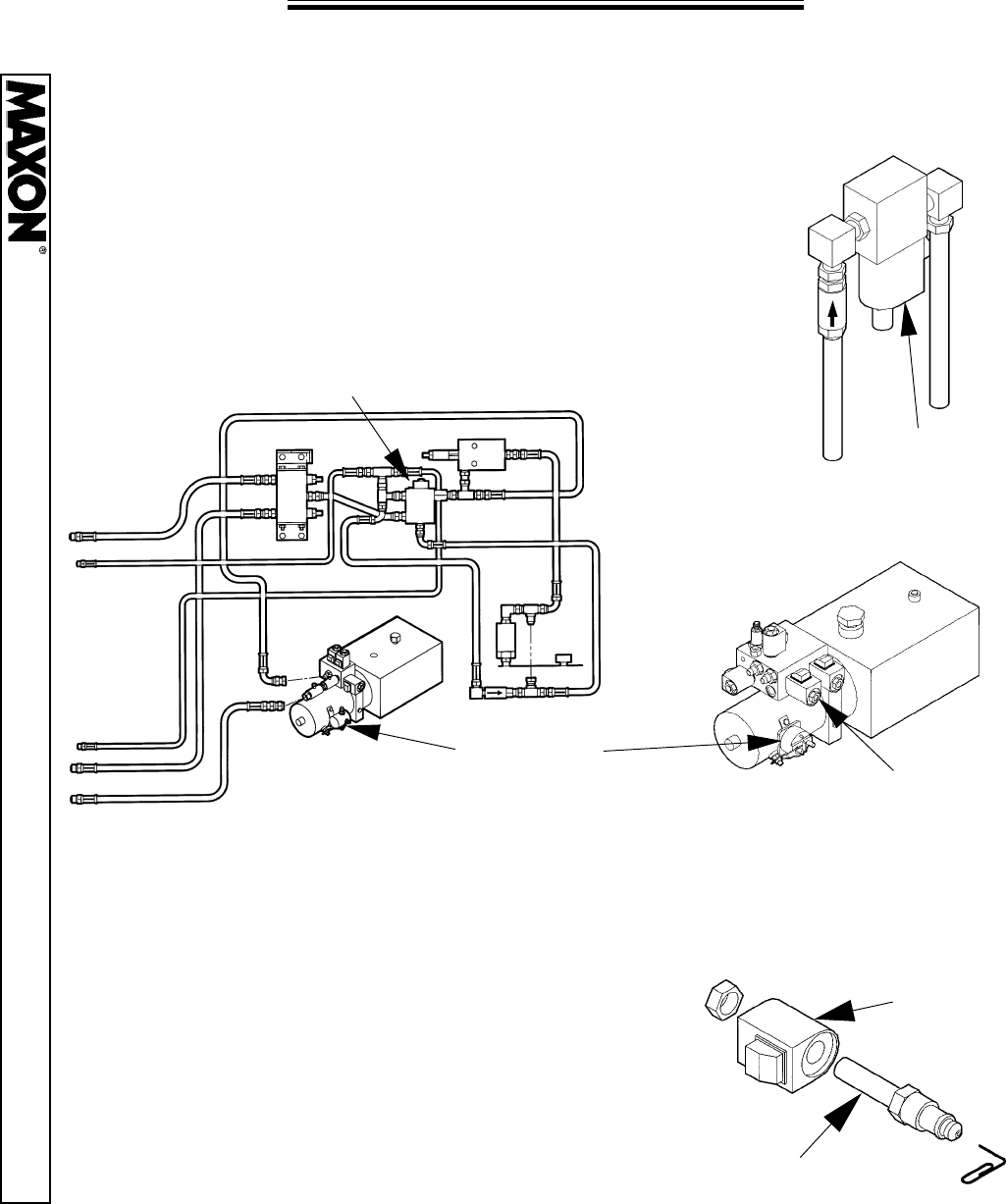
1. Check the “B” and “C” Valve Coils (located in the Pump Box), for power.
Place a screwdriver about 1/4” from the Solenoid and energize the unit. If the
screwdriver is
not drawn to the energized solenoid the solenoid must be
repaired or replaced.
1/4”
VALVE
COIL
VALVE CARTRIDGE
SOLENOID
“B”
SOLENOID
“B”
SOLENOID
“C”
SOLENOID
“C”
2. To clean the Valve, remove the Valve Coil from
the Valve Cartridge. Using a paper clip, push on
the Plunger inside the Valve Cartridge. It should
move freely approximately 1/8”. Inspect O-Ring
and wash the Cartridge in solvent to remove any
foreign substances inside the Cartridge. If Plunger
still does not move freely (approx. 1/8”), then
replace the Valve Cartridge.
OLD STYLE PUMP NEW STYLE PUMP
3. Check the Pressure Compensation Valves. (Ref. Platform Lowers Uneven)

11921 Slauson Ave. Santa Fe Springs, CA. 90670 (800) 227-4116 FAX (888) 771-7713
PAGE 44
TROUBLESHOOTING
POWER DOWN
11921 Slauson Ave. Santa Fe Springs, CA. 90670 (800) 227-4116 FAX (888) 771-7713
PAGE 45
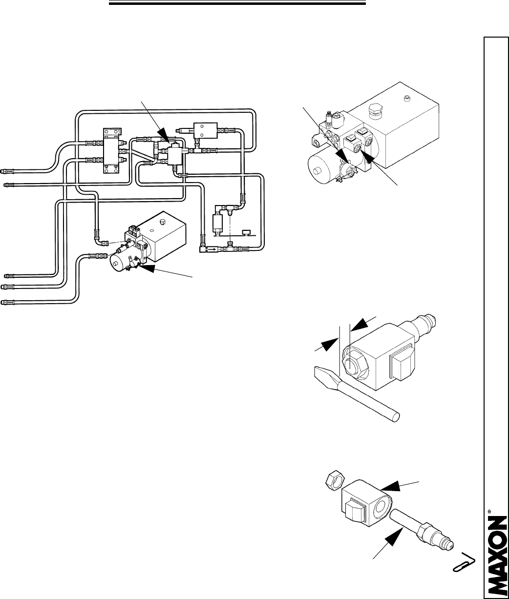
PLATFORM WILL NOT RAISE, MOTOR RUNS
1. Raise the Platform to bed height. Fill the Reservoir to about the middle. Do
not overfill as this causes spillage.
2. The Motor Solenoid (“M”) Valve should be the only solenoid energized
during the “RAISE” function. Verify that no other Solenoid is energized.
3. The 4-Way Solenoid Valve may be stuck in the “open” position.
OLD STYLE PUMPS: Verify that the “F” Solenoid Valve is not energized
during the “RAISE” function. Remove the “F” Solenoid Valve Body and clean.
To clean the Valve, remove the Valve Coil from the Valve Cartridge. Using a
paper clip, push on the Plunger inside the Valve Cartridge. It should move
freely approximately 1/8”. Inspect O-Ring and wash the Cartridge in solvent to
remove any foreign substances inside the Cartridge. If Plunger still does not
move freely (approx. 1/8”), then replace the Valve Cartridge.
NEW STYLE PUMPS: Verify that the “C”
Solenoid Valve is not energized during the
“RAISE” function. Remove the “C” Solenoid
Valve Body and clean.
SOLENOID
“C”
SOLENOID
“F”
F
VALVE
COIL
VALVE CARTRIDGE
11921 Slauson Ave. Santa Fe Springs, CA. 90670 (800) 227-4116 FAX (888) 771-7713
PAGE 46
PLATFORM WILL NOT LOWER
1.
Check the Battery Cables for damage, and the Battery for a charge.
Replace or recharge as needed. The use of a Voltage Load Tester is
recommended.
2. Check the following Solenoids for power: the two “D”
Solenoid Valve Coils (located at the top of each Column),
the “M” Motor Solenoid Valves, and the “4-Way” Solenoid
Valves (located in the Pump Box).
VALVE
COIL
VALVE CARTRIDGE
SOLENOID
“D”
3. To clean the Valve, remove the Valve Coil
from the Valve Cartridge. Using a paper clip,
push on the Plunger inside the Valve
Cartridge. It should move freely approximately
1/8”. Inspect O-Ring and wash the Cartridge in
solvent to remove any foreign substances
inside the Cartridge. If Plunger still does not
move freely (approx. 1/8”), then replace the
Valve Cartridge.
4-WAY
SOLENOID “F”
F
OLD STYLE PUMP
SOLENOID
“M”
4-WAY
SOLENOID “C”
NEW STYLE PUMP
11921 Slauson Ave. Santa Fe Springs, CA. 90670 (800) 227-4116 FAX (888) 771-7713
PAGE 47
PLATFORM LOWERS SLOWLY
1/4”
VALVE
COIL
VALVE CARTRIDGE
3. To clean the Valve, remove the Valve Coil from
the Valve Cartridge. Using a paper clip, push on
the Plunger inside the Valve Cartridge. It should
move freely approximately 1/8”. Inspect O-Ring
and wash the Cartridge in solvent to remove any
foreign substances inside the Cartridge. If Plunger
still does not move freely (approx. 1/8”), then
replace the Valve Cartridge.
OLD STYLE PUMP
4. Check the Pressure Compensation Valves. (Ref. Platform Lowers Uneven)
1. Check the “M” Motor Solenoid Valves, and the “4-Way” Solenoid Valves
(located in the Pump Box), for power.
4-WAY
SOLENOID “F”
F
SOLENOID
“M”
4-WAY
SOLENOID “C”
NEW STYLE PUMP
SOLENOID
“M”
2. Check the Solenoid Valve Coil for power.
Place a screwdriver about 1/4” from the Solenoid
and energize the unit. If the screwdriver is not
drawn to the energized solenoid the solenoid
must be repaired or replaced.
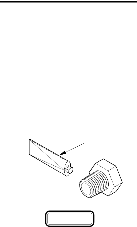
LIQUID SEALANT APPLICATION
Clean all threads with a soft brush and a suitable cleaning solvent.
Dry threads thoroughly with compressed air or shop towel.
Apply the Liquid Sealant (Compound PLS 2), to the external threads of
the Male Connector.
Assemble the fitting and torque it to the prescribed value.
Check for leakage. If leakage exists, remove the fitting and return to
Step # 1.
If fitting is loosened or removed, return to Step # 1.
1.
2.
3.
4.
5.
6.
P/N 260798-02
CAUTION
Due to the 80% lead content in PLS 2, follow these safety and first aid
precautions:
Eye Contact - Flush eyes immediately with large quantities of water,
lifting the upper and lower eyelids occasionally. If irritation persists, con-
sult a physician.
Skin Contact - Flush the contaminated skin and wash with soap and
water.
Ingestion - If person is conscious, give large quantities of water to drink
and induce vomiting. Consult a physician immediately.
