
4
ENGINEERING
447
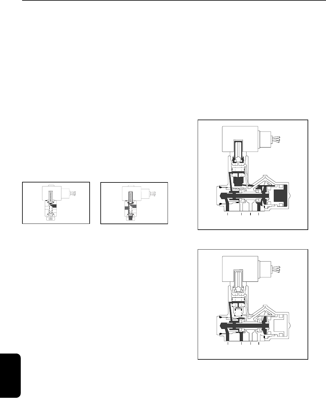
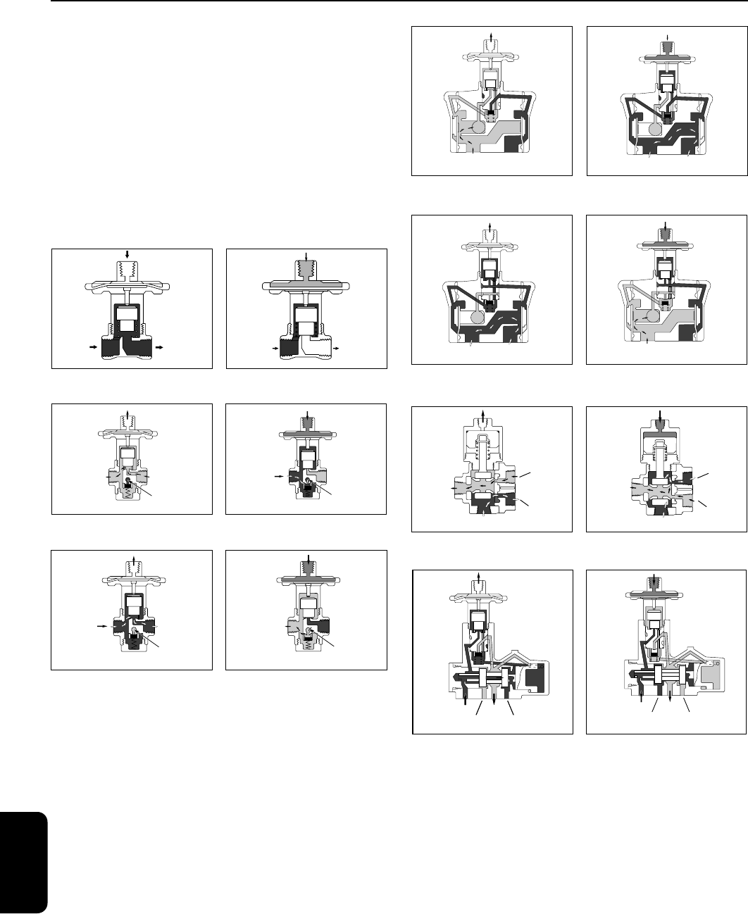
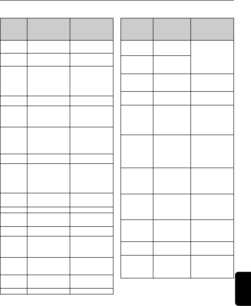
Figure 1A:
Direct Acting,
Normally Closed Valve,
De-Energized
Figure 1B:
Direct Acting,
Normally Closed Valve,
Energized
Figure 2A:
Pilot Operated, Normally
Closed Valve,
De-Energized
Figure 2B:
Pilot Operated,
Normally Closed Valve,
Energized
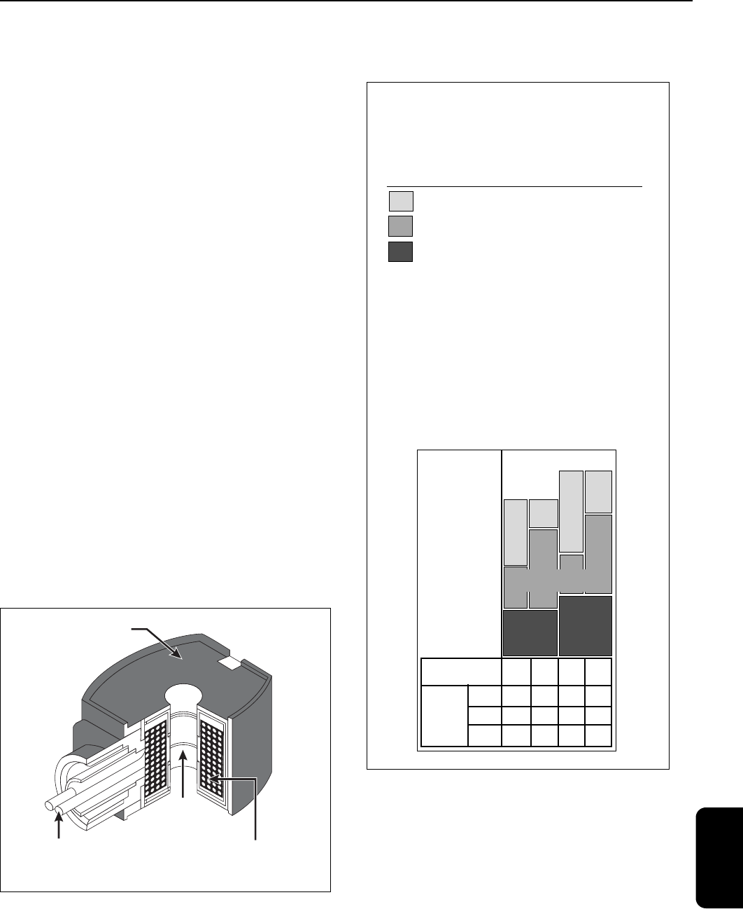
Figure 3A:
Pilot Operated, Normally
Closed Valve,
De-Energized
Figure 3B:
Pilot Operated,
Normally Closed Valve,
Energized
Figure 4A:
No Voltage Release
Manual Reset Valve,
Un-Latched, De-Energized
Figure 4B:
No Voltage Release
Manual Reset Valve,
Latched, Energized
A solenoid valve is a combination of two basic
functional units:
• A solenoid (electromagnet) with its core
• A valve body containing one or more orifices
Flow through an orifice is shut off or allowed by
the movement of the core when the solenoid is
energized or de-energized. ASCO valves have a
solenoid mounted directly on the valve body. The
core is enclosed in a sealed tube, providing a
compact, leaktight assembly.
Direct Acting Valves (Figures 1A, 1B)
When the solenoid is energized in a direct acting
valve, the core directly opens the orifice of a
Normally Closed valve or closes the orifice of a
Normally Open valve. When de-energized, a
spring returns the valve to its original position.
The valve will operate at pressures from 0 psi to
its rated maximum.
The force needed to open the valve is proportional
to the orifice size and fluid pressure. As the orifice
size increases, so does the force required. To open
large orifices while keeping solenoid size small, a
Pilot Operated construction is used.
Internal Pilot Operated Valves
(Figures 2A, 2B)
Normally, these valves have a pilot and bleed
orifice which enable them to use line pressure for
operation.
When the solenoid is de-energized, the pilot orifice
is closed and full line pressure is applied to the top
of the piston or diaphragm through the bleed
orifice, providing seating force for tight closure.
When the solenoid is energized, the core opens
the pilot orifice, relieving pressure from the top of
the piston or diaphragm via the outlet side of the
valve. The line pressure then opens the valve by
lifting the diaphragm or piston off the main orifice.
Two constructions are available for 2-way valves:
• Floating diaphragm or piston which requires a
minimum pressure drop across the valve to remain
in the open position (Figures 2A, 2B).
• Hung-type diaphragm or piston held open
mechanically by the solenoid core.
The valve
opens and remains open with zero pressure drop
(Figures 3A, 3B).
Manual Reset Valves
(Figures 4A, 4B)
Manual reset valves must be manually latched into
position and will return to their original position
only when the solenoid has been energized or
de-energized, depending on construction
Engineering Information
Solenoid Valves
Principles of Operation
Solenoid Valves
EngineeringR2
4
ENGINEERING
448
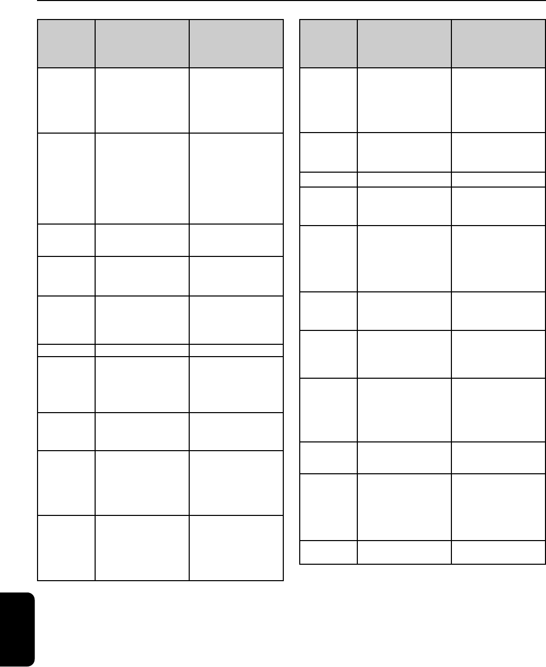
1 Cyl.
2 Press.
3 Exh.
Figure 5A:
Three-Way
Normally Closed Valve,
De-Energized
1 Cyl.
2 Press.
3 Exh.
Figure 5B:
Three-Way
Normally Closed Valve,
Energized
2-Way Valves
(Figures 1A, 1B, 2A, 2B, 3A, 3B)
Two-way valves have one inlet and one outlet pipe
connection. They are used to allow or shut off fluid
flow, and are available in either:
Normally Closed – closed when de-energized and
open when energized.
Normally Open – open when de-energized and
closed when energized.
3-Way Valves
(Figures 5A, 5B)
Three-way valves have three pipe connections
and two orifices (when one is open, the other is
closed, and vice versa). They are commonly used
to alternately apply pressure to and exhaust pres-
sure from the diaphragm operator of a control
valve, single -acting cylinder, or rotary actuator.
Three modes of operation are available:
Normally Closed – when the valve is de-energized,
the pressure port is closed and the cylinder port is
connected to the exhaust port. When the valve is
energized, the pressure port is connected to the
cylinder port and the exhaust port is closed.
Normally Open – when the valve is de-energized,
the pressure port is connected to the cylinder port
and the exhaust port is closed. When the valve is
energized, the pressure port is closed and the
cylinder port is connected to the exhaust port.
Universal – allows the valve to be connected in
either the Normally Closed or Normally Open
position to select one of two fluids or to divert flow
from one port to another.
4-Way Valves
(Figures 6A, 6B)
Four-way valves are generally used to operate
double-acting cylinders or actuators. They have
four or five pipe connections: one pressure, two
cylinder, and one or two exhausts. In Position A,
pressure is connected to one cylinder port, the
other is connected to exhaust. In Position B,
pressure and exhaust are reversed at the cylinder
ports.
Press. Cyl.
A
Cyl.
B
Exh.
Figure 6A:
Four-Way Valve, De-Energized
Figure 6B:
Four-Way Valve, Energized
Press. Cyl.
A
Cyl.
B
Exh.
Types of Solenoid Valves
Engineering Information
Solenoid Valves
EngineeringR2
4
ENGINEERING
449
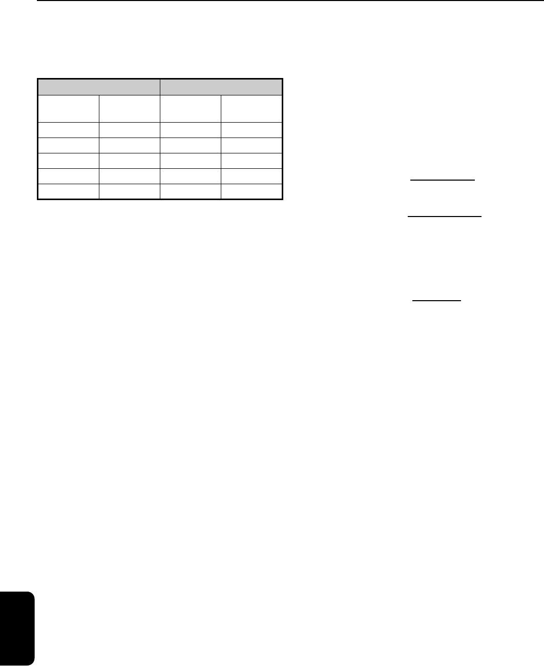
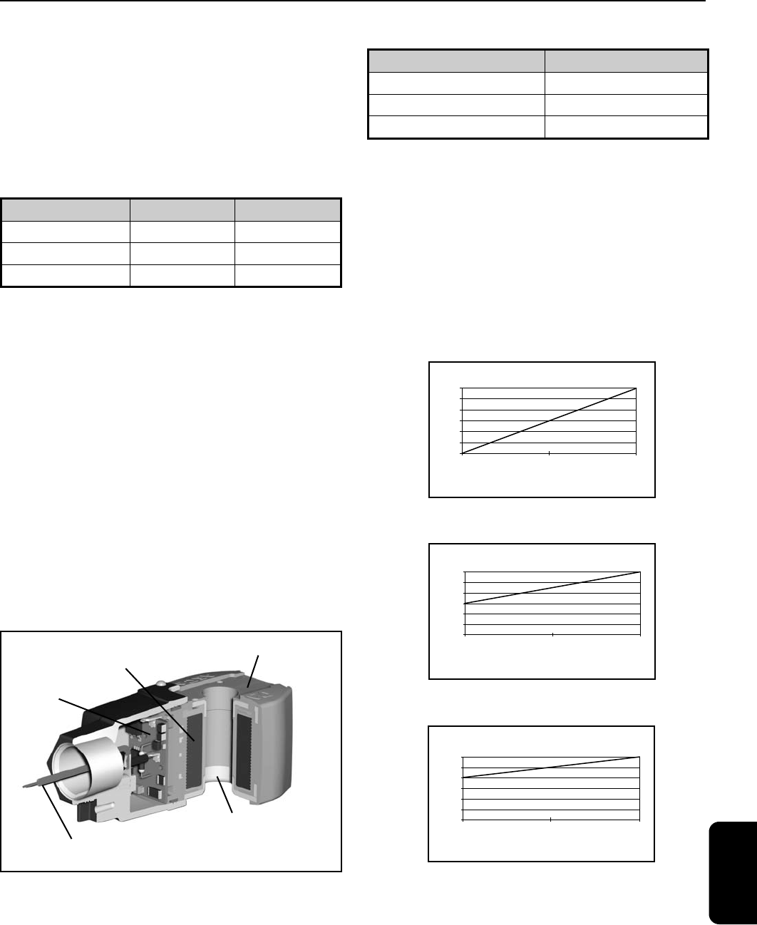
MAGNET WIRE
Class F: 392˚F (200˚C)
Class H: 392˚F (200˚C)
or 428˚F (220˚C)
UL and CSA LISTED
600 VOLT LEADS
LEAD WIRE
6 STRAND 18 AWG
PE COATED
EPOXY
ENCAPSULATION
BOBBIN
Class F and H
PPS
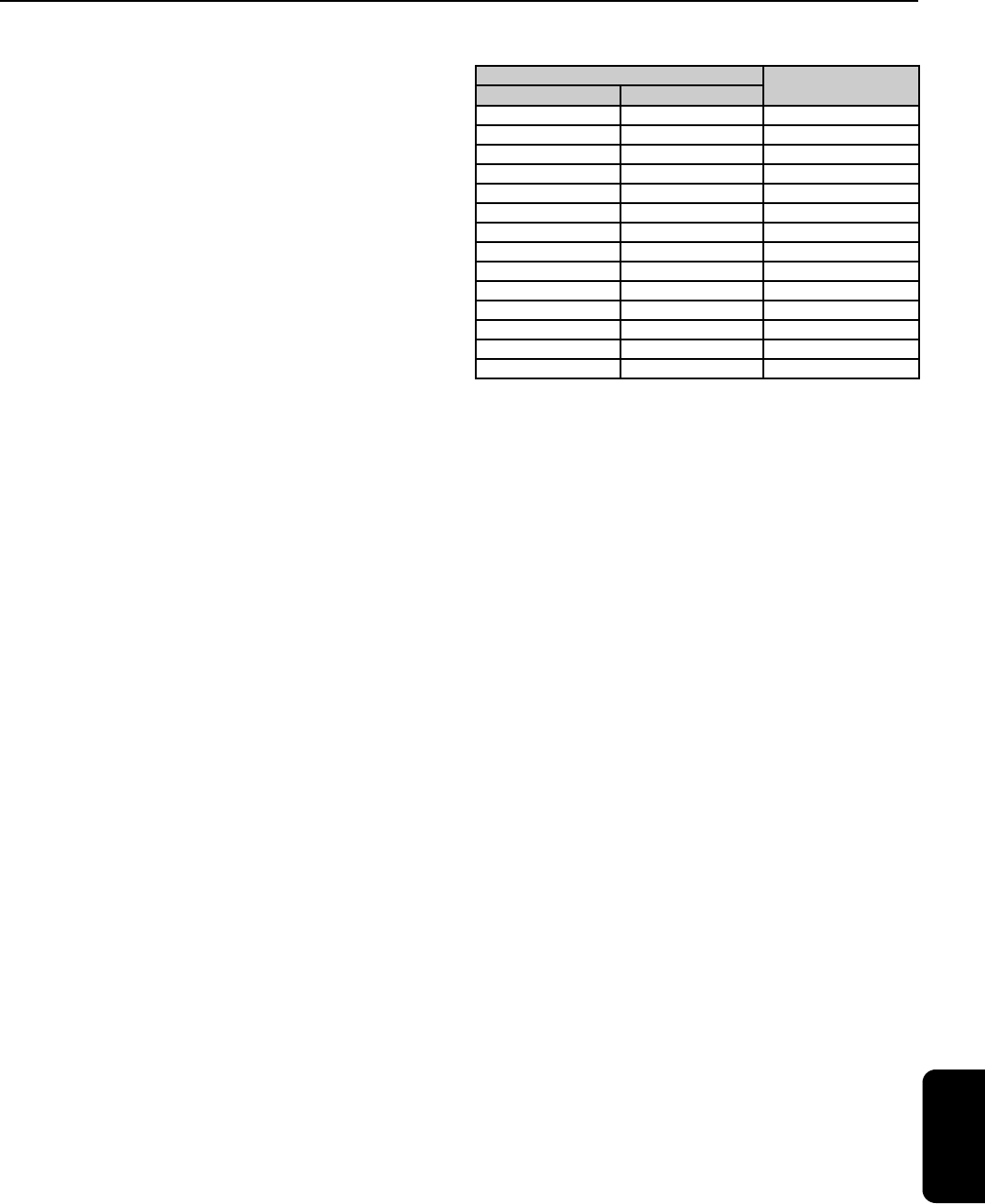
Coil Insulation Systems and
Temperature Limitations
RedHat II Solenoid Class F 311°F (155°C) and Class H 356°F (180°C)
Final Temperature °C (°F)
Class “F”
Limit
Class “H” Limit
Coil Class
Typical
AC
Wattage
Rating
M6
MXX
M12
FT FB HT HB
6.1 9.1 6.1 9.1
10.1 17.1 10.1 17.1
Ambient
Ambient
200
(356
°F) 180
160
(311
°F) 155
(284
°F) 140
(266
°F) 130
120
(212
°F) 100
(194
°F) 90
80
(140
°F) 60
(125
°F) 51.6
40
20
0
Temperature Rise from
Power Input
16.1 20.1 16.1 20.1
Industrial Temperature Limitations
and Thermal Characteristics of
ASCO RedHat II Solenoids and Coils
The typical watt ratings given show the relationship
between different classes of coil insulation and the
watt ratings to achieve higher temperature capabilites.
The information contained in these tables applies only to
Non-Explosionproof, AC constructions.
Excess margin for higher fluid or ambient temperature
Listed ambient
Temperature rise due to power input
Notes:
As measured by the “Resistance Method.”
Ambient temperatures are directly additive to coil rise —
fluid temperature is not.
For M-6, 50 Hz wattage values, add 2 watts to the
indicated values.
Because of explosionproof codes and surface temperature
limitations, the maximum listed ambients for specific valves
should not be exceeded.
Consult factory concerning
explosionproof applications where higher-than-listed ambients
are encountered.
Maximum temperatures shown are industrial limits. For UL
limits, subtract 27°F (15°C) for Class F coils and 36°F (20°C)
for Class H coils.
AC Ambient Capabilities
Solenoid Coils (Non-Electronic*)
Except where noted, all ASCO valves are
equipped with coils which can be energized con-
tinuously without danger of overheating or failure.
Standard coils have 18" leads which can be con-
nected to any controlling device. Spade, screw
terminal, and DIN-type spade connector coils are
also available. For three phase power systems, the
two leads can be connected to any two of the
three phases.
All coils are constructed in accordance with
Underwriters Laboratories Inc., NEMA, IEEE, and
other industrial standards ASCO Class B, F, and
H insulation systems are UL listed in the
Recognized Component Index (yellow book)
under Guide No. OBJY2.
For AC ambient capabilities, see chart to the right.
DC ambient capabilities are 104°F (40°C), or 131˚F
(55˚C) for RedHat II depending on construction.
These ambients are based on a minimum available
voltage of 85% of nominal. If minimum available
voltage is greater, a higher ambient limitation may
be possible.
Consult factory for details.
Solenoid
Engineering Information
Solenoid Valves
* See Pages 469-472 for RedHat Next Generation
Electronic coils.
EngineeringR2
4
ENGINEERING
450
Coil Operating Voltage Ranges
All coils are designed for industrial operating voltages
and can be used on the following voltage ranges:
Note: Special coils are required for battery charging
circuits where wider voltage ranges are typically
encountered. For these applications, special
continuous duty Class H coils are available that will
accom modate a voltage range equivalent to 12%
over nominal, 28% under nominal, and a 140°F
(60°C) ambient. Standard nominal voltages are
125 and 250 DC, which translate to a voltage
range of 90-140 and 180-280, respectively. Add
prefix “HC” to the catalog number. “HC” prefix is
only applicable to valves with coil classes FT and
HT.
Consult factory for other constructions.
Most ASCO valves, depending upon construction,
will operate at 15% under nominal voltage and
maximum operating pressure differential, and are
capable of operating for short periods at 10% over
nominal voltage. For coil classes other than FT and
HT, over voltage is not recommended.
For wider
voltage ranges than shown here or for operating
voltage ranges for specific catalog numbers,
please consult your local ASCO sales office.
Power Consumption
Power consumption can be determined from the
ratings shown on individual Series pages. For AC
valves, the watts, volt-ampere “inrush” (the high
momentary surge occurring at coil energization),
and volt-ampere “holding” (the continuous draw
following inrush) are given.
The current rating for inrush and holding may be
determined by dividing the voltage into the
volt-amp rating:
Notes:
1. When a valve has been energized for a long
period, the solenoid becomes hot and can be
touched by hand for only an instant. This is a
perfectly safe operating temperature. Any excessive
heating will be indicated by smoke and the odor
of burning coil insulation.
2. Valves for AC service can be converted to
other AC voltages simply by changing the coil.
Similarly, DC valves can be converted to other
DC voltages.
When converting from AC to DC, or
vice versa, consult your local ASCO sales office
for instructions.
Solenoid Constructions
Internal parts in contact with fluids are of
non-magnetic 300 and magnetic 400 series stainless
steel. In AC constructions, the shading coil is
normally copper, except that silver is mostly used in
valves with stainless steel bodies. Other materials
are available, when required. In DC constructions,
no shading coil is required. Typically, the core
tubes are of 300 series stainless steel.
DC valves have no inrush current. The amp rating
can be determined by dividing the voltage into
the DC watt rating:
Engineering Information
Solenoid Valves
AC DC
Nominal
Voltage Rating
Normal
Operating Range
Nominal
Voltage Rating
Normal
Operating Range
24 20-24 6 5.1-6.3
120 102-120 12 10.2-12.6
— — 24 20-25
240 204-240 120 102-126
480 408-480 240 204-252
Inrush
Amps
volt-amp inrush
voltage
=
Holding
Amps
volt-amp holding
voltage
=
Amps
watts (DC)
voltage
=
EngineeringR2

4
ENGINEERING
451
Solenoid Enclosures
ASCO offers two types of enclosures, each for a
variety of applications: a one-piece molded
epoxy construc tion called the RedHat II solenoid
and a conventional RedHat metallic construction.
Both meet ICS-6 ANSI/NEMA, and UL Standards
429, 508, and/or 1002. These standards define
enclosure protection levels and the tests passed
to earn each Type designation. (
See Page 469 for
RedHat Next Generation Solenoid Enclosures).
RedHat II
RedHat II solenoid enclosures are of one-piece
molded epoxy construction, with an integral 1/2"
NPT conduit hub. This epoxy encapsulation serves
as the enclosure. The magnetic frame is molded
into the coil.
RedHat II solenoids are offered as Type 1
General
Purpose or Type 7 (A, B, C, and D) Explosionproof.
Type 1 – Solenoids are green and come equipped
with three 18" long leads (the green lead is a
ground wire). Also available as options are 1/4"
spade connectors, screw terminals, and DIN-type
terminals meeting ISO 4400 and DIN Standard 43650.
An optional junction box/terminal coil construction
is also available for use with spade and screw
terminal constructions.
Refer to the “Optional
Features” Section for details.
Type 7 – Solenoids are black and are available
only in the leaded construction.
All RedHat II solenoids also meet the requirements
for Types 2 Dripproof, 3 and 3S Raintight, and 4
and 4X Watertight-Corrosion Resistant.
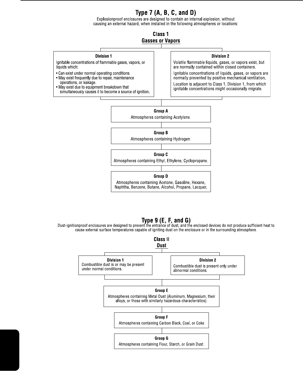
The Following wattages carry Type 7 and Type 9
approvals as shown; for
Enclosure Classifications and Types
Engineering Information
Solenoid Valves
Wattage
Type 7
Class I, Div. 1 & 2
Gas Groups
Type 9
Class II, Div. 1
Dust Groups
6.1, 10.1, 17.1 A, B, C, D E, F, G
16.1, 20.1 A, B, C, D E, F
10.6, 11,6 A, B, C, D E, F, G
Type 1 General Purpose
Intended for indoor use, primarily
to provide protection for enclosed
parts in locations without unusual
service conditions.
Type 2 Dripproof
Intended for indoor use, primarily
to provide protection against limited
amounts of falling water or dirt.
Type 3
Raintight, Dusttight,
and Sleet (Ice)
Resistant
Intended for outdoor use, primarily
to provide protection against wind-
blown dust, rain, and sleet;
undamaged by the formation of ice
on the enclosure.
Type 3S
Raintight, Dusttight,
and Sleet (Ice)
Resistant
Intended for outdoor use, primarily
to provide protection against wind-
blown dust, rain, and sleet; external
mechanism remains operable when
ice laden.
Type 3R
Rainproof, Sleet (Ice)
Resistant
Intended for outdoor use, primarily
to provide protection against falling
rain and sleet; undamaged by the
formation of ice on the enclosure.
Type 4
Watertight and
Dusttight
Intended for indoor or outdoor
use to provide protection against
splashing water, water seepage,
falling or hose-directed water, and
severe external condensation;
undamaged by the formation of ice
on the enclosure.
Type 4X
Watertight, Dusttight,
and Corrosion
Resistant
Same as Type 4, but provides addi-
tional protection to resist corrosion.
Type 6 Submersible
Intended for indoor or outdoor use
to provide protection against entry
of water during submersion at a
limited depth. (Tested to 6’ for 30
minutes.)
Type 6P Submersible
Same as Type 6 Enclosure, but
provides prolonged submersion
protection at a limited depth.
(Tested to 6’ for 24 hours.)
Type 7 &
Type 9
Refer to charts on next page.
EngineeringR2
4
ENGINEERING
452
Engineering Information
Solenoid Valves
EngineeringR2
4
ENGINEERING
453
RedHat Metallic Enclosures
Conventional metallic enclosures are offered to
meet Type I General Purpose enclosure applications
and Type 7 (C and D) Explosionproof enclosure
applications .
Type 1 — General Purpose metallic enclosures are
epoxy-painted, zinc-coated steel with a 7/8" diameter
hole to accept standard conduit hubs or connectors.
Type 7 (C and D) — Explosionproof metallic enclo-
sures are epoxy-painted, zinc-plated steel or die-cast
aluminum with a 1/2" threaded conduit hub.
Type 7 enclosures also meet Type 3 (Raintight) require-
ments as well as some also meet Type 7 (C and D)
Explosionproof and Type 9 (E, F, and G) Dust-
Ignitionproof requirements for Class I, Division 1,
Groups C and D; Class I, Division 2, Groups C and D;
and Class II, Division 1, Groups E, F, and G.
Please
contact your local ASCO sales office for details.
Also available as options are: Type 3R (Rainproof),
Type 4 and 4X (Watertight), Type 6 (Submersible),
Type 7B (Explosionproof for Hydrogen Atmospheres,
Class I, Division 1, Group B), as well as Splice Box
enclosures.
Please contact your local ASCO sales
office for details on these options.
Note: Metallic solenoid enclosures provide part of
the magnetic circuit for the solenoid. Removal will
affect valve operation.
Hazardous Location Solenoid Temperature
Range Codes
Hazardous location solenoids are marked to indicate
the maximum exposed surface temperature or
temperature indicating code. This temperature is
based on the maximum obtained in the temperature
or burnout (blocked core) tests, whichever is higher,
at a minimum ambient of 104°F (40°C) or at the
rated maximum ambient temperature.
To prevent ignition of hazardous atmospheres, do
not install in areas where vapors or gases having
ignition temperatures lower than the marked
temperatures are present.
The operating temperatures for each indicating
code are shown in the following chart:
Most RedHat II solenoids and/or solenoid valves
are marked:
“To prevent fire or explosion, do not install where
ignition temperature of hazardous atmosphere is less
than 329°F (165°C). Open circuit before disassembly .”
This corresponds to code number T3B.
Valves with Class H solenoids and valves used on
steam service are marked:
“To prevent fire or explosion, do not install where
ignition temperature of hazardous atmosphere is less
than 356°F (180°C). Open circuit before disassembly .”
This corresponds to code number T3A.
The Class II, Group F, Dust Location designation is
not applicable for solenoids and/or solenoid
valves used for steam service, or when a Class H
solenoid is used.
RedHat II Explosionproof solenoids include an
internal, non-resettable thermal fuse to limit sole-
noid temperature in the event that extraordinary
conditions occur which could cause excessive
temperatures. These conditions include high
input voltage, a jammed valve, excessive ambi-
ent temperature, shorted coil, etc. This unique
feature is standard only in RedHat II solenoids.
When used on valves having fluid temperature
ratings exceeding 250°F (121°C), consult ASCO
for applicable enclosure class, groups and
temperature range codes. For temperature
range codes of optional solenoids and features,
or if a better temperature range code is desired,
consult your local ASCO sales office.
Operating Temp. Range Indicating Code No.
Engineering Information
Solenoid Valves
Note: Except where otherwise noted in specific Series, all RedHat
metallic enclosure solenoids have temperature range Code T3C.
Maximum Temperature
Code NumberDegrees in C Degrees in F
450 842 T1
300 572 T2
280 536 T2A
260 500 T2B
230 446 T2C
215 419 T2D
200 392 T3
180 356 T3A
165 329 T3B
160 320 T3C
135 275 T4
120 248 T4A
100 212 T5
85 185 T6
EngineeringR2

4
ENGINEERING
454
Maximum Operating Pressure Differential
(M.O.P.D.)
The maximum operating pressure differential refers
to the maximum difference in pressure between the
inlet and outlet, against which the solenoid can
safely operate the valve. If the pressure at the valve
outlet is not known, it is safest to regard supply
pressure as the M.O.P.D.
Minimum Operating Pressure Differential
The minimum operating pressure differential is
that which is required to open the valve and keep
it open. For 2-way valves with a floating piston or
diaphragm, the valve will start to close below the
minimum operating differential pressure. For 3
and 4-way pilot valves, the minimum operating
pressure is measured between the pressure and
exhaust ports, and must be maintained through-
out the operating cycle to ensure complete
transfer from one position to the other.
Note: Direct acting, hung diaphragm or hung piston valves do not
require a minimum pressure, but may not yield maximum flow on low
pressure differentials.
Safe Working Pressure
Safe working pressure is the line or system pressure
to which the valve may be subjected without being
damaged.
Contact the factory or your local ASCO
sales office if you require this value.
Proof Pressure
Proof pressure is five times the safe working pres-
sure.
Contact the factory or your local ASCO sales
office if you require this value.
Operating Pressures
Minimum Ambient Temperature
The nominal limitation of 32°F (0°C) is advisable for
any valve that might contain moisture (water vapor).
Where freezing water is not a factor, minimum
ambience as low as 0°F (-18°C) can be tolerated. In
addition, special constructions are available for
ambient temperatures down to -40°F (-40°C).
Consult your local sales office with your specific needs.
Ambient Temperatures*
Response time from fully closed to fully open or
vice versa depends on the valve size and operat-
ing mode, electrical service, fluids, temperature,
inlet pressure, and pressure drop. The response
time for AC valves on air service, under average
conditions, can be generalized as follows:
Small direct acting valves: 5 to 10 milliseconds.
Large direct acting valves: 20 to 40 milliseconds.
Internal pilot operated valves:
1. Small diaphragm types: 15 to 50 milliseconds.
2. Large diaphragm types: 50 to 75 milliseconds.
3. Small piston types: 75 to 100 milliseconds.
4. Large piston types: 100 to 150 milliseconds
Generally speaking, operation on liquids has rela-
tively little effect on small direct acting valves;
however, response time of large direct acting and
internally piloted valves will slow by 50% to 100%.
Response time of DC valves will be 50% slower
than equivalent AC valves. For specific response
time on any critical-timing applications, response
time can be reduced to meet specific requirements.
*
See Page 469 for RedHat Next Generation
Solenoid Valves).
Response Times*
Engineering Information
Solenoid Valves
Maximum Ambient Temperature
The nominal maximum ambient temperatures listed
are based primarily on test conditions used by
Underwriters Laboratories, Inc. for setting safe limits
for coil insulation. They are determined under con-
tinuously energized conditions and with maximum
fluid temperatures in the valves. Actual conditions,
in many applications, will permit use at considerably
higher ambient temperatures. In addition, modifica-
tions to standard constructions are available to
extend maximum ambient temperature limitations.
Consult your local ASCO sales office with your
specific needs.
EngineeringR2

4
ENGINEERING
455
STEM
SEAL
Figure 7
Figure 8A: Instrument Air
Pressure Range Operator
Figure 8B: Pneumatic Range
Operator
Exh.
Outlet
Inlet
Figure 9A: Normally Closed,
Direct Acting, Air Operated
Valve with Operator
Exhausted
Press.
Outlet
Inlet
Figure 9B: Normally Closed,
Direct Acting, Air Operated
Valve with Operator
Pressurized
Exh.
Outlet
Inlet
Figure 10A: Normally
Closed, Internal,
Pilot Operated Valve with
Operator Exhausted
Press.
Outlet
Inlet
Figure 10B: Normally
Closed, Internal,
Pilot Operated Valve with
Operator Pressurized
An air operated valve has two basic functional units:
An operator with a diaphragm or piston assembly
which, when pressurized, develops a force to operate
A valve containing an orifice in which a disc or plug is
positioned via air pressure to stop or allow flow
Operators
Two operators are offered in this catalog, each
having a pressure range to suit various industrial
requirements: instrument air range 3 to 30 psi
(0.2 to 2.1 bar) and pneumatic range 30 to 125
psi (2.1 to 8.6 bar).
When a particular valve is selected, any pressure
within its pressure range will operate the valve,
regardless of variations in the main line pressure.
Control air for the operator
is completely isolated from
the main line fluid by a
unique seal arrangement
(see Figure 7). This permits
a wide range of main line
fluids to be handled .
The instrument air pressure range operator utilizes
a diaphragm (see Figure 8A) for operation, while
the pneumatic range operator has a piston (see
Figure 8B). By applying pressure to and exhaust-
ing pressure from the operator, the main valve will
open or close.
Direct Acting Valves (Figures 9A, 9B)
In a direct acting valve, the operator stem is
moved by the diaphragm or piston and directly
opens or closes the orifice, depending on whether
the operator is pressurized or exhausted. The
valve will operate from zero psi to its maximum
rated pressure.
Internal Pilot Operated Valves (Figure 10A, 10B)
This valve is equipped with a pilot and bleed ori-
fice and uses the line pressure for operation.
When the operator is pressurized, it opens the
pilot orifice and releases pressure from the top of
the valve piston or diaphragm to the outlet side of
the valve. This results in unbalanced pressure,
which causes the line pressure to lift the piston or
diaphragm off the main orifice, thereby opening
the valve. When the operator is exhausted, the
pilot orifice is closed and full line pressure is
applied to the top of the valve piston or
diaphragm through the bleed orifice, providing a
seating force for tight closure.
Two types of construction are available:
Floating diaphragm or piston, which requires a
minimum pressure drop to hold it in the open position .
Hung type diaphragm or piston, which is
mechanically held open and
operates from
zero to the maximum pressure rating.
Principles of Operation
Engineering Information
Air Operated Valves
Air Operated Valves
EngineeringR2
4
ENGINEERING
456
Flow
1
(Cyl.)
2
(Press.)
3
(Exh.)
Figure 12A: Normally Open,
Operator Exhausted
Flow
1
(Cyl.)
2
(Exh.)
3
(Press.)
Inlet
Outlet
Figure 11A: Normally Open,
Operator Exhausted
Inlet
Outlet
Figure 11B: Normally Open,
Operator Pressurized
Exh.
Cyl. Press.
Figure 13A: Normally Closed,
Operator Exhausted
Exh.
Cyl. Press.
Figure 13C: Normally Open,
Operator Exhausted
Cyl. B
Press.
Exh.
Cyl. A
Figure 14A: Operator
Exhausted
Press.
Cyl. B
Exh.
Cyl. A
Figure 14C: Operator
Exhausted
Flow
1
(Cyl.)
2
(Press.)
3
(Exh.)
Flow
1
(Cyl.)
2
(Exh.)
3
(Press.)
Figure 12B: Normally Open,
Operator Pressurized
Figure 12C: Normally
Closed, Operator Exhausted
Figure 12D: Normally
Closed, Operator
Pressurized
Cyl. Press.
Exh.
Press.
Cyl. B
Exh.
Cyl. A
Figure 14D: Operator
Pressurized
Press.
Exh.
Cyl. B
Cyl. A
Figure 14B: Operator
Pressurized
Exh.
Cyl. Press.
Figure 13D: Normally Open,
Operator Pressurized
Figure 13B: Normally Closed,
Operator Pressurized
2-Way Valves:
Normally closed and normally open operation.
Figures 9A, 9B, 10A, 10B, 11A, 11B.
3-Way Valves:
Normally closed, normally open and universal
operation. Figures 12A-D, 13A-D.
4-Way Valves:
Figures 14A-D
Minimum Operating Pressure Differential
The minimum operating pressure differential is
that which is required to open the valve and to
keep it open. Two way valves with floating piston
or diaphragm will start to close below the mini-
mum differential pressure. Three and four way
pilot valves must maintain the minimum operating
pressure throughout the operating cycle to ensure
complete transfer from one position to the other.
Maximum Operating Pressure
Maximum operating pressure is the highest pres-
sure at the inlet side of the valve, against which the
operator can operate the valve. This pressure may
be much less than the maximum safety rating of
the valve body.
Note: Direct acting valves do not require a minimum pressure.
Types of Air Operated Valves
Operating Pressures
Engineering Information
Air Operated Valves
EngineeringR2
4
ENGINEERING
457
UL, FM, CSA listings and compliance to applicable CE
directives have been indicated for each Series in this
catalog. Listing codes and other information follow in
this section.
In addition to approvals with the standard features and
for the standard voltages listed in each Series, many
valves with optional features and other voltages have
also been approved.
Consult your local ASCO sales
office for details.
Agency Valve Classifications and Code Reference
General Purpose Valve – a Normally Open or Normally
Closed valve intended to control the fluid flow, but not to
be depended upon to act as a safety valve. This is a UL
and CSA classification, and is not intended to indicate
valve service or application.
Safety Shutoff Valve
– a Normally Closed valve of the
“on” and “off” type, intended to be actuated by a
safety control or emergency device, to prevent unsafe
fluid delivery. It may also be used as a General Purpose
valve. A multiple port valve may be designated as a
Safety Shutoff valve only with respect to its Normally
Closed port. This is a UL, FM, and CSA valve classifica-
tion.
Safety shutoff valves are listed in UL index
under Guide YIOZ or YIOZ2 for ordinary locations
and YTSX or YTSX2 for hazardous locations.
Process Control Valve – an FM approved valve to
control flammable gases, not to be relied upon as a
Safety Shutoff valve. Refer to note under individual
valve listing. Unless otherwise stated under the
individual Series numbers, valves are listed as General
Purpose valves.
Underwriters Laboratories, Inc.
UL standards governing solenoid valves are:
UL429, “Electrically Operated Valves,”
UL1002, “Electrically Operated Valves
for Use in Hazardous Locations.”
UL1604, “Electrical Equipment for use in Class
I and II, Division 2 and Class III Hazardous
Classified Locations.”
UL provides two “Listing” categories for solenoid valves:
General Use. Valves authorized for general use are
complete in their requirements; therefore, they may be
installed in the field. They are identified by the UL
symbol, followed by the word “Listed” and the valve
classification. UL Listings for ASCO “General Use”
valves and solenoids can be found in the “UL Gas and
Oil
Equipment Directory” under Electrically Operated
Valves, Guide No. YIOZ or YI0Z2 (File MP-618), and
in the “UL Hazardous Location Equipment List”
under Electric Valves, Guide No. YTSX or YTSX2
(File E25549) or under Solenoids, Guide No. VAPT
(File E12264).
Component. Valves in this category are
intended for use as factory-installed
components of equipment where final
acceptability must be determined by
UL. They are not intended for installation in the field.
Component valves are termed “UL Recognized” and
use UL’s special Recognized Component mark. UL
Listings of ASCO Component Valves can be found in
the “UL Recognized Component Index” under
Electrically Operated Valves, Guide No. YIOZ2 and
YSY12 (File MP-618).
Canadian Standards Association
Standard C22.2 No. 139, “Electrically
Operated Valves,” covers the standards
governing solenoid valves.
Standard C22.2 No. 213, “Electrical equipment
for use in Class I, Division 2 hazardous locations.”
CSA certified valves and solenoids are listed in the
“CSA Certified Electrical Equipment Book” under
Valves, Guide No. 440-A-0 (File 10381) and Guide
No. 440-A-0.8 (File 13976).
Factor y Mutual Research
Corporation
FM “approves” and lists in the
“Factory Mutual Approval Guide”
fuel oil and fuel gas safety shutoff
valves, process control valves, explosionproof /
dust-ignitionproof, and intrinsically safe valves for
hazardous locations. Valves designated for other
fluids and operational characteristics, although not
subject to FM approval, are usually “accepted” by
FM on specific equipment installations.
Approval Listing Code and Information
Engineering Information
Approvals
Approvals
&
EngineeringR2

4
ENGINEERING
458
Industrial Risk Insurers (Formerly FIA)
Industrial Risk Insurers does not approve equipment. It
established “recommended good practices” in such
areas as combustion safeguards on single-burner
boiler -furnaces, and safeguarding Class B and Class C
furnaces and ovens. Conforming to these practices
results in either insurability for fire protection or in
more advantageous rates for their protection.
To meet the standards of good practice, safety
controls must be either listed by Underwriters
Laboratories, accepted by Industrial Risk Insurers
or other nationally recognized testing laboratories
(NRTL). The National Fire Protection Association
(NFPA) maintains similar requirements and recom-
mendations for safety shutoff and vent valves in oil
and gas burner boiler systems.
European Directives – CE
The Council of the European
Communities, under the treaty
establishing the European
Community (EC), adopted into law a series of
directives to harmonize technical standards.
Solenoid valves are controlled by:
EMC (Electomagnetic Capability) 2004/108/EC
Low Voltage 2006/95/EC
ASCO valves complying to these directives,
through third-party or self-certification, display
the CE mark on the nameplate or coil and on the
Instruction and Maintenance sheet packaged with
each valve. On request, ASCO will issue a
Declaration of Incorporation and/or Declaration
of Conformity for the valve supplied.
ASCO’s Quality Assurance Program meets all the
requirements of
ISO-9001:2008
. We are also
certified to IQ Net, providing customers with the
products from 17 ISO-certified facilities around
the world. The US, Canada, UK, France, the
Netherlands, Germany, and Japan are included.
When desired, ASCO solenoid valves can be
supplied to meet the additional requirements of
a variety of approval agencies around the world.
The following can be requested.
Consult your
local ASCO sales office for details.
United States of America
AGA American Gas Association
ANSI American National Standards Institute, Inc.
CSA Canadian Standards Association
(Certified to US Standards)
EIA Electronic Industries Association
ETL Electronic Testing Laboratory
FM Factory Mutual Research Corporation
IEEE Institute of Electrical and Electronics Engineers, Inc.
IRI
Industrial Risk Insurers (formerly Factory Insurance Association
)
JIC Joint Industrial Council
MIL Military Standards
MSHA Mine Safety and Health Administration
NACE National Association of Corrosion Engineers
NAVSEA Naval Sea Systems Command
NEC National Electric Code
NEMA National Electrical Manufacturers Association
NFPA National Fire Protection Association
NFPA National Fluid Power Association, Inc.
NSF National Sanitation Foundation
UL Underwriters Laboratories, Inc.
USCG United States Coast Guard
Engineering Information
Approvals
Agency Approvals – Worldwide
EngineeringR2

4
ENGINEERING
459
European Economic Community
CE European Directives
CEE International Commission on Rules for the
Approval of Electrical Equipment
ATEX Directive 94/9/EC
Apparatus for Potentially Explosive Atmospheres
(ATmospheres EXplosibles)
IEC International Electrotechnical Commission
ISO International Organization for Standardization
Austria
TÜV-A Technischer Überwachungs-Verein Österreich
BVFA Bunderversuchs-und Forschungsanstalt Arsenal
ETI Elektrotechnisches Institut
Australia
AGA Australian Gas Association
SAA Standards Association of Australia
Belgium
CEB Comite Electrotechnique Belge
IBN Institut Belge de Normalisation
ISSEP Institut Scientifique de Service Public
(anciennement INIEX)
K.V.B.G. Koninklijke Vereniging der Belgische
Gasvaklieden
VERGAS Technische Vereniging van de Gasindustrie in
Belgie V.Z.W.D.
Brazil
INMETRO Instituto Nacional de Metrologia
Canada
CGA Canadian Gas Association
CSA Canadian Standards Association
EEMAC Electrical and Electronic Manufacturers
Association of Canada
ULC Underwriters Laboratories of Canada
China
NEPSI National Supervision and Inspection Center for
Explosion Protection and Safety of Instrumentation
CCC China Compulsory Certification
Denmark
DEMKO Danmarks Elektriske Materielkontrol
Finland
SL Sähkötarkastuslaitos Laboratoria
VTT Technical Research Centre of Finland
France
AFNOR Association Française de Normalisation
INERIS Institut National de l’Environnement In dustriel et
des Risques (anciennement CERCHAR)
Bureau Veritas
LCIE Laboratoire Central des Industries Electriques
MDIS Ministère du Développement Industrial et
Scientifique
Germany
BVS Bergbau-Versuchsstrecke
DIN Deutsches Institut für Normung
DVGW
Deutscher Verein des Gas – Und Wasserfaches e.V.
Germanischer Lloyd
PTB Physikalisch – Technische Bundesanstalt
VDE Verband Deutscher Electrotechniker
Italy
CEI Comitato Elettrotecnico Italiano
Japan
JEM Japan Electrical Manufacturers Association
JIS Japanese Industrial Standards
MIL Ministry of Labor
NK Japan Maritime Association
RIIS Research Institute of Industrial Safety,
Department of Labor
Korea
KISCO Korea Industrial Safety Corp.
KGSG Korea Gas Safety Corp.
Luxembourg
Service de l’énergie de l’état
Northern Ireland
Industrial Science Centre, Department of Economic Development
Norway
Det Norske Veritas
NEMKO
Norges Elektriske Materiellkontroll
Russia
USSR Register of Shipping
South Africa
SABS South African Bureau of Standards
Spain
CESI Centro Elettrotecnico Sperimentale Italiano
LOM Laboratorio Oficial José Maria Madariaga
Sweden
SEMKO Svenska Elektriska Material Kontrollanstalen
SP Swedish National Testing and Research Institute
Switzerland
ASE Association Suisse des Electriciens
SEV Schweizerischer Electrotechnischer Verein
The Netherlands
DGA Direktoraat – Generaal van de Arbeid
KEMA Koningklijk Instituut voor het Testen van
Elektrische Materialen N.V.
NEC Nederlands Elektrotechnisch Comité
NNI Nederlands Normalisatie – Instituut
REGO Richtlijnen Voor de Samenstelling van Elektrisch
Material In Verband Met Gasontploffinsgevaar
VEG VEG-Gasistituut N.V.
VGN Veriniging van Gasfabrikanten In Nederland
United Kingdom
BASEEFA
British Approvals Service for Electrical
Equipment in Flammable Atmospheres
BGC British Gas Corporation
BSI British Standard Institution
EECS Electrical Equipment Certification Service
(BASEEFA)
Lloyds Register of Shipping
MRS Midlands Research Station
NWC National Water Council
SCS Sira Certification Service
SFA Special Flammable Atmospheres
WH Watson House
Engineering Information
Solenoid Valves
EngineeringR2
4
ENGINEERING
460
Improper sizing of a solenoid valve results in below-
stan dard performance and can involve unnecessary
cost.
The basic factors in valve sizing include:
Maximum and minimum flows to be controlled
Maximum and minimum pressure differential
across the valve
Specific gravity, temperature, and viscosity of
fluids being controlled
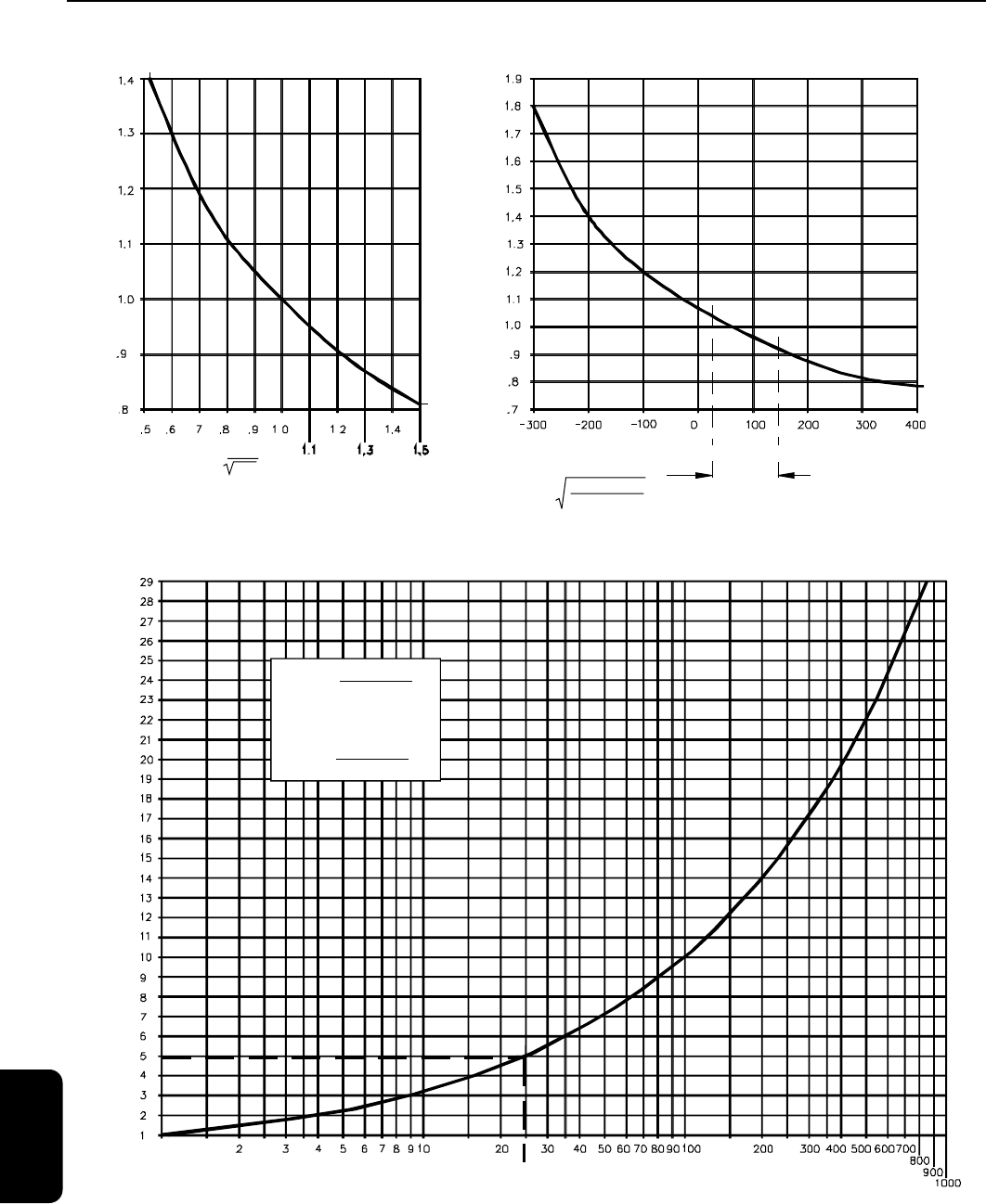
The Cv method of valve sizing reduces all variables
to a common denominator called the Flow
Coefficient. After existing or projected conditions
have been converted to this coefficient (the Cv),
the proper valve size can be found in the catalog
pages.
This section provides the complete procedure and
reference data for accurate sizing of ASCO sole-
noid valves in liquid, gas services, and steam. The
graphs provide the simplest means of finding the
required Cv factor, and are based on the formula:
The graph factor can be determined by aligning
known pressure conditions on the graphs.
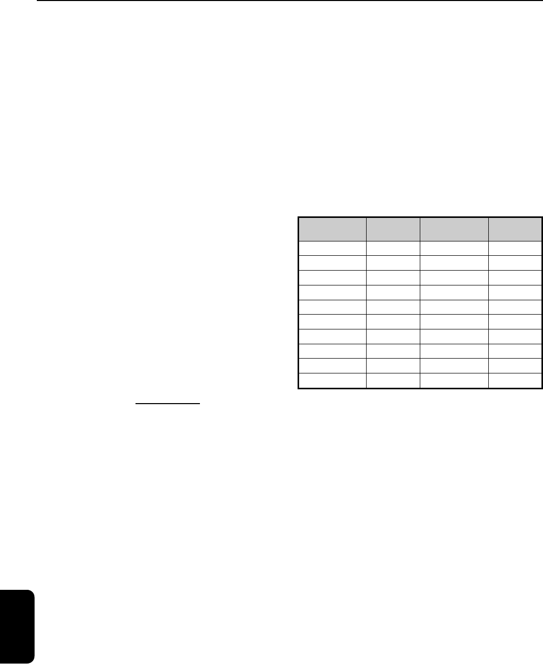
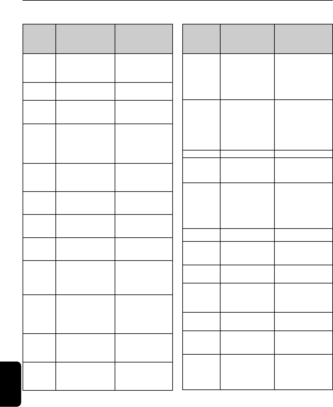
Estimating Cv or Orifice Size:
The table below can be used to estimate a Cv if
the orifice size is known or, conversely, to relate the
approximate orifice size if the Cv is known. The
chart is based on the ASCO designs of inline
globe type valves.
The flow charts must be used for precise sizing
and converting Cv factors to actual flow terms,
and the catalog must be consulted for the actual
Cv of a particular valve.
Importance of Valve Sizing
Engineering Information
Flow Data
Flow Data
Approximate
Orifice Size (ins.)
Approximate
Cv
Approximate
Orifice Size (ins.)
Approximate
Cv
1/32 .02 1/2 3.5
3/64 .06 5/8 4.5
1/16 .09 11/16 5
3/32 .20 3/4 7.5
1/8 .30 1 13
9/64 .36 1 1/4 17
3/16 .53 1 1/2 25
1/4 .70 2 48
5/16 1.7 2 1/2 60
3/8 2 3 100
Cv
Flow Required
Graph Factor
=
EngineeringR2

4
ENGINEERING
461
Liquids:
To find Cv: What Cv is required to pass 20 GPM of
oil, with a specific gravity of 0.9 and a pressure drop
of 25 psi? The viscosity is less than 300 SSUs.
Solution: Formula is:
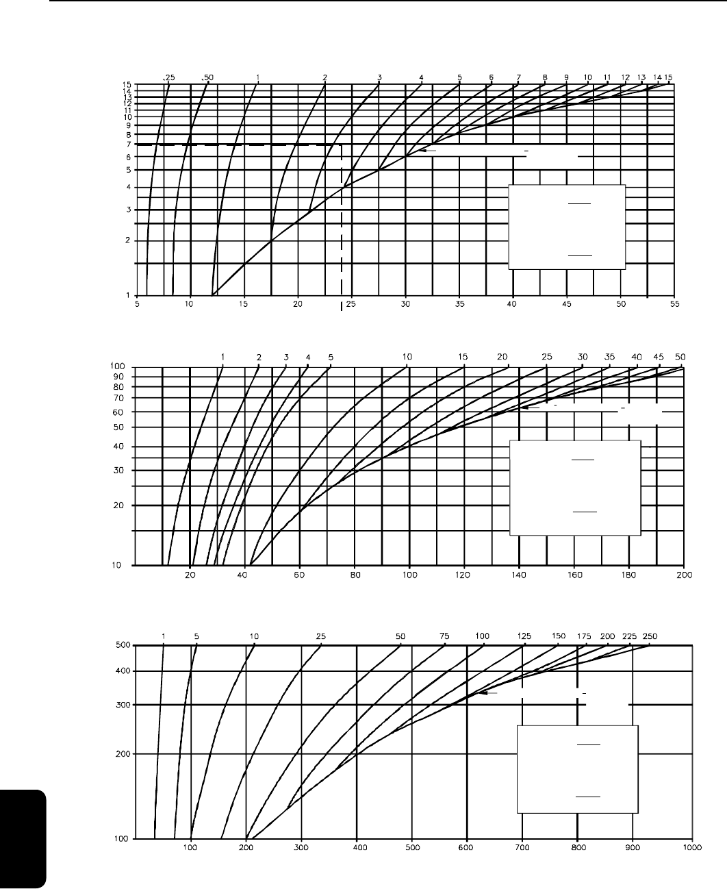
Steam:
To find Cv: A valve is required to pass 25 lb/hr of
saturated steam at an inlet pressure of 7 psig and
a
∆p
of 3 psi. What is the Cv?
Solution: Refer to the Steam Graph on page 11.18.
Use formula:
Locate Fg on graph corresponding to 7 psig inlet
pressure and 3 psi
∆p
(curved lines). Fg = 23.5.
Insert values into formula:
For further information, consult your local ASCO
sales office.
Notes:
Liquid formulas and flow graphs are based on US gallons.
If viscosity is less than 300 SSU, correction factors are not necessary.
∆p stands for pressure drop.
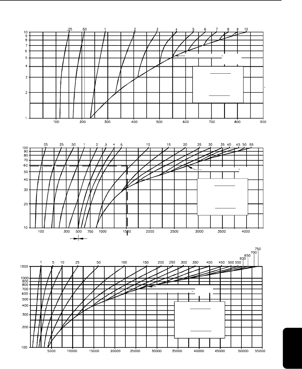
Locate Fg at the intersection of 60 psig inlet pressure
and 10 psi
∆p
(curved lines). Read down to Fg.
Fg=1560.
Locate Fsg corresponding to specific gravity of
carbon dioxide (S.G.=1.5). Fsg=0.81. (Refer to next
page.) Since the gas is at room temperature, the
Ft factor can be ignored.
Insert values into formula:
To find Fg (Graph Factor), use Liquid Flow Graph
on page 11.16. The Fg factor is that corresponding
to 25 psi pressure drop and equals 5. The Fsg
factor (Specific Gravity Factor) can be obtained
from the Fsg Chart, and is that corresponding to .9
specific gravity and equals 1.05.
Therefore:
Air and Gases:
To find Cv: A valve is required to pass 500 SCFH at
an inlet pressure of 60 psig and a
∆p
of 10 psi.
Find Cv if the fluid is carbon dioxide at room tem-
perature.
Solution: Refer to 10-100 psig graph on page
11.17. The formula to be used is:
Sample Problems
Engineering Information
Flow Data
Cv
GPM
Fg x Fsg
=
Cv
20
5 x 1.05
=
= 3.81
Cv
SCFH
Fg x Fsg x Ft
=
Cv
lb / hr
Fg
=
Cv
25
23.5
=
= 1.06
EngineeringR2
4
ENGINEERING
462
Pressure Drop Across Valve (psi)
Graph Factor (Fg)
Example Line
1.
2.
3.
GPM = Cv x Fg x Fsg
Cv =
GPM
Fg x Fsg
Fg=
GPM
Cv x Fsg
Specific Gravity @ 14.7 PSIA and 60°F.
For others Fsg =
Fsg
1
SG
Ft =
(460˚ + °F.)
530
Ft
For others
The correction for
temperature in the range of
20°F to 150°F is very small
and, therefore, can be
ignored in ordinary
applications.
Temperature (° F)
Engineering Information
Flow Data
Fsg Chart
Liquid Flow Graph
Ft Chart
EngineeringR2
4
ENGINEERING
463
Pressure Drop Across Valve (psi)
Valve Inlet Pressure (Psig)
Graph Factor (Fg)
1.
2.
3.
SCFH = Cv x Fg x Fsg x Ft
Cv =
SCFH
Fg x Fsg x Ft
Fg =
SCFH
Cv x Fsg x Ft
Note: Charts above are useful in temperature range of 20°F to 150°F.
Refer to Ft chart on previous page.
Do Not Read
Beyond This
Curve
Limiting Flow Curve
Pressure Range, 100-1500 Psig
Pressure Drop Across Valve (psi)
Valve Inlet Pressure (Psig)
Graph Factor (Fg)
Example Line
Scale Change
Limiting Flow Curve
1.
2.
3.
SCFH = Cv x Fg x Fsg x Ft
Cv =
SCFH
Fg x Fsg x Ft
Fg =
SCFH
Cv x Fsg x Ft
Pressure Range, 10-100 Psig
Pressure Drop Across Valve (psi)
Valve Inlet Pressure (Psig)
Graph Factor (Fg)
1.
2.
3.
SCFH = Cv x Fg x Fsg x Ft
Cv =
SCFH
Fg x Fsg x Ft
Fg =
SCFH
Cv x Fsg x Ft
Limiting Flow Curve
Do Not Read
Do Not Read
Beyond This
Beyond This
Curve
Curve
Do Not Read
Beyond This
Curve
Limiting Flow Curve
Limiting Flow Curve
Limiting Flow Curve
Pressure Range, 1-10 Psig
Do Not Read
Beyond This
Curve
Engineering Information
Flow Data
Air and Gas Flow Graphs
EngineeringR2
4
ENGINEERING
464
1.
2.
3.
LB/HR = Cv x Fg
Cv =
LB/HR
Fg
Fg =
LB/HR
Cv
Pressure Drop Across Valve (psi)
Valve Inlet Pressure (Psig)
Do Not Read
Beyond This
Curve
Limiting Flow Curve
Graph Factor (Fg)
Example Line
Pressure Range,1-15 Psig
Pressure Drop Across Valve (psi)
Valve Inlet Pressure (Psig)
Graph Factor (Fg)
Do Not Read
Beyond This
Curve
Limiting Flow Curve
1.
2.
3.
LB/HR = Cv x Fg
Cv =
LB/HR
Fg
Fg =
LB/HR
Cv
Pressure Range, 10-100 Psig
Pressure Drop Across Valve (psi)
Valve Inlet Pressure (Psig)
Graph Factor (Fg)
1.
2.
3.
LB/HR = Cv x Fg
Cv =
LB/HR
Fg
Fg =
LB/HR
Cv
Do Not Read
Beyond This
Curve
Limiting Flow Curve
Pressure Range, 100-500 Psig
Engineering Information
Flow Data
Steam Flow Graphs
EngineeringR2

4
ENGINEERING
465
All orders entered using this guide must state
actual fluid, fluid pressure, fluid concentration,
and fluid temperature of the application. Actual
fluid is extremely important when elastomer
options are specified because other substitutions
may be required.
ASCO valves are available to control many acids,
alcohols, bases, solvents, and corrosive gases and
liquids. Modified or special designs are some-
times required, depending upon the application.
Corrosion occurs either as a chemical or electro-
chemical reaction. Therefore, consideration must be
given to both the galvanic and electromotive force
series, as well as to pressure, temperature, and other
factors that might be involved in the application.
This guide provides information on types of valves
that are available for most common corrosive and
non-corrosive gases and liquids.
For applications
in which abnormal conditions exist and for other
fluids, consult your local ASCO office, giving full
details on operating conditions.
This guide is not intended as a specific recommen-
dation; factors beyond our control could affect valve
operation or materials.
Material Selection Guide for Commonly Used Fluids
NBR (Buna ‘N’, Nitrile)
NBR is commonly referred to as a nitrile rubber
and is the standard synthetic elastomer for accom-
plishing resilient-type seating or sealing in ASCO
valves. It has excellent compatibility for most air,
water, and light oil applications. It has a useful
temperature range of 0°F to 180°F (-18°C to 82°C).
CR (Neoprene)
CR is principally used as an external seal in refrig-
eration applications. It is also utilized for oxygen
service. It has a useful temperature range of 0°F to
180°F (-18°C to 82°C).
EPDM (Ethylene Propylene)
EPDM is selected for applications above the NBR
temperature range, such as handling hot water
and steam. Ethylene propylene has an extremely
wide range of fluid compatibility, but has the dis-
tinct disadvantage that it cannot be used with
petroleum-based fluids or contaminated fluids
(such as lubricated air). It has a useful temperature
range of -10°F to 300°F (-23°C to 149°C).
FKM (Viton
®
/Fluorel
®
, etc.)
FKM is a fluorocarbon elastomer primarily developed
for handling such hydrocarbons as jet fuels, gaso-
lines, solvents, etc., which normally cause detrimental
swelling to NBR. FKM has a high temperature range
similar to EPDM, but with the advantage of being
somewhat more resistant to “dry heat.” FKM has a
wide range of chemical compatibility. It has a useful
temperature range of 0°F to 350°F (-18°C to 177°C).
PTFE (Teflon
®
, Rulon)
PTFE and PTFE with fillers are considered more
a plastic than a resilient-type material. They are
virtually unattacked by any fluid. Their tempera-
ture usage has ranged from discs for cryogenic
valves to discs for steam valves. They are not
easily fabricated and are known to have “cold
flow” characteristics which may contribute to
objectionable leakage, particularly on gases.
Other materials referred to in this catalog
CA (Acetal, Celcon, Delrin)
FFKM (Perfluoroelastomers)
FMQ (Fluorosilicone)
HYT (Hytrel)
MTBE (Methyl tertiary-butyl ether)
PA (Nylon, Zytel)
PA + FV (Polyamide)
PE (Polyethylene)
PP (Polypropylene)
PPS (Polyphenelyne Sulfide, Ryton)
PUR (Polyurethane)
UR (Urethane)
VMQ (Silicone)
Viton and Teflon are registerd Trademarks of DuPont Co.
Fluorel is a registered Trademark of 3M.
General Information on Elastomer Materials Frequently Used in ASCO Valves
Engineering Information
Material Selection
EngineeringR2
4
ENGINEERING
466
Material Selection Guide for Commonly Used Fluids
Engineering Information
Material Selection
Fluids
Qualifying Service
Information
Materials of Construction and
Ordering Information
(Refer to List Price Schedule
for availability and prices of
Special Features)
Acetic Acid Standard strengths of water
solution are:
28, 56, 70, 80, 85, 98%.
For solutions of 40% or less,
use stainless steel Type 316
Normally Closed valve with
EPDM elastomers. Add suffix
“E” to catalog number.
Acetic Acid,
Glacial
99.9% solid. Use appropriate ball valve with
ASCO 3 or 4-way auxiliary air
pilot valve.
Acetone Colorless, flammable liquid with
mint-like odor. Soluble in water
and ether.
Standard catalog valves with
EPDM elastomers. Add suffix
“E” to catalog number. PTFE or
metal seated valves also used.
Acetylene A colorless, highly flammable
gas used for welding and flame
cutting of metals, and for pro-
ducing other chemicals. If mois-
ture is present, copper, silver,
and alloys containing more than
66% copper are not suitable.
Standard catalog aluminum,
brass, or stainless steel valves.
Specify aluminum shading coil.
Do not use bar stock brass
valves.
Air, Lubricated
(Shop Air)
Most sources of air carry lubri-
cation from pumps and other
equipment. Others are directly
lubricated in lines.
Standard resilient seated
catalog valves. For synthetic
diester lubricating oils, FKM
seals may be required.
Consult local ASCO office.
Air (or Gas), Dry,
Unlubricated
Used in instrument air
applications and telephone lines
where moisture and
oil cannot be tolerated.
Special constructions required.
Refer to Long-Life Solenoid
Valve Constructions.
Alcohol, Ethyl
(Denatured
Alcohol)
A grain alcohol commonly used
as solvent. Also used
as a radiator antifreeze and
rocket fuel.
Standard resilient seated
catalog valves
Alcohol, Methyl
(Methanol)
A flammable wood alcohol used
in automotive antifreeze, general
solvent, aviation, and rocket
fuel.
Standard catalog
constructions; however, where
high purity of liquid is essential,
use stainless steel designs.
Ammonia
(Anhydrous or
Dissociated)
Used in refrigeration. Other uses
include: for cleaning and bleach-
ing, for etching aluminum, and in
chemical processing. Presence of
slight trace of water moisture can
be harmful to brass.
Stainless Steel construction with
aluminum shading coil and CR
elastomers are required. Specify
aluminum shading coil. Add
prefix “X” and suffix “J” to
catalog number.
Argon The valves must be free of conta-
minants when filling incandescent
lamps, luminescent tubes, gas
thermometers, etc. Also used as
an inert shielding gas in welding
equipment.
Standard catalog aluminum and
brass valves used in connection
with welding equipment. Most
other applications require
stainless steel valves, specially
cleaned to avoid contamination.
Specify AP-1-005.
Benzene,
(Benzol)
Solvent used for waxes, resins,
rubber, and other organic mate-
rials. Also employed as
a fuel or for blending with gaso-
line or other fuels.
Standard catalog valves with
FKM, or PTFE disc and gasket.
Butane One of the principal LP gases.
Used as fuel for household and
other industrial purposes. Also a
refrigerant and a propellant in
aerosol cans.
Special construction required.
Refer to Combustion Section.
Fluids
Qualifying Service
Information
Materials of Construction and
Ordering Information
(Refer to List Price Schedule
for availability and prices of
Special Features)
Carbon Dioxide
(Gas or Liquid)
(CO
2
)
Also known as carbonic anhy-
dride. Used in industrial refrig-
eration and refrigeration of
foods and carbonated
beverages. Also, as a fire
extinguisher and inert
atmosphere in welding
equipment.
For gas pressures below 100 psi,
use standard valves with NBR
discs. Above 100 psi, use Series
8264, especially designed for
this service.
Carbon
Tetrachloride
(“Carbona”)
Also known as tetra-
chloromethane. Mainly used
as a metal degreasing agent.
Also used in fire extinguish-
ers. It is a general solvent and
dry-cleaning medium. Its
fumes are highly toxic and
should be handled in well-ven-
tilated areas.
Standard catalog brass valves
with PTFE or FKM discs. Add
suffix “T” or “V” to catalog
number. Diaphragm valves
must be equiped with FKM
parts. Add suffix “V” to catalog
number. Metal seated valves
also used.
Caustic Soda See “Sodium Hydroxide.”
Cellulube One of the phosphate ester
lubricating fluids which are
fire resistant.
Standard catalog designs with
EPDM elastomers. Add suffix
“E” to catalog number. PTFE or
metal seated valves also used.
Chlorine Chlorine has a powerful suffo-
cating odor and is strongly
corrosive to organic tissues
and to metals. Uses include:
for bleaching textiles and
paper pulp, but it is also used
for the manufacture of many
chemicals.
Use appropriate ball valve with
ASCO 3 or 4 way auxiliary air
pilot valve.
City Gas See “Natural” and
“Manufactured Gas.”
Coffee Automatic or semiautomatic
dispensing equipment.
Stainless steel or plastic
valves.For FDA approved elas-
tomers, consult your local
ASCO office.
Coke Oven Gas
(Bench Gas;
Coal Gas)
Flammable gas used in
domestic and industrial heat-
ing.
Standard steel or stainless steel
valves with FKM
elastomers.
Coolant Oil Oil used in automatic screw
machines and related equip-
ment as cutting oils or
coolants. Usually contain
suspended solids.
Consult your local ASCO office.
Diesel Fuel Petroleum oil used as fuel for
diesel engines.
Standard resilient seated cata-
log valves with FKM seating.
Ethylene Glycol
(Ethylene Alchohol)
“Prestone”
Also known as glycol. Used
in permanent antifreeze
solutions, brake fluids, and
as a dye solvent.
Standard resilient seated
catalog valves.
“Freon
®
” Solvents
“MF,” “TF,” and
“BF”
Trademark for a solvent
which is commonly used in
ultrasonic degreasers for
removing oil, common
grease, and dirt on metal or
plastic parts.
Standard catalog items with
metal-to-metal seating, or NBR
elastomers only.
EngineeringR2
4
ENGINEERING
467
Engineering Information
Material Selection
Fluids
Qualifying Service
Information
Materials of Construction and
Ordering Information
(Refer to List Price Schedule
for availability and prices of
Special Features)
Fuel Oil (Light)
Nos. 1, 2, 3
“Distillate” petroleum oil used
in combustion applications
without preheating.
Refer to Combustion Section.
Fuel Oil (Heavy)
Nos. 4, 5, 6
Heavy “Bunker” fuel oil.
Usually preheated to 135°F or
more for combustion.
Refer to Combustion Section.
Gasoline Special or high-test gasolines
have additives or aromatics
that affect synthetic rubber by
excessive swell, or extraction
of plasticizers.
Standard catalog valve con-
structions with FKM elas-
tomers. Add suffix “V” to cata-
log number. If MTBE additive is
present in gasoline, then use
FFKM elastomers. Metal seated
valves also used.
Helium An inert gas used in heat
treating, purging, and welding.
Standard resilient seated
catalog valves.
Hydraulic Oil Petroleum base only —
viscosity usually 50 SSU or
300 SSU. For fire-resistant
hydraulic oils, see “Cellulube,”
“Pydraul,” and “Skydrol.”
Standard resilient seated
catalog valves.
Hydrochloric Acid Also known as muriatic acid.
Corrosive chemical.
Use an appropriate ball valve
with ASCO 3 or 4 way auxiliary
air pilot valve. For low pressure,
small flow, and a maximum
concentration of 20%, refer to
Shielded Core valves.
Hydrogen A highly flammable gas when
exposed to air.
Standard resilient seated
catalog valves with soft seats.
Jet Fuels
(JP1 through 8).
For others, consult
your local ASCO
office.
These fuels are used in jet
engines and are petroleum
products, similar to kerosene.
Some jet fuels contain substan-
tial quantities of aromatics
which affect most synthetic
rubbers.
Standard catalog valves with
FKM elastomers. Add suffix “V”
to catalog number. PTFE and
metal seated valves also used.
Kerosene Generally used as a solvent for
cleaning purpose and as a
heating fuel.
Standard catalog valve with
FKM elastomers. Add suffix
“V” to catalog number.
LP Gas See “Propane.” Refer to Combustion Section.
Liquid Natural
Gas, Nitrogen,
and Oxygen
Refer to Cryogenic Valves.
Manufactured Gas Refine coke oven gas used in
city applications.
Refer to Combustion Section.
Mercury Uses: mercury cells and other
electrical apparatus; mercury
vapor boilers, lamps, barome-
ters, thermometers, etc.
Use stainless steel body. Valve
must be mounted upside down.
Special construction required.
Consult your local ASCO office
with application details.
Methyl Ethyl
Ketone (MEK)
Used in lacquers, paint
removers, cements and
adhesives. It is a flammable
liquid.
Standard catalog valves with
EPDM elastomers. Add suffix
“E” to catalog number. PTFE or
metal seated valves also used.
Naphtha A coal-tar solvent. Use NBR or FKM elastomers.
For FKM elastomer, add suffix
“V” to catalog number.
Natural Gas Common heating fuel. Refer to Combustion Section.
Fluids
Qualifying Service
Information
Materials of Construction and
Ordering Information
(Refer to List Price Schedule
for availability and prices of
Special Features)
Nitric Acid (aqua fortis
or azotic acid)
Normally, concentrations
are 60% nitric and 40%
water.
Stainless steel valves with
aluminum shading coil and
PTFE disc. Add suffix “T”
tocatalog number. Metal seated
valves also used. Maximum
temperature at which we can
offer valve is 100°F.
Nitric Acid-Red
Fuming
Red fuming is more than
86% nitric acid. These can
be handled with all stainless
steel valves.
Nitric Acid-White
Fuming
White fuming, which is
pure to 97.5% acid, and
nitric acid vapors are very
difficult to handle.
For white fuming acid, use
appropriate ball valve with
ASCO pilot.
Nitrogen An inert gas used in heat
treating, purging, and
welding.
Standard resilient seated
catalog valves.
Oils, Lubricating
or Motor
Common motor oils
known as SAE oils and
synthetic lube oils, etc.
Standard catalog valves for
300 SSU maximum. For higher
SSU, consult your local ASCO
office.
For compressor service
involving refrigerants, consult
your local ASCO office for
elastomer selection.
Oxygen, Gas Used in conjunction with
various fuels in furnaces,
ovens, cutting torches,
welding, and heat treating.
A nonflammable gas.
Contact with hydrocarbons
will result in spontaneous
combustion.
Metal body valves with FKM or
CR elastomers, specially
cleaned to avoid contamination
with hydrocarbons. Add suffix
“N” to catalog number.
Perchloroethylene
(Tetrachloroethylene)
“Perk”
Used as a dry-cleaning
solvent and in vapor
degreasing equipment.
Standard catalog items with
FKM elastomers. Add suffix
“V” to catalog number. Special
piston valves available. Do not
use diaphragm valves.
Consult
your local ASCO office.
Phosphoric Acid Also known as orthophos-
phoric acid. Used in pick-
ling and rust-proofing
metals, soft drinks and
flavoring syrups, as well
as pharmaceuticals.
For concentration of up to
20% and temperatures of
100°F, use 300 series stainless
steel with ethylene propylene,
FKM, or NBR elastomers.
Photographic
Solutions
Also known as sodium
thiosulfate or hypo. Most
metals corrode sufficiently
to cause solution
contamination.
For low pressure, small flow,
and low concentrations (20%
max.), refer to Shielded
Core Valves.
Potassium Sulfate Used in fertilizers. Also in
aluminum and glass
manufacturing.
Standard stainless steel
catalog valves.
Propane Gas One of the principal LP
gases commonly used in
grain dryer applications,
and a bottled gas for
heating and cooking.
Special construction required.
Refer to Combustion Section.
EngineeringR2
4
ENGINEERING
468
Engineering Information
Material Selection
Fluids
Qualifying Service
Information
Materials of Construction and
Ordering Information
(Refer to List Price Schedule
for availability and prices of
Special Features)
Trichloroethylene
(“Carbona”
or “TRIAD”)
Common degreasing solvent,
noncombustible, but very
toxic. Adequate ventilation
required.
Standard brass catalog valves,
if dry, use FKM elastomers
(add suffix “V” to catalog
number). If moisture is
present, use stainless steel.
Metal and PTFE seated valves
also used.
Turpentine Solvent or thinner for paints,
varnishes, and lacquers. Also, a
rubber solvent and reclaiming
agent. The liquid is volatile.
Standard catalog valves with
FKM elastomers. Add suffix
“V” to catalog number.
Vacuum Refer to Vacuum Valves.
Vegetable Oils Edible oils extracted from
seeds, fruits, or plants, such
as peanut oils, cottonseed
oils, etc.
Standard resilient seated cata-
log valves.
For FDA approved
elastomers, consult your local
ASCO office.
Vinegar A diluted impure solution of
acetic acid.
Stainless steel valves with
EPDM elastomers (FKM
elastomers may also be used).
Add suffix “E” to catalog
number.
For FDA approved
elastomers, consult your
local ASCO office.
Water, Boiler Feed Commonly treated water with
inhibitors to avoid corrosion of
boiler tubes.
Standard stainless steel catalog
valves with FKM elastomers.
Add suffix “V” to catalog
number.
Water, Distilled or
Deionized
A purified water, sometimes
called deionized water, neutral
and free from contaminants.
Stainless steel valves with
EPDM elastomers. Add suffix
“E” to catalog number.
Stainless steel or PTFE seated
valves also used.
Water, Fresh Standard resilient seated
catalog valves. Aerated water,
which is slightly acidic, will
cause seat erosion by process
known as dezincification.
Stainless steel or plastic valves
should then be selected.
Water, High
Pressure
When handling water above
500 psi, erosion and water
hammer must be considered.
Special designs for car wash
applications, etc.
Consult your
local ASCO office.
Water, Hot Water above 200°F: Often
flashes to steam due to regula-
tors or other line restrictions.
Below 200°F, this change of
state is unlikely.
Standard catalog designs suit-
able to temperatures listed in
catalog. Also see Series 8210
and 8222 Hot Water Service
listings.
For temperatures
exceeding those listed, consult
your local ASCO office.
Water, Sea, Brine,
Brackish
Difficult to handle due to
galvanic corrosion.
Use appropriate ball valve with
ASCO air pilot valve.
Fluids
Qualifying Service
Information
Materials of Construction and
Ordering Information
(Refer to List Price Schedule
for availability and prices of
Special Features)
“Pydraul”
(Monsanto)
A trademark for a series of
fire-resistant hydraulic fluids.
Used in automatic welding
machines, hydraulic presses,
and air compressors. Also
used in die-casting machines,
forging, and extrusion presses.
Standard catalog items with
FKM elastomers. Add suffix
“V” to catalog number. PTFE or
metal seated valves also used.
Refrigerants, CFC
(chlorofluorocar-
bon) “Freon®”
CFCs are used as refrigerants;
as blowing agents in the man-
ufacture of insulation, packag-
ing, and cushioning foams; as
cleaning agents for metal and
electronic components; and in
many other applications. CFCs
contain chlorine and have been
targeted by the EPA to be
phased out.
Refrigerants require special
selection of elastomers.
Consult your local ASCO office.
Refrigerants, HFC
(hydrofluorocar-
bon) “Suva®”
Environmentally acceptable
alternative to CFC. Contains no
chlorine.
Refrigerants require special
selection of elastomers.
Consult your local ASCO office.
“Skydrol” Trademark for fire-resistant jet
aircraft hydraulic fluid.
Standard catalog items with
EPDM elastomer. Add suffix
“E” to catalog number. PTFE or
metal seated valves also used.
Sodium Hydroxide
(Caustic Soda)
Used in pulp and paper industry.
Included in detergents and
soap, also in textile processing.
Solutions range between 50%
and 73% commercial.
Stainless steel valves with
EPDM elastomers. Add suffix
“E” to catalog number.
Stainless steel or PTFE seated
valves also used.
Sour Gas See “Coke Oven Gas.”
Steam Condensate This is return condensate
from steam boilers, which has
various degrees of dissolved
carbon dioxide or oxygen.
Temperature is normally high
to boiling point.
Brass valves suitable with
EPDM elastomers. See Series
8210 and 8222 Hot Water
Service Listings. Use suffix “E”
on all others.
Stoddard Solvent This is a dry-cleaning solvent
of usually high-purity naphtha,
clear and free of undissolved
water. A coal-tar solvent.
Standard catalog items.
Sulfuric Acid An oily, highly corrosive liquid
oxidizing organic materials and
most metals. It is used for
pickling and cleaning metals in
electric batteries and in plating
baths, for making explosives
and fertilizers.
Use an appropriate ball valves
with ASCO 3 or 4 way auxiliary
air pilot valve. For low pressure,
small flow, and a concentration
of up to 60%, refer to Shielded
Core Valves.
Toluene (Toluol) Also called methyl benzene or
methyl benzol. One of the
coal-tar solvents. Used in
aviation and high octane
gasolines. Also a solvent for
paints, coatings, resins, etc.
It is a flammable liquid.
Standard catalog valves with
FKM disc and gasket. Add
suffix “V” to catalog number.
EngineeringR2
4
ENGINEERING
469
Engineering Information
Next Generation
The coils with voltage ranges of 100-240 and 24-99
have three lead wires, 24 inches long (2 red for
power input, and one green lead for grounding
where necessary). These two versions are not
polarity sensitive.
The coil with a voltage range of 12-24/DC has 3
lead wires, one red, one black, and one green. This
coil is polarity sensitive. The red lead is the posi-
tive, black is the negative, and green is the ground
wire. This solenoid is also polarity protected.
Reversing the polarity will not damage the coil, but
the coil will not function until the correct polarity
is applied.
Note: The 100-240 voltage range is also suitable
for battery charging circuits designed around a
125/DC nominal voltage range.
Lead wire - UL and CSA listed 600 volt
leads, 6 strand, 18awg, PE coated
Overmold LCP
Bobbin-LCP
Magnet wire - Class H insulation
Electrical Specifications
Voltage Range Minimum Voltage Maximum Voltage
100-240V/50 or 60Hz/DC 85 264
24-99V/50 or 60Hz/DC 20.4 109
12-24/DC only 10.4 26.4
2 Watt Electronic Coils Type
Maximum Ambient Temperature 140˚F
Maximum Cycle Rate 1 Operation/ Second
Standard Coil Class of Insulation H
Power Consumption
The Next Generation solenoid nominal power
rating is 2 watts. Depending on the input voltage
applied, the actual power rating may vary. Please
use the charts below to determine your actual
power rating.
1.4
1.5
1.6
1.7
1.8
1.9
2.0
24 62 99
Voltage Input
1.4
1.5
1.6
1.7
1.8
1.9
2.0
100 170 240
Voltage Input
1.4
1.5
1.6
1.7
1.8
1.9
2.0
12 18 24
Voltage Input
Watts
Watts
Watts
Watt Rating
Watt Rating
Watt Rating
Version
100-240/50-60Hz
Version
24-99/50-60Hz
Version
12-24/DC
Electronically Enhanced Solenoids
(Next Generation)
All RedHat Next Generation solenoid valves are
rated for continuous duty under the operating
conditions outlined within this section.
Coil Operating Voltage Ranges
All coils are designed for industrial operating voltages
and can be used on the following voltage ranges
:
Power Management
Circuit
EngineeringR2
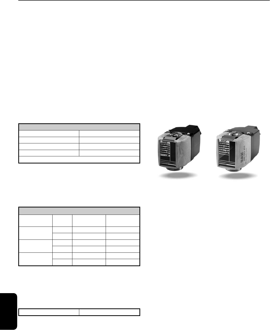
4
ENGINEERING
470
Inrush Current: The power source, wiring, and
output device used need to have surge ratings
equal to or greater than the inrush current value
(appropriate to the voltage range) specified in
the table below.
Holding Current: The power source, wiring, and
output device used need to have continuous cur-
rent ratings equal to or greater than the holding
current value (appropriate to the voltage range)
specified in the table below.
Leakage Currents: The leakage current is defined
as a current that is supplied from an output device
when the device is in its off or de-activated state.
Operation of Next Generation coil in a system that
utilizes supervisory currents is not recommended.
The advanced technology used in the Next
Generation coil includes electronic circuitry which
may limit the compatibility with certain control
system components. The following issues need to
be considered when specifying an output card or
device to operate the Next Generation coil. An
initial inrush current spike is drawn by the Next
Generation coil. This inrush spike is 72 msec in
duration, which is sufficient time for the core to
reach the plugnut. The electrical requirement then
drops to the holding value.
Solenoid Enclosures
The Next Generation solenoid coil is fully encap-
sulated using Dupont™ Zenite
®
Liquid Crystal
Polymer resin (LCP). Zenite (LCP) is a thermoplas-
tic polyester resin which exhibits several advan-
tages over other thermoplastics. The advantages
include excellent resistance to a wide range of
organic solvents and automotive fluids*, resis-
tance to impact, and long term retention of prop-
erties at continuous-use temperatures.
*Chemical resistance of Zenite LCP may not be
suitable for all applications. Zenite LCP is not suit-
able for caustic solution.
Please consult ASCO for
appropriate product solutions.
Zenite is a registered Trademark of Dupont Co.
RedHat Next Generation Solenoids are
available as:
General Purpose/Watertight
– Intended for indoor
and outdoor use and provides protection classi-
fications from NEMA Types 1 through 4X.
Class I, Division 2 for Hazardous Locations/Watertight
– Meets Types 1 through 4X and is UL listed and
CSA certified for Class I, Division 2, Groups A, B, C,
and D and Class II, Division 2, Groups F and G.
Operating temperature code T4A (120˚C).
Inrush Current Rating
Coil Version Peak Inrush Current (Amps)
12-24/DC 3.2
24-99/50-60Hz/DC 1.4
100-240/50-60Hz/DC 0.32
Maximum Duration = 72 ms
Holding Current Rating
Coil Version
Input
Voltage
Average Holding
Current (Amps)
Average Holding
Volt-Amps (VA)
12-24/DC
12 0.340 4.0
24 0.250 6.0
24-99/50-60Hz/DC
24 0.170 4.0
99 0.100 10.0
100-240/50-
60Hz/DC
100 0.040 4.0
240 0.032 7.5
Maximum Leakage Current 3 mA
Engineering Information
Next Generation
EngineeringR2
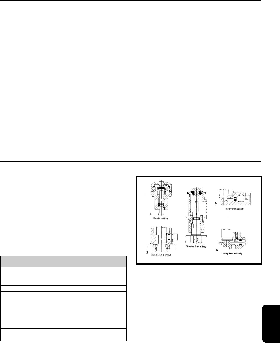
4
ENGINEERING
471
Valve Specifications
Maximum Ambient Temperature
The maximum ambient temperature is 140˚F
(60˚C). This limit is based on continuous ener-
gization with the maximum fluid temperatures as
shown on each catalog page.
Response Time
Response time from fully closed to fully open or
vice versa depends on valve size, operating
mode, fluids, temperature, inlet pressure, and
pressure drop. The response times for Next
Generation are defined as:
Small direct acting valves – 10 to 60 msec
Large direct acting valves – 25 to 90 msec
Internally pilot operated valves:
- Small diaphragm types – 20 to 100 msec
- Large diaphragm types – 80 to 150 msec
- Small piston types – 80 to 150 msec
- Large piston types – 105 to 200 msec
Engineering Information
Next Generation
Manual Operators
Manual operators are provided to operate the
valves manually when electric actuation is not
provided. There are two basic types of manual
operators, momentary and maintained. To deter-
mine which type of manual operator is available
for your valves, please see the Optional Features
Chart on the relevant valve catalog page. Once it
is determined that the subject valve can accom-
modate a manual operator, the chart below will
tell you the type of manual operator. The chart
also references the relevant cutaway illustration.
Series
Number
Const.
Ref.
Manual
Operator Suffix
Manual
Operator Type
Illustration
Number
8030 8 MO Maintained 3
8210 4, 7, 10, 11, 12 MO Maintained 2
8262 1 MS Maintained 6
8263 1 MS Maintained 6
8314 1 MS Maintained 6
8316 5, 6 MO Maintained 2
8320 2 MO Momentary 1
8320 2 MS Maintained 6
8321 4 MO Momentary 1
8321 4 MS Maintained 3
8344 1, 3, 4 MO Maintained 2
8345 2 MO Maintained 5
Operation on liquids has relatively little effect on
small direct acting valves, however, response
times of large direct acting and internally piloted
valves may be lengthened by 50% to 100%.
EngineeringR2

4
ENGINEERING
472
Engineering Information
Next Generation
Valve Parts in Contact with Fluids
Catalog Number Body Seals and Discs Disc Holder Core Guide Springs Shading Coil Stem
8030P003 Brass NBR - - 302 Stainless Steel - -
8030P083 Brass NBR - - 302 Stainless Steel - -
8210P004 Brass NBR - - 302 Stainless Steel - -
8210P007 Brass NBR - - 302 Stainless Steel - -
8210P008 Brass NBR - - 302 Stainless Steel - -
8210P022 Brass NBR PA - 302 Stainless Steel - -
8210P033 Brass NBR PA - 302 Stainless Steel - -
8210P034 Brass NBR PA - 302 Stainless Steel - -
8210P035 Brass NBR PA - 302 Stainless Steel - -
8210P087 304 Stainless Steel NBR - - 302 Stainless Steel - -
8210P088 304 Stainless Steel NBR - - 302 Stainless Steel - -
8210P093 Brass NBR - - 302 Stainless Steel - -
8210P094 Brass NBR - - 302 Stainless Steel - -
8210P095 Brass NBR - - 302 Stainless Steel - -
8210P100 Brass NBR - - 302 Stainless Steel - -
8223P003 Brass NBR, PA, PTFE - - 302 Stainless Steel Copper -
8223P005 Brass NBR, PA, PTFE - - 302 Stainless Steel Copper -
8223P010 304 Stainless Steel PTFE, NBR - - 302 Stainless Steel Silver -
8223P025 Brass NBR, PA, PTFE - - 302 Stainless Steel Copper -
8223P027 Brass NBR, PA, PTFE - - 302 Stainless Steel Copper -
8262R202 Brass NBR - - 302 Stainless Steel Copper -
8262R208 Brass NBR - - 302 Stainless Steel Copper -
8262R212 Brass NBR - - 302 Stainless Steel Copper -
8262R220 304 Stainless Steel NBR - - 302 Stainless Steel Silver -
8262R226 304 Stainless Steel NBR - - 302 Stainless Steel Silver -
8262R230 304 Stainless Steel NBR - - 302 Stainless Steel Silver -
8262R232 Brass NBR - - 302 Stainless Steel Copper -
8262R261 Brass UR - - 302 Stainless Steel Copper PA
8262R262 Brass NBR - - 302 Stainless Steel Copper PA
8262R263 Brass NBR - - 302 Stainless Steel Copper PA
8262R265 Brass NBR - - 302 Stainless Steel Copper PA
8314R035 Brass NBR, FKM - CA 302 Stainless Steel Copper -
8314R036 Brass NBR, FKM - CA 302 Stainless Steel Copper -
8314R121 304 Stainless Steel NBR, FKM - CA 302 Stainless Steel Silver -
8316P054 Brass NBR CA CA 302, 17-7PH Stainless Steels Copper -
8316P064 Brass NBR CA CA 302, 17-7PH Stainless Steels Copper -
8316P074 Brass NBR CA CA 302, 17-7PH Stainless Steels Copper -
8317P035 Brass NBR, FKM, CR - CA 302, 17-7PH Stainless Steels Copper -
8320P172 Brass NBR CA CA 302, 17-7PH Stainless Steels Copper -
8320P174 Brass NBR CA CA 302, 17-7PH Stainless Steels Copper -
8320P176 Brass NBR CA CA 302, 17-7PH Stainless Steels Copper -
8320P182 Brass NBR CA CA 302, 17-7PH Stainless Steels Copper -
8320P184 Brass NBR CA CA 302, 17-7PH Stainless Steels Copper -
8320P186 Brass NBR CA CA 302, 17-7PH Stainless Steels Copper -
8320P192 Brass NBR CA CA 302, 17-7PH Stainless Steels Copper -
8320P194 Brass NBR CA CA 302, 17-7PH Stainless Steels Copper -
8321P001 Brass NBR CA CA 302 Stainless Steel Copper -
8321P002 Brass NBR CA CA 302 Stainless Steel Copper -
8344P070 Brass NBR CA CA 302, 17-7PH Stainless Steels Copper -
8344P072 Brass NBR CA CA 302, 17-7PH Stainless Steels Copper -
8344P074 Brass NBR CA CA 302, 17-7PH Stainless Steels Copper -
8344P076 Brass NBR CA CA 302, 17-7PH Stainless Steels Copper -
8344P078 Brass NBR CA CA 302, 17-7PH Stainless Steels Copper -
8345P001 Brass NBR, FKM - CA 302, 17-7PH Stainless Steels Copper -
Note: All core tubes are 305 Stainless Steel and all cores and plugnuts are 430F Stainless Steel.
EngineeringR2
