
E
DIRECTIONAL CONTROLS
327
Solenoid Operated Directional Valves ....................................................................................................Page 331
Solenoid Controlled Pilot Operated Directional Valves............................................................................Page 331
“” Series Shockless Type Directional Valves ......................................................................................Page 331
Pilot/Manually/Mechanically Operated Directional Valves ......................................................................Page 331
Poppet Type Directional Valves ..............................................................................................................Page 451
Check/Pilot Controlled Check Valves ......................................................................................................Page 497
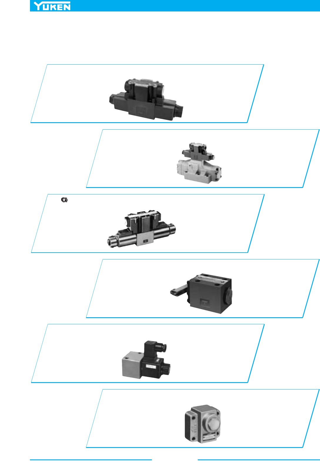
Directional Valves
328
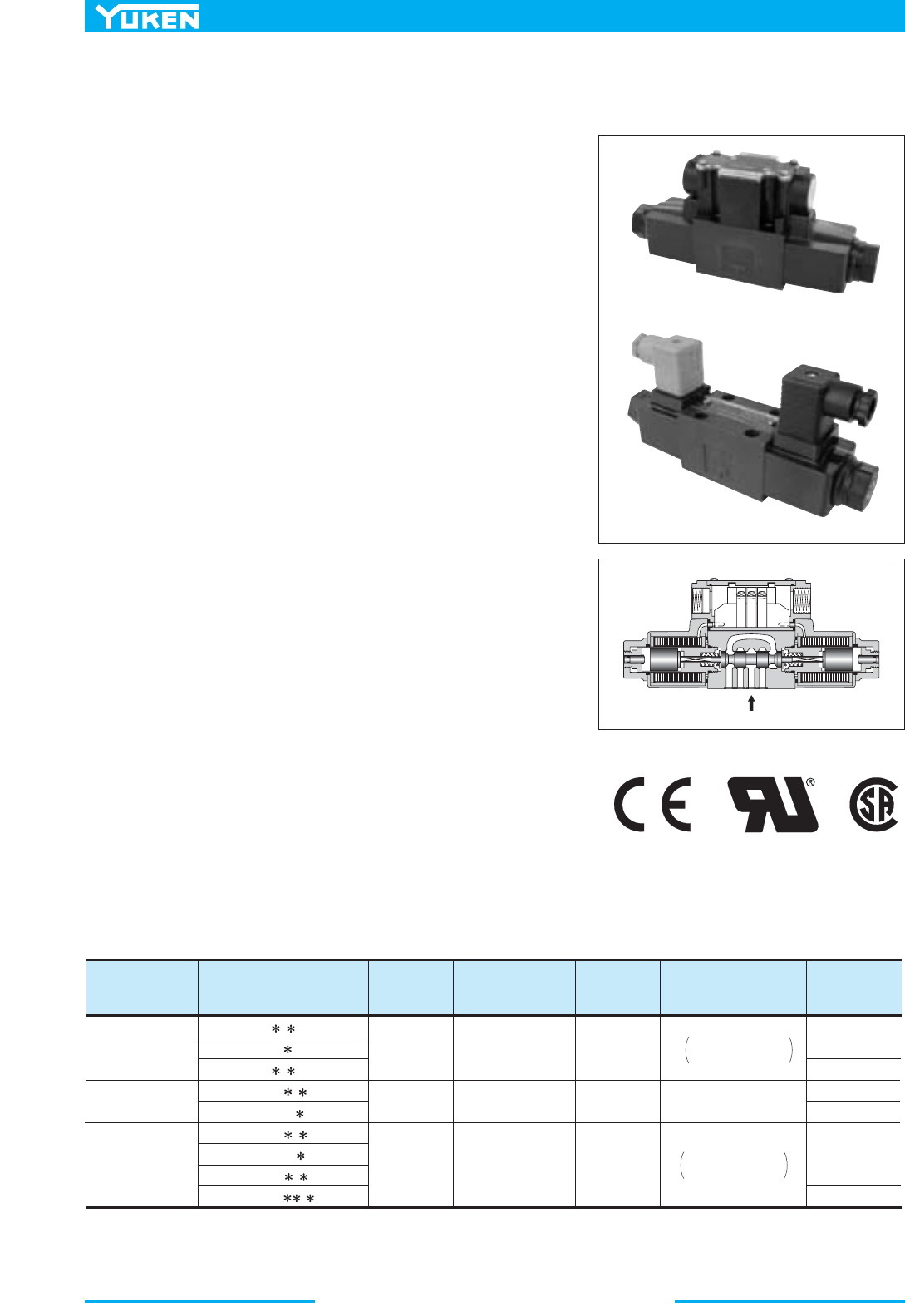
Solenoid Operated Directional Valves
■Directional Valves
These valve are used for shifting oil flow direction of hydraulic circuit and for actuator starting/stopping as well as the
operating direction shifting of actuator.
329
DIRECTIONAL CONTROLS
Directional Valves
E
Directional Valves
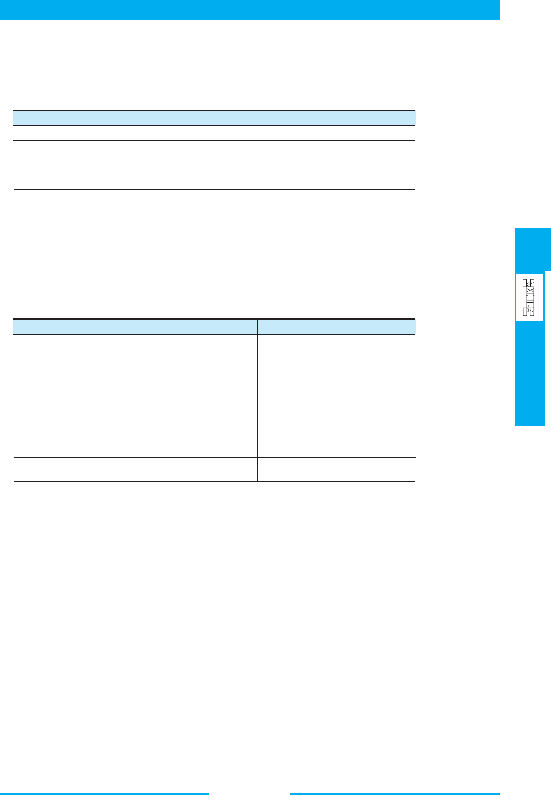
Hydraulic Fluids
1. Type of Fluids
Any type of hydraulic fluid, listed in the table below can be used.
2. Recommended Viscosity and Oil Temperatures
Use hydraulic fluids which satisfy the both recommended viscosity and oil temperatures given in the table below.
3. Control of Contamination
Due caution must be paid to maintaining control over contamination of the hydraulic fluids which may otherwise lead
to breakdowns and shorter the life of the valve. Please maintain the degree of contamination within NAS 1638-Grade
12. Use 25 µm or finer line filter (In case of DSG-005 series Solenoid Operated Directional Valves, NAS1638-Grade
11. Use 20 µm or finer line filter).
Use fluids equivalent to ISO VG32 or VG46.
Use phosphate ester or polyol ester type. When phosphate ester
type fluid is to be used, prefix “F-” to the model number
because a special seal (fluororubber) will be used.
Use water-glycol fluids or W/O emulsion type fluids.
Type of Fluids Remarks
Petroleum Base Oils
Water Containing Fluids
Synthetic Fluids
1
)
Notes 1: Not applicable with G-DSG and G-DSHG series valves.
2: For two types of manually operated directional valves, DMT- and DMT- , only petroleum base oils
and polyol ester type fluids are available.
3: Water-glycol fluids cannot be used for two types of solenoid operated poppet type two-way valves; CDST-
03✻ and CDSG-03 types.
4: For use with hydraulic fluids other than those listed above, please consult your Yuken representatives is
advance.
06
06X
10
10X
DSG-005 series Solenoid Operated Directional Valves
Solenoid Operated Directional Valves
Solenoid Controlled Pilot Operated Directional Valves
Poppet Type Solenoid Operated Directional Valves
Multi Purpose Control Valves
Solenoid Operated Poppet Type Two-Way Valves
Pilot Controlled Directional Valves
Manually Operated Directional Valves
Mechanically Operated Directional Valves
Check Valves
Pilot Controlled Check Valves
G Series Shockless Type Solenoid Operated Directional Valves
(Shifting Time Adjustable)
Name
Viscosity Oil Temperature
20 – 200 mm
2
/s
(100 – 900 SSU)
15 – 200 mm
2
/s
(80 – 900 SSU)
15 – 400 mm
2
/s
(80 – 1800 SSU)
–15 – +60°C
(5 – 140°F)
–15 – +60°C
(5 – 140°F)
–15 – +70°C
(5 – 160°F)
Directional Valves
330
Item
Standard
Type
Description
Compliance
DSG-005
(S-/T-/L-)DSG-01
DSHG-01
DSHG-03
(S-)DSHG-04
(S-)DSHG-06
(S-)DSHG-10
E-DSG-01
(S-/E-/T-/L-)
DSG-03
G-DSG-01
G-DSG-03
G-DSHG-04
G-DSHG-06
DSLG
DSLHG
DSP❇
CDS❇
JIS F8001
Water-proof test
for marine
electric appliance
JIS D0203
Damp-proof and
Water-proof test
for automobile
parts
JIS C0920
Water-proof test
for electro-
mechanical parts
an wiring
materials
JIS C0911
Vibration test for
small electric
appliances
JIS D1601
Vibration test for
automobile parts
(I.E.C)
PUBL. 529
(I.E.C)
PUBL. 529
Class 1 water spray
Class 2 water spray
Damp-proof test M1
Damp-proof test M2
Splash-proof test R1
Splash-proof test R2
Test to examine damp-resistance of parts
Test to examine functions of part under high
temperature and high humidity
Test to examine functions of parts which are
likely to be exposed to water splash.
Test to examine functions of parts which are
indirectly exposed to stormy weather or water splash.
Drip-proof type
Rain-proof type
Froth-proof type
Jet-flow proof type
Protection Class 2:
Drip-proof type (2)
Protection Class 3:
Rain-proof type
Protection Class 4:
Froth-proof type
Protection Class 5:
Jet-flow proof type
Not affected by water dropping at vertical angle of 15 degrees or less.
Not affected by rain fall at vertical angle of 60 degrees or less.
Not affected by water drip from any dirction.
Not affected by jet flow from any direction.
Not affected by water drip falling at vertical angle of
15 degrees or less.
Not affected by rain falling at vertical angle of 60
degrees or less.
Vibration range: 7-59.5 Hz
Duplex amplitude: 0.1 mm
Not affected by water drip from any direction.
Not affected by jet flow from any direction.
Fully protected from entry of dust.
Frequence: 20 Hz
Frequency range: 7-59.5 Hz
Grade 1: duplex amplitude-0.5 mm
Grade 2: duplex amplitude-1.2 mm
Grade 3: duplex amplitude-1.8 mm
Grade 4: duplex amplitude-2.4 mm
Grade 1: duplex amplitude-0.3 mm
Grade 2: duplex amplitude-0.5 mm
Grade 3: duplex amplitude-
0.75
mm
Water-proof
Dust-proof
Vibration-
resistance
Protection Class 6
Resonace test (IC)
Fixed frequency
resistance test (IIC)
Variable frequency
resistance test
(IIIC)
Grade A:
Parts mounted on spring of body or chassis
having relatively low vibration.
Grade B:
Parts mounted on spring of body or chassis
having relatively low vibration.
Grade C: Parts mounted in engine having relatively low
vibration
Class 1:
mainly for parts of
passenger car
(2D✻)★1
(2D✻)★1
(2D✻)★1
(2D✻)★1
(2D✻)★1
(2D✻)★1
(2D✻)★1
(2D✻)★1
(2D✻)★1
(2D✻)★1
(2D✻)★1
(2D✻)★1
(2D✻)★1
(2D✻)★1
(2D✻)★1
(2D✻)★1
(2D✻)★1
(2D✻)★1
★1
★1
★1
★1
★1
★1
: No-spring detented type (2D✻) and No-spring type (2N✻) can be used when energised continous for position holding.
★1
★2
★2
: For outdoor use, protect equipment with a cover, etc., to prevent direct exposure to water.
■ Water-proof, dust-proof and vibration-resistance
There properties are in compliance with the following standards.
(The marking of indicates compliance)
Drip-proof construction
Froth-roof construction
331
Directional Valves
Solenoid Operated Directional Valves
Solenoid Controlled Pilot Operated Directional Valves
“” Series Shockless Type Directional Valves
Pilot / Manually / Mechanically Operated Directional Valves
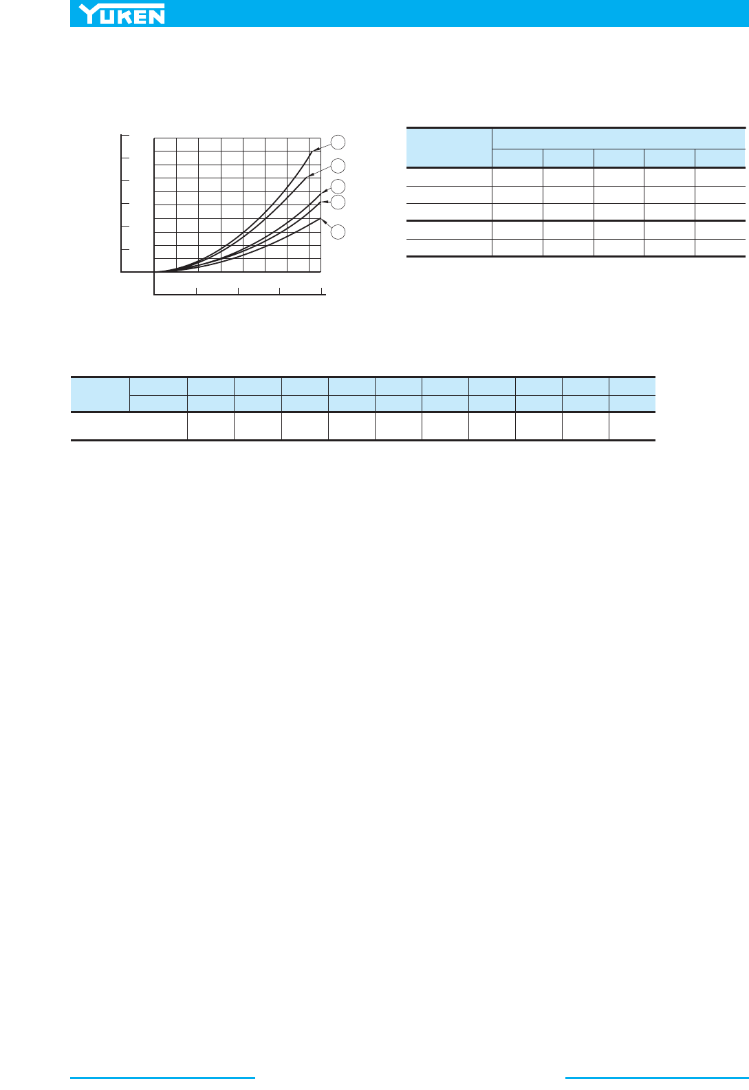
Maximum Flow
336
25 (3600)
16 (2320)
25 (3600)
35 (5080)
16 (2320)
25 (3600)
31.5 (4580)
16 (2320)
25 (3600)
35 (5080)
25 (3600)
31.5 (4580)
21 (3050)
25 (3600)
31.5 (4580)
25 (3600)
25 (3600)
31.5 (4580)
21 (3050)
31.5 (4580)
7 (1020)
25 (3600)
S DSG 01
L DSG 03
DSG 01
S DSG 03
DSG 03
T S DSG 01
T DSG 01
T S DSG 03
T DSG 03
DSHG 01
DSHG 03
DSHG 04/S DSHG 04
DSHG 06/S DSHG 06
DSHG 10/S DSHG 10
G DSG 01
G DSG 03
G DSHG 04
G DSHG 06
DHG 0406 10
Threaded Connection (DMT030610
DMG 01 03 04 06 10
Rotary (DR
T
G
) 02
Cam Operated (DC
T
G
) 01 03
344
412
418
379
381
379
361
423
441
429
E DSG 01
E DSG 03
378
A
B
PT
X
Y
AB
PT
AB
PT
A
B
PT
a
b
AB
P
T
a
b
AB
P
T
AB
P
T
b
a
Y
A
B
P
T
a
b
A
B
P
T
b
a
Y
a
b
AB
P
T
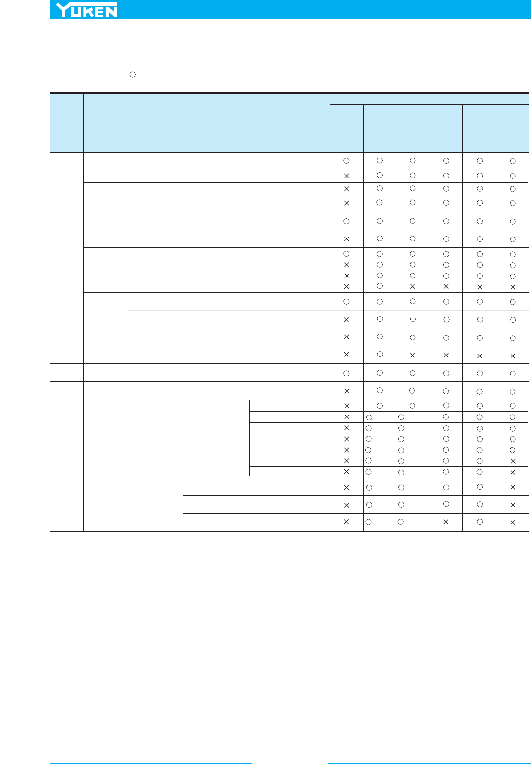
Page
Max.
Operating
Pressure
MPa (PSI)
Graphic Symbols
Valve Type
DSG
005
L
DSG 01
Solenoid Operated
Directional Valves
Low Wattage (5W) Type
Dolenoid Operated
Directional Valves
Electronic Relay
Incorporated
Solenoid Operated
Directional Valves
Mechanically Operated
Directional Valves
Solenoid Controlled
Pilot Operated
Directional Valve
“ ” Series Shockless Type
Solenoid Operated
Directional Valves
“ ” Series Shockless Type
Solenoid Controlled Pilot
Operated Directional Valves
Pilot Operated
Directional Valves
Manually Operated
Directional Valves
2000 5000200 500100502010521 1000
L/min
U.S.GPM
.3 .5 1 2 10 50 100 200 500 1000205
Directional Valves
332
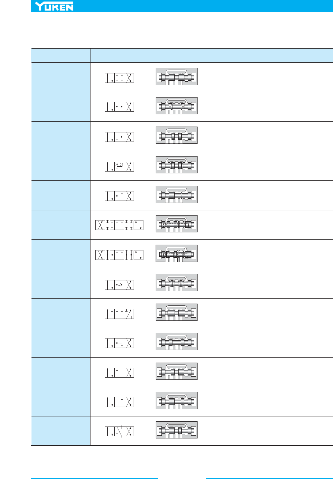
■ Spool Types
Spool types are classified to the condition of flow at the neutral position.
AB
P
T
ABPT
AB
PT
ABPT
AB
P
T
ABPT
AB
P
T
ABPT
AB
P
T
ABPT
AB
P
T
AB
P
T
AB
P
T
ABPT
AB
P
T
ABPT
AB
P
T
ABPT
AB
P
T
ABPT
AB
P
T
ABPT
AB
P
T
ABPT
ABPT
ABPT
Spool Type Graphic Symbols
Schematic Drawing
(Centre Position)
Functions and Applications
2
Closed Centre
All Ports
( )
3
Open Centre
All Ports
( )
40
Open Centre A, B&T
Restricted Flow
6
Open Centre P&T
Closed Crossover
60
Open Centre P&T
Open Crossover
7
Open Centre All Ports
Restricted Flow
( )
( )
( )
( )
4
(Open Centre A, B&T)
5
(Open Centre P, A&T)
8
(2-Way)
9
(Open Centre P, A&B)
10
(Open Centre B&T)
11
(Open Centre P&A)
12
(Open Centre A&T)
Holds pump pressure and cylinder position at neutral. Care
should be paid if used as a 2-position type because shock
occurs when each port is blocked in transit.
Pump can be unloaded and actuator is floating at neutral.
If a 2-position type is used, shock is reduced as each ports is
released to tank in transit.
Pump pressure is held and actuator is floated at neutral.
2-position type is used when system pressure is required to be
held in transit. Shock during transit is less compared to spool
type “2”.
In a variation of spool type “4”, a restrictor is provided in A-T
and B-T ports. Making it faster at stopping the actuator.
It can be used when a pump is unloading at neutral and actuato
r
is halted at one way flow.
Pump is unloading and actuator position held at neutral.
Suitable for series operation.
It is a variation of spool type “6”.
Shock is reduced as each port is released to tank on transit.
Mainly used as a 2-position type. Shock is reduced on transit.
Pump pressure and cylinder position is held at neutral in the
same way as spool type “2”.
It is used as 2 way type.
Regenerative circuit is provided at neutral.
Prevent actuator from one direction drift by leakage of P port at
neutral.
Halt actuator movement positively at B, T ports blocked P, A
ports connected at neutral.
Prevent actuator from one direction drift by leakage of P port at
neutral.
333
DIRECTIONAL CONTROLS
Directional Valves
E
Directional Valves
Model Numbers
ISO Code of Mounting Surface
S–
L–
E–
T–
G–
( )
DSG–01
DSHG–01
DMG–01
DCG–01
S–
L–
E–
T–
G–
( )
DSG–03
DSHG–04
DMG–03
DCG–03
DHG–04
DMG–04
DSHG–03
ISO 4401–AB–03–4–A
ISO 4401–AC–05–4–A
ISO 4401–AC–05–4–A
✻
ISO 4401–AD–07–4–A
ISO 4401–AE–08–4–A
ISO 4401–AF–10–4–A
S–
G–
( )
DSHG–06
DHG–06
DMG–06
DHG–10
DMG–10
S–
G–
( )
(S–) DSHG–10
✻ The main port conform to the ISO 4401–AC–05–4–A.
The pilot and drain ports is sccordance with the ISO original draft.
■ Mounting Surface
Mounting surface dimensions conform to ISO 4401, Hydraulic fluid power-Four-Port directional control valves-
Mounting surfaces.
Model change has been made on the following product.
The difference between current and new design has been described on the paragraph of “Interchangeability in
Installation between Current and New Design.” Refer to relevant pages on each series.
Interchangeability in Installation between Current and New Design
DSG–01– – –60/6090
(S–)
DSHG–04– – –51/5190
Name
Model Numbers
Currrent New
Interchangeability
in Installation
Related
Page
Major Changes
DSG–005 Series Solenoid
Operated Directional Valves
DSG–01 Series Solenoid
Operated Directional Valves
1/8,3/8 Solenoid Controlled
Pilot Operated Directional
Valves
3/4,1–1/4 Solenoid Controlled
Pilot Operated Directional
Valves
1/2 Solenoid Controlled
Pilot Operated Directional
Valves
DSG–005– – –30/3090
DSHG–01– – –13/1390
DSHG–03– – –13/1390
DSHG–01– – –14/1490
DSHG–03– – –14/1490
DSG–005– – –40/4090
DSG–005– – – –40/4090
N
N1
S–
L–
T–
( )
DSG–01– – –70/7090
S–
L–
T–
( )
(S–)
DSHG–04– – –52/5290
(S–)
DSHG–06– – –52/5290
(S–)
DSHG–10– – –42/4290
(S–)
DSHG–06– – –53/5390
(S–)
DSHG–10– – –43/4390
Ye s
Ye s
Ye s
Ye s
Ye s
—
357
—
—
—
●
High Flow
●
Low Pressure Drop
●
Din-connector type solenoid in addition
●
High Pressure and High Flow
●
Low Pressure Drop
●
Pilot valve has been changed
from DSG-01, 60 design to 70 design.
●
Pilot valve has been changed
from DSG-01, 60 design to 70 design.
●
Pilot valve has been changed
from DSG-01, 60 design to 70 design.
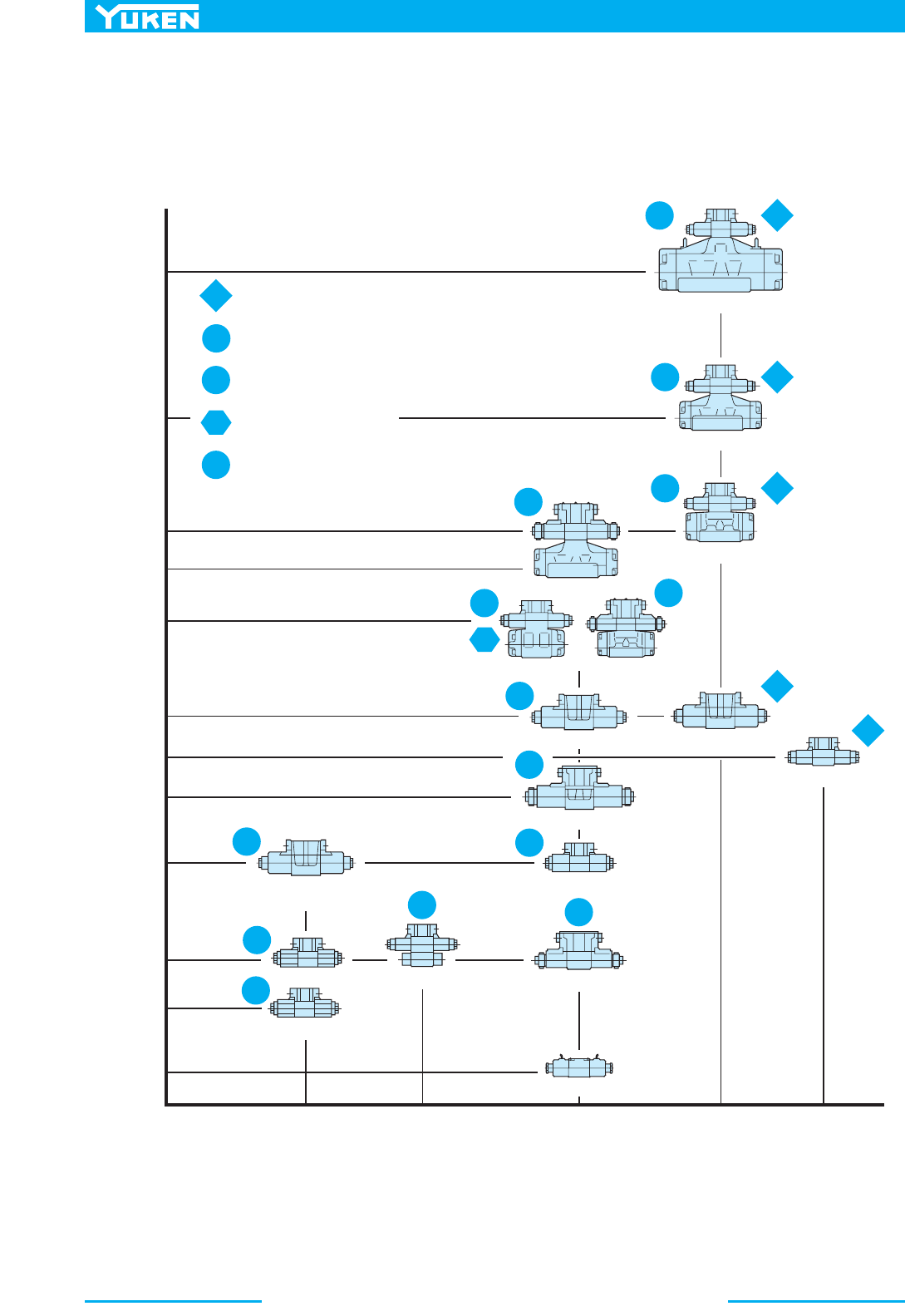
Solenoid Operated / Solenoid Controlled Operated Directional Valves
334
■ Solenoid Operated / Solenoid Controlled Operated Directional Valves
WIDE RANGE OF MODELS
– Choose the optimum valve to
meet your needs from a largeselection available.
1100
(291)
500
(132)
300
(79.3)
250
(66.1)
160
(42.3)
120
(31.7)
80
(21.1)
63
(16.6)
40
(10.6)
0
16
(2320)
21
(3050)
25
(3630)
35
(5080)
H
(S
–
)DSHG
–
04
H
(S
–
)DSHG
–
06
H
(S
–
)DSHG
–
10
15
(4.0)
H
DSG
–
03
H
DSG
–
01
G
–
DSHG
–
04
P
DSHG
–
03
G
–
DSHG
–
06
G
–
DSG
–
03
S
–
DSG
–
03
G
–
DSG
–
01
DSG
–
005
DSHG
–
01
S
–
DSG
–
01
H
S
S
S
S
S
S
S
S
E
E
E
G
G
E
G
G
G
P
30
(7.9)
100
(26.4)
31.5
(4570)
E
–
DSG
–
03
E
–
DSG
–
01
E
–
DSG
–
01
L-DSG-03 [60 L/min (15.9 U.S.GPM)]
Pressure MPa (PSI)
Maximum Flow L / min (U.S.GPM)
: High Pres., High Flow, Low Pres. Drop Type
: Shockless Type
: Shockless Type [Shifting Time Adjustable]
: Low Pressure Drop Type
: Low Wattage Type
335
DIRECTIONAL CONTROLS
Solenoid Operated / Solenoid Operated Controlled
Directional Valves
E
Solenoid Operated / Solenoid Controlled Operated Directional Valves
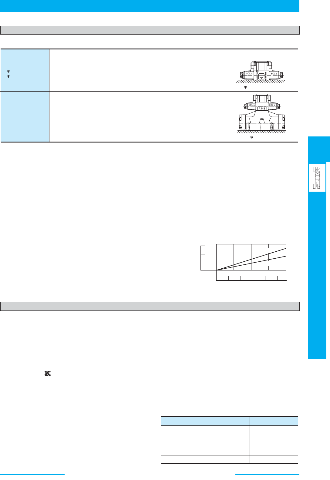
Instructions
● Mounting
● Energisation
1. No-Spring Type
One of two solenoids should be energised continuously to avoid malfunction.
2. On double solenoid valves do not energise both at the same time as it will result in coils burning out.
● Valve Tank Port
Avoid connecting the valve tank port to a line with possible surge pressure.
Piping end of tank line should be submerged in oil.
● Pilot Drain Port for Solenoid Controlled Pilot Operated Valve
Avoid connecting the valve pilot drain port to a line with possible surge pressure.
Piping end of drain should be submerged in oil.
● Shockless Type
In order to benefit from a shockless operation, it is necessary to fill the
tank line with operating oil.
Only after the tank line has been filled with operating oil should the
valve be used on a regular basis.
● Operating Force be Manual Actuator
Take care as the operating force by the manual actuator increases in
proportion to the tank line back pressure. (See the graph right.)
DSG-005
DSHG-01
DSHG-03
(S-) DSHG-04
(S-) DSHG-06
(S-) DSHG-10
-DSG-01
-DSG-03
No mounting restrictions for any model.
No-spring detented models not energised continuously must be installed so that
the spool axis L-L’ is horizontal. Otherwise there is no mounting restrictions.
No-spring models not energised continuously must be installed so that the spool
axis L-L’ is horizontal. Otherwise there is no mounting restrictions.
-DSG-01/03
L
L’
-DSHG
L
L
,
100
50
0
0 100 200 300 400 500
0
10
20
30
lbf.
150
1234
MPa
PSI
except for DSG-005
DSG-005
N
Tank Line Back Pressure
Operating
Force
Solenoid
■ Solenoid connector (DIN connector)
The solenoid connector is in accordance with the
international standard ISO 4400 (Fluid power systems
and components-Three-pin electrical plug connectors-
Characteristics and requirements).
■ AC Solenoid
50-60 Hz common service solenoids do not require re-
wiring when the applied frequency is changed.
■ DC Solenoid ( -series Solenoid Operated
Directional Valve)
These valves differ from conventional DC solenoid
operated directional valves and have the following
characteristics:
1. The spark between the relay contacts has been
eliminated and therefore the valve can be operated by
miniature relays.
2. The surge voltage is approximately 10 % of that
normally experienced.
3. Time lag on de-energisation is reduced by
approximately 50 %.
■ R type Models with Current Rectifier and DC
Solenoid
Specially designed DC solenoid and receptacle (or
connector) containing AC-DC rectifier and transient
peak suppressor are provided. Connection to be made
to AC power source as with conventional AC solenoid.
Remarkably high reliability and long life and other
advantages including quiet valve operation. No over-
heating of coil due to the spool sticking and protection
against transient voltage peaks are assured.
■ RQ type Models with Current rectifier and Quick
Return Solenoid
Valve characteristics are identical to R type except for
the fast return time of the spool after deenergisation.
■ Insulation Class of Solenoid
DSG-005, DSG-01, S-DSG01
L-DSG-01, E-DSG-01, T-DSG-01
DSG-03, S-DSG-03, L-DSG-03
E-DSG-03, T-DSG-03
DSHG-01/03/04/06/10, S-DSHG-04/-06/10
Model numbers
Insulation Class
G-DSG-01, G-DSG-03
Class H
Class F
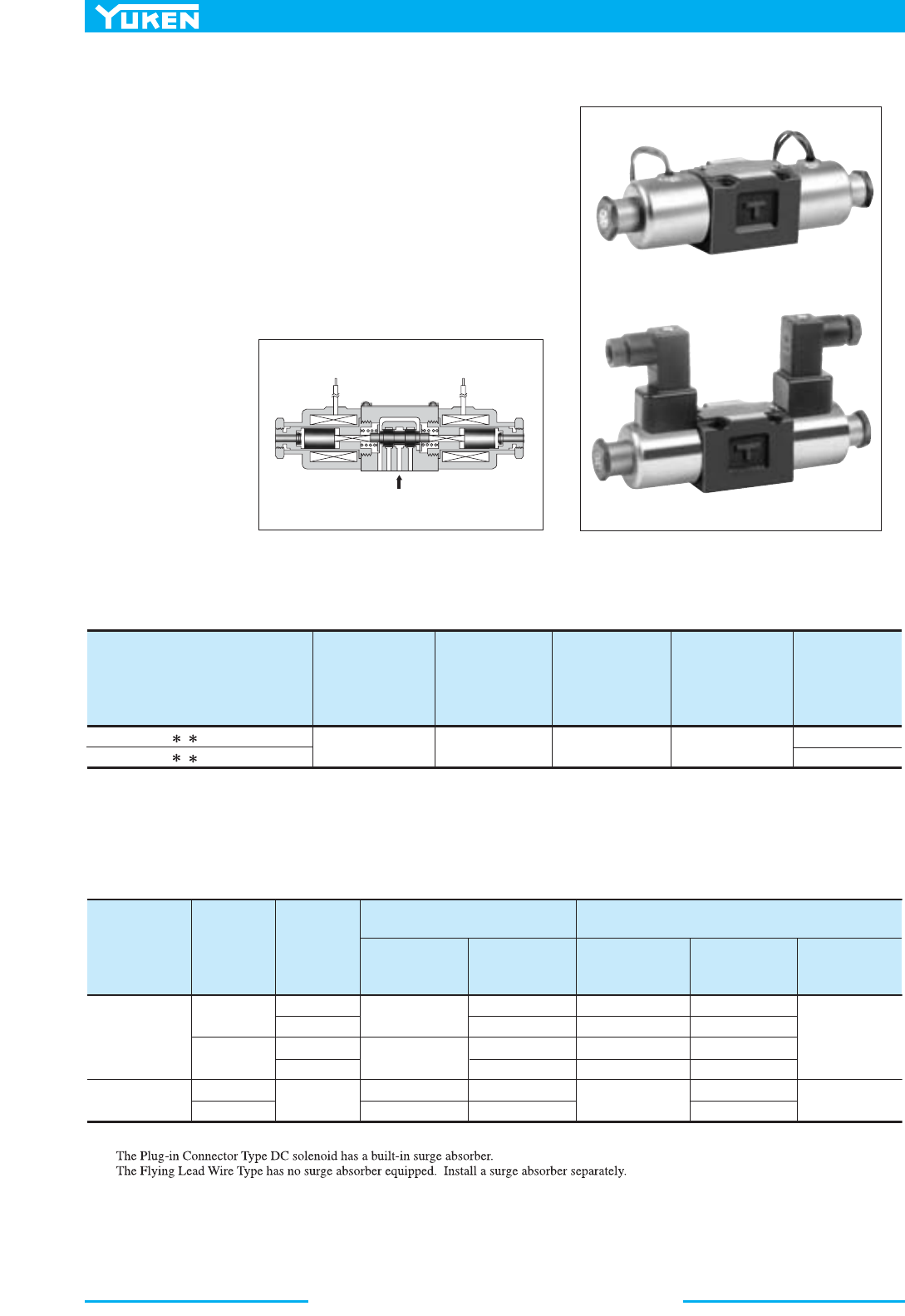
DSG-005 Series Solenoid Operated Directional Valves
336
■ Solenoid Operated Directional Valves, DSG-005 Series
These DSG-005 series solenoid directional valves are the pro-ducts
newly developed as a “Mini-series”. Compared with DSG-01
series, the valve are much more compactly manufactured but enjoy a
maximum operating pressure of 25 MPa (3630 PSI) and a maximum
flow rate of 15 L/min (3.96 U.S.GPM), while contributing further to
a space saving requirement. Moreover, using wet armature
solenoids, the valves ensure the long life.
Flying Lead Wire Type
Plug-in Connector Type
■ Specifications
■ Solenoid Rating
Model Numbers
Max. Flow
L/min
(U.S.GPM)
Max. Operating
Pressure
MPa
(PSI)
Max. Tank-Line
Back Pressure
MPa
(PSI)
Max. Changeover
Frequency
min
–1
(Cycles/min)
Approx. Mass
kg
(lbs.)
DSG-005-3C - -40/4090
DSG-005-2B - -40/4090
15
(3.96)
25
(3630)
7
(1020)
120
0.5 (1.1)
0.4 (.9)
★
★
The maximum flow means the limited flow without inducing any abnormality to the operation (changeover) of the valve.
The maximum flow differs according to the type and operating conditions. For details, please refer to the “List of Standard Models and Maximum
Flow” on
pages 338 to 339.
★1
★2
★1
★2
Electric Source
Coil Type
Frequency
(Hz)
Voltage (V)
Source Rating Serviceable
Current & Power at Rated Voltage
Inrush
(A)
Holding
(A)
Power
(W)
50
60
50
60
—
0.36
0.34
0.18
0.17
—
0.16
0.11
0.08
0.05
1.2
0.6
80 – 110
90 – 120
160 – 220
180 – 240
10.8 – 13.2
21.6 – 26.4
100
200
12
24
A100
A200
D12
D24
15
—
AC
DC
Inrush current in the above table shows rms values at maximum stroke.
337
DIRECTIONAL CONTROLS
DSG-005 Series Solenoid
Operated Directional Valves
E
DSG-005 Series Solenoid Operated Directional Valves
■ Model Number Designation
■ Sub-plates
■ Mounting Bolts
Four socket head cap screws in the table below are included.
■ Typical Changeover Time (Example)
Changeover time varies according to oil viscosity, spool type and hydraulic circuit.
DSG
Series Number
Valve Size
Number of
Valve Position
Spool-Spring
Arrangement
Spool Type
Coil Type
Design
Standard
Design
Number
Electrical Conduit
Connection
AC
A100, A200
DC
D12, D24
-005
-3
C2-D24
-N
-40
F:
DSG:
Special Seals
F-
Special Seals for
Phosphate Ester
Type Fluids
(Omit if not
required)
Solenoid Operated
Directional Valve
Design Standards: None .......... Japanese Standard “JIS” and European Design Standard
90 ............... N. American Design Standard
005
C:
Spring Centred
B:
Spring Offset
None: Flying Lead
Wire Type
N: Plug-in
Connector Type
N1: Plug-in
Connector with
Indicator Light
Refer to
40
★
2, 3
40
2, 3
3
2
★
Piping
Size
DSGM-005X-20
DSGM-005Y-20
DSGM-005X-2080
DSGM-005Y-2080
DSGM-005X-2090
DSGM-005Y-2090
1/8
1/4
Rc 1/8
Rc 1/4
1/8 BSP.F
1/4 BSP.F
1/8 NPT
1/4 NPT
0.8 (1.8)
0.8 (1.8)
Japanese Standard “JIS”
European Design Standard N. American Design Standard
Sub-plate
Model Numbers
Thread
Size
Sub-plate
Model Numbers
Thread
Size
Sub-plate
Model Numbers
Thread
Size
Approx.
Mass
kg (lbs.)
Sub-plates are available. Specify the sub-plate model number from the table above. When sub-plates are not used, the mounting surface should
have a good machined finish.
Japanese Standard “JIS”
European Design Standard
Descriptions Soc. Hd. Cap Screw (4 Pcs.)
M4 × 35 Lg.
No. 8-32 UNC × 1-3/8 Lg.
Tightening Torque
N. American Design Standard
2.5 - 3.5 Nm (22.1 - 31.0 in. lbs.)
ON
OFF
OFF
T
1 T2
0
0
Solenoid
Spool Shift
Max.
[Test Conditions]
Pressure: 16 MPa (2320 PSI)
Flow Rate: 7.5 L/min (1.98 U.S.GPM)
Viscosity: 30 mm
2
/s (141 SSU)
Voltage: Rated Voltage (After coil temperature rises and saturated)
A B
Direction of Flow: P T
B A
[Result of Measurement]
Model Numbers
Time ms
T
1
T2
DSG-005-3C2-A
DSG-005-3C2-D
DSG-005-2B2-A
DSG-005-2B2-D
16
23
14
15
60
40
45
33
DSG-005 Series Solenoid Operated Directional Valves
338
■ List of Standard Models and The Maximum Flow
5101625510 16 25 5 10 16 25
15DSG-005-3C2
14
13.5
15
14
13.5
15
14
13.5
15
15 15 15 15
12 12 12 12
14
13.5
15(12)
15(14)
15
2
12(3)
15(7)
5(1)
12(3)
1(0.5)
4(0.5)
15(10)
15(14)
12(5)
15(6)
5(2)
12(2)
1(0.5)
4(0.5)
15 15 15
15(12)
15(14)
15
12(3)
15(7)
5(1)
12(3)
15(14)
15(14)
15(11)
15(11)
15(9)
15(9)
1(0.5)
4(0.5)
15(14)
15(14)
14(9)
15(10)
8(4)
13(5)
4(0.5)
6(0.5)
15(10)
15(14)
12(5)
15(6)
5(2)
12(2)
1(0.5)
4(0.5)
15 15 15
111
3 333
15
Max. Flow
L/min
Working Pressure MPa Working Pressure MPa Working Pressure MPa
Model
Numbers
Graphic
Symbols
DSG-005-3C3
DSG-005-3C40
DSG-005-2B2
DSG-005-2B3
A
B
A
P
T
B
P
A [ Port "B" Blocked ]
P
B [ Port "A" Blocked ]
a
AB
T
P
b
a
AB
T
P
b
A
B
TP
b
A
B
T
P
b
a
AB
TP
b
● Models with AC Solenoids : DSG-005- -A -40/4090
Two
Positions
Spring
Offset
Three Positions
Spring Centred
No. of Valve
Position
Spool-Spring
Arrangement
Notes: 1. The relation between the maximum flow in the table above and the frequency/voltage (within the serviceable voltage) is as shown below.
( Example )
The maximum flow rate is constant
regardless of 50 Hz or 60 Hz and of
any voltage variants within the
serviceable voltage
50 Hz, At minimum serviceable voltage
(80% of rated voltage)
50 Hz, At rated voltage
60 Hz, At rated voltage
60 Hz, At minimum serviceable voltage
(90% of rated voltage)
15
15 (14)
15 (14)
5101625510 16 25 5 10 16 25
15DSG-005-3C2
14
13.5
15
14
13.5
15
14
13.5
15
15 15 15 15
15 15 15 15
14
13.5
12
15
15
15
8.5
5
8
3
5
2
3
9
13
5.5
8
3.5
5
15 15 15
12
15
15
5
8
3
5
15 11 9
11 7.5 5.5
13.5
10.5
2
3
9
13
5.5
8
3.5
5
15 15 15
4.5 6.5 6.5
8 789
15
15 15
15
15
Max. Flow
L/min
Working Pressure MPa Working Pressure MPa Working Pressure MPa
Model
Numbers
Graphic
Symbols
DSG-005-3C3
DSG-005-3C40
DSG-005-2B2
DSG-005-2B3
A
B
A
P
T
B
P
A [ Port "B" Blocked ]
P
B [ Port "A" Blocked ]
a
AB
T
P
b
a
AB
T
P
b
A
B
TP
b
A
B
T
P
b
a
AB
TP
b
● Models with DC Solenoids : DSG-005- -D -40/4090
Two
Positions
Spring
Offset
Three Positions
Spring Centred
No. of Valve
Position
Spool-Spring
Arrangement
Notes: 1. The relation between the maximum flow in the table above and the voltage (within the serviceable voltage) is as shown below.
( Example )
The maximum flow rate is constant
regardless of any voltage variants
within the serviceable voltage
At rated voltage
[after temperature rise and saturated]
At minimum serviceable voltage
(90% of rated voltage)
[after temperature rise and saturated]
15
13
9
339
DIRECTIONAL CONTROLS
DSG-005 Series Solenoid
Operated Directional Valves
E
DSG-005 Series Solenoid Operated Directional Valves
■ List of Standard Models and The Maximum Flow
730 1450 2320 3630 730 1450 2320 3630 730 1450 2320 3630
DSG-005-3C2
Max. Flow
U.S.GPM
Working Pressure PSI Working Pressure PSI Working Pressure PSI
Model
Numbers
Graphic
Symbols
DSG-005-3C3
DSG-005-3C40
DSG-005-2B2
DSG-005-2B3
A
B
A
P
T
B
P
A [ Port "B" Blocked ]
P
B [ Port "A" Blocked ]
a
AB
T
P
b
a
AB
T
P
b
A
B
TP
b
A
B
T
P
b
a
AB
TP
b
● Models with AC Solenoids : DSG-005- -A -40/4090
Two
Positions
Spring
Offset
Three Positions
Spring Centred
No. of Valve
Position
Spool-Spring
Arrangement
Notes: 1. The relation between the maximum flow in the table above and the frequency/voltage (within the serviceable voltage) is as shown below.
4.0 4.0 4.0
4.0
4.0
4.0 4.0
4.0
.5
.3 .3
.3
.8
.8 .8
.8
4.0(3.7) 4.0(1.9)
3.2(.8)
1.1(.1)
4.0(3.2) 4.0(.8) 1.3(.3) .3(.1)
4.0(3.7) 4.0(1.6)
3.2(.5)
1.1(.1)
4.0(2.6) 3.2(1.3) 1.3(.5) .3(.1)
4.0
4.0
4.0 4.0
4.0
4.0(3.7) 4.0(1.9)
3.2(.8)
1.1(.1)
4.0(3.2) 3.2(.8) 1.3(.3) .3(.1)
4.0(3.7) 4.0(1.6)
3.2(.5)
1.1(.1)
4.0(3.7) 4.0(2.6)
3.4(1.3)
1.6(.1)
4.0(3.7) 3.7(2.4)
2.1(1.1)
1.1(.1)
4.0(2.6) 3.2(1.3) 1.3(.5)
4.0(3.7) 4.0(2.9)
4.0(2.4)
4.0(3.7) 4.0(2.9) 4.0(2.4)
.3(.1)
4.0 4.0 4.0
4.0
3.2 3.2 3.2
3.2
3.7 3.7 3.7
3.7
3.6 3.6 3.6
3.6
( Example )
The maximum flow rate is constant
regardless of 50 Hz or 60 Hz and of
any voltage variants within the
serviceable voltage
50 Hz, At minimum serviceable voltage
(80% of rated voltage)
50 Hz, At rated voltage
60 Hz, At rated voltage
60 Hz, At minimum serviceable voltage
(90% of rated voltage)
4.0
4.0(3.7)
4.0(3.7)
730 1450 2320 3630 730 1450 2320 3630 730 1450 2320 3630
4.0
4.0 4.0
4.0
4.0
2.1 1.3
.8
3.4 2.1
1.3
2.4 1.5
.9
3.2
1.3 .8
4.0
2.9 2.4
2.9
2.0 1.5
3.6
2.8
.5
4.0
4.0 4.0
4.0
4.0
4.0
4.0 4.0
4.0
4.0 4.0
4.0
4.0
2.1 1.3
.8
3.4 2.1
1.3
2.4 1.5
.9
3.2
1.3 .8
.5
4.0
4.0
4.0
4.0 4.0
4.0
4.0
4.0 4.0
4.0
3.7
3.7 3.7
3.7
2.3
1.2 1.7
1.7
2.1
1.9 2.1
2.4
3.6
3.6 3.6
3.6
DSG-005-3C2
Max. Flow
U.S.GPM
Working Pressure PSI Working Pressure PSI Working Pressure PSI
Model
Numbers
Graphic
Symbols
DSG-005-3C3
DSG-005-3C40
DSG-005-2B2
DSG-005-2B3
A
B
A
P
T
B
P
A [ Port "B" Blocked ]
P
B [ Port "A" Blocked ]
a
AB
T
P
b
a
AB
T
P
b
A
B
TP
b
A
B
T
P
b
a
AB
TP
b
● Models with DC Solenoids : DSG-005- -D -40/4090
Two
Positions
Spring
Offset
Three Positions
Spring Centred
No. of Valve
Position
Spool-Spring
Arrangement
Notes: 1. The relation between the maximum flow in the table above and the voltage (within the serviceable voltage) is as shown below.
( Example )
The maximum flow rate is constant
regardless of any voltage variants
within the serviceable voltage
At rated voltage
[after temperature rise and saturated]
At minimum serviceable voltage
(90% of rated voltage)
[after temperature rise and saturated]
4.0
3.4
2.4
DSG-005 Series Solenoid Operated Directional Valves
340
■ Pressure Drop
Pressure drop curves based on viscosity of 30 mm
2
/s (141 SSU) and specific gravity of 0.850.
2.0
1.6
1.2
0.8
0.4
0
01234
L/min
U.S.GPM
24681012 14
15
2
3
4
5
1
0
50
100
150
200
250
300
PSI
MPa
Flow Rate
Pressure Drop ∆P
DSG-005-3C2
DSG-005-3C3
DSG-005-3C40
DSG-005-2B2
DSG-005-2B3
Model Numbers
Pressure Drop Curve Numbers
P → AB → TP → BA → TP → T
4444—
55553
4444—
1144—
2244
—
Viscosity
mm
2
/s
SSU
15
77
0.84
20
98
0.91
30
141
1.00
40
186
1.07
50
232
1.14
60
278
1.19
70
324
1.24
80
371
1.28
90
417
1.32
100
464
1.35
Factor
● For any other viscosity, multiply the factors in the tabele below.
● For any other specific gravity (G’), the pressure drop (∆P) may be obtained from the formula below.
∆P’ = ∆P (G’/0.850)
341
DIRECTIONAL CONTROLS
DSG-005 Series Solenoid
Operated Directional Valves
E
DSG-005 Series Solenoid Operated Directional Valves
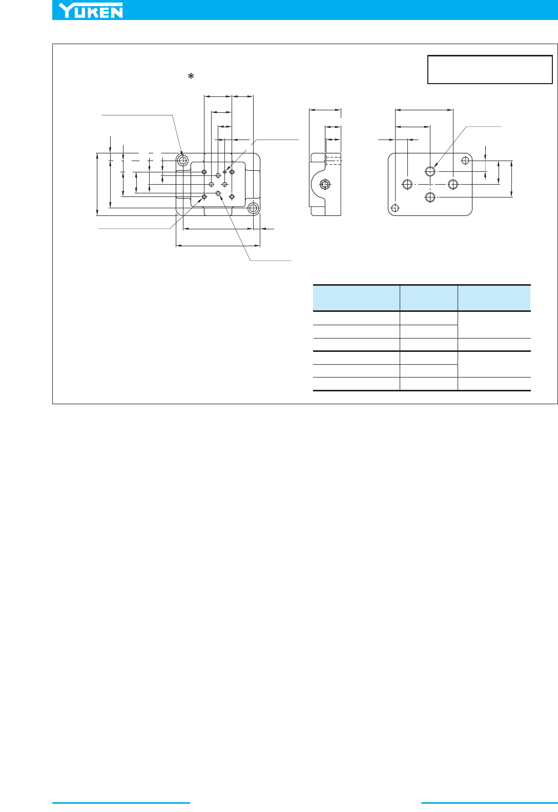
32 (1.26)
132 (5.20)
28
(1.10)
52
(2.05)
44
(1.73)
4
25(.98)
33
(1.30)
SOL bSOL a
270(10.63)
16(.63)
34
(1.34)
29(1.14)
3
(.12)
17
(.67)
4.5(.18) Dia Through
8(.31) Dia Spotface
4 Places
Space Needed to Remove
Solenoid-Each End.
Pressure Port "P"
Cylinder Port "A"Cylinder Port "B"
Tank Port "T"
Spring Centred: DSG-005-3C - -40/4090
A
D
●
■
Flying Lead Wire Type
Lead Wire
Approx.
Mounting Surface
(O-Rings Furnished)
2(.08) Dia.
Location Pin
Manual Actuator
4.8(.19) Dia.
8
(.31)
SOL b
For other dimensions, refer
to “Spring Centred” type.
93
(3.66)
Spring Offset:
DSG-005-2B - -40/4090
A
D
●
●
46
(1.81)
18
(.71)
30.1
(1.19)
SOL a SOL b
73
(2.87)
65.1(2.56)
46(1.81)
15.8
(.62)
Spring Centred: DSG-005-3C - -N/N1-40/4090
A
D
●
Spring Offset: DSG-005-2B - -N/N1-40/4090
A
D
●
■
DIN Connector Type / DIN Connector with Indicator Light
Cable Departure
Cable Applicable:
Outside Dia.
....
3.5-6 mm (.14 - .24in.)
Conductor Area
....
Not Exceeding .75mm
2
(.0012 sq. in.)
Single Solenoid Models Only
Lock Nut
Tightening Torque:
2.9 - 3.9 Nm (25.67 - 34.52 in. lbs)
The position of the Plug-in connector can be
changed as illustrated below by loosening the
lock nut. After completion of the change, be
sure to tighten the lock nut with the torque as
specified below.
For other dimensions, refer to “Flying Lead Wire Type”.
●
DIMENSIONS IN
MILLIMETRES (INCHES)
DSG-005 Series Solenoid Operated Directional Valves
342
32
(1.26)
7.5
(.30)
T
A
B
P
85
(3.35)
71
(2.80)
7
(.28)
28
(1.10)
14
(.55)
21.5
(.85)
20.75
(.82)
25(.98)
21.5
(.85)
63 (2.48)
48 (1.89)
37
(1.46)
24
(.94)
11
(.43)
12.5
(.49)
35.5
(1.40)
58.5
(2.30)
15
(.59)
"C" Thd.
4 Places
"D" Thd. 7.5(.30) Deep
4 Places
2.7(.11) Dia.
4(.16) Deep
7(.28) Dia. Through
11(.43) Dia. Spotface
2 Places
4.3(.17) Dia.
4 Places
Sub-plates: DSGM-005 -20/2080/2090
■
DIMENSIONS IN
MILLIMETRES (INCHES)
11.5
(.45)
3.5(.14)
12.5(.49)
16(.63)
7.25
(.29)
Piping Size
"C" Thd.
"D" Thd.
Sub-plate
Model Numbers
DSGM-005X-20
DSGM-005X-2080
DSGM-005X-2090
DSGM-005Y-20
DSGM-005Y-2080
DSGM-005Y-2090
Rc 1/8
1/8 BSP. F
1/8 NPT
Rc 1/4
1/4 BSP. F
1/4 NPT
M4
No. 8-32 UNC
M4
No. 8-32 UNC
343
DIRECTIONAL CONTROLS
DSG-005 Series Solenoid
Operated Directional Valves
E
DSG-005 Series Solenoid Operated Directional Valves
■ List of Seals, Solenoid Ass'y, Coil and Connector Ass'y
5 24 10
211 1 12 20 24
78
9
13
35 21 2223 25
SOL a
SOL b
DSG-005- - -40/4090
30 31
Item
Name of Parts
Qty.
SO-NB-P14
SO-NB-P6
SO-NB-P14
O-Ring
O-Ring
O-Ring
—
4
2
Part Numbers
List of Seals
10
11
21
1
4
1
2B3C
Remarks
Included in Solenoid Ass’y
Note: When ordering seals, please specify the seal kit number “KS-DSG-005-40”.
DSG-005- -A100
DSG-005- -A200
DSG-005- -D12
DSG-005- -D24
DSG-005- -A100-N
DSG-005- -A200-N
DSG-005- -D12-N
DSG-005- -D24-N
DSG-005- -A100-N1
DSG-005- -A200-N1
DSG-005- -D12-N1
DSG-005- -D24-N1
SA05-100-40
SA05-200-40
SD05-12-40
SD-05-24-40
SA05-100-N-40
SA05-200-N-40
SD05-12-N-40
SD-05-24-N-40
SA05-100-N-40
SA05-200-N-40
SD05-12-N-40
SD-05-24-N-40
C-SA05-100-40
C-SA05-200-40
C-SD05-12-40
C-SD-05-24-40
C-SA05-100-N-40
C-SA05-200-N-40
C-SD05-12-N-40
C-SD-05-24-N-40
C-SA05-100-N-40
C-SA05-200-N-40
C-SD05-12-N-40
C-SD-05-24-N-40
Solenoid Ass’y, Coil and Connector Ass’y No.■
Valve Model Number
9 Solenoid Ass’y No. @2 Coil No.
Connector
Ass’y Part No.
#0
Connector
Ass’y Part No.
Remarks
#1
TK290378-9
TK290379-7
TK290089-2
TK290090-0
TK290058-7
TK290378-9
TK290379-7
TK290089-2
TK290090-0
TK290058-7
Flying Lead Wire Type
Plug-in Connector Type
Plug-in Connector
with
Indicator Light
DSG-01 Series Solenoid Operated Directional Valves
344
■ 1/8 Solenoid Operated Directional Valves, DSG-01 Series
These are Solenoid Operated Directional Valves of high pressure, high
flow and low pressure drop, the features of which can be materialized
by employing a powerful wet type solenoid and the rational flow
channel design.
● High Pressure & High Flow Rate
In comparison to our existing lines, both the pressure and flow of
these valves are much increased.
●
Max. Operating Pressure: approx. 10 % increased [31.5→35 MPa
(4570 →5080 PSI)]
●
Max. T-Line Back Pressure: approx. 30 % increased [16→21 MPa
(2320 →3050 PSI)]
●
Max. Flow Rate: approx. 60 % increased [63→100 L/min (16.64
→26.42 U.S.GPM)]
● Low Pressure Drop
The pressure drop of these valves is reduced by 10 % from 1.0 to 0.9
MPa (145 to 131 PSI), in comparison to our existing lines*; the valves
effectively reduce the energy consumption of the unit.
{* At Flow Rate: 60 L/min (15.9 U.S.GPM), Spool Type: 3C2 (P→A)}
● Compact & Small Mass
Despite of high pressure, high flow and low pressure drop, these valve
bodies are compact and lightweight with DC double solenoids; the
overall length and mass are reduced from 210 to 205 mm (8.26 to 8.07
inch) and from 2.2 to 1.85 kg (4.85 to 4.08 lbs), respectively.
● Shockless type available
In addition to the standard valves for high pressure and high flow, a
shockless type capable of minimizing noise and vibration in piping
during spool changeover is also available.
● Stable Operation
Due to the powerful magnetic and spring force of the solenoids, these
valves exhibit a high tolerance to contaminants and especially stable
operation.
● IP65-equivalent high dust- and water-proof
These valves demonstrate excellent dust- and water-proof
characteristics, in compliance with I. E. C. Pub. 529. IP65 and JIS C
0920 IP65 (dust- and jet-proof type).
● Usable in products of various standards
These standard valves are CE certified for installation in equipment overseas.
UL/CSA certified products are also available.
■ Specifications
★ 1. For details of L-DSG-01, please contact us.
★ 2. Maximum flow indicates a ceiling flow depends on the type of spool and operating condition, refer to the List of Spool Functions on pages 347
to 351 for details.
Terminal Box Type
Plug-in Connector Type
Max. Changeover
Frequency
Cycle/min {min
–1
}
Max. Operating
Pressure
MPa (PSI)
Max. T-Line
Back Pressure
MPa (PSI)
Mass
kg
(lbs.)
Valve Type
Model Numbers
Max. Flow
L/min
(U.S.GPM)
★2
★1
Standard Type
DSG-01-3C - -70/7090
DSG-01-2D2- -70/7090
DSG-01-2B - -70/7090
S-DSG-01-3C - -70/7090
S-DSG-01-2B2- -70/7090
L-DSG-01-3C - -70/7090
L-DSG-01-2D2- -70/7090
L-DSG-01-2N - -70/7090
L-DSG-01-2B - -70/7090
Shockless Type
Low Wattage(14W)
Type
100
(26.4)
63
(16.6)
40
(10.6)
35
(5080)
25
(3630)
16
(2320)
21
(3050)
1.85
(4.08)
1.85
(4.08)
1.4(3.09)
1.4(3.09)
1.4(3.09)
1.85(4.08)
21
(3050)
16
(2320)
300
R Type Sol. Only
120
300
R Type Sol. Only
120
120
345
DIRECTIONAL CONTROLS
DSG-01 Series Solenoid
Operated Directional Valves
E
DSG-01 Series Solenoid Operated Directional Valves
Sub-plate
Piping
Size
Sub-plate
Model Numbers
Thread
Size
Japanese Standard "JIS "
Sub-plate
Model Numbers
Thread
Size
European Design Standard
Sub-plate
Model Numbers
Thread
Size
N.American Design Standard
Approx.
Mass
kg (lbs.)
Rc 1/8DSGM-01-31 1/8 BSP. FDSGM-01-3180
1/8 NPT
0.8 (1.8 )
Rc 1/4
Rc 3/8
1/4 BSP. F
1/4 NPT
3/8 NPT
0.8 (1.8 )
0.8 (1.8 )
1/8
Mounting Bolt
Descriptions Soc. Hd. Cap Screw (4 pcs.) Tightening Torque
Japanese Standard "JIS"
European Design Standard
N. American Design Standard
M5
×
×
45 Lg.
No. 10-24 UNC 1-3/4 Lg.
5 - 7 Nm (43 - 60 in. 1bs.)
Applicable to working pressure more than
25 MPa (3630 PSI): 6 - 7 Nm (52 - 60 in. 1bs.)
1/4
3/8
DSGM-01-3190
DSGM-01X-31
DSGM-01Y-31
DSGM-01X-3180 DSGM-01X-3190
DSGM-01Y-3190
For socket head cap screws in the table below are included.
Sub-plates are available. Specify the sub-plate model number from the table above.
When sub-plates are not used, the mounting surface should have a good machined finish.
1.
2.
3.
1
2
Solenoid Ratings
Valve Type Electric source
Coil
Type
Frequency
(Hz)
Source Ratin g
Voltage (V)
Serviceable Range
Inrush (A)
Holding (A) Power (W)
Current & Power at Rated Voltage
100
100
110
120
200
200
220
240
12
24
48
100
200
50
60
50
60
50
60
50
60
50/60
A100
A120
A200
A240
D12
D24
D48
R100
R200
80 - 110
90 - 120
96 - 132
108 - 144
160 - 220
180 - 240
192 - 264
216 - 288
10.8 - 13.2
21.6 - 26.4
43.2 - 52.8
90 - 110
180 - 220
2.42
2.14
2.35
2.02
1.78
1.21
1.07
1.18
1.01
0.89
0.51
0.37
0.44
0.42
0.31
0.25
0.19
0.22
0.21
0.15
2.45
1.23
0.61
0.33
0.16
AC
DC (K Series)
AC
→
DC Rectified (R )
Standard
Type
Shockless
Type
29
29
AC solenoid is not available in shockless type.
R type models with built-in current rectifier is recommended for shockless operation with AC power.
Inrush current in the above table show rms values at maximum stroke.
There are more coil types other than the above. For details, please make inquiries.
The coil type numbers in the shaded column are handled as opotinal extras.
In case these coils are required to be chosen, please confirm the time of
delivery with us before ordering.
SOL b
SOL b
Lock Nut
Push Button
Plug-in Connector
With Indicator Light
■ Options
● Push Button with Lock Nut
Can be used for manual changeover of spool. The push button
can be locked in the pressed condition.
● Plug-in Connector with Solenoid Indicator Light
These are the indicator light incorporated plug-in connector
type solenoids. Energisation or de-energisation of the solenoid
can be easily identified with the incorporated indicator light.
DSG-01 Series Solenoid Operated Directional Valves
346
■ Model Number Designation
2
1
1
F-
F:
S-
DS G -
01
-2 B
2A -D24 -C
-N
-70
-L
Special
Seals
Shockless
Type
Series
Number
Valve
Size
Number
of Valve
Positions
Spool-
Spring
Arrangement
Spool
Type
Special Two
Position Valve
Omit if not
require
d
Coil
Type
Manual
Override
Electrical
Conduit
Connection
Design
Number
Design
Standard
Models with
Reverse Mtg. of
Solenoid
Omit if not
require
d
For Phosphate
Ester Type
Fluids
(Omit if not
required
None:
Standard
Type
DSG:
Solenoid
Operated
Directional
Valve
S:
Shockless
Type
3:
Three
Positions
2:
Two
Positions
2:
Two
Positions
3:
Three
Positions
C:
Spring
Centred
D:
No-Spring
Detented
B:
Spring
Offset
C:
Spring
Centred
B:
Spring
Offset
None:
Manual
Override
Pin
C :
Push
Button
and
Lock Nut
(Option)
None:
Terminal
Box Type
N:
Plug-in
Connector
Type
N1 :
Plug-in
Connector
Type
with
Indicator
Light
(Option)
None:
Japanese
Std. "JIS"
90:
N.American
Design Std.
None:
Japanese
Std. "JIS"
and
European
Design
Std.
90:
N. American
Design
Std.
01
L
AC:
A100
A120
A200
A240
DC:
D12
D24
D48
R:
(AC
DC)
R100
R200
L
A
B
3
40
9
11
2,
4,
10,
12
2
3
8
2
4
2
70
60,
→
DC:
D12
D24
D48
R:
DC)
R100
R200
2
(AC
→
In case of the special two position valve, please refer to page 352 for details.
N1 is not available for R type solenoids.
In the table above, the symbols or numbers highlighted with shade represent the optional
extras. The valves with model number having such optional extras are handles as options,
therefore, please confirm the time of delivery with us before ordering.
★1.
★2.
347
DIRECTIONAL CONTROLS
DSG-01 Series Solenoid
Operated Directional Valves
E
DSG-01 Series Solenoid Operated Directional Valves
100
10080
9063
90
85
80
4323
4023
100
100
100
100
80
85
70
10
DSG 01 3C2
DSG
01 3C3
DSG
01 3C4
DSG
01 3C40
DSG
01 3C60
DSG
01 3C9
DSG
01 3C10
DSG
01 3C11
DSG
01 3C12
DSG
01 2D2
DSG
01 2B2
DSG
01 2B3
DSG
01 2B8
16 25 31. 5 35 10 16 25 31. 5 35 10 16 25 31. 5 35
100
10080
9063
90
85
80
4323
4023
100
100
10070
100
100
10070
80
85
70
100
10080
9063
90
9026
85
8030
4223
3823
100
10063
8020
100
10063
8020
80
85
70
100
10077
9063
9022
4314
8040
6315
4223
3623
100
10033
7020
100
10033
7020
80
85
70
100
10077
9063
3518
3011
8022
2510
4223
3523
100
10027
4019
100
10027
4019
80
85
70
10043
5738
7046
4530
10038
5031
8540
7026
5432
4830
20
10050
10037
23
10050
10037
45
20
50
26
10041
5331
7046
4530
7628
3820
8535
5024
5432
4730
15
10037
5525
20
10037
5525
45
16
50
17
8021
2917
7046
4530
6715
2010
8524
3216
5232
4730
10
10020
2914
13
10020
2914
4521
3618
16
50
13
6017
1910
7046
4530
5710
167
6016
2213
5232
4730
10
7816
2011
10
7816
2011
4516
2813
15
50
11
3815
139
7046
4530
357
125
5512
1810
5232
4730
8
6213
1510
5
6213
1510
3813
2212
13
50
10
10043
5738
7046
4530
10038
5031
8540
7026
5432
4830
20
10050
10037
10065
7050
10050
10037
50
8563
8530
8070
7048
8050
3520
10041
5331
7046
4530
7628
3820
8535
5024
5432
4730
15
10037
5525
8552
5740
10037
5525
5045
5045
8050
6033
8070
7048
7040
2315
8021
2917
7046
4530
6715
2010
8524
3216
5232
4730
10
10020
2914
7245
5025
10020
2914
5042
5042
6340
5028
8070
7048
6020
158
6017
1910
7046
4530
5710
167
6016
2213
5232
4730
10
7816
2011
6534
4319
7816
2011
4540
4540
4432
4028
8070
7048
4510
105
38 15
13 9
70 46
4530
35 7
12 5
55 12
18 10
52 32
47 30
8
62
13
15 10
60 27
35 18
62 13
15 10
4540
4540
44 32
4028
80 70
70 48
3010
75
a
b
PT
BA
a
b
AB
PT
a
b
AB
PT
a
b
AB
PT
a
b
AB
PT
a
b
AB
PT
a
b
AB
PT
a
b
AB
PT
a
b
AB
PT
a
b
AB
PT
b
AB
PT
b
AB
PT
b
AB
PT
P
A
T
B
P
A
T
B
P
A
T
B
Graphic
Symbols
Model
Numbers
Spool-Spring Arrangement
No. of Valve Positions
[Port "A" Blocked][Port "B" Blocked]
Max. Flow
Working Pressure MPa
Working Pressure MPa
Working Pressure MPa
L/min
Spring Centred
Three Positions
No-Spring
Detented
Spring Offset
Two Positions
■ List of Standard Models and The Maximum Flow
● Models with AC Solenoids: DSG-01- -A
T of the valves with a mark, please see page 351.
( Example )
The maximum flow rate is constant
regardless of 50 Hz or 60 Hz and of
any voltage variants within the
serviceable voltage
50 Hz, At minimum serviceable voltage
(80% of rated voltage)
50 Hz, At rated voltage
60 Hz, At rated voltage
60 Hz, At minimum serviceable voltage
(90% of rated voltage)
100
100 (43)
57 (38)
Notes: 1. The relation between the maximum flow in the table above and the frequency/voltage (within the serviceable voltage) is as shown below.
The valve models with a mark are handled as
Options. If you choose such valves, check the time
of delivery beforehand.
For the maximum flow rate in P
→
2.
DSG-01 Series Solenoid Operated Directional Valves
348
22
17
75
70
29
23
24
19
66
58
8
24
19
5
24
19
27
22
13
50
10
100
100
80
90
85
50
41
100
85
100
85
75
70
80
70
10
DSG 01 3C2
DSG
01 3C3
DSG
01 3C4
DSG
01 3C40
DSG
01 3C60
DSG
01 3C9
DSG
01 3C10
DSG
01 3C11
DSG
01 3C12
DSG
01 2D2
DSG
01 2B2
DSG
01 2B3
DSG
01 2B8
16 25 31. 5 35 10 16 25 31. 5 35 10 16 25 31. 5 35
100
55
78
70
100
62
85
65
66
58
20
100
74
23
100
74
45
20
50
26
28
23
78
70
38
30
30
25
66
58
10
36
28
13
36
28
40
30
16
50
13
25
19
78
70
31
25
26
21
66
58
10
28
20
10
28
20
30
25
15
50
11
100
55
78
70
100
62
85
65
66
58
20
100
74
100
85
100
74
50
46
32
75
65
53
35
100
100
80
90
85
50
41
100
85
100
85
75
70
80
70
100
100
80
90
42
65
45
50
41
100
85
35
100
85
35
75
70
80
70
100
100
80
50
26
40
30
50
41
100
80
23
100
80
23
75
70
80
70
100
100
80
38
20
33
26
50
41
100
40
20
100
40
20
75
70
80
70
45
35
78
70
58
48
52
36
66
58
15
56
43
20
56
43
45
16
50
17
45
35
78
70
58
48
52
36
66
58
15
56
43
60
46
56
43
50
45
31
23
75
65
35
30
28
23
78
70
38
30
30
25
66
58
10
36
28
40
32
36
28
50
42
24
19
75
65
23
17
25
19
78
70
31
25
26
21
66
58
10
28
20
36
28
28
20
45
40
22
18
75
65
19
13
22
17
75
70
29
23
24
19
66
58
8
24
19
32
24
24
19
45
40
22
18
75
65
17
12
P
A
T
B
P
A
T
B
P
A
T
B
a
b
PT
BA
a
b
AB
PT
a
b
AB
PT
a
b
AB
PT
a
b
AB
PT
a
b
AB
PT
a
b
AB
PT
a
b
AB
PT
a
b
AB
PT
a
b
AB
PT
b
AB
PT
b
AB
PT
b
AB
PT
[Port "A" Blocked][Port "B" Blocked]
Graphic
Symbols
Model
Numbers
Spool-Spring Arrangement
No. of Valve Positions
Max. Flow
Working Pressure MPa
Working Pressure MPa
Working Pressure MPa
L/mi
Spring Centred
Three Positions
No-Spring
Detented
Spring Offset
Two Positions
■ List of Standard Models and The Maximum Flow
● Models with DC or R Type Solenoids: DSG-01- -D /R
T of the valves with a mark, please see page 351.
( Example )
The maximum flow rate is constant
regardless of any voltage variants
within the serviceable voltage
At rated voltage
[after temperature rise and saturated]
At minimum serviceable voltage
(90% of rated voltage)
[after temperature rise and saturated]
100
100
55
Notes: The relation between the maximum flow in the table above and the voltage (within the serviceable voltage) is as shown be low.1.
2.
The valve models with a mark are handled as
Options. If you choose suce valves, check the time
of delivery beforehand.
For the maximum flow rate in P
→

349
DIRECTIONAL CONTROLS
DSG-01 Series Solenoid
Operated Directional Valves
E
DSG-01 Series Solenoid Operated Directional Valves
DSG 01 3C2
DSG
01 3C3
DSG
01 3C4
DSG
01 3C40
DSG
01 3C60
DSG
01 3C9
DSG
01 3C10
DSG
01 3C11
DSG
01 3C12
DSG
01 2D2
DSG
01 2B2
DSG
01 2B3
DSG
01 2B8
a
b
PT
BA
a
b
AB
PT
a
b
AB
PT
a
b
AB
PT
a
b
AB
PT
a
b
AB
PT
a
b
AB
PT
a
b
AB
PT
a
b
AB
PT
a
b
AB
PT
b
AB
PT
b
AB
PT
b
AB
PT
P
A
T
B
P
A
T
B
P
A
T
B
Graphic
Symbols
Model
Numbers
Spool-Spring Arrangement
No. of Valve Positions
[Port "A" Blocked][Port "B" Blocked]
Max. Flow
Working Pressure PSI
Working Pressure PSI
Working Pressure PSI
U.S.GPM
Spring Centred
Three Positions
No-Spring
Detented
Spring Offset
Two Positions
■ List of Standard Models and The Maximum Flow
● Models with AC Solenoids: DSG-01- -A
1450 2320 3630 4570 5080 1450 2320 3630 4570 5080 1450 2320 3630 4570 5080
26.4
26.4(11.4) 26.4(10.8) 21.1(5.6) 15.9(4.5) 10.0(4.0)
15.1(10.0) 14.0(8.2) 7.7(4.5) 5.0(2.6) 3.4(2.4)
26.4(13.2) 26.4(9.8) 26.4(5.3) 20.6(4.2) 16.4(3.4)
26.4(9.8) 14.5(6.6) 7.7(3.7) 5.3(2.9) 4.0(2.6)
26.4(13.2) 26.4(9.8) 26.4(5.3) 20.6(4.2) 16.4(3.4)
26.4(9.8) 14.5(6.6) 7.7(3.7) 5.3(2.9) 4.0(2.6)
26.4(17.2) 22.5(13.7) 19.0(13.7) 17.2(9.0) 15.9(7.1)
18.5(13.2) 15.1(10.6) 13.2(6.6) 11.4(5.0) 9.2(4.8)
26.4(13.2) 26.4(9.8) 26.4(5.3) 20.6(4.2) 16.4(3.4)
11.9(5.6) 11.9(4.2) 10.0(3.4)
9.5(4.8) 7.4(3.4) 5.8(3.2)
26.4(9.8) 14.5(6.6) 7.7(3.7) 5.3(2.9) 4.0(2.6)
26.4(13.2) 26.4(9.8) 26.4(5.3) 20.6(4.2) 16.4(3.4)
22.5(16.6) 21.1(13.2) 16.6(10.6) 11.6(8.5) 11.6(8.5)
22.5(7.9) 15.9(8.7) 13.2(7.4) 10.6(7.4) 10.6(7.4)
21.1(13.2) 18.5(10.6) 15.9(5.3) 11.9(2.6) 7.9(2.6)
9.2(5.3) 6.1(4.0) 4.0(2.1) 2.6(1.3) 1.9(1.3)
21.1(18.5) 21.1(18.5) 21.1(18.5) 21.1(18.5) 21.1(18.5)
18.5(12.7) 18.5(12.7) 18.5(12.7) 18.5(12.7) 18.5(12.7)
26.4(9.8) 14.5(6.6) 7.7(3.7) 5.3(2.9) 4.0(2.6)
13.2(11.9) 13.2(11.1) 11.9(10.6) 11.9(10.6)
13.2(11.9) 13.2(11.1) 11.9(10.6) 11.9(10.6)
26.4(10.0) 20.1(17.4) 17.7(4.0) 15.1(2.6) 9.2(1.8)
13.2(8.2) 10.0(5.3) 5.3(2.6) 4.2(1.9) 3.2(1.3)
22.5(10.6) 22.5(9.3) 22.5(6.3) 15.9(4.2) 14.5(3.2)
18.5(6.9) 13.2(6.3) 8.5(4.2) 5.8(3.4) 4.8(2.6)
14.2(8.4) 14.2(8.4) 13.7(8.4) 13.7(8.4) 13.7(8.4)
12.7(7.9) 12.4(7.9) 12.4(7.9) 12.4(7.9) 12.4(7.9)
22.5(10.6) 22.5(9.3) 22.5(6.3) 15.9(4.2) 14.5(3.2)
18.5(6.9) 13.2(6.3) 8.5(4.2) 5.8(3.4) 4.8(2.6)
14.2(8.4) 14.2(8.4) 13.7(8.4) 13.7(8.4) 13.7(8.4)
12.7(7.9) 12.4(7.9) 12.4(7.9) 12.4(7.9) 12.4(7.9)
26.4(10.0) 20.1(7.4) 17.7(4.0) 15.1(2.6) 9.2(1.8)
13.2(8.2) 10.0(5.3) 5.3(2.6) 4.2(1.9) 3.2(1.3)
26.4(21.1) 26.4(21.1) 26.4(21.1) 26.4(21.1) 26.4(21.1)
23.8(16.6) 23.8(16.6) 23.8(16.6) 23.8(16.6) 23.8(16.6)
11.4(6.1) 11.4(6.1) 11.1(6.1) 11.1(6.1) 11.1(6.1)
10.6(6.1) 10.6(6.1) 10.0(6.1) 9.5(6.1) 9.2(6.1)
23.8(6.9) 11.4(3.7) 7.9(2.9)
23.8(5.8) 9.2(4.8)
21.1(7.9) 16.6(4.0) 6.6(2.4)
26.4(18.5) 21.1(5.3) 18.5(5.3) 10.6(5.0)
26.4(16.6) 26.4(8.7) 26.4(7.1)
26.4(18.5) 21.1(5.3) 18.5(5.3) 10.6(5.0)
26.4(16.6) 26.4(8.7) 26.4(7.1)
21.1(10.6) 21.1(5.8)
18.5(12.2) 18.5(12.2) 18.5(12.2) 18.5(12.2) 18.5(12.2)
11.9(7.9) 11.9(7.9) 11.9(7.9) 11.9(7.9) 11.9(7.9)
15.1(10.0) 14.0(8.2) 7.7(4.5) 5.0(2.6) 3.4(2.4)
18.5(12.2) 18.5(12.2) 18.5(12.2) 18.5(12.2) 18.5(12.2)
11.9(7.9) 11.9(7.9) 11.9(7.9) 11.9(7.9) 11.9(7.9)
26.4(11.4) 26.4(10.8) 21.1(5.6) 15.9(4.5) 10.0(4.0)
26.4
23.8 23.8
22.5 22.5
22.5
21.1 21.1
23.8
26.4 26.4 26.4
26.4
26.4
26.4
26.4
26.4 26.4 26.4
21.1 21.1 21.1 21.1 21.1
22.5 22.5 22.5 22.5 22.5
18.5 18.5 18.5 18.5 18.5
13.2 13.2 13.2 13.2 13.2
5.3 4.2 4.2 4.0 3.4
6.9 4.5 3.4 2.9 2.6
11.9 11.9 13.2
26.4
26.4
26.4
26.4 26.4 26.4 26.4
5.3 4.0 2.6 2.6 2.1
6.1 5.3 3.4 2.6 1.3
5.3 4.0 2.6 2.6 2.1
T of the valves with a mark, please see page 351.
( Example )
The maximum flow rate is constant
regardless of 50 Hz or 60 Hz and of
any voltage variants within the
serviceable voltage
50 Hz, At minimum serviceable voltage
(80% of rated voltage)
50 Hz, At rated voltage
60 Hz, At rated voltage
60 Hz, At minimum serviceable voltage
(90% of rated voltage)
26.4
26.4(11.4)
15.1(10.0)
Notes: 1. The relation between the maximum flow in the table above and the frequency/voltage (within the serviceable voltage) is as shown below.
The valve models with a mark are handled as
Options. If you choose such valves, check the time
of delivery beforehand.
For the maximum flow rate in P
→
2.

DSG-01 Series Solenoid Operated Directional Valves
350
5.8
4.5
19.8
18.5
7.7
6.1
6.3
5.0
17.4
15.3
2.1
6.3
5.0
1.3
6.3
5.0
7.1
5.8
3.4
13.2
2.6
26.4
26.4
21.1
23.8
22.5
13.3
10.8
26.4
22.5
26.4
22.5
19.8
18.5
21.1
18.5
DSG 01 3C2
DSG
01 3C3
DSG
01 3C4
DSG
01 3C40
DSG
01 3C60
DSG
01 3C9
DSG
01 3C10
DSG
01 3C11
DSG
01 3C12
DSG
01 2D2
DSG
01 2B2
DSG
01 2B3
DSG
01 2B8
26.4
14.5
20.6
18.5
26.4
16.4
22.5
17.2
17.4
15.3
5.3
26.4
19.6
6.1
26.4
19.6
11.9
5.3
13.2
6.9
7.4
6.1
20.6
18.5
10.0
7.9
7.9
6.6
17.4
15.3
2.6
9.5
7.4
3.4
9.5
7.4
10.6
7.9
4.2
13.2
3.4
6.6
5.0
20.6
18.5
8.2
6.6
6.9
5.6
17.4
15.3
2.6
7.4
5.3
2.6
7.4
5.3
7.9
6.6
4.0
13.2
2.9
26.4
14.5
20.6
18.5
26.4
16.4
22.5
17.2
17.4
15.3
5.3
26.4
19.6
26.4
22.5
26.4
19.6
13.2
12.2
8.5
19.8
17.2
14.0
9.3
26.4
26.4
21.1
23.8
22.5
13.3
10.8
26.4
22.5
26.4
22.5
19.8
18.5
21.1
18.5
26.4
26.4
21.1
23.8
11.1
17.2
11.9
13.3
10.8
26.4
22.5
9.2
26.4
22.5
9.2
19.8
18.5
21.1
18.5
26.4
26.4
21.1
13.2
6.9
10.6
7.9
13.3
10.8
26.4
21.1
6.1
26.4
21.1
6.1
19.8
18.5
21.1
18.5
26.4
26.4
21.1
10.0
5.3
8.7
6.9
13.3
10.8
26.4
10.6
5.3
26.4
10.6
5.3
19.8
18.5
21.1
18.5
11.9
9.3
20.6
18.5
15.3
12.7
13.7
9.5
17.4
15.3
4.0
14.8
11.4
5.3
14.8
11.4
11.9
4.2
13.2
4.5
11.9
9.3
20.6
18.5
15.3
12.7
13.7
9.5
17.4
15.3
4.0
14.8
11.4
15.9
12.2
14.8
11.4
13.2
13.2
8.2
6.1
19.8
17.2
9.2
7.9
7.4
6.1
20.6
18.5
10.0
7.9
7.9
6.6
17.4
15.3
2.6
9.5
7.4
10.6
8.5
9.5
7.4
13.2
11.1
6.3
5.0
19.8
17.2
6.1
4.5
6.6
5.0
20.6
18.5
8.2
6.6
6.9
5.6
17.4
15.3
2.6
7.4
5.3
9.5
7.4
7.4
5.3
11.9
10.6
5.8
4.8
19.8
17.2
5.0
3.4
5.8
4.5
19.8
18.5
7.7
6.1
6.3
5.0
17.4
15.3
2.1
6.3
5.0
8.5
6.3
6.3
5.0
11.9
10.6
5.8
4.8
19.8
17.2
4.5
3.2
P
A
T
B
P
A
T
B
P
A
T
B
a
b
PT
BA
a
b
AB
PT
a
b
AB
PT
a
b
AB
PT
a
b
AB
PT
a
b
AB
PT
a
b
AB
PT
a
b
AB
PT
a
b
AB
PT
a
b
AB
PT
b
AB
PT
b
AB
PT
b
AB
PT
[Port "A" Blocked][Port "B" Blocked]
Graphic
Symbols
Model
Numbers
Spool-Spring Arrangement
No. of Valve Positions
Max. Flow
Working Pressure PSI
Working Pressure PSI
Working Pressure PSI
U.S.GPM
Spring Centred
Three Positions
No-Spring
Detented
Spring Offset
Two Positions
■ List of Standard Models and The Maximum Flow
● Models with DC or R Type Solenoids: DSG-01- -D /R
1450 2320 3630 4570 5080 1450 2320 3630 4570 5080 1450 2320 3630 4570 5080
T of the valves with a mark, please see page 351.
( Example )
The maximum flow rate is constant
regardless of any voltage variants
within the serviceable voltage
At rated voltage
[after temperature rise and saturated]
At minimum serviceable voltage
(90% of rated voltage)
[after temperature rise and saturated]
26.4
26.4
14.5
Notes: The relation between the maximum flow in the table above and the voltage (within the serviceable voltage) is as shown be low.1.
2.
The valve models with a mark are handled as
Options. If you choose suce valves, check the time
of delivery beforehand.
For the maximum flow rate in P
→
351
DIRECTIONAL CONTROLS
DSG-01 Series Solenoid
Operated Directional Valves
E
DSG-01 Series Solenoid Operated Directional Valves
10 MPa
(1450 PSI)
55
(14.5)
16 MPa
(2320 PSI)
44
(11.6)
25 MPa
(3630 PSI)
30
(7.9)
31.5 MPa
(4570 PSI)
26
(6.9)
35 MPa
(5080 PSI)
22
(5.8)
63
(16.6)
63
(16.6)
40
(10.6)
40
(10.6)
32
(8.5)
25
(6.6)
a
b
AB
PT
P
A
T
B
P
A
T
B
P
A
T
B
a
b
PT
BA
a
b
AB
PT
b
AB
PT
Maximum Flow of Centre By-Pass
In valve type 3C60, in case where the actuator is put on in between the cylinder ports A and B as illustrated below and
where the actuator moves and suspended at its stroke end and where the valve is then shifted to the neutral position in
the suspended state of the actuator, the maximum flow rates available are those as shown as the table below regardless
of any voltage in the range of serviceable valtage.
Mode Numbers
Graphic
Symbol
Max. Flow L/min (U.S.GPM)
Max. Flow L/min (U.S.GPM)
DSG-01-3C60-A /D /R
List of Shockless Models and The Maximum Flow
Models with DC or R Type Solenoids: S-DSG-01- -D /R
[Port "B" Blocked]
[Port "A" Blocked]
Graphic
Symbol
Model Numbers
Spool-Spring
Arrangement
No. of
Valve
Positions
Three
Positions
Two
Positions
Spring
Centred
Spring
Offset
S-DSG-01-3C2
S-DSG-01-3C4
S-DSG-01-3B2
Working Pressure
MPa (PSI)
Working Pressure
MPa (PSI)
Working Pressure
MPa (PSI)
10
(1450)
16
(2320)
25
(3630)
10
(1450)
16
(2320)
25
(3630)
10
(1450)
16
(2320)
25
(3630)
40
(10.6)
32
(8.5)
50
(13.2)
40
(10.6)
40
(10.6)
20
(5.3)
25
(6.6)
40
(10.6)
32
(8.5)
16
(4.2)
40
(10.6)
32
(8.5)
16
(4.2)
32
(8.5)
20
(5.3)
16
(4.23)
32
(8.5)
20
(5.3)
16
(4.23)
32
(8.45)
16
(4.23)
12
(3.17)
50
(13.2)
45
(11.9)
45
(11.9)
45
(11.9)
40
(10.6)
40
(10.6)
32
(8.45)
16
(4.23)
12
(3.17)
30
(7.9)
30
(7.9)
30
(7.9)
60
(15.9)
60
(15.9)
40
(10.6)
40
(10.6)
( Example )
The maximum flow rate is constant
regardless of any voltage variants
within the serviceable voltage
At rated voltage
[after temperature rise and saturated]
At minimum serviceable voltage
(90% of rated voltage)
[after temperature rise and saturated]
60
(15.9)
50
(13.2)
40
(10.6)
Notes: The relation between the maximum flow in the table above and the voltage (within the serviceable voltage) is as shown be low.1.
U.S.GPM
L/min
DSG-01 Series Solenoid Operated Directional Valves
352
A
B
P
T
b
B
A
T
P
a
AB
P
T
b
B
A
T
P
a
DSG-01-2B
B
DSG-01-2B2B
DSG-01-2B3B
DSG-01-2B4B
DSG-01-2B60B
DSG-01-2B10B
DSG-01-2B
A
DSG-01-2B2A
Model Numbers Model Numbers
Standard
Mtg. Type
Revers
e
Mtg. Type
Standard
Mtg. Type
Reverse
Mtg. Type
Graphic SymbolsG raphic Symbols
Reverse Mounting of Solenoid.
In spring offset type, it is a standard configuration that the solenoid is mounted onto the valve in the SOL b position
(side). However, in this particular spool-spring arrangement, the mounting of the solenoid onto the valve in the reverse
position -SOL a side- is also available. The graphic symbol for this reverse mounting is as shown below.
As for the valve type 2B A and 2B B, please refer to the explanation under the heading of "Valves Using Neutral
Position and Side Position" given below.
A
B
P T
b
B
A
TP
a
Valves Using Neutral Position and Side Position. (Special Two position Valve)
Besides the use of the standard 2-position valves aforementioned in the "List of Standard Models and Maximum Flow",
the 3-position valves also can be used as the 2-position valves using the two of their three positions. In this case, there
are two kinds of the valve available. One is the valve using the neutral position and SOL a position (2B
A) and another
is the valve using the neutral position and SOL b position (2B B) .
Standard Mtg. of Solenoid Reverse Mtg. of Solenoid
(Example) In case of Spool Type "2"
A
P
T
a
b
A B
P T
b
A
B
P
T
b
"A": Use of Neutral and
SOL. a Energised
Position (2B2A)
SOL. a Energised
Position
2B2A
2B2B
SOL. b Energised
Position
Neutral Positio
n
"B": Use of Neutral and
SOL. b Energised
Position (2B2B
)
In the above table, the graphic symbols in mounting
type highlighted with shade are optional extra,
therefore, please confirm the time of delivery with
us before ordering.
SOL b SOL a
B
353
DIRECTIONAL CONTROLS
DSG-01 Series Solenoid
Operated Directional Valves
E
DSG-01 Series Solenoid Operated Directional Valves
Type Model Numbers
1
T
2
T
Time ms
DSG-01-3C2- A
DSG-01-3C2- D
DSG-01-3C2- R
Standard
Type
15
48
50
23
19
100
Type Model Nmbers
1
T
2
T
Time
ms
1
G
2
G
Acceleratio
n
2
m/s (G)
12
(1.2
)
18
(1.8
)
7
(0.7
)
15
(1.5
)
30
25
70
35
S-DSG-01-3C2- D
DSG-01-3C2- D
Shockles
s
Type
Standard
Type
T
Max.
OFF O FF
ON
0
0
Solenoid
Spool Shift
1
T
2
a
b
Ps
Speed
Load
Accelmeter
ON
OFF
G
SOL a
Acceleration
(G)
(Ps)
Pressure
Time
1
G
2
T
1
T
2
Typical Changeover Time
Changeover time varies according to oil viscosity, spool type and hydraulic circuit.
16 MPa (2320 PSI)
31.5 L /min (8.3 U.S.GPM)
2
35 mm /s (164 SSU)
100 %V
(After coil temprature rises and saturated)
[Test Conditions
]
Standard Type
(Without Shockless Function)
Pressure:
Flow Rate:
Viscosity:
Voltage:
Shockless Type
[Test Circuit and Conditions]
Setting Pressure (Ps): 7 MPa (1020 PSI)
Load (W): 1000 kg (2205 1bs.)
Speed: 8 m/min (26.2 ft./min)
2
Viscosity: 35 mm /s (164 SSU )
[Reaults of Measurement]
[Result of Measurement]
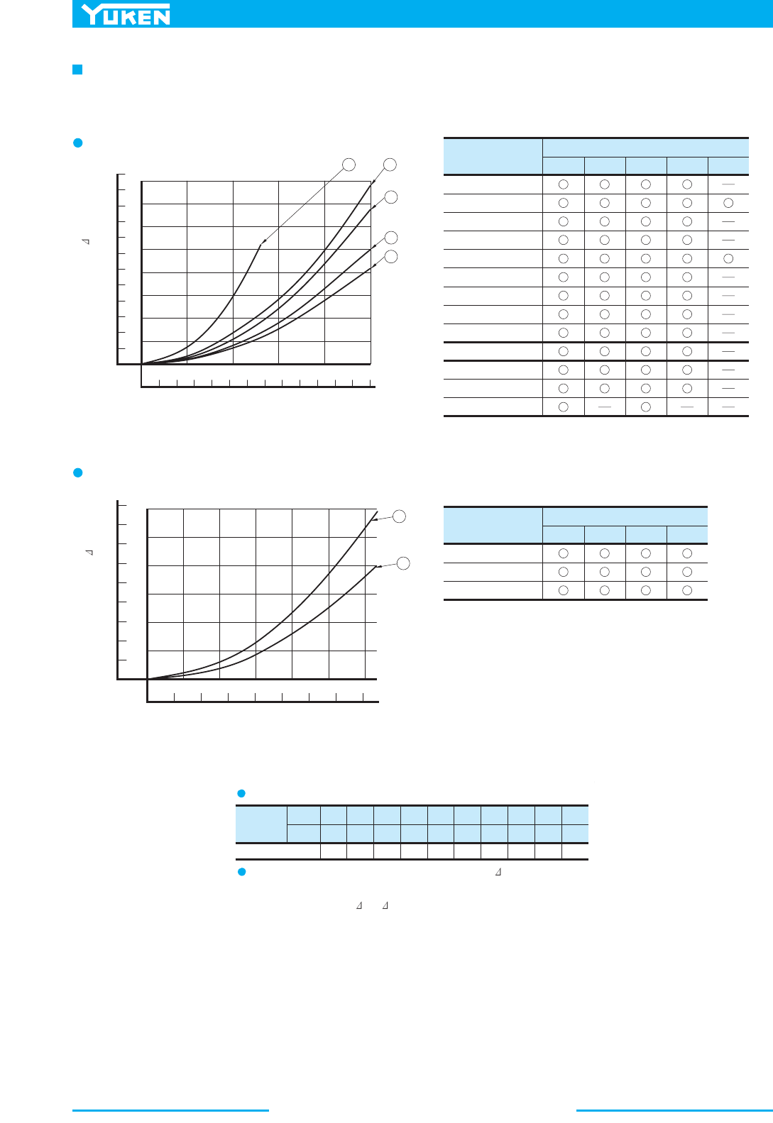
DSG-01 Series Solenoid Operated Directional Valves
354
Model Numbers
P
A
Pressure Drop Curve Number
4
5
4
4
1
5
4
4
4
5
5
5
5
DSG-01-3C2
DSG-01-3C3
DSG-01-3C4
DSG-01-3C40
DSG-01-3C60
DSG-01-3C9
DSG-01-3C10
DSG-01-3C11
DSG-01-3C12
DSG-01-2D2
DSG-01-2B2
DSG-01-2B3
DSG-01-2B8
4
5
4
4
1
3
5
4
4
4
4
5
4
5
4
4
1
5
4
4
4
5
5
5
4
4
5
4
4
1
3
4
4
5
4
4
5
2
2
Model Numbers
Pressure Drop Curve Number
1
1
1
2
1 1
1
2
1
S-DSG-01-3C2
S-DSG-01-3C4
S-DSG-01-2B2
11
1
Viscosity
SSU
Factor 0.81 0.87 0.96 1.03 1.09 1.14 1.19 1.23 1.27 1.30
77 98 141 186 232 278 324 371 417 464
2
mm /s 15 20 30 40 50 60 70 80
90 100
→
B
T
→
P
B
→
A
T
→
P
T
→
P
A
→
B
→
T
P
→
BA
T
→
Pressure Drop
P
Flow Rate
Flow Rate
Pressure Drop P
2
Pressure drop curves based on viscosity of 35 mm /s (164 SSU) and specific gravity of 0.850.
Shockless Type: S-DSG-01
Standard Type: DSG-01
Pressure Drop
For any other viscosity, multiply the factors in the table below.
For any other specific gravity (G'), the pressure drop ( P') may be
obtained from the formula below.
P' = P (G'/0.850)
0
0481216 20 24 U.S.GPM
L/min
20 40 60 80 100
2
1
3
4
1
2
3
4
5
0
100
200
300
400
500
600
PSI
MPa
0
0
40
80
120
160
180
PSI
MPa
024681012 14 16
U.S.GPM
L/min
10 20 30 40 50 60
1.2
1.0
0.8
0.6
0.4
0.2
2
1
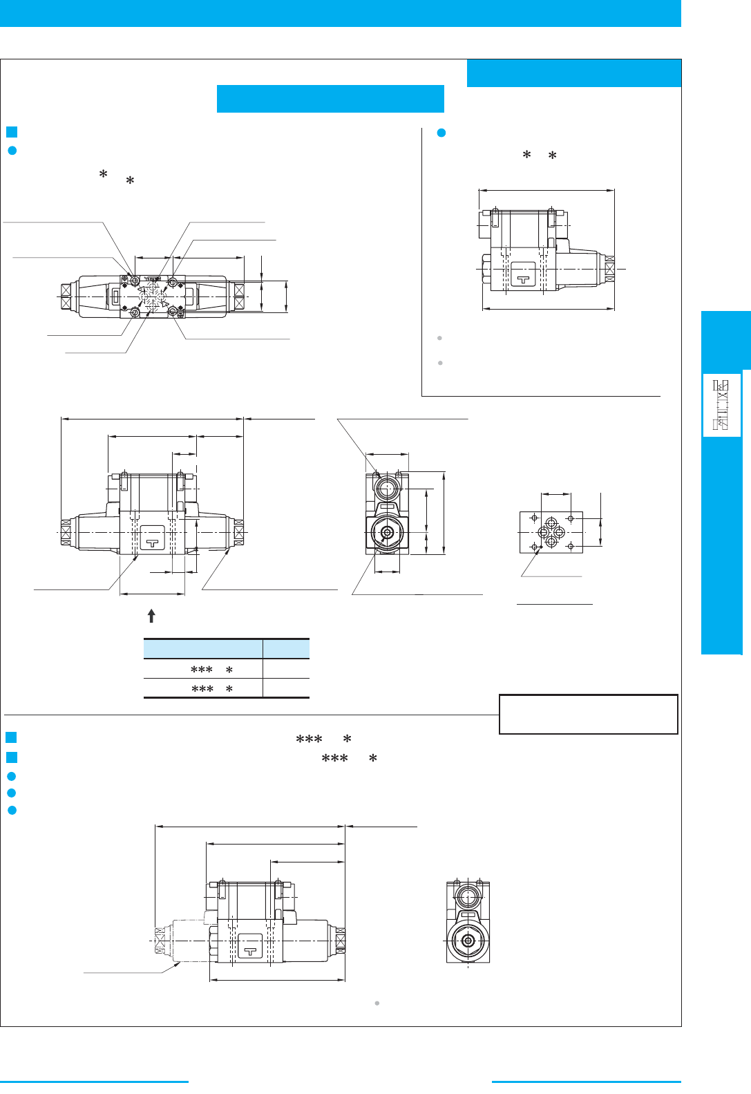
355
DIRECTIONAL CONTROLS
DSG-01 Series Solenoid
Operated Directional Valves
E
DSG-01 Series Solenoid Operated Directional Valves
Mounting Surface
(O-Rings Furnished)
Lock Nut
Tightening Torque:
10.3-11.3
Nm (
91-100
IN.lbs.)
Manual Actuator-Both Ends
Locating pin can be fitted to this hole to conform with
ISO4401-03-02-94. However, locating pin is not provided
to standard design valve. When ordering valve with a
locating pin, please consult Yuken.
6(.24)
Dia.
3(.12)
Dia.
5(.20)
VIEW ARROW X
Deep
Electrical Conduit Connection
"C "
Thd. (Both Ends)
Model Numbers
DSG-01-
-A
-7
0
DSG-01-
-A
-7090
"C
"
Thd.
G 1/2
1/2 NPT
★
★
Spring Centred
No-Spring Detented
Spring Offset
Models with DC Solenoids: (S-)DSG-01- -D -70/7090
Models with R Type Solenoids: (S-)DSG-01- -R -70/7090
Space Needed to Remove
Solenoid-Each End
Spring Offset Type
Double Solenoid
Models Only
For other dimensions, refer to models with AC solenoids.
DIMENSIONS IN
MILLIMETRES (INCHES)
Mounting surface: ISO 4401-AB-03-4-A
TERMINAL BOX TYPE
Double Solenoid: Spring Centred & No-Spring Detented
Models with AC Solenoids
-A -70/7090DSG-01-
3C
2D2
Single Solenoid: Spring Offset
DSG-01-2B -A
-70/7090
For other dimensions, refer to "spring Centred and
No-Spring Detented" models.
Solenoid being mounted in the reverse position
SOL a side is also available.
Space Needed to Remove
Solenoid-Each En
d
76.7
(3.02)
40.5
(1.59)
31
(1.22)
32.5
(1.28)
0.75
(.03)
Tank Port "T"
Cylinder Port "B"
Solenoid Indicator Light
(For Sol b)
Solenoid Indicator Light
(For Sol a)
Cylinder Port "A"
Pressure Port "P"
5.5(.22)
Dia. Through
9.5(.37)
C' Bore
4 Places
142.2
(5.60)
145.7
(5.74)
SOL b
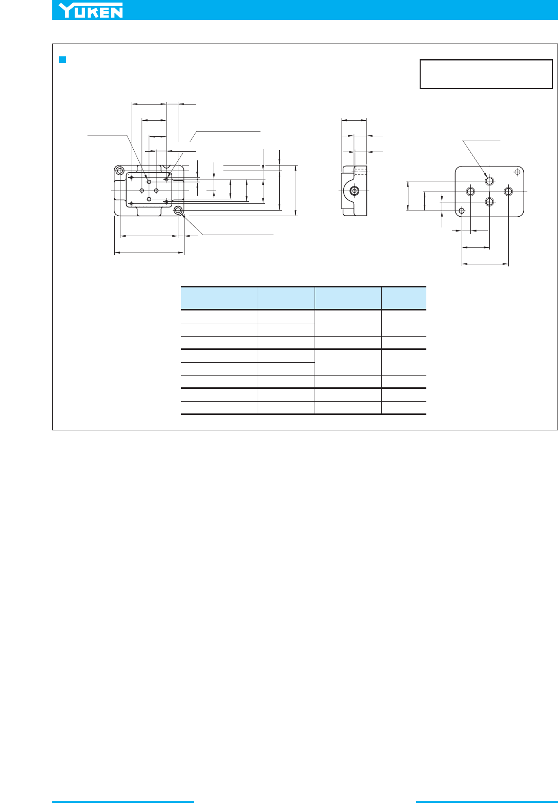
DSG-01 Series Solenoid Operated Directional Valves
356
Sub-plate
Model Numbers
Piping Size
"C"
Thd.
"D"
Thd.
"E"
mm(IN.)
DSGM-01-31
DSGM-01-3180
DSGM-01-3190
DSGM-01X-31
DSGM-01X-3180
DSGM-01X-3190
DSGM-01Y-31
DSGM-01Y-3190
Rc 1/8
1/8 BSP.F
1/8 NPT
Rc 1/4
1/4 BSP.F
1/4 NPT
Rc 3/8
3/8 NPT
M5
M5
No.10-24 UNC
M5
No. 10-24 UNC
12 (.47)
10 (.39)
12 (.47)
10 (.39)
10 (.39)
12 (.47)No.10-24 UNC
A
T
P
B
12.7(.50)
21.5
(.85)
30.2
(1.19)
40.5
(1.59)
14.2
(.56)
0.75
(.03)
15.5
(.61)
5.2
(.20)
25.8
(1.02)
31
(1.22)
31.75
(1.25)
8.5
(.33)
48
(1.89)
7.5
(.30)
63
(2.48)
71
(2.80)
85
(3.35)
7
(.28)
7 (.28) Dia. Through
11 (.43)
Dia. Spotface
2 Places
7 (.28) Dia.
4 Places
"
D
" Thd.
"
E
" Deep
4 Places
15
(.59)
16
(.63)
32
(1.26)
11
(.43)
24
(.94)
37
(1.46)
12.5
(.49)
35.5
(1.40)
58.5
(2.30)
"
C
" Thd.
4 Places
Sub-plate : DSGM-01/01X/01Y-31/3180/3190
DIMENSIONS IN
MILLIMETRES (INCHES)
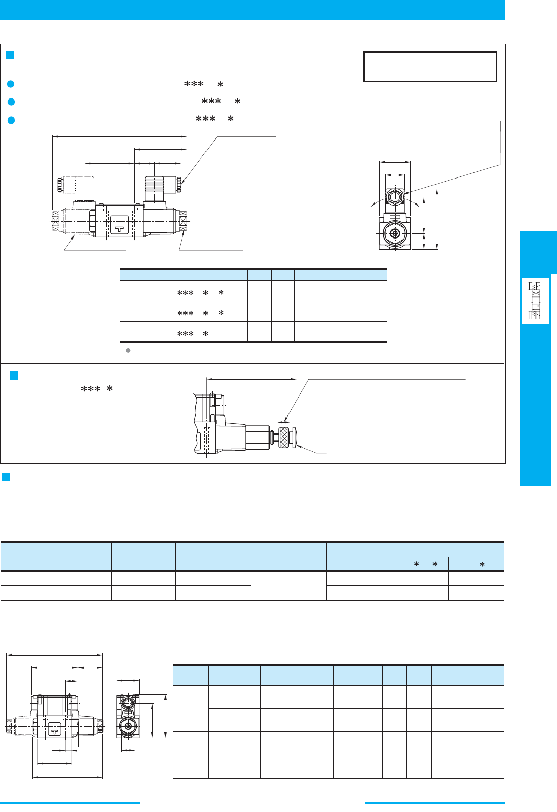
357
DIRECTIONAL CONTROLS
DSG-01 Series Solenoid
Operated Directional Valves
E
DSG-01 Series Solenoid Operated Directional Valves
CDEFGH
196.4
(7.73)
76.7
(3.02)
88.5
(3.48)
53
(2.09)
27.5
(1.08)
39
(1.54)
204.4
(8.05)
80.7
(3.18)
99.5
(3.92)
64
(2.52)
27.5
(1.08)
39
(1.54)
204.4
(8.05)
80.7
(3.18)
102.5
(4.04)
57.2
(2.25)
34
(1.34)
53
(2.09)
ABCDE FH JKL
C
72.5
(2.85)
29.5
(1.16)
H
D
23.5
(.93)
F
E
G
46(1.81)
A100
SOL a SOL b
SOL b
A
E
H
F
SOL a
SOL b
J
K
D
27
L
C
A100
A
3
5
B
38
PLUG-IN CONNECTOR TYPE (N)
PLUG-IN CONNECTOR WITH INDICATOR LIGHT (N1)
Models with AC Solenoids: DSG-01- -A - -70/7090
Models with DC Solenoids: (S-)DSG-01- -D - -70/7090
Models with R Solenoids: (S-)DSG-01- -R -N-70/7090
N
N1
N
N1
DIMENSIONS IN
MILLIMETRES (INCHES)
Double Solenoid
Models Only
Lock Nut
Tightening Torque:
10.3 - 11.3 Nm (90 - 100 IN.lbs.)
Cable Departure
Cable Applicable:
Outside Dia.
....
8 - 10 mm (.31 - .39 in.)
Conductor Area
....
Not Exceeding 1.5 mm
2
(.0023 Sq. in.)
The position of the Plug-in connector can be changed as
illustrated below by loosening the lock nut. After
completion of the change, be sure to tighten the lock nut
with the torque as specified below.
Model Numbers
DSG-01- -A -N
(S-)DSG-01- -D -N
(S-)DSG-01- -R -N
For other dimensions, refer to "Terminal Box type" (Page 356).
Models with Push Button & Lock Nut
(S-)DSG-01- - -C
AC: 132.2(5.20)
DC/R: 136.2(5.36)
Lock Nut
Press the "Push Button" then turn "Lock Nut"
clockwise. The position of the "Push Button" is held.
Be sure to loosen "Lock Nut" fully before solenoid
is energised.
Push Button
Interchangeability in Installation Current and New Design
In ouder to achieve higher pressure, higher flow, lower pressure drop DSG-01 valves has been upgraded from the 60
design series to the 70 design series.
The figures in the table below are the comparison between the current and the new design valves.
Design Number
★ Flow Rate: 60 L/min (15.9 U.S.GPM), Viscosity: 30 mm
2
/s (141 SSU), Spool type "2" (Closed centre)
Max. Operating
Pressure
MPa (PSI)
Max. T-Line
Back Pres.
MPa (PSI)
Pressure Drop
MPa (PSI)
{P→A}
Mass kg (lbs.)
Max. Flow
L/min
(U.S.GPM)
Max. Changeover
Frequency
Cycle/min (min
–1
)
★
3C /2D
2B
1.85(4.08)
2.2(4.85)
0.9(130)
1.0(145)
21(3050)
16(2320)
35(5080)
31.5(4570)
100(26.4)
63(16.6)
300
(R Type sol. Only 120)
1.4(3.09)
1.6(3.53)
New Design: 70
Current Design:
60
● Specifications
● Interchangeability in Installation
Interchangeability in installation in maintained though there are minor differences in demension as in the following table.
196.4
(7.73)
142.2
(5.60)
46
(1.81)
88.8
(3.50)
95
(3.74)
50.7
(2.00)
26
(1.02)
70
(2.76)
13.5
(.53)
70.5
(2.78)
191.4
(7.54)
142.7
(5.62)
48
(1.89)
90.3
(3.56)
90
(3.54)
50.7
(2.00)
23.5
(.93)
65
(2.56)
11
(.43)
72
(2.83)
204.4
(8.05)
146.2
(5.76)
46
(1.81)
88.8
(3.50)
95
(3.74)
54.7
(2.15)
26
(1.02)
70
(2.76)
13.5
(.53)
70.5
(2.78)
210
(8.27)
152
(5.98)
48
(1.89)
90.3
(3.56)
90
(3.54)
60
(2.36)
23.5
(.93)
65
(2.56)
11
(.43)
72
(2.83)
Coil Type
Design
Number
New Design
: 70
Current Design
: 60
New Design
: 70
Current Design
: 60
AC
DC
R
(1.06)
(1.50)
DSG-01 Series Solenoid Operated Directional Valves
358
3
3
1.
2.
3.
Type of
Electrical Conduit
Connection
Double Solenoid Type Single Solenoid Type
Terminal
Box Type
Plug-in
Connector
Type
Type of
Electrical Conduit
Connection
Electric Source
Terminal
Box Type
Plug-in
Connector
Type
AC DC AC
→
DC Rectified
1
1
3
2
2
3
SOL.
SOL
.SOL.
SOL.
SOL
.
SOL.
1
Ground
3
Power Supply
(For SOL.a
)
Indicator Light
SOL. bSOL.
a
3
Power Supply
(For SOL.b)
Indicator Light
1
Ground
2
Common Plate
Commo
n
Indicator Light
Ground
3
Power Suppl y
SOL. b
Ground
3
2-Power Suppl y
1-Power Suppl
y
Indicator Light
Indicator Light
Voltage-Surge
Suppressor
Indicator Light
Voltage-Surge
Suppressor
Rectifier
Circui
t
Power
Supply
Common
Ground
Power
Supply
Common
Ground
Power
Supply
Common
Ground
Indicator Light
(Integrated in "N1"
model only
)
1-Power
Supply
Ground
2-Power
Supply
1-Power
Supply
Ground
2-Power
Supply
Indicator Light
(Integrated in "N1"
model only
)
Voltage-Surge
Suppressor
(Circuit composed
in coil
)
1-Power
Supply
Ground
2-Power
Supply
Voltage-Surge
Suppressor
Rectifier
Circuit
Details of Receptacle
There are two grounding terminals. You can use either one.
If you do not need the common plate, remove it.
With DC solenoids, polarity is no question.
Electrical Circuit
Do not perform wiring while the power is on.
Doing so may result in electric shock, burns or death.
Make the wiring properly. Improper wiring will cause an
irregular movement of the machine, resulting in a grave
accident.
DANGER
359
DIRECTIONAL CONTROLS
DSG-01 Series Solenoid
Operated Directional Valves
E
DSG-01 Series Solenoid Operated Directional Valves
8
9
18
19
24
25
26
27
30
AS 568-026 (NBR, Hs70)
4
1
2
2
2
2
4
4
1
2
2
2
2
4
4
1
1
2
1
1
1
2
2
SOL a
SOL b
16 12
18
14
19
17
13
15
5
431 8 2 27 25 21 23 20 26 22
30
9
7
6
8
28
11
29 10
Valve Model Numbers
-DSG-01-
-
-70/7090
-DSG-01-
-
-N-70/7090
Seal Kit No.
KS-DSG-01-70
KS-DSG-01-N-70
O-Ring Details for Seal Kit
(4 Pcs.), & (2 Pcs., see above), (4 Pcs.)
8 9 25 27
(4 Pcs.), & (2 Pcs., see above)
8 9 25
When ordering the O-Rings, please specify the seal kit number from the table below.
List of Seals
-DSG-01- - -70/7090
Item
Name of Parts Part Numbers
Qty.
3C 2D
2B
Remarks
Included in Solenoid Ass'y (Item 11)
SO-NB-P18
SO-NA-P20
SO-NA-P4
1790S-VK418329-9
O-Ring
O-Ring
Packing
O-Ring
O-Ring
O-Ring
O-Ring
O-Ring
Plug
SO-NB-A-012 (NBR, Hs90)
SO-NB-P18
1790S-VK421290-8
S6
Spring Offset type
24
Solenoid Ass'y, Coil, Receptacle and Connector Refer to page 360 for the details of these parts.
SOL a
SOL b
18
11 19
16
15 14
-DSG-01- - -N/N1-70/7090
■ List of Seals
DSG-01 Series Solenoid Operated Directional Valves
360
Valve Model Numbers
DSG-01-
-A100-70
DSG-01-
-A120-70
DSG-01-
-A200-70
DSG-01-
-A240-70
DSG-01-
-D12-70
DSG-01-
-D24-70
DSG-01-
-D48-70
DSG-01-
-R100-70
DSG-01-
-R200-70
S-DSG-01-
-D12-70
S-DSG-01-
-D24-70
S-DSG-01-
-D48-70
S-DSG-01-
-R100-70
S-DSG-01-
-R200-70
DSG-01-
-A100-N-70
DSG-01-
-A120-N-70
DSG-01-
-A200-N-70
DSG-01-
-A240-N-70
DSG-01-
-D12-N-70
DSG-01-
-D24-N-70
DSG-01-
-D48-N-70
DSG-01-
-R100-N-70
DSG-01-
-R200-N-70
S-DSG-01-
-D12-N-70
S-DSG-01-
-D24-N-70
S-DSG-01-
-D48-N-70
S-DSG-01-
-R100-N-70
S-DSG-01-
-R200-N-70
DSG-01-
-A100-N1-70
DSG-01-
-A120-N1-70
DSG-01-
-A200-N1-70
DSG-01-
-A240-N1-70
DSG-01-
-D12-N1-70
DSG-01-
-D24-N1-70
DSG-01-
-D48-N1-70
S-DSG-01-
-D12-N1-70
S-DSG-01-
-D24-N1-70
S-DSG-01-
-D48-N1-70
11
Solenoid Ass'y No.
20
Coil No.
13
Receptacle
Part No.
18
Connector Ass'y
Part No.
19
Connector Ass'y
Part No.
Remarks
SA1-100-70
SA1-120-70
SA1-200-70
SA1-240-70
SD1-12-70
SD1-24-70
SD1-48-70
SR1-100-70
SR1-200-70
SD1-12-S-70
SD1-24-S-70
SD1-48-S-70
SR1-100-S-70
SR1-200-S-70
SA1-100-N-70
SA1-120-N-70
SA1-200-N-70
SA1-240-N-70
SD1-12-N-70
SD1-24-N-70
SD1-48-N-70
SR1-100-N-70
SR1-200-N-70
SD1-12-S-N-70
SD1-24-S-N-70
SD1-48-S-N-70
SR1-100-S-N-70
SR1-200-S-N-70
SA1-100-N-70
SA1-120-N-70
SA1-200-N-70
SA1-240-N-70
SD1-12-N-70
SD1-24-N-70
SD1-48-N-70
SD1-12-S-N-70
SD1-24-S-N-70
SD1-48-S-N-70
C-SA1-100-70
C-SA1-120-70
C-SA1-200-70
C-SA1-240-70
C-SD1-12-70
C-SD1-24-70
C-SD1-48-70
C-SR1-100-70
C-SR1-200-70
C-SD1-12-70
C-SD1-24-70
C-SD1-48-70
C-SR1-100-70
C-SR1-200-70
C-SA1-100-N-70
C-SA1-120-N-70
C-SA1-200-N-70
C-SA1-240-N-70
C-SD1-12-N-70
C-SD1-24-N-70
C-SD1-48-N-70
C-SR1-100-N-70
C-SR1-200-N-70
C-SD1-12-N-70
C-SD1-24-N-70
C-SD1-48-N-70
C-SR1-100-N-70
C-SR1-200-N-70
C-SA1-100-N-70
C-SA1-120-N-70
C-SA1-200-N-70
C-SA1-240-N-70
C-SD1-12-N-70
C-SD1-24-N-70
C-SD1-48-N-70
C-SD1-12-N-70
C-SD1-24-N-70
C-SD1-48-N-70
R1-70
KR1-A-70
KR1-B-70
RR1-70
KR1-A-70
KR1-B-70
RR1-70
Terminal
Box
Type
Plug-in
Connector
Type
Plug-in
Connector
with
Indicator
Light
GDM-211-A-11
GDME-211-R-A-10
GDM-211-A-11
GDME-211-R-A-10
GDML-211-1-11
GDML-211-2-11
GDML-211-3-11
GDML-211-1-11
GDML-211-2-11
GDML-211-3-11
GDML-211-1-11
GDM-211-B-11
GDME-211-R-B-10
GDM-211-B-11
GDME-211-R-B-10
GDML-211-1-11
GDML-211-2-11
GDML-211-3-11
GDML-211-1-11
GDML-211-2-11
GDML-211-3-11
GDML-211-1-11
Note: T
he connector assembly is not included in the solenoid assembly.
■ Solenoid Ass'y, Coil, Receptacle and Connector Ass'y No.
361
DIRECTIONAL CONTROLS
DSG-03 Series Solenoid
Operated Directional Valves
E
DSG-03 Series Solenoid Operated Directional Valves
Specifications
Valve
Type
AC
Model
Numbers
Max. Flow
L/min (U.S.GPM)
Max. Operating
Pressure
MPa (PSI)
Max. T-Line
Back Pres.
MPa (PSI)
Max. Changeover
Frequency
-1
min (Cycles/Min)
DC, R, RQ
Type of Solenoid
Approx. Mass kg(1bs.)
DSG-03-3C
-
-50/5090
DSG-03-2D2-
-50/5090
DSG-03-2B
-
-50/5090
L-DSG-03-3C - -50/5090
L-DSG-03-2D2- -50/5090
L-DSG-03-2B - -50/5090
S-DSG-03-3C
-
-50/5090
S-DSG-03-2B2-
-50/5090
Standard
Type
Shockless
Type
120 (31.7)
60 (15.9)
120 (31.7)
31.5 (4570)
Spool Type 60 Only
25 (3630)
25 (3630)
16 (2320)
16 (2320)
16 (2320)
16 (2320)
240
R Type Sol. Only
120
120
240
R Type Sol. Only
120
2.9 (6.4)
3.6 (7.9) 5 (11)
3.6 (7.9) 5 (11)
3.6 (7.9
2.9 (6.4) 3.6 (7.9I
)
5 (11)
3.6 (7.9
)
For details of L-DSG-03, please contact us.
Low
Wattage
(14W)Type
★1
★1
★2
★2
The maximum flow means the limited flow without inducing any abnormality to the operation (changeover) of the valve. The maximum flow
differs according to the spool type and operating conditions. For details, please refer to the "List of Standard Models and Maximum Flow" on
pages 364 to 368.
Sub-plate
Piping
Size
Sub-plate
Model Numbers
Thread
Size
Japanese Standard "JIS"
Sub-plate
Model Numbers
Thread
Size
European Design Standard
Sub-plate
Model Numbers
Thread
Size
N.American Design Standard
Approx.
Mass
kg (lbs.)
Rc 3/8DSGM-03-40 3/8 BSP.FDSGM-03-2180
3/8 NPT
3.0 (6.6)
Rc 1/2
Rc 3/4
1/2 BSP.F
1/2 NPT
3/4 NPT
3.0 (6.6)
4.7 (10.4)
3/8
Mounting Bolts
Descriptions Soc. Hd. Cap Screw (4 pcs.) Tightening Torque
Japanese Standard "JIS"
European Design Standard
N. American Design Standard
M6
×
×
35 Lg.
1/4-20 UNC 1-1/2 Lg.
12 - 15 Nm
(106 - 133 in. 1bs.)
1/2
3/4 3/4 BSP.F
DSGM-03-2190
DSGM-03X-40
DSGM-03Y-40
DSGM-03X-2180
DSGM-03Y-2180
DSGM-03X-2190
DSGM-03Y-2190
For socket head cap screws in the table below are included.
Sub-plates are available. Specify the sub-plate model number from the table above.
When sub-plates are not used, the mounting surface should have a good machined finish
.
■ 3/8 Solenoid Operated Directional Valves, DSG-03 Series
These are epoch-making solenoid operated valves of high pressure, high flow
which have been developed incorporating a unique design concept into every
part of the valve including the solenoid. With wet type solenoids, these
valves ensure the low noise and the long life, moreover, ensure no leakage of
oil outside of the valves.
● Wide Range of Models
Choose the optimum valve to meet your need from a large selection available.
The DSG-03 50 design series solenoid operated directional valves are
classified into the two basic models.
●
Standard type …. Useable at high pressure: 31.5 MPa (4570 PSI) and high
flow: 120 L/min (31.7 U.S.GPM)
●
Shockless type …. A noise at spool changeover and a vibration in piping
can be reduced to a minimum.
● Stable Operation
With a strong magnet and spring force, the valves are tough against
contamination and thus ensure a stable operation.
● Usable in products of various standards
CE/UL/CSA certified products are available.
Terminal Box Type
Plug-in Connector Type
DSG-03 Series Solenoid Operated Directional Valves
362
SOL b
1.
2.
3.
1
2
Solenoid Ratings
Valve Type Electric source
Coil
Type
Frequency
(Hz)
Source Rating
Voltage (V)
Serviceable Range
Inrush (A)
Holding (A) Power (W)
Current & Power at Rated Voltage
100
100
110
120
200
200
220
240
12
24
100
100
200
100
50
60
50
60
50
60
50
60
50/60
50/60
A100
A120
A200
A240
D12
D24
D100
R100
R200
RQ100
80 - 110
90 - 120
96 - 132
108 - 144
160 - 220
180 - 240
192 - 264
216 - 288
10.8 - 13.2
21.6 - 26.4
90 - 110
90 - 110
180 - 220
5.37
4.57
5.03
4.48
3.81
2.69
2.29
2.52
2.24
1.91
0.90
0.63
0.77
0.75
0.52
0.45
0.31
0.38
0.37
0.26
3.16
1.57
0.38
0.43
0.21
0.4390 - 110
AC
DC (K Series)
AC
→
DC Rectified (R )
AC DC Rectified (RQ)
(Quick Return )
Standard
Type
Shockless
Type
38
38
38
→
AC solenoid is not available in shockless type.
R or RQ type models with built-in current rectifier is recommended for shockless operation with AC power.
Inrush current in the above table show rms values at maximum stroke.
There are more coil types other than the above. For details, please make inquiries .
The coil type numbers in the shaded column are handled as optional extras.
In case these coils are required to be chosen, please confirm the time of
delivery with us before ordering .
Plug-in Connector
with Solenoid
Indicator Light
Lock Nut
Push Button
Push Button with Lock Nut
Options
Can be used for manual changeover of spool. The push button
can be locked in the pressed condition.
Plug-in Connector with Solenoid Indicator Light
These are the indicator light incorporated plug-in connector type
solenoids. Energisation or de-energisation of the solenoid can
be easily identified with the incorporated indicator light.
(Example)
The valve is supplied with 4 pcs. hexagon
socket head cap screws M8 × 38 Lg.
M8 Mounting Bolts.
As the mounting bolts, M6 socket head cap screws are used for
the standard valves, however, M8 socket head cap screws are also
available for supply as optional extras. In case the M8 screws
are required, suffix "02" to the design number of both valve and
sub-plate model number like below.
Valve: DSG-03-3C2-A100-5002
Sub-plate: DSGM-03-4002
363
DIRECTIONAL CONTROLS
DSG-03 Series Solenoid
Operated Directional Valves
E
DSG-03 Series Solenoid Operated Directional Valves
1.
2.
3.
In case of the special two position valve, please refer to
page 369 for details.
N is not available for RQ-type solenoids .
N1 is not available for R and RQ-type solenoids
.
In the table above, the symbols or numbers highlighted with shade represent the optional
extras. The valves with model number having such optional extras are handles as options,
therefore, please confirm the time of delivery with us before ordering.
3
2
1
1
1
1
F- S- DSG -03 -2 B A
Special
Seals
Shockless
Type
Series
Number
Valve
Size
Number
of Valve
Positions
Spool-
Spring
Arrangement
Spool
Type
Special Two
Position Valve
Omit if not
require
d
-D24 -C -N -50
-L
Coil
Type
Manual
Override
Electrical
Conduit
Connection
Design
Number
Design
Standard
Models with
Reverse Mtg. of
Solenoid
Omit if not
required
F:
For Phosphate
Ester Type
Fluids
(Omit if not
required)
None:
Standard
Type
S:
Shockless
Type
DSG:
Solenoid
Operated
Directional
Valve
03 50
3:
Three
Positions
2:
Two
Positions
2:
Two
Positions
3:
Three
Positions
C:
Spring
Centred
D:
No-Spring
Detented
B:
Spring
Offset
C:
Spring
Centred
B:
Spring
Offset
A
B
A
B
None:
Terminal
Box Type
N:
Plug-in
Connector
Type
N1:
Plug-in
Connector
Type
with
Indicator
Light
(Option)
None:
Japanese
Std. "JIS"
90:
N.American
Design Std.
None::
Japanese
Std. "JIS"
and
European
Design
Std.
90:
N. American
Design
Std.
L
L
None:
Manual
Override
Pin
C
:
Push
Button
and
Lock Nut
(Option)
3
40
60
10
12
2,
4,
9,
11,
2
3
2
8
2
2
4
AC:
A100
A120
A200
A240
DC:
D12
D24
D100
R:
(AC
DC)
R100
R200
RQ:
RQ100
(AC
DC)
5,
→
→
DC:
D12
D24
D100
R:
(AC
DC)
R100
R200
RQ:
RQ100
(AC
DC)
■ Model Number Designation
2
DSG-03 Series Solenoid Operated Directional Valves
364
m
T of the valves with a mark, please see page 368.
AB
T
P
b
A
B
T
P
b
A
B
T
P
b
a
A
B
TP
b
a
AB
TP
b
a
AB
T
P
b
a
AB
T
P
b
a
AB
T
P
b
a
AB
T
P
b
a
AB
T
P
b
a
AB
TP
b
a
AB
T
P
b
a
AB
TP
b
a
AB
TP
b
AB
P
T
PT
A
B
PT
A
B
60 60 40 35
100(62)
80(42)
100(79)
92(55)
100(35)
45(21)
100(62)
73(36)
100(72)
89(46)
87(15)
34(12)
100(44)
63(34)
100(64)
78(28)
94(37)
51(33)
100(59)
70(27)
30
100
60
28
100
60
28
100
60
28
60
100(70)
90(49)
100(81)
100(81)
100(58)
90(47)
100(62)
62(40)
100(48)
53(30)
100(81)
100(81)
100(33)
50(26)
100(39)
47(26)
96(28)
34(19)
100(81)
100(81)
76(22)
28(18)
84(21)
27(16)
65(24)
26(15)
100(81)
100(81)
46(19)
22(15)
48(18)
20(12)
100(55)
60(38)
100(80)
80(60)
100(55)
60(38)
100(36)
47(24)
100(65)
70(46)
100(36)
47(24)
60(21)
23(14)
85(35)
51(32)
60(21)
23(14)
34(16)
17(11)
62(28)
45(25)
34(16)
17(11)
34
57
26
24
57
19
20
57
18
19
57
16
40 40 30 28
26
100
60
21
100
60
18
100
60
16
60
100(70)
90(49)
100(81)
100(81)
100(58)
90(47)
100(62)
62(40)
100(48)
53(30)
100(81)
100(81)
100(33)
50(26)
100(39)
47(26)
96(28)
34(19)
100(81)
100(81)
76(22)
28(18)
84(21)
27(16)
65(24)
26(15)
100(81)
100(81)
46(19)
22(15)
48(18)
20(12)
100(55)
60(38)
100(80)
80(60)
100(55)
60(38)
100(36)
47(24)
100(65)
70(46)
100(36)
47(24)
60(21)
23(14)
85(35)
51(32)
60(21)
23(14)
34(16)
17(11)
62(28)
45(25)
34(16)
17(11)
100
100
100
90
80
100
30
70
100
80
100
90
100
30
100
100
30
70
100
100
90
100
90
80(65)
75(20)
80(25)
30(15)
100(75)
100(25)
80(30)
30(25)
80(20)
20(15)
DSG-03-2D2
DSG-03-2B2
DSG-03-2B3
DSG-03-2B8
DSG-03-3C2
DSG-03-3C3
DSG-03-3C4
DSG-03-3C40
DSG-03-3C5
DSG-03-3C60
DSG-03-3C9
DSG-03-3C10
DSG-03-3C11
DSG-03-3C12
10 16
Working Pressure MPa
Working Pressure MPa
Working Pressure MPa
25 31.5
A
B
A
P
T
B
P AB
100
100
100
100
100
100
100
100 100 100
100
90
80
100
30
70
100
80
100
90
90(30)
40(20)
90(20)
20(15)
100(75)
100(90)
100
100(75)
100(90)
100(75)
100(90)
100(75)
100(90)
( 9 )61
( 9 )15
( 7 )49
( 6 )11
[Port "A" Blocked][Port "B" Blocked]
Max. Flow
L/min
10 16 25 31.5 10 16 25 31.5
Graphic
Symbols
Model
Numbers
Spool-Spring Arrangement
No. of Valve Positions
Spring Centred
Three Positions
No-Spring
Detented
Spring Offset
Two Positions
(Example)
100(75)
100
The maximum flow rate is
constant regardless of 50 Hz or
60 Hz and of any voltage
variants within the serviceable
voltage
100(25)
50Hz, At rated voltage
Notes : The relation between the maximum flow in the table above and the frequency/voltage (within the serviceable voltage) is as shown below.1.
2.
60Hz, At rated voltage
50Hz, At minimum serviceable voltage
(80% of rated voltage)
60Hz, At minimum serviceable voltage
(90% of rated voltage)
The valve models with a ark are handled as
Options. If you choose such valves, check the time
of delivery beforehand.
List of Standard Models and The Maximum Flow
For the maximum flow rate in P
→
Models with AC Solenoids: DSG-03- -A
P
365
DIRECTIONAL CONTROLS
DSG-03 Series Solenoid
Operated Directional Valves
E
DSG-03 Series Solenoid Operated Directional Valves
m
T of the valves with a mark, please see page 368.
A B
T
P
b
A B
TP
b
A
B
T
P
b
a
A
B
TP
b
a
A B
T
P
b
a
A B
TP
b
a
A B
T
P
b
a
A B
T
P
b
a
A B
TP
b
a
A B
TP
b
a
A B
T
P
b
a
A B
T
P
b
a
A B
TP
b
a
A B
TP
b
A
B
P
T
P T
A
B
P T
A
B
120
120
120
120
50
120
120
120
120
120
DSG-03-2D2
DSG-03-2B2
DSG-03-2B3
DSG-03-2B8
DSG-03-3C2
DSG-03-3C3
DSG-03-3C4
DSG-03-3C40
DSG-03-3C5
DSG-03-3C60
DSG-03-3C9
DSG-03-3C10
DSG-03-3C11
DSG-03-3C12
10 16 25 31.5
A
B
A
P
T
B
P AB
120
120
120
120
50
120
120
120
120
120
[Port "A" Blocked][Port "B" Blocked]
Max. Flow L/min
10 16 25 31.5 10 16 25 31.5
Graphic
Symbols
Model
Numbers
Spool-Spring Arrangement
No. of Valve Positions
Spring Centred
Three Positions
No-Spring
Detented
Spring Offset
Two Positions
120
65
120
The maximum flow rate is constant regardless of
any voltage variants within the serviceable voltage
At rated voltage [after temperature rise and saturated]
At minimum serviceable voltage
(90% of rated voltage) [after temperature rises and saturated]
120 120 120 120 45 37 30 28 60 60 40 35
120
120
120
120
35
120
100
120
100
120
120
120
120
120
45
120
100
120
100
120
120
100
80
54
55
43
120
120
120 120
84
65
62
57
120
104
64
53
49
42
24
120
100
21
120
100
20
100
112
69
120
86
60
46
80
62
62
47
51
40
65
52
51
40
100
120
100
80
54
55
43
120
120
120 120
84
65
62
57
120
104
64
53
49
42
45
120
100
45
120
100
45
100
112
69
120
86
60
46
80
62
62
47
51
40
65
52
51
40
100
120
120
120
120
50
120
120
120
120
120
120
50
120
65
50
120
65
120
65
65
50
120 120
110
100
110
100
110
100
110
100
120 120 120 120
114
83
75
58
63
48
120
103
47
37
62
40
120
62
120 120
68
77
53
47
77
33
38
77
24
38
77
23
120
120
120
(Example)
Notes ) The relation between the maximum flow in the table above and the voltage (within the serviceable voltage) is as shown below.1.
2.
The valve models with a ark are handled as
Options. If you choose such valves, check the time
of delivery beforehand.
List of Standard Models and The Maximum Flow
For the maximum flow rate in P
→
Models with DC Solenoids: DSG-03- -D
Models with R Type Solenoids: DSG-03- -R
Models with RQ Type Solenoids: DSG-03- -RQ100
P
Working Pressure MPa
Working Pressure MPa
Working Pressure MPa

DSG-03 Series Solenoid Operated Directional Valves
366
m
T of the valves with a mark, please see page 368.
A B
T
P
b
A
B
T
P
b
A
B
T
P
b
a
A
B
TP
b
a
A B
TP
b
a
A B
T
P
b
a
A B
T
P
b
a
A B
T
P
b
a
A B
T
P
b
a
A B
T
P
b
a
A B
TP
b
a
A B
T
P
b
a
A B
TP
b
a
A B
TP
b
A B
P
T
P T
A
B
P T
A
B
DSG-03-2D2
DSG-03-2B2
DSG-03-2B3
DSG-03-2B8
DSG-03-3C2
DSG-03-3C3
DSG-03-3C4
DSG-03-3C40
DSG-03-3C5
DSG-03-3C60
DSG-03-3C9
DSG-03-3C10
DSG-03-3C11
DSG-03-3C12
1450 2320 3630 4570
A
B
A
P
T
B
P AB
[Port "A" Blocked][Port "B" Blocked]
Max. Flow U.S.GPM
Graphic
Symbole
Model
Numbers
Spool-Spring Arrangement
No. of Valve Positions
Spring Centred
Three Positions
No-Spring
Detented
Spring Offset
Two Positions
26.4
23.8
21.1
26.4
7.9
18.5
26.4
21.1
26.4
23.8
1450 2320 3630 4570 1450 2320 3630 4570
26.4
23.8
21.1
26.4
7.9
18.5
26.4
21.1
26.4
23.8
26.4
23.8
26.4
23.8
26.4
7.9
18.5
26.4
7.9
26.
4
26.4 26.4
26.4 26.4 26.4 26.4 10.6 10.6 7.9 7.4 10.6 9.215.915.9
9.0
15.1
6.9
6.3
15.1
5.0
5.3
15.1
4.8
5.0
15.1
4.2
6.
9
5.5 4.8 4.2 7.9 7.4 7.4 7.4
26.4 26.4 26.4 26.4 26.4 26.4
15.9 15.9 15.9 15.9 15.9 15.9 15.9 15.9
21.1 (17.2)
19.8 (5.3)
21.1 (6.6)
7.9 (4.0)
26.4 (19.8)
26.4 (6.6)
26.4 (18.5)
23.8 (12.9)
26.4 (21.4)
26.4 (21.4)
26.4 (15.3)
23.8 (12.4)
26.4 (16.4)
16.4 (10.6)
26.4 (12.7)
14.0 (7.9)
26.4 (21.4)
26.4 (21.4)
26.4 (8.7)
13.2 (6.9)
26.4 (10.3)
12.4 (6.9)
25.4 (7.4)
9.0 (5.0)
26.4 (21.4)
26.4 (21.4)
20.1 (5.8)
7.4 (4.8)
22.2 (5.5)
7.1 (4.2)
17.2 (6.3)
6.7 (4.0)
26.4 (21.4)
26.4 (21.4)
12.2 (5.0)
5.8 (4.0)
12.7 (4.8)
5.3 (3.2)
21.1 (7.9)
7.9 (6.6)
21.1 (5.3)
5.3 (4.0)
23.8 (7.9)
10.6 (5.3)
23.8 (5.3)
5.3 (4.0)
26.4 (23.8) 26.4 (23.8) 26.4 (23.8) 26.4 (23.8)
26.4 (19.8) 26.4 (19.8) 26.4 (19.8) 26.4 (19.8)
26.4 26.4 26.4 26.4
26.4 26.4 26.4 26.4
26.4 (16.4)
21.1 (11.1)
26.4 (20.9)
24.3 (14.5)
26.4 (9.2)
11.9 (5.5)
26.4 (16.4)
19.3 (9.5)
26.4 (19)
23.5 (12.2)
23 (4.0)
9.0 (3.2)
26.4 (11.6)
16.6 (9.0)
26.4 (16.9)
20.6 (7.4)
16.1 (2.4)
4.0 (2.4)
24.8 (9.8)
13.5 (8.7)
26.4 (15.6)
18.5 (7.1)
12.9 (1.8)
2.9 (1.6)
26.4 (21.1)
21.1 (15.9)
26.4 (17.2)
18.5 (12.2)
22.5 (9.2)
13.5 (8.5)
16.4 (7.4)
11.9 (6.6)
26.4 (21.1)
21.9 (15.9)
26.4 (17.2)
18.5 (12.2)
22.5 (9.2)
13.5 (8.5)
16.4 (7.4)
11.9 (6.6)
26.4 (14.5)
15.9 (10)
26.4 (9.5)
12.4 (6.3)
15.9 (5.5)
6.1 (3.7)
9.0 (4.2)
4.5 (2.9)
26.4 (14.5)
15.9 (10)
26.4 (9.5)
12.4 (6.3)
15.9 (5.5)
6.1 (3.7)
9.0 (4.2)
4.5 (2.9)
26.4 (14.5)
15.9 (10)
26.4 (9.5)
12.4 (6.3)
15.9 (5.5)
6.1 (3.7)
9.0 (4.2)
4.5 (2.9)
26.4 (14.5)
15.9 (10)
26.4 (9.5)
12.4 (6.3)
15.9 (5.5)
6.1 (3.7)
9.0 (4.2)
4.5 (2.9)
List of Standard Models and The Maximum Flow
(Example)
26.4(19.8)
26.
4
The maximum flow rate is
constant regardless of 50 Hz or
60 Hz and of any voltage
variants within the serviceable
voltage
26.4(6.6)
50Hz, At rated voltage
Notes: The relation between the maximum flow in the table above and the voltage (within the serviceable voltage) is as shown below.1.
2.
60Hz, At rated voltage
50Hz, At minimum serviceable voltage
(80% of rated voltage)
60Hz, At minimum serviceable voltage
(90% of rated voltage)
The valve models with a ark are handled as
Options. If you choose such valves, check the time
of delivery beforehand.
For the maximum flow rate in P
→
Models with AC Solenoids: DSG-03- -A
P
Working Pressure PSI
Working Pressure PSI
Working Pressure PSI
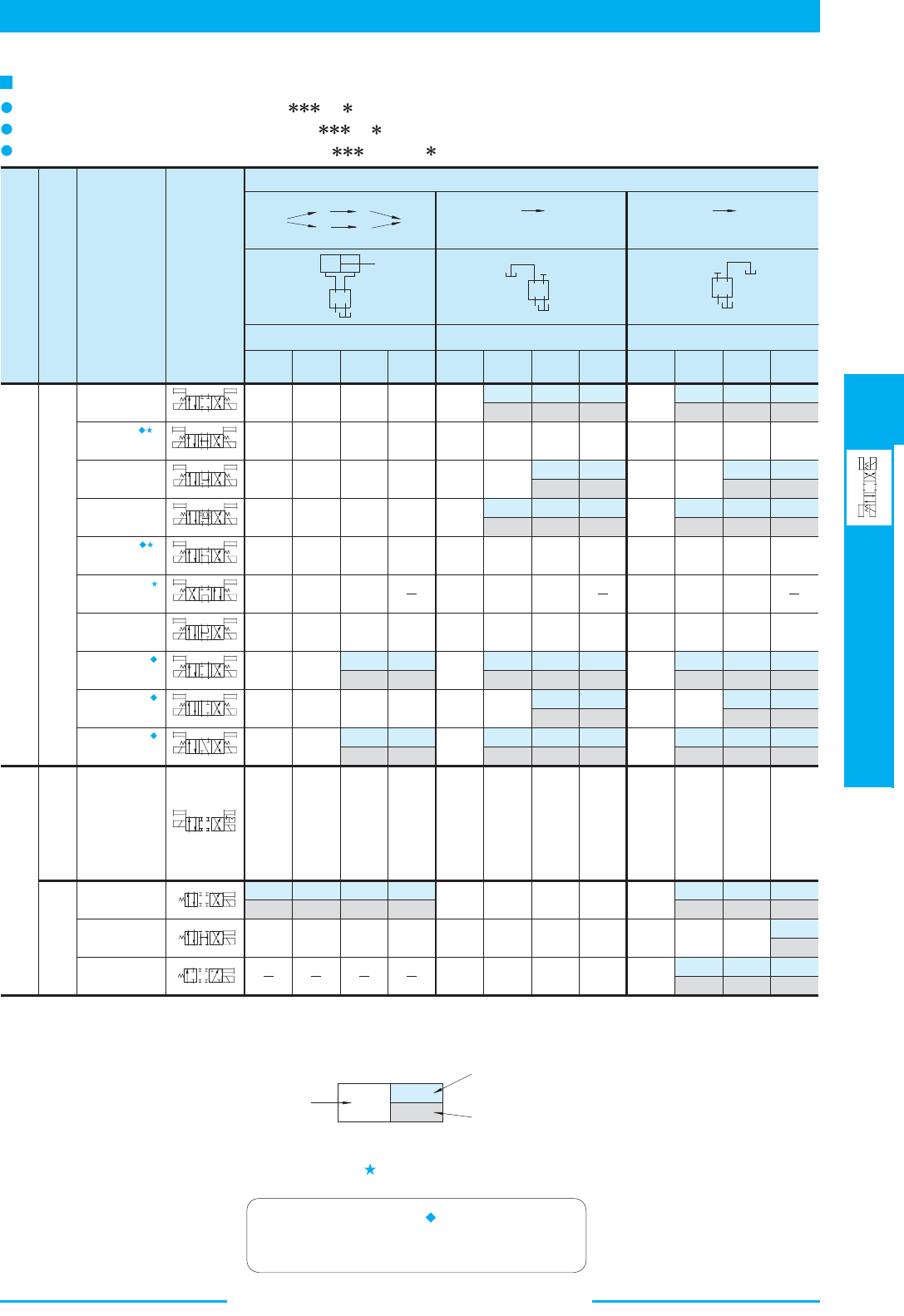
367
DIRECTIONAL CONTROLS
DSG-03 Series Solenoid
Operated Directional Valves
E
DSG-03 Series Solenoid Operated Directional Valves
T of the valves with a mark, please see page 368.
A B
T
P
b
A B
TP
b
A
B
T
P
b
a
A
B
TP
b
a
A B
T
P
b
a
A B
TP
b
a
A B
T
P
b
a
A B
T
P
b
a
A B
TP
b
a
A B
TP
b
a
A B
T
P
b
a
A B
T
P
b
a
A B
TP
b
a
A B
TP
b
A
B
P
T
P T
A
B
P T
A
B
31.7
31.7
31.7
31.7
13.2
31.7
31.7
31.7
31.7
31.
7
DSG-03-2D2
DSG-03-2B2
DSG-03-2B3
DSG-03-2B8
DSG-03-3C2
DSG-03-3C3
DSG-03-3C4
DSG-03-3C40
DSG-03-3C5
DSG-03-3C60
DSG-03-3C9
DSG-03-3C10
DSG-03-3C11
DSG-03-3C12
1450 2320 3630 4570
A
B
A
P
T
B
P AB
[Port "A" Blocked][Port "B" Blocked]
Max. Flow U.S. GPM
Graphic
Symbols
Model
Numbers
Spool-Spring Arrangement
No. of Valve Positions
Spring Centred
Three Positions
No-Spring
Detented
Spring Offset
Two Positions
31.7
31.7
31.7
31.7
13.2
31.7
31.7
31.7
31.7
31.7
31.7 31.7
31.7
31.7
31.7
31.7
13.2
31.7
31.7
31.7
31.7
31.7
31.7
13.2
31.7
31.7
31.7
31.7
31.7
9.2
31.7
26.4
31.7
26.4
31.7
6.3 5.5 5.3 11.9 11.9 11.9 11.9
31.7
26.4
31.7
26.4 26.4
31.7
26.4
31.7
26.4 26.4
31.7
26.4
26.4 26.4
31.7
26.4
31.7
29.6
18.2
31.7
22.7
15.9
12.2
21.1
16.4
16.4
12.4
13.5
10.6
17.2
13.7
13.5
10.6
29.6
18.2
31.7
22.7
15.9
12.2
21.1
16.4
16.4
12.4
13.5
10.6
17.2
13.7
13.5
10.6
31.7 31.7
31.7
17.2
17.2
13.2
17.2
13.2
31.7
17.2
31.7 31.7 11.9 9.8 7.9 7.4 15.9 15.9 10.6 9.2
31.7
31.7
31.7
27.5
22.2
17.2
16.4
15.1
16.9
14
12.9
11.1
31.7
26.4
21.1
14.3
14.5
11.4
31.7 31.7 31.7
31.7
31.7
27.5
22.2
17.2
16.4
15.1
16.9
14
12.9
11.1
31.7
26.4
21.1
14.3
14.5
11.4
31.7 31.7
31.7
31.7
31.7
31.7
29.1
26.4
31.7 31.7 31.7 31.7 31.7
31.7
31.7
29.1
26.4
29.1
26.4
29.1
26.4
31.7 31.7
30.1
21.9
31.7
16.4
19.8
15.3
16.4
10.6
16.6
12.7
31.7
27.2
12.4
9.8
18
20.3
14
10
20.3
6.3
10
20.3
6.1
12.4
20.3
8.7
1450 2320 3630 4570 1450 2320 3630 4570
List of Standard Models and The Maximum Flow
(Example)
Notes ) The relation between the maximum flow in the table above and the voltage (within the serviceable voltage) is as shown below.1.
2.
The valve models with a mark are handled as
Options. If you choose such valves, check the time
of delivery beforehand.
22.2
17.2
31.
7
The maximum flow rate is constant regardless of
any voltage variants within the serviceable voltage
At rated voltage [after temperature rise and saturated]
At minimum serviceable voltage
(90% of rated voltage) [after temperature rises and saturated]
For the maximum flow rate in P
→
Models with DC Solenoids: DSG-03- -D
Models with R Type Solenoids: DSG-03- -R
Models with RQ Type Solenoids: DSG-03- -RQ100
P
Working Pressure PSI
Working Pressure PSI
Working Pressure PSI
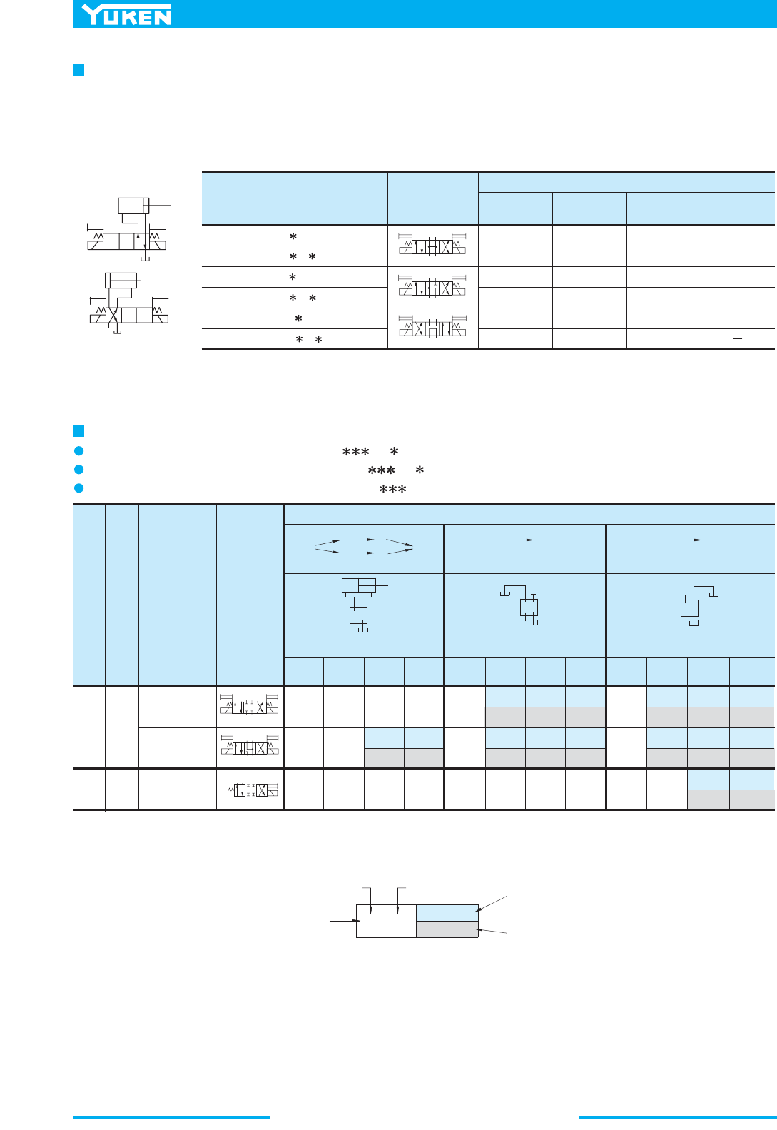
DSG-03 Series Solenoid Operated Directional Valves
368
P T
A
B
P T
A
B
A B
P
T
a
b
P
T
A B
a
b
P
T
A B
A
B
T
P
b
P T
A B
b
a
P T
A B
b
a
P T
A B
b
a
Spring
Centred
Spring
Offset
Three
Positions
Two
Positions
S-DSG-03-3C2
S-DSG-03-3C4
S-DSG-03-2B2
PA
[Port "B" Blocked]
PB
A
P
T
B
B
A
Graphic
Symbols
Model
Numbers
Spool-Spring
Arrangement
No. of Valve
Positions
Max. Flow L/min (U.S.GPM)
[Port "A" Blocked]
120 (31.7) 120 (31.7)
120 (31.7)
120 (31.7)
120 (31.7)
100 (26.4)
120 (31.7)
85 (22.5)
70 (18.5)
65 (17.2)
45 (11.9)
75 (19.8)
40 (10.6)
120 (31.7)
10
(1450)
5
(730)
16
(2320)
25
(3630)
10
(1450)
5
(730)
16
(2320)
25
(3630)
10
(1450)
5
(730)
16
(2320)
25
(3630)
120 (31.7)
120 (31.7)
120 (31.7)
105 (27.7)
120 (31.7)
100 (26.4)
75 (19.8)
65 (17.2)
75 (19.8)
65 (17.2)
120 (31.7)
105 (27.7)
120 (31.7)
100 (26.4)
75 (19.8)
65 (17.2)
75 (19.8)
65 (17.2)
105 (27.7)
80 (21.1)
50 (13.2)
120 (31.7)
120 (31.7)
120 (31.7) 120 (31.7)
39 (10.3) 39 (10.3) 39 (10.3)
50 (13.2)
40 (10.6)
40 (10.6)
35 (9.2)
50 (13.2)
40 (10.6)
40 (10.6)
60 (15.9)
35 (9.2)
39 (10.3)
DSG-03-3C3-A
DSG-03-3C3-D
/R
/RQ100
DSG-03-3C5-A
DSG-03-3C5-D
/R
/RQ100
DSG-03-3C60-A
DSG-03-3C60-D
/R
/RQ100
Model Numbers
Graphic
Symbols
Max. Flow L/min (U.S.GPM)
10 MPa
(1450 PSI)
16 MPa
(2320 PSI)
25 MPa
(3630 PSI)
31.5 MPa
(4570 PSI)
100 (26.4)
120 (31.7)
26 (6.9)
35 (9.2)
84 (22.2)
68 (18.0)
100 (26.4)
120 (31.7)
21 (5.5)
24 (6.3)
52 (13.7)
65 (17.2)
100 (26.4)
120 (31.7)
18 (4.8)
21 (5.5)
52 (13.7)
61 (16.1)
100 (26.4)
120 (31.7)
16 (4.2)
20 (5.3)
(Example)
Maximum Flow of Centre By-Pass
120 (31.7)
80 (21.1)
120 (31.7)
The maximum flow rate is constant regardless of
any voltage variants within the serviceable voltage
At rated voltage
[after temperature rise and saturated]
At minimum serviceable voltage
(90% of rated voltage)
[after temperature rises and saturated]
List of Shockless Models and The Maximum Flow
Note: The relation between the maximum flow in the table above and the voltage (within the serviceable voltage) is as shown below.
L/min U.S.GPM
In valve type 3C3, 3C5 and 3C60, in case where the actuator is put on in between the cylinder ports A and B as illustrated
below and where the actuator moves and suspended at its stroke end and where the valve is then shifted to the neutral
position in the suspended state of the actuator, the maximum flow rates available are those as shown as the table below
regardless of any voltage in the range of serviceable voltage.
Models with DC Solenoids: S-DSG-03- -D
Models with R Type Solenoids: S-DSG-03- -R
Models with RQ Type Solenoids: S-DSG-03- -RQ100
Working Pressure MPa (PSI)
Working Pressure MPa (PSI)
Working Pressure MPa (PSI)
369
DIRECTIONAL CONTROLS
DSG-03 Series Solenoid
Operated Directional Valves
E
DSG-03 Series Solenoid Operated Directional Valves
A
B
P
T
b
B
A
T
P
a
A B
P
T
b
B
A
T
P
a
DSG-03-2B
B
DSG-03-2B2B
DSG-03-2B3B
DSG-03-2B4B
DSG-03-2B60B
DSG-03-2B10B
(S-) DSG-03-2B
A
(S-) DSG-03-2B2A
Model Numbers Model Numbers
Standard
Mtg. Type
Reverse
Mtg. Type
Standard
Mtg. Type
Reverse
Mtg. Type
Graphic SymbolsG raphic Symbol
s
(S-)
(S-)
Reverse Mounting of Solenoid
In spring offset type, it is a standard configuration that the solenoid is mounted onto the valve in the SOL b position
(side). However, in this particular spool-spring arrangement, the mounting of the solenoid onto the valve in the reverse
position -SOL a side- is also available. The graphic symbol for this reverse mounting is as shown below.
As for the valve type 2B A and 2B B, please refer to the explanation under the heading of "Valves Using Neutral
Position and Side Position" given below.
Valves Using Neutral Position and Side Position (Special Two Position Valve)
Besides the use of the standard 2-position valves aforementioned in the "List of Standard Models and Maximum Flow",
the 3-position valves also can be used as the 2-position valves using the two of their three positions. In this case, there
are two kinds of the valve available. One is the valve using the neutral position and SOL a position (2B A) and another
is the valve using the neutral position and SOL b position (2B B).
Standard Mtg. of Solenoid Reverse Mtg. of Solenoid
(Example) In case of Spool Type "2"
A B
P
T
a
b
A B
P T
b
A
B
P
T
b
"A": Use of Neutral and
SOL. a Energised
Position (2B2A)
SOL. a Energised
Positio
n
SOL. b Energised
Position
Neutral Positio
n
"B": Use of Neutral and
SOL. b Energised
Position (2B2B
)
In the above table, the graphic symbols in mounting
type highlighted with shade are optional extra,
therefore, please confirm the time of delivery with
us before ordering.
A
B
P T
b
B
A
TP
a
2B2A
2B2B
DSG-03 Series Solenoid Operated Directional Valves
370
Type Model Numbers
1
T
2
T
Changeover Time ms
Standard
Type
27
97
97
22
30
204
Type Model Numbers
T T
Time
ms
G G
Acceleration
2
m/s (G)
6.4
(.65)
6.4
(.65)
110S-DSG-03-3C2-D
Shockless
Type
97 41
DSG-03-3C2-A
DSG-03-3C2-D
DSG-03-3C2-R
DSG-03-3C2-RQ100
110
110
120
220
120
S-DSG-03-3C2-R
S-DSG-03-3C2-RQ100
1 2 1 2
T
Max.
OFF OFF
ON
0
0
Solenoid
Spool Shift
1
T
2
ON
OFF
G
SOL a
Acceleration
(G)
(Ps)
Pressure
Time
1
G
2
T
1
T
2
a
b
Ps
Speed
Load
Accelmeter
Typical Changeover Time
Changeover time varies according to oil viscosity, spool type and hydraulic circuit.
16 MPa (2320 PSI)
70 L/min (18.5 U.S.GPM)
2
30 mm /s (140 SSU)
100 %V (After coil temperature rises and saturated)
[Test Conditions]
Standard Type
(Without Shockless Function)
Pressure:
Flow Rate:
Viscosity:
Voltage:
[Result of Measurement]
Shockless Type
[Test Circuit and Conditions]
Setting Pressure (Ps): 7 MPa (1020 PSI)
Load (W): 1000 kg (2205 1bs.)
Speed: 8.8 m/min (28.9 ft./min)
2
Viscosity: 30 mm /s (140 SSU)
[Result of Measurement]
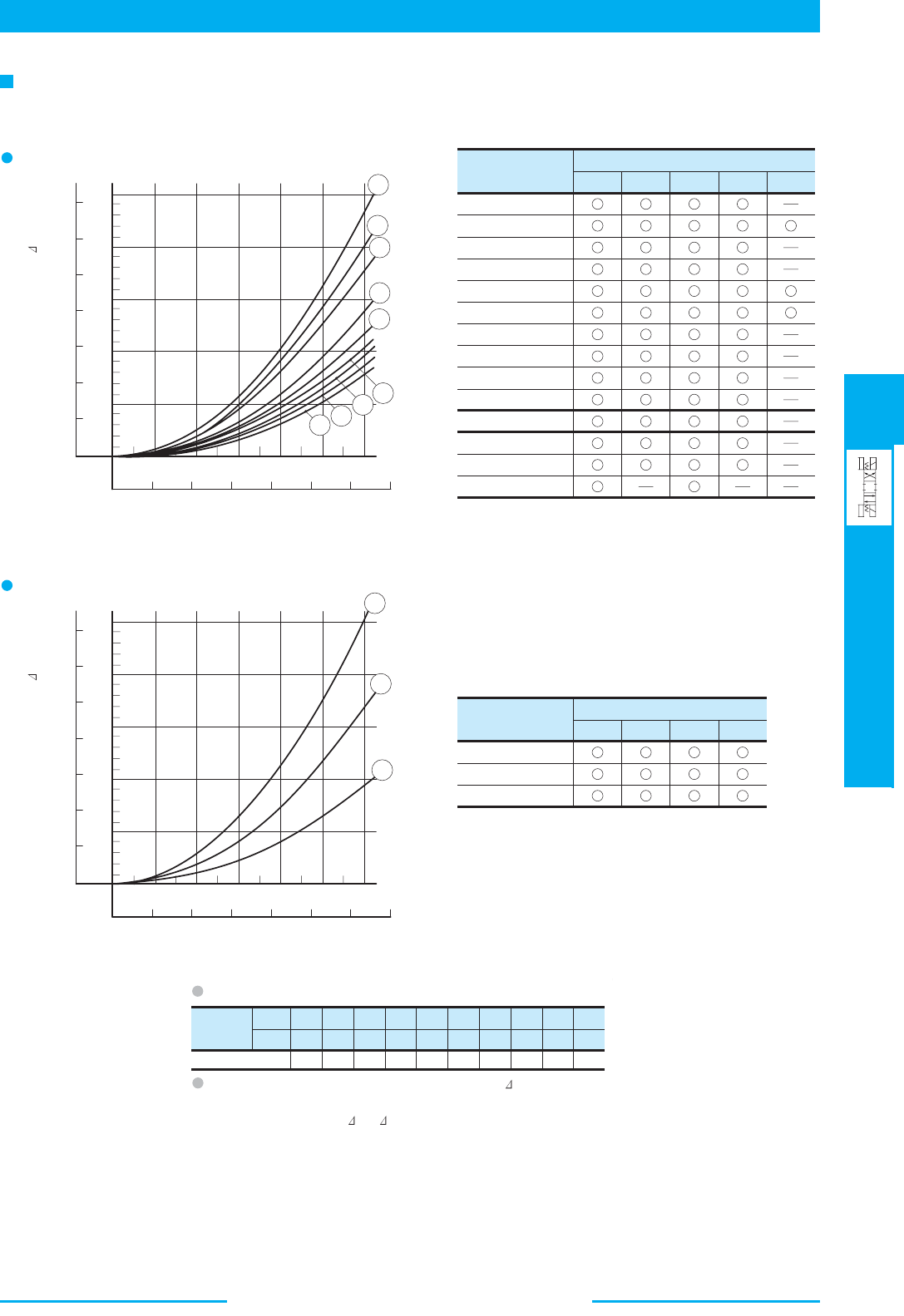
371
DIRECTIONAL CONTROLS
DSG-03 Series Solenoid
Operated Directional Valves
E
DSG-03 Series Solenoid Operated Directional Valves
Model Numbers
Pressure Drop Curve Number
7
9
7
7
9
6
9
7
9
7
4
2
3
DSG-03-3C2
DSG-03-3C3
DSG-03-3C4
DSG-03-3C40
DSG-03-3C5
DSG-03-3C60
DSG-03-3C9
DSG-03-3C10
DSG-03-3C11
DSG-03-3C12
DSG-03-2D2
DSG-03-2B2
DSG-03-2B
3
7
9
8
7
7
5
7
8
7
7
3
1
7
9
7
7
7
6
9
7
7
7
6
7
9
7
9
8
7
9
5
7
7
7
8
6
7
5
1
Model Numbers
P
A
Pressure Drop Curve Number
B
→
T P→
B A→ T
2
2
1
2
2 2
2
3
2
S-DSG-03-3C2
S-DSG-03-3C4
S-DSG-03-2B2
2
3
Viscosity
SSU
Factor 0.81 0.87 0.96 1.03 1.09 1.14 1.19 1.23 1.27 1.30
77 98 141 186 232 278 324 371 417 464
2
mm /s 15 20 30 40 50 60 70 80
90 100
DSG-03-2B8
6
2
5
9
1
→
P
A B→
T P→
B A→ T
→
P
T
→
MPa
PSI
Flow Rate
1
2
3
4
5
6
7
8
9
0
20 40
60
80
100
120
2.5
2.0
1.5
1.0
0.
5
350
300
250
200
150
100
50
0
0
0 5 10 15 20 25 30 35
L/ min
U.S.GPM
Pressure Drop P
1
2
3
020
40
60
80
100
120
2.5
2.0
1.5
1.0
0.5
Flow Rate
350
300
250
200
150
100
50
0
0 5 10 15 20 25 30 35
L/ min
U.S.GPM
Pressure Drop P
0
MPa
PSI
2
Pressure drop curves based on viscosity of 35 mm /s (164 SSU) and specific gravity of 0.850.
Shockless Type: S-DSG-03
Standard Type: DSG-03
Pressure Drop
For any other viscosity, multiply the factors in the table below.
For any other specific gravity (G'), the pressure drop ( P') may be
obtained from the formula below.
P' = P (G'/0.850)
2
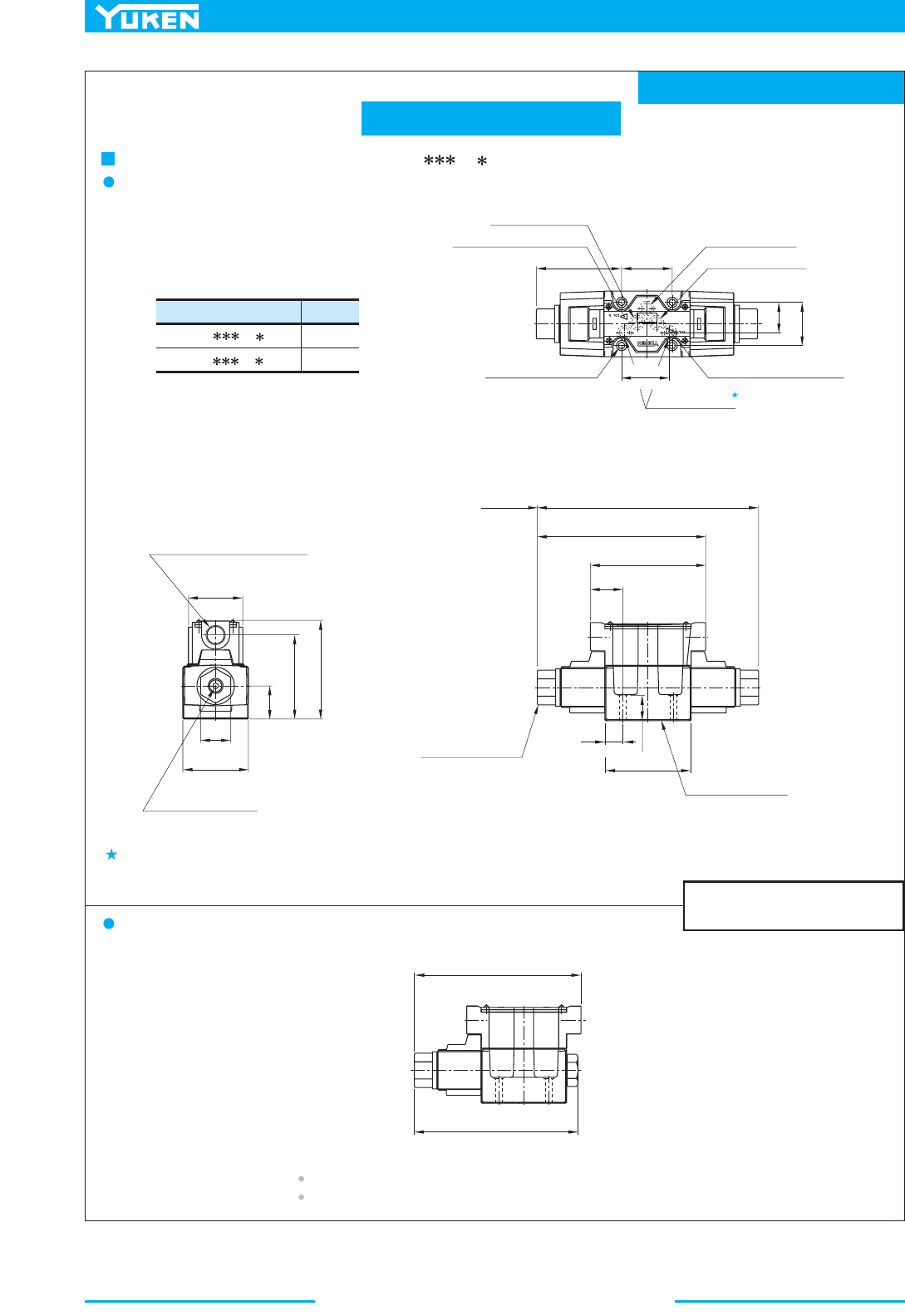
DSG-03 Series Solenoid Operated Directional Valves
372
Mounting surface: ISO 4401-AC-05-4-A
TERMINAL BOX TYPE
.
Model Numbers
DSG-03- -A
-50
DSG-03- -A
-5090
"C"
Thd.
G 1/2
1/2 NPT
179.
176.3
5
(7.07)
(6.94)
70
(2.76)
32
(1.26)
89.5
(3.52)
35.3
(1.39)
Manual Actuator
6.3(.25)
Dia.
58
(2.28)
105.3
(4.15)
Electrical Conduit Connection
"C "
Thd. (Both Ends)
47.5
(1.87)
Space Needed to Remove
Solenoid-Each End
236
(9.29)
179.5
(7.07)
123
(4.84)
34.5
(1.36)
92
(3.62)
27
(1.06)
Lock Nut
Tightening Torque:
8.5-10.5
Nm (
75-93
IN.lbs.)
Mounting Surface
(O-Rings Furnished
)
91
(3.58)
54
(2.13)
46
(1.81)
32.5
(1.28)
50.8
(2.00)
Tank Port
"T"
Cylinder Port
"B
"
Solenoid Indicator Light
(For Sol b)
Solenoid Indicator Light
(For Sol a)
Cylinder Port
"A "
Pressure Port
"P"
7(.28)
Dia. Through
11(.43)
Dia. Spotface
4 Places
Double Solenoid: Spring Centred & No-Spring Detended
Models with AC Solenoids: DSG-03- -A -50/5090
Single Solenoid: Spring Offset
For other dimensions, refer to "Spring Centred and No-Spring Detented" medels.
Of the two of tank port "T", the tank port in the left side is normally used in our standard sub-plate,
though, either side of the tank port "T" can be used without problem.
DIMENSIONS IN
MILLIMETRES (INCHES)
Solenoid being mounted in the reverse position -SOL a side- is also available.
19
(.75)
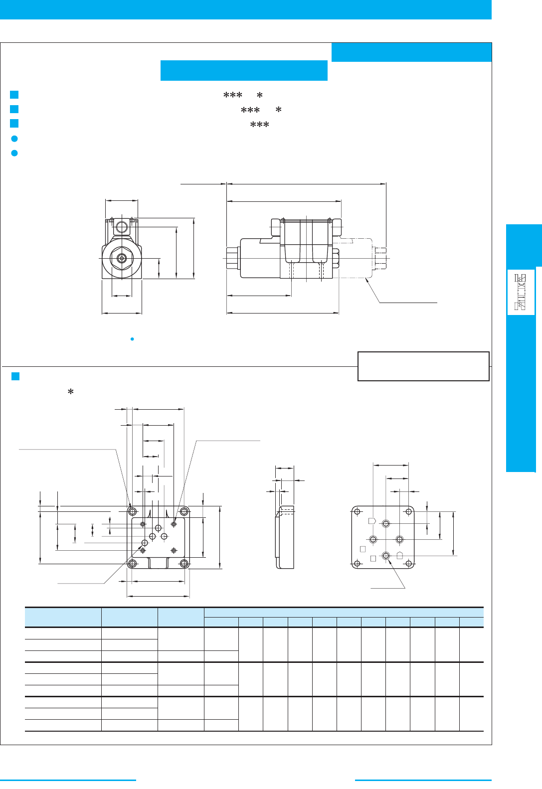
373
DIRECTIONAL CONTROLS
DSG-03 Series Solenoid
Operated Directional Valves
E
DSG-03 Series Solenoid Operated Directional Valves
Mounting surface: ISO 4401-AC-05-4-A
TERMINAL BOX TYPE
Sub-plate
Model Numbers
DSGM-03-40
DSGM-03-2180
DSGM-03-2190
DSGM-03X-40
DSGM-03X-2180
DSGM-03X-2190
DSGM-03Y-40
DSGM-03Y-2180
Piping Size
"
C
" Thd.
Rc 3/8
3/8 BSP.F
3/8 NPT
Rc 1/2
Rc 3/4
1/2 BSP.F
1/2 NPT
3/4 BSP.F
DSGM-03Y-2190 3/4 NPT
"
D
" Thd.
M6
1/4-20 UNC
M6
1/4-20 UNC
M6
1/4-20 UNC
E
13 (.51)
15 (.59)
F
110
(4.33)
13 (.51)
15 (.59)
13 (.51)
15 (.59)
110
(4.33)
120
(4.72)
HKNQT
9
(.35)
9
(.35)
14
(.55)
10
(.39)
10
(.39)
15
(.59)
32
(1.26)
32
(1.26)
50
(1.97)
62
(2.44)
62
(2.44)
80
(3.15)
40
(1.57)
40
(1.57)
45
(1.77)
16
(.63)
16
(.63)
10
(.39)
48
(1.89)
48
(1.89)
47
(1.85)
21
(.83)
21
(.83)
16
(.63)
24
(.94)
24
(.94)
42
(1.65)
Dimensions mm (Inches)
SOL b
SOL
a
P
B
A
T
L
L'
58
(2.28)
70
(2.76)
32
(1.26)
35.3
(1.39)
89.5
(3.52)
105.3
(4.15)
114
(4.49)
199.3
(7.85)
202.5
(7.97)
282
(11.10)
70.5
(2.78)
Space Needed to Remove
Double Solenoid
Models Only
Solenoid-Each End
L
N
P
S
Q
76
(2.99)
"
C
" Thd.
4 Places
T
7
(.28)
K
6.4
(.25)
21.4
(.84)
32.5
(1.28)
46
(1.81)
22
(.87)
90
(3.54)
10
(.39)
8.8 (.35) Dia. Through
14 (.55) Dia. Spotface
4 Places
92
(3.62)
H
F
11 (.43) Dia.
4 Places
70
(2.76)
110
(4.33)
3.2
(.13)
16.7
(.66)
27
(1.06)
37.3
(1.47)
54
(2.13)
90
(3.54)
18
(.71)
J
"
D
" Thd. "
E
" Deep
4 Places
20
(.79)
DIMENSIONS IN
MILLIMETRES (INCHES)
Double Solenoid: Spring Centred & No-Spring Detented
Models with DC Solenoids : (S-)DSG-03- -D -50/5090
Models with R Type Solenoids : (S-)DSG-03- -R -50/5090
Single Solenoid: Spring Offset
Sub- plates
DSGM-03 -40/2180/2190
For other dimensions, refer to Models with AC solenoids (Page 372).
Models with RQ Type Solenoids : (S-)DSG-03- -RQ100-50/5090
JL
P
S
DSG-03 Series Solenoid Operated Directional Valves
374
Model Numbers
DSG-03-
-D
- -50/5090
C
N
N1
DSG-03-
-R
-N-50/5090
DF
Dimensions mm (Inches)
39 (1.54)27.5 (1.08)73.8 (2.91)121.1 (4.77)
53 (2.09)34 (1.34)62.6 (2.46)124.9 (4.92)
Double Solenoid
Models Only
SOL b
SOL
a
SOLb
SOLa
: 158.5 (6.24)
: 181.5 (7.15)
AC
DC,R,RQ
Push Button
Lock Nut
Press the "Push Button" then turn "Lock Nut"
clockwise. The position of the "Push Button" is
held.
Be sure to loosen "LockNut" fully before solenoid
is energised
70
(2.76)
(1.26)
Lock Nut
Tightening Torque:
8.5 - 10.5 Nm (75-93 IN.lbs.)
199.3
(7.85)
114
(4.49)
89
(3.50)
35
(1.38)
F
282
(11.10)
Cable Departure
Cable Applicable:
Outside Dia.
.....
8-10mm(.31-.39 in.)
Conductor Area
.....
Not Exceeding 1.5mm
2
(.0023 Sq. in.)
The position of the Plug-in connector can be changed as
illustrated below by
l
oosening the lock nut. After
completion of the change, be sure to tighten the lock nut
with the torque as specified below.
E
C
D
35.3
(1.39)
Lock Nut
Tightening Torque:
8.5 - 10.5 Nm (75-93 IN.lbs.)
Cable Departure
Cable Applicable:
Outside Dia.
......
8-10mm(.31-.39 in.)
Conductor Area
.....
Not Exceeding 1.5mm
2
(.0023 Sq. in.)
The position of the Plug-in connector can be changed as
illustrated below by loosening the lock nut. After
completion of the change, be sure to tighten the lock nut
with the torque as specified below.
176.3
(6.94)
39
(1.54)
35
(1.38)
91
(3.58)
89
(3.50)
236
(9.29)
70
(2.76)
(1.26)
27.5(1.08)
61.8
(2.43)
61.8
(2.43)
35.3
(1.39)
109.1
(4.30)
Double Solenoid
Models Only
Models with AC Solenoids: DSG-03- -A - -50/5090
For other dimensions, refer to "Terminal Box Type"
(
Page 372 – 373).
Options
Models with Push Button & Lock Nut: (S-)DSG-03- - C(- )-50/5090
N
N1
Models with DC Solenoids: (S-)DSG-03- -D - -50/5090
N
N1
N
N1
Models with R Type Solenoids: (S-)DSG-03- -R -N-50/5090
DIMENSIONS IN
MILLIMETRES (INCHES)
E
PLUG-IN CONNECTOR TYPE (N)
PLUG-IN CONNECTOR WITH INDICATOR LIGHT (N1)
375
DIRECTIONAL CONTROLS
DSG-03 Series Solenoid
Operated Directional Valves
E
DSG-03 Series Solenoid Operated Directional Valves
1
2
3
3
3
1
1.
2.
3.
Type of
Electrical Conduit
Connection
Double Solenoid Type Single Solenoid Type
Terminal
Box Type
Plug-in
Connector
Type
Type of
Electrical Conduit
Connection
Electric Source
Terminal
Box Type
Plug-in
Connector
Type
AC DC AC DC Rectified
→
1
1
3
2
2
3
SOL.
SOL.
SOL.
SOL.
SOL.
SOL.
Earth
Power Supply
(For SOL.b)
Indicatot
Light
Power Supply
(For SOL.a)
Indicator Light
Common Plate
Common
Power
Supply
Ground
2-Power Suppl
y
1-Power Suppl
y
Indicator Ligh
t Indicator Ligh
t
Voltage-Surge
Suppresso
r
Indicator Light
Voltage-Surge
Suppressor
Rectifier
Circui
t
Power
Supply
Common
Ground
Power
Supply
Common
Ground
Power
Supply
Common
Ground
Indicator Light
(Integrated in "N1"
model only
)
1-Power
Supply
Ground
2-Power
Supply
1-Power
Supply
Ground
2-Power
Supply
Indicator Light
(Integrated in "N1"
model only
)
Voltage-Surge
Suppressor
(Circuit composed
in coil
)
1-Power
Supply
Ground
2-Power
Suppl
y
Voltage-Surge
Suppressor
Rectifier
Circui
t
SOL. aSOL.
b
Earth
SOL.
b
Indicator
Light
Earth
Details of Receptacle
Electrical Circuit
There are two grounding terminals. You can use either one.
If you do not need the common plate, remove it.
With DC solenoids, polarity is no question.
Do not perform wiring while the power is on.
Doing so may result in electric shock, burns or death.
Make the wiring properly. Improper wiring will cause an
irregular movement of the machine, resulting in a grave
accident.
DANGER
DSG-03 Series Solenoid Operated Directional Valves
376
Item Name of Parts Part Numbers
3C
2D2 2B
Qty.
Remarks
1 1 1
1
5
2
2 2 2
2 2 1
4 4
1751S-VK418689-6
SO-NB-A014(NBR, Hs90)
SO-NB-P21
1790S-VK418329-9
S6
SO-NB-P21
SO-NA-P4
Gasket
O-Ring
O-Ring
Plug
O-Ring
O-Ring
O-Ring
21
27
28
29
30
41
43
Included in Solenoid Ass'y (Item 16
)
Valve Model Numbers
DSG-03-
-
-50/5090
DSG-03-
-
-N-50/5090
Seal Kit No.
KS-DSG-03-50
KS-DSG-03-N-50
O-Ring Details for Seal Kit
(5 Pcs.), & (2 Pcs., see above), (4 Pcs.)
27 28 41 43
(5 Pcs.), & (2 Pcs., see above)
27 28 41
5 5
2
SOL a
SOL
b
30 26 19
21 20 22
18
24
31
17 23
25
43 42 41 40 44
16
27
2
1
3
6 4 10
29
15
14
28
27
SOL b
SOL a
46 47 48 45 16
List of Seals
When ordering the O-Rings, please specify the seal kit number from the table below.
Spring Offset Type
Solenoid Ass'y, Coil, Receptacle and Connector
Refer to Page 377 for the details of these parts.
-DSG-03- - -50/5090
-DSG-03- -N/N1-50/5090
■ List of Seals
377
DIRECTIONAL CONTROLS
DSG-03 Series Solenoid
Operated Directional Valves
E
DSG-03 Series Solenoid Operated Directional Valves
Valve Model Numbers
16
Solenoid Ass'y No.
42
Coil No.
17
Receptacle
Part No.
45
Connector Ass'y
Part No.
46
Connector Ass'y
Part No.
Remarks
SA3-100-51
SA3-120-51
SA3-200-51
SA3-240-51
SD3-12-51
SD3-24-51
SD3-100-51
SR3-100-51
SR3-200-51
SD3-12-S-51
SD3-24-S-51
SD3-100-S-51
SR3-100-S-51
SR3-200-S-51
SA3-100-N-51
SA3-120-N-51
SA3-200-N-51
SA3-240-N-51
SD3-12-N-51
SD3-24-N-51
SD3-100-N-51
SR3-100-N-51
SR3-200-N-51
SD3-12-S-N-51
SD3-24-S-N-51
SD3-100-S-N-51
SR3-100-S-N-51
SR3-200-S-N-51
SA3-100-N-51
SA3-120-N-51
SA3-200-N-51
SA3-240-N-51
SD3-12-N-51
SD3-24-N-51
SD3-100-N-51
SD3-12-S-N-51
SD3-24-S-N-51
SD3-48-S-N-51
C-SA3-100-51
C-SA3-120-51
C-SA3-200-51
C-SA3-240-51
C-SD3-12-51
C-SD3-24-51
C-SD3-100-51
C-SR3-100-51
C-SR3-200-51
C-SD3-12-51
C-SD3-24-51
C-SD3-100-51
C-SR3-100-51
C-SR3-200-51
C-SA3-100-N-51
C-SA3-120-N-51
C-SA3-200-N-51
C-SA3-240-N-51
C-SD3-12-N-51
C-SD3-24-N-51
C-SD3-100-N-51
C-SR3-100-N-51
C-SR3-200-N-51
C-SD3-12-N-51
C-SD3-24-N-51
C-SD3-100-N-51
C-SR3-100-N-51
C-SR3-200-N-51
C-SA3-100-N-51
C-SA3-120-N-51
C-SA3-200-N-51
C-SA3-240-N-51
C-SD3-12-N-51
C-SD3-24-N-51
C-SD3-100-N-51
C-SD3-12-N-51
C-SD3-24-N-51
C-SD3-100-N-51
R3-60
KR3-A-60
KR3-C-60
RR3-60
KR3-A-60
QR3-C-60
RR3-60
Terminal
Box
Type
Plug-in
Connecto
r
Type
Plug-in
Connecto
r
with
Indicator
Light
GDM-211-A-11
GDME-211-R-A-10
GDM-211-A-11
GDME-211-R-A-10
GDML-211-1-11
GDML-211-2-11
GDML-211-3-11
GDML-211-1-11
GDML-211-2-11
GDML-211-3-11
GDML-211-1-11
GDM-211-B-11
GDME-211-R-B-10
GDM-211-B-11
GDME-211-R-B-10
GDML-211-1-11
GDML-211-2-11
GDML-211-3-11
GDML-211-1-11
GDML-211-2-11
GDML-211-3-11
GDML-211-1-11
SR3-100-51 C-SR3-100-51
DSG-03-
-A100-50
DSG-03-
-A120-50
DSG-03-
-A200-50
DSG-03-
-A240-50
DSG-03-
-D12-50
DSG-03-
-D24-50
DSG-03-
-D100-50
DSG-03-
-R100-50
DSG-03-
-R200-50
S-DSG-03-
-D12-50
S-DSG-03-
-D24-50
S-DSG-03-
-D100-50
S-DSG-03-
-R100-50
S-DSG-03-
-R200-50
DSG-03-
-A100-N-50
DSG-03-
-A120-N-50
DSG-03-
-A200-N-50
DSG-03-
-A240-N-50
DSG-03-
-D12-N-50
DSG-03-
-D24-N-50
DSG-03-
-D100-N-50
DSG-03-
-R100-N-50
DSG-03-
-R200-N-50
S-DSG-03-
-D12-N-50
S-DSG-03-
-D24-N-50
S-DSG-03-
-D100-N-50
S-DSG-03-
-R100-N-50
S-DSG-03-
-R200-N-50
DSG-03-
-A100-N1-50
DSG-03-
-A120-N1-50
DSG-03-
-A200-N1-50
DSG-03-
-A240-N1-50
DSG-03-
-D12-N1-50
DSG-03-
-D24-N1-50
DSG-03-
-D100-N1-50
S-DSG-03-
-D12-N1-50
S-DSG-03-
-D24-N1-50
S-DSG-03-
-D100-N1-50
DSG-03-
-RQ100-50
S-DSG-03-
-RQ100-50
SR3-100-51
KR3-C-60
QR3-C-60C-SR3-100-51
Note:
The connector assembly is not included in the solenoid assembly.
■ Solenoid Ass'y, Coil, Receptacle and Connector Ass'y No.
E-DSG-01
E-DSG-03
Low Wattage Type E-DSG Series
E-DSG-01: 5W
E-DSG-03: 5W
Standard DSG Series
DSG-01: 29W
DSG-03: 38W
■ Low Wattage (5W) Type Solenoid Operated Directional Valves
2 type of Direct Acting type Solenoid Operated Directional Valves,
E-DSG-01/03, with suppressed consumption power 5W were launched
in series.
● Because these valves only 5W of power which enables remarkable
reduction of operating cost.
● Since these valves operate on only 5W, they can be driven through the
output circuit of a programmed or sequence controller. This feature
simplifies the electric circuitry and enables savings in initial cost.
● These low wattage valves minimize coil surface temperature.
● CE certified products are available.
Low Wattage (5W) Type Solenoid Operated Directional Valves
378
Specifications
Model Numbers
Max. Flow
L/min
(U.S.GPM)
Max. Operating Pressure
MPa (PSI)
Max. T-Line
Back Pressure
MPa (PSI)
Max. Changeover
Frequency
Cycle/min {min
-1
}
Mass
kg (1bs.)
E-DSG-01-3C -D -60
E-DSG-01-2N2-D -60
E-DSG-01-2D2-D -60
E-DSG-01-2B -D -60
E-DSG-03-3C -D -50
E-DSG-01-2D2-D -50
E-DSG-01-2B2-D -50
30
(7.9)
16 (2320)
16 (2320)
63
(16.6)
16 (2320)
16 (2320)
240
240
2.2 (4.85)
2.2 (4.85)
2.2 (4.85)
1.6 (3.53)
5 (11.03)
5 (11.03)
3.6 (7.94)
Maxmum flow indicates a ceiling flow depends on the type of spool and operating condition.
★
★
Solenoid Ratings
Model Numbers
Electric source
Coil Type
Source Rating
Voltage (V)
Serviceable Range
Inrush (A)
Power (W)
Current & Power at Rated Voltage
The coil type numbers in the shaded column are handled as optional extras.
In case these coils are required to be chosen, please confirm the time of
delivery with us before ordering .
E-DSG-01
E-DSG-03
DC (K Series)
D12
D24
D12
D24
12
24
12
24
10.8 – 13.2
21.6 – 26.4
10.8 – 13.2
21.6 – 26.4
0.43
0.23
0.44
0.22
5
5
For details, please contact us.
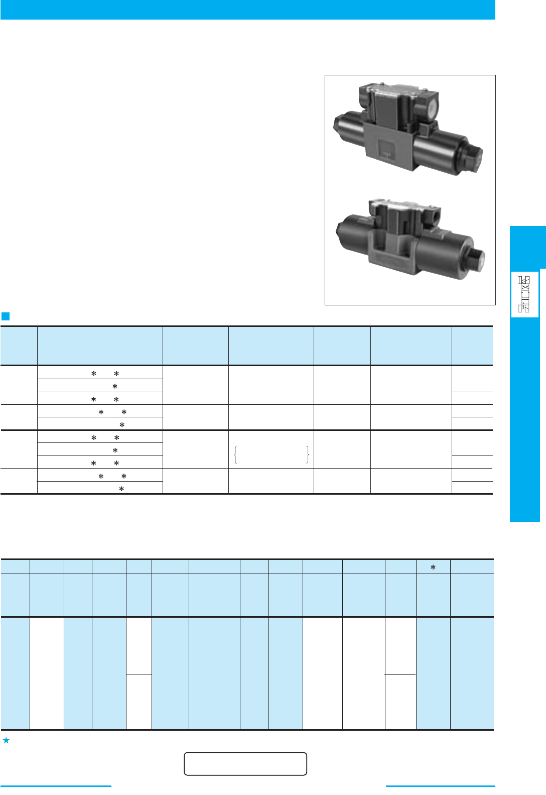
379
DIRECTIONAL CONTROLS
Electronic Relay Incorporated
Solenoid Operated Directional Valves
E
Electronic Relay Incorporated Solenoid Operated Directional Valves
■
Electronic Relay Incorporated Solenoid Operated Directional Valves
Drive power source and signal are separate.
The valve is actuated by operating a built-in switch using a very small
current signal (about 10 mA) when the solenoid is energised.
● A Direct Drive by a programmable controller is now possible.
As the valve can be actuated by a very small current, as we have
mentioned, a Direct Drive is possible on the output circuit of the
programmable controller or sequence controller.
● Simple construction and stable operation.
Since the valve is a direct type, the construction is quite simple.
Also the solenoid is the well proven wet armature type, which can
withstand contamination.
Therefore a stable operation can be obtained.
T-DSG-01
T-DSG-03
Specifications
Valve
Type
Model Numbers
T-DSG-01-3C -D24 -70/7090
T-DSG-01-2D2-D24 -70/7090
T-DSG-01-2B -D24 -70/7090
T-S-DSG-01-3C -D24 -70/7090
T-S-DSG-01-2B2-D24 -70/7090
T-DSG-03-3C -D24 -50/5090
T-DSG-03-2D2-D24 -50/5090
T-DSG-03-2B -D24 -50/5090
T-S-DSG-03-3C -D24 -50/5090
T-S-DSG-03-2B2-D24 -50/5090
Standard
Type
Shockless
Type
Standard
Type
Shockless
Type
100
(26.4)
63
(16.6)
120
(31.7)
120
(31.7)
35
(5080)
21
(3050)
21
(3050)
16
(2320)
16
(2320)
25
(3630)
25
(3630)
1.85 (4.08)
5 (11.03)
5 (11.03)
1.85 (4.08)
1.4 (3.09)
3.6 (7.94)
3.6 (7.94)
1.4 (3.09)
★
Maximum flow indicates a ceiling flow. As the ceiling flow depends on the type of spool and operating condition the same as those for standard
DSG-01/03, refer to the List of Spool Functions on
pages 347 - 351 (DSG-01) and 364 - 368 (DSG-03) for details.
Max. Flow
L/min
(U.S.GPM)
★
Max. Operating Pressure
MPa
(PSI)
31.5 (4570)
Spool Type 60 Only
25 (3630)
Max. T-Line
Back Pressure
MPa
(PSI)
Max. Changeover
Frequency
Cycle/min {min
-1
}
300
120
240
120
Mass
kg
(1bs.)
Please refer to the valve type DSG-01 and DSG-03 shown on page 346 and 363 for the area shaded.
F-
T-
S-
DSG
-03 -2 B A
Coil Type
Spool
Type
Control
Type
Special
Seals
Type
Valve
Size
Number
of Valve
Position
Spool-Spring
Arrangement
Special
Two
Position
Valve
-D24 M -70
-L
Supply
Type of
Signal
Power
Design
Standard
Design
Number
Series
Number
Models with
Alternate
Offset
Solenoid
T:
Electronic
Relay
Incorporated
Type
■ Model Number Designation
2
01
03
70
50
DC
D24
None:
Internal
Signal
Power
M:
External
Signal
Power
For details, please contact us.
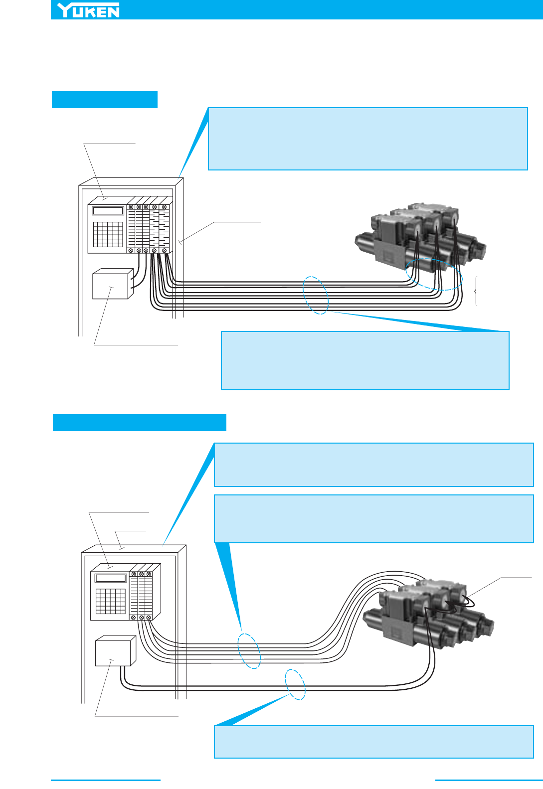
Electronic Relay Incorporated Solenoid Operated Directional Valves
380
■ Comparison of The Conventional Type and The Electronic Relay
Incorporated Type
Conventional Type
Electronic Relay Incorporated Type
Programmable
Controller
Control Board
Solenoid Power Supply
Programmable
Controller
Control
Board
Thick wires are
required and,
therefore, wiring
is awkward.
● Output Unit
● Large capacity output units (approximately 2A per unit) are required to operate solenoid
operated directional valves.
● As there is a limitation for common capacity, all contacts of the output units can be used in
some cases.
● Total cost therefore becomes higher, and a larger installation space is required.
● Power Supply Cables
● As each double solenoid valve requires a minimum of three cables, it is obvious that
the more valves you use, the more power supply cables and wiring is necessitated.
This may increase the possibility of miswriting.
● Miswriting and short circuits may damage a very expensive programmable
controller and output units.
Solenoid Power Supply
Common
Cables
● Output Unit
● Standard small capacity output unit, which is usually less expensive can be used.
● Other electric devices can be commonly used with the solenoid directional valves.
Therefore, installation as or output units can be reduced.
● Signal Output Cables
● Thinner cable, compared with power supply cable, can be used and therefore wiring is easier.
● The solenoid operated directional valve is provided with a protective circuit to ensure a
constant current, which protects the programmable controller from serious effects caused by
miswriting.
● Only two power supply cables are required for solenoid operated directional valves
and, therefore wiring can be reduced.
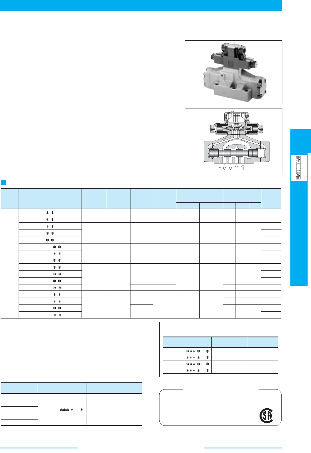
381
DIRECTIONAL CONTROLS
Solenoid Controlled
Pilot Operated Directional Valves
E
Solenoid Controlled Pilot Operated Directional Valves
■ Solenoid Controlled Pilot Operated Directional Valves
These valves are composed of a solenoid operated pilot valve and a pilot
operated slave valve. When a solenoid is energised the pilot valve
directs the flow to move the spool of the slave valve, thus changing the
direction of flow in the hydraulic circuit.
● High Pressure High Flow
High pressure [31.5 MPa (4570 PSI)] along which high flow means
compact system design.
● Lower Pressure Drop
System energy saving increased as pressure drop of each valve has been
greatly reduced.
Specifications
Valve
Type
Model Numbers
DSHG-01-3C - -14/1480/1490
DSHG-01-2B - -14/1480/1490
DSHG-03-3C - -14/1490
DSHG-03-2N - -14/1490
DSHG-03-2B - -14/1490
(S-)DSHG-04-3C - -52/5290
(S-)DSHG-04-2N - -52/5290
(S-)DSHG-04-2B - -52/5290
(S-)DSHG-06-3C - -53/5390
(S-)DSHG-06-2N - -53/5390
(S-)DSHG-06-2B - -53/5390
(S-)DSHG-06-3H - -53/5390
(S-)DSHG-10-3C - -43/4390
(S-)DSHG-10-2N - -43/4390
(S-)DSHG-10-2B - -43/4390
(S-)DSHG-10-3H - -43/4390
Standard
Type
Shockless
Type
40 (10.6)
160 (42.3)
300 (79.3)
500 (132)
1100 (291)
21 (3050)
25 (3630)
21 (3050)
21 (3050)
21 (3050)
21 (3050)
16 (2320) 16 (2320) 120
120
120
120
120
100
60
110
120
120
120
120
100
100
50
110
120
120
120
120
120
100
60
110
16 (2320)
16 (2320)
16 (2320)
16 (2320)
16 (2320)
1.0 (145)
3.2 (7.1)
2.7 (6.0)
6.9 (15.2)
6.9 (15.2)
6.4 (14.1)
8.5 (18.7)
8.5 (18.7)
8.0 (17.6)
12.4 (27.3)
12.4 (27.3)
11.9 (26.2)
13.2 (29.1)
45.0 (99.2)
45.0 (99.2)
44.5 (98.1)
52.9 (116.6)
1.0 (145)
1.0 (145)
0.7 (100)
0.8 (120)
0.8 (120)
21 (3050)
21 (3050)
25 (3630)
25 (3630)
25 (3630)
25 (3630)
31.5 (4570)
31.5 (4570)
31.5 (4570)
Max. Flow
L/min
(U.S.GPM)
★1 ★2
★3
★3
Max.
Operating
Pressure
MPa (PSI)
Min.
Required
Pilot Pres.
MPa (PSI)
Max. Pilot
Pressure
MPa (PSI)
Ext. Drain Int. Drain
Max. T-Line Back
Pressure
MPa (PSI)
Max. Change-
over Frequecy
Cycles/Min {min
–1
}
Mass
kg
(1bs.)
AC
DC
R
★
1. Maximum flow indicates a ceiling flow. As the ceiling flow depends on the type of
spool and operating condition, refer to the List of Spool Functions on pages 386 to 390
for details.
★
2. Pilot pressure of internal pilot drain models must always exceed tank line back pressure
by a minimum required pilot pressure.
★
3. Min. pilot pressure of with pilot piston in 1.8 MPa (260 PSI).
Yuken can offer flanged connection valves described below.
Consult us for the details.
Model Numbers
Model
Numbers
Pilot Valve Model
Numbers
Solenoid Ratings described
on the page below
DSHF-10- - -27
DSHF-16- - -37
DSHF-24- - -28
DSHF-32- - -27
DSHG-01
DSHG-03
(S-)DSHG-04
(S-)DSHG-06
(S-)DSHG-10
21 (3050)
21 (3050)
21 (3050)
21 (3050)
315 (83)
500 (132)
1200 (317)
2400 (634)
Rated Flow
l/min (U.S.GPM)
Max. Pressure
MPa (PSI)
■ Solenoid Ratings
Solenoid ratings of pilot valve are identical with those of standard solenoid
valve. Refer to relevant solenoid ratings described on the page below.
CSA Approved Solenoid Valve
Available to supply DSHG-06 series valve approved
by the CSA (Canadian Standards Association).
Consult us for details.
DSG-01- - -70
345
Solenoid Controlled Pilot Operated Directional Valves
382
F- S- DSHG -06 -2 2B
A
Special
Seals
Type
Series
Number
Valve
Size
No. of
Valve
Position
Spool-Spring
Arrangement
Spool
Type
Special Two
Position
Valve
-E
T-C2
Models with
Pilot Choke
Valve
Pilot
Connec-
tion
Drain
Connec-
tion
F:
For
Phos-
phate
Ester
Type
Fluids
None
:
Standard
Type
C
:
Spring Centred
C
:
Spring Centred
N
:
No-Spring
B
:
Spring Offset
B
:
Spring Offset
C
:
Spring Centred
C1
:
With C1
Choke
E
:
External
Pilot
C2
:
With C2
Choke
C1C2
:
With C1 &
C2 Choke
A
(Omit if not required)
A B
(Omit if not required)
H
:
Pressure Centred
C
:
Spring Centred
N
:
No-Spring
N
:
No-Spring
B
:
Spring Offset
B
:
Spring Offset
DSHG
:
Solenoid
Controlled
Pilot
Operated
Directional
Valve,
Sub-plate
Mounting
None
:
Standard
Type
S
:
Shock-
less
Type
■ Model Number Designation
Omit if not
required
( )
01
2, 3, 4
40, 5, 60
7, 9, 10
11, 12
2, 3, 4
40, 5, 60
7, 9, 10
11, 12
2, 4, 40
(3, 7)
2, 4, 40
(3, 7)
2, 4, 40
60, 10, 12
3, 5, 6
7, 9, 11
2, 3, 4
40, 7
2
3
4
40
7
★1
★1
★2
A
(Omit if not required)
★2
★2
★2
A B
(Omit if not required)
★2
★2
★1
2, 4, 40
(3, 7)
★1
2, 4, 40
(3, 7)
★1
03
04
06
10
3
2
3
2
3
2
3
2
( )
2, 4, 40
60, 10, 12
3, 5, 6
7, 9, 11
★1
( )
Omit if not
required
( )
None
:
Internal
Pilot
E
:
Internal
Drain
None
:
External
Drain
Note: In spool type “3”, “5”, “6”, “60”, and “7”, the combination applicable between pilot system and drain system is as described in the table below.
Pilot Connection Drain Connection
External Drain
External Drain
Internal Drain (T)
Internal Drain (T)
Combination is not applicable
No restrictions in the combination on us
Care in Application
Internal Pilot
External Pilot (E)
Hold back pressure in the tank line so that the difference between
pilot pressure and drain pressure is always more than minimum
required pilot pressure.
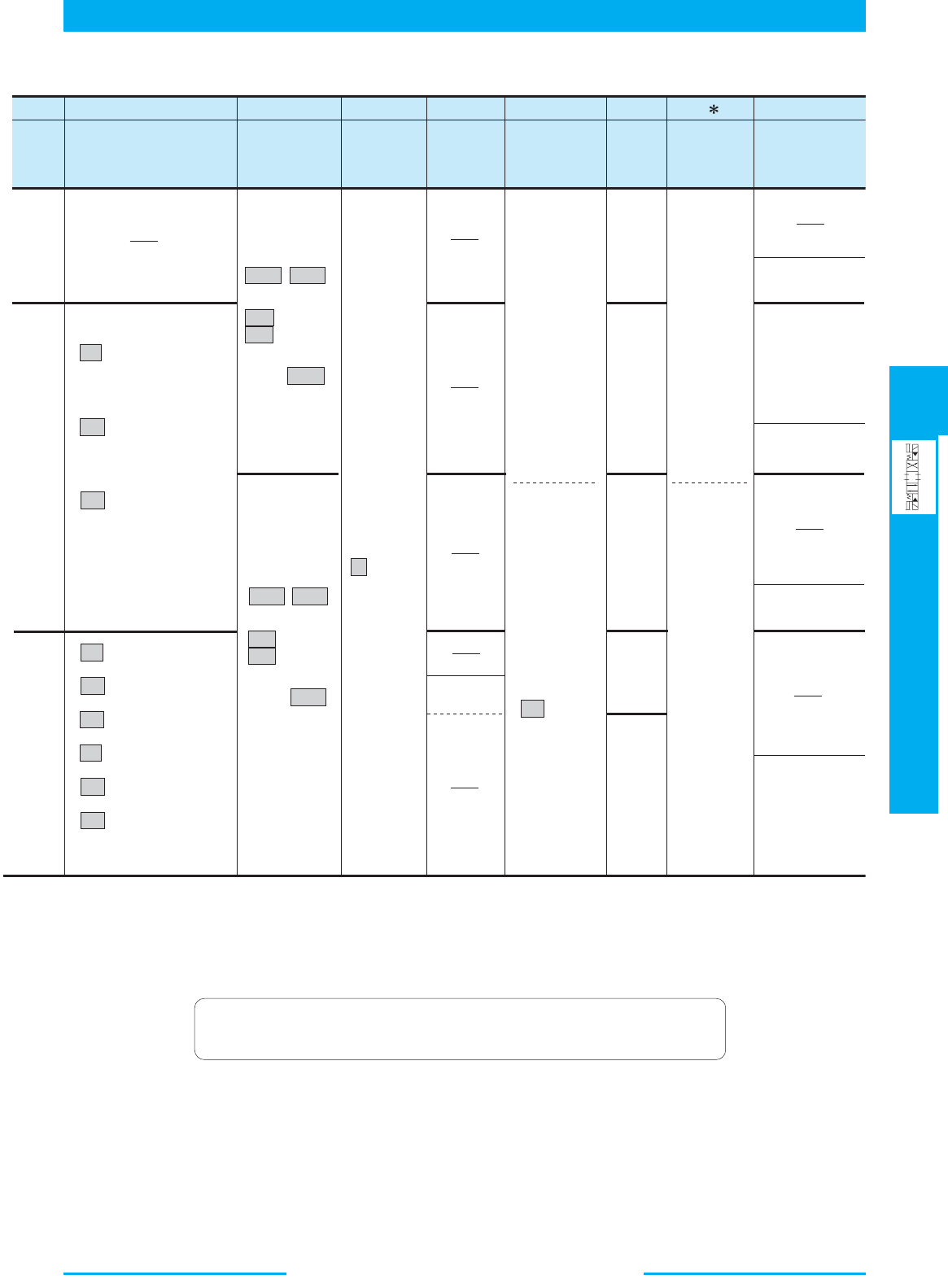
383
DIRECTIONAL CONTROLS
Solenoid Controlled
Pilot Operated Directional Valves
E
Solenoid Controlled Pilot Operated Directional Valves
-A100-R2
-H
-N
-53
-C
-
-L
Design
Number
Design
Standard
Models with
Reverse Mtg.
of Solenoid
Type of Elec-
trical Conduit
Connection
Bult-in
Orifice for
Pilot Line
Spool Control
Modification
(Omit if not required)
Coil
Type
Manual
Override of
Pilot Valve
R2 :
With Stroke
Adjustment,
Both Ends
C :
Push
Button &
Lock Nut
N:
Push-in
Connector
Type
N1 :
Push-in
Connector
with
Indicator
Light
H:
Refer to ★5
AC:
A100 , A200
A120 , A240
AC → DC
R100 , R200
DC:
D12 , D24
D48
AC:
A100 , A200
A120 , A240
AC → DC
R100 , R200
DC:
D12 , D24
D48
R2 : With Stroke Adj.,
Both Ends
RA : With Stroke Adj.,
Port "A" End
RB : With Stroke Adj.,
Port "B" End
P2 : With Pilot Piston,
Both Ends
PA : With Pilot Piston,
Port "A" End
PB : With Pilot Piston,
Port "B" End
RA :
With Stroke
Adjustment,
Port "A" End
RB :
With Stroke
Adjustment,
Port "B" End
None :
Manual
Override
Pin
None:
Terminal
Box Type
None:
Japanese
Standard
"JIS"
None:
Japanese
Standard
"JIS" &
European
Design
Standard
90:
N.
American
Design
Standard
90:
N.
American
Design
Standard
80:
European
Design
Standard
(Applicable
only for
DSHG-01)
14
14
52
53
43
L
(Omit if not required)
L
(Omit if not required)
L
(Omit if not required)
L
(Omit if not required)
★3
★4
★1. Shekless type (S-DSHG) are not available for spool type marked ( ).
★2. As for the details of the valve using the neutral position and the side position (either SOL a or SOL b side), please refer to page 391.
Furthermore, the spool types other than “2”, “4”, “40” (3, 7) are also available.
★3. In spool-spring arrangement “H” (Pressure centred models), the valves with stroke adjustment (R*) and pilot-piston (P*) are not available.
★4. NI stands for Plug-in connector with solenoid indicator light. NI is not available for R-type solenoids.
★5. In spool-spring arrangement “H” (pressure centred models), in case the pilot pressure is more than 10 MPa (1450 PSI), please specify that the
valve should have the built-in orifice to the pilot line.
In the table above, the symbols and numbers highlighted with shade represent the optional extras.
The valves with model number having such optional extras are handles as options, therefore
please confirm the time of delivery with us before ordering.

Solenoid Controlled Pilot Operated Directional Valves
384
Valve
Model
Numbers
Japanese Standard "JIS"
Sub-plate
Model Numbers
Thread
Size
Approx.
Mass
kg (1bs.)
Sub-plate
Model Numbers
Thread
Size
Approx.
Mass
kg (1bs.)
European Design Standard
Sub-plate
Model Numbers
Thread
Size
Approx.
Mass
kg (1bs.)
N. American Design Standard
DSGM-01-31
DSGM-01X-31
DSGM-01Y-31
Rc 1/8
DSGM-03-40
DSGM-03X-40
DSGM-03Y-40
DHGM-03Y-10
DHGM-04-20
DHGM-04X-20
DHGM-06-50
DHGM-06X-50
DHGM-10-40
DHGM-10X-40
Rc 1/4
Rc 3/8
Rc 3/8
Rc 1/2
Rc 3/4
Rc 3/4
Rc 1/2
Rc 3/4
Rc 3/4
Rc 1
Rc 1-1/4
Rc 1-1/2
4.7
0.8
0.8
0.8
3.0
3.0
(10.4)
(1.8)
(1.8)
(1.8)
(6.6)
(6.6)
4.7 (10.4)
4.4 (9.7)
4.1 (9.0)
7.4 (16.3)
7.4 (16.3)
21.5 (47.4)
21.5 (47.4)
DSGM-01-3080
DSGM-01X-3080
DSGM-03-2180
DSGM-03X-2180
DSGM-03Y-2180
DHGM-03Y-1080
DHGM-04-2080
DHGM-04X-2080
DHGM-06-5080
DHGM-06X-5080
DHGM-10-4080
DHGM-10X-4080
1/8 BSP.F
1/4 BSP.F
3/8 BSP.F
1/2 BSP.F
3/4 BSP.F
3/4 BSP.F
1/2 BSP.F
3/4 BSP.F
3/4 BSP.F
1 BSP.F
1-1/4 BSP.F
1-1/2 BSP.F
0.8 (1.8)
0.8 (1.8)
3.0 (6.6)
3.0 (6.6)
4.7 (10.4)
4.4 (9.7)
4.1 (9.0)
8.5 (18.7)
8.5 (18.7)
4.7 (10.4)
21.5 (47.4)
21.5 (47.4)
DSGM-01-3090
DSGM-01X-3090
DSGM-01Y-3090
DSGM-03-2190
DSGM-03X-2190
DSGM-03Y-2190
DHGM-03Y-1090
DHGM-04-2090
DHGM-04X-2090
DHGM-06-5090
DHGM-06X-5090
DHGM-10-4090
DHGM-10X-4090
1/8 NPT
1/4 NPT
3/8 NPT
3/8 NPT
1/2 NPT
3/4 NPT
3/4 NPT
1/2 NPT
3/4 NPT
3/4 NPT
1 NPT
1-1/4 NPT
1-1/2 NPT
0.8 (1.8)
0.8 (1.8)
3.0 (6.6)
3.0 (6.6)
4.7 (10.4)
4.4 (9.7)
4.1 (9.0)
7.4 (16.3)
7.4 (16.3)
4.7 (10.4)
21.5 (47.4)
21.5 (47.4)
0.8
(1.8)
DSHG-01
DSHG-03
DSHG-04
DSHG-06
DSHG-10
Sub-plates
DSGM-03 is available only for Internal pilot-Internal drain type (Use DHGM-03Y for other valves).
Sub-plates are available. Specify the sub-plate model number from the table above.
When sub-plates are not used, the mounting surface should have a good machined finish.
1.
3
1
2
1
2
2.
3.
Model
Numbers
Name
Japanese Standard "JIS"
European Design Standard
N. American Design Standard Qty.
Tightening Torque
Nm (in. 1bs.)
Mouting Bolt
Mtg. Bolt Kit
Soc. Hd. Cap Screw
Soc. Hd. Cap Screw
Soc. Hd. Cap Screw
Soc. Hd. Cap Screw
DSHG-01
DSHG-03
(S-)DSHG-04
(S)-DSHG-06
(S)-DSHG-10
MBK-01-01-30
MBK-01-02-30
M6 35 Lg.
M6 45 Lg.
M10 50 Lg.
M12 60 Lg.
M20 75 Lg.
MBK-01-01-3090
MBK-01-02-3090
1/4-20 UNC 1-3/4 Lg.
1/4-20 UNC 1-3/4 Lg.
3/8-16 UNC 2 Lg.
1/2-13 UNC 2-1/2 Lg.
3/4-10 UNC 3 Lg.
1 set
4
2
4
6
6
5
12
12
58
100
473
-
-
-
-
-
-
6
15
15
72
123
585
(43
(104
(104
(504
(868
(4106
-
-
-
-
-
-
52)
130)
130)
625)
1068)
5078)
Model Numbers
MBK-01-01-30
MBK-01-02-30
MBK-01-01-3090
MBK-01-02-3090
(
(
(
(
94
134
94
134
)
)
)
)
3.70
5.28
3.70
5.28
A
mm (In.) "
B
" Thd.
M5
No.10-24 UNC
8.5
Dia.
(.33)
9
(.35)
A
9
(.35)
"
B
" Thd.
9
(.35)
15
(.59)
4
(.16)
"
B
" Thd.
Both Ends
For Internal Pilot-Internal Drain.
Mounting Bolt
For External Pilot or External Drain.
Mounting bolt kit is common to that of 01 series modular valves.
Refer to figure below for the dimensions of bolt kit.
Stud Bolt
Nut
DIMENSIONS IN
MILLIMETRES (INCHES)
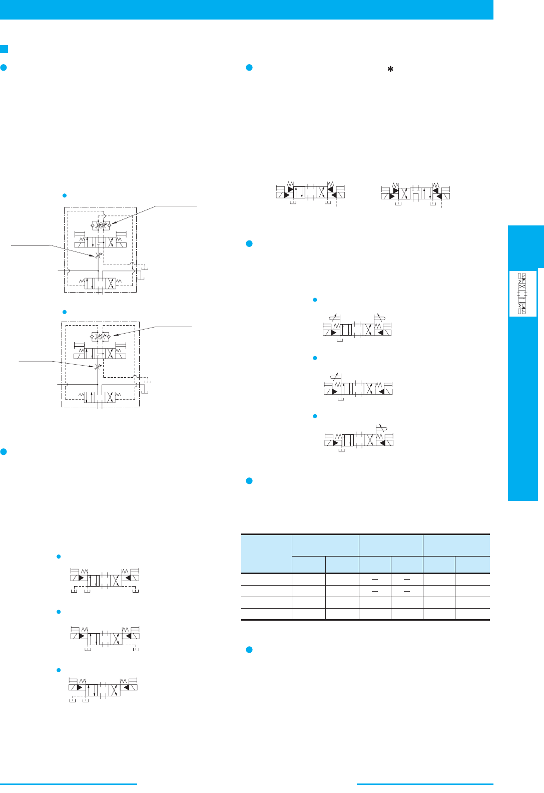
385
DIRECTIONAL CONTROLS
Solenoid Controlled
Pilot Operated Directional Valves
E
Solenoid Controlled Pilot Operated Directional Valves
(.7)
(1.1)
(1.3)
(4.1)
C1, C2 C1C2 P2
PA
PB
P2
PA
PB
Model with Pilot
Choke Adj.
Models with
Pilot Piston
Models with
Stroke Adj.
Model
Numbers
DSHG-03
(S-)DSHG-04
(S-)DSHG-06
(S-)DSHG-10
0.65(1.4)
0.65(1.4)
0.65(1.4)
0.65(1.4)
1.3(2.9)
1.3(2.9)
1.3(2.9)
1.3(2.9)
1.0(2.2)
3.6(7.9)
0.5(1.1)
1.8(4.0)
0.6(1.3)
1.0(2.2)
1.2(2.6)
3.7(8.2)
0.3
0.5
06
1.85
kg (1bs.)
ab
P
Y
AB
T
b
a
P
Y
A
B
T
AB
P
T
a
Y
b
V
W
A
B
P
T
a
Y
b
V
A
B
P
T
a
Y
b
W
Choke
C2
Choke
C1 Choke
C2
Choke
C1
AB
PT
Y
V
X
b
a
AB
PT
V
X
b
a
Y
AB
P
T
b
a
Y
AB
P
T
b
a
Y
A
B
PT
b
a
Y
Models with Pilot Choke Adjustment
Options
When the adjustment screw is turned clockwise,
changeover speed of the main spool becomes slow. In
case of the spring centred valves in particular, making
slow of the returning speed of the main spool to the
neutral position is possible with a C2 choke valve.
These choke valves can be used in combination with the
valves of spring centred, no-spring, offset, pressure
centred and the valves with stroke adjustment.
Models with Pilot Piston(P2, PA, PB)
The valves with a pilot piston can be used when the high
speed changeover of the main spool is required.
However, please not that in case of spring centered
valves, there is no change in the returning speed of the
main spool to the neutral position even with the pilot
piston.
Graphic Symbols (Ex.: Spring Centred)
"PB" Models
Graphic Symbols (Ex.: Spring Centred)
DSHG-01,06,10
DSHG-03, 04
"PA" Models
"P2" Models
Pressure Centred Models (3H )
The pressure centered type can be used when the
returning of the main spool to the neutral position is
required to be firmily.
Models with Stroke Adjustment (R2, RA, RB)
When the adjustment screw is screwed in , the main
spool stroke becomes short and flow rate reduces.
"RB" Models
"RA" Models
"R2" Models
Graphic Symbols (Ex.: Spring Centred)
Graphic Symbols (Ex.: External Pilot-External Drain)
(Only for 3H6, 3H60)
Additional Mass of Options
Add the mass described below to the mass of standard
models on page 381, if options are required.
Options on Pilot Valve
The same options to DSG-01 series valves are available.
Please refer to page 345 for the details.
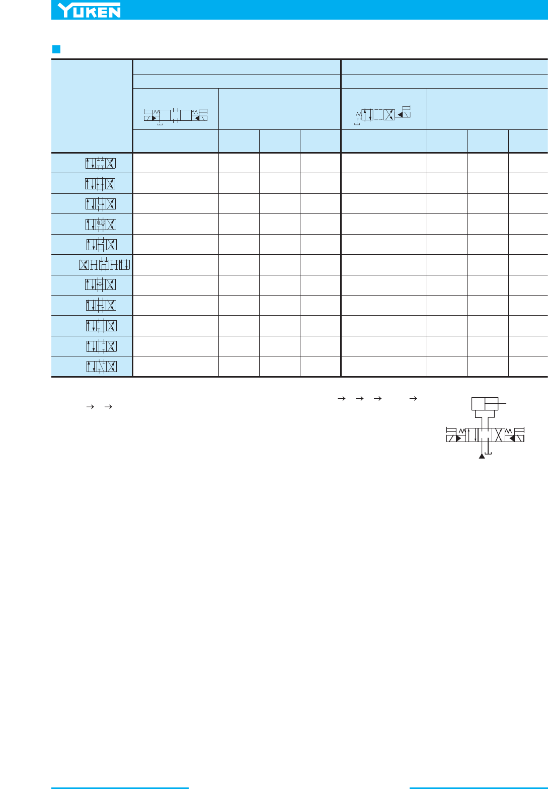
Solenoid Controlled Pilot Operated Directional Valves
386
b
AB
PT
Y
P
TY
a
b
A
B
40 (10.6)
40 (10.6)
40 (10.6)
40 (10.6)
40 (10.6)
40 (10.6)
40 (10.6)
40 (10.6)
40 (10.6)
40 (10.6)
40 (10.6)
DSHG-01-3C2
DSHG-01-3C3
DSHG-01-3C4
DSHG-01-3C40
DSHG-01-3C5
DSHG-01-3C60
DSHG-01-3C7
DSHG-01-3C9
DSHG-01-3C10
DSHG-01-3C11
DSHG-01-3C12
DSHG-01-2B2
DSHG-01-2B3
DSHG-01-2B4
DSHG-01-2B40
DSHG-01-2B7
"2"
"3"
"4"
"40"
"5"
"60"
"7"
"9"
"10"
"11"
"12"
40 (10.6)
40 (10.6)
40 (10.6)
40 (10.6)
40 (10.6)
40 (10.6)
40 (10.6)
40 (10.6)
40 (10.6)
40 (10.6)
40 (10.6)
40 (10.6)
40 (10.6)
40 (10.6)
40 (10.6)
40 (10.6)
40 (10.6)
40 (10.6)
40 (10.6)
40 (10.6)
40 (10.6)
40 (10.6)
40 (10.6)
40 (10.6)
40 (10.6)
40 (10.6)
40 (10.6)
40 (10.6)
40 (10.6)
40 (10.6)
40 (10.6)
40 (10.6)
40 (10.6)
40 (10.6)
40 (10.6) 40 (10.6) 40 (10.6)
7 MPa
(1020 PSI)
14 MPa
(2030 PSI)
21 MPa
(3050 PSI)
7 MPa
(1020 PSI)
14 MPa
(2030 PSI)
21 MPa
(3050 PSI)
srebmuN ledoMsrebmuN ledoM
lobmyS cihparGlobmyS cihparG
Maximum Flow
L/min (U.S.GPM)
Maximum Flow
L/min (U.S.GPM)
dertneC gnirpSdertneC gnirpS
snoitisoP owTsnoitisoP eerhT
Spool Type
A
P
T
B
b
a
Notes ) Max. flow shows value at pilot pressure more than 1 MPa (150 PSI)1.
Max. flow in the table above represents the value in the flow condition of
P A B T (or P B
A T) as shown in the circuit diagram right.
In case the valve is used in the condition that either A or B port is blocked, the maximum flow differs
according to a hydraulic circuit, therefore, please consult us for details.
2.
List of Spool Functions and Maxmum Flow (DSHG-01)
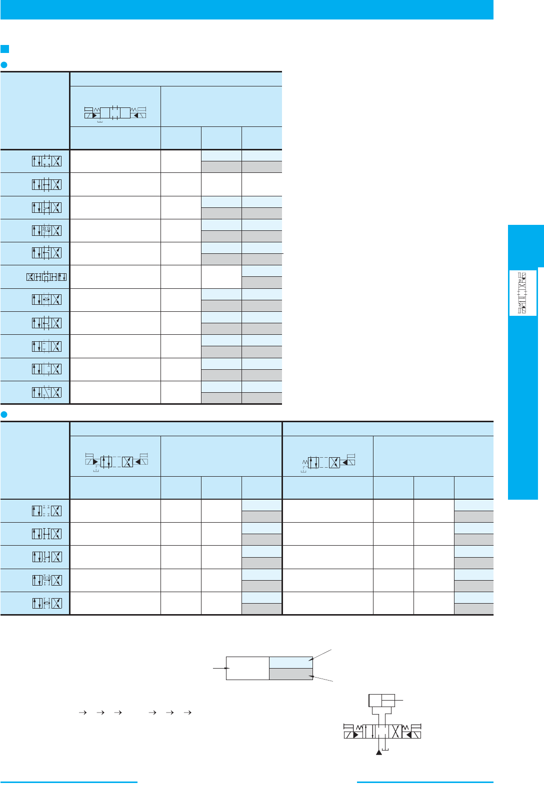
387
DIRECTIONAL CONTROLS
Solenoid Controlled
Pilot Operated Directional Valves
E
Solenoid Controlled Pilot Operated Directional Valves
b
AB
PT
Y
b
A
B
P
T
Y
a
PTY
a
b
A
B
DSHG-03-2N2
DSHG-03-2N3
DSHG-03-2N4
DSHG-03-2N40
DSHG-03-2N7
160 (42.3)
160 (42.3)
160 (42.3)
160 (42.3)
160 (42.3)
DSHG-03-2B2
DSHG-03-2B3
DSHG-03-2B4
DSHG-03-2B40
DSHG-03-2B7
"2"
"3"
"4"
"40"
"7"
160 (42.3)
160 (42.3)
160 (42.3)
160 (42.3)
160 (42.3)
160 (42.3)
160 (42.3)
160 (42.3)
160 (42.3)
160 (42.3)
160 (42.3)
160 (42.3)
160 (42.3)
160 (42.3)
160 (42.3)
7 MPa
(1020 PSI)
14 MPa
(2030 PSI)
25 MPa
(3630 PSI)
Model Numbers
Maximum Flow
L/min (U.S.GPM)
No-Spring
Spool Type
7 MPa
(1020 PSI)
14 MPa
(2030 PSI)
25 MPa
(3630 PSI)
Maximum Flow
L/min (U.S.GPM)
Model Numbers
lobmyS cihparGlobmyS cihparG
Spring Offset
DSHG-03-3C2
DSHG-03-3C3
DSHG-03-3C4
DSHG-03-3C40
DSHG-03-3C5
DSHG-03-3C60
DSHG-03-3C7
DSHG-03-3C9
DSHG-03-3C10
DSHG-03-3C11
DSHG-03-3C12
7 MPa
(1020 PSI)
14 MPa
(2030 PSI)
25 MPa
(3630 PSI)
Model Numbers
Maximum Flow
L/min (U.S.GPM)
Spring Centred
Spool Type
Graphic Symbol
160 (42.3)
160 (42.3)
160 (42.3)
160 (42.3)
160 (42.3)
160 (42.3)
160 (42.3)
160 (42.3)
160 (42.3)
160 (42.3)
160 (42.3)
"2"
"3"
"4"
"40"
"5"
"60"
"7"
"9"
"10"
"11"
"12"
85
160
(22.5)
(42.3)
85
160
85
160
85
160
85
160
85
160
(22.5)
(42.3)
(22.5)
(42.3)
(22.5)
(42.3)
(22.5)
(42.3)
(22.5)
(42.3)
85
160
85
160
85
160
85
160
85
160
(22.5)
(42.3)
(22.5)
(42.3)
(22.5)
(42.3)
(22.5)
(42.3)
(22.5)
(42.3)
85
160
85
160
85
160
85
160
85
160
85
160
85
160
85
160
(22.5)
(42.3)
(22.5)
(42.3)
(22.5)
(42.3)
(22.5)
(42.3)
(22.5)
(42.3)
(22.5)
(42.3)
(22.5)
(42.3)
(22.5)
(42.3)
125
160
60
95
60
95
60
95
60
95
60
95
(33.0)
(42.3)
(15.9)
(25.1)
(15.9)
(25.1)
(15.9)
(25.1)
(15.9)
(25.1)
(15.9)
(25.1)
60
95
(15.9)
(25.1)
60
95
60
95
(15.9)
(25.1)
(15.9)
(25.1)
60
95
(15.9)
(25.1)
160 (42.3) 160 (42.3)
160 (42.3)
Three Positions
Two Positions
A
P
T
B
b
a
85 (22.5)
160 (42.3)
160 (42.3)
Notes: The relation between max. flow and pilot pressure in the table
above is as shown below.
1.
2.
(Example)
Maximum flow rate is constant regardless of pilot pressure.
Pilot Pressure more than 0.7 MPa (100 PSI).
Pilot Pressure at 0.7 MPa (100 PSI).
Pilot Pressure at 1 MPa (150 PSI).
Max. flow in the table above represents the value in the flow
condition of
P A B T (or P B A T) as shown
in the circuit diagram right.
In case the valve is used in the condition that either A or B port
is blocked, the maximum flow differs according to a hydraulic
circuit, therefore, please consult us for details.
List of Spool Functions and Maxmum Flow (DSHG-03)
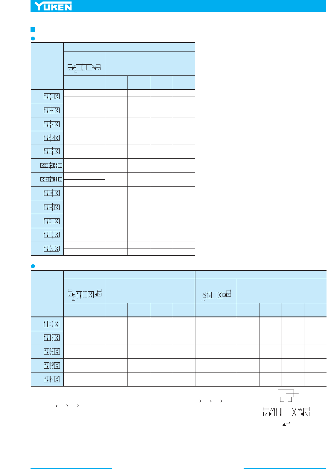
Solenoid Controlled Pilot Operated Directional Valves
388
b
A
B
P
T
Y
a
b
AB
PT
Y
PTY
a
b
A
B
DSHG-04-2N2
DSHG-04-2N3
DSHG-04-2N4
DSHG-04-2N40
DSHG-04-2N7
DSHG-04-2B2
DSHG-04-2B3
DSHG-04-2B4
DSHG-04-2B40
DSHG-04-2B7
"2"
"3"
"4"
"40"
"7"
300 (79.3)
300 (79.3)
300 (79.3)
300 (79.3)
300 (79.3)
Maximum Flow
L/min (U.S.GPM)
No-Spring
Spool Type
Model Numbers
(S-)
(S-)
(S-)
(S-)
(S-)
(S-)
Model Numbers
Graphic Symbol
10 MPa
(1450 PSI)
16 MPa
(2320 PSI)
25 MPa
(3630 PSI)
31.5 MPa
(4570 PSI)
Maximum Flow
L/min (U.S.GPM)
Spring Offset
300 (79.3)
300 (79.3)
300 (79.3)
300 (79.3)
300 (79.3)
300 (79.3)
300 (79.3)
300 (79.3)
300 (79.3)
300 (79.3)
300 (79.3)
300 (79.3)
300 (79.3)
300 (79.3)
300 (79.3)
300 (79.3)
300 (79.3)
300 (79.3)
300 (79.3)
300 (79.3)
300 (79.3)
300 (79.3)
300 (79.3)
300 (79.3)
300 (79.3)
300 (79.3)
300 (79.3)
300 (79.3)
300 (79.3)
300 (79.3)
300 (79.3)
300 (79.3)
300 (79.3)
300 (79.3)
300 (79.3)
"2"
"3"
"4"
"40"
"5"
"6"
"60"
"7"
"9"
"10"
"11"
"12"
Model Numbers
Maximum Flow
L/min (U.S.GPM)
Spool Type
Graphic Symbol
Spring Centred
10 MPa
(1450 PSI)
16 MPa
(2320 PSI)
25 MPa
(3630 PSI)
31.5 MPa
(4570 PSI)
10 MPa
(1450 PSI)
16 MPa
(2320 PSI)
25 MPa
(3630 PSI)
31.5 MPa
(4570 PSI)
(S-)
DSHG-04-3C2
DSHG-04-3C2
(S-)
(S-)
DSHG-04-3C4
DSHG-04-3C4
DSHG-04-3C40
DSHG-04-3C40
DSHG-04-3C3
DSHG-04-3C5
DSHG-04-3C6
(S-)
DSHG-04-3C60
DSHG-04-3C60
DSHG-04-3C7
DSHG-04-3C9
(S-)
DSHG-04-3C10
DSHG-04-3C10
(S-)
DSHG-04-3C12
DSHG-04-3C12
DSHG-04-3C11
300 (79.3)
300 (79.3)
300 (79.3)
300 (79.3)
300 (79.3)
300 (79.3)
300 (79.3)
250 (66.1)
300 (79.3)
300 (79.3)
300 (79.3)
300 (79.3)
300 (79.3)
300 (79.3)
300 (79.3)
300 (79.3)
300 (79.3)
300 (79.3)
300 (79.3)
300 (79.3)
300 (79.3) 300 (79.3) 300 (79.3)
250 (66.1)
300 (79.3)
300 (79.3)
300 (79.3)
250 (66.1)
250 (66.1)
140 (37.0)
200 (52.8)
120 (31.7)
165 (43.6)
110 (29.1)
145 (38.3)
110 (29.1)
260 (68.7)
245 (64.7) 245 (64.7)
245 (64.7)
300 (79.3) 300 (79.3)
235 (62.1)
200 (52.8) 145 (38.3)
250 (66.1)280 (74.0)
260 (68.7) 160 (42.3) 140 (37.0)
280 (74.0)
250 (66.1)
170 (44.9)
120 (31.7)
135 (35.7)
110 (29.1)
300 (79.3)
250 (66.1)
200 (52.8)
120 (31.7)
150 (39.6)
110 (29.1)
300 (79.3)
250 (66.1)
200 (52.8)
120 (31.7)
145 (38.3)
110 (29.1)
Graphic Symbol
Notes: Max flow described above shown value at pilot pressure more than 0.8 MPa (120 PSI).
1.
A
P
T
B
b
a
Two Positions
Three Positions
Max. flow in the table above represents the value in the flow condition of P A B T (or
P B A T) as shown in the circuit diagram right.
In case the valve is used in the condition that either A or B port is blocked, the maximum flow
differs according to a hydraulic circuit, therefore, please consult us for details.
2.
List of Spool Functions and Maxmum Flow (DSHG-04/S-DSHG-04)
389
DIRECTIONAL CONTROLS
Solenoid Controlled
Pilot Operated Directional Valves
E
Solenoid Controlled Pilot Operated Directional Valves
b
A
B
P
T
Y
a
b
AB
PT
Y
PTY
a
b
A
B
P
T
Y
a
b
A
B
V
"2"
"3"
"4"
"40"
"7"
Maximum Flow
L/min (U.S.GPM)
No-Spring
Spool Type
Graphic Symbol
DSHG-06-2N2
DSHG-06-2N3
DSHG-06-2N4
DSHG-06-2N40
DSHG-06-2N7
500 (132)
500 (132)
500 (132)
500 (132)
500 (132)
(S-)
(S-)
(S-)
Model Numbers
10 MPa
(1450 PSI)
16 MPa
(2320 PSI)
25 MPa
(3630 PSI)
31.5 MPa
(4570 PSI)
DSHG-06-2B2
DSHG-06-2B3
DSHG-06-2B4
DSHG-06-2B40
DSHG-06-2B7
Model Numbers
(S-)
(S-)
(S-)
Maximum Flow
L/min (U.S.GPM)
Spring Offset
10 MPa
(1450 PSI)
16 MPa
(2320 PSI)
25 MPa
(3630 PSI)
31.5 MPa
(4570 PSI)
Graphic Symbol
"2"
"3"
"4"
"40"
"5"
"6"
"60"
"7"
"9"
"10"
"11"
"12"
Model Numbers
Maximum Flow
L/min (U.S.GPM)
Spool Type
Graphic Symbol
Spring Centred
10 MPa
(1450 PSI)
16 MPa
(2320 PSI)
25 MPa
(3630 PSI)
31.5 MPa
(4570 PSI)
(S-)DSHG-06-3C2
DSHG-06-3C3
DSHG-06-3C4
DSHG-06-3C40
DSHG-06-3C5
DSHG-06-3C6
DSHG-06-3C60
DSHG-06-3C7
DSHG-06-3C9
DSHG-06-3C10
DSHG-06-3C11
DSHG-06-3C12
500 (132)
500 (132)
500 (132)
500 (132)
500 (132)
500 (132)
500 (132)
500 (132)
500 (132)
500 (132)
500 (132)
500 (132)
500 (132)
500 (132)
500 (132)
500 (132)
500 (132)
500 (132)
500 (132)
500 (132)
500 (132)
500 (132)
500 (132)
500 (132)
500 (132)
500 (132)
500 (132)
500 (132)
500 (132)
500 (132)
500 (132)
500 (132)
500 (132)
500 (132)
500 (132)
10 MPa
(1450 PSI)
16 MPa
(2320 PSI)
25 MPa
(3630 PSI)
31.5 MPa
(4570 PSI)
Model Numbers
Maximum Flow
L/min (U.S.GPM)
Graphic Symbol
Pressure Centred
(S-)
(S-)
(S-)
(S-)
(S-)
(S-)DSHG-06-3H2
DSHG-06-3H3
DSHG-06-3H4
DSHG-06-3H40
DSHG-06-3H5
DSHG-06-3H6
DSHG-06-3H60
DSHG-06-3H7
DSHG-06-3H9
DSHG-06-3H10
DSHG-06-3H11
DSHG-06-3H12
(S-)
(S-)
(S-)
(S-)
(S-)
500 (132)
500 (132)
500 (132)
500 (132)
500 (132)
475 (125)
475 (125)
500 (132)
500 (132)
500 (132)
500 (132)
500 (132)
500 (132)
500 (132)
500 (132)
500 (132)
500 (132)
390 (103)
420 (111)
500 (132)
500 (132)
500 (132)
500 (132)
500 (132)
500 (132)
500 (132)
500 (132)
500 (132)
500 (132)
500 (132)
500 (132)
500 (132)
500 (132)
500 (132)
500 (132)
500 (132)
500 (132)
500 (132)
500 (132)
500 (132)
500 (132)
500 (132)
500 (132)
500 (132)
500 (132)
500 (132)
500 (132)
500 (132)
500 (132)
500 (132)
500 (132)
500 (132)
500 (132)
500 (132)
500 (132)
500 (132)
500 (132)
500 (132)
500 (132)
500 (132)
425 (112)
300 (79.3)
340 (89.8)
450 (119)
350 (92.5)
230 (60.8)
280 (74.0)
360 (95.1)
)231( 005)8.79( 073)221( 064
500 (132)
500 (132)
410 (108)
500 (132)
310 (81.9)
500 (132)
310 (81.9)
500 (132)
310 (81.9)
500 (132)
410 (108)
500 (132)
410 (108)
500 (132)
450 (119)
500 (132)
410 (108)
500 (132)
410 (108)
500 (132)
410 (108)
500 (132)
360 (95.1)
500 (132)
310 (81.9)
500 (132)
310 (81.9)
500 (132)
310 (81.9)
500 (132)
460 (122)
500 (132)
460 (122)
500 (132)
460 (122)
500 (132)
420 (111)
500 (132)
420 (111)
500 (132)
470 (124)
500 (132)
420 (111)
500 (132)
420 (111)
500 (132)
420 (111)
500 (132)
A
P
T
B
b
a
410 (108)
500 (132)
500 (132)
Notes: The relation between max. flow and pilot pressure in the table above is as shown
below.
1.
2.
(Example)
Maximum flow rate is constant regardless of pilot pressure.
Pilot Pressure more than 0.8 MPa (120 PSI).
In case pressure centred models, pilot pressure is more than
1 MPa (150 PSI).
Pilot Pressure at 0.8 MPa (120 PSI).
In case pressure centred models, pilot pressure
is more than 1 MPa (150 PSI)
Pilot Pressure at 1.5 MPa (220 PSI).
Two Positions
Three Positions
Max. flow in the table above represents the value in the flow condition of P A
B T (or P B A T) as shown in the circuit diagram right.
In case the valve is used in the condition that either A or B port is blocked, the
maximum flow differs according to a hydraulic circuit, therefore, please consult us
for details.
List of Spool Functions and Maxmum Flow (DSHG-06/S-DSHG-06)
Solenoid Controlled Pilot Operated Directional Valves
390
Two Positions
b
A
B
P
T
Y
a
b
AB
PT
Y
PTY
a
b
A
B
P
T
Y
a
b
A
B
V
Model Numbers
Maximum Flow
L/min (U.S.GPM)
Spool Type
Graphic Symbol
Spring Centred
10 MPa
(1450 PSI)
16 MPa
(2320 PSI)
25 MPa
(3630 PSI)
31.5 MPa
(4570 PSI)
16 MPa
(2320 PSI)
25 MPa
(3630 PSI)
31.5 MPa
(4570 PSI)
Model Numbers
Maximum Flow
L/min (U.S.GPM)
Graphic Symbol
Pressure Centred
"2"
"3"
"4"
"40"
"5"
"6"
"60"
"7"
"9"
"10"
"11"
"12"
(S-)DSHG-10-3C2
DSHG-10-3C3
DSHG-10-3C4
DSHG-10-3C40
DSHG-10-3C5
DSHG-10-3C6
DSHG-10-3C60
DSHG-10-3C7
DSHG-10-3C9
DSHG-10-3C10
DSHG-10-3C11
DSHG-10-3C12
(S-)
(S-)
(S-)
(S-)
(S-)
1100 (291)
1100 (291)
1100 (291)
1100 (291)
1100 (291)
1050 (277)
1050 (277)
1100 (291)
1100 (291)
1100 (291)
1100 (291)
1100 (291)
(S-)DSHG-10-3H2
DSHG-10-3H3
DSHG-10-3H4
DSHG-10-3H40
DSHG-10-3H5
DSHG-10-3H6
DSHG-10-3H60
DSHG-10-3H7
DSHG-10-3H9
DSHG-10-3H10
DSHG-10-3H11
DSHG-10-3H12
(S-)
(S-)
(S-)
(S-)
(S-)
950 (251)
"2"
"3"
"4"
"40"
"7"
Maximum Flow
L/min (U.S.GPM)
No-Spring
Spool Type
Graphic Symbol
DSHG-10-2N2
DSHG-10-2N3
DSHG-10-2N4
DSHG-10-2N40
DSHG-10-2N7
(S-)
(S-)
(S-)
Model Numbers
16 MPa
(2320 PSI)
25 MPa
(3630 PSI)
31.5 MPa
(4570 PSI)
DSHG-10-2B2
DSHG-10-2B3
DSHG-10-2B4
DSHG-10-2B40
DSHG-10-2B7
Model Numbers
(S-)
(S-)
(S-)
Maximum Flow
L/min (U.S.GPM)
Spring Offset
16 MPa
(2320 PSI)
25 MPa
(3630 PSI)
31.5 MPa
(4570 PSI)
Graphic Symbol
10 MPa
(1450 PSI)
1100 (291)
1100 (291)
1100 (291)
1100 (291)
1100 (291)
880 (232)
940 (248)
1100 (291)
1100 (291)
1100 (291)
1100 (291)
1100 (291)
1100 (291)
1100 (291)
1100 (291)
1100 (291)
1100 (291)
1100 (291)
1100 (291)
1100 (291)
1100 (291)
1100 (291)
1100 (291)
1100 (291)
1100 (291)
1100 (291)
1100 (291)
1100 (291)
1100 (291)
1100 (291)
1100 (291)
1100 (291)
1100 (291)
1100 (291)
1100 (291)
1100 (291)
1100 (291)
1100 (291)
1100 (291)
1100 (291)
1100 (291)
1100 (291)
1100 (291)
1100 (291)
1100 (291)
1100 (291)
1100 (291)
1100 (291)
750 (198)
1060 (280) 895 (236)
950 (251)
950 (251)
750 (198)
750 (198)
980 (259)
700 (185)
785 (207)
850 (225)
570 (151)
680 (180)
1040 (275) 870 (230)
950 (251)
950 (251)
950 (251)
1040 (275) 870 (230)
750 (198)
750 (198)
750 (198)
1060 (280)
1060 (280)
1060 (280)
1100 (291)
1100 (291)
970 (256)
1050 (277)
970 (256)
970 (256)
1000 (264)
970 (256)
970 (256)
10 MPa
(1450 PSI)
10 MPa
(1450 PSI)
1100 (291)
1100 (291)
1100 (291)
1100 (291)
1100 (291)
1100 (291)
1100 (291)
1100 (291)
1100 (291)
1100 (291)
1100 (291)
1100 (291)
1100 (291)
1100 (291)
1100 (291)
1100 (291)
1100 (291)
1100 (291)
1100 (291)
1100 (291)
1100 (291)
1100 (291)
1100 (291)
1100 (291)
1100 (291)
1100 (291)
1100 (291)
1100 (291)
1100 (291)
1100 (291)
1100 (291)
1100 (291)
1100 (291)
1100 (291)
1100 (291)
1100 (291)
1100 (291)
1100 (291)
1100 (291)
1100 (291
)
A
P
T
B
b
a
1040 (275)
1100 (291)
1100 (291)
Notes ) The relation between max. flow and pilot pressure in the table above
is as shown below.
1.
2.
(Example)
Maximum flow rate is constant regardless of pilot pressure.
Pilot Pressure more than 1 MPa (150 PSI).
Pilot Pressure at 1 MPa (150 PSI).
Pilot Pressure at 1.5 MPa (220 PSI).
Three Positions
Max. flow in the table above represents the value in the flow condition
of P
A
B T (or P B A T) as shown in the circuit
diagram right.
In case the valve is used in the condition that either A or B port is
blocked, the maximum flow differs according to a hydraulic circuit,
therefore, please consult us for details.
List of Spool Functions and Maxmum Flow (DSHG-010/S-DSHG-10)
1100 (291) 1100 (291)
1100 (291)
1100 (291)
1100 (291)
1100 (291)
1100 (291) 1100 (291)
1100 (291)
1100 (291)
1100 (291)
1100 (291)
1100 (291)
1100 (291)
1100 (291)
1100 (291)
1100 (291)
1100 (291)
1100 (291)
1100 (291)
1100 (291)
1100 (291)
1100 (291)
1100 (291)
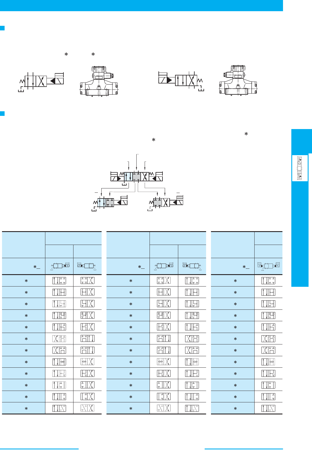
391
DIRECTIONAL CONTROLS
Solenoid Controlled
Pilot Operated Directional Valves
E
Solenoid Controlled Pilot Operated Directional Valves
AB
T
P
Y
b
B
A
PT
Y
a
AB
TP
Y
b
B
A
PT Y
aab
Y
PT
A
B
Standard
Mtg.
Reverse
Mtg. Type
Standard
Mtg.
Reverse
Mtg. Type
Standard
Mtg.
slobmyS cihparGslobmyS cihparG
Graphic
Symbols
srebmuN ledoMsrebmuN ledoMsrebmuN ledoM
04
06
10
DSHG-
-2B A
04
06
10
DSHG- -2B B
04
06
10
DSHG- -2N A
DSHG- -2B2A(S-)
DSHG- -2B3A
DSHG- -2B4A(S-)
DSHG- -2B40A(S-)
DSHG- -2B5A
DSHG- -2B6A
DSHG- -2B60A(S-)
DSHG- -2B7A
DSHG- -2B9A
DSHG- -2B10A(S-)
DSHG- -2B11A
DSHG- -2B12A(S-)
DSHG- -2B2B(S-)
DSHG- -2B3B
DSHG- -2B4B(S-)
DSHG- -2B40B(S-)
DSHG- -2B5B
DSHG- -2B6B
DSHG- -2B60B(S-)
DSHG- -2B7B
DSHG- -2B9B
DSHG- -2B10B(S-)
DSHG- -2B11B
DSHG- -2B12B(S-)
DSHG- -2N2A(S-)
DSHG- -2N3A
DSHG- -2N4A(S-)
DSHG- -2N40A(S-)
DSHG- -2N5A
DSHG- -2N6A
DSHG- -2N60A(S-)
DSHG- -2N7A
DSHG- -2N9A
DSHG- -2N10A(S-)
DSHG- -2N11A
DSHG- -2N12A(S-)
Y
P
T
A
B
b
Y
T
P
B
A
a
)"L"( dioneloS fo .gtM esreveRdioneloS fo .gtM dradnatS
A
B
PT
a
b
Y
A
B
P
Y
T
b
A
B
Y
PT
b
2B2A
2B2B
(Example) In case of Spool Type "2"
"A": Use of Neutral and
SOL. a Energised
Position
SOL. a Energised
Position
SOL. b Energised
Position
Neutral Position
"B": Use of Neutral and
SOL. b Energised
Position
Valves Using Neutral Position and Side Position. (Special Two position Valve)
Besides the use of the standard 2-position valves aforementioned in the "List of Standard Models and Maximum Flow",
the 3-position valves also can be used as the 2-position valves using the two of their three positions. In this case, there
are two kinds of the valve available. One is the valve using the neutral position and SOL a position
(2B A) and another
is the valve using the neutral position and SOL b position (2B B).
Reverse Mounting of Solenoid.
In spring offset type, it is a standard configuration that the solenoid is mounted onto the valve in the SOL b
position (side). However, in this particular spool-spring arrangement, the mounting of the solenoid onto the valve in
the reverse position - SOL a side - is also available. The graphic symbol for this reverse mounting is as shown below.
As for the valve type
2B A and 2B B, please refer to the explanation under the heading of "Valves Using Neutral
Position and Side Position" given below.
SOL b
A P B
XA
B
SOL a
A P B
XA B
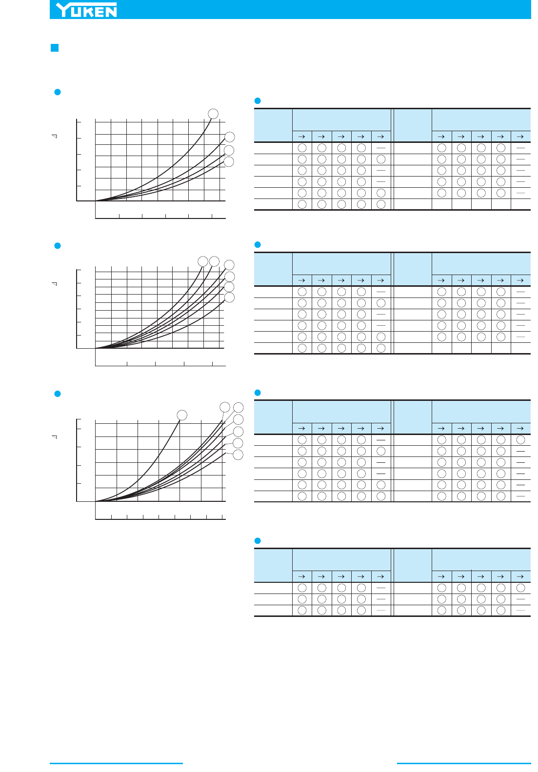
Solenoid Controlled Pilot Operated Directional Valves
392
Spool
Type
P A
B T P B A T P T
Pressure Drop
Curve Numbers
Spool
Type
P A
B T P B A T P T
Pressure Drop
Curve Numbers
3
4
3
3
3
3
2
2
2
2
2
2
3
4
3
3
3
3
2
1
1
3
4
3
3
3
2
2
2
2
2
3
4
3
3
3
2
2
2
2
2
2
3
4
40
5
60
7
9
10
11
12
2
2
2
2
2
2
Spool
Type
P A
B T P B A T P T
Pressure Drop
Curve Numbers
Spool
Type
P A
B T P B A T P T
Pressure Drop
Curve Numbers
3
5
3
3
6
3
3
5
5
3
3
3
4
5
4
4
4
4
4
2
1
3
6
3
6
3
3
3
5
3
3
4
6
4
4
4
4
4
4
4
6
2
3
4
40
5
60
7
9
10
11
12
4
6
6
4
6
4
Spool
Type
P A B T P B A T P T
Pressure Drop
Curve Numbers
Spool
Type
P A B T P B A T P T
Pressure Drop
Curve Numbers
5
5
5
5
7
5
4
3
3
4
4
3
5
7
5
1
7
5
5
5
6
5
4
4
2
4
7
5
5
5
5
7
6
6
6
6
2
3
4
40
5
6
7
9
10
11
12
Spool
Type
P A B T P B A T P T
Pressure Drop
Curve Numbers
Spool
Type
P A B T P B A T P T
Pressure Drop
Curve Numbers
2
2
2
2
3
4
2
2
2
6
2
2
4
2
2
6
2
2
7
4
5
2
4
40
60
10
12
4
5
6
60
5
5
5
5
5
6
5
5
6
5
6 5 4 5 5
2
2
MPa
PSI
Pressure Drop P
L /min
U.S.GPM
Flow Rate
1
2
3
4
010
20
30
40
1.4
1.2
0.8
0.4
1.0
0.6
0.2
0
200
160
120
80
40
0
246810
0
MPa
PSI
Pressure Drop P
L /min
U.S.GPM
Flow Rate
40
80 120
160
2.0
1.6
1.2
0.8
0.4
300
0
10 20 30 400
0
3
4
5
6
2
1
250
200
150
100
50
0
MPa
PSI
Pressure Drop P
L /min
U.S.GPM
Flow Rate
180
0
20 40 60 800
160
120
80
40
2
Pressure drop curves based on viscosity of 35 mm /s (164 SSU) and specific gravity of 0.850.
1
2
3
4
5
6
7
0
100
150
200
50
250
300
1.2
0.8
0.4
DSHG-01
DSHG-03
DSHG-04, S-DSHG-04
0
DSHG-01
DSHG-03
DSHG-04
S-DSHG-04
Pressure Drop
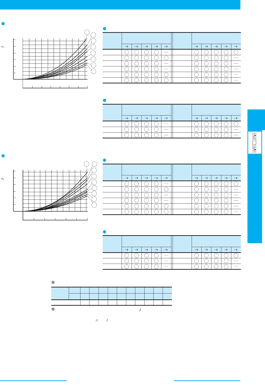
393
DIRECTIONAL CONTROLS
Solenoid Controlled
Pilot Operated Directional Valves
E
Solenoid Controlled Pilot Operated Directional Valves
Spool
Type
P A B T P B A T P T
Pressure Drop
Curve Numbers
Spool
Type
P A B T P B A T P T
Pressure Drop
Curve Numbers
8
6
8
8
8
5
5
4
5
5
4
3
8
6
8
8
5
5
4
1
1
6
6
6
8
8
5
4
5
5
4
6
6
6
8
5
7
2
3
4
40
5
6
7
9
10
11
12
7
60
8 5 8
1
7
7
7
7
4
7
7
7
7
7
Spool
Type
P A B T P B A T P T
Pressure Drop
Curve Numbers
Spool
Type
P A B T P B A T P T
Pressure Drop
Curve Numbers
6
6
8
1
2
5
6
6
8
6
8
8
2
5
5
6
8
8
3
2
4
40
10
12
2
60
1
2
7
7
7
Spool
Type
P A B T P B A T P T
Pressure Drop
Curve Numbers
Spool
Type
P A B T P B A T P T
Pressure Drop
Curve Numbers
9
7
9
9
9
5
6
6
6
6
6
3
9
7
9
9
8
5
5
1
2
8
7
7
9
9
5
6
6
5
6
8
7
7
9
8
5
2
3
4
40
5
6
7
9
10
11
12
8
60
9 7 9
3
7
6
8
6
2
7
8
8
7
6
Spool
Type
P A B T P B A T P T
Pressure Drop
Curve Numbers
Spool
Type
P A
B T P B A T P T
Pressure Drop
Curve Numbers
8
8
9
3
5
6
8
8
9
8
9
9
4
5
7
8
9
9
4
2
4
40
10
12
4
60
2
6
8
8
6
Viscosity
SSU
Factor 0.81 0.87 0.96 1.03 1.09 1.14 1.19 1.23
77 98 141 186 232 278 324 371
2
mm /s 15 20 30 40 50 60 70 80
1.27
417
90
1.30
464
100
1
2
3
4
5
6
7
8
9
0
200 400
600
800
2.0
1.6
1.2
0.8
0.4
1
2
3
4
5
6
7
8
0
100
200 300
400
500
2.0
1.6
1.2
0.8
0.4
PSI
Pressure Drop P
L /min
U.S.GPM
Flow Rate
300
250
200
150
50
0
20 60 80 100 1200
0
140
40
100
MPa
1000
1100
PSI
Pressure Drop P
L /min
U.S.GPM
Flow Rate
300
250
200
150
50
0
50 150
0 300100
100
MPa
200 250
0
DSHG-06, S-DSHG-06
DSHG-10, S-DSHG-10
DSHG-06
S-DSHG-06
DSHG-10
S-DSHG-10
For any other viscosity, multiply the factors in the table below.
For any other specific gravity (G'), the pressure drop ( P') may be obtained
from the formula right.
P' = P(G'/0.850)
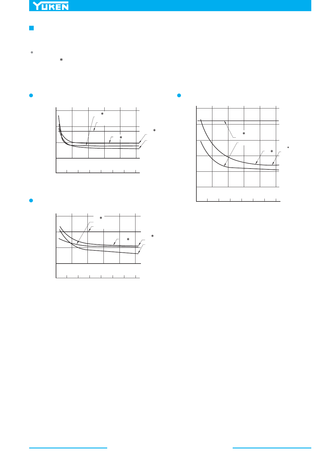
Solenoid Controlled Pilot Operated Directional Valves
394
Pilot Pressure
SOL"OFF"
SOL"ON"
3C
SOL"ON","OFF"
2B
2N
250
200
150
100
50
510
15 20
25
SOL"OFF"
SOL"ON"
3C
2N
SOL"ON"
2B
SOL"OFF"
150
100
50
510
15 20
25
SO L" OF F"
SOL"ON"
3C
2N
SOL"ON"
2B
SOL"OFF"
150
100
50
510
15 20
25
30002000100003600
MPa
PSI
ms
Changeover Time
0
0
Pilot Pressure
30002000100003600
MPa
PSI
ms
Changeover Time
0
0
Pilot Pressure
30002000100003600
MPa
PSI
Changeover Time
0
0
ms
Changeover time varies according to oil viscosity, spool type and hydraulic circuit.
DSHG-04
Test Conditions
Coil Type : D (Models with DC solenoids)
Voltage : Rated Voltage
2
Oil Viscosity : 35 mm /s (164 SSU)
DSHG-10
DSHG-06
Typical Changeover Time
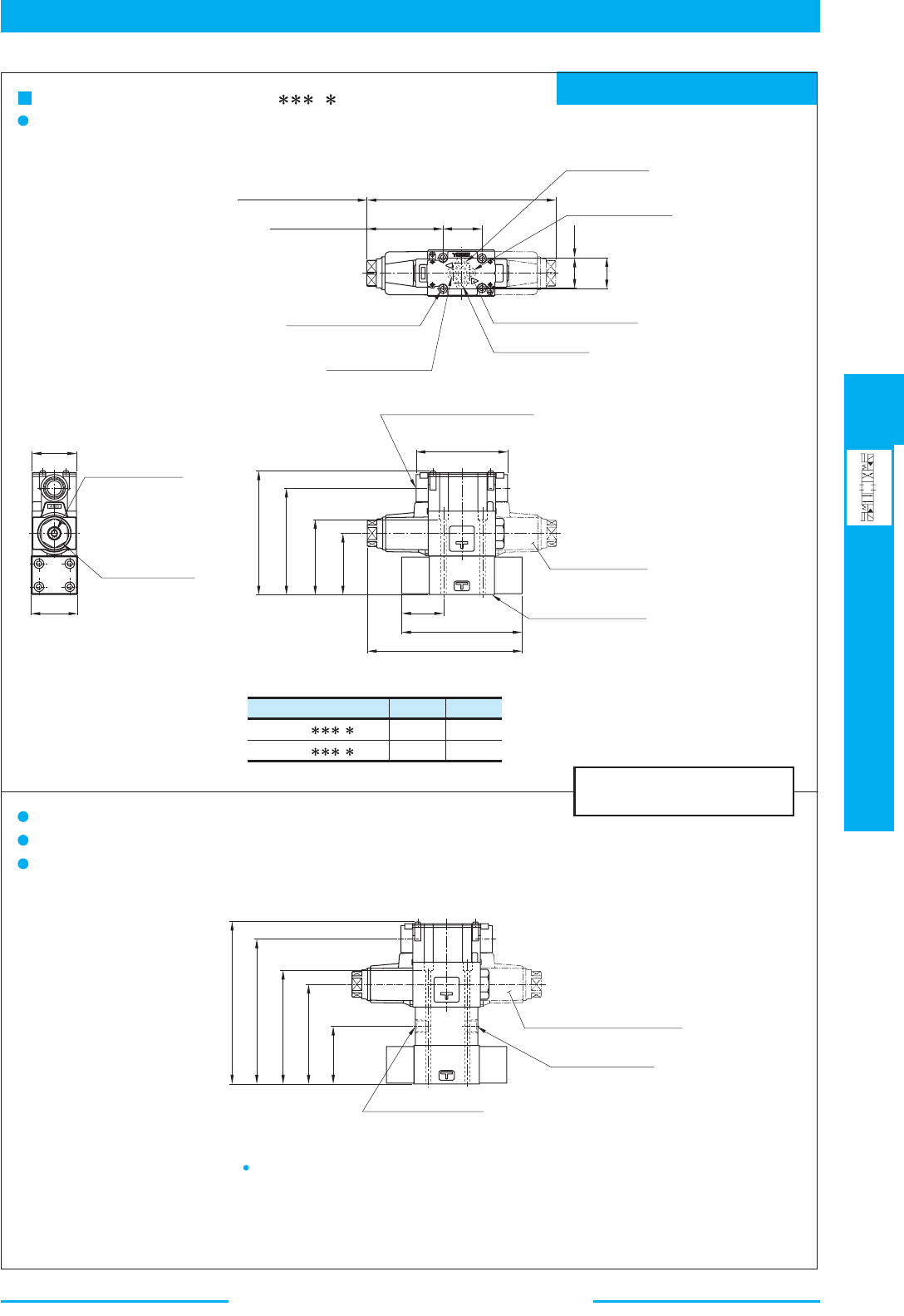
395
DIRECTIONAL CONTROLS
Solenoid Controlled
Pilot Operated Directional Valves
E
Solenoid Controlled Pilot Operated Directional Valves
Mounting surface: ISO 4401-AB-03-4-A
DIMENSIONS IN
MILLIMETRES (INCHES)
Model Numbers
DSHG-01- --14
DSHG-01- --1490
"C"
Thd.
G 1/2
1/2 NPT
Rc 1/4
1/4 NPT
"D"
Thd.
Manual Actuator
Nut 27 (1.06) Hex.
6(.24)
Dia.
Electrical Conduit Connection
"C"
Thd. (Both Ends)
Double Solenoid
Models Only
Mounting Surface
(O-Rings Furnished)
Ter minal Box type: DSHG-01- - -14/1490
Internal Pilot - Internal Drain
Pilot Drain Port
"Y"
"D"
Thd.
Pilot Pressure Port
"X"
"D"
Thd.
External Pilot - External Drain
External Pilot - Internal Drain
Internal Pilot - External Drain
For other dimensions, refer to "Internal Pilot Internal Drain".
40.5
(1.59)
Space Needed to Remove
5.5 (.22) Dia. Through
7 (.28) Dia. Spotface
4 Places
Solenoid-Each End
AC :
DC,R :
45.5 (1.79)
50 (1.97)
Cylinder Port
"B"
Pressure Port
"P"
Cylinder Port
"A"
AC :
DC,R :
196.4 (7.73)
204.4 (8.05)
AC :
DC,R :
79.2 (3.12)
83.2 (3.28)
Tank Port
"T"
Solenoid Indicator Light
31
(1.22)
32.5
(1.28)
0.75
(.03)
Double Solenoid Models Only
48
(1.89)
46
(1.81)
SOL b SOL a
125(4.92)
95
(3.74)
78
(3.07)
110.5
(4.35)
63.5
(2.5)
128.8
(5.07)
AC 160.7(6.33)
DC,R164.7(6.48)
43.5
(1.71)
B
P
A
T
SOL aSOL b
60
(2.36)
103.5
(4.07)
118
(4.65)
150.5
(5.92)
168.8
(6.65)
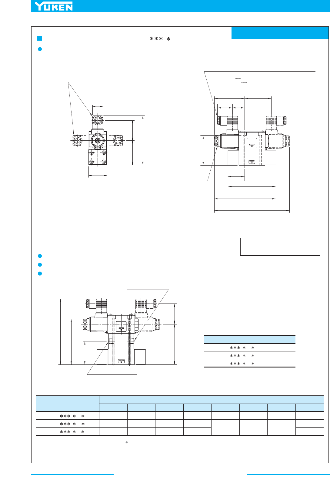
Solenoid Controlled Pilot Operated Directional Valves
396
Mounting surface: ISO 4401-AB-03-4-A
DIMENSIONS IN
MILLIMETRES (INCHES)
Model Numbers
DSHG-01- - -N -14
DSHG-01- - -N -1480
DSHG-01- - -N -1490
"J"
Thd.
Rc 1/4
1/4 BSP.F
1/4 NPT
Model Numbers
Dimensions mm (Inches)
LJHFEDC
128.5 (5.06)
139.5 (5.49)
142.5 (5.61)
53 (2.09)
64 (2.52)
57.2 (2.25)
27.5 (1.08)
27.5 (1.08)
34 (1.34)
39 (1.54)
39 (1.54)
53 (2.09)
168.5 (6.63)
179.5 (7.07)
182.5 (7.19)
79.2 (3.12)
83.2 (3.28)
196.4 (7.73) 160.7 (6.33)
204.4 (8.05) 164.7 (6.48)
DSHG-01- - -A -N/N1
DSHG-01- - -D -N /N1
DSHG-01- - -R -N
K
SOL a
SOL b
SOL a
SOL b
Pilot Pressure Port "X"
"J"
Thd.
Pilot Drain Port
"Y"
"J"
Thd.
60
(2.36)
118
(4.65)
L
D
103.5
(4.07)
D
63.5
(2.5)
C
48
(1.89)
E
H
F
32
(1.26)
(2.76)
70
78
(3.07)
43.5
(1.71)
125
(4.92)
K
J
Cable Departure
Cable Applicable:
Outside Dia. 8-10mm(.31-.39 IN.)
Conductor Area Not Exceeding
2
1.5mm (.0023 Sq. IN.)
The position of the Plug-i n connector can be changed as
illustrated below by loosening the lock nut. After
completion of the change, be sure to tighten the lock nut
with the torque as specified below.
Lock Nut
Tightening Torque:
10.3 - 11.3 Nm (91-100 IN.lbs.)
External Pilot-External Drain
External Pilot-Internal Drain
Internal Pilot-External Drain
Internal Pilot-Internal Drain
Plug-in Connector Type: DSHG-01- - - -14/1480/1490
N
N1
For other dimensions, refer to "Terminal Box Type".
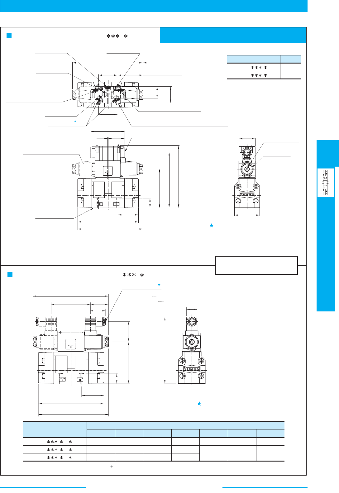
397
DIRECTIONAL CONTROLS
Solenoid Controlled
Pilot Operated Directional Valves
E
Solenoid Controlled Pilot Operated Directional Valves
Mounting surface: ISO 4401-AC-05-4-A
(The pilot and drain ports in accordance with the ISO original draft)
DIMENSIONS IN
MILLIMETRES (INCHES)
Model Numbers
DSHG-03- --14
DSHG-03- --1490
"C"
Thd.
G 1/2
1/2 NPT
Model Numbers
Dimensions mm (Inches)
CDEFHJ
53 (2.09)
64 (2.52)
57.2 (2.25)
173.5 (6.83)
184.5 (7.26)
187.5 (7.38)
27.5 (1.08)
27.5 (1.08)
34 (1.34)
182.2 (7.17)
186.2 (7.33)
196.4 (7.73) 47.2 (1.86)
204.4 (8.05) 51.2 (2.02)
DSHG-03- - -A -N/N1
DSHG-03- - -D -N/N1
DSHG-03- - -R -N
K
39 (1.54)
39 (1.54)
53 (2.09)
SOL a
SOL b
Space Needed to Remove
Solenoid-Each End
Manual Actuator
6(.24)
Dia.
Nut
27(1.06) Hex.
Electrical Conduit Connection
"C"
Thd. (Both Ends)
Mounting Surface
(O-Rings Furnished)
Double Solenoid Models Only
Tank Port
"T"
Solenoid
Indicator Light
Cylinder Port
"B"
Pressure Port
"P"
Cylinder Port
"A"
7(.28)
Dia. Through,
11(.43)
Dia. Spotface 4 Places
Pilot Drain Port
"Y"
(For External Drain Models Only)
Pilot Pressure Port
"X"
(For External Pilot Models Only)
F
E
D
27
(1.06)
108.5
(4.27)
58
(2.28)
170
(6.69)
H
J
K
C
102
(4.02)
Cable Departure
Cable Applicable:
Outside Dia.
8-10mm(.31-.39 IN.)
Conductor Area Not Exceeding
2
1.5mm (.0023 Sq. IN.)
Ter minal Box Type: DSHG-03- - -14/1490
Position of cable departure can be changed. For
details, refer to DSHG-01 valve on page 396.
Of the two of tank port "T", the tank port
in the left side is normally used in our
standard sub-plate, though, either side of
the tank port "T" can be used without
problem.
For other dimensions, refer to "Terminal Box Type".
Plug-in Connector Type: DSHG-03- - - -14/1490
N
N1
SOL a SOL b
AC : 45.5(1.79)
DC,R : 50(1.97)
170(6.69)
95(3.74)
46.5
(1.83)
1
(.04)
58
(2.28)
173.8
(6.84)
155.5
(6.12)
108.5
(4.27)
27
(1.06)
L' L
L'L
50.8
(2.0)
46
(1.81)
32.5
(1.28)
A100
AC 70.2 (2.76)
DC,R 74.2 (2.92)
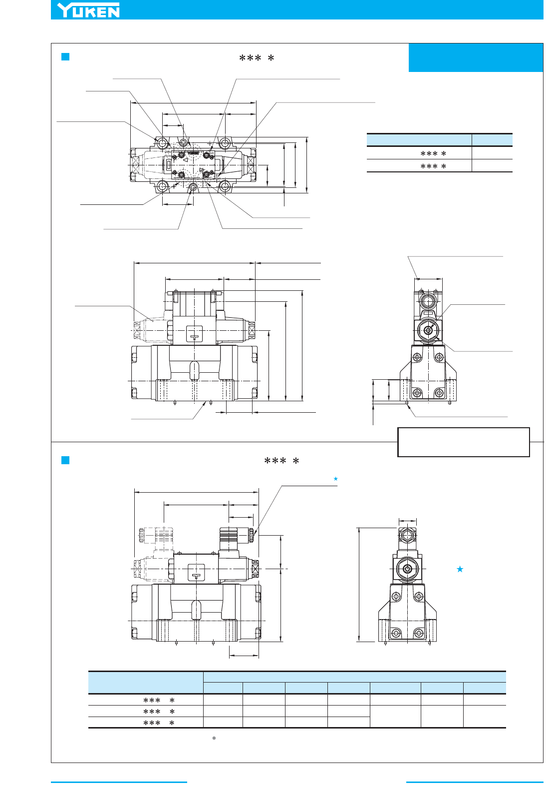
Solenoid Controlled Pilot Operated Directional Valves
398
Mounting surface:
ISO 4401-AD-07-4-A
DIMENSIONS IN
MILLIMETRES (INCHES)
Model Numbers "
C
" Thd.
(S-)DSHG-04- - -52
(S-)DSHG-04- - -5290
G 1/2
1/2 NPT
Model Numbers
(S-)DSHG-04- -A -N/N1
(S-)DSHG-04- -D -N/N1
(S-)DSHG-04- -R -N
Dimensions mm (Inches)
KJFEDCH
39
39
53
(1.54)
(1.54)
(2.09)
53
64
57.2
(2.09)
(2.52)
(2.25)
173.5
184.5
187.6
(6.83)
(7.26)
(7.39)
27.5
27.5
34
(1.08)
(1.08)
(1.34)
196.4 (7.73)
204.4 (8.05)
47.2 (1.86)
51.2 (2.02)
45.6 (1.80)
49.6
(1.95)
SOL a
SOL b
Tank Port "
T
"
11(.43)
Dia. Through
17.5(.69)
Dia. Spotface
4 Places
Pressure Port "
P
"
Pilot Pressure Port "
X
"
(For External Pilot Models Only)
Pilot Drain Port "
Y
"
(For External Drain Models Only)
Cylinder Port "
B
"
Solenoid Indicator Light
Cylinder Port "
A
"
7(.28)
Dia. Through
11(.43)
Dia. Spotface
2 Places
Space Needed to Remove
Solenoid-Each End
Double Solenoid
Models Only
Manual Actuator
6(.24)
Dia.
Nut
27(1.06)
Hex.
3(.12)
Dia. Two Locating Pins
Electrical Conduit Connection
"
C
" Thd. (Both Ends)
Mounting Surface
(O-Rings Furnished)
Cable Departure
Cable Applicable:
Outside Dia. 8-10 mm(.31 - .39 IN.)
2
Conductor Area Not Exceeding 1.5 m
m
(.0023 Sq. IN.)
......
...
H
102
(4.02)
J
C
D
K
114.5
(4.51)
E
F
Ter minal Box Type: (S-)DSHG-04- - -52/5290
Plug-in Connector Type: (S-)DSHG-04- - - -52/5290
N
N1
Position of cable
departure can be
changed. For details,
refer to DSHG-01
valve on page 396.
For other dimensions, refer to "Terminal Box Type".
AC 50.7(2.00)
DC,R54.7(2.15)
1.5
(.06)
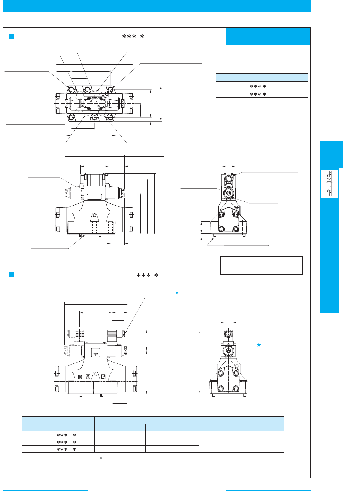
399
DIRECTIONAL CONTROLS
Solenoid Controlled
Pilot Operated Directional Valves
E
Solenoid Controlled Pilot Operated Directional Valves
Mounting surface:
ISO 4401-AE-08-4-A
DIMENSIONS IN
MILLIMETRES (INCHES)
Model Numbers "
C
" Thd.
(S-)DSHG-06- - -53
(S-)DSHG-06- - -5390
G 1/2
1/2 NPT
Model Numbers
(S-)DSHG-06- -A -N/N1
(S-)DSHG-06- -D -N/N1
(S-)DSHG-06- -R -N
Dimensions mm (Inches)
KJFEDC H
39
39
53
(1.54)
(1.54)
(2.09)
53
64
57.2
(2.09)
(2.52)
(2.25)
200.5 (7.95)
211.5 (8.33)
214.5 (8.44)
27.5
27.5
34
(1.08)
(1.08)
(1.34)
196.4 (7.73)
204.4 (8.05)
47.2 (1.86)
51.2 (2.02)
45.2 (1.78)
49.2 (1.94)
SOL a SOL b
Tank Port "T"
13.5(.53) Dia. Through
20(.79) Dia. Spotface
6 Places
Pressure Port "
P"
Pilot Pressure Port "
X"
(For External Pilot Models Only)
Pilot Drain Port "
Y"
(For External Drain Models Only)
Cylinder Port "
B"
Solenoid Indicator Light
Cylinder Port "
A"
Space Needed to Remove
Solenoid-Each End
Manual Actuator
6(.24) Dia.
Nut
27(1.06) Hex.
6(.24) Dia. Two Locating Pins
Electrical Conduit Connection
"
C
" Thd. (Both Ends)
Mounting Surface
Double Solenoid
Models Only
(O-Rings Furnished)
Cable Departure
Cable Applicable:
Outside Dia. 8-10 mm (.31 - .39 IN.)
Conductor Area Not Exceeding 1.5 mm
2
(.0023 Sq. IN.)
......
...
H
102
(4.02)
J
C
D
K
135.5
(5.33)
E
F
Terminal Box Type: (S-)DSHG-06- - -53/5390
Plug-in Connector Type: (S-)DSHG-06- - - -53/5390
N
N1
For other dimensions, refer to "Terminal Box Type".
Position of cable
departure can be
changed. For details,
refer to DSHG-01
valve on page 396.
AC 45.2(4.78)
DC,R49.2(1.94)
AC 50.7(2.00)
DC,R54.7(2.15)
AC 45.5(1.79)
DC,R50(1.97)
AC 196.4(7.73)
DC,R204.4(8.05)
LL
53.2
(2.09)
130.2
(5.13)
255(10.04)
77
(3.03)
46.1
(1.81)
92.1
(3.63)
13
(.51)
118
(4.65)
156
(6.14)
46
(1.81)
41
(1.61)
6
(.24)
50.5
(1.99)
200.8(7.91)
182.5(7.19)
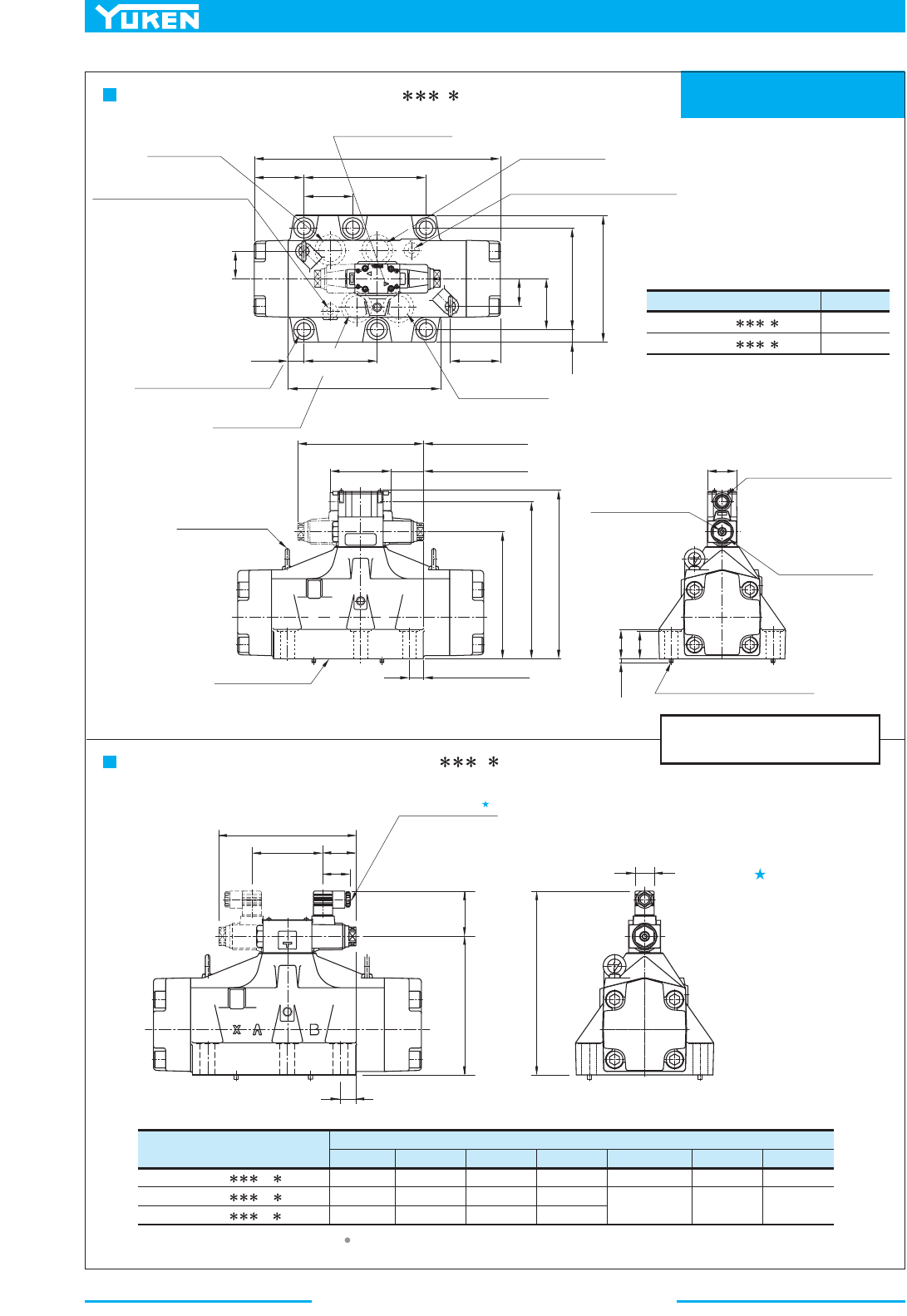
Solenoid Controlled Pilot Operated Directional Valves
400
Mounting surface:
ISO 4401-AF-10-4-A
DIMENSIONS IN
MILLIMETRES (INCHES)
Model Numbers "
C
" Thd.
(S-)DSHG-10- --43
(S-)DSHG-10- --4390
G 1/2
1/2 NPT
Model Numbers
(S-)DSHG-10- -A -N/N1
(S-)DSHG-10- -D -N/N1
(S-)DSHG-10- -R -N
Dimensions mm (Inches)
KJFEDCH
39
39
53
(1.54)
(1.54)
(2.09)
53
64
57.2
(2.09)
(2.52)
(2.25)
263.5
274.5
277.5
(10.37)
(10.81)
(10.93)
27.5
27.5
34
(1.08)
(1.08)
(1.34)
196.4 (7.73)
204.4 (8.05)
47.2 (1.86)
51.2 (2.02)
22.2 (.87)
26.2
(1.03)
Tank Port "T"
Pressure Port "
P"
Pilot Pressure Port "
X"
(For External Pilot Models Only)
Cylinder Port "
B"
Solenoid Indicator Light
Cylinder Port "
A"
Space Needed to Remove
Solenoid-Each End
Two Eye Bolts M8
Manual Actuator
6(.24) Dia.
Nut
27(1.06) Hex.
6(.24) Dia. Two Locating Pins
Electrical Conduit Connection
"
C
" Thd. (Both Ends)
Mounting Surface
(O-Rings Furnished)
Cable Departure
Cable Applicable:
H
102
(4.02)
J
C
D
K
198.5
(7.81)
F
21.5(.85) Dia. Through
32(1.26) Dia. Spotface
6 Places
Pilot Drain Port "
Y
"
(For External Drain Models Only)
E
Terminal Box Type: (S-)DSHG-10- - -43/4390
Plug-in Connector Type: (S-)DSHG-10- - - -43/4390
N
N1
Position of cable
departure can be
changed. For details,
refer to DSHG-01
valve on page 396.
For other dimensions, refer to "Terminal Box Type".
AC 50.7(2.00)
DC,R54.7(2.15)
AC 22.2(.87)
DC,R26.2(1.03)
AC 45.5(1.79)
DC,R50(1.97)
AC 196.4(7.73)
DC,R204.4(8.05)
BAX
BA
X
Y
19.6
(.77)
114.3
(4.50)
Outside Dia. 8-10 mm (.31 - .39 IN.)
Conductor Area Not Exceeding 1.5 mm
2
(.0023 Sq. IN.)
......
...
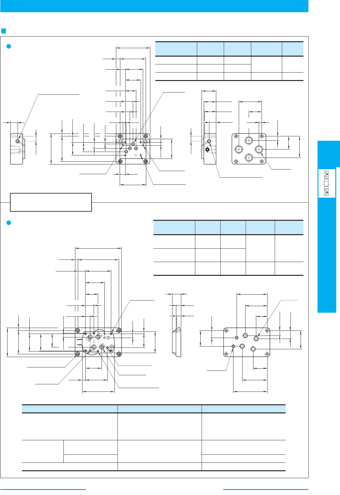
401
DIRECTIONAL CONTROLS
Solenoid Controlled
Pilot Operated Directional Valves
E
Solenoid Controlled Pilot Operated Directional Valves
DIMENSIONS IN
MILLIMETRES (INCHES)
Sub-plate
Model Numbers
DHGM-03Y-10
DHGM-03Y-1080
DHGM-03Y-1090
"
C
" Thd. "
D
" Thd.
Rc 3/4
3/4 BSP.F
3/4 NPT
"
E
" Thd.
13(.51)
15(.59)
Rc 1/4
1/4 BSP.F
1/4 NPT
M6
1/4-20 UNC
F
mm (in.)
Sub-plate
Model Numbers
DHGM-04-20
DHGM-04X-20
"
C
" Thd.
Rc 1/2
Rc 3/4
"
E
" Thd.
M10
3/8-16 UNC
1/2 BSP.F
3/4 BSP.F
1/2 NPT
3/4 NPT
"
D
" Thd.
Rc 1/4
1/4 BSP.F
1/4 NPT
"
F
" Thd.
M6
1/4-20 UNC
DHGM-04-2080
DHGM-04X-2080
DHGM-04-2090
DHGM-04X-2090
Valve Types
Spring Centred
No-spring
Solenoid Controlled Pilot
Operated Directional Valves
Pilot Operated
Directional
Valves
Manually Operated Directional Valves
Spring Offset
Pilot Pressure Port "
X
" troP"
Y
"
Used only on external pilot type
valves.
To be plugged on internal pilot
type valves.
Used
Not used (plug is not required)
Used as drain port only on external
drain type valves.
To be plugged on internal drain
type valves.
Used as drain port
Used as pilot drain port
Used as pilot pressure port
120
(4.72)
90
(3.54)
15
(.59)
110
(4.33)
22(.87)
"
D
" Thd.
Used only on external
pilot type valves.
To be plugged on internal
pilot type valves.
"
E
" Thd. "
F
" Deep
4 Places
25
(.98)
19
(.75)
90
(3.54)
46
(1.81)
10
(.39)
32.5(1.28)
21.5(.85)
6.4(.25)
6.2(.24)
Dia.
6.2(.24)
Dia.
19
(.75)
92
(3.62)
11
(.43)
12
(.47)
70
(2.76)
11(.43)
Dia.
4 Places
18
(.71)
62
(2.44)
54
(2.13)
37.3(1.47)
27(1.06)
16.7(.66)
8(.31)
3.2
(.13)
"
C
" Thd.
4 Places
P
T
A
B
19
(.75)
25(.98)
42(1.65)
43(1.69)
50
(1.97)
10
(.39)
45
(1.77)
80
(3.15)
16(.63)
47
(1.85)
76
(2.99)
P
T
A
B
X
Y
190
(7.48)
166
(6.54)
101.6
(4.00)
76.7
(3.02)
12(.47)
32.2(1.27)
50
(1.97)
34(1.34)
18.3(.72)
11(.43)
Dia. Through
17.5(.69)
Dia. Spotface
4 Places
3.6(.14)
Dia.
5(.20)
Deep
2 Places
14.2
(.56)
65.8
(2.59)
88.1
(3.47)
130
(5.12)
"
E
" Thd.
17(.67)
Deep
4 Places
6(.24)
Dia. 2 Places
17.5(.69)
Dia.
4 Places
"
F
" Thd.
12(.47)
Deep
2 Places
120
(4.72)
96
(3.78)
71.4
(2.81)
12
(.47)
13.1
(.52)
69.8
(2.75)
55.6
(2.19)
14.2
(.56)
1.6(.06)
16
(.63)
10.1
(.40)
57.1
(2.25)
90
(3.54)
36
(1.42)
20
(.79)
19
(.75)
P
T
A
B
X
Y
"
D
" Thd.
2 Places
125
(4.92)
90
(3.54)
46
(1.81)
65
(2.56)
29
(1.14)
58
(2.28)
102
(4.02)
137.5
(5.41)
76
(2.99)
21.5(.85)
33(1.30)
"
C
" Thd.
4 Places
"
D
" Thd.
Used only on external
drain type valves.
To be plugged on internal
drain type valves.
DHGM-03Y-10/1080/1090
DHGM- -20/2080/2090
04
04X
Sub-plate
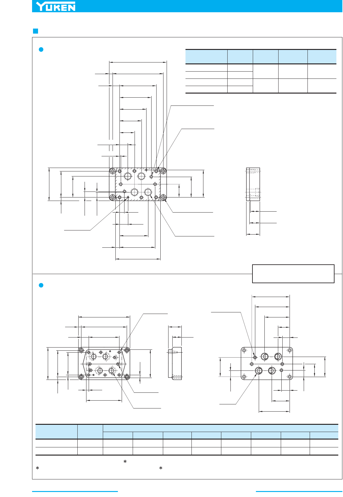
Solenoid Controlled Pilot Operated Directional Valves
402
DIMENSIONS IN
MILLIMETRES (INCHES)
Sub-plate
F
mm (in.)
Sub-plate
Model Numbers
"
C
" Thd. "
E
" Thd.
M12
1/2-13 UNC
Rc 3/4
Rc 1
3/4 NPT
1 NPT
"
D
" Thd.
Rc 1/4
1/4 NPT
24 (.94)
26 (1.02)
DHGM-06-50
DHGM-06X-50
DHGM-06-5090
DHGM-06X-5090
Sub-plate
Model Numbers
"
C
" Thd.
3/4 BSP.F
1 BSP.F
DHGM-06-5080
DHGM-06X-5080
Dimensions mm (Inches)
DEFHJ KLN
151.2 (5.95)
155.2 (6.11)
137.7 (5.42)
148 (5.83)
102 (4.02)
106 (4.17)
54.4 (2.14)
50 (1.97)
30.6 (1.20)
25 (.98)
125.8 (4.95)
130 (5.12)
78.2 (3.08)
74 (2.91)
42.5 (1.67)
32 (1.26)
204
(8.03)
12
(.47)
"
E
" Thd. "
F
" Deep
6 Places
116
(4.57)
17.5(.69)
53.2
(2.09)
29.4(1.16)
PT
A
B
Y
X
V
7(.28)
Dia.
8(.31)
Deep
2 Places
11(.43)
Dia. Through
17.5(.69)
Dia. Spotface
4 Places
23(.91)
Dia.
"
C
" Thd. (From Rear)
4 Places
11(.43)
Dia.
"
D
" Thd. (From Rear)
4 Places
180
(7.09)
25
(.98)
130.2
(5.13)
112.7
(4.44)
94.5
(3.72)
77
(3.03)
5.6(.22)
19.1(.75)
92.1
(3.63)
74.6
(2.94)
12
(.47)
46.1
(1.81)
73.1
(2.88)
96.9
(3.81)
17.5
(.69)
29.5
(1.16)
100.8
(3.97)
126.2
(4.97)
12.5
(.49)
156
(6.14)
50
(1.97)
34(1.34)
35(1.38)
P
T
AB
Y
X
V
W
204
(8.03)
180
(7.09)
12
(.47)
25
(.98)
130.2
(5.13)
M12
Thd.
24(.94)
Deep
6 Places
11(.43)
Dia.
4 Places
24.5(.96)
Dia.
4 Places
12.5
(.49)
156
(6.14)
92.1
(3.63)
110
(4.33)
134
(5.28)
8.9
(.35)
12
(.47)
11.9
(.47)
116
(4.57)
50
(1.97)
35
(1.38)
P
T
AB
Y
W
D
E
F
H
J
N
L
K
73.1
(2.88)
17.5
(.69)
19.1
(.75)
74.6
(2.94)
46.1
(1.81)
1/4 BSP.F Thd.
4 Places
"
C
" Thd.
4 Places
X
V
DHGM- -50/5090
06
06X
DHGM- -5080
06
06X
For other dimensions, refer to "DHGM-06 -50/5090" above.
For Uses of Port "X", "Y", "V", "W", refer to DHGM-10 on the following page.
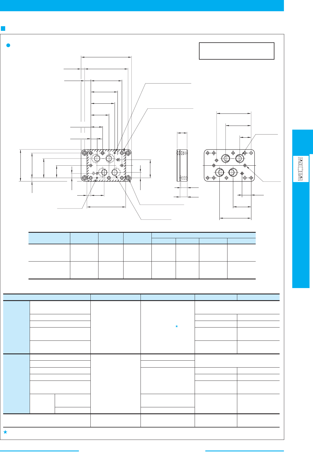
403
DIRECTIONAL CONTROLS
Solenoid Controlled
Pilot Operated Directional Valves
E
Solenoid Controlled Pilot Operated Directional Valves
Sub-plate
Sub-plate
Model Numbers
"C"
Thd.
"D"
Thd.
"E"
Thd.
FH J K
Dimensions mm (Inches)
DHGM-10-40
DHGM-10-4080
DHGM-10-4090
Rc 1-1/4
1-1/4 BSP.F
1-1/4 NPT
Rc 3/8
3/8 BSP.F
3/8 NPT
M20
M20
3/4-10 UNC
152 (5.98) 79 (3.11) 185.5 (7.30) 120.5 (4.74)
DHGM-10X-40
DHGM-10X-4080
DHGM-10X-4090
Rc 1-1/2
1-1/2 BSP.F
1-1/2 NPT
Rc 3/8
3/8 BSP.F
3/8 NPT
M20
M20
3/4-10 UNC
156 (6.14) 74 (2.91) 194.5 (7.66) 112.5 (4.43)
Spring Centred, No-spring,
Spring Offset
Pressure Centred
With Pilot Piston, Both Ends
With Pilot Piston,
Port "A" End
With Pilot Piston,
Port "B" End
Solenoid
Controlled
Pilot
Operated
Directional
Valves
Used only on
external pilot type
valves.
To be plugged on
internal pilot type
valves.
Used as drain port only
on external drain type
valves.
To be plugged on
internal drain type
valves.
Not used (plug is not required)
Used Not used
Used Used
Used
Not used
(plug is required)
Not used
(plug is required)
Used
Spring Centred, No-spring
Spring Offset
Pressure Centred
With Pilot Piston, Both Ends
With Pilot Piston,
Port "B" End
With Pilot
Piston
Port "A"
End
Spring Centred
No-spring
Spring Offset
Manually Operated Directional Valves
Pilot
Operated
Directional
Valves
Used
Used as pilot pres. port
Used as pilot drain port
Used as pilot pres. port
Used as pilot pres. port
Used as pilot drain port
Not used
(plug is not required)
Not used
(plug is not required)
Not used (plug is not required)
Used
Used
Not used
(pllug is required)
Not used
Used
Used
Not used
(plug is required)
Not used (plug is
not required)
Used
Used
Valve Types Pilot Pres. Port "
X
"Port "
Y
" Drain Port "
V
" Drain Port "
W
"
Note: Uses of port "X", "Y", "V", and "W"
F
H
K
J
W
Y
P
T
V
A
B
X
Y
B
A
PT
V
X
W
41.3(1.63)
76.2(3.00)
114.3
(4.50)
147.6
(5.81)
168.3
(6.63)
190.5
(7.50)
266.5
(10.49)
38(1.50)
20(.79)
306.5
(12.07)
28.6
(1.13)
79.4
(3.13)
123.8
(4.87)
158.8
(6.25)
199
(7.83)
20.1
(.79)
82.5
(3.25)
21.8
(.86)
234
(9.21)
35
(1.38)
114.3
(4.50)
7 (.28) Dia. 8 (.31) Deep
2 Places
"E"
Thd. 34 (1.34) Deep
6 Places
11 (.43) Dia.
4 Places
17.5 (.69) Dia. Through
26 (1.02) Dia. Spotface
4 Places
36 (1.42) Dia.
4 Places
60
(2.36)
43(1.69)
44(1.73)
55
(2.17)
213
(8.39)
"C"
Thd.
4 Places
"D"
Thd.
4 Places
10
10X
DHGM- -40/4080/4090
As the thread is provided on the body, plug either port on the sub-plate or port on the body.
DIMENSIONS IN
MILLIMETRES (INCHES)
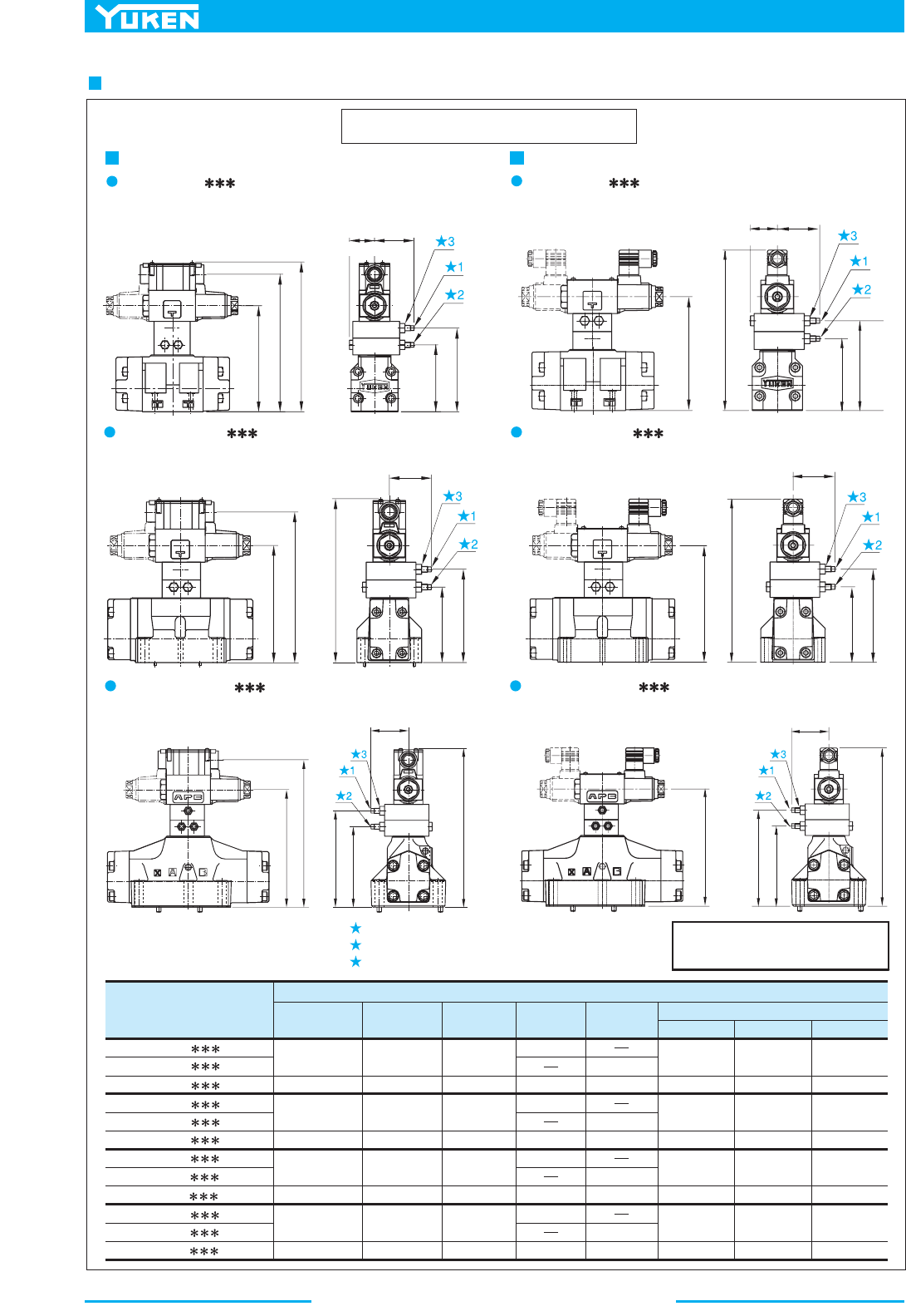
Solenoid Controlled Pilot Operated Directional Valves
404
Options
DIMENSIONS IN
MILLIMETRES (INCHES)
1.
2.
3.
Fully Extended
Models with Pilot Choke Valve
Terminal Box Type
Plug-in Connector Type
"C1" Choke Adj. Screw 6 (.24) Hex.
"C2" Choke Adj. Screw 6 (.24) Hex.
Lock Nut 12 (.47) Hex.
Fully Extended
59
(2.32)
59
(2.32)
Fully Extended
59
(2.32)
Fully
Fully
Extended
J
J
H
F
37.5
DSHG-03- -C1/C2/C1C2
N
N1
DSHG-03- -C1/C2/C1C2-
(S-)DSHG-04- -C1/C2/C1C2 (S-)DSHG-04- -C1/C2/C1C2-
N
N1
(S-)DSHG- - -C1/C2/C1C2
06
10
(S-)DSHG- - -C1/C2/C1C2-
06
10
N
N1
SOL a
SOL b
SOL a
SOL b
E
D
C
H
F
H
F
Fully Extended
59
(2.32)
Extended
A
SOL a SOL b
SOL a SOL b
E
D
C
H
F
E
E
59
(2.32)
SOL a
SOL b
SOL a
SOL b
E
E
D
F
H
F
H
59
(2.32)
37.5
(1.48)
(1.48)
Model Numbers
CDEFH
AC SO L DC SO L R SOL
J
Dimensions mm (Inches)
(S-)
(S-)
(S-)
(S-)
(S-)
(S-)
(S-)
(S-)
(S-)
DSHG-03- -C1
198.8 (7.83)
223.8 (8.81)
229.8 (9.05)
204.8 (8.06)
250.8 (9.87)
225.8 (8.89)
313.8 (12.35)
288.8 (11.37)
198.5 (7.81)
223.5 (8.80)
229.5 (9.04)
204.5 (8.05)
250.5 (9.86)
225.5 (8.88)
313.5 (12.34)
288.5 (11.36)
180.5 (7.11)
100 (3.94)
100 (3.94)
100 (3.94)
125 (4.92)
106 (4.17)
106 (4.17)
106 (4.17)
131 (5.16)
127 (5.00)
127 (5.00)
127 (5.00)152 (5.98)
190 (7.48)
190 (7.48)
190 (7.48)215 (8.46)
205.5 (8.09)
211.5 (8.33)
186.5 (7.34)
232.5 (9.15)
207.5 (8.17)
133.5 (5.26)
158.5 (6.24)
164.5 (6.48)
139.5 (5.49)
185.5 (7.30)
160.5 (6.32)
295.5 (11.63)
270.5 (10.65)
209.5 (8.25)
234.5 (9.23)
240.5 (9.47)
215.5 (8.48)
261.5 (10.30)
236.5 (9.31)
324.5 (12.78)
299.5 (11.79)
212.5 (8.37)
237.5 (9.35)
243.5 (9.59)
218.5 (8.60)
264.5 (10.41)
239.5 (9.43)
327.5 (12.89)
302.5 (11.91)
248.5 (9.78)
223.5 (8.80)
DSHG-03- -C2
DSHG-03- -C1C2
DSHG-04- -C1
DSHG-04- -C2
DSHG-04- -C1C2
DSHG-06- -C1
DSHG-06- -C2
DSHG-06- -C1C2
DSHG-10- -C1
DSHG-10- -C2
DSHG-10- -C1C2

405
DIRECTIONAL CONTROLS
Solenoid Controlled
Pilot Operated Directional Valves
E
Solenoid Controlled Pilot Operated Directional Valves
DIMENSIONS IN
MILLIMETRES (INCHES)
Options
Model Numbers
(S-)DSHG-06- -R2
(S-)DSHG-10- -R2
CDE
376 (14.80)
558 (21.97)
111 (4.37)
164.5 (6.48)
40 (1.57)
65 (2.56)
Model Numbers
(S-)DSHG-06-3H
(S-)DSHG-10-3H
C
306.5 (12.07)
456 (17.95)
D
102 (4.02)
149.5 (5.89)
Model Numbers
C
323 (12.72)
479 (18.86)
D
84 (3.31)
125 (4.92)
(S-)DSHG-06- -P2
(S-)DSHG-10- -P2
Stroke Adj. Screw (Port
"B"
End)
17 (.67) Hex.
D
Fully Extended
C
Fully Extended
Fully Extended
93 (3.66)
Stroke Adj. Screw (Port
"A"
End)
17 (.67) Hex.
Lock Nut
24(.94) Hex.
Fully Extended
289 (11.38)
(1.30)
Stroke Adj. Screw (Port
"A"
End)
13 (.51) Hex.
Stroke Adj. Screw (Port
"B"
End)
13 (.51) Hex.
Lock Nut
17(.67) Hex.
Fully Extended
99 (3.90)
Stroke Adj. Screw (Port
"A"
End)
13 (.51) Hex.
Stroke Adj. Screw (Port
"B"
End)
13 (.51) Hex.
Lock Nut
17(.67) Hex.
Fully Extended
252 (9.92)
Models with Stroke Adjustment
DSHG-03- -R
(S-)DSHG-04- -R
06
10
(S-)DSHG-
- -R
Pressure Centred Model s Models with Pilot Piston
06
10
(S-)DSHG-
-3H
60
01
(S-)DSHG- - -P
SOL a
SOL b
35
(1.38)
SOL a
SOL b
33
SOL a
SOL b
E
C
D
SOL a
SOL b
SOL a
SOL b
C
D
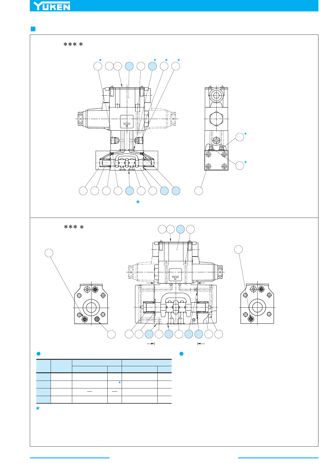
Solenoid Controlled Pilot Operated Directional Valves
406
List of Seals and Pilot Valves
Item Name
Part Numbers Qty.
DSHG-01
Part Numbers Qty.
DSHG-03
7
8
9
10
O-Ring
O-Ring
O-Ring
O-Ring
JASO-1018-1A
SO-NB-P9
SO-NB-P5
2
8(4)
2
SO-NB-P28
SO-NB-A104
SO-NB-P9
2
5
6
SO-NB-P9
2
Pipe Plug
Removed for External Drain Models
Pipe Plug
Removed for Internal Pilot Models
Pipe Plug
Removed for Internal Drain Models
Pipe Plug
Removed for External
Pilot Models
Pipe Plug
Removed for Internal
Pilot Models
Pipe Plug
Removed for Internal
Drain Models
DSHG-01- - -14/1480/1490
Note: Piece parts marked are not available
for internal pilot-internal drain type
DSHG-03- - -14/1490
Section Y-Y
Section X-X
sevlaVtoliPslaeSfotsiL
See page 408 for the pilot valve model numbers to be used.
Quantities in the ( ) are applicable to internal pilot-internal drain.
Note: When ordering theo-rings, please specify theseal kitnumber listed
in page 408. In addition to the above o-rings, o-rings for pilot
valve
is included in the seal kit.
For the detail of the pilot valve o-rings, see page 359.
T
SOL b
SOL a
6
13
13
12188161714
12
254 713811 10
15
X
XY
Y
SOL a SOL b
16171415
13
12
3819451072
6
13
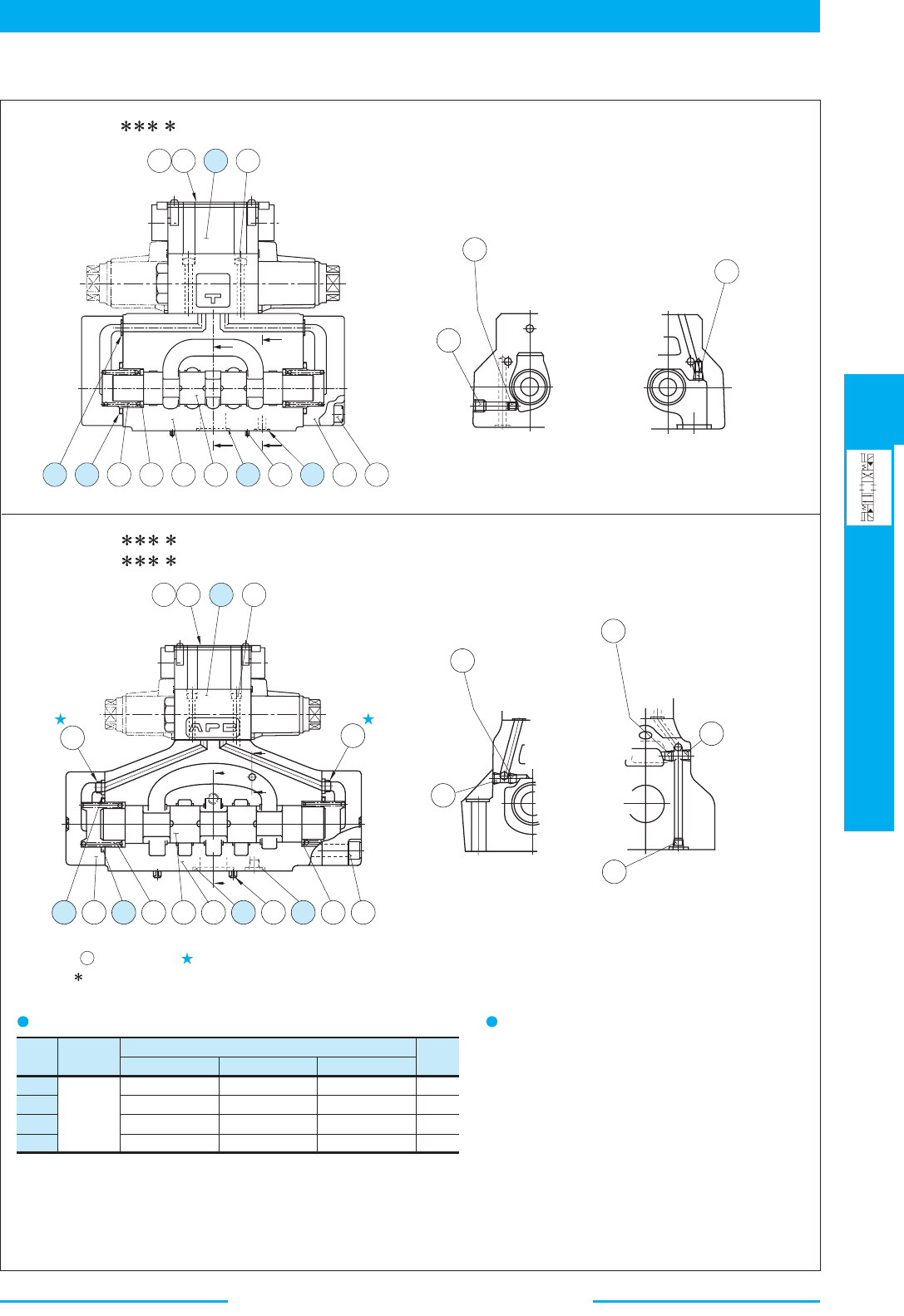
407
DIRECTIONAL CONTROLS
Solenoid Controlled
Pilot Operated Directional Valves
E
Solenoid Controlled Pilot Operated Directional Valves
■ List of Seals and Pilot Valves
Item Name
(S-)DSHG-04
SO-NB-P9
SO-NB-P22
SO-NB-P34
SO-NB-P9
(S-)DSHG-06
SO-NB-P14
SO-NB-P30
SO-NB-P40
SO-NB-P10
(S-)DSHG-10
SO-NB-P20
SO-NB-P42
SO-NB-P65
SO-NB-P14
Qty.
Part Numbers
2
4
2
2
O-Ring
8
9
10
18
12
11
11
Pipe Plug
Removed for Internal
Drain Models
Pipe Plug
Removed for Internal
Pilot Models
X
Y
X
Y
21
18 2 10 5 319138 4 7
11
11
12
12
Pipe Plug
Removed for Internal
Pilot Models
Pipe Plug
Removed for Internal
Drain Models
11
Pipe Plug
Removed for External
Drain Models
21
Section Y-Y Section X-X
Section Y-Y
Section X-X
sevlaVtoliPslaeSfotsiL
See page 408 for the pilot valve model numbers to
be used.
Note: When ordering the o-rings, please specify the seal kit number listed in page
408. In addition to the above o-rings, o-rings for pilot valve is included in
the seal kit.
For the detail of the pilot valve o-rings, see page 359.
Item orifice marked is applicable to pressure centred models Note:
(3H ) with pilot pressure more than 10 MPa (1450 PSI).
(S-)DSHG-04- - -52/5290
(S-)DSHG-06- - -53/5390
(S-)DSHG-10- - -43/4390
21
SOL a SOL b
X
Y
Y
X
72813931451018
171614
15
SOL a SOL b
17161415
Solenoid Controlled Pilot Operated Directional Valves
408
Fill coil type (a symbol representing current/voltage) in section marked . Likewise, in section marked , fill a symbol
KS-DSHG-01- -14
KS-DSHG-01-ET- -14
KS-DSHG-03- -14
KS-DSHG-04- -52
KS-DSHG-06- -53
KS-DSHG-10- -43
DSG-01-3C4- - -70
DSG-01-3C4- -N-70
DSG-01-3C4- - -7090
DSG-01-2B2- - -70-L
DSG-01-2B2- -N-70-L
DSG-01-2B2- - -7090-L
DSG-01-3C4- - -70
DSG-01-3C4- - -7090
DSG-01-2B2- - -70
DSG-01-2B2- - -7090
DSG-01-2D2- - -70
DSG-01-2D2- - -7090
DSG-01-3C4- - -70
DSG-01-3C4- - -7090
DSG-01-2B2- - -70
DSG-01-2B2- - -7090
DSG-01-2D2- - -70
DSG-01-2D2- - -7090
DSG-01-3C4- - -70
DSG-01-3C4- - -7090
DSG-01-2B2- - -70-L
DSG-01-2B2- - -7090-L
DSG-01-2D2- - -70
DSG-01-2D2- - -7090
DSG-01-3C4- - -70
DSG-01-3C4- - -7090
DSG-01-2B2- - -70-L
DSG-01-2B2- - -7090-L
DSG-01-2D2- - -70
DSG-01-2D2- - -7090
- - -14
- - -14
- - -1490
- -N-1480
- - -1490
- - -14
- -N-1480
- - -1490
- - -14
- - -1490
- - -14
- - -1490
- - -52
- - -5290
- - -52
- - -5290
- - -52
- - -5290
- - -53
- - -5390
- - -53
- - -5390
- - -53
- - -5390
- - -43
- - -4390
- - -43
- - -4390
- - -43
- - -4390
Valve Model Numbers Pilot Valve Model Numbers Seal Kit Numbers
DSHG-03-3C
DSHG-03-3C
DSHG-01-3C
DSHG-01-3C
DSHG-01-3C
DSHG-01-2B
DSHG-01-2B
DSHG-01-2B
DSHG-03-2B
DSHG-03-2B
DSHG-03-2N
DSHG-03-2N
(S-)DSHG-04-3C
(S-)DSHG-04-3C
(S-)DSHG-04-2B
(S-)DSHG-04-2B
(S-)DSHG-04-2N
(S-)DSHG-04-2N
(S-)DSHG-06-3C
(S-)DSHG-06-3C
(S-)DSHG-06-2B
(S-)DSHG-06-2B
(S-)DSHG-06-2N
(S-)DSHG-06-2N
(S-)DSHG-10-3C
(S-)DSHG-10-3C
(S-)DSHG-10-2B
(S-)DSHG-10-2B
(S-)DSHG-10-2N
(S-)DSHG-10-2N
(For Internal Pilot-Internal Drain)
(Except for Internal Pilot-Internal Drain)
Notes) 1:
2:
representing the type of electrical conduit connection (None: Terminal Box Type, N: Plug-in Connector Type).
For the details of the pilot valves, see page 359 to 360.
■ List of Seal Kits and Pilot Valves
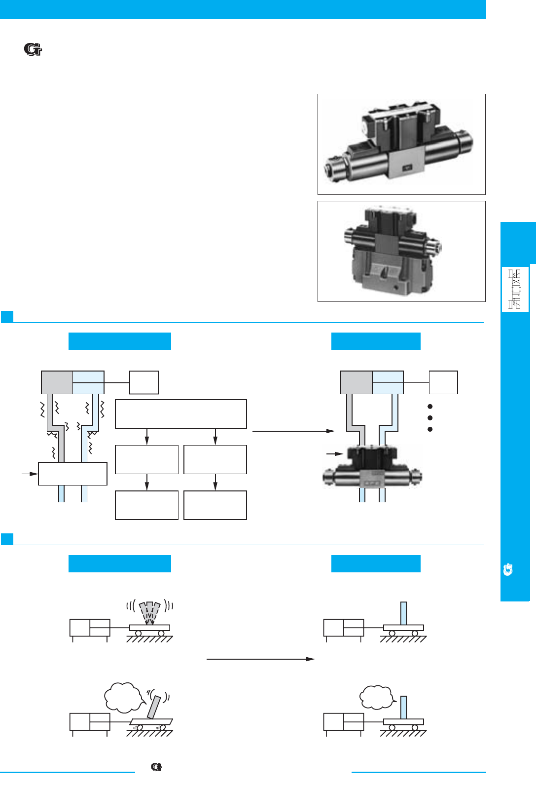
409
DIRECTIONAL CONTROLS
“ ” Series Shockless Type Solenoid Operated /
Solenoid Controlled Pilot Operated Directional Valves
E
“ ” Series Shockless Type Solenoid Operated /
Solenoid Controlled Pilot Operated Directional Valves
■ “ ” Series Shockless Type Solenoid Operated / Solenoid
Controlled Pilot Operated Directional Valves
1
2
Conventional Type G-Series Valve
Conventional Type G-Series Valve
W
Solenoid Valve
SOL
ON
P
T
Piping
vibration
Machine
vibration
Oil leakage
Large machining
errors
Oil Hammering
W
P T
SOL
ON
No vibration
No oil leakage
Enhanced
machining
accuracy
Improvement
Jerk at start up
Sudden stop, causing shock
Shaking
Improvement
Slow start
No shaking
Slow stop
No shaking
Stopping accurac
y
enhanced
Still
Reduces oil hammering during spool changeover.
Reduces shock caused by acceleration and deceleration
G-DSG-01
G-DSHG-04
The G-Series Solenoid Operated Directional Valves incorporate electronic
circuits o enable adjustment of the spool shifting time.
A special spool shape that minimises shock is used, shocks caused by the
actuator starting and stopping, as well as vibration due to oil hammering.
The shifting time of conventional Solenoid Operated, Shockless, and
Directional Valves is constant and cannot be adjusted.
As the shifting time of the G-Series valves can be adjusted, it can be set at
an optimal level to minimise shocks to the machine.
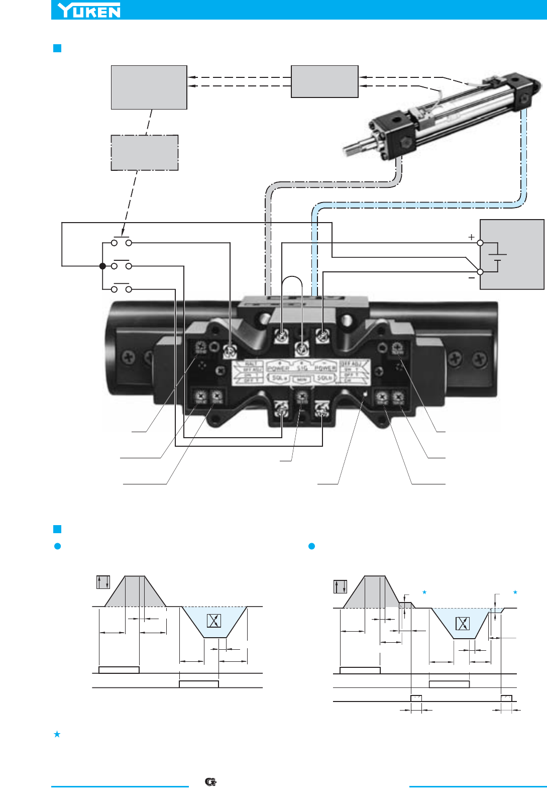
410
“ ” Series Shockless Type Solenoid Operated /
Solenoid Controlled Pilot Operated Directional Valves
HALT
SOL a
SOL b
Adj. Volume
"OFF ADJ"
DC Power
Supply
24 V DC
Shifting Signal
Deceleration
Start Signal
Programmable
Controller
Adj. Volume
"ON T"
Adj. Volume
"OFF T"
Adj. Volume "MIN"
Output Current Check (to 0V)
Adj. Volume "OFF ADJ"
Adj. Volume "ON T"
Adj. Volume "OFF T"
AB
P
T
SOL a
SOL b
ON T
(Max. 1s)
OFF T
OFF ADJ
ON
OFF
OFF
ON T
OFF T
ON
OFF
OFF ADJ
AB
PT
Pattern
of Flow
SOL a
SOL b
ON
HALT
ON
AB
P
T
AB
P
T
ON ON
OFF
OFF
OFF
OFF
ON T
MIN
OFF T
MIN
ON T OFF T
OFF
ADJ
Hold for 0.1 second or longer
Max.
60s
Pattern
of Flow
(Max. 1s)
(Max. 1s) (Max. 1s)
OFF
ADJ
Max.
60s
(Max. 1s)
(Max. 1s)
(Max. 1s) (Max. 1s)
Hold for 0.1 second or longer
Relationships between SOL signals and flow patterns
Without
HALT
functions With
HALT
functions
System Diagram (Example of sink type wiring)
The minimum adjustment volume is common for SOL a and b, and it is not possible to set a different volume for each SOL a and b individually.
If the HALT functions are not used, set the minimum ad
j
ustment volume to zero.
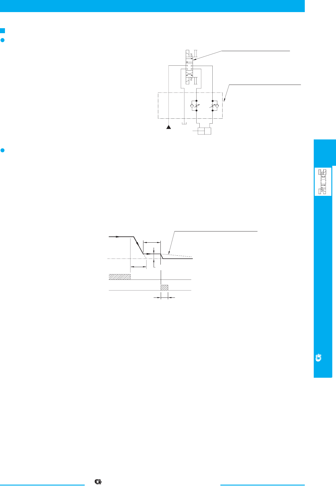
411
DIRECTIONAL CONTROLS
“ ” Series Shockless Type Solenoid Operated /
Solenoid Controlled Pilot Operated Directional Valves
E
“ ” Series Shockless Type Solenoid Operated /
Solenoid Controlled Pilot Operated Directional Valves
P
T
B
A
b
a
(Example)
G-DSG valve
fully opens after the ON T duration.
To adjust maximum flow rates, with
"G" series solenoid operated direc-
tional valves (G-DSG-01/03), flow
control valves such as throttle check
modular valves are used.
With "G" series solenoid controlled
pilot operated directional valves (G-
DSHG-04/06), maximum flow rates
can be adjusted without flow control
valves but by using a model with
stroke adjustment (option).
Max. 60 s
MIN
ON
OFF
OFF
OFF
OFF T
ON
SOL
HALT
Flow Rate
0
Hold for 0.1 second or longer
If no HALT signal is set on within 60
seconds of the end of OFF T, the flow rate
decreases gradually.
Instructions
Adjustment of maximum flow rate
The G-Series Solenoid Operated Directional Valves
cannot be adjusted for maximum flow rates.
To adjust maximum flow rates, use flow control valves.
In G-series solenoid controlled pilot operated direc-
tional valves (G-DSHG-04/06), the maximum flow rate
can be adjusted by use of the valve with stroke adjust-
ment screw of optional extra.
How to use HALT functions
The HALT functions are used to drive the actuator at a low speed to the stop position while keeping a slight flow
after OFF T.
A flow rate (min. flow rate) during a low-speed operation can be set with the minimum adjusting volume (The minimum
adjusting volume is common for SOL a and b. Individual setting is not possible for SOL a and b.) When HALT signal
is on, the min. flow rate becomes zero and the actuator stops. Here, take care to keep the HALT signal on for longer
than 0.1 second. The min. flow rate gets to "0" after about 60 seconds following the OFF T. If the HALT functions
are not used, set the minimum adjusting volume to zero.
The HALT functions are not applicable to the spool function "2B7".
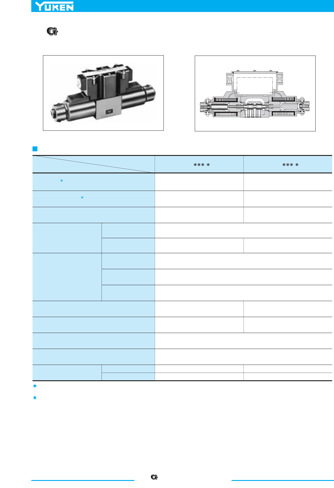
“ ” Series Shockless Type
Solenoid Operated Directional Valves
412
1.
2.
1
2
Electronic
Circuit
Descriptions
Model Numbers
G-DSG-01-
- -50/5090 G-DSG-03- - -50/5090
Max. Flow
Max. Operating Pres.
Max. T-Line Back Pres . MPa (PSI)
MPa (PSI)
L /min (U.S.GPM)
Voltage
Input Power at 24V
Voltage
Current
Input interface
Electric Power Supply
Shifting signal, low speed
operation halt signal (can be
used in common with electric
power supply).
Shifting time range (for ON and OFF)
Low speed operation flow rate (min. flow rate) range
(for SOL a and b)
L /min (U.S.GPM)
Low speed operation flow rate (min. flow rate) hold time
Ambient Temperature
Approx. Mass
Single Solenoid
Double Solenoid
10 (2.6), 20 (5.3), 30 (7.9), 40 (10.6) 40 (10.6), 60 (15.9), 80 (21.1)
25 (3630)
16 (2320)
25 (3630)
16 (2320)
24 V DC (21 - 28 V DC Included Ripple): Use a stable power supply
W63W63
5 - 48 V DC (Use a stable power supply)
Constant at 10 mA (A constant-current circuit is used)
Sink Type, Source Type
s1-3.0s1-1.0
)6.2-62.(01-1)3.1-31.(5-5.0
Max. 60 s (After 60 seconds, the flow rate decreases gradually.)
0 - 50 ˚C (32 - 122 ˚F) with circulated air
2.1 kg (4.6 lbs.)
3.0 kg (6.6 lbs.)
5.3 kg (11.7 lbs.)
7.5 kg (16.5 lbs.)
Specifications
The maximum flow rates may vary according to the operating pressure. Refer to Maximum Flow Rates Characteristics on pages 414 and 415 fo
r
At pressures more than 21 MPa (3050 PSI), the "shockless effect" is slightl
y
less if compared it with that at 16 MPa (2320 PSI).
details.
■
“ ” Series Shockless Type Solenoid Operated Directional Valves
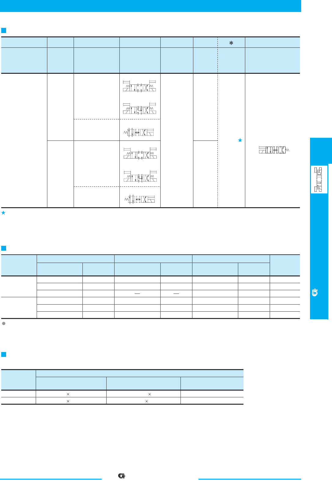
413
DIRECTIONAL CONTROLS
“ ” Series Shockless Type
Solenoid Operated Directional Valves
E
“ ” Series Shockless Type
Solenoid Operated Directional Valves
Va lve
Model
Numbers
Japanese Standard "JIS"
Sub-plate
Model Numbers
Thread
Size
DSGM-01-31
DSGM-01X-31
DSGM-01Y-31
DSGM-03-40
DSGM-03X-40
DSGM-03Y-40
Rc 1/8
Rc 1/4
Rc 3/8
Rc 3/8
Rc 1/2
Rc 3/4
European Design Standard
Sub-plate
Model Numbers
Thread
Size
Sub-plate
Model Numbers
N. American Design Standard
Thread
Size
0.8 (1.8)
0.8 (1.8)
0.8 (1.8)
3.0 (6.6)
3.0 (6.6)
4.7 (10.4)
Approx.
Mass
kg (lbs.)
G-DSG-01
G-DSG-03
DSGM-01-3180
DSGM-01X-3180
DSGM-03-2180
DSGM-03X-2180
DSGM-03Y-2180
1/8 BSP.F
1/4 BSP.F
3/8 BSP.F
1/2 BSP.F
3/4 BSP.F
DSGM-01-3190
DSGM-01X-3190
DSGM-01Y-3190
DSGM-03-2190
DSGM-03X-2190
DSGM-03Y-2190
1/8 NPT
1/4 NPT
3/8 NPT
3/8 NPT
1/2 NPT
3/4 NPT
M5 45 Lg. No.10-24 UNC 1-3/4 Lg.
Socket Head Cap Screw (4 pcs.)
Japanese Standard "JIS" &
European Design Standard
Model
Numbers
N. American Design Standar d Tightening Torque
M6 35 Lg. 1/4-20 UNC 1-1/2 Lg.
G-DSG-01
G-DSG-03
5-7 Nm (44-62 in. lbs.)
12-15 Nm (106-133 in. lbs.)
a
b
A
B
P
T
a
b
A
B
P
T
3C2
3C40
AB
P
T
b
2B7
a
b
AB
P
T
3C2
a
b
A
B
P
T
3C40
AB
P
T
b
2B7
G-DSG
G Series Shockless
Type Solenoid
Operated
Directional Valve,
Sub-plate
Mounting
G-DSG -01
Va lve
Size
01
Series
Number
:
-50
Design
Number
Design
Standards
Refer to
50
0530
-L
Models with Alternate
Offset Solenoid
AB
P
T
a
-10
Metred Flow
Capacity
-2B7
Spool Type
-S
Input
Interface
Model Number Designation
Sub-plate
Sub-plates are available. Specify the sub-plate model number from the table above. When sub-plates are not used, the mounting surface should
have a good machined finish.
Attachment (Mtg. Bolt)
Four socket head cap screws in the table below are included.
Design Standards: None
90
Japanese Standard "JIS" and European Design Standard
N. American Design Standard
...........
...............
None
10
20
:
:
:
40 L /min
10 L /min
20 L /min
L
Applicable only for 2B7
(Omit if not required)
None:
Sink Type
(Standard)
S:
Source Type
None
10
20
:
:
:
30 L /min
10 L /min
20 L /min
None
40
60
:
:
:
80 L /min
40 L /min
60 L /min
None
40
:
:
60 L /min
40 L /min
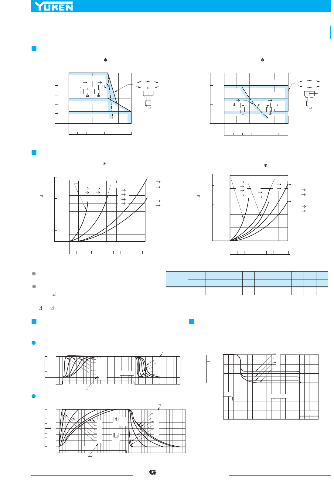
“” Series Shockless Type
Solenoid Operated Directional Valves
414
Viscosity
2
mm /s
SSU
Factor
15
77
0.84
20
98
0.91
30
141
1.00
40
186
1.07
50
232
1.14
60
278
1.19
70
324
1.24
80
371
1.28
90
417
1.32
100
464
1.35
P
A
B
B
A
T
P
A
B
B
A
T
B
TP
A
B
TP
A
100ms
OFF
ON
200 ms
ON
OFF
ISP036300030
Pressure
20001000
0
5
10 15 25 MPa20
2
0
4
6
8
10
0
10
20
30
40
Max.Flow
U.S.GPM
L/min
Direction of
Flow
PB
P
AB
T
P
AB
T
PA
40 L/min
Type
20 L/min Type
10 L/min Type
Direction of Flow
P
AB
T
P A
P
AB
T
PB
Direction of
Flow
Direction
of Flow
10 L/min Type
0
3000
3630 PSI
Pressure
20001000
0
510
15 25 MPa20
0
10
20
30
40
U.S.GPM
L/min
2
0
4
6
8
10
Max.Flow
10 L/min Type
P A,P B
A T,B T
20 L/min
Type
PB
PA
AT
B T
40 L/min
Type
PA
P B
40 L/min
Type
AT
BT
10 L/min
Type
PB
PA
AT
BT
20 L/min
Type
AT
BT
20 L/min
Type
PB
PA
30 L/min
Type
PB
PA
30 L/min
Type
AT
B T
1.0
PSI MPa
0.8
0.6
0.4
0.2
0
40
0
80
120
140
0
10
30 L/min20 40
Flow Rate
02 6 U.S.GPM4108
0
10
30 L/min20
Flow Rate
0
2
6U.S.GPM48
PSI
MPa
1.6
1.2
0.8
0.4
0
0
240
40
80
120
160
200
ON
20
10
0
30
4
2
0
6
8
SOL
HALT
Flow Rate
OFF
Vo lume "MIN" Position
Vo lume "ON T" Position
Vo lume "OFF T" Position
Vo lume "OFF T" Position
Vo lume "ON T" Position
ON
100
ms
OFF
SOL
20
10
0
30
2
4
8
2
8
Flow Rate
20
10
30
6
4
0
6
P
AB
T
P
AB
T
20
10
0
30
4
2
0
6
8
SOL
L /min
U.S.GPM
Flow Rate
0
2
4
6
8
10
0
2
4
6
8
10
0
3
5
7
10
0
3
5
7
10
6
8
5
0
30 L/min Type
20 L/min Type
Pressure Drop P
Pressure Drop P
L /min
U.S.GPM
L /minU.S.GPM
Maximum Flow Rate
Pressure Drop
G-DSG-01-
3C2
3C40
-10-GSD-G
- -2B7
G-DSG-01-
3C2
3C40
-
G-DSG-01- -2B7
For any other viscosity, multiply the factors in
the table right.
For any other specific gravity (G'), the pressure
drop ( P') may be obtained from the formula
below.
P'= P (G'/0.850)
scitsiretcarahC wolF gnitarepO deepS woLscitsiretcarahC gnitfihS
Supply Pressure : 16 MPa (2320 PSI)
Flow Rate : 30 L/min (7.9 U.S.GPM)
Supply Pressure : 16 MPa (2320 PSI)
Flow Rate : 30 L/min (7.9 U.S.GPM)
2B7
3C2, 3C40
Typical Performance Characteristics of "G-DSG-01" at Viscosity 30 mm
2
/s (141 SSU), Specific Gravity 0.850
415
DIRECTIONAL CONTROLS
“”Series Shockless Type
Solenoid Operated Directional Valves
E
“” Series Shockless Type
Solenoid Operated Directional Valves
Viscosity
2
mm /s
SSU
Factor
15
77
0.84
20
98
0.91
30
141
1.00
40
186
1.07
50
232
1.14
60
278
1.19
70
324
1.24
80
371
1.28
90
417
1.32
100
464
1.35
Model Numbers
Pressure Drop Curve Numbers
1
3
2
1
3
3C2
3C40
G-DSG-03-
3C2
3C40
G-DSG-03-40-
3C2
3C40
G-DSG-03-60-
G-DSG-03-2B7
G-DSG-03-40-2B7
P
AB
T
P
AB
T
P
A
B
B
A
T
B
TP
A
P
AB
T
P
AB
T
P
A
B
B
A
T
B
TP
A
ON
OFF
ON
OFF
200ms
100ms
OFF
10
7
5
3
0
ON
P
AB
T
P
AB
T
Volume "OFF T" Position
Volume "ON T" Position
10
7
5
3
0
10
8
7
6
0
Volume "OFF T" Position
Volume "ON T" Position
10
7
5
3
0
100ms
10
7
5
3
0
ON
OFF
40
20
0
60
8
4
0
12
16
SOL
HALT
Flow Rate
40
20
0
60
8
4
0
12
16
SOL
L /minU.S.GPM
Flow Rate
SOL
40
20
0
60
4
8
16
4
16
Flow Rate
40
20
60
12
8
0
12
Direction of
Flow
80 L/min Type
Direction of Flow
40 L/min Type
60 L/min Type
PBPA
ISP036300030
Pressure
20001000
0
510
15 25 MPa20
40 L/min
Type
60 L/min Type
Direction of Flow
PBPA
Direction of
Flow
ISP036300030
Pressure
20001000
0
510
15 25
MPa
20
0
20
40
60
80
U.S.GPM
L/min
0
5
10
20
Max.Flow
15
Pressure Drop P
0
U.S.GPM
Flow Rate
481216 20
020 40 60 80
L/min
0
20
40
60
80
MPa
L/min
0
0.8
Max.Flow
0.4
1.2
1.6
PSI
240
200
160
120
80
40
0
3
2
1
U.S.GPM
0
5
10
20
15
Volume "MIN" Position
L /min
U.S.GPM
L/min
U.S.GPM
Maximum Flow Rate
G-DSG-03-
3C2
3C40
-
G-DSG-03- -2B7
Pressure Drop
For any other viscosity, multiply the factors in
the table right.
For any other specific gravity (G'), the pressure
drop ( P') may be obtained from the formula
below.
P'= P (G'/0.850)
scitsiretcarahC wolF gnitarepO deepS woLscitsiretcarahC gnitfihS
Supply Pressure : 16 MPa (2320 PSI)
Flow Rate : 60 L/min (15.9 U.S.GPM)
Supply Pressure : 16 MPa (2320 PSI)
Flow Rate : 60 L/min (15.9 U.S.GPM)
2B7
3C2, 3C40
The numbers of the pressure drop curves are the same for P A,
P B, A T and B T.
Typical Performance Characteristics of "G-DSG-03" at Viscosity 30 mm
2
/s (141 SSU), Specific Gravity 0.850
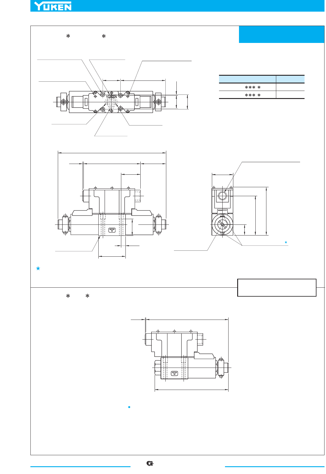
“” Series Shockless Type
Solenoid Operated Directional Valves
416
Mounting Surface:
ISO 4401-AB-03-4-A
DIMENSIONS IN
MILLIMETRES (INCHES)
Model Numbers "
C
" Thd.
G-DSG-01- - -50
G-DSG-01- - -5090
G 1/2
1/2 NPT
SOL b
SOL a
SOL b
40.5
(1.59)
5.5(.22)
Dia. Through
9.5(.37) C' bore
4 Places
Pressure Port "
P"
110
(4.33)
Solenoid Indicator Light
(For Sol. b)
0.75
(.03)
Tank Port "T"
31
(1.22)
32.5
(1.28)
Cylinder Port "A"
Cylinder Port "
B"
Solenoid Indicator Light
(For Sol. a)
38
(1.50)
263
(10.35)
132
(5.20)
65.5
(2.58)
44.5
(1.75)
0.5
(.02)
11
(.43)
65
(2.56)
Mounting Surface
(O-Rings Furnished)
Air Vent (Both Sides)
3 (.12) Hex. Soc.
Electrical Conduit Connection
"
C
" Thd. (Both Ends)
Manual Actuator
6 (.24) Dia.
25
(.98)
89
(3.50)
48
(1.89)
109.5
(4.31)
197.5
(7.78)
0.5
(.02)
178.5
(7.03)
G-DSG-01- -3C2/3C40- -50/5090
G-DSG-01- -2B7- -50/5090
Air vent position around valve longitudinal axis can be optionally selected.
For other dimensions, refer to the drawing above.
Note: For the valve mounting surface dimensions, see the dimensional drawing of the sharable
sub-plate in page 356.
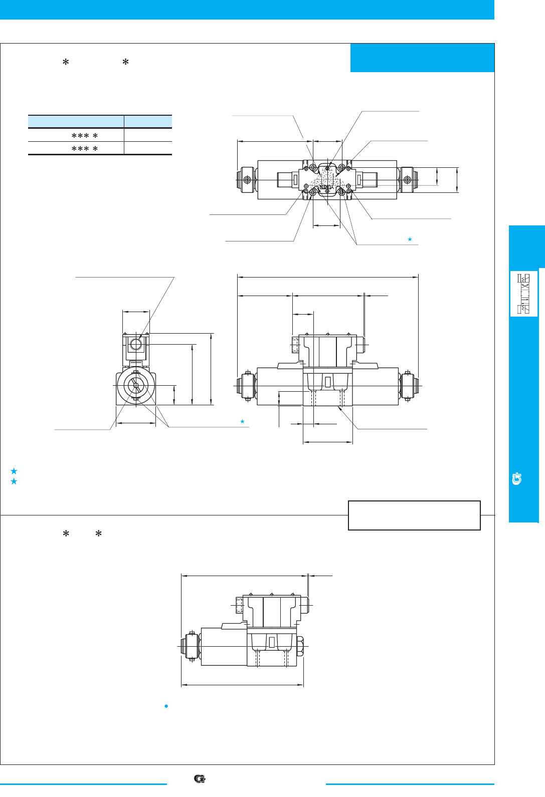
417
DIRECTIONAL CONTROLS
“”Series Shockless Type
Solenoid Operated Directional Valves
E
“” Series Shockless Type
Solenoid Operated Directional Valves
Mounting Surface:
ISO 4401-AC-05-4-A
DIMENSIONS IN
MILLIMETRES (INCHES)
1.
2.
1
Model Numbers "
C
" Thd.
G-DSG-03-
- -50
G-DSG-03- - -5090
G 1/2
1/2 NPT
SOL b
SOL a
SOL b
G1/2
G1/2
54
(2.13)
7(.28)
Dia. Through
11(.43) Dia. Spotface
4 Places
Pressure Port "
P"
141
(5.55)
Solenoid Indicator Light
(For Sol. b)
Tank Port "
T"
32.5
46
(1.81)
Cylinder Port "A
"
Cylinder Port "
B"
Solenoid Indicator Light
(For Sol. a)
35.3
(1.39)
48
(1.89)
336
(13.23)
39
(1.54)
70
(2.76)
Mounting Surface
(O-Rings Furnished)
2
Air Vent (Both Sides)
3 (.12) Hex. Soc.
Electrical Conduit Connection
"
C
" Thd. (Both Ends)
Manual Actuator
6 (.24) Dia.
130.1
(5.12)
132
(5.20)
109.6
(4.31)
234
(9.21)
50.8
(2.00)
(1.28)
27
(1.06)
19
(.75)
92
(3.62)
102
(4.02)
0.5
(.02)
0.5
(.02)
226.3
(8.91)
G-DSG-03- -3C2/3C40- -50/5090
G-DSG-03- -2B7- -50/5090
For other dimensions, refer to the drawing above.
Although the tank port is shown on the left in our sub-plate, either may be used.
Air vent position around valve longitudinal axis can be optionally selected.
Note: For the valve mounting surface dimensions, see the dimensional drawing of the sharable
sub-plate in page 373.
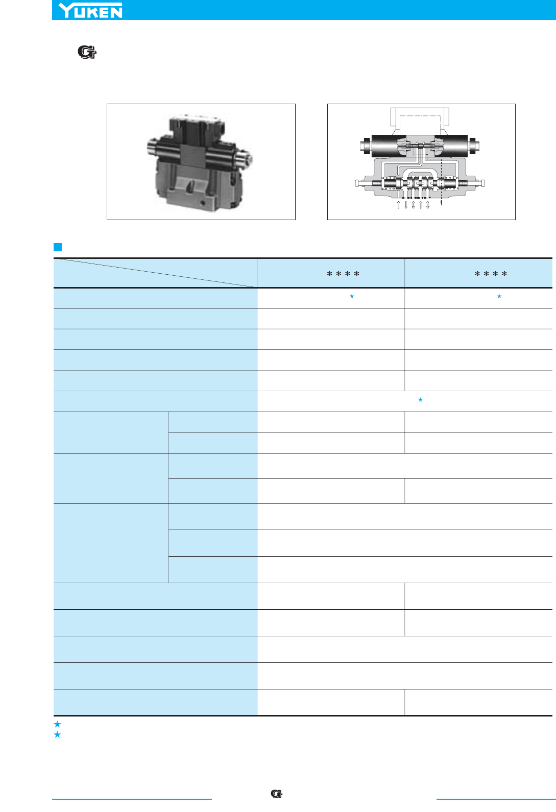
“ ” Series Shockless Type
Solenoid Controlled Pilot Operated Directional Valves
418
■
“”
Series Shockless Type Solenoid Controlled Pilot
Operated Directional Valves
1.
2.
1 1
2
XTAPB Y
Electronic
Circuit
Descriptions
Model Numbers
G-DSHG-04-3C
- - - -50/5090 G-DSHG-06-3C - - - -50/5090
Max. Flow
Max. Operating Pres.
Max. T-Line Back Pres. MPa (PSI)
MPa (PSI)
L /min (U.S.GPM)
Voltage
Input Power at 24V
Voltage
Current
Input interface
Electric Power Supply
Shifting signal, low speed
operation halt signal (can be
used in common with electric
power supply)
Shifting time range (for ON and OFF)
Low speed operation flow rate (min. flow rate) range
(for SOL a and b)
L /min (U.S.GPM)
Low speed operation flow rate (min. flow rate) hold time
Ambient Temperature
Approx. Mass
160 (42.3)
25 (3630)
16 (2320)
3 (440)
16 (2320)
24 V DC (21 - 28 V DC Included Ripple): Use a stable power supply
W 63W 63
5 - 48 V DC (Use a stable power supply)
Constant at 10 mA (A constant-current circuit is used)
Sink Type, Source Type
ON: 0.06 - 1.5 s, OFF: 0.1 - 2 s ON: 0.1 - 1 s, OFF: 0.2 - 2 s
)9.7 - 6.2( 03 - 01)3.5 - 3.1( 02 - 5
Max. 60 s (After 60 seconds, the flow rate decreases gradually.)
0 - 50 ˚C (32 - 122 ˚F) with circulated air
250 (66.1)
25 (3630)
16 (2320)
3 (440)
16 (2320)
MPa (PSI)
MPa (PSI)
MPa (PSI)
Max. Drain Line Back Pressure
Max. Pilot Pressure
Min. Required Pilot Pres.
L /min (U.S.GPM)
Pilot Flow
at Normal
at Transition
1.5 (220)
1 (0.3)
4 (1.1)
1 (0.3)
6 (1.6)
).sbl 1.33( gk 51).sbl 5.62( gk 21
Specifications
The maximum flow rate is constant irrespective of the working pressure.
Be sure that the difference between pilot pressure and drain port back pressure is larger than the minimum pilot pressure.
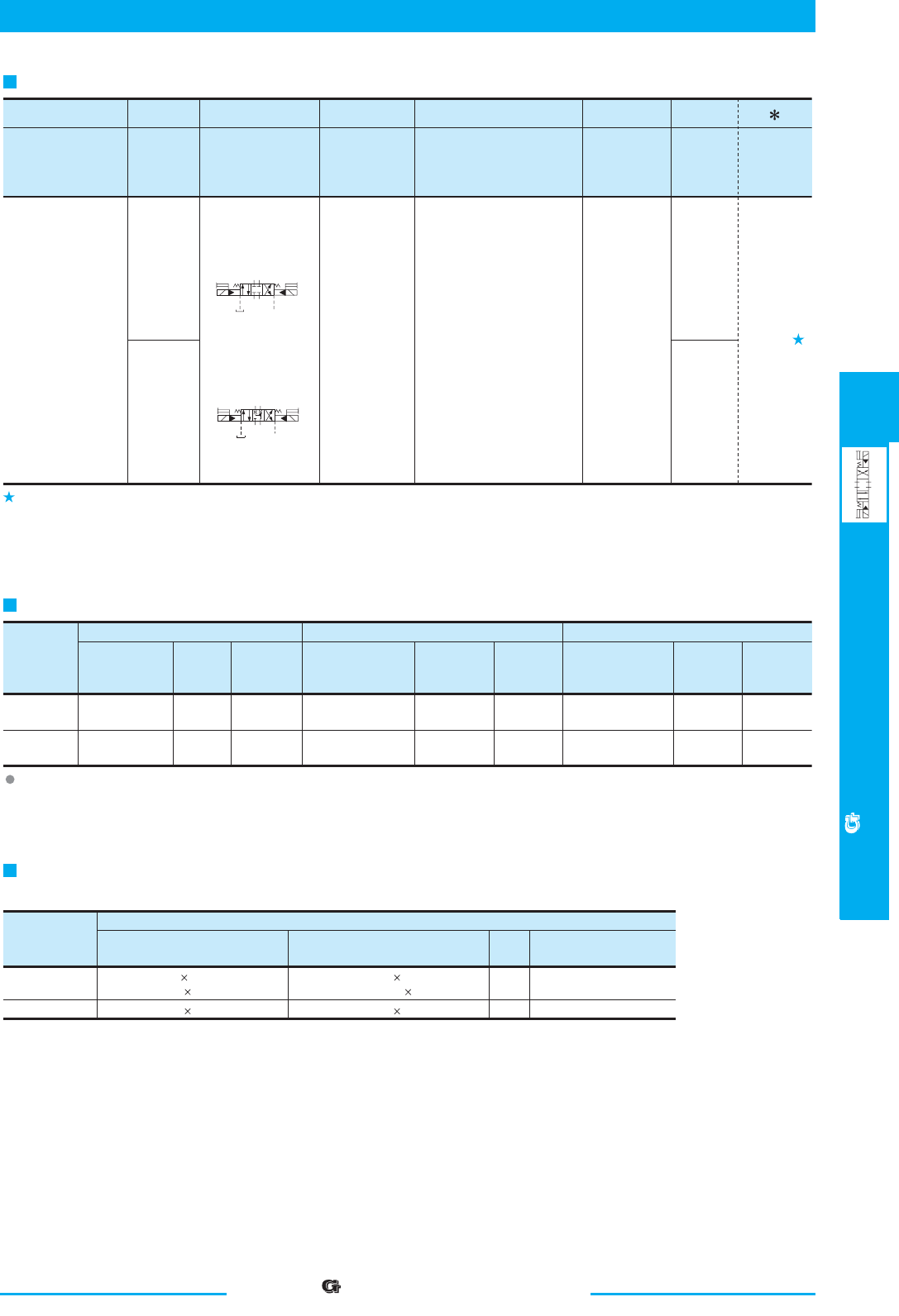
419
DIRECTIONAL CONTROLS
“ ” Series Shockless Type
Solenoid Controlled Pilot Directional Valves
E
“ ” Series Shockless Type
Solenoid Controlled Pilot Operated Directional Valves
Japanese Standard "JIS" European Design Standard N. American Design Standard
M12 60 Lg. 1/2-13 UNC 2-1/2 Lg.
Socket Head Cap Screw
Valve
Model
Numbers
Sub-plate
Model
Numbers
Thread
Size
Approx.
Mass
kg (lbs.)
Sub-plate
Model
Numbers
Thread
Size
Approx.
Mass
kg (lbs.)
Sub-plate
Model
Numbers
Thread
Size
Approx.
Mass
kg (lbs.)
G-DSHG-04
G-DSHG-06
DHGM-04-20
DHGM-04X-20
DHGM-06-50
DHGM-06X-50
Rc 1/2
Rc 3/4
4.4
4.1
(9.7)
(9.0)
Rc 3/4
Rc 1
7.4
7.4
(16.3)
(16.3)
DHGM-04-2080
DHGM-04X-2080
DHGM-06-5080
DHGM-06X-5080
1/2 BSP.F
3/4 BSP.F
4.4
4.1
(9.7)
(9.0)
8.5
8.5
(18.7)
(18.7)
3/4 BSP.F
1 BSP.F
DHGM-04-2090
DHGM-04X-2090
DHGM-06-5090
DHGM-06X-5090
1/2 NPT
3/4 NPT
4.4
4.1
(9.7)
(9.0)
7.4
7.4
(16.3)
(16.3)
3/4 NPT
1 NPT
Japanese Standard "JIS" &
European Design Standard
Model
Numbers
N. American Design Standard Qty.
Tightening Torque
Nm (in. lbs.)
M6 45 Lg.
M10 50 Lg.
1/4-20 UNC 1-3/4 Lg.
3/8-16 UNC 2 Lg.
G-DSHG-04
G-DSHG-06
2
4
6
12-15 (106-133)
58-72 (513-637)
100-123 (885-1089)
G-DSHG
G Series Shockless
Type Solenoid
Controlled Pilot
Operated
Directional Valve,
Sub-plate
Mounting
G-DSHG -04
Valve
Size
04
Series
Number
:
-50
Design
Number
Design
Standards
Refer to
50
06 50
-3C2
Spool Type
-S
Input
Interface
-E
Pilot
Connection
-R2
Spool Control Modification
(Omit if not required)
Model Number Designation
Sub-plates are available. Specify the sub-plate model number from the table above.
When sub-plates are not used, the mounting surface should have a good machined finish.
Attachment (Mtg. Bolts)
Socket head cap screws in the table below are included.
Sub-plate
Design Standards: None
90
Japanese Standard "JIS" and European Design Standard
N. American Design Standard
...........
...............
None:
Sink Type
(Standard)
S:
Source Type
3C2
3C40
AB
P
T
a
b
X
Y
AB
P
T
a
b
Y
X
None:
Internal
Pilot
E:
External
Pilot
R2 :
With Stroke Adjustment,
Both Ends
RA:
With Stroke Adjustment,
Port "A" End
RB:
With Stroke Adjustment,
Port "B" End
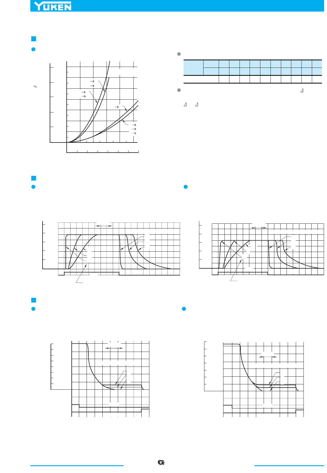
“ ” Series Shockless Type
Solenoid Controlled Pilot Operated Directional Valves
420
Viscosity
2
mm /s
SSU
Factor
15
77
0.84
20
98
0.91
30
141
1.00
40
186
1.07
50
232
1.14
60
278
1.19
70
324
1.24
80
371
1.28
90
417
1.32
100
464
1.35
3C2
3C40
G-DSHG-04-
P A
PB
AT
B T
B T
3C2
3C40
G-DSHG-06-
PA
PB
AT
0
U.S.GPM
Flow Rate
10 20 30 50 70
0 50 100 150 200
L/min
250
40 60
MPa
0
0.4
0.2
0.6
1.2
0.8
1.0
1.4
Pressure Drop P
PSI
200
160
120
80
40
0
250ms
Volume "OFF T" Position
ON
Volume "ON T" Position
10
5
0
0
5
10
250ms
Volume "OFF T" Position
0
5
10
10
5
0
Volume "ON T" Position
500ms
500ms
Volume "MIN" Position
Volume "MIN" Position
ON
ON
OFF
OFF
OFF
OFF
0
20
10
0
30
50
SOL
HALT
L /min
U.S.GPM
Flow Rate
240
200
160
120
80
40
40
60
70
0
SOL
HALT
L/min
150
125
100
75
50
25
10
0
U.S.GPM
Flow Rate
20
30
40
10
0
U.S.GPM
Flow Rate
20
50
30
40
L /min
0
SOL
200
150
100
50
0
80
60
40
20
100
Flow Rate
L /min
0
SOL
400
300
200
100
U.S.GPM
OFF
OFF
ON
10
8
0
10
8
0
ON
ON
Hydraulic Fluid: Viscosity
2
30 mm /s (141 SSU)
, Specific Gravity
0.850
Pressure Drop
G-DSHG-04/06-3C2/3C40
For any other viscosity, multiply the factors in the table below.
For any other specific gravity (G'), the pressure drop ( P') may
be obtained from the formula below.
P'= P (G'/0.850)
Shifting Characteristics
04C3/2C3-60-GHSD-G04C3/2C3-40-GHSD-G
Low Speed Operating Flow Characteristics
04C3/2C3-60-GHSD-G04C3/2C3-40-GHSD-G
Supply Pressure : 16 MPa (2320 PSI)
Flow Rate : 150 L/min (39.6 U.S.GPM)
Pilot Pressure : 16 MPa (2320 PSI)
Supply Pressure : 16 MPa (2320 PSI)
Flow Rate : 250 L/min (66.1 U.S.GPM)
Pilot Pressure : 16 MPa (2320 PSI)
Supply Pressure : 16 MPa (2320 PSI)
Flow Rate : 150 L/min (39.6 U.S.GPM)
Pilot Pressure : 16 MPa (2320 PSI)
Supply Pressure : 16 MPa (2320 PSI)
Flow Rate : 250 L/min (66.1 U.S.GPM)
Pilot Pressure : 16 MPa (2320 PSI)
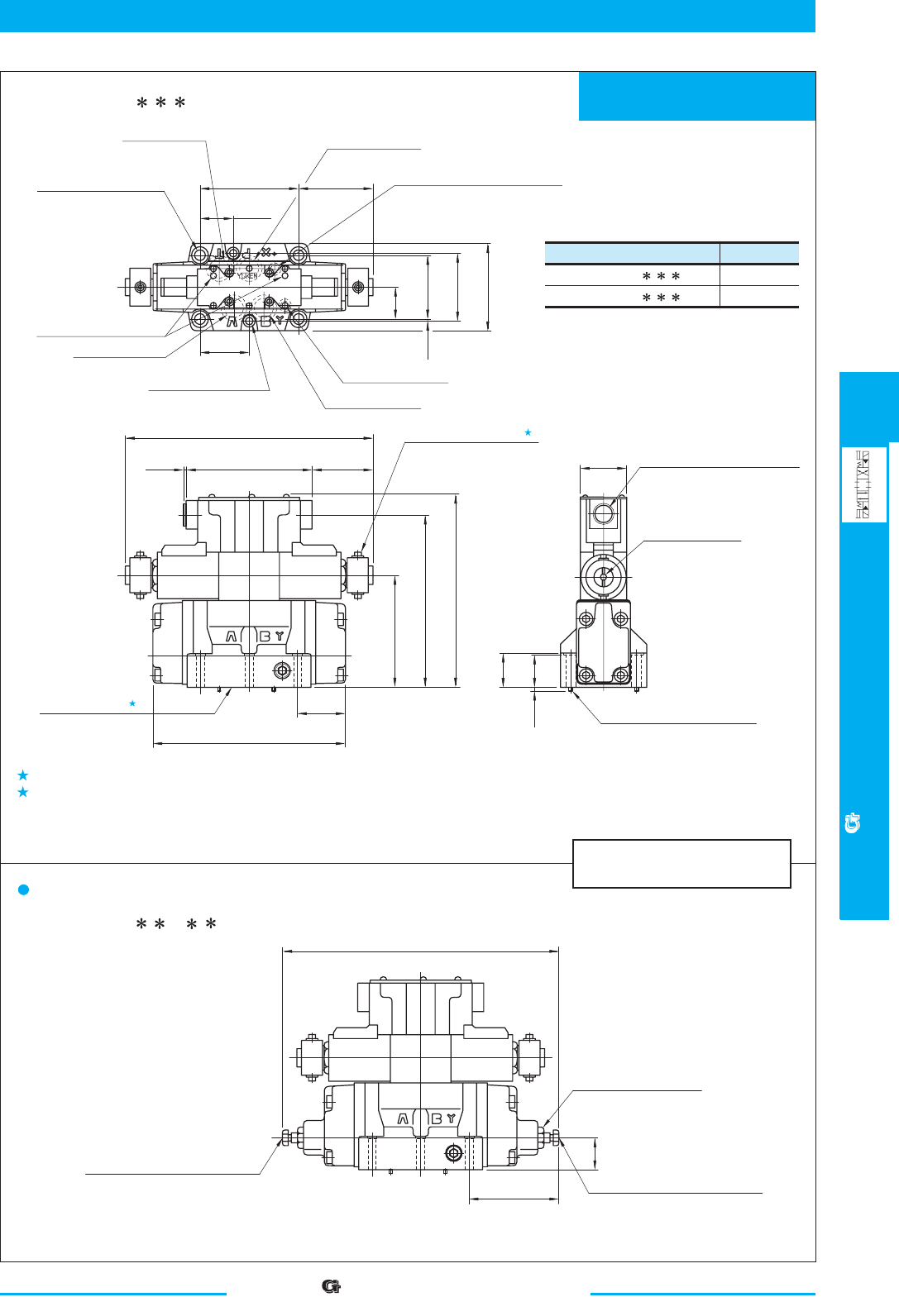
421
DIRECTIONAL CONTROLS
“”Series Shockless Type
Solenoid Controlled Pilot Directional Valves
E
“” Series Shockless Type
Solenoid Controlled Pilot Operated Directional Valves
Mounting Surface:
ISO 4401-AD-07-4-A
DIMENSIONS IN
MILLIMETRES (INCHES)
1.
2.
1
2
Model Numbers "
C
" Thd.
G-DSHG-04-3C - --50
G-DSHG-04-3C - --5090
G 1/2
1/2 NPT
L'
L
SOL a
SOL b
L'
L
SOL a
SOL b
34
(1.34)
7(.28)
Dia. Through
11(.43) Dia. Spotface
4 Places
Pressure Port "
P"
Solenoid Indicator Light
Tank Port "
T"
34.9
69.8
(2.75)
Cylinder Port "A"
Cylinder Port "
B"
Mounting Surface
(O-Rings Furnished)
Air Vent (Both Sides)
3 (.12) Hex. Soc.
2 Places
Electrical Conduit Connection
"
C
" Thd. (Both Ends)
50
(1.97)
(1.37)
116
(4.57)
132
(5.20)
48
(1.89)
11(.43)
Dia. Through
17.5(.69) Dia. Spotface
4 Places
Pilot Pressure Port "
X"
(For External Pilot Models Only)
101.6
(4.00)
79.9
(3.15)
Pilot Drain Port "Y"
1.5
(.06)
72.9
(2.87)
91
(3.58)
Manual Actuator
6(.24) Dia.
263
(10.35)
65.5
(2.58)
0.5
(.02)
181
(7.13)
200.5
(7.89)
50.4
(1.98)
204
(8.03)
3(.12)
Dia. Two Locating Pins
4
(.16)
34
(1.34)
35
(1.38)
289(11.38)Fully Extended
93(3.66)
Fully Extended
33
(1.30)
Stroke Adj. Screw (Port "B" End)
13(.51) Hex.
Lock Nut
17(.67) Hex.
Stroke Adj. Screw (Port "
A" End)
13(.51) Hex.
G-DSHG-04-3C - - -50/5090
Air vent position around valve longitudinal axis can be optionally selected.
O-rings for ports: SO-NB-P22 for P/A/B/T ports
SO-NB-P9 for X/Y ports
G-DSHG-04-3C - -R - -50/5090
Models with Stroke Adjustment (Option)
Note: For the valve mounting surface dimensions, see the dimensional drawing of the
sharable sub-plate on page 401.
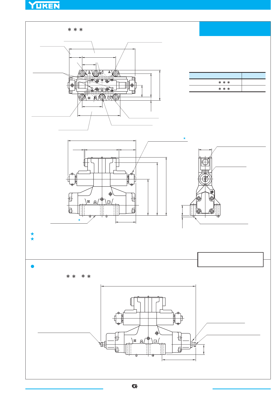
“” Series Shockless Type
Solenoid Controlled Pilot Operated Directional Valves
422
Mounting Surface:
ISO 4401-AE-08-4-A
DIMENSIONS IN
MILLIMETRES (INCHES)
1.
2.
Model Numbers "
C
" Thd.
G-DSHG-06-3C - --50
G-DSHG-06-3C - --5090
G 1/2
1/2 NPT
SOL a SOL b
L'
L
53.2
(2.09)
Solenoid Indicator
Light
Tank Port "
T"
46.1
(1.81)
Cylinder Port "A"
Cylinder Port "
B"
77
(3.03)
13.5(.53)
Dia. Through
20(.79) Dia. Spotface
6 Places
Pilot Pressure Port "
X"
(For External Pilot Models Only)
130.2
(5.13)
Pilot Drain Port "Y"
13
(.51)
134.8(5.31)
Fully Extended
40
(1.57)
Stroke Adj. Screw (Port "B" End)
13(.51) Hex.
Lock Nut
17(.67) Hex.
Stroke Adj. Screw (Port "
A" End)
13(.51) Hex.
Pressure Port "
P"
50.5
(1.99)
255
(10.04)
156
(6.14)
92.1
(3.63)
118
(4.65)
376(14.80)Fully Extended
G-DSHG-06-3C - - -50/5090
Air vent position around valve longitudinal axis can be optionally selected.
O-rings for ports: SO-NB-P30 for P/A/B/T ports
SO-NB-P14 for X/Y ports
G-DSHG-06-3C - -R - -50/5090
Models with Stroke Adjustment (Option)
1
2
L'
L
SOL a
SOL b
Mounting Surface
(O-Rings Furnished)
Air Vent (Both Sides)
3 (.12) Hex. Soc.
2 Places
Electrical Conduit Connection
"
C
" Thd. (Both Ends)
137
(5.39)
132
(5.20)
48
(1.89)
Manual Actuator
6(.24) Dia.
263
(10.35)
65.5
(2.58)
0.5
(.02)
202
(7.95)
221.5
(8.72)
78.5
(3.09)
6(.24)
Dia. Two Locating Pins
6
(.24)
41
(1.61)
Note:
For the valve mounting surface dimensions, see the dimensional drawing of
the sharable sub-plate in page 403.
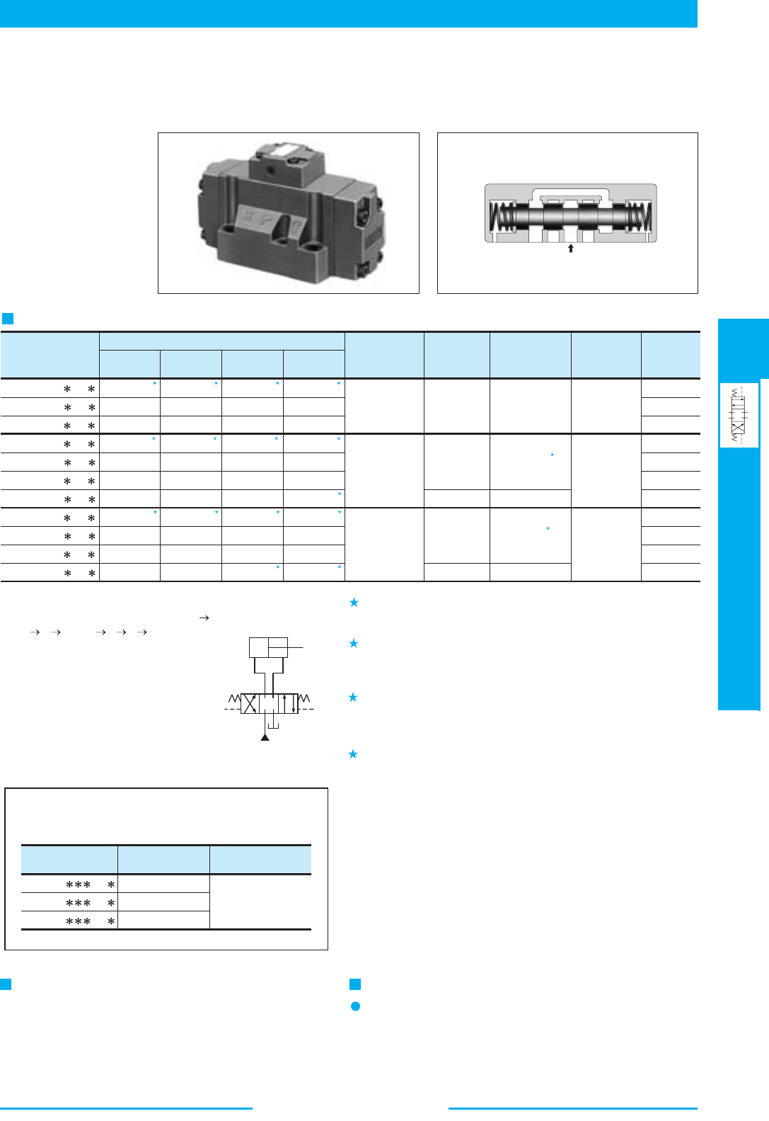
423
DIRECTIONAL CONTROLS
Pilot Operated Directional Valves
E
Pilot Operated Directional Valves
500 (132)
1100 (291)
500 (132)
1100 (291)
500 (132)
1100 (291)
1100 (291)
500 (132)
500 (132)
1100 (291)
1100 (291)
1
300 (79.3) 300 (79.3) 300 (79.3) 300 (79.3)
1.
2.
3.
4.
1 1 1
2 2 2 2
3 3 3 3
3 3
2
4
4
X
P
Y
10 MPa
(1450 PSI)
16 MPa
(2320 PSI)
25 MPa
(3630 PSI)
31.5 MPa
(4570 PSI)
Maximum Flow L /min (U.S.GPM)
DHG-04-3C -50
DHG-04-2N -50
DHG-04-2B -50
DHG-06-3C -50
DHG-06-2N -50
DHG-06-2B -50
DHG-06-3H -50
DHG-10-3C -40
DHG-10-2N -40
DHG-10-2B -40
DHG-10-3H -40
Model Numbers
These valves perform a change over of spool by hydraulic pilot and shift the direction of oil flow.
Max.Operating
Pressure
MPa (PSI)
Max. T-Line
Back Pressure
MPa (PSI)
Approx.
Mass
kg (lbs.)
Min. Required
Pilot Pressure
MPa (PSI)
Max. Pilot
Pressure
MPa (PSI)
300 (79.3)
130 (34.3)
500 (132)
140 (37)
500 (132)
1100 (291)
460 (122)
1100 (291)
300 (79.3)
70 (18.5)
500 (132)
100 (26.4)
500 (132)
1100 (291)
300 (79.3)
1100 (291)
300 (79.3)
70 (18.5)
500 (132)
90 (23.8)
500 (132)
1100 (291)
220 (58.1)
300 (79.3)
60 (15.9)
500 (132)
80 (21.1)
1100 (291)
200 (52.8)
7.4 (16.3)
7.4 (16.3)
7.8 (17.2)
11.2 (24.7)
11.2 (24.7)
11.7 (25.8)
12.0 (26.5)
43.8 (96.6)
43.8 (96.6)
45.6 (101)
51.6 (114)
31.5 (4570)
31.5 (4570)
31.5 (4570)
25 (3630)
25 (3630)
25 (3630)
21 (3050)
21 (3050)
21 (3050)
21 (3050)
21 (3050)
0.8 (120)
0.8 (120)
1 (150)
1 (150)
1 (150)
Model Numbers
Rated Flow
L /min (U.S.GPM)
Max.Operating Pres.
MPa (PSI)
21 (3050)
500 (132)
1200 (317)
2400 (634)
DHF-16-
-30
DHF-24- -26
DHF-32- -21
.woleb debircsed sevlav noitcennoc degnalf reffo nac nekuY
Consult us for the details.
Note: Max. flow in the table above represents
the value in the flow condition of P A
B T (or P B A T) as shown in
the circuit diagram right.
In case the valves is used in the condi-
tion that eihter A or B port is blocked,
the maximum flow differs according to a
hydraulic circuit, therefore, please consult
us for details.
AB
PT
YX
Pressure Drop
Same as those for Solenoid Controlled Pilot Operated
Directional Valves. See
pages 392 and 393 for the
related
information.
Instruction
In case of Spring Offset Models, directly connect the pilot
pressure port "Y" to the reservoir as a drain port.
Specifications
■ Pilot Operated Directional Valves
Varies depending on the spool type. For more information, see page
388 for the List of “Standard Model and Maximum Flow” (DSHG-
04) for Solenoid Controlled Pilot Operated Directional Valves.
Varies depending on the spool type and pilot pressure. For more
information, see page 389 for the List of “Standard Model and
Maximum Flow” (DSHG-06) related to the Solenoid Controlled Pilot
Operated Directional Valves.
Varies depending on the spool type and pilot pressure. For more
information, see page 390 for the List of “Standard Model and
Maximum Flow” (DSHG-10) related to the Solenoid Controlled Pilot
Operated Directional Valves.
Minimum Pilot Pressure for the models with pilot piston is 1.8 MPa
(260 PSI).
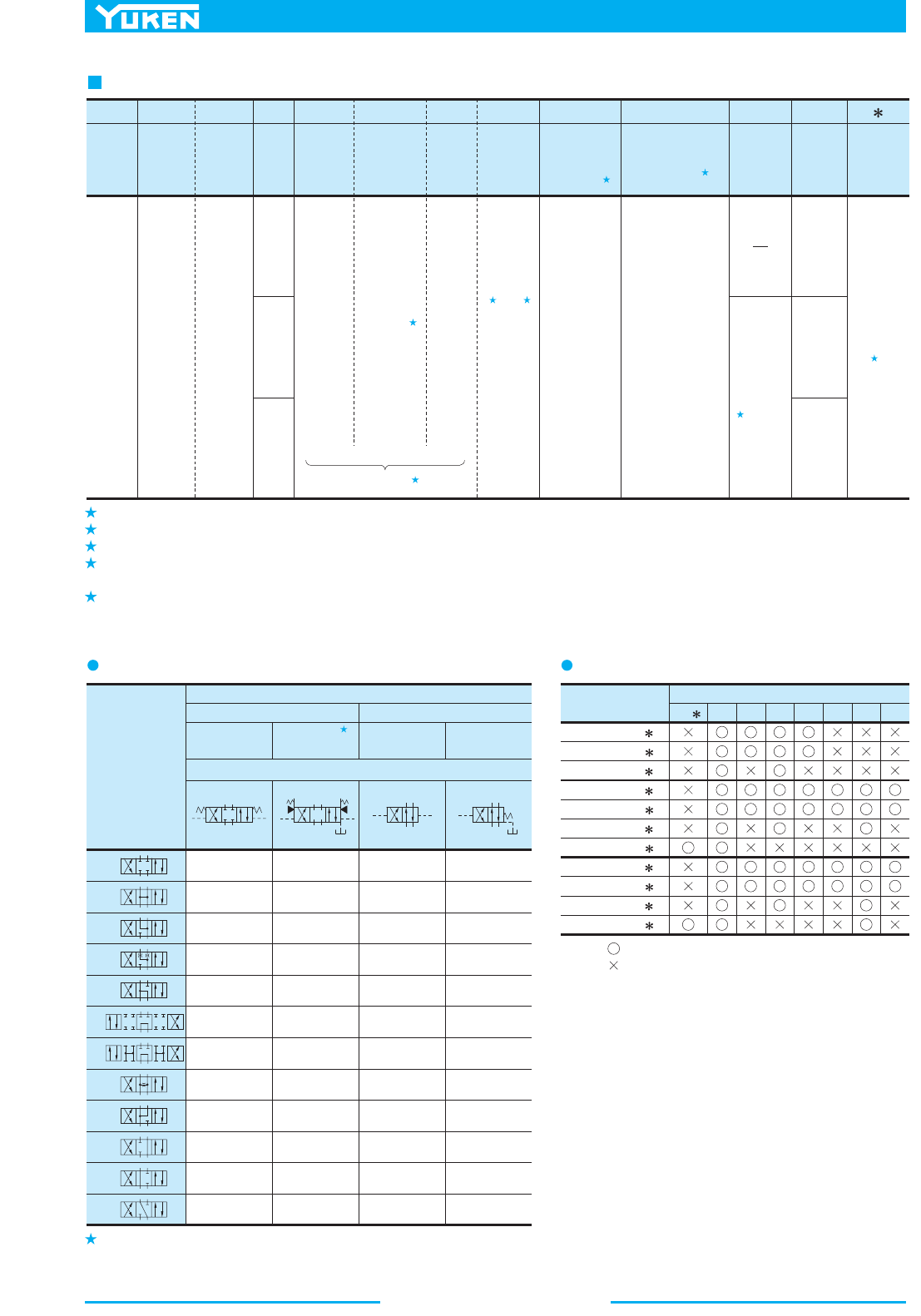
Pilot Operated Directional Valves
424
1.
2.
3.
4.
5.
1
2
3 3
4
5
2
2
:
F:
Special
Seals
for
Phos-
phate
ester
type
fluids
(Omit
if not
required)
Special
Seals
F- DH
Series
Number
G
Type of
Connec-
tion
-04
Valve
Size
-2
Number
of Valve
Positions
B
Spool-
Spring
Arrange-
ment
2
Spool
Type
A
Special
Two
Position
Valve
-C2
Model with
Pilot Choke
Valve
(Options)
-RA
Spool Control
Modification
(Options)
-H
Built-in
Orifice
for Pilot
Line
-50
Design
Number
Design
Standard
04
06
10
DH:
Pilot
Oper-
ated
Direc-
tional
Valve
G:
Sub-
plate
Mount-
ing
3
2
C:
Spring
Centred
H:
Pressure
Centred
(Option)
N:
No-Spring
B:
Spring
Offset
2
4
5
60
9
11
3
40
6
7
10
12
A , B
(Omit if
not
required)
C2:
With C2
Choke
R2:
Adjustment,
Both Ends
With Stroke
RA:
Adjustment,
Port A End
With Stroke
RB:
Adjustment,
Port B End
With Stroke
P2:
Piston, Both
Ends
With Pilot
PA:
Piston, Port A
End
With Pilot
PB:
Piston, Port B
End
With Pilot
50
40
50
Refer to
H:
Refer to
Refer to
Spool Type
Valve Types
Three Positions
Spring
Centred
Pressure
Centred
Two Positions
No-
Spring
Spring
Offset
Graphic Symbols
3C2
3C3
3C4
3C40
3C5
3C6
3C60
3C7
3C9
3C10
3C11
3C12
3H2
3H3
3H4
3H40
3H5
3H6
3H60
3H7
3H9
3H10
3H11
3H12
2N2
2N3
2N4
2N40
2N7
2B2
2B3
2B4
2B40
2B7
2
3
4
40
5
6
60
7
9
10
11
12
Model Numbers
3H C2 R2 RA RB P2 PA PB
Option Code
DHG-04-3C
DHG-04-2N
DHG-04-2B
DHG-06-3C
DHG-06-2N
DHG-06-2B
DHG-06-3H
DHG-10-3C
DHG-10-2N
DHG-10-2B
DHG-10-3H
AB
PT
X
Y
AB
PT
X Y
V
AB
PT
X
Y
AB
PT
Y
X
For various combination, see the List of Valve Types below.
Model Number Designation
For the option combinations of the Type (Valve Size) and Options, see the List of Options below.
Refer to the column "valves using neutral position and side position" (Special 2-position valve) on page 426.
In spool-spring arrangement "H" (pressure centred models), in case the pilot pressure is more than 10 MPa (150PSI), please specify that the valve
should have the built-in orifice to the pilot line.
Design Standards: Japanese Standard "JIS" and European Design Standard
N. American Design Standard
None..................
90......................
List of OptionsList of Valve Type
Note. Mark: Available
Mark: Not Available
Pressure Centered Models are not available for the Valve Size of "04".
,
,
,
,
,
,
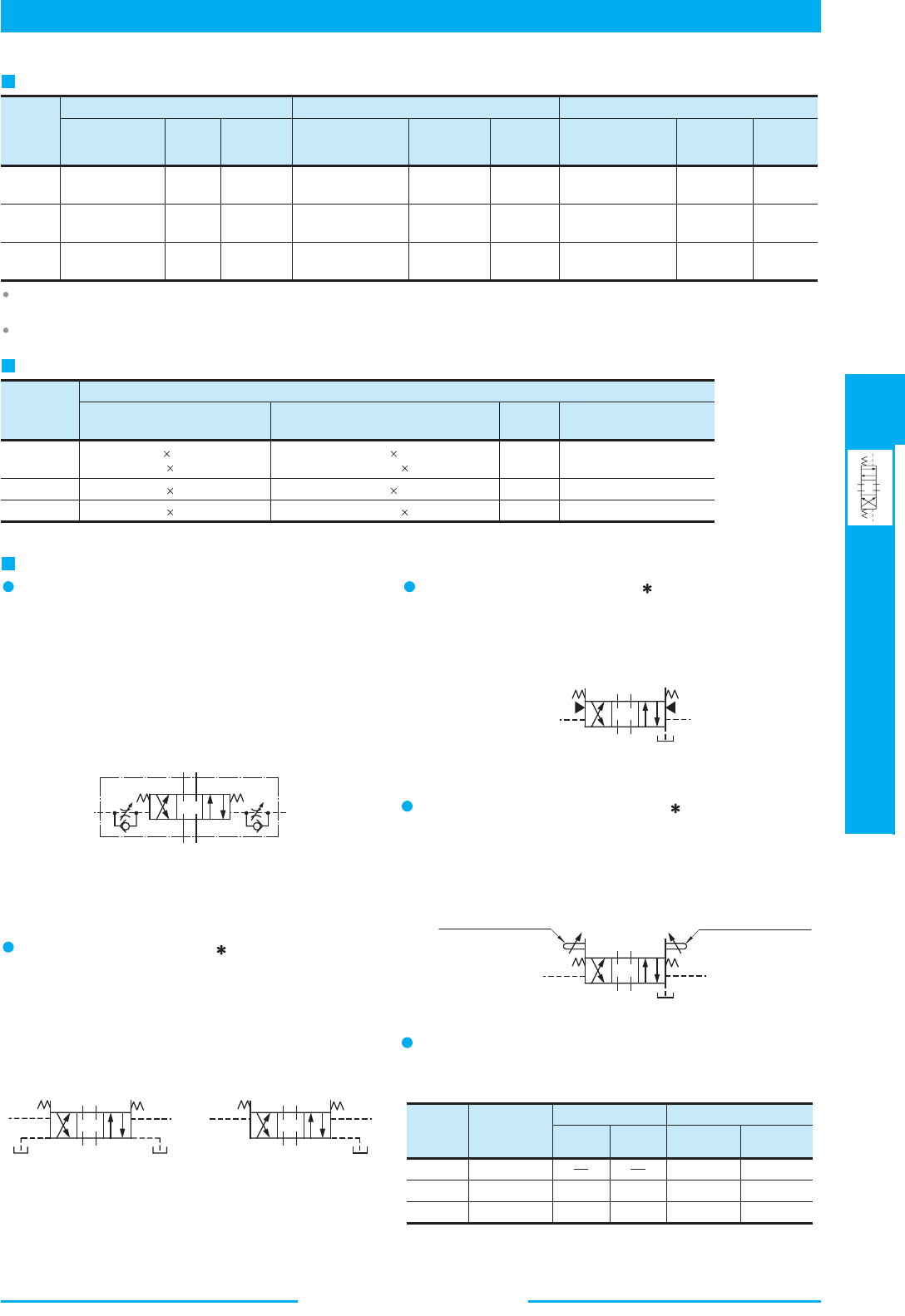
425
DIRECTIONAL CONTROLS
Pilot Operated Directional Valves
E
Pilot Operated Directional Valves
Valve
Model
Numbers
Sub-plate
Model Numbers
Thread
Size
Approx.
Mass
kg (lbs.)
Sub-plate
Model Numbers
Thread
Size
Approx.
Mass
kg (lbs.)
Sub-plate
Model Numbers
Thread
Size
Approx.
Mass
kg (lbs.)
Japanese Standard "JIS" European Design Standard N. American Design Standard
Rc 1/2
Rc 3/4
4.4 (9.7)
4.1 (9.0)
7.4 (16.3)
7.4 (16.3)
DHG-04
DHG-06
DHG-10
21.5 (47.4)
21.5 (47.4)
Rc 3/4
Rc 1
Rc 1-1/4
Rc 1-1/2
DHGM-04-20
DHGM-04X-20
DHGM-06-50
DHGM-06X-50
DHGM-10-40
DHGM-10X-40
DHGM-04-2080
DHGM-04X-2080
DHGM-06-5080
DHGM-06X-5080
DHGM-10-4080
DHGM-10X-4080
4.4 (9.7)
4.1 (9.0)
7.4 (16.3)
7.4 (16.3)
21.5 (47.4)
21.5 (47.4)
4.4 (9.7)
4.1 (9.0)
8.5 (18.7)
8.5 (18.7)
21.5 (47.4)
21.5 (47.4)
DHGM-04-2090
DHGM-04X-2090
DHGM-06-5090
DHGM-06X-5090
DHGM-10-4090
DHGM-10X-4090
1/2 BSP.F
3/4 BSP.F
3/4 BSP.F
1 BSP.F
1-1/4 BSP.F
1-1/2 BSP.F
1/2 NPT
3/4 NPT
3/4 NPT
1 NPT
1-1/4 NPT
1-1/2 NPT
Model
Numbers
DHG-04
DHG-06
DHG-10
M12 60 Lg.
M20 75 Lg.
M6 45 Lg.
M10 50 Lg.
2
4
6
6
12-15 (106-133)
58-72 (513-637)
100-123 (885-1089)
473-585 (4186-5177)
1/4-20 UNC 1-3/4 Lg.
3/8-16 UNC 2 Lg.
1/2-13 UNC 2-1/2 Lg.
3/8-16 UNC 2 Lg.
Qty.
Tightening Torque
Nm (in. lbs)
N. American Desgin Standard
Japanese Standard "JIS"
European Design Standard
Socket Head Cap Screw
Model
Numbers
With Pilot
Choke Valve
P2
PA
PB
R2
RA
RB
With Pilot Piston With Stroke Adjustment
DHG-04
DHG-06
DHG-10
0.65 (1.4)
0.65 (1.4)
0.65 (1.4)
1.0 (2.2)
3.6(7.9)
0.5 (1.1)
1.8 (4.0)
1.0 (2.2)
1.2 (2.6)
3.7 (8.2)
0.5 (1.1)
0.6 (1.3)
1.85 (4.1)
kg (lbs.)
A
B
P
T
X
W
Y
V
A
B
P
T
YX
V
A
B
P
T
YX
A
B
P
T
X
Y
V
Stroke Adjustment
Screw (Port "A" End)
Stroke Adjustment
Screw (Port "B" End)
AB
PT
YX
Mounting Bolts
Sub-plate
Sub-plates are available. Specify the sub-plate model number from the table above.
When sub-plates are not used, the mounting surface should have a good machined finish.
Sub-plates are shared with those for Solenoid Controlled Pilot Operated Directional Valves. Refer to
pages 401 to 403 for dimensions.
Options
Models with Pilot Choke Adjustment (C2)
When the adjustment screw is turned clockwise, changeover speed of
the spool becomes slow. In case of the spring centred valves in
particular, making slow of the returning speed of the spool to the
neutral position is possible with a C2 choke valve.
These choke valves can be used in combination with valves of spring
centred, no spring, spring offset, pressure centred and the valves with
stroke adjustment.
Models with Pilot Piston (P )
The valves with a pilot piston can be used when the high speed
changeover of the spool is required. However, please note that in case
of spring centred valves, there is no change in the returning speed of
the spool to the neutral position even with the pilot piston.
Pressure Centered Models (3H
)
The pressure centred type can be used when the returning of the spool
to the neutral position is required to be done firmly.
Models with Stroke Adjustment (R )
When the adjustment screw is screwed in, the spool stroke becomes
short and flow rate reduces
Graphic Symbol
Graphic Symbol
Graphic Symbols
Spring Centred Models
Graphic Symbols
Spring Centred Models with Stroke Adjustment on Both Ends (R2)
Spring Centred Models with Pilot
Piston on Both Ends (P2)
Spring Centred Models
with Pilot Piston on Port "A" End (PA)
Additional Mass of Options
Add the mass described below to the mass of standard models on page 423
if options are required.
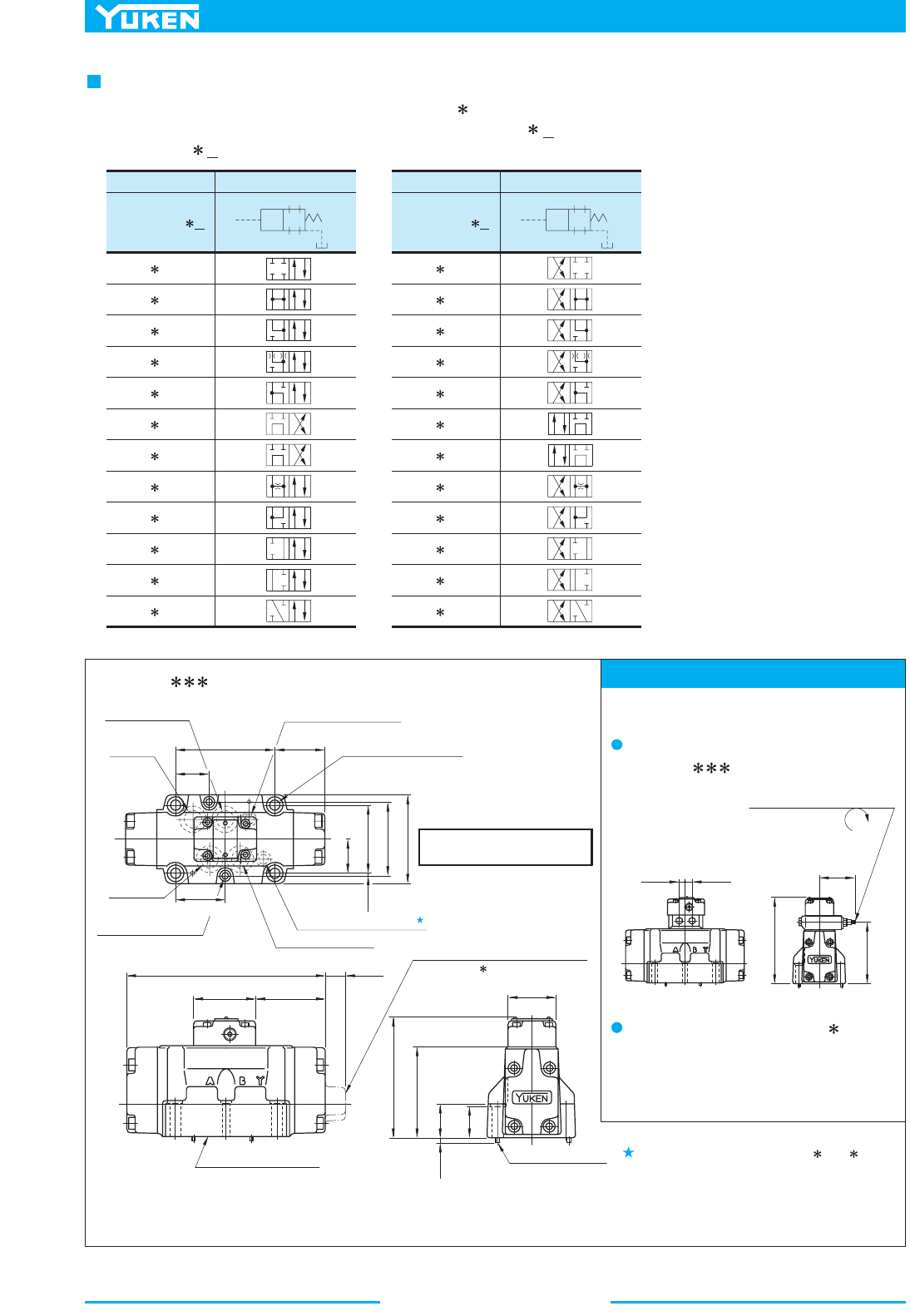
Pilot Operated Directional Valves
426
Mounting Surface: ISO 4401-AD-07-4-A
A
B
P
T
Y
X
A
B
P T
Y
X
Model Numbers Graphic Symbols
04
06
10
DHG-
-2B A
DHG- -2B2A
DHG- -2B3A
DHG- -2B4A
DHG- -2B40A
DHG- -2B5A
DHG- -2B6A
DHG- -2B60A
DHG- -2B7A
DHG- -2B9A
DHG- -2B10A
DHG- -2B11A
DHG- -2B12A
Model Numbers Graphic Symbols
04
06
10
DHG-
-2B B
DHG- -2B2B
DHG- -2B3B
DHG- -2B4B
DHG- -2B40B
DHG- -2B5B
DHG- -2B6B
DHG- -2B60B
DHG- -2B7B
DHG- -2B9B
DHG- -2B10B
DHG- -2B11B
DHG- -2B12B
P
A
T
X
B
Y
101.6
(4.00)
Tank
Port "
T"
7(.28) Dia. Through
11(.43) Dia. Spotface
2 Places
Pressure Port "
P"
50
(1.97)
Pilot Pressure Port "X"
Pilot Pressure Port "
Y"
Cylinder Port "
B"
Cylinder
Port "
A"
34.9(1.37)
69.8(2.75)
73(2.87)
91(3.58)
1.6
(.06)
50.4
(1.98)
34
(1.34
)
11(.43)
Dia. Through
17.5(.69) Dia. Spotface
4 Places
3(.12) Dia.
Two Locating Pins
Mounting Surface
(O-Rings Furnished)
Chain line indicates Spring Offset
Models (2B
)
65
(2.56)
204(8.03)
69.5
(2.74)
21
(.83)
48
(1.89)
Models with Pilot Choke Valve
Models with Stroke Adj. (
R
)
35
(1.38)
4
(.16)
121(4.76)
91(3.58)
146
(5.75)
9.3
(.37)
10.4
(.41)
106
(4.17)
59
(2.32)
Pilot Flow Adjustment
Screw
6(.24) Hex.
34
(1.34
)
Fully Extended
DEC.
DHG-04- -50/5090
Valves Using Neutral Position and Side Position (Special Two Position Valve)
Note: For the valve mounting surface dimensions, see the dimensional drawing of the
sharable sub-plate on
page 401.
For Spring Offset Models
(2B , 2B
A
B
),
it functions as drain port. When that model
is used, directly connect it to the reservoir.
Options
DHG-04- -C2
DIMENSIONS IN
MILLIMETRES (INCHES)
Outside dimensions are the same as thos e of the
main valve of Solenoid Controlled Pilot Operated
Directional Valves (DSHG-04). See page 405.
In addition to the standard two positions valves (2B ), the following two types of two positions valves are available:
valves with neutral position and pilot Y pressure position (2B A), valves with neutral position and pilot X pressure
position (2B B).
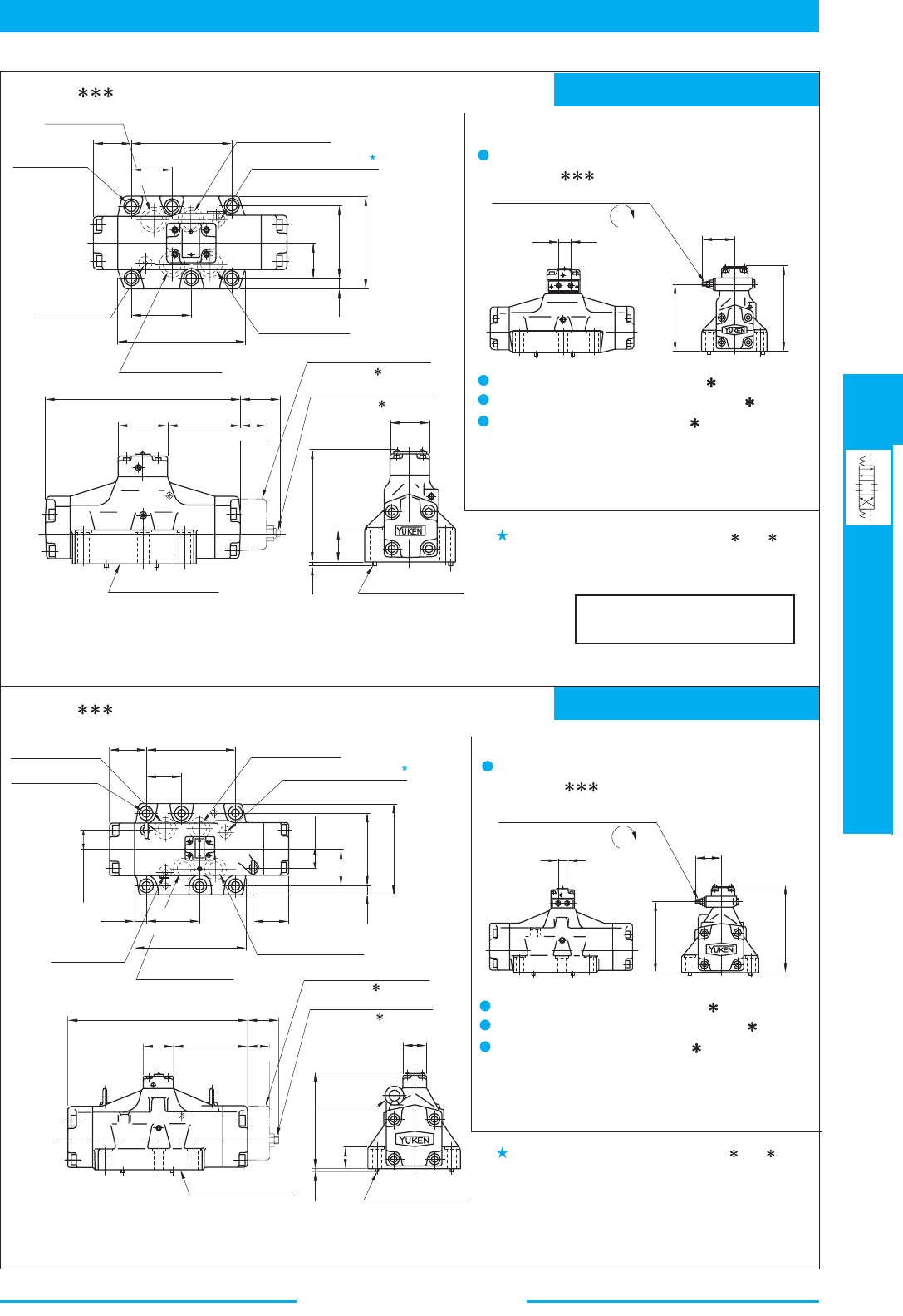
427
DIRECTIONAL CONTROLS
Pilot Operated Directional Valves
E
Pilot Operated Directional Valves
Mounting surface: ISO 4401-AE-08-4-A
Mounting surface: ISO 4401-AF-10-4-A
DIMENSIONS IN
MILLIMETRES (INCHES)
50.5
(1.99)
Pilot Pressure Port "Y"
Pressure Port "
P"
130.2
53.2
(2.09)
13.5(.53)
Dia.
Through
20(.79) Dia.
Spotface
6 Places
Pilot Pressure
Port "
X"
Cylinder Port "
A"
Cylinder Port "
B"
77
(3.03)
156
(6.14)
13
(.51)
46.1
(1.81)
92.1
(3.63)
118
(4.65)
Indicates Spring Offset
Models (2B ).
Indicates Spring Offset
Models (2B A).
48
(1.89)
6
(.24)
142
(5.59)
41
(1.61)
6(.24) Dia.
Two Location Pins
Mounting Surface
(O-Rings Furnished)
255
(10.04)
65
(2.56)
95
(3.74)
34
(1.34)
19.7 (.78)
59 (2.32)
Fully Extended
190
(7.48)
230
(9.06)
Pilot Flow Adjustment Screw
6 (.24) Hex.
Indicates Spring Offset
Models (2B ).
Indicates Spring Offset
Models (2B A).
6(.24) Dia.
Two Location Pins
Mounting Surface
(O-Rings Furnished)
384
(15.12)
65
(2.56)
159.5
(6.28)
(2.62)
66.5
84
(3.31)
48
(1.89)
6
46 (1.81)
205
(8.07)
2-Eye Bolts
(.24)
Pilot Pressure
Port "
X"
Cylinder Port "
A"
Cylinder Port "
B"
233.8
(9.20)
114.3
(4.50)
21.8
(.86)
78
(3.07)
43.1
(1.69)
79.4
(3.13)
158.8
(6.25)
198
(7.80)
Pilot Pressure Port "Y"
Pressure Port "
P"
Tank Port "
T"
Tank Port "
T"
21.5(.85) Dia.
Through
32(1.26) Dia.
Spotface
6 Places
43 (1.69)
77.5
(3.05)
190.5
(7.50)
76.2
(3.00)
19.6
(.77)
(5.13)
52
(2.05)
XA B
19.7 (.78)
127
(5.00)
167
(6.57)
Pilot Flow Adjustment Screw
6 (.24) Hex.
59 (2.32)
Fully Extended
DEC.
DEC.
DHG-06- -50/5090
DHG-10- -40/4090
evlaV ekohC toliP htiw sledoM
DHG-06- -C2
Options
evlaV ekohC toliP htiw sledoM
DHG-10- -C2
Options
Pressure Centred Models (3H )
Models with Stroke Adjustment (R
)
Models with Pilot Piston (P )
The outside dimensions of the above options are the same
as those of the main valve of Solenoid Controlled Pilot
Operated Directional Valve (DSHG-06). See
page 405.
Pressure Centred Models (3H )
Models with Stroke Adjustment (R )
Models with Pilot Piston (P )
The outside dimensions of the above options are the same
as those of the main valve of Solenoid Controlled Pilot
Operated Directional Valves (DSHG-10). See
page 405.
In case of Spring Offset Model (2B , 2B
A
B
), it
functions as a drain port. When that model is used,
directly connect it to the reservoir.
In case of Spring Offset Model (2B , 2B
A
B
), in
functions as a drain port. When that model is used,
directly connect it to the reservoir.
Note:
For the valve mounting surface dimensions, see the dimensional drawing of
the sharable sub-plate in
page 402.
Note:
For
the valve mounting surface dimensions, see the dimensional drawing of
the sharable sub-plate in page 403.
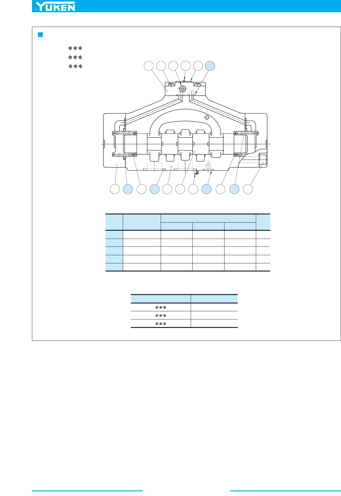
Pilot Operated Directional Valves
428
List of Seals
Item Name of Parts
9
10
11
12
13
O-Ring
O-Ring
O-Ring
O-Ring
O-Ring
Part Numbers
DHG-04 DHG-06 DHG-10
Qty
2
4
2
2
4
SO-NB-P9
SO-NB-P22
SO-NB-P34
SO-NB-P9
SO-NB-P9
SO-NB-P14
SO-NB-P30
SO-NB-P40
SO-NB-P10
SO-NB-P9
SO-NB-P20
SO-NB-P42
SO-NB-G65
SO-NB-P14
SO-NB-P9
Valve Model Numbers Seal Kit Numbers
DHG-04- -50/5090
DHG-06- -50/5090
DHG-10- -40/4090
KS-DHG-04-50
KS-DHG-06-50
KS-DHG-10-40
6 815161713
1
1 510 1 314 9 412 72
DHG-04- -50/5090
DHG-06- -50/5090
DHG-10- -40/4090
Note: When ordering the o-rings, please specify the seal kit number from the table
below.
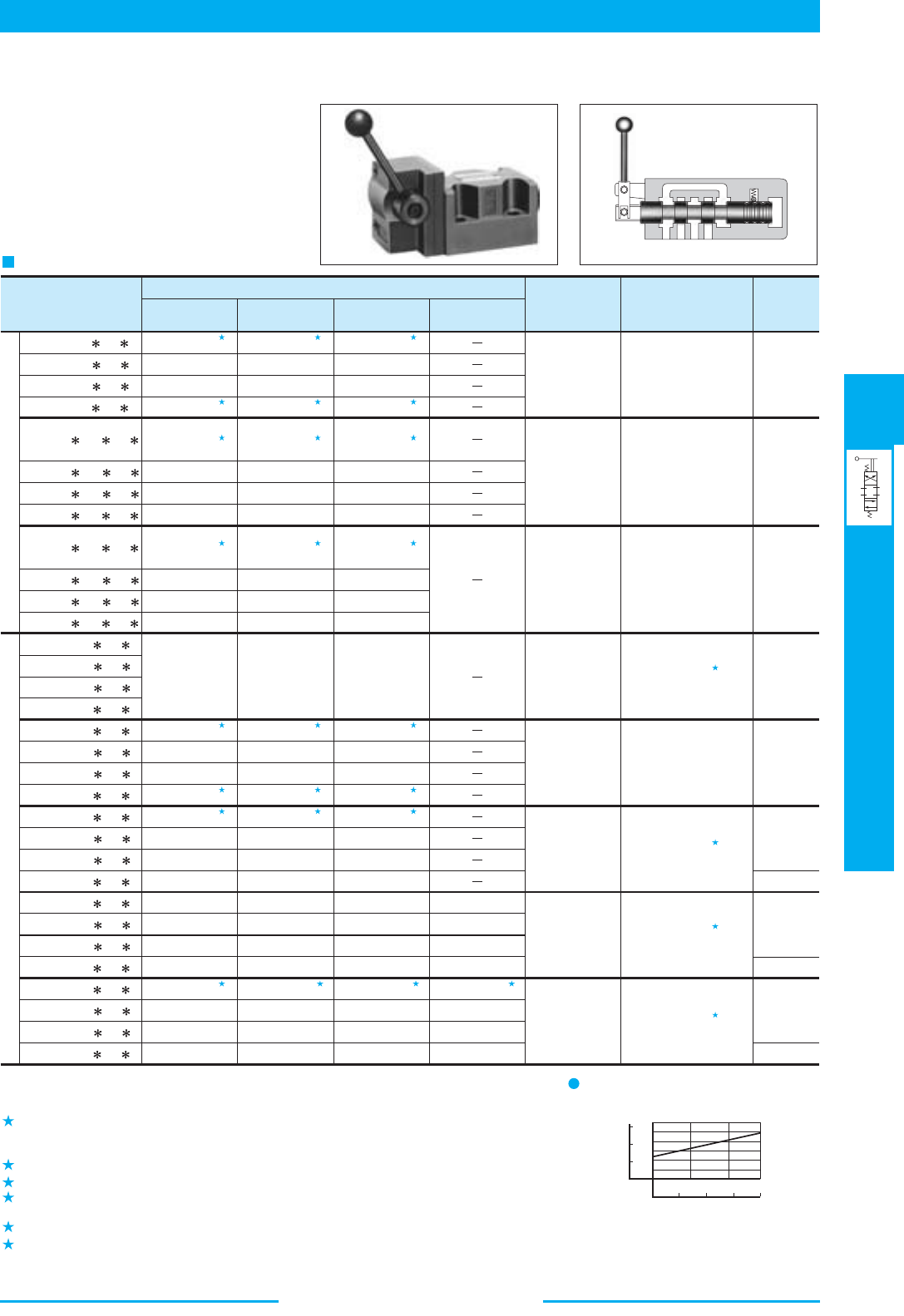
429
DIRECTIONAL CONTROLS
Manually Operated Directional Valves
E
Manually Operated Directional Valves
1100 (291)
100 (26.4)
100 (26.4)
(79.3 {26.4})
500 {315}
100 (26.4)
100 (26.4)
105 (27.7)
1100 (291)
(79.3 {31.7})
500 {315}
(79.3 {52.8})
500 {315}
100 (26.4)
100 (26.4)
100 (26.4)
100 (26.4)
100 (26.4)
100 (26.4)
200 (52.8)
1100 (291)
100 (26.4)
100 (26.4)
200 (52.8)
1100 (291)
1.
2.
3.
4.
5.
6.
1
1
2
2
1
1
3
4 4 4 4
1
3
1
3
1 1
2 2
2 2
1
1
1
1
5
6
6
6
DMT-03-3C -50
DMT-03-3D -50
DMT-03-2D -50
DMT-03-2B -50
DMT-06 -3D -30
DMT-06 -2D -30
DMT-06 -2B -30
DMT-06 -3C -30
DMT-10 -3C -30
DMT-10 -3D -30
DMT-10 -2D -30
DMT-10
-2B -30
DMG-01-3C -10
DMG-01-3D -10
DMG-01-2D -10
DMG-01-2B -10
DMG-03-3C -50
DMG-03-3D -50
DMG-03-2D -50
DMG-03-2B -50
DMG-04-3C -21
DMG-04-3D -21
DMG-04-2D -21
DMG-04-2B -21
DMG-06-3C -50
DMG-06-3D -50
DMG-06-2D -50
DMG-06-2B -50
DMG-10-3C -40
DMG-10-3D -40
DMG-10-2D -40
DMG-10-2B -40
Model Numbers
7 MPa
(1020 PSI)
14 MPa
(2030 PSI)
21 MPa
(3050 PSI)
31.5 MPa
(4570 PSI)
Max.Operating
Pressure
MPa (PSI)
Max. T-Line Back
Pressure
MPa (PSI)
Approx.
Mass
kg (lbs.)
At time spool shift
is required:
7 (1020)
At time spool shift
is not required:
21 (3050)
At time spool shift
is required:
7 (1020)
At time spool shift
is not required:
21 (3050)
Maximum Flow L /min (U.S.GPM)
5.0 (11.0)
12.9 (28.5)
22 (48.5)
1.8 (4.0)
4.0 (8.8)
7.4 (16.3)
7.9 (17.4)
12 (26.5)
11.5 (25.4)
48.2 (106)
50 (110)
16 (2320)
14 (2030)
16 (2320)
21 (3050)
21 (3050)
21 (3050)
25 (3630)
21 (3050)
21 (3050)
25 (3630)
25 (3630)
21 (3050)
31.5 (4570)
31.5 (4570)
500 (132)
500 (132)
500 (132)
200 (52.8)
1100 (291)
1100 (291)
200 (52.8)
100 (26.4)
100 (26.4)
300 (79.3)
300 (79.3)
100 (26.4)
300 {100}
500 (132)
500 (132)
315 (83.2)
(132 {83.2})
35 (9.2)
100 (26.4)
100 (26.4)
200 (52.8)
200 (52.8)
50 (13.2)
500 (132)
500 (132)
500 (132)
250 (66.1)
1100 (291)
1100 (291)
260 (68.7)
35 (9.2)35 (9.2)
300 (79.3)
300 (79.3)
120 (31.7)
300 {120}
500 (132)
500 (132)
315 (83.2)
(132 {83.2})
300 (79.3)
300 (79.3)
200 (52.8)
300 {200}
500 (132)
500 (132)
315 (83.2)
(132 {83.2})
100 (26.4)
100 (26.4)
100 (26.4)
100 (26.4)
100 (26.4)
100 (26.4)
200 (52.8)
200 (52.8)
60 (15.9)
500 (132)
500 (132)
500 (132)
300 (79.3)
1100 (291)
1100 (291)
350 (92.5)
100 (26.4)
100 (26.4)
200 (52.8)
200 (52.8)
90 (23.8)
500 (132)
500 (132)
500 (132)
420 (111)
1100 (291)
1100 (291)
670 (177)
Threaded Connections
Sub-Plate Mounting
05
0
1410
0.5
1.0
1.5
500 1000 1500 2000
MPa
0
T-Line Back Pressure
8
12
4
0
Nm(in.lbf.)
Operating Torque
DMG-01 Lever Operating Torque
Note: The maximum flow means the limited flow without inducing any abnormality to the operation
(changeover) of the valve. For details, please refer to the "List of Standard Models and Maximum
Flow" on
pages 386 to 390.
Varies depending on the spool type. For details, see the "List of Standard Model and Maximum
Flows" for DSG-03 Series Solenoid Operated Directional Valves (page 364 and 366 at 50 Hz
rated voltage).
The figures in parentheses indicate Max. flow for 3C3,3C5, 3C6 and 3C60.
Varies depending on the spool type. For the details, see the table in the following page.
Varies depending on the spool type. Same as DSHG-10 (at pilot pressure of 1.5 MPa (220 PSI).
See page 390.
Lever operating torque varies depends on the T-line back pressure. See the right-hand figure.
If the T-Line back pressure exceeds 7 MPa (1020 PSI), directly connect the drain port to the
reservoir.
Specifications
These valves may be used to manually
shift the spool position and change the
direction of oil flow.
■ Manually Operated Directional Valves
PSI
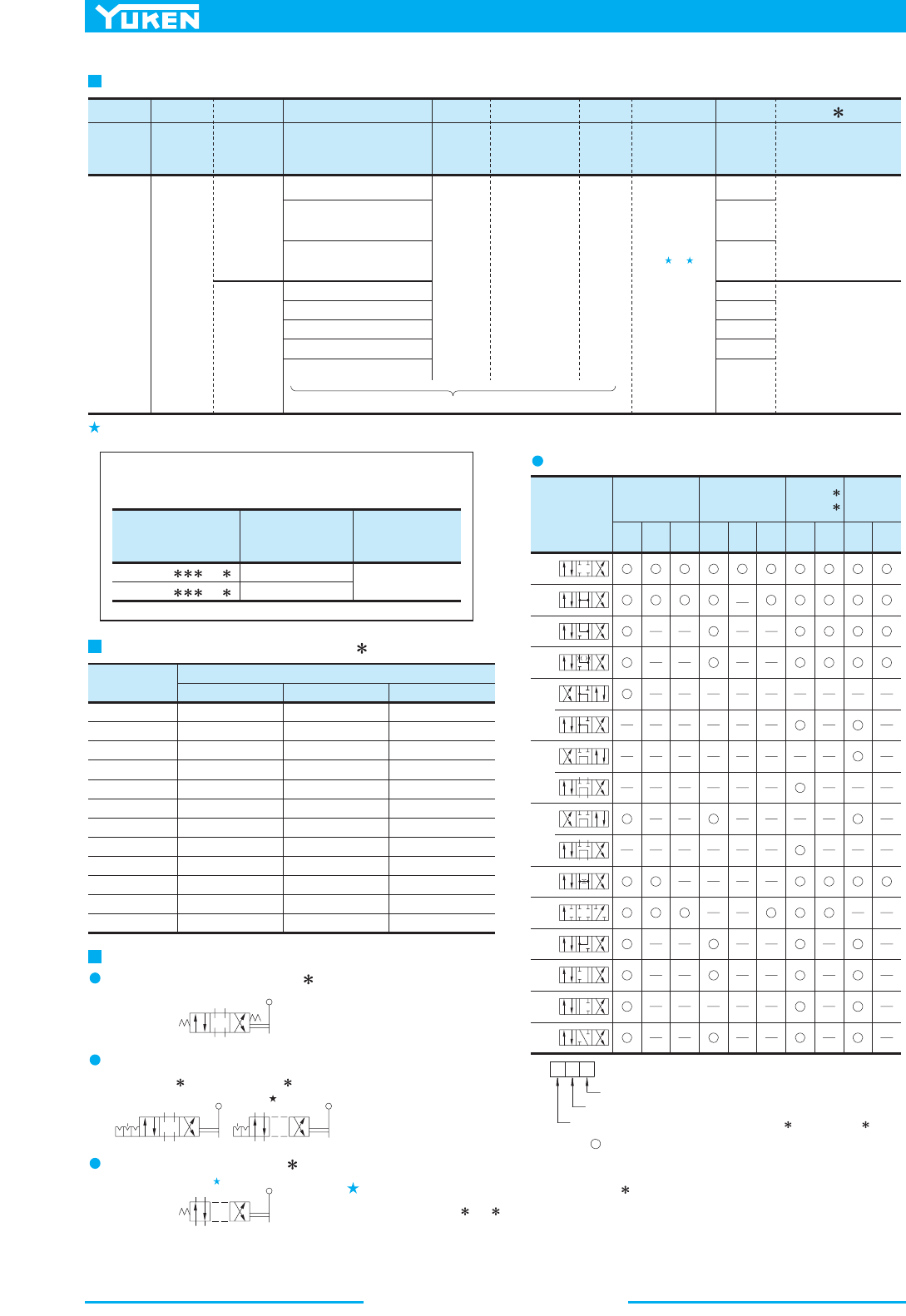
Manually Operated Directional Valves
430
A ,B
.
Max. Operating
Pressure
MPa (PSI)
Rated Flow
L/min
(U.S.GPM)
Model Numbers
DMF-10- -30
DMF-16- -31
21 (3050)
315 (83.2)
400 (106)
Special
Seals for
Phos-
phate
ester
type
fluids
(Omit if
not
required)
F:
F-
Special
Seals
DM
Series
Number
T
Type of
Connec-
tion
Manually
Operated
Direc-
tional
Valves
DM :
Threaded
Connec-
tion
T :
Sub-plate
Mounting
G:
-03
Valve
Size
-2
No. of
Valve
Position
B
Spool-Spring
Arragement
2
Spool
Type
3
2
03
01
03
04
06
10
(Piping size 3/4)
06
(Piping size 1)
06X
(Piping size 1-1/4)
10
(Piping size 1-1/2)
10X
Spring
Centred
C:
No-Spring
Detented
D:
Spring Offset
B:
See the table below for combinations.
2
,
3
4
,
40
5
,
6
60
,
7
8
,
9
10
,
11
12
A
Special Two
Position
Valve
-50
Design
Number
(Omit if not
required)
50
30
30
10
50
21
50
Design
Standard
None:
Japanese
Std. "JIS"
80:
European
Design Std.
90:
N. American
Design Std.
None:
Japanese
Std. "JIS"
and Euro-
pean Design
Std.
90:
N. American
Design Std.
Model
Numbers
DMG-04-3C2
DMG-04-3C3
DMG-04-3C4
DMG-04-3C40
DMG-04-3C5
DMG-04-3C6
DMG-04-3C60
DMG-04-3C7
DMG-04-3C9
DMG-04-3C10
DMG-04-3C11
DMG-04-3C12
7 MPa(1020 PSI) 14 MPa(2030 PSI) 21 MPa(3050 PSI)
Max. Flow L /min (U.S.GPM)
200
180
200
200
80
90
140
200
200
200
200
200
(52.8)
(47.6)
(52.8)
(52.8)
(21.1)
(23.8)
(37.0)
(52.8)
(52.8)
(52.8)
(52.8)
(52.8)
130
90
200
200
50
60
70
75
125
130
150
200
(34.3)
(23.8)
(52.8)
(52.8)
(13.2)
(15.9)
(18.5)
(19.8)
(33.0)
(34.3)
(39.6)
(52.8)
85
70
90
105
40
55
55
55
100
85
85
95
(22.5)
(18.5)
(23.8)
(27.7)
(10.6)
(14.5)
(14.5)
(14.5)
(26.4)
(22.5)
(22.5)
(25.1)
Spool Type
DMG-01
DMT-03
DMG-03
DMT-0
6
DMT-1
0
DMG-04
DMG-06
DMG-10
3C
3D
2D 2B
3C
3D
2D 2B
3C
3D
2D
2B
3C
3D
2D
2B
2
3
4
40
5
6
60
7
8
9
10
11
12
Position #3
Position #2
T
G
Position #1 (#2, in case of D M -01/03-2B
T
G
, DM -03-2D )
40
Model Number Designation
Consult us for the details.
Refer to column "valves using neutral position and side position" (special 2-position valve) on
page 431.
Maximum Flow of DMG-04-3C
Note: The mark indicate the spool type available for each type.
Graphic Symbols
List of Spool Type
Spring Centred Models (3C )
3D 2D
AB
PT
#1 #2
#3
No-Spring Detented Models
AB
PT
#1 #2
#3
AB
P
T
#1 (#2)
#3
Spring Offset Models (2B )
AB
P
T
#1 (#2) #3
Position #2 is applied for models DMG-01-2B
T
G
and DM
-03-2B /2D .
.woleb debircsed sevlav noitcennoc degnalf reffo nac nekuY
431
DIRECTIONAL CONTROLS
Manually Operated Directional Valves
E
Manually Operated Directional Valves
.
A
B
P
T
A
B
P
T
AB
P
T
AB
P T
2B2A
2B3A
2B4A
2B40A
2B5A
2B6A
2B60A
2B7A
2B8A
2B9A
2B10A
2B11A
2B12A
2B2B
2B3B
2B4B
2B40B
2B5B
2B6B
2B60B
2B7B
2B8B
2B9B
2B10B
2B11B
2B12B
Valve
Type
Valve
Type
slobmyS cihparGslobmyS cihparG
ledoMledoM
DMT-03
DMG-03
DMT-06
DMT-10
DMG-04
DMG-06
DMG-10
DMT-03
DMG-03
DMT-06
DMT-10
DMG-04
DMG-06
DMG-10
DMG-01
2D2A
2D3A
2D4A
2D40A
2D5A
2D6A
2D60A
2D7A
2D8A
2D9A
2D10A
2D11A
2D12A
2D2B
2D3B
2D4B
2D40B
2D5B
2D6B
2D60B
2D7B
2D8B
2D9B
2D10B
2D11B
2D12B
Valve
Type
Valve
Type
slobmyS cihparGslobmyS cihparG
ledoMledoM
DMT-06
DMT-10
DMG-04
DMG-06
DMG-10
DMT-06
DMT-10
DMG-04
DMG-06
DMG-10
DMG-01
In addition to the standard two positions valves (2D , 2B ), the following two types of two positions valves are
available : Valves with neutral position (#2) and position #1 (2B A,
2D A), valves with neutral position (#2) and
position #3 (2B
B, 2D B).
The mark in the table below indicates the spool type available for each models.
Valves Using Neutral Position and Side Position (Special Two Position Valve)
Spring Offset Models
Position #2
Position #1
Position #3
Position #2
No-spring Detented Models
Position #2
Position #1
Position #3
Position #2
Position number is determined with three position type (3C and 3D ) as the standard.
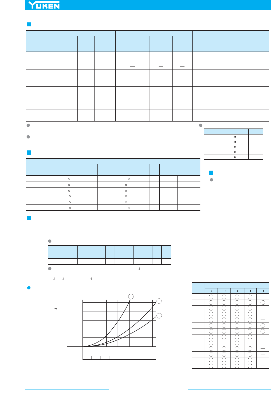
Manually Operated Directional Valves
432
Va lve
Model
Numbers
Japanese Standard "JIS"
Sub-plate
Model Numbers
Thread
Size
Approx.
Mass
kg (1bs.)
Sub-plate
Model Numbers
Thread
Size
Approx.
Mass
kg (1bs.)
European Design Standard
Sub-plate
Model Numbers
Thread
Size
Approx.
Mass
kg (1bs.)
N. American Design Standard
DSGM-01-31
DSGM-01X-31
DSGM-01Y-31
Rc 1/8
Rc 1/4
Rc 3/8
0.8
0.8
0.8
(1.8)
(1.8)
(1.8)
DSGM-01-3080
DSGM-01X-3080
1/8 BSP.F
1/4 BSP.F
0.8
0.8
(1.8)
(1.8)
DSGM-01-3190
DSGM-01X-3190
DSGM-01Y-3190
1/8 NPT
1/4 NPT
3/8 NPT
0.8
0.8
0.8
(1.8)
(1.8)
(1.8)
DMG-01
DSGM-03-40
DSGM-03X-40
DSGM-03Y-40
DMG-03
Rc 3/8
Rc 1/2
Rc 3/4
3.0
3.0
4.7
(6.6)
(6.6)
(10.4)
DSGM-03-2180
DSGM-03X-2180
DSGM-03Y-2180
3/8 BSP.F
1/2 BSP.F
3/4 BSP.F
3.0
3.0
4.7
(6.6)
(6.6)
(10.4)
DSGM-03-2190
DSGM-03X-2190
DSGM-03Y-2190
3/8 NPT
1/2 NPT
3/4 NPT
3.0
3.0
4.7
(6.6)
(6.6)
(10.4)
DMG-04
DHGM-04-20
DHGM-04X-20
Rc 1/2
Rc 3/4
4.4
4.1
(9.7)
(9.0)
DHGM-04-2080
DHGM-04X-2080
1/2 BSP.F
3/4 BSP.F
4.4
4.1
(9.7)
(9.0)
DHGM-04-2090
DHGM-04X-2090
1/2 NPT
3/4 NPT
4.4
4.1
(9.7)
(9.0)
DMG-06
DHGM-06-50
DHGM-06X-50
Rc 3/4
Rc 1
7.4
7.4
(16.3)
(16.3)
DHGM-06-5080
DHGM-06X-5080
3/4 BSP.F
1 BSP.F
8.5
8.5
(18.7)
(18.7)
DHGM-06-5090
DHGM-06X-5090
3/4 NPT
1 NPT
7.4
7.4
(16.3)
(16.3)
DMG-10
DHGM-10-40
DHGM-10X-40
Rc 1-1/4
Rc 1-1/2
21.5
21.5
(47.4)
(47.4)
DHGM-10-4080
DHGM-10X-4080
1-1/4 BSP.F
1-1/2 BSP.F
21.5
21.5
(47.4)
(47.4)
DHGM-10-4090
DHGM-10X-4090
1-1/4 NPT
1-1/2 NPT
21.5
21.5
(47.4)
(47.4)
Subplate Model Number
s Page
DSGM-01
DSGM-03
DHGM-04
DHGM-06
DHGM-10
Va lve
Model
Numbers
Japanese Standard "JIS"
European Design Standard
N. American
Design Standard
Qty.
Tightening Torque
Nm (in. 1bs.)
Socket Head Cap Screw
DMG-01
DMG-03
DMG-04
DMG-06
DMG-10
M5 45 Lg.
M6 35 Lg.
M6 40 Lg.
M10 45 Lg.
M12 60 Lg.
M20 75 Lg.
No. 10-24 UNC 1-3/4 Lg.
1/4-20 UNC 1-3/4 Lg.
1/4-20 UNC 1-1/2 Lg.
3/8-16 UNC 1-3/4 Lg.
1/2-13 UNC 2-1/2 Lg.
3/4-10 UNC 3 Lg.
4
4
2
4
6
8
5-7 (44-62)
12-15
12-15
58-72
(106-133)
(106-133)
(513-637)
100-123 (885-1089)
473-585 (4195-5177)
Viscosity
SSU
Factor 0.81 0.87 0.96 1.03 1.09 1.14 1.19 1.23 1.27 1.30
77 98 141 186 232 278 324 371 417 464
2
mm /s 15 20 30 40 50 60 70 80
90 100
P A B T P B A T P T
Pressure Drop Curve Number
Spool
Type
2
3
4
40
5
6
60
7
8
9
10
11
12
2
3
2
2
3
3
3
2
2
3
2
3
2
2
2
3
2
2
2
2
2
2
2
2
2
2
3
2
2
2
3
3
2
2
3
2
2
2
2
2
2
2
2
2
2
2
2
2
2
2
2
1
1
50 100 150 200 300250
0.2
0.4
0.6
0.8
1.0
0
0
20 40 60 80
0
0
50
100
150
1
2
3
MPa
PSI
Pressure Drop P
L /min
U.S.GPM
Flow Rate
Sub-plates
Sub-plates are available. Specify the sub-plate model number from the table above.
When sub-plates are not used, the mounting surface should have a good machined finish.
Sharable with Solenoid Operand Directional Valves and Solenoid Controlled Pilot Operated
Directional Valves. For dimensions, refer to the right table then see the corresponding pages.
Sub-plate dimensions appearing page
Mounting Bolts
Pressure Drop
2
The following characteristics are based on the following conditions: viscosity of the fluid: 35 mm /s (164 SSU) and
Specific Gravity: 0.850
For any other viscosity, multiply the factors in the table below.
For any other specific gravity (G'), the pressure drop ( P') may be obtained
from the formula below.
P' = P (G'/G) where, P is a value on the following chart and G is
0.850.
DMT-06, 06X
Instructions
Avoid connecting the
Tank Port "T" to a line with
possible surge pressure.
356
373
401
402
403
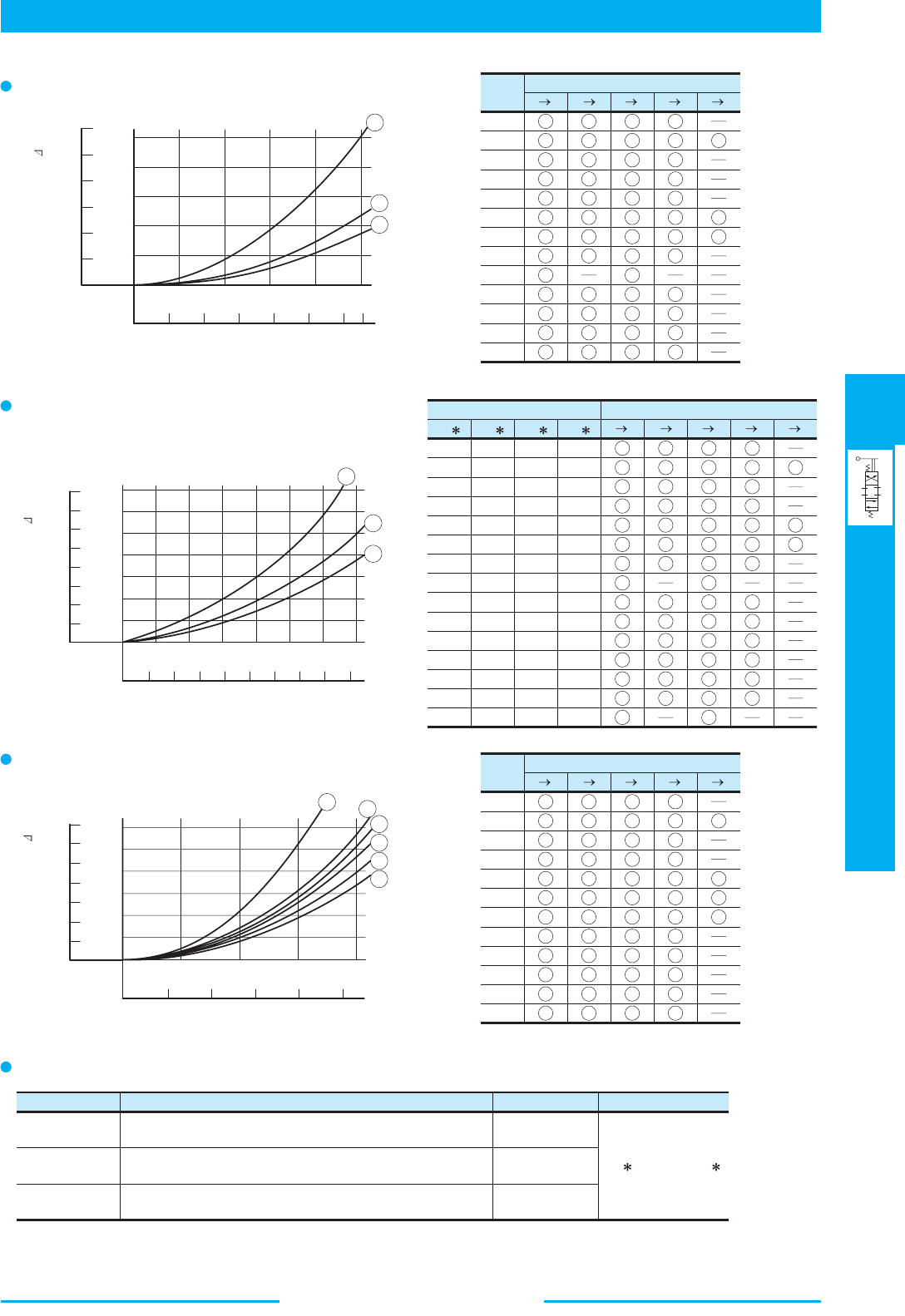
433
DIRECTIONAL CONTROLS
Manually Operated Directional Valves
E
Manually Operated Directional Valves
P A B T P B A T P T
Pressure Drop Curve Number
Spool
Type
2
3
4
40
5
6
60
7
8
9
10
11
12
3
3
3
3
3
3
3
3
3
3
3
3
3
2
2
2
2
2
3
3
2
2
2
2
2
3
3
3
3
3
3
3
3
3
3
3
3
3
2
2
2
2
2
3
3
2
2
2
2
2
2
1
1
P A B T P B A T P T
Pressure Drop Curve Number
3
3
3
3
2
1
3
3
3
3
3
3
2
3
3
3
3
1
1
3
3
3
3
2
3
3
3
3
1
1
3
3
3
3
3
3
3
3
3
3
3
1
1
3
3
3
3
3
2
3
3
2
3
3
2 3
3
3
3
3C
Valve type
3C2
3D
3D2
2D
2D2
2B
3C3
3C4
3C40
3C5
3C60
3C7
3C8
3C9
3C10
3C11
3C12
3D3
3D4
3D40
3D5
3D60
3D7
3D8
3D9
3D10
3D11
3D12
2D3
2D7
2D8
2B8
2B3
2B2
P A B T P B A T P T
Pressure Drop Curve Number
Spool
Type
2
3
4
40
5
6
60
7
9
10
11
12
5
6
5
5
5
2
2
5
6
5
5
5
2
3
4
4
2
3
3
2
2
4
4
3
5
6
5
5
4
4
4
5
6
5
5
5
4
5
5
5
5
2
2
5
5
5
5
5
3
1
1
1
Model Number
DMT-03
DMG-03
DMG-06
DMG-10
Same as DSG-03 Series Solenoid Operated Directional Valves
(Standard Type)
Same as Solenoid Controlled Pilot Operated Directional Valves
(DSHG-06)
Same as Solenoid Controlled Pilot Operated Directional Valves
(DSHG-10)
Page
371
393
393
Remarks
3D
is same as 3C
Pressure Drop Characteristics
1
100 200 300 400 500
0.
2
0
0
0.4
0.6
0.8
1.
0
0
50
100
150
200 40 60 80 100 120 130
PSI
L /min
U.S.GPM
Flow Rate
MPa
Pressure Drop P
2
3
0 5 10 15 20 25 30
1.4
1.2
1.0
0.8
0.6
0.4
0.2
0
35
02468
9
1
2
3
200
100
50
0
150
PSI
L /min
U.S.GPM
Flow Rate
MPa
Pressure Drop P
0 50 100 150 200
0.2
1
2
3
4
5
6
0.4
0.6
0.8
1.0
1.2
0
PSI
L /min
U.S.GPM
MPa
Pressure Drop P
175
150
100
50
0
0 1020304050
Flow Rate
DMT-10, 10X
DMG-01
DMG-04
For
DMT-03
,
DMG-03
,
DMG-06
, and
DMG-10
, refer to the table below then see the related page.
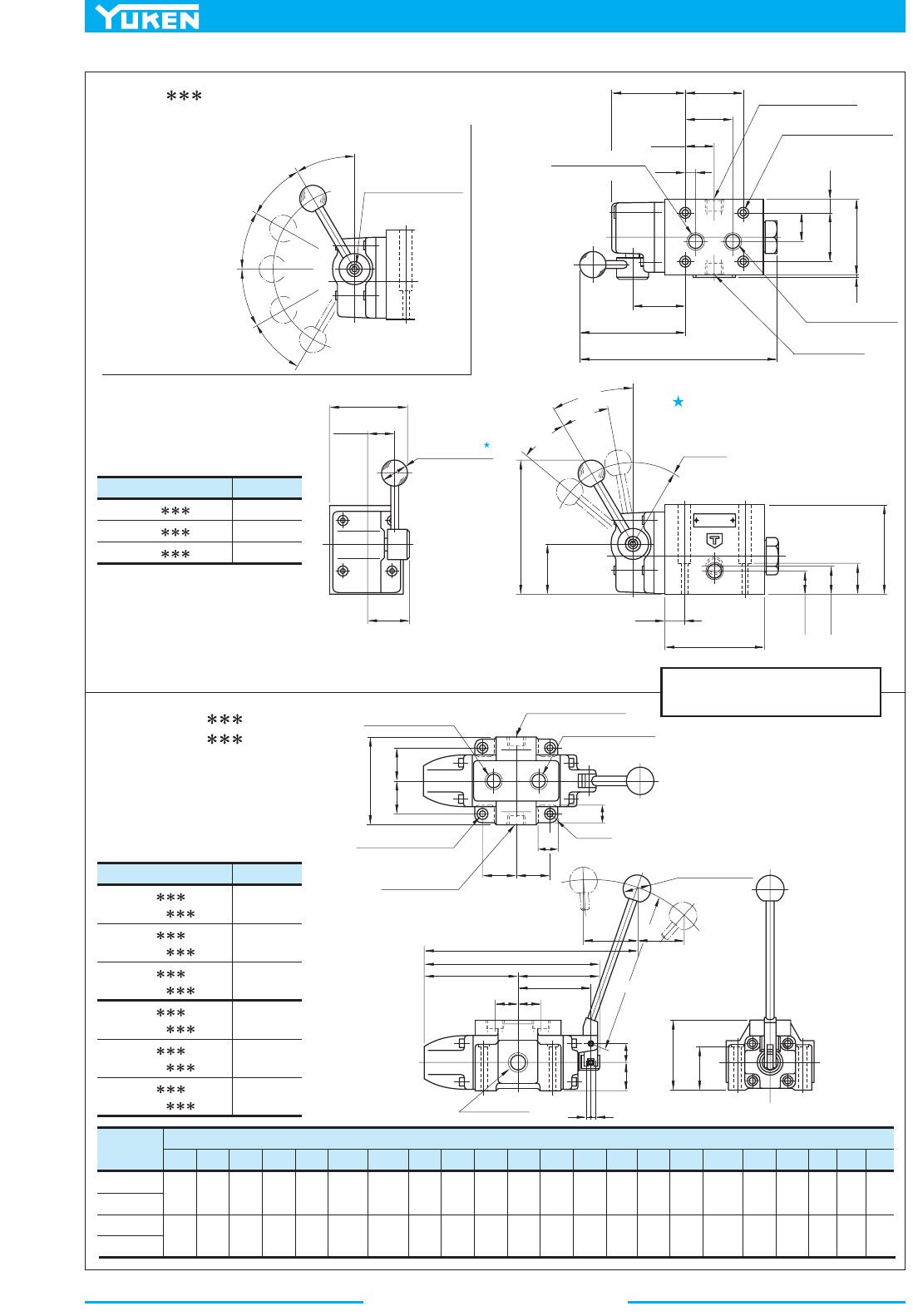
Manually Operated Directional Valves
434
DIMENSIONS IN
MILLIMETRES (INCHES)
1.
1
Model Numbers
"C"
Thd.
Rc 3/8
3/8 BSP.F
3/8 NPT
DMT-03- -50
DMT-03- -5080
DMT-03- -5090
Model Numbers
"h"
Thd.
Rc 3/4
Rc 1
DMT-06- -30
DMT-06X- -30
3/4 BSP.F
1 BSP.F
3/4 NPT
1 NPT
Rc 1-1/4
Rc 1-1/2
1-1/4 BSP.F
1-1/2 BSP.F
1-1/4 NPT
1-1/2 NPT
DMT-06- -3080
DMT-06X- -3080
DMT-06- -3090
DMT-06X- -3090
DMT-10- -30
DMT-10X- -30
DMT-10- -3080
DMT-10X- -3080
DMT-10- -3090
DMT-10X- -3090
A B
P
T
30˚
30˚
30˚
30˚
30˚
Soc. Hd. Cap Screw
4 (.16) Hex. Soc.
3
0
˚
2
0
˚
2
0˚
R94.5
(R3.72)
Position #3
Position #2
Position #1
27
(1.06)
85.3
(3.36)
19
(.75)
92
(3.62)
46.3
(1.82)
139
(5.47)
26.8
(1.06)
21.8
(.86)
74.5
(2.93)
27
(1.06)
39.7
(1.56)
25 (.98)
Dia.
Cylinder Port "
A"
"
C
" Thd.
69.7
(2.74)
54
(2.13)
Cylinder Port "B"
"
C
" Thd.
Tank Port "
T"
"
C
" Thd.
Pressure Port "
P"
"
C
" Thd.
7(.28) Dia. Through
11(.43) C' bore
4 Places
46
(1.81)
12
(.47)
70
(2.76)
2
(0.8)
48.7
(1.92)
108.5
(4.27)
193.8
(7.63)
44
(1.73)
27
(1.06)
10
(.39)
XX
Stroke
d
b
Y
Z
SS
L
Q
N
K
J
U V
Position #3
Neutral Position #2
Position #1
40 (1.57) Dia.
CC
D
R "
e
"
H
F
F
E
Cylinder Port "A"
Pressure Port "
P"
Cylinder Port "
B"
"f"
Dia. Through
"g"
Dia. Spotface
4 Places
Tank Port "
T"
a
"h"
Thd.
4 Places
27
(1.06)
DMT-03- -50/5080/5090
DMT-06, 06X- -30/3080/3090
DMT-10, 10X- -30/3080/3090
How to Change Lever Position:
The lever position can
be changed to any
position in five
different positions
shown on the sketch in
the right. For the lever
position change,
remove the Soc. Hd.
Cap Screw and lever
once, set the lever at
the required position
and tighten it with the
Soc. Hd. Cap Screw
firmly.
Lever Operating Torque:
Not exceeding 30 Nm (266 IN. 1bs.)
Model No.
DMT-06
DMT-06X
DMT-10
DMT-10X
50
(1.97)
30
(1.18)
126
(4.96)
47.5
(1.87)
24
(.94)
66
(2.60)
40
(1.57)
160
(6.30)
62.5
(2.46)
33
(1.30)
320
(12.60)
402
(15.83)
255
(10.04)
320
(12.60)
137
(5.39)
173
(6.81)
118
(4.65)
147
(5.79)
107
(4.21)
135
(5.31)
33.5
(1.32)
40
(1.57)
86
(3.39)
102
(4.02)
76
(2.99)
90
(3.54)
9
(.35)
12.5
(.49)
40
(1.57)
50
(1.97)
25
(.98)
35
(1.38)
250
(9.84)
300
(11.81)
100
(3.94)
120
(4.72)
63.5
(2.50)
78.5
(3.09)
12
(.47)
15
(.59)
11
(.43)
13.5
(.53)
17.5
(.69)
21
(.83)
CDEFH J K LNQSU YXZabdefgV
Dimension mm (Inches)
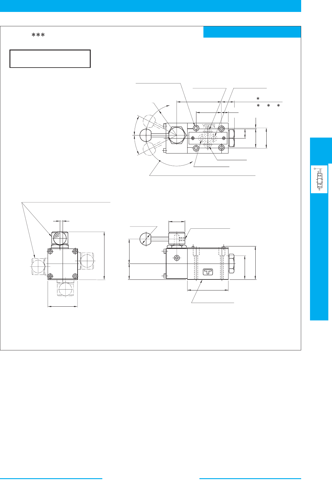
435
DIRECTIONAL CONTROLS
Manually Operated Directional Valves
E
Manually Operated Directional Valves
Mounting surface: ISO 4401-AB-03-4-A
DIMENSIONS IN
MILLIMETRES (INCHES)
71
(2.80)
40.5
(1.59)
11
(.43)
17(.67):3D
,2D ,2B
22(.87):3C
31
(1.22)
32.5
(1.28)
15.5
(.61)
0.75
(.03)
Cylinder Port "A"
Pressure Port "
P"
5.5(.22) Dia. Through
9.5(.37) Dia. C' bore
4 Places
R49
(R1.93)
Cylinder Port "B"
Tank Port "
T"
The operating lever position can be adjusted as required
on the circumference by loosening the set screw.
Neutral Position #2
Position #3
Position #1
2
7
˚
2
7
˚
DMG-01- -10/1090
5
(.20)
48
(1.89)
74
(2.91)
39
(1.54)
25
(.98)
65
(2.56)
38
(1.50)
50.5
(1.99)
Mounting Surface
(O-Rings Furnished)
26 (1.02) Dia.
Lever Fixing Screw
2.5 (.10) Hex. Soc.
20 (.79) Dia.
Four positions are available in 90˚ increment.
Note: For the valve mounting surface dimensions, see the dimensional drawing of the sharable sub-plate in page 356.

Manually Operated Directional Valves
436
Mounting surface: ISO 4401-AC-05-4-A
DIMENSIONS IN
MILLIMETRES (INCHES)
3
1.
2.
3.
1
Cylinder Port "A"
Pressure Port "
P"
Cylinder Port "
B"
7(.28) Dia. Through
11(.43) Dia. Spotface
4 Places
Tank Port "
T"
32.5
(1.28)
12
(.47)
70
(2.76)
69.7
(2.74)
54
(2.13)
48.7
(1.92)
50.8
(2.00)
108.5
(4.27)
193.8
(7.63)
46
(1.81)
Although the tank port is shown on the left
in our sub-plate either may be used.
The position of operating lever can be
changed as required. For the detail, see the
DMT-03 in the
pre
vious page.
Lever Operating Torque:
Not exceeding 30 Nm (266 IN. 1bs.)
DMG-03- -50/5090
27
(1.06)
59
(2.32)
2 (.08)
76.3
(3.00)
19
(.75)
92
(3.62)
46.3
(1.82)
139
(5.47)
R94.5
(R3.72)
Position #3
Position #2
Position #1
3
0
˚
2
0
˚
2
0
˚
Mounting Surface
(O-Rings Furnished)
Note: For the valve mounting surface dimensions, see the dimensional drawing of the sharable
sub-plate in
page 373.
74.5
(2.93)
27
(1.06)
39.7
(1.56)
25 (.98)
Dia.
437
DIRECTIONAL CONTROLS
Manually Operated Directional Valves
E
Manually Operated Directional Valves
Mounting surface: ISO 4401-AD-07-4-A
Mounting surface: ISO 4401-AE-08-4-A
DIMENSIONS IN
MILLIMETRES (INCHES)
A
B
T
P
Y
X
A
B
32
(1.26)
32
(1.26)
50
(1.97)
232.5 (9.15)
202.5 (7.97)
22.5
(.89)
59.2
(2.33)
1.5
(.06)
10.1
(.40)
34.9
(1.37)
69.8
(2.75)
72.9
(2.87)
90
(3.54)
101.6
(4.00)
34
(1.34)
130
(5.12)
Cylinder Port "B"
Pressure Port "
P"
Tank Port "
T"
11(.43) Dia. Through
17.5(.69) Dia. Spotface
4 Places
Drain Port "
Y"
Cylinder Port "
A"
7(.28) Dia. Through
11(.43) Dia. Spotface
2 Places
Position #1
Position #2
Position #3
R200
(R7.87)
Chain line indicates
Spring Offset Models
(2B
,2B A).
30
(1.18)
Mounting Surface
(O-Rings Furnished)
50
(1.97)
4
(.16)
3(.12) Dia.
Two Locating Pins
32
(1.26)
103
(4.06)
30 (1.18)
40 (1.57)
Dia.
Pressure Port "
P"
Tank Port "
T"
Drain Port "
V"
300.5
(11.83)
13.5(.53)
Dia. Through
20(.79) Dia. Spotface
6 Places
95.8
(3.77)
130.2
(5.13)
53.2
(2.09)
55.8
(2.20)
77
(3.03)
13
(.51)
92.1
(3.63)
118
(4.65)
46.1
(1.81)
Cylinder Port "B"
Cylinder Port "
A"
260.5
(10.26)
57
(2.24)
57
(2.24)
Position #2
Position #3
Position #1
R200
(R7.87)
34
(1.34)
52
(2.05)
116
(4.57)
156
(6.14)
12.5
(.49)
Mounting Surface
(O-Rings Furnished)
40
(1.57)
47
(1.85)
41
(1.61)
6
(.24)
6(.24) Dia.
Two Locating Pins
40 (1.57) Dia.
30 (1.18)
Indicates Spring Offset
Models (2B ).
Indicates Spring Offset
Models (2B A).
14.2
(.56)
DMG-04- -21/2190
DMG-06- -50/5090
Note: For the valve mounting surface dimensions, see the dimensional drawing of the sharable sub-plate in page 402.
Note: For the valve mounting surface dimensions, see the dimensional drawing of the sharable sub-plate in page 401.
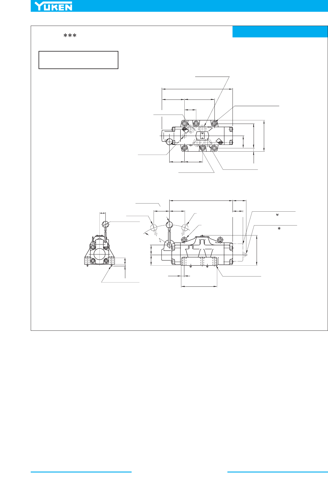
Manually Operated Directional Valves
438
Mounting surface: ISO 4401-AF-10-4-A
DIMENSIONS IN
MILLIMETRES (INCHES)
ABX
TP
Y
Cylinder Port "A"
Pressure Port "
P"
Cylinder Port "
B"
21.5(.85) Dia. Through
32(1.26) Dia. Spotface
6 Places
Tank Port "
T"
Drain Port "
V"
19.6
(.77)
79.4
(3.13)
158.8
(6.24)
198
(7.80)
76.2
(3.00)
146.5
(5.77)
453
(17.83)
190.5
(7.50)
401
(15.79)
94.5
(3.72)
114.3
(4.50)
66.5
(2.62)
47.5
(1.87)
105
(4.13)
105
(4.13)
Position #3
Position #2
Position #1
R300
(R11.81)
40 (1.57)
Dia.
36 (1.42)
Two Eye Bolts
M8
Indicates Spring Offset
Models (2B )
Indicates Spring Offset
Models (2B A)
180
(7.09)
60
(2.36)
65
(2.56)
21.5
(.85)
233.8
(9.20)
Mounting Surface
(O-Rings Furnished)
6(.24) Dia.
Two Locating Pins
44.5 (1.75)
6
(.24)
Note: For the valve mounting surface dimensions, see the dimensional drawing of the sharable sub-plate in page 403.
DMG-10- -50/5090
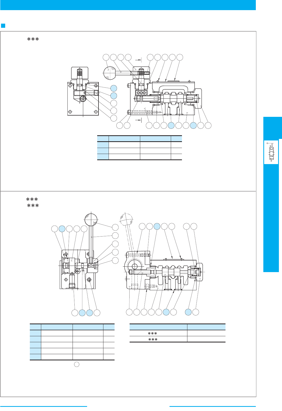
439
DIRECTIONAL CONTROLS
Manually Operated Directional Valves
E
Manually Operated Directional Valves
List of Seals
21
22
23
Item Name of Parts
O-Ring
O-Ring
O-Ring
Part Numbers
SO-NB-P18
SO-NA-P6
SO-NB-P9
Qty.
3
1
4
14
15
18
Item Name of Parts
O-Ring
O-Ring
O-Ring
Part Numbers
SO-NB-P21
SO-NA-P8
SO-NB-A014
Qty.
2
2
5
16 Back Up Ring SO-BB-P8 2
17 O-Ring SO-NB-A023 1
Valve Model Numbers
DMT-03- -50/5080/5090
DMG-03- -50/5090
Seal Kit Numbers
KS-DMT-03-50
KS-DMG-03-50
X
14 13 9 12
18 10 17 15 16
21
22
25
24
20
X
19
3 8 6 5
23
2 1
21 11
4
20
3
14
29 30 10 9
2 6 21
1 5 18 8 14
4
28
27
13
24
23
26 17 25 11
13
22 15
16
12
DMG-01- -10/1090
Note: When ordering the o-ring, please specify the
seal kit number (KS-DMG-01-10).
DMT-03- -50/5080/5090
DMG-03- -50/5090
Note: O-rings of Item 18 are not used for
DMT-03.
When ordering the seals, please specify
the seal kit number from the table right.
Section X-X
1.
2.
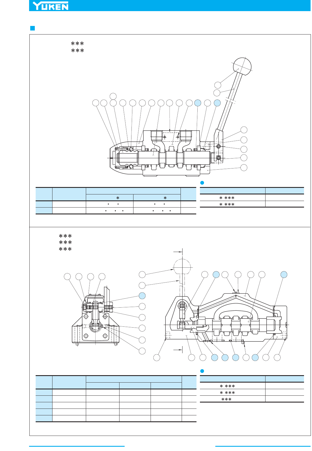
Manually Operated Directional Valves
440
List of Seals
Item Name of Parts
01-GMD40-GMD
Qty.
Part Numbers
DMG-06
29
30
31
32
33
O-Ring
O-Ring
O-Ring
O-Ring
O-Ring
SO-NB-P34
SO-NB-P22A
SO-NA-P20
SO-NB-P9
SO-NB-P9
SO-NB-P40
SO-NB-P30
SO-NA-P20
SO-NB-P14
SO-NB-P10
SO-NB-G65
SO-NB-P42
SO-NA-P25
SO-NB-P20
SO-NB-P14
2
4
2
1
2
7
2
1
1
3
1
4
1
5
2
316 2
4
1
7 1
2
6
2
4
2
2
5
1
2
2
5
6
1
8
1
9
2
0
3
2
8
2
6
9
2
2
3
1
2
2
8
1
5
2
8
2
4
7
23
A
2
1
2
1
1
2
9
3
2
3
025
2
9
3
20
A
1
0
3
33617 1 633
DMT-06, 06X- -30/3080/3090
DMT-10, 10X- -30/3080/3090
Valve Model Numbers
DMG-04 - -21/2190
DMG-06
- -50/5090
DMG-10- -40/4090
Seal Kit Numbers
KS-DMG-04-21
KS-DMG-06-50
KS-DMG-10-40
List of Seal Kits
DMT-06
- -30/3080/3090
Valve Model Numbers
DMT-10 - -30/3080/3090
KS-DMT-06-30
Seal Kit Numbers
KS-DMT-10-30
List of Seal Kits
DMG-04- -21/2190
DMG-06- -50/5090
DMG-10- -40/4090
Note: When ordering the seals, please specify the seal kit number from the table right.
Section A-A
Item Name of Parts
DMT-06 DMT-10
Qty.
Part Numbers
Packing
Dust Seal
24
25
UPI 32
40 6Y
DKI 32 44 7 10
UPI 40
55 10Y
DKI 40 52 7 10
2
1
Note: When ordering the seals, please specify the seal kit number from the table right.
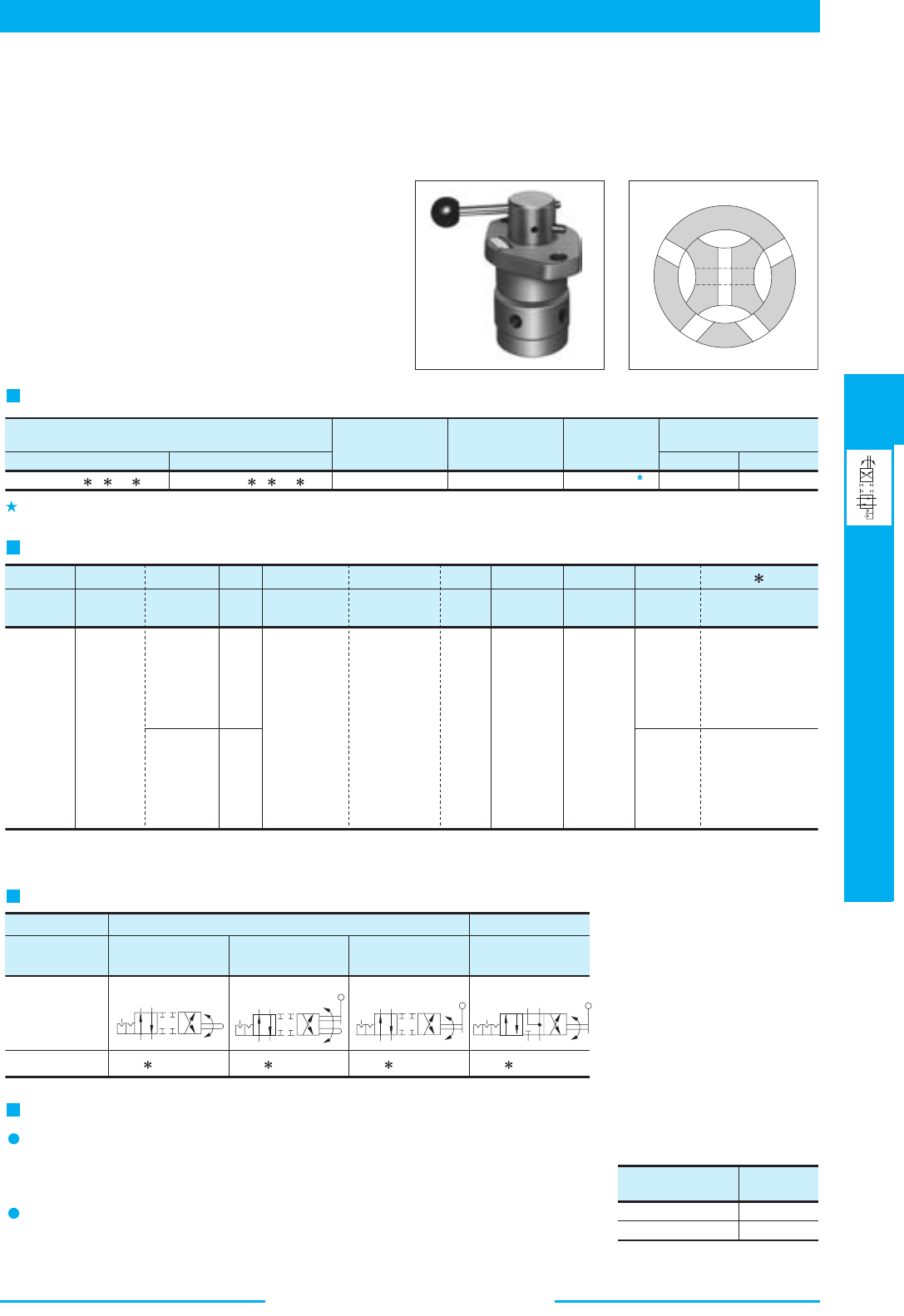
441
DIRECTIONAL CONTROLS
Mechanically Operated Directional Valves
E
Mechanically Operated Directional Valves
■ Mechanically Operated Directional Valves
F:
Special
seals for
phosphate
ester
type
fluids
(Omit if
not
required)
Special
Seals
F-
DR:
Rotary
Type
Directinal
Valve
02
Type of
Mounting
Valve
Size
Design
Standards
-2-02
None:
Japanese
Std. "JIS"
80:
European
Design Std.
90:
N. American
Design Std.
-20
Design
Number
Model Number Designation
DR
Series
Connection
T:
Threaded
Connection
Model Numbers
Threaded Connection Sub-plate Mounting
DRG-02- D -20DRT-02- D -20
Rated Flow
L /min (U.S.GPM)
16 (4.2)
Max. Operating
Pressure
MPa (PSI)
7 (1020)
Max. T-Line
Pressure
MPa (PSI)
7 (1020)
DRG TypeDRT Type
4.7 (10.4) 3.4 (7.5)
Approx. Mass kg (lbs.)
G
No. of Valve
Position
D
Spool-Spring
Arrangement
2
Spool
Type
-A
Operation
Type
-R
Drain
Connection
G:
Sub-plate
Mounting
02
2
3
D:
No-spring
Detented
2
4
A:
Reversing
Dog
B:
Reversing
Dog &
Manual
C:
Manual
None:
Intrenal
Drain
R:
External
Drain
20
20
None:
Japanese
Std. "JIS" &
European
Design Std.
90:
N. American
Design Std.
Graphic Symbols
No. of Position
Operation
Type
Reversing Dog
Operation
Reversing Dog &
Manual Operation
Manual
Operation
2-Position Type
Manual
Operation
3-Position Type
Model No.
DR -02-2D2-A
DR -02-2D2-B DR -02-2D2-C DR -02-3D4-C
Graphic
Symbols
Instructuions
Tank Port Back Pres.
MPa (PSI)
Torque
Nm (in. 1bs.)
0
3 (435)
1.0 (8.9)
4.8 (42.5)
Changeover Torque
AB
#1
P
T
#3
AB
#1
P
T
#3
AB
#1
P
T
#3
AB
#1
P
T
#3#2
Specifications
When a back pressure of more than 3 MPa (435 PSI) is generated in the tank port, be sure to use External Drain Type.
When selecting the Model type, be sure to give the model number from the following Graphic Symbols.
No combinations other than those in the table below are allowed.
When the pressure of pressure port "P" and cylinder port "A" (or "B") is set to 7 MPa
(1020 PSI), the valve changeover torque will be as right side table:
Changeover Torque
Be sure to use the External Drain T
y
pe Valve of spool t
y
pe "2" and plug the tank port.
2-Way directional valves
Note:
These valves are chiefly used to shift the pilot circuit. Rotary Type Directional Valves and Cam Operated Type
Directional Valves are available.
■
Rotary Type Directional Valves
These valves are used to rotate the spool either
manually or by way of cam and shift the direction
of oil flow. The detented mechanism incorporated
in these valves prevents the valve from being
changed over by itself due to vibrations or any
other shocks.
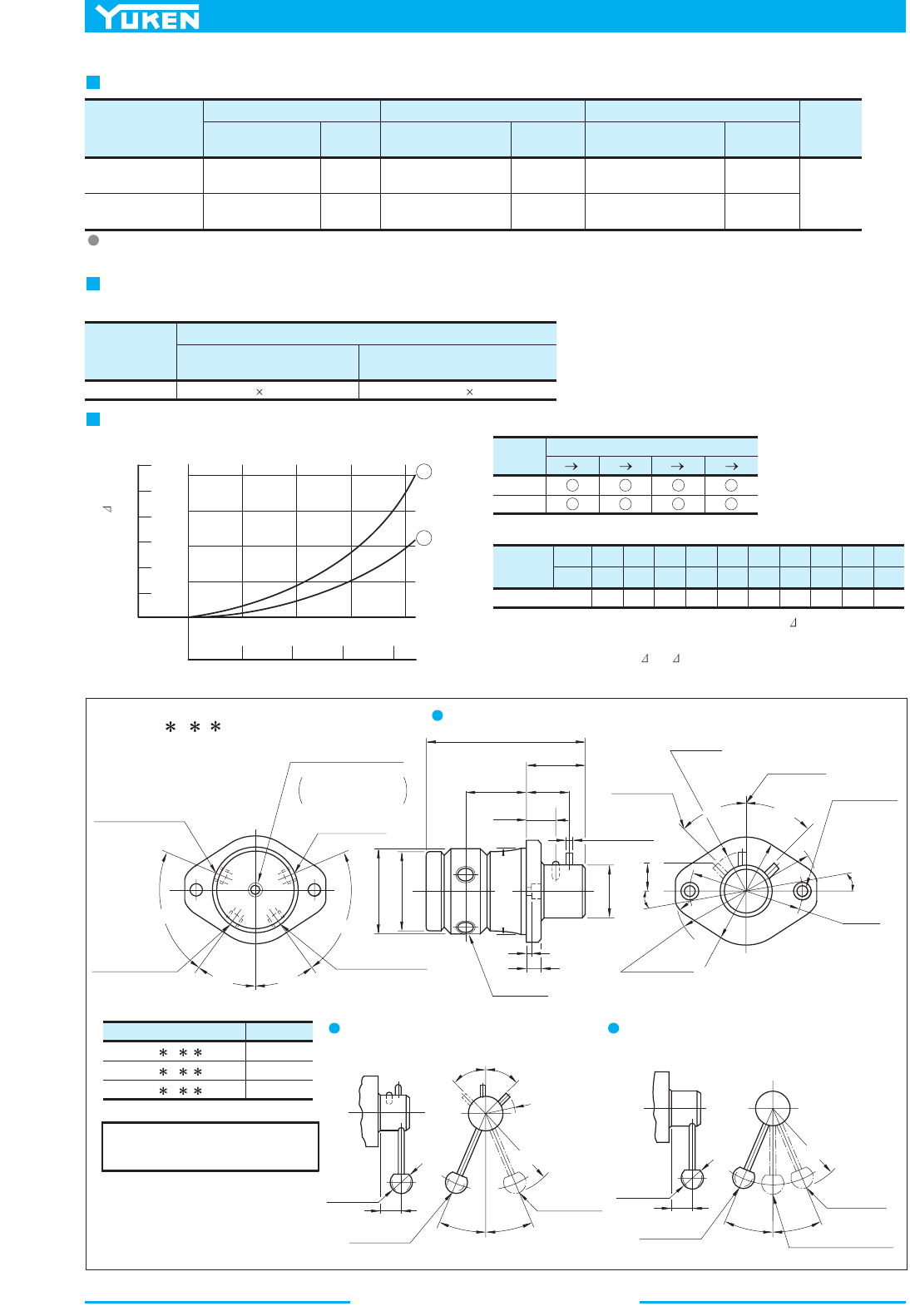
Mechanically Operated Directional Valves
442
DIMENSIONS IN
MILLIMETRES (INCHES)
Drain
Connection
Japanese Standard "JIS"
Sub-plate
Model Numbers
Thread
Size
European Design Standard
Sub-plate
Model Numbers
Thread
Size
N.American Design Standard
Sub-plate
Model Numbers
Thread
Size
Approx.
Mass
kg (1bs.)
For Internal
Drain
For External
Drain
DRGM-02-20
DRGM-02X-20
DRGM-02-R-20
DRGM-02X-R-20
Rc 1/4
Rc 3/8
Rc 1/4
Rc 3/8
DRGM-02-2080
DRGM-02X-2080
DRGM-02-R-2080
DRGM-02X-R-2080
1/4 BSP.F
3/8 BSP.F
1/4 BSP.F
3/8 BSP.F
DRGM-02-2090
DRGM-02X-2090
DRGM-02-R-2090
DRGM-02X-R-2090
1/4 NPT
3/8 NPT
1/4 NPT
3/8 NPT
1.9 (4.2)
Model
Numbers
DRG-02
Socket Head Cap Screw (5 Pcs.)
Japanese Standard "JIS"
European Design Standard
M8 45 Lg.
5/16-18 UNC 1-3/4 Lg.
N. American Design Standard
Valve
Type
P A
Pressure Drop Curve No.
2D2
3D4
2
2
BT PB A T
2
2
2
1
2
2
Viscosity
SSU
Factor 0.81 0.87 0.96 1.03 1.09 1.14 1.19 1.23 1.27 1.30
77 98 141 186 232 278 324 371 417 464
2
mm /s 15 20 30 40 50 60 70 80 90 100
4
0
1
128160
01 324
0.1
0.2
0.3
0.4
60
40
20
0
PSI MPa
L
/min
2
Flow Rate
U.S.GPM
Pressure Drop P
Sub-plates
Sub-plates are available. Specify the sub-plate model number from the table above.
When sub-plates are not used, the mounting surface should have a good machined finish.
Mounting Bolts
The Sub-plate Mounting Type Valves (DRG-02) only are furnished with the following mounting bolts.
Pressure Drop
1. For any other viscosity, multiply by the factors in the table below.
2. For any other specific gravity (G'), the pressure drop ( P') may be obtained
from the formula below.
P' = P (G'/0.850)
DRT-02- D - -20/2080/2090
Type "A" : Reversing Dog Operation
Viscosity
2
35 mm /s (164 SSU)
,
Specific Gravity
0.850
Hydraulic Fluid:
5.2(.20)
16(.63)
"C"
Thd.
4 Places
80(3.15) Dia.
76(2.99) Dia.
80(3.15) Dia.
8(.31) Dia.
30
(1.18)
56
(2.20)
43
(1.69)
58.5
(2.30)
151.5
(5.96)
50(1.97)
Dia.
76.5˚
36˚
36˚
76.5˚
Pressure Port
"P"
Cylinder Port "A"
Cylinder Port "B"
Drain Port "Y"
"C"
Thd.
Tank Port
"T"
External drain type
only has drain port.
4
5
˚
4
5
˚
1
0
˚
10˚
26
(1.02)
134(5.28)
R
1
2
(
R
.
4
7
)
R38
(R1.50)
Position #1
11 (.43) Dia.
Through
17.5 (.69)
C' bore
2 Places
110
(4.33)
1
0
0
(
3
.
9
4
)
Position #3
Model Numbers
"C"
Thd.
DRT-02- D - -20
DRT-02- D - -2080
DRT-02- D - -2090
Rc 1/4
1/4 BSP.F
1/4 NPT
2
2
.
5
˚
2
2
.
5
˚
R
3
8
(R
1
.
5
0
)
R105(R4.13)
4
5
˚
4
5
˚
2
2
.
5
˚
2
2
.
5
˚
30
(1.18)
Position #3
32(1.26)
Dia.
Position #1
30
(1.18)
32(1.26)
Dia.
Neutral Position #2
Position #3
R105(R4.13)
Position #1
Type "B" : Reverseing Dog and
Manual Operation
Type "C" : Manual Operation
For other dimensions, refer to "Reversing Dog Operation".
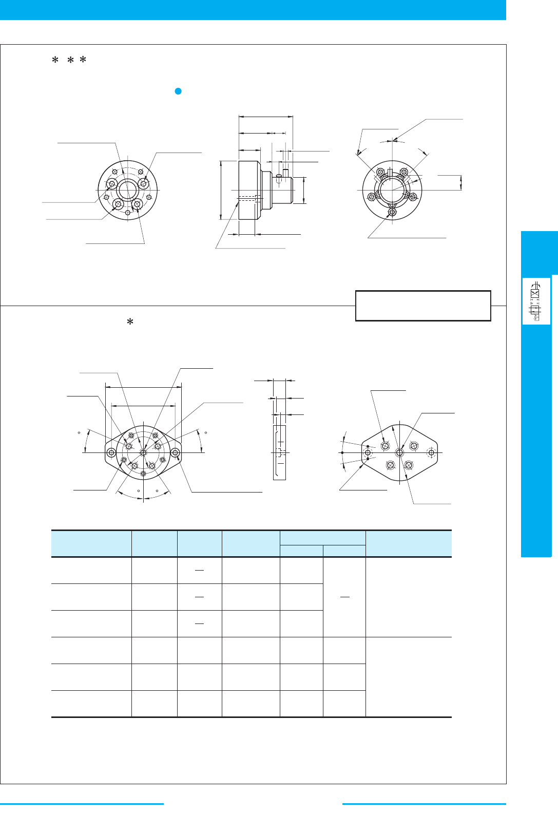
443
DIRECTIONAL CONTROLS
Mechanically Operated Directional Valves
E
Mechanically Operated Directional Valves
DIMENSIONS IN
MILLIMETRES (INCHES)
M8
M8
5/16-18 UNC
M8
M8
5/16-18 UNC
11 (.43)
11.7 (.46)
11 (.43)
11 (.43)
11.7 (.46)
11 (.43)
11 (.43)
11.7 (.46)
11 (.43)
For Internal Drain
For External Drain
Sub-plate
Model Numbers
"C"
Thd.
"D"
Thd.
"E"
Thd.
FH
mm (Inches)
Remarks
DRGM-02-20
DRGM-02X-20
DRGM-02-2080
DRGM-02X-2080
DRGM-02-2090
DRGM-02X-2090
DRGM-02-R-20
DRGM-02X-R-20
DRGM-02-R-2080
DRGM-02X-R-2080
DRGM-02-R-2090
DRGM-02X-R-2090
Rc 1/4
Rc 3/8
1/4 BSP.F
3/8 BSP.F
1/4 NPT
3/8 NPT
Rc 1/4
Rc 3/8
1/4 BSP.F
3/8 BSP.F
1/4 NPT
3/8 NPT
Rc 1/4
1/4 BSP.F
1/4 NPT
82.6(3.25) Dia.
Tank Port
"T"
Pressure Port "P"
Cylinder Port "B"
Cylinder Port "A"
106(4.17)
Dia.
42
(1.65)
63
(2.48)
12(.47)
8(.31) Dia.
103.5
(4.07)
25
(.98)
50(1.97) Dia.
33.4(1.31)
Mounting Surface
(O-Rings Furnished)
4
5
˚
4
5
˚
R
3
8
Position #1
Position #3
(
R
1
.
5
0
)
26
(1.02)
8.8(.35) Dia. Through
14(.55) C' bore
5 Places
62.7(2.47)
"F"
Dia.
4 Places
"H"
Dia.
82.6(3.25)
11(.43) Dia. Through
17.5(.69) C' bore
2 Places
"E"
Thd.
16(.63) Deep
5 Places
BT
AP
"C"
Thd.
4 Places
"D"
Thd.
106(4.17)
R12(R.47)
25
(.98)
22
(.87)
11.2
(.44)
10˚ 10˚
151
(5.94)
127
(5.00)
22.5
22.5
36 36
DRG-02- D - -20/2090
Type "A" : Reversing Dog Operation
For information on Type "B": reversing Dog and Manual Operation and Type "C": Manual Operation, see DRT-02 on the previous page.
02
02X
Sub-plates : DRGM- - -20/2080/2090
Mechanically Operated Directional Valves
444
■ List of Seals
Item Name of Parts Part Numbers Qty. Remarks
14
15
O-Ring
O-Ring
SO-NB-G35
SO-NA-P16
2
1
Included in Seal Kit
(Kit No.: KS-DRT-02-20)
Item Name of Parts Part Numbers Qty. Remarks
15
16
O-Ring
O-Ring
SO-NB-G35
SO-NA-P16
2
1
Included in Seal Kit
(Kit No.: KS-DRG-02-20)
17 O-Ring SO-NB-P16
4
1
617
6 9
4
1
1
1
0
8
7
1
2
5
1
5
3
1
4
1
1
3
2
1
8
5 912 411 7
6
1
3
2
1
6
1
5
3
1
4
1
1
7
1
9
1
5
8
DRT-02- D - -20/2080/2090
DRG-02- D - -20/2090
445
DIRECTIONAL CONTROLS
Mechanically Operated Directional Valves
E
Mechanically Operated Directional Valves
F:
Special
seals for
phos-
phate
ester
type
fluids
(Omit if
not
required)
Special
Seals
F-
01
Type of
Connection
Valve
Size
Design
Standards
None:
Japanese
Model Number Designation
Series
Number
T:
Threaded
Connection
Model Numbers
Threaded Connection Sub-plate Mounting
DCT-01-2B -40
Max. Flow
L /min (U.S.GPM)
30 (7.9)
Max. Operating
Pressure
MPa (PSI)
21 (3050)
Max. T-Line
Pressure
MPa (PSI)
7 (1020)
DCG TypeDCT Type
1.1 (2.4) 1.1 (2.4)
Approx. Mass kg (lbs.)
No. of
Valve
Position
Spool-Spring
Arrangement
Spool
Type
G:
Sub-plate
Mounting
40
100 (26.4) 25 (3630) 10 (1450) 4.5 (9.9) 3.8 (8.4)DCT-03-2B -50
DCG-01-2B -40
DCG-03-2B -50
DC T -01 -2 B 2 -R -40
Roller
Position
Design
Number
03
01
03
2
2
3
8
50
40
50
DC:
Cam
Oper-
ated
Direc-
tional
Valve
B:
Spring Offset
Standard "JIS"
80:
European
Design Standard
90:
N. American
Design Standard
None:
Japanese
Standard "JIS" &
European Design
Standard
90:
N. American
Design Standard
Valve
Model
Numbers
Sub-plates
Sub-plate
Model Numbers
Japanese Standard "JIS"
Thread
Size
Sub-plate
Model Numbers
European Design Standard
Thread
Size
Sub-plate
Model Numbers
N. American Design Standard
Thread
Size
Approx.
Mass
kg (1bs.)
DSGM-01-31
DSGM-01X-31
DSGM-01Y-31
DSGM-03-41
DSGM-03X-41
DSGM-03Y-41
Rc 1/8
Rc 1/4
Rc 3/8
Rc 3/8
Rc 1/2
Rc 3/4
DSGM-01-3180
DSGM-01X-3180
DSGM-03-2180
DSGM-03X-2180
DSGM-03Y-2180
1/8 BSP.F
1/4 BSP.F
3/8 BSP.F
1/2 BSP.F
3/4 BSP.F
DSGM-01-3190
DSGM-01X-3190
DSGM-01Y-3190
DSGM-03-2190
DSGM-03X-2190
DSGM-03Y-2190
1/8 NPT
1/4 NPT
3/8 NPT
3/8 NPT
1/2 NPT
3/4 NPT
0.8 (1.8)
0.8 (1.8)
0.8 (1.8)
3.0 (6.6)
3.0 (6.6)
4.7 (10.4)
DCG-01
DCG-03
Mounting
Surface
None
Normal
Position
Y
DC -01
only
R
■ Cam Operated Directional Valves
Specifications
These valves may be used to shift the direction of oil flow by depressing the spool by way of a cam.
Max. flow indicates the ceiling flow which does not affect the normal function (changeover) of valves.
Sub-plates are available. Specify the sub-plate model number from the table above.
When sub-plates are not used, the mounting surface should have a good machined finish.
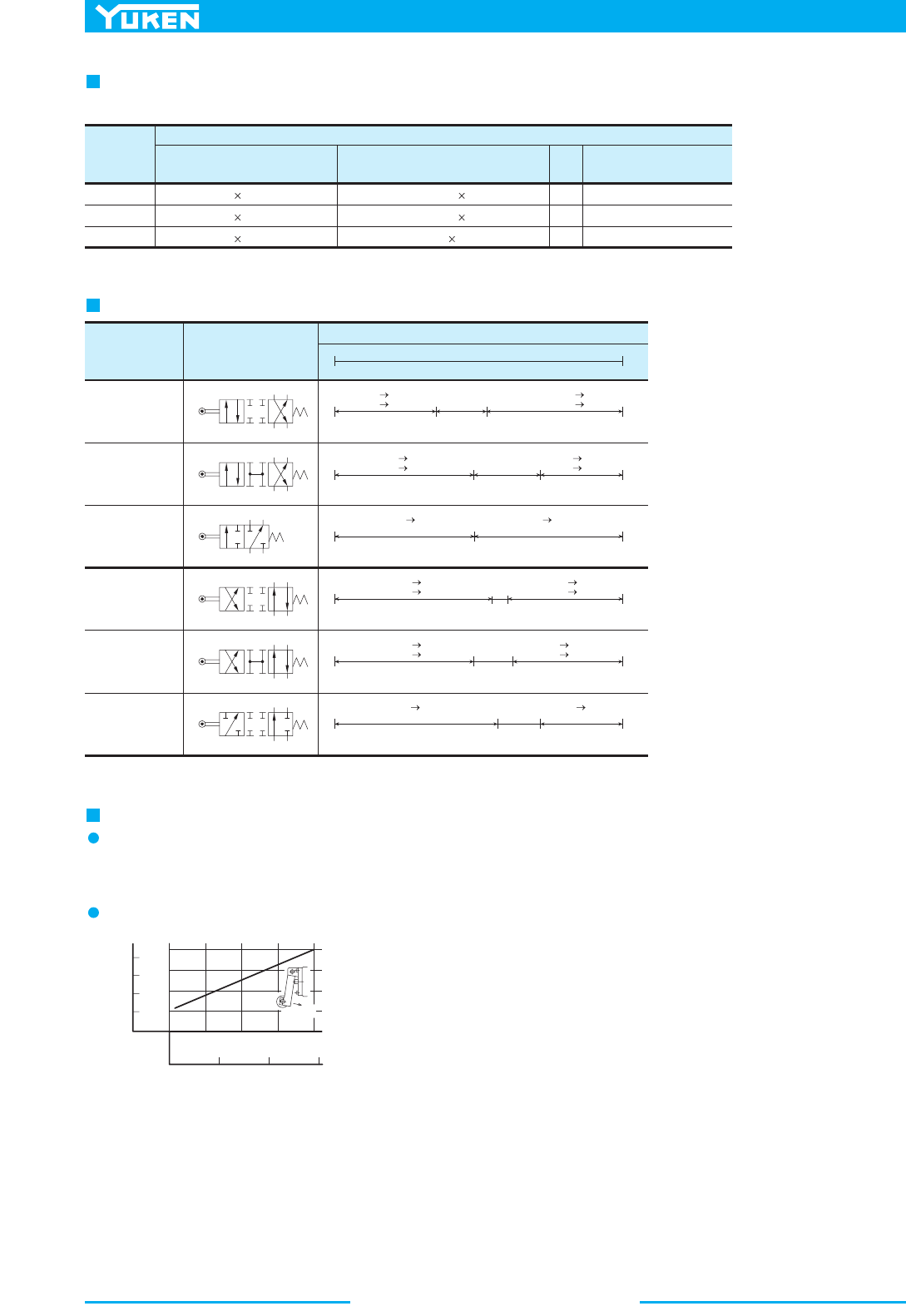
Mechanically Operated Directional Valves
446
Model
Numbers
DCT-01
Socket Head Cap Screw
Japanese Standard "JIS"
European Design Standard
M5 45 Lg. No. 10-24 UNC 1-3/4 Lg.
N. American Design Standard
DCG-01
DCG-03
Qty.
Tightening Torque
Nm (in. 1bs)
M5 45 Lg.
M6 35 Lg.
No. 10-24 UNC 1-3/4 Lg.
1/4-20 UNC 1-1/2 Lg.
2
4
4
5-7 (43-60)
5-7 (43-60)
12-15 (105-130)
Model
Numbers
Graphic Symbols
DCT
DCG
-01-2B2
DCT
DCG
-01-2B3
DCT
DCG
-01-2B8
DCT
DCG
-03-2B2
DCT
DCG
-03-2B3
DCT
DCG
-03-2B8
Roller Position and Direction of Oil Flow
Force
200
150
100
50
0
40
20
0
02.55.07.5
10
500 1000 15000
MPa
PSI
N1bf
Actuation Force
T-Line Back Pressure
AB
P
T
AB
P
T
AB
P
T
AB
P
T
AB
P
T
AB
P
T
PB
AT
8.30
(.150)
4.6
(.181)
9.5
(.374)
PA
BT
All ports blocked
PB
AT
8.30
(.150)
4.6
(.181)
9.5
(.374)
PA
BT
All ports open
PB
A&T ports blocked
8.30
(.150)
PA
B&T ports blocked
9.5
(.374)
PA
BT
8.30
(.150)
3.4
(.134)
7
(.276)
P
B
AT
All ports blocked
PA
BT
0.30
(.118)
4.0
(.157)
7
(.276)
PB
AT
All ports open
6.30
(.142)
4.7
(.185)
7
(.276)
All ports
blocked
PA
B&T ports blocked
PB
A&T ports blocked
Roller Stroke from Offset Position mm(Inches)
Extended(Offset)
Depressed
Mounting Bolts
Socket head cap screws in the table below are included.
Valve Type "2B8"
Direction of Oil Flow for Roller Position
Instructions
Tank port "T" functions as a drain port. Directly connect it to the reservoir.
[Max. allowable back pressure 0.35 MPa (50 PSI)].
Actuation Force
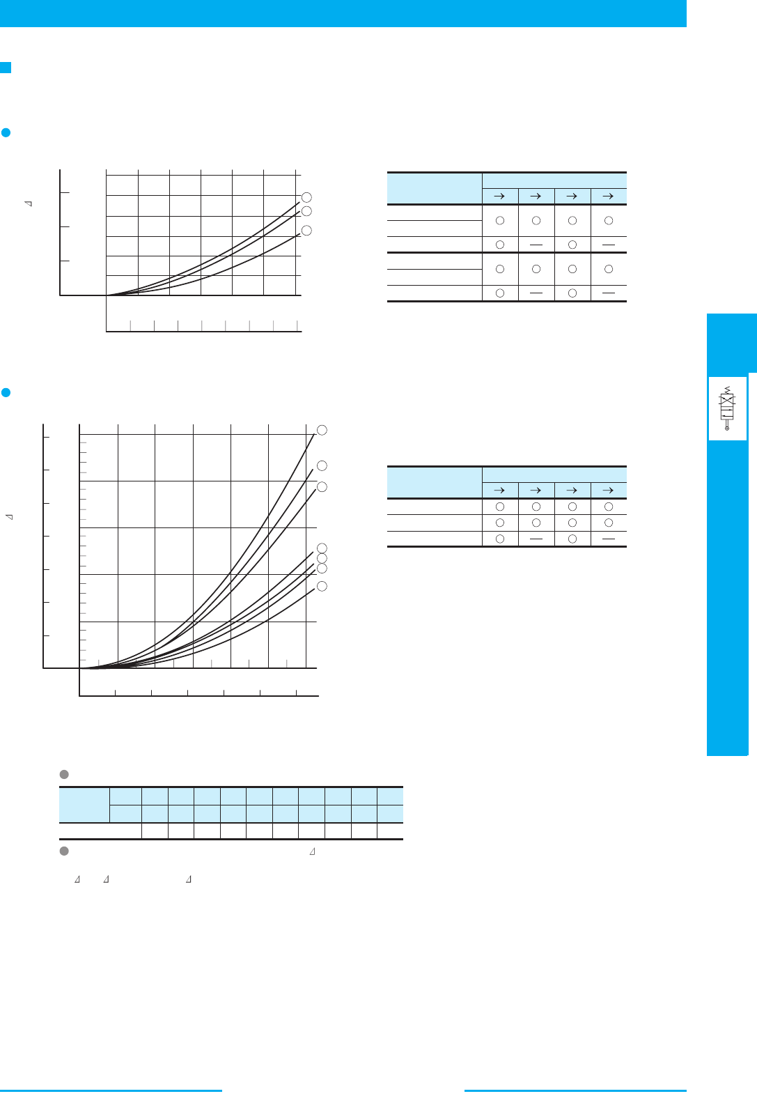
447
DIRECTIONAL CONTROLS
Mechanically Operated Directional Valves
E
Mechanically Operated Directional Valves
Model Numbers
DCT-01-2B2
DCT-01-2B3
DCT-01-2B8
DCG-01-2B2
DCG-01-2B3
DCG-01-2B8
PA
Pressure Drop Curve No.
1 1 2 1
2 2
2 2 3
3 3
3
Model Numbers
DCG-03-2B2
DCG-03-2B3
DCG-03-2B8
Pressure Drop Curve No.
6 5
3
2
2
1
7
4
7
4
Viscosity
SSU
Factor 0.81 0.87 0.96 1.03 1.09 1.14 1.19 1.23 1.27 1.30
77 98 141 186 232 278 324 371 417 464
2
mm /s 15 20 30 40 50 60 70 80
90 100
For any other viscosity, multiply the factors in the table below.
For any other specific gravity (G'), the pressure drop ( P') may be obtained
from the formula below.
P' = P (G'/G) where, P is a value on the above chart and G is
0.850.
B TP BAT
P
AB TP BAT
1
2
3
010 20 30
02468
0
0.4
0.8
1.2
0
50
100
150
MPa
PSI
L /min
U.S.GPM
Pressure Drop P
Flow Rate
1
3
5
6
4
7
2
2.5
2.0
1.5
1.0
0.5
0
300
250
200
150
100
50
0
MPa
PSI
350
0 20 40 60 80 100 120
0 5 10 15 20 25 30
L /min
U.S.GPM
Flow Rate
Pressure Drop P
Pressure Drop
2
Pressure drop curves based on viscosity of 35 mm /s (164 SSU) and specific gravity of 0.850.
DCT
DCG
-01
DCT
DCG
-03
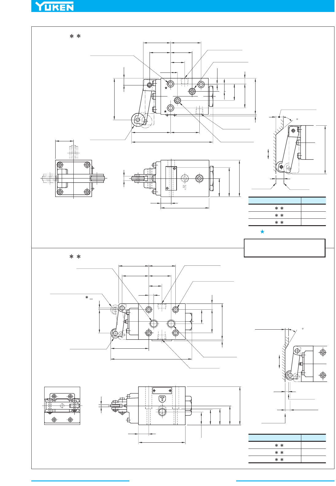
Mechanically Operated Directional Valves
448
DIMENSIONS IN
MILLIMETRES (INCHES)
.
Model Numbers
"C"
Thd.
DCT-01-2B --40
DCT-01-2B - -4080
DCT-01-2B - -4090
Rc 1/8
1/8 BSP.F
1/8 NPT
Model Numbers
"C"
Thd.
DCT-03-2B --50
DCT-03-2B - -5080
DCT-03-2B - -5090
Rc 3/8
3/8 BSP.F
3/8 NPT
Cam and Roller Travel
Cam and Roller Travel
B
A
35.5
(1.40)
9
(.35)
19
(.75)
29
(1.14)
28.5
(1.12)
40.5
(1.59)
24
(.94)
4
(.16)
13.5
(.53)
65
(2.56)
25
(.98)
38
(1.50)
49
(1.93)
9.5
(.37)
Max.
66 (2.60)
M
a
x
.
5
0
53
(2.09)
38.5
(1.52)
Fully Extended
110 (4.33)
8.5
(.33)
55.8
(2.20)
0.75
(.03)
10.25
(.40)
22.25
(.88)
32.5
(1.28)
48
(1.89)
7.75
(.31)
2
(.08)
Cam
Stroke
Extended
(Offset)
Depressed
Tank Port "
T"
"
C
" Thd.
Cylinder Port "
B"
"
C
" Thd.
17 (.67) Dia.Roller
5.5 (.22) Dia. Through
9.5 (.37) C' bore
3 places
Position "
R
"
Normal Position
Position "Y"
Height of Cam
9.5(.37)
Fully Extended
73.3 (2.89)
Fully Extended
158.6 (6.24)
27
(1.06)
46
(1.81)
12
(.47)
70
(2.76)
2
(.08)
19
(.75)
92
(3.62)
21.8
(.86)
26.8
(1.06)
27
(1.06)
35.3
(1.39)
85.3
(3.36)
6
(.24)
10
(.39)
27
(1.06)
44
(1.73)
50
(1.97)
56.8
(2.24)
54
(2.13)
2
(.08)
46.2
(1.82)
Height of Cam
7 (.28)
Cam
M
a
x
.
5
0
8.2 (.32)
Max. Stroke
7
(.28)
Extended
(Offset)
Depressed
Pressure Port "
P"
"
C
" Thd.
Cylinder Port "
A"
"
C
" Thd.
Tank Port "
T"
"
C
" Thd.
Cylinder Port "
B"
"
C
" Thd.
18 (.71) Dia.Roller
7 (.28) Dia. Through
11 (.43) C' bore
4 places
Pressure Port "
P"
"
C
" Thd.
Cylinder Port "
A"
"
C
" Thd.
Chain line indicates the
Model DCT-03-2B -R.
DCT-01-2B - -40/4080/4090
DCT-03-2B - -50/5080/5090
Note: When mounting the valve, be sure to use two mounting holes marked with
T
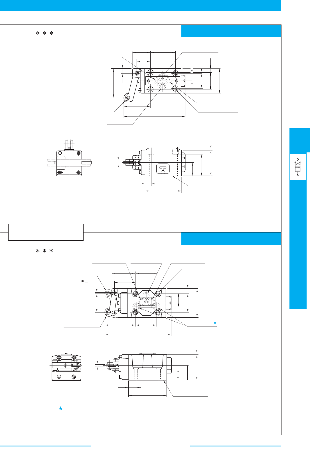
449
DIRECTIONAL CONTROLS
Mechanically Operated Directional Valves
E
Mechanically Operated Directional Valves
Mounting Surface: ISO 4401-AB-03-4-A
Mounting Surface: ISO 4401-AC-05-4-A
DIMENSIONS IN
MILLIMETRES (INCHES)
.
28.5
(1.12)
35.5
(1.40)
40.5
(1.59)
15.5
(.61)
31
(1.22)
0.75
(.03)
32.5
(1.28)
48
(1.89)
7.75
(.31)
53
(2.09)
Fully Extended
110 (4.33)
8.5
(.33)
55.8
(2.20)
Pressure Port "P"
Cylinder Port "
A"
5.5 (.22) Dia. Through
9.5 (.37) C' bore
4 places
Tank Port "
T"
17(.67) Dia. Roller
Cylinder Port "
B"
Position "
R
"
Normal Position
Position "Y"
13.5
(.53)
65
(2.56)
25
(.98)
38
(1.50)
49
(1.93)
Mounting Surface
(O-Rings Furnished)
4
(.16)
50
(1.97)
56.8
(2.24)
54
(2.13)
46.2
(1.82)
2
(.08)
50.8
(2.00)
73.3
(2.89)
Fully Extended
158.6 (6.24)
32.5
(1.28)
46
(1.81)
12
(.47)
70
(2.76)
Cylinder Port "B"
7 (.28) Dia. Through
11 (.43) Dia. Spotface
4 places
Pressure Port "
P"
Cylinder Port "
A"
Chain line indicates the
Model DCG-03-2B -R
18 (.71) Dia. Roller
Tank Port "T"
6
(.24)
19
(.75)
92
(3.62)
Mounting Surface
(O-Rings Furnished)
27
(1.06)
35.3
(1.39)
59
(2.32)
2
(.08)
3
(.12)
DCG-01-2B - - 40/4090
Note1: For the cam and roller travel, see DCT-01 in the previous page.
DCG-03-2B - - 50/5090
Although the tank port is shown on the left in our sub-plate, either may be used.
Note1: For the cam and roller travel, see DCT-03 in the previous page.
Note2: For the valve mounting surface dimensions, see the dimensional drawing of
the sharable sub-plate in page 373.
Note2: For the valve mounting surface dimensions, see the dimensional drawing of
the sharable sub-plate in page 356.
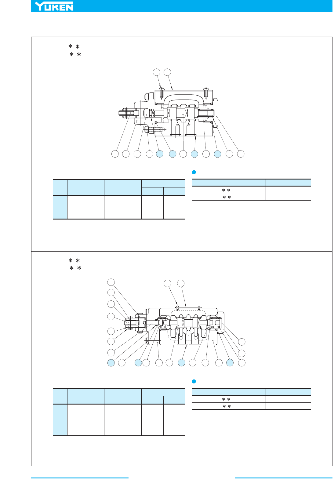
Mechanically Operated Directional Valves
450
■ List of Seals
Item Name of Parts Part Numbers
13
DCT-01
Quantity
14
15
DCG-01
O-Ring
O-Ring
O-Ring
SO-NA-P5
SO-NB-P18
SO-NB-P9
1
2
0
1
2
4
Item Name of Parts Part Numbers
11
DCT-03
Quantity
12
14
DCG-03
O-Ring
O-Ring
O-Ring
SO-NB-P21
SO-NA-P6
SO-NB-A014
2
1
0
2
1
5
13 Back Up Ring SO-BE-P6 1 1
Valve Mdel Numbers Seal Kit Numbers
DCT-03-2
B - -50/5080/5090
DCG-03-2
B - -50/5090
KS-DCT-03-50
KS-DCG-03-50
12
8
4
916
2
1
3
1
4
1
5
3 1
1
4
7 6
2
019
1
6
1
7
2
1
1
5
2
3
2
2
9
1
3
1
8121411
1
08 3
2 6 7
1
4
5
DCT-01-2B - -40/4080/4090
DCG-01-2B - -40/4090
Note: When ordering the o-rings, please specify the seal kit number
from the table right.
DCT-03-2B - -50/5080/5090
DCG-03-2B - -50/5090
Note: When ordering the seals, please specify the seal kit number
from the table right.
List of Seal Kit No.
Valve Mdel Numbers Seal Kit Numbers
DCT-01-2
B - -40/4080/4090
DCG-01-2
B - -40/4090
KS-DCT-01-40
KS-DCG-01-40
List of Seal Kit No.
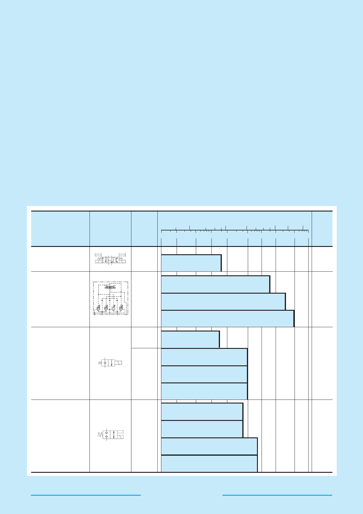
DIRECTIONAL CONTROLS
451
Poppet Type Directional Valves
Poppet Type Directional Valves
1 2 5 10 20 50 100 200 500 1000
453
459
480
489
DSLG 01
DSLHG 10
DSLHG 06
DSLHG 04
CDSG 03
CDST 03
CDSC 03
CDSC 01
DSPG 03
DSPC 03
DSPG 01
DSPC 01
25
(3630)
14
(2030)
21
(3050)
25
(3630)
a
A
B
P
T
TAPB Y
b
a
b
Y
X
2
1
.5 1 5 10 50 100 200
U. S. GPM
Maximum Flo
w
L/min
Page
Max.
Operating
Pressure
MPa (PSI)
Graphic Symbols
Valve Type
Poppet Type Solenoid
Operated Directional
Va lve s
Multi Purpose
Control Valves
Solenoid Operated
Poppet Type
Two-Way Valves
Shut-off Type Solenoid
Operated Directional
Va lve s
Poppet Type Directional Valves
452
Mounting Surface
Mounting surfacedimensions conform to ISO standard discribed in below table.
Multi Purpose
Control Cavles
Name Model Number ISO Code of Mounting Surface
DSPG-01
DSPG-03
DSPC-01
DSPC-03
DSLHG-04
DSLHG-06
DSLHG-10
ISO 4401-AB-03-4-A
ISO 4401-AC-05-4-A
ISO 7789 20-01-0-93
ISO 7789 27-01-0-93
ISO 4401-AD-07-4-A
ISO 4401-AE-08-4-A
ISO 4401-AF-10-4-A
Shut-off Type Solenoid
Operated Directional
Valves
Interchangeability in Installation between Current and New Design
Model change has been made on the following products.
The difference between current and new design has been described on the paragraph of “Interchangeability in Installation
between Current and New Design”. Refer to relevant pages on each series.
Name
Model Numbers
Solenoid Operated Poppet Type
Two-Way Valves
Shut-offf Type Solenoid
Operated Directional Valves
Multi Purpose
Control Valves
CDS -03 -C- -20
DSLHG-04- - -12
DSLHG-06- - -12
DSLHG-10- - -12
DSLHG-04- - -13
DSLHG-06- - -13
DSLHG-10- - -13
DSP -01-C- -10
CDS -03 -C- -21
DSP -01-C- -20
Yes
Pilot valve (DSG-01)
changed to design.
The change of
solenoid ratings.
The change of
solenoid.
Yes
Yes
—
488
—
Current
New
Page
Main changes
Mtg. Inter-
changeability
Solenoid
■ Solenoid connector (DIN connector)
The solenoid connector is in accordance with the
international standard ISO 4400 (Fluidpower System
and components-Three-Pin electrical plug connectors-
Characteristics and requirements.).
■ AC Solenoid
50-60 Hz common service solenoids do not require re-
wiring when the applied frequency is changed.
■ DC Solenoid ( -series Solenoid)
-series DC Solenoid which has a reputation for
excellent DC control is employed.
1. The spark between the relay contacts has been
eliminated and therefore the valve can be operated
by miniature relays.
2. The surge voltage is approximately 10 % of that
normally experienced.
3. Time lag on de-exercitation is reduced by
approximately 50 %.
■
R Type Models with Current Rectifier and DC Solenoid
Specially designed DC solenoids and receptacle (or
connector) containing AC-DC rectifier and transient
peak suppressor are provided. Connection to be made
to AC power source as with conventional AC solenoid.
Remarkably high reliability and long life and other
advantages including quiet valve operation. No over-
heating of coil due to the spool sticking and protection
against transient voltage peaks are assured.
Model Numbers Insulation Class
DSLG-01
DSLHG-04/06/10
CDSC-01
CDS -03
DSP -01/03
Class H
■ Insulation Class of Solenoid
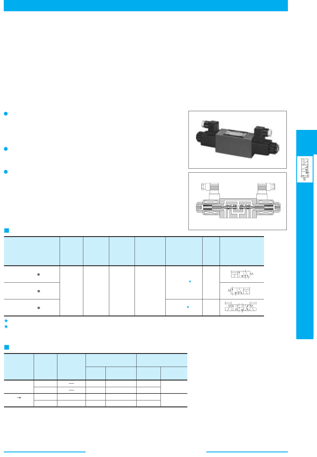
453
DIRECTIONAL CONTROLS
Poppet Type Solenoid Operated Directional Valves
E
Poppet Type Solenoid Operated Directional Valves
1
2
1.
2.
Model Numbers
DSLG-01-3-C- -N-11
DSLG-01-3-O- -N-11
DSLG-01-4-O- -N-11
Max.
Flow
L /min
(U.S.GPM)
Max.
Operating
Pressure
MPa
(PSI)
Max. T-
Line Back
Pressure
MPa
(PSI)
Max.
Changeover
Frequency
16
(4.2)
31.5
(4570)
16
(2320)
240
Graphic
Symbols
Approx.
Mass
kg
(lbs.)
1.9
(4.2)
3.7
(8.2)
Internal leakage
3
cm /min
(cu. in./min)
Or Less
0.5
(.03)
Or Less
1
(.06)
Electric
Source
Coil
Type
Frequency
(Hz)
Source
Rating
Serviceable
Range
Holding
(A)
Power
(W)
Voltage (V)
Current & Power
at Rated Voltage
DC
(K Series)
AC DC
Rectified
D12
D24
R100
R200
50/60
50/60
12
24
100
200
10.8 - 13.2
21.6 - 26.4
90 - 110
180 - 220
2.45
1.23
0.33
0.16
29
29
-1
min
{Cycles/Min}
A
PT
a
A
P
T
b
A
B
P
T
b
a
Specifications
High Response High Reliability
Because these valves are of poppet type, there is no overlap, high
response can be achieved. At the same time, hydraulic lock is elimi-
nated.
No Leak
Sheet type seal has been adopted and internal leak is greatly reduced.
ISO Comformant Mounting Surface
Because the mounting surface conforms to ISO 4401-AB-03-4-A, there
is an interchangeability with the conventional valves. This makes it
possible to use these valves in combination with 01 Series Modular
Valves.
This is the leakage towards "T" port in A port block at "P" port pressure 14 MPa (2030 PSI).
This is the leakage towards "T" port in A•B port block at "P" port pressure 14 MPa (2030 PSI).
Solenoid Ratings
These are Solenoid Operated Directional Valves of No Leak Type developed with the aim of responding the demand of
the age including energy saving. Because these valves are of no leak type they allow the low viscosity hydraulic fluids to
be used as well as the circuit construction which cannot be used by the conventional spool type directional valves because
of too much internal leak of pressure oil. The use of the low viscosity hydraulic fluids reduces the pressure loss which can
arise from the passage resistance of the hydraulic fluids, leading to the system energy saving.
■ Poppet Type Solenoid Operated Directional Valves
Poppet Type Directional Valves
■
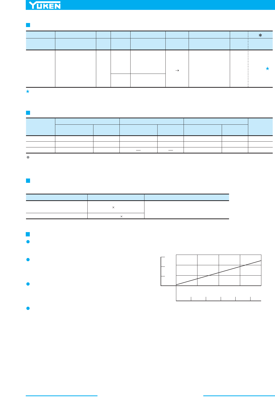
Poppet Type Solenoid Operated Directional Valves
454
Model Number Designation
Special Seals
for Phosphate
Ester Type
Fluids
(Omit if not
required)
F:
DSLG
Poppet Type
Solenoid Operated
Directional Valve
(Sub-plate Mtg.)
F- DSLG -01
Va lve
Size
01
Special Seals Series Number
:
-11
Design
Number
Design
Standards
Refer to
11
-N
Type of Electrical
Conduit Connection
N :
Plug-in Connector
-4
Number
of Port
3:
3 Port
4:
4 Port
-O
Function
-D24
Coil Type
O:
Normally Open
C:
Normally Closed
O:
Normally Open
DC
D12, D24
AC DC
R100
R200
Piping
Size
Japanese Standard "JIS"
Sub-plate
Model No.
Thread
Size
DSGM-01-31
DSGM-01X-31
DSGM-01Y-31
Rc 1/8
Rc 1/4
Rc 3/8
European Design Std.
Sub-plate
Model No.
Thread
Size
Sub-plate
Model No.
N. American Design Std.
Thread
Size
0.8 (1.8)
0.8 (1.8)
0.8 (1.8)
Approx.
Mass
kg (lbs.)
1/8
1/4
3/8
DSGM-01-3180
DSGM-01X-3180
1/8 BSP.F
1/4 BSP.F
DSGM-01-3190
DSGM-01X-3190
DSGM-01Y-3190
1/8 NPT
1/4 NPT
3/8 NPT
M5 45 Lg.
No. 10-24 UNC 1-3/4 Lg.
Descriptions Socket Head Cap Screw (4 pcs.) Tightening Torque
Japanese Standard "JIS"
European Design Standard
N. American Design Standard
5-7 Nm (44-62 in. lbs.)
[Applicable to working pressure more than
25 MPa (3630 PSI) : 6-7 Nm (53-62 in. lbs.)]
Design Standards: None
90
Japanese Standard "JIS" and European Design Standard
N. American Design Standard
...........
...............
Sub-plate
Sub-plates are available. Specify the sub-plate model number from the table above. When sub-plates are not used, the mounting surface should
have a good machined finish.
Mounting Bolts
Four socket head cap screws in the table below are included.
0 1.0 2.0 3.0 4.0
Operating Force by Manual Actuator
0 100 200 300 400 500
Tank Line Back Pressure
Operating force
0
50
100
150
N
0
10
20
30
lbs.
Instructions
Mounting
No mounting restrictions for any models.
Solenoid Shifting
On double solenoid valves do not energise both at the
same time.
Valve Tank Port
Avoid connecting the valve tank port to a line with
possible surge pressure.
Operating Force by Manual Actuator
Take care as the operating force by the manual actuator
increases in proportion to the tank line back pressure.
(See the graph right.)
MPa
PSI
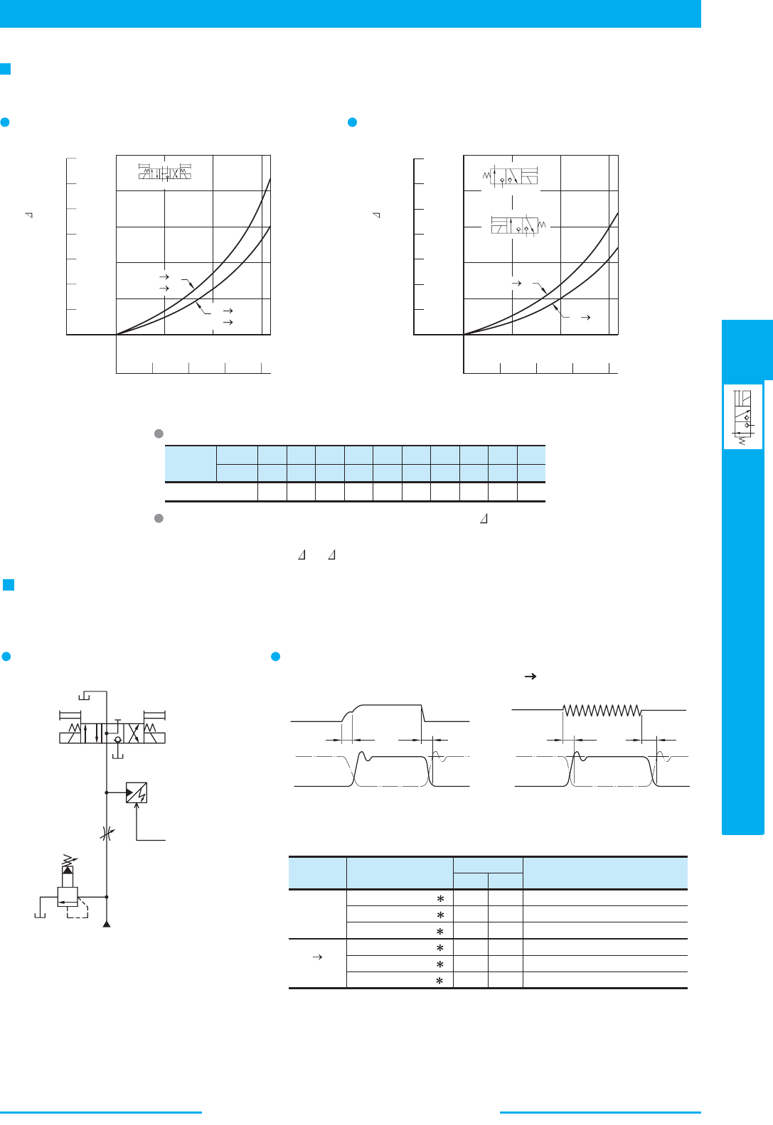
455
DIRECTIONAL CONTROLS
Poppet Type Solenoid Operated Directional Valves
E
Poppet Type Solenoid Operated Directional Valves
Viscosity
2
mm /s
SSU
Factor
15
77
0.81
20
98
0.87
30
141
0.96
40
186
1.03
50
232
1.09
60
278
1.14
70
324
1.19
80
371
1.23
90
417
1.27
100
464
1.30
Solenoid
Type
skrameRsrebmuN ledoM
Time (ms)
DC
AC DC
Rectified
T
1
T
2
DSLG-01-4-O-D
DSLG-01-3-O-D
DSLG-01-3-C-D
DSLG-01-4-O-R
DSLG-01-3-O-R
DSLG-01-3-C-R
55
55
70
55
55
70
30
30
25
150
150
150
4 port valve, normally open
3 port valve, normally open
3 port valve, normally closed
4 port valve, normally open
3 port valve, normally open
3 port valve, normally closed
b
a
AB
P
T
b
a
A
PT
a
A
P
T
b
MPa
2.5
PSI
350
2.0
1.5
1.0
0.5
0
Pressure Drop P
300
200
100
0
P A
P B
A T
B T
0 5 10 15 16
01234
Flow rate
P A
A T
MPa
2.5
PSI
350
2.0
1.5
1.0
0.5
0
Pressure Drop P
300
200
100
0
0 5 10 1516
01234
Flow rate
Presssure Detector
T
1
T
2
Current
Waveform
Pressure Waveform
ON
OFF
Current
Wavefo rm
Pressure Waveform
ON
OFF
T
1
T
2
Pressure Drop
2
Hydraulic Fluid: Viscosity 35 mm /s (164 SSU), Specific Gravity 0.850
Changeover Time
Changeover time varies according to hydraulic circuit of the model actually used and conditions. An example of
measurement is given in the figure below.
Test Circuit and Conditions
evlaV troP 3evlaV troP 4
For any other viscosity, multiply the factors in the table below.
For any other specific gravity (G'), the pressure drop ( P') may be
obtained from the formula below.
P'= P (G'/0.850)
Result of Measurement
(DC Solenoid)
(AC DC Rectified)
Pressure: 21 MPa (3050 PSI)
Flow Rate: 16 L/min (4.2 U.S.GPM)
Voltage: Rated voltage
Note: Alternate long and short dash lines in the pressure waveform figures indicate the
waveforms for Normally Closed Type 3 Port Valves.
L /min
MPG.S.U
L /min
MPG.S.
U
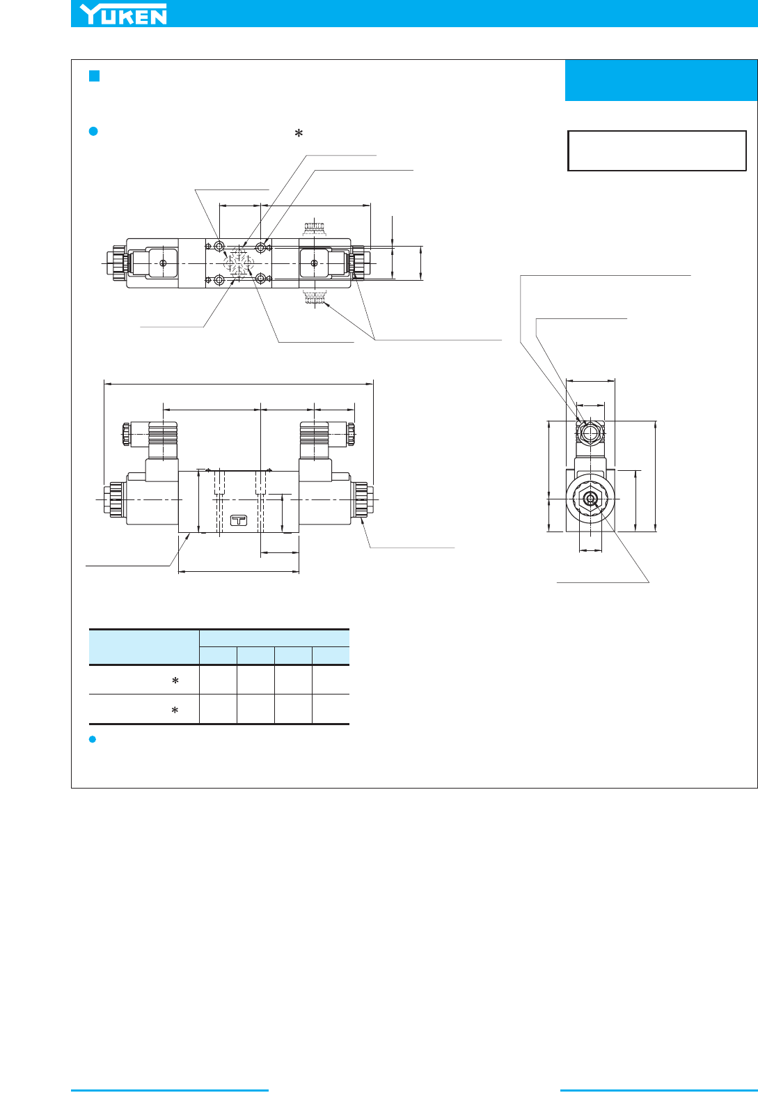
Poppet Type Solenoid Operated Directional Valves
456
Mounting Surface:
ISO 4401-AB-03-4-A
DIMENSIONS IN
MILLIMETRES (INCHES)
Dimensions mm (Inches)
CDEF
108
(4.25)
111
(4.37)
57.2
(2.25)
51
(2.01)
34
(1.34)
64
(2.52)
39
(1.54)
27.5
(1.08)
Model Numbers
DSLG-01-4-O-D -N
DSLG-01-4-O-R -N
SOL b
SOL a
5.5(.22)
Dia. Through
9.5(.37)
C' bore
4 Places
Tank Port "
T
"
Cylinder Port "
A
"
Four positions of cable
departure are available in 90˚
increments.
31
(1.22)
0.75
(.03)
32.5
(1.28)
263
(10.35)
Mounting Surface
(O-Rings Furnished)
Manual Actuator
6 (.24)
Dia.
The connector can be moved to various
positions by loosening the "Lock Nut".
After location tighten "Lock Nut".
62.3
(2.45)
53.5
(2.11)
E
96.5
(3.80)
38
(1.50)
37.5
(1.48)
118
(4.65)
Lock Nut
Tightening Torque:
10.3 - 11.3 Nm
(90 - 100 IN. lbs.)
48
(1.89)
F
D
C
32
(1.26)
60
(2.36)
22
(.87)
Cable Departure
Cable Applicable:
Outside Dia. 8-10 mm (.31 - .39 in.)
2
Conductor Area Not Exceeding 1.5 mm
(.0023 Sq. in.)
......
...
4 Port Valve
Normally Open: DSLG-01-4-O- -N-11/1190
The information on 3 Port Valves is provided in the following page.
110
(4.33)
40.5
(1.59)
Cylinder Port "
B
"
Pressure Port "
P
"
Note: For the valve mounting surface dimensions, see the dimensional drawing of the sharable sub-plate in page 356.
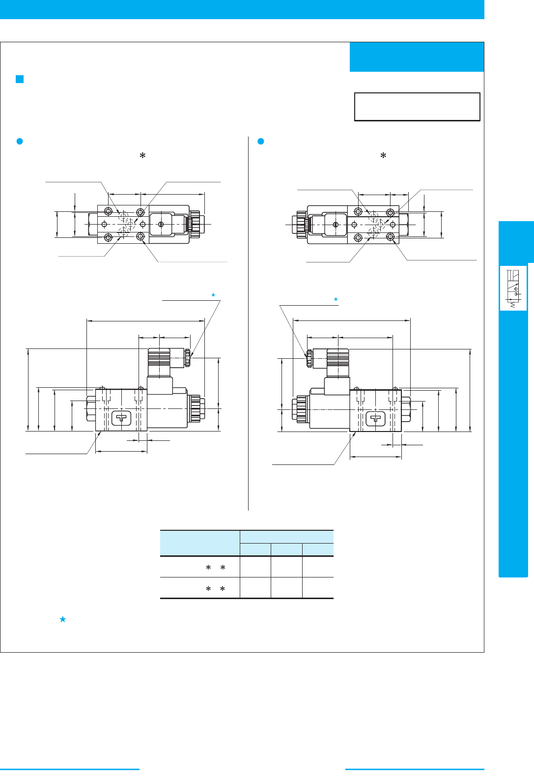
457
DIRECTIONAL CONTROLS
Poppet Type Solenoid Operated Directional Valves
E
Poppet Type Solenoid Operated Directional Valves
Mounting Surface:
ISO 4401-AB-03-4-A
DIMENSIONS IN
MILLIMETRES (INCHES)
Dimensions mm (Inches)
C
104
(4.09)
107
(4.21)
Model Numbers
DSLG-01-3- -D -N
DSLG-01-3- -R -N
D
64
(2.52)
57.2
(2.25)
E
39
(1.54)
51
(2.01)
SOL b
SOL a
5.5(.22) Dia. Through
9.5(.37) C' bore
4 Places
Pressure Port "
P"
Tank Port "
T"
Cylinder Port "
A"
32.5
(1.28)
0.75
(.03)
(1.22)
40.5
(1.59)
31
86
(3.39)
151.5
(5.96)
Mounting Surface
(O-Rings Furnished)
Cable Departure
29.5
(1.16)
E
28
(1.10)
13.5
(.53)
70
(2.76)
D
C
55.1
(2.17)
52
(2.05)
38
(1.50)
0.75
(.03)
(1.22)
31
32.5
(1.28)
Pressure Port "P"
Cylinder Port "
A"
5.5(.22) Dia. Through
9.5(.37) C' bore
4 Places
Tank Port "
T"
40.5
(1.59)
22.5
(.89)
Cable Departure
D
C
28
(1.10)
Mounting Surface
(O-Rings Furnished)
13.5
(.53)
70
(2.76)
38
(1.50)
52
(2.05)
55.1
(2.17)
151.5
(5.96)
E
72.5
(2.85)
3 Port Valves
:epyT nepO yllamroN
DSLG-01-3-O- -N-11/1190
:epyT desolC yllamroN
DSLG-01-3-C- -N-11/1190
Cable departure position can be changed. See "4 Port Valves" in the previous page for the details.
Note: For the valve mounting surface dimensions, see the dimensional drawing of the sharable sub-plate in page 356.
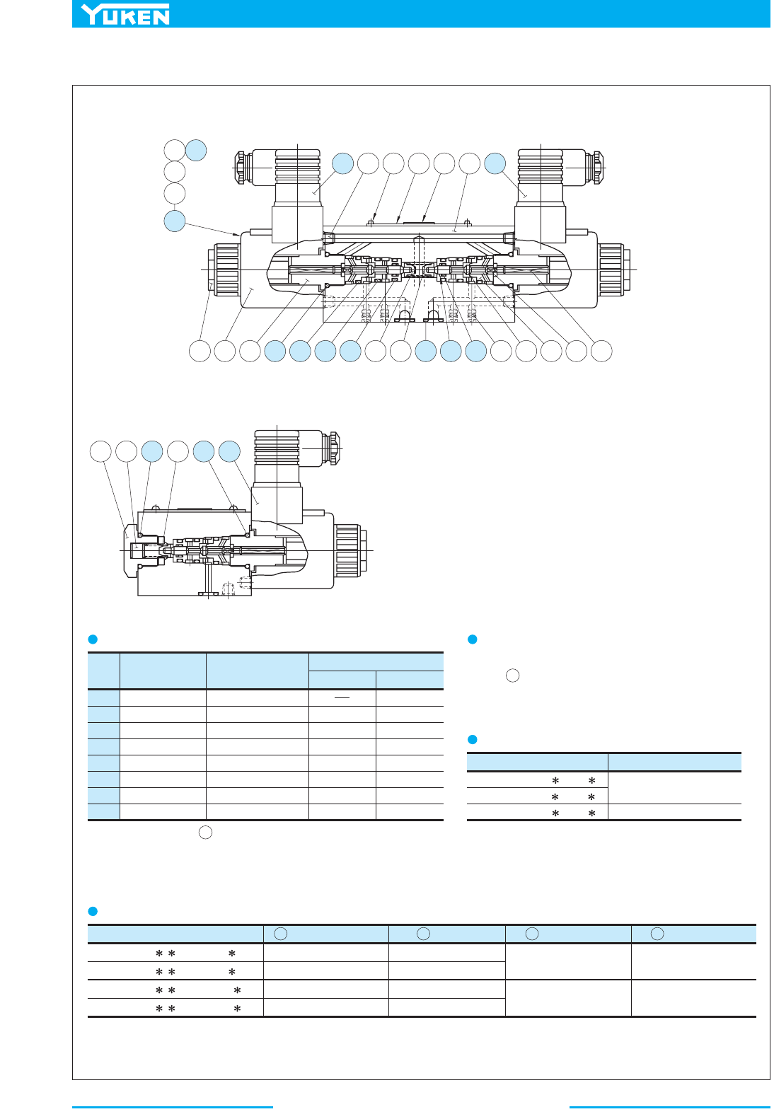
Poppet Type Solenoid Operated Directional Valves
458
■ List of Seals, Solenoid Ass'y and Connectors
Item Name of Parts
O-Ring
O-Ring
O-Ring
O-Ring
O-Ring
O-Ring
Back Up Ring
O-Ring
10
11
12
13
14
15
16
25
Valve Model Number s Seal Kit Numbers
DSLG-01-3-O-
-N-11
DSLG-01-3-C- -N-11
DSLG-01-4-O- -N-11
KS-DSLG-01-3-N-11
SO-NB-P18
SO-NB-P14
SO-NB-P12
SO-NB-P11
SO-NB-P9
SO-NA-P5
2705-VK414322-8
SO-NB-P18
4 Port Valve
1
1
1
1
3
1
1
1
Quantity
Part Numbers
2
2
2
4
2
2
2
3 Port Valve
25
21
KS-DSLG-01-4-N-11
27 18 42 40 41 1 28
2524
23
21
20
24 21 23 25 11 12 13 4 5 14 16 15 19 2 3 6 7
4 Port Valve
3 Port Valve
8 9 10 5 25 28
List of Seals
List of Seal Kits
Note O-Ring of item are included in solenoid assembly.
When ordering the seals, specify the seal kit number from the table
right.
1:
2:
Change of supply voltage
The supply voltage can be changed by replacing the
coil only.
Valve Model No . Solenoid Ass'y No.
DSLG-01-
- -D12-N-11
DSLG-01- - -D24-N-11
DSLG-01-
- -R100-N-11
DSLG-01- - -R200-N-11
SD1L-12-N-20
SD1L-24-N-20
SD1L-100-N-20
SD1L-200-N-20
20
C-SD1-12-N-60
C-SD1-24-N-60
C-SR1-100-N-60
C-SR1-200-N-60
Connector No.
27
Connector No.
28
Coil No.
21
GDM-211-A-11
GDME-211-R-A-10
GDM-211-B-11
GDME-211-R-B-10
List of Solenoid Ass'y and Connectors
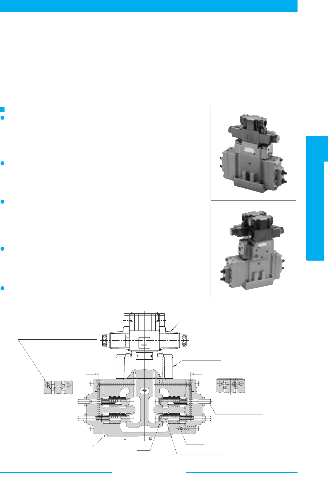
459
DIRECTIONAL CONTROLS
Multi Purpose Control Valves
E
Multi Purpose Control Valves
Section X-X
Section Y-Y
X
X
Y
Y
T
B
P
A
T
Solenoid Operated Directional Valve for Pilot
Pilot Selector Valve
Orifice
By selecting proper diameter of orifice
for pilot, the open/close timing of the
flow passage can be set freely.
Flow Adjustment Screw
Spring
Shockless Type Poppet
Seat
Main Valve
Multi-purpose control valves
The valves combine three functions of directional control, flow control
and of pilot operated check valve (or counterbalance valve). The valves
contribute for reducing a number of valves in applications and space for
installation and then eventually leads to reduction in size and cost of your
machines.
Quick response, High reliability
Changeover response time is very quick as the valves are poppet type,
there is no over-lap.
No hydraulic lock occurs as there is no leakage of pressurised oil from
the seat parts.
Easy to reduce shock in your hydraulic system
By selecting proper diameter of orifice for pilot, the open/close timing
of the flow passage can be set freely. Therefore, smooth starting and
stopping of actuator can be done combined with using shockless type
poppet. Noise of ON/OFF and vibration of piping in hydraulic system
can be also reduced.
Features
For regenerative circuit
4 position-4 way type, which is to compose regenerative circuit, is
available. By adopting regenerative circuit, gaining fast feed speed by
using smaller volume pump is possible. Therefore saving electric power
of system is possible.
The mounting dimensions are conformed with ISO standard
The valves are interchangeable with our conventional valves in
mounting.
YUKEN's Multi Purpose Control Valve s are compound valves composed of the main valve having four poppets, 1/8
Solenoid Operated Directional Valves for pilot and Pilot Selector Valves. This valve is multifunctionalized by having
individual poppet had functions such as directional control, flow control or pressure control according to the combination
of the main valve and pilot selector valve.
The Yuken Multi-Purpose Control Valves Comply with The Needs of Reducing Cost and
Size of Your Machine
■ Multi Purpose Control Valves
Multi Purpose Control Valves
460
Specifications
Model Numbers
Max. Flow
L/min
(U.S.GPM)
Max.
Operating
Pressure
MPa (PSI)
Max. Pilot
Pressure
MPa (PSI)
Max. T-Line
Back Pres.
MPa (PSI)
Pressure Adj.
Range of
Counterbalance
MPa (PSI)
Ratio of Poppet Area
(Seat Area: Annular Area)
Direction &
Flow Control
Pressure
Control
Approx.
Mass
kg (lbs.)
DSLHG-04-1-
-13
DSLHG-04-2- -13
DSLHG-04-3- -13
DSLHG-04-4 - - -13
DSLHG-04-5 - - -13
DSLHG-06-1- -13
DSLHG-06-2- -13
DSLHG-06-3- -13
DSLHG-06-4 - -13
DSLHG-06-5 - -13
DSLHG-10-1- -13
DSLHG-10-2- -13
DSLHG-10-3- -13
DSLHG-10-4 - -13
DSLHG-10-5 - -13
150 (39.6)
150 {100}
(39.6 {26.4})
300 (79.3)
300 {200}
(79.3 {52.8})
500 (132)
500 {300}
(132 {79.3})
25 (3630) 25 (3630) 16 (2320)
25 (3630) 25 (3630) 16 (2320)
25 (3630) 25 (3630)
16 (2320)
Refer to Model
No. Designation
Refer to Model
No. Designation
Refer to Model
No. Designation
1:1
1:1 24:1
1:1
1:1 24:1
1:1
1:1 24:1
15
15
19
20
22.5
26.5
26.5
28
31
34.5
59
59
62
63.5
67
(33)
(33)
(42)
(44)
(50)
(59)
(59)
(62)
(68)
(76)
(130)
(130)
(137)
(140)
(148)
In case of counterbalance function line, maximum flow is limited to the values in brackets.
Solenoid Ratings
Refer to Pilot Valve (DSG-01 Series Solenoid Operated Directional Valve) Solenoid Ratings on page 345.
- 7 ( - 1020)
- 25 ( - 3630)
- 25 ( - 3630)
1
1
1 1
11
1.
For phosphate
ester type fluids
(Omit if not
required)
F:
DSLH:
Multi-Purpose
Control Valve
DSLH
Special
Seals
Series
Number
A
W
:
:
AT Line
AT & BT Lines
F-
04
06
10
G
Type of
Mounting
G:
Sub-plate
Mounting
-04
Va lve
Size
1
2
3
4
5
1
2
3
4
5
1
2
3
4
5
-4
Type of
Pilot
Control
A
Counterbalance
Function
-B
Pressure Adj. Range
of Counterbalance
MPa (PSI)
See page 462 for functions
and purpose of use.
A
W
:
:
AT Line
AT & BT Lines
B
H
:
:
6 - 25 (870 - 3630)
None:
A
W
:
:
AT Line
AT & BT Lines
None:
See "Min. Ad
j
ustment Pressure", page 464, for information on minimum ad
j
ustment pressure.
Model Number Designation
461
DIRECTIONAL CONTROLS
Multi Purpose Control Valves
E
Multi Purpose Control Valves
Japanese Standard "JIS" European Design Standard N. American Design Standard
M12 60 Lg.
1/2-13 UNC 2-1/2 Lg.
Socket Head Cap Screw
Valve
Model
Numbers
Sub-plate
Model
Numbers
Thread
Size
Approx.
Mass
kg (lbs.)
Sub-plate
Model
Numbers
Thread
Size
Approx.
Mass
kg (lbs.)
Sub-plate
Model
Numbers
Thread
Size
Approx.
Mass
kg (lbs.)
DSLHG-04
DSLHG-06
DSLHG-10
DHGM-04-20
DHGM-04X-20
DHGM-06-50
DHGM-06X-50
DHGM-10-40
DHGM-10X-40
Rc 1/2
Rc 3/4
4.4
4.1
(9.7)
(9.0)
Rc 3/4
Rc 1
7.4
7.4
(16.3)
(16.3)
Rc 1-1/4
Rc 1-1/2
21.5
21.5
(47.4)
(47.4)
DHGM-04-2080
DHGM-04X-2080
DHGM-06-5080
DHGM-06X-5080
DHGM-10-4080
DHGM-10X-4080
1/2 BSP.F
3/4 BSP.F
4.4
4.1
(9.7)
(9.0)
8.5
8.5
(18.7)
(18.7)
21.5
21.5
(47.4)
(47.4)
3/4 BSP.F
1 BSP.F
1-1/4 BSP.F
1-1/2 BSP.F
DHGM-04-2090
DHGM-04X-2090
DHGM-06-5090
DHGM-06X-5090
DHGM-10-4090
DHGM-10X-4090
1/2 NPT
3/4 NPT
4.4
4.1
(9.7)
(9.0)
7.4
7.4
(16.3)
(16.3)
21.5
21.5
(47.4)
(47.4)
3/4 NPT
1 NPT
1-1/4 NPT
1-1/2 NPT
Japanese Standard "JIS" and
European Design Standard
Model
Numbers
N. American
Design Standar d Qty.
Tightening Torque
Nm (In. lbs.)
M20 75 Lg.
M6 40 Lg.
M10 45 Lg.
1/4-20 UNC 1-1/2 Lg.
3/8-16 UNC 1-3/4 Lg.
3/4-10 UNC 3 Lg.
DSLHG-04
DSLHG-06
DSLHG-10
2
4
6
6
12-15 (106-133)
58-72 (513-637)
100-123 (885-1089)
473-585 (4186-5177)
Sub-plates are available. Specify the sub-plate model number from the table above.
These sub-plates are sharable with those for DSHG Series Solenoid Controlled Pilot Operated Directional Valve. For dimensions,
see
pages 401 to 403.
When sub-plates are not used, the mounting surface should have a good machined finish.
Mounting Bolts
Socket head cap screws in the table below are included.
Sub-plate
The coil type numbers in the shaded column are handled as optional extras.
In case these coils are required to be chosen, please confirm the time of
delivery with us before ordering.
2
2.
None:
Internal Pilot
T
Pilot
Connection
Connection
Drain
-E
13
-A100
Coil
Type
N:
Plug-in
Connector
Type
-C
Manual
Override
-N
Electrical
Conduit
Connection
-13
Design
Number
Design Standards
E:
External Pilot
None:
External
Drain
T:
Internal
Drain
None:
Japanese Std. "JIS"
13
13
A100
A120
A200
A240
AC:
D12
D24
D48
DC:
R100
R200
R:
(AC DC)
None:
Manual
Override
Pin
C:
Push
Button &
Lock Nut
(Options)
None:
Terminal
Box Type
A
W
90:
N.American Design Std.
None:
Japanese Std. "JIS" &
European Design Std.
90:
N.American Design Std.
A
W
In case of lines with counterbalance function (-4 , -5 ), External Drain must be selected for Drain Connection.
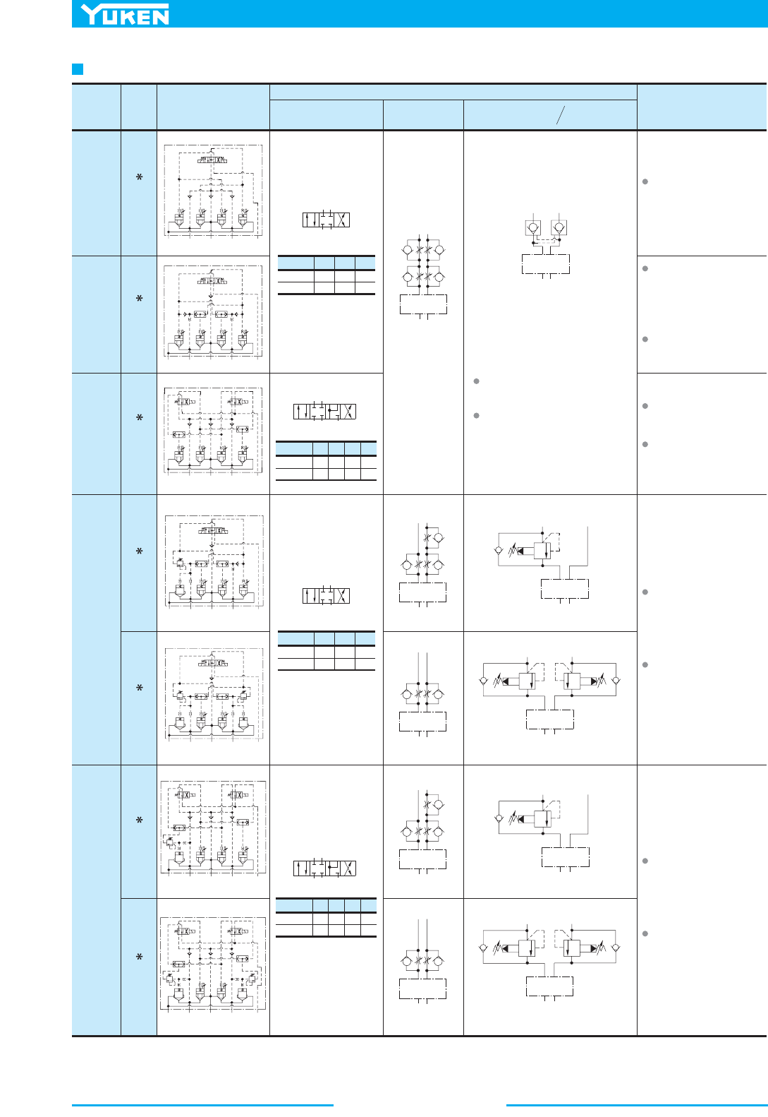
Multi Purpose Control Valves
462
Model
No.
Type "1"
Type of
Pilot
Control
DSLHG- -1
Type "2"
DSLHG- -2
Type "3"
DSLHG- -3
Type "4"
DSLHG- -4A
DSLHG- -4W
Type "5"
DSLHG- -5ADSLHG- -5W
Graphic Symbols
Function
Directional Control Flow Control
Pilot Operated
Check Valve
Pressure
Control
Purpose of Use
Functions as Three Position
Four-Way Valve (Spring
Centred Model).
Functions as Three Position
Four-Way Valve (Spring
Centred Model) as well as
Two Position Valve which
uses positions #1 and #3.
Effective especially when
the actuator has inertia
force.
Functions as Four Position
Four-Way Valve.
Regenerative circuit can be
constructed at the Position
#3.
Pressure control function
(counterbalance valve) has
been added to Type "2" to
make this type.
Used to control the back
pressure of the actuator.
Pressure control function
(counterbalance valve) has
been added to Type "3" to
make this type.
Used to control the back
pressure of the actuator.
To get a function of pilot operated
check valve, the following conditions
should be fulfilled.
Internal pilot type
("
P" port pressure)
("
A""B" ports pressure)
External pilot type
(Pilot pressure)
("
A""B" ports pressure)
>
=
>
=
A
B
PT
Directional
Control
A B
PT
Directional
Control
A
B
PT
Directional
Control
A
B
PT
Directional
Control
A
B
PT
Directional
Control
A
B
Both Metre-in
and Metre-out
are possible
P
T
Directional
Control
Directional
Control
Directional
Control
Directional
Control
Directional
Control
A
B
P
T
A
B
P
T
A
B
P
T
A
B
P
T
AB
PT
#1
SOL a
SOL b
ON
ONOFF
OFF OFF
OFF
#2 #3
AB
PT
#1
#1
SOL a
SOL b
ON
OFF
#2
OFF
OFF
#3
ON
ON
#4
OFF
ON
Position
#2 #3 #4
AB
PT
#1
#1
SOL a
SOL b
ON
OFF
#2
OFF
OFF
#3
ON
ON
#4
OFF
ON
Position
#2 #3 #4
Position #1 #2 #3
AB
PT
#1
SOL a
SOL b
ON
ONOFF
OFF OFF
OFF
#2 #3
Position #1 #2 #3
ba
PATB
Y
b
a
PATB
Y
ba
PATB
Y
ba
PATB
Y
ba
PATB
Y
ba
PATB
Y
b
a
PATB
Y
Function and Purpose of Use
463
DIRECTIONAL CONTROLS
Multi Purpose Control Valves
E
Multi Purpose Control Valves
aPM0
Min. Controlled Flow for Types "2" and "4A" at The Time of Metre-out Control
0 1000 2000 3000
Differential Pressure
PSI
Min. Flow Rate
0
5
L/min
4 8 12 16 20 24
3500
0
1
2
3
4
10
15
U.S.GPM
DSLHG-10-2
DSLHG-06-2
06
10
DSLHG-04-2, DSLHG- -4A
DSLHG-04-4A
Instructions
Pilot Pressure
Pilot pressure of external pilot drain models must always exceed the pressure of the main pressure port "P ".
Pilot Drain Port
Avoid connecting the pilot drain port to a line with possible surge pressure.
Drain Connection when with Counterbalance Function
When a valve having counterbalance function is used with internal drain type, the counterbalance pilot valve is subjected
to pressure fluctuation and the pressure setting becomes unstable. For this reason, be sure to use external drain type
valve.
Flow Adjustment
To perform the flow adjustment, loosen the lock nut, then turn the flow adjustment screw clockwise to decrease the
flow. Be sure to re-tighten the lock nut after the adjustment.
Pressure Adjustment
To perform the pressure adjustment, loosen the lock nut, then turn the pressure adjustment screw clockwise to increase
the pressure. Be sure to re-tighten the lock nut after the adjustment.
Min. Controlled Flow for Types "2" and "4A" at The Time of Metre-out Control
Minimum controlled flow at the time of metre-out control is limited (this does not happen during metre-in control) as
shown in the figure below only in the case of pilot control types "2" (DSLHG- -2) and "4A" (DSLHG- -4A).

Multi Purpose Control Valves
464
Viscosity
2
mm /s
SSU
Factor
15
77
0.81
20
98
0.87
30
141
0.96
40
186
1.03
50
232
1.09
60
278
1.14
70
324
1.19
80
371
1.23
90
417
1.27
100
464
1.30
L /min
U.S.GPM
Flow Rate
MPa
PSI
0
Pressure Drop P
0
25
50
75
100
125
0
0.2
0.4
0.6
0.8
1.0
20 40 60 80 100 120 140 150
0 5 10 15 20 25 30 35 40
A T, B T
P A, P B
MPa
PSI
Pressure Drop P
0
25
50
75
100
125
0
0.2
0.4
0.6
0.8
1.0
L /min
U.S.GPM
Flow Rate
0
0 1020304050607080
50 100 150 200 250 300
P A
P B
A T
B T
MPa
PSI
Pressure Drop P
0
0.2
0.4
0.6
0.8
1.0
0
25
50
75
100
125
L /min
U.S.GPM
Flow Rate
0
0 20 40 60 80 100 120 130
100 200 300 400 500
A T
B T
P A, P B
L /min
U.S.GPM
P: Differential Pres.
01-GHLSD60-GHLSD40-GHLSD
01-GHLSD60-GHLSD40-GHLSD
150
0
140
120
100
80
60
40
20
Flow Rate
40
35
30
25
20
15
10
5
0
Adj. Screw Position
(Number of Turns)
Fully
Closed
0123456
P=MPa(PSI)
P=21(3050)
P=14(2030)
P=7(1020)
P=3(440)
P=1.0(145)
P: Differential Pres. P: Differential Pres.
Adj. Screw Position
(Number of Turns)
Fully
Closed
0123456
L /min
U.S.GPM
300
0
Flow Rate
80
70
60
50
40
30
20
10
0
50
100
150
200
250
P=MPa(PSI)
P=21(3050)
P=14(2030)
P=7(1020)
P=3(440)
P=1.0(145)
L /min
500
Flow Rate
130
U.S.GPM
400
300
200
100
0
120
100
80
60
40
20
0
Adj. Screw Position
(Number of Turns)
Fully
Closed
012345678
P=MPa(PSI)
P=7(1020)
P=3(440)
P=1.0(145)
P=21
(3050)
P=14
(2030)
4
5
DSLHG-04-
4
5
DSLHG-06-
4
5
DSLHG-10-
L /min
U.S.GPM
Flow Rate
025 50 75 100
0 5 10 15 20 25
MPa
PSI
0
Min. Adj. Pressure
0
50
100
150
200
0.5
1.0
1.5
MPa
PSI
0
Min. Adj. Pressure
0
50
100
150
200
0.5
1.0
1.5
L /min
U.S.GPM
Flow Rate
0 50 100 150 200
0 1020304050
MPa
PSI
0
Min. Adj. Pressure
0
50
100
150
200
0.5
1.0
1.5
L /min
U.S.GPM
Flow Rate
0 100 200 300
0 20406080
Pressure Drop
Hydraulic Fluid: Viscosity
2
35 m m /s (164 SSU)
, Specific Gravity
0.850
For any other viscosity, multiply the factors in the table below.
For any other specific gravity (G'), the pressure drop ( P') may be
obtained from the formula below.
P'= P (G'/0.850)
Flow vs. Adjustment Revolutions
Minimum Adjustment Pressure
Because the minimum adjustment pressure varies with the tank line back pressure, add the tank line back pressure
to the value on the following lines.
465
DIRECTIONAL CONTROLS
Multi Purpose Control Valves
E
Multi Purpose Control Valves
Mounting Surface:
ISO 4401-AD-07-4-A
Terminal Box Type
DIMENSIONS IN
MILLIMETRES (INCHES)
Model Numbers "
C
" Thd.
DSLHG-04- - -13
DSLHG-04- - -1390
G 1/2
1/2 NPT
a LOSb LOS
SOL b
SOL a
SOL b
SOL a
SOL b
SOL a
SOL b
SOL a
SOL
b
SOL
a
69.9
(2.75)
35(1.38)
69.9
(2.75)
90
(3.54)
1.6
(.06)
Pressure Port "
P
"
277(10.91)
Fully Extended
Fully Extended
101.6(4.00)
96(3.78)
34.1(1.34)
Tank Port "
T
"
50
(1.97)
27
(1.06)
11(.43)
Dia. Through
17.5(.69)
Dia. Spotface
4 Places
Cylinder Port "
A
"
7(.28)
Dia. Through
11(.43)
Dia. Spotface 2 Places
Cylinder Port "
B
"
Pilot Drain Port "
Y
"
(For External Drain Type only)
95(3.74)
DC/R : 204.4(8.05)
AC
: 196.4(7.73)
DC/R : 54.7(2.15)
AC
: 50.7(2.00)
Electrical Conduit Connection
"
C
" Thd. (Both Ends)
Manual
Actuator
6(.24)
Dia.
"AT"
"PA"
"BT"
"PB"
Lock Nut
17(.67)
Hex.
DEC.
Flow Adj. Screw
5(.20)
Hex. Soc.
Mounting Surface
(O-Rings Furnished)
41
(1.61
)
46
(1.81)
73
(2.87)
73
(2.87)
193.5 (7.62)
240.5 (9.46)
258.8 (10.19)
3(.12)
Dia.
Two Locating Pins
4
(.16)
31
(1.22)
Electrical Conduit Connection
"
C
" Thd. (Both Ends)
"AT"
"PA"
"BT"
"PB"
216.5 (8.52)
263.5 (10.37)
281.8 (11.09)
99(3.90)
3
"AT"
(.12)
"PA"
"BT"
Fully Extended
283.3(11.15)
96(3.78)
"PB"
Lock Nut
14(.55)
Hex.
DEC.
Lock Nut
17(.67)
Hex.
INC.
Flow Adj. Screw
5(.20)
Hex. Soc.
Counterbalance Pressure
Adj. Screw
5(.20)
Hex. Soc.
140 (5.51)
213.5 (8.41)
260.5 (10.26)
278.8 (10.98)
Fully Extended
277(10.91)
Fully Extended
"AT"
"PA"
"BT"
"PB"
"AT"
"PA"
"BT"
"PB"
Lock Nut
14(.55)
Hex.
DEC.
Lock Nut
17(.67)
Hex.
INC.
Counterbalance Pressure
Adj. Screw
5(.20)
Hex. Soc.
99(3.90)
53
(2.09)
3
(.12)
283.3(11.15)
Fully Extended
136(5.35)
261.5 (10.30)
308.5 (12.15)
326.8 (12.87)
"BT"
"PB"
"AT"
"PA"
277(10.91)
Fully Extended
1
2
DSLHG-04- - -13/1390
DSLHG-04-3- -13/1390
For other dimensions, see "DSLHG-04-4W"
drawing left.
DSLHG-04-4A- - -13/1390
DSLHG-04-4W- - -13/1390
DSLHG-04-5W- - -13/1390
DSLHG-04-5A- - -13/1390
For other dimensions, see "DSLHG-04- " drawing left.
1
2
For other dimensions, see "DSLHG-04- " drawing above.
1
2
For other dimensions, see "DSLHG-04- " drawing above.
1
2
For other dimensions, see "DSLHG-04-5W"
drawing left.
Flow Adj. Screw
5(.20)
Hex. Soc.
Pilot Pressure Port "
X
"
(For External Pilot Type only)
53
(2.09)
96(3.78)
Fully Extended
Multi Purpose Control Valves
466
Mounting Surface:
ISO 4401-AD-07-4-A
Plug-in Connector Type
DSLHG-04- -A -N
DSLHG-04-
-D -N
DSLHG-04- -R -N
Model Numbers
Dimensions mm (Inches)
CD E F
39 (1.54)
39 (1.54)
53 (2.09)
53 (2.09)
64 (2.52)
57.2 (2.25)
27.5 (1.08)
27.5 (1.08)
34 (1.34)
DSLHG-04-3-A -N
DSLHG-04-3-D -N
DSLHG-04-3-R -N
Model Numbers
Dimensions mm (Inches)
DE
53 (2.09)
64 (2.52)
57.2 (2.25)
SOL b
SOL a
69.9
(2.75)
1.6
(.06)
35(1.38)
71.5
(2.81)
90(3.54)
Pressure Port "
P
"
Pilot Pressure Port "
X
"
(For External Pilot Type only)
Tank Port "
T
"
277(10.91)
Fully Extended
101.6(4.00)
96(3.78)
Fully Extended
50
(1.97)
11(.43)
Dia. Through
17.5(.69)
Dia. Spotface
4 Places
Cylinder Port "
A
"
7(.28)
Dia. Through
11(.43)
Dia. Spotface 2 Places
Cylinder Port "
B
"
Pilot Drain Port "
Y
"
(For External Drain Type only)
102
(4.02)
DC/R : 204.4(8.05)
AC : 196.4(7.73)
DC/R : 54.7(2.15)
AC : 50.7(2.00)
C
"AT"
"PA"
"BT"
"PB"
Lock Nut
17(.67)
Hex.
DEC.
Flow Adj. Screw
5(.20)
Hex. Soc.
Mounting Surface
(O-Rings Furnished)
Manual Actuator
6(.24)
Dia.
E
D
F
3(.12)
Dia.
Two Locating Pins
4
(.16)
31
(1.22)
"AT"
"PA"
"BT"
"PB"
E
D
73(2.87)
193.5(7.62)
41
(1.61)
216.5
(8.52)
53
(2.09)
99(3.90)
3
(.12)
Cable Departure
Cable Applicable:
Outside Dia.
.........
8 - 10 mm (.31 - .39 in.)
Conductor Area
....
Not Exceeding 1.5mm
2
(.0023 sq. In)
The position of the Plug-in connector
can be changed as illustrated left by
loosening the lock nut. After com-
pletion of the change, be sure to tighten
the lock nut with the torque as specified
left.
1
2
DSLHG-04- - -N-13/1390
DSLHG-04-3- -N-13/1390
For other dimensions, see "DSLHG-04- - -N" drawing above.
1
2
DIMENSIONS IN
MILLIMETRES (INCHES)
258.5(10.18)
269.5(10.61)
272.5(10.73)
281.5 (11.08)
292.5 (11.52)
299.5 (11.63)
SOL b
SOL a
34.1
(1.34)
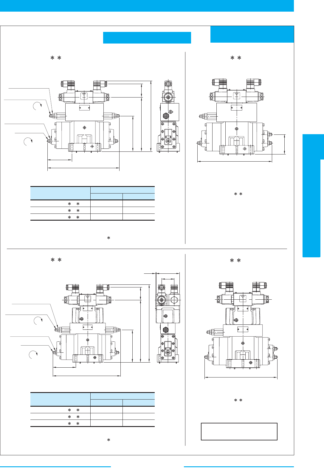
467
DIRECTIONAL CONTROLS
Multi Purpose Control Valves
E
Multi Purpose Control Valves
Mounting Surface:
ISO 4401-AD-07-4-A
Plug-in Connector Type
DSLHG-04-4W- -A -N
DSLHG-04-4W- -D -N
DSLHG-04-4W- -R -N
Model Numbers
Dimensions mm (Inches)
DE
53 (2.09)
64 (2.52)
57.2 (2.25)
278.5 (10.96)
289.5 (11.40)
292.5 (11.52)
DSLHG-04-5W- -A -N
DSLHG-04-5W- -D -N
DSLHG-04-5W- -R -N
Model Numbers
Dimensions mm (Inches)
DE
53 (2.09)
64 (2.52)
57.2 (2.25)
SOL b SOL a
SOL b
SOL a
SOL b
SOL a
SOL b
SOL a
"AT"
"PA"
"BT"
283.3(11.15)
Fully Extended
96(3.78)
"PB"
Lock Nut
14(.55)
Hex.
DEC.
Lock Nut
17(.67)
Hex.
INC.
Flow Adj. Screw
5(.20)
Hex. Soc.
Counterbalance Pressure
Adj. Screw
5(.20)
Hex. Soc.
Fully Extended
277(10.91)
Fully Extended
"AT"
"PA"
"BT"
"PB"
E
D
213.5
(8.41)
140
(5.51)
73
(2.87)
"AT"
"PA"
"BT"
283.3(11.15)
Fully Extended
96(3.78)
Lock Nut
14(.55)
Hex.
DEC.
Lock Nut
17(.67)
Hex.
INC.
Flow Adj. Screw
5(.20)
Hex. Soc.
Counterbalance Pressure
Adj. Screw
5(.20)
Hex. Soc.
Fully Extended
"PB"
E
D
261.5
(10.30)
136
(5.35)
3
(.12)
99(3.90)
53
(2.09)
277(10.91)
Fully Extended
"AT"
"PA"
"BT"
"PB"
DSLHG-04-4W- - -N-13/1390 DSLHG-04-4A- - -N-13/1390
DSLHG-04-5W- - -N-13/1390
DSLHG-04-5A- - -N-13/1390
For other dimensions, see
"DSLHG-04-4W- - -N" drawing left.
For other dimensions, see
"DSLHG-04-5W- - -N" drawing left.
For other dimensions, see DSLHG-04- - -N on the previous page.
1
2
For other dimensions, see DSLHG-04- - -N on the previous page.
1
2
DIMENSIONS IN
MILLIMETRES (INCHES)
326.5 (12.85)
337.5 (13.28)
340.5 (13.41)
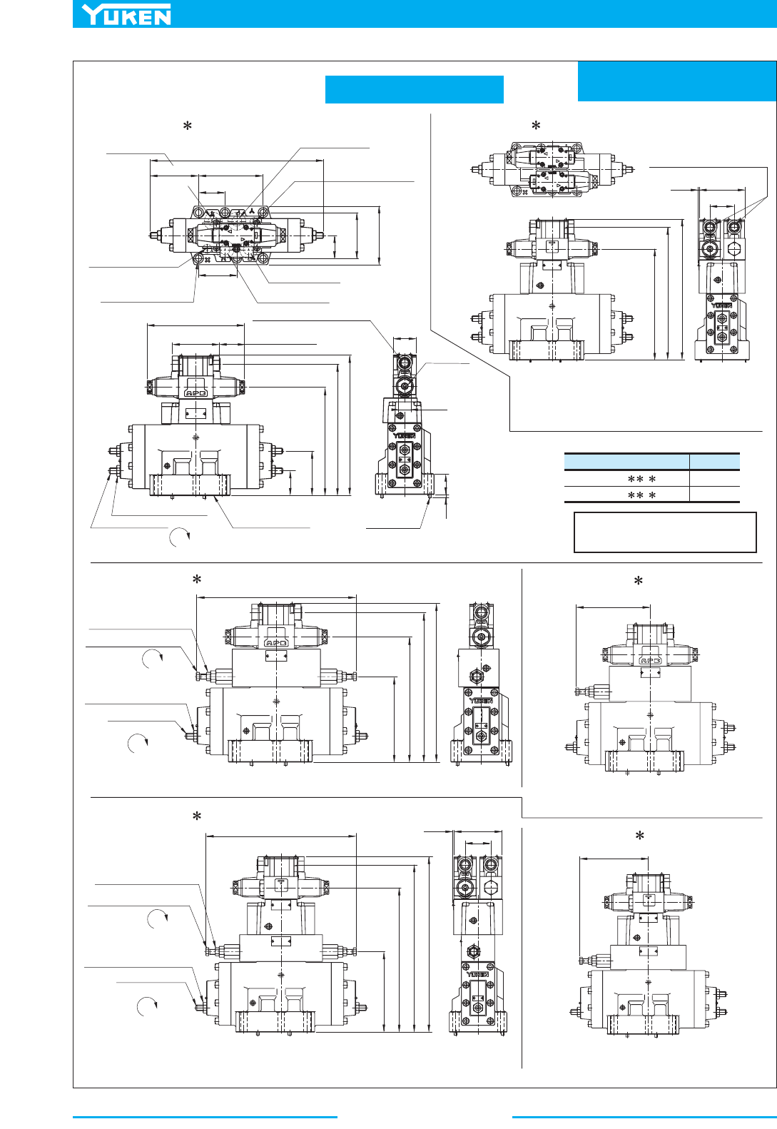
Multi Purpose Control Valves
468
Mounting Surface:
ISO 4401-AE-08-4-A
Terminal Box Type
Model Numbers "
C
" Thd.
DSLHG-06- - -13
DSLHG-06- - -1390
G 1/2
1/2 NPT
SOL b
SOL a
SOL b
SOL a
SOL a
SOL b
SOL a
SOL b
SOL b
SOL a
SOL b SOL a
46.1
(1.81)
92.1
(3.63)
118
(4.65)
Pressure Port "
P
"
Pilot Pressure Port "
X"
(For External Pilot
Type only)
350(13.78)
Fully Extended
Fully Extended
130.2
(5.13)
97.8(3.85)
77
(3.03)
Cylinder Port "
B
"
Cylinder Port "
A
"
Pilot Drain Port "
Y
"
(For External Drain Type only)
95(3.74)
DC/R : 204.4(8.05)
AC : 196.4(7.73)
DC/R : 54.7(2.15)
AC
: 50.7(2.00)
Electrical Conduit Connection
"
C
" Thd. (Both Ends)
27
(1.06)
46
(1.81)
Manual
Actuator
6(.24)
Dia.
"AT"
"PA"
"BT"
"PB"
Lock Nut
19(.75)
Hex.
DEC.
Flow Adj. Screw
6(.24)
Hex. Soc.
Mounting Surface
(O-Rings Furnished)
41
(1.61)
50
(1.97)
218.5 (8.60)
265.5 (10.45)
283.8 (11.17)
6(.24)
Dia.
Two Locating Pins
6
(.24)
Electrical Conduit Connection
"
C
" Thd. (Both Ends)
"AT"
"PA"
"BT"
"PB"
241.5 (9.51)
288.5 (11.36)
306.8 (12.08)
99(3.90)
53
(2.09)
3
(.12)
"AT"
"PA"
"BT"
Fully Extended 309(12.17)
"PB"
Lock Nut
14(.55)
Hex.
DEC.
Lock Nut
19(.75)
Hex.
INC.
Flow Adj. Screw
6(.24)
Hex. Soc.
Counterbalance Pressure
Adj. Screw
14(.55)
Hex.
165 (6.50)
241.5 (9.51)
288.5 (11.36)
306.8 (12.08)
154.5(6.08)
Fully Extended
"AT"
"PA"
"BT"
"PB"
"AT"
"PA"
"BT"
"PB"
Lock Nut
14(.55)
Hex.
DEC.
Lock Nut
19(.75)
Hex.
INC.
Counterbalance Pressure
Adj. Screw
14(.55)
Hex.
99(3.90)
53
(2.09)
3
(.12)
165(6.50)
296.5 (11.67)
343.5 (13.52)
361.8 (14.24)
"BT"
"PB"
"AT"
"PA"
154.5(6.08)
Fully Extended
13.5(.53)
Dia. Through
20(.79)
Dia. Spotface
6 Places
Tank Port "
T
"
53.2
(2.09)
309(12.17)
Fully Extended
Flow Adj. Screw
6(.24)
Hex. Soc.
90(3.54)
1
2
DSLHG-06- - -13/1390 DSLHG-06-3- -13/1390
For other dimensions, see "DSLHG-06-4W"
drawing left.
For other dimensions, see "DSLHG-06-5W"
drawing left.
DSLHG-06-4A- -13/1390
DSLHG-06-4W- -13/1390
DSLHG-06-5W- -13/1390
DSLHG-06-5A- -13/1390
For other dimensions, see "DSLHG-06- " drawing above.
1
2
For other dimensions, see "DSLHG-06- " drawing above.
1
2
For other dimensions, see "DSLHG-06- "
drawing left.
1
2
DIMENSIONS IN
MILLIMETRES (INCHES)
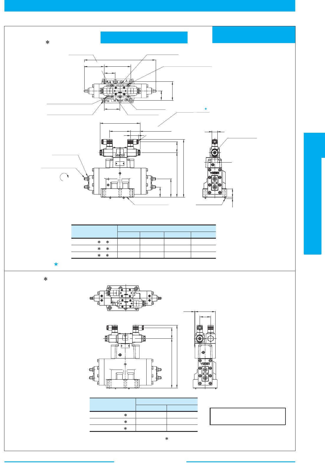
469
DIRECTIONAL CONTROLS
Multi Purpose Control Valves
E
Multi Purpose Control Valves
Mounting Surface:
ISO 4401-AE-08-4-A
Plug-in Connector Type
DSLHG-06- -A -N
DSLHG-06- -D -N
DSLHG-06-
-R -N
Model Numbers
Dimensions mm (Inches)
CD E F
39 (1.54)
39 (1.54)
53 (2.09)
53 (2.09)
64 (2.52)
57.2 (2.25)
283.5 (11.16)
294.5 (11.59)
297.5 (11.71)
27.5 (1.08)
27.5 (1.08)
34 (1.34)
DSLHG-06-3-A -N
DSLHG-06-3-D -N
DSLHG-06-3-R -N
Model Numbers
Dimensions mm (Inches)
DE
53 (2.09)
64 (2.52)
57.2
(2.25)
SOL b
SOL a
Pressure Port "
P
"
Pilot Pressure Port "
X
"
(For External Pilot Type only)
Tank Port "
T
"
53.2
(2.09)
350(13.78)
Fully Extended
130.2(5.13)
77
(3.03)
13.5(.53)
20(.79)
Dia. Spotface
Dia. Through
6 Places
Cylinder Port "
A
"
Cylinder Port "
B
"
Pilot Drain Port "
Y
"
(For External Drain Type only)
102
(4.02)
DC/R :204.4(8.05)
AC : 196.4(7.73)
DC/R : 54.7(2.15)
AC : 50.7(2.00)
C
"AT"
"PA"
"BT"
"PB"
Lock Nut
19(.75)
Hex.
DEC.
Flow Adj. Screw
6(.24)
Hex. Soc.
Mounting Surface
(O-Rings Furnished)
Manual Actuator
6(.24)
Dia.
E
D
F
6(.24)
Dia.
Two Locating Pins
6
(.24)
90(3.54)
218.5 (8.60)
50
(1.97)
46.1
(1.81)
92.1(3.63)
41
(1.61)
27
(1.06)
Cable Departure
1
2
DSLHG-06- - -N-13/1390
Position of cable departure can be changed. For the details, refer to DSLHG-04 valve on page 466.
DSLHG-06-3- -N-13/1390
For other dimensions, see "DSLHG-06- - -N" drawing above.
1
2
DIMENSIONS IN
MILLIMETRES (INCHES)
306.5 (12.07)
317.5 (12.50)
320.5 (12.62)
Cable Applicable:
Outside Dia.
.........
8 - 10 mm (.31 - .39 in.)
Conductor Area
....
Not Exceeding 1.5mm
2
(.0023 sq. In)
SOL b SOL a
"AT"
"PA"
"BT"
"PB"
D
241.5(9.51)
E
53
(2.09)
99(3.90)
3
(.12)
Fully Extended
97.8(3.85)
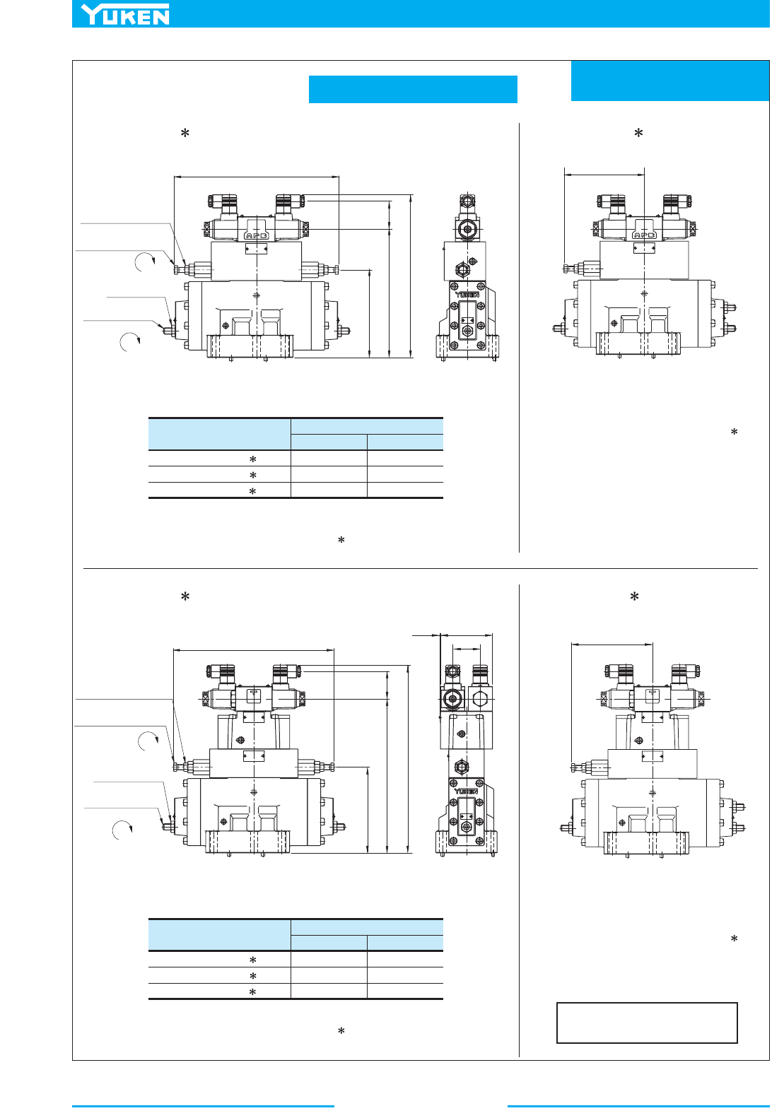
Multi Purpose Control Valves
470
Mounting Surface:
ISO 4401-AE-08-4-A
Plug-in Connector Type
DSLHG-06-4W-A -N
DSLHG-06-4W-D -N
DSLHG-06-4W-R -N
Model Numbers
Dimensions mm (Inches)
DE
53 (2.09)
64 (2.52)
57.2 (2.25)
DSLHG-06-5W-A -N
DSLHG-06-5W-D -N
DSLHG-06-5W-R -N
Model Numbers
Dimensions mm (Inches)
DE
53 (2.09)
64 (2.52)
57.2 (2.25)
SOL b SOL a
SOL b SOL a
SOL b
SOL a
SOL b
SOL a
"AT"
"PA"
"BT"
309(12.17)
Fully Extended
"PB"
Lock Nut
14(.55)
Hex.
DEC.
Lock Nut
19(.75)
Hex.
INC.
Flow Adj. Screw
6(.24)
Hex. Soc.
Counterbalance Pressure
Adj. Screw
14(.55)
Hex.
154.5(6.08)
Fully Extended
"AT"
"PA"
"BT"
"PB"
E
D
241.5
(9.51)
165
(6.50)
"AT"
"PA"
"BT"
309(12.17)
Fully Extended
Lock Nut
14(.55)
Hex.
DEC.
Lock Nut
19(.75)
Hex.
INC.
Flow Adj. Screw
6(.24)
Hex. Soc.
Counterbalance Pressure
Adj. Screw
14(.55)
Hex.
"PB"
E
D
296.5
(11.67)
165
(6.50)
3
(.12)
99(3.90)
53
(2.09)
154.5(6.08)
Fully Extended
"AT"
"PA"
"BT"
"PB"
DSLHG-06-4W- -N-13/1390
DSLHG-06-4A- -N-13/1390
DSLHG-06-5W- -N-13/1390 DSLHG-06-5A- -N-13/1390
For other dimensions, see "DSLHG-06-4W- -N"
drawing left.
For other dimensions, see DSLHG-06- - -N on the previous page.
1
2
For other dimensions, see DSLHG-06- - -N on the previous page.
1
2
For other dimensions, see "DSLHG-06-5W- -N"
drawing left.
DIMENSIONS IN
MILLIMETRES (INCHES)
306.5 (12.07)
317.5 (12.50)
320.5 (12.62)
361.5 (14.23)
372.5 (14.67)
375.5 (14.78)
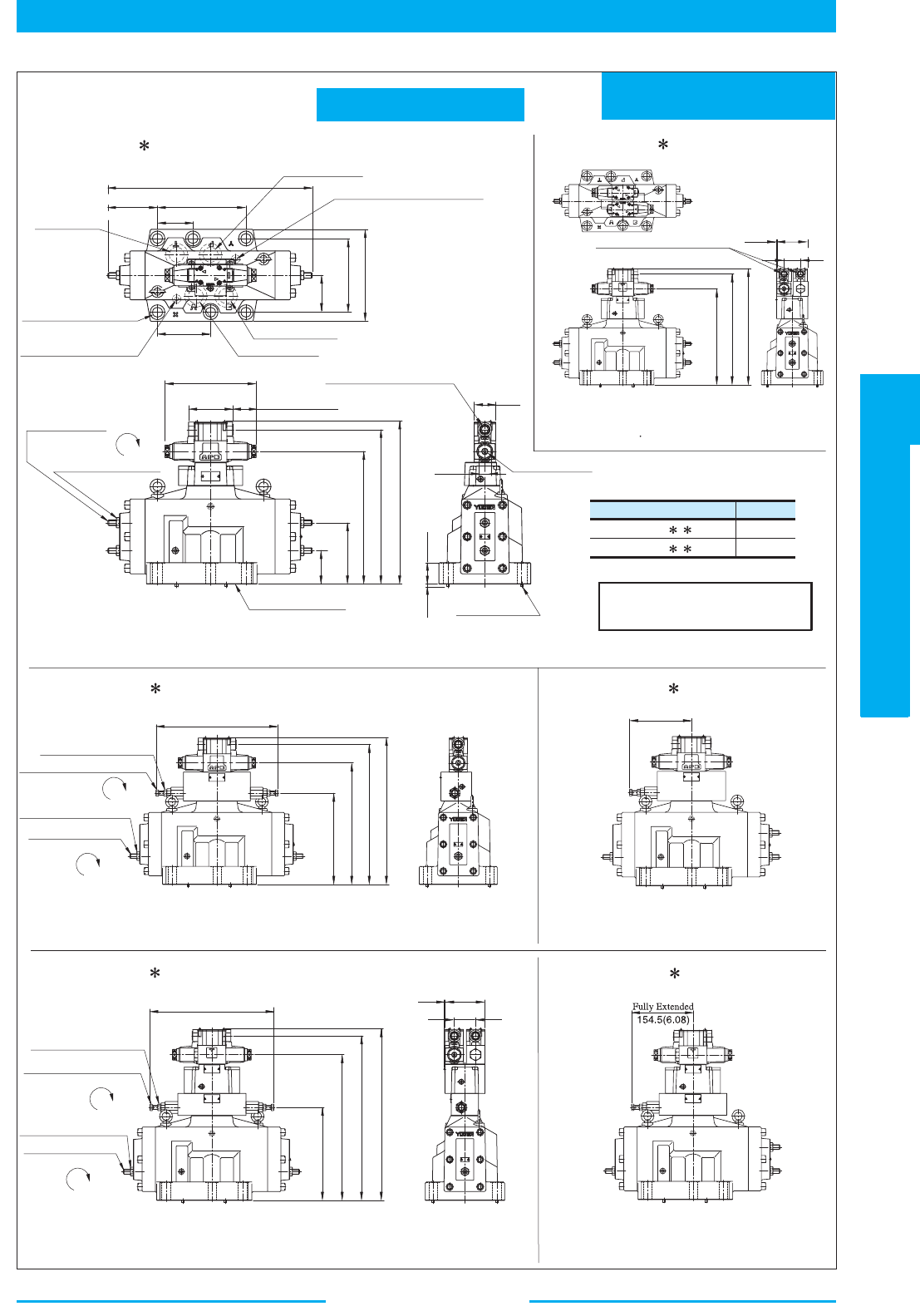
471
DIRECTIONAL CONTROLS
Multi Purpose Control Valves
E
Multi Purpose Control Valves
Mounting Surface:
ISO 4401-AF-10-4-A
Terminal Box Type
Model Numbers "
C
" Thd.
DSLHG-10- --13
DSLHG-10-
--1390
G 1/2
1/2 NPT
SOL a
SOL b
SOL a
SOL b
SOL a
SOL b
SOL a
SOL b
SOL aSOL b
SOL a SOL b
79.4
(3.23)
158.8(6.25)
Pressure Port "
P
"
Pilot Pressure Port "
X
"
(For External Pilot Type only)
190.5(7.50)
76.2(3.00)
Tank Port "
T
"
114.3
(4.50)
21.5(.85)
Dia. Through
32(1.26)
Dia. Spotface
6 Places
Cylinder Port "
B
"
Cylinder Port "
A
"
Pilot Drain Port "
Y
"
(For External Drain Type only)
95(3.74)
46
(1.81)
27
(1.06)
Electrical Conduit Connection
"
C
" Thd. (Both Ends)
Manual Actuator
6(.24)
Dia.
"AT"
"PA"
"BT"
"PB"
Lock Nut
19(.75)
Hex.
DEC.
Flow Adj. Screw
6(.24)
Hex. Soc.
Mounting Surface
(O-Rings Furnished)
72
(2.83)
285.5 (11.24)
332.5 (13.09)
350.8 (13.81)
6(.24)
Dia.
Two Locating Pins
6
(.24)
45
(1.77)
Electrical Conduit Connection
"
C
" Thd. (Both Ends)
"AT"
"PA"
"BT"
"PB"
308.5 (12.15)
355.5 (14.00)
373.8 (14.72)
99(3.90)
53(2.09)
3
(.12)
"AT"
"PA"
"BT"
Fully Extended
309(12.17)
"PB"
Lock Nut
14(.55)
Hex.
DEC.
Lock Nut
19(.75)
Hex.
INC.
Flow Adj. Screw
6(.24)
Hex. Soc.
Counterbalance Pressure
Adj. Screw
14(.55)
Hex.
232 (9.13)
308.5 (12.15)
355.5 (14.00)
373.8 (14.72)
154.5(6.08)
Fully Extended
"AT"
"PA"
"BT"
"PB"
"AT"
"PA"
"BT"
"PB"
99(3.90)
53(2.09)
3
(.12)
309(12.17)
Fully Extended
232(9.13)
363.5 (14.31)
410.5 (16.16)
428.8 (16.88)
"BT"
"PB"
"AT"
"PA"
440(17.32)
Fully Extended
Fully Extended
106.7(4.20)
DC/R : 204.4(8.05)
AC : 196.4(7.73)
DC/R : 54.7(2.15)
AC : 50.7(2.00)
198(7.80)
132(5.20)
Lock Nut
14(.55)
Hex.
DEC.
Lock Nut
19(.75)
Hex.
INC.
Flow Adj. Screw
6(.24)
Hex. Soc.
Counterbalance Pressure
Adj. Screw
14(.55)
Hex.
1
2
DSLHG-10- - -13/1390
DSLHG-10-3- -13/1390
For other dimensions, see "DSLHG-10-4W"
drawing left.
For other dimensions, see "DSLHG-10-5W"
drawing left.
DSLHG-10-4A- -13/1390
DSLHG-10-5A- -13/1390
DSLHG-10-4W- -13/1390
DSLHG-10-5W- -13/1390
For other dimensions, see "DSLHG-10- "
drawing left
1
2
For other dimensions, see "DSLHG-10- " drawing above.
1
2
For other dimensions, see "DSLHG-10- " drawing above.
1
2
DIMENSIONS IN
MILLIMETRES (INCHES)
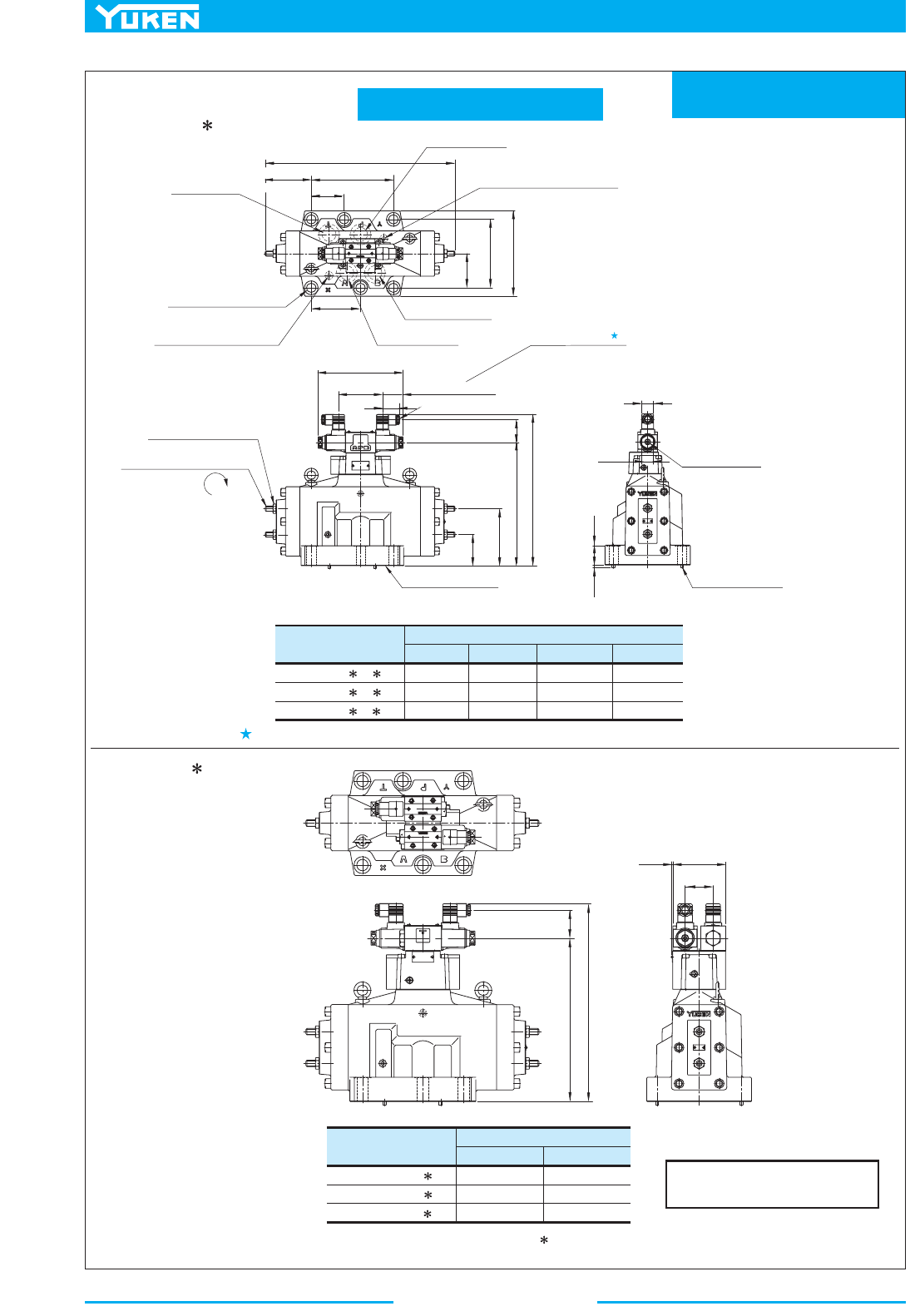
Multi Purpose Control Valves
472
Mounting Surface:
ISO 4401-AF-10-4-A
Plug-in Connector Type
DSLHG-10- -A -N
DSLHG-10- -D -N
DSLHG-10-
-R -N
Model Numbers
Dimensions mm (Inches)
CD E F
39 (1.54)
39 (1.54)
53 (2.09)
53 (2.09)
64 (2.52)
57.2 (2.25)
27.5 (1.08)
27.5 (1.08)
34 (1.34)
DSLHG-10-3-A -N
DSLHG-10-3-D -N
DSLHG-10-3-R -N
Model Numbers
Dimensions mm (Inches)
DE
53 (2.09)
64 (2.52)
57.2
(2.25)
SOL a
SOL b
SOL bSOL a
Pressure Port "
P
"
Pilot Pressure Port "
X
"
(For External Pilot Type only)
Tank Port "
T
"
76.2
(3.00)
Fully Extended
440(17.32)
106.7(4.20)
Fully Extended
114.3
(4.50)
21.5(.85)
Dia. Through
32(1.26)
Dia. Spotface
6 Places
Cylinder Port "
B
"
Cylinder Port "
A
"
Pilot Drain Port "
Y
"
(For External Drain Type only)
102
(4.02)
C
"AT"
"PA"
"BT"
"PB"
Lock Nut
19(.75)
Hex.
DEC.
Flow Adj. Screw
6(.24)
Hex. Soc.
Mounting Surface
(O-Rings Furnished)
Manual Actuator
6(.24)
Dia.
E
D
F
6(.24)
Dia.
Two Locating Pins
6
(.24)
45
(1.77)
"AT"
"PA"
"BT"
"PB"
E
D
132(5.20)
72
(2.83)
308.5 (12.15)
53
(2.09)
3
(.12)
79.4
(3.23)
158.8
(6.25)
190.5 (7.50)
DC/R : 204.4(8.05)
AC : 196.4(7.73)
DC/R : 54.7(2.15)
AC : 50.7(2.00)
99
(3.90)
198
(7.80)
Cable Departure
Cable Applicable:
Outside Dia. 8 - 10 mm (.31 - .39 in.)
Conductor Area Not Exceeding 1.5 mm
2
(.0023 sq. in.)
......
...
285.5(11.24)
1
2
DSLHG-10- - -N-13/1390
Position of cable departure can be changed. For the details, refer to DSLHG-04 valve on page 466.
DSLHG-10-3- -N-13/1390
For other dimensions, see "DSLHG-10- - -N" drawing above.
1
2
DIMENSIONS IN
MILLIMETRES (INCHES)
350.5 (13.80)
361.5 (14.23)
364.5 (14.35)
373.5 (14.70)
384.5 (15.14)
387.5 (15.26)
27
(1.06)
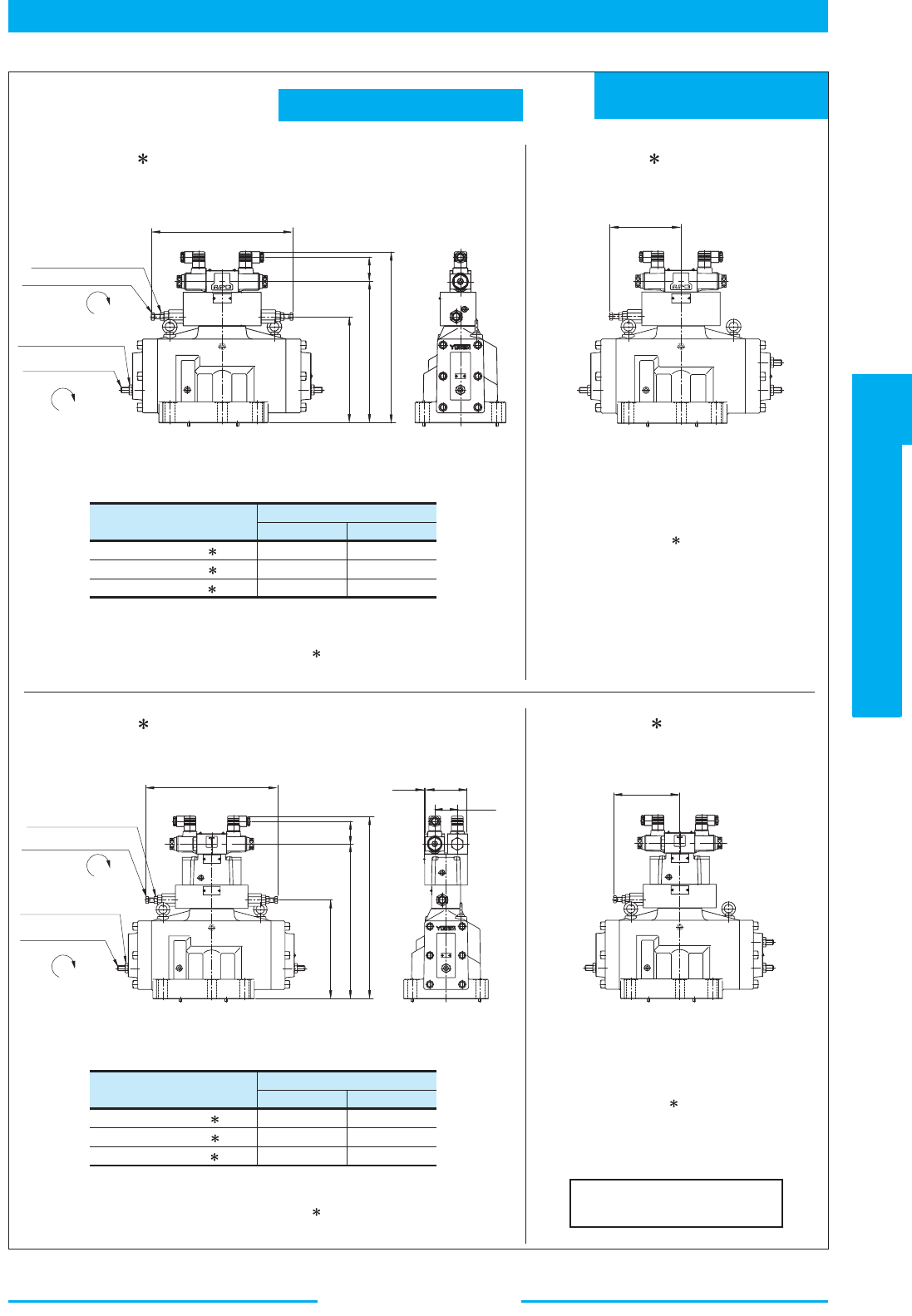
473
DIRECTIONAL CONTROLS
Multi Purpose Control Valves
E
Multi Purpose Control Valves
Mounting Surface:
ISO 4401-AF-10-4-A
Plug-in Connector Type
DSLHG-10-4W-A -N
DSLHG-10-4W-D -N
DSLHG-10-4W-R -N
Model Numbers
Dimensions mm (Inches)
DE
53 (2.09)
64 (2.52)
57.2 (2.25)
DSLHG-10-5W-A -N
DSLHG-10-5W-D -N
DSLHG-10-5W-R -N
Model Numbers
Dimensions mm (Inches)
DE
53 (2.09)
64 (2.52)
57.2
(2.25)
SOL a
SOL b
SOL a
SOL b
SOL bSOL a
SOL bSOL a
"AT"
"PA"
"BT"
309(12.17)
Fully Extended
"PB"
Lock Nut
14(.55)
Hex.
DEC.
Lock Nut
19(.75)
Hex.
INC.
Flow Adj. Screw
6(.24)
Hex. Soc.
Counterbalance Pressure
Adj. Screw
14(.55)
Hex.
154.5(6.08)
Fully Extended
"AT"
"PA"
"BT"
"PB"
E
308.5 (12.15)
232 (9.13)
"AT"
"PA"
"BT"
309(12.17)
Fully Extended
"PB"
E
363.5 (14.31)
232 (9.13)
3
(.12)
99
(3.90)
53
(2.09)
154.5(6.08)
Fully Extended
"AT"
"PA"
"BT"
"PB"
D
Lock Nut
14(.55)
Hex.
DEC.
Lock Nut
19(.75)
Hex.
INC.
Flow Adj. Screw
6(.24)
Hex. Soc.
Counterbalance Pressure
Adj. Screw
14(.55)
Hex.
D
DSLHG-10-4W- -N-13/1390
DSLHG-10-4A- -N-13/1390
DSLHG-10-5W- -N-13/1390
DSLHG-10-5A- -N-13/1390
For other dimensions, see
"DSLHG-10-4W- -N" drawing left.
For other dimensions, see
"DSLHG-10-5W- -N" drawing left.
For other dimensions, see DSLHG-10- - -N on the previous page.
1
2
For other dimensions, see DSLHG-10- - -N on the previous page.
1
2
DIMENSIONS IN
MILLIMETRES (INCHES)
373.5 (14.70)
384.5 (15.14)
387.5 (15.26)
428.5 (16.87)
439.5 (17.30)
442.5 (17.42)
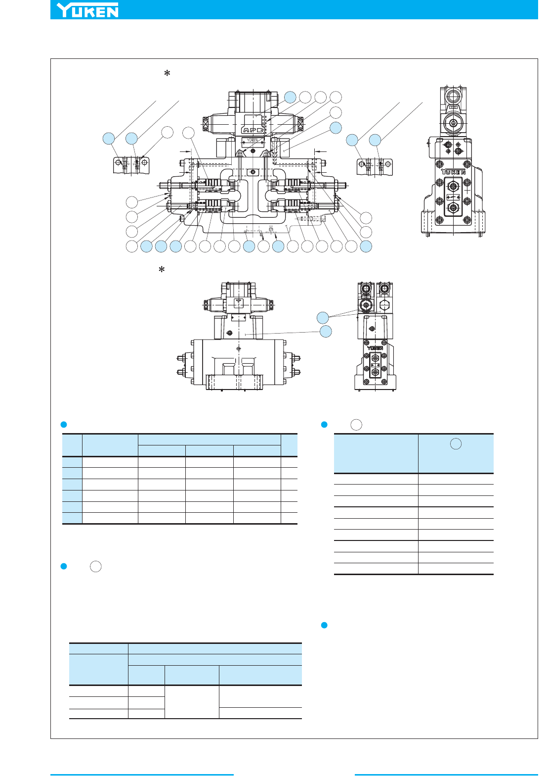
Multi Purpose Control Valves
474
Item Name of Parts
DSLHG-04 DSLHG-06 DSLHG-10
Part Numbers
Qty.
15
16
17
18
19
20
O-Ring
O-Ring
O-Ring
O-Ring
O-Ring
Back Up Ring
SO-NB-P22
SO-NB-P22
SO-NB-P9
SO-NA-P8
SO-NB-P8
SO-BB-P8
SO-NB-G30
SO-NB-P30
SO-NB-P14
SO-NA-P10
SO-NB-P9
SO-BB-P10
SO-NB-G40
SO-NB-P42
SO-NB-P14
SO-NA-P16
SO-NB-P11
SO-BB-P16
4
4
2
4
4
4
Multi-Purpose
Control Valve
Model Numbers
Pilot Selector Valve
Model Numbers
DSLHG-04-1
DSLHG-04-2
DSLHG-04-3
DSLHG-06-1
DSLHG-06-2
DSLHG-06-3
DSLHG-10-1
DSLHG-10-2
DSLHG-10-3
CG-04-1-10
CG-04-2-10
CG-04-3-10
CG-06-1-10
CG-06-2-10
CG-06-3-10
CG-06-1-10
CG-06-2-10
CG-06-3-10
Orifice Type
Model Numbers
TP-OPT-1/16 x d
Orifice Diameter "
d
" mm
Standard
Built-in
Selectable
Max. Dia. at Pressure
over 20 MPa(2900 PSI)
DSLHG-04
DSLHG-06
DSLHG-10
1.0
1.2
1.4
0.5, 0.6, 0.8, 1.0
1.2, 1.4, 1.6, 1.8
2.0, 2.5
1.4
1.2
SOL b
SOL a
SOL b
SOL a
24
26
7
21
23
10
9
20
18 15
65
4
16 11 17 1
6
7
8
2
19
23
22
24
14
25142726
13 13
12
13 13
O
r
i
f
i
c
e
f
o
r
A
T
O
r
i
f
i
c
e
f
o
r
P
A
O
r
i
f
i
c
e
f
o
r
B
T
O
r
i
f
i
c
e
f
o
r
P
B
Z
Z
Y
Y
1
2
DSLHG-04/06/10- - -13/1390
DSLHG-04/06/10-3- -13/1390
Note) Main valve is same as above drawings.
List of Seals for Main Valves
Note: When ordering the seals, please specify the seal kit number listed on
page 478
.
Item Pilot Selector Valve List
24
24
Note: For details of Pilot Selector Valve, see page 476.
Pilot Valve
Refer to page 478 for Pilot Valve Model Numbers.
Item Orifice
13
The timing of flow path opening/closing can be adjusted as required by
selecting the appropriate pilot orifice diameter. When the diameter of
the orifice is to be changed, another orifice should be ordered. Standard
built-in orifice diameters and selectable orifice diameters are listed in
the table below.
Section Z-ZSection Y-Y
■ List of Seals for Main Valve, Pilot Selector Valve and Orifice
3
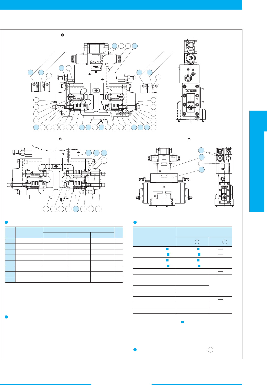
475
DIRECTIONAL CONTROLS
Multi Purpose Control Valves
E
Multi Purpose Control Valves
CG-04-4A- -10
CG-04-4W- -10
CG-04-5A- -10
CG-04-5W- -10
in section marked with .
Item Name of Parts
DSLHG-04 DSLHG-06 DSLHG-10
Part Numbers
Qty.
19
20
21
22
23
24
25
26
O-Ring
O-Ring
O-Ring
O-Ring
O-Ring
O-Ring
O-Ring
Back Up Ring
SO-NB-P22
SO-NB-P22
SO-NB-P16
SO-NB-P14
SO-NB-P9
SO-NA-P8
SO-NB-P8
SO-BB-P8
SO-NB-G30
SO-NB-P30
SO-NB-P22
SO-NB-P20
SO-NB-P14
SO-NA-P10
SO-NB-P9
SO-BB-P10
SO-NB-G40
SO-NB-P42
SO-NB-P30
SO-NB-A122
SO-NB-P14
SO-NA-P16
SO-NB-P11
SO-BB-P16
4
4
2(1)
2(1)
2
2(3)
4
2(3)
Multi-Purpose
Control Valve
Model Numbers
Pilot Selector Valve
Model Numbers
DSLHG-04-4A-
DSLHG-04-4W-
DSLHG-04-5A-
DSLHG-04-5W-
DSLHG-06-4A
DSLHG-06-4W
DSLHG-06-5A
DSLHG-06-5W
DSLHG-10-4A
DSLHG-10-4W
DSLHG-10-5A
DSLHG-10-5W
CG-06-4A-10
CG-06-4W-10
CG-06-5A-10
CG-06-5W-10
CG-06-4A-10
CG-06-4W-10
CG-06-5A-10
CG-06-5W-10
Item
Item
CG-04-3-10
CG-06-3-10
CG-06-3-10
36
3
4
3
5
3
2
36 37 33 32
31
19 24 26 3
11
12
29
30
6 5 8 720 27 2310321
19
16
30
28
15 18 17 14 22
13
31
25 1
13 13 13
Section Z-Z
Section W-W
4
262432
2 6 5 9 19 7 11 12
W
W
Z
Z
O
r
i
f
i
c
e
f
o
r
A
T
O
r
i
f
i
c
e
f
o
r
P
A
O
r
i
f
i
c
e
f
o
r
B
T
O
r
i
f
i
c
e
f
o
r
P
B
DSLHG-04/06/10-4W- -12/1290
4A
5A
DSLHG-04/06/10- - -12/1290
Note) Main valve is the same as above drawings.
List of Seals for Main Valves
Note 1:
Note 2:
The figures in ( ) indicate the quantity of seals used for 4A and
5A.
When ordering the seals, please specify the seal kit number listed
on
page 478.
Pilot Selector Valve List
Note: Fill "B" or "H" representing the pressure adjustment range
See page 477 for the details of the pilot selector valves.
Pilot Valve
Refer to page 478 for Pilot Valve Model Numbers.
See the previous page for Item Orifice.
13
3432
DSLHG-04/06/10-5W- -12/1290
■ List of Seals for Main Valves and Pilot Selector Valve
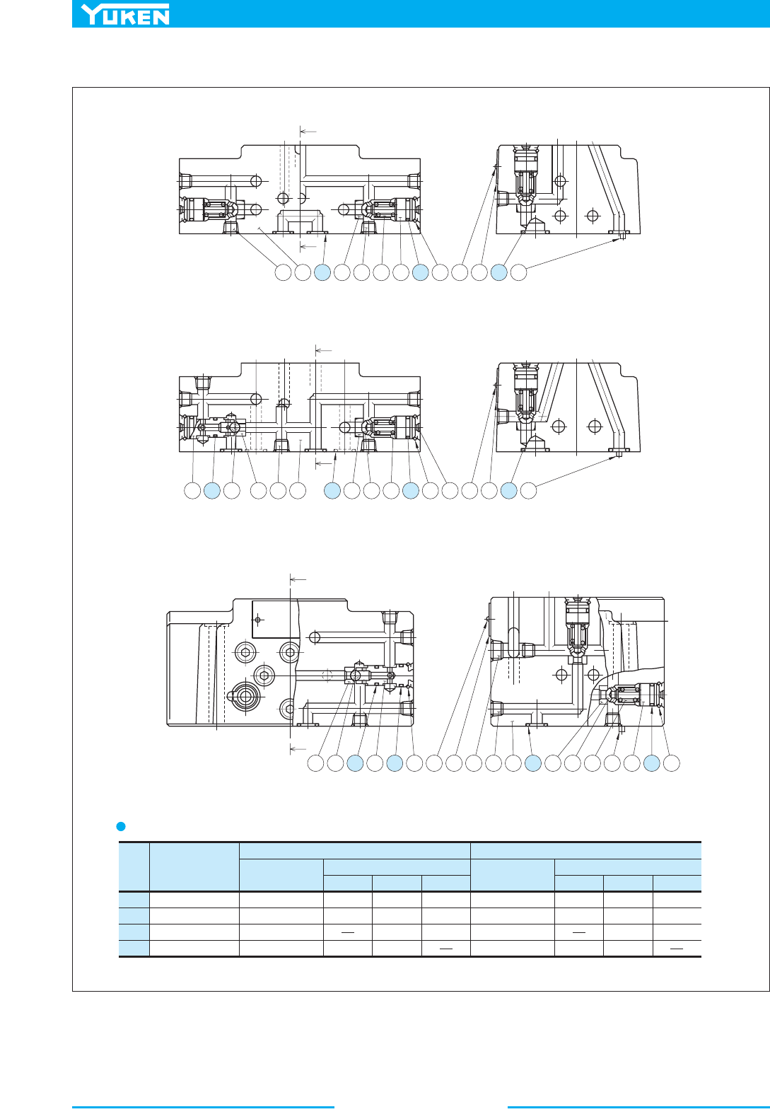
Multi Purpose Control Valves
476
Item Name of Parts
CG-04
Part Numbers
Quantity
CG-04-1 CG-04-2 CG-04-3
14
15
16
17
O-Ring
O-Ring
O-Ring
O-Ring
SO-NB-P10
SO-NB-P8
SO-NB-P8
SO-NB-P8
3
7
1
5
7
2
1
5
8
2
CG-06
Part Nmbers
Quantity
CG-06-1 CG-06-2 CG-06-3
SO-NB-P10
SO-NB-P9
SO-NB-P8
SO-NB-A014
3
7
1
5
7
2
1
5
8
2
Section X-X
X
12 115 5 2 7 614 8131017 9
31611 412 115 5 2 714 8 6131017 9
Section X-X
X
X
X
41116 314 813101812 115 5 2 7 9 614 8
Section X-X
X
X
List of Seals
CG-04/06-1-10
Note: When ordering the o-rings, please specif
y
the seal kit number listed in page 478.
CG-04/06-2-10
CG-04/06-3-10
■ List of Seals (Pilot Selector Valves)
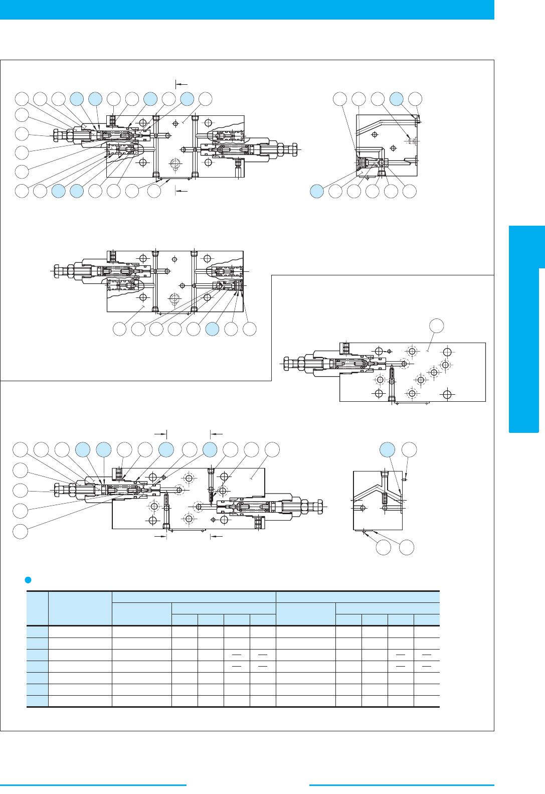
477
DIRECTIONAL CONTROLS
Multi Purpose Control Valves
E
Multi Purpose Control Valves
Item Name of Parts
CG-04
Part Numbers
Quantity
24
25
26
27
O-Ring
O-Ring
O-Ring
O-Ring
SO-NB-P12
SO-NB-P9
SO-NB-P10
SO-NB-P8
-4W- -4A- -5W- -5A-
SO-NA-P6
SO-NB-P8
SO-BB-P6
O-Ring
O-Ring
Back Up Ring
28
29
30
2
2
3
2
2
8
2
1
1
4
2
1
8
1
2
2
2
8
2
1
1
1
8
1
Part Nmbers
Quantity
SO-NB-P16
SO-NB-P11
SO-NB-P10
SO-NB-P8
-4W- -4A- -5W- -5A-
SO-NA-P9
SO-NB-P9
SO-BB-P9
2
2
3
2
2
8
2
1
1
4
2
1
8
1
2
2
2
8
2
1
1
1
8
1
CG-06
32 31
Section Y-Y
34230281920246251
9
8
7
5
10 12 26 27 22 11 32 31
13 12 17 29 23
26 16 14 18 21 15
Y
Y
121326161415211
1
3 2 30 28 19 20 24 6 25 18 17 1
9
8
7
5
YY
YY
29 23
Section Y-Y
CG-04/06-4W-10
List of Seals
Note: When ordering the seals, please specif
y
the seal kit number listed in page 478.
CG-04/06-5A-10
CG-04/06-4A-10
CG-04/06-5W-10
4
■ List of Seals (Pilot Selector Valves)
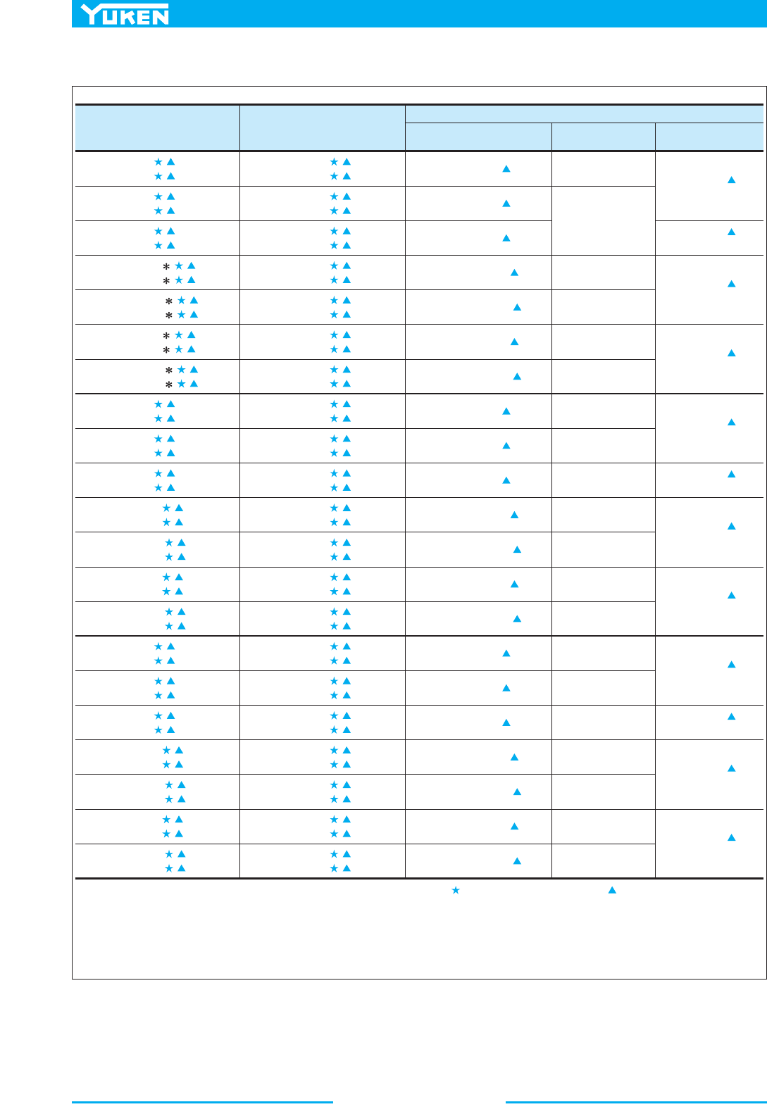
Multi Purpose Control Valves
478
Fill coil type (a symbol representing current/voltage) in section marked . Likewise, in section marked , fill a symbol
KS-DSG-01- -70
KS-DSG-01- -70
KS-DSLHG-06-5W- -13
KS-DSLHG-10-4W- -13
KS-DSLHG-10-5W- -13
KS-DSLHG-10-4A- -13
KS-DSLHG-10-5A- -13
KS-DSLHG-10-1- -13
KS-DSLHG-10-2- -13
KS-DSLHG-10-3- -13
KS-DSG-01- -70
KS-DSG-01- -70
KS-DSG-01- -70
KS-DSG-01- -70
DSG-01-3C9- - -70
DSG-01-3C9- - -7090
DSG-01-3C9- - -70
DSG-01-3C9- - -7090
DSG-01-2B2- - -70
DSG-01-2B2- - -7090
DSG-01-3C9- - -70
DSG-01-3C9- - -7090
DSG-01-3C9- - -70
DSG-01-3C9- - -7090
DSG-01-2B2- - -70
DSG-01-2B2- - -7090
DSG-01-2B2- - -70
DSG-01-2B2- - -7090
DSLHG-06-3- - -1390
DSLHG-06-2- - -1390
DSLHG-06-3- - -13
DSLHG-06-4A- - -13
DSLHG-06-4A- - -1390
DSLHG-06-4W- - -13
DSLHG-06-4W- - -1390
DSLHG-06-5A- - -13
DSLHG-06-5A- - -1390
DSLHG-06-5W- - -13
DSLHG-06-5W- - -1390
DSLHG-10-1- - -13
DSLHG-10-1- - -1390
DSLHG-10-2- - -13
DSLHG-10-2- - -1390
DSLHG-10-3- - -13
DSLHG-10-3- - -1390
DSLHG-10-4A- - -13
DSLHG-10-4A- - -1390
DSLHG-10-4W- - -13
DSLHG-10-4W- - -1390
DSLHG-10-5A- - -13
DSLHG-10-5A- - -1390
DSLHG-10-5W- - -13
DSLHG-10-5W- - -1390
DSLHG-04-1- - -13
DSLHG-04-1- - -1390
DSLHG-04-2- - -13
DSLHG-04-2- - -1390
DSLHG-04-3- - -13
DSLHG-04-3- - -1390
- - -13
- - -1390
- - -13
- - -1390
- - -13
- - -1390
- - -13
- - -1390
DSLHG-06-1- - -13
DSLHG-06-1- - -1390
DSLHG-06-2- - -13
DSG-01-3C9- - -70
DSG-01-3C9- - -7090
DSG-01-3C9- - -70
DSG-01-3C9- - -7090
DSG-01-2B2- - -70
DSG-01-2B2- - -7090
DSG-01-3C9- - -70
DSG-01-3C9- - -7090
DSG-01-3C9- - -70
DSG-01-3C9- - -7090
DSG-01-2B2- - -70
DSG-01-2B2- - -7090
DSG-01-2B2- - -70
DSG-01-2B2- - -7090
DSG-01-3C9- - -70
DSG-01-3C9- - -7090
DSG-01-3C9- - -70
DSG-01-3C9- - -7090
DSG-01-2B2- - -70
DSG-01-2B2- - -7090
DSG-01-3C9- - -70
DSG-01-3C9- - -7090
DSG-01-3C9- - -70
DSG-01-3C9- - -7090
DSG-01-2B2- - -70
DSG-01-2B2- - -7090
DSG-01-2B2- - -70
DSG-01-2B2- - -7090
KS-DSLHG-04-4W- -13
KS-DSLHG-04-5W- -13
KS-DSLHG-04-4A- -13
KS-DSLHG-04-5A- -13
KS-DSLHG-04-1- -13
KS-DSLHG-04-2- -13
KS-DSLHG-04-3- -13
KS-DSLHG-06-4W
- -13
KS-DSLHG-06-4A- -13
KS-DSLHG-06-5A- -13
KS-DSLHG-06-1- -13
KS-DSLHG-06-2- -13
KS-DSLHG-06-3- -13
KS-DSG-01- -70
KS-DSG-01- -70
KS-DSG-01- -70
KS-DSG-01- -70
KS-DSG-01- -70
KS-DSG-01- -70
Model Numbers Pilot Valve Model Numbers
Seal Kit Numbers
Complete Kit
For Pilot
Selector Valves
For Pilot Valves
DSLHG-04-4A-
DSLHG-04-4A-
DSLHG-04-4W-
DSLHG-04-4W-
DSLHG-04-5A-
DSLHG-04-5A-
DSLHG-04-5W-
DSLHG-04-5W-
KS-CG-04-1-10
KS-CG-04-2-10
KS-CG-04-4A-10
KS-CG-04-4W-10
KS-CG-04-5A-10
KS-CG-04-5W-10
KS-CG-06-1-10
KS-CG-06-4A-10
KS-CG-06-4W-10
KS-CG-06-5A-10
KS-CG-06-5W-10
KS-CG-06-2-10
KS-CG-06-3-10
KS-CG-06-1-10
KS-CG-06-4A-10
KS-CG-06-4W-10
KS-CG-06-5A-10
KS-CG-06-5W-10
KS-CG-06-2-10
KS-CG-06-3-10
(2 Set Req'd)
(1 Set Req'd)
(1 Set Req'd)
(2 Set Req'd)
(2 Set Req'd)
(1 Set Req'd)
(1 Set Req'd)
(2 Set Req'd)
(2 Set Req'd)
(1 Set Req'd)
(1 Set Req'd)
(2 Set Req'd)
Note 1:
2:
3:
representing the
type of electrical conduit connection (None: Terminal Box Type, N: Plug-in Connector Type).
A complete seal kit is composed of seal kit for pilot selector valve, seal kit for pilot valve and seal for main valve.
See
pages 474 and 475 for information on the seals for main valve.
See page 344
for the detailed information on the pilot valves.
■ List of Seal Kits and Pilot Valves
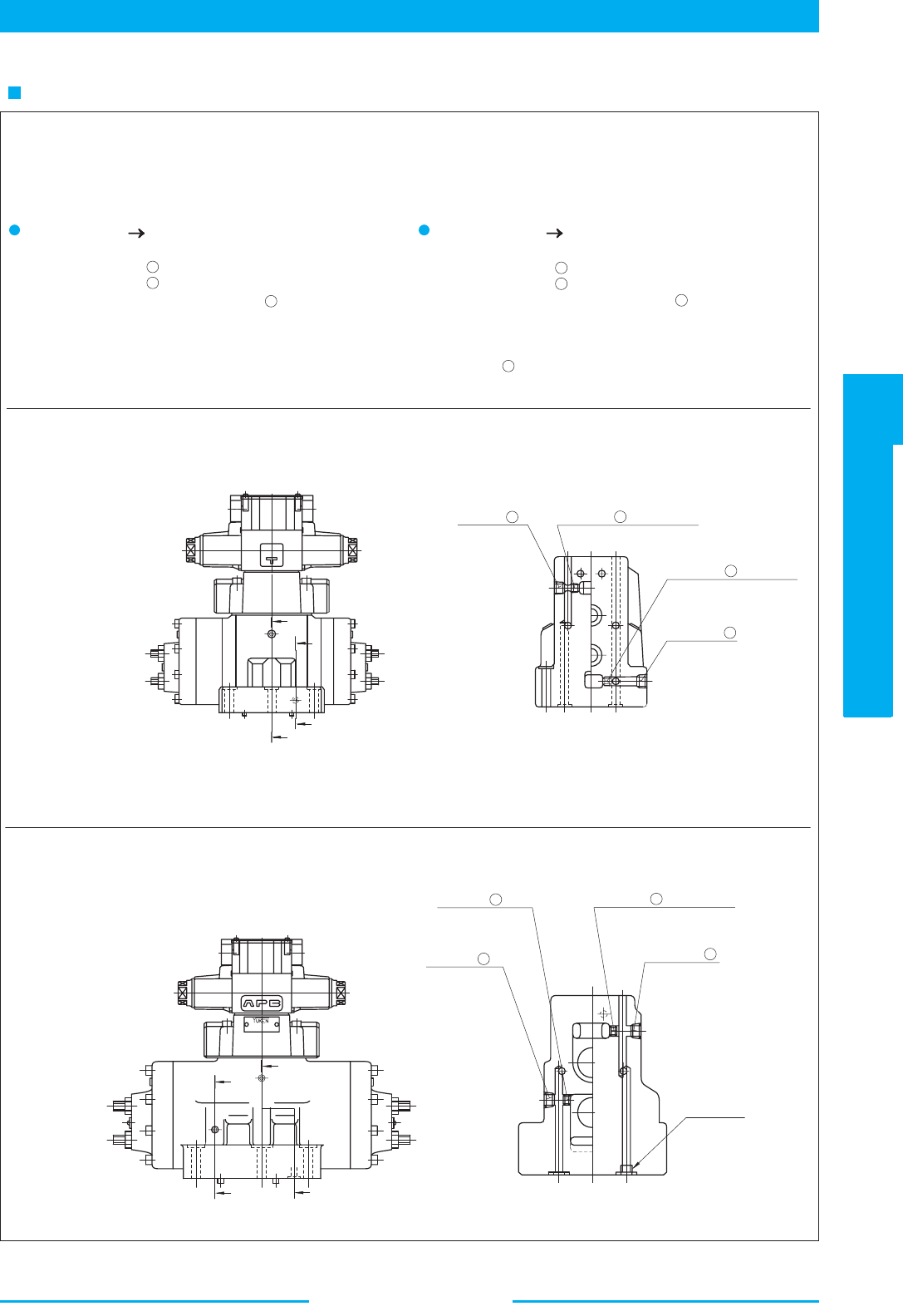
479
DIRECTIONAL CONTROLS
Multi Purpose Control Valves
E
Multi Purpose Control Valves
SOL a
SOL b
SOL b
SOL a
D
E
E
D
Section E-E Section D-D
D
E
E D Section E-E Section D-D
Pilot Connection
Selection
Drain Connection Selection
Thread "Y"
Drain Connection Selection
Pilot Connection Selection
Pipe Plug for 4
Pipe Plug for
2
Pipe Plug
1
External Pilot toliP lanretnI
(See Section E-E)
Pilot Connectio n and Drain Connectio n can be changed easily with a disconnection/connectio n of pilot plug. The
following drawings give illustrations of External Pilot-External Drain Type, When changing to Internal Pilot-Internal
Drain Type, the following procedure may be followed.
1)
2)
3)
Remove pipe plug .
Remove pipe plug .
Wind a sealing tape around the pipe plug , then fit the plug into
the port.
1
2
1
External Drain niarD lanretnI
(See Section D-D)
1)
2)
3)
4)
Remove pipe plug .
Remove pipe plug .
Wind a sealing tape around the pipe plug , then fit the plug into
the port.
In case of DSLHG-04, fit the plug into the port "Y" on the
sub-plate. In case of DSLHG-06/10, wind a sealing tape around
the plug and then thread it into the port "Y".
3
4
3
4
DSLHG-04
Pipe Plug
3
DSLHG-06/10
Pipe Plug
3
Pipe Plug
1
Pipe Plug for 2
Pipe Plug for 4
How to Change Pilot & Drain Connection
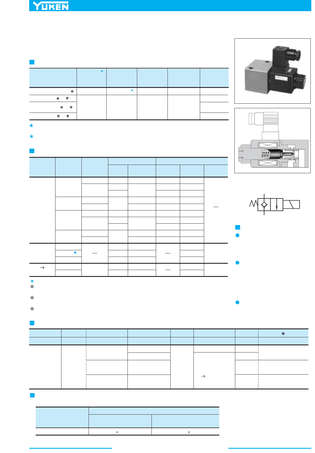
480
Solenoid Operated Poppet Type Two-Way Valves
Model Numbers
Max. Flow
L /min
(U.S.GPM)
Max. Operating
Pressure
MPa (PSI)
Internal leakage
3
cm /min
(cu.in./min)
Max. Changeover
Frequency
-1
min
(Cycles/Min)
Approx.
Mass
kg(1bs.)
CDSC-01-C-D24-10
CDSC-03-C- -21
CDSG-03-C- -21
03W
03
CDST- -C- -21
15 (4.0)
50 (13.2)
14 (2030)
21 (3050)
or less
0.25 (.015)
or less
0.25 (.015)
AC: 300
DC: 240
240
R: 120
0.5 (1.1)
0.35 (.8)
0.85 (1.9)
0.85 (1.9)
Solenoid Ratings
Electric
Source
Coil Type
Frequency
(Hz)
Source
Rating
Serviceable
Range
Voltage (V)
Holding
(A)
Power
(W)
Inrush
(A)
Current & Power at Rated Voltage
0.55
0.40
0.36
0.46
0.33
0.28
0.20
0.18
0.23
0.17
2.20
1.10
0.55
0.30
0.15
1.12
0.95
0.86
0.93
0.79
0.56
0.48
0.43
0.47
0.40
80 - 100
90 - 120
96 - 132
108 - 144
160 - 220
180 - 240
192 - 264
216 - 288
10.8 - 13.2
21.6 - 26.4
43.2 - 52.8
90 - 110
180 - 220
100
100
110
120
200
200
220
240
12
24
48
100
200
50
60
50
60
50
60
50
60
50/60
A100
A120
A200
A240
D12
D24
D48
R100
R200
AC
DC
(K Series)
AC DC
Rectified
26
26
Graphic Symbol
Instructions
X
Y
Direction of flow when the
solenoid is energised
These valves do not allow flow from
Y to X when the solenoid is energised.
At the time of test run
At the time of test run, there is a
possibility that the oil may not flow
even after the solenoid is energised
because of the residual air in the
valve.
Specifications
Mounting
There are no mounting restrictions
for any models.
2
1
These valves are used for opening/closing the oil path by having the poppet valve
operated with an electric signal via solenoid. Because these are of poppet type, the
internal leakage is quite small and there is no worry about hydraulic lock.
The maximum flow means the limited flow without inducing any abnormality to the operation
(changeover) of the valve.
When the valve is operated at 18.5 Mpa (2680 PSI) or higher pressure, continuous energies time is
restricted with Max. 30 min., and also the energies ratio less than 90 %.
1.
2.
CDSC-01 is available with coil type “D24” only.
Because both AC and DC solenoids employ the plug-in type electrical wiring, the valve can be
removed without removing the wiring. (Coil type of CDSC-01 is flying lead wire only.)
Being 50-60 Hz common service AC solenoids, do not require rewiring when the applied frequency is
changed.
K-Series DC Solenoid which has a reputation for excellent DC control is employed.
(Coil type of CDSC-01 is with Surge Suppressor.)
F:
Special seals
for phosphate
ester type
fluids
(Omit if not
required)
Special Seals
F-
None:
Japanese Std.
"JIS"
80:
European Design Std.
90:
N. American Design Std.
Model Number Designation
Series Number
None:
Japanese Std.
"JIS" &
European Design Std.
90:
N. American
Design Std.
None:
Japanese Std.
"JIS" &
European Design Std.
90:
N. American
Design Std.
CDS T -03 -C -D1 2 -21
Type of Connection
Valv e S i z e
Valv e Typ e
Coil Type
Design Number
Design Standard
CDS:
Solenoid
Operated
Poppet
Type
Two-Way
Va lve s
T: Threaded
Connection
C: Cartridge
Type
G: Gasket
Mounting
01
03
03
03W
(Piping Size 1/4)
03 (Piping Size 3/8)
C:
Normally
Closed
AC
A100, A120
A200, A240
DC D24
DC
D12, D24, D100
AC DC Rectified
R100, R200
10
21
21
21
Valve Model Numbers
CDSG-03
M6 60 Lg.
1/4-20 UNC 2-1/4Lg.
Japanese Standard "JIS
European Design Standard
N. American Design Standard
Socket Head Cap Screws (2pcs.)
Mounting Bolts
Mounting bolt in the table below is attached only for Gasket mounting type valve (CDSG-03).
■ Solenoid Operated Poppet Type Two-Way Valves
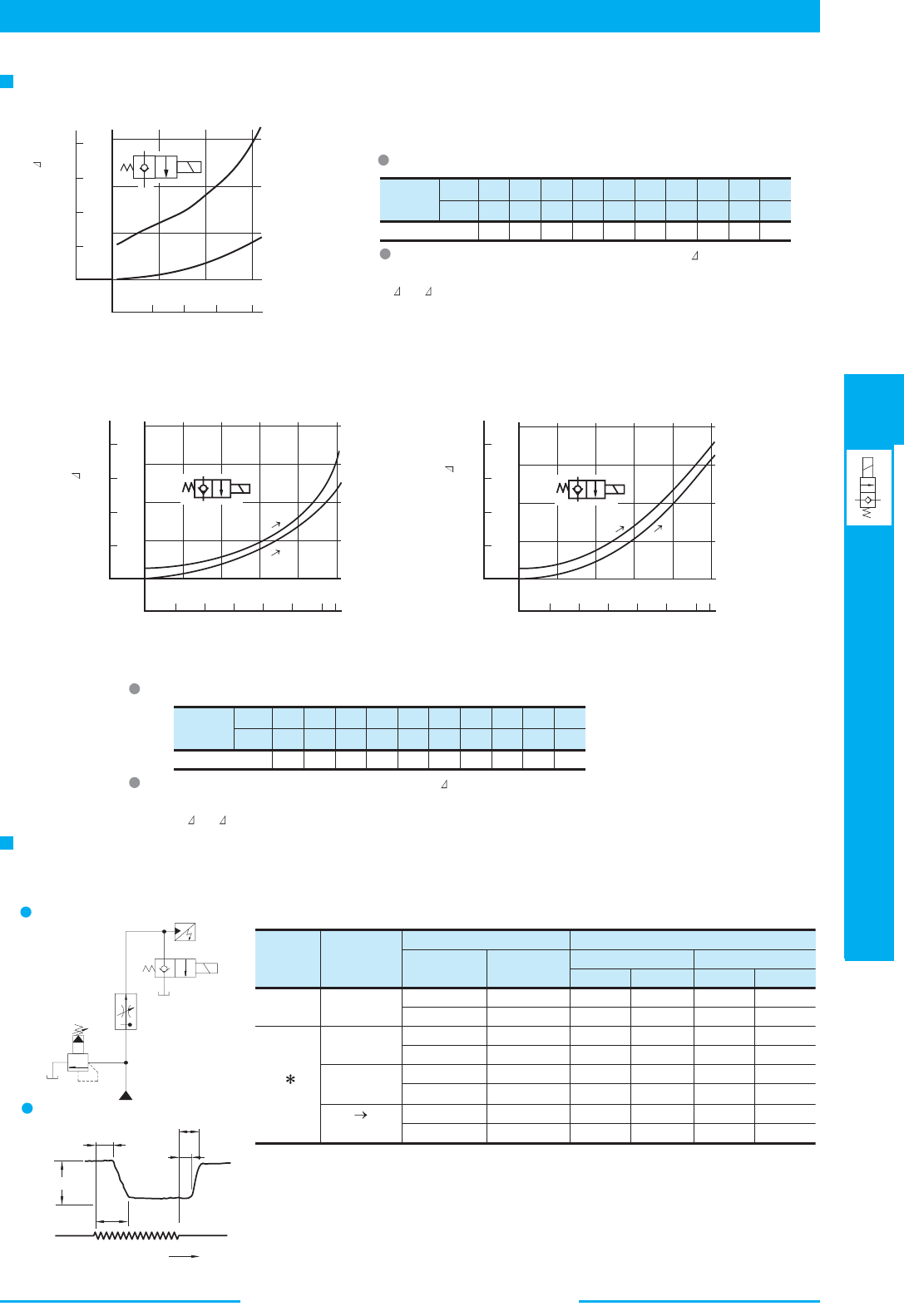
481
DIRECTIONAL CONTROLS
Solenoid Operated Poppet Type Two-Way Valves
E
Solenoid Operated Poppet Type Two-Way Valves
Viscosity
SSU
Factor 0.81 0.87 0.96 1.03 1.09 1.14 1.19 1.23 1.27 1.30
77 98 141 186 232 278 324 371 417 464
2
mm /s 15 20 30 40 50 60 70 80 90 100
Condition
Pressure "P"
MPa (PSI)
Flow Rate
L/min
(U.S.GPM)
SOL "OFF"(Open→Close)SOL "ON"(Open→Close)
T1 T2 (ex.)
38.4
44.0
44.0
54.0
66.0
73.0
146.0
142.0
29.0
27.0
20.0
12.0
44.0
41.0
114.0
108.0
44.0
47.0
86.0
43.0
104.0
60.0
100.0
66.0
21.4
30.6
10.0
11.0
22.0
24.0
27.0
32.0
T
3
T4 (ex.)
Shifting time (ms)
15 (4.0)
15 (4.0)
50 (13.2)
50 (13.2)
50 (13.2)
50 (13.2)
50 (13.2)
50 (13.2)
10 (1450)
21 (3050)
7 (1020)
14 (2030)
7 (1020)
14 (2030)
7 (1020)
14 (2030)
Solenoid
Types
Model
Number
AC
DC
DC
CDSC-01
CDS -03
AC DC
Rectified
Flow Rate
Pressure Drop P
Pressure Drop P
PSI MPa
L /min
U.S.GPM
X
Y
Y
X
X
Y
0.4
0.8
1.2
1.6
0
50
100
150
200
0
01020 304050
02468101213
Flow Rate
X
Y
X
Y
Y
X
L /min
U.S.GPM
010
20
30 40 50
02468
10
12 13
PSI MPa
0.4
0.8
1.2
1.6
0
50
100
150
200
0
Pressure Detector
ON
OFF
SOL
P
T
4
T
3
T
2
T
1
Time
Pressure Drop
Changeover Time
For any other viscosity, multiply the factors in the table below.
For any other specific gravity (G'), the pressure drop ( P') may be obtained from the
formula below.
P' = P (G'/0.850)
Test Circuit
● CDSC-03
● CDST-03
● CDSG-03
Hydraulic Fluid: Viscosity 35 mm
2
(164 SSU), Specific Gravity 0.850
Hydraulic Fluid: Viscosity 30 mm
2
(141 SSU), Specific Gravity 0.850
● CDST-03W
● CDSC-01
Note: Measuring has been made for the CDSC-03 (Cartridge type) when it is equipped with the same body
as the threaded connections and the gasket mounting type.
Changeover time, T2 and T4, in particular, varies according to the hydraulic circuit and operating conditions. As an
example, the following figures show how the measurement is made.
Result of measurement
Viscosity
SSU
Factor 0.84 0.91 1.00 1.07 1.14 1.19 1.24 1.28 1.32 1.35
77 98 141 186 232 278 324 371 417 464
2
mm /s 15 20 30 40 50 60 70 80 90 100
For any other viscosity, multiply the factors in the table below.
from the formula below.
P' = P (G'/0.850)
For any other specific gravity (G'), the pressure drop ( P') may be obtained
YX
XY
X
Y
PSI MPa
Flow Rate
U.S.GPM
L/min
Pressure Drop P
50
0.5
0
1.5
1.0
100
150
200
0
01
5
10 15
23
4
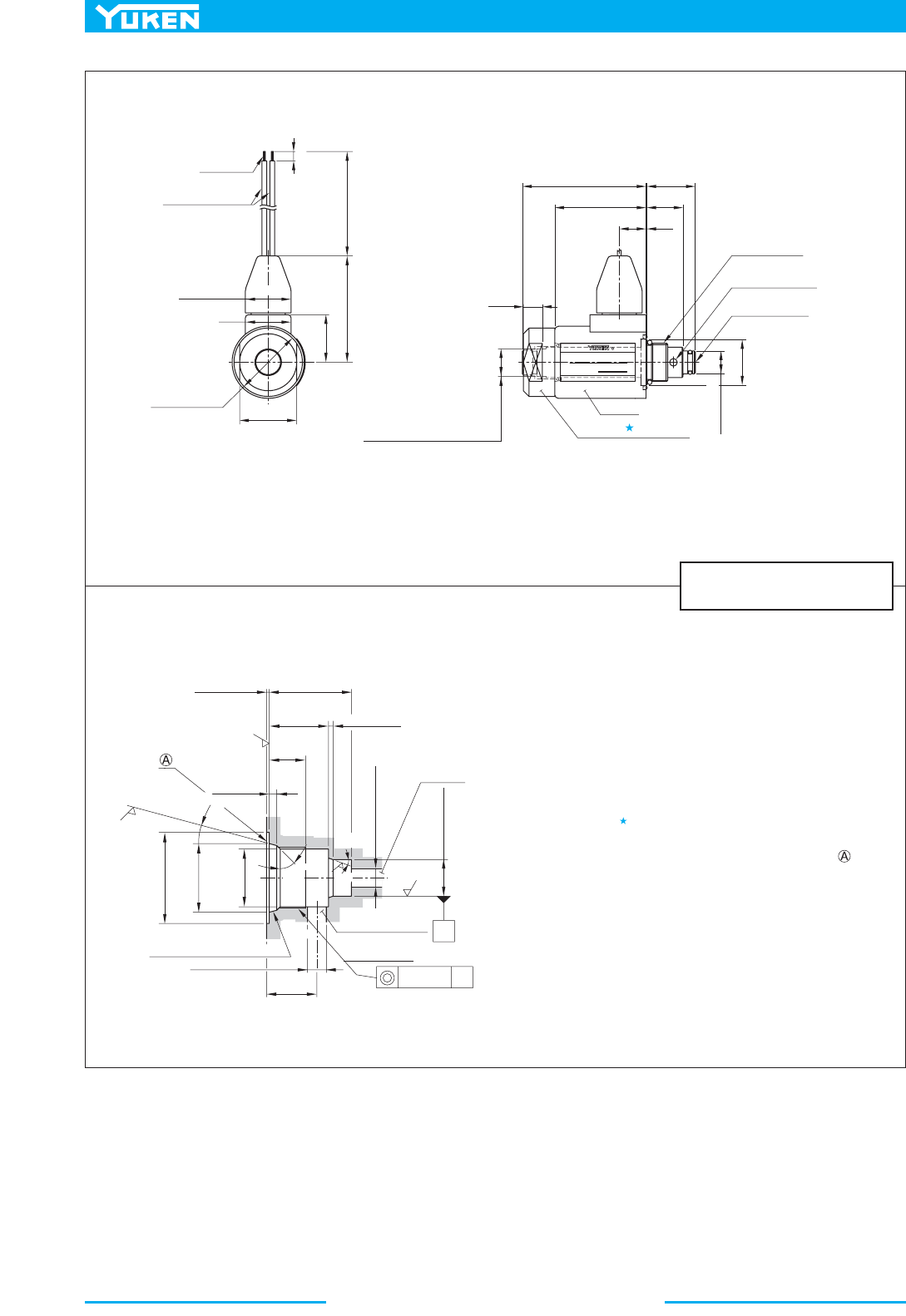
482
Solenoid Operated Poppet Type Two-Way Valves
CDSC-01-C-D24-10/1090
DIMENSIONS IN
MILLIMETRES (INCHES)
0.3(.012)
0.2(.008)
19.6(.772)
19.4(.764)
Min. 27(1.063)
Min.
12(.472)
1.5(.059)
15°
20°
45°
2.9(.114)
2.5(.098)
16
(.630)
22.7(.893)
22.6(.890)
12.027(.4735)
12.000(.4724)
1.6
30(1.18) Dia.
6.2(.244)
6.0(.236) Dia.
19(.75)
Dia.
Dia.
6.2(.244)
6.0(.236)
Dia.
Dia.
R0.1 - 0.3(R.004 - .012)
Port "X"
Port "Y"
M20 × 1 Thd.
0.1(.004)
Dia.
1.6
3.2
Note: The fitting portion of o-rings should have a good machined finish.
140
(5.51)
55
(2.17)
5
(.20)
24
(.94)
30
(1.18)
24(.94) Dia.
24(.94)
Dia.
38(1.50) Dia.
25
(.98)
MODEL
VOLTAGE
YUKEN KOGYO CO., LTD. JAPAN
CDSC-01-C-D24-10
DC24V
R
0.1
(.004)
14
(.55)
10(.39)
14.5(.57)
Across Flats
48
(1.89)
19(.75)
25.5(1.00)65 (2.56)
AWG 18
Flying Lead Wire
Core Tightening End
Tightening torque
: 25.5 - 30.6 Nm (230 - 270 IN. lbs)
12(.47) Dia.
Coil
Free Flow Outlet
Port "X"
Free Flow Inlet
Port "Y"
M20 × 1 Thd.
Nut
Tightening torque
: 3.9 - 5.9 Nm (35 - 52 IN. lbs)
How to Mount
When mounting, the following steps must be followed:
1. Loosen the nut , then remove the coil.
2. Thread the cartridge, making sure that the collar 24 (.94) Dia. of
the cartridge is well fitted to the component surface ( surface
in the left drawing).
3. Attach the coil and secure it with a nut.
Details of Mounting Holes
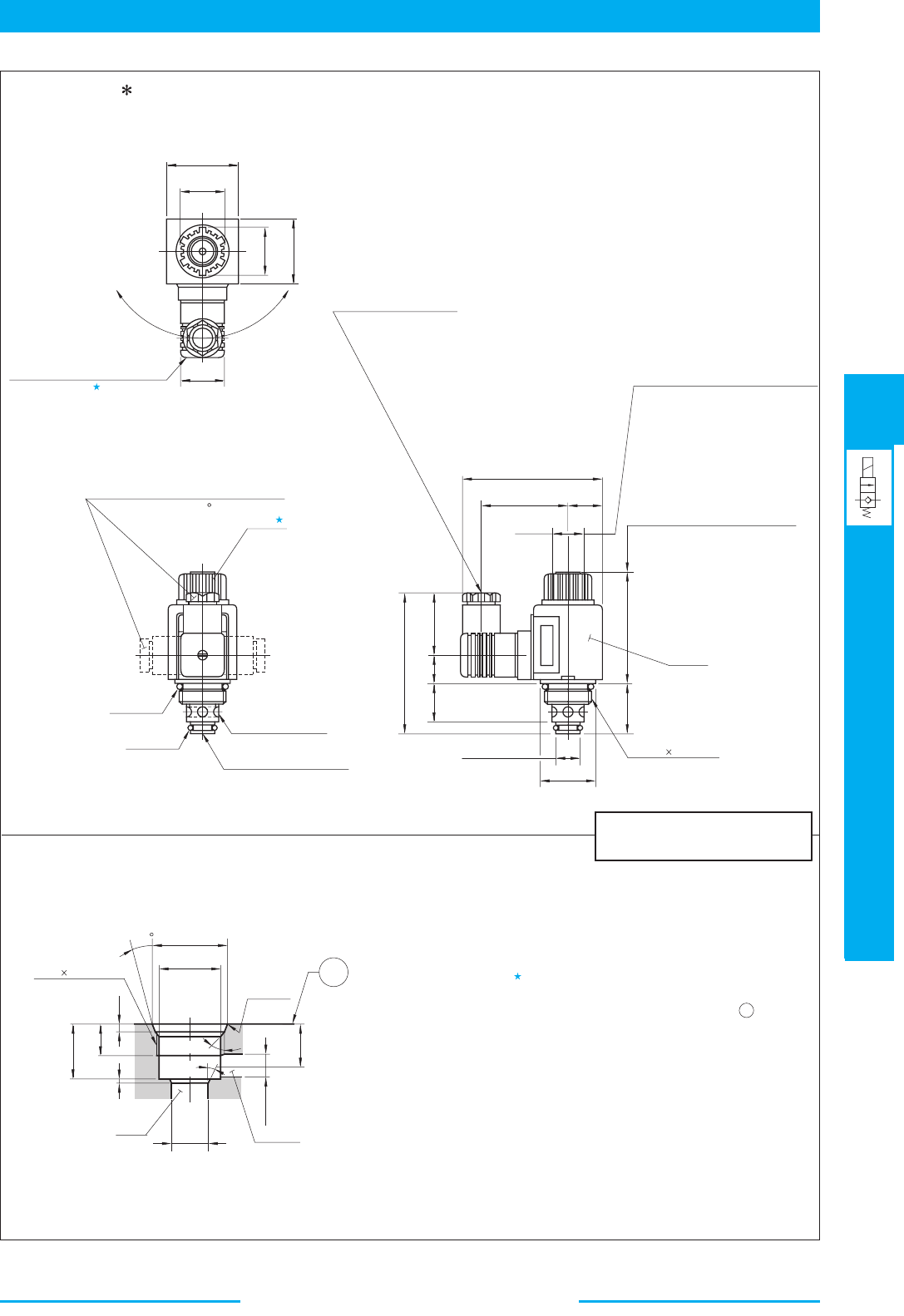
483
DIRECTIONAL CONTROLS
Solenoid Operated Poppet Type Two-Way Valves
E
Solenoid Operated Poppet Type Two-Way Valves
loosening the nut . Be sure to
Loosen the nut , then remove the coil.
27
(1.06)
44
(1.73)
27.5
(1.08)
The position can be changed by
retighten the nut after changing
the position.
29(1.14)
Dia.
40
(1.57)
Three positions of cable departure
are available in 90 increments.
O-Ring
SO-NB-P26
O-Ring
SO-NB-P12
Free Flow Outlet
Port
"X"
Free Flow Inlet Port "Y"
Nut
Tightening Torque
: 6.0-7.5Nm (53-66 in. 1bs.)
39
(1.54)
17.7
(.70)
24
(.94)
88.2
(3.47)
69
(2.72)
31.5
(1.24)
48
(1.89)
Space Needed to Remove Coil
Coil
M30 1.5 Thd.
16(.63) Dia.
35(1.38)
Dia.
19
(.75)
54
(2.13)
20
(.79)
86
(3.39)
Cable Departure
Cable Applicable:
Outside Dia
................
8-10 mm (.31-.39 in.) Dia.
Conductor Area
..........
Not Exceeding 1.5mm
2
(.0023 Sq. in.)
Wrench Flats for Fixing Cartridge
Tightening Torque
: 30-49 Nm (266-434 in. 1bs.)
45˚
20˚
A
R 0.2
(R .008)
"Y"
1
5
28.4 (1.12)
Dia.
18
(.71)
Max.
14 (.55)
Dia.
"X"
1
(.04)
3.5
(.14)
14
(.55)
24.6(.969)
24.4(.961)
M30 1.5 Thd.
32.9(1.295)
32.7(1.287)
Dia.
16.027(.6310)
16.000(.6299)
Dia.
Models with AC Solenoids
CDSC-03-C-A -21/2190
Details of Mounting Holes
Note: The fitting portion of O-rings should have a good machined finish.
How to Mount
When mounting, the following steps must be followed:
Thread the cartridge, making sure that the collar 35 (1.38) Dia.
of the cartridge is well fitted to the component surface (
surface in the left drawing).
Attach the coil and secure it with a nut.
1.
2.
3.
DIMENSIONS IN
MILLIMETRES (INCHES)
A
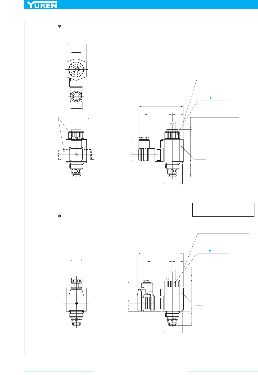
484
Solenoid Operated Poppet Type Two-Way Valves
22
(.87)
47.5
(1.87)
27.5
(1.08)
Three positions of cable departure
are available in 90 increments.
39
(1.54)
18.7
(.74)
100.5
(3.96)
15
(.59)
64
(2.52)
24.5
(.96)
52
(2.05)
75.2
(2.96)
31.5
(1.24)
47(1.85)
Dia.
Space Needed to Remove Coil
Coil
Wrench Flats for Fixing Cartridge
Tightening Torque
: 30-49 Nm (266-434 in. 1bs.)
Nut
Tightening Torque
: 10.3-11.3 Nm (91-100 in. 1bs.)
34
(1.34)
47(1.85)
Dia.
53
(2.09)
18.7
(.74)
103.5
(4.07)
15
(.59)
57.2
(2.25)
24.5
(.96)
52
(2.05)
75.2
(2.96)
31.5
(1.24)
Space Needed to Remove Coil
Coil
Wrench Flats for Fixing Cartridge
Tightening Torque
: 30-49 Nm (266-434 in. 1bs.)
Nut
Tightening Torque
: 10.3-11.3 Nm (91-100 in. 1bs.)
CDSC-03-C-D -21/2190
Models with DC Solenoids
CDSC-03-C-R -21/2190
Models with R Type Solenoids
For other dimensions, refer to the "Models with AC Solenoids".
For other dimensions, refer to the "Models with AC Solenoids".
DIMENSIONS IN
MILLIMETRES (INCHES)
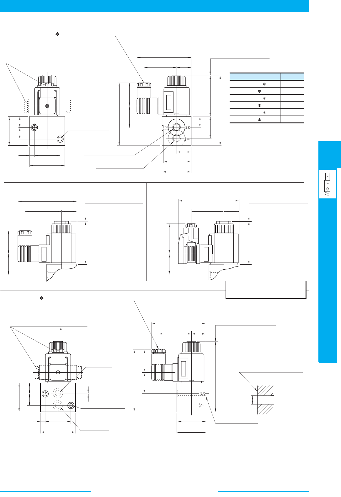
485
DIRECTIONAL CONTROLS
Solenoid Operated Poppet Type Two-Way Valves
E
Solenoid Operated Poppet Type Two-Way Valves
Model Numbers
CDST-03W-C- -21
CDST-03-C- -21
CDST-03W-C- -2180
CDST-03-C- -2180
CDST-03W-C- -2190
CDST-03-C- -2190
"A"
Thd.
Rc 1/4
Rc 3/8
1/4 BSP.F
3/8 BSP.F
1/4 NPT
3/8 NPT
Mounting Surface
45
(1.77)
Three positions of cable departure
are available in 90 increments.
60
(2.36)
7.5
(.30)
19
(.75)
18.5
(.73)
49.5
(1.95)
7(.28) Dia. Through
11(.43) Dia. Spotface
2 Places
Free Flow Outlet Port "X"
"A"
Thd.
Free Flow Inlet Port "Y"
"A"
Thd. (Opposite Side)
25
(.98)
49
(1.93)
50
(1.97)
18
(.71)
37
(1.46)
69
(2.72)
48
(1.89)
118.5
(4.67)
25
(.98)
54
(2.13)
91
(3.58)
Cable Departure
Cable Applicable:
Outside Dia
..............
8-10 mm (.31-.39 in.) Dia.
Conductor Area
........
Not Exceeding 1.5mm
2
(.0023 Sq. in.)
Space Needed to Remove Coil
39
(1.54)
36.2
(1.43)
106.2
(4.18)
64
(2.52)
25
(.98)
101
(3.98)
52
(2.05)
75.2
(2.96)
39
(1.54)
37.2
(1.46)
Space Needed to Remove Coil
Space Needed to Remove Coil
57.2
(2.25)
25
(.98)
104
(4.09)
52
(2.05)
53
(2.09)
37.2
(1.46)
75.2
(2.96)
Three positions of cable departure
are available in 90 increments.
Free Flow
Outlet Port "X"
7(.28) Dia. Through
11(.43) Dia. Spotface
2 Places
Free Flow
Inlet Port "Y"
45
(1.77)
7.5
(.30)
60
(2.36)
1
(.04)
19
(.75)
18.5
(.73)
49.5
(1.95)
25
(.98)
54
(2.13)
91
(3.58)
39
(1.54)
36.2
(1.43)
106.2
(4.18)
49
(1.93)
50
(1.97)
118.5
(4.67)
48
(1.89)
Space Needed to Remove Coil
Mounting surface should have
a good machined finish.
Max.
11(.43)
Dia.
Mounting Surface
(O-Rings Furnished)
Cable Departure
Cable Applicable:
Outside Dia
..............
8-10 mm (.31-.39 in.) Dia.
Conductor Area
........
Not Exceeding 1.5mm
2
(.0023 Sq. in.)
Models with AC Solenoids
CDST-03, 03W-C- -21/2180/2190
Note: The position of cable departure
can be changed. For the detail,
refer to CDSC-03 on the
previous page
.
sdioneloS epyT R htiw sledoMsdioneloS CD htiw sledoM
For other dimensions, refer to the "Models with AC Solenoids".
Models with AC Solenoids
CDSG-03-C- -21/2190
Note For models with DC solenoids and models with R type solenoids, refer to CDST-03, 03W.
The position of cable departure can be changed. For the detail, refer to CDSC-03 on the
previous page.
1:
2:
DIMENSIONS IN
MILLIMETRES (INCHES)
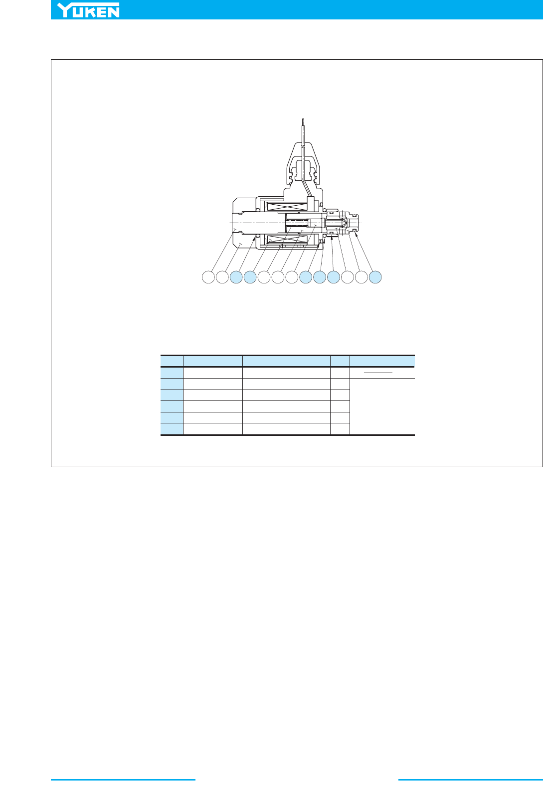
486
Solenoid Operated Poppet Type Two-Way Valves
Item Name of Parts Part Numbers
Qty.
Seal Kit Numbers
6
10
11
12
13
14
O-Ring
O-Ring
Coil Ass'y
O-Ring
O-Ring
O-Ring
2697-VK317470-3
TK280163-7
SO-NB-P18
SO-NB-P16
SO-NB-P9
SO-NB-A014
1
1
1
1
1
1
KS-CDSC-01-10
Note: When ordering the seals, please specif
y
the seal kit number.
CDSC-01-C-D24-10/1090
■ List of Seals and Coil Ass'y
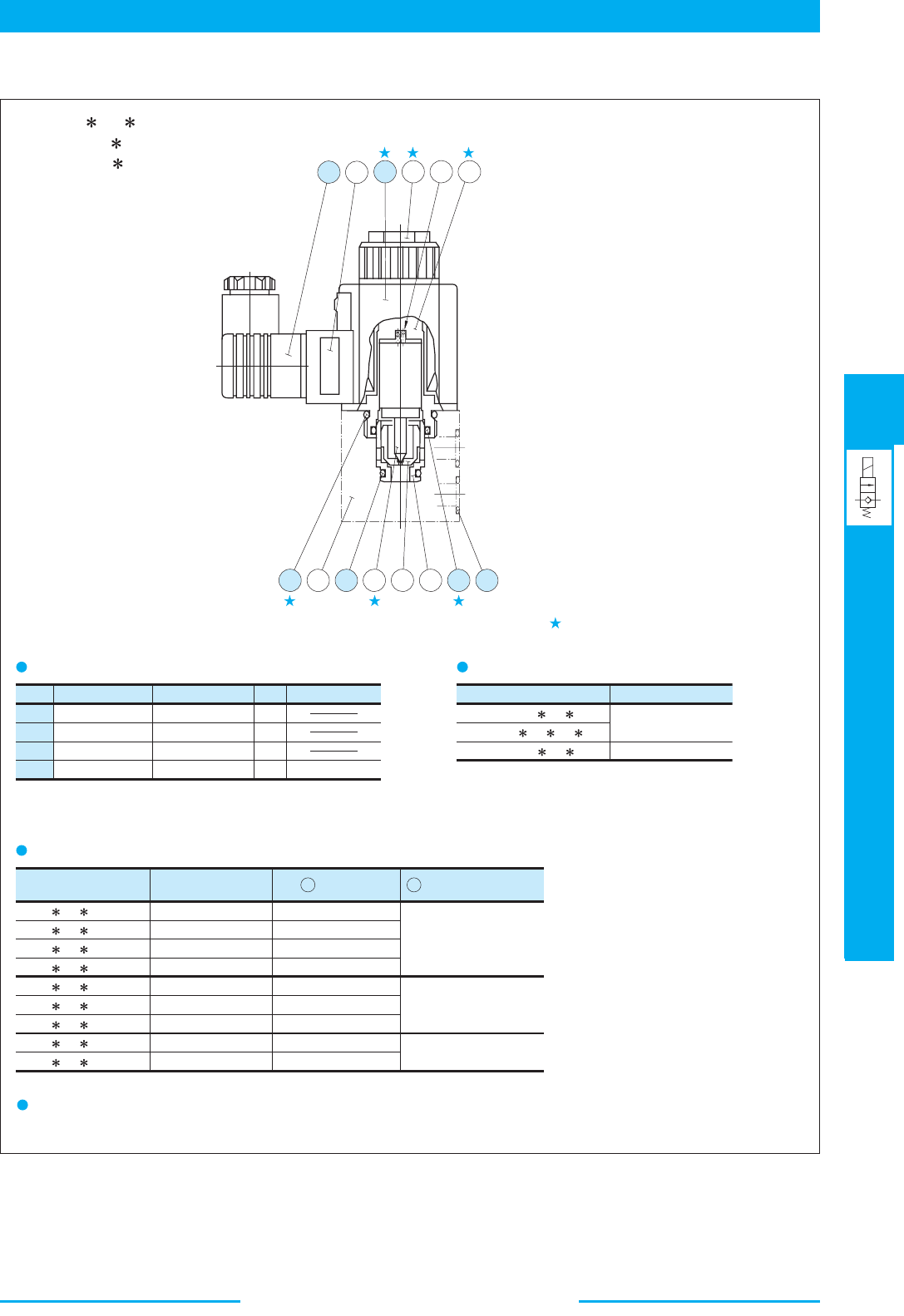
487
DIRECTIONAL CONTROLS
Solenoid Operated Poppet Type Two-Way Valves
E
Solenoid Operated Poppet Type Two-Way Valves
Solenoid assembly is composed of the parts marked with .
Item Name of Parts Part Numbers Qty. Remarks
9
10
11
14
O-Ring
O-Ring
O-Ring
O-Ring
SO-NB-P26
SO-NB-P20
SO-NB-P12
SO-NB-A014
1
1
1
2 only for CDSG
Valve Model No. Solenoid Ass'y No.
CDS -03 -C-A100
CDS -03 -C-A120
CDS -03 -C-A200
CDS -03 -C-A240
CDS -03 -C-D12
CDS -03 -C-D24
CDS -03 -C-D48
CDS
-03 -C-R100
CDS -03 -C-R200
CSA1-100-20
CSA1-120-20
CSA1-200-20
CSA1-240-20
CSD1-12-20
CSD1-24-20
CSD1-48-20
CSR1-100-20
CSR1-200-20
Coil No.
1
C-CSA1-100-20
C-CSA1-120-20
C-CSA1-200-20
C-CSA1-240-20
C-SD1-12-50
C-SD1-24-50
C-SD1-48-50
C-SR1-100-50
C-SR1-200-50
Connector Ass'y No.
GDM-211-B-11
GDM-211-B-11
GDME-211-R-B-10
12
Valve Model Numbers Seal Kit Numbers
CDSC-03-C- -21
CDST-03 -C- -21
CDSG-03-C- -21
KS-CDSC-03-20
KS-CDSG-03-20
12
5
1 4 3 2
9 13 11 6 8 7 10 14
List of Seals
Note: When ordering the seals, please specify the seal kit number
from the table right.
Solenoid Ass'y, Coil Ass'y and Connector Ass'y No.
List of Seal Kits
Change of supply voltage
The suppl
y
voltage can be changed b
y
replacing the coil.
CDST-03 -C- -21/2180/2190
CDSC-03-C- -21/2190
CDSG-03-C- -21/2190
■ List of Seals, Solenoid Ass'y, Coil Ass'y and Connector Ass'y
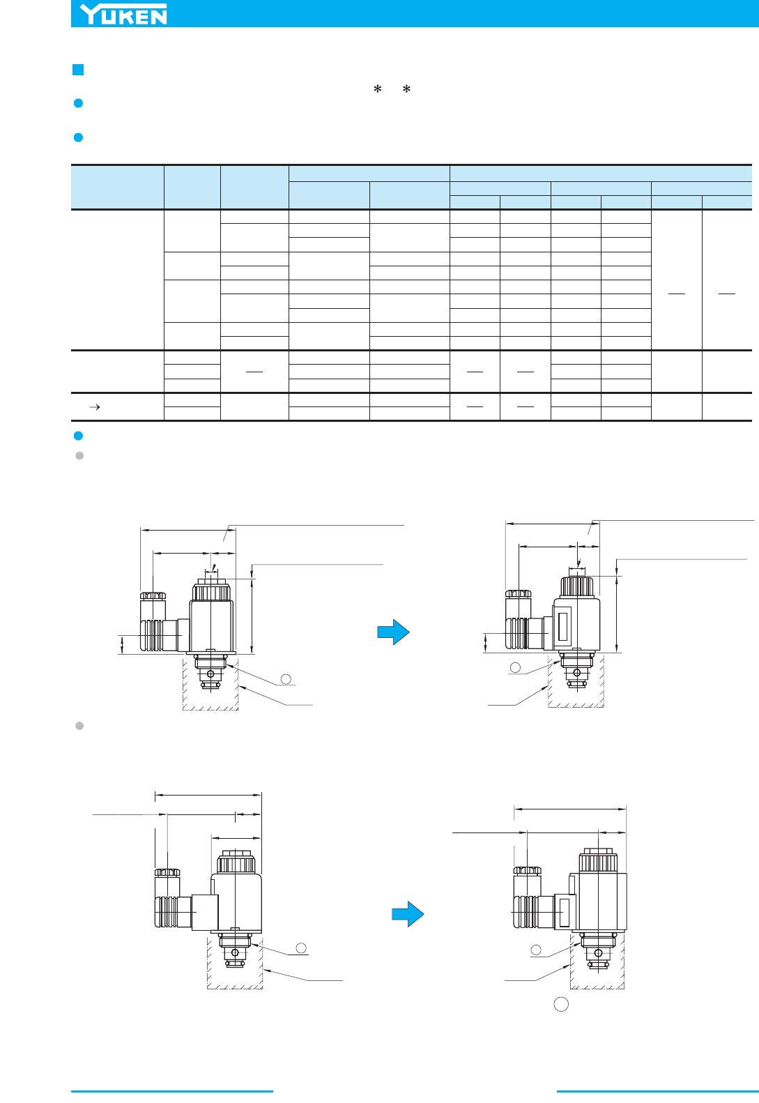
488
Solenoid Operated Poppet Type Two-Way Valves
Electric Source Coil Type
Frequency
(Hz)
Source
Rating
Serviceable
Range
New Current New New
Inrush (A) Holding (A) Power (W)
Current & Power at Rated VoltageVoltage (V)
0110805-100
100
110
120
200
200
220
240
12
24
48
100
60
50
60
50
60
50
60
50/60
A100
A120
A200
A240
D12
D24
D48
R100
R200
AC
DC
(K Series)
AC
DC Rectified
90 120-
96 132-
108 144-
160 220-
180 240-
216 288-
192 264-
10.8 13.2-
21.6 26.4-
43.2 52.8-
90 110-
180 220-200
0.55
0.40
0.36
0.46
0.33
0.28
0.20
0.18
0.23
0.17
2.20
1.10
0.55
0.30
0.15
0.52
0.39
0.47
0.45
0.33
0.27
0.20
0.24
0.23
0.17
2.40
1.20
0.60
0.32
0.17
1.12
0.95
0.86
0.93
0.79
0.56
0.48
0.43
0.47
0.40
1.30
1.08
1.19
1.08
0.98
0.65
0.54
0.59
0.55
0.45
26 29
26
29
A
A
R : 57.2(2.25)
: 99.4(3.91)
R : 103(4.06)
DC
A
A
DC
: 64(2.52)
R
: 57.2(2.25)
DC
:100.5(3.96)
R
:103.5(4.07)
DC
: 63.2(2.49)
48(1.89)
Dia.
24
(.94)
24.5
(.96)
Body
Body
ydoB
ydoB
18.7(.74)
75.2
(2.96)
52(2.05)
Space Needed to Remove Coil
Wrench Flats for Fixing Cartridge
Hex. 15(.59)
23.6
(.93)
52.2
(2.06)
88
(3.46)
Wrench Flats for Fixing Cartridge
Hex. 19(.75)
Space Needed to Remove Coil
48(1.89)
69
(2.72)
17.7(.70)
20
(.79)
86
(3.39)
54
(2.13)
Because of solenoid assembly improvements, CDS -03 has been model-changed (design 20 to design 21).
Specifications and Characteristics
There are no changes in the specifications and characteristics of the valves themselves.
Solenoid Ratings
There are changes in the inrush current, holding current and power as shown below. No other changes.
Interchangeability in Installation
AC Solenoids
Most items of mounting are interchangeable except the dimensions as shown below. In addition, the size of the spanner
(core end faces) for locking the CDSC cartridges has been changed to 15-19 mm across flats.
New: Design 21Current: Design 20
New: Design 21
Current: Design 20
DC/R Type Solenoids
Most items of mounting are interchangeable except the dimensions as shown below. The solenoid shape changed from
circular to hexagonal. No change in the size 15 mm of the spanner for locking cartridges.
Note: The above drawings give illustrations for the cartridge type. The dimension A at the mounting section remains
unchanged. In case of the Thread Connection Type and Gasket Mounting Type, a body is mounted to the hatched section.
The dimensions of the bod
y
remain unchanged.
Interchangeability between Current and New Design
Current Current
489
DIRECTIONAL CONTROLS
Shut-off Type
Solenoid Operated Directional Valves
E
Shut-off Type Solenoid Operated Directional Valves
1
2
1.
2.
3.
4.
3
4
3
3
3
Specifications
Model Numbers
Graphic Symbol
Max. Flow
L/min
(U.S.GPM)
"1" to "2"
Flow
"2" to "1"
Flow
Port "1"
Port
"2"
Max. Operating Pressure
Max.
Changeover
Frequency
-1
min
(Cycles/Min)
Internal
leakage
3
cm /min
(cu.in./min)
AC DC
Approx.
Mass
kg(1bs.)
DSPC-01-C- -20
DSPG-01-C- -20
DSPC-03-C- -10
DSPG-03-C- -10
40
(10.6)
80
(21.1)
10 (1450) 16 (2320) 25 (3630)
300
240
or Less
0.25 (.015)
or Less
0.25 (.015)
0.45 (1.0)
1.45 (3.2)
0.9 (2.0)
3.8 (8.4)
0.6 (1.3)
1.6 (3.5)
1.0 (2.2)
3.9 (8.6)
1
2
Port
"2"
Port
"1"
Maximum flow rates depend on operating conditions. For details, see page 491.
Do not connect port "1" to a line subjected to surge pressures. In addition, if you use port "1" for tank line, be sure to keep the end of the
line in the oil.
Protections against dust and water conform to the international electric standard (IEC) PUBL 529 IP64.
In the case of "DSPC-01-C-D ", use iron material for installation body (cabity).
The shut-off type solenoid operated directional valves are poppet type
solenoid operated two-way directional valves developed to meet the
needs of this age such as energy and resources saving.
High-response
High response is provided by the poppet design.
Smallest internal leakage
Internal leakage are very small, less than 5 drips per min., which is
achieved by the poppet design.
Two mounting types: cartridge and sub-plate
Mounting dimensions for both types conform to ISO standard.
Water-proof type (conforming to JIS D 0203 Water Spray Test
32) is also available.
■ Shut-off Type Solenoid Operated Directional Valves
490
Shut-off Type Solenoid Operated Directional Valves
1
1.
2.
2
F:
Special Seals
for Phosphate
Ester Type
Fluids
(Omit if not
required)
Special Seals
F-
90:
N. American
Design Std.
Model Number Designation
Sub-plate
DSP
Series
Number
G
Type of
Connection
-01
Valve Size
-C
Valve Type
-D24
Coil Type
-20
Design
Number
Design Standard
20
10
01
03
DSP:
Shut-Off Type
Solenoid
Operated
Directional
Valves
C:
Cartridge Type
G:
Sub-plate
Mounting
C:
Normally
Closed
AC
A 100
A 200
DC
D12
D24
None:
Japanese Std.
"JIS" & European
Design Std.
Solenoid Ratings
Electric
Source
Coil Type
Frequency
(Hz)
Source
Rating
Serviceable
Range
01 03 01 03 01 03
Inrush (A) Holding (A) Power (W)
egatloV detaR ta rewoP & tnerruC)V( egatloV
2.42
2.14
2.35
1.21
1.07
1.18
5.37
4.57
5.03
2.69
2.29
2.52
0.51
0.37
0.44
0.25
0.19
0.22
0.90
0.63
0.77
0.45
0.31
0.38
2.45
1.23
3.16
1.57
29 38
-80 110
-90 120
-160 220
-180 240
-10.8 13.2
-21.6 26.4
100
100
110
200
200
220
12
24
50
60
50
60
A100
A200
D12
D24
DC
(K Series)
AC
Model
Numbers
Sub-plate
Model Numbers
Thread
Size
Japanese Standard "JIS"
Sub-plate
Model Numbers
Thread
Size
European Design Standard
Sub-plate
Model Numbers
Thread
Size
N.American Design Standard
Approx.
Mass
kg (lbs.)
Rc 1/8 F.PSB 8/113-10-MGSD DSGM-01-3180
1/8 NPT
DSGM-01-3190 0.8 (1.8)
DSGM-01X-31
DSGM-01Y-31
DSGM-03-40
DSGM-03X-40
DSGM-03Y-40
Rc 1/4
Rc 3/8
Rc 3/8
Rc 1/2
Rc 3/4
DSGM-01X-3180
DSGM-03-2180
DSGM-03X-2180
DSGM-03Y-2180
1/4 BSP.F
3/8 BSP.F
1/2 BSP.F
3/4 BSP.F
DSGM-01X-3190
DSGM-01Y-3190
DSGM-03-2190
DSGM-03X-2190
DSGM-03Y-2190
1/4 NPT
3/8 NPT
3/8 NPT
1/2 NPT
3/4 NPT
0.8 (1.8)
0.8 (1.8)
3.0 (6.6)
3.0 (6.6)
4.7 (10.4)
DSPG-01
DSPG-03
Mounting Bolts
Descriptions Soc. Hd. Cap Screw (4 pcs.) Tightening Torque
Japanese Standard "JIS" and
European Design Standard
N. American Design Standard
Japanese Standard "JIS" and
European Design Standard
N. American Design Standard
M5 50 Lg.
No. 10-24 UNC 2 Lg.
M6 80 Lg.
1/4-20 UNC 3-1/4 Lg.
5-7 Nm
(44 -62 in. 1bs.)
12-15 Nm
(106 -133 in. 1bs.)
Valve Model Numbers
DSPG-01
DSPG-03
Four socket head cap screws in the table below are included.
Sub-plates are available. Specify the sub-plate model number from the table above. When sub-plates are not used, the mounting surface should
have a good machined finish.
Inrush current in the above table show rms values at maximum stroke.
K-Series DC Solenoid which has a reputation for excellent DC control is employed.
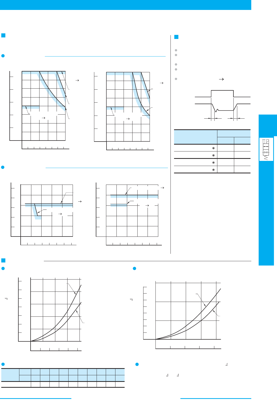
491
DIRECTIONAL CONTROLS
Shut-off Type
Solenoid Operated Directional Valves
E
Shut-off Type Solenoid Operated Directional Valves
Typical Performance Characteristics at Viscosity 30 mm
2
/s (141 SSU) [ISO VG 46 oils, 50°C(122°F)]
Maximum Flow Rate
The zone under each shaded line denotes the flow rate ranges being free of
trouble in changeover.
DSPC/DSPG-01
PSI
MPa
Models with AC Solenoids
40
30
20
10
51015202
5
0
Direction
of flow
"2" "1"
0 1000 2000 300
0
2
0
4
6
8
10
L /min
U.S.GPM
100 %V
(50, 60 Hz)
80 %V
(50 Hz)
90 %V
(60 Hz)
Direction of flow
"1" "2"
Pressure
Flow Rate
40
30
20
10
0 5 10 15 20 25
PSI
MPa
Models with DC Solenoids
Direction
of flow
"2" "1"
0 1000 2000 300
0
2
0
4
6
8
10
L /min
U.S.GPM
100 %V
Direction of flow
"1" "2"
90 %V
Pressure
Flow Rate
DSPC/DSPG-03
20
40
60
80
100
0
510152025
Models with AC Solenoids
10
0
15
20
25
L /min
U.S.GPM
5
MPa
0 1000 2000 3000
PSI
Direction
of flow
"2" "1"
Direction of flow
"1" "2"
Pressure
Flow Rate
20
40
60
80
100
0
510152025
Models with DC Solenoids
10
0
15
20
25
L /min
U.S.GPM
5
MPa
0 1000 2000 3000
PSI
Direction of flow
"1" "2"
Direction of flow "2" "1"
Pressure
Flow Rate
Typical Changeover Time
[Test Conditions]
Pressure:
Flow Rate:
Viscosity:
Voltage:
Direction of Flow:
15 MPa (2180 PSI)
(01) 30 L/min (7.9 U.S.GPM)
(03) 63 L/min (16.6 U.S.GPM)
2
30 mm /s (141 SSU)
100 % V
"2" "1"
(After coil temperature rise and saturates)
ON
OFFOFF
0
0
Max.
Solenoid
Poppet Shift
T
1
T
2
Model Numbers
DSPC/DSPG-01-C-A
Shifting Time (ms)
22 30
69 14
22 20
60 80
DSPC/DSPG-01-C-D
DSPC/DSPG-03-C-A
DSPC/DSPG-03-C-D
T
1
T
2
Pressure Drop
DSPC/DSPG-01
DSPC/DSPG-03
4010 20 30
0
DSPG
0.5
1.0
1.5
2.0
2.
5
0
200
300
350
100
02468
10
DSPC
MPa
L /min
U.S.GPM
PSI
80
0
20 40 60
1.0
2.0
3.
0
0
300
400
100
MPaPSI
350
250
200
150
50
051015
L /min
20
U.S.GPM
DSPC
DSPG
Flow Rate
Pressure Drop P
Flow Rate
Pressure Drop P
Viscosity
SSU
Factor 0.81 0.87 0.96 1.03 1.09 1.14 1.19 1.23 1.27 1.30
77 98 141 186 232 278 324 371 417 464
2
mm /s 15 20 30 40 50 60 70 80
90 100
For any other viscosity, multiply the factors in the table below.
For any other specific gravity (G'), the pressure drop ( P') may be
obtained from the formula below.
P' = P(G'/0.850)
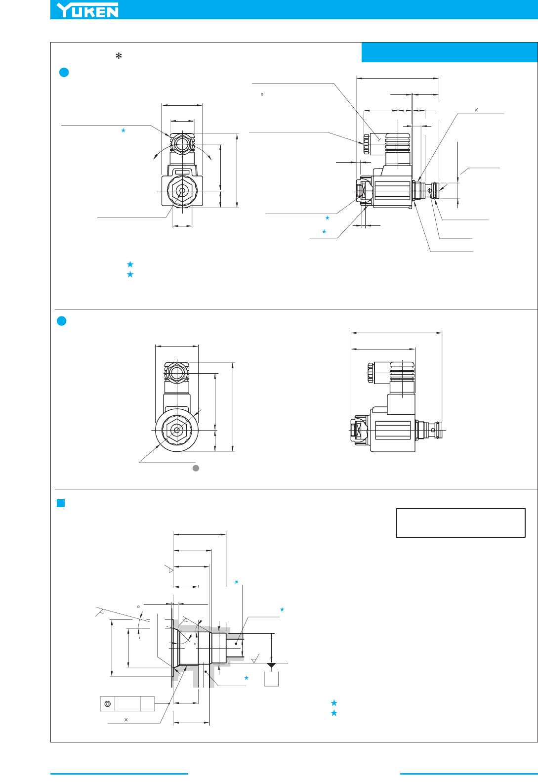
492
Shut-off Type Solenoid Operated Directional Valves
Mounting Surface: ISO 7789 20-01-0-93
2
1
2
1.
2.
3.
4.
3
3
45
27.5
(1.08)
47
(1.85)
Three positions of cable
departure are available in
90 increments.
The position can be changed
by loosening the nut .
Be sure to retighten the nut
after changing the position.
Manual Actuator
6(.24) Dia.
22
(.87)
20
(.79)
53
(2.09)
85
(3.35)
Cable Departure
Cable Applicable:
Outside Dia.
.....
8-10 mm (.31-.39 in.) Dia.
Conductor Area
.....
Not Exceeding
2
1.5m m
(.0023 Sq. in.)
4.5
(.18)
10
(.39)
14.5
(.57)
16
(.63)
39
(1.54)
0.3
(.01)
93.7
(3.69)
30.2
(1.19)
M20 1.5 Thd.
Port "1"
16.85(.6634)
16.82(.6622)
Dia.
O-Ring
SO-NB-A015
O-Ring
SO-NB-P18
Port "2"
4
(.16)
Core Tightening End
15(.59) Across Flats
Nut
72.5
(2.85)
103
(4.06)
47.5
(1.87)
64
(2.52)
24
(.94)
100
(3.94)
48(1.89) Dia.
1
.
6
1
5
6.3
30˚
3
.
2
1.6
A
0.1(.004)
Dia.
Max.
20.5(.807)
M20 1.5 Thd.
Port "2"
3
A
17.027(.6703)
17.000(.6693)
Dia.
Port "1"
6.2(.244)
6.0(.236)
Dia.
2.9(.114)
2.5(.098)
Min.
14.5(.571)
21.4(.842)
21.0(.827)
22.7(.893)
22.3(.878)
Min.
30.5(1.201)
R 0.1-0.3
22.7(.893)
22.6(.890)
33(1.30)
Dia.
Min.
14.5(.571)
18.6(.732)
18.5(.728)
Dia.
0.3(.012)
0.2(.008)
Models with AC Solenoids
DSPC-01-C- -20/2090
Tightening torque for iron core assembly: 30 - 50 Nm (266-443 IN. lbs.)
Tightening torque for nuts: 10.3 - 11.3 Nm (91-100 IN. lbs.)
Models with DC Solenoids
For other dimensions, refer to the "Models with AC Solenoids".
Details of Mounting Holes
Port diameter of 6.2 (.244) Dia. recommended.
Use iron materials for the mounting section.
DIMENSIONS IN
MILLIMETRES (INCHES)
(R .004-.012)
How to Mount
Loosen the coil fastening the nut and remove the coil.
Attach the coil and fix it with the nut.
1.
2.
3.
When mounting, the following steps must be followed.
Making use of the core tightening end, screw the
cartridge in.

493
DIRECTIONAL CONTROLS
Shut-off Type
Solenoid Operated Directional Valves
E
Shut-off Type Solenoid Operated Directional Valves
Mounting Surface: ISO 7789 27-01-0-93
1
2
1.
2.
3
3
3.
4.
2
27.5
(1.08)
69.5
(2.74)
61.8
(2.43)
27
(1.06)
100.8
(3.97)
32
(1.26)
Manual Actuator
6.3(.25) Dia.
5
(.20)
39
(1.54)
16
(.63)
0.3
(.01)
46
(1.81)
118.3
(4.66)
22
(.87)
19.5
(.77)
24.95(.98)
Dia.
22.85(.8996)
22.82(.8984)
Dia.
4
(.16)
Cable Departure
Cable Applicable:
Outside Dia.
.....
8-10 mm (.31-.39 in.) Dia.
Conductor Area
.....
Not Exceeding
2
1.5mm (.0023 Sq. in.)
Core Tightening End
22(.87) Across Flats
Nut
O-Ring
SO-NB-A119
O-Ring
SO-NB-A018
M27 2 Thd.
Port "2"
Port "1"
73.8
(2.91)
34.5
(1.36)
120.3
(4.74)
95
(3.74)
141.3
(5.56)
69(2.72) Dia.
0.05(.002)
Dia.
A
45˚
15˚
3
.
2
0
˚
-
2
˚
3
0
˚
6.3
1.6
A
1
.
6
Min.
22(.866)
Max.
35(1.378)
29.5(1.161)
29.4(1.158)
36(1.42)
Dia.
0.3(.012)
0.2(.008)
3.5(.138)
3.1(.122)
35.9(1.413)
35.5(1.398)
Min.
22(.866)
37.6(1.480)
37.2(1.465)
46.9(1.846)
46.5(1.831)
25.1(.988)
25.0(.984)
23.033(.9068)
23.000(.9055)
Dia.
R 0.1-0.3
(R .004-.012)
M27 2 Thd.
Port "2"
Port "1"
The position can be changed
by loosening the nut .
Be sure to retighten the nut
after changing the position.
Models with AC Solenoids
DSPC-03-C- -10/1090
Tightening torque for iron core assembly: 110-140 Nm (970-1240 IN. lbs.)
Tightening torque for nuts: 8.5-10.5 Nm (75-93 IN. lbs.)
Models with DC Solenoids
For other dimensions, refer to the "Models with AC Solenoids".
A recommendable port dia. is 11 (.433) mm.
Use iron materials for the mounting section.
DIMENSIONS IN
MILLIMETRES (INCHES)
Details of Mounting Holes
How to Mount
Loosen the coil fastening the nut and remove the coil.
Attach the coil and fix it with the nut.
1.
2.
3.
When mounting, the following steps must be followed.
Making use of the core tightening end, screw the
cartridge in.
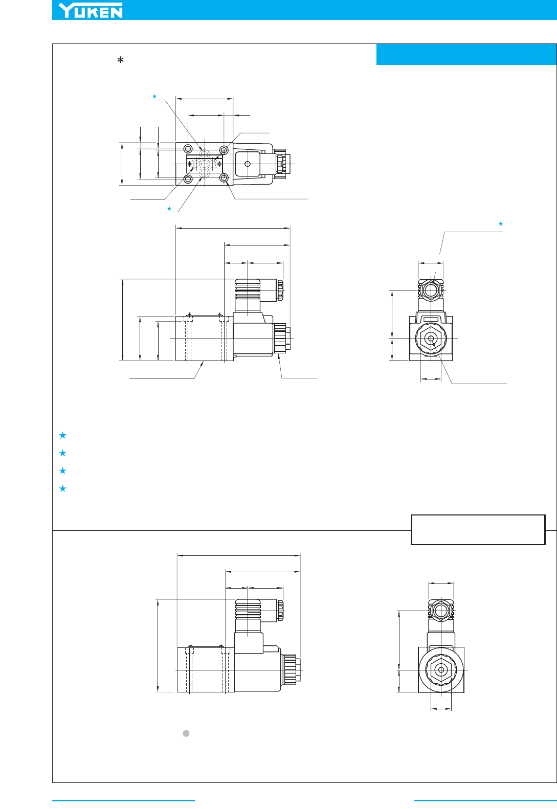
494
Shut-off Type Solenoid Operated Directional Valves
Mounting Surface: ISO 4401-AB-03-4-A
1.
2
2
2.
3.
4.
1
40.5
(1.59)
65
(2.56)
11
(.43)
0.75
(.03)
31
(1.22)
32.5
(1.28)
7.75
(.31)
48
(1.89)
Port "1"
Port "2"
5.5(.22) Dia. Through
9.5(.37) C' bore
4 Places
39
(1.54)
27
(1.06)
74.2
(2.92)
128.2
(5.05)
43
(1.69)
49
(1.93)
90
(3.54)
Lock Nut
Tightening Torque:
10.3-11.3 Nm
(91-100 IN. 1bs.)
Mounting Surface
(O-Rings Furnished)
27.5
(1.08)
53
(2.09)
25
(.98)
22
(.87)
Manual Actuator
6(.24) Dia.
Cable Departure
Cable Applicable:
Outside Dia.
.....
8-10 mm(.31-.39 in.) Dia.
Conductor Area
.....
Not Exceeding
1.5mm
2
(.0023 Sq. in.)
27.5
(1.08)
64
(2.52)
25
(.98)
27
(1.06)
39
(1.54)
83.5
(3.29)
137.5
(5.41)
101
(3.98)
22
(.87)
Models with AC Solenoids
DSPG-01-C- -20/2090
The location and the position of the cable departure can be changed. For details, see the cartridge type.
Models with DC Solenoids
These ports (2) are not used. In addition, the body has the O-ring grooves and O-rings are included in the body.
The mounting dimensions conform to ISO 4401-AB-03-4-A. Ports A and B are used as ports "2" and "1" respectively.
O-rings for ports: SO-NB-P9
For other dimensions, refer to the "Models with AC Solenoids".
DIMENSIONS IN
MILLIMETRES (INCHES)
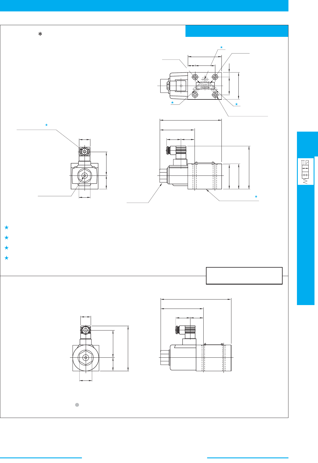
495
DIRECTIONAL CONTROLS
Shut-off Type
Solenoid Operated Directional Valves
E
Shut-off Type Solenoid Operated Directional Valves
Mounting Surface: ISO 4401-AC-05-4-A
1.
2.
3.
4.
2
2
2
19
(.75)
54
(2.13)
92
(3.62)
46
(1.81)
12
(.47)
70
(2.76)
Port "2"
Port "1"
3
Mounting Surface
(O-Rings Furnished)
7(.28) Dia. Through
11(.43) Dia. Spotface
4 Places
39
(1.54)
35
(1.38)
91
(3.58)
164
(6.46)
69
(2.72)
70
(2.76)
109.3
(4.30)
Lock Nut
Tightening Torque:
8.5-10.5 Nm
(75-93 IN. 1bs.)
35.5
(1.40)
61.8
(2.43)
32
(1.26)
27.5
(1.08)
Manual Actuator
6.3(.25) Dia.
1
Cable Departure
Cable Applicable:
Outside Dia.
.....
8-10 mm (.31-.39 in.) Dia.
Conductor Area
.....
Not Exceeding
1.5mm
2
(.0023 Sq. in.)
27.5
(1.08)
73.8
(2.91)
35.5
(1.40)
121.3
(4.78)
32
(1.26)
39
(1.54)
35
(1.38)
114
(4.49)
187
(7.36)
Models with AC Solenoids
DSPG-03-C- -10/1090
The location and the position of the cable departure can be changed. For details, see the cartridge type.
Models with DC Solenoids
These ports (3) are not used. In addition, the body has the O-ring grooves and O-rings are included in the body.
The dimensions of mounting surface conform to ISO 4401-AC-05-4-A. Ports A and B are used as port 2 and port 1 respectively.
O-rings for each port: SO-NB-A014
For other dimensions, refer to the "Models with AC Solenoids".
DIMENSIONS IN
MILLIMETRES (INCHES)
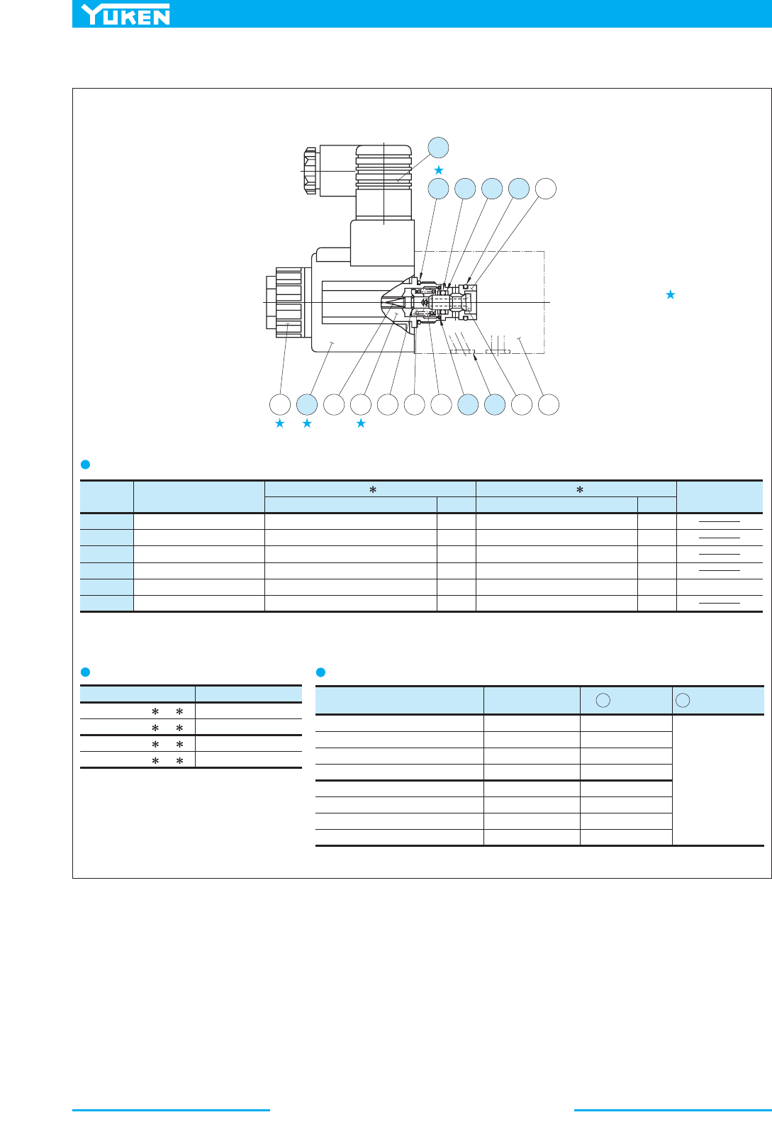
496
Shut-off Type Solenoid Operated Directional Valves
Item Remarks
Valve Model No. Solenoid Ass'y No.
DSPC/DSPG-01-C-A100-20/2090
12 Coil No. 13 Connector No.
GDM-211-B-11
Valve Model Numbers Seal Kit Numbers
DSPC-01-C-
-20
C-SA1-100-N-60
Name of Parts
DSP -01
.ytQ.ytQsrebmuN traP
DSP -03
8
9
10
15
16
17
O-Ring
O-Ring
O-Ring
O-Ring
O-Ring
Back Up Ring 5701-VK413831-9
SO-NA-P8
SO-NB-A014
SO-NB-A015
SO-NB-P9
SO-NB-P18
Part Numbers
2691-VK418550-0
SO-NA-P12
SO-NB-A017
SO-NB-A018
SO-NB-A014
SO-NB-A119
1
1
1
4
1
2
1
1
1
5
1
2
only for "DSPG"
DSPC/DSPG-01-C-A200-20/2090
DSPC/DSPG-01-C-D12-20/2090
DSPC/DSPG-01-C-D24-20/2090
DSPC/DSPG-03-C-A100-10/1090
DSPC/DSPG-03-C-A200-10/1090
DSPC/DSPG-03-C-D12-10/1090
DSPC/DSPG-03-C-D24-10/1090
C-SA1-200-N-60
C-SD1-12-N-60
C-SD1-24-N-60
C-SA3-100-N-50
C-SA3-200-N-50
C-SD3-12-N-50
C-SD3-24-N-50
SA1-100-N-6055
SA1-200-N-6055
SD1-12-N-6055
SD1-24-N-6055
SA3-100-N-5130
SA3-200-N-5130
SD3-12-N-5130
SD3-24-N-5130
KS-DSPC-01-C-10
KS-DSPC-03-C-10
KS-DSPG-01-C-10
KS-DSPG-03-C-10
DSPC-03-C- -10
DSPG-01-C- -20
DSPG-03-C- -10
13159645711
16 8 17 10
2
13
1218
List of Seals
Solenoid Ass'y, Coil Ass'y and Connector Ass'y No.
List of Seal Kits
Solenoid assembly is composed of the
parts marked with .
Note: When ordering the seals, specify the seal kit number from the table below.
■ List of Seals, Solenoid Ass'y, Coil Ass'y and Connector Ass'y
497
Check/Pilot Controlled Check Valves
Check/Pilot Controlled Check Valves
25
(3630)
498
504
25
(3630)
02 03 06 10
10 16 24
03 06 10
10 16
03 06 10
2000 5000200 500100502010521 1000
L/min
U.S.GPM
.3 .5 1 2 10 50 100 200 500 1000205
Max.
Operating
Pressure
MPa (PSI)
Graphic
Symbols
Page
Valve Type
Check Valves
In-Line
(CIT)
Right Angle
(CRT/CRG)
Flanged Connection(CP F)
Threaded Connection(CP T)
Sub-plate Mounting(CP G)
Right Angle, Flanged Connection
(CRF)
Pilot Operated
Check Valves
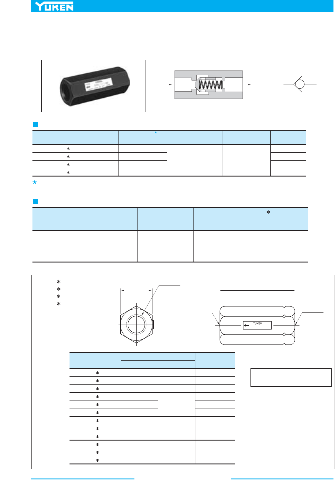
Check/Pilot Controlled Check Valves
498
■ In-Line Check Valves
These valves allow free flow in one direction and prevent flow in the reverse direction. Cracking pressure specified
is the pressure required to open the valve and allow free flow.
Graphic Symbol
Max. Operating Pres.
MPa (PSI)
Model Numbers
Approx. Mass
kg (lbs.)
0.1 (.22)
0.3 (.66)
0.8 (1.8)
2.3 (5.1)
Cracking Pres.
MPa (PSI)
Rated Flow
L /min (U.S.GPM)
CIT-02- -50/5080/5090
CIT-03- -50/5080/5090
CIT-06- -50/5080/5090
CIT-10- -50/5080/5090
0.04 (6)
0.35 (50)
0.5 (70)
25
(3630)
16 (4.23)
30 (7.93)
85 (22.5)
230 (60.8)
CI T -04 -50
Series
Number
Type of
Connection
Valve
Size
Design
Number
Design
Standards
-03
02
03
06
10
50
50
50
50
None:
Japanese Std. "JIS"
80:
European Design Std.
90:
N. American Design Std.
04:
0.04 (6)
35:
0.35 (50)
50:
0.5 (70)
T:
Threaded
Connection
CI:
In-Line
Check Valve
Cracking Pressure
MPa (PSI)
Model Number Designation
Specifications
Note: For In-Line Check Valves, standard type (for petroleum base oils) can be used phosphate ester type fluid.
Rated flow is the approximate flow rate, when there is a free flow pressure drop of maximum 0.3 MPa (44 PSI), the fluid has a specific
2
gravity of 0.85 and a kinematic viscosity of 20 mm /s (98 SSU), and the cracking pressure is 0.04 MPa (6 PSI).
Model Numbers
"D"
Thd.
mm (Inches)
A B
CIT-02- -50
CIT-02- -5080
CIT-02- -5090
CIT-03- -50
CIT-03- -5080
CIT-03- -5090
CIT-06- -50
CIT-06- -5080
CIT-06- -5090
CIT-10- -50
CIT-10- -5080
CIT-10- -5090
Rc 1/4
1/4 BSP.F
1/4 NPT
Rc 3/8
3/8 BSP.F
3/8 NPT
Rc 3/4
3/4 BSP.F
3/4 NPT
Rc 1-1/4
1-1/4 BSP.F
1-1/4 NPT
19 (.75)
22 (.87)
19 (.75)
27 (1.06)
41 (1.61)
60 (2.36)
58
65
58
76
83
76
95
102
95
(2.28)
(2.56)
(2.28)
(2.99)
(3.27)
(2.99)
(3.74)
(4.02)
(3.74)
133
(5.24)
FREE
A
B
"D"
Thd.
2 Places
Outlet Port
Inlet Port
CIT-02- -50/5080/5090
CIT-03- -50/5080/5090
CIT-06- -50/5080/5090
CIT-10- -50/5080/5090
DIMENSIONS IN
MILLIMETRES (INCHES)
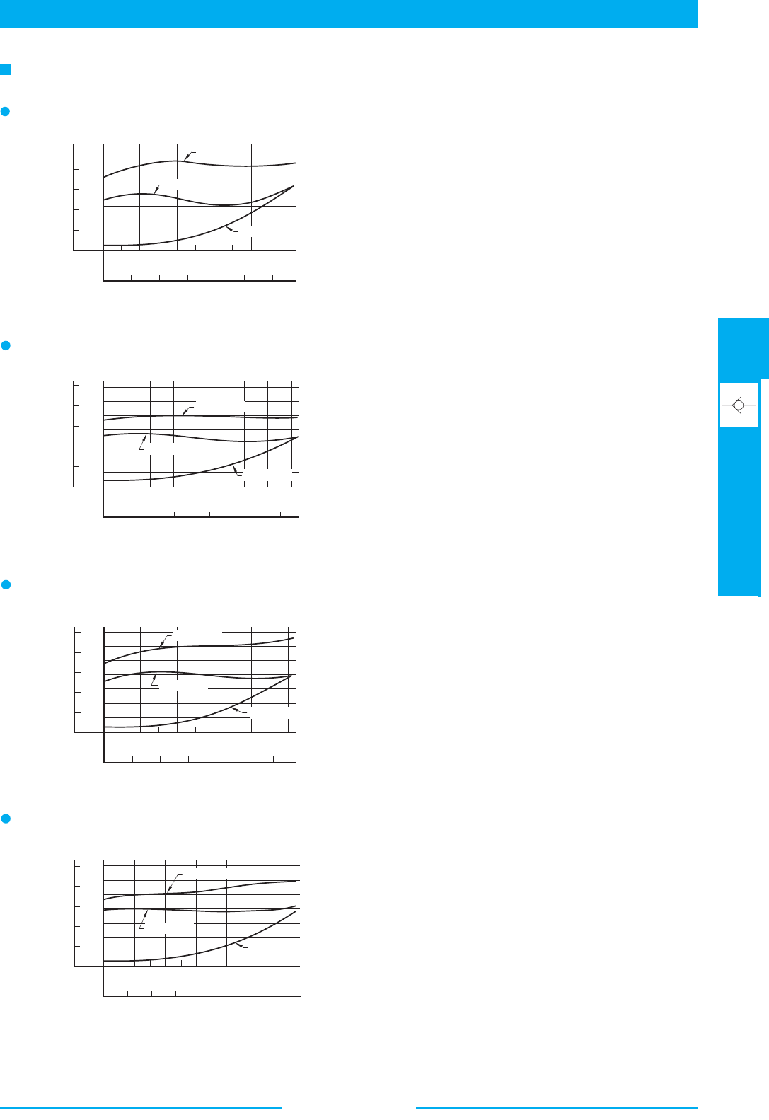
499
DIRECTIONAL CONTROLS
In-Line Check Valves
E
In-Line Check Valves
Hydraulic Fluid: Viscosity 30 mm
2
/s (141 SSU), Specific Gravity 0.850
Pressure Drop
CIT-02
0
10
5
15 20 25
L/min
0
0.4
PSI
40
80
Pressure Drop ΔP
20
0
0.2
0.6
60
0
2
1
345
U.S.GPM
6
Flow Rate
0.7
MPa
100
CIT-02-50
CIT-02-35
CIT-02-04
0
10 20 30 40
L/min
0
24
U.S.GPM
6
Flow Rate
108
0
0.4
PSI
40
80
Pressure Drop ΔP
20
0
0.2
0.6
60
0.7
MPa
100
CIT-03-04
CIT-03-35
CIT-03-50
CIT-03
0
0.4
PSI
40
80
Pressure Drop ΔP
20
0
0.2
0.6
60
0.7
MPa
100
0
25 50 100
L/min
0
10 20
U.S.GPM
30
Flow Rate
75 125
CIT-06-50
CIT-06-35
CIT-06-04
CIT-06
0
50 100 200 300
L/min
0
20 40
U.S.GPM
60
Flow Rate
80
0
0.4
PSI
40
80
Pressure Drop ΔP
20
0
0.2
0.6
60
0.7
MPa
100
150
250
CIT-10-35
CIT-10-04
CIT-10-50
CIT-10
500
Right Angle Check Valves
CR T -04 -50
Series
Number
Type of
Connection
Valve
Size
Design
Number
Design
Standards
-03
03
06
10
03
06
10
04:
35:
50:
04:
35:
50:
None:
Japanese Std. "JIS"
& European Design Std.
90:
N. American Design Std.
T:
Threaded
Connection
Cracking Pressure
MPa (PSI)
Model NumbersType of Connection
CRT-03- -50/5080/5090
CRT-06- -50/5080/5090
CRT-10- -50/5080/5090
CRG-03- -50/5090
CRG-06- -50/5090
CRG-10- -50/5090
Max. Operating Pres.
MPa (PSI)
Approx. Mass
kg (lbs.)
Cracking Pres.
MPa (PSI)
Rated Flow
L /min (U.S.GPM)
0.9 (2.0)
1.7 (3.7)
5.6 (12.3)
1.7 (3.7)
2.9 (6.4)
5.5 (12.1)
25 (3630)
0.04 (6)
0.35 (50)
0.5 (70)
0.04 (6)
0.35 (50)
0.5 (70)
25 (3630)
40 (10.6)
125 (33)
250 (66)
40 (10.6)
125 (33)
250 (66)
Threaded Connection
Sub-plate Mounting
50
50
50
50
50
50
None:
Japanese Std. "JIS"
European Design Std.
90:
N. American Design Std.
80:
F-
Special
Seals
G:
Sub-plate
Mounting
CR:
Right Angle
Check Valve
F:
Special seals
for phosphate
ester type
fluids
(Omit if not
required)
0.04 (6)
0.35 (50)
0.5 (70)
0.04 (6)
0.35 (50)
0.5 (70)
Valve
Model
Numbers
Socket Head Cap Screw
Qty.
Japanese Standard "JIS"
European Design Standard
N.American Design Standard
CRG-03
CRG-06
CRG-10
4
4
6
M10 45 Lg.
M10 50 Lg.
M10 55 Lg.
3/8-16 UNC 1-3/4 Lg.
3/8-16 UNC 2 Lg.
3/8-16 UNC 2-1/4 Lg.
Approx. Mass
kg (lbs.)
Japanese Standard "JIS" European Design Standard N.American Design Standard
Valve
Model
Numbers
Sub-plate
Model Numbers
Sub-plate
Model Numbers
Sub-plate
Model Numbers
Thread
Size
Thread
Size
Thread
Size
CRG-03
CRG-06
CRG-10
(3.5)
(3.5)
(5.3)
(6.6)
(10.6)
(12.6)
1.6
1.6
2.4
3.0
4.8
5.7
3/8 NPT
1/2 NPT
3/4 NPT
1 NPT
1-1/4 NPT
1-1/2 NPT
3/8 BSP.F
1/2 BSP.F
3/4 BSP.F
1 BSP.F
1-1/4 BSP.F
1-1/2 BSP.F
Rc 3/8
Rc 1/2
Rc 3/4
Rc 1
Rc 1-1/4
Rc 1-1/2
CRGM-03-50
CRGM-03X-50
CRGM-06-50
CRGM-06X-50
CRGM-10-50
CRGM-10X-50
CRGM-03-5080
CRGM-03X-5080
CRGM-06-5080
CRGM-06X-5080
CRGM-10-5080
CRGM-10X-5080
CRGM-03-5090
CRGM-03X-5090
CRGM-06-5090
CRGM-06X-5090
CRGM-10-5090
CRGM-10X-5090
Model No.
Rated Flow
L /min (U.S.GPM)
Max. Operating
Pressure
MPa (PSI)
CRF-10- -50
CRF-16- -50
CRF-24- -50
300 (79.3)
600 (159)
1300 (343)
25 (3630)
Model Number Designation
Specifications
Rated flow is the approximate flow rate, when there is a free flow pressure drop of maximum 0.3 MPa (44 PSI), the fluid has a specific
2
gravity of 0.85 and a kinematic viscosity of 20 mm /s (98 SSU), and the cracking pressure is 0.04 MPa (6 PSI).
Sub-plate
Mounting Bolts
Socket head cap screws in the table below are included.
Yuken can offer flanged connection
valves described below.
For details, contact us.
Sub-plates are available. Specify the sub-plate model number from the table above. When sub-plates are not used, the mounting surface
should have a good machined finish.
■ Right Angle Check Valves
These valves allow free flow in one direction and prevent flow in the reverse direction. Cracking pressure specified
is the pressure required to open the valve and allow free flow.
Graphic Symbol
501
DIRECTIONAL CONTROLS
Right Angle Check Valves
E
Right Angle Check Valves
Mounting surface: ISO 5781-AJ-10-2-A
CRT-03- -50
CRT-03- -5080
CRT-03- -5090
CRT-06- -50
CRT-06- -5080
CRT-06- -5090
CRT-10- -50
CRT-10- -5080
CRT-10- -5090
Rc 3/8
3/8 BSP.F
3/8 NPT
Rc 3/4
3/4 BSP.F
3/4 NPT
Rc 1-1/4
1-1/4 BSP.F
1-1/4 NPT
Model Numbers
"H"
Thd.
Dimensions mm (Inches)
FAB DE
62
(2.44)
36
(1.42)
38
(1.50)
Dia
80.5
(3.17)
33
(1.30)
44
(1.73)
45
(1.77)
54
(2.13)
Dia.
104.5
(4.11)
49
(1.93)
54
(2.13)
65
(2.56)
80
(3.15)
SQ.
130
(5.12)
65
(2.56)
80
(3.15)
74
(2.91)
107
(4.21)
ecafruS gnitnuoMsrebmuN ledoM
Dimensions mm (Inches)
FABCDE H J
ISO 5781-AG-06-2-A
ISO 5781-AH-08-2-A
CRG-03
CRG-06
90
(3.54)
102
(4.02)
79.4
(3.13)
66.7
(2.63)
11.3
(.44)
11.7
(.46)
93
(3.66)
72
(2.83)
60.3
(2.37)
42.9
(1.69)
21.4
(.84)
17.5
(.69)
84.5
(3.33)
72.5
(2.85)
35
(1.38)
30
(1.18)
E
FREE
FREE
A
F
B
C
C
D
"H"
Thd.
2 Places
Outlet Port
Inlet Port
D
E
F
B
A
J
H
6
C
Outlet Port
Inlet Port
Mounting Surface
(O-Rings Furnished)
Locating Pin
6(.24) Dia.
(.24)
Outlet Port
Inlet Port
11(.43) Dia. Through
17.5(.69) Dia. Spotface
6 Places
Mounting Surface
(O-Rings Furnished)
Locating Pin
6(.24) Dia.
96.8
(3.81)
120
(4.72)
11.6
(.46)
42.1
(1.66)
84.1
(3.31)
123
(4.84)
20.3 (.80)
97
(3.82)
6
(.24)
40
(1.57)
11(.43)
Dia. Through
17.5(.69) Dia. Spotface
4 Places
CRT-03- -50/5080/5090
CRT-06- -50/5080/5090
CRT-10- -50/5080/5090
DIMENSIONS IN
MILLIMETRES (INCHES)
CRG-03- -50/5090
CRG-06- -50/5090
CRG-10- -50/5090
C
502
Right Angle Check Valves
CRGM-03-50
CRGM-03-5080
CRGM-03-5090
CRGM-03X-50
CRGM-03X-5080
CRGM-03X-5090
Sub-plate
Model Numbers
Thread Size
"A"
Thd.
"B"
Thd.
Rc 3/8
3/8 BSP.F
3/8 NPT
Rc 1/2
1/2 BSP.F
1/2 NPT
M10
3/8-16 UNC
3/8-16 UNC
M10
82.3 (3.24)
80 (3.15)
82.3 (3.24)
22 (.87)
24 (.94)
22 (.87)
"H"
Thd.
"J"
Thd.
Rc 3/4
3/4 BSP.F
3/4 NPT
Rc 1
1 BSP.F
1 NPT
M10
3/8-16 UNC
3/8-16 UNC
M10
FEDCBA
Thread SizeDimensions mm (Inches)
Sub-plate
Model Numbers
CRGM-06-50
CRGM-06-5080
CRGM-06-5090
CRGM-06X-50
CRGM-06X-5080
CRGM-06X-5090
124
(4.88)
10
(.39)
77
(3.03)
27
(1.06)
36
(1.42)
110
(4.33)
136
(5.35)
16
(.63)
45
(1.77)
130
(5.12)
"H"
Thd.
"J"
Thd.
Rc 1-1/4
1-1/4 BSP.F
1-1/4 NPT
Rc 1-1/2
1-1/2 BSP.F
1-1/2 NPT
M10
3/8-16 UNC
3/8-16 UNC
M10
FEDCBA
Thread SizeDimensions mm (Inches)
Sub-plate
Model Numbers
CRGM-10-50
CRGM-10-5080
CRGM-10-5090
CRGM-10X-50
CRGM-10X-5080
CRGM-10X-5090
150
(5.91)
177
(6.97)
12
(.47)
25.5
(1.00)
96
(3.78)
104
(4.09)
30
(1.18)
22
(.87)
45
(1.77)
50
(1.97)
135
(5.31)
167
(6.57)
90(3.54)
70(2.76)
33.3
(1.31)
66.7(2.63)
7.1
(.28)
(1.25)
31.8
(1.41)
35.7
42.9
(1.69)
19.5
(.77)
21
(.83)
61
(2.40)
82
(3.23)
102
(4.02)
10
(.39)
90
(3.54)
15
(.59)
32(1.26)
13(.51)
Dia.
2 Places
"B"
Thd.
20(.79) Deep
4 Places
8.8(.35) Dia. Through
14(.55) Dia. Spotface
4 Places
10(.39)
1.7(.07)
"A"
Thd.
2 Places
7(.28) Dia.
10(.39) Deep
102(4.02)
79.4(3.13)
11.3
(.44)
39.7
(1.56)
8.8(.35)
Dia. Through
14(.55) Dia. Spotface
4 Places
22(.87) Dia.
2 Places
"J"
Thd.
20(.79) Deep
4 Places
11.1
(.44)
(1.75)
44.5
(1.94 )
49.2
(2.37)
60.3
22
(.87)
D
C
104(4.09)
A
B
F
15
(.59)
E
7(.28) Dia.
10(.39) Deep
"H"
Thd.
2 Places
F
19
(.75)
E
28(1.10) Dia.
2 Places
A
(.66)
16.7
(1.66)
42.1
(2.47)
62.7
(2.66)
67.5
(3.31)
84.1
11.6
(.46)
120
(4.72)
48.4
(1.91)
96.8
(3.81)
140(5.51)
116(4.57)
7(.28)
Dia.
10(.39) Deep
"H"
Thd.
2 Places
11(.43) Dia. Through
17.5(.69) Dia. Spotface
4 Places
12(.47)
9.6(.38)
"J"
Thd.
20(.79) Deep
6 Places
B
D
C
(.83)
21
126(4.96)
DIMENSIONS IN
MILLIMETRES (INCHES)
CRGM-03-50/5080/5090
CRGM-03X-50/5080/5090
CRGM-06-50/5080/5090
CRGM-06X-50/5080/5090
CRGM-10-50/5080/5090
CRGM-10X-50/5080/5090
■ Sub-plate
503
DIRECTIONAL CONTROLS
Right Angle Check Valves
E
Right Angle Check Valves
Name of Parts .ytQmetI
CRT-03 CRT-06 CRT-10
Part Numbers
7
O-Ring
Seal Kit
SO-NB-P21
KS-CRT-03-50
SO-NB-P24
KS-CRT-06-50
SO-NB-P32
KS-CRT-10-50
1
Name of Parts .ytQmetI
CRG-03 CRG-06 CRG-10
Part Numbers
7
8
O-Ring
O-Ring
Seal Kit
SO-NB-P21
SO-NB-P18
KS-CRG-03-50
SO-NB-P24
SO-NB-P28
KS-CRG-06-50
SO-NB-P32
SO-NB-P32
KS-CRG-10-50
1
2
10
8
2
1
3
4
6
9
7
5
1
2
3
6
8
4
7
5
0
10 20
L/min
0
5
U.S.GPM
Flow Rate
30 40 50 60
15
10
0
0.4
PSI
40
80
Pressure Drop ΔP
0
0.2
0.6
0.8
140
1.0
120
MPa
0
25 50
L/min
0
10
U.S.GPM
Flow Rate
75 125 150 175
50
40
100 200
20 30
0
0.4
PSI
50
100
Pressure Drop ΔP
0
0.2
0.6
0.8
200
1.0
150
MPa
1.2
1.4
0
nim/L
05
0
20
U.S.GPM
Flow Rate
150
100
80
100 200
40 60
0
0.4
PSI
50
100
Pressure Drop ΔP
0
0.2
0.6
0.8
200
1.0
150
MPa
1.2
1.4
250 300 350
400
0
10 20
L/min
0
5
U.S.GPM
Flow Rate
30 40 50 60
15
10
0
0.4
PSI
40
80
Pressure Drop ΔP
0
0.2
0.6
0.8
140
1.0
120
MPa
0
25 50
L/min
0
10
U.S.GPM
Flow Rate
75 125 150 175
50
40
100
200
20 30
0
0.4
PSI
50
100
Pressure Drop ΔP
0
0.2
0.6
0.8
200
1.0
150
MPa
1.2
1.4
0
50
L/min
0
20
U.S.GPM
Flow Rate
150
100
80
100 200
40 60
0
0.4
PSI
50
100
Pressure Drop ΔP
0
0.2
0.6
0.8
175
1.0
150
MPa
1.2
250 300 350
400
CRG-03-50
CRG-03-35
CRG-03-04
CRG-06-50
CRG-06-35
CRG-06-04
CRG-10-50
CRG-10-35
CRG-10-04
CRT-10-50
CRT-10-35
CRT-10-04
CRT-06-50
CRT-06-35
CRT-06-04
CRT-03-50
CRT-03-35
CRT-03-04
Hydraulic Fluid: Viscosity 30mm
2
/s (141 SSU), Specific Gravity 0.850
CRT-03
CRT-06
CRT-10
CRG-03
CRG-06
CRG-10
List of Seals
CRT-03-50/5080/5090
CRT-06-50/5080/5090
CRT-10-50/5080/5090
CRG-03-50/5090
CRG-06-50/5090
CRG-10-50/5090
When ordering the O-Rings, please specify the seal kit number from the table
above.
When ordering the O-Rings, please specify the seal kit number from the table
above.
List of Seals & Seal Kits
List of Seals & Seal Kits
Pressure Drop
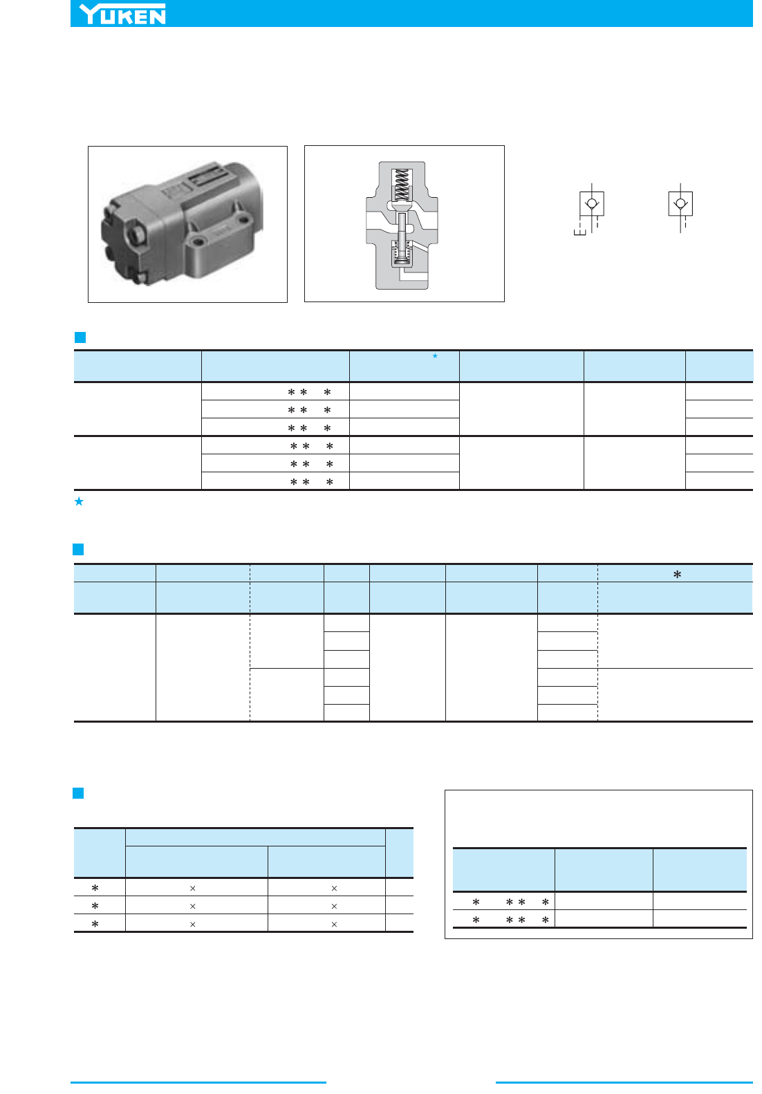
504
Pilot Operated Check Valves
Specifications
Model Numbers
Rated Flow
L /min (U.S.GPM)
CP F-10- - -50
CP F-16- - -50
Max. Operating
Pressure
MPa (PSI)
250
600
(66)
(159)
25
25
(3630)
(3630)
Valve
Model
Numbers
Socket Head Cap Screw
Qty.
Japanese Standard "JIS" &
European Design Standard
N.American
Design Standard
CP G-03
CP G-06
CP G-10
4
4
6
M10 45 Lg.
M10 50 Lg.
M10 55 Lg.
3/8-16 UNC 1-3/4 Lg.
3/8-16 UNC 2 Lg.
3/8-16 UNC 2-1/4 Lg.
CP T -04 -50
Series
Number
Type of
Connection
Valve
Size
Design
Number
Design
Standards
03
Cracking Pres.
MPa (PSI)
F-
Special
Seals
-E
Drain
Connection
03
06
10
03
06
10
50
50
50
50
50
50
None:
Japanese Std. "JIS"
European Design Std.
90:
N. American Design Std.
80:
None:
Japanese Std. "JIS" &
European Design Std.
90:
N. American Design Std.
T:
Threaded
Connection
G:
Sub-plate
Mounting
F:
Special Seals
for Phosphate
Ester Type
Fluids
(Omit if not
required)
CP:
Pilot Operated
Check Valve
CPD:
Decompression
Type Pilot
Operated
Check Valve
04:
20:
35:
50:
0.04 (6)
0.2 (29)
0.35 (50)
0.5 (70)
None:
Internal
Drain
E:
External
Drain
Threaded Connection
Model NumbersType of Connection
CPT/CPDT-03-
- -50
CPT/CPDT-06-
- -50
CPT/CPDT-10- - -50
CPG/CPDG-03- - -50
CPG/CPDG-06- - -50
CPG/CPDG-10- - -50
Max. Operating Pres.
MPa (PSI)
Approx. Mass
kg (lbs.)
Cracking Pres.
MPa (PSI)
Rated Flow
L /min (U.S.GPM)
25 (3630)
25 (3630)
40
125
250
40
125
250
Sub-plate Mounting
0.04
0.2
0.35
0.5
(6)
(29)
(50)
(70)
0.04
0.2
0.35
0.5
(6)
(29)
(50)
(70)
(10.6)
(33)
(66)
(10.6)
(33)
(66)
3.0
5.5
9.6
3.3
5.4
8.5
(6.6)
(12.1)
(21.2)
(7.3)
(11.9)
(18.7)
Yuken can offer flanged connection valves
described below.
For details, contact us.
Mounting Bolts
Socket head cap screws in the table below are included.
Model Number Designatioin
Graphic Symbols
Internal Drain Type External Drain Type
Rated flow is the approximate flow rate, when there is a free flow pressure drop of maximum 0.3 MPa (44 PSI), the fluid has a specific
2
gravity of 0.85 and a kinematic viscosity of 20 mm /s (98 SSU), and the cracking pressure is 0.04 MPa (6 PSI).
These check valves allow flow in one direction and prevent flow in the reverse direction, until operated by pilot pressure
to allow free reverse flow. The specified cracking pressure is required to open the valve to allow free flow direction.
■ Pilot Operated Check Valves
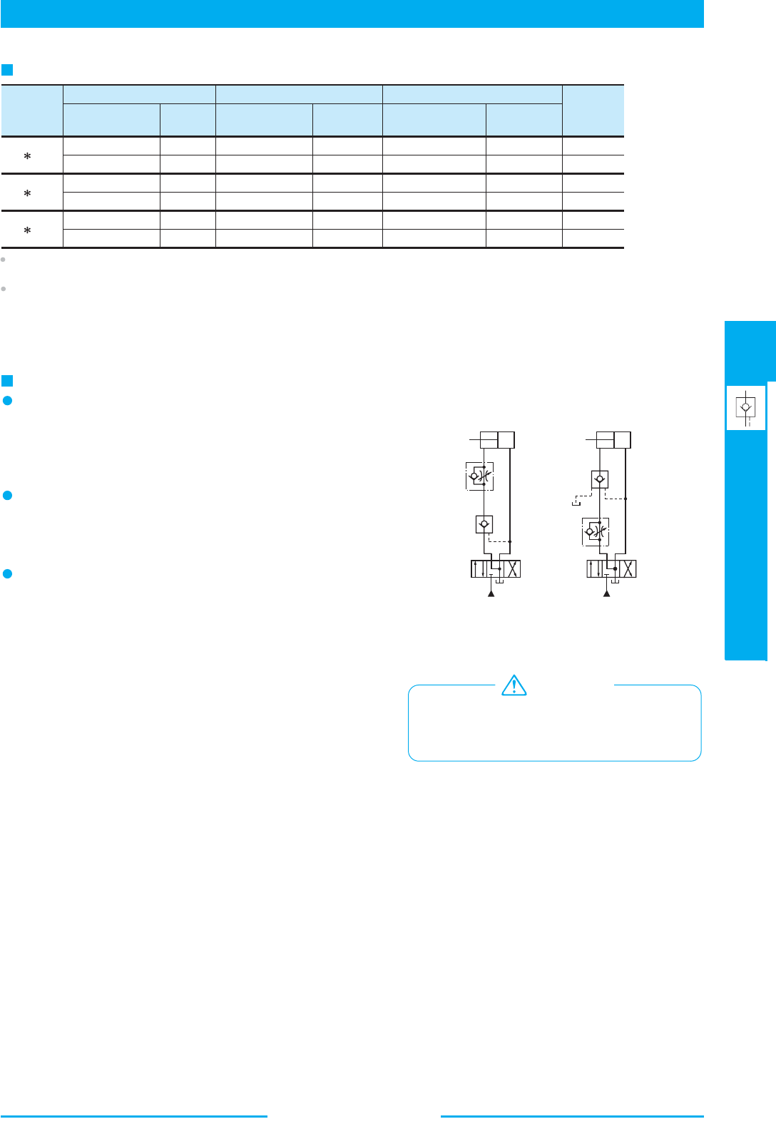
505
DIRECTIONAL CONTROLS
Pilot Operated Check Valves
E
Pilot Operated Check Valves
(Fig.a) (Fig.b)
P
1
P
2
P
2
P
1
DR
Valve
Model
Numbers
Japanese Standard "JIS"
Sub-plate
Model Numbers
Thread
Size
Sub-plate
Model Numbers
Thread
Size
Sub-plate
Model Numbers
Approx.
Mass
kg (lbs.)
Thread
Size
European Design Standard N. American Design Standard
CP G-03
CP G-06
CP G-10
1.6 (3.5)
1.6 (3.5)
2.4 (5.3)
3.0 (6.6)
4.8 (10.6)
5.7 (12.6)
Rc 3/8
Rc1/2
Rc 3/4
Rc 1
Rc 1-1/4
Rc 1-1/2
3/8 BSP.F
1/2 BSP.F
3/4 BSP.F
1 BSP.F
1-1/4 BSP.F
1-1/2 BSP.F
3/8 NPT
1/2 NPT
3/4 NPT
1 NPT
1-1/4 NPT
1-1/2 NPT
HGM-03-20
HGM-03X-20
HGM-06-20
HGM-06X-20
HGM-10-20
HGM-10X-20
HGM-03-2080
HGM-03X-2080
HGM-06-2080
HGM-06X-2080
HGM-10-2080
HGM-10X-2080
HGM-03-2090
HGM-03X-2090
HGM-06-2090
HGM-06X-2090
HGM-10-2090
HGM-10X-2090
Sub-plate
Instructions
Operation of internal and external drain types
When the outlet side P1 is directly connected to the tank in reversed
free flow (Fig. a), the internal drain type is normally used. When
the back pressure is applied to the outlet side P
1 (Fig. b), be sure
to use the external drain type.
Minimum pilot pressure characteristics
That depends on the pressure of the inlet side P
2 in the reversed
free flow.
This value can be determined from the characteristics chart.
Cautions on replacement of 20 design low cracking pressure
.sevlav ngised 05 htiw sevlav epyt
In 20 design valve with cracking pressure of 0.035 MPa (5 PSI)
(Code "5"), for closing the valve completely and certainly, it was
necessar y to introduc e the pressurize d oil into the drain port to
push down the piston compulsory.
While in 50 design valve with cracking pressure of 0.04 MPa (6
PSI) (Code "6"), it has such structure that the valve can be closed
completely and certainly without introducing the pressurized oil
into the drain port. On the contrary , what is worse is that if the
pressurized oil is introduced into the drain port, the oil acts towards
the direction o f opening the valve, which i s very dangerous and
has to be absolutely avoided. Therefore, please do not supply any
pressurized oil into the drain port in case of using 50 design valve.
The machinery, if misused due to failure to observe
the "Cautions" on the left, may perform
unforeseeable movements, resulting in a disastrous
accident.
WARNING
Sub-plates are available, specify the sub-plate model number from the table above. When sub-plates are not used, the mounting surface should
have a good machined finish.
Sub-plates are shared with those for H Type Pressure Control Valves. Refer to pages 244 to 246 for dimensions.
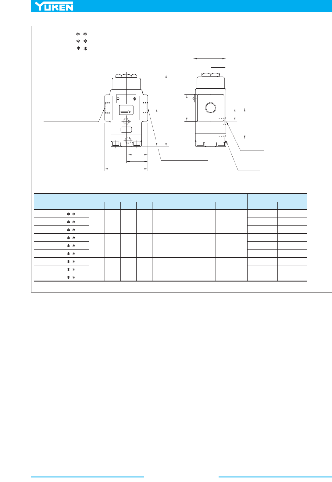
506
Pilot Operated Check Valves
Model Numbers
B
Dimensions mm (Inches)
C
CPT/CPDT-03- - -50
CPT/CPDT-03- - -5080
CPT/CPDT-03- - -5090
CPT/CPDT-06- - -50
CPT/CPDT-06- - -5080
CPT/CPDT-06- - -5090
CPT/CPDT-10- - -50
CPT/CPDT-10- - -5080
CPT/CPDT-10- - -5090
DEFH KLA
"N"
Thd.
"P"
Thd.
Thread Size
Rc 3/8
3/8 BSP.F
3/8 NPT
Rc 3/4
3/4 BSP.F
3/4 NPT
Rc 1-1/4
1-1/4 BSP.F
1-1/4 NPT
Rc 1/4
1/4 BSP.F
1/4 NPT
Rc 1/4
1/4 BSP.F
1/4 NPT
Rc 1/4
1/4 BSP.F
1/4NPT
80
(3.15)
40
(1.57)
39
(1.54)
150.5
(5.93)
84.5
(3.33)
38
(1.50)
Dia.
60
(2.36)
29
(1.14)
67.5
(2.66)
26.5
(1.04)
96
(3.78)
48
(1.89)
47
(1.85)
171.5
(6.75)
92.5
(3.64)
62
(2.44)
SQ.
72
(2.83)
35
(1.38)
75.5
(2.97)
31
(1.22)
140
(5.51)
70
(2.76)
64
(2.52)
203.5
(8.01)
113
(4.45)
80
(3.15)
SQ.
82
(3.23)
40
(1.57)
96
(3.78)
43
(1.69)
FREE
C
B
A
D
E
F
H
J
L
K
Free Flow Inlet or Reversed
Controlled Flow Outlet Port
"N"
Thd.
Free Flow Outlet or
Reversed Controlled
Flow Inlet Port
"N"
Thd.
Drain Port
"P"
Thd.
Pilot Port
"P"
Thd.
CPT/CPDT-03- - -50/5080/5090
CPT/CPDT-06- - -50/5080/5090
CPT/CPDT-10- - -50/5080/5090
J
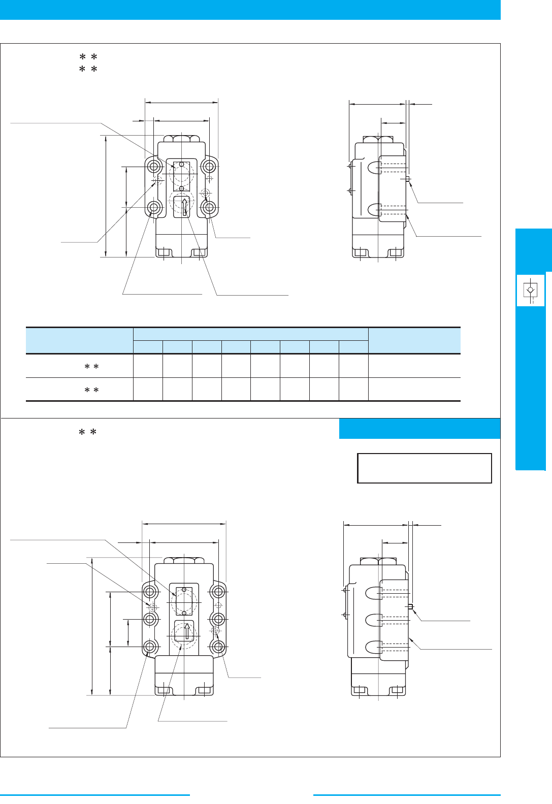
507
DIRECTIONAL CONTROLS
Pilot Operated Check Valves
E
Pilot Operated Check Valves
Mounting surface: ISO 5781-AJ-10-2-A
Model Numbers
B
Dimensions mm (Inches)
CDEFH JA
Mounting Surface
CPG/CPDG-03- - -50/5090
CPG/CPDG-06- - -50/5090
ISO 5781-AG-06-2-A
ISO 5781-AH-08-2-A
90
(3.54)
66.7
(2.63)
11.7
(.46)
150.5
(5.93)
42.9
(1.69)
66
(2.60)
62
(2.44)
30
(1.18)
102
(4.02)
79.4
(3.13)
11.3
(.44)
171.5
(6.75)
60.3
(2.37)
67.5
(2.66)
74
(2.91)
35
(1.38)
FREE
FREE
A
B
C
E
F
D
Drain Port
Pilot Port
11(.43) Dia. Through
17.5(.69) Dia. Spotface
4 Places
Free Flow Inlet or
Reversed Controlled
Flow Outlet Port
H
J
Free Flow Outlet or Reversed
Controlled Flow Inlet Port
Locating Pin
6(.24) Dia.
Mounting Surface
(O-Rings Furnished)
Locating Pin
6(.24) Dia.
Mounting Surface
(O-Rings Furnished)
Drain Port
Pilot Port
11(.43) Dia. Through
17.5(.69) Dia. Spotface
6 Places
Free Flow Inlet or
Reversed Controlled
Flow Outlet Port
Free Flow Outlet or Reversed
Controlled Flow Inlet Port
119
(4.69)
96.8
(3.81)
11.1
(.44)
42.1
(1.66)
84.1
(3.31)
203.5
(8.01)
70
(2.76)
89
(3.50)
40
(1.57)
6
(.24)
6
(.24)
CPG/CPDG-03- - -50/5090
CPG/CPDG-06- - -50/5090
DIMENSIONS IN
MILLIMETRES (INCHES)
CPG/CPDG-10- - -50/5090
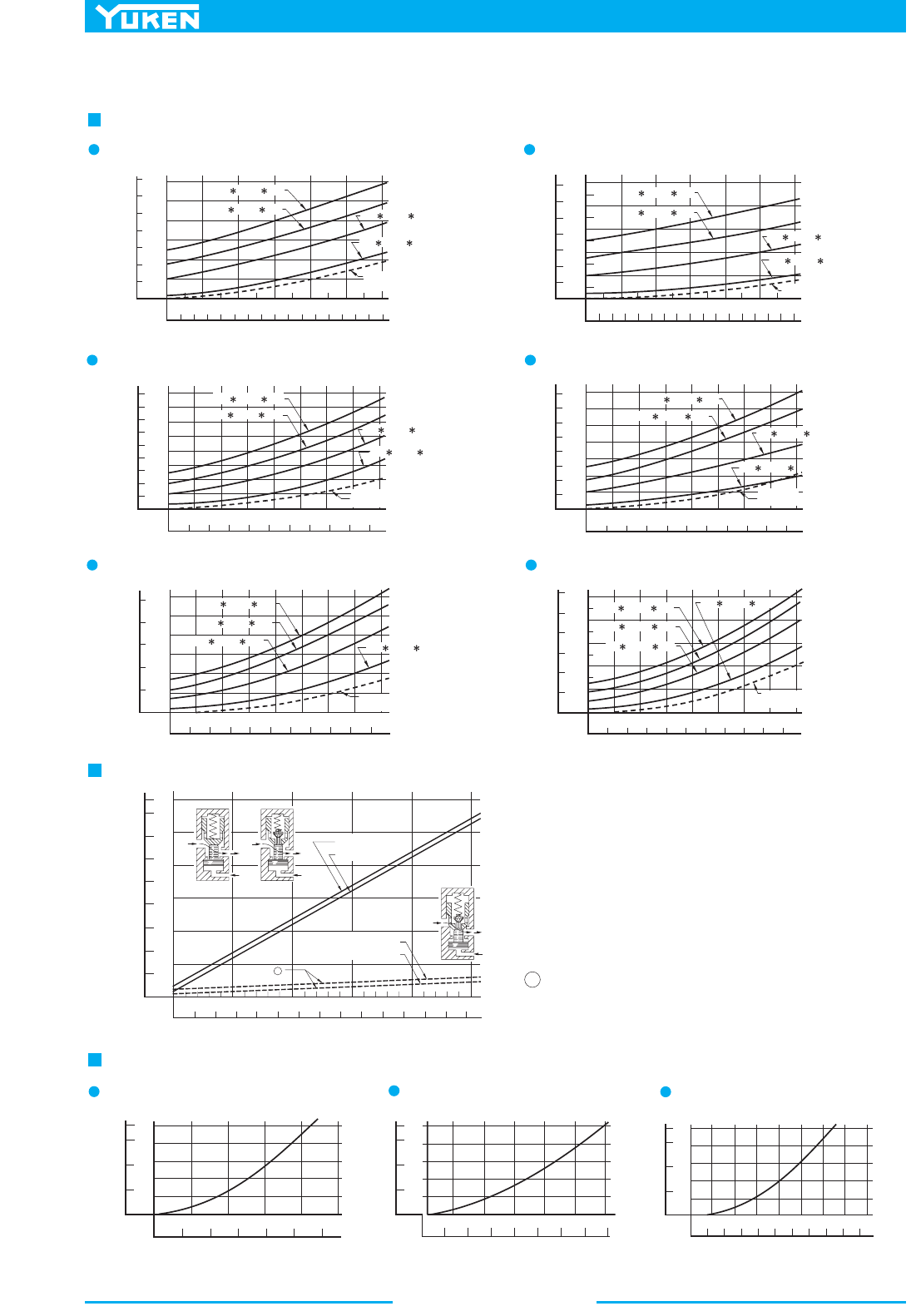
508
Pilot Operated Check Valves
Hydraulic Fluid: Viscosity 30 mm
2
/s (141 SSU), Specific Gravity 0.850
Pressure Drop
CPT-03, CPDT-03 CPG-03, CPDG-03
0
20
10
30 40 50
L/min
0
0.8
PSI
100
175
MPa
Pressure Drop ΔP
50
0
0.4
1.2
150
0
510
U.S.GPM
15
Flow Rate
60
0
20
10
30 40 50
L/min
0
0.8
PSI
100
MPa
Pressure Drop ΔP
20
0
0.4
1.0
0
510
U.S.GPM
15
Flow Rate
60
40
60
80
120
140
CP T-03- -50
CP T-03- -35
CP T- 0 3 - - 2 0
CP T- 0 3 - - 0 4
CP G-03- -50
CP G-03- -35
CP G-03- -20
CP G-03- -04
Reversed
Controlled Flow
Reversed
Controlled Flow
CPT-06, CPDT-06 CPG-06, CPDG-06
CPT-10, CPDT-10
CPG-10, CPDG-10
0
50
25
75 150 175
L/min
0
0.8
PSI
100
200
MPa
Pressure Drop ΔP
50
0
0.4
1.2
150
0
10 40
U.S.GPM
50
Flow Rate
200100 125
20 30
1.6
225
0
50
25
75
150
175
L/min
0
0.8
PSI
100
200
MPa
Pressure Drop ΔP
50
0
0.4
1.2
150
0
10 40
U.S.GPM
50
Flow Rate
200100 125
20 30
1.
4
CP T- 0 6 - - 5 0
CP T- 0 6 - - 3 5
CP T- 0 6 - - 2 0
CP T- 0 6 - - 0 4
CP G-06- -50
CP G-06- -35
CP G-06- -20
CP G-06- -04
Reversed
Controlled Flow
Reversed
Controlled Flow
0
50 150
L/min
0
0.9
PSI
100
200
MPa
Pressure Drop ΔP
50
0
0.3
1.5
150
0
20 80
U.S.GPM
100
Flow Rate
200100
40 60
1.8
250
250 300 350 400
0.6
1.2
0
50 150
L/min
0
1.2
PSI
100
200
MPa
Pressure Drop ΔP
50
0
0.4
1.6
150
0
20 80
U.S.GPM
100
Flow Rate
200100
40 60
2.0
250
250 300 350 400
0.8
300
CP T- 1 0 - - 5 0
CP T-10- -35
CP T-10- -20
CP T-10- -04
CP G-10- -50
CP G-10- -35
CP G-10- -20
CP G-10--04
Reversed
Controlled Flow
Reversed
Controlled Flow
Min. Pilot Pressure Chart
P2 P2
P1
PP
P
1
PP
P
2
P1
PP
0
MPa
52025
0
4
200
600
Minimum Pilot Pressure (PP)
0
6
8
800
10
2
500
PSI
Supply Pressure (P2)
1500
1000
0
PSI MPa
12
1000
1200
1400
1600
1700
400
2000 2500 3000 3500
1510
Cracking Pressure
0.5 MPa (70 PSI)
0.04 MPa (6 PSI)
0.5 MPa (70 PSI)
Cracking Pressure
0.04 MPa (6 PSI)
A
A : Min. Pilot Pressure to open the Decompression Valve
Pressure Drop for Reversed Controlled Flow Only when Decompression Valve is Opened
CPDT-03, CPDG-03
CPDT-06, CPDG-06
CPDT-10, CPDG-10
0
10 20
L/min
30 40 50 60
0
2
Flow Rate
12
8
46
10
14 16 U.S.GPM
0
510
L/min
15 20 25
0
1
Flow Rate
5
4
2 3 6 U.S.GPM
0
10
PSI
1000
2000
Pressure Drop ΔP
0
5
15
20
3500
25
3000
MPa
0
10
PSI
1000
2000
Pressure Drop ΔP
0
5
15
20
3500
25
3000
MP
a
0
10
PSI
1000
2000
Pressure Drop ΔP
0
5
15
20
3500
25
3000
MPa
0
50 100
L/min
150 200
0
10
Flow Rate
50
40
20 30 U.S.GPM
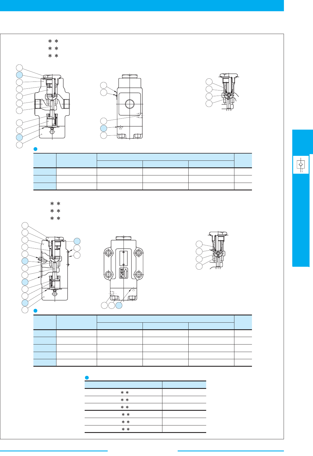
509
DIRECTIONAL CONTROLS
Pilot Operated Check Valves
E
Pilot Operated Check Valves
■ List of Seals
5
1
2
1
4
3
2
7
6
8
9
1
3
1
0
1
6
1
7
1
1
1
5
2
0
1
9
2
1
1
8
2
2
2
3
2
4
2
1
1
4
1
9
1
11816
1
0
5
4
1
3
2
0
1
2
2
7
1
3
6
8
1
5
9
Name of PartsItem Qty.
CPT/CPDT-03
Part Numbers
11
12
13
O-Ring
O-Ring
O-Ring
1
1
1
CPT/CPDT-06 CPT/CPDT-10
SO-NB-P7
SO-NB-P21
SO-NB-G25
SO-NB-P9
SO-NB-P36
SO-NB-P42
SO-NB-P9
SO-NB-P29
SO-NB-P32
Name of PartsItem Qty.
CPG/CPDG-03
Part Numbers
11
12
13
14
15
O-Ring
O-Ring
O-Ring
O-Ring
O-Ring
1
2
2
1
1
CPG/CPDG-06 CPG/CPDG-10
SO-NB-P7
SO-NB-P9
SO-NB-P18
SO-NB-P21
SO-NB-G25
SO-NB-P9
SO-NB-P9
SO-NB-P32
SO-NB-P36
SO-NB-P42
SO-NB-P9
SO-NB-P9
SO-NB-P28
SO-NB-P29
SO-NB-P32
Model Numbers Seal Kit Numbers
KS-CPT-03-50
KS-CPT-06-50
KS-CPT-10-50
KS-CPG-03-50
KS-CPG-06-50
KS-CPG-10-50
CPT/CPDT-03-
- -50/5080/5090
CPT/CPDT-06- - -50/5080/5090
CPT/CPDT-10-
- -50/5080/5090
CPG/CPDG-03- - -50/5090
CPG/CPDG-06- - -50/5090
CPG/CPDG-10- - -50/5090
CPT/CPDT-03- - -50/5080/5090
CPT/CPDT-06-
- -50/5080/5090
CPT/CPDT-10-
- -50/5080/5090
CPG/CPDG-03- - -50/5090
CPG/CPDG-06- - -50/5090
CPG/CPDG-10- - -50/5090
List of Seals
Note: When ordering the seals, please specify the seal kit number from the table below.
Note: When ordering the O-Rings, please specify the seal kit number from the table below.
List of Seals
List of Seal Kits
CPDG-03/06/10
CPDT-03/06/10

510
