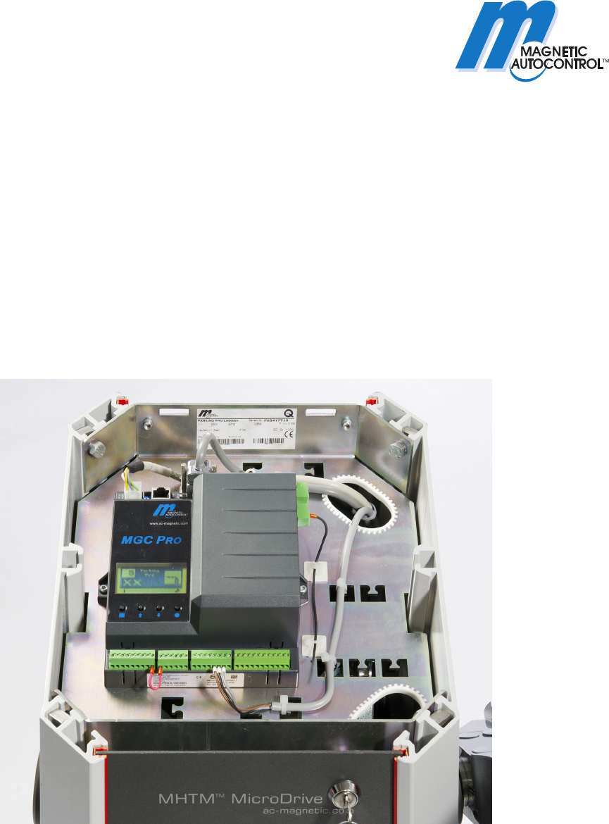
Description
Control Unit MGC and MGC-Pro
for MHTM
TM
MicroDrive Barriers
Doc-ID: 5816,0006EN
Version: 00

Control Unit MGC and MGC-Pro MHTM
TM
MicroDrive Barriers
2 5816,0006EN / Version 00

Control Unit MGC and MGC-Pro MHTM
TM
MicroDrive Barriers
Contents
5816,0006EN / Version 00 3
Contents
1 General....................................................................................5
1.1 Information on the instructions.......................................5
1.2 Pictogram explanation ...................................................5
1.3 Requirements to the specialists.....................................6
2 Digital inputs, digital outputs and output relays ................7
2.1 Digital inputs ..................................................................7
2.2 Digital outputs and output relays .................................11
3 Parameterising control unit ................................................18
3.1 Safety...........................................................................18
3.2 Changing menu language............................................18
3.3 Entering password .......................................................22
3.4 Control elements control unit .......................................23
3.5 Displays on the control unit..........................................24
3.6 Symbols in the display .................................................25
3.6.1 Control button functions ...............................25
3.6.2 Current state of the barrier ...........................26
3.6.3 Current programme mode ............................27
3.6.4 Current state of the induction loops .............27
3.6.5 Further symbols............................................27
3.7 Setting display contrast................................................28
3.8 Protecting parameterisation from access ....................28
3.9 Parameterising options ................................................29
3.10 Parameterising values .................................................30
3.11 Select programme mode .............................................31
3.11.1 Mode 1: Permanent signal ...........................32
3.11.2 Mode 2: Deadman........................................32
3.11.3 Mode 3: One button (bistable)......................33
3.11.4 Mode 4: Two buttons
(Open/Closed button) ...................................34
3.11.5 Automatic Modes 5 to 8:
Drive directions 1 –
overview and differences..............................35
3.11.6 Automatic Modes 5 to 8: Drive direction 2 ...39
3.11.7 Mode "Service "............................................40
3.12 Menu "Information" ( ).................................................41
3.13 Menu "Function"...........................................................41
3.14 Programme mode (Prog. mode)..................................41
3.15 Menu "Setup" ...............................................................42
3.15.1 Barrier speed................................................42
3.15.2 Delays...........................................................42
3.15.3 Cut off angle .................................................44

Control Unit MGC and MGC-Pro MHTM
TM
MicroDrive Barriers
Contents
4 5816,0006EN / Version 00
3.15.4 Vend count................................................... 45
3.15.5 Impact settings............................................. 48
3.15.6 Start-up settings........................................... 49
3.15.7 Start-up behaviour ....................................... 50
3.15.8 Power failure................................................ 54
3.16 Menu "In-/Outputs"...................................................... 54
3.16.1 Inputs ........................................................... 54
3.16.2 Outputs ........................................................ 54
3.17 Menu "Special functions" ............................................ 55
3.17.1 Closure by light barrier ................................ 55
3.17.2 Closure by additional safety ........................ 55
3.17.3 Stop at tailgating .......................................... 56
3.17.4 Master/Slave................................................ 56
3.18 Menu "Attachments".................................................... 57
3.18.1 Signal light ................................................... 57
3.18.2 Boom contact settings ................................. 60
3.18.3 Boom locking ............................................... 61
3.18.4 Battery backup............................................. 62
3.19 Menu "Service"............................................................ 63
3.20 Menu "System"............................................................ 64
3.21 Menu "Information"...................................................... 64
3.22 Menu "Motor GW (Gateway)....................................... 65
3.23 Menu "Detector 1 (A-B)".............................................. 65
3.23.1 Check the working frequency
of the induction loops................................... 67
3.23.2 Reconciling and setting the operating
frequency of the induction loop.................... 67
3.24 Menu "Detector 2 (C-D)" ............................................. 70
3.25 Menu "Radio control FM" ............................................ 70
3.26 Factory settings........................................................... 73
4 Menu setup .......................................................................... 77
Index............................................................................................. 83
Control Unit MGC and MGC-Pro MHTM
TM
MicroDrive Barriers
General
5816,0006EN / Version 00 5
1 General
1.1 Information on the instructions
These instructions describe the control unit MGC and the
associated plug-in modules from the programme versions named
below onwards. Software number (software #) and software
version (SW version) are displayed in the menu "Module info".
For information about assembly, electrical connection,
troubleshooting and maintenance, see the corresponding operating
instructions.
Programme versions Control unit
MGC and plug-in modules
Designation Software # SW version
Master Controller Standard 4915,1000 0.12
Motor Gateway Controller 4915,3000 0.12
Detector module 2-channel 4915,3001 0.12
Radio module 433 MHz 4915,3003 0.12
Ethernet Module 4915,3004 0.12
Table 1: Programme versions
1.2 Pictogram explanation
Warning notes Warning notes are characterised by pictograms in these operating
instructions. The warning notes are followed by signal words
expressing the scale of the hazard.
It is absolutely essential to observe the notes and to proceed with
caution in order to prevent accidents as well as bodily injuries and
property damage.
WARNING!
WARNING!
…points to a possibly dangerous situation that may
lead to death or severe injuries if it is not avoided.
Hints and recommendations
NOTE!
…highlights useful hints and recommendations as
well as information for an efficient and trouble-free
operation.
Control Unit MGC and MGC-Pro MHTM
TM
MicroDrive Barriers
General
6 5816,0006EN / Version 00
1.3 Requirements to the specialists
WARNING!
Risk of injury in case of inadequate
qualification!
Improper handling can lead to considerable bodily
injuries and property damage.
Therefore:
– Have any activities only carried out by the
individuals designated for that purpose.
MHTM
TM
MicroDrive service experts
are able, due to their technical training, knowledge and
experiences as well as knowledge of the relevant standards and
regulations, to execute tasks on electrical systems and to
independently recognise possible hazards.
Additionally, these electricians are trained and authorised by
MAGNETIC to perform special repair and service work at MHTM
TM
MicroDrive barriers.
In Germany, the electrical specialist must comply with the
provisions of accident prevention regulation BGV A3 (e.g. master
electrical fitter). Appropriate regulations apply in other countries.
The regulations valid there must be observed.
Control Unit MGC and MGC-Pro MHTM
TM
MicroDrive Barriers
Digital inputs, digital outputs and output relays
5816,0006EN / Version 00 7
2 Digital inputs, digital outputs and output relays
2.1 Digital inputs
Improper parameterisation and
wiring
WARNING!
Risk of injury by improper parameterisation and
wiring of the control unit!
Inappropriate parameterisation and wiring can
cause severe injuries!
Therefore:
– The parameterisation and wiring of the control
unit must only be carried out by qualified
personnel or professional electricians.
– The electrical connection of the signal
generators to the IN1 to IN8 inputs must fit the
parameterisation.
Freely parameterisable and firmly
assigned input functions
NOTE!
For barriers with a MGC-Pro control unit, the
functions of the digital inputs can be parameterised
freely. The MGC-Pro control unit is installed in the
following types:
– Access Pro, Access Pro L, Access Pro H,
Access Select and Access Select L
– Access XL and Access XXL
– Parking Pro and Parking Select
– Toll Pro
– Toll HighSpeed with MGC-Pro
In the other barriers, the control unit MGC is
installed. The input functions are firmly assigned
here.
For input parameterisation, refer to page 18,
chapter 3.
Control Unit MGC and MGC-Pro MHTM
TM
MicroDrive Barriers
Digital inputs, digital outputs and output relays
8 5816,0006EN / Version 00
Factory setting
Clamp Description Function
IN1 Input 1 Open low priority
IN2 Input 2 Open low priority
IN3 Input 3
Opening with vend
count
IN4 Input 4 Open high priority
IN5 Input 5
External opening loop
exit
IN6 Input 6 Close
IN7 Input 7 Close
IN8 Input 8 Boom contact
Table 2: Factory settings "Digital inputs"
The functions have different priorities towards each other. The
function "Open high priority" has the highest priority (priority 1). I.e.
all other functions, such as "Open low priority", "Close", etc. are
ignored if the function "Open high priority" is active.
Function Description
Open high priority Control Unit: MGC-Pro and MGC
Connect fire fighter switch, emergency opening contacts, etc. to this input.
This input has the highest priority. The barrier opens when +24 V DC are
applied to this input. While the signal is present, the barrier cannot be
closed. This input must not be used for opening loops. This input function is
superordinated to all other input functions.
Open low priority
Programme modes
2, 4 to 8:
Open low priority
Programme mode 3:
Close/Open
Control Unit: MGC-Pro and MGC
Depending on programme mode, a permanent signal or impulse is required.
Programme modes 2, 4 to 8:
The barrier opens when +24 V DC are applied to this input.
Programme mode 3:
The barrier changes its state with every impulse, i.e. the barrier closes or
opens.
Opening exit
1)
Control Unit: MGC-Pro
This function is used for selective counting, e.g. for permanent renters of a
parking space.
Opening with vend count
1)
Control Unit: MGC-Pro and MGC
An internal vend count counts the impulses present at this input. The
impulse must be present for approx. 100 to 300 ms. The reset behaviour of
the vend count can be set by the "Reset behaviour" parameter.
Refer to page 45, chapter 3.15.4.
Close Control Unit: MGC-Pro and MGC
Depending on programme mode, a permanent signal or impulse is required.
The barrier closes when +24 V DC are applied to this input.

Control Unit MGC and MGC-Pro MHTM
TM
MicroDrive Barriers
Digital inputs, digital outputs and output relays
5816,0006EN / Version 00 9
Function Description
Close low priority Control Unit: MGC-Pro
The function "Close low priority" is subordinated to all opening functions.
The barrier closes when +24 V DC are applied to this input.
Inhibit opening Control Unit: MGC-Pro
The function "Close low priority" is subordinated to all opening functions.
The barrier closes when +24 V DC are applied to this input.
Inhibit opening loop Control Unit: MGC-Pro
If the input function is active, the barrier remains closed when the opening
loop is driven on.
Inhibit signal light Control Unit: MGC-Pro
Signal lights are no longer controlled when +24 V DC are applied to this
input.
External opening loop
entry
1)
Control Unit: MGC-Pro
The barrier opens when +24 V DC are applied to this input. Connect
external opening loops to this input.
External opening loop
exit
1)
Control Unit: MGC-Pro and MGC
The barrier opens when +24 V DC are applied to this input. Connect
external opening loops to this input.
External impact detection Control Unit: MGC-Pro and MGC
You can install external impact detection to the barrier boom. While no
vehicle touches the barrier boom from below, the input "External impact
detection" has +24 V DC applied. When the barrier boom impacts a vehicle,
e.g. due to impermissible driving through of a vehicle, the +24 V DC are
removed from the input "External impact detection".
The barrier's behaviour in case of impact detection can be set in the "Impact
settings" menu. Refer to page 48, chapter 3.15.5.
Boom contact input Control Unit: MGC-Pro
The barrier is equipped with a boom release input in the flange. While the
barrier boom is in its correct position, +24 V DC are applied to the "Boom
contact input" input. When the barrier boom is moved from its position e.g.
by a collision with a vehicle, the +24 V DC are removed from the "Boom
contact input" input. The barrier moves into the "open" position.
The boom contact must be activated in the menu "Boom contact settings".
In the menu "Boom contact settings", the option "Enabled" must be chosen
for the parameter "Inactive/active". Refer to page 60, chapter 3.18.2.
Additional safety device Control Unit: MGC-Pro
For barriers of the Parking and Toll series, these functions can be assigned
to input IN6.
+24 V DC must be applied at this input for operation. You can implement
this as follows:
Via a safety device with potential-free contact
Via a wire bridge, connected to +24 V DC
The barrier cannot be closed if the input signal +24 V is interrupted.
If the barrier is in the process of closing and the +24 V input signal is
interrupted and the cut-off angle for the parameter "Safety loop close" is not
undercut yet, the barrier opens again.
This input must only be used in addition to the internal detector module
and/or to the safety light barriers connected to clamp X11.

Control Unit MGC and MGC-Pro MHTM
TM
MicroDrive Barriers
Digital inputs, digital outputs and output relays
10 5816,0006EN / Version 00
Function Description
Acknowledgement Control Unit: MGC-Pro
This input is required for parallel operation. For more information on
parallel operation, see separate instructions.
Blink signal light Control Unit: MGC-Pro
While +24 V DC are pending at the input, the lamps flash at 1 Hz.
This input function overwrites the following settings:
Parameter "Signal light A", all options
Parameter "Signal light B", all options except for "Illumination strip
green".
You may use this function for special signalling like "Parking place
assigned".
Parking counter reset Control Unit: MGC-Pro
Through this input, you can reset the lot counter to "0" by applying a
+24 V DC-signal. For other information, see separate instructions "ECN-
module".
1) This function is only sensible for automatic programme modes 5 to 8.
Table 3: Function "Digital inputs"
Control Unit MGC and MGC-Pro MHTM
TM
MicroDrive Barriers
Digital inputs, digital outputs and output relays
5816,0006EN / Version 00 11
2.2 Digital outputs and output relays
Freely parameterisable and firmly
assigned output functions
NOTE!
For barriers with a MGC-Pro control unit, the
functions of the outputs can be parameterised
freely. The MGC-Pro control unit is installed in the
following types:
– Access Pro, Access Pro L, Access Pro H,
Access Select and Access Select L
– Access XL and Access XXL
– Parking Pro and Parking Select
– Toll Pro
– Toll HighSpeed with MGC-Pro
In the other barriers, the control unit MGC is
installed. The output functions are firmly assigned
here.
For output parameterisation, refer to page 18,
chapter 3.
Factory setting
Clamp Description Function
DO1 Digital output 1 Boom locking
DO2 Digital output 2 Pulse after passage
DO3 Digital output 3 Signal light A
DO4 Digital output 4 Signal light B
NO1 Relay 1 Open
NO2 Relay 2 Closed
NO3 Relay 3 Error
NO4/NC4 Relay 4 Loop active A
NO5/NC5 Relay 5 Loop active B
NO6/NC6 Relay 6 Signal light C
Table 4: Factory settings "Digital outputs" and "Relay outputs"
Function Description
Error Control Unit: MGC-Pro and MGC
When the control unit recognises any "safety-relevant error" or "error", the
output with this function is reactivated (Fail safe). See operating
instructions of the barrier, chapter "Warning and interference messages on
the display".
Warning Control Unit: MGC-Pro
When the control unit recognises any "warning", the output with this function
is reactivated (Fail safe).
Closed Control Unit: MGC-Pro and MGC
When the barrier is closed, the output with this function is active.

Control Unit MGC and MGC-Pro MHTM
TM
MicroDrive Barriers
Digital inputs, digital outputs and output relays
12 5816,0006EN / Version 00
Function Description
Open Control Unit: MGC-Pro and MGC
When the barrier is open, the output with this function is active.
Closing Control Unit: MGC-Pro
While the barrier closes, the output with this function is active.
Opening Control Unit: MGC-Pro
While the barrier opens, the output with this function is active.
Boom angle feedback Control Unit: MGC-Pro
This function is used to set the upper and lower angles. When the barrier
boom is within this angle range, the output with this function is active. When
the barrier boom is outside of the angle range set, the output is inactive.
The upper and lower angle can be set for values between 0° and 90°.
Pulse after passage
1)
Control Unit: MGC-Pro and MGC
When a passage was detected, this output emits a counter pulse of 300 ms
with this function. Passage is possible in either direction.
Sliding door pulse Control Unit: MGC-Pro
This output is used to control a sliding gate. When the barrier is open, the
output with this function emits a counter pulse of 300 ms with this function.
Boom contact feedback Control Unit: MGC-Pro
The barrier can optionally be equipped with a boom contact in the flange.
When the boom contact triggers, the output with this function is deactivated
(fail safe). The output is activated again once the boom contact is re-
established and the boom is opened again entirely.
Signal light A Control Unit: MGC-Pro and MGC
This output is used to control a signal light. The function of this output can
be parameterised via the parameter "Signal mode A", page 57,
cha
pter 3.18.1.
Signal light B Control Unit: MGC-Pro and MGC
This output is used to control a signal light. The function of this output can
be parameterised via the parameter "Signal mode B", page 57,
cha
pter 3.18.1.
Signal lamp C Control Unit: MGC-Pro and MGC
This output is used to control a signal light. The function of this output can
be parameterised via the parameter "Signal mode C", page 57,
cha
pter 3.18.1.
Boom locking Control Unit: MGC-Pro and MGC
The barrier can optionally be equipped with a boom lock. This output serves
control of the electro-mechanical boom lock at the end of the barrier boom.
When the barrier is closed, the boom lock is activated via this output. If a
signal is present for opening, the boom lock is removed first. The barrier
opens with a short delay. The parameter "With boom locking" must be
activated in the menu "Boom locking".
The parameter "with boom lock" must be activated in the menu "Boom
lock". Refer to page 61, chapter 3.18.3.

Control Unit MGC and MGC-Pro MHTM
TM
MicroDrive Barriers
Digital inputs, digital outputs and output relays
5816,0006EN / Version 00 13
Function Description
Parallel operation Control Unit: MGC-Pro
This output can be used to operate two barriers synchronously. This output
function must be activated via the menu "Master/Slave".
Refer to page 56, chapter 3.17.4.
For info
rmation on parallel operation, see separate instructions.
Acknowledgement Control Unit: MGC-Pro
This output is required for parallel operation.
For information on parallel operation, see separate instructions.
Impact detection Control Unit: MGC-Pro
The output with this function is activated when an impact was recognised.
The output is deactivated again once the barrier is opened again.
Barrier ready Control Unit: MGC-Pro
The output with this function is deactivated (fail safe) if the reference run
(homing) is completed and release has taken place. Also refer to
page 50, chapter 3.15.7 parameter description "Start-up be
haviour".
1. Parking zone full Control Unit: MGC-Pro
The output with this function is activated when all lots of the 1st parking
zone are occupied. For other information, see separate instructions
"ECN-module".
2. Parking zone full Control Unit: MGC-Pro
The output with this function is activated when all lots of the 2nd parking
zone are occupied. For other information, see separate instructions
"ECN-module".
Open Control Unit: MGC-Pro
While the barrier is opening or opened, the output with this function is
active.
Closed Control Unit: MGC-Pro
While the barrier is closing or closed, the output with this function is active.
This output signal can be used, e.g. as release signal for a ticket vending
machine.
Loop active A
1)
Control Unit: MGC-Pro and MGC
When the induction loop A is busy, the output with this function is active.
Loop active B
1)
Control Unit: MGC-Pro and MGC
When the induction loop B is busy, the output with this function is active.
Loop active pulse A
1)
Control Unit: MGC-Pro
When a vehicle drives into loop A (rising flank), the output with this function
emits an impulse.
Loop active pulse B
1)
Control Unit: MGC-Pro
When a vehicle drives into loop B (rising flank), the output with this function
emits an impulse.
Loop inactive pulse A
1)
Control Unit: MGC-Pro
When a vehicle drives out of loop A (falling flank), the output with this
function emits an impulse.
Control Unit MGC and MGC-Pro MHTM
TM
MicroDrive Barriers
Digital inputs, digital outputs and output relays
14 5816,0006EN / Version 00
Function Description
Loop inactive pulse B
1)
Control Unit: MGC-Pro
When a vehicle drives out of loop B (falling flank), the output with this
function emits an impulse.
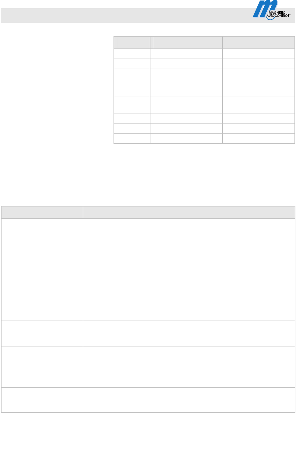
Direction 1 Pls A => B
1)
Control Unit: MGC-Pro
The vehicle drives from direction A to B. When the vehicle leaves loop A in
the direction of loop B, this output emits a counter impulse of 300 ms.
AB
DO
NO/NC
t = 300 ms
Mag00113
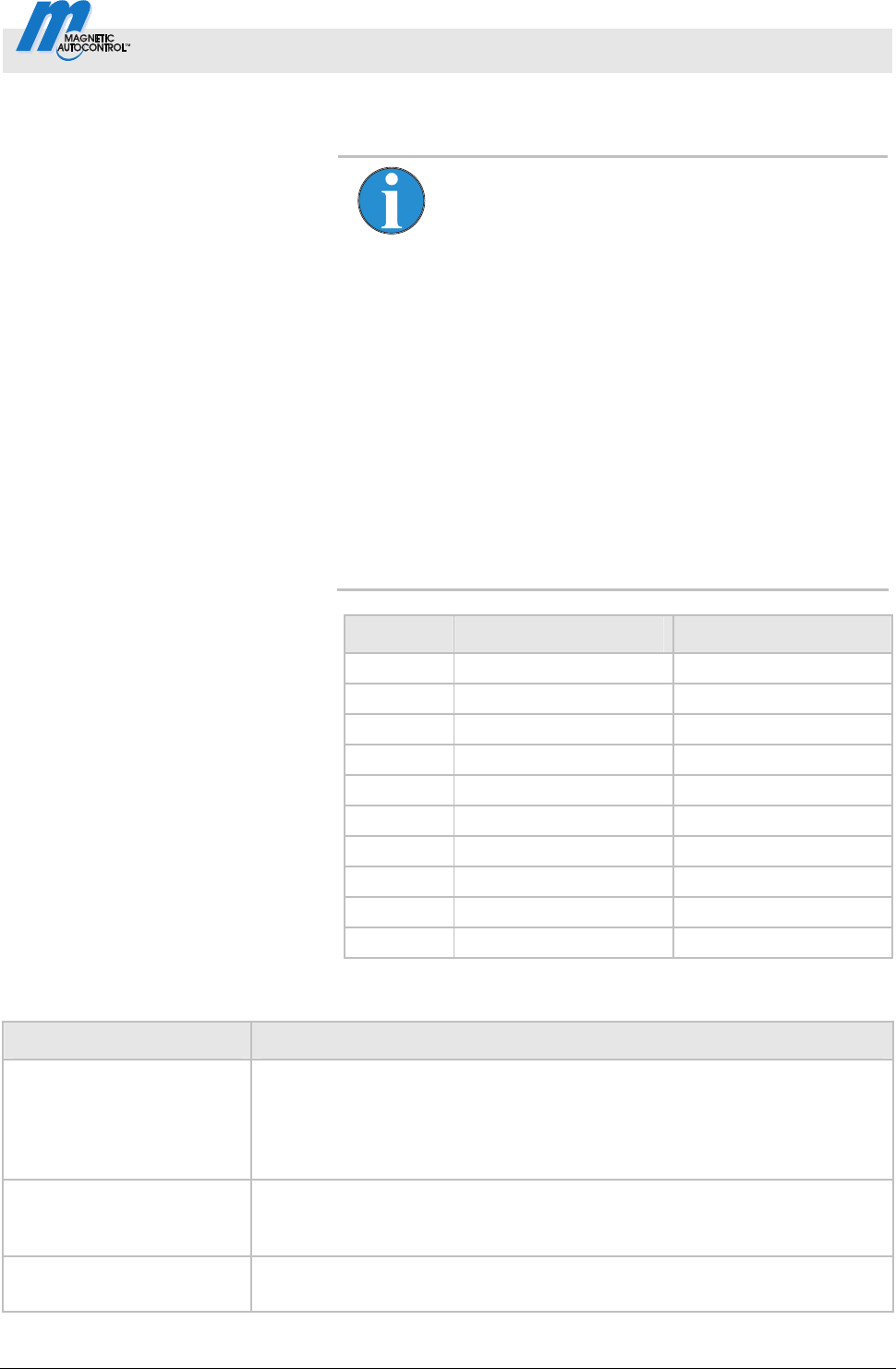
Direction 1 Pls B => A
1)
Control Unit: MGC-Pro
The vehicle drives from direction B to A. When the vehicle leaves loop B in
the direction of loop A, this output emits a counter impulse of 300 ms.
AB
DO
NO/NC
t = 300 ms
Mag000114
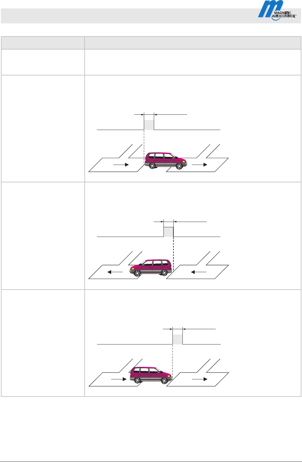
Direction 2 Pls A => B
1)
Control Unit: MGC-Pro
The vehicle drives from direction A to B. When the vehicle drives on loop A
in the direction of loop B, this output emits a counter impulse of 300 ms.
AB
DO
NO/NC
t = 300 ms
Mag00115
Control Unit MGC and MGC-Pro MHTM
TM
MicroDrive Barriers
Digital inputs, digital outputs and output relays
5816,0006EN / Version 00 15
Function Description
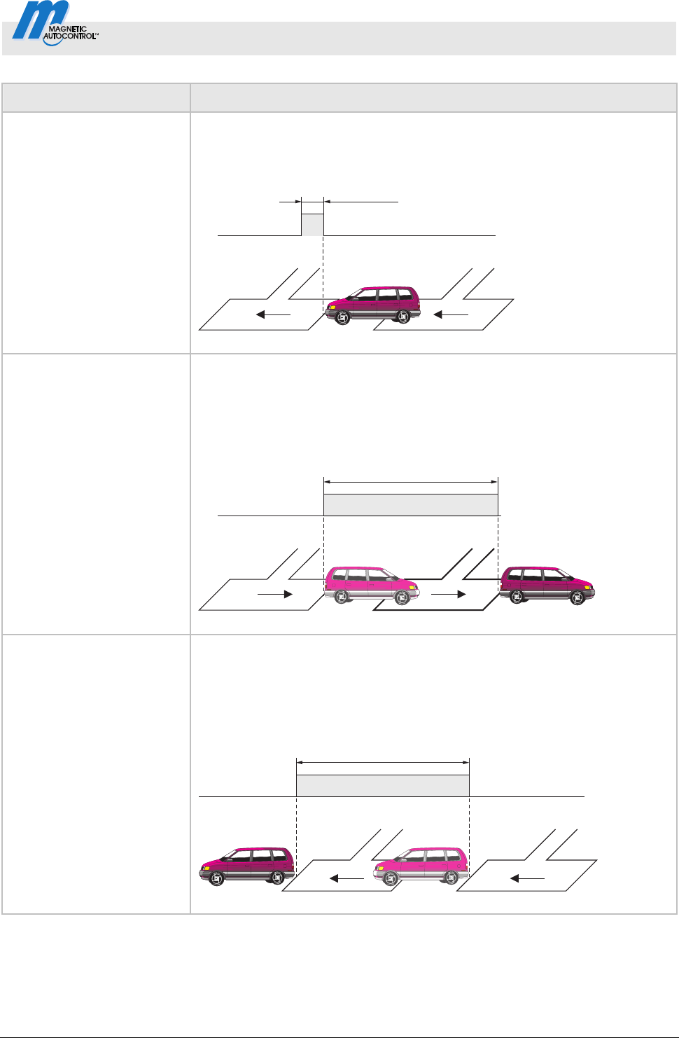
Direction 2 Pls B => A
1)
Control Unit: MGC-Pro
The vehicle drives from direction B to A. When the vehicle drives on loop B
in the direction of loop A, this output emits a counter impulse of 300 ms.
AB
DO
NO/NC
t = 300 ms
Mag00116
Direction 1 A => B
1)
Control Unit: MGC-Pro
The vehicle drives from direction A to B. When the vehicle leaves loop A,
this output starts emitting a permanent signal. When the vehicle leaves loop
B, this output stops the permanent signal. This function can be used, e.g. to
control traffic lights.
AB
DO
NO/NC
t
Mag00117
t
1
t
2
Direction 1 B => A
1)
Control Unit: MGC-Pro
The vehicle drives from direction B to A. When the vehicle leaves loop B,
this output starts emitting a continuous signal. When the vehicle leaves loop
A, this output stops the permanent signal. This function can be used, e.g. to
control traffic lights.
AB
DO
NO/NC
t
Mag00118
t
1
t
2
Control Unit MGC and MGC-Pro MHTM
TM
MicroDrive Barriers
Digital inputs, digital outputs and output relays
16 5816,0006EN / Version 00
Function Description
Direction 2 A => B
1)
Control Unit: MGC-Pro
The vehicle drives from direction A to B. When the vehicle enters loop B,
this output starts emitting a continuous signal. When the vehicle leaves loop
B, this output stops the permanent signal. This function can be used, e.g. to
control traffic lights.
AB
DO
NO/NC
t
Mag00119
t
1
t
2
Direction 2 B => A
1)
Control Unit: MGC-Pro
The vehicle drives from direction B to A. When the vehicle enters loop A,
this output starts emitting a continuous signal. When the vehicle leaves loop
A, this output stops the permanent signal. This function can be used, e.g. to
control traffic lights.
AB
DO
NO/NC
t
Mag00120a
t
1
t
2
Module-Open prior
2)
Control Unit: MGC-Pro
This output function can be used to output the command "Open high
priority" from the plug-in modules, such as "Ethernet", "Radio" or
"RS485/422".
Module-Open
2)
Control Unit: MGC-Pro
This output function can be used to output the command "Opening" from
the plug-in modules, such as "Ethernet", "Radio" or "RS485/422".
Module-Close
2)
Control Unit: MGC-Pro
This output function can be used to output the command "Closing" from the
plug-in modules, such as "Ethernet", "Radio" or "RS485/422".

Control Unit MGC and MGC-Pro MHTM
TM
MicroDrive Barriers
Digital inputs, digital outputs and output relays
5816,0006EN / Version 00 17
Function Description
External
3)
Control Unit: MGC-Pro
The output function "External" permits superordinated control of the output
through the plug-in modules, such as "Ethernet" or "RS485/422" and the
"service module".
1) This function is only available with the plug-in module "Detector" plugged in.
2) This function is only available with the plug-in module "Ethernet", "Radio" or "RS485/422" plugged in.
3) This function is only available with the plug-in module "Ethernet" " or "RS485/422" or the "service module" plugged in.
Table 5: Function "Digital outputs" and "Output relay"
Control Unit MGC and MGC-Pro MHTM
TM
MicroDrive Barriers
Parameterising control unit
18 5816,0006EN / Version 00
3 Parameterising control unit
3.1 Safety
See operating instructions of the barrier, chapter "Occupational
safety and special dangers".
Improper parameterisation
WARNING!
Risk of injury by improper parameterisation of
the control unit!
Improper parameterisation of the control unit can
lead to severe injuries!
Therefore:
– The parameterisation of the control unit may
only be carried out by qualified personnel or
professional electricians.
– The electrical connection of the signal
generators to the IN1 to IN8 inputs must fit the
parameterisation.
3.2 Changing menu language
The default setting in the control unit MGC is the menu language
"English".
The menu language can be switched as follows:
1. The operating view is displayed.
Mag00446
A B DC
Access
Select
4
Fig. 1: Example "Operational view"
Control Unit MGC and MGC-Pro MHTM
TM
MicroDrive Barriers
Parameterising control unit
5816,0006EN / Version 00 19
2. Access to parameterisation can be password-protected. If
password protection was activated, you are asked to enter a
password.
Mag00455
Password
–––
0
Fig. 2: View "Enter password"
3. The "Function" menu is displayed. The "Function" menu has a
dark background and is thus selected.
Mag00447
Function
Setup
In-/Outputs
Special functions
Main menu
Fig. 3: View "Function"
4. Select the menu "System" with the two middle buttons
,
.
Mag00448
Special functions
Attachements
Service
System
Main menu
Fig. 4: View "Main menu – System"
Control Unit MGC and MGC-Pro MHTM
TM
MicroDrive Barriers
Parameterising control unit
20 5816,0006EN / Version 00
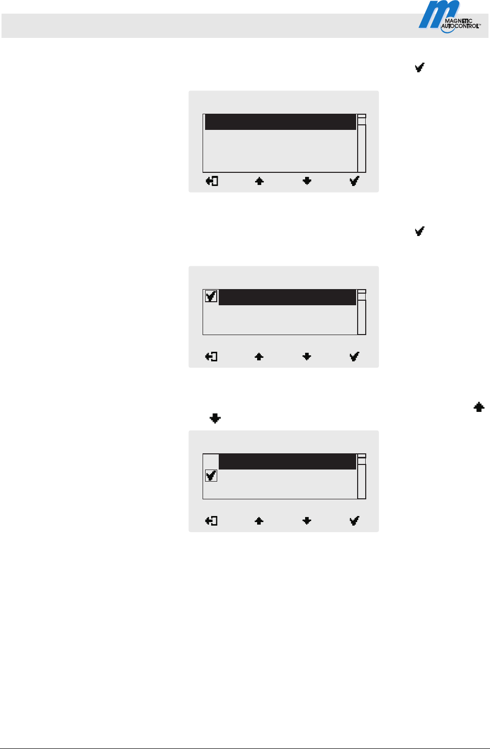
5. Confirm selection with the right control button
. The
following view is displayed. The menu "Language" is chosen.
Mag00449
Language
Date/Time
System
Fig. 5: View "Language"
6. Confirm selection with the right control button
. The
following view is displayed. The menu language "English" is
chosen.
Mag00450
Spanish
English
French
Language
Fig. 6: View "Language" – English"
7. Select the language "German" with the two middle buttons
,
. The language "German" has a dark background.
Mag00451
French
German
English
Language
Fig. 7: View "Language" – German"
Control Unit MGC and MGC-Pro MHTM
TM
MicroDrive Barriers
Parameterising control unit
5816,0006EN / Version 00 21
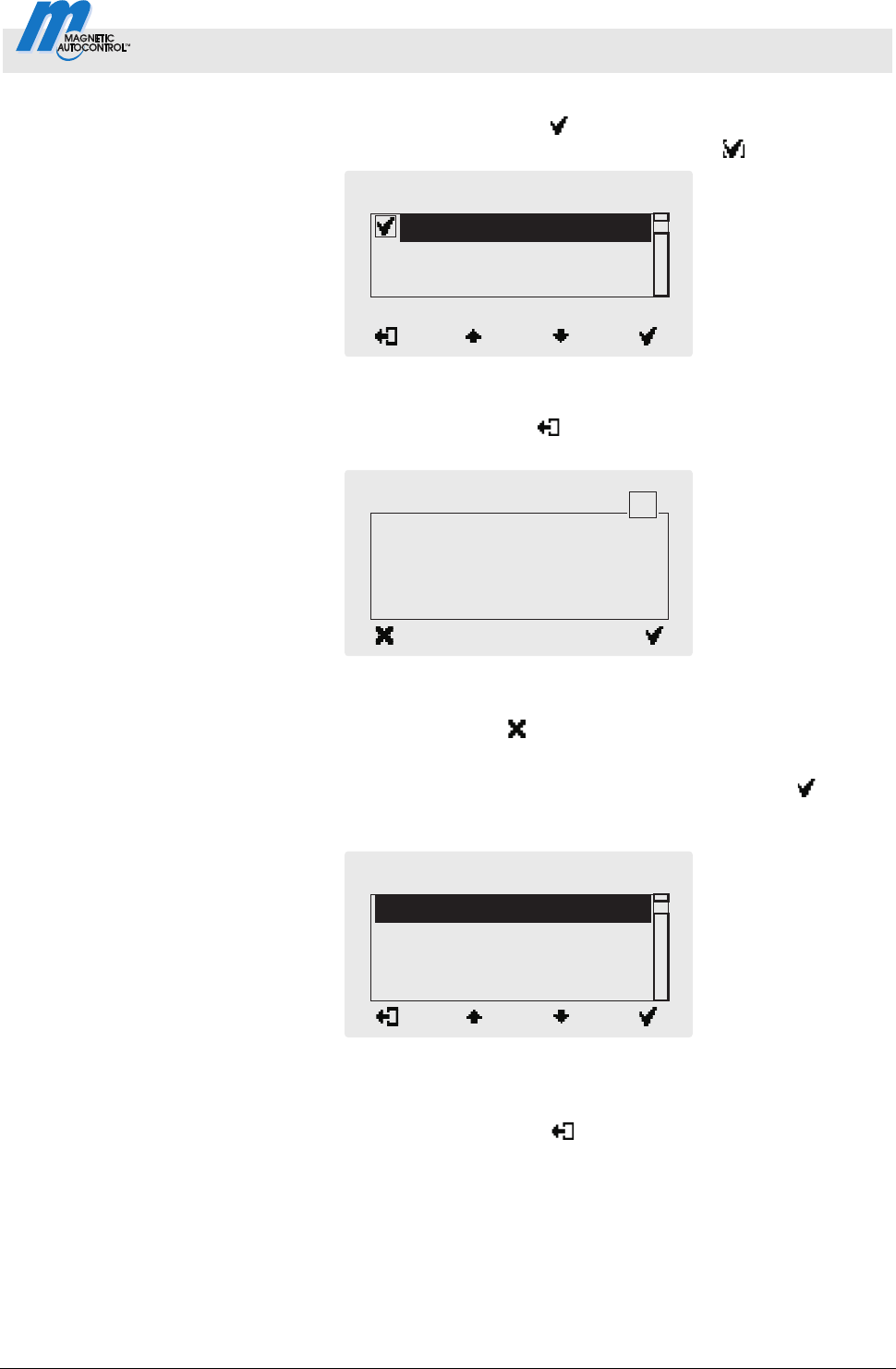
8. Use the right button
to select the new menu language.
Your selection is marked with the symbol
.
Mag00452
French
German
English
Language
Fig. 8: View "Language" – German, step 2"
9. Use the left button
to leave the "Language" menu. The
safety prompt "Save changes? " appears.
Mag00453
Save changes?
Language
?
Fig. 9: View "Safety prompt – Save changes?"
Push the left button
if you do not want to save the changes. The
menu language "English" remains active.
10. Confirm safety prompt with the right control button
. The
new menu language "German" is activated. The following view
is displayed:
Mag00454
Sprache
Datum/Zeit
System
Fig. 10: View "Menu System –
Menu language "German" is activated
11. Press the left button
repeatedly until the operating view is
displayed again. Refer to page 18, Fig. 1.
Control Unit MGC and MGC-Pro MHTM
TM
MicroDrive Barriers
Parameterising control unit
22 5816,0006EN / Version 00
3.3 Entering password
You need to enter a password in the following cases:
You would like to change parameters in the control unit and the
password protection was activated.
You would like to reset the parameters to factory settings.
You would like to delete the assignment between all hand
transmitters and the plug-in module "Radio remote control".
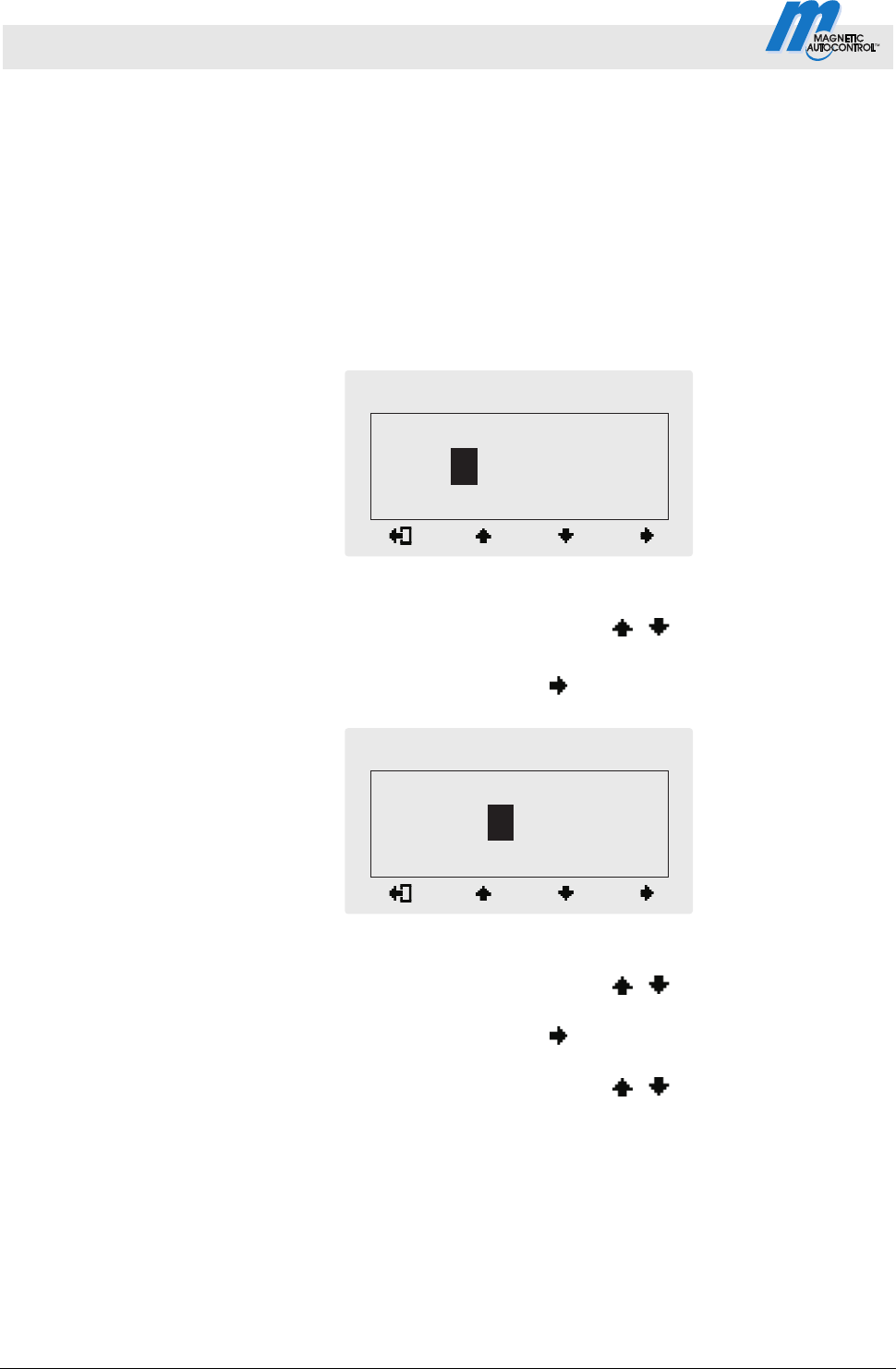
1. If a password is required, the following view is displayed:
Mag00456
Passwort
–––
0
Fig. 11: View "Password"
2. Use the two middle buttons
, to enter the first digit of
the password.
3. Use the right button
to select the second digit of the
password. The following view is displayed:
Mag00457
Passwort
0
*
––
Fig. 12: View"Enter second digit of the password"
4. Use the two middle buttons
, to enter the second digit
of the password.
5. Use the right button
to select the third digit of the
password.
6. Use the two middle buttons
, to enter the third digit of
the password.
Control Unit MGC and MGC-Pro MHTM
TM
MicroDrive Barriers
Parameterising control unit
5816,0006EN / Version 00 23
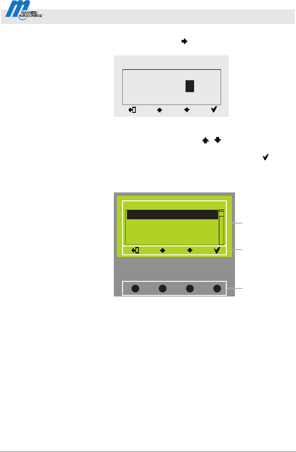
7. Use the right button
to select the fourth digit of the
password. The following view is displayed:
Mag00458
Passwort
**
0
*
Fig. 13: View"Enter fourth digit of the password"
8. Use the two middle buttons
, to enter the fourth digit of
the password.
9. Confirm the password with the right control button
.
3.4 Control elements control unit
Control elements control unit MGC
(Magnetic Gate Controller)
Mag00121c
1
3
2
Function
Setup
In-/Outputs
Special functions
Main menu
Fig. 14: Control unit elements MGC
1 Menu
2 Current function of the 4 control buttons
3 Control buttons
Control Unit MGC and MGC-Pro MHTM
TM
MicroDrive Barriers
Parameterising control unit
24 5816,0006EN / Version 00
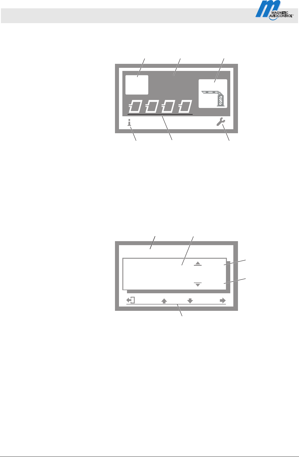
3.5 Displays on the control unit
Example "Operational view"
Mag00126a
A B DC
Access
Select
4
456
12
3
Fig. 15: Example "Operational view"
1 Programme mode, here programme mode 4
2 Barrier type, here type "Access Select"
3 Current state of the barrier, here barrier closed
4 Current function of the right control button,
here calling menu "Main menu"
5 Current state of the induction loops
6 Current function of the left control button,
here calling menu "Information"
Example "Screen change value"
Mag00129a
60
3
15
5
3
4
sek
12
Hold-open time
Fig. 16: Example "Screen Change value"
1 Parameter
2 Current value
3 Possible upper value
4 Possible lower value
5 Current functions control buttons
Control Unit MGC and MGC-Pro MHTM
TM
MicroDrive Barriers
Parameterising control unit
5816,0006EN / Version 00 25
3.6 Symbols in the display
3.6.1 Control button functions
The control unit is equipped with 4 control buttons. The function of
the control buttons change depending on the current view in the
display. The current functions are displayed.
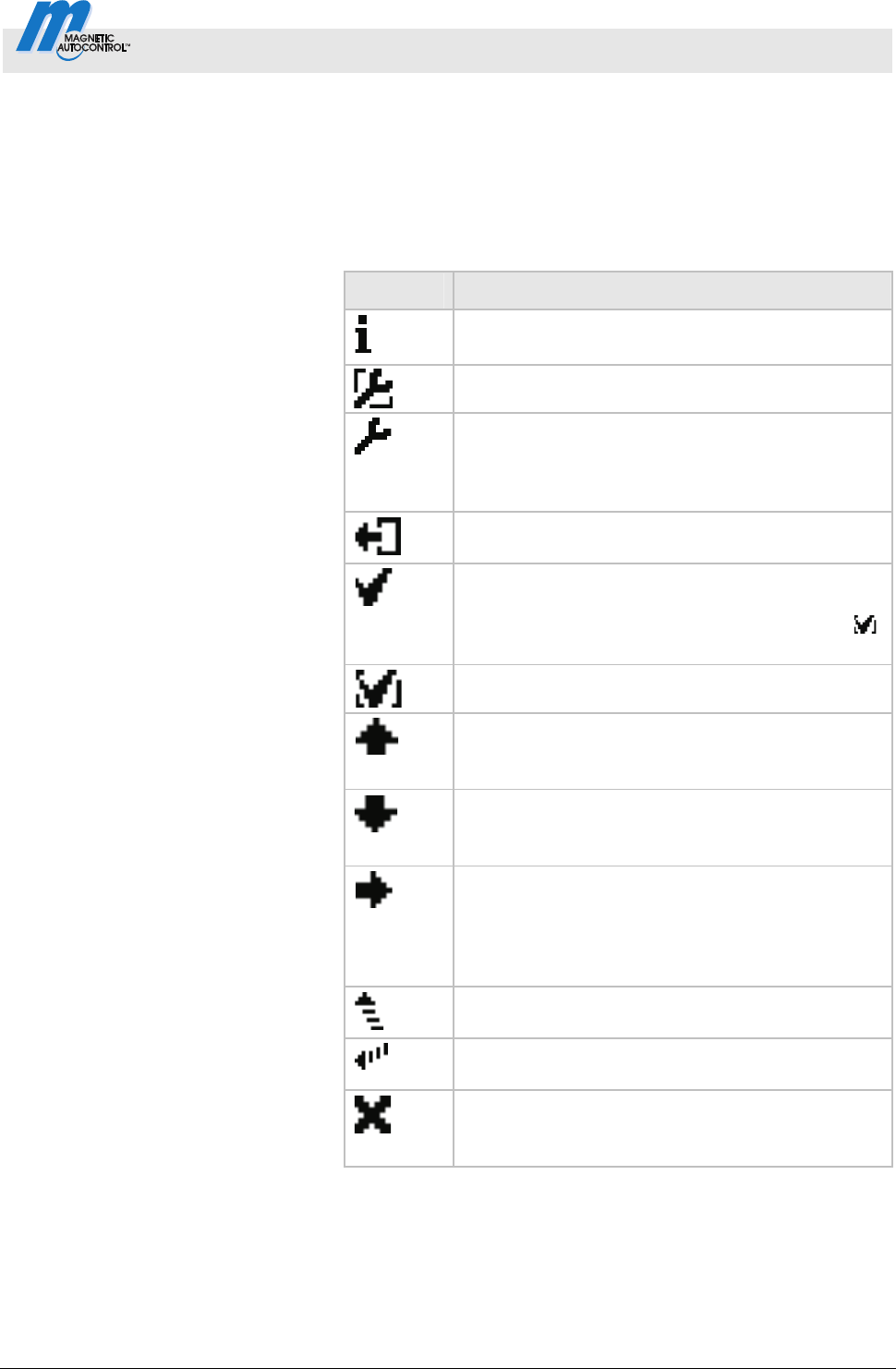
Symbols Description
Call menu "Information".
Scroll menu "Information".
Perform loop reconciliation
Call menu "Main menu" Make all settings in the
menu "Main menu".
Menu "Information" Menu "Detector":
Perform reference of the induction loops.
Leave current menu level. The next-higher menu
level is displayed.
Call next-lower menu level.
Select desired option or desired value. When
the desired option was selected, the symbol
is displayed.
Option was selected but not yet stored
Within one menu level:
Move cursor (market) upwards.
For setting value: Increase figure.
Within one menu level:
Move cursor (market) downwards.
For setting value: Decrease figure.
Move cursor one position to the right.
Menu "Information" Menu "Detector", for
plug-in module "Detector (C-D)": Call view
"Detector (C-D)" and switch between "Detector
(A-B)" and "Detector (C-D)".
Programme mode "Service": Manually open the
barrier.
Programme mode "Service": Manually close the
barrier.
Delete error message.
When changing settings: Cancel changing
process.
Table 6: Control button functions
Control Unit MGC and MGC-Pro MHTM
TM
MicroDrive Barriers
Parameterising control unit
26 5816,0006EN / Version 00
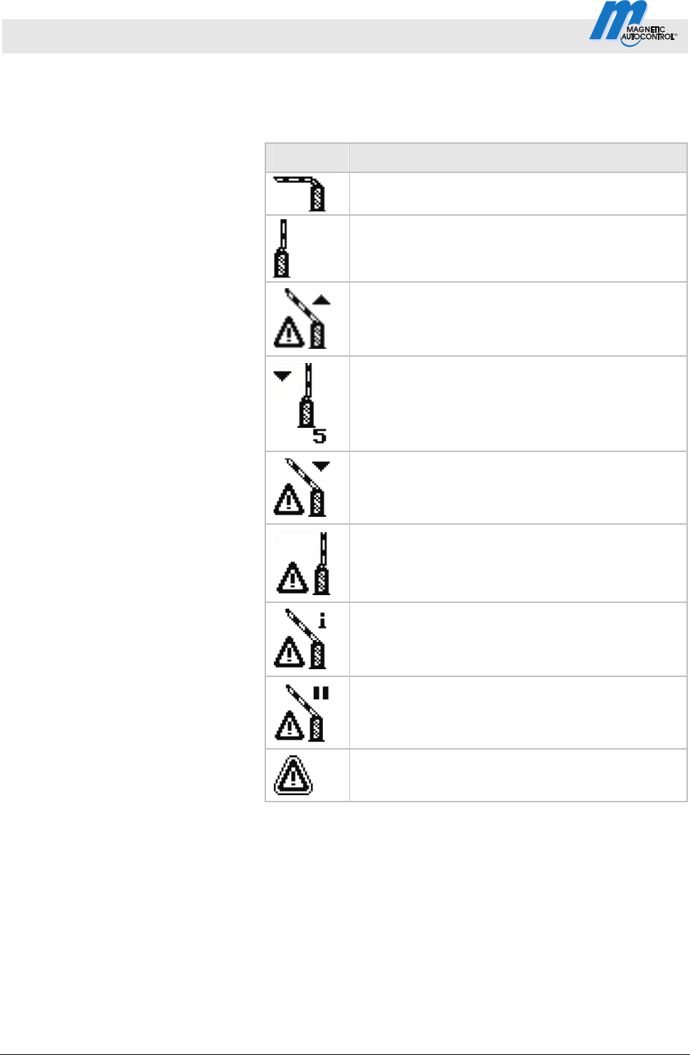
3.6.2 Current state of the barrier
The barrier can have the following states:
Symbols Description
Barrier boom closed.
Barrier boom open.
Barrier boom opens.
Closing signal was recognised. Traffic lights active.
Barrier closes in 5 seconds. Time for traffic light
lead is counted down.
Barrier boom closes.
Monitoring unit used.
Barrier boom position unknown.
"Homing" active.
Barrier boom stopped
An error is present.
Table 7: Current state of the barrier
Control Unit MGC and MGC-Pro MHTM
TM
MicroDrive Barriers
Parameterising control unit
5816,0006EN / Version 00 27
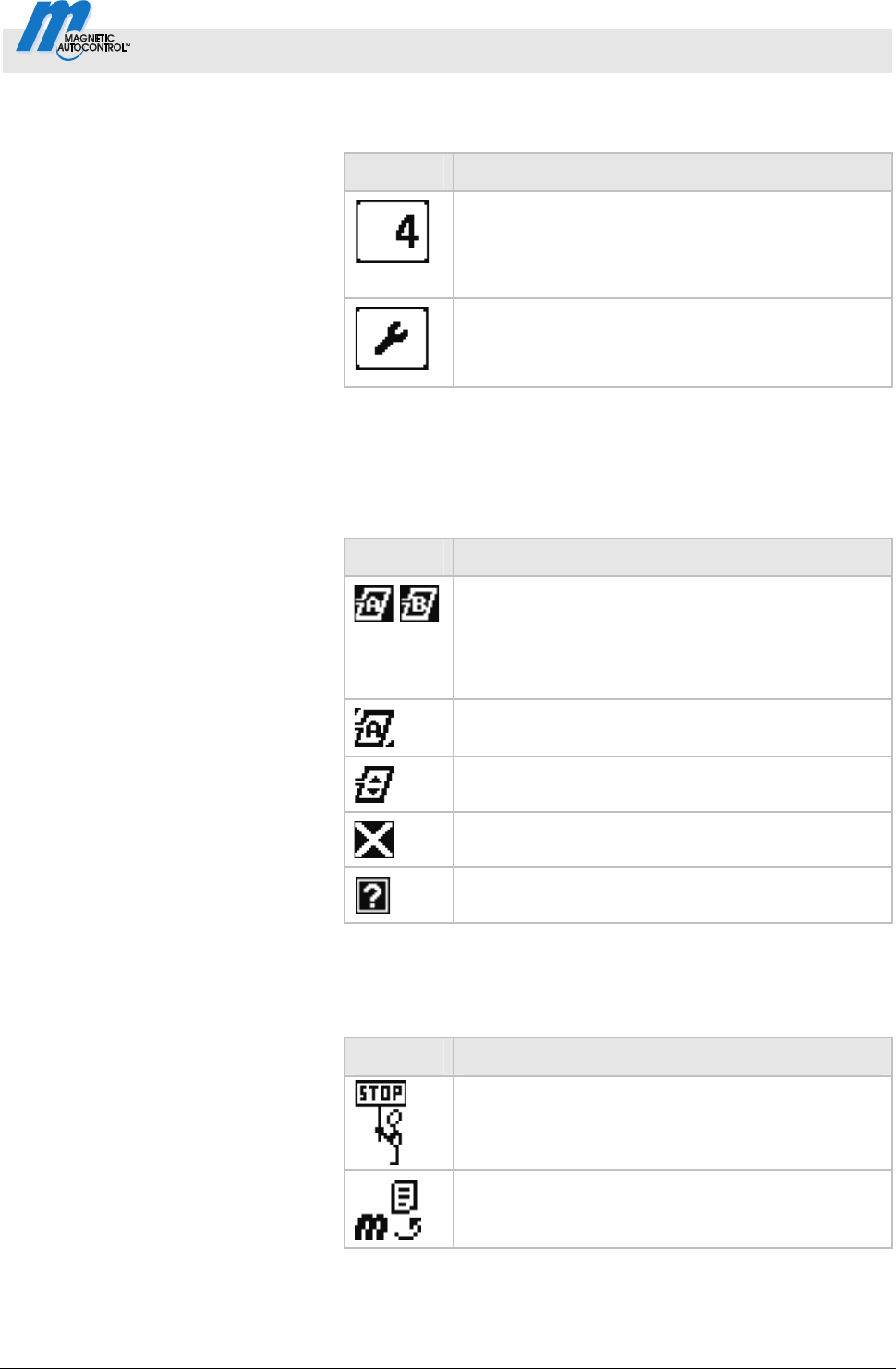
3.6.3 Current programme mode
Symbols Description
Current programme mode,
here programme mode 4
For description of programme modes, refer to
page 31, chapter 3.11.
Programme mode "Service"
For description of programme mode "Service",
refer to page 40, chapter 3.11.7.
Table 8: Current programme mode
3.6.4 Current state of the induction loops
Symbols Description
Loop A and B connected. The induction loop
function is OK.
If the icon flashes, the loop is occupied.
If another "detector" plug-in module is connected,
these induction loops are marked "C" and "D".
The induction loop assumes the function of the
safety loop. Refer to page 65, chapter 3.23.
Reference is performed.
Induction loop deactivated.
Induction loop defective.
Table 9: Current state of the induction loops
3.6.5 Further symbols
Symbols Description
Wrong password entered. Access denied.
Reset values to factory settings. Enter the
password "0000" for this.
Table 10: Further symbols

Control Unit MGC and MGC-Pro MHTM
TM
MicroDrive Barriers
Parameterising control unit
28 5816,0006EN / Version 00
3.7 Setting display contrast
Setting display contrast The display contrast of the control unit can be set after activation
while the logo is still displayed. The logo is displayed for 3
seconds.
If you push one of the middle buttons
, , the display time of
the logo extends by 2 seconds per push. You can thus extend the
time to set the display contrast.
Increase contrast, display grows darker:
button.
Reduce contrast, display grows lighter:
button.
The set display contrast is saved automatically.
3.8 Protecting parameterisation from access
You can apply the access to the main menu with password
protection.
Refer to page 63, chapter 3.19.
Control Unit MGC and MGC-Pro MHTM
TM
MicroDrive Barriers
Parameterising control unit
5816,0006EN / Version 00 29
3.9 Parameterising options
Menu setup, refer to page77.
Programme modes overview, refer to page 31.
Example: Se
lect programme mode
1. The operating view is displayed. Refer to page 24, Fig. 15.
2.
Press right operating button
.
3. The "Main menu" menu is displayed.
4. The "Function" menu is highlighted with a dark background
and therefore selected. If required, select the "Function" menu
with the two middle buttons
, .
5. Confirm selection with the right control button
.
6- The "Programme mode" menu has a dark background and is
thus selected.
7. Confirm selection with the right control button
.
8. A list with the possible programme modes is displayed.
9. Select the desired programme mode with the two middle
buttons
, .
10. Use the right button
to select the new programming mode.
Your selection is marked with the symbol
.
11. Use the left button
to leave the "Programme Mode" menu.
12. The safety prompt "Save changes?" appears.
If the changes are to be saved, press the right button
.
The new programme mode is activated.
If the changes are not to be saved, press the left button
.
The previous programme mode remains active.
13. The menu "Function" is displayed.
14. Press the left button
repeatedly until the operating view is
displayed again.
Control Unit MGC and MGC-Pro MHTM
TM
MicroDrive Barriers
Parameterising control unit
30 5816,0006EN / Version 00
3.10 Parameterising values
Example: Change hold-open time
1. The operating view is displayed. Refer to page 24, Fig. 15.
2.
Press right operating button
.
3. The "Main menu" menu is displayed.
4. Select the menu "Setup" with the two middle buttons
, .
5. Confirm selection with the right control button
.
6. Select the menu "Delays" with the two middle buttons
, .
7. Press right control button
.
8. The "Hold-open time" parameter is highlighted with a dark
background and therefore selected. If required, select the
"Hold-open time" parameter with the two middle buttons
,
.
9. Press right control button
.
10. The current hold-open time value is displayed. The cursor
flashes on the first digit.
11. Use the middle buttons
, to set the desired digit.
12. Use the right button
to move the cursor to the right.
13. The cursor flashes on the second digit.
14. Use the middle buttons
, to set the desired digit.
15. Press the right button
.
16. Use the left button
to leave the "Hold-open time"
parameter.
17. The safety prompt "Save changes?" appears.
If the changes are to be saved, press the right button
.
The new hold-open time is activated.
If the changes are not to be saved, press the left button
.
The previous hold-open time remains active.
18. The "Delays" menu is displayed.
19. Press the left button
repeatedly until the operating view is
displayed again.
Control Unit MGC and MGC-Pro MHTM
TM
MicroDrive Barriers
Parameterising control unit
5816,0006EN / Version 00 31
3.11 Select programme mode
Overview programme modes 8 programme modes and the service mode are available for the
MHTM
TM
MicroDrive barriers.
Programme modes 1 to 4 are manual modes. In the manual
modes, the barrier must be closed manually after a drive through.
Programme modes 5 to 8 are automatic modes. In the automatic
modes, the barrier closes again automatically after a vehicle drives
through.
Programme Description
1 Maintained contact
2 Deadman
3 Pulse control (bistable)
4 Two-Pulse control (Open/Closed button)
(Factory setting)
5 Automatic (5):
with hold-open time
6 Automatic (6):
with hold-open time and decoupling of the
opening loop at drive through in the opposite
direction
7
Automatic (7):
without hold-open time
8
Automatic (8)
without hold-open time and decoupling of the
opening loop at drive through in the opposite
direction
Service
Table 11: Programme modes
Select programme mode
Another programme mode can be selected pursuant to
chapter 3.7, page 28.
NOTE!
For reasons of safety, the first barrier boom motion
after programme mode change is performed at
slow speed.
Control Unit MGC and MGC-Pro MHTM
TM
MicroDrive Barriers
Parameterising control unit
32 5816,0006EN / Version 00
3.11.1 Mode 1: Permanent signal
Typical application This mode is suitable, e.g. for parallel operation of two barriers.
Refer to page 56, chapter 3.17.4 "Master/Slave".
Function
The ba
rrier is controlled only by one switch.
When the switch is closed, the barrier closes. When the switch is
opened, the barrier opens.
Supported input functions
Direction Input function Signal type
Open Open high priority
(priority 1)
Impulse signal
Close Close
(priority 2)
Permanent signal
Table 12: Supported input functions "permanent signal"
Also refer to page 7, chapter 2.1 "Digital inputs".
3.11.2 Mode 2: Deadman
Typical application This mode is suitable for barriers on parking places, factory
premises, etc. The barrier must be operated by a person.
Function
The barrier is operated by two buttons.
While the button "Open" is pressed, the barrier opens. While the
button "Close" is pressed, the barrier closes. If no button is
pressed, the barrier boom stops.
NOTE!
You can use the input function "Additional safety
device" for a release signal for closing.
Supported input functions
Direction Input function Signal type
Open high priority
(priority 1)
Permanent signal Open
Open low priority
(priority 3)
Permanent signal
Close Close
(priority 2)
Permanent signal
Table 13: Supported input functions "Deadman"
Also refer to page 7, chapter 2.1 "Digital inputs".
Control Unit MGC and MGC-Pro MHTM
TM
MicroDrive Barriers
Parameterising control unit
5816,0006EN / Version 00 33
3.11.3 Mode 3: One button (bistable)
Typical application This mode is suitable for barriers on factory premises, etc. that are
little frequented by vehicles. The signal generator may be, e.g. a
wireless button. The barrier must be operated by a person.
Function The barrier is opened and closed by one command unit (pulse
repetition). Every impulse changes the barrier's movement
direction. The impulse must be present between 100 and 300 ms.
1. Signal: barrier opens
2. Signal: barrier closes
3. Signal: barrier opens
etc.
If another impulse is given during closing, the barrier opens. If
another impulse is given during opening, the barrier opens
completely and closes afterwards for reasons of safety.
Supported input functions
Direction Input function Signal type
Open high priority
(priority 1)
Impulse or
permanent signal
Open and
close
alternately
Open low priority
(priority 2)
Impulse or
permanent signal
Table 14: Supported input functions "One button"
Also refer to page 7, chapter 2.1 "Digital inputs".

Control Unit MGC and MGC-Pro MHTM
TM
MicroDrive Barriers
Parameterising control unit
34 5816,0006EN / Version 00
3.11.4 Mode 4: Two buttons (Open/Closed button)
Typical application This mode is suitable for barriers on factory premises, etc. that are
often frequented by vehicles. The barrier must be operated by a
person.
Function The input function "Open low priority " is subordinated to the input
function "Close". This means that while a closing signal is applied,
a signal at the input "Open low priority" is ignored.
Supported input functions
Direction Input function Signal type
Open high priority
Impulse or
permanent signal
Open low priority
Impulse or
permanent signal
Open
Opening with vend
count
Impulse signal
Close Close
Impulse or
permanent signal
Table 15: Supported input functions "Two buttons"
Also refer to page 7, chapter 2.1 "Digital inputs".
Control Unit MGC and MGC-Pro MHTM
TM
MicroDrive Barriers
Parameterising control unit
5816,0006EN / Version 00 35
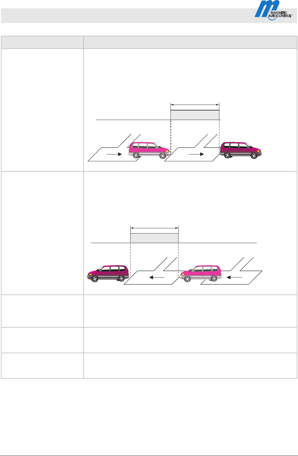
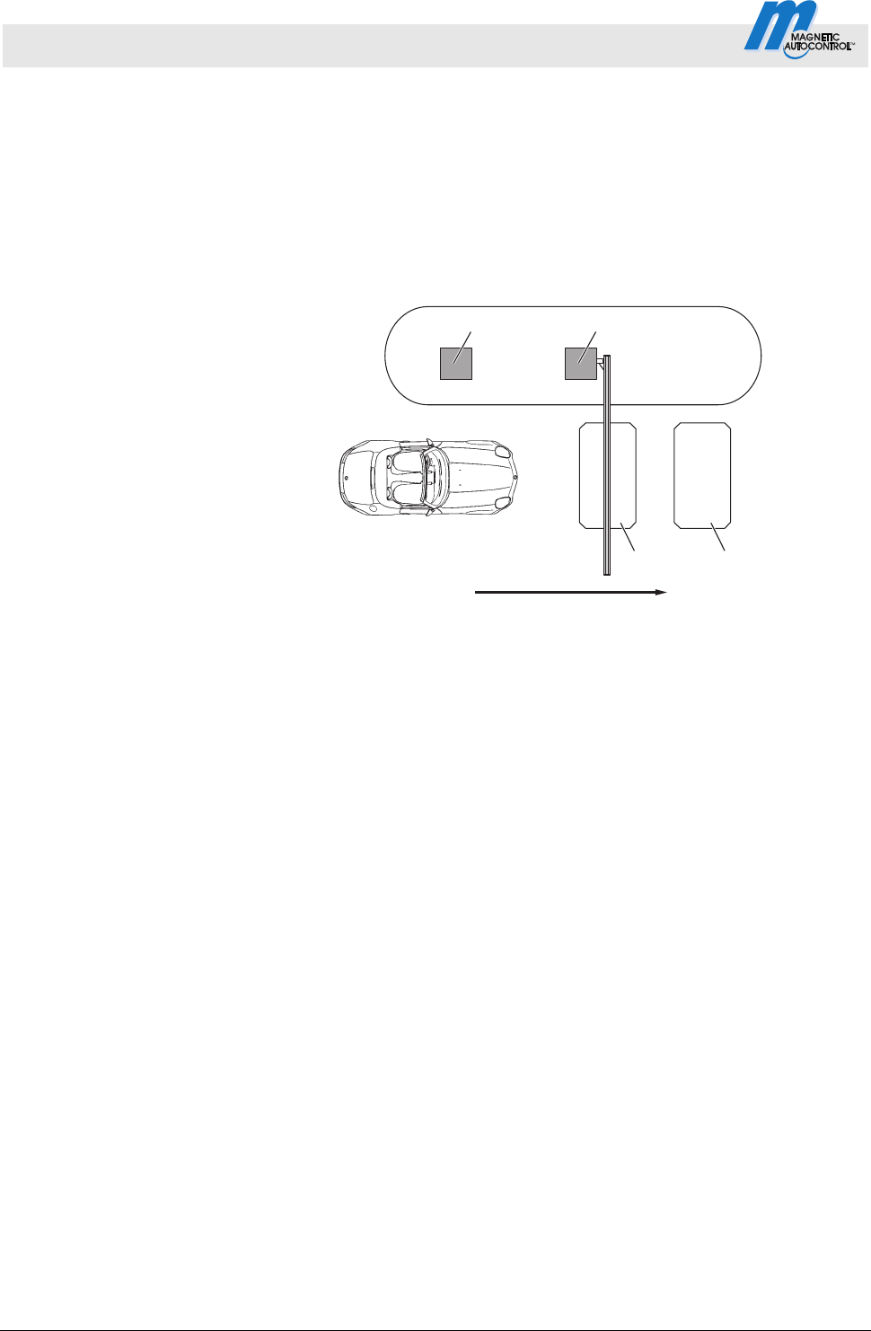
3.11.5 Automatic Modes 5 to 8:
Drive directions 1 – overview and differences
The automatic modes differ in their functions in drive direction 1
"Safety loop Opening loop".
In drive direction 2 "Opening loop Safety loop", the automatic
modes are identical. Refer to page 39, chapter 3.11.6.
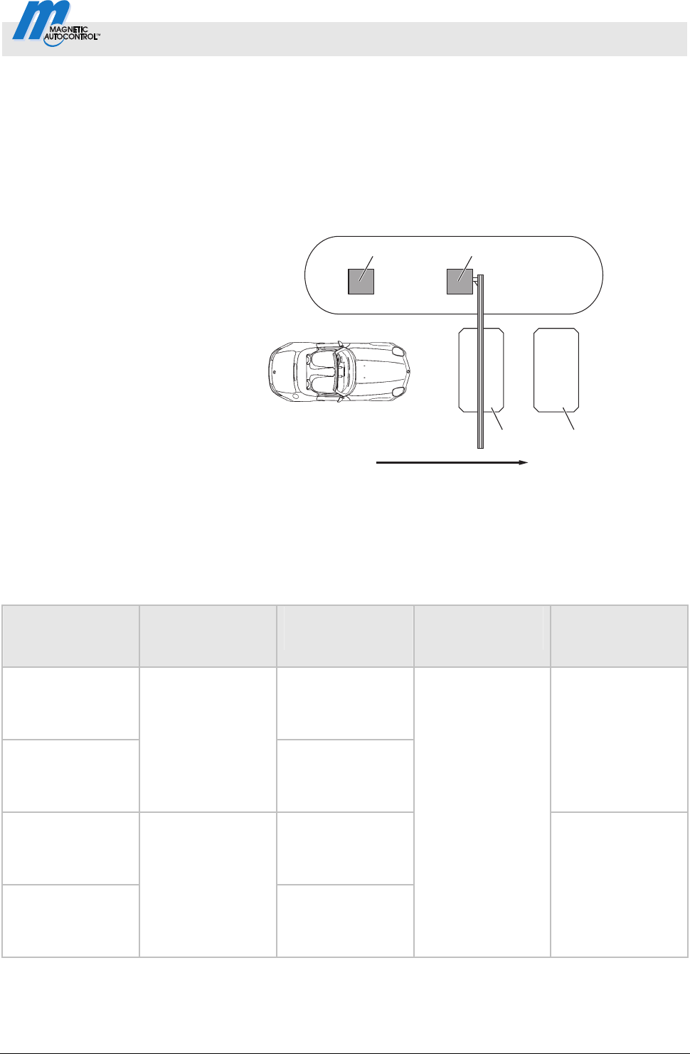
Drive direction 1: "Safety loop
Opening loop"
Mag00096
12
34
5
Fig. 17: Programme modes 5 to 8, Passage in direction 1
1 Remote control, card reader, coin acceptor, etc.
2 Barrier
3 Opening loop
4 Safety loop
5 Passage in direction 1
Programme mode Hold-open time
Function
Opening loop
Closing time
drive backwards
Closing time
without drive
through
Automatic (5)
The opening loop
here acts as an
extended safety
loop.
Automatic (6)
With hold-open
time
The opening loop
does not act as an
extended safety
loop here.
Barrier closes after
the end of the
opening time or at
a closing signal.
Automatic (7)
The opening loop
here acts as an
extended safety
loop.
Automatic (8)
Without hold-open
time
The opening loop
does not act as an
extended safety
loop here.
If a vehicle drives
onto the safety
loop and leaves it
again backwards,
the barrier closes.
Barrier closes after
drive-through of
the next vehicle or
after the closing
signal.
Table 16: Differences of automatic programme modes 5 to 8, direction 1

Control Unit MGC and MGC-Pro MHTM
TM
MicroDrive Barriers
Parameterising control unit
36 5816,0006EN / Version 00
Mode 5: Automatic (5) Typical application
This mode is suitable for the automatic operation of a barrier, e.g.
with card readers, remote control, coin acceptors and induction
loops or light barriers. Passage of the barrier is possible in either
direction.
Function
The barrier is opened from direction 1 "Safety loop Opening
loop" with an impulse at the "Open low priority" impulse, e.g. with a
card reader or coin acceptor. The hold-open time that was set is
also started.
When the vehicle leaves the safety loop, the hold-open time is
deleted.
The barrier closes in the following cases:
If the vehicle drives over both loops in direction 1, the barrier
closes as soon as the vehicle leaves the opening loop. The
opening loop here acts as an extended safety loop.
If a vehicle drives onto the safety loop but leaves it again
backwards, the barrier closes at once.
If the vehicle drives over neither of the two loops, i.e. there is no
drive through, the barrier closes after the end of the hold-open
time.
For barriers with a safety light barrier but no safety loop
installed, see page 55. chapter 3.17.1.
Mode 6:
Automatic (6) Typical application
This mode is suitable for the automatic operation of a barrier, e.g.
with card readers, remote control, coin acceptors and induction
loops or light barriers. Passage of the barrier is possible in either
direction.
Function
The barrier is opened from direction 1 "Safety loop Opening
loop" with an impulse at the "Open low priority" impulse, e.g. with a
card reader or coin acceptor. The hold-open time that was set is
also started.
When the vehicle leaves the safety loop, the hold-open time is
deleted.

Control Unit MGC and MGC-Pro MHTM
TM
MicroDrive Barriers
Parameterising control unit
5816,0006EN / Version 00 37
The barrier closes in the following cases:
If the vehicle drives over both loops in direction 1 "Safety loop
Opening loop", the barrier closes as soon as the vehicle
leaves the safety loop. The opening loop here does not act as
an extended safety loop.
If a vehicle drives onto the safety loop but leaves it again
backwards, the barrier closes.
If the vehicle drives over neither of the two loops, i.e. there is no
drive through, the barrier closes after the end of the hold-open
time.
For barriers with a safety light barrier but no safety loop
installed, see page 55. chapter 3.17.1.
Mode 7:
Automatic (7) Typical application
This mode is suitable for the automatic operation of a barrier, e.g.
with ticket vending machines with internal logic. Passage of the
barrier is possible in either direction.
Function
From direction 1 "Safety loop Opening loop", the barrier is
opened by an opening signal at one of the digital opening inputs.
Hold-open time is not active in this mode.
The barrier closes in the following cases:
If the vehicle drives over both loops in direction 1, the barrier
closes as soon as the vehicle leaves the opening loop. The
opening loop here acts as an extended safety loop.
If a vehicle drives onto the safety loop but leaves it again
backwards, the barrier closes.
If the vehicle does not drive onto any of the two loops, the
barrier remains open until a vehicle drives through or a closing
signal is given.
For barriers with a safety light barrier but no safety loop
installed, see page 55. chapter 3.17.1.

Control Unit MGC and MGC-Pro MHTM
TM
MicroDrive Barriers
Parameterising control unit
38 5816,0006EN / Version 00
Mode 8: Automatic (8) Typical application
This mode is suitable for the automatic operation of a barrier, e.g.
with ticket vending machines with internal logic. Passage of the
barrier is possible in either direction.
Function
From direction 1 "Safety loop Opening loop", the barrier is
opened by an opening signal at one of the digital opening inputs.
Hold-open time is not active in this mode.
The barrier closes in the following cases:
If the vehicle drives over both loops in direction 1 "Safety loop
Opening loop", the barrier closes as soon as the vehicle
leaves the safety loop. The opening loop here does not act as
an extended safety loop.
If a vehicle drives onto the safety loop but leaves it again
backwards, the barrier closes.
If the vehicle does not drive onto any of the two loops, the
barrier remains open until a vehicle drives through or a closing
signal is given.
For barriers with a safety light barrier but no safety loop
installed, see page 55. chapter 3.17.1.
Modes 5 to 8
:
Automatic (5) to (8) - supported
input functions
Direction Input function Signal type
Open high priority
Impulse or
permanent signal
Open low priority
Impulse or
permanent signal
Opening with vend
count
Impulse signal
Ext. opening loop entry
Impulse or
permanent signal
Open
Ext. opening loop exit
Impulse or
permanent signal
Close Close
Impulse or
permanent signal
Table 17: Supported input functions "Automatic (5) to (8)"
Also refer to page 7, chapter 2.1 "Digital inputs".
22
Control Unit MGC and MGC-Pro MHTM
TM
MicroDrive Barriers
Parameterising control unit
5816,0006EN / Version 00 39
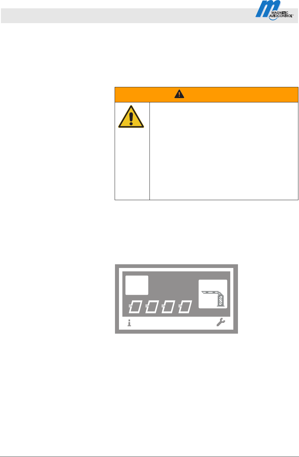
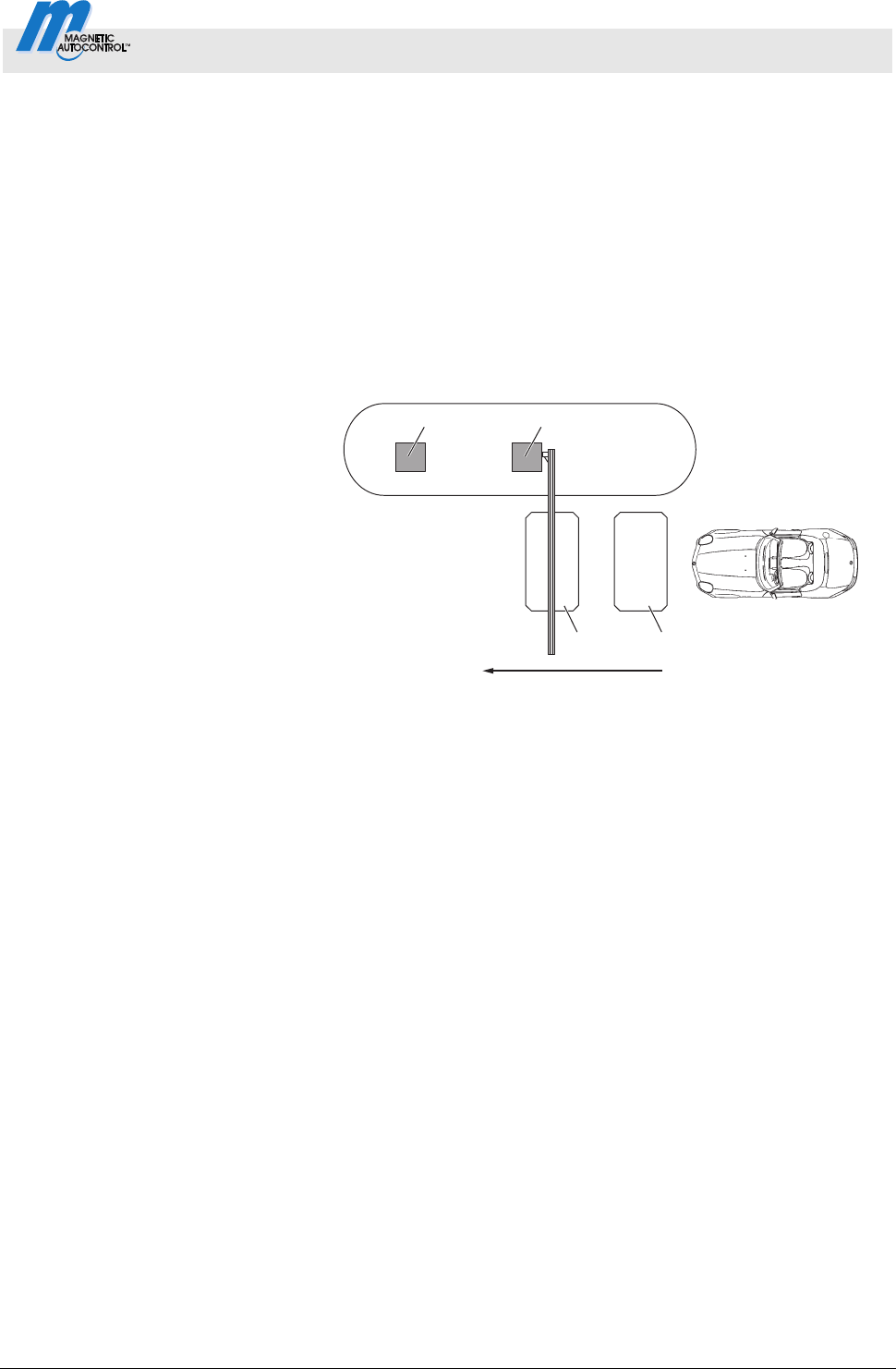
3.11.6 Automatic Modes 5 to 8: Drive direction 2
In drive direction 2 "Opening loop safety loop", the automatic
modes are identical.
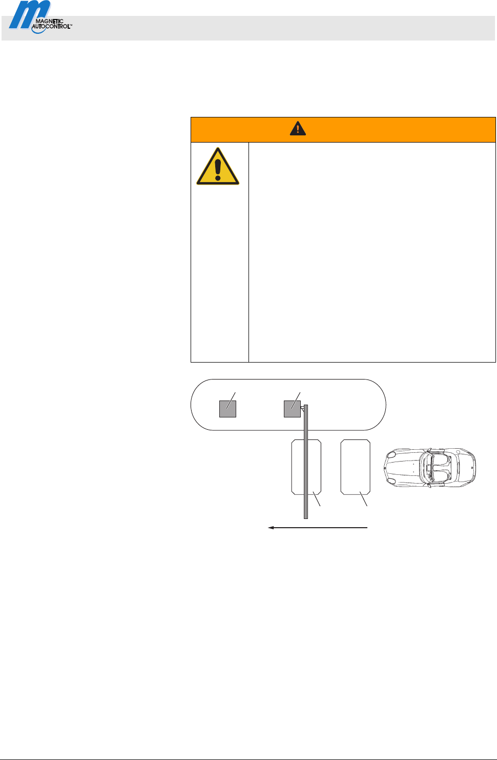
Closing barrier boom – maximum
distance of the induction loops
WARNING!
WARNING!
Danger from closing boom!
A closing boom may cause severe or lethal injury
to persons, bicyclers, cabriolet drivers and
motorcycle drivers!
Therefore:
– The maximum distance between opening loop
and safety loop must be not greater than max.
1 m. In direction 2 "Opening loop Safety
loop", the barrier closes as soon as the vehicle
leaves the opening loop. This means, if the
distance is too large, the barrier closes before
the car has cleared the barrier. See
operating instructions of the barrier, chapter
"Design notes for induction loops".
Drive direction 2: "Opening loop
Safety loop"
Mag00097
12
34
5
Fig. 18: Programme modes 5 to 8, Passage in direction 2
1 Remote control, card reader, coin acceptor, etc.
2 Barrier
3 Opening loop
4 Safety loop
5 Passage in direction 2
In direction 2, the opening loop is driven on first. The barrier opens.
While the opening loop or safety loop is occupied, the barrier
remains open. When the vehicle has left both loops, the barrier
closes.
Hold-open time is not active in drive direction 2.
When the vehicle leaves the opening loop backwards, the barrier
closes at once.
Control Unit MGC and MGC-Pro MHTM
TM
MicroDrive Barriers
Parameterising control unit
40 5816,0006EN / Version 00
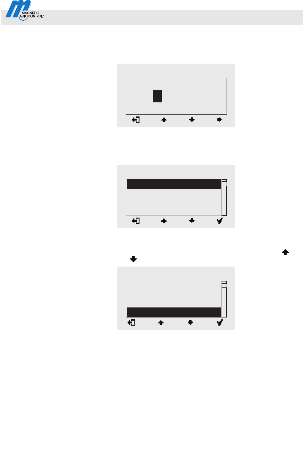
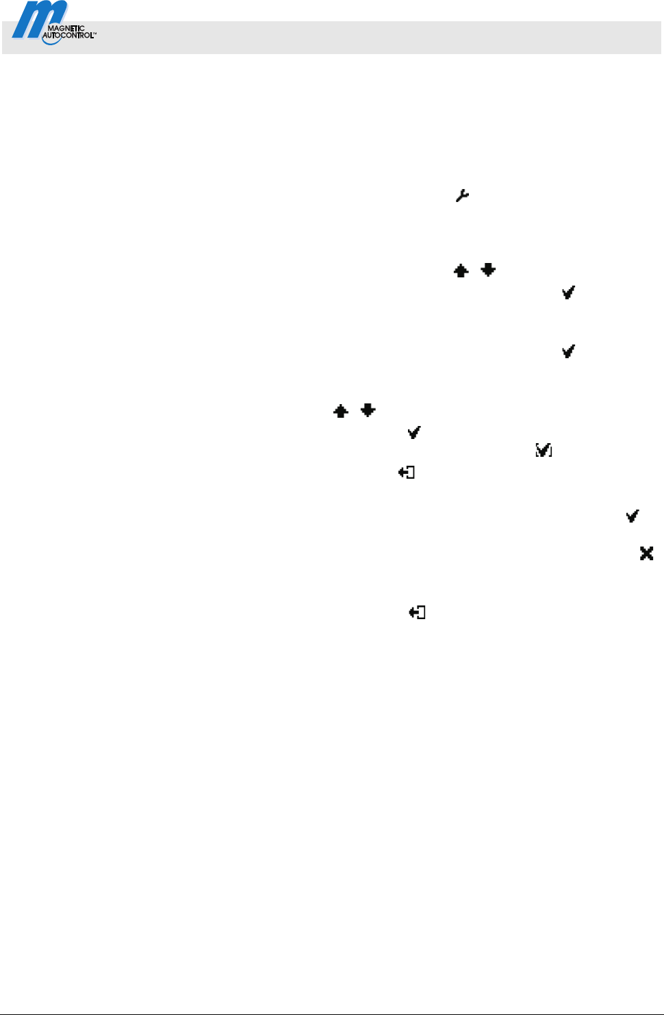
3.11.7 Mode "Service "
In the "Service" mode, all opening and closing signals are ignored.
The functions of safety devices like the safety loop or safety light
barrier remain active for security reasons. This means that as soon
as, e.g., the safety loop is occupied, the barrier cannot be closed.
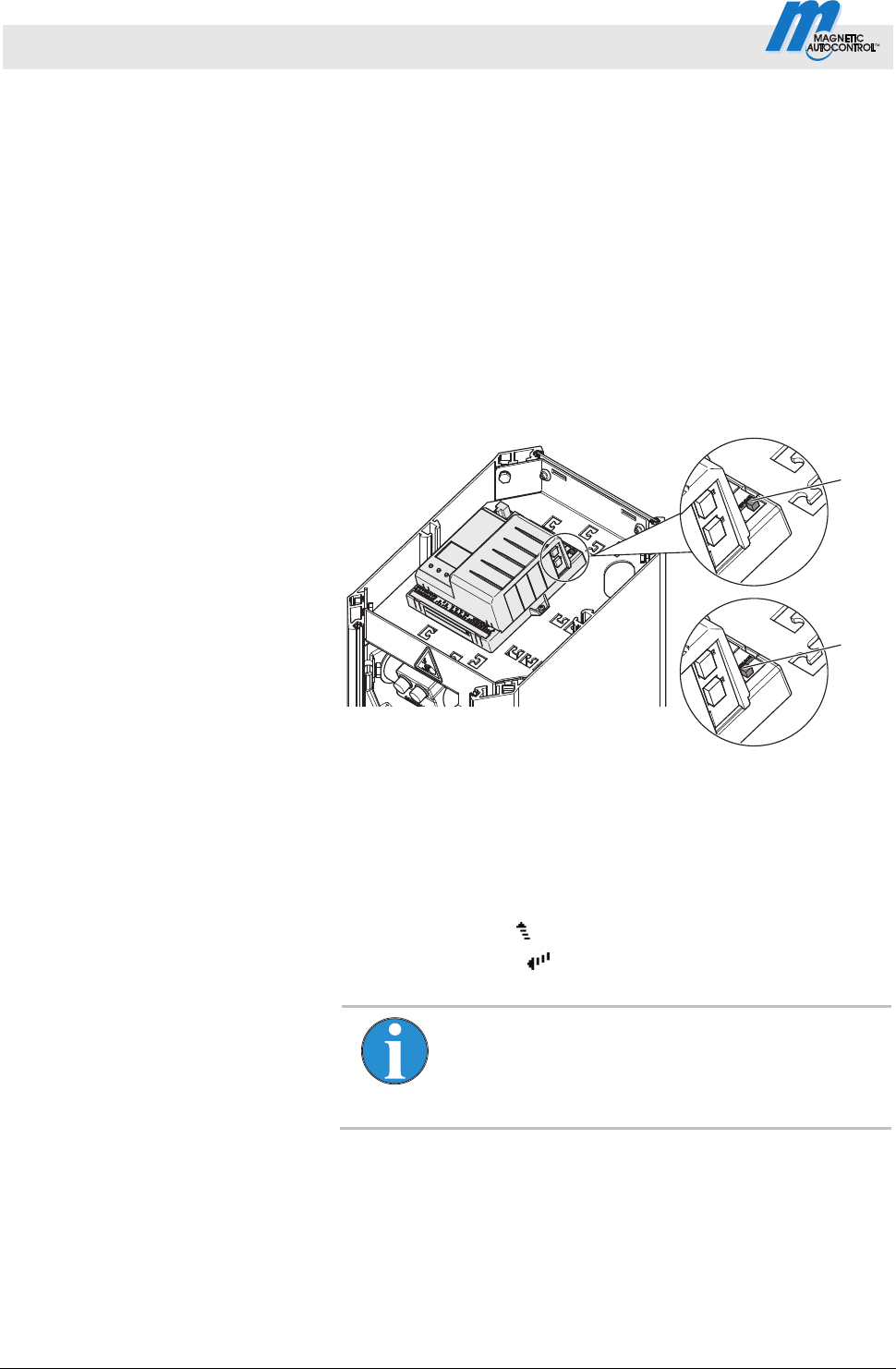
Switch on Mode "Service " Switch the "Service" switch for the "Service" mode. The LED lights
red. The display backlighting flashes.
Switch off Mode "Service " After the service work, the switch "Service" must be switched. The
LED must light green.
Mag00206b
2
1
Fig. 19: Service switch
1 Mode "Service" on
2 Mode "Service" off
Button function In the "Service" mode, you can control the motor with the two
middle control buttons.
Middle left button
: Manually open the barrier.
Middle right button
: Manually close the barrier.
NOTE!
For reasons of safety, the first barrier boom motion
after programme mode change is performed at
slow speed.
Control Unit MGC and MGC-Pro MHTM
TM
MicroDrive Barriers
Parameterising control unit
5816,0006EN / Version 00 41
3.12 Menu "Information" ( )
Call and navigate
1. The operating view is displayed. See page 24, Fig. 15.
2.
Press left control button
.
3. Use the left control button
to scroll within the menu.
4. The "Information" menu is can be left as follows:
Press the left control button
repeatedly until the operating
view is displayed again or
Press right control button
control button.
Operating view Information
Parameters Description
Error messages Shows the currently pending errors.
If no error messages are present, the menu is not displayed.
Inputs Displays the current settings for the digital inputs IN1 to IN8
Outputs
Displays the current settings for the digital outputs DO1 to DO4 and the relay
outputs NO1 to NO3 and NO/NC4 to NO/NC6.
Module info
Display of the software numbers (software #) and software versions (SW version) of
the control unit and plugged-in plug-in modules.
Induction loops
Detector (A-B),
Detector (C-D)
Displays the current frequencies of the connected induction loops.
The first plug-in module is displayed as "Detector (A-B)". The second plug-in module
is displayed as "Detector (C-D)". The frequencies of induction loops A and B are
displayed directly. To display the frequencies for the induction loops C and D, you
have to press the button
. Use the button you can switch the view between
"Detector (A-B)" and "Detector (C-D)". Also refer to page 65, chapter 3.23Menu .
Table 18: Menu "Information"
3.13 Menu "Function"
3.14 Programme mode (Prog. mode)
Refer to page 31, chapter 3.11.

Control Unit MGC and MGC-Pro MHTM
TM
MicroDrive Barriers
Parameterising control unit
42 5816,0006EN / Version 00
3.15 Menu "Setup"
3.15.1 Barrier speed
Operating view Main menu Setup Speed
Parameters Description
Closing Select the closing speed for the barrier boom.
The closing speed can be changed for all barrier types. The option "fast"
corresponds to the barrier-specific speed (100 %).
Options
slow: approx. 50 % of the maximum speed
medium: approx. 70 % of the maximum speed
fast: maximum speed (barrier-specific speed)
Factory setting
fast
Open
Select the opening speed for the barrier boom. The option "fast" corresponds
to the barrier-specific speed (100 %).
The parameter is displayed for the following barrier types: Access Pro,
Access Pro L, Access Pro H, Access Select, Access Select L, Access XL and
Access XXL, Parking Pro and Parking Select, Toll Pro and Toll HighSpeed with
MGC-Pro control unit.
Options
slow: approx. 50 % of the maximum speed
medium: approx. 70 % of the maximum speed
fast: maximum speed (barrier-specific speed)
Factory setting
fast
Table 19: Menu "Barrier speed"
3.15.2 Delays
Operating view Main menu Setup Delay
Parameters Description
Hold-open time
The parameter "Hold-open time" sets the hold-open time for the automatic
programme modes 5 and 6.
The hold-open time is started by an opening impulse by a control unit, such as
a card reader. A passage should occur during the set hold-open time. If no
passage occurs during the hold-open time, the barrier closes automatically.
When the vehicle drives on the safety loop, the hold-open time is deleted.
Setting range
3 to 60 s
Factory setting
30 s

Control Unit MGC and MGC-Pro MHTM
TM
MicroDrive Barriers
Parameterising control unit
5816,0006EN / Version 00 43
Operating view Main menu Setup Delay
Parameters Description
Close delay
The barrier only closes if the set time for the closing delay is over. The timer for
closing delay is started with the closing signal. With this parameter, you can
also set the "Lead time" in the "Signal light" menu to the same menu. Refer
to page 57, chapter 3.18.1.
Setting ra
nge
0 to 15 s
Factory setting
0 s
Light barrier delay
The barrier only closes if the set time for the light barrier delay is over. The
timer for light barrier delay is started with clearance of the light barrier.
Setting range
0 to 15 s
Factory setting
5 s
Impact delay
After the control unit has recognised that, e.g., a vehicle roof was hit by the
closing barrier boom, the control unit tries to close the barrier again after the
set impact delay. Impact is possible if, e.g., a user tries to drive through the
barrier without permission.
The following conditions must be met for the barrier to close after the end of
the impact delay:
In the "Impact settings" menu, the parameter "Restart" must be set to
"Automatic".
The safety devices, such as safety loop or safety light barrier must be clear.
Also refer to page 48, chapter 3.15.5 Menu "Impact settings"
Setting ra
nge
5 to 30 s
Factory setting
5 s
Table 20: Menu "Delays"

Control Unit MGC and MGC-Pro MHTM
TM
MicroDrive Barriers
Parameterising control unit
44 5816,0006EN / Version 00
3.15.3 Cut off angle
Operating view Main menu Setup Cut off angle
Parameters Description
Safety loop close
This parameter serves to ensure that a closed barrier can not be opened
without authorisation.
If the barrier boom is below the angle set for "Safety loop close", signals form
the safety devices such as safety loop or safety light barrier are ignored. I.e.,
the barrier closes completely below the angle set here.
Setting range
Access: 1 to 40°
Access XL and Access XXL: 1 to 40°
Parking: 1 to 80°
Toll and Toll HighSpeed: 1 to 80°
Light barrier
If the barrier boom is below the set angle for "Light barrier" during closing, the
light barrier is ignored. I.e., the barrier closes completely below the angle set
here even if the light barrier is covered.
Setting range
1 to 40°
Factory setting
10°
Impact detection
Where the barrier boom is below the set angle for impact detection during
closing, impact detection is deactivated. I.e., the barrier tries to close
completely below the angle set here.
Observe the length of the barrier boom when setting the angle. The barrier
boom tip height at impact detection depends on the angle set and the barrier
boom length.
Setting range
1 to 40°
Factory setting
10°
Table 21: Menu "Cut off angle"

Control Unit MGC and MGC-Pro MHTM
TM
MicroDrive Barriers
Parameterising control unit
5816,0006EN / Version 00 45
3.15.4 Vend count
Operating view Main menu Setup Vend count
Parameters Description
Reset behaviour
Use this parameter to set vend count reset behaviour. The function "Vend
count" is available for programme modes 4 to 8. An internal vend count counts
the impulses present at the input with the "Opening with vend count" function.
The pulses are decremented only in driving direction 1 "Safety loop Opening
loop".
Options
no counter reset (without vend count reset)
Time-out
The vend count is set to the value "0" if the vehicle does not pass the
supervision device within the set hold-open time.
Reset on closing
The vend count is set to value "0" when a closing signal is given.
Time-out/Reset on closing
The vend count is set to the value "0" if the event "Time-out" or the event
"Reset on closing" occurs.
Factory setting
Time-out/Reset on closing
Counter This parameter shows the current counter reading of the vend count.
Count open loop
This function is sensible for systems where the opening loop is installed farther
than one vehicle length away from the safety loop. The opening loop must be
connected to a detector module. When using this function, passage is
permitted in one direction only.
Once the function is activated, passages over the opening loop are counted as
impulse. The direction is not considered when decrementing the impulses.
Options
Deactivated [...]
Activated [ X ]
Factory setting
Deactivated [...]
Table 22: Menu "Vend count"
NOTE!
By default, the internal vend count is decremented
after safety loop and opening loop are driven over.
In the following systems, the vend count is
decremented after the safety loop is driven over
already: No opening loop is activated or the option
"Inactive" was chosen for the parameter "Count
open loop".
Control Unit MGC and MGC-Pro MHTM
TM
MicroDrive Barriers
Parameterising control unit
46 5816,0006EN / Version 00
Example vend count
with programme mode
"Automatic mode (5)"
This mode is suitable for the automatic operation of a barrier, e.g.
with card readers, remote control, coin acceptors and induction
loops or light barriers. The control units and the barrier have a
larger distance from each other. An internal vend count is
incremented and decremented. The hold-open time counts down at
the same time. Passage of the barrier is possible in either
direction.
Drive direction 1: "Safety loop
Opening loop"
Mag00096
12
34
5
Fig. 20: Programme mode 5 with vend count, Passage in direction 1
1 Remote control, card reader, coin acceptor, etc.
2 Barrier
3 Opening loop
4 Safety loop exit
5 Passage in direction 1
The barrier is opened from direction 1 "Safety loop Opening
loop" with an impulse at the "Opening with vend count" impulse,
e.g. with a card reader or coin checking device. At the same time,
an internal vend count is incremented. For the parameter "Count
open loops", the option "Inactive" is set.
After passage of the safety loop and the opening loop, the vend
count is decremented again. When the internal vend count reaches
the value "0, the barrier is closed.
Additionally, the vend count is set to the value "0" and the barrier
closed in the following cases, depending on the settings for the
"Vend count" parameter:
The vehicle does not drive over the supervision facility within
the set hold-open time.
A closing signal is assigned.
Control Unit MGC and MGC-Pro MHTM
TM
MicroDrive Barriers
Parameterising control unit
5816,0006EN / Version 00 47
The barrier closes in the following cases:
If the vehicle drives over both loops in direction 1, the barrier
closes as soon as the vehicle leaves the opening loop. The
opening loop here acts as an extended safety loop.
If a vehicle drives onto the safety loop but leaves it again
backwards, the hold-open time is deleted and the barrier
closes.
If the vehicle drives over neither of the two loops, i.e. there is no
drive through, the barrier closes depending on setting of the
"vend count" parameter.
Drive direction 2: "Opening loop
Safety loop"
Mag00097
12
34
5
Fig. 21: Programme mode 5 with impulse storage,
Passage in direction 2
1 Remote control, card reader, coin acceptor, etc.
2 Barrier
3 Opening loop
4 Safety loop exit
5 Passage in direction 2
In direction 2, the opening loop is driven on first. The barrier opens.
While the opening loop or safety loop is occupied, the barrier
remains open. When the vehicle has left both loops will the barrier
close.
From drive direction 2, vend count is not active.
When the vehicle leaves the opening loop backwards, the barrier
closes at one.

Control Unit MGC and MGC-Pro MHTM
TM
MicroDrive Barriers
Parameterising control unit
48 5816,0006EN / Version 00
3.15.5 Impact settings
Operating view Main menu Setup Impact settings
Parameters Description
Impact response
Select the barrier boom's impact reaction if the control unit detects an impact.
Refer to parameter "Impact detection" page 44, chapter 3.15.3.
Select the ba
rrier boom's impact reaction if the control unit detects an impact.
This setting relates to the impact detection while the barrier boom closes. If an
impact is recognised during opening, the barrier boom is stopped.
Options
Open
After impact detection, the barrier boom is opened completely.
Stop
After impact detection, the barrier boom's closing movement is stopped.
Safe stop
After impact detection, the barrier boom's closing movement is first stopped
and then slightly opened.
Factory setting
Open
Impact delay
After the control unit has recognised that, e.g., a vehicle roof was hit by the
closing barrier boom, the control unit tries to close the barrier again after the
set impact delay. Impact is possible if, e.g., a user tries to drive through the
barrier without permission.
The following conditions must be met for the barrier to close after the end of
the impact delay:
In the "Restart" parameter, the option must be set to "Automatic".
The safety devices, such as safety loop or safety light barrier, must be
clear.
This parameter corresponds to the parameter "Impact delay" in the "Delays"
menu. Refer to page 42, chapter 3.15.2.
Setting ra
nge
5 to 30 s
Factory setting
5 s
Restart Select behaviour of the barrier after impact recognition.
Options
Automatic
The barrier boom automatically completes the started movement after the
impact delay has run.
Signal
For the barrier boom to complete the started movement, the matching
signal (open/close) must be applied.
Factory setting
Signal
Table 23: Menu "Impact settings"

Control Unit MGC and MGC-Pro MHTM
TM
MicroDrive Barriers
Parameterising control unit
5816,0006EN / Version 00 49
3.15.6 Start-up settings
Use this menu to select the start-up settings of the barrier
according to the following events:
after switching on voltage supply
after return of voltage
after reset
Homing When the barrier starts up, the barrier performs a homing run. The
barrier boom is opened at reduced speed to the upper end
position. This process is also called homing.
Operating view Main menu Setup Start-up settings
Parameters Description
Start-up behaviour
Select start-up behaviour of the barrier.
Refer to page 50, chapter 3.15.7 "Start-up behaviour".
Setting ra
nge
1 … 8
Factory setting
1
Stay closed
Select start-up behaviour for the barrier when the barrier boom is in the
"closed" position.
Options
Activated [ X ]
If the barrier boom is in the "closed" position, the selected start-up
behaviour is ignored. If the barrier boom is in any other position, the barrier
will act according to the chosen start-up behaviour.
Before homing,m the barrier position is inspected. A short movement in the
closing direction is performed to check if the barrier is closed. If the barrier
is closed, the barrier remains closed until an opening signal is pending. The
opening signal is used for homing. No release signal is required.
Deactivated [ ]
The barrier behaves according to the selected start-up behaviour.
Factory setting
Deactivated [...]
Table 24: Menu "Start-up settings"

Control Unit MGC and MGC-Pro MHTM
TM
MicroDrive Barriers
Parameterising control unit
50 5816,0006EN / Version 00
3.15.7 Start-up behaviour
NOTE!
The display messages "Waiting for passage" and
"Waiting for release" can be confirmed with the left
button of the control unit. Ensure that no persons or
vehicles are present below the barrier boom. In
operating modes 3 to 8, the barrier will close as
soon as the message has been confirmed. In
operating modes 1 and 2, a closing signal is still
required after the message is confirmed.
Operating view Main menu Setup Start-up behaviour
Option Description
1
Reference run
In this option, the barrier initially performs a reference run. This means that the
barrier opens completely at low speed.
Release signal
No release signal is required to close the boom.
Closing behaviour
Programme modes 1 or 2:
If a safety loop is installed, the barrier closes only after a vehicle has
passed through and a permanent closing signal is pending. If only a safety
light barrier is installed, no passage is required. The barrier closes at once
when a permanent closing signal is applied.
Programme modes 3 to 8:
If a safety loop is installed, the barrier closes when the first vehicle has
driven through. If only a safety light barrier is installed, the barrier closes at
once when the voltage returns.
2
Reference run
In this option, the barrier initially performs a reference run. This means that the
barrier opens completely at low speed.
Release signal
A release signal must be applied for the barrier to be ready fro closing. The
release signal can be applied even before the voltage returns.
The release signal is given either by an external closing signal, an external
opening signal or by pushing the left operating button at the control unit.
Closing behaviour
Programme modes 1 or 2:
If a safety loop is installed, the barrier closes only after a vehicle has
passed through and a permanent closing signal is pending. If only a safety
light barrier is installed, no passage is required. The barrier closes at once
when a permanent closing signal is applied.
Programme modes 3 to 8:
If a safety loop is installed, the barrier closes when the first vehicle has
driven through. If only a safety light barrier is installed, the barrier closes at
once when the voltage returns.

Control Unit MGC and MGC-Pro MHTM
TM
MicroDrive Barriers
Parameterising control unit
5816,0006EN / Version 00 51
Operating view Main menu Setup Start-up behaviour
Option Description
3
Reference run
In this option, the barrier initially performs a reference run. This means that the
barrier opens completely at low speed.
Release signal
A release signal must be applied for the barrier to be ready for closing.
If the release signal is applied before return of voltage, the release signal is
ineffective. In this case, the release signal must be revoked and applied again
after the barrier opens.
The release signal can be given by an external closing signal or by pushing the
left operating button at the control unit.
Closing behaviour
Programme modes 1 or 2:
If a safety loop is installed, the barrier closes only after a vehicle has
passed through and a permanent closing signal is pending. If only a safety
light barrier is installed, no passage is required. The barrier closes at once
when a permanent closing signal is applied.
Programme modes 3 to 8:
If a safety loop is installed, the barrier closes only after the first vehicle has
driven through. If only a safety light barrier is installed, the barrier closes at
once when the voltage returns.
4
Reference run
In this option, the barrier boom stops initially. The barrier will only carry out a
reference run after a release signal.
Release signal
A release signal must be applied for the barrier to carry out a reference run.
If the release signal is applied before return of voltage, the release signal is
ineffective. In this case, the release signal must be revoked and applied again
after the barrier opens.
The release signal can be given by an external closing signal or by pushing the
left operating button at the control unit.
Closing behaviour
Programme modes 1 or 2:
If a safety loop is installed, the barrier closes only after a vehicle has
passed through and a permanent closing signal is pending. If only a safety
light barrier is installed, no passage is required. The barrier closes at once
when a permanent closing signal is applied.
Programme modes 3 to 8:
If a safety loop is installed, the barrier closes only after the first vehicle has
driven through. If only a safety light barrier is installed, the barrier closes at
once when the voltage returns.

Control Unit MGC and MGC-Pro MHTM
TM
MicroDrive Barriers
Parameterising control unit
52 5816,0006EN / Version 00
Operating view Main menu Setup Start-up behaviour
Option Description
5
Reference run
In this option, the barrier boom stops initially. The barrier will only carry out a
reference run after a release signal.
Release signal
A release signal must be applied for the barrier to be ready fro closing. The
release signal can be applied even before the voltage returns.
The release signal is given either by an external closing signal, an external
opening signal or by pushing the left operating button at the control unit.
Closing behaviour
Programme modes 1 or 2:
If a safety loop is installed, the barrier closes only after a vehicle has
passed through and a permanent closing signal is pending. If only a safety
light barrier is installed, no passage is required. The barrier closes at once
when a permanent closing signal is applied.
Programme modes 3 to 8:
If a safety loop is installed, the barrier closes only after the first vehicle has
driven through. If only a safety light barrier is installed, the barrier closes at
once when the voltage returns.
6
Reference run
In this option, the barrier boom stops initially.
Release signal
For a release signal must be applied for the barrier to carry out a reference run.
Release takes place by pushing the left operating button at the control unit.
Closing behaviour
Programme modes 1 or 2:
The barrier closes at once when a permanent closing signal is applied.
Programme modes 3 to 8:
The barrier closes at once after the barrier reference run.
Control Unit MGC and MGC-Pro MHTM
TM
MicroDrive Barriers
Parameterising control unit
5816,0006EN / Version 00 53
Operating view Main menu Setup Start-up behaviour
Option Description
7
Reference run
In this option, the barrier initially performs a reference run. This means that the
barrier opens at low speed.
Release signal
No release signal is required to close the boom.
Closing behaviour
Programme modes 1 or 2:
The barrier closes at once when a permanent closing signal is applied.
Programme modes 3 to 8:
If a safety loop is installed, the barrier closes only after the first vehicle has
driven through or after closing. If only a safety light barrier is installed, the
barrier closes at once when the voltage returns.
WARNING!
Danger of injury from closing boom!
Sight contact to the barrier is required when the voltage
is switched on again.
No vehicles and persons must stand below the barrier
when the closing signal is given.
8
Reference run
In this option, the barrier initially performs a reference run. This means that the
barrier opens at low speed.
Release signal
No release signal is required to close the boom.
Closing behaviour
Programme modes 1 or 2:
The barrier closes at once when a permanent closing signal is applied.
Programme modes 3 to 8:
Barrier closes at once.
WARNING!
Danger of injury from closing boom!
Sight contact to the barrier is required when the voltage
is switched on again.
No vehicles and persons must stand below the barrier
when the closing signal is given.
Table 25: Menu "Start-up behaviour", parameter "Start-up settings"

Control Unit MGC and MGC-Pro MHTM
TM
MicroDrive Barriers
Parameterising control unit
54 5816,0006EN / Version 00
3.15.8 Power failure
Operating view Main menu Setup Power failure
Parameters Description
Power failure
This parameter sets whether the barrier boom opens at power outage or opens
or closes depending on the barrier boom position. The balancing springs must
be set according to the selected option. See operating instructions of the
barrier, chapter "Check and set the balancing springs in the lever system".
Options
Unlocked
With this option, the lever system of the closed barrier is unlocked; the
barrier remains closed. The boom can be opened manually.
If the boom angle is less than approx. 30°, the boom will close. If the barrier
boom is above an angle of approx. 35°, the barrier boom opens. The ba-
lancing springs in the lever system must be set accordingly.
Open
This option is only possible for the barrier types Access, Access Pro,
Parking, Parking Pro, Toll and Toll Pro with a locking width of up to 3.5
metres.
In this option, the barrier boom opens at power outage. The barrier boom is
moved to the locked end position with the present residual energy of the
mains unit and completely opened by the balancing springs of the lever
system. The balancing springs must be set correctly and the barrier boom
must not be kept in the closed position by external influence.
Locked
For this option, the barrier boom behaviour depends on the barrier boom
position at power outage. When the barrier is closed, it remains closed and
the lever system remains locked. Manual opening of the barrier is not
possible or requires considerable application of force. If the barrier boom is
below an angle of approx. 30°, the barrier boom closes. If the barrier boom
is above an angle of approx. 35°, the barrier boom opens. The balancing
springs in the lever system must be set accordingly.
Factory setting
Unlocked
Table 26: Menu "Power failure"
3.16 Menu "In-/Outputs"
3.16.1 Inputs
Refer to page 7, chapter 2.1 "Digital inputs".
3.16.2 Outputs
Refer to page 11, chapter 2.2 "Digital outputs and output
relays".

Control Unit MGC and MGC-Pro MHTM
TM
MicroDrive Barriers
Parameterising control unit
5816,0006EN / Version 00 55
3.17 Menu "Special functions"
3.17.1 Closure by light barrier
Operating view Main menu Special functions Closure by light barrier
Parameters Description
Closure by light barrier
Use this parameter to select the closing behaviour for barriers with only one
safety light barrier installed.
If a safety loop is installed, the barrier closes only after the first vehicle has
driven through in the automatic programme modes 5 to 8. If only a safety light
barrier is installed, the barrier will not close automatically after the first vehicle
has driven through in the automatic programme modes 5 to 8.
Options
Deactivated [...]
In programme modes 5 and 6, the barrier only closes if either a closing
signal is applied or the hold-open time has passed. In programme modes 7
and 8, the barrier only closes when a closing signal is applied.
Activated [ X ]
In programme modes 5 to 8, the barrier closes at once when a vehicle
drives through the safety light barrier and after passage of the set time for
the parameter "Light barrier delay". Refer to page 42, chapter 3.15.2.
Factor
y setting
Deactivated [...]
Table 27: Menu "Closure by light barrier"
3.17.2 Closure by additional safety
Operating view Main menu Special functions Closure by additional safety
Parameters Description
Closure by add. safety
(Closure by additional
safety)
This parameter is only displayed if the input function "Additional safety device"
was assigned to an input.
Options
Deactivated [...]
The barrier remains open after clearing of the additional safety device.
Active [ X ]
The barrier closes after clearing of the additional safety device.
Factory setting
Deactivated [...]
Table 28: Menu " Closure by additional safety"

Control Unit MGC and MGC-Pro MHTM
TM
MicroDrive Barriers
Parameterising control unit
56 5816,0006EN / Version 00
3.17.3 Stop at tailgating
Operating view Main menu Special functions Stop at tailgating
Parameters Description
Stop at tailgating This parameter is only available for the series "Parking".
Options
Deactivated [...]
If the safety loop is driven on above the cut-off angle for the parameter
"Safety loop close" during closing, the barrier boom opens. When the safety
loop is cleared, cloying is continued.
Active [ X ]
If the safety loop is driven on above the cut-off angle for the parameter
"Safety loop close" during closing, the barrier boom stops. When the safety
loop is cleared, cloying is continued.
Also refer to page 44, chapter 3.15.3 Menu "Cut off angle"
Factor
y setting
Deactivated [...]
Table 29: Menu:"Stop at tailgating"
3.17.4 Master/Slave
Operating view Main menu Special functions Master/Slave
Parameters Description
Master/Slave
Activate and deactivate "Parallel operation" function. By activating the
master/slave function, the corresponding inputs and outputs are switched
automatically. See separate instructions for information on parallel
operation.
Options
Deactivated [...]
Activated [ X ]
Factory setting
Deactivated [...]
Table 30: Menu "Master/Slave"

Control Unit MGC and MGC-Pro MHTM
TM
MicroDrive Barriers
Parameterising control unit
5816,0006EN / Version 00 57
3.18 Menu "Attachments"
3.18.1 Signal light
The parameters "Signal Mode A", "Signal Mode B" and "Signal
Mode C" can be used to parameterise the function for the outputs
"Signal light A", "Signal light B" and "Signal light C". Refer to
page 12, chapter 2.2.
You can
connect three signal lights.
If you want to control light strips via the MAGNETIC control unit,
you need to select the "Illumination strip red" option for "Signal
Mode A" and "Illumination strip green" for "Signal Mode B".
Operating view Main menu Attachments Signal light
Parameters Description
Signal mode A
(continued on next
page)
Select function for output "Signal light A".
The parameter "lead time" can be used to parameterise the warning lamp so
that it already lights up red or flashes before closing. The lead time is the time
between the closing signal and commencement of the closing procedure.
Options
Traffic light (permanent signal for red/green signal lights):
Barrier closed: Traffic light red
Barrier opens: Traffic light red
Barrier open (upper end position): Traffic light off
Barrier closes (without lead time)/
closing time (with lead time): Traffic light red
Warning signal (connection of a visual or acoustic signal/
permanent signal before and during closing of the barrier):
Barrier closed: Warning signal off
Barrier opens: Warning signal off
Barrier open (upper end position): Warning signal off
Barrier closes (without lead time)/
closing time (with lead time): Warning signal red
Flashing light (flashing light connection/
flashing signal while the barrier opens or closes):
Barrier closed: Flashing light off
Barrier opens: Flashing light flashes at 2 Hz
Barrier open (upper end position): Flashing light off
Barrier closes (without lead time)/
closing time (with lead time): Flashing light flashes at 2 Hz
Boom illumination (boom illumination connection/
permanent flashing signal except when the barrier is open):
Barrier closed: Illumination flashes at 2 Hz
Barrier opens: Illumination flashes at 2 Hz
Barrier open (upper end position): Illumination off
Barrier closes (without lead time)/
closing time (with lead time): Illumination flashes at 2 Hz

Control Unit MGC and MGC-Pro MHTM
TM
MicroDrive Barriers
Parameterising control unit
58 5816,0006EN / Version 00
Operating view Main menu Attachments Signal light
Parameters Description
Signal mode A
(continued)
Illumination strip red / Boom illumination / Flashing light
Barrier closed (lower end position): Red, permanent light
Barrier opens: Red flashes at 2 Hz
Barrier open (upper end position): Red off
Barrier closes (without lead time)/
closing time (with lead time): Red flashes at 2 Hz
Factory setting
Illumination strip red
Signal mode B Select function for output "Signal light B".
Options
For the options "Traffic light", "Warning signal", "Flashing lights", "Boom
illumination", see parameters "Signal mode A".
Illumination strip green
Barrier closed (lower end position): Green off
Barrier opens: Green off
Barrier open (upper end position): Green, permanent light
Barrier closes (without lead time)/
closing time (with lead time): Green off
Factory setting
Illumination strip green
Signal mode C Select function for output "Signal light C".
Options
Traffic light (permanent signal for red/green signal lights):
Barrier closed: Traffic light red
Barrier opens: Traffic light red
Barrier open (upper end position): Traffic light off
Barrier closes (without lead time)/
closing time (with lead time): Traffic light red
Warning signal (connection of a visual or acoustic signal/
permanent signal before and during closing of the barrier):
Barrier closed: Warning signal off
Barrier opens: Warning signal off
Barrier open (upper end position): Warning signal off
Barrier closes (without lead time)/
closing time (with lead time): Warning signal red
Factory setting
Warning signal

Control Unit MGC and MGC-Pro MHTM
TM
MicroDrive Barriers
Parameterising control unit
5816,0006EN / Version 00 59
Operating view Main menu Attachments Signal light
Parameters Description
Lead time
In some application cases, it is required for reasons of safety that a warning
signal for the following traffic lights up after before closing of the barrier. This
warning signal must light up before the barrier closes. The warning signal is
switched on with the closing signal and the lead time is started. The barrier
closes only after the end of the set lead time.
0 sWith this parameter, you can also set the "Closing delay" in the "Delay"
menu to the same menu. Refer to page 42, chapter 3.15.2.
Setting ra
nge
0 to 15 s
Factory setting
0 s
Start event Select the start event from when on the signal lights should switch.
Options
Closing signal
Safety loop active
The option "Safety loop active" is only sensible for the automatic
programme modes 5 to 8. If an opening signal is pending, the signal lamps
are not switched.
Factory setting
Closing signal
Table 31: Menu "Signal light"

Control Unit MGC and MGC-Pro MHTM
TM
MicroDrive Barriers
Parameterising control unit
60 5816,0006EN / Version 00
3.18.2 Boom contact settings
The barrier can optionally be equipped with a boom contact in the
flange. In the "Toll" series, the boom contact is integrated by
default and performed as a "Swing Away" or "Auto Swing Away".
Operating view Main menu Attachments Boom contact settings
Parameters Description
Enabled/disabled
The barrier can optionally be equipped with a boom contact in the flange. The
parameter "Enabled/disabled" is used to select the behaviour of the input
function "Boom contact input" and the output function "Boom contact
feedback". The functions must be selected. Refer to page 9, chapter 2.1
and pa
ge 12, chapter 2.2.
Options
Inac
tive
"Boom contact" is deactivated. The input "Boom contact input" has no
function in this option.
The output with the function "Boom contact feedback" is deactivated once
the boom contact triggers
Active
"Boom contact" is activated. While the barrier boom is in the flange,
24 V DC are pending at the input with the function "Boom contact input". If
the barrier boom is moved from its position, the +24 V DC are removed
from the "Boom contact input" input. The barrier moves to the "Open"
position.
The output with the unction "Boom contact feedback" is deactivated once
the boom contact triggers.
Factory setting
Inactive
Automatic closing Select signal for closing of the barrier boom after boom release.
Options
Automatic
The barrier boom automatically closes after the end of the delay time.
Signal
For the barrier boom to close, a signal must be applied to the input with the
function "Close" or "Close low priority".
Factory setting
Automatic

Control Unit MGC and MGC-Pro MHTM
TM
MicroDrive Barriers
Parameterising control unit
5816,0006EN / Version 00 61
Operating view Main menu Attachments Boom contact settings
Parameters Description
Closing delay The parameters are only relevant in the following cases:
The barrier is a "Swing Away" or "Auto Swing Away" design.
In the "Automatic closing" parameter, the option is set to "Automatic".
If a car drives against a "Swing Away" barrier boom, it snaps from the flange.
In the "Swing Away" version, the barrier boom must be returned to the flange
manually. In the "Auto Swing Away" version, the barrier boom automatically
moves into the "open" position. When the position is reached, the barrier boom
is locked in the flange by springs.
After the barrier boom has caught again, the barrier closes after the time set
here.
Setting range
0 to 10 s
Factory setting
10 s
Table 32: Menu "Boom contact settings"
3.18.3 Boom locking
The barrier can optionally be equipped with an electro-mechanical
boom lock at the end of the barrier boom. When the barrier is
closed, the boom locking is activated via the output function "Boom
locking". If a signal is present for opening, the boom lock is
released first. Refer also to page 12, Output function "Boom
locking".
Operating view Main menu Attachments Boom locking
Parameters Description
Boom locking Indicates whether a boom lock is present.
Options
Without boom locking
No boom locking present.
With boom locking
Boom locking present.
Factory setting
Without boom locking
Table 33: Menu "Boom locking"

Control Unit MGC and MGC-Pro MHTM
TM
MicroDrive Barriers
Parameterising control unit
62 5816,0006EN / Version 00
3.18.4 Battery backup
The menu "Battery backup" is used to set the opening and closing
speed of the barrier boom during battery operation. The setting
affects the battery life.
For standard operation, set the opening and closing speed of the
barrier boom in the menu "Barrier speed". Refer to page 42,
cha
pter 3.15.1.
Operating view Main menu Attachments Battery backup
Parameters Description
Battery backup Select opening and closing speed of the barrier boom.
Options
Normal speed:
The opening and closing speed corresponds to the setting in the menu
"Speed".
Slowly after 200 cycles:
The opening and closing speed is reduced to level "Slow" after 200 cycles.
Slow down directly:
The opening and closing speed is reduced to the level "Slow" at once after
switching to battery operation.
Factory setting
Normal speed
Table 34: Menu "Battery backup"

Control Unit MGC and MGC-Pro MHTM
TM
MicroDrive Barriers
Parameterising control unit
5816,0006EN / Version 00 63
3.19 Menu "Service"
This menu is only intended for MAGNETIC's service and only
accessible with a password.
Operating view Main menu Service
Parameters Description
Cycles Display of the complete closing and opening processes
Operation
Display operating hours counter. The operating hours counter records the time,
during which the barrier is live.
System time Displays the internal date and the internal clock
Main menu password Activate and deactivate password protection for the main menu
To activate a change of the settings, either call the operating view or switch the
voltage supply on or off.
Options
Inactive
You can change the main menu without entering a password.
Active
You can change the main menu only after entering a password. The
password is identical with the one for the menu "Service".
Factory setting
Inactive
Table 35: Menu "Service"
Control Unit MGC and MGC-Pro MHTM
TM
MicroDrive Barriers
Parameterising control unit
64 5816,0006EN / Version 00
3.20 Menu "System"
Operating view Main menu System
Parameters Description
Language Select menu language.
Options
German
English
French
Spanish
Italian
Portuguese
Swedish
Finnish
Norwegian
Danish
Estonian
Dutch
Factory setting
English
Date/time Correct date and time of the control unit MGC.
Table 36: Menu "System"
3.21 Menu "Information"
Operating view Main menu Information
Parameters Description
Serial no. Displays the serial number of the control unit
Hardware version Displays the present hardware version
Software # Display of the present software number
SW version Displays the present software version
Temperature Displays the current temperature in the control unit
Table 37: Menu "Information"
Control Unit MGC and MGC-Pro MHTM
TM
MicroDrive Barriers
Parameterising control unit
5816,0006EN / Version 00 65
3.22 Menu "Motor GW (Gateway)
Operating view Main menu Motor GW (Gateway)
Parameters Description
Software # Displays the present software number
SW version Displays the present software version
Motor temperature Display of the current motor temperature
Motor-SW Display of the present motor software
Table 38: Menu "Motor GW (Gateway)"
3.23 Menu "Detector 1 (A-B)"
This menu is used to reference the induction loops A and B.
Operating view Main menu Detector 1 (A-B)
Parameters Description
Recalibration Start reference of the induction loops (activate)
Mode A Select position and function of loop A.
Options
Inactive
Induction loop is not present or not relevant for evaluation.
Active
The induction loop state is put on the output with function "Loop active".
Internally, the induction loop condition is not used.
Safety loop
The induction loop assumes the function of the safety loop.
Opening entry
The induction loop assumes the function of the opening loop on the entry
lane.
Open exit
The induction loop assumes the function of the opening loop on the exit
lane.
Presence entry
The induction loop assumes the function of the presence loop on the entry
lane.
Presence exit
The induction loop assumes the function of the presence loop on the exit
lane.
Mode B Select position and function of loop B.
For description, see parameter "Mode A".
Sensitivity A
Set the response sensitivity of the induction loop A. The response sensitivity is
divided into increments.
Factory setting
5
Setting range
0…9
Control Unit MGC and MGC-Pro MHTM
TM
MicroDrive Barriers
Parameterising control unit
66 5816,0006EN / Version 00
Operating view Main menu Detector 1 (A-B)
Parameters Description
Sensitivity B Set the response sensitivity of the induction loop B.
For description, see parameter "Sensitivity A".
Frequency setting
Refer to page 66, Table 40.
Information
Displays information about the plug-in module "Detector 1 (A–B). Here, the
serial number (SerNo), hardware version, software # and software version and
of the plug-in module are displayed.
Table 39: Menu "Detector 1 (A-B)"
Operating view Main menu Detector 1 (A-B) Frequency settings
Parameters Description
Freq. A Displays the currently measured frequency for induction loop A
Freq. B Displays the currently measured frequency for induction loop B
Frequ. Shift
Interference influences, e.g. from external loop detectors or induction loops of
barriers close by can influence the frequency of loops A and B. Use the
parameter "Freq. Shift" to change the frequency values for loops A (channel A)
and B (channel B) by approx. 10 % and thus reduce the influence of loops A
and B.
Options for channels A and B.
High: high frequency value
Low: low frequency value
Ref value A Displays the reference frequency for induction loop A
Ref value B Displays the reference frequency for induction loop B
Table 40: Menu "Frequency settings"
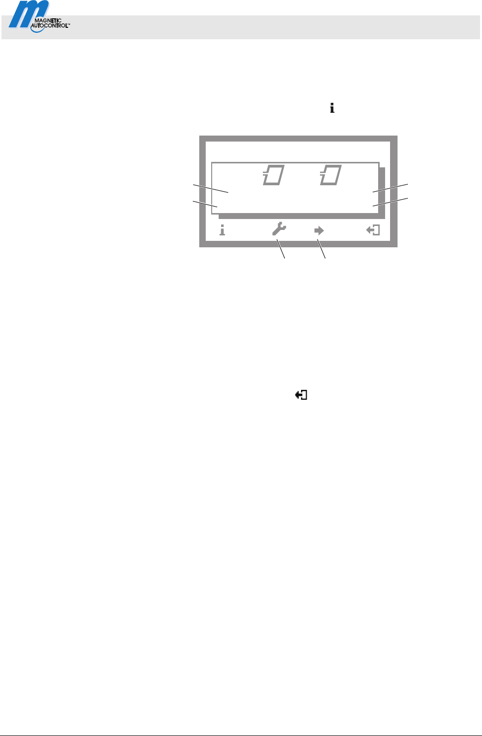
Control Unit MGC and MGC-Pro MHTM
TM
MicroDrive Barriers
Parameterising control unit
5816,0006EN / Version 00 67
3.23.1 Check the working frequency of the induction loops.
1. The operating view is displayed. See page 24, Fig. 15.
2.
Press the left control button
repeatedly, until the menu
"Detector 1 (A-B)" is displayed.
Mag00127a
f: 25454 Hz
38576 Hz
Df/f:
0.003 % 2.565 %
AB
56
1
2
3
4
Detector 1 (A – B)
Fig. 22: Example "View – Menu Detector 1 (A-B)"
1 Relative frequency of induction loop A
2 Currently measured frequency of induction loop A
3 Currently measured frequency of induction loop B
4 Relative frequency of induction loop B
5 If another optional detector module is present:
Switching between the two detector modules
6 Recalibration of the induction loop
3. Use the right button
to leave the "Detector 1 (A-B)" menu.
The operating view is displayed.
3.23.2 Reconciling and setting the operating frequency of the induction
loop
Operating frequency requirements
The operating frequency must fulfil following requirements:
When driving over the induction loop with a vehicle, a significant
frequency increase must be measurable. Chose stage 5 or 6 for
sensitivity. The relative frequency change (f/f) must be at least
0.1%. The higher the relative frequency increase, the higher the
operating safety of the induction loop.
The induction loops of a control unit operate alternating, and
can therefore not affect each other.
However, to avoid interferences by frequency coupling from
external loop detectors or other control units in the direct
proximity, a frequency clearance of at least 10000 Hz must be
kept between them. For this, the menu "Freq. Shift" is used to
set the frequency option to "Low" or "High", or to deactivate or
adjust the induction loop windings number.

Control Unit MGC and MGC-Pro MHTM
TM
MicroDrive Barriers
Parameterising control unit
68 5816,0006EN / Version 00
Reference working frequency via
the menu "Information" (
)
1. The operating view is displayed. See page 24, Fig. 15.
2.
Press left operating button
.
3. Press the left control button repeatedly, until the menu
"Detector 1 (A-B)" is displayed. See page 67, Fig. 22.
4.
Press second operating button from the left
.
5. The barrier is referenced. The loop symbols flash during re-
conciliation.
6. Check working frequencies. If required, perform settings like
sensitivity, etc. in the menu "Detector 1 (A-B)" in the main
menu.
7. Perform one of the following steps:
For a "Detector" plug-in module: Use the right button
to
leave the "Detector 1 (A-B)" menu. The operating view is
displayed.
For two "Detector" plug-in modules: Press the third
operating button from the left
. The "Detector 2 (C-D)"
menu is displayed.
8. The barrier is referenced. The loop symbols flash during
reconciliation.
9. Check working frequencies. If required, perform settings like
sensitivity, etc. in the menu "Detector 2 (C-D)" in the main
menu.
10. Use the right button
to leave the "Detector 2 (C-D)" menu.
The operating view is displayed.
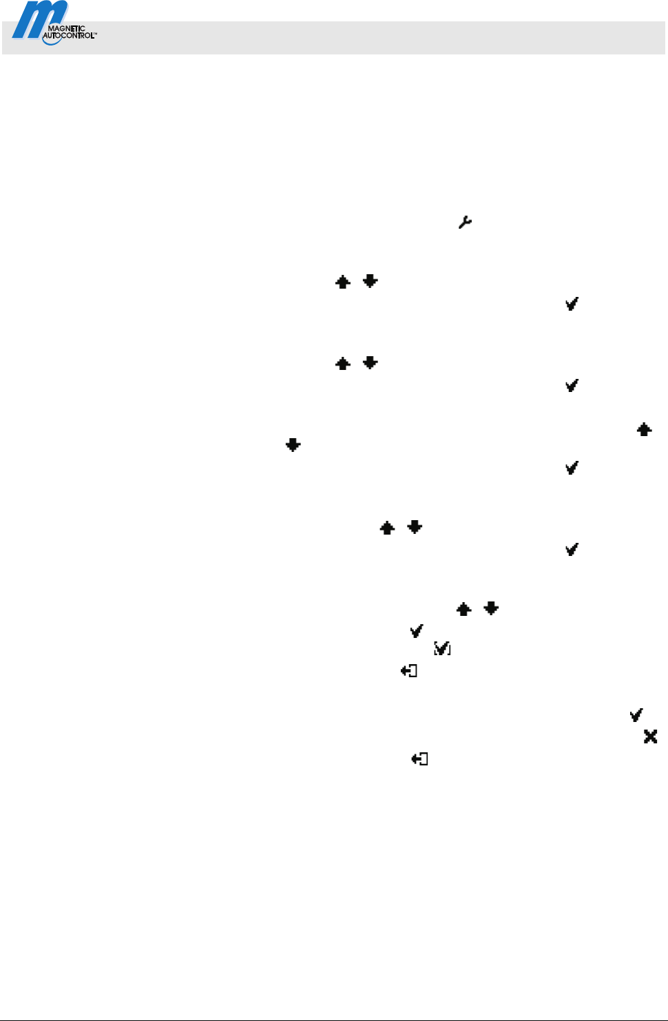
Control Unit MGC and MGC-Pro MHTM
TM
MicroDrive Barriers
Parameterising control unit
5816,0006EN / Version 00 69
Frequency value of the
un-assigned induction loop
unstable
If the frequency value of an induction loop is unstable, this
induction loop is influenced by an induction loop of another barrier
or an external detector. The detector channels do not influence
each other.
Depending on the loop geometry and settings of the external
detector, set the menu "Freq. Shift" to "Low" or "High".
1. The operating view is displayed. See page 24, Fig. 15.
2.
Press right operating button
.
3. The "Main menu" menu is displayed.
4. Select the menu "Detector 1 (A-B)" with the two middle
buttons
, .
5. Confirm selection with the right control button
.
6. The "Detector 1 (A-B)" menu is displayed.
7. Select the menu "Frequency settings" with the two middle
buttons
, .
8. Confirm selection with the right control button
.
9. The "Frequency settings" menu is displayed.
10. Select the menu "Freq. Shift" with the two middle buttons
,
.
11. Confirm selection with the right control button
.
12. The "Freq. Shift" menu is displayed.
13. Select the parameter "Channel A" or "Channel B" with the two
middle buttons
, .
14. Confirm selection with the right control button
.
15. The corresponding menu is displayed.
16. Select the option "Low" or "High" for the respective channel
with the two middle buttons
, .
17. Use the right button
to select the option. Your selection is
marked with the symbol
.
18. Use the left button
to leave the menu.
19. The safety prompt "Save changes?" appears.
If the changes are to be saved, press the right button
.
If the changes are not to be saved, press the left button
.
20. Press the left button
repeatedly until the operating view is
displayed again.
21. Test the operating frequencies.
For another plug-in module, the menu "Detector 2 (C-D)" is
displayed in the main menu. Reconciliation is performed for the
induction loops A and B.
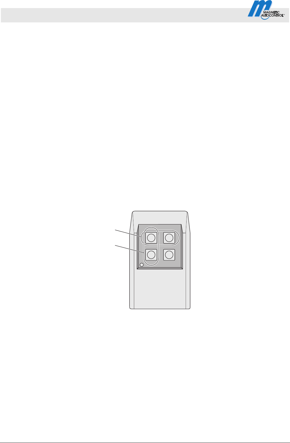
Control Unit MGC and MGC-Pro MHTM
TM
MicroDrive Barriers
Parameterising control unit
70 5816,0006EN / Version 00
3.24 Menu "Detector 2 (C-D)"
This menu is displayed if a second plug-in module with the function
"Detector" was plugged into the control unit. This menu is used to
reference the induction loops C and D.
The menu "Detector 2 (C-D)" corresponds to the menu "Detector 1
(A-D)". Refer to page 65, chapter 3.23.
3.25 Menu "Radio control FM"
The "Radio control FM " menu is displayed when the "Radio" plug-
in module is plugged into one of the control device slots.
The hand transmitters are available as 1-, 2- and 4-channel
versions.
Each channel (button) can be assigned a function.
See page 71, parameter "Teach in remote control". e.g. you can
open o
r close 4 barriers or open and close 2 barriers with a 4-
cannel version.
If you want to open and close a barrier via the hand transmitter,
you have to assign the functions to the buttons row by row. Up to
two functions per barrier can be taught in.
1
2
Mag00445
Fig. 23: 4-channel hand transmitter
1 Row
2 Column
If you want to operate the barrier via hand transmitter, programme
mode 3 to 8 must be selected.
The barrier is opened or closed by pressing the button on the hand
transmitter. After pressing the button on the hand transmitter, the
hand transmitter number is indicated in the display.
A radio module can manage up to 100 hand transmitters using
different codes.
Control Unit MGC and MGC-Pro MHTM
TM
MicroDrive Barriers
Parameterising control unit
5816,0006EN / Version 00 71
Operating view Main menu Radio control FM
Parameters Description
Number of transmitters Display of number of hand transmitters with which the barrier can be opened
Teach in
remote control
Use this parameter to pair a hand transmitter with the radio module.
Options
Open high priority
The button is assigned to the function "Open high priority".
Opening
The button is assigned to the function "Open”.
Closing
The button is assigned to the function "Close".
Delete remote control
Use this parameter to revoke a pairing between a hand transmitter and the
radio module.
Options
With remote control
Dissolve pairing by pressing a button on the hand transmitter.
With number
Dissolve pairing by entering the hand transmitter number.
Delete ALL
Delete all hand transmitters. Password input is required for this.
Information
Displays information about the plug-in module "Radio". Here, the hardware
version, software version and serial number (SerNo) of the plug-in module are
displayed.
Table 41: Menu "Radio control FM"
Set hand transmitter code The hand transmitter code is set via DIP switches in the hand
transmitter. We recommend changing the DIP switches' standard
settings.
1. Open hand transmitter housing. For this, press the coloured
pressure point while pulling up the upper housing part at the
same time.
2. Change and document the DIP switches' settings.
56
7
9
OFF
12
3
4
Mag00210
ON
10
81112
Fig. 24: Example DIP switches settings
3. Close housing.
Control Unit MGC and MGC-Pro MHTM
TM
MicroDrive Barriers
Parameterising control unit
72 5816,0006EN / Version 00
Teach in remote control
example option "Close"
1. The operating view is displayed. See page 24, Fig. 15.
2.
Press right operating button
.
3. The "Main menu" menu is displayed.
4. Select the menu "Radio control" with the two middle buttons
, .
5. Confirm selection with the right control button
.
6. Select the parameter "Teach in remote control" with the two
middle buttons
, .
7. Confirm selection with the right control button
.
8. Select the parameter "Close" with the two middle buttons
,
.
9. The message "Press button" appears.
10. Press the button on the hand transmitter. For the 2-channel
hand transmitter, the corresponding channel is paired with the
radio module.
11. The message "Successful" appears on the display. The
number for the parameter "Number of transmitter" is increased
by one.
12. Press the left button
repeatedly until the operating view is
displayed again.
Delete remote control
1. The operating view is displayed. See page 24, Fig. 15.
2.
Press right operating button
.
3. The "Main menu" menu is displayed.
4. Select the menu "Radio control" with the two middle buttons
, .
5. Confirm selection with the right control button
.
6. Select the parameter "delete remote control" with the two
middle buttons
, .
7. Confirm selection with the right control button
.
8. The options "with remote control" and "with number" are
displayed.
9. Select an option with the two middle buttons
, .
10. Confirm selection with the right control button
.
Option "With remote control"
The option "'With remote control" was selected
1. The message "Press button" appears.
2. Press the button on the hand transmitter.
3. The message "Successful" appears. The number for the
parameter "Number transmitter" is decreased by one.
4. Press the left button
repeatedly until the operating view is
displayed again.
Control Unit MGC and MGC-Pro MHTM
TM
MicroDrive Barriers
Parameterising control unit
5816,0006EN / Version 00 73
Option "With number"
The option "with number" was selected
1. Enter hand transmitter number.
2. Use the left button
to leave the menu.
3. The safety prompt "Save changes?" appears.
If the hand transmitter is to be deleted, press the right
button
.
If the hand transmitter is not to be deleted, press the left
button
.
4. The "Delete remote control" menu is displayed.
5. Press the left button
repeatedly until the operating view is
displayed again.
Option "Delete ALL"
The option "Delete ALL" was selected
1. Enter the service password.
2. Confirm input with the right control button
.
3. The message "Successful" appears. All hand transmitters
were deleted.
NOTE!
If a hand transmitter is deleted, the memory slot
used is released. The sequence does not change
by deletion. Teaching in new hand transmitters will
first fill the gaps and only then continue numbering.
3.26 Factory settings
NOTE!
The parameters of the control unit are stored in the
three memory areas "FW defaults", "Factory
settings" and "User parameters".
The FW defaults are identical to the factory settings
in these operating instructions. The FW defaults
are firmly store din the firmware and cannot be
changed.
The factory setting can be assigned factory- or
product-specific settings.
The user settings are the operating parameters.
Control Unit MGC and MGC-Pro MHTM
TM
MicroDrive Barriers
Parameterising control unit
74 5816,0006EN / Version 00
Options in the menu "Factory
settings"
The menu "Factory settings" offers the following options:
Restore factory settings:
The stored parameters in the memory area "Factory settings"
are assuaged as operating settings.
User settings as factory settings:
The current parameter settings are stored as factory settings.
These factory settings can be used to receive project-specific
settings.
FW defaults as factory setting:
The factory setting are overwritten by the FW standard values.
If you would like to assume the FW defaults as operating settings
and the factory settings were overwritten first, you need to use the
option "FW defaults as factory settings" and then the option
"Restore factory settings".
Option "Restore factory settings"
1. The operating view is displayed. See page 24, Fig. 15.
2.
Press right operating button
.
3. The "Main menu" menu is displayed.
4. Select the menu "Factory settings" with the two middle buttons
, .
5. Confirm selection with the right control button
.
6. Enter password "0 0 0 0".
7. Confirm password with the right control button
.
8. The message "Reset to factory settings" appears.
9. Press right operating button
.
10. The safety prompt "Save changes?" appears.
If the changes are to be saved, press the right button
.
The current settings are reset to factory settings. A restart
is performed.
If the changes are not to be saved, press the left button
.
11. Press the left button
repeatedly until the operating view is
displayed again.
Control Unit MGC and MGC-Pro MHTM
TM
MicroDrive Barriers
Parameterising control unit
5816,0006EN / Version 00 75
Via Service Password –
Option "Restore factory settings",
"User settings as factory settings"
or "FW standard values as factory
settings"
1. The operating view is displayed. See page 24, Fig. 15.
2.
Press right operating button
.
3. The "Main menu" menu is displayed.
4. Select the menu "Factory settings" with the two middle buttons
, .
5. Confirm selection with the right control button
.
6. Enter the service password.
7. Confirm password with the right control button
.
8. The message "Reset to factory settings" appears.
9. Select the desired option with the two middle buttons
, .
10. Confirm selection with the right control button
.
11. The safety prompt "Save changes?" appears.
If the changes are to be saved, press the right button
.
The corresponding parameter set is written anew
depending on the selected option. A restart is performed.
If the changes are not to be saved, press the left button
.
12. Press the left button
repeatedly until the operating view is
displayed again.

Control Unit MGC and MGC-Pro MHTM
TM
MicroDrive
76 5816,0006EN / Version 00
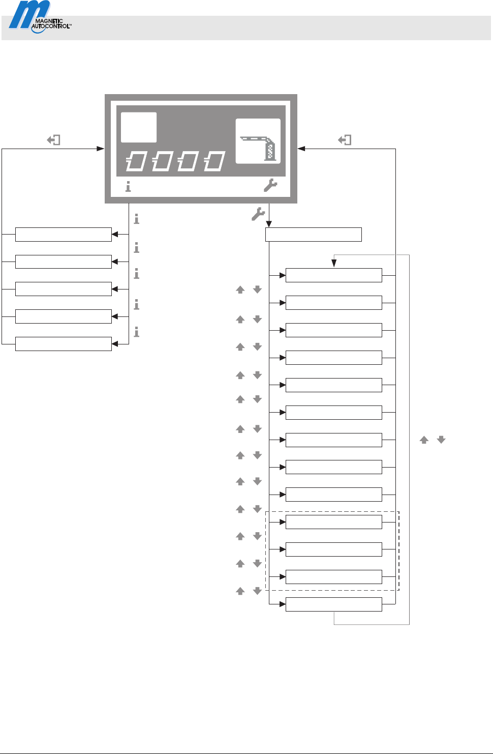
Control Unit MGC and MGC-Pro MHTM
TM
MicroDrive
Menu setup
5816,0006EN / Version 00 77
4 Menu setup
Mag00256b
A B DC
Access
Select
4
1)
Special functions
Attachments
Service
System
Motor GW
Main menu
Function
Setup
In-/Outputs
Factory settings
Information
2)
3)
Warnings
Inputs
Detector 1 (A-B)
Outputs
Module info
Detector 1 (A-B)
Radio control
Detector 2 (C-D)
4)
Fig. 25: Menu "Information" and main menu
1 The view depends on the plugged-in plug-in modules such as "Ethernet" or "RS485/422" and on whether a service
module is connected.
2 Menu "Detector 1 (A-B)" in the first plug-in module "Detector"
3 Menu "Detector 2 (C-D)" only with a second plug-in module "Detector" (optional)
4 Menu "Remote control" only with optional plug-in module "Radio"
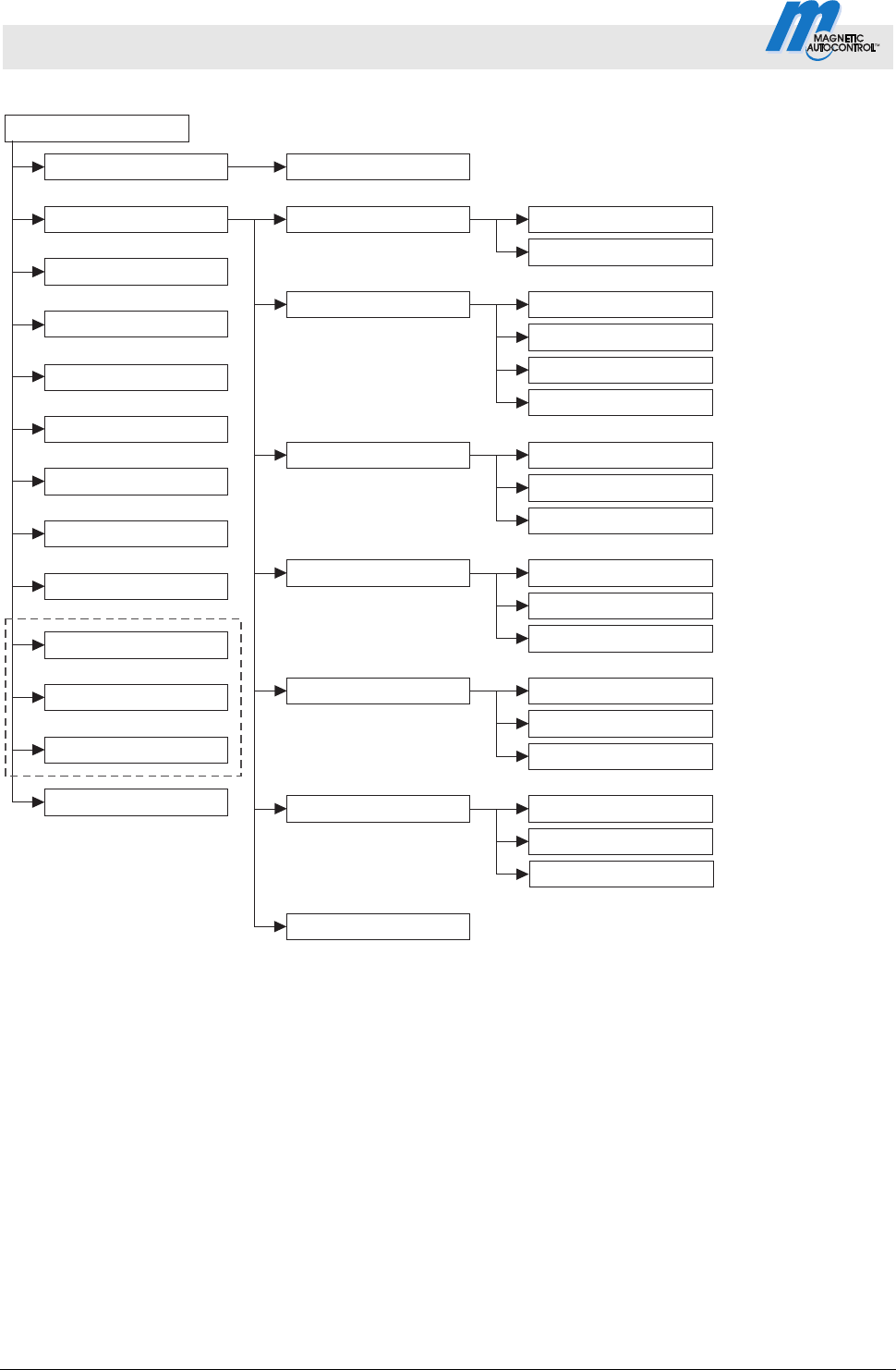
Control Unit MGC and MGC-Pro MHTM
TM
MicroDrive Barriers
Menu setup
78 5816,0006EN / Version 00
Mag00130h
2)
Special functions
Attachments
Service
Detector 1 (A-B)
Detector (C-D)
Cut off angle
Vend count
Impact settings
Main menu
Prog. mode
In-/Outputs
Barrier speed
Delays
Open
Close
Hold-open time
Close delay
Light barrier delay
Impact delay
Safety loop close
Light barrier
Impact detection
Impact response
Impact delay
Restart
Setup
Reset behaviour
Counter
Power failure
Factory settings
Radio control
4)
System
1)
Count open loop
Function
Start-up settings
Start-up behav.
Stay closed
Quick-up homing
Information
Motor GW
3)
5)
Fig. 26: Main menu – Menu "Function" and "Setup"
1 The parameter is displayed for barriers with a control unit MGC-Pro.
2 The view depends on the plugged-in plug-in modules such as "Ethernet" or "RS485/422" and on whether a service
module is connected.
3 Menu "Detector 1 (A-B)" in the first plug-in module "Detector"
4 Menu "Detector 2 (C-D)" only with a second plug-in module "Detector" (optional)
5 Menu "Remote control" only with optional plug-in module "Radio"
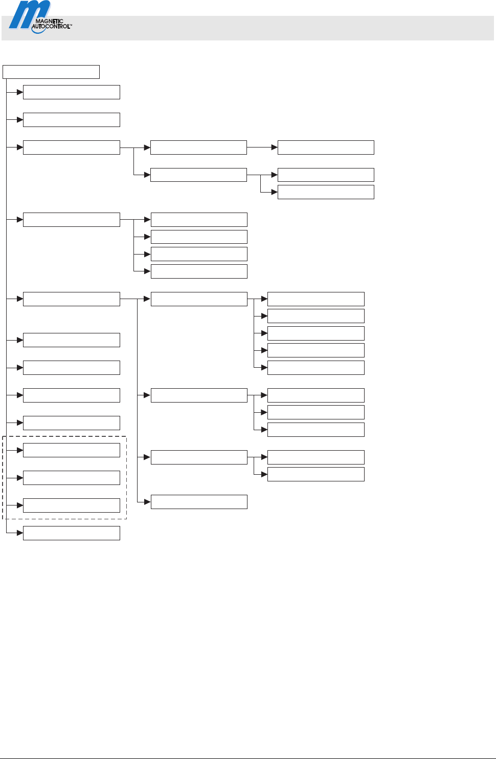
Control Unit MGC and MGC-Pro MHTM
TM
MicroDrive
Menu setup
5816,0006EN / Version 00 79
Mag00459
1)
Special functions
Attachments
Service
Detector 1 (A-B)
Detector (C-D)
Factory settings
Radio control
4)
System
Information
Motor GW
2)
Closure by light barr.
Closure by add. safety
Stop at tailgating
Signal light
Boom contact settings
Main menu
Function
In-/Outputs
Inputs
Outputs
Input1–8
Signal mode B
Signal mode C
Lead time
Automatic closing
Closing delay
with boom locking
Setup
Start event
Signal mode A
Boom locking
Battery backup
without boom locking
3)
Enabled/disabled
Digital output 1 – 4
Relay
Master/Slave
Fig. 27: Main menu – Menus "In-/Outputs", "Special functions" and "Attachments"
1 The view depends on the plugged-in plug-in modules such as "Ethernet" or "RS485/422" and on whether a service
module is connected.
2 Menu "Detector 1 (A-B)" in the first plug-in module "Detector"
3 Menu "Detector 2 (C-D)" only with a second plug-in module "Detector" (optional)
4 Menu "Remote control" only with optional plug-in module "Radio"
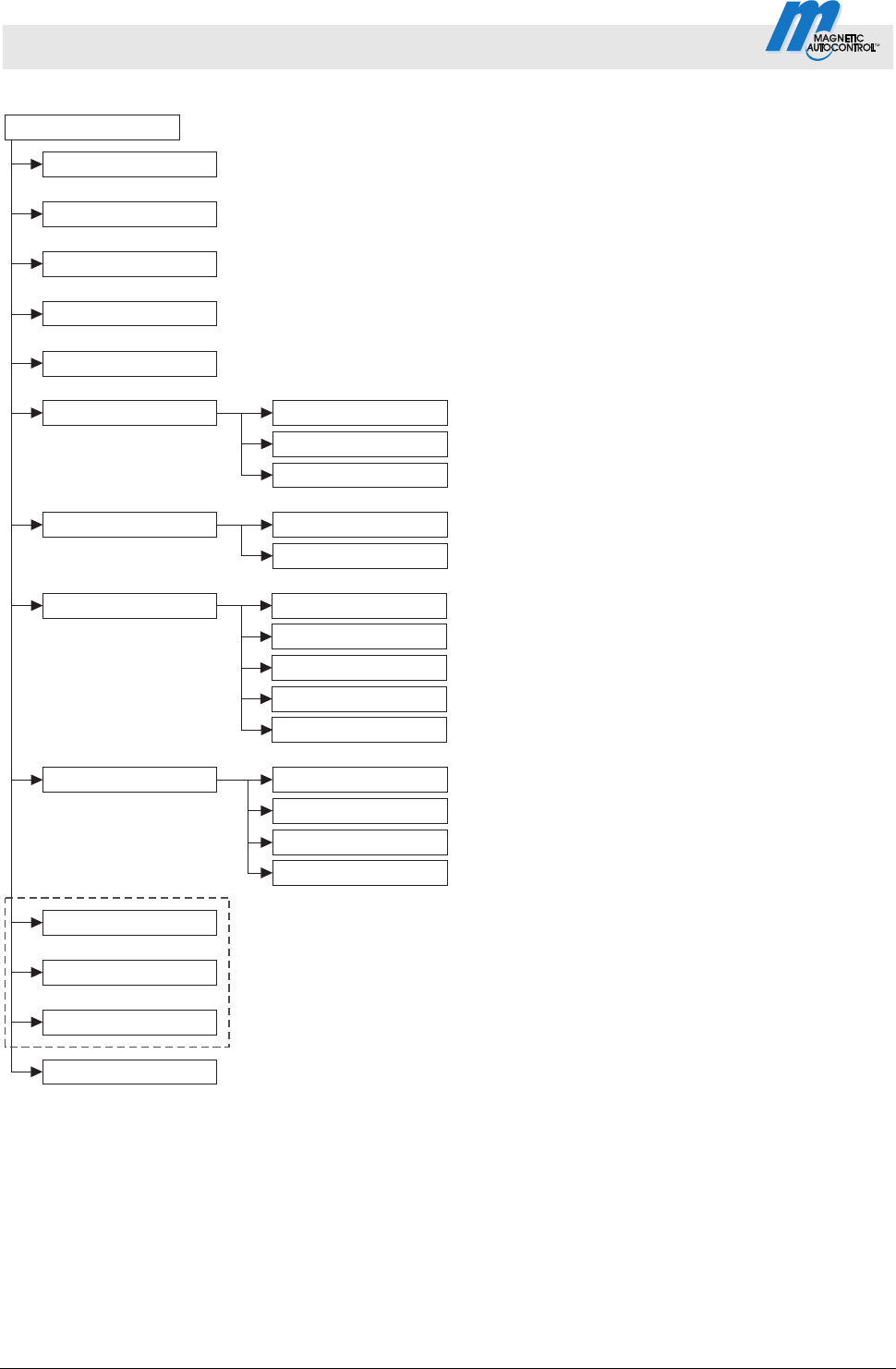
Control Unit MGC and MGC-Pro MHTM
TM
MicroDrive Barriers
Menu setup
80 5816,0006EN / Version 00
Mag00460
1)
3)
4)
Special functions
Function
System
Informationen
Motor GW
Detector 1 (A-B)
Radio control
Factory settings
Detector 2 (C-D)
In-/Outputs
Service
Setup
Date/Time
Language
Cycles
Lifetime
Main menu password
Attachments
Software #
Temperature
Hardware Version
SW Version
Serial No.
Software #
SW Version
Motor temperature
Motor-SW
2)
Main menu
Fig. 28: Main menu – Menus "Service", "System", "Information" and "Motor GW"
1 The view depends on the plugged-in plug-in modules such as "Ethernet" or "RS485/422" and on whether a service
module is connected.
2 Menu "Detector 1 (A-B)" in the first plug-in module "Detector"
3 Menu "Detector 2 (C-D)" only with a second plug-in module "Detector" (optional)
4 Menu "Remote control" only with optional plug-in module "Radio"

Control Unit MGC and MGC-Pro MHTM
TM
MicroDrive
Menu setup
5816,0006EN / Version 00 81
Mag00461
1)
3)
4)
Special functions
Function
System
Informationen
Motor GW
Detector 1 (A-B)
Remote control
Factory settings
Detektor 2 (C-D)
In-/Outputs
Service
Setup
Attachments
Teach in remote control
Delete remote control
Informationen
Number of transm.
Channel A
Channel B
Freq. A
Freq. B
Freq. shift
Ref.-Value A
Ref.-Value B
Sensitivity B
Frequency settings
Informationen
Recalibration
Mode A
Mode B
Sensitivity A
2)
Main menu
Fig. 29: Main menu – Menus "Detector 1 (A-B)" and "Remote control"
1 The view depends on the plugged-in plug-in modules such as "Ethernet" or "RS485/422" and on whether a service
module is connected.
2 Menu "Detector 1 (A-B)" in the first plug-in module "Detector"
3 Menu "Detector 2 (C-D)" only with a second plug-in module "Detector" (optional)
4 Menu "Radio transmitter" only with optional plug-in module "Radio"

Control Unit MGC and MGC-Pro MHTM
TM
MicroDrive Barriers
82 5816,0006EN / Version 00

Control Unit MGC and MGC-Pro MHTM
TM
MicroDrive Barriers
Index
5816,0006EN / Version 00 83
Index
1
1. Parking zone full
Output function................................................13
2
2. Parking zone full
Output function................................................13
A
Acknowledgement
Input function ..................................................10
Output function................................................13
Additional safety device
Input function ....................................................9
Attachments
Menu ...............................................................57
Automatic closing
Parameter .......................................................60
B
Barrier
Manually close ................................................40
Manually open.................................................40
Barrier ready
Output function................................................13
Battery backup
Menu ...............................................................62
Battery Backup
Parameter .......................................................62
Bistable...............................................................33
Blink signal light
Input function ..................................................10
Boom angle feedback
Output function................................................12
Boom contact feedback
Output function................................................12
Boom contact input
Input function ....................................................9
Boom contact settings
Menu ...............................................................60
Boom lock
Output function................................................12
Boom locking
Menu ...............................................................61
Parameter .......................................................61
C
Change value .....................................................24
Changing menu language ..................................18
Close
Input function.....................................................8
Close delay
Parameter .......................................................43
Close low priority
Input function.....................................................9
Closed
Output function..........................................11, 13
Closing
Output function................................................12
Parameter .......................................................42
Closing delay
Parameter .......................................................61
Closure by add. safety
Menu ...............................................................55
Parameter .......................................................55
Closure by light barr.
Menu ...............................................................55
Control buttons
Function ..........................................................25
Control elements.................................................23
Control unit
Displays...........................................................24
Control unit control elements..............................23
Count open loop
Parameter .......................................................45
Counter
Parameter .......................................................45
Cut off angle
Menu ...............................................................44
Cycles
Parameter .......................................................63
D
Date/time
Parameter
.......................................................64
Deadman ............................................................32
Delays
Menu ...............................................................42
Delete remote control
Parameter .......................................................71
Detector 1 (A-B)
Menu ...............................................................65
Detector 2 (C-D)
Menu ...............................................................70
Digital inputs .........................................................7
Digital outputs .....................................................11
Direction 1 A => B
Output function................................................15

Control Unit MGC and MGC-Pro MHTM
TM
MicroDrive Barriers
Index
84 5816,0006EN / Version 00
Direction 1 B => A
Output function............................................... 15
Direction 1 Pls A => B
Output function............................................... 14
Direction 1 Pls B => A
Output function............................................... 14
Direction 2 A => B
Output function............................................... 16
Direction 2 B => A
Output function............................................... 16
Direction 2 Pls A => B
Output function............................................... 14
Direction 2 Pls B => A
Output function............................................... 15
Display
Symbols.......................................................... 25
Display contrast
Setting ............................................................ 28
E
Electrical specialists............................................. 6
Enabled/disabled
Parameter....................................................... 60
Entering password ............................................. 22
Error
Output function............................................... 11
External
Output function............................................... 17
External impact detection
Input function.................................................... 9
External opening loop entry
Input function.................................................... 9
External opening loop exit
Input function.................................................... 9
F
Factory settings
Reset .............................................................. 73
Frequency setting
Parameter....................................................... 66
Function
Menu .............................................................. 41
G
General ................................................................ 5
H
Hardware version
Parameter....................................................... 64
Hold-open time
Parameter....................................................... 42
I
Impact delay
Parameter................................................. 43, 48
Impact detection
Output function ............................................... 13
Parameter....................................................... 44
Impact response
Parameter....................................................... 48
Impact settings
Menu............................................................... 48
In-/Outputs
Menu............................................................... 54
Information
Menu......................................................... 41, 64
Parameter................................................. 66, 71
Inhibit opening
Input function.................................................... 9
Inhibit opening loop
Input function.................................................... 9
Inhibit signal light
Input function.................................................... 9
Input function
Acknowledgement .......................................... 10
Additional safety device.................................... 9
Blink signal light.............................................. 10
Boom contact input........................................... 9
Close ................................................................ 8
Close low priority .............................................. 9
External impact detection ................................. 9
External opening loop entry
.............................. 9
External opening loop exit ................................ 9
Inhibit opening .................................................. 9
Inhibit opening loop .......................................... 9
Inhibit signal light.............................................. 9
Open high priority ............................................. 8
Open low priority .............................................. 8
Opening exit ..................................................... 8
Opening with vend count.................................. 8
Parking counter reset ..................................... 10
Inputs
Menu............................................................... 54
Inputs (Menue)........................... See Digital inputs
L
Language
Parameter....................................................... 64
Lead time
Parameter....................................................... 59
Light barrier
Parameter....................................................... 44
Light barrier delay
Parameter....................................................... 43

Control Unit MGC and MGC-Pro MHTM
TM
MicroDrive Barriers
Index
5816,0006EN / Version 00 85
Loop active A
Output function................................................13
Loop active B
Output function................................................13
Loop active pulse A
Output function................................................13
Loop active pulse B
Output function................................................13
Loop inactive pulse A
Output function................................................13
Loop inactive pulse B
Output function................................................14
M
Main menu password .........................................28
Parameter .......................................................63
Master.................................................................56
Master/Slave
Menu ...............................................................56
Menu setup.........................................................77
MHTM
TM
MicroDrive service expert......................6
Mode A
Parameter .......................................................65
Mode B
Parameter .......................................................65
Module-Close
Output function................................................16
Module-Open
Output function................................................16
Module-Open prior
Output function................................................16
Motor GW
Menu ...............................................................65
Motor temperature
Parameter .......................................................65
Motor-SW
Parameter .......................................................65
N
Number hand transmitters
Parameter .......................................................71
O
One button..........................................................33
Open
Output function..........................................12, 13
Parameter .......................................................42
Open high priority
Input function ....................................................8
Open low priority
Input function ....................................................8
Open/Closed button............................................34
Opening
Output function................................................12
Opening exit
Input function.....................................................8
Opening with vend count
Input function.....................................................8
Operation
Parameter .......................................................63
Operational view .................................................24
Output function
1st Parking zone full........................................13
2nd Parking zone full.......................................13
Acknowledgement...........................................13
Barrier ready ...................................................13
Boom angle feedback .....................................12
Boom contact feedback...................................12
Boom lock .......................................................12
Closed .......................................................11, 13
Closing ............................................................12
Direction 1 A => B ...........................................15
Direction 1 B => A ...........................................15
Direction 1 Pls A => B .....................................14
Direction 1 Pls B => A .....................................14
Direction 2 A => B ...........................................16
Direction 2 B => A ...........................................16
Direction 2 Pls A => B .....................................14
Direction 2 Pls B => A .....................................15
Error ................................................................11
External ...........................................................17
Impact detection..............................................13
Loop active A ..................................................13
Loop active B ..................................................13
Loop active pulse A.........................................13
Loop active pulse B.........................................13
Loop inactive pulse A......................................13
Loop inactive pulse B......................................14
Module-Close ..................................................16
Module-Open
..................................................16
Module-Open prior ..........................................16
Open..........................................................12, 13
Opening...........................................................12
Parallel operation ............................................13
Pulse after passage ........................................12
Signal light A ...................................................12
Signal light B ...................................................12
Signal light C ...................................................12
Sliding door pulse............................................12
Warning...........................................................11
Output relay ........................................................11
Outputs
Menu ...............................................................54
Outputs (Menue)...................... See Digital outputs

Control Unit MGC and MGC-Pro MHTM
TM
MicroDrive Barriers
Index
86 5816,0006EN / Version 00
P
Parallel operation............................................... 56
Output function............................................... 13
Parameterisation
Protection from access................................... 28
Parameterising
Options ........................................................... 29
Values ............................................................ 30
Parking counter reset
Input function.................................................. 10
Password protection .......................................... 28
Permanent signal............................................... 32
Pictogram explanation ......................................... 5
Power failure
Menu .............................................................. 54
Parameter....................................................... 54
Prog. mode .......................... See Programm mode
Programme mode
Deadman........................................................ 32
Menu .............................................................. 41
One button...................................................... 33
Permanent signal ........................................... 32
Select ............................................................. 29
Setup .............................................................. 42
two buttons ..................................................... 34
Pulse after passage
Output function............................................... 12
R
Radio control FM
Menu .............................................................. 70
Recalibration
Parameter....................................................... 65
Reset behaviour
Parameter....................................................... 45
Restart ............................................................... 48
S
Safety loop close
Parameter....................................................... 44
Safety loop close
Parameter....................................................... 44
Select programme mode ................................... 31
Sensitivity A
Parameter....................................................... 65
Sensitivity B
Parameter....................................................... 66
Serial no
Parameter....................................................... 64
Service
Menu............................................................... 63
Mode............................................................... 40
Switch off Mode.............................................. 40
Switch on Mode.............................................. 40
Service switch .................................................... 40
Setup
Programme mode........................................... 31
Signal light
Menu............................................................... 57
Signal light A
Output function ............................................... 12
Signal light B
Output function ............................................... 12
Signal light C
Output function ............................................... 12
Signal mode A
Parameter....................................................... 57
Signal mode B
Parameter....................................................... 58
Signal mode C
Parameter....................................................... 58
Slave .................................................................. 56
Sliding door pulse
Output function ............................................... 12
Software #
Parameter................................................. 64, 65
Special functions
Menu............................................................... 55
Specialists
Requirements ................................................... 6
Speed
Menu............................................................... 42
Start event
Parameter
....................................................... 59
Start-up behaviour
Parameter................................................. 49, 50
Start-up settings
Menu............................................................... 49
Stay closed
Parameter....................................................... 49
Stop at tailgating
Menu............................................................... 56
Parameter....................................................... 56
SW Version
Parameter................................................. 64, 65
Symbols
Control button functions ................................. 25
Current programme mode .............................. 27
Current state of the barrier ............................. 26
Current state of the induction loops ............... 27
Further ............................................................ 27

Control Unit MGC and MGC-Pro MHTM
TM
MicroDrive Barriers
Index
5816,0006EN / Version 00 87
System
Menu ...............................................................64
T
Teach in remote control
Parameter .......................................................71
Temperature
Parameter .......................................................64
Two buttons ........................................................34
V
Vend Count
Menu ...............................................................45
W
Warning
Output function................................................11
Warning notes.......................................................5

F05512812
MAGNETIC Autocontrol GmbH
Grienmatt 20
79650 Schopfheim
Germany
Tel.: +49 (0)76 22 695 5
Fax: +49 (0)76 22 695 602
E-Mail: [email protected]
Internet: www.ac-magnetic.com
Address sales partner:
