
ETSI TS 102 606-2
V1.1.1 (2014-07)
Digital Video Broadcasting (DVB);
Generic Stream Encapsulation (GSE);
Part 2: Logical Link Control (LLC)
TECHNICAL SPECIFICATION

ETSI
ETSI TS 102 606
-
2 V1.1.1 (2014
-
07)
2
Reference
DTS/JTC-DVB-338-2
Keywords
broadcasting, DVB
ETSI
650 Route des Lucioles
F-06921 Sophia Antipolis Cedex - FRANCE
Tel.: +33 4 92 94 42 00 Fax: +33 4 93 65 47 16
Siret N° 348 623 562 00017 - NAF 742 C
Association à but non lucratif enregistrée à la
Sous-Préfecture de Grasse (06) N° 7803/88
Important notice
The present document can be downloaded from:
http://www.etsi.org
The present document may be made available in electronic versions and/or in print. The content of any
electronic and/or
print versions of the present document shall not be modified without the prior written authorization of ETSI. In case of any
existing or perceived difference in contents between such versions and/or in print, the only prevailing document is the
print of the Portable Document Format (PDF) version kept on a specific network drive within ETSI Secretariat.
Users of the present document should be aware that the document may be subject to revision or change of status.
Information on the current status of this and other ETSI documents is available at
http://portal.etsi.org/tb/status/status.asp
If you find errors in the present document, please send your comment to one of the following services:
http://portal.etsi.org/chaircor/ETSI_support.asp
Copyright Notification
No part may be reproduced or utilized in any form or by any means, electronic or mechanical, including photocopying
and microfilm except as authorized by written permission of ETSI.
The content of the PDF version shall not be modified without the written authorization of ETSI.
The copyright and the foregoing restriction extend to reproduction in all media.
© European Telecommunications Standards Institute 2014.
© European Broadcasting Union 2014.
All rights reserved.
DECT
TM
, PLUGTESTS
TM
, UMTS
TM
and the ETSI logo are Trade Marks of ETSI registered for the benefit of its Members.
3GPP
TM
and LTE™ are Trade Marks of ETSI registered for the benefit of its Members and
of the 3GPP Organizational Partners.
GSM
® and the GSM logo are Trade Marks registered and owned by the GSM Association.

ETSI
ETSI TS 102 606
-
2 V1.1.1 (2014
-
07)
3
Contents
Intellectual Property Rights ................................................................................................................................ 5
Foreword ............................................................................................................................................................. 5
Modal verbs terminology .................................................................................................................................... 5
Introduction ........................................................................................................................................................ 6
1 Scope ........................................................................................................................................................ 8
2 References ................................................................................................................................................ 8
2.1 Normative references ......................................................................................................................................... 8
2.2 Informative references ........................................................................................................................................ 9
3 Symbols and abbreviations ..................................................................................................................... 10
3.1 Symbols ............................................................................................................................................................ 10
3.2 Abbreviations ................................................................................................................................................... 10
4 Overview ................................................................................................................................................ 10
5 Protocol Elements .................................................................................................................................. 11
5.1 Record Structures ............................................................................................................................................. 12
5.1.1 Index Structure ............................................................................................................................................ 12
5.1.1.1 Offset Mechanism ................................................................................................................................. 13
5.1.2 Link Control Data (LCD) records table ...................................................................................................... 14
5.1.3 Network Control Data (NCD) records table ............................................................................................... 14
5.1.3.1 Platform descriptors .............................................................................................................................. 15
5.1.3.2 Target descriptors .................................................................................................................................. 15
5.1.3.3 Operational descriptors ......................................................................................................................... 15
5.2 Descriptors ....................................................................................................................................................... 15
5.2.1 Descriptor identification and location ......................................................................................................... 15
5.2.2 Descriptor coding ........................................................................................................................................ 16
5.2.2.1 Application system descriptor ............................................................................................................... 16
5.2.2.1.1 OMA BCAST info .......................................................................................................................... 17
5.2.2.2 C2 PHY descriptor ................................................................................................................................ 18
5.2.2.3 DHCPv4 options descriptor .................................................................................................................. 19
5.2.2.3.1 DHCPv4 options profile .................................................................................................................. 20
5.2.2.4 DHCPv6 options descriptor .................................................................................................................. 21
5.2.2.4.1 DHCPv6 options profile .................................................................................................................. 22
5.2.2.5 IP/MAC generic stream location descriptor .......................................................................................... 22
5.2.2.6 IP/MAC link location descriptor ........................................................................................................... 23
5.2.2.7 IP/MAC stream location descriptor ....................................................................................................... 23
5.2.2.8 Link association descriptor ................................................................................................................... 23
5.2.2.9 NGH PHY descriptor ............................................................................................................................ 24
5.2.2.10 ROHC-U descriptor .............................................................................................................................. 27
5.2.2.11 S2 PHY descriptor ................................................................................................................................ 28
5.2.2.12 T2 PHY descriptor ................................................................................................................................ 29
5.2.2.13 URI descriptor ....................................................................................................................................... 30
5.2.3 Rules for future extensibility of descriptors ................................................................................................ 31
6 Transport in GSE Packets....................................................................................................................... 31
6.1 GSE Header Fields ........................................................................................................................................... 32
6.1.1 Start Indicator and End Indicator ................................................................................................................ 32
6.1.2 Label Type Indicator ................................................................................................................................... 32
6.1.3 Protocol Type .............................................................................................................................................. 32
6.1.4 Extension Header Byte ............................................................................................................................... 32
6.1.5 PDU Data Byte ........................................................................................................................................... 32
6.2 GSE Table Structure Fields .............................................................................................................................. 33
6.2.1 Table ID ...................................................................................................................................................... 33
6.2.2 Interactive Network ID ............................................................................................................................... 33
ETSI
ETSI TS 102 606
-
2 V1.1.1 (2014
-
07)
4
6.2.3 Version Number and Current/Next Indicator .............................................................................................. 33
6.3 Combining Streams From Different Interactive Networks ............................................................................... 33
7 Deployment Profiles ............................................................................................................................... 33
7.1 Bi-directional interface emulation .................................................................................................................... 33
7.2 Generic network service profile ....................................................................................................................... 34
7.3 Application system profile ............................................................................................................................... 34
7.3.1 OMA BCAST system profile...................................................................................................................... 35
Annex A (informative): Examples ......................................................................................................... 36
A.1 Carriage of LLC data in extension headers ............................................................................................ 36
A.2 Finding the size of the last table ............................................................................................................. 37
A.3 Underlying data model ........................................................................................................................... 38
History .............................................................................................................................................................. 40

ETSI
ETSI TS 102 606
-
2 V1.1.1 (2014
-
07)
5
Intellectual Property Rights
IPRs essential or potentially essential to the present document may have been declared to ETSI. The information
pertaining to these essential IPRs, if any, is publicly available for ETSI members and non-members, and can be found
in ETSI SR 000 314: "Intellectual Property Rights (IPRs); Essential, or potentially Essential, IPRs notified to ETSI in
respect of ETSI standards", which is available from the ETSI Secretariat. Latest updates are available on the ETSI Web
server (http://ipr.etsi.org
).
Pursuant to the ETSI IPR Policy, no investigation, including IPR searches, has been carried out by ETSI. No guarantee
can be given as to the existence of other IPRs not referenced in ETSI SR 000 314 (or the updates on the ETSI Web
server) which are, or may be, or may become, essential to the present document.
Foreword
This Technical Specification (TS) has been produced by Joint Technical Committee (JTC) Broadcast of the European
Broadcasting Union (EBU), Comité Européen de Normalisation ELECtrotechnique (CENELEC) and the European
Telecommunications Standards Institute (ETSI).
NOTE: The EBU/ETSI JTC Broadcast was established in 1990 to co-ordinate the drafting of standards in the
specific field of broadcasting and related fields. Since 1995 the JTC Broadcast became a tripartite body
by including in the Memorandum of Understanding also CENELEC, which is responsible for the
standardization of radio and television receivers. The EBU is a professional association of broadcasting
organizations whose work includes the co-ordination of its members' activities in the technical, legal,
programme-making and programme-exchange domains. The EBU has active members in about
60 countries in the European broadcasting area; its headquarters is in Geneva.
European Broadcasting Union
CH-1218 GRAND SACONNEX (Geneva) Switzerland
Tel: +41 22 717 21 11
Fax: +41 22 717 24 81
The Digital Video Broadcasting Project (DVB) is an industry-led consortium of broadcasters, manufacturers, network
operators, software developers, regulatory bodies, content owners and others committed to designing global standards
for the delivery of digital television and data services. DVB fosters market driven solutions that meet the needs and
economic circumstances of broadcast industry stakeholders and consumers. DVB standards cover all aspects of digital
television from transmission through interfacing, conditional access and interactivity for digital video, audio and data.
The consortium came together in 1993 to provide global standardisation, interoperability and future proof
specifications.
The present document is part 2 of a multi-part deliverable covering the Digital Video Broadcasting (DVB); Generic
Stream Encapsulation (GSE), as identified below:
Part 1: "Protocol";
Part 2: "Logical Link Control (LLC)";
Part 3: "Robust Header Compression (ROHC) for IP".
Modal verbs terminology
In the present document "shall", "shall not", "should", "should not", "may", "may not", "need", "need not", "will",
"will not", "can" and "cannot" are to be interpreted as described in clause 3.2 of the ETSI Drafting Rules
(Verbal forms
for the expression of provisions).
"must" and "must not" are NOT allowed in ETSI deliverables except when used in direct citation.

ETSI
ETSI TS 102 606
-
2 V1.1.1 (2014
-
07)
6
Introduction
As introduced in part 1 [1], the Generic Stream Encapsulation (GSE) protocol is a link layer which provides
multiplexing mechanisms that make it possible for several network protocols (for example IP, IPX, Decnet and
Appletalk) to coexist within a multipoint network and to be transported over the same network media. GSE is designed
to be deployed across all DVB broadcast bearers which provide a Generic Stream mode.
Figure 1: Role of DVB-GSE across broadcast bearers
This abstraction from the MAC layer allows to provision services on top of network protocols independently of the
underlying physical layer. This is illustrated from a network operator's perspective in Figure 1, and from a protocol
stack perspective in Figure 2.
Figure 2: Protocol layers when using DVB-GSE
As shown in Figure 2, the DVB-GSE link layer hides any MAC layer specifics from the upper layers. It thus enables
receivers to present DVB-GSE streams as regular, LAN-type network interfaces to upper layers. The logical link
control protocol defined in the present document provides the necessary information to receivers to accomplish this.

ETSI
ETSI TS 102 606
-
2 V1.1.1 (2014
-
07)
7
On a Point-to-Point Protocol (PPP) link according to RFC 1661 [i.3], two hosts establish a connection on any
point-to-point serial interface (e.g. RS-232), and exchange IP datagrams. The PPP implementation encapsulates this link
as a normal network interface, so that applications can use it as if it were a regular LAN interface. To achieve this, a
Link Control Protocol (LCP) for establishing, configuring, and testing the data-link connection, and a family of
Network Control Protocols (NCPs) for establishing and configuring different network-layer protocols is defined in
RFC 1661 [i.3]. When the connection establishment begins, the two hosts first use the LCP to negotiate the
configuration parameters (e.g. link speed) of the serial data link. After this is completed, the two hosts use the
appropriate NCPs to negotiate the configuration of the network interface (e.g. use of IPv4 or IPv6, IP addresses to use),
and thus conclude the connection establishment phase. After this, the hosts present new LAN-type network interfaces to
applications running on them.
The LLC protocol for DVB-GSE adopts the same partitioning of information. One set of information is needed to
enable the DVB-GSE layer to configure the underlying MAC and physical layer devices. This first set of information is
referred to as Link Control Data (LCD) in the present document. A second set of information is needed to configure the
network interfaces which represent the DVB-GSE streams and make them available for the upper layers. This second
set of information is referred to as Network Control Data (NCD) in the present document.
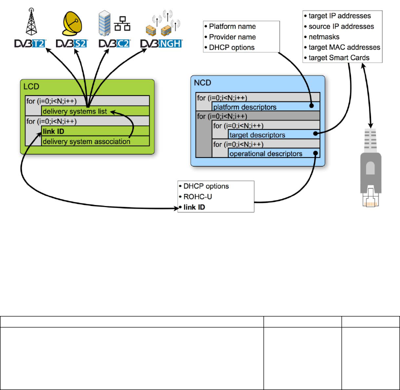
Figure 3: Application programming model of DVB-GSE with LLC
Once these network interfaces have been made available to the upper layers (see Figure 3), the properties of the MAC
and physical layers are no longer exposed to upper layers, and applications can act on these interfaces like on any other
network interface. Use of the tunnelling mechanism defined in RFC 3077 [11] in combination with a return channel
allows for the interfaces to be used for reading and writing.

ETSI
ETSI TS 102 606
-
2 V1.1.1 (2014
-
07)
8
1 Scope
The present document specifies a Logical Link Control (LLC) method to be used on DVB streams where the Generic
Stream Encapsulation (GSE) TS 102 606-1 [1] protocol is used as the link layer.
2 References
References are either specific (identified by date of publication and/or edition number or version number) or
non-specific. For specific references, only the cited version applies. For non-specific references, the latest version of the
referenced document (including any amendments) applies.
Referenced documents which are not found to be publicly available in the expected location might be found at
http://docbox.etsi.org/Reference
.
NOTE: While any hyperlinks included in this clause were valid at the time of publication, ETSI cannot guarantee
their long term validity.
2.1 Normative references
The following referenced documents are necessary for the application of the present document.
[1] ETSI TS 102 606-1: "Digital Video Broadcasting (DVB); Generic Stream Encapsulation (GSE)
Protocol; Part 1: Protocol".
[2] ETSI TS 102 606-3: "Digital Video Broadcasting (DVB); Generic Stream Encapsulation (GSE)
Protocol; Part 3: Robust Header Compression (ROHC)".
[3] ETSI EN 301 192: "Digital Video Broadcasting (DVB); DVB specification for data broadcasting".
[4] ETSI EN 301 545-2: "Digital Video Broadcasting (DVB); Second Generation DVB Interactive
Satellite System (DVB-RCS2); Part 2: Lower Layers for Satellite standard".
[5] ETSI EN 300 468: "Digital Video Broadcasting (DVB); Specification for Service Information (SI)
in DVB systems".
[6] ETSI TS 101 162: "Digital Video Broadcasting (DVB); Allocation of identifiers and codes for
Digital Video Broadcasting (DVB) systems".
[7] IETF RFC 2131: "Dynamic Host Configuration Protocol".
[8] IETF RFC 2132: "DHCP Options and BOOTP Vendor Extensions".
NOTE: A complete list of all DHCP options defined by various sources is available from IANA at
http://www.iana.org/assignments/bootp-dhcp-parameters/bootp-dhcp-parameters.xml.
[9] IETF RFC 5795: "The Robust Header Compression (ROHC) Framework".
[10] IETF RFC 3095: "RObust Header Compression (ROHC): Framework and four profiles: RTP,
UDP, ESP, and uncompressed".
[11] IETF RFC 3077: "A Link-Layer Tunneling Mechanism for Unidirectional Links".
[12] ETSI EN 302 769: "Digital Video Broadcasting (DVB); Frame structure channel coding and
modulation for a second generation digital transmission system for cable systems (DVB-C2)".
[13] ETSI EN 302 755: "Digital Video Broadcasting (DVB); Frame structure channel coding and
modulation for a second generation digital terrestrial television broadcasting system (DVB-T2)".
[14] ETSI EN 302 307: "Digital Video Broadcasting (DVB); Second generation framing structure,
channel coding and modulation systems for Broadcasting, Interactive Services, News Gathering
and other broadband satellite applications (DVB-S2)".

ETSI
ETSI
TS 102 606
-
2 V1.1.1 (2014
-
07)
9
[15] DVB BlueBook A160: "Digital Video Broadcasting (DVB); Next Generation broadcasting system
to Handheld, physical layer specification (DVB-NGH)".
NOTE 1: Available at https://www.dvb.org/resources/public/standards/A160_DVB-NGH_Spec.pdf
.
NOTE 2: This document will be available as ETSI EN 303 105 which is due to become publicly available in 2015
[16] IETF RFC 3986: "Uniform Resource Identifier (URI): Generic Syntax".
[17] IANA: "Unidirectional Lightweight Encapsulation (ULE) Next-Header Registry".
NOTE: See http://www.iana.org/assignments/ule-next-headers/ule-next-headers.xml.
[18] IETF RFC 4776: "Dynamic Host Configuration Protocol (DHCPv4 and DHCPv6) Option for
Civic Addresses Configuration Information".
[19] IETF RFC 4833: "Timezone Options for DHCP".
[20] IETF RFC 3011: "The IPv4 Subnet Selection Option for DHCP".
[21] IETF RFC 3442: "The Classless Static Route Option for Dynamic Host Configuration Protocol
(DHCP) version 4".
[22] IETF RFC 3495: "Dynamic Host Configuration Protocol (DHCP) Option for CableLabs Client
Configuration".
[23] IETF RFC 6225: "Dynamic Host Configuration Protocol Options for Coordinate-Based Location
Configuration Information".
[24] IETF RFC 3315: "Dynamic Host Configuration Protocol for IPv6 (DHCPv6)".
[25] IETF RFC 3633: "IPv6 Prefix Options for Dynamic Host Configuration Protocol (DHCP)
version 6".
[26] IETF RFC 6603: "Prefix Exclude Option for DHCPv6-based Prefix Delegation".
[27] IETF RFC 3646: "DNS Configuration options for Dynamic Host Configuration Protocol for IPv6
(DHCPv6)".
[28] IETF RFC 4326: "Unidirectional Lightweight Encapsulation (ULE) for Transmission of IP
Datagrams over an MPEG-2 Transport Stream (TS)".
[29] OMA BCAST DVB-NGH Adaptation: OMA-TS-BCAST-DVB-NGH-Adaptation: "BCAST
Distribution System Adaptation - over DVB-NGH".
NOTE: See http://www.openmobilealliance.org.
2.2 Informative references
The following referenced documents are not necessary for the application of the present document but they assist the
user with regard to a particular subject area.
[i.1] ETSI TS 102 771: "Digital Video Broadcasting (DVB); Generic Stream Encapsulation (GSE)
implementation guidelines".
[i.2] ETSI TS 102 006: "Digital Video Broadcasting (DVB); Specification for System Software Update
in DVB Systems".
[i.3] IETF RFC 1661: "The Point-to-Point Protocol (PPP)".
NOTE: The assigned Next-Header values are published at http://www.iana.org/assignments/ule-next-headers/ule-
next-headers.xml.
[i.4] IETF RFC 3736: "Stateless Dynamic Host Configuration Protocol (DHCP) Service for IPv6".

ETSI
ETSI TS 102 606
-
2 V1.1.1 (2014
-
07)
10
[i.5] IEEE 1003.1-2008: "Standard for Information Technology - Portable Operating System Interface
(POSIX(R)".
3 Symbols and abbreviations
3.1 Symbols
For the purposes of the present document, the symbols given in TS 102 606-1 [1] and the following apply:
123 A number without prefix denotes a decimal integer (base 10)
0x123 A number with a "0x" prefix denotes a hexadecimal integer (base 16)
0123 A number with a "0" prefix denotes an octal integer (base 8)
(1010)
2
A number enclosed in parentheses, and with a number suffix denotes an integer to the base
indicated by the suffix.
EXAMPLE: The representations for the number one-hundred and twenty three are: 123 to the base 10
(decimal), 0x7B to the base 16 (hexadecimal), 0173 to the base 8 (octal), and (1111011)
2
to the
base 2 (binary).
NOTE: For binary and hexadecimal representations it may sometimes be convenient to group digits, and fill in
leading zeroes to accommodate common word sizes. The number one-hundred and twenty three can
hence for example also be represented as 0x007B, 0x0000 007B, (0111 1011)
2
, or
(0000 0000 0111 1011)
2
.
3.2 Abbreviations
For the purposes of the present document, the abbreviations given in TS 102 606-1 [1] and the following apply:
GSE Generic Stream Encapsulation
IANA Internet Assigned Numbers Authority
LAN Local Area Network
LCD Link Control Data
LLC Logical Link Control
NOTE: See http://www.iana.org/.
4 Overview
To enable receivers to process LLC data in an efficient way, it is sent in GSE packets with a specific protocol type (see
clause 6.1.3). This allows for very lightweight processing in the DVB-GSE layer: packets with the protocol type for
LLC are processed within the GSE layer, all other packets are forwarded to higher layers.
The two sets of LLC data, the LCD for configuring the MAC and physical layer devices, and the NCD for configuring
the network interfaces are transmitted in tables, which bear a table_id value for demultiplexing them. These LLC tables
are carried in an extension header of LLC GSE packets. To provide faster access and support local caching
mechanisms, an index structure is conveyed in an extension header. This scheme is shown in Figure 4.

ETSI
ETSI TS 102 606
-
2 V1.1.1 (2014
-
07)
11
Figure 4: Basic scheme of LLC transport
To allow for large configurations, the LLC tables in the payload may of course be fragmented as defined in
TS 102 606-1 [1]. The basic fragmentation scheme is shown in Figure 5
NOTE: For a definition of Start and End packet, see clause 4.2.3 of part 1 [1].
Figure 5: Basic scheme of fragmenting LLC data
5 Protocol Elements
This clause defines the data structures and the associated semantics that constitute the GSE LLC protocol. For
information on how these data structures are conveyed, see clause 6.
The present document defines two table structures (see Figure 6):
• The first table structure (the LCD) conveys records describing the physical layer parameters in use on the
broadcast links, and associates the data channels in the broadcast links with stream identifiers.
• The second table structure (the NCD) conveys records describing the network protocol configurations in use
on the network interfaces, and associates the network interfaces with stream identifiers.
ETSI
ETSI TS 102 606
-
2 V1.1.1 (2014
-
07)
12
The concept of the stream identifier used in both record tables allows to associate network interfaces with broadcast
links as shown in Figure 6. This partitioning of the information in link-related and network-related data allows for
flexible end-to-end system management, where different entities can manage different parts or aspects of the operations.
These entities can generate the LLC records describing the applied configurations independently. The use of the stream
identifiers will only need to be coordinated when the set of streams changes, i.e. streams are added or removed from the
system. For typical changes of operational parameters, e.g. a modulation parameter change on the broadcast physical
layer, or the reallocation of a multicast group address to a different network interface, only the corresponding records
table needs to be updated, while the other table may remain unchanged.
Figure 6: Overview of LLC record structures
For the sake of clarity and brevity, the syntax definitions in the present document make use of a template for descriptor
loops. For the purposes of the present document, wherever a syntax element called "descriptor_loop()" - optionally
preceded by a prefix - occurs, it shall be encoded according to Table 1.
Table 1: Descriptor loop template structure
Syntax
No. of Bits
Mnemonic
descriptors() {
descriptors_length
16 uimsbf
for (i=0;i<N;i++) {
descriptor()
variable bslbf
}
}
Semantics for the descriptor loop template:
descriptors_length: This 16-bit field specifies the number of bytes following for descriptors.
descriptor(): This variable size field conveys descriptors as applicable.
NOTE: The type and size of each of the descriptors can be inferred from its tag value and length field.
5.1 Record Structures
5.1.1 Index Structure
The LLC index structure provides information on the presence and location of LLC tables in the extension header, and
on the version of each table to allow for timely detection and processing of any updates by receivers.

ETSI
ETSI TS 102 606
-
2 V1.1.1 (2014
-
07)
13
Table 2: Syntax of the Index Structure
Syntax
No. of Bits
Mnemonic
LLC_index() {
num_table_entries
8 uimsbf
for (i=0;i<N;i++) {
table_id
8 uimsbf
reserved
2 bslbf
version
5 uimsbf
current_next_indicator
1 bslbf
offset
32 uimsbf
}
Semantics of the LLC index:
table_id, version, and current_next_indicator: These fields shall be set according to the corresponding fields in the
gse_table_structure() being described by the instance of the loop.
offset: This 32-bit field indicates the offset of the first byte of the LLC table being described in the respective instance
of the loop. It shall be encoded according to clause 5.1.1.1.
The LLC index shall correctly describe all the tables for the interactive network present in the stream up to (and
including) the next GSE end packet carrying LLC data (see also Figure 7).
5.1.1.1 Offset Mechanism
For the calculation of the offset field in the LLC index structure, it is assumed that the index structure itself, and all
LLC table structures are assembled in a theoretical buffer in the order they have been received. This is illustrated in
Figure 7.
NOTE: For a definition of Start, Intermediate, and End packet, see clause 4.2.3 of TS 102 606-1 [1].
Figure 7: Offset calculation scheme
Given this model, the value of the offset field shall be calculated as the number of bytes between the last byte of the
index structure, and the first byte of the gse_table_structure() that is referenced. Hence, the offset of the first table (at
index zero) shall always be set to zero as it immediately follows the index.
The offset of a given LLC table at index position n may hence be calculated as:
{
0
1
0
)()1(
1
)(
=
≥
+−
−
=
nfor
nfor
tablesizeofnoffset
n
noffset

ETSI
ETSI TS 102 606
-
2 V1.1.1 (2014
-
07)
14
The length of a given table can be calculated by subtracting the table's offset from the offset of the following table.
Except for the last table, as in this case there is no following table. The end, and therefore the length of the last table can
be determined by calculating the last table's effective offset relative to the end of the PDU. The end of the PDU can be
inferred from the Total_Length field in the GSE header.
NOTE: For an example of finding the size of the last table in the index, see clause A.2.
5.1.2 Link Control Data (LCD) records table
The Link Control Data (LCD) provides information about the physical layer being used to transmit the link data
streams.
It shall be carried in the table_content_byte field of a gse_table_structure () as defined in clause 6.2.
NOTE: For a complete example of the use of the gse_table_structure(), see Figure A.1.
Table 3: Syntax of the LCD
Syntax
No. of Bits
Mnemonic
LCD() {
PHY_descriptors()
variable bslbf
number_of_links
16 uimsbf
for (i=0;i<N;i++) {
link_id
16 uimsbf
link_association_descriptors()
variable bslbf
}
}
Semantics of the LCD records table:
PHY_descriptors(): This variable size field describes the broadcast modulation systems associated with the
interactive_network_id (see clause 6.2.2).
number_of_links: This 16-bit field indicates the number of link records following.
link_id: This 16-bit field uniquely identifies the physical link within the interactive_network_id (see clause 6.2.2).
link_association_descriptors(): This variable size field conveys link association descriptors according to clause 5.2.
5.1.3 Network Control Data (NCD) records table
The Network Control Data provides information describing the Network Service Access Points (NSAP) which are
provided by the network service. This information may be used by receivers to configure network interfaces as
Sub-Network Points of Attachment (SNPA).
NOTE 1: The latter typically involves populating routing tables.
It shall be carried in the table_content_byte field of a gse_table_structure () as definded in clause 6.2.
NOTE 2: For a complete example of the use of the gse_table_structure(), see Figure A.1.
Table 4: Syntax of the NCD
Syntax
No. of Bits
Mnemonic
NCD() {
platform_descriptors()
variable bslbf
for (i=0;i<N;i++) {
target_descriptors()
variable bslbf
operational_descriptors()
variable bslbf
}
}
ETSI
ETSI TS 102 606
-
2 V1.1.1 (2014
-
07)
15
5.1.3.1 Platform descriptors
The platform_descriptors() carries information about the IP/MAC platform. It shall be encoded as a descriptor loop
according to Table 1, and shall convey descriptors as defined in clause 5.2.
5.1.3.2 Target descriptors
The target_descriptors() discriminates between individual devices. It shall be encoded as a descriptor loop according to
Table 1, and shall convey descriptors as defined in clause 5.2.
This descriptor loop may contain target IP/MAC address, smartcard or private, etc. descriptors. This descriptor loop
forms a list of all target devices to be addressed and the operational loop applied. If this descriptor loop is empty, the
operational loop applies to all devices.
A receiver device not recognizing a target descriptor (new or unknown target descriptor) shall assume this target
descriptor does not target this receiver device.
5.1.3.3 Operational descriptors
The operational_descriptors() contains action, informational, and operational descriptors, which apply only to those
target devices that meet the requirements of the target descriptor loop. It shall be encoded as a descriptor loop according
to Table 1, and shall convey descriptors as defined in clause 5.2.
5.2 Descriptors
This clause describes the different descriptors that can be used within the LLC records.
5.2.1 Descriptor identification and location
Table 5 lists the descriptors declared or defined within the present document, giving the descriptor_tag values and the
intended placement within the LCD and the NCD. This does not imply that their use in other tables is restricted. Table 5
further partitions the descriptor_tag name space, and those descriptor_tag values within each range, which are not being
assigned semantics in Table 5, shall be deemed to be reserved for future use.

ETSI
ETSI TS 102 606
-
2 V1.1.1 (2014
-
07)
16
Table 5: Identification and location of descriptors in LLC records
Name Descriptor tag
LCD
loop
NCD Loop
Note
PHY
Link
Platform
Target
Operation
al
Descriptors define
d in DVB
-
DATA
[
3
] and DVB
-
SSU
[
i.2
]
0x00 to 0x3F
target_smartcard_descriptor 0x06 * see [3]
target_MAC_address_descriptor 0x07 * see [3]
target_serial_number_descriptor 0x08 * see [3]
target_IP_address_descriptor 0x09 * see [3]
target_IPv6_address_descriptor 0x0A * see [3]
IP/MAC_platform_name_descriptor 0x0C * see [3]
IP/MAC_platform_provider_name_descriptor 0x0D * see [3]
target_MAC_address_range_descriptor 0x0E * see [3]
target_IP_slash_descriptor 0x0F * see [3]
target_IP_source_slash_descriptor 0x10 * see [3]
target_IPv6_slash_descriptor 0x11 * see [3]
target_IPv6_source_slash_descriptor 0x12 * see [3]
IP/MAC_generic_stream_location_descriptor 0x15 * see [3]
IP/MAC_stream_location_descriptor 0x13 * see [3]
Descriptors defined in the present document
0x40 to 0xFF
S2_PHY_descriptor 0x40 * clause 5.2.2.11
T2_PHY_descriptor 0x41 * clause 5.2.2.12
C2_PHY_descriptor 0x42 * clause 5.2.2.2
NGH_PHY_descriptor 0x43 * clause 5.2.2.9
link_association_descriptor 0x44 * clause 5.2.2.8
application_system_desciptor 0x50 * * clause 5.2.2.1
DHCPv4_options_descriptor 0x51 * * clause 5.2.2.3
DHCPv6_options_descriptor 0x52 * * clause 5.2.2.4
ROHC-U_descriptor 0x53 * * clause 5.2.2.10
URI_descriptor 0x54 * clause 5.2.2.13
IP/MAC_link_location_descriptor 0x55 [3] * clause 5.2.2.6
5.2.2 Descriptor coding
5.2.2.1 Application system descriptor
The application system descriptor identifies the application system used in the IP/MAC stream. This information can
assist receivers to optimize the service discovery process.
The following rules shall apply:
a) Transmission of this descriptor is optional.
b) More than one instance is allowed in a loop.

ETSI
ETSI TS 102 606
-
2 V1.1.1 (2014
-
07)
17
Table 6: Application system descriptor
Syntax
No. of Bits
Mnemonic
application_system_desciptor() {
descriptor_tag
8 uimsbf
descriptor_length
8 uimsbf
application_system_id
16 uimsbf
selector_length
8 uimsbf
if (application_system_id == OMA_BCAST) {
OMA_BCAST_info()
} else {
for (i=0;i<N;i++) {
selector_byte
8 bslbf
}
}
Semantics of the application system descriptor:
application_system_id: This 16-bit field identifies the application system used in the IP/MAC stream. It shall be
encoded according to TS 101 162 [6].
selector_length: This 8-bit field indicates the length in bytes of any following OMA BCAST info, or selector fields.
OMA_BCAST_info(): This field shall be encoded as defined in clause 5.2.2.1.1.
selector_byte: This is an 8-bit field. The sequence of selector_byte fields provides further information about the
parameters used to operate the application system.
5.2.2.1.1 OMA BCAST info
The OMA BCAST info structure can provide a reference to a bootstrap session, and advance versioning information
about elements of the OMA BCAST signalling as defined in [29]. Further details on the use of OMA BCAST over
DVB-GSE can be found in OMA BCAST DVB-NGH Adaptation [29].
Table 7: OMA BCAST info
Syntax
No. of Bits
Mnemonic
OMA_BCAST_info() {
bootstrap_session_info_flag
1 bslbf
L2_version_info_flag
1 bslbf
SG_content_verion_info_flag
1 bslbf
bootstrap_version_info_flag
1 bslbf
reserved_for_future_use
4 bslbf
if (bootstrap_session_info_flag == 1) {
interactive_network_id
16 uimsbf
modulation_system_type
8 uimsbf
modulation_system_id
16 uimsbf
PHY_stream_id
8 uimsbf
}
if (L2_version_info_flag == 1) {
L2_version_info
8 uimsbf
}
if (SG_content_verion_info_flag == 1) {
SG_content_version_info
8 uimsbf
}
if (bootstrap_sersion_info_flag == 1) {
bootstrap_version_info
8 uimsbf
}
}
Semantics of the OMA BCAST info:
bootstrap_session_info_flag: This 1-bit field indicates the presence of the interactive_network_id,
modulation_system_type, modulation_system_id, and PHY_stream_id fields. If it is set to one, those fields shall be
present. If it is set to zero, those fields shall not be present.
ETSI
ETSI TS 102 606
-
2 V1.1.1 (2014
-
07)
18
L2_version_info_flag: This 1-bit field indicates the presence of the L2_version_info field. If it is set to one, that field
shall be present. If it is set to zero, that field shall not be present.
SG_content_verion_info_flag: This 1-bit field indicates the presence of the SG_content_version_info field. If it is set
to one, that field shall be present. If it is set to zero, that field shall not be present.
bootstrap_version_info_flag: This 1-bit field indicates the presence of the bootstrap_version_info field. If it is set to
one, that field shall be present. If it is set to zero, that field shall not be present.
reserved_for_future_use: This 4-bit field is reserved for future use, and all bits shall be set to zero.
The following four fields, the interactive_network_id, the modulation_system_type, the modulation_system_id, and the
PHY_stream_id together provide a reference to a GSE stream carrying data for a bootstrap session as defined in OMA
BCAST DVB-NGH Adaptation [29].
interactive_network_id: This 16-bit field identifies the interactive network carrying data for a bootstrap session as
defined in OMA BCAST DVB-NGH Adaptation [29].
modulation_system_type: This 8-bit field indicates the type of broadcast modulation system carrying data for a
bootstrap session as defined in OMA BCAST DVB-NGH Adaptation [29]. It shall be encoded as the
modulation_system_type field of the IP/MAC_generic_stream_location_descriptor defined in EN 301 192 [3].
modulation_system_id: This 16-bit field indicates the system identifier used to identify the modulation parameters for
the modulation system, within the interactive_network_id carrying data for a bootstrap session as defined in OMA
BCAST DVB-NGH Adaptation [29]. It shall be encoded as the modulation_system_id field of the
IP/MAC_generic_stream_location_descriptor defined in EN 301 192 [3].
PHY_stream_id: This 8-bit field conveys the stream identifier of the Generic Stream within the modulation system
identified by the modulation_system_id field carrying data for a bootstrap session as defined in OMA BCAST DVB-
NGH Adaptation [29]. It shall be encoded as the PHY_stream_id field of the
IP/MAC_generic_stream_location_descriptor defined in EN 301 192 [3].
The following three fields, the L2_version_info, the SG_content_version_info, and the bootstrap_version_info provide
advance versioning information about elements of the OMA BCAST signalling as defined in OMA BCAST DVB-NGH
Adaptation [29]. This information may be used by receivers to react appropriately to updates to the respective
information.
L2_version_info: This 8-bit field indicates the version of the L2 information included in the SGDD data transmitted as
part of the OMA BCAST service on top of IP OMA BCAST DVB-NGH Adaptation [29]. The information conveyed in
this field shall be updated whenever the L2 information included in the SGDD is updated to enable receivers to react
appropriately.
SG_content_version_info: This 8-bit field indicates the version of the service guide information in the SG data
transmitted as part of the OMA BCAST service on top of IP OMA BCAST DVB-NGH Adaptation [29]. The
information conveyed in this field shall be updated whenever the service guide information in the SG is updated to
enable receivers to react appropriately.
bootstrap_version_info: This 8-bit field indicates the version of the bootstrap session data transmitted as part of the
OMA BCAST service on top of IP OMA BCAST DVB-NGH Adaptation [29]. The information conveyed in this field
shall be updated whenever the bootstrap session data is updated to enable receivers to react appropriately.
5.2.2.2 C2 PHY descriptor
The C2_PHY_descriptor shall be used to describe DVB-C2 transmissions according to EN 302 769 [12] within the
interactive_network_id (see clause 6.2.2).
The following rules shall apply:
a) Transmission of this descriptor is optional.
b) More than one instance is allowed in a loop.

ETSI
ETSI TS 102 606
-
2 V1.1.1 (2014
-
07)
19
c) The information from all instances in a loop shall be aggregated.
Table 8: C2 PHY descriptor
Syntax
No. of Bits
Mnemonic
C2_PHY_descriptor() {
descriptor_tag
8 uimsbf
descriptor_length
8 uimsbf
C2_system_id
16 uimsbf
active_OFDM_symbol_duration
3 bslbf
guard_interval
3 bslbf
reserved_for_future_use
3 bslbf
PHY_stream_loop_length
8 uimsbf
for(i=0;i<N;i++) {
PHY_stream_id
16 uimsbf
C2_System_tuning_frequency
32 bslbf
C2_System_tuning_frequency_type
2 uimsbf
reserved_for_future_use
6 bslbf
}
}
Semantics of the C2 PHY descriptor:
C2_system_id: This 16-bit field uniquely identifies the C2 System within the interactive_network_id (see clause 6.2.2).
The term is defined in EN 302 769 [12].
active_OFDM_symbol_duration: This field shall be encoded as defined in clause 6.4.5.1 of EN 302 769 [12].
guard_interval: This field shall be encoded as defined in clause 6.4.5.1 of EN 302 769 [12].
PHY_stream_loop_length: This 8-bit field indicates the length in bytes of the following PHY stream loop.
PHY_stream_id: This field shall be encoded as defined in clause 8.4.5.15 of EN 301 192 [3].
NOTE: The Data Slice identifier is encoded in the bits b
15
through b
8
as a 8-bit uimsbf, and the Physical Layer
Pipe (PLP) identifier is encoded in the bits b
7
through b
0
as an 8-bit uimsbf.
C2_System_tuning_frequency: This field shall be encoded as defined in clause 6.4.5.1 of EN 302 769 [12].
C2_System_tuning_frequency_type: This field shall be encoded as defined in clause 6.4.5.1 of EN 302 769 [12].
5.2.2.3 DHCPv4 options descriptor
This descriptor conveys a DHCP options field as defined in RFC 2131 [7] and RFC 2132 [8] and as listed in the
Dynamic Host Configuration Protocol (DHCP) and Bootstrap Protocol (BOOTP) Parameters registry at IANA (see note
to RFC 2132 [8]). This information shall be used by receivers to automate network-parameter assignment to network
devices.
The following rules shall apply:
a) Transmission of this descriptor is optional.
b) More than one instance is allowed in a loop.
c) The information from all instances in a loop shall be aggregated.

ETSI
ETSI TS 102 606
-
2 V1.1.1 (2014
-
07)
20
d) The DHCPv4 options as defined in clause 5.2.2.3.1 shall be supported.
Table 9: DHCPv4 options descriptor
Syntax
No. of Bits
Mnemonic
DHCPv4_options_descriptor() {
descriptor_tag
8 uimsbf
descriptor_length
8 uimsbf
for (i=0;i<N;i++) {
DHCPv4_option_byte
8 bslbf
}
}
Semantics of the DHCP options descriptor:
DHCPv4_option_byte: This field conveys a DHCP options field. This includes the termination of the options field by
an end option and optional, subsequent pad options.
5.2.2.3.1 DHCPv4 options profile
The DHCPv4 option number space (1 to 254) is split into two parts. The site-specific option codes (128 to 254) are
defined as "Private Use", and are implementation dependent.
The public option codes (0 to 127, and 255) are defined by a range of RFCs in addition to RFC 2132 [8] and are
detailed in Table 10. Options marked as "mandatory" shall be supported by receivers, options marked as "optional"
should be supported by receivers, and options not listed in Table 10 may be ignored by receivers.
Table 10: DHCPv4 options profile
Option description
Reference
(RFC 2132 [8]
unless otherwise
stated)
Option
number
Support in GSE LLC receivers
Pad 3.1 0 mandatory
End 3.2 255 mandatory
Subnet Mask 3.3 1 mandatory
Time Offset 3.4 2 mandatory
Router 3.5 3 mandatory if RFC 3077 [11] is
used as defined in clause 7.1
Time Server 3.6 4 mandatory
Domain Name Server 3.8 6 mandatory
Host Name 3.14 12 optional
Domain Name 3.17 15 mandatory
IP Forwarding Enable/Disable 4.1 19 optional
Non-Local Source Routing Enable/Disable 4.2 20 optional
Policy Filter 4.3 21 optional
Maximum Datagram Reassembly Size 4.4 22 optional
Default IP Time-to-live 4.5 23 optional
Interface MTU 5.1 26 optional
All Subnets are Local 5.2 27 optional
Broadcast Address 5.3 28 optional
Static Route 5.8 33 optional
TCP Default TTL 7.1 37 optional
TCP Keepalive Interval 7.2 38 optional
TCP Keepalive Garbage 7.3 39 optional
Network Time Protocol Servers 8.3 42 mandatory if NTP is used
Mobile IP Home Agent 8.13 68 mandatory for mobile receivers
Requested IP Address 9.1 50 mandatory if RFC 3077 [11] is
used as defined in clause 7.1
IP Address Lease Time 9.2 51 mandatory if RFC 3077 [11] is
used as defined in clause 7.1
Option Overload 9.3 52 mandatory
DHCP Message Type 9.6 53 mandatory

ETSI
ETSI TS 102 606
-
2 V1.1.1 (2014
-
07)
21
Option description
Reference
(RFC 2132 [8]
unless otherwise
stated)
Option
number
Support in GSE LLC receivers
Server Identifier 9.7 54 mandatory
Parameter Request List 9.8 55 mandatory if RFC 3077 [11] is
used as defined in clause 7.1
Message 9.9 56 mandatory if RFC 3077 [11] is
used as defined in clause 7.1
Renewal (T1) Time Value 9.11 58 mandatory if RFC 3077 [11] is
used as defined in clause 7.1
Rebinding (T2) Time Value 9.12 59 mandatory if RFC 3077 [11] is
used as defined in clause 7.1
Client-identifier 9.14 61 mandatory if RFC 3077 [11] is
used as defined in clause 7.1
GEOCONF_CIVIC RFC 4776 [18] 99 mandatory
(used for CellID locality
determination)
PCode (IEEE 1003.1 [i.5] TZ String) RFC 4833 [19]
section 2
100 optional
TCode (Reference to the TZ Database) RFC 4833 [19]
section 2
101 optional
Subnet Selection RFC 3011 [20] 118 mandatory if RFC 3077 [11] is
used as defined in clause 7.1
Classless Static Route RFC 3442 [21] 121 mandatory
CableLabs Client Configuration RFC 3495 [22] 122 optional
GeoConf RFC 6225 [23]
section 2.2.1
123 optional
5.2.2.4 DHCPv6 options descriptor
IPv6 hosts can acquire IP addresses by either using stateless address auto configuration, or by using DHCPv6. DHCP
may be preferred in situations where central management of hosts is important, such as a broadcast network using
DVB-GSE for transmitting IP. Stateless auto configuration does not require any central management, and is therefore
preferable in situations where no management is readily available, such as a typical home network. The DHCPv6
options descriptor can be used to centrally manage and configure the IPv6 interfaces associated with DVB-GSE
streams.
The following rules shall apply:
a) Transmission of this descriptor is optional.
b) More than one instance is allowed in a loop.
c) The information from all instances in a loop shall be aggregated.
d) The DHCPv6 options as defined in clause 5.2.2.4.1 shall be supported.
Table 11: DHCPv6 options descriptor
Syntax
No. of Bits
Mnemoni
c
DHCPv6_options_descriptor() {
descriptor_tag
8 uimsbf
descriptor_length
8 uimsbf
for (i=0;i<N;i++) {
DHCPv6_option_byte
8 bslbf
}
}
Semantics of the DHCP options descriptor:
DHCPv6_option_byte: This field conveys a DHCP options field. This includes the termination of the options field by
an end option and optional, subsequent pad options.

ETSI
ETSI TS 102 606
-
2 V1.1.1 (2014
-
07)
22
5.2.2.4.1 DHCPv6 options profile
Options marked as "mandatory" in Table 12 shall be supported by receivers, options marked as "optional" should be
supported by receivers, and options not listed in Table 12 may be ignored by receivers. Implementations should use the
Stateless Dynamic Host Configuration Protocol (DHCP) Service for IPv6 as defined in RFC 3736 [i.4] where
appropriate.
Table 12: DHCPv6 options profile
Option description
Reference
(RFC 3315 [24]
unless
otherwise
stated)
Option
number
Support in GSE LLC receivers
Client Identifier 22.2 1 optional
Server Identifier 22.3 2 mandatory
Identity Association for Non-temporary
Addresses
22.4 3 mandatory
Identity Association for Temporary
Addresses
22.5 4 mandatory if RFC 3077 11 is
used as defined in clause 7.1
IA Address 22.6 5 mandatory
Option Request 22.7 6 optional if RFC 3077 11 is used
as defined in clause 7.1
Preference 22.8 7 mandatory
Elapsed Time 22.9 8 mandatory if RFC 3077 [11] is
used as defined in clause 7.1
Relay Message 22.10 9 mandatory if RFC 3077 [11] is
used as defined in clause 7.1
Authentication 22.11 11 optional
Server Unicast 22.12 12 mandatory if RFC 3077 [11] is
used as defined in clause 7.1
Status Code 22.13 13 mandatory
Rapid Commit 22.14 14 optional if RFC 3077 [11] is used
as defined in clause 7.1
User Class 22.15 15 optional if RFC 3077 [11] is used
as defined in clause 7.1
Vendor Class 22.16 16 optional if RFC 3077 [11] is used
as defined in clause 7.1
Vendor-specific Information 22.17 17 optional
Interface-Id 22.18 18 optional if RFC 3077 [11] is used
as defined in clause 7.1
Reconfigure Message 22.19 19 optional
Reconfigure Accept 22.20 20 optional if RFC 3077 [11] is used
as defined in clause 7.1
Identity Association for Prefix Delegation RFC 3633 [25]
section 9
25 mandatory
IA_PD Prefix RFC 3633 [25]
section 10
26 mandatory
Prefix Exclude RFC 6603 [26]
section 4.2
67 mandatory
DNS Recursive Name Server RFC 3646 [27]
section 3
23 mandatory if RFC 3077 [11] is
used as defined in clause 7.1
Domain Search List RFC 3646 [27]
section 4
24 mandatory if RFC 3077 [11] is
used as defined in clause 7.1
5.2.2.5 IP/MAC generic stream location descriptor
The IP/MAC generic stream location descriptor associates a set of operational IP/MAC stream parameters in the NCD
with a link in a different interactive network. It shall be encoded as defined in clause 8.4.5.15 of EN 301 192 [3].
NOTE: For associating operational parameters with links on the same interactive network, see clause 5.2.2.6.
The following rules shall apply:
a) Transmission of this descriptor is optional.

ETSI
ETSI TS 102 606
-
2 V1.1.1 (2014
-
07)
23
b) More than one instance is allowed in a loop.
c) When it occurs more than once in a loop, each tuple of interactive_network_id, modulation_system_type,
modulation_system_id. and PHY_stream_id shall be unique within that instance of the descriptors loop.
5.2.2.6 IP/MAC link location descriptor
The IP/MAC link location descriptor associates a set of operational IP/MAC stream parameters in the NCD with a link
in the same interactive network.
The following rules shall apply:
a) This descriptor shall be transmitted at least once in each instance of the operational descriptors loop of the
NCD.
b) When it occurs more than once in a loop, each value of link_id shall be unique within that instance of the
descriptors loop.
Table 13: IP/MAC link location descriptor
Syntax
No. of Bits
Mnemonic
IP/MAC_link_location_descriptor() {
descriptor_tag
8 uimsbf
descriptor_length
8 uimsbf
link_id
16 uimsbf
}
Semantics of the IP/MAC link location descriptor:
link_id: This 16-bit field uniquely identifies the physical link within the interactive_network_id (see clause 6.2.2), to
which the operational parameters apply.
5.2.2.7 IP/MAC stream location descriptor
The IP/MAC stream location descriptor associates a set of operational IP/MAC stream parameters in the NCD with an
IP/MAC stream carried in MPE sections in DVB Transport Streams according to clause 7 of EN 301 192 [3]. It shall be
encoded as defined in clause 8.4.5.14 of EN 301 192 [3].
NOTE: Transmissions of IP/MAC streams in MPE sections may use additional signalling on the DVB Transport
Stream according to clause 8 of EN 301 192 [3].
The following rules shall apply:
a) Transmission of this descriptor is optional.
b) More than one instance is allowed in a loop.
c) When it occurs more than once in a loop, each tuple of network_id, original_network_id, transport_stream_id,
service_id, and component_tag shall be unique within that instance of the descriptors loop.
5.2.2.8 Link association descriptor
The link association descriptor associates a Generic Stream in a DVB system with a link in the LCD.
The following rules shall apply:
a) This descriptor shall be transmitted at least once in each instance of the link association descriptors loop of the
LCD.

ETSI
ETSI TS 102 606
-
2 V1.1.1 (2014
-
07)
24
b) When it occurs more than once in a loop, each tuple of modulation_system_type, modulation_system_id, and
PHY_stream_id shall be unique within that instance of the descriptors loop.
Table 14: Link association descriptor
Syntax
No. of Bits
Mnemonic
Link_association_descriptor() {
descriptor_tag
8 uimsbf
descriptor_length
8 uimsbf
modulation_system_type
8 uimsbf
modulation_system_id
16 uimsbf
PHY_stream_id
16 uimsbf
}
Semantics of the link association descriptor:
modulation_system_type: This 8-bit field indicates the type of broadcast modulation system. It shall be encoded as the
modulation_system_type field of the IP/MAC_generic_stream_location_descriptor defined in EN 301 192 [3].
modulation_system_id: This 16-bit field indicates the system identifier used to identify the modulation parameters for
the modulation system, within the interactive_network_id. It shall be encoded as the modulation_system_id field of the
IP/MAC_generic_stream_location_descriptor defined in EN 301 192 [3].
PHY_stream_id: This 8-bit field conveys the stream identifier of the Generic Stream within the modulation system
identified by the modulation_system_id field. It shall be encoded as the PHY_stream_id field of the
IP/MAC_generic_stream_location_descriptor defined in EN 301 192 [3].
5.2.2.9 NGH PHY descriptor
The NGH_PHY_descriptor shall be used to describe DVB-NGH transmissions according to EN 303 105 [15] within the
interactive_network_id (see clause 6.2.2).
The following rules shall apply:
a) Transmission of this descriptor is optional.
b) More than one instance is allowed in a loop.
c) The information from all instances in a loop shall be aggregated.

ETSI
ETSI TS 102 606
-
2 V1.1.1 (2014
-
07)
25
Table 15: NGH PHY descriptor
Syntax
No. of Bits
Mnemonic
NGH_PHY_descriptor() {
descriptor_tag
8 uimsbf
descriptor_length
8 uimsbf
NGH_system_id
16 uimsbf
bandwidth
4 uimsbf
transmission_mode
3 uimsbf
other_frequency_flag
1 uimsbf
guard_interval
4 uimsbf
network_sync_flag
1 uimsbf
reserved_for_future_use
2 bslbf
tfs_flag
1 uimsbf
reserved_for_future_use
4 bslbf
common_clock_reference_id
4 uimsbf
plp_loop_length
16 uimsbf
for (i=0;i<N;i++) {
plp_id
8 uimsbf
IO_mode
4 uimsnf
reserved_for_future_use
4 bslbf
}
cell_loop_length
16 uimsbf
for (i=0;i<N;i++) {
cell_id
16 uimsbf
if (tfs_flag == 1) {
frequency_loop_length
8 uimsbf
for (i=0;i<N;i++) {
centre_frequency
32 uimsbf
}
}
else {
centre_frequency
32 uimsbf
}
subcell_info_loop_length
8 uimsbf
for (i=0;i<N;i++) {
cell_id_extension
8 uimsbf
transposer_frequency
32 uimsbf
}
}
}
Semantics of the NGH PHY descriptor:
NGH_system_id: This 16-bit field uniquely identifies the NGH System within the interactive_network_id (see
clause 6.2.2). The term is defined in EN 303 105 [15].
bandwidth: This 4-field indicates the channel bandwidth used by the NGH system. It shall be encoded according to
Table 16.
Table 16: Encoding of the bandwidth
bandwidth
Description
0 20 MHz
1 15 MHz
2 10 MHz
3 8 MHz
4 7 MHz
5 6 MHz
6 5 MHz
7 1,7 MHz
8 to 15 reserved for future use

ETSI
ETSI TS 102 606
-
2 V1.1.1 (20
14
-
07)
26
transmission_mode: This 3-bit field indicates the FFT size of the transmitted signals. It shall be encoded according to
Table 17.
Table 17: Encoding of the transmission mode
transmission_mode
Description
0 2 k mode
1 4 k mode
2 8 k mode
3 16 k mode
4 to 7 reserved for future use
other_frequency_flag: This 1-bit flag indicates whether other frequencies (non-TFS case) or other groups of
frequencies (TFS case) are in use. The value 0 (zero) indicates that the set of frequencies (non-TFS case) or the set of
groups of frequencies (TFS case) included in the descriptor is complete, whereas the value 1 (one) indicates that the set
is incomplete.
guard_interval: This 3-bit field indicates the guard interval. It shall be encoded according to Table 18.
Table 18: Encoding of the guard interval
guard_interval
Description
0 1/32
1 1/16
2 1/8
3 1/4
4 1/128
5 19/128
6 19/256
7 reserved for future use
network_sync_flag: This 1-bit flag conveys information about whether the start of super-frames is synchronized in
time across all transmitted signals of the NGH System. A value of 1 (one) indicates that they are synchronised within
the NGH System. A value of 0 (zero) indicates that they are not synchronised within the NGH System.
tfs_flag: This 1-bit flag indicates whether a TFS arrangement is in place or not. A value of 0 (zero) indicates that no
TFS arrangement is in place, whereas a value of 1 (one) indicates that a TFS arrangement is in place.
common_clock_reference_id: This 4-bit field indicates whether the signal in the current T2 multiplex or system is
synchronized with other multiplexes or systems within the same network, and if synchronized it gives the ID of the
clock reference it uses in common with other multiplexes or systems according to Table 24. This field will allow for fast
zapping to a multiplex the receiver has previously visited.
Table 19: Common clock reference ID coding
common_clock_reference_id
Description
0 Not synchronized
1 Synchronized with clock ID 1
2 Synchronized with clock ID 2
3 Synchronized with clock ID 3
4 Synchronized with clock ID 4
5 Synchronized with clock ID 5
6 Synchronized with clock ID 6
7 Synchronized with clock ID 7
8 to 15 reserved for future use
plp_loop_length: This 16-bit filed indicates the length in bytes of the following PLP loop.
plp_id: This 8-bit field uniquely identifies a data PLP within an NGH system, within an NGH network.

ETSI
ETSI TS 102 606
-
2 V1.1.1 (2014
-
07)
27
IO_mode: This 4-bit field indicates the single/multiple input/output mode applied to the PLP, and - in the case of
MISO PLPs - the frame type they are carried in. It shall be encoded according to Table 20.
Table 20: Encoding of the IO mode
IO_mode
Description
0 SISO
1 MISO (carried in MISO frames)
2 MISO (carried in MIMO frames)
3 MIMO
4 to 15 reserved for future use
cell_loop_length: This 16-bit field indicates the length in bytes of the following cell and subcell loops.
cell_id: This 16-bit field uniquely identifies a cell, as defined in EN 303 105 [15].
frequency_loop_length: This 8-bit field indicates the length in bytes of the following frequency loop.
centre_frequency: This 32-bit field indicates the frequency value in multiples of 10 Hz. The coding range is from
minimum 10 Hz (0x00000001) up to a maximum of 42 949 672 950 Hz (0xFFFFFFFF).
subcell_info_loop_length: This 8-bit field indicates the length in bytes of the following subcell loop.
cell_id_extension: This 8-bit field is used to identify a sub-cell within a cell.
transposer_frequency: This 32-bit field indicates the centre frequency that is used by a transposer in the sub-cell
indicated. It shall be encoded in the same way as the centre_frequency field.
5.2.2.10 ROHC-U descriptor
This descriptor conveys configuration parameters for the Robust Header Compression RFC 5795 [9] decompressor in
Unidirectional mode of operation (ROHC-U, defined in section 4.4.1 of RFC 3095 [10]) for GSE streams which use
ROHC for IP as defined in TS 102 606-3 [2].
The following rules shall apply:
a) Transmission of this descriptor is optional.
b) Only one instance with the same context_id is allowed in a loop.
Table 21: ROHC-U descriptor
Syntax
No. of Bits
Mnemonic
ROHC-U_descriptor() {
descriptor_tag
8 uimsbf
descriptor_length
8 uimsbf
context_id
8 or 16 bslbf
context_profile
8 uimsbf
static_chain_length
8 uimsbf
for (i=0;i<N;i++) {
static_chain_byte
8 bslbf
}
}
Semantics of the ROHC-U descriptor:
context_id: This 8-bit or 16-bit field indicates the context id (CID) of the compressed IP stream. It shall be encoded as
defined in clause 5.1.3 of RFC 3095 [10].
NOTE: Clause 5.1.3 of RFC 3095 [10] defines that ROHC uses either a small or a large CID, and that it is
encoded using the self-describing variable-length encoding (defined in clause 4.5.6 of RFC 3095 [10])
with the field size limited to two octets.

ETSI
ETSI TS 102 606
-
2 V1.1.1 (2014
-
07)
28
context_profile: This 8-bit field indicates the range of protocols used to compress the stream. It shall convey the eight
least significant bits of the ROHC profile identifier defined in clause 4.1.1 of TS 102 606-3 [2].
static_chain_length: This 8-bit field indicates the length of the static chain byte sequence.
static_chain_byte: This field conveys the static information used to initialize the ROHC-U decompressor. The size and
structure of this field depend on the context profile.
5.2.2.11 S2 PHY descriptor
This descriptor describes DVB-S2 transmissions in non backwards compatible broadcast services mode (NBC-BS
EN 302 307 [14]).
The following rules shall apply:
a) Transmission of this descriptor is optional.
b) More than one instance is allowed in a loop.
c) The information from all instances in a loop shall be aggregated.
Table 22: S2 PHY descriptor
Syntax
No. of Bits
Mnemonic
S2_PHY_descriptor() {
descriptor_tag
8 uimsbf
descriptor_length
8 uimsbf
S2_system_id
16 uimsbf
frequency
32 bslbf
symbol_rate
28 bslbf
west_east_flag
1 uimsbf
scrambling_sequence_selector
1 uimsbf
reserved_zero_for_future_use
4 bslbf
polarization
2 uimsbf
reserved_zero_for_future_use
1 bslbf
roll_off
2 uimsbf
reserved_zero_for_future_use
1 bslbf
TYPE
2 uimsbf
reserved_zero_for_future_use
1 bslbf
MODCOD
5 uimbsf
orbital_position
16 bslbf
if (scrambling_sequence_selector == 1){
reserved_for_future_use
6 bslbf
scrambling_sequence_index
18 uimsbf
}
}
Semantics of the S2 PHY descriptor:
S2_system_id: This 16-bit field uniquely identifies the S2 System within the interactive_network_id (see clause 6.2.2).
The term is defined in EN 302 307 [14].
frequency: This field shall be encoded as defined in clause 6.2.13.2 of EN 300 468 [5].
symbol_rate: This field shall be encoded as defined in clause 6.2.13.2 of EN 300 468 [5].
west_east_flag: This field shall be encoded as defined in clause 6.2.13.2 of EN 300 468 [5].
scrambling_sequence_selector: This field shall be encoded as defined in clause 6.2.13.3 of EN 300 468 [5].
polarization: This field shall be encoded as defined in clause 6.2.13.2 of EN 300 468 [5].
roll_off: This field shall be encoded as defined in clause 6.2.13.2 of EN 300 468 [5].
TYPE: This field shall be encoded as defined in clause 5.5.2.3 of EN 302 307 [14].

ETSI
ETSI TS 102 606
-
2 V1.1.1 (2014
-
07)
29
MODCOD: This field shall be encoded as defined in clause 5.5.2.2 of EN 302 307 [14].
orbital_position: This field shall be encoded as defined in clause 6.2.13.2 of EN 300 468 [5].
scrambling_sequence_index: This field shall be encoded as defined in clause 6.2.13.3 of EN 300 468 [5].
5.2.2.12 T2 PHY descriptor
The T2_PHY_descriptor shall be used to describe DVB-T2 transmissions according to EN 302 755 [13] within the
interactive_network_id (see clause 6.2.2).
The following rules shall apply:
d) Transmission of this descriptor is optional.
e) More than one instance is allowed in a loop.
f) The information from all instances in a loop shall be aggregated.
Table 23: T2 PHY descriptor
Syntax
No. of Bits
Mnemonic
T2_PHY_descriptor() {
descriptor_tag
8 uimsbf
descriptor_length
8 uimsbf
T2_system_id
16 uimsbf
SISO/MISO
2 bslbf
bandwidth
4 bslbf
reserved_future_use
2 bslbf
guard_interval
3 bslbf
transmission_mode
3 bslbf
other_frequency_flag
1 bslbf
tfs_flag
1 bslbf
common_clock_reference_id
4 uimsbf
reserved_for_future_use
4 bslbf
cell loop_length
8 uimsbf
for (i=0;i<N,i++) {
cell_id
16 uimsbf
if (tfs_flag == 1) {
frequency_loop_length
8 uimsbf
for (i=0;i<N,i++) {
centre_frequency
32 uimsbf
}
}
else {
centre_frequency
32 uimsbf
}
subcell_info_loop_length
8 uimsbf
for (i=0;i<N,i++) {
cell_id_extension
8 uimsbf
transposer_frequency
32 uimsbf
}
}
}
Semantics of the T2 PHY descriptor:
T2_system_id: This 16-bit field uniquely identifies the T2 System within the interactive_network_id (see clause 6.2.2).
The term is defined in EN 302 755 [13].
SISO/MISO: This field shall be encoded as defined in clause 6.4.4.3 of EN 300 468 [5].
bandwidth: This field shall be encoded as defined in clause 6.4.4.3 of EN 300 468 [5].
guard_interval: This field shall be encoded as defined in clause 6.4.4.3 of EN 300 468 [5].

ETSI
ETSI TS 102 606
-
2 V1.1.1 (2014
-
07)
30
transmission_mode: This field shall be encoded as defined in clause 6.4.4.3 of EN 300 468 [5].
other_frequency_flag: This field shall be encoded as defined in clause 6.4.4.3 of EN 300 468 [5].
tfs_flag: This field shall be encoded as defined in clause 6.4.4.3 of EN 300 468 [5].
common_clock_reference_id: This 4-bit field indicates whether the signal in the current T2 multiplex or system is
synchronized with other multiplexes or systems within the same network, and if synchronized it gives the ID of the
clock reference it uses in common with other multiplexes or systems according to Table 24. This field will allow for fast
zapping to a multiplex the receiver has previously visited.
Table 24: Common clock reference ID coding
commo
n_clock_reference_id
Description
0 Not synchronized
1 Synchronized with clock ID 1
2 Synchronized with clock ID 2
3 Synchronized with clock ID 3
4 Synchronized with clock ID 4
5 Synchronized with clock ID 5
6 Synchronized with clock ID 6
7 Synchronized with clock ID 7
8 to 15 reserved for future use
cell_loop_length: This 8-bit field indicates the length in bytes of the following cell and subcell loops.
cell_id: This field shall be encoded as defined in clause 6.4.4.3 of EN 300 468 [5].
frequency_loop_length: This field shall be encoded as defined in clause 6.4.4.3 of EN 300 468 [5].
centre_frequency: This field shall be encoded as defined in clause 6.4.4.3 of EN 300 468 [5].
subcell_info_loop_length: This field shall be encoded as defined in clause 6.4.4.3 of EN 300 468 [5].
cell_id_extension: This field shall be encoded as defined in clause 6.4.4.3 of EN 300 468 [5].
transposer_frequency: This field shall be encoded as defined in clause 6.4.4.3 of EN 300 468 [5].
5.2.2.13 URI descriptor
This descriptor is used to list prominent URIs. By appropriate placement of this descriptor in the operational descriptor
loop of the NCD records table, an association between the listed URIs and any streams, referenced by stream location
descriptors in the same instance of the loop, can be established.
The following rules shall apply:
a) Transmission of this descriptor is optional.
b) More than one instance is allowed in a loop.
c) The information from all instances in a loop shall be aggregated.
Table 25: URI descriptor
Syntax
No. of Bits
Mnemonic
URI_descriptor() {
descriptor_tag
8 uimsbf
descriptor_length
8 uimsbf
for (i=0;i<N,i++) {
URI_length
16 uimsbf
for (i=0;i<N,i++) {
URI_byte
8 bslbf
}
}
}

ETSI
ETSI TS 102 606
-
2 V1.1.1 (2014
-
07)
31
Semantics of the URI descriptor:
URI_length: This 8-bit field indicates the length in bytes of the following URI.
URI_byte: This field conveys a URI and shall be encoded according to RFC 3986 [16].
5.2.3 Rules for future extensibility of descriptors
The rules defined in this clause enable descriptors to be extended in a forwards and backwards compatible way. This
means that:
• an old parser implementation will still be able to correctly process a descriptor which was encoded according
to a newer syntax;
• a new parser implementation will still be able to correctly process a descriptor which was encoded according
to an older syntax.
When extending the syntax of descriptors defined in the present document and when adding new descriptors to
the present document, the following rules shall apply:
a) To parse the known fields of a descriptor, it shall not be required to know the value of the descriptor_length
field.
NOTE 1: This means that variable length fields and elements will need to be preceded by length fields as
appropriate.
b) New fields shall always be appended to the end of the descriptor.
c) Fields from previous versions shall never be removed from a descriptor. When a field from a prior version is to
be replaced by a new one, later versions of the syntax may define that the contents of the old field shall be
ignored.
NOTE 2: When encoding a descriptor with such a replaced field, operators should ensure that the old field is still
set to a meaningful value to enable old parsers to correctly process the descriptor.
d) When adding new fields to a descriptor, default values should be defined for them as appropriate.
When parsing descriptors defined in the present document, the following rules shall apply:
a) Parsers shall never assume that any descriptor has a fixed length, and shall always take the value of the
descriptor_length field into account.
b) Parsers shall ignore any unknown data fields at the end of a descriptor.
c) The presence of unknown data fields shall not result in the descriptor being ignored, but the values decoded
from the known fields shall be returned as if the descriptor had fully met the parser's expectations.
d) The absence of known data fields shall not result in the descriptor being ignored, but the values decoded from
the present fields shall be returned as if the descriptor had fully met the parser's expectations, and default
values shall be returned for the absent fields.
6 Transport in GSE Packets
All LLC data as defined in clause 5.1 shall be encoded in the extension header bytes as defined in TS 102 606-1 [1].
All LLC index and table data as defined in clause 5.1 shall be carried in gse_table_structure() containers as defined in
clause 6.4.3.1.1 of EN 301 545-2 [4] for un-addressed lower layer signalling transport in GSE packets. This implies that
the gse_table_structure() containers are carried in the extension header field of GSE packets. For the use of these
containers, the rules in this clause shall be followed.
NOTE: For a complete example of the use of the gse_table_structure(), see Figure A.1.

ETSI
ETSI TS 102 606
-
2 V1.1.1 (2014
-
07)
32
6.1 GSE Header Fields
6.1.1 Start Indicator and End Indicator
These fields shall be set according to TS 102 606-1 [1]. This implies that a gse_section_structure() container may be
larger than a single GSE packet. If fragmentation is used, all fragmentation rules set forth in TS 102 606-1 [1] shall be
applicable.
6.1.2 Label Type Indicator
GSE packets carrying LLC information shall omit any label, and hence set the Label_Type_Indicator field to the value
"10", indicating the absence of the label field as defined in TS 102 606-1 [1].
6.1.3 Protocol Type
The header of every GSE packet that contains the start of an encapsulated PDU, contains the 16-bit Protocol_Type field
to indicate the type of payload carried in the PDU, or the presence of a Next-Header (see clause 4.2.1 of
TS 102 606-1 [1]). Either the Protocol_Type field, or the Next-Header field of GSE packets carrying LLC information
shall use the Protocol_Type value allocated by IANA [17] to "DVB-GSE_LLC". Which field is used will depend on
whether any optional extension headers precede the LLC mandatory extension header; for more information see
clause 6.1.4.
NOTE: The allocated value can be looked up at https://www.iana.org/assignments/ule-next-headers/ule-next-
headers.xhtml.
6.1.4 Extension Header Byte
Since a protocol type value less than 0x0600 (i.e. outside the standard EtherType range) is used for LLC information,
all LLC data is carried in the extension header field of the GSE packets. All LLC data shall be carried in
gse_table_structure() containers as defined in clause 6.4.3.1.1 of EN 301 545-2 [4] for un-addressed lower layer
signalling transport in GSE packets. Since the value for the Protocol_Type is less than 256, the LLC data is carried as a
mandatory extension header.
NOTE 1: For an introduction to the extension header mechanism, please see clause 6.1.2 of TS 102 771 [i.1].
NOTE 2: For a complete example of the use of the gse_table_structure(), see Figure A.1.
For the use of extension headers in GSE packets carrying LLC data, the following rules shall apply:
a) The mandatory extension header carrying LLC data may be preceded by optional extension headers (see
clause 5 of RFC 4326 [28]).
b) No other mandatory extension headers shall be present.
NOTE 3: This also implies that only one mandatory extension header carrying LLC data may be present.
c) The mandatory extension header carrying LLC data shall always begin with the index structure as is defined in
clause 5.1.
d) The index structure shall list all LLC tables following it.
e) There shall only be only one index structure in the LLC mandatory extension header.
f) The index structure may be followed by other LLC records as are defined in clause 5.1.
6.1.5 PDU Data Byte
The PDU_data_byte field shall not be present in GSE packets carrying LLC information.

ETSI
ETSI TS 102 606
-
2 V1.1
.1 (2014
-
07)
33
6.2 GSE Table Structure Fields
The syntax and semantics of the gse_table_structure() are defined in clause 6.4.3.1.1 of EN 301 545-2 [4].
NOTE: For a complete example of the use of the gse_table_structure(), see Figure A.1.
6.2.1 Table ID
Since the present document uses the same method for conveying LLC as [4], the value of the table_id field needs to be
coordinated with EN 301 545-2 [4]. Table 6-1 in EN 301 545-2 [4] allocates the values for various uses, and reserves
the values given below for the present document. For the purposes of the present document, the following rules shall
apply:
a) index data shall be carried in gse_table_structure() containers using a table_id of 0xB3;
b) LCD shall be carried in gse_table_structure() containers using a table_id of 0xB4;
c) NCD shall be carried in gse_table_structure() containers using a table_id of 0xB5.
6.2.2 Interactive Network ID
This 16-bit field shall be set to the same value as the network_id EN 300 468 [5] and TS 101 162 [6].
6.2.3 Version Number and Current/Next Indicator
These fields shall be set according to EN 301 545-2 [4].
6.3 Combining Streams From Different Interactive Networks
When streams originating from different interactive networks are to be combined of a single service platform, the LLC
data from these interactive networks will also need to be combined.
7 Deployment Profiles
7.1 Bi-directional interface emulation
In deployments where enhanced interactivity is desired, the uni-directional broadcast link may be complemented by an
additional interaction channel. An example use-case employing an Internet service provided by an ISP over a DSL
connection is shown in Figure 8.
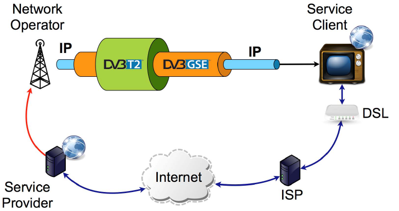
ETSI
ETSI TS 102 606
-
2 V1.1.1 (2014
-
07)
34
Figure 8: Example bi-directional use-case
In this scenario, the service client sends requests to the service provider via the interaction channel. The service
provider may then decide whether to send the response back to the client through the broadcast channel, or the
interaction channel.
To make service client implementations independent of the specifics of the interaction channel, those network interfaces
on the service client that represent broadcast channels carrying such enhanced interactivity services, shall use the UDLR
mechanism defined in RFC 3077 [11] to emulate a bi-directional channel.
7.2 Generic network service profile
In this profile, the GSE link layer is used to provide a generic network service to receivers. The information in the GSE
packets carrying LLC is only used to configure network interfaces on the receiver. This is similar to an Internet service
provided by an ISP over a DSL connection, or by a mobile operator over a 3G or LTE connection. This profile allows
more than one applications to coexist, and to be used on top of the network service.
In the Generic Network Service Profile, the following rules shall apply:
a) The application system descriptor shall not be transmitted.
b) The URI descriptor shall not be transmitted.
Since no additional information about any applications in use on top of the network service is available, receivers shall
use service discovery and selection mechanisms provided on top of the network service. This may for example involve
joining well-known multicast groups in the case of an IP network service. The presence of well-known multicast groups
can also be inferred from information in NCD records tables (see clause 5.1.3).
7.3 Application system profile
In this profile, the GSE link layer is used to provide a network service to a predominant application used on top of it.
In the Application System Profile, the following rules shall apply:
a) The application system descriptor shall always be transmitted.
Since an application system may provide the same, or similar information about network links as defined in the present
document, the information conveyed in the GSE LLC data may be restricted to a minimum. This minimum set of GSE
LLC data may only describe the entry points to the service discovery information provided by the application system.
ETSI
ETSI TS 102 606
-
2 V1.1.1 (2014
-
07)
35
7.3.1 OMA BCAST system profile
In case the OMA BCAST system is used as application on the top of IP layer, the application system descriptor shall be
present, and the application_system_id field shall be set according to TS 101 162 [6].
The L2 signalling information LCD and NCD elements are transmitted in the Service Guide Delivery Descriptor of the
announcement channel as defined in OMA BCAST DVB-NGH Adaptation [29].
NOTE: Here, LCD and NCD refer to the data structures defined in [29] and transmitted as part of the SGDD in
OMA BCAST, and not to the tables of the same name defined in the present document.
The GSE LLC data shall at least describe the entry point of the bootstrap channel by conveying an appropriate
application system descriptor. This entry point is transmitted in the OMA_BCAST_info of the application system
descriptor. This entry point identifies the PLP used for the transmission of the bootstrap session. For an efficient
filtering in the receiver, the OMA_BCAST_info can provide versioning information to notify receivers of any updates.
All other LLC tables and descriptors are optional in this profile.
As defined in [29], the bootstrap session containing the bootstrap descriptors will be retrieved in the PLP defined in the
OMA_BCAST_info, on a specific FLUTE channel as defined in [29].
The bootstrap descriptors, the ESGProviderDiscovery Descriptor and ESGAccessDescriptor that are used within the
bootstrap session allow the discovery of the provider of the service guide and the access to the service guide. The
session accessible with ESGAccessDescriptor is a Service Guide Announcement Channel containing the Service Guide
Delivery Descriptor where the LCD and NCD elements are transmitted. For more details, see [29].

ETSI
ETSI TS 102 606
-
2 V1.1.1 (2014
-
07)
36
Annex A (informative):
Examples
A.1 Carriage of LLC data in extension headers
The example given in Figure A.1 demonstrates how LLC data structures - in this case an index structure, an LCD table,
and an NCD table - are carried as a mandatory extension header in a GSE packet. As defined in clause 6.1.4, GSE
packets conveying LLC data do not carry a regular payload in addition to extension headers. GSE parsers which do not
implement LLC according to the present document, will skip the entire LLC mandatory extension header.

ETSI
ETSI TS 102 606
-
2 V1.1.1 (2014
-
07)
37
Figure A.1: Example GSE packet with LLC data carried in the extension header
A.2 Finding the size of the last table
As explained in clause 5.1.1.1, the end of the last table cannot be inferred from the index alone, but needs to be
calculated by taking the total size of the LLC data into account. The index structure hints to the sizes of all tables,
except for the last. The Total_Length field for cases where fragmentation occurs, or the GSE_Length field for cases
where fragmentation does not occur, on the other hand indicate the overall size of the LLC data. The length (and
therefore the end) of the last table can thus be inferred from the difference between the beginning of the last table, and
the overall LLC data size. Of course the size of the index itself, and the Protocol_Type field will need to be taken into
account for this calculation.
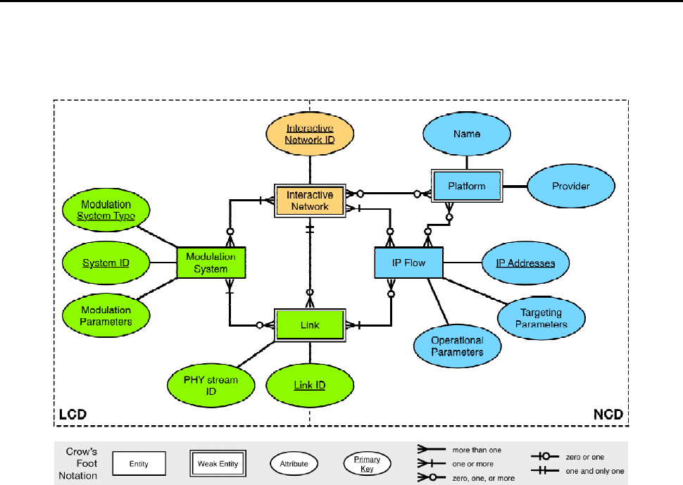
ETSI
ETSI TS 102 606
-
2 V1.1.1 (2014
-
07)
38
In the hypothetical buffer used in clause 5.1.1.1, the end of the last table can be calculated as:
[]
1)()()( +−−=
lastindexlast
tableoffsetLLCsizeofhTotalLengttablesizeof
NOTE: The above equation applies when fragmentation occurs. In case fragmentation does not occur,
Total_Length can be replaced with GSE_Length.
In the example in Figure A.1, the GSE_Length field has the value 807, the offset of the last table in the GSE packet is
38. With these figures the size of the last table computes to:
[]
7721879011717807)(
1
=−=+−−=tablesizeof
Which equals the 768 bytes table body, plus the four bytes of gse_table_structure() header.
A.3 Underlying data model
The data model underlying the syntax and semantics of the LLC data defined in the present document is shown in
Figure A.2 as an entity-relationship (ER) model, and the mapping to the LCD and NCD tables is hinted.
Figure A.2: Data model of the LLC information
The entities of this model are:
• Modulation System: This entity represents a modulation system at the RF level, characterised by its type (for
example DVB-T2), and its system id (for example the T2_system_id). It is further described by a set of
modulation parameters (frequencies, etc.).
• Link: This entity represents a virtual network interface on the receiver. It is hence associated with exactly one
IP Flow. Since the same data stream may be available on more than one modulation system stream, a Link
may appear in more than one instance, each of which is associated with exactly one modulation system stream
characterised by modulation system type, modulation system ID, and PHY stream ID (for example a specific
PLP in a particular DVB-T2 system). As the same data is delivered on all instances of a Link, receivers may
freely switch between the instances of a particular Link, however bearing in mind that different routes may
imply different propagation delays being applied to the data.
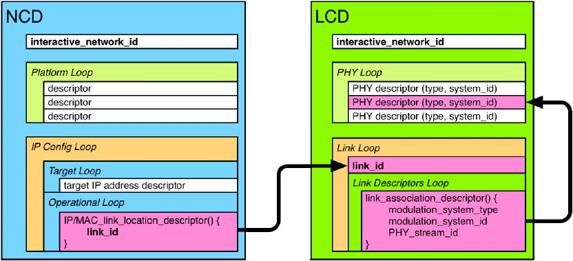
ETSI
ETSI TS 102 606
-
2 V1.1.1 (2014
-
07)
39
• IP Flow: This entity represents the data stream delivered over a given Link. Since the same data may be
available from various locations, an IP Flow can be associated with one or more Links. An IP Flow is further
described by targeting parameters (for example describing IP source and/or destination addresses found in the
flow), and operational parameters (for example ROHC-U header compression parameters). The connection
between IP Flows and Links is made by the Link ID.
• Platform: This entity represents a collection of IP Flows provided by an operator. An operator may operate
one or more IP Flows.
Figure A.3: Mapping to LLC tables and lookup path
Figure A.3 shows how the above concepts have been mapped to the LCD and NCD tables, and how lookups can be
performed. Note that due to the one-to-many relationships in the data model above, unambiguous lookups can only be
done in one direction. This design was chosen based on the assumption that receivers would start from service
discovery information they have acquired above the IP layer. Such information would for example indicate that the
elements comprising a certain service, are available on specific multicast group addresses. To acquire the service, a
receiver would then need to determine which PHY stream in which modulation system carries data for those multicast
addresses, and what interface configuration needs to be applied (for instance whether ROHC-U is used).
To implement this lookup sequence, the operational loop in the NCD features the IP/MAC link location descriptor,
which specifies a Link ID, on which the relevant data is available. The link loop in the LCD in turn lists all the links,
and it can hence be scanned for the Link ID in question. From the modulation system streams listed in under this Link
ID, the receiver can infer the modulation parameters, and the PHY stream ID.
Reverse lookups are of course possible, but will most likely yield lists of entities. Hence additional information may be
needed to select one of the options from the lookup results.
Figure A.3 also shows that the LCD and NCD are labelled by an interactive network ID. It identifies the RF network
which carries the streams, and is independent of the Platform described above. This is to accommodate the fact that
often the operator of the RF infrastructure, and the operator of the services carried on it are different entities.

ETSI
ETSI TS 102 606
-
2 V1.1.1 (2014
-
07)
40
History
Document history
V1.1.1 July 2014 Publication
