Experimental Evaluation of Distributed k-Core
Decomposition
Bin Guo
Department of Computing & Information Systems
Trent University
Peterborough, Canada
Runze Zhao
Department of Computing & Software
McMaster University
Hamilton, Canada
zhaorz@mcmaster.ca
Abstract—Given an undirected graph, the k-core is a subgraph
in which each node has at least k connections, which is widely
used in graph analytics to identify core subgraphs within a
larger graph. The sequential k-core decomposition algorithm
faces limitations due to memory constraints and data graphs can
be inherently distributed. A distributed approach is proposed to
overcome limitations by allowing each vertex to independently do
calculation by only using local information. This paper explores
the experimental evaluation of a distributed k-core decomposition
algorithm. By assuming that each vertex is a client as a single
computing unit, we simulate the process using Golang, leveraging
its Goroutine and message passing. Due to the fact that the
real-world data graphs can be large with millions of vertices,
it is expensive to build such a distributed environment with
millions of clients if the experiments run in a real-life scenario.
Therefore, our experimental simulation can effectively evaluate
the running time and message passing for the distributed k-core
decomposition.
Index Terms—k -core decomposition, distributed, Golang, mes-
sage passing
I. INTRODUCTION
Graphs are fundamental data structures to model real appli-
cations, which are mathematical representations of relation-
ships between objects such as individuals, knowledge, and
positions. In the graph, each vertex represents an object and
each edge represents some relationship between a pair of
objects, for example, the social network of Facebook can be
represented as graph data where each user is a vertex and the
relationships between users are edges.
Since many real-world applications can be modeled as
graphs, graph analytics has attracted much attention from
both research and industry communities. Many algorithms
are proposed to analyze large data graphs, including graph
trimming, strong connected component (SCC) decomposition,
k-core decomposition, k-truss decomposition, etc.
Among all the above algorithms, the k-core decomposition
is to analyze the structure of a graph by identifying its core
subgraphs. The k-core of a graph is a subgraph in which each
node has at least k connections; the core number of nodes is
the highest order of a subgraph in which every vertex has at
least a specified degree.
There are various applications [1] for the k-core decompo-
sition listed below:
• Biology. The k-core and phylogenetic analysis of Protein-
Protein Interaction network help predict the feature of
functional-unknown proteins.
• Social Network. The k-core decomposition is widely
accepted to reveal the network structure. It can be used
to identify the key nodes in the network or to measure
the influence or users in online social networks.
• Compute Sciences. The k-core decomposition can be used
to study large scale Internet graphs. It easily reveals
ordered and structural features of the networks. The
k-core subgraphs also reveals the primary hierarchical
layers of the network and also permits their analytical
characterization.
The widely used sequential algorithm for the k-core de-
composition is proposed by Batagelj and Zaversnik, the so-
called BZ algorithm [2]. It recursively removes vertices (and
incident edges) with degrees less than k. The algorithm uses
bucket sorting and can run in O(m + n) time, where m is
the number of edges and n is the number of vertices. The
sequential BZ algorithm has two limitations:
• First, the graph must be loaded into memory, since the
BZ algorithm requires random access the whole graph
during computation. So, some graphs may be too large
to fit in a single host due to memory restriction.
• Second, the graph can be inherently distributed over a
collection of hosts and each host hold a partial subgraph
(one-to-many), which is not convenient to move each
portion to a central host. Furthermore, each vertex can be
a independent host and the edges can be the connections
between different hosts (one-to-one), e.g., mobile phone
networks.
To overcome the above limitations, distributed graph algo-
rithms are proposed in [3]. In this paper, we focus on using
the one-to-one model such that each vertex in the graph is
a single host that calculates its own k-core simultaneously,
which can be compatible with the one-to-one model. Hence,
tiny memory and computing resources are required for each
vertex, and there is no central host to store the entire graph.
Real-world graphs are large and always have millions of
vertices and edges. It is expensive to build a distributed physi-
cal environment that has millions of clients to simulate vertices
one-to-one, in order to test the distributed algorithms. Instead,
arXiv:2406.17580v1 [cs.DC] 25 Jun 2024

we can simulate the distributed algorithm on a single machine
by choosing a highly concurrent programming language that
supports lightweight threads and massage passing, e.g. Golang.
In this paper, we are going to simulate the distributed k-core
decomposition algorithm to explore its runtime behaviors. The
experiment is conducted with Golang to simulate distributed
runtime environment. In our experiment, we used real-world
data graphs, and the size of data graphs varies from thousands
to millions of vertices. The core number of each vertex is
calculated, and we capture the number of messages passed
between each vertex for analysis.
The distributed k-core decomposition algorithm is explained
in Section II. The details of the implementation are demon-
strated in Section III. Our experiments are described in Sec-
tion IV.
II. PRELIMINARIES
In this section, we review the distributed k-core decompo-
sition algorithm.
Let G = (V, E) be an undirected unweighted graph,
where V (G) denotes the set of vertices (or nodes) and
E(G) represents the set of edges in G. When the context
is clear, we will use V and E instead of V (G) and E(G)
for simplicity, respectively. As G is an undirected graph, an
edge (u, v) ∈ E(G) is equivalent to (v, u) ∈ E(G). We
denote the number of vertices and edges of G by n and m,
respectively. The set of neighbors of a vertex u ∈ V is defined
by u.adj = {v ∈ V : (u, v) ∈ E}. The degree of a vertex
u ∈ V is denoted by u.deg = |u.adj|.
A. The k-Core Decomposition
Definition II.1 (k-Core [4]). Given an undirected graph G =
(V, E) and a natural number k, an induced subgraph G
k
of G
is called a k-core if it satisfies: (1) for ∀u ∈ V (G
k
), u.deg ≥
k, and (2) G
k
is maximal. Moreover, G
k+1
⊆ G
k
, for all
k ≥ 0, and G
0
is just G.
Definition II.2 (Core Number [4]). Given an undirected graph
G = (V, E), the core number of a vertex u ∈ G(V ), denoted
u.core, is defined as u.core = max{k : u ∈ V (G
k
)}. That
means u.core is the largest k so that there exists a k-core
containing u.
Definition II.3 (k-Core Decomposition [4]). Given a graph
G = (V, E), the problem of computing the core number for
each u ∈ V (G) is called k-core decomposition.
Example II.1. Figure 1 demonstrates an example of k-core
decomposition. In the graph, the circles are the nodes, and the
inside letters A, B, C, D, E, F, G, H are their ID. The black
lines that connect two nodes are called edges. The edges are
undirected, and each node is aware of the connected neighbors.
The number of neighbors is the degree of the node.
The three dot circles demonstrate the k-core of this graph.
As mentioned, the k-core is a maximal subgraph in which
every node has at least degree k. The whole is 1-core since
all nodes have degree at least 1. The nodes A, B, E, F, G, H
Fig. 1: An Example of k-Core Decomposition
form the subgraph that all the nodes in this subgraph have
degree at least 2, which is 2-core. The subgraph contains nodes
A, B, E, F is 3-core because all nodes in this subgraph have
degree at least 3.
The core number of a node is the largest k such that this
node is part of the k-core. In this example, for node A, it is
part of 1-core, 2-core, and 3-core, so the largest k is 3 and
the core number is 3. Similarly, nodes B, E, F have a core
number of 3; nodes G, H have a core number of 2 and nodes
C, D have core numbers 1.
The process of computing the core number of each node in
this graph is called k-core decomposition.
B. Distributed Core Decomposition
Theorem II.1 (Locality [3]). For all u ∈ V , its core number,
u.core, is the largest value k such that u has at least k
neighbors that have core numbers not less than k. Formally,
we define u.core = k, where k ≤ |{v ∈ u.adj : v.core ≥ k}|
and (k + 1) > |{v ∈ u.adj : v.core ≥ (k + 1)}|.
Theorem II.1 shows that the vertex u is sufficient to cal-
culate its core number from the neighbor’s information. The
procedure works as in the following steps [3]:
1) For the initialization stage, each u ∈ V has its esti-
mate core numbers initialized as its degree. Each u will
maintain a set of estimated core numbers u.core
′
for all
neighbours u.adj . Then, each u sends its estimated core
numbers u.core
′
to all neighbours.
2) Then u will receive the estimated core numbers v.core
′
from its neighbours v ∈ u.adj. The received core
′
will
be stored by u locally. Then, u will wait until receiving
estimated core numbers from all neighbours before it
calculates its own core number k. If k is not equal to
u.core
′
, u will update its core number with Theorem II.1
and send the updated core number to all neighbours.
2
3) Each vertex u ∈ V executes the above distributed
algorithm in parallel. The termination condition is that
all vertices u ∈ V satisfy Theorem II.1 and thus stop
decreasing the estimated core numbers u.core
′
at the
same time.Finally, all vertices obtain the calculated core
numbers.
a) Message Complexity: The performance of the dis-
tributed k-core decomposition algorithm can be measured
using time complexity or message complexity [3]. The time
complexities are used to measure the total running time, while
the message complexities are used to measure the number
of messages passed between different nodes to complete the
k-core decomposition. The number of messages that pass
through the go channels can be recorded during the program
run time. It will not interfere with running the program locally
or on a real distributed network. For distributed algorithms,
since most of the running time is spent on the message pass-
ing through networks, which is much slower than accessing
memory, we should mainly analyze the message complexities.
We analyze the message complexities in the standard
work-depth model [5]. The work, denoted as W, is the
total number of operations that the algorithm uses. The
depth, denoted as D, is the longest chain of sequential
operations. The work W is the total number of messages
that the degree reduces to the core number, denoted as
W = O[
P
u∈V
u.deg · (u.deg − u.core)], since the vertex
must send messages to notify all neighbors when each time
its core number decreases by one.
In the worst case, the process can be reduced to sequential
running, e.g., a chain graph. In other words, the whole process
needs the worst-case n round to converge. Therefore, the depth
D is equal to the work W. However, in real graphs, e.g. social
networks and communication networks, such a worst-case can
rarely happen, and it has a high probability to run in parallel,
as such chain structure rarely exists in most of real graphs.
Normally, it takes only several rounds, such as 1 to 10, to
converge.
In this paper, our experiments are to evaluate the total
number of messages passed during the process of k-core
decomposition. More importantly, we will analyze the number
of messages passed over different time intervals as well as how
soon each node completes the k-core decomposition to obtain
how distributed k-core decomposition behaves over time.
C. Termination Detection
Concurrent programming involves multiple processes exe-
cuting simultaneously, often leading to complex interactions.
Termination detection is a critical aspect of concurrent pro-
gramming, ensuring that processes finish execution properly
without deadlocks or infinite loops. There are several well-
developed termination detection algorithms:
• Chandy-Lamport Snapshot Algorithm [6]: It operates by
taking snapshots of the local states of processes and the
states of communication channels.
• Mattern’s Algorithm [7]: It is an improvement over the
Chandy-Lamport algorithm, using vector clocks to track
causal relationships between events.
• Lai-Yang Algorithm [8]: This algorithm is another ap-
proach that leverages colored markers (white and red) to
capture global states without requiring F IF O channels.
• Dijkstra-Scholten Algorithm [9]: This algorithm uses a
hierarchical tree structure. The coordinator process at the
root collects messages from child processes, which in turn
collect messages from their children, and so on.
In this paper, for simplicity and efficiency, we use a cen-
tralized server for termination detection. That is, all clients
send heartbeat to the server, so the server can terminate the
algorithm when the heartbeat is not received for a period.
III. IMPLEMENTATION
In this section, we discuss the implementation of the dis-
tributed k-core decomposition algorithm.
A. Procedures
Our implementation contains the following procedures:
• receive: Each node continuously runs the receive func-
tions until the termination. This function receives the
incoming message from the neighbors and calculates
node’s k-core.
• send: Once the receive function calls this function to send
k-core to neighbors after calculating the node’s k core
number.
• updateCore: The receive function calls this function to
calculate the node’s k-core number after receiving the
k-core number from its neighbors.
• sendHeartBeat: Each node uses this function to send
heartbeat to the central server.
• receiveHeartBeat: The central server continuously runs
this function to receive hearbeat messages from all nodes
and determine whether the termination signal should be
issued.
• dataCleanse: This function processes the graph data to
make it usable for the simulation.
B. Golang Simulation
Golang, also known as Go, is a compiled programming
language developed by Google
1
. Go has built-in support for
concurrent programming through Goroutines and channels.
As lightweight threads, Goroutines are multiplexed onto a
small number of Operating System threads and are auto-
matically scheduled by the Go runtime system. Goroutines
enable concurrent programming in Go, allowing functions
to be executed concurrently, independently of other parts
of the program. The study [10] shows that concurrency in
Go is easier to implement and has better performance than
Java. The Go channel is a powerful feature that facilitates
communication and synchronization between Goroutines. The
channels provide a way for Goroutines to send and receive
data to and from each other safely and efficiently. Channels
1
https://go.dev/doc/
3

can also be used to synchronize the execution of Goroutines.
For example, a Goroutine may wait until it receives a signal
from another Goroutine through a channel before proceeding
with its execution.
a) Why Choose Golang: In this paper, we try to simulate
the distributed k-core decomposition algorithm. Each vertex is
a computational unit, which can be simulated as a lightweight
thread. Since there can be millions of vertex in a tested data
graph, our simulation has to execute millions of lightweight
threads in parallel. In addition, vertices communicate by
passing messages to each other, which can be simulated as the
message passing between lightweight threads. In a word, our
simulation experiments require a programming language that
efficiently supports a large number of concurrent lightweight
threads that can be synchronized by message passing.
In addition to Go, there exist many other programming
languages that support concurrent lightweight threads and
message passing, such as Erlang
2
, Haskell
3
, Elixir
4
, and Rust
5
.
However, Go well supports a large number of lightweight
threads called Goroutines running concurrently in parallel, and
message passing through channels for each Goroutine. We
can start a Goroutines simply by a statements ”go func”,
which is the most convenient compared to other programming
languages.
The tested data graphs contain up to millions of vertices.
If the experiment runs in a real-life scenario, each vertex
would require a single physical client to run the program,
and all clients would communicate through public networks.
It is hard to have such a large resource to carry out such
experiments. The simulation of such an experiment requires
strong concurrency and message-passing capabilities, where
Go excels. Each physical client can be simulated using a
single Goroutine, and the communication of all nodes can
be synchronized by sending and receiving messages through
channels. By such a simulation, we can run the experiments on
a single machine, without a large number of physical machines
and setting up a complex running environment.
C. Algorithm Implementation
a) Data Structure: Following is the implementation of
node data structure. Each node should maintain such data
structure and updated by exchange information with their
neighbours;
type Node struct {
ID string
coreNumber int
storedNeighborK map[string] int
status string
selfChan chan sendMsg
serverChan chan string
terminationChan chan bool
2
https://www.erlang.org/docs
3
https://www.haskell.org/
4
https://elixir-lang.org/
5
https://www.rust-lang.org/
neighbors []chan sendMsg
}
• ID: Each node has its own unique id as an identifier.
• coreNumber: Each node stores its own core number.
• storedNeighborK: Each node stores its neighbours’ core
number.
• status: Each node has two status:
– Active: The node is actively calculating its k-core
number and passing messages to its neighbours
– Inactive: The node is currently not processing
passed messages nor calculating its k-core number.
• selfChan: Each node has its own channel to receive
messages from neighbour nodes.
• serverChan: The channel used by server to receive heart-
beat from all nodes.
• terminationChan: Each node has a channel to receive
termination message from server.
• neighbors: Each node stores its neighbour channels.
(a) Initially, k-core numbers are degrees
(b) First round, each node sends its k-core number to neighbors
Fig. 2: An Example of distributed k-core decomposition with
message passing (a)
b) Message Passing:
4

(c) Second round, node B and C send new core number to neighbors
(d) Final round, all nodes finish k-core decomposition
Fig. 3: An Example of distributed k-core decomposition with
message passing (b)
Example III.1. Fig. 2 and Fig. 3 show the distributed
k-core decomposition procedure with a small example
graph. The circles are the nodes, and the inside letters
A, B, C, D, E, F, G, H are their ID. The Active nodes are
colored red, the Inactive nodes are colored green, and
the arrows between the nodes demonstrate how messages are
passed. The beside table indicates the data structure stored in
each node. The message contains the sender’s ID and core
number, for example, the message {A, 2} in which A is the
ID and 2 is the core number.
• Initially, as shown in Fig. 2(a), all nodes are initialized
with degree number as their coreN umber; all nodes
are aware of their neighbors but do not know the
coreNumber of their neighbors
• In the first round, as shown in Fig. 2(b), all nodes send
their coreNumber to all neighbors. Nodes A, D, and
E do not need to decrease their coreNumber. Nodes B
and C decrease their coreNumber to 2 according to the
distributed k-core decomposition algorithm.
• In the second round, as shown in Fig. 3(c), nodes B and
C send a new coreNumber to their neighbors.
• Finally, as shown in Fig. 3(d), all nodes have up-
dated coreNumber from nodes B and C; no nodes
needs to update their coreN umber; all nodes enter the
Inactive status.
c) Termination Detection: In order to reduce the re-
sources and number of passing messages used for termina-
tion detection, we use the centralized termination detection
approach [3]. We use a central server process and a dedicated
channel called server channel to directly collect messages
from all nodes. This is a classic Master-Worker Paradigm
[11] design, which involves a master node (central server) that
coordinates the actions of the worker nodes (processes), which
reports their status to the master. This concept is closely related
to centralized monitoring and failure detection in distributed
systems. It embodies the principles of centralized coordination
[12] and monitoring in distributed systems. This approach is
easier to implement and lightweight on each node. Each node
does not need to store or pass messages from other nodes.
• Initially, all nodes start with Active status since they
will need to send their degree numbers to neighbours.
• Once the Active nodes complete the k-core calculation
using distributed k-core decomposition algorithm and
send the k-core to their neighbours, they change the status
to Inactive.
• The Inactive nodes can turn into Active status as
soon as receiving updated core number from its neigh-
bours because updated core number from neighbour will
trigger a recalculation of its own core number.
The message sent to the server is called a heartbeat. It is
a message that each node sends to the server to inform its
status. Only Active nodes generate and send heartbeats to
the server. Inactive nodes do not send heartbeat messages
to the server because the server only needs to know if there are
still Active nodes in the system. If there exist any Active
nodes, the server will not send a termination notice to all
nodes.
All nodes send heartbeat message to server in either of
following conditions:
• When node receives an updated k-core number from its
neighbour, it sets its status to Active and immediately
send a heartbeat to the server.
• All Active nodes send heartbeats to the server every 10
seconds. If the k-core calculation takes too long, the node
will use this periodic heartbeat to inform the Active
status to the server. This prevents false termination from
the server in the event that no heartbeat is received but
there are nodes still calculating k-core numbers.
The server Goroutine constantly reads messages from the
server channel and checks if there are any incoming heartbeats
in the past 30 seconds. If there is no incoming heartbeat
from any node for 5 minutes, the server will send termination
message to all nodes’ termination channels to stop all nodes.
The k-core number stored on each node is considered the
final result. The 30-second interval is much longer than the
5
heartbeat interval, which is only 10 seconds. This is done to
ensure that there is no pending message in the system or that
any node takes too long to calculate the core numbers. The
downside of using a long check interval is that termination is
delayed and that the system will not terminate as soon as it
finishes calculating the core numbers.
IV. EXPERIMENTS
In this section, we carry out extensive experiments to
evaluate the message complexity of the distributed k-core
decomposition algorithm with the simulation results for each
data graph. The analysis contains the number of total passing
messages, the number of passing messages over time interval,
and the number of Active nodes over time interval.
A. Experiment Setup
The experiments are performed on a server with an AMD
CPU (64 cores, 128 hyperthreads, 256 MB of last-level
shared cache) and 256 GB of main memory. The server
runs the Ubuntu Linux (version 22.04) operating system. The
distributed k-core decomposition algorithm is implemented in
Golang (version 1.21). The code implementation is shared on
the Github repository
6
B. Tested Graphs
We select 14 real-world graphs within seven categories. All
graphs are obtained from the Stanford Large Network Dataset
Collection (SNAP)
7
, shown in Table I. The detailed graph
descriptions are summarized as follows:
• soc-pokec-relationships(SPR): the most popular on-line
social network in Slovakia.
• musae-PTBR-features(PTBR): twitch user-user networks
of gamers who stream in a certain language.
• facebook-combined(FC): This dataset consists of ’circles’
(or ’friends lists’) from Facebook.
• musae-git-features(MGF): a large social network of
GitHub developers that was collected from the public API
in June 2019.
• soc-LiveJournal1(LJ1): a free on-line community with
almost 10 million members; a significant fraction of these
members are highly active.
• email-Enron(EEN): enron email communication network
covers all the email communication within a dataset of
around half million emails.
• email-EuAll(EEU): the network was generated using
email data from a large European research institution.
• p2p-Gnutella31(G31): the network was generated using
email data from a large European research institution.
• com-lj(CLJ): LiveJournal friendship social network and
ground-truth communities.
• com-amazon(CA): Ground-truth community defined by
product category provided by Amazon.
6
https://github.com/Marcus1211/MEng
7
https://snap.stanford.edu/data/
• web-Stanford(WS): the nodes represent pages from Stan-
ford University (stanford.edu), and the directed edges
represent the hyperlinks between them.
• web-Google(WG): nodes represent web pages and di-
rected edges represent hyperlinks between them
• amazon0505(A0505): the network was collected by
crawling Amazon website.
• soc-Slashdot0811(S0811): the network contains friend/-
foe links between the users of Slashdot.
Each graph is pre-processed before the experiment. For
simplicity, all directed graphs are converted to undirected
graph based on following rules:
• A vertex can not connect to itself
• Each pair of vertices can only connect with one edge
• All graphs are converted into JSON format that the key
is the vertex and all its neighbour vertices are stored in
the value
a) Graph Properties: In Table I, we can see that the
tested graphs have up to millions of edges. Their average
degrees range from 2 to 46, and their maximal core numbers
range from 8 to 376. Each column in Table1.1 is explained
below:
• Type: directed and undirected. Directed graphs contain
directed edges, which means that connected nodes are
not mutually aware of each other. Undirected graphs
have edges that do not have a direction. Directed graphs
must be converted into undirected graphs before the
experiment, simply by removing the direction.
• n = |V |: the number of vertices in the graph.
• m = |E|: the number of edges in the graph.
• AvgDeg (Average Degree): The number of neighbors of
a node is called degree; the average degree is the sum of
all degrees divided by the total number of nodes.
• MaxDeg (Max Degree): the maximum degree among all
nodes.
• MaxCore: the maximum core numbers among all nodes
after k-core decomposition.
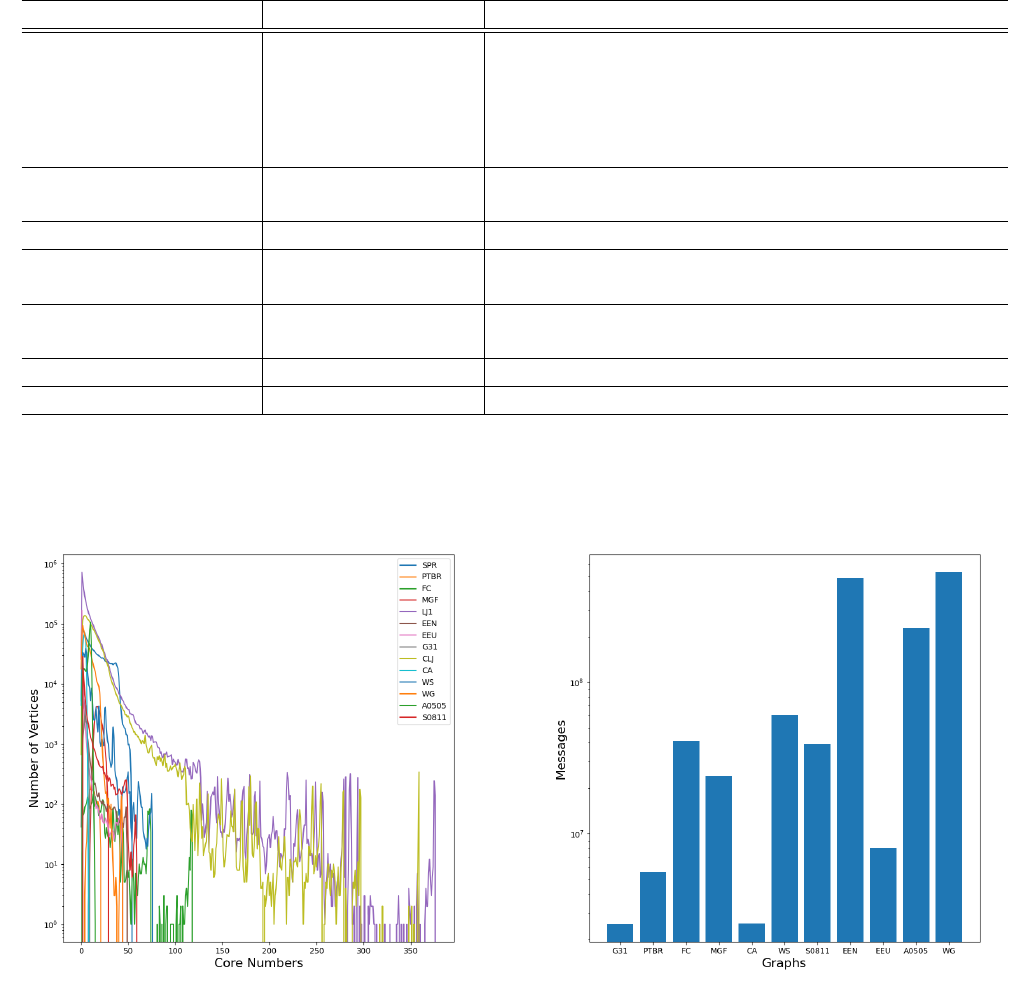
b) Core Number Distribution: In Fig. 4, we can see that
the core numbers of vertices are not uniformly distributed in
all the graphs tested, where the x-axis is core numbers and
the y-axis is the number of vertices. That is, a great portion
of vertices have small core numbers, and few have large core
numbers. For example, LJ has 0.5 million vertices with a core
number of 1; PTBR and MGF have no vertices with a core
number of 1. Although CA has more than 300, 000 nodes, all
the core number of vertices range from 0 to 8.
C. Evaluate Total Number of Messages
Fig. 5 shows the total number of passing messages for
each graph, where the x-axis is the tested graphs and y-
axis is the total number of passed messages for each graph
to complete the distributed k-core decomposition. Generally,
large graphs, for example WG, EEN, and A0505, with more
nodes and edges, require more messages passed to complete
the simulation.
6
Category Graph Name Type n = |V | m = |E| AvgDeg MaxDeg MaxCore
Social Networks
soc-pokec-relationships (SPR) Directed 1,632,803 30,622,564 29 14739 118
musae-PTBR-features (PTBR) Undirected 1,912 31,299 24 1635 21
facebook-combined (FC) Undirected 4039 88234 46 986 118
musae-git-features (MGF) Undirected 37,700 289,003 36 28191 29
soc-LiveJournal1 (LJ1) Directed 4,847,571 68,993,773 19 20314 376
Communication Networks
email-Enron (EEN) Undirected 36,692 183,831 10 1383 49
email-EuAll (EEU) Directed 265,214 420,045 2 7631 44
Internet peer-to-peer networks p2p-Gnutella31 (G31) Directed 62,586 147,892 7 68 9
Ground-Truth Communities
com-lj (CLJ) Undirected 3,997,962 34,681,189 25 14208 360
com-amazon (CA) Undirected 334,863 925,872 5 546 8
Web Graphs
web-Stanford (WS) Directed 281,903 2,312,497 14 38625 75
web-Google (WG) Directed 875,713 5,105,039 10 6331 44
Product Co-Purchasing Networks amazon0505 (A0505) Directed 410,236 3,356,824 12 2760 15
Signed Networks soc-Slashdot0811 (S0811) Directed 77,357 516,575 13 2540 59
TABLE I: Tested Data Graphs
Fig. 4: The Core Number Distribution
However, the average degree can also affect the number of
messages passed, even when the number of nodes is small. For
example, MGF has 37, 700 nodes with an average degree of
36 and FC has only 4039 nodes, but with an average degree of
46. Both MGF and FC are considered small graphs but require
a large number of messages to complete the simulation. The
high average degree means that each node has more neighbors
on average. When a node updates its core number, it needs to
send more messages if it has more neighbors, and thus more
messages are passed. The number of messages passed does
not increase in liner to the average degree. It also depends on
Fig. 5: The Total Number of Passing Messages
the core distribution among all nodes.
D. Evaluate the Number of Message Passing with Time Inter-
val
Fig. 6 and Fig. 7 show the number of messages passed in the
system over time interval, where the x-axis is the time interval
when each data point is collected and the y-axis is the number
of total messages passed between all nodes when simulating
the distributed k -core decomposition algorithm. Since different
graphs take different times to complete the experiment; Some
large graphs take up to 3 days to complete, we only use time
7

Fig. 6: Number of Passing Messages over Time Interval (a)
\
Fig. 7: Number of Passing Messages over Time Interval (b)
intervals instead of real time to plot the graph. This helps
demonstrate the general trend of each simulation despite the
time it takes.
We can observe that most of the messages are passed in
the first couple of time intervals. This is expected as all nodes
need to share their degree number with their neighbor when
initiating the core decomposition. Every time a node updates
its core number, it needs to pass messages to its neighbors;
most of the nodes remain in the active state and keep updating
their core number at the beginning of the simulation. Hence
a large mount of messages is passed during the first couple
of time intervals. The number of messages passed decreases
for all graphs as the simulation progresses because more
nodes finish calculating its core number. Therefore, no more
messages are sent from the inactive node.
The graph WG demonstrates a special case in which there is
a spike in the number of messages passing during the middle of
the simulation. This is due to the core calculation of nodes that
have many neighbors; when they update their core number,
they send messages to a large number of neighbors, which
causes neighbors to update their core numbers as well. Hence,
a recursive effect results in a spike of messages passed.
E. Number of Active Node for Each Time Interval
Fig. 8: Number of Active Node over Time Interval (a)
Fig. 8 and Fig. 9 show the number of Active nodes
over time, where the x-axis is the time interval when each
data point is collected and the y-axis is the number of total
messages passed between all nodes. Most of the nodes are
in the Active state at the beginning of the simulation. As
8

Fig. 9: Number of Active Node over Time Interval (b)
stated in the implementation, the node will only enter the
Active state when it needs to decrease its core number
and send messages to its neighbor. Hence, more and more
nodes enter the Inactive state once they finish calculating
its core number and do not receive messages from its neighbor
to trigger further core number calculation. The number of
Active nodes decreases at different rates despite running on
the same machine. This is caused by the distribution of nodes
with different core numbers. For some graphs such as A0505
or EEN, most of the nodes have small core numbers, so they
will be processed quickly and enter the Inactive state. On
the other hand, graphs like CA or MGF, they have more nodes
with a higher core number; it will take some time for them
to process these nodes; hence the number of Active nodes
does not drop rapidly at the beginning of the simulation.
The speed of the distributed k-core decomposition algorithm
is determined by the number of Active nodes remaining
in the experiment. As the experiment progresses, more and
more nodes turn into the Inactive state and eventually all
nodes become Inactive. Nodes with a small core number
always turn into Inactive first, which means if the speed
of the algorithm is determined by the core number distribution
among all nodes, e.g. if most of the nodes have a high core
number, it would take longer time for the distribute k-core
decomposition to finish.
F. Evaluate Total Running Time
Fig. 10 shows the total running time for each graph, where
the x-axis is the tested graphs and y-axis is the total running
time in minutes for each graph to complete the distributed k-
Fig. 10: Total Running Time
core decomposition. The results show a similar trend similar
compared with the number of passing message in Fig. 5, which
means that it takes a large portion of running time for passing
messages during the computation.
However, Fig. 10 cannot be used as a reference for the
real-world implementation of the distributed algorithm. If the
distributed k-core decomposition algorithm is implemented in
the real world, all messages will be sent over the Internet.
The geographical locations of the nodes will cause various
delays in transferring messages. Our experiment leverages Go
Channels and computer memory, which generate less delay
than the Internet over the smaller size of the tested graphs
but more delays than the Internet over the larger size of the
tested graphs. Therefore, as pointed out in Section II, the
performance of the distributed k core decomposition algorithm
is evaluated based on the complexity of the message rather
than the complexity of time.
V. CONCLUSION AND FUTURE WORK
This paper presents an experimental evaluation of the dis-
tributed k-core decomposition algorithm on real-world graphs
with up to millions of vertices. The algorithm is able to
calculate the core number for each node without shared
memory. Golang is used to simulate the distributed runtime
environment, and we can analyze the number of messages
passing when executing the algorithm.
In the future, our experimental evaluation can extend to
other distributed graph algorithms, e.g., k-truss decomposition
and SCC decomposition. In addition, instead of using Golang,
we can invent a specific framework to simulate distributed
algorithms, which supports the simulation of accurate latency
for passing messages.
REFERENCES
[1] Y.-X. Kong, G.-Y. Shi, R.-J. Wu, and Y.-C. Zhang, “k-core: Theories
and applications,” tech. rep., 2019.
9
[2] V. Batagelj and M. Zaversnik, “An o(m) algorithm for cores decompo-
sition of networks,” CoRR, vol. cs.DS/0310049, 2003.
[3] A. Montresor, F. De Pellegrini, and D. Miorandi, “Distributed k-core
decomposition,”
[4] B. Guo and E. Sekerinski, “Simplified algorithms for order-based core
maintenance,” The Journal of Supercomputing, pp. 1–32, 2024.
[5] J. J
´
eJ
´
e, An introduction to parallel algorithms. Reading, MA: Addison-
Wesley, 1992.
[6] K. M. Chandy and L. Lamport, “Distributed snapshots: Determining
global states of distributed systems,” ACM Transactions on Computer
Systems (TOCS), vol. 3, no. 1, pp. 63–75, 1985.
[7] F. Mattern, “Algorithms for distributed termination detection,” Dis-
tributed computing, vol. 2, no. 3, pp. 161–175, 1987.
[8] T. H. Lai and T. H. Yang, “On distributed snapshots,” Information
Processing Letters, vol. 25, no. 3, pp. 153–158, 1987.
[9] E. W. Dijkstra and C. S. Scholten, “Termination detection for diffusing
computations,” Information Processing Letters, vol. 11, no. 1, pp. 1–4,
1980.
[10] N. Togashi and V. Klyuev, “Concurrency in go and java: Performance
analysis,” in 2014 4th IEEE International Conference on Information
Science and Technology, pp. 213–216, 2014.
[11] M. Van Steen and A. Tanenbaum, “Distributed systems principles and
paradigms,” Network, vol. 2, no. 28, p. 1, 2002.
[12] G. F. Coulouris, J. Dollimore, and T. Kindberg, Distributed systems:
concepts and design. pearson education, 2005.
10
