USER
GUIDE
1
User Guide
wecare@JTECH.com
800.321.6221
System
Components 3
Things to Know 4 Quick Set Up 6
Range Test 7
Adding Range
Extenders 8
Optional Call
Buttons 28
System Default
Configuration 9
Smart Band
Assembly 12
Smart Band
Functions 13
Dashboard and
Menus 14
Settings 19
Sending
Messages 25
Assignments 26
Help 30 Appendix 31
Table of Contents
2
User Guide
wecare@JTECH.com
800.321.6221
User Guide
wecare@JTECH.com
800.321.6221
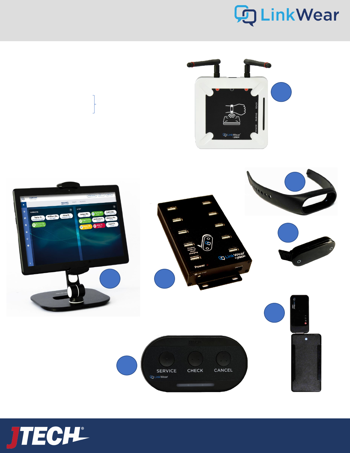
The LinkWear system is comprised of the following
components:
1. LinkWear Hub
2. LinkWear Band
3. LinkWear Brain
4. LinkWear Brain Charger
5. User Interface Tablet and Mount
6. Optional Equipment
A. Range Extender(s)
B. Call Button(s)
1
3
4
5
6a
6b
Smart Band
*Comes attached as one unit.
2
System Components
3
User Guide
wecare@JTECH.com
800.321.6221
User Guide
wecare@JTECH.com
800.321.6221
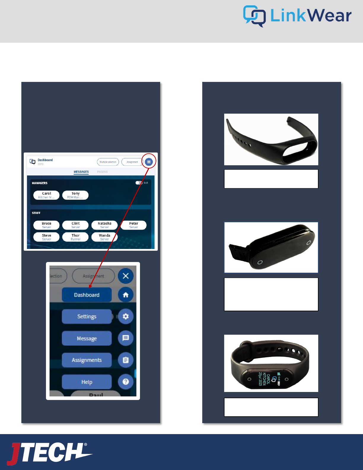
LinkWear Menus
Click the Hamburger Stack
Icon to access the various
LinkWear Menus.
LinkWear Lingo
Band
+
=
Smart Band
Brain with USB
Connector
Things to Know Before Getting Started
4
User Guide
wecare@JTECH.com
800.321.6221
User Guide
wecare@JTECH.com
800.321.6221
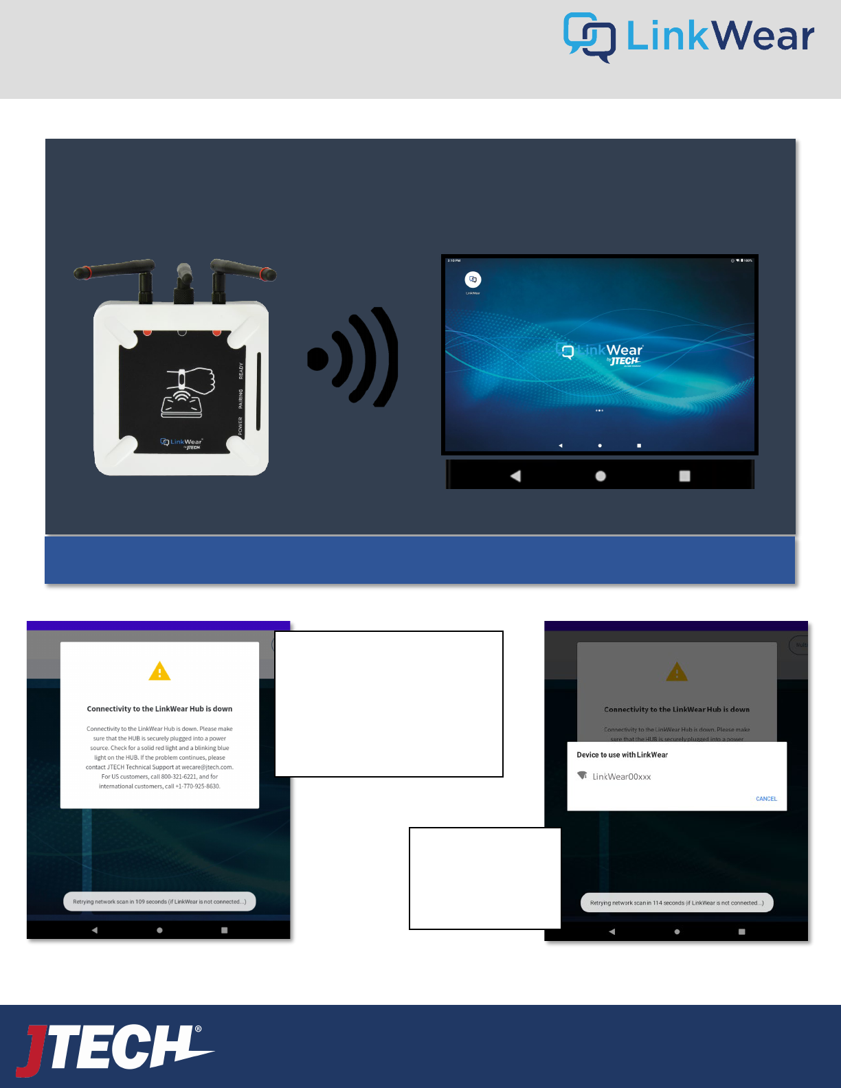
LinkWear Hub Think of LinkWear as its own little network.
Your tablet(s) needs to be connected to the LinkWear Hub.
NOT YOUR WIFI ROUTER – for your system to work.
Things to Know Before Getting Started – Cont.
Back Home Recent
5
If the disconnection issue persists, please reboot the LinkWear Hub by unplugging it and plugging it back in. Then wait for it to
connect to the tablet.
If you get an error message saying
connectivity to the LinkWear Hub is
down, make sure it is connected to
the power and wait for
approximately 3 minutes. The hub
should automatically reconnect.
If you see this
message, click on the
hub name (SSID) and
it should connect.
We recommend that the hub and tablets be within approximately 50 feet for optimal performance.

User Guide
wecare@JTECH.com
800.321.6221
User Guide
wecare@JTECH.com
800.321.6221
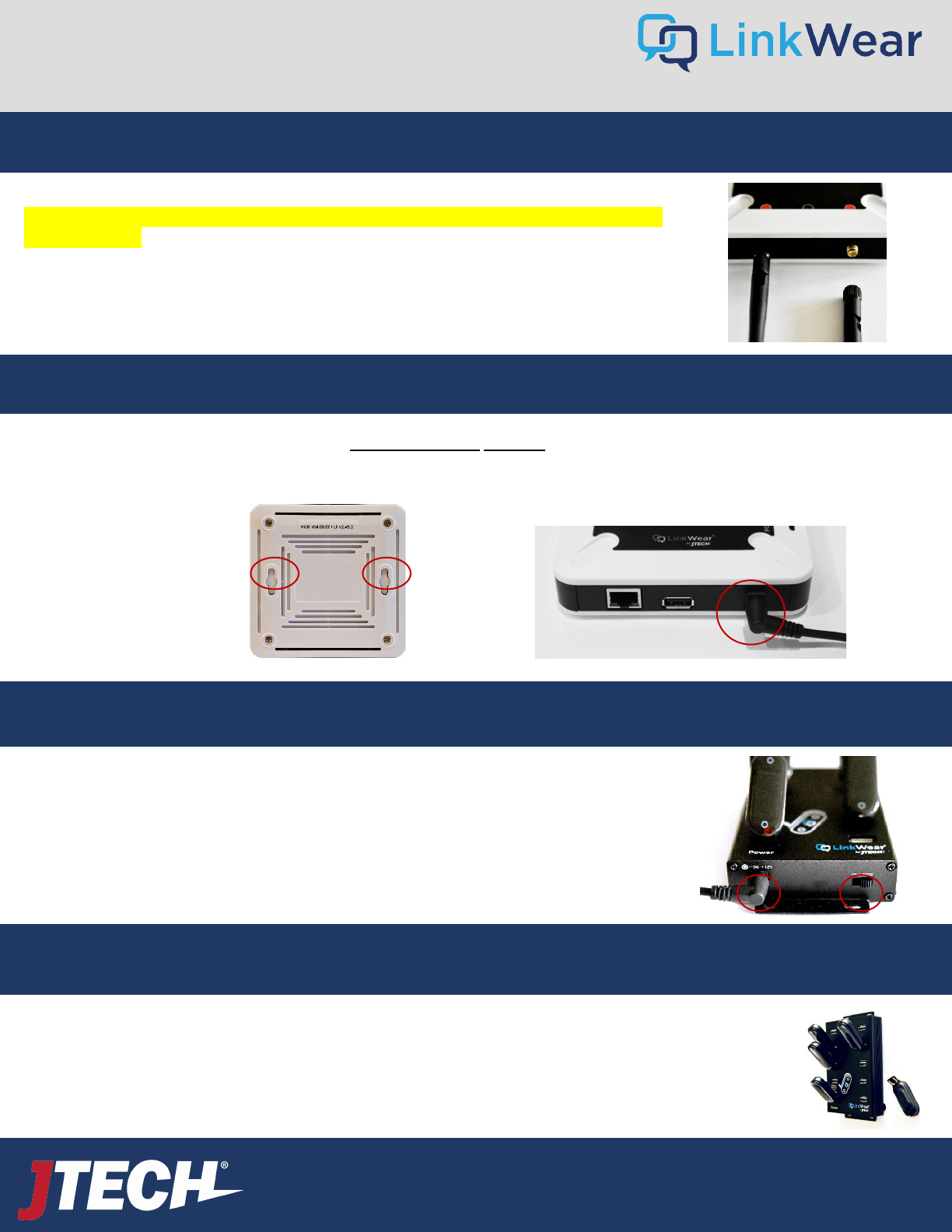
Hub
• Connect the 2 red tipped antennas to the Hub by twisting left to lock into place. Note: If using the optional Legacy
Paging Converter, you will have a third center antenna without the red ring. MAKE CERTAIN THE ANTENNAS ARE FULLY
TIGHTENED TO ENSURE PROPER CONNECTION.
• Place or mount the Hub on a flat surface, in a cool, dry, metal free, central location in the middle of your building
towards the main dining area. Above 8’ if possible- Higher is better!
• Plug the Hub power supply into a standard 110-240V outlet and then into the Hub. Secure the plug into the Hub in
such a way that secures it from being easily pulled out. The Hub must always remain powered on. When plugged in,
a re d light will show.
• A flashing blue light will appear on the Hub in one to three minutes. This signifies that the Hub is ready to use. It is
now time to connect the tablet to the hub.
Brain
Charger
• Place the charger in a dry, secure and easily accessible location – in the office is recommended.
• Plug the power supply into the charger and then into a standard 110-240v outlet. Secure the plug into the charger in
such a way that secures it from being easily pulled out. Power the charger on via the on/off switch. A red light will
show next to power.
• Add LinkWear Brains into the charger slots. The brains only charge one way in the charger. Follow the guide on the charger face. You
will see “Charging” appear on each Smart Band indicating charging has started. Allow up to 6 hours for a complete charge of the
Smart Bands. Confirm bands are inserted properly and charging.
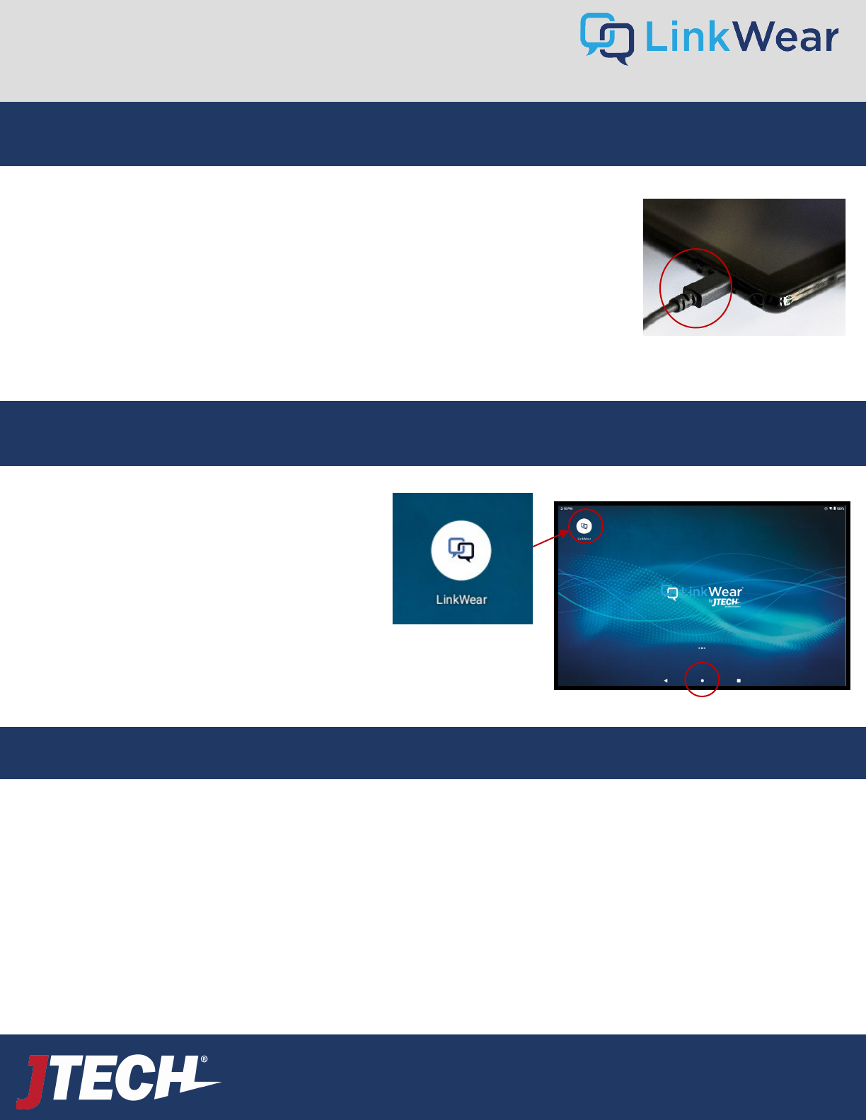
Tablet
• Plug the power supply into the tablet and then into a standard 110-240v outlet. Secure the plug into the tablet in such a way to
power it on and so that it is secure from being easily pulled out. The tablet should always remain plugged in. Press the power
button on the tablet and power it on and let it boot up. **Keep away from heat lamps. ***Tablet will be connected to the
LinkWear Hub once powered on – do not attempt to connect to any local Wi-Fi network connection this will cause set up issues
.
• A range test should be performed prior to using the system – CLICK HERE.
• Place the Tablet in the tablet mount and place where the notifications will originate. (i.e., Kitchen line, Host/Reception Area).
Optional
Equipment
• Call buttons will come pre-configured to work with your system.
• Call Button programming changes can be done in the “Settings” option on the right-hand side of the tablet (Hamburger Stack).
• Range Extender should be placed on the fringe of coverage area. See Range Extenders installation for further instructions. –
CLICK HERE
Quick Setup For the Quick Start Guide Included with your LinkWear System, CLICK HERE
6
User Guide
wecare@JTECH.com
800.321.6221
User Guide
wecare@JTECH.com
800.321.6221
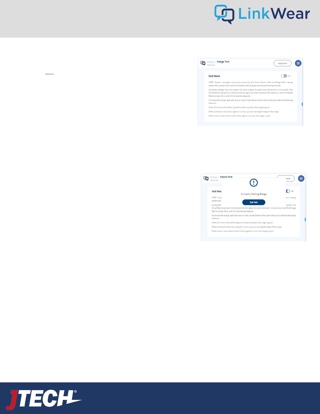
• Select “Range Test” under Settings on the Tablet (Hamburger Stack)
• Take two Smart Bands and place on your wrist
• On the Tablet, turn on the “Range Test”
• Walk the entire coverage area with the Smart Band, noting areas that are
on the fringe (1 bar or no bars).
• Every 15 seconds the Smart Band will vibrate and show if the range is
strong (4 green bars) or on the fringe (1 green bar). Bands showing any
green bars means it is within range and should function properly. When
fluctuating between 1 bar and no bars, this means you are nearing the end of
coverage or a dead spot. If an “out of range” message is displayed or no signal
is received, you are not within the coverage area and a range extender may be
required.
Note: The range test mode will automatically time out after 15 minutes
.
Fringe areas can receive messages, but you are getting close to the limit of the
range. When the messages stop you have exceeded the fringe area. This can be
caused by:
• General range limits
• Obstructions – Metal, elevators, freezers, etc.
• Multiple levels
If you exceeded any fringe areas (no messages received), you can extend range by:
• Moving the hub to a more central location and re-testing
• Mounting the Hub higher or different location
• Adding range extender(s) to your system
After moving the Hub or adding range extender(s), repeat the above four steps to
verify the area has adequate coverage.
**NOTE: Some reflective window coverings have been shown to significantly
reduced coverage outside of the window. Should you discover this issue is
reducing your systems range, please call our support team at 800-321-6221 for
solutions.
Coverage Area Range Test
7
7
User Guide
wecare@JTECH.com
800.321.6221
User Guide
wecare@JTECH.com
800.321.6221
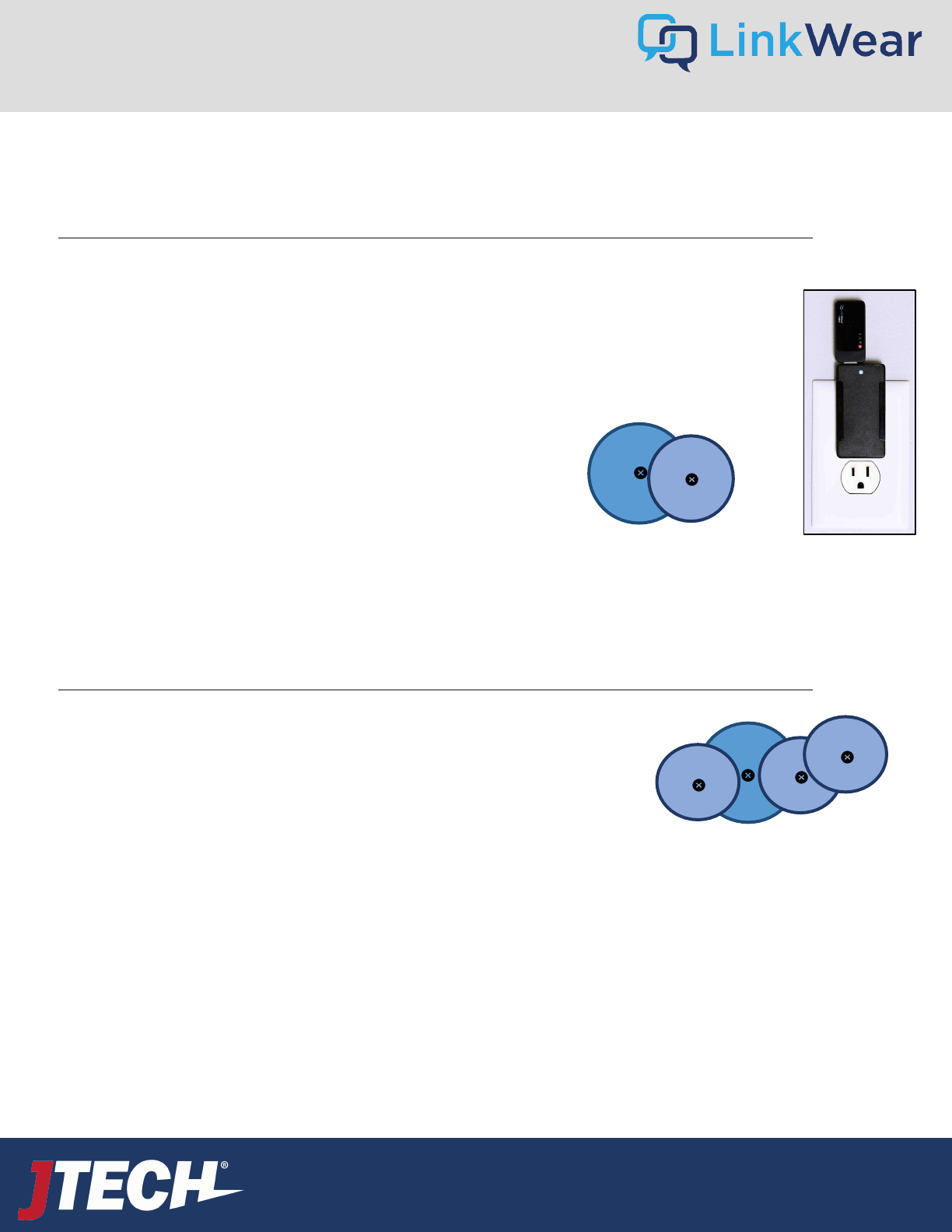
Adding a Single Range Extender
Adding Multiple Range Extenders
• Settings Full device list Extends
• Rename each Range Extender with an identifying name so they are easily located (i.e., Patio North)
HUB
Extend
Extend
Extend
HUB
Extend
Range Extenders
• Insert Range Extender into the power brick provided
• Range Extenders require a standard 110-240v outlet
• Plug the Range Extender near the area where you are losing coverage. *You must be able to still receive a
message from the Hub in the area where you place the Extender.
• The Extender will catch the signal from the Hub and resend it to the extended area.
• On the tablet
• Settings Full device list Extends
• Rename each Range Extender with an identifying name so they are easily
located (i.e., Patio North)
• Insert Range Extender into the power brick provided
• Range Extenders require a standard 110-240v outlet
• Plug in the Range Extenders around the areas where you are losing coverage in the same
manner explained above with single range extenders.
• On the tablet
8
User Guide
wecare@JTECH.com
800.321.6221
User Guide
wecare@JTECH.com
800.321.6221
A site survey will be conducted with your Customer Success Manager upon placement of your order. Each LinkWear system is
configured based on the results of this survey prior to shipment. These can be modified as needed on site – instructions are
below in the change system settings section. (Hamburger Stack → Message → Set Up Messages)
Messages:
• Food Ready (default)
• 86 Item
• All Hands
• Inquiry
• Re-Fire
• To Go order up
• Phone
Staff Roles:
• Server
• Busser
• Bartender
• Host
• Runner
• Expo
• Key Employee
• Shift Lead
Manager
Roles:
• Bar Manager
• FOH Manager
• Kitchen Manager
Responses:
• Got it
• Done
• Busy
System Default Configuration
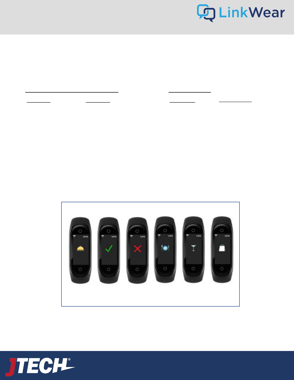
ICONS
Call Check
OK
Cancel
Alert
Food Up Bar
Drinks
To Go
Default Messages/Responses Default Roles
Note: Use of the icons along with messages is optional.
These icons are hard coded and cannot be replaced or
edited.
9
User Guide
wecare@JTECH.com
800.321.6221
User Guide
wecare@JTECH.com
800.321.6221
The LinkWear system can accommodate up to 7 messages, one of which is the default. The default message is sent whenever a button is
pressed on the Dashboard. This is the message you send most frequently and is the quickest to send. For example – Food Ready.
The system also has 6 predefined messages that are accessed in one of two ways:
• Long press on a button
• Select the Multiple Selection button at that top of the screen
Changing Default and Predefined Messages
These predefined messages are pre-programmed into
your system prior to shipping. These messages can be
changed by the end user at any time by accessing the
Setup Messages Field.
Hamburger Stack Message Setup Messages Click the pencil icon to edit or delete to remove a predefined message. To add a
new predefined message, you can either erase and copy over an existing message or delete a message and create a new one by
pressing the Create Message Button. The system can only accommodate a total of 7 messages.
The system also offers 6 ICONs to send along with your messages. You can choose which Icon to use in the same edit field where you
edit the messages. Simply select the Icon you wish to use and press SAVE. *Note – The use of Icons can be turned on or off by selecting
the Allow Icons toggle.
10
User Guide
wecare@JTECH.com
800.321.6221
User Guide
wecare@JTECH.com
800.321.6221
Default system settings are pre-programmed prior to shipping based on each locations requirement. These settings are adjustable on
site and are accessed through the Hamburger Stack.
System Operational Defaults
Changing the Default Settings:
Transition ◊ OFF Hamburger Stack Message Message Setting
Escalations ◊ OFF Hamburger Stack Message Message Setting
Sleep ◊ OFF Hamburger Stack Settings Band Configuration
Range Test ◊ OFF Hamburger Stack Settings Range Test
Out of Range ◊ ON Out of Range is always ON and cannot be turned off.
Mirror Tablet ◊ OFF Hamburger Stack Settings Mirror Tablets
Smart Band Vibration ◊ 3x Hamburger Stack Settings Band Configuration Band Vibration Pattern
Standard Default Configuration
Transition OFF
Escalations OFF
Sleep OFF
Range Test OFF
Out of Range ON
Mirror Tablet OFF
Smart Band Vibration 3x
11
User Guide
wecare@JTECH.com
800.321.6221
User Guide
wecare@JTECH.com
800.321.6221
Smart Bands are key part of the LinkWear System. At the beginning of each shift employees should take a fully charged Smart
Band and assign it to themselves with the appropriate role for that shift.
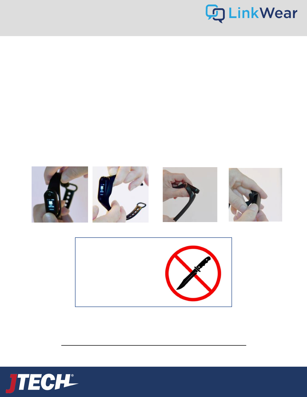
Inserting and Removing the Brain
Inserting
• Insert the USB end into the slot on the band side with the holes as far as you can.
• Push down on the brain while pulling up on the clasp side of the band to seat the brain.
Removing
• Pull down on the clasp side of the band while pushing up on the same side of the brain.
• Grab the brain and pull it away from the band while holding the side of the band with the holes.
Smart Band Assembly
Click here for information on assigning the Smart Bands
Warning: Do not use any tools,
utensils, etc. to pry the brains
out of the bands. This can
irreparably damage the brains.
12
User Guide
wecare@JTECH.com
800.321.6221
User Guide
wecare@JTECH.com
800.321.6221
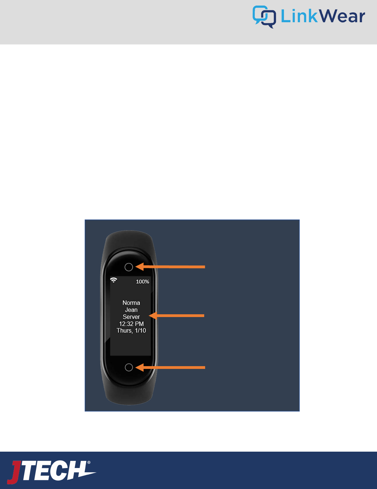
Power On Hold bottom touch point and top touch point for 2 seconds.
Wake Up from Blank Screen Tap Bottom touch point
Go to Blank Screen Do not touch for 10 seconds.
Go to Message Screen from Standby Screen Hold bottom touch point for 2 seconds and release.
Look through Messages from Message Screen Tap top touch point to scroll up and tap bottom touch point to scroll down.
Look through Responses from Message Screen Touch and hold bottom touch point for 2 seconds to see and scroll through all
responses.
Select and Send Response When desired response is on the screen, tap and hold bottom touch point for
seconds to send response.
Connection/Pairing Mode Touch and hold top touch point and bottom touch point for 10 seconds and
release. Mode will time out in 20 seconds.
Smart Band Functionality
Top Touch Point
Tap – Scroll Screen
Hold – Cancel Reply Action
Standby Screen
Bottom Touch Point
Tap – Wake Up, Scroll Down
Hold - Enter
13
User Guide
wecare@JTECH.com
800.321.6221
User Guide
wecare@JTECH.com
800.321.6221
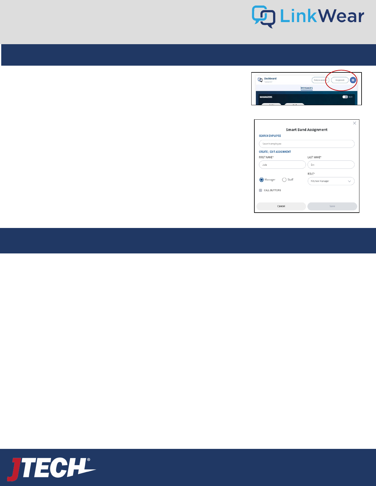
Access the Tablet Dashboard
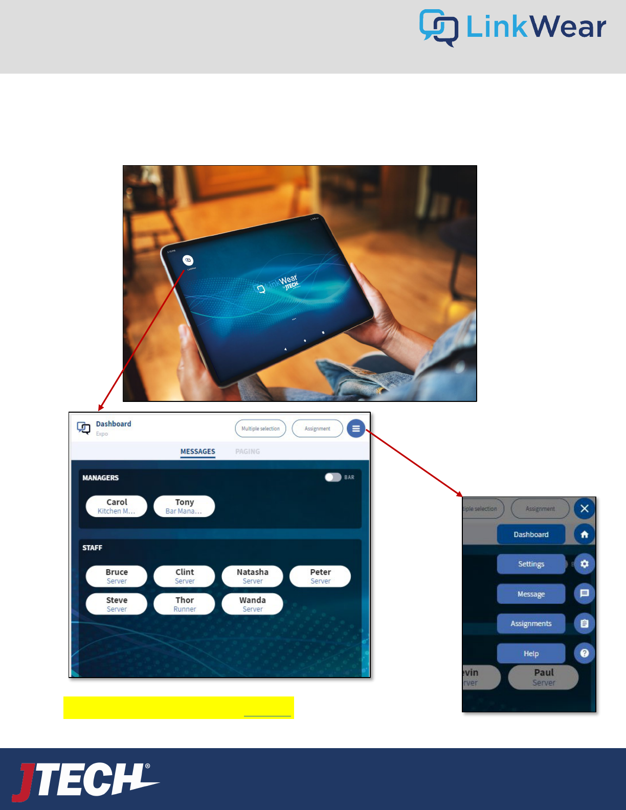
• The Dashboard is the main home screen for the LinkWear System. Open the LinkWear App by touching the icon.
• You can access the dashboard on the tablet by selecting the “house” icon in the hamburger stack on the right side of the tablet screen
or by selecting the LinkWear Logo, located at the top left side of the tablet screen.
Click the Hamburger Stack on the
top right of the screen to access
the various LinkWear Menus. Click
the X to close the pop-up menu.
Tablet
FYI: The tablet can be
oriented in landscape or
portrait positions. The
tablet will automatically
adjust to how the tablet is
mounted.
To troubleshoot connection issues, click here.
14
User Guide
wecare@JTECH.com
800.321.6221
User Guide
wecare@JTECH.com
800.321.6221
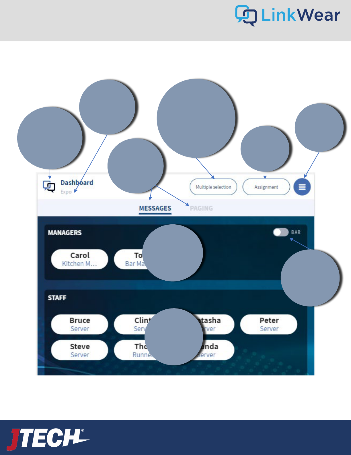
Dashboard
Manager
Call
Points
Staff Call
Points
Takes you
to the
Dashboard
Tablet
Identifier
• Message
Numerous
Bands
• Send Custom
Messages
• Send
Predefined
Notifications
Messages
And Paging
Tabs
Assign
Bands
Here
Change
Dashboard
View
Settings
Menu
15
User Guide
wecare@JTECH.com
800.321.6221
User Guide
wecare@JTECH.com
800.321.6221
The Dashboard is the “Home” screen of the LinkWear
application. From this screen, you can see the existing Smart
Band assignments, add/change assignments and access the other
menus for settings, help, etc.
Dashboard
The tablet can be oriented in landscape or portrait positions. The
tablet will automatically adjust to how the tablet is mounted.
In Portrait Mode: The Assignment Screen has two options for
viewing with the toggle switch:
1. Button View
2. Bar/List View
In Landscape Mode: The Assignment Screen has multiple options
for viewing. Click the Icon with six squares on the top right side
of the Bubble Staff section to select from the following:
• Bar
• Bubbles 3x3
• Bubbles 4x2
• Bubbles 2x4
• Bubbles 1x5
• Bubbles 5x1
16
User Guide
wecare@JTECH.com
800.321.6221
User Guide
wecare@JTECH.com
800.321.6221
Distributing a Smart Band
• Remove a Brain from the charger.
• Ensure the Brain is sufficiently charged (>70%)
• Insert Brain into a Wrist Band
• Smart Band should be worn with the holes on the wrist band facing towards their body
Assigning a Smart Band on the Tablet Dashboard
If optional call buttons are installed, you will select each call button assigned to you prior to selecting save.
Dashboard – Bands and Assignments
17
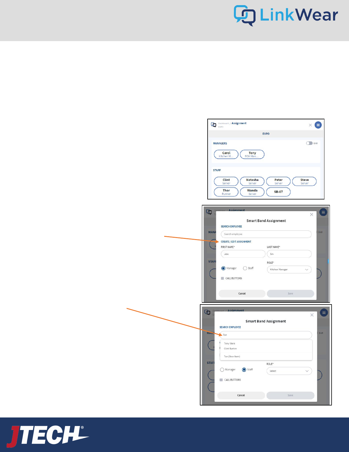
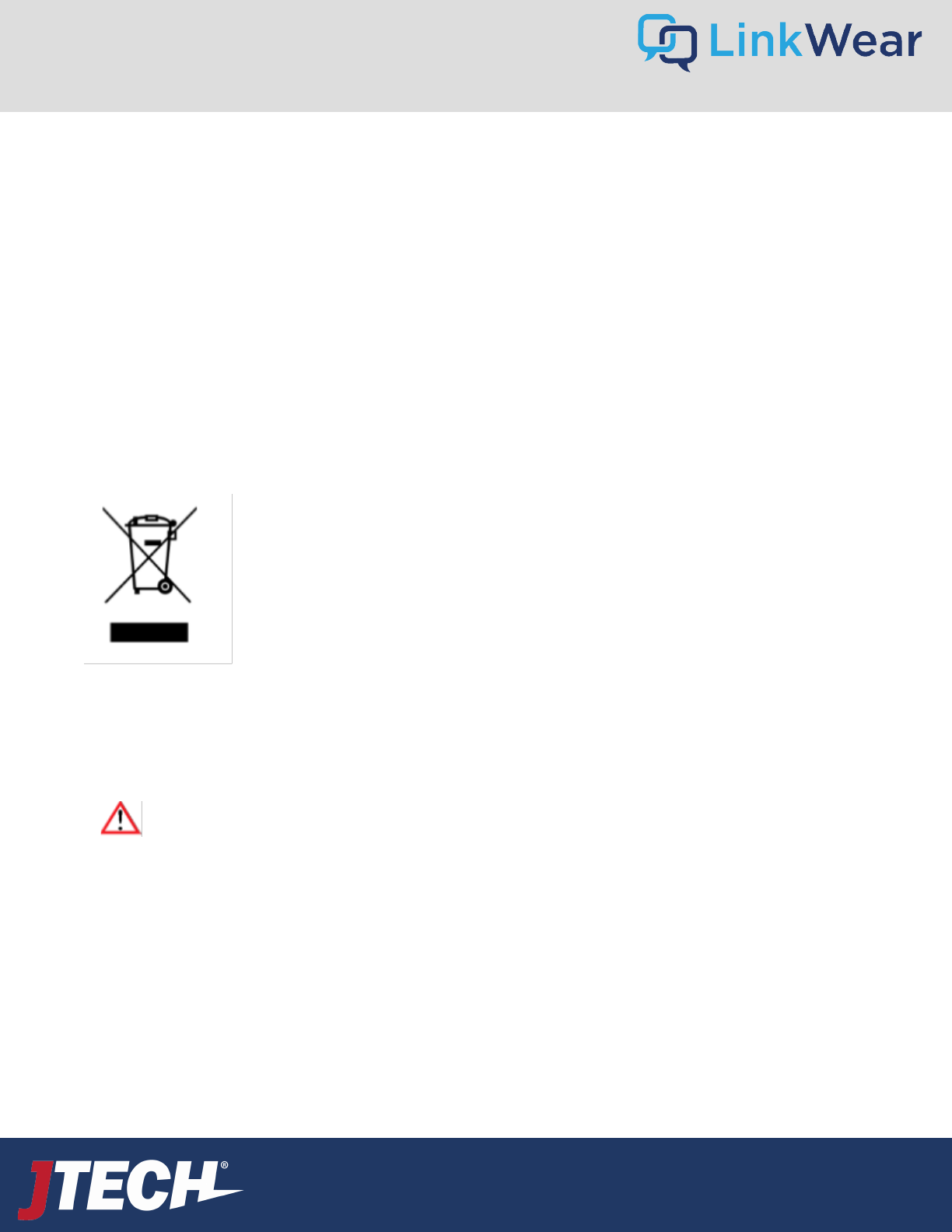
Select “Assignment” on the upper right-hand side.
Match the name from the band you are assigning with the name on
the assignment screen and select it. Assignment screen will have a
white background and will time out after one minute of inactivity.
To Add a New Person
1. Enter the information under “Create/Edit Assignment”
1. Enter in the staff member’s first and last name
2. Select Manager or Staff
3. Select the correct role from the drop-down list
4. Save
To Assign and/or Edit an Existing Person
1. Select “Search Person”
2. Tap in the “Search Employee” text box
3. Enter the employee’s name
4. Select the correct name and make any changes needed
5. Select either manager or staff
6. Select correct role from drop down list
7. Save
User Guide
wecare@JTECH.com
800.321.6221
User Guide
wecare@JTECH.com
800.321.6221
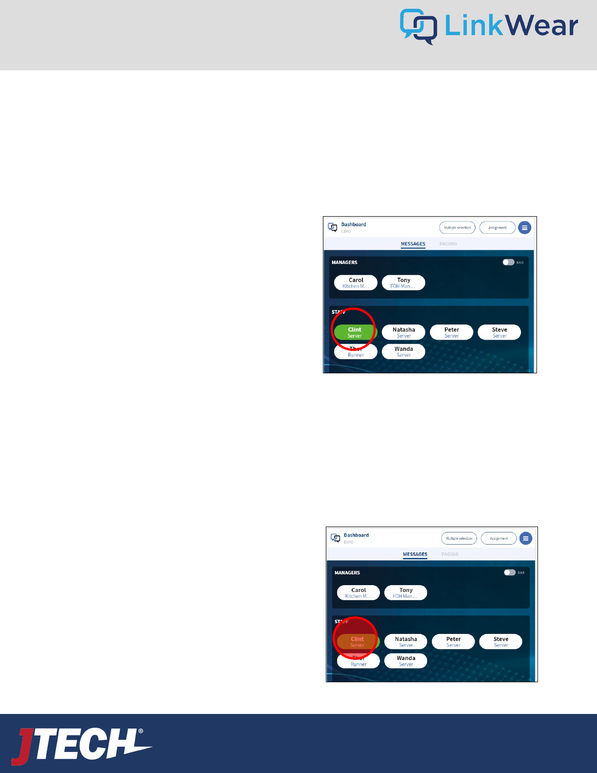
Messaging a Staff Member with the Default Notification
1. To message a staff member with the default message, quick press on their name via the tablet dashboard. The button will turn green
when the message is sent then revert back to white.
2. The Smart Band will alert the staff member with a vibration and the message will be stored on the Smart Band.
You can view up to 10 messages.
Messaging a Staff Member with a Custom or Predefined Notification
1. To message a staff member with a custom message, long press for 2 seconds and release on their name via the tablet dashboard.
2. The Predefined message list will display. Select the message you want to send or type a free text message by selecting “Create Custom
Message”.
3. To choose an Icon when sending a custom message, touch the desired icon prior to sending the message.
4. Select “Send” to send the message.
Dashboard – Sending Messages
18
User Guide
wecare@JTECH.com
800.321.6221
User Guide
wecare@JTECH.com
800.321.6221
19
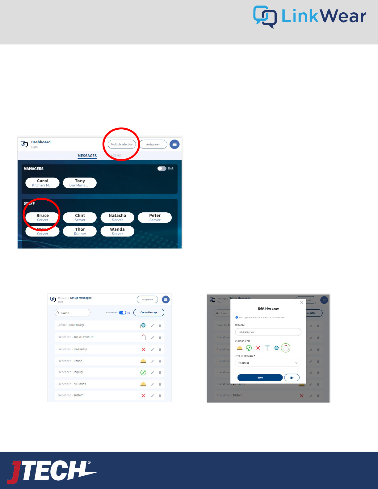
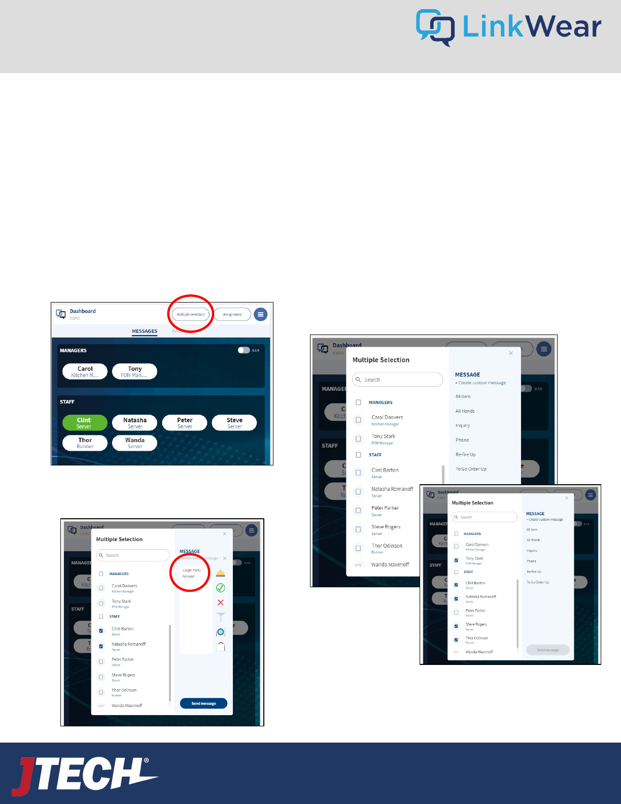
Message – Sending Messages
Here you can select staff members you want to
alert. You can choose a predefined message or
create custom messages and add an icon.
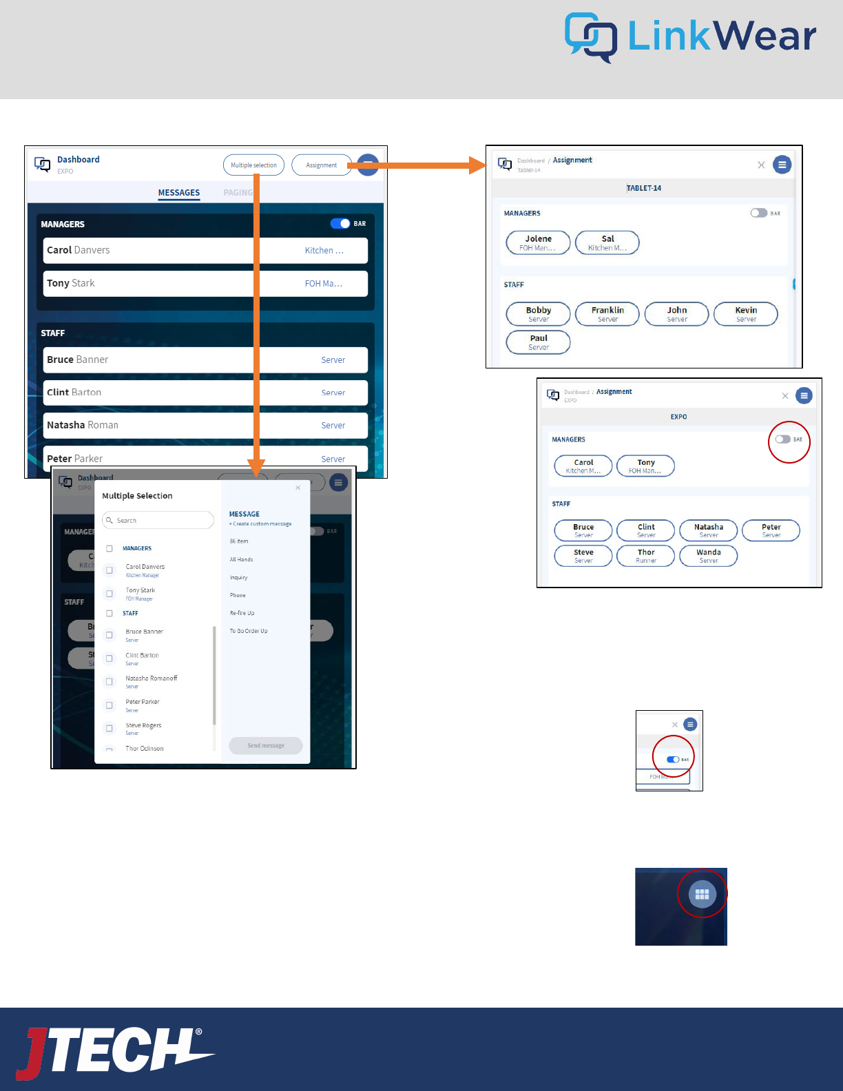
Messaging Multiple Staff or Managers
1. To select multiple staff or managers to notify, select “multiple selection” at the top of the tablet.
2. Select the staff member(s) and/or manager(s) to notify.
3. Choose from the Predefined messages or type in a custom message by selecting “Create Custom Message".
4. To choose an Icon when sending a custom message, touch the desired icon prior to sending the message.
5. Select “Send” to send the message.
Note: When using the Multiple Selection feature,
Transitions are disabled, and the Read Response arrow is
not functional.
User Guide
wecare@JTECH.com
800.321.6221
User Guide
wecare@JTECH.com
800.321.6221
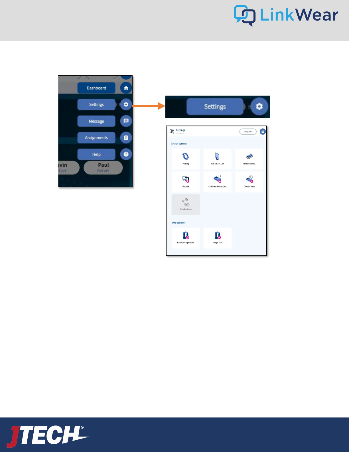
Pairing Pair Smart Bands, Call Buttons and Extends.
Full Device List See all devices on the system and where they are assigned.
Mirror Tablets Mirror tablets so they show the same information in each location.
Update Software update tool.
LinkWear Hub Access Change LinkWear password.
Cloud Access Coming Soon
Data Partners Coming Soon
Band Configuration Various Smart Band settings including Vibration Patterns.
Range Test Conduct System Range Testing
Settings Menu
20
User Guide
wecare@JTECH.com
800.321.6221
User Guide
wecare@JTECH.com
800.321.6221
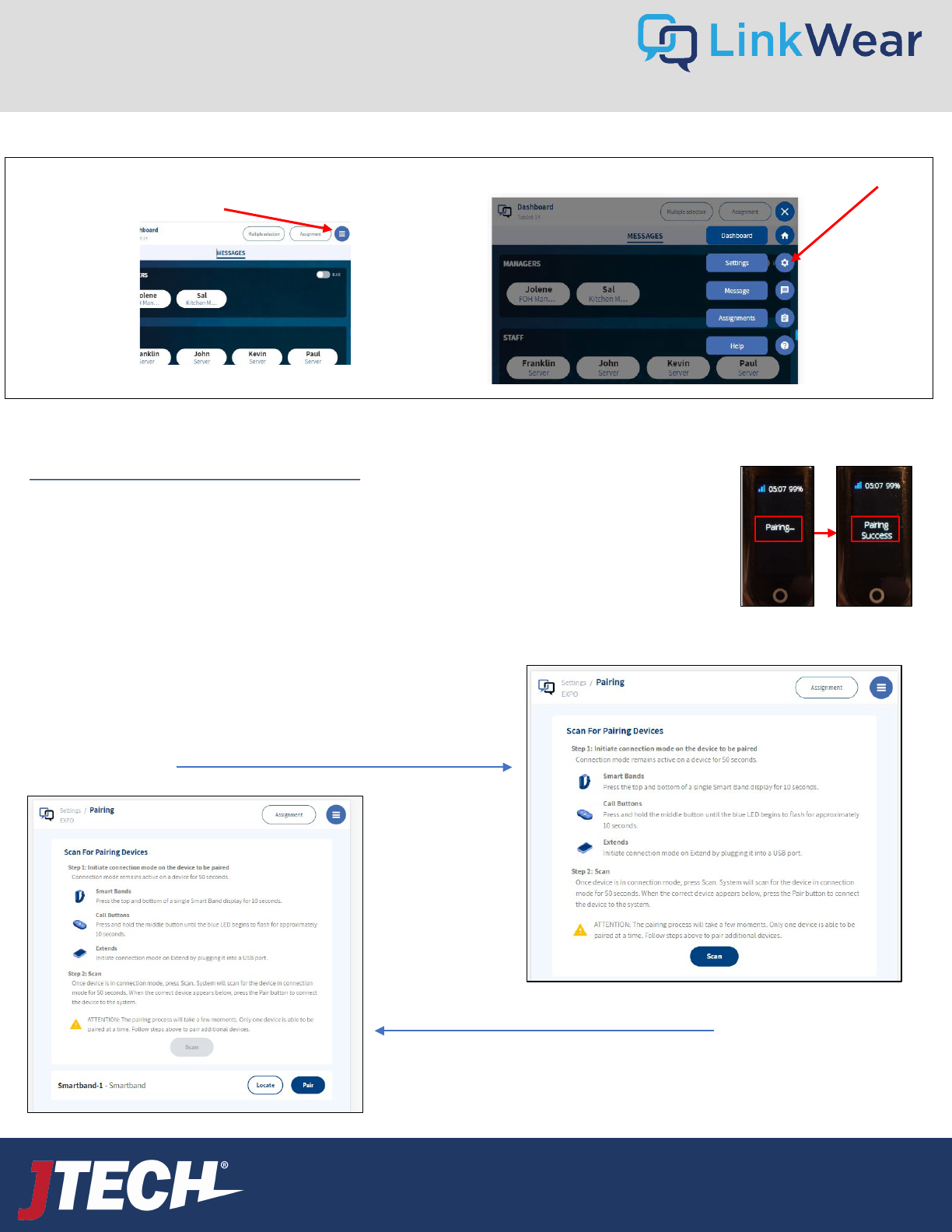
When adding additional equipment (Smart Bands / Call Buttons / Extenders) to the LinkWear System, each device needs to be paired via
the Hub.
Pairing the Smart Bands via NFC (preferred) Pair one device at a time.
1. Ensure that the Hub is plugged in, and the blue light is flashing.
2. Hamburger Stack Settings Pairing
3. Touch the Smart Band to the center of the Hub, a beep will sound, a green light will show on the
Hub and the Smart Band will display Pairing.
4. The Smart Band will display Pairing Success once finished and will appear under the Smart Bands
Active tab on the Tablet under Full Device List.
5. Repeat steps 3-4 for each Smart Band.
Settings – Pairing Devices
21
Pairing the Smart Bands, Extenders Over the Air – OPTIONAL
You need to put each device into pairing mode just prior to pairing
by tapping and holding for 12 seconds the 2 little circles.
After releasing it, the display will show “Connection Mode”.
Once the device is in Connection mode, tap SCAN. (Figure 1)
The item will show up. Now press PAIR. (Figure 2)
A Smart Band will show pairing and then pairing success.
Pressing Locate will cause the brain to vibrate.
To update any pre-set programming to the LinkWear system, select the Hamburger Stack icon (“Settings”) at the right- side of the tablet screen
on the hamburger menu.
User Guide
wecare@JTECH.com
800.321.6221
User Guide
wecare@JTECH.com
800.321.6221
Settings – Pairing Devices Cont.
22
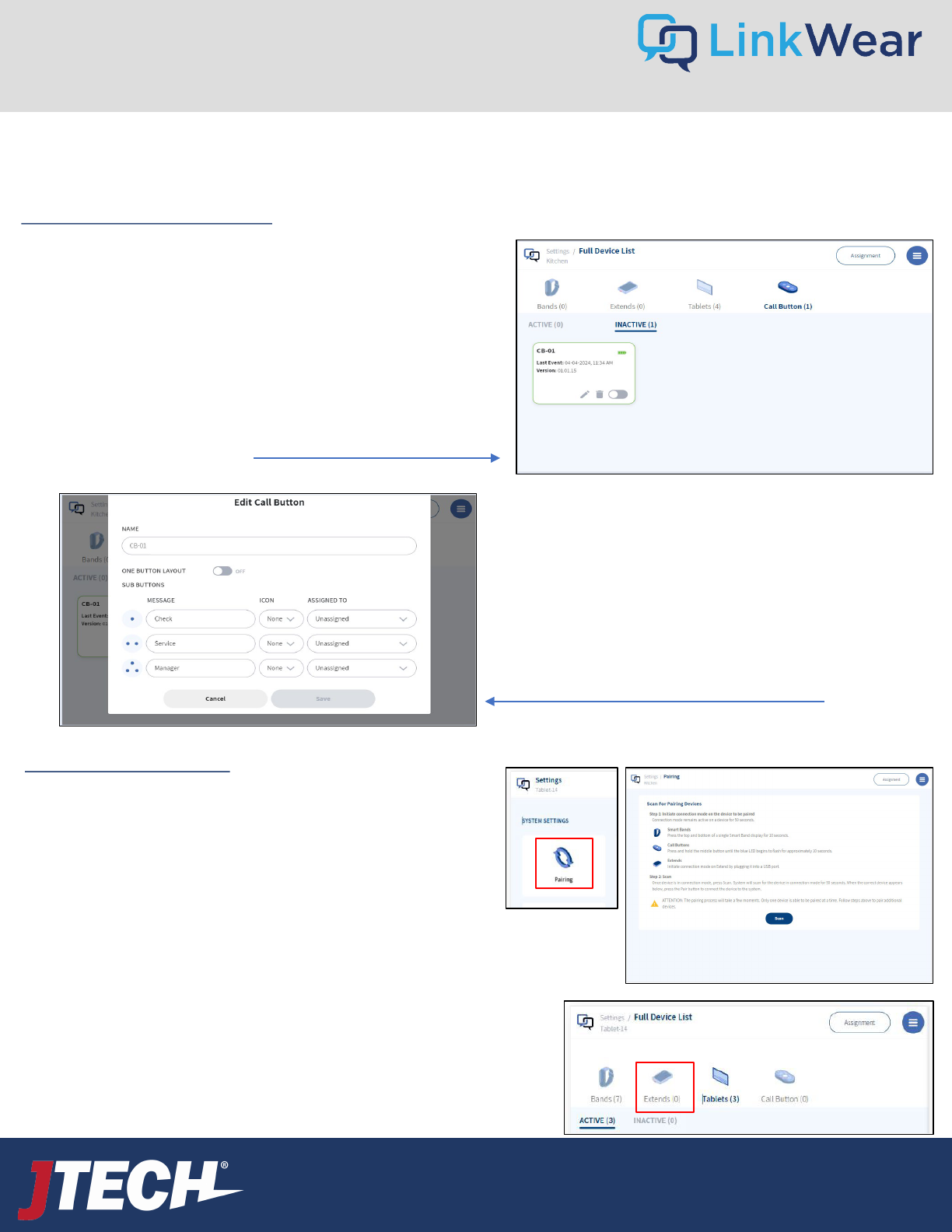
When adding additional equipment (Smart Bands / Call Buttons) to the LinkWear System each device needs to be paired via the Hub.
Pairing the Call Button(s) via NFC
1. Ensure that the Hub is plugged in, and the blue light is flashing.
2. Hamburger Stack Settings Full Device List Call Button
Inactive
3. Touch the Call Button to the center of the Hub, you will hear a
beep and see a green light on the Hub. The Call Button should
start flashing Blue.
4. The Screen will display Pairing Success once finished and
will appear under Inactive tab.
5. Do NOT pair the Next Call Buton until the Name and
Assignments are complete for each. Tap the pencil to Edit the device .
Click the pencil icon to edit (Figure 2)
6. In the Name Box, type the desired name.
For example: Table a, Bar 25, Office, etc.
7. Enter the desired message fore each of the buttons.
8. Select desired Icon to show when sending the message.
9. Select the designated Roll that is intended to receive the
message from that button.
10. Tap SAVE to save the configuration. (It will now show
under the Active tab).
11. Repeat Steps 3-10 to pair and assign the next device.
Pairing Extend(s) for Range
When determining a location for an Extend, ensure it is in the Good
coverage (Full bars) area not in an area where the range has become
poor (1 bar).
It is Recommended that a Range test is conducted to know the blind spots.
To pair the Extend(s) to the Hub, follow the procedures below:
1. On the tablet, tap Settings then tap Pairing.
2. Plug the Extend into an outlet near the Hub, it should start blinking
Blue, Tap Scan within the 30 seconds after plugging in the extend.
3. When you see the extend show on the Tablet, tap the pairing button.
4. Once paired, the Extend will appear on the Extends section under Full
Device List.
5. Repeat steps 2-3 for each Extend.
User Guide
wecare@JTECH.com
800.321.6221
User Guide
wecare@JTECH.com
800.321.6221
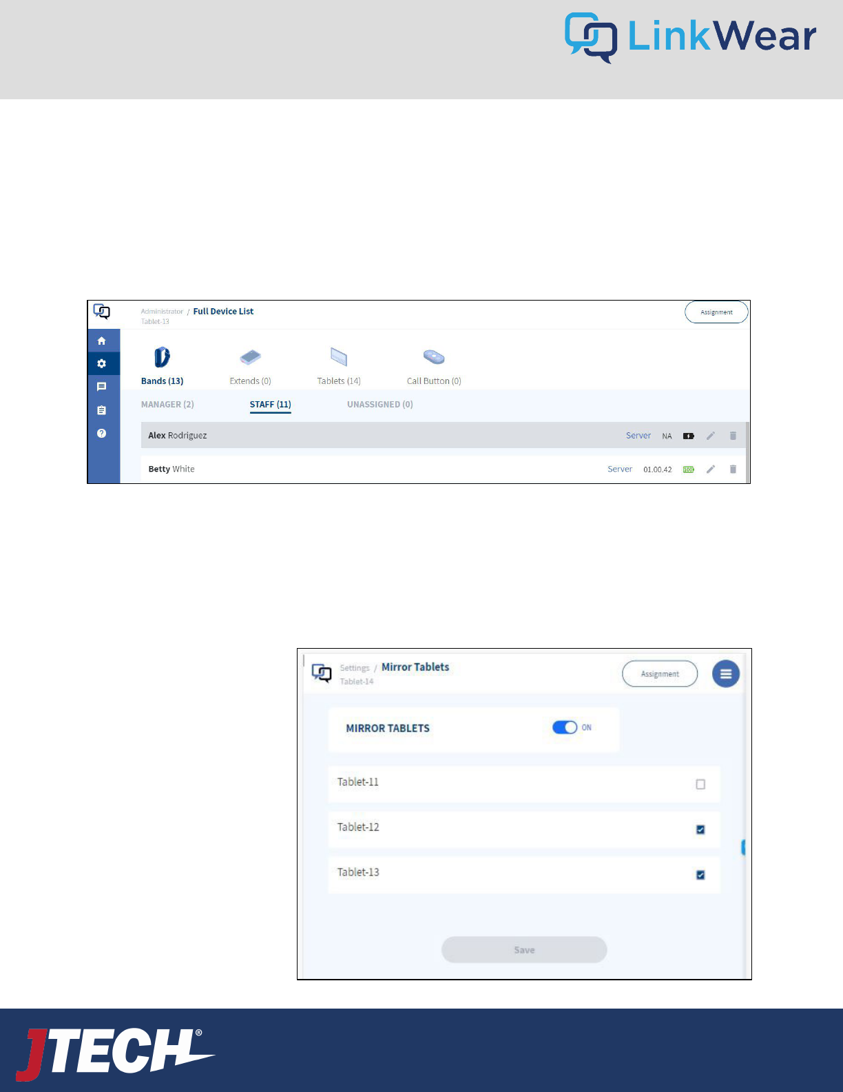
Mirror Tablets
Mirror Tablets allows you to have 2 tablets display the exact same information - one will mirror all the actions of the
other. This is typically used when accessing the tablets from different locations but communicating with the same staff
members. For example, you may have a tablet facing the cook line for the chef, and another facing the expediter line
facing the runners or server staff. The chef can call for the server when they put the food in the window and the server
can cancel the alert after they pick it up. Note: You can only mirror two tablets at a time.
To turn on Tablet Mirroring:
1. Navigate to Setting
2. Mirror Tablets
3. Mirror Tablets Toggle On
Full Device list
The Full device list can be accessed under the Settings Tab on the left of the screen. Click on “Full Device List” to open it.
The Full Device List will show a snapshot of all devices on the system. Bands, Extends, Tablets & Call Buttons. It will also show
which bands are Assigned or Unassigned as well as which of the other devices are active or inactive.
To edit a device, navigate to it and click on the pencil. There you can edit, name and delete devices. To delete a device, click on
the trash can.
Settings – Full Device List and Tablet Mirroring
23
User Guide
wecare@JTECH.com
800.321.6221
User Guide
wecare@JTECH.com
800.321.6221
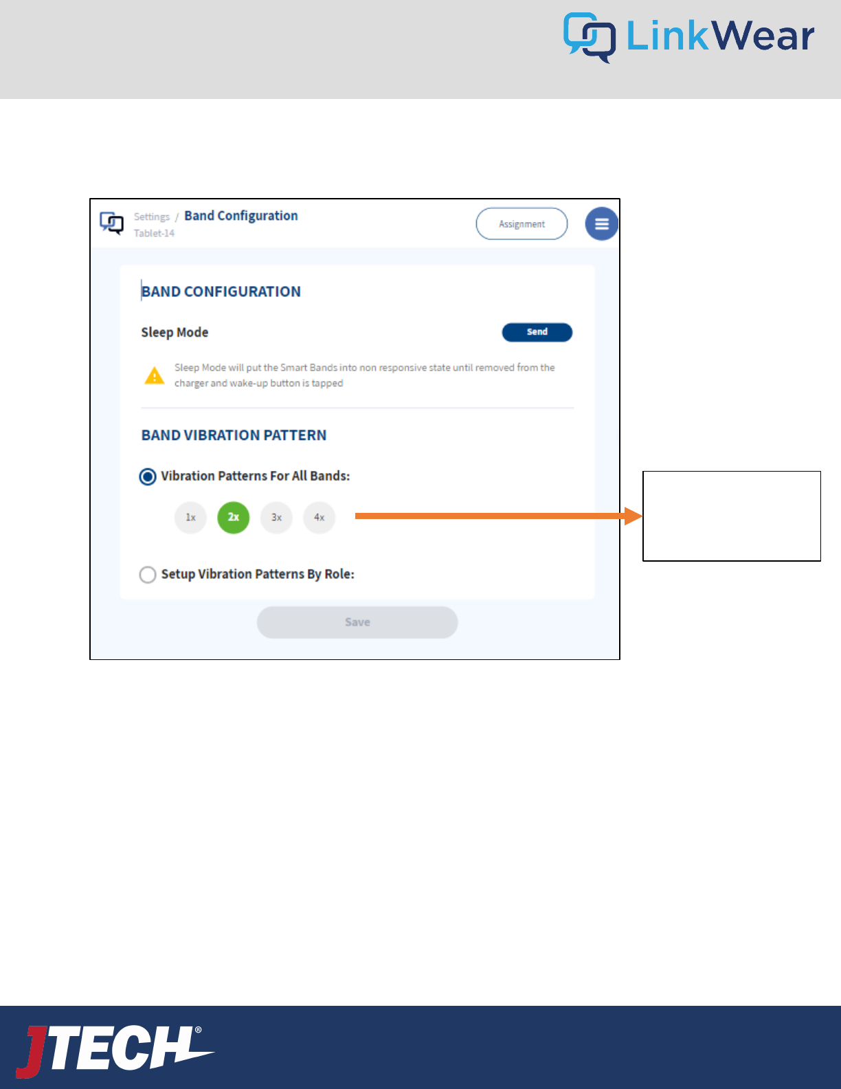
> Set smart band vibration pattern
Settings – Band Configuration
Refers to vibration cycles on
the Smart Band.
Each vibration cycle consists
of 4 short pulses.
Vibration cycles work like this:
1x - The alert will have 1 cycle that lasts for 4 small pulses.
2x - The alert will have 2 cycles of 4 small pulses each
(8 in total).
3x - The alert will have 3 cycles of 4 small pulses each
(12 in total).
4x - The alert will have 4 cycles of 4 small pulses each
(16 in total).
The default vibration cycle is 3. Choose the vibration cycle that works best for your team.
24
User Guide
wecare@JTECH.com
800.321.6221
User Guide
wecare@JTECH.com
800.321.6221
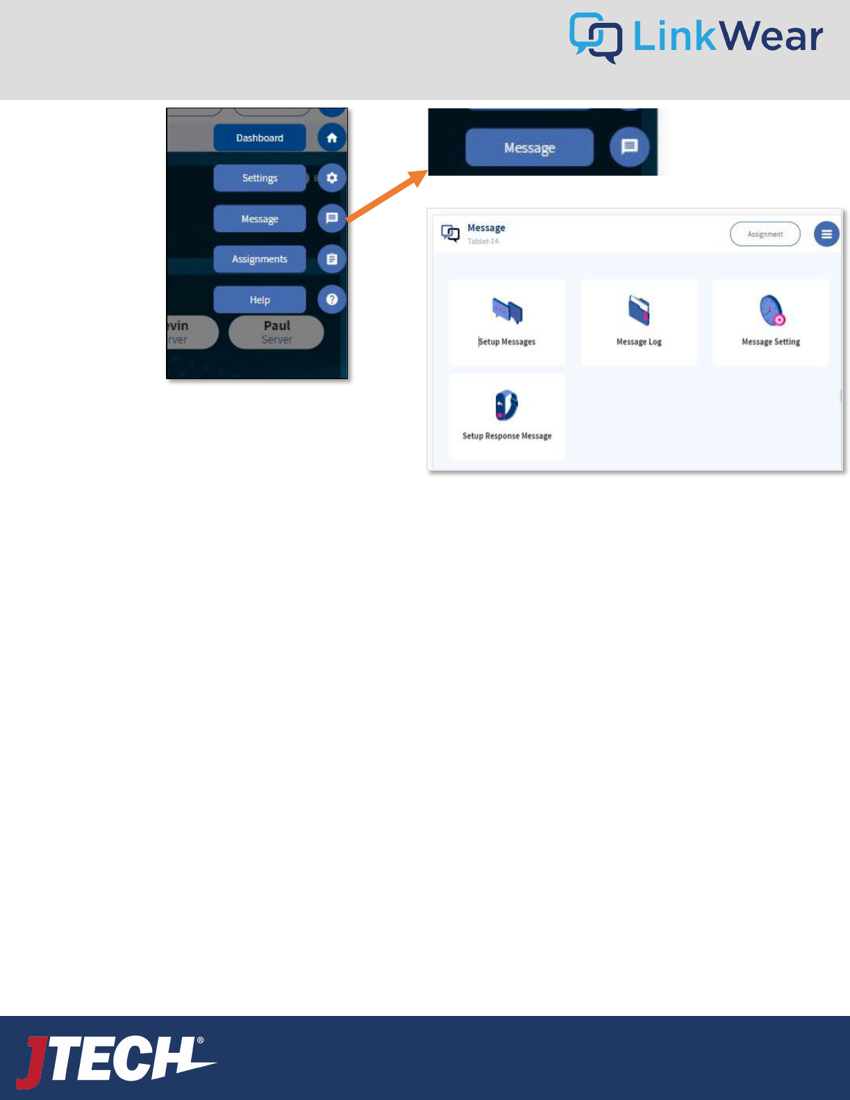
Setup Messages Define default messages and icons.
Message Log Log of all messages sent, recipient, status, etc.
Message Setting Transition setting for manager notification.
Setup Response Message Coming Soon
Message
Menu
25
1. On the Tablet, tap Message on the left column.
2. Tap Setup Message.
3. Tap Create Message in the top right corner, then enter the desired message and select an icon.
4. After you have typed in the message, you can define it as a Default or Predefined message.
a. The Default message will automatically be sent when an employee’s name is tapped on the Tablet
dashboard.
b. Predefined messages display when an employee’s name is held down for 3 seconds, providing a list of
custom messages to select from.
5. Once the type of message has been entered and defined, tap Save and repeat steps 3-4 to add more messages.
Creating Messages
All systems are prepopulated with default roles that can be edited.
Message – Creating Messages
User Guide
wecare@JTECH.com
800.321.6221
User Guide
wecare@JTECH.com
800.321.6221
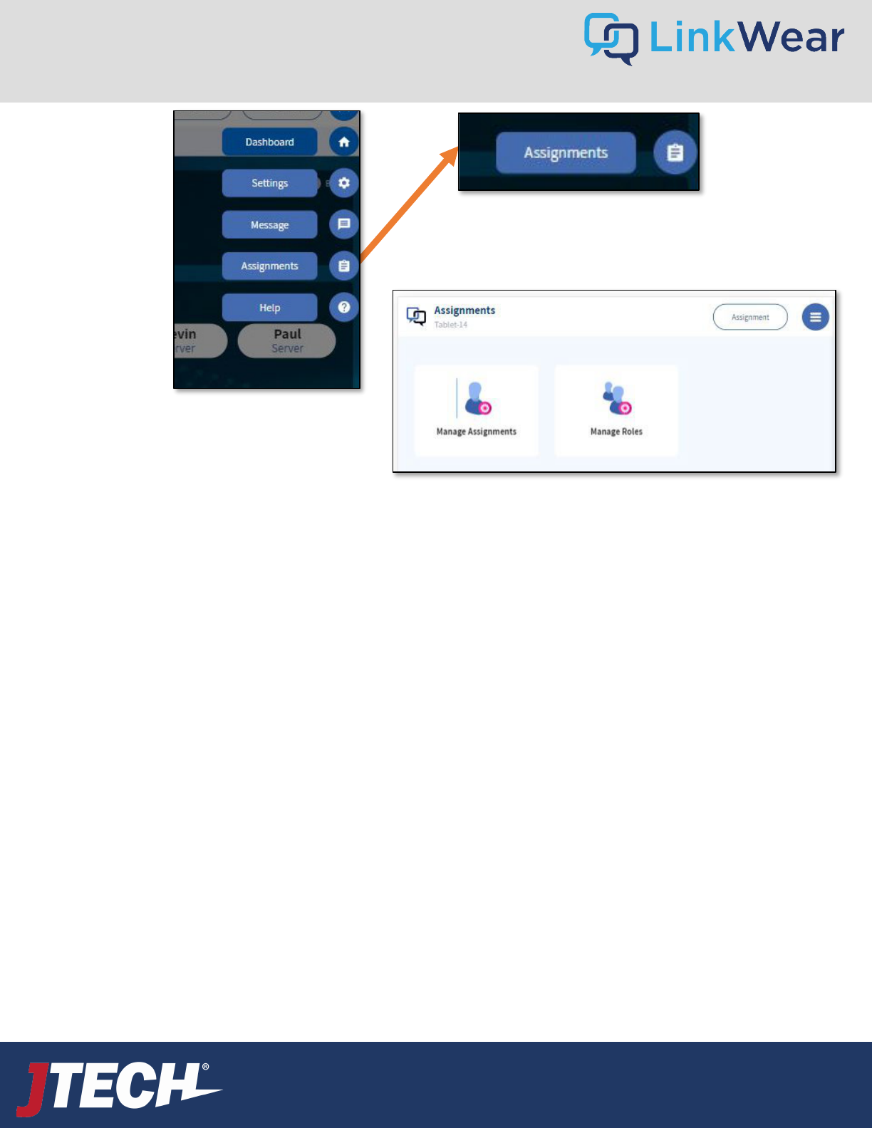
Manage Assignments Manage users and assign roles.
Manage Roles Define the roles of managers and staff.
Assignments
Menu
26
User Guide
wecare@JTECH.com
800.321.6221
User Guide
wecare@JTECH.com
800.321.6221
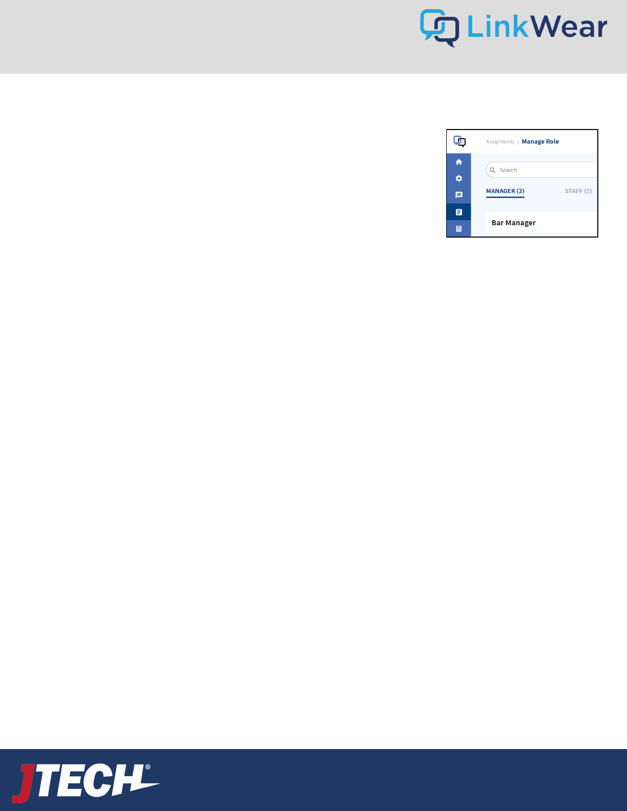
Creating Roles
All systems are prepopulated with default roles that can be edited.
1. On the Tablet, tap Assignments on the left column.
2. Tap Manage Role.
3. At the top of the screen, tap STAFF then tap Create Role.
4. Enter the name of the desired role, tap Save. Repeat until you have created all
the staff roles.
5. Once you have created all the STAFF roles, tap MANAGER then tap
Create Role.
6. Enter the name of the desired manager role, then tap on all the staff roles that
report to that manager role and Save. Repeat until you have created all the
manager roles.
Assignments – Creating Roles
27
User Guide
wecare@JTECH.com
800.321.6221
User Guide
wecare@JTECH.com
800.321.6221
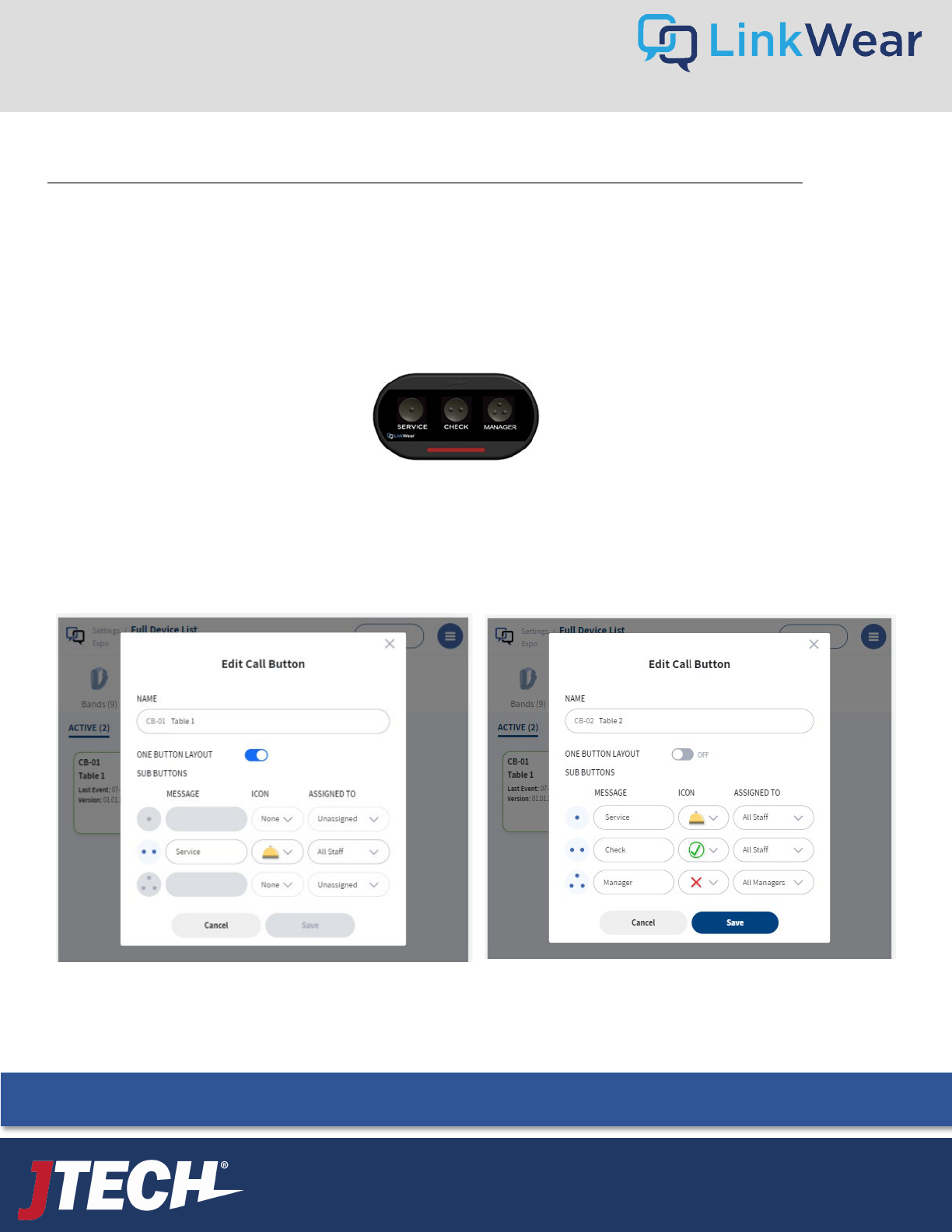
If ordered, your Call Buttons will arrive already paired to your system, programmed, and labeled as per your instructions. Each Call Button
will be assigned to the requested role. Place each call button in the assigned areas. To send a message to a smart band, simply press any
button to alert the associated Smart Band.
To assign a call button(s) to an individual recipient select the call button while assigning a smart band to a staff member/manager.
Note: If no individual is assigned to a specific call button, the message will be received by all staff members/managers within that role
assignment.
Optional Call Buttons
Call Button Programming
Call Buttons are pre-programmed to your specifications prior to shipping. The end user can also edit this programming on site.
Hamburger Stack Settings Full Device List Call Button Active Click the pencil icon to edit
Here you can change the button name, message sent, Icon preferred, and staff members assigned to.
When finished programming click SAVE and repeat for each Call Button.
28
Batteries are user replaceable by removing the 6 small screws on the back of each unit.
We recommend the use of High-Quality AAA Alkaline or Lithium Batteries.
User Guide
wecare@JTECH.com
800.321.6221
User Guide
wecare@JTECH.com
800.321.6221
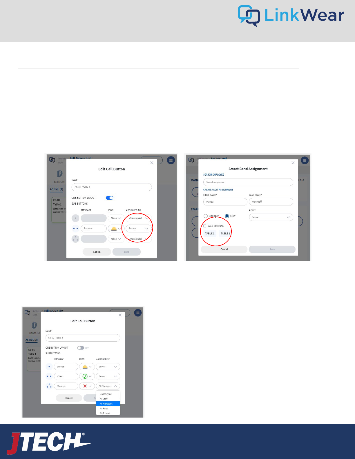
Assigning Call Buttons to Employees
When assigning a staff member to a Smart Band, you can also assign them tables from their station. This identifies the servers’ tables for
each shift and routes messages only to that server.
*Call buttons need to be set up with the appropriate role prior to being able to assign them. i.e. Server (fig. 1)
When assigning the Smart Band, you will see the available Call Buttons. Simply click the call buttons you want to assign to that server and
SAVE. The server will now see all messages from those Call Buttons. (fig. 2)
*Note: Clicking the Call Buttons Box will assign or unassign any selected Call Buttons.
Optional Call Buttons Continued
To route messages to a group i.e. All Managers, select the proper role from the drop-down menu. In the example below, when the
manager button is pressed, all Smart Bands with the role of Manager will receive the message.
When the Service or Check button is pressed, the message will go to all servers UNLESS a server has already assigned Call Buttons to
their Smart Bands. This feature keeps messages from being missed if someone is sat in a closed station.
At the end of each person’s shift, they should either place their Brain in
the charger (which deletes the assignment along with any assigned table
Call Buttons) or manually unselect their tables from the assignment tab
so messages are routed to the remaining staff.
Fig. 1 Fig. 2
29
User Guide
wecare@JTECH.com
800.321.6221
User Guide
wecare@JTECH.com
800.321.6221
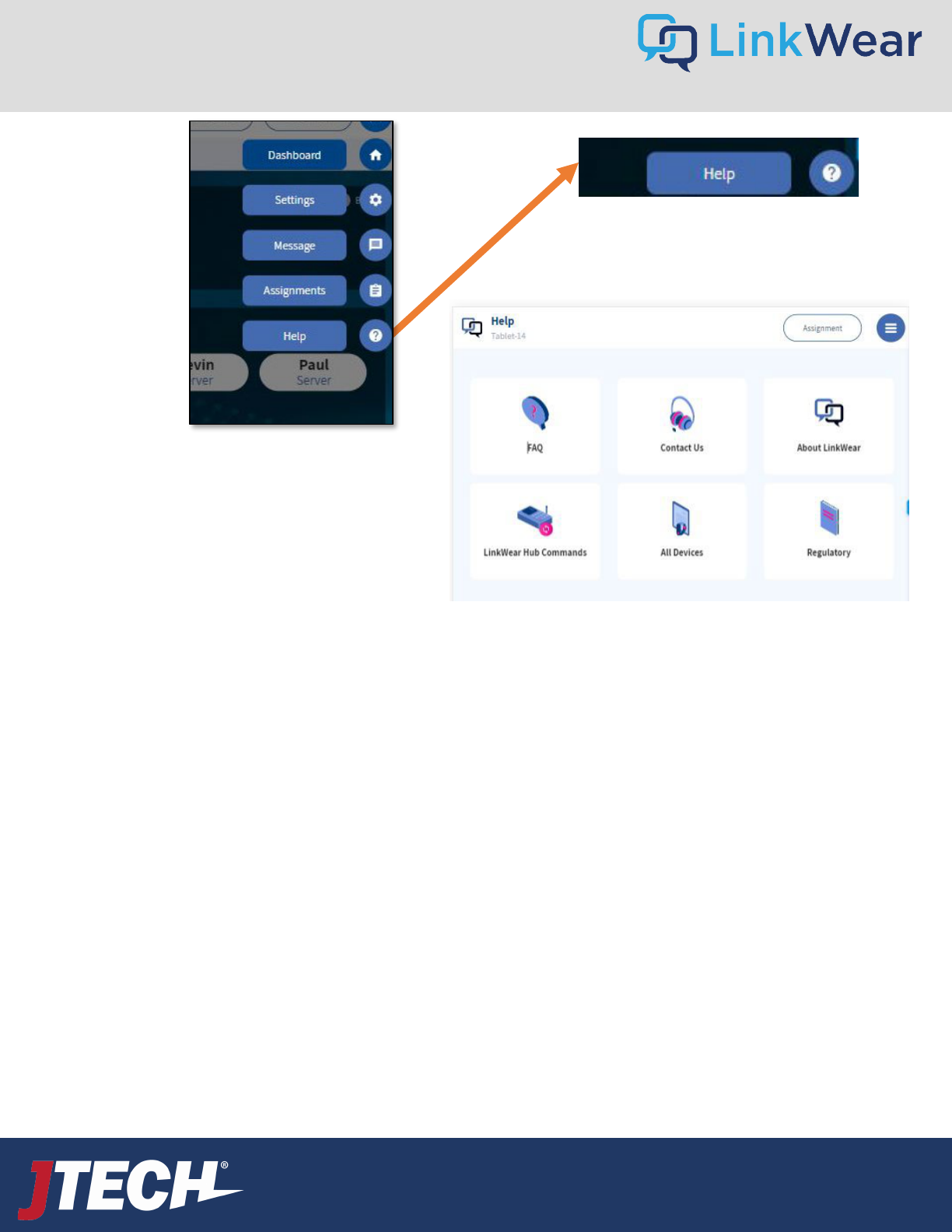
FAQ Frequently asked questions
Contact Us How to contact JTECH
About LinkWear Information about this LinkWear installation
LinkWear Hub Commands Technical commands for LinkWear Hub
All Devices A list of all devices and the associated technical information.
Regulatory FCC Regulatory Information
Help
Menu
30
User Guide
wecare@JTECH.com
800.321.6221
User Guide
wecare@JTECH.com
800.321.6221
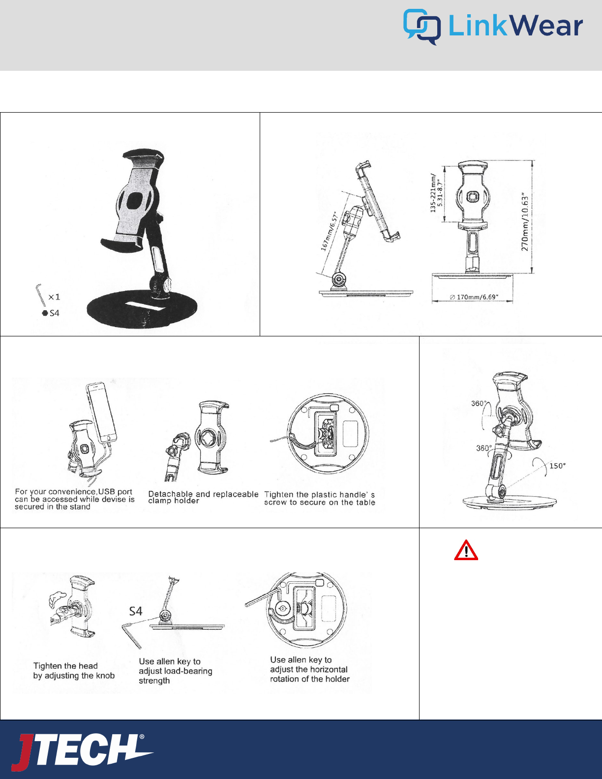
Product Contents Dimensions
Use and Maintenance Features
Tension Adjustment
CAUTION
1. Do no exceed 1kg
2. Not intended for children
3. Attach base to dry, clean, flat surface
4. Any misuse, disassembly or
modification voids all warranties
Tablet Mounts - Desk
32
User Guide
wecare@JTECH.com
800.321.6221
User Guide
wecare@JTECH.com
800.321.6221
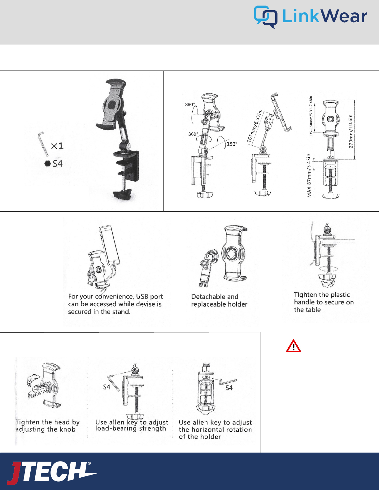
Product Contents Product Features and Dimensions
Tension Adjustment
CAUTION
1. Do no exceed 1kg
2. Not intended for children
3. Attach base to dry, clean, flat surface
4. Any misuse, disassembly or
modification voids all warranties
Use and Maintenance
Tablet Mounts - Line
33
User Guide
wecare@JTECH.com
800.321.6221
User Guide
wecare@JTECH.com
800.321.6221
Legacy Guest Paging
34
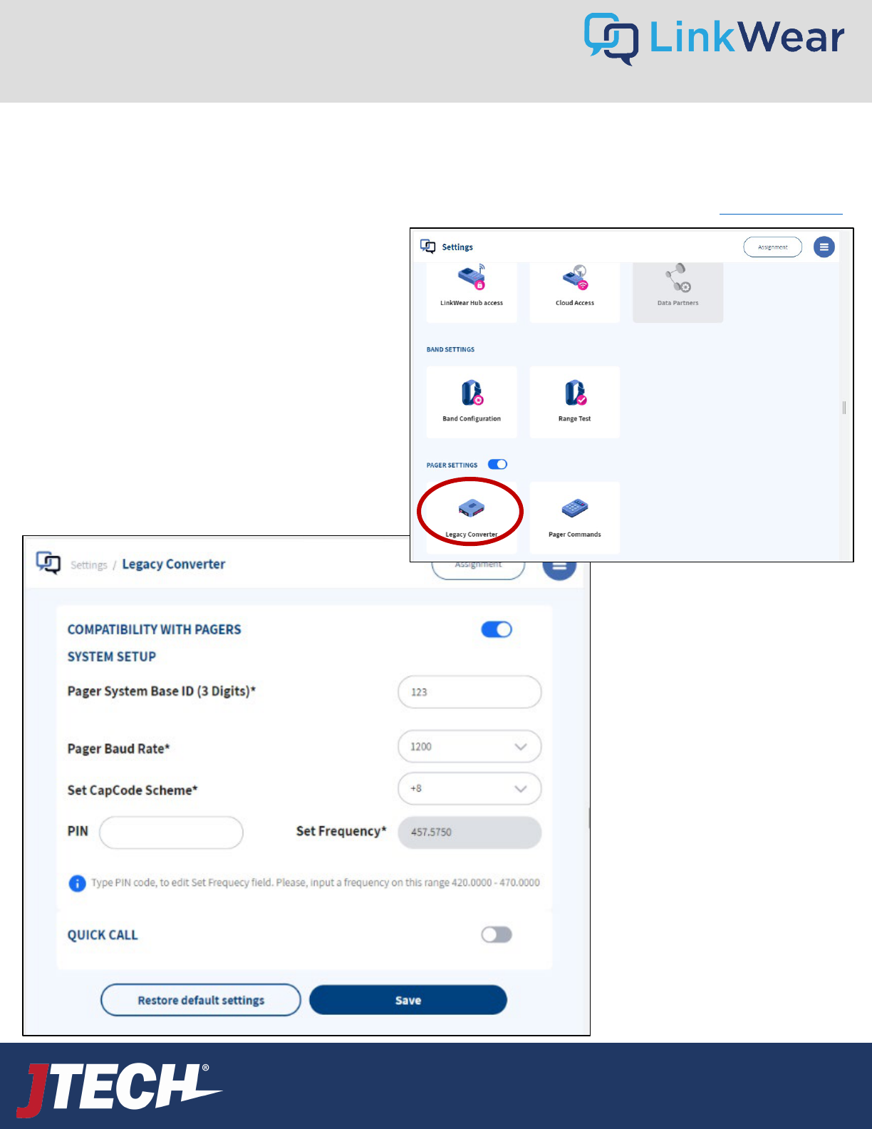
The LinkWear system can alert traditional JTECH Guest Pagers. Should you wish to take advantage of this functionality, you need to
have a LinkWear system Hub that includes a “Legacy Pager Module”. Check under settings to see if the pager settings toggle will
turn on. If it does, you are able to page guest pagers. To upgrade to this Hub please call your sales rep or email weca[email protected]
.
Note:
Do not alter these settings
without direction from JTECH
support.
The system frequency can
only be changed by a JTECH
technician in order to comply
with various regulatory
agencies.
The dashboard of your LinkWear tablet is where you
will find the interface and all the settings.
Click the Hamburger Stack Settings
Legacy Converter.
Here you will find the settings that need to
match your JTECH paging system. This will be
preprogrammed at the factory for you. *Note-
this is where you turn on the QuickCall paging
option (more to come on that later).
User Guide
wecare@JTECH.com
800.321.6221
User Guide
wecare@JTECH.com
800.321.6221
Legacy Guest Paging - Commands
35
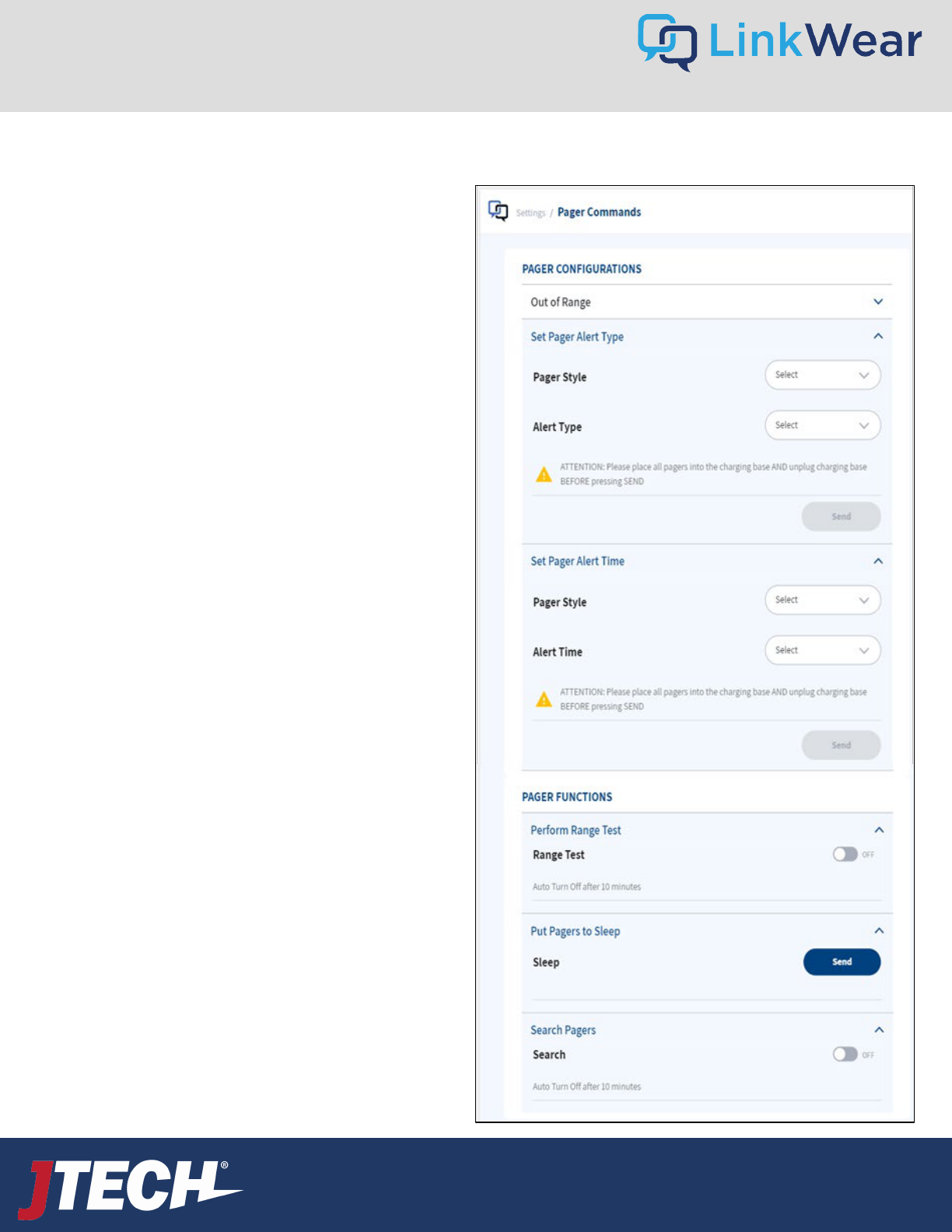
To program the settings on your guest pagers through the
LinkWear system:
From the Hamburger Stack Settings Pager Commands
Here you can customize all your settings and run certain
functions, for example:
• Out of Range – On or Off
• Pager Style – Numeric or Alpha
• Alert Type
• Vibe only
• Flash & Beep
• Vibe and Flash, etc.
• Pager Alert Time (how long the device alerts for)
• 8 seconds
• 15 seconds
• 30 seconds
• 60 seconds
• 120 seconds
• Perform a Range Test
• Put the Pagers to Sleep (for quiet travel!)
• Search for Missing Pagers
User Guide
wecare@JTECH.com
800.321.6221
User Guide
wecare@JTECH.com
800.321.6221
Legacy Guest Paging – Pager User Interface
36
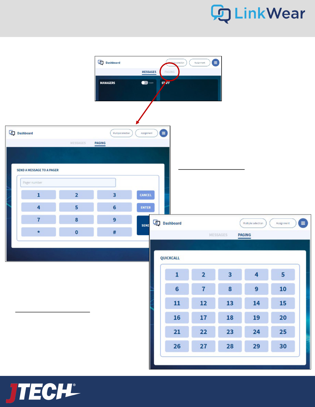
You access the interface under paging on the
dashboard
You have two options to use when paging JTECH Guest
Pagers:
10 Key Pager Interface
This is the default setting. The 10 key interface allows
the operator to enter any pager number followed by
the send key to send a message
QuickCall Pager Interface
The QuickCall interface show all the pager numbers (within
your range up to 60 total) on one screen for a quick direct
press and faster messaging.
①
②
User Guide
wecare@JTECH.com
800.321.6221
User Guide
wecare@JTECH.com
800.321.6221
Legacy Guest Paging – Setting Up QuickCall Pager Number Range
37
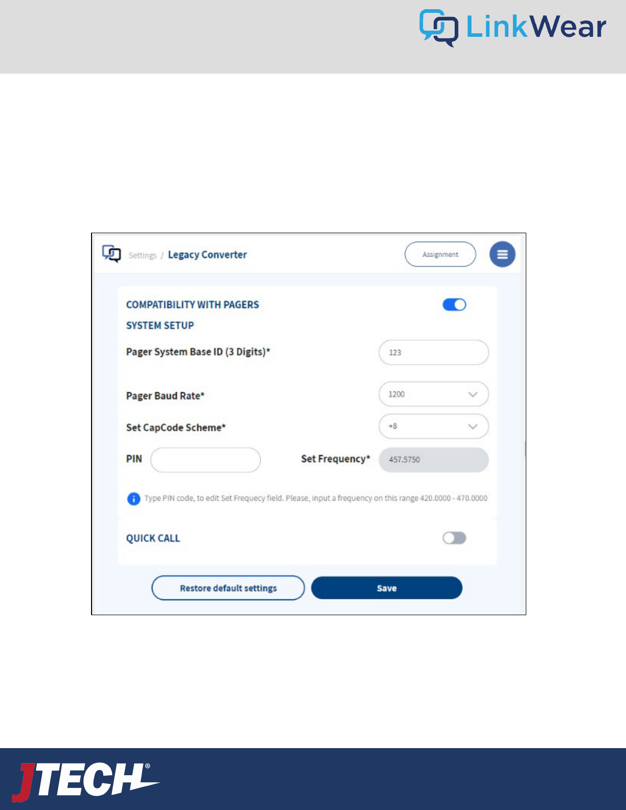
From the Hamburger Stack Settings Legacy Converter
1. To turn QuickCall on or off use the toggle switch.
2. Once turned on, enter the number of Guest Pagers you are using.
3. Enter the starting pager number.
*Pagers should be programmed sequentially i.e. 1-30
User Guide
wecare@JTECH.com
800.321.6221
Tightly connect the 2 antennas to the Hub by screwing them on by hand. Antennas should
always point UP.
Mount the Hub on a flat surface, in a cool, dry, metal
free, central location in the middle of your building. The ideal height for
mounting the hub is above 8’. Plug the power supply into a standard 110-240v outlet and then into the Hub. When plugged in a
red light will show, followed by a flashing blue light after 1 minute to indicate ready status. Ensure all antennas are pointed up.
STEP 1 Attach Antennas
STEP 2 Hub Mount/Power
Plug the power supply into a standard 110-240v outlet and then into the Charger.
Ensure that the switch is turned to ON, a red light will show next to power. Store in a
cool, dry & safe place (like the office).
STEP 3 Brain Charger Setup
Insert all Brains (removed from the band) into the Charger and charge for 4 hours. All Brains must be
inserted as shown or they will not charge. Display will read “Charging” when inserted properly. Brains stay
in charger when not in use.
STEP 4 Charge LW Brains
Quick Start Guide
38
User Guide
wecare@JTECH.com
800.321.6221
Assemble the stand and place in the desired location. Mount the tablet. Plug the power supply
into a standard 110-240v outlet and then into the Tablet. Turn the Tablet on by pressing and
holding power button on the left side of tablet.
**Keep away from heat lamps**
STEP 5 Tablet Mount/Power
STEP 6 Connect Tablet to Hub
• Swipe down from the top of the screen.
• Press and hold the WiFi icon to open WiFi settings.
• Select your LinkWear Hub (ex. LinkWear 00xxx).
• Once connected press center home button.
• Tap the LW Dashboard icon. To start the application.
Note: This system uses WIFI but not the internet. The Hub creates its own
WIFI which the tablet connects to.
Perform a Range Test to ensure all areas of your location have coverage. To accurately test the range of your system you will need
your Hub, Tablet, and Smart Bands to be ON and charged.
1. Tap Settings and Range Test
2. Turn on the Range Test, then remove two Brains from the Charger and insert into bands.
3. Place one Smart Band on each wrist.
4. Every 15 seconds the Smart Bands will vibrate and show if the range is strong (4 green bars) or weak (1 red bar).
5. Walk the entire coverage area with the Smart Bands, noting areas that have poor coverage.
If both the Smart Bands received any level signal in your coverage area, move on to step 8. If there are areas where both bands
received weak and/or no alerts in the same area, you should add an Extend.
STEP 7 Range Test
Quick Start Guide 2
39
User Guide
wecare@JTECH.com
800.321.6221
STEP 9 Assigning Smart Bands
Assign Smart Bands at the beginning of each shift.
1. On the Tablet Settings, tap Assignment in the top right corner.
2. You will see a list of all paired Smart Bands (ex. SB-01). Tap your current
Smart Band to open the assignment window.
3. Tap Create or Edit Person. Enter the employee’s first and last name. Next,
choose staff or management and what role should be assigned to them.
If the employee has already been created, search their name by selecting
Search Person.
4. After entering the information, tap Save. The Smart Band will be displayed
under Manager or Staff – assigned to that employee.
5. Repeat steps 2-4 for all Smart Bands.
Note: Placing a Smart Band back into the charger will erase all messages and
takes the Smart Band off the LinkWear Dashboard.
STEP 10 Send Messages to Smart Bands
1. Hand out the assigned Smart Bands to each employee.
2. Navigate to the LinkWear Dashboard on your Tablet.
3. You will see a list of Smart Bands under manager and staff.
4. To send the default message, tap on the employee’s name.
5. To send a predefined message, hold on the employee’s name for 3 seconds and then release. A popup screen will list
all predefined messages. Tap on the message you want to send.
6. Tap “Multiple Selection” for custom messages and more message options.
Quick Start Guide 3
40

User Guide
wecare@JTECH.com
800.321.6221
User Guide
wecare@JTECH.com
800.321.6221
Due to the nature of the Polycarbonate materials used when manufacturing our products, it is
imperative that specific instructions are followed closely to ensure that JTECH products remain in
optimum condition.
The safest and MOST EFFECTIVE way to clean our products is to wipe them down
thoroughly with a damp cloth and allow them to air dry. Do not soak the products and let
them dry with chemicals on the plastics.
If disinfecting is required, the following are the only JTECH-approved solutions to be used:
1. Any product with no more than 5% Sodium Hypochlorite. This product can be found at
www.grainger.com. It is listed as Clorox Healthcare – Bleach Germicidal Cleaner. Item #
6VDE6. Similar products can be used.
2. Any product with no more than 30% Hydrogen Peroxide. This product can be found at
www.grainger.com. It is listed as Tough Guy Hydrogen Peroxide Cleaner. Item # 12M180.
Similar products can be used.
3. White Vinegar – Acetic Acid up to a 10% solution.
*Failure to adhere to these instructions can compromise the quality of JTECH Products. Using the
wrong cleaner / disinfectant may cause the plastic on JTECH products to weaken, crack and
become brittle.
Product Cleaning & Disinfecting
The Smart Band material is TPU, the same material most phone cases are made of. This is the recommended
sanitizing process:
Disinfecting a Smart Band
1.Soak part of a soft cloth in rubbing alcohol. Use rubbing alcohol or an alcohol-based sanitizer that's at least 70
percent alcohol.
2.Wipe the Smart Band down with the alcohol-soaked cloth.
3.Wipe off the rubbing alcohol with a dry, soft cloth.
4.Let the Smart Band air dry.
You can also wash the band in soapy water, rinse and let dry.
*Although the Brains are water resistant, we don’t recommend soaking them in water or any cleanser. Simply
wipe them with a damp cloth and let them air dry.
41

User Guide
wecare@JTECH.com
800.321.6221
User Guide
wecare@JTECH.com
800.321.6221
(Applies only to users in the United States)
Regulatory compliance
Applicant Name: JTECH Global Enterprises, Inc.
Applicant Address: 1965 Evergreen Parkway, Suite 300, Duluth, GA 30096, United States
Manufacturer Name: JTECH Global Enterprises, Inc.
Manufacturer Address: 1965 Evergreen Parkway, Suite 300, Duluth, GA 30096, United States
Country of Origin: USA
Brand: LinkWear
Caution: All products are compliant with regulatory requirements detailed in this document when
the user follows all installation instructions and operating conditions in
accordance with LinkWear System specifications
Caution: Use of accessories and peripherals other than those recommended by Smart band may void
the product's compliance as well as the user's authority to operate the equipment.
Caution: All products are designed for use with the standard, integral or dedicated (external)
antenna(s) that are shipped together with the equipment. Any product changes or modifications will
invalidate all applicable regulatory certifications and approvals.
Caution: The use of software or firmware not supported/provided by LinkWear products may result
that the equipment is no longer compliant with the regulatory requirements.
Warning: The power adaptor is the equipment´s disconnection device. The power outlet must be
located nearby the equipment and its access must be easy.
FCC Notice
This device complies with Part 15 of the FCC rules. Operation is subject to the following two
conditions: (1) This device may not cause harmful interference; and (2) This device must accept any
interference received, including interference that may cause undesired operation.
Note: This equipment has been tested and found to comply with the limits for a Class A digital device,
pursuant to Part 15 of the FCC rules. These limits are designed to provide reasonable protection
against harmful interference when the equipment is operated in a commercial environment. This
equipment generates, uses and can radiate radio frequency energy and, if not installed and used in
accordance with the instruction manual, may cause harmful interference to radio communication.
Operation of this equipment in a residential area is likely to cause harmful interference, in which case
the user will be required to correct the interference at his own expense.
Changes or modifications not expressly approved by JTECH An HME Company, could void the user’s
authority to operate this equipment.
User Restriction in the 5Ghz band: The device for the band 5150-5250MHz is only for indoor usage
to reduce potential for harmful interference to cochannel mobile satellite systems.
FCC/IC/EC RF exposure warning
This product complies with FCC/IC/EC radiation exposure limits set forth for an uncontrolled
LinkWear Regulatory Compliance
42

User Guide
wecare@JTECH.com
800.321.6221
User Guide
wecare@JTECH.com
800.321.6221
environment.
This product may not be co-located or operated in conjunction with any other antenna or
transmitter.
The Smart Band has been tested to comply with FCC/IC/EC RF Exposure requirements in body worn position.
Use of third-party clips or holsters with the Smart Band may not ensure compliance
with FCC/IC/EC RF exposure requirements and should be avoided.
To comply with FCC/IC/EC RF exposure requirements, the LinkWear Hub must be installed
and operated at least 20 cm (8 inches) from any person.
Australia compliance statement
User Restriction in the 5Ghz band: This device is restricted to indoor use only when operating in 5150-
5350MHz.
Until further notice, devices subject to this Section shall not be capable of transmitting in the band
5600-5650MHz, so that environmental weather radars operating in this band are protected.
New Zealand compliance statement
User Restriction in the 5Ghz band: This device is restricted to indoor use only when operating in 5150-
5250MHz.
European Union (CE mark)
The CE marking indicates compliance with the following directives and standards, whenever
applicable to the product in question.
Directives:
Radio Equipment Directive 2014/53/EU Electromagnetic
Compatibility Directive 2014/30/EU Low Voltage Directive
2014/35/EU
RoHS Directive 2011/65/EU and 2015/863/EU
Standards
EN55022/EN55032
EN55024/ EN55035
IEC/EN62368-1 EN300328
EN301893 EN301489
EN50581
Warning: This is a Class A product. In a domestic environment this product may cause radio
interference in which case the user may be required to take adequate measures.
Waste Electrical and Electronic Equipment (WEEE)
The European Union (EU) WEEE Directive (2012/19/EU) places an obligation on producers
(manufacturers, distributors and/or retailers) to take-back electronic products at the end of their
useful life. The WEEE Directive covers most LinkWear products being sold into the EU
LinkWear Regulatory Compliance 2
43
User Guide
wecare@JTECH.com
800.321.6221
User Guide
wecare@JTECH.com
800.321.6221
as of August 13, 2005. Manufacturers, distributors and retailers are obliged to finance the costs of recovery
from municipal collection points, reuse, and recycling of specified percentages per the WEEE requirements.
Instructions for Disposal of WEEE by Users in the European Union
The symbol shown below is on the product or on its packaging which indicates that this product was put on
the market after August 13, 2005 and must not be disposed of with other waste. Instead, it is the user’s
responsibility to dispose of the user’s waste equipment by handing it over to a designated collection point for
the recycling of WEEE. The separate collection and recycling of waste equipment at the time of disposal will
help to conserve
natural resources and ensure that it is recycled in a manner that protects human health and the environment.
For more information about where you can drop off your waste equipment for recycling, please contact your
local authority, your household waste disposal service or the seller from whom you purchased the product.
General Battery Safety Instructions
SAFETY PRECAUTIONS: To ensure the safety and reliability of your battery, follow the
guidelines in this section.
Using the Battery
WARNING! Do Not Abuse/Modify Battery Packs
Lithium-ion cells and battery packs may get hot, explode or ignite and cause serious injury if
modified or abused.
Follow the safety instructions below:
• Do not place the battery in fire or heat the battery.
• Do not connect the battery backward, so the polarity is reversed.
• Do not connect the positive terminal and negative terminal of the battery to each other
with any metal object (such as a wire).
• Do not carry or store the battery together with necklaces, hairpins, or other metal
objects.
• Do not pierce the battery with nails, strike the battery with a hammer, step on the
LinkWear Regulatory Compliance 3
44
User Guide
wecare@JTECH.com
800.321.6221
User Guide
wecare@JTECH.com
800.321.6221
battery or otherwise subject it to strong impacts to shocks.
• Do not solder directly onto the battery.
• Do not expose the battery to water or salt water or allow the battery to get wet.
• Do not disassemble or modify the battery. The battery contains safety and protection devices which, if
damaged, may cause the battery to generate heat, explode or ignite.
• The protection circuit module provided with battery packs is not to be used as a substitute for a shut
off switch.
• Do not place the battery in or near fire, on stoves or in other high temperature locations.
• Do not place the battery in direct sunlight or use or store the battery in cars in hot weather. Doing so may
cause the battery to generate heat, explode or ignite. Using the battery in this manner may also result in a
loss of performance or shortened life expectancy.
• When the battery is worn out, insulate the terminals with adhesive tape or a similar nonconducting material before
disposal.
• Immediately discontinue use of the battery if, while using, charging, or storing the battery, the battery emits an
unusual smell, feels hot, changes color or shape or appears abnormal in any other way.
• Do not place the battery in microwave ovens, high-pressure containers or on induction cookware.
In the event the battery leaks and the fluid gets into one’s eye, do not rub the eye. Rinse well with water and
immediately seek medical care. If left untreated, the battery fluid could cause damage to the eye.
If the device causes abnormal current to flow, it may cause the battery to become hot, explode, or ignite
causing serious injury.
LinkWear Regulatory Compliance 4
45

User Guide
wecare@JTECH.com
800.321.6221
User Guide
wecare@JTECH.com
800.321.6221
LinkWear Regulatory Compliance 5
46
One Button Call Button – Encloser contains one interface button
PMNS: LWCB00100
Three Button Call Button – Encloser contains three interface buttons
PMNS: LWCB00300
Hub
PMNS: LWTX00100
Hub with additional POCSAG Module
PMNS: LWTX00200
Extend:
PMNS: LWRP0010
Smart Band:
LWSB00100
US
Canada
EU
UK
AU & NZ
FCC
ISED
CE
UKCA
RCL
*LinkWear is compliant
in the following Areas:
ISED non-interference disclaimer
This device contains licence-exempt transmitter(s)/receiver(s) that comply with Innovation, Science and Economic
Development Canada’s licence-exempt RSS(s). Operation is subject to the following two conditions:
1. This device may not cause interference.
2. This device must accept any interference, including interference that may cause undesired operation of the device.
This device complies with the Canadian ICES-003 Class A specifications. CAN ICES-003(A) / NMB-003 (A).
L’émetteur/récepteur exempt de licence contenu dans le présent appareil est conforme aux CNR d’Innovation, Sciences et
Développement économique Canada applicables aux appareils radio exempt de licence. L’exploitation est autorisée aux deux
conditions suivantes :
1. L’appareil ne doit pas produire de brouillage;
2. L’appareil doit accepter tout brouillage radioélectrique subi, même si le brouillage est susceptible d’en compromettre le
fonctionnement.
Cet appareil numérique de la Canadian ICES-003. Cet appareil numérique de la classe A est conforme à la norme NMB-003 du
Canada.
RF Exposure statement
This equipment complies with ISED RSS-102 radiation exposure limits set forth for an uncontrolled environment. This
equipment should be installed and operated with minimum distance 20 cm (7.9 inches) between the radiator and any part of
your body. This transmitter must not be co-located or operating in conjunction with any other antenna or transmitter.
Cet équipement est conforme aux limites d’exposition aux radiations ISED CNR-102 établies pour un environnement non
contrôlé. Une distance de séparation d'au moins 20 cm doivent être maintenue entre l'antenne de cet appareil et toutes les
personnes. Lanceurs ou ne peuvent pas coexister cette antenne ou capteurs avec d’autres.