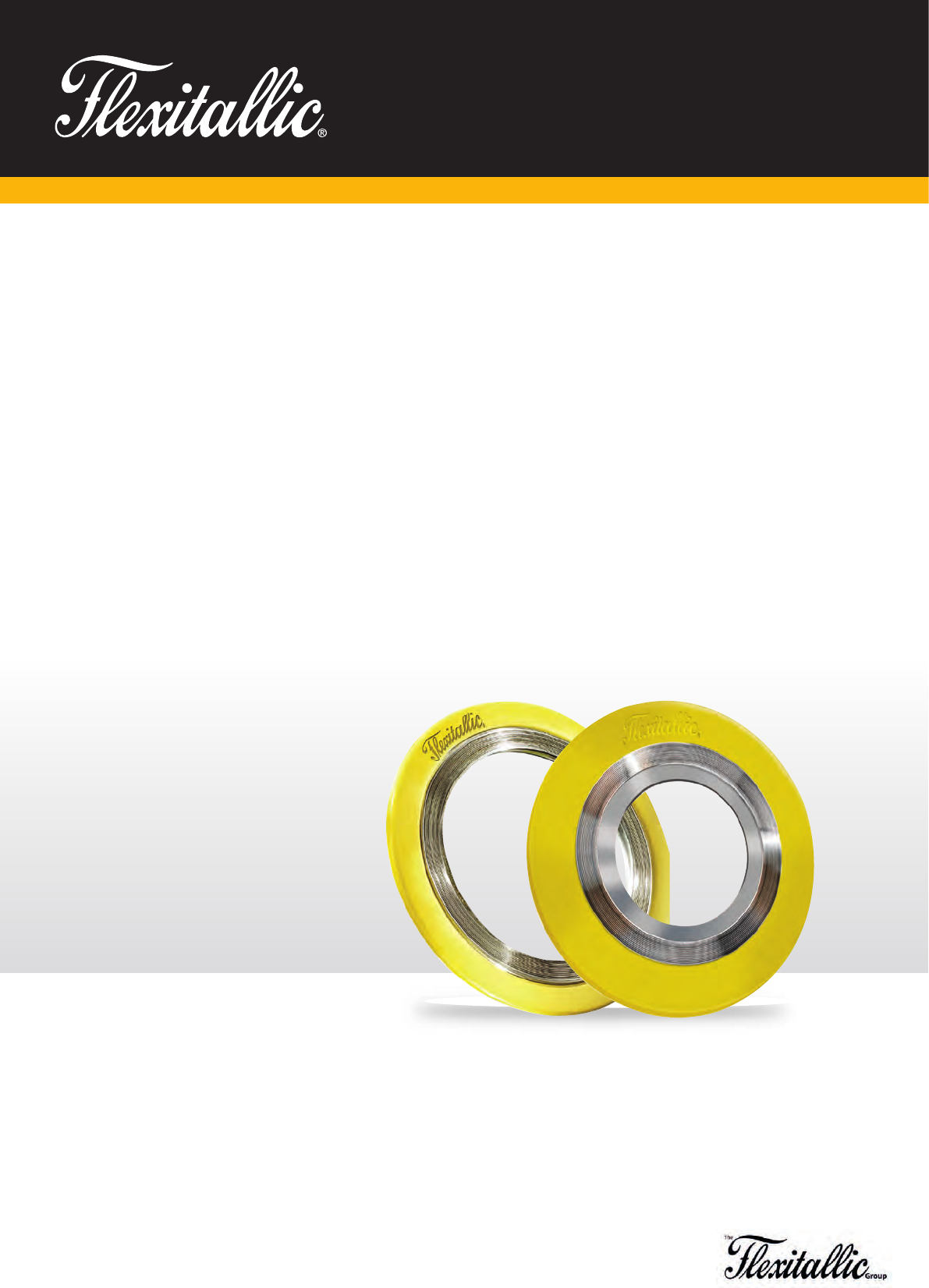
Driven by the industry's
need for safe, effective
sealing solutions,
Flexitallic invented the
spiral wound gasket.
SPIRAL WOUND
GASKETS
www.flexitallic.com

Our extensive and varied product
offering includes spiral wound gaskets,
RTJ gaskets, Flexpro
™
Kammprofiles,
sheet materials, dynamic and static
packings, pipe support and custom
rubber products. Drawing upon the
group’s rich history and present day
values of leadership, quality, service
and technology, we are at the forefront
of developing sealing solutions for
industries around the world.
In addition to a wide range of products,
we also deliver world-class technical
support and Joint Integrity training.
The Flexitallic Group is the international
market leader in the manufacture
and supply of high quality, high value
industrial static sealing products.
About us
As the developer of the spiral wound
gasket in 1912, we have built on this
legacy of innovation with revolutionary
products including Thermiculite
®
and
Sigma
®
, The Flange Rescue Gasket, and
most recently the Change
™
Gasket, set
to transform the global sealing industry.
We have a global network of Allied
Distributors across 30 countries. This
ensures local demand is met quickly,
providing a combination of the highest
product quality and outstanding
customer service.
FLEXITALLIC
Making the world safer and cleaner
through engineered sealing solutions.
Our Mission

1.
Based on sales and geographic reach, the Flexitallic Group
has become the global supplier of industrial gaskets.
Allied distributors
Inside Industry
We pride ourselves on not simply supplying
products, but by supporting customers with
a detailed knowledge of their industry and
applications, so that products and services
are tailored to their specific needs.
This unique approach means that we focus
on providing more than just a product, but
also a complete solution that adds genuine
value to our clients.
Global Distribution... Local Support
Our products are distributed through a
global network of Allied Distributors.
These carefully selected distribution partners
are strategically located within their territory
to deliver the best possible service and
products to our customers. This approach
means our products and know-how are
available to the global industries we service.
Innovative Product Range
We have a rich history of innovation,
which has seen us lead the industry
with many new products.
Over the years, our products have gained
a reputation for quality, reliability and
technology that is second to none.
Customised Engineering Solutions
Our Application Engineering, Production
Engineering and R&D teams work
closely together to design, develop and
manufacture bespoke sealing solutions.
We have been responsible for a number
of truly revolutionary products, including
Thermiculite
®
, Sigma
®
and the Flange
Rescue Gasket, which ensure we are
able to continually meet the ever more
stringent requirements of our customers.
Flexitallic
®
Safe
Over the last century, our aggressive
R&D efforts have helped customers
become Flexitallic
®
Safe. From the first
Spiral Wound Gasket in 1912 to the ever
evolving applications for Thermiculite
®
,
our goal is to develop materials that
push the parameters of heat, pressure
and chemical resistance.
Our Commitment to Quality
We place great emphasis on maintaining
international quality standards,
and are approved to ISO 9001:2008,
ISO 14001:2004 and OHSAS 18001:2007,
API 6A and API 17D, to ensure we meet
the highest possible standards for all
our products and services.
We also invest heavily in test and
quality assurance equipment to maintain
our reputation for the highest quality
products.
Our materials are subjected to a wide
range of tests as specified by statutory
regulations and customer requirements.
These approvals enable our customers
to make informed choices as to the
suitability of a product for each and
every application.

2. www.flexitallic.com
PAGE
INTRODUCTION 1
SPIRAL WOUND GASKETS 3
GASKET IDENTIFICATION 4
GASKET MATERIALS 5
GASKET SELECTION 6
STYLE CG & CGI GASKETS 7
DIMENSIONAL DATA 8
TECHNICAL INFORMATION 21
SPECIAL APPLICATION GASKETS 25
THE ACADEMY OF JOINT INTEGRITY 32
CONTENTS
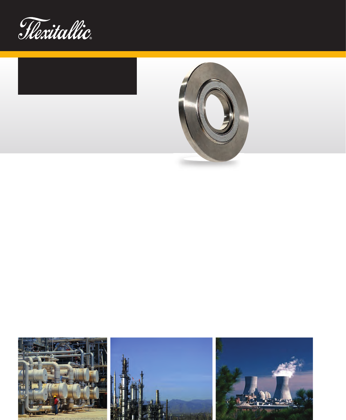
Driven by the industry’s
need for safe, effective
sealing solutions for
increasingly demanding
applications, Flexitallic
invented the spiral
wound gasket in 1912.
SPIRAL WOUND
GASKETS
First and Foremost
The concept of spiral wound gasket
construction was originated by Flexitallic
in 1912, starting a new era in safe,
effective sealing. The primary purpose
for this development was the increasingly
severe temperatures and pressures used
by U.S. refinery operators in the first half
of the 20th century.
The necessity for a gasket to have
the ability to recover cannot be over
emphasised. The effects of pressure
and temperature fluctuations, the
temperature differential across the
flange face, together with bolt stress
relaxation and creep, demand a gasket
with adequate flexibility and recovery
to maintain a seal even under these
varying service conditions. The Flexitallic
Spiral Wound Gasket is the precision
engineered solution to such problems,
meeting the most exacting conditions
of both temperature and pressure in
flanged joints and similar assemblies
and against virtually every known
corrosive and toxic media.
Metal Strip
Filler Material
3.
4. www.flexitallic.com
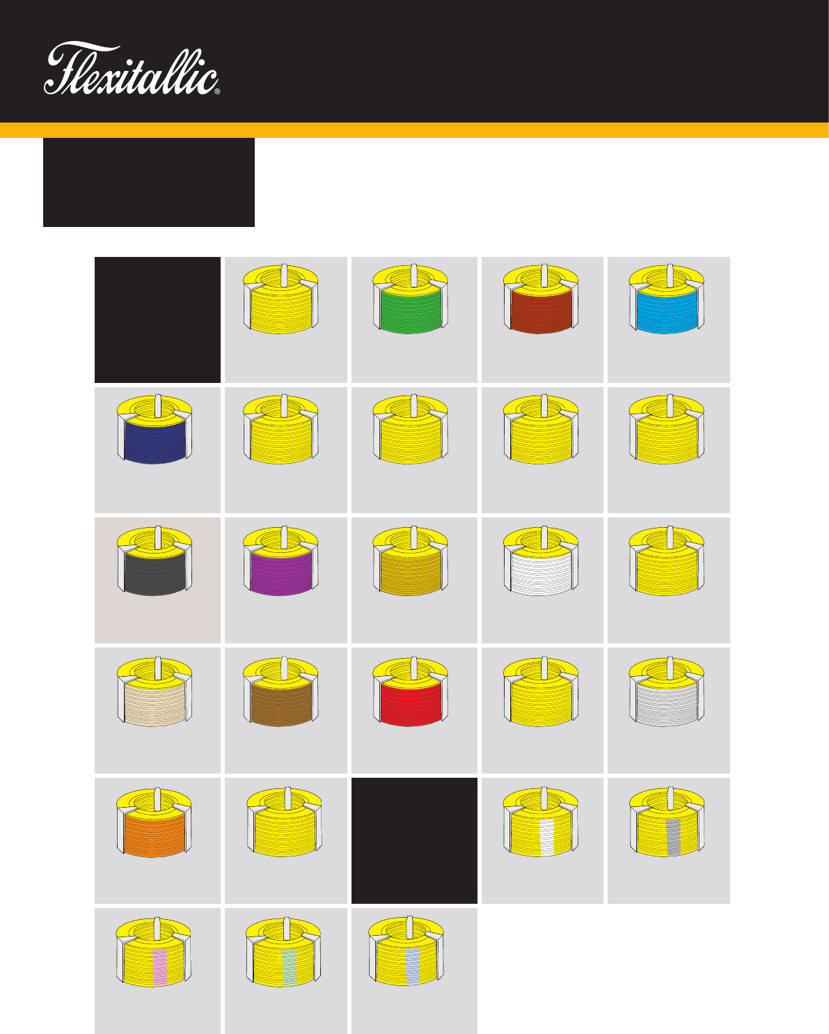
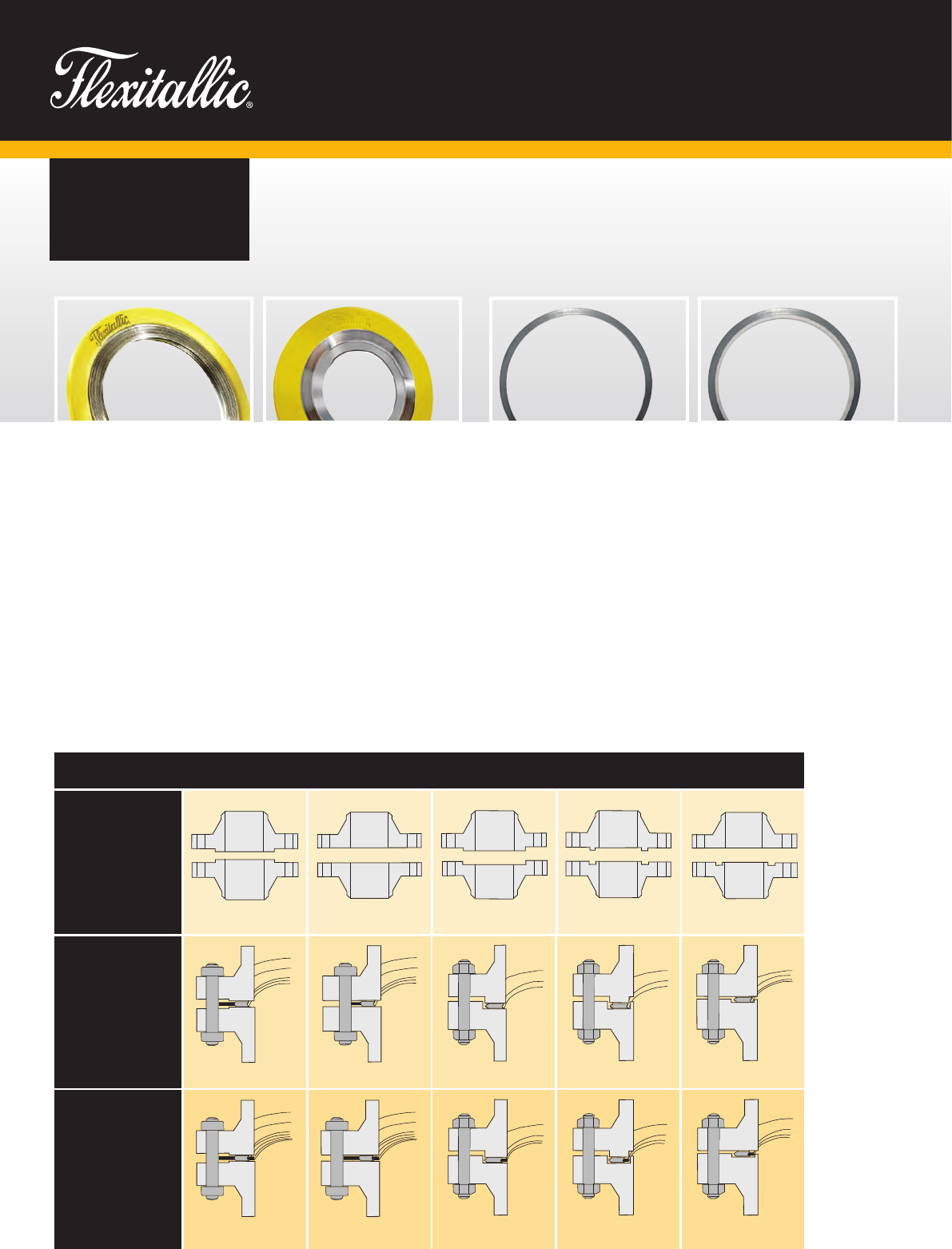
GASKET
IDENTIFICATION
Metallic Winding
Materials
The metallic winding
material is designated
by a solid colour
identification around
the outside edge of
the centering ring.
Non Metallic Fillers
The gasket filler
materials are designated
by a number of stripes
placed at equal intervals
around the outside edge
of the centering ring.
304SS
Yellow
347SS
Blue
321SS
Turquoise
316LSS
Green
304LSS
No colour
317L
Maroon
430SS
No colour
309SS
No colour
310SS
No colour
Titanium
®
Purple
Inconel
®
X750
No Colour
Incoloy
®
800/825
White
Inconel
®
600/625
Gold
Alloy 20
Black
Nickel 200
Red
Hastelloy
®
C276
Beige
Carbon Steel
Silver
Zirconium
No colour
Hastelloy
®
B2
Brown
Monel
®
Orange
Flexite Super
®
Pink Stripe
Flexicarb
®
Gray Stripe
PTFE
White Stripe
Ceramic
Light Green Stripe
Thermiculite
®
835
Light Blue Stripe
Duplex
No colour
Gaskets are colour coded to help expedite the selection and identity of the gaskets you need.
The colour on the outside edge of the centering ring identifies both the winding and filler materials.
The metallic winding material is designated by a solid colour. The filler materials are designated by
colour stripes at equal intervals on the outside edge of the centering ring. Flexitallic colour coding
meets the industry standard for metal and filler materials listed in ASME B16.20.
5.
GASKET
MATERIALS
NOTES
Figures stated are for information only. Please refer to the current version of the original standards for dimensional information.
Selected materials should be compatible with operating temperature and chemicals. If in doubt, contact Flexitallic Technical Department.
We recommend a max continuous operating temperature of 260
o
C, above this decomposition starts to occur slowly, increasing rapidly above 400
o
C (750
o
C)
IDENTIFICATION REQUIREMENTS
Stainless Steel 304
316L
OTHERS
Stainless Steel 304L
310
316Ti
317L
321
347
430
17-7PH
Alloy 20
Monel
®
Titanium
®
Nickel
®
200
Inconel
®
600
625
X-750
Hastelloy
®
B2
C276
Incoloy
®
800
825
Duplex
Zirconium
®
Tantalum
®
METAL WINDING STRIP AS STANDARD
Flexicarb
®
flexible graphite
Thermiculite
®
835
Flexite Super
®
PTFE
Ceramic
Non-sintered PTFE
Thermiculite
®
, FLEXITALLIC’S
proprietary high-temperature,
sealing material is comprised
of chemically exfoliated and
thermally exfoliated vermiculite.
This revolutionary patented
product simulates the structure
of exfoliated graphite but with one
notable exception... gaskets made
with Thermiculite
®
maintain their
integrity, even at extreme
temperatures.
Thermiculite
®
is thermally
stable, ensuring against thermal
oxidation, at temperatures in
excess of 1000
o
C
(Thermiculite
®
835).
FILLER MATERIAL
Carbon Steel
OTHERS
Stainless Steel 304
304L
316
316L
316Ti
310
321
347
410
Inconel
®
600
625
Monel
®
Titanium
®
Nickel
®
Incoloy
®
800
825
Alloy 20
Hastelloy
®
B2
C276
GUIDE RING MATERIAL AS STANDARD
6. www.flexitallic.com
GASKET
SELECTION
Style RIRStyle CGI
Raised Face Flat Face Male and Female
Tongue and Groove
Style CG Style R
Flat Face to Recess
Style CG
Style CGI
Style R Style R
Style RIR Style RIR
Flange Face
NOTES: Where style R gaskets are fitted it is essential that the flange is correctly dimensioned to provide a compression stop, as over compression can result in failure.
Recommended
Gasket Style
For general duties
Recommended
Gasket Style
For high pressure/
temperature duty,
also for gaskets with
PTFE filler, corrosive
or fluctuating pressure
or temperature service
conditions.
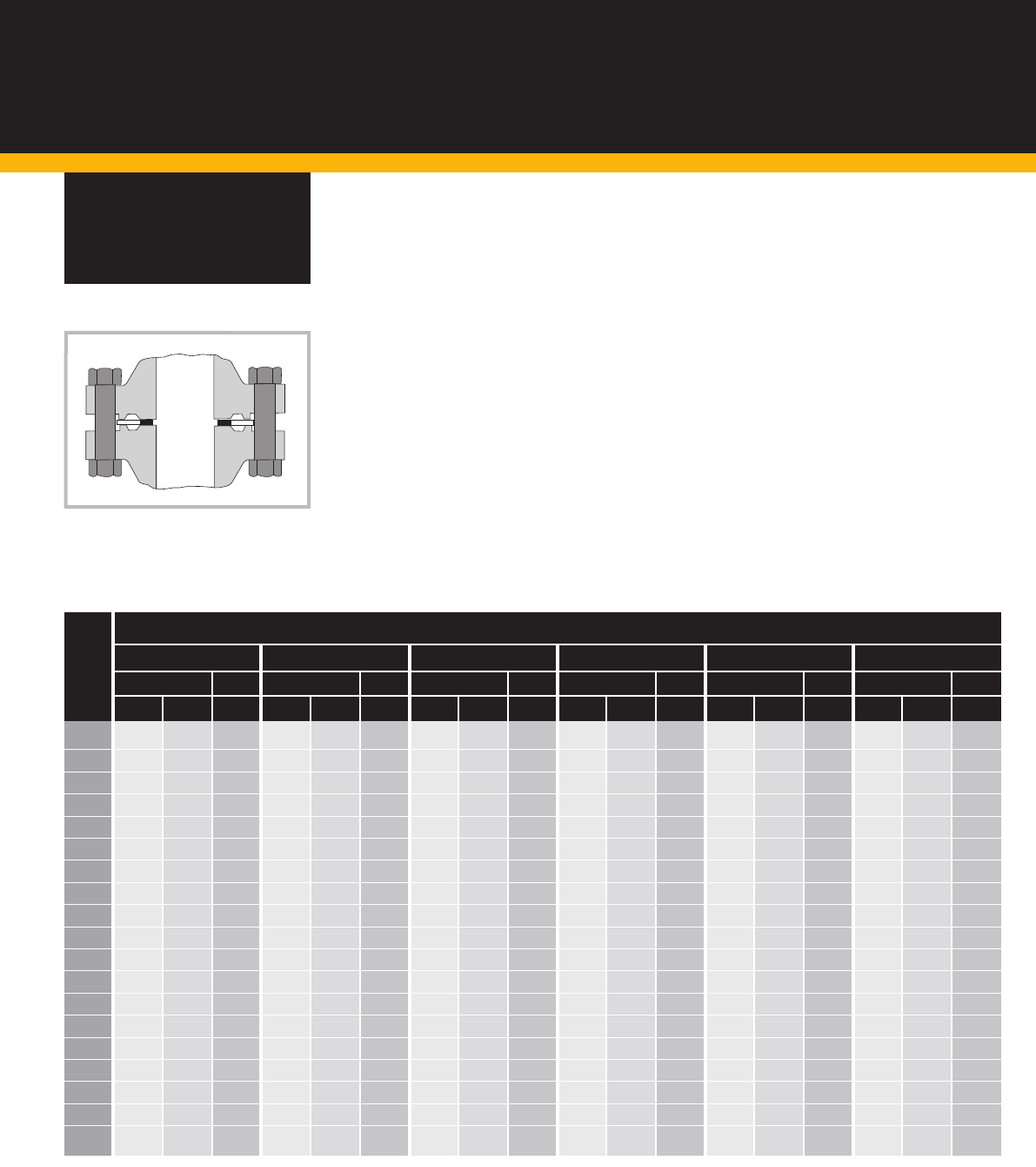
Style CG – Is comprised of a
sealing element and outer metal
ring. The outer ring assists in
locating the gasket on the mating
flange faces and prevents over
compression of the sealing
element ensuring optimum sealing
performance. Style CG gaskets are
suitable for use on raised and flat
faced flanged connections. Style CG
gaskets are suitable for use in mild
to moderate service conditions.
Style CGI – In addition to an outer
metal ring the CGI style gasket is fitted
with an inner metal ring, constraining
the sealing element on both internal
and external diameters. The inner ring
functions as an additional compression
stop and prevents inner buckling of the
sealing element. It also creates a
physical barrier between the sealing
element and process stream shielding
from heat and media while preventing
erosion. Style CGI gaskets are suitable
for use on raised and flat faced flanged
connections and moderate to severe
service conditions.
Style R – Is comprised of a sealing
element, additional plies of metal
are used at the start and
termination of the winding process
improving stability and sealing
performance. Unlike other styles
of spiral wound gasket compression
of the sealing element is controlled
by the use of the correct flange
face configuration, style R gaskets
are suitable for use on tongue and
groove, male and female and flat
to groove flanged connections.
Style RIR – Is comprised of a
sealing element and inner metal ring.
The inner ring functions as both
a compression stop and creates a
physical barrier between the sealing
element and media stream. The inner
ring is also designed to reduce
turbulent flow, minimising flange
erosion and prevents the build up
debris in the annular space between
the pipe bore and internal diameter
of the gasket. Style RIR gaskets are
suitable for use on male and female
(spigot and recess) flanged
connections.
SELECTION GUIDE
Published as an indication of which Flexitallic spiral wound gasket best suits different pipe flange configurations and service conditions.
7.
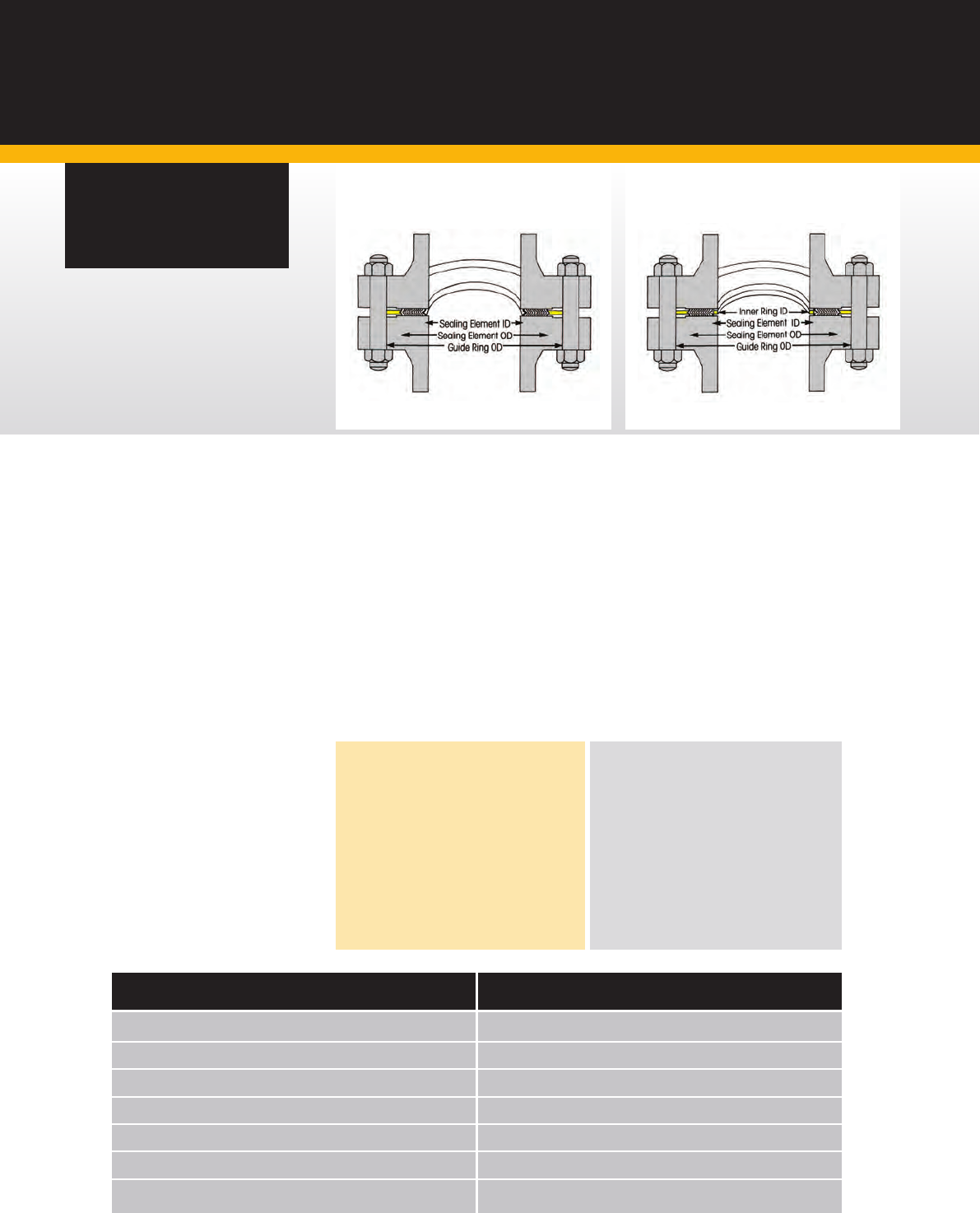
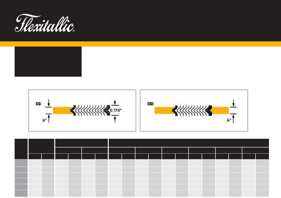
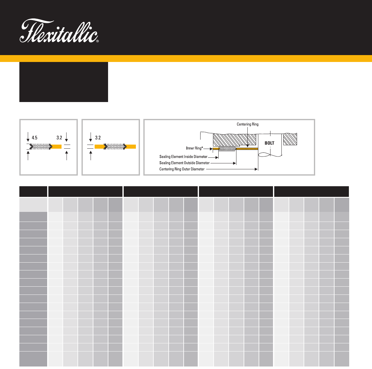
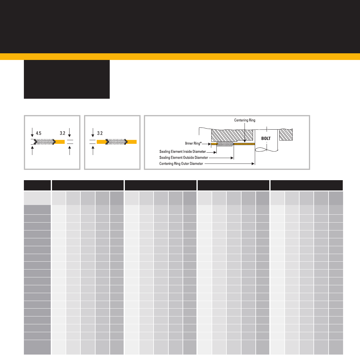
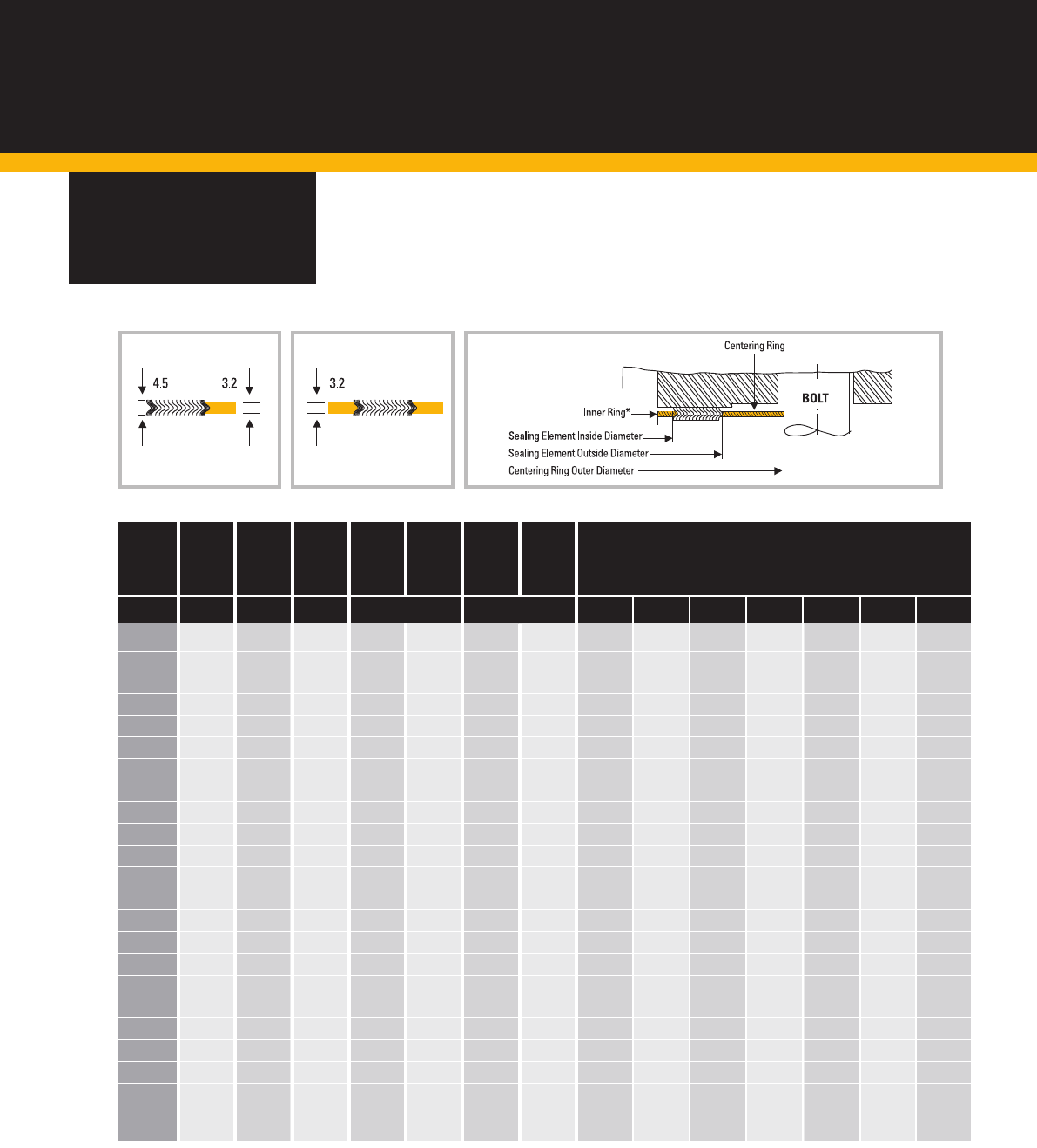
STYLE CG &
CGI GASKETS
To suit standard
raised face and
flat face flanges.
All CG and CGI Gaskets for these standard
flanges are 0.175 in (4.5mm) thick, fitted
with 0.125 in (3.2mm) thick solid metal rings,
unless otherwise stated.
Special gaskets
Gaskets of special design can be engineered
and fabricated using the same basic fundamentals
of Flexitallic Spiral Wound Gasket design and
construction to cover a wide range of applications
in installations for which there are no industry-wide
standards. Special gaskets have been designed for
valves, pumps, compressors, turbines, boilers, heat
exchangers, etc. Consult with Flexitallic engineers
as early in the design stage as possible.
Style CG Style CGI
Flexitallic style CG and CGI Spiral
Wound Gaskets can be
manufactured in accordance with
all relevant gasket standards to suit
the following flange designations.
Please note that gaskets for non-
standard flanges are also readily
available.
ASME B16.5
ASME B16.47 Series A (MSS SP 44)
ASME B16.47 Series B (API 605)
BS 10
BS 1560
BS 4504
BS EN 1092
BS EN 1759
DIN Flanges
JIS Flanges
Low Emission style Gaskets are
available, which conform to major oil
refinery requirements in accordance
with CFET March 2013 revision.
Please speak to the Applications
Engineering Department for further
information.
Note: When using PTFE filler material,
Spiral Wound Gaskets shall be fitted
with an inner metal ring (i.e. style CGI).
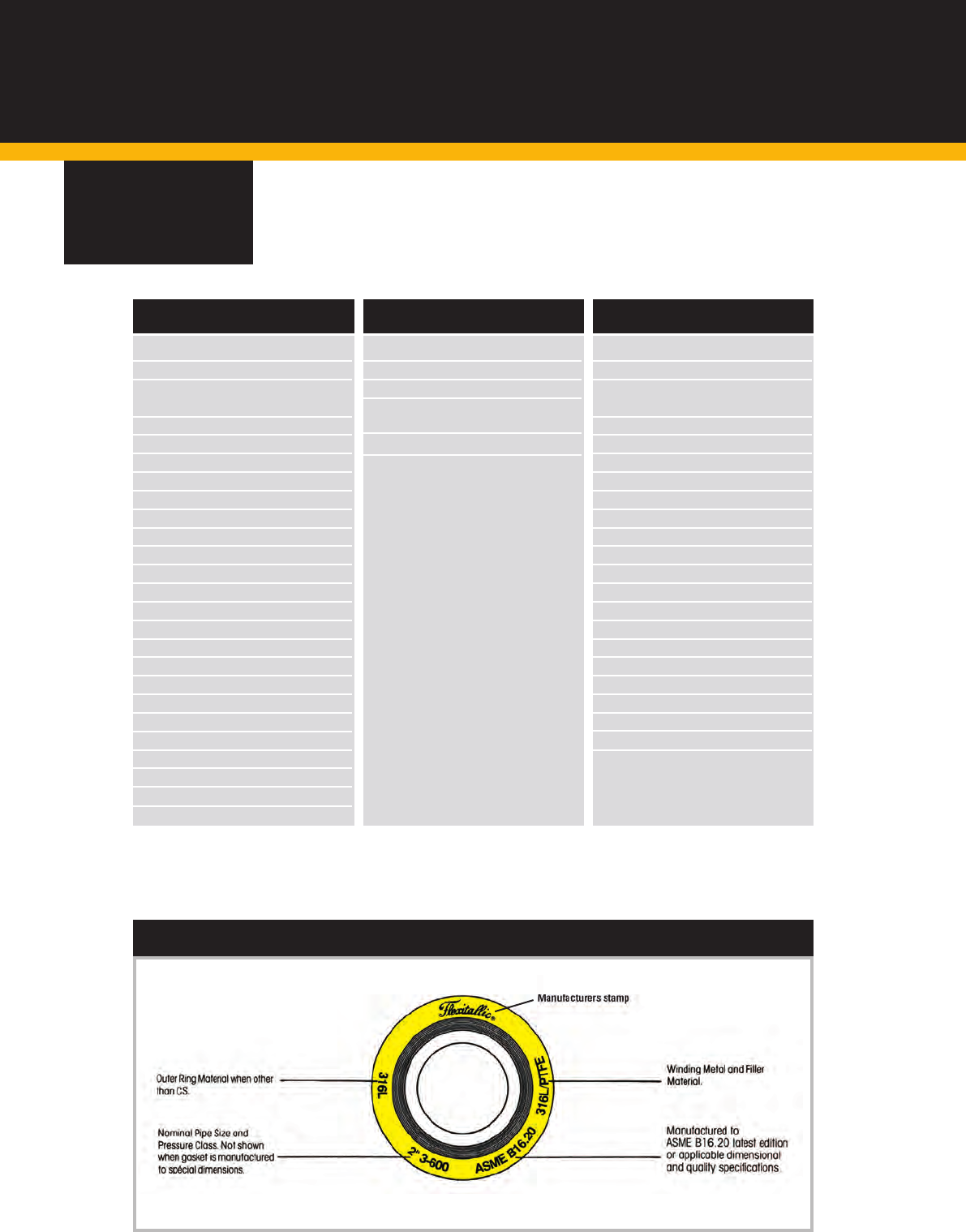
WHEN ORDERING PLEASE SPECIFY EXAMPLE
Gasket style
Nominal pipe size (NPS)
Pressure rating
Gasket standard
Winding materials
Outer ring material
Inner ring material
Flexitallic Style “CGI” Spiral Wound Gasket
4”
Class 900
ASME B16.20
316L/Flexicarb (FG)
Carbon Steel
316L

mm #150 #300 #400 #600 #900 #1500 #2500 #150 #300 #400 #600 #900 #1500 #2500 #150 #300 #400 #600 #900 #1500 #2500 #150 #300 #400 #600 #900 #1500 #2500
(5) (5) (5) (4) (4) (4) (4) (4) (4)
15 14.2 14.2 - 14.2 - 14.2 14.2 19.1 19.1 - 19.1 - 19.1 19.1 31.8 31.8 31.8 31.8 31.8 31.8 31.8 47.8 54.1 - 54.1 - 63.5 69.9
20 20.6 20.6 - 20.6 - 20.6 20.6 25.4 25.4 - 25.4 - 25.4 25.4 39.6 39.6 39.6 39.6 39.6 39.6 39.6 57.2 66.8 - 66.8 - 69.9 76.2
25 26.9 26.9 - 26.9 - 26.9 26.9 31.8 31.8 - 31.8 - 31.8 31.8 47.8 47.8 47.8 47.8 47.8 47.8 47.8 66.8 73.2 - 73.2 - 79.5 85.9
32 38.1 38.1 - 38.1 - 33.3 33.3 47.8 47.8 - 47.8 - 39.6 39.6 60.5 60.5 60.5 60.5 60.5 60.5 60.5 76.2 82.6 - 82.6 - 88.9 104.9
40 44.5 44.5 - 44.5 - 41.4 41.4 54.1 54.1 - 54.1 - 47.8 47.8 69.9 69.9 69.9 69.9 69.9 69.9 69.9 85.9 95.3 - 95.3 - 98.6 117.6
50 55.6 55.6 - 55.6 - 52.3 52.3 69.9 69.9 - 69.9 - 58.7 58.7 85.9 85.9 85.9 85.9 85.9 85.9 85.9 104.9 111.3 - 111.3 - 143.0 146.1
65 66.5 66.5 - 66.5 - 63.5 63.5 82.6 82.6 - 82.6 - 69.9 69.9 98.6 98.6 98.6 98.6 98.6 98.6 98.6 124.0 130.3 - 130.3 - 165.1 168.4
80 81.0 81.0 - 81.0 78.7 78.7 78.7 101.6 101.6 - 101.6 95.3 92.2 92.2 120.7 120.7 120.7 120.7 120.7 120.7 120.7 136.7 149.4 - 149.4 168.4 174.8 196.9
100 106.4 106.4 102.6 102.6 102.6 97.8 97.8 127.0 127.0 120.7 120.7 120.7 117.6 117.6 149.4 149.4 149.4 149.4 149.4 149.4 149.4 174.8 181.1 177.8 193.8 206.5 209.6 235.0
125 131.8 131.8 128.3 128.3 128.3 124.5 124.5 155.7 155.7 147.6 147.6 147.6 143.0 143.0 177.8 177.8 177.8 177.8 177.8 177.8 177.8 196.9 215.9 212.9 241.3 247.7 254.0 279.4
150 157.2 157.2 154.9 154.9 154.9 147.3 147.3 182.6 182.6 174.8 174.8 174.8 171.5 171.5 209.6 209.6 209.6 209.6 209.6 209.6 209.6 222.3 251.0 247.7 266.7 289.1 282.7 317.5
200 215.9 215.9 205.7 205.7 196.9 196.9 196.9 233.4 233.4 225.6 225.6 222.3 215.9 215.9 263.7 263.7 263.7 263.7 257.3 257.3 257.3 279.4 308.1 304.8 320.8 358.9 352.6 387.4
250 268.2 268.2 255.3 255.3 246.1 246.1 246.1 287.3 287.3 274.6 274.6 276.4 266.7 270.0 317.5 317.5 317.5 317.5 311.2 311.2 311.2 339.9 362.0 358.9 400.1 435.1 435.1 476.3
300 317.5 317.5 307.3 307.3 292.1 292.1 292.1 339.9 339.9 327.2 327.2 323.9 323.9 317.5 374.7 374.7 374.7 374.7 368.3 368.3 368.3 409.7 422.4 419.1 457.2 498.6 520.7 549.4
350 349.3 349.3 342.9 342.9 320.8 320.8 - 371.6 371.6 362.0 362.0 355.6 362.0 - 406.4 406.4 406.4 406.4 400.1 400.1 - 450.9 485.9 482.6 492.3 520.7 577.9 -
400 400.1 400.1 389.9 389.9 374.7 368.3 - 422.4 422.4 412.8 412.8 412.8 406.4 - 463.6 463.6 463.6 463.6 457.2 457.2 - 514.4 539.8 536.7 565.2 574.8 641.4 -
450 449.3 449.3 438.2 438.2 425.5 425.5 - 474.7 474.7 469.9 469.9 463.6 463.6 - 527.1 527.1 527.1 527.1 520.7 520.7 - 549.4 596.9 593.9 612.9 638.3 704.9 -
500 500.1 500.1 489.0 489.0 482.6 476.3 - 525.5 525.5 520.7 520.7 520.7 514.4 - 577.9 577.9 577.9 577.9 571.5 571.5 - 606.6 654.1 647.7 682.8 698.5 755.7 -
600 603.3 603.3 590.6 590.6 590.6 577.9 - 628.7 628.7 628.7 628.7 628.7 616.0 - 685.8 685.8 685.8 685.8 679.5 679.5 - 717.6 774.7 768.4 790.7 838.2 901.7 -
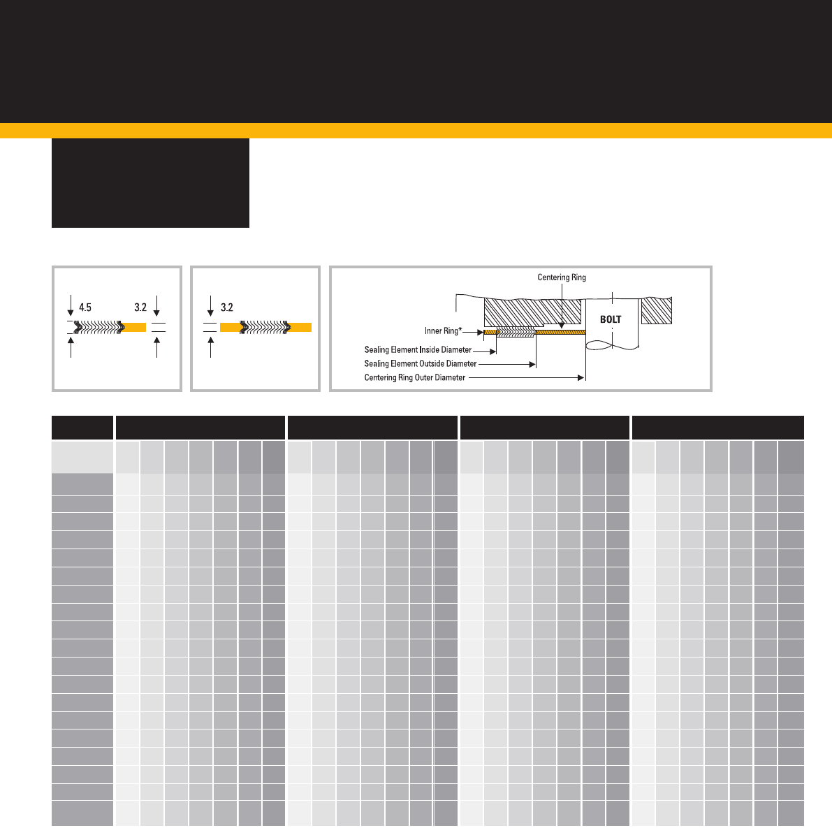
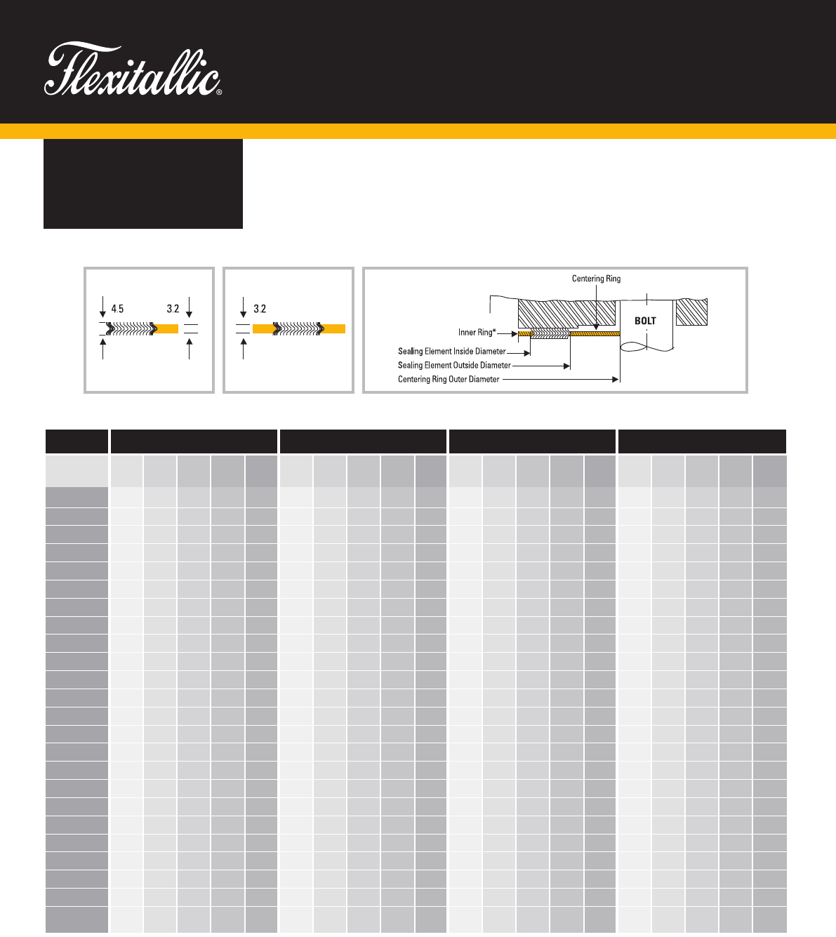
8. www.flexitallic.com
DIMENSIONAL
DATA
SPIRAL WOUND GASKETS
Dimensions to ASME B16.20
to suit ASME B16.5 Flanges
CG CGI
GENERAL NOTES
All dimensions are in mm.
Figures stated are for information only. Please refer to the current version of the original standards for dimensional information.
The gasket thickness tolerance is +/- .13 mm measured across the metallic portion of the gasket, not including the filler, which may protrude slightly beyond the metal.
The inner-ring thickness shall be 2.97mm to 3.33mm.
For sizes NPS ½ through NPS 3, the insider diameter tolerance is +/- 0.8mm; for larger sizes the inside diameter tolerance is +/- 1.5mm.
NOTES
1. The gasket outside diameter tolerance for NPS ½ through to NPS 8 is +/-0.8mm; for NPS 10 through NPS 24 +1.5mm -0.8mm
2. The gasket inside diameter tolerance for NPS ½ through to NPS 8 is +/-0.4mm; for NPS 10 through NPS 24 +/- 0.8mm
3. The centering ring outside diameter tolerance is +/-0.8mm
4. There are no Class 400 flanges in NPS ½ through NPS 3 (use Class 600), Class 900 flanges in NPS ½ through NPS 2 ½ (use Class 1500), or Class 2500 flanges NPS 14 and larger
5. There are no NPS ½ through NPS 3 Class 400 flanges (use Class 600), NPS ½ through NPS 2 ½ Class 900 flanges (use Class 1500), or NPS 14 and larger Class 2500 flanges
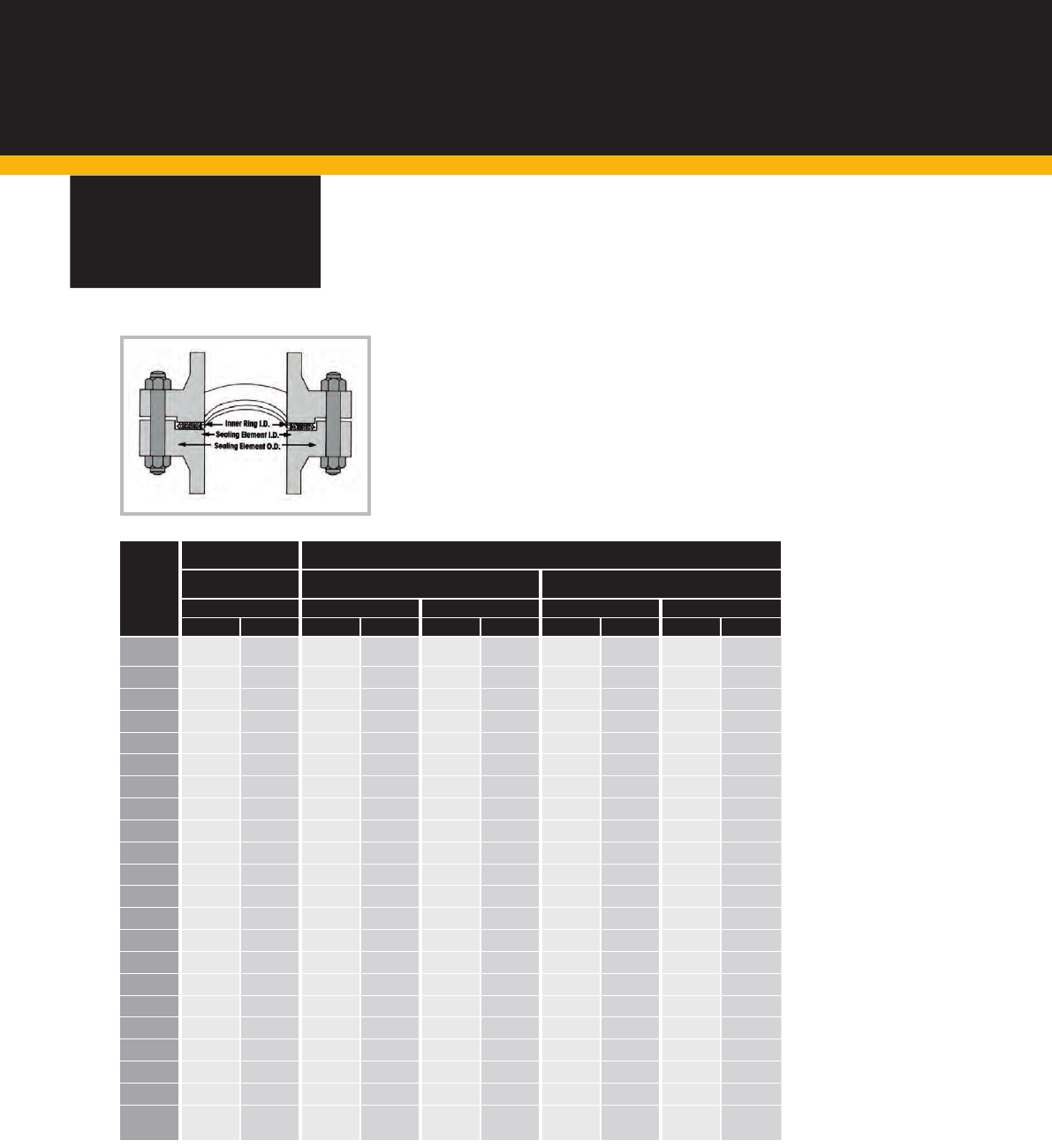
NOMINAL BORE INNER RING ID SEALING ELEMENT ID (1) (2) SEALING ELEMENT OD CENTERING RING OD (3)
Inches #150 #300 #400 #600 #900 #1500 #2500 #150 #300 #400 #600 #900 #1500 #2500 #150 #300 #400 #600 #900 #1500 #2500 #150 #300 #400 #600 #900 #1500 #2500
(5) (5) (5) (4) (4) (4)
(4) (4) (4)
½ 0.56 0.56 - 0.56 - 0.56 0.56 0.75 0.75 - 0.75 - 0.75 0.75 1.25 1.25 1.25 1.25 1.25 1.25 1.25 1.88 2.13 - 2.13 0.00 2.50 2.75
¾ 0.81 0.81 - 0.81 - 0.81 0.81 1.00 1.00 - 1.00 - 1.00 1.00 1.56 1.56 1.56 1.56 1.56 1.56 1.56 2.25 2.63 - 2.63 0.00 2.75 3.00
1 1.06 1.06 - 1.06 - 1.06 1.06 1.25 1.25 - 1.25 - 1.25 1.25 1.88 1.88 1.88 1.88 1.88 1.88 1.88 2.63 2.88 - 2.88 0.00 3.13 3.38
1 ¼ 1.50 1.50 - 1.50 - 1.31 1.31 1.88 1.88 - 1.88 - 1.56 1.56 2.38 2.38 2.38 2.38 2.38 2.38 2.38 3.00 3.25 - 3.25 0.00 3.50 4.13
1 ½ 1.75 1.75 - 1.75 - 1.63 1.63 2.13 2.13 - 2.13 - 1.88 1.88 2.75 2.75 2.75 2.75 2.75 2.75 2.75 3.38 3.75 - 3.75 0.00 3.88 4.63
2 2.19 2.19 - 2.19 - 2.06 2.06 2.75 2.75 - 2.75 - 2.31 2.31 3.38 3.38 3.38 3.38 3.38 3.38 3.38 4.13 4.38 - 4.38 0.00 5.63 5.75
2 ½ 2.62 2.62 - 2.62 - 2.50 2.50 3.25 3.25 - 3.25 - 2.75 2.75 3.88 3.88 3.88 3.88 3.88 3.88 3.88 4.88 5.13 - 5.13 0.00 6.50 6.63
3 3.19 3.19 - 3.19 3.10 3.10 3.10 4.00 4.00 - 4.00 3.75 3.63 3.63 4.75 4.75 4.75 4.75 4.75 4.75 4.75 5.38 5.88 - 5.88 6.63 6.88 7.75
4 4.19 4.19 4.04 4.04 4.04 3.85 3.85 5.00 5.00 4.75 4.75 4.75 4.63 4.63 5.88 5.88 5.88 5.88 5.88 5.88 5.88 6.88 7.13 7.00 7.63 8.13 8.25 9.25
5 5.19 5.19 5.05 5.05 5.05 4.90 4.90 6.13 6.13 5.81 5.81 5.81 5.63 5.63 7.00 7.00 7.00 7.00 7.00 7.00 7.00 7.75 8.50 8.38 9.50 9.75 10.00 11.00
6 6.19 6.19 6.10 6.10 6.10 5.80 5.80 7.19 7.19 6.88 6.88 6.88 6.75 6.75 8.25 8.25 8.25 8.25 8.25 8.25 8.25 8.75 9.88 9.75 10.50 11.38 11.13 12.50
8 8.50 8.50 8.10 8.10 7.75 7.75 7.75 9.19 9.19 8.88 8.88 8.75 8.50 8.50 10.38 10.38 10.38 10.38 10.13 10.13 10.13 11.00 12.13 12.00 12.63 14.13 13.88 15.25
10 10.56 10.56 10.05 10.05 9.69 9.69 9.69 11.31 11.31 10.81 10.81 10.88 10.50 10.63 12.50 12.50 12.50 12.50 12.25 12.25 12.25 13.38 14.25 14.13 15.75 17.13 17.13 18.75
12 12.50 12.50 12.10 12.10 11.50 11.50 11.50 13.38 13.38 12.88 12.88 12.75 12.75 12.50 14.75 14.75 14.75 14.75 14.50 14.50 14.50 16.13 16.63 16.50 18.00 19.63 20.50 21.63
14 13.75 13.75 13.50 13.50 12.63 12.63 - 14.63 14.63 14.25 14.25 14.00 14.25 - 16.00 16.00 16.00 16.00 15.75 15.75 - 17.75 19.13 19.00 19.38 20.50 22.75 -
16 15.75 15.75 15.35 15.35 14.75 14.50 - 16.63 16.63 16.25 16.25 16.25 16.00 - 18.25 18.25 18.25 18.25 18.00 18.00 - 20.25 21.25 21.13 22.25 22.63 25.25 -
18 17.69 17.69 17.25 17.25 16.75 16.75 - 18.69 18.69 18.50 18.50 18.25 18.25 - 20.75 20.75 20.75 20.75 20.50 20.50 - 21.63 23.50 23.38 24.13 25.13 27.75 -
20 19.69 19.69 19.25 19.25 19.00 18.75 - 20.69 20.69 20.50 20.50 20.50 20.25 - 22.75 22.75 22.75 22.75 22.50 22.50 - 23.88 25.75 25.50 26.88 27.50 29.75 -
24 23.75 23.75 23.25 23.25 23.25 22.75 - 24.75 24.75 24.75 24.75 24.75 24.25 - 27.00 27.00 27.00 27.00 26.75 26.75 - 28.25 30.50 30.25 31.13 33.00 35.50 -
9.
DIMENSIONAL
DATA
SPIRAL WOUND GASKETS
Dimensions to ASME B16.20
to suit ASME B16.5 Flanges
CG CGI
GENERAL NOTES
All dimensions are in inches.
Figures stated are for information only. Please refer to the current version of the original standards for dimensional information.
The gasket thickness tolerance is +/- .13 mm measured across the metallic portion of the gasket, not including the filler, which may protrude slightly beyond the metal.
The inner-ring thickness shall be 0.117 in to 0.131 in
For sizes NPS ½ through NPS 3, the insider diameter tolerance is +/- 0.03in; for larger sizes the inside diameter tolerance is +/- 0.06in.
NOTES
1. The gasket outside diameter tolerance for NPS ½ through to NPS 8 is +/-0.03in for NPS 10 through NPS 24 +0.06in – 0.03in
2. The gasket inside diameter tolerance for NPS ½ through to NPS 8 is +/-0.016in; for NPS 10 through NPS 24 +/- 0.03in.
3. The centering ring outside diameter tolerance is +/-0.03in
4. There are no Class 400 flanges in NPS ½ through NPS 3 (use Class 600), Class 900 flanges in NPS ½ through NPS 2 ½ (use Class 1500), or Class 2500 flanges NPS 14 and larger
5. There are no NPS ½ through NPS 3 Class 400 flanges (use Class 600), NPS ½ through NPS 2 ½ Class 900 flanges (use Class 1500), or NPS 14 and larger Class 2500 flanges
NOMINAL BORE INNER RING ID SEALING ELEMENT ID (1) (2) SEALING ELEMENT OD CENTERING RING OD (3)
10. www.flexitallic.com
GENERAL NOTES
All dimensions are in mm and inches.
NOTES
The above style CG & CGI Spiral Wound Gaskets are dimensioned to suit existing screwed or slip-on flanges for NPS 1⁄4 to 1-½ ASME B16.5 & BS 1560 flanges.
DIMENSIONAL
DATA
STYLE CG & CGI GASKETS
Dimensions to suit ASME B16.5 & BS1560
Small Diameter Screwed or Slip-on Flanges
INSIDE DIA. OUTSIDE DIA. CLASS 150 CLASS 300 CLASS 400 CLASS 600 CLASS 900 CLASS 1500
SEALING ELEMENT GUIDE RING OUTSIDE DIAMETER
NOMINAL
PIPE
SIZE
INNER RING
INSIDE
DIAMETER
¼ - - 0.56 14.3 0.88 22.2 1.75 44.5 1.75 44.5 1.75 44.5 1.75 44.5 ----
½ 0.56 14.3 0.94 23.8 1.25 31.8 1.88 47.6 2.13 54.0 2.13 54.0 2.13 54.0 2.50 63.5 2.50 63.5
¾ 0.81 20.6 1.19 30.2 1.56 39.7 2.25 57.2 2.63 66.7 2.63 66.7 2.63 66.7 2.75 69.9 2.75 69.9
1 1.06 27.0 1.44 36.5 1.88 47.6 2.63 66.7 2.88 73.0 2.88 73.0 2.88 73.0 3.13 79.4 3.13 79.4
1 ¼ 1.38 34.9 1.88 47.6 2.38 60.3 3.00 76.2 3.25 82.6 3.25 82.6 3.25 82.6 3.50 88.9 3.50 88.9
1 ½ 1.63 41.3 2.13 54.0 2.75 69.9 3.38 85.7 3.75 95.3 3.75 95.3 3.75 95.3 3.88 98.4 3.88 98.4
INCHES MM
INCHES MM INCHES MM
INCHES MM
INCHES MM
INCHES MM
INCHES MM
INCHES MM
INCHES MM

11.
DIMENSIONAL
DATA
SPIRAL WOUND GASKETS
Style CG & CGI ASME B16.20 Gaskets
to suit ASME B16.47 Flanges Series A
mm #150 #300 #400 #600 #900 #150 #300 #400 #600 #900 #150 #300 #400 #600 #900 #150 #300 #400 #600 #900
(4)
650 654.1 654.1 660.4 647.7 660.4 673.1 685.8 685.8 685.8 685.8 704.9 736.6 736.6 736.6 736.6 774.7 835.2 831.9 866.9 882.7
700 704.9 704.9 711.2 698.5 711.2 723.9 736.6 736.6 736.6 736.6 755.7 787.4 787.4 787.4 787.4 831.9 898.7 892.3 914.4 946.2
750 755.7 755.7 755.7 755.7 768.4 774.7 793.8 793.8 793.8 793.8 806.5 844.6 844.6 844.6 844.6 882.7 952.5 946.2 971.6 1009.7
800 806.5 806.5 812.8 812.8 812.8 825.5 850.9 850.9 850.9 850.9 860.6 901.7 901.7 901.7 901.7 939.8 1006.6 1003.3 1022.4 1073.2
850 857.3 857.3 863.6 863.6 863.6 876.3 901.7 901.7 901.7 901.7 911.4 952.5 952.5 952.5 952.5 990.6 1057.4 1054.1 1073.2 1136.7
900 908.1 908.1 917.7 917.7 920.8 927.1 955.8 955.8 955.8 958.9 968.5 1006.6 1006.6 1006.6 1009.7 1047.8 1117.6 1117.6 1130.3 1200.2
950 958.9 952.5 952.5 952.5 1009.7 977.9 977.9 971.6 990.6 1035.1 1019.3 1016.0 1022.4 1041.4 1085.9 1111.3 1054.1 1073.2 1104.9 1200.2
1000 1009.7 1003.3 1000.3 1009.7 1060.5 1028.7 1022.4 1025.7 1047.8 1098.6 1070.1 1070.1 1076.5 1098.6 1149.4 1162.1 1114.6 1127.3 1155.7 1251.0
1050 1060.5 1054.1 1051.1 1066.8 1111.3 1079.5 1073.2 1076.5 1104.9 1149.4 1124.0 1120.9 1127.3 1155.7 1200.2 1219.2 1165.4 1178.1 1219.2 1301.8
1100 1111.3 1104.9 1104.9 1111.3 1155.7 1130.3 1130.3 1130.3 1162.1 1206.5 1178.1 1181.1 1181.1 1212.9 1257.3 1276.4 1219.2 1231.9 1270.0 1368.6
1150 1162.1 1152.7 1168.4 1162.1 1219.2 1181.1 1178.1 1193.8 1212.9 1270.0 1228.9 1228.9 1244.6 1263.7 1320.8 1327.2 1273.3 1289.1 1327.2 1435.1
1200 1212.9 1209.8 1206.5 1219.2 1270.0 1231.9 1235.2 1244.6 1270.0 1320.8 1279.7 1286.0 1295.4 1320.8 1371.6 1384.3 1324.1 1346.2 1390.7 1485.9
1250 1263.7 1244.6 1257.3 1270.0 - 1282.7 1295.4 1295.4 1320.8 - 1333.5 1346.2 1346.2 1371.6 - 1435.1 1378.0 1403.4 1447.8 -
1300 1314.5 1320.8 1308.1 1320.8 - 1333.5 1346.2 1346.2 1371.6 - 1384.3 1397.0 1397.0 1422.4 - 1492.3 1428.8 1454.2 1498.6 -
1350 1358.9 1352.6 1352.6 1378.0 - 1384.3 1403.4 1403.4 1428.8 - 1435.1 1454.2 1454.2 1479.6 - 1549.4 1492.3 1517.7 1555.8 -
1400 1409.7 1403.4 1403.4 1428.8 - 1435.1 1454.2 1454.2 1479.6 - 1485.9 1505.0 1505.0 1530.4 - 1606.6 1543.1 1568.5 1612.9 -
1450 1460.5 1447.8 1454.2 1473.2 - 1485.9 1511.3 1505.0 1536.7 - 1536.7 1562.1 1555.8 1587.5 - 1663.7 1593.9 1619.3 1663.7 -
1500 1511.3 1524.0 1517.7 1530.4 - 1536.7 1562.1 1568.5 1593.9 - 1587.5 1612.9 1619.3 1644.7 - 1714.5 1644.7 1682.8 1733.6 -
GENERAL NOTES
All dimensions are in mm.
Figures stated are for information only. Please refer to the current version of the original standards for dimensional information.
The gasket thickness tolerance is +/-0.13mm measured across the metallic portion of the gasket, not including the filler, which may protrude slighlty beyond the metal.
ASME B16.47 Series A flanges NPS 12 through NPS 24 have the same raised face dimensions as ASME B16.5 flanges.
The inner-ring thickness shall be 2.97 mm to 3.33 mm.
The inside diameter tolerance is +/- 3.0 mm.
These inner rings are suitable for use with pipe walls 9.53 mm or thicker.
NOTES
1. The gasket outside diameter tolerance for NPS 26 through NPS 60 is +/-1.5 mm
2. The gasket inside diameter tolerance for NPS 26 through NPS 34 is +/-0.8 mm; and the tolerance for NPS 36 through NPS 60 is ±1.5 mm.
3. The centering ring outside diameter tolerance is +/-0.8 mm.
4. There are no Class 900 flanges NPS 50 and larger.
NOMINAL BORE INNER RING ID SEALING ELEMENT ID (2) (4) SEALING ELEMENT OD (1) (4) CENTERING RING OD (3) (4)
CG CGI
12. www.flexitallic.com
DIMENSIONAL
DATA
SPIRAL WOUND GASKETS
Style CG & CGI ASME B16.20 Gaskets
to suit ASME B16.47 Flanges Series A
GENERAL NOTES
All dimensions are in inches.
Figures stated are for information only. Please refer to the current version of the original standards for dimensional information.
The gasket thickness tolerance is +/-0.005in measured across the metallic portion of the gasket, not including the filler, which may protrude slightly beyond the metal.
ASME B16.47 Series A flanges NPS 12 through NPS 24 have the same raised face dimensions as ASME B16.5 flanges.
NOTES
1. The gasket outside diameter tolerance for NPS 26 through NPS 60 is +/-0.06in
2. The gasket inside diameter tolerance for NPS 26 through NPS 34 is +/-0.03in and the tolerance for NPS 36 through NPS 60 is +/-0.05in
3. The centering ring outside diameter tolerance is +/-0.03in
4. There are no Class 900 flanges NPS 50 and larger.
CG CGI
Inches #150 #300 #400 #600 #900 #150 #300 #400 #600 #900 #150 #300 #400 #600 #900 #150 #300 #400 #600 #900
(4
)
26 25.75 25.75 26.00 25.50 26.00 26.50 27.00 27.00 27.00 27.00 27.75 29.00 29.00 29.00 29.00 30.50 32.88 32.75 34.13 34.75
28 27.75 27.75 28.00 27.50 28.00 28.50 29.00 29.00 29.00 29.00 29.75 31.00 31.00 31.00 31.00 32.75 35.38 35.13 36.00 37.25
30 29.75 29.75 29.75 29.75 30.25 30.50 31.25 31.25 31.25 31.25 31.75 33.25 33.25 33.25 33.25 34.75 37.50 37.25 38.25 39.75
32 31.75 31.75 32.00 32.00 32.00 32.50 33.50 33.50 33.50 33.50 33.88 35.50 35.50 35.50 35.50 37.00 39.63 39.50 40.25 42.25
34 33.75 33.75 34.00 34.00 34.00 34.50 35.50 35.50 35.50 35.50 35.88 37.50 37.50 37.50 37.50 39.00 41.63 41.50 42.25 44.75
36 35.75 35.75 36.13 36.13 36.25 36.50 37.63 37.63 37.63 37.75 38.13 39.63 39.63 39.63 39.75 41.25 44.00 44.00 44.50 47.25
38 37.75 37.50 37.50 37.50 39.75 38.50 38.50 38.25 39.00 40.75 40.13 40.00 40.25 41.00 42.75 43.75 41.50 42.25 43.50 47.25
40 39.75 39.50 39.38 39.75 41.75 40.50 40.25 40.38 41.25 43.25 42.13 42.13 42.38 43.25 45.25 45.75 43.88 44.38 45.50 49.25
42 41.75 41.50 41.38 42.00 43.75 42.50 42.25 42.38 43.50 45.25 44.25 44.13 44.38 45.50 47.25 48.00 45.88 46.38 48.00 51.25
44 43.75 43.50 43.50 43.75 45.50 44.50 44.50 44.50 45.75 47.50 46.38 46.50 46.50 47.75 49.50 50.25 48.00 48.50 50.00 53.88
46 45.75 45.38 46.00 45.75 48.00 46.50 46.38 47.00 47.75 50.00 48.38 48.38 49.00 49.75 52.00 52.25 50.13 50.75 52.25 56.50
48 47.75 47.63 47.50 48.00 50.00 48.50 48.63 49.00 50.00 52.00 50.38 50.63 51.00 52.00 54.00 54.50 52.13 53.00 54.75 58.50
50 49.75 49.00 49.50 50.00 - 50.50 51.00 51.00 52.00 - 52.50 53.00 53.00 54.00 - 56.50 54.25 55.25 57.00 -
52 51.75 52.00 51.50 52.00 - 52.50 53.00 53.00 54.00 - 54.50 55.00 55.00 56.00 - 58.75 56.25 57.25 59.00 -
54 53.50 53.25 53.25 54.25 - 54.50 55.25 55.25 56.25 - 56.50 57.25 57.25 58.25 - 61.00 58.75 59.75 61.25 -
56 55.50 55.25 55.25 56.25 - 56.50 57.25 57.25 58.25 - 58.50 59.25 59.25 60.25 - 63.25 60.75 61.75 63.50 -
58 57.50 57.00 57.25 58.00 - 58.50 59.50 59.25 60.50 - 60.50 61.50 61.25 62.50 - 65.50 62.75 63.75 65.50 -
60 59.50 60.00 59.75 60.25 - 60.50 61.50 61.75 62.75 - 62.50 63.50 63.75 64.75 - 67.50 64.75 66.25 68.25 -
NOMINAL BORE INNER RING ID SEALING ELEMENT ID (2) (4) SEALING ELEMENT OD (1) (4) CENTERING RING OD (3) (4)
13.
DIMENSIONAL
DATA
SPIRAL WOUND GASKETS
Style CG & CGI ASME B16.20 Gaskets
to suit ASME B16.47 Flanges Series B
GENERAL NOTES
All dimensions are in mm.
Figures stated are for information only. Please refer to the current version of the original standards for dimensional information.
The inner-ring thickness shall be 2.97 mm to 3.33 mm.
The inside diameter tolerance is +/-3.0 mm.
These Inner rings are suitable for use with pipe walls 9.53 mm or thicker.
The gasket thickness tolerance is +/-0.13mm measured across the metallic portion of the gasket, not including the filler, which may protrude slightly beyond the metal.
NOTES
1. The gasket outside diameter tolerance for NPS 26 through NPS 60 is +/-1.5 mm
2. The gasket inside diameter tolerance for NPS 26 through NPS 34 is +/-0.8 mm, and the tolerance for NPS 36 through NPS 60 is +/-1.2 mm.
3. The centering ring outside diameter tolerance is +/-0.8 mm.
4. There are no Class 900 flanges NPS 50 and larger.
mm #150 #300 #400 #600 #900 #150 #300 #400 #600 #900 #150 #300 #400 #600 #900 #150 #300 #400 #600 #900
(4)
650 654.1 654.1 654.1 644.7 666.8 673.1 673.1 666.8 663.7 692.2 698.5 711.2 698.5 714.5 749.3 725.4 771.7 746.3 765.3 838.2
700 704.9 704.9 701.8 685.8 717.6 723.9 723.9 714.5 704.9 743.0 749.3 762.0 749.3 755.7 800.1 776.2 825.5 800.1 819.2 901.7
750 755.7 755.7 752.6 752.6 781.1 774.7 774.7 765.3 778.0 806.5 800.1 812.8 806.5 828.8 857.3 827.0 886.0 857.3 879.6 958.9
800 806.5 806.5 800.1 793.8 838.2 825.5 825.5 812.8 831.9 863.6 850.9 863.6 860.6 882.7 914.4 881.1 939.8 911.4 933.5 1016.0
850 857.3 857.3 850.9 850.9 895.4 876.3 876.3 866.9 889.0 920.8 908.1 914.4 911.4 939.8 971.6 935.0 993.9 962.2 997.0 1073.2
900 908.1 908.1 898.7 901.7 920.8 927.1 927.1 917.7 939.8 946.2 958.9 965.2 965.2 990.6 997.0 987.6 1047.8 1022.4 1047.8 1124.0
950 958.9 971.6 952.5 952.5 1009.7 974.9 1009.7 971.6 990.6 1035.1 1009.7 1047.8 1022.4 1041.4 1085.9 1044.7 1098.6 1073.2 1104.9 1200.2
1000 1009.7 1022.4 1000.3 1009.7 1060.5 1022.4 1060.5 1025.7 1047.8 1098.6 1063.8 1098.6 1076.5 1098.6 1149.4 1095.5 1149.4 1127.3 1155.7 1251.0
1050 1060.5 1085.9 1051.1 1066.8 1111.3 1079.5 1111.3 1076.5 1104.9 1149.4 1114.6 1149.4 1127.3 1155.7 1200.2 1146.3 1200.2 1178.1 1219.2 1301.8
1100 1111.3 1124.0 1104.9 1111.3 1155.7 1124.0 1162.1 1130.3 1162.1 1206.5 1165.4 1200.2 1181.1 1212.9 1257.3 1197.1 1251.0 1231.9 1270.0 1368.6
1150 1162.1 1178.1 1168.4 1162.1 1219.2 1181.1 1216.2 1193.8 1212.9 1270.0 1224.0 1254.3 1244.6 1263.7 1320.8 1255.8 1317.8 1289.1 1327.2 1435.1
1200 1212.9 1231.9 1206.5 1219.2 1270.0 1231.9 1263.7 1244.6 1270.0 1320.8 1270.0 1311.4 1295.4 1320.8 1371.6 1306.6 1368.6 1346.2 1390.7 1485.9
1250 1263.7 1267.0 1257.3 1270.0 - 1282.7 1317.8 1295.4 1320.8 - 1325.6 1355.9 1346.2 1371.6 - 1357.4 1419.4 1403.4 1447.8 -
1300 1314.5 1317.8 1308.1 1320.8 - 1333.5 1368.6 1346.2 1371.6 - 1376.4 1406.7 1397.0 1422.4 - 1408.2 1470.2 1454.2 1498.6 -
1350 1365.3 1365.3 1352.6 1378.0 - 1384.3 1403.4 1403.4 1428.8 - 1422.4 1454.2 1454.2 1479.6 - 1463.8 1530.4 1517.7 1555.8 -
1400 1422.4 1428.8 1403.4 1428.8 - 1444.8 1479.6 1454.2 1479.6 - 1478.0 1524.0 1505.0 1530.4 - 1514.6 1593.9 1568.5 1612.9 -
1450 1478.0 1484.4 1454.2 1473.2 - 1500.1 1535.2 1505.0 1536.7 - 1528.8 1573.3 1555.8 1587.5 - 1579.6 1655.8 1619.3 1663.7 -
1500 1535.2 1557.3 1517.7 1530.4 - 1557.3 1589.0 1568.5 1593.9 - 1586.0 1630.4 1619.3 1644.7 - 1630.4 1706.6 1682.8 1733.6 -
NOMINAL BORE INNER RING ID SEALING ELEMENT ID (2) (4) SEALING ELEMENT OD (1) (4) CENTERING RING OD (3) (4)
CG CGI

14. www.flexitallic.com
DIMENSIONAL
DATA
SPIRAL WOUND GASKETS
Style CG & CGI ASME B16.20 Gaskets
to suit ASME B16.47 Flanges Series B
GENERAL NOTES
All dimensions are in inches.
Figures stated are for information only. Please refer to the current version of the original standards for dimensional information.
The gasket thickness tolerance is +/-0.005in measured across the metallic portion of the gasket, not including the filler, which may protrude slightly beyond the metal.
NOTES
1. The gasket outside diameter tolerance for NPS 26 through NPS 60 is +/-0.06in
2. The gasket inside diameter tolerance for NPS 26 through NPS 34 is +/-0.03in, and the tolerance for NPS 36 through NPS 60 is +/-0.05in
3. The centering ring outside diameter tolerance is +/-0.03in
4. There are no Class 900 flanges NPS 50 and larger
CG CGI
Inches #150 #300 #400 #600 #900 #150 #300 #400 #600 #900 #150 #300 #400 #600 #900 #150 #300 #400 #600 #900
(4)
26 25.75 25.75 25.75 25.38 26.25 26.50 26.50 26.25 26.13 27.25 27.50 28.00 27.50 28.13 29.50 28.56 30.38 29.38 30.13 33.00
28 27.75 27.75 27.63 27.00 28.25 28.50 28.50 28.13 27.75 29.25 29.50 30.00 29.50 29.75 31.50 30.56 32.50 31.50 32.25 35.50
30 29.75 29.75 29.63 29.63 30.75 30.50 30.50 30.13 30.63 31.75 31.50 32.00 31.75 32.63 33.75 32.56 34.88 33.75 34.63 37.75
32 31.75 31.75 31.50 31.25 33.00 32.50 32.50 32.00 32.75 34.00 33.50 34.00 33.88 34.75 36.00 34.69 37.00 35.88 36.75 40.00
34 33.75 33.75 33.50 33.50 35.25 34.50 34.50 34.13 35.00 36.25 35.75 36.00 35.88 37.00 38.25 36.81 39.13 37.88 39.25 42.25
36 35.75 35.75 35.38 35.50 36.25 36.50 36.50 36.13 37.00 37.25 37.75 38.00 38.00 39.00 39.25 38.88 41.25 40.25 41.25 44.25
38 37.75 38.25 37.50 37.50 39.75 38.37 39.75 38.25 39.00 40.75 39.75 41.25 40.25 41.00 42.75 41.13 43.25 42.25 43.50 47.25
40 39.75 40.25 39.38 39.75 41.75 40.25 41.75 40.38 41.25 43.25 41.88 43.25 42.38 43.25 45.25 43.13 45.25 44.38 45.50 49.25
42 41.75 42.75 41.38 42.00 43.75 42.50 43.75 42.38 43.50 45.25 43.88 45.25 44.38 45.50 47.25 45.13 47.25 46.38 48.00 51.25
44 43.75 44.25 43.50 43.75 45.50 44.25 45.75 44.50 45.75 47.50 45.88 47.25 46.50 47.75 49.50 47.13 49.25 48.50 50.00 53.88
46 45.75 46.38 46.00 45.75 48.00 46.50 47.88 47.00 47.75 50.00 48.19 49.38 49.00 49.75 52.00 49.44 51.88 50.75 52.25 56.50
48 47.75 48.50 47.50 48.00 50.00 48.50 49.75 49.00 50.00 52.00 50.00 51.63 51.00 52.00 54.00 51.44 53.88 53.00 54.75 58.50
50 49.75 49.88 49.50 50.00 - 50.50 51.88 51.00 52.00 - 52.19 53.38 53.00 54.00 - 53.44 55.88 55.25 57.00 -
52 51.75 51.88 51.50 52.00 - 52.50 53.88 53.00 54.00 - 54.19 55.38 55.00 56.00 - 55.44 57.88 57.25 59.00 -
54 53.75 53.75 53.25 54.25 - 54.50 55.25 55.25 56.25 - 56.00 57.25 57.25 58.25 - 57.63 60.25 59.75 61.25 -
56 56.00 56.25 55.25 56.25 - 56.88 58.25 57.25 58.25 - 58.18 60.00 59.25 60.25 - 59.63 62.75 61.75 63.50 -
58 58.19 58.44 57.25 58.00 - 59.07 60.44 59.25 60.50 - 60.19 61.94 61.25 62.50 - 62.19 65.19 63.75 65.50 -
60 60.44 61.31 59.75 60.25 - 61.31 62.56 61.75 62.75 - 62.44 64.19 63.75 64.75 - 64.19 67.19 66.25 68.25 -
NOMINAL BORE INNER RING ID SEALING ELEMENT ID (2) (4) SEALING ELEMENT OD (1) (4) CENTERING RING OD (3) (4)
10 18 3 24 5 34 5 34 46 46 46 46 56 56 56
15 23 3 29 5 39 5 39 51 51 51 51 61 61 61
20 28 3 34 6 46 - - 61 61 61 61 - - -
25 35 3 41 6 53 6 53 71 71 71 71 82 82 82
32 43 3 49 6 61 - - 82 82 82 82 - - -
40 50 3 56 6 68 6 68 92 92 92 92 103 103 103
50 61 4.5 70 8 86 8 86 107 107 107 107 113 119 119
65 77 4.5 86 8 102 10 106 127 127 127 127 137 143 143
80 90 4.5 99 8 115 10 119 142 142 142 142 148 154 154
100 115 6 127 8 143 10 147 162 162 168 168 174 180 180
125 140 6 152 10 172 12 176 192 192 194 194 210 217 217
150 167 6 179 10 199 12 203 218 218 224 224 247 257 257
200 216 6 228 10 248 12 252 273 273 284 290 309 324 324
250 267 6 279 12 303 14 307 327 329 340 352 364 391 388
300 318 6 330 12 354 14 358 377 384 400 417 424 458 458
350 360 8 376 12 400 14 404 437 444 457 474 486 512 -
400 410 6 422 14 450 17 456 488 495 514 546 543 572 -
500 510 6 522 14 550 17 556 593 617 624 628 657 704 -
600 610 6 622 14 650 17 656 695 734 731 747 764 813 -
700 710 6 722 17 756 20 762 810 804 833 852 879 950 -
800 810 10 830 17 864 20 870 917 911 942 974 988 - -
900 910 10 930 17 964 20 970 1017 1011 1042 1084 1108 - -
1000 1010 10 1030 22 1074 25 1080 1124 1128 1154 1194 - - -
15.
DIMENSIONAL
DATA
SPIRAL WOUND GASKETS
Style CG & CGI Gaskets to BS EN 1514-2
to suit BS EN 1092-1 Flanges
NOMINAL
DIAMETER
INNER
DIAMETER
OF THE
INNER
RING
INNER
DIAMETER
OF THE
SEALING
ELEMENT
INNER
DIAMETER
OF THE
GUIDE
RING
INNER
DIAMETER
OF THE
GUIDE
RING
OUTSIDE DIAMETER OF THE GUIDE RING TO EACH PRESSURE CLASS
MM PN10 PN25 DN40 PN63 PN100 PN160
WIDTH
OF THE
INNER
RING
WIDTH
OF THE
SEALING
ELEMENT
WIDTH
OF THE
SEALING
ELEMENT
PN10-PN40
PN63-PN160
GENERAL NOTES
Dimensions in mm.
Figures stated are for information only. Please refer to the current version of the original standards for dimensional information.
The use of an inner ring is recommended for gaskets for use with PN100 Flanges an above.
Gasket dimensions are available to suit PN250 and above, consult the technical department.
Ref: EN1514-2 - standard
CG CGI
PN16
16. www.flexitallic.com
GENERAL NOTES
All dimensions are in mm amd inches.
*It is essential that Style R gaskets are fitted with a compression stop. Without a correctly dimensioned stop the gasket can easily be over-compressed resulting in failure. To provide a
compression stop the depth of the tongue, groove or recess should be controlled to provide optimum compressed gasket thickness with metal to metal contact on the flange faces.
There are three types of Style R gaskets:
(a) Style R-1 indicates gaskets for use with
large male and female flanges.*
(b) Style R-3 indicates gaskets for use with
large tongue and groove flanges.
(c) Style R-4 indicates gaskets for use with
small tongue and groove flanges.
*As a general rule, the use of Flexitallic Spiral
Wound Gaskets with small male and female
flange facings is not recommended.
Dimensional limitations established by the
proportions of the small tongue and groove
facings limit the possibility of increasing gasket
dimensions to improve the load carrying capacity
in the higher pressure series. For this reason, it is
suggested that large tongue and groove facings
be selected for new construction when class 900,
1500 and 2500 flanges are to be used.
DIMENSIONAL
DATA
STYLE R
Flexitallic dimensions for use with Male & Female and Tongue & Groove
ASME 16.5 & BS EN1092
Standard Style R gaskets embody all the
exclusive features of Flexitallic design for
keeping compression values in balance with
bolting and providing adequate resilience to
compensate for variable stresses encountered
in service. Standard Style R gaskets are
manufactured to a nominal thickness of .125"
(3.2mm). Optimum compression is in the range
of .090" to .100" (2.3mm to 2.5mm) thick.
STYLE R1 FOR LARGE MALE & FEMALE STYLE R3 FOR LARGE TONGUE & GROOVE STYLE R4 FOR SMALL TONGUE & GROOVE
NOMINAL
PIPE
SIZE
SEALING ELEMENT CLASS 150-1500 SEALING ELEMENT CLASS 2500 SEALING ELEMENT CLASS 150-2500 SEALING ELEMENT CLASS 150-2500
ID OD ID OD ID OD ID OD
¼ 0.50 12.7 1.00 25.4 ----0.50 12.7 1.00 25.4 ----
½ 1.00 25.4 1.38 34.9 0.19 20.6 1.38 34.9 1.00 25.4 1.38 34.9 1.00 25.4 1.38 35.1
¾ 1.31 33.3 1.69 42.9 1.06 27.0 1.69 42.9 1.31 33.3 1.69 42.9 1.31 33.3 1.69 42.9
1 1.50 38.1 2.00 50.8 1.25 31.8 2.00 50.8 1.50 38.1 2.00 50.8 1.50 38.1 1.88 47.8
1 ¼ 1.88 47.6 2.50 63.5 1.63 41.3 2.50 63.5 1.88 47.6 2.50 63.5 1.88 47.6 2.25 57.2
1 ½ 2.12 54.0 2.88 73.0 1.88 47.6 2.88 73.0 2.12 54.0 2.88 73.0 2.12 54.0 2.50 63.5
2 2.88 73.0 3.62 92.1 2.38 60.3 3.62 92.1 2.88 73.0 3.62 92.1 2.88 73.0 3.25 82.6
2 ½ 3.38 85.7 4.12 104.8 3.00 76.2 4.12 104.8 3.38 85.7 4.12 104.8 3.38 85.7 3.75 95.2
3 4.25 108.0 5.00 127.0 3.75 95.3 5.00 127.0 4.25 108.0 5.00 127.0 4.25 108.0 4.62 117.5
3 ½ 4.75 120.6 5.50 139.7 ----4.75 120.6 5.50 139.7 4.75 120.6 5.12 130.2
4 5.19 131.8 6.19 157.2 4.75 120.7 6.19 157.2 5.19 131.8 6.19 157.2 5.19 131.8 5.69 144.5
4 ½ 5.69 144.5 6.75 171.5 ----5.69 144.5 6.75 171.5 ----
5 6.31 160.3 7.31 185.7 5.75 146.1 7.31 185.7 6.31 160.3 7.31 185.7 6.31 160.3 6.81 173.0
6 7.50 190.5 8.50 215.9 6.75 171.5 8.50 215.9 7.50 190.5 8.50 215.9 7.50 190.5 8.00 203.2
8 9.38 238.1 10.62 269.9 8.75 222.3 10.62 269.9 9.38 238.1 10.62 269.9 9.38 238.1 10.00 254.0
10 11.25 285.8 12.75 323.9 10.75 273.1 12.75 323.9 11.25 285.8 12.75 323.9 11.25 285.8 12.00 304.8
12 13.50 342.9 15.00 381.0 13.00 330.2 15.00 381.0 13.50 342.9 15.00 381.0 13.50 342.9 14.25 362.0
14 14.75 374.6 16.25 412.8 ----14.75 374.6 16.25 412.8 14.75 374.6 15.50 393.7
16 16.75 425.4 18.50 469.9 ----16.75 425.4 18.50 469.9 16.75 425.4 17.62 447.5
18 19.25 489.0 21.00 533.4 ----19.25 489.0 21.00 533.4 19.25 489.0 20.12 511.2
20 21.00 533.4 23.00 584.2 ----21.00 533.4 23.00 584.2 21.00 533.4 22.00 558.8
24 25.25 641.4 27.25 692.2 ----25.25 641.4 27.25 692.2 25.25 641.4 26.25 666.8
INCHES MM
INCHES MM INCHES MM
INCHES MM
INCHES MM
INCHES MM
INCHES MM
INCHES MM
Style R-4 gaskets may be compressed an
additional amount when exposed to the higher
bolt loads, but not to the degree that the gasket
will be crushed due to the radial support
provided by the confining groove.
Special Style R gaskets are adaptable to
non-standard flanges and can be designed
and manufactured according to specifications
for high and low pressure applications and for
severe corrosive conditions.
When ordering special Style R gaskets for
non-standard flanges and for special
applications,contact the Applications
Engineering Team.
17.
DIMENSIONAL
DATA
SPIRAL WOUND GASKETS
Flexitallic dimensions for use with Large Male & Female
ASME B16.5
Standard RIR gaskets are manufactured to
0.125" (3.2mm) thickness. The gasket features
a solid metal inner ring nominally 0.090"
(2.3mm) thick, as an integrated part of its
design. The inner ring provides a positive
stop preventing the gasket from over
compression and possible damage.
Special styles are available in other thickness.
STYLE R1 FOR LARGE MALE AND FEMALE
ID ID OD ID OD
INNER RING SEALING ELEMENT CLASS 150 - 1500 SEALING ELEMENT CLASS 2500
NOMINAL
PIPE
SIZE
GENERAL NOTES
All dimensions in mm and inches.
Figures stated are for information only. Please refer to the current version of the original standards for dimensional information.
¼ - - 0.50 12.7 1.00 25.4 - - - -
½ 0.56 14.2 1.00 25.4 1.38 34.9 0.81 20.6 1.38 34.9
¾ 0.81 20.6 1.31 33.3 1.69 42.9 1.06 27.0 1.69 42.9
1 1.06 26.9 1.50 38.1 2.00 50.8 1.25 31.8 2.00 50.8
1 ¼ 1.38 34.9 1.88 47.6 2.50 63.5 1.63 41.3 2.50 63.5
1 ½ 1.63 41.3 2.12 54.0 2.88 73.0 1.88 47.6 2.88 73.0
2 2.06 52.4 2.88 73.0 3.62 92.1 2.38 60.3 3.62 92.1
2 ½ 2.50 63.5 3.38 85.7 4.12 104.8 3.00 76.2 4.13 104.8
3 3.06 77.8 4.25 108.0 5.00 127.0 3.75 95.3 5.00 127.0
3 ½ 3.56 90.5 4.75 120.6 5.50 139.7 ----
4 4.06 103.2 5.19 131.8 6.19 157.2 4.75 120.7 6.19 157.2
4 ½ 4.56 115.9 5.69 144.5 6.75 171.5 - - - -
5 5.06 128.6 6.31 160.3 7.31 185.7 5.75 146.1 7.31 185.7
6 6.06 154.0 7.50 190.5 8.50 215.9 6.75 171.5 8.50 215.9
8 8.00 203.2 9.38 238.1 10.62 269.9 8.75 222.3 10.62 269.9
10 10.00 254.0 11.25 285.8 12.75 323.9 10.75 273.1 12.75 323.9
12 11.94 303.2 13.50 342.9 15.00 381.0 13.00 330.2 15.00 381.0
14 13.50 342.9 14.75 374.6 16.25 412.8 ----
16 15.50 393.7 16.75 425.4 18.50 469.9 ----
18 17.50 444.5 19.25 489.0 21.00 533.4 - - - -
20 19.50 495.3 21.00 533.4 23.00 584.2 - - - -
24 23.50 596.9 25.25 641.4 27.25 692.2 --- -
INCHES MM
INCHES MM
INCHES MM
INCHES MM
INCHES MM
18. www.flexitallic.com
DIMENSIONAL
DATA
SPIRAL WOUND GASKETS
Dimensions to JIS B2404 for JIS B2220 & JIS B2238 - 2240 Flanges
NOMINAL BORE INNER RING ID (d1) SEALING ELEMENT ID (d2) SEALING ELEMENT OD (d3) CENTERING RING OD (d4)
mm 10K 16 to 30K 40K 63K 10K 16 to 30K 40K 63K 10K 16 to 30K 40K 63K 10K 16 to 30K 40K 63K
20K 20K 20K 20K
10 18.0 18.0 18.0 15.0 15.0 24.0 24.0 24.0 21.0 21.0 37.0 37.0 37.0 34.0 34.0 52.0 52.0 59.0 59.0 64.0
15 22.0 22.0 22.0 18.0 18.0 28.0 28.0 28.0 24.0 24.0 41.0 41.0 41.0 37.0 37.0 57.0 57.0 64.0 64.0 69.0
20 28.0 28.0 28.0 23.0 23.0 34.0 34.0 34.0 29.0 29.0 47.0 47.0 47.0 42.0 42.0 62.0 62.0 69.0 69.0 75.0
25 34.0 34.0 34.0 29.0 29.0 40.0 40.0 40.0 35.0 35.0 53.0 53.0 53.0 48.0 48.0 74.0 74.0 79.0 79.0 80.0
32 43.0 43.0 43.0 38.0 38.0 51.0 51.0 51.0 44.0 44.0 67.0 67.0 67.0 60.0 60.0 84.0 84.0 89.0 89.0 90.0
40 49.0 49.0 49.0 43.0 43.0 57.0 57.0 57.0 51.0 51.0 73.0 73.0 73.0 67.0 67.0 89.0 89.0 100.0 100.0 107.0
50 61.0 61.0 61.0 55.0 55.0 69.0 69.0 69.0 63.0 63.0 89.0 89.0 89.0 79.0 79.0 104.0 104.0 114.0 114.0 125.0
65 77.0 77.0 68.0 68.0 68.0 87.0 87.0 78.0 78.0 78.0 107.0 107.0 98.0 98.0 98.0 124.0 124.0 140.0 140.0 152.0
80 89.0 89.0 80.0 80.0 80.0 98.0 99.0 90.0 90.0 90.0 118.0 119.0 110.0 110.0 110.0 134.0 140.0 150.0 150.0 162.0
90 102.0 102.0 92.0 92.0 92.0 110.0 114.0 102.0 102.0 102.0 130.0 139.0 127.0 127.0 127.0 144.0 150.0 162.0 162.0 179.0
100 115.0 115.0 104.0 104.0 104.0 123.0 127.0 116.0 116.0 116.0 143.0 152.0 141.0 141.0 141.0 159.0 165.0 172.0 182.0 194.0
125 140.0 140.0 128.0 128.0 128.0 148.0 152.0 140.0 140.0 140.0 173.0 177.0 165.0 165.0 165.0 190.0 202.0 207.0 224.0 235.0
150 166.0 166.0 153.0 153.0 153.0 174.0 182.0 165.0 165.0 165.0 199.0 214.0 197.0 197.0 197.0 220.0 237.0 249.0 265.0 275.0
175 - - 202.0 202.0 202.0 201.0 - 218.0 218.0 218.0 226.0 - 250.0 250.0 250.0 245.0 - 294.0 315.0 328.0
200 217.0 217.0 251.0 251.0 251.0 227.0 233.0 271.0 271.0 271.0 252.0 265.0 311.0 311.0 311.0 270.0 282.0 360.0 378.0 394.0
225 - - 300.0 300.0 300.0 252.0 - 320.0 320.0 320.0 277.0 - 360.0 360.0 360.0 290.0 - 418.0 434.0 446.0
250 268.0 268.0 336.0 336.0 336.0 278.0 288.0 356.0 356.0 356.0 310.0 328.0 396.0 396.0 396.0 332.0 354.0 463.0 479.0 488.0
300 319.0 319.0 383.0 383.0 383.0 329.0 339.0 403.0 403.0 403.0 361.0 379.0 453.0 453.0 453.0 377.0 404.0 524.0 531.0 545.0
350 356.0 356.0 - - - 366.0 376.0 - - - 406.0 416.0 - - - 422.0 450.0 - - -
400 407.0 407.0 - - - 417.0 432.0 - - - 457.0 482.0 - - - 484.0 508.0 - - -
450 458.0 458.0 - - - 468.0 483.0 - - - 518.0 533.0 - - - 539.0 573.0 - - -
500 508.0 508.0 - - - 518.0 533.0 - - - 568.0 583.0 - - - 594.0 628.0 - - -
550 559.0 559.0 - - - 569.0 584.0 - - - 619.0 634.0 - - - 650.0 684.0 - - -
600 610.0 610.0 - - - 620.0 635.0 - - - 670.0 685.0 - - - 700.0 734.0 - - -
GENERAL NOTES
All dimensions are in mm.
Figures stated are for information only. Please refer to the current version of the original standards for dimensional information.
NOTES
With these dimensions the inner ring will not protrude into the bore of the pipe to be sealed.
CG CGI
19.
DIMENSIONAL
DATA
STYLE CG-RJ & CGI-RJ GASKETS
For use with ASME B16.5 and API 6A Ring Joint Flanges
CG-RJ and CGI-RJ Spiral Wound Gaskets
are designed for use, as a replacement
maintenance item, of standard oval and
octagonal ring joint gaskets. These gaskets are
available for NPS ½ to 24 and pressure classes
150 to 1500. Gasket thickness is 0.175" (4.5mm)
and the outer ring thickness is 0.125" (3.2mm).
Style CGI-RJ gaskets are fitted with an inner
ring 0.125 (3.2mm) thick. Flexitallic recommends
CGI-RJ gaskets for pressure classes 900 and
above, and where operating temperatures are
above 572 F (300 C). Consult our technical
department for CGI-RJ gasket dimensions.
GENERAL NOTES
All dimensions in inches.
Note: Clearance dimensions between flange faces
should be checked on close coupling pipework
prior to installation of CG-RJ and CGI-RJ gaskets to
ensure that optimum compression can be achieved
without over stressing bolts and or flanges.
It is the user’s responsibility to ensure that there
is sufficient clearance between the flange bore
and ring groove for proper seating of the gasket.
Dimensions are listed below for CG-RJ Spiral
Wound Gaskets. Flexitallic’s technical department
should be consulted for CGI-RJ and API gasket
sizes.
PRESSURE CLASS
ID OD OD ID OD OD ID OD OD ID OD OD ID OD OD ID OD OD
150 300 400 600 900 1500
NOMINAL
PIPE
SIZE
½ - - - 0.69 1.06 2.13 0.69 1.06 2.13 0.69 1.06 2.13 0.69 1.06 2.50 0.69 1.06 2.50
¾ - - - 0.88 1.31 2.63 0.88 1.31 2.63 0.88 1.31 2.63 0.88 1.38 2.75 0.88 1.38 2.75
1 1.13 1.63 2.63 1.13 1.63 2.88 1.13 1.63 2.88 1.13 1.63 2.88 1.13 1.63 3.13 1.13 1.63 3.13
1 ¼ 1.44 1.88 3.00 1.44 2.00 3.25 1.44 2.00 3.25 1.44 2.00 3.25 1.44 2.00 3.50 1.44 2.00 3.50
1 ½ 1.69 2.19 3.38 1.69 2.38 3.75 1.69 2.38 3.75 1.69 2.38 3.75 1.69 2.38 3.88 1.69 2.38 3.88
2 2.13 2.88 4.13 2.13 2.75 4.38 2.13 2.75 4.38 2.13 2.75 4.38 2.25 3.25 5.63 2.25 3.25 5.63
2 ½ 2.75 2.31 4.88 2.75 3.31 5.13 2.75 3.31 5.13 2.75 3.31 5.13 2.56 3.63 6.50 2.56 3.63 6.50
3 3.31 3.94 5.38 3.31 3.94 5.88 3.31 3.94 5.88 3.31 3.94 5.88 3.19 4.19 6.63 3.19 4.69 6.88
4 4.31 5.19 6.88 4.31 5.19 7.13 4.31 5.19 7.00 4.31 5.19 7.63 4.25 5.19 8.13 4.25 5.69 8.25
5 5.31 6.19 7.75 5.31 6.44 8.50 5.31 6.44 8.38 5.31 6.44 9.50 5.31 6.44 9.75 5.06 6.94 10.00
6 6.31 7.19 8.75 6.44 7.63 9.88 6.44 7.63 9.75 6.44 7.63 10.50 6.31 7.63 11.38 6.31 7.56 11.13
8 8.25 9.19 11.00 8.25 9.94 12.13 8.25 9.94 12.00 8.25 9.94 12.63 8.25 9.94 14.13 8.13 9.75 13.88
10 10.31 11.44 13.38 10.31 12.00 14.25 10.31 12.00 14.13 10.31 12.00 15.75 10.31 12.00 17.13 10.25 11.88 17.13
12 12.19 13.56 16.13 12.88 14.25 16.63 12.88 14.25 16.50 12.88 14.25 18.00 12.88 14.25 19.63 11.94 13.81 20.50
14 13.44 14.94 17.75 14.25 15.75 19.13 14.25 15.75 19.00 14.25 15.75 19.38 13.81 15.56 20.50 13.44 15.19 22.75
16 15.50 16.94 20.25 16.25 17.75 21.25 16.25 17.75 21.13 16.25 17.75 22.25 15.56 17.56 22.63 15.00 17.00 25.25
18 17.25 19.00 21.63 18.25 20.25 23.50 18.25 20.25 23.38 18.25 20.25 24.13 17.69 19.94 25.13 17.25 19.50 27.75
20 19.75 21.13 23.88 20.25 22.19 25.75 20.25 22.19 25.50 20.25 22.19 26.88 19.69 21.94 27.50 19.19 21.44 29.75
24 23.50 25.25 28.25 24.25 26.31 30.50 24.25 26.31 30.25 24.25 26.31 31.13 23.19 25.94 33.00 23.25 25.50 35.50
GASKET RING GASKET RING GASKET RING GASKET RING GASKET RING GASKET RING
20. www.flexitallic.com
This table shows the maximum bore of flanges for which the Spiral Wound gasket dimensions
shown are recommended considering the tolerances involved, possible eccentric installation,
and the possibility that the gasket may extend into the assembled flange bore.
No flanges
Use Class 1500
WN flange only
b
No flanges
WN flange with SW bore
(includes nozzle
d
but excludes SO flange)
WN Flange with
Schedule 80 bore
(excludes nozzle
and SO flange)
WN flange
only
b
SO flang
c
WN flange
b
SO flang
c
WN flange,
any bore
SO flange
c
WN flange,
any bore
No flanges
Use Class
600
WN flange with
Schedule 10S bore
described in ASME B36.19M
(includes nozzle
d
but excludes
SO flange)
WN flange with
Schedule 10S bore described
in ASME B36.19M
(excludes nozzle
d
and SO flange)
e
WN flange
only
b
SO flange
c
WN flange
b
SO flange
c
WN flange,
any bore
b
SO flange
WN flange, any bore
1/2
3/4
1
1-1/4
1-1/2
2
2-1/2
3
4
6
8
10
12
14
16
18
20
24
FLANGE
SIZE
(NPS)
NOTES
SO = slip on and threaded; WN = welding neck; SW = standard wall.
a
Inner rings are required for Class 900 gaskets, NPS 24; Class 1500 gaskets, NPS 12 through NPS 24; and Class 2500 gaskets; NPS 4 through NPS 12. These inner rings may extend
into the pipe bore a maximum of 0.06 inch (1.5 millimeters) under the worst combination of maximum bore, eccentric installation, and additive tolerances.
b
In these sizes the gasket is suitable for welding-neck flange with a standard-wall bore, if the gasket and the flanges are assembled concentrically. This also applies to nozzle.
It is the user's responsibility to determine if the gasket is satisfactory for a flange of any larger bore.
c
Gaskets in these sizes are suitable for slip-on flanges only if the gaskets and flanges are assembled concentrically.
d
A nozzle is a long welding neck; the bore equals the flange NPS.
e
An NPS 24 gasket is suitable for nozzles.
* Spiral Wound gasket dimensions for use on screwed or slip-on flanges.
DIMENSIONAL
DATA
MAXIMUM BORE OF ASME B16.5 FLANGES
For use with CG & CGI Spiral Wound Gaskets
75 150 300 400 600 900 1500* 2500*
No flanges
PRESSURE CLASS
21.
Assembly techniques.
Gasket Style Selection
Ensure that the correct style of
gasket has been selected for the
appropriate application.
All PTFE filled Spiral Wound Gaskets
for raised face and flat face flanges
should utilise an inner and outer
guide ring. When using Style ‘R’
Spiral Wound Gaskets ensure that
a compression stop is incorporated
into the flange arrangement.
Required Gasket Compression
For optimum sealing performance
Flexitallic Spiral Wound Gaskets
should be compressed to the
thicknesses shown in the table left.
Spiral Wound Gaskets with internal
or external guide rings i.e. Style CG
and CGI, should be fully compressed
to the guide ring. This will not
damage the gasket or affect the
sealing performance, since the rings
are provided as a compression
limiting stop.
Flanges
Check that the flange faces are clean, in good
condition and with a turned surface finish within
the following range Ra 3.2 to 6.3 micro metres
(125 to 250 micro inches).
Bolting
Ensure that the correct bolting material is utilised
to suit the operating conditions, taking into
account the limitation of low yield strength bolts.
Ensure that the use of bolt lubrication is employed.
For torque tightening methods Flexitallic
recommends the use of molybdenum disulphide
bolt lubrication or similar nickel based compound.
Do not apply any lubricants when using PTFE coated
fasteners. Consult with the coating manufacturers
for product specific friction coefficients
.
Tightening Procedures
Controlled tightening procedures should be used
when installing Spiral Wound Gaskets. Flexitallic
recommends that the use of hydraulic tensioning
equipment be considered where possible for
bolt diameters 1-
1
⁄4" and above. Please refer to
Flexitallic's Design Criteria for further technical
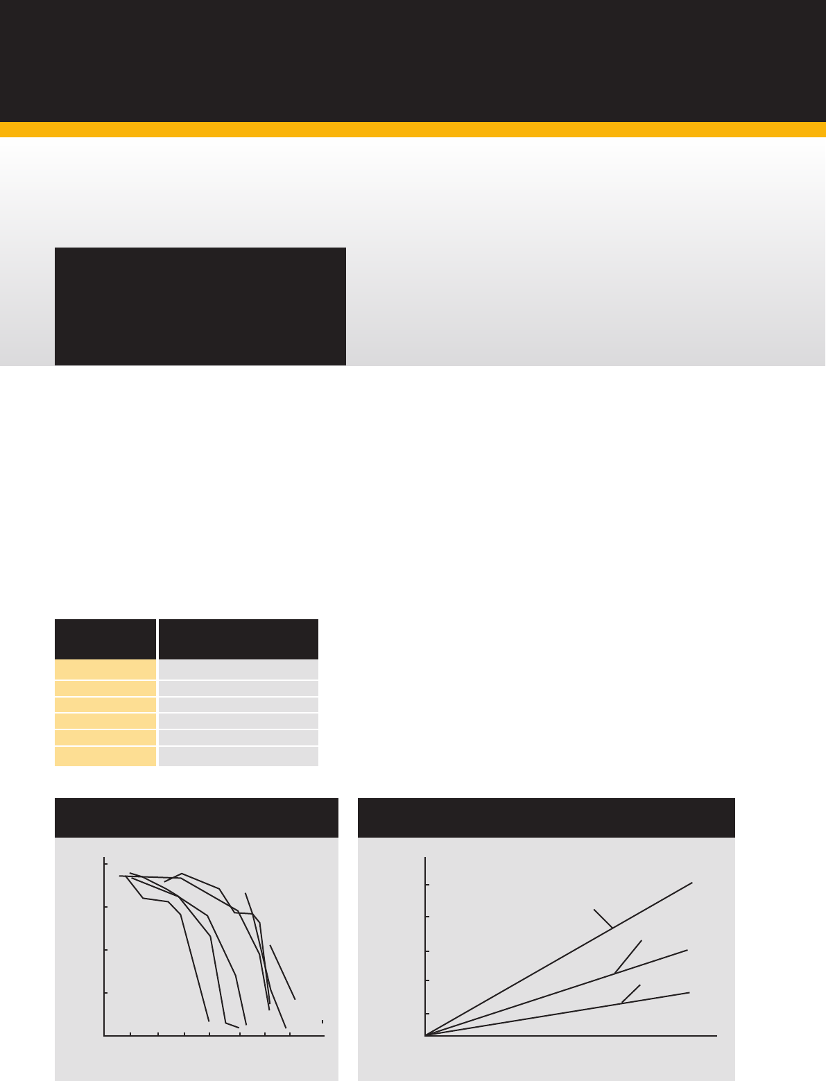
information.
TECHNICAL
INFORMATION
INITIAL GASKET
THICKNESS mm
RECOMMENDED COMPRESSED
THICKNESS mm
1. 6
1.3/1.4
2.5
1.9/2.0
3.2
2.3/2.5
4.5
3.2/3.4
6.4
4.6/5.1
7. 2
5.1/5.6
100
75
50
25
0
212 392 572 752 932 1112 1292
Carbon Steel
B7
B8M
B16
B80A
B17/660
B8
0
Temperature °F
Residual Stress (% of initial stress retained
after 1000 hours)
1472
100 (10)
80 (8)
60 (6)
40 (4)
20 (2)
54 (40) 81 (60) 108 (80) 136 (100) 163 (120)
Dry bolt with
no lubrication
As received
condition from
manufacturer
Lubricated with
molybdenum
disulphide
27 (20)
Torque Nm (lbft)
Load KN (tons)
STRESS RELAXATION OF BOLT STRESS & ALLOYS
AT UPPER TEMPERATURE LIMITS
THE IMPORTANCE OF BOLT LUBRICATION
REQUIRED GASKET COMPRESSION

22. www.flexitallic.com
INSTALLATION
PROCEDURES
In order to ensure the
optimum service life of
metallic gasket materials,
it is not only important to
choose the correct material
for the application but to
install and maintain it
correctly.
These guidelines are
designed to assist the
end user in the assembly
of gasket materials.
Installation of Metallic Gaskets
Flange Condition
• Remove the old gasket and check
that the flange faces are clean and free
from indentations and scoring. Radial
(cross face) scoring is a particular
concern and can lead to joint leakage
• For spiral wound gaskets, a surface
finish of between 3.2μm to 6.3μm Ra
(125 to 250 micro inch) is
recommended. Use a surface
comparator to check flange finishes.
• Check that the flange faces are parallel
or that the pipework is sufficiently
flexible to allow the flanges to be
pulled parallel and concentric without
excessive bolt loads.
Gasket
• Always use a new gasket
• Check that the gasket is in good
condition and that the dimensions are
correct for the class and size of the
flanges
• Do not use jointing compounds, grease
or lubricants with metallic gasket
materials. These compounds can affect
the contact friction between the gasket
and the flange and can lead to creep
and premature joint failure
• If there is a requirement to fix the
gasket to the flange prior to assembly
(e.g. large vertical flanges) then a light
dusting of spray adhesive e.g. 3M 77
spray may be used. The adhesive
should be applied sparingly and in
isolated areas, and must be compatible
with the fluid medium.
Bolting
• Ensure the bolt and nut threads are clean.
Apply bolt lubrication to the bolt and nut
threads and to the face of the nut to be
tightened. Do not apply grease or bolt
lubricant to the joint face. After cleaning
and lubrication it should be possible to run
the nut along the full length of the bolt by
hand. If this is not possible the bolts and
nuts should be refurbished or replaced
• Scrape, wire brush or file as necessary
the back face of each flange where the
bolt heads and nuts are to sit, ensuring
that the surfaces are clean and flat
• If possible use hardened flat washers to
ensure even transfer of the load.
Installation
• Ensure that the gasket is installed centrally
• It is recommended that the bolts are
tightened using a controlled method such as
torque or tension. If using a torque wrench,
ensure that it is accurately calibrated
• Tighten bolts in a star-like crossing
pattern in the following sequence
• Finger tighten nuts
• Tighten to 30% of the final load
• Tighten to 60% of the final load
• Tighten to full load
• Make a final tightening sequence, working
around the flange, tightening each bolt in
turn until the specified torque is achieved.
After Installation
Check that the flange faces are parallel using a
suitable tool e.g. the Flange Gap Tool, which is
available to purchase via The Academy of Joint
Integrity (www.academyofjointintegrity.com)
23.
TECHNICAL
INFORMATION
BOLTING DATA
For ASME B16.5 & BS 1560 Flanges
GENERAL NOTES
Flange Diameter and Bolt Diameter dimensions are in inches. Figures stated are for information only. Please refer to the current version of the original standards for dimensional information.
½ 3.50 4
1
⁄2 2.38 3.75 4
1
⁄2 2.62 3.75 4
1
⁄2 2.62 3.75 4
1
⁄2 2.62
¾ 3.88 4
1
⁄2 2.75 4.62 4
5
⁄8 3.25 4.62 4
5
⁄8 3.25 4.62 4
5
⁄8 3.25
1 4.25 4
1
⁄2 3.12 4.88 4
5
⁄8 3.50 4.88 4
5
⁄8 3.50 4.88 4
5
⁄8 3.50
1 ¼ 4.62 4
1
⁄2 3.50 5.25 4
5
⁄8 3.88 5.25 4
5
⁄8 3.88 5.25 4
5
⁄8 3.88
1 ½ 5.00 4
1
⁄2 3.88 6.12 4
3
⁄4 4.50 6.12 4
3
⁄4 4.50 6.12 4
3
⁄4 4.50
2 6.00 4
5
⁄8 4.75 6.50 8
5
⁄8 5.00 6.50 8
5
⁄8 5.00 6.50 8
5
⁄8 5.00
2 ½ 7.00 4
5
⁄8 5.50 7.50 8
3
⁄4 5.88 7.50 8
3
⁄4 5.88 7.50 8
3
⁄4 5.88
3 7.50 4
5
⁄8 6.00 8.25 8
3
⁄4 6.62 8.25 8
3
⁄4 6.62 8.25 8
3
⁄4 6.62
3 ½ 8.50 8
5
⁄8 7.00 9.00 8
3
⁄4 7.25 9.00 8
7
⁄8 7.25 9.00 8
7
⁄8 7.25
4 9.00 8
5
⁄8 7.50 10.00 8
3
⁄4 7.88 10.00 8
7
⁄8 7.88 10.75 8
7
⁄8 8.50
5 10.00 8
3
⁄4 8.50 11.00 8
3
⁄4 9.25 11.00 8
7
⁄8 9.25 13.00 8 1 10.50
6 11.00 8
3
⁄4 9.50 12.50 12
3
⁄4 10.62 12.50 12
7
⁄8 10.62 14.00 12 1 11.50
8 13.50 8
3
⁄4 11.75 15.00 12
7
⁄8 13.00 15.00 12 1 13.00 16.50 12 1
1
⁄8 13.75
10 16.00 12
7
⁄8 14.25 17.50 16 1 15.25 17.50 16 1
1
⁄8 15.25 20.00 16 1
1
⁄4 17.00
12 19.00 12
7
⁄8 17.00 20.50 16 1
1
⁄8 17.75 20.50 16 1
1
⁄4 17.75 22.00 20 1
1
⁄4 19.25
14 21.00 12 1 18.75 23.00 20 1
1
⁄8 20.25 23.00 20 1
1
⁄4 20.25 23.75 20 1
3
⁄8 20.75
16 23.50 16 1 21.25 25.50 20 1
1
⁄4 22.50 25.50 20 1
3
⁄8 22.50 27.00 20 1
1
⁄2 23.75
18 25.00 16 1
1
⁄8 22.75 28.00 24 1
1
⁄4 24.75 28.00 24 1
3
⁄8 24.75 29.25 20 1
5
⁄8 25.75
20 27.50 20 1
1
⁄8 25.00 30.50 24 1
1
⁄4 27.00 30.50 24 1
1
⁄2 27.00 32.00 24 1
5
⁄8 28.50
24 32.00 20 1
1
⁄4 29.50 36.00 24 1
1
⁄2 32.00 36.00 24 1
3
⁄4 32.00 37.00 24 1
7
⁄8 33.00
CLASS 150 CLASS 300 CLASS 400 CLASS 600
FLANGE NO. OF BOLT B.C. FLANGE NO. OF BOLT B.C. FLANGE NO. OF BOLT B.C. FLANGE NO. OF BOLT B.C.
DIAMETER BOLTS DIAMETER DIAMETER DIAMETER BOLTS DIAMETER DIAMETER DIAMETER BOLTS DIAMETER DIAMETER DIAMETER BOLTS DIAMETER DIAMETER
NOM
PIPE
SIZE
(inches)
GENERAL NOTES
Flange Diameter and Bolt Diameter dimensions are in inches. Figures stated are for information only.
Please refer to the current version of the original standards for dimensional information.
½ 4.75 4
3
⁄4 3.25 4.75 4
3
⁄4 3.25 5.25 4
3
⁄4 3.50
¾ 5.12 4
3
⁄4 3.50 5.12 4
3
⁄4 3.50 5.50 4
3
⁄4 3.75
1 5.88 4
7
⁄8 4.00 5.88 4
7
⁄8 4.00 6.25 4
7
⁄8 4.25
1 ¼ 6.25 4
7
⁄8 4.38 6.25 4
7
⁄8 4.38 7.25 4 1 5.13
1 ½ 7.00 4 1 4.88 7.00 4 1 4.88 8.00 4 1
1
⁄8 5.75
2 8.50 8
7
⁄8 6.50 8.50 8
7
⁄8 6.50 9.25 8 1 6.75
2 ½ 9.62 8 1 7.50 9.62 8 1 7.50 10.50 8 1
1
⁄8 7.75
3 9.50 8
7
⁄8 7.50 10.50 8 1
1
⁄8 8.00 12.00 8 1
1
⁄4 9.00
4 11.50 8 1
1
⁄8 9.25 12.25 8 1
1
⁄4 9.50 14.00 8 1
1
⁄2 10.75
5 13.75 8 1
1
⁄4 11.00 14.75 8 1
1
⁄2 11.50 16.50 8 1
3
⁄4 12.75
6 15.00 12 1
1
⁄8 12.50 15.50 12 1
3
⁄8 12.50 19.00 8 2 14.50
8 18.50 12 1
3
⁄8 15.50 19.00 12 1
5
⁄8 15.50 21.75 12 2 17.25
10 21.50 16 1
3
⁄8 18.50 23.00 12 1
7
⁄8 19.00 26.50 12 2
1
⁄2 21.25
12 24.00 20 1
3
⁄8 21.00 26.50 16 2 22.50 30.00 12 2
3
⁄4 24.38
14 25.25 20 1
1
⁄2 22.00 29.50 16 2
1
⁄4 25.00 ----
16 27.75 20 1
5
⁄8 24.25 32.50 16 2
1
⁄2 27.75 ----
18 31.00 20 1
7
⁄8 27.00 36.00 16 2
3
⁄4 30.50 ----
20 33.75 20 2 29.50 38.75 16 3 32.75 ----
24 41.00 20 2
1
⁄2 35.50 46.00 16 3
1
⁄2 39.00 ----
CLASS 900 CLASS 1500 CLASS 2500
FLANGE NO. OF BOLT B.C. FLANGE NO. OF BOLT B.C. FLANGE NO. OF BOLT B.C.
. DIAMETER BOLTS DIAMETER DIAMETER DIAMETER BOLTS DIAMETER DIAMETER DIAMETER BOLTS DIAMETER DIAMETER
NOM
PIPE
SIZE
(inches)
24. www.flexitallic.com
TECHNICAL
INFORMATION
FACING DIMENSIONS
For ASME B16.5 & BS 1560 Flanges
Class 150, 300, 400, 600, 900, 1500 and 2500
GENERAL NOTES
Flange Diameter and Bolt Diameter dimensions are in inches.
Figures stated are for information only.
Please refer to the current version of the original standards for dimensional information.
NOTES
1. Regular facing for class 150 and 300 steel flanged fittings and companion flange standards is a 0.06in raised face. Classes 400, 600, 900, 1500, and 2500
pipe flanges and fittings are regularly furnished with a 0.25in raised face. In all cases the raised face must be added to the minimum flange thickness.
2. Regular facing for class 400, 600, 900, 1500, and 2500 flange thickness dimensions.
3. Tolerance of plus or minus 0.016in. is allowed on the inside and outside diameters of all facings.
4. For small male and female joints care should be taken in the use of these dimensions to insure that pipe used is thick enough to permit sufficient bearing
surface to prevent the crushing of the gasket. The dimensions apply particularly on lines where the joint is made on the end of the pipe. Screwed companion
flanges for small male and female joints are furnished with plain face and are threaded with American Standard Locknut Thread.
5. Gaskets for male-female and tongue-groove joints shall cover the bottom of the recess with minimum clearances taking into account the tolerances
prescribed in Note 3.
½ 1.38 0.72 1.38 1.00 1.44 0.78 1.44 0.94 0.06 0.25 0.19
¾ 1.69 0.94 1.69 1.31 1.75 1.00 1.75 1.25 0.06 0.25 0.19
1 2.00 1.19 1.88 1.50 2.06 1.25 1.94 1.44 0.06 0.25 0.19
1-¼ 2.50 1.50 2.25 1.88 2.56 1.56 2.31 1.81 0.06 0.25 0.19
1-½ 2.88 1.75 2.50 2.12 2.94 1.81 2.56 2.06 0.06 0.25 0.19
2 3.62 2.25 3.25 2.88 3.69 2.31 3.31 2.81 0.06 0.25 0.19
2-½ 4.12 2.69 3.75 3.38 4.19 2.75 3.81 3.31 0.06 0.25 0.19
3 5.00 3.31 4.62 4.25 5.06 3.38 4.69 4.19 0.06 0.25 0.19
3-½ 5.50 3.81 5.12 4.75 5.56 3.88 5.19 4.69 0.06 0.25 0.19
4 6.19 4.31 5.69 5.19 6.25 4.38 5.75 5.12 0.06 0.25 0.19
5 7.31 5.38 6.81 6.31 7.38 5.44 6.88 6.25 0.06 0.25 0.19
6 8.50 6.38 8.00 7.50 8.56 6.44 8.06 7.44 0.06 0.25 0.19
8 10.62 8.38 10.00 9.38 10.69 8.44 10.06 9.31 0.06 0.25 0.19
10 12.75 10.50 12.00 11.25 12.81 10.56 12.06 11.19 0.06 0.25 0.19
12 15.00 12.50 14.25 13.50 15.06 12.56 14.31 13.44 0.06 0.25 0.19
14 16.25 13.75 15.50 14.75 16.31 13.81 15.56 14.69 0.06 0.25 0.19
16 18.50 15.75 17.62 16.75 18.56 15.81 17.69 16.69 0.06 0.25 0.19
18 21.00 17.75 20.12 19.25 21.06 17.81 20.19 19.19 0.06 0.25 0.19
20 23.00 19.75 22.00 21.00 23.06 19.81 22.06 20.94 0.06 0.25 0.19
24 27.25 23.75 26.25 25.25 27.31 23.81 26.31 25.19 0.06 0.25 0.19
OUTSIDE DIAMETER See note 3 OUTSIDE DIAMETER See note 3 HEIGHT
RAISED FACE,
LAPPED,
LARGE MALE,
& LARGE
TONGUES
See Note 5
NOM
PIPE
SIZE
(inches)
SMALL
MALE
See Notes
4 & 5
SMALL
TONGUE
See Note 5
I.D. OF
LARGE
& SMALL
TONGUE
See Notes
3 & 5
LARGE
FEMALE &
LARGE
GROOVE
See Note 5
SMALL
FEMALE
See Notes
4 & 5
SMALL
GROOVE
See Note 5
I.D. OF
LARGE
& SMALL
GROOVE
See Notes
3 & 5
RAISED
FACE CLASS
150 & 300
See Note 1
RAISED
FACE LARGE &
SMALL MALE
& TONGUE
CLASS 400, 600,
900, 1500 &
2500
See Note 2
DEPTH OF
GROOVE OR
FEMALE
25.
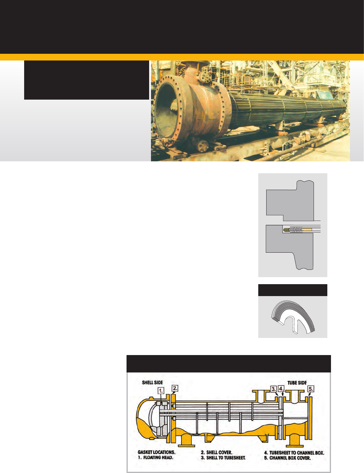
Heat Exchanger
Gaskets.
Exchanger Gaskets with Spiral Wound Outer Ring
(ALTERNATIVES HE-CG, HE-CGI)
Flexitallic special HE-CGI Gaskets with spiral wound
outer ring are primarily designed for TEMA male and
female flanges and are custom built to suit the design
conditions of individual heat exchanger vessels. These
gaskets are available in an extensive range of materials.
This style incorporates several special features,
as follows:
1. The outer wound nose to ensure correct sealing
element location in the flange recess.
2. A spiral wound sealing element to ensure a positive
seal under fluctuating temperature and pressure
conditions.
3. A solid metal inner ring to protect the sealing
element and act as a compression stop. As an
optional extra, inner rings can also be supplied with
nylon location screws to secure the gasket to the
flange on assembly.
4. Can be supplied with pass partition bars in any
configuration. Pass bars are secured to the inner ring
and can be supplied in either solid metal or double
jacketed construction.
SPECIAL APPLICATION
GASKETS
HEAT EXCHANGERS WITH FLAT FACE OR RAISED FACE FLANGES
SHOULD UTILISE STYLE CG AND CGI SPIRAL WOUND GASKETS
STYLE HX-RIR
26. www.flexitallic.com
SPECIAL APPLICATION
GASKETS
The carrier ring concept consists of a solid
metal ring with a machined recess in each
face. Spiral Wound Gaskets are then located
in each of the machined recesses.
This type of arrangement has been
successfully used in sealing problematic
flanges and vessels in the nuclear, power and
petrochemical industries. The major benefits
of the carrier ring assembly are due to the
double spiral wound gasket being present.
This results in a very high recovery gasket,
ensuring that the bolt load is maintained on
the sealing elements when arduous pressure
/ temperature cycling occurs in service, thus
maintaining a seal.
Carrier rings can be used on flat face, raised
face or tongue and groove type flange, as
well as non standard flange configurations.
They can be supplied for both small and large
diameter nominal bores up to class 2500
pressure rating. Carrier rings are also tailor
made to suit specific flange arrangements
and design conditions.
Carrier Ring
Gaskets.
Typical Applications
The carrier ring concept has been extensively
used in the power generation industries,
petrochemical and nuclear industries.
Typical applications are as follows:
Heat Exchanger
Operating Pressure: 2900 psi
Temperature: 200ºC
Tube Sheet
H.P. Heaters, Fossil Fired Generators,
H.O.T. Construction, Steam Service
Operating Pressure: 700 psi
Temperature: 370ºC
Materials Ultilised
316L/Flexicarb
®
17-7PH/Flexicarb
®
Inc X750 HT (Special high recovery material)
Catalytic Crackers
720ºC, Regenerators, 2980 mm OD
Hydrocarbon Service, Refineries
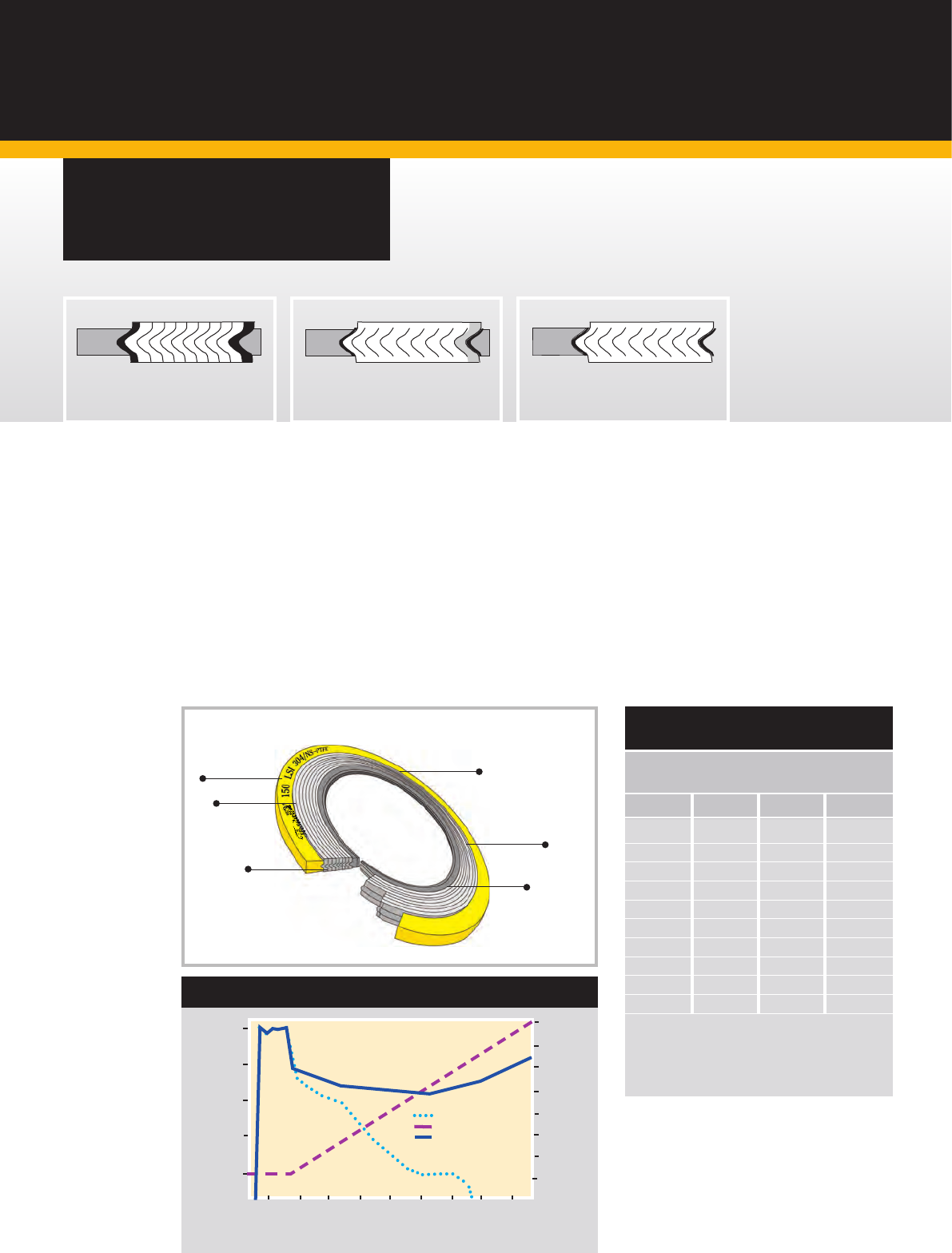
27.
Style LS
™
& LSI
Low Stress Range
of Spiral Wound
Gaskets.
The LS gasket offers the same high integrity seal
associated with the spiral wound gasket however,
the LS and LSI has been designed in such a way
that compression and sealing requirements are
achieved under very low seating stresses. These
gaskets are intended for use on class 150 and 300
applications, where customers traditionally do not
use Spiral Wound Gaskets due to concerns about
exceeding allowable design stresses.
The traditional spiral wound gasket has its steel
windings protruding above the compression stop;
this requires a significant loading stress to compress
the gasket to its optimum operating thickness.
The LS and LSI gaskets have only soft Flexicarb
®
or PTFE filler protruding above metal windings and
guide ring; therefore as the gasket is compressed,
the Flexicarb
®
or PTFE filler is readily compressed
thus producing the sealing mechanism at an earlier
stage as compared to the conventionally
manufactured spiral wound gasket.
The “LSI” gasket retains more of its initial
stress or tightness, even when subjected to
high temperatures, unlike PTFE sheet gaskets.
Available in a variety of metals, engineered
to suit specific applications.
GENERAL NOTES
Dimensions in mm.
Figures stated are for information only. Please refer to the current
version of the original standards for dimensional information.
Please select correct gasket style for your particular application.
See page 6 “Gasket Selection”.
LOWER BOLT STRESS-REDUCED
FUGITIVE EMISSIONS
Flexitallic recommend minimum bolt torque figures for
use with the ‘LSI’ gasket on ASME/B16.5 Flanges.*
Available with
Flexicarb,
Thermiculite™,
or PTFE filler
Low Stress
construction seals at
sheet gasket torques
Metallic centering
ring provides blowout
resistance and
compression stop
Colour coded and stamped
centering ring for easy
product identification
Spiral wound design
significantly reduces
gasket creep
Metallic inner ring
contains and protects
sealing elements
Patent #5161807/5275423
Traditional Spiral Wound Gasket
with Inner Ring
LSI Gasket LS Gasket
5000
4000
3000
2000
1000
0
0.5 1.0 1.5 2.0 2.5 3.0 3.5
1/16” PTFE Sheet
Temperature
LSI Gasket
Elapsed Test Time (hours)
Gasket Stress (psi)
4.0 4.5
Temperature (°F)
SPECIAL APPLICATION
GASKETS
FLEXITALLIC LSI VS. PTFE SHEET
800
700
600
500
400
300
200
100
0
NPS (in) N/m NPS (in) N/m
1/2 34 5 111
3/4 34 6 111
1 34 8 111
1 1/4 34 10 178
1 1/2 34 12 178
2 67 14 273
2 1/2 67 16 273
3 67 18 395
3 1/2 67 20 397
4 67 24 559
Note: Minimum Required torques may be even lower depending on
gasket size and bolt materials. Please contact Flexitallics Technical
Department for more information.
*Above torque values are for class 150 ASME flanges
Torque values for 300# available on request
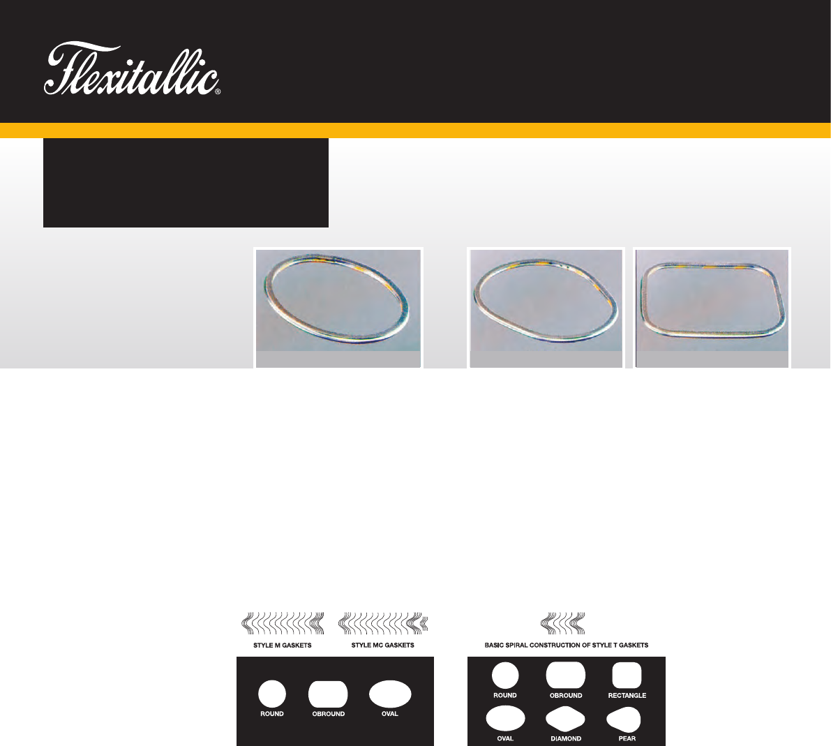
28. www.flexitallic.com
Style M & MC & MCS
Spiral Wound Gaskets for Boiler
Manhole Cover Assemblies.
The Flexitallic manhole gasket spiral
constructions incorporate modified
compression values to provide seating
loads within the normal range of cover
assemblies.
Size/Range Specification
Available in circular, obround, and oval
shapes to suit standard manhole plate
configurations.
Style T
Spiral Wound Gaskets for Boiler Handhole and Tubecap
Assemblies.
The design features of the basic Flexitallic spiral wound
construction alleviate the need for sealing compound. Particularly
suitable where old and pitted faces have rendered other gaskets
ineffective.
Size/Range Specification
Available in several standard shapes:
Supplied in thicknesses of 3.2mm (0.125in.) or 4.5mm (0.175 in.).
The standard thickness of 4.5mm (0.175in.) is recommended for
use in assemblies where the seat is relatively broad and bolting
load is low.
SPECIAL APPLICATION
GASKETS
Gaskets for boiler handhole, tubecap and
manhole covers incorporating the unique
Flexitallic Spiral Wound profile and
specially manufactured with Flexicarb
®
filler, are ideal for corrosive, high
pressure or temperature duties.
Flexitallic’s anticipation of developments
in modern steam generating and
engineering equipment and ability to
design to specific requirements are the
guarantee of the perfect seal at minimum
maintenance cost with consistently high
standards of performance.
• High safety factor related to specific
operating conditions
• Compression loadings proportional to
safe stresses of cover assemblies
• Resilient under concentrated and
fluctuating loads
• Prolonged trouble-free service
• Reduced seat cleaning time
For Boiler Cap and
Manhole Cover
Assemblies.
Standard Style M Style T Pear Style T Square
Materials
Standard materials are Type 304 Stainless Steel
and Flexicarb windings. Special materials to suit
specific operating conditions are available.
To Order
With all orders or inquiries please submit
the following:
a) Name of boiler or equipment manufacturer
b) Gasket style
c) Dimensions of gasket
d) Gasket thickness
e) Flange width of gasket
f) Pressure service rating
g) Gasket material preference
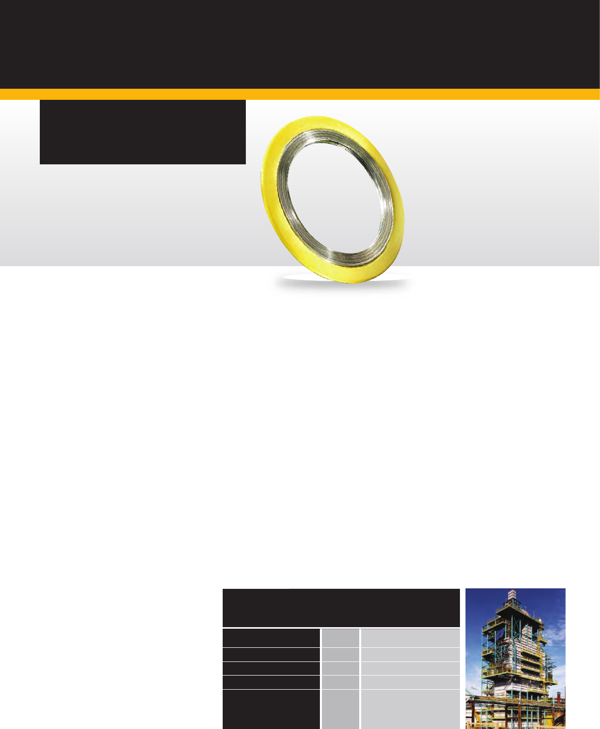
29.
SPECIAL APPLICATION
GASKETS
Thermiculite
®
835 Spiral Wound Gasket
with Heat Treated Inconel X-750 Winding
Ethylene Cracker Unit
Thermiculite
®
835 Heat
Treated Inconel X-750
Spiral Wound Gasket.
Increased safety.
Proven results.
Proven cost savings.
Severe cyclic conditions?
For the most demanding cyclic conditions, the
choice is Flexitallic’s Thermiculite
®
835 Spiral
Wound Gasket with Heat Treated Inconel
X-750 winding.
Differential thermal expansion and contraction
of components in a bolted joint, due to the effects
of cyclic conditions, requires that extra resiliency
be built into the joint or the gasket to compensate
for fluctuating load conditions.
Normal gasket materials do not provide sufficient
resiliency, and therefore cannot compensate for
the adverse effects of cyclic conditions. Special
Heat Treated Inconel X-750 gasket materials have
been developed by Flexitallic to ensure that joint
integrity is maintained during thermal cycles.
In OEM and End User testing comparing the
performance of standard 316L SS windings
vs. Heat Treated Inconel X-750 windings
(precipitation hardened), HT Inconel X-750
winding material significantly increased the yield
strength resulting in increased springback before
leakage, or usable recovery.
Specify Flexitallic’s proprietary precipitation
hardened Inconel X-750 windings in
applications where there are concerns about:
• Cyclic conditions
• Differential thermal expansion
and contraction
• Radial shear
• Bolt relaxation
• Hot torquing
• Mating flanges of dissimilar metals
When ordering this material it is
important that you specify Precipitation
Hardened Inconel X750 Windings,
or Inconel X750HT.
FULL SCALE TEST RESULTS (AVERAGED)
GASKET DIMENSIONS 1032 x 1067 x 4.5
Winding Material 316L SS Heat Treated Inconel X-750
Initial Thickness 4.5 4.5
Compressed Thickness 3.1 3.1
Total Springback 0.3 0.3
Spingback to
Leakage @ 2500 psi 0.1 0.2
Test Pressure
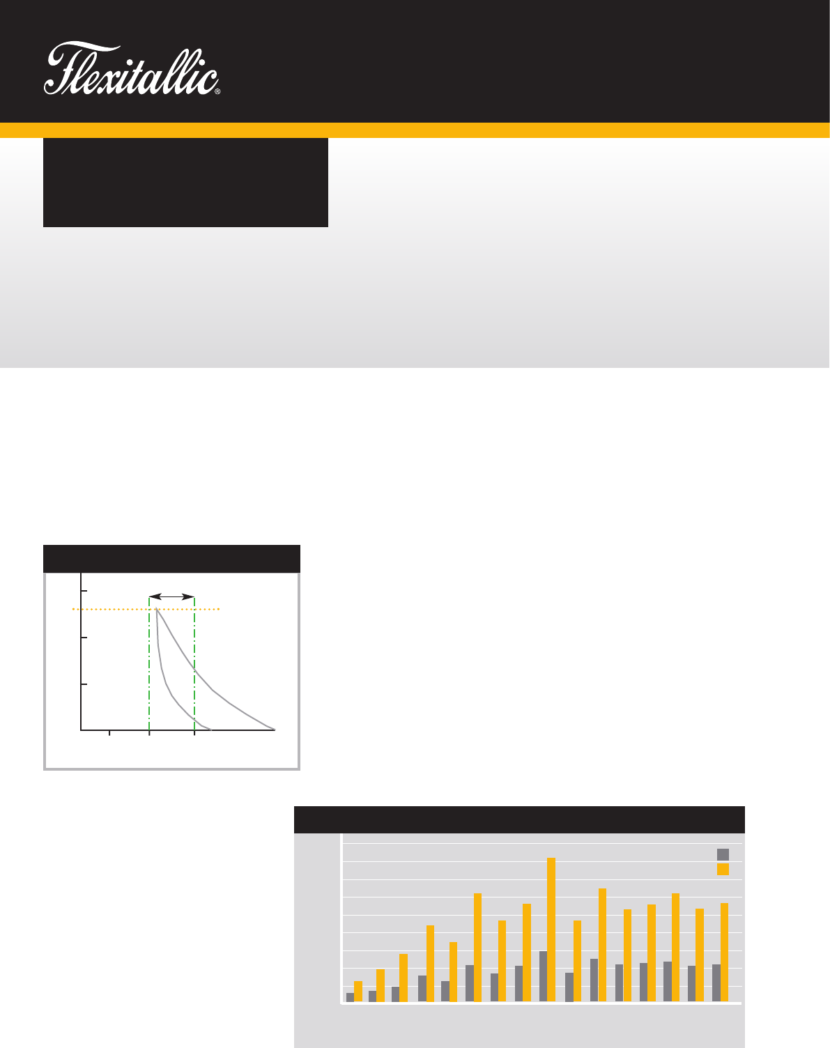
30. www.flexitallic.com
SPECIAL APPLICATION
GASKETS
Low Emission Gasket.
The Flexitallic Low Emission gasket
is a high performance spiral wound gasket
that has been specially engineered to
exceed stringent oil and gas industry
fugitive emissions requirements, such
as those found in the Chevron Fugitive
Emissions Test (CFET).
Gaskets to suit standard ASME B16.5
and B16.47 flanged connections remain
diametrically unchanged and in this respect
are dimensionally compliant with ASME
B16.20. Enhanced sealing performance is
achieved by modification of the sealing
element. The key design features are
specification of the filler thickness range
0.36 to 0.41mm; ASME B16.20 does not
specify filler thickness and typically 0.5mm
thick is used. In addition filler protrusion is
specified to be within the range of 0.2 to
1.0mm above the metal winding; resulting
in a thicker sealing element.
Compression requirements for LE gaskets
are different from those specified in ASME
B16.20 that stipulates a compressed
sealing element
thickness for a given bolt stress
irrespective of pressure class. LE gaskets
are required to compress within specified
limits based on directly applied gasket
stress. Gaskets made to LE construction
requirements are designed to compress
to between 0.76 and 1.27mm above the
guide ring thickness when subjected to
a compressive stress of 128 MPa
(see diagram A, left).
Independent testing in accordance
with the CEFT protocol has shown that
Flexitallic LE gaskets comfortably exceed
allowable fugitive emissions leakage
levels. Leakage testing of ASME Class 150
CGI spiral wound gaskets in accordance
with the PVRC ROTT procedure shows that
Flexitallic LE gaskets require significantly
lower bolt stress to achieve a T3 tightness
class (see diagram B, below).
For more information regarding Flexitallic
Low Emission spiral wound gaskets please
contact the Flexitallic Applications
Engineering Team.
450
400
350
300
250
200
150
100
50
0
1
⁄2
3
⁄4
11
1
⁄2
2 3 4 6 8 10 12 14 16 18 20 24
Nominal Pipe Size (NPS) inches
Bolt Stress (MPa)
150
T
T - Guide ring thickness
Defection (mm)
Gasket Stress (MPa)
DIAGRAM A
100
50
T +0.76
T +1.27
Compression Range
128
B: STD SWG V LE SWG 150 CLASS FLANGE T3 PVRC TIGHTNESS
LE
ST
D
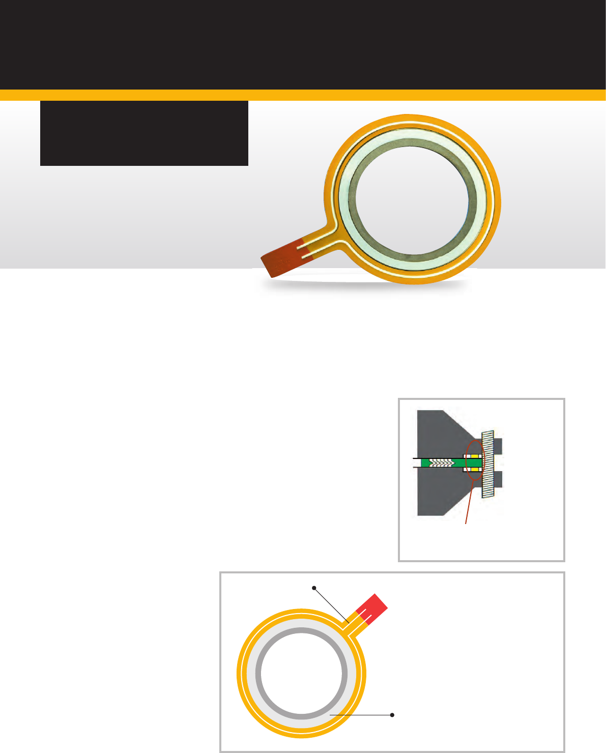
31.
SPECIAL APPLICATION
GASKETS
Any HF emissions are focused to the tagged
area where a reaction with the detector paint
can be easily observed. This concept has
been successfully field tested.
PTFE Channel Ring
Spiral Wound Gasket utilising PTFE
or Flexicarb filler materials
The Baker Gasket.
For HF Acid & other
hazardous chemical
applications.
Problem
A leak occurs on HF service
•
HF can attack the bolts causing bolt failure.
•
A small emission goes undetected.
Solution
•
Prevents HF attacking the bolts.
•
Early detection of small leaks.
•
Containment of HF emissions.
•
Improves maintenance (detect & repair).
•
Requires no modification to the flanges.
•
Designed to suit Class 150 & 300 flanges.
•
Contains no respirable fibers.
What are the benefits?
The Baker gasket offers the user the reliability of
a spiral wound gasket with the additional back-up
of an emissions containment system should a leak
occur. Reduced maintenance costs through an
improved ‘Detect & Repair’ program. Improvements
in plant operators Health & Safety profile.
A PTFE ring is attached to the external
guide ring. Any emissions will be
confined within the flange arrangement.

32. www.flexitallic.com
Flexitallic can offer
speciality training
and consultancy via
The Academy of
Joint Integrity.
Courses
Training can be delivered in a variety
of ways:
• At the Academy, utilising our purpose
built training centres
• At the clients premises, utilising mobile
training rigs and equipment
• At one of our training facilities in
Aberdeen, Teesside and Humberside
Benefits
• Legislation compliance
• Motivated workforce with
best practice skills
• Reduced costs with increased
asset integrity
• Access to the latest technical standards
and procedures
• Sealing and integrity modules providing
greater knowledge
• Alliance and structured support from a
world class technical / training team
For further information on the
range of courses available visit
www.academyofjointintegrity.com
Training Courses
The Academy of Joint Integrity offers
Accredited and Awareness Training
Courses to all personnel who are involved
in the assembly and tightening of flanged
bolted connections. Mentoring and
assessment programmes also complement
the training provision. All our training
courses are given by industry
professionals who themselves have
current and relevant industry-based
experience.
The Academy is a member of the Energy
Institute and has contributed to the latest
UK Oil and Gas best practice guidelines,
specific to Joint Integrity Management.
The Academy is also an active member
of an ASME sub-committee, developing
new initiatives for Pressure Boundary
Bolted Flange Joint Assembly.
Academy training courses incorporate
ECITB Mechanical Joint Integrity MJI10,
MJI18, MJI19, Energy Institute, European
(EN1591 part 4) and ASME PCC-1 2013
methods and procedures.
Location
The Academy has dedicated facilities
in Aberdeen, Teesside, Humberside
and West Yorkshire.
Training is also offered within our
overseas operations.
“Fundamental to successful
joint integrity is the training
of the personnel involved in
the process of inspection,
assembly and tightening
of bolted connections.
The Academy provides
a range of cost effective
tailored training courses to
suit the needs of the client
or contractor.”
Gary Milne
Technical Training Manager
THE ACADEMY OF
JOINT INTEGRITY
For more information on our range
of product and services please
visit www.flexitallic.com or
email [email protected]
PRODUCT
RANGE:
• Corriculite
®
• Change
™
Gasket
• Thermiculite
®
• I-Flex Isolation Kits
• Sigma
®
PTFE
• Flange Rescue Gaskets (FRG)
• Spiral Wound Gaskets
• Kammprole Gaskets
• Ring Type Joints
• HDS1 Insulating Kits
• Novus Sheet Jointing
• Cut Gaskets
• Solid Metallic Gaskets
• Compression Packings
• Academy of Joint Integrity
– Training

FLEX003–OCT2019–REV8
Designed by Clear Design (North). E. [email protected]
www.flexitallic.com
About The Flexitallic Group
The Flexitallic Group is a global leader in specialised
sealing solutions and products serving the oil and gas, power
generation, chemical and petrochemical industries in emerging
and developed markets. Focused on the upstream, downstream
and power generation sectors, it has operations in France, the
United States, Canada, Mexico, the United Kingdom, Germany,
Italy, Belgium, the United Arab Emirates, Thailand and China
plus a network of worldwide licensing partners and distributors.
www.theflexitallicgroup.com
FRANCE
Siem Supranite
a Flexitallic Company
31-33 Rue de Mogador
75009 Paris
FRANCE
Tel. +33 (0)1 48 88 88 88
Fax. +33 (0)1 47 66 88 44
www.siem.fr
UNITED KINGDOM
Flexitallic UK Ltd
Scandinavia Mill
Hunsworth Lane
Cleckheaton
West Yorkshire, BD19 4LN
UK
Tel. +44 1274 851273
Fax. +44 1274 300303
www.flexitallic.com
Branches also in Aberdeen,
Middlesbrough, Ellesmere
Port and South West.
CANADA
Flexitallic Canada Ltd
4340 - 78 Avenue
Edmonton
Alberta, T6B 3J5
CANADA
Tel. +780 466 5050
Fax. +780 465 1177
www.flexitallic.com
SINGAPORE
Flexitallic Ltd
Singapore Branch
Level 42 Suntec Tower Three
8 Temasek Boulevard
SINGAPORE
038988
Tel. +65 68663638
www.exitallic.com
BENELUX
Flexitallic Benelux BVBA
Smallandlaan 21
2660 Hoboken
BELGIUM
Tel. + 32 3 369 19 68
www.flexitallic.com
UNITED STATES
Flexitallic US LLC
6915 Highway 225
Deer Park
Texas 77536
USA
Tel. +1 281 604 2400
Fax. +1 281 604 2415
www.flexitallic.com
UNITED ARAB EMIRATES
Flexitallic LLC
PO Box No. 6591-Al Jazeera
Plot 108, Road E, Al Hamra Industrial
Ras Al Khaimah
UNITED ARAB EMIRATES
Tel. +971 (0)7 243 4305
Fax. +971 (0)7 243 4306
www.flexitallic.com
GERMANY
Flexitallic GmbH
Halskestr. 4a
47877 Willich
GERMANY
Tel. +49 (0) 2154 95363-0
Fax. +49 (0) 2154 95363-29
www.flexitallic.com
CHINA
Flexitallic Gasket Technology
(Suzhou) Co., Ltd
Building A, 1868 Guangming Rd
Technological Development Zone
WuJiang Economic 215200
CHINA
Tel. +86 512 6303 2839
Fax. +86 512 6303 2879
www.flexitallic.com
UNITED STATES
Custom Rubber Products
2625 Bennington
Houston
Texas 77093
USA
Tel. +1 713 691 2211
Fax. +1 713 691 3005
www.customrubber.com
ITALY
Flexitallic Italy Sr.l
Via Leonardo Da Vinci 6B
26020 Ticengo CR
ITALY
Tel. +39 0374 71006
Fax. +39 0374 71277
www.flexitallic.com
THAILAND
Flexitallic Sealing
Technology Co Ltd
No. 7/456, Moo 6,
Amata City Rayong Industrial Estate
Mabyangporn Sub-district
Pluak Daeng District,
Rayong Province
THAILAND
Tel. +66 (0)33017561 ~ 3
Fax. +66 (0)33017564
www.exitallic.com
