

Neutron
Diffusion and
Moderation
Simon
Cöster
Outline
Fick’s Law
The
Equation of
Continuity
The
Diffusion
Equation
Solutions to
The
Diffusion
Equation
The Group
Diffusion
Method
Fick’s Law
Diffusion theory is based on Fick’s Law
Solute will diffuse from high concentration to low
Fick’s Law
J = −D∇φ,
where D is the diffusion coefficient, φ is the neutron flux and J
is the neutron current density vector.

Neutron
Diffusion and
Moderation
Simon
Cöster
Outline
Fick’s Law
The
Equation of
Continuity
The
Diffusion
Equation
Solutions to
The
Diffusion
Equation
The Group
Diffusion
Method
The Equation of Continuity
Since neutrons do not disappear (β-decay neglected) the
following must be true for an arbitrary volume V .
[Rate of change in number of neutrons inV ] =
[rate of production of neutrons inV ]
− [rate of absorption of neutrons inV ]
− [rate of leakage of neutrons fromV ]

Neutron
Diffusion and
Moderation
Simon
Cöster
Outline
Fick’s Law
The
Equation of
Continuity
The
Diffusion
Equation
Solutions to
The
Diffusion
Equation
The Group
Diffusion
Method
The Equation of Continuity
In mathematical terms the Equation of Continuity can be
expressed as
Neutron change rate =
Z
V
∂n
∂t
dV
Production rate =
Z
V
sdV
Absorption rate =
Z
V
Σ
a
φdV
Leakage rate =
Z
V
∇JdV

Neutron
Diffusion and
Moderation
Simon
Cöster
Outline
Fick’s Law
The
Equation of
Continuity
The
Diffusion
Equation
Solutions to
The
Diffusion
Equation
The Group
Diffusion
Method
The Equation of Continuity
This gives the general Equation of Continuity
The Equation of Continuity
∂n
∂t
= s − Σ
a
φ − ∇J,
where n is the density of neutrons, s is the rate at which
neutrons are emitted from sources per cm
3
, Σ
a
is the
macroscopic absorption cross-section, J is the neutron current
density vector and φ is the neutron flux.

Neutron
Diffusion and
Moderation
Simon
Cöster
Outline
Fick’s Law
The
Equation of
Continuity
The
Diffusion
Equation
Solutions to
The
Diffusion
Equation
The Group
Diffusion
Method
The Diffusion Equation
Two unknowns; the neutron density n and the neutron
current density vector J.
Substitute Fick’s law into the equation
The Diffusion Equation
General:
D∇
2
φ − Σ
a
φ + s =
∂n
∂t
Time-independent:
D∇
2
φ − Σ
a
φ + s = 0
or
∇
2
φ −
1
L
2
φ +
s
D
= 0,
where L
2
=
D
Σ
a
. L is called the diffusion length.

Neutron
Diffusion and
Moderation
Simon
Cöster
Outline
Fick’s Law
The
Equation of
Continuity
The
Diffusion
Equation
Solutions to
The
Diffusion
Equation
The Group
Diffusion
Method
Solutions to The Diffusion Equation
Infinite Planar Source
φ =
SL
2D
e
−|x|/L
Point Source
φ =
S
4πDr
e
−r/L
Bare Slab, width 2a (˜a = a + d is called extrapolated
boundary)
φ =
SL
2D
sinh[(˜a − |x|)/L]
cosh(˜a/L)

Neutron
Diffusion and
Moderation
Simon
Cöster
Outline
Fick’s Law
The
Equation of
Continuity
The
Diffusion
Equation
Solutions to
The
Diffusion
Equation
The Group
Diffusion
Method
The Group Diffusion Method
Neutrons emitted with a continuous energy spectrum.
Divided into N energy intervals.
Averaged diffusion coefficients and cross-section.
The flux of neutrons in a group g is described by
φ
g
=
Z
g
φ(E )dE ,
where φ(E ) is the energy-dependent neutron flux.

Neutron
Diffusion and
Moderation
Simon
Cöster
Outline
Fick’s Law
The
Equation of
Continuity
The
Diffusion
Equation
Solutions to
The
Diffusion
Equation
The Group
Diffusion
Method
The Group Diffusion Method
The absorption rate in a specific group is given by
Absorption rate =
Z
g
Σ
a
(E )φ(E )dE
We can define the macroscopic group absorption cross-section,
Σ
ag
, as
Σ
ag
=
1
φ
g
Z
g
Σ
a
(E )φ(E )dE
Then the absorption rate can be written as
Absorption rate = Σ
ag
φ
g

Neutron
Diffusion and
Moderation
Simon
Cöster
Outline
Fick’s Law
The
Equation of
Continuity
The
Diffusion
Equation
Solutions to
The
Diffusion
Equation
The Group
Diffusion
Method
The Group Diffusion Method
The rate at which neutrons transfers from group g to h is given
by
Transfer rate = Σ
g→h
φ
g
,
where Σ
g→h
is called the group transfer cross-section.
Total transfer rate out of g =
N
X
h=g +1
Σ
g→h
φ
g
Analogy, the rate at which neutrons transfers from group h into
g is given by
Total transfer rate into g =
g−1
X
h=1
Σ
h→g
φ
h

Neutron
Diffusion and
Moderation
Simon
Cöster
Outline
Fick’s Law
The
Equation of
Continuity
The
Diffusion
Equation
Solutions to
The
Diffusion
Equation
The Group
Diffusion
Method
The Group Diffusion Method
This gives the steady-state diffusion equation for group g
The Diffusion Equation for Groups
D
g
∇
2
φ
g
− Σ
ag
φ
g
−
N
X
h=g +1
Σ
g→h
φ
g
+
g−1
X
h=1
Σ
h→g
φ
h
+ s
g
= 0
where the group-diffusion coefficient D
g
is defined by
D
g
=
1
φ
g
Z
g
D(E )φ(E )dE
These calculations are done by computers.

Neutron
Diffusion and
Moderation
Simon
Cöster
Outline
Fick’s Law
The
Equation of
Continuity
The
Diffusion
Equation
Solutions to
The
Diffusion
Equation
The Group
Diffusion
Method
The Group Diffusion Method
At least two groups must be used to obtain reasonable
result
Thermal neutrons and fast neutrons
For a point source emitting S fast neutrons per second, the
Diffusion Equation can be written (Σ
1
= Σ
1→2
)
∇
2
φ
1
−
Σ
1
D
1
φ
1
= 0
Σ
a1
≈ 0 above thermal energies.
Only two groups → only Σ
1→2
is non-zero in the third term
No thermal neutrons are scattered into the fast group.

Neutron
Diffusion and
Moderation
Simon
Cöster
Outline
Fick’s Law
The
Equation of
Continuity
The
Diffusion
Equation
Solutions to
The
Diffusion
Equation
The Group
Diffusion
Method
The Group Diffusion Method
For neutrons in the thermal group, the diffusion equation can
be written
∇
2
φ
T
−
1
L
2
T
φ
T
=
Σ
1
φ
1
D
Necessary to solve for fast neutrons first
φ
1
=
Se
−r/
√
τ
T
4πD
1
r
.
Then
φ
T
=
SL
2
T
4πD(L
2
T
− τ
T
)
(e
−r/L
T
− e
−r/
√
τ
T
),
where τ
T
=
D
1
Σ
1
and L
2
T
=
D
Σ
a


One-group reactor equation
Time-dependent diffusion equation
D∇
2
φ − Σ
a
φ + s = −
1
v
∂φ
∂t
(1)
where D and Σ
a
are the one-group diffusion coefficient and
macroscopic absorption cross-section for fuel-coolant mixture.
s = νΣ
f
φ (2)
If the source term is to balance the leak and absorption in (1), we
get
D∇
2
φ − Σ
a
φ +
1
k
νΣ
f
φ = 0 (3)
Ola Håkansson Reactor theory


One-group reactor equation
For an infinite reactor all neutrons are absorbed, the multiplication
factor k
∞
is
k
∞
=
ηf Σ
a
φ
Σ
a
φ
= ηf (11)
and the source term can now be written as
s = k
∞
Σ
a
φ (12)
and we now have
−DB
2
φ − Σ
a
φ +
k
∞
k
Σ
a
φ = −
1
v
∂φ
∂t
(?) (13)
For a critical reactor (k = 1), we get
B
2
=
k
∞
− 1
L
2
, L
2
=
D
Σ
a
(14)
Ola Håkansson Reactor theory

The slab reactor
For a critical, infinite bare slab of thickness a the reactor equation is
d
2
φ
dx
2
+ B
2
φ = 0 (15)
Boundary conditions: φ vanishes at x =
˜
a/2 and at x = −
˜
a/2
where
˜
a = a + 2d. Note symmetry and
dφ
dx
= 0|
x=0
.
General solution to (15) is
φ(x) = A cos Bx + C sin Bx (16)
which reduces to
φ(x) = A cos Bx (17)
when making use of the condition on the derivative.
Ola Håkansson Reactor theory


The slab reactor
A can be found by calculating the power of the reactor P.
P = E
R
Σ
f
Z
a/2
−a/2
φ(x)dx (21)
where E
R
is the recoverable energy per fission and Σ
f
φ(x) are the
number of fissions at the point x. Introducing
φ(x) = A cos
πn
˜
a
(22)
and solve (21) for A, we get
A =
πP
2
˜
aE
R
Σ
f
sin
πa
2˜a
(23)
Ola Håkansson Reactor theory

The spherical reactor
Critical, spherical reactor with radius R - The flux only depends on
r. The reactor equation is
1
r
2
d
dr
r
2
dφ
dr
+ B
2
φ = 0 (24)
with the boundary condition φ(
˜
R) = 0 as well as the flux must be
finite.
Solution to (24) is given by
φ = A
sin Br
r
+ C
cos Br
r
(25)
and reduces to
φ = A
sin Br
r
(26)
since the flux must be finite when r = 0.
Ola Håkansson Reactor theory


The finite cylinder reactor
Finite cylindrical reactor with height H and radius R. The flux here
depends on the distance r from the axis and the distance z from
the midpoint of the cylinder. The reactor equation takes the form
1
r
∂
∂r
r
∂φ
∂r
+
∂
2
φ
∂z
2
+ B
2
φ = 0 (37)
The boundary conditions in this case are
φ(
˜
R, z) = φ(r ,
˜
H/2) = 0 (38)
Ola Håkansson Reactor theory

The finite cylinder reactor
Assuming the solution can be obtained by separation of variables
φ(r, z) = R(r )Z (z) (39)
we now get
1
R
1
r
∂
∂r
r
∂R
∂r
+
1
Z
∂
2
Z
∂z
2
= −B
2
(40)
This implies that the first and second term of (40) must be
constants. This gives that
d
2
R
dr
2
+
1
r
dR
dr
+ B
2
r
R = 0,
d
2
Z
dz
2
+ B
2
z
= 0 (41)
where B
2
r
+ B
2
z
= B
2
. Both of the equations in (41) have been
solved earlier.
Ola Håkansson Reactor theory

Maximum-to-average flux and power
The ratio between φ
max
and φ
average
, Ω, is in some cases of
interest. φ
max
, in a uniform bare reactor is always found at the
center pf the reactor. In the case of a bare spherical reactor, the
maximum flux is obtained from the limit
φ
max
=
P
4E
R
Σ
f
R
2
lim
r→0
sin (πr /R)
r
=
πP
4E
R
Σ
f
R
3
(42)
The average flux is given by
φ
average
=
1
V
Z
φdV (43)
Ola Håkansson Reactor theory


Thermal reactors
an infinite reactor composed of a homogeneous fuel-moderator
mixture. Σ
a
is the macroscopic cross-section of the mixture so that
Σ
a
= Σ
aF
+ Σ
aM
(48)
Letting
f =
Σ
aF
Σ
a
(49)
it is clear that f Σ
a
φ
T
neutrons are absorbed per cm
3
/sec in the
fuel. If η
T
is the average number of neutrons emitted per thermal
neutron absorbed in the fuel, η
T
f Σ
a
φ
T
neutrons are emitted per
cm
3
/sec.
Ola Håkansson Reactor theory

Thermal reactors
The multiplication factor of the reactor is given by the four-factor
formula
k
∞
= η
T
fp (50)
where is defined as the ratio of the total number of fission
neutron produces by both fast and thermal fission to the number
produced by only thermal fission and p is the probability that a
fission neutron is not absorbed at any other energies than thermal.
Ola Håkansson Reactor theory

Thermal reactors, criticality calculation
Two-group calculation with fast and thermal neutrons.
η
T
f Σ
a
φ
T
= (k
∞
/p)Σ
a
φ
T
neutrons are emitted to the fast group
and Σ
1
φ
1
are scattered out of the group. The diffusion equation for
the fast group is
D
1
∇
2
φ
1
− Σ
1
φ
1
+
k
∞
p
Σ
a
φ
T
= 0 (51)
With pΣ
1
φ
1
neutrons entering the thermal group (i.e the source)
the diffusion equation for the thermal group is
D∇
2
φ
T
− Σ
a
φ
T
+ pΣ
1
φ
1
= 0 (52)
Ola Håkansson Reactor theory


Reflected reactors
For a spherical reactor with a core and infinite reflector, there are
two reactor equations - One for the core and one for the reflector.
In this case,
∇
2
φ
c
+ B
2
φ
c
= 0 (58)
and
∇
2
φ
r
−
1
L
2
r
φ
c
= 0 (59)
These must be solved and satisfy continuity of the neutron flux at
the boundary between the core and reflector (quite lengthy
calculations).
Ola Håkansson Reactor theory

Multigroup calculation
One-group method is a rough estimate. More accurate results are
obtained by multigroup calculations.
Σ
fg
is the group-averaged macroscopic fission cross-section
ν
g
is the average number of fission neutron from fission
induced by group g
X
g
is the fraction of fission neutrons emitted with energies in
the group g
The multigroup equation for group g is then
D
g
∇
2
φ
g
−Σ
ag
φ
g
−
N
X
h=g +1
Σ
g→h
φ
g
+
g−1
X
h=1
Σ
h→g
φ
h
+X
g
N
X
h=1
ν
h
Σ
fh
φ
h
= 0
(60)
.
Ola Håkansson Reactor theory


Reactor Physics tutorial
Heterogeneous reactors
Quasi-homogeneous vs. heterogeneous reactors
Quasi-homogeneous vs. heterogeneous reactors
I
Most reactors are non-homogeneous: fuel (rods), coolant,
moderator (if thermal reactor) are separated
I
Even such a reactor may be considered to be
quasi-homogeneous
I
Mean free path λ larger than fuel rod dimensions at all E
n
I
> 1 collision in fuel rod unlikely
I
If λ . fuel rod dimensions at some energy: multiple collisions
probable ⇒ Heterogeneous reactor
Examples
I
Highly enriched fuel ⇒ thin fuel rods ⇒ quasi-homogeneous
I
Slightly enriched fuel ⇒ thicker fuel rods ⇒ heterogeneous

Reactor Physics tutorial
Heterogeneous reactors
Heterogeneous reactor parameters
Heterogeneous reactor parameters
η
T
I
Average number of fission neutrons produced per neutron
absorbed by fuel (thermal neutrons)
I
Example fuel rod contents:
235
U,
238
U,
16
O
I
Average number of fission neutrons produced: νΣ
f
I
Σ
f ,238
= 0 at thermal energies
I
Absorption cross section for
16
O ≈ 0
η
T
=
ν
f ,235
Σ
f ,235
Σ
a,235
+ Σ
a,238

Reactor Physics tutorial
Heterogeneous reactors
Heterogeneous reactor parameters
Heterogeneous reactor parameters
f - Thermal utilization
I
Probability that neutron absorbed in core is absorbed in the
fuel
I
Number of neutrons absorbed in volume (fuel/moderator) per
second:
Z
V
Σ
a
φ
T
dV = Σ
a
φ
T
V
f =
Σ
aF
V
F
Σ
aF
V
F
+ Σ
aM
V
M
ζ
I
ζ =
φ
TM
φ
TF
: thermal disadvantage factor. Generally, ζ > 1 in
heterogeneous reactor
I
f is calculated numerically. Analytical solutions (Wigner-Seitz
method) only rough approximation in most cases

Reactor Physics tutorial
Heterogeneous reactors
Heterogeneous reactor parameters
Heterogeneous reactor parameters
k
∞
- Multiplication factor in infinite reactor
I
Four-factor formula: k
∞
= η
T
fp
I
Thermal utilization: f
hetero
< f
homo
I
Resonance escape probability: p
hetero
> p
homo
. Increases more
than f decreases ⇒ (fp)
hetero
> (fp)
homo
I
Fast fission factor:
hetero
>
homo
k
∞
|
hetero
> k
∞
|
homo
Homogeneous reactor containing natural uranium and graphite:
k
∞
≤ 0.85 ⇒ non-critical. Rods of same fuel (heterogeneous
reactor) ⇒ critical reactor possible.

Reactor Physics tutorial
Classification of time problems
Classification of time problems
Time-dependent neutron population
I
Short Time Problems (seconds - tens of minutes)
I
Reactor conditions altered ⇒ change in k
I
Intermediate Time Problems (hours - 1 or 2 days)
I
Radioactive decay of fission products ⇒ change in
concentration
I
Fission product concentration affects absorption term
I
Long Time Problems (days - months)
I
Variation of neutron flux over long periods.
I
Assume system in series of stationary states. Solve diffusion
equation for each configuration:
D∇
2
φ − Σ
a
φ = λνΣ
f
φ
I
Change design parameters (buckling, absorption/fission
cross-sections) so that λ = 1
Reactor Physics tutorial
Reactor kinetics
Prompt Neutron Lifetime
Prompt Neutron Lifetime
I
Produced directly at fission
I
Average time between emission and absorption of prompt
neutron: l
p
(prompt neutron lifetime)
I
Average time spent as thermal neutron before absorption: t
d
(mean diffusion time)
I
For infinite thermal reactor: l
p
' t
d
t
d
=
√
π
2v
T
(
Σ
aF
+
Σ
aM
)
I
For thermal reactor: l
p
' 1 ·10
−4
s
I
For fast reactor: l
p
' 1 ·10
−7
s

Reactor Physics tutorial
Reactor kinetics
Reactor with No Delayed Neutrons
Reactor with No Delayed Neutrons
I
100% of neutrons are prompt neutrons
I
Infinite thermal reactor
I
Number of fissions at time t, N
F
(t):
N
F
(t) = N
F
(0) exp
t
T
I
Reactor period T :
T =
l
p
k
∞
− 1
I
l
p
= 1 ·10
−4
s ⇒ T = 0.1 s ⇒ Power increase by factor
22000 after 1 second. Delayed neutrons needed!

Reactor Physics tutorial
Reactor kinetics
Reactor with Delayed Neutrons
Reactor with Delayed Neutrons
I
Simplification: single delayed-neutron precursor (in reality: 6)
I
Diffusion equation for homogeneous reactor:
s
T
Σ
a
− φ
T
= l
p
dφ
T
dt
I
Pure prompt-neutron source term: s
T
= k
∞
Σ
a
φ
T
I
If fraction β are delayed, this becomes
s
T
|
prompt
= (1 −β)k
∞
Σ
a
φ
T
I
Delayed-neutron source term depends on resonance escape
probability p, precursor decay constant λ and precursor
concentration C : s
T
|
delayed
= pλC


Reactor Physics tutorial
Reactor kinetics
Reactor with Delayed Neutrons
Reactor with Delayed Neutrons
Solution for the flux:
φ
T
= A
1
exp(ω
1
t) + A
2
exp(ω
2
t)
I
Define reactivity ρ =
k−1
k
I
k > 1 ⇒ ρ > 0
I
k < 1 ⇒ ρ < 0
I
k = 1 ⇒ ρ = 0
I
ρ depends on ω ⇒ evolution of flux for specific ρ
I
In general, φ
T
→ exp(ω
1
t) ⇒ φ
T
→ exp
t
T
I
Example reactor period with delayed neutrons: 57 s (0.1 s
without)

HEAT REMOVAL FROM NUCLEAR
REACTORS
Sebastian Thor

TABLE OF CONTENTS
1. Thermodynamic Considerations
2. Heat Generation in Reactors
3. Fission Product Decay Heating
4. Heat Flow by Conduction
5. Fuel Elements
6. Heat Transfer to Coolants
7. Boiling Heat Transfer
5/17/2013
Sebastian Thor
2
THERMODYNAMIC CONSIDERATIONS
No change in phase of the
coolant
Temperature increases, pressure
invariant
The rate of heat absorbed in the
coolant is given by:
=
The enthalpy:
= +
=
+
Change in phase of the coolant
Up to the saturation temperature
it acts the same:
=
+
Once saturation temperature is
achieved, the coolant has to absorb
an amount of heat equal to the heat
of vaporization
per unit mass to
change phase.
=
+
+
5/17/2013
Sebastian Thor
3
HEAT GENERATION IN REACTORS
Fission fragment, -ray and about 1/3 of the -ray energy is absorbed in the
fuel. This is about 90% of the recoverable fission energy.
The rate of heat production per unit volume at the point is given by:
=
,
For the thermal reactor this reduces to:
=
()
Where
is the energy deposited locally in the fuel per fission,
is the
thermal cross-section of the fuel and
() is the thermal flux.
Derivations and assumptions then leads to
(8.12)
No significant errors when used in heat transfer calculations.
5/17/2013
Sebastian Thor
4

FISSION PRODUCT DECAY HEATING
After a few days of reactor operation, the fission products
accumulates and together stand for about 7% of the total thermal
power output through and decays. This is something that has to
be dealed with in the event of a shut down.
If not, the temperature may rise to a point where the integrity of the
fuel might be compromised. (Fukushima).
5/17/2013
Sebastian Thor
5

HEAT FLOW BY CONDUCTION
Fourier’s law
=
Steady-state equation of conductivity
= 0
Steady-state heat conduction equation:
+
= 0
Where no heat sources exist (i.e.
= 0); Laplace’s equation:
= 0
These equations are then for example used to calculate how the heat
transferes from a fuel rod to a coolant.
5/17/2013
Sebastian Thor
6

FUEL ELEMENTS
Plate-type fuel
In the fuel:
=
2
cf.
=
With the cladding:
=
Using Fourier’s law:
=
2
+
=
+
This shows that the thermal resistances behaves like two electrical
resistors in series.
The last part also applies for cylindrical fuel, however
and
are
calculated differently.
5/17/2013
Sebastian Thor
7
HEAT TRANSFER TO COOLANTS
Continues along the lines of the previous slide.
=
1
=
1
is the bulk temperature of the coolant,
is the thermal resistance for
convective heat transfer, h is the heat transfer coefficient, which depends on
many factors such as the coolant temperature and the manner in which it
flows by the heated surface. A is the area of contact.
Coolant channels
=
+
1 + sin
,
=
+
2
5/17/2013
Sebastian Thor
8

BOILING HEAT TRANSFER
Up to this point it has been assumed that the coolant does not change phase.
However there are some advantages to permitting the coolant to boil.
The fact that one does not need a heat transfer system between the reactor
coolant and the turbines for one, and also lower pressure in the reactor.
Boiling regimes
No boiling: Temperature rises. Nothing significant happens
Local boiling: Bubbles form but quickly transfer their heat to the
surrounding liquid coolant
Bulk boiling: Bubbles persists. Bubbly flow leads to anular flow.
Boiling Crisis
Partial film boiling: The sides of the coolant channels gets covered with a
thin layer of gas. The gas has higher thermal resistance, heat conduction is
reduced.
Full film boiling: Even though the heat conduction is reduced, the fuel is
still going now becoming hotter and hotter due to decreased cooling…
5/17/2013
Sebastian Thor
9

Nuclear reactor licensing and
regulation
BENJAMINAS MARCINKEVICIUS

Table of contents
• History
• Reactor licensing
• Nuclear reactor safety principles
• Radiation release
• Data from NPP

History
• First legislation related to nuclear power 1946 McMahon
Act
• In 1974 –Nuclear regulatory Comission (NCR) was
created to manage licensing and regulation of nuclear
power plants.
• DOE – Department of energy, takes responsibility to
sposor recearch and development of Nuclear Energy.

Licensing
• NRC regulates everything from reactor project approval to
fuel transport licensing and disposal of radioactive waste.
• Although all nuclear power plants have to receive from
other institutions as well. (Like coal or gas plants).
• It is more than 40 licensing actions and may take more
than two years.
Licensing

Licensing
NRC groups:
– Regulatory staff
» Building, regulation of normal working, fuel regulation
etc.
– ACRS (Advisor committee on reactor safeguards)
» Reviews reactor licensing and predicts potential
hazards
– ASLB (Atomic safety and licensing boards)
» Grants, revokes or suspends license of object. At least
two technical members.

Licensing
• Stages
– Construction permit
» Informal Site review
» Application of license
– Includes financial information, technical information,
preliminary safety analysis, Environmental report.
» Submission of AER
» Review of regulatory staff

Licensing
» Review by ACRS
» Public hearings
– Against Atomic safety and Licensing board which
decides if application should be approved.
» Appeals

Licensing
• Operation license
– Submittal for Operating License
– Review by Regulatory staff
» Determine new information after the CP and its impact
– Review by ACRS
– Hearings
– Appeals

Nuclear power plant safety principles
• Three main contamination paths
– Operation
– Refueling
– Shipping of fuel

Nuclear power plant safety principles
• Multiple barriers
– Fuel
– Cladding
– Closed coolant system
– Pressure vessel
– Containment
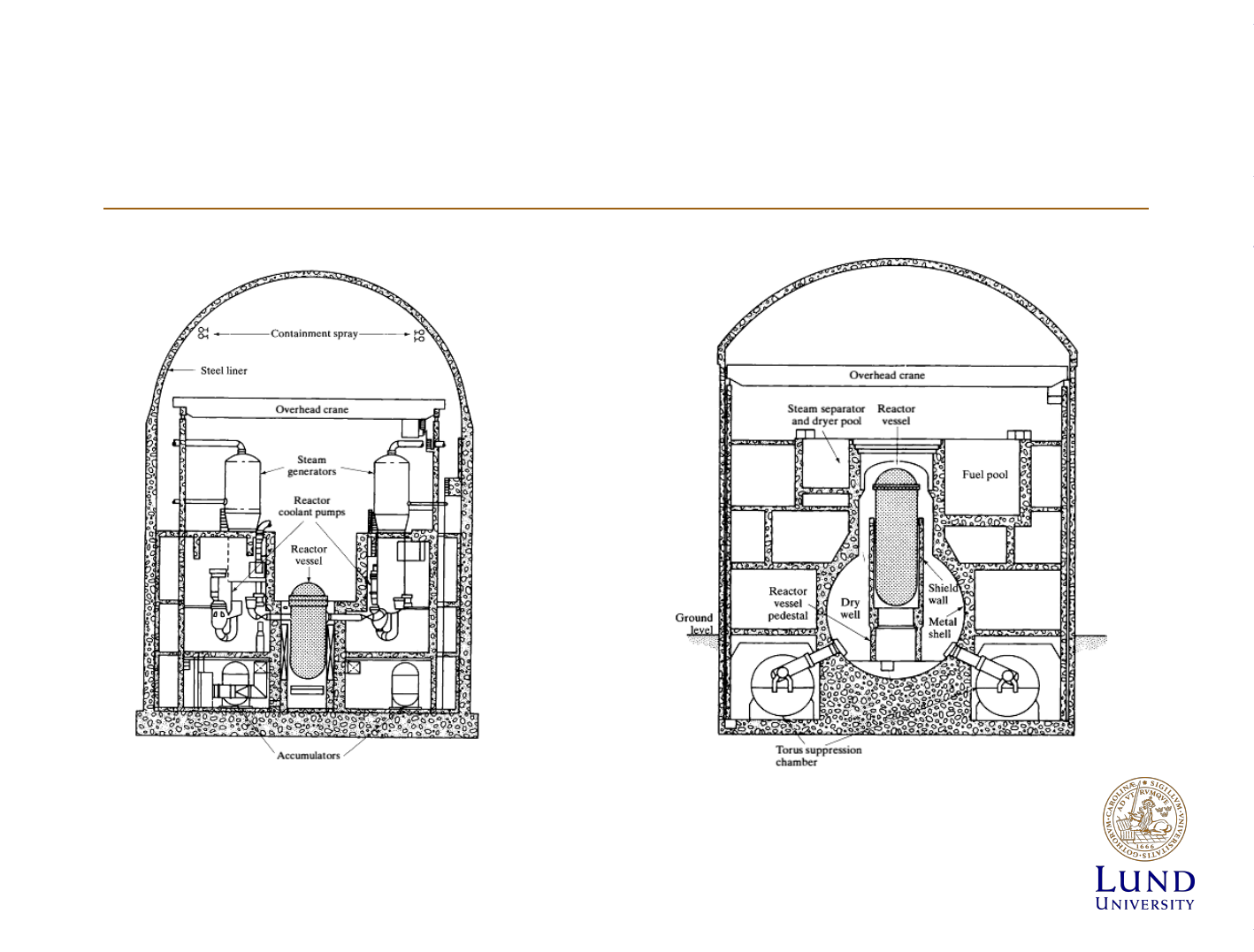
Nuclear power plant safety principles
Containment. Left –PWR, Right BWR. [Lamarsh]

Nuclear power plant safety principles
• Three levels of safety
• First:
– Accident prevention by safe design, construction and
surveillance.
» Negative void and temperature coefficients.
» Only known property materials should be used.
» Sufficient instrumentation so that operators should have
information at all times.
» High quality construction.
» Continual monitoring of plant.

Nuclear power plant safety principles
• Second level of safety:
– Objective is to protect operators and public from
radiation damage.
» Emergency core cooling system
» Fast shut down ability without control rod insertion
» Independent sources of power from Nuclear power
plant for instrumentation.
• Third level of safety
– Margin of safety for very unlikely events

Radiation release
• Dose sources
– External radiation from emitted plume
– Internal dose from radionuclide inhalation
– External dose from radionuclide deposited on the
ground
– External dose from radionuclide deposited on clothes
and body
– Direct dose from power plant.
Radiation release
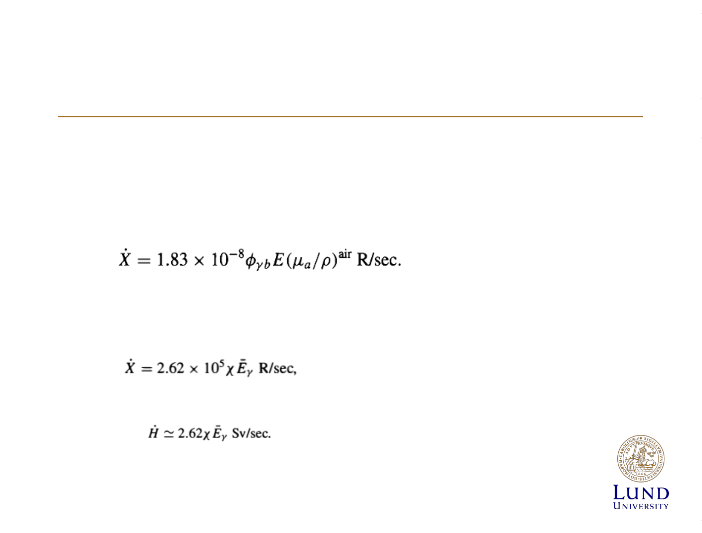
• Gamma from released plume
– It is taken that plume is infinitely large – gives
conservative values and simplifies calculation.
– For more than one gamma ray:
– Dose rate:

Radiation release
• β dose:
– Treatment is similar as gamma ray case.
» Surface dose estimation
» Internal dose estimation
Radiation release
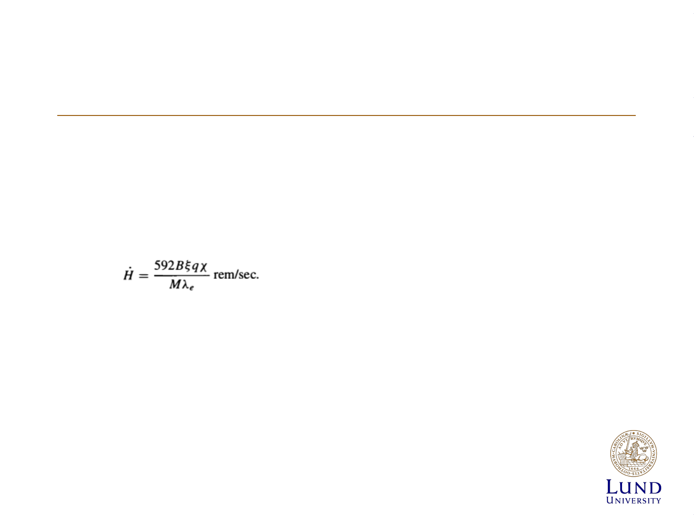
• Internal dose
– Function of breathing activity
– Steady state equilibrium equation for dose rate

Radiation release
• Dose from Ground-deposited nuclides
– 80 % of dose form meltdown would be from Cs137
• Release from nuclear power plant
• Population dose:
– Defined by person-rems
Data from NPP
Product
Activity
Average
Lithuania
Bq/kg
Vicinity of NPP
50 km diameter
Bq/kg
Milk
90
Sr
137
Cs
alfa
beta
0,02±0,01
0,03±0,01
0,25±0,05
50±1
0,03±0,01
0,04±0,02
0,14±0,06
49±4
Meat
90
Sr
137
Cs
alfa
beta
0,03±0,02
0,14±0,18
0,39±0,29
117±6
0,03±0,02
0,09±0,03
0,57±0,29
117±3
Cabbage
90
Sr
137
Cs
alfa
beta
0,06±0,02
0,04±0,01
0,46±0,32
71±6
0,05±0,03
0,07±0,08
0,33±0,23
62±3
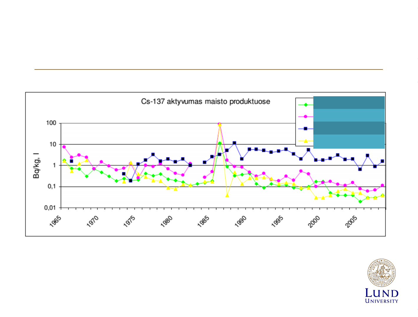
Data from NPP
Milk
Meat
Fish
Veggies
Data from NPP
• Average dose to NPP workers in Sweden in year 2010
1.7 mSv per year.
• Maximal dose in 2010 - 16.9 mSv.
• Doses are ~50 % higher in BWR reactors in Sweden.
Nuclide
Coal, Lodz
power station
238
U
1.1 GBq/year
210
Pb
1.2 GBq/year

Data from NPP
•
131m
Xe,
133m
Xe,
135
Xe – up to 96 % of released
radioactivity.
• 2790 GBq/a from Xenon
• During Fukushima accident 19.0 ± 3.4 Ebq of
Xenon.

References
• www.RSC.lt
• Lamarsh, Introduction to unclear engineering
• Walinder Robert, Radiation doses to Swedish nuclear
workers and cancer incidence in a NPP
• Martin B. Kalinowski, Matthias P. Tuma, Global
radioxenon emission inventory based on nuclear power
reactor reports, Journal of Environmental Radioactivity,
Volume 100, Issue 1, January 2009,
• Andreas Stohl, Petra Seibert, Gerhard Wotawa, The total
release of xenon-133 from the Fukushima Dai-ichi
nuclear power plant accident, Journal of Environmental
Radioactivity, Volume 112, October 2012


Dispersion of Effluents
Reactor physics 2013
SANDRA ANDERSSON
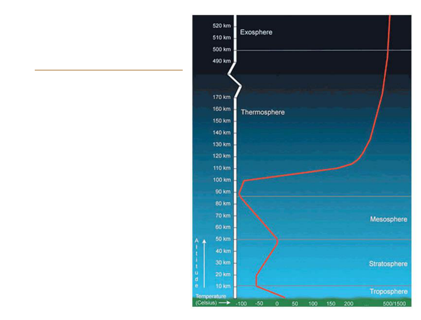
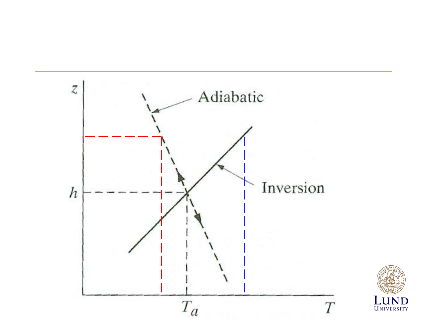
Atmospheric
structure
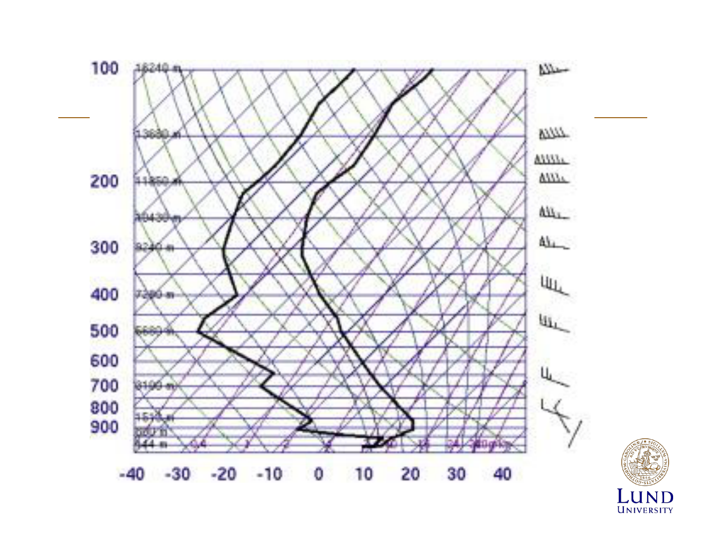
Themperature profile of the lowermost
troposphere

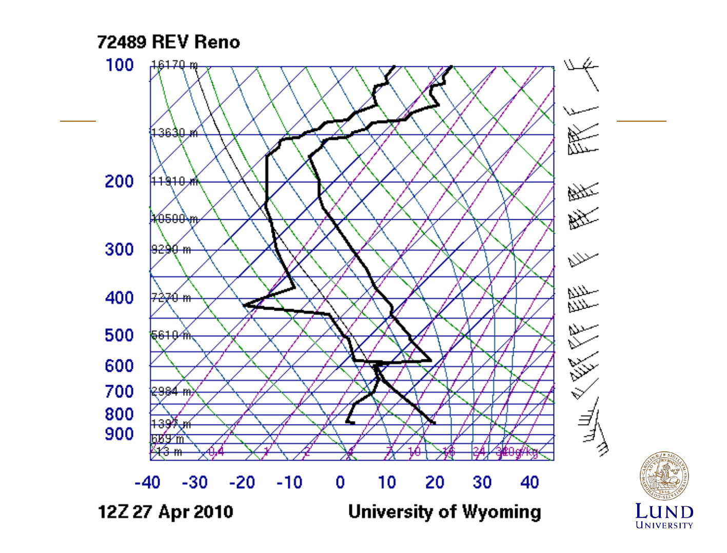
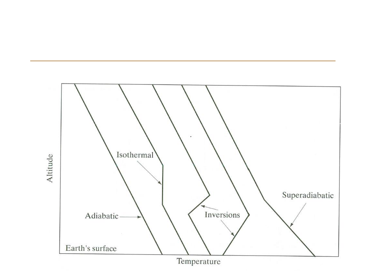
Atmospheric stabillity
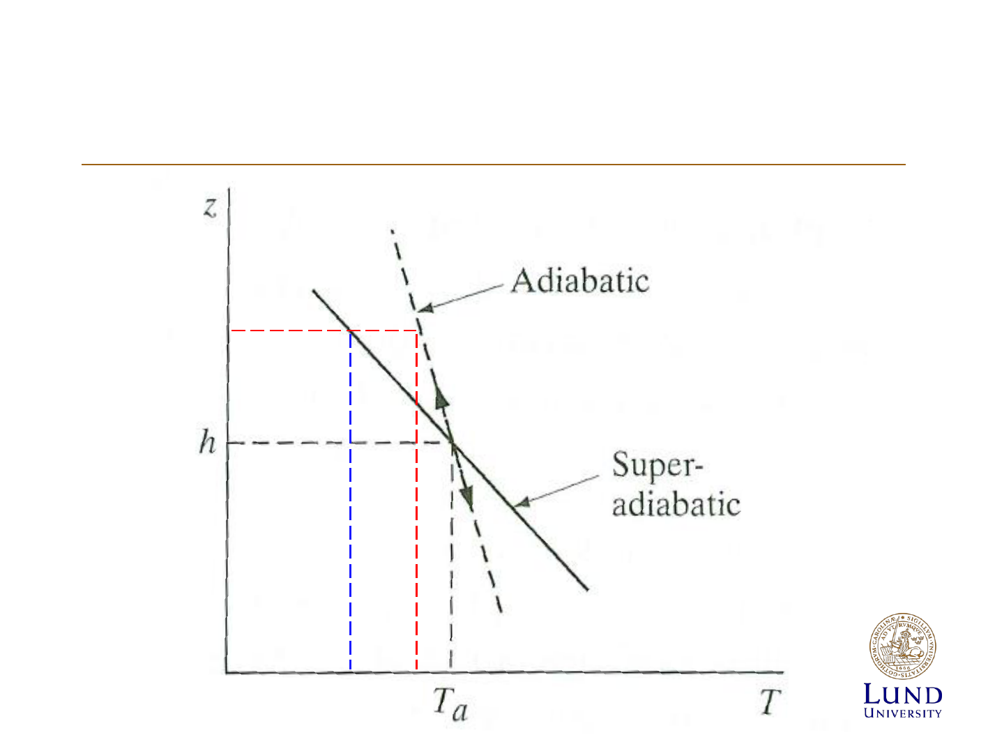
Atmospheric stabillity
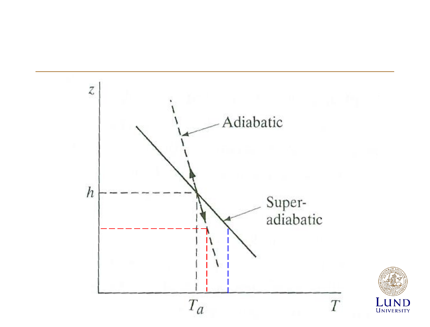
Atmospheric stabillity
Atmospheric stabillity
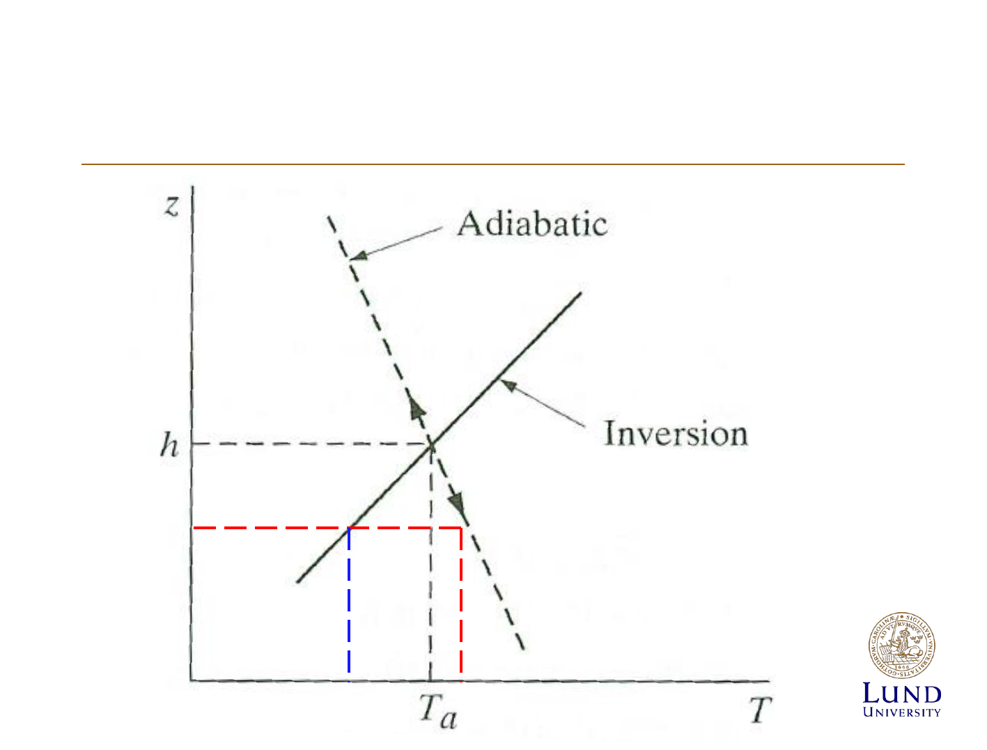
Atmospheric stabillity
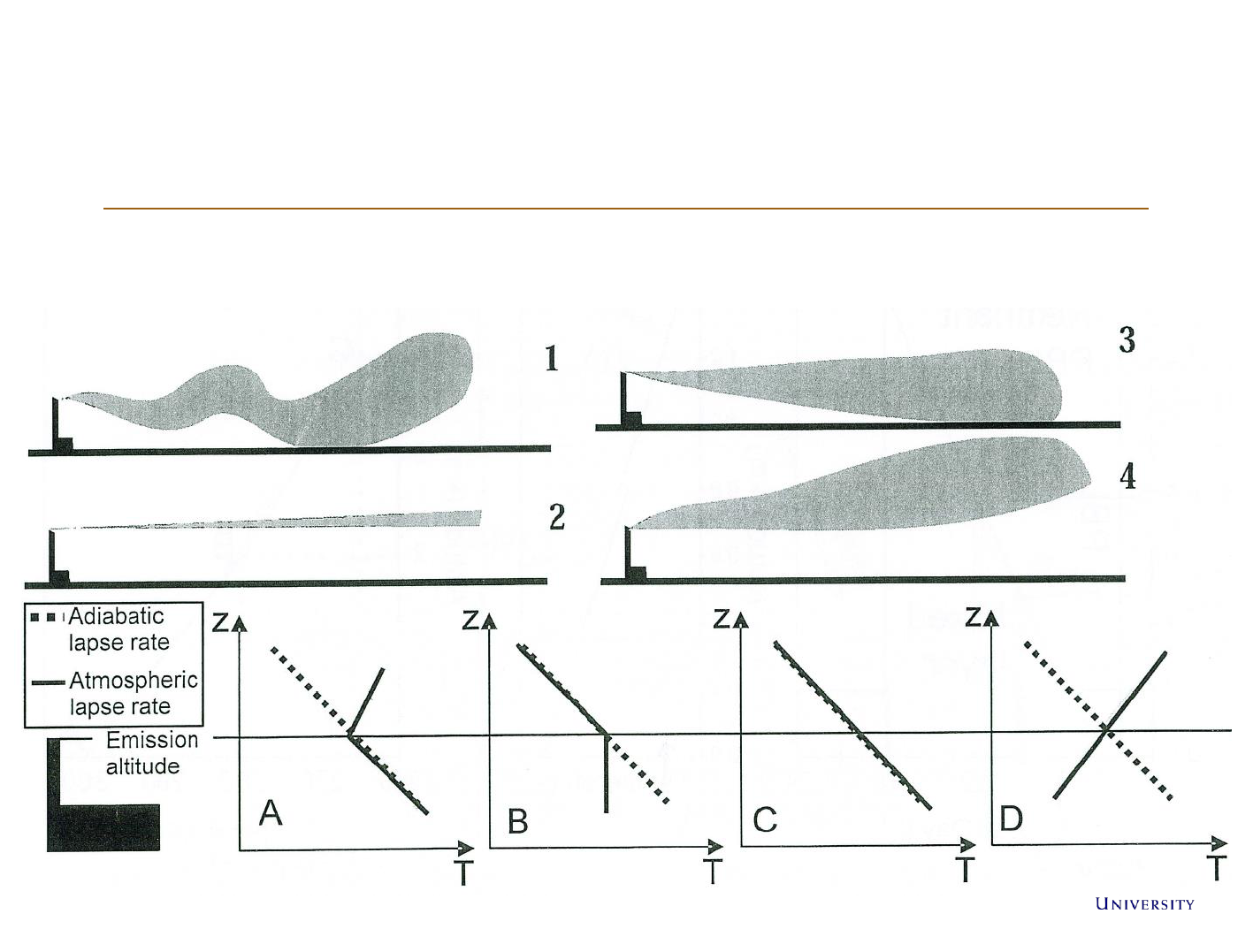
Dispersion of a plume
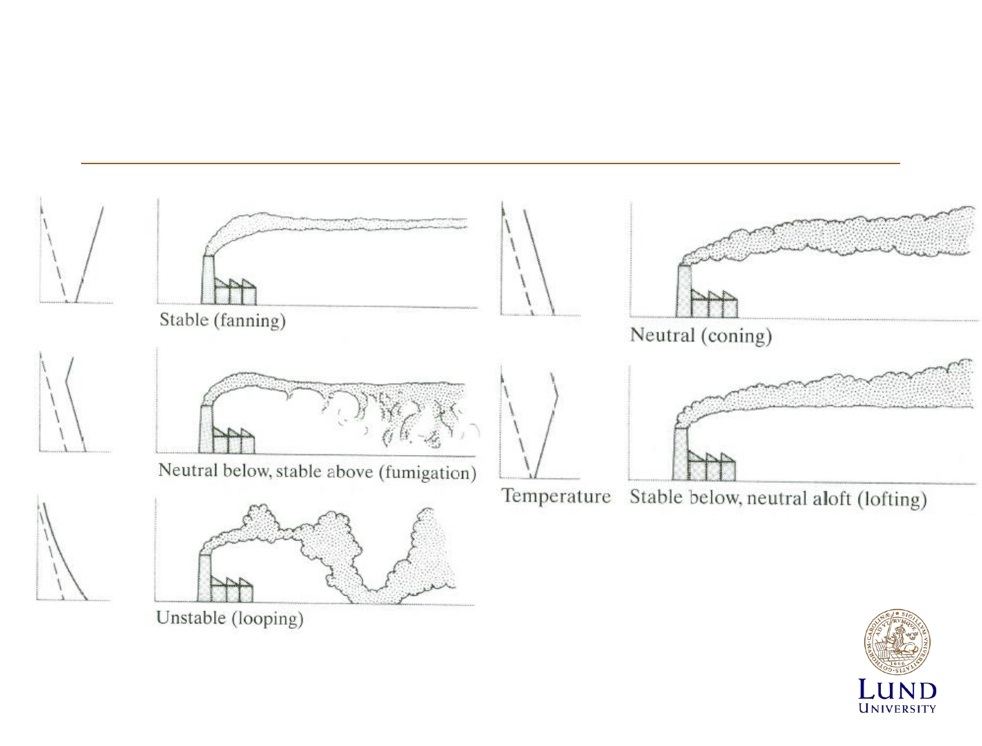
Dispersion of a plume
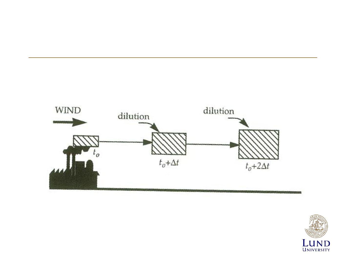
Modelling the dispersion of pollutants
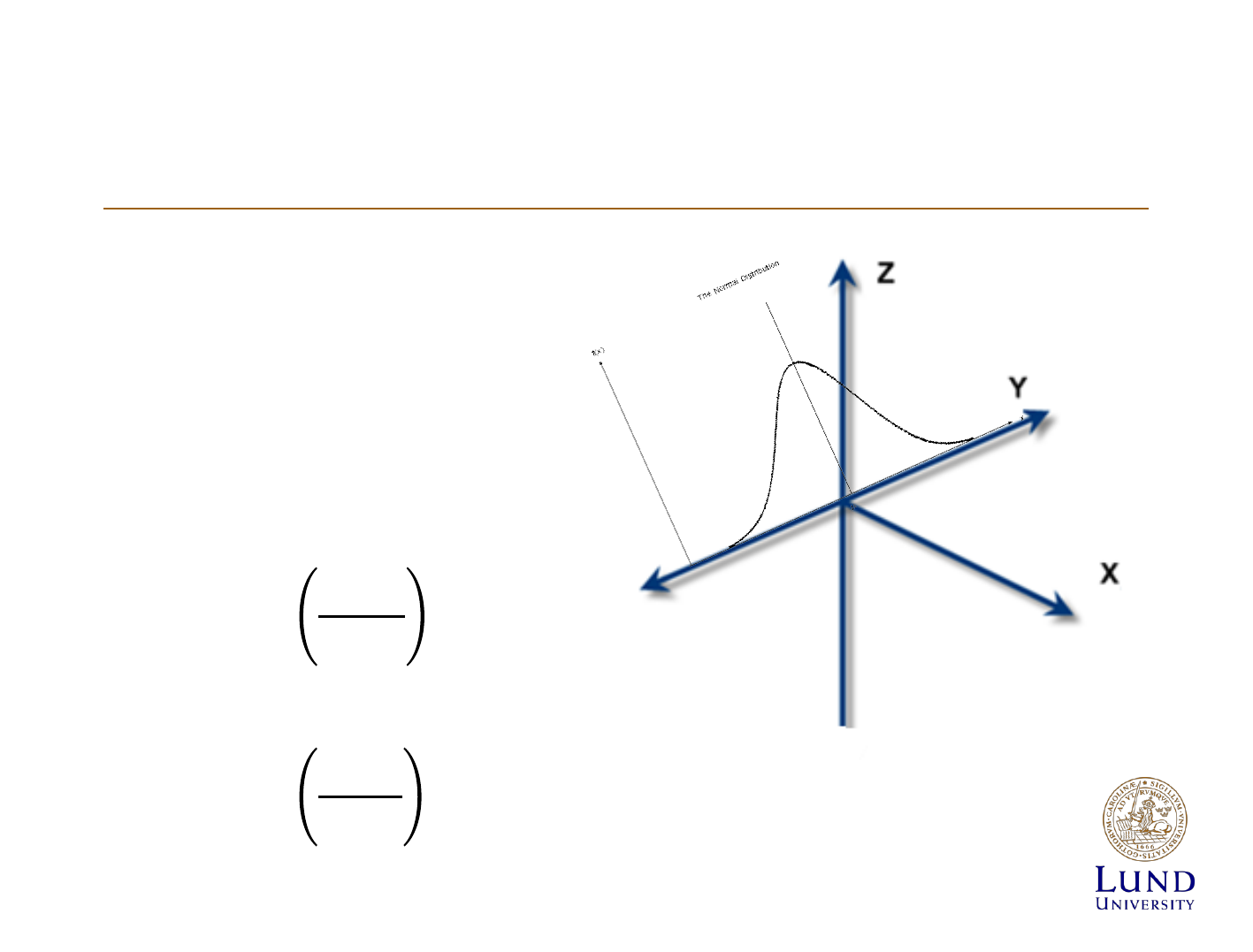
Diffusion of Effluents
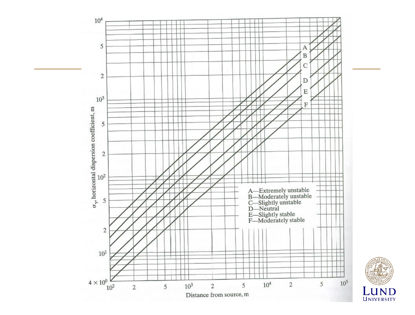
• Mainly turbulent diffusion
• Spreads out in gaussian
distribution
• Standard deviation:
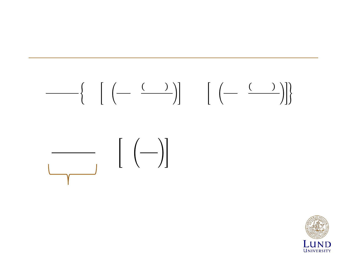
Concentration of effluents
h=0 => released at ground level, use if
do not know emission altitude
z=0 => at ground level
y=0 => at centerline, use if
know emission altitude

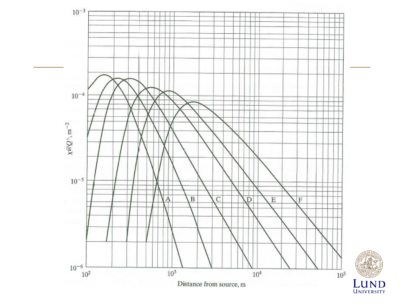
[X]/Q= dilution factor
Deposition and radioactive decay
Depositionrate:
Ci/m
2
/s
Radioactive decay:
=
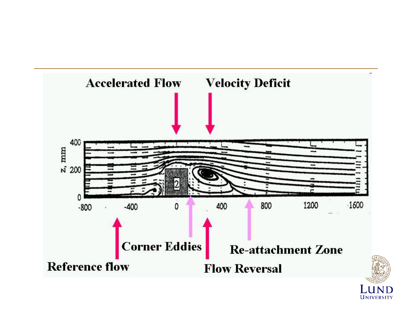
Releases from Buildings
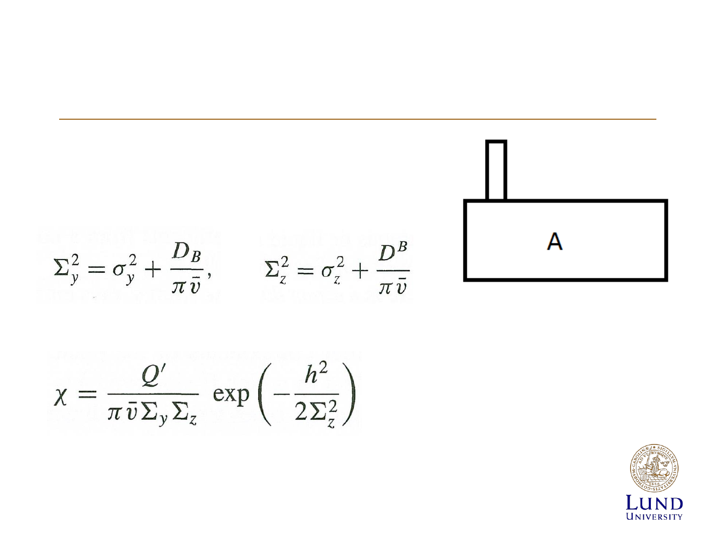
Releases from Buildings
Building dilution factor

The wedge model
The wedge model

The location of a nuclear reactor has an obvious bearing on the consequences of a reactor accident
to the public
construction permit from the NRC (regulations regarding reactor site criteria)
-without undue risk to the health and safety of the public
-minimal effect on the environment
The NRC evaluation considerations
Reactor itself, its design characteristics, and its proposed mode of operation.
Population Considerations
the physical characteristics of the site :seismology, meteorology, geology, and hydrology of the area
the use of appropriate engineering safeguards

Population Considerations
the NRC has defined two areas in the vicinity of the reactor
An exclusion area, or exclusion zone: is that area surrounding the reactor in which the reactor licensee has
the authority to determine all activities including exclusion or removal of personnel and property from the
area
A low-population zone (LPZ) is "the area immediately surrounding the exclusion area which contains
residents, the total number and density of which are such that there is a reasonable probability that
appropriate protective measures could be taken in their behalf in the event of a serious accident
the NRC also defines
the population center distance. "the distance from the reactor to the nearest boundary of a densely
populated center containing more than 25,000 residents."
total radiation dose to the whole body in excess of 25 rem
the population center distance be no less than 1 .33 times the radius of the LPZ.
The assumptions that the NRC makes in calculating the radii of the exclusion area and the LPZ , are used
to compute the external and internal dose from the effluent cloud and the direct dose from nuclides
Population Considerations
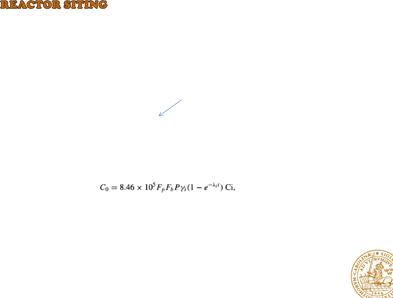
The amount of a fission product available for release to the atmosphere can be estimated by
where Fp is the fraction of the radionuclide released from the fuel into the reactor containment and Fb is
the fraction of this that remains airborne and capable of escaping from the building.
If the cumulative yield of the fission product is Yi atoms per fission, the rate of production of this
nuclide is
To begin the computation
rate of production = P Yi atoms/sec.
Reactor power(MW)
Population Considerations

Physical Characteristics of Site
Nuclear power plants must be designed and constructed in such a manner that all structures and systems
important to safety can withstand the effects of earthquakes, tornadoes, hurricanes, floods, and other
natural phenomena, without a loss of safety function
Seismology: Geologists now believe that the surface of the earth is composed of large structures called
tectonic plates.
Figure 1 1 .19 The earth's tectonic plates and earthquake belts (From C. Kissinger, "Earthquake Prediction," Physics Today, March, 1 974.)
the centers of 42,000 earthquakes

To safety-related structures of reactor plant
from: hurricanes and tornadoes
Meteorology
Limitations
•Hurricanes: up to 600 miles in diameter, with winds from 75 to 200 mi/hr
•Tornadoes, Their diameters range from several feet to a mile
Geology
:
Studies must be made of the geological structure of a proposed site in order to
determine whether the area can family support the reactor building with all its internal
components.
Hydrology
It is necessary to prevent large quantities of water from entering the site of a nuclear
power plant, since water could compromise some of the safety-related systems of the
plant.
the hydrological phenomena : depends upon the nature and location of the site
Physical Characteristics of Site
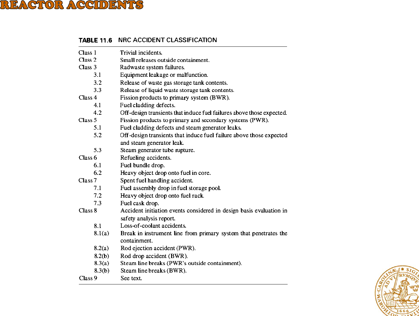
the NRC has divided the spectrum of possible accidents into nine classes,

Loss-of-Coolant Accident
coolant flow through a reactor core ---- caused by leak in a small coolant pipe
-to serious consequences for the plant as a whole
-the pressure in the reactor vessel quickly drops to the saturation
pressure
-change in the average water temperature
Three Mile Island Accident: The accident at the Three Mile Island nuclear power station (TMI) near
Harrisburg, Pennsylvania, in March 1979 is one of the worst that has occurred in a commercial nuclear
power plant.
During maintenance operations, the feedwater flow to the steam generator was lost, an event that can be
expected to happen two or three times a year in a plant. Because of the sudden loss of heat removal,
pressure began to increase in the primary system
control: emergency core cooling system (ECCS):
when the pressure has dropped below about 650 psi
The accident at Three Mile Island did seriously damage the core, but did not result in a large release of
radioactivity to the atmosphere
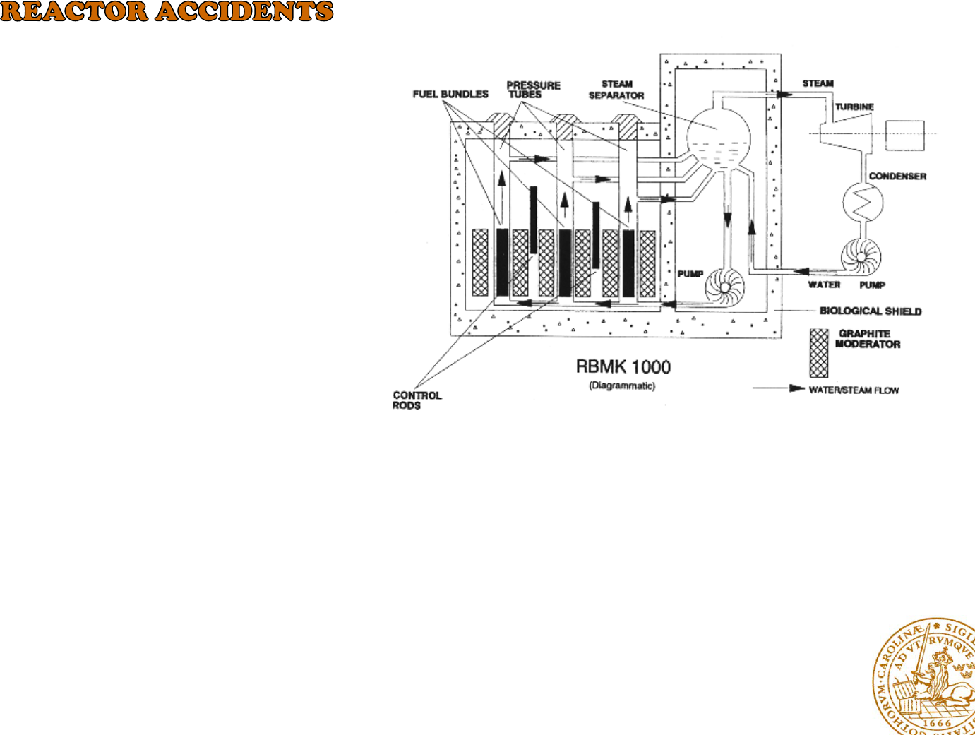
The Chernobyl Accident
Chernobyl Nuclear Power Plant
During the shutdown process, the reactor was in an extremely unstable condition. A peculiarity of the
design of the control rods caused a dramatic power surge as they were inserted into the reactor
The interaction of very hot fuel with the cooling water led to fuel fragmentation along with rapid steam
production and an increase in pressure.
Where a low power level with an unfavorable power distribution, a high coolant flow rate in the core,
a reduced feedwater flow rate to the reactor with increasing coolant temperature at the core inlet,
and an unstable xenon spatial distribution
Ukranian City of Kiev April 26, 1 986
The Chernobyl reactor was a graphite
moderated boiling water pressure tube
reactor of the RBMK

BWR: Steam Pipe Break: The steam in a BWR plant is somewhat radioactive, since it is produced
directly in the reactor
In analyzing this accident
( 1 ) the isolation valves close in the maximum time characteristic of the valves
(2) all of the coolant in the broken steam line and its connecting lines at the time of the break, plus the
steam passing through the valves prior to closure, is released;
(3) the activity (including all the iodine and noble gases that may be present in the steam from leaking fuel
rods) is released to the atmosphere within 2 hrs, at a height of 30 feet, under fumigation conditions.
BWR: Rod Drop
: The control rods in a BWR enter from the bottom of the core and are inserted
upwards.
A number of failures in the control rod drive system: to the release of some activity
into the containment.
PWR: Rod Ejection
failure of the control rod housing could occur in such a way that high-pressure reactor coolant water
might forcibly eject a cluster control rod assembly.
-power transient similar to that in a BWR rod drop accident
The Meaning of Risk
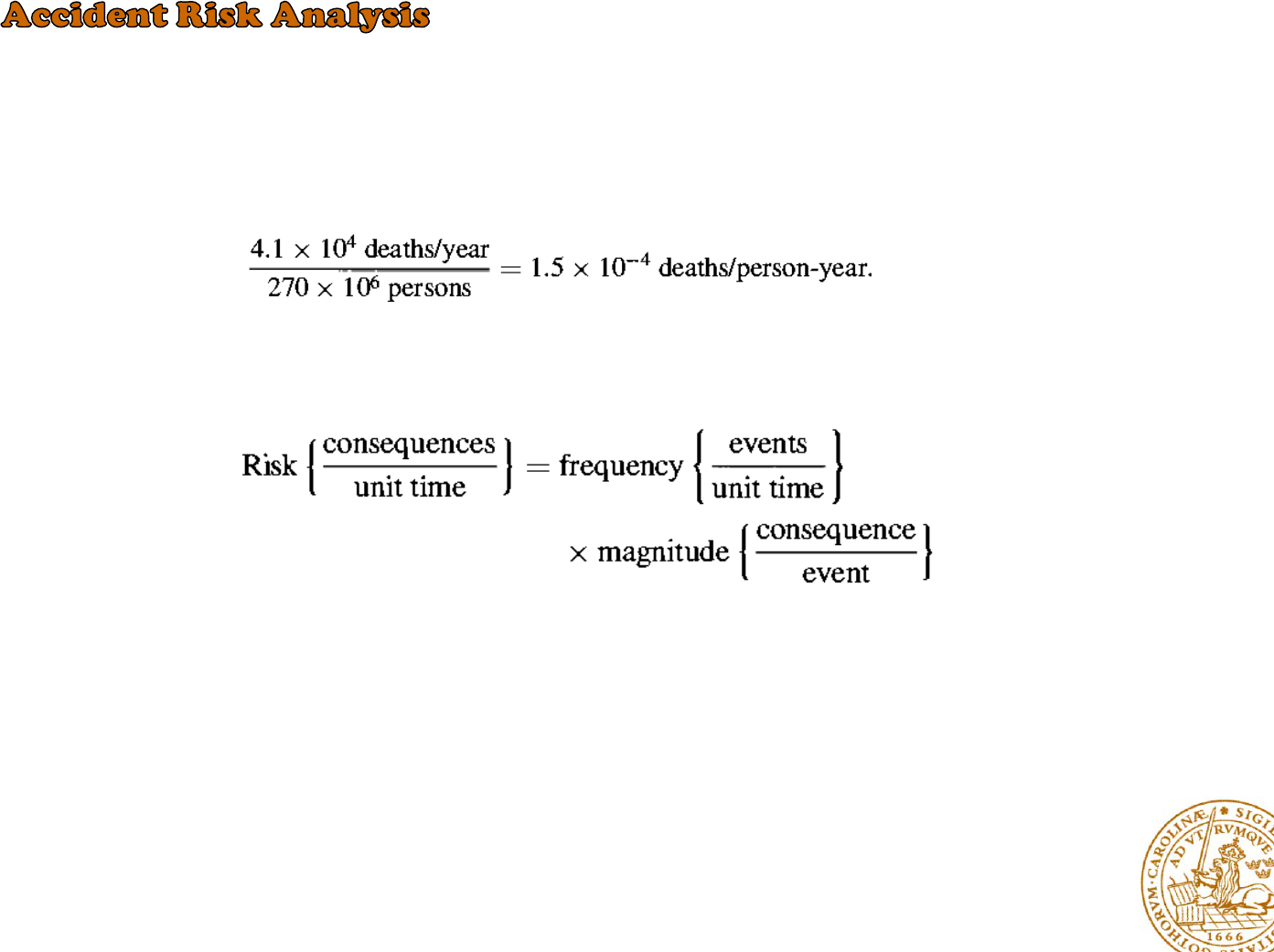
as the consequence of the event per unit time
the average individual risk is defined as
The risk of an event can be computed in an obvious way from the frequency
of the event and the magnitude of the consequences of the event:
However, the public acceptability of a given risk depends not only on the size
of the risk, but also on the magnitude of the consequences of the event.
The calculation of the risk associated with accidents in a nuclear power plant is a three-step process:
1- determine the probabilities of the various releases of radioactivity resulting from accidents
2- the consequences to the public of these releases must be evaluated
3- the release probabilities and their consequences are combined to obtain the overall risk.
Risk Determination
event trees :the identification of the accident sequences leading to various releases
The effluent released to the environments: gaseous or liquid form
the origin, amount, and composition of this effluent varies from plant to plant,
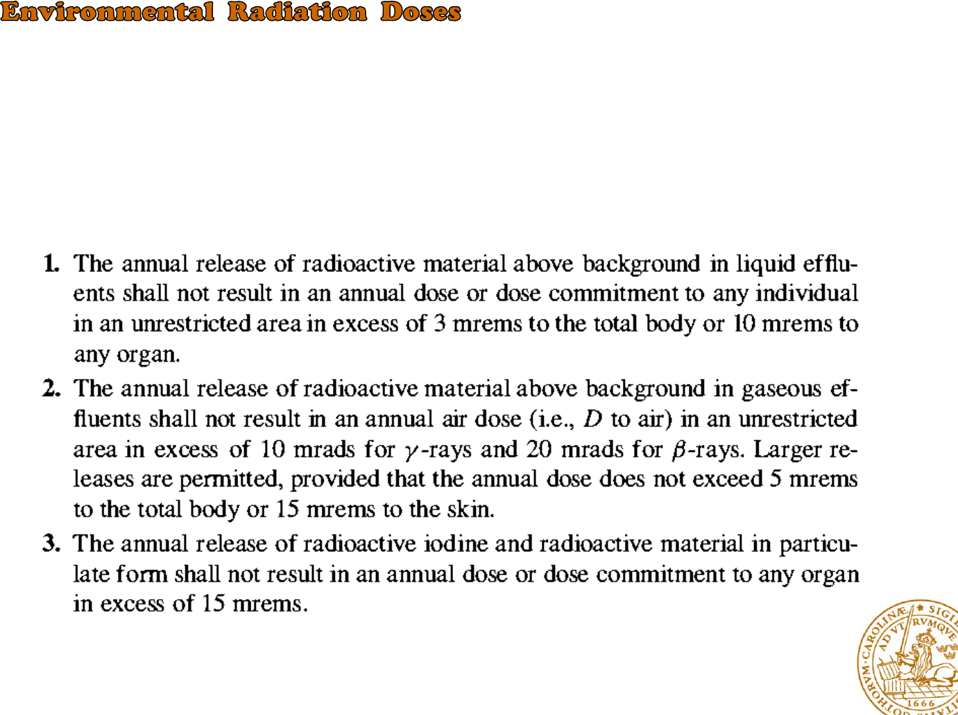
The NRC has translated its "as low as reasonably achievable
Regulation of Effluents
Doses from Effluents
The gaseous effluents emitted to the atmosphere and liquid wastes discharged to bodies of water, and
these two cases will be considered separately.
:noble gases and the isotopes of iodine
131
I
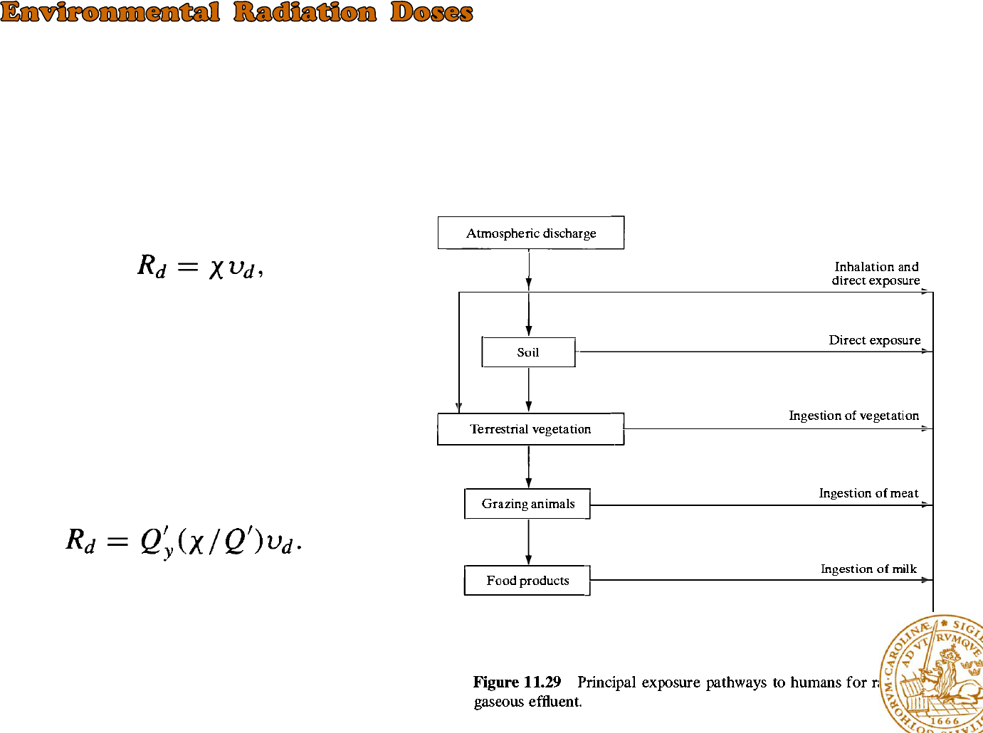
Gaseous Effluents
radiation dose from ingested food
Where Vd is a proportionality constant, has
units of 0,01m/sec and is called the deposition
velocity, Rd has units of Ci/m2-sec and X is in
Ci/m3
Because the emission of radioactive
effluent is often stated in Ci/yr
Where Q’ is in Ci/yr, (X / Q') is the dilution factor in
sec/m3
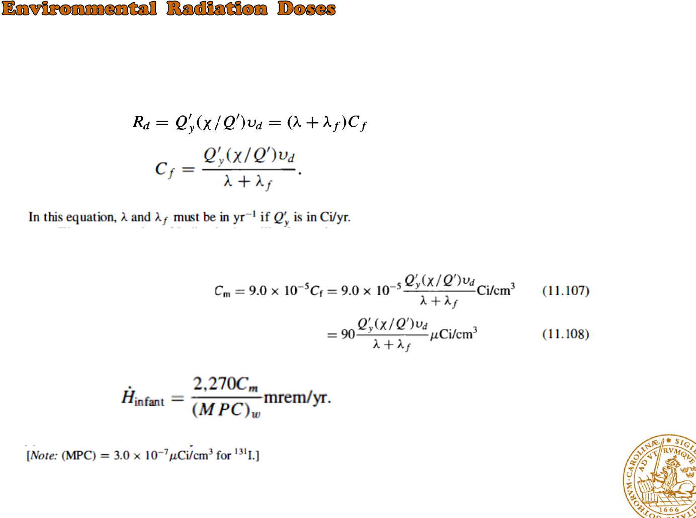
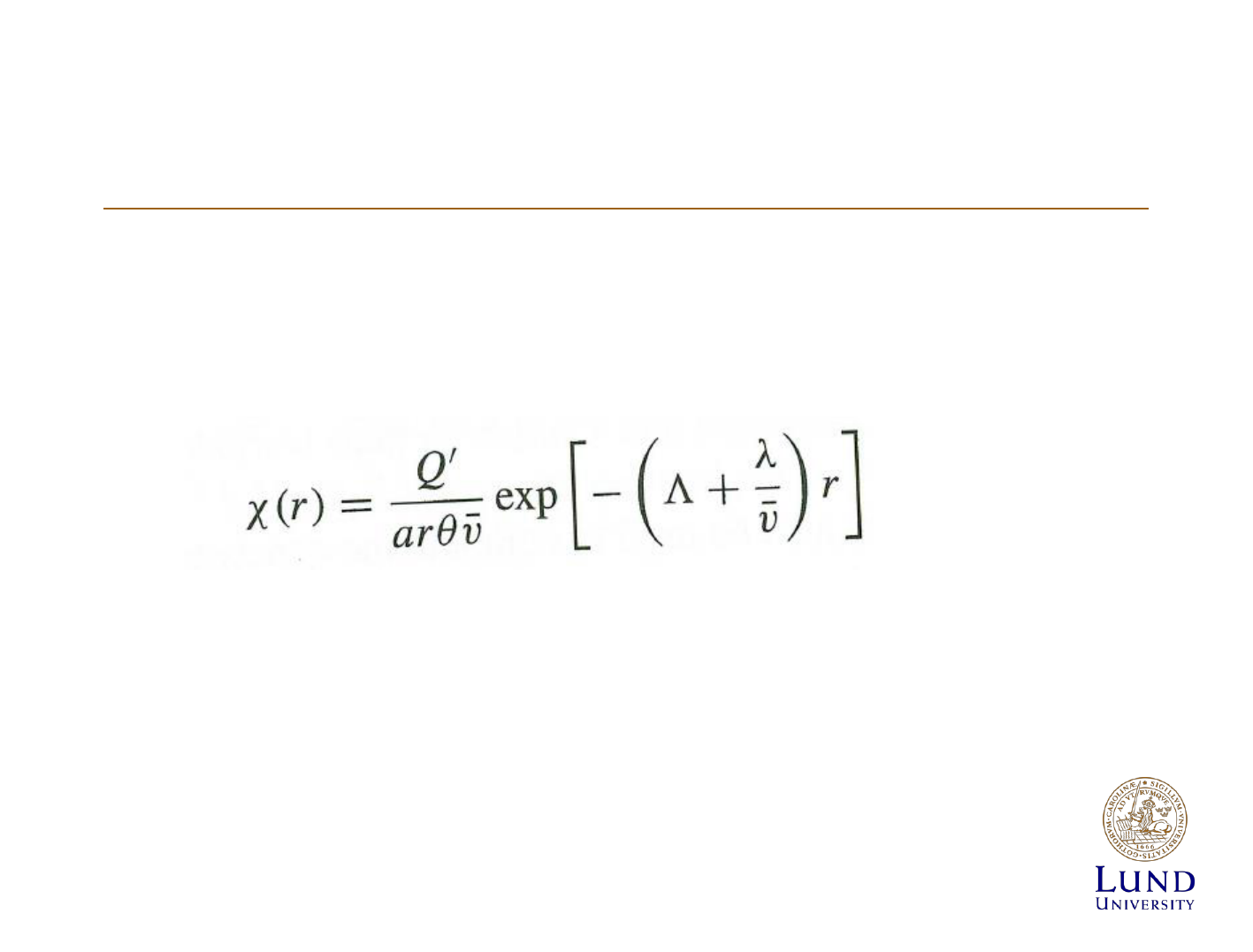
Once the Iodine has fallen on the foliage ?
*When the rates of production and decay are equal
*the annual dose rate is
*the Iodine concentration in sample
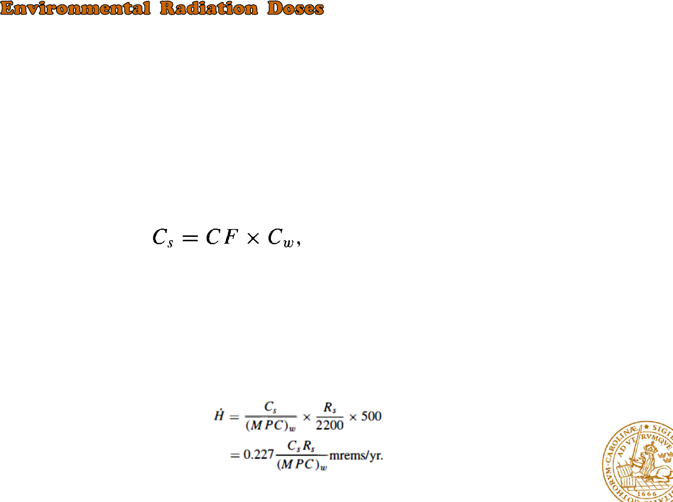
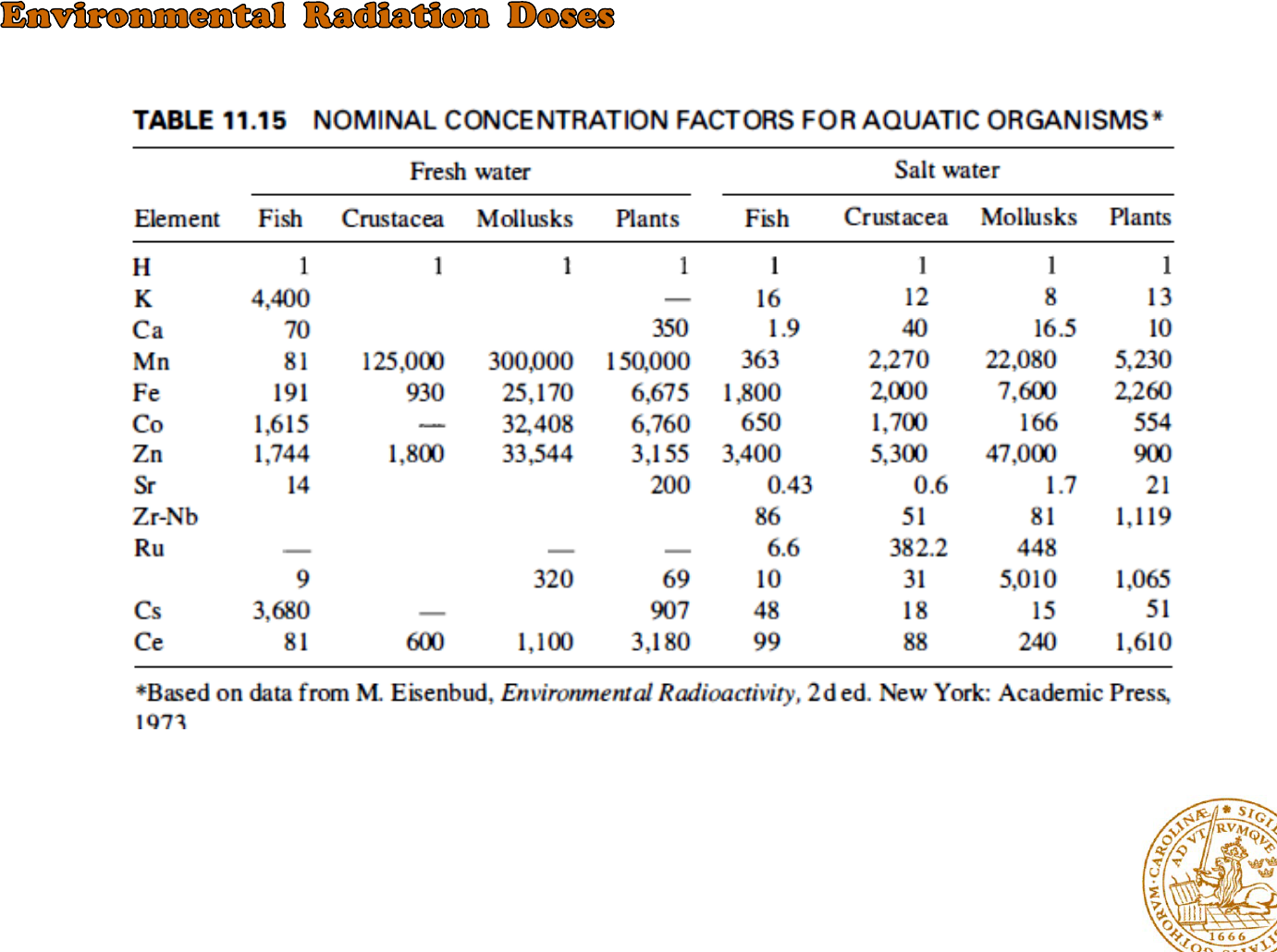
Liquid Effluents
There are several pathways by which man may become exposed to the radioactive waste
discharged into bodies of water
the proportionality constant CF is usually called the concentration factor and sometimes the
bioaccumulation factor.
The calculation of the radiation dose from contaminated seafood?
1)-the concentration of the radionuclides discharged from the plant is estimated from the discharge rate
and dispersion characteristics of the receiving body of water.
2)-the concentration of the radionuclides in seafood is computed
3)-the consumption rate of seafood from waters near the power plant must be estimated
4)-the dose rate can be found by comparing the activity of the seafood Cs in µCi/cm3 and its consumption
rate Rs in cm3/day with the dose rate
the dose rate received from the seafood: