
Draft
ETSI EN 303 348
V1.1.0 (2016-02)
Induction
loop systems
intended to assist the hearing impaired
in the frequency range 10 Hz to 9 kHz;
Harmonised Standard covering the essential requirements
of article 3.2 of the Directive 2014/53/EU
HARMONISED EUROPEAN STANDARD

ETSI
Draft ETSI EN 303 348 V1.1.0 (2016
-
02)
2
Reference
DEN/ERM-TG17WG3-16
Keywords
harmonised standard, hearing aid, inductive
ETSI
650 Route des Lucioles
F-06921 Sophia Antipolis Cedex - FRANCE
Tel.: +33 4 92 94 42 00 Fax: +33 4 93 65 47 16
Siret N° 348 623 562 00017 - NAF 742 C
Association à but non lucratif enregistrée à la
Sous-Préfecture de Grasse (06) N° 7803/88
Important notice
The present document can be downloaded from:
http://www.etsi.org/standards-search
The present document may be made available in electronic versions and/or in print. The content of any electronic and/or
print versions of the present
document shall not be modified without the prior written authorization of ETSI. In case of any
existing or perceived difference in contents between such versions and/or in print, the only prevailing document is the
print of the Portable Document Format (PDF) version kept on a specific network drive within ETSI Secretariat.
Users of the present document should be aware that the document may be subject to revision or change of status.
Information on the current status of this and other ETSI documents is available at
http://portal.etsi.org/tb/status/status.asp
If you find errors in the present document, please send your comment to one of the following services:
https://portal.etsi.org/People/CommiteeSupportStaff.aspx
Copyright Notification
No part may be reproduced or utilized in any form or by any means, electronic or mechanical, including photocopying
and microfilm except as authorized by written permission of ETSI.
The content of the PDF version shall not be modified without the written authorization of ETSI.
The copyright and the foregoing restriction extend to reproduction in all media.
© European Telecommunications Standards Institute 2016.
All rights reserved.
DECT
TM
, PLUGTESTS
TM
, UMTS
TM
and the ETSI logo are Trade Marks of ETSI registered for the benefit of its Members.
3GPP
TM
and LTE™ are Trade Marks of ETSI registered for the benefit of its Members and
of the 3GPP Organizational Partners.
GSM® and the GSM logo are Trade Marks registered and owned by the GSM Association.

ETSI
Dra
ft ETSI EN 303 348 V1.1.0 (2016
-
02)
3
Contents
Intellectual Property Rights ................................................................................................................................ 5
Foreword ............................................................................................................................................................. 5
Modal verbs terminology .................................................................................................................................... 5
Introduction ........................................................................................................................................................ 5
1 Scope ........................................................................................................................................................ 7
2 References ................................................................................................................................................ 7
2.1 Normative references ......................................................................................................................................... 7
2.2 Informative references ........................................................................................................................................ 7
3 Definitions, symbols and abbreviations ................................................................................................... 8
3.1 Definitions .......................................................................................................................................................... 8
3.2 Symbols ............................................................................................................................................................ 10
3.3 Abbreviations ................................................................................................................................................... 10
4 Technical overview ................................................................................................................................ 11
4.1 Induction Loop Amplifiers ............................................................................................................................... 11
4.1.0 General ........................................................................................................................................................ 11
4.1.1 Frequency response..................................................................................................................................... 11
4.1.2 Field strength .............................................................................................................................................. 11
4.1.3 General performance criteria ...................................................................................................................... 11
4.2 AFILS Receivers and Test Equipment ............................................................................................................. 11
4.3 General ............................................................................................................................................................. 12
4.3.1 Presentation of induction loop amplifier equipment for testing purposes ................................................... 12
4.3.2 Choice of model for testing ........................................................................................................................ 12
4.4 Mechanical and electrical design ...................................................................................................................... 12
4.4.1 Controls ...................................................................................................................................................... 12
4.4.2 Amplifier shut-off facility ........................................................................................................................... 12
4.4.3 Marking (equipment identification) ............................................................................................................ 12
4.4.3.0 General requirements ............................................................................................................................ 12
4.4.3.1 Equipment identification ....................................................................................................................... 13
4.4.3.2 Equipment marking ............................................................................................................................... 13
4.5 Declarations by the provider ............................................................................................................................ 13
4.6 Auxiliary test equipment .................................................................................................................................. 13
4.7 Interpretation of the measurement results ........................................................................................................ 13
5 Test conditions, power sources and ambient temperatures .................................................................... 13
5.1 Normal test conditions ...................................................................................................................................... 13
5.1.0 General requirement ................................................................................................................................... 13
5.1.1 Normal temperature and humidity .............................................................................................................. 13
5.2 Test power source ............................................................................................................................................. 14
5.2.0 General requirements .................................................................................................................................. 14
5.2.1 External test power source .......................................................................................................................... 14
5.2.2 Internal test power source ........................................................................................................................... 14
5.2.2.0 General .................................................................................................................................................. 14
5.2.2.1 Mains voltage ........................................................................................................................................ 14
5.2.2.2 Valve-regulated lead-acid battery power sources .................................................................................. 14
5.2.2.3 Other power sources .............................................................................................................................. 14
5.2.3 Extreme test conditions ............................................................................................................................... 14
5.2.3.1 Extreme test source voltages ................................................................................................................. 14
5.2.3.1.1 Mains voltage .................................................................................................................................. 14
5.2.3.2 Valve-regulated lead-acid battery power sources .................................................................................. 15
5.2.3.3 Power sources using other types of batteries ......................................................................................... 15
5.2.3.4 Other power sources .............................................................................................................................. 15
5.2.3.5 Extreme test temperatures ..................................................................................................................... 15
6 General conditions .................................................................................................................................. 15
6.1 Normal test signals ........................................................................................................................................... 15
ETSI
Draft ETSI EN 303 348 V1.1.0 (2016
-
02)
4
6.2 Loop connections ............................................................................................................................................. 15
6.2.0 General ........................................................................................................................................................ 15
6.2.1 Artificial loop .............................................................................................................................................. 16
6.3 Modes of operation of the induction loop amplifier ......................................................................................... 16
6.4 Measuring receiver ........................................................................................................................................... 16
7 Induction loop amplifier ......................................................................................................................... 16
7.0 General ............................................................................................................................................................. 16
7.1 Induction loop amplifier definitions ................................................................................................................. 17
7.1.0 General ........................................................................................................................................................ 17
7.1.1 Product Classes ........................................................................................................................................... 17
7.2 Induction loop amplifier spurious output levels ............................................................................................... 19
7.2.1 Radiated H-field Limits below 5 MHz ....................................................................................................... 19
7.2.1.1 Definition .............................................................................................................................................. 19
7.2.1.2 Methods of measurement ...................................................................................................................... 19
7.2.1.3 Limits .................................................................................................................................................... 19
7.3 Audio frequency baseband emission limits ...................................................................................................... 20
7.3.1 Definition .................................................................................................................................................... 20
7.3.2 Methods of measurement ............................................................................................................................ 20
7.3.3 Limits .......................................................................................................................................................... 21
7.4 Spurious domain emission limits ...................................................................................................................... 21
7.4.1 Definition .................................................................................................................................................... 21
7.4.2 Measurement conditions ............................................................................................................................. 21
7.4.3 Methods of measurement of Conducted emissions below 5 MHz .............................................................. 21
7.4.4 Limits .......................................................................................................................................................... 21
8 Measurement uncertainty ....................................................................................................................... 21
9 Interpretation of results .......................................................................................................................... 22
9.1 Measurement uncertainty is equal to or less than maximum acceptable uncertainty ....................................... 22
Annex A (normative): Relationship between the present document and the essential
requirements of Directive 2014/53/EU ......................................................... 23
Annex B (normative): Measurement .................................................................................................. 24
B.1 Standard test position to be used with internal loop equipment or equipment having a loop
connector ................................................................................................................................................ 24
B.2 Technical performance of the spectrum analyser or receiver ................................................................. 24
Annex C (normative): Customized loops ........................................................................................... 25
C.1 Antenna loops below 1 MHz .................................................................................................................. 25
C.2 Magnetic field strength at an arbitrary point .......................................................................................... 25
Annex D (informative): Test fixture ..................................................................................................... 26
Annex E (normative): Induction loop amplifier emission levels and spectrum mask
measurements ................................................................................................. 28
Annex F (informative): Determination and use of the measurement bandwidth ............................. 29
Annex G (informative): Bibliography ................................................................................................... 30
History .............................................................................................................................................................. 31
ETSI
Draft ETSI EN 303 348 V1.1.0 (2016
-
02)
5
Intellectual Property Rights
IPRs essential or potentially essential to the present document may have been declared to ETSI. The information
pertaining to these essential IPRs, if any, is publicly available for ETSI members and non-members, and can be found
in ETSI SR 000 314: "Intellectual Property Rights (IPRs); Essential, or potentially Essential, IPRs notified to ETSI in
respect of ETSI standards", which is available from the ETSI Secretariat. Latest updates are available on the ETSI Web
server (https://ipr.etsi.org/).
Pursuant to the ETSI IPR Policy, no investigation, including IPR searches, has been carried out by ETSI. No guarantee
can be given as to the existence of other IPRs not referenced in ETSI SR 000 314 (or the updates on the ETSI Web
server) which are, or may be, or may become, essential to the present document.
Foreword
This draft Harmonised European Standard (EN) has been produced by ETSI Technical Committee Electromagnetic
compatibility and Radio spectrum Matters (ERM), and is now submitted for the combined Public Enquiry and Vote
phase of the ETSI standards EN Approval Procedure.
The present document has been prepared under the Commission's standardisation request C(2015) 5376 final [4] to
provide one voluntary means of conforming to the essential requirements of Directive 2014/53/EU on the harmonisation
of the laws of the Member States relating to the making available on the market of radio equipment and repealing
Directive 1999/5/EC [i.1].
Once the present document is cited in the Official Journal of the European Union under that Directive, compliance with
the normative clauses of the present document given in table A.1 confers, within the limits of the scope of the present
document, a presumption of conformity with the corresponding essential requirements of that Directive, and associated
EFTA regulations.
Proposed national transposition dates
Date of latest announcement of this EN (doa): 3 months after ETSI publication
Date of latest publication of new National Standard
or endorsement of this EN (dop/e):
6 months after doa
Date of withdrawal of any conflicting National Standard (dow): 18 months after doa
Modal verbs terminology
In the present document "shall", "shall not", "should", "should not", "may", "need not", "will", "will not", "can" and
"cannot" are to be interpreted as described in clause 3.2 of the ETSI Drafting Rules (Verbal forms for the expression of
provisions).
"must" and "must not" are NOT allowed in ETSI deliverables except when used in direct citation.
Introduction
Audio Frequency Induction Loop Systems (AFILS) have been on the market since the middle of the twentieth century,
with the first recognizable patents appearing circa 1938. AFILS are primarily used to facilitate improved
communication to people with impaired hearing and are an important tool in the reduction of discrimination against
disabled people.
The present document represents the performance of equipment which is currently on the market, which has not
previously been subjected to compliance to a "radio" directive.
ETSI
Draft ETSI EN 303 3
48 V1.1.0 (2016
-
02)
6
AFILS are installed in places of worship, places of entertainment, places of education, ticket booths and service
counters, etc., as well as in domestic situations, providing huge benefits to users with impaired hearing.
AFILS provide an audio frequency magnetic field that couples with a receiving coil (Telecoil) fitted in hearing aids (see
note), cochlear implants and loop receiving and testing devices. This magnetic field is generated in a wire loop that is
fed by an audio frequency amplifier which is capable of driving current through the "induction loop" which, in turn, is
fed from external signals such as those generated by microphones, audio-visual equipment and musical instruments.
NOTE: These are covered in ETSI EN 300 422 [2].
AFILS operate below 9 kHz and have a very limited range (some few metres) and there is no known evidence of
interference with radio equipment.
The market for AFILS is relatively small compared with technologies such as RFID, and is physically separated from
most radio systems, so the opportunity for mutual interference problems is reduced compared to other users of the
spectrum in this frequency range.
The present document has been developed in response to the Radio Equipment Directive, which reduces the lower limit
for radio equipment from 9 kHz defined in the R&TTE. It is the first radio standard that has been produced for AFILS
equipment and has been prepared to allow the assessment of audio frequency induction loop amplifiers and receivers for
compliance with the Radio Equipment Directive (RED).

ETSI
Draft ETSI EN 303 348 V1.1.0 (2016
-
02)
7
1 Scope
The present document applies to the following major equipment types:
1) induction loop amplifiers operating from 10 Hz to 9 kHz;
2) induction loop receivers operating from 10 Hz to 9 kHz;
These radio equipment types are capable of operating in the frequency band within the 10 Hz to 9 kHz range:
• either with an output connection/s and dedicated loop(s) or with an internal loop(s);
• for audio frequency baseband transmission (un-modulated and without the use of a carrier);
• induction loop receivers.
The present document covers fixed induction loop amplifiers, mobile induction loop amplifiers and portable induction
loop amplifiers.
The present document covers requirements for emissions below, as well as above, 9 kHz.
2 References
2.1 Normative references
References are either specific (identified by date of publication and/or edition number or version number) or
non-specific. For specific references, only the cited version applies. For non-specific references, the latest version of the
reference document (including any amendments) applies.
Referenced documents which are not found to be publicly available in the expected location might be found at
http://docbox.etsi.org/Reference.
NOTE: While any hyperlinks included in this clause were valid at the time of publication, ETSI cannot guarantee
their long term validity.
The following referenced documents are necessary for the application of the present document.
[1] ETSI TR 100 028 (all parts) (V1.4.1) (12-2001): "Electromagnetic compatibility and Radio
spectrum Matters (ERM); Uncertainties in the measurement of mobile radio equipment
characteristics".
[2] ETSI EN 300 422 (parts 1 and 2) (V1.5.1) (V1.4.1) (06-2015): "Electromagnetic compatibility and
Radio spectrum Matters (ERM); Wireless microphones in the 25 MHz to 3 GHz frequency range".
[3] BS 7594:2011: "Code of practice for audio-frequency induction-loop systems (AFILS)".
[4] Commission Implementing Decision C(2015) 5376 final of 4.8.2015 on a standardisation request
to the European Committee for Electrotechnical Standardisation and to the European
Telecommunications Standards Institute as regards radio equipment in support of Directive
2014/53/EU of the European Parliament and of the Council.
2.2 Informative references
References are either specific (identified by date of publication and/or edition number or version number) or
non-specific. For specific references, only the cited version applies. For non-specific references, the latest version of the
reference document (including any amendments) applies.
NOTE: While any hyperlinks included in this clause were valid at the time of publication, ETSI cannot guarantee
their long term validity.
The following referenced documents are not necessary for the application of the present document but they assist the
user with regard to a particular subject area.

ETSI
Draft ETSI EN 303 348 V1.1.0 (2016
-
02)
8
[i.1] Directive 2014/53/EU of the European Parliament and of the Council of 16 April 2014 on the
harmonisation of the laws of the Member States relating to the making available on the market of
radio equipment and repealing Directive 1999/5/EC.
[i.2] CEPT/ERC/REC 70-03: "Relating to the use of Short Range Devices (SRD)".
[i.3] CISPR 16-2-3: "Specification for radio disturbance and immunity measuring apparatus and
methods - Part 2-3: Methods of measurement of disturbances and immunity - Radiated disturbance
measurements".
[i.4] ITU Radio Regulations.
[i.5] IEC 60118-4: "Electroacoustics - Hearing aids - Part 4: Induction loop systems for hearing aid
purposes - Magnetic field strength".
[i.6] IEC 62489-1 + Amd 1: "Electroacoustics - Audio-frequency induction loop systems for assisted
hearing - Part 1: Methods of measuring and specifying the performance of system components".
[i.7] IEC 61672-1: "Electroacoustics. Sound level meters. Specifications".
[i.8] IEC 60268-10: "Sound system equipment. Methods for specifying and measuring the
characteristics of peak programme level meters".
[i.9] ECC report 208: "Impact of RFID devices using the band at 13.56 MHz on radio services".
3 Definitions, symbols and abbreviations
3.1 Definitions
For the purposes of the present document, the following terms and definitions apply:
artificial loop: reduced size -radiating dummy load equal to the nominal impedance of the loop specified by the
provider
Audio-Frequency Induction-Loop System (AFILS): system including induction loop amplifier(s), microphones
and/or other signal sources, in which magnetic fields are created by the flow of audio-frequency current in a conductor
arranged in the form of a loop or coil
conducted measurements: measurements which are made using a direct connection to the equipment under test
customized loop: loop built according to manufacturers' loop design rules inside tested limits
dedicated loop: removable loop supplied and type tested with the AFILS equipment, designed as an indispensable part
of the equipment
NOTE: The loop has been designed or developed for one or more specific types of equipment. It is the
combination of dedicated loop and induction loop amplifier that is expected to be compliant with the
regulations.
hearing aid: personal amplification system, worn entirely on the listener, which is designed to enable a person with
impaired hearing to hear more easily
hearing instrument: hearing aid or cochlear implant
induction loop: current carrying loop or coil of an AFILS used to create the magnetic field
NOTE: This is equivalent to the term "antenna" used in other ETSI documents and is used in the present
document as it is the term commonly understood by AFILS industry.
Induction loop amplifier: audio amplifier designed to drive an induction loop
NOTE: This is equivalent to the term "transmitter" used in other ETSI documents and is used in the present
document as it is the term commonly understood by AFILS industry.
ETSI
Draft ETSI EN 303 348 V1.1.0 (2016
-
02)
9
Induction loop listener: portable listening device which is designed to give an audible output in response to signals
produced by an AFILS
Induction loop monitor receiver: equipment designed to verify the performance of an AFILS by audio and visual
means:
a) providing visible indication that it is powered and when the strength of the magnetic field produced by the
loop falls within a specified range; and
b) providing an audio-frequency output by which the sound quality of the AFILS transmissions can be assessed
induction-loop system: See AFILS.
internal loop: loop designed as a fixed part of the equipment, without the use of an external connector and as such
which cannot be disconnected from the equipment by the user
loop: See induction loop.
loop listener: See induction-loop listener.
magnetic dipole moment: product of (Number of loop turns) × (loop area) × (loop current)
NOTE: Air loops only.
magnetic field strength level meter: instrument designed to measure magnetic field strength of audio frequency
magnetic fields
NOTE: Two types are in common use; a peak-programme meter (PPM) type having dynamic characteristics
similar to those of the Type II meter specified in IEC 60268-10 [i.8], and a true r.m.s. meter type that
incorporates a true r.m.s. rectifier, and meets the relevant requirements for a Class 2 sound level meter
specified in IEC 61672-1 [i.7]. Full functional specifications for both types of meter can be found in
IEC 60118-4 [i.5].
mobile amplifier: equipment normally installed in a vehicle
phased loop array: system of neighbouring loops in which the currents are not in phase with each other
portable amplifier: amplifier intended to be carried or attached
radiated measurements: measurements which involve the absolute measurement of a radiated field
rated load: the load, stated by the manufacturer, to which the amplifier output is connected for measurement purposes
reference magnetic field strength level: 0 dB reference for magnetic field strength levels, which is 400 mA/m
spurious emissions: emissions on a frequency or frequencies which are outside the occupied bandwidth and the level of
which may be reduced without affecting the corresponding transmission of information
telecoil: magnetic pickup coil intended to receive signals from an audio-frequency induction-loop system in accordance
with IEC 60118-4 [i.5]
NOTE: A telecoil can be part of a hearing aid or of any other device for receiving signals from an audio-
frequency induction-loop system in accordance with IEC 60118-4 [i.5].
type designation: providers' marking of the equipment
useful magnetic field volume: volume within which the AFILS provides a hearing-aid user with a signal of acceptable
quality (see IEC 60118-4 [i.5])

ETSI
Draft ETSI EN 303 348 V1.1.0 (2016
-
02)
10
3.2 Symbols
For the purposes of the present document, the following symbols apply:
ohm
A loop area
C correction factor
E electrical field strength
f frequency
f
C
centre frequency in Hz
H magnetic field strength
Hf H-field-strength limit
H
C
H-field strength at the centre of the frequency of interest
H
S
H-field-strength limit for radiated spurious emissions
I
C
audio frequency baseband output current
I
S
spurious output current
Wave length
m magnetic dipole moment
N number of turns for a loop
P Power
t time
3.3 Abbreviations
For the purposes of the present document, the following abbreviations apply:
AFILS Audio Frequency Induction Loop System
NOTE: Also known as Hearing Loop.
AMN Artificial Mains Network
BS British Standard
CDN Coupling/Decoupling Network
CEPT Conférence Européenne des Postes et Télécommunications
CISPR Comité International Spécial des Perturbations Radioélectriques
e.r.p. effective radiated power
EAS Emergency Alert System
EC European Community
ECC Electronic Communication Committee
EFTA European Free Trade Area
EMC ElectroMagnetic Compatibility
ERC European Radiocommunications Committee
EU European Union
HF High Frequency (range)
ISM Industrial, Scientific and Medical
ISN Impedance Stabilization Network
ITU-T ITU-Telecommunication sector
LISN Line Impedance Stabilization Network
NIA Product of N (the number of turns of the loop) x I (current in the loop) x A (the area of the loop)
NRI National Radio Interfaces
R&TTE Radio & Telecommunications Terminal Equipment
r.m.s. root mean square
RED Radio Equipment Directive
RF Radio Frequency
RFID Radio Frequency Identification Device
SRD Short Range Device
TR Technical Report

ETSI
Draft ETSI EN 303 348 V1.1.0 (2016
-
02)
11
4 Technical overview
4.1 Induction Loop Amplifiers
4.1.0 General
Induction loop amplifiers, together with an internal or external induction loop, are used to generate audio-frequency
magnetic fields that may be used by a listener's hearing instrument or AFILS receiver to provide noise-free and
reverberation-free audio directly to the listener. This therefore removes the acoustic gap between talker and listener and
allows what would otherwise be a difficult or unintelligible message for a hearing-impaired listener to become
intelligible.
The majority of hearing instruments are equipped with a small pickup coil (the telecoil) and so no additional equipment
is required by a hearing instrument wearer to use this service. People without hearing instruments wishing to receive the
AFILS signal can use dedicated portable stand-alone receivers called loop listeners.
4.1.1 Frequency response
As an audio frequency baseband transmission system, the output of an AFILS system corresponds precisely with the
bandwidth of the audio. There is no carrier frequency or modulation scheme. A correctly designed and installed AFILS
complying with the requirements of IEC 60118-4 [i.5] has a frequency response within the range 100 Hz to 5 kHz of
± 3 dB with reference to the response at 1 kHz. Wider frequency responses up to 9 kHz may be required for non-hearing
instrument use (e.g. tour guides) and for future developments of hearing instrument technology.
4.1.2 Field strength
A correctly designed and installed AFILS, complying with the requirements of IEC 60118-4 [i.5] and with a 1 kHz sine
wave input signal will produce a magnetic field strength of 400 mA/m when measured with the true r.m.s. meter with
0,125 s averaging time in at least one place within the space where listeners' heads (and therefore hearing instruments)
are expected to be, and should be no more than 3 dB higher for large area AFILS, and no more than 8 dB higher for
small area systems. This is the level also achieved on the highest peaks in the programme material (speech or music).
The average magnetic field strength is much lower and will depend on the programme content.
4.1.3 General performance criteria
For the purpose of the induction loop amplifier performance tests, the amplifier shall be operated as described in
clauses 6 and 7.
4.2 AFILS Receivers and Test Equipment
AFILS receivers, like hearing instruments, are stand-alone battery-powered devices using a telecoil to transduce an
AFILS magnetic field into a voltage, which can be processed and amplified to drive an earphone or headphones.
AFILS field strength meters also sense the magnetic field with a telecoil and often provide a headphone output so that
the measured signal can be assessed by listening.
As there is no heterodyning of signals and no internal intermediate frequency mixer oscillators, etc., the baseband
Audio Frequency magnetic field is transposed directly to an audio frequency baseband output signal. Antenna emissions
tests are therefore not required. EMC standards cover any likely emissions from such equipment, including any internal
loop(s).
Receivers and test equipment are non-critical communication devices, whose failure to operate correctly causes loss of
function which can be overcome by parallel means. This classification is based upon the impact on persons in case the
equipment does not operate above the specified minimum performance level.
Other equipment (e.g. hearing aids, cochlear implants and assistive listening devices) that may be used as AFILS
receivers shall fulfil the standards applicable to that equipment (if any).
ETSI
Draft ETSI EN 303 348 V1.1.0 (2016
-
02)
12
4.3 General
4.3.1 Presentation of induction loop amplifier equipment for testing
purposes
Each equipment submitted for testing shall fulfil the requirements of the present document when operated as intended.
The provider shall declare the range of operating conditions and power requirements to establish the appropriate test
conditions.
Additionally, technical documentation and operating manuals sufficient to make the test shall be supplied.
For equipment supplied without an internal induction loop, i.e. Product Class 2 as defined in clause 7.1.1, the provider
shall supply either a tuned reduced radiating load (see clause 6.2.1) or an artificial loop as defined by annex C.
In the case of equipment supplied with an internal induction loop, i.e. Product Class 1 equipment as defined in
clause 7.1.1, it is permissible to supply a sample of the equipment with a temporary connector to facilitate testing. This
shall be used to provide a method to monitor the loop current, or at the providers discretion, to use an artificial loop.
The means to access and/or implement the internal permanent or temporary loop connector shall be stated by the
provider with the aid of a diagram. The fact that use has been made of the internal loop connection, or of a temporary
connection to facilitate measurements, shall be recorded in the test report. Such ports shall not affect the performance of
the equipment.
If equipment is designed to operate with different radiated field strengths or power levels, measurement of each
parameter shall be performed on samples of equipment defined in clause 4.3.2.
4.3.2 Choice of model for testing
Stand-alone equipment shall be supplied by the provider complete with any ancillary equipment needed for testing.
If an equipment has optional features, considered not to affect the RF parameters, then the tests need only to be
performed on the equipment configured with that combination of features considered to be the most complex, as
declared by the provider.
Equipment offered for test shall provide an output connector for conducted RF measurements. For equipment with an
internal loop, this can be a modification for the tests.
The performance of the equipment submitted for testing shall be representative of the performance of the corresponding
production model.
4.4 Mechanical and electrical design
4.4.1 Controls
Controls that may need to be adjusted after installation such as input gain, loop drive, bass, treble, tone or "metal
compensation" adjustments may be provided. However any controls that might increase the interfering potential of the
equipment, if misadjusted, shall not be easily accessible to the user.
4.4.2 Amplifier shut-off facility
If the amplifier is equipped with an automatic shut-off facility (such as a time-out device, over or under temperature,
voltage or current, etc.) it should be made inoperative for the duration of the test, or be monitored to ensure that the
shut-off facility is not activated during the duration of the test.
4.4.3 Marking (equipment identification)
4.4.3.0 General requirements
The equipment shall be marked in a visible place. This marking shall be legible and durable. Where this is not possible
due to physical constraints, the marking shall be included in the user's manual.

ETSI
Draft ETSI EN 303 348 V1.1.0 (2016
-
02)
13
4.4.3.1 Equipment identification
The marking shall include as a minimum:
• the name of the manufacturer or his trade mark;
• the type designation;
• a reference to allow traceability such as a serial number or works order number.
4.4.3.2 Equipment marking
The equipment shall be marked, where applicable, in accordance with the Directive 2014/53/EU (the RED) [i.1]. Where
this is not applicable the equipment shall be marked in accordance with the National Regulatory requirements.
4.5 Declarations by the provider
When submitting equipment for testing, the provider shall declare any necessary information which may be required by
an external laboratory.
4.6 Auxiliary test equipment
All necessary test signal sources and set-up information shall accompany the equipment when it is submitted for testing
and shall be included in the test report.
4.7 Interpretation of the measurement results
The interpretation of the results recorded on the test report for the measurements described in the present document
shall be as follows:
• the measured value relating to the corresponding limit shall be used to decide whether an equipment meets the
requirements of the present document;
• the measurement uncertainty value for the measurement of each parameter shall be included in the test report;
• the recorded value of the measurement uncertainty shall, for each measurement, be equal to, or lower than, the
figures in the table of measurement uncertainty (clause 8).
5 Test conditions, power sources and ambient
temperatures
5.1 Normal test conditions
5.1.0 General requirement
Testing shall be made under normal test conditions.
The test conditions and procedures shall be as specified in clause 5.2.
5.1.1 Normal temperature and humidity
The normal temperature and humidity conditions for tests shall be any convenient combination of temperature and
humidity within the following ranges:
• temperature +15 °C to +35 °C;
• relative humidity 20 % to 75 %.
When it is impracticable to carry out tests under these conditions, a note to this effect, stating the ambient temperature
and relative humidity during the tests, shall be added to the test report.
ETSI
Draft ETSI EN 303 348 V1.1.0 (2016
-
02)
14
5.2 Test power source
5.2.0 General requirements
The equipment shall be tested using the appropriate test power source as specified in clauses 5.2.2 or 5.2.3. Where
equipment can be powered using either external or internal power sources, then the equipment shall be tested using the
external power source as specified in clause 5.2.1 then repeated using the internal power source as specified in
clause 5.2.2.
The test power source used shall be stated in the test report.
5.2.1 External test power source
During tests, the power source of the equipment shall be replaced by an external test power source capable of producing
normal and extreme test voltages as specified in clauses 5.2.2 and 5.2.3. The internal impedance of the external test
power source shall be low enough for its effect on the test results to be negligible. For the purpose of the tests, the
voltage of the external test power source shall be measured at the input terminals of the equipment. The external test
power source shall be suitably de-coupled (including the use of ferrite beads, inductors, chokes, de-coupling capacitors
or networks as required by specific test methods e.g. AMN, ISN, LISN, CDN, etc.) as close to the equipment input
power terminals as practicable.
During tests the test power source voltages shall be within a tolerance of < ±1 % relative to the voltage at the beginning
of each test.
Where it can be shown that internal regulation of power supply rails or output regulation is employed (such as in a
constant-current output design) in such a way as to negate the effects of such power supply variations or fluctuations,
then this tolerance may be relaxed to ± 5 % of nominal and RF emission tests shall be performed at the nominal voltage
only.
5.2.2 Internal test power source
5.2.2.0 General
If appropriate, for conducted measurements or where a test fixture is used, an external power supply at the required
voltage may replace the supplied or recommended internal batteries. This shall be stated on the test report.
5.2.2.1 Mains voltage
The normal test voltage for equipment to be connected to the mains shall be the nominal mains voltage. For the purpose
of the present document, the nominal voltage shall be the declared voltage, or any of the declared voltages for which the
equipment was designed.
The frequency of the test power source corresponding to the ac mains shall be +/- 1Hz of the mains frequency specified
by the provider.
5.2.2.2 Valve-regulated lead-acid battery power sources
When the equipment is intended for operation from valve-regulated lead-acid battery power source, the normal test
voltage shall be 1,1 multiplied by the nominal voltage of the battery (e.g. 6 V, 12 V, etc.).
5.2.2.3 Other power sources
For operation from other power sources or types of battery (primary or secondary), the normal test voltage shall be that
declared by the equipment provider. Such values shall be stated in the test report.
5.2.3 Extreme test conditions
5.2.3.1 Extreme test source voltages
5.2.3.1.1 Mains voltage
The extreme test voltages for equipment to be connected to an ac mains source shall be the nominal mains voltage
±10 %. For equipment operating over a range of mains voltages clause 5.3.3.4 applies.

ETSI
Draft ETSI EN 303 348 V1.1.0 (2016
-
02)
15
5.2.3.2 Valve-regulated lead-acid battery power sources
When the equipment is intended for operation from valve-regulated lead-acid battery power sources the extreme test
voltages shall be 1,3 and 0,9 multiplied by the nominal voltage of the battery (6 V, 12 V, etc.).
For float charge applications using "gel-cell" type batteries the extreme voltage shall be 1,15 and 0,85 multiplied by the
nominal voltage of the declared battery voltage.
5.2.3.3 Power sources using other types of batteries
The lower extreme test voltages for equipment with power sources using batteries other than lead-acid shall be as
follows:
• For equipment with a battery indicator, the end point voltage as indicated.
• For equipment without a battery indicator the following end point voltages shall be used:
a) For the Leclanché or the lithium type of battery:
0,85 multiplied by the nominal voltage of the battery.
b) For the nickel-cadmium type of battery:
0,9 multiplied by the nominal voltage of the battery.
• For other types of battery or equipment, the lower extreme test voltage for the discharged condition shall be
declared by the equipment provider.
The nominal voltage is considered to be the upper extreme test voltage in this case.
5.2.3.4 Other power sources
For equipment using other power sources, or capable of being operated from a variety of power sources, the extreme
test voltages shall be those agreed between the equipment provider and the test laboratory. This shall be recorded in the
test report.
5.2.3.5 Extreme test temperatures
Extreme test temperatures are as specified by the provider. As there is no heterodyning of signals and no internal
intermediate frequency mixer oscillators, etc., the baseband audio frequency signal is transposed directly to the
baseband audio frequency magnetic field. Therefore emissions tests are not carried out at extreme temperatures.
6 General conditions
6.1 Normal test signals
For equipment without an external loop connector a connector shall be added to allow testing.
The normal test signal is specified as follows:
• 1 kHz sinusoidal tone
6.2 Loop connections
6.2.0 General
For equipment supplied without an internal loop, i.e. Product Class 2 as defined in clause 7.1.1, the provider shall
supply a tuned reduced radiating load (artificial loop).
Alternatively, for equipment supplied with an internal loop, i.e. Product Class 1 equipment as defined in clause 7.1.1,
the provider may decide to use the existing internal loop and provide a method to monitor the loop current, or use an
artificial loop. The actual method used shall be stated within the test report.
ETSI
Draft ETSI EN 303 348 V1.1.0 (2016
-
02)
16
NOTE: Typical loop impedances are described in IEC 62489-1 [i.6], annex B.
6.2.1 Artificial loop
For measurements of induction loop amplifiers, a tuned reduced radiating load (artificial loop) connected to the loop
output connectors, shall be used as agreed with the test laboratory.
The impedance shall be equal to the nominal load of the equipment specified by the provider.
This method facilitates conducted measurements to be made of the following:
• induction loop amplifier loop currents up to 9 kHz; and
• induction loop amplifier spurious loop currents up to 5 MHz;
A description of the artificial loop shall be stated in the test report.
For equipment supplied with an internal loop, the provider may decide to use the existing internal loop as the load and
provide a suitable method to monitor the loop current, or use an artificial loop. The actual method used shall be stated
within the test report.
6.3 Modes of operation of the induction loop amplifier
For the purpose of the measurements with and without an input test signal, there should preferably be a facility to
energize the induction loop amplifier with or without an input signal source. The method of achieving this shall be
described in the documentation from the provider and shall be recorded in the test report. It may involve suitable
temporary internal modifications of the equipment under test.
For the purpose of testing, the normal test signal, see clause 6.1, shall be applied to the input of the induction loop
amplifier under test with the normal input device(s) disconnected (e.g. microphone or other audio equipment).
6.4 Measuring receiver
The term "measuring receiver" refers to a selective voltmeter, spectrum analyser or receiver used in the process of
testing the equipment under test, to the appropriate emission limits. The bandwidth and detector type of the measuring
receiver are given in table 1.
Table 1
Frequency: (f)
Detector type
Measurement receiver bandwidth
Spectrum
analyser
bandwidth
9 kHz ≤ f < 150 kHz
Quasi Peak 200 Hz 300 Hz
150 kHz ≤ f < 5 MHz
Quasi Peak 9 kHz 10 KHz
If different bandwidths are used, follow the guidance in annex E and record this in the test report.
7 Induction loop amplifier
7.0 General
To meet the requirements of the present document, the induction loop amplifier shall be measured whilst operated at the
maximum rated continuous average output level, for the load under test, as declared by the provider, with any tone
controls set to a flat response.
When making tests on equipment designed for intermittent operation, the duty cycle of the equipment, as declared by
the provider, shall not be exceeded. The actual duty cycle used shall be stated on the test report.
For equipment supplied without a loop, i.e. Product Class 2 as defined in clause 7.1.1, the provider shall supply a tuned
reduced radiating load (artificial loop) which is to be used for the full tests which are to be carried out.
For equipment supplied with an internal loop, i.e. Product Class 1 equipment as defined in clause 7.1.1, the provider
may decide to use the existing internal loop and provide a method to monitor the loop current, or use an artificial loop
for conducted emission measurements below 5 MHz. The actual method used shall be stated within the test report.
ETSI
Draft ETSI EN 303 348 V1.1.0 (2016
-
02)
17
7.1 Induction loop amplifier definitions
7.1.0 General
Induction loop amplifiers are divided into Product Classes (see clause 7.1.1) depending on the loop type to be used.
Class 1 equipment is provided with an internal loop, whereas Class 2 equipment provides an external connection and
may allow the customer to use his own loop design based on the manufacturers design guidelines. The user's manual
shall include the guidelines for the design of the induction loops.
7.1.1 Product Classes
The equipment is divided into Product Classes depending on the induction loop type used. The different loop types are
referencing CEPT/ERC/REC 70-03 [i.2], as implemented through National Radio Interfaces (NRI) and additional NRI
as relevant.
The Product Classes according to table 2 are:
Product Class 1:
Induction loop amplifier supplied with an internal loop;
The following restrictions apply to this product class:
- no customization of the internal loop(s) is allowed in the field (or by the end user); and
- internal loop area shall be < 4 m
2
;
The audio frequency baseband output and spurious emissions are limited by the maximum output loop current
multiplied by the loop area, and number of turns as described in annex C and clause 7.3.3 and shall comply
with the equivalent radiated H-field limits given in clauses 7.3.3, 7.2.1.3 and 7.4.2.2.
Where a manufacturer provides a range of standard internal loops, the equipment shall be tested as Product
Class 1. Either each of the loop(s) shall be fitted in turn with an appropriate monitoring connector attached, or
at the provider's discretion, with representative artificial loops used to show compliance when operated with
the minimum and maximum expected loads.
The actual method used shall be stated within the test report.
Product Class 2:
This Product Class is intended for use with external loops which may, or may not, be customized. The
induction loop amplifier is tested by using an artificial loop.
The audio frequency baseband output and spurious emissions are limited by the maximum output loop current
multiplied by the loop area, and number of turns as described in annex C and clause 7.3.3, and shall comply
with the equivalent radiated H-field limits given in clauses 7.3.3, 7.2.1.3 and 7.4.2.2. The manufacturer shall
declare the maximum size of the loop in the user's manual.
Conducted emission measurements, below 5 MHz, shall be carried out with representative artificial loops used
to show compliance when operated with the minimum and maximum expected loads.

ETSI
Draft ETSI EN 303 348 V1.1.0 (2016
-
02)
18
Table 2: Description of product classes
Product
Class
Description of
induction loop
amplifier
Loads to be tested Loop area
Customization of loop
design allowed
Audio frequency baseband and
Spurious emission output limits
1
Supplied with
Internal Loop(s)
Artificial or internal loop
(with test connector) for all Conducted
measurements below 5 MHz
(see note 1)
For internal loop(s) < 4 m
2
For equipment with an
external connector(s), as
per class 2
For Internal loop(s) no
customization is allowed.
For equipment with an
external connector(s), the
external loop(s) may be
modified as per class 2
clause 7.3.3
clause 7.2.1.3
clause 7.4.2.2
2
Supplied with
external Loop
connection
Test using an artificial loop
(see notes 2 and 3)
Not Applicable Yes
clause 7.3.3
clause 7.2.1.3
clause 7.4.2.2
NOTE 1: Where a manufacturer provides equipment with a range of standard class 1 loops, the equipment shall be tested as stated in clause 7.1.4.
NOTE 2: Conducted emission measurements, below 5 MHz, shall be carried out with representative artificial loops used to show compliance when operated with the minimum
and maximum expected loads (loop area).
NOTE 3: Customization is only allowed according to the manufacturer's loop design rules published in the equipment manual.

ETSI
Draft ETSI EN 303 348 V1.1.0 (2016
-
02)
19
7.2 Induction loop amplifier spurious output levels
7.2.1 Radiated H-field Limits below 5 MHz
7.2.1.1 Definition
Spurious emission limits below 5 MHz, are presented here in terms of a reference H-Field at a set distance. This allows
comparison with other standards and international agreements.
7.2.1.2 Methods of measurement
The equipment under test shall operate with a test input signal as specified in clause 6.1, with any tone controls set to a
flat response as stated in clause 7.
7.2.1.3 Limits
The limits presented in the present document are the required field strengths to allow satisfactory operation of Audio
Frequency Induction Loop Systems (AFILS).
The maximum H-field strengths for certain frequency bands are given in table 3. Field-strength limits of National Radio
Interfaces (NRI) apply.
Regulatory information is available in CEPT/ERC/REC 70-03 [i.2], ECC report 208 [i.9] and where applicable ERC or
ECC Decisions as implemented through National Radio Interfaces (NRI) and additional NRI as relevant.
Table 3: H-field limits at 10 m
Frequency range (MHz)
H-field strength limit (H
f
) dB
μ
A/m at 10 m (note 4)
0,009 ≤ f < 0,090
72 descending 3 dB/octave above 0,03 MHz
or according to note 1
(see note 3)
0,09 ≤ f < 0,119
42
0,119 ≤ f < 0,135
66 descending 3 dB/octave above 0,119 MHz
or according to note 1
(see note 3)
0,135 ≤ f < 0,140
42
0,140 ≤ f < 0,1485
37,7
0,1485 ≤ f < 30
-5
0,315 ≤ f < 0,600
-5
3,155≤ f < 3,400
13,5
4,234 9
4,516 7
7,400 ≤ f < 8,800
9
10,2 ≤ f < 11,00
9
12,5 f 20 -7
6,765 ≤ f ≤ 6,795
13,553 ≤ f ≤ 13,567
26,957 ≤ f ≤ 27,283
42 (see note 5)
13,410 ≤ f ≤13,553, 13,567 ≤ f ≤ 13,710
9
13,110 ≤ f ≤ 13,410, 13,710 ≤ f ≤ 14,010
-3,5
12,660 ≤ f ≤ 13,110, 14,010 ≤ f ≤ 14,460
-10
11,810 ≤ f ≤ 12,660, 14,460 ≤ f ≤ 15,310
-16
13,460 ≤ f ≤ 13,553, 13,567 ≤ f ≤ 13,660
27
13,360 ≤ f ≤ 13,460, 13,660 ≤ f ≤ 13,760
Linear transition from 27 to -3,
13,110 ≤ f ≤ 13,360, 13,760 ≤ f ≤ 14,010
-3,5
12,660 ≤ f ≤ 13,110, 14,010 ≤ f ≤ 14,460
-5
13,553 ≤ f ≤ 13,567
60 (see note 2)
27,095 42
ETSI
Draft ETSI EN 303 348 V1.1.0 (2016
-
02)
20
Frequency range (MHz)
H-field strength limit (H
f
) dB
μ
A/m at 10 m (note 4)
NOTE 1: For the frequency ranges 9 kHz to 135 kHz, the following additional restrictions apply to limits
above 42 dBµA/m:
- for loops with an area
0,16 m
2
this table and table 2 with the limitations apply;
- for loops with an area between 0,05 m
2
and 0,16 m
2
table 2 applies
with a correction factor. The limit is: table value + 10 × log (area/0,16 m
2
);
- for loops with an area < 0,05 m
2
the limit is 10 dB below table 2.
NOTE 2: For RFID and EAS applications only.
NOTE 3: Limit is 42 dBµA/m for the following spot frequencies:
60 kHz ± 250 Hz, 66,6 kHz ± 750 Hz, 75 kHz ± 250 Hz, 77,5 kHz ± 250 Hz,
and 129,1 kHz ± 500 Hz.
NOTE 4: The H-field strength limits (H
f
) in dBµA/m at 10 m distance of a Wireless Power Transfer
System in the declared working situations.
NOTE 5: The frequency range 6,765 MHz - 6,79 MHz is not a harmonised ISM frequency band
according article 5.138 of the ITU Radio Regulations [i.4]. For the decision scheme in table 3
only Case 2 may therefore be applicable in some countries.
7.3 Audio frequency baseband emission limits
7.3.1 Definition
Audio frequency baseband emission limits are defined as the calculated equivalent emissions produced (see
clause C.1.4 of BS 7594:2011 [3]), for the declared loop size(s), at the furthest point of the useful magnetic field
volume. The manufacturer shall declare the maximum loop size and the distance to the furthest point of the useful
magnetic field volume and this shall be stated in the test report.
7.3.2 Methods of measurement
The equipment shall be set up as follows:
• Class 1 equipment shall be connected either to an appropriate artificial loop(s), see clause 6.2.1 and annex B,
or at the provider's discretion, shall be connected to the internal loop(s), with a suitable method provided to
monitor the loop current.
• Class 2 equipment shall be connected to the artificial loop(s), see clause 6.2.1 and annex B.
The actual method used shall be stated within the test report, along with details of any modifications to the equipment
required to make the measurements possible.
The current delivered to the loop or artificial loop shall be measured up to 9 kHz. The current shall be measured either
by using:
• a derived output from a calibrated artificial loop connected to a measuring receiver, see annex B; or
• a calibrated current probe connected to a measuring receiver; or
• a calibrated non-inductive resistive current sense element, whose value should not significantly affect the
current delivered to the loop, for example the equipment's own internal current sense, connected to a
measuring receiver.
The measuring bandwidth and detector type shall be in accordance with clause 6.4.
The measurements shall be made under normal and extreme test conditions, see clauses 5.3 and 5.3.3.
However, where it can be shown that internal regulation of power supply rails or output regulation is employed (such as
in a constant current output design) in such a way as to negate the effects of such power supply variations or
fluctuations, then the requirement to test emissions at the extreme voltages shall be removed.

ETSI
Draft ETSI EN 303 348 V1.1.0 (2016
-
02)
21
7.3.3 Limits
The limit for the audio frequency baseband emission for both Product Classes is given in table 4.
Table 4: Equivalent H-Field limits for audio frequency baseband emissions
Frequency range (kHz)
Audio frequency
baseband
emission limit
(
A
/m
)
10 Hz to 9 kHz
1,005 A/m (see notes 1 and 2)
NOTE 1: This limit is the equivalent H-Field limit, when calculated using the formulae in clause C.1.4 of
BS 7594:2011 [3], and when measured at the furthest point of the useful magnetic field volume, as
declared by the provider. Actual equipment measurements are taken in terms of conducted loop output.
NOTE 2: This is as per the spectrum mask given in annex C.
7.4 Spurious domain emission limits
7.4.1 Definition
Spurious domain emission limits are limits on emissions at frequencies other than those within the normal operational
bandwidth.
7.4.2 Measurement conditions
a) For Class 1 equipment, their current into an artificial loop or at the discretion of the provider, their current into
the actual loop, with a suitable method provided to monitor the loop current.
b) For Class 2 equipment, their current level into an artificial loop.
The level of spurious emissions shall be measured at normal conditions (see clause 5.3).
7.4.3 Methods of measurement of Conducted emissions below 5 MHz
For Class 1 equipment, the induction loop amplifier shall be connected to an artificial loop or at the discretion of the
provider, into the actual loop with a suitable method provided to monitor the loop current (clause 6.2.1).
For Class 2 equipment, the induction loop amplifier shall be connected to an artificial loop (clause 6.2.1).
The measuring receiver shall be connected to the output of the artificial loop, or suitable monitoring point in the case of
Class 1 equipment and the current for the spurious components shall be measured.
For further details of the artificial loop, see annex D.
The currents shall first be measured with the induction loop amplifier energized (operational) with the test signal
applied (clause 6.1) and then repeated with the amplifier energized (operational) with the test signal removed.
7.4.4 Limits
The conducted limits are calculated via the equations given in annex B, and the limits set out in table 3.
This relates the output loop current, declared maximum loop area and number of turns, to the maximum equivalent
radiated H-Field which may be generated.
Emission limits are stated in H-Field terms to allow comparison and interpretation with other standards and
international agreements.
8 Measurement uncertainty
The interpretation of the results recorded in the test report for the measurements described in the present document shall
be as follows:
• The measured value related to the corresponding limit shall be used to decide whether an equipment meets the
requirements of the present document.

ETSI
Draft ETSI EN 303 348 V1.1.0 (2016
-
02)
22
• The value of the measurement uncertainty for the measurement of each parameter shall be separately included
in the test report.
• the value of the measurement uncertainty shall be, for each measurement, equal to or lower than the figures
given below:
- RF frequency ±1 × 10
-7
.
- RF power, conducted ±1 dB.
- RF power, radiated ±6 dB.
- Temperature ±1 °C.
- Humidity ±5 %.
For the test methods, according to the present document the uncertainty figures shall be calculated according to the
methods described in the ETSI TR 100 028 [1] and shall correspond to an expansion factor (coverage factor) k = 1,96 or
k = 2 (which provide confidence levels of respectively 95 % and 95,45 % in case where the distributions characterizing
the actual measurement uncertainties are normal (Gaussian)).
The measurement uncertainties given above are based on such expansion factors.
The particular expansion factor used for the evaluation of the measurement uncertainty shall be stated.
9 Interpretation of results
9.1 Measurement uncertainty is equal to or less than maximum
acceptable uncertainty
The interpretation of the results when comparing measurement values with specification limits shall be as follows:
a) When the measured value does not exceed the limit value the equipment under test meets the requirements of
the present document.
b) When the measured value exceeds the limit value the equipment under test does not meet the requirements of
the present document.
c) The measurement uncertainty when carrying out the measurement should be recorded in the test report.
d) The measurement uncertainty may be a maximum value for a range of values of measurement, or may be the
measurement uncertainty for the specific measurement untaken. The method used should be recorded in the
test report.

ETSI
Draft ETSI EN 303 348 V1.1.0 (2016
-
02)
23
Annex A (normative):
Relationship between the present document and the
essential requirements of Directive 2014/53/EU
The present document has been prepared under the Commission's standardisation request C(2015) 5376 final [4] to
provide one voluntary means of conforming to the essential requirements of Directive 2014/53/EU on the harmonisation
of the laws of the Member States relating to the making available on the market of radio equipment and repealing
Directive 1999/5/EC [i.1].
Once the present document is cited in the Official Journal of the European Union under that Directive, compliance with
the normative clauses of the present document given in table A.1 confers, within the limits of the scope of the present
document, a presumption of conformity with the corresponding essential requirements of that Directive, and associated
EFTA regulations.
Table A.1: Relationship between the present document and
the essential requirements of Directive 2014/53/EU
Harmonised Standard ETSI
EN 303
348
The following requirements are relevant to the presumption of conformity
under the article 3.2 of Directive 2014/53/EU [i.1]
Requirement
Requirement Conditionality
No Description
Reference:
Clause No
U/C Condition
1 Induction loop amplifier spurious
output
7.2 U
2 Audio frequency baseband emission
limits
7.3 U
3 Spurious domain emission 7.4 U
Key to columns:
Requirement:
No A unique identifier for one row of the table which may be used to identify a requirement.
Description A textual reference to the requirement.
Clause Number Identification of clause(s) defining the requirement in the present document unless another
document is referenced explicitly.
Requirement Conditionality:
U/C Indicates whether the requirement shall be unconditionally applicable (U) or is conditional upon
the manufacturers claimed functionality of the equipment (C).
Condition Explains the conditions when the requirement shall or shall not be applicable for a requirement
which is classified "conditional".
Presumption of conformity stays valid only as long as a reference to the present document is maintained in the list
published in the Official Journal of the European Union. Users of the present document should consult frequently the
latest list published in the Official Journal of the European Union.
Other Union legislation may be applicable to the product(s) falling within the scope of the present document.

ETSI
Draft ETSI EN 303 348 V1.1.0 (2016
-
02)
24
Annex B (normative):
Measurement
B.1 Standard test position to be used with internal loop
equipment or equipment having a loop connector
The standard position for equipment shall be the following:
a) for equipment with an internal loop, it shall be placed in the position closest to normal use as declared by the
provider.
Equipment which is intended to be worn on a person may be tested using a simulated man as support. The simulated
man comprises a rotatable acrylic tube filled with salt water, placed on the ground.
The container shall have the following dimensions:
• Height: 1,7 m ± 0,1 m.
• Inside diameter: 300 mm ± 5 mm.
• Sidewall thickness: 5 mm ± 0,5 mm.
The container shall be filled with a salt (NaCl) solution of 1,5 g per litre of distilled water.
The equipment shall be fixed to the surface of the simulated man, at the appropriate height for the equipment, as
intended in normal use.
NOTE: To reduce the weight of the simulated man it may be possible to use an alternative tube which has a
hollow centre of 220 mm maximum diameter.
B.2 Technical performance of the spectrum analyser or
receiver
It shall be possible, using a resolution bandwidth of 1 kHz, to measure the amplitude of a signal or noise at a level 3 dB
or more above the noise level of the spectrum analyser or receiver, to an accuracy of ±2 dB in the presence of a signal
separated in frequency by 10 kHz, at a level 90 dB above that of the signal to be measured.
The reading accuracy of the frequency marker shall be within ±2 % of the limits.
The accuracy of relative amplitude measurements shall be within ±1 dB.
It shall be possible to adjust the spectrum analyser to allow the separation, on the display, of two components with a
frequency difference of 1 kHz.

ETSI
Draft ETSI EN 303 348 V1.1.0 (2016
-
02)
25
Annex C (normative):
Customized loops
C.1 Antenna loops below 1 MHz
The design formulas given under clauses C.1 and C.2 allow correlation of loop current to equivalent H-Field emissions.
The radiated magnetic field H from a loop in the near field is given by:
A/m (C.1)
where:
N is the number of turns of the induction loop.
I is the current in Ampere in the induction loop.
A is the area in m
2
of the induction loop.
d is the distance in metre from the induction loop.
The formula is valid at low frequencies under the following conditions:
• Length of the induction loop wire in m:
.
• Distance from induction loop in m:
.
The product of NIA is the magnetic dipole moment m of the loop.
The equation for the magnetic moment is:
(Am
2
) (C.2)
In the present document the reference measuring distances d are 10 m or 30 m.
If 10 m is inserted into (C.2):
(Am
2
) (C.3)
where:
H
10
is the H-field limit at 10 m in A/m
The equation is only valid up to 1 MHz.
For method of measurement for loop current into an artificial loop, see annex D.
C.2 Magnetic field strength at an arbitrary point
See BS 7594:2011 [3], clause C.1.4.
3
2 d
NIA
H
π
=
l <
λπ
/2
d <
λπ
/2
3
2 dHNIAm
π
==
6283
10
×== HNIAm
ETSI
Draft ETSI EN 303 348 V1.1.0 (2016
-
02)
26
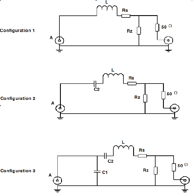
Annex D (informative):
Test fixture
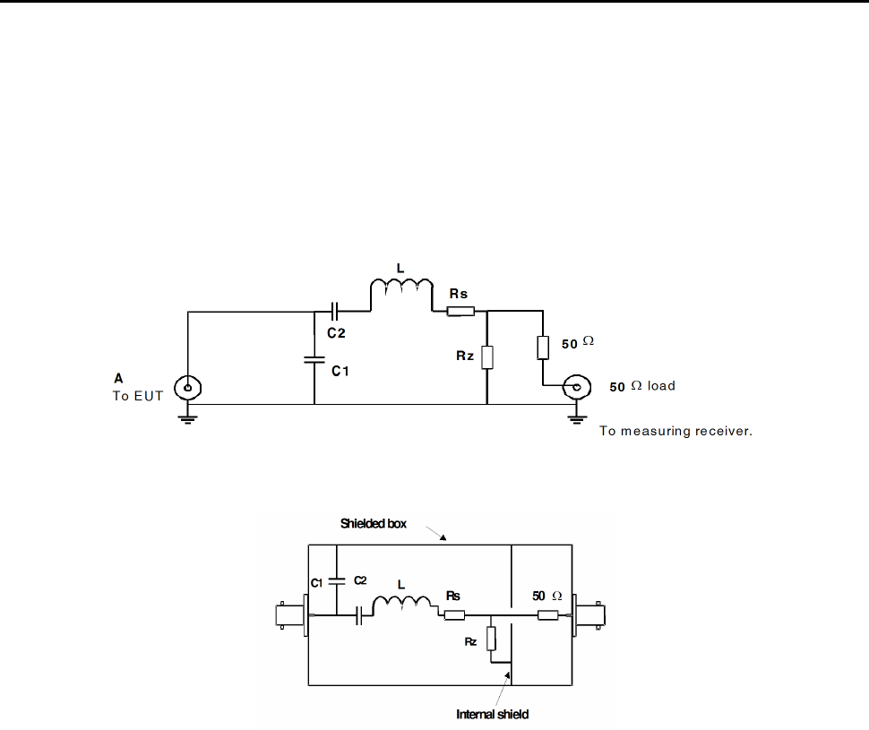
Test fixture for measuring induction loop amplifier audio frequency baseband and spurious currents by use of an
artificial loop.
The artificial loop may be used for equipment with a loop connector and submitted for testing without a loop. The
radiated fields for the baseband and spurious emissions are proportional to the audio frequency baseband and spurious
currents. Therefore, measurements are made to determine the audio frequency baseband and spurious currents in the
artificial loop.
Figure D.1
Figure D.2
An example of the mechanical layout and the equivalent electric circuit of the components are given in figures D.2 and
D.1 respectively.
If the manufacturer specifies a range of loop dimensions, two artificial loops having maximum and minimum
inductance L should be supplied. This fact should be stated in the test report.
R
z
is a low value non-reactive resistor. The voltage across R
z
is proportional to the conducted audio frequency baseband
and spurious loop currents. These can be measured at the output connector.
R
s
in combination with R
z
ensures that the artificial loop has the same Q as the specified loop.
As the artificial loop does not provide galvanic isolation between the equipment under test and the test receiver,
isolation may be required elsewhere in order to ensure correct and/ or safe operation.
Capacitors C1, C2 are optional components together with L to be used as appropriate by the manufacturer to simulate
the actual loop configuration. Other possible configurations are shown in figure D.3.
ETSI
Draft ETSI EN 303 348 V1.1.0 (2016
-
02)
27
Figure D.3
The test fixture configuration used by the manufacturer should be stated in the test report.
ETSI
Draft ETS
I EN 303 348 V1.1.0 (2016
-
02)
28
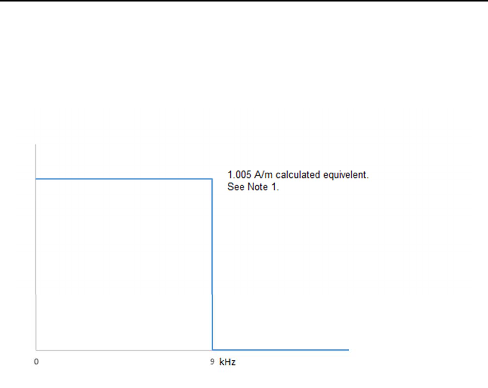
Annex E (normative):
Induction loop amplifier emission levels and spectrum mask
measurements
The present document allows spectrum measurements to be made. The measurements are relevant for AFILS operating
between 0 Hz to 9 kHz.
NOTE: This limit is the equivalent H-Field limit, when calculated using the formulae in clause C.1.4 of
BS 7594:2011 [3], and when measured at the furthest point of the useful magnetic field volume, as
declared by the provider. Actual equipment measurements are taken in terms of conducted loop output.
Figure E.1

ETSI
Draft ETSI EN 303 348 V1.1.0 (2016
-
02)
29
Annex F (informative):
Determination and use of the measurement bandwidth
CISPR 16-2-3 [i.3] specifies a reference bandwidth for the measurement of unwanted emissions by measurement
receivers and spectrum analysers.
The reference bandwidth (BW
REFERENCE
) cannot always be used as the measurement bandwidth (BW
MEASUREMENT
).
This is particularly the case if the measurement is to be made for example on the slope of a spectrum mask or a receiver
selectivity curve. In such situations the measurement should be made with a sufficiently low bandwidth in order not to
distort the reading.
The actual measured value, A, should be referred back to the reference bandwidth by.
Either:
a) Correcting the measured value, A, for any signal having a flat level spectrum with the following formula:
where:
- B is the measured level, A, transferred to the reference bandwidth.
Or:
b) Use the measured value, A, directly if the measured spectrum is a discrete spectral line.
A discrete spectrum line is defined as a narrow peak with a level of at least 6 dB above the average level inside the
measurement bandwidth.
MEASURED
REFERENCE
BW
BW
AB log10+=

ETSI
Draft ETSI EN 303 348 V1.1.0 (2016
-
02)
30
Annex G (informative):
Bibliography
• ERC Report 044 (1997): "Sharing between inductive systems and radiocommunication systems in the band
9 - 135 kHz".
• ERC Report 069: "Propagation model and interference range calculation for inductive systems
10 kHz - 30 MHz".
• ERC Report 092: "Sharing between inductive SRD systems and radio communication systems operating in the
frequency band 10.2 - 11 MHz".
• Council Directive 2004/108/EC of 20 April 2016 on the approximation of the laws of the Member States
relating to electromagnetic compatibility.
• Directive 2014/30/EU of the European Parliament and of the Council of 26 February 2014 on the
harmonisation of the laws of the Member States relating to electromagnetic compatibility.
• ERC Decision of 12 March 2001 on harmonised frequencies, technical characteristics and exemption from
individual licensing of Short Range Devices used for inductive applications operating in the frequency bands
9 - 59.750 kHz, 59.750 - 60.250 kHz, 60.250 - 70 kHz, 70 - 119 kHz, 119 - 135 kHz; (ERC/DEC(01)13).
• Directive 98/34/EC of the European Parliament and of the Council of 22 June 1998 laying down a procedure
for the provision of information in the field of technical standards and regulations.
• ETSI EG 201 399: "Electromagnetic compatibility and Radio spectrum Matters (ERM); A guide to the
production of candidate Harmonized Standards for application under the R&TTE Directive".
• CENELEC EN 55022: "Information technology equipment - Radio disturbance characteristics - Limits and
methods of measurement".

ETSI
Draft ETSI EN 303 3
48 V1.1.0 (2016
-
02)
31
History
Document history
V1.1.0 February 2016 EN Approval Procedure AP 20160524: 2016-02-24 to 2016-05-24
