Thank you for your purchase !
WOODEN PLATFORM
BED FRAME
ASSEMBLY INSTRUCTIONS
Before You Begin:
Please identify all component parts and hardware pieces required before you begin. Carefully remove all of the
components from the packaging and set aside for assembly. Assemble on a soft surface to prevent scratching
during assembly.
Caution:
Tighten all components securely before use. Failure to do so may result in personal injury.
DO NOT use any sharp objects to open plastic wrapped components as damage to product or componenets may
result.
Warning:
CHOKING HAZARD - Small Parts. Adult Assembly Required.
lnjury may result from tipping furniture. You must installthe Tipping Restraint Hardware with the unit to prevent
the unit from tipping and causing any accidental in.1ury, instability, death or damage. The tipping restraint is
intended only as a safety measure, it is not a substitute for proper adult supervision.
This tipping restraint is not an earthquake restraint. lf you wish to add the extra security of earthquake
restraints, they must be purchased and installed separately.
Serious or fatal crushing injuries can occur frorn furniture tipping over. To prevent furniture from tipping
over it must be permanently fixed to the wall. Fixing devices for the wall are not included since different wall
materials require different types of fixing devices. Use fixing devices suitable for the walls in your
home
Failure to detach this restraint before moving furniture may result in injury or damage.
DO NOT ALLOW CHILDREN TO CLIMB ON FURNITURE
..................................................................................
YKC-1090-F-WAL-GG / YKC-1090-F-NAT-GG

Have a Question/Concern?
Quality products and first-class customer service are the cornerstone of
longlasting consumer relationships. We strive toward excellence in all we do and
want you to be completely satisfied with your purchase.
Please contact our exceptional Customer Experience Agents at the email
address or phone number shown below to assist you with any product
questions or issues before requesting a return.
We look forward to serving you in a friendly, efficient manner to resolve any issues
you may have.
Customer Seryice Email: CustomerExperience@belnick.com
Customer Service Phone: 866-552-2810
Our Warranty Statement
This warranty covers manufacturing defects associated with your new product. The product is
warranted from the original purchase date and to the original purchaser for normal usage,
according to the below-referenced specifications and limitations.
Non-moving metal parts are warranted for 5 years,
Component parts including pneumatic cylinder, control mechanism, base and casters
are warranted for 2 years.
All other items are warranted for 1 year.
Normal usage means use in compliance with the restrictions and welght limits specified for the
product. ln the absence of product-specific restrictions and weight limits, normal usage means
use for no more than forty hours per week by persons weighing 250 lbs. or less. Coverage
terminates if the product is sold or otherwise transferred. Repairs made by parties otherthan
Belnick also void this warranty.
This warranty will not cover: (1) labor, freight, or damage from misuse, abuse, negligence,
alteration, assembly, installation, attachments, accident, vandalism, acts of nature or any other
event beyond the control of Belnick; (2)tearing, scratching, scuffing, or blemishing of leather or
fabric; (3) cosmetic damage that may result from normal usage; {4) damage attributable to use
by persons exceeding specified weight limits or commercial use exceeding forty hours per
week; or (5) rust or other damage caused by exposure to moisture. The user assumes all risk of
injury resulting from use of this product. Liability for incidental or consequential damage is
excluded. Some states do not allow the exclusion or limitation of incidental or consequential
damages, so the above limitation or exclusion may not apply to you.
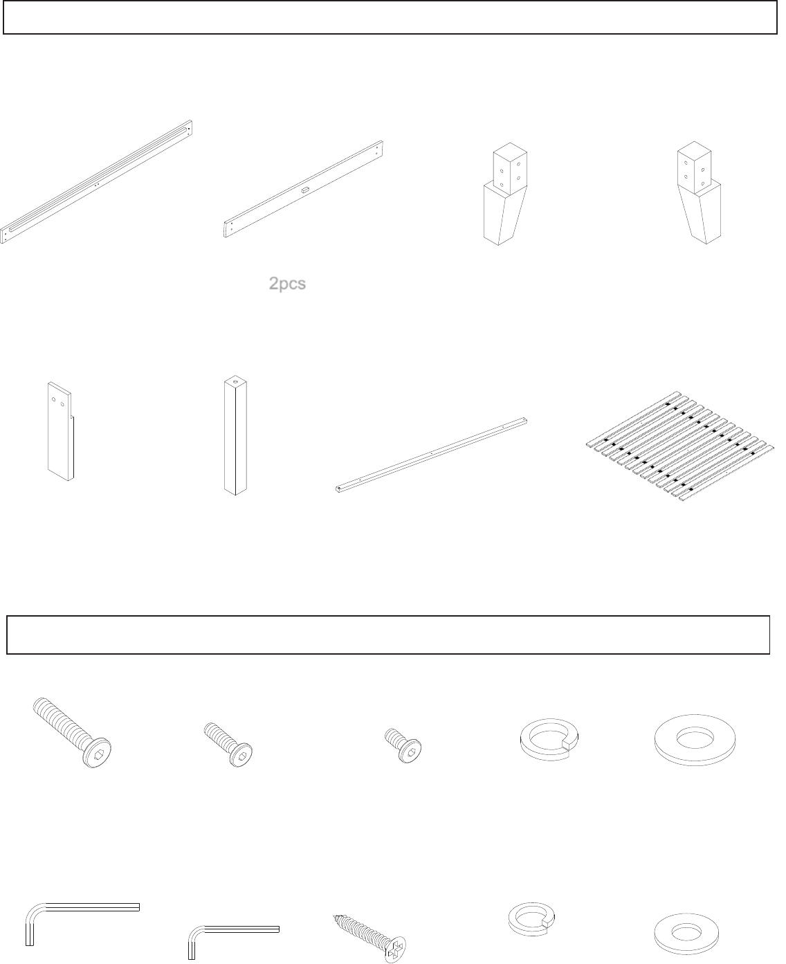
Parts
Part 1: Le� & Right Siderails Part 2: Headboard & Footboard Part 3: Le� Headboard & Part 4: Right Headboard
Right
Footboard Legs & Le� Footboard Legs
2pcs 2pcs
Part 5: Le� & Right Side Legs Part 6: Center Legs Part 7: Center Rail Part 8: Support Slats
2pcs
3pcs
1pc
1pc
Hardware
M8 – 85mm Screw
Par
t A x 16pcs
M6 – 50mm Screw
Part B x 3pcs
M6 – 30mm Screw
Part C x 4pcs
M8 – 1mm Large Lock
W
asher
Part D
x 16pcs
M8 – 1mm Large Flat
Washer
Part E x 16pcs
M5 Allen Wrench
M4 Allen Wrench
30mm Self-Tapping
Screw
Part H
x 1pcs
Part I
x 1pcs
Part J x 2pcs
2
pcs
2pcs
Left Headboard Leg
Headboard
Left Side Leg
M6 – 1mm Small Lock Washer
M6 – 1mm Small Flat Washer
Part F x 4pcs
Part G x 4pcs
Left Footboard Leg
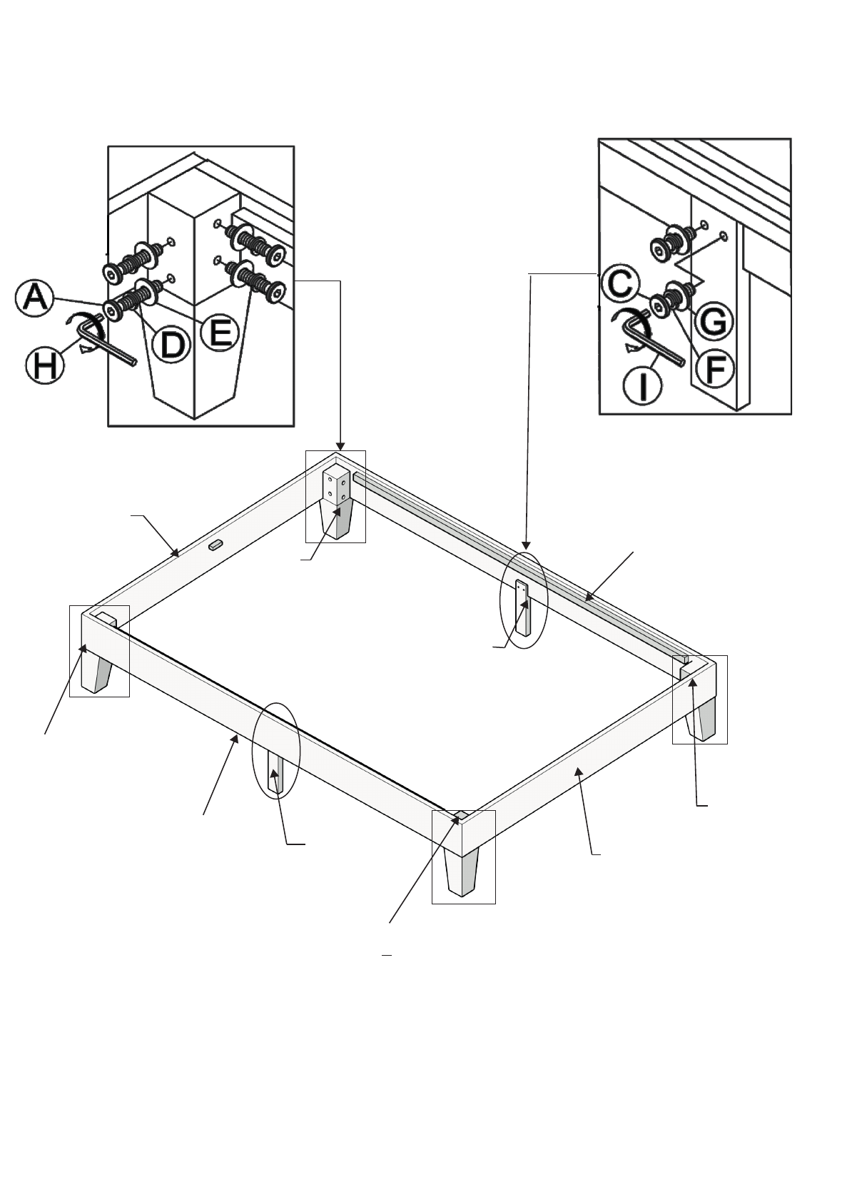
STEP 1B: Attach Left Side Leg & Right Side Leg (Part 5) to the Left and Right
Siderails (Part 1) using (4) M6 – 30mm Screws (Part C), (4) M6 – 1mm Small
Lock Washers (Part F) and (4) M6 – 1mm Small Flat Washers (Part G). Tighten
with M4 Allen Wrench (Part I).
STEP 1A:
Attach Left Headboard & Right Footboard Legs (Part
3)
and Right Headboard & Left Footboard Legs (Part 4) to the
Headboard and Footboard (Part 2) and the Left and Right
Siderails (Part 1) using (16) M8 – 85mm Screws, (16) Large Lock
Washers (Part D) and (16) Large Flat Washers (Part E).
Tighten with M5 Allen Wrench (Part H)
Right Footboard Leg
Right Headboard Leg
Footboard
Right Side Leg
M4 Allen Wrench
M6 – 30mm Screw
M6 – 1mm Small
Lock
Washer
M6 – 1mmSmall
Flat
Washer
Left Footboard Leg
STEP 1B: Attach Left Side Leg & Right Side Leg (Part 5) to the
Left and Right Siderails (Part 1) using (4) M6 – 30mm
M6 – 1mm Small Lock Washers (Part F) and (4) M6
Flat Washers (Part G). Tighten with M4 Allen Wrench (Part I).
STEP 1A: Attach Left Headboard & Right Footboard Legs (Part
3) and Right Headboard & Left Footboard Legs (Part 4) to the
Headboard and Footboard (Part 2) and the Left and Right
Siderails (Part 1) using (16) M8 – 85mm Screws (Part A), (16)
Large Lock Washers (Part D) and (16) Large Flat Washers (Part
E). Tighten with M5 Allen Wrench (Part H)
Left Headboard Leg
Right Footboard Leg
Right Headboard Leg
Footboard
Headboard
Right Side Leg
Left Side Leg
M4 Allen Wrench
M6 – 30mm Screw
3
3
5
5
1
1
2
2
4
4
Left siderail
Right siderail
Right side leg
Left side leg
Headboard
Left Headboard
leg
Left footboard leg
Left footboard
leg
Footboard
Right Headboard leg
M8 – 85mm Screw
M5 Allen Wrench
Large Lock
Washer
Large Flat
Washer
M6 – 30mm Screw
M4 Allen Wrench
M6 – 1mm Small
Lock Washer
M6 – 1mm Small
Flat Washer
Attach Left Side Leg & Right Side Leg (Part 5) to the
Screws, (4)
1mm Small
Flat Washers (Part G). Tighten with M4 Allen Wrench (Part I).
M6 – 1mm Small
Lock
Washer
M6 – 1mmSmall
Flat
Washer
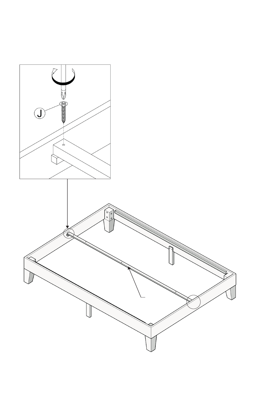
Attach the Center Rail (Part 7) to the
Headboard &
Footboard
(
Part
2
)
using
(2)
30mm Self-Tapping Screws (Part J)
.
STEP 2: A
ttach the Center Rail (Part 7) to the Headboard & Footboard ( Part 2 )
using (2) 30mm Self-Tapping Screws .( Part J)
7
30mm Self-Tapping
Screws
Center Rail
Left Siderail
Center Rail
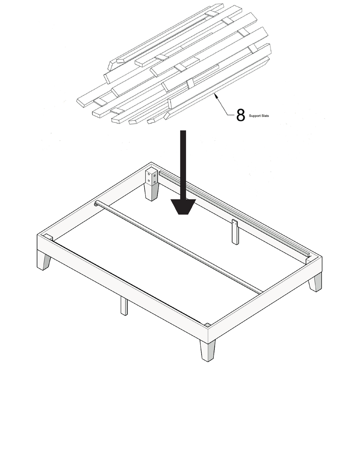
STEP 3: Place rolled support slats (Part 8) onto the Center Rail and Siderails.
Support Slats
Right Siderail
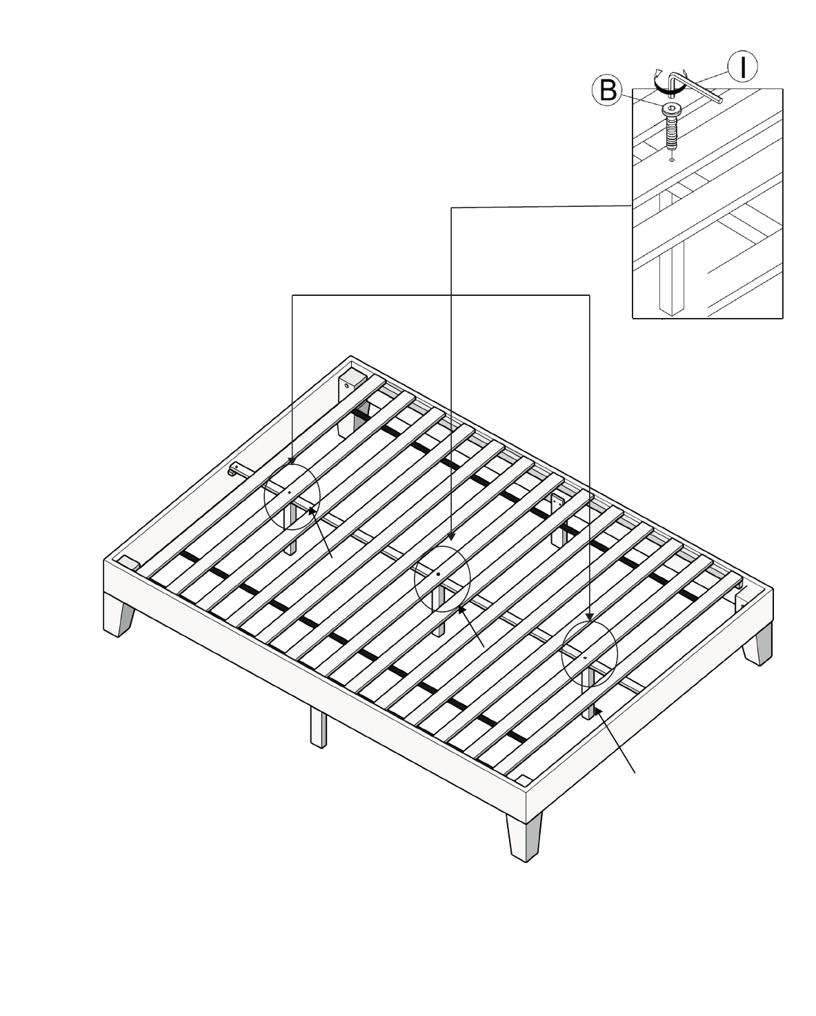
STEP 4:
Place the Center Legs (Part 6) under the
Center Rail and unroll
Support Slats until the
first
screw hole is visible. Attach the Support Slats to the
Center Rail and Center Legs using (3)
M6 – 50mm
Screws (Part B).
T
igh
ten with M
4 Allen
Wrench (Part I).
NOTE: Do not fully unroll support
slats to begin. Once the first leg is
attached, slowly unroll slats until the
next screw hole is visible. Attach to
center rail and leg one at a time until
all 3 are attached.
STEP 4:
Place the Center Legs (Part 6) under the
Center Rail and unroll
Support Slats until the
first
screw hole is visible. Attach the Support Slats to the
Center Rail and Center Legs using (3)
M6 – 50mm
Screws, (3)
Small Lock Washers (Part F) and (3)
Small Flat Washers (Part G). Tighten with M
4
Allen
Wrench (Part I).
NOTE: Do not fully unroll support
slats to begin. Once the first leg is
attached, slowly unroll slats until the
next screw hole is visible. Attach to
center rail and leg one at a time until
all 3 are attached.
Center Legs
Center Legs
M6 – 50mm Screw
M4 Allen Wrench
6
6
6
Center Legs
M6 - 50mm Screw
M4 Allen Wrench
