,,,,,
One Center
Three Air Logistics Complexes
Three Air Base Wings
Two Supply Chain Wings with a diverse mission set
Art of the Possible Handbook
AFSCH60-101
30 August 2023
Certified Current, 31 July 2024
Air Force Sustainment Center

1
The Air Force Sustainment Center’s mission is to deliver combat power for America. Our success is the
foundation of the warfighter's success, whether it is ensuring our nation's nuclear deterrent, maintaining
air supremacy, fueling the fight, or delivering hope. Our warriors in combat cannot succeed without the
sustainment capabilities of AFSC.
Behind this war-winning mission, we have an amazing team who will build on the legacy of success
already achieved. Using P4 - Produce to Promise, People Make it Happen, Process is How We Do It, and
Prepare for Competition and Future Warfighting - we will continue to leverage Art of the Possible to realize
incredible results across the enterprise.
AoP is the mission culture imperative of AFSC. It is not what we do, it is HOW we do everything. It is the
“playbook” that allows us to operate as one team across each of our 27 operating locations. Our customers
and our suppliers benefit when we speak with a consistent voice and use one set of operating principles.
AoP requires leadership and commitment at all levels. I expect all leaders to have the ability to build and lead a
team, horizontally and vertically, to influence outside organizations, and to possess mastery of their processes.
This handbook is an important part of institutionalizing AoP across our enterprise. It reflects collective experiences,
lessons learned, best practices, and important content on how AoP will be applied in every work area. This
handbook is the foundation of our training activities and I expect every supervisor and leader within AFSC to
internalize its purpose – and practice it every day!
Through commitment and disciplined implementation, we will continue to operationalize AoP, and drive
continuous process improvement as part of our mission culture. Our nation depends on us.
Your Fellow Airman,
STACEY T. HAWKINS
Lieutenant General, USAF
Commander

2
BY ORDER OF THE COMMANDER AIR FORCE SUSTAINMENT CENTER
AIR FORCE SUSTAINMENT CENTER HANDBOOK 60-101
30 August 2023
Certified Current, 31
July 2024
Standardization
AFSC Art of the Possible Handbook
ACCESSIBILITY: Publications and forms are available on the e-Publishing website at www.e-
publishing.af.mil for downloading or ordering.
RELEASABILITY: There are no releasability restrictions on this publication.
OPR: AFSC/LZZ Certified by: AFSC/LG
(Mr. Jeffrey S. Sick, SES)
Supersedes: AFSCH 60-101, 28 December 2021 Pages:
This is a newly revised handbook and should be reviewed in its entirety. As stated in Joint
Publication (JP) 4-0, Joint Logistics, “the relative combat power that military forces can generate
against an adversary is constrained by a nation’s capability to plan for, gain access to, and deliver
forces and materiel to required points of application.” Art of the Possible (AoP) is the constraints
based management system used by the Air Force Sustainment Center (AFSC) to provide effective
support to the delivery of combat power by the warfighter. This handbook implements Air Force
Policy Directive (AFPD) 60-1, Air Force Standardization Program and prescribes minimum
requirements for implementing AoP, a standard constraints based management system for
managing, conducting, tracking, and reporting workload performed within AFSC. Refer
recommended changes and questions about this publication to the Office of Primary Responsibility
(OPR) listed above using the AF Form 847, Recommendation for Change of Publication. Route
AF Form 847s from the field through the appropriate chain of command. Ensure that all records
created as a result of processes prescribed in this publication are maintained in accordance with
Air Force Instruction (AFI) 33-322, Records Management and Information Governance Program,
and disposed of In Accordance With (IAW) Air Force Records Disposition Schedule (RDS)
located in the Air Force Records Information Management System (AFRIMS).
SUMMARY OF CHANGES
Administrative changes have been made to the AFSC commander letter and the executive
summary. Previous changes to this document are below. Major changes include an expanded
discussion on engaged leadership and the Leadership Model, questions for maturing AoP and
growing leaders, and the necessity of positive accountability. The science of throughput and
Theory of Constraints (ToC) discussions have been incorporated into the requirements of the
Radiator Chart to better link the application of science to the management system. Also, a chapter
on managing the machine has been added to emphasize the necessity to actively monitor,
understand, manage, and improve the process machine on a continuous basis.

3
1. Scope. This publication is the keystone document for AFSC’s AoP. It provides overarching
doctrine on constraint based management of center Mission Essential Tasks (METs). It provides
the foundation, fundamentals, and core tenets that guide commanders and directors in
implementing, executing, and, assessing AoP.
2. Purpose. This publication has been prepared under the direction of the commander of the
AFSC. It sets forth center doctrine for the activities and performance of the AFSC in constraints
based management and provides the basis for the implementation, execution, and assessment of
AoP within AFSC units. It provides guidance for the management of center METs. It provides
the framework within which METs can be optimized to support Air Force operations throughout
the world. This publication is intended to provide guidance to AFSC commanders, directors, and
their staffs for constraint based management of METs.
3. Application.
3.1. AFSC directives established in this publication apply to all AFSC organizations.
3.2. The AoP Handbook is implemented by Air Force Sustainment Center Instruction (AFSCI)
60-101, Art of the Possible, and will be used by AFSC senior leaders to create a culture that
relies on the skills, abilities, and forward thinking of the entire enterprise to create the
teamwork necessary to enable AoP. If conflicts arise between the contents of this publication
and the contents of complex, wing, or directorate publications, this publication will take
precedence unless the commander of the AFSC has provided more current and specific
guidance.
Chapter 1 – INTRODUCTION
1.1. What is Art of the Possible (AoP)?
1.2. Why AoP?
1.3. The Cycle
1.4. Key Ingredients for Success
Chapter 2 – ENGAGED LEADERSHIP
2.1. Introduction
2.2. Leadership Model
2.3. The Importance of Leadership
2.4. Application
2.5. Summary
Chapter 3 – MANAGEMENT SYSTEM INTEGRATION
3.1. Management System Integration
3.2. Road to Goals
3.3. Process Flow
3.4. Gates
3.5. Release Points
3.6. Visual Displays
3.7. Standard Work and Scripting

4
3.8. Tools and Regulatory Guidance
3.9. Touch Time
Chapter 4 – MANAGE THE MACHINE
4.1. Introduction
4.2. Leader Expectations
4.3. Summary
Chapter 5 – PURSUIT OF EXCELLENCE
5.1. Pursuit of Excellence
5.2. Maturity
Chapter 6 – GETTING STARTED
6.1. Step 1: Identify and Define Mission Essential Task List (METL)
6.2. Step 2: Select One Task for AoP Implementation
6.3. Step 3: Set Up the Machine
6.4. Apply the Rules of Flow
6.5. Step 4: Manage the Machine
Chapter 7 – CONCLUSION
Appendix Section
APPENDIX A – CASE STUDIES
A.1. AFSC Logistics Directorate’s Performance Management Division (LZZ) Non-Technical
Special Projects
A.2. 309th Aerospace Maintenance and Regeneration Group (AMARG) Component Reclamation
A.3. Ogden Air Logistics Complex (OO-ALC) – 583 Missile Maintenance Squadron (MMXS),
Rivet MILE Legacy
A.4. 523rd
Electronics Maintenance Squadron (EMXS) Radio Frequency (RF) Shop Production
Machine
A.5. 309th Commodities Maintenance Group (CMXG) F-35 Canopy Machine
A.6. 76th Software Engineer Group (SWEG) Mission Planning
A.7. Oklahoma City Air Logistics Complex (OC-ALC) TF33 Engines
A.8. 567th Aircraft Maintenance Squadron (AMXS) B-1 Journey
A.9. 406th Supply Chain Management Squadron (SCMS) Technical Order Management and
Editorial Operations
A.10. 406th SCMS Part Number Requisition (PNR) Support
A.11. 78nd Air Base Wing (ABW) Nonjudicial Punishment Program and Discharge Program
A.12. 574th Commodities Maintenance Squadron (574 CMMXS) Supplies Repaired and
Overhauled Components for Aircraft
Attachment 1 - GLOSSARY OF REFERENCES AND SUPPORTING INFORMATION

5
Executive Summary
AoP is a constraint-based management system designed to create a workforce culture focused on
efficient process execution. A thorough understanding of what each unit does in reference to their
mission and customers is critical. Next, setting common goals and vetting them through the
enterprise and all process stakeholders ensures commitment, ownership and teamwork toward
accomplishing goals. Operationalizing a common enterprise vision by building process machines
with measurable performance that guide data-driven decisions will ensure AFSC achieves AoP
results.
AFSC processes are set up as machines that have specific, predictable results once they are
understood. Process machines are based upon established AoP core tenets, principles of standard
work, and visual displays that help the process doers understand the status of the process machine
and how they affect the overall process. Any process can be gated in order to measure throughput
and focus process improvement activities. There is science behind the creation of process
machines leading to predictable outputs. Once a process machine is set up according to AoP
methodologies and science, it is monitored and measured for performance, so the process
constraint can be identified and resolved through process improvement methods. This allows a
robust constraint based resolution plan to be enacted to increase process throughput. Tactical
process management allows issues in the process to be identified so they can be quickly resolved
and eliminated to increase touch time thus improving process speed. Process speed is the key
indicator that the machine is set and the culture is in place, to enable processes to reach AoP Road
to Goals.
In order to be truly successful, AoP processes must focus on safety, quality and cost effectiveness
in addition to speed. Speed, Safety, Quality and Cost Effectiveness represent the true north metrics
that will guide our AFSC Process machines to reach their common goals and achieve world class
results
This book provides the core tenets and guiding principles of AoP to ensure these concepts remain
the foundation for daily operations. It also provides a simplified approach to getting started with
AoP. Embracing AoP requires a culture shift. Together, we must build a culture of “believers” in
the machine methodology and the necessity of an enterprise approach to constraint based
management in order to attain AoP results. This will require leaders to be champions of change
by identifying their burning platform(s) to rally the enterprise around common goals establish
process machines managed through operational meetings, lead robust constraint resolution and
personal engagement in the work area.
Ultimately, AoP is about utilizing a methodical approach to improve processes. It is about reaching
beyond today’s limitations to grasp previously unimagined heights of performance. It is about
challenging each other to recognize opportunities, eliminate constraints, improve processes and
optimize resources to achieve world-class results. It isn’t about working harder, cutting corners or
jeopardizing workplace safety but about expanding our vision of what is truly possible and refusing
to settle for marginal improvements. AoP results within AFSC will positively affect the cost of
sustainment for the Air Force, thereby determining the size of the future Air Force and the ability
of our nation to fight and win the next war.

6
Chapter 1
INTRODUCTION
1.1. What is Art of the Possible?
1.1.1. Before we describe what AoP is, let’s discuss what it is not. It is not a new “flavor of
the month” process improvement initiative. It is not a passing fad that will fade into the sunset
with the next command change. It is not a CPI method that is delegated to a dedicated office
or team to accomplish. Instead, AoP is a universal set of best practice standards that form the
AFSC management system. In accordance with AFSCI60-101, AoP will be used to govern all
AFSC processes.
1.1.2. For more than three decades the Air Force, as well as industries across the globe, have
been in a continuous search for better ways to do business. There has been a constant stream
of new concepts that have consumed the time and attention of the industrial world. Each
passing year seemed to bring the next big thing that promised to transform the way we did
business. Concepts such as Total Quality Management, Lean, ToC, 6 Sigma, as well as dozens
of variations and combinations of these, have been at the forefront of every organization in the
Air Force. Each of these brought great promises but equally large challenges. Every new
initiative brought a new vocabulary and new tools that must be learned. With them also came
a growing mountain of resistance to the next “flavor of the month.”
1.1.3. When the AFSC stood up in July 2012, it was a collection of individual depots and
supply chain pieces operating with individualized ideas that had been developed through 30
years of innovation initiatives. This merging of supply chain functions under one center
presented the opportunity to standardize business practices and adopt guiding, operating
principles that would become the basis of a new culture: the Art of the Possible. AoP is not a
new initiative, but a universal management system that establishes a standardized set of
operating principles for the AFSC. It takes the gold standard concepts that have been learned
through 30 years of experience and combines them into one language and customizes them to
the work that we do in the AFSC.
1.1.4. AoP is a constraint based management system where throughput is king. AoP is based
on the concept of gaining an accurate understanding of the flow of work and then locating the
constraint that interrupts the flow, preventing execution of the mission. Successful mission
execution is defined by achieving the common goals of the organization to include speed,
safety, quality, and cost effectiveness. AoP tools simplify the process so constraints can be
identified. Once the constraint is identified, specific focusing steps are used to resolve the
constraint with a continuous eye on the goals of the organization.
This handbook will systematically lead the reader through the role of leadership and how it
equates to success. It will then provide detailed instruction of how to apply principles and
tools in managing, sustaining and improving work processes.

7
1.2. Why AoP?
1.2.1. Part of the question of why we use AoP is answered in the previous section. It is
designed to stabilize the continuous introduction of new concepts and buzz words. It creates
a common language and a set of guiding principles that are backed by science to direct the way
we approach work and improvement of that work. AoP is a methodical approach to our
business; a science behind our operations that is based on sound “flow” principles utilizing a
constraints-based management philosophy that leads to a predictable output. Daily
identification and elimination of process constraints with a focus on CPI is essential for
success. AoP allows the user to simplify complex processes into visible and understandable
content that can be monitored and communicated with others.
1.2.2. Weapon system sustainment costs are growing at an unsustainable rate. These costs
determine the size of the force we can afford to sustain. The size of our force determines the
ability to fight and win the next war. The future readiness of our weapons systems are based
on two realities: our ability to obtain more readiness with the same cost and/or our ability to
maintain a level of readiness with less cost. Every person in the AFSC must be cost conscious
and look for ways to reduce cost. AoP drives us to greater cost effectiveness through focusing
on enhanced speed, safety and quality.
1.2.3. AoP accomplishes its objectives by increasing speed. But a word of caution, speed is
not about working faster, cutting corners, or taking risks. The term speed in AoP lexicon, is
meant to be synonymous with efficient processes that promote throughput paced to a road
to…goal (aka the burning platform). In its most basic sense, speed equals reduced flowtime.
AoP creates a methodology that measures performance in a manner that focuses the
organization on the weakest link in their processes. This focus leads to process improvement
initiatives that affect the speed of throughput for the organizational process. To achieve speed
we must quickly resolve issues that affect the critical path of the process to allow the product
to continue moving forward unhindered.
1.2.4. Although AoP is a management system based on scientific principles, it is nothing
without engaged leadership. AoP includes developing effective leadership skills. Leadership
is the fuel that drives the machine. Leadership must be engaged in understanding the health of
the system and relentlessly striving to make it better through obstacle elimination. Leaders
must be proactive in working within and across organizational boundaries. All stakeholders
must understand the goals and be engaged in meeting those goals. It is essential that all leaders
at all levels share this responsibility. Chapter 2 will provide details of what engaged leaders
should be and what they should do.
1.2.5. Perhaps the best way to illustrate why we use AoP is to look at a simple example.
1.2.5.1. Let’s consider Joe who has an automotive repair shop. Joe has only one employee,
himself. Joe currently has two customers who want him to repair their cars. He has a labor
standards book that shows how many hours it takes to make each repair. Joe uses those
standards to give his customers their price. If Joe can get the work done in the length of
time allotted he makes money. If he takes longer, he makes less or could even lose money.
If he can get it done sooner than the standard, he has created extra capacity so he can get
additional customers or perhaps hire an additional mechanic.

8
1.2.5.2. Since Joe is the only mechanic it is obvious that he cannot work on more than one
thing at a time. But, to make his customers happy, he brings both cars into his shop and
starts work on them. Joe spends 30 minutes finding all of his tools that were not put back
up after the last day’s work. He works on one car for a few minutes and then moves to the
next car. The first car requires a water pump, so he runs to the parts store to get one. When
he gets back, he puts the water pump on the table and starts to work on the second car.
This car needs a temperature switch. He again runs to the parts store to get the switch.
When he gets back, he begins to put the water pump on the first car. After he gets it
installed, he realizes he needs a new belt, so back to the part store he goes. It does not take
a scientist to realize that Joe has a problem. Joe ultimately takes two days to repair both
cars. The standard says that he should have taken four hours each or eight hours total. Joe
realizes that he cannot survive if he continues to work this way.
1.2.5.3. Joe decides to start using AoP to manage his work. He begins by setting a goal for
himself. His road to… goal is to have every customer’s car completed in 90% of the
amount of time the labor standard says it should take. That is a pretty lofty goal considering
it has taken 400% on the previous two cars (16hrs/4hrs). His next step is to map out the
steps in the process so that he can better understand what is involved. Once he has the flow
defined, he establishes some gates (see sect. 3.4) in the process so that he can have
milestones to help him monitor and communicate his progress. Included in those gates are
some triggers to let him know when he needs to have his parts available. He realizes that
since he can only work on one car at a time, he will only bring one car into the shop at a
time. This is a concept known as Work in Process (WIP) control.
1.2.5.4. Joe soon discovers there is a serious problem. He has a constraint. His constraint
is himself. In order to meet his goal, he must be working on the car all of the allotted time.
How can he get parts if he needs to be working on the car the whole time? To exploit his
constraint (see sect.3.3.3.1.2) he must find a way to get his parts delivered. He contacts
the parts store and shares what his goal is and works out an agreement that they will deliver
his parts to him within 30 minutes of order (horizontal integration). In addition, Joe
understands that in order to protect his available time for the next car there are some things
that must be done before the next car can come into the shop. He sets up some release
points that establish all of the things (like putting his tools in place) that must be done
before the next car is ready to come into the shop.
1.2.5.5. Joe has just completed a very simple application of AoP. His first pass may not
result in his 90% goal but he can then use the tactical management tools to help to continue
moving toward his goal.
1.2.5.6. In Joe’s example, the process is simple and the solutions may readily be seen
without applying the AoP methods. However, in more complex processes it may not be as
obvious or the WIP may not be as easily seen as a car in a shop. This is the reason we
use AoP. It allows us to simplify and create visibility in complex systems. AoP gives
us proven principles that allow us to identify our constraint and find ways to resolve it.
1.2.6. The result of effectively applying the AoP principles is enhanced speed or throughput.
Throughput is king! If we can do work within the defined target, we make money. If we can
do it quicker, we increase capacity. If we increase capacity, we can, in turn, bring in more
work and make additional revenue. If it takes longer than the target, we lose money and the

9
customer is not happy. It is really that simple. The challenge comes in the complexity of the
process. AoP is designed to allow us to define complex systems in simple terms that can be
analyzed, communicated, and improved.
1.3. The Cycle:
1.3.1. As discussed in section 1.1.4., AoP is the application of a repetitive cycle of activities
focused on achieving the common goals of the organization. The cycle consists of:
• Mapping the flow and location of the WIP in the system.
• Identifying the constraint in the system.
• Resolving the constraint.
1.3.1.1. Mapping the flow of the process is essential to fully understand the work content
and the sequence in which things should happen. When the process flow includes the WIP
that is currently in the system, it identifies where there may be problems in the flow that
could indicate a bottle neck. While simple systems like our previous garage example are
easily seen, more complex systems can hide a multitude of problems and opportunities in
the chaos. Until there is a graphical representation of process flow and complete
understanding of where the WIP is located, complex systems will hide the constraint.
1.3.1.2. Once the process is mapped and the WIP is located in the system, the areas of
underperformance to the target will normally lead you to the constraint. It may initially
appear that the process has many constraints, but systematically analyzing the individual
situations will identify the primary constraint which is where your time and resources
should be directed.
1.3.1.3. When analysis has uncovered the likely culprit, a series of focusing steps should
be used to resolve the constraint. The ToC methodology gives us a roadmap of how to
attack and remove a constraint (see sect. 3.3.3.4).
1.4. Key Ingredients for Success:
1.4.1. For any endeavor, there are specific aspects that are required for success. AoP is no
different. The organization will only be successful if it is dedicated to achieving these key
ingredients at every level from the top down and from the bottom up. If any of these are
missing or are only given lip service, the organization will fail to achieve the results that are
possible. This handbook is designed to lead the reader through an understanding of the
components of AoP and why they are important. It will also give sufficient detail of how to
apply these components in your organization. The structure of the remaining chapters of this
handbook will follow these key ingredients for success.
1.4.1.1. Fully Engaged Leadership: Leadership expert John Maxwell states that
“everything rises and falls on leadership” (Maxwell, 2007)₁. The success of any
organization ultimately resides in the underlying culture of that organization. What is
culture and where does it come from? Businessculture.org defines culture as “an evolving
set of collective beliefs, values and attitudes” (Businessculture.org, 2019)₂, or put another
way, “the way we do things around here.” If we say that everything rises and falls on

10
leadership, we understand that culture is created as a direct output of the behaviors, values
and attitude of the leaders! There is a key word in this definition of culture and that word
is evolving. That means the culture is ever changing based on the behaviors, values, and
attitude of the leaders. Evolving culture requires constant engagement to keep it moving
in the right direction. Nothing stays the same. If leaders are not intentionally engaged to
better the organization, the order of nature tells us the culture will degrade. Anything left
to itself will degrade over time. Work is required just to maintain and even more work
is required to improve. Without fully engaged leaders, any implementation of AoP or
any other good thing will never be sustained, much less improved. The AoP Leadership
Model, as well as practical actions to be an effective leader will be fully explored in Chapter
2.
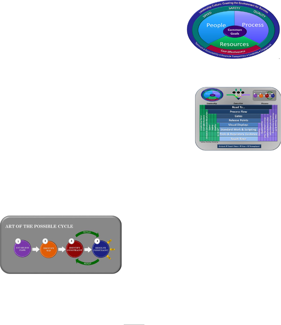
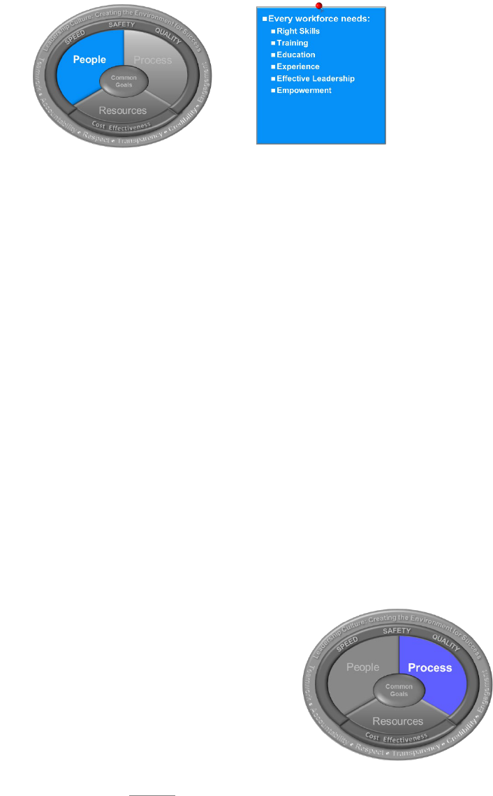
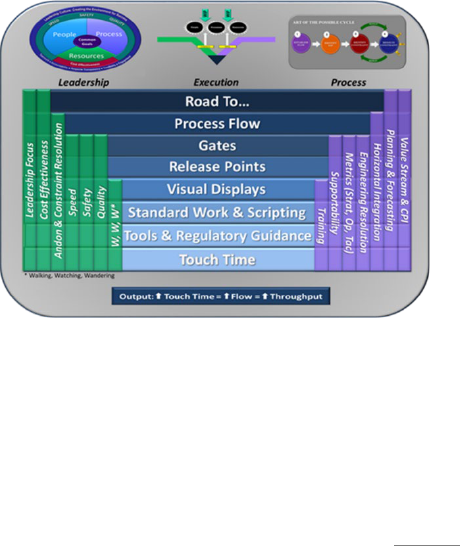
1.4.1.2. Management System Integration: The AFSC has developed a model of the AoP
management system that is commonly referred to as the Radiator Chart. The Radiator
Chart is a graphical representation of the path an organization should take to apply the
principles and tools of AoP. The model also shows how those principles and tools are
intertwined with leadership and organizational processes. Chapter 3 of this handbook will
provide detailed instruction of how and why to apply the components of the Radiator Chart
to fully integrate all aspects of the management system.
1.4.1.3. Managing the Machine: Chapter 4 will provide the day to day application of
leadership in managing the machine. Managing the machine is the responsibility of the
leader at all levels of the organization. It will require fully engaged leaders who possess
both the will and the skill to execute the mission. It will require leaders that are committed
to following standard work and reaching across organizational boundaries to engage
stakeholders to reach maximum potential. This handbook will provide the necessary
information for the leader to develop the skill to execute the mission through intentionally
and “intensely” managing the AoP machine.
1.4.1.4. Drive for Excellence: We have already discussed how anything left to itself will
degrade over time. Without a dedication to specific actions and behaviors even the best
process will degrade over time. The dynamics of AFSC leadership assignments and
rotations make that reality even more challenging. Sustainment and Maturity are elusive
characteristics of even world class organizations. Without laser focused pursuit of
excellence, we will neither sustain nor improve.
1.4.1.4.1. Sustainment: Historically, businesses across the globe indicate the average
lifespan of new improvement initiatives is 18 months. There are numerous factors that
influence this reality, but it is a clear indication there must be robust work standards in
place for leaders in order to sustain any initiative. AoP, in part, was created to help
address those tendencies to change over time. However, there must be much more
attention to the daily activities and standard work of leaders at all levels to counter what
psychologists call the chasm. The chasm is the point where initiatives reach a critical
point where they need the intense focus of the organization to prevent falling into the
black hole of previous “flavor of the month” efforts. Without the continuous attention
and drive, the new way will revert to previous methods or possibly cascade into chaos.
Section 5.1 will provide greater detail into what standards are needed and why.

11
1.4.1.4.2. Maturity: AFSC has developed a Maturity Matrix to help guide progression
of the journey. Every organization within AFSC should take a proactive approach to
the pursuit of excellence by building on the stages of maturity in each area of the
management system. Compliance to just conducting a periodic self-assessment is not
the goal, but rather an honest assessment of the status of the organizational culture.
Answer the question of “is that truly the way we do things here?” If not, what is the
next step to achieve it? Sect. 5.2 will give greater detail into use of the Maturity Matrix
and the supporting behaviors.
12
Chapter 2
ENGAGED LEADERSHIP
2.1. Introduction: In this chapter the necessity of leadership engagement in achieving AoP will
be the centerpiece of our discussion. The leader is the foundation that sustainment and maturity
are built upon. Leaders are the key to creating the environment for success. The AFSC leader is
expected to learn, understand, and use AoP.
2.1.1. The Leadership Model is much more than a motivational poster to hang on the wall. It
outlines the requirement of each leader to establish the common goals of their organization and
realize success by synchronizing people, process and resources to
achieve the mission. Every AFSC leader is expected to
embrace and embody the character traits of a successful
culture. They must possess the will and the skill to create
accountability in themselves and in those they lead. Great
leaders must be intentional about creating other leaders that
also possess the will and the skill to carry on the mission.
2.1.2. The Radiator Chart will be discussed in greater detail in Chapter 3, but it is also key to
the success of an AFSC leader. The components of the Radiator Chart are not just a checklist
of tasks to be done, rather it allows the leader to understand their
business in the greatest detail possible so they can design the
best process possible. The Radiator Chart is a roadmap to
removing variability and creating expectations. The
expectations of the AoP machine create the source of
accountability that must exist in each person. Each element of
the Radiator Chart provides a building block of expectations for
the workforce. The AFSC leader must understand every level
of the AoP management system and seek to transfer that understanding to those they lead. The
Radiator Chart provides a systematic application of AoP for the leader to follow to ensure
everyone is aware of the daily expectations.
2.1.3. Lastly, the leader must be present in the daily activities of those they lead and be focused
on the operation of the AoP machines within their organization. They must be constantly
asking questions, assessing the success of their AoP machines, and looking for ways to
improve them. They must be accountable to success
and actively seek that same accountability of every
other person that holds a stake in their success.
Standard work for AoP management is essential and
every leader at every level must be engaged in
following it and assessing the effectiveness of it.
Leaders must be good AoP coaches and constantly
ask questions to learn and to create the thinking skills of others. Without engaged leaders, the
ideals of AoP will not be achieved.
13
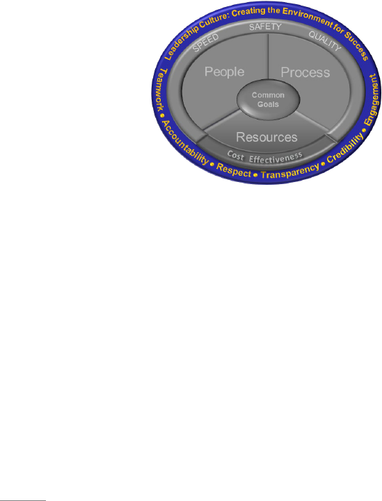
2.2. The Leadership Model:
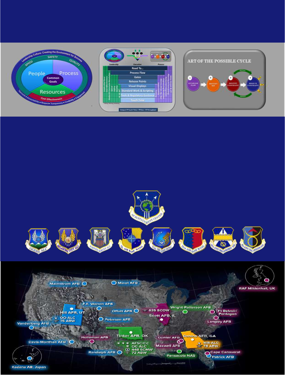
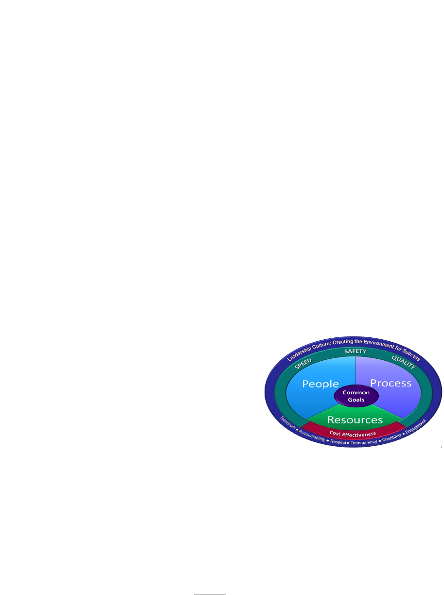
2.2.1. AFSC has developed a model to help communicate the essentials a successful leader
must understand and execute to achieve true AoP performance. The model represents what
the culture of leadership should embody. The right leadership culture will produce an
environment for success. Earlier we defined culture as: “an evolving set of collective beliefs,
values and attitudes.” The culture of an organization is formed by the behaviors, values, and
attitudes of the leaders; the culture then influences the behaviors of each individual and the
behavior of the individual determines the level of success of the mission. Leaders are the
foundation for our success. Leaders are required to be fully engaged and create an environment
that enables success. “Sustaining weapon system readiness to generate airpower for America”
is AFSC’s mission and overarching focus. Therefore, it is the duty of each leader at every
level to embrace the Leadership Model and strive to understand and use it to accomplish the
AFSC mission.
Successfully accomplishing our mission in a time of unprecedented challenges demands we
achieve our full potential as we strive for AoP results. In an environment where organizations
are struggling to survive, we are looking to thrive, lead, and exceed. We must provide greater
military capability and improved readiness at less cost than ever before. It is not about working
harder, cutting corners, or jeopardizing workplace safety; it is about recognizing opportunities,
understanding, and eliminating true limiting constraints, developing people, improving
processes, and maximizing available resources. To achieve our full potential, we must start
with common goals and then apply effective use of people, processes and resources to achieve
quick, safe, high quality and cost-effective success of the mission. The Leadership Model
provides enduring principles to equip everyone with a holistic approach to gaining
effectiveness and efficiency. By creating a leadership and management construct where
teamwork, accountability, respect, transparency, credibility, and engagement are paramount,
we create an environment where we can achieve AoP results. We must embrace a culture of
performance that encompasses the individual, the agency, and the enterprise.
2.2.2. Leadership Model breakdown: The Leadership Model
is built from the center out. The success of a leader
begins with understanding and taking ownership of the
common goals of the organization and then engaging
the mechanisms of people, process and resources to
successfully execute the mission. The mission is only
executed successfully if the components of speed, safety,
quality and cost effectiveness are maintained in concert
with common goals. The end result of successful leadership is a
culture where the mission is consistently executed and traits of Teamwork, accountability,
respect, transparency, credibility and engagement are evident throughout the organization.
14
2.2.2.1. Common Goals: Common goals are the rallying point for everyone in AFSC. To
drive behaviors that are focused on successfully executing the mission, these goals must
be defined in each of the four components of a successful mission. Every organization
must understand what their goals are in relation to speed (or throughput), safety, quality
and cost effectiveness. If any of these components are not met, the mission is not fully
successful. If the goal is not defined and understood, then success cannot be measured.
Common goals drive us to provide “best on the planet” sustainment support that is quick,
safe, high quality, and at the least cost. It is imperative that both professional leaders and
the professional workforce understand their specific work center goals. The role that each
individual plays in meeting those goals must be clearly communicated. We would not
expect everyone in AFSC to recite a list of organizational goals, but each and every
individual should understand what is expected in their work area and how they measure up
against specific targets. Understanding roles and expectations allows everyone to know if
we are winning and keeping our promises.
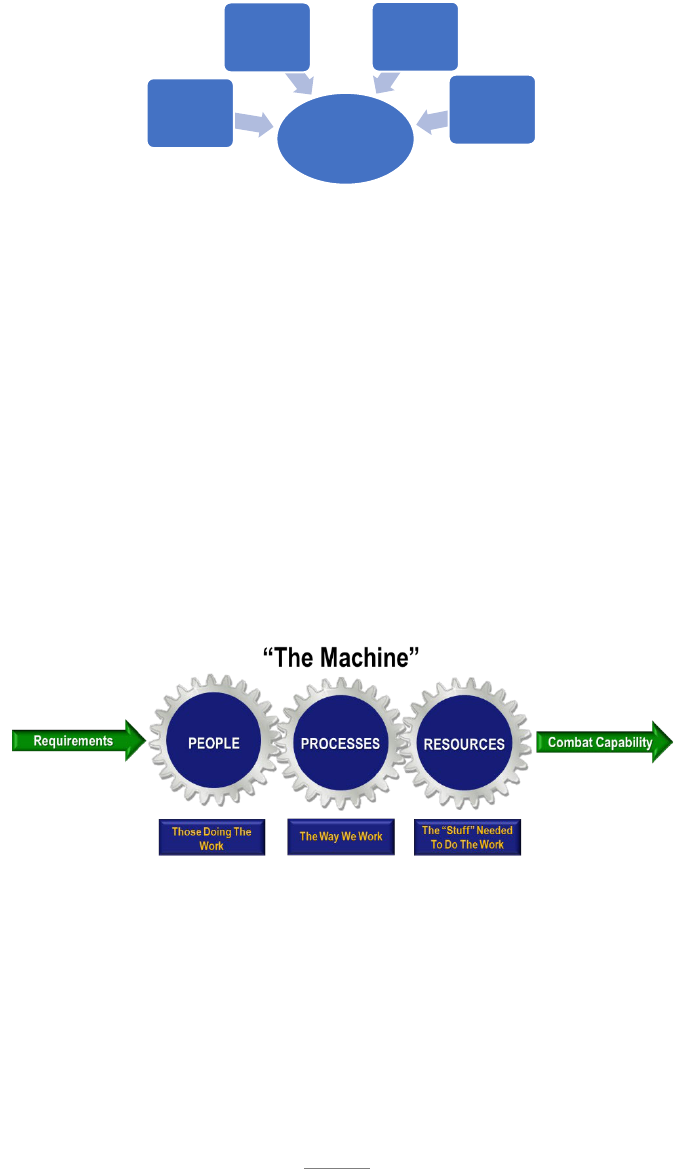
2.2.2.2. People, Processes, and Resources: Leaders are responsible for accomplishing a
successful mission by operating a well-oiled machine of people, processes, and resources.
Think of these three components as cogs in that machine
(see fig. below). A leader is the operator that is constantly monitoring and adjusting the
function of each cog to give the desired output; transforming a customer requirement into
combat capability. The concepts of this machine will be developed in much greater detail
throughout the remainder of this book.
Consider a builder who has a contract to build a house. He must first receive the
requirement in a set of plans that define the details of the contract. Those plans will define
the timeframe that is desired, the budget that is available and the quality of the
workmanship and materials that are to be used. The builder then must secure the funding,
hire the right people and determine the processes that will be used to safely achieve the
desired quality. The builder then choreographs the people, processes and materials to
produce a completed home for the customer within the agreed upon timeframe and budget.
The same is true of any organization in the AFSC. People, processes and resources are the
Common
Goals
Speed Target
(Throughput)
Safety
Targets
Quality
Targets
Cost
Effectiveness
Targets
15
levers that the leader has in his arsenal to achieve the mission. The successful leader must
choreograph the use of those levers to achieve the defined mission. The mission delivery
must be quick, safe, of high quality and cost effective.
2.2.2.2.1. People: The strength of the AFSC lies in our dedicated, competent, and
professional workforce. Without them nothing is accomplished. For this reason,
leading people is an essential role of the manager in the AFSC.
2.2.2.2.1.1. A central role of a leader is to ensure those under their leadership are
fully engaged in accomplishing the mission. Gallup defines engaged employees
as: those who are involved in, enthusiastic about and committed to their work and
workplace. Engaged employees do not happen by accident. The leader is
responsible for communicating the goals to the workforce. Leaders must also
define and communicate the role of every person in the accomplishment of those
goals. The leader must provide ways for the individual process doer to understand
their progress to achieving the target. The process doer needs to have the
opportunity to develop skills to improve mastery of the job and to believe that they
have autonomy in achieving their own career goals. The leader is responsible for
empowering the employee to be successful by ensuring the needed processes and
resources are in place.
2.2.2.2.1.2. Availability of the correct number of people with the correct skill sets
is elementary to success of the mission. The appropriate planning tools must be
used to understand the requirement (see sect. 4.2.2.1.1.) and communicate the need
through the chain of command. While complete control of this process does not
always exist at every level, the leader is still responsible for actively participating
in the process. They cannot just rely on the system to give them their fate.
2.2.2.2.2. Process: In order to have engaged employees, they must be empowered
through robust processes to perform the work. Effective leaders ensure that all
processes under their control or responsibility are current and
complete. Processes should be standardized to the
greatest extent possible and have predictable and
measurable results. Leaders must engage direct reports
in finding ways to improve their processes and be their
champion to see those improvements acted upon. They
must solicit the help of CPI teams or upper level leaders
16
where they do not have the expertise or authority to enact the improvements. Effective
leaders will review the standard work of their direct reports often and observe it in
action to ensure it is being followed. They must ensure all processes are viewed with
the end in mind. The goal of every process is to provide value by meeting the customer
requirement. If there are gaps or if the outcomes are not as expected, then the leader
must recognize the constraint to reaching the goal and engage the AoP system to
resolve the constraint.
2.2.2.2.2.1. Robust processes are not just a requirement for the direct report.
Leaders must seek out and follow standard work for themselves. They must commit
their actions to it. Where improvements are needed, they must engage the
appropriate people to see that the improvements are implemented. Effective
processes are not just checklists to be complied with, but are actions that will lead
to success. Great leaders will be those that are seeking ways to maximize their time
and the time of their employees, to creating value and achieving the common goals
of the organization. Leader standard work must be living and vibrant. All
processes must be reviewed continuously to ensure they are up-to-date, followed
correctly, so that the processes are achieving the desired outcome.
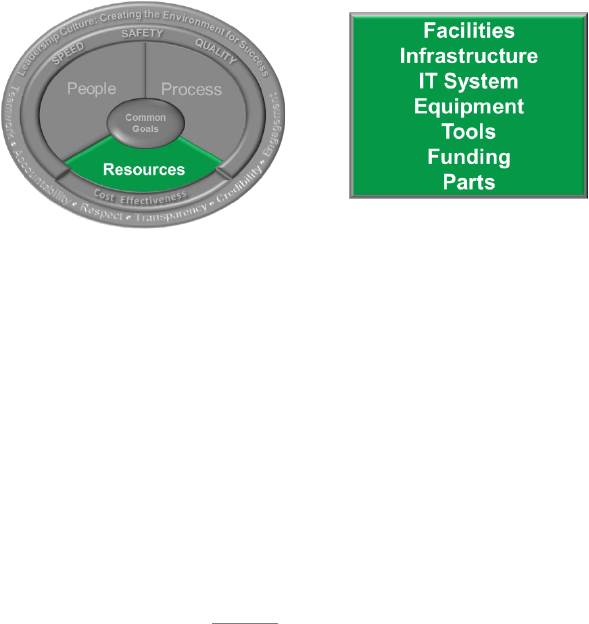
2.2.2.2.3. Resources: Proper planning and responsible stewardship of resources is an
essential prerequisite for success. Leaders are accountable for planning the right work
environment and must identify needs lead-time away. Without proper planning and
management of facilities, infrastructure, IT systems, equipment, tools, funding, and
parts, we severely jeopardize mission capability and readiness. To achieve true AoP,
leaders must do everything possible to maximize the value of the effort that our people
contribute to the mission. Time spent searching for resources or finding work arounds,
reduces speed, creates safety concerns, impacts quality, and adds to the cost of the
product. In our industrial and support environment, we must ensure our workforce has
the necessities to accomplish the mission safely and at the defined quality. However,
the requirement for cost effectiveness may not allow for everything they desire.

17
2.2.2.3. Mission Execution (Speed, Safety, Quality, and Cost Effectiveness): The inner
circle of the model represents the requisite components of
successful mission execution. The end goal of every leader
in the AFSC is mission execution. In the previous sections
we discussed that success is accomplished through the
application of people, processes, and resources. But how
do you know when the mission is a success? The mission
is only successful if the common goals in the areas of
speed, safety, quality and cost effectiveness are each met.
We will discuss each one briefly.
2.2.2.3.1. Speed is NOT about cutting corners or simply working harder and faster.
Instead, speed is enhanced by our ability to quickly identify, elevate, and eliminate
issues to the process flow. Our workforce must feel constraint and issue elimination is
a valued attribute. We must operate with the same sense of urgency to sustain critical
path timelines as we do when facing mission failure. Speed is about generating
throughput by application of proven scientific concepts to reduce flowtimes (see sect.
3.3.3.), Speed is enhanced when leadership embraces a safety culture, therefore,
reducing injuries and damages. Speed is also achieved when attention to quality
eliminates rework. Enhanced throughput will ultimately lead to improved cost
effectiveness. Greater throughput will lead to better customer satisfaction, greater
capacity, and enhanced support of the AFSC mission. Every day we interact with
processes in our personal lives where we desire speed. We want to be served quickly
and accurately. Whether it is in a drive through at the fast-food restaurant, in the
waiting room of our doctor’s office or in the checkout line at the grocery store, we all
want to be served quickly. Our future choices are influenced by those experiences.
The same is true with the AFSC. If we strive to create speed in everything we do, we
will create value for every customer. Science confirms that speed is directly linked to
safety, quality, and cost effectiveness. The combination cannot be separated.
2.2.2.3.2. Safety is the priority of everyone, especially the leader. Zero mishaps and
zero near misses are a possibility and are to be a goal of every organization. We need
to ensure everyone who comes to work for their shift goes home after their shift ready
to give their best the next day. Safety is about application of the three machine
components of people, processes, and resources by taking care of our people and
ensuring their work environment and processes always keep them safe. A strong
Voluntary Protection Program (VPP) is essential. Keeping every member of our team
safe is critical to the success of our organization. Safety is also about protecting the
speed, quality and cost effectiveness of our mission by protecting our equipment,
facilities, and products from damage. Damage to facilities, equipment, and products
are all detrimental to the mission.
2.2.2.3.3. Quality is paramount. Defects in our products have the potential for
disastrous effects on our warfighter. Leaders reinforce the mandate for quality and take
the necessary steps to ensure quality is sacrosanct. We build trust and confidence by
doing our jobs right the first time. Ford Motor Company championed the mantra
18
“Quality is Job One.” The idea this slogan represents is that production without quality
is not production at all, but rather mission failure. Mistakes will happen, but we have
the tools to identify and prevent repeats and take proactive steps to eliminate
opportunities for error. Quality production leads to greater throughput, higher safety,
and enhanced cost effectiveness. As AoP principles are applied, such as eliminating
multi-tasking and reducing WIP, quality will improve.
2.2.2.3.4. Cost Effectiveness: The defense environment is changing, and a heightened
awareness of cost is forcing Air Fore leadership to take an ever-mindful look into our
spending. As Air Force leaders, this is a paradigm shift in the way we operate.
Unparalleled declining budgets dictate the need to develop and implement cost
effective solutions to reduce operating costs, specifically within AFSC. But, to
understand where we can reduce cost, we must first have a firm grasp of what it costs
to produce our end items. Once we understand where we spend our money, we can
then identify areas to reduce costs and eliminate wastes. The taxpayer and our
warfighter customer are counting on us to provide available, affordable, and capable
weapon systems on time and on cost. Our ability to reduce cost to sustain weapons
systems will affect our ability to defend our nation. The most direct path to cost
effectiveness is by intense focus on speed, safety and quality. Failure in any of these
areas leads to higher costs and decreased readiness of the Air Force.
2.2.2.4. Leadership Culture: The outer ring of the AFSC Leadership Model represents the
AFSC culture, along with the character traits essential for sustaining
this culture. The focus on a culture of “leadership” is
imperative because setting the stage for AoP results will
come only through leadership focus. To put it simply:
leadership matters. It is the tie that binds strategic planning
with mission execution and makes it possible for the
components and tenets of the Leadership Model to unite
with the common goals that are needed for success.
Creating the environment for success is the ultimate
responsibility of leadership across the AFSC enterprise. The
bottom line is that if there is teamwork, accountability, respect,
transparency, credibility, and engagement, an environment for success will exist.
2.2.2.4.1. Teamwork: Cooperative and coordinated effort on the part of a group of
persons acting together as a team in the interest of a common goal.
2.2.2.4.2. Accountability: Ownership of personal and organizational behavior.
2.2.2.4.3. Respect: Positive appreciation and consideration for the value of teammates
demonstrated through specific actions and conduct indicative of holding them in high
regard.
2.2.2.4.4. Transparency: Open and honest communication both horizontally and
vertically.

19
2.2.2.4.5. Credibility: Believable and worthy of trust both individually and
organizationally.
2.2.2.4.6. Engagement: Measure of an employee’s emotional commitment to their
leader, team, and mission.
2.3. The Importance of Leadership: In order to discuss the importance of leadership we need to
take a deeper look at what leadership is. In this discussion we define leadership as: the art of
influencing an individual or group of people to exhibit actions and behaviors consistent with
achieving common goals. Leadership is not just a position, but the right behaviors guided by the
proper mindset. The term “art” infers this is a skill that must be developed. It is much more than
a paint by the numbers approach where a manager simply follows a checklist and magically
becomes an effective leader. It takes application and practice as well as vision. The word
“influencing” indicates the follower must be willfully doing the things that are needed rather than
obeying through coercion. The characteristic of influence is not meant to convey one of positional
authority, but rather the use of influence to persuade or convince others using data and facts to
build a consensus call for action (Greenleaf, n.d.)₃. Good leaders get others to do the right
things the right way for the right reasons.
In his book, The 21 Irrefutable Laws of Leadership, John Maxwell talks about the Law of the Inner
Circle; “Nobody does anything great alone. A leader’s potential is determined by those closest to
him. What makes a difference is the leader’s inner circle” (Maxwell, 2007 p127)₁. A leader is
only as successful as those they are leading. So how does a leader succeed? A leader must begin
by managing the people, processes, and resources to achieve the mission. The leader must
communicate the goals to the workforce and provide the processes and resources to empower them
to accomplish the goals. However, only managing will not get you to AoP. To achieve the true
extent of what is possible, people must be developed (see sect. 2.2.3.) and processes must be
constantly improved to better utilize resources.
The term servant leader lends itself to best describe the attributes that a leader should have.
“Traditional leadership generally involves the accumulation and exercise of power by one at the
‘top of the pyramid,’ servant leadership is different. The servant-leader shares power, puts the
needs of others first and helps people develop and perform as highly as possible” (Greenleaf n.d.)₃.
The development of employees to leaders is essential in order to attain the AoP mindset. This
development requires intentional focus. Effective leaders must be engaged. They must be engaged
in managing the people, processes, and resources under their control and engaged in developing
more leaders to enhance the mission. Engaged leadership is distinguished by an assertiveness to
ask for what is needed for success rather than accepting status quo reactions that do not promote a
“minutes matter” mentality. Engaged leadership has many forms. It includes setting expectations
for support from enterprise partners by horizontally integrating the common goal across the
command. It also includes setting expectations for the best effort from those within their own
organizations. Leadership sets the tone for effective constraint identification, elevation, and
resolution. This focus leads to the execution of efficient processes and achievement of the AoP
mindset. Engaged leaders must continually motivate their organization to identify and resolve
problems, in order to continue to move the mission forward.
20
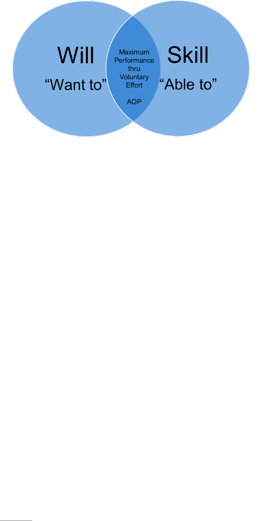
2.3.1. Will and Skill: There are two things that must be in place for a person to sustain any
behavior. First the person must have the “will” to do the thing in question. Will is the
motivation or desire to accomplish an end result. Any artist or musician must begin with a
motivation or desire to become good. If the motivation is strong enough, they will put in the
time and effort to develop the second essential component of “skill.” Sustainment of any
behavior must ultimately include both. The below graphic illustrates the relationship of will
and skill. A person may have skill alone, but without motivation they will not strive to use the
skill. A person with desire but without skill will soon become frustrated and give up. True
AoP comes at the intersection of the two. An engaged leader is that person who has the will
and the skill to develop the will and skill in those they lead. For some the will comes naturally,
but for most it must be encouraged and
developed through relationships and
intentional development. For the AFSC to
achieve AoP, we must have an army of
servant leaders who possess both the “will
and the skill” to be engaged leaders, to be
dedicated to influence those around them
to be engaged employees and to develop
others to become engaged leaders.
Following a checklist of career development
steps is helpful, but that alone does not create
leaders. Rather, having a desire to see the organization and those around them, grow and
develop skills needed to achieve the Common goals will lead to true AoP.
2.3.2. Accountability: While some individuals naturally have the intrinsic or internal desire to
see and achieve the end state, and instinctively know what needs to be done to get there, the
vast majority of the population do not fall into that category. Psychologists tell us less than
5% of the population are fortunate enough to have those intrinsic characteristics. So where
does that leave the rest of us? The desire to achieve the end goal must come through
accountability. The typical response to the word accountability is one of negative
reinforcement (if someone does not do something then there are negative consequences to be
faced). While that may get immediate results, it is not sustainable. It is not sustainable for one
very natural reason. Those that must hand out the consequences do not like it any more than
those receiving the consequences, so over time they will come to avoid it. Typically, when we
complain about lack of accountability, we delegate that responsibility to someone else. We
say things like “their supervisor does not hold them accountable” or “no one is ever held
accountable.” If we are applying the idea to the individual, we may say “they did not have
integrity,” meaning they did not hold themselves accountable. Seldom do we hear someone
say, “I did not hold them accountable” or “I did not hold myself accountable,” or “I lacked
integrity.” Effective accountability is the concept of creating sustainable accountability by
requiring it in the right way. It is a way that is acceptable and sustainable to those on the
receiving end as well as on the giving end. It is about voluntarily taking ownership of goals,
people, processes, and resources and then expecting that same ownership by those under their
leadership as well as their business partners.

21
2.3.2.1. Voluntary Accountability: In the book “Propeller: Accelerating Change by
Getting Accountability Right” (Corbridge, et.al, 2019)₄, the authors give an exceptional
definition of accountability. They propose that accountability is: “A personal choice to
rise above one’s circumstances and demonstrate the ownership necessary for achieving the
desired result…” AoP gives the leader the framework to take ownership of achieving
results. By taking ownership of the machine consisting of people, processes, and resources
they will exhibit voluntary accountability that will lead to success.
2.3.2.1.1. To the Goals: Leaders must take ownership of the common goals of the
organization. These goals include the Road to… stretch goals that will define their
success as well as the daily working goals of speed, safety, quality and cost
effectiveness. Leaders must understand what they are and how they apply to them and
their areas of responsibility. Leaders must understand how to measure the goal and
continuously know how they are performing to the goal (see sect. 4.2.1.2.2.1.).
Successful leaders are constantly pursuing those goals and helping others around them
to achieve the goals.
2.3.2.1.2. To the People: Leaders must be voluntarily accountable for their people and
to their people. Leaders must know the burden for the level of engagement of those
that work under their leadership resides with themselves. If the workforce is not
engaged, it is the failure of the leader. The higher the level in the organization, the
greater the responsibility. The leader must be accountable to their people by
communicating the goals and ensuring that every person knows how they affect the
goal, and how they are performing in regard to the goal. The leader is responsible for
empowering their people by ensuring the processes and resources are supplied to make
them successful in achieving their goals.
2.3.2.1.3. To the Process: The leader must take ownership of the processes that are
needed to be successful. Those processes may be the standard processes of those doing
the work, or it may pertain to the processes that they themselves should be following
to protect the mission. Processes also include those that link the supporting partners to
the mission. The bottom line is they must “own” the success or failure of processes
under their control or influence. It is never sufficient to assume that because processes
have been documented they are being followed and are effective. Every leader at every
level must verify processes are in place, being followed and are achieving the desired
outcome (see sect. 4.2.1.2.1.).
2.3.2.1.4. To the Resources: Leaders must do everything in their power to ensure that
the resources needed are in place to support processes and people. They are responsible
to make sure the proper planning is being accomplished and actions are taken to provide
the resources. Are the processes robust that provide the resources? When they are not,
what can be done to identify, communicate and elevate the shortcomings (see sect.
4.2.1.2.1.4.)?
2.3.3. Develop other Leaders: Earlier we discussed unique characteristics that some people
have, allowing them to see what needs to be done, how to do it, and have the intrinsic drive to
22
achieve it. It only makes sense those people would make great leaders. The problem is less
than 5% of the population are born with those traits. No organization can achieve AoP with
only 5% of their leadership team having good leadership traits. But there is a silver lining.
While a few great leaders are born, most are developed. People that find themselves in a place
of leadership must understand they most likely are not one of the lucky 5% that inherently see
and understand how to lead others. Every leader must seek to become the best leader they can
become. Just as importantly, they must develop others to become good leaders as well. To
quote John Maxwell again, “If you develop yourself, you can experience personal success. If
you develop a team, your organization can experience growth. If you develop leaders, your
organization can achieve explosive growth” (Maxwell, 2007 p249)₁. Explosive growth is what
leads to world class performance and the essence of what an AoP mindset embodies. In order
to develop leaders a person must first develop themselves so that they can have the desire and
understanding to develop others into leaders. Developing leaders is much more than giving
them assignments or sending them to class to build a resume. It is about creating the thinking
processes that enable them to become problem solvers. It requires dedication and practice to
become a developer. Developing others is a choice. It is the ultimate application of voluntary
accountability. If a person is developing others, they are providing a legacy that will follow
beyond themselves. The following section will give practical information on how to use
proven methods of leadership to not only achieve constraint resolution, but develop thinkers
and leaders in the process.
2.4. Application: Effective leadership boils down to two simple concepts: 1) set the expectations
and 2) be present. AoP gives the leader all the tools to understand the future and current state of
the machine and communicate the associated expectations. Being present is voluntarily taking
accountability and actively demonstrating the behaviors that give results.
2.4.1. Set the Expectations: To be successful, a leader must begin by setting expectations.
They must fully understand what the expectations are for their organization and for their area
of influence. Once understood they must ensure the expectations and related goals and metrics
are communicated to those they lead as well as
all supporting organizations. Without clear
understanding of where the organization is
going you are unlikely to get there. The tools
contained in AoP are all designed to simplify
complex processes so they can be understood.
The Radiator Chart, that will be discussed in
detail later (See Chapter 3), provides the
concepts needed to communicate the
expectations. These tools all come together to
define the desired and current state so the
leader can communicate what is required.
2.4.1.1. Road to Goal: The Road to… Goal is the understanding of where the organization
desires to be (see sect. 3.2.). The leader must understand the goal and the subcomponent
Common goals of speed, safety, quality, and cost. Once these goals are fully understood
the leader must adopt those as their own and communicate them to all concerned.

23
2.4.1.2. Process Flow: The process flow is the understanding of the work content involved
in producing the product identified in the Road to… Goals (see sect. 3.3.). The work
content can be translated into daily tasks that establish the work to be done.
2.4.1.3. Gates and Release Points: Gates are the buckets of work that add clarity to the
work content. Gates are where the expectations of people, processes, and resources are
defined to enable the leader to manage the machine. Each gate must have release points
which are the checks and balances that ensure compliance to the process. Adherence to
the release points helps establish the expectations for all stakeholders (see sect. 3.5.).
2.4.1.4. Visual Displays: Visual displays are designed to be a direct link to the workforce
that establishes the daily/weekly expectations to reach the goal. Visual displays should
allow the process doer to understand when they have had a “good day” (see sect. 3.6.).
2.4.1.5. Standard Work and Scripting: Standard work and scripting is the heart and soul of
setting the expectations. The daily activities and actions that are required to produce output
and to sustain the system are defined through documented procedures and processes (see
Section 3.7.).
2.4.1.6. Touch Time: Touch time is all about showing the importance of maximizing each
employee's available time to achieve the mission by staying on task. The daily expectations
and sense of urgency are communicated to the workforce by the leader’s dedication to
removing barriers (see sect. 3.9.).
2.4.2. Be Present: Leadership is much more than telling people what needs to be done and then
walking away and assuming that it will be done. Leaders not only set expectations, but they
must validate the objective is understood, the people have the skills to accomplish the task,
they have the resources needed and they have the level of engagement necessary to complete
the task. This cannot be done from a distance. Leaders must observe the work (see sect.
4.2.2.2.5.) and be part of the daily improvement process. Sustainment only happens when
leaders remain engaged in the process to include regular observation and feedback. To put it
simply, being present is focused management of the work. Chapter 4 will give details about
the specifics of managing the machine to produce the work. Other functions and programs
may be used to assist in that process such as quality or safety inspections, but responsibility
resides with the leader. There are many aspects to being present, but the bottom line is
demonstrating accountability to the results through the machine of people, processes, and
resources.
2.4.2.1. Value of Questions: A desired outcome of the leadership culture outlined in the
Leadership Model is development of thinkers and problem solvers. This is the essence of
developing new leaders and engaged employees. It is often said that if you give a man a
fish you will feed him for a day but if you teach him to fish you will feed him for a lifetime.
The same applies to AoP. If you give a person a solution you solve their problem for today,
but if you teach a person to think you solve their problems for a lifetime. Like it or not,
humans are inherently lazy. We will often default to asking for someone to give us a
solution rather than seeking a solution for ourselves. The digital age that we live in today
24
often exasperates this situation. On the other hand, mental engagement not only fuels
creativity and solutions but it creates autonomy in the process. When people believe they
have a part in the solution they will naturally have ownership in the success of the
organization. The greatest tool that we have to become true leaders is the art of asking
questions.
2.4.2.1.1. Ask the Right Questions: Leaders must become good coaches. Good coaches
are able to ask the right questions to cause people to develop an understanding of the
goals and develop solutions to the constraints. Even if we already know the answer,
asking the question can have tremendous results. On the surface asking questions
seems to be easy enough, after all we have done it from the time we were a small child.
We ask questions like: How does that work? Why did you do that? What time is it?
All of these questions have value, but most of the questions we ask are for our own
benefit. We benefit because we grow in knowledge from the answer. While personal
knowledge is a valuable side effect of asking questions, the questions of a great leader
should be designed for the benefit of the person being asked. The questions should be
designed to create understanding and stimulate creativity. The greatest benefit
however, is when voluntary accountability is generated in the doer. When the doer
develops an understanding of the goal, develops a plan to get there and takes personal
ownership of accomplishing the plan. The following section is provided to give the
leader a tool to guide discussions. We provide sample questions based on AoP
principles that can be used to focus discussion on understanding the goals,
understanding our current state, and creating solutions to barriers that prevent reaching
the goals.
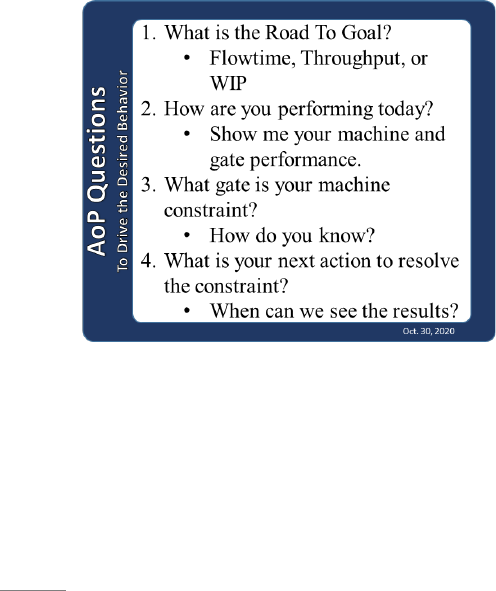
2.4.2.1.2. AoP Questions: AoP is designed to provide a framework to answer specific
questions that will lead to understanding and behaviors necessary to achieve the
mission. The leader can use the
following questions to begin a
conversation leading to better
understanding of the AoP principles and
perfecting the skills of using the tools.
A standardized set of questions helps to
avoid personality conflicts and the
perception that people are being blamed.
Additional questions are also provided
to assist when a deeper understanding is
needed based on the level of leadership
or the current situation.
2.4.2.1.2.1. What is the Road to… Goal?
2.4.2.1.2.1.1. Where are you headed? What is your stretch goal?
2.4.2.1.2.1.2. What is the primary driver of the goal? (WIP, demand, capacity,
output)

25
2.4.2.1.2.1.3. How is the goal driving you to future-state performance?
2.4.2.1.2.1.4. Are all enterprise stakeholders on board with the goal? Is there
evidence to support this?
2.4.2.1.2.1.5. Has an Enterprise Value Stream Mapping event been
accomplished?
2.4.2.1.2.1.6. Is the Road To…Goal more aggressive than the customer
requirement?
2.4.2.1.3.1. How is your machine performing today?
2.4.2.1.3.1.1. What is your current state?
2.4.2.1.3.1.2. Can you show me your machine and performance of each gate?
2.4.2.1.3.1.3. What are the performance trends telling you? Can you show me?
2.4.2.1.3.1.4. Are there performance threats to the machine? Do you anticipate
any?
2.4.2.1.3.1.5. Are enterprise stakeholders involved in issue resolution?
2.4.2.1.3.1.6. Is there an effective structure in place to provide horizontal
integration where potential pitfalls are identified and solutions or workarounds
are in place lead-time from impact?
2.4.2.1.4.1. What is your machine constraint?
2.4.2.1.4.1.1. How are you determining your machine constraint? (WIP,
variance to target, queue, cost, quality, safety)
2.4.2.1.4.1.2. What data tells you about the primary contributors to the
constraint?
2.4.2.1.5.1. What is your next step to resolve the constraint?
2.4.2.1.5.1.1. How are you using the Focusing Steps of ToC? (Leaders should
be able to effectively verbalize the application of exploit, subordinate and
expand/elevate) (see sect. 3.3.3.4.).
2.4.2.1.5.1.2. What CPI tools are you using to resolve the constraint? Are
enterprise stakeholders involved and effectively contributing toward resolving
the identified constraint or issue?
26
2.4.2.1.5.1.3. Are tactical issues identified and elevated? Are enterprise
stakeholders involved in resolving tactical issues with the necessary urgency?
2.4.2.1.5.1.4. Do enterprise actions show value toward early strategic and
tactical constraint/issue identification and resolution (effective horizontal
integration)?
2.4.2.1.5.1.5. Is there evidence of horizontal integration from the way in which
the enterprise views and focuses on accomplishing the process machine mission
at the pace of the stated common goal(s)?
2.4.2.2. Leader Standard Work: Leader standard work is the activities where the leader
monitors, evaluates, and improves processes. It is also the most likely opportunity to apply
coaching skills and develop People through asking questions. Leader standard work will
be discussed in more detail in Chapter 3 and Chapter 5.
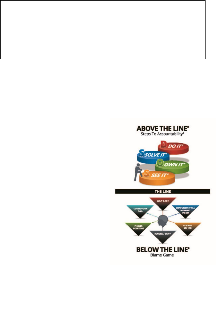
2.4.3. Stay Above the Line®: There is a fine line
between voluntarily taking accountability for
success and taking the role of victim. We all fall
below that line at times and take on an attitude of
victimization. In the areas below the line we blame
others for our lack of success. As a victim we give
the other party the ownership of our success or
failure. It is undeniable that we must rely on others
to execute our mission, but we should never allow
the actions or inactions of others to solely define our
mission’s success or failure. In the book
“Propeller,” (Corbridge, et.al 2019)₄ the authors lay
out a model of personal accountability that shows
how we fall into the trap of victimization and the
steps that must be taken to accept true accountability
as a leader.
2.4.3.1. Those who stay Above the Line® “See
It®” by using the AoP tools to find the constraints to achieving the goals (See Chapter 3).
They “Own It®” by acknowledging the circumstances and accepting their responsibility
as a leader to find a solution. Accountable leaders “Solve It®” by applying the focusing
steps of ToC, using CPI, and pursuing horizontal integration to find rapid resolutions. Most
IMPORTANT – The priority for improvement is always to be the
constraint gate. Dedicated CPI resources should never be used to
improve non-constraint gates if they can be used to resolve the
constraint. However, the gate owner of non-constraint
gates should always strive to improve their own gate and develop
thinking skills of those under their leadership.
Used by Permission of Partners in Leadership

27
importantly, above the line leaders “DO It®” by taking the actions necessary to see the
solutions carried out to the end. If a supplier does not have a part that is needed, do we
give up and wait until the part is available or do we pursue other avenues and alternatives
and develop supplier relationships to ensure part availability in the future? If a form has
not been completed properly, do we just send it back; or do we work with the customer to
gather the information, understand why the information was not put in initially and then
put processes in place to ensure complete information in the future? The idea of Above the
Line® mindset is well illustrated in the common phrase “be the change.” The idea that is
communicated here is each person should see where change is needed, take ownership of
the situation, find a solution, and then make it happen. It is easy to see a problem. It takes
an act of will to take ownership. After taking ownership, a person must put in the effort to
create the environment to find a solution. Once a solution is defined then the real work
starts. Make it happen! We will seldom have control over every ingredient needed to see
a plan to completion. Therefore, leaders must intentionally work to create influence and
use that influence to work with those below, above, and around them to see change through
to completion.
2.4.3.2. Observe and Acknowledge Below the Line® Activities: Leaders must constantly
be on guard to recognize when people are falling into the blame game. When they find
themselves blaming others for problems, they must quickly take voluntary accountability
of the situation and work to quickly resolve issues. More importantly, when they observe
others exhibiting those behaviors, they must engage in asking questions to challenge
behavior and reverse the mindset from victim to problem solver. These Below the Line®
behaviors take many forms such as ignoring the problem, hoping it will go away, blaming
others for not fulfilling their role, or possibly denying there is a problem. Many times, the
blame game may not look like blame, it may look like confusion. Often people will say
“just tell me what you want me to do.” This indicates they have disconnected from the
problem and are waiting for someone else to solve it. People will often create a narrative
that buries their lack of ownership in a justification of the problem. Often the approach is
to just wait and see if things will get better on their own. All of these behaviors do nothing
to move the machine forward. They are an indication there is a lack of Accountability for
resolving the constraint and an indication they are a victim of the system. It is the AFSC
leader’s responsibility to take ownership of the constraint and expect that ownership from
everyone within their sphere of influence.
2.4.3.3. Horizontal Integration: Horizontal integration is the actions necessary to ensure
every stakeholder is aligned properly to achieve the goal. This is quite possibly one of the
most important components of successful mission execution. However, it is also one of
the easiest areas to fall Below the Line®. When our suppliers or mission partners fail to
deliver on our needs, it is easy to blame and make excuses. Will there be times when we
cannot change the outcome? It is possible, but great leaders are those that identify the
problem and take ownership to implement solutions to prevent constraints from
reoccurring. Good leaders are those that are always asking themselves if they have done
everything in their power to improve the situation to include involving enterprise partners
in developing solutions. Great leaders are those that not only ask themselves that question
but also create that expectation in everyone around them.

28
2.4.4. Follow Up: Persistent follow-up is the key to sustainment and long-term mission
success. Without it, the best processes will deteriorate over time. Even worse, standard
processes will not be fully implemented, or solutions realized. Leaders cannot assume
everything is good just because there was an action plan or standard work implemented.
Follow-up is the primary purpose of leader standard work (see sect. 5.1.2.). Leaders must
observe and improve the work to ensure continued progress toward common goals. Consistent
follow-up is the component to leadership that creates accountability, both in the leader and the
follower. Many aspects of persistent follow up will be explored in Chapter 4 as we discuss
managing the machine.
2.5. Summary: The success of every organization rises and falls in the level of engagement of its
leaders. The leader is the foundation that sustainment and maturity are built upon. The AFSC
leader must embrace the concepts of this chapter and must be intentional about application of the
tools.
2.5.1. The Leadership Model was developed to provide leaders with a concise representation
of the requirements that each leader must embody. Leaders must know and support the
common goals of the organization and work diligently to synchronize people, processes, and
resources to achieve the mission. Mission success must include a focus on not only speed but
safety, quality, and cost effectiveness as well. Every AFSC leader is expected to embrace and
embody the character traits of a successful culture. Leaders must be accountable to success
and to those that create value in the machine. Great leaders also hold themselves accountable
for creating other leaders that possess the will and the skill to carry on the mission and continue
the fight.
2.5.2. The Radiator Chart is key to the success of an AFSC leader. The Radiator Chart
establishes a roadmap of actions the successful leader can use to reduce variability and
establish expectations for the workforce. The design of the AoP machine provides the
expectations that is the focal point of accountability. Engaged leaders will leverage the
Radiator Chart to ensure everyone is accountable to the daily expectations.
2.5.3. Lastly, the engaged leader must be intentional in the daily execution of the mission.
They must be constantly asking questions, assessing the success of their AoP machines, and
looking for ways to improve. Leaders must be accountable to success and actively seek
accountability of every person that holds a stake in their success. Engaged leaders will seek to
be good coaches and constantly ask questions to learn and to create the thinking skills of others.
The success of the AFSC rises and falls with its leaders.
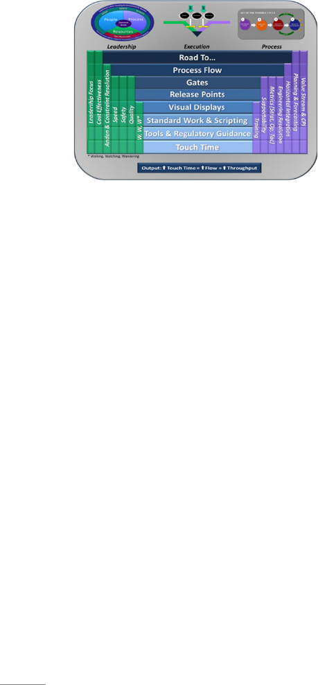
29
Chapter 3
MANAGEMENT SYSTEM INTEGRATION
3.1 Management System Integration: The AoP management system involves the relentless
application of a series of essential concepts and tools integrated into a process machine of people,
processes and resources. In Chapter 2 we discussed the indispensable role of the leader in
achieving AoP, but every leader needs a game plan to ensure the organization moves forward in
its pursuit of world class performance. The Radiator Chart was created in an effort to establish a
singular sustainment “game plan” for the enterprise. Graphically represented in the figure below,
the Radiator Chart is a single “game-plan” that represents the vision of how to set up and operate
an AFSC process machine to achieve “world class” status and Art of the Possible results.
3.1.1. The Radiator Chart: A radiator is essential
to keep a car’s engine running properly. The
cooling fluid within the system circulates through
the radiator to be cooled. Without the radiator, the
car’s engine would overheat causing catastrophic
failure. In much the same manner, the elements of
the Radiator Chart are essential to a well-
functioning AFSC process machine.
3.1.1.1. The Radiator Chart brings the leadership focus and the science of throughput
together into a single game plan which represents the vision of how an AFSC process
machine is set up to achieve world class status and AoP results. Within the chart, the
horizontal and vertical elements intersect to represent the complexity and interdependence
of its components. Focusing on select areas of the chart in isolation will not translate to
success. Success depends on focus and implementation of all areas of the chart as a whole.
The enterprise approach is woven into the elements throughout the Radiator Chart. The
entire enterprise must align metrics and objectives of each element for the whole to be
successful. Leaders will need to utilize and leverage the unique capabilities encompassed
within each element of the chart to unite the vertical leadership and process components
with those of the horizontal execution components in order to optimize the flow of products
and services through the process machine.
3.1.1.2. At first glance, the Radiator Chart seems complex because it is representative of
the complex business of providing readiness for the Air Force. The stacked and
overlapping design signifies the interdependence of the chart elements, just like each AFSC
organization is dependent on one another. The length of each element signifies the
ability and scope of influence each particular element has over the other chart
elements. The Radiator Chart is the way we execute our game plan and the standardized
set of operating principles by which we set-up machines. The elements on the chart touch
every part of the enterprise. The horizontal elements depict how the machine is set up.
The vertical elements enable the machine to work effectively and efficiently. Without
these elements working together, the machine will fail. The following is a brief discussion

30
of each component of the model. Detailed explanation of each of the horizontal execution
elements will follow in the body of this chapter.
3.1.2. Horizontal Elements: There are eight horizontal elements that represent the execution
elements or blueprint for setting up the machine. These are in order of strategic to tactical.
Each of these will be discussed in greater detail in the following sections.
3.1.2.2. Road to… The Road to… element communicates the need for a future-state goal
that will be used to set the pace for throughput and focus the enterprise in the same
direction. It is the road map for accomplishing Art of the Possible results. It includes the
process of communicating the goal up, down, and across the enterprise and requires
stakeholders’ ownership and integration of the goal into their objectives. Most importantly,
it must align directly and clearly to the customer’s requirements and needs.
3.1.2.3 Process Flow: Process flow is a visual representation (or map) of the tasks required
to complete the execution plan paced to the Road to… Goal. It defines the Critical Path or
Critical Chain (see sect. 3.3.3.2.) and serves as the basis for creating standard work with
repeatable, disciplined processes with predictable outcomes. The map of the process flow
serves to eliminate gaps or duplication and allow users to interface and tactically manage
the machine to control WIP and flow. A well-structured process flow identifies
predecessors, successors, and concurrent work along the Critical Path. A well-structured
process flow also allows the identification of constraints by showing where WIP stacks up
within a process and allows users to expeditiously attack and resolve their constraints or
disruptions to ensure steady flow of WIP. Understanding and protecting the Critical Path
or Critical Chain during execution is a foundational concept throughout AoP.
3.1.2.4. Gates: The term gates refers to the practice of breaking long flowtime production
“machines” into “buckets” or discrete increments of work along the Critical Path/Chain
with tangible ending points. Gates allow simplification of complex processes and projects
into understandable and measurable buckets of work. The use of gates creates a disciplined
monitoring system with a focus on Critical Path/Chain urgency. CPI efforts should be tied
to improving the performance of under-performing gates.
3.1.2.5. Release Points: Release points within the gated process instill both the mindset and
the discipline to not pass work and problems to later gates – especially as it relates to the
Critical Path/Chain of the production flow. This includes the discipline to never release
work from one gate to the next that is not supportable in respect to personnel and resources.
Release points require business rules and checklists to create the culture and awareness that
ensure specific actions are taken by critical points in the production process. Creating a
culture that uses these rules to create the urgency necessary to elevate and resolve issues
prior to the release point (and protect the Critical Path/Chain) is essential to creating the
type of throughput that leads to attaining an Art of the Possible mindset.
3.1.2.6. Visual Displays: This is one of the elements that can answer “How do you know
you’re having a good day?” Visual Displays are located at the point of execution (where
the process value is created) and provide information about the process or project. The
information displayed should include measures of speed, safety, quality and Cost as well
as the Critical Path execution of the project as applicable.

31
3.1.2.7. Standard Work and Scripting: Creating standard work processes through gated
Scripting efforts allows Resources to be synchronized to the needs of the product/project
during execution. The focus is to create repeatable processes, which lend themselves to
total transparency and are designed to eliminate constraints and enable a predictive
repetitive process.
3.1.2.8. Tools/Tech Data: Follows standard work and involves giving the process doer what
they need. Addresses all tools required in all areas of the organization that surround and
impact the process doer and the Critical Path. If this element is achieved properly the next
element, touch time, will be positively affected.
3.1.2.9. Touch Time: Involves keeping hands on the product/project. Kitting of materials
and information needed during execution is an example of touch time reduction efforts.
Touch Time improvement is about finding anything that surrounds the process doer that
can positively affect their output along the Critical Path.
3.1.3. Green Vertical Elements: These vertical elements are focused on the leadership aspect
of the enterprise and are used to set the organization up for success. Systems and execution
tools do not give you permission to not manage process and People. Leadership sets the tone
for effective issue elevation and resolution that leads to the execution of efficient processes
and achievement of AoP mindset by the organization.
3.1.3.1. Leadership Focus: Leadership is responsible for building the proper environment.
Leadership must continually drive their organization to understand where the problems are
and determine how to resolve those problems in order to move the organization forward.
Leadership must be comfortable in the red – with a focus to stay on the Critical Path. Being
comfortable in the red does not mean it is ok to miss customer requirements, but that targets
should be set that continuously stretch the organization to improve. We should never be
satisfied with status quo.
3.1.3.2. Cost Effectiveness: Means to measure the impact of processes and output. As your
processes improve, output should increase without increasing Cost. Savings should start
to be seen in the form of time and money.
3.1.3.3. Andon: Andon is a Japanese word meaning lantern. An Andon shines light on an
issue and serves as notification of when a process is off the Critical Path/Chain. Refers to
identifying, elevating, and resolving issues BEFORE they have a negative effect on the
Critical Path/Chain of the project. Involves allowing our teammates to help us resolve
issues.
3.1.3.4. Speed, Quality, and Safety: These are the three important touchstones of an AoP
mindset. Speed –a focus to make our processes effective and efficient; meeting the needs
of our customer in terms of products and services. Quality- because this is our reputation.
Safety – because this is our responsibility to protect our people. Lead with safety and
quality – speed will improve.
3.1.3.5. Walking, Watching, and Wandering (W3): Observing the 3 W’s will aid in
answering; “Why are people not on task?” W3 is about the leader being present in the
daily activities and observing what is happening. Leader standard work, to be discussed in
section 5.1.2, should encompass these behaviors. Daily leader engagement in W3 will help

32
to reduce Walking, Watching and Wandering by the doer, which will, in turn, improve
touch time and create a “Minutes Matter” mentality.
3.1.4. Purple Vertical Elements: These vertical elements are focused on the processes that
enable success with the help of the enterprise. Leadership will utilize these “tools” to achieve
the Art of the Possible mindset throughout their organization. These elements are not intended
to just improve performance but will deliver sustained and enduring resiliency.
3.1.4.1. Value Stream and CPI: Data from established gates and release points gives you
the information necessary to identify problem areas to focus process improvement efforts.
Success should be measured against your Road to… Goal. Success is measured by results,
not activities and comes from obtaining knowledge from the level closest to the process.
3.1.4.2. Planning/Forecasting: Good Planning translates into good Forecasts that allow the
supply chain to strategically plan for the needs of the enterprise. Collaborative Planning
with all functions in the supply chain (i.e. Systems Program Office (SPO), Facility
Engineers, Maintenance Planning and Production, Defense Logistics Agency (DLA) etc.)
translates into better Forecasts for requirements which allows a proactive approach to
Supportability.
3.1.4.3. Horizontal Integration: Speaks to the increased “synergy” that is possible when all
members of the process machine and enterprise adopt and work toward the Road to… Goal.
3.1.4.4. Engineering Resolution: A project or process is governed by rules, regulations and
instructions that attempt to provide the necessary guidance for the process doer. Situations
are often encountered that are not addressed in available guidance. When this occurs, it is
essential the required guidance is given in a timely manner to keep the project moving
forward on its Critical Path. Engineering must also implement a machine process to
manage the variety of engineering work such as facility, equipment, process, software and
other projects in order to provide speed and quality for the customer.
3.1.4.5. Metrics (Strat/Op/Tac): Metrics are the foundation of a data-driven organization
and must be aligned from the strategic through the tactical levels. Metrics should be clear,
actionable, and relate to Critical Path/Chain of the project/process. However, leadership
discernment is required to react to data and Metrics in order to allow experience to drive
interpretation of the data as it translates to action.
3.1.4.6. Supportability: Involves proactive actions to move Supportability efforts to
strategic and operational based on findings and experience at the tactical level. Aggressive
constraint identification-elevation-resolution efforts at the tactical level keep the plan
executing along the Critical Path/Chain.
3.1.4.7. Training: Focused on the process doer and linked to their tasks. Also involves
Training process doers to elevate problems and needs because having what you need
eliminates the push to “do what it takes.”

33
3.1.5. Summary: The Execution Model horizontal elements represent the standard vision of
how process machines across the AFSC will be setup to achieve “world-class” status. As such,
these execution elements then become measurable expectations of sub organizations
throughout the AFSC and the game-plan to achieving success within the AoP methodology.
The remaining sections of this Chapter will give more detail about what each horizontal
element represents and how it is applied.
3.2. Road to…Goals: A journey of a thousand miles begins with the first
step, however you must know where you are headed to begin moving in
the right direction. There must be an understanding of what road the
organization will be taking to the desired destination. Achieving the
required throughput for the process machine requires the focus of not only
the organization, but also that of its teammates. For this reason, an
important element of this phase of the process is to communicate and create buy-in through all
levels within the organization, and with external teammates throughout the Enterprise itself.
External partners include the customer, suppliers and organizations that support the organization’s
processes. Understanding and ownership of the Road to…Goal will provide the motivation these
external partners need to pace their processes to that of the organization. The next section will
describe the elements of a good Road to…Goal and the necessity to effectively communicate the
Road to…Goal throughout the enterprise.
3.2.1. Importance: Creating a Road to…Goal is the foundational step in the journey toward
achieving an AoP mindset. Road to…Goals create a destination for the organization and its
teammates enabling the path to be marked with the actions and milestones that will ultimately
end in achieving Common goals. Without a Road to…Goal the organization will ultimately
fall into complacency and be unprepared to respond to the needs of the future. The Road to…
Goal is the vision that keeps an organization moving forward toward the Art of the Possible.
3.2.2. Criteria: The Road to…Goal must begin with the needs of the customer, but it must also
include the future needs of the organization. The Road to…Goal must position both the
customer and the organization for success years into the future.
3.2.2.1. The needs of the customer can include the pace of the process required to meet
aircraft availability requirements, engine war readiness levels, inventory turns of high
volume components or the given need date of an engineering or contract request. However,
the current needs cannot be considered in isolation of future needs. The organization must
always be looking forward to examine the landscape of future challenges. Is the fleet size
decreasing or increasing? What is the impact of planned future modifications? Are there
future changes that could impact the demand rate of any particular component?
Machine Setup
The first four elements of the radiator chart are focused on designing and setting up the Machine.
Here the emphasis is on understanding the requirement and establishing the measures and
controls required to manage the Machine.

34
3.2.2.2. Organizational needs should include understanding capacity requirements such as
facility restrictions, future workload requirements, and the availability of personnel and
equipment resources. Understanding whether capacity and resources are scarce or
abundant should be reflected in the organization’s Road to…Goal plan. The answer to
questions such as these should constantly be examined and drive adjustments to the Road
to…Goal accordingly.
3.2.2.3. All Road to…Goals should ultimately be expressed in terms of throughput or a
metric that directly affects the throughput such as WIP or flowtime. The goal of every
machine is to utilize the people, processes, and resources in order to transform a
requirement into a product or service. That machine output is measured in terms of
throughput. In section 3.3.3.1. we will discuss the effects of WIP and flowtime on
throughput using Littles Law; therefore, WIP and flowtime may be a measure of the
organization’s Road to…Goal.
3.2.3. Common Goals vs. Road to…Goals:
3.2.3.1. As discussed in chapter 2, each leader is responsible for successfully achieving the
mission. That mission is not successful unless the Common goals of speed, safety, quality
and Cost Effectiveness are achieved. The Common goals are those of the organization and
are essential for successful mission completion. Although the common goals are at the
organizational level, they must be representative of the higher level Road to…Goal.
3.2.3.2. Road to…Goals are specific to the program or weapon system platform and must
be supported by all partners regardless of organizational ties. For this reason, there must
be complete Horizontal Integration across all organizations that have a role in supporting
the program. The Road to…Goal should reach far beyond the present day requirement to
position the organization and the customer for success. This vision of the Road to…Goal
is what drives the AFSC to an AoP mindset reaching beyond just compliance to the
mission.
3.2.4. Communication: Once the organization has established the Road to…Goals, they must
communicate the goal, and the foundation behind the goal, to their enterprise partners. This
communication is at the heart of the vertical leadership element of Horizontal Integration. All
stakeholders must be in agreement the Road to…Goal is in fact the Goal and all are
committed to achieving it. This concept is obvious for the common goals of performance to
the mission, but less obvious for the Road to…Goal. External partners should always see the
necessity to meet the common goals of the current workload, but they may not see urgency in
supporting the future needs of an outside organization. However, intentional effort must be
given to position both the internal and external partners to achieve future goals. Let’s consider
below a modern-day illustration to show the necessity of Road to…Goal communication.

35
The organization must communicate the “Why” behind their goals. Unless partners understand
why a goal is important, how it is to be achieved, what their role is, and what is in it for them,
we cannot expect them to be committed to helping our organization reach our Road to…Goal.
The following sections will explore in further detail the communication requirements for the
Road to…Goal.
3.2.4.1. The Burning Platform: The burning platform communicates the urgent and
compelling reason to establish the Road to…Goal, looking first to the needs of the
customer. What is the pace of the customer requirement today? What is on the horizon for
the customer that could affect the current pace? In the case of an aircraft production
environment, future modifications, or anticipated repair challenges can threaten to extend
the time aircraft spend in a depot maintenance environment. Extended flow days, in turn,
can increase the number of aircraft captured in a depot repair setting, increasing the
pressure on the customer’s aircraft availability goals. Changing workloads can also drive
the need for improvement in administrative areas, such as the need for a more robust hiring
process. A burning platform for an aggressive AoP Road to…Goal can be created around
the need to maintain a specific number of depot aircraft in the face of challenges that,
unchecked, will increase the number.
3.2.4.1.1. Perhaps the look into the future did not uncover changing needs for the
customer. The next question to ask: is the current pace supported by the organization’s
constraints, such as facility limitations in a production environment? If the pace of the
customer requires 20 aircraft to be captured and in work at one time, does the
organization have space for 20 aircraft? Other workloads competing for the same
capacity requirements should be reflected in the burning platform of a Road to…Goal.
3.2.4.1.2. In the case of an administrative environment, what are the customer’s
requirements and how are those requirements regulated by law or policy? When
building contracts, what needs to be funded, what is the duration of the contract, what
aspects of service or product should be covered? Will there be care and maintenance of
systems, services, or parts? On what portions of industry will the contract be focused?
Is the contract commensurate with policy (i.e. Federal Acquisition regulations)? What
is the customer need date for the contract? An aggressive Road to…Goal should
consider all current and future customer requirements and reflect the customer’s
enterprise approach.
Consider an online retailer who currently offers 2-day shipping for their customers. They have successfully
worked with their suppliers and partners to create a set of Common Goals and have established a Machine
to achieve the Throughput of 2-day delivery for thousands of items. However, in order to continue
movement toward their Road to…Goal of being the global online retailer of choice, they have a target of one
day delivery. Performance is measured against this Road to…Goal, while continuing to execute the expected
2-day delivery. They must work with their suppliers and shipping partners to move the Machine toward one
day delivery. Setting the aggressive goal, and measuring to it, allows the enterprise to reveal gaps and
opportunities that would otherwise be unseen. Without intentional focus of the entire enterprise to the
Road to…Goal, this result would never come to pass.

36
3.2.4.2. Process Machine: This communication tool is a visual representation of process
flow and an understanding of the mathematical science behind the Road to…Goal. Process
owners must understand the machine science and math will dictate the expected pace of
the machine. The science and math used to create a particular process machine should be
communicated so the enterprise understands the science and math behind the ultimate Road
to...Goal. Unless all stakeholders are in agreement the process is realistic and necessary to
meet the goal, they will not be engaged in protecting the flow of the machine. The tools
used to develop the machine will be discussed in detail in section 3.3. (process flow).
3.2.4.3. Frame the Challenge: A challenging Road to…Goal will not be easy to achieve.
Road to…Goals require the organization to closely examine themselves and use data
analysis to uncover the gaps in the organization’s current processes. Detailing the gaps
between current and desired performance will lead to an understanding of what needs
to change in order to meet the ultimate Road to…Goal.
3.2.4.3.1. Framing the challenge should include comparing current flow day
performance to the required future performance. Specifically state the reduction
required so the enterprise understands the extent of the challenge. Later, as
performance improves, and the organization moves closer to meeting its Road
to…Goal, this variance can be used to show the improvement and motivate the
enterprise to see that success is possible.
3.2.4.3.2. The challenge should be framed from an enterprise view. While an
organization should certainly focus on internal processes that can be improved;
framing the challenge should be about communicating gaps from an enterprise
perspective. Are there specific Supportability elements that need to be met? Does
engineering need to help develop standard, repeatable repair processes or define
processes to enable concurrent work? Does the organization need to develop a
standard Script for the desired flow? Is there a facility challenge that needs to be
overcome? An organization frames the challenge in order to leverage the burning
platform. This empowers and motivates the enterprise to resolve and overcome the
challenges to attaining an AoP Road to…Goal.
3.2.4.4. Call for Action: Once the Road to…Goal has been established, and buy-in has been
achieved, then the real work begins. The organization must have a call to action for all
players. A strategy must be established on how the Road to…Goal will be measured,
reviewed and enforced. This often proves to be the most challenging part of the process,
especially when external organizations are involved. Accountability to the goal must be in
place for all involved. Goals should be documented along with the roles of each
stakeholder in accomplishing those goals. The communication plan and meeting battle
rhythm of the enterprise should be leveraged to the maximum extent necessary to ensure
progress to the Road to…Goal. Daily, weekly and monthly reviews should consistently
drive actions to achieve the goal. Leaders at all levels must ensure a sense of urgency is
communicated and embraced by all. Senior leaders must be engaged in asking the right
questions to ensure issues and constraints are identified and are being resolved. It is
ultimately the responsibility of upper level leaders to ensure all stakeholders are in
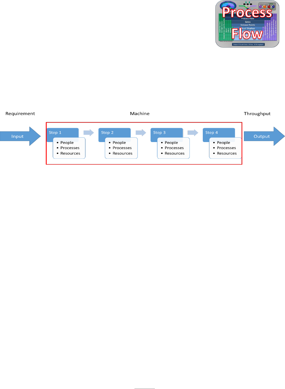
37
agreement with Road to…Goals and are dedicated to achieve the common goals of speed,
safety, quality and Cost Effectiveness of the machine.
3.3. Process Flow: Every organization produces their product or
service through a system that utilizes people, processes, and resources
to achieve their mission. In AoP terminology, we refer to this system
as a machine. Every machine is made up of a sequence of tasks that
must be completed on schedule in order to meet the delivery date. This
may sound simple, but for complex machines, the work can quickly get
out of hand and the machine will get off track. Requirements enter the machine and FLOW
through that machine in a defined path with an expected outcome. Work is performed on the
product or to the service creating value to the customer. Good flow of a machine consists of orderly
and continuous movement of the work through a series of established steps to achieve a predictable
output. The graphic below represents a simple machine.
Continuous, streamlined flow of work through the machine will result in maximized throughput.
For the AFSC to achieve world class mission support we must have a mindset that “throughput
is King.” This does not mean we can ignore safety, quality and Cost or take shortcuts to achieve
speed. Speed is achieved by improving processes, eliminating wait time, avoiding accidents,
preventing quality misses, and avoiding rework. Improving the flow through the machine
improves throughput and when done correctly, will also improve safety, quality and Cost
Effectiveness.
3.3.1. Importance of Flow: When flow is streamlined and constraints to flow are removed, the
result is greater throughput. With throughput comes reduced WIP, with reduced WIP comes
reduced Resource requirements - less dock space, less shop space, less equipment, less labor
Costs, and less supporting overhead. Throughput is King. Focusing on throughput and the
supporting Metrics provides the mechanism that will lead to reduced Cost and increased
capabilities for the Air Force. The most important result of flow is that it allows us to reach
our Road to…Goals and position the customer and the organization for the future. Every AFSC
organization should strive to create movement through the machine that is a steady and
continuous stream. A flow that is free from disruptions, where value is being added to the
product as it moves quickly through to output.
3.3.2. Disruption of Flow: All work is a process, and every process has flow. Unfortunately,
there are inherent enemies that impact flow and thereby negatively impact the throughput of
the organization. Each machine is a composite of numerous sub-processes; each with its own
set of issues that potentially impact throughput. It is easy to imagine how issues can compound

38
to drastically reduce the success of the organization. There is a common adage that states you
cannot get better until you admit you have a problem. The same holds true to improving the
throughput of the machine. We must understand these potential issues exist so we can
recognize them and take the appropriate action to protect the flow of the machine. The enemy
takes many forms and can attack from all directions. The following paragraphs will discuss
some of the most prevalent issues that work together to reduce our success. Some are obvious,
but some are not; however, if we acknowledge they all exist, we can better develop a plan for
a counter attack.
3.3.2.1. Process Constraints: The first enemy to flow that we will discuss is that of process
constraints. Imagine a garden hose with water flowing through it. The hose along with the
faucet, and the spray attachment on the end of the hose constitute the machine. A single
component of that machine is the determining factor that governs how much water can be
delivered to the plant. That limiting factor is called the constraint. It may be the faucet,
the size of the hose, a kink in the hose, or the nozzle size of the sprayer. In order to
maximize the amount of water provided to the plant, the gardener must analyze the machine
to determine what needs to be adjusted to provide more water. If the hose is kinked,
opening the nozzle wider will not provide any improvement to the flow. The kink must be
removed before flow will improve. This example may seem overly simple, but every
machine has a constraint or weakest link that must be resolved before throughput will
improve. The tools of AoP allow us to identify those constraints that disrupt the flow. In
section 3.3.3.4. we will discuss a systematic methodology to resolve constraints, but the
first step to improvement is understanding there is a constraint in every process/machine
and we must find it before we can improve.
3.3.2.2. Parkinson’s Law: Parkinson’s Law states “the time it takes to perform a task will
expand to fill the time allotted.” If you give me two days, I will take two days, even if I
could do it in a half day. We do not typically like to admit this enemy exists. No one wants
to admit they waste time or drag out the work. This is a reality of human nature. We are
all guilty, and it is a huge enemy to rapid and continuous flow through the machine.
3.3.2.3. Student’s Syndrome: The Student Syndrome says typically there are other
priorities, and the tasks wait to be started close to the deadline. This is another reality of
human nature we may not like to admit, but is very real. To understand where the name
comes from, think about the high school student that has an essay paper due on Friday.
The student knows they can normally write an essay in about an hour. Throughout the
week they have many activities going on, but they know they still have plenty of time to
complete the paper. Finally, on Thursday night there is no more time available, so the
student begins the paper.
3.3.2.4. Natural Causes: No system is perfect, and every system has some natural variation
where things do not go as planned. For example, we may find more discrepancies during
an inspection than what we expected, aging systems may break more than we thought, and
troubleshooting or debugging may take longer than we thought. There may be funding
shortfalls, we may not have sufficient information, or the right proficiency level to
complete the work quickly. In other words, things will not go as planned (Murphy’s Law
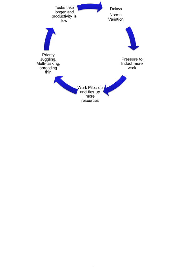
39
exists) leading to delays. Delays in one part of the system can cascade and flow will get
disrupted. These disruptions to flow are intrinsic to any system and are not easy to remove.
Therefore, in any system some intrinsic disruptions to flow will cause some delays.
3.3.2.5. Self-Inflicted Causes: In real world systems, a majority of flow disruptions are due
to the way we react to and manage the natural delays. When things get delayed and we
start missing our commitments (deadlines), there is pressure to start or release work sooner
in order to meet deadlines. When we induct work too early, or before it is supportable,
work piles up in front of Resources resulting in wait times (i.e. the flow is getting blocked).
As wait times increase, and things get delayed, more work becomes urgent; as a result there
are priority conflicts and Resources start multi-tasking. As queues build up the same
Resources (crews, teams, etc.) are now “spread thin” over more jobs. As a result, each job
gets fewer Resources than needed and therefore takes longer. Also supporting personnel
and partners are required to work more issues and deal with shifting priorities. The net
impact of multi-tasking, priority conflicts and spreading thin is that it takes much longer
than planned and the productivity of resources is low, which results in more delays than
when we started. This vicious cycle of delays leads to more delays is shown below:
3.3.2.6. The pressure to induct work before it is supportable comes from an assumption
that we must keep everyone actively employed, and “the sooner we start, the faster we can
finish.” Unfortunately, when there is limited resources or capacity, starting work sooner
increases the amount of Work-in-Process (WIP) in the system. High WIP leads to long
wait times, priority conflicts, firefighting, multitasking and spreading resources thin, which
leads to increasing delays and poor throughput. WIP is the enemy of FLOW.
3.3.3. Dealing with Disruptions: When we consider all the inherent enemies to flow, it may
seem like a no-win situation. Constraints and natural variations in work cause delays and our
reactions cause even more delays. The good news is there are principles and actions that
drastically improve flow and make positively managing the machine more achievable.
3.3.3.1. Define the Flow: In order to resolve a constraint, it must first be visible. In order
to be visible, the flow must be well defined and documented. For complex machines,
complete visibility can only be achieved through detailed mapping of the flow. Every

40
aspect of the flow must be identified and thoroughly documented. Graphical displays
should be created to allow quick communication of the flow and where WIP is located and
how that compares to where it should be located (see sect. 3.3.3.3.1.1. on how to calculate
target WIP). The following must be defined in order to adequately monitor the flow of
work through the machine.
3.3.3.2. Work Sequence: The first step of defining the flow is to determine the sequence of
work that must be performed. This is essential to ensure a quality product is produced and
to understand the progress of the work through the machine. Work requirements must be
reviewed, and the process doers and enablers must be engaged, to ensure the sequence of
work is logical and efficient. The work sequence should be captured in the appropriate
data systems and displayed graphically, as necessary, to communicate expectations (see
sect. 3.6. for further information on visual displays).
3.3.3.2.1. Critical Path: The Critical Path is the sequence of dependent tasks that result
in the longest flowtime from start to finish. The key is tasks on the Critical Path are
dependent, meaning one must be completed before the next can begin. Understanding
the Critical Path of the project allows the organization to prioritize which tasks require
a greater focus. Those tasks falling along the Critical Path directly impact the ability
of the organization to complete the project on time. If any task on the Critical Path is
delayed or underperforming, it becomes an issue to on-time delivery. Management of
flow using Critical Path is common for complex long duration machines with many
tasks and resource requirements. Understanding and documenting the Critical Path
should be accomplished using the following steps.
3.3.3.2.1.1. List the Steps: As with any methodology used to manage the flow of a
machine, Critical Path begins with listing all tasks required to complete the
requirement.
3.3.3.2.1.2. Estimate the Durations: The duration of every task should be identified
and documented.
3.3.3.2.1.3. Capture Dependencies: All task dependencies should be captured and
documented. Even if tasks are not on the Critical Path, determine where they will
eventually impact the Critical Path if not completed. Resource requirements should
not be considered when determining dependencies. In other words, the fact that
Joe typically does two tasks on the Critical Path and he cannot work on one until
he completes the first, does not create a process dependency. Dependencies should
be defined by work sequence not individual skill sets. Proper analysis of tasks on
the Critical Path can help identify tasks that can be performed concurrently and
moved off the Critical Path. This can help to shorten the Critical Path and thereby
increase throughput.
3.3.3.2.1.4. Determine the Milestones: Define the major phases of work, or major
transition points in the flow. These may eventually become the criteria for the
machine gate structure to be discussed in section 3.4.

41
3.3.3.2.1.5. Once all this information is collected and documented, the process flow
can be observed, analyzed and managed to protect the delivery performance of the
machine. When an issue is determined to be a constraint to the Critical Path, the
ToC Focusing Steps discussed in section 3.3.3.4 should be used to resolve the
constraint.
3.3.3.2.2. Critical Chain: Another approach, known as Critical Chain Project
Management (CCPM), is often applied to low volume, high touch-time project
environments. Examples include aircraft depot maintenance that can be considered a
project and involve many steps (pre-dock, disassemble, inspect, repair, assemble, rig
etc.) with each step having significant variability.
3.3.3.2.2.1. Critical Chain methodology considers variability in the project tasks
and resource dependencies. Under CCPM, projects are planned differently. Instead
of trying to get a precise estimate for each task (which drives inflated estimates),
CCPM asks people to plan each task aggressively, then add a buffer at the end of
the project and at the end of concurrent (feeder) paths. Building a project this way
allows us to create an aggressive plan with explicit buffers.
3.3.3.2.2.2. CCPM also operates differently during execution. Tasks are full kitted,
and resource loaded. People are NOT asked for completion dates; instead, they are
asked to complete the job as fast as possible without compromising quality and
safety, and report back once the task is complete. Then the next task will be
assigned. Meanwhile, the next task in queue is prepared with a Full Kit. This
allows the fastest and most efficient execution. At the end of each day, a rough
estimate is given for the work remaining to examine how much of the buffer has
been consumed. If too much buffer is consumed, the manager has to develop a
buffer recovery plan. Instead of worrying about each task, the manager is focused
on making decisions to recover the buffer. This is called Buffer Management.
3.3.3.2.2.3. The CCPM approach can be effective at addressing resource constraints
and in countering some of the common enemies of flow such as Parkinson’s Law
and Student Syndrome.
3.3.3.3. Rules of Flow: In order to help address many of the common enemies of flow, a
set of principles and actions have been established. These principles are referred to as the
Rules of Flow. If these principles are followed closely it will greatly enhance the
organization’s opportunity for success.
Note
The Critical Path can change during execution. If tasks that are not on the Critical
Path get delayed, they may eventually impact the Critical Path. Resource availability
may also impact the Critical Path causing it to be delayed.

42
3.3.3.3.1. WIP Control: Hopefully, by now, you have noticed the theme of WIP control
running through the discussion of flow. It bears repeating excessive WIP is the enemy
of flow. WIP leads to priority conflicts, resource depletion, multi-tasking, long wait
times, firefighting, and overall poor throughput. Healthy machines must define the
correct amount of WIP that should be in the system, and determine where that WIP
should be located. In section. 3.4, we will discuss the formation of gates, and WIP
control in those gates, but for now, just consider those gates a subset of the overall flow
of the machine. The same rules for WIP will apply.
3.3.3.3.1.1. Little’s Law: In order to control WIP there must first be an
understanding of what the correct amount of WIP should be. For simple processes
that may be an intuitive solution, but for more complex process machines one must
grasp the concept of Little’s Law before the methodology behind WIP calculation
can be understood. A description of Little’s Law will help strengthen the
understanding of important concepts such as throughput, flowtime, WIP, and takt
time. Little’s Law provides the foundation for creating and setting up a process
machine.
3.3.3.3.1.1.1. Why is Little’s Law important? It is the basis for distributing WIP
and setting target days throughout the process machine with an even flow from
induction to output. At steady state, all process machines have an average
throughput, WIP, and flowtime. The fundamental relationship between all
three is described by Little’s Law: WIP = throughput x flowtime. Throughput
is the required rate of output of a process machine expressed in units per time
(for example units per month). Flowtime is the average time that a unit stays
in a process machine. WIP is the average number of units in work throughout
the process machine. To fully understand the relationship between these three
components (WIP, throughput and flowtime) and how they relate to AFSC’s
concept of speed, we need to explore Little’s Law. The equation can also be
expressed in terms of the desired target as shown below:
= =
=
3.3.3.3.1.1.2. In AoP, speed equals reduced flowtime. For a constant
throughput, increasing the speed of a process machine (reducing the flowtime)
WIP = Throughput x Flowtime.
Throughput is the required rate of output of a process
Machine expressed in units per time (for example
units per month). Flowtime is the average time that a
unit stays in a process Machine. WIP is the average
number of units in work throughout the process
Machine.

43
will reduce WIP. If you have a system with unlimited demand, and you keep a
constant WIP, then increasing the speed (reducing the flowtime) will result in
an increased throughput for your process machine. It is important to understand
these relationships because your focus on improving speed will result either in
1) reduced WIP or 2) increased throughput for your process machine, or both.
For the purposes of an AFSC process machine, we will modify Little’s Law to
include the concept of takt time.
3.3.3.3.1.1.3. Takt time is the heartbeat of a process machine. It defines how
often a single unit must be produced from a process machine in order to meet
the Road to…Goal. For example, a takt time of 10 days means the process
machine must produce one unit every 10 days. Mathematically, it is the
reciprocal of throughput as defined above. Takt time is determined by dividing
the available time (AT) by the required output (RO) in that amount of time
(expressed in units of time).
=
3.3.3.3.1.1.4. It is important to note that when calculating takt time the available
time for a process should reflect the total number of units of time that is
available, whether it is in minutes, hours, days, months or years. The required
output is a measurement of customer demand, or how many products or units
of service a process-doer is required to complete in the given period of time that
is available. For example, if a process machine is designed to produce 37 units
in one year, the throughput rate is 37 units / 365 days or 0.1 unit per day
37/365 = 0.1 /
The takt time would be 365 days divided by 37 units which equal to a takt time
of 10 days.
365/37 = 10 /
Said another way, every 10 days the process machine must produce a unit and
all enterprise teammates must support this tempo. Another example would be
to imagine a doctor’s office that operates 600 minutes per day (10-hour shift)
with a demand of 30 patients per day. The takt time is then calculated:
600/30 = 20 /
In other words, the doctor cannot average more than 20 minutes with each
patient to meet the requirement of treating 30 patients per day. The AFSC
modified version of Little’s Law then becomes:
=
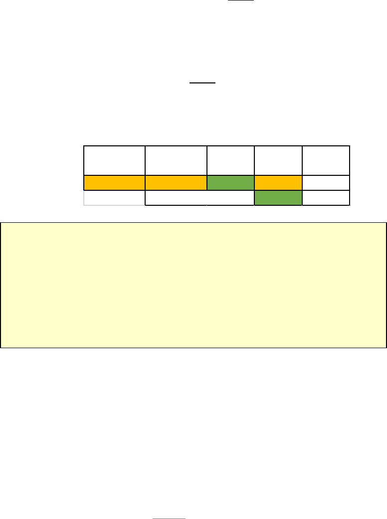
44
3.3.3.3.1.1.5. When designing a process machine, two of the three variables in
Little’s Law must be defined. As an example let’s assume there is a Road
to…Goal for a process machine to produce 64 aircraft per year with a limited
WIP of only 23 aircraft. The production output requirement of 64 aircraft per
year is defined by the future state customer requirement. The WIP target is
defined by a) the customer (in this case the Aircraft Availability requirement)
or b) an internal goal to reduce Cost and create capacity. The takt time is
calculated by dividing days available by the required output in that available
time.
365 ÷ 64 = 5.7
=
Every 5.7 days this machine must output an aircraft. Flowtime then equals WIP
x takt time.
23 5.7
= 131
This process machine must perform at a speed (flowtime) of 131 days to output
64 aircraft per year, while maintaining a total WIP of only 23 aircraft.
3.3.3.3.1.1.6. Through the above example you can see how the parameters of
the process machine are designed based on a future state Road to…Goal. The
resulting flowtime target is now understood and the organization must do
everything possible to achieve improvements in the process to achieve that goal.
3.3.3.3.1.1.7. Another important component of the formula is the overall
capacity of the organization. For instance, the footprint of an individual weapon
system, based on its aircraft availability calculation alone, may be greater than
the physical space available to a Complex given its total workload
Caution:
Application of Little’s Law does not have a cause and effect relationship to Process
performance. It is only a mathematical equation that shows the relationship of the
variables in a steady state process. It provides the basis to calculate the
foundational levels for the process Machine and expresses the mathematical
representation of the Road to…Goal. Progress toward the Road to…Goal is
measured against this calculated target.
Available
Time (Days)
Required
Output
Takt
(Days)
365 64 5.
7 23 WIP
131 Cal. Days
Req'd Flowtime (Days)

45
requirements. There may be cases where increasing the speed of a weapon
system is necessary to reduce its footprint (WIP) in order to free capacity for
new or increased workload for the Complex. For this reason, it is important to
understand the workload requirements of the organization in its entirety to
ensure the individual Road to…Goals allow the organization to meet its overall
workload obligations.
3.3.3.3.2. Release Only Supportable Work: The Release Control element of Rules of
Flow communicates the discipline to only start work when it is fully supportable.
Release Control, as discussed here, is the “leadership resolve” to follow the criteria and
demand discipline to the concept. Release Control is focused on ensuring the process
is fully supportable, and everything needed for work is available before being released
to the doer. For a production process, this means all skills, parts, tools, materials and
tech data are on hand, or there is high confidence it will be available prior to the need
date. For an administrative process, this may mean all data is complete and all funding
is available. AFSC machines having everything fully supportable with adequate
personnel (with right proficiency levels & skills) parts, tools, equipment, work
documents, troubleshooting tech data etc. before starting work on the job can
significantly reduce flowtime. Full Supportability is a key enabler of low WIP. Once
we control WIP, it is important to release work only when fully supportable. Complete
Supportability provides everything needed at the point of execution/use, generating one
overall start action and one stop action; thus, eliminating multiple starts and stops to
gather parts and tools.
3.3.3.3.3. Release of Work to a Synchronized Plan: When tasks are fully supportable,
and have passed all of the business rules for Release Control, they should be loaded
with the appropriate personnel to accomplish the job as quickly as possible. The work
should be assigned based on the daily scripted work plan and priorities. Following a
Tax Example
When completing tax returns it is more beneficial to gather all the information
needed before beginning. The taxes cannot be completed until all the information is
available. It may seem beneficial to begin the filing process prior to receiving all the
pertinent documents such as W-2s, Mortgage interest reports or donation receipts. This
requires certain steps to be skipped and increases the likelihood of omissions or errors.
In the end, the return cannot be submitted until all documentation is available and all
steps completed. Having all the needed documentation in hand reduces the time
required to complete the process, improves Quality, and reduces frustration.
DIY Example
Imagine starting a do-it-yourself home improvement project. Is it better to have
all the tools, parts and material on hand before you start, or would you prefer to make
multiple trips to the home improvement store after you begin? Extra trips have a
significant impact on the flowtime of the project. On the other hand, having everything
ready before starting the job enables us to finish the job quicker with better Quality and
much less frustration.

46
disciplined flow of work will allow the synchronization of enterprise resources to
execute the plan. All players in the process should be in tune with the daily plan and
maximize utilization of resources to meet the expectations. Proper assignment of work
minimizes multi-tasking and allows the doer to Focus and Finish the task before
moving on to the next task. Not only does this enhance the speed of the machine, but
it greatly enhances the quality of the product. The opportunity for quality escapes are
minimized by eliminating starting and stopping and creating fewer handoffs.
3.3.3.3.4. Quick Issue Resolution: Quick issue resolution is foundational to the AoP
management system. Without quick resolution of constraints and issues, the rest of the
tools within AoP are meaningless. When issues arise that impact WIP levels, they must
be dealt with quickly. When constraints affect the Supportability of the task, they must
be resolved. If personnel issues prevent proper resource loading, then find ways to
resolve the constraint. AoP is about using the tools to discover constraints and then
resolving them quickly. Quick issue resolution is the desired outcome of the
Leadership Model. It is the job of every leader at every level. Leaders and supervisors
should make frequent contact with process doers throughout the day to identify issues
and ensure prompt resolution. While leaders may use the resources available to them
to resolve issues and constraints, they cannot just delegate the responsibility to others.
If quick issue resolution is not carried out with a sense of urgency, the other components
of the Rules of Flow are just irritations that stop the flow while we wait for things to
get better. AoP is designed to uncover issues and constraints; however, failing to follow
the Rules of Flow only hides issues and constraints and prevents them from being
resolved. If we lower the water in a pond to find where the stumps are, it only makes
sense to remove the stumps before we refill the pond. Those that observed the stumps
may remember where they are, and be able to navigate around them, but everyone that
comes behind will continue hitting the stumps.
3.3.3.4. ToC Focusing Steps: In the book “The Goal” (Goldratt et.al. 1997)₅ the author lays
out the foundation behind the ToC approach to process improvement and creation of flow.
ToC establishes a series of Focusing Steps that are used to eliminate constraints to flow.
These steps will apply to every process, both production and administrative. The premise
of ToC is processes act much like a chain that is only as strong as their weakest link. The
weakest link in any operation is described as the constraint, which prevents the output of
the entire system from meeting the desired performance. The constraint is usually
Quick Issue Resolution is foundational to the AoP business model. Without quick
resolution of constraints and issues, the rest of the tools within AoP are meaningless. It is
the job of every leader at every level. If Quick Issue Resolution is not carried out with a
sense of urgency, the other components of the Rules of Flow are just irritations that stop
the flow while we wait for things to get better. In addition, WIP control DIRECTLY impacts
Quick Issue Resolution. Lower WIP lowers the number of issues to be resolved making
Quick Issue Resolution achievable

47
identified as the process or shop that has the most WIP queued upstream, or the most
heavily loaded process or shop in the system. The utilization of ToC requires all CPI
resources to be focused on the constraint. Just as opening the nozzle wider will not improve
flow if the garden hose is kinked, CPI efforts that do not attack the constraint, will not
improve the overall system performance, and could actually make the entire system
perform less effectively. The five basic and sequential steps for proper application of ToC
are described below.
3.3.3.4.1. Identify the Constraint: As mentioned earlier, the constraint is usually
identified as the gate with the lowest throughput rate. This may manifest itself with
queue before the gate or excessive WIP in the gate due to poor performance.
3.3.3.4.2. Exploit the Constraint: Usually this involves obtaining the immediate
maximum potential out of the constraint without significant investment. For example,
if a machine tool is limiting the system’s output, the constraint is exploited by
continually operating the machine during second or third shifts, lunch breaks,
weekends, etc. Buying a second machine tool is not a way to exploit the constraint (see
paragraph 3.3.3.1.4, Expand the constraint below). If People resources are the
constraint, then having all parts, tools and materials available to maximize their touch-
time on the process will create the most value for the customer.
3.3.3.4.3. Subordinate everything to the Constraint: It is inefficient to allow
unconstrained functions to operate above the limiting constraint’s capability. All
operations must match the constraint’s pace to prevent overwhelming or starving the
preceding and succeeding tasks. Support functions must also be subordinate to the
constraint. Competing priorities must be resolved so supporting resources can devote
time and energy to protecting and resolving the constraint. This is another area where
Horizontal Integration is necessary so that all stakeholders have a clear understanding
of the common goals.
3.3.3.4.4. Expand or Elevate the Constraint: Most constraints will be resolved by the
time step three has been completed, but in some cases it may require elevation of the
problem. Expansion of the constraint is elevating the output of the limiting process,
Resource or shop until overall system performance can be met, or until another
constraint becomes the limit to the system. This might include the purchase of
additional equipment, addition/realignment of personnel, or preferably, an increase in
output through waste removal or other CPI activity.
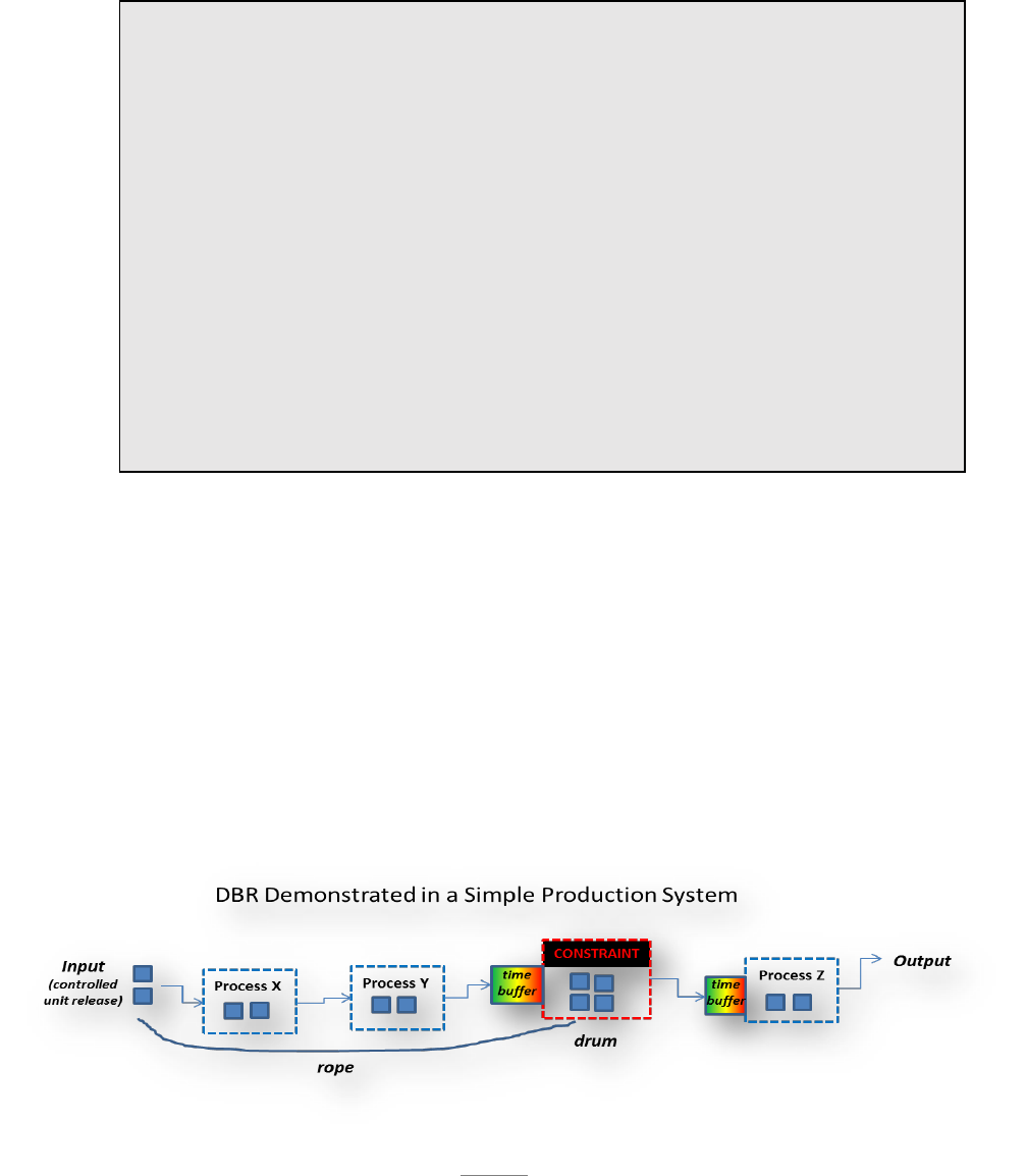
48
3.3.3.4.5. Repeat the Process (Identify, Exploit, Subordinate, Expand): If a constraint
still exists, these steps must be repeated until all constraints are removed. It should be
noted that if the desired performance of the system is attained, no limiting constraint
requires attention; however, different processes or shops may have different capacities
(i.e. the system may not be balanced) or it may be time to re-evaluate the Road to…Goal
(see sect. 3.2.) for the future.
3.3.3.5. Release Control Methods: The following are common methods for managing the
release of work into the process machine.
3.3.3.5.1. Drum-Buffer-Rope (DBR): DBR is a Planning and scheduling methodology
for the application of ToC. It is effective in high volume, low flowtime and high
variation systems comprised primarily of short duration tasks where the system
constraint cannot be eliminated and, instead must be managed. The ‘drum’ is the set
schedule based upon the constraint’s output capacity and is used instead of takt time.
The ‘buffer’ is a protection against variability and is used to protect the performance of
the schedule or drum. In DBR, the buffer could be time or material. The ‘rope’ is used
to subordinate all other processes to the constraint. The rope is the lever that
strategically releases WIP (time or material) into the machine at the appropriate time,
NOTE:
These five Focusing Steps are the foundation of a constraints-based management
system. The application may be more direct in some Processes than in others, but they
all use the same premise to approach flow:
1) Identify the constraint.
2) Exploit the constraint to get the most you can out of it.
3) Make all other Processes and Resources subordinate to the constraint.
4) (If it hasn’t been solved by that point) Find ways to Expand the capacity of the
constraint.
5) When the constraint is resolved move on to the next constraint.

49
ensuring the constraint is not starved or overwhelmed. In essence, the rope
synchronizes the schedule of all resources to the drum or limiting constraint (ToC Step
3 above: Subordinate Everything to the Constraint). Each individual process or shop
can utilize Little’s Law (see sect. 3.3.3.3.1.1.) to determine the appropriate flowtime,
WIP, and takt relationships, but the overall process machine is synchronized via the
DBR system.
3.3.3.5.1.1. In order to execute DBR it is important to begin with a commitment to
an overall system performance (delivery date of the product). Once this date is
established, a right to left schedule is established for the drum to execute to the
delivery schedule. All the processes that occur downstream of the drum are then
scheduled so the delivery date is met. A similar process is applied when scheduling
work upstream of the drum to ensure material arrives to the constraint on time.
Time buffers and inventory buffers are utilized at critical locations throughout the
system to protect the overall delivery of the schedule against variations due to
rework, peak demands, unscheduled production interruptions, etc.
3.3.3.5.1.2. An example of a time buffer is the scheduling of a product from the
constraint to the delivery point for 25 days even though the product delivery is not
expected for 30 days after passing through the constraint. Depending on the
existing process variation, the additional 5 days could provide near 100% on-time
delivery, and can essentially remove delivery uncertainty. A similar time buffer,
or inventory buffer depending on the process, is often applied upstream of the
constraint to ensure the original schedule is protected and the drum (the constraint)
never shuts down due to upstream variability (ToC Step 2: Exploit the Constraint)

50
Laundry Example:
One of the simplest and most practical examples of DBR is laundry in
a home setting. The laundry workflow consists of two pieces of equipment:
the washer and the dryer. The laundry process is often exacerbated by
“stock outs” in the form of the lack of clean clothes on shelves and in closets.
These stock outs often lead to reactionary firefighting in the form of
completing a specific load of laundry to resolve the current stock out
situation (rushing through a load of clothes containing specifically what is
desired to be worn at the time). Everyone is happy for the moment – at least
until the next stock out.
In this laundry example, individuals need a way to 1) prevent stock
outs from occurring and 2) respond when a stock out is imminent in order to
prevent the stock out from occurring. The first step is to examine and
understand the process. In this case, dirty laundry is collected in the hamper.
Items from the hamper are placed into the washer and then the dryer. Once
the laundry completes the dryer step it is ready to be stocked on the shelves
and in the closets.
The clothes in the hamper represents customer need. Once the
clothes are placed in the hamper, they have been inducted into the laundry
Machine and therefore become WIP. There are only a limited number of
clothes available so if WIP is high there are less clothes available in the
closet. Reducing the WIP reduces the chances of a stock out of clothing,
consequently forcing the firefighting mode.
The goal of AoP would be to reduce the WIP by adding process
discipline and thereby provide better support the customer. In order to do
this we apply the five ToC Focusing Steps discussed previously. The first step
in the laundry example is to identify the constraint in the process. In this
case, it takes longer to dry the clothes than it does to wash the clothes;
thereby making the dryer the constraint (the drum). In order to create the
necessary flow through the process it is necessary to exploit the Constraint.
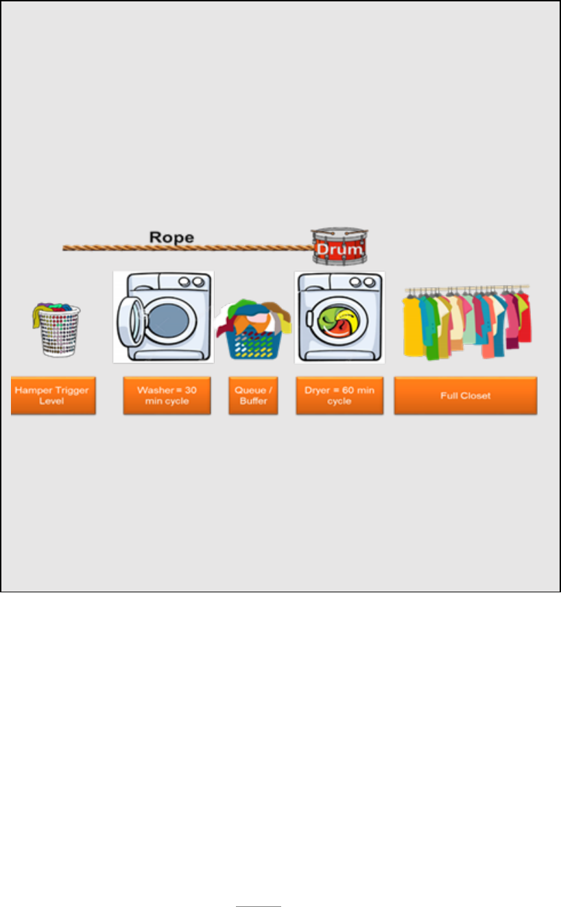
51
3.3.3.5.2. Pipelining: Pipelining is similar to DBR in that the work is released based on
the most limited resources or capacity of the constraint. However, Pipelining is
typically applied to projects rather than piece work. The metering is like traffic lights
releasing cars onto an interstate. Instead of the most limited resources being spread
over multiple projects, the projects must be staggered so the most limited resources can
complete a project as quickly as possible and move to the next. Other gates or process
doers may even be idle because, as we know, the constraint or most limited Resources
will determine the throughput of the machine, and the machine cannot go any faster
than the constraint can produce. If Resources are idle because they are not part of the
constraint, they should be used to make the work prior to the constraint fully
supportable! As the Greek philosopher Aristotle (and our AoP Rule of Flow number
two insinuates) said, “Well done is half begun!” These Resources, which might be
considered idle, can actually help the organization make great progress on the projects.
Laundry example continued
In order to provide clothes for the dryer the washer must operate, but it is
subordinated to the dryer to the extent it only provides enough clothes to keep the
dryer operating. Washing loads of clothes and piling clean, but wet, laundry in front of
the dryer will result in clothes that are mildewed and in need of washing again (rework).
Since the washer only takes 30 minutes to complete, it has excess capacity and will finish
sooner than the dryer. This results in a buffer for the dryer. This is both a time buffer (it
finishes 30 minutes ahead of the dryer) and a material buffer (clothes are ready to put in
the dryer when needed).
In this case, the process discipline instilled by exploiting the constraint and subordinating
other Processes and Resources to the dryer should eliminate the necessity of expanding
the constraint by purchasing a larger or faster dryer. However, if the Process continues
to experience stock outs that cannot be resolved with Process discipline, then
purchasing a new dryer may be necessary to preclude stock outs! We should resist the
tendency to purchase more clothes to solve the problem. Without Process discipline,
more clothes would eventually lead to more WIP and eventually reoccurring stock outs
and more firefighting.
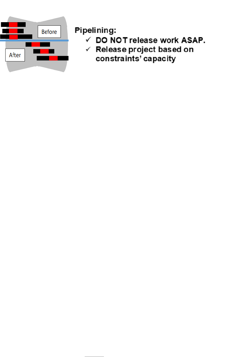
52
When multiple projects are being worked at one time, the flow of all projects can be
pipelined, and the pipeline managed in accordance with machine WIP control rules.
Pipelining is a highly effective work release and management tool for project
environments.
3.3.3.5.3. Focus and Finish (Simplified DBR): Focus and Finish is a means of
controlling WIP to prevent process doers from inherently taking on more work than
can be efficiently managed so projects can be completed in a timely fashion. Focus
and Finish prevents inefficient multi-tasking from occurring through a controlled
release of work. Think of an engineering office with people who can take on a variety
of projects of various durations. Typically projects (or WIP) are assigned based on
area of responsibility, skill, etc. and we hand out all the work to all the people or they
receive the work and we do not even know they are working it.
3.3.3.5.3.1. In the Focus and Finish flow approach, all WIP is held in a queue and
we assign only one to five projects at a time to each person. The bandwidth of the
person is the constraint. Process doers should focus only on those projects released
to them, and finish them, before we assign the next one out of the queue. The
release criteria is the rope that subordinates the incoming work to the constraint.
While the projects sit in queue, we can exploit the bandwidth of the worker by
having an expert look at the projects, determine difficulty, develop a Critical Path,
and make sure they are ready to be worked when assigned. Operationally,
constraints are measured by the size of the queue (Is it growing or shrinking?). If
queues are growing it may be necessary to expand or elevate the constraint. This
approach is applicable to a wide range of processes. Any process assigned to
individuals or small teams with relatively small number of tasks or short duration
touch time can be managed by a Focus and Finish machine. The graphics below
depict a Focus and Finish machine; before, during and after implementation.
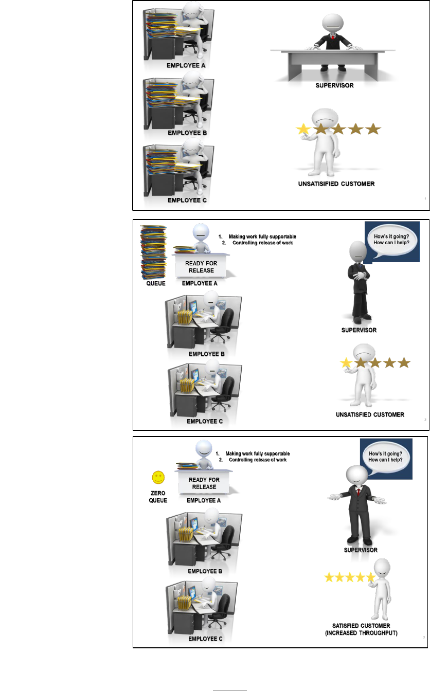
53
Before
During
After

54
3.3.3.6. Development/Security/Operations (DevSecOps) is a technique designed to create
rapid development and delivery of software specific projects by removing constraints or
barriers between organizations that have traditionally been viewed as separate functions.
3.3.3.6.1. DevSecOps is AoP as it is Theory of Constraints-based and incorporates the
tenants of AoP including Rules of Flow. DevSecOps is a software engineering culture
and practice that aims at unifying software development (Dev) and software operation
(Ops). Additionally, DevSecOps employs processes with robust security, authorization
mechanisms, and continuous runtime monitoring of operational software. The main
characteristic of the DevSecOps movement is to strongly advocate automation and
monitoring at all steps of software construction, from integration, testing, releasing to
deployment and infrastructure management.
3.3.3.6.2. Modern software development techniques employ DevSecOps processes and
are focused on rapid frequent delivery of software to the user. DevSecOps takes an
iterative and incremental approach to software development. Iterations are standard,
fixed length time boxes, typically 2-4 weeks in length. DevSecOps teams iteratively
execute the software development lifecycle within these time boxes. Increments
consist of multiple iterations and can result in a potentially releasable product.
DevSecOps development is often contrasted with traditional or waterfall development,
where large projects are planned up front and executed against that plan. Delivering
production capable code every iteration or increment requires the DevSecOps team to
account for this accelerated pace.
3.3.3.6.3. DevSecOps teams conduct daily standup meetings where they perform
tactical management of their work. DevSecOps teams conduct Wall Walk
retrospective meetings, problem solving workshops, and innovations iterations to
identify and resolve issues and operational constraints. DevSecOps aims at shorter
development cycles, increased deployment frequency, and more dependable releases
in close alignment with business objectives. Further, DevSecOps values frequent user
feedback and engagement at every iteration. In addition to fostering shorter lead times,
DevSecOps focuses on making work visible, limiting WIP, reducing batch sizes,
reducing hand-offs between teams, and the identification and elimination of constraints
and waste.
3.4. Gates: With long flowtime machines, it is critical to break the process into smaller sections
or gates. This provides increased transparency into the performance of
the machine, enables more timely issue identification-elevation-
resolution, and ensures optimum performance of the overall machine.
Gates create a common language to help communicate the status of the
machine and issues that affect throughput to enterprise stakeholders.
3.4.1. Gating is the grouping of similar work within a process machine’s overall flow. The
primary purpose of the gate is to provide succinct data to pinpoint underperforming processes,
and clearly illustrate where to apply CPI techniques in order to improve process machine

55
performance. As such, it is imperative gates are constructed to allow this type of visibility.
Key factors to consider in the gate construct include work content, concrete (rather than
abstract) boundaries, length, and total number of gates. These factors work together to
construct gates that provide repeatable comparisons.
3.4.2. The application of Little’s Law is just as critical to the design of these individual gates
as it is to the overall process machine design. Let’s look at the production machine that was
discussed in section 3.3.3.3.1.1.5. concerning Little’s Law. Here the machine is further broken
down into gates.
Available
Time (Days)
Required
Output
Takt
(Days)
Gate 1
(Pre-dock)
Gate 2
(Inspect Dock)
Gate 3
(Structures)
Gate 4
(System Ops)
Gate 5
(Post Dock)
TOTALS
365
64
5.7
2
3
10
3
5
23
WIP
Req'd Flowtime (Days):
11
17
57
17
29
131
Cal Days
3.4.3. In this example, the overall flowtime is broken down into five separate gates. Defining
the WIP in each gate is an iterative process that will depend on the physical constraints of the
system and/or the amount of work to be accomplished within each gate. In some cases, the
WIP will be determined by constraints such as dock space, or machine availability. In other
cases, the WIP may be calculated using Little’s Law based on the targeted flowtime determined
through process analysis. Keep in mind the gate flowtime for your future state machine may
seem unattainable relative to current performance, but it is critical to properly pro-rate the
required overall WIP across the entire machine. The defined WIP within the gates determines
the required flowtime performance for that gate. As noted above, defining a WIP of 2 in the
“Pre-Dock” gate leads to a required flowtime performance of 11.4 days (flowtime=WIP x takt
or 2x5.7=11.4). Remember, the sum of the WIP in each gate cannot exceed the total WIP
threshold of 23 in this example.
3.4.4. The length of a gate is an important consideration when constructing the process machine
to guard against constructing gates that are too short or too long. Gates should be long enough
as to show a significant portion of the process, and can encompass several handoffs between
skill sets in order to make the Gate a meaningful length. Similar work scope and content is a
key determinant when constructing gates. For example, all prep work completed before a
product enters a primary repair location could be grouped together, even if there are hand-offs
within the gate, in order to make the gate a significant representation of the process machine.
Gates need to show the processes of the machine, but do not need to detail every sub-process
or sub-task within the specific gates. It is also important to ensure the gates are not so long it
becomes difficult to monitor the progress or determine failure points within the gate. The
ability (or inability) to consolidate gates based on work scope and content, the process machine
Critical Path, and actual product physical constraints, work together to determine the number
of gates required within a process machine.
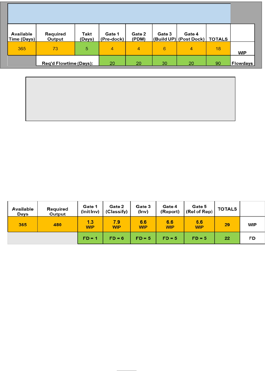
56
3.4.5. Below is an example of a machine with predefined WIP targets for each gate. Little’s
Law is used to determine the flowdays for each gate. Observe in the graphic how WIP and
takt time are used to determine the flowday target.
3.4.6. The following is a gated machine example in an administrative area. The Safety Office
typically processes 480 accident reports per year. AFI requires completion in 30 days. The
team gave themselves a buffer of eight days and set an internal AoP Road to…Goal of 22 days.
There are five gates in the investigation machine. The team determined how the 22 days would
be broken down in each gate based on analysis of the process. Using Little’s Law the WIP
was calculated for each gate based on the target flowday goal.
3.4.7. Little’s Law calculations often lead to WIP targets that are fractions. This raises the
question of how WIP is handled when it is a fraction. If you round down, the flowday
requirements will decrease, and when you round up, the flowday requirement will increase.
Round up or down according to the mathematical data. In our example, Gate 1 has a WIP of
1.3. This means 30% of the time, the WIP will be above one so it makes sense to round down
in this scenario. In our example, Gate 2 has a WIP of 7.9. This means 90% of the time, the
WIP will be above seven so it makes sense to round up in this scenario.
3.4.8. The application of Little’s Law is critical to maintaining a balanced process machine.
This enables proper resourcing of the system ensuring those resources are not overwhelmed or
starved by an unbalanced machine. If you are not monitoring the system, you are failing.
Note:
Process Machines with long flowtime present a unique challenge and may
need to be broken down into smaller challenges or sub-Gates within each
overall process Machine Gate.
GATE 1: 4 WIP x 5 Takt = 20 Flowdays
GATE 3: 6 WIP x 5 Takt = 30 Flowdays

57
Focus should be on the Processes in each gate, not the challenges of each unit of production
(individual items should be monitored as part of the tactical management system). You must
trend performance of the processes within each gate; this identifies constraints to the system
and creates a tool to link CPI to the constraints. Gated machines become the basis for capturing
the Metrics that must be communicated “from the shop floor to the Chief’s door.”
3.5. Release Points: Release Points are well defined criteria and
associated business rules that govern the boundaries established for the
gates. These boundaries should not be abstract, but rather should be solid
un-compromisable and documented rules. In section 3.3.3.3.2. we
discussed the necessity of Release Control to create discipline in the
machine flow. This section further reinforces that discipline through
expanding the need for well-defined and documented process controls. It is about the
corresponding criteria and business rules the organization’s leaders must create to govern the
decision making process. Having firm release points with associated business rules is key to
maintaining the most efficient flow of product and projects moving through AoP machines.
Release Points are the mechanism to create the process discipline necessary to see rapid
improvement and world class performance. Process discipline within the gated process instills
both the mindset and the resolve to not pass work and problems to later gates. Release Points
require business rules to create a cultural awareness that ensures specific actions are taken at
critical points in the process. Creating a culture that uses these rules to create the urgency
necessary to elevate and resolve issues prior to the gate release point (and protect the Critical
Path/Chain) is essential to creating the type of throughput that leads to attaining an AoP mindset.
3.5.1. Meeting structure should be established to support the use of release points. Leaders
must dogmatically enforce release points and utilize the established meeting structure to
provide the enforcement. Failure to adhere to defined release point criteria only hides issues
and constraints and encourages workarounds and behaviors that are detrimental to machine
performance.
3.5.1.1. WIP Limits: In the previous section we discussed the perils of high WIP and how
to use Little’s Law to calculate what the WIP targets should be. Work should not be
released into the machine, or from one gate to the next, if it will violate the WIP limits;
thereby resulting in multi-tasking those resources.
3.5.1.2. Travel Work: Travel work is work that should have been completed in a prior
gate but is allowed to travel to a subsequent gate. Work should not be traveled from one
gate to the next. Effort should be made to minimize traveling work to avoid the negative
impact to the process machine. Traveling work is typically allowed to accommodate a
schedule or timeline, but in actuality, slows down the flow in subsequent phases of the
Critical Path. Too much traveling work puts undo pressure on the subsequent gate and
can be the primary cause of not completing the gate on time. It increases the WIP level

58
for those downstream and leads to confusion. Traveling work causes multi-tasking and
hides the visibility of the constraint.
3.5.2. Gates should be designed with concrete release points that need to physically occur in
order to complete the current gate and transition to the next gate. Abstract boundaries make
consistent application of gate transition decisions difficult. Management review processes
must be established to control the movement of WIP from one gate to the next, and must ensure
the unit is truly ready to transition. Movement of work to a gate that adversely impacts the
Critical Path of the subsequent gate should not be allowed. Instead, management should utilize
the situation to highlight the impacting constraint and create an enterprise call to action through
the use of urgency tools.
3.5.3. Additionally, it is helpful if the concrete boundary is part of the process machine’s
Critical Path. This will alleviate transitioning to the next gate without the concrete, Critical
Path boundary requirement being met. Good gate transition habits are dependent upon how
well each gate boundary is clearly defined to trigger the transition.
3.5.4. Clearly defined work content and concrete boundaries also help management better
visualize and define traveling work. Traveling work is work that should have been completed
in a prior gate but is allowed to travel to a subsequent gate. Traveling work can degrade the
integrity of the gated production machine process. Too much traveling work puts undo
pressure on the subsequent gate and can be the primary cause of not completing the gate on
time.
3.6. Visual Displays: Information is power. The power comes from the
ability to share information that leads to better effectiveness and success
of the organization. In today’s computer driven world, we have
information at our fingertips. However, information that is not relevant
or shared with the correct people is powerless. Visual displays are
intended to be a practical method to communicate the relevant
information needed by the process doer.
3.6.1. Visual displays are a graphic depiction of the process map or machine flow and include
a visualization of information covering speed, safety, quality, and Cost Effectiveness as
applicable in the work area. Visual displays should be process doer-centric; allowing everyone
to understand their role, especially as it relates to the Critical Path/Chain of execution. In
addition, displays identify execution along the Critical Path and pinpoint existing and/or
emerging issues for resolution as well as allow transparency in the process. Visual displays
should provide the process doer with the answer to the all-important question: “Are you are
having a good day?” Visual displays should provide the process doer with the daily
expectations as well as the level of effectiveness. If the process doer is not regularly reviewing
the display, the displays are ineffective.

59
3.6.2. In order to be effective, communication has to fill a need. Information for the sake of
information can overwhelm and lead to non-value-added activity. For the purpose of AoP,
visual displays are intended to help the process doer, or the process support team, understand
process status, the daily requirements, and performance to those requirements. Visual displays
also provide information to help managers and senior leaders understand the overarching
process status. Effective shop floor communication is most effectively accomplished via visual
displays located in the work area, while dashboard type documents are effective to
communicate overarching information to managers and senior leaders.
3.6.3. Some basic elements that should be considered in each type of Visual display include:
1) relevancy; 2) simplicity; and 3) accuracy. An understanding of what is relevant to the
intended audience will ensure the visual display is not cluttered with unnecessary information
that disrupts the intended message. Another element that can add clutter to the message is
complexity. A simple and straightforward design enables more effective information delivery.
Information must be accurate in order to be useful.
3.6.4. AFSC leaders should continuously evaluate the visual displays in use in their
organization. Leaders should regularly visit the visual displays and assess their effectiveness.
There are simple ways to understand if visual displays are effective rather than just a display
to meet an inspection requirement or a talking point for tour groups. If a display is meeting
the intent, it will meet the following expectations:
3.6.4.1. Process doers review it often and rely on it to understand the expectations of the
day. A few questions to randomly selected personnel in the applicable area will reveal if
visual displays are being used to govern daily expectations.
3.6.4.2. All information will be current and will readily communicate the status of the
machine. Is it behind, on track or ahead of schedule? If this cannot be readily determined,
the display is not being used as intended.
3.6.4.3. Are constraints identified? Visual displays should communicate any issues or
machine constraints that are limiting performance. This information should include what
the problem is, who is working it and when a solution is expected. Regular review by
leadership will reveal if the correct sense of urgency exists to create an AoP mindset.
Empower the Process Doer:
The first four elements of the Radiator Chart were focused on defining the machine. We are
now transitioning into the tactical execution portion of the management system. The last
four elements are focused on empowering the process doer to be effective and efficient.

60
3.7. Standard Work and Scripting
3.7.1. Doer Standard Work: Normal daily operations should be controlled by standard work.
In a production environment standard work takes the form of technical documentation such as
Tech Orders (TOs), process Orders (POs), drawings, Work Control
Documents (WCDs), etc. In an administrative environment standard
work may be an AFI, checklists, desktop procedures or continuity
documentation. The leader should always evaluate their processes
through the eyes of a new employee. Is there a document that can be
given to a new employee to perform the job? If not, there is an area
of opportunity to improve the organization by developing standard work. Standard work
creates flow in the process because it reduces the opportunity for quality misses or safety
problems. It empowers the doer to perform the work, rather than searching for answers to their
questions. Standard work is HOW we do the work. No employee should ever have to ask how
to do the task. All value producing processes should have standard work documented and
controlled.
3.7.2. Scripting: The process flow discussed in (section 3.3.) provides the overarching plan,
and establishes task dependencies, in order to determine the Critical Path of the schedule.
Scripting is the next iteration of process flow in that it looks at subsets of the flow and
determines the sequence of events at a level more relative to the process doer. Scripting is the
ORDER in which work is accomplished and communicates the sequence of events on a more
finite level. A script is a visual representation of dependencies that communicate to the doer
the agreed upon order of steps within a process. The process can be an entire gate, a specific
repair task, or a complex portion of an administrative process.
3.7.2.1. Scripts provide both a monitoring and measurement function. Monitoring is visible
to the doer through displays in the work area and tells the entire team if the project is on
track. Measuring the variance of execution in Critical Path tasks provides important data
for process improvement. Scripting also provides a mechanism for people, processes, and
resources to be synchronized to the flow of work. The focus is to create repeatable
processes in order to reveal constraints and enable a predicted, repeatable outcome. Scripts
and standard work represent the best flow based on the information available. They
represent codified processes changed only through process improvement efforts, and
through the vetting of appropriate stakeholders. The goal is not to create robots who
mindlessly execute to scripts and regulations, but rather to create opportunities for critical
thinkers to identify improvements through CPI.
3.7.2.2. Synchronization can occur when discipline has been instilled with regard to
following the sequence of steps. Any change in the order of the scripted steps needs to be
considered by the team, and the change documented into the agreed upon script. This
process allows for continuous improvement as a collective and collaborative effort.

61
3.7.3. Leader Standard Work: Leader standard work is the most critical element of sustainment
and maturity of a management system. History indicates the average lifespan of new business
initiatives is only 18 months. While there are many contributing factors to this rapid death
rate, most agree the primary reason is lack of leader standard work. Without care and feeding,
a plant will die. Without nurturing, a young child will struggle to develop into the best person
they can be. Without oversight and continuous improvement, the best management system
will slowly cease to execute. Leader standard work is the methodology an organization must
use to ensure the continued execution of all standard work, and the fuel for continuous
improvement that will lead to maturity and world class performance.
3.7.3.1. Leaders must develop standard repeatable processes within their organization that
are designed to assess and improve the process flow. Standard work for leaders must be
incorporated into the daily battle rhythm. Without intentionally assessing and improving
the machine, leaders will struggle to see sustainment of the machine flow and improvement
will be almost impossible. First line leader’s standard work will focus primarily on the
accomplishment of the daily requirement and adherence to the standard work of the doer.
This focus must include front line support functions. The standard work of more senior
leaders must focus on adherence to, and effectiveness of, standard work of other leaders
under their influence.
3.8. Tools and Regulatory Guidance: This section involves the
availability of all approved Tools and guidance needed to accomplish the
task. In order to achieve AoP results, the organization’s leaders must
ensure everything needed to accomplish the work is identified, and readily
available. Streamlining access to the Resources needed to perform the
required tasks improves throughput, increases quality, reduces the chances
for injury and reduces the overall Cost of business. Process doer standard work (as discussed in
section 3.7.1.) is included, but this also encompasses anything needed to protect the Critical
Path/Chain. When the process doer is provided all the Tools and guidance needed to accomplish
the task, he or she is able to stay on task, and not be distracted by having to search for what is
needed. This will directly improve the amount of touch time a process doer has on the process at
hand.
3.9. Touch Time: Touch time is the culmination of the application of all
the previous levels of a mature machine. If you recall our discussion about
the Focusing Steps of ToC in section 3.3.3.4., you will remember the
second step is to exploit the constraint. The application of the touch time
element in the Radiator Chart is the exploitation of our number one
resource, people. The goal of AoP is to constantly improve the process
flow by eliminating the constraint. We never want personnel to be the constraint because we have
not done everything possible to empower the process doer to do the work.
3.9.1. We normally think of exploitation of people as a negative concept, but that is the opposite
of the idea of increasing touch time. We do not want to exploit people by forcing them to work

62
long hours or in harsh conditions. Neither is the goal to compel people to work harder and
faster. These conditions ultimately lead to behaviors that are contrary to the organization, such
as taking short cuts which lead to safety and quality failures. Exploiting the process doer is
about removing the things that create waste in the process. It is about empowering the process
doer to expend their energy on creating value for the customer rather than chasing parts or
searching for information. Kitting has been shown to have tremendous positive impact on the
touch time of the process doer. Just as the surgeon in the operating room has everything they
need at their fingertips; we should strive to have everything the process doer needs to fulfill
their task or mission at their fingertips. Maturity in the areas of visual displays, standard work,
tools, materials, and documentation will increase the amount of touch time that is experienced.
3.9.2. CPI initiatives focused on the process will uncover opportunities for touch time
improvements. Leaders who show a sense of urgency in empowering greater touch time will
pass that same sense of urgency to process doers. This mindset will establish a culture of
problems solvers and will result in an AoP mindset.

63
Chapter 4
MANAGE THE MACHINE
4.1. Introduction: In Chapter 2 we discussed the necessity of having a fully engaged leader. In
Chapter 3 we discussed the elements of a well-designed machine and guidance for the leader to
design that machine. Now, in Chapter 4 we will bring the two together to create a sustainable and
effective management method. Creating a well-balanced and well-designed machine following
the execution elements of Chapter 3 is essential, but just checking off the boxes of the Radiator
Chart is not sufficient to achieve AoP performance. A fully engaged leader must embody the
Leadership Model to be accountable to the machine and to achieving the goals of the organization.
Continuous and intentional management of the process machine is necessary to keep the machine
operating to its intended purposes.
4.1.1. What, How, and Why: In his book “Start with Why,” (Sinek, 2011)₆Simon Sinek
discusses a model he refers to as the Golden Circle. This model is intended to show the
components of what defines an organization: what they do, how they do it, and why they do it.
We will follow the structure of the model to define the machine management process. We will
cover:
4.1.1.1. What is required to effectively manage a machine?
4.1.1.2. How to successfully manage the machine using the tools available,
4.1.1.3. And, most importantly, why it is vitally important leaders are fully engaged in
managing their machine.
4.1.2. Management Levels: Within the construct of what, how, and why we will break each
component into the levels of management that must exist. Machine management falls into one
of three levels: strategic, operational, and tactical. Each level is essential for the leader to
embrace.
4.1.2.1. Strategic: Manage the goals with a focus on the future.
4.1.2.2. Operational: Manage the processes with a focus on constraint Resolution.
4.1.2.3. Tactical: Manage the product, project, or service with a focus on throughput.
4.2. Leader Expectations: Every leader, at every level, must embrace the concepts of the
Leadership Model to design a world-class machine and manage it each day. This section will
address what leaders are to be concerned with at each level of machine management, how they can
accomplish it using the tools they have available to them, and why they must make themselves
accountable to the machine through intentional management.
4.2.1. What: What are the key elements for the successful management of the machine? This
section will discuss the key things leaders must ensure are in place to implement, sustain, and
improve AoP in their organizations.

64
4.2.1.1. Strategic: Strategic management is an intentional view of the current requirement
with the future in mind. What are the current needs of the customer, as well as the
organization? What are the future needs of the customer? What are the future workload
requirements for the organization? What do we need to do to prepare ourselves for the
future? What stakeholders need to be involved for future success?
4.2.1.1.1. Road to…Goal, Common Goals and Horizontal Integration: In Chapter 2,
we discussed the role of the leader in identifying the common goals of the organization
and ensuring those goals are clearly defined and communicated to every stakeholder in
the machine. In Chapter 3, we expanded this idea to include a focus on the Road
to…Goal that positions the organization for the future. To be successful, leaders must
ensure the Road to…Goal and common goals are common to every stakeholder. We
typically refer to this as horizontal integration. Horizontal integration of enterprise
stakeholders is essential for success. If the mission partners do not share the same goals
as the machine owner, they will never view meeting those goals as a top priority.
4.2.1.2. Operational: The goal of operational management is to ensure processes are in
place and functioning to create throughput in the machine. Operational management
should never focus on the status of individual products or service requirements but instead,
focus on the health of the system and all supporting processes. Under operational
management, we will discuss four key outcomes that are the conceptual foundation for
success. Without an intentional focus on achieving these objectives, the goal of world-
class performance will not be achieved. We will also discuss key focus areas embedded in
a constraints-based management system such as AoP. Leaders at every level must be
involved in operational management, but the percentage of time spent will vary based on
the level of leadership. For more senior leaders, most of the daily focus will be primarily
on operational management. By contrast, first-line supervisors should devote a smaller
percentage of their time on operational management and a greater percentage to tactical
management.
4.2.1.2.1. Key Objectives: There are four basic objectives that operational management
must achieve. A healthy operational management system will have a management
structure in place to ensure each of these objectives is met.
4.2.1.2.1.1. Ensure Processes Are in Place: The first focus of operational
management is to ensure the machine is designed using the Radiator Chart format
described in Chapter 3. Just as any quality product begins with sound design, AFSC
machines must also begin with a solid design. However, beyond the deliverables
of the Radiator Chart, all machines are made up of a multitude of supporting
processes. It is the leader’s responsibility to assess where process standards are
needed, and take the appropriate actions to establish standard work. This must
include doer standard work and standard work for leaders at all levels. Standard
work was discussed in Chapter 3 as a primary requirement of machine design, but
operational management goes beyond initial design to require the machine and
supporting processes are continually evaluated for sufficiency. Some supporting

65
processes may appear to be tactical, meaning execution of the process has a direct
impact on the movement of product or services through the machine; however,
oversight of those processes is an operational management requirement.
4.2.1.2.1.2. Ensure Processes Are Being Followed: It is also a primary
responsibility of the leader to ensure all processes are being followed. Leaders must
take personal accountability to observe processes in action and confirm the process
is being executed according to the standard. Leaders must create an environment
of accountability, so everyone knows the importance of following all standard
work. Without the personal Accountability of the leader to the processes under
their control, they cannot assume those under their leadership will be accountable.
Without a system of checks and balances, processes will change over time, or will
cease to be followed. Organizations should develop a method to objectively
measure compliance with the standard processes in place.
4.2.1.2.1.3. Assess Processes for Effectiveness: Confirming standard work is in
place and being followed is only the starting point of operational management. The
leader must be accountable to the machine to identify constraints or areas where
standard work is failing to give the expected outcome. A machine is a map of the
workflow consisting of the interface of people, processes, and resources to the
machine throughput. Any time the gears of the machine fail to work properly,
effective operational management will identify the constraint and take decisive
action to resolve it. This includes, not only gate constraints, but supportability
issues that impact touch time of the doer.
4.2.1.2.1.4. Ensure Configuration Control That Supports Rapid Change: When
constraints are identified, the leader must utilize the ToC Focusing Steps to rapidly
resolve it. When the Focusing Steps identify the need to change the machine
structure or process standards, leaders must be accountable to rapidly engage the
configuration control process to effect that change. All standard work must have a
sound configuration control policy established to prevent processes from changing
over time, or being replaced by the next well-meaning leader. Without
configuration control, standard work ceases to be standard. If we expect processes
to be maintained, followed and improved, we must have a dynamic and responsive
configuration control process focused on rapid improvement. The greatest
impediment to an improvement mindset is delayed results and uncertainty in the
outcome.
4.2.1.2.2. Key Focus Areas: The intent of operational management is monitoring,
enforcing, and improving the machine. Certain principles are core to the AoP mindset,
and as such must be embedded into the daily focus. Each of these focus areas is
essential to achieve true AoP performance. Each area of focus should be addressed
through the lens of the above outcomes. Every AFSC organization should have
established processes and policies to ensure leaders understand, and are actively
pursuing these principles.

66
4.2.1.2.2.1. Understand the Current Machine Performance: The overarching idea
behind this principle is that every leader must know the true performance of their
machine. They must know every meaningful aspect of performance such as:
• Where is the WIP?
• What are the trends?
• Is the machine meeting customer demand?
• Are the assets/projects on track to the Critical Path?
• Are there any issues threatening the Critical Path of machine assets/projects?
• Are we meeting the common goals of speed, safety, quality, and cost-
effectiveness?
• Are we tracking to the Road to…Goal?
Every leader must ensure everyone in their sphere of influence has well-established
processes in place to continually understand the performance of their machines.
4.2.1.2.2.2. Enforce the Rules of Flow: The first priority for operational
management of the machine should be to implement and enforce the Rules of Flow.
The Rules of Flow are effective measures to combat the common causes to
disruption of flow. If these rules are followed closely, most problems with
throughput will be resolved. The Rules of Flow attack common process constraints
even if those constraints cannot be readily determined.
• Control WIP: Organization leaders must ensure solid processes and business
rules are in place to control active machine WIP. Whether the machine is a gated
process or a focus and finish machine, well-defined business rules must be in
place to manage the active WIP to defined WIP targets. The organization must
instill the discipline to utilize release points as a lever for controlling active WIP.
As discussed in section 3.3.3.3. concerning Rules of Flow, WIP control is
essential to minimize disruption to flow, minimize multitasking, and increase
machine throughput.
• Release Only Supportable Work: AFSC leaders must make Release Control a
priority in their operational management of AoP machines. As previously
discussed under Rules of Flow, Release control is the discipline required to only
begin fully supportable work. When work is fully supportable at the point of
release, flow times are reduced, and multi-tasking is reduced, which facilitates
higher touch time. Release control should demand the highest level of execution
in processes that facilitate supportability of a product. Without effective
Supportability processes, release control will only be a source of frustration as
we wait and hope for things to get better. Another compelling benefit of release
control is it requires a sense of urgency to resolve issues, do the necessary prep

67
work, and implement the measures for forward-looking supportability measures.
Leaders must establish and enforce the necessary policies and processes to
ensure compliance with business rules. When it becomes prudent to violate
these rules, there should be checks and balances in place to guarantee informed
decisions.
• Assign Work According to the Synchronized Plan: Once WIP is under control,
and the work is known to be supportable, it now has to be assigned. But how
the work is assigned is vitally important. It must be assigned based on a
synchronized plan. What is a synchronized plan? First, a detailed plan for the
short and long term must be in place. The plan will provide a proper work
sequence and priorities for accomplishing the work. This plan is to be based on
the method of management chosen for the work to include Critical Path, Critical
Chain, Drum-Buffer-Rope, pipelining, or focus and finish. Once the plan is
established, it must be synchronized. In other words, everyone that has a role in
executing the plan must know the plan and be advised as it changes. Only then
does it become a synchronized plan. In the AoP vernacular, we call these
synchronized plans scripts. Scripts provide visibility of the collaborated,
synchronized plan for a gate, or portion of the overall process. Now everyone
will know when to provide information, parts, and services to the machine based
on the scripted synchronized plan.
• Quick Issue Resolution: Leaders must ensure their organization has robust
processes and procedures in place to facilitate the rapid resolution of issues
affecting the movement of work through the machine. Issues, as discussed here,
are different from constraints to the machine. Issues refer to situations that
hinder movement of the work through the machine but are not systemic. Issues
may be tactical because they affect the movement of individual products or
services through the machine; however, the management of the processes to
support issue resolution is operational. Organizations must ensure issue
resolution processes are in place, are being used, involve enterprise stakeholders
as appropriate, and ensure processes are effective. Quick issue resolution
processes should include a defined mechanism to elevate problems when the
existing processes consistently fail to support the work plan, or as necessary to
resolve the problem.
4.2.1.2.2.3. Know the Constraint: When organizations strictly follow the Rules of
Flow, many constraints will be resolved and throughput will increase. However, if
a true constraint does exist, well defined processes following the Rules of Flow will
help to uncover the process constraint. In more complex machines, the
determination of the constraint gate is only the beginning of understanding the
constraint. A constraint gate is not the actual constraint, but where the constraint
lies. Analysis of the constraint cannot end there. A gate, or major phase of the
machine, is a process in itself, and every process has a constraint. To resolve the

68
constraint gate, the leader must be able to drill down to discover where the true
constraint lies. The constraint gate is a process with process flow. Every process
has a constraining resource that limits throughput. True constraint identification is
essential for successful operational management leading to AoP results.
4.2.1.2.2.4. Resolve the Constraint: Once the process owner has determined the
True constraint, every effort must be made to quickly resolve it. CPI tools and
process mapping events can be used to define the true constraint and actions to
resolve it. Leaders must engage CPI resources and tools such as the Practical
Problem Solving Method (PPSM) to exploit the constraint by offloading, finding
parallel tasks, or removing waste that affects the constraint. If teams embrace the
application of the ToC Focusing Steps, it will help focus the actions needed to
rapidly create throughput. Exploitation of the constraint resource is always the first
step. CPI actions focused on exploitation will have the most rapid return on
investment. Typical problem solving often jumps to expanding the constraint rather
than doing everything possible to increase touch time or machine run time. Leaders
should challenge actions directed at expanding the constraint as the first step.
Hiring more people or buying additional equipment are not actions to exploit the
constraint but rather expand or elevate the constraint. The exploitation of the
constraint is normally the easiest and quickest avenue to achieve throughput. But,
perhaps, more importantly, it demands accountability of the process owner because
those actions are normally within their control. To support the effective execution
of the exploitation step, senior leaders must ensure policies support and empower
the process owners to achieve those actions; otherwise, policies become the
constraint to machine improvement. Nothing causes disengagement, and removes
accountability quicker than policy roadblocks (actual or perceived) to otherwise
good ideas.
4.2.1.3. Tactical: Tactical management is the execution of processes and standard work
intended to affect the progress of individual items through the machine. The dictionary
describes tactical as actions that happen at the battlefront. Tactical management is the
actions that provide the interface between people, processes, and resources and the work
that generates throughput of the machine. Leaders, process doers, and support function
personnel must strive to faithfully execute the processes that have been designed to
facilitate the daily performance of work. Process control should be considered part of the
operational management system, but the execution of those processes is tactical.
Note:
Constraints are systemic machine or process
bottlenecks that hinder throughput. Constraints are
not one-time issues that affect the movement of
individual items.

69
4.2.1.3.1. Key Objective: The key objective of tactical management is rapidly moving
units of work through the machine to achieve throughput targets. Although throughput
is the objective of tactical management, the common goals of safety, quality, and cost
effectiveness can never be ignored because each is critical to successful mission
execution. Failure to achieve safety, quality, and cost goals equate to mission failure.
4.2.1.3.2. Key Focus Areas: Just as with operational management, there are key focus
areas organizations must ensure are consistently executed to achieve the intended
objective. If daily attention is given in these areas, tactical execution will be successful.
In essence, tactical management is setting the expectation through work assignments
and then providing the process doer what is needed to do the work efficiently.
• Supportability of the Work: Supportability refers to ensuring the process doer
has everything needed to perform the task before, or at, the time it is started.
In production environments, numerous processes are designed to make every
task supportable. Without faithful execution of these processes, the flow of
work will stumble and throughput will suffer. Tactical management entails the
strict execution of these processes to ensure the process doer has what is needed,
when it is needed at the point of execution. Supportability processes cover
numerous functional areas and skillsets; therefore, high levels of collaboration
are essential for success.
• Assignment of Daily Work: First-line supervisors are expected to make daily
assignments based on the scripted, synchronized plan, and the Rules of Flow.
The supervisor must know the status of the machine and project to make
assignments to protect the Critical Path and accomplish the work as quickly as
possible. Work assignments must work hand in hand with supportability
execution to ensure support functions and process doers are synchronized to the
same goals. For this reason, daily work assignments pertain to both process
doers and enablers. The entire organization must assign work in accordance with
the plan. Doers are assigned to work on tasks in priority order until there are no
doers left to assign (if more work than doers). It is essential all work is fully
loaded with personnel which means the maximum number of people are
assigned to the work before the next task is made available for assigning doers.
Loading a task with the optimum number of personnel enables the task to be
completed as quickly as possible, and frees up personnel to be assigned to the
next task quicker. This results in more focus because less activity is open and in
work. This is essentially WIP control at the process doer level.
• Quick Issue Resolution: By now, it should be obvious there is a common thread
running through the heart of AoP. Quick issue resolution is a foundational
concept that creates world-class performance. Tactical management is about
rapidly pulling together all of the people, processes, and resources in the
execution phase of the machine, to include enterprise partners when an issue is
beyond the scope of the process owner to resolve. When effective processes are

70
in place, tactical management should be simple execution of the processes.
When issues arise, they must be resolved quickly. Quick resolution enables
people to accomplish the assigned work as quickly as possible. Also, quick
resolution signals the importance of throughput and fosters employee
engagement. If processes fail to give the intended outcome, feedback to the
operational management system should be part of the process.
4.2.2. How: This section is intended to provide an understanding of how the leader at any level
can access the standard tools, meetings, and processes available to them to achieve the desired
objectives. It is not intended to provide detailed instructions on how to carry out every
component of machine management. The tools in this section are not exhaustive, but,
hopefully, will give the reader examples of actions that can be used to achieve the objective.
Each organization will vary in the application of processes; therefore, the leader must gain an
understanding of what processes their organization has in place and apply those to effectively
manage their process machines.
4.2.2.1. Strategic: AFSC has many strategic management and planning processes that play
a role in defining the common goals of the organization, and the Road to…Goals that must
be met to position the organization for the future. No one process will provide the complete
answer to the common and Road to…Goals, but, in combination, the organization should
be able to define their strategy and goals to build a clear case to support buy-in from their
business partners through the horizontal integration process.
4.2.2.1.1. Strategic Management and Goal Setting: The following types of processes
are examples of existing opportunities that can be leveraged to provide the information
to adequately build a realistic strategy and the defendable goals of the organization.
Goals cannot just be created out of thin air, but must be built on a strong foundation in
order to provide the confidence needed to motivate the process doers and enablers of
the organization.
4.2.2.1.1.1. Mission Essential Task List: The first step to successful strategic
management, and defining the goals of the organization, should consist of
developing a list of Mission Essential Tasks (METs). It is important organizations
have a clear understanding of their mission and thereby do not pursue efforts that
are not value-added to the organization.
4.2.2.1.1.2. Existing Forecasting and Planning Processes: The following are all
standing and recurring processes that must play a part in strategic management and
goal setting, and often involve horizontal integration:
• Requirements Review Depot Determination (R2D2)
• Logistics Requirements Determination Process (LRDP), AF Manual 63-143
• Annual Budgeting Cycle
• MilCon Planning

71
• Source of Repair (SOR) Requests
4.2.2.1.1.3. Performance Review and Special Considerations: Every
organization should look at their current state, as well as their desired future state
as they develop their strategic plan. The following should be considered in the
establishment of common and Road to…Goals:
• Facility Constraints
• Customer Requirements
• Desired Opportunity for Future Workload
• Aging Aircraft Projections
• World Events
Action plans to achieve the goals should also include the following:
• Throughput Performance
• Staffing Levels
• Quality Performance
• Safety Records
• Cost Performance
4.2.2.1.2. Horizontal Integration: Once the Road to…Goal and common goals have
been defined, the organization must communicate those goals to all stakeholders.
Section 3.2.4. lays out the requirements of effectively communicating the machine
goals to all stakeholders. The below processes are available formats to accomplish
horizontal integration and obtain buy-in from all mission partners:
• Enterprise Value Stream Mapping
• Process Improvement Events
• Process Machine Reviews (all levels)
• Supportability Reviews
• Planning Reviews
• Issue Resolution Meetings
• Routine Scheduled Partnership Meetings
4.2.2.2. Operational: Operational management should be the primary focus of leaders
throughout the organization. Every machine is a process made up of many more processes.
Therefore, operational management is a systematic method of managing those processes.
Organizational leaders should strive to utilize every opportunity available to observe,

72
assess, and improve those processes. This section will discuss some of the processes,
meetings, and structures that can be used in managing the machine processes.
4.2.2.2.1. Wall Walks: Wall Walks are the pivotal element of organizational
management. Wall Walks are intended to be the first line of machine improvement. A
Wall Walk is a recurring process-focused review to understand process machine
performance, identify constraints, coordinate constraint resolution and identify actions
to improve machine performance. Wall Walks enable organizational learning and
require involvement at all levels. Wall Walks are not a briefing to leadership and are
not tactical level management for the process team. Wall Walks are action-oriented
reviews of the overall machine health. As your organization grows in its AoP journey,
the Wall Walks will mature and include deeper analyses.
4.2.2.2.1.1. Wall Walks utilize visual displays set up around process execution
gates. A gated process machine has separate charts for each respective gate. Each
chart portrays performance trends, business rules, and the improvement
opportunities, and actions to achieve those opportunities for its respective gate. The
goal is to depict information relevant to the overall machine health.
4.2.2.2.1.2. Wall Walks allow an organization to understand how the process
machine is performing with measured data. Metrics used should be meaningful to
the process doer, data-driven, specific, and tied to the organization’s Road to…
Goal. Wall Walks allow for transparent assessment of an organization’s
performance concerning mission objectives, and holds personnel accountable for
meeting performance expectations.
4.2.2.2.1.3. The power of the Wall Walk is in the creation of ownership of gaps,
improvements, and actions. Ownership for a gate, gap, and/or improvement
initiative is an important component in improving the performance of a process at
the level of the process doer, owner or both. Further, the Wall Walk creates a means
for self-sustaining process improvement by the process doers and owners. It also
provides opportunities for both accountability and praise for improvement
initiatives and results.
4.2.2.2.1.4. Wall Walks must include all enterprise teammates and subject matter
experts to resolve gaps and use PPSM to improve processes. Enterprise teammates
should also be present during Wall Walks to show support for initiatives in which
they play a part, and to continually understand the goals and initiatives of the
organization to whom they provide support.
4.2.2.2.1.5. Wall Walks also present the opportunity for leaders to provide guidance
and encouragement to members of their organization. Leaders should not miss the
opportunity to open the door for critical thinking and to celebrate small successes.
This is an excellent opportunity to coach, mentor, and teach everyone at the Wall
Walk briefing.

73
4.2.2.2.1.6. It is also important to recognize and celebrate small successes along the
journey to AoP goals; however, do not allow these small successes to create
complacency toward the larger goal. Encourage out-of-the-box thinking to create
Engagement. With a truly engaged workforce, the boundaries of traditional
thinking can be lifted, and freedom from the “good enough” approach can be
obtained, as AFSC organizations reach for AoP results.
4.2.2.2.2. Staff Meetings: Standing meetings are perhaps the most accessible
opportunity to engage in operational management. The culture of the organization
should develop around ensuring the Rules of Flow are being followed. When the Rules
of Flow are followed closely, the constraint will normally be resolved even if it could
not be completely defined. In addition, the Leadership Model should be used as a filter
to address the health of the machine in terms of speed, safety, quality and cost
effectiveness.
4.2.2.2.3. Major Graded Area (MGA) Reviews: The MGAs of Leading People,
Improving the Unit, Managing Resources, and Executing the Mission align very well
with the structure of the Leadership Model. The MGA reviews of the organization can
be utilized to resolve the constraints affecting common goals. Each constraint must be
resolved by leveraging the areas of people, processes, and resources to achieve the
common goals of the mission.
4.2.2.2.4. Daily Battle Rhythm: Every organization should develop a daily battle
rhythm of activities and meetings to protect the execution of standard work by
preventing it from being replaced by other pressing issues. People will always act in a
fashion they perceive to be in their best interest. If the organization does not have a
daily battle plan, with appropriate checks and balances in place that require operational
management, other issues will take priority.
4.2.2.2.5. Walking, Watching, and Wandering, (W3) In section 3.1.3.5. we discussed
the vertical leadership element in the Radiator Chart referred to as W3. The objective
of W3 is direct observation of what is going on in the work area to prevent process
doers from W3. Leaders must create time in their day to get out and see the processes
in action. W3 is not just about walking around to make sure everyone is working, but
about gaining understanding and creating positive accountability. If leaders are never
present to check in on the execution, how will they know if processes are being
followed, or if they are functioning as intended? Without personal accountability to
standard work, people will default to what is easiest for them, and what they perceive
will meet their immediate needs. W3 by leaders is the most effective way to prevent
W3 by the process doer. W3 by the process doer is counterproductive to the machine
and can be countered if the leader has firsthand knowledge of the processes and status
of the work.
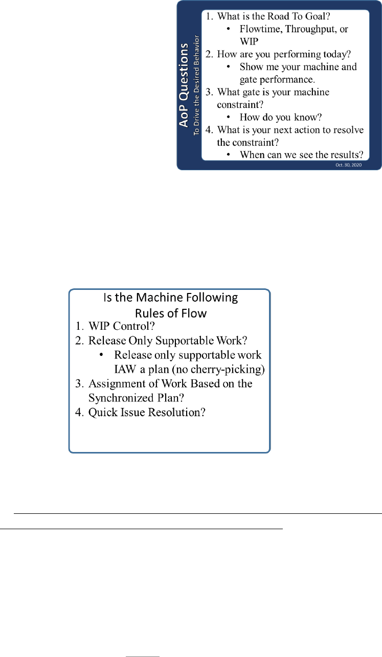
74
4.2.2.2.5.1. W3 is not about creating compliance through intimidation, it is about
seeing, asking questions, and listening to the answers. In section 2.4.2.1.2., we
introduced a set of questions that are
designed to create discovery and a
mindset of problem-solving. These
questions use the principles of AoP to
require people to understand their
common goals, and have a sufficient
understanding of their machine, to
know what is limiting the achievement
of those goals. Leaders should make
asking these questions part of their
daily routine.
4.2.2.2.5.2. The above questions focused on understanding and improvement. Now
we will introduce a second set of requirements that are tailored to the Rules of Flow
discussed in section 3.3.3.3. The following questions focus on the execution of the
business rules designed to protect flow. Leaders must require the Rules of Flow
are followed, and the best way to accomplish this is to verify by asking questions.
4.2.2.2.5.3. Rules of Flow:
1. WIP Control
Are you controlling the number of items in the machine so processes and
individuals are not being multitasked and spread thin? This is the most
challenging concept. Conventional thinking is that it is better to make SOME
progress on every item versus personnel-loading and focusing and finishing a
limited number of items.
2. Release Only Supportable Work

75
Is work being released only when it is fully supportable? Release work only
when it is supportable. Strive to know the complete condition of the item and
ensure everything needed to complete the next gate is available, or will be
available, before it is needed. Supportability includes personnel and equipment
resources. If all work from the previous gate is complete, but the next gate is
not supportable, complete the gate and put the asset in Queue.
3. Assign Work Based on the Synchronized Plan
Are all mission partners/stakeholders synchronized with the plan so
supportable work can always be provided when assigned? Individuals are to
be assigned to items/tasks in priority order until you run out of people. At this
point do not start any additional work until those assigned tasks are completed.
Ensure each task and item is fully personnel-loaded so the doer can focus and
finish before moving to the next job/item. This will avoid spreading people
across multiple items.
Is there a scripted plan? If so, is it being followed? Work should be assigned
according to the scripted plan. Maintaining this discipline is a challenging
concept. Following a scripted plan is the key to synchronizing resources to a
plan.
4. Quick Issue Resolution
What is your process for resolving issues quickly? Ask for evidence that it
is followed and is effective. The process should include enterprise partners as
appropriate.
How do you ensure the constraint gate is the priority over non-constraint
gates? There should be evidence of process improvement or other exploitation
steps involving the constraint gate.
4.2.2.3. Tactical: Tactical management is the daily execution of the processes designed to
create movement through the machine. Throughput is created by ensuring work is
supportable, personnel are assigned according to the scripted plan, and issues are resolved
quickly. The processes below are presented as examples of actions that directly affect the
movement of work. The oversight of the processes to ensure effectiveness is an operational
management concern; but execution directly affects the movement of work and, therefore,
is tactical.
4.2.2.3.1. Beginning and End of Shift Team Meetings: Daily tactical management
starts at the point tasks are assigned to the process doer. Task assignment should
include a discussion of the status of the project, along with the current day’s goals and
objectives to frame the urgency of accomplishing the current day’s tasks. Everyone
should know how their tasks fit into the synchronized plan.

76
4.2.2.3.2. Project Team Meetings: The project team consists of all the doers and
enablers responsible for the execution and progress of a particular asset or project. This
team discusses the progress of the project to the script, noting any problems or resulting
changes in the sequence of work activities required to keep the project moving forward
along its Critical Path.
4.2.2.3.2.1. Issues noted during the project team meeting are evaluated for their
effect on the Critical Path. Issues that are likely not to be resolved before their
impact on the Critical Path are elevated to the next level. This elevation must
include a description of what the impact to the Critical Path will be, when the impact
will occur, and a description of the critical elements of the issue along with details
of the efforts that have been undertaken thus far to resolve the issue. The project
team should also discuss what actions need to occur to recover any time lost on the
Critical Path – thus attempting to keep the project on schedule to the organization’s
Road to…Goals.
4.2.2.3.3. Daily Execution Meetings: The daily execution or production meeting is led
by the machine owners and is attended by the level of supervision of those participating
in the project meetings. This meeting discusses each asset or project in the context of
its relation to where it is, compared to where it should be along its Critical Path. This
meeting is the receiver of the information concerning Critical Path issues that have been
elevated from the project team. The supervisors of the project team members relay this
information in this meeting. This meeting is also attended by members of supporting
organizations to allow those organizations to receive the issue information and engage
in dialogue that leads to the ultimate resolution of the issue. This is also an essential
meeting for constraint team members to attend – allowing them to quickly react to issue
information and report any actions being taken.
4.2.2.3.4. Andons: Andon is a manufacturing term originating in the Toyota Production
System referring to a mechanism to notify management, maintenance, and other
workers of a quality or process problem. Andon is the Japanese word for “lantern” and
the term is representative of illuminating the problem. In its traditional manufacturing
context, an Andon identifies an issue and stops the production line until that issue is
resolved. In AFSC, the concept has been slightly adapted to apply to the AFSC
environment where it identifies an issue that impacts or potentially impacts the Critical
Path and calls the enterprise team to action for quick response.
4.2.2.3.4.1. Traditionally an Andon is associated with a delay. An issue or Andon
is a potentially negative situation, but the result should be a collaborative effort to
understand and resolve the root cause of the delay. Efforts must be made to avoid
a culture that attributes a negative message to the initiating organization, or the
organization best postured to provide relief, lest the collaborative mindset is lost.
The desired response needs to be conditioned by focusing positive efforts on a
shared “Road to…Goal” rather than attributing blame. Andon is not a verb. It is
not something that one organization does to another in a state of duress! Therefore,

77
Andons must be clearly communicated across organizations, as well as up and
down the chain of command, without emotions becoming involved. Effective use
of two tactics, focused communication, and transparency are required to promote
this culture.
4.2.2.3.4.2. The first tactic, focused communication requires the Andon to
explicitly state what help is needed, by whom, and describe the impact to the
machine. Requests for support must be crafted to target the individual or
organization that is expected to assist, and scoped to explicitly articulate the support
requested. This tactic is required to articulate exactly the support required by the
next level when an issue is elevated. Focused communication is also utilized when
the supported organization requests Subject Matter Experts (SMEs) from
supporting organizations for the resolution effort to meet and determine short and
long-term resolution actions.
4.2.2.3.4.3. The second tactic, transparency, provides visibility of the Andon to all
levels of the organization. The issue resolution process is the mechanism utilized
by all stakeholders to eliminate obstacles to AoP performance. This tactic is
necessary to ensure these stakeholders have a common site picture of the health of
the machine. When an issue is elevated, transparency allows the next higher level
to review an issue without an explicit request for support. Transparency has a push
component, which includes activities such as including Andons in project and
machine review meetings. It also includes a pull component, which includes
activities like allowing stakeholder access to an Andon visibility tool.
4.2.2.3.4.4. Communication begins with the stakeholder. Any stakeholder in the
AFSC production machine has the right and responsibility to identify issues. While
the process doer may have the first awareness of some issues, supporting
organizations may be in a position to identify other issues early. For example, a
DLA employee might recognize a key parts shortage in advance, or a program
office engineer might unearth a technical risk that will require mitigation. Again,
communicating these discoveries to the correct organization promptly could
alleviate the need for an Andon during process execution, and allow for the
development of acceptable workarounds or expedited delivery in advance of
Critical Path impact.
4.2.2.3.4.5. Most organizations have had success in utilizing a tiered
communication approach to managing their processes. This approach allows
Andons to bubble up to the highest tier and possibly identify group-wide trends of
certain issues. A tiered communication process also helps keep track of Andons
until they are resolved, providing visibility of issues to senior management.
4.2.2.3.5. Tier Meetings: Many organizations across the AFSC have adopted a formal
meeting alignment approach known as the Tier System. The figure below depicts the
basic Tier System process that begins at the shop floor (Tier 1) and culminates with
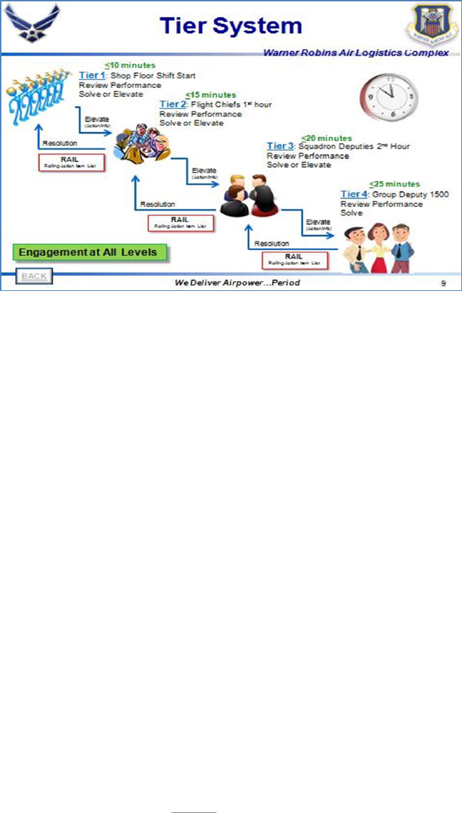
78
group leadership (Tier IV) daily. Similar to the Project Team Meeting alignment
approach discussed previously, the Tier System is based on the script in place at the
process doer level. The tier approach also incorporates speed, quality and safety
metrics, monitors output, elevates issues, and keeps machine goals in front of everyone
– from process doers, to support organizations, to leadership – daily.
4.2.2.3.5.1. Including the process doers in the Tier System gives those doers
ownership in solving issues and changing processes to meet organizational Road
to…Goals. This process is repeated at the flight (Tier II) and squadron (Tier III)
levels. This commitment to daily process reviews through all organizational tiers
sends the message of the importance placed on improving process performance to
gain the desired throughput (speed).
4.2.2.3.5.2. Tier meetings encourage problem-solving at every level, creating a
problem-solving synergy that goes beyond the capabilities of even the wisest and
most experienced lone process manager. A fundamental component of the tiered
approach is the inclusion of a scripted flow diagram for each meeting level of the
system. This Script ensures the meeting dialogue is centered on the process and its
issues at each meeting level. Placing the focus on the process removes emotions
and allows discussion to concentrate on resolving process issues. The tier approach
also provides a systematic, standardized format to allow issues and Andons to be
communicated and/or elevated to the next level. In the Tier System, unresolved
Andons are placed on the Recurring Action Item List (RAIL) and persist at the Tier
IV level until they are resolved.
4.2.2.3.6. Visual Displays: Effective tactical management includes effective visual
displays at the point of work. In a complex project environment, the visual display may
focus on a portion of the flow such as a particular gate, while an environment with
many small, quick turn assets or projects will focus on progress of a mix of items. In
either case, the displays should reflect information that is important to the process doer

79
and support team to understand what is currently in work, what will be worked next,
and what issues could impede the progress of the Critical Path to be relevant.
Simplistically displaying this information to promote ease of updating (and thereby
promoting accuracy) is key to a successful Visual Display.
4.2.3. Why: In his book “Start with Why” (Sinek, 2011)₆, Simon Sinek explores the fact that
unless a person or an organization knows why they are doing something they are unlikely to
do it with enthusiasm or dedication. Anyone that has raised a child knows that from an early
age, everyone wants to know why. When you ask a toddler to pick up their toys, they ask,
“Why?” “Clean your room,” “Why, Daddy?” “Eat all of the food on your plate,” “Why,
Mama?” We also know eventually the default answer of “because I said so” ceases to be
effective. Adults may not always ask the question, but unless we know “why,” we are unlikely
to be engaged in the activity and even less likely to repeat it. Expecting the workforce to
consistently perform the work just “because we said so” is not realistic. This section is about
creating an understanding of why it is essential for the leader to actively manage the machine.
When leaders fully embrace the “why” of daily and continuous machine management, they
will be able to create the “WHY” for those doing the work. Without embracing why it is
important to manage the machine, leaders will not see value in improving the process, and the
workforce will not connect their purpose to the purpose of the organization.
4.2.3.1. Every car owner knows to keep their vehicle running well, and providing years of
reliable service, certain things must be done to maintain it. The oil must be changed
regularly. The tires must be rotated and replaced when required. Fuel must be put in when
needed. All of these actions are elements of managing the transportation machine. We
understand when action must be taken because we are constantly engaged in managing the
machine. The metrics of the machine tell us when it is time to act. We listen for noises,
and watch the indicator lights that tell us something is not right and warrants a trip to the
mechanic. We watch the odometer to know when it is time to rotate the tires or change the
oil. The fuel gauge tells us when we should find a gas station. The AFSC process machines
are no different. The leader/manager must continuously watch and listen to the heartbeat
of the machine to know when something is not right so adjustments can be made. Just as
any car (regardless of quality) that is ignored will quickly begin to fail, the best-designed
machine will quickly fall into disrepair if it is left to itself.
4.2.3.2. We understand that cars cannot perform their own maintenance, so we naturally
know the owner is responsible for those actions. However, in the case of a process
machine, that may be less clear. After all, machines are made up of people, processes, and
resources and those people should be able to manage their machines, right? We indeed
manage our daily affairs continuously. We make decisions and take action in response to
a constant barrage of demands. Each day we manage our time and actions based on one
simple reality: We will always do what we perceive to be in our best interest at the
moment. The problem is, what is in our best interest may not always be in the best interest
of the machine or the organization.

80
4.2.3.3. Let’s look at a very simple example. Suppose two employees attend an event on a
weeknight and get home very late. The next morning the alarm goes off and they roll over
and hit the snooze. While lying there, they think about what they need to do at work that
day. One employee does not know what he will be assigned that day. He doubts anyone
would miss him if he didn’t go to work. His supervisor rarely comes around, and he seldom
has the material he needs, so he just does the best he can each day. Consequently, he does
not think he has a real impact on the daily outcome of the machine. As you might imagine,
he calls in sick for the day. On the other hand, the other employee’s supervisor is very
engaged in managing their machine; therefore, the employee knows that if she is not there,
the work on the Critical Path will not get finished and the flowdays of the machine will be
extended. She understands the work she does is very important, and directly affects the
Road to…Goal. As you might imagine this employee gets up and comes into work. The
difference between the two is what they perceive to be in their best interest. The first
believes staying in bed is in his best interest. The second believes making a real
contribution to the output of the organization is in her best interest.
4.2.3.4. In scenarios like the one we just discussed; we might be tempted to say the second
employee has more integrity than the first. Most people want to make a difference and
they want to believe what they do is important. Therefore, integrity could be described as
holding one’s self accountable for what one believes is important. What we desire is for
someone to have personal accountability to the goals of the organization. The challenge
then becomes, how to cause the goals of the organization to be important to the individual.
We cannot expect someone to be concerned about achieving goals they do not believe are
important. Personal accountability does not result from having some arbitrary level of
integrity; it comes from understanding ‘why’ what you do is important. It is not about
integrity; it is about leadership creating a culture of personal accountability. It is the role
of leadership to design a machine that will provide the feedback necessary to know how it
is performing and to be fully engaged in communicating the health of the machine to the
workforce and enterprise partners. Leaders must be accountable to the machine (people,
processes, and resources) and take steps to manage and improve. Without this continuous
management of the machine, the process doers will not understand why it is important to
do what they are asked to do. They will become disengaged and the machine will
inevitably go into disrepair.
4.2.3.5. Tactical Tendencies: The daily management of a process machine involves an
intentional focus on both tactical and operational management. Strategic management
activities may only occur occasionally or on a set schedule, but operational and tactical
must occur continuously. While both are required in the daily management of the machine,
operational management is often lacking. We tend to manage everything from a tactical
level and provide much less attention to operational management. We often refer to it as
firefighting. This approach may fix the current problem, but it often causes significant
problems with machine design. Tactical management results in finding workarounds that
often become standard practice. Tactical management is essential but must be balanced
with healthy operational management. AoP tools and structure are designed to achieve

81
both, but often operational meetings focus on individual tail numbers or specific parts
problems rather than identifying process constraints. Operational meetings are not to fix
item-specific problems, but to identify and address systemic constraints. Tactical meetings
should focus on item-specific issues and operational meetings should focus on the
effectiveness of the machine and its processes. Leaders must actively counter tactical
thinking tendencies and instill an operational mindset.
4.2.3.6. Behavior Science: To understand why people default to tactical thinking rather
than operational focus, we must answer the question of “why people do what they do?”
Earlier we discussed that people do what they believe to be in their best interest; but what
influences that belief? The first piece of the puzzle is found in the inference that something
in our best interest will lead to a positive outcome.
A positive outcome is certainly the starting point,
but it is not sufficient to explain reality. If we did
everything that would lead to a positive outcome,
we would always say “no thank you” to that slice
of cake we know will derail our diet. However,
reality tells us people often succumb to a sweet
delight knowing it is not in the best interest of their
long-term health. To fully understand why we do
what we do, there must be an understanding that the most powerful factors in our
behavior are related to time and certainty. How soon will I see the result, and how likely
is it to occur? If you combine a positive outcome with immediate and certain
consequences, the person is highly likely to execute the action in question. If the outcome
is positive, but it is unlikely to happen, or will happen sometime in the future, the person
becomes much less likely to perform the task. In this case, the person will choose another
action that will give an immediate and certain outcome that is perceived to be positive.
That is why we choose the cake over our diet because cake gives an immediate and certain
pleasure, while dieting (although it will have a positive result) gives a future outcome that
is significantly uncertain. Immediate and positive results give pleasure or a sense of
accomplishment.
4.2.3.6.1. How does this apply to tactical management versus operational management?
Most AFSC leaders have a limited amount of time available to them. If we had
unlimited time and energy, we would eventually do everything we knew would have a
positive outcome. However, with limited bandwidth, we must make choices on which
action to take. Leaders will not choose to engage in operational improvement if they
do not believe the effort will see results soon. When a manager focuses only on tactical
efforts, he/she is normally focusing on what they believe will give positive results and
in a relatively short amount of time. Getting an asset or project completed quicker
gives a sense of accomplishment and often is reinforced by praise from senior leaders.
Therefore, tactical thinking meets all the criteria to drive behavior: it gives positive
results, the results are believed to be certain, and it will be effective in relatively short
order. On the other hand, focusing on process improvement normally does not meet
The most powerful factors
in human behavior are time
and certainty. How quick
will I see the outcome and
how certain am I that it will
happen?

82
any of those criteria. In a tactically focused culture, there is little recognition built into
the system to provide positive reinforcement for process-focused behaviors. It is
typically something people do not like to do, so the process itself is not positive. The
leader may not truly understand the problem, or they do not believe anything will ever
be done about it, so the outcome is uncertain. At best, the results are somewhere in the
future. It is no wonder when posed with a choice, people will almost always default to
tactical management discussions rather than focusing on operational improvement.
When standard processes do not fulfill the intended outcome, people will pursue actions
perceived to be immediate and certain, and will ignore the standard processes.
4.2.3.6.2. Managers and senior leaders must extend an intense focus on creating a
culture of operational management. Expectations must be set to require an operational
focus and desired behaviors must be reinforced by senior leaders. Without dedicated
management of the machine through all levels, strategic through tactical, the machine
will not improve, and disruptions to flow will result in tactical firefighting. The effect
of intentional management of the machine will create a culture of voluntary
accountability. Accountability must exist throughout the machine at every level, not
just tactical. When senior leaders are accountable to drive improvement and demand
operational management, it leads to middle managers gaining personal accountability
to the processes. As first-line supervisors and process doers see a rapid resolution to
process constraints, it results in positive accountability in the daily work. In short,
everyone begins to believe operational management is a positive behavior, and that it
brings certain and rapid action.
4.2.3.6.3. The outer ring of the Leadership Model communicates a leadership culture
that delivers an environment where process doers and leaders at every level can be
successful. The Leadership Model requires every leader to be actively engaged in
managing the machine. Managing the machine creates expectations for those within
the machine to execute and improve. That will only happen through positive and
personal accountability. Positive accountability is where people voluntarily accept the
role of a problem solver. It is not a result of an arbitrary measure of personal integrity
but is the result of systematic management. Management where the expectations are
communicated, the progress is measured, the results are communicated, and success is
celebrated. If leaders at every level are personally accountable to the machine, those
below them will be accountable as well.
4.2.4. Create Bandwidth: We have already stated we typically have limited bandwidth when
it comes to doing our daily job, much less the necessary time it takes to improve. When we
are stretched, we default to what we know and what gives us a sense of accomplishment.
Tactical thinking and firefighting are typically the things that give us that sense of
accomplishment because they have immediate and positive consequences. In a hectic work
environment, it is hard to see how leaders can create extra bandwidth. It may not be easy, but
it is necessary. Author, Derek Sivers once said “The hours don’t suddenly appear. You have
to steal them from comfort.” (Where to Find the Hours to Make It Happen | Sivers, 2019)₇

83
Comfort is fighting fires and letting the processes fend for themselves. Comfort is expecting
everyone else to manage the machine while we attend meetings and create reports. Comfort is
hiding behind “reasons” and blaming others for our problems. Leaders must be unyielding in
looking for opportunities to steal minutes from the comfort zone so they can apply their energy
to manage the machine. Leaders must embrace their “WHY.” They must understand why it
is essential to manage the machine to create accountability in the process, in themselves and
in everyone they influence. Machine management is the key to allowing the process doer to
understand their impact on the machine. When employees understand “why” what they do is
important it will lead to improved employee engagement and greater success.
4.3. Summary: Managing the machine is the most essential component of the implementation and
execution of AoP. Without it, the principles of the Leadership Model and the elements of the
Radiator Chart are just empty words and meaningless activities. Managing the machine is where
accountability is created. It is where people see the importance of what they do and how it affects
the throughput of the machine and the success of the organization. Every leader at every level
must choose to be accountable for their role in the mission. Leaders must observe the processes
under their influence and ensure every person under their scope of influence understand the
importance of what they do. Processes must be in place; they must be carried out and they must
be effective. If leaders fail to ensure active machine management is carried out, people will revert
to what they know and the way it has been done in the past. Tactical firefighting will be the norm
and inevitably the design of the machine will be compromised.
4.3.1. What: Successful machine management consists of three levels (strategic, operational,
and tactical). Each level focuses on essential aspects of machine health and has key elements
that define the level of management. Strategic management sets the goals and establishes the
expectations for success. Operational management ensures processes are in place and
effective. Operational management is the most elusive of the three, but without it, the machine
will never mature and will eventually degrade. Tactical management is where the daily issues
are resolved, and intentional and intense actions are required.
4.3.2. How: Leaders must not only understand what should be done, they must understand
how to apply the tools available to them. Application of the tools requires intentional effort
and focus. Every leader has a responsibility to be actively engaged in every level of
management. These responsibilities cannot be delegated or ignored. The leader must be
accountable for learning how to apply the tools effectively and ensure others within their
influence understand how to apply the tools as well.
4.3.3. Why: The most important part to successful machine management is understanding why
it is important. It is essential to understand every aspect of machine flow and performance;
because, without it, you cannot see the constraints, and more importantly, you cannot
communicate expectations to the workforce. If the leader does not fully embrace the
importance of active machine management, the desired outcome of AoP will not be realized.
There is an old adage that says, “We will always find time to do what we want to do.” Or said
another way, “We will always find time to do what we think is important.” If we do not
embrace the importance of active machine management, other activities will always take its

84
place. However, the greatest impact of failing to manage the machine is the process doer will
not understand the importance of their role and, consequently, will not be able to see the fruits
of their labor. When people cannot see the importance of their task, other non-value-added
activities will take its place.

85
Chapter 5
PURSUIT OF EXCELLENCE
5.1. Pursuit of Excellence: The objective of AoP is to create a culture of dissatisfaction with the
present and an aspiration for that which is beyond our current reach. Excellence is the reality of
being all that we can be, both as an organization and as individuals. It means being the best
provider of products and services available. The majority of this handbook has been directed to
AFSC leaders; because excellence in the AFSC will only be realized through excellence in its
leaders. Leaders determine the culture of the organization, and the culture of the organization
ultimately determines the level of success that will be achieved.
5.1.1. Sustainment: AoP provides tools that allow us to define our current processes in ways
that address common issues and provide the data needed for continuous improvement. The
Radiator Chart provides the structure for a management system that will lead to excellence.
However, that excellence will only be achieved if there is a steadfast focus on sustaining the
work that is put in.
5.1.1.1. Standard Work: Sustainment has many enemies, but lack of standard processes is
the beginning of failure. Without a standard there is no measure of performance or success.
If processes are not standard, they cannot be sustained because there is no baseline to be
built upon. Without standard processes, every disruption to flow will impact the way the
process is carried out. When standard processes are not maintained, every change of
leadership is an opportunity for change in the processes. This change may take place
because the new leader has a different idea and wants to do it a different way, or it may be
because they focused on other priorities and, therefore, there is no oversight of the
processes. Do not misunderstand, change is not bad, unless it is not leading toward the
Road to…Goals. Change should be about building on standardized processes through
incremental improvements with a continuous focus on finding the breakthrough solution
that will provide rapid movement toward the Road to…Goal. Organizations should
continuously seek that one thing, that if was in place today, would fundamentally change
the success of the mission.
5.1.1.2. Continuous improvement is expected, but without a standard, change creates a
moving target that prevents the measurement of success. Without a recipe, how can we
recreate a childhood favorite meal? Without standard processes how will the next leader
know what works and what doesn’t? Change to a family recipe may lead to
disappointment; change to processes without a structured approach to achieve the Road
to…Goal will lead to frustration and confusion. Without standardization with checks and
balances, the process will inevitably change over time, eventually requiring a reset. Every
time processes are changed without a logical explanation or reason, the workforce becomes
disengaged and disillusioned with leadership.
5.1.2. Leader Standard Work: In Chapter 2, we introduced the concept of leader standard work
as the avenue where leaders can assess the health of their organization and develop other
leaders. In Chapter 3, we expanded the idea as a critical element in designing a sustainable

86
machine. Now we will answer the question of why leader standard work is critical to
sustainment.
5.1.2.1. We all have experienced a new initiative that began with much fanfare and activity.
New processes were put in place. New posters and banners were printed and placed in
conspicuous places. In many cases, improvements were realized only to disappear within
a couple of years or sooner. The posters may still be in place, but the processes have ceased
to exist or have been replaced by something new. Why does this happen? Lack of leader
standard work is the primary culprit of not sustaining improvements. Our tendency is to
create a better way, implement it and then walk away and assume people will continue to
follow the better way. This approach does not work! In the Steps to Accountability® model
we introduced in Chapter 2, we identified the final step as Do it®. Unfortunately, we
normally consider implementation of an idea as completion of the path to improvement.
However, implementation should only be considered the beginning of the effort. The work
is not complete until it is sustained. Organizational tendency throughout the business world
is to implement a “good” solution and then move on to the next good thing. Without leader
standard work in place to sustain and improve the processes they will cease to exist within
months.
5.1.2.2. Implementing new improvements without Leader standard work in place to ensure
the processes are maintained, is comparable to an army taking a hill in battle only to move
on to the next hill and allow the enemy to move back in to the area just won. Without
focused execution of standard work at every level of leadership, the ground that was won
through hard fought battles will be surrendered back to the enemy. We cannot expect our
workforce to be engaged if they are continually asked to retake the same hill every few
months.
5.1.2.3. Leader standard work will be different for every level of leadership because the
processes they are trying to sustain are different. Standard work for a squadron director
should be primarily focused on ensuring the flight chief is following their standard work
and consistently applying the Focusing Steps, and managing their machine. For a first line
supervisor, the standard work should focus primarily on ensuring the tactical processes are
followed, and the work is being supported and accomplished.
5.1.2.4. Everyone desires to work in their comfort zone. Our comfort zone is the area
where we know what to do and what the expected outcome will be. When we work in a
new process, we are working outside our comfort zone. Leaders must ensure the new way
is maintained long enough that it becomes the new comfort zone. If people are left alone
without reinforcement in the new way, they will quickly resort back to the old way and the
old comfort zone.
5.1.2.5. Leader standard work is necessary to ensure new processes that are established to
implement the management system, and to resolve constraints, stay in place long enough
to become the normal method of operation.
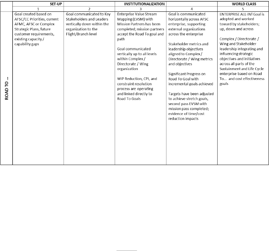
87
5.2. Maturity:
5.2.1. Introduction: Sustainment is essential, but it is only the first step to becoming a world class
organization. Once a unit implements AoP, using the principles described throughout this
handbook, and institutes the necessary standard work to sustain, then a journey begins toward a
true AoP culture. AFSC has devised a way to measure progress along that journey. The Maturity
Matrix was created in an effort to measure the transformational progress towards world-class
performance envisioned by the AFSC. The Maturity Matrix is a measurement tool used by leaders
to add transparency to their organizations. Used at all unit levels down to the squadron and
division, the Maturity Matrix provides a common yardstick to self-assess how well an organization
is implementing the science necessary to reach AoP results for the center. By assessing unit status
for each of the horizontal execution bars on the Radiator Chart, the Maturity Matrix helps provide
a top-to-bottom view from Road to…Goal to process doer level touch time. Using the matrix,
units across AFSC may self-assess using a common standard. The Maturity Matrix establishes a
1 through 5 grading scale for each execution element of the Radiator Chart (each of the eight
horizontal elements). This grading scale defines stages of maturity evolving from initial set-up (1-
2), to institutionalization (3-4), to the ultimate goal of establishing a world-class organization (5).
Shown below is one page of the Maturity Matrix as it relates to one element of the Radiator Chart:
5.2.2. Criteria for assessing the organizational stage of maturity are listed within the matrix
under the respective grading scale level. The verbiage is succinct in nature and creates a well-
defined common language by which organizations within AFSC can grade themselves. The
criteria for moving from 1-5 on the grading scale becomes progressively more difficult to
achieve and drives leaders to reach outside their own organizations for support. This is by
design, and is intended to strengthen and drive additional collaboration within, and even
Road to…. Maturity Matrix

88
outside, of the enterprise. Units must meet all criteria within the respective grading scale level
before assessing themselves with that score.
5.2.3. Leaders utilizing the Maturity Matrix should
thoroughly understand the criteria for each stage of
maturity and transparently assess their organizations
against it. They should also recognize that advancing
through the stages in the matrix will be difficult;
whereas achieving a level 1 or 2 may be fully within
their control, achieving level 3 or beyond may require
enterprise alignment and the commitment of external
stakeholders. Additionally, it is logical that in order to
progress to the next level of maturity, each of the criteria
must be met within the current level.
5.2.4. The criteria verbiage may appear to be subjective, but leaders should be able to describe
and provide evidence of the rating they have chosen. Though presentation requirements may
vary from organization to organization, several constants remain: what is your currently
assessed maturity rating; what evidence supports your assessment and what actions will be
taken to advance to the next level or desired state?
5.2.5. A maturity score reflects the state of the unit’s process machines--a critical self-
awareness of the current maturity level of the process, and how it will evolve toward world
class. Maturity Matrix scores, and associated action plans, are intended to inform unit and
center leadership.
5.2.6. The Maturity Matrix is an excellent tool that, when used honestly, will drive progress
toward a world class operation and the enterprise alignment envisioned by AFSC. A current
version of the Maturity Matrix can be found here:
https://cs2.eis.af.mil/sites/22197/AoP/_layouts/15/WopiFrame.aspx?sourcedoc=/sites/22197/
AoP/SiteCollectionDocuments/Tools/3.%20AoP%20Maturity%20Matrix/Maturity%20Matri
xv2.pptx&action=default

89
Chapter 6
GETTING STARTED
6.1. Step 1: Identify and Define METL. AoP is a constraints-based management system that
uses the science of throughput and principles of flow to improve process speed, quality, safety,
and cost effectiveness. When implemented across the AFSC, it will create a culture that is
focused on the efficient execution of essential processes. Under AoP, processes are defined as
machines that can be set up and calibrated to produce specific, predictable results. Once a
machine is set, it is monitored for performance. AoP should be implemented on the processes
that are critical to an organization successfully accomplishing its mission. Units implementing
AoP must first know their critical processes. For this reason, AFSC has adopted a best practice
of identifying and defining a METL for use across the center.
6.1.1. Previous experience in implementing AoP, particularly in administrative organizations,
has shown there can be significant confusion in identifying an organization’s critical
processes. In most cases, units define far too many tasks as mission critical. This delays
implementation and frustrates the workforce as they try to implement AoP. This section
describes how the use of the METLs can assist unit commanders and directors in identifying
critical processes where AoP should be implemented.
6.1.2. The METL provides the analytical framework to determine the right focus and priority
for implementation across a broad range of functions within an organization. It ensures
standard documentation of essential processes within an organization, determination of
processes not supported by an appropriate regulatory source, and identification of processes
that could be divested or streamlined through simple waste and Resource analysis. Use of
the METL for prioritization of implementation is designed to aid in maturity and
understanding of AoP methodologies, and provide a useful indicator of the overall mission
performance of the organization.
6.1.3. The METL concept is used across all services. Most military organizations have
defined missions and a METL that supports that mission. Chairman of the Joint Chiefs of
Staff Manual (CJCSM) 3500.04F defines an essential task as “Tasks based on mission
analysis and approved by the commander that are absolutely necessary, indispensable, or
critical to the success of a mission.” A unit’s METL is a complete list of all such tasks for the
unit. The use of the terms MET and METL in AoP are not operational terms. They are used
to assist the unit in finding its most important processes and are used only as the starting point
for AoP implementation.
6.1.3.1. METLs should align within the squadron and group to the wing/complex
strategic goals and objectives. AoP should then be seen as the enabler to
rationalize, define and align the right METLs that directly support AFSC, AFMC
and AF vision, mission, and strategic goals and objective.
6.1.4. AFSC/CC’s direction to implement AoP across the center applies to critical processes
down to the squadron/division level. Critical processes are those that are essential to the

90
successful execution of a unit’s mission. The unit mission can be thought of as the reason for
the unit’s existence. This reason must be considered from the customer’s perspective.
Critical processes are those that create outputs upon which the unit’s customers are
depending.
6.1.5. The following points are meant to assist a commander/director in reviewing or defining
a unit’s METL:
6.1.5.1. Review the squadron/division mission statement and identify and prioritize
specified and implied tasks. Specified tasks are those tasks explicitly stated in the
mission, by the next higher commander, or by law or regulation. Implied tasks are actions
or activities not specifically stated but which must be accomplished to successfully
complete the mission.
6.1.5.2. From the list of specified and implied tasks, identify essential tasks. The criteria
of essentiality are whether the unit mission can be accomplished without the task being
performed to the standard.
6.1.5.3. For service and staff organizations, apply the essentiality criteria from the unit’s
customer’s perspective. Care and feeding type functions (i.e. time sheet approval, leave
request approval, TDY voucher approval etc.) that do not deliver value to a customer are
not essential tasks.
6.1.5.4. Specified tasks directed in the mission statement or by the next higher commander
are normally mission essential.
6.1.5.5. Tasks providing support to other organizations, particularly organizations
delivering goods or services directly to the center’s customers, are normally mission
essential.
6.1.5.6. Most unit METLs will contain 10 or fewer essential tasks. If you have fewer than
five or more than 10, you should consult with your AoP SME.
6.1.5.7. Each AFSC unit down to the squadron/division level, should develop a METL
and “get in the struggle” by simply picking an essential task upon which to implement
AoP. AoP SMEs are available to provide mentoring and coaching of AoP fundamentals
such as establishing flow and assisting units with their internal machines.
6.2. Step 2: Select One Task for AoP Implementation. Analyze and prioritize METL tasks
for impact and complexity. Select one METL task per squadron or division for initial AoP
implementation. For the initial selection, choose ease of implementation over mission impact in
order to learn and apply basic techniques. Get an AoP SME to review the METL with you and
provide recommendations and assistance. Finally, build an implementation plan for the
remaining METL tasks that are listed. The burn-down plan should show when each organization
intends to have AoP implemented on all METL tasks.
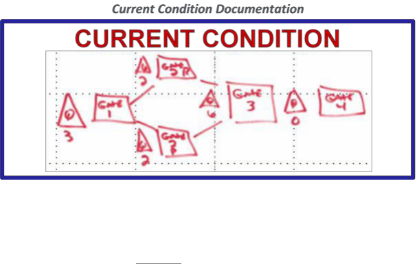
91
6.3. Step 3: Set Up the Machine. Use the Radiator Chart to build a process machine for the
selected METL task.
6.3.1. Determine the Road to…Goal for the Machine (sect. 3.2.).
6.3.1.1. What is the customer requirement?
6.3.1.2. Understand the target condition (future state) of the process machine.
6.3.1.3. What result does the process machine need to produce?
6.3.1.4. What are the throughput requirements of the machine?
6.3.1.5. Conduct horizontal integration (sect. 4.2.2.1.2,.).
6.3.2. Define the Flow of the Machine Process (sect. 3.3.).
6.3.2.1. What is the work sequence?
6.3.2.1.1. Define the Critical Path/Critical Chain.
6.3.2.1.1.1. List the steps.
6.3.2.1.1.2. Estimate the durations.
6.3.2.1.1.3. Capture dependencies.
6.3.2.1.1.4. Define the milestones.
6.3.2.1.2. Observe the process.
6.3.2.1.2.1. Go see the work in action at the place where the value is created.
6.3.2.1.2.2. Your eyes do not lie, your ears will.

92
6.3.2.1.3. Draw out the process. It does not have to be pretty. Capture the WIP levels
and locations.
6.3.3. Establish Gates (sect. 3.4.).
6.3.3.1. Break complex processes down into smaller groups of work.
6.3.3.2. Define the WIP for each gate.
6.3.3.2.1. Calculate WIP using Little’s Law (sect. 3.3.3.3.1.1.).
6.3.4. Define the Release Points (sect. 3.5).
6.3.4.1. Define the criteria for releasing work from one gate to the next.
6.3.4.2. Establish the business rules for controlling the release of work.
6.3.4.3. Create A to Z checklists to document all work was completed and conditions
were met for release.
6.3.5. Establish Visual Displays (sect. 3.6.).
6.3.5.1. Create meaningful, process doer-focused, visual displays depicting the relevant
portion of the process.
6.3.5.2. Ensure visual displays communicate speed, safety, quality and cost metrics (as
applicable) as well as process status.
6.3.5.3. Ensure visual displays provide an opportunity to capture process issues.
6.3.6 Apply the Rules of Flow (sect. 3.3.3.3.).
6.3.6.1. Control WIP.
6.3.6.2. Release only supportable work.
6.3.6.3. Assign work according to a synchronized plan.
6.3.6.4. Practice quick issue resolution.
6.4. Step 4: Manage the Machine. (Chapter 4)
6.4.1. Operational Management (sect. 4.2.2.2.).
6.4.1.1. Wall Walks (sect. 4.2.2.2.1.).

93
6.4.1.1.1. Visual representation of the machine.
6.4.1.1.2. Monitor WIP levels.
6.4.1.1.3. Monitor gate performance.
6.4.1.1.4. Identify and resolve constraints.
6.4.2. Tactical Management (sect. 4.2.2.3.).
6.4.2.1. Daily meetings.
6.4.2.2. Daily work assignments.
6.4.2.3. Quick issue resolution.
6.5. Step 5: Mature the Organization.
6.5.1. Complete implementation of the Radiator Chart (sect. 3.7-3.9.).
6.5.2. Mature the standard work (sect. 5.1.1.).
6.5.3. Develop leaders who believe and practice AoP (sect. 5.1.2.).

94
Chapter 7
Conclusion
7.1. The AFSC is a $16B enterprise – it is big business. This business is not rocket science, but it
is complex – it is an intertwined, complicated machine with a lot of moving parts. “Seat of your
pants” management techniques will not lead to success. Success cannot be personality driven,
meaning that it cannot rest in the skills of one individual. Leadership and success must be tied to
a methodology and focused on processes. Leaders move and rotate to different assignments;
therefore success cannot be sustained if there is not a systematic approach to managing the
machine.
7.2. Although disciplined processes are the foundation to AoP, it does not lessen the necessity for
fully engaged leadership. Leaders at every level of the organization must voluntarily take
accountability for the principles of AoP. They must empower their people with dynamic processes
and needed resources to achieve the mission. They must embrace the “need for speed” while
ensuring quality, safety and cost effectiveness are never compromised. The common goals must
be understood, embraced, and communicated to all within the leader’s scope of influence. Good
leaders will not only be engaged in the intentional management of the machine, but will develop
other leaders that will carry on the mission when they are no longer around.
7.3. Every organization must develop well designed machines that follow the integrated
components of the management system depicted by the Radiator Chart. The machines must have
a predictable output and must be measurable through every step of the process. These machines
must be managed with a sense of urgency that demonstrates a “minutes matter” mentality.
Strategic management must ensure targets are set for success of the customer and the organization
far into the future through challenging Road to…Goals that are horizontally integrated throughout
the enterprise. Every machine must be operationally managed to ensure the processes are in place,
effective, and followed to ensure sustainment and continuous improvement. And all units of work
must be tactically managed to ensure continuous movement through the machine resulting in real-
time, rapid resolution of issues affecting the movement of daily work.
7.4. The AFSC must create a culture of believers. This starts with setting the vision for the future,
and backing up that vision by focusing on well-defined processes and continually improving to
allow organizations to efficiently obtain that vision. Believe in the vision. Believe in the value of
the AFSC people. Believe in the need to focus on processes. Believe in the power of involving
the enterprise. Believe in the AFSC Way.
7.5. However, belief by itself is not enough. Belief without action does not equate to success.
Leaders must take personal accountability for putting the contents of this handbook into action.
They must personally practice the principles presented so that belief is transferred to Skill and
repetition of skill becomes habit. True Art of the Possible will only be achieved when its principles
become habit for everyone in the command!

95
APPENDIX A – CASE STUDIES
A.1. AFSC Logistics Directorate’s Performance Management Division (LZZ) Non-Technical
Special Projects
A.1.1. Mission Overview. AFSC/LZZ is a staff organization that provides AFSC with
executive level decision support through performance assessments, metrics development and
reporting, facilitating decision making forums, and executing special projects. Its work is
administrative in nature and its products include written reports, briefings, position papers,
center level procedures, and center level meeting facilitation. AFSC/LZZ’s customers are Air
Force leaders at the center, complex, wing, and center staff levels. Some products are reported
up to AFMC/CC and Headquarters Air Force (HAF). When AFSC/LZZ embarked on
implementing AoP, division leadership reviewed its specified and implied tasks in order to
define its METL. The AFSC/LZZ METL is made up of six METs. These are:
A.1.1.1. Administration – Workflow, SOCCERs, and Action Officer (AO) Management.
A.1.1.2. Non-Technical Special Projects.
A.1.1.3. Recurring Center-Level Reviews.
A.1.1.4. Tool Development.
A.1.1.5. Metric & Data Reporting.
A.1.1.6. Analysis & Studies.
A.1.2. Non-Technical Special Projects. One of the primary tasks AFSC/LZZ performs for the
center is executing enterprise level projects. These projects frequently originate as directives,
questions, or taskings from leadership at the LG or center level. One unique aspect of these
projects is they generally will not be repeated. They are typically special one-time efforts to
establish or implement a new capability. AFSC Strategic Objective 7.1, to “institutionalize
Art of the Possible across the AFSC to achieve the right results the right way,” is one such
example. It is a special project directed by AFSC/CC. Once complete, it will not be executed
again.
A.1.2.1. Case for AoP Implementation. Special projects assigned to AFSC/LZZ vary
widely in size, complexity, and the frequency with which they are assigned. AFSC
Objective 7.1 is an example of a very large and complex project; however most special
projects are shorter in duration and not as complex. There is also no set cadence for how
or when projects are assigned. In addition, customers can vary from peer divisions to
AFSC/CC or higher. In the past, this variability drove focus to the project or task level.
Each project was managed individually and no operational level management occurred to
identify process level problems or constraints that impacted the delivery of special projects
nor was any effort made to prioritize competing projects. Each project was assigned equal

96
importance and all were worked at the same time. This tactical level approach resulted in
the poor utilization of team members with some overtasked and others underutilized. It
drove work on everything but delivery of few things. Firefighting took place on the day’s
hottest project and leaders were frequently dissatisfied with results. These were all
compelling reasons to consider managing this workload differently. Lastly, this process
was responsible for institutionalizing AoP for the center. It clearly had to be able to
demonstrate the very management process it was institutionalizing. In the fall of 2016,
AFSC/LZZ set out to implement AoP on its non-technical special projects workload.
A.1.3. Special Projects Flow. While each special project has a unique implementation
timeline, there are common steps across all special projects. The AFSC/LZZ team faced the
challenge of defining the flow at a level above project uniqueness but low enough to provide
insight into where constraints impacted the delivery of projects. The team started by assessing
all the current special project WIP and the steps required to deliver these projects. The goal
was to identify four to eight steps that are common to all special projects. These steps would
become process machine gates. Four basic steps emerged: project planning, project execution,
project reporting, and project documentation. During this time, AFSC/LZZ had the privilege
of visiting the Air Force Special Operations Command (AFSOC) C-130 line at WR-ALC. One
of the key concepts that team had implemented was a supportability gate, or gate 0, that ensured
workload was supportable prior to being inducted. In a production sense, this meant all the
parts, tools, and data were available for the mechanic before the workload was inducted. While
the gate 0 concept originated in the production world, the concept applied to staff work as well.
The team used this concept to identify the things needed for an AO to begin work on an
assigned project. This led to the identification of one additional special project gate, that of
project definition.
A1.3.1. Gate 1: Project Definition. The first step is to receive the project from the customer
and to define the essential information that will be needed by the AO to execute the project.
Without this information, AOs may deliver the wrong project, answer the wrong question,
or provide it to the wrong stakeholder(s).
A.1.3.1.1. Identify the Lead Stakeholder. This is the leader or customer for whom
AFSC/LZZ is delivering the project. Their approval will be required at key milestones
in the project and they will ultimately decide when a given project is complete.
A.1.3.1.2. Define the Problem. The inventor Charles F. Kettering stated “a problem
well-stated is a problem half-solved” (Charles Kettering Quotes. (n.d.).
BrainyQuote.com)₈. In order to provide a clear understanding of the intent of the
project, the correct problem must be clearly defined. This must define the cause or the
opportunity for change. It must be validated by the lead stakeholder. This is necessary
to ensure the project is addressing the right problem.
A.1.3.1.3. Define the Desired End State. After the problem has been defined a clear
end state should be communicated to ensure the AO understands the vision for what he
or she is to implement. This end state should be defined from the perspective of value
to the lead stakeholder or customer.

97
A.1.3.1.4. Workload Balancing. Before the project is assigned to an AO, the
AFSC/LZZB supervisor must review the currently assigned workload to determine
which AO to assign the project. If there is no open capacity within the team, projects
must be prioritized to ensure the highest priority project is being worked. If necessary,
a lower priority project may need to be pulled back from an AO and put in queue so
the higher priority project can be worked. No work should be done on projects in
queue.
A.1.3.1.5. Release Point: Assign to an AO. The final step of Gate 1 is for AFSC/LZZB
to assign the project to an AO.
A.1.3.2. Gate 2: Project Planning. The AO assumes responsibility for the project at Gate
2: Project Planning. During this gate, the AO develops a detailed plan with milestones and
dates. This should include the key steps of:
A.1.3.2.1. Validating project definition. AOs should meet with all stakeholders
necessary to ensure they understand the problem and desired end state.
A.1.3.2.2. Identifying all project stakeholders. AOs cannot work in a vacuum or even
only with the lead stakeholder. They need to identify and include all impacted
stakeholders or they risk rework and missed milestones.
A.1.3.2.3. Developing a draft Integrated Master Schedule (IMS) or project plan
considering Doctrine, Organization, Training, materiel, Leadership, Personnel,
Facilities, and Policy (DOTmLPF-P). Medium and large projects require a deliberate
plan with carefully considered milestones associated with dates. This plan should
consider whether the project will affect any of the areas of DOTmLPF-P.
A.1.3.2.4. Brief through leadership up to the lead stakeholder for approval. The AO’s
leaders, up to the lead stakeholder, must understand and validate the plan.
A.1.3.2.5. Release Point: Leadership Approval of Plan. When leadership approves the
plan, the project is released from Gate 2 into Gate 3.
A.1.3.3. Gate 3: Project Execution
A.1.3.3.1. Execute according to plan. Once plan approval is gained, the AO should
execute the project according to the plan and work to deliver on schedule.
A.1.3.3.2. Re-plan as necessary. If new requirements or changes occur, the plan may
need to be adjusted or redone.
A.1.3.3.3. Provide status updates through appropriate leadership level. The AO should
keep leadership informed on the progress of the project.

98
A.1.3.3.4. Release Point: All Tasks Complete. Once the plan is complete and all
milestones have been achieved, the project progresses to Gate 4.
A.1.3.4. Gate 4: Reporting
A.1.3.4.1. Report project recommendations, findings, or results through appropriate
leadership. Upon completion of the plan, project results should be reported up to the
lead stakeholder for approval. This can be done via a formal briefing or the staffing of
a package or paper up to leadership.
A.1.3.5.1. Release Point: Gain Leadership Approval. The project is complete when
deemed complete by the lead stakeholder. At that point, it moves to Gate 5.
A.1.3.5. Gate 5: Documenting
A.1.3.5.1. Document project results. The AO should document the products of the
project along with any approval documentation.
A.1.3.5.2. Post/archive project documentation in the appropriate repository. Project
documents should be retained for reference if there are questions or if related
issues/projects arise.
A.1.3.5.3. Close project. Upon archiving all the project documentation the project is
closed.
A.1.3.5.4. Release Point: Branch Approval.
A.1.4. WIP. Individual projects make up the WIP for the special projects machine. WIP is
separated into three tiers based on the complexity of the project. Projected time to completion
is the method used to assess the project as a large, medium, or small project. While this is not
a perfect approach, it allowed the team to get its machine up and running. Additionally, the
branch chief may deviate from this convention based on other circumstances. For example, a
high priority project directed by AFSC/CA that will be of a duration less than a year can be
assessed as a large project due to the high level of direction.
A.1.4.1. Large projects are defined as those that will take more than a year to complete.
A.1.4.2. Medium projects are defined as those that will take more than a month but less
than a year to complete.
A.1.4.3. Small projects are defined as those that will take more than a week but less than a
month to complete.
A.1.5. Constraint Identification. Constraining gates are identified as the gate with the lowest
throughput; however, each project within the special project machine is unique. Each has its
own planned execution time for Gate 3. This means that the throughput required for gate 3
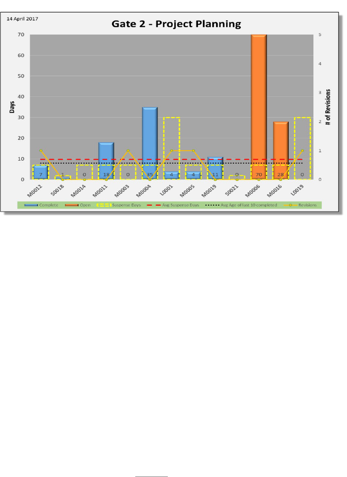
99
changes each time a new project is added or a project is completed. For this reasons, the special
project constraining gate can most easily be identified by identifying the gate that is
accumulating the most queue.
A.1.5.1. Post Implementation Constraint. Immediately following the implementation of the
special projects machine, WIP began to pile up in Gate 2, project planning. Additionally,
gate performance was poor as the planning for most projects exceeded the target
completion time. The figure below shows Gate 2 performance in Apr 2017. At that time,
the average time to complete planning for medium sized projects was 10.7 days, or three
days higher than the target planning time. Four of the last 10 projects to complete gate 2
were late and two of the in work projects far exceeded their target planning time. In
addition, the quality of the plans were not good. Four of the last 10 completed plans had
been redone and one of the projects still in planning was being reworked.
Much of this problem was created by the newness of our approach which included a
deliberate planning process. The team focused on developing quality plans within the
target completion time. Results have come with practice. While the average planning
time remains above the target of seven days for medium projects, the average completion
time for medium projects has been driven down to 7.3 days. Additionally, there have
been no quality problems in the last ten projects that have completed Gate 2.
A.1.5.2. Current Constraint. As of the writing of this case study, Gate 2 performance has
improved but Gate 3 data shows an alarming trend. While nine of the last 10 projects to
complete Gate 3 have done so on time, the open projects reveal a growing problem. See
the figure below.
Special Projects Gate 2: Performance
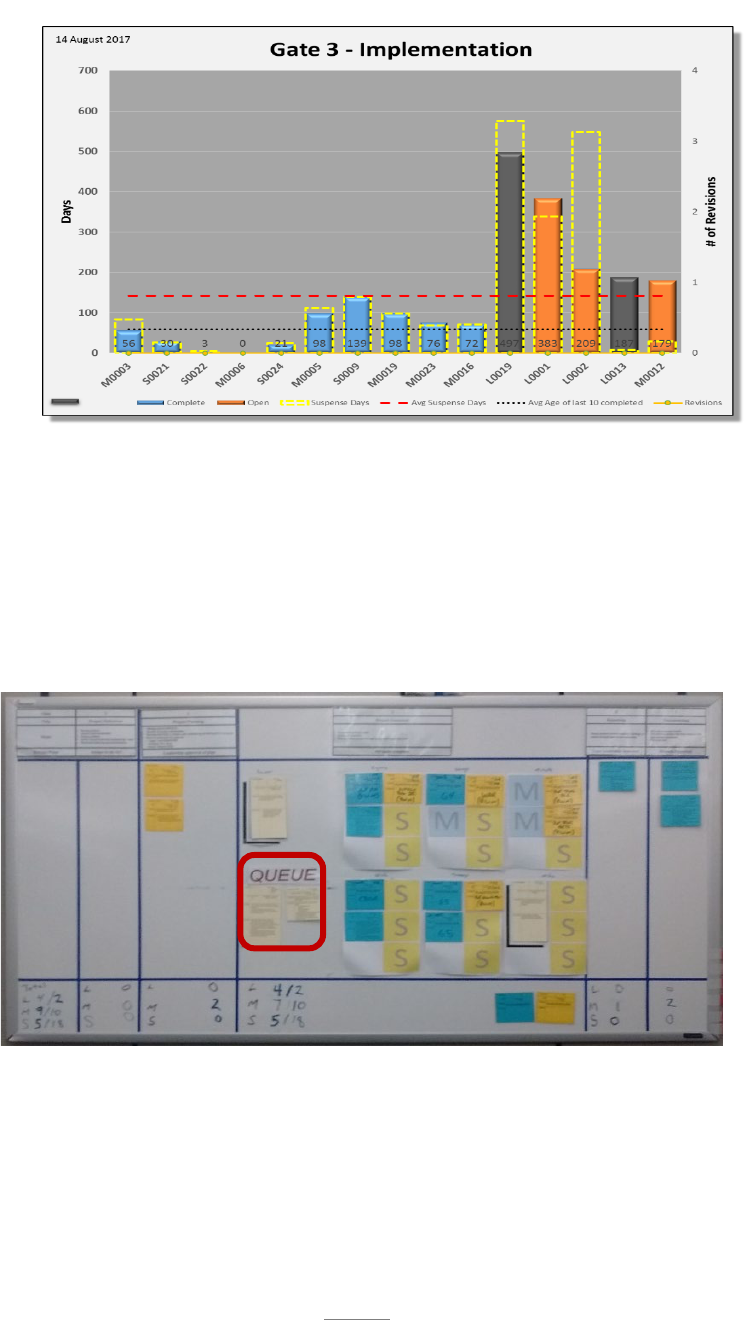
100
Three of the projects have already exceeded their planned time for Gate 3. Four of
the five projects in Gate 3 have been characterized as large projects. This means
they were planned to take over a year in duration or are of a high degree of
complexity or difficulty. These projects require AOs with the skills, ability, and
experience to independently plan, communicate, lead, and execute large projects.
Currently, the team assigns large projects to only two AOs. This results in a queue
of two large projects in front of Gate 3. See below.
The current constraint is the ability to execute large and complex projects.
A.1.6. Constraint Resolution. AoP has served its purpose by identifying the current constraint
in AFSC/LZZ’s ability to execute special projects. The resolution for the current constraint is
not quick and easy. The team is working to develop the necessary skills within its AOs to
execute complex projects, thereby expanding its capacity in this area. Team member roles on
current large projects are expanding as part of the development effort and opportunities are
Large Project: Queue in the Special Projects Machine
Gate 3: Performance
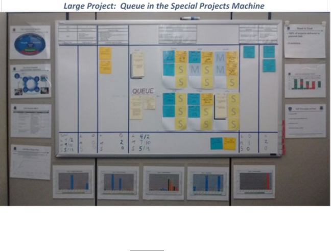
101
being given to develop the needed skills. Additionally, the performance planning process is
being utilized to lay out personal performance and development goals that are in line with
closing the large project constraint.
A.1.6.1. Results. While the constraint remains in Gate 3, AoP has proven successful in
effectively prioritizing and managing workload in a constrained administrative
environment. In Feb 2017, AFSC/LZZ had three AOs capable of taking on large projects
and it was working three large projects (projects A, B, and C) in Gate 3. At that time,
center leadership placed a higher priority on another project (project D) that was rated as a
medium project at the time. The elevation in priority set a very aggressive schedule for
project D—cutting the planned time to completion in half. Due to the accelerated schedule
and the high level of attention to project D, the AFSC/LZZB chief reclassified the project
as a large project and took it to division and directorate leadership for prioritization. Both
the AFSC/LG deputy and the AFSC/LZZ division chief were very familiar with the special
project machine and understood its limited large project capacity. They recognized the
high priority given to project D. Both leaders agreed to pull project C out of Gate 3 and
put it in queue so one of the large project capable AOs could focus exclusively on project
D. As a result, the assigned AO was able to focus on and finish project D by the very
aggressive date. This most certainly would not have been the case without AoP. A likely
scenario is AFSC/LZZ would have been directed to complete project D. Projects A, B,
and C would have remained in work with AOs being overtasked. None of the projects
would be completed on time. Having missed their delivery date, one or more of the projects
would have become a crisis with senior leadership. At that point, staff ‘heroics’ would
have ensued to push to deliver the project with poor results and dissatisfied leaders.
A.1.7. Visual Display. The AFSC/LZZ special projects process machine is set up in a cube
environment on a magnetic dry erase board. It provides the visual displays for the team to
conduct weekly wall walks at 1400 each Monday and tactical management at 1030 on
Tuesdays and Thursdays. The magnetic board portraying flow and WIP of the special projects
machine is surrounded by supporting AoP and performance charts. See the figure below.
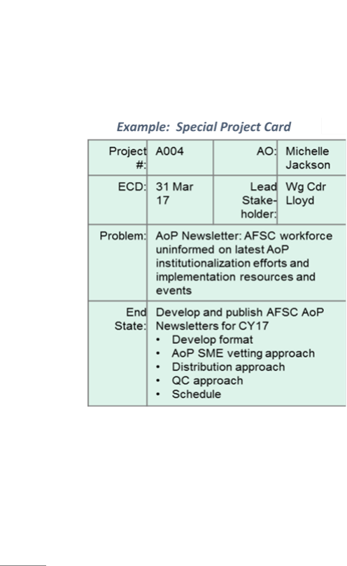
102
A.1.7.1. The surrounding charts are in counter clockwise order from the top left:
A.1.7.1.1. The Leadership Model.
A.1.7.1.2. AoP implementation approach, or the five steps for implementing AoP.
A.1.7.1.3. AFSC/LZZ METL.
A.1.7.1.4. AFSC/LZZ AoP burn down plan.
A.1.7.1.5. Gate performance charts for Gates 1-5.
A.1.7.1.6. Principles of flow.
A.1.7.1.7. Gate time and quality targets assessment chart.
A.1.7.1.8. Road to…Goal.
A.1.7.2. The machine flow and WIP are portrayed on the magnetic board at the center of
the wall.
A.1.7.2.1. Gates are displayed as columns from left to right.
A.1.7.2.2. WIP is displayed as post it note sized magnetic cards that document essential
attributes of the project. See example to the right. As the project progresses from gate
to gate, the project card moves on the board
through the gates.
A.1.7.2.2.1. Large projects are visually
portrayed on 3” x 6” beige cards.
A.1.7.2.2.2. Medium projects are visually
portrayed on 3” x 3” blue cards.
A.1.7.2.2.3. Small projects are visually
portrayed on 3” x 3” yellow cards.
A.1.7.2.3. Employee Capacity Model. One
area where administrative work can be
different from production workload is the
area of manloading and multi-tasking. One
of the four principles of flow is to manload work. This means put all necessary labor
on an item of work with a focus to complete the task. The inverse of this principle is
multi-tasking. Under multi-tasking, an employee diffuses his or her focus across all
available work. Multi-tasking is bad. It is better to focus the employee on a single task
until it is finished. This focus and finish approach minimizes the time needed to
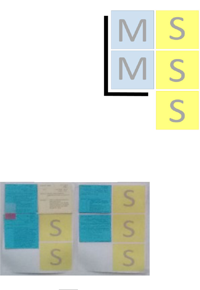
103
generate a single unit of output. Once one project is complete, another is issued to the
employee. The reality of staff work is there are very few projects that can be worked
non-stop for eight hours every work day. Most, if not all, require wait time while
meetings are scheduled, emails are returned, and coordination takes place. For this
reason, it is unrealistic to focus an administrative employee on only one task. There
also is no precise, optimum answer for how many projects should be assigned to an
employee. That optimum answer is dependent on the complexity of the tasks and the
skills and aptitude of the employee. The special projects team addressed this question
by developing an Employee Capacity Model to represent the work capacity of a GS-
13. This model is not perfect but is good enough to make the machine functional. It
sets a usable framework for loading AOs with projects. Under this framework, at any
point in time an AO may be assigned up to three small projects and either two medium
projects or one large project. As projects are
assigned, the project cards are placed over an
available spot of corresponding size on the
employee’s model. Large projects use a card
that covers both medium spaces on the
employee’s model visually reinforcing the two
mediums or one large rule. This approach
reinforces two principles of flow. First, WIP is
controlled by limiting how much each
employee can work at any point in time.
Second, manloading is achieved by keeping
employees focused on a limited number of
projects. When they complete a project, another
can be issued from queue. To make the display
practical, the model is only displayed under
Gate 3. When the project is not in Gate 3, a
place holder is placed on the employee’s model
with the project number and a reference to the gate where that project resides. The
actual project card is placed under the gate where it resides.
A.1.7.2.4. Late projects. Projects that are behind schedule have a red tab placed on
them to add emphasis and urgency. An example of two employee models are provided
below.
Example: Special Project Card
Example: Employee Work Loading

104
A.1.8. Next Steps. AoP is never finished. AFSC/LZZ continues to work on its special projects
machine to both resolve its current constraint and to improve the machine itself. Current efforts
include:
A.1.8.1. Continuing to develop AOs in order to increase large project capacity.
A.1.8.2. Developing more robust approaches to characterizing large, medium, and small
projects; employee capacity; and target times for each gate, particularly gate 4 when
projects need to be reported through the center command section (data has shown this to
be a highly variable process).
A.1.9. Lessons learned. AFSC/LZZ continues to learn daily from its use of AoP. Several key
lessons stand out as worth sharing across the center.
A.1.9.1. Get started and, if necessary, use guesses to overcome barriers to building a
workable machine. Do not allow the lack of a perfect answer to prevent you from
implementing a workable process machine. There are many imperfect but adequate
guesses that underpin the special projects machine. These include the time standards for
large, medium, and small projects for Gates 1, 2, 4, and 5; as well as the Employee Capacity
Model. These are not mathematically precise models but they work for getting started. As
you learn more, you can modify and improve your guesses. When you get started, best
guesses will allow you to build a machine that is good enough to identify your constraint.
As you improve your process and learn more, you will begin to have data to replace your
guesses.
A.1.9.2. Visit other organizations, similar and dissimilar to yours, that have implemented
AoP. Consider what you may use from their application of AoP. The application of AoP
in three other areas played prominently in the development of the special projects machine.
A.1.9.2.1. AFSOC C-130 line at WR-ALC contributed the concept of supportability
and the need to ensure the employee, whether it be a mechanic or a staff AO, is
adequately equipped to begin work.
A.1.9.2.2. TSP area of WR-ALC contributed the idea of engineers having a set capacity
to work projects. This was used to develop the AFSC/LZZ Employee Capacity Model.
A.1.9.2.3. Contracting area of OO-ALC/OB contributed the idea of using different
standard for different variations of workload. Their machine segregated work into three
tiers based on the dollar value of the contract. Each tier was measured against an
appropriate time standard. This approach provided the flexibility to operationally
manage work with high variability within the same machine.
A.1.9.3. If necessary, define your Road to…Goal last. Do not get hung up on defining a
Road to…Goal before you fully understand your process at an operational level. You may
not know enough to set a goal. Establish flow, identify your WIP, and let the data identify
your constraint. After you utilize your machine for several weeks you should start to

105
understand your baseline performance and should have enough information to set a Road
to…Goal based on speed, quality, and safety.
A.1.9.4. Leadership cannot delegate AoP. The role for leaders who are not building a
machine is different but as important. They must understand and recognize the limitations
of the machines in their organization. They must understand and respect the rules of flow.
When constraints exist, provide prioritization on the sequencing of workload. Expect
problems and issues to be communicated through AoP: What is the constraint? How do
you know? What are we doing to fix it? Observe wall walks and tactical management.
The project D example in 1.6.1. would not have been successful if leaders were not also
practicing AoP.
A.1.10. Contact Information: Scot Doepker, AFSC/LZZB, DSN 674-0092.
Additional case studies are available on the AoP SharePoint site:
https://cs2.eis.af.mil/sites/22197/AoP/SiteCollectionDocuments/Forms/AllItems.aspx?RootF
older=%2Fsites%2F22197%2FAoP%2FSiteCollectionDocuments%2FTools%2F5%2E%2
0AoP%20Case%20Studies%20and%20Success%20Stories&FolderCTID=0x012000DAB3
83134B80214DA2915E65CA1D21A9&View=%7BD14873CF%2DA051%2D4026%2D9BD
B%2D9A133FA658AB%7D
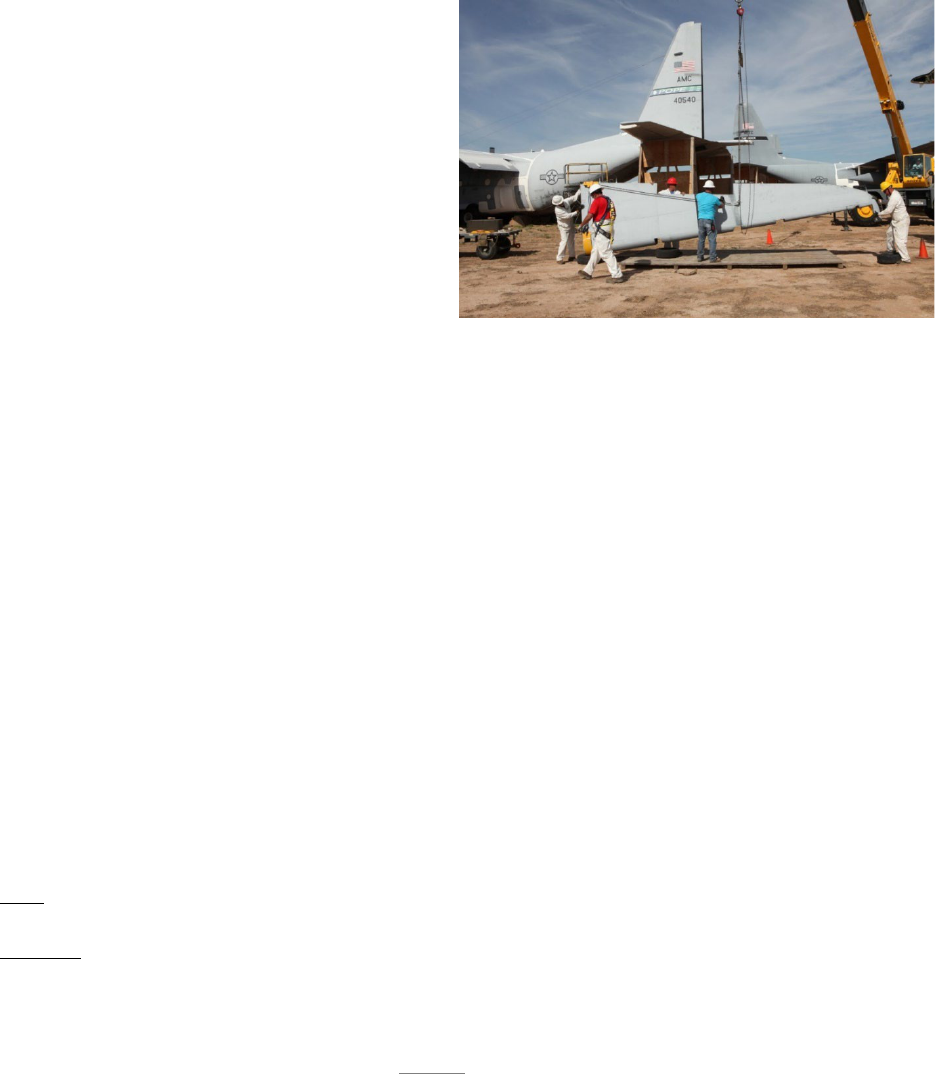
106
APPENDIX A – CASE STUDIES
A.2. Mission Essential Task for Study: 309th Aerospace Maintenance and Regeneration Group
(AMARG) METL: Component Reclamation.
A.2.1. Mission Overview. 309th AMARG is located at Davis-Monthan Air Force Base, Ariz. and
recognized as a one-of-a-kind specialized facility within the Department of Defense (DoD). It’s
also the largest aircraft storage facility in the world and considered a National Airpower Reservoir!
The lack of rainfall and hard caliche-based, high alkaline soil makes AMARG ideal for long-term
storage and reclamation of aerospace assets,
utilizing 2,600 acres of desert to store more
than 3,000 aerospace vehicles, 6,000 engines,
and 300,000 production tooling line items.
The 577th Commodities Reclamation
Squadron (CMRS) executes a portion of
AMARG’s mission by removing aircraft parts
for the services and government agencies.
CMRS is often tasked to quickly harvest
critical parts for the AOR, proving its “surge”
capability in response to urgent warfighter
needs.
A.2.1.1. Case for AoP Implementation.
CMRS’ Reclamation Flight was deemed optimal for implementation of Art of the Possible
(AoP) due to its variable workload and environment. Daily part pulls can widely vary from
one to hundreds. Part complexities can be as simple as the removal of a bolt to removal of
an oversized wing. Specialized support equipment, engineering specifications, and 80
Mission Design and Series (MDS) aircraft further affect the highly variable workload.
A.2.2. Flow. The Item Manager (IM) or System Manager (SM) in the Program Office submit
prioritized orders through the AFSC’s supply wings based on customer needs:
Priority 1-3, the highest priority, includes Mission Impaired Capability Awaiting Parts
(MICAP) and Global War on Terror (GWOT) parts request. AMARG’s goal is to ship these
parts to the AOR in 2-3 workdays.
Priority 4-8 and 9-15 are worked in order of precedence, but subject to complexity. The chart
below reflects priority flow days per part (per Air Force Materiel Command Instruction
(AFMCI) 23-111):
AMARG’s priority reclamation is based on three degrees of complexity. The following are
general, examples of each:
Low: An instrument easily removed from a cockpit panel, requiring minimum time to clean,
bench check, package, and ship.
Medium: A structural fitting requiring aircraft jacking or special tools/equipment to effect
removal, but is relatively simple to clean, inspect, package and ship.
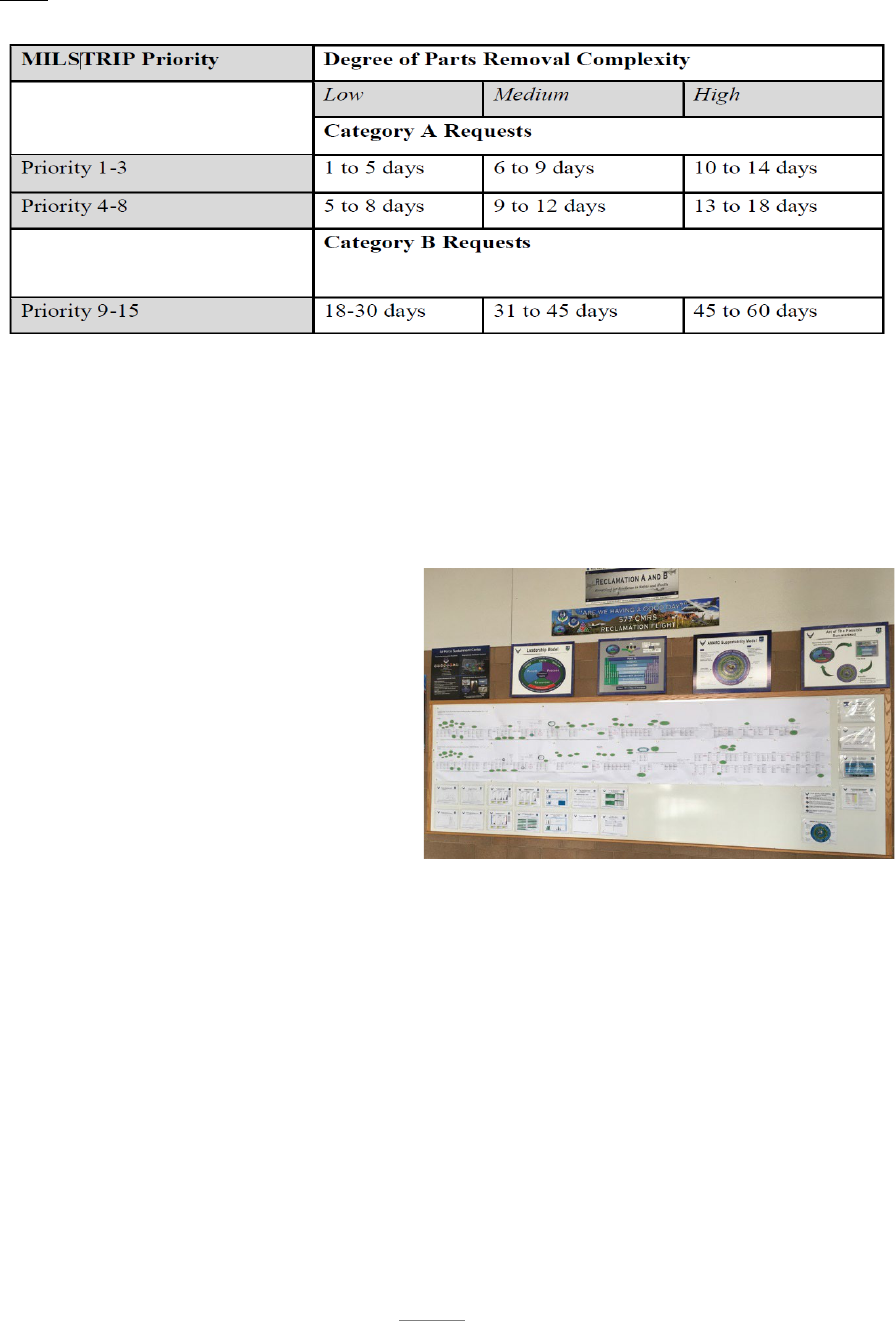
107
High: A wing that requires heavy equipment/ballasts to accomplish the removal, construction
of aircraft support modules and extensive packing and crating work to prepare it for shipment.
A.2.3. WIP and Constraint Identification. Nine process machines were created after assessing
both priority and degrees of complexity, immediately providing a new lens to reveal
challenges. The combination of the Road to…Goal, future state process map, nine-machine
construct and the gate performance charts, provided the Flight with information to prioritize
constraints into Event Driven Plans (EDPs). EDPs were visible at each of the tier levels,
enforcing a level of accountability, urgency, and engagement.
A.2.4. Constraint Resolution. Visual
displays are embraced throughout CMRS,
from color coding to standard work
displays, to Andon stack lights and tier
boards. Tier boards at each level are used
for wall walks and tactical management.
The squadron level tier 3 board is less
tactical but strategic. The flight board is
the tier 2 board (see figure). Tier 1 boards
are at the employee and supervisor level.
Tier 1 boards are employee centric.
Standard cascading metrics are aligned from the tier 1 board through to group level tier 4. All
tier boards convey flow, WIP, gate performance and traits of “having a good day.”
A.2.5. Constraint Resolution. The visual displays work hand-in-hand with the established tier
process. Tier 1 incorporates a quick stand-up meeting approach to review yesterday’s gate
performance, plan for today, look ahead for tomorrow to ensure shop is postured for success,
overall status, escalation of issues, employee ideas/problems and countermeasures, and
communication of relevant information. Daily schedulers and Tier meetings set a strict focus
with effective communication controls between the reclamation crews, scheduling and
supporting shops within the process. The daily battle rhythm provides a 3/5/10 and next-day
look ahead and keeps all shops in-the-know. The combination of visual displays, wall walks
and tier meetings has considerably improved communication effectiveness and created a
common focus within the reclamation flight.

108
AMARG business system changes included color coding customer requests based on priority
level. Additional features included which planner is working a particular request, reducing
assignment delays and prioritization. Programmed thresholds indicated whether CMRS
needed to exercise loans and borrows, or if overtime was needed to quickly expedite customer
requests. Business rules and a management approach were established and standardized,
minimizing variations. Working with reclamation production, release points were set at the
end of the admin gate to minimize false starts due to unavailable resources; i.e., equipment,
tools, slings, missing or unclear requirements.
A proactive scheduling cell was formed to minimize the impact of workload diversity and
variation in work. This includes capitalizing on concurrent operations, scheduling each of the
shops within the reclamation process to their capacity, and implementing a synchronous
representative position that focuses solely on flow. Visual controls were put in place
throughout the reclamation process to trigger schedulers and production personnel of their next
actions.
In reclamation production, business rules such as adjustable work hours were implemented to
minimize the variable work environment impacted by weather. Right-sized AGE sub-pools
were placed strategically in the desert to provide reclamation crews with required equipment,
significantly reducing delays.
Visual controls such as red, blue and grey containers were implemented in the reclamation
processing line. Reclaimed parts are placed in colored bins according to priority levels, a cue
for employees to prioritize processing.
Disruptions in flow prior to packaging and shipping are mitigated by implementation of
standard work and release points after discovering trends of incorrect or missing paperwork
accompanying parts.
A 5-S campaign and process flow improvement were initiated to address a constraint in
packaging and shipping. Excessive WIP, past dues, disorganization, and running out of
packing boxes were addressed through simple visual controls. A Kanban system was
implemented to set standard min/max levels and establish a proactive re-order point.
Andon stack lights were implemented to alert personnel (based on color of light) for help.
Standardized shipping lanes were established based on priority, destination, and shipping type.
A single entry point was established to eliminate extraneous parts from arriving without
paperwork.
A.2.5.1. Results. Implementation of AoP in CMRS provides a foundation for future
success and indicates how it can be applied to benefit unpredictable, high volume, highly
variable workload environments and streamline AMARG’s Component Reclamation
Mission Essential Task (MET), as indicated by the following table reflecting process
improvements from July 2019 through July 2020.
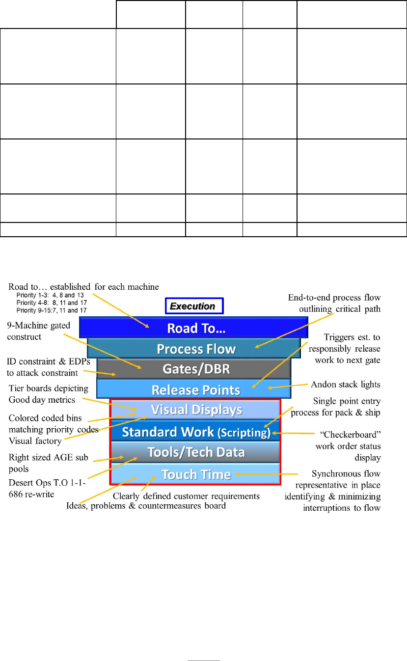
109
July 2019
Road To
Goal
July
2020
Improvement
Priority 1-3 (days)
Simple
9
4
3
67%
Medium
9
8
5
44%
Complex
18
13
10
44%
Priority 4-8 (days)
Simple
39
7
4
90%
Medium
33
11
6
82%
Complex
39
17
17
56%
Priority 9-15 (days)
Simple
62
7
9
85%
Medium
76
11
75
1%
Complex
56
17
14
75%
Lead time
(consolidated)
29
10 66%
Quality Pass Rate
88.3%
95%
99.9%
13%
Summary of initiatives aligned to AoP radiator chart model:
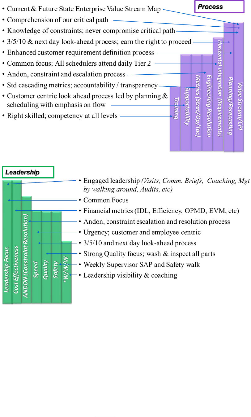
110
A.2.6. Next step. Committed to continuing its AoP journey CMRS will focus next on maturity
of its processes. This includes adhering to business rules, implement implementing an
effective communication and feedback process to further drive a culture of problem solvers
and a CPI mindset. Following these steps will focus on refinement of the tier meeting
effectiveness and visual display boards to clearly convey “are we having a good day?” metrics
and mature how we look at metrics, flow, and constraints. To address agility and meet
customer needs, CMRS is continuing to hone the effectiveness of the 3/5/10 and next day look
ahead process.

111
A.2.7. Lessons learned. The fragility of AoP. An environment for success encompasses the
understanding that sustaining the gains made along the AoP journey requires constant
monitoring and preventative maintenance to prevent slippage.
A.2.8. Contact information: Jose (Joe) Chacon, MXDSM, DSN 228-8496

112
APPENDIX A – CASE STUDIES
A.3. OO-ALC – 583d Missile Maintenance Squadron (MMXS), Rivet MILE Legacy
A.3.1. Mission Overview. The mission of the 583 MMXS is to provide Air Force Global Strike
Command (AFGSC) and Air Force Nuclear Weapons Center (AFNWC) with on-site depot
maintenance in support of the Intercontinental Ballistic Missile (ICBM) missile wings. The
primary purpose of the 583 MMXS is to perform Programmed Depot Maintenance (PDM) of
all Minuteman III (MMIII) Launch Facilities (LF) and Launch Control Centers (LCC) spread
across three states and three different missile wings. The 583 MMXS maintains three
Geographically Separated Units (GSU) to support the missile wings at their location. As the
MMIII weapon system continues to age, the work performed by the 583 MMXS to keep the
LF/LCCs operational is critical to our nation’s defense. The below 583 MMXS METL
communicates the core tasks performed within squadron.
MET 1 – MMIII Launch Facility Programmed Depot Maintenance
MET 2 – MMIII Launch Control Center Programmed Depot Maintenance
A.3.2. MET for Study. The MET identified for this case study is the MMIII Launch Facility
PDM. PDM includes repairing water leaks and associated corrosion, component servicing in
and around the LF, equipment inspections, repair or replacement of Missile Stabilization
System (MSS) components, and repair or replacement of worn hoses and ducts throughout.
A.3.2.1. Case for AoP Implementation. AoP was implemented in the squadron in 2017
with a bottom up approach where each GSU went through a trial and error phase to see
what worked and what didn’t for their location. In 2019 the decision was made to
standardize the process flow across the GSUs using critical chain methodology. The three
GSUs came together at Hill AFB to discuss best practices and map out the flow for PDM.
A.3.3. Flow. Prior to 2019, the PDM process was segmented into three gates with all the on-
site maintenance performed in Gate 2. This approach did not lend well to constraint
identification or true measurement of task performance. The new gated process consists of
seven gates with the on-site time measured over five gates, each having defined task flow
requirements. Gates 1 and 7 capture the production support time between induction and
beginning maintenance as well as from maintenance completion to final sell. Gate 1
improvements have allowed the production support team better control over parts and material
supportability which allows the technicians to have what they need when they need it. The
flow of Gates 2-6 are scripted to maximize manpower and support equipment availability
which has helped significantly reduce overlapping requirements on the minimal available
resources.
A.3.4. WIP. WIP is negotiated with AFGSC a year in advance to reduce impact to nuclear
capability. Ideal WIP is three LFs per wing which means nine LFs in work overall. Each GSU
has three PDM teams and a fourth team that are available to work tasks that are outside the
PDM requirements. The production support team manages WIP very closely to ensure the
Master Production Schedule is accomplished on time.
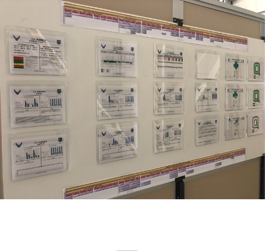
113
A.3.5. Constraint Identification. Constraints are captured throughout the process and trended
to identify the main constraints to the process and weed out the one offs. All members of the
team understand the importance of their role to identify, document, analyze, monitor and bust
constraints. Constraints are discussed during Wall Walks at the individual GSUs and
communicated up to the Squadron when assistance is needed. Due to the age of the weapon
system the largest constraints to LF PDM surround the availability of parts, material and
support equipment necessary to complete all required tasks.
A.3.6. Constraint Resolution. Resolution at the lowest level possible is always the goal. When
this is not possible constraints are elevated through daily tier meetings and Wall Walks at the
GSUs up to the Wall Walk board at the squadron. If a constraint becomes a work stoppage,
the Andon process is utilized to get immediate action. This flow of information has increased
engagement from leadership and enterprise partners to bust constraints.
A.3.6.1. Results. Using CCPM and standardizing the LF PDM process has led to greater
cross talk and sharing of best practices between the three GSUs. Constraints that have been
plaguing the 583 MMXS for years are starting to break free. Enterprise involvement is at
an all-time high.
A.3.7. Visual Display (picture of Wall Walk board).
A.3.8. Next Steps. Further development of the Wall Walk boards and trend analysis at the
squadron level move away from just looking at lagging indicators of what has happened, to
looking for leading indicators of potential constraints.

114
A.3.9. Lessons learned. Consistency is key to constraint identification. Without a standardized
flow it is almost impossible to identify true constraints.
A.3.10. Contact Information: Cade Andersen, 583 MMXS/MXDPH, DSN 586-3570.

115
APPENDIX A – CASE STUDIES
A.4. 523
Electronics Maintenance Squadron (EMXS) RF Shop Production Machine
A.4.1. Mission Overview: The 523
EMXS Mission is to safely and consistently produce high
quality Electronic Avionics and Flight Control products to meet customer and warfighter
requirements on time, at best value.
MET 1: F-16 Radar System Programmed, un-programmed depot level repair and
modification workload with safe, reliable, and defect-free aircraft. The MET supports
MGA 4, Execute the Mission.
MET 2: Planning/Target Development. MET supports MGA 1, Managing Resources.
MET 3: Personnel/Workforce Development. MET supports MGA 2, Leading People.
MET 4: Assets/Parts Acquisition Management. MET supports MGA 1, Managing
Resources.
MET 5: Administrative Controls. MET supports MGA 3, Improving the Unit.
A.4.2. MET for Study. Electronic Component Overhaul and Repair. Specifically, RF Shop,
F-16 Radar System is the identified task for this study. The RF Shop is the sole source of
repair on this workload that directly supports the Air Force and qualifying Foreign Military
Sales (FMS) countries to enable combat ready warfighter for national defense. As of 1 October
2018, the APG 68 antenna had 7460 Mission Incapable, Awaiting Parts (MICAP) hours, 36
MICAP incidents, 43 Backorders (BO) and 1 Delayed Discrepancy Requisition (YBQ). The
Modular Low Power Radio Frequency (MLPRF) had 38 BO’s with 25 missed On Time
Delivery (OTD) shipments.
A.4.2.1. Case for AoP Implementation. With the Mission Capable 80% (MC80) initiative
in place to reach an 80% RO fill rate, the Radar Systems throughput needed to increase to
fill the multiple BOs and reduce WIP. This was being directly affected by
equipment/processes such as the Advanced Intermediate Shop (AIS) test station,
Intermittent Fault Detection Isolation System (IFDIS), and Fire Control Radar Antenna
Test System (FCRATS) Range as well as constraints with Point of Use (POU) and supply
chain processes.
A.4.2.1.1. The crisis or opportunity that drove AoP implementation.
The burning platform of zero BOs. BO burn down plan to reduce MICAP hours, a CPI
event on POU, as well as open communication with supply chain/program office to
increase part availability for the technicians to increase OTD were planned out.
A.4.3. Gates. The RF shop uses a 4 gate flow process consisting of:
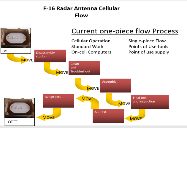
116
Gate 1 Initial: Incoming visual inspection, verification of asset P/N and S/N, and removal of
any access panels.
Gate 2 Repair: Verify test station software/hardware currency, troubleshoot test/repair (IFDIS
testing if require), removal and installation of parts as required, secondary Foreign Object
Damage (FOD) inspection, replace access panels if removed.
Gate 3 Final Test: Final testing procedures completed.
Gate 4 Final Inspect: Final visual inspection, Line Replaceable Unit (LRU) cleaning/painting,
affix proper labels, markings, and final out-processing.
The gates identify how the RF machine flows in regards to time/hours in the shop. The RF
machine as a whole can be seen as a Drum Buffer Rope process beginning and ending with the
Execution and Prioritization Repair Support System (EXPRESS). EXPRESS is a system that
gathers data by using a number of different sources to determine what repairs can and should
be made. The customer forecast or funding requirements along with EXPRESS is the “drum”
of the process and the capacity or “M” switch is the “buffer” that sets the WIP. WIP is
throughput times the flowtime (Littles Law). Where the RF machine is a repair process the
flowtime of an asset can vary opposed to say an overhaul process and can affect the throughput
in each gate. However, an average WIP can be set to ensure there are enough assets throughout
the process to keep the machine moving at a steady pace while EXPRESS maintains this level.
As an asset finishes Gate 4 and is out-processed, that is the signal or “rope” to bring another
asset into the shop at the front of the line for the machine to begin the process again.
Constraints such as parts issues, equipment downtime, and training of technicians all affect the
speed of the machine, so the quicker these constraints are identified and corrected along the
way, the more efficient the machine runs.
A.4.4. WIP. Due to the 50 MLPRF’s that were brought in on the 206 to be tested and used as
serviceable parts the WIP for the shop did increase in October 2018. As the shop worked

117
through the assets and identified Low Noise Assembly (LNA), sample data Circuit Card
Assembly (CCA), and Ribbon Cable Assemblies this enabled the flow of the process machine
to increase throughput and reduces Awaiting Parts (AWP) percentage.
A.4.5. What we did to address the constraint.
By using the five focusing steps of ToC and leaderships adherence on managing resources,
communication, and leading our technicians to improve processes highlighted the true
constraints within the RF machine.
The majority of issues in the RF machine were due to parts availability. Gate 1 was identified
to be the constraint in the machine flow, as identified with the lack of throughput. Parts such
as the 68 LNAs a CCA in the MLPRF that has a 40% replacement factor. Carcass constraint
and parts shortages such as Receiver Protector (RP) and Stalo Assembly sent AWP for parts
constraints, due to sporadic shipments coming from the manufacturer.
The Azimuth and Elevation Compensator and Power Amplifier (Az/EI) has a replacement
factor of 15% on all upgraded antennas. All antennas needing an Az/EI went into AWP for
the entire FY-19 timeframe. There were no repair contracts in place for the Az/EI for all of
CY-18 and CY-19 until the Northrup Grumman contract of five per month began in January
2020. There were 62 antennas in AWP for the Az/EI as of 1 January 2020 when the Northrup
repair contract began.
In an effort to improve a constraint that was preventing the shop from executing the mission
with the 68 APG antenna mechanical modification upgrade kit, a CPI event was initiated. The
RF Point of Use parts usage was not reporting correctly due to a kitting issue. Because the
parts were stock listed as a kit, individual usage was not captured. Essentially, the POU only
had eight items available for use and many additional parts that met the POU criteria and could
be added. The CPI team met with members of DLA and identified what parts of the antenna
met the cost and availability criteria and could be stocked in the RF POU. This CPI event
essentially quadrupled the parts readily available to technicians from 8 to 32.
Constant communications with supply chain, IMs for the MLPRF and antenna due to low NRO
contributed to managing resources. IMs provided EXPRESS over-rides to allow more WIP to
flow into the RF Shop. Due to the Uniphasors contracts long lead times the antenna IM
approved a 206 to induct all F condition antennas to pre-screen and identify all antennas with
serviceable Uniphasors. These Uniphasors had to meet specific criteria such as:
-Having the proper date stamp
-Electronics functioning in serviceable condition
-Passed all air leak check TO specifications.
All antennas that failed to meet these criteria were returned to supply in G condition, so they
would not be put back into supply and stay separated from all F condition assets that had not
been inspected.
The IM for the MLPRF approved a 206 to test and tear down 50 MLPRF’s to be used as donor
parts and alleviate carcass constraints on multiple CCA in the MLPRF. The LNA, Sample
Data CCA, and Back Plane Assembly were at a carcass constraint with 60 total MLPRF’s in

118
AWP until this 206 was fulfilled. IFDIS testing was required to test all 50 MLPRF Ribbon
cables, as there are over a thousand test points on the MLPRF Ribbon Cable Assembly that
could be potentially bad or intermittently faulty. IFDIS can test 1024 test points for intermittent
faults by cooling to - 40 degrees Celsius and heating to + 120 degrees Celsius while vibrating
at a force of up to three G’s.
IFDIS
Uniphasors are a set of four phase shifters that have a replacement factor of 38% on all antenna
repairs. Uniphasors are required when an antenna is upgraded per Time Compliant Technical
Orders (TCTO). Uniphasors were unprocurable during FY-19 and greatly slowed the flow of
the antenna. Uniphasors continue to be a parts constraint due to manufacturing flaws and lack
of availability due to lapse in contracts and manufacturers inability to fulfill shipments. Hurley
Inc. has only fulfilled a quantity of 30 out of a contract for 300 Uniphasors. Hurley Inc.
provided an Estimated Delivery Date (EDD) of July 2020 that just got delayed again until
December 2020.
22 Oct 2018 the RF shop had 49 antenna BOs 3 MICAPs and 3 YBQ’s with an RO Fill
Percentage of 48%. Initiated BO burn down plan, hit the MC-80 goal of 80 % RO Fill % and
zero BOs and zero MICAPs in April 2019. By June 2019 the RF shop exceeded the MC-80
requirements with zero antenna BOs and 118% RO fill percentage.
A.4.6. Results. The RF Shop sold 337 antennas of the 355 Master Production Schedule (MPS)
planned antennas for FY-19 with an OTD of 95 % and a 95% Actual MPS shipment rate for
the antenna workload. The RF Shop sold 409 MLPRF’s of the 355 MPS planned MLPRF’s
for FY-19 with an OTD of 96 % and a 96% Actual MPS shipment rate for the MLPRF
workload.
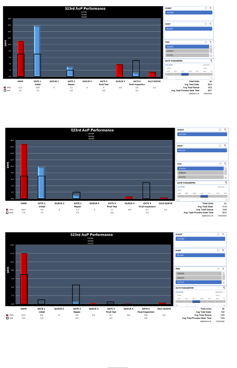
119
A.4.7. Visual Display.
Gate Chart: A gated process developed for all WCD in the 523. The antenna and MLPRF were
the first assets to receive the newly developed gated WCD’s and were used as a sample to track
the gate times as well as increases/decreases in shop WIP and flow time.
For the antenna Gate 1 completion time decreased from 15.8 to 9.9 hours. Gate 2 similarly
decreased from 3.2 to just 1.3 hours. Gate 4 Queue time dropped significantly as did Gate 4
as a whole.
For the MLPRF Awaiting Maintenance (AWM) time dropped almost in half from 23.6 to 12.1
hours. Gate 1 stayed relatively the same while Queue 2 time dropped to zero. Gate 2, through
the end of the process stayed relatively the same.
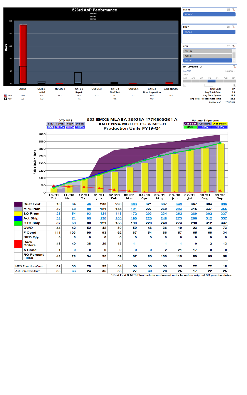
120
Antenna OTD FY-19
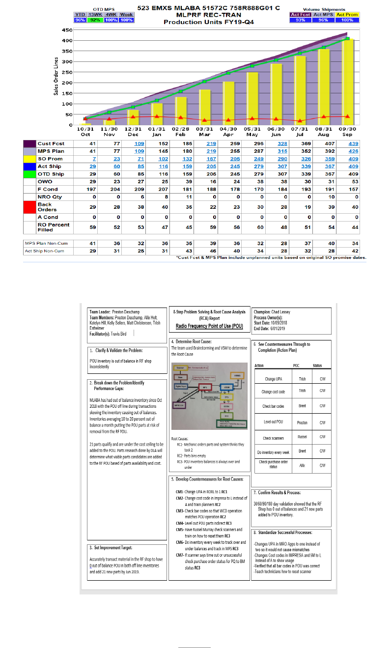
121
MLPRF OTD FY-19
A3’s: Below is the A-3 for the CPI Event for the RF POU.

122
A.4.8. Next Steps. Uniphasors will be a game changer when they are received/approved. The
Receiver Protector (RP) contract (Herley Inc) is for 10 per month and started in December
2019 A contract with Northrup Grumman for the AZ/EI Power Compensator was implemented
for a quantity of five per month starting 1 January 2020.
It was clear that without parts to repair the antenna and MLPRF the RF machine was not going
to successfully reach the Road to…Goal of zero BOs. Effective communication with supply
chain along with the 206’s allowed the bottlenecks of the process to resume, improving speed
of the shop. Cross training technicians to perform more phases of the F-16 Radar system. The
RF shop had 11 people and due to effective production hours flexed up to 13 as of 1 January
2019.
A.4.9. Contact Information: For more information on this case study, please contact: Tarra
Heywood, 523 EMXS, DSN 586-6389, Jeff Cummings, 523 EMXS, DSN 777-1774 or Kelly
Sellers, 523 EMXS, DSN 586-3810.

123
APPENDIX A – CASE STUDIES
A.5. 309 CMXG F-35 Canopy Machine.
A.5.1. MET for Study: For this study, the F-35 Canopy Machine supports 309 CMXG Mission
Essential Task which is to provide overhaul and repair supporting the DoD Supply Chain. The
machines purpose is to induct unserviceable F-35 canopies, disassemble them into their sub-
components, repair or replace any damages found, re-assemble the canopy, test the final
assembly, and return it to the DoD supply chain. In the case of the F-35, the final customer is
multiple US military service branches and partner nations who utilize the F-35 platform.
A.5.2. Case for AoP Implementation: OO-ALC/309 CMXG was chosen as the first organic
repair capability for the F-35 canopy partnering with the Joint Program Office (JPO) and
Lockheed Martin. AoP Implementation was chosen out of absolute need. MICAPs from field
units began to rise due to shorter than expected performance life and the canopy manufacturer
was unable to increase production to keep up with the demand from the field and active
production line simultaneously. Additionally, the shop wasn’t producing canopies at a
consistent rate, leading to longer than expected flow days and sporadic deliveries.
Compounding these issues is the looming future requirement of roughly 3.5 times more
canopies than currently overhauled and repaired as the F-35 shifts into sustainment.
A.5.3. Flow: Asset flow was developed using a process review team which value stream
mapped with enterprise partners and outlined all critical processes and support resources
needed at each step. The team identified the future customer requirement and established flow
by sequencing the process steps along the critical path. The next step was to identify WIP and
where the WIP should be located in the machine’s processes. Gates were defined using takt
time and natural break points in the overhaul and repair process. There are 5 gates which
include Gate 1 - Induction/Disassembly, Gate 2 - Assembly/Buildup, Gate 3 - Test, Gate 4 -
Final Inspection/Finishes, and Gate 5 - Crate/Sell.
Challenges and lessons learned were (1) fully understanding what process steps would be
linear/concurrent throughout the machine flow. (2) How to control WIP & release control. (3)
Only assigning work based on the synchronized plan. (4) Resolving constraints QUICKLY!
A.5.4. WIP: Products that flow through the machine are three different configurations of F-35
canopies which include Conventional Takeoff and Landing (CTOL), Conventional Takeoff
and Landing Carrier Variant (CTOL/CV), and Short Takeoff Vertical Landing (STOVL).
Work in progress was determined using a takt time release, fully understanding the customer
requirement, available work hours, and gate timelines/release points which drove the team to
fully understand the sum of the cycle time per gate divided by the takt time release = staggered
WIP per gate.
Challenges and lessons learned were (1) maintaining the staggered WIP in each gate to takt
time. (2) Releasing work to takt time and working to the synchronized critical path.
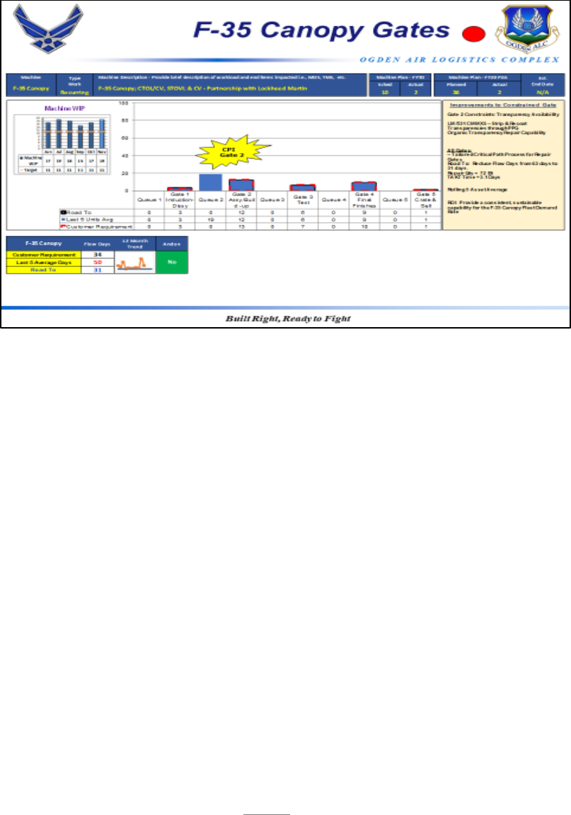
124
A5.5. Constraint Identification: As with anything in AoP, once the process has been mapped,
gated constraints are easy to identify. Simply look for the bottlenecks, trended gate
performance and WIP/Queue. In the case of our machine, the constraint was clearly evident
in Queue/WIP prior to Gate 2, Assembly/Buildup. The reason for the constraint was there
were not enough canopy transparencies being provided by the supplier to keep the machine
running and assets could not be assembled due to the part constraint.
Challenges and Lessons learned were (1) trend data of gate performance early in the machine
stand up. (2) WIP management. (3) The team developed a better understanding of not only
current constraints but also predicting what constraints lie ahead – Maturity of team increased
by using the constraint based management system!
A.5.6. Constraint Resolution: Once identified, the enterprise team used the ToC focusing steps
of (1) identifying the constraint – Gate 2 Queue. (2) Exploiting the constraint – In this case,
exploiting, subordinating, and expanding the constraint enabled stake holders to identify a
second source of repair for the transparency strip & recoat process during the Gate 1 process
step. During this step, the transparency was removed and provided to another vendor creating
a pull system from the vendor back to the machine.
This constraint couldn’t be solved by the shop alone. It also required program office
personnel to work with the government partnered suppliers and focusing on increasing
canopy production and ensure timely deliveries of transparencies.
A.5.6.1. Results: The Road to…Goal was to meet a 30 day flow time.
Short Term - The results of the needed transparencies arriving from the multiple sources
on time, drove the F-35 Canopy Process Machine total flow days from 63 day to 31 days.
This enabled the depot to meet the field’s canopy supply needs.
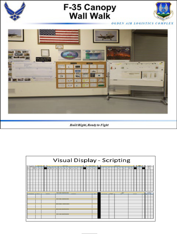
125
Long Term results was a true indicator of machine processing time that allows for the
standup of duplicate machines to meet the 3.5X increase of future requirements.
A.5.7. Visual Display: The F-35 Canopy Wall Walk depicts the operational level machine
performance to include process mapping, trending gate performance and tactical level daily
scripting using magnets to define WIP and progress.
Visual displays also show speed, safety, and quality measures for the overall machine and even
at the tactical level for each configuration on F-35 canopy.
Visual display of the CPI activity are included to communicate to all stakeholders on
constraints and constraint resolution with get well dates.
Visual Display of the daily scripting by gate – magnets are used and moved daily to show
progress, WIP (upper portion) and gate constraints and resolution are depicted on the lower
portion.

126
A.5.8. Next Steps: The next steps for the F-35 Canopy Operational Machine is to continue to
use AoP to identify process health. Additionally, as the F-35 shifts more from production to
sustainment, the shop will be able to accurately identify what resources and quantities of
those resources it needs to increase production.
A.5.9. Lessons learned: AoP is an amazing management tool that takes all of the guesswork
out of process problem solving. You can quickly identify where bottlenecks in the process
are even if you aren’t familiar with the process.
A.5.10. Contact Information: Capt Garrick Warren, 531 CMMXS/DO, DSN 586-1929

127
APPENDIX A – CASE STUDIES
A.6. 76 SWEG Mission Planning
A.6.1. MET for Study. The MET identified for this case study is the 76 SWEG MET to provide
best value software and hardware engineering solutions. Specifically, the B-52 Mission
Planning (MP) software development project will be discussed. MP software is used
operationally for flight planning, enhanced route editing, weapon planning, generation of
combat mission folder materials and avionics flight software and mission data transfer to a
Data Transfer Cartridge (DTC). The purpose of this project is to ensure the software is
designed, developed, tested, and delivered to operational users.
A.6.1.1. Case for AoP Implementation. The B-52 MP software development project was
selected for AoP implementation due to the complexity involved throughout the software
development lifecycle, and the number of external stakeholders involved. The MP
enterprise has a high number of stakeholders due to the many individual components which
are all integrated into a single Mission Planning Environment (MPE) release. For the B-
52 MP team, there are over 30 components requiring integration, with many of these
components being developed by different organizations. This makes communication
between the B-52 MP team and other organizations crucial to ensure timely integration and
minimal schedule delays. One organization’s schedule delay or a communication failure
between stakeholders for an interface change has the potential to significantly impact
scheduled releases, ultimately delaying needed capabilities to the warfighter. As well,
unlike many AoP implementations, software development work is unique every time. In
spite of that uniqueness, AoP, when combined with Agile and DevSecOps methodologies,
provided an opportunity for the B-52 MP team to improve their software development
processes resulting in quicker software deliveries to the warfighter.
A.6.2. Flow. The process flow for the B-52 MP project came from the Agile software
development methodology already used by the team. In Agile, work moves, in order, through
the following phases:
• New – Work has been identified.
o In this phase, work will be broken down into smaller, more manageable pieces.
• In Progress – The work has been broken down and is in development.
o In this phase, the design and development work will take place.
• In Review – The work is ready for others to review.
o In this phase, other members of the software development team will review the
quality of the work which was done.
• Ready For Test – The work has been reviewed and is ready to be tested.
o In this phase, the work will be tested to ensure it operates as a user would expect it
to.
• Done – The work has been completed.
These phases of work were identified as the gates for the B-52 MP project. In Agile software
development, work is broken down from high level requirements into individual units of work.
For the B-52 MP team, this breakdown of work goes from a Requirement to Features to Product

128
Backlog Items (PBIs) to Tasks. Through experimentation, the B-52 MP team has found that
the most beneficial way to track their work was at the PBI level. PBIs are the level of work a
team expects to complete each Sprint and are tracked through the previously discussed gates.
For the B-52 MP team, this means a PBI was an amount of work expected to be completed in
under two weeks. Above the PBI level, there was not enough insight into the status of the
work and the states were constant for too long to be useful. On the other side, below the PBI
level, items were changing too rapidly to be useful. Tracking of their PBIs allowed the teams
to see work moving through the process and quickly identify their constraints. This breakdown
also helped to resolve some of the complexities involved with software development. By
having more manageable units of work, developers were able to focus on making small,
incremental software changes which would build up the overall software.
A second benefit as a result of the team’s analysis of their workflow was the ability to more
easily identify work waiting on external stakeholders. When the team had work which could
not begin until an external dependency was resolved, they created a new piece of work to be
tracked as an external issue. Looking at those items individually gave the team the ability to
demonstrate how long an issue had been active and the impact it was having on development
to external developers.
A.6.3. WIP. For the B-52 MP Agile software development team, WIP is defined as the items
within the In Progress, In Review, or Ready For Test (RFT) gates discussed previously. This
means that when discussing WIP, only PBIs are considered.
The team opted to incorporate WIP management by implementing WIP limits within their
teams. Their WIP was limited to one PBI in progress per developer at a time. This ensured
the team did not overload their process and would be able to complete more of their items
during their two-week sprints. Developers were not prevented from pulling additional work
within a Sprint, so long as they had completed their first PBI before beginning work on another.
A.6.4. Constraint Identification. Through the tracking of their flow and WIP, teams within the
B-52 MP development project began identifying ways to improve touch time on developing
the actual software. Some of the constraints the team identified include:
• Time spent updating developer machines.
o The team noticed every time a machine required an update, every developer and
tester on the project would be unable to work for at least half a day. Across the 40
engineers and scientists on the project, that amounted to over 20 days’ worth of lost
productivity, not including the three to four days it took another developer to set up
and test the new development environment.
o This constraint was made apparent by tracking the team’s WIP. When upgrades
and patches were required, all WIP would be stagnant while the developers were
performing the updates. This would occur multiple times during the team’s
development cycle, which made it apparent this was a constraint which would need
to be addressed.
• Time spent running test cases on software builds which were not working.
o The testing team found that often they would waste time creating an installer,
updating a machine, and running tests on a build which was fundamentally broken.

129
This resulted in the testers taking several hours to build the machine, only to find
out they needed to go back to the developer to fix an issue. The issue would be
compounded, as often a developer would begin work on another PBI while waiting
for testing to be completed. This resulted in inefficient multitasking, as developers
would have to go back to previous tasks and mentally re-engage in the previous
task after an issue was found.
o This constraint was identified by observing the flow of WIP. Each time a build was
found to be broken, the associated PBI was moved from Ready to Test back to In
Progress. By tracking the number of times items which required rework after being
marked ready for testing, the team was able to see the need to address the high
number of broken software builds.
• Time spent running various quality assurance tools.
o Every time a developer checked in code to be integrated with the main set of
software, multiple tools were required to be run on the new software to ensure it
meets quality standards. The team found they were being unproductive while
waiting for tools (such as Fortify Static Code Analysis or Unit Tests) to be
completed. This problem was compounded when multiple software tools required
running. If a developer was not paying attention, it was easy for software to be
ready for the next step and to be forgotten, resulting in even longer delays.
o This constraint was identified based on reviewing the cycle time for the In Review
gate and analyzing the time WIP was waiting for quality tools to be run.
• Time spent waiting for software to be reviewed.
o Part of the process for software development is to have team members review
software which was written, before it can begin testing. After a developer checked
in code, they would often have to wait several days before enough of their team had
reviewed the new code. Similar to the issue with testing that was identified above,
developers would often begin working on other tasks while waiting for teammates
to review their code. Inefficient multitasking would occur when a developer had
to stop work on a new task to revisit an issue in previously written code.
o Similar to above, this constraint was identified by looking at WIP buildup in the In
Review gate. Analysis of the time it took between when code was ready to be
reviewed and when other developers commented and approved the changes showed
a high amount of lag for most items in the In Review gate.
Between these four constraints, along with several others which were identified, the developers
were spending a significant amount of time manually doing administrative or non-value added
work, as well as engaging in inefficient multitasking.
A.6.5. Constraint Resolution.
• Time spent updating developer machines.
o This first constraint was resolved using Virtual Machines (VMs) as their
development environment. The team utilized tools available to create checkpoints
during the VM creation process which allowed for quicker updates and patching.
This lowered the time needed to create a new development environment from two
to three days, to around one day, on average. In addition, by utilizing VMs,
developers were able to update in a significantly shorter amount of time, typically

130
around one hour, rather than 6. This time savings came from the ease of updating
and quicker download times associated with using the VMs.
o Across all developers, resolving this constraint gave approximately 22 days’ worth
of available touch time back to the team, each time an update was required.
• Time spent running test cases on software builds which were not working.
o The solution to this constraint required multiple improvement events. First, the
team identified a need for automated user interface testing. A software tool was
purchased which could exercise the user interface of the MP software and identify
common issues which would indicate a build was not going to be successful. The
team developed automated tests which would create a basic B-52 route and add
common weapon drops within the MP software. Through doing this, the tool could
alert a developer when a build did not pass the tests, indicating it was a bad build
which needed to be updated.
o The second step to resolving the constraint was to get the automated tests to run as
part of the software build process, without intervention from a developer. This
required integrating the automated tests into the software build pipeline, by creating
a virtual machine, installing that machine on a remote computer, and then running
the automated tests. By conducting each of these steps, a developer would be
notified shortly after checking in code whether they had introduced a bug that was
causing the software to break.
• Time spent running various quality assurance tools.
o This constraint was resolved similar to the previous constraint. Updates were made
to the build pipeline so that each required software quality tool would run
automatically as soon as a developer checked in their code.
o By integrating the quality tools directly into the build pipeline, developers received
much quicker feedback on the quality of their code. This helped to prevent the
issues found where a developer’s code would have issues that were not found for
hours to days after they had checked it in.
• Time spent waiting for software to be reviewed.
o The solution for this constraint was much simpler than the other identified
constraints. The team found the main cause of code waiting to be reviewed was
that their teammates did not know they had a review waiting on them. The team
added a display to their team-level dashboard which showed how many items were
in review and what the status of each review was. This allowed team members to
see when code was waiting to be reviewed and also showed the developer when
their teammates had responded. This dashboard was shown at the team’s daily
meetings and was also available to each developer at their desk. The tactical
management of software reviews increased the throughput of reviews significantly.
A.6.5.1. Results. The results for the constraints identified above provided both immediate
short term results, as well as continuing long term results. Despite the significant amount
of time spent learning and developing some of the solutions, each of them has proven to be
well worth the investment. As the team has implemented these DevSecOps principles into
their daily workflow, greater throughput has been shown and developer’s touch time has
been significantly improved.
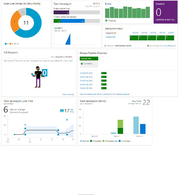
131
A.6.6. Visual Display. For all of their visual displays, the B-52 MP software teams utilized
integrated dashboards available within Microsoft Azure DevOps. Each team was using Visual
Studio, also developed by Microsoft, which provided a simple way to have automatically
updated charts and metrics to view. Multiple dashboards were used depending on the purpose
for the review. For tactical management at the team level, each team was given autonomy to
view what they found the most important. Figure 1 shows an example of a team-level
dashboard.
The second level of dashboard utilized was for the teams’ wall walks. This level of dashboard
shows more of the trending data, such as velocity, cycle times, burn-up/burn-down, and
cumulative flow. Figures 2 and 3 show an example of a wall walk dashboard which was
utilized.
A third level of dashboard utilized for the project, was the sprint review dashboard. At the end
of every two week Sprint, the teams have a meeting with the B-52 Program Office to show
what was accomplished and discuss the current status of the project. This meeting gives the
customer an opportunity to discuss changes they would like to see earlier in the project, as well
as reprioritize future work for the team to accomplish. Figure 4 shows an example of a Sprint
Review dashboard.
Figure 1: Team-Level Tactical Dashboard
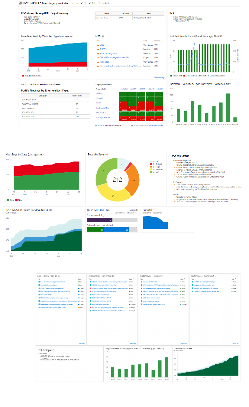
132
F
IGURE 3: WALL WALK DASHBOARD
F
IGURE 4: CUSTOMER-LEVEL SPRINT REVIEW DASHBOARD
Figure 2: Wall Walk Dashboard

133
A.6.7. Next Steps. In spite of the many accomplishments and improvements already realized,
the team is continuing to grow in its implementation of AoP, through utilizing DevSecOps
principles. The team has identified multiple improvement ideas, a few of which are listed
below for future implementation.
• Integration with the MP Cloud Development Environment.
• Implementation of further automated build pipeline improvements, such as
containerization of build events.
• Alignment of other 557 SWES MP development projects (such as B-1, E-3/E-8, and E-
3 DRAGON) to the same development environment to enhance communication and
sharing of lessons learned between teams.
• Improved metrics within automated dashboards to aid continued identification of
constraints.
• Integration of all 557 SWES projects within a Tableau dashboard to aid identification
of common squadron constraints.
A.6.8. Lessons learned. Throughout the development of the B-52 MP AoP implementation,
the team learned a lot about how AoP and their existing Agile and DevSecOps practices lined
up. Table 1 summarizes some of the ways the team identified their current process and AoP
inherently lined up. AoP provided a framework to allow teams to identify their constraints
quickly and empowered the team to find resolutions. The team would encourage other groups
to be creative in their implementation of AoP and use its flexibility to work in their area.
TABLE 1: AOP TERMS TO B-52 MP INTERPRETATION
AoP Term
B-52 MP Agile Software Development Interpretation
Flow
The movement of PBIs from New to In Progress to In Review
to Ready for Test to Done
Gates
The different states work can be in – New, In Progress, In
Review, Ready for Test, and Done
Operational
Meeting
The end of Sprint meetings with the customer to discuss
current project status and future work.
Release Points
The established Definition of Done which allows a developer
to say their code change is ready to be reviewed, ready to be
tested, or done.
Tactical Meeting
The 15-minute, daily team meeting to discuss what was
accomplished the previous day, what will be worked the next
day, and what constraints each team member has.
Touch Time
The time a developer spends coding. Work such as project
management, reporting, procurement, requirements
analysis, and reviews are not considered to be part of touch
time.
Visual Displays
The automated dashboards the team uses to see current
Sprint status, conduct wall walks, or show current project
status to customers.

134
WIP
The work PBIs which have moved past the New state, but are
not considered Done yet.
When looking to identify constraints, be sure to consider all tasks. Be sure not to ignore tasks
which seem to be vitally important, because there could always be a simpler or more
streamlined way to approach it.
A.6.9. Contact Information: Tyler Moudy, 557 SWES/MXDPC, DSN 622-7223

135
APPENDIX A – CASE STUDIES
A.7. OC-ALC TF33 Engines
A.7.1. MET for Study: Provide repair and overhaul of whole engine, module, and propulsion
exchangeables.
A.7.1.1. Case for AoP Implementation. OC-ALC generated 50 two-level maintenance
(2LM) TF33 engines in FY18 meeting only 52% of the customer requirement of 96 2LM
engines. This reduced War Readiness Engine (WRE) levels, and the critical level of
serviceable TF33 engine supply quantity on hand, for the E-8, B-52 and E-3 aircraft. These
reduced supply levels posed a threat to the warfighters’ ability to accomplish their mission
if not resolved. The team recognized the need to apply AoP methodologies across the TF33
enterprise to include exchangeables, supportability, overhaul and delivery of TF33 engines.
Collectively, organizational leadership for DLA, Air Force Life Cycle Management
Center, Engine Program Management (AFLCMC/LP), 448 Supply Chain Management
Wing (SCMW), 421 SCMS, 848 SCMS, 546 Propulsion Maintenance Squadron (PMXS),
547 PMXS, 548 PMXS, OC-ALC/AS and OC-ALC/OBW made the decision to conduct
an Enterprise Value Stream Mapping event (EVSM), with the goal of identifying and
prioritizing issues within the TF33 engine overhaul process. The enterprise team started
the improvement process with a Suppliers-Inputs-Process-Outputs-Customers (SIPOC)
exercise in Oct 2018. This exercise reviewed the end to end process, from requirement
generation to engine delivery, identifying 15 critical, enterprise-wide processes that were
pre-mapped prior to the Jan 2019 EVSM. The EVSM allowed an enterprise review of
those processes and issues, and developed a prioritized set of follow-on events and action
items aimed at a collaborative, enterprise improvement effort.
A.7.2. Flow. The 2LM engine overhaul process was adjusted as a result of EVSM. The
following is the post EVSM flow process. The 2LM engine overhaul process is divided into
four gates encompassing engine induction, disassembly, repair, assembly and test. The repair
process, represented as a material queue prior to engine assembly, is broken into four micro
gates as individual parts and components make their way through repair back shops before
being “kitted” for engine assembly.
A.7.2.1. Gate 1: Categorization and Borescope Inspection. The goal of this gate is to
understand the condition of the engine based on external and internal inspections prior to
engine disassembly. As a result of the EVSM, the results of these inspections are reviewed
collaboratively with PMXG production, planning, PMXG process engineering,
AFLCMC/LPS cognizant engineering, quality assurance, and engine records personnel in
order to determine specific repair actions to adequately complete engine overhaul. This
nine workday, 13 calendar day process is represented on the Gate 1 waterfall visual display.
Gate 1
Day 1 Day 2 Day 3 Day 4 Day 5 Day 6 Day 7 Day 8 Day 9 Day 10
CAT/BS
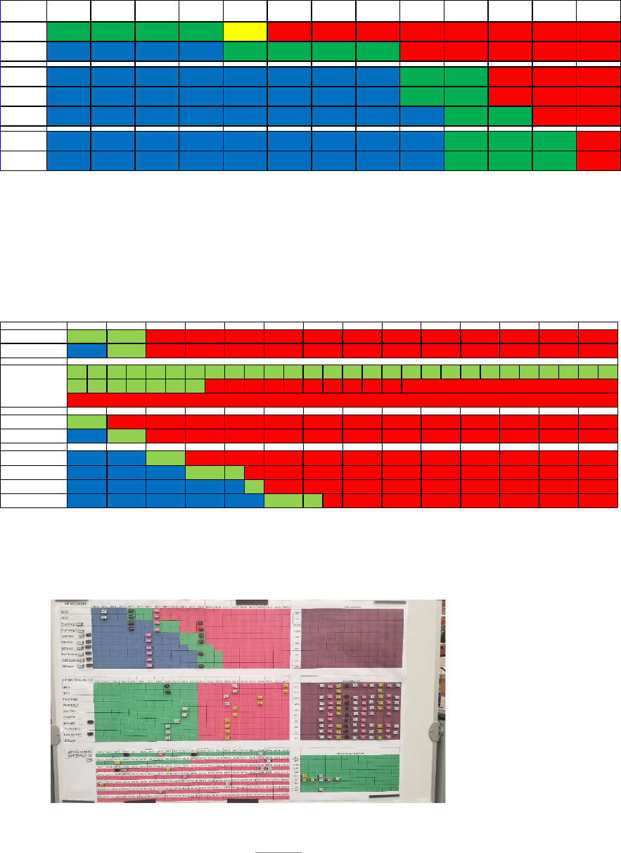
136
A.7.2.2. Gate 2: Disassembly. The engine is disassembled into sub modules and
individual parts and turned in to the Production Logistics Support (PLS) Center for
processing and individual piece part ordering. This twelve workday, 17 calendar day
process is represented on the Gate 2 waterfall visual display.
A.7.2.3. Material Queue-PLS Kitting and Back Shop Repair. The PLS completes
ordering of replacements for non-serviceable, non-repairable parts and routes submodules
to PMXG back shops for further disassembly and repair. The back shop process is
managed through four micro-gates that include submodule disassembly, kitting,
submodule assembly and final inspection and records update. These micro-gates are
represented on the Back Shop Micro-Gate Waterfall visual display.
Serviceable parts and submodules are delivered to the engine PLS for engine assembly
kitting. The kit status is tracked using the Material Queue Kitting Waterfall visual
display.
Gate 2
Day 1 Day 2 Day 3 Day 4 Day 5 Day 6 Day 7 Day 8 Day 9 Day 10 Day 11 Day 12 Day 13
QEC / PLUM BING DIS.
PLUMBING / QEC /
DIS.
GRBX
DISASSEMBLY
ELEVATOR
DISASSEMBLY
EXHAUST
DISASSEMBLY
COLD
DISASSEMBLY
HOT
DISASSEMBLY
Gate 1
DISASSEMBLY
RECORDS
Gate 2
29 30 31 32 33 34 35 36 37 38 39 40 41 42 43 44 45
Gate 3
INSPECT/ALLIGN/BAKE/BUILD
INSTALL BLADES/RIVETS
Gate 4
BALANCE
CMM/FINAL
SCHEDULING REVIEW
RECORDS
KITTING
Day 2
Day 3
6
Day 1
Day 3
Day 12
Day 11
Day 4
Day 11
Day 4
Day 5
Day 8
8
7
21
22
Day 14
23
24
25
26
Day 12
Day 13
Day 8
Day 6
Day 7
Day 9
9
10
Day 11
Day 10
Day 1
Day 2
Day 4
Day 5
Day 3
15
16
27
17
18
5
4
3
Day 5
Day 7
Day 14
Day 6
Day 7
Day 6
Day 13
Day 9
Day 8
Day 10
Day 14
Day 12
Day 13
Day 1
Day 2
Day 9
Day 10
11
12
13
14
19
20
LATE OVER 10 DAYS
28
LATE OVER 10 DAYS
2
1

137
A.7.2.4. Gate 3: Assembly. Once submodules and parts are supportable, kits are released
to Assembly Gate mechanics for engine assembly. Quality assurance, PMXG process
engineers and AFLCMC/LPS cognizant engineers are available throughout the assembly
and final inspection process as needed. This twenty-six workday, 37 calendar day process
is represented on the Gate 3 waterfall visual display.
A.7.2.5. Gate 4: Test Cell. During this eight calendar day process, assembled engines
receive a rigorous test procedure with heavy involvement from PMXG process
engineering. Once testing is complete, the engine is wrapped, prepped and shipped to the
customer.
A.7.3. WIP. Prior to the EVSM event, the FY20 WIP target for TF33 engines was 30 total in
work with a target of not more than 12 engines in the Material Queue Gate. In reality, 12
disassembled engines was not enough WIP to keep the engine Assembly Gate fed at a constant
WIP of nine engines due to the time necessary to develop and execute repairs as a workaround
to supportability issues in the PMXG back shop. The team recognized an increased buffer
stock of disassembled engines was necessary to improve the release cadence to Assembly Gate.
Using Little’s Law, the team calculated a buffer of 19 disassembled engines was necessary to
improve the release cadence to Assembly Gate. Once kitting improvement actions described
in paragraph 1.5.4. were realized, the kitting process made significant improvements toward
achieving the 2LM process takt-time release goal of four days – meaning a completed kit for
engine assembly needs to be released every four days. The excess queue in the TF33 machine
meant flow days could not accurately reflect if the machine was improving. Monitoring the
takt time release cadence to the Assembly Gate became the measure of success – because it
was the key to improving overall throughput.
A.7.4. Constraint Identification. During the EVSM, the team identified 867 constraints. Of
those constraints, 803 were classified as Just Do Its (JDI) and assigned action officers. The
remaining 64 were determined to be too complex for a JDI and would require 24 future follow
on events to address them. The top constraints centered on enterprise actions and processes
required to address part availability and supportability for an aging engine fleet. Champions,
process Owners, and Team Leads were assigned for each event and problem statements
constructed. The follow on events were scheduled at a rate of one per month, in order of
highest impact. The follow on action methodology allowed improvements to be worked in a
transparent manner with all enterprise partners maintaining the key objective of understanding
the process interrelationships and impacts of one process on the other.
Gate 3
Day 1 Day 2 Day 3 Day 4 Day 5 Day 6 Day 7 Day 8 Day 9 Day 10 Day 11 Day 12 Day 13 Day 14 Day 15 Day 16 Day 17 Day 18 Day 19 Day 20 Day 21 Day 22 Day 23 Day 24 Day 25 Day 26 Day 27
DIFFUSER
HOT
SECTION
COLD
SECTION
EXHAUST
CASE
GEARBOX
Accessories 1&2, Pre
QEC
ELEVATOR
Accessories 1 / GB
Install
PLUMBING 1 /
ACCESSORY 2
QEC /
Plum bing 2
QEC 2 /
Plum bing 3
QEC 3
Borescope /
Final Shake

138
A.7.4.1. Non-conforming Material Review Parts: PMXG’s electronic Non-conforming
Material Review (eNCMR) Board database manages the process of obtaining permission
from cognizant engineering to expand technical serviceable data limits or authorize a work
around repair to save and reuse parts. This process did not reliably or repeatedly create a
demand signal to trigger the supply chain to contract sources for new or repaired parts, thus
perpetuating the parts availability/supportability problem. Thirty-seven percent of the
incomplete Assembly Gate kits were waiting for a part going through the eNCMR process
– adding an average of 37 days to the Material Queue.
A.7.4.2. Demand Signal: In addition to the eNCMR demand signal issue, other PMXG
processes were found to be creating demand signal issues, including a break down in the
process to send Demand History Adjustments (DHAs) to DLA.
A.7.4.3. Kitting: Many issues contributed to the kitting process being unable to fill
Assembly Gate kits by need dates. Among these: kit carts were not laid out in a manner
that highlighted missing parts; parts were lost due to the disorganized layout of kitting cage;
part non-supportability; the required volume of kit carts were not available to maintain the
necessary WIP levels to meet demand. System training inconsistencies in key personnel
were identified and a process to work constrained assets was not standard nor reliable.
A.7.4.4. Challenges: One of the primary challenges from the EVSM was organizational
resource capacity. Each of the follow on events required the attention of many of the same
people resources. The subsequent events and action items generated from the follow on
events required the attention of these same people. Time was needed to implement the
action items from the events in order to realize real change.
A.7.5. Constraint Resolution. All of the constraints identified at the mapping events were
consolidated onto one newspaper stored on a share point site as a living document to allow all
partnership POCs to update and filter the status of their action items. Action item status fed
into graphs and charts for simple, standard information allowing complete visibility between
all partnerships and the chain of command. A newsletter tab is created for each follow on
event on the main newspaper so all updates were accomplished in one place. The action items
for sub events were added to the appropriate organization’s tab on the newspaper. Monthly
enterprise-wide meetings were held with leadership to update the status of the action items for
each organization within the partnership and follow up events.
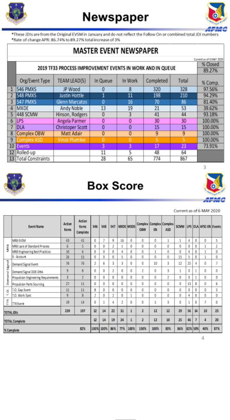
139
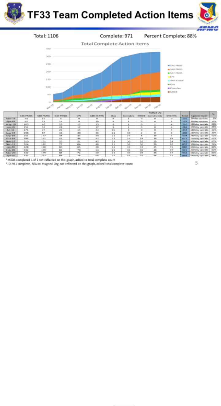
140
A.7.5.1. Material Review Board (MRB): To address the issue of timely dispositions, the
team designed and implemented an MRB Decision Tree tool to standardize the way PMXG
communicates issues on frustrated parts with engineering. This tool provides complete and
accurate information to allow cognizant engineers to make timely dispositions and created
an enterprise-wide collaborative process. The tool was a good first step, but a second pass
MRB event was necessary based on data errors with submissions to the MRB Decision
Tree tool. As a result of the second pass MRB event the MRB Decision Tree tool was
revised to assist in reducing the quantity of invalid MRB submissions. The event also
inserted the supply chain further to the left in the process to allow supportability
assessments to be completed and reduce the need for resources to be expended on assets
that met supportability thresholds. The volume of non-conforming assets in this process
provided the data to drive the hire of additional Designated Engineering Authority (DEA)
engineers to expedite engineering disposition turn-around time of these items.
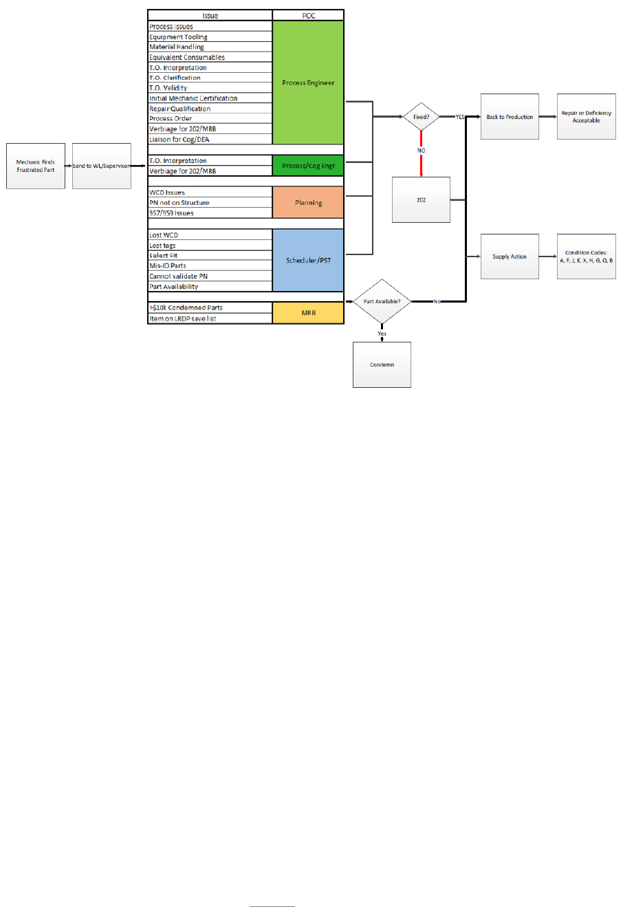
141
A.7.5.2. Demand Signal: In response to overwhelming evidence of demand signal issues,
new Demand Data Exchange (DDE) and DHA processes were created to feed into 448th
SCMW and DLA existing processes. A new FHZ DHA process was created to send
missed demand signals to 448 SCMW in an auditable database. Training was created and
delivered by the complex Aerospace Sustainment Division (ASD) for PMXG Production
Support Technicians (PSTs), Schedulers, and Planners as well as the 848th Supply Chain
Management Group’s (SCMG) IM, Equipment Specialists (ES), and Logisticians to learn
the new processes. Finally, a communication loop was created between the PMXG, 448
SCMW, and DLA to ensure an accurate signal is sent and received.
A.7.5.3. Logistics Requirements Determination Process for Propulsion (LRDP-P): Created
the LRDP-P, a collaborative process with standardized business rules for assessing parts
and non-part element supportability, determining the actions required to increase
supportability, develop roles and responsibilities for functions across multiple
organizations, and measurements to determine if the process is working. The LRDP-P
team is a strategic resource that identifies potential shortfalls, resolve and/or develop
workarounds plans to mitigate production work stoppages. Using the Supply Chain
Mitigation Process (SCMP), identify potential workarounds in a tiered approach. Starting
with a Supply Chain Level 1 (SC1) checklist, the owning supply chain looked for
workarounds within their own control. Once the SC1 Checklist is complete, the Depot
Supply Chain Management (DSCM) team member will determine if there is still a
supportability gap or if SC1 mitigated the gap. If there is still a gap, the DSCM team
member will engage with the maintenance planner to trigger the Supply Chain Level 2

142
(SC2) checklist. The maintenance planner will use the SC2 checklist to identify
workarounds within their control. If the planner is able to identify workaround options,
the options will be returned to the owning supply chain and a collaborative determination
of the gap will be mitigated. If a gap still exists, the DSCM team member will engage with
the cognizant engineer organization to trigger the Supply Chain Level 3 (SC3) checklist.
If the engineer identifies any potential workarounds, the options are returned to the owning
supply chain and a collaborative determination as to the length of the gap the collective
workarounds mitigate. All workaround options are input into the supportability tool and
supportability colors adjusted IAW the business rules.
A.7.5.4. Kitting:
A.7.5.4.1. Personnel: PSTs did not have end-to end visibility of the kitting process.
Prior to the Kitting EVSM, PSTs were working in silos with no standardized processes.
Action items from the event created standardized, auditable business rules, script
charts, and order forms. A Material Queue Waterfall chart was created to mirror the
production floor Gates 1 through 4 charts for full visibility of kit status throughout the
lifecycle of the kit (see 1.7.4). One primary PST and one backup were assigned to each
style of kit cart (see 1.7.11). Prior to the Kitting EVSM, material queue averaged 150
flow days. After the action items were fully implemented, the material queue average
dropped to 55 days with part supportability.
A.7.5.4.2. Kit and Kitting Cage Layouts: The layout of the kitting cage did not have
the full WIP capacity necessary to meet takt or allow parts to be adequately secured.
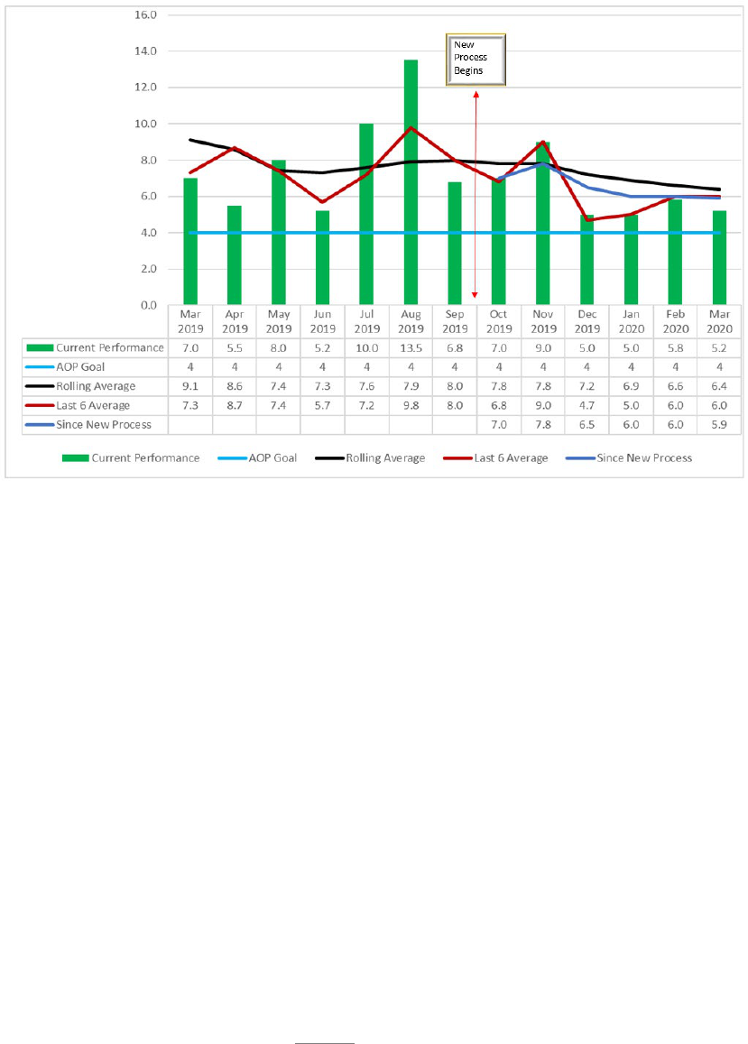
143
The team created an ingenious and affordable shelving design to allow full WIP
capacity in a secured location. Kit carts were designed with foam shadow inlays for
each part, providing a visual cue of parts needed to complete kit. As of March 2020,
kits are releasing to Assembly Gate at a takt time average of six days with an AoP goal
of four days.
A.7.6. Results: In 2018, FY19 predictions and indicators for TF33 WRE was as low as -19
due to part supportability issues that would have led to grounded aircraft and an impact to
mission capabilities. Due to the efforts of the enterprise in the EVSM, follow-on events, and
action item close outs, the impact to WRE was mitigated and never fell below -3.
Improvements include; new gate to categorize engine work spec, scripts for every gate,
identification of parts BOs are identified within three days of engine disassembly, core team
establishment to work BOs and constraints to critical path, BO reviews identifying constraints
to DLA and Air Force supply chain enabled workarounds to be worked immediately when
needed, new order sheets and kit carts made production shop more efficient and ordering of
material more accurate, establishment of reclamation line provided source of constrained
materials, this is just to name a few of the extraordinary actions that it truly took the entire
enterprise to accomplish. Though the production environment continues to be constrained by
part supportability and challenges keep coming, TF33s has been able to continue production
avoiding catastrophic consequences to our war fighter through enterprise focus on mechanic
centric process and CPI efforts to find a better way.
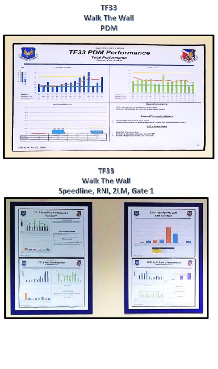
144
A.7.7. Visual Display:
A.7.7.1. 546
th
Walk the Wall
145
A.7.8. Next Steps: The enterprise team continually reviews the data from the process machine
as well as data from their newly established collaborative processes to determine opportunities
for conducting second pass EVSMs to reduce variation, improve standardization and
communication. They also continue to look across other organizational value streams for
opportunities to share and implement these new key processes and improvements.
A.7.9. Lessons Learned: Cross-collaboration is key for success, all stakeholders need to be
involved from the very beginning. Full enterprise involvement prevents work in silos and
allows groups to see how their actions impact groups farther down the chain and can ensure
actions do not have a negative impact on those groups. Organizations must agree to have
complete transparency and a willingness to discuss and resolve the issues identified in the
process reviews. Leadership needs to be heavily involved to have a cohesive enterprise-wide
team with frequent, open communications in order to provide encouragement from the chief’s
door to the shop floor. Unified enterprise level leadership provides laser focus onto constraint
resolution and enables enterprise-wide organizational learning and improvement.
A.7.10. Contact Information: 76th PMXG, Joshua Dobbs, DSN 334-4812

146
APPENDIX A – CASE STUDIES
A.8. 567th AMXS B-1 Journey
A.8.1. MET for Study. MET 1; Execute B-1B PDM/UDLM, repair, overhaul, and
modification workload with safe, reliable, and defect-free aircraft. The MET supports MGA
4, Execute the Mission. MET 1 purpose is to provide 100% organic depot level maintenance
supporting 62 B-1s at 3 separate main operating bases across the nation. Performing depot
level Maintenance Repair and Overhaul (MRO) workload on the B-1 every 60 months,
provides the SPO, and AFGSC, with B-1 aircraft ready to support world-wide contingency
operations anytime and anywhere as needed.
A.8.1.1. Case for AoP Implementation. In March 2018, the first in a series of TCTOs were
released, that drove significant hours of unplanned emerging requirement workload to the
depot. From 2018 to current, a total of 24 TCTOs were released for action. B-1 program
Full Scale Fatigue testing and subsequent findings from a test article at Boeing Washington
necessitated the B-1 SPO engineering directorate to issue a succession of 30, 60, 90, and
180 day safety TCTOs to expedite the required urgent repairs of the 62 aircraft fleet.
Because all 24 TCTOs were depot level requirements, the 567 AMXS was called to
dispatch Depot Field Team (DFTs) to the three main operating bases while also scripting
unplanned workload into the current PDM and Integrated Battle Station (IBS) production
lines at OC-ALC. During 2018-2019 the 567 AMXS had DFTs on the road working these
TCTOs for 300+ days of the year for both years. At any given time, more than thirty 567th
sheet metal and aircraft technicians, roughly 12% of the available workforce, were on DFT
assignments at Dyess, Ellsworth, and Edwards AFBs. This loss of available workforce to
PDM and IBS production lines, although necessary to meet customer requirements at each
of the main operating bases, impacted the 567
th
overall product flow. The impacts ranged
from a low at the beginning of TCTO releases at 158 days, to an average of 212 days, an
increase of 54 days. Given this new challenge of incorporating emerging and unplanned
tasks into the PDM process flow, it was important for 567 AMXS to ensure they were using
all elements of AoP to mitigate current/potential impacts.
A.8.2. Flow. Project process flow was developed using a Statement of Work (SOW) provided
by SPO engineering that detailed work requirements and step-by-step process procedures.
Using the SOW, a Validation/Verification (Val/Ver) process was completed on at least two
aircraft prior to release of the actual safety TCTOs. During the validation/verification process,
production mechanics, ES, engineers, and supervisors worked side-by-side to ensure a well
scripted and clearly defined TCTO was established including scripted work requirements.
Since the Val/Ver process is accomplished on aircraft currently in-work, overall flowdays
increased day-for-day, based on the work content and duration of the Val/Ver. After the
validation/verifications were completed, the 567th planning section, working in collaboration
with production, crafted a well-defined script and associated network to be used during both
the current PDM and IBS process. Scripting the TCTO workload into the current process
machine began with identifying the optimal concurrency advantage. In PDM, Gate 2
(Access/Inspect Gate) was identified as the optimal insertion of the TCTO scripted work. In

147
IBS, most of the TCTO’s could be worked concurrently with planned IBS workload throughout
the in-dock process but had to be completed prior to operational checks in Gate 4B. Challenges
impacting flow related to scripting insertion of safety TCTO’s were primarily due to timing
associated with the release of individual TCTOs. If the TCTO was released after the optimum
time in the flow, loss of concurrency occurred resulting in extended flow in both in-dock (See
Figure 1) and post dock. In some cases the insertion point resulted in rework requirements.
When loss of concurrency was experienced, the 567th developed work plans to reduce flow
using targeted overtime as needed and increased use of third shift to maximize capacity of
operations on those aircraft.
A.8.3. WIP. The 567th has two primary production lines each with maximum WIP
requirements. For PDM, the maximum WIP requirement is 6, and for IBS, the maximum is 7.
Each production line has an individual process machine. For PDM, the incoming takt is 28
days, and for IBS is 35 days. Takt was developed based on a 365 day calendar availability,
and scheduled input requirements set by the B-1 SPO. With the known input requirement,
input takt, and targeted maximum WIP, a process machine that included 5 gates with basically,
1 WIP allowed in each of the first four gates along with a maximum of two in Post Dock. For
IBS, gates are dissimilarly sized due to the nature of the work associated with the modification
program but do maintain a WIP of one throughout the in-dock gates, and two in Post Dock.
Based on the maximum WIP allowed for each line, the combined maximum WIP in post dock
was set at four: two PDM and two2 IBS. Prior to the release of the 24 TCTO’s, all IBS gates
met and/or were below AoP targets. PDM in-dock gates were steadily trending down towards
AoP with three of the four, at or just above AoP targets. After the steady release of the TCTOs
beginning in March of 2018, in-dock WIP and Post Dock WIP steadily increased due to the
unplanned emerging requirements associated with those TCTOs and the loss of concurrency
advantages on any aircraft in the flow that had already completed Gate 2.
A.8.4. Constraint Identification. A number of constraints identified were directly associated
with the unplanned emerging requirements associated with the safety TCTO’s. There were
also some known constraints that were simply amplified due to the increased work
requirements created by associated TCTO insertion. Because this workload had never been
accomplished on a B-1, the defects associated with the work caused an increase in technical
resolution requirements, i.e. Air Force Technical Order (AFTO) form 202, Request for
Engineering Resolution, being submitted, and a resulting increase in delays associated with
getting a complete total technical resolution. A significant rise in the number of 202’s
submitted resulted in the need for OEM involvement formally known as a Technical Inquiry
(TI). The need for TI resulted in an increase of approximately 30 days per inquiry. The delays
directly resulted in a day-for-day slip to the PDM and IBS lines. Additionally, these TCTO’s
drove significant increases in unplanned parts requirements resulting in an additional 30-45
day increase in “awaiting parts” delays. Most of these delays were the result of “never before
ordered parts” that were non-stock listed and required expedited surplus buys through DLA
and the 406
th
SCMS Part Number Supply Support Request (PNSSR) processes.
A.8.5. Constraint Resolution. In every case, constraint resolution was the result of an effective
use of urgency tools such as Andon notification, Special Handling 202 submission, and
increased communication to our support services counterparts, i.e. NDI, paint, weld, local

148
manufacture. Andon submission of issues directly impacting the critical path of aircraft are
submitted to ensure enterprise awareness and targeted actions by the appropriate OPR is
completed to prevent and/or mitigate constraint delays. Special Handling 202’s are submitted
to rally the engineering and production teams to work through specific engineering issues
causing critical path delays or having potential for doing so. Effective communication at all
levels was and continues to be the driving force of success in constraint resolution.
Communication and collaboration between all stakeholders including DLA, SCMW, DSCM,
SPO Engineering and Logistics, and CMXG backshops are critical to ensuring expedited
constraint resolution for each tactical constraint. During this period, two primary constraints
were and continue to be sluggish engineering decisions and parts availability. Primary lessons
learned for both constraints has been the effective use of urgency tools, i.e. “being a demanding
customer”, and an increased level of understanding in the non-stock listed process associated
with PNSSR surplus buy requirements and the need to keep the 406
th
Supply Chain
Management Squadron well informed of continuing changes.
A.8.5.1. Results. In March 2018, PDM flow day performance was 157.6, just 12 days from
the PDM AoP goal. After release of the TCTO’s, a steady increase of flowdays was
experienced driving an increase to 222 days in June 2019. It was then, the 567
th
initiated
the EDP. The goal of the EDP was to reduce overall flow days by 60 days and return PDM
performance to where it was in early 2018. After a series of enterprise-wide CPI events
targeted at known constraints caused by the unplanned variation, a reduction of 22 days or
30% to the EDP target of 60 was realized in December 2019.
A.8.6. Visual Display. Figure 2, provides a visual display of the “mini-machine” used specific
to TCTO workload and is tailored based on TCTO requirements. The machines are developed
in collaboration with production, planning, scheduling experts and coordinated by the 567
th
Master Scheduler. The mini-machines are updated daily by the aircraft scheduler and briefed
daily at tail team meetings. In addition to tail team meetings, these mini-machines are included
in weekly fixer, execution, and performance review briefings. Where workload can be scripted
into an existing production machine, i.e. PDM and IBS, gate charts are used for measuring gate
performance and WIP. In addition to standard gate charts, the 567
th
developed a daily scripting
tool (see Figure 3) enabling tracking and easy identification of constraints associated with each
task.
A.8.7. Next Steps. Because of the variation thrust into both the PDM and IBS lines by these
24 unplanned TCTOs, flow days and WIP increases resulted in under performance to quarterly
requirements. The 567
th
went under an EDP in October 2019. Since then, the 567
th
has under
taken 14 targeted improvement events directly focused at constraints associated with both the
manner in which TCTO’s were planned and released as well as the logistics element associated
with parts identification. The 567
th
most recently completed a comprehensive Gate 2 task
content review of the current workload. Currently, Gate 2 has 9,857 hrs loaded to the gate,
more hours than gate 1, 3, and 4 combined. The comprehensive review identified and resulted
in 24 actionable items to improve overall gate performance and work content completion. The
next event scheduled for the EDP journey, is the Gate 2 rescripting event. The event is targeted
primarily at re-scripting and gating the new FY-21 production machine requirements. The
PDM machine will be substantially changing by the decision reducing fleet size from 62 to 45.

149
This reduction will drive changes in total yearly input requirements from 12 to 9 and input takt
changing from every 28 days to 41 days with an overall AMREP increasing from 187 to 249.
All gates will subsequently change and rescripting will be necessary. After the Gate 2
rescripting event is complete, gates, 3, 4, and 5 will be completed as well. A new PDM process
machine has already been developed and approved (See Figure 3).
A.8.8. Lessons learned. Throughout this process, AoP discipline has been the driving force in
mitigating known constraints and reducing potential constraints from impacting critical path
issues throughout the process machine. Adherence to script discipline and buy-in by all
enterprise partners is critical to the overall success of the machine. Celebrating small successes
along the journey is important as well. Recognizing accomplishments of process owners and
supporting organizations furthers the maturation of an organizational culture that embraces
AoP tenants. Inclusion and complete transparency in process constraints whether they are
associated with an actual PDM/IBS process machine, an outside process such as TCTO
development from the SPO enterprise, or non-stock listed surplus buy processes within the
PNSSR/406 SCMS are instrumental in driving a AoP culture that understands both tactical and
strategic impacts to depot line effectiveness when variation to a scripted process is introduced.
Quickly scripting processes that encompass concurrency to its fullest potential and allow the
flexibility to “plug and play” in the overall machine has been the biggest single contributing
factor allowing the 567
th
to mitigate overall flow day impact to the customer and keep aircraft
availability at required levels.
A.8.9. Contact Information: Rodney C. Shepard, 567 AMXS/CL, 405-734-0221, DSN; 334-
0221.
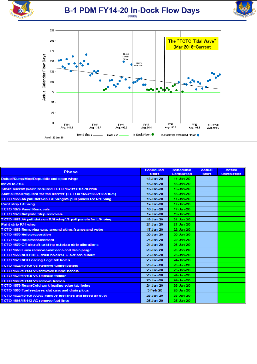
150
B-1 PDM In-Dock Flow Day Chart
B1 Mini-Machine

151
Daily Scripting Tool
B-1 Event Driven Plan

152
APPENDIX A – CASE STUDIES
A.9. 406 SCMS Technical Order Management and Editorial Operations
A.9.1. Mission Overview. The 406 SCMS/GUEE-Tinker is responsible for standardizing,
streamlining, issuing procedures and guidance, and executing commodity TO sustainment and
management functions for the 448 SCMW, AFLCMC, AFNWC, and the Air Force Petroleum
Agency (AFPET). TO Management was identified in August 2017 to be a Mission Essential
Task (MET) during the 948 SCMG’s annual goals and objectives scrub. The implementation
of the AoP began October 2017 and continues today in a steady state environment.
A.9.1.1. Technical Order Management and Editorial Operations. The Technical Order
Management Agency (TOMA) within the 406 SCMS at Tinker AFB is responsible for TO
acquisition, sustainment, format, publishing, storage, distribution, and archiving TOs and related
technical data in accordance with Air Force Policy Directive (AFPD) 63-1/AFPD 20-1, Integrated
Life Cycle Management, AFI 63-101/20-101, Integrated Life Cycle Management, AFMCI 21-301,
AFMC TO System Implementing Policies, Air Force Materiel Command Manual (AFMCMAN)
63-1202, Air Force Material Command Engineering Technical Assistance (ETAR) Process, TO
00-5-1, AF Technical Order System, AFMC Technical Order System Procedures, TO 00-5-3, Air
Force Technical Order Life Cycle Management, Military Standard (MIL-STD)-38784, Manuals,
Technical: General Style and Format Requirements, and all other Technical Manual Specifications
and Standards (TMSS).
A.9.2. MET for Study. The TO Management and Editorial Operations organization receives,
tracks, manages, and executes the AFTO Form 252, Technical Order Publication Change
Request (PCR), as an official form to direct TO updates. The AFTO Form 252 provides word-
for-word direction on any update needed to be incorporated or revised within the TO. The TO
Manager screens all AFTO Form 252s to ensure required data is current and complete, properly
coordinated, and includes all recommended changes for the next TO update. In addition, the
TO Manager submits packages for updates to the editorial function for Standard Generalized
Markup Language (SGML) tag structure and state-of-the-art graphic designs. Subsequently,
the TO Manager submits the approved updated package for distribution to the AF maintenance
community, both field and depot users.
A.9.2.1. Case for AoP Implementation. In December 2016, the 406 SCMS/GUEE-Tinker
TOMAs received an unforeseen, significant increase of AFTO Form 252s resulting in a
workload spike due to a 76 CMXG reset. The new incoming AFTO Form 252s were
exceeding the output capacity. The overall surge of AFTO Form 252s had increased to an
alarming rate of over 900 units resulting in an anticipated catchup date of December 2020.
This was an unacceptable completion date, and a process revamp needed to be
implemented. The 948 SCMG and the 848
SCMG established a working group to tackle
the staggering issue with backlogged AFTO Form 252s. In October 2017, the team utilized
AoP tools to establish a comprehensive TO Process Machine.

153
A.9.3. Flow. A cross organizational Integrated Process Team (IPT) was tasked to define the
process flow and identify the constraints impeding the flow of the PCRs through the process
machine. The team established Road-to-Goals, gates and sub-gates, defined daily production
and stretch goals, and used constraints based management to increase the process flow. Gates
were defined as Gate 1, New PCR Acceptance, Gate 2, Lead Editor Technical Manual
Information System (TMIS)/Contenta TO Prep/Research, Gate 3, AFLCMC Robins-Integrated
Data for Maintenance (IDM) Prep, Gate 4, Robins-IDM Import, Gate 5, Editing Operations,
Gate 6, ES Pre-Pub Review, and Gate 7 as the Completed Output. The challenges encountered
during the development of the TO Process Machine included initially establishing too many
gates for evaluation and the lack of an automated information tool to extract concise data
points. Lessons learned were to consolidate gates where possible and establish an assertive
automated process to obtain accurate data for each defined gate.
A.9.4. WIP. Through AoP principles and utilizing Little’s Law, the 406 SCMS/GUEE team
was able to identify the 930 AFTO Form 252s across the machine to capture the WIP. There
were set entry/exit criteria for each gate, which ensured accurate transfer of work from one
gate to the next. A collaboration between the TO Manager, Editor, and ES utilizing various
products (AFTO Form 252s, TOs) and tools (Enhanced Technical Information Management
System (ETIMS), TMIS, and Robins-IDM) allowed for a better process flow and ensured that
no gate contained more WIP than necessary.
A.9.5. Constraint Identification. Over the lifecycle of the 406 SCMS/GUEE’s AoP wall walk,
there were three constraints identified. The first constraint encountered was a significant
increase of AFTO Form 252s flowing into Gate 2, Team Lead Technical Manual Information
System (TMIS)/Contenta TO Prep/Research, exceeding the throughput capacity to the next TO
process gate. Once solved, the team found the next constraint to be Gate 3, AFLCMC Robins-
IDM Prep, who fell short in supplying a required amount of TOs, starving the process machine.
Finally, the 406 SCMS/GUEE team discovered that Gate 6, ES Pre-Pub Review, had no
internal TO review process timelines, triggering a delay in the finalization and TO distribution.
A.9.6. Constraint Resolution. An assembled TO team conjointly resolved Gate 2’s constraint
within a one-week timeframe by swiftly executing/transferring workload to the next gate. To
resolve Gate 3’s constraint, the TO team partnered with AFLCMC/LZP at Robins setting an
aggressive delivery schedule. In addition, because the 406 SCMS/GUEE team was able to
quantify and present their issues, Robins was able to bring on additional contract resources to
sufficiently feed the TO Process Machine and meet delivery demands. Gate 6’s constraint
resolution involved an internal/external assessment on the Pre-Pub Review process driving a
leadership directed policy to enhance the response time from the ES community.
A.9.6.1. Results. Utilizing the AoP tools, a TO backlog surge downsized from 930 to 226
PCRs, equating to a 76% decrease in total backlog in 10 months. This implementation
improved the overall catchup timeline by one year. In addition, an external agency turn time
improved from 21 days to 8 days, improving monthly output from 100 PCRs to 230 PCRs per
month. These combined efforts provided a result remedying a projected long term backlog.
The current steady state management of the machine is allowing the team to control the amount
of output despite fluctuations of machine input. The team is now postured to embrace and
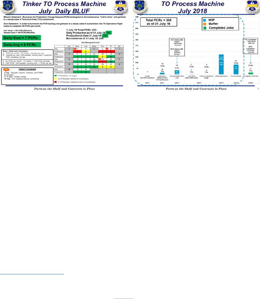
154
easily handle a spike in PCR workload. In addition, due to the COVID-19 pandemic, the
machine hasn’t experienced or been impacted by a reduction in production during situational
telework.
A.9.7. Visual Display. The 406 SCMS/GUEE-Tinker TO wall walk displays a comprehensive
machine with Road-to-Goals, gates, and sub-gates to address AFTO Form 252 workload.
Visual images demonstrate how the flow, WIP, and gate performance are measured within the
TO Process Machine. Due to the COVID-19 pandemic driving a situational telework
environment, a Daily Bottom Line Up Front (BLUF) chart is virtually distributed to the
stakeholders on a daily basis. (Wall Walk charts and daily BLUF provided separately).
A.9.8. Next Steps. The next steps were to continue socializing the TO Process Machine with
internal/external agencies to provide world class support for the warfighter. In addition, the
team recalibrated the machine to realign the daily goal and averages creating a firm steady
state throughput. From October 2018 until present, the team continues to apply AoP tools
along with Little’s Law to define the TO steady state process machine, maintaining oversight
of tactical management via weekly wall walks, monitoring production goals and WIP. After
completing the workload spike, the team faced the challenge of standing down from a ramped
up production culture to a steady state. By monitoring the machine, the team determined what
areas could be drawn down and was able to modify the production output from an average of
100+ PCRs per month down to 80 PCRs to retain a good, constant flow of approximately 220
PCRs in the WIP at all times to preclude starving the machine. Today sustainment performance
of processing routine PCRs in an average of 60 days against the AFMC 365-day standard. The
team is now equipped to accept and accommodate future workload spikes.
A.9.9. Lessons learned. Constant communication and transparency among all stakeholders are
the keys to success. Don’t panic - - keep the machine simplified; minimize gates to a
manageable level. Another key factor is to not allow emotions to drive decisions. Focus on
the metrics. Let the data steer you towards the constraints making adjustments when necessary
and adding resources where needed.
A.9.10. Contact Information: Vicki Bowen, 406 SCMS/GUEE-Tinker, DSN 852-9694,

155
APPENDIX A – CASE STUDIES
A.10. 406 SCMS Part Number Requisition (PNR) Support
A.10.1. Mission Overview. The 406 SCMS serves all 448 SCMW supply chain managers as
the focal point for all matters concerning Wing Supply Plan Operations and Technical Data
Operations functions. Responsible for standardizing, streamlining, issuing procedures and
guidance, and executing supply plan operations functions including provisioning, cataloging,
loan control for Government Furnished Property/Government Furnished
Equipment/Government Furnished Material (GFP/GFE/GFM), packaging test and design,
traffic management, explosive certification/verification, Item Level Supply Assignment
(ILSA) and PNR support. In August 2017, because of the 948 SCMG’s annual goals and
objective scrub, the 406 SCMS established METs. The implementation of the AoP across the
squadron began in October for our different METs.
A.10.1.1. PNR Support Study. AoP for the PNR Support process began in December 2017.
The Part Number Office (PNO) within the 406 SCMS is responsible for expediting the
1348-6 Non-Stocklisted/Part Number Requests (NSL/PNR) process in effort to balance
and deliver responsive and resilient support to the depot/field warfighter.
A.10.2. MET for Study. The PNO provides support for those items, which for a variety of
reasons, have not been cataloged with a national stock number and therefore have zero stock
on the shelves. The field or depot customer submits a request for support of a NSL item to the
part number IM via a DD form 1348-6, DOD Single Line Item Requisition System Document.
The DD 1348-6 is then entered into the PNSSR System and forwarded to the appropriate ES
for disposition. The disposition may include using a substitute part, using the next higher
assembly, getting a part from AMARG, purchasing a part from a vendor or having the part
manufactured at the depot. In the event we have three demands in 180 days in accordance with
AFMCMAN 23-501V1, D035A, D035B, and WHSL Module Data Sub-Systems, the ES will
consider getting a national stock number assigned.
A.10.2.1. A.10.2.1. Case for AoP Implementation. The 406 SCMS started taking over the
Part Number Requisition support function from the 635th Supply Chain Operation Wing
(SCOW) in May 2013 after a 2012 workload review and manpower study, which disbanded
all Combat Support Offices (CSOs) at Robin, Hill and Tinker AFBs. Robins and Tinker
implemented the PNO process in Dec 2014 with Hill acting as the centralized buying
activity. Robins and Tinker took over their own buys in Oct of 2017. Metrics identified
the following goals for PNRs were not being met:
- PNR with disposition other than procurement/local manufacture: MICAP goal eight
hours - non MICAP goal 30 days
- PNR with disposition for procurement on GPC: MICAP goal seven to 14 days if
stock on hand with vendor – Non MICAP goal is under 60 days
- PNR with disposition for procurement on Contract: MICAP goal between 45-60
days – non MICAP goal not to exceed 60 days

156
- PNR with disposition of Organic Manufacture (Field only) MICAP goal 45-60
days – non MICAP goal not to exceed 60 days
In December 2017, the three locations determined to work together and utilize AoP tools
in order to establish the Part Number Requisition Process Machine.
A.10.3. Flow. A cross-organizational IPT was tasked to define the process flow and identify
the constraints impeding the flow of the PNRs (1348-6s) through the process machine. The
team established Road to Goals, gates and sub-gates, defined daily production and stretch
goals, and used constraints based management to increase the process flow. The teams
originally started with 12 gates as part of the leadership charts for the OPS-X briefings.
Through efforts of the IPT, gates were combined and reduced to the 6 gates (0-5) being used
today. Gates were defined as Gate 0-Input, NSL/PNR Requests, Gate 1, PNO Research, Gate
2, Tech Disposition, Gate 3, PNO Buy Process, Gate 4, Buyer/Vendor, Gate 5, NSL/PNR
Resolution (by other tech disposition or local purchase/local manufacturing. The challenges
encountered during the development of the PNR Process Machine included initially trying to
figure out what gates to have in the process, not having ownership or control of certain steps
within the process and how that would overall effect our goals. The initial gates established
were Gate 1 through Gate 5 but during the storming/forming sessions of going through the
steps of the process, the team realized that there were many 1348-6s that didn’t make it into
the machine but were still part of the process and goals. Hence, the team added Gate 0 to
capture those that do not go through the process machine but are resolved through other means.
Lessons learned were to consolidate gates where possible and establish an assertive automated
process to obtain accurate data for each defined gate.
A.10.4. WIP. Through AoP principles and utilizing Little’s Law, the PNO team was able to
identify every PNR across the machine to capture the WIP. There were set entry/exit criteria
for each gate, which ensured accurate transfer of work from one gate to the next. Even though
PNO does not own every gate of the process, collaboration between stakeholders and having
ownership of the PNSSR system, helped in ensure the PNRs continued to flow through the
process.
A.10.5. Constraint Identification. In Jan 2018, the 406 SCMS established the PNR AoP to
address the ongoing constraints that were identified as we standardized our process. The
resolution of PNR requirements was averaging between 90 – 180 days due to the lack of clearly
identified roles and responsibilities among the different stakeholders in the process which
included AF PSTs/Planners, DLA Aviation, Field Logistics Readiness Squadrons (LRS), ESs
and engineers (EN). There was no clear reporting of long lead-time delays within Gate 2
technical disposition for ES/EN review. We had no formalized elevation process to resolve
vendor procured PNRs or depot manufacture constraints. We received an enormous number
of part number requisitions with bad data/lack of information from requestors that increased
our WIP. Moreover, the team identified a critical need to track PNR demand history for the
purpose of increasing stock listing actions to ensure sustainable support.
A.10.6. Constraint Resolution. Through gaining visibility of PNRs across the process machine
within the further development of the PNSSR system, the number of days to process a PNR
decreased tremendously. Overall averaged WIP was decreased by 43% from 2018 to 2019.
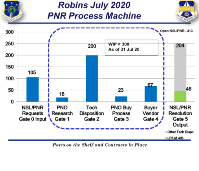
157
Stakeholders within the process were held accountable for their part of the process. PNO
Teams collaborated with ES/EN communities to establish guidelines for processing AFMC
Form 202, nonconforming technical assistant request, for PNRs. The team gained buy in for
new 202 Rules of Engagement that stated planners would initiate the 202 in accordance with
technical disposition from the ES as required. This resolved a four plus month stalemate with
planners and their supervisors at Robins AFB. The teams also established a monthly cadence
with depot customers for review of PNRs sitting in Gate 0 that lacked required information or
were not going to be submitted for processing, thus facilitating mass deletions of invalid
requests. Gate 4, Buyer/Vendor, now allows for identification of problem vendors and
facilitates the ability to report issues to senior management those issues for their involvement
when needed.
A.10.6.1. Results. Utilizing the AoP tools, we gained visibility of an average of 3000+
PNRs in the process machine. The teams resolved 5,625 PNRs across three locations from
Mar-Aug 2018. The Robins team was able to reduce their Gate 0 by 57% (823 to 353)
through cleanup of incomplete PNRs. Across all locations, the team was able to execute
$2.9M: accomplished 1,699 Government Purchase Card (GPC) purchases (to include 374
MICAPs) and 78 Purchase Requests (PRs) (including 10 MICAPs) to provide 1053 parts
to depot maintenance and field customers. In 2019, the PNO team had a visibility average
of 1700 PNRs across the process machine. They resolved 9309 PNRs across three
locations (Oct 2018-Aug 2019) and executed $3M: accomplished 1,677 GPC purchases,
38 PRs and 48 local manufacture requests to provide 1,904 parts to depot maintenance and
field customers.
A.10.7. Visual Display. The PNR Wall Walk displays a comprehensive machine with Road
to Goals, gates, and sub-gates to address the PNR workload. Visual images demonstrate how
the flow, WIP, and gate performance are measured within the PNR Process Machine (Robins
–Wall Walk Chart along with Constraints Gate Comparison Chart are below).
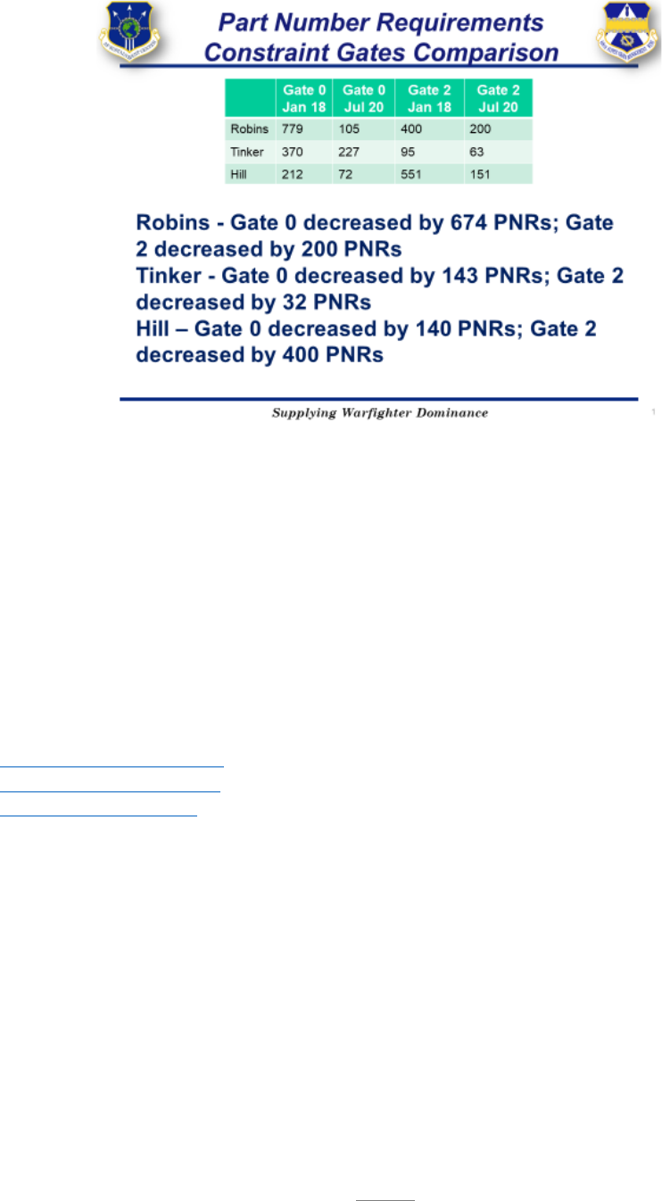
158
A.10.8. Next Steps. The next steps are to continue socializing the PNR Process Machine with
internal/external stakeholders to provide the best support for the warfighter. In addition, the
team will continue the feedback loop on the process machine to realign the daily goal and
averages creating a firm steady state throughput.
A.10.9. Lessons Learned. Constant communication and transparency among all stakeholders
are the keys to success. Improvement never stops! Always be open to learning new ways of
doing things and out of the box thinking. Do not panic - - keep the machine simplified;
minimize gates to a manageable level. Let the data steer you toward the constraints making
adjustments when necessary and adding resources where needed.
A.10.10. Contact Information: Dallas Voorhies, 406 SCMS/GULAC-Hill, DSN 586-5599,
[email protected]; Sherry Haney, 406 SCMS/GULAC-Robins, DSN 468-3057,
[email protected]; Ann Polesky, 406 SCMS/GULAC-Tinker, DSN 852-9722,

159
APPENDIX A – CASE STUDIES
A.11. 78th Air Base Wing (ABW) Nonjudicial Punishment Program and Discharge Program
A.11.1. MET for Study. 78 ABW/JA chose the Nonjudicial Punishment Program and
Discharge Program as the METs for this case study. The programs’ customers and
beneficiaries are Air Force units at Robins AFB.
A.11.1.1. Case for AoP Implementation. The nonjudicial punishment and discharge
programs were chosen for this case study because they have processing times driven by
AF guidance which are measurable. The programs’ processing times are compiled and
reflected in Automated Military Justice Analysis and Management System (AMJAMS) (a
repository for military justice case file information) and used to study how efficiently and
effectively units are processing their nonjudicial disciplinary actions and administrative
separations. At the time of AoP implementation, average processing times at Robins AFB
for these programs were not meeting the goal times outlined in AF guidance.
A.11.2. Flow. AF guidance outlines certain requirements, to include time considerations,
which was useful in developing the process flow and gates for that flow. Those time
requirements helped our office know how to structure the gates. For instance, nonjudicial
punishment guidance, AFI 51-202, has a goal metric for when nonjudicial punishment should
be offered, which is, within 21 days from discovery of the offense. Our office created a gate
to capture that gate in the process work flow.
A.11.3. WIP. The WIP for the nonjudicial punishment process is an Article 15, with
accompanying paperwork. Specifically, Article 15s are captured on AF Form 3070, which
reflects a process that requires offer, service, response, punishment, and appeal. The WIP for
the discharge process is the administrative separation paperwork. Administrative separation
houses various administrative steps, including but not limited to, notification, response,
discharge and service characterization recommendations.
A.11.4. Constraint Identification. The difficulty with the implementation of AoP to the
nonjudicial punishment and discharge processes is that, unlike a maintenance or manufacturing
process that involves consistent variables in a repetitive process, there are many unknown
variables that can occur throughout these processes because each case is unique and involve
cooperation and participation from other agencies. For instance, if during the course of
processing a nonjudicial punishment, the member becomes unavailable for personal reasons
(i.e. mental health, family emergency, etc.), the process often hits a standstill until the member
becomes available. Similarly, if a unit fails to include certain documents when submitting the
discharge package to Military Personnel Flight (MPF), MPF will not process the package until
those exclusions are resolved. These types of constraints offer a certain unknown variation
that are challenging but can be clearly identified and improved with implementation of AoP.
A.11.5. Constraint Resolution. The gates help identify where constraints occur in the process;
we brief these constraints to commanders at the Status of Discipline meetings. The

160
dissemination of this information helps us and our commanders understand at what gate the
WIP becomes a constraint. Because the process involves multiple agencies, our agency cannot
unilaterally improve the process; improvement requires transparency, accountability and buy-
in from all stake-holders.
A.11.5.1. Results. Since implementation of AoP to our nonjudicial punishment program
(quarter 3, 2019), and after removing outliers, our average processing times have been
within the goal metric (39 days) outlined by the Air Force every quarter thereafter. Our
average processing time fell from an average of 50 days to approximately 37 days. Since
implementation of AoP to our discharge program (quarter 3, 2019), our average processing
times did reach the goal metric (30 days) in quarter 1, 2020. The decline in average
processing times happened as follows: 54 days (quarter 3, 2019); 43 days (quarter 4, 2019);
29 days (quarter 1, 2020). However, in the subsequent quarter (quarter 2, 2020), we saw
average processing times jump back up to an average processing time of 49 days, which
we suspect is due to the impact of the global pandemic. The average at the end of 2020
was 40.5 days. The 39 day target was missed due to one case being in Gate 1 for 107 days.
A.11.6. Visual Display. A simple visual display of the gate charts is used for tactical
management and to monitor the machine.
A.11.7. Next Steps. Due to COVID, our office and other agencies involved in the nonjudicial
punishment and discharge processes, have primarily migrated to an electronic transmittal
process. We are mindful of the impact this may have on processing times after monitoring
them from a different working environment. By the end of CY20, we have seen processing
times improve almost to the level of pre-COVID.
A.11.8. Lessons learned. After four quarters, AoP implementation on these METs appears to
be successful. At some point, the improvement will plateau, but AoP will remain a useful tool
for monitoring and identifying the constraints in the programs so we can address and adjust as
necessary.
A.11.9. Contact Information: Major Teah Lambright, 78 ABW/JA, DSN 497-45829.

161
APPENDIX A – CASE STUDIES
A.12. 574
th
Commodities Maintenance Squadron (574 CMMXS) Supplies Repaired and
Overhauled Components for Aircraft
A.12.1. MET for Study. The 574 CMMXS supplies repaired and overhauled components for
aircraft undergoing depot maintenance in 402nd Aircraft Maintenance Group (routed assets)
and for the 78 LRS and DLA managed Air Force supply system (Managed Items Subject to
Repair (MISTR) assets). These components primarily support C-5, C-17, C-130, F-15, and E-
8 aircraft and undergo various structural and composite material repair and overhaul processes.
This case study highlights the streamlining of the business processes, managing those
operations in transitioning from twenty-one individual AoP machines into two METs: MET 1
– Repair and Overhaul of Routed Assets & MET 2 – Repair and
Overhaul of MISTR Assets and the governing AoP fundamentals.
A.12.1.1. Case for consolidating machines. In late August 2020 the performance indicators
for 574 CMMXS were all in the red. Asset flow days were exceeding customer
agreements, WIP was high, earned hours were 30% below fiscal targets, and indirect time
exceeded budget (even accounting for COVID-19 effects). The team looked to AoP
fundamentals to assess the current state and develop an improvement strategy.
A.12.1.1.1. The initial approach to gating the processes was to create 21 machines for
all of the product lines. The work content of operations was characterized by twenty-
one machines and each contained multiple products and types of products. For
example, one machine contained routed and MISTR rudders for F-15, MISTR elevators
for F-15, and routed and MISTR C-130 leading edges. Another contained routed and
MISTR C-130 scoops, MISTR C-130 hatches, and routed and MISTR C-130 ramps.
This was both confusing to manage and difficult to measure. The visuals were
cumbersome and the data was difficult to analyze.
A.12.1.1.2. Twenty-one machines made it difficult to understand the METs and
common goals were confusing to those within the squadron and with customers and
partners. Input and induction targets varied by month across all the machines and
throughput varied without controls or feedback loops.
A.12.1.1.3. WIP was difficult to quantify across twenty one machines and had
gradually increased to troublesome levels.
A.12.1.1.4. Synchronization required excessive management bandwidth. With so
many machines to monitor, creating a synchronized plan and ensuring supportability
was a confusing and cumbersome process.
A.12.2. Flow. The process engineering team worked with production shops and planners to
improve the machine design. The 21 product lines were consolidated into two METs (MET 1
– Routed Assets, MET 2 – MISTR Assets). The team created a visual depiction of the
machines enabling the team to see WIP targets and gate structure. The visuals highlighted the

162
need for streamlining to a standard gate structure to help control WIP and control the release
of supportable work. This led to a standard 5 gate structure for all products and implementing
targets for inspection complete and total technical resolution. While flow day targets still vary
by product line depending on the work content, the gate structure is the same: induct,
disassemble & inspect, repair, build up, final. This simplification improved the ability to
manage WIP and ensure a synchronized plan is established for each asset entering repair.
A.12.3. WIP. With the simplified machine design, common goals were established with
customers for both METs. These goals helped improve the Road to…Goals and refine
appropriate WIP levels. The Commodities Maintenance Team (CMT) executes standard work
for WIP and supportability management at the shop level. These teams release supportable
work into the shop and work to resolve or elevate constraints.
A.12.4. Constraints. The simplified machine design quickly identified the Repair Gate as the
constraint. Using the focusing steps we next exploited the constraint to get the most work out
of it. This meant first prioritizing resources in inspection to ensure only supportable work was
released into the Repair Gate. All of the additional work we were performing in the Repair
Gate is now done prior to entering repair. Ordering parts and materials and answering
engineering requests is accomplished prior to repair to prevent waiting and down time in the
Repair Gate. We also subordinated asset inductions to the Repair Gate throughput to maintain
WIP level. We will continue monitoring performance and apply additional focusing steps as
we progress.
A.12.5. Results. Flow days are decreasing; people are becoming more engaged in the process.
The new process makes it easier to control WIP. Routed assets are meeting flow day
requirements for the first time in over a year. The process is becoming less variable and
constraints are becoming more obvious. The team expects to see continued improvements and
flow day reduction with constraint resolution and therefore continued improvements in
consistently meeting common goals.
A.12.6. Next Steps. The team is currently running the system. The streamlined system is
easier to manage and more engaging for the team. The team is able to take ownership of the
performance gaps and find ways to solve problems to positively impact the common goals.
A.12.7. Lessons learned. Simplifying the machines helped manage the process.
A.12.7.1. Too many machines make the operations management task cumbersome and
confusing. Simplifying helped identify the constraints and focus improvement efforts.
A.12.8. Contact Information: Joshua A. Campbell, 574 CMMXS/CL, 478-319-0433, DSN;
497-2617.
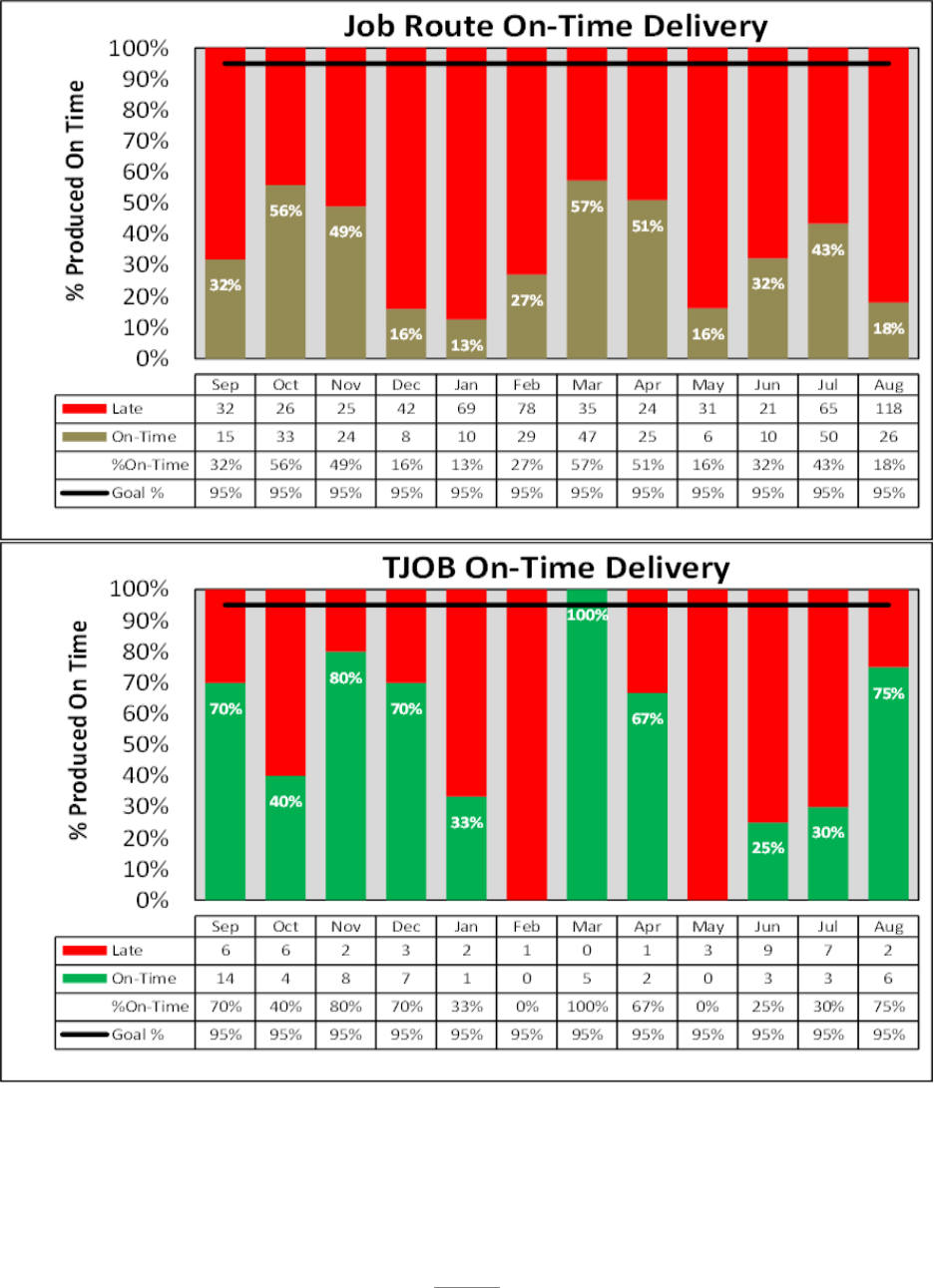
163
574 CMMXS Current State On-Time Delivery Data
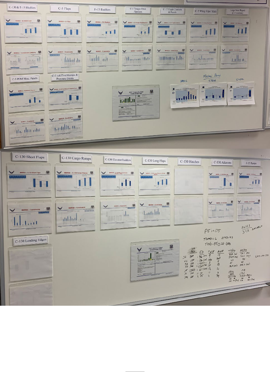
164
21 Product Lines
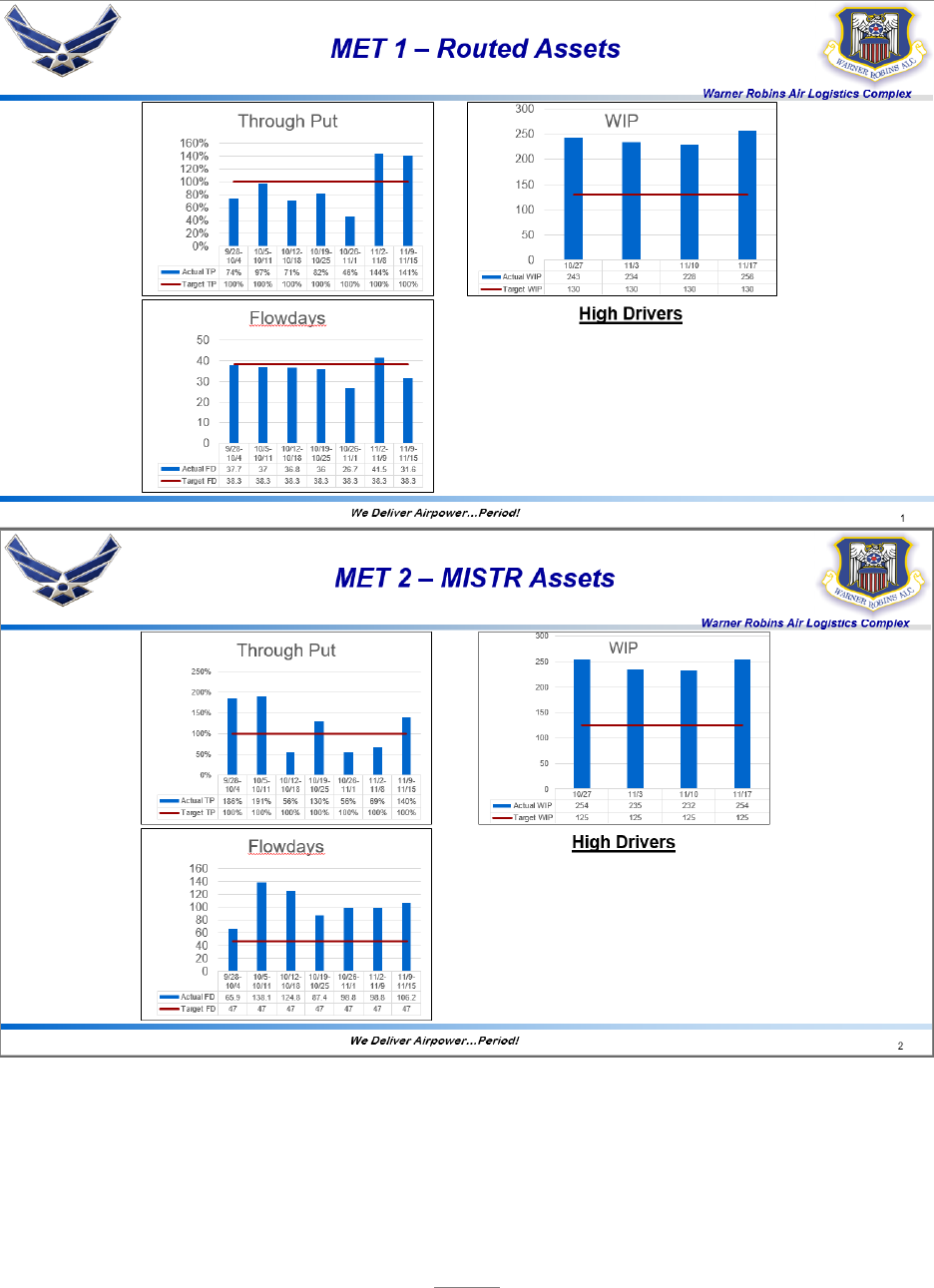
165
MET 1 and MET 2
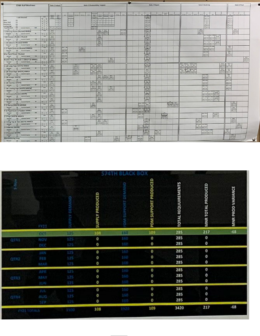
166
The Black Box Goal
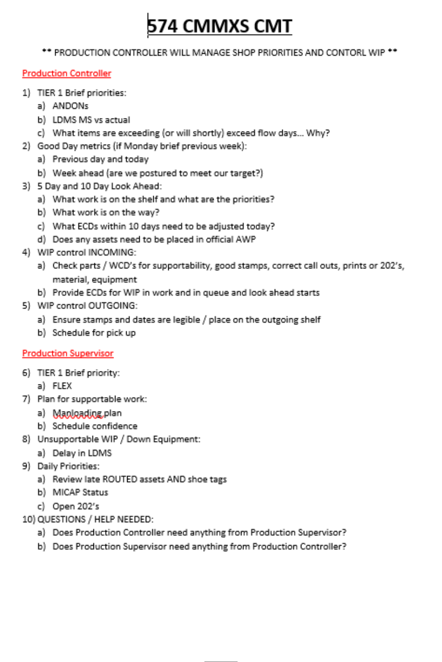
167
Synchronized Schedule CMT Script
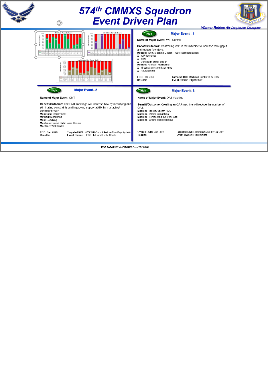
168
574 CMMXS Event Driven Plan

169
Attachment 1
GLOSSARY OF REFERENCES AND SUPPORTING INFORMATION
References
Joint Publication (JP) 4-0, Joint Logistics, 8 May 2019
AFPD 20-1, Integrated Life Cycle Management, 7 Aug 2018
AFMCI 21-301, AFMC TO System Implementing Policies, 7 Jun 2017
AFMCI 23-111, Reclamation of Air Force Property, 1 Feb 2019
AFMCMAN 23-501V1, D035A, D035B, and WHSL Module Data Sub-Systems, 11 Apr 2017
AFI 33-322, Records Management and Information Governance Program, 10 Mar 2020
AFI 51-202, Nonjudicial Punishment, 6 Mar 2019
AFPD 60-1, Air Force Standardization Program, 19 Mar 2019
AFSCI 60-101, Art of the Possible, 22 Sep 20
AFPD 63-1, Integrated Life Cycle Management, 7 Aug 2018
AFI 63-101/20-101, Integrated Life Cycle Management, 30 Jun 2020
AF Manual 63-143, Centralized Asset Management Procedures, 18 Dec 2020
AFMCMAN 63-1202, Air Force Material Command Engineering Technical Assistance (ETAR)
Process, 4 Nov 2020
TO 00-5-1, AF Technical Order System, AFMC Technical Order System Procedures
TO 00-5-3, Air Force Technical Order Life Cycle Management, Military Standard (MIL-STD)-
38784, Manuals, Technical: General Style and Format Requirements
Maxwell, J. C. (2007). The 21 Irrefutable Laws of Leadership Workbook: Revised and Updated
(10th Anniversary ed.). HarperCollins Leadership.
Culture Definition. (2019). Businessculture.Org. https://businessculture.org/business-
culture/#:~:text=In%20other%20words%20culture%20can%20be%20defined%20as,and%20all
%20business%20functions%20from%20accounting%20to%20production.
Greenleaf, R. (n.d.). Ten principles of servant leadership. Retrieved December 16, 2013 from:
http://www.butler.edu.volunteer/resources/principles-of-servant-leadership//
Corbridge, T., Jones, J., Hickman, C., & Smith, T. (2019). Propeller: Accelerating Change by
Getting Accountability Right (Illustrated ed.). Portfolio.

170
Goldratt, E. M., & Cox, J. (2014). The Goal: A Process of Ongoing Improvement (30th
Anniversary Edition). North River Press.
Sinek, S. (2011). Start with Why: How Great Leaders Inspire Everyone to Take Action
(Illustrated ed.). Portfolio.
Where to find the hours to make it happen | Derek Sivers. (2019, October 1). Deric Sivers.
https://sive.rs/uncomf
Charles Kettering Quotes. (n.d.). BrainyQuote.com. Retrieved December 3, 2020, from
BrainyQuote.com Web site: https://www.brainyquote.com/quotes/charles_kettering_181210
Additional references and reading material can be found at the following link:
https://cs2.eis.af.mil/sites/22197/AoP/SiteCollectionDocuments/Forms/AllItems.aspx?RootFolde
r=%2Fsites%2F22197%2FAoP%2FSiteCollectionDocuments%2FTools%2F1%2E%20%20Guid
ance%20and%20Additional%20Reading&FolderCTID=0x012000DAB383134B80214DA2915
E65CA1D21A9&View=%7BD14873CF%2DA051%2D4026%2D9BDB%2D9A133FA658AB
%7D
Prescribed Forms
DD Form 1348-6, DOD Single Line Item Requisition System Document
AF Form 847, Recommendation for Change of Publication
AF Form 3070, Record of Nonjudicial Punishment Proceeding
AFTO Form 252, Technical Order Publication Change Request
AFTO form 202, Request for Engineering Resolution
Abbreviations and Acronyms
2LM – Two Level Maintenance
ABW – Air Base Wing
AFB – Air Force Base
AFGSC – Air Force Global Strike Command
AFI – Air Force Instruction
AFIMS – Air Force Information Management System
AFLCMC – Life Cycle Management Center
AFMC – Air Force Material Command
AFMCI – Air Force Material Command Instruction
AFNWC – Air Force Nuclear Weapons Center
AFPD – Air Force Policy Directive
AFPET – Air Force Petroleum Agency
AFRIMS – Air Force Records Information Management System
AFSC – Air Force Sustainment Center
AFSCI – Air Force Sustainment Center Instruction

171
AFSOC – Air Force Special Operations Command
AFTO – Air Force Technical Order
AIS – Advanced Intermediate Shop
AMARG – Aerospace Maintenance and Regeneration Group
AMJAMS – Automated Military Justice Analysis and Management System
AMXS – Aircraft Maintenance Squadron
AO – Action Officer
AoP – Art of the Possible
AOR – Area of Responsibility
ASD – Aerospace Sustainment Division
AWM – Awaiting Maintenance
AWP – Awaiting Parts
Az/EI – Azimuth Elevation Compensator and Power Amplifier
BLUF – Bottom Line Up Front
BO – Backorder
CCA – Circuit Card Assembly
CCPM – Critical Chain Project Management
CMMXS – Commodities Maintenance Squadron
CMRS – Commodities Reclamation Squadron
CMT- Commodities Maintenance Team
CMXG – Commodities Maintenance Group
CPI – Continuous Process Improvement
CSO – Combat Support Offices
CTOL – Conventional Takeoff and Landing
CTOL/CV – Conventional Takeoff and Landing Carrier Variant
DBR – Drum Buffer Rope
DDE – Demand Data Exchange
DEA – Designated Engineering Authority
DevSecOps –Development/Security/Operations
DFT – Depot Field Team
DHA – Demand History Adjustment
DLA – Defense Logistics Agency
DoD – Department of Defense
DOTmLPF-P – Doctrine, Organization, Training, materiel, Leadership, Personnel, Facilities,
and Policy
DSCM – Depot Supply Chain Management
DTC – Data Transfer Cartridge
EDD – Estimated Delivery Date
EDP – Event Driven Plan
EMXS – Electronics Maintenance Squadron
eNCMR – electronic Non-conforming Material Review
ES – Equipment Specialist
ETIMS – Enhanced Technical Information Management System
EVSM – Enterprise Value Stream Mapping
EXPRESS – Execution and Prioritization Repair Support System
FCRATS – Fire Control Radar Antenna Test System

172
FMS – Foreign Military Sales
FOD – Foreign Object Damage
GFE – Government Furnished Equipment
GFM – Government Furnished Material
GFP – Government Furnished Property
GLSC – Global Logistics Supply Chain
GPC – Government Purchase Card
GSU – Geographically Separated Unit
GWOT – Global War on Terror
HAF – Headquarters Air Force
IAW – In Accordance With
IBS – Integrated Battle Station
ICBM – Intercontinental Ballistic Missile
IDL – Indirect Labor
IDM – Integrated Data for Maintenance
IFDIS – Intermittent Fault Detection Isolation System
ILSA – Item Level Supply Assignment
IM – Item Manager
IMS – Integrated Master Schedule
IPT – Integrated Process Team
JDI –Just Do Its
JP – Joint Publication
JPO – Joint Program Office
LCC – Launch Control Center
LDMS – Lean Depot Maintenance System
LF – Launch Facility
LG – Logistics Directorate
LGS – Logistics Directorate’s Performance Management Division
LNA – Low Noise Assembly
LRDP – Logistics Requirements Determination Process
LRDP-P – Logistics Requirements Determination Process for Propulsion
LRS – Logistics Readiness Squadron
LRU – Line Replaceable Unit
MC80 – Mission Capable 80%
MDS – Mission Design Series
MET – Mission Essential Task
METL – Mission Essential Task List
MGA – Major Graded Area
MICAP – Mission Impaired Capability Awaiting Part
MIL-STD – Military Standard
MILE – Minuteman Integrated Life Extension
MISTR – Managed of Items Subject to Repair
MLPRF – Modular Low Power Radio Frequency
MMIII – Minuteman III
MMXS – Missile Maintenance Squadron
MP – Mission Planning

173
MPE – Mission Planning Environment
MPF – Military Personnel Flight
MPS – Master Production Schedule
MRB – Material Review Board
MRO – Maintenance Repair and Overhaul
MSS – Missile Stabilization System
NSL/PNR – Non-Stock Listed/Part Number Request
OC-ALC – Oklahoma City Air Logistics Complex
OO-ALC – Ogden Air Logistics Complex
OO-ALC/OB – OO-ALC Business Office
OPR – Office of Primary Responsibility
OTD – On Time Delivery
PBI –Product Backlog Items
PCR – Publication Change Request
PDM – Programmed Depot Maintenance
PLS – Production Logistics Support
PMXG –Propulsion Maintenance Group
PMXS –Propulsion Maintenance Squadron
P/N – Part Number
PNO – Part Number Office
PNR – Part Number Requisition
PNSSR –Part Number Supply Support Request
POU – Point of Use
PO – Process Order
PPSM – Practical Problem Solving Method
R2D2 – Requirements Review Depot Determination
RDS – Records Disposition Schedule
RF – Radio Frequency
RFT – Ready for Test
RO – Requisition Objective
RP – Receiver Protector
SCMG – Supply Chain Management Group
SCMS – Supply Chain Management Squadron
SCMP – Supply Chain Mitigation Process
SCMW – Supply Chain Management Wing
SCOW – Supply Chain Operations Wing
SGML – Generalized Markup Language
SIPOC – Supplier Input Process Output Customer
SM – System Manager
SME – Subject Matter Expert
S/N – Serial Number
SOCCER – Senior Officer Communication and Coordination Electronic Resource
SOR – Source of Repair
SOW – Statement of Work
SPO – System Program Office
STOVL – Short Takeoff Vertical Landing

174
SWEG – Software Engineer Group
TCTO – Time Compliant Technical Order
TMIS –Technical Manual Information System
TMSS –Technical Manual Specifications and Standards
TO – Technical Order
ToC – Theory of Constraints
TOMA –Technical Order Management Agency
UDLM – Unplanned Depot Level Maintenance
Val/Ver – Validation/Verification
VM – Virtual Machine
VPP – Voluntary Protection Program
W3 – Walking, Watching, and Wandering
WCD – Work Control Document
WIP – Work In Process
WR-ALC – Warner Robins Air Logistics Complex
WRE – War Readiness Engine
YBQ – Delayed Discrepancy Requisition
Glossary
This glossary is intended as an explanation of terms that may be new or uncommon.
Art of the Possible (AoP) – A constraints based management system designed to create an
environment for success by creating a culture of problem-solvers, defining processes (aka
machines), eliminating constraints, and continuously improving. It is the framework for how the
AFSC conducts business and how we strive to achieve world class results in warfighter support.
Andon – A signal used to call for help when an abnormal condition is recognized, or that some
sort of action is required. (Andon comes from an old Japanese word for paper lantern).
Comfortable in Red – Refers to the willingness to set aggressive targets with the understanding
the metrics will show as “red” until process throughput efficiencies improve.
Common Goals – Organizational goals that should be understood and shared across the
organization. Common goals should include goals for speed, safety, quality and Cost
Effectiveness.
Constraint – Systemic machine or Process bottlenecks that hinder throughput.
Constraint Gate – The gate with the lowest throughput.
Continuous Process Improvement (CPI) – The focus of continuously improving the flow of
work through the organization using a combination of tool sets such as: Lean, 6-Sigma, and ToC.
Critical Path – A sequence of activities in a project plan which must be completed by a specific
time for the project to be completed on its need date. The AFSC adaption of this term refers to the

175
linkage of critical elements in a process or project that keep an asset realistically moving forward
toward completion.
Drum Buffer Rope (DBR) – A schedule methodology that controls the release of work into the
system. It is a pull system in the sense that when a job is completed by the constraint resource, it
sends a pull signal to trigger the release of a new job into the system.
Flowtime – The average time that a unit stays in a production machine.
Kanban – A system to set standard min/max levels and establish a proactive re-order point.
Maturity Matrix – AFSC method of measuring organizational maturity with regard to the
adaption of principles found in the “Execution” section of the AFSC Radiator Chart.
Process Machine – Refers to the science of the process and implies that any process can be gated
in order to measure throughput and focus process improvement activities.
Queue – Assets awaiting induction to a process. Also a WIP control tool in a gated monitoring
system.
Quick Issue Resolution – The rapid identification and resolution of one time issues that affect the
movement of individual items through the machine.
Radiator Chart – Model depicting the fundamental components of the AoP methodology.
Personnel Loading – A systematic assignment of personnel to jobs or tasks in an efficient manner.
Road to…Goal – Reflects the throughput-pace required for both the interest of the customer and
the organization. The throughput goal that sets the pace of the process.
Specified tasks – Tasks directly stated in the mission, by the next higher commander, or by law
or regulation.
Standard Work – A detailed, documented and sometimes visual system by which team members
follow a series of predefined process steps. It is how work is accomplished and is defined by
technical data, process orders, regulations, instructions, or approved checklists.
Tactical Management – An established frequent review of WIP flowing through the process
machine. It focuses on the individual items of WIP flowing through the process machine rather
than the process machine performance at the operational level.
Takt Time – The rate of customer demand, how often a single unit must be produced from a
machine (takt is a German word for rhythm or meter).

176
Theory of Constraints (ToC) – 1. Identify the system's constraint(s), 2. Decide how to exploit
the system's constraint(s), 3. Subordinate everything else to the above decision, 4. Elevate the
system's constraint(s), 5. Return to step one but beware of inertia WIP.
Throughput – The required output of a production machine expressed in units per time.
Traditional definition based on ToC - The rate at which the system generates money through sales.
Urgency Tools – Process tools that allow an organization to react and quickly resolve constraints
encountered during process execution.
Value Stream Map (VSM) – A method of creating a simple diagram of the material and
information flow that bring a product through a value stream.
Visual Management – The use of simple visual indicators to help people determine immediately
whether they are working inside the standards or deviating from it, this must be done at the place
where the work is done.
Wall Walk – A recurring process-focused review to understand process machine performance,
to identify constraints, and to coordinate constraint resolution.
