
1
Simon® Basic : 2
Special Installation Requirements 3
Requirements for UL-Listed Installations 3
Canada Listings (pending) 3
California State Fire Marshall Listing 3
Introduction 4
System Components 4
Planning Sensor Types & Locations 7
Planning Control Locations 10
Planning for Lamp*, Appliance*,
Wallswitch*, and Universal/Garage
Door* Module Control 10
Settin
g
the House Code and Unit Number 10
Planning System Access Codes 12
Utility Access Code 1 12
Utility Access Code 2 12
Master Access Code 12
Access Codes (1 - 5) 12
Panic Code 12
Planning System Options 12
Reset Memory to the Factory Defaults 20
Wiring the Control Panel 23
Connecting Hardwire Interior Sirens 23
Connecting a Hardwire Exterior Siren 23
Connecting Hardwire Sensors 23
Connecting the Universal/Garage Door
Opener Module* 24
Connecting the Power Transformer 24
Connecting the Backup Batteries 24
Installin
g
a Non-rechar
g
eable Battery 24
Installin
g
a Rechar
g
eable Battery 25
Connecting the Phone Line to the Control
Panel 25
Installin
g
an RJ-31X Jack 25
Connectin
g
the Phone Line to the Control
Panel 25
Programming Overview 26
Pro
g
rammin
g
Sensors 27
Programming the House Code and Unit
Numbers* 28
Programming Light and Appliance Con-
trols* 28
Programming Options 29
Programming System Access Codes 30
Installing the System 31
Control Panel General Information 31
Control Panel Specifications 31
Installation Guidelines 31
Sensor Installation 32
Testin
g
the Control Panel 32
Testing the System 32
Testing Sensors 33
Sensor Trippin
g
Instructions: 33
If a Sensor Fails the Sensor Test 34
Testing Phone Communication 34
Testing Central Station Communication 34
Testing the X-10 Lamp Modules* 35
Siren and X-10 Lamp Module Functions*
35
Panel Tamper 35
Troubleshooting 36
Typical Backup Battery Life of the 9 Volt Ul-
traLife 38
Notices 39
Index 40
Quick Reference Guide 44
Simon
®
Security System
Installation Instructions
Document No. 466-1574
Rev E Dated March 1999
Table of Contents
Attachment: 466-1622, Booklet of Installa-
tion Instructions for SAW Sensors

.
2
Simon
®
Basic :
Features
not
Available with the
Simon
®
Basic ITI # 60-776-02-95R
2-Wa
y
Voice
Remote Phone Control
S
p
eaker Volume Control
Chime S
p
ecial Motion
Li
g
ht Control
Wireless Sirens
Options
not
for Use with Simon
®
Basic
O
p
tion 33: 2-Wa
y
Voice
O
p
tion 36: Sensor Activated Li
g
ht Lockout Start
Time
O
p
tion 37: Sensor Activated Li
g
ht Lockout Sto
p
Time
O
p
tion 42: S
p
eaker Level
O
p
tion 46: Fire Shutdown - AVM
O
p
tion 47: AVM Mode
O
p
tion 48: Panic Talk
Modules that
Cannot
be Used with
Simon
®
Basic
Interro
g
ator 200 Audio Verification Module
®
(AVM) (60-787)
X-10 Lam
p
(13-403)
A
pp
liance (13-402)
Powerhorn/Remote (13-398)
Universal/Gara
g
e Door (13-399)
Wall Switch Modules (13-397)
Touchtalk 2-Wa
y
RF Touch
p
ad (60-788-95R)
Su
p
ervised Wireless Siren SWS (60-736-95)

Installation Instructions Document No. 466-1574
3
Special Installation Require-
ments
This security system can be used as a fire warning
system, an intrusion alarm system, an emergency no-
tification system, or any combination of the three.
Some installations may require certain configurations
dictated by city codes, state codes, or insurance re-
quirements. The following information indicates the
components of various listings.
Requirements for UL-Listed Installa-
tions
This section describes the minimum system configu-
rations for UL-listed, Grade A (supervised) systems.
Typical System
All UL-listed systems require the following basic
components. The basic system does not require sen-
sors and can use the Remote Handheld Touchpad as a
controlling device.
• Basic Control Panel (60-776-02-95R)
• Control Panel (60-776-95R)
• Control Panel On-Board 2-Way Voice (60-776-
01-95R)*
• Class II Line Carrier Power Transformer (22-
091)*
• 9-Volt, 1.2 Ah Lithium Backup Battery (34-037)
or a rechargeable 7.2Volt, 1 Ah Nickel Metal
Hydride Battery Pack (34-052)
• Hardwire Siren (13-046) or LD105 Siren (13-
374)
Residential Burglary Alarm System Unit (UL
1023)
Basic system above, plus:
• Door/Window Sensor (60-670-95R) suitable for
installation on non-ferrous surfaces only
Residential Fire Alarm System Unit (UL 985)
Basic system above, plus:
• System Sensor Smoke Sensor (60-506-95)
Canada Listings (pending)
Residential Burglary Alarm System Unit
(ULC-S309)
Basic system as described for UL-listed installations,
plus:
• Door/Window Sensor (60-670-95R)
Note
: The KeyChain Touchpad #60-659 is UL Listed as a
miscellaneous signalling device and is for supplementary
use only.
CSA Certified Accessories
Residential Fire Warning System Control Unit
(ULC-S545-M89)
Basic system as described for UL-listed installations,
plus:
• Wireless Smoke Sensor (60-506-95)
• SUPSYNC (Supervisory Synchronization) set to
2 (hours)
California State Fire Marshall Listing
The California State Fire Marshall listing is approved.
* = Not Available with Basic Model
Installation Instructions Document No. 466-1574.
4
Introduction
This ITI Securit
y
S
y
stem is eas
y
to install if
y
ou
p
lan
ahead and
p
erform the installation in the followin
g
or-
der.
1. Plan where to locate the hardwire sirens, sensors
and Control Panel. Use the tear out
p
lannin
g
sheets at back of this manual.
2. Wire the Class II transformer, hardwire sirens,
and
p
hone.
3. Decide how the sensors, li
g
hts, and s
y
stem
o
p
tions will o
p
erate.
4. Pro
g
ram the sensors, li
g
hts and a
pp
liances, and
s
y
stem o
p
tions.
5. Install sensors and Li
g
htin
g
Modules.
6. Test s
y
stem.
Note
: Program the sensors before installing them because
the Control Panel and sensors must be in the same place
for programming. After you’ve programmed each sensor,
you can install them where you planned.
System Components
The s
y
stem can monitor u
p
to 24 sensors usin
g
an
y
combination of the followin
g
sensors:
• Door/Window Sensor (60-670-95R)
•Ke
y
Chain Touch
p
ad (60-659-95R)
• Remote Handheld Touch
p
ad (60-671-95R)
• Touchtalk 2-Wa
y
RF Touch
p
ad (60-788-95R)*
• Indoor Motion Sensor (60-639-95R)
• Outdoor Motion Sensor (60-639-95R-OD)
• Carbon Monoxide Alarm (60-652-95)
• Water Sensor (60-744-95R)
• Freeze Sensor (60-742-95R)
• SWS (60-736-95)*
• ITI 319.5 Sensors (includin
g
Smoke Sensors,
excludin
g
other touch
p
ads)
Note
: Both ITI SAW and Crystal sensors function with this
Control Panel.
You ma
y
use an
y
of these modules:
•Interro
g
ator
®
200 Audio Verification Module
(AVM) (60-787)*
• X-10 Lam
p
Modules (13-403)*
• X-10 A
pp
liance Modules (13-402)*
• X-10 Powerhorn/Remote Siren Modules (13-
398)*
• X-10 Universal/Gara
g
e Door Modules (13-399)*
• X-10 Wall Switch Modules (13-397)*
Note
: Use of the above X-10 modules has not been inves-
tigated by UL.
Fi
g
ure 1. shows the Control Panel, control touch
p
ads,
and some com
p
atible sensors and modules.
Figure 1. Typical Security System Components
Security System
The securit
y
s
y
stem has three t
yp
es of com
p
onents:
the Control Panel, devices that re
p
ort to the Control
Panel, and devices that res
p
ond to commands from
the Control Panel.
Control Panel
The Control Panel is the main
p
rocessin
g
unit for all
securit
y
functions. It receives si
g
nals from and re-
s
p
onds to wireless sensors and wireless touch
p
ads
throu
g
hout the
p
remises. The buttons o
p
erate the se-
curit
y
s
y
stem. When usin
g
the Control Panel with the
cover o
p
en, the buttons
p
ro
g
ram the securit
y
s
y
stem.
Two confi
g
urations of the Simon Control Panel are
available. One has an on-board 2-wa
y
voice micro-
p
hone, the other does not. The Interro
g
ator® can be
added to either confi
g
uration.
X-10 POWERHOUSE
1
3
5
9
13
7
11
15
A
C
E
I
M
GK
O
UNIT CODE
HOUSE CODE
CONTINUOUS
MOMENTARY
SOUNDER ONLY
SOUNDER & RELAY
RELAY ONLY
ON
OFF
DOOR/WINDOW
SENSOR
LAMP
MODULE
APPLIANCE
MODULE
GARAGE DOOR
MODULE
REMOTE
HANDHELD
TOUCHPAD
MOTION
SENSOR
KEYCHAIN
TOUCHPAD
SMOKE
SENSOR
8988G21D.DSF
1
3
5
9
13
7
11
15
A
C
E
I
M
GK
O
1
3
5
9
13
7
11
15
A
C
E
I
M
GK
O
7
4
1
89
5
2
6
3
Off
sP
EMERGENCY
On
d&sre s Hol hBtoeKy
DISARM
SYSTEM
STATUS
Doors &
Windows
ARM
ARM
Sensors
Motion
-
CARBON
MONOXIDE
DETECTOR
CARBON MONOXIDE
ALARM
TOUCHTALK
2-WAY RF
TOUCHPAD
AUDIO VERIFICATION
MODULE
* = Not Available with Basic Model

Installation Instructions Document No. 466-1574
5
Door/Window Sensor
For intrusion protection, install Door/Window sen-
sors on all ground-floor doors and windows. At a min-
imum, install them in the following locations:
• All easily accessible exterior doors and windows.
• Interior doors leading into the garage.
• Doors to areas containing valuables such as cabi-
nets and closets.
KeyChain Touchpad
The KeyChain Touchpad enables you to turn the sys-
tem on and off from right outside the home or to turn
on the siren and to call the central monitoring station
if there is an emergency. If you have Lamp Modules,
you can use the KeyChain Touchpad to turn all sys-
tem controlled lights on and off.
Remote Handheld Touchpad
The Remote Handheld Touchpad enables you to turn
the system on and off while in the home, turn lights
controlled by the system on and off (all or individual
lights), or turn on a system siren and call the central
monitoring station if there is a non-medical emergen-
cy. The Remote Handheld Touchpad will report an
alarm type specific to its sensor type (see Table 3 on
page 9 for sensor and siren types).
Touchtalk 2-Way RF Touchpad*
The wall-mounted wireless Touchtalk 2-Way RF
Touchpad enables you to arm and disarm the system
while in the home, turn system controlled lights on
and off (all or individual lights), turn on a system si-
ren, or call the central monitoring station if there is a
non-medical emergency. The Touchtalk 2-Way RF
Touchpad will report an alarm type specific to its sen-
sor type (see Table 3 on page 9 for sensor and siren
types). It annunciates status beeps and Control Panel
voice feedback.
Note: Use of the Touchtalk 2-Way RF Touchpad has not
been investigated by UL.
Indoor Motion Sensor
Indoor Motion Sensors are ideal whenever it is not
practical to install Door/Window sensors on every
opening. Identify areas where an intruder is likely to
walk. Large areas in an open floor plan, downstairs
family rooms, and hallways are candidates for Indoor
Motion Sensors. Indoor Motion Sensors are not suit-
able for rooms where pets can enter. Indoor motion
sensors can also be used to sound chimes, but cannot
be used for intrusion protection and as a chime sensor
simultaneously.
Outdoor Motion Sensor
Use Outdoor Motion Sensors to identify motion in a
protected outdoor area. Detected motion in this pro-
tected area can sound chimes or turn on outside lights.
Do not use Outdoor Motion Sensors for intrusion pro-
tection.
Smoke Sensor
Smoke Sensors can provide fire alert protection by
causing the alarm to sound throughout the house. You
can add smoke sensors near sleeping areas and other
floors of the house. Avoid areas which could have
some smoke or exhaust such as attics, kitchens, above
fireplaces, dusty locations, garages, and areas with
temperature extremes. In these areas you may want to
install Rate-of-Rise sensors to detect extreme temper-
ature changes. See the instructions packaged with the
Smoke Sensor for complete placement information.
Refer to the diagram on the next page for specific
placement of Smoke Sensors.
ITI ToolBox
®
The ITI ToolBox is a Windows
®
-based program that
saves you time by simplifying Control Panel pro-
gramming. Using only a PC, a modem, and a standard
telephone line, ToolBox makes creating new custom-
er accounts and updating the panel settings of existing
customers simple and quick. See the ITI ToolBox
manual and ToolBox’s on-line help for instructions to
use ToolBox for programming this Control Panel.
The ITI ToolBox has not been investigated by UL and
should not be used on UL Listed Systems.
CAUTION!: The Downloader code (option 09) should al-
ways be changed to avoid competitor theft.
ITI CS-5000 Receiver
The CS-5000 Receiver is used to monitor this security
system.
* = Not Available with Basic Model
Installation Instructions Document No. 466-1574.
6
Living
Room
Dining
Room
Basement
x
H
Hall
Bedroom
Bedroom
Living
Room
Recreation
Room
Basement
Hall
Bedroom
Bedroom
Living
Room
Dining
Room
Hall
Bedroom
Bedroom
Bedroom
Kitchen
A smoke detector should
be located on each level.
Smoke detectors should
be located between the
sleeping area and the rest
of the family living unit.
NOTE: Do not install smoke detectors where normal ambient temperatures are above
100°F or below 40°F. Also, do not locate detectors in front of AC/ Heat
registers or other locations where normal air circulation will keep smoke
from entering the detector.
NOTE: Additional information on household fire warning is available at nominal
cost from: The National Fire Protection Association, Batterymarch Park,
Quincy, MA 02269. Request Standard No. NFPA74.
H
x
Living
Room
Bedroom
Bedroom
Bedroom
Dining
Room
Kitchen
TV
Room
In family living units with more
than one sleeping area, locate a
smoke detector at each area.
H
NOTE: Ceiling-mounted smoke detectors should be located in the center of the room
or hall, or not less than 4 inches from the wall. When the detector is mounted
on the wall, the top of the detector should be 4 to 12 inches from the ceiling.
Required smoke detector
Heat detector
Indicates smoke detector is optional if door is not provided between
basement and recreation rooms.
8557144a
ITI HomeLink
®
Transceiver (IHT)
The ITI HomeLink Transceiver is a radio transmitter/
receiver desi
g
ned to receive si
g
nals from the Prince
Universal Transmitter (HomeLink
®
), then retransmit
the si
g
nals to a securit
y
s
y
stem
p
anel, allowin
g
the
HomeLink
®
to control the armin
g
, disarmin
g
, and
li
g
ht functions of the securit
y
s
y
stem. The IHT also
enables the user to control the
g
ara
g
e door o
p
ener
from the HomeLink
®
.
The ITI HomeLink Transceiver has not been investi-
g
ated b
y
UL and should not be used on UL Listed
S
y
stems.
SWS*
The Su
p
ervised Wireless Siren (#60-736-95) annun-
ciates alarm a
pp
ro
p
riate sounds and because of its
back-u
p
batter
y
, functions when the
p
ower is off. Su-
p
ervised means that the siren will notif
y
the Control
Panel durin
g
trouble conditions such as low batter
y
,
p
ower failure, etc.
Note: Use of the SWS has not been investigated by UL.
Carbon Monoxide (CO) Alarm
The Learn Mode CO Alarm (#60-652-95) alerts users
to hazardous levels of carbon monoxide
g
as. If dan-
g
erous concentrations of
g
as are
p
resent, the CO
Alarm’s red indicator li
g
ht comes on, its internal siren
g
oes off, and it transmits an alarm to the Control Pan-
el. The Control Panel sounds its own alarm and calls
the central station.
Interrogator
®
200 Audio Verification Module
(AVM)*
The AVM (#60-687)
g
ives the central station o
p
erator
the abilit
y
to hear what’s ha
pp
enin
g
at the
p
remises
durin
g
an alarm and s
p
eak directl
y
to the s
y
stem user.
The o
p
erator can then determine how serious an alarm
is, find out what kind of hel
p
is needed, and dis
p
atch
the a
pp
ro
p
riate assistance. Onl
y
one AVM ma
y
be in-
stalled
p
er Control Panel.
Note: Use of the above module has not been investigated
by UL.
Emergency Planning Floor Plan
Use the followin
g
g
uidelines when
drawin
g
an emer
g
enc
y
p
lannin
g
floor
p
lan for the homeowner:
• Show all buildin
g
levels.
• Show exits from each room (2
exits
p
er room are recom-
mended).
• Show the locations of all secu-
rit
y
s
y
stem com
p
onents.
• Show the locations of an
y
fire
extin
g
uishers.
* = Not Available with Basic Model

Installation Instructions Document No. 466-1574
7
Planning Sensor Types & Locations
The first step to an easy and successful installation is
to decide what areas or items to protect, which lights
or appliances to operate, and the best location for the
Control Panel, touchpad, sensors or sirens. Use the
previous information and Table 1 on page 7, Device
Location Planning, to note your requirements.
Use Table 2 on page 8 and Table 3 on page 9 to deter-
mine the appropriate Sensor Type for the sensors you
will be adding. You’ll need to understand the applica-
tion for each sensor. For example, KeyChain Touch-
pads are typically programmed as sensor type 01
(Portable panic), used to send an intrusion alarm to a
central monitoring station. This sensor type is instant
intrusion, it does not require restoral or supervisory
communication with the Control Panel and it is active
in 4 arming levels (disarm, arm doors & windows,
arm motion sensors, and arm doors/windows and mo-
tions sensors).
Table 1
Sensor/Device Location Planning Table
Locations in order as communicated by Control Panel when
adding sensors, except that Remote Locations are not used by the Control Panel, but only used here for planning purposes.
Sensor No.
Sensor/Device Name
(use Table 2 on page 8
& Table 3 on page 9 to
determine sensor type
numbers)
The following are
examples only.
Sensor Type
Remote Locations
Front Door
Back Door
Garage Door
Bedroom
Guest Room
Child’s Room
Utility Room
Living Room
Dining Room
Bathroom
Laundry Room
Kitchen
Office
Den
Garage
Special Chime
Basement
Upstairs
Downstairs
Hallway
Medicine Cabinet
Closet
Attic
KeyChain Touchpad 01 X
Door/Window 13 X
1
2
3
4
5
6
7
8
9
10
11
12
13
14
15
16
17
18

Installation Instructions Document No. 466-1574.
8
19
20
21
22
23
24
Table 1
Sensor/Device Location Planning Table
Locations in order as communicated by Control Panel when
adding sensors, except that Remote Locations are not used by the Control Panel, but only used here for planning purposes.
Sensor No.
Sensor/Device Name
(use Table 2 on page 8
& Table 3 on page 9 to
determine sensor type
numbers)
The following are
examples only.
Sensor Type
Remote Locations
Front Door
Back Door
Garage Door
Bedroom
Guest Room
Child’s Room
Utility Room
Living Room
Dining Room
Bathroom
Laundry Room
Kitchen
Office
Den
Garage
Special Chime
Basement
Upstairs
Downstairs
Hallway
Medicine Cabinet
Closet
Attic
Table 2
Recommended Sensor Types
Device
Recommended Sensor
Type
KeyChain Touchpad
01, 03, 06, 07
Remote Handheld Touchpad
and Touchtalk 2-Way RF
Touchpad*
01, 03, 06, 07
Indoor Motion Sensor
17 (intrusion), 25 (chime)
Outdoor Motion Sensor
25
Smoke Sensor
26
Exterior Door
10
Interior Door
14
Window Sensor
13
SWS*
33
CO Alarm
34
Freeze & Water Sensors
29
* = Not Available with Basic Model

Installation Instructions Document No. 466-1574
9
*This type is not certified as a primary protection circuit for UL-list-
ed systems and is for supplementary use only.
§This type is required for UL-listed residential fire alarm applica-
tions.
‡This type has not been investigated by UL.
The arming levels are:
0 = Subdisarmed (used to bypass intrusion sensors which are active
24 hrs/day) Only the Master Access Code can enter this level
1 = Disarm
2 = Arm Doors & Windows
3 = Arm Motion Sensors
4 = Arm Doors/Windows & Motion Sensors
Delays:
I = Instant Delay (no delay, immediate alarm)
S = Standard Delay (alarm sounds after programmed entry delay
time)
F = Follower Delay (alarm sounds immediately if entry/exit delay is
not active, otherwise alarm sounds after programmed entry delay
time)
Table 3 Sensor Type Characteristics
Type
Name/Application Siren Type
Delay
Rest
oral
Super
visory
Active in
Levels
00
Fixed Panic: 24 hour audible fixed emergency button
Intrusion I No Yes 1234
01
Portable Panic: 24 hour audible portable emergency buttons
Intrusion I No No 1234
02
Fixed Panic: 24 hour silent fixed emergency buttons. Status light will not
blink.
Silent I No Yes 01234
03
Portable Panic: 24 hour silent portable emergency buttons. Status light
will not blink.
Silent I No No 01234
04
Fixed auxiliary: 24 hour auxiliary sensor, such as Pendant Panic
Emergency I No Yes 01234
05
Fixed Auxiliary: 24 hour emergency button. Siren shut off confirms CS
report
Emergency
I No Yes 01234
06
Portable Auxiliary: 24 hour portable auxiliary alert button
Emergency
I No No 01234
07
Portable Auxiliary: 24 hour portable auxiliary button. Siren shut off con-
firms CS report
Emergency
I No No 01234
08
Special Intrusion: such as gun cabinets and wall safes.
Intrusion I Yes Yes 1234
09
Special Intrusion: such as gun cabinets and wall safes.
Intrusion S Yes Yes 1234
10
Entry/Exit Delay: Entry/Exit Delay that require a standard delay time.
Chime
Intrusion S Yes Yes 24
13
Instant perimeter: Exterior doors and windows. Chime
Intrusion I Yes Yes 24
14
Instant Interior: Interior doors
Intrusion F Yes Yes 234
15
Instant Interior: Interior PIR motion sensors*
Intrusion F No Yes 234
16
Instant Interior: Interior doors
Intrusion F Yes Yes 34
17
Instant Interior: PIR motion sensors*
Intrusion F No Yes 34
19
Delayed Interior: interior doors that initiate a delay before going into
alarm*
Intrusion S Yes Yes 34
20
Delayed Interior: PIR motion sensors that initiate a delay before going
into alarm*
Intrusion S No Yes 34
21
Local Instant Interior: 24 hour local alarm zone protecting anything that
opens and closes. No Report
Intrusion I Yes Yes 1234
22
Local delayed interior: same as group 21, plus activation initiates a delay
before going into alarm. No report.*
Intrusion S Yes Yes 1234
23
Local instant Auxiliary: 24 hour local alarm zone protecting anything that
opens and closes.‡ No report
Emergency I Yes Yes 01234
24
Local Instant Auxiliary: 24 hour local alarm zone protecting anything that
opens and closes. Sirens shut off at restoral. No report.*
Emergency
I Yes Yes 01234
25
Local Special Chime: Notify the user when a door is opened. Sounds
emit from a local annunciator.* No report
Three
Beeps
I No Yes 01234
26
Fire: 24 hour fire, rate-of-rise heat, and smoke sensors§.
Fire I Yes Yes 01234
27
Lamp control or other customer feature.‡ No report
Silent I Yes Yes 01234
28
PIR motion sensor, sound sensor, or pressure mat.‡ No report
Silent I No Yes 01234
29
Auxiliary: Freeze and Water Sensors
Trouble
Beeps
I Yes Yes 01234
32
PIR motion sensor or sound sensor‡ No report
Silent I No No 01234
33
Supervised Wireless Siren (SWS)
Silent I Yes Yes 01234
34
Carbon Monoxide Alarm
Emergency I Yes No 01234

Installation Instructions Document No. 466-1574.
10
Planning Control Locations
Control Panel
Locate the Control Panel so that the alarm sounds can
be heard and the Control Panel will be convenient to
o
p
erate. It must be near an electrical outlet and tele-
p
hone rece
p
tacle.
Remote Handheld Touchpad and Touchtalk 2-
Way RF Touchpad*
Locate Remote Handheld Touch
p
ads and the wall-
mounted Touchtalk 2-Wa
y
RF Touch
p
ad where the
y
will be convenient and offer
q
uick access to the user.
KeyChain Touchpad
Ke
y
Chain Touch
p
ads attach to the owner’s ke
y
rin
g
or can be convenientl
y
carried.
Planning for Lamp*, Appliance*,
Wallswitch*, and Universal/Garage
Door* Module Control
As
y
ou
p
ro
g
ram the modules, the Control Panel asks
y
ou to choose the house code, unit number and acti-
vation method. Fill out Table 6 on
p
a
g
e 11, Home
Control Plannin
g
Table, before
y
ou be
g
in
p
ro
g
ram-
min
g
.
The s
y
stem can control 8 individual unit numbers on
Lam
p
, Wallswitch, A
pp
liance, and Universal/Gara
g
e
Door Modules.
Setting the House Code and Unit Num-
ber
Each device (lam
p
, a
pp
liance,
g
ara
g
e door, etc.) con-
trolled b
y
the Control Panel must have an identifica-
tion settin
g
. The modules use two dials to set
identification codes: one with letters A throu
g
h P and
one with numbers 1 throu
g
h 16.
The lettered dial sets the house code. The house code
enables the s
y
stem to differentiate this home from
other homes in the area. Set all modules (exce
p
t the
remote siren) and the Control Panel to the same house
code.
The numbered dial sets the unit number. The unit
number tells the s
y
stem which device
y
ou want to
control. Each unit number should be different (unless
y
ou want s
p
ecific li
g
hts or a
pp
liances to be activated
to
g
ether). The Control Panel reco
g
nizes u
p
to 8 unit
numbers for sensor-activated, time-activated and en-
tr
y
/exit dela
y
li
g
hts. When unit numbers 9-16 are
used for lam
p
modules, the
y
can onl
y
be controlled b
y
an all on or all off command.
A lam
p
will flash to the armin
g
level if its unit number
is set to 10. A lam
p
set to unit number 10 will flash
once if the Control Panel is disarmed, twice if doors
& windows are armed, etc.
The remote siren can be set to an
y
unit number to hear
alarm sounds. Set it to unit number 9 to also hear arm-
in
g
level bee
p
s, status bee
p
s, and trouble bee
p
s.
To Fill Out the Home Control Planning Table:
Note
: Do not use a lamp module to control appliances, use
an appliance module, since the wattage rating on Lamp
Modules is less than on Appliance Modules.
1. Set the house code on all the Modules, exce
p
t the
remote siren to the same letter.
Note
: The house code instructions which come with the
Powerhorn Siren won’t work with this Control Panel. Follow
the house-code instructions given here.
Set the Remote Siren house code to the
next
al-
p
habetical letter. For exam
p
le, if the house code
is B, set the remote siren’s house code to C.
2. Set the Module unit numbers.
Note
: If you are using a Universal Module to operate a ga-
rage door, make sure to assign a unique unit number to this
Module choosing from 1-8.
3. List the location of the lam
p
or a
pp
liance in the
Location column of Table 6 on
p
a
g
e 11.
4. Write the location of each Lam
p
Module on an
adhesive note and label the module.
5. Decide if the device should be activated b
y
sen-
sors, entr
y
/exit dela
y
, time, or a combination. An
exam
p
le of sensor activation is usin
g
a motion
sensor to turn on a li
g
ht. Record the information
in the a
pp
ro
p
riate columns.
* = Not Available with Basic Model

Installation Instructions Document No. 466-1574
11
Use the following three tables to help you further plan module installation.
Table 4 Unit Number Assignments*
Unit Number
(1 through 16)
Result
1-8 Used for sensor-activated, time-activated, and entry/exit delay lights.
Sensor-activated lights are enabled and disabled pressing the LIGHTS Sensor Activated
button on the Control Panel.
Time-activated lights are enabled and disabled by pressing the LIGHTS Time Activated
button on the Control Panel.
If using the universal module to operate a garage door, be sure to assign a unique unit number.
The STAR button on the KeyChain Touchpad activates the universal module to open the
garage door or to turn on special lights if programmed.
9-16 Used for lamp modules and controlled by an all on or all off command.
9 Used for remote siren to hear arming level beeps, status beeps and trouble beeps.
If set to any other number the user will hear only alarm sounds.
10 Lamps will flash to arming level.
Table 5 House Code Assignments*
House Codes Results
A through O Set all modules to the same house code
except the remote sirens
Next Higher House Code Remote Siren needs to be the next higher
alphabetical letter
Table 6 Home Control Planning Table*
Module Activated by Time Activated
Unit # Type Location Sensor Entry/Exit Start Time Stop Time
Example Lamp Hall lamp Motion Yes 8 p.m. 10:30 p.m.
1
2
3
4
5
6
7
8
* = Not Available with Basic Model

Installation Instructions Document No. 466-1574.
12
Planning System Access Codes
Use the followin
g
to
p
lan s
y
stem Access Codes. Fill
out Table 7 on
p
a
g
e 12 to use when
p
ro
g
rammin
g
these codes.
Utility Access Code 1
This access code is used durin
g
installation. The de-
fault utilit
y
access code is 4321. This code can be used
for all
p
ro
g
rammin
g
.
Utility Access Code 2
The default access code is 4321. This access code is
used for all
p
ro
g
rammin
g
exce
p
t chan
g
in
g
utilit
y
ac-
cess code 1 and chan
g
in
g
o
p
tions 4, 5, 6, 8, 9, 12, and
13.
Master Access Code
The default Master Access Code is 1234. This user
code is used to: disarm the Control Panel, subdisarm
the Control Panel,
p
ro
g
ram o
p
tions 1 throu
g
h 3, 36,
37, 41 - 43,
p
ro
g
ram li
g
ht control, set the s
y
stem
clock,
p
ro
g
ram the master code,
p
ro
g
ram access
codes 1-5,
p
ro
g
ram the
p
anic code, and
p
erform a sen-
sor or
p
hone test.
Note
: If the installer deletes the master access code, the
owner may enter program mode by pressing cancel.
Access Codes (1 - 5)
The Control Panel can have u
p
to 5 secondar
y
user ac-
cess codes. These could be used b
y
children, a bab
y
sitter, or a service
p
erson. These codes cannot be used
for
p
ro
g
rammin
g
.
Panic Code
The Panic Code is able to disarm or subdisarm the
p
anel and send a silent alarm to the Central Station.
There will be no indication of an alarm at the
p
anel.
Planning System Options
Use the followin
g
to
p
lan s
y
stem O
p
tions. See Table
18 on
p
a
g
e 21 for a com
p
lete listin
g
of all s
y
stem o
p
-
tions and their characteristics. Fill out the last column
of this table to use when
p
ro
g
rammin
g
.
Option 01: Panel Piezo Beeps
Add
turns on
p
anel bee
p
s that sound when an access
code is entered or when the armin
g
level is chan
g
ed.
The armin
g
buttons will cause bee
p
s accordin
g
to the
armin
g
level. See Table 8 on
p
a
g
e 13 for a detailed ex-
p
lanation of
p
anel
p
iezo bee
p
s.
Delete
turns off
p
anel
p
iezo bee
p
s.
Option 02: Panel Voice
Add
enables the
p
anel’s voice.
Delete
disables the
p
anel’s voice.
Note that the
p
anel voice is alwa
y
s on for status mes-
sa
g
es, o
p
en sensor res
p
onses, and when in
p
ro
g
ram
mode.
Table 7 System Access Codes
Type Default
Installer
Settings
Utilit
y
Access Code 1 4321
Utilit
y
Access Code 2 4321
Master Access Code 1234
Access Code 1 None
Access Code 2 None
Access Code 3 None
Access Code 4 None
Access Code 5 None
Panic Code None

Installation Instructions Document No. 466-1574
13
Table 8 Panel Piezo Beeps
Option 03: Latchkey
Add programs the Latchkey time. If Latchkey is en-
abled when the Control Panel is armed and the Con-
trol Panel is not disarmed by the preprogrammed
time, the Control Panel will call in a Latchkey alarm
at the programmed time.
The system clock must be set for Latchkey to func-
tion.
Delete turns off this option and Latchkey cannot be
enabled when the Control Panel is armed.
Option 04: Primary Phone Number
Add programs the primary phone number to be called
when there is an alarm. The phone number will call
the central station.
Delete removes the primary phone number.
Option 05: Secondary Phone Number
Add and Delete function the same as they do for the
primary phone number. This number can be to a nu-
meric pager or a central station. When using it to call
a numeric pager, program this phone number with 2
pauses (press the test button to program a pause) at the
end of the number. Some pagers may require 3 or 4
additional pauses be appended to the phone number.
Set Phone Mod 2 (option 13) to 8 or 9. The Control
Panel will call a numeric pager twice for each report.
Pagers that require the Control Panel to dial more than
22 digits will not work. Silent alarms report to a pager
as an intrusion alarm. See Table 17 on page 19 for
more reporting information.
Option 06: Downloader Phone Number
Programs the ITI ToolBox Downloader telephone
number.
Add and Delete function the same as they do for the
primary phone number.
Option 07: Account Number
Add programs the account number.
Delete resets it to 00000.
Option 08: Phone Lock
Add enables phone lock. Options 04, 05, 06, 08, 09,
12, and 13 will not be cleared if the system memory is
cleared and phone lock is on.
Delete disables phone lock.
Activity Beep Response
ARM Doors & Win-
dows
Exit delay beeps sound 2 times when you arm and 2 times at the end of the delay time;
Entry delay beeps sound 2 times every 5 seconds and 2 times per second during the last 10
seconds
ARM Motion Sensors Exit delay beeps sound 3 times when you arm and 3 times at the end of the delay time;
Entry delay beeps sound 3 times every 5 seconds and 3 times per second during the last 10
seconds
ARM Doors/Win-
dows & Motion Sen-
sors
Exit delay beeps sound 4 times when you arm and 4 times at the end of the delay time;
Entry delay beeps sound 4 times every 5 seconds and 4 times per second during the last 10
seconds
DISARM 1 beep
CHIME DOORS 2 beeps (when programmed)
CHIME SPECIAL
MOTION
3 beeps (when programmed)
Trouble Beeps 6 beeps every minute. Press SYSTEM STATUS button to stop beeps for 4 hours
No Activity 20 beeps every minute for 5 minutes (when programmed)

Installation Instructions Document No. 466-1574.
14
Option 09: DL Code (Downloader Code)
Add
p
ro
g
rams the downloader access code. The
Downloader Code is used durin
g
Control Panel
p
ro-
g
rammin
g
with the ITI ToolBox. The Control Panel’s
downloader code must match the downloader access
code in the ITI ToolBox account in order to
p
ro
g
ram
the Control Panel usin
g
the ITI ToolBox.
Delete
resets the code to 12345.
CAUTION!: The downloader code should always be
changed to avoid competitor theft.
Option 10: Entry Delay
Add
p
ro
g
rams the entr
y
dela
y
. Enter time in seconds.
The ran
g
e is 005-120 seconds (3 di
g
its must be en-
tered). Entr
y
dela
y
bee
p
s will sound when the dela
y
is
activated. The
p
anel will sound bee
p
s corres
p
ondin
g
to the armin
g
level ever
y
5 seconds. For exam
p
le,
y
ou
will hear 2 bee
p
s ever
y
5 seconds if the
p
anel is armed
to level 2. The entr
y
dela
y
bee
p
s will sound ever
y
sec-
ond durin
g
the last 10 seconds of the dela
y
to warn the
user that the dela
y
is about to ex
p
ire.
Delete
sets the dela
y
to 5 seconds.
For UL listed s
y
stems, the entr
y
dela
y
should not ex-
ceed 45 seconds.
Option 11: Exit Delay
Add
p
ro
g
rams the exit dela
y
. Enter time in seconds.
The ran
g
e is 005-120 seconds (3 di
g
its must be en-
tered). The exit dela
y
bee
p
s will occur when the
p
anel
is armed and when the exit dela
y
has ex
p
ired. The exit
dela
y
bee
p
s corres
p
ond to the armin
g
level. For ex-
am
p
le,
y
ou will hear 2 bee
p
s if armin
g
to level 2. The
p
anel will sound three sets of warnin
g
bee
p
s if a sen-
sor that re
q
uires restoral is o
p
en durin
g
the exit dela
y
if auto arm is off (o
p
tion 38). The
p
anel will
p
rotest if
a sensor that re
q
uires restoral is o
p
en durin
g
the exit
dela
y
if auto arm is on (o
p
tion 38).
Delete
sets the dela
y
to 5 seconds.
For UL listed s
y
stems, the exit dela
y
should not ex-
ceed 45 seconds.
Option 12: Phone Mod 1
Add
sets the re
p
ort content and format which the
p
ri-
mar
y
p
hone number uses. The ran
g
e is 0-3.
Delete
sets the
p
hone mod to 0.
Alarms include: Fire, Intrusion, Emer
g
enc
y
, Silent,
and Alarm Cancels.
Non-Alarms include: Latchke
y
, No Activit
y
, O
p
en-
in
g
s, Closin
g
s, Fail to O
p
en, Fail to Close, Force
Armed, AC Power Failure, CPU Low Batter
y
, and
Trouble Restorals.
All includes: Alarms and Non-Alarms.
UL has onl
y
verified com
p
atibilit
y
with the ITI
CS5000 Di
g
ital Alarm Communicator Receiver.
Option 13: Phone Mod 2
Add
sets the re
p
ort content and format that the second-
ar
y
p
hone number uses. Ran
g
e is 0-9.
Delete
sets the
p
hone mod to 0.
Option 14: DTMF Dialing
Add
enables DTMF dialin
g
.
Delete
enables
p
ulse dialin
g
.
Table 9 Phone Mod 1
Enter # Reports Format
0All
SIA
1All
Contact ID
2Alarms
SIA
3Alarms
Contact ID
Table 10 Phone Mod 2
Enter # Reports Format
0
All
SIA
1
All
Contact ID
2
Alarms
SIA
3
Alarms
Contact ID
4
Non-Alarms
SIA
5
Non-Alarms
Contact ID
6
Phone 1 failure
SIA
7
Phone 1 failure
Contact ID
8
Latchkey, No Activity, Phone Test,
Openings, Closings, Fail to Open/
Close, AC Power Restorals/Fail-
ures
Pa
g
er
9
Same as Phone Mod 8 plus
Alarms
Pa
g
er

Installation Instructions Document No. 466-1574
15
Option 15: No Activity
Add enables the no activity time-out. Program the no
activity time-out in hours. The range is 02-24 hours (2
digits must be entered). A no activity alarm will be
called in if the programmed amount of time passes
and the panel is in level 0, 1, or 2 and no activity has
occurred.
No activity is defined as: a key has not be pressed
from the panel or a touchpad and a sensor has not been
tripped (except one that is type 25).
Delete disables the no activity time-out.
Option 16: Auto Phone Test
Add enables the auto phone test. Program the auto
phone test frequency in days. The range is 001 - 254
days (3 digits must be entered). The start time for the
auto phone test begins 12 hours after the Control Pan-
el is powered up.
Delete disables auto phone test.
Option 17: Dialer Delay
Add enables the dialer delay. Program the delay in
seconds. The range is 001-120 seconds (3 digits must
be entered). This option causes the Control Panel to
wait the programmed time before calling the central
station. Alarms activated by sensors that are type 0-8,
26, and the emergency button on the front of the con-
trol panel or on any of the touchpads will always be
called in immediately.
Delete disables the dialer delay.
For UL installations, dialer delay time cannot be
greater than 45 seconds.
Note: The Control Panel will not wait the programmed dial-
er delay to call in an alarm if the Control Panel is disarmed
before the dialer delay expires and opening reports are on.
Both the alarm and opening report will be called in immedi-
ately.
Option 18: Alarm Cancel
Add enables alarm cancel. Program the time in min-
utes. If the Control Panel is disarmed from an alarm
state within the programmed time, the Control Panel
will send an alarm cancel message. The range is 001-
254 minutes (3 digits must be entered). If pro-
grammed to 255, cancels will always be sent to the
central station.
Delete disables the alarm cancel.
Option 19: Supervisory Time (SUPSYNC)
Add sets the supervisory time. Program the time in
hours. The range is 02-24 hours (2 digits must be en-
tered).
Delete resets SUPSYNC to 2 hours.
For UL listed systems, the SUPSYNC shall not ex-
ceed 4 hours.
Option 20: Manual Phone Test
Add allows the user to perform a manual phone test.
Delete disables manual phone test.
Option 21: Opening Reports (Disarming Reports)
Add enables opening reports. Opening reports will be
sent to the central station if the Control Panel is dis-
armed from a higher arming level.
Delete disables opening reports.
Option 22: Closing Reports (Arming Reports)
Add enables closing reports. Closing reports will be
sent to the central station if the Control Panel is armed
to level 2, 3, or 4.
Delete disables closing report.
Option 23: Force Armed
Add enables force armed reports. A force armed re-
port will be sent to the central station if a sensor is in-
directly bypassed.
Delete disables force armed reports.
Table 11 User Codes for Opening and
Closing Reports
Arm or Disarm with:
Reports as
User:
Control Panel, Touchtalk 2-Way RF
Touchpad, & Handheld Touch Pad
0
FOB 1-24 (sensor num-
ber)
Master Code 30
Access Codes 1-5 31-35
Panic Code 36

Installation Instructions Document No. 466-1574.
16
Option 24: AC Power Failure
Add
enables AC
p
ower failure re
p
orts. The
p
anel
LEDs will shut off and an AC
p
ower failure re
p
ort
will be sent to the central station if the Control Panel
has lost
p
ower for 15 minutes. The Control Panel will
re
p
ort AC
p
ower restoral when
p
ower returns to the
Control Panel.
Delete
disables AC
p
ower failure and restoral re
p
orts.
Option 25: CPU Low Battery
Add
enables CPU low batter
y
re
p
orts. A low batter
y
re
p
ort will be sent to the central station when the Con-
trol Panel’s lithium batter
y
volta
g
e dro
p
s below 6.2
volts or the rechar
g
eable batter
y
dro
p
s below 6.5
volts.
Delete
disables CPU low batter
y
re
p
orts.
Option 26: Fail to Communicate
Add
enables fail to communicate. If the Control Panel
is not able to connect to the CS when it’s tr
y
in
g
to re-
p
ort an alarm, the Control Panel will indicate this with
trouble bee
p
s and in the status messa
g
e.
Delete
disables fail to communicate.
Option 27: Ring/Hang/Ring
Add
enables rin
g
/han
g
/rin
g
to use with ToolBox and
remote
p
hone access. This feature is useful when
p
ro-
g
rammin
g
a Control Panel in a home with an answer-
in
g
machine.
Delete
disables rin
g
/han
g
/rin
g
. The Control Panel
will not answer.
Pro
g
ram rin
g
/han
g
/rin
g
b
y
number.
If rin
g
/han
g
/rin
g
is
p
ro
g
rammed as:
Pro
g
ram # 1 -
1. Call the Control Panel and let the
p
hone rin
g
twice then han
g
u
p
.
2. Wait 10-40 seconds and call the Control Panel
a
g
ain.
3. The Control Panel should answer on the first
rin
g
.
Pro
g
ram # 2 - Re
p
eat ste
p
s 1 & 2 before the Control
Panel will answer.
Pro
g
ram # 3 - Re
p
eat ste
p
s 1 & 2 twice before the
Control Panel will answer.
The followin
g
table identifies the
p
hone commands to
be used when usin
g
remote
p
hone control.
CODE = an
y
access code exce
p
t utilit
y
access codes
1 and 2
Option 28: No Delay from KeyChain Touchpad
Add
arms with no entr
y
dela
y
when usin
g
the Ke
y
-
Chain Touch
p
ad.
Delete
arms with an entr
y
dela
y
when usin
g
the Ke
y
-
Chain Touch
p
ad.
Option 29: Control Panel Alarms
Add
enables the Control Panel’s
p
iezo to sound
alarms. Alarms will sound from the Control Panel.
Table 12 Ring/Hang/Ring Program Numbers
Program # Control Panel will answer after:
1rin
g
/han
g
/rin
g
or 10 rin
g
s
2rin
g
/han
g
/rin
g
/han
g
/rin
g
or 10 rin
g
s
3rin
g
/han
g
/rin
g
/han
g
/rin
g
/han
g
/rin
g
or 10 rin
g
s
4 10 rin
g
s
Table 13 Phone Commands for Remote
Access*
Control Panel Function Phone Command
DISARM * + CODE + 1
ARM Doors/Windows * + CODE + 2
ARM Doors/Windows with No
Entr
y
Dela
y
* + CODE + 2 + 2
ARM Motion Sensors * + CODE +3
ARM Motion Sensors with
Latchke
y
* + CODE + 3 + 3
ARM Doors/Windows and
Motion Sensors
* + CODE + 2 + 3
ARM Doors/Windows with No
Entr
y
Dela
y
and Motion Sen-
sors with Latchke
y
* + CODE + 2 + 2 + 3 + 3
To
gg
le Li
g
hts * + CODE + 0
S
y
stem Status * + CODE + # + 1
Audio Verification * + CODE + 5 + X (X = a
command from the audio
verification command set).
See Table 15 on
p
a
g
e 17
* = Not Available with Basic Model

Installation Instructions Document No. 466-1574
17
Delete disables the Control Panel’s piezo from sound-
ing alarms. Alarms will not sound from the Control
Panel.
For UL listed systems, at least one listed external au-
dible signal device shall be used if the external piezo
is disabled.
Option 30: Panic Alarms
Add enables all panic alarms (intrusion, auxiliary, and
fire) initiated from the Control Panel. Use the decal
included with the Control Panel if this option is on.
Delete disables intrusion, auxiliary, and fire panic
buttons on the control panel. The emergency button
on the control panel is always active.
Option 31: Day of Week
Add will program the day of week based on a pro-
grammed number. The day of week may be viewed in
the event buffer using ToolBox.
Delete sets day of week to 0.
Option 32: 300 Baud
Add enables 300 baud communication. Enable this
option for faster communication
Delete enables 110 baud communications
Option 33: 2-Way Voice*
Add enables 2-way voice communications between
the security system site and a monitoring station. 2-
way voice is also available to the owner if Ring/Hang/
Ring (option 27) is on.
Delete disables 2-way voice.
Do the following to conduct an audio session:
1. After the panel has completed reporting the
alarm, pick up the CS phone.
2. Press the * button on the phone to start the audio
session.
3. Press 1 or 0 to speak and 3 or 6 to listen.
4. Press 99 to terminate the session.
Note: To conduct an audio session using remote phone ac-
cess see Table 13 on page 16.
Option 34: Fail to Open
Add enables fail to open. If the panel has not been dis-
armed by the programmed opening time, the panel
will call in a fail to open alarm to the Central Station
and/or a pager.
Delete disables fail to open.
Option 35: Fail to Close
Add enables fail to close. If the panel has not been
armed by the programmed opening time, the panel
will call in a fail to close alarm to the Central Station
and/or a pager.
Delete disables fail to close.
Option 36: Sensor Activated Light Lockout Start
Time*
Add enables sensor activated light lockout start time.
The panel will not turn on a light between the pro-
grammed start time (option 36) and the programmed
stop time (option 37), even if sensor activated lights
are on. Both options must be programmed for this
option to work correctly.
Delete disables sensor activated light lockout start
time. The panel will turn on a light activated by a sen-
sor at all times if sensor activated lights are enabled.
Table 14 Day of Week by Number
0 Sunday
1 Monday
2Tuesday
3 Wednesday
4 Thursday
5 Friday
6 Saturday
Table 15 Audio Verification Set
Phone
Button(s)
Audio Verification System
1 Speak
3 or 6 Listen
7 Extend session for 90 more seconds
88 Terminates session with call back (the
panel will answer on the first ring if
called within 5 minutes)
99 Terminates session with no call back
* = Not Available with Basic Model

Installation Instructions Document No. 466-1574.
18
Option 37: Sensor Activated Light Lockout Stop
Time*
Add
enables sensor activated li
g
ht lockout sto
p
time.
The
p
anel will not turn on a li
g
ht, between the
p
ro-
g
rammed start time (o
p
tion 36) and the
p
ro
g
rammed
sto
p
time (o
p
tion 37), even if sensor activated li
g
hts
are on.
Both options must be programmed for this
option to work correctly.
Delete
disables sensor activated li
g
ht lockout sto
p
time. The
p
anel will turn on a li
g
ht activated b
y
a sen-
sor at all times if sensor activated li
g
hts are enabled.
Option 38: Auto Arm
Add
enables auto arm. An
y
sensor that re
q
uires resto-
ral and is o
p
en when the
p
anel is armed will automat-
icall
y
be b
yp
assed when the
p
anel is done
p
rotestin
g
.
The
p
anel will
p
rotest for 4 minutes, then auto arm.
Pressin
g
the ARM Doors & Windows button a second
time will sto
p
the control
p
anel
p
rotest and auto arm
the s
y
stem. Pressin
g
this button a third time will arm
with no entr
y
dela
y
. The
p
anel will
g
o into alarm if an
instant alarm sensor is o
p
ened durin
g
an exit dela
y
. A
sensor learned as t
yp
e 26 can never be b
yp
assed.
Delete
disables auto arm. An
y
sensor that re
q
uires
restoral and is o
p
en when the exit dela
y
ex
p
ires will
automaticall
y
be b
yp
assed. Bee
p
s indicatin
g
the arm-
in
g
level will sound four times when the control
p
anel
is armed and one time when the exit dela
y
ends. The
p
anel will
g
o into alarm if an instant alarm sensor is
o
p
ened durin
g
an exit dela
y
. A sensor learned as t
yp
e
26 can never be b
yp
assed.
Option 39: Siren Time Out
Add
p
ro
g
rams siren time out from 1 to 30 minutes.
The default siren time out is 4 minutes.
Delete
siren never time out.
Option 40: Trouble Beeps
Add
enables trouble bee
p
s. If there is a trouble condi-
tion, six bee
p
s will sound ever
y
minute. If the
p
anel is
armed, disarmed, or status is
p
ressed, the trouble
bee
p
s will sto
p
and then resume 4 hours later.
Trouble bee
p
s will be heard if:
• There is AC
p
ower failure.
• The CPU batter
y
is low.
• There is a sensor failure.
• There is sensor trouble.
• There is a fail to communicate
p
roblem.
• The no activit
y
timer has timed out. Trouble
bee
p
s will continue for 5 minutes and if the
p
anel
does not see activit
y
, the trouble bee
p
s will sto
p
and the
p
anel will call the CS to re
p
ort the no
activit
y
.
Delete
disables trouble bee
p
s, so that if a
p
roblem oc-
curs the control
p
anel will not notif
y
the owner with
trouble bee
p
s.
Option 41: Chime Voice
The
p
anel has two chime modes which ma
y
be en-
abled b
y
p
ressin
g
the a
pp
ro
p
riate button on the
p
anel.
CHIME Doors
Chime doors is a chime sound (two bee
p
s) that will be
emitted from the interior siren out
p
ut, the
p
anel siren,
SWS, and the X-10
p
owerhorn siren (if set to unit #9)
when a door/window sensor which is t
yp
e 10 or 13 is
activated. If there are no sensors learned as t
yp
e 10 or
13, this function will not be available. The
p
anel will
announce which sensor was tri
pp
ed if chime voice is
on and the sensor was o
p
ened while the
p
anel is dis-
armed.
CHIME Special Motion*
Chime s
p
ecial motion is a chime sound (three bee
p
s)
that will be emitted from interior siren out
p
ut, the
p
anel siren, SWS, and the X-10
p
owerhorn siren (if
set to unit #9) when a chime sensor that is t
yp
e 25 is
activated (the alarm state is sent to the
p
anel). If there
are no sensors learned as t
yp
e 25, this function will
not be available. The
p
anel will announce which sen-
sor was tri
pp
ed if chime voice is on and the sensor
was o
p
ened while the
p
anel is disarmed.
Add
enables chime voice. The
p
anel will announce
which chime sensor has been tri
pp
ed if the chime fea-
ture is enabled.
Delete
disables chime voice. The
p
anel will not an-
nounce which chime sensor has been tri
pp
ed even if
the chime feature is enabled.
Option 42: Speaker Level*
Add
sets s
p
eaker level to the hi
g
h voice level.
Delete
sets the s
p
eaker level to the low voice level.
* = Not Available with Basic Model

Installation Instructions Document No. 466-1574
19
Option 43: Pager Phone Number
Add enables pager phone number. Program the pager
phone number. The phone number can only call a
pager. Some pagers may require 3 or 4 additional
pauses be appended to the phone number.
Delete disables pager phone number. The phone num-
ber will not be called in an alarm situation.
Option 44: Pager Phone Mod 3
Add enables pager phone mod 3 sets the report content
and format the pager phone number uses. Use the fol-
lowing table to determine the value to enter.
Delete sets pager phone mod to 8.
Table 17 Pager Reporting Message
Option 45: Sensor Alarm Restoral
Add enables sensor alarm restoral. This sends a report
to the central station when a restoral sensor that is in
alarm is restored.
Delete disables sensor alarm restoral reports.
Option 46: Fire Shutdown - AVM*
Add enables fire shutdown - AVM. This option allows
the panel to turn off the sirens during a two way voice
session with the user and the central station. Beeps
will sound every 10 seconds while the sirens are off.
Delete disables fire shutdown - AVM. If this option is
turned off, the sirens will not shut off during a two
way voice session.
Option 47: AVM Mode*
Add enables AVM mode. This allows the central sta-
tion to hang up and call the panel back for a two way
voice session.
Delete disables AVM mode. When this option is off,
the two way session will start immediately.
Option 48: Panic Talk*
Add enables panic talk. This allows the central station
to listen and talk to the user during a silent alarm.
(Sensor type 02 or 03 or if the Panic Code was en-
tered).
Delete disables panic talk. When this option is turned
off, the central station may only listen during a silent
alarm.
Option 49: Rechargeable Battery
Add enables the rechargeable battery to be used.
Delete enables the lithium battery to be used.
Option 50: RF Jam Detect
Add enables RF jam detect. This allows the Control
Panel to detect RF interference. The control panel will
call the Central Station if RF jam detect is on and the
panel receives a constant 319.5 MHz signal.
Option 50 Detected is the status message for this op-
tion.
Delete disables RF jam detect. When this option is
turned off, the Control Panel is unable to detect RF in-
terference.
Table 16 Pager Phone Mod Format
Enter
#
Reports Format
8 Latchkey, No Activity, Phone Test,
Openings, Closings, Fail to Open/
Close, AC Power Restorals/Failures
Pager
9 The same as Phone Mod 8 plus Alarms Pager
Use the following table to determine what the numer-
ic message is reporting.
Reports Numeric Message
Phone Test -101 -101
AC Power Restoral -102 -102
AC Power Failure -103 -103
Latchkey -104 -104
No Activity -105 -105
Panic Code -106 -106
Emergency -107 -107
Intrusion -108 -108
Fire -109 -109
Openings -110 -110
Closings -111 -111
Fail to Open -112 -112
Fail to Close -113 -113
* = Not Available with Basic Model

Installation Instructions Document No. 466-1574.
20
Option 51: 24 Hour Battery Test
Add
sets batter
y
test
p
eriod to 24 hours. This feature
is onl
y
useful when usin
g
a non-rechar
g
eable Ultra-
Life 9V lithium batter
y
because it extends batter
y
life.
Delete
sets batter
y
test
p
eriod to 4 hours
.
Option 52: High Level Status
Add
sets status bee
p
s and armin
g
level bee
p
s to hi
g
h
volume.
Delete
sets status bee
p
s and armin
g
level bee
p
s to low
volume
.
Option 53: Hardwire Siren Supervision
Add
turns hardwire siren su
p
ervision on. Turn this o
p
-
tion on if installin
g
a hardwire siren and su
p
ervision
is desired.
See the “Wirin
g
the Control Panel” on
p
a
g
e 23 for the
correct EOL resistor connection.
Delete
turns hardwire su
p
ervision off and is the a
p
-
p
ro
p
riate settin
g
if hardwire sirens are not bein
g
con-
nected
.
Reset Memory to the Factory Defaults
If it becomes necessar
y
to set
all
p
ro
g
rammin
g
back
to the factor
y
defaults, do the followin
g
:
1. O
p
en the Control Panel cover.
2. Un
p
lu
g
the transformer and the batter
y
.
3. Simultaneousl
y
p
ress
Cancel
,
Clock Set
, and
Minutes
.
4. Restore
p
ower to the
p
anel with either the batter
y
or the transformer while
p
ressin
g
these three but-
tons.
5. Plu
g
in the transformer or connect the batter
y
.
NOTE: If Phone Lock is on, options 04, 05, 06, 08, 09,
12, and 13 will not reset to their defaults.

Installation Instructions Document No. 466-1574
21
Table 18
Programmable Options
Op-
tion #
Function Default Delete Range
Who Can
Change:
U1 - Utility
Access Code 1;
U2 - Utility
Access Code 2;
M - Master;
Installer
Settings
01 Panel Piezo Beeps On Off On/Off U1 U2 M
02 Panel Voice On Off On/Off U1 U2 M
03 Latchkey Option Off Off 12:00 AM-
11:59 PM
U1 U2 M
04 Primary Phone Number None None 22 digits U1
05 Secondary Phone Number None None 22 digits U1
06 Downloader Phone Number None None 22 digits U1
07 Account Number 00000 00000 00000-
99999
U1 U2
08 Phone Lock Off Off On/Off U1
09 Downloader Code 12345 12345 00000-
99999
U1
10 Entry Delay 030 sec 005 sec 005-120 sec U1 U2
11 Exit Delay 030 sec 005 sec 005-120 sec U1 U2
12 Phone Mod 1 0 0 0-3 U1
13 Phone Mod 2 0 0 0-9 U1
14 DTMF On Pulse On/Off U1 U2
15 No Activity Report Off Off 02-24 hrs U1 U2
16 Auto Phone Test (Must be enabled for UL
Listed systems)
Off Off 001-254
days
U1 U2
17 Dialer Delay Off Off 001-120 sec U1 U2
18 Alarm Cancel Report Off Off 001-255 min U1 U2
19 Supervisory Time (SUPSYNC) 12 hrs 02 hrs 02-24 hrs U1 U2
20 Manual Phone Test On Off On/Off U1 U2
21 Opening Reports Off Off On/Off U1 U2
22 Closing Reports Off Off On/Off U1 U2
23 Force Armed Report Off Off On/Off U1 U2
24 AC Power Failure Report (Must be enabled
for UL Listed systems)
Off Off On/Off U1 U2
25 CPU Low Battery Report (Must be enabled
for UL Listed systems)
On Off On/Off U1 U2
26 Fail to Communicate (Must be enabled for
UL Listed systems)
On Off On/Off U1 U2
27 Ring/Hang/Ring 1 Off 1-4 U1 U2

Installation Instructions Document No. 466-1574
22
28 No Delay from KeyChain Touchpad Off Off On/Off U1 U2
29 Panel Piezo Alarm On Off On/Off U1 U2
30 Panic Alarms Off Off On/Off U1 U2
31 Day of Week 0 0 0-6 U1 U2
32 300 Baud Central Station Communications On 110 Baud On/Off U1 U2
33 Audio Verification* Off Off On/Off U1 U2
34 Fail to Open Off Off 12:00 AM -
11:59 PM
U1 U2
35 Fail to Close Off Off 12:00 AM -
11:59 PM
U1 U2
36 Sensor Activated Light Lockout Start
Time*
Off Off 12:00 AM -
11:59 PM
U1 U2 M
37 Sensor Activated Light Lockout Stop Time* Off Off 12:00 AM -
11:59 PM
U1 U2 M
38 Auto Arm Off Off On/Off U1 U2
39 Siren Time Out 04 min Siren
never
times out
01 - 30 min-
utes
U1 U2
40 Trouble Beeps On Off On/Off U1 U2
41 Chime Voice Off Off On/Off U1 U2 M
42 Speaker Level* On Low On/Off U1 U2 M
43 Pager Phone Number Off Off 22 digits U1 U2 M
44 Pager Phone Mod 3 9 9 8 or 9 U1 U2
45 Sensor Alarm Restoral Off Off On/Off U1 U2
46 Fire Shutdown - AVM* Off Off On/Off U1 U2
47 Audio Verification Mode* Off Off On/Off U1 U2
48 Panic Talk - AVM* Off Off On/Off U1 U2
49 Rechargeable Battery Off Off On/Off U1 U2
50 RF Jam Detect Off Off On/Off U1 U2
51 24 Hour Battery Test Off Off On/Off U1 U2
52 High Level Status Off Off On/Off U1 U2
53 Hardwire Siren Supervision Off Off On/Off U1 U2
Table 18
Programmable Options
Op-
tion #
Function Default Delete Range
Who Can
Change:
U1 - Utility
Access Code 1;
U2 - Utility
Access Code 2;
M - Master;
Installer
Settings
* = Not Available with Basic Model
Installation Instructions Document No. 466-1574
23
Wiring the Control Panel
This section describes how to:
• connect hardwire interior and exterior sirens (if
being installed)
• connect hardwire sensors
• connect garage door opener module
• connect the power transformer
• connect the backup battery
• connect a phone line
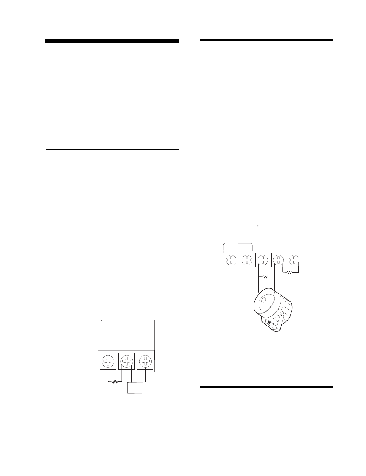
Connecting Hardwire Interior Sirens
The following ITI interior sirens may be used with
this Control Panel:
• LD105 Siren (13-374)
• Phone Jack Siren (60-683)
Turn option 53 on for siren supervision. When option
53 is on and a hardwire exterior siren is not connected,
a 47k ohm resistor (two 47k ohm resistors are shipped
with the Control Panel) must be connected across the
positive and negative terminals. If a 47k ohm resistor
or a siren is not connected to the exterior siren termi-
nals, SYSTEM STATUS will say Module 1 failure.
Follow the siren installation instructions included
with the siren for siren specific EOL resistor connec-
tions. Only one hardwire interior siren may be con-
nected. See figure 2 below for a generalized wiring
connection.
Figure 2. Supervised Interior Siren Connections
Connecting a Hardwire Exterior Siren
The following ITI exterior siren may be used with this
Control Panel:
• Hardwire Exterior Siren (13-046)
Turn option 53 on for siren supervision. When option
53 is on and a hardwire interior siren is not connected,
a 47k ohm resistor (two 47k ohm resistors are shipped
with the Control Panel) must be connected across the
positive and negative terminals. If a 47k ohm resistor
or a siren is not connected to the interior siren termi-
nals, SYSTEM STATUS will say Module 2 failure.
Wire sirens to be supervised by using a 4.7k ohm EOL
resistor, included with the siren.
Only one hardwire exterior siren may be connected.
See figure 3 below for wiring connections.
Note
:
Two 47k ohm resistors are included with the Con-
trol Panel. These should not be used for EOL resistors
when wiring sirens.
Figure 3. Supervised Exterior Siren Connections
Connecting Hardwire Sensors
This section shows how to wire hardwire sensors to
the Control Panel. For more programming informa-
tion on installing hardwire devices, “Programming
Sensors” on page 27. Wire sensors to be supervised
by using a 47k Ohm resistor (included with the Con-
trol Panel).
8988G48C.DS
4
All inputs are Class II
power-limited circuits.
Hardwire
Input 1
or
Exterior
Siren
–
HARDWIRE INPUTS/SIREN
Hardwire
and
Power
Common
+
Hardwire
Input 2
or
Interior
Siren
–
47k
SIREN
8988G20E.DS4
HARDWIRE
EXTERIOR SIREN
PART NO. 13-046
RED
BLACK
All inputs are Class II
power-limited circuits.
AC POWER
Hardwire
Input 1
or
Exterior
Siren
–
HARDWIRE INPUTS/SIREN
Hardwire
and
Power
Common
+
Hardwire
Input 2
or
Interior
Siren
–
9 VAC
4.7k OHM
RESISTOR
47k OHM
RESISTOR

Installation Instructions Document No. 466-1574.
24
Figure 4. Wire Hardwire Sensors Normally Closed
Connecting the Universal/Garage
Door Opener Module*
Use the followin
g
to connect a universal module to be
used to o
p
en a
g
ara
g
e door:
1.
Set the unit code
of the universal module to a
uni
q
ue unit number between 1 and 8.
2.
Set the house code
to the house code for the
installation.
3.
Set the module’s switches
to momentar
y
and
rela
y
onl
y
.
4.
Connect the terminals on the universal mod-
ule
to the button terminals on the
g
ara
g
e door
o
p
ener.
5. Plug the universal module into a wall outlet.
Note
: See the “Programming Light and Appliance Con-
trols*” on page 28 to program a KeyChain Touchpad to
open a garage door.
Connecting the Power Transformer
Connect the
p
ower transformer as shown in Fi
g
ure 5.
Plu
g
the transformer into an unswitched outlet
Note: Failure to terminate unused inputs as shown will
cause the Control Panel to indicate module 1 and mod-
ule 2 failure.
Figure 5. Power Transformer Control Panel Con-
nections
Connecting the Backup Batteries
Installing a Non-rechargeable Battery
Connect a 9-Volt lithium batter
y
(ITI #34-037) to the
batter
y
stra
p
as shown in Fi
g
ure 6.
Figure 6. Control Panel Battery Installation
Note
: The Control Panel will initially indicate a low battery
by lighting the SYSTEM STATUS button. If this button is
pressed the Control Panel will announce,
System low bat-
tery.
The Control Panel does a batter
y
test ever
y
4 hours
and will clear the status messa
g
e if the batter
y
is
g
ood.
Perform a sensor test, “Testin
g
Sensors” on
p
a
g
e 33,
to
p
erform an immediate batter
y
test.
8988G22B.DS4
All inputs are Class II
power-limited circuits.
Hardwire
Input 1
or
Exterior
Siren
–
HARDWIRE INPUTS/SIREN
Hardwire
and
Power
Common
+
Hardwire
Input 2
or
Interior
Siren
–
Normally
Closed
47k
Normally
Closed
8988G03B.DS4
CLASS II POWER
TRANSFORMER
PART NO. 22-091
All inputs are Class II
power-limited circuits.
AC POWER
Hardwire
Input 1
or
Exterior
Siren
–
HARDWIRE INPUTS/SIREN
Hardwire
and
Power
Common
+
Hardwire
Input 2
or
Interior
Siren
–
9 VAC
8959G 17D .D S F
9 VO LT BATTERY
* = Not Available with Basic Model
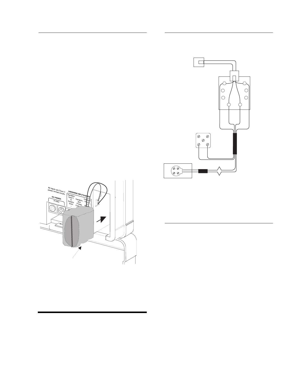
Installation Instructions Document No. 466-1574
25
Installing a Rechargeable Battery
Plug the AC power transformer into an unswitched
outlet.
Connect the rechargeable battery (#34-051 or #34-
052) as shown below in 7 Option 49 must be turned
on in order for the charging circuit to be activated.
The rechargeable battery will be fully charged after
nine hours. The system will have a low battery report
when checking system status until the battery is fully
charged.
If a rechargeable battery needs replacing, the control
panel must be power-cycled in order for the new bat-
tery to become fully charged. To power-cycle the con-
trol panel do the following:
1. Unplug the AC power transformer and battery.
2. Plug in the AC power transformer.
3. Plug in the new rechargeable battery.
Figure 7. Rechargeable Battery Installation
Connecting the Phone Line to the
Control Panel
If the system will be monitored by a central monitor-
ing station, you must install an RJ-31X jack between
the telephone company (TELCO) block and the Con-
trol Panel. The jack must be located within 5 feet of
the Control Panel.
Installing an RJ-31X Jack
Install and wire the RJ-31X jack as shown in Figure 8.
Figure 8. RJ-31X Wiring Diagram
Connecting the Phone Line to the Con-
trol Panel
1. Plug one end of the phone cord (included with
the Control Panel) into the RJ-31X jack.
2. Plug the other end of the phone cord into the
Control Panel phone jack labeled TO LINE.
3. When looking at the back of the Control Panel,
the top block is used to connect the phone to the
Control Panel, and is labeled TO PHONE, the
bottom block is used to connect the Control
Panel to the wall phone jack, and is labeled TO
LINE.
8959G 30A .D S F
RECHARGEABLE BATTERY
BRN
GRY
GRN
RED
DEALER
CABLE
TELCO
PROTECTOR
BLOCK
WHITE OR YELLOW
BLACK
GREEN
GREEN
RED
RED
BLACK
WHITE OR YELLOW
SPLICE
SPLICE
PREMISES PHONE JACK
EXISTING
PHONE
LINE
PHONE CORD
TO PANEL
JACK LABELED
'TO LINE'
GREEN
RED
8988G05B.DS4
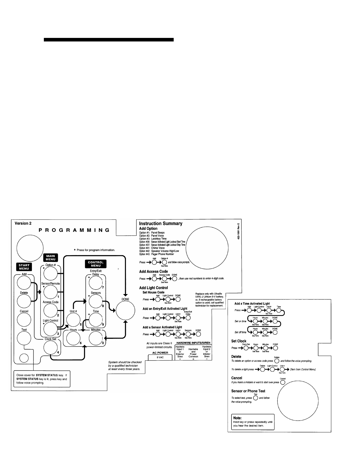
Installation Instructions Document No. 466-1574.
26
Programming Overview
These instructions tell
y
ou how to set u
p
for
p
ro
g
ram-
min
g
and to
p
ut the Control Panel in
p
ro
g
ram mode.
1.
Arrange the sensors, modules, Control Panel,
and user controls
on a table.
2.
Open the Control Panel cover
.
3.
Enter Utility Access Code 1
(default is 4321)
usin
g
red numbered ke
y
s.
Note:The default for utility access codes 1 and 2 is 4321.
Note:The default master access code is 1234.
You are now in
p
ro
g
ram mode.
Pro
g
rammin
g
is eas
y
if
y
ou understand the flow from
left to ri
g
ht when usin
g
the
p
ro
g
rammin
g
buttons.
Follow the
p
ro
g
rammin
g
arrows or use the flow dia-
g
rams to the ri
g
ht of the
p
ro
g
rammin
g
buttons. The
Control Panel will voice
p
rom
p
t
y
ou throu
g
h
p
ro-
g
rammin
g
.
To
g
et
y
ou started:
1. Press
Add or Delete
from the Start Menu.
2. Press
Option #, Sensor/Remote, Access Code
or Light Control
from the Main Menu.
The s
y
stem res
p
onse at this
p
oint de
p
ends u
p
on what
button
y
ou
j
ust
p
ressed. Follow the voice
p
rom
p
ts and
p
ro
g
rammin
g
arrows to continue.
Pro
g
ram the Control Panel in this order:
1. Sensors
2. House Code
3. Li
g
ht & A
pp
liance Control
•Entr
y
/Exit activated li
g
hts
• Sensor activated li
g
hts
• Time activated li
g
hts
4. O
p
tions
5. Access Codes
8988G37D.DSF
8988G38A.DSF

Installation Instructions Document No. 466-1574
27
Programming Sensors
These instructions show you how to program sensors,
touchpads and other system devices into the Control
Panel.
Program sensors and devices before you install them.
The Control Panel recognizes a sensor when you
press the sensor’s program button or tamper switch.
Note: The hardwire inputs must have sirens, hardwire sen-
sors, or 47k Ohm resistors connected between the positive
and negative terminals before learning in a sensor. If one of
these connections is not made, the panel will learn in a
hardwire zone. See the section “Wiring the Control Panel”
on page 23.
Note: If you are installing a sensor used with a gun case,
jewelry box, or similar usage, and the sensor is active in lev-
el one, you must go into program mode to avoid putting the
Control Panel into alarm when the sensor and the magnet
are separated.
Table 19 describes the programming button location
for each device.
Note: When installing crystal sensors, use the installation
instructions included in their packing boxes. The appendix
at the back of this document has instructions for the SAW
sensors.
The Control Panel uses an ascending numbering se-
quence (beginning with 1) when adding (learning)
sensors. You may override the system suggested sen-
sor number by using the red numbered keys.
Use Table 1 on page 7, which was filled out during the
system planning, to help program sensors.
To add a hardwire or RF sensor, SWS, or remote
control:
Note: Do not program the SWS into the control panel until
the house code has been programmed. See “Programming
the House Code and Unit Numbers*” on page 28.
1. Press Add from the Start menu.
2. Press the Sensor/Remote button from the Main
menu until you hear the room name or item you
want to add. The order of names the Control
Panel uses are: keychain remote, touchpad
remote, front door, back door, garage door, bed-
room, guest room, child’s room, utility room, liv-
ing room, dining room, bathroom, laundry room,
kitchen, office, den, garage, special chime, base-
ment, upstairs, downstairs, hallway, medicine
cabinet, closet, attic. Each name may be used
more than once.
Note: When adding sensors, if you wish to use a more de-
scriptive location you may press the option button to use the
compass directions (north, north east, east, south east,
south, south west, west, north west). This is especially use-
fule when installing a system with a Touchtalk 2-Way RF
Touchpad. The touchpad will not announce the sensor
numbers when the system status is pressed. Instead of
Sensor 1 Bedroom Open
you will hear
Bedroom Sensor
Open
. For example, if you have two bedrooms, name the
sensors West Bedroom and East Bedroom. When status is
pressed on the touchpad you will hear
West Bedroom Sen-
sor Open
.
3. Press DONE when you hear the name you wish
to add.
4. Enter the 2 digit sensor type using Table 1 on
page 7, with the red numbered keys.
Note: If you wish to use a sensor number other than the
next available, enter a 2 digit sensor number with the red
numbered keys immediately after entering the sensor type.
5. Press the sensor’s program button or tamper
button. Open the switch of hardwired sensors.
See Table 19, “Device Programming” for more
information. The Control Panel verbally con-
firms your programming.
Table 19 Device Programming
Device To Program
Door/Window Sensor Press button on top of sensor
(cover removed)
Motion Sensor Press button on back of sensor
(mounting plate removed)
KeyChain Touchpad Press lock & Unlock buttons
Remote Handheld Touch-
pad and Touchtalk 2-Way
RF Touchpad*
Press the EMERGENCY but-
tons (to be used for non-medi-
cal emergencies)
Hardwire Sensors Separate sensor from magnet
SWS* Plug in the module
CO Alarm Plug in the modules and within
30 seconds press the button for
6 beeps
Freeze & Water Press the button on top of the
sensor (cover removed) until
the control panel confirms the
programming. If the button is
not held down long enough,
SYSTEM STATUS will report
the sensor is open.
* = Not Available with Basic Model

Installation Instructions Document No. 466-1574.
28
To delete sensors:
1. Press
Delete
from the Start menu.
2. Press
Sensor/Remote
from the Main menu until
y
ou hear the name
y
ou want to delete.
3. Press
DONE
. The s
y
stem confirms the item
y
ou
removed.
Programming the House Code and
Unit Numbers*
Lam
p
Modules, A
pp
liance Modules, Remote Sirens,
and the SWS use the existin
g
electrical wirin
g
in the
home to receive si
g
nals from the Control Panel. Since
there are no direct wire connections re
q
uired, an
y
number of modules can be
p
lu
gg
ed into available out-
lets and installed in the s
y
stem. All Lam
p
Modules
and A
pp
liance Modules have a common house code
that allows modules to be identified b
y
ei
g
ht different
control addresses.
The house code allows ad
j
acent homes that have a
common
p
ower source to co-exist. The available
house code choices are from A to O.
To program the house code:
1. Press
Add
from the Start menu.
2. Press
Light Control
from the Main menu until
y
ou hear the house code letter
y
ou want.
3. Press
DONE
.
4.
Set the house code on each lamp and appli-
ance module
usin
g
a screwdriver.
5.
Set house code on the remote siren
to the next
al
p
habetical letter
g
reater than the house code.
All Lam
p
Modules with the same house code will turn
on or flash as a
g
rou
p
on alarm or when o
p
eratin
g
the
“Li
g
ht” button on a Ke
y
Chain Touch
p
ad. The units
must be identified with a uni
q
ue unit number, from 1-
8, to individuall
y
o
p
erate li
g
hts and a
pp
liances from a
Remote Handheld Touch
p
ad or to selectivel
y
p
ro-
g
ram li
g
hts to
g
o on durin
g
the entr
y
/exit dela
y
, to be
o
p
erated b
y
a sensor or at scheduled times.
To assign a unit number:
1.
See Table 6 on page 11
for
y
our
p
lannin
g
infor-
mation.
2.
Set the Unit number switch
on each module.
Programming Light and Appliance
Controls*
Use Table 6 on
p
a
g
e 11, which was filled out durin
g
the s
y
stem
p
lannin
g
, to hel
p
p
ro
g
ram control mod-
ules.
To add an entry/exit activated light:
1. Press
Add
from the Start menu.
2. Press
Light Control
from the Main menu.
3. Press
Unit #
until
y
ou hear the number
y
ou chose
on the module.
4. Press
Entry/Exit Delay
from the Control menu.
The Control Panel confirms
y
our
p
ro
g
rammin
g
.
To add a sensor-activated light:
1. Press
Add
from the Start menu
2. Press
Light Control
from the Main menu.
3. Press
Unit #
until
y
ou hear the number
y
ou chose
on the module.
4. Press
Sensors
from the Control menu until
y
ou
hear the sensor
y
ou want to control the li
g
ht.
5. Press
DONE
. The Control Panel confirms
y
our
p
ro
g
rammin
g
.
Note
: A KeyChain Touchpad can be programmed to a unit
number. Press the star button to activate a light or open/
close a garage door using the Universal Module.
To add a time-activated light:
1. Press
Add
from the Start menu.
2. Press
Light Control
from the Main menu.
3. Press
Unit #
until
y
ou hear the unit number
y
ou
chose on the module.
4. Press
Time
from the Control menu.
5. Press
Hours
and
Minutes
to set the be
g
innin
g
of
the schedule.
6. Press
DONE
.
7. Press
Hours
and
Minutes
to set the end of the
schedule.
8. Press
DONE
. The s
y
stem confirms
y
our
p
ro-
g
rammin
g
.
To delete an Entry/Exit-activated light:
1. Press
Delete
from the Start menu.
2. Press
Light Control
from the Main menu.
3. Press
Unit #
until
y
ou hear the unit number
y
ou
want to delete.
* = Not Available with Basic Model

Installation Instructions Document No. 466-1574
29
4. Press Entry/Exit Delay. The system confirms
your programming.
To delete a sensor-activated light:
1. Press Delete from the Start menu.
2. Press Light Control from the Main menu.
3. Press Unit # until you hear the unit number you
want to delete.
4. Press Sensors from the control menu until you
hear the one you want to delete.
5. Press DONE. The system confirms your pro-
gramming.
To delete a time-activated light:
1. Press Delete from the Start menu.
2. Press Light Control from the Main menu.
3. Press Unit # until you hear the unit number you
want to delete.
4. Press Time from the control menu.
Programming Options
Use Table 18 on page 21, which was filled out during
the system planning, to help program options.
There are two ways to enter options. They are as fol-
lows:
•Press Add and press the Option # button until
you hear the option to be changed.
or--
•Press Add and enter the option number you
want to program with the red numbered keys.
The following instructions use the second method.
To set system options 01 and 02:
1. Press Add from the Start menu.
2. Press Option # and 01 or 02 with the red num-
bered keys.
3. Press DONE.
To set system option 03:
1. Press Add from the Start menu.
2. Press Option # 03.
3. Press Hours and Minutes to set the time.
4. Press DONE.
To set system options 04, 05, and 06:
1. Press Add from the Start menu.
2. Press Option # and 04, 05, or 06.
3. Enter a phone number with the red numbered
keys. Press Test to enter a pause in the phone
number.
Note
: The phone number is automatically stored after
you’ve pressed 22 digits. You will not have to press DONE
to store the number. If the number is less than 22 digits,
then DONE must be pressed.
To set system option 07:
1. Press Add from the Start menu.
2. Press Option # 07.
3. Enter the account number.
4. Press DONE.
To set system option 08:
1. Press Add from the Start menu.
2. Press Option # 08.
3. Press DONE.
To set system option 09:
1. Press Add from the Start menu.
2. Press Option # 09.
3. Enter the downloader code.
4. Press DONE.
To set system options 10 & 11:
1. Press Add from the Start menu.
2. Press Option # 10 or 11.
3. Enter the delay times in seconds (3 digits must
be entered).
To set system options 12 & 13:
1. Press Add from the Start menu.
2. Press Option # and 12 or 13.
3. Enter phone mod number.
To set system option 14:
1. Press Add from the Start menu.
2. Press Option # 14.
3. Press DONE.
To set system option 15:
1. Press Add from the Start menu.
2. Press Option # 15.
3. Enter the no activity time out (2 digits must be
entered).
To set system option 16:
1. Press Add from the Start menu.

Installation Instructions Document No. 466-1574.
30
2. Press
Option #
16
.
3.
Enter the number of days
between each auto
p
hone test (3 di
g
its must be entered).
To set system option 17:
1. Press
Add
from the Start menu.
2. Press
Option #
17
.
3.
Enter the dialer delay
in seconds (3 di
g
its must
be entered).
To set system option 18:
1. Press
Add
from the Start menu.
2. Press
Option #
18
.
3.
Enter the alarm cancel time
in minutes (2 di
g
-
its must be entered).
To set system option 19:
1. Press
Add
from the Start menu.
2. Press
Option #
19
.
3.
Enter the supervisory time
in hours (2 di
g
its
must be entered).
To set system options 20 - 26, 28 - 30, and 32:
1. Press
Add
from the Start menu.
2. Press
Option #
XX
.
3. Press
DONE
.
To set system option 27:
1. Press
Add
from the Start menu.
2. Press
Option #
27
.
3.
Enter the ring/hang/ring number
.
To set system option 31:
1. Press
Add
from the Start menu.
2. Press
Option #
31
.
3. Enter the day of week number.
To set system option 33, 38, 40-42:
1. Press
Add
from the Start menu.
2. Press
Option #
XX
.
3. Press
DONE
.
To set system options 34-37:
1. Press
Add
from the Start menu.
2. Press
Option #
XX
.
3. Press
Hours
and
Minutes
to set the time.
4. Press
DONE
.
To set system option 39:
1. Press
Add
from the Start menu.
2. Press
Option #
39
.
3. Enter the minutes (2 di
g
its must be entered).
To set system option 43:
1. Press
Add
from the Start menu.
2. Press
Option #
43
.
3.
Enter a phone number
with the red numbered
ke
y
s. Press
Test
to enter a
p
ause in the
p
hone
number.
Note: The phone number is automatically stored after
you’ve pressed 22 digits. You will not have to press DONE
to store the number. If the number is less than 22 digits,
then DONE must be pressed.
To set system option 44:
1. Press
Add
from the Start menu.
2. Press
Option
#
44
.
3.
Enter phone mod number
.
To set system option 45 - 53:
1. Press
Add
from the Start menu.
2. Press
Option #
XX
.
3. Press
DONE
.
To delete options:
1. Press
Delete
from the Start menu.
2. Press
Option
from the Main menu until
y
ou hear
the name
y
ou want to delete or use the red num-
bered ke
y
s to
g
o directl
y
to the o
p
tion.
3. Press
DONE
. The s
y
stem confirms the item
y
ou
deleted.
Programming System Access Codes
Use Table 7 on
p
a
g
e 12
,
which was filled out durin
g
the s
y
stem
p
lannin
g
, to
p
ro
g
ram s
y
stem Access
Codes.
To add a code:
1. Press the
Add
button.
2. Press the
Access Code
button. Continue
p
ressin
g
the Access Code button until
y
ou hear the access
code to be chan
g
ed.
3. Press
DONE.
4.
Enter the new access code
b
y
usin
g
the red
numbered ke
y
s.

Installation Instructions Document No. 466-1574
31
The Control Panel says, code name is XXXX (the new
4 digit access code).
To delete a code:
1. Press Delete from the Start menu.
2. Press the Access Code button. Continue pressing
the Access Code button until you hear the access
code to be deleted.
3. Press DONE.
The Control Panel says, code name is deleted.
Installing the System
Control Panel General Information
Do not install the Control Panel near a window or
door where it can be reached easily by an intruder.
Control Panels should be installed in locations where
they are most likely to be heard.
Metal objects, mirrors, and metallic wallpaper can
block signals sent by the wireless sensors. Make sure
there are no metal objects in the way when installing
the system.
The system will prompt you through programming
steps with beeps and voice messages. If you need
more time before proceeding, simply close the Con-
trol Panel cover until you are ready to continue.
When the cover is closed, the Control Panel is in the
operating mode. Each time you close the Control Pan-
el cover, a series of beeps (from the control panel pi-
ezo, hardwire internal siren, SWS, and the X-10
powerhorn) will indicate the system status:
• One beep indicates the system is disarmed
• Two beeps verify that Door/Window sensors are
armed.
• Three beeps verify that Motion Sensors are
armed.
• Four beeps verify that both Door/Window and
Motion sensors are armed.
The system cannot work without power. If the electri-
cal power fails and the Control Panel battery is weak
or dead, the system will not work.
Control Panel Specifications
Power Requirements: 9 VAC, 700 mA
Non-Chargeable Backup Battery: 9 VDC 1.2 AH
UltraLife Lithium. The battery will last 24 hours with
no AC if fully charged. Typical Life of 1 year.
Rechargeable Backup Batteries:
1. 7.2 VDC, 1 Ah 5/3 AAA Nickel Metal Hydride
The battery will last 30 hours with no AC
2. 7.2 VDC, 580 mAh AAA Nickel Metal Hydride
The battery will last 16-18 hours with no AC
Radio Frequency: 319.5 MHz + or - 140 kHz
Nominal Range: 500 feet, open-air receiving range
Operating Temperature Range: 32°-122 ° F (0°-
50° C)
Maximum Humidity: 85% relative humidity, non-
condensing
Auxiliary Power Output: Regulated & unregulated,
fused 12 VDC at 250 mA (maximum)
Installation Guidelines
Use the following procedure to mount the Control
Panel to the wall or wall studs, using the supplied
mounting hardware and the panel mounting holes.
Table 20 Arming Levels
Arming
Level
Description of Level
0 Bypasses 24 hour intrusion sensors (Master
Access Code Only)
1 Disarm the system
2 Arm Doors and Windows
3 Arm Motions
4 Arm Doors, Windows, and Motions

Installation Instructions Document No. 466-1574.
32
Materials Needed
•Pencil
• Hammer
• Screwdriver
To mount the panel:
1. Choose a s
p
ot within a few feet of an electrical
outlet (the outlet should not be controlled b
y
a
wall switch) and also within reach of a tele
p
hone
j
ack. The Control Panel can be
p
laced on a desk,
tableto
p
, or it can be wall mounted.
2. O
p
en the Control Panel cover and
p
osition on the
wall.
3. Mark the screw hole locations with a
p
encil.
4. Start holes with the ti
p
of the screwdriver or a
nail.
5. Ta
p
the wall anchors
p
rovided into the holes.
6. Insert the screws and
p
artiall
y
ti
g
hten with the
screwdriver.
7. Han
g
the Control Panel on the screws and ti
g
hten
securel
y
.
8. Remove the center screw from the outlet cover
p
late.
9. Position the transformer so that its screw hole is
ali
g
ned with the screw hole on the outlet cover
p
late. Then
p
lu
g
the transformer into the outlet.
10. Re
p
lace the screw, and use it to secure the trans-
former to the outlet cover
p
late. Ti
g
hten the
screw firml
y
with
y
our screwdriver.
Sensor Installation
Use the installation instructions included with each
sensor or if installin
g
SAW sensors use document
466-1622, Booklet of Installation Instructions, at-
tached to the back of this manual, for SAW Sensors.
Testing the Control Panel
Test the Control Panel b
y
p
ressin
g
the buttons as de-
scribed below:
• ARM Doors & Windows-The Control Panel
arms Doors & Windows. Press twice to eliminate
the
p
re
p
ro
g
rammed entr
y
dela
y
. The button will
blink when No Entr
y
Dela
y
is on.
• ARM Motion Sensors-The Control Panel will
arm Motion Sensors. Press twice to turn Latch-
ke
y
on. The button blinks when Latchke
y
is on.
• DISARM -The Control Panel will disarm Doors,
Windows, and Motion Sensors when also enter-
in
g
the a
pp
ro
p
riate access code.
• SYSTEM STATUS-Press to determine s
y
stem
status and s
y
stem time.
• CHIME Doors-Press to enable two bee
p
s which
will sound from the interior siren out
p
ut, the
p
anel siren, SWS, and the X-10
p
owerhorn siren
(if set to unit number 9) when a
p
rotected door or
window, that is
p
ro
g
rammed as sensor t
yp
e 10 or
13, is o
p
ened.
• CHIME S
p
ecial Motion- Press to enable three
bee
p
s which will sound from the interior siren
out
p
ut, the
p
anel siren, SWS, and the X-10
p
ow-
erhorn siren (if set to unit number 9) when a
Motion Sensor, that is
p
ro
g
rammed as sensor
t
yp
e 25, is activated. If there are no sensors
learned as t
yp
e 25, this function will not be avail-
able. The control
p
anel will also announce which
sensor was tri
pp
ed if chime voice (o
p
tion 41) is
on.
• LIGHTS Time Activated-Press to enable s
y
stem
controlled li
g
hts to turn on/off at a scheduled
time.
• LIGHTS Sensor Activated-Press to enable s
y
s-
tem controlled li
g
hts to turn on for 4 minutes
when a s
p
ecific sensor is tri
pp
ed.
• EMERGENCY-Press and hold or
p
ress twice
q
uickl
y
to activate a non-medical emer
g
enc
y
alarm.
Testing the System
This section describes how to
p
erform the followin
g
test
p
rocedures:
• Testin
g
sensors
• Testin
g
p
hone communication
• Testin
g
central station communications
• Testin
g
the X-10 Lam
p
Modules
You should test the s
y
stem after installin
g
, after ser-
vicin
g
, and after addin
g
or removin
g
devices from the
s
y
stem.

Installation Instructions Document No. 466-1574
33
Testing Sensors
We recommend that you test the sensors after all pro-
gramming is completed and whenever a sensor-relat-
ed problem occurs.
Note
: While the sensor test is a valuable installation and
service tool, it only tests sensor operation for the current
conditions. You should perform a sensor test after any
change in environment, equipment, or programming.
1. Place all sensors in their secured (non-alarm)
state.
2. Open the Control Panel cover.
3. Enter the appropriate access code.
4. Press Test.
The Control Panel responds with Sensor test, press
again to change or DONE to select.
5. Press DONE.
Note:
If the primary or secondary phone number (option 4
or 5) has been programmed, after pressing
Test
a second
time, the Control Panel announces
Phone Test
. The phone
testing procedure will be discussed later in this manual. Af-
ter pressing
Test
a third time, the Control Panel announces
DL phone test
.
The Control Panel will prompt you to trip each sensor
one at a time. You may follow the Control Panel’s
voice prompting or test the sensors in any order.
Interior sirens and speakers sound transmission beeps
as each sensor is tripped. Each beep represents one RF
packet.
Use the following table to trip sensors.
6. Count the number of transmission beeps and
refer to Table 21 on page 34 for minimum
requirements. After the beeps, the Control Panel
announces, Sensor Name is activated, sensor sta-
tus is XX (XX = number of RF packets). The sys-
tem will continue to prompt for sensors which
have not yet been tested. When all sensors have
been tested the Control Panel will announce,
Sensor test complete, press DONE.
7. Press DONE. The system will respond, Sensor
Test OK.
8. If Cancel or DONE is pressed and the Control
Panel has not heard from all sensors, the Control
Panel will respond, Sensor test canceled or fail-
ure.
Note
: If a sensor does not meet the minimum transmission
beep requirements, refer to the If a Sensor Fails the Sensor
Test section.
Sensor Tripping Instructions:
Sensor Do This
Door/Window Open the secured door or win-
dow
Freeze Appl
y
ice to the sensor. Do not
allow the sensor to
g
et wet
Water Press a wet ra
g
or wet fin
g
er
over both of the round,
g
old-
plated terminals on the underside
of the sensor
Carbon Monoxide
Alarm
Unplu
g
the CO Alarm. Plu
g
it
back in, then press the TEST/
RESET button until the unit
beeps 8 times
Glass Guard Tap the
g
lass 3 or 4 inches from
the sensor
Motion Sensor Avoid the Motion Sensor’s view
for 5 minutes, then enter its view
Rate-of-Rise Heat
Detector
Rub
y
our hands to
g
ether until
warm, then place one hand on
the detector for 30 seconds
Shock Tap the
g
lass twice, awa
y
from
the sensor. Wait at least 30 sec-
onds before testin
g
a
g
ain
Smoke Press and hold the test button
until the s
y
stem sounds trans-
mission beeps
Panic Buttons Press and hold the appropriate
panic button
(
s
)
for 3 seconds
Ke
y
Chain Touch-
pad
Press and hold LOCK and
UNLOCK simultaneousl
y
for 3
seconds
Remote Handheld
Touchpad and
Touchtalk 2-Wa
y
RF Touchpad*
Press and hold the 2 EMER-
GENCY buttons simultaneousl
y
for 3 seconds
SWS* Unplu
g
the SWS, plus the unit
back in
Sensor Tripping Instructions:
Sensor Do This
* = Not Available with Basic Model

Installation Instructions Document No. 466-1574.
34
* The Control Panel Emer
g
enc
y
Button cannot be
tested.
If a Sensor Fails the Sensor Test
If sirens do not bee
p
when a sensor is tri
pp
ed, use an
ITI RF Sniffer (60-401) test tool to verif
y
that the sen-
sor is transmittin
g
. Constant bee
p
s from the RF Sniff-
er indicate a runawa
y
(fault
y
) sensor. Re
p
lace the
sensor.
If
p
ossible, locate sensors within 100 feet of the
p
anel.
While a transmitter ma
y
have a ran
g
e of 500 feet or
more out in the o
p
en, the environment at the installa-
tion site can have a si
g
nificant effect on transmitter
ran
g
e. Sometimes a chan
g
e in sensor location can
hel
p
overcome adverse wireless conditions.
To improve sensor communication, you can
•re
p
osition the sensor
• relocate the sensor
• if necessar
y
, re
p
lace the sensor
To reposition a sensor:
1. Rotate the sensor and test for im
p
roved sensor
communication at 90 and 180 de
g
rees from the
ori
g
inal
p
osition.
2. If
p
oor communication
p
ersists, relocate the sen-
sor as described as follows.
To relocate a sensor:
1. Test the sensor a few inches from the ori
g
inal
p
osition.
2. Increase the distance from the ori
g
inal
p
osition
and retest until an acce
p
table location is found.
3. Mount the sensor in the new location.
4. If no location is acce
p
table, re
p
lace the sensor.
To replace a sensor:
1. Test a known
g
ood sensor at the same location.
2. If the transmission bee
p
s remain below the mini-
mum level, avoid mountin
g
a sensor at that loca-
tion.
3. If the re
p
lacement sensor functions, contact ITI
for re
p
air or re
p
lacement of the
p
roblem sensor.
Testing Phone Communication
Perform a
p
hone test to check the
p
hone communica-
tion between the
p
anel and the central station.
To perform a phone test/DL phone test:
1.
Open the Control Panel cover.
2.
Enter the appropriate access code.
3. Press
Test twice
.
4. Press
DONE
.
The Control Panel res
p
onds with,
Phone test is on
. When the
p
hone test is com-
p
lete, the Control Panel will announce
Phone
Test is OK
within 3 minutes. The Control Panel
will sa
y
Phone test is on
three times if
y
ou have a
p
a
g
er. Your
p
a
g
er will dis
p
la
y
101 101 if the
p
hone test to the
p
a
g
er was successful. If the test
is unsuccessful, the
SYSTEM STATUS
button
will li
g
ht and the Control Panel will sa
y
Phone
communication failure
within 10 minutes.
If the
p
anel announces
Phone communication failure
,
p
roceed to the followin
g
instructions.
If the phone test fails:
1. Check that the
p
anel is connected to the
p
hone
j
ack.
2. Check the
p
hone number
p
ro
g
rammed into the
p
anel.
3. Perform the
p
hone test a
g
ain.
4. If the
p
hone test fails a
g
ain, check the
p
hone con-
nection wirin
g
.
Testing Central Station Communica-
tion
After
p
erformin
g
sensor and
p
hone tests, check that
the s
y
stem is re
p
ortin
g
alarms successfull
y
to the cen-
tral station.
Table 21 Minimum Transmission Beeps
Type of Sensor
Number of
Beeps
Wireless Intrusion Sensors 7–8 beeps
Wireless Smoke & Heat Sensors 7–8 beeps
Wireless Environmental/Panic Buttons 7–8 beeps
Hardwire Loops 1
Emergency Buttons* 7-8 beeps

Installation Instructions Document No. 466-1574
35
To test communication with the central station:
1. Call the central station and tell the operator that
you will be testing the system.
2. Arm the system.
3. Test each of the wireless panic buttons and trip at
least one sensor of each type—fire, intrusion,
etc.—to verify that the appropriate alarms are
working correctly.
4. When you finish testing the system, call the cen-
tral station to verify that the alarms were
received.
Testing the X-10 Lamp Modules*
Use Table 6 on page 11 to determine the full extent of
module testing to be accomplished.
To test the system controlled lamp modules:
1. Press the LIGHT button on the KeyChain
Touchpad repeatedly to turn all lights on and off.
The Control Panel responds with Lights on/off.
2. Press the Lights On button and the unit # of the
lamp module using the numeric buttons on the
Remote Handheld Touchpad to test individual
lamp modules, the Control Panel will respond
with Lights # on/off.
Siren and X-10 Lamp Module Func-
tions*
All sirens will time-out in the programmed siren time-
out (1 - 254 minutes). Siren priority is as follows: fire,
intrusion, then emergency. If an alarm of greater pri-
ority occurs during an alarm of lower priority, the
higher priority alarm sirens sound. The X-10 must be
set to unit #9 to hear emergency alarm beeps. Fire
alarms will sound a temporal 3 pattern. Temporal 3 is
0.5 seconds on, 0.5 seconds off for 3 beeps then 1.5
seconds off.
Panel Tamper
If the system is armed and the cover is opened an in-
trustion alarm will sound and the system status will
say System Access Alarm when the button is pressed.
Table 22 Alarm Siren and X-10 Light
Information
Fire Intrusion Emergency
X-10 Lights Steady Flashing Steady
X-10 Siren Steady Steady Alarm beeps
Interior & Panel
Siren
Temporal 3 Steady Fast on/off
Exterior Siren Temporal 3 Steady
SWS Temporal 3 Steady Fast on/off
* = Not Available with Basic Model

Installation Instructions Document No. 466-1574.
36
Troubleshooting
Use the followin
g
table to aid
y
ou with troubleshootin
g
p
roblems durin
g
installation.
Table 23 Troubleshooting Guide
Problem Solution
SYSTEM STATUS
How to clear SYSTEM STATUS (Alarm Memor
y
) From a disarmed state
p
ress SYSTEM STATUS twice, listen to the
status messa
g
e, then
p
ress DISARM.
SYSTEM STATUS sa
y
s
Module 1 failure or Module 2
failure.
•Turn o
p
tion 53 off if a hardwire siren or sensor is not connected.
• Check for the correct EOL resistor at Hardwire in
p
uts 1 and 2.
See “Connectin
g
Hardwire Interior Sirens” on
p
a
g
e23.
SYSTEM STATUS sa
y
s
Low Battery
. UltraLife lithium batter
y
• Do a sensor test then check SYSTEM STATUS a
g
ain. If the bat-
ter
y
is still low, re
p
lace the batter
y
.
Rechar
g
eable Batter
y
• If the control
p
anel has
j
ust been
p
lu
gg
ed in, the control
p
anel
will indicate a low batter
y
until the batter
y
is full
y
char
g
ed (9-12
hours). Make sure to turn o
p
tion 49 on.
• If the control
p
anel has been
p
owered for more than 12 hours,
make sure o
p
tion 49 is on.
SYSTEM STATUS sa
y
s
Option 50 Detected
.O
p
tion 50 is RF
j
am detect. The control
p
anel has detected RF inter-
ference.
SYSTEM STATUS sa
y
s that a sensor is o
p
en. See Sensors section below.
SYSTEM STATUS sa
y
s
System time is not set
.Set the s
y
stem time.
Control Panel
The s
y
stem sa
y
s
Function not available
when Chime
Doors is
p
ressed.
No sensors are
p
ro
g
rammed usin
g
sensor t
yp
e 10 or 13.
The s
y
stem sa
y
s
Function not available
when Chime
S
p
ecial Motion is
p
ressed.*
No sensors are
p
ro
g
rammed usin
g
sensor t
yp
e 25
The s
y
stem sa
y
s
Function not available
when LIGHTS
Time Activated is
p
ressed.*
No time activated li
g
hts have been
p
ro
g
rammed.
The s
y
stem sa
y
s
Function not available
when LIGHTS
Sensor Activated is
p
ressed.*
No sensor activated li
g
hts have been
p
ro
g
rammed.
The s
y
stem sa
y
s
Invalid. Sensor already programmed as
Sensor Name
.
This sensor is alread
y
p
ro
g
rammed. Delete sensor if not correctl
y
p
ro
g
rammed.
Options (Programmable by the homeowner)
The Control Panel does not bee
p
.Pro
g
ram o
p
tion 1 to be on.
Latchke
y
does not function. • Latchke
y
time (o
p
tion 3) is not set. Set Latchke
y
time.
• Latchke
y
is not enabled. Enable Latchke
y
b
y
p
ressin
g
ARM
Motion Sensors twice.
•The
p
hone number is not
p
ro
g
rammed
p
ro
p
erl
y
. Re
p
ro
g
ram the
p
hone number. (o
p
tion 43)
•S
y
stem Time is not set. Set s
y
stem time.
Sensors
A sensor does not work.
• Make sure the batter
y
is fresh and installed correctl
y
.
• Check for interference from metal ob
j
ects. Move or rotate the
sensor.
• Move the sensor to a new location.
* = Not Available with Basic Model

Installation Instructions Document No. 466-1574
37
Door or window is closed, but the Control Panel voice
says it is open.
• Be certain the arrow on the magnet and the guide line on the
transmitter are aligned and are within 1/4’ of each other.
• The sensor tamper switch may be open if it is a crystal sensor.
Motion sensors go off continuously. Be sure the sensor is mounted on a solid surface and the viewing field
is free from sources of changing temperature.
Motion sensor does not respond to motion. • Make sure the battery is fresh and installed correctly. Wait 2
minutes after installing a new battery to test the sensor.
• Adjust the sensor mounting.
• Leave the area for 3 minutes, then retest.
• The environment is too hot or too cold. Outdoor sensors will
operate between 32° and 120°F.
• Dirt or dust may be causing the problem. Wipe the sensor with a
clean, damp cloth.
X-10 Modules*
All Lamp Modules or Siren not working.*
• Be sure the Control Panel transformer is plugged directly into an
outlet and that the outlet is not controlled by a wall switch.
• Possibly a bad transformer.
• House code was programmed incorrectly.
One Lamp Module or Siren is not working.* • Unplug nearby equipment which may be causing interference
(light dimmer switches, televisions, appliances with older
motors).
• Check that the switch on the lamp or appliance is turned on and
remains on.
• Make sure the lamp has a working bulb.
• Make sure the lamp or appliance is plugged into the Lamp/
Appliance Module, the Module is plugged into the outlet and the
outlet is not controlled by a wall switch.
• Make sure the House and Unit Codes are correct.
• Move the Module to a different outlet that is on the same phase
(branch) of the household electrical circuit as the Control Panel.
Time activated or sensor activated light not working.* • Make sure you have programmed the light to be activated by a
timer or sensor.
• Make sure the system clock is set.
• Make sure these functions have been enabled by pressing the
LIGHTS Time Activated/Sensor Activated
on the Control
Panel. They are enabled if the button is lit.
Table 23 Troubleshooting Guide
Problem Solution
* = Not Available with Basic Model
Installation Instructions Document No. 466-1574.
38
Typical Backup Battery Life of the 9
Volt UltraLife
The followin
g
table and chart demonstrate backu
p
batter
y
life over time if the batter
y
is tested ever
y
4
hours (o
p
tion 50 is off).
Table 24 Typical Backup Battery Life
Cycle Over Time
Months in Use
Estimated Hours of
Backup Power
0 30.159
1 27.861
2 25.562
3 23.264
4 20.966
5 18.668
6 16.370
7 14.072
811.774
99.475
10 7.177
11 4.879
12 2.581
13 0.283
Typical Backup Battery Life Cycle Over Time
Months in Use
Estimated Hours of Backup Power
0
10
15
20
25
30
5
| |
1 2 3 4 5 6 7 8 9 10 11 12 13
1061G50A.DS
F
| |
| | | | | | | |
|

Installation Instructions Document No. 466-1574
39
Notices
This manual may refer to products that are announced but are not yet available.
FCC Notices
This equipment has been tested and found to comply with the limits for a class B dig-
ital device, pursuant to part 15 of the FCC rules. These limits are designed to provide
reasonable protection against harmful interference in a residential installation. This
equipment generates, uses, and can radiate radio frequency energy and, if not in-
stalled and used in accordance with the instructions, may cause harmful interference
to radio communications. However, there is no guarantee that interference will not
occur in a particular installation. If this equipment does cause harmful interference
to radio or television reception, which can be determined by turning the equipment
off and on, the user is encouraged to try to correct the interference by one or more of
the following measures:
• Install a quality radio or television outdoor antenna if the indoor antenna is
not adequate.
• Reorient or relocate the Control Panel.
• Move the Control Panel away from the affected equipment.
• Move the Control Panel away from any wire runs to the affected equipment.
• Connect the affected equipment and the Control Panel to separate outlets, on
different branch circuits.
• Consult the dealer or an experienced radio/TV technician for help.
• Send for the FCC booklet How to Identify and Resolve Radio-TV Interference
Problems, available from the U.S. Government Printing Office, Washington,
D.C. 20402. Stock Number: 004-000-00345-4.
This device complies with part 15 of the FCC rules. Operation is subject to the fol-
lowing two conditions: (1) this device may not cause harmful interference, and (2)
this device must accept any interference received, including interference that may
cause undesired operation.
This equipment complies with part 68 of the FCC rules. On the FCC label affixed to
this equipment is the FCC Registration Number and Ringer Equivalence Number
(REN) for this equipment. If requested, provide this information to your telephone
company.
The REN is used to calculate the maximum number of devices your telephone line
will support with ringing service. In most areas the sum of all device RENs should
not exceed 5.0. Contact your local telephone company to determine the maximum
REN for your calling area.
If your telephone equipment causes harm to the telephone network, your telephone
company may temporarily disconnect your service. If possible, you will be notified
in advance. When advance notice is not practical, you will be notified as soon as pos-
sible. You will also be advised of your right to file a complaint with the FCC.
Your telephone company may make changes in its facilities, equipment, operations,
or procedures that could affect the proper operation of your equipment. You will be
given advanced notice in order to maintain uninterrupted service.
If you experience trouble with this equipment, please contact
Interactive Technologies, Inc.
2266 Second Street North
North Saint Paul, MN 55109
1-800-777-1415
for service and repair information. The telephone company may ask you to discon-
nect this equipment from the network until the problem has been corrected or until
you are sure that the equipment is not malfunctioning.
This equipment may not be used on coin service provided by the telephone company.
Connection to party lines is subject to state tariffs.
Canada Notice
The Canadian Department of Communications label identifies certified equipment.
This certification means that the equipment meets certain telecommunications net-
work protective, operational, and safety requirements. The department does not
guarantee the equipment will operate to the user’s satisfaction.
Before installing this equipment, users should ensure that it is permissible to be con-
nected to the facilities of the local telecommunications company. The equipment
must also be installed using an acceptable method of connection. In some cases, the
company’s inside wiring associated with a single-line individual service may be ex-
tended by means of a certified connector assembly (telephone extension cord). The
customer should be aware that compliance with the above conditions may not pre-
vent degradation of service in some situations.
Repairs to certified equipment should be made by an authorized Canadian mainte-
nance facility designated by the supplier. Any repairs or alterations made by the user
to this equipment, or equipment malfunctions, may give the telecommunications
company cause to request the user to disconnect the equipment.
For your protection, make sure that the electrical ground connections of the power
utility, telephone lines, and internal metallic water pipe system, if present, are con-
nected together.
Caution
Do not attempt to make connections yourself. Contact the appropriate
electrician or electric inspections authority.
The Load Number (LN) assigned to each terminal device denotes the percentage of
the total load to be connected to a telephone loop which is used by the device, to pre-
vent overloading. The termination on a loop may consist of any combination of de-
vices subject only to the requirement that the total of the LNs of all the devices does
not exceed 100. Load Number: _____________ Acceptability Number:
____________
“AVIS: - L
´
étiquette du ministère des Communications du Canada identifie le maté-
riel homologué. Cette étiquette certifie que le matériel est conforme a certaines
normes de protection, d ´ exploitation et de sécurité des réseaux de télécommunica-
tions. Le ministère n ´ assure toutefois pas que le matériel fonctionnera a la satisfac-
tion de l ´ utilisateur.
Avant d ´ installer ce matériel, l ´ utilisateur doit s ´ assurer qu´ il est permis de le
raccorder aux installations de l ´ enterprise locale de télécommunication. Le matériel
doit également etre installé en suivant une méthod acceptée de raccordement. Dans
certains cas, les fils intérieurs de l´ enterprise utilisés pour un service individuel a
ligne unique peuvent etre prolongés au moyen d´ un dispositif homologué de raccor-
dement (cordon prolongateur téléphonique interne). L ´ abonné ne doit pas oublier
qu ´ il est possible que la conformité aux conditions énoncées ci-dessus n ´ empech-
ent pas le dégradation du service dans certaines situations. Actuellement, les enter-
prises de télécommunication ne permettent pas que l ´ on raccorde leur matériel a des
jacks d ´ abonné, sauf dans les cas précis prévus pas les tarrifs particuliers de ces en-
terprises.
Les réparations de matériel homologué doivent etre effectuées pas un centre d ´ en-
tretien canadien autorisé désigné par le fournisseur. La compagne de télécommuni-
cations peut demander a l ´ utilisateur de débrancher un appareil a la suite de
réparations ou de modifications effectuées par l ´ utilisateur ou a cause de mauvais
fonctionnement.
Pour sa propre protection, l ´ utilisateur doit s ´ assurer que tous les fils de mise a la
terre de la source d ´ énergie électrique, des lignes téléphoniques et des canalisations
d ´´ eau métalliques, s ´ il y en a, sont raccordés ensemble. Cette précaution est par-
ticulièrement importante dans les régions rurales.
Avertissment. - L ´ utilisateur ne doit pas tenter de faire ces raccordements lui-
meme; il doit avoir recours a un service d ´ inspection des installations élec-
triques, ou a electricien, selon le cas”.

Installation Instructions Document No. 466-1574.
40
Une note explicative sur les indices de charge (voir 1.6) et leur emploi, a l ´ intention
des utilisateurs du matériel terminal, doit etre incluse dans l ´ information qui ac-
compagne le materiel homologué. La note pourrait etre rédigée selon le modèle sui-
vant:
“L ´ indice de charge (IC) assigné a chaque dispositif terminal indique, pour éviter
toute surcharge, le pourcentage de la charge totale qui peut etre raccordée a un circuit
téléphonique bouclé utilisé par ce dispositif. La terminaison du circuit bouclé peut
etre constituée de n ´ import somme des indices de charge de l ´ ensemble des dis-
positifs ne dépasse pas 100.”
L ´ Indice de charge de cet produit est ____________.
Trademarks
ITI
®
is a registered trademark of Interactive Technologies, Inc. Simon
®
is a trade-
mark of Interactive Technologies, Inc. X-10 is a registered trademark of X-10
(USA), Inc.
651-777-2690
651-779-4890

Installation Instructions Document No. 466-1574
41
Numerics
24 Hour Battery Test 22
2-Way Voice 17
2-way voice, on-board 4
300 Baud Central Station Communications 17,
22
319.5 Sensors 4
A
AC Power Failure 16
AC Power Failure Report 21
Access Code 12
Access Code Programming 30
Access Code, Master 12
access code, master default 26
Access Code, Panic Code 12
Access Code, Utility 12
access codes, utility defaults 26
Account Number 13, 21
activation method 10
add hardwire/RF sensor, SWS, or remote con-
trol 27
alarm 35
Alarm Cancel 15
Alarm Cancel Report 21
appliance module 10
Appliance Modules 4
Arm Doors & Windows 9, 32
Arm Doors/Windows 16
Arm Doors/Windows & Motion Sensors 9
Arm Doors/Windows and Motion Sensors 16
ARM Doors/Windows with No Entry Delay 16
Arm Doors/Windows with No Entry Delay and
Motion Sensors with Latchkey 16
Arm Motion Sensors 9, 16, 32
Arm Motion Sensors with Latchkey 16
arming levels 9
Audio Verification 16, 22
Audio Verification Mode 22
Audio Verification Module 6
Auto Arm 18, 22
Auto Phone Test 15, 21
Auxiliary Power Output 31
AVM 4, 6
AVM Fire Shutdown 19
AVM Mode 19
B
Backup Battery Control Panel 31
Backup Battery, Connecting 24, 25
Backup Battery, Lithium 3
Battery Pack, Nickel Metal Hydride 3
battery test 24
C
Carbon Monoxide (CO) Alarm 4, 6
CHIME Doors 18, 32
CHIME Special Motion 18, 32
Chime Voice 18, 22
Closing Reports 15, 21
CO Alarm 6
CO Alarm Sensor Type 8
Control Panel 4
Control Panel Alarms 16
Control Panel beeps 31
Control Panel Specifications 31
Control Panel, Wiring 23
CPU Low Battery 16
CPU Low Battery Report 21
CS-5000 Receiver 5
D
Day of Week 17, 22
Delays 9
delete options 30
delete sensors 28
Dialer Delay 15, 21
disarm 9, 16, 32
DL Code (Downloader Code) 14
Door Window Sensor program button 27
Door/Window Sensor 3, 4, 5
Downloader Code 21
Downloader Phone Number 13, 21
DTMF 21
DTMF Dialing 14
E
EMERGENCY 32
EMERGENCY buttons 27
Emergency Planning Floor Plan 6
Entry Delay 14, 21
Entry/Exit activated light 28
Entry/Exit-activated light 28
Exit Delay 14, 21
Exterior Door 8
F
Factory Defaults, reset memory to 23
Fail to Close 17, 22
Fail to Communicate 16, 21
Fail to Open 17, 22
Fire Shutdown - AVM 19, 22
Floor Plan, Emergency 6
Follower Delay 9

Installation Instructions Document No. 466-1574.
42
Force Arm 15
Forced Armed Report 21
Freeze Sensor 4, 8
G
Garage Door Modules 4
H
Hardwire Exterior Siren, Connecting 23
Hardwire Interior Sirens, Connecting 23
Hardwire Sensors program buttons 27
Hardwire Sensors, Connecting 23
High Level Status 22
HomeLink Transceiver 6
House Code 10
House Code and Unit Number programming
28
house code choices 28
I
improve sensor communication 34
Indoor Motion Sensor 5, 8
Indoor/Outdoor Motion Sensor 4
Installation Guidelines 31
Installing the Control Panel 31
Instant Delay 9
Interior Door 8
Interrogator AVM 4
Interrogator® 200 Audio Verification Module
(AVM) 6
ITI CS-5000 Receiver 5
ITI HomeLink Transceiver (IHT) 6
ITI ToolBox 5
K
KeyChain Touchpad 3, 4, 5, 8
KeyChain Touchpad program buttons 27
KeyChain Touchpad programmed to a unit
number 28
L
Lamp Modules 4
Lamp Modules house code 28
Latchkey 13, 21
LD105 Siren 23
learning sensors 27
LIGHTS Time or Sensor Activated 32
Lock & Unlock buttons 27
low battery 24
M
Manual Phone Test 15, 21
Maximum Humidity 31
Motion Activated Light Lock-Out Start Time
17
Motion Activated Light Lock-Out Stop Time
18
Motion Sensor Program Buttons 27
Motion Sensor, Indoor 5
Motion Sensor, Indoor/Outdoor 4
Motion Sensor, Outdoor 5
mount the panel 32
N
No Activity 15
No Activity Report 21
No Delay from KeyChain Touchpad 16, 22
Nominal Range 31
Non-rechargeable Battery, installation 24
Normal Battery Use 38
O
on-board 2-way voice 4
Opening Reports 15, 21
Operating Temperature Range 31
Option 01 Panel Piezo Beeps 12
Option 02 Panel Voice 12, 13
Option 03 Latchkey 13
Option 04 Primary Phone Number 13
Option 05 Secondary Phone Number 13
Option 06 Downloader Phone Number 13
Option 07 Account Number 13
Option 08 Phone Lock 13
Option 09 DL Code (Downloader Code) 14
Option 10 Entry Delay 14
Option 11 Exit Delay 14
Option 12 Phone Mod 1 14
Option 13 Phone Mod 2 14
Option 14 DTMF Dialing 14
Option 15 No Activity 15
Option 16 Auto Phone Test 15
Option 17 Dialer Delay 15
Option 18 Alarm Cancel 15
Option 19 Supervisory Time (SUPSYNC) 15
Option 20 Manual Phone Test 15
Option 21 Opening Reports 15
Option 22 Closing Reports 15
Option 23 Force Armed 15
Option 24 AC Power Failure 16
Option 25 CPU Low Battery 16
Option 26 Fail to Communicate 16
Option 27 Ring/Hang/Ring 16
Option 28 No Delay from KeyChain Touchpad
16
Option 29 Control Panel Alarms 16
Option 30 Panic Alarms 17

Installation Instructions Document No. 466-1574
43
Option 31 Day of Week 17
Option 32 300 Baud 17
Option 33 2-Way Voice 17
Option 34 Fail to Open 17
Option 35 Fail to Close 17
Option 36 Motion Activated Light Lock-Out
Start Time 17
Option 37 Motion Activated Light Lock-Out
Stop Time 18
Option 38 Auto Arm 18
Option 39 Siren Time Out 18
Option 40 Trouble Beeps 18
Option 41 Chime Voice 18
Option 42 Speaker Level 18
Option 43 Pager Phone Number 19
Option 44 Pager Phone Mod 3 19
Option 45 Sensor Alarm Restoral 19
Option 46 Fire Shutdown - AVM 19
Option 47 AVM Mode 19
Option 48 Panic Talk 19
Option 49 Rechargeable Battery 19
Option 50 RF Jam Detect 19, 20
Options Programming 29
Options, System 12
Outdoor Motion Sensor 4, 5, 8
P
Pager Phone Mod 3 19, 22
Pager Phone Number 19, 22
Panel Piezo Alarm 22
Panel Piezo Beeps 12, 21
Panel Piezo Beeps Table 13
Panel Tamper 35
Panel Voice 12, 13, 21
Panic Alarms 17, 22
Panic Talk 19
Panic Talk - Audio Verification Mode 22
Phone Button(s) 17
Phone Line Connecting 25
Phone Line to the Control Panel, Connecting
25
Phone Lock 13, 21
Phone Mod 1 14, 21
Phone Mod 2 14, 21
Planning Control Locations 10
Planning Module Control 10
Planning System Access Codes 12
Power Requirements Control Panel 31
Power Transformer 3
Power Transformer, Connecting 24
Powerhorn Siren house code 10
Primary Phone Number 13, 21
Program Buttons 27
program mode 26
program the house code 28
Programming Access Codes 30
Programming Light/ Appliance Controls 28
Programming Options 29
Programming Overview 26
Programming the House Code and Unit Num-
bers 28
R
Radio Frequency Control Panel 31
range 34
Receiver, CS-5000 5
Rechargeable Battery 19, 22, 31
Rechargeable Battery, Connecting 25
Recommended Sensor Types 8
relocate a sensor 34
Remote Access 16
Remote Handheld Touchpad 4, 5, 8
Remote Handheld Touchpad program buttons
27
remote siren house code 28
Remote Siren house code, unit number 10
Remote Siren, Powerhorn 4
replace a sensor 34
reposition a sensor 34
Reset Memory to the Factory Defaults 23
RF Jam Detect 19, 20, 22
RF Sniffer 34
Ring/Hang/Ring 16, 21
RJ-31X Jack, Installing 25
S
Secondary Phone Number 13, 21
Sensor Activated Light Lockout Start Time 22
Sensor Activated Light Lockout Stop Time 22
Sensor Alarm Restoral 19, 22
Sensor Fails Sensor Test 34
sensor learning 27
Sensor Tripping Instructions 33
Sensor Type Characteristics 9
sensor, 24-hour 34
sensor, deleting 28
sensor, hardwire loop 34
Sensor/Device Location Planning Table 7
sensor-activated light 28, 29
Siren and X-10 Lamp Module Functions 35
Siren Time Out 18, 22

Installation Instructions Document No. 466-1574.
44
Siren, LD105 23
Smoke Sensor 3, 5, 8
Smoke Sensor, Wireless 3
Speaker Level 18, 22
Special Installation Requirements 3
Specifications Control Panel 31
Standard Delay 9
Status, System 16
Subdisarm 9
subdisarm 12
Supervised Wireless Siren (SWS) 6
Supervisory Time (SUPSYNC) 15, 21
SUPSYNC 3
SWS 4, 6
SWS programming 27
SWS Sensor Type 8
SWS, Supervised Wireless Siren 6
System Options 12
System Status 16, 24, 32
System, Basic 3
T
Table Access Codes 12
Table Alarm Siren and X-10 Light Information
35
Table Arming Levels 31
Table Audio Verification Set 17
Table Day of Week by Number 17
Table Device Programming 27
Table Home Control Planning 11
Table House Code Assignments 11
Table Minimum Transmission Beeps 34
Table Opening/Closing Reports User Codes 15
Table Pager Phone Mod Format 19
Table Pager Reporting Message 19
Table Panel Piezo Beeps 13
Table Phone Commands for Remote Access 16
Table Phone Mod 1 14
Table Phone Mod 2 14
Table Programmable Options 21
Table Recommended Sensor Types 8
Table Ring/Hang/Ring Program Numbers 16
Table Sensor Tripping Instructions 33
Table Sensor Type Characteristic 9
Table Sensor/Device Location Planning 7
Table Troubleshooting Guide 36
Table Unit Number Assignments 11
Table User Codes for OpeningClosing Reports
15
Tamper alarm 35
tamper button 27
Testing Phone Communication 34
Testing the System 32
Testing the X-10 Lamp Modules 35
time-activated light 28, 29
Toggle Lights 16
ToolBox, ITI 5
Touchpad, 2-Way RF Touchtalk 4
Touchpad, KeyChain 4, 5
Touchpad, Remote Handheld 4, 5
Touchpad, Touchtalk 2-Way RF 5
Touchtalk 2-Way RF Touchpad 4, 5, 8
Touchtalk 2-Way RF Touchpad program but-
tons 27
Trouble Beeps 22
Trouble beeps 18
U
UL 1023 3
ULC-S545-M89 3
UL-Listed Installation Requirements 3
Unit Number 10
Universal Module 10
Universal/Garage Door Modules 4
Universal/Garage Door Opener Module, Con-
necting 24
User Codes for Opening/Closing Reports Table
15
W
Wall Switch Modules 4
Water Sensor 4, 8
Window Sensor 8
Wiring the Control Panel 23
X
X-10 Appliance Module 4
X-10 Lamp Module and Siren Functions 35
X-10 Lamp Modules 4
X-10 Powerhorn/Remote Siren Modules 4
X-10 Universal/Garage Door Modules 4
X-10 Wall Switch Modules 4

Installation Instructions Document No. 466-1574
45
This page intentionally left blank
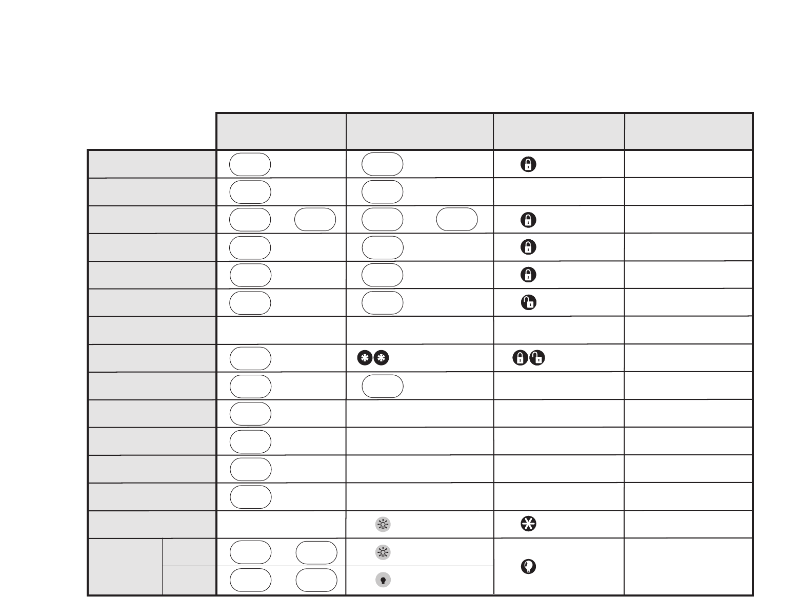
How to . . .
Arm the system
– Doors & Windows
Arm the system
– Motion Sensors
Arm the system
– Doors/Windows & Motion Sensors
Activate No Entry Delay
Windows
Doors &
ARM
Activate the Latchkey feature
Disarm the system
Subdisarm the system
Send an alarm to the
Central Monitoring Station
Check the system status
Set doors to Chime
Set Special Motion Chime
Set lights to time activated
Set lights to sensor activated
Open a garage door or turn
on special lights
Toggle lights
Master Code
CONTROL PANEL
REMOTE HANDHELD &
Touchtalk 2-Way RF
TOUCHPAD
KEYCHAIN TOUCHPAD
Sensors
Motion
ARM
Windows
Doors &
ARM
Sensors
Motion
ARM
Windows
Doors &
ARM
Press Twice
Press Twice
Sensors
Motion
ARM
DISARM
+ Access Code
SYSTEM
STATUS
Press Once
Windows
Doors &
ARM
Sensors
Motion
ARM
Press Twice
Windows
Doors &
ARM
Sensors
Motion
ARM
Windows
Doors &
ARM
Press Twice
Sensors
Motion
ARM
DISARM
+ Access Code
Master Code
EMERGENCY
CHIME
DOORS
LIGHTS
Time
Activated
CHIME
Special
Motion
LIGHTS
Sensor
Activated
SYSTEM
STATUS
SYSTEM
STATUS
Press Twice
Press & hold
for 3 seconds
Press both EMERGENCY buttons.
Press & hold for 3 seconds.
Lights on
Lights off
SYSTEM
STATUS
7 – 8
9 – 0
+
+
Press Twice
Press Twice
+ Unit #
Press & hold
Press + Master Code + 0
*
Press + Master Code + 2
*
REMOTE PHONE CONTROL
Press + Master Code + 3
*
Press + Master Code + 2 + 3
*
Press + Master Code + 2 + 2
*
Press + Master Code + 3 + 3
*
Press + Master Code + 1
*
Press + Master Code + 1
*
Press + Master Code + + 1
*
#
Press & hold
for 3 seconds
Press 3 times
Press once if
programmed
Press twice
Quick Reference Table
46
466-1574
