Policy Framework and its
Deployment Mechanism in India
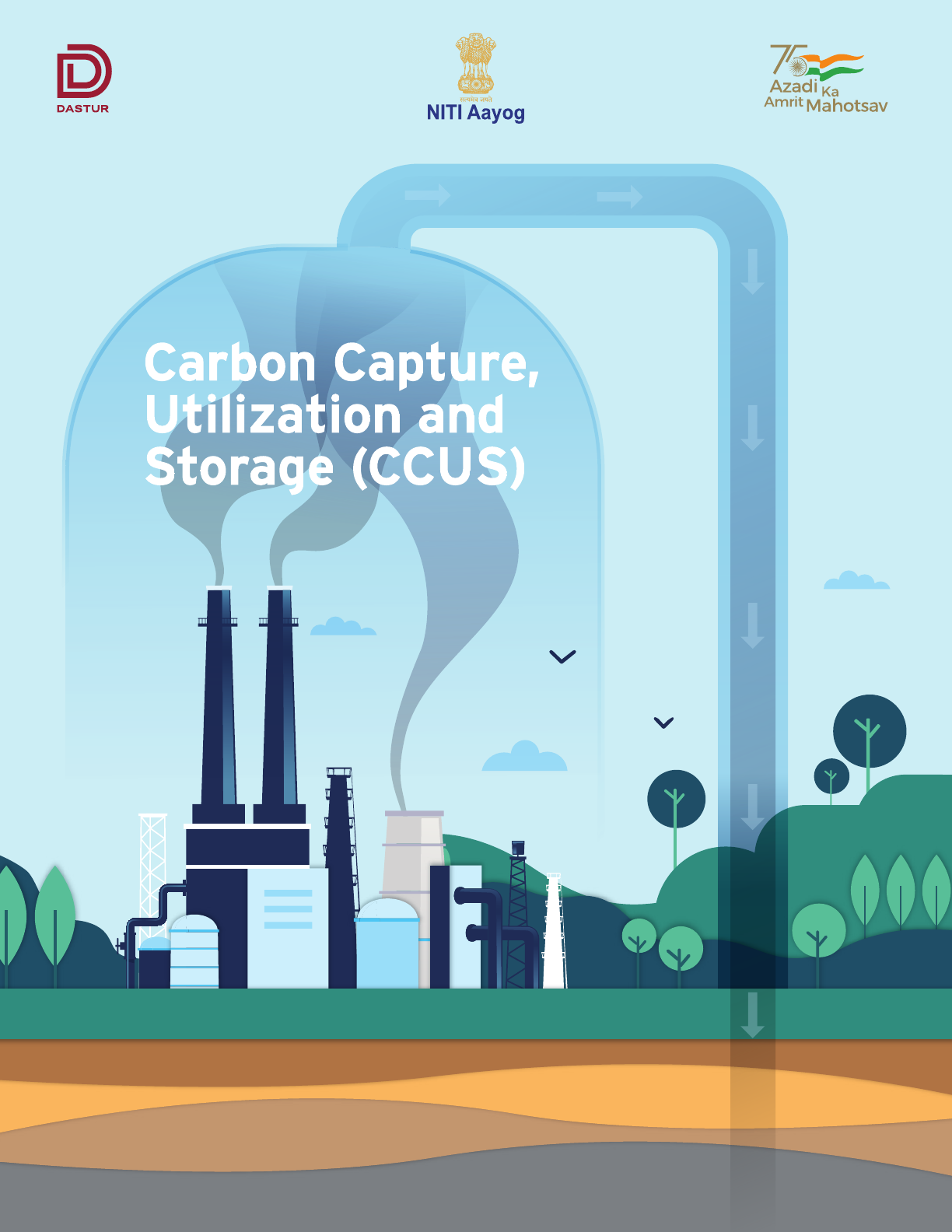
Carbon Capture,
Utilization and
Storage (CCUS)
November 2022

Authors and Acknowledgements
Atanu Mukherjee, Principal Investigator,
M. N. Dastur & Co. (P) Ltd.
Saurav Chatterjee, Co-Principal Investigator,
M. N. Dastur & Co. (P) Ltd.
Authors Acknowledgment
The team is grateful for the mentorship and inputs provided by:
Dr. V. K. Saraswat, Member, NITI Aayog
Dr. Neeraj Sinha, Sr. Adviser (S&T), NITI Aayog
Shri Rajnath Ram, Adviser (Energy), NITI Aayog
Leadership
The study was carried out with the financial support of NITI Aayog,
Government of India and conducted by M. N. Dastur & Co. (P) Ltd.
The team is grateful for the input and contributions received from:
Shri Jawahar Lal, Deputy Chief Engineer, NITI Aayog
Shri Naveen Kumar Vidyarthi, Director (Energy), NITI Aayog
Shri Amit Verma, Director (Energy), NITI Aayog
Shri Manoj Kumar Upadhayay,
Deputy Advisor (Energy), NITI Aayog
Dr. Abhinav Trivedi, Consultant, NITI Aayog
Shri Akash Jain, Young Professional, NITI Aayog
Abhijit Sarkar, Vice President, Dastur International, Inc.
Dr. Suprotim Ganguly, Techno-Strategic Advisor,
M. N. Dastur & Co. (P) Ltd.
Arunava Maity, Sr. Principal Analyst, M. N. Dastur & Co. (P) Ltd.
Dr. Vikram Vishal, Convenor - National Centre of Excellence in
Carbon Capture and Utilization, IIT Bombay
Dr. Ken Medlock, Baker Institute, Rice University
Phil Amick, Principal, Dastur Energy Inc.
Dr. Susan D. Hovorka, The University of Texas at Austin
Saptarshi Bhattacharya, M. N. Dastur & Co. (P) Ltd.
Anand Senguttuvan, M. N. Dastur & Co. (P) Ltd.
Arnab Adak, M. N. Dastur & Co. (P) Ltd.
Debarka Chakraborty, M. N. Dastur & Co. (P) Ltd.
Anindya Majumdar, M. N. Dastur & Co. (P) Ltd.
Pratyush Kumar, M. N. Dastur & Co. (P) Ltd.
We would also like to thank the following organizations who provided
valuable inputs in shaping the report:
Shri A. Balan, Member (Planning),
Central Electricity Authority, India
Shri A K Rajput, Chief Engineer, Central Electricity Authority, India
Shri Neelesh Kr Sah, Joint Secretary,
Ministry of Environment, Forest and Climate Change, Govt. of India
Shri Gurdip Singh, Chairman and Managing Director,
National Thermal Power Corporation Ltd.
Shri Nalin Singhal, Chairman and Managing Director,
Bharat Heavy Electricals Ltd.
Shri U K Bhattacharya, Director,
National Thermal Power Corporation Ltd.
Shri Anirban Das Gupta, Director-in-Charge,
Steel Authority of India Ltd.
Shri Sanjay Shrivastava, Executive Director -
Chief Carbon Management & Sustainability Group,
Oil and Natural Gas Corporation Ltd.
Shri Peeyush Kumar, Officer on Special Duty,
Ministry of Coal, Govt. of India
Dr. Anita Gupta, Adviser / Scientist G,
Department of Science & Technology
Shri Sanjay Singh, Scientist G, Technology Information
Forecasting and Assessment Council
Dr. Deepak Saxena, Executive Director, Indian Oil Corporation Ltd.
Shri Pradeep, Executive Director, Technology Information
Forecasting and Assessment Council
Shri Gaurav Mishra, Executive Engineer,
Reservoir, Oil and Natural Gas Corporation Ltd.
Shri Sujit Mitra, General Manager - Reservoir,
Oil and Natural Gas Corporation Ltd.
Smt. Neha Verma, Director, Ministry of Steel, Govt. of India
Shri Paramjeet Singh, Additional Industrial Advisor,
Ministry of Steel, Govt. of India
Dr. Mukesh Kumar, Director - Steel Research & Technology
Mission of India, Ministry of Steel, Govt. of India
Shri Kumar Saurabh, Deputy Director,
Ministry of Power, Govt. of India
Ms. Soujanya Mondal, Senior Manager, Corporate Strategy,
Planning & Advocacy, Gas Authority of India Ltd.
Shri Rahul Buswala, Strategy Manager,
Carbon Capture, Bharat Heavy Electricals Ltd.
Acknowledgment
Available at:
NITI Aayog: www.niti.gov.in
Disclaimer
M. N. Dastur & Co. (P) Ltd. has received the financial assistance under the Research Scheme of NITI Aayog to prepare the report. While due care has
been exercised to prepare the report using the data from various sources, NITI Aayog does not confirm the authenticity of data and the accuracy of
the methodology to prepare the report. NITI Aayog shall not be held responsible for finding or opinions expressed in the document. This
responsibility completely rests with M. N. Dastur & Co. (P) Ltd.
03
Carbon Capture Utilization and Storage (CCUS) –
Policy Framework and Deployment Mechanism in India
Carbon Capture Utilization and Storage (CCUS) –
Policy Framework and Deployment Mechanism in India

04
About DASTUR
M. N. Dastur & Company (P) Ltd. along with Dastur Energy (DASTUR)
conceptualizes, designs, and develops business, technology, engineering and policy
blueprints for clean energy systems for enterprises, governments, and institutions.
DASTUR envisions the enablement of an affordable and clean energy future
through industrial decarbonization, carbon capture, low-carbon alternative fuels
and low-carbon transformation of solid fuels and hydrocarbons. DASTUR has
conceptualized and designed several pioneering industrial-scale low-carbon
projects worldwide in hydrogen, methanol, chemicals, steel, hydrocarbons, power,
and carbon capture, and works with governments and international institutions on
policy and market design aspects for enabling a low-carbon economy. DASTUR’s
intellectual property and operating frameworks help design commercially viable
and sustainable energy solutions using low-carbon energy technologies and
carbon capture utilization and storage. DASTUR optimizes the design of integrated
clean energy systems for superior long-term techno-economic performance that
include emerging energy systems like industrial carbon capture systems, CO
2
utilization and sequestration, clean baseload power, clean hydrogen production,
net-negative gasifier complexes, methanol ecosystems, waste gas conditioning and
use, clean chemicals, and clean materials. DASTUR’s intellectual assets in clean
energy systems, economics, and finance help shape policies and strategies in clean
energy market designs, carbon capture, carbon credit & trade mechanisms,
regulatory frameworks, and macro-energy strategies for nations and institutions.
By designing scalable clean energy systems which are pragmatic, commercially
viable, and competitive, DASTUR makes sustainability and climate goals real,
achievable, and implementable.
Carbon Capture Utilization and Storage (CCUS) –
Policy Framework and Deployment Mechanism in India
Carbon Capture Utilization and Storage (CCUS) –
Policy Framework and Deployment Mechanism in India

05
Executive Summary 15
1. Introduction 27
2. Analysis of Sector-wise CO
2
Emissions 35
3. Overview of CO
2
Capture & Utilization Technologies 67
4. Potential for CO
2
Storage in India 93
5. CCUS Policy Framework for India 111
6. Investment and Financing Mechanism 135
7. Conclusions 157
Bibliography 163
Contents
Carbon Capture Utilization and Storage (CCUS) –
Policy Framework and Deployment Mechanism in India
Carbon Capture Utilization and Storage (CCUS) –
Policy Framework and Deployment Mechanism in India

06
List of Figures
Figure E-1 The 70% Emissions Challenge
Figure E-2 Sector-wise CO
2
Emissions (in mtpa)
Figure E-3 Cost Curve for CO
2
Capture Across
Industries/Sectors
Figure E-4 Mega Scale CO
2
Cluster Model
Figure E-5 Region-wise Storage Clusters in India
Figure 1.1 The 70% Emissions Challenge
Figure 2-1 Illustration of Emission Types and Boundary
Consideration
Figure 2-2 Sector-wise CO
2
Emissions, mtpa
Figure 2-3 Break-up of Installed Generation Capacity, GW
Figure 2-4 Break-up of Generation, Billion Unit
Figure 2-5 Break-up of Thermal Power Plants by Fuel
(Power Sector at a Glance ALL INDIA)
Figure 2-6 PFD of Coal-fired TPP
Figure 2-7 Schematic Representation of Gas Turbine
Figure 2-8 NGCC Power Plant Schematic Diagram
Figure 2-9 Share of Total CO
2
Emissions by Each Prime
Mover, mtpa
Figure 2-10 State-Wise Analysis of CO
2
Emissions (mtpa)
Figure 2-11 Crude Steel Capacity & Production in Last
5 Years (in mtpa)
Figure 2-12 Process Route Wise Steel Production and
Contribution (in mtpa)
Figure 2-13 Various Iron and Steel Making Routes in India
Figure 2-14 CO
2
Emission (in tonne) per tonne of Finished
Steel BF-BF route
Figure 2-15 Region-wise Distribution and Total CO
2
Emissions (in mtpa)
Figure 2-16 Cement Production (in mtpa)
Figure 2-17 Per Capita Cement Consumption in 2018 (in kg)
Figure 2-18 Cement Production (in mtpa)
Carbon Capture Utilization and Storage (CCUS) –
Policy Framework and Deployment Mechanism in India
Carbon Capture Utilization and Storage (CCUS) –
Policy Framework and Deployment Mechanism in India
Figure 2-19 Top 10 Cement Clusters Based on Cumulative
Capacity
Figure 2-20 Cement Demand (in mtpa) and Per-capita
Cement Consumption (in kg)
Figure 2-21 Typical Process Flow Diagram for Cement
Making
Figure 2-22 Typical CO
2
Cascade (in kg of CO
2
per tonne
of cement)
Figure 2-23 Cement Plant CO
2
Emission Projection
(in mtpa)
Figure 2-24 Simplified Block Flow Diagram of Hydrogen
Generation Units (HGUs)
Figure 2-25 Domestic Oil Production (in mtpa)
Figure 2-26 Natural Gas Production - FY 2014-15 to FY
2019-20 (in billion cubic meter)
Figure 2-27 Oil Production by Operator in FY 2019-20
(in mtpa)
Figure 2-28 Natural Gas Production in FY 2019-20 (in
billion cubic meters)
Figure 2-29 Carbon Emission by E&P Operator in FY
2019-20 (in mtpa of CO
2
eq)
Figure 2-30 Emissions Projection for 2030, MT CO
2
eq
Figure 2-31 A Typical Coal Gasification Based Ecosystem
Figure 3-1 Scheme of Post-combustion, Pre-combustion &
Oxy-fuel combustion
Figure 3-2 Simplified Representation of CO
2
Capture
Technologies
Figure 3-3 Schematic Representation of Working Principle
of Solvent-Based CO
2
Capture
Figure 3-4 Schematic Representation of CO
2
Absorption
Capacity of Chemical and Physical Solvents as
a Function of the Partial Pressure of CO
2
Figure 3-5 Operating Regimes of Various Solvents for
CO
2
Capture
Figure 3-6 Typical Flow Diagram of a Chemical Solvent
Based CO
2
Capture

Figure 3-7 Process Flow Diagram of Air Liquide’s Amine
Based CO
2
Capture
Figure 3-8 Process Flow Diagram of a Pilot Slipstream
Test Unit at National Carbon Capture Center,
USA using ION’s Proprietary ICE-21 Solvent for
CO
2
Capture
Figure 3-9 Process Flow Diagram of KM CDR CO
2
Capture
using Proprietary KS-1 Solvent
Figure 3-10 Process Flow Diagram of the Amine Guard
™
FS
CO
2
Capture using Proprietary UCARSOL
™
Solvent
Figure 3-11 Process Flow Diagram of Baker Hughes Chilled
Ammonia Process (CAP) using Ammonium
Carbonate Solvent
Figure 3-12 Basic Process Flow diagram of the Rectisol
®
Process
Figure 3-13 Basic Process Flow Diagram of the Selexol
™
Process
Figure 3-14 Basic Process Flow Diagram of Air Products’
VSA Technology
Figure 3-15 Five-step Pressure-swing Cycle of UOP’s
Polybed
™
PSA Systems
Figure 3-16 Process Flow Diagram of the Cryocap
™
H
2
Technology
Figure 3-17 Summary of Major Large Scale Carbon Capture
Commercial Projects
Figure 3-18 Cost Curve for CO
2
Capture Across
Processes/Industries
Figure 3-19 Possible CO
2
Utilization Pathways
Figure 3-20 A Simplified Schematic of CO
2
Mineralization
Process
Figure 3-21 Typical Schematic for the CO
2
Hydrogenation
Process along with Integration with Carbon
Capture Unit
Figure 3-22 Systematic Indigenization of Technology
through Technology Transfer
Figure 3-23 Promising CO
2
Utilization Technology
Propositions
Figure 4-1 Working of CO
2
EOR
Figure 4-2 Working of CO
2
ECBMR
Figure 4-3 Classification of CO
2
Storage Potential of
Sedimentary Basins of India
Figure 4-4 Major Sedimentary Basins in India with their
CO
2
Storage Potential
Figure 4-5 Seven RSCPs Funded by the US DOE
Figure 5-1 CCUS Hub and Cluster Framework
Figure 5-2 CCUS Cluster Around the World
Figure 5-3 Rotterdam CCS Cluster
Figure 5-4 Timeline Denver City Hub
Figure 5-5 Denver City Storage
Figure 5-6 ACTL Map
Figure 5-7 ACTL Timelines
Figure 5-8 Mega Scale CO
2
Cluster Model
Figure 5-9 Region-wise Storage Clusters in India
Figure 6-1 Utility Costs Considered
Figure 6-2 Sector-wise CO
2
emission and Contribution
Figure 6-3 Incentives such as the Product Linked
Incentive (PLI) scheme create a level playing
field for low-carbon products
Figure 6-4 CCUS Financing Mechanism
Figure 6-5 Results of CCUS Financing Analysis – Financing
Option 1 (Clean Energy Cess)
Figure 6-5 Results of CCUS Financing Analysis – Financing
Option 2 (Bonds and Govt. Budget Support)
Figure 6-6 SPV Framework to Finance Gasification
Projects in a Deficit-Neutral Way
07
Carbon Capture Utilization and Storage (CCUS) –
Policy Framework and Deployment Mechanism in India
Carbon Capture Utilization and Storage (CCUS) –
Policy Framework and Deployment Mechanism in India

08
List of Tables
Carbon Capture Utilization and Storage (CCUS) –
Policy Framework and Deployment Mechanism in India
Carbon Capture Utilization and Storage (CCUS) –
Policy Framework and Deployment Mechanism in India
Table E-1 Estimated CO
2
Storage Capacity in India
Table E-2 Sector-wise Typical Carbon Capture Capital
Charge and Cash Cost
Table E-3 CCUS Funding through Clean Energy Cess
Table E-4 CCUS Funding with Bonds and Government
Budgetary Support
Table 1-1 Large Scale CCUS facilities in operation in 2020
Table 2-1 Flue Gas Characteristics of Coal-Fired Thermal
Power Plants
Table 2-2 Flue Gas Characteristics of Coal-Fired Thermal
Power Plants
Table 2-3 Overall Analysis of CO
2
Emissions from the Power
Sector in India
Table 2-4 CO
2
Emissions by Prime Mover for Plants with
Minimum 2 mtpa Capturable CO
2
Table 2-5 District-wise CO
2
Emission Analysis
Table 2-6 Energy & CO
2
Volume Projections for
FY 2029-30
Table 2-7 CO2 Direct Emission Intensities for Various Iron
Making Routes
Table 2-8 Major Players of Cement Industry and Capacity
in mtpa)
Table 2-9 State-wise Cement Capacity
Table 2-10 Top 20 Districts/Clusters and Aggregate Capacity
Table 2-11 Plant Capacity Distribution
Table 2-12 Consumption Parameters
Table 2-13 Gas Composition at Different Source Points
Table 2-14 CO
2
Concentration at Different Refinery Units
Table 2-15 Cracker Furnace Flue Gas Composition
Table 2-16 Total CO
2
Emissions from Refineries,
Petrochemicals & Fertilizers
Table 2-17 Total CO
2
Emissions from Oil & Gas Upstream
Operations
Table 2-18 Total CO
2
Emission from Coal Gasification
Table 2-19 Sector-wise CO
2
Emissions and Interventions
Required
Table 3-1 Comparison of Various Flow Schemes of UOP
Amine Guard
™
FS Technology
Table 3-2 Comparative Analysis of Various Classes of CO
2
Capture Technologies
Table 3-3 Various CO
2
Utilization Pathways
Table 4-1 CO
2
EOR Storage Capacity Estimates
Table 4-2 CO
2
ECBMR Storage Capacity Estimates
Table 4-3 CO
2
Storage Capacity Estimation for Deep
Saline Aquifers
Table 4-4 Basalt Formation CO
2
Storage Capacity Estimates
Table 4-5 Theoretical CO
2
Storage Capacity in India
Table 5-1 EU Funding Schemes for CCUS
Table 5-2 Carbon Pricing System Adopted by Different
Provinces of Canada
Table 5-3 Comparison of Carbon Credits/Incentives and
Carbon Tax Based Policy
Table 5-4 Key Elements of a CCUS Policy Framework
for India
Table 5-5 Sedimentary Basins Spanning Across Multiple
Regions
Table 6-1 Capex and Opex Considerations for CCUS Retrofit
Table 6-2 Sector-wise Typical Carbon Capture Capital Cost
Table 6-3 Sector-wise Typical Carbon Capture Cash Costs
Table 6-4 Sector-wise Typical Carbon Capture Cash Costs
and Capital Charges
Table 6-5 Carbon Capture Volume in Two Scenarios and
Tentative Investment
Table 6-6 Assumptions/Considerations for CCUS Financing
Analysis
Table 6-7 45Q Tax Credit Amounts
Table 6-8 Tax Credits for Hydrogen Production in USA -
Inflation Reduction Act of 2022
Table 6-9 Probable Distribution of 750 mtpa and low-C
Product Volume
Table 7-1 Sector-wise CO
2
Emissions and Interventions
Required
Table 7-2 Theoretical CO
2
Storage Capacity in India
Table 7-3 Key Elements of a CCUS Policy Framework
for India
Table 7-4 Sector-wise Typical Carbon Capture Capital
Charge and Cash Cost

Abbreviations
ACTL Alberta Carbon Dioxide Trunk Line
AD Accelerated Depreciation
ADB Asian Development Bank
ARRA American Recovery and Reinvestment Act
BEE Bureau of Energy Efficiency
BF Blast Furnace
BGS British Geological Society
BOF Basic Oxygen Furnace
BOO Build-Own-Operate
CAP Chilled Ammonia Process
CBAM Cross Border Adjustment Mechanism
CBM Coal Bed Methane
CCF Climate Change Fund
CCFC Carbon Capture Finance Corporation
CCL Central Coalfields Limited
CCM Carbon Concentrating Mechanism
CCUS Carbon Capture Utilization and Storage
CDU Crude Distillation Unit
FCC Fluid Catalytic Cracking
CEA Central Electricity Authority
CEIL Cairn Energy India Limited
CFD Contracts-for-Difference
CGP Co-Gen Plant
CIF CCUS Infrastructure Fund
CIFIA Infrastructure Finance and Innovation Act
CIL Coal India Limited
CIR Color Infrared
CO Carbon Monoxide
Coal DR Coal Based DR Processes
COG Coke Oven Gas
CRF Capital recovery factor
CRI Carbon Recycling International
DAC Direct Air Capture
DEPG Dimethyl Ether of Polyethylene Glycols
DGH Directorate General of Hydrocarbons
DOE Department of Energy
DRCF Dual Refrigerant CO
2
Fractionation
DVP Deccan Volcanic Province
E&P Exploration and production activities
EAF Electric Arc Furnace
EBP Ethanol Blend Petrol
ECBMR Enhanced Coal Bed Methane Recovery
ECL Eastern Coalfields Limited
EIB European Investment Bank
EMIT Electromagnetic Induction Tomography
EOR Enhanced Oil Recovery
09
Carbon Capture Utilization and Storage (CCUS) –
Policy Framework and Deployment Mechanism in India
Carbon Capture Utilization and Storage (CCUS) –
Policy Framework and Deployment Mechanism in India

EPA Environmental Protection Agency
ERT Electrical Resistance Tomography
ESP Electrostatic Precipitator
EU ETS European Union Emissions Trading System
EXIM Export Import Bank of the United States
FCC Fluid Catalytic Cracking
FECM Fossil Energy and Carbon Management
FT Fischer-Tropsch
FTE Full Time Equivalent
Gas DR Gas Based DR Processes
GBI Generation Based Incentives
GBS Gross Budgetary Support
GFANZ Glasgow Financial Alliance for Net Zero
GGPPA Greenhouse Gas Pollution Pricing Act
GT Giga Tonne
GTPA Gigatonne Per Annum
HGU Hydrogen Generation Unit
HP High Pressure
IEA International Energy Agency
IECM Integrated Environmental Control Model
IETF Industrial Energy Transformation Initiative
IF Induction Furnace
IFC International Finance Corporation
ION ION Clean Energy
IP Intellectual Property
IPCC Intergovernmental Panel on Climate Change
JTF Just Transition Fund
JTM Just Transition Mechanism
KM CDR
™
Kansai Mitsubishi Carbon Dioxide Recovery
LCA Life Cycle Analysis / Life Cycle Assessment
LCFS Low Carbon Fuel Standard
LETS Low Emission Technology Statement
LIC Life Insurance Corporation
LP Low-Pressure
MDEA Methyl diethanolamine
MHI Mitsubishi Heavy Industries Ltd
MRV Monitoring Reporting and Verification
framework
MTPA Million Tonne Per Annum
MVA Monitoring Verification and Accounting
NAS Non Aqueous Solvent
NCEEF National Clean Energy and Environment Fund
NETL National Energy Technology Laboratory
NEXI Nippon Export and Investment Insurance
NGCC Natural Gas Combined Cycle
10
Carbon Capture Utilization and Storage (CCUS) –
Policy Framework and Deployment Mechanism in India
Carbon Capture Utilization and Storage (CCUS) –
Policy Framework and Deployment Mechanism in India

11
Carbon Capture Utilization and Storage (CCUS) –
Policy Framework and Deployment Mechanism in India
Carbon Capture Utilization and Storage (CCUS) –
Policy Framework and Deployment Mechanism in India
OBPS Output Based Pricing System
OPC Ordinary Portland Cement
OPGC Odisha Power Generation Corporation Limited
OPGGSA Offshore Petroleum and Greenhouse Gas
Storage Act 2006
PLI Production Linked Incentive
PMAY Pradhan Mantri Awas Yojana
PP Power Plant
PPC Portland Pozzolana Cement
PSA Pressure Swing Adsorption
PSC Portland Slag Cement
RCF Rashtriya Chemicals & Fertilizers
RCP Rotterdam Cluster Project
RCSPs Regional Carbon Sequestration Partnerships
RRF Recovery and Resilience Facility
SAR Synthetic Aperture Radar
SECARB Southeast Regional Carbon Sequestration
Program
SECL South-Eastern Coalfields Limited
SMR Steam Methane Reforming
SSEB Southern States Energy Board
syngas Synthesis Gas
T&S Transport and Storage
TCF Trillion Cubic Feet
TIER Technology Innovation and Emissions Reduction
TIFAC Technology Information Forecasting and
Assessment Council
TSA Temperature Swing Adsorption
UIC Underground Injection Control
UKRI UK Research and Innovation’s
URR Ultimate Recoverable Reserves
USIDFC US International Development Finance
Corporation
VDU Vacuum Distillation Unit
VGas Volume of Methane
VRM Vertical Roller Mill
VSA Vacuum Swing Adsorption
VSP Vertical Seismic Profile
WCL Western Coalfields Limited
12
Carbon Capture Utilization and Storage (CCUS) –
Policy Framework and Deployment Mechanism in India
Carbon Capture Utilization and Storage (CCUS) –
Policy Framework and Deployment Mechanism in India
13
Carbon Capture Utilization and Storage (CCUS) –
Policy Framework and Deployment Mechanism in India
Carbon Capture Utilization and Storage (CCUS) –
Policy Framework and Deployment Mechanism in India
14
Carbon Capture Utilization and Storage (CCUS) –
Policy Framework and Deployment Mechanism in India
Carbon Capture Utilization and Storage (CCUS) –
Policy Framework and Deployment Mechanism in India

Executive
Summary

Carbon Capture, Utilization and Storage is an Essential
Imperative for India to Reach its Decarbonization Goals
India is the 3rd largest emitter of CO
2
in the world
after China and the US, with estimated annual
emissions of about 2.6 gigatonne per annum (gtpa).
The Government of India has committed to reducing
CO
2
emissions by 50% by 2050 and reaching net zero
by 2070. The growth of renewable power capacity has
been one of the key success stories of the clean
energy transition in India; however, the power sector
only contributes to about 1/3 rd of the aggregate CO
2
emissions, which will continue to abate as renewables
increasingly replace fossil fuel based power
generation. The growing industrial economy emits
close to another third of the aggregate emissions that
are hard to abate, and will continue to increase unless
new technologies and carbon abatement mechanisms
are deployed. At the same time, while India phases
down the use of coal over time, India will be
dependent on fossil energy sources like coal for a long
time to support the industry and meet the
requirements for affordable and reliable baseload
power. Therefore, India’s decarbonization pathway
has to also embrace technologies which will abate
emissions from the hard to abate industrial sectors as
well as for residual baseload power generation.
Carbon Capture Utilization and Storage (CCUS) has an
important and critical role to play in decarbonizing the
industrial sector, which is hard to electrify and hard to
abate, due to the use of fossil fuels not only as a
source of energy but within the process itself. CCUS
also has an important role to play in decarbonizing the
power sector, given India’s present reliance on coal
for meeting over 70% of its electricity needs. Even if
India is able to substantially green the grid and meet
the target of 500 GW installed capacity of renewables
by 2030, there would still be a need to meet the
baseload power demand from fossil fuels (most likely
coal) or other dispatchable sources, given the
intermittency and non-dispatchable nature of solar
and wind power.
Direct Air Capture (DAC) that directly captures dilute
CO
2
(415 ppm) from the air, may also emerge as a
form of carbon capture that has wide applicability as it
is independent of the source and concentration of the
emission stream. However, DAC is still in its early
stages and the economics (present cost of DAC is
estimated to range between US$ 400-800/tonne of
CO
2
) and scale of operations are yet to be established.
Figure E-1: The 70% Emissions Challenge
16
Carbon Capture Utilization and Storage (CCUS) –
Policy Framework and Deployment Mechanism in India
Carbon Capture Utilization and Storage (CCUS) –
Policy Framework and Deployment Mechanism in India
Executive Summary
Industry
Agriculture
Transport
Building
Electricity
31%
~30%
2.6
gtpa
~70%
20
10
5
India

A Policy Driven Approach is
Required for CCUS
Industrial Sector Needs to be
a Key Focus Area for CCUS
CCUS is key to ensuring sustainable development and
growth in India, particularly for the production of
clean products and energy, leading to an
Indian economy. The areas where CCUS can
contribute to sustained economic growth in India
are manifold:
a. Energy, materials & food security and
self-sufficiency: CCUS offers the only known
technology for decarbonizing the hard-to-electrify
and CO
2
- intensive sectors such as steel, cement,
oil & gas, petrochemicals & chemicals, and
fertilizers. These sectors are critical to the
continued growth of the Indian economy and for
ensuring energy, materials and food security for
the country.
b. Enabling the sunrise sectors of coal gasification
and low-carbon hydrogen economy: CCUS is
expected to play a major role in enabling the
hydrogen economy in India, through the
production of blue hydrogen (i.e. coal gasification
based hydrogen production coupled with CCUS)
based on the utilisation of India’s rich
endowments of coal. Given the current cost
structure of green hydrogen at US$ 5-6/kg,
cost-competitive blue hydrogen production at
around US$ 2/kg can provide a pathway for the
hydrogen economy in the future.
c. Sustenance of existing emitters: Nearly
two-thirds of India’s 144 mtpa crude steel capacity
and 210 GW of coal-based power capacity have an
age of less than 15 years and cannot be wished
away or stranded and need to be made
sustainable by retrofitting with CO
2
capture and
disposition infrastructure. Significant economic
costs and damages (estimated to be in the range
of US$ 6 billion/year by 2050) can be avoided by
ensuring the sustenance of existing emitters by
implementing CCUS.
While CCUS enables competitive and sustainable sunrise
industries in certain sectors in India, it also imposes
costs on other sectors – particularly for the adoption of
CCUS by existing emitters. The initial adoption of CCUS
implementation in such sectors will impose costs as
they start internalizing the negative externality of
emission of CO
2
into the atmosphere, whose cost is
currently borne by society. As more CO
2
utilization
technologies develop and learning curve effects set in,
CCUS costs can come down significantly and new
industries around carbon utilization will also develop.
Therefore, to enable the sustainable development of
the Indian economy, economy-wide adoption of CCUS
will require policy support to initiate and accelerate
deployment through economic incentives. These
economic incentives can take various forms like tax or
cash subsidy on the captured CO
2
, viability gap
funding, loan guarantee, demonstration project
support and R&D incentives.
India’s power and industrial sectors contributed
around 1,600 mtpa of CO
2
emissions (around 60%)
out of the total emissions of 2,600 mtpa in 2020.
The remaining 40% of emissions come from
distributed point emissions sources like agriculture,
transport, and buildings which are not amenable for
CCUS. Fuelled by economic growth across sectors as
well as rapid urbanization, emissions from these
sectors are expected to increase to nearly 2,300
mtpa by the year 2030, thus making their capture
and abatement critical.
1,004
1,210
177
240
450
196
325
2030 CO
2
emission
56
125
2020 CO
2
emission
2,291
27
102
1,621
Coal Gasifcation
NG based H
2
production Upstream O&G/Refinery/Chemicals
Cement
Iron & Steel
Power
Figure E-2: Sector-wise CO
2
Emissions (in mtpa)
17
Carbon Capture Utilization and Storage (CCUS) –
Policy Framework and Deployment Mechanism in India
Carbon Capture Utilization and Storage (CCUS) –
Policy Framework and Deployment Mechanism in India
Executive Summary

CCUS has an integral role to play in the
decarbonization and sustenance of all these industries
and sectors, which are critical and vital pillars of the
Indian economy.
Steel: The future growth of the steel
industry in India is largely expected to be
based on fossil fuels and the CO
2
-intensive
BF-BOF route, given the scarcity of scrap
and natural gas in India. CCUS is
necessary for ensuring the sustainability of this
critical sector of the Indian economy and also
ensuring export competitiveness.
CCUS can also enable the scalable and profitable
conversion of waste gases from Blast Furnace, Coke
Oven and Basic Oxygen Furnaces of Integrated Steel
Plants to blue hydrogen at a cash cost of less than Rs.
100 per kg. Blue hydrogen can be used within the steel
plant as a source of clean energy or for producing clean
DRI. The blue hydrogen can also be sold to external
consumers, thus propelling the clean hydrogen
economy in India.
Cement: Cement is another major CO
2
emitting sector, where fossil fuels are
difficult to replace in the cement-making
process. The capture, sequestration and
conversion of CO
2
to aggregates and
other chemical products provide synergies for the
cement sector.
Oil & gas, refineries and chemicals: This
is another hard-to-abate sector, where
CCUS is essential for ensuring
sustainability. Carbon capture is inbuilt in
many of the processes, which makes CCUS costs
competitive for this sector.
Hydrogen production: The
cost-competitive production of blue
hydrogen using India’s rich coal
endowments is key to enabling the
hydrogen economy of the future. Carbon capture is
inbuilt in the H
2
production process, leading to
cost-competitive CCUS.
Coal gasification: Coal gasification is a
sunrise sector and key to ensuring the
materials and energy security of India,
based on India’s rich endowments of coal.
CCUS is critical to enabling the coal gasification
economy in India and the production of clean
products.
Thermal power: Even with the expected
growth in renewable energy capacities,
coal-based power will continue to meet
more than 50% of electricity demand in India in the
foreseeable future. As the largest emitter of CO
2
,
CCUS of the power sector is essential for meaningful
decarbonization and ensuring energy security in India.
Appropriate Carbon Capture
Technologies for Different
Applications
There are different categories and types of
commercial-scale carbon capture technologies and
their suitability or appropriateness for different
applications/sectors depends on the typical CO
2
gas
stream composition:
a. Chemical solvent-based CO
2
capture
technologies: preferred when dealing with gas
streams that are lean in CO
2
and have relatively
lower pressures, such as flue gas streams from
power plants, BF gases in steel plants, gas streams
in refineries or chemicals plants. The cost and
availability of steam is also a key factor as
regenerating the solvent requires large quantities
of steam.
b. Physical solvent-based CO
2
capture
technologies: these work well on gas streams with
relatively higher CO
2
concentration and pressure,
such as pre-combustion capture in the case of
gasification projects.
c. Adsorption-based CO
2
capture: suitable for gas
streams with moderate to high pressure and
moderate CO
2
concentration such as SMR flue gas
or BF gas.
d. Cryogenic CO
2
capture: preferred in cases where
the cost of power is low. This technology can be
applied for carbon capture from the PSA tail gas
of Steam Methane Reforming Units (for producing
H
2
) and provides a unique advantage of increasing
the yield/recovery of hydrogen production from
the same quantity of feedstock (natural gas).
18
Carbon Capture Utilization and Storage (CCUS) –
Policy Framework and Deployment Mechanism in India
Carbon Capture Utilization and Storage (CCUS) –
Policy Framework and Deployment Mechanism in India
Executive Summary

Carbon Capture Costs
Vary Widely Across
Industries/Sectors -
Policy Incentives Need to
be Appropriately Calibrated
Carbon capture costs (both capital cost and cash
cost) vary widely across industries and sectors, and
depend on CO
2
source characteristics (mainly
pressure & CO
2
concentration), capture technology,
power & steam sourcing costs. The estimated CO
2
capture cost curve for demo scale carbon capture
projects in each sector is provided below,
considering a reference plant size for each sector
and CO
2
delivery and disposition at 100 bar (a).
CO
2
capture cost is the lowest for the gasification
process, as carbon capture is already integrated
within the process. So, the additional cost is only
around Rs. 400/tonneCO
2
, required for polishing and
compression of the CO
2
stream. The capture costs
for other production processes like SMR-based H
2
production, iron & steel, cement, etc. include the
costs for gas processing, carbon capture, and
compression and are hence higher.
Carbon capture costs are amongst the highest for
coal-based power plants, due to the low
Figure E-3: Cost Curve for CO
2
Capture
Across Industries/Sectors
1000
0
400
4100
0 1 2 3 4 5 6 7 8 9 10 11 12
mtpa
2000
3000
4000
5000
6000
Gasification based product
Cement
Iron & Steel
Coal based power
Refinery & Chemical
SMR based H
2
Note: The CO
2
capture costs depicted above include costs for
capture, conditioning and compression to 100 bar (a) and the
amortized capital costs
Converting Captured CO
2
to
Value Added Products -
Opportunity to Profitably
Abate CO
2
Emissions
Carbon utilization technologies can provide a wide
variety of opportunities to convert the captured CO
2
to value-added products with a ready market in
India, thus contributing to the circular economy. The
most promising utilization pathways are:
a. Green urea: Green urea can be produced from the
captured CO
2
and cost-competitive green
hydrogen, from renewable energy based
electrolysis of water. Green urea can
replace/complement the traditional LNG/NG
based production and import of ammonia and
urea. The total urea consumption in India is over
30 mtpa, and thus green urea provides a
significant opportunity for CO
2
utilization at scale.
b. F&B applications: CO
2
is utilized in F&B
applications such as carbonated drinks, dry ice,
and modified atmosphere packing; however, the
scales are much lower compared to green urea.
c. Building materials (concrete and aggregates):
There is a large market for aggregates and
concrete in a developing country like India,
providing a pathway for utilizing CO
2
for producing
building materials through concrete curing and
aggregate formation. In these applications
,
CO
2
is
injected in a liquid state without any conversion,
thus reducing the energy requirements.
Additionally, large quantities of wastes such as
steelmaking slag are available as sources of
CaO/MgO, which can be utilized to produce
synthetic aggregates.
d. Chemicals (methanol and ethanol): Conversion
of CO
2
to methanol and ethanol from CO
2
is
proven at a commercial scale in different parts of
the world.
concentration of CO
2
in the power plant flue gas
stream. However, given the share of the power
sector in overall emissions, demo scale CCUS
projects in the power sector are also essential for
CCUS to meaningfully contribute to decarbonization
in India.
19
Carbon Capture Utilization and Storage (CCUS) –
Policy Framework and Deployment Mechanism in India
Carbon Capture Utilization and Storage (CCUS) –
Policy Framework and Deployment Mechanism in India
Executive Summary

Methanol and ethanol both have important fuel
substitution applications; additionally, methanol is
an intermediate for the production of value-added
chemicals like acetic acid, MTBE, DME, and
formaldehyde, all of which have multiple
downstream applications and offer significant
import substitution opportunities. The conversion
of CO
2
to chemicals thus provides a large-scale
CO
2
utilization and disposition pathway, given the
scale and potential of the downstream chemicals,
and can also help in reducing India’s import bill,
thus laying the foundation for an
economy.
e. Polymers (including bio-plastics): Conversion of
CO
2
to various polymers has been attempted
globally at different scales, and presents another
possible CO
2
utilization route. These polymers
have multiple applications, such as laptop
packaging, cell phone casings, furniture etc. and
provide an interesting futuristic optionality for
CO
2
utilization and conversion.
f. Enhanced Oil Recovery (EOR): CO
2
based EOR
has been successfully operating for decades for
producing low-carbon oil from maturing oil fields
in North America and other geographies. For
carbon capture projects in India with proximity to
oil fields, CO
2
EOR can play a role in residual oil
extraction that is environmentally sustainable and
economically feasible.
The technology, scale and economics for commercial
deployment are important determinants of how
existing carbon utilization technologies as well as
new technologies develop in India and compete in
markets. Policy support for carbon utilization and
conversion technologies through offtakes, PLI, price
support and R&D incentives will be necessary for
carbon utilization markets to develop.
However, one needs to be cognizant of the fact that
even with developed carbon utilization technologies,
the impact of carbon conversion technologies on
carbon abatement through carbon capture and
utilization will be modest. The sheer scale of CO
2
emission abatement requires that sequestration be
an essential complement to carbon utilization
technologies in the CCUS value chain.
Promoting Innovation,
Development, Transfer and
Adoption of CCUS
Technologies is Key to Rapid
Decarbonization in India
Government support and incentivization are needed
to promote the adoption and development of CCUS
technologies at a commercial scale in India.
A multi-pronged approach is recommended:
a. Technology transfer: Technologies for carbon
capture, CO
2
sequestration and EOR have been
demonstrated at a commercial scale for almost 50
years in many parts of the world and particularly
the US. While the development of indigenous
technologies is certainly desirable, the immediate
focus should be on the transfer, assimilation and
adoption of proven TRL 8 and 9 technologies in
the CCUS domain. The Government of India may
fund CCUS demonstration projects in sectors such
as coal-based power, steel, cement, refining &
petrochemicals based on commercially proven
technologies, thus reducing the technology risks,
operational risks and costs for CCUS projects in
India and avoiding the reinvention of the wheel.
Engagement with technology suppliers is also
important to ensure the transfer and
indigenization of technology and Intellectual
Property (IP). Policy support for the transfer of
technology and indigenization will not only
support the manufacturing of CCUS equipment for
India at a low cost, but also create export
opportunities.
b. Promoting R&D in novel CO
2
utilization
technologies: CO
2
utilization technologies are
relatively less developed, compared to capture
technologies. Technologies which have great
potential for India, such as CO
2
to methanol and
CO2 to aggregates, are at TRL levels of 4-5 and
6-7 only, respectively. Other propositions such as
CO
2
to synthetic fuels, polymers and novel
materials like carbon nanotubes are even further
behind on the development curve.
20
Carbon Capture Utilization and Storage (CCUS) –
Policy Framework and Deployment Mechanism in India
Carbon Capture Utilization and Storage (CCUS) –
Policy Framework and Deployment Mechanism in India
Executive Summary

The Government of India should promote an
ecosystem to foster R&D and innovation in CO
2
utilization technologies and new products &
applications based on CO
2
utilization. Similarly, in
the area of capture technologies, the
Government’s policy incentives should encourage
R&D in DAC as a possible future option. The
developments are multi-faceted and given the
difficulty in predicting the innovation and
development trajectory, there is a need to fund,
foster and incubate innovation-based ecosystems
through national centres of excellence such as the
National Centre of Excellence in Carbon Capture
and Utilization at IIT Bombay.
c. Private sector participation: Private sector
participation is essential to promote the transfer
and commercialization of existing CCUS
technologies and also push the envelope for the
development of new and emerging technologies,
particularly CO
2
utilization technologies.
Public/government funding and favourable
policies are required to incentivize & de-risk CCUS
projects, promote private sector participation and
enable viable CCUS business models and value
chains to emerge. Similar to the US DOE and UK
Infrastructure Bank’s support for the development
of novel technologies and projects in CCUS, India
also needs government institutional frameworks
and grants to strategically support new and
emerging CCUS technologies, as well as CCUS
projects across the full project/funding cycle.
Geological Storage is Critical
for CO
2
Disposition at Scale
For effective CCUS adoption at scale, apart from the
conversion of CO
2
to useful value-added products, there
needs to be a clear strategy and pathway for the
disposition of the captured CO
2
through permanent
geological storage. Save any miraculous technological
innovation at the commercial scale for carbon
abatement technologies, the only commercial
large-scale (giga tonne scale) CO
2
disposition option is
geological sequestration.
The options for the geological storage of CO
2
include
EOR (Enhanced Oil Recovery), ECBMR (Enhanced Coal
Bed Methane Recovery) and permanent storage options
like saline aquifers and basalt storage. However, the
geological data on the pore space availability in India for
the storage of CO
2
is limited, especially for saline
aquifers and basaltic storage. In the case of EOR and
ECBMR, the data availability is better given the prior
exploration activities for facilitating hydrocarbon (both
oil & gas and coal) extraction.
Theoretical assessments and estimates by the British
Geological Society and IIT Bombay indicate a large
potential for CO
2
storage in India, to the tune of 400 –
600 Gt.
However, to make the geological storage of CO
2
a
reality, further work needs to be supported by the
Government of India, especially in the areas of
source-sink mapping, pore space mapping,
geological characterization of the most promising
CO
2
storage regions & basins and developing the CO
2
storage infrastructure through characterization,
validation and development of commercial scale (at
least 1 mtpa) CO
2
injection programmes in the
selected sites. Similar programmes have been
funded in the US by the US DOE in the form of a
network of seven Regional Carbon Sequestration
Partnerships (RCSPs), to develop the regional
infrastructure for carbon capture and storage
across seven identified regions of the US.
A review of carbon capture projects around the world
reveals that a policy framework and Government
support for CCUS are key to managing project costs &
risks, incentivizing the private sector and establishing
the CCUS value chain comprising CO
2
capture,
transportation and storage.
Supportive Incentive Based
Policy Framework is Key to
CCUS Adoption in India
Table E-1: Estimated CO
2
Storage Capacity in India
3.4 Gt
Total
EOR
ECBMR
Saline
acquifers
Basaltic
formations
Well established in North
America; oil recovery possible
to the extent of 30-60%
3.5 - 3.7 Gt
CO
2
injected in unmineable coal
seams; further R&D required
before commercial deployment
291 Gt
No economic benefit - but
potential of large scale CO
2
storage
97 - 315 Gt
More recent developments
vis-à-vis saline aquifers
400 - 600 Gt
21
Carbon Capture Utilization and Storage (CCUS) –
Policy Framework and Deployment Mechanism in India
Carbon Capture Utilization and Storage (CCUS) –
Policy Framework and Deployment Mechanism in India
Executive Summary

Hub and Cluster Model Critical to Drive CCUS Economics and
Implementation at Scale
Given the cost and risks associated with CCUS projects,
CCUS clusters are necessary to drive CO
2
capture,
transport and disposition at scale and create a
meaningful decarbonization impact. CCUS clusters
incentivize emission-intensive co-located facilities (both
industrial facilities and power plants) to form a capture
cluster and connect to large-scale CO
2
storage sites
using oversized shared transport infrastructure (which
can be shared by multiple emitters), as well as options
for utilization of CO
2
to produce low carbon
downstream products. The anchor project would be
large CO
2
emitters, viz. a thermal power plant or a large
industrial facility, which can cover the initial
infrastructure costs, thereby reducing the cost for new
joiners to the cluster. Similarly, CO
2
disposition clusters
can be spread across multiple but reasonably closely
located geological sequestration sites, oil fields for
enhanced oil recovery (EOR) or CO
2
utilization projects.
A carbon credits-based policy is most suited for a
developing country like India, to incentivize CCUS
adoption and bring down the cost of carbon capture,
establish markets for low-carbon products and
decarbonize India’s large and relatively young
industrial asset base by offsetting carbon capture
costs. The key elements for the recommended CCUS
policy framework for India are:
a. Policy path: CCUS policy in India should be
carbon credits or incentives based, to seed and
promote the CCUS sector in India through tax and
cash credits and provide early stage financing and
funding mechanisms for CCUS projects
b. Hub & cluster business model: The policy
framework should promote the creation of
regional hub & cluster models to drive economies
of scale across the CCUS value chain, with defined
roles for emitters, aggregators, hub operators,
disposers and conversion agents.
c. Low carbon products: Low carbon or
carbon-abated products need to be supported
through preferential procurement in Government
tenders and Production Linked Incentive (PLI)
schemes.
Emitters and storage sites can connect through
storage and transportation hubs, similar to natural
gas hubs for the collection and distribution of natural
gas across different producers and consumers.
The services provided by such hubs would include the
compression and transportation of CO
2
, and
substantially lower the cost of transportation
infrastructure between emitters and CO
2
injection points.
Because of the high mobilization and laying expenses,
the economics of CCUS cluster projects in the initial
years is quite challenging due to lower CO
2
volumes
and the outsized infrastructure created. This can be
overcome through long-term and low-cost financing
through Government support and access to
international clean funds.
d. Environmental and social justice: CCUS policy
should protect communities most affected by
environmental and climate change by ensuring
the distribution of the economic value created by
CCUS and the protection of jobs in traditional
sectors (viz. coal mining etc.) affected by
migration to clean energy systems.
e. Accounting and regulatory framework: To
incentivize carbon capture in different sectors,
there is a need to establish a baseline of regulated
emission levels and allowances for different
sectors, and also adopt a Life Cycle Analysis (LCA)
framework that looks beyond just the direct Scope
1 emissions and takes into account Scope 2 and
Scope 3 emissions and ensures effective carbon
abatement.
f. Risk mitigation: For CCUS policy to be effective
in India and encourage wider and private sector
participation, there is a need to de-risk CCUS
projects by limiting the liability and ownership of
CO
2
across the CCUS value chain and monitoring
risk through appropriate Monitoring, Verification
and Accounting (MVA) frameworks.
22
Carbon Capture Utilization and Storage (CCUS) –
Policy Framework and Deployment Mechanism in India
Carbon Capture Utilization and Storage (CCUS) –
Policy Framework and Deployment Mechanism in India
Executive Summary
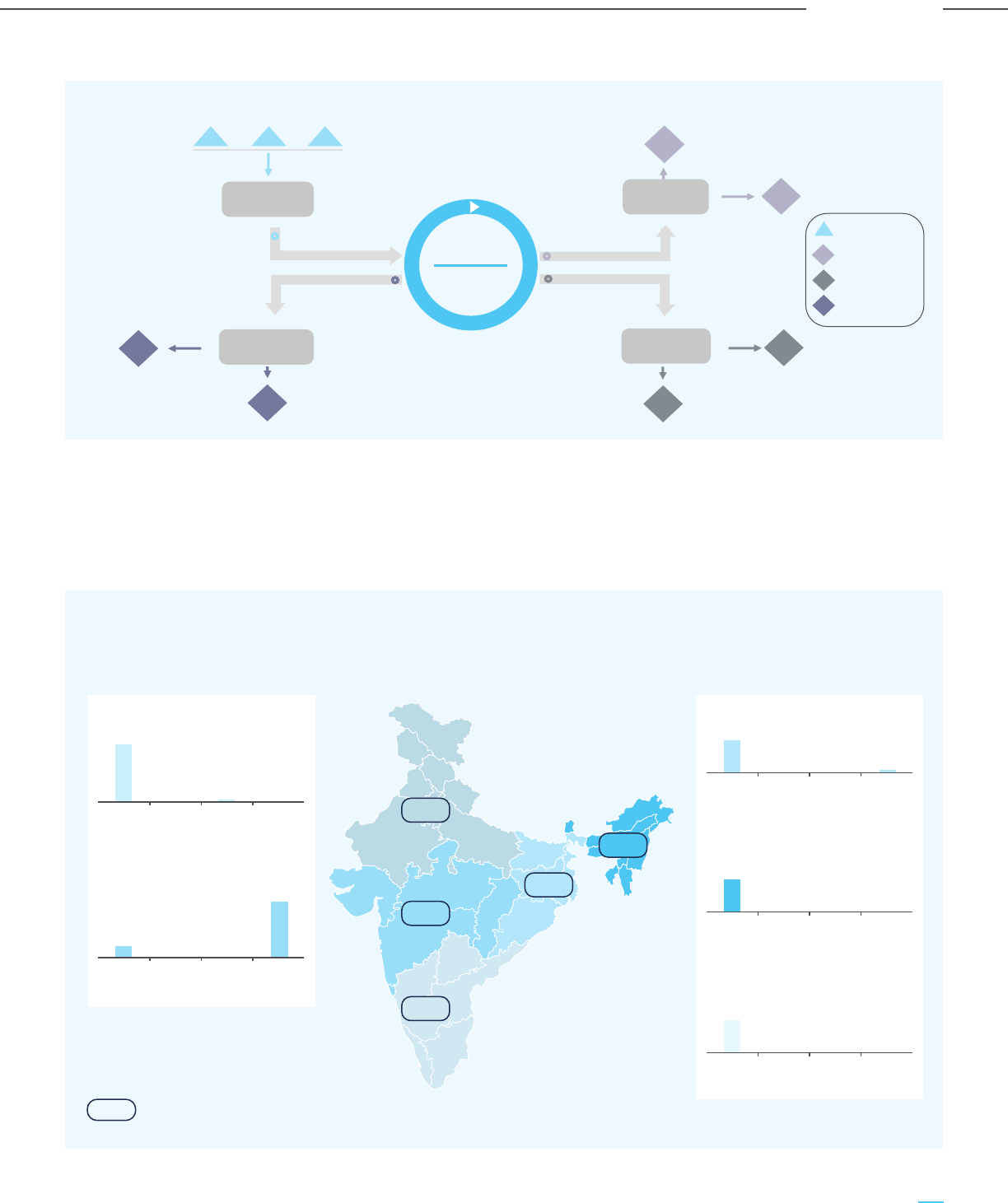
Preliminary analysis shows that there is sufficient
potential for creating regional CCUS clusters in each of
five regions of India (North, South, East, West, and
North-East) and sequestration in deep saline aquifers
has the best potential in all the regions. However, due
to the lack of data on the northern sedimentary basins,
the theoretical storage capacity for the saline aquifers
is low. But as more exploratory activities focused on
CO
2
storage are undertaken, the storage potential in
the northern region is likely to increase.
Figure E-4: Mega Scale CO
2
Cluster Model
Aggregator
E
11
Disposer
EOR Cluster
EOR
HUB
Conversion
Cluster
MeOH
EOR
Regulated Monopoly
Regulated Monopoly
Regulated Monopoly
Demand-Supply
Time Contracts
Regulated Monopoly
E
Emitters
S
Sequestration
Conv
Conversion
EOR
Enhanced Oil
Recovery
S
1
S
2
Mineral
E
12
E
13
Figure E-5: Region-wise Storage Clusters in India
Total Theoretical Storage Capacity of India = 395 - 614 Gt CO
2
7.21 GT
16.58 GT
10.13 GT
0.22 GT
9.01 GT
Region-wise estimated CO
2
emission volumes (2030-2050)
Northem Region: 7.65 Gt CO
2
Saline
aquifer
ECBMR EOR Basalt
7.34
0 0
0.31
Western Region: 388.9 Gt CO
2
Saline
aquifer
ECBMR EOR Basalt
304.9
0.9
80.8
2.3
Southern Region: 76.3 Gt CO
2
Saline
aquifer
ECBMR EOR Basalt
75.2
0.3 00.8
North-Eastern Region: 47.2 Gt CO
2
Saline
aquifer
ECBMR EOR Basalt
46.5
0 00.7
Eastern Region: 47.2 Gt CO
2
Saline
aquifer
ECBMR EOR Basalt
67.2
2.4 10.980
23
Carbon Capture Utilization and Storage (CCUS) –
Policy Framework and Deployment Mechanism in India
Carbon Capture Utilization and Storage (CCUS) –
Policy Framework and Deployment Mechanism in India
Executive Summary

Carbon Capture Finance Corporation of India –
Institutional Mechanism to Support CCUS Project
Funding, Capital and Cash Costs
Financing CCUS projects can be quite challenging in
a developing country like India, even with incentive
and credits-based policy support. For CCUS to take
off in India, it is important to fund and support initial
demonstration scale CCUS projects. The typical
capital cost and cash costs for CCUS projects in
different sectors can be quite different, depending
on the source and quality of the gas stream and the
extent of CO
2
capture targeted, as shown below.
While the funding for the initial demonstration
projects can be achieved through direct Government
grants and funds, for CCUS to reach scale in India, it
is also important to understand the CCUS
investment requirements over a long-term horizon
and establish a financial framework such as a Carbon
Capture Finance Corporation (CCFC) to support
CCUS projects across their lifecycle. This is
important as CCUS provides an unmatched
opportunity for turbocharging the growth of the
Indian economy by creating a clean-energy based
industrial sector, potentially leading to the
development of new technologies, skills and
high-value employment opportunities in India.
Table E-2: Sector-wise Typical Carbon Capture Capital Charge and Cash Cost
Industry
name
Ref. Plant
capacity
CCU capacity
(mtpa)
Capital Charges
(A), Rs./T
CO
2
Cash Cost
(B), Rs./T
CO
2
Total Capture Cost
(A+B), Rs./T
CO
2
Capital Costs,
Rs. crores
Gasification
based
production
70 ktpa H
2
1 mtpa Rs. 80-100
Crore
90-120 250-300 340-420
NG based
SMR for H
2
production
130 ktpa H
2
0.7 mtpa Rs. 700-800
Crore
900-1,200 1,150-1,400 2,050-2,600
Cement 2.5 mtpa
clinker
2 mtpa Rs. 1,600 to
1800 Crore
800-1,000 1,050-1,600 1,800-2,600
Iron and
Steel
2.0 mtpa
BF-BOF
based ISP
2 mtpa Rs. 1,600-2,000
Crore
1,000-1,300 1,900-2,300 2,900-3,600
Refinery
(CDU & FCC)
5 mtpa crude
processing
1 mtpa Rs. 1,100-1,300
Crore
1,200-1,400 2,700-3,100 3,900-4,500
Coal-based
power
800 MW 5 mtpa Rs. 3,500-4,000
Crore
700-1,000 2,100-2,500 2,800-3,500
Total 11.7 mtpa Rs. 8,600 –
10,000 Crore
24
Carbon Capture Utilization and Storage (CCUS) –
Policy Framework and Deployment Mechanism in India
Carbon Capture Utilization and Storage (CCUS) –
Policy Framework and Deployment Mechanism in India
Executive Summary

It is estimated that out of the total emissions
emanating from sectors such as coal-based power,
steel, cement, upstream oil & gas operations,
refineries, chemicals, hydrogen production and
gasification, about 85% will be capturable through
CCUS projects. Based on the trajectory of economic &
industrial development in India and the concomitant
growth in CO
2
emissions, it is expected that the
capturable emissions will reach about 2400 mtpa by
the year 2050, the year by which India has committed
to halving its emissions. For CCUS to make a
meaningful contribution to this lofty and laudable
goal, it is envisaged that CCUS projects should capture
at least 30% of the capturable emissions of 2400
mtpa, i.e. around 750 mtpa. To sufficiently incentivize
CCUS projects at the envisaged scale, the following
subsidies are suggested:
a. Subsidy for CO
2
sequestration/storage:
Rs. 4,100/tonne till 2040 and Rs. 3,000/tonne
till 2050
b. Subsidy for CO
2
EOR: Rs. 3,000/tonne till 2040
and Rs. 2,400/tonne till 2050
c. Subsidy for CO
2
utilization: Rs. 2,300/tonne
till 2050
The above subsidy amounts have been estimated
based on the likely CCUS costs in the Indian context
and the likely trajectory of cost reduction from the
increasing scale of CCUS projects, and also the
revenue streams from CO
2
EOR or the coversion of
CO
2
to value-added products.
The total subsidy amount required by the year 2050 to
support 750 mtpa of CCUS is estimated to be around Rs.
210,000 crores. While this is a very significant amount, it
is a necessary expenditure required to support CCUS
and ensure the sustainability of the Indian economy. It is
proposed that the proposed CCFC be developed as a
financial institution to fund CCUS projects through
equity and debt participation, with the objective of
supporting and realizing the carbon neutrality goal. The
CCFC will be funded by low-cost sovereign or
International Green Funds, Carbon Bonds or Climate
Funds. By investing in CCUS projects, along with the
utilization of a part of the incremental tax revenue
generated, it should be possible to fund the carbon
capture credits, eventually leading to subsidy-neutral
CCUS operations. Two alternate mechanisms are
proposed to fund the CCFC.
a. Option 1: CCUS financing through ‘Clean Energy
Cess’ only
It is assumed that CCUS will be funded by the
Clean Energy Cess’ levied on coal. The ‘Clean
Energy Cess’ on coal @ USD 5.3/tonne (Rs. 400
per tonne) will be re-introduced from 1 April 2026,
as the GST compensation cess has been extended
till 31 March 2026. India’s coal and coke
consumption is expected to increase from the
current 1,050 mtpa to around 1,200 mtpa by 2030
at a 2% CAGR. Accordingly, the annual cess
collection is estimated to be around USD 6-7 BB$
(Rs. 48,000 – 53,000 crores). The surplus funds in
the initial period creates an opportunity for the
corpus to grow significantly through re-financing
through appropriate investment vehicles.
Table E-3: CCUS Funding through Clean Energy Cess
Year Fund. Req.,
Thou. crore
Fund available,
Thou. crore
Surplus/Shortfall,
Thou. crore
2023 - 23 23
2030 15 169 154
2040 89 603 514
2050 210 225 15
25
Carbon Capture Utilization and Storage (CCUS) –
Policy Framework and Deployment Mechanism in India
Carbon Capture Utilization and Storage (CCUS) –
Policy Framework and Deployment Mechanism in India
Executive Summary

b. Option 2: CCUS financing through bond and gross
budgetary support
The government budget and bonds will finance the
subsidy (cash and tax credits) required for CCUS. It
is estimated that 30.5 BB$ (Rs. 2,29,000 crores) of
bonds with a 9% spread in re-investment return,
along with a maximum of 0.5% of the Government’s
spending or the ‘Gross Budgetary Support (GBS)’
can finance 750 mtpa of CCUS by 2050.
It is proposed that the bonds will be raised from the
low-cost national/international bond market and
invested in green projects in India with an assured
return of 9% spread. While the bonds will be raised
and re-invested in the initial years, projected
utilization has been estimated to limit the
government spending on CCUS to be about 0.5% of
the ‘Gross Budgetary Support’.
Table E-4: CCUS Funding with Bonds and Government Budgetary Support
Year Fund. Req.,
Thou. crore
Bond with Return,
Thou. crore
Gross Budgetary Support (GBS),
Thou. crore
2023 - - -
2030 15 - 15 (0.2% of GBS)
2040 89 36 53 (0.4% of GBS)
2050 210 107 103 (0.5% of GBS)
CCUS projects will require upfront capital
investments of US$ 100-150 billion [2022 dollars] for
750 mtpa of CO
2
capture, utilization, and storage.
These investments will develop the market for CO
2
and the positive impact on the Indian GDP is
estimated as US$ 100 to 150 billion over the next 30
years, based on the envisaged improvement and
indigenization of CCUS technology.
In particular, CCUS-enabled coal gasification projects
will generate clean value-added products like
methanol, ammonia, acetic acid, mono-ethylene
glycol, etc. and reduce their imports significantly.
India imports almost US$ 13 billion per annum of
organic chemicals and it is estimated that the
CCUS will have a Material Positive Impact on GDP, Employment
Growth, Energy and Material Security, and Import Substitution
indigenous production of these coal-based chemicals
can replace US$ 7-10 billion of imports by 2050 and
also contribute to the domestic GDP.
CCUS projects will also lead to significant
employment generation, both during the construction
phase and the operating phase, as well as create
significant indirect employment and shape the future
economic development of nearby areas. It is
estimated that the envisaged CCUS target of 750
mtpa by 2050 can create employment opportunities
of 8-10 million full time equivalent (FTE) years in a
phased manner, thus creating a compelling case for
investment in CCUS projects.
26
Carbon Capture Utilization and Storage (CCUS) –
Policy Framework and Deployment Mechanism in India
Carbon Capture Utilization and Storage (CCUS) –
Policy Framework and Deployment Mechanism in India
Executive Summary
Chapter 1
Introduction

1.1 Background
India is the 3rd largest emitter of CO
2
in the world
after China and the US, with estimated emissions of
2.6 gigatonne per annum (gtpa) in 2019, which
marginally reduced to 2.45 gtpa in 2020 due to the
impact of the COVID-19 pandemic. India’s per capita
CO
2
emissions are about 1.9 tonnes per annum, which
is less than 40% of the global average and about
one-fourth of that of China. However, with rapid
economic growth, infrastructure and industrial
development, as well as a growing population
(expected to overtake China in the next decade and
cross 1.50 billion by 2036), the total CO
2
emissions is
expected to cross 4 gtpa by the year 2030. The
sectoral break-up of the CO
2
emissions reveals that
while renewable energy is making great strides in
India, it can theoretically contribute at most 30% of
the desired decarbonization by replacing fossil
fuel-based power generation.
What is CCUS?
The International Energy Agency (IEA) defines Carbon
Capture, Utilization and Storage (CCUS) as a group of
technologies for capturing of CO
2
from large and
stationary CO
2
emitting sources, such as fossil fuel
based power plants and other industries. CCUS also
involves the transport of the captured CO
2
(typically
by pipeline and in certain situations by through
shipping, rail or trucks also) to sites, either for
utilization in different applications or injection into
geological formations or depleted oil & gas fields for
permanent storage and trapping of the CO
2
.
CCUS also includes Direct Air Capture (DAC), which
involves the capture of CO
2
directly from the
atmosphere, although the same is not the focus of this
study, as DAC is still in its early stages and the
economics (present cost of DAC is estimated to range
between US$ 400-800/tonne of CO
2
) and scale of
operations are yet to be established.
Decarbonization Challenge and the Role of CCUS
The decarbonization challenge for India is to identify
scalable and economically sustainable solutions for
the decarbonization of sectors that contribute to 70%
of emissions. CCUS has an important and critical role
to play, especially for India to accomplish net-zero by
2070, as envisioned by the Hon’ble Prime Minister of
India. Though the target date is five decades away, as
the noted author Vaclav Smil has documented in his
work, energy transitions take decades. It is therefore
important to implement the framework and policy
instruments for CCUS to become a reality in India and
make a meaningful contribution to decarbonization
in India.
Figure 1.1: The 70% Emissions Challenge
28
Carbon Capture Utilization and Storage (CCUS) –
Policy Framework and Deployment Mechanism in India
Carbon Capture Utilization and Storage (CCUS) –
Policy Framework and Deployment Mechanism in India
Introduction
Industry
Agriculture
Transport
Building
Electricity
31%
~30%
2.6
gtpa
~70%
20
10
5
India

This study has been prepared by M. N. Dastur & Co. (P)
Ltd. and Dastur Energy Pvt. Ltd., under the tutelage of
the National Institution for Transforming India (NITI
Aayog), Government of India and aims to provide the
policy framework and deployment mechanism for
CCUS at scale to become a reality in India. This study
focuses on CCUS for large point CO
2
emission sources
(with >100 ktpa of CO
2
emissions) such as coal based
power plants and industrial applications. CO
2
emissions from sectors such as agriculture,
transportation and buildings are distributed and
require interventions related to change in fuel (viz.
biofuels), electrification, enhancing thermal &
electrical efficiencies and are outside the purview of
this study.
In particular, industrial applications are hard to
electrify, and industrial CO
2
emissions are hard to
abate due to the use of fossil fuels not only as a
source of energy but also within the process itself.
Carbon Capture Utilization and Storage (CCUS) also
has applications for the power sector, given India’s
present reliance on coal for meeting over 70% of its
electricity needs; even in the future, if India is able to
substantially green the grid power and meet the
target of 500 GW installed capacity of renewables by
2030, there would still be a need to meet the baseload
power demand from fossil fuels (most likely coal) or
other dispatchable sources, given the intermittency
and non-dispatchable nature of solar and wind power.
Thus, CCUS also has a role to play in enabling clean
and green baseload power and ensuring the
sustenance and non-stranding of our over 210 GW of
coal and lignite based thermal power plants.
In their September 2020 report, the International
Energy Agency points out that reaching net-zero
without CCUS is virtually impossible. The
Intergovernmental Panel on Climate Change (IPCC)
also concludes that without CCUS, it would not be
possible to stabilize the CO
2
concentration in the
atmosphere between 450 – 750 ppmv (parts per
million by volume) and limit global temperature
rise between 1.5 to 2 degrees Celsius above
pre-industrial levels.
The adverse climatic effects of a rise in GHG
emissions and global temperatures rises are well
established and proven, and India too has not been
spared from adverse climatic events. As a signatory
of the Paris Agreement 2015, India has committed to
reducing emissions by 50% by the year 2050 and
reaching net zero by 2070. Given the sectoral
composition and sources of CO
2
emissions in India,
CCUS will have an important and integral role to play
in ensuring India meets its stated climate goals,
through the deep decarbonization of energy and CO
2
emission intensive industries such as thermal power
generation, steel, cement, oil & gas refining, and
petrochemicals. CCUS can enable the production of
clean products while utilizing our rich endowments
of coal, reducing imports and thus leading to an
Indian economy. CCUS also has an important
role to play in enabling sunrise sectors such as coal
gasification and the nascent hydrogen economy
in India.
1.2 Global CCUS Landscape
Globally there are about 21 CCUS facilities, with a
capacity of capturing about 40 mtpa of CO
2
or only
0.1% of the 40 gtpa global annual GHG emissions. The
first CCUS projects started in the 1970s and 1980s in
Texas for capturing CO
2
from natural gas processing
plants and supplying it to local oil producers for
utilizing the CO
2
for Enhanced Oil Recovery. Since
then, CCUS has spread to other regions and countries,
viz. Norway, Canada, Australia, Brazil, Canada, China,
Saudi Arabia and the United Arab Emirates. A list of
the operating CCUS facilities as of 2020 is tabulated in
Table 1-1. The extent of public funding support
provided to these CCUS facilities (where applicable) is
also provided.
29
Carbon Capture Utilization and Storage (CCUS) –
Policy Framework and Deployment Mechanism in India
Carbon Capture Utilization and Storage (CCUS) –
Policy Framework and Deployment Mechanism in India
Introduction

Table 1-1: Large Scale CCUS facilities in operation in 2020
Country Project Operations CO
2
Public Funding CO
2
capture CO
2
start source funding sources capacity disposition
(mtpa)
USA
1972Terrell natural gas plants
(earlier Val Verde)
Natural gas
processing
No 0.5 EORCapital cost: US$
27.6 mn
USA
1982Enid fertiliser Fertilizer
production
No
0.7 EORNot available
Norway
2008Snohvit CO
2
storage
project
Natural gas
processing
No 0.7 StorageNot available
USA
2013Lost Cabin Gas Plant Natural gas
processing
No 0.9 EORProject cost –
US$ 400 mn
USA
2013Coffeyville
Gasification
Fertilizer
production
No 1.0 EORNot available
Brazil
2013Petrobras Santos Basin
pre-salt oilfield CCS
Natural gas
processing
No 3.0 EORNot available
Saudi Arabia
2015Uthmaniyah CO
2
-EOR
demonstration
Natural gas
processing
No 0.8 EORNot available
Canada
2015Quest Hydrogen
production
Yes 1.0 StorageProject cost-
CAD 1.35 bn
Federal Govt. support
– CA$ 120 mn
Alberta Govt. –
CA$ 745 mn
Canada
2014Boundary Dam CCS Power
generation
(coal)
Yes 1.0 EORProject Cost –
CA$ 1.35 bn
Federal Govt.
support – CA$
240 mn
USA
2010Century plant Natural gas
processing
No 8.4 EORProject cost –
US$ 1.1 bn
USA
2013Air Products steam
methane reformer
Hydrogen
production
Yes 1.0 EORProject cost –
US$ 431 mn
US DOE funding –
US$ 284 mn
(through the
American
Recovery and
Reinvestment Act)
Norway
1996Sleipner CO
2
storage
project
Natural gas
processing
No 1.0 StorageProject cost –
US$ 100 mn
USA/Canada
2000Great Plains Synfuels
(Weyburn/Midale)
Synthetic
natural gas
Yes 3.0 EORProject cost –
US$ 80 mn
US DOE funding –
US$ 3 million
Canadian Govt.
funding- US$ 2 mn
USA
1986Shute Creek gas
processing facility
Natural gas
processing
No 7.0 EORInitial cost – US$
170 mn
Expansion cost –
US$ 80 mn
30
Carbon Capture Utilization and Storage (CCUS) –
Policy Framework and Deployment Mechanism in India
Carbon Capture Utilization and Storage (CCUS) –
Policy Framework and Deployment Mechanism in India
Introduction

Country Project Operations CO
2
Public Funding CO
2
capture CO
2
start source funding sources capacity disposition
(mtpa)
UAE
2016Abu Dhabi CCS Iron and steel
production
Yes 0.8 EORPipeline capex –
US$ 200 mn
USA
2017Petra Nova Power
generation
(coal)
Yes
1.4 EORProject cost –
US$ 1 bn
US DOE –
US$ 167 mn
NRG Energy –
US$ 300 mn
JX Nippon – US$
300 mn
Debt funding from
Japan Bank for
International
Cooperation &
Mizuho Bank –
US$ 250 mn
USA
2017Illinois Industrial Ethanol
production
Yes
1.0 StorageProject cost –
US$ 208 mn
US DOE support –
US$ 142 mn
China
2018Jilin oilfield CO
2
-EOR Natural gas
processing
No
0.6 EORPhase 1 cost –
US$ 11 mn
Canada
2020Alberta Carbon Trunk
Line (ACTL) with
Agrium CO
2
stream
Fertilizer
production
No
0.3 - 0.6 EORCapital cost –
US$ 27.6 mn
Capital cost –
US$ 27.6 mn
Canada
2020ACTL with North West
Sturgeon Refinery
CO
2
stream
Hydrogen
production
No
1.2 - 1.4 EOR
Australia
2019Gorgon Carbon
Dioxide Injection
Natural gas
processing
No
3.4 - 4.0 StorageProject total cost –
US$ 55 bn
Injection capex –
US$ 2 bn
Commitment from
Australian Govt. –
US$ 60 mn
Note: Large scale CCUS: at least 0.8 mtpa of CO
2
capture for coal based power plant and at least 0.4 mtpa for other industrial facilities, including NG based power
Source: International Energy Agency, MIT database, Dastur research
CCUS deployment has mostly been concentrated in
the US, due to the low cost of capture from NG
processing facilities, CO
2
demand for EOR, CO
2
pipeline networks and Government funding for CCUS.
The 2010 to 2020 time period was largely a decade of
misses for CCUS, with CCUS capacity only reaching 40
mtpa, vis-à-vis the IEA 2009 roadmap of 100 CCUS
projects with a capture capacity of 300 mtpa.
However, recent years have seen renewed global
interest in CCUS, particularly after the Paris climate
agreement of 2015, global focus and pledges on
reaching net-zero and the realization that renewable
energy can only solve a part of the decarbonization
challenge. Over 100 new CCUS projects have been
announced in the recent past, which are expected to
become operational by 2030 and take the aggregate
carbon capture capacity to 150 mtpa. These projects
span across regions (including many developing
countries) and are geared towards a diverse mix of
CO
2
applications and disposition options.
31
Carbon Capture Utilization and Storage (CCUS) –
Policy Framework and Deployment Mechanism in India
Carbon Capture Utilization and Storage (CCUS) –
Policy Framework and Deployment Mechanism in India
Introduction

1.3 Decarbonization
Through CCUS
1.4 The CCUS Value Chain
CCUS can contribute to decarbonization and transition
to clean energy systems in various ways:
a. Hard-to-abate sectors: CCUS offers the only
known technology for the decarbonization of
hard-to-electrify CO
2
intensive sectors such as
steel, cement, oil & gas, petrochemicals &
chemicals, and fertilizers. These sectors are
important to the continued growth of the Indian
economy and for ensuring energy, materials and
food security. The maturity of technology
development in these sectors portends the
continued use of fossil fuels and concomitant CO
2
emissions from these sectors in the foreseeable
future, thus making CCUS critical in these sectors.
b. Low carbon hydrogen economy: CCUS is
expected to play a major role in enabling the
hydrogen economy in India, through the
production of blue hydrogen based on the
utilization of our rich endowments of coal. Given
the current cost structure of green hydrogen of
US$ 5-6/kg, cost competitive blue hydrogen
production (i.e. coal gasification based hydrogen
production coupled with CCUS) at around US$
2/kg can provide a pathway for the hydrogen
economy in the future.
c. Removal of the CO
2
stock from the atmosphere:
The race towards net zero and containing global
temperature within 1.5 degrees from pre-industrial
levels is not possible without the removal of
excess CO
2
from the atmosphere through Direct
Air Capture (DAC). DAC plants are in operation at
a small scale, due to their prohibitively high cost
of operations. With technological innovation and
focused policy interventions, CCUS through DAC
applications is also expected to have a role in the
net-zero transition journey.
d. Sustenance of existing emitters: Existing
thermal power plants and industrial plants (such
as steel and cement production facilities) can be
retrofitted with CO
2
capture infrastructure. Nearly
two-thirds of India’s 210 GW of coal-based power
capacity and 144 mtpa crude steel capacity have
an age of less than 15 years and cannot be just
Carbon capture has a critical role to play in the
decarbonization of hard to abate sectors and the path
towards the net zero transition. However, in order to
deploy carbon capture at scale, it is important to look
beyond just carbon capture technologies, and
holistically look at the CCUS value chain. The CCUS
value chain consists of three basic components
(source: Medlock, III, Kenneth B. and Keily Miller,
“Expanding Carbon Capture in Texas”, Baker Institute
Center for Energy Studies, January 2021):
i) Capture of carbon dioxide (CO
2
) from fuel
combustion or industrial gas streams,
compression, dehydration & purification of CO
2
to
the desired specifications;
ii) Transport of the CO
2
(generally via pipeline) to the
CO
2
sink
iii) Disposition of the CO
2
, either through utilization
in applications such as Enhanced Oil Recovery
(EOR), food and beverage applications, or the
production of value-added products (viz. urea,
green methanol, cured concrete) or through
sequestration of CO
2
in permanent
geological storages
The success of the CCUS value chain depends on the
actors in each part of the CCUS value chain acting in
close coordination with each other. In order to
incentivize coordination between actors across the
CCUS value chain, there is a need for an appropriate
enabling policy framework and business model.
wished away or stranded and need to be made
sustainable through the application of CCUS.
Significant economic costs and damages can be
avoided by ensuring the sustenance of existing
emitters through the implementation of CCUS. As
per estimates provided in the article
“Understanding initial opportunities and key
challenges for CCUS deployment in India at
scale” by Professors Vikram Vishal, Debanjan
Chandra, Udayan Singh, Yashvardhan Verma, by
year 2050, about US$ 6 billion/year of economic
damage can be avoided through CCUS.
32
Carbon Capture Utilization and Storage (CCUS) –
Policy Framework and Deployment Mechanism in India
Carbon Capture Utilization and Storage (CCUS) –
Policy Framework and Deployment Mechanism in India
Introduction
1.5 CCUS in India
Presently carbon capture in India is confined to
certain industries/applications where the carbon
capture is part of the process, viz., the manufacture of
urea. India’s urea production is about 24 mtpa, where
capture CO
2
is utilized in the ammonia to urea
conversion process. CO
2
is also captured as part of the
gas conditioning process in the gasifiers of Reliance
Industries Limited in Jamnagar (10 mtpa of petcoke
gasification capacity) and JSPL in Angul (2 mtpa of
coal gasification capacity), but the CO
2
is largely
released to the atmosphere and not utilized or stored.
While there are few pilot scale carbon capture projects
(viz. IOCL R&D’s amine and biological enzyme based
carbon capture plant and Tata Steel Jamshedpur’s
pilot scale carbon capture plant for capturing 5 tonnes
per day CO
2
from Blast Furnace gases), there are no
commercial-scale dedicated CCUS projects in India.
While the sustainability of operations and carbon
footprint is a major concern for the promoters and top
management of most industries, the main impediments
to companies investing in CCUS projects are the lack of
any policy incentives and framework, lack of a viable or
established business model with independent players
providing services for the transportation and
disposition of CO
2
and lack of established pathways &
options for the utilization or storage of CO
2
at scale.
Given India’s climate and CO
2
emission reduction
commitments, there is a need to design and establish
a robust and effective CCUS policy framework to
enable projects across the CCUS value chain and at
scale for the major industrial sectors of the Indian
economy like power, steel, cement, chemicals, and
petrochemicals.
33
Carbon Capture Utilization and Storage (CCUS) –
Policy Framework and Deployment Mechanism in India
Carbon Capture Utilization and Storage (CCUS) –
Policy Framework and Deployment Mechanism in India
Introduction

1.6 Objectives of the Study 1.7 Structure of this Study
This study consists of the following chapters:
Executive Summary
Chapter 1 : Introduction
Chapter 2 : Analysis of Sector-wise CO
2
Emissions
Chapter 3 : Overview of CO
2
Capture &
Utilization Technologies
Chapter 4 : Potential for CO
2
Storage in India
Chapter 5 : CCUS Policy Framework for India
Chapter 6 : Investment and Financing Mechanism
Chapter 7 : Conclusions
1.8 Acknowledgement
We express our sincere gratitude and grateful
acknowledgement to the NITI Aayog, and especially
Dr V. K. Saraswat (Member, NITI Aayog), Shri Rajnath
Ram (Adviser – Energy) and Shri Jawahar Lal (Deputy
Chief Engineer, Energy) for the guidance and
cooperation extended during this study.
Against this backdrop, this study seeks to formulate a
framework for CCUS policies in India and a viable
economic model for CCUS adoption and
implementation in various industries and sectors. The
objectives of the study are as follows:
a. Recommend the most suitable CCUS policy
instrument & path for India, i.e. whether to pursue
an incentive or cash & tax credits based policy
(similar to the USA) or a carbon tax based policy
(similar to the EU)
b. A CCUS cluster framework: cluster design and
infrastructure to process, store, sell and transport
CO
2
through centralized processing at each
cluster.
c. Creation of a CCUS business model, institutional
framework & opportunity: to provide a market and
an effective price/premium for low-carbon
products.
d. Conceptualize and articulate the need for a CCUS
technology and investment enabling carbon fund
for India, which will enable CCUS deployments to
be financially feasible in India; designing the
structure and deployment mechanism of the same
e. An industrial CCUS financing framework:
development of a CCUS technology and
infrastructure enabling funding mechanism.
f. Assessment of the socio-economic impact -
promoting new industries and job creation with a
reduction in overall GHG emissions
34
Carbon Capture Utilization and Storage (CCUS) –
Policy Framework and Deployment Mechanism in India
Carbon Capture Utilization and Storage (CCUS) –
Policy Framework and Deployment Mechanism in India
Introduction
Chapter 2
Analysis of Sector-wise
CO
2
Emissions

2.1 Introduction
The total CO
2
emissions from a system can be
categorized into three types (Figure 2-1)
a) Direct or scope 1 emissions: Emissions from the
production process from the combustion of fuel.
This typically occurs within the plant/facility
premises.
b) In-direct or scope 2 emissions: Emission
associated with the purchase of utilities. This is
generally an emission outside the plant boundary.
c) In-direct or scope 3 emissions: Indirect emissions
are associated with the entire value chain, starting
from equipment purchase, construction works, raw
material sourcing and product dispatch.
The objective of this chapter is to estimate the
capturable CO
2
volume within the plant boundary for
different target sectors; accordingly, Scope 1 emissions
have been estimated for the target sectors.
India’s power and industrial sectors contributed
around 1,600 mtpa of CO
2
emission (around 60%) out
of 2,600 mtpa in 2020. The remaining 40% CO
2
emissions are contributed by distributed point
emissions sources like agriculture, transport, and
buildings. Since carbon capture, utilization and storage
are not applicable for such sources, this chapter
focuses on power and key industrial sectors. Emissions
from these sectors are expected to increase to nearly
2,300 mtpa by the year 2030, fuelled by industrial
growth across multiple sectors as well as rapid
urbanization. The sector-wise emissions (current and
projected) are shown in Figure 2-2.
Figure 2-1: Illustration of Emission Types and Boundary Consideration
1,004
1,210
177
240
450
196
325
2030 CO
2
emission
56
125
2020 CO
2
emission
2,291
27
102
1,621
Coal Gasifcation
NG based H
2
production Upstream O&G/Refinery/Chemicals
Cement
Iron & Steel
Power
Figure 2-2: Sector-wise CO
2
Emissions, mtpa
36
Carbon Capture Utilization and Storage (CCUS) –
Policy Framework and Deployment Mechanism in India
Carbon Capture Utilization and Storage (CCUS) –
Policy Framework and Deployment Mechanism in India
Analysis of Sector-wise CO
2
Emissions
Scope 1
Scope 2
Scope 3

Figure 2-3: Break-up of Installed Generation Capacity, GW
2.2 Analysis of Major Industrial CO
2
Sources (Power, Steel,
Chemicals, Cement & Gasification) in India
2.2.1 CO
2
Emissions: Indian Power Industry
2.2.1.1 Introduction
Being the third-largest producer and second-largest
consumer of electricity, the Indian power sector plays
a major role in the world energy scenario (IBEF, 2021).
India generated a total of 1382 TWh of electricity in FY
2020-21, about 2.5% less than the total generation in
FY 2019-20 (Ministry of Power Annual Report,
2020-21).
Given our rich endowments of coal, the major portion
of power demand is met by coal and lignite based
thermal power plants, along with power plants based
on other fossil fuels (natural gas and diesel). At the
same time, the last decade has seen considerable
additions of renewable energy generation capacity to
the energy mix, towards the path of achieving India’s
goal of achieving 175 GW of renewable energy capacity
by 2022 (IEA, India Energy Outlook, 2021). India has
also committed to generating 40% of electricity in the
future from non-fossil fuel sources (IEA, India Energy
Outlook, 2021). While the share of fossil fuel-based
energy is expected to reduce going forward, energy
demand is also expected to increase significantly from
the present levels, i.e., 25-30% by 2030 and 60-70%
by 2040 (IEA, India Energy Outlook, 2021). The major
share of the power demand will continue to be met
from coal in the foreseeable future, in order to secure
India’s energy security and ensure electricity for every
household. Thus, the power sector will continue to be a
major source of GHG emissions, and hence CCUS is of
prime importance for the abatement of CO
2
from
the sector.
2.2.1.2 Installed Capacity and Power Generation
As of January 2022, India’s total electricity generation
capacity was 395 GW, including 106 GW of renewable
energy capacity (Figure 2-3). Fossil fuels like coal,
natural gas, lignite, and diesel) contribute to almost
60% of total generation capacity, with coal-based
thermal power capacity alone accounting for around
52% (203 GW). The installed capacity of renewables
like solar, wind, biomass, etc. has increased significantly
in the last two years. Renewable capacity has increased
from 86 GW to 106 GW, an increase of 23% whereas
total capacity has increased by only 7%.
Thermal
236,
60%
Nuclear,
7, 1%
Hydro,
47, 12%
RES,
106,
27%
369
377
395
86
93
106
Jan-2020 Jan-2021 Jan-2022
Total RES
37
Carbon Capture Utilization and Storage (CCUS) –
Policy Framework and Deployment Mechanism in India
Carbon Capture Utilization and Storage (CCUS) –
Policy Framework and Deployment Mechanism in India
Analysis of Sector-wise CO
2
Emissions
Source: CEA
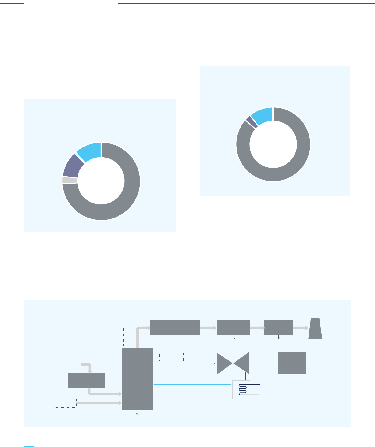
Figure 2-6: PFD of Coal-fired TPP [Reproduced from (Breeze, 2019)]
Figure 2-4: Break-up of Generation, Billion Unit
(Ministry of Power Annual Report, 2020-21)
Though renewables contribute to around 30% of the
current capacity mix, due to their intermittent and
non-dispatchable nature, their share in power
generation was only 11% in FY 2021-22 (Figure 2-4).
Thus going forward also, even as India targets to
reach 450 – 500 GW of renewables capacity by the
year 2030, coal-based power generation will continue
to play an important role in the power mix of India.
2.2.1.3 Brief Description of Thermal Power Plants
The basic principle behind the working of a thermal
power plant is that they generate electricity using the
thermal energy from the combustion of fuels. Based
on the type of fuel used, thermal power plants can be
divided into four categories, coal, natural gas, lignite,
The process flow of power generation from coal
(process flow for lignite is also similar) and natural
gas-based power plants is described below.
a) Coal-fired thermal power plant
Coal-fired thermal power plants generate electricity
by burning coal as a fuel and using the heat to
produce steam from water. The steam is used to
generate electricity by passing through a steam
turbine generator. The various unit operations
involved in this process are illustrated in Figure 2-6
(Breeze, 2019).
Thermal, 913, 74%
Nuclear,39, 3%
Hydro,134, 11%
Bhutan, 7, 1%
RES, 141, 11%
Figure 2-5: Break-up of Thermal Power Plants by
Fuel (Power Sector at a Glance ALL INDIA)
and diesel. The share of diesel-based power capacity
in India is minimal; the major share of capacity is from
coal-powered thermal power plants, followed by
natural gas.
Coal, 203.9, 86%
Lignite, 6.6, 3%
Gas, 24.9, 11%
Diesel, 0.5, 0%
SlurryFly ash
Coal
Steam
Steam
Turbine
Warm water
Cold water
Condenser
Ash disposal
Stack
Water
Exhaust
Gas
Air
Coal
Pulverizer
Boiler
Selective Catalytic
Reduction Reactor
Electrostatic
Precipitator
SO
2
Scrubber
Generator
38
Carbon Capture Utilization and Storage (CCUS) –
Policy Framework and Deployment Mechanism in India
Carbon Capture Utilization and Storage (CCUS) –
Policy Framework and Deployment Mechanism in India
Analysis of Sector-wise CO
2
Emissions

Coal is received at the material handling yard and
thereafter undergoes crushing and beneficiation to
reduce the size/moisture/ash content, depending on
the quality and size of the coal. The coal is then
pulverized to coal fines that can be efficiently
combusted in the boiler. This pulverized coal is mixed
with air in the combustion chamber and controlled
combustion is performed to produce heat energy.
After the completion of the combustion process, the
ash residue is collected at the bottom of the
combustion chamber and is ejected as slag. The
combustion chamber and boiler are efficiently
integrated to minimize heat loss. The boiler has tubes
present in it, which carry water. The heat energy
released from combustion is absorbed by this water to
turn into steam. This steam is passed through steam
turbines. A series of high pressure (HP), intermediate
pressure (IP) and low-pressure (LP) turbines are
present to extract the maximum heat energy from the
steam. These steam turbines drive the generators to
produce electricity.
The flue gas is subjected to cleaning operations such
as a selective catalytic reduction reactor (for NOx),
electrostatic precipitator (for fly ash), and sulfur
dioxide scrubber. After the flue gas meets the
emission norms, it is emitted through flue gas stacks
in the atmosphere. The only source of Scope 1
emissions is the flue gas stack. The rest of the
operations incur Scope 2 emissions. Typical flue gas
characteristics of a coal-fired thermal power plant are
given in Table 2-1.
b) Natural Gas-fired Thermal Power Plant
Natural gas is a relatively cleaner fuel compared to coal
and has very few impurities. Gas turbine technology is
used to generate power from natural gas (Figure 2-7).
Air is sent to the compressor, where it gets pressurized.
This high-pressure air is sent to the combustion
chamber and mixed with the fuel (natural gas). This
mixture is ignited and the combustion results in hot flue
gases. This flue gas stream then drives the turbine
which is connected with the generator that uses the
kinetic energy to generate electricity. The turbine and
compressor are on the same shaft; thus, the compressor
energy requirement also decreases.
The flue gases released are still at a very high
temperature, indicating that more heat energy can be
extracted from this stream. Thus, the flue gases are
further fed to a heat recovery steam generator. Here,
the heat energy of flue gases is used to generate
steam from water which drives the steam turbine to
generate additional power. This increases the energy
conversion efficiency of plants. This type of plant is
termed as a “combined cycle power plant”. Figure 2-8
illustrates a schematic of a natural gas combined cycle
(NGCC) power plant.
Table 2-1: Flue Gas Characteristics of
Coal-Fired Thermal Power Plants
Figure 2-7: Schematic Representation of
Gas Turbine [Reproduced from (Breeze, 2019)]
Figure 2-8: NGCC Power Plant Schematic Diagram
[Reproduced from (Breeze, 2019)]
Component Unit Value
Temperature °C 150-180
Pressure atm 1
Composition
CO
2
vol% 12-14
H
2
O vol% 8-10
O
2
vol% 3-5
N
2
vol% 72-77
SO
2
ppmv 120-200
NOx ppmv 150-250
Fuel
Air inlet
Compressor Turbine
Flue gas
To
Atmosphere
Steam
Turbine
Generator
Generator
Generator
Flue gas
Compressor
Air
inlet
Natural
gas
Combustion
chamber
Combustion
chamber
Heat
recovery
steam
generator
39
Carbon Capture Utilization and Storage (CCUS) –
Policy Framework and Deployment Mechanism in India
Carbon Capture Utilization and Storage (CCUS) –
Policy Framework and Deployment Mechanism in India
Analysis of Sector-wise CO
2
Emissions

The Scope 1 emissions are from the flue gas emitted to
the atmosphere at the end of the process. The rest of
the processes may involve Scope 2 emissions. Typical
flue gas characteristics of natural gas combined cycle
(NGCC) power plants are mentioned in Table 2-2.
2.2.1.4 CO
2
Emissions from the Power Industry
Globally the power sector accounts for the largest
share of GHG emissions; the sector accounted for
42% of the total anthropogenic CO
2
emissions of the
world in 2019 (IEA). In India, the power sector is
responsible for 51% of total anthropogenic emissions
(IEA). Thus, decarbonization of the power sector is
critical to lowering total anthropogenic CO
2
emissions
in India.
For the analysis of CO
2
emissions from the power
sector, merchant power plants (owned by Central
PSUs, State PSUs, JVs as well as private generators),
along with captive power plants of the aluminium
industry, have been considered. The CO
2
emission
intensity database is provided by Central Electricity
Authority (CEA) (CEA, 2020). The analysis was carried
out for the financial year FY 2021-22, using the actual
plant load factor of 57.02% (till 30 November 2021) to
calculate the emission figures. A total of 271 power
plants were analyzed. These plants have been
analyzed based on their district, state and the prime
mover used. The prime mover can be of 3 types:
steam, gas, and diesel.
Figure 2-9: Share of Total CO
2
Emissions by
Each Prime Mover, mtpa
Component Unit Value
Temperature °C 100-150
Pressure atm 1
Composition
CO
2
vol% 4-10 vol%
H
2
O vol% 10-12 vol%
O
2
vol% 8-10 vol%
N
2
vol% 70-75 vol%
SO
2
ppmv Low
NOx ppmv Low
Table 2-2: Flue Gas Characteristics of
Coal-Fired Thermal Power Plants
Component Value
Total number of power plants 271
No. of days of operation 330
Total emissions (mtpa) (PLF = 100%) 1760.8
Total emissions (mtpa) (PLF = 57.02%) 1,004
Total number of power plants with 159
greater than 2 mtpa CO
2
emissions
Total number of districts with 10
greater than 20 mtpa CO
2
emissions
Table 2-3: Overall Analysis of CO
2
Emissions from
the Power Sector in India
Coal and lignite based power plants use steam as the
prime mover, but have different CO
2
emission
intensities. An overall analysis is provided in Table
2-3. A minimum capturable CO
2
of 2 mtpa from a
single source is envisaged to be economically feasible.
For district-level analysis, districts with CO
2
emissions
(power-related) greater than 20 mtpa have been
considered.
CO
2
Emissions by Prime Mover
Power plants can be categorized into three types
based on their prime mover, i.e. steam, gas, and
diesel. Coal and lignite have the largest installed
generation capacity in India, followed by natural gas
and a small share for diesel. The contribution of each
prime mover to the total CO
2
emissions from the
power sector is illustrated in Figure 2-9.
956
47
1
1,004
Steam Gas Diesel Total
40
Carbon Capture Utilization and Storage (CCUS) –
Policy Framework and Deployment Mechanism in India
Carbon Capture Utilization and Storage (CCUS) –
Policy Framework and Deployment Mechanism in India
Analysis of Sector-wise CO
2
Emissions

Prime Mover No. of Total CO
2
plants Emissions (mtpa)
Steam 155 917
Gas 4 11
Diesel - -
Total 159 928
District Number of CO
2
Emissions
plants (mtpa)
Singrauli 5 52
Sonbhadra 6 49
Kutch 2 34
Korba 6 34
Nagpur 4 28
Angul 4 27
Raigarh 5 27
Cuddalore 5 25
Janjgir-Champa 4 24
Chandrapur 4 21
Total 45 321
Table 2-4: CO
2
Emissions by Prime Mover for Plants
with Minimum 2 mtpa Capturable CO
2
Table 2-5: District-wise CO
2
Emission Analysis
Figure 2-10: State-Wise Analysis of
CO
2
Emissions (mtpa)
Considering a minimum of 2 mtpa of capturable CO
2
from each plant, the above analysis is presented in
Table 2-4.
Power plants with steam as the prime mover (both
coal and lignite-fired) have the highest emissions;
thus, CCUS projects need to be focused on these
plants. The emissions from power plants with gas and
diesel as the prime mover are significantly less and
these plants can be included in the scope of CCUS at a
later stage.
CO
2
Emission by Region
In order to form a CCUS cluster, it is important to
perform a region-wise emission analysis of power
plants. The aim of the analysis is to identify the
hotspots/clusters of emissions that can be targeted
for CCUS. This would also help define the policy/
credit system suitable for that region. The region-wise
analysis can be carried out based on
a) Districts
b) States
The district-wise analysis yields information about
the highest emitting districts, which can be the focus
of initial CCUS projects in the Indian power sector.
A centralized CO
2
processing unit can be planned for
these districts, which will make the capture and
transportation of CO
2
more techno-economically
feasible. Only power plants with minimum CO
2
emissions of 2 mtpa have been considered in the
analysis. For district-wise analysis, districts that
emit more than 20 mtpa CO
2
have been considered.
Information about these districts is provided in
Table 2-5.
These districts account for about 32% of the total CO
2
emissions by the power sector in India.
Implementation of CCUS in these districts will lead to
significant CO
2
abatement. The state-wise analysis
(Figure 2-10) identifies the states to be prioritized for
CCUS implementation in India. The top 10 states
contribute 75% of the total CO
2
emission by the
power sector. Thus, incentivizing the implementation
of CCUS clusters through various policy mechanisms
suited to these states will help in quicker adoption &
implementation of CCUS and lead to significant
decarbonization of India’s power sector.
109
107
105
97
70
61
60
57
49
42
173
Maharashtra
Uttar Pradesh
Chhattisgarh
Madhya Pradesh
Gujarat
Tamil Nadu
West Bengal
Odisha
Andhra Pradesh
Rajasthan
Others
41
Carbon Capture Utilization and Storage (CCUS) –
Policy Framework and Deployment Mechanism in India
Carbon Capture Utilization and Storage (CCUS) –
Policy Framework and Deployment Mechanism in India
Analysis of Sector-wise CO
2
Emissions

Component Present (2022) FY 2029-30
Installed Capacity, GW
Thermal 236 (60%) 292 (36%)
Hydro 46 (12%) 66 (8%)
Nuclear 7 (2%) 19 (2%)
RES 106 (26%) 440 (54%)
Total 395 817
Gross Generation, BU
Thermal 913 (74%) 1393 (56%)
Hydro 134 (11%) 206 (8%)
Nuclear 39 (3%) 113 (5%)
RES 141 (11%) 804 (31%)
Total 1,227 2,516
Wtd. avg. CO
2
emisison intensity, kg/kWh 1.09 0.868
Total CO
2
emissions from thermal power plant 1,004 1,210
Table 2-6: Energy & CO
2
Volume Projections for FY 2029-30
2.2.1.5 CO
2
Emission Projections for the Power sector
According to CEA and IEEFA projections (Gujarat’s
Electricity Sector Transformation, 2019), the installed
capacity in India is expected to more than double and
reach around 820 GW by 2030 from the existing
capacity of around 400 GW. The projection of the
generation capacity by type is given in Table 2-6.
Thermal power (coal + gas) capacity in India is
expected to reach 290 GW by 2030. Although the
share of thermal capacity is expected to drop from the
present 60% to 36% in 2030, thermal power
generation is expected to still account for 56% of the
total electricity generation in India.
2.2.2 CO
2
Emissions: Indian Steel Industry
2.2.2.1 Introduction
The Indian iron and steel industry is primarily based
on the processing of virgin materials like iron ore,
coal, etc. and is hence an energy-intensive sector,
responsible for about 10% of the total CO
2
emissions
in India. Production of iron largely through the blast
furnace and coal-based DR route, combined with low
availability of scrap in India, make the Indian steel
industry a coal-intensive sector, leading to an
estimated 240 mtpa of direct CO
2
emissions for
supporting steel production of 109 mt in 2019. The
The drop in the share of installed generation capacity
of thermal power plants is due to the significant
increase in renewable energy capacity. However,
anthropogenic CO
2
emissions from the power sector
will still contribute to the majority of CO
2
emissions in
India. The CO
2
intensity will also increase in the future
with improved plant performance and PLF, the
retirement of old facilities and the operation of
super-critical or ultra super-critical units. Based on the
contribution of thermal power plants and their CO
2
emission intensity, the total scope 1 emissions from
thermal power plants is estimated to be around 1200
mtpa in 2030 (Table 2-6).
crude steel capacity and production for the last five
years are shown in Figure 2-11. Steel production has
grown at a compounded annual growth rate (CAGR)
of 6% from FY 2016-17, till the COVID-19 hit both
demand and production in FY 2020-21. However, steel
demand and production has sharply bounced back in
FY 2021-22 and a long term growth rate of 6% is
achievable for India. Steel demand and production in
India is expected to reach about 190 - 200 mtpa by
the year 2030. The share of different steel making
routes is unlikely to significantly change till 2030;
based on the same, CO
2
emission from the steel
sector is expected to reach 450 mtpa by 2030.
42
Carbon Capture Utilization and Storage (CCUS) –
Policy Framework and Deployment Mechanism in India
Carbon Capture Utilization and Storage (CCUS) –
Policy Framework and Deployment Mechanism in India
Analysis of Sector-wise CO
2
Emissions
2.2.2.2 Routes of Iron and Steelmaking in India
There are three steelmaking routes prevalent in India
(i) Basic Oxygen Furnace (BOF); ii) Electric Arc
Figure 2-11: Crude Steel Capacity & Production in Last 5 Years (in mtpa)
Figure 2-12: Process Route Wise Steel Production and Contribution (in mtpa)
128
138
142
142
144
98
103
111
109
104
FY16 FY17 FY18 FY19 FY20
Capacity Production
Furnace (EAF), and (iii) Induction Furnace (IF). The
contribution of different routes for the last five years
is shown in Figure 2-12.
FY16 FY17 FY18 FY19 FY20
BOF EAF IF
43%
46%
45%
45%
44%
30%
26%
26%
26%
28%
28%
28%
30%
30%
28%
FY16 FY17 FY18 FY19 FY20
BOF EAF IF
Source: JPC
Source: JPC
43
Carbon Capture Utilization and Storage (CCUS) –
Policy Framework and Deployment Mechanism in India
Carbon Capture Utilization and Storage (CCUS) –
Policy Framework and Deployment Mechanism in India
Analysis of Sector-wise CO
2
Emissions
42
29
27
47
27
29
45
29
29
49
28
33
49
28
32
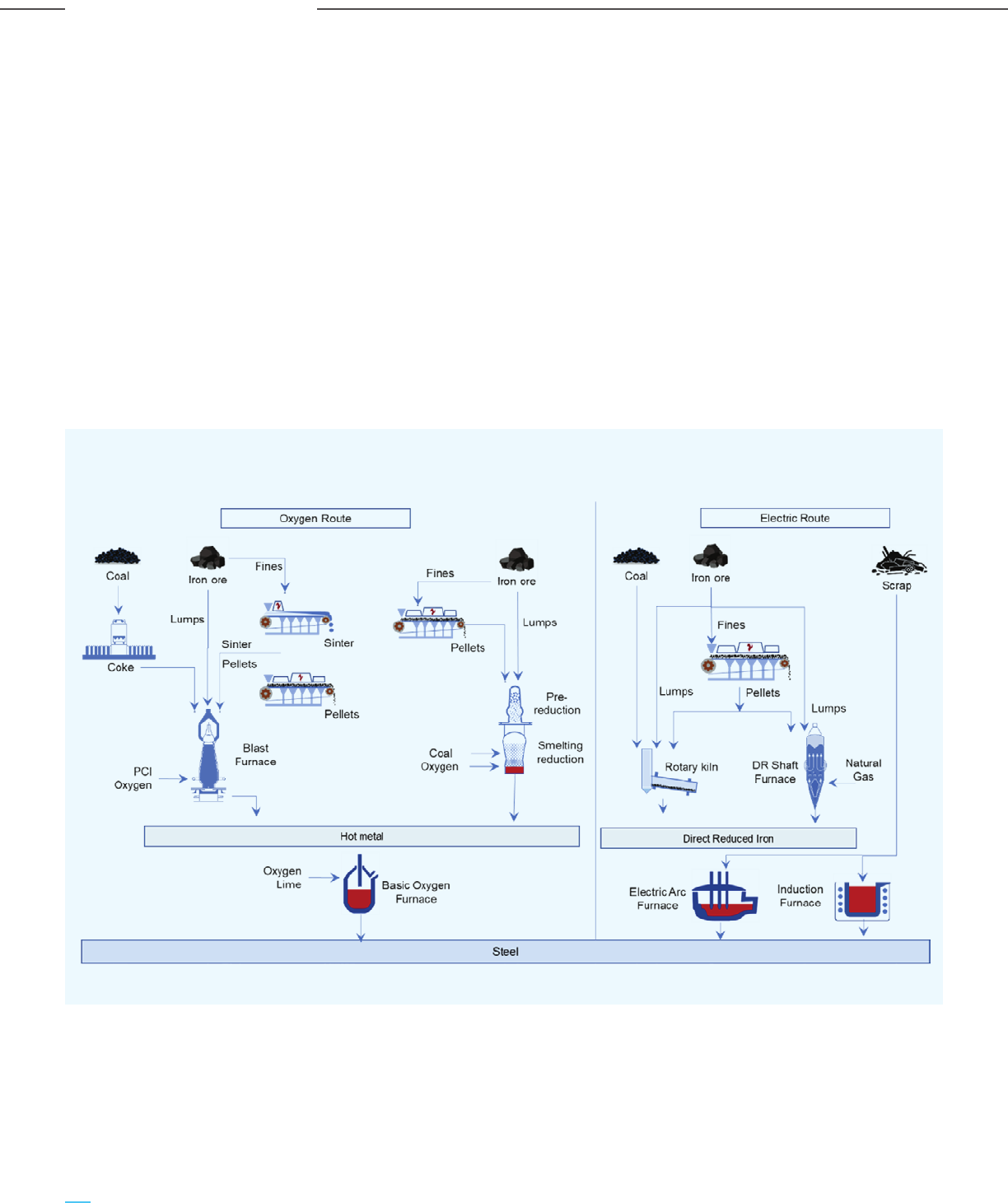
Almost all the large integrated steel plants have
adopted the BOF route production because of its
robustness, scale, and reliability. The BOF route uses
85-95% hot metal in the charge mix, produced from
Blast Furnace/COREX/FINEX. On the other hand, the
induction furnace route is 100% solid-charge based,
and primarily uses DRI, pig iron, and scrap. IF-based
production is electric-energy intensive and suitable
for small-scale production. The EAF route is flexible
and ideal for mid-sized plants (0.5 to 1 mtpa) and can
be designed to take more than 80% hot metal,
whereas the conventional EAF design is based on
100% solid charge. Due to the operational robustness
& flexibility and superior techno-economics of BFs,
most EAFs in India use a certain percentage of hot
metal in the charge mix.
Figure 2-13: Various Iron and Steel Making Routes in India
In the BF route, iron is extracted as liquid hot metal
from sinter, pellet, and iron ore lumps, with coke and
pulverized coal being used as reductants. In smelting
reduction processes like FINEX & COREX, iron ore
fines and coal are used to produce hot metal. The
alternative iron-making routes encompass the
coal-based and gas-based DR processes that produce
solid iron known as DRI or sponge iron, which is
subsequently melted and refined in the EAF/IF
process. The unit processes are described below,
including the perspective of direct CO
2
emissions in
each process. An illustration of the various process
routes in India is given in Figure 2-13.
44
Carbon Capture Utilization and Storage (CCUS) –
Policy Framework and Deployment Mechanism in India
Carbon Capture Utilization and Storage (CCUS) –
Policy Framework and Deployment Mechanism in India
Analysis of Sector-wise CO
2
Emissions

2.2.2.3 Brief Description of Unit Processes
Coke making
Metallurgical coke is produced at scale
(typically 0.5 mtpa and higher) in
by-product recovery and non-recovery
coke ovens. By product recovery coke oven battery is
the preferred choice for the ISPs, while non-recovery
coke oven is generally adopted by merchant coke
producers. Coking is the process of heating coking coal
at a high temperature in the absence of air to expel its
volatile matter and obtain a strong porous coke.
Metallurgical or coking coal softens, swells, and
hardens with sufficient porosity and strength during
the coking process. The pulverized coal blend is
charged into the ovens and heated at 1100 C for about
16-20 hours (for by-product ovens) or about 45-50
hours (for non-recovery ovens). The hot coke is pushed
out of the ovens into a quenching car that is taken to
quenching stations for cooling before being conveyed
to the blast furnace. In by-product recovery ovens, the
gas coming out from the coking chamber is processed
in a chemical plant to produce clean coke oven gas
(COG) and several by-products such as tar, ammonium
sulphate, phenol, naphthalene and sulphur. Clean coke
oven gas, with high calorific value, is used as a fuel
source in downstream facilities after suitably mixing
with other fuel gases. In the non-recovery ovens, all the
gas emissions are utilized to produce steam, which is
subsequently used in power generation. The total
amount of CO
2
released from the coke oven flue stack
is estimated to be about 0.3 tonne per tonne of finished
steel.
Sintering
Sintering is a process of agglomeration of
ore fines along with fluxes to improve the
reducibility of the ore material and
decrease coke consumption in the blast
furnace. A sintering machine consists of a
travelling grate with air suction from its bottom all
along its length. A mixture of ore fines, fluxes, and
coke breeze is charged on the travelling grate and is
ignited on the surface by a hood near the beginning of
the strand. Due to the air suction and coke breeze, the
ignition front travels across the depth of the bed,
providing the heat for sintering. Sintering occurs at a
temperature of about 1300 C which results in melting
particles at the surface and agglomeration at the grain
level. At the end of the strand, the hot sinter is passed
through a roll crusher, screens, and coolers. The
off-gas from a sinter plant is released into the
atmosphere after recovery of the sensible heat. The
combustion of coke breeze and fuel gases in the
process contributes to about 0.43 tonne of CO
2
per
tonne of finished steel.
Pelletization
Pelletization is the process of
agglomerating very fine particles of iron
ore with fluxes, without any incipient
melting. The pelletization process consists of three
main steps: mixing of the feed particles with a binder,
making of raw pellet balls in a drum or disc pelletizer,
and heat hardening of raw pellets in a travelling
grate-rotary kiln-train at around 1300 C. Since the
bonding is established due to diffusion without any
melting, the pelletization process consumes
significantly less energy and emits significantly lower
CO
2
vis-à-vis sintering.
Ironmaking
Iron making or production of hot metal in
India is primarily through the Blast Furnace
(BF) route; additionally, there are a few
COREX plants in India. In a BF, iron ore lumps and sinter
or pellets is charged from the top of the furnace along
with coke, limestone and dolomite. A hot blast of
preheated air with a temperature of over 900 C is
blown through the tuyeres from the bottom of the BF,
which burns the coke to produce heat and carbon
monoxide (CO). The coke reduces the iron oxide to
metallic iron, while producing BF gas. The fluxes help
the separation of gangue from the ore, thus forming
slag. A high temperature of 1400 C in the hearth of the
furnace enables the tapping of hot metal and slag in the
liquid form. The top gas (BF gas) is collected, cleaned
and cooled. Despite its lower CV, the large volume of
BFG generation makes it an important fuel that is used
in the various furnaces of the steel plant, that require
an external heat source. BF gas is also used in power
production after suitably mixing with other gases like
COG and BOFG. The direct CO
2
emission from the stove
flue stack accounts for 0.4 tonne of CO
2
per tonne of
finished steel. The CO
2
and equivalent CO
2
from the CO
in BF gas are emitted in the units which consume the
BF gas.
45
Carbon Capture Utilization and Storage (CCUS) –
Policy Framework and Deployment Mechanism in India
Carbon Capture Utilization and Storage (CCUS) –
Policy Framework and Deployment Mechanism in India
Analysis of Sector-wise CO
2
Emissions
Figure 2-14: CO
2
Emission (in tonne) per tonne of Finished Steel BF-BOF route
Sinter Plant
0.27
0.39
7%
0.03
66%
0.23
25%
0.63
18%
0.17 2.15
CO
2
conc.
Coke Oven Blast Furnace BOF Calcining
Plant
Captive
Power Plant
Mills Total
0.43
8% 23% 23%
Basic Oxygen Steelmaking (BOF)
This is a refining process whereby oxygen
is blown through hot metal in a converter
to remove impurities like carbon, silicon
and phosphorous to produce liquid steel. The oxygen
blowing results in the formation of an emulsion of gas,
molten metal and fluxes, leading to high reaction rates
and making this a rapid process. The oxidized impurities
and fluxes form a basic slag that is tapped at the end,
separate from the tapping of steel. To consume the heat
released from the oxidation reactions, scrap or iron ore
is added as coolant. The oxidation of carbon releases CO
and CO
2
. Due to its high CO concentration, the cooled
and cleaned BOF off-gas is collected for further use.
Liquid steel from the BOF is further refined in
secondary steelmaking units like ladle furnace, VD,
VOD, RH-OB before being sent to the casters for
billet/bloom/slab production.
Rolling Mills
Semis from the steel melt shop are rolled for
production of final products like rebars, wire
rods, structural sections and hot rolled coils.
Cold billets/slabs are charged to a reheating furnace,
fueled by mixed gas, to reheat the semis to around
900-1000
0
C. The hot semis are passed through multiple
rolling stands before being cooled down in a cooling
station. The Scope 1 emissions are limited to the
reheating furnace flue gas only. It is estimated that 0.17
tonne of CO
2
per tonne of finished steel will be emitted
from the rolling mill.
Calcining Plant
For the refining of hot metal, calcined lime
and dolo are required in the SMS operations.
For the production of lime and dolo, raw
limestone/dolomite is charged into a kiln (vertical shaft
or horizontal kiln), where calcination occurs at a
temperature of around 1000
0
C. Heat is supplied by
in-plant fuel gas or purchased fuel. CO
2
is generated from
the combustion of fuel as well as from the decomposition
of CaCO
3
. The calcining process contributes around 0.23
tonne of CO
2
per tonne of finished steel.
Total CO
2
emission in a typical BF-BOF based ISP is
estimated at 2.15 tonne per tonne of finished steel
(Figure 2-14). The CO
2
concentration at each unit is
based on the typical specific fuel consumption and
fuel blend.
46
Carbon Capture Utilization and Storage (CCUS) –
Policy Framework and Deployment Mechanism in India
Carbon Capture Utilization and Storage (CCUS) –
Policy Framework and Deployment Mechanism in India
Analysis of Sector-wise CO
2
Emissions

Coal Based DR Processes (Coal DR)
This route of iron making uses non-coking
coal as a reductant to obtain the solid
product of reduced iron, known as DRI or
sponge iron. DRI is further melted and refined in the EAF
to produce steel. Rotary kiln and rotary hearths are the
two major coal DR processes widely used in India. In the
rotary kiln process, sized lump ore or pellets, coal,
limestone and dolomite are charged from the feeding
end of a rotating kiln, while air and the heating source
are provided at the discharge end of the kiln. The
generation of CO enables the complete reduction of iron
oxide by the discharge end, which is later magnetically
separated out from other solid residues. The limestone
and dolomite calcine, releasing CO
2
and forming lime and
magnesia that act as desulphurizing agents. A
temperature of around 1000 C is maintained to enable
faster reactions as well as to minimize any fusion of
reaction products. The sensible heat of off-gas
containing N
2
& CO
2
is used for the production of power,
through utilization in a waste heat recovery boiler. Since
the coal DR processes involves solid-solid reactions, it is
not as efficient as the countercurrent gas-based blast
furnace process. This results in higher coal consumption
and higher CO
2
emission intensity.
Gas Based DR Processes (Gas DR)
Natural gas based DR production is a
continuous countercurrent moving bed
process employing vertical shaft furnaces to produce DRI
from lump ore or pellet charge and using reformed
natural gas as the reductant. The principle of iron ore
reduction is similar to the blast furnace, except that there
is no fusion and melting of solid products, thereby using
less energy and emitting less CO
2
directly. Iron ore pellets
are charged from the top of the shaft while reformed
natural gas is heated and injected from the bottom of the
reduction zone. The gas leaving the shaft from the top
(the top gas) has significant reducing power and calorific
value due to its unutilized CO and H
2
and is therefore
recycled back to the DR shaft after bringing down the
CO
2
and N
2
fractions. The N
2
is lowered by splitting a
portion of the top gas to be use as a fuel for heating. The
CO
2
in the remaining stream is lowered either by CO
2
separation or using the gas for dry reforming of
natural gas.
Midrex and Hyl are two the major gas DR processes
widely employed across the globe, with similar operating
principles. The Midrex process operates at low pressures
(< 2 bar) and uses dry reforming of natural gas. The Hyl
process operates at high pressure (6 to 8 bar) and hence
employs smaller shafts. Conventional Hyl uses steam for
reforming natural gas, while the Hyl-ZR process uses in
situ reforming and therefore the separated CO
2
during
the top gas cleaning is available for utilization or
sequestration.
Given the high CO
2
intensity of the BF-BOF route, CCUS is
critical to ensuring the long-term sustainability of the
Indian steel sector. CCUS can also enable the scalable
and profitable conversion of waste gases from Blast
Furnace, Coke Oven and Basic Oxygen Furnaces of
Integrated Steel Plants to blue hydrogen at a cash cost of
less than Rs. 100 per kg. Blue hydrogen can be used
within the steel plant as a source of clean energy or for
producing clean DRI. The blue hydrogen can also be sold
to external consumers, thus propelling the clean
hydrogen economy in India.
2.2.2.4 CO
2
Emissions from the Steel Industry
Based on the emission intensities of different processes
(Table 2-7) and production data for FY 2019-20, the total
volume of CO
2
emission from the three routes is
estimated to be 240 mtpa. Based on the current
momentum in steel demand, it is reasonable to consider
that the steel production will reach 190-200 mtpa by
2030 with demand growing at 6% CAGR. This is
corroborated by the fact that in addition to the existing
144 mtpa of steel production capacity (FY 20-21),
expansions of 63 mtpa BF-BOF based capacity have been
announced by various major steel players in the country.
The DRI production is expected to increase by 20% by
2030 to 41 mtpa, merely by the increase in capacity
utilization, which is currently at a low level of 70%. The
share of gas DR versus coal DR is expected to remain the
same, i.e. 20–80%. Scrap usage is expected to rise to 60
mtpa in 2030 from 30 mtpa in FY 2019-20.
Based on these considerations, hot metal production is
estimated to rise to 150 mtpa from 69 mtpa in FY
2019-20. Combining these estimates with the respective
CO
2
emission intensities, it is estimated that the total CO
2
emission shall increase to 450 mtpa by 2030. It is
reasonable to assume that the route-wise distribution of
production will not change significantly. Accordingly, the
projected CO
2
volumes along with the region-wise
analysis are provided below.
47
Carbon Capture Utilization and Storage (CCUS) –
Policy Framework and Deployment Mechanism in India
Carbon Capture Utilization and Storage (CCUS) –
Policy Framework and Deployment Mechanism in India
Analysis of Sector-wise CO
2
Emissions

2.2.2.4 CO
2
Emissions from the Steel Industry
Based on the emission intensities of different processes
(Table 2-7) and production data for FY 2019-20, the total
volume of CO
2
emission from the three routes is
estimated to be 240 mtpa. Based on the current
momentum in steel demand, it is reasonable to consider
that the steel production will reach 190-200 mtpa by
2030 with demand growing at 6% CAGR. This is
corroborated by the fact that in addition to the existing
144 mtpa of steel production capacity (FY 20-21),
expansions of 63 mtpa BF-BOF based capacity have been
announced by various major steel players in the country.
The DRI production is expected to increase by 20% by
2030 to 41 mtpa, merely by the increase in capacity
utilization, which is currently at a low level of 70%. The
share of gas DR versus coal DR is expected to remain the
same, i.e. 20–80%. Scrap usage is expected to rise to 60
mtpa in 2030 from 30 mtpa in FY 2019-20.
Based on these considerations, hot metal production is
estimated to rise to 150 mtpa from 69 mtpa in FY
2019-20. Combining these estimates with the respective
CO
2
emission intensities, it is estimated that the total CO
2
emission shall increase to 450 mtpa by 2030. It is
reasonable to assume that the route-wise distribution of
production will not change significantly. Accordingly, the
projected CO
2
volumes along with the region-wise
analysis are provided below.
In 2017, the Ministry of Steel published the National Steel
Policy for India, which projected a crude steel capacity of
300 mtpa and crude steel production of 255 mtpa by the
year 2030. The National Steel Policy is aspirational and
provides an upper bound on the likely growth of the
domestic steel sector. In case the targets and goals of
the National Steel Policy are realized, it will lead to much
higher CO
2
emissions of about 560 mtpa from the steel
sector, as shown in Figure 2-15.
India’s current cement production capacity is about
550 mtpa, implying capacity utilization of about 50%
only. While India accounts for 8% of global cement
capacity, India’s per capita cement consumption is only
235 kg, and significantly low compared to the world
average of 500 kg per capita, and China’s per capita
consumption of around 1700 kg per capita. It is
expected that domestic demand, capacity utilization
and per capita cement consumption will increase in the
next decade, driven by robust demand from rapid
industrialization and urbanization, as well as the Central
Government’s continued focus on highway expansions,
investment in smart cities, Pradhan Mantri Awas Yojana
(PMAY), as well as several state-level schemes.
2.2.3.2 Cement Plant Production and Capacity
Limestone is the major feedstock in cement production.
Hence most cement plants are built either close to
captive limestone quarries or are well connected with
limestone quarries. Therefore clinker based cement
plants are concentrated in South and North India. The
market for slag/fly ash-based cement has also evolved in
the last few years, with blast furnace slag/fly ash-based
cement plants expanding in Eastern India. The
region-wise cement production is shown in Figure 2-18
(Source: IBEF.org).
Product BF-BOF Coal Gas
DR-EAF/IF DR-EAF
t CO
2
/t product 1.8 - 2.2 2.6 - 3.0 0.6 - 0.8
Table 2-7: CO
2
Direct Emission Intensities for
Various Iron Making Routes
Figure 2-15: Region-wise Distribution and
Total CO
2
Emissions (in mtpa)
Figure 2-16: Cement Production (in mtpa)
561
240
2020
Western Northern Southern
450
2030e
2030e (NSP)
Eastern
2.2.3 CO
2
Emissions: Indian Cement Industry
2.2.3.1 Introduction
India is the second-largest cement producer in the world
after China. Over the last five years, cement production
has grown from 274 mtpa (FY 2015-16) to 381 mtpa (FY
2021-22) at a CAGR of 6% (Figure 2-16). Cement
demand and production in FY 2020-21 was impacted by
COVID-19, and has recovered in the subsequent year.
Figure 2-17: Per Capita Cement
Consumption in 2018 (in kg)
520
1700
235
World
China
India
274
273
291
329 329
294
381
FY16 FY17 FY18 FY19 FY20e FY21e FY22e
+6%
48
Carbon Capture Utilization and Storage (CCUS) –
Policy Framework and Deployment Mechanism in India
Carbon Capture Utilization and Storage (CCUS) –
Policy Framework and Deployment Mechanism in India
Analysis of Sector-wise CO
2
Emissions
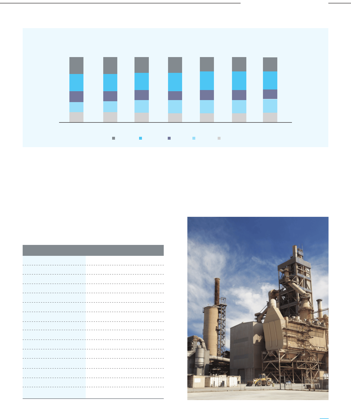
Cement production in India is dominated by private
players. Almost 98% of the cement capacity belongs to
private players like UltraTech, Shree Cements, Ambuja,
ACC, Dalmia Cement etc. The cement market is also
oligopolistic and the top 10 companies account for over
60% of the total capacity. The cement capacity of major
players is given in Table 2-8 (Source: Indian Minerals
Yearbook 2019 published by the Government of India).
The state-wise cement capacity is given in Table 2-9
(source: Indian Minerals Yearbook 2019 published by
Government of India). The top five states i.e., Rajasthan,
Andhra Pradesh, Karnataka, Tamil Nadu, and Gujarat,
account for almost 50% of the total capacity. Given the
proximity to limestone quarries, the majority of future
expansions are also planned in these states only.
Figure 2-18: Cement Production (in mtpa)
Company Name Capacity
Ultratech 125
Shree Cement 41
Ambuja 35
ACC 34
Dalmia 21
ICL 20
Jaypee Cement 17
Birla 15
Ramco 15
JK Lakshmi 15
Chettinad 14
Nirma 14
JSW 11
JK Cement 11
Kesoram Industries 11
Table 2-8: Major Players of Cement Industry
and Capacity (in mtpa)
Northern Southern Central Eastern Western
274 273 291 329 329 294 381
FY16 FY17 FY18 FY19 FY20e FY21e FY22e
16% 16% 15% 14% 15% 15% 15%
16% 17% 19% 19% 20% 20% 21%
16% 16% 16% 15% 16% 15% 15%
26% 27% 26% 29% 27% 28% 28%
26% 25% 24% 23% 22% 22% 22%
49
Carbon Capture Utilization and Storage (CCUS) –
Policy Framework and Deployment Mechanism in India
Carbon Capture Utilization and Storage (CCUS) –
Policy Framework and Deployment Mechanism in India
Analysis of Sector-wise CO
2
Emissions

State No. of Plants Capacity (mtpa) % of total capacity
Rajasthan 24 87 15.7%
Andhra Pradesh 26 63 11.3%
Karnataka 18 49 8.9%
Tamil Nadu 22 42 7.6%
Gujarat 17 41 7.5%
Madhya Pradesh 13 39 7.0%
Telangana 18 34 6.2%
Maharashtra 13 32 5.8%
Chhattisgarh 13 31 5.6%
Uttar Pradesh 14 24 4.3%
West Bengal 16 22 4.0%
Himachal Pradesh 9 16 2.9%
Odisha 5 13 2.4%
Jharkhand 6 13 2.3%
Bihar 6 11 1.9%
Meghalaya 10 9 1.7%
Haryana 5 7 1.3%
Punjab 4 7 1.3%
Assam 6 5 0.9%
Uttarakhand 3 4 0.7%
Andaman Nicobar 1 2 0.3%
Kerala 2 1 0.2%
Jammu and Kashmir 3 1 0.1%
Goa 1 0.2 0.0%
Total 255 554 100%
Table 2-9: State-wise Cement Capacity
The district-wise distribution of cement plants has
also been analyzed to understand the clusters of
cement plant units. The top 20 districts/clusters
contribute to almost 50% of the total capacity
(Table 2-10) (Source: Indian Minerals Yearbook 2019
published by Government of India).
50
Carbon Capture Utilization and Storage (CCUS) –
Policy Framework and Deployment Mechanism in India
Carbon Capture Utilization and Storage (CCUS) –
Policy Framework and Deployment Mechanism in India
Analysis of Sector-wise CO
2
Emissions
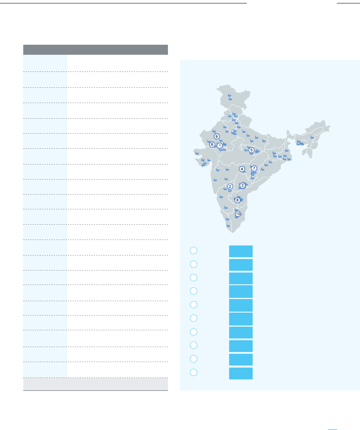
Figure 2-19 below shows the top 10 cement clusters,
based on their capacity, along with the names of the
major producers in each cluster.
District name State name Capacity (mtpa)
Chittorgarh Rajasthan 25
Gulbarga Karnataka 23
Nalgonda Telangana 21
Chandrapur Maharashtra 20
Satna Madhya Pradesh 20
Sirohi Rajasthan 18
Raipur Chhattisgarh 15
Anantapur Andhra Pradesh 14
Pali Rajasthan 13
Ariyalur Tamil Nadu 13
Kurnool Andhra Pradesh 12
Solan Himachal Pradesh 12
Kadapa Andhra Pradesh 11
Surat Gujarat 10
Krishna Andhra Pradesh 9
Jaintia Hills Meghalaya 8
Amerli Gujarat 8
Durg Chhattisgarh 7
Junagadh Gujarat 7
Bardhaman West Bengal 7
Others 282
Total 554
Table 2-10: Top 20 Districts/Clusters and
Aggregate Capacity
Figure 2-19: Top 10 Cement Clusters
Based on Cumulative Capacity
Clusters
Chittorgarh, 25 mtpa Wonder Cement, UltraTech, Nirma, Birla
Rajasthan 5 units J.K Cement
Gulbarga, 23 mtpa UltraTech, Orient, Kesoram,
Karnataka 5 units Chettinad, Kalburgi
Nalgonda, 21 mtpa My Home, Sagar, Zuari, ICL Penna,
Telangana 12 units NCL, Deccan, etc.
Chandrapur, 20 mtpa UltraTech, Ambuja, ACC, Dalmia
Maharashtra 5 units
Satna, 20 mtpa Prism Cement, UltraTech, Birla, KJS
MP 6 units Cement, Jaypee Cement
Sirohi, 18 mtpa UltraTech, JK Laxmi Cement
Rajasthan 2 units
Raipur, 15 mtpa Shree Cement, UltraTech, Nirma,
Chhattisgarh 6 units Ambuja
Anantapur, 14 mtpa Penna Cement, UltraTech, Sagar Cement
AP 4 units
Pali, 13 mtpa Shree Cement, Nirma, Ambuja
Rajasthan 4 Units
Ariayalur, 13 mpta Chettinad cement, UltraTech, Dalmia,
Tamil Nadu 5 units ICL
1
2
3
4
5
6
7
8
9
10
51
Carbon Capture Utilization and Storage (CCUS) –
Policy Framework and Deployment Mechanism in India
Carbon Capture Utilization and Storage (CCUS) –
Policy Framework and Deployment Mechanism in India
Analysis of Sector-wise CO
2
Emissions

2.2.3.3 Medium-term demand projection
The 10% decrease in cement demand in FY 2020-21
was temporal and due to the COVID-19. Cement
demand is expected to grow going forward based on
investments towards the infrastructure and housing
sectors. It is envisaged that cement demand per
capita will grow at around 6% CAGR to FY 2029-30.
Thus, cement consumption per capita will reach 300
kg per capita by 2025 and 400 kg per capita by 2030.
Thus cement demand is estimated to be around 440
mtpa by 2025 and about 650 mtpa by 2030,
considering a population growth rate of 2%
year-on-year and growth in cement consumption per
capita at 6% per year.
Analysis of the capacity distribution of individual
cement plants reveals that the average capacity for
the 255 cement plant units is 2.2 mtpa, whereas the
capacity of most of the cement plants is between
1 to 3 mtpa.
2.2.3.4 Typical Cement Manufacturing Process
Cement can be primarily categorized into three types,
based on the clinker factor and usage of other
ingredients i.e. fly ash or slag:
a) Ordinary Portland Cement (OPC): OPC is the
most common type and is used widely in
construction activities. The clinker factor is
generally above 90% for OPC cement.
b) Portland Pozzolana Cement (PPC): Since fly ash
is abundantly available at a low cost, the share of
PPC-type cement has increased significantly over
the last decade. The clinker factor is less than
60%. PPC is advantageous over OPC due to
fineness, resistance to corrosiveness, and
impermeability.
c) Portland Slag Cement (PSC): Blast furnace slag
is predominantly used for the production of PSC.
PSC is used in applications where concrete is
exposed to rough weather like marine
applications, high-rise buildings, etc.
The process route for different types of cement
production is almost similar except for the final
blending and grinding process steps. The dry-type
technology predominant in the Indian cement industry
is described below and depicted in Figure 2-21.
a) Mining
The manufacturing process starts from
mining limestone, which is the primary
ingredient for cement production. The
limestone is primarily excavated from open cast mines
after drilling and blasting and loaded onto dumpers.
Dumpers transport the limestone and unload it into
hoppers of limestone crushers. Other feed materials
like sand, coal, pet coke etc., are sourced
from outside.
b) Screening & Crushing
The raw materials are crushed in the primary
crushing unit and then fed into the
secondary crushing unit (along with the
mixing of additives) to reduce the material
size. The raw mix is conveyed to a circular
storage unit called the raw mix storage. The mix is
reclaimed from the stockpile by reclaimers and
conveyed to the raw mix bin for grinding. High purity
limestone and coal/pet coke generally have dedicated
crushing and storing systems. However, other
additives like sand are crushed in a common or shared
crushing system.
Capacity range No of plants % share
Less than 1.0 mtpa 63 25%
1.0 mtpa to 2.0 mtpa 85 33%
2.0 mtpa to 3.0 mtpa 55 22%
3.0 mtpa to 4.0 mtpa 29 11%
4.0 mtpa to 5.0 mtpa 11 4%
Greater than 5.0 mtpa 12 5%
Table 2-11: Plant Capacity Distribution
Figure 2-20: Cement Demand (in mtpa)
and Per-capita Cement Consumption (in kg)
52
Carbon Capture Utilization and Storage (CCUS) –
Policy Framework and Deployment Mechanism in India
Carbon Capture Utilization and Storage (CCUS) –
Policy Framework and Deployment Mechanism in India
Analysis of Sector-wise CO
2
Emissions
327
443
654
235
297
397
0
100
200
300
400
500
600
700
2020e 2025f 2030f
Demand Kg/Capita

c) Raw meal drying, grinding, and homogenization
Additives like iron ore/red mud are blended with
limestone with the help of weigh feeder before drying
and grinding to get the desired composition and
properties. The raw mill consists of two chambers,
namely a drying chamber and a grinding chamber,
separated by a diaphragm. The hot flue gas from a
preheater (preheater/kiln system) is used for drying.
Then the materials enter the grinding chamber of the
raw mills for fine grinding. The grinding mill can be of
the conventional and simple ball mill type, or the
advanced and complex Vertical Roller Mill (VRM) type.
The hot gas, along with grinding materials, is fed to a
separator that separates fine and coarse products.
The course product is returned to the grinding unit.
The hot gas and fine materials are passed through a
cyclone unit to separate fine materials and gases. The
fine material is collected from the multi-cyclone. The
very fine materials carried away by flue gas to an
electrostatic precipitator (ESP), where the finer
particles are separated from gases. The ESP dust is
collected from bag filters and fed into screw
conveyors, and mixed with the fine material. Raw
meal/kiln feed is stored in a blending silo for
homogenization before being fed to the top of the
preheater for pyro-processing.
Figure 2-21: Typical Process Flow Diagram
for Cement Making
d) Clinkerisation
Cement clinker is made by pyro-processing the kiln
feed in the preheater-kiln system. The preheater-kiln
system consists of a multi-stage (generally more than
five) cyclone preheater, combustion chamber, riser
duct, rotary kiln, and grate cooler. In the preheater
section, heat transfer depends on the number of
stages of the preheater. Additionally, coal is also fired
for additional heat requirements. The preheater helps
in removing moisture from the feed, as well as raising
the temperature of the feed through countercurrent
heat transfer with hot flue gas.
The preheated kiln feed is partially calcined in a
combustion chamber and riser duct and then
completely calcined in a rotary kiln and heated to
approximately 1400-1500
o
C to form the clinker
components. Coal is fed through a burner which is the
primary source of heat for the calcination. However,
alternative fuels like petcoke, biomass, and other solid
waste are also used. Hot clinker is discharged to the
grate cooler for cooling from 1350-1450
o
C to around
1200
o
C with atmospheric air. The cooled clinker is
then conveyed to hoppers for clinker storage.
e) Cement grinding and storage
Clinker and gypsum for OPC, fly ash for PPC, and slag
for PSC is transferred from individual hoppers and fed to
the cement mills. The mill discharge is fed to the screen,
which separates fine and coarse products. The course
product is returned to the mill inlet for regrinding, and
the final product is stored in concrete silos.
f) Packing
Cement is conveyed from silos to the automatic
packers, where it is packed in 50 kg bags and
dispatched to the market.
2.2.3.5 CO
2
Emissions from Cement Manufacturing
In 2018, cement production contributed about 12% or
264 mtpa of anthropogenic CO
2
emissions in India
(source: IEA). The emissions will rise with the sustained
increase in cement demand and production in the near
future. CO
2
emissions vary widely from plant to plant
depending on specific factors such as product type,
plant efficiency, fuel usage, plant capacity etc.
Raw Material incl. additives
(High grade limestone, sand
iron ore fines, red mud, clay
Screening & Crushing
Pre-blending &
Proportioning
Grinding Grinding
Rejects
Final Grinding
Storage & Dispatch
Fuel
(Coal/Pet coke/Bio)
Additives
(Gypsum/Fly ash)
Homogenising
Pre-heating
Clinkerisation
Cooling & Storage
of Clinker
53
Carbon Capture Utilization and Storage (CCUS) –
Policy Framework and Deployment Mechanism in India
Carbon Capture Utilization and Storage (CCUS) –
Policy Framework and Deployment Mechanism in India
Analysis of Sector-wise CO
2
Emissions

Particulars Unit Global Avg. India Best India Average
Specific Electrical Energy Consumption kWh/tonne of cement 91 64 80
Specific Thermal Energy Consumption GJ/tonne of clinker 3.5 2.83 3.1
Table 2-12: Consumption Parameters
Figure 2-22: Typical CO
2
Cascade
(in kg of CO
2
per tonne of cement)
Figure 2-23: Cement Plant CO
2
Emission
Projection (in mtpa)
The average CO
2
emission intensity per tonne of
cement was 576 kg in 2018. The Scope 1 and Scope 2
emissions are primarily from three sources:
a. Emission from process calcination (CaCO3 -> CaO)
accounts for 57-60% of total emissions
b. Emission from process heating in terms of
thermal energy usage contributes around 27-31%
c. Emission from power usage for grinding, process
fans, etc., accounts for 10-13%.
d. Limestone mining also has a small contribution to
the total CO
2
emission (limited to 1-2%).
A typical CO
2
cascade is shown in Figure 2-22.
The CO
2
emission intensity is expected to reduce to
500-520 kg per tonne with further improvement in
the cement production process, through higher
production of blended cement, using vertical roller
mills, installing WHRB, etc. The total CO
2
emission
from the cement sector has been estimated to reach
325 mtpa by the year 2030, considering 0.5 tonne of
CO
2
emissions per tonne of cement.
346
156
75 576
Calcination Thermal Energy Power Total
196
244
325
2020e 2025f 2030f
Hence an average CO
2
emission per tonne of cement
has been used to calculate the total CO
2
emissions
at the current and project level of cement demand
and production.
The Indian cement industry is focused on sustainability
and environmental impact, vis-à-vis its peers.
According to an April 2018 publication by CDP, a
UK-based organization, five out of the top ten global
cement companies in terms of low carbon transitions
are from India. Indian cement companies are ahead of
the global average in terms of specific electrical and
thermal energy consumption (Table 2-12). This is
primarily due to fly ash/slag usage in the blend,
efficient dry processes, and alternate fuel usage.
54
Carbon Capture Utilization and Storage (CCUS) –
Policy Framework and Deployment Mechanism in India
Carbon Capture Utilization and Storage (CCUS) –
Policy Framework and Deployment Mechanism in India
Analysis of Sector-wise CO
2
Emissions
Source: Cement Manufacturing Association

2.2.4 CO
2
Emissions: Indian Oil & Gas and
Chemical Industry
2.2.4.1 Introduction
The chemical industry is another energy-intensive
sector and produces materials used in multiple
downstream sectors. The Indian chemical industry is
ranked as the 6
th
largest in the world and the 3
rd
largest in Asia. India is one of the largest production
hubs of chemicals and in the next 5-10 years the
industry is expected to have a high growth trajectory,
which would result in a significant increase in
CO
2
emissions.
The chemical sector is recognized by the Indian
government as one of the country’s primary growth
drivers and is expected to grow at 9.3% to reach US$
304 billion by 2025, based on rising demand from the
end-user segments, especially for speciality chemicals
and petrochemicals. In July 2020, production volumes
of key chemicals stood at around 0.9 mtpa and
petrochemicals at 1.9 mtpa. India ranks 14
th
in global
exports and 8
th
in global imports of chemicals
(excluding pharmaceuticals).
In 2020, the chemical industry accounted for about 160
mtpa of CO
2
emissions (7% of total emissions), which is
expected to increase to approximately 220 mtpa by
2030, fueled by growth in speciality chemicals,
petrochemicals and fertilizers. This chapter focuses on
CO
2
emissions from the production of different
segments of the chemicals sector, viz. refinery &
petrochemical products, fertilizers, hydrogen,
methanol and synthesis gas via coal/coke gasification.
Hydrogen
Hydrogen is widely considered a future
energy carrier due to its potential uses
across multiple sectors like refinery, steel,
petrochemicals, power, transportation etc., with
(potentially) zero CO
2
footprint and its potential role in
the decarbonization of energy systems and as a low
carbon fuel & chemical feedstock. Additionally,
development and innovation in electrolyzer
technologies and the availability of renewable power
make the prospect of green hydrogen also realistic in
the future. However, to be deployed at scale,
hydrogen needs to compete with existing fossil fuels
and other emerging low carbon alternatives, such as
battery electric vehicles. Despite being inexpensive and
2.2.4.2 Type of Primary Chemicals
plentiful, there will be competing needs for low-carbon
power, and hydrogen production via electrolysis is an
extremely electro-intensive process. As a result, it’s
critical to analyze hydrogen’s potential role from a
systems viewpoint, considering the different end-uses,
production routes, and value-chain combinations.
Hydrogen demand in India is currently 6 mtpa, and is
confined to fertilizer plants and refineries. The
development of new uses of hydrogen, cost
reductions in key technologies, as well as the growing
requirement to decarbonize the energy system could
push hydrogen demand to roughly 11 mtpa by 2030
and 28 mtpa by 2050. Demand will remain mostly
concentrated in industrial sectors, either expanding in
existing sectors like fertilizers and refineries or
extending into new ones like steel. Hydrogen will also
have a minor role in the electricity sector as a
long-term storage vector, and in the transportation
sector in heavy-duty and long-distance segments.
Demand for green hydrogen is expected to continue
to rise after 2050, particularly in the steel and road
transportation industries, as well as shipping and
aviation.
Methanol
Methanol is an essential chemical building
block for hundreds of everyday products
and applications, including plastics, paints, car parts
and construction materials. Methanol is also an
alternative clean energy resource that can be blended
in existing fuels and used in cars, trucks, buses, ships,
fuel cells, boilers and cooking stoves. India’s current
methanol production capacity is 0.7 mtpa, which is
less than one-third of the country’s total demand. The
market is heavily reliant on imports from the Middle
East, which account for more than 75 percent of
methanol consumed in India. Methanol demand in
India was 2.26 mtpa in FY 2020-21 and is expected to
rise to 4.1 million tonnes by FY 2029-2030.
India has developed an indigenous technique for
converting high-ash Indian coal to methanol and has
set up its first pilot plant in Hyderabad for producing
0.25 tpd of 99 percent purity methanol. Conversion of
coal to methanol will provide an alternate route for
producing methanol and increase India’s self
dependence in this important energy carrier of the
future, thus providing a pathway to India to lower both
its crude imports and CO
2
emissions (i.e. when the
methanol production is combined with CCUS).
55
Carbon Capture Utilization and Storage (CCUS) –
Policy Framework and Deployment Mechanism in India
Carbon Capture Utilization and Storage (CCUS) –
Policy Framework and Deployment Mechanism in India
Analysis of Sector-wise CO
2
Emissions

Ammonia
India is the fourth-largest ammonia
producer in the world, with production of
15.4 mtpa in 2020 and also one of the
largest ammonia importers in the world. The largest
demand for ammonia is for producing urea,
ammonium nitrate and ammonium phosphate, which
are major compounds for nitrogen-based fertilizers.
Urea and ammonium phosphate fertilizers account for
over 90% of ammonia demand in India.
Urea production in India is about 25 mtpa. With a
growing population and food demand, the demand for
urea and ammonia is also expected to grow. Ammonia
is also an essential chemical needed for refrigerants.
With rapid urbanization the demand for refrigerants is
expected to increase, in turn impacting the demand
for ammonia. Ammonia is also a basic building block
for various compounds used in producing household
products, cosmetics, pharmaceuticals, and in metal
treating. Ammonia can also play a role in the future
energy transitions as a hydrogen carrier for storing
and transporting the chemical energy of hydrogen,
and can be used as a transport fuel, particularly in the
shipping industry.
Synthetic Gas
Synthesis gas (syngas) production
provides the foundation of many
industries. Syngas is a mixture of H
2
/CO and is
produced from gasification (coal, heavy hydrocarbons
coke) or reforming (light hydrocarbons). Steam,
oxygen, carbon dioxide or mixtures of them act as
reforming agents and react with the carbon source at
high temperatures, producing syngas of varying
compositions.
The desired composition of syngas depends on the
downstream applications; the most common H
2
/CO
ratio is 2:1 for methanol and Fischer-Tropsch synthesis,
or higher for hydrogen production. The generation of
ethanol and higher alcohols, dimethyl ether, and
oxo-alcohols use lower H
2
/CO ratios of about 1. When
the carbon source is natural gas (methane), the
conversion to syngas process is called reforming. The
common technologies offer syngas with high hydrogen
content (Steam Methane Reforming or SMR) or with
reduced operating investment (Partial Oxidation or
POX, Auto-thermal Reforming or ATR and Combined
Reforming or CR). Newer technologies, which can
consume CO
2
(Dry Methane Reforming or DMR,
Bi-reforming or BR and Tri-reforming TR) are also
interesting options, even though they are more
cost-intensive or produce syngas with lower H
2
/CO
ratios, due to their reduced environmental impact
under specific situations. Reliance Industries Ltd’s
(RIL) Jamnagar plant has the only petcoke gasification
unit in India having a capacity of producing 12 mtpa of
synthesis gas, which can be further used to produce
various chemicals. The synthesis gas has a typical
composition of H
2
30-35 vol%, CO 35-40 vol% & CO
2
15-20 vol%.
Petrochemicals
Petrochemicals provide the basic raw
materials for products of daily use.
Petrochemicals are primarily of two types:
olefins and aromatics. The demand for petrochemicals
is expanding rapidly and is expected to reach 35 mtpa
by FY 2029-30. Within petrochemicals, the production
of ethylene and propylene are the most emission
intensive processes after ammonia. These chemicals
are the building blocks for the polymer industry and
are increasingly being used across diverse
applications as they provide varied operational
benefits over their metal counterparts.
2.2.4.3 Process Description of Various
CO
2
Sources
a) Refinery Unit
India’s oil consumption is forecast to increase from 5
million barrels/day in 2020 to 7.2 million barrels/day
in 2030 and 9.2 million barrels/day in 2050. The total
refining capacity in India is about 250 mtpa, with total
CDU capacity of 2300 thousand barrel/day & FCC
capacity of 938 thousand barrel/day. For any complex
refinery, there are multiple CO
2
emission sources such
as Hydrogen Generation Unit (HGU), Power Plant/
Co-Gen Plant (PP/CGP), Fluid Catalytic Cracking (FCC),
Crude Distillation Unit (CDU) / Vacuum Distillation Unit
(VDU) as well as heaters and boilers. Amongst these,
the HGUs generate the most concentrated gas
streams in terms of CO
2
(20-70 vol%), followed by
CDU/VDU (10-12 vol.%), FCC (8-16 vol.%) and PP / CGP
(4-8 vol%). The majority of CO
2
emissions in a typical
refinery is contributed by the hydrogen generation
unit, FCC, boilers, and process heaters. A brief
description of HGU and FCC are given below:
56
Carbon Capture Utilization and Storage (CCUS) –
Policy Framework and Deployment Mechanism in India
Carbon Capture Utilization and Storage (CCUS) –
Policy Framework and Deployment Mechanism in India
Analysis of Sector-wise CO
2
Emissions

Fluid Catalytic Cracking (FCC):
FCC helps in
improving the recovery from crude through cracking
higher hydrocarbons. Crude is allowed to react with
steam in a fluidized bed (or fluid-bed) of catalyst
particles. When the heated catalyst particles come in
the presence of the feed, they evaporate it, and
cracking begins as the gas oil vapors and catalyst
particles migrate upward in the reactor. During the
upward movement, the temperature of the catalyst
particles reduces as the gas oil evaporates and
endothermic cracking processes occur. Cracking
processes also deposit a coke layer on the catalysts,
causing them to become inactive. The coked catalyst is
transferred to the regeneration unit before they are
reintroduced to the riser. After being separated from
the catalyst particles in the upper section of the
reactor, the cracking products are transferred to the
fractionator for recovery. In the regeneration unit, the
deposited coke layer of catalyst is burnt at around
700-800
0
C, and this is a primary source of CO
2
emission. The CO
2
concentrations at different units of
a typical refinery operation, as shown in Table 2-14,
vary depending on the respective processes.
Hydrogen generation unit: Hydrogen is indispensable
in refinery operations for handling sour crudes as well
for meeting stringent fuel norms. In India, almost all
refineries produce hydrogen from natural gas (as well
as naptha) through steam methane reforming (SMR).
Only RIL has a petcoke based gasifier at Jamnagar,
which caters to a part of the total hydrogen
requirement. In the SMR process, natural gas is fed to
the reformer to react with steam over special
catalyst-filled tubes to produce hydrogen and carbon
monoxide. The gas stream from the SMR is
conditioned in a water gas shift reactor to maximize
the H
2
recovery. In the WGS, the carbon monoxide
reacts with steam to form hydrogen and carbon
dioxide. The hydrogen is then separated in a Pressure
Swing Adsorption unit. Pure hydrogen with 99.9%
purity is sent to end-user and the tail gas is used as
fuel in the reformer unit.
The hydrogen production process and the possible
CO
2
capture points are schematically depicted in
Figure 2-24. The three gas streams where CO
2
can be
captured are marked as 1, 2 and 3. Gas composition at
these identified sources is given in Table 2-13. While
Parameter Shifted syngas (vol.%, db) PSA tail gas (vol.%, db) Flue gas, (vol. %, db)
Carbon Dioxide 20 64 18-20
Hydrogen 77 26
Carbon Monoxide 0.7 7
Nitrogen 58
Table 2-13: Gas Composition at Different Source Points
Figure 2-24: Simplified Block Flow Diagram of
Hydrogen Generation Units (HGUs)
NG: Natural Gas; SMR: Steam Methane Reforming; WGS: Water Gas Shift;
PSA: Pressure Swing Adsorption
PSA Tail Gas
Shifted
Syngas
Flue
Gas
H
2
Feed (NG)
SMR WGS PSA
Fuel (NG)
Steam
1
2
3
capture from tail gas or syngas (1 & 2) ensures the
lowest cost of capture because of higher
concentration and partial pressure of CO
2
, it can
capture only 60% of total direct CO
2
emissions,
whereas flue gas capture ensures over 95% direct
CO
2
capture.
57
Carbon Capture Utilization and Storage (CCUS) –
Policy Framework and Deployment Mechanism in India
Carbon Capture Utilization and Storage (CCUS) –
Policy Framework and Deployment Mechanism in India
Analysis of Sector-wise CO
2
Emissions

b) Petrochemical Unit
The petrochemical industry generates various kinds
of chemical products such as polymers, fibers or
rubber, from such raw materials as petroleum, LPG,
natural gas, and other hydrocarbons through
different production processes. The source
feedstock, i.e. light or heavy hydrocarbons, are
used to produce a variety of components including
ethylene, propylene, butadiene and pyrolysis
gasoline through non-catalytic thermal
decomposition reaction with steam (thermal
cracking). Pyrolysis of hydrocarbons is the most
critical process in petrochemical production and
presents the main source for most basic organic
industrial raw materials: α-olefins (ethylene,
propylene, isobutane, butene), butadiene, and
aromatic hydrocarbons (BTX = benzene, toluene,
xylene). The most CO
2
emission intensive process is
the production of ethylene through the following
processes:
Table 2-14: CO
2
Concentration at Different Refinery Units
Unit Section CO
2
vol% (db)
FCC FCCU Regenerator 8.5
SMR Reformer Flue 18-22
CDU Crude distillation Unit 11
DCU Coke heater 8.5
Reformer Reformer heater 4
heater
VDU Vacuum Unit 11
Naphtha Reformer-Naphtha 8.5
splitter splitter
HC Hydrocracker 8.5
HC-Heater Hydrocracker Heater 8.5
HDS Hydrodesulfurization 8.5
HDS-Heater HDS- Charge heater 4
SRU Sulfur removal & 4
tail gas treatment
FCCU Heater FCCU heater 4
Table 2-15: Cracker Furnace Flue Gas Composition
Parameter vol% (db)
CO
2
11-13
H
2
3-4
N
2
85-87
CO 100-200 ppm
Steam Cracking: In steam cracking, a gaseous or
liquid hydrocarbon feed-like ethane, propane, butane,
naphtha, gas oil is diluted with steam and then
heated in a furnace without oxygen. Typically, the
endothermic reaction temperature is very hot
(around 850
0
C) and allowed to take place with short
residence time (resulting in gas velocities reaching
speeds beyond the speed of sound) in the furnace
coils. In modern cracking furnaces, the residence
time is reduced to milliseconds in order to improve
the yield of the desired products. After the cracking
temperature has been reached, the gas is quickly
quenched to stop the undesirable reaction in the
downstream transfer line exchanger. The products
produced in the reaction depend on the composition
of the feed, on the hydrocarbon to steam ratio and
on the cracking temperature and furnace residence
time. The flue gas temperature is at around
1100-1200
0
C depending upon fuel gas composition.
Light hydrocarbon feeds (such as ethane, propane,
or light naphtha) give product streams rich in the
lighter alkenes, including ethylene, propylene, and
butadiene while heavier hydrocarbons (full range
and heavy naphtha as well as other refinery
products) feeds give some of these, but also give
products rich in aromatic hydrocarbons and
hydrocarbons suitable for inclusion in gasoline or
fuel oil. The higher cracking temperature favors the
production of ethylene and benzene, whereas lower
severity produces relatively higher amounts of
propylene, C4 cut, and liquid products.
Gas composition: The exhaust flue gas is a CO
2
rich
product, depending upon the type of fuel, combusted
in modern low SOx-NOx burners. Normally the
methane content varies from 60-70 vol% in the
gaseous fuel. The typical flue gas composition with
10-15 vol% excess air is given Table 2-15.
58
Carbon Capture Utilization and Storage (CCUS) –
Policy Framework and Deployment Mechanism in India
Carbon Capture Utilization and Storage (CCUS) –
Policy Framework and Deployment Mechanism in India
Analysis of Sector-wise CO
2
Emissions
c) Fertilizer Unit
A typical fertilizer unit comprises hydrogen
production, ammonia production and urea production.
Most fertilize plants in India operate with natural gas
based SMR for hydrogen production, which is similar
to refineries. However, CO
2
removal after the water
gas shift reactor is an added process in fertilizer
plants, since CO
2
is required for production of urea. In
a fertilizer complex, the majority of CO
2
emission is
contributed by hydrogen production. A part of CO
2
is
consumed in downstream urea production. A brief
description of the ammonia and urea production
process is given below:
Ammonia production: The Haber process, in which
nitrogen and hydrogen combine in the presence of an
iron catalyst to make ammonia, is the most common
method of producing ammonia. The cooled,
compressed gas combination is supplied into the
ammonia production loop. The incoming gas stream
is mixed with a mixture of ammonia and unreacted
gases that have already travelled around the loop
and chilled to 5
0
C. The ammonia is removed, and the
unreacted gases are heated to 400
0
C and passed
over an iron catalyst. 26 percent of the hydrogen and
nitrogen are transformed to ammonia under these
conditions. The ammonia converter’s discharge gas is
cooled from 220 to 230
0
C. Moreover half of the
ammonia is condensed during the cooling process,
which is subsequently separated. The residual gas is
combined with incoming gas that has been cooled
and compressed. The ammonia is compressed quickly
to 24 barg. The ammonia recovery machine removes
the gas mixture above the liquid ammonia (which also
includes considerable levels of ammonia).
Urea production: Urea is produced from ammonia
and carbon dioxide. A mixture of compressed CO
2
and ammonia at 240 barg is reacted to form
ammonium carbamate in two stage reactors. The
major impurities in the mixture at this stage are
water from the urea production reaction and
unconsumed reactants (ammonia, carbon dioxide and
ammonium carbamate). The unconsumed reactants
are removed in three stages with a series of pressure
reduction and heating. By the time the mixture is at
0.35 barg, a solution of urea dissolved in water and
free of other impurities remains. The urea solution is
heated under vacuum, which increases the urea
concentration from 68% to 80% w/w. At this stage
some urea crystals also form. The solution is then
heated from 80
0
C to 110
0
C to redissolve these
crystals prior to evaporation. In the evaporation
stage molten urea (99% w/w) is produced at 140
0
C.
Urea is sold as 2 - 4 mm diameter granules. These
granules are formed by spraying molten urea onto
seed granules which are supported on a bed of air.
2.2.4.4 CO
2
Emissions from the Chemical Industry
Based on the CO
2
emission intensities for various
process units in the chemical industry, the direct
process emissions may considered for CO
2
capture
and further utilization or sequestration. Based on the
production data from various industries, the
sector-wise production of different chemicals
through various routes and the associated CO
2
emissions have been estimated.
The major sources of CO
2
emissions are hydrogen
production in refineries, production of olefin, urea &
syngas. Out of these emissions, only those from direct
processes, apart from the utility CPP associated with
these units, account for the capturable CO
2
volumes
due to their possibility of integration with CCU
facilities. The distribution of CO
2
emitted by the
chemical industry is provided in Table 2-16.
59
Carbon Capture Utilization and Storage (CCUS) –
Policy Framework and Deployment Mechanism in India
Carbon Capture Utilization and Storage (CCUS) –
Policy Framework and Deployment Mechanism in India
Analysis of Sector-wise CO
2
Emissions

Figure 2-25: Domestic Oil Production (in mtpa)
FY15 FY16 FY17 FY18 FY19 FY20
Products Production in Emission Intensity, CO
2
emissions in Expected Estimated CO
2
2020, mtpa TCO
2
/TProduct 2020, mtpa production emissions in
2030, mtpa 2030, mtpa
Ethylene 7.2 1.2 8.6 10.5 12.6
Methanol 0.7 0.5 0.4 4.1 2.1
Ethylene Oxide 1.36 0.5 0.7 2.2 1.1
Syngas (via coke) 10 2 20 12 24.0
SMR based hydrogen* 6 8.5 - 11 56 11 102
Refinery (CDU & FCC) 250 0.2 50 350 70.0
Vinyl Chloride 1.6 0.3 0.5 2 0.6
Urea 25 0.7 17.5 40 28.0
DAP 4.65 0.73 3.4 8 5.8
Complex + SSP 10 0.76 7.6 19 14.4
Total 165 261
Table 2-16: Total CO
2
Emissions from Refineries, Petrochemicals & Fertilizers
Note: *Most SMRs have the flexibility to take both NG and naphtha as feed, depending on the price. For calculating the CO
2
emissions,
we have assumed 70% production from NG & 30% from naphtha.
2.2.5.1 Introduction
Exploration and production activities (E&P) to extract
oil and gas from the subsurface are crucial in order
to reduce the import dependency of petroleum and
natural gas and ensure energy security. The fossil
fuels thus produced are further refined to produce
various value-added products that empower the
Indian economy. The domestic production of oil and
gas from FY 2014-15 to FY 2019-20 has been on a
decline, as shown in Figure 2-25 and Figure 2-26.
37.45 36.96
36
35.68
34.2
32.17
-3%
Figure 2-26: Natural Gas Production -
FY 2014-15 to FY 2019-20 (in billion cubic meter)
FY15 FY16 FY17 FY18 FY19 FY20
33.65 32.25
31.9
32.65
32.88
31.18
-2%
In the year FY 2019-20, ONGC accounted for about
64% of the crude oil production, followed by CEIL
(Cairn Energy India Limited), accounting for 24% of
crude oil production and OIL, with 10% of the total
crude oil production.
2.2.5 CO
2
Emissions: Upstream Oil & Gas Exploration
60
Carbon Capture Utilization and Storage (CCUS) –
Policy Framework and Deployment Mechanism in India
Carbon Capture Utilization and Storage (CCUS) –
Policy Framework and Deployment Mechanism in India
Analysis of Sector-wise CO
2
Emissions

Figure 2-27: Oil Production by Operator in FY 2019-20 (in mtpa)
2.2.5.2 CO
2
Emission from the E&P Industry
The majority of the emissions in the upstream oil and
gas exploration and production consists of methane,
with some CO
2
also being released during flaring and
during power generation required to operate drilling
and other necessary equipment. The methane
emissions thus need to be considered along with the
CO
2
emissions and represented in terms of CO
2
eq.
To estimate the emissions from the upstream oil &
gas operations, an emission intensity factor has
been estimated. This has been done using the
Others
OIL
CEIL
Total
ONGC
31.2
1.9
2.67
23.89
2.72
CEIL
OIL
Others
Total
ONGC
32.2
0.53
3.11
20.8
7.77
In the year FY 2019-20, natural gas production was
also led by ONGC, producing 76% of the total
natural gas production. It was followed by OIL
accounting for 9% and CEIL accounting for 6% of
the total production (India’s Hydrocarbon Outlook,
2020).
Figure 2-28: Natural Gas Production in FY 2019-20 (in billion cubic meters)
emissions data for oil and gas production activities
provided in World Energy Outlook (2018). The
emission intensity factor thus obtained has been
adjusted for the Indian scenario and used to
estimate the CO
2
eq emissions from the oil and gas
production data. The emission intensity for
upstream activities for crude oil production is
calculated to be 0.04 tCO
2
eq/toil and for upstream
activities involved in natural gas production, the
emission intensity is calculated to be 0.2
tonneCO
2
eq/bcmgas. Accordingly, the total CO
2
emissions have been tabulated in Table 2-17.
61
Carbon Capture Utilization and Storage (CCUS) –
Policy Framework and Deployment Mechanism in India
Carbon Capture Utilization and Storage (CCUS) –
Policy Framework and Deployment Mechanism in India
Analysis of Sector-wise CO
2
Emissions

ONGC is the largest producer of crude oil and
natural gas and has the lion’s share of the total
Products Units Production CO
2
emission, mtpa of CO
2
eq
Crude Oil mtpa 32.17 9.43
Natural Gas billion cubic meter 31.18 6.24
Total 15.7
Table 2-17: Total CO
2
Emissions from Oil & Gas Upstream Operations
emission from the upstream E&P sector, followed by
CEIL (Cairn Energy India Limited) and OIL.
The forecasted domestic production data for oil in
FY 2029-30 is expected to decline to 27 mtpa of oil,
while natural gas production is expected to increase
to 55 billion cubic meters (source: India Energy
Outlook, 2021). Based on these forecasts, the
corresponding emissions have been estimated for
Figure 2-29: Carbon Emission by E&P Operator in FY 2019-20 (in mtpa of CO
2
eq)
CEIL
OIL Others TotalONGC
10.87
2.66
1.45
0.70 15.70
FY 2029-2030 using the emission intensity factors.
The increase in natural gas production will result in
higher CO
2
emission volumes, and will offset the
decrease due to lower crude oil production. Overall
emissions in FY 2029-30 from upstream oil & gas
operations is expected to reach 19 mtpa CO
2
eq.
Figure 2-30: Emissions Projection for 2030, MT CO
2
eq
2020
Oil
2030e
Natural Gas
16
19
62
Carbon Capture Utilization and Storage (CCUS) –
Policy Framework and Deployment Mechanism in India
Carbon Capture Utilization and Storage (CCUS) –
Policy Framework and Deployment Mechanism in India
Analysis of Sector-wise CO
2
Emissions

2.2.6 CO
2
Emisisons: Gasification
2.2.6.1 Introduction
In India, coal is the most abundant and important
fossil fuel. Despite a drop in demand due to the
COVID-19 pandemic, India’s coal production reached
730 mtpa in the fiscal year FY 2019-20 and 716 mtpa
in FY 2020-21. The gasification of coal produces
synthesis gas, which can be converted into a diverse
slate of products such as hydrogen, methanol,
ethanol, olefins, ammonia, acetic acid, DME and
others. The Hon’ble Prime Minister has set a lofty
goal of gasifying 100 mtpa of coal by the year 2030.
Coal gasification can help India become by
substituting imports of crude oil and other
value-added chemicals to meet the needs of a
growing and resource-hungry nation. It is imperative
for coal gasification to be combined with CCUS and
provide a sustainable and clean pathway for
producing chemicals and transportation fuels. In
order to support this infant industry, financial
support from the Government of India is necessary
to help CCUS-enabled coal gasification projects
compete with the conventional and carbon unabated
fossil fuel (primarily NG) based manufacturing
routes of these products.
As of today, there is only one commercial-scale coal
gasifier operating in India, at JSPL Angul. The syngas
feeds to a gas-based DRI unit. Given the importance
of developing gasification technologies and projects
suitable for high ash Indian coals, the Ministry of Coal
has planned a three phase strategy for developing
commercial-scale gasification projects:
i) Phase I: Establishing a pilot project through two
gasification projects for gasifying about 4 mtpa of
coal. These projects are the Talcher Fertilizer
Plant and the Dankuni Methanol complex. The
Talcher Fertilizer Plant is a joint venture of Coal
India Limited (CIL), Rashtriya Chemicals &
Fertilizers (RCF), and GAIL India Limited, and will
be based on gasification of high ash coal with
petcoke blending. The methanol plant in Dankuni
will use low-ash coal from the country’s eastern
region and will be built under the
Build-Own-Operate (BOO) method with an
estimated investment of Rs. 20,000 crore.
ii) Phase II: Coal India Limited has identified four
key gasification projects to be implemented
through its subsidiaries: Eastern Coalfields
Limited (ECL), South-Eastern Coalfields Limited
(SECL), Central Coalfields Limited (CCL), and
Western Coalfields Limited (WCL). These projects
aim to gasify 6 mtpa of coal for producing
different chemicals such as methanol, ammonium
nitrate and synthetic natural gas.
iii) Phase III: Phase III aims to gasification the
balance quantity of coal (as per the vision of the
Government) by identifying new projects,
following the successful implementation of the
Phase II projects.
2.2.6.2 Process Description
A typical block flow diagram is shown in Figure 2-31.
Details of major blocks like gasification and gas
processing part is explained below:
Gasification: Coal after beneficiation and grinding is
fed to the gasifiers. The coal reacts with steam and
oxygen to produce syngas comprising of H
2
, CO, CO
2
along with H
2
S and other impurities. The hot gas is
passed through a cooler where high pressure steam
is generated through a heat exchanger. The steam is
recycled partially in the gasifier and the balance is
used for downstream gas conditioning units. Syngas
comes out of cooler is passed through a series of
filters to remove the particulate matters present in
the gas. The particulate matters are recycled in the
gasifier. Further, the cooled and particulate free
syngas is scrubbed with water to remove corrosive
chlorides present in the syngas. From the scrubber,
the syngas is piped to the water gas shift reactor for
gas conditioning.
Water gas shift: Based on the downstream
requirements, the raw syngas needs to be processed
to conform to a certain hydrogen/carbon monoxide
(H
2
/CO) ratio, depending on the downstream
application. To achieve the desired H
2
/CO ratio, the
syngas is passed through a double-stage fixed bed
reactor containing shift catalysts. This process
converts a part of the CO and water of the syngas to
additional CO
2
and H
2
. This process increases the
H
2
/CO ratio as well as CO
2
content in the shifted gas.
63
Carbon Capture Utilization and Storage (CCUS) –
Policy Framework and Deployment Mechanism in India
Carbon Capture Utilization and Storage (CCUS) –
Policy Framework and Deployment Mechanism in India
Analysis of Sector-wise CO
2
Emissions
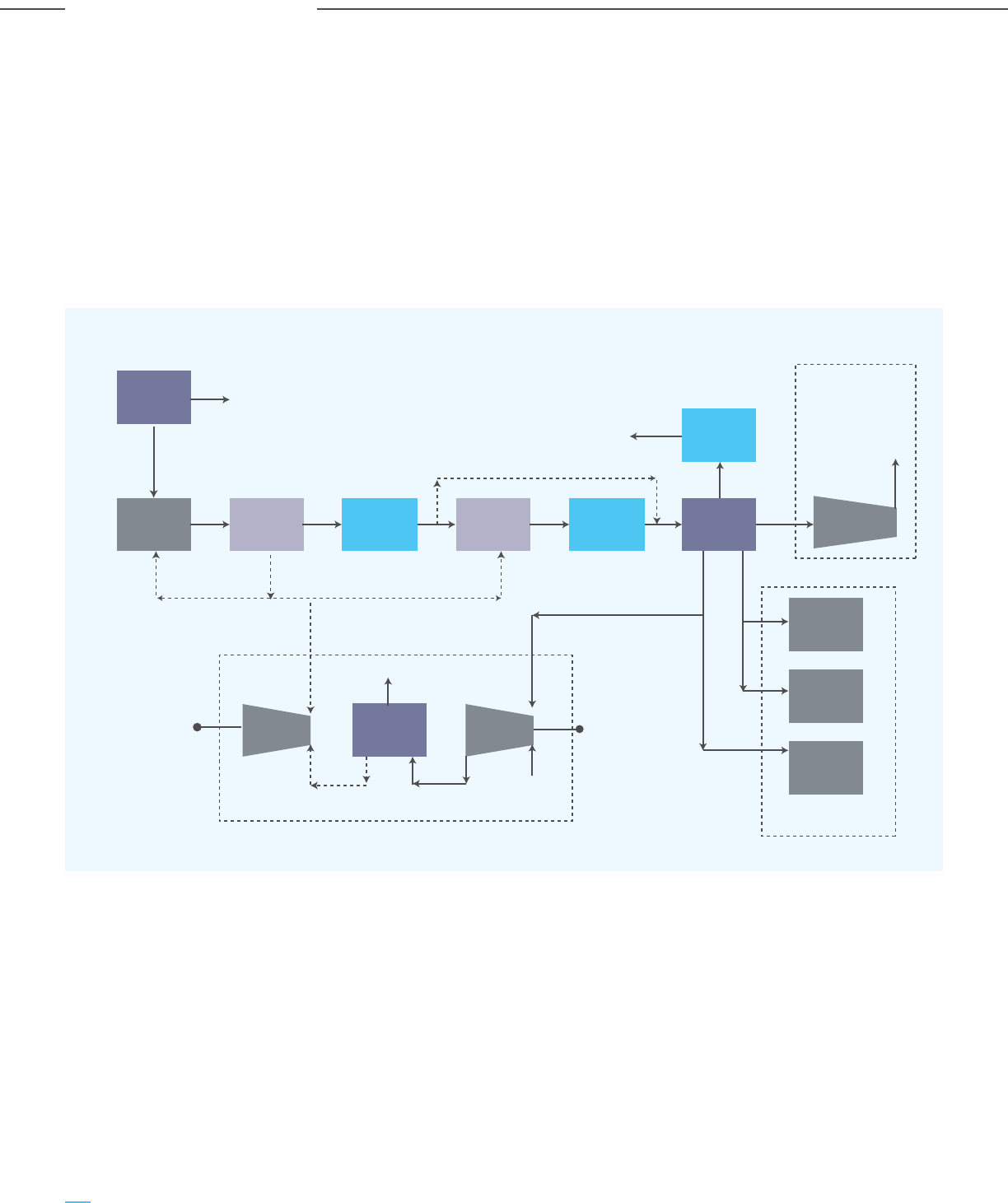
Figure 2-31: A Typical Coal Gasification Based Ecosystem
2.2.6.3 CO
2
Emission from the Gasification Industry
Though the Government of India has envisioned 100
mtpa of coal gasification by 2030, actual
implementation may be delayed given the progress
of the existing projects and the long gestation period
and uncertainties involving gasification projects. The
CO
2
emissions have been estimated considering the
announced projects, as well as 1 mtpa hydrogen
production from coal gasification. Based on the
values of emission intensities for various end
product through syngas route, the capturable direct
process emissions have been considered. The actual
CO
2
emissions will vary based on the actual
downstream products produced from the syngas.
Excess moisture present in the syngas takes part in
the shift reaction to achieve the required H
2
/CO
composition. The required additional steam is
injected to the reactor.
Acid gas removal: Syngas conditioned in the water
gas shift process contains CO
2
and H
2
S which are
removed in the acid gas removal unit. CO
2
is
captured and sent to the carbon dioxide processing
hub for compression. The H
2
S in the syngas is also
captured and sent to the sulphur recovery unit.
There are multiple commercially proven absorption
processes using both physical and chemical solvents.
However, due to the high concentration of CO
2
at the
inlet of the acid gas removal process, a physical
solvent based acid gas removal system is
generally used.
N
2
to
Ammonia
Plant
O
2
to
Gasifier
Air
Separation
Plant
Gasifier
Heat
Recovery
Water
Gas Shift
H
2
/CO : 2.3
H
2
Rich
Gas
Electric
Power
Air
Steam
46% gas by-pass for Methanol
and IGCC Plant
Sulphur
H
2
S Rich
Gas
CO
2
TO
EOR
Field
Carbon
Processing
Hub
Chemical Block
IGCC Block
Steam
Flue
Electric
Power
CO
2
Capture
Ammonia
Plant
Hydrogen
Plant
Methanol
Plant
Heat
Recovery
Steam
Turbine
Gas
Turbine
CO
2
Compression
Sulphur
Recovery
Syngas
Cooling
Particulate
Removal
64
Carbon Capture Utilization and Storage (CCUS) –
Policy Framework and Deployment Mechanism in India
Carbon Capture Utilization and Storage (CCUS) –
Policy Framework and Deployment Mechanism in India
Analysis of Sector-wise CO
2
Emissions

Table 2-19: Sector-wise CO
2
Emissions and Interventions Required
2.3 Key Interventions Required
The estimated CO
2
emissions from key sectors of the Indian economy requiring CCUS interventions are
tabulated below:
Thermal power
generation
Even with RE growth, coal-based power
will continue to meet more than 50% of
electricity demand. As the largest emitter
of CO
2
, CCUS of the power sector is
essential for meaningful decarbonization
and ensuring energy security in India
Establish CCUS clusters in
key identified districts
1,004 1,210
Steel
Future steel growth is largely based on
the BF-BOF route, where use of fossil
fuels is hard to replace. CCUS is
necessary for sustainability and also
ensures export competitiveness
Establish CCUS for
Integrated Steel Plants,
particularly in Eastern India
240 450
Cement
Another major CO
2
emitter, where fossil
fuels are difficult to replace. Utilization of
CO
2
in aggregates has synergies with the
cement business
Establish CCUS clusters in
key identified areas/districts
196 325
Oil & gas upstream,
refineries &
chemicals
Hard to abate sector. CCUS essential for
the sustainability of the sector; carbon
capture inbuilt in many of the processes
Decarbonize key applications
like urea, olefins, syngas
from petcoke
125 177
Hydrogen
Blue hydrogen is key to the hydrogen
economy of the future. Carbon capture is
unbuilt in the H
2
production process
Establish pathways for CO
2
utilization and storage
56 102
Coal gasification
Sunrise sector - key to materials and
energy security of India, based on India’s
rich endowments of coal
Establish pathways for CO
2
utilization and storage
- 27
Total 1621 2291
Products Emission Intensity, Expected production CO
2
emission projection
TCO
2
/TProduct 2030, mtpa in 2030, mtpa
Hydrogen 13 - 15 1 14.0
Methanol 2 – 2.7 2 5.0
Ammonia 3 - 3.5 1.4 4.6
Urea 1.5 - 1.7 2 3.2
Total 27
Table 2-18: Total CO
2
Emission from Coal Gasification
Sector Rationale for CCUS Key interventions
required
2020 2030
Estimated CO
2
emissions (in mtpa)
65
Carbon Capture Utilization and Storage (CCUS) –
Policy Framework and Deployment Mechanism in India
Carbon Capture Utilization and Storage (CCUS) –
Policy Framework and Deployment Mechanism in India
Analysis of Sector-wise CO
2
Emissions

The categorization of emissions depending on CO
2
concentration, stream, pressure, synergy with
existing operations, as well as CO
2
emission
baselining is an immediate requirement for the
development of carbon capture projects in India.
Capturing from high concentration CO
2
sources
(more than 30%) like HGU tail gas, gasification, etc.
will reduce the CO
2
footprint with a low to moderate
cost impact; however, the capturable CO
2
volume is
limited to 100-150 mtpa i.e., 4 to 6% only of overall
CO
2
emissions. So, it is important to prioritize carbon
capture demonstration projects for high CO
2
concentration and low to medium volume sources.
Once technologies, as well as the disposition
strategy, are finalized and demonstrated at a certain
scale, carbon capture for low concentration and high
volume sources such as power plants, steel &
cement plants can be gradually taken up. However,
the CO
2
volume for power and steel plants is often
more than 5 mtpa, which is significantly higher than
any other industry. So, it will be advantageous to
develop CCU cluster infrastructure based on
large-scale power or steel projects as anchor
projects, which will lower the CCUS infrastructure
costs for small and medium scale CO
2
emitters and
enable them to adopt carbon capture projects.
66
Carbon Capture Utilization and Storage (CCUS) –
Policy Framework and Deployment Mechanism in India
Carbon Capture Utilization and Storage (CCUS) –
Policy Framework and Deployment Mechanism in India
Analysis of Sector-wise CO
2
Emissions
Chapter 3
Overview of CO
2
Capture & Utilization
Technologies
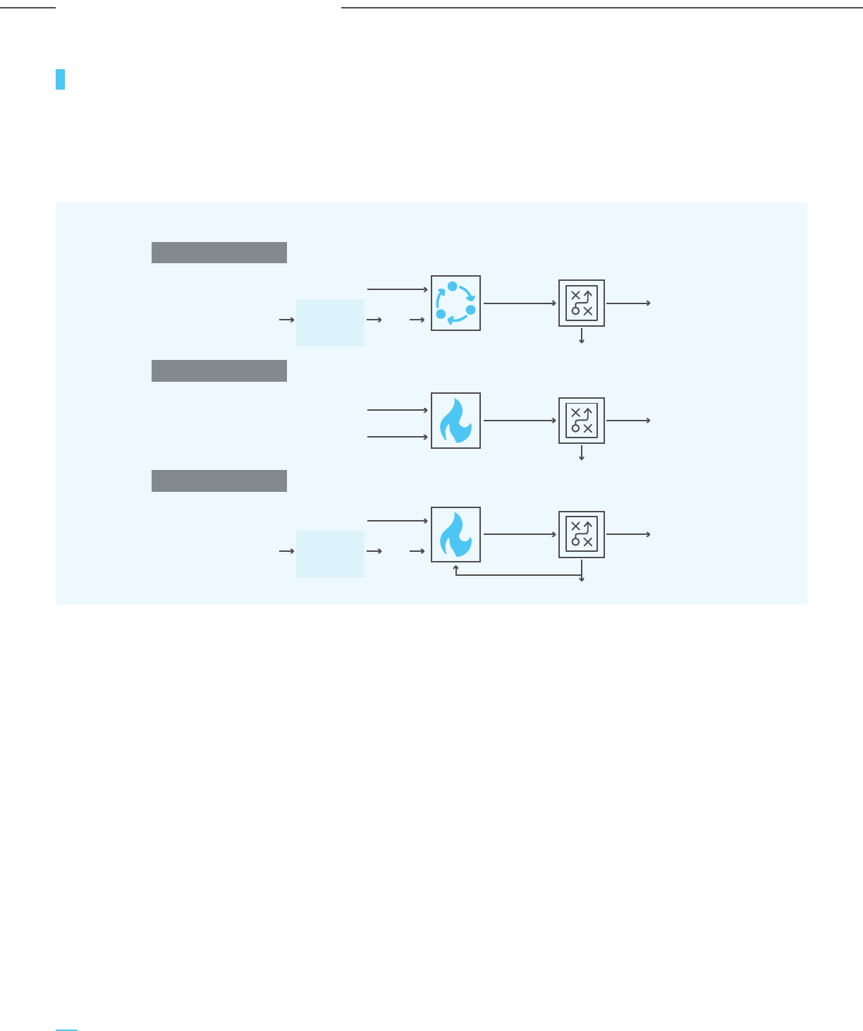
3.1 Introduction to Carbon Capture Technologies
CO
2
capture technologies separate carbon dioxide from
gas streams that are released from industrial processes
such as power plants, chemical production, cement
production or steel making. There are three different
broad categories of technologies for capturing CO
2
:
post-combustion capture, pre-combustion and oxy-fuel
combustion. The operating principles of each is
depicted in Figure 3-1.
(i) Post-combustion technologies: CO
2
is separated
from the flue gas after combustion. Fossil fuels
like coal, oil, NG etc., are burnt in the presence of
air; hence the flue gas is rich in N
2
, and the CO
2
percentage typically varies between 3% to 15%.
Since the partial pressure of CO
2
in the flue gas is
quite low, very high-volume chemical solvent
(amine) circulation is required for CO
2
capture,
making post-combustion technologies energy and
cost-intensive.
(ii) Pre-combustion technologies: they involve
removing CO
2
through the upstream treatment of
fossil fuels prior to combustion. The major
difference between pre-combustion and
post-combustion is that the former is favoured in
cases where the gas stream has a higher partial
pressure of CO
2
, such as in gasification of fossil
fuels, NG based H
2
production or sour gas
processing. Since no chemical bonds need to be
broken for solvent regeneration, the thermal
energy penalty is much lower.
The regeneration of the physical solvent is
primarily achieved by reducing pressure.
(iii) Oxy-fuel combustion technologies: While
post-combustion and pre-combustion carbon
capture technologies have been commercially
established, oxy-fuel combustion technologies are
still in the developmental stage. Oxy-fuel
combustion represents an emerging novel
approach to near zero-emission. It is accomplished
by burning the fuel in pure oxygen (O
2
) instead of
air (O
2
and N
2
). The flue gas stream would be
primarily composed of water and CO
2
, rather than
N
2
. High purity CO
2
can be recovered by the
condensation of water.
Direct Air Capture (DAC): DAC directly captures
dilute CO
2
(at 415 ppm) from the air, and may also
emerge as a form of carbon capture that has wide
applicability, as it is independent of the source and
concentration of the emission stream. However, DAC
is still in early stages and the economics and scale of
operations are yet to be established.
Figure 3-1: Scheme of Post-combustion, Pre-combustion & Oxy-fuel combustion
Pre-Combustion1
Post-Combustion2
Oxy-Combustion3
SynGas for
DR Plant
Methanol,
Power, etc.
N
2
/
Impurities
Air O
2
Fuel
Fuel
Air
Partial Oxidation
CO
2
capture
CO
2
capture
CO
2
CO
2
Air
Separation
Plant
Syn Gas
CO
2
(>25%)
Flue Gas
CO
2
(3-15%)
Combustion
H
2
O &
Impurities
Air O
2
Fuel
Combustion
CO
2
capture
CO
2
CO
2
Air
Separation
Plant
Flue Gas
CO
2
(>90%)
Removing
CO
2
prior to
their
combustion
Removing
CO
2
after
combustion
Removing
CO
2
after
combustion in
controlled
environment
68
Carbon Capture Utilization and Storage (CCUS) –
Policy Framework and Deployment Mechanism in India
Carbon Capture Utilization and Storage (CCUS) –
Policy Framework and Deployment Mechanism in India
Overview of CO
2
Capture & Utilization Technologies

3.2 Mature and Commercially Proven CO
2
Capture Technologies
The mature and commercially proven CO
2
capture
technologies can be broadly classified into three
groups, as shown below. Additionally, there are
membrane, microbial and algae-based CO
2
capture technologies, but these are at the
developmental stage.
i) Solvent-based absorption
a) Physical solvent based absorption
b) Chemical solvent based absorption
ii) Adsorption
iii) Cryogenic separation
Brief descriptions of the aforementioned commercially proven and matured carbon capture technologies are provided.
Figure 3-2: Simplified Representation of CO
2
Capture Technologies
Figure 3-2: Simplified Representation of CO
2
Capture Technologies
Physical solvent based
Feed
Gas
Other
components
CO
2
Physical
Solvent
Chemical solvent based
(i) Solvent based absorption
(ii) Adsorption (iii) Cryogenic separation
Feed
Gas
Feed
Gas
Other
components
Other
components
CO
2
CO
2
Adsorbent
CO
2
Capture
Chemical
Water
(Base solvent)
Feed
Gas
Other
components
A simplified schematic depiction of these matured technologies is shown in Figure 3-2.
69
Carbon Capture Utilization and Storage (CCUS) –
Policy Framework and Deployment Mechanism in India
Carbon Capture Utilization and Storage (CCUS) –
Policy Framework and Deployment Mechanism in India
Overview of CO
2
Capture & Utilization Technologies
Figure 3-4: Schematic Representation of
CO
2
Absorption Capacity of Chemical and
Physical Solvents as a Function of
the Partial Pressure of CO
2
3.2.1 Solvent-Based Absorption
Solvent-based CO
2
capture processes have been used for
over half a century for processing natural (sour) gas,
combustion flue gas and Fischer-Tropsch (FT) synthesis
products. The fundamental principle on which
solvent-based CO
2
capture technologies work is ‘selective
absorption’ of CO
2
over the other gaseous constituents.
The working principle of solvent-based CO
2
capture is
depicted in a schematic flow diagram in Figure 3-3.
While the CO
2
present in the feed/process gas is first
selectively absorbed in an absorber using a solvent
(physical or chemical), the CO
2
lean gas exits the
absorber. Next, the CO
2
rich solvent is sent to a
stripper-type configuration where the CO
2
is released
from the solvent and the lean solvent is regenerated for
reuse. The CO
2
rich stream needs to be purified,
dehydrated, and compressed to raise the pressure to the
required level: supercritical CO
2
for pipeline
transportation or liquefied CO
2
for ship or road
transportation. Supercritical CO
2
can be obtained at
pressures of >74 bar(a) at ambient temperature, whereas
liquefied CO
2
can be obtained at pressures of 6-7 bar(a) at
a temperature of about -50 °C. In the case of pipeline
transportation to oilfields for EOR, the exit pressure at
the carbon capture complex is determined based on the
transportation distance and miscibility pressure
requirements in the oil reservoir.
The solvent-based CO
2
capture technologies are
distinguished based on whether CO
2
reacts with the
solvent chemically (chemical absorption) or dissolved
physically (physical absorption). A schematic depiction of
the relationship between the CO
2
absorption capacities of
chemical and physical solvents (known as ‘solvent
loading’) and partial pressure of CO
2
in the gas stream is
provided in Figure 3-4.
Figure 3-3: Schematic Representation of Working Principle of Solvent-Based CO
2
Capture
Physical solvent
Chemical solvent
Partial pressure of CO
2
CO
2
Absorption Capacity /
Solvent Loading
Favors Physical solventFavors Chemical solvent
CO
2
lean gas
CO
2
CO
2
lean solvent
CO
2
rich solvent
Reboiler
Compressor
EOR / F&B / Storage
Feed gas
Absorber
Stripper
70
Carbon Capture Utilization and Storage (CCUS) –
Policy Framework and Deployment Mechanism in India
Carbon Capture Utilization and Storage (CCUS) –
Policy Framework and Deployment Mechanism in India
Overview of CO
2
Capture & Utilization Technologies
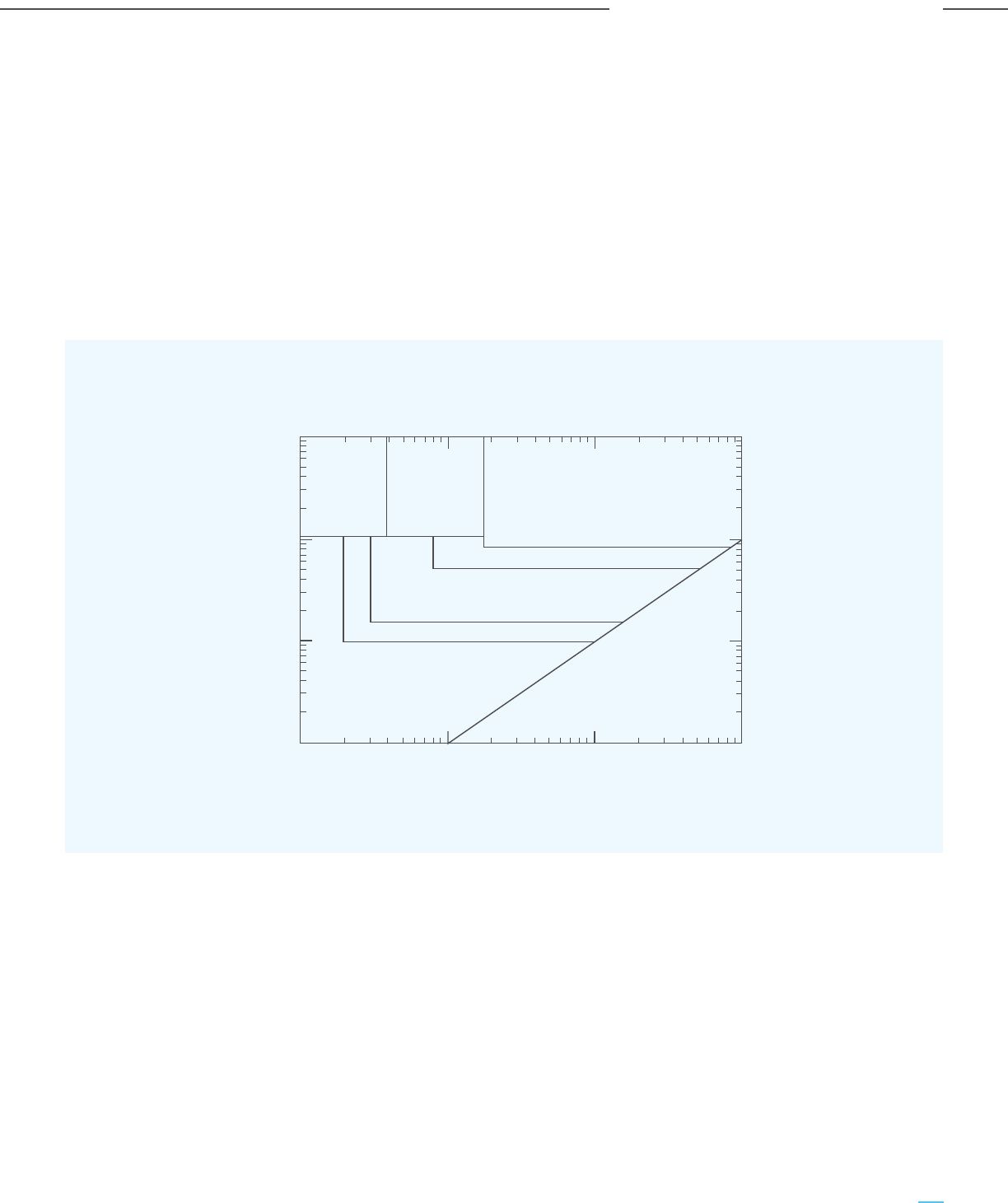
Chemical absorption based CO
2
capture is better
suited for gas streams having a low concentration and
partial pressure of CO
2
due to the high chemical
affinity of CO
2
to amine-/carbonate-based chemical
solvents as well as faster rate kinetics. While the
chemical solvents can achieve high absorption
capacity at low partial pressures of CO
2
, a
non-reactive or physical solvent performs well at
higher partial pressures of CO
2
. As shown in Figure
3-4, the solubility curve for a physical solvent typically
follows Henry’s law, i.e., a linear relationship with the
partial pressure of CO
2
.
A chart depicting the operating ranges of various
solvents for CO
2
capture is shown in Figure 3-5 and
forms the basis for selecting suitable CO
2
solvents.
The low CO
2
partial pressures in the flue gas of
coal-fired power plants make amine-based chemical
absorption the preferred technique. However,
relatively higher gas stream pressure and CO
2
concentration, such as in the syngas of gasifiers
and SMRs make physical absorption-based capture
more suitable.
3.2.1.1 Chemical Solvent-Based Absorption
A basic flow diagram for a chemical solvent-based CO
2
capture is depicted in Figure 3-6. The chemical
reaction between CO
2
and the chemical solvent is an
exothermic reaction and hence favoured at lower
temperatures. Hence it is necessary to pre-cool the
feed gas. During the cooling of the feed gas, water
condenses out of the wet gas.
Figure 3-5: Operating Regimes of Various Solvents for CO
2
Capture
Physical solvent,
hybrid, or hot
potassium
carbonate
Physical solvent
Hybrid
10
3
10
2
10
1
10
0
10
-1
10
0
10
1
10
2
Amine
Partial pressure of acid gas in feed, psia
Activated hot potassium carbonate or amine
Physical solvent or activated hot potassium carbonate
Partial pressure of acid gas in product, psia
Line of equal inlet and outlet pressures
Activated hot potassium carbonate
or inhibited concentrated amine
Source: NETL, US Department of Energy (DOE)
71
Carbon Capture Utilization and Storage (CCUS) –
Policy Framework and Deployment Mechanism in India
Carbon Capture Utilization and Storage (CCUS) –
Policy Framework and Deployment Mechanism in India
Overview of CO
2
Capture & Utilization Technologies
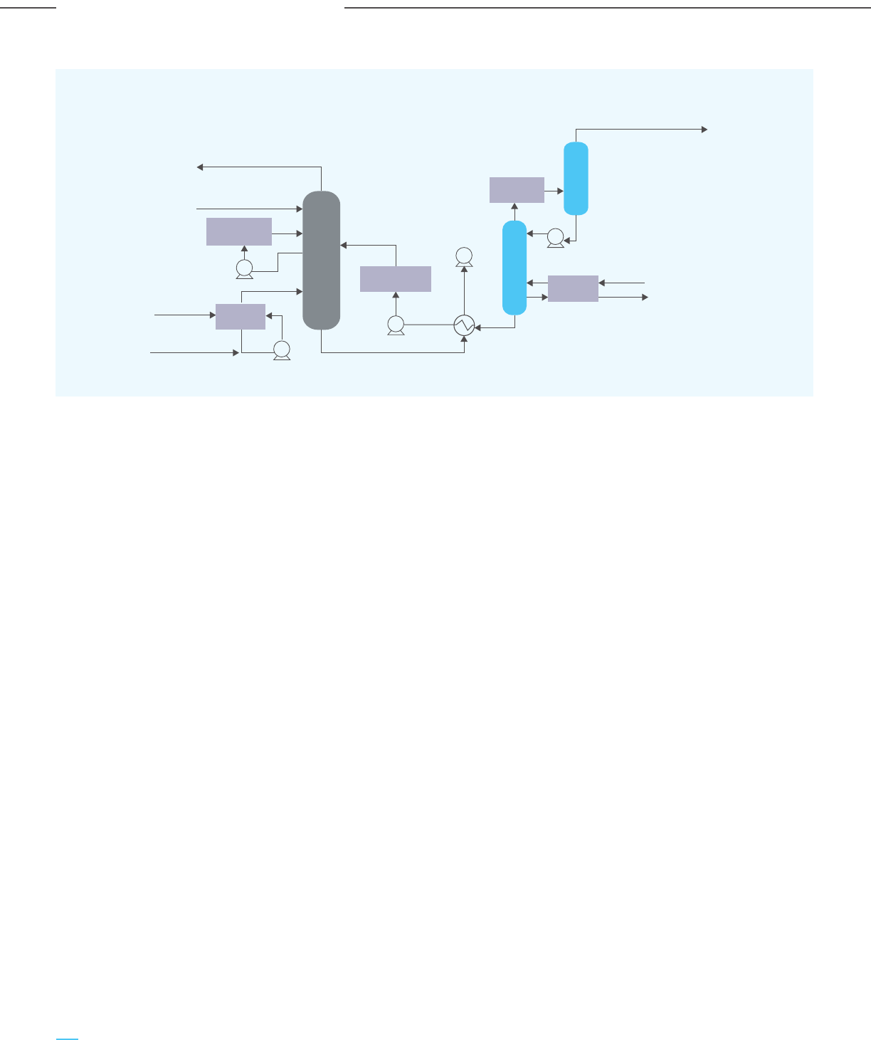
The cooled gas stream reacts with the amine-based
solvent at 40-60°C via a countercurrent flow reaction
within the absorber column, resulting in:
a) CO
2
free gas stream; and
b) Solvent with chemically bound CO
2
Multiple stages of structured packing in the absorber
columns maximize the contacting surface area and
mass transfer rate of CO
2
in the solvent during the
countercurrent flow. While the CO
2
depleted gas
stream leaves the absorber from its top stage, the CO
2
rich solvent stream exits the absorber column from its
bottom stage, and is pumped to the stripper, where
the application of higher temperatures (100-140°C)
results in regeneration of the solvent by breaking the
chemical bonds between CO
2
and the chemical
solvent. The heat required for the regeneration of the
solvent is provided by a reboiler, supplied with steam
extracted from captive CHPs/CGPs. Such a heat and
strip operation for the regeneration of the solvent
leads to a high thermal energy penalty. Depending on
the solvent used and system configuration, the steam
consumption for solvent regeneration can range from
1.1 to 1.5 t/tCO
2
.
While the dense CO
2
stream exits the stripper from its
top stage, the CO
2
lean solution is cooled and
recirculated to the absorber. Typically, the absorber and
stripper’s operating pressures for chemical
solvent-based capture are low, ranging from 1 – 4 bar(a).
The primary characteristics of a solvent that need to be
analyzed to determine its efficacy are as follows:
a) Rate kinetics: Faster rates of reaction between
the solvent and CO
2
ensure better mass transfer
performance at the gas-liquid interface, thus
facilitating a smaller absorber volume and a lower
cost of capture.
b) CO
2
carrying capacity: A higher CO
2
carrying
capacity of the solvent reduces the regeneration
load, auxiliary unit costs and energy
requirements.
c) Reaction enthalpy: A lower enthalpy for the
reaction between the solvent and CO
2
transpires
into lower energy requirements to break the
solvent-CO
2
bond during desorption.
d) Water content: A decrease in water content in
the solvent (aqueous solution) decreases the
energy loss associated with vaporizing water
(during CO
2
stripping at high temperatures) and
increases the CO
2
carrying capacity of the solvent.
e) Other desirable characteristics of the solvent:
- Low CO
2
equilibrium backpressures at
absorption conditions
- Easy reversible reactions at regeneration
temperatures
- Low volatility of the solvent
- High resistance of solvent to oxidative and
thermal degradation
Figure 3-6: Typical Flow Diagram of a Chemical Solvent Based CO
2
Capture
Flue gas to stack
>95% pure CO
2
to compression (2 bar)
90% captured
Lean solvent
2.1 bar
115
0
C
23 bar
~130
0
C
saturated
Water wash
LP steam
Condensate
Flue gas
Water make-up Rich solvent
Absorber tower (40
0
C)
Stripper tower
Reflux drum
Wash water
cooler
Lean solvent
cooler
Reflux
condenser
Solvent
reboiler
Flue gas
cooler
72
Carbon Capture Utilization and Storage (CCUS) –
Policy Framework and Deployment Mechanism in India
Carbon Capture Utilization and Storage (CCUS) –
Policy Framework and Deployment Mechanism in India
Overview of CO
2
Capture & Utilization Technologies
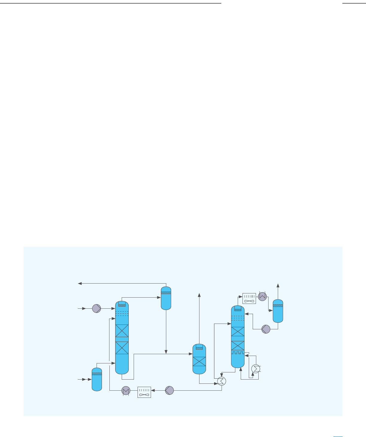
A multitude of chemical solvents have shown varying
degrees of success, including amine-based (primary/
secondary/tertiary/hindered), non-aqueous solvent
(NAS), carbonate-based and phase change. While
primary and secondary amines (such as MEA, DGA,
AEE, DEA) have higher reaction rates and lower CO
2
carrying capacities, tertiary, and polyamines (such as
MDEA and piperazine) have lower reaction kinetics and
higher CO
2
carrying capacities. Due to competing
characteristics, often blends of varying solvent
compositions are used to exploit high reaction rates
and CO
2
carrying capacity along with lower
regeneration loads. Specifically, for MEA based
systems, the steam (LP steam at ~3 bar(a)) energy
requirement for solvent regeneration can range from
3.6 to 7 GJ/t CO
2
, depending on the system
configuration and heat integration. A few of the proven
and emerging solvent-based technologies are
described below:
a) Air Liquide Amine
Both generic and proprietary amine-based
solvents are used in the carbon capture solutions
provided by Air Liquide. A process flow diagram
for carbon capture using Air Liquide’s
amine-based solvent is depicted in Figure 3-7. The
major process units include:
- Pre-cooler: cools the feed gas to the desired
temperature
- Absorber: CO
2
is absorbed in the solvent
through a chemical reaction, facilitated by the
countercurrent flow of the solvent and the
feed gas
- Regenerator: recovers the solvent by CO
2
stripping and recirculates the solvent back to
the absorber
The proprietary OASE
®
(or former aMDEA
®
patented by BASF) amine solvent is also used
apart from generic amine solvents. The main
characteristics of the amine-based BASF OASE
®
solvent are as follows:
- Proprietary composition: most likely consists
of blends of amines (primary/secondary/
tertiary/hindered) and activators
(heterocycles, primary or secondary
alkanolamines, alkylenediamines or
polyamines)
- Solvent stability: Higher stability than MEA
- Energy consumption for CO
2
stripping and
solvent regeneration:
• Significantly lower (2.4 to 2.6 GJ/t CO
2
)
compared to MEA (3.6 to 7 GJ/t CO
2
)
• Similar to piperazine (2.4 to 2.6 GJ/t CO
2
)
Figure 3-7: Process Flow Diagram of Air Liquide’s Amine Based CO
2
Capture
73
Carbon Capture Utilization and Storage (CCUS) –
Policy Framework and Deployment Mechanism in India
Carbon Capture Utilization and Storage (CCUS) –
Policy Framework and Deployment Mechanism in India
Overview of CO
2
Capture & Utilization Technologies
Acid Gas
(to LTGT
®
)
Clean Gas (to DMR)
Demin
Water
Feed
Gas
Absorption RegenerationHP-Flash
Flash Gas
(to CLS)
Source: Air Liquide Technology Handbook 2017
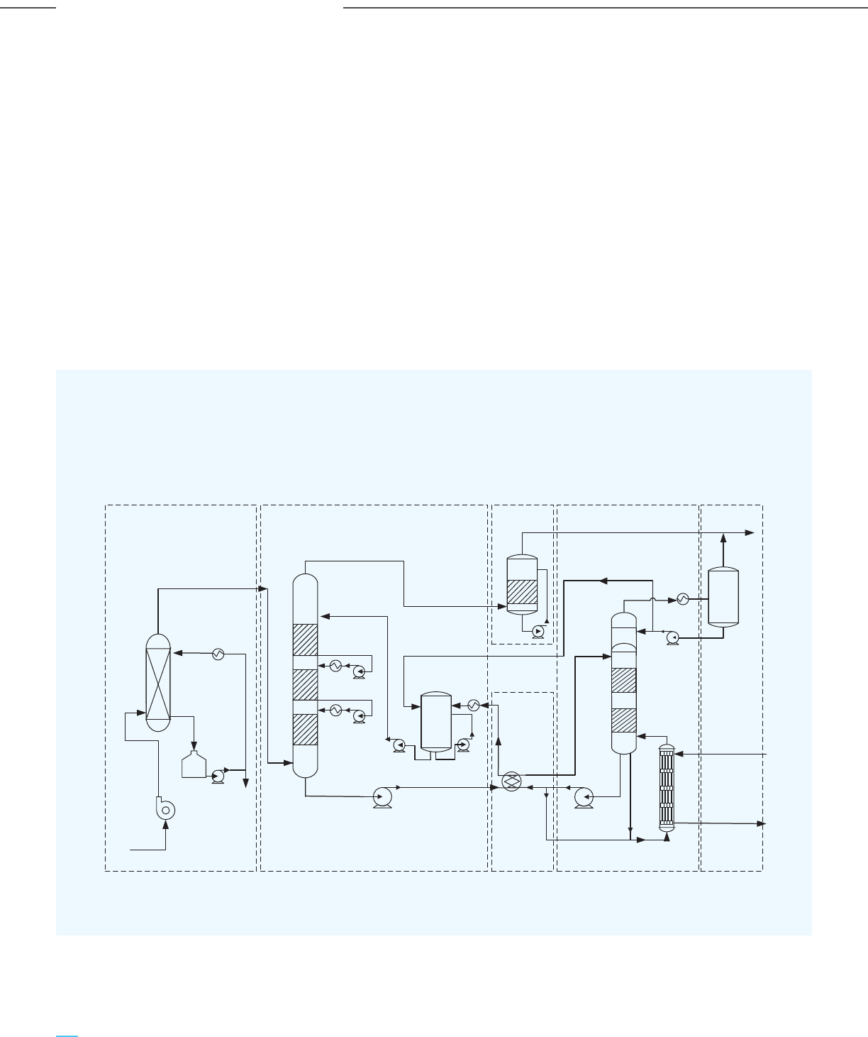
b) ION Clean Energy’s Proprietary Amine-Organic
Solvent
In collaboration with the US DOE NETL, ION Clean
Energy (ION) has developed a proprietary solvent
consisting of a low aqueous amine with an
‘organic liquid’ as the solvent (instead of water).
Due to its lower sensible and latent heats, organic
liquid results in a lower thermal regeneration
energy duty compared to water. Their system
design also includes process modifications such as
cold rich gas bypass and intercooling, which
further lowers the reboiler duty. A process flow
diagram for carbon capture using ION’s
proprietary ICE-21 solvent is depicted in Figure
3-8. The major process units include:
- Pre-scrubber: Removes SOx, other harmful
gases and most of the particles
- Direct contact cooling unit: Controls inlet
flue gas temperature and humidity
- Absorber: A packed column removes CO
2
using the proprietary ICE-21 solvent through a
chemical reaction, facilitated by countercurrent
flow of the solvent and feed gas
- Water wash: Removes solvent droplets and
vapors from the exhaust gas
- Regenerator: Recovers the solvent by CO
2
stripping and recirculates the solvent back to
the absorber
Figure 3-8: Process Flow Diagram of a Pilot Slipstream Test Unit at National Carbon Capture Center,
USA using ION’s Proprietary ICE-21 Solvent for CO
2
Capture
74
Carbon Capture Utilization and Storage (CCUS) –
Policy Framework and Deployment Mechanism in India
Carbon Capture Utilization and Storage (CCUS) –
Policy Framework and Deployment Mechanism in India
Overview of CO
2
Capture & Utilization Technologies
Source: ION Report 2018
Absorber Column
Direct Contact Cooler
Flue Gas From Polisher
Flue Gas
Steam (Sat.)
Condensate
Regeneration
Column &
Reboiler/Thermosiphon
Flue Gas Blower
Clean Flue Gas
Purge
Wash Water
Column
Solvent Surge Tank
Mist Separator
Process
Water Tank
Cool Rich Solvent
Hot Rich
Solvent
Warm Lean
Solvent
Hot Lean
Solvent
Shell & Tube
Thermosiphon Reboiler
Lean
Solvent
Trim
Solvent
Cooler
Economizer
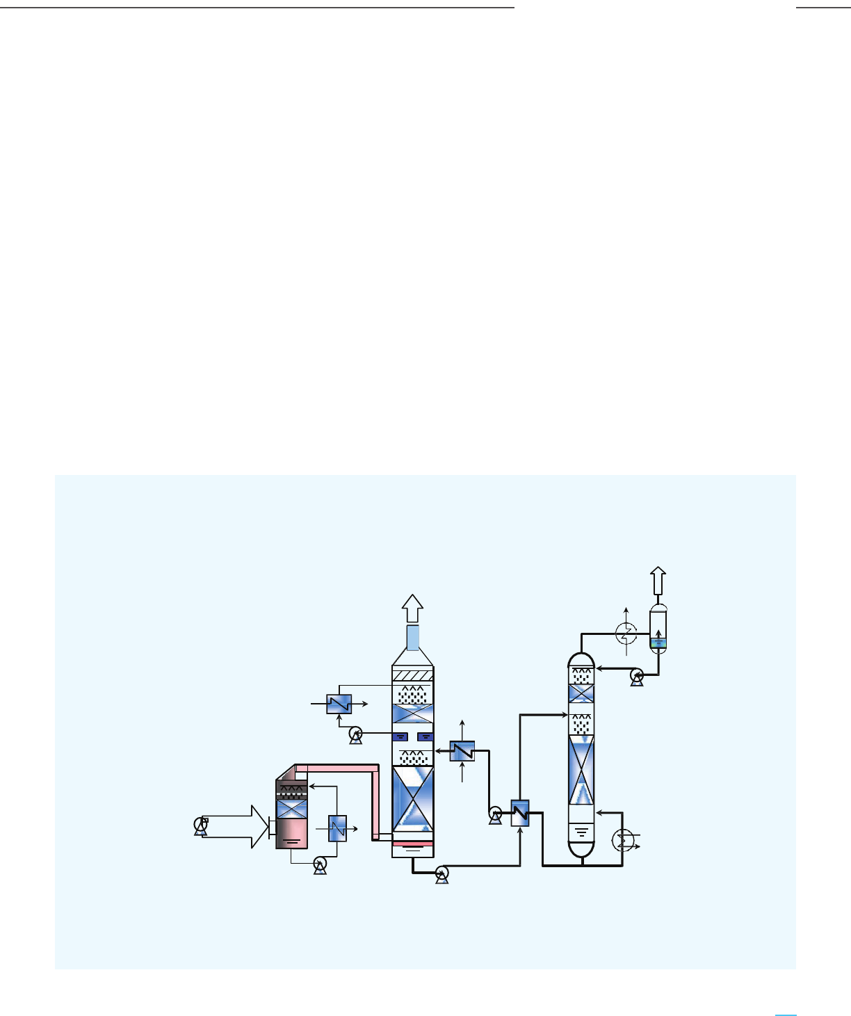
The main characteristics of ION’s proprietary
amine-organic solvent are as follows:
- Proprietary composition (ICE-21 and ICE-31):
Amine with an organic solvent; low water content.
- Solvent stability: Resistant to thermal
degradation with low heat stable salt buildup on
exposure to SOx and NOx
- Energy consumption for CO
2
stripping and
solvent regeneration:
• Significantly lower (1.6 to 2.5 GJ/t CO
2
)
compared to MEA (3.6 to 7 GJ/t CO
2
)
• Solvent regeneration in flash vessels
instead of conventional packed bed
stripper columns and reboilers lowers
capital costs
- Solvent recirculation rate: ~30% lower than
MEA for 90% CO
2
capture; lowers capital costs of
the pumps, heat exchangers and flash vessels
c) Kansai Mitsubishi Carbon Dioxide Recovery
(KM CDR
TM
)’s Proprietary Amine solvent
The advanced amine-based absorption technology
named Kansai Mitsubishi Carbon Dioxide
Recovery (KM CDR
TM
) was jointly developed by
Mitsubishi Heavy Industries Ltd. (MHI) & Kansai
Electric Power Co. Inc. The KM CDR process has
historically used the proprietary solvent named
the KS-1
TM
solvent, with the potential to capture
over 90% of the CO
2
from a flue gas stream and
generate CO
2
with over 99.9% purity. The KS-1
TM
solvent is an advanced sterically hindered amine.
The development of a new solvent has improved
the original KM-CDR process: KS-21
TM
. A process
flow diagram for carbon capture using KM CDR’s
proprietary KS-1
TM
solvent is depicted in
Figure 3-9.
Figure 3-9: Process Flow Diagram of KM CDR CO
2
Capture using Proprietary KS-1 Solvent
75
Carbon Capture Utilization and Storage (CCUS) –
Policy Framework and Deployment Mechanism in India
Carbon Capture Utilization and Storage (CCUS) –
Policy Framework and Deployment Mechanism in India
Overview of CO
2
Capture & Utilization Technologies
Source: US DOE NETL Compendium of Carbon Capture Technology 2020
Flue Gas
Outlet
CO
2
CO
2
Condenser
REGENERATOR
ABSORBER
C.W.
C.W.
C.W.
Flue Gas
Flue Gas
Quencher
Reboiler
Steam
Purity: 99.9%
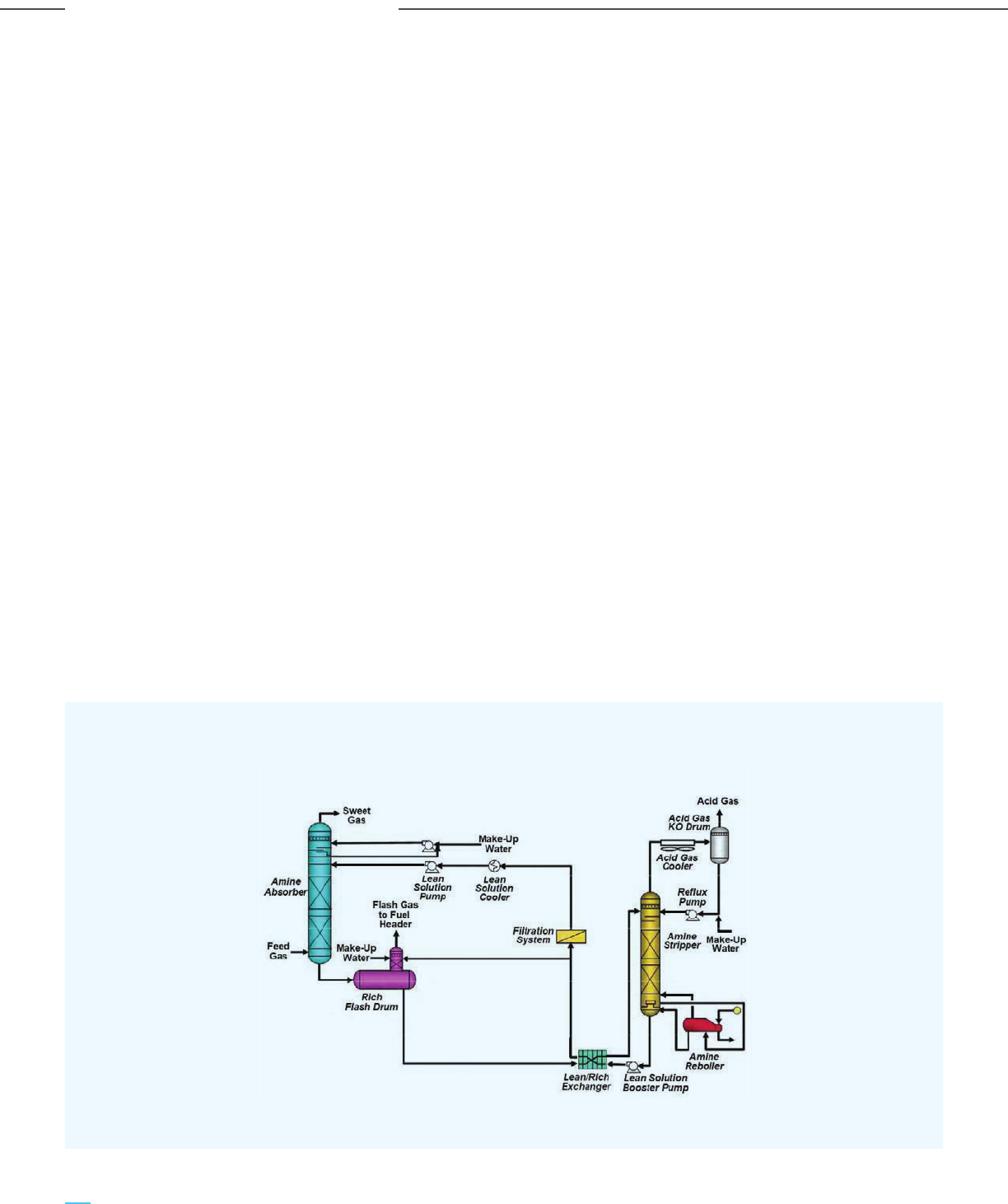
The major process units include:
- Flue gas pretreatment: Cools the flue gas to
the desired process temperature and also
enables trim acid gas removal along with gas
scrubbing to remove contaminants in a deep
polishing scrubber
- Absorber: CO
2
is absorbed in the proprietary
KS-1
TM
solvent through a chemical reaction,
facilitated by the countercurrent flow of the
solvent and the feed gas
- Regenerator: Recovers the KS-1
TM
solvent
by CO
2
stripping and recirculates the solvent
back to the absorber
The main characteristics of KM CDR KS-21
TM
solvent
are as follows:
- Proprietary composition: sterically hindered
amine
- Recovery of 95% of the CO
2
from the flue gas
- Low solvent volatility, which reduces the height of
the water wash section of the CO
2
absorber
- Improved thermal stability of the solvent
allows the regenerator to operate at a higher
pressure and temperature
- Low heat of absorption: allows high circulation
rate and low steam consumption.
- Good resistance to oxidative degeneration
that reduces solvent loss
d) UOP Solvent Systems
UOP has several solvent-based solutions for CO
2
capture, including Amine Guard
TM
FS, Benfield
TM
and SeparALL
TM
. Amongst these, the Amine
Guard
TM
FS is arguably the most widely accepted
technology. It uses the proprietary UCARSOL
TM
chemical solvents (MDEA based), formulated by
The Dow Chemical Company. The solvents have a
high affinity for acid gas components. UOP
Benfield
TM
uses a chemical solvent that is made up
of activated hot potassium carbonate. A process
flow diagram for carbon capture using UOP’s
Amine Guard
TM
FS solvent is depicted in Figure
3-10. The major process units include:
- Absorber: CO
2
absorption in the proprietary
UCARSOL
TM
solvent through a chemical
reaction, facilitated by the countercurrent
flow of the solvent and the feed gas
- Regenerator: Recovers the UCARSOL
TM
solvent by CO
2
stripping and recirculates the
solvent back to the absorber
- HP & LP flash columns: Higher pressure
operations allow exploitation of flash
regeneration
Figure 3-10: Process Flow Diagram of the Amine Guard
TM
FS CO
2
Capture
using Proprietary UCARSOL
TM
Solvent
76
Carbon Capture Utilization and Storage (CCUS) –
Policy Framework and Deployment Mechanism in India
Carbon Capture Utilization and Storage (CCUS) –
Policy Framework and Deployment Mechanism in India
Overview of CO
2
Capture & Utilization Technologies
Source: UOP Technical paper
Apart from the conventional flow scheme, other flow
schemes are also possible depending on the feed gas
characteristics and final product specifications, as
depicted in Table 3-1.
Table 3-1: Comparison of Various Flow Schemes of UOP Amine Guard
TM
FS Technology
Scheme Configuration Feed gas Desired product Solvent Cons. Reboiler duty,
quality quality MBTU/lb CO
2
removed
Conventional
Low acid gas (<7%)Absorber + thermal
regeneration
50 ppmv
CO
2
Lowest 45-60
Flash only
Very high acid
gas (>12%)
Absorber + flash
column
>2% CO
2
Low 8-10
1-stage
High acid gas
(7-12%)
Absorber + flash
column + thermal
regeneration
50-1000
ppmv CO
2
Higher than
flash only
32-40
2-stage
Very high acid
gas (>12%)
1-stage + semi-lean
solvent stream
500 ppmv
CO
2
Highest 12-18
The main characteristics of the proprietary
UCARSOL
TM
solvent are as follows:
- Proprietary composition: MDEA based
solvent with low activator concentrations;
solvent formulation can be tailored to achieve
specific levels of CO
2
absorption. Amine
Guard
TM
II uses inhibitors to increase the
alkanolamine strength
- Fast kinetics: Activator accelerates the slow
overall kinetics of the chemical reaction
between CO
2
and MDEA
- Reduced packing height of absorber column:
Use of an activator facilitates reduced
column heights
- High thermal and chemical stability
- Non-corrosive solvent: No corrosion
inhibitors needed
- No foaming problems
77
Carbon Capture Utilization and Storage (CCUS) –
Policy Framework and Deployment Mechanism in India
Carbon Capture Utilization and Storage (CCUS) –
Policy Framework and Deployment Mechanism in India
Overview of CO
2
Capture & Utilization Technologies
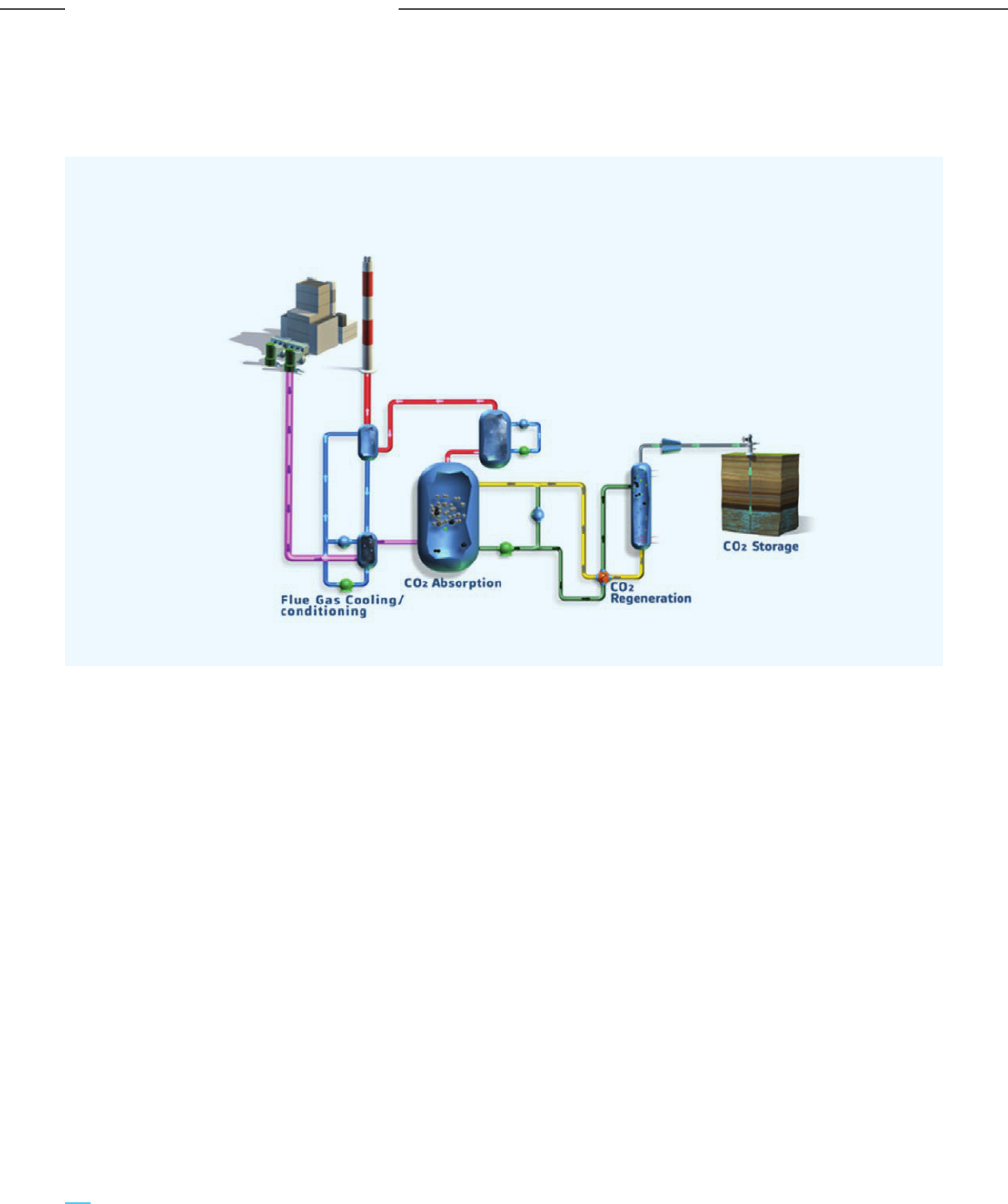
e) Baker Hughes Chilled Ammonia Process (CAP)
A process flow diagram for carbon capture using
the Baker Hughes Chilled Ammonia Process (CAP)
is depicted in Figure 3-11.
Figure 3-11: Process Flow Diagram of Baker Hughes Chilled Ammonia Process (CAP)
using Ammonium Carbonate Solvent
An ammonia-based solvent, ammonium carbonate
solution, is used for the absorption of CO
2
from flue
gas at low temperature in the Chilled Ammonia
Process (CAP). The ammonium carbonate solution
reacts with CO
2
present in the flue gas to form
ammonium bicarbonate. The regeneration of solvent
and release of CO
2
from the solution is facilitated by
raising the temperature in the regenerator.
The major process units of the CAP include:
- Flue gas cooling: Cools the flue gas to the
temperature desired for absorption
- Pretreatment: for removal of NOx, SOx and
other contaminants to acceptable levels
- Absorber: CO
2
is absorbed in the ammonium
carbonate solvent through a series of
chemical reactions.
- Ammonia-based chiller system: Reduces
ammonia volatility.
- Sulfuric acid supply: Enables reduction of
ammonia emissions into the atmosphere to
acceptable levels.
- Stripper: Recovers the solvent by stripping
CO
2
from ammonium bicarbonate solution and
recirculates the solvent back to the absorber.
The stripping operation can take place at
higher pressure as the solvent can tolerate
higher temperatures.
The main characteristics of the process include:
- High purity CO
2
and delivery pressure
- Tolerant to oxygen and flue gas impurities
- No degradation of solvent
- No emission of trace contaminants
- Efficient capture of CO
2
(90%)
- Low-cost, globally available reagent
78
Carbon Capture Utilization and Storage (CCUS) –
Policy Framework and Deployment Mechanism in India
Carbon Capture Utilization and Storage (CCUS) –
Policy Framework and Deployment Mechanism in India
Overview of CO
2
Capture & Utilization Technologies
Source: Baker Hughes
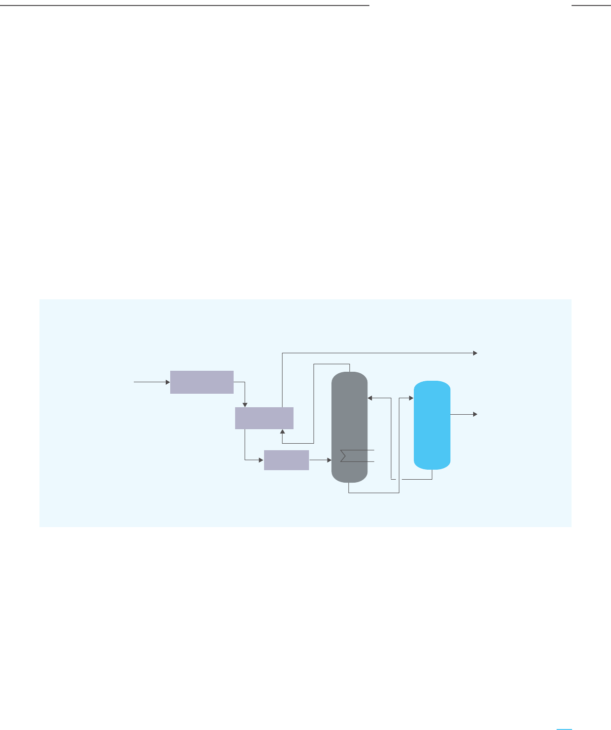
3.2.1.2 Physical Solvent-Based Absorption
The major difference between chemical solvent-based
capture and physical solvent-based capture is that the
latter is favored in cases where the gas stream has a
higher partial pressure of CO
2
, such as in gasification,
sour gas processing or syngas from SMRs. There is no
chemical reaction involved in the capture process as it
is guided purely by physisorption. Since no chemical
bonds need to be broken for solvent regeneration, the
thermal energy penalty is much lower. The
regeneration of the physical solvent is achieved by
reducing pressure. However, the operating
temperatures of physical solvent-based capture
processes are much lower (ranging from -70°C to
+20°C) compared to chemisorption-based capture,
thus necessitating higher power consumption. The two
major commercially available physical
absorption-based technologies are discussed.
a) Rectisol
®
In the Rectisol
®
process, the shifted syngas (after
the WGS stage in the HGU) needs to be cooled
first and then sent to the absorber column. The
physical solvent used for CO
2
absorption is chilled
methanol (at sub-zero temperatures). CO
2
is
stripped from the CO
2
rich solvent in the stripper
and compressed for transportation. The
regenerated solvent is recycled and reused in the
absorption unit. One advantage of this process
route is that water levels in the exit CO
2
rich
stream are very low, thus eliminating the
dehydration facility requirement. The process flow
diagram is depicted in Figure 3-12 below.
b) Selexol
TM
The Selexol
TM
process uses a mixture of dimethyl
ether of polyethylene glycols (DEPG) and has two
variants. The first variant removes all the acid gas
components (H
2
S and CO
2
) in one step; the second
is a dual-stage process where H
2
S is removed first,
followed by CO
2
.
The typical process operating temperature is
between 0-20°C, which saves on the refrigeration
cost compared to the Rectisol® process. The feed
gas is supplied at a pressure of 2-15 MPa with a
CO
2
partial pressure of 0.7-3 MPa. A basic process
flow diagram of the Selexol
TM
process is depicted
in Figure 3-13.
Figure 3-12: Basic Process Flow diagram of the Rectisol
®
Process
Syngas
CO, H
2
H
2
CO
2
Refrigerant
CO shift
conversion
Heat
exchanger
Cooler
Absorber
Flash
regeneration
79
Carbon Capture Utilization and Storage (CCUS) –
Policy Framework and Deployment Mechanism in India
Carbon Capture Utilization and Storage (CCUS) –
Policy Framework and Deployment Mechanism in India
Overview of CO
2
Capture & Utilization Technologies
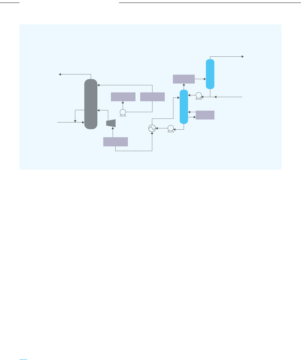
Figure 3-13: Basic Process Flow Diagram of the Selexol
TM
Process
Treated gas
Lean solvent
Flue gas
Heat
exchanger
Rich solvent
Make-up Water
CO
2
to compression
Absorber tower
Stripper tower
Knock-out drum
CO
2
condenser
Reboiler
Lean solvent
filtration
Lean solvent
cooler
Rich solution
flash drum
3.2.2 Adsorption
In the adsorption-based CO
2
capture process, the CO
2
molecules selectively adhere to the surface of the
adsorbent material and form a film, as shown in Figure
3-2 (ii) earlier. This is possible because of the difference in
diffusivities and heat of adsorption values for the feed
gas stream components.
The working principle of adsorption-based CO
2
capture
can be described in three primary steps:
- CO
2
adsorption on the surface of the adsorbent
material
- Diffusion of other gaseous molecules through the
adsorbent material and exit from the system
- CO
2
desorption by either decreasing pressure or
increasing temperature. While the former is known
as Pressure Swing Adsorption (PSA), the latter is
called Temperature Swing Adsorption (TSA)
Since TSA operations involve high temperatures, it
may lead to degradation of the desirable products and
reduce the life of the adsorbent material. Since there
is no need for heating/cooling in the PSA route, the
cycle time is significantly reduced to the order of a
few minutes. Hence, adsorption through the PSA route
is the preferred choice, allowing the economical
removal of a large number of impurities.
The PSA route comprises timed cycles of adsorption,
pressure equalization, depressurization, blowdown,
purge and re-pressurization across multiple fixed
beds. These beds consist of different types of
adsorbent materials, such as activated alumina, silica
gel, activated carbon or molecular sieves. Few
relevant PSA based technologies for carbon capture
are described below:
80
Carbon Capture Utilization and Storage (CCUS) –
Policy Framework and Deployment Mechanism in India
Carbon Capture Utilization and Storage (CCUS) –
Policy Framework and Deployment Mechanism in India
Overview of CO
2
Capture & Utilization Technologies
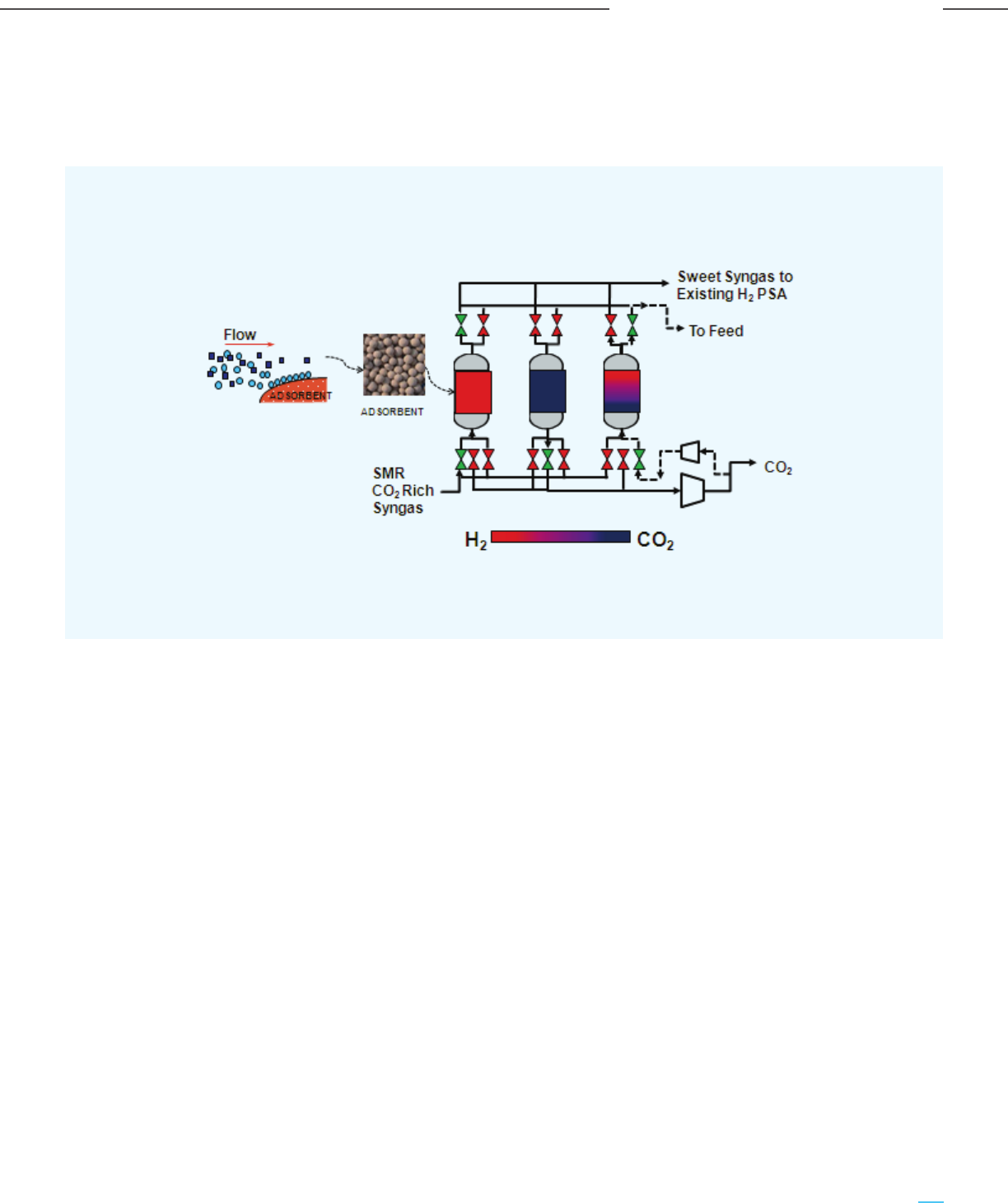
3.2.2.1 Air Products Vacuum Swing Adsorption (VSA)
The process flow diagram of the Air Products’ VSA technology is depicted in Figure 3-14.
Figure 3-14: Basic Process Flow Diagram of Air Products’ VSA Technology
Source: IEAGHG 2018 Report on “The Carbon Capture Project at Air Products’ Port Arthur Hydrogen Production Facility”
The various features and steps of the process are
outlined below:
- The SMR syngas is cooled in the cold process
condensate separator
- VSA vessels (fixed beds) consist of high surface
area adsorbent material, on which the CO
2
molecules are selectively adsorbed
- The SMR syngas at high pressure is sent to one
vessel for adsorption, while the other vessels
undergo low-pressure regeneration
- The H
2
rich sweet syngas (devoid of CO
2
) is sent to
the existing PSAs for purification
- A series of pressure equalizations are performed
in the VSA vessels at reduced pressures before a
vacuum pump removes the CO
2
- The blowdown gas is taken from the intermediate
pressure bed during a ‘rinse step’. This gas is
compressed and fed to a higher pressure bed to
improve the CO
2
recovery
81
Carbon Capture Utilization and Storage (CCUS) –
Policy Framework and Deployment Mechanism in India
Carbon Capture Utilization and Storage (CCUS) –
Policy Framework and Deployment Mechanism in India
Overview of CO
2
Capture & Utilization Technologies
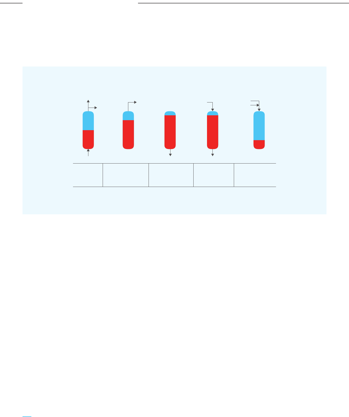
3.2.2.2 UOP Polybed
TM
PSA systems
Typically, a five-step pressure swing cycle is followed
in UOP’s Polybed
TM
PSA systems. The steps are shown
Figure 3-15: Five-step Pressure-swing Cycle of UOP’s Polybed
TM
PSA Systems
- Step 1 (Adsorption): The feed gas (usually flowing
in the upward direction) enters an adsorber vessel
at high pressure. Once the adsorbent material is
saturated, the vessel is taken offline and the feed
is automatically switched to a fresh vessel
- Step 2 (Co-current depressurization): The
adsorbed vessel is co-currently (in the same
direction of feed gas flow) depressurized to
recover the residual product components. This
residual product gas is used internally to
repressurize and purge other adsorbers
- Step 3 (Countercurrent depressurization): Right
after the co-current depressurization step, the
adsorbent is partially regenerated by
counter-currently depressurizing the adsorber to
the tail gas pressure. At the same time, the
impurities are rejected
- Step 4 (Purge): Further regeneration of the
adsorbent is achieved by purging it with a
high-purity stream obtained from Step 2
- Step 5 (Re-pressurization): On repressurizing
(with the gas stream from Step 2 and a slipstream
from the product or the feed), the adsorber
reaches the adsorption pressure and is ready for
the next adsorption step. This marks the
completion of the cycle
3.2.3 Cryogenic Separation
Cryogenic separation for CO
2
capture is similar to the
conventional distillation process, except that it involves
the separation of components from a gaseous mixture
(instead of liquid) based on the difference in their
boiling points. A simple schematic illustration is
provided in Figure 3-2 (iii). The feed gas stream is
cooled to sub-zero temperatures (lower than -50°C) to
separate CO
2
from the other components. Due to the
extreme operating conditions of high pressure and low
temperature, it is an energy intensive process. The
energy consumption can range from 600-660 kWh/t
CO
2
recovered in liquid form. Few relevant cryogenic
separation-based technologies for carbon capture are
described herein.
schematically in Figure 3-15, where red and blue
represent the impurities and the product, respectively.
Product To Next
Vessel
Feed Tail Gas
Purge
From
Product
From Other
Vessel
Tail Gas
Red: impurity | Blue: product
Step 1:
Adsorption
Step 4:
Purge
Step 2:
Co-current
depressurization
Step 3:
Counter current
depressurization
Step 5:
Re-pressurization
Source: UOP White Paper
82
Carbon Capture Utilization and Storage (CCUS) –
Policy Framework and Deployment Mechanism in India
Carbon Capture Utilization and Storage (CCUS) –
Policy Framework and Deployment Mechanism in India
Overview of CO
2
Capture & Utilization Technologies
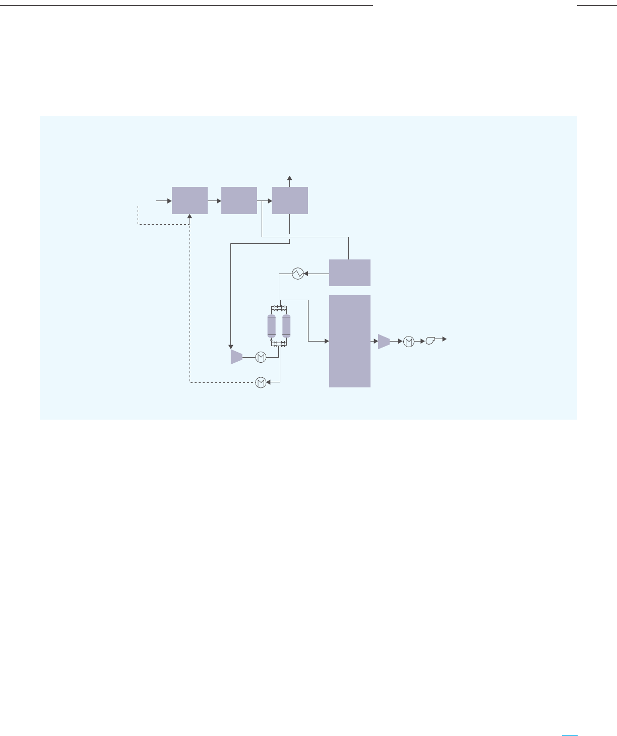
Figure 3-16: Process Flow Diagram of the Cryocap
TM
H
2
Technology
3.2.3.1 Air Liquide’s Cryocap
TM
Technology
The Cryocap
TM
technology for CO
2
capture is based on
the principle of cryogenic separation combined with
Natural
gas
Fuel
Residue
to fuel gas
CO
2
Product
H
2
Product
SMR Shift
Membranes
Cold
Box
H
2
-PSA
membrane separation. The process flow diagram of
the Cryocap
TM
H
2
technology is depicted in Figure 3-16.
The important features of this technology are listed
below:
- A combination of partial condensation and
distillation is utilized for CO
2
separation from the
other components
- The non-condensed gases are recycled through a
membrane system to recover H
2
and CO
2
- Over 98% CO
2
recovery is possible
- Additional (13 to 20%) H
2
production can be
achieved with the same amount of SMR feed i.e.
natural gas. The credit of the additional H
2
/
savings in natural gas consumption for the
production of the same quantity of hydrogen (as
the case may be) reduces the overall cost of
carbon capture
- The residual gas is utilized as a fuel for the
reformer (SMR)
- It is possible to produce food-grade CO
2
by adding
a step of catalytic bed purification to destroy all
the remaining hydrocarbons and alcohols
- Lower area footprint is required compared to
amine-based systems
3.2.3.2 UOP’s Ortloff Dual Refrigerant CO
2
Fractionation (DRCF)
- The Ortloff Dual Refrigerant CO
2
Fractionation
(DRCF) technology is similar to Air Liquide’s
Cryocap
TM
technology. Some of the key features
include:
- Recovery of CO
2
in the liquid state
- Low energy consumption due to liquid state
separation (no need to solidify CO
2
)
- Additional recovery is possible from the residue
gas stream by coupling DRCF with a physical
solvent like Selexol™ or membranes
- Lower area footprint than amine-based systems
83
Carbon Capture Utilization and Storage (CCUS) –
Policy Framework and Deployment Mechanism in India
Carbon Capture Utilization and Storage (CCUS) –
Policy Framework and Deployment Mechanism in India
Overview of CO
2
Capture & Utilization Technologies

3.3 R&D in Direct Air Capture
DAC directly captures dilute CO
2
( 415 ppm) from the
air, and may also emerge as a form of carbon capture,
as it has wide applicability and is independent of the
source and concentration of the emission stream. DAC
is still in its early stages and the economics (present
cost of DAC is estimated to range between US$
400-800/tonne of CO
2
) and scale of operations are
yet to be established. Given the wide applicability of
DAC as also the opportunity to remove CO
2
stock from
the atmosphere, it is important from a policy
perspective to support R&D in DAC technologies.
3.4 Microalgae Based
Carbon Capture
Microalgae cultivation has piqued the curiosity of the
research community for its application in the field of
carbon sequestration and further production of various
value-added products such as renewable biofuels,
bio-fertilizers, bioactive substances, etc. They utilize
the sparsely concentrated CO
2
from the atmosphere
via Carbon Concentrating Mechanism (CCM) thus are
well qualified for CO
2
capture from a more
concentrated stream of flue gas. These can be
cultivated in saline water systems as well and do not
compete with food crops for arable land for cultivation.
Due to the faster growth cycle of these microalgae,
they can typically entrap 10-50 times more CO
2
compared to terrestrial plants. They can also deacidify
the seawater or wastewater used for their cultivation.
Owing to these factors, microalgae have been studied
for carbon capture and sequestration by several
researchers as well as industries around the globe.
The basic philosophy behind the process of carbon
capture by microalgae is the use of CO
2
as a nutrient
for the cultivation of microalgae. The selected strains
of microalgae can be cultivated in ponds or
vertical/horizontal photo-bioreactors. The flue gas
stream after removal of traces of heavy metals and
other harmful components can be mixed in the
ponds/photo-bioreactors, cultivating selected strains
of microalgae. The CO
2
will be absorbed by the
microalgae and the resulting gas will leave the
cultivation system. Selection of appropriate strain of
algae and maintaining its growth condition is critical
to this process of carbon capture.
The technology is in its nascent stages, with a
majority of tests being performed at lab and pilot
scales. The capture rate would vary with the climatic
conditions, location, algae strain, and other relevant
parameters. A demonstration was performed at
NALCO’s coal-based captive power plant facility in
Angul, Odisha in 2017, where algal productivity of 20
tons ac
-1
year
-1
was achieved, leading to a carbon
sequestration capacity of 32 tons ac
-1
year
-1
. A
simulation based study was also carried out for
simulation of algal productivity techno-economic
feasibility study for Odisha Power Generation
Corporation Limited (OPGC)’s coal-based power plant
in Jharsuguda, led by P. Balasubramanian et al. (2019).
The maximum average algal productivity achieved in
the biophysical model on MATLAB was 111.39 Kg ha
-1
d
-1
enabling CO
2
sequestration of 147.03 Kg ha
-1
d
-1
. This
translates to the sequestration figure of 1.32 Kg CO
2
/
Kg algal biomass produced in one hectare in a day.
The maximum growth varied each month with the
highest growth being observed in the month of
February. The techno-economic modelling was
performed in SuperPro Designer. The study revealed
that the production cost came out to be US$
58.41/metric tonne of algal biomass. The algal paste
could further be sold as a fertilizer which would lead
to an evaluated revenue generation. The technology
needs to further develop in both upstream (cultivation
and harvesting) and downstream (value added
products synthesis) stages for commercialization.
84
Carbon Capture Utilization and Storage (CCUS) –
Policy Framework and Deployment Mechanism in India
Carbon Capture Utilization and Storage (CCUS) –
Policy Framework and Deployment Mechanism in India
Overview of CO
2
Capture & Utilization Technologies

Summary of the CO
2
capture technology types and
applicability to carbon capture:
- Chemical solvent-based CO
2
capture
technologies: Preferred when dealing with gas
streams that are lean in CO
2
and have relatively
lower pressures, such as flue gases. The cost and
availability of steam is also a key factor as
regenerating the solvent requires large quantities
of steam.
- Physical solvent-based CO
2
capture
technologies: These work well on gas streams
with relatively higher CO
2
concentration and
pressure.
- Adsorption-based CO
2
capture: They are suitable
for pre-combustion capture, where the gas stream
has high pressure and a high CO
2
concentration.
- Cryogenic CO
2
capture: Preferred in cases where
the cost of power is low. This technology also
provides a unique advantage of generating
additional hydrogen without increasing the
amount of feedstock (natural gas)/ producing the
same quantity of hydrogen with lower natural gas
consumption.
The applicability of the various CO
2
capture
technologies viz., physical solvent, chemical solvent,
adsorption and cryogenic, depends on the project
objectives and the project-specific and gas stream
characteristics, including:
- CO
2
capture volumes targeted/desired
- CO
2
end usages and CO
2
purity required
- Source gas characteristics (CO
2
concentration,
pressure and volumes)
- Availability and cost of utilities such as steam,
power, water, fuel, etc.
- Plot availability and space constraints
3.5 Comparative Analysis of Various CO
2
Capture Technologies
Table 3-2: Comparative Analysis of Various Classes of CO
2
Capture Technologies
Chemical
Solvent
• Chemical reaction between
CO
2
and solvent
• Governed by rate kinetics
& thermodynamics
• High absorption at low
partial pressure of CO
2
• Selective capture and
high purity CO
2
product
High energy (steam)
requirements for
solvent regeneration
• BASF / OASE®
• ICE-21, ICE-31
• KS-1
TM
, KS-21
TM
• UCARSOL
TM
• CAP
Physical
Solvent
• Absorption due to CO
2
solubility in the solvent
• Governed by Henry’s Law
• Suitable for gas streams
with high partial
pressure of CO
2
• Regeneration through
low temperature flashing
or pressure reduction
• High absorption capacity
& lower solvent
recirculation rates
• Low energy efficiency
for low partial
pressure of CO
2
• High compression
requirement for low
pressure feed gas
• H
2
S often absorbed
more effectively than
CO
2
• Rectisol
TM
• Selexol
TM
Adsorption
• Selective adsorption due
to difference in diffusivity
& heat of adsorption
• Governed by pressure
change
• Selective capture
• Can be performed at
normal temperatures
• Batch process
• Complex pressure
balancing
management system
• High electrical energy
consumption
• PSA
• VSA
• TSA
Cryogenic
Separation
• Low-temperature
separation through
liquefaction
• Governed by temperature
change
• Selective capture and
high purity CO
2
• Liquefied CO
2
product
• Food grade CO
2
• Almost no steam
consumption
• Low area footprint
• High energy
requirement
• High operating
pressure
• Cryocap
TM
• Ortloff Dual
Refrigerant CO
2
Fractionation
(DRCF)
Process Working Principle Advantages Limitations Examples
85
Carbon Capture Utilization and Storage (CCUS) –
Policy Framework and Deployment Mechanism in India
Carbon Capture Utilization and Storage (CCUS) –
Policy Framework and Deployment Mechanism in India
Overview of CO
2
Capture & Utilization Technologies
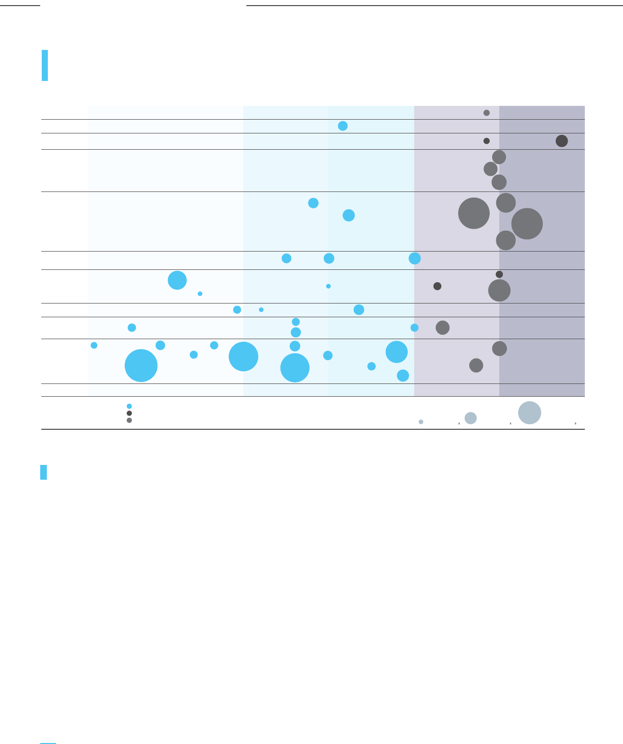
3.7 CO
2
Capture Cost Across Processes/Industries
The capital cost and cash costs of carbon capture
depends on CO
2
source characteristics (pressure &
CO
2
concentration), capture technology, power &
steam sourcing costs. Given the trajectory of growing
CO
2
emissions in India and the nascent stage of CCUS
in India, it is envisioned that by 2030, at least one
demonstration scale project carbon capture should be
implemented in each of the identified sectors.
The estimated CO
2
capture cost curve for demo scale
carbon capture projects in each sector is shown in
Figure 3-18. This curve is based on the CO
2
capture
potential in each sector, and the typical costs for
carbon capture projects, considering Indian costs and
conditions. Since the CO
2
source characteristics are
generally process-driven, the typical capture cost of
CO
2
(including cash costs & capital charges) has been
estimated for a reference plant size for each sector.
CO
2
delivery from the plant gate has been assumed at
100 bar (a) for each case.
CO
2
capture cost is the lowest for the gasification
process, as carbon capture is already integrated
within the process. So, an additional cost of around
Rs. 400/tonne of CO
2
is estimated for polishing and
compression of the CO
2
stream. The capture costs for
other production processes like SMR-based H
2
production, iron & steel, cement, etc. include the costs
for gas processing, carbon capture, and compression
and are hence higher. Since CO
2
concentration is the
lowest for coal-based power plants, the capture cost is
the highest out of all major industries.
86
Carbon Capture Utilization and Storage (CCUS) –
Policy Framework and Deployment Mechanism in India
Carbon Capture Utilization and Storage (CCUS) –
Policy Framework and Deployment Mechanism in India
Overview of CO
2
Capture & Utilization Technologies
Cement
Production
Iron & Steel
Production
Waste to
Energy
Power
Generation
Natural Gas
Power
Generation
Coal
Hydrogen
Production in
Refinery
Chemical
Production
(Others)
Ethanol
Production
Fertisliser
Production
Natural Gas
Processing
Applications 1972 2010 2015 2020 2025
1.0 Mtpa OF C0
0.2 Mtpa OF C0 5.0 Mtpa OF C0
Size of the circle is
proportionate to the capture
capacity of the facility.
Chart indicates the primary
industry type of each facility
among various options.
IN OPERATION
IN CONSTRUCTION
ADVANCED DEVELOPMENT
3.6 Summary of Major Large Scale Carbon Capture
Commercial Projects
BREVIK NORCEM
ABU DHABI
CCS 1
SHUTE
CREEK
TERRELL
ABU DHABI
CCS 2
UTHMANIYAH
GORGON
QATAR LNG CCS
CNPC JILIN
SLEIPNER SNØHVIT
LOST CABIN
PETROBRAS
SANTOS
CENTURY
PLANT
SANTOS
COOPER
BASIN
CORE ENERGY
ENID FERTILISER WABASH
COFFFEYVILLE
PCS NITROGEN
ACTL NUTRIEN
GREAT
PLAINS
SINOPEC QILU
YANCHANG
LAKE
CHARLES
KARAMAY DUNHUA
SINOPEC
ZHONGYUAN
ILLINOIS INDUSTRIALBONANZA BIOENERGYARKALON
QUEST
BOUNDARY DAM
PETRA NOVA
PRAIRIE
STATE
SAN
JUAN
GERALD
GENTLEMAN
PROJECT
TUNDRA
CAL CAPTURE
MUSTANG STATION
PLANT DANIEL
FORTUM OSLO VARME ZEROS
ACTL
STURGEON
AIR PRODUCTS
SMR
Source: Global Status of CCS 2020 Report
Figure 3-17: Summary of Major Large Scale Carbon Capture Commercial Projects
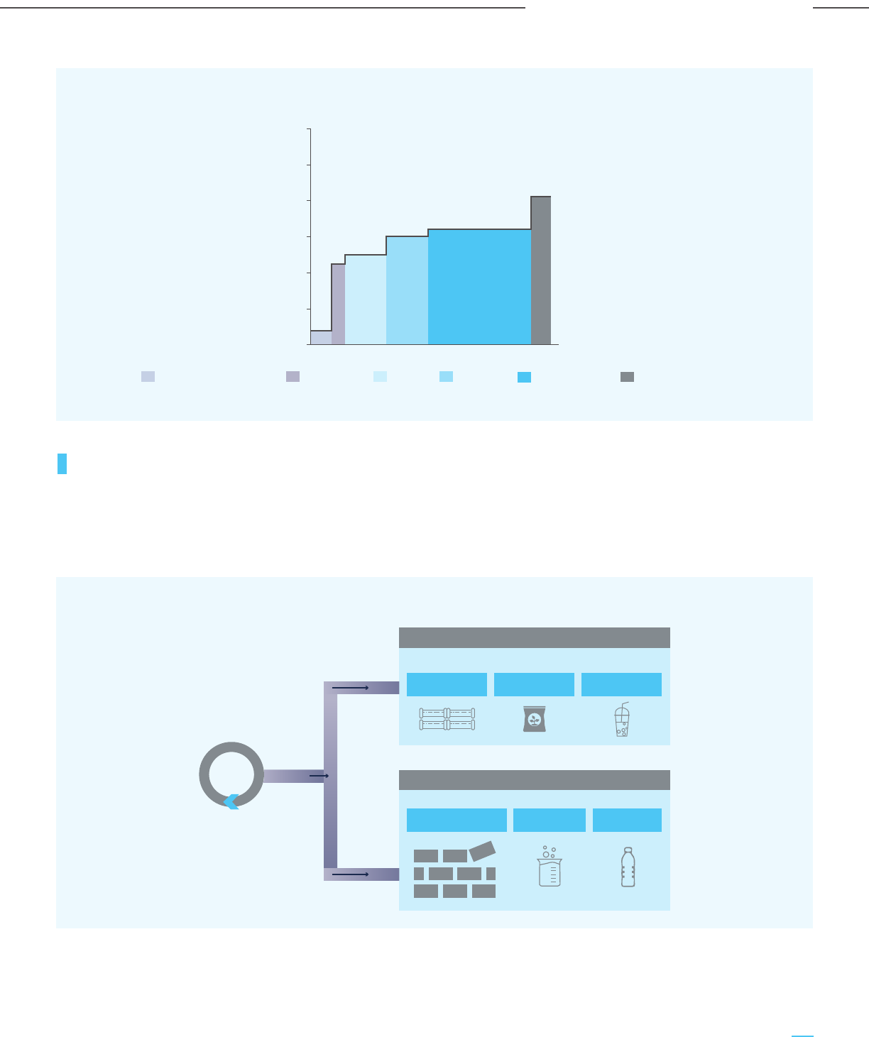
Figure 3-18: Cost Curve for CO
2
Capture Across Processes/Industries
1000
0
400
4100
0 1 2 3 4 5 6 7 8 9 10 11 12
mtpa
2000
3000
4000
5000
6000
Gasification based product
SMR based H
2
Cement
Iron & Steel
Coal based power Refinery & Chemical
Note: The CO
2
capture costs depicted above include costs for capture, conditioning and compression to 100 bar (a) and the amortized capital costs
Figure 3-19: Possible CO
2
Utilization Pathways
3.8 Overview of CO
2
Utilization Technologies
Thways for utilization of the captured CO
2
are
primarily EOR, green urea production (conversion of
green ammonia to green urea using the captured CO
2
)
and utilization of CO
2
in food & beverage applications.
With the rising interest in CCUS as a decarbonization
solution across industries, there is also a need to look
at the CO
2
utilization pathways and technologies that
CO
2
EOR Green Urea F&B usage
Building Material Chemicals Polymers
Proven Technologies
New Technologies
CaCO
3
CaCO
3
CaCO
3
87
Carbon Capture Utilization and Storage (CCUS) –
Policy Framework and Deployment Mechanism in India
Carbon Capture Utilization and Storage (CCUS) –
Policy Framework and Deployment Mechanism in India
Overview of CO
2
Capture & Utilization Technologies
are most appropriate for India. The possible CO
2
utilization pathways are illustrated in Figure 3-19.
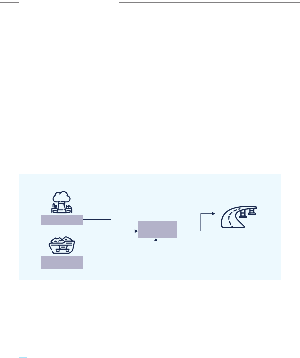
(i) Enhanced Oil Recovery (EOR): Using CO
2
for EOR
has been successfully carried out for decades to
produce low-carbon oil from maturing oil fields in
North America and other geographies. With Indian
oil fields progressing towards their maturity, CO
2
EOR can play an important role in residual oil
extraction that is environmentally sustainable and
economically feasible.
(ii) Green urea: Urea production from green ammonia
can utilize a significant part of CO
2
. India’s current
production of ammonia and urea is primarily
based on imported LNG. So, renewable
energy-based ammonia can replace conventional
ammonia production with an increased scale of
renewables and a competitive cost of green
hydrogen production. While renewable-based
hydrogen is still in a nascent stage in India, the
new green hydrogen policy will boost electrolysis
based hydrogen production in the near future.
(iii) F&B applications: The utilization of CO
2
in F&B is
in applications such as carbonated drinks, dry ice,
and modified atmosphere packing; however,
the scales are quite small compared to the volume
of CO
2
generation/emissions.
Additionally, there are other promising propositions
for the utilization of CO
2
. The relatively matured CO
2
utilization pathways are:
(i) Building material (concrete and aggregates): A
high-level review of the new technologies
indicates that utilizing CO
2
for producing building
materials (aggregates and concretes) is likely to
be the most attractive and feasible option. There
is a large market for aggregates and concrete in a
developing country like India. CO
2
can be used
both during concrete curing and aggregate
formation. Since CO
2
is injected in a liquid state
without any conversion, relatively little energy is
consumed. Moreover, large volumes of alternative
feedstock, such as steelmaking slag, are available
sources of CaO/MgO which can be utilized to
produce synthetic aggregates. The simplified
schematic for the CO
2
mineralization process has
been illustrated in Figure 3-20.
(ii) Chemicals (methanol and ethanol): The
production of chemicals such as methanol and
ethanol from CO
2
have been proven at commercial
scales by various companies around the world. India
has ambitious plans for increasing indigenous
methanol production capacity and to that extent,
the NITI Aayog has also launched ‘Methanol
Economy’ programme. Methanol is a low carbon
hydrogen carrier fuel that can support
applications like fuel substitution, as well as an
intermediate for the production of various
speciality chemicals like acetic acid, MTBE, DME,
and formaldehyde which produce essential
products like adhesives, foams, plywood subfloors
etc. Thus, the proposed methanol economy
programme would not only bring down the crude oil
import bill and GHG emissions but also can establish
a billion-dollar methanol based economy.
Figure 3-20: A Simplified Schematic of CO
2
Mineralization Process
Carbon
Mineralization
CO
2
Source
CaO & MgO from
waste concrete
Concrete for
new applications
vkREkfuHkZj
88
Carbon Capture Utilization and Storage (CCUS) –
Policy Framework and Deployment Mechanism in India
Carbon Capture Utilization and Storage (CCUS) –
Policy Framework and Deployment Mechanism in India
Overview of CO
2
Capture & Utilization Technologies
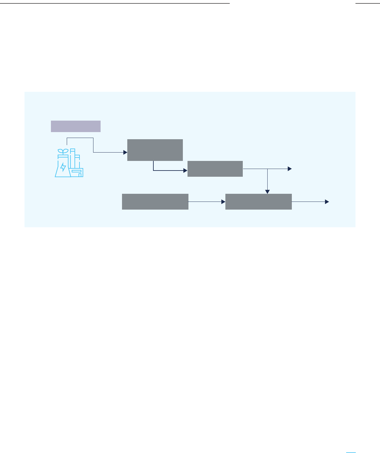
CO
2
hydrogenation process is used to convert the
captured CO
2
into methanol. The typical
schematic for the CO
2
hydrogenation process
along with integration with the carbon capture
unit has been illustrated in Figure 3-21. The
hydrogenation reaction takes place in the
presence of a suitable catalyst.
The major challenges to this technology include
sourcing raw materials (H
2
, CO and CO
2
), their
capture and conditioning, sourcing clean power
for operations, and the conversion process. Some
technology suppliers in this field are Carbon
Recycling International (CRI), Thyssenkrupp and
Mitsui Chemical.
The Government has also set out a target for 20%
Ethanol Blend Petrol (EBP) by 2030. Ethanol can
be produced by ethylene hydration or biological
processes like using H
2
, CO and CO
2
by biological
gas fermentation process. Recently, Twelve (a
carbon transformation company) and LanzaTech
(a biotechnology company) have announced a
research and development partnership for CO
2
to
ethanol conversion that would eventually aid in
scaling up the process to the commercial level. In
2021, LanzaTech and Twelve had also announced
plans to develop propylene from CO
2
.
Conversion of CO
2
to methanol and ethanol
present attractive opportunities for India. Apart
from obvious advantages like reduction in oil
import bill and GHG emissions, it would also give
boost to commodity production in the country and
thus contribute to economic development and job
creation.
(iii) Polymers (including bio-plastics): The conversion
of CO
2
to polymers presents another possible CO
2
utilization route. Various kinds of polymers, such
as polyether carbonates, polycarbonates, diphenyl
carbonate, cyclic carbonates etc. have been
manufactured globally at different scales.
However, the polymer product named AirCarbon,
produced by the company named Newlight, has
found multiple applications (laptop packaging, cell
phone casings, furniture, etc.).
The development of new utilization technologies and
pathways would enable a circular carbon economy in
the country. The need of the hour is to support
research development and demonstration (RD&D) of
such technologies to establish their viability and aid
them in commercialization. The following table
summarizes the products, technologies and
production scales based on the new technologies for
CO
2
utilization.
Figure 3-21: Typical Schematic for the CO
2
Hydrogenation Process
along with Integration with Carbon Capture Unit
Gas Processing &
Boosting Station
CO
2
Capture Unit
CO
2
to Methanol Unit
Electrolysis based H
2
Generation Unit
Pure CO
2
MethanolHydrogen
CO
2
Sources
89
Carbon Capture Utilization and Storage (CCUS) –
Policy Framework and Deployment Mechanism in India
Carbon Capture Utilization and Storage (CCUS) –
Policy Framework and Deployment Mechanism in India
Overview of CO
2
Capture & Utilization Technologies

Table 3-3: Various CO
2
Utilization Pathways
Building
materials
Concrete San Francisco Bay
Aggregates LLC, USA
Blue Planet 33 ktpa (Phase-I)
Product Sub-category Project &
Location
Technology
Provider
14 ktpa (Phase-I)
Concrete Thomas Concrete, USA CarbonCure
Technologies
1.8 million yd
3
4500 tpa (across its
US operations)
Lightweight
construction
aggregates
AVR’s Energy from
waste plant, Duiven,
Netherlands
Carbon8 Systems 100 tonnes of
building product
(pilot level)
-
Concrete bricks Ghent Footpath
Construction, Belgium
Carbstone Innovation Unknown 1 m
3
of carbstone
bricks stores a net
350 kg of CO
2
Concrete Masonry
Unit (CMU)
- Carbicrete Unknown 3 kg CO
2
removed
per CMU
Chemicals
Methanol Shunli CO
2
-to-Methanol
plant, China
Carbon Recycling
International (CRI)
110,000 tpa 150,000 tpa
Methanol George Olah Renewable
Methanol plant, Iceland
Carbon Recycling
International (CRI)
4000 tpa 5500 tpa
Polymers
Bio-plastics
(AirCarbon)
• Dell Latitude series
laptop packaging
• Sprint cell phone cases
• KI plastic chair
components
Newlight > 23 ktpa Unknown
Polyether
carbonate
Cardyon mattresses,
Germany
Covestro 10 ktpa
Mattresses formed
of 20 % CO
2
Methanol ThyssenKrupp
Duisburg Steel Plant,
Germany
ThyssenKrupp Unknown Unknown
Ethanol Beijing Shougang
LanzaTech New
Energy, China
LanzaTech 60 kt (since May
2018)
100 kt CO
2
(since May 2018)
Ethanol Steelanol,
ArcelorMittal, Belgium
LanzaTech 80 million litres of
bio ethanol (aim)
~1.5 mtpa CO
2
(aimed)
Quantity of
CO
2
utilized
Production
Capacity
3.9 Promoting the Adoption of CCUS Technologies in India
The envisaged CCUS policy needs to adopt a
multi-pronged approach to promote the adoption of
CCUS technologies in India. The key elements of the
approach need to incentivize the following:
i) Technology transfer: Carbon capture, CO
2
sequestration and CO
2
EOR technologies are
already demonstrated at commercial scale in
different parts of the world and particularly in the
US for nearly 50 years. Hence the focus for
India should be on technology transfer,
assimilation and adoption of such proven
technologies (TRL 8 and 9), rather than
reinventing the wheel. This would reduce the
technology risks, operational risks and costs for
CCUS projects in India. Pre-combustion and
post-combustion carbon capture technologies
(whether solvent, adsorption or cryogenic based)
are deployed in commercial scale projects and
available from multiple technology providers.
90
Carbon Capture Utilization and Storage (CCUS) –
Policy Framework and Deployment Mechanism in India
Carbon Capture Utilization and Storage (CCUS) –
Policy Framework and Deployment Mechanism in India
Overview of CO
2
Capture & Utilization Technologies
The modalities of the technology transfer could
be international collaboration between the
suppliers of commercially proven carbon capture
technologies and premier Indian engineering
consultants for the development and engineering
of the Process Development Package and
subsequent fabrication & manufacturing of
equipment at Indian manufacturing plants,
leading to implementation of successful
demonstration projects. The collaborating model
needs to build in considerations of IP rights
transfer/use mechanisms, manufacturing
capability and quality, and performance fidelity of
operations for transferred technology through
EPC implementation in India. The project
structure can also be in the form of a consortium
of partners with shared incentives to support the
technology transfer and technology suppliers as
part of the project consortium. This will drive the
incentive to successfully transfer technology
while retaining control of the IP of the originating
technology partner. This will eventually support
the Make-in-India programme, enable
technology/IP exports from the originating
country, will be less expensive, reduce equipment
imports and increase domestic expertise in India.
Government funding for demonstration projects
should be through stage gates, with the project
partners also contributing to the cost share of the
project, typically in the form of in-kind
contributions. This kind of model has been
successfully implemented by the US DOE for
funding carbon capture projects in the US,
primarily in the NG based power generation and
more recently in other hard to abate industrial
sectors. The typical stage gates could be project
conceptualization & Pre-FEED, FEED and
demonstration of the project, with outputs and
parameters being defined at each stage, based on
which the funding decision for the subsequent
stage is made. A staged approach will also help in
developing and detailing the potential technology
transfer model, as the details of technology and
engineering dependencies across the project life
cycle become better defined. It will be necessary
to clearly delineate the technology interfaces so
that once the project is implemented, the
technology performance responsibilities can be
assured across the parties.
ii) Promoting R&D in novel technologies: While
carbon capture technologies and technologies for
CO
2
EOR and sequestration are well developed
and implemented at a commercial scale,
technologies for the utilization of CO
2
are
relatively less developed. Even the relatively
more developed technologies for CO
2
utilization
such as CO
2
to methanol and CO
2
to aggregates
are at TRL levels of 4-5 and 6-7 only respectively.
Other promising technology propositions such as
CO
2
to synthetic fuels, polymers and novel
materials like carbon nano tubes are even further
behind on the technology development and
deployment curve.
There is an opportunity to engage with such
technology suppliers for deploying these proven
technologies in demonstration scale projects
across different industries, viz. coal-based power,
steel, cement, refining & petrochemicals.
The Government of India, through its Department
of Science and Technology, may fund such CCUS
demonstration projects, with the twin objectives
of promoting CCUS projects at demonstration
scale, as well as to initiate the process of
technology transfer, based on Intellectual
Property (IP) use and transfer. The key steps in
the technology transfer transfer process,
ultimately leading to manufacturing leadership is
demonstrated in Figure 3-22 below.
Figure 3-22: Systematic Indigenization of
Technology through Technology Transfer
4
3
5
2
1
Start up again with
new technology
Turn into
manufacturing
leaders
Scale
implementation
Indigenize
technology
Full localisation
& ToT
First of a kind
partial ToT
License &
transfer programme
91
Carbon Capture Utilization and Storage (CCUS) –
Policy Framework and Deployment Mechanism in India
Carbon Capture Utilization and Storage (CCUS) –
Policy Framework and Deployment Mechanism in India
Overview of CO
2
Capture & Utilization Technologies
Figure 3-23: Promising CO
2
Utilization Technology Propositions
MethanolAggregate Novel MaterialsFuel Polymers
CaCO
3
CaCO
3
CaCO
3
TRL 4-5 TRL 6-7 TRL 4-5 TRL 3-4 TRL 3-4
The Government of India should support and
promote an ecosystem that promotes and fosters
R&D and innovation in the development of CO
2
utilization technologies and also develops new
products & applications based on the utilization of
the captured CO
2
. The other technology areas to
support could be the relatively nascent oxy-fuel
combustion, membrane, microbial & algae-based
CO
2
capture technologies and calcium looping,
which potentially could have a role to play in
India’s net zero and clean energy transition
journey. Similarly, in the area of capture
technologies, the Government’s policy incentives
should encourage R&D in DAC as a possible
future option.
These developments are mutli-faceted and across
different applications, viz. the development of
CO
2
to materials, carbon injection, new CO
2
capture technologies etc. and many of the
developments are also happening in India through
international collaborations and support, such as
at the National Centre of Excellence in Carbon
Capture and Utilization at IIT Bombay. It is
difficult to pronounce a verdict on the developing
technologies as innovation and technology
development follow their own trajectory.
Therefore there is a need to fund, foster and
incubate an innovation-based ecosystem, both
through national centers of excellence such as
the IIT Bombay as well as jointly fund pilot-scale
projects with private sector participation.
iii) Private sector participation: Private sector
participation is quintessential to promote the
transfer and commercialization of existing CCUS
technologies and also push the envelope for the
development of new and emerging technologies
in both capture and utilization. One need not look
further than the US DOE or the Build Back
Greener programme of the UK Government
regarding the institutional frameworks created
for leveraging private investments in clean
energy and CCUS technology and project
development. Early investment and signalling
through public/government funding, long term
policies to incentivize & de-risk CCUS projects and
viable CCUS business models and value chains
are needed to encourage and leverage private
investment and participation in the development
of CCUS technologies and projects. While the
funding provided by the US DOE for the
development of novel technologies and projects
in CCUS is well known, recently the UK
Infrastructure Bank has been set-up for
promoting the development of new clean energy
technologies, particularly for scaling early-stage
technologies beyond the R&D phase, where
typically more Government support is required.
The Bank has initial funding of £12 billion and
seeks to pull in private investment to accelerate
the net-zero transition in the UK. Similarly in
India, governmental institutional frameworks and
grants are needed to strategically support new
and emerging CCUS technologies, as well as CCUS
projects. This will lower the risk for private sector
participation and investment, as CCUS scales up
and moves to the commercial scale in India. Given
the nascent stage of CCUS in India, the
Government would need to support the full
project/funding cycle, from emerging
technologies to part-funding actual CCUS
implementations and projects.
92
Carbon Capture Utilization and Storage (CCUS) –
Policy Framework and Deployment Mechanism in India
Carbon Capture Utilization and Storage (CCUS) –
Policy Framework and Deployment Mechanism in India
Overview of CO
2
Capture & Utilization Technologies
Chapter 4
Potential for CO
2
Storage in India
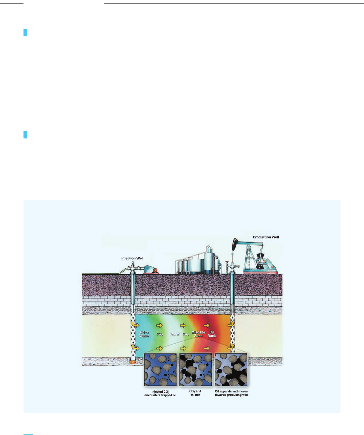
4.1 Introduction
4.2 CO
2
Storage Options
The end use of the captured CO
2
can be either
utilization or permanent storage. Utilization can be
done in various areas such as urea manufacturing,
conversion to other chemicals (methane, methanol,
ethanol), and evolving applications like aggregates. An
alternative is the permanent storage of the captured
CO
2
in deep underground geological reservoirs like
depleted oil and gas reservoirs (for enhanced oil
production or EOR), deep saline aquifers, and in
basaltic rock formations.
For carbon capture at scale, it is important to estimate
the CO
2
storage capacity in the geological formations
in the Indian subcontinent. This section focuses on the
potential CO
2
storage capacities in India for utilization
pathways such as EOR (Enhanced Oil Recovery) &
ECBMR (Enhanced Coal Bed Methane Recovery) and
permanent storage options like saline aquifers &
basaltic storage. In India, exploration activities have
been performed with hydrocarbon extraction as the
primary target and not CO
2
storage. Thus, the values
are theoretical capacities derived from hydrocarbon
exploration data available in the public domain.
In-depth and detailed studies are required for more
accurate CO
2
storage capacity estimation.
4.2.1 Enhanced Oil Recovery (EOR)
Oil recovery techniques can be categorized as
primary, secondary, and tertiary recovery techniques.
Primary techniques rely on natural reservoir pressure
and the use of pumps to bring oil to the surface, but
the recovery is only about 10%. The secondary
techniques involve the injection of water or gas in the
reservoir to drive the oil to the production wellbores.
This helps in the recovery of 20-40% of the original
oil in place. To further improve the production
performance of wells, tertiary techniques are used.
Figure 4-1: Working of CO
2
EOR
94
Carbon Capture Utilization and Storage (CCUS) –
Policy Framework and Deployment Mechanism in India
Carbon Capture Utilization and Storage (CCUS) –
Policy Framework and Deployment Mechanism in India
Potential for CO
2
Storage in India
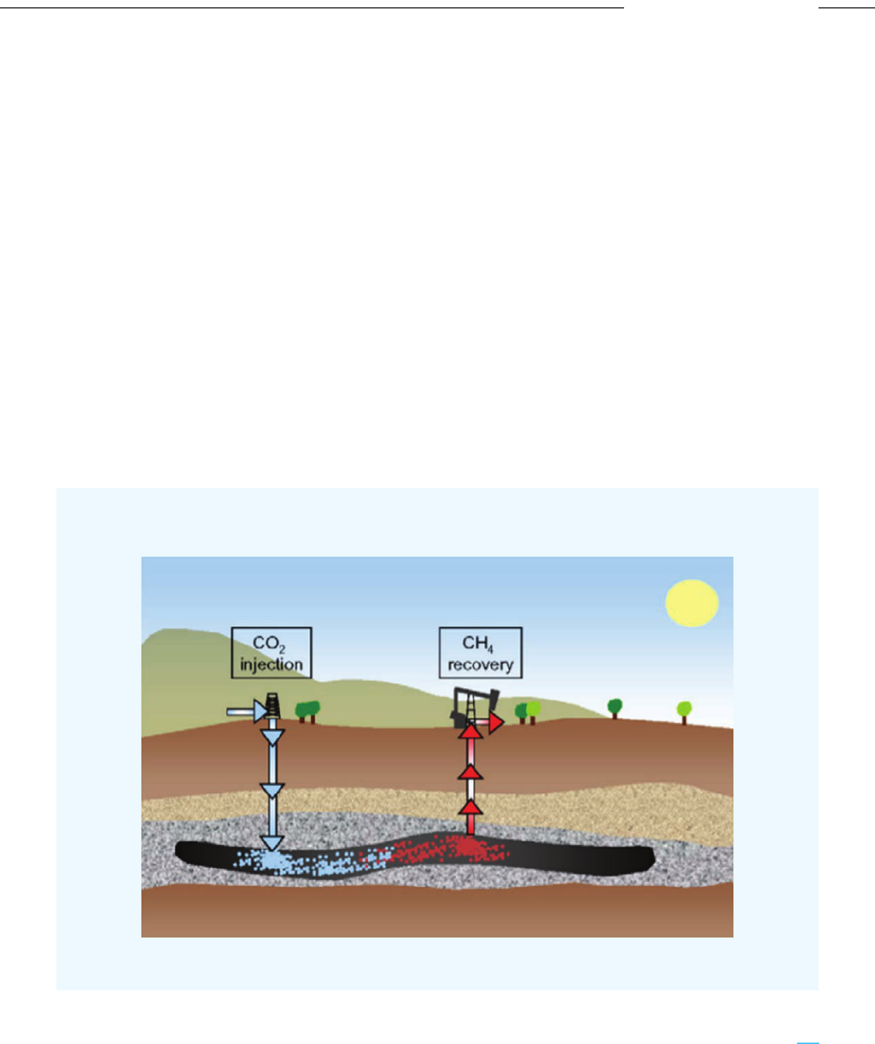
Tertiary techniques of recovery include thermal
recovery (steam injection), gas injection (CO
2
injection), and chemical injection (use of polymers or
surfactants). These help in the production of 30-60%
of the original oil in place.
Injection of CO
2
for EOR has been studied and applied
for years, especially in North America. CO
2
is
miscible with crude oil which helps in recovering oil
not possible by secondary methods. This also
helps in permanently storing CO
2
in oil reservoirs,
thus making CO
2
EOR a sustainable option for
abating CO
2
.
In CO
2
EOR, compressed CO
2
is injected into the
reservoir. At high densities, CO
2
is readily miscible
with oil. It swells the oil and reduces its viscosity,
thereby driving it away from rock formations and
towards the production wells. A minimum pressure is
required for CO
2
and oil to be miscible. To prevent
lower viscosity CO
2
from escaping the reservoir, water
and CO
2
are injected alternatively.
4.2.2 Enhanced Coal Bed Methane
Recovery (ECBMR)
Coal bed methane (CBM) can be produced from coal
seams and can contribute to the energy security of
India. In ECBMR, CO
2
is injected into unmineable coal
seams under supercritical conditions. The CO
2
injected
is accumulated in the coal cleats in a dense gas phase.
This CO
2
is adsorbed and absorbed in the coal. Since
CO
2
has a higher affinity for coal than CBM, it pushes
the coal bed methane towards production wells, thus
enhancing its primary recovery. Similar to CO
2
EOR,
ECBMR can help in permanently storing CO
2
and the
recovered methane can also help offset the cost of
carbon capture. This can be a viable option for thermal
power plants as many large coal based power plants
are located near coalfields. Figure 4-2 gives a pictorial
representation of the ECBMR process.
Several pilot tests for ECBMR have been performed
across the world, but there is no commercial-scale
ECBMR plant (Mazzotti, Pini, & Storti, 2009). Thus,
further R&D is required before commercial deployment.
Figure 4-2: Working of CO
2
ECBMR
95
Carbon Capture Utilization and Storage (CCUS) –
Policy Framework and Deployment Mechanism in India
Carbon Capture Utilization and Storage (CCUS) –
Policy Framework and Deployment Mechanism in India
Potential for CO
2
Storage in India

4.2.3 Storage in Deep Saline Aquifers
Captured CO
2
can be permanently stored in deep
saline aquifers. Unlike EOR and ECBMR, injection of
CO
2
in deep saline aquifers has no economic benefit.
Deep saline aquifers are spread across very large
areas and thus have the potential to store very large
quantities of CO
2
.
Deep saline aquifers consist of porous rock formation
that contains high quantities of unusable saltwater.
The salt/mineral content is very high in this water
rendering it unusable for human use. The brine water
is called formation liquid and it is trapped by an
impermeable rock called the caprock.
Supercritical CO
2
can be injected into the saline
aquifers. Brine water has a higher density compared
to the injected CO
2
; thus, CO
2
rises towards the
caprock and is trapped in the saline aquifer. This is
also termed structural/ stratigraphic trapping. While
injecting, some CO
2
might occupy the pore spaces by
displacing the previously present fluid. This is known
as residual trapping. Some of the injected CO
2
also
dissolves in the brine. This mixture is denser than the
surrounding brine and thus settles down. This is called
solubility trapping. CO
2
dissolves in water to form a
weak carbonic acid that can react with minerals over
time to form solid carbonate minerals. This process is
termed mineral trapping.
4.2.4 CO
2
Storage in Basalts
Recently studies have been carried out to learn about
the CO
2
storage potential of basaltic rocks. Basaltic
rock constitutes divalent cations of Ca, Mg, and Fe.
They can react with the CO
2
dissolved in water to form
stable carbonate minerals and thus can offer a safe
CO
2
sequestration method for an extended period.
Compared to mineralization in saline aquifers, basalt
rocks offer faster reaction kinetics due to the
abundance of iron, calcium, and magnesium oxides.
The abundance of basalts on the earth’s surface is
also a reason for the rising interest in CO
2
storage
research and development programmes in basalts.
According to calculations done by researchers, the
global CO
2
storage capacity of basalts is estimated to
be around 8000-41000 Gt of CO
2
(Vikram,
Yashvardhan, Debanjan, & Dhananjayan, 2021).
4.3 Capacity Assessment
for CO
2
Storage
Based on secondary research, the estimated CO
2
storage capacity of India for each of the options
discussed above has been presented in this section.
Due to the absence of high-level data focused on CO
2
storage, all the capacities presented here are
theoretical calculations and estimations. Further work
is required to acquire real-time storage data for these
options.
Currently, initial storage assessment is being carried
out in India. These are focused on the feasibility of
CO
2
EOR through seismic, geomechanical, and
reservoir studies based on initial surveys by ONGC.
Research on the possibility of CO
2
storage in saline
aquifers and basalts, predicting and monitoring of CO
2
plume by seismic methods has also been done by
some authors. The Technology Information,
Forecasting, and Assessment Council (TIFAC), Govt of
India, has identified CO
2
EOR and ECBMR as the two
immediate pathways for CO
2
sequestration in India
(TIFAC, 2018). However, there are no elaborate or
dedicated geological, geomechanical or seismic
studies ‘focused’ on country-wide CO
2
storage.
4.3.1 CO
2
EOR Storage Capacity Assessment
India has a total of 26 sedimentary basins. The
Directorate General of Hydrocarbon’s (DGH) 2020
India Hydrocarbon Outlook report divides these basins
into three categories, namely category I, category II,
and category III basins.
Category I basins are the ones where commercial oil &
gas exploration and production activities are ongoing.
There are 7 basins in category I. Extensive data for
these basins are available due to the exploratory
efforts of oil and gas companies. However, these
basins have not been explored with the intention of
CO
2
storage. Thus, the data of in-place hydrocarbon
resources and Ultimate Recoverable Reserves (URR)
provided by DGH in the recent exploration assessment
has been used with a suitable Recovery Factor for
EOR (RF
EOR
= 10%) to calculate the total pore volume.
A conversion factor of 1.165 is used to convert the
values of MMTOE to Mm
3
. This pore volume is used
along with the formation volume factor (B
0
) and CO
2
96
Carbon Capture Utilization and Storage (CCUS) –
Policy Framework and Deployment Mechanism in India
Carbon Capture Utilization and Storage (CCUS) –
Policy Framework and Deployment Mechanism in India
Potential for CO
2
Storage in India

Table 4-1: CO
2
EOR Storage Capacity Estimates
density at reservoir conditions to calculate the
quantity of CO
2
that can be stored in a particular
basin. The calculation formulae in equations (1) and (2)
are used.
V = URR + (OOIP x RF
EOR
) (1)
M = V B
0
ρ
CO2
(2)
The theoretical capacity estimates of the seven
category I basins have been listed in Table 4-1.
Basin Storage Capacity
(mt CO
2
)
Krishna-Godavari 658.69
Mumbai 1597.24
Assam shelf 667.48
Rajasthan 312.52
Cauvery 99.50
Assam-Arakan 67.01
Cambay 657.25
Total 3402.43
Thus, a total of 3.4 Gt of theoretical storage capacity
is estimated to be available for EOR. The Bengal basin
has also started producing oil in late 2020, but it has
been excluded due to the lack of availability of data
about the reserves. The CO
2
EOR capacities are
expected to increase as more basins are explored for
hydrocarbon production.
4.3.2 CO
2
ECBMR Storage Capacity Assessment
Indian coal reserves mostly comprise anthracite and
bituminous coal, spread across the Gondwana basin
and scattered in some parts of north-eastern India.
These coalfields are rich in CBM, and the CH
4
to CO
2
ratio may vary in the range of 1:2 to 1:3. Since several
large-scale thermal power plants are located near
coal fields, ECBMR presents a promising opportunity
for CO
2
utilization and storage.
Information about several parameters is required for
a high-level estimation of the CO
2
storage capacity in
coal reserves. Since it is difficult to get information
about each of these parameters, a few empirical
equations have been used to calculate the storage
capacity. In the referred work (Vikram, Yashvardhan,
Debanjan, & Dhananjayan, 2021), four equations, given
by Kim, Ryan, Mavor, and Langmuir, were used to
estimate the volume of methane (VGas) present in the
coal formations. This volume thus calculated indicates
the amount of CO
2
that can be stored in the coal
formations using equation (3).
Q
CO2
= 3V
Gas
x Q
coal
x ρ
CO2
(3)
Q
CO2
is the quantity of CO
2
adsorbed in the coal seam,
Q
coal
is the quantity of coal resources and ρ
CO2
is the
density of CO
2
at coal formation depths. The
calculations according to the formula of Kim and
Langmuir get results close to each other and are
considered as appropriate estimations in this study.
Kim’s formula considers the coal properties and depth
of reserve, while Langmuir’s formula relies on
sorption properties. Mavor’s formula was found to be
the simplest as it only took ash and moisture content
into account. Ryan’s formula is dependent on vitrinite
reflectance. Based on the above analysis, the results
for each coalfield have been tabulated in Table 4-2.
97
Carbon Capture Utilization and Storage (CCUS) –
Policy Framework and Deployment Mechanism in India
Carbon Capture Utilization and Storage (CCUS) –
Policy Framework and Deployment Mechanism in India
Potential for CO
2
Storage in India

Table 4-2: CO
2
ECBMR Storage Capacity Estimates
Coalfield Kim Ryan Mavor Langmuir
(Gt CO
2
) (Gt CO
2
) (Gt CO
2
) (Gt CO
2
)
Bokaro 0.28 0.32 0.30 0.20
North Karanpura 0.28 0.38 0.35 0.21
Raniganj 0.50 0.59 0.44 0.52
Sohagpur 0.09 0.16 0.19 0.07
Sonhat 0.03 0.06 0.07 0.03
South Karanpura 0.08 0.16 0.13 0.11
Wardha Valley 0.06 0.15 0.15 0.09
Birbhum 0.08 0.14 0.11 0.10
Godavari 0.23 0.53 0.50 0.32
Mand–Raigarh 0.25 0.60 0.53 0.35
Rajmahal 0.16 0.30 0.31 0.13
Singrauli 0.10 0.26 0.29 0.10
Tatapani–Ramkola 0.05 0.08 0.07 0.05
Ib river 0.17 0.41 0.34 0.19
Talcher 0.32 0.80 0.61 0.41
Makum 0.01 0.01 0.01 0.00
Jharia 0.47 0.55 0.41 0.51
Ramgarh 0.01 0.03 0.04 0.01
Auranga 0.02 0.06 0.07 0.03
Hutar 0.00 0.00 0.01 0.00
Daltonganj 0.00 0.00 0.00 0.00
Deogarh 0.00 0.01 0.01 0.00
Johilla 0.00 0.00 0.01 0.00
Pench–Kanhan 0.03 0.06 0.07 0.02
Pathakhera 0.01 0.01 0.01 0.00
Singrauli 0.09 0.23 0.20 0.10
Jhilimili 0.00 0.00 0.01 0.00
Chirimiri 0.00 0.01 0.01 0.00
Bisrampur 0.01 0.02 0.05 0.00
Lakhanpur 0.00 0.00 0.01 0.00
Hasdo–Arand 0.04 0.08 0.10 0.02
Sendurgarh 0.00 0.00 0.01 0.00
Korba 0.06 0.16 0.18 0.06
Kamptee 0.02 0.06 0.06 0.03
Umrer–Makardhokra 0.00 0.01 0.01 0.00
Nand–Bander 0.00 0.01 0.02 0.00
Total 3.5 6.3 5.7 3.7
98
Carbon Capture Utilization and Storage (CCUS) –
Policy Framework and Deployment Mechanism in India
Carbon Capture Utilization and Storage (CCUS) –
Policy Framework and Deployment Mechanism in India
Potential for CO
2
Storage in India

Table 4-3: CO
2
Storage Capacity Estimation for Deep Saline Aquifers
Based on Kim and Langmuir’s formula, the CO
2
storage
capacity has been estimated storage to be between 3.5
Gt to 3.7 Gt of CO
2
, respectively. More pilot tests are
required to generate data for ECBMR in the Indian
context, which would pave the way for the commercial
deployment of this technology.
4.3.3 Deep Saline Aquifer CO
2
Storage Capacity
Assessment
Indian deep saline aquifers are distributed in the 26
sedimentary basins and are categorized into 3
categories, namely category I, II & III basins.
Category I basins have the most detailed lithological
data. Additional exploration is needed to obtain
high-quality data for category II & III basins.
The CO
2
storage capacity estimation has been done by
using the volume of formation being considered for
storage and appropriate storage efficiency factors.
The storage efficiency factors account for the
dominant lithology of a formation or basin and help in
calculating a more accurate capacity. The formula
used for calculation has been given in equation (4).
The storage capacity estimates for each basin have
been tabulated in Table 4-3. Capacity estimation has
not been possible for seven basins of category III due
to lack of data.
G
CO2
= AhφρE (4)
In the above equation, A is the area covered by the
basin, h is the gross thickness of the formation, φ is the
average porosity, ρ is the CO
2
density at reservoir
conditions and E is the storage efficiency factor that
takes area, thickness, porosity, volumetric displacement,
and microscopic displacement efficiency into account.
Category Basin Capacity (Gt)
Category I Krishna–Godavari 13.39
Mumbai offshore 9.26
Assam Shelf 14.16
Rajasthan 7.34
Cauvery 16.08
Assam-Arakan fold belt 32.3
Cambay 16.13
Saurashtra 39.74
Kutch 15.6
Category II Vindhyan 11.81
Mahanadi–NEC (North East Coast) 3.25
Andaman–Nicobar 12.35
Kerala–Konkan–Lakshadweep 25.33
Bengal–Purnea 51.58
Ganga–Punjab -
Pranhita–Godavari 6.14
Satpura–South Rewa–Damodar 1.87
Himalayan Foreland -
Chhattisgarh 0.11
Category III Narmada -
Spiti–Zanskar -
Deccan Syncline -
Cuddapah 14.24
Karewa -
Bhima–Kaladgi 0.41
Bastar -
Total 291.09
99
Carbon Capture Utilization and Storage (CCUS) –
Policy Framework and Deployment Mechanism in India
Carbon Capture Utilization and Storage (CCUS) –
Policy Framework and Deployment Mechanism in India
Potential for CO
2
Storage in India

Table 4-4: Basalt Formation CO
2
Storage Capacity Estimates
The total theoretical storage capacity is estimated to
be 291.1 Gt CO
2
for deep saline aquifers. This
estimation will increase based upon the availability of
more data on the seven category III basins for which
calculations could not be done. Deep saline aquifers
offer immense storage potential and thus more studies
and pilot tests are required to generate the baseline
data for CO
2
sequestration operations in India.
4.3.4 Basalt Rock CO
2
Storage Capacity
Assessment
Basalt formations in India have been discovered in the
Deccan Volcanic Province (DVP) and Rajmahal trap
(Vikram, Yashvardhan, Debanjan, & Dhananjayan,
2021). The DVP basalts are spread across the
north-western region, covering nearly 500,000 km
2
in
area. The volume of these formations is estimated to
be close to 512,000 km
3
. A relatively smaller basalt
formation is present in the eastern part of India in the
Rajmahal traps. This trap consists of 450 to 600 m
thick basalt, and spread across an area of
18,000 km
2
.
The CO
2
storage capacity for basalts has been
estimated by using the methodologies used by
Sænbjörnsdόttir et al. (Sænbjörnsdόttir, 2014) and
McGrail et al. (McGrail, 2006). The formula used for
calculation has been described in equation (5).
G
CO2
= AhφE
CO2
(5)
In the above equation, A is the area of basalt
formation, h is the net thickness of formation,
φ is the
average porosity and E
CO2
is the storage efficiency
factor. The methodology used by Sænbjörnsdόttir
considers three geothermal systems in Iceland, Krafla,
Hellisheidi, and Reykjanes, where the CO
2
content per
square meter of surface area was measured. Reykjanes
provided the lower limit of CO
2
storage efficiency while
Krafla provided the upper limit. McGrail assumed 10
suitable interflow zones, average porosity of 15%, and
1000 m as the targeted depth of injection.
These two methodologies have been applied to Indian
basalts to generate the CO
2
storage efficiency factors
and, ultimately, the storage capacity estimates. The
efficiency factor results and the storage capacity
estimates for the two basalt formations of India have
been tabulated in Table 4-4.
Sænbjörnsdόttir al. (2014) McGrail et al. (2006)
Low High
Storage Efficiency (Kg/m
3
) 18.8 48.7 40.65
CO
2
Storage Capacity (Gt)
Deccan Volcanic Province (DVP) 94 243.5 304.88
Rajmahal Traps 3.38 8.77 10.98
Total (Gt) 97.38 252.27 315.85
100
Carbon Capture Utilization and Storage (CCUS) –
Policy Framework and Deployment Mechanism in India
Carbon Capture Utilization and Storage (CCUS) –
Policy Framework and Deployment Mechanism in India
Potential for CO
2
Storage in India
4.4 Overall CO
2
Storage
Capacity in India
The overall CO
2
storage capacity assessment for the
four options discussed above has been summarized in
Table 4-5.
Table 4-5: Theoretical CO
2
Storage Capacity in India
EOR 3.4
ECBMR 3.5-3.7
Deep Saline Aquifers
291
Basalts 97-315
Total 395-614
EOR and ECBMR provide relatively low storage
capacity in comparison to deep saline aquifers and
basalts. However, EOR is a more researched and
tested technology in major carbon capture projects
across the globe and thus can be probably more easily
101
Carbon Capture Utilization and Storage (CCUS) –
Policy Framework and Deployment Mechanism in India
Carbon Capture Utilization and Storage (CCUS) –
Policy Framework and Deployment Mechanism in India
implemented in the Indian scenario. ECBMR requires
more dedicated studies and pilot tests for the Indian
coal beds since no commercial-scale project is active
in the world.
Deep saline aquifers offer great CO
2
storage potential
for India. Since waste material injection is not an
industrial practice in India, data related to storage in
deep saline aquifers is not readily available. Thus,
characterization of the various onshore/ offshore
saline formations and improving the quality of data
available should be part of future studies for saline
aquifers. Based on the recommended CCUS cluster
framework, field/basin-specific studies need to be
undertaken for regions of higher priority. The pilot
tests will further help in preparing baseline data for
the development of commercial-scale injection of CO
2
in saline aquifers. Basalt formations are concentrated
in the western part of the country and offer a good
storage option for emitters in the western states of
India like Maharashtra, Gujarat, and parts of Madhya
Pradesh. Some basalts are also found in Eastern India
in the Rajmahal traps. Further studies are required to
get a better understanding of storage mechanisms in
these traps. Pilot tests need to be carried out to
further develop the industrial CO
2
sequestration
framework and infrastructure.
Potential for CO
2
Storage in India
Theoretical Storage
Capacity (Gt)
Storage
Pathways

4.5 CO
2
Storage Capacity in India - Earlier Work and Future Work
4.5.1 Assessment by the British
Geological Society
Some of the earliest work done with regard to the
assessment of the potential of CO
2
storage in
geological reserves in India was done by the British
Geological Society (BGS). The BGS report submitted in
2008, covered the Indian subcontinent (India,
Pakistan, Bangladesh and Sri Lanka) and was
commissioned by the International Energy Agency
Greenhouse Gas R&D Programme. The potential
geological storage sites were divided into three
categories. The categories, along with the estimated
CO
2
storage capacity, is given below:
- Oil fields – 1 to 1.1 Gt
- Coal seams – 0.345 Gt
- Saline water-bearing reservoir rocks – 142 Gt
Thus, the total CO
2
storage capacity estimated was
143 Gt, which is a significant number considering the
annual CO
2
emissions in India of 2.6 Gt. However, the
BGS study did not consider the potential CO
2
storage
capacity in basaltic rock formations due to the relative
immaturity of the technology but noted the potential
of CO
2
storage in the thick basaltic formations of the
Deccan trap and the smaller Rajmahal trap. The BGS
study also involved a high-level source-sink mapping
based on which the sources in the north-west and
south-eastern coast of India were identified to have
good nearby storage potential, whereas the sources in
south-east, central and northern India were not found
to have good nearby storage potential.
4.5.2 Assessment by IIT Bombay
Building on the earlier work of the BGS, an assessment
was recently undertaken by Professors Vikram Vishal,
Yashvardhan Verma, Debanjan Chandra, Dhananjayan
Ashok of IIT Bombay. Their paper “A systematic
capacity assessment and classification of geologic CO
2
storage systems in India” has reviewed and applied
different methodologies for estimating CO
2
storage
capacities in different types of geological formations in
India. The study identified four storage pathways with
adequate potential for CO
2
storage:
- CO
2
storage in deep saline aquifers – 291 Gt
- CO
2
storage in basalt formations – 97 to 316 Gt
- CO
2
based enhanced oil recovery (EOR) – 3.4 Gt
- Enhanced coalbed methane recovery (ECBMR) – 3.7 Gt
The study also categorized the sedimentary
basins of India based on CO
2
storage prospects as
well as the feasibility of CO
2
storage; the same is
depicted in Figure 4-3.
102
Carbon Capture Utilization and Storage (CCUS) –
Policy Framework and Deployment Mechanism in India
Carbon Capture Utilization and Storage (CCUS) –
Policy Framework and Deployment Mechanism in India
Potential for CO
2
Storage in India
Figure 4-3: Classification of CO
2
Storage Potential of Sedimentary Basins of India
Storage prospectivity
Storage capacity (Gt)
Very high potential
High potential
Moderate potential
Low potential
Assam-Arakan fold belt
Saurashtra
Bengal-Purnea
Kerala-Konkan
Cuddapah
Andaman-Nicobar
Kutch
Vindhyan
Assam shelf
Cauvery
Cambay
Krishna-Godavari
Rajasthan
Mumbai
offshore
Mahanadi
Bhima-Kaladgi
Satpura-South
Pranhita
Chhatisgarh
Godavari
1
0
0
10 20 30 40 50
Storage feasibility
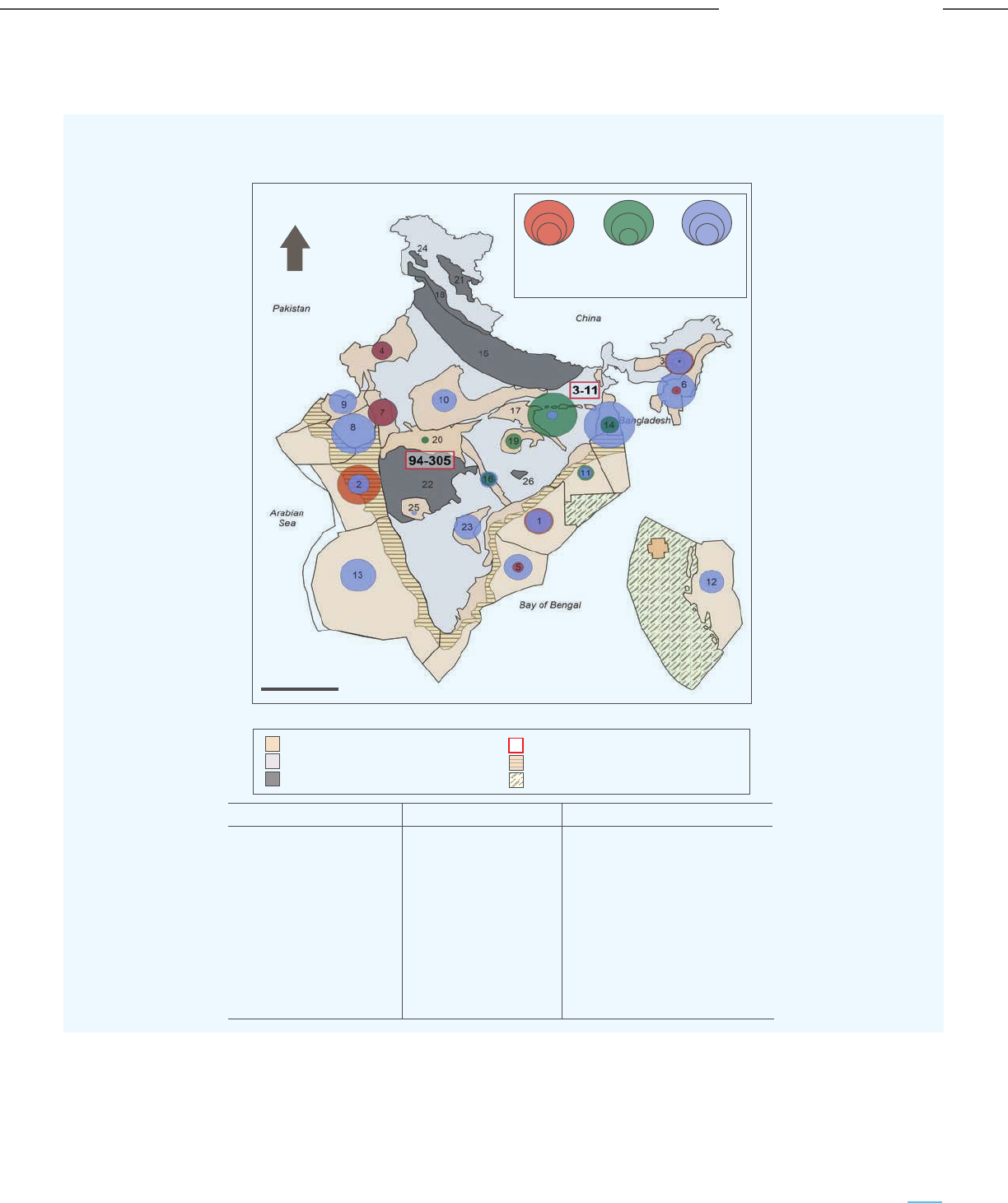
103
Carbon Capture Utilization and Storage (CCUS) –
Policy Framework and Deployment Mechanism in India
Carbon Capture Utilization and Storage (CCUS) –
Policy Framework and Deployment Mechanism in India
Potential for CO
2
Storage in India
Figure 4-4: Major Sedimentary Basins in India with their CO
2
Storage Potential
N
65
0
E
35
0
N
30
0
N
EOR
(Gt)
ECBMR
(TCF)
Saline Aquifers
(Gt)
CO
2
storage capacity
25
0
N
20
0
N
15
0
N
10
0
N
5
0
N
0 500
km
35
0
N
30
0
N
25
0
N
20
0
N
15
0
N
10
0
N
5
0
N
70
0
E 75
0
E 80
0
E 85
0
E 90
0
E 95
0
E 100
0
E
65
0
E
Sedimentary basins
Precambrian basement
Basins with insufficient data
Category-I basins Category-II basins Category-III basins
CO
2
storage capacity in basalt (Gt)
Shallow water areas
Unassessed deepwater areas
70
0
E 75
0
E 80
0
E 85
0
E 90
0
E 95
0
E 100
0
E
1. Krishna-Godavari
2. Mumbai Offshore
3. Assam-Shelf
4. Rajasthan
5. Cauvery
6. Assam-Arakan Fold belt
7. Cambay
8. Saurashtra
9. Kutch
10. Vindhyan
11. Mahanadi
12. Andaman
13. Kerala-Konkan
14. Bengal-Purnea
15. Ganga-Punjab
16. Pranhita-Godavari
17. Satpura-South Rewa-Damodar
18. Himalayan Foreland
19. Chhattishgarh
20. Narmada
21. Spiti-Zanskar
22. Deccan Syncline
23. Cuddapah
24. Karewa
25. Bhima-Kaladgi
26. Baster
10
25
50
10
35
70
0.5
1
2
Although the estimated storage capacity for EOR and
ECBMR is relatively smaller, they still offer an attractive
option due to the following:
- Provide an option to store CO
2
emissions from nearby
large point sources
- Economic value creation through enhanced oil and
methane production, thus offsetting part of the
CCUS costs
- Availability of exploration data, geological information
and infrastructure in existing oil fields and coal fields
The CO
2
storage potential of the different basins in India is depicted in Figure 4-4.

104
Carbon Capture Utilization and Storage (CCUS) –
Policy Framework and Deployment Mechanism in India
Carbon Capture Utilization and Storage (CCUS) –
Policy Framework and Deployment Mechanism in India
Potential for CO
2
Storage in India
4.5.3 Future Work Required
Existing studies show enormous CO
2
storage potential
in India; however, further actions are needed to make
geological storage of CO
2
a reality in India. Some of
the key steps which need to be funded/promoted by
the Government of India are:
- Source sink mapping to prioritize the regions and
basins most opportune for CO
2
storage in terms of
storage capacity and feasibility
- Pore space mapping and characterization of the
most promising CO
2
storage regions and basins –
geological characterization and exploration for CO
2
storage. In the US, the US Department of Energy
(US DOE) has funded a network of seven Regional
Carbon Sequestration Partnerships (RCSPs) across
the country. The aim of the RSCP program is to
develop the regional infrastructure of carbon
capture and storage across seven identified
regions of the US. The seven RSCPs are depicted in
Figure 4-5.
- For the prospective regions identified in India,
developing the CO
2
storage infrastructure would
consist of the following steps:
i) Characterization: characterization and
geological modelling of the prospective regions
for assessing the potential to store CO
2
in
different types of geological formations.
This would include mapping the large point
sources of CO
2
in the region, characterizing
prospective sites for CO
2
storage, and ranking
the sites for future CO
2
storage projects. The
characterization would provide the requisite
data for mapping sites to the large CO
2
point
sources, develop a better understanding of the
CO
2
transportation & storage costs and create a
business case for the envisaged CCUS projects.
ii) Validation: undertaking lab-scale field projects
in different types of storage fields across EOR,
ECBMR, saline aquifers and basaltic formations
to gather information about the CO
2
storage
sites, and validation of the characterization and
modelling work done. This would help in
validating the most promising CO
2
storage sites
in each region.
iii) Commercial-scale Development: undertake
commercial-scale (at least 1 mtpa of CO
2
) CO
2
injection in selected sites. The projects would be
optimized through the implementation of an
appropriate Monitoring, Verification and
Accounting (MVA) framework and risk
management measures, and also help in proving
the permanence of CO
2
storage in the
subsurface and monitoring the extent &
movement of CO
2
plume.
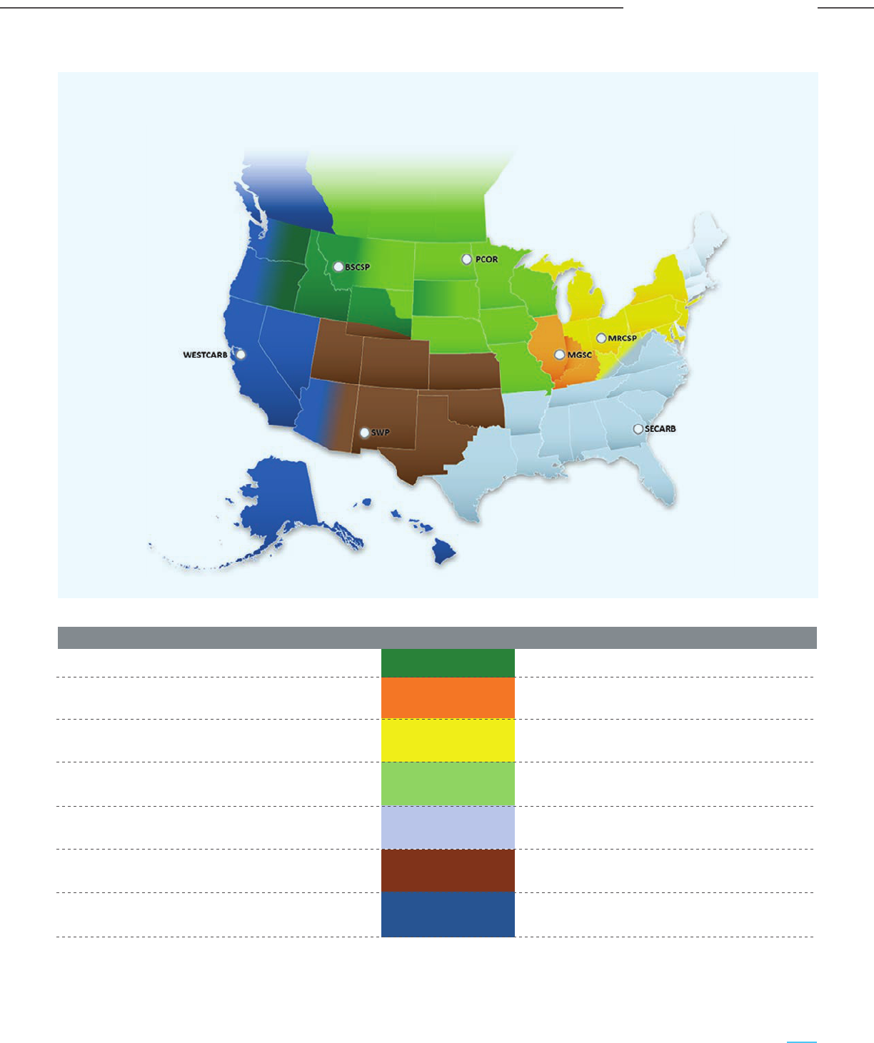
105
Carbon Capture Utilization and Storage (CCUS) –
Policy Framework and Deployment Mechanism in India
Carbon Capture Utilization and Storage (CCUS) –
Policy Framework and Deployment Mechanism in India
Potential for CO
2
Storage in India
Figure 4-5: Seven RSCPs Funded by the US DOE
RCSP Abbreviation Lead Organisation
Big Sky Carbon Sequestration Partnership BSCSP Montana State University Bozeman
Midwest Geological MGSC Illinois State Geological Survey
Sequestration Consortium
Midwest Regional Carbon MRCSP Battelle Memorial University
Sequestration Partnership
Plains CO
2
Reduction PCOR University of North Dakota Eenergy
Partnership and Environmental Research Center
Southeast Regional Carbon SECARB Southern States Energy Board
Sequestration Partnership
Southwest Regional Partnership on SWP New Mexico Institute of Mininig
Carbon Sequestration and Technlology
West Coast Regional Carbon WESTCARB California Energy Commission
Sequestration Partnership
Source: US DOE National Energy Technology Laboratory

Potential for CO
2
Storage in India
4.6 SECARB
The Southeast Regional Carbon Sequestration
Program (SECARB) is one of the prominent RSCPs,
setup with US DOE funding for the development and
management of CO
2
storage and CO
2
storage
infrastructure across 13 south-eastern states of the
US. SECARB was set up in 2003 and is managed by
the Southern States Energy Board (SSEB). The main
goal was to identify major sources of carbon
emissions, characterize the geology of the 13 states
with respect to CO
2
storage (both EOR and
sequestration), identify the most promising sites and
sequestration technologies and validate the same
through extensive field testing.
The key phases of the SECARB program and
accomplishments/developments in each phase are
as below:
i) Phase I (2003 – 2005): Phase I focussed on
characterizing the geology and CO
2
storage
potential of different sequestration options in the
SECARB area, based on which an action plan was
developed for undertaking small-scale field
demonstration of CO
2
sequestration in the
subsequent phase of the program.
ii) Phase II (2005 – 2010): During Phase II, three
types of small scale field tests were conducted in
four locations. These were:
a. Enhanced Oil Recovery: Ageing oil fields
along the US Gulf Coast have an estimated
CO
2
storage potential of 31 Gt and are an ideal
target for geological storage of CO
2
. SECARB’s
Gulf Coast Stacked Storage Field Test ran
from 2008 to 2015 and was the first RSCP
Phase II program to inject more than 500 ktpa
of CO
2
.
b. Coal bed methane: Two field tests were
conducted at an existing CNX gas well in
Russel County, Virginia and near Tuscaloosa,
Alabama.
c. Saline aquifers: CO
2
injection in saline
aquifers was conducted at the Mississippi
Power Company’s Victor J. Daniel coal-fueled
power plant.
iii) Phase III (2007 – 2017): Phase III consisted of
two large CO
2
volume storage projects, namely:
a. CO
2
EOR at the Cranfield oilfield: The
SECARB “Early Test” ran from 2009 to 2015
and the cumulative volume of stored CO
2
that
was monitored during this period was about
5.4 million tonnes. The CO
2
volumes were
monitored using a variety of MVA technologies
to determine the commercial viability of
the project.
b. CO
2
sequestration at Citronelle oilfield: The
SECARB “Anthropogenic Test” ran from 2012
to 2014 during which 114 ktpa of CO
2
captured
from Alabama Power Company’s James M.
Barry Electric Generating Plant in Bucks,
Alabama was transported (through pipeline)
about 19 km and sequestered in a deep saline
formation. MVA technologies were applied to
monitor the movement of the CO
2
plume in the
sub-surface.
The role of both the SECARB Phase III projects in
advancing the understanding of CO
2
storage
technologies has been recognized internationally and
has also helped in the development of international
guidance, best practices and standards for carbon
capture, transportation, and storage.
The key learning and finding from the SECARB is that
once site selection & design, project management and
logistical issues are managed, operations of CO
2
storage projects are simple and without any effect or
manifestation on the surface. SECARB also
demonstrates the criticality of project planning and
coordinating the various elements of the CCUS value
chain and the importance of site-specific public
outreach with local government leaders, community
representatives, and sharing details of the project and
address their questions & apprehensions about the
project risks. The success of the SECARB project has
also led to other commercial-scale CCUS projects
being constructed in the SECARB area.
The success of the SECARB program demonstrates
how Government funding and support can lay the
seeds and develop a CCUS value chain. The
Government of India may also consider similar
programs for the regions that prima facie have good
prospects for CCUS, viz. the Krishna Godavari basin,
Mumbai offshore, Cambay and eastern parts of the
Bay of Bengal basin, especially around Haldia.
106
Carbon Capture Utilization and Storage (CCUS) –
Policy Framework and Deployment Mechanism in India
Carbon Capture Utilization and Storage (CCUS) –
Policy Framework and Deployment Mechanism in India

Potential for CO
2
Storage in India
4.7 MVA (Monitoring Verification and Accounting)
The storage of CO
2
in geological storage sites requires
a variety of tools to monitor the volume of CO
2
stored,
as well as to prevent CO
2
leakages and releases from
the storage sites. These tools are used for monitoring
the CO
2
in the atmosphere, near the surface and the
sub-surface. The MVA framework provides the tools
and approaches required for ensuring the safe,
effective and permanent geological storage of CO
2
.
MVA plans are needed for all CO
2
geological storage
projects, covering aspects of CO
2
storage, quality
control, as well as verification and accounting of CO
2
volumes stored, which would be eligible for earning
incentives/credits linked to carbon abatement, viz. the
45Q tax credits in the US. MVA plans need to be
developed specific to sites, given the variance of
geological conditions across storage sites. Risk
management is an important component of the MVA
framework for ensuring the safe, effective, and
permanent storage of CO
2
across a variety of geologic
formations and avoiding CO
2
releases & leakages. It is
also important to monitor the location and movement
of the CO
2
plume in the subsurface and ensure that
the water table is not polluted. In the case of CO
2
EOR,
the monitoring and tracking of the CO
2
plume may be
easier due to the presence of a number of oil wells; at
the same time there is more complexity due to the
presence of oil and gas.
The key goals of MVA for CO
2
storage sites are as
follows (source: US DOE):
- Improve understanding of the CO
2
storage
processes and confirm the storage effectiveness
- Evaluate the reaction and interaction of CO
2
with
the formation solids and fluids.
- Assess the likely environmental, safety, and health
impacts in case of a CO
2
leakage event and
evaluate the remedial actions required.
- Provide a technical basis in case of events such as
groundwater impacts, seismic events, crop losses
as a result of the CO
2
sequestration.
For any geological sequestration project, the MVA
activities are carried out in four phases:
i) Pre-Operation Phase: Project design,
establishing baseline conditions,
characterization of the site geology and
identification of risks.
ii) Operation Phase: Period of CO
2
injection in
the storage site.
iii) Closure Phase: Period of closing and plugging
the sites, removal of equipment and facilities
and undertaking site restoration. However,
necessary monitoring equipment are retained
at the site.
iv) Post-Closure Phase: Ongoing monitoring is
undertaken before making a decision that
further monitoring is not required, except in
case of any incidents like leakage, or legal
cases, for which new information is required
about the storage project/site.
Each monitoring phase has specific monitoring tools
and techniques to address the specific atmospheric,
near-surface hydrologic, and deep-subsurface
monitoring needs. These are tabulated below:
Table 4-6: List of Monitoring Techniques for CO
2
Storage Projects
Area of Monitoring Monitoring Techniques
- CO
2
Detectors: Sensors for monitoring CO
2
either intermittently or
continuously in the air.
- Eddy Covariance: Atmospheric flux measurement technique to measure
atmospheric CO
2
concentrations at a height above the ground surface
- Advanced Leak Detection System: sensitive three-gas detector
(CH
4
, Total HC, and CO
2
) with a GPS mapping system carried by aircraft or
terrestrial vehicles
Atmospheric
Monitoring Techniques
107
Carbon Capture Utilization and Storage (CCUS) –
Policy Framework and Deployment Mechanism in India
Carbon Capture Utilization and Storage (CCUS) –
Policy Framework and Deployment Mechanism in India

Potential for CO
2
Storage in India
108
Carbon Capture Utilization and Storage (CCUS) –
Policy Framework and Deployment Mechanism in India
Carbon Capture Utilization and Storage (CCUS) –
Policy Framework and Deployment Mechanism in India
Area of Monitoring Monitoring Techniques
Near-Surface
Monitoring
Subsurface
Monitoring
- Laser Systems and LIDAR: Open-path device that uses a laser to shine a
beam with a wavelength that CO
2
absorbs
- Tracers or Isotopes: Natural isotopic composition and/or compounds
injected into the target formation along with the CO
2
- Ecosystem Stress Monitoring: Satellite or airplane-based optical method.
- Tracers: CO
2
soluble compounds injected along with the CO
2
. into the
target formation
- Groundwater Monitoring: Sampling of water or vadose zone/soil (near
surface) for basic chemical analysis.
- Thermal Hyperspectral Imaging: An aerial remote-sensing approach
primarily for enhanced coalbed methane recovery and sequestration.
- Synthetic Aperture Radar (SAR & InSAR): Satellite-based technology in
which radar waves are sent to the ground to detect surface deformation.
- Color Infrared (CIR) Transparency Films: Vegetative stress technology
deployed on satellites or aerially.
- Tiltmeter: Measures small changes in elevation via mapping tilt , either on
the surface or in subsurface.
- Flux Accumulation Chamber: Quantifies the CO
2
flux from the soil, but
only from a small, predetermined area.
- Induced Polarization: Geophysical imaging technology commonly used in
conjunction with DC resistivity to distinguish metallic minerals and
conductive aquifers from clay minerals in subsurface materials.
- Spontaneous (Self) Potential: Measurement of natural potential
differences resulting from electrochemical reactions in the subsurface.
Typically used in groundwater investigations and in geotechnical
engineering applications for seepage studies.
- Soil and Vadose Zone Gas Monitoring: Sampling of gas in vadose
zone/soil (near surface) for CO
2
.
- Shallow 2-D Seismic: Closely spaced geophones along a 2-D seismic line.
- Multi-component 3-D Surface Seismic Time- lapse Survey: Periodic
surface 3-D seismic surveys covering the CCS reservoir.
- Vertical Seismic Profile (VSP): Seismic survey performed in a wellbore
with multi-component processes. Can be implemented in a “walk-away”
fashion in order to monitor the footprint of the plume as it migrates away
from the injection well and in time-lapse application.
- Magnetotelluric Sounding: Changes in electromagnetic field resulting
from variations in electrical properties of CO
2
and formation fluids.
- Electromagnetic Resistivity: Measures the electrical conductivity of the
subsurface including soil, groundwater, and rock.
- Electromagnetic Induction Tomography (EMIT): Utilizes differences in
how electromagnetic fields are induced within various materials.

Potential for CO
2
Storage in India
- Injection Well Logging (Wireline Logging): Wellbore measurement using a
rock parameter, such as resistivity or temperature, to monitor fluid
composition in wellbore
- Annulus Pressure Monitoring: Mechanical integrity test on the annular
volume of a well to detect leakage from the casing, packer or tubing.
- Pulsed Neutron Capture: A wireline tool capable of depicting oil
saturation, lithology, porosity, oil, gas, and water by implementing pulsed
neutron techniques.
- Electrical Resistance Tomography (ERT): Use of vertical arrays of
electrodes in two or more wells to monitor CO
2
as a result of changes in
layer resistivity.
- Sonic (Acoustic) Logging: A wireline log used to characterize lithology,
determine porosity, and travel time of the reservoir rock.
- 2-D Seismic Survey: Acoustic energy, delivered by explosive charges or
vibroseis trucks (at the surface) reflecting back to a straight line of
recorders (geophones). After processing, the reflected acoustic signature
of various lithologies is presented as a 2-D graphical display.
- Time-lapse Gravity: Use of gravity to monitor changes in density of fluid
resulting from injection of CO
2
.
- Density Logging (RHOB Log): Continuous record of a formation bulk
density as a function of depth by accounting for both the density of matrix
and density of liquid in the pore space.
- Optical Logging: Device equipped with optical imaging tools is lowered
down the length of the wellbore to provide detailed digital images of the
well casing.
- Cement Bond Log (Ultrasonic Well Logging): Implements sonic
attenuation and travel time to determine whether casing is cemented or
free. The more the cement which is bonded to the casing, the greater will
be the attenuation of sounds transmitted along the casing.
- Gamma Ray Logging: Use of natural gamma radiation to characterize the
rock or sediment in a borehole.
- Microseismic (Passive) Survey: Provides real-time information on
hydraulic and geomechanical processes taking place within the reservoir in
the interwell region, remote from wellbores by implementing surface or
subsurface geophones to monitor earth movement.
- Crosswell Seismic Survey: Seismic survey between two wellbores in
which transmitters and receivers are placed in opposite wells. Enables
subsurface characterization between those wells. Can be used for
time-lapse studies.
- Aqueous Geochemistry: Chemical measurement of saline brine in storage
reservoir.
- Resistivity Log: Log of the resistivity of the formation, expressed in
ohm-m, to characterize the fluids and rock or sediment in a borehole.
Area of Monitoring Monitoring Techniques
Source: Best Practices for Monitoring, Verification, and Accounting of CO
2
Stored in Deep Geologic Formations (US DOE NETL)
109
Carbon Capture Utilization and Storage (CCUS) –
Policy Framework and Deployment Mechanism in India
Carbon Capture Utilization and Storage (CCUS) –
Policy Framework and Deployment Mechanism in India

Potential for CO
2
Storage in India
110
Carbon Capture Utilization and Storage (CCUS) –
Policy Framework and Deployment Mechanism in India
Carbon Capture Utilization and Storage (CCUS) –
Policy Framework and Deployment Mechanism in India
Examples of successful MVA programs are the MVA
programs funded by the US DOE with the goal of
demonstrating 95% and up to 99% retention of CO
2
through geological storage by ensuring leakages are
contained up to 5% and 1% of the stored CO
2
volumes. The US DOE’s Carbon Sequestration
Program supports the development of technologies in
this domain through the Regional Carbon
Sequestration Partnerships (RCSP) Program. Some of
the early projects/CO
2
storage sites where the US
DOE supported the MVA program are given below.
The portfolio of sites was selected to ensure variety in
the type and geology of site, CO
2
application,
formation depth and porosity, pressure and
temperature conditions, to maximize the
understanding of the behaviour of the stored CO
2
in
different operating and geological regimes.
i) Gulf Coast Mississippi Strandplain Deep
Sandstone Test in Mississippi: moderate
porosity and permeability storage site
ii) Nugget Sandstone Test in Wyoming: high depth,
low porosity and permeability site
iii) Cambrian Mt. Simon Sandstone Test in Illinois:
moderate depth, low porosity and permeability site
iv) San Joaquin Valley Fluvial-Braided Deep
Sandstone Test in California: high porosity and
permeability site
v) Williston Basin Deep Carbonate Test in North
Dakota: EOR site
The US DOE also supported the MVA program at the
Petro Nova project in Texas for CO
2
capture from NRG
Energy’s WA Parish Unit 8 (a 640 MW coal fired
power plant) and storage in the West Ranch oilfield.
The MVA program was conducted by the University of
Texas at Austin’s Bureau of Economic Geology and
consisted of the following components:
i) Modeling: development of a fluid flow simulation
model using actual logging and production data
ii) Mass balance accounting: accounting for
injected CO
2
iii) Pressure monitoring: monitoring pressure in
10 dedicated AZMI (above zone monitoring
intervals) wells
iv) Fluid sampling: collection of pre-injection fluids
(brine, gas, oil) in the injection and AZMI zones
v) Groundwater monitoring: one year of baseline
and periodic ongoing sampling of groundwater at
several groundwater wells
vi) Soil gas monitoring: characterization of soil
gases at several sites
vii) Additional monitoring: additional monitoring of
the surface level and downhole pressure by the
oilfield operator
CO
2
storage in geological formations (both
sequestration and EOR to a limited extent) is the most
likely pathway for the disposition of CO
2
at scale, and
hence critical to the implementation of CCUS at scale
in India, especially for the decarbonization of large
emitters of CO
2
such as coal-based power plants. The
emissions for a 660 MW supercritical coal based
power plant is estimated to be about 4 mtpa of CO
2
.
Given the safety concerns about underground CO
2
storage as well as for accounting CO
2
volumes eligible
for credits/incentives, it is necessary to develop CO
2
storage demonstration projects and develop robust
MVA programs for them. These CO
2
storage
demonstration projects should be at identified sites
across the different prospective regions in India. In
order to develop a holistic perspective, it is also
important to implement projects at different types of
CO
2
storage sites, such as saline aquifers, basaltic
traps and oilfields amenable for EOR. The MVA
programs and best practices developed by the US
DOE and ISO 14064 & ISO 14065 standards developed
for GHG accounting, verification and validation
provides a good starting point based on which site
specific MVA programs can be developed and
implemented.

Chapter 5
CCUS Policy
Framework for India

robust CO
2
injection regime in the state and established
mechanisms to manage the long-term liability with CO
2
storage. It is expected that owing to their extensive oil
and gas industry presence and favourable geology,
Texas and Louisiana stand to gain significant carbon
storage market share if they can successfully obtain
primacy and establish regulatory frameworks that
meet EPA’s standards and provide the industry with
planning certainty.
5.2.1.4 SCALE Act
The SCALE (Storing CO
2
and Lowering Emissions) Act
was proposed by a bipartisan coalition in 2021. The
Act aims to assist the development of vital CO
2
transit
and storage infrastructure to support CCUS and CO
2
removal technologies, as well as regional economic
prospects and jobs in the US. The key goals are:
a. Establishing a CO
2
Infrastructure Finance and
Innovation Act (CIFIA) programme to stimulate the
development of shared CO
2
transportation
infrastructure through flexible and low-interest
loans and grants. This federal funding mechanism
is aimed to reduce overall costs by enabling
economies of scale through interconnected
transport systems
b. Supporting commercial geologic CO
2
storage
initiatives with grants.
c. Promoting CO
2
utilization through legislation
allowing the US DOE to grant financing to
municipalities and states to enable procurement
of low carbon products and equipment.
d. Supporting legal and regulatory authorizations for
permitting Class VI CO
2
storage wells
5.2.2 European Union
The EU has been at the forefront of CCUS technology
development and has employed a variety of measures
to support, fund and incentivize CCUS. These support
measures are in the form of grant funds and
legislative & policy initiatives for CCUS, which have
been crucial in supporting the CCUS R&D, pilot and
demonstration projects across EU countries. A few
active funding programmes for CCUS in the EU region
are summarized in Table 5-1.
5.2.1.1 45Q
The 45Q provides tax credits for CCUS, starting from
USD 12.83 for each tonne of CO
2
utilized for EOR in
2017, linearly increasing to US$ 35/tonne in 2026.
Similarly, for CO
2
captured and geologically stored,
the tax credit was US$ 22.66/tonne in 2017, rising
linearly to US$ 50/tonne of CO
2
in 2026. Post-2026,
the credit shall be inflation-adjusted. Few mandatory
criteria must be met by emitters in order to avail the
tax credit, such as:
- facilities must begin construction before
1 January 2026
- the credit can be claimed over a 12-year period
after operations commence
- a minimum volume of CO
2
must be captured and
sequestered or utilized, which depends upon the
type of the emitting industry, as below:
• Non-EOR carbon utilization: 25-500 ktpa
of CO
2
• Industrial and DAC: 100 ktpa of CO
2
• Power plants: 500 ktpa of CO
2
The Global CCS Institute has long hailed USA’s 45Q
tax credit mechanism as the “most progressive
CCS-specific incentive globally”. The 45Q credits
lower a firm’s tax liability; in case there is no tax
liability, the credits can be traded in the tax equity
market. Tax credits have been successful in spurring
renewable energy projects in the US over the last two
decades. An important component for the successful
implementation of the 45Q or any tax incentive-based
system is designing a Monitoring Reporting and
Verification framework (MRV) to ensure compliance
of the projects seeking the 45Q credits.
The recently enacted Inflation Reduction Act of 2022
has substantially increased the maximum level of
credits available from US$ 50 to US$85/tonneof CO
2
sequestered and upto US$180/tonne of CO
2
for DAC.
5.2.1.2 California Low Carbon Fuel
Standard (LCFS)
The Low Carbon Fuel Standard (LCFS) in California is
a trading mechanism aimed at lowering the CO
2
intensity of the state’s fuel mix. A CCUS protocol for
the LCFS was agreed upon in January 2019, allowing
transportation fuels whose lifecycle emissions have
been lowered using CCUS to qualify for credits. The
protocol covers a wide range of CCUS applications
involving permanent storage of captured CO
2
in
depleted oil and gas reservoirs or saline formations or
used for enhanced oil recovery in oil and gas
reservoirs. Project credits are based on life cycle
emission reductions and granted if the reported
reductions have been validated.
LCFS is a strong motivator for CCUS deployment in
California. In 2020, the carbon credits obtained
through the LCFS roughly translated to USD 200 per
tonne of CO
2
. While the eligibility standards are strict,
several new project announcements have stated that
LCFS credits have been considered in their evaluation
and analysis of cost economics. The LCFS programme
offers several credit-generating possibilities to boost
low-carbon fuel supply and usage, viz:
i) Fuel pathway-based crediting: Low carbon fuels
generate credits based on emissions reduced
compared to the established baseline. These
credits incentivize developers to bring more clean
fuel options to California.
ii) Project-based crediting: This category includes
projects for reducing emissions across the
petroleum supply chain using measures such as
CCUS and direct air capture.
iii) Zero-emissions vehicle infrastructure
(capacity-based) crediting: Installation of
hydrogen and fast-charging DC infrastructure can
generate credits based on capacity.
5.2.1.3 State Primacy for CO
2
Storage
In 2010, the US EPA created the sixth well class (Class
VI) specifically to regulate the injection of CO
2
into
deep subsurface rock formations. At the time, very
few projects were sequestering CO
2
solely to reduce
greenhouse gas emissions, but the EPA anticipated
that technology development would be key to
achieving domestic emissions reductions. Wyoming
and North Dakota have been approved by the US
Environmental Protection Agency (EPA) to take
primary responsibility (‘primacy’) for regulating CO
2
injection for dedicated geological storage in Class VI
wells under the Underground Injection Control
(UIC) Program.
Texas and Louisiana have also stepped up efforts to
assume regulatory authority for CO
2
dedicated storage.
Louisiana has already applied for primacy, based on a
5.1 Introduction
The key to a successful CCUS policy for India is a
framework that supports the creation of sustainable
and viable markets for CCUS projects. The framework
must consider the fact that the private sector is
unlikely to invest in CCUS unless there are sufficient
incentives to do so (or conversely penalties from
inaction), or unless it can benefit from the sale of CO
2
or gain credits for emissions avoided under carbon
pricing regimes. Direct capital grants, tax credits,
carbon pricing schemes, operational subsidies,
regulatory requirements, and public procurement
preference for low-carbon products are some of the
policy measures required for CCUS to become a
reality in India.
5.2 Review of Policy
Instruments and
Strategies Adopted by
Various Countries and
Institutions
Local market conditions and institutional factors, such
as the current stage of CCUS infrastructure
development, emission targets, domestic energy
resources and mix, availability and cost of alternative
approaches to cutting emissions, all influence the
appropriate choice or mix of instruments for each
country. The appropriateness of each form of policy
instrument varies depending on the CCUS application.
Some applications of carbon capture, such as natural
gas processing, are well-established and relatively
inexpensive and need only minor policy changes.
Other applications, such as the CCUS in heavy
industries such as steel, are still in the early stages of
development. High CO
2
capture costs and their impact
on the cost/price and competitiveness of the final
product are major hurdles to CCUS adoption.
Government support for project developers is key to
managing the costs and risks associated with CCUS
projects, across the value chain of capture,
transportation and storage and establishing and
expanding CCUS in a meaningful way in India.
5.2.1 USA
The US leads the world in CCUS deployment, with the
earliest CCUS projects being implemented in the 1970s.
There are 14 operating CCUS facilities in the US, with a
combined carbon capture capacity of more than 25
mtpa. The US has heavily invested in CCS R&D since the
early 2000s. The US DOE has funded research and
development (R&D) in aspects of CCS since 1997 within
its Fossil Energy and Carbon Management Research,
Development, Demonstration, and Deployment
programme (FECM) portfolio. Since 2010, the US
Congress has provided USD 7.3 BB$ for DOE’s
CCS-related activities, including annual increases in
recent years. In 2021, the US Congress provided USD
750 MM$ to FECM, of which USD 228.3 MM$ was
earmarked for CCUS.
Apart from the DOE funding, CCUS projects received a
major fillip in 2009 when the US Federal Government
enacted the American Recovery and Reinvestment Act
(ARRA), which provided another USD 3.4 BB$
specifically for CCS projects and R&D activities. Nine
individual projects accounted for USD 2.65 BB$ out of
the ARRA funding, with each receiving in excess of USD
100 MM$. Five out of the nine projects are large scale
demonstration projects intended to capture CO
2
from
electric power plants. The balance four are in the
industrial sector. While some of the projects have faced
implementation challenges and delays, the policy intent
in USA has clearly focused on developing large scale
demonstration plants for CCS through government
support and funding. A large number of CCUS projects
are under different stages of conceptualization and
development, and CCUS is integral to the emission
reduction and net-zero commitments of a large number
of corporations in different sectors such as coal & NG
based power plants, waste-to-energy plants, cement,
ethanol facilities, and chemical production.
Some of the key enablers of CCUS in the US are the
45Q tax credits, California’s LCFS standards, State
Primacy for CO
2
injection and the SCALE Act; these are
describe herein:
CCUS Policy Framework for India
112
Carbon Capture Utilization and Storage (CCUS) –
Policy Framework and Deployment Mechanism in India
Carbon Capture Utilization and Storage (CCUS) –
Policy Framework and Deployment Mechanism in India

robust CO
2
injection regime in the state and established
mechanisms to manage the long-term liability with CO
2
storage. It is expected that owing to their extensive oil
and gas industry presence and favourable geology,
Texas and Louisiana stand to gain significant carbon
storage market share if they can successfully obtain
primacy and establish regulatory frameworks that
meet EPA’s standards and provide the industry with
planning certainty.
5.2.1.4 SCALE Act
The SCALE (Storing CO
2
and Lowering Emissions) Act
was proposed by a bipartisan coalition in 2021. The
Act aims to assist the development of vital CO
2
transit
and storage infrastructure to support CCUS and CO
2
removal technologies, as well as regional economic
prospects and jobs in the US. The key goals are:
a. Establishing a CO
2
Infrastructure Finance and
Innovation Act (CIFIA) programme to stimulate the
development of shared CO
2
transportation
infrastructure through flexible and low-interest
loans and grants. This federal funding mechanism
is aimed to reduce overall costs by enabling
economies of scale through interconnected
transport systems
b. Supporting commercial geologic CO
2
storage
initiatives with grants.
c. Promoting CO
2
utilization through legislation
allowing the US DOE to grant financing to
municipalities and states to enable procurement
of low carbon products and equipment.
d. Supporting legal and regulatory authorizations for
permitting Class VI CO
2
storage wells
5.2.2 European Union
The EU has been at the forefront of CCUS technology
development and has employed a variety of measures
to support, fund and incentivize CCUS. These support
measures are in the form of grant funds and
legislative & policy initiatives for CCUS, which have
been crucial in supporting the CCUS R&D, pilot and
demonstration projects across EU countries. A few
active funding programmes for CCUS in the EU region
are summarized in Table 5-1.
5.2.1.1 45Q
The 45Q provides tax credits for CCUS, starting from
USD 12.83 for each tonne of CO
2
utilized for EOR in
2017, linearly increasing to US$ 35/tonne in 2026.
Similarly, for CO
2
captured and geologically stored,
the tax credit was US$ 22.66/tonne in 2017, rising
linearly to US$ 50/tonne of CO
2
in 2026. Post-2026,
the credit shall be inflation-adjusted. Few mandatory
criteria must be met by emitters in order to avail the
tax credit, such as:
- facilities must begin construction before
1 January 2026
- the credit can be claimed over a 12-year period
after operations commence
- a minimum volume of CO
2
must be captured and
sequestered or utilized, which depends upon the
type of the emitting industry, as below:
• Non-EOR carbon utilization: 25-500 ktpa
of CO
2
• Industrial and DAC: 100 ktpa of CO
2
• Power plants: 500 ktpa of CO
2
The Global CCS Institute has long hailed USA’s 45Q
tax credit mechanism as the “most progressive
CCS-specific incentive globally”. The 45Q credits
lower a firm’s tax liability; in case there is no tax
liability, the credits can be traded in the tax equity
market. Tax credits have been successful in spurring
renewable energy projects in the US over the last two
decades. An important component for the successful
implementation of the 45Q or any tax incentive-based
system is designing a Monitoring Reporting and
Verification framework (MRV) to ensure compliance
of the projects seeking the 45Q credits.
The recently enacted Inflation Reduction Act of 2022
has substantially increased the maximum level of
credits available from US$ 50 to US$85/tonneof CO
2
sequestered and upto US$180/tonne of CO
2
for DAC.
5.2.1.2 California Low Carbon Fuel
Standard (LCFS)
The Low Carbon Fuel Standard (LCFS) in California is
a trading mechanism aimed at lowering the CO
2
intensity of the state’s fuel mix. A CCUS protocol for
the LCFS was agreed upon in January 2019, allowing
transportation fuels whose lifecycle emissions have
been lowered using CCUS to qualify for credits. The
protocol covers a wide range of CCUS applications
involving permanent storage of captured CO
2
in
depleted oil and gas reservoirs or saline formations or
used for enhanced oil recovery in oil and gas
reservoirs. Project credits are based on life cycle
emission reductions and granted if the reported
reductions have been validated.
LCFS is a strong motivator for CCUS deployment in
California. In 2020, the carbon credits obtained
through the LCFS roughly translated to USD 200 per
tonne of CO
2
. While the eligibility standards are strict,
several new project announcements have stated that
LCFS credits have been considered in their evaluation
and analysis of cost economics. The LCFS programme
offers several credit-generating possibilities to boost
low-carbon fuel supply and usage, viz:
i) Fuel pathway-based crediting: Low carbon fuels
generate credits based on emissions reduced
compared to the established baseline. These
credits incentivize developers to bring more clean
fuel options to California.
ii) Project-based crediting: This category includes
projects for reducing emissions across the
petroleum supply chain using measures such as
CCUS and direct air capture.
iii) Zero-emissions vehicle infrastructure
(capacity-based) crediting: Installation of
hydrogen and fast-charging DC infrastructure can
generate credits based on capacity.
5.2.1.3 State Primacy for CO
2
Storage
In 2010, the US EPA created the sixth well class (Class
VI) specifically to regulate the injection of CO
2
into
deep subsurface rock formations. At the time, very
few projects were sequestering CO
2
solely to reduce
greenhouse gas emissions, but the EPA anticipated
that technology development would be key to
achieving domestic emissions reductions. Wyoming
and North Dakota have been approved by the US
Environmental Protection Agency (EPA) to take
primary responsibility (‘primacy’) for regulating CO
2
injection for dedicated geological storage in Class VI
wells under the Underground Injection Control
(UIC) Program.
Texas and Louisiana have also stepped up efforts to
assume regulatory authority for CO
2
dedicated storage.
Louisiana has already applied for primacy, based on a
CCUS Policy Framework for India
113
Carbon Capture Utilization and Storage (CCUS) –
Policy Framework and Deployment Mechanism in India
Carbon Capture Utilization and Storage (CCUS) –
Policy Framework and Deployment Mechanism in India

robust CO
2
injection regime in the state and established
mechanisms to manage the long-term liability with CO
2
storage. It is expected that owing to their extensive oil
and gas industry presence and favourable geology,
Texas and Louisiana stand to gain significant carbon
storage market share if they can successfully obtain
primacy and establish regulatory frameworks that
meet EPA’s standards and provide the industry with
planning certainty.
5.2.1.4 SCALE Act
The SCALE (Storing CO
2
and Lowering Emissions) Act
was proposed by a bipartisan coalition in 2021. The
Act aims to assist the development of vital CO
2
transit
and storage infrastructure to support CCUS and CO
2
removal technologies, as well as regional economic
prospects and jobs in the US. The key goals are:
a. Establishing a CO
2
Infrastructure Finance and
Innovation Act (CIFIA) programme to stimulate the
development of shared CO
2
transportation
infrastructure through flexible and low-interest
loans and grants. This federal funding mechanism
is aimed to reduce overall costs by enabling
economies of scale through interconnected
transport systems
b. Supporting commercial geologic CO
2
storage
initiatives with grants.
c. Promoting CO
2
utilization through legislation
allowing the US DOE to grant financing to
municipalities and states to enable procurement
of low carbon products and equipment.
d. Supporting legal and regulatory authorizations for
permitting Class VI CO
2
storage wells
5.2.2 European Union
The EU has been at the forefront of CCUS technology
development and has employed a variety of measures
to support, fund and incentivize CCUS. These support
measures are in the form of grant funds and
legislative & policy initiatives for CCUS, which have
been crucial in supporting the CCUS R&D, pilot and
demonstration projects across EU countries. A few
active funding programmes for CCUS in the EU region
are summarized in Table 5-1.
Table 5.1: EU Funding Schemes for CCUS
Funding scheme Fund sizeObjectives
EU Innovation Fund - Fund for demonstration of - EUR 38 billion support for 2020-2030,
low carbon technologies depending on the carbon price
- Part of the fund allocated to CCUS
Connecting Europe - Supports cross-border - EUR 25.8 billion CEF
Facility (CEF) CO
2
transportation transport budget
- EUR 11 billion budget for
cohesion countries
Recovery and Resilience - Mitigate the economic and - Funds raised by issuing
Facility (RRF) social impact of COVID bonds on behalf of the EU
- Investment in flagship areas (including - EUR 723.8 billion funds
CCUS & renewable energy) available
- EUR 385.8 billion in loans and
EUR 338 billion in grants
Just Transition - Support provided to territories - EUR 19.2 billion fund
Fund (JTF) facing socio-economic challenges
due to climate neutrality transitions
Horizon Europe - Programme supports the R&D and - EUR 95.5 billion budget for the
demonstration of CCUS period of 2021-2027
related projects
5.2.1.1 45Q
The 45Q provides tax credits for CCUS, starting from
USD 12.83 for each tonne of CO
2
utilized for EOR in
2017, linearly increasing to US$ 35/tonne in 2026.
Similarly, for CO
2
captured and geologically stored,
the tax credit was US$ 22.66/tonne in 2017, rising
linearly to US$ 50/tonne of CO
2
in 2026. Post-2026,
the credit shall be inflation-adjusted. Few mandatory
criteria must be met by emitters in order to avail the
tax credit, such as:
- facilities must begin construction before
1 January 2026
- the credit can be claimed over a 12-year period
after operations commence
- a minimum volume of CO
2
must be captured and
sequestered or utilized, which depends upon the
type of the emitting industry, as below:
• Non-EOR carbon utilization: 25-500 ktpa
of CO
2
• Industrial and DAC: 100 ktpa of CO
2
• Power plants: 500 ktpa of CO
2
The Global CCS Institute has long hailed USA’s 45Q
tax credit mechanism as the “most progressive
CCS-specific incentive globally”. The 45Q credits
lower a firm’s tax liability; in case there is no tax
liability, the credits can be traded in the tax equity
market. Tax credits have been successful in spurring
renewable energy projects in the US over the last two
decades. An important component for the successful
implementation of the 45Q or any tax incentive-based
system is designing a Monitoring Reporting and
Verification framework (MRV) to ensure compliance
of the projects seeking the 45Q credits.
The recently enacted Inflation Reduction Act of 2022
has substantially increased the maximum level of
credits available from US$ 50 to US$85/tonneof CO
2
sequestered and upto US$180/tonne of CO
2
for DAC.
5.2.1.2 California Low Carbon Fuel
Standard (LCFS)
The Low Carbon Fuel Standard (LCFS) in California is
a trading mechanism aimed at lowering the CO
2
intensity of the state’s fuel mix. A CCUS protocol for
the LCFS was agreed upon in January 2019, allowing
transportation fuels whose lifecycle emissions have
been lowered using CCUS to qualify for credits. The
protocol covers a wide range of CCUS applications
involving permanent storage of captured CO
2
in
depleted oil and gas reservoirs or saline formations or
used for enhanced oil recovery in oil and gas
reservoirs. Project credits are based on life cycle
emission reductions and granted if the reported
reductions have been validated.
LCFS is a strong motivator for CCUS deployment in
California. In 2020, the carbon credits obtained
through the LCFS roughly translated to USD 200 per
tonne of CO
2
. While the eligibility standards are strict,
several new project announcements have stated that
LCFS credits have been considered in their evaluation
and analysis of cost economics. The LCFS programme
offers several credit-generating possibilities to boost
low-carbon fuel supply and usage, viz:
i) Fuel pathway-based crediting: Low carbon fuels
generate credits based on emissions reduced
compared to the established baseline. These
credits incentivize developers to bring more clean
fuel options to California.
ii) Project-based crediting: This category includes
projects for reducing emissions across the
petroleum supply chain using measures such as
CCUS and direct air capture.
iii) Zero-emissions vehicle infrastructure
(capacity-based) crediting: Installation of
hydrogen and fast-charging DC infrastructure can
generate credits based on capacity.
5.2.1.3 State Primacy for CO
2
Storage
In 2010, the US EPA created the sixth well class (Class
VI) specifically to regulate the injection of CO
2
into
deep subsurface rock formations. At the time, very
few projects were sequestering CO
2
solely to reduce
greenhouse gas emissions, but the EPA anticipated
that technology development would be key to
achieving domestic emissions reductions. Wyoming
and North Dakota have been approved by the US
Environmental Protection Agency (EPA) to take
primary responsibility (‘primacy’) for regulating CO
2
injection for dedicated geological storage in Class VI
wells under the Underground Injection Control
(UIC) Program.
Texas and Louisiana have also stepped up efforts to
assume regulatory authority for CO
2
dedicated storage.
Louisiana has already applied for primacy, based on a
114
Carbon Capture Utilization and Storage (CCUS) –
Policy Framework and Deployment Mechanism in India
Carbon Capture Utilization and Storage (CCUS) –
Policy Framework and Deployment Mechanism in India
CCUS Policy Framework for India

The OBPS is a carbon emission performance-based
system and is similar to the EU ETS, and brings
various industrial sectors under the federal carbon
pricing mechanism. A standard level of carbon
emission is set for each industry. Plant or facilities
emitting more than the limit shall be charged for the
additional emissions on a per tonne of CO
2
basis.
Plants and facilities that emit less than the set level
earn credits, which can be used to offset future
emissions or sold to other emitters who have higher
emission levels.
This kind of performance-based system incentivizes
industries to be energy efficient and limit Scope 1
carbon emissions through CCUS measures. The
prerequisites for a plant or facility to be covered
under the federal OBPS are that they should have
reported emission of at least 50,000 tonne of CO
2
e in
2014 or later and be located in a province following
the federal pricing system. The sectors covered in the
OBPS are oil and gas production, mineral processing,
chemical production, pharmaceutical production, iron
& steel, metal production, mining & ore processing,
electricity generation, fertilizer production, food
processing, pulp & paper processing and automotive
assembly.
The system aims to be revenue neutral, wherein the
proceeds from the fuel charge and OBPS is disbursed
back to the territories and provinces that have joined
the federal system. Provinces or territories that do not
join the federal system can formulate their own
provincial systems, which meet the minimum national
stringency standards or the federal benchmark or be
replaced by the federal system. In such regions, the
proceeds from the provincial system are to be
delivered back to the individuals, families, and
businesses through payments and climate action
programmes. Table 5-2 shows the carbon pricing
system opted for by the different provinces of Canada.
This is accompanied by the progressive withdrawal
of free CO
2
emission allowance for emission
intensive sectors, as allowed by the EU ETS
- Introduction of a Cross Border Adjustment
Mechanism (CBAM) to prevent carbon leakage
and substitution of goods produced in the EU by
imported goods from a country with lower or no
carbon price or CO
2
abatement requirements.
Importers would need to buy CBAM certificates
for the embedded carbon emission in their goods,
thus creating a level playing field between EU and
non-EU (high CO
2
emitting) manufacturers.
- Decouple economic growth from resource
exploitation, i.e., GHG emission reductions must
happen alongside enhanced resource usage
efficiency. This will require technological
advancements and fast adoption, rethinking and
change in lifestyles, communities and businesses
- Inclusive green transition to alleviate
socio-economic impacts of the energy transition.
The EU has devised the Just Transition
Mechanism (JTM), aimed to provide targeted
support to mobilize € 55 billion in 2021-2027
period for the most affected regions
The financing requirement of the European Green
Deal is estimated at €1 trillion, and is expected to be
financed from the EU budget and EU ETS (50) and the
InvestEU programme (balance 50%).
5.2.2.3 Norway
Within the EU, member countries, such as Norway have
their own individual legislations and regulatory
requirements to support the R&D and deployment of
CCUS technologies. An example of this is the LongShip
(‘Langskip’ in Norwegian) project which has been
successful due to the Norweigian Government’s support
in terms of economic benefits and stimulus for CCUS.
The LongShip project is a CCS demonstration project in
Norway, where annually about 400 ktpa of carbon
captured from the Norcem’s cement factory in Brevik is
transported by tankers to a reception terminal in the
west coast of Norway, and then injected into saline
aquifer storage formation through pipelines. Northern
Lights (a JV of Equinor, Shell and Total) has developed
the transport and storage solution, while Norcem
developed the carbon capture section. The LongShip
project is expected to ramp up CO
2
capture and storage
to 1.5 mtpa for 25 years. Two-thirds of the funding
requirement of around USD 2.7 BB$ is expected to be
funded from public sources.
The success of the LongShip project is largely owing
to the CO
2
transport and storage infrastructure
developed by the Northern Lights project. Initially able
to store 1.5 mtpa of CO
2
per year, the Northern Lights
project has the capacity to increase storage to 5 mtpa
of CO
2
per year. Incremental commercial CO
2
volumes
can be transported and stored at the Northern Lights
facilities, thereby reducing the unit cost of CO
2
storage. However, while LongShip has been hailed as
a success, the estimated CCUS cost of €144/tonne
(capture costs of €104/tonne and €40/tonne for CO
2
transport and storage costs) is significantly higher
than the prevailing EU ETS carbon price as of early
2022. Also, one key risk is the CO
2
leakage from the
underground geologic storage, as previous studies at
the Sleipner project in the North Sea have shown the
potential for significant leaks.
The Norwegian Government also plans to support
CCUS projects at waste incineration plants in Bergen,
Trondheim and Stavanger. The Government is keen to
develop CCS in Waste-to-Energy projects as this has
the potential of net removal of CO
2
from the
atmosphere, which is vital for achieving the EU’s
net-zero emission targets by 2050.
5.2.3 Canada
Canada has a policy mechanism for supporting its
2030 GHG reduction target of 40% from 2005 levels.
Canada also plans to adopt a carbon pricing
mechanism, with carbon emission emissions exceeding
certain limits to be taxed based on a carbon pricing
system, as stipulated by the Greenhouse Gas Pollution
Pricing Act (GGPPA) of 2018. The GGPPA defines two
separate pricing mechanisms: a) Federal Fuel Charge;
and b) Output Based Pricing System (OBPS).
The fuel charge is levied on 21 types of fuel that are
produced (including imports) or used or on any waste
used for the purpose of generating heat or energy.
The fuel charge came into effect in April 2019 and the
charge was set at CAD $ 20 per tonne of fuel. This
charge will be stepped up by CAD $10 every year, till it
reaches CAD $50 in 2022. The fuel charge is levied at
the registered distributor level, as they are one of the
earliest participants in the supply chain.
The different funding schemes cater to different
aspects of technology development. The Innovation
fund and Horizon Europe programme specifically
focuses on R&D of different low carbon technologies,
including CCUS. It also supports the demonstration of
these technologies at pilot scale. The Innovation Fund
is funded by the revenues collected from the EU
Emissions Trading System (EU ETS) and unspent
funds from the NER 300 programme. The fund
supports both small scale (<EUR 7.5 million capital
cost) and large scale (> EUR 7.5 million capital
cost) projects.
The CEF was established to support transport
networks across Europe, including cross-border CO
2
transportation infrastructure. The REF and JTF are
emergency funds deployed to support EU countries
transition to climate-neutral solutions in difficult
times, like the coronavirus pandemic. This kind of
support fund ensures that the countries do not deter
from their climate goals in times of crisis.
Horizon Europe (started in 1984) is one of the most
significant research and innovation support
mechanisms across Europe. It has collaboration with
several research bodies and large-scale industries and
links them to develop industrial solutions including
CCUS. The programme has been responsible for
increasing the TRL of several technologies by
supporting their demonstration at pilot scale.
The EU has also enacted various policy initiatives to
support CCUS technologies and projects. The CCUS
Directive of 2009 provides the legal framework for
environmentally safe geological storage of CO
2
,
ensuring risk minimization from CO
2
storage, such as
damage to human health and the environment. The
restructured Renewable Energy Directive now
supports fuels produced by CCUS.
5.2.2.1 EU Emissions Trading System (EU ETS)
The European Union Emissions Trading System (EU
ETS) is the world’s first GHG emissions trading
scheme. The salient features of EU ETS are as follows:
- Applicable for all EU countries, plus Iceland,
Liechtenstein and Norway
- Limits emissions from around 10,000 GHG emitters
across power and industrial sector, as well as
airlines operating between participating countries
- Covers around 40% of the total GHG emissions of
the participating countries
- The EU ETS framework has been revised multiple
times since its inception in 2005. Presently, the
4
th
trading phase is underway (2021-2030). The
legislative framework for this 4
th
phase was
revised to ensure emissions reductions in line with
EU’s 2030 emissions reduction target, i.e., ~40%
reduction in GHG emissions by 2030 as compared
to 1990 levels
- Follows a ‘cap and trade’ mechanism, where a cap
(or limit) is set on each installation/facility for
total permissible GHG emissions, where the cap is
reduced over time. Within the cap, installations
buy and receive emission allowances (i.e.,
emissions trading) with each other. The market
determines the emissions trading price and hence
adds a carbon cost to the industry.
Facilities participating in the EU ETS scheme have
reduced their GHG emissions by 35% in 2019, compared
to 2005, indicating the success of the scheme. The EU
policy support for CCUS is further strengthened by the
European Green Deal and 2030 Climate and Energy
Framework, wherein CCUS will be an integral tool in
achieving the target of reducing net GHG emissions by
at least 55% below the 1990 levels and EU becoming
the first climate-neutral continent by 2050.
5.2.2.2 European Green Deal
The European Green Deal was approved in 2020 and
provides a set of policy initiatives aimed at making EU
climate neutral by 2050, i.e., no net GHG emissions by
2050. The 2030 GHG emissions reduction target is
55% below 1990 levels. The Green Deal proposes to
review existing climate goals and redesign public
policies, and also introduce new legislation across EU
ETS, energy taxation, energy efficiency,
aviation/transport fuel regulations, GHG emissions
standards and regulations, land use, forestry and
agriculture regulations, creating a social climate fund
and carbon border adjustment mechanism. The three
main goals of the European Green Deal are:
- Achieve net-zero emissions by 2050 by proposing
specific strategies that can help curb emissions
across all sectors, with a strong focus on energy,
which makes up more than 75% of the total
EU-27’s greenhouses gas emissions.
- Reduction of the emissions cap allowed under the
EU ETS, so that the ETS is aligned to the “Fit for 55”
target of 55% GHG reduction by the year 2030.
115
Carbon Capture Utilization and Storage (CCUS) –
Policy Framework and Deployment Mechanism in India
Carbon Capture Utilization and Storage (CCUS) –
Policy Framework and Deployment Mechanism in India
CCUS Policy Framework for India

The OBPS is a carbon emission performance-based
system and is similar to the EU ETS, and brings
various industrial sectors under the federal carbon
pricing mechanism. A standard level of carbon
emission is set for each industry. Plant or facilities
emitting more than the limit shall be charged for the
additional emissions on a per tonne of CO
2
basis.
Plants and facilities that emit less than the set level
earn credits, which can be used to offset future
emissions or sold to other emitters who have higher
emission levels.
This kind of performance-based system incentivizes
industries to be energy efficient and limit Scope 1
carbon emissions through CCUS measures. The
prerequisites for a plant or facility to be covered
under the federal OBPS are that they should have
reported emission of at least 50,000 tonne of CO
2
e in
2014 or later and be located in a province following
the federal pricing system. The sectors covered in the
OBPS are oil and gas production, mineral processing,
chemical production, pharmaceutical production, iron
& steel, metal production, mining & ore processing,
electricity generation, fertilizer production, food
processing, pulp & paper processing and automotive
assembly.
The system aims to be revenue neutral, wherein the
proceeds from the fuel charge and OBPS is disbursed
back to the territories and provinces that have joined
the federal system. Provinces or territories that do not
join the federal system can formulate their own
provincial systems, which meet the minimum national
stringency standards or the federal benchmark or be
replaced by the federal system. In such regions, the
proceeds from the provincial system are to be
delivered back to the individuals, families, and
businesses through payments and climate action
programmes. Table 5-2 shows the carbon pricing
system opted for by the different provinces of Canada.
This is accompanied by the progressive withdrawal
of free CO
2
emission allowance for emission
intensive sectors, as allowed by the EU ETS
- Introduction of a Cross Border Adjustment
Mechanism (CBAM) to prevent carbon leakage
and substitution of goods produced in the EU by
imported goods from a country with lower or no
carbon price or CO
2
abatement requirements.
Importers would need to buy CBAM certificates
for the embedded carbon emission in their goods,
thus creating a level playing field between EU and
non-EU (high CO
2
emitting) manufacturers.
- Decouple economic growth from resource
exploitation, i.e., GHG emission reductions must
happen alongside enhanced resource usage
efficiency. This will require technological
advancements and fast adoption, rethinking and
change in lifestyles, communities and businesses
- Inclusive green transition to alleviate
socio-economic impacts of the energy transition.
The EU has devised the Just Transition
Mechanism (JTM), aimed to provide targeted
support to mobilize € 55 billion in 2021-2027
period for the most affected regions
The financing requirement of the European Green
Deal is estimated at €1 trillion, and is expected to be
financed from the EU budget and EU ETS (50) and the
InvestEU programme (balance 50%).
5.2.2.3 Norway
Within the EU, member countries, such as Norway have
their own individual legislations and regulatory
requirements to support the R&D and deployment of
CCUS technologies. An example of this is the LongShip
(‘Langskip’ in Norwegian) project which has been
successful due to the Norweigian Government’s support
in terms of economic benefits and stimulus for CCUS.
The LongShip project is a CCS demonstration project in
Norway, where annually about 400 ktpa of carbon
captured from the Norcem’s cement factory in Brevik is
transported by tankers to a reception terminal in the
west coast of Norway, and then injected into saline
aquifer storage formation through pipelines. Northern
Lights (a JV of Equinor, Shell and Total) has developed
the transport and storage solution, while Norcem
developed the carbon capture section. The LongShip
project is expected to ramp up CO
2
capture and storage
to 1.5 mtpa for 25 years. Two-thirds of the funding
requirement of around USD 2.7 BB$ is expected to be
funded from public sources.
The success of the LongShip project is largely owing
to the CO
2
transport and storage infrastructure
developed by the Northern Lights project. Initially able
to store 1.5 mtpa of CO
2
per year, the Northern Lights
project has the capacity to increase storage to 5 mtpa
of CO
2
per year. Incremental commercial CO
2
volumes
can be transported and stored at the Northern Lights
facilities, thereby reducing the unit cost of CO
2
storage. However, while LongShip has been hailed as
a success, the estimated CCUS cost of €144/tonne
(capture costs of €104/tonne and €40/tonne for CO
2
transport and storage costs) is significantly higher
than the prevailing EU ETS carbon price as of early
2022. Also, one key risk is the CO
2
leakage from the
underground geologic storage, as previous studies at
the Sleipner project in the North Sea have shown the
potential for significant leaks.
The Norwegian Government also plans to support
CCUS projects at waste incineration plants in Bergen,
Trondheim and Stavanger. The Government is keen to
develop CCS in Waste-to-Energy projects as this has
the potential of net removal of CO
2
from the
atmosphere, which is vital for achieving the EU’s
net-zero emission targets by 2050.
5.2.3 Canada
Canada has a policy mechanism for supporting its
2030 GHG reduction target of 40% from 2005 levels.
Canada also plans to adopt a carbon pricing
mechanism, with carbon emission emissions exceeding
certain limits to be taxed based on a carbon pricing
system, as stipulated by the Greenhouse Gas Pollution
Pricing Act (GGPPA) of 2018. The GGPPA defines two
separate pricing mechanisms: a) Federal Fuel Charge;
and b) Output Based Pricing System (OBPS).
The fuel charge is levied on 21 types of fuel that are
produced (including imports) or used or on any waste
used for the purpose of generating heat or energy.
The fuel charge came into effect in April 2019 and the
charge was set at CAD $ 20 per tonne of fuel. This
charge will be stepped up by CAD $10 every year, till it
reaches CAD $50 in 2022. The fuel charge is levied at
the registered distributor level, as they are one of the
earliest participants in the supply chain.
- The EU ETS framework has been revised multiple
times since its inception in 2005. Presently, the
4
th
trading phase is underway (2021-2030). The
legislative framework for this 4
th
phase was
revised to ensure emissions reductions in line with
EU’s 2030 emissions reduction target, i.e., ~40%
reduction in GHG emissions by 2030 as compared
to 1990 levels
- Follows a ‘cap and trade’ mechanism, where a cap
(or limit) is set on each installation/facility for
total permissible GHG emissions, where the cap is
reduced over time. Within the cap, installations
buy and receive emission allowances (i.e.,
emissions trading) with each other. The market
determines the emissions trading price and hence
adds a carbon cost to the industry.
Facilities participating in the EU ETS scheme have
reduced their GHG emissions by 35% in 2019, compared
to 2005, indicating the success of the scheme. The EU
policy support for CCUS is further strengthened by the
European Green Deal and 2030 Climate and Energy
Framework, wherein CCUS will be an integral tool in
achieving the target of reducing net GHG emissions by
at least 55% below the 1990 levels and EU becoming
the first climate-neutral continent by 2050.
5.2.2.2 European Green Deal
The European Green Deal was approved in 2020 and
provides a set of policy initiatives aimed at making EU
climate neutral by 2050, i.e., no net GHG emissions by
2050. The 2030 GHG emissions reduction target is
55% below 1990 levels. The Green Deal proposes to
review existing climate goals and redesign public
policies, and also introduce new legislation across EU
ETS, energy taxation, energy efficiency,
aviation/transport fuel regulations, GHG emissions
standards and regulations, land use, forestry and
agriculture regulations, creating a social climate fund
and carbon border adjustment mechanism. The three
main goals of the European Green Deal are:
- Achieve net-zero emissions by 2050 by proposing
specific strategies that can help curb emissions
across all sectors, with a strong focus on energy,
which makes up more than 75% of the total
EU-27’s greenhouses gas emissions.
- Reduction of the emissions cap allowed under the
EU ETS, so that the ETS is aligned to the “Fit for 55”
target of 55% GHG reduction by the year 2030.
116
Carbon Capture Utilization and Storage (CCUS) –
Policy Framework and Deployment Mechanism in India
Carbon Capture Utilization and Storage (CCUS) –
Policy Framework and Deployment Mechanism in India
CCUS Policy Framework for India

Table 5 2: Carbon Pricing System Adopted by Different Provinces of Canada
The OBPS is a carbon emission performance-based
system and is similar to the EU ETS, and brings
various industrial sectors under the federal carbon
pricing mechanism. A standard level of carbon
emission is set for each industry. Plant or facilities
emitting more than the limit shall be charged for the
additional emissions on a per tonne of CO
2
basis.
Plants and facilities that emit less than the set level
earn credits, which can be used to offset future
emissions or sold to other emitters who have higher
emission levels.
This kind of performance-based system incentivizes
industries to be energy efficient and limit Scope 1
carbon emissions through CCUS measures. The
prerequisites for a plant or facility to be covered
under the federal OBPS are that they should have
reported emission of at least 50,000 tonne of CO
2
e in
2014 or later and be located in a province following
the federal pricing system. The sectors covered in the
OBPS are oil and gas production, mineral processing,
chemical production, pharmaceutical production, iron
& steel, metal production, mining & ore processing,
electricity generation, fertilizer production, food
processing, pulp & paper processing and automotive
assembly.
The system aims to be revenue neutral, wherein the
proceeds from the fuel charge and OBPS is disbursed
back to the territories and provinces that have joined
the federal system. Provinces or territories that do not
join the federal system can formulate their own
provincial systems, which meet the minimum national
stringency standards or the federal benchmark or be
replaced by the federal system. In such regions, the
proceeds from the provincial system are to be
delivered back to the individuals, families, and
businesses through payments and climate action
programmes. Table 5-2 shows the carbon pricing
system opted for by the different provinces of Canada.
States
Federal
system
Provincial
system
Federal cum
provincial system
Yukon √
Nunavut √
Manitoba √
Alberta √
Saskatchewan √
Ontario √
Prince Edward Island √
British Columbia √
Northwest Territories √
Quebec √
Newfoundland and Labrador √
Nova Scotia √
New Brunswick √
This is accompanied by the progressive withdrawal
of free CO
2
emission allowance for emission
intensive sectors, as allowed by the EU ETS
- Introduction of a Cross Border Adjustment
Mechanism (CBAM) to prevent carbon leakage
and substitution of goods produced in the EU by
imported goods from a country with lower or no
carbon price or CO
2
abatement requirements.
Importers would need to buy CBAM certificates
for the embedded carbon emission in their goods,
thus creating a level playing field between EU and
non-EU (high CO
2
emitting) manufacturers.
- Decouple economic growth from resource
exploitation, i.e., GHG emission reductions must
happen alongside enhanced resource usage
efficiency. This will require technological
advancements and fast adoption, rethinking and
change in lifestyles, communities and businesses
- Inclusive green transition to alleviate
socio-economic impacts of the energy transition.
The EU has devised the Just Transition
Mechanism (JTM), aimed to provide targeted
support to mobilize € 55 billion in 2021-2027
period for the most affected regions
The financing requirement of the European Green
Deal is estimated at €1 trillion, and is expected to be
financed from the EU budget and EU ETS (50) and the
InvestEU programme (balance 50%).
5.2.2.3 Norway
Within the EU, member countries, such as Norway have
their own individual legislations and regulatory
requirements to support the R&D and deployment of
CCUS technologies. An example of this is the LongShip
(‘Langskip’ in Norwegian) project which has been
successful due to the Norweigian Government’s support
in terms of economic benefits and stimulus for CCUS.
The LongShip project is a CCS demonstration project in
Norway, where annually about 400 ktpa of carbon
captured from the Norcem’s cement factory in Brevik is
transported by tankers to a reception terminal in the
west coast of Norway, and then injected into saline
aquifer storage formation through pipelines. Northern
Lights (a JV of Equinor, Shell and Total) has developed
the transport and storage solution, while Norcem
developed the carbon capture section. The LongShip
project is expected to ramp up CO
2
capture and storage
to 1.5 mtpa for 25 years. Two-thirds of the funding
requirement of around USD 2.7 BB$ is expected to be
funded from public sources.
The success of the LongShip project is largely owing
to the CO
2
transport and storage infrastructure
developed by the Northern Lights project. Initially able
to store 1.5 mtpa of CO
2
per year, the Northern Lights
project has the capacity to increase storage to 5 mtpa
of CO
2
per year. Incremental commercial CO
2
volumes
can be transported and stored at the Northern Lights
facilities, thereby reducing the unit cost of CO
2
storage. However, while LongShip has been hailed as
a success, the estimated CCUS cost of €144/tonne
(capture costs of €104/tonne and €40/tonne for CO
2
transport and storage costs) is significantly higher
than the prevailing EU ETS carbon price as of early
2022. Also, one key risk is the CO
2
leakage from the
underground geologic storage, as previous studies at
the Sleipner project in the North Sea have shown the
potential for significant leaks.
The Norwegian Government also plans to support
CCUS projects at waste incineration plants in Bergen,
Trondheim and Stavanger. The Government is keen to
develop CCS in Waste-to-Energy projects as this has
the potential of net removal of CO
2
from the
atmosphere, which is vital for achieving the EU’s
net-zero emission targets by 2050.
5.2.3 Canada
Canada has a policy mechanism for supporting its
2030 GHG reduction target of 40% from 2005 levels.
Canada also plans to adopt a carbon pricing
mechanism, with carbon emission emissions exceeding
certain limits to be taxed based on a carbon pricing
system, as stipulated by the Greenhouse Gas Pollution
Pricing Act (GGPPA) of 2018. The GGPPA defines two
separate pricing mechanisms: a) Federal Fuel Charge;
and b) Output Based Pricing System (OBPS).
The fuel charge is levied on 21 types of fuel that are
produced (including imports) or used or on any waste
used for the purpose of generating heat or energy.
The fuel charge came into effect in April 2019 and the
charge was set at CAD $ 20 per tonne of fuel. This
charge will be stepped up by CAD $10 every year, till it
reaches CAD $50 in 2022. The fuel charge is levied at
the registered distributor level, as they are one of the
earliest participants in the supply chain.
- The EU ETS framework has been revised multiple
times since its inception in 2005. Presently, the
4
th
trading phase is underway (2021-2030). The
legislative framework for this 4
th
phase was
revised to ensure emissions reductions in line with
EU’s 2030 emissions reduction target, i.e., ~40%
reduction in GHG emissions by 2030 as compared
to 1990 levels
- Follows a ‘cap and trade’ mechanism, where a cap
(or limit) is set on each installation/facility for
total permissible GHG emissions, where the cap is
reduced over time. Within the cap, installations
buy and receive emission allowances (i.e.,
emissions trading) with each other. The market
determines the emissions trading price and hence
adds a carbon cost to the industry.
Facilities participating in the EU ETS scheme have
reduced their GHG emissions by 35% in 2019, compared
to 2005, indicating the success of the scheme. The EU
policy support for CCUS is further strengthened by the
European Green Deal and 2030 Climate and Energy
Framework, wherein CCUS will be an integral tool in
achieving the target of reducing net GHG emissions by
at least 55% below the 1990 levels and EU becoming
the first climate-neutral continent by 2050.
5.2.2.2 European Green Deal
The European Green Deal was approved in 2020 and
provides a set of policy initiatives aimed at making EU
climate neutral by 2050, i.e., no net GHG emissions by
2050. The 2030 GHG emissions reduction target is
55% below 1990 levels. The Green Deal proposes to
review existing climate goals and redesign public
policies, and also introduce new legislation across EU
ETS, energy taxation, energy efficiency,
aviation/transport fuel regulations, GHG emissions
standards and regulations, land use, forestry and
agriculture regulations, creating a social climate fund
and carbon border adjustment mechanism. The three
main goals of the European Green Deal are:
- Achieve net-zero emissions by 2050 by proposing
specific strategies that can help curb emissions
across all sectors, with a strong focus on energy,
which makes up more than 75% of the total
EU-27’s greenhouses gas emissions.
- Reduction of the emissions cap allowed under the
EU ETS, so that the ETS is aligned to the “Fit for 55”
target of 55% GHG reduction by the year 2030.
CCUS development in Canada is concentrated in
Alberta and Saskatchewan. Both the provinces have
CCUS supportive regulations equivalent to the GGPPA
norms. The province of Saskatchewan has entered
into an agreement with the Federal Government
wherein at least 40% of electricity shall be generated
from non-emitting sources, which would lead to the
phasing out of coal based power plants without CCUS.
This would also incentivize retrofitting coal-based
power plants with CCUS technology to ensure their
continued operations.
117
Carbon Capture Utilization and Storage (CCUS) –
Policy Framework and Deployment Mechanism in India
Carbon Capture Utilization and Storage (CCUS) –
Policy Framework and Deployment Mechanism in India
CCUS Policy Framework for India

Alberta has adopted the Technology Innovation and
Emissions Reduction Implementation Act (TIER). TIER
is a provincial policy measure which sets the CO
2
emission benchmark for emission-intensive industries
and a CO
2
price of CAD $30 per tonne for emissions
above the benchmark. Facilities with emissions below
the benchmark earn emission performance credits,
which can be traded/sold with other regulated
authorities. CCUS is an eligible technology for CO
2
emission reduction under TIER. The Government of
Alberta has also supported and funded CCUS project
development through a CAD 80 MM$ Industrial
Energy Efficiency and Carbon Capture Utilization and
Storage Grant Program, for funding up to 75% of
project expenses up to CAD 20 MM$. Grant support
has been provided to many CCUS projects such as
Boundary Dam (2014), Quest (2015), ACTL-Agrium
(2020), and ACTL- North West Sturgeon Refinery
(2020). In particular, the ACTL project has received
grant support CAD 558 MM$ from the Government of
Alberta and Canada. To address CO
2
storage risks, the
Canadian Government has also introduced laws
regarding the long-term liabilities surrounding CO
2
storage.
5.2.4 UK
The UK Government’s decarbonization plans are
guided by four main principles:
- no mandates on consumers to replace existing
products or infrastructure
- implementation of fair carbon pricing by the
Government
- economic assistance to low-income consumers
- incentives to businesses for deploying low-carbon
technology
A new element of the UK’s policy is the carbon price.
In 2021, a new UK Emissions Trading Scheme covering
energy-intensive industries, power generation, and
certain parts of aviation was implemented. By 2023,
an emissions cap will be implemented for a net zero
trajectory and strategy. The aim is to have CCUS
projects for capturing 10 mtpa CO
2
by 2030, to be
expanded to 20–30 mtpa subsequently. The CCUS
deployment goal aims at establishing two CCUS
clusters by 2025 and two more by 2030. Clusters
would be based on the co-location of coast based
industries and electricity generating facilities and CO
2
storage facilities, similar to the approach taken in the
United States, Australia and China.
The Climate Change Act of 2008 has mandated the
creation of “carbon budgets,” which set
emissions-reduction objectives in five-year intervals.
The UK has nearly eliminated coal based electricity
generation, increased industrial and building
efficiency, and reduced methane emissions from fossil
fuels. According to the most recent carbon budget,
the UK will need to collect 47 mtpa of CO
2
per year by
2050 to achieve net-zero emissions. Accordingly, the
2018 CCUS Deployment Pathway Action Plan outlines
the targets for addressing policy impediments and
establishing market mechanisms for CCUS. The
approach is based on industry consultation and
identification of viable CCUS business models and
supply chains.
The UK government has also invested in R&D and
CCUS demonstration projects and has allocated USD
61.2 MM$ for the same. The UK Government is also
supporting the CCUS Innovation 2.0 competition,
which pledges USD 26.5 MM$ in grants to new
technologies or processes that reduce the cost of
CCUS.
Additionally, the UK Government is considering
economic support for projects in different parts of the
CCUS value chain, including CO
2
transit and storage,
industrial and power projects with CCUS. The UK
Government is employing a “build it and they will
come” strategy for CO
2
transportation and storage,
providing funding to the first movers ready to build
CCUS infrastructure and guaranteeing a rate of
return. When supply is likely to surpass demand
during the initial phases, the USD 1.4 BB$ CCUS
Infrastructure Fund (CIF) will help in covering capital
expenses. Then, under an Economic Regulatory
Regime, transportation and storage providers will be
granted licences to charge user fees to CO
2
emitters
at a regulated rate of return.
118
Carbon Capture Utilization and Storage (CCUS) –
Policy Framework and Deployment Mechanism in India
Carbon Capture Utilization and Storage (CCUS) –
Policy Framework and Deployment Mechanism in India
CCUS Policy Framework for India

Industrial CCUS will also be provided financial
assistance similar to transportation and storage.
Industrial facilities using CCUS can seek funding from
the USD 435 MM$ CIF or the Industrial Energy
Transformation Initiative (IETF) to de-risk feasibility
studies and early deployment projects. Mining,
manufacturing, material recovery and recycling, and
data centres are eligible for the IETF. An Industrial
Carbon Capture contract between the project owner
and a government-appointed counterparty will provide
ongoing financial support. The counterparty will pay a
strike price based on estimated operational costs that
have been negotiated. Power plants with CCUS will not
receive capital support for construction but can receive
ongoing economic support and operational subsidies.
Power plants with CCUS will enter into Dispatchable
Power Agreements with a government-appointed
counterparty, which will pay an availability payment for
capacity and a variable payment so that electricity from
CCUS based plants is less expensive than from
unabated fossil fuel based plants.
The deployment strategy for CCUS in the United
Kingdom focuses on creating CCUS clusters in industrial
hubs around the country. The two CCUS clusters
initially identified are the Teeside and Humber cluster
on the North Sea. The Scottish cluster has been
designated as a “reserve cluster” in the event that one
of the two selections fails to reach an agreement with
the UK Government during discussions. The clusters
plan to capture carbon from fossil fuel power
generation, biomass power production, hydrogen
production, nitrogen production, steel production, and
waste-to-energy initiatives. The selected clusters, as
well as other clusters that have been evaluated, are
primarily located near the North Sea, home to much of
the UK’s oil and gas production. The UK Government is
also supporting the domestic oil and gas industry in
lowering carbon emissions by supporting joint
investments of up to USD 4 BB$ in CCUS projects.
5.2.5 Australia
Australia has been working proactively towards
achieving its emissions reduction targets and aims to be
a net-zero economy by 2050. The Australian
Government has identified CCUS as a crucial element of
achieving net-zero and articulated the same in their
Low Emission Technology Statement (LETS). The
Australian Government is providing grant funding,
regulation amendment and policy support for
promoting the development of CCUS infrastructure.
By 2030, the Australian Government plans to invest
AUD 20 BB$ in low emissions technology, including
CCUS, and have made a series of investments in CCUS
technology development in the form of grant support.
In 2021, the Australian Government also launched an
AUD 250 MM$ programme called the “CCUS Hubs and
Technologies Programme” to develop collaborative
partnerships and make CCUS deployment affordable at
a commercial scale. A part of the programme
(“Technology stream”) will fund R&D for scaling up of
CCUS technologies and identification of viable CO
2
storage sites; the second part (“Hubs stream”) will fund
the design and development of CCUS transportation
and hubs infrastructure that can be shared by
co-located CO
2
emitters.
Another example of grant support by the Australian
Government is the Carbon Capture, Use and Storage
Development Fund of AUD 50 MM$, which supports six
projects for the development of carbon capture
technology and demonstration in different industries,
along with CO
2
storage or utilization.
The Australian Government has also implemented
regulations to incentivize private sector investment in
CCUS to ensure emission reductions. The “Offshore
Petroleum and Greenhouse Gas Storage Act 2006
(OPGGSA)” was amended in May 2020 to allow CO
2
injection and storage across state and territorial
jurisdictions. The Australian Government has also made
emission reduction performance-based regulatory
standards and obligations a requisite for the approval of
storage projects. An example is the Gorgon CCUS
project, where a necessary condition for project
approval was the injection of at least 80% of the CO
2
emitted by the plant.
One of the key risks in CCUS projects is the long-term
storage liability of CO
2
, which demotivates private
investors. As a risk mitigation measure, the Australian
Government has enacted legislation related to long
term storage liability, which enables project
developers/CO
2
storage site owners to obtain a
declaration for the end of the “Closure Assurance
Period” 15 years after a CCUS site closure, post which
the project developer/CO
2
storage site owner shall no
longer be liable for damages to the storage site and will
have indemnity for any liability occurring after the
Closure Assurance Period.
119
Carbon Capture Utilization and Storage (CCUS) –
Policy Framework and Deployment Mechanism in India
Carbon Capture Utilization and Storage (CCUS) –
Policy Framework and Deployment Mechanism in India
CCUS Policy Framework for India

5.3 CCUS Policy Framework for India
Based on the review of the prevailing policy mechanisms in different parts of the world, it is clear that there are two
clear policy choices/approaches for India to adopt, i.e.
a) Carbon credits/incentives based policy
b) Carbon tax based policy
A comparison of the two policy approaches is provided in Table 5-3.
Table 5-3: Comparison of Carbon Credits/Incentives and Carbon Tax Based Policy
Policy type Carbon tax based policyCarbon credits based policy
- Incentivizes CCUS adoption & drives down
the cost of capture
- Establishes markets for
carbon-based products
- Offsets carbon capture costs through
financial instruments and future taxes &
growth
- Most suitable for decarbonization of
existing industrial asset base
Tax credit equity trading
- US 45Q tax credits
- Netherlands’ SDE++ scheme
- UK power sector
Contracts-for-Difference (CfD)
- UK CCUS Infrastructure fund
- EU Innovation fund
- Petra Nova CCUS (USA)
- Gorgon LNG (Australia)
- US 45Q tax credit:
• up to 60 USD/t CO
2
for EOR & conv.
• up to 85 USD/t CO
2
for storage
• up to 180 USD/t CO
2
for DAC
- Australia: AUD 60 MM$ for
Gorgon LNG project
- Canada: CAD 865 MM$ for Quest
Developing economy like India
- May not directly incentivize CCUS
- CCUS not established in India -
acceptability and affordability of
carbon tax is uncertain
- Eventually required in the long term
- Potential near term problems:
• May lead to industrial migration
and loss of competitiveness
• Effectiveness questionable
in the near term
Carbon emissions trading
- EU ETS
- China ETS
- Norway CO
2
tax
- Canada Output-Based
Pricing System (OBPS)
- California cap-and-trade
- Sleipner (Norway)
- Snøhvit (Norway)
- EU ETS: 34 Eur/t CO
2
- Canada ETS:
• 2021: 30 USD/t CO
2
• 2030: 170 USD/t CO
2
- Norway:
• 2021: 590 NOK (~70 USD) /t CO
2
• 2030: 2000 NOK (~237 USD)/t CO
2
Developed economies like EU
Key aspects of
the Policy
Trading scheme
Application
examples
CCUS project
examples
Suitability
Carbon subsidy/tax
examples
120
Carbon Capture Utilization and Storage (CCUS) –
Policy Framework and Deployment Mechanism in India
Carbon Capture Utilization and Storage (CCUS) –
Policy Framework and Deployment Mechanism in India
CCUS Policy Framework for India

The oversized carbon disposition infrastructure would
be too large for single users but rather be designed for
multiple users/emitters.
The anchor project would be large CO
2
emitters, viz. a
thermal power plant or a large industrial facility, which
can cover the initial infrastructure costs, thereby
enabling cost-effective CCUS deployment based on
incremental capital and operating expenses. Emitting
industrial clusters are frequently co-located with power
generation facilities, thus providing substantial
capturable CO
2
sources. The CO
2
disposition can be
spread across multiple but reasonably closely located
geological sequestration sites and/or oil fields for
enhanced oil recovery (EOR).
Both emitters and storage sites need to interconnect
through hubs, similar to the natural gas distribution
industry, where pipeline networks are interconnected
in order to collect gas from many different production
fields, and to distribute the gas in the market. One hub
would service the collection of CO
2
from a capture
cluster or distribution of CO
2
to a storage cluster, as
depicted in Figure 5-1. Hubs can be built at the capture,
collection, or storage end of a multi-user pipeline or
both (forming capture/collection or storage hubs).
Depending on the individual emissions sources within
the cluster, the volume and composition of the
captured CO
2
can vary significantly. Collection and
storage hubs will offer compressed CO
2
transportation
services, thus substantially lowering the cost of
transportation infrastructure between point source
emitters and CO
2
injection points.
The elements along the CCUS value chain (CO
2
source,
capture, transport, injection, and storage) are brought
together in a CCUS hub and cluster network, with
multiple co-located (clustered) source capture
facilities (of the same or different types) supplying
CO
2
to a shared “oversized” transport and storage
system. With the growth of the CO
2
supplier or emitter
base, the transport and storage infrastructure must
expand through multiple transport pipelines, injection
facilities, and storage formations (depending upon
local geological characteristics). Multiple and high
concentration sources of CO
2
in a close geographical
location with neighbouring storage capacity will make
the CCUS infrastructure effective & economical.
Table 5-4: Key Elements of a CCUS Policy Framework for India
The key elements to be considered while formulating a CCUS policy framework for India are tabulated in Table 5-4.
Element Details
- In the near term, CCUS policy should be carbon credits or incentives based, to seed
and promote the CCUS sector in India through tax and cash credits
- Over time (probably beyond 2050), the policy should transition to carbon taxes, so
as to enable reaching India’s net zero goals by 2070
- The policy should establish early stage financing and funding mechanisms for
CCUS projects
- Regional hub & cluster models need to be established to drive economies of scale
- The role of emitters, aggregators, hub operator, disposers and conversion agents
needs to be defined
- Preferential procurement in Government tenders for low carbon or
carbon abated products
- Incentives to foster innovation for low carbon products through schemes like PLI
- Distribution of benefits of economic value added created to communities most
affected by environmental and climate change
- Protection of communities and jobs, especially in sectors affected by clean energy
regulations
- Regulated emission levels and allowances for different sector
- Adoption of Life Cycle Analysis (LCA) framework to take into account Scope 2 and
Scope 3 emissions and drive effective carbon abatement
- Limiting the CO
2
liability and ownership of participants across the
CCUS value chain
- Monitoring, Verification and Accounting (MVA) framework and monitoring
for risk management
Policy path
Hub & cluster
business model
Low carbon products
Environmental and
social justice
Accounting and
regulatory framework
Risk mitigation
5.4 CCUS Clusters for CO
2
Capture and Disposition at Scale
The key to a successful CCUS policy for India is a
framework that supports the creation of sustainable
and viable markets for CCUS projects. The framework
must consider the fact that the private sector is
unlikely to invest in CCUS unless there are sufficient
incentives to do so (or conversely penalties from
inaction), or unless it can benefit from the sale of CO
2
or gain credits for emissions avoided under carbon
pricing regimes. Direct capital grants, tax credits,
carbon pricing schemes, operational subsidies,
regulatory requirements, and public procurement
preference for low-carbon products are some of the
policy measures required for CCUS to become a
reality in India. In this section we look at the concept
of CCUS clusters required for CO
2
capture and
disposition at scale, and how policy mechanisms can
drive and support the same.
5.4.1 Basic Concept
The concept of clusters is well established in the
economics of industrial development. An industry
cluster is a geographic concentration of
interconnected businesses, suppliers, and associated
organizations in a specific geographical area. For
CCUS, clusters will be advantageous for
emissions-intensive facilities (both industrial facilities
and power plants) co-located in geographical clusters
and provide incentives to CO
2
emitters to form a
capture cluster, which can be connected to a
large-scale CO
2
storage site using an oversized
shared transport infrastructure, as well as options
for utilization of CO
2
to produce low carbon
downstream products.
121
Carbon Capture Utilization and Storage (CCUS) –
Policy Framework and Deployment Mechanism in India
Carbon Capture Utilization and Storage (CCUS) –
Policy Framework and Deployment Mechanism in India
CCUS Policy Framework for India
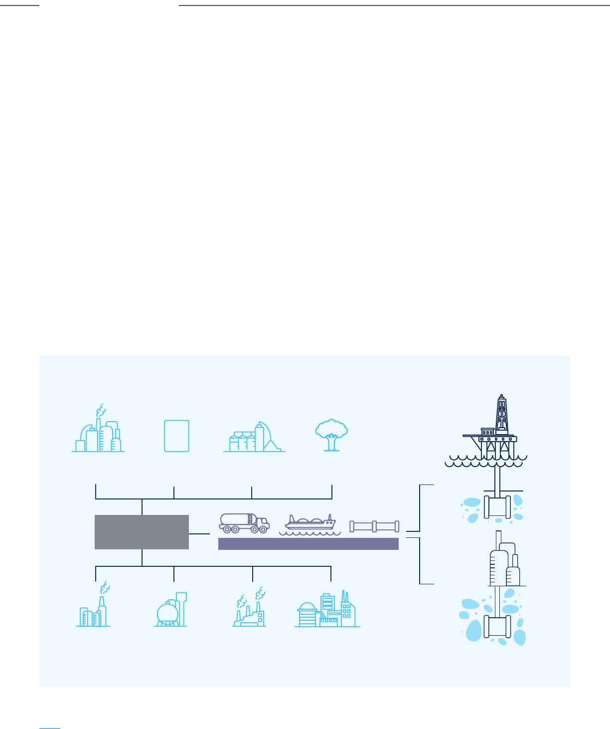
The oversized carbon disposition infrastructure would
be too large for single users but rather be designed for
multiple users/emitters.
The anchor project would be large CO
2
emitters, viz. a
thermal power plant or a large industrial facility, which
can cover the initial infrastructure costs, thereby
enabling cost-effective CCUS deployment based on
incremental capital and operating expenses. Emitting
industrial clusters are frequently co-located with power
generation facilities, thus providing substantial
capturable CO
2
sources. The CO
2
disposition can be
spread across multiple but reasonably closely located
geological sequestration sites and/or oil fields for
enhanced oil recovery (EOR).
Both emitters and storage sites need to interconnect
through hubs, similar to the natural gas distribution
industry, where pipeline networks are interconnected
in order to collect gas from many different production
fields, and to distribute the gas in the market. One hub
would service the collection of CO
2
from a capture
cluster or distribution of CO
2
to a storage cluster, as
depicted in Figure 5-1. Hubs can be built at the capture,
collection, or storage end of a multi-user pipeline or
both (forming capture/collection or storage hubs).
Depending on the individual emissions sources within
the cluster, the volume and composition of the
captured CO
2
can vary significantly. Collection and
storage hubs will offer compressed CO
2
transportation
services, thus substantially lowering the cost of
transportation infrastructure between point source
emitters and CO
2
injection points.
The elements along the CCUS value chain (CO
2
source,
capture, transport, injection, and storage) are brought
together in a CCUS hub and cluster network, with
multiple co-located (clustered) source capture
facilities (of the same or different types) supplying
CO
2
to a shared “oversized” transport and storage
system. With the growth of the CO
2
supplier or emitter
base, the transport and storage infrastructure must
expand through multiple transport pipelines, injection
facilities, and storage formations (depending upon
local geological characteristics). Multiple and high
concentration sources of CO
2
in a close geographical
location with neighbouring storage capacity will make
the CCUS infrastructure effective & economical.
Figure 5-1: CCUS Hub and Cluster Framework
H
1
Source: Global CCS Institute
STEEL PLANT
FERTILISER
PLANT
NATURAL GAS
PROCESSING
REFINING
POWER PLANT
CEMENT PLANT
BIOMASS
OFFSHORE
CO
2
STORAGE
ONSHORE
CO
2
STORAGE
CO
2
HYDROGEN
PRODUCTION
CO
2
COLLECTION HUB
CO
2
TRANSPORT
122
Carbon Capture Utilization and Storage (CCUS) –
Policy Framework and Deployment Mechanism in India
Carbon Capture Utilization and Storage (CCUS) –
Policy Framework and Deployment Mechanism in India
CCUS Policy Framework for India

5.4.2 Economic and Business Rationale for
CCUS Hubs and Clusters
The development and deployment of CCUS at scale
requires the development of not only the technologies
for CO
2
capture and use, but also the implementation
of enabling transportation infrastructure and markets
at Giga-tonne (GT) scale, along with the development
of a complete value chain of capture, aggregation,
transportation, disposition and use or storage. An
effective CCUS hub and cluster framework will
incentivize participants across the CCUS value chain by
providing seamless access to CCUS infrastructure,
minimize costs and coordination issues, offer
opportunities to maximize benefits/profits and de-risk
investments by widening the market, and abrogate the
necessity of bilateral agreements between CO
2
sources
and sinks.
For CCUS hubs and clusters to be effective,
they need to:
- Provide sufficient incentives for both sources (CO
2
emitters) and sinks of CO
2
(CO
2
end-users) to
participate in the market, as well as CO
2
aggregators and CO
2
marketers. This is especially
relevant when entry involves large fixed costs that
could limit participation
- Aggregate carbon emissions across emitters to
create economies of scale
- Exploit different storage and use patterns across
geographical regions or clusters
- Enable market clearing of CO
2
demand and
supply within and across regions through
interconnecting hubs
- Recognize the heterogeneity of emitters, and
provide them open access to the hub and cluster
network for CO
2
disposition
CO
2
Pricing and the Necessity of Markets
Capture costs are dependent on a number of factors,
including the source, density and purity of the CO
2
emission stream. Transportation costs depend on
volume and distance, and injection costs depend on
volume and site location. If a utilization opportunity
exists, the costs depend on the application, with
enhanced oil recovery (EOR) being an injection activity
while applications like chemicals or advanced materials
being dependent on a host of other factors. The build
up of these costs across the CCUS value chain can
become the substantial and prevent the development
and implementation of CCUS projects.
Hence there is a necessity for a market model for
encouraging and incentivizing scale & innovation,
leading to lower costs and prices for participants
across the CCUS value chain.
Innovations in the CCUS context could involve
technologies and applications leading to creation of
value added products from CO
2
, such CO
2
to chemicals,
cement and advanced carbon materials. As with any
innovation, it is difficult to predict which of these
applications will reach commercialization earlier than
the others. Innovation could reduce costs across the
CCUS value chain or also bring forth new pathways for
using CO
2
as a feedstock, leading to higher demand and
prices for carbon and CCUS.
Prices will be governed by both expectations of future
demand-supply as well as the level of competition in
the market on both the demand and supply side.
Sufficient competition is necessary for efficient pricing,
leading to efficient allocation of resources for CCUS
and sharing of gains between the supply and the
demand side. On the supply side, the market needs to
incentivize participation by sellers that can supply CO
2
at the lowest cost. On the demand side, the CO
2
should
be allocated to buyers that have the highest value
usage and ability to pay the CO
2
price.
Auctions provide a way for the efficient allocation of
resources. Consumers of CO
2
can compete against
each other so that the final bids reflect the
highest-value use for CO
2
. A higher price for CO
2
implies that demand is higher than supply and should
incentivize new CO
2
emitters (supply) to capture CO
2
and enter the CCUS value chain/market. However,
during the initial operations of the CCUS value chain
with a small market and limited number of participants,
CO
2
emitters may need additional incentives to enter
the market, through measures such as administered
pricing mechanisms. It is likely that more efficient and
purely demand-supply based pricing mechanisms will
emerge as markets mature and grow in size.
Hubs and clusters provide a valuable market-making
mechanism for de-risking investments and
incentivizing participation in the CCUS value chain.
During their initial period, Government support (either
in the form of federal & private investments, tax
credits, carbon taxes) is critical for ensuring sufficient
participation and success, till the market reaches scale
and efficiency. The next section discusses some of the
CCUS hubs and clusters in different parts of the world.
123
Carbon Capture Utilization and Storage (CCUS) –
Policy Framework and Deployment Mechanism in India
Carbon Capture Utilization and Storage (CCUS) –
Policy Framework and Deployment Mechanism in India
CCUS Policy Framework for India
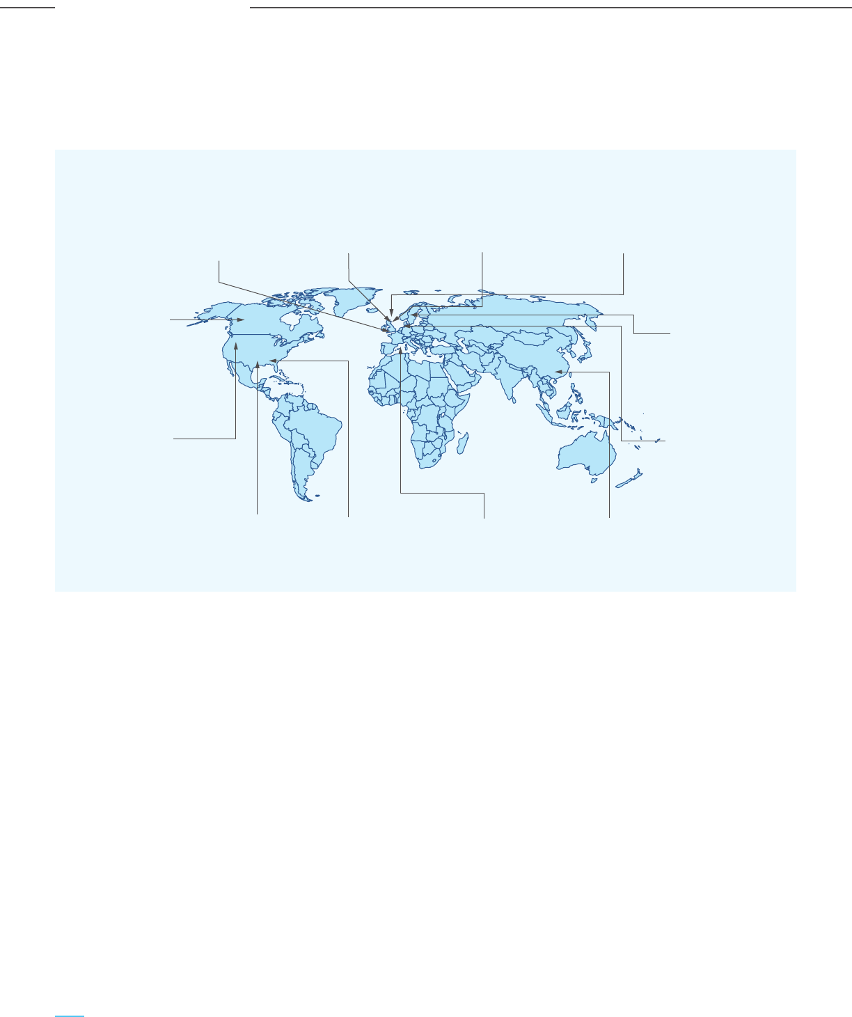
Long term economic analysis reveals the potential
to capture up to 62 mtpa of CO
2
considering the
available onshore and offshore reservoirs.
iii) Transport: CO
2
will be transported by a dedicated
pipeline to a depleted gas field located 25 km
offshore. The pipeline will be insulated to ensure
the CO
2
is warm enough to be injected into the low
pressure depleted reservoir. In subsequent phases
of the project, other sources would be connected to
the offshore section of the line, which will be
modified to transport up to 5 mtpa. This phase will
also include a network extension to connect more
CO
2
sources and sinks, along with assessments of
connectivity to other prospective CO
2
hub locations
which can share the transportation infrastructure.
iv) Storage: Initially, the CO
2
is planned to be stored in
the offshore P18 field’s reservoirs 6, 5 and 2, which
have a capacity of up to 42.4 mtpa. Initial
investigations also reveal the possibility of storing
up to 259 mtpa of CO
2
in other fields in the area.
v) Funding: The Dutch Government will be granting
the project consortium (which includes Royal Dutch
Shell and ExxonMobil) around USD 2.4 BB$ in
subsidies for what is set to become one of the
largest CCUS projects in the world.
vi) Value proposition: The main value proposition is
the competitive cost structure of the Rotterdam
hub vis-à-vis CCUS projects worldwide, providing a
one-stop CO
2
disposition solution for CO
2
emitters
and making carbon abatement a part of the
Rotterdam city’s and port’s goals. The competitive
cost structure is driven by the favourable location,
with sources and offshore sinks co-located, making
CO
2
transport simpler and less expensive. Other
reasons are the economies of scale and the
potential of CO
2
being shipped to the cluster from
other CO
2
emitting areas, thus leading to high
capacity utilization.
vii) Revenue streams: The main revenue stream will
be from the CO
2
transit charge collected from
emitters. There is also an option of the Government
providing loans or investments for early project
development, with analysis indicating that the
revenues to the Government from royalties and
taxes earned through CO
2
EOR will compensate
underwriting the initial project costs and risks.
Figure 5-2: CCUS Cluster Around the World
5.4.3 Review of CO
2
Clusters Around the World
The major CCUS cluster around the world are illustrated below. Many of the clusters are located near ports with large
industrial footprints, and provide regions and countries a competitive advantage in a carbon-constrained world.
5.4.3.1 Rotterdam Cluster Project (RCP),
Netherlands
i) Outline: This cluster is supported principally
through the Rotterdam Climate Initiative, which is a
partnership between the City of Rotterdam, the
Port of Rotterdam, DCMR Environmental
Protection Agency Rijnmond, and Deltalinqs, an
association of industrial enterprises in the
Rotterdam area. The initiative started with the
objective of reducing CO
2
emissions by 50% within
2030. The vision includes a full CO
2
network
capturing CO
2
from the power plants and industries
in the Rotterdam area and transporting the CO
2
for
offshore storage. The long term vision is to extend
beyond the Rotterdam region and also to
neighbouring countries and beyond the Dutch
continental shelf. The plan is to develop the project
as an integrated CCUS cluster project, termed as
ROAD (Rotterdam Opslag en Afvang Demonstratie,
or Rotterdam Storage and Capture Demonstration)
ii) Capture: The ROAD project initially had a capacity
of 1.1 mtpa with a single carbon capture unit for
capturing 25% of the flue gas from a coal-fired
power plant. A collection of projects have entered
into cooperation agreements, which may increase
the capture volume by an additional 5 mtpa. The
Rotterdam area has outsized CCUS infrastructure,
which can capture and sequester up to 17.5 mtpa of
CO
2
by 2025 and become a regional centre by
storing CO
2
from other parts of the Netherlands,
and potentially the neighbouring countries of
Germany and Belgium.
Le Havre cluster
(COCATE)
14.5 mtpa
Teesside cluster
26 mtpa
Yorkshire cluster
60 mtpa
Firth of Forth
7.6 mtpa
Skagerrak/
Kattegat cluster
14 mtpa
Rotterdam
climate project
(RCP)
17.5 mtpa
Shenzhen City
cluster
43 mtpa
Marseille cluster
(VASCO)
35.5 mtpa
Gulf Coast
cluster
7.6 mtpa
Denver City Hub
cluster
8.4 mtpa
Rocky Mountain
cluster
9.5mtpa
Alberta CO
2
Truck Line
(ACTL)
14.6 mtpa
124
Carbon Capture Utilization and Storage (CCUS) –
Policy Framework and Deployment Mechanism in India
Carbon Capture Utilization and Storage (CCUS) –
Policy Framework and Deployment Mechanism in India
CCUS Policy Framework for India
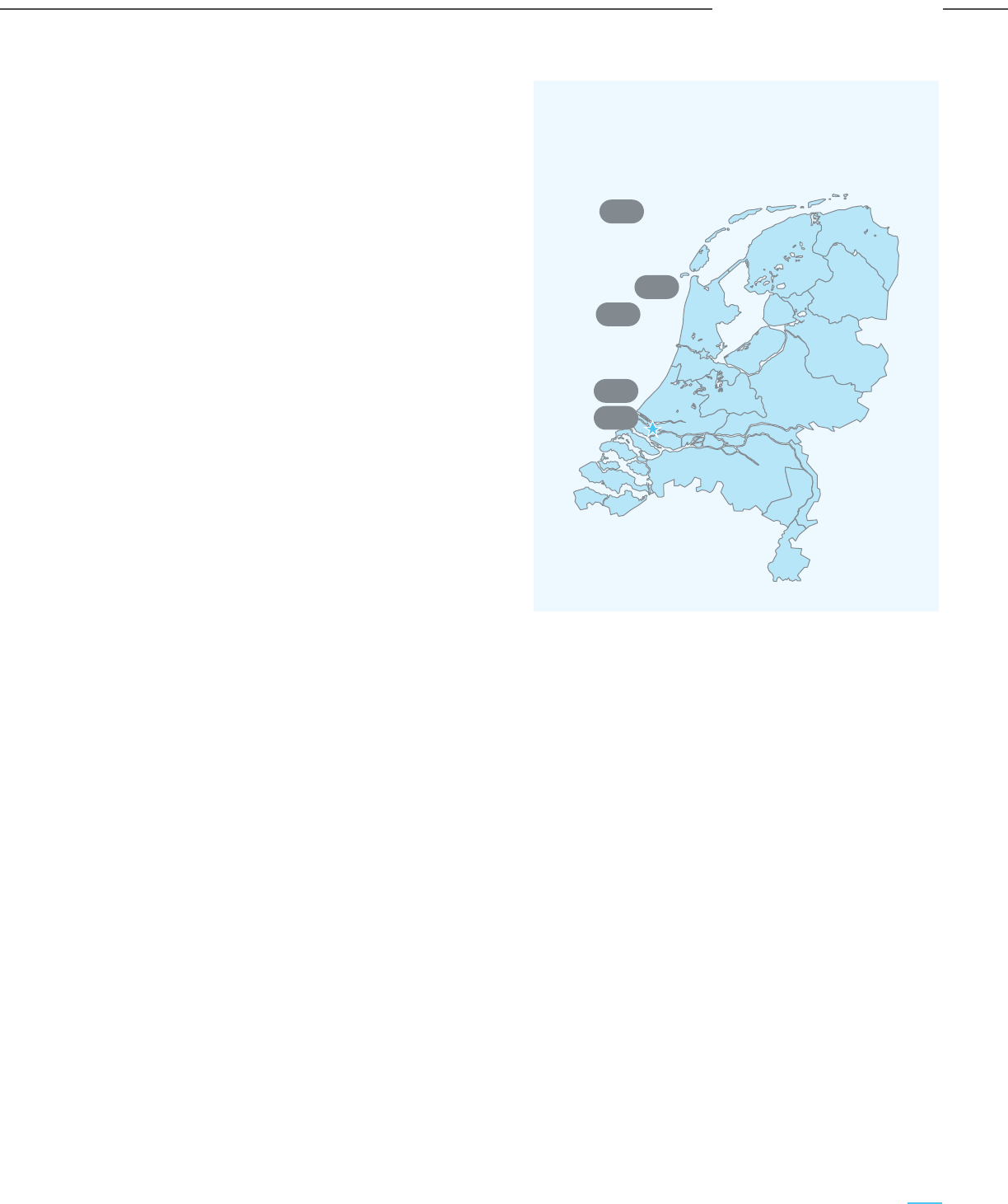
The anchor emitter will inject 5 mtpa of CO
2
in the
hub, and the capacity will increase with other
emitters joining the hub. These emitters would be
across industries such as power plants, steel
plants, chemical plants, petroleum refineries,
biomass based plants and other sources.
Additionally, a new IGCC plant using underground
coal gasification is also being explored.
iii) Transport: The hub has been designed with a
notional 200 km offshore line that can reach
several potential storage sites, along with the
possibility of shipping during the capacity
build-up phase.
iv) Storage: Studies have identified a handful of
prospective offshore storage sites within a
200-kilometer radius. Further studies on the
characterization of the reservoirs is being
undertaken. The high-level storage costs are
predicted to be between £12 – 14 per tonne of CO
2
.
v) Funding: The project has secured about USD 39
MM$ 28m of public funding from the UK Research
and Innovation (UKRI) Industrial Decarbonisation
Challenge fund.
vi) Value proposition: The core value proposition for
participating industries is avoiding payments on
emission certifications, as pooling transportation
and storage facilities will make CCUS less
expensive. Teesside’s proximity to storage
locations makes it a low-cost option for CCUS in
the UK.
vii) Revenue streams: The main revenue stream
would be transport and storage payments from
emitters, either in the form of tariffs or based on
equity/cost recovery arrangements. Government
support would be needed to cover the business
risks in the form of CO
2
floor prices, CCUS fees,
and demonstration project funding.
viii)Business model: To further support the
development of the CCUS hubs and clusters, the
UK Government, in consultation with the industry,
is also developing a business model for Industrial
Carbon Capture (ICC) projects. The key elements
addressed by the business model are:
- Commercial framework for ICC projects,
including the payment mechanism between
different counterparties in the CCUS value chain
- Transport and Storage (T&S) fees
- Carbon price
- Conditions and time period for which capital
grant and ongoing revenue support will be
provided by to eligible projects by the
Government
- Risk allocation and mitigation
- Carbon intensity of industrial products and
free allowances
- Legal contractual framework and draft
contract for Industrial Carbon Capture
between CO
2
emitters and counterparties
- Conditions precedent and milestones
- Metering and reporting requirements
5.4.3.3 Denver City Hub Cluster, USA
i) Outline: The Denver City hub is located in Texas
and is part of the trunk line for transporting CO
2
from naturally occurring underground resources to
EOR projects. Several long-distance CO
2
pipelines
converge at Denver City in Texas, from where CO
2
is distributed to over 40 oilfields for EOR. Kinder
Morgan is the primary partner in the Denver City
hub and operates a variety of oil & gas production
and distribution facilities in addition to the CO
2
business. Other large oil and gas firms, such as
Occidental, BP, Amerada Hess, and Exxon Mobil,
are co-owners and operators of parts of the
system. There are efforts to expand the hub to
other locations for CO
2
EOR as well as large
sources of anthropogenic CO
2
emissions.
ii) Capture: Presently the CO
2
entering the system
comes from natural CO
2
reservoirs. The plan is to
inject CO
2
emissions from natural gas processing
plants in the region, given the total system capacity
of 45 mtpa, considering the four main pipelines and
the available natural CO
2
reservoirs in the hub.
iii) Transport: Transportation is by
supercritical-pressure pipeline, and additions are
common in both design and operation. A
160-kilometer pipeline has been built from the
facility to the Denver City hub for the Century
natural gas processing project of Occidental
Petroleum in West Texas, which is the largest
carbon capture plant in the world, with a capacity
of 8.4 mtpa of CO
2
capture.
Figure 5-3: Rotterdam CCS Cluster
Long term economic analysis reveals the potential
to capture up to 62 mtpa of CO
2
considering the
available onshore and offshore reservoirs.
iii) Transport: CO
2
will be transported by a dedicated
pipeline to a depleted gas field located 25 km
offshore. The pipeline will be insulated to ensure
the CO
2
is warm enough to be injected into the low
pressure depleted reservoir. In subsequent phases
of the project, other sources would be connected to
the offshore section of the line, which will be
modified to transport up to 5 mtpa. This phase will
also include a network extension to connect more
CO
2
sources and sinks, along with assessments of
connectivity to other prospective CO
2
hub locations
which can share the transportation infrastructure.
iv) Storage: Initially, the CO
2
is planned to be stored in
the offshore P18 field’s reservoirs 6, 5 and 2, which
have a capacity of up to 42.4 mtpa. Initial
investigations also reveal the possibility of storing
up to 259 mtpa of CO
2
in other fields in the area.
v) Funding: The Dutch Government will be granting
the project consortium (which includes Royal Dutch
Shell and ExxonMobil) around USD 2.4 BB$ in
subsidies for what is set to become one of the
largest CCUS projects in the world.
vi) Value proposition: The main value proposition is
the competitive cost structure of the Rotterdam
hub vis-à-vis CCUS projects worldwide, providing a
one-stop CO
2
disposition solution for CO
2
emitters
and making carbon abatement a part of the
Rotterdam city’s and port’s goals. The competitive
cost structure is driven by the favourable location,
with sources and offshore sinks co-located, making
CO
2
transport simpler and less expensive. Other
reasons are the economies of scale and the
potential of CO
2
being shipped to the cluster from
other CO
2
emitting areas, thus leading to high
capacity utilization.
vii) Revenue streams: The main revenue stream will
be from the CO
2
transit charge collected from
emitters. There is also an option of the Government
providing loans or investments for early project
development, with analysis indicating that the
revenues to the Government from royalties and
taxes earned through CO
2
EOR will compensate
underwriting the initial project costs and risks.
Rotterdam CCS cluster - Locations of licensing blocks
with depleted fields identified as suitable for CO
2
storage
5.4.3.2 Teesside UK Cluster, UK
i) Outline: A significant number of large CO
2
emitting
industries are located around the mouth of the
River Tees on England’s NE coast. Net Zero
Teesside is a carbon capture, utilization, and
storage (CCUS) initiative in the Teesside region of
England that aims to reduce industrial emissions. It
entails the construction of an 840 MW gas-fired
power station fitted with carbon capture
technology, as well as the creation of CO
2
collection network to enable low-carbon hydrogen
production. Initially, the project aims to capture up
to 10 mtpa of CO
2
emissions. Along with the
Teeside cluster, another CCUS cluster is also
coming up around the river Humber on the East
Coast of England. The CO
2
from both projects will
be permanently stored in a geological aquifer in the
Southern North Sea.
ii) Capture: The project includes a single-source initial
anchor project, as well as other small, medium, and
large CO
2
emitters.
ROAD (Rotterdam Opslag en Afvang Demonstratie,
or Rotterdam Storage and Capture Demonstration)
ii) Capture: The ROAD project initially had a capacity
of 1.1 mtpa with a single carbon capture unit for
capturing 25% of the flue gas from a coal-fired
power plant. A collection of projects have entered
into cooperation agreements, which may increase
the capture volume by an additional 5 mtpa. The
Rotterdam area has outsized CCUS infrastructure,
which can capture and sequester up to 17.5 mtpa of
CO
2
by 2025 and become a regional centre by
storing CO
2
from other parts of the Netherlands,
and potentially the neighbouring countries of
Germany and Belgium.
iv) Storage: The CO
2
is entirely utilized for EOR projects
and there are no projects purely for storage.
v) Value proposition: The current CO
2
value
proposition is based on the profitability of
extracting additional oil using CO
2
EOR. The costs
per tonne of CO
2
delivered hence should be
substantially lower than the value of the extra oil
recovery. Recent contracts have also incorporated
specific carbon credit provisions, based on the
minimum offtake of CO
2
.
vi) Revenue streams: Transportation tariffs and CO
2
sales are the two main revenue streams, apart
from the potential revenues from the credits
earned through the project.
125
Carbon Capture Utilization and Storage (CCUS) –
Policy Framework and Deployment Mechanism in India
Carbon Capture Utilization and Storage (CCUS) –
Policy Framework and Deployment Mechanism in India
CCUS Policy Framework for India
Netherlands
Rotterdam
K12
Q1
P6
P15
P18

The anchor emitter will inject 5 mtpa of CO
2
in the
hub, and the capacity will increase with other
emitters joining the hub. These emitters would be
across industries such as power plants, steel
plants, chemical plants, petroleum refineries,
biomass based plants and other sources.
Additionally, a new IGCC plant using underground
coal gasification is also being explored.
iii) Transport: The hub has been designed with a
notional 200 km offshore line that can reach
several potential storage sites, along with the
possibility of shipping during the capacity
build-up phase.
iv) Storage: Studies have identified a handful of
prospective offshore storage sites within a
200-kilometer radius. Further studies on the
characterization of the reservoirs is being
undertaken. The high-level storage costs are
predicted to be between £12 – 14 per tonne of CO
2
.
v) Funding: The project has secured about USD 39
MM$ 28m of public funding from the UK Research
and Innovation (UKRI) Industrial Decarbonisation
Challenge fund.
vi) Value proposition: The core value proposition for
participating industries is avoiding payments on
emission certifications, as pooling transportation
and storage facilities will make CCUS less
expensive. Teesside’s proximity to storage
locations makes it a low-cost option for CCUS in
the UK.
vii) Revenue streams: The main revenue stream
would be transport and storage payments from
emitters, either in the form of tariffs or based on
equity/cost recovery arrangements. Government
support would be needed to cover the business
risks in the form of CO
2
floor prices, CCUS fees,
and demonstration project funding.
viii)Business model: To further support the
development of the CCUS hubs and clusters, the
UK Government, in consultation with the industry,
is also developing a business model for Industrial
Carbon Capture (ICC) projects. The key elements
addressed by the business model are:
- Commercial framework for ICC projects,
including the payment mechanism between
different counterparties in the CCUS value chain
- Transport and Storage (T&S) fees
- Carbon price
- Conditions and time period for which capital
grant and ongoing revenue support will be
provided by to eligible projects by the
Government
- Risk allocation and mitigation
- Carbon intensity of industrial products and
free allowances
- Legal contractual framework and draft
contract for Industrial Carbon Capture
between CO
2
emitters and counterparties
- Conditions precedent and milestones
- Metering and reporting requirements
5.4.3.3 Denver City Hub Cluster, USA
i) Outline: The Denver City hub is located in Texas
and is part of the trunk line for transporting CO
2
from naturally occurring underground resources to
EOR projects. Several long-distance CO
2
pipelines
converge at Denver City in Texas, from where CO
2
is distributed to over 40 oilfields for EOR. Kinder
Morgan is the primary partner in the Denver City
hub and operates a variety of oil & gas production
and distribution facilities in addition to the CO
2
business. Other large oil and gas firms, such as
Occidental, BP, Amerada Hess, and Exxon Mobil,
are co-owners and operators of parts of the
system. There are efforts to expand the hub to
other locations for CO
2
EOR as well as large
sources of anthropogenic CO
2
emissions.
ii) Capture: Presently the CO
2
entering the system
comes from natural CO
2
reservoirs. The plan is to
inject CO
2
emissions from natural gas processing
plants in the region, given the total system capacity
of 45 mtpa, considering the four main pipelines and
the available natural CO
2
reservoirs in the hub.
iii) Transport: Transportation is by
supercritical-pressure pipeline, and additions are
common in both design and operation. A
160-kilometer pipeline has been built from the
facility to the Denver City hub for the Century
natural gas processing project of Occidental
Petroleum in West Texas, which is the largest
carbon capture plant in the world, with a capacity
of 8.4 mtpa of CO
2
capture.
iv) Storage: The CO
2
is entirely utilized for EOR projects
and there are no projects purely for storage.
v) Value proposition: The current CO
2
value
proposition is based on the profitability of
extracting additional oil using CO
2
EOR. The costs
per tonne of CO
2
delivered hence should be
substantially lower than the value of the extra oil
recovery. Recent contracts have also incorporated
specific carbon credit provisions, based on the
minimum offtake of CO
2
.
vi) Revenue streams: Transportation tariffs and CO
2
sales are the two main revenue streams, apart
from the potential revenues from the credits
earned through the project.
126
Carbon Capture Utilization and Storage (CCUS) –
Policy Framework and Deployment Mechanism in India
Carbon Capture Utilization and Storage (CCUS) –
Policy Framework and Deployment Mechanism in India
CCUS Policy Framework for India

The anchor emitter will inject 5 mtpa of CO
2
in the
hub, and the capacity will increase with other
emitters joining the hub. These emitters would be
across industries such as power plants, steel
plants, chemical plants, petroleum refineries,
biomass based plants and other sources.
Additionally, a new IGCC plant using underground
coal gasification is also being explored.
iii) Transport: The hub has been designed with a
notional 200 km offshore line that can reach
several potential storage sites, along with the
possibility of shipping during the capacity
build-up phase.
iv) Storage: Studies have identified a handful of
prospective offshore storage sites within a
200-kilometer radius. Further studies on the
characterization of the reservoirs is being
undertaken. The high-level storage costs are
predicted to be between £12 – 14 per tonne of CO
2
.
v) Funding: The project has secured about USD 39
MM$ 28m of public funding from the UK Research
and Innovation (UKRI) Industrial Decarbonisation
Challenge fund.
vi) Value proposition: The core value proposition for
participating industries is avoiding payments on
emission certifications, as pooling transportation
and storage facilities will make CCUS less
expensive. Teesside’s proximity to storage
locations makes it a low-cost option for CCUS in
the UK.
vii) Revenue streams: The main revenue stream
would be transport and storage payments from
emitters, either in the form of tariffs or based on
equity/cost recovery arrangements. Government
support would be needed to cover the business
risks in the form of CO
2
floor prices, CCUS fees,
and demonstration project funding.
viii)Business model: To further support the
development of the CCUS hubs and clusters, the
UK Government, in consultation with the industry,
is also developing a business model for Industrial
Carbon Capture (ICC) projects. The key elements
addressed by the business model are:
- Commercial framework for ICC projects,
including the payment mechanism between
different counterparties in the CCUS value chain
- Transport and Storage (T&S) fees
- Carbon price
- Conditions and time period for which capital
grant and ongoing revenue support will be
provided by to eligible projects by the
Government
- Risk allocation and mitigation
- Carbon intensity of industrial products and
free allowances
- Legal contractual framework and draft
contract for Industrial Carbon Capture
between CO
2
emitters and counterparties
- Conditions precedent and milestones
- Metering and reporting requirements
5.4.3.3 Denver City Hub Cluster, USA
i) Outline: The Denver City hub is located in Texas
and is part of the trunk line for transporting CO
2
from naturally occurring underground resources to
EOR projects. Several long-distance CO
2
pipelines
converge at Denver City in Texas, from where CO
2
is distributed to over 40 oilfields for EOR. Kinder
Morgan is the primary partner in the Denver City
hub and operates a variety of oil & gas production
and distribution facilities in addition to the CO
2
business. Other large oil and gas firms, such as
Occidental, BP, Amerada Hess, and Exxon Mobil,
are co-owners and operators of parts of the
system. There are efforts to expand the hub to
other locations for CO
2
EOR as well as large
sources of anthropogenic CO
2
emissions.
ii) Capture: Presently the CO
2
entering the system
comes from natural CO
2
reservoirs. The plan is to
inject CO
2
emissions from natural gas processing
plants in the region, given the total system capacity
of 45 mtpa, considering the four main pipelines and
the available natural CO
2
reservoirs in the hub.
iii) Transport: Transportation is by
supercritical-pressure pipeline, and additions are
common in both design and operation. A
160-kilometer pipeline has been built from the
facility to the Denver City hub for the Century
natural gas processing project of Occidental
Petroleum in West Texas, which is the largest
carbon capture plant in the world, with a capacity
of 8.4 mtpa of CO
2
capture.
v) Value propositions: The major value proposition is
the delivery of CO
2
to CO
2
-EOR projects at a
reasonable cost. Another advantage is the
opportunity to minimize the “tax” on CO
2
emissions
imposed by the Alberta Government and access to
Government and private funding for carbon
abated projects.
vi) Revenue streams: The project is being funded
through Government support for investments and
private venture capital. The main revenue sources
are the payments received for the CO
2
delivered
for EOR.
Figure 5-4: Timeline Denver City Hub
Figure 5-5: Denver City Storage
iv) Storage: The CO
2
is entirely utilized for EOR projects
and there are no projects purely for storage.
v) Value proposition: The current CO
2
value
proposition is based on the profitability of
extracting additional oil using CO
2
EOR. The costs
per tonne of CO
2
delivered hence should be
substantially lower than the value of the extra oil
recovery. Recent contracts have also incorporated
specific carbon credit provisions, based on the
minimum offtake of CO
2
.
vi) Revenue streams: Transportation tariffs and CO
2
sales are the two main revenue streams, apart
from the potential revenues from the credits
earned through the project.
Time line Denver Cirty Hub
pre1990 1990 2000 2010 2020 2030 2040 2050
Development of natural
CO
2
business ~45 mtpa
Invt
Business development
Century gas plant capture
8.4 mtpa added
Potential for expansion
by capture
5.4.3.4 The Alberta Carbon Dioxide
Trunk Line (ACTL)
i) Outline: The project is based on the synergy
between oil producers who can benefit from
CO
2
-EOR and CO
2
emitters, particularly from the oil
& gas industry, who can abate their CO
2
emissions.
The project consists of a central CO
2
trunk pipeline,
similar to trunk lines in the oil & gas industry.
The first phase consists of two capture locations.
The CO
2
pipeline will be constructed and operated
by Enhance Energy, for transporting the CO
2
for
EOR. The EOR operations will also include
monitoring of the stored CO
2
plume, design of wells
and the injection programme and reservoir
management.
ii) Capture: The project started with two CO
2
sources:
an Agrium fertilizer facility and the Sturgeon heavy
oil upgrading refinery. The capture costs are CAD
21/tonne at Agrium (for 1.2 mtpa of CO
2
) and CAD
12/tonne at Sturgeon (for 0.4 mtpa). The trunk line
capacity is expected to be expanded to 14.6 mtpa,
which allows headroom for adding further emitters.
iii) Transport: The CO
2
is transported over a 242 km
pipeline (12 km having 12” dia and 220 km having
16” dia). The pipeline stretches from the Edmonton
industrial area to the Clive oil field, south of the
city. A spare 12” line will be constructed where the
12” portion crosses the Saskatchewan river. The
line has a maximum allowable working pressure
(MAWP) of 179 bar and is sunk to a minimum depth
of 1.2m. The CO
2
is delivered at a pressure of 137
bar. There is no intermediate pumping in the initial
phase; pumping stations would be required when
the pipeline reaches the maximum capacity of 14.6
mtpa. The main line will be made of 14.3mm thick
welded carbon steel, and does not require crack
arrestors due to its thickness.
iv) Storage: The Clive oil field will be the first
storage site, with CO
2
injected into the Nisku and
Leduc horizons for improved oil recovery. Based
on re-pressurizing to the initial discovery
pressure of 165 bar from the current depletion
pressure of roughly 125 bar, the estimated CO
2
capacity is 18.9 mt (1800psig). However, the
regional storage potential is significantly larger,
estimated at 2000 mt.
127
Carbon Capture Utilization and Storage (CCUS) –
Policy Framework and Deployment Mechanism in India
Carbon Capture Utilization and Storage (CCUS) –
Policy Framework and Deployment Mechanism in India
CCUS Policy Framework for India
McElmo Dome
EOR
CO
2
capture
Natural CO
2
source
Doe Canyon
Sheep Mtn.
Bravo Dome
TEXAS
MEXICO
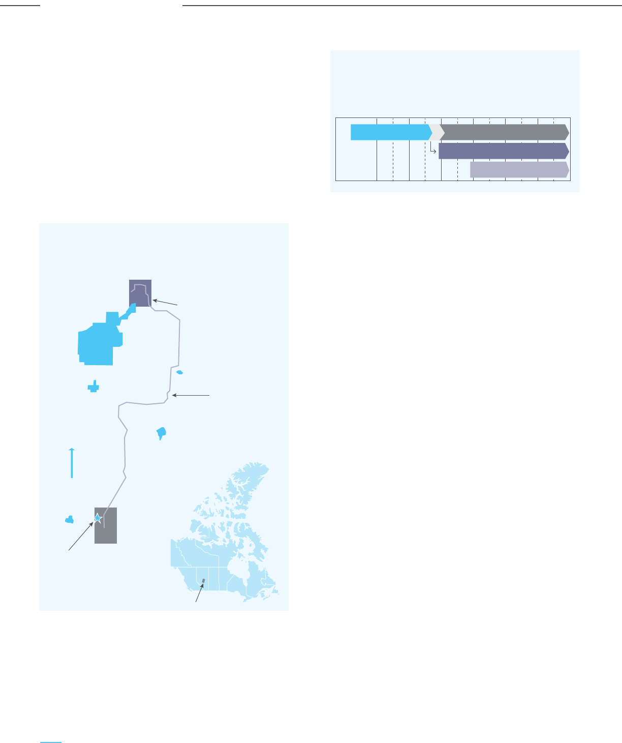
Figure 5-6: ACTL Map
Figure 5-7: ACTL Timelines
Time line for Alberta CO
2
Trunk Line
pre1990 1990 2000 2010 2020 2030 2040 2050
Inception
Invt
Business development
First projects 1.6 mtpa (firm 2015)
Expansions to 14.6 mtpa
v) Value propositions: The major value proposition is
the delivery of CO
2
to CO
2
-EOR projects at a
reasonable cost. Another advantage is the
opportunity to minimize the “tax” on CO
2
emissions
imposed by the Alberta Government and access to
Government and private funding for carbon
abated projects.
vi) Revenue streams: The project is being funded
through Government support for investments and
private venture capital. The main revenue sources
are the payments received for the CO
2
delivered
for EOR.
5.4.4 Critical Assessment of CO
2
Clusters
Based on the review of global CCUS clusters, clusters
based on the utilization of CO
2
for EOR applications are
the most successful. For projects involving the
sequestration or the storage of CO
2
, the funding/cost
gap for large scale CCUS deployment (whether as hub
and spoke clusters or point-to-point projects), needs
Government support and policies to incentivize carbon
capture and sequestration. Economies of scale exist in
merging CCUS infrastructure and result in lowering
pipeline and transportation costs. However,
Government support is required for funding the capital
costs, de-risking CCUS projects and building confidence
amongst emission sources in the cluster to move
forward with their plans.
The other major benefits offered by clusters could
result from combining organizational costs, acquiring
permissions, winning public acceptability, and pooling
professional services such O&M of carbon capture
facilities, chemical supply & waste disposal, and CO
2
measurement & accounting services.
Because of the high mobilization and laying expenses,
cost reductions for CCUS cluster projects are greater
for offshore and distant storage locations. The
economics of such CCUS cluster projects in the initial
years are quite challenging due to lower CO
2
volumes
and the outsized infrastructure created. This can be
overcome if long-term and low-cost financing are
available for clusters with competitive locations, both
through Government support and access to
international clean funds.
5.4.3.4 The Alberta Carbon Dioxide
Trunk Line (ACTL)
i) Outline: The project is based on the synergy
between oil producers who can benefit from
CO
2
-EOR and CO
2
emitters, particularly from the oil
& gas industry, who can abate their CO
2
emissions.
The project consists of a central CO
2
trunk pipeline,
similar to trunk lines in the oil & gas industry.
The first phase consists of two capture locations.
The CO
2
pipeline will be constructed and operated
by Enhance Energy, for transporting the CO
2
for
EOR. The EOR operations will also include
monitoring of the stored CO
2
plume, design of wells
and the injection programme and reservoir
management.
ii) Capture: The project started with two CO
2
sources:
an Agrium fertilizer facility and the Sturgeon heavy
oil upgrading refinery. The capture costs are CAD
21/tonne at Agrium (for 1.2 mtpa of CO
2
) and CAD
12/tonne at Sturgeon (for 0.4 mtpa). The trunk line
capacity is expected to be expanded to 14.6 mtpa,
which allows headroom for adding further emitters.
iii) Transport: The CO
2
is transported over a 242 km
pipeline (12 km having 12” dia and 220 km having
16” dia). The pipeline stretches from the Edmonton
industrial area to the Clive oil field, south of the
city. A spare 12” line will be constructed where the
12” portion crosses the Saskatchewan river. The
line has a maximum allowable working pressure
(MAWP) of 179 bar and is sunk to a minimum depth
of 1.2m. The CO
2
is delivered at a pressure of 137
bar. There is no intermediate pumping in the initial
phase; pumping stations would be required when
the pipeline reaches the maximum capacity of 14.6
mtpa. The main line will be made of 14.3mm thick
welded carbon steel, and does not require crack
arrestors due to its thickness.
iv) Storage: The Clive oil field will be the first
storage site, with CO
2
injected into the Nisku and
Leduc horizons for improved oil recovery. Based
on re-pressurizing to the initial discovery
pressure of 165 bar from the current depletion
pressure of roughly 125 bar, the estimated CO
2
capacity is 18.9 mt (1800psig). However, the
regional storage potential is significantly larger,
estimated at 2000 mt.
128
Carbon Capture Utilization and Storage (CCUS) –
Policy Framework and Deployment Mechanism in India
Carbon Capture Utilization and Storage (CCUS) –
Policy Framework and Deployment Mechanism in India
CCUS Policy Framework for India
EOR projects
Clive
Camrose
Tofield
Alberta Industrial Heartland
Leduc
ACTL
First capture locations
North
First injection site
Edmonton

5.5 Hub and Cluster
Framework for India
The merits of a hub and cluster framework make it the
best suited for implementing CCUS in India. The first
step is to map identified industry-wise clusters and
suitable storage clusters in India. A cluster framework
is both advantageous and necessary for incentivizing
CO
2
capture from both large and small emitters. The
underlying principles for a potential CCUS cluster
framework in India are provided below:
5.5.1 Principles of Proposed Framework
5.5.1.1 Evolutionary and Phase Cluster Model
An evolutionary and phased cluster model would be
appropriate for India, as there no commercial-scale
CCUS projects in operation. CCUS can be deployed in
a phased manner, prioritizing regions and industrial
clusters based on their total CO
2
emissions. The
cluster framework should also be adaptable and
accommodate new local networks as and when they
develop. This type of approach to CCUS deployment
will enable India to build a scalable network, whereas a
single point-to-point approach may not be scalable in
the future and face issues of alternative storage
spaces or lack of buyers for CO
2
in the future. A
cluster model will ensure a robust market for the
captured CO
2
by efficiently integrating the supply and
demand sides.
5.5.1.2 Hub Based Cluster Clearing Model
The cluster networks that will obtain CO
2
from emitters
will supply CO
2
to the parties responsible for its
utilization or sequestration. In case there is excess
CO
2
(greater than the demand for utilization or
storage) present with the cluster network, the excess
CO
2
can be transferred to other networks that may
have higher CO
2
demand. This transfer can be
executed by centralized bodies or hubs. Hubs need to
be created for the smooth operation of the CO
2
transfer process between the existing and upcoming
cluster networks. These hubs will act as an exchange
point for the cluster networks and enable the physical
switching of CO
2
. Hubs will also ensure the de-risking
of CO
2
transport network assets, thereby making the
entry to hub and cluster systems more profitable.
5.5.1.3 Hub Investment as a Signal of Cluster
Growth and Evolution.
Each hub can be the representative of certain clusters
associated with it. Investment in the hub
infrastructure will lead to the growth of various
cluster networks connecting to it. This will lead to the
evolution of cluster networks to cater to the CO
2
demand of multiple parties, who may be involved in
either utilization, EOR or sequestration of CO
2
. Each
cluster network will be a profit-maximizing cluster
network. The profitability of these cluster networks
will ensure the inflow of investment into the hubs &
clusters, which would help them grow their operations.
These clusters may be operated by a Government
appointed body as a regulated monopoly and the
pricing of CO
2
can be regulated throughout the
value chain.
5.5.1.4 Accounting for Innovation on the Supply
and Demand Side
The possibilities of innovation on both the supply side
(capture and transportation) and demand side (new
pathways for CO
2
utilization) will be embedded in the
design of the cluster framework. The innovations in the
supply side can reduce the social cost of carbon capture.
Innovations on the demand side will have a more
prominent effect as it may generate new CO
2
based
products. These additional competing uses of CO
2
with
efficient pricing will result in resources being directed to
the highest social value uses at any given time.
5.5.2 Architecture of Evolutionary Cluster Model
The grid design for the hub and cluster model is
illustrated in Figure 5-8. This includes the various
participants in an evolutionary cluster framework,
such as emitters, local network (cluster),
sequestration party, utilization party (EOR, conversion
to chemicals, etc.).
129
Carbon Capture Utilization and Storage (CCUS) –
Policy Framework and Deployment Mechanism in India
Carbon Capture Utilization and Storage (CCUS) –
Policy Framework and Deployment Mechanism in India
CCUS Policy Framework for India
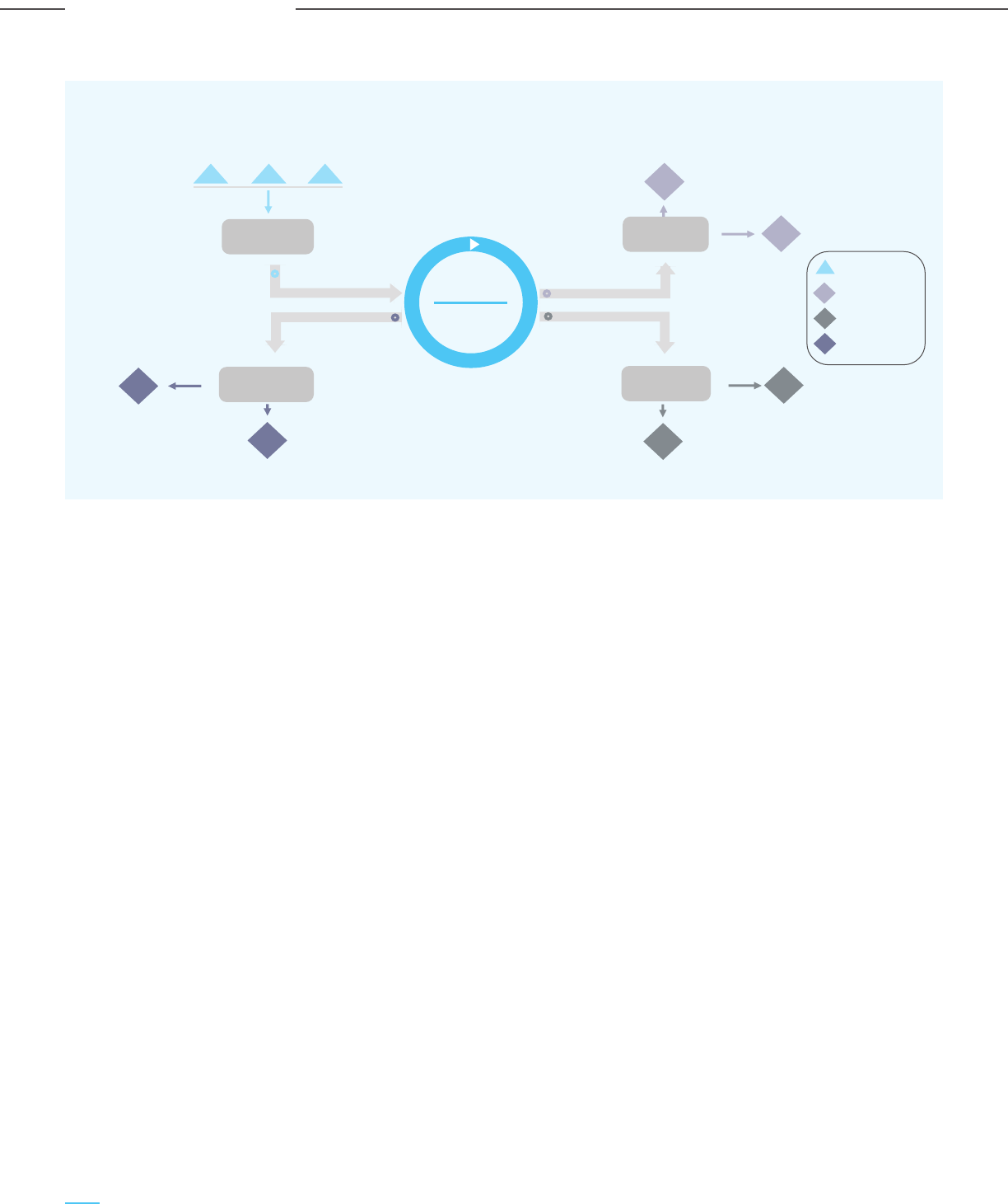
Aggregator
E
11
Disposer
EOR Cluster
EOR
HUB
Conversion
Cluster
MeOH
EOR
Regulated Monopoly
Regulated Monopoly
Regulated Monopoly
Demand-Supply
Time Contracts
Regulated Monopoly
S
1
S
2
Mineral
E
12
E
13
Figure 5-8: Mega Scale CO
2
Cluster Model
The emitters (E
11
, E
12
, E
13
) form the CO
2
emission
cluster, with similar types of industries placed in an
emission cluster and being connected to their local
cluster network, which is operated by a CO
2
aggregator as a regulated monopoly. The storage
operators (S
1
, S
2
) represent the storage cluster, where
CO
2
will be sequestered without recovering any
economically beneficial product. Similarly, there are
clusters for EOR and CO
2
utilization.
The emitters have CO
2
capture technology suited to
their quality of gas streams. The cluster will be
initiated by an emitter with very large CO
2
emissions.
This emitter is termed an anchor project. High purity
CO
2
captured from emitters is transported to the local
cluster network. These emitters will have to pay a
fixed cost for using the local network’s infrastructure.
The transport infrastructure for the cluster is
maintained by the local network bodies, thereby
reducing the risk for individual industries. This
increases the incentive for industries to join this kind
of cluster network.
The captured CO
2
is then sent to the hub and from the
hub to either sequestration sites S
1
or S
2
, to be stored
in geological formations of deep saline aquifers or
mineralized in the basalt formations. In return, the hub
pays S
1
/S
2
a regulated charge based on the CO
2
volumes being stored. A similar process is followed for
disposition of the CO
2
either through EOR or for
utilization of the CO
2
for producing methanol, mineral
aggregates or other value-added products. The
emitters are agnostic to the final CO
2
disposition; the
disposition pathway is dynamically determined by the
hub operator based on the demand-supply scenario.
In the future, a new cluster with a local network may
want to join this hub, which would be possible due to
the evolutionary model of hub and cluster systems.
This will also bring in additional investments into the
hub, leading to its growth. This new cluster may or
may not have an emission source. In case it does not
have an emission source, it will procure CO
2
from the
hub. A new emission source may also come up in the
future, which can be integrated with the new
cluster network.
5.5.3 Region-wise Cluster Potential for India
The cluster potential has been analyzed for the five
regions of India: North, South, East, West, and
North-East. By identifying the nearest state/UT to the
storage locations mentioned, the storage sites can be
classified and mapped to the various regions. A similar
practice has been carried out with the emission
sources. The estimation of region-wise emission for
the year 2030 is considered for analyzing the CO
2
volume emitted for the duration 2030 - 2050. Figure
5-9 illustrates the region-wise cluster potential data
for India.
130
Carbon Capture Utilization and Storage (CCUS) –
Policy Framework and Deployment Mechanism in India
Carbon Capture Utilization and Storage (CCUS) –
Policy Framework and Deployment Mechanism in India
CCUS Policy Framework for India
E
Emitters
S
Sequestration
Conv
Conversion
EOR
Enhanced Oil
Recovery
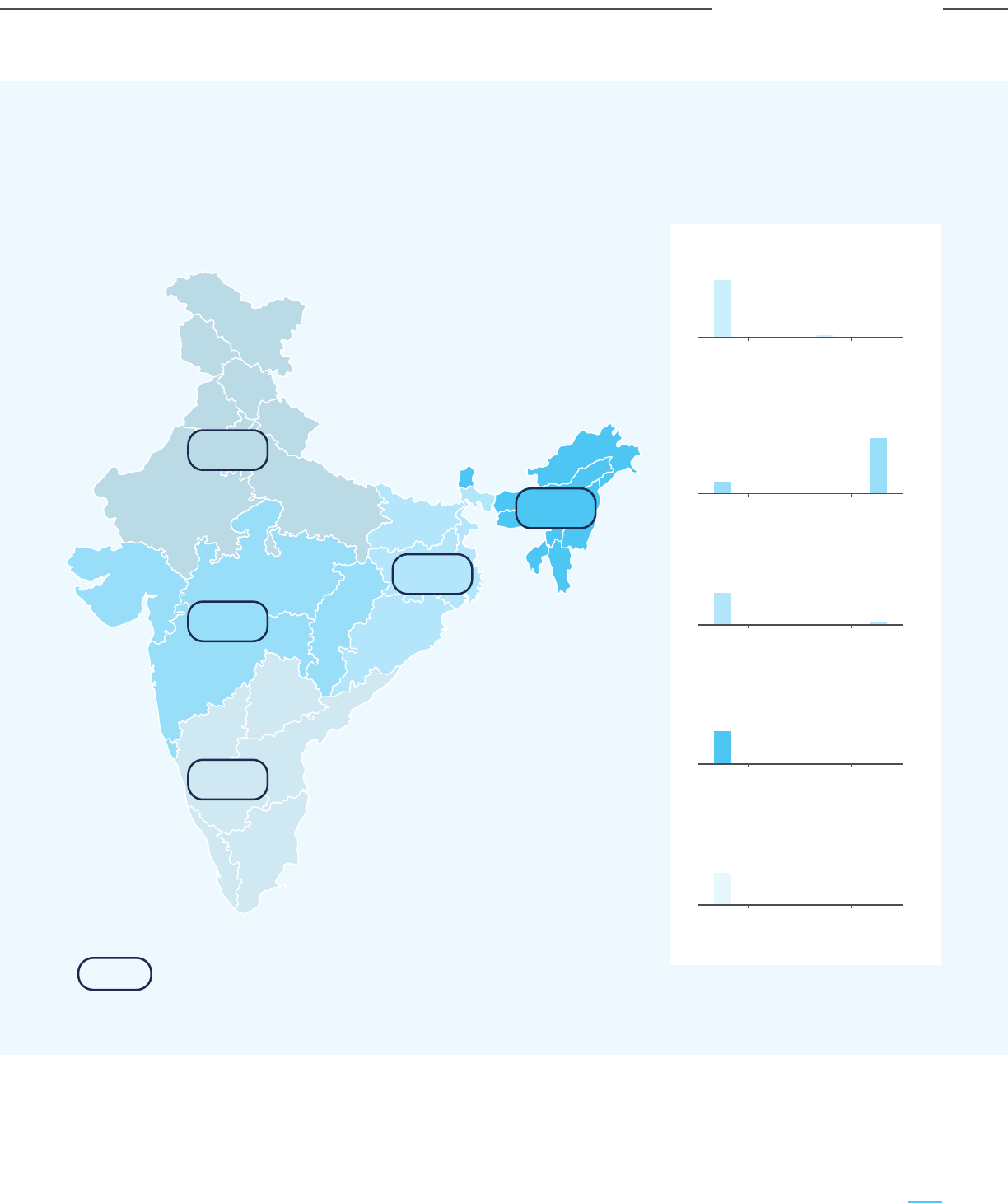
Figure 5-9: Region-wise Storage Clusters in India
Total Theoretical Storage Capacity of India = 395 - 614 Gt CO
2
7.21 GT
16.58 GT
10.13 GT
0.22 GT
9.01 GT
Northem Region: 7.65 Gt CO
2
Saline
aquifer
ECBMR EOR Basalt
7.34
0 0
0.31
Southern Region: 76.3 Gt CO
2
Saline
aquifer
ECBMR EOR Basalt
75.2
0.3 00.8
North-Eastern Region: 47.2 Gt CO
2
Saline
aquifer
ECBMR EOR Basalt
46.5
0 00.7
Eastern Region: 47.2 Gt CO
2
Saline
aquifer
ECBMR EOR Basalt
67.2
2.4 10.980
Western Region: 388.9 Gt CO
2
Saline
aquifer
ECBMR EOR Basalt
304.9
0.9
80.8
2.3
Region-wise estimated CO
2
emission volume (2030-2050)
131
Carbon Capture Utilization and Storage (CCUS) –
Policy Framework and Deployment Mechanism in India
Carbon Capture Utilization and Storage (CCUS) –
Policy Framework and Deployment Mechanism in India
CCUS Policy Framework for India

Table 5-5: Sedimentary Basins Spanning Across Multiple Regions
Basin name Basin category State/UT Theoretical storage potential
(Gt of CO
2
)
Vindhyan Category II Madhya Pradesh/ 11.81
Uttar Pradesh/ Rajasthan
Satpura- Category III Madhya Pradesh/ 1.87
South Rewa- Damodar Chhattisgarh/Jharkhand
Bhima-Kaladagi Category III Maharashtra/ Karnataka 0.41
Total 14.09
ECBMR: The potential for ECBMR is localized in the
eastern region due to the presence of major
coalfields. These can be storage clusters for
industries that are close to the coalfields, such as
steel and power plants.
EOR: The potential for EOR will increase in the future
as more wells are maturing and newer wells may be
discovered through exploratory activities.
Storage in basalt formations: Mineralization in
basalt formations provides a large opportunity for
CO
2
storage in the western region, but is currently in a
nascent stage of development.
Comparing the region-wise emission volumes during
the time horizon of 2030 – 2050 and the theoretical
storage capacity, sufficient storage capacity is
available for cluster formation in each region. The
formation of hubs will result in a smooth transfer of
CO
2
between clusters of different regions. Apart from
the four CO
2
disposition options discussed above,
several other CO
2
utilization clusters (CO
2
to
chemicals, new utilization techniques, etc.) can evolve
and become more viable over time, thus increasing
the options for abatement of enhanced volumes of
CO
2
from the power and industrial sector.
5.6 Key Risks Associated
with CCUS
The CCUS policy framework for India should also
address the key risks associated with the CCUS value
chain. CCUS projects integrate various sub-systems
such as carbon capture, transportation, and
sequestration. The interfaces between the
sub-systems projects involve complex interfaces and
lead to risks associated with CCUS projects. Some of
the key risks and their mitigation measures are
described below:
5.6.1 Technical Risks
5.6.1.1 Reservoir Suitability for CO
2
Flooding
for EOR
The extent of CO
2
abatement possible through EOR
depends on the comparative performance and
cost-effectiveness of CO
2
EOR vis-à-vis other methods
of tertiary recovery like nitrogen injection, polymer
injection, steam injection, natural gas injection, and
the use of foaming agents. Some of the current
developments, such as the use of foams or other
chemicals to improve sweep efficiency may reduce the
attractiveness of CO
2
EOR, while on the other hand,
The region-wise storage cluster formation shows that
sequestration in deep saline aquifers has the best
potential in all the regions. Due to the lack of data on
the northern sedimentary basins, the theoretical
storage capacity for saline aquifers is low. But as more
exploratory activities are carried focused on CO
2
storage, the storage potential in the northern region is
likely to increase. Few sedimentary basins span across
multiple states and they have been mentioned in
Table 5-5.
exploration and production from more complex
hydrocarbon resources may increase the role of CO
2
.
Hence it is necessary to monitor the developments of
other tertiary recovery systems, as well as use
improved reservoir simulation tools to understand
CO
2
flooding and EOR performance. It is also
important to calibrate financial commitments to
capacity expansions based on assured future offtakes
for CO
2
to mitigate this risk.
5.6.1.2 Change in Processes Emitting Industries:
This risk emanates from the possibility of using
electricity or new clean energy carriers to replace the
use of fossil fuels in industrial processes like iron &
steel or cement, thereby substantially impacting the
CO
2
emissions available for capture. Even the power
sector is not immune to such changes: for example,
base-load plants may transition to only peaking
operations, limiting the quantity of CO
2
emissions.
Therefore it is important to develop a understanding
of the industrial processes and the likely trajectory of
technological innovation in the industry, as well as the
risk of the end-products of the industry getting
replaced by alternate products.
5.6.1.3 Offshore Unloading & Condition of
Shipped CO
2
CO
2
shipping is considered a future alternative to CO
2
piping and would involve vessels similar to
semi-refrigerated LNG/LPG carriers that use
pressurized tanks. Compared to a fixed pipeline based
distribution network, CO
2
shipping provides flexibility
to adjust to demand-supply dynamics and deploy
ships/barges to different consumption points and
allows for more gradual expansion of the CCUS
system. One key issue is converting liquid CO
2
from
temperatures as low as -50°C to a temperature
suitable for injection. Significant heat energy would be
required, involving cost and emissions, if done with
fossil fuels. The logistics of ship unloading also need
to be addressed, including issues related to ship
loading & unloading rates to limit demurrage as well
as using floating barges for offshore offloading.
5.6.1.4 CO
2
Specification Challenges
Most carbon capture solutions try to address and
meet the required CO
2
specifications. The key
requirement is adequate dehydration, along with
other impurity tolerances depending on the CO
2
source and capture process. However, problems may
arise when integrating multiple CO
2
sources and
capture processes, and additional treatment of the
captured raw CO
2
may be required, depending on the
disposition pathway for the CO
2
. These requirements
would depend on the diversity of CO
2
sources in a
particular cluster, which increases the likelihood of
CO
2
mixing issues. The other issues to be handled are
the concentration of non-condensable and inert
impurities such as nitrogen and argon, that have an
effect on pipeline and reservoir capacity.
5.6.2 Financial Risks
5.6.2.1 Cost of Capture
The main cost driver in the CCUS value chain is the
capture cost. In industrial processes such as natural
gas processing and gasification, carbon capture is part
of the process itself and hence there is no additional
cost of carbon capture. However, in the case of thermal
power plants and other industrial processes, there are
significant capital and cash costs, leading to financial
risks for the entire CCUS value chain, which need to be
mitigated through suitable commercial arrangements.
Significant resources have been invested in developing
more efficient and cost-effective carbon capture
technologies, and the cost range for most
commercial-scale carbon capture technologies is well
established. It may be worthwhile to focus further R&D
efforts on finding creative ways to sell or consume the
CO
2
product in new ways or optimize opex through
low-cost sources of low-grade heat/steam for solvent
regeneration and meet the electricity duty
requirements of other carbon capture technologies.
5.6.2.2 Financing Risks
The CCUS value chain consists of several connected
sub-systems and functions that must act in
coordination for the overall success of the project.
Multiple sources or sinks in a cluster mitigate the risk
and may require more elaborate transport and storage
infrastructure, leading to higher capital costs and
financing requirements, particularly in the early
“anchor” stages of the project. The risk of financing
delays or inadequacy leads to cost escalation and
hence needs to be mitigated through measures such as
meticulous planning, access to bridge financing during
the early stage of the project and making realistic
provisions for additional funding to cover the
contingency of delays.
5.6.2.3 Loss of Storage Site
Complications during CO
2
injection may lead to the
stoppage of operations at CO
2
storage sites. Although
reservoir management should provide adequate warning
of such occurrences, there are technical risks in
estimating/predicting the final capacity of a new storage
site with certainty. Relying on a single site or a single
well is a key technical risk. Hence there is a need to
prove new storage sites to ensure continued operations.
Careful long-term planning and contracting of multiple
sites can mitigate this risk. Drilling additional wells or
temporarily increasing the injectivity of existing wells
can boost the short-term capacity of alternate sites.
Hence, it is recommended that contingency plans be
developed for additional storage capacity via additional
wells or reservoirs. If rigs and requisite well supplies
are available, new wells can be drilled and completed
fast. It is therefore prudent to ensure rapid access to
drilling rather than storing spare wells, as well as
developing and assessing multiple storage locations.
5.6.2.4 Price of Green Products
The issue of “inadequate prices” for low carbon or
green products is a major risk factor. To address this
risk, renewable energy has widely used feed-in tariffs,
but only until it became cost-competitive. The tariff is
paid centrally and passed on to consumers via taxation
or a general price increase. However, the system is
inflexible as the pre-determined feed-in tariff rates may
become inappropriate and may need to be lowered.
Ultimately the higher costs for the commitment for
green products has to be passed on to customers and
businesses, since the Government’s revenues comes
from citizens and businesses.
5.6.2.5 Lack of Tradeable Long Term CO
2
Emission
Reduction
CCUS ensures long-term emission reductions and
requires long term investments and financing having
time horizons of up to 40 years. There is a need to
design financial instruments where the payoffs/rewards
are directly related to CO
2
abatement levels. The
probable investors/buyers would be organizations that
need to achieve future carbon reductions. The potential
to invest directly in the best CCUS locations/projects
should be less expensive than purchasing abatement
certificates. There is thus a need to structure financial
products directly linked to specific CO
2
abatement,
transportation, and storage quantities, which can be
marketed to different types of investors (viz.
individuals, institutions and industrial enterprises), and
preferably in a globally tradable manner.
5.6.2.6 Withdrawal of Key Partners & Delay
The CCUS value chain requires the interplay and
association of multiple partners and the
withdrawal/loss of a partner in the value chain can
compromise the entire system. Contracts need to be
designed to prevent the same, as well as protect the
project from changes in ownership or divestments.
However, there is the residual risk of a business
partner’s insolvency or business failure. One model
could be to centralize the core activities related to the
CCUS value chain within one dedicated well-funded
organization (with a lower probability of failure or
disruption) rather than having multiple partner
organizations and procuring the balance support
services from the market.
5.6.3 Safety Risks
5.6.3.1 Pipeline Incidents
Pipeline related accidents and incidents are significant
safety risks and need to be mitigated through adequate
insurance to cover the costs of paying compensation to
affected parties and the cost of repairing the pipeline.
Permanent disruption or permanent stoppage of CO
2
transportation may occur if the entire CCUS
facility/infrastructure has been destroyed.
The effect of one pipeline incident may spill over to the
development of the CCUS industry and operations of
already commissioned CCUS facilities, who would need
to upgrade their operations and safety protocols.
Fortunately, there have been no major failures or
disasters to date in the CCUS industry. At the same
time, it is necessary for strict international safety
standards to be adopted to preemptively avoid any
incident. The safety standards followed in the
international seaborne movement of LNG provides an
excellent example worth emulating.
5.6.3.2 Large Dia Pipeline in Populated Areas
Historical pipeline incident records reveal that larger
diameter lines generally have a lower frequency of
incidents. In order to avoid any incidents, automatic
isolation valves at short intervals and leak monitoring
systems are two solutions adopted by some projects.
CO
2
is not dangerous in moderate quantities and
becomes life-threatening only above certain
threshold levels. However, adequate safety and
failsafe precautions need to be adopted for dense
phase or supercritical CO
2
pipeline transport in
populated areas, as may be required for developing
large scale CCUS projects in densely populated
countries like India, along with clearly defined and
established emergency response and communication
protocols.
132
Carbon Capture Utilization and Storage (CCUS) –
Policy Framework and Deployment Mechanism in India
Carbon Capture Utilization and Storage (CCUS) –
Policy Framework and Deployment Mechanism in India
CCUS Policy Framework for India

exploration and production from more complex
hydrocarbon resources may increase the role of CO
2
.
Hence it is necessary to monitor the developments of
other tertiary recovery systems, as well as use
improved reservoir simulation tools to understand
CO
2
flooding and EOR performance. It is also
important to calibrate financial commitments to
capacity expansions based on assured future offtakes
for CO
2
to mitigate this risk.
5.6.1.2 Change in Processes Emitting Industries:
This risk emanates from the possibility of using
electricity or new clean energy carriers to replace the
use of fossil fuels in industrial processes like iron &
steel or cement, thereby substantially impacting the
CO
2
emissions available for capture. Even the power
sector is not immune to such changes: for example,
base-load plants may transition to only peaking
operations, limiting the quantity of CO
2
emissions.
Therefore it is important to develop a understanding
of the industrial processes and the likely trajectory of
technological innovation in the industry, as well as the
risk of the end-products of the industry getting
replaced by alternate products.
5.6.1.3 Offshore Unloading & Condition of
Shipped CO
2
CO
2
shipping is considered a future alternative to CO
2
piping and would involve vessels similar to
semi-refrigerated LNG/LPG carriers that use
pressurized tanks. Compared to a fixed pipeline based
distribution network, CO
2
shipping provides flexibility
to adjust to demand-supply dynamics and deploy
ships/barges to different consumption points and
allows for more gradual expansion of the CCUS
system. One key issue is converting liquid CO
2
from
temperatures as low as -50°C to a temperature
suitable for injection. Significant heat energy would be
required, involving cost and emissions, if done with
fossil fuels. The logistics of ship unloading also need
to be addressed, including issues related to ship
loading & unloading rates to limit demurrage as well
as using floating barges for offshore offloading.
5.6.1.4 CO
2
Specification Challenges
Most carbon capture solutions try to address and
meet the required CO
2
specifications. The key
requirement is adequate dehydration, along with
other impurity tolerances depending on the CO
2
source and capture process. However, problems may
arise when integrating multiple CO
2
sources and
capture processes, and additional treatment of the
captured raw CO
2
may be required, depending on the
disposition pathway for the CO
2
. These requirements
would depend on the diversity of CO
2
sources in a
particular cluster, which increases the likelihood of
CO
2
mixing issues. The other issues to be handled are
the concentration of non-condensable and inert
impurities such as nitrogen and argon, that have an
effect on pipeline and reservoir capacity.
5.6.2 Financial Risks
5.6.2.1 Cost of Capture
The main cost driver in the CCUS value chain is the
capture cost. In industrial processes such as natural
gas processing and gasification, carbon capture is part
of the process itself and hence there is no additional
cost of carbon capture. However, in the case of thermal
power plants and other industrial processes, there are
significant capital and cash costs, leading to financial
risks for the entire CCUS value chain, which need to be
mitigated through suitable commercial arrangements.
Significant resources have been invested in developing
more efficient and cost-effective carbon capture
technologies, and the cost range for most
commercial-scale carbon capture technologies is well
established. It may be worthwhile to focus further R&D
efforts on finding creative ways to sell or consume the
CO
2
product in new ways or optimize opex through
low-cost sources of low-grade heat/steam for solvent
regeneration and meet the electricity duty
requirements of other carbon capture technologies.
5.6.2.2 Financing Risks
The CCUS value chain consists of several connected
sub-systems and functions that must act in
coordination for the overall success of the project.
Multiple sources or sinks in a cluster mitigate the risk
and may require more elaborate transport and storage
infrastructure, leading to higher capital costs and
financing requirements, particularly in the early
“anchor” stages of the project. The risk of financing
delays or inadequacy leads to cost escalation and
hence needs to be mitigated through measures such as
meticulous planning, access to bridge financing during
the early stage of the project and making realistic
provisions for additional funding to cover the
contingency of delays.
5.6.2.3 Loss of Storage Site
Complications during CO
2
injection may lead to the
stoppage of operations at CO
2
storage sites. Although
reservoir management should provide adequate warning
of such occurrences, there are technical risks in
estimating/predicting the final capacity of a new storage
site with certainty. Relying on a single site or a single
well is a key technical risk. Hence there is a need to
prove new storage sites to ensure continued operations.
Careful long-term planning and contracting of multiple
sites can mitigate this risk. Drilling additional wells or
temporarily increasing the injectivity of existing wells
can boost the short-term capacity of alternate sites.
Hence, it is recommended that contingency plans be
developed for additional storage capacity via additional
wells or reservoirs. If rigs and requisite well supplies
are available, new wells can be drilled and completed
fast. It is therefore prudent to ensure rapid access to
drilling rather than storing spare wells, as well as
developing and assessing multiple storage locations.
5.6.2.4 Price of Green Products
The issue of “inadequate prices” for low carbon or
green products is a major risk factor. To address this
risk, renewable energy has widely used feed-in tariffs,
but only until it became cost-competitive. The tariff is
paid centrally and passed on to consumers via taxation
or a general price increase. However, the system is
inflexible as the pre-determined feed-in tariff rates may
become inappropriate and may need to be lowered.
Ultimately the higher costs for the commitment for
green products has to be passed on to customers and
businesses, since the Government’s revenues comes
from citizens and businesses.
5.6.2.5 Lack of Tradeable Long Term CO
2
Emission
Reduction
CCUS ensures long-term emission reductions and
requires long term investments and financing having
time horizons of up to 40 years. There is a need to
design financial instruments where the payoffs/rewards
are directly related to CO
2
abatement levels. The
probable investors/buyers would be organizations that
need to achieve future carbon reductions. The potential
to invest directly in the best CCUS locations/projects
should be less expensive than purchasing abatement
certificates. There is thus a need to structure financial
products directly linked to specific CO
2
abatement,
transportation, and storage quantities, which can be
marketed to different types of investors (viz.
individuals, institutions and industrial enterprises), and
preferably in a globally tradable manner.
5.6.2.6 Withdrawal of Key Partners & Delay
The CCUS value chain requires the interplay and
association of multiple partners and the
withdrawal/loss of a partner in the value chain can
compromise the entire system. Contracts need to be
designed to prevent the same, as well as protect the
project from changes in ownership or divestments.
However, there is the residual risk of a business
partner’s insolvency or business failure. One model
could be to centralize the core activities related to the
CCUS value chain within one dedicated well-funded
organization (with a lower probability of failure or
disruption) rather than having multiple partner
organizations and procuring the balance support
services from the market.
5.6.3 Safety Risks
5.6.3.1 Pipeline Incidents
Pipeline related accidents and incidents are significant
safety risks and need to be mitigated through adequate
insurance to cover the costs of paying compensation to
affected parties and the cost of repairing the pipeline.
Permanent disruption or permanent stoppage of CO
2
transportation may occur if the entire CCUS
facility/infrastructure has been destroyed.
The effect of one pipeline incident may spill over to the
development of the CCUS industry and operations of
already commissioned CCUS facilities, who would need
to upgrade their operations and safety protocols.
Fortunately, there have been no major failures or
disasters to date in the CCUS industry. At the same
time, it is necessary for strict international safety
standards to be adopted to preemptively avoid any
incident. The safety standards followed in the
international seaborne movement of LNG provides an
excellent example worth emulating.
5.6.3.2 Large Dia Pipeline in Populated Areas
Historical pipeline incident records reveal that larger
diameter lines generally have a lower frequency of
incidents. In order to avoid any incidents, automatic
isolation valves at short intervals and leak monitoring
systems are two solutions adopted by some projects.
CO
2
is not dangerous in moderate quantities and
becomes life-threatening only above certain
threshold levels. However, adequate safety and
failsafe precautions need to be adopted for dense
phase or supercritical CO
2
pipeline transport in
populated areas, as may be required for developing
large scale CCUS projects in densely populated
countries like India, along with clearly defined and
established emergency response and communication
protocols.
133
Carbon Capture Utilization and Storage (CCUS) –
Policy Framework and Deployment Mechanism in India
Carbon Capture Utilization and Storage (CCUS) –
Policy Framework and Deployment Mechanism in India
CCUS Policy Framework for India

exploration and production from more complex
hydrocarbon resources may increase the role of CO
2
.
Hence it is necessary to monitor the developments of
other tertiary recovery systems, as well as use
improved reservoir simulation tools to understand
CO
2
flooding and EOR performance. It is also
important to calibrate financial commitments to
capacity expansions based on assured future offtakes
for CO
2
to mitigate this risk.
5.6.1.2 Change in Processes Emitting Industries:
This risk emanates from the possibility of using
electricity or new clean energy carriers to replace the
use of fossil fuels in industrial processes like iron &
steel or cement, thereby substantially impacting the
CO
2
emissions available for capture. Even the power
sector is not immune to such changes: for example,
base-load plants may transition to only peaking
operations, limiting the quantity of CO
2
emissions.
Therefore it is important to develop a understanding
of the industrial processes and the likely trajectory of
technological innovation in the industry, as well as the
risk of the end-products of the industry getting
replaced by alternate products.
5.6.1.3 Offshore Unloading & Condition of
Shipped CO
2
CO
2
shipping is considered a future alternative to CO
2
piping and would involve vessels similar to
semi-refrigerated LNG/LPG carriers that use
pressurized tanks. Compared to a fixed pipeline based
distribution network, CO
2
shipping provides flexibility
to adjust to demand-supply dynamics and deploy
ships/barges to different consumption points and
allows for more gradual expansion of the CCUS
system. One key issue is converting liquid CO
2
from
temperatures as low as -50°C to a temperature
suitable for injection. Significant heat energy would be
required, involving cost and emissions, if done with
fossil fuels. The logistics of ship unloading also need
to be addressed, including issues related to ship
loading & unloading rates to limit demurrage as well
as using floating barges for offshore offloading.
5.6.1.4 CO
2
Specification Challenges
Most carbon capture solutions try to address and
meet the required CO
2
specifications. The key
requirement is adequate dehydration, along with
other impurity tolerances depending on the CO
2
source and capture process. However, problems may
arise when integrating multiple CO
2
sources and
capture processes, and additional treatment of the
captured raw CO
2
may be required, depending on the
disposition pathway for the CO
2
. These requirements
would depend on the diversity of CO
2
sources in a
particular cluster, which increases the likelihood of
CO
2
mixing issues. The other issues to be handled are
the concentration of non-condensable and inert
impurities such as nitrogen and argon, that have an
effect on pipeline and reservoir capacity.
5.6.2 Financial Risks
5.6.2.1 Cost of Capture
The main cost driver in the CCUS value chain is the
capture cost. In industrial processes such as natural
gas processing and gasification, carbon capture is part
of the process itself and hence there is no additional
cost of carbon capture. However, in the case of thermal
power plants and other industrial processes, there are
significant capital and cash costs, leading to financial
risks for the entire CCUS value chain, which need to be
mitigated through suitable commercial arrangements.
Significant resources have been invested in developing
more efficient and cost-effective carbon capture
technologies, and the cost range for most
commercial-scale carbon capture technologies is well
established. It may be worthwhile to focus further R&D
efforts on finding creative ways to sell or consume the
CO
2
product in new ways or optimize opex through
low-cost sources of low-grade heat/steam for solvent
regeneration and meet the electricity duty
requirements of other carbon capture technologies.
5.6.2.2 Financing Risks
The CCUS value chain consists of several connected
sub-systems and functions that must act in
coordination for the overall success of the project.
Multiple sources or sinks in a cluster mitigate the risk
and may require more elaborate transport and storage
infrastructure, leading to higher capital costs and
financing requirements, particularly in the early
“anchor” stages of the project. The risk of financing
delays or inadequacy leads to cost escalation and
hence needs to be mitigated through measures such as
meticulous planning, access to bridge financing during
the early stage of the project and making realistic
provisions for additional funding to cover the
contingency of delays.
5.6.2.3 Loss of Storage Site
Complications during CO
2
injection may lead to the
stoppage of operations at CO
2
storage sites. Although
reservoir management should provide adequate warning
of such occurrences, there are technical risks in
estimating/predicting the final capacity of a new storage
site with certainty. Relying on a single site or a single
well is a key technical risk. Hence there is a need to
prove new storage sites to ensure continued operations.
Careful long-term planning and contracting of multiple
sites can mitigate this risk. Drilling additional wells or
temporarily increasing the injectivity of existing wells
can boost the short-term capacity of alternate sites.
Hence, it is recommended that contingency plans be
developed for additional storage capacity via additional
wells or reservoirs. If rigs and requisite well supplies
are available, new wells can be drilled and completed
fast. It is therefore prudent to ensure rapid access to
drilling rather than storing spare wells, as well as
developing and assessing multiple storage locations.
5.6.2.4 Price of Green Products
The issue of “inadequate prices” for low carbon or
green products is a major risk factor. To address this
risk, renewable energy has widely used feed-in tariffs,
but only until it became cost-competitive. The tariff is
paid centrally and passed on to consumers via taxation
or a general price increase. However, the system is
inflexible as the pre-determined feed-in tariff rates may
become inappropriate and may need to be lowered.
Ultimately the higher costs for the commitment for
green products has to be passed on to customers and
businesses, since the Government’s revenues comes
from citizens and businesses.
5.6.2.5 Lack of Tradeable Long Term CO
2
Emission
Reduction
CCUS ensures long-term emission reductions and
requires long term investments and financing having
time horizons of up to 40 years. There is a need to
design financial instruments where the payoffs/rewards
are directly related to CO
2
abatement levels. The
probable investors/buyers would be organizations that
need to achieve future carbon reductions. The potential
to invest directly in the best CCUS locations/projects
should be less expensive than purchasing abatement
certificates. There is thus a need to structure financial
products directly linked to specific CO
2
abatement,
transportation, and storage quantities, which can be
marketed to different types of investors (viz.
individuals, institutions and industrial enterprises), and
preferably in a globally tradable manner.
5.6.2.6 Withdrawal of Key Partners & Delay
The CCUS value chain requires the interplay and
association of multiple partners and the
withdrawal/loss of a partner in the value chain can
compromise the entire system. Contracts need to be
designed to prevent the same, as well as protect the
project from changes in ownership or divestments.
However, there is the residual risk of a business
partner’s insolvency or business failure. One model
could be to centralize the core activities related to the
CCUS value chain within one dedicated well-funded
organization (with a lower probability of failure or
disruption) rather than having multiple partner
organizations and procuring the balance support
services from the market.
5.6.3 Safety Risks
5.6.3.1 Pipeline Incidents
Pipeline related accidents and incidents are significant
safety risks and need to be mitigated through adequate
insurance to cover the costs of paying compensation to
affected parties and the cost of repairing the pipeline.
Permanent disruption or permanent stoppage of CO
2
transportation may occur if the entire CCUS
facility/infrastructure has been destroyed.
The effect of one pipeline incident may spill over to the
development of the CCUS industry and operations of
already commissioned CCUS facilities, who would need
to upgrade their operations and safety protocols.
Fortunately, there have been no major failures or
disasters to date in the CCUS industry. At the same
time, it is necessary for strict international safety
standards to be adopted to preemptively avoid any
incident. The safety standards followed in the
international seaborne movement of LNG provides an
excellent example worth emulating.
5.6.3.2 Large Dia Pipeline in Populated Areas
Historical pipeline incident records reveal that larger
diameter lines generally have a lower frequency of
incidents. In order to avoid any incidents, automatic
isolation valves at short intervals and leak monitoring
systems are two solutions adopted by some projects.
CO
2
is not dangerous in moderate quantities and
becomes life-threatening only above certain
threshold levels. However, adequate safety and
failsafe precautions need to be adopted for dense
phase or supercritical CO
2
pipeline transport in
populated areas, as may be required for developing
large scale CCUS projects in densely populated
countries like India, along with clearly defined and
established emergency response and communication
protocols.
134
Carbon Capture Utilization and Storage (CCUS) –
Policy Framework and Deployment Mechanism in India
Carbon Capture Utilization and Storage (CCUS) –
Policy Framework and Deployment Mechanism in India
CCUS Policy Framework for India

Chapter 6
Investment &
Financing
Mechanism

6.1 Introduction
6.2 Estimation of Capital Costs
and Cash Costs for Demo
Scale CCUS Projects
Financing CCUS projects can be quite challenging in a
developing country like India, even with policy support,
whether be it incentive or tax based. With an inherently
lower ability to absorb reduced tax revenues than a
developed nation like the USA, India would initially need
to look for international financial support for CCUS
projects. India should create a financial framework
around the CCUS value chain to support and expedite
carbon capture adoption across industries. This chapter
discusses different options for financing CO
2
capture,
utilization and storage projects in a subsidy-neutral
way for achieving decarbonization and ensuring the
sustainability of the Indian economy.
CCUS represents an unmatched opportunity for
turbocharging the growth of the Indian economy
through large-scale ‘carbon-friendly’ investments in the
industrial sector. These investments will help create a
clean-energy based industrial sector, potentially
leading to the development of new technologies, skills
and high-value employment opportunities in India. With
time, the clean-energy industrial sector will develop
expertise and value-added low-carbon products that
can be exported to other countries. CCUS also provides
an opportunity for private enterprises to invest in the
development of a new low-carbon emissions industrial
infrastructure that will provide increasing returns on
investments as the industry develops over time.
An active energy market backed up with a proper
national CCUS policy to support the entire chain of
operations can attract investments. This has to be
ensured by designing ‘Integrated Energy’ policies that
support primary manufacturing industries along with
CCUS, leading to energy and materials security for
India and attracting diverse foreign enterprises and
private equity companies to engage in sustainable
energy businesses in India.
To support CCUS in India, it is important to fund and
support demonstration scale projects. This section
estimates the capital costs and cash costs for one
demo scale CCUS project in each of the sectors under
consideration. The costs vary widely, as even with the
same CO
2
stream, carbon capture cash costs vary
widely depending on the unit costs of power and
steam. The basis of estimation of the capital and cash
costs is listed below:
- It is envisaged that the proposed carbon capture
projects/units will be retrofitted to existing
plants/units
- All the cost parameters are based on currently
available technologies and Indian conditions
& costs
- All auxiliary facilities like pre-treatment of gases
or compression are considered as part of the
carbon capture project
- Power required for the carbon capture project will
be sourced from existing operations
- The steam requirements of the carbon capture
project will be met from natural gas-based boilers
for refineries or petrochemical projects and from
coal-based boilers for other sectors
- For carbon capture projects for existing power
plants, the steam will be sourced from existing
power plant operations. The cost of steam will be
considered at the opportunity cost
- Costs towards manpower, solvent make up,
consumables, repair & maintenance, cooling water,
make up water etc. have been considered on a
normative basis for Indian conditions and costs
- The capital costs for the carbon capture units
include all the hard and soft costs, including
applicable taxes & duties, owner’s cost,
financing cost
- Capital recovery factor (CRF) has been estimated
on the basis of 8% financing cost and 20 years
of life
- The utility costs considered are shown in
Figure 6-1.
Figure 6-1: Utility Costs Considered
3,000
750
1,500
NG based steam, Rs./TCoal based steam, Rs./TPower, Rs./MWh
136
Carbon Capture Utilization and Storage (CCUS) –
Policy Framework and Deployment Mechanism in India
Carbon Capture Utilization and Storage (CCUS) –
Policy Framework and Deployment Mechanism in India
Investment & Financing Mechanism

The key considerations for calculations of the capital and cash costs for CCUS units in each sector/application is
provided below:
Sector CO
2
stream sources CO
2
stream spec. Considerations
Table 6-1: Capex and Opex Considerations for CCUS Retrofit
Gasification based
production
Outlet of the acid
gas removal unit
- CO
2
removal and capture are part of the process.
- CCUS unit will undertake purication and
compression of high conc. CO
2
stream for further
disposition
- Accordingly, only CO
2
polishing and compression
facilities have been considered
- 90% CO
2
conc
- 1-5 bar (a) pressure
NG based SMR for
H
2
production
Tail gas from PSA
- Depending on the extent of decarbonization
targeted, the carbon capture source and
technology will change. While CO
2
capture from
tail gas will give the lowest capture cost for around
60% CO
2
reduction, capture from ue gas will
ensure 95% capture with a higher cost of capture
- Cryogenic separation has been considered for CO
2
capture from tail gas as it ensures high purity CO
2
(99.9%) with additional H
2
recovery
- Overall CO
2
reduction will be limited to 60-70%
- ~65%+ CO
2
conc.
- Near atm. pressure
Cement Flue gas
- A hybrid (PSA + cryo) solution has been
considered
- ~20% CO
2
conc.
- Near atm. pressure
Iron and steel BF gas
- An integrated steel plant has multiple CO
2
sources
with dierent characteristics. However,
pre-combustion capture from BF gas will ensure at
least 50% capture with minimum cost of capture.
- Water gas shift has been considered to ensure
maximum CO
2
capture from a single point and
potential H
2
recovery from the BF gas
- ~20% CO
2
conc.
- Near atm. pressure
Refinery and
chemical
Flue gas
- Since a renery has multiple sources of CO
2
,
aggregation is dicult due dierent stream
characteristics as well as space constraints of
existing layout of typical reneries
- CDU & FCC unit are considered for carbon capture
- Amine based carbon capture is considered to be
the most economical solution
- 7-20% CO
2
conc.
- Near atm. pressure
Coal-based power Flue gas
- Amine based carbon capture considered
- All retrotting required for carbon capture like
SOx, NOX removal, steam extraction, ue gas
treatment has been considered as part of the
carbon capture unit
- 8-15% CO
2
conc.
- Near atm. pressure
137
Carbon Capture Utilization and Storage (CCUS) –
Policy Framework and Deployment Mechanism in India
Carbon Capture Utilization and Storage (CCUS) –
Policy Framework and Deployment Mechanism in India
Investment & Financing Mechanism

The typical capital costs for CCUS demo projects in each sector is tabulated below:
Note: The capital costs are on a net of GST basis and include cost towards plant & equipment, construction cost, applicable taxes & duties, licensing cost, financing
cost, owner’s cost, etc.
Table 6-2: Sector-wise Typical Carbon Capture Capital Cost
Sector Ref. Plant CCU CO
2
intensity CO
2
capture Capital Source
capacity capacity percentage Cost1
Gasification 70 ktpa H
2
1 mtpa 13-15 T/TH
2
Around 90% Rs. 80-100 - Dastur estimate for
based Crore similar projects
production - Cost of capturing CO
2
from industrial sources
(DOE/NETL-2013/1602)
NG based SMR 130 ktpa H
2
0.7 mtpa 8-9 T/TH
2
60-65% Rs. 700-800 Dastur project database &
for H
2
production Crore IEA Technical Report
Cement 2.5 mtpa 2 mtpa 0.7-0.9 T/ Around 90% Rs. 1,600 to Dastur project database &
clinker TClinker 1800 Crore IEA Technical Report
Iron and steel 2.0 mtpa BF-BOF 2 mtpa 1.8-2.2 T/TSteel Around 50% Rs. 1,600- Dastur project database &
based ISP 2,000 Crore IEA Technical Report
Refinery 5 mtpa crude 1 mtpa 0.2 T/TCrude Around 90% Rs. 1,100- - Dastur estimate for
(CDU & FCC) processing 1,300 Crore similar facilities
- IEA Technical Report
Coal-based 800 MW 5 mtpa 0.85-1.1 T/MWh Around 90% Rs. 3,500- - Integrated Environmental
power 4,000 Crore Control Model (IECM)
Version 11.5
- NETL
- IEA Technical Report
Total 11.7 mtpa - - Rs. 8,600 –
10,000 Crore
138
Carbon Capture Utilization and Storage (CCUS) –
Policy Framework and Deployment Mechanism in India
Carbon Capture Utilization and Storage (CCUS) –
Policy Framework and Deployment Mechanism in India
Investment & Financing Mechanism

Similarly, the typical cash costs for CCUS demo projects in each sector are tabulated below:
Note:
- Other costs include costs towards water, consumables, repair & maintenance, manpower, and other miscellaneous items
- Typical cost numbers include the cash costs for carbon capture only. The cost of transportation, sequestration, monitoring, etc. will be an additional US$ 10-15 per
tonne depending on distance, sub-surface characteristics, etc. CO
2
quality of 100 bar(a) pressure and 95% plus purity has been assumed for all cases.
Table 6-3: Sector-wise Typical Carbon Capture Cash Costs
Gasification 70-90 Negligible 210-270 Negligible 25-30 250-300
based
production
NG based SMR 220-250 Negligible 660-750 Negligible 450-600 1,150-1,400
for H
2
production
Cement 340-370 Negligible 720-1,110 Negligible 300-450 1,050-1,600
Iron and steel 170-190 1.3-1.5 510-570 975-1125 400-600 1,900-2,300
Refinery 110-130 1.2-1.5 330-390 1,800-2,250 500-700 2,700-3,100
(CDU & FCC)
Coal-based 250-300 1.3-1.55 750-900 975-1,165 800-1000 2,100-2,500
power
Sector Electricity
Consumption,
kWh/TCO
2
Steam
Consumption,
T/TCO
2
Electricity
Cost,
Rs./TCO
2
Steam
Cost,
Rs./TCO
2
Other
Costs,
Rs./TCO
2
Total Cash
Costs,
Rs./TCO
2
The sector-wise levelized cost of carbon capture per tonne of CO
2
, consisting of both capital charges and cash costs,
is tabulated below.
Table 6-4: Sector-wise Typical Carbon Capture Cash Costs and Capital Charges
Gasification based 70 ktpa H
2
1 mtpa 90-120 250-300 340-420
production
NG based SMR 130 ktpa H
2
0.7 mtpa 900-1,200 1,150-1,400 2,050-2,600
for H
2
production
Cement 2.5 mtpa 2 mtpa 800-1,000 1,050-1,600 1,800-2,600
clinker
Iron and steel 2.0 mtpa BF- 2 mtpa 1,000-1,300 1,900-2,300 2,900-3,600
BOF based ISP
Refinery 5 mtpa crude 1 mtpa 1,200-1,400 2,700-3,100 3,900-4,500
(CDU & FCC) processing
Coal-based power 800 MW 5 mtpa 700-1,000 2,100-2,500 2,800-3,500
Industry
name
Ref. Plant
capacity
CCU capacity Cash Costs (B),
Rs./TCO
2
Capital Charges (A),
Rs./TCO
2
Total Cost (A+B),
Rs./TCO
2
139
Carbon Capture Utilization and Storage (CCUS) –
Policy Framework and Deployment Mechanism in India
Carbon Capture Utilization and Storage (CCUS) –
Policy Framework and Deployment Mechanism in India
Investment & Financing Mechanism

6.3 Aggregate CCUS Investment Requirements at Country Level
CO
2
emissions in India from the hard to abate sectors
like steel, cement, coal-based power, chemical, etc. is
estimated to reach around 2,300 mtpa by the year
2030. The details of the CO
2
emissions from each
sector are given in Figure 6-2.
In addition to the investments required for funding
demo scale projects, the aggregate CCUS investment
requirements at the country level have been
estimated for two scenarios of CO
2
abatement in the
year 2030: the base case and the optimistic case. The
investment numbers have been estimated based on
typical sector-wise capital costs for carbon capture,
CO
2
transportation pipeline and sequestration. While
the base case represents a carbon capture volume of
20 mtpa, the optimistic case represents a target of
approximately 35 mtpa of carbon capture by 2030.
The carbon capture volumes under the two scenarios
are given in Table 6-5. The type of industry, the ease
of implementation and likely cost impact has been
considered while estimating the capital costs for
each industry.
Figure 6-2: Sector-wise CO
2
emission and Contribution
1,621
2,291
56
2020 2030
27
Gasifcation based productionSMR based H
2
productionCementIron & SteelO&G Upstream/Refinery/ChemicalsPower
53%
8%
20%
14%
4%
1%
1,004
1,210
177
450
325
102
125
240
196
140
Carbon Capture Utilization and Storage (CCUS) –
Policy Framework and Deployment Mechanism in India
Carbon Capture Utilization and Storage (CCUS) –
Policy Framework and Deployment Mechanism in India
Investment & Financing Mechanism

Note:
- For the gasification industry, carbon capture is part of the process. The high concentration CO
2
stream has to be purified and compressed for further
disposition. Hence, only the capital cost of CO
2
purification and compression has been considered.
- Delivery pressure of product CO
2
is considered as 100 bar (a) for all cases.
- The capital costs have been calculated considering the capital cost for similar projects in different parts of the world and adapting the same to Indian costs
and conditions.
Table 6-5: Carbon Capture Volume in Two Scenarios and Tentative Investment
Gasification based production 27 4 10
SMR/ATR based H
2
production 102 2 2.5
Cement 325 2 2
Iron and Steel 450 4 5
Refinery and Chemical 177 - 0.5
Coal-based power 1,210 8 15
Total 2,291 20 35
Investment Required BB$ 4.0 6.7
Rs. crores 30,000 50,000
Industry CO
2
Emissions
in 2030, mtpa
CO
2
Capture in Base
Case, mtpa
CO
2
Capture in
Optimistic Case, mtpa
6.4 CCUS Financing
Mechanism
In the absence of any tax incentives or supporting
market conditions for low carbon footprint products,
emerging ‘low-carbon’ technologies cannot compete
with traditional fossil fuel-based technologies. Under
such scenarios, deploying public procurement
programmes that favor low-carbon products or ensure
a guaranteed minimum price for products generated
from CCUS equipped operations, along with CO
2
tax
credits, can provide the foundations of a level playing
field for investors.
Incentives from the Government in the form of tax
credits, cash credits, or Product Linked Incentives
(PLI) can boost CCUS technology implementations.
Figure 6-3 shows how incentives can create a level
playing field for CCUS projects. Also, incentivizing
investments through capture credits enables
progressive reduction of capture costs and establishes
markets for low carbon-based products.
The likely required investment in carbon capture will
be 4 BB$ (Rs. 30,000 crores) to 6.7 BB$ (Rs. 50,000
crores), depending on the carbon capture volume. An
additional amount of around 1.5 BB$ (Rs. 11,000
crores) to 2.5 BB$ (Rs. 19,000 crores) will be
necessary for the transportation and storage
infrastructure.
These estimates are based on the installation and
costs of the best and commercial-scale technologies
currently available. The investment can reduce with
strategic aggregation at scale and the usage of
common CCUS infrastructure. Further, improved scale
and breakthrough novel technologies can also reduce
the costs significantly.
141
Carbon Capture Utilization and Storage (CCUS) –
Policy Framework and Deployment Mechanism in India
Carbon Capture Utilization and Storage (CCUS) –
Policy Framework and Deployment Mechanism in India
Investment & Financing Mechanism
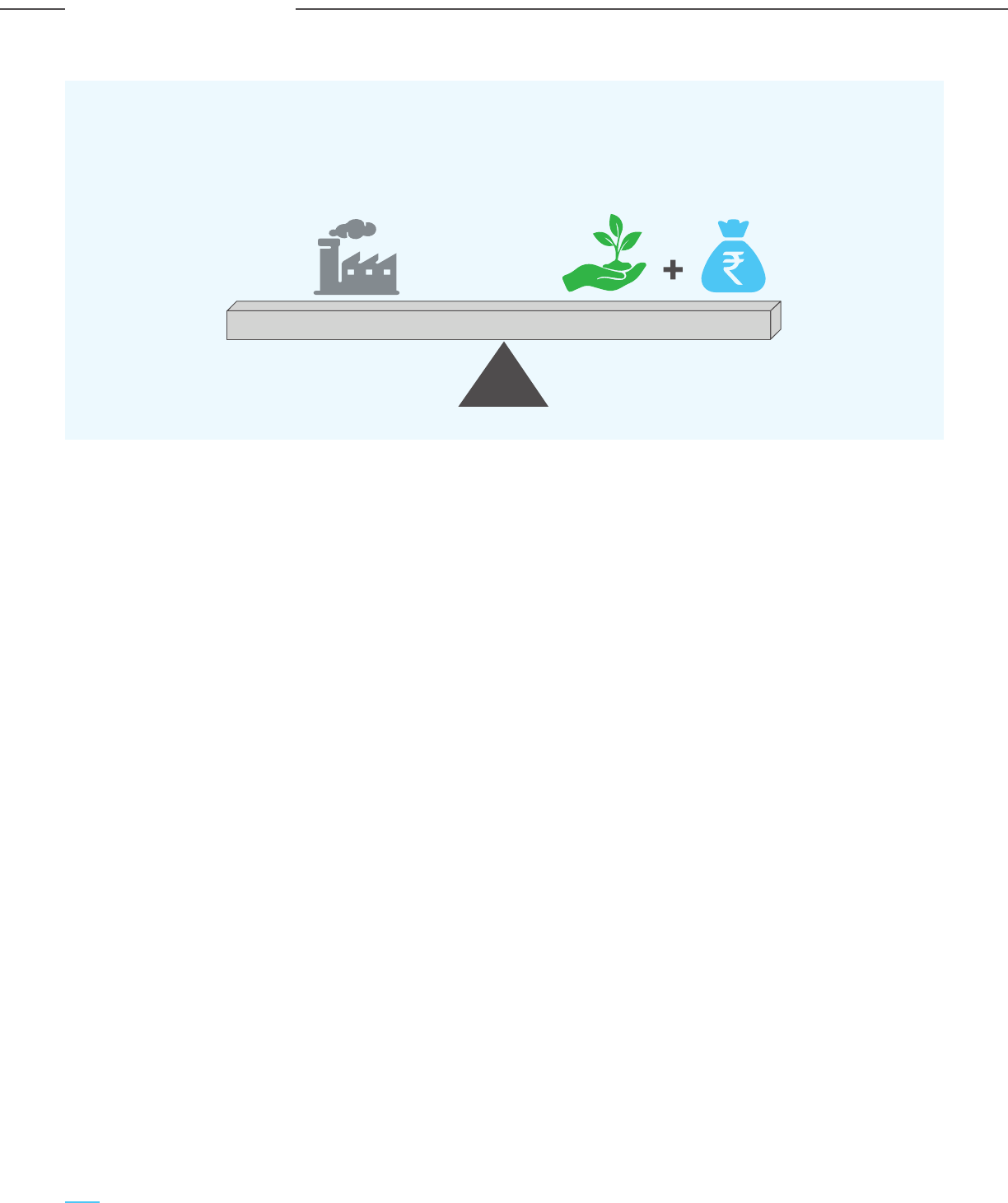
The decarbonization costs will have a varying impact
on the unit cost/price of products in different
industries, viz. power, cement, steel, etc. Hence it is
suggested to have a well-considered policy that takes
care of the CCUS cost structure in domestic and
international markets and the decarbonization cost for
each industry without compromising product
competitiveness and India’s industrial and economic
development goals. An incentive for low-C production
should be primarily guided by the following parameters:
a) Carbon capture/abatement cost;
b) CO
2
emission intensity of the conventional process;
c) Cost structure of alternative process/production
route (if any) for the production of green or low-C
products; and
d) India’s energy security and sustainability goals.
While the initial demo scale projects can be funded
through grants or project specific support, in the long
term it is necessary to also create an institutional
framework to finance and support CCUS projects at
scale, so that CCUS can make a meaningful
contribution to decarbonization and the clean energy
future of India. Therefore, it is proposed to develop a
“Carbon Capture Finance Corporation (CCFC)”, as a
financial institution which will participate in CCUS
projects through equity or debt participation, with the
Figure 6-3: Incentives such as the Product Linked Incentive
(PLI) scheme create a level playing field for low-carbon products
Traditional Fossil-
based products
Low-C products
+ PLI
objective of supporting and realizing the carbon
neutrality goal. The CCFC will be funded by low-cost
sovereign or International Green Funds, Carbon
Bonds or Climate Funds. By investing in CCUS
projects, along with a part of the incremental tax
revenue generated, it should be possible to fund the
carbon capture credits, eventually leading to
subsidy-neutral CCUS operations.
As a signatory of the Paris Agreement of 2015, India
has committed to reducing CO
2
emissions by 50% by
the year 2050 and reaching net zero by 2070. Given
the trajectory of capturable CO
2
emissions, this study
envisions that at least 30% of the emissions should be
captured through CCUS projects, for CCUS to make a
meaningful contribution and providing a pathway for
reaching net zero by the year 2070. Thus, a CCUS
target volume of 750 mtpa has been considered for
analyzing the institutional financial frameworks
required to support the lofty and ambitious goal of net
zero by 2070.
Two financing options have been evaluated and
analyzed for CCUS financing with the target CCUS
volume of 750 mtpa. A general schematic has been
presented in Figure 6-4.
Financing Option 1: CCUS financing through only the
‘Clean Energy Cess’
Financing Option 2: CCUS financing through bond
and gross budgetary support
142
Carbon Capture Utilization and Storage (CCUS) –
Policy Framework and Deployment Mechanism in India
Carbon Capture Utilization and Storage (CCUS) –
Policy Framework and Deployment Mechanism in India
Investment & Financing Mechanism
Figure 6-4: CCUS Financing Mechanism
In both options, it is proposed to develop the CCFC
with seed funding and support from the Government
of India. The surplus funds will be re-financed to
generate earnings at an 8-10% spread. The CCFC will
subsidize the cash costs of CCUS projects through
cash credit, while the capital charges will be
subsidized as a tax credit. Since the cash credit and
tax credit required for each industry will be different
and critical for the adoption of CCUS, it is proposed to
finalize the same based on CCUS demonstration
projects based on different technologies, FEED study
for the projects and discussion with industries. The tax
credit created by the CCUS projects can be either
availed by the parent company or can be sold in the
‘carbon market’.
In financing option 1, it is assumed that the ‘Clean
Energy Cess’ on coal @ USD 5.3/tonne (Rs. 400 per
tonne) will be re-introduced from 1 April 2026, as the
GST compensation cess has been extended till 31
March 2026. India’s coal and coke consumption is
expected to increase from the current 1,050 mtpa to
around 1,200 mtpa by 2030 at a 2% CAGR.
Accordingly, the annual cess collection is estimated to
be around USD 6-7 BB$ (Rs. 48,000 – 53,000 crores).
The maximum cash credit requirement by the year
2030 is estimated to be around USD 2 BB$ (Rs. 15,000
crores) considering the optimistic case i.e 35 mtpa of
capture and disposition. So, the surplus funds in the
initial period will create an opportunity for the CCFC
to grow the corpus significantly through re-financing
through appropriate investment vehicles.
In financing option 2, the Government budget and
bonds will finance the subsidy (cash and tax credits)
required for CCUS. It is estimated that 30.50 BB$ (Rs.
2,29,000 crores) of bonds with a 9% spread in
re-investment return, along with a maximum of 0.5% of
the Government’s spending or the ‘Gross Budgetary
Support (GBS)’ can finance 750 mtpa of CCUS by 2050.
International/National
Boad market
CCFC
Clean Cess Fund/
Budgetary Support
Investment
Vehicle
Guarantees
& Equity
Coupon
Payment
Funding for CCUS
Assessment,
Credit Guarantee
Commercial Banks/
Bonds/ NBFCs/ Private Equity
Promoters/Institutions
Equity
Debt
D
1
E
1
Assured return @ X%
Information
Carbon Capture
Utilization & Storage
(CCUS) Projects
Cash
Credit
Tax/
Cess
Carbon
Credit
CCMB
143
Carbon Capture Utilization and Storage (CCUS) –
Policy Framework and Deployment Mechanism in India
Carbon Capture Utilization and Storage (CCUS) –
Policy Framework and Deployment Mechanism in India
Investment & Financing Mechanism

Table 6-6: Assumptions/Considerations for CCUS Financing Analysis
Current CO
2
emissions from 1600 mtpa
industries & power sector
CAGR of CO
2
emissions 4% till 2030
2% from 2031-40
1% from 2041-50
Capturable CO
2
85% of emissions
Current coal consumption 1050 mtpa
CAGR of coal consumption 2% till 2035, no increase after that
Clean energy cess 400 Rs./tonne Existing rate of Rs. 400/tonne, to be
effective from 1 April 2026
Subsidy for storage 4.1k Rs./tonne till 2040 Based on the average CCUS cost for
3.0k Rs./tonne till 2050 industries and power
Subsidy for EOR usage 3.0k Rs./tonne till 2040 Based on the average CCUS cost for industries
2.4k Rs./tonne till 2050 and power, adjusted for benefits from EOR
Subsidy for utilization for 2.3k Rs./tonne Based on average CCUS cost for industries and
value-added products power, adjusted for benefits from value-added
product
Return on corpus/bond 9%
re-investment
GDP growth rate 8% till 2030
5% for 2031-2050
Govt. expenditure as a 18% Based on the FY 2022-23 budget allocation
percenatge of GDP
Parameters Remarks
It is proposed that the bonds will be raised from the
low-cost national/international bond market and
invested in green projects in India with an assured
return of 9% spread. While the bonds will be raised
and re-invested in the initial years, the projected
utilization has been estimated to limit the government
spending on CCUS to be less than 0.5% of the “Gross
Budgetary Support”.
The assumptions/considerations and the results of the
analysis are presented below.
144
Carbon Capture Utilization and Storage (CCUS) –
Policy Framework and Deployment Mechanism in India
Carbon Capture Utilization and Storage (CCUS) –
Policy Framework and Deployment Mechanism in India
Investment & Financing Mechanism

CO
2
capture progression, in mtpa
Annual cess, Thou. Crore
Coal cons. , mtpa
Figure 6-5: Results of CCUS Financing Analysis –
Financing Option 1 (Clean Energy Cess)
Capture CO
2
CO
2
Capture
Earning from InvestmentTotal Cess Collection
1,360
2023 2030 2040 2050
1,790
2,182
218
35
747
2,410
31%
10%
2%
Coal consumption & ‘Clean Energy
Cess’ Collection
Clean energy cess fund with
re-investment @9%, Thou. crore
1,050
2023 2030 2040 2050
1,206
48
53 53
1,332 1,332
2023 2030
190
2040 2050
23
28
162
679
345
1,024
1212
735
1,947
2023 - 23 23
2030 15 169 154
2040 89 603 514
2050 210 225 15
Year Fund. Req.,
Thou.creore
Bond With Return,
Thou. crore
Gross Budgetary Support
(GBS), Thou. crore
145
Carbon Capture Utilization and Storage (CCUS) –
Policy Framework and Deployment Mechanism in India
Carbon Capture Utilization and Storage (CCUS) –
Policy Framework and Deployment Mechanism in India
Investment & Financing Mechanism

Figure 6-5: Results of CCUS Financing Analysis –
Financing Option 2 (Bonds and Govt. Budget Support)
CO
2
capture progression, in mtpa
CO
2
Capture
Capturable CO
2
1,360
1,790
2,182
2,410
2023 2030
218
747
35
2040 2050
2%
10%
31%
7,823
20,758
1,12,208
2,743
68,880
42,285
4,465
24,675
2023 2030 2040 2050
Bond
Earnings from Investment
Govt. expenditure
GDP
Govt. bonds & budget support with
re-investment @ 9% Thou. crore
Progression of GDP & Govt.
expenditure @18.5%, Thou. crore
41
221
664
1,076
67
3
2023 2030 2040 2050
38
154
229
436
229
847
2023 - - -
2030 15 - 15 (0.2% of GBS)
2040 89 36 53 (0.4% of GBS)
2050 210 107 103 (0.5% of GBS)
Year Fund. Req.,
Thou.creore
Bond With Return,
Thou. crore
Gross Budgetary Support
(GBS), Thou. crore
146
Carbon Capture Utilization and Storage (CCUS) –
Policy Framework and Deployment Mechanism in India
Carbon Capture Utilization and Storage (CCUS) –
Policy Framework and Deployment Mechanism in India
Investment & Financing Mechanism

6.5 Carbon Capture Finance Corporation (CCFC)
It is proposed that the Government of India set-up a
financial institution for the promotion and
development of CCUS projects in India. The financial
institution, which can be called the “Carbon Capture
Finance Corporation (CCFC)” shall provide tax and
cash credits for carbon capture projects in India. The
CCFC may also participate in certain carbon capture
projects through equity and debt funding & financing.
Whilst the detailing the implementation framework for
the CCFC is a separate exercise, the salient features of
the envisaged framework are enumerated below:
i) Timelines: It is envisaged that the CCFC should be
set up by the year 2023 or 2024 to kick start CCUS
projects in India and continue to support carbon
capture projects till the year 2050, i.e. the target
year for CCUS volumes to reach 750 mtpa or about
30% of the capturable emissions in 2050. In this
context, it may be noted that the 45Q carbon tax
credits prevailing in the US originally came into
vogue in 2008 and their validity was extended from
1 January 2026 to 1 January 2033 by the recent
Inflation Reduction Act of 2022. The total timeframe
for the 45Q credits is hence about 25 years, which is
a reasonable timeframe to consider for CCUS to
reach scale and make a meaningful contribution to
India’s energy transition & decarbonization journey
and also cover the depreciable project life of an
infrastructure/CCUS project for recovering the
capital costs. A similar timeframe from 2023 or
2024 to 2050 is also proposed for the CCFC in India,
so that investors in CCUS projects have a long
enough cash flow visibility over the depreciable life
of the assets. Projects need to begin construction
before a specified cut-off date to be eligible for the
CO
2
credits.
ii) Types of credits: It is proposed that the CCFC
shall extend both tax credits and cash credits to
eligible CCUS projects; the tax credits shall be for
the recovery of the capital costs and the cash
credits shall be for the recovery of the operating
costs of CCUS projects. In this context, it may be
noted that similar incentives are already available
in India for wind power projects. Wind power
projects enjoy the benefit of Accelerated
Depreciation (AD), which was first introduced as
early as 1994, with a depreciation rate of 100%.
The depreciation rate was reduced to 80% in 2002
and the AD scheme was subsequently withdrawn in
2012. There was a steep reduction in wind sector
capacity additions post 2012, and the scheme was
re-introduced in 2014 (with an 80% depreciation
benefit) and made applicable for plants installed on
or after 1 April 2014. Additionally, Generation
Based Incentives (GBI) has also been available for
wind power to the extent of INR 0.50 per kWh for
the period of up to 31 March 2022. A similar
combination is also envisioned for CCUS projects,
with the following features to maximize the
envisaged CCUS outcomes:
a. Combination of Accelerated Depreciation
(AD) and GBI: A combination of AD and GBI
may be provided, with the caveat the CCUS
projects should operate at a certain minimum
level of utilization to be eligible for the AD; else
the AD shall be recovered along with interest.
b. Capital cost recovery: Tax credits such as AD
for the recovery of capital costs & charges
should reward actual performance and CO
2
tonnage abated, rather than just capacity
addition, regardless of actual operating
performance. This will also incentivize project
proponents and by extension, technology
providers to invest time and effort in reducing
capital costs over time.
c. Adequate monitoring/auditing mechanisms:
There should be mechanisms for monitoring
and auditing the reported performance of CCUS
projects through independent organizations,
since both tax credits and cash credits shall be
tied to actual operating performance.
d. Transferability of tax credits: The tax credit
should be tradeable or transferable to third
parties in lieu of cash. This ensures a market for
the tax credits so that even emitters which may
not have a tax liability have incentives to
participate in CCUS projects.
147
Carbon Capture Utilization and Storage (CCUS) –
Policy Framework and Deployment Mechanism in India
Carbon Capture Utilization and Storage (CCUS) –
Policy Framework and Deployment Mechanism in India
Investment & Financing Mechanism

Given this backdrop, it is suggested to have
different levels of credit for each industry,
depending on the CO
2
concentration & pressure,
power & steam penalties, Scope 2 emissions,
technology maturity and the typical cost of
capture. Since carbon capture projects are still at
the pilot stage in India (except for fertilizer and
gasification plants), FEED studies and actual
demonstration stage projects are required to
finalize the level of credits that are provided. It
may also be worthwhile to look at providing
incentives for emerging technologies in the areas
of carbon utilization as well as direct air capture,
to promote their development and implementation
in India.
iv) Production Linked Incentive (PLI): An
alternative to tax and cash credits is offering
production linked incentives or PLI to carbon
abated products. The PLI scheme has been in
vogue in India since March 2020 and is applicable
to multiple manufacturing sectors, with benefits
applicable for a period of four to six years. The
goals of the PLI scheme are the creation of large
scale manufacturing capacity in India, import
substitution and employment generation, and
resonate well with the goals of CCUS in India.
Table 6-7: 45Q Tax Credit Amounts
2022 $37.86 $17 $85 $36 $180 $25.13 $12 $60 $26 $130
2023 $40.90 $17 $85 $36 $180 $27.59 $12 $60 $26 $130
2024 $43.94 $17 $85 $36 $180 $30.05 $12 $60 $26 $130
2025 $46.98 $17 $85 $36 $180 $32.51 $12 $60 $26 $130
2026 $50.00 $17 $85 $36 $180 $35.00 $12 $60 $26 $130
2027+ $50.00 as $17 $85 $36 $180 $35.00 as $12 $60 $26 $130
adjusted adjusted for
for inflation inflation
Carbon Captured and
Sequestered ($/metric ton)
Carbon Captured and Used
($/metric ton)
IRA for Industrial
Capture
IRA for Direct
Air Capture
IRA for Industrial
Capture
IRA for Direct
Air Capture
Prior
Law
Prior
Law
Year
Base Bonus Base Bonus Base Bonus Base Bonus
iii) Level of credits: The 45Q tax credits offered in
the USA may serve as a reference point for the
level of tax credits offered for carbon capture
utilization and sequestration projects. The recently
enacted Inflation Reduction Act of 2022 has
substantially enhanced the maximum level of
credits available from US$ 50 to US$ 85 per
tonne of CO
2
sequestered. However, the level of
credits are the same irrespective of the source and
concentration of the CO
2
captured and creates a
disparity of incentives for different types of
emitters, viz. an ethanol plant with almost 100%
pure CO
2
vs. a coal based power plant with 8-15%
CO
2
concentration in the flue gas stream.
148
Carbon Capture Utilization and Storage (CCUS) –
Policy Framework and Deployment Mechanism in India
Carbon Capture Utilization and Storage (CCUS) –
Policy Framework and Deployment Mechanism in India
Investment & Financing Mechanism

Coal gasification (with CCUS) is an important and
strategic sector for ensuring the future energy and
materials security of India and reduce
import-dependence for critical chemicals and
commodities. It is recommended to set up a special
purpose organization to drive and promote coal
gasification in India, including the production of blue
hydrogen to enable the hydrogen economy. The key
areas of focus for the envisaged SPV would be to
conceptualize and strategize the implementation of
coal gasification projects in emerging areas,
identification and implementation of pilot and demo
projects, arranging financing of projects, promoting
and enabling policy research and advocacy, support
start-ups etc. The organization may be formed with
participation from the concerned PSUs from the
Ministry of Coal, Ministry of Heavy Industries,
Ministry of Steel, academic institutes and think tanks
working in these areas.
Additionally, viable financing mechanisms may be
adopted for promoting coal gasification and CCUS
projects. A suggested mechanism is described below:
It is proposed to develop an institutional financing/
SPV framework supported by the Government of
India. The illustrated SPV framework in the example
below (Figure 6-6) is based on mega-scale coal
gasification-based projects that promote and
accelerate the adoption of CCUS, thus enabling a
low-carbon economy. The SPV shall use equity and
debt raised through the international bond markets
to finance the carbon capture costs. The equity will
be funded through the participation of sovereign
funds, government bodies, and private investment
bodies.
The SPV will act as a self-financing funding vehicle
for integrated coal gasification and CCUS projects,
with a likely fund size of between 5-10 BB$ (Rs.
37,500 – 75,000 Crores). The coupon payment and
equity return would be ensured from the returns on
the SPV’s investment in the gasification and CCUS
economy.
6.6 Mechanisms for Promoting Coal Gasification
Projects with CCUS
Table 6-8: Tax Credits for Hydrogen Production in USA - Inflation Reduction Act of 2022
4 – 2.5 6% $0.60
2.5 – 1.5 7.5% $0.75
1.5 – 0.45 10% $1.00
0.45 – 0 30% $3.00
Life Cycle CO
2
Emissions
(kg of CO
2
e / kg of H
2
)
Investment tax credit Production tax credit
(2022 US$ / kg of H
2
)
It is reported that the Government of India is
contemplating extending the PLI scheme for the
production of green hydrogen in India; the same
should be considered for CCUS also. In order to
implement PLI for CCUS projects, it is important to
define the extent of PLI that will be available for
different levels of decarbonization or abatement,
and an independent organization would need to
define the baselines and certify the
extent of decarbonization/greenness of the
products for which the PLI is being claimed. An
example is again provided by the Inflation
Reduction Act of 2022, which provides hydrogen
producers different levels of investment or
production tax credits, depending on the extent
of CO
2
produced per tonne of hydrogen, as
tabulated below.
149
Carbon Capture Utilization and Storage (CCUS) –
Policy Framework and Deployment Mechanism in India
Carbon Capture Utilization and Storage (CCUS) –
Policy Framework and Deployment Mechanism in India
Investment & Financing Mechanism
The carbon credit incentives would be primarily
offset by the tax generated from the indigenous coal
gasification-based economy and generating
value-added products like methanol, power, other
chemicals, hydrogen, steel, and fertilizers. By
investing the funds in the gasification economy,
along with a part of the tax revenue generated from
gasification-based operations, it should be possible to
fund the carbon capture credits of 1-3 BB$
(Rs. 7,500 – 22,5000 Crore)/year – eventually
leading to subsidy-neutral CCUS operations. Also,
investment in gasification projects will enable the
SPV to access, monitor, and enforce CO
2
capture
through a Carbon Capture Monitoring Board (CCMB).
Additionally, the SPV will create revenue of ~ 0.6 BB$
(Rs. 4,500 Crore) through innovative fund design.
The key recommendations for the CCUS financing
framework are summarized below:
a) A statutory body like the ‘Bureau of Energy
Efficiency (BEE)’ needs to be created for the
assessment, baselining, and monitoring of CO
2
emissions for each industry. It will also identify the
best practices to reduce carbon footprint and
design the incentive mechanism for the adoption
of best practices and technologies.
b) PLI for low carbon products should be linked with
the decarbonization goal and the cost
disadvantages of renewable-based/
non-conventional greener production.
Figure 6-6: SPV Framework to Finance Gasification Projects
in a Deficit-Neutral Way
International
Sovereign Fund
66 BB$
500 MM$
Euity
Carbon Bonds
Taxv Revenue
GOI
Carbon Capture
Monitoring Board
Gasification Projects
(MeOH, Ammonia,
Steel)
Equity
Debt
4500 MM$
Bonds
4500 MM$
Assessment,
Credit Guarantee
Information
Return @
20% RoE
Commercial
Banks/Bonds
/NBFCs
/Private Equity
Promoters
/Institutions
Return @
20% RoE
Guarantees
& Equity
Equity
44 BB$
5 BB$
22 BB$
5 BB$
1 BB$
630
MM$
SPV
International
Bond Market
(1-3)
BB$
0-3
BB$
Carbon Credit
Tax
Investment
(Debt for
Equity swap)
Securitized
Carbon Bonds
(6% coupon
rate)
270
MM$
100
MMS
150
Carbon Capture Utilization and Storage (CCUS) –
Policy Framework and Deployment Mechanism in India
Carbon Capture Utilization and Storage (CCUS) –
Policy Framework and Deployment Mechanism in India
Investment & Financing Mechanism
Source: Dastur research

6.7.1 Green Bonds
Ever since its inception, the green bond market has
seen significant growth, especially in the last five
years. The growth has been fueled by the resolution
of various nations and companies towards a net-zero
economy. The year 2021 saw outstanding
participation of investors in the green bond market,
as a result of which the green bond market rose to
over USD 517 BB$ (from USD 350 BB$ in 2020). This
is the highest since the market’s inception (source:
climatebonds.net). With more investors joining the
bond market, many developing nations and emerging
economies like India are introducing sovereign green
6.7 Evaluation of Various
Funding Sources
c) The cost of CO
2
abatement will be subsidized
through cash credits and tax credits. Cash costs
will be subsidized as cash credits, while the capital
cost will be subsidized through tax credits.
d) The cash credit and tax credit levels should be
different for different industries since the cost of
capture varies widely depending on CO
2
concentration & pressure of sources, as well as
technology selection and synergy with existing
operations.
e) Cash credit and tax credit numbers for each
industry should be finalized based on
demonstration projects and/or FEED studies.
Demonstration projects are essential to find out
the best technologies and the possible
optimization through learning and R&D. FEED
studies as well as implementation of
demonstration plants should be supported by the
Government through loan guarantees or a
mandate for PSUs.
f) The cash credit and tax credit mechanism should
be reviewed every 3 to 5 years depending on the
progress, adoption and challenges.
g) Life cycle assessment (LCA) of CCU should be a
mandatory evaluation criterion for finding out the
best possible technologies. To implement LCA, an
India-specific life cycle inventory database and a
framework sho
uld be created on a priority basis.
bonds. Companies can also issue green bonds to
raise funds for environmentally sustainable projects.
Green bonds have attracted considerable attention in
India since it was first issued in 2015. In 2021, India
had the highest issuance of green bonds since 2015,
amounting to USD 6.11 BB$. With India’s plans to
introduce sovereign green bonds in FY 2022-23, it
could attract a significant number of investments
from foreign green bonds, hedge funds, investors,
etc. Being an emerging market, India has a
tremendous economic growth potential which is
attractive to foreign investors. A portion of the
money raised from these bonds could be utilized for
funding CCUS projects and cluster development.
6.7.2 Clean Technology Fund (CTF)
The CTF fund is a USD 5.3 BB$ fund and a part of
Climate Investment Funds. The fund is aimed at
supporting low carbon technology and upscaling to
mitigate long term GHG emissions. 85% of the funds
are approved for projects in renewable energy,
energy efficiency and clean transportation sector.
The fund has supported low carbon projects in 19
countries. In India, the CTF investment plan is worth
USD 775 MM$ and a large share of it has supported
the development of 3 GW solar power capacity and
supporting transmission infrastructure (source:
climateinvestmentfunds.org).
6.7.3 National Clean Energy and Environment
Fund (NCEEF)
The NCEEF was formulated and announced in the
Finance Bill of FY 2010-2011; it was then known as
National Clean Energy Fund (NCEF). The fund was
sourced from the coal cess collected from coal
producers and importers, and cess from other
industries like pan masala, tobacco, aerated water
etc., to finance India’s transition to a low carbon
economy. Apart from renewables and energy
efficiency-related projects, the fund has also
identified CCUS and coal gasification projects as
eligible for funding. However, these funds had been
diverted to support the Goods and Services Tax
(Compensation to States) Act 2017 to compensate
the states for five years (thereafter extended) for
potential losses on account of GST implementation.
This extended period is expected to end in 2026,
after which the funds are expected to be utilized to
support low carbon technologies and projects.
151
Carbon Capture Utilization and Storage (CCUS) –
Policy Framework and Deployment Mechanism in India
Carbon Capture Utilization and Storage (CCUS) –
Policy Framework and Deployment Mechanism in India
Investment & Financing Mechanism

Identification of the right financing partners is
critical to the success of CCUS projects. Based on
the financial analysis of projects, the weightage of
equity and debt financing for projects must be
decided. Sources of equity financing can be large
government/ private corporations owning the
emitter projects (steel, cement, power plants,
fertilizer & chemical plant owners), carbon capture
technology suppliers working on Build Own Operate
(BOO) model and CO
2
storage site owners. Debt
financing can be obtained from various financial
institutions like banks, hedge funds, financial
corporations, etc.
6.8.1 Potential Sources of Debt
6.8.1.1 Project Finance Loans
Project lenders, typically banks and insurance
corporations with both their sources of funding and
debt raised from public and institutional investors,
provide most of the capital needed for project
finance. In Indian projects, project lenders are in the
form of commercial banks, regional banks,
investment banks, and even hedge funds. Examples
include:
6.8 Private Investment
Requirements
6.7.4 Carbon Capture and Storage Fund
This fund is managed by ADB and was started as a
single partner fund with Australia as a partner in
2009; The United Kingdom subsequently joined the
fund in 2012, making this a multi-partner trust fund.
The fund was established for accelerating CCS
technology demonstration, aiding in the
identification and reduction/elimination of possible
country-specific barriers to CCS technology
demonstrations and mitigating the real or perceived
risks related to carbon capture, transport or storage
technology demonstration. The fund supports
capacity development, geological investigations, and
social awareness and support programmes. All ADB
developing member countries are eligible to receive
support through this fund, with priority given to India
and other Asian countries like the People’s Republic
of China, Indonesia, and Vietnam. (source adb.org)
a) The Life Insurance Corporation (LIC) is the doyen
of the insurance industry in India, with a total of
INR 31 Lakh cr (almost USD 410 BB$) in AUM.
They have invested in infrastructure and
industrial projects, including running several
dedicated infrastructure and industrial funds,
and could be a source of funds for CCUS projects.
b) MUFG is the largest Japanese bank and has been
operating in India since 1953. It has recently
renewed its commitment to Indian corporates
and projects with its move to its new 30,000 ft
headquarters in BKC in Mumbai. With USD 17 BB$
in sustainable investments globally and a long
record of investing in developing countries,
including India, MUFG could be a source of funds
for CCUS projects.
c) BNP Paribas has been around since the 1850s
and is a tour de force in Europe’s investing
landscape, with about EURO 470 billion under
management at the end of 2019. With a special
focus on sustainable projects, BNP was the
number 3 participant worldwide in the green
bond market at the end of 2019 and signed 3.7
billion euros of Sustainability Linked Loans at the
end of 2019, a financing instrument indexed on
environmental, social, and governance (ESG)
criteria. They were awarded World’s Best Bank
for corporate responsibility in 2019 by
Euromoney and can be a potential source for
project finance for CCUS projects and CCUS
cluster development.
6.8.1.2 Commercial Bank Long Tenor Loans
Commercial banks raise funds from customer
deposits and allocate a part of their portfolio to
long-tenured industrial loans for infrastructure and
industrial projects. This group would include:
a) Indian Nationalized Banks like State Bank of India
(SBI), Punjab National bank (PNB), and others.
b) Foreign banks such as FAB, Credit Suisse, JP
Morgan, HSBC, Lloyds banking group and
Goldman Sachs, and others.
6.8.1.3 Development Financial Loans
Development finance loans are more specialized and
typically originate from banks and corporations with
lending mandates for sustainable development and
emerging markets. Examples are:
152
Carbon Capture Utilization and Storage (CCUS) –
Policy Framework and Deployment Mechanism in India
Carbon Capture Utilization and Storage (CCUS) –
Policy Framework and Deployment Mechanism in India
Investment & Financing Mechanism

a) International Finance Corporation (IFC): One of
the earliest corporations to issue a green bond in
2010, through its Green Bond Programme. IFC
has issued USD 10.50 BB$ across 178 bonds in 20
currencies. Being one of the largest financiers for
climate-smart projects, IFC has supported these
initiatives and projects with more than USD 28
BB$ in long-term financing.
b) The World Bank: With USD 17 BB$ equivalent,
the World Bank is one of the largest issuing
bodies for green bonds. They have issued green
bonds through 200 bonds in 24 currencies. The
main objectives of the World Bank CCS Capacity
Building Trust Fund (WB CCS TF) is to support
capacity and knowledge building around CCS in
developing nations. It aims to help the developing
countries to explore CCS potential and to
integrate CCS options into their strategies and
policies developed for sustainable growth. Close
to USD 70 MM$ of funds have been granted in
two phases to developing countries like Mexico
and South Africa for pilot demonstration of CCS.
c) Asian Development Bank (ADB): The ADB
works closely with governments and private
bodies to support India’s inclusive
transformation. ADB has set up a Climate Change
Fund (CCF), as an enabler to address
environmental and climate challenges through
participation in low-carbon and climate-resilient
development. “From 2011 to 2020, the ADB has
approved about USD 41.6 BB$ in climate
financing. ADB’s own resources provided USD
36.2 BB$, while external resources contributed
almost USD 5.4 BB$. ADB supports green growth
in Asia and the Pacific through financing and
innovative technologies. Through mechanisms
such as the Climate Investment Funds,
multilateral development banks have mobilized
billions for climate action in
developing countries.
d) European Investment Bank (EIB): EIB has been
operating in India since 1993 and has extended
financial support towards a wide variety of
themes, including climate action and sustainable
economic development. With lifetime finance of
over USD 4.45 BB$ in India, they have made
major investments in the transport and energy
sector. EIB and SBI have jointly launched the 100
million climate action initiative to support MSMEs
working in the clean energy sector, transport
(EV), and circular economy projects.
e) US International Development Finance
Corporation (USIDFC) is America’s development
bank, partnering with private sector equipment
suppliers and service providers to finance
numerous projects in the developing world.
USIDFC invests across sectors including energy,
healthcare, critical infrastructure, and
technology and provides the developing world
with financially sound alternatives to
unsustainable and irresponsible state-directed
initiatives. In India, the USIDFC has been seeking
investment opportunities in India’s crucial
sectors, including financial services, health
infrastructure, food security, etc. A fund of
around USD 350 MM$ has been earmarked for
the same. The development bank of America has
already approved loans of around USD 142 MM$
for one of India’s leading renewable energy IPP
(Independent Power Producer), ReNew Power,
and also has loans with Sitara Solar Energy to
build solar power plants in Rajasthan.
f) Glasgow Financial Alliance for Net Zero
(GFANZ) consists of more than 450 leading
financial institutions representing over USD 130
trillion in assets across the globe in various
financial sectors such as banks, asset managers,
asset owners, insurers, and financial service
providers (stock exchange, rating agencies,
auditors and investment consultants), supporting
the UN’s Race to Zero campaign.
The GFANZ essentially provides a platform where
financial firms can team up or work in
partnership to discuss various issues and come
up with innovative solutions that would support
the decarbonization of the world economies,
companies by accelerating green financing
across the globe. They are also dedicated to
mobilizing investment of private capital into
emerging markets and developing countries.
Furthermore, GFANZ consists of sector-specific
alliances like Net Zero Banking Alliance, Net Zero
Asset Managers Alliance, Net Zero Asset Owner
Alliance, Net Zero Insurance Alliance, Net Zero
Financial Service Providers Alliance, Net Zero
Investment Consultants Initiative, and the Paris
Aligned Investment Initiative. The financial
institutions who are members of these alliances,
based on their region of operations, can be
potential sources of green funding for CCUS
projects and cluster development.
153
Carbon Capture Utilization and Storage (CCUS) –
Policy Framework and Deployment Mechanism in India
Carbon Capture Utilization and Storage (CCUS) –
Policy Framework and Deployment Mechanism in India
Investment & Financing Mechanism

6.9 Socio-Economic Impact
of CCUS
6.8.1.4 Export Credit Agencies
Financing CCUS projects in emerging markets can
pose risks to foreign investors. Export Credit
Agencies (ECA) can play a pivotal role in reducing
the risk of investment/ debt financing for such
projects by providing financing solutions and risk
insurance. Examples include:
a. Export Import Bank of the United States
(EXIM): EXIM provides trade financing solutions,
including export credit insurance, working capital
guarantees, and guarantees of commercial loans
to foreign buyers, to empower exporters of US
goods and services. EXIM works closely with both
US-based suppliers of equipment and services,
as well as with foreign buyers of the same. US
EXIM Bank is an independent federal agency that
fills gaps in private export finance. The US EXIM
Bank was first active in India in the 1950s and
today supports a significant volume of US
exports to India.
b. Nippon Export and Investment Insurance
(NEXI): NEXI is the official export credit agency of
Japan. In 2019, NEXI launched a “Loan insurance
for green innovation”. This insurance was made
for the financing of projects in the field of
environmental protection/ climate change
prevention. This product has been designed
specifically for Japanese companies (exporters or
equity investors) who implement projects in the
field of renewable energy, energy conservation,
and projects utilizing new technologies that
contribute to global environmental protection (like
CCUS, hydrogen-related technology, fuel-cell).
6.8.2 Potential Sources of Equity
a. Large corporations like NTPC, RIL, Adani Group,
IOCL, SAIL, Tata Steel, JSW, IFFCO, etc. can be
equity investors in carbon capture projects
constructed at their plants.
b. Technology and operational investors like Air
Liquide, Honeywell UOP, Mitsubishi Heavy
Industries Ltd., ION Clean Energy, Baker Hughes,
etc. can be equity partners in such projects.
c. Sequestration/EOR site operators like crude oil
and natural gas producers (ONGC) can be equity
investors in carbon capture and cluster
development projects, as they will be utilizing the
captured CO
2
for EOR.
The socio-economic impact of the CCUS project is
manifold. CCUS will help in the production of low-C
products through the decarbonization of
hard-to-abate industries and power plants. Thus, it
will create export opportunities for green products
with a significant premium and also enable new
coal-based industries such as gasification-based
production of chemicals and power. At the same
time, other manufacturing and service sectors will be
benefitted from large investments across the carbon
value chain (capture, processing, transportation,
utilization, storage, and EOR). This will have a
beneficial effect on existing as well as new industries.
With targeted capture of 750 mtpa by 2050, India
could become a global leader in CCUS technology,
thus creating significant export opportunities.
Additionally, coal-based chemical production at a
competitive cost can reduce the import of chemicals
like methanol, ammonia, MEG, etc. This will reduce
the foreign exchange outgo and also ensure energy
security in future.
The additional oil produced from CO
2
-EOR will
substitute crude oil imports to India and, therefore will
decrease the current account deficit of India.
Additionally, the direct and indirect tax revenues
generated from the project and the incomes from
direct and indirect employment will also generate
significant tax revenues in India. Direct, indirect, and
induced employment both during the engineering and
construction phase will have a significant social and
development multiplier. Although rigorous
Input-Output modelling is not possible at this stage, the
baseline parameters indicative of the socio-economic
impact of the project are provided below:
- Economic Activity Parameters:
• Value addition and GDP contribution
• Investment and GDP contribution
• Tax revenues
- Employment Generation Parameters:
• Direct, indirect (including induced) and total
employment during construction & operations
- Import Substitution Parameter:
• Value of import of products substituted
• Contribution to the reduction in current account
decit/surplus.
154
Carbon Capture Utilization and Storage (CCUS) –
Policy Framework and Deployment Mechanism in India
Carbon Capture Utilization and Storage (CCUS) –
Policy Framework and Deployment Mechanism in India
Investment & Financing Mechanism

6.9.1 Net CO
2
Reduction from the Industrial &
Power Sector
CCUS is the only sustainable and feasible solution to
support India’s growing demand for energy and rapid
industrialization and meet the aspiration of over 1.3
billion Indians. The Indian industrial and power sector
emits about 1.6 Gtpa of anthropogenic CO
2
today,
which is expected to increase to 2.3 Gtpa by 2030
and 2.8 Gtpa by 2050. With the envisaged capture of
around 0.75 Gtpa by 2050, CO
2
emissions will reduce
by around 30%. Out of 0.75 Gtpa, a majority will be
contributed by steel, cement and power industries in
addition to new gasification-based industries. A
probable distribution of 0.75 Gtpa across different
sectors and the corresponding low-C production is
shown in Table 6-9.
However, most of the currently available
technologies for carbon capture are
energy-intensive. Conventional technologies like
amine-based carbon capture consume large
quantities of steam for regeneration, while
non-conventional technologies like
PSA/cryo/membrane consume power. Since steam
can only be produced efficiently through the burning
of fossil fuels in boilers, there will be CO
2
emissions
for steam production. With proper sourcing of steam
and fuel selection, CO
2
emissions from boilers can be
reduced, reducing the net CO
2
emission by 20-40%,
depending on the industry. Waste heat recovery (if
available) is ideal for the generation of steam,
especially for cement and steel plants. On the other
hand, Scope 2 emissions for electricity-based
technologies will depend on the grid emission
intensity. With the increased share of renewables,
grid CO
2
intensity will reduce over time, which will
benefit electricity-based technologies.
6.9.2 GDP & GVA Impact
A total of around USD 100-150 BB$ [2022 dollars]
of investments are required over the next few
decades for 750 mtpa CO
2
capture, utilization, and
storage. Since the investment will be across the CO
2
value chain, it will help develop the market for CO
2
.
This preliminary estimation has been done based on
the envisaged improvement of technology as well
as cost reductions expected through indigenization.
During the implementation stage, the impact on
GDP has been assessed as US$ 100 to 150 BB over
the next 30 years.
Coal gasification projects will generate value-added
products like methanol, ammonia, acetic acid,
mono-ethylene glycol, etc. A significant part of these
chemicals are presently imported to India; presently,
India imports almost USD 13 BB$ per annum of
organic chemicals. Coal-based production through
gasification will help in significantly reducing imports.
Table 6-9: Probable Distribution of 750 mtpa and low-C Product Volume
Thermal power generation 530 80-100 GW
Steel 100 40-50 mtpa
Cement 50 80-100 mtpa
Refineries & chemicals 10 40-60 mtpa
Hydrogen 10 ~ 2 mtpa
Coal gasification 50 5 mtpa H
2
or 25 mtpa
Methanol or 16 mtpa Ammonia
Total 750
Capture volume, mtpa Equi. Low-C product
155
Carbon Capture Utilization and Storage (CCUS) –
Policy Framework and Deployment Mechanism in India
Carbon Capture Utilization and Storage (CCUS) –
Policy Framework and Deployment Mechanism in India
Investment & Financing Mechanism

The contribution to the GDP from gasification-based
products will be in the form of revenues from the
production of methanol, ammonia, acetic acid,
mono-ethylene glycol, etc. Revenues throughout the
operating life cycle have been considered for
estimating the GDP contribution from gasification
projects. Depending on the product-mix
(methanol/MEG/AA), coal based chemicals
production can replace 7-10 BB$ of imports by 2050.
Coal gasification projects will generate multiple tax
streams for the Government exchequer. The major
sources of tax, like the tax on the purchase of capital
goods (during the construction stage) and the
corporate tax (throughout the economic life of the
project) have been assessed. Additionally, there will
be a cascading effect due to the significant
employment generation as well as economic
development in the vicinity of the project, which is
difficult to ascertain; hence the same has not been
assessed.
Contribution to the GVA for value addition has been
estimated as the revenue generated from the low-C
products, less the cost for the intermediate inputs.
The EBITDA (Earnings Before Interest Tax
Depreciation and Amortization or the operating
profits) throughout the economic life of the project
have been used for calculating the GVA. Considering
a minimum premium of 10% over conventional
products, GVA for decarbonized products is
estimated at around 10 BB$.
6.9.3 Potential Direct & Indirect Employment
Creation
During the construction stage, the generation of
temporary employment for construction works
(skilled, semi-skilled, and unskilled) will be one of the
major impacts of CCUS projects. Additionally, high
skilled and valued resources will be required by
contractors, technology suppliers, and project
proponents for project management, administration,
and supervision. The employment of construction
workers from the nearby area will boost the regional
economic conditions. As there is a multiplier effect
on consumption, savings, taxes, etc. the projects will
help in shaping the future economic development of
the nearby areas. The indirect employment is likely
to be 3-5X of the direct employment generated.
Additionally, jobs for O&M of the entire carbon value
chain will progressively expand. These persons will
mostly be skilled personnel and SMEs in the required
fields. The total impact has been estimated based on
the annual requirement of manpower multiplied by
the economic life of the project, considered as 25
years of operations. As the indirect employment
multiplier is a function of the salary, savings, and
domestic consumption, indirect employment will be
around 5-7X of the direct employment.
Based on the above, it is estimated that India’s CCUS
ambitious target of 750 mtpa by 2050 can create
employment of over 8-10 million full time equivalent
(FTE) years in a phased manner.
6.9.4 Potential FDI
Primary industries are capital cost intensive and
CCUS will increase the cost further. CCUS
implementation for a volume of 750 mtpa will cost
more than 100 BB$ over the next two to three
decades. The Government of India should work with
international partners, technology suppliers,
policymakers, etc. to support India’s decarbonization
goal through technology transfer and financing
capital cost-intensive CCUS projects. Additionally,
decarbonization will gradually become one of the key
criteria for attracting international financing. So,
projects with CCUS may be able to secure low-cost
financing from outside India.
156
Carbon Capture Utilization and Storage (CCUS) –
Policy Framework and Deployment Mechanism in India
Carbon Capture Utilization and Storage (CCUS) –
Policy Framework and Deployment Mechanism in India
Investment & Financing Mechanism

Chapter 7
Conclusions

This chapter summarizes the findings and
recommendations of this study, as below:
1. Carbon Capture Utilization and Storage (CCUS)
has an important and critical role to play for India
to halve CO
2
emissions by 2050 and accomplish
net-zero by 2070, as envisioned by the Hon’ble
Prime Minister of India. Energy transitions take
decades and hence it is important to implement
the framework and policy instruments for CCUS to
become a reality in India and make a meaningful
contribution to decarbonization in India.
2. CCUS is required for the decarbonization of both
industrial applications and the power sector:
a. Industrial applications: Industrial applications
are hard to electrify, and industrial CO
2
emissions are hard to abate due to the use of
fossil fuels not only as a source of energy but
within the process itself. Thus CCUS is
imperative to decarbonize the industrial
sector, which accounts for over 30% of total
CO
2
emissions in India.
b. Clean products: CCUS can enable the
production of clean products while utilizing our
rich endowments of coal, reducing imports and
thus leading to an Indian economy.
CCUS also has an important role to play in
enabling sunrise sectors such as coal
gasification and the nascent hydrogen
economy in India.
c. Power: India relies on coal for meeting over
70% of its electricity needs; even if India is
able to meet the renewables target of 500 GW
installed capacity by 2030, there would still be
a need to meet baseload power demand from
fossil fuels (most likely coal) or other
dispatchable sources, given the intermittency
and non-dispatchable nature of solar and wind
power. Thus, CCUS has a role to play in
enabling clean and green baseload power and
ensuring the sustenance and non-stranding of
our over 210 GW of coal and lignite-based
thermal power plants.
3. CCUS can contribute to decarbonization and
transition to clean energy systems in various ways:
a. Ensuring the sustenance of existing emitters
b. Decarbonizing hard to abate sectors
c. Promoting the low carbon hydrogen economy
d. Removal of the CO
2
stock from the atmosphere
4. Scope 1 emissions from India’s power and
industrial sectors (primarily steel, cement, H
2
production, oil & gas, refineries, chemicals and
coal gasification) amount to 1,600 mtpa of CO
2
,
which is around 60% of the total CO
2
emissions
(2,600 mtpa) in India in 2020. The remaining 40%
CO
2
emissions are contributed by distributed point
emissions sources like agriculture, transport, and
buildings, which are not amenable to carbon
capture. Emissions from these sectors (power and
industries) are expected to increase to nearly
2,300 mtpa by the year 2030, fuelled by India’s
strong GDP growth outlook.
5. The key CCUS related interventions required for
the CO
2
intensive sectors of the Indian economy is
tabulated below:
158
Carbon Capture Utilization and Storage (CCUS) –
Policy Framework and Deployment Mechanism in India
Carbon Capture Utilization and Storage (CCUS) –
Policy Framework and Deployment Mechanism in India
Conclusions

Total
6. Commercially proven carbon capture technologies:
The mature and commercially proven CO
2
capture
technologies may be broadly classified into the
following types:
a. Chemical solvent-based CO
2
capture
technologies: preferred when dealing with gas
streams that are lean in CO
2
and have relatively
lower pressures, such as flue gases. The cost and
availability of steam is also a key factor as
regenerating the solvent requires large
quantities of steam.
b. Physical solvent-based CO
2
capture
technologies: these work well on gas streams with
relatively higher CO
2
concentration and pressure.
Steel Future steel growth is largely based on
the BF-BOF route, where the use of fossil
fuels is hard to replace. CCUS is
necessary for sustainability and also
ensures export competitiveness
Establish CCUS for
Integrated Steel Plants,
particularly in Eastern India
240 450
Cement Another major CO
2
emitting sector,
where fossil fuels are difficult to replace.
Utilization of CO
2
in aggregates has
synergies with the cement business
Establish CCUS clusters in
key identified areas/ districts
196 325
Oil & gas upstream,
refineries &
chemicals
Hard to abate sector. CCUS essential for
the sustainability of the sector; carbon
capture inbuilt in many of the processes
Decarbonize key applications
like urea, olefins, syngas
from petcoke
125 177
Hydrogen Blue hydrogen is key to the hydrogen
economy of the future. Carbon capture is
unbuilt in the H
2
production process
Establish pathways for CO
2
utilization and storage
56 102
Coal gasification Sunrise sector - key to materials and
energy security of India, based on India’s
rich endowments
Establish pathways for CO
2
utilization and storage
- 27
1,621 2,291
c. Adsorption-based CO
2
capture: they are
suitable for pre-combustion capture, where the
gas stream has high pressure and a high CO
2
concentration.
d. Cryogenic CO
2
capture: preferred in cases
where the cost of power is low. This technology
also provides a unique advantage by
generating additional hydrogen without
increasing the amount of feedstock (natural
gas)/ producing the same quantity of hydrogen
with lower natural gas consumption
7. CO
2
utilization: The pathways for utilization of the
captured CO
2
are primarily:
Thermal power
generation
Even with RE growth, coal-based power
will continue to meet more than 50% of
electricity demand. As the largest emitter
of CO
2
, CCUS in the power sector is
essential for meaningful decarbonization
and ensuring energy security in India
Establish CCUS clusters in
key identified districts
1,004 1,210
Table 7-1: Sector-wise CO
2
Emissions and Interventions Required
Sector
2020 2030
Estimated CO
2
emissions (in mtpa)
Rationale for CCUS Key interventions
required
159
Carbon Capture Utilization and Storage (CCUS) –
Policy Framework and Deployment Mechanism in India
Carbon Capture Utilization and Storage (CCUS) –
Policy Framework and Deployment Mechanism in India
Conclusions

a. Enhanced Oil Recovery (EOR): CO
2
for EOR
has been successfully carried out for decades
to produce low-carbon oil from maturing oil
fields in North America and other geographies.
CO
2
EOR could also be feasible for maturing
Indian oil fields.
b. Green urea: Urea production from green
ammonia can utilize a significant part of
captured CO
2
. Renewable energy-based ammonia
(green ammonia) can replace conventional
ammonia production from LNG if green
hydrogen is available at a competitive cost.
c. F&B applications: CO
2
utilization in F&B
applications comprise of carbonated drinks,
dry ice, and modified atmosphere packing;
however, the scales are quite small compared
to the volume of CO
2
generation/emissions.
d. Additionally, there are other promising
propositions for the utilization of CO
2
. The
relatively matured CO
2
utilization pathways
are: chemicals (methanol and ethanol),
building materials (concrete and aggregates)
and polymers
8. Notwithstanding the above-mentioned
opportunities for CO
2
utilization, the permanent
sequestration or geological storage of CO
2
in
saline aquifers and basaltic traps, EOR and
Enhanced Coal Bed Methane Recovery (ECBMR)
are the only available pathways for CO
2
disposition at scale. The overall CO
2
storage
capacity assessment for India (based on
theoretical assessments) for the four options is
tabulated below.
9. Existing studies by the British Geological Society
and IIT Bombay indicate a large CO
2
storage
potential in India; however, further actions need to
be supported by the Government of India to make
geological storage of CO
2
a reality in India:
a. Source sink mapping to prioritize the regions
and basins most suitable for CO
2
storage in
terms of storage capacity and feasibility
b. Pore space mapping and characterization of
the most promising CO
2
storage regions and
basins – geological characterization and
exploration for CO
2
storage, similar to the
seven Regional Carbon Sequestration
Partnerships (RCSPs) funded by the US
Department of Energy (US DOE).
c. For the prospective regions identified in India,
developing the CO
2
storage infrastructure
through characterization, validation and
commercial scale development.
10. The key to a successful CCUS implementation in
India is to enact a policy framework that supports
the creation of sustainable and viable markets for
CCUS projects. The private sector is unlikely to
invest in CCUS unless there are sufficient
incentives or unless it can benefit from the sale of
CO
2
or gain credits for emissions avoided under
carbon pricing regimes.
EOR Relatively more researched area; technology tested in
major carbon capture projects across the globe
3.4
ECBMR Requires more dedicated studies and pilot tests for
Indian coal beds; no commercial-scale project
3.5-3.7
Deep Saline
Aquifers
Offers great CO
2
storage potential; however, limited
data available on storage in deep saline aquifers
291
Basalts Studies required for understanding storage
mechanisms in basaltic traps
97-315
Total 395-614
Table 7-2: Theoretical CO
2
Storage Capacity in India
Storage Pathways
Theoretical Storage Capacity (Gt) Extent of Existing Research
160
Carbon Capture Utilization and Storage (CCUS) –
Policy Framework and Deployment Mechanism in India
Carbon Capture Utilization and Storage (CCUS) –
Policy Framework and Deployment Mechanism in India
Conclusions

carbon capture costs through financial
instruments and future taxes & growth. On the
other hand, the effectiveness of a carbon tax
based policy is questionable for a developing
country like India and may lead to industrial
migration and loss of competitiveness.
12. The key elements of the proposed carbon credits
and incentives based CCUS policy framework for
India are tabulated below:
13. Financing CCUS projects can be quite challenging
in a developing country like India, even with policy
support. To support CCUS in India, it is important
to fund and support demonstration scale projects.
The typical cost structure of potential CCUS
Table 7-3: Key Elements of a CCUS Policy Framework for India
Element Details
- In the near term, CCUS policy should be carbon credits or incentives based, to seed
and promote the CCUS sector in India through tax and cash credits
- Over time (probably beyond 2050), the policy should transition to carbon taxes, to
enable reaching India’s net zero goals by 2070
- The policy should establish early stage financing and funding mechanisms for
CCUS projects
- Regional hub & cluster models need to be established to drive economies of scale
- The role of emitters, aggregators, hub operator, disposers and conversion agents
needs to be defined
- Preferential procurement in Government tenders for low carbon or carbon abated
products
- Incentives to foster innovation for low carbon products through schemes like PLI
- Distribution of benefits of economic value added created, to communities most
affected by environmental and climate change
- Protection of communities and jobs, especially in sectors affected by clean energy
regulations
- Regulated emission levels and allowances for different sectors
- Adoption of Life Cycle Analysis (LCA) framework to take into account Scope 2 and
Scope 3 emissions and drive effective carbon abatement
- Limiting the CO
2
liability and ownership of participants across the CCUS value
chain
- Monitoring, Verification and Accounting (MVA) framework and monitoring for risk
management
Policy path
Hub & cluster
business model
Low carbon products
Environmental and
social justice
Accounting and
regulatory framework
Risk mitigation
demonstration projects in India for different
sectors can be quite different, depending on the
source and quality of the gas stream and the
extent of CO
2
capture targeted; the same is
summarized below.
Based on the review of the prevailing policy
mechanisms in different parts of the world, there
are two clear policy choices/approaches for India
to adopt, i.e. either carbon credits/incentives
based policy or carbon tax based policy.
11. A comparison of the two approaches reveals that
a cash and tax credit based policy is more likely to
incentivize CCUS adoption in India, by establishing
markets for carbon-based products and offsetting
161
Carbon Capture Utilization and Storage (CCUS) –
Policy Framework and Deployment Mechanism in India
Carbon Capture Utilization and Storage (CCUS) –
Policy Framework and Deployment Mechanism in India
Conclusions

Table 7-4: Sector-wise Typical Carbon Capture Capital Charge and Cash Cost
Gasification 70 ktpa H
2
1 mtpa Rs. 80-100 90-120 250-300 340-420
based Crore
production
NG based 130 ktpa H
2
0.7 mtpa Rs. 700-800 900-1,200 1,150-1,400 2,050-2,600
SMR for H
2
Crore
production
Cement 2.5 mtpa 2 mtpa Rs. 1,600 to 800-1,000 1,050-1,600 1,800-2,600
clinker 1800 Crore
Iron and 2.0 mtpa BF 2 mtpa Rs. 1,600- 1,000-1,300 1,900-2,300 2,900-3,600
Steel BOF based ISP 2,000 Crore
Refinery 5 mtpa crude 1 mtpa Rs. 1,100- 1,200-1,400 2,700-3,100 3,900-4,500
(CDU & FCC) processing 1,300 Crore
Coal-based 800 MW 5 mtpa Rs. 3,500- 700-1,000 2,100-2,500 2,800-3,500
power 4,000 Crore
Total 11.7 mtpa Rs. 8,600 –
10,000 Crore
Industry
name
Ref. Plant
capacity
CCU capacity
(mtpa)
Capital Costs,
Rs. crores
Capital
Charges (A),
Rs./TCO
2
Cash Cost
(B), Rs./TCO
2
Total Capture
Cost (A+B),
Rs./TCO
2
The financing of CCUS projects at scale can be
considered through options:
a. Option 1: CCUS financing through ‘Clean Energy
Cess’ only
b. Option 2: CCUS financing through bond and gross
budgetary support
In both options, it is proposed that a “Carbon Capture
Finance Corporation (CCFC)” be developed as a
financial institution to fund CCUS projects through
equity or debt participation, with the objective of
supporting and realizing the carbon neutrality goal.
The CCFC will be funded by low-cost sovereign or
International Green Funds, Carbon Bonds or Climate
Funds. By investing in CCUS projects, along with a part
of the incremental tax revenue generated, it should be
possible to fund the carbon capture credits, eventually
leading to subsidy-neutral CCUS operations.
14. The other measures required for promoting CCUS
projects are as follows:
a. A statutory body like the ‘Bureau of Energy
Efficiency (BEE)’ is required for the
assessment, baselining, and monitoring of CO
2
emissions for each industry.
b. PLI for low carbon products should be linked
with the decarbonization goal and the
additional cost required for producing
green/clean products.
c. The cost of CO
2
abatement should be
subsidized through cash credits (for cash
costs) and tax credits (for capital costs). The
levels should be commensurate to the industry
cost structure and be finalized based on
demonstration projects and/or FEED studies.
The cash and tax credit mechanism should be
reviewed every 3 to 5 years.
d. Demonstration projects are essential to find
out the best CCUS technologies for different
sectors and applications in the Indian context,
based on Life Cycle Assessment (LCA) of the
CCUS projects. FEED studies, as well as the
implementation of demonstration plants
should be supported by the Government/PSUs.
15. Promoting CCUS adoption and implementation in
India requires a multi-pronged approach to
incentivize the following:
a. Technology transfer of commercially proven
CCUS technologies
b. Promoting R&D in novel technologies,
particularly in the area of CO
2
utilization
c. Encouraging private sector participation in
implementing CCUS demo projects
162
Carbon Capture Utilization and Storage (CCUS) –
Policy Framework and Deployment Mechanism in India
Carbon Capture Utilization and Storage (CCUS) –
Policy Framework and Deployment Mechanism in India
Conclusions

Bibliography
1. International Energy Agency, IEA
2. Intergovernmental Panel on Climate Change (IPCC)
3. India's Intended Nationally Determined Contributions. (2015). (Retrieved from
https://moef.gov.in/wp-content/uploads/2018/04/revised-PPT-Press-Conference-INDC-v5.pdf)
4. MIT database - https://sequestration.mit.edu/tools/projects/index.html
5. IEA 2009 Roadmap for CCUS
6. Vishal, Vikram, et al. "Understanding initial opportunities and key challenges for CCUS deployment in India at scale."
Resources, Conservation and Recycling 175 (2021): 105829.
7. Medlock, III, Kenneth B. and Keily Miller, “Expanding Carbon Capture in Texas”, Baker Institute Center for Energy
Studies, January 2021.
8. IBEF Power, 2021
9. Ministry of Power Annual Report, 2020-2021
10. India Energy Outlook 2021, IEA.
11. Central Electricity Authority (CEA)
12. Power Sector at a Glance (All India) - Ministry of Power
13. Breeze, Paul. Power generation technologies. Newnes, 2019.
14. Colin, A. S., Minh, T. H., & Dianne, E. W. (2016). Membrane-Cryogenic Post-Combustion Carbon Capture of Flue Gases
from NGCC. Technologies, 4(2), 14.
15. Tim, B. & Kashish, S. (2019). Gujarat’s Electricity Sector Transformation. IEEFA.
16. Joint Plant Committee (JPC)
17. National Steel Policy, Ministry of Steel
18. IBEF Cement, 2021
19. Indian Minerals Yearbook 2019, Indian Bureau of Mines, Government of India.
20. Cement Manufacturing Association
21. India’s Hydrocarbon Outlook, 2020.
22. NETL, US Department of Energy (DOE).
23. IEAGHG 2018 Report on “The Carbon Capture Project at Air Products’ Port Arthur Hydrogen Production Facility”.
163
Carbon Capture Utilization and Storage (CCUS) –
Policy Framework and Deployment Mechanism in India
Carbon Capture Utilization and Storage (CCUS) –
Policy Framework and Deployment Mechanism in India

24. UOP White Paper (UOP Polybed™ PSA Systems)
25. Air Liquide Technology Handbook 2018.
26. Global Status of CCS 2020 Report, Global CCS Institute.
27. https://www.frontiersin.org/articles/10.3389/fmars.2019.00029/full
28. Behera, Bunushree, Nazimdhine Aly, and P. Balasubramanian. "Biophysical model and techno-economic
assessment of carbon sequestration by microalgal ponds in Indian coal based power plants." Journal of
Cleaner Production 221 (2019): 587-597.
29. https://www.energy.gov/fecm/science-innovation/oil-gas-research/enhanced-oil-recovery
30. Mazzotti, M., Pini, R., & Storti, G. (2009). Enhanced coalbed methane recovery. Journal of Supercritical
Fluids, 47(3), 619-627.
31. Vikram, V., Yashvardhan, V., Debanjan, C., & Dhananjayan, A. (2021). A systematic capacity assessment and
classification of geologic CO
2
storage systems in India. International Journal of Greenhouse Gas Control,
111, 103458.
32. Snæbjörnsdóttir, S. e. (2014). CO
2
storage potential of basaltic rocks in Iceland and the oceanic ridges.
Energy Procedia, 63, 4585-4600
33. McGrail, B. P. (2006). Potential for carbon dioxide sequestration in flood basalts. Journal of Geophysical
Research: Solid Earth, 111(B12).
34. A regional assessment of the poential for CO
2
storage in the Indian subcontinent - IEAGHG 2008
35. Best Practices for Monitoring, Verification, and Accounting of CO
2
Stored in Deep Geologic Formations (US
DOE NETL).
36. European Commission- Carbon Capture, Utilization and Storage
(https://energy.ec.europa.eu/topics/oil-gas-and-coal/carbon-capture-storage-and-utilisation_en#carbon-ca
pture-storage-and-utilisation-in-the-eu)
37. Carbon pollution pricing scheme across Canada
(https://www.canada.ca/en/environment-climate-change/services/climate-change/pricing-pollution-how-it-
will-work.html)
38. Cost of capturing CO
2
from Industrial sources (DOE/NETL-2013/1602).
39. Integrated Environmental Control Model (IECM) Version 11.5.
40. IEA Technical Report.
41. Climate Bonds Initiative (www.climatebonds.net )
42. Climate Investment Funds (www.climateinvestmentfunds.org)
43. Asian Development Bank (adb.org)
164
Carbon Capture Utilization and Storage (CCUS) –
Policy Framework and Deployment Mechanism in India
Carbon Capture Utilization and Storage (CCUS) –
Policy Framework and Deployment Mechanism in India

www.niti.gov.in
