
Visual Programming
for Gaming Device Customization
Master Project in Computer Science
Logitech Europe S.A.
Student:
Thanuditha Ruchiranga
Wickramasinghe
Faculty Supervisor:
Dr. Pearl Pu
Industry Supervisor:
Mr. Sidney Bovet
Fall Semester, 2020

Acknowledgements
First and foremost, I would like to express my sincere gratitude to my industry supervi-
sor, Mr. Sidney Bovet for his guidance and support given throughout the project. Second, I
would like to thank my faculty supervisor, Dr. Pearl Pu for advising me on this project. I also
thank my colleagues in the Logitech Gaming team for the support they extended reviewing my
user study designs and providing me with useful feedback. I also wish to acknowledge all the
Logitech employees who participated in the user studies carried out as a part of the project
and offered useful insights to improve my work. My gratitude also goes to all the academic
and non-academic staff at EPFL who helped me to successfully complete my postgraduate
studies. Last, but not the least, I thank my parents, my brother and my wife who supported
me in numerous ways during my studies at EPFL.
Lausanne, 12 March 2021
i

Abstract
The Logitech G HUB software provides a Lua scripting environment for users to perform
advanced customizations on Logitech Gaming gear. This feature requires the user to have
some familiarity with programming in Lua language and a lengthy reference manual has to
be referred to learn the Lua API functions provided by G HUB. This project aims to explore
how visual programming can be utilized in this setup to make this scripting environment in G
HUB easy to use, more intuitive and more approachable, for users without any programming
experience. The project follows a User Centered Design process where progress is made in
iterations, carrying out user tests at each step to verify the design decisions.
To start with, two types of candidate visual programming setups were evaluated. One setup
used a notion of blocks that fit together to create meaningful programs. The other setup
used a notion of a graph of nodes connected to each other using lines that specify the flow of
execution and the flow of data. Low fidelity prototypes of the two setups were developed and
tested with users. Based on user input, it was decided to proceed with the blocks based setup.
Thereafter, a high fidelity visual programming prototype that functioned fully integrated with
the G HUB software was developed. A final round of user tests was carried out to discover any
further usability issues in the prototype to be addressed in future iterations. A majority of the
participants of the high fidelity prototype user test, stated with confidence that they would
prefer to use the prototype rather than write code in text to perform device customizations.
Key words: Visual Programming, User Centered Design, Logitech G HUB
iii

Contents
Acknowledgements i
Abstract iii
List of figures vii
List of tables ix
1 Introduction 1
2 Visual Programming - Current State of the Art 5
2.1 Scratch Programming . . . . . . . . . . . . . . . . . . . . . . . . . . . . . . . . . . 8
2.2 Blueprints Visual Scripting . . . . . . . . . . . . . . . . . . . . . . . . . . . . . . . 10
3 Methodology 15
4 Analysis 17
4.1 Audience analysis . . . . . . . . . . . . . . . . . . . . . . . . . . . . . . . . . . . . . 17
4.1.1 Persona 1 (Primary Persona) . . . . . . . . . . . . . . . . . . . . . . . . . . 18
4.1.2 Persona 2 (Secondary Persona) . . . . . . . . . . . . . . . . . . . . . . . . . 19
4.2 Problem statement . . . . . . . . . . . . . . . . . . . . . . . . . . . . . . . . . . . . 19
4.3 Vision statement . . . . . . . . . . . . . . . . . . . . . . . . . . . . . . . . . . . . . 20
4.4 Context scenario . . . . . . . . . . . . . . . . . . . . . . . . . . . . . . . . . . . . . 20
5 Design 21
6 Evaluation - Iteration 1 25
6.1 Recruiting users . . . . . . . . . . . . . . . . . . . . . . . . . . . . . . . . . . . . . . 25
6.2 Experiment design . . . . . . . . . . . . . . . . . . . . . . . . . . . . . . . . . . . . 26
6.3 User interview and user task . . . . . . . . . . . . . . . . . . . . . . . . . . . . . . 27
6.4 Results . . . . . . . . . . . . . . . . . . . . . . . . . . . . . . . . . . . . . . . . . . . 28
6.4.1 General impression on visual programming . . . . . . . . . . . . . . . . . 28
6.4.2 Preferred visual programming setup . . . . . . . . . . . . . . . . . . . . . . 29
6.4.3 Insights on usability . . . . . . . . . . . . . . . . . . . . . . . . . . . . . . . 33
6.4.4 User performance . . . . . . . . . . . . . . . . . . . . . . . . . . . . . . . . 37
6.4.5 User mental model . . . . . . . . . . . . . . . . . . . . . . . . . . . . . . . . 37
v

Chapter 0 CONTENTS
6.4.6 Self understanding on the context at the beginning of user test . . . . . . 39
6.4.7 G HUB use . . . . . . . . . . . . . . . . . . . . . . . . . . . . . . . . . . . . . 39
6.4.8 Suggested use cases . . . . . . . . . . . . . . . . . . . . . . . . . . . . . . . 40
7 Implementation 41
8 Evaluation - Iteration 2 51
8.1 Recruiting users . . . . . . . . . . . . . . . . . . . . . . . . . . . . . . . . . . . . . . 51
8.2 Experiment design . . . . . . . . . . . . . . . . . . . . . . . . . . . . . . . . . . . . 51
8.3 Interview and user task . . . . . . . . . . . . . . . . . . . . . . . . . . . . . . . . . . 52
8.4 Results . . . . . . . . . . . . . . . . . . . . . . . . . . . . . . . . . . . . . . . . . . . 53
8.4.1 Insights on usability . . . . . . . . . . . . . . . . . . . . . . . . . . . . . . . 53
8.4.2 User performance . . . . . . . . . . . . . . . . . . . . . . . . . . . . . . . . 56
9 Discussion 57
10 Future work 59
11 Conclusion 61
A Appendix 63
A.1 Interview Guide . . . . . . . . . . . . . . . . . . . . . . . . . . . . . . . . . . . . . . 63
A.1.1 Introduction and Setup . . . . . . . . . . . . . . . . . . . . . . . . . . . . . 63
A.1.2 Demographics and Background . . . . . . . . . . . . . . . . . . . . . . . . 64
A.1.3 Task on the prototype . . . . . . . . . . . . . . . . . . . . . . . . . . . . . . 65
A.1.4 Follow up questions . . . . . . . . . . . . . . . . . . . . . . . . . . . . . . . 66
A.1.5 Wrap up . . . . . . . . . . . . . . . . . . . . . . . . . . . . . . . . . . . . . . 66
Bibliography 68
vi

List of Figures
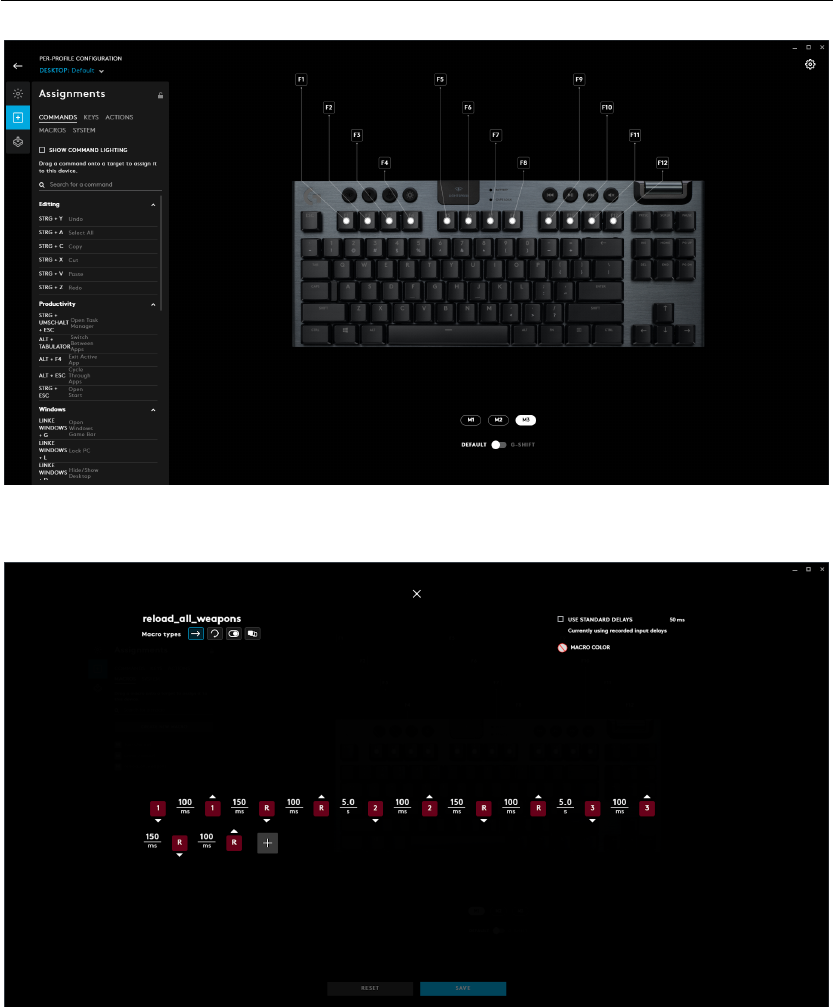
1.1 Keyboard key assignment configuration tool in G HUB . . . . . . . . . . . . . . . 2
1.2 G HUB Macro editor . . . . . . . . . . . . . . . . . . . . . . . . . . . . . . . . . . . 2
1.3 G HUB Lua script editor . . . . . . . . . . . . . . . . . . . . . . . . . . . . . . . . . 3
2.1 Scratch UI . . . . . . . . . . . . . . . . . . . . . . . . . . . . . . . . . . . . . . . . . 8
2.2 Simple Scratch program . . . . . . . . . . . . . . . . . . . . . . . . . . . . . . . . . 9
2.3 Scratch block connection visual prompts . . . . . . . . . . . . . . . . . . . . . . . 10
2.4 Unreal Editor game design view . . . . . . . . . . . . . . . . . . . . . . . . . . . . 11
2.5 Blueprints user interface . . . . . . . . . . . . . . . . . . . . . . . . . . . . . . . . . 12
2.6 Blueprints menu . . . . . . . . . . . . . . . . . . . . . . . . . . . . . . . . . . . . . 13
2.7 Blueprints example program . . . . . . . . . . . . . . . . . . . . . . . . . . . . . . 13
3.1 User Centered Design process . . . . . . . . . . . . . . . . . . . . . . . . . . . . . 16
5.1 Block based and Node based low fidelity prototypes . . . . . . . . . . . . . . . . 22
6.1 Participant screening questionnaire . . . . . . . . . . . . . . . . . . . . . . . . . . 26
6.2 Participants’ general impression on visual programming . . . . . . . . . . . . . . 29
6.3 Visual programming prototype choice in general . . . . . . . . . . . . . . . . . . 30
6.4 Visual programming prototype choice with respect to programming experience 32
6.5
Visual programming prototype choice with respect to the order prototypes were
tested . . . . . . . . . . . . . . . . . . . . . . . . . . . . . . . . . . . . . . . . . . . . 32
6.6 Visual programming prototype choice with respect to gender . . . . . . . . . . . 33
6.7 Steps to customize an if block with the mini canvas . . . . . . . . . . . . . . . . . 34
6.8
Socket sizes of blocks are flexible to accommodate a compatible block of any size
35
6.9 Toolbox options in low fidelity blocks based prototype . . . . . . . . . . . . . . . 36
6.10
Comparison of time taken by participants to complete the task with the first
prototype and the second prototype they tested . . . . . . . . . . . . . . . . . . 38
7.1 Configurable ‘if’ block and pre-configured ‘if-else’ block . . . . . . . . . . . . . . 41
7.2 High fidelity blocks based prototype . . . . . . . . . . . . . . . . . . . . . . . . . . 42
7.3 Examples menu in high fidelity prototype . . . . . . . . . . . . . . . . . . . . . . 42
7.4 Example scripts provided in the high fidelity prototype . . . . . . . . . . . . . . . 45
7.4 Example scripts provided in the high fidelity prototype . . . . . . . . . . . . . . . 46
vii

Chapter 0 LIST OF FIGURES
7.5 G HUB Lua API blocks in high fidelity prototype . . . . . . . . . . . . . . . . . . . 46
7.6
Blocks representing Lua programming language features in the high fidelity
prototype . . . . . . . . . . . . . . . . . . . . . . . . . . . . . . . . . . . . . . . . . . 47
7.7 High fidelity prototype textual script editor . . . . . . . . . . . . . . . . . . . . . . 48
7.8 Mutator for configuring ‘Press Key’ block . . . . . . . . . . . . . . . . . . . . . . . 48
7.9 Block implementation of GetDate() G HUB Lua API function . . . . . . . . . . . 49
8.1 Iteration 2 user test screen capture . . . . . . . . . . . . . . . . . . . . . . . . . . . 52
8.2 Alternative configuration mechanism for ‘if’ block . . . . . . . . . . . . . . . . . 54
viii

List of Tables
6.1 Participants of the first round of user tests . . . . . . . . . . . . . . . . . . . . . . 28
6.2 Time taken by participants to solve the given task in evaluation iteration 1 . . . 38
8.1 Participants of the second round of user tests . . . . . . . . . . . . . . . . . . . . 53
8.2 Time taken by participants to solve the given task in evaluation iteration 2 . . . 56
ix

1 Introduction
Logitech is one of the world’s leading manufacturers of input and interface devices for per-
sonal computers and various other digital products. Logitech G is a team within Logitech
that focuses on bringing out the best experience for PC gamers with a set of advanced and
fully customizable gaming gear. Logitech G HUB is the main software that enables users to
customize and personalize the Logitech Gaming gear they own.
The device customization needs of users can vary significantly. Some gamers could prefer to
use their devices in the simplest ways possible with no customizations, some could prefer to
use some preset customizations that they would personally find useful, where as some could
prefer making unique customizations to their devices to address their individually unique
needs. In order to cater for different levels of customization users need, G HUB currently
provides three conceptual layers of customization. The simplest level provides the users with
a set of preset actions that can be easily assigned to different configurable buttons or keys of
the connected devices. Figure 1.1 shows this interface. Key assignments can be done simply
by dragging a command from the left panel and dropping it onto a configurable keyboard key.
A step beyond that, G HUB provides a macro editor where users can create simple sequences
or repetitions of actions that can also then be assigned to different configurable buttons or
keys of the connected devices. Figure 1.2 shows a macro that automates reloading of multiple
weapons in a game. This assumes the keys 1, 2 and 3 selects the weapons in-game and the
key R reloads them. Finally, to cater for advanced customization needs, G HUB provides a
script editor tool that lets users write their own scripts in Lua language. A script can consume
different events triggered by the gaming devices and perform various actions based on them.
Figure 1.3 shows this Lua script editor.
Unlike the simple configurations and macro features in G HUB, the script editor feature,
understandably, can be expected to be appealing to a niche group of users who have some
unique advanced customization needs as well as some skills in programming. In fact, the
software usage analytic information show that less than 1% of G HUB users even attempt to
open the script editor. While we do not have statistics on the number of people who actually
have written their own scripts, it would be fair to expect that, that number is even less.
1
Chapter 1 Introduction
Figure 1.1 – Keyboard key assignment configuration tool in G HUB
Figure 1.2 – A macro that automates reloading of multiple weapons in a game, created using
the G HUB Macro editor.
The objective of this project is to explore means of introducing visual programming to try
to broaden the aforementioned user base by making the script editor more accessible and
intuitive to use for both users with basic coding skills as well as users without any coding
experience. This visual programming tool will be a new conceptual layer of customization
that lie between the Macros feature and the textual script editing feature, providing the same
customization capabilities of a Lua script while still trying to be as close as possible to the
2

Introduction Chapter 1
Figure 1.3 – G HUB Lua script editor.
Macro editor in terms of intuitiveness, and simplicity.
The project followed a User Centered Design approach where design and development was
carried out in iterations. Two initial low fidelity prototypes following two different paradigms
of visual programming were created and user tests were carried out to evaluate and compare
the applicability of them into this specific use case. Based on the user input received, one
paradigm was chosen to proceed with. A high fidelity prototype of the chosen kind was then
developed and another round of user tests were carried out to identify further usability issues
and avenues for improvement.
3

2 Visual Programming - Current State
of the Art
The general concept of Visual Programming (VP) refers to creation of programs utilizing
graphical elements arranged spatially in specific ways that imply a flow of commands getting
executed. A visual programming environment can assist users in creating programs in three
different levels (Repenning, 2017).
1. Syntactic
: Provision of pre-built graphical elements that represent programming con-
structs can reduce or even completely eliminate the need to worry about syntactic errors
such as misspelled keywords, improper indentations or missing statement terminators.
This lets users produce well-formed programs without necessarily having to be familiar
with a set of syntactic rules.
2. Semantic
: The use of graphical elements in visual programming enables means of
assisting users with the comprehension of the meaning of programming primitives. For
instance, the graphical elements can provide documentations in terms of tooltips or
help functions.
3. Pragmatic
: Visual Programming Languages (VPLs) can support the users in compre-
hending programs in the context of specific situations. In most situations, this means
allowing the user to manipulate the state of the artifacts created with the VPL to explore
how the program reacts to that.
A number of different VPLs exist today and there is active research happening on their ap-
plicability in various domains. While a majority of the VPLs and VP tools have been made
targeting the educational sector, especially in teaching children how to code, they have been
successfully utilized in other domains as well such as multimedia, video game design and
development, simulation, automation and data warehousing
I
.
Each of the many VPLs that exist today can be categorized based on the visual style and setup
they use as follows (ai craft, 2015).
I
Visual programming language [Page Version ID: 1008802939]. (2021). Retrieved February 26, 2021, from
https://en.wikipedia.org/w/index.php?title=Visual_programming_language&oldid=1008802939.
5

Chapter 2 Visual Programming - Current State of the Art
• Blocks
: Block based VPLs can be considered to be the closest of all types to the source
code of a classical imperative programming language. Their grammar is essentially
similar to that of an imperative programming language, but the visual cues provided with
the graphical elements makes it easier for the user to discover syntax and understand
how to combine different blocks together to manipulate the execution flow and the data
flow as a well-formed program. The Scratch programming language developed by MIT
(Resnick et al., 2009) is a famous block based VPL.
• Flowcharts
: Flowchart based VPLs follow the concept of “boxes and arrows” that is
commonly used in representing algorithms. “Boxes” can take different forms such
as inputs, outputs, processing steps and decision points. Arrows signify the flow of
execution. Owing to the simplicity of the concept of flowcharts, these VPLs are rather
easy to understand. Yet the logical constructs that can be built using them is limited.
For instance, a flow chart cannot intuitively represent an event driven execution setup.
Data-flow VPLs and Finite-state Machine VPLs resemble Flowchart VPLs and they try to
address these gaps. Bonita BPM
II
, which is a business process management tool and
Flowgorithm (Cook, 2015) are some examples of Flowchart based VPLs.
• Data-flows/Nodes
: Data flow based VPLs can most commonly be seen in professional
applications that has a target audience of designers, rather than novice programmers.
These VPLs use a setup of nodes that are connected to each other with links that con-
nect the output socket of one node to the input socket of another. Links are used to
represent both the data flow as well the execution flow. All the processing instructions
of the program are embedded in each of the nodes and pre-built nodes with specific
functionality are usually provided for the user. Although this graph based setup makes it
look simple, it requires some understanding on the notions of data flow and execution
flow in programming. Blueprints
III
and Nodes
IV
are some tools that follow this data-flow
based visual programming setup.
• Finite-state Machines
: Similar to Data-flow setup, these VPLs also use nodes and links
connecting each other. But unlike in Data-flow setup, the nodes here represent states
and the links represent state transitions. Each node has its conditions to transit to a
certain other state specified within itself and instructions are triggered when the state
changes. The applicability of this setup could be limited to specific use cases and it also
requires the user to be familiar with the concepts of state machines. Yet, because of
the “boxes and arrows” setup, the visual grammar becomes simple and the user gets to
see the overall picture of how the program behaves. Mecanim
V
is a tool that provides a
II
BPM software & open source workflow for your processes | Bonitasoft. (n.d.). Retrieved February 26, 2021,
from https://www.bonitasoft.com/business-process-management-bpm.
III
Unreal Engine | The most powerful real-time 3D creation platform. (n.d.). Retrieved February 26, 2021, from
https://www.unrealengine.com/en-US/.
IV
Blender.org - Home of the Blender project - Free and Open 3D Creation Software. (n.d.). Retrieved February 26,
2021, from https://www.blender.org/.
V
Unity - Manual: Animation System Overview. (n.d.). Retrieved February 26, 2021, from https://docs.unity3d.
com/Manual/AnimationOverview.html.
6

Visual Programming - Current State of the Art Chapter 2
Finite-state machine based visual programming environment for setting up animations.
• Behaviour Trees
: Behaviour Trees based VPLs essentially follow the same concept of
Data-flow based VPLs except for the visual presentation of the programs. They consist
of nodes and links arranged in the form of a tree. Each node can have multiple child
nodes and each children node returns a status value (‘success’ of ‘failure’) back to its
parent node after performing its assigned task. The parent node is able to control the
flow of execution depending on the status values returned by its children nodes. For
instance, a “sequence” node evaluates its children in a sequential order from left to right
and stops if one of them fails. Similar to data-flow based VPLs, Behaviour Trees based
VPLs require the user to understand how the execution flows in a given tree program,
which in this case, is akin to a stack based tree processing in classical programming.
Tools such as Craft.ai
VI
that provide Artificial Intelligence services utilize this kind of a
VPL at its core.
• Event-based Rules
: These are very simple VPLs that follow rules of ‘If this, then that’
(IFTTT) pattern. A set of instructions are executed when the specified conditions are
met. The simplicity of these VPLs makes them very intuitive and accessible even for
users without any programming experience. On the other hand, these VPLs perform
extremely poor in terms of expressive power as a programming language. Zapier
VII
and
IFTTT
VIII
are some popular tools that utilize VPLs that follow event-based rules.
The objective of this project is to explore a suitable VP alternative to complement the ex-
isting textual Lua script editor in G HUB software and this VP tool needs to offer the same
expressive power that the existing textual script editor offers to the users. Looking at the types
of VPLs described above, it becomes clear that use of simple flowchart based VPLs would
make representing complex scripts unnecessarily convoluted and it would lack the necessary
constructs to represent processing of events that get triggered based on user interactions
with the devices. A simple Event-based rules setup will fail to match the expressive power of
a textual scripting tool. A Finite-state Machine based setup will not match the use case as
trying to map the execution of an imperative language script to states and transitions makes
things unnecessarily complicated. A Behaviour Tree based VPL could represent sequential
and conditional execution flows of a program with great clarity, yet, the representation of loop
structures become less intuitive owing to its acyclic nature. This leaves us with two candidate
VP setups that can possibly help us achieve the final objective of the project: Blocks based
VPLs and Data-flow/Node based VPLs. Accordingly, one popular existing VP tool from each of
those two categories were studied in detail to draw inspiration from them for the next steps of
the project.
VI
Craft ai | Explainable AI, as-a-service. (n.d.). Retrieved February 26, 2021, from https://www.craft.ai/.
VII
Zapier | The easiest way to automate your work. (n.d.). Retrieved February 26, 2021, from https://zapier.com/.
VIII
IFTTT. (n.d.). Retrieved February 26, 2021, from https://ifttt.com.
7
Chapter 2 Visual Programming - Current State of the Art
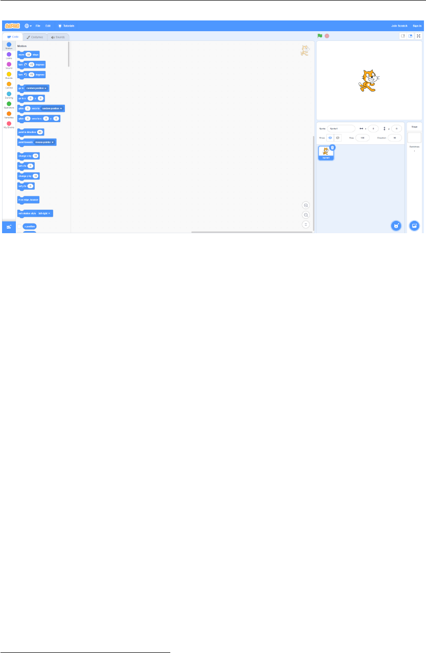
Figure 2.1 – The user interface of Scratch with its three primary ares: the toolbox area, canvas
area and the stage area.
2.1 Scratch Programming
Developed by the MIT Media Lab at the Massachusetts Institute of Technology, Scratch, as
a Block based VPL, has gained much popularity among children as well as educators. As of
March, 2021, more than 70 million projects have been created and shared with the community
by more than 65 million registered users
IX
. Scratch was developed primary targeted at children
of ages from 8 to 16 as an educational tool for teaching them how to code while working on
personally meaningful projects such as animated stories and games (Maloney et al., 2010).
The Scratch user interface consists of three primary regions; a tool box which has all the
programming elements (blocks) made available for the user, a canvas area where the user
can drag and drop the blocks onto and create programs and finally a stage area where the
results of the program being executed are reflected on. Figure 2.1 shows a screen capture of
this user interface. The toolbox is accompanied by a category menu that makes the search for
a specific block easier. For instance, ‘Motion’ category contains all the blocks that represents
actions related with the motion of the cartoon sprite in the staging area such as ‘Move
n
steps’
and ‘Turn
θ
degrees’. Similarly, ‘Looks’ and ‘Sound’ categories, as the names suggest, contain
action blocks that manipulate the looks of the cartoon sprite and the sounds it can make
respectively. The ‘Event’ category has blocks that lets the users specify when a certain piece
of Scratch code should be executed. ‘When space key is pressed’ is one such example. The
‘Sensing’ category holds a set of blocks that primarily lets the user perform checks on the
cartoon sprite, such as whether the mouse arrow is touching it, or checks on the input devices
such as whether a certain keyboard key is pressed. The Operators category primarily has
IX
Scratch - Imagine, Program, Share. (n.d.). Retrieved March 1, 2021, from https://scratch.mit.edu/statistics/.
8

Visual Programming - Current State of the Art Chapter 2
Figure 2.2 – A simple Scratch program that repeatedly checks if the mouse pointer is touching
the cartoon sprite and moves it to a random position if so.
blocks that represent the common operators used in classical programming such as addition,
subtraction, multiplication, division, inequalities as well as some additional operations like
round off, absolute value and contains. The ‘Control’ category holds the blocks that help
manipulate execution flow such as loops and conditional statements. ‘Variables’ category lets
the user create variables to store values and a setter and a getter block for the variable is made
available in the toolbox the moment a variable is created. Finally, the ‘My Blocks’ category
lets the users create blocks that are akin to function definitions in classical programming.
They user first gets to create the function signature by graphically configuring a block with the
appropriate parameter values. Once that is done, a holder appears on the canvas for the user
to then proceed with stacking blocks underneath to define its implementation.
Figure 2.2 depicts a Scratch program created using one ‘Event’ block, two ‘Control’ blocks, one
‘Sensing‘ block and finally one ‘Motion’ block. The arrangement and the wording of the blocks
makes it possible for the user to read what the program does as a story. The functionality of this
script turned into words is almost the same as reading what is mentioned on the blocks from
top to bottom: "When the space key is pressed, repeat forever to check if the mouse-pointer is
touching the cartoon sprite and if it is, move the sprite to a random position". This little piece
of code can be seen as a simple game for kids where every time they try to touch the cartoon
character with the mouse arrow, they fail as it immediately moves to a different position.
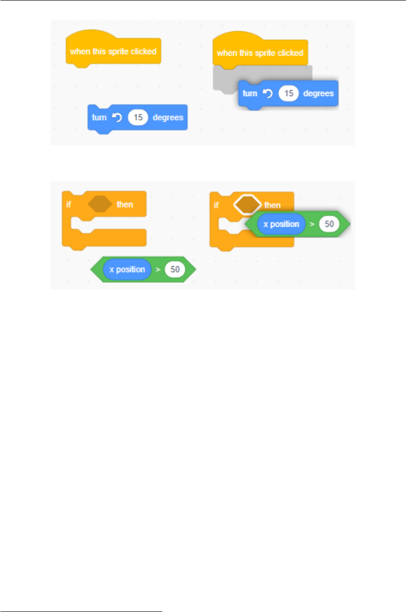
Scratch manages to enforce data type constraints by means of different block shapes. For
instance, blocks that give out boolean values always take the shape of a diamond where as
blocks that give out values such as numbers of strings has an oval shape. At places where a
boolean value is expected, the socket takes the same shape, which makes it intuitive that an
oval shape block will not fit in there. Figure 2.3(b) depicts this idea with the condition input
socket for the ‘if’ block being of diamond shape. Scratch also provides visual cues on when
a certain block can fit at a certain socket when it is brought close by either with a shadow
showing how the block would look if it was fitted there or by simply highlighting the socket.
Figure 2.3 demonstrates this feature.
9
Chapter 2 Visual Programming - Current State of the Art
((a)) Visual prompt showing a shadow of what the ‘Motion’ block looks like when it is
fit under the ‘Event’ block.
((b)) Visual prompt highlighting condition input socket of ‘if’ block implying the
inequality block can fit in there.
Figure 2.3 – Scratch provides visual cues to convince the user that a certain block can fit at a
certain place when a block is dragged and brought closer by.
2.2 Blueprints Visual Scripting
Unreal Engine is one if the world’s most advanced 3D creation tools originally created as a
state-of-the-art game engine, which subsequently evolved to serve creators across industries
such as architecture, transportation, film and simulation in creating interactive experiences
and immersive 3D virtual worlds
X
. Unreal Engine 4, which was released in 2014 introduced
the ‘Blueprints’ visual scripting system with the aim of enabling technical artists and designers
to work on the game logic as well without having to write code. It follows a data-flow based VP
setup where users create graphical structures that consist of nodes that perform actions or
listen on events and wires connecting them to infer the flow of execution and data.
Figure 2.4 shows the 3D Perspective Viewport an example Unreal game development project.
As can be seen in the figure, the environment contains different objects such as a humanoid
player character, certain structures and game objects such as the white box shown selected
at the center of the figure. Blueprints enable the user to attach certain behaviours to these
objects.
X
Unreal Engine | The most powerful real-time 3D creation platform. (n.d.). Retrieved February 26, 2021, from
https://www.unrealengine.com/en-US/.
10

Visual Programming - Current State of the Art Chapter 2
Figure 2.4 – The viewport of a sample game development project in Unreal Engine 4.
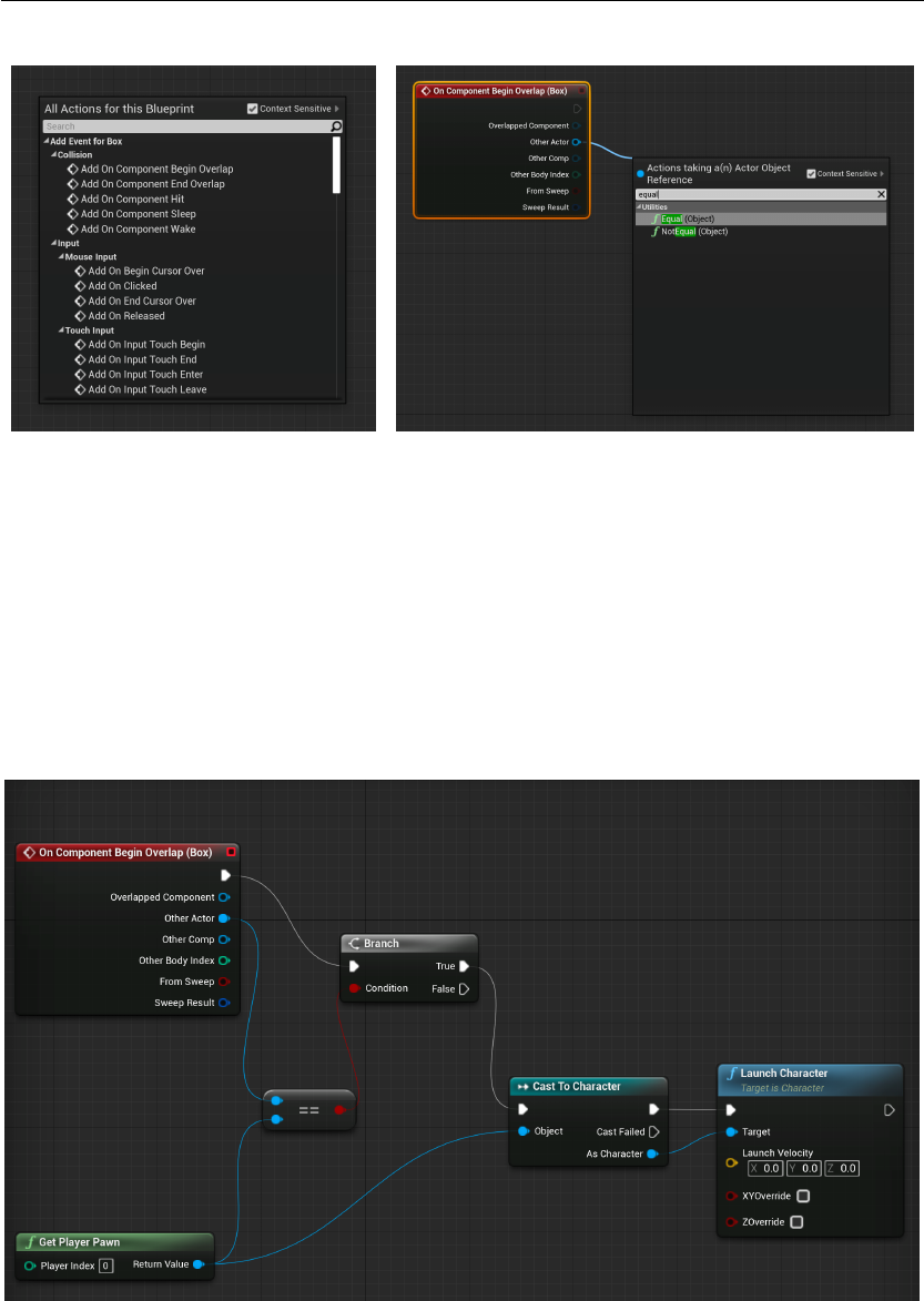
Figure 2.5 shows the user interface of the Blueprints editor. The interface has the prominent
empty canvas area in the middle where the users can create the visual programs. New nodes
can be added to the canvas by accessing a menu that appears when right-clicked on an empty
space on the canvas. Figure 2.6(a) shows how this menu is categorized into a number of
categories. A search bar is provided to make it easier to find a specific node. This particular
menu is by default context sensitive, meaning that it filters the contents in the menu to reduce
clutter and narrow down the options that the user can use in a particular situation. Creating
new nodes can also be intuitively done by dragging off a line from a socket of an existing node
in the canvas and once the mouse button is released, the menu shown has only the nodes that
can possibly connect to the node the line is being dragged from. Figure 2.6(b) shows this.
Blueprints facilitates using graphs of nodes for purposes such as object construction, func-
tion calls and general gameplay event handling in order to implement behaviour and other
functionality
XI
. Blueprint scripts can be attached to any object created in the scene. Figure 2.7
shows a sample script that is created attached to the white Box structure that is seen in Fig-
ure 2.4. The purpose of this script is to launch the Player Pawn up into the air when the Player
Pawn walks onto the Box during gameplay. Accordingly, the script is made to be run when the
humanoid player moves over the the Box object. The ‘On Component Begin Overlap’ node
with a red header in Figure 2.7 specifies this. Figure 2.6(a) shows several other ‘Event’ nodes
made available to the user in this specific context. The white connecting lines in Figure 2.7
represent the flow of execution in the script. When the event is fired as a result of the game
player moving the game character over the Box, the execution moves to the Branch node.
Branch node then evaluates the condition value that is fed into it. In this case, it checks if
XI
Introduction to Blueprints. (n.d.). Retrieved March 2, 2021, from https :// docs.unrealengine. com/ en -
US/ProgrammingAndScripting/Blueprints/GettingStarted/index.html.
11

Chapter 2 Visual Programming - Current State of the Art
Figure 2.5 – The user interface of Unreal Engine Blueprints visual scripting system.
‘Other Actor’ that triggered the event is the Player Pawn (returned by the ‘Get Player pawn’
function node). If that evaluates to be true, the execution moves to the ‘Cast To Character’
node, which performs a cast operation on the value returned from ‘Get Player Pawn’, which is
finally fed into the ‘Launch Character’ function node. It can be seen that most of the nodes
have sockets for accepting input values and for cases those values are not fed from any external
source, the values can be configured on the node itself. This can be seen with ‘Launch Velocity’
parameters in the ‘Launch Character’ node.
By default, Blueprint visual scripts get compiled and converted to an UnrealScript VM bytecode
before they are used in-game. The Blueprints system also provides the option for the user to
generate C++ code out of a visual script
XII
if desired.
Drawing inspiration from the above discussed VPLs, we build two low fidelity prototypes
based on blocks and nodes setups and evaluate which of the two setups is most preferred by
the target users for our specific use case. These steps are discussed in detail in the following
section.
XII
Blueprint Compiler Overview. (n.d.). Retrieved March 2, 2021, from https://docs.unrealengine.com/en-
US/ProgrammingAndScripting/Blueprints/TechnicalGuide/Compiler/index.html.
12
Visual Programming - Current State of the Art Chapter 2
((a)) New nodes can be created on the canvas
by choosing them from the menu accessible
by right-clicking on an empty area on the can-
vas.
((b)) Dragging out a line from any socket and releasing the
mouse provides a menu that has all the contextually filtered
node options that could possibly connect.
Figure 2.6 – Blueprints menu for creating new node.
Figure 2.7 – An example Blueprint program.
13

3 Methodology
In this section, we discuss the methodology followed in exploring visual programming solu-
tions to improve the user reach out of the G HUB Lua scripting feature. The project intended
to reach out only to the existing user base of Logitech G HUB software and the requirement
was to create a visual programming solution by obtaining an understanding of the related
needs, desires and experiences of the target user base so that the final outcome will be per-
ceptually, cognitively and emotionally intuitive. Accordingly, a User Centered Design process
was followed from the very beginning. This practice helped us identify and address usability
issues in the design of the product from early on, saving both time and effort and ultimately
enabling us to achieve an acceptable level of usability.
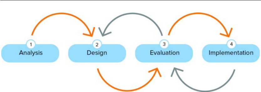
A typical User Centered Design process for designing web applications goes through the
following phases
I
in an iterative fashion.
1. Analysis
2. Design
3. Evaluation
4. Implementation
The process iterates among the design, evaluation and optionally implementation phases until
the expected level of usability and quality of user experience is achieved. Figure 3.1 illustrates
this idea. This four step iterative process was employed in carrying out this project. Chapter 4
discusses in detail the analysis of the problem at hand and target user base. Chapter 5 goes
into detail on the design and implementation of two low fidelity prototypes, one of which
follows a blocks based setup and the other, which follows a nodes based setup. Then, Chapter 6
discusses the first iteration of evaluations carried out on the two low fidelity prototypes with
I
Notes on User Centered Design Process (UCD). (n.d.). Retrieved March 2, 2021, from https://www.w3.org/
WAI/redesign/ucd.
15
Chapter 3 Methodology
Figure 3.1 – User Centered Design process (Havik, 2017)
user tests. Drawing from the learnings of the evaluation carried out, a high-fidelity blocks
based prototype was built and Chapter 7 discusses in detail the specifics of its implementation.
Finally, as a means of verifying the usability of the high fidelity prototype developed, another
iteration of user tests were carried as a second evaluation iteration.
Further usability issues were uncovered by the second evaluation iteration and it was clear
that few more iterations between implementation and evaluation stages were necessary to
achieve a high level of usability. Considering the limited time frame the project was carried
out in, it was not feasible to proceed with any further iterations and hence those identified
possible improvements were left as future work.
16

4 Analysis
4.1 Audience analysis
As the project targeted the existing user base of Logitech G HUB software, and the G HUB
software team at Logitech already had a clear understanding on the goals and motivations of
those users, it was decided that there is no necessity to carry out interviews to empathize with
the users. Accordingly, the identified user task, user pain points, user goal and user behaviour
patterns are discussed below.
The identified user task was to make advanced customizations on Logitech gaming gear that
cannot otherwise be made with the general G HUB device configuration interface or using the
‘Macros’ functionality provided in G HUB.
Several user pain points were identified with the existing textual Lua scripting system. First,
users had to be comfortable with the Lua programming language syntax and concepts to make
the customizations they wanted. The script editor feature in G HUB provided for making those
advanced customizations was placed quite hidden in the sophisticated G HUB UI and it looked
out of place with the rest of the application in terms of look and feel. The editor had only very
basic support for writing code and there was no automatic code completion functionality
to assist the users in writing the code. Users had to refer to a lengthy API documentation
I
to figure out the supported G HUB Lua functions they can use in the code and there was
minimum support for code debugging.
The identified main user goal for the proposed visual programming tool was to make advanced
automations to Logitech gear to assist them in games or other applications they use in an
intuitive, easy to use way.
The significant behaviour patterns of the targeted users of our visual programming tool
were identified to be, being PC gamers who either do or do not have previous programming
I
G-series lua api - overview and reference. (n.d.). Retrieved March 2, 2021, from https://douile.github.io/
logitech-toggle-keys/APIDocs.pdf.
17

Chapter 4 Analysis
experience.
Following 2 personas characterizes the above discussed behaviours and traits of the target
users. Persona 1 was chosen to be the Primary Persona, i.e. the persona that represents the
primary target for the design of the system simply due to the fact that it mostly satisfies the
scope of Persona 2 as well. Accordingly, Persona 2 was chosen to be the Secondary Persona
with the idea behind being: ‘designing the solution first for the primary, and then adjusting
the design to accommodate the secondary’ (Cooper et al., 2007).
4.1.1 Persona 1 (Primary Persona)
Stephan Willan is a 19 year old, living with his parents. He is awaiting to enter university
to start his bachelor’s degree in architecture soon. He loves gaming and spends most of his
weekends and weekday evenings in front of his PC, playing Fortnite, an online multiplayer
game.
He has a Logitech RGB gaming keyboard and an RGB mouse that he has been using for gaming
for several years now and he finds the ability to customize and personalize them using G
HUB very useful. While he has created some macros in G HUB and has assigned them to
different keys in his mouse to automate some moves in the games he plays, he knows that the
macros feature is just not expressive enough to create certain automations he wanted done.
He knows about the Lua script editor of G HUB that gives that additional expressivity as he has
seen Lua scripts shared in the internet gaming communities by various users to make various
automations for the games, but with his very limited experience in programming, he has no
clue at all on how to write a similar script to address his needs by himself.
He wishes there was a more intuitive and non-cryptic way to make the customizations he
needs.
18

Analysis Chapter 4
4.1.2 Persona 2 (Secondary Persona)
Seth Colbert is a 35 year old father of 2 kids. He is a Software Engineer by profession and has
been working in the software industry for more than 10 years. He used to be an avid PC gamer
before he got married, but now with more responsibilities in life, he does not get to play as
much as he did before. Yet, he still has with him his gaming PC with his favourite Logitech
RGB keyboard and Logitech RGB mouse and enjoys playing games every now and then.
Being a technical expert himself, he likes to customize his gaming gear to assist him in both
gaming as well as when he is working. He maintains two different profiles in G HUB, one for
gaming and the other for work related applications and has written Lua scripts to customize
the behaviours of his devices differently in each of those profiles. Although, with his experience
as a developer, he was able to convert his customization needs into Lua code and get the job
done, he found it frustrating that he had to first familiarize himself with the Lua language
syntax the first time he tried to use the textual script editor. Every time he wanted to add
a new functionality to the script he had to go through the G HUB Lua API documentation
to figure out the correct supported G HUB functions to use. Debugging the code was not
straightforward either.
He expects to be able to make such customizations faster and easier without having to spend
time on such mundane tasks like reading through documentations.
4.2 Problem statement
The user reach out of the Logitech G HUB Lua scripting feature is quite narrow as it does
not provide an easy to use intuitive way of performing advanced customizations to Logitech
gaming gear for the less tech savvy as well as expert level users to meet their goals of automating
repetitive tasks in games or other applications they work with.
19

Chapter 4 Analysis
4.3 Vision statement
The new design of the Logitech G HUB scripting feature with visual programming will help
even less tech savvy users achieve their goals of automating repetitive tasks in games or
other applications they work with by giving them the ability to create scripts graphically in
an intuitive, playful and easy to use environment, without them needing to have any prior
knowledge in programming or the G HUB Lua API. This will significantly increase the user
reach out of the scripting based advanced device customization feature of Logitech G HUB
and lead to an overall better user experience of the application.
4.4 Context scenario
After having a long day at work, Stephen comes home in the evening. After taking a shower, to
clear his mind and relax a bit, he decides to play an online multiplayer shooting game that he
recently started playing. As he plays, he notices that as the player shoots bursts in the video
game, the in-game gun recoil simulation causes the cross hair of the gun to move away from
the target. He notices that this recoil movement of the gun can be cancelled out by moving the
mouse tactfully with the right speed in the opposite direction of recoil movement, but he is
not skilled enough to do that mouse movement precisely while shooting.
He figures out that this can easily be achieved by automating the mouse movement using G
HUB software. He minimizes the game, opens G HUB and opens the script editor. As he is in a
hurry to play the game and does not want to spend time learning Lua language syntax and
concepts, he chooses to create the script graphically.
He immediately sees the list of components available for him to use to create the script
graphically. He chooses the components that let him detect the left mouse button press,
simulate relative mouse movements and designate the execution flow of the script to start
with. He then associates those components together in a way that reads out the requirement
he has in his mind.
After saving the completed graphical script, he also finds the option to view the corresponding
generated Lua script. He feels empowered by the fact that he could produce that code without
having to know a single thing about the Lua language.
He returns back to the game and tests how good his script is and realizes that he has to make
some adjustments on the amounts of the relative mouse movements to perfectly match and
counter the in-game gun recoil movement. So he switches back to G HUB, makes those
changes in the graphical script, returns back to the game and tests again. This time, the script
perfectly works and this drastically increases his shooting accuracy.
20

5
Design
The initial design decision that we were faced with was to decide on the kind of visual pro-
gramming setup to use. As was described in Chapter 2, we observed that we have two main
candidate setups for our use case.
The first option was to have the components of the script represented by blocks that would fit
together like puzzle pieces. We refer to this as a blocks based setup. Section 2.1 in Chapter 2
dives into the details of a famous visual programming tool called Scratch that uses exactly
this notion. Someone familiar with programming and writing code in general would quickly
notice that this notion of blocks closely resemble the way a chunk of code is written. What
makes it different from writing the code itself is that the user here does not need to worry
about using the correct keywords, having proper indentations or statement separators and
getting the syntax right. All that complexity is abstracted away by the use of graphical blocks
that fit each other like pieces of a puzzle.
The second option uses a notion of nodes to represent the components of the script. We refer
to this as a nodes based setup. Section 2.2 in Chapter 2 describes in detail a tool that has
a similar setup called the Blueprint visual scripting system, which is used in Unreal Engine
4. The general idea of this concept is that nodes are connected to each other by wires and
these wires can specify either the flow of control or the flow of data from one node to another
within the script. Unlike the blocks based option, scripts created with this setup do not directly
resemble a block of code at a glance, yet each node would always correspond to a chunk or a
full line of code.
To make sure the choice is made with the end users in mind, it was decided to carry out the
first round of user tests. The primary target of this round of user tests was to understand which
setup gave the users the best experience and to gain any additional insights from the users as
to what they think can be improved in the prototypes in general.
21

Chapter 5 Design
((a)) The interface of Block based prototype with the visual script that performs the user assigned task.
((b)) The interface of Nodes based prototype with the visual script that performs the user assigned task.
Figure 5.1 – Block based and Node based low fidelity VP prototypes developed for the first
iteration of user tests.
Figure 5.1(a) and Figure 5.1(b) shows the interfaces of the two low fidelity prototypes developed
for the study. Due to the ongoing COVID-19 pandemic and social distancing concerns, it
was decided to conduct all the user tests completely virtually via Zoom. As a result, a virtual
representation of a Logitech Gaming mouse was included in the prototype interface so that
the effects of running the created visual scripts can be observed by the users real time as it
would have been with a real mouse, if the interview was carried out in person. Both prototypes
have a set of provided graphical elements on the left that can be dragged and dropped onto
the canvas area in the middle to create visual scripts. After creating a script on the canvas, the
participant has to click on the ‘Run Script’ button for the script to take effect.
22

Design Chapter 5
In terms of implementation, both the prototypes were built as web applications that can run on
a web browser. For implementing the blocks based visual programming canvas in the blocks
based prototype, the Blockly
I
JavaScript library was used. Blockly provides a set of pre-built
blocks that support commonly used programming constructs such as conditional statements
and loops and also provides the ability for the developers to customize its functionality in a
variety of ways. The library also comes with a framework that simplifies the generation of
textual code from a visual script. For implementing the nodes based visual programming
canvas, Rete.js
II
JavaScript library was used. Unlike Blockly, Rete.js had minimum off-the-
shelf support for implementing a nodes based visual programming environment. As a result,
functionality of all the nodes provided in the toolbox in the nodes based prototype had to be
implemented from scratch. The functionality of the virtual mouse in both the prototypes was
implemented using pure JavaScript, HTML and CSS.
I
Blockly. (n.d.). Retrieved March 12, 2021, from https://developers.google.com/blockly.
II
Rete.js. (n.d.). Retrieved March 12, 2021, from https://rete.js.org/#/.
23

6 Evaluation - Iteration 1
The Nielsen Norman Group in their report ‘234 Tips and Tricks for Recruiting Users as Par-
ticipants in Usability Studies’ (Sova & Nielsen, 2010) suggests the following as the three main
rules for simplified user testing.
1. Get representative users
2. Ask them to perform a representative task with the design
3. Let the users do the talking
6.1 Recruiting users
Participant recruiting lays the foundation for all user testing as without it there is no way to
conduct any user test (Sova & Nielsen, 2010). For our requirement, it was decided to recruit
users from within the company due to cost concerns and information non disclosure concerns.
Since all the participants were from within the company, there was neither a necessity to pay
incentives nor to have participants agree with any terms of nondisclosure.
The aim was to reach out to some internal employees who happen to be PC gamers themselves
and who do not have direct involvement with the G HUB software as part of their work at
Logitech. This was to have the participants’ profiles as close as possible to the target end
user group. We also wanted to balance the study group in terms of gender and programming
experience. Accordingly we planned to have 50% representation of males and females and
programmers and non-programmers. This makes it possible to rule out any possibility that
any imbalance in those factors influenced the final results of the study.
Once the recruiting criteria was prepared, the next task was to decide on the number of
participants to recruit for the test. Based on various research carried out on the field, it has
been found that there are severely diminishing returns from usability testing a given design as
the number of participants increase. In fact, from a large number of projects surveyed by the
25

Chapter 6 Evaluation - Iteration 1
Figure 6.1 – Participant screening questionnaire
Nielsen Norman Group, almost 80% of the usability problems of the system subjected to the
testing were found, after testing with four users (Sova & Nielsen, 2010). Since the intention
of the study was to get qualitative insights and not to obtain statistically significant results,
it was decided to recruit five participants per each distinctly different user group of interest,
i.e programmers and non-programmers, and males and females. Having an odd number of
participants in each user group also made sure that there will not be ties within a group in
terms of the preferred visual programming setup out of the two options.
The next step in the process was to prepare a screening questionnaire that reflects the identified
recruiting criteria. The questionnaire was designed so that the provided answers would help
us easily screen out the responders that do not meet our recruitment criteria. The questions
were carefully crafted in a way that avoids ‘giving away’ the profile we were targeting so that
in case even if for some reason, someone really wanted to get into the study by giving false
answers, they still would not know which right answers to give. The questionnaire was sent
out as a Google Form via some internal company communication channels to reach around
1500 Logitech employees all over the world. Figure 6.1 contains the complete questionnaire.
6.2 Experiment design
The experiment was carried out in a within-subjects fashion where each participant would in-
teract with both the prototypes built
I
. This choice was made based on time related constraints
and the fact that we were only targeting for qualitative results. Recruitment of participants
I
Between-Subjects vs. Within-Subjects Study Design. (n.d.). Retrieved March 2, 2021, from https://www.
nngroup.com/articles/between-within-subjects/.
26

Evaluation - Iteration 1 Chapter 6
were done so that the group of participants are balanced in terms of gender as well as pro-
gramming experience. As we were targeting 10 regular participants only, it was not feasible to
flip a coin at the beginning of the user test to determine which prototype the user would test
first as in the end it might leave us with a very skewed distribution of the testing orders; for
example only one or two participants testing the nodes based prototype first and everyone else
testing the blocks based prototype first. So, to counteract the possible order effects and effects
of transfer and learning across the two conditions, it was decided to manually pre-assign
randomly chosen five participants to first try the nodes based prototype and the rest to first
try the blocks based prototype. Then, to avoid any effects on the user test results by the date,
the time, or the context the experiments are executed, the order of conducting the user tests
with the 10 participants was also randomized.
The expectations of the experiment were three fold. 1) The primary target of the experiment
was to identify the preferred setup (blocks based setup vs. nodes based setup) among the 10
participants. We arrive at this decision assuming that our user sample is a representation of the
Logitech G HUB user base and the fact that we balanced the user sample in terms of gender,
programming expertise and learning transfer gives us confidence in the result obtained. 2)
The second objective was to verify the hypothesis “Programmers prefer to use the Block based
prototype and the non-programmers prefer to use the Node based prototype”. This hypothesis
was formed based on the fact that the Block based setup closely resembles actual coding than
the Node based setup. The fact that we have an odd number of participants from each of
the groups guarantees that we will obtain a final preferred choice for each group. 3) Finally,
the experiment also targeted at getting to know users’ judgement on visual programming
in general, qualitatively measuring how well the users were able to understand each setup
and identifying any critical usability issues in the prototypes that can be improved on in later
iterations. This information can also give insights on how appropriate visual programming is,
as a general solution to the problem being addressed.
6.3 User interview and user task
An initial interview guide was created with the aforementioned expectations as the basis to
make sure each participant gets exposed to the same instructions and same set of information.
A dry-run of the interview was carried out with an internal team member to get feedback
mainly on the interview guide, the protocol, the timing, and the working of the user task in
order to fine tune the study system. Appendix A.1 contains the final version of the interview
guide used for conducting the user tests.
Each participant was asked to complete a task with each of the prototypes. The task was to
create a visual script so that when executed, each time the left mouse button of the virtual
mouse is pressed, the color of the G logo on it changes once, cycling through the colors red,
green and blue. In other words, on the event of mouse left click, the script should read the
current lighting color and depending on what color it is, set the appropriate lighting color, i.e.
27

Chapter 6 Evaluation - Iteration 1
if the current color is red, set it to green, if the current color is green, set it to blue and if the
current color is blue, set it to red. The visual scripts in the canvas area of Figure 5.1(a) and
Figure 5.1(b) shows how this can be achieved with each prototype. Users were asked to think
out loud as they interact with the prototype and the Zoom sessions were recorded for later
analysis.
Table 6.1 shows the details of all the participants of the first iteration of the user study. Real
names of the participants are omitted for privacy reasons.
Table 6.1 – Participants of the first round of user tests.
Gender Age Programmer First test Location Date/time
P1 Male 40-60 Yes Nodes Lausanne, CH 19/11/2020 13:00
P2 Female 20-40 Yes Blocks Lausanne, CH 19/11/2020 14:00
P3 Male 40-60 No Nodes Lausanne, CH 19/11/2020 18:00
P4 Male 20-40 Yes Nodes Newark, US 20/11/2020 19:00
P5 Female 20-40 Yes Blocks Lausanne, CH 24/11/2020 15:30
P6 Male 20-40 No Blocks Newark, US 24/11/2020 20:00
P7 Female 20-40 No Nodes Lausanne, CH 25/11/2020 14:00
P8 Female 20-40 No Blocks San Francisco, US 03/12/2020 23:00
P9 Male 20-40 No Nodes Lausanne, CH 19/01/2021 11:00
P10 Female 20-40 Yes Blocks Newark, US 18/01/2021 20:00
6.4 Results
6.4.1 General impression on visual programming
During the user tests, before they were exposed to the prototypes, participants were asked to
remember the last time they used a visual programming tool and recall what their impression
was in general about it. User sentiment on visual programming in general can be a strong
deciding factor on how much the users will adopt this kind of a new feature in G HUB. Hence,
this was an important opinion to be collected from each of the participants.
A majority of the participants held a positive impression towards visual programming tools
based on their previous experience. Figure 6.2 depicts this.
Participant P1 stated
“I think for certain use cases it is just a lot better to have these kind of tools than
having to write code out. It just allows a lot more kind of creativity and flexibility.
It just depends on the use case I guess. So sometimes those kind of tools can
be too inflexible and just don’t give you enough flexibility to do the things that
you want to do and other times for other types of tasks they allow you work a lot
quicker and be more creative, in my experience.”
28

Evaluation - Iteration 1 Chapter 6
Figure 6.2 – Participants’ impression on visual programming in general.
6.4.2 Preferred visual programming setup
General preference
Out of the 10 participants, 6 preferred the blocks based prototype. Figure 6.3 depicts this in a
pie chart. The most common positive comment for the blocks based prototype was the fact
that it provides a compact narrative like view of the program that can be read from left to right,
top to bottom making the comprehension easier. Participant P9 stated
“It’s a bit reassuring because I can almost read like a sentence... like a paragraph...
Because my dream will be like (saying) “I left click, each time I left click, change
the color from red to blue to green and that in a loop or endlessly”. And then I
select run the script and it does it. So this is closer to what I’d love.”
Participant P1 appreciated how compact looking the block based script he created is.
“This one (block based prototype) seems a little more concise and a little more
easy to do complex things... I guess... in the long run because it’s just visually
smaller.”
Participant P8 also expressed a similar opinion.
“The other one on the other hand (block based prototype), like you said, it was
a whole puzzle piece... so it was kind of like, ok... you start reading it just like a
story... you start from left to right to top to bottom kind of thing. So that made it
easier to understand.”
29

Chapter 6 Evaluation - Iteration 1
Figure 6.3 – Preferred visual programming prototype among the 10 test participants in general.
A common negative comment on the same was that differences in the sizes of blocks and the
sockets made it difficult to identify whether a certain block piece would fit in another without
moving it and making an attempt to fit them. When asked for what participant P1 did not like
in the blocks based prototype he stated
“I really like the puzzle piece idea because it gives another kind of nudge in terms
of what should be fitting where. It helps narrow your options. However the fact
that there are things that aren’t visually obvious, like the sizes not matching or
that you can expand certain things, whatever it is, that makes it a bit harder.”
Participant P2 expressed a similar opinion when asked.
“It is not 100% what can fit and what can’t. So may be make it a bit easier and
more fast to get understood coz I could not understand how to put the blocks
together, this took me a while.”
Participant P7 mentioned what her thoughts were when trying to determine whether a certain
block could fit in another one.
“May be this is me being a bit slow... I’m kind of like... ‘But it’s a different size does
it fit in? should i try it? no? Should I do something else?’...”
The most common complaint against the Node prototype was that the script quickly becomes
convoluted with a lot of lines that span all over the canvas making it difficult to follow through
30

Evaluation - Iteration 1 Chapter 6
the flow of execution. Participants P2, P5, P7 and P8 expressed following opinions on that
regard.
“This (nodes based prototype) is more complicated, you have a lot of lines, doesn’t
give you the idea of clean work... something clean and organized.”
“That one (nodes based prototype) is easier when you would like to do some
simple steps, but if you have like multiples... like... if you have 3, 4 branches, it is a
bit confusing to have again the link to the branch, you don’t know where it starts,
where it ends... and with a ‘if-else-if’, it’s more structured.”
“Once you do like a couple of branches, it is a bit difficult for my eye to follow
where I was before and where I gotta go next.”
“This one (nodes based prototype) definitely feels more convoluted. Again, just
because of the flow of it, it was just so like all over. It was like from here to there
to there to there.. I was kind of like ok.. hold on.. I gotta make sure I follow it
accordingly.”
The Nodes setup being less like plain coding and the connecting lines acting as a guide on the
flow of the graph when the graph is not so complicated were some positive traits the users
found. Participant P6 stated
“I feel like I like this (nodes based prototype) because it feels less like I’m program-
ming... like I have... I can go into this kind of with a zero knowledge where I think
in the previous one (blocks based prototype) it feels like maybe I should know a
little bit more of the language before I can start to piece stuff together.”
Preference based on coding experience
In order to verify the stated hypothesis, the preferred choice of setup was analysed within
each group. 3 out of the 5 programmers as well as the 5 non-programmers preferred the
blocks based prototype. Figure 6.4 depicts these observations. Accordingly, this refutes our
hypothesis “Programmers prefer to use the Block based prototype and the non-programmers
prefer to use the Node based prototype”. Apparently, the results say both the user groups
prefer the blocks based prototype more.
Preference based on order of prototypes
Since the experiment was carried out on a within-subject setup, even if the effect on the final
result by the order of prototype exposure is carefully balanced out by managing the orders of
31

Chapter 6 Evaluation - Iteration 1
Figure 6.4 – Preferred visual programming prototype with respect to coding experience.
testing, it could be interesting to see if we can observe any patterns in the choices within each
group in terms of the first prototype they were exposed to.
It could be seen that out of the 5 participants who first tried out the nodes based prototype, 3
preferred the blocks prototype in the end. The situation was exactly similar with those who
first tried out the Blocks prototype as well. 3 out of the 5 preferred the blocks based prototype.
Figure 6.5 depicts these findings.
Figure 6.5 – Preferred visual programming prototype with respect to the order the prototypes
were tested by the participant.
Preference based on gender
Traditionally, the gaming and tech savvy user base was believed to be dominated by males. But
nowadays more and more women are moving into the tech and gaming sphere and Logitech
as a company is making efforts to streamline their products and services to the growing
female user base as well. Accordingly, the choice of setup within males and females is also an
interesting observation one could make.
It could be observed that a majority of the males preferred the nodes based prototype where
as a majority of the females preferred the blocks based prototype. Figure 6.6 depicts these
observations.
Every female participant made a remark about the nodes based setup being less organized.
32

Evaluation - Iteration 1 Chapter 6
Figure 6.6 – Preferred visual programming prototype with respect to the gender of the partici-
pants.
This observation could be due to a tendency in females to prefer neat and tidy work. Following
statements made by participants P2 and P5 supports this:
“This (nodes) is more complicated, you have a lot of lines, doesn’t give you the
idea of clean work, something clean and organized”
“The connection is intuitive but it is less organized, it’s like a draft”
Moreover, participant P10 who preferred the nodes based setup, still made the remark that the
setup looks messy.
“You know I gotta say, even though I struggle... I think I like this interface better
even though it looks like a spaghetti mess.”
6.4.3 Insights on usability
As mentioned in section 6.2, one of the objectives of the user study was to identify any usability
issues in the low fidelity prototypes built so that they can be avoided or improved in the high
fidelity prototype implemented in the next iteration. It was also useful to get feedback from
the participants on certain design choices in order to decide whether they should be carried
on to the next iteration prototype as is or whether they should be modified in any ways. As
it was decided to proceed only with the blocks based setup, only the usability related input
received with the blocks based low fidelity prototype are discussed.
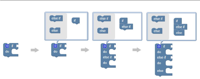
With the Blocks prototype, many participants struggled to find the way to convert an ‘if’ block
to an ‘if-elseif-else‘ block. Figure 6.7 shows how this could be achieved step by step with the
‘if’ block made available in the low fidelity prototype. The user first needs to click in the small
blue button that shows a cog wheel icon. On the mini canvas that appear, user has to drag and
drop the ‘else if’ and ‘else’ blocks under the ‘if’ block in the required order. As that is done, the
33
Chapter 6 Evaluation - Iteration 1
Figure 6.7 – Steps to convert an ‘if’ block to an ‘if-elseif-else’ ladder of any length.
changes get reflected on the original condition block. Only participant P2 was able to figure
out how this configuration is done by herself without any assistance. Many of the other nine
participants did not notice that it is a button that can be clicked on. Participant P6 stated:
“I just thought... oh! there is a cool little logo there, but i didn’t think to click on it”
Even when after the mini canvas was shown, some participants still could not understand
what they can do with it. Many tried clicking on the ‘else’ and ‘else if’ blocks on the left and
gave up when nothing happened. Some tried to drag them out of the mini canvas to fit in to
the original block. Only a few number of participants could figure out how to perform the
configuration after the mini canvas was shown. When asked, participants P4 and P8 stated:
“Oh, I would have never figured that out. I got that they are separated, I wanted to
click it. I did not see a prompt that it was draggable in itself”
“And I think with this part where you told me to click over here to do the whole
else if, I would never have known to... that I needed to do that until you told me”
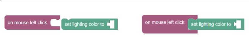
Another issue that was raised by multiple participants was the mismatching blocks and socket
sizes confused them in determining whether a certain block could fit in a certain socket.
Figure 6.8 shows an example depiction of this. On a first glance, due to the differences in
the heights of the socket of ‘on mouse left click’ block and the ‘set lighting color to’ block, it
gives an impression that they will not fit. But, as the ‘set lighting color to’ block is dragged and
hovered over the ‘on mouse left click’ block socket, the socket expands to match the height of
the incoming block. On this issue, participants P2, P7 and P8 stated:
“It is not 100% clear what can fit and what can’t”
34
Evaluation - Iteration 1 Chapter 6
Figure 6.8 – In terms of sizes, the socket of the ‘on mouse left click’ block is smaller in height
than the height of the ‘set lighting color to’ block. Yet, when the latter is fit into the former, the
height of the socket changes to accommodate the incoming block.
“It took me a second... just because it’s not too dissimilar in shape and obviously
because the size is very very different... may be this is me being a bit slow... I’m
kind of like... ‘but it’s a different size does it fit in? should I try it? no? Should I do
something else?’...”
“Honestly the shape of it first of all did seem like it would fit and sizing itself also
was like hold on that one is like a smaller piece and that one is like a larger piece”
Several participants mentioned that they would have performed the task easier and faster if
they could first see some pre-build examples. Participant P1 stated:
“...But again, like... if there was a visual reference where it showed me, like... if
it showed me a pre-configured example of what it would look like, then I would
probably very quickly be able to understand how the system generally works
Participant P10 expressed similar opinions:
“One thing that I am a big proponent of is examples. Like... in tutorials. So if you
give me an example of how it is supposed to look like... I mean that’s what you do
in StackOverflow too, when you look for something you look at examples”
“It’s almost like you need a little bit of tutorial to also show people in each one,
how would you expect each shape to behave, because I didn’t know this could
expand (block sockets), I didn’t know you can click into this (if block configuration
button)”
The arrangement of the toolbox in the blocks based prototype was also something certain
participants raised a concern on. Their opinion was that the fact that you can only see the
blocks of one category at a time and the fact that you have to click on each category to see
the blocks listed under that made it difficult to remember all the options made available for
use. Figure 6.9 gives an idea of how the toolbox in the blocks based prototype functioned.
To deal with that issue, some participants first tried to drag all the available blocks on to the
canvas first so that they do not have to go to the toolbox and click on each category to see what
options are made available
35

Chapter 6 Evaluation - Iteration 1
Figure 6.9 – Blocks were listed categorized into sections and clicking on a category shows the
list of blocks that belongs to it.
On this regard, participant P6 and P8 said:
“... you gotta go into the menus and then like... kind of drag everything out. So that
made it... going through that and having to sit through and then like remember
‘Oh!... where was everything again?’...”
“So with this prototype (blocks based)... like... how those subsections that you
have in the top (menu of the blocks), where it’s just the events, the logic and
everything. .. I felt just kind of like you have to click on it to kind of see all these
pieces, but with the other one everything is already kind of laid out for you. And
it’s like I’ve always been a person that’s more visual... if i see it... like... then I can
kind of grasp it better, but then if... like... you put it in these little lists, I have to
go through each list and if I can’t see everything all at the same time it’s harder to
kind of visualize it”
The low fidelity blocks based prototype provided three separate blocks to represent the colors
red, green and blue as values. Participants P4 and P9 expressed that they would prefer to
see just one block for color which has some color palette like functionality allowing them to
choose one color. P4 stated:
36

Evaluation - Iteration 1 Chapter 6
“Here I would love to (have), if I right click, give me the options for the colors. I
wanna change blue to green or red”
“What could be nice is maybe for the color, you don’t have red, blue, green, but
you have color, because you want to change the color and then you pick and
therefore you don’t go back here (the toolbar) because here each time I can’t see
whats behind (each category) like the loops or the thing... so either it would be
nice to dispatch them all on top, or use arrows to have them directly, so.. I want to
tweak the color, color is blue, red bla bla bla and so on...”
was something participant P9 mentioned during the user test.
When asked for possible improvements, participant P5 stated that she would like to have full
support for keyboard shortcuts like undo, copy and paste.
6.4.4 User performance
Table 6.2 lists down the time it took for each participant to complete the given task with
each prototype. Participant P1 did not manage to complete the task on the blocks based
prototype and participant P3 did not complete the task with both the prototypes. Only a very
few participants were able to complete the task all by themselves without any assistance. This
can be expected due to the fact that the task requires a certain level of algorithmic thinking
and problem solving skills and especially non-programmers can struggle at doing that. Yet,
as these time values are influenced by the amount of help they received during the tasks, it
would not be fair to derive conclusions from the duration values observed. Nevertheless, as
shown in Figure 6.10, it is interesting to see how the time, 9 out of the 10 participants took in
performing the task with the second prototype they tested, is lower than the time they took in
doing the same task with the first prototype they tested. This can imply that the knowledge
they acquired when performing the task with the first prototype helped them in performing
the task with the second prototype faster.
6.4.5 User mental model
Before exposing to the users the two low fidelity prototypes, they were asked about what they
think a visual programming tool to customize devices in G HUB would look like. While most
answers seemed to stem from the existing device configuration interface in G HUB with some
drag and drop functionality built on top, two participants expressed a mental model that
closely resembles the two prototypes we had built. Participant P6 stated
“...like a visual thing where I can like connect here to here and that something
happens... that’s kind of like what I imagined... sort of like a little network or
37

Chapter 6 Evaluation - Iteration 1
Table 6.2 – Time duration taken by each participant to complete the assigned task with each
prototype during the first round of user tests. Durations marked with a
†
imply that the
participant failed to complete the task and the task was given up halfway.
Duration (mm:ss)
Participant Blocks prototype Nodes prototype First tested
P1
†
07:51 21:33 Nodes
P2 09:23 05:01 Blocks
P3
†
10:14
†
09:09 Nodes
P4 09:10 15:30 Nodes
P5 09:37 06:46 Blocks
P6 17:56 07:27 Blocks
P7 07:43 12:12 Nodes
P8 10:51 09:41 Blocks
P9 07:13 09:05 Nodes
P10 09:53 04:26 Blocks
Figure 6.10 – Comparison of time taken by participants to complete the task with the first
prototype and the second prototype they tested.
framework of some sort... you have these modules... like all the ports, ins and
outs... and you just connect one thing to another and that’s kind of how I imagined
it. Like it’s in the sequence that you plug things in you’ll get you know a certain
effect.”
where he talks about all the features seen in our nodes based prototype.
Participant P7 stated
“Thinking back on the stuff I have done before, like on other programs I have
38

Evaluation - Iteration 1 Chapter 6
worked on, it is usually a GUI with a number of buttons to... kind of like command
buttons that you would use... that then in the background the code would (run)...
it’s like a GUI button that develops the code line.”
Although her description does not exactly match any of our prototypes, her line of thinking
matches with the fact that we use visual components, which in the background generates a
code that can be executed.
6.4.6 Self understanding on the context at the beginning of user test
After showing the first assigned prototype to each participant, before they were given any
explanation on how to use the tool or what it does, they were asked to play around with it
and tell what they think the tool allows them to do. 8 out of the 10 participants were able
to either explain that it allows them to program what each mouse button would do in terms
of configuring some lighting or create by themselves a simple test script to set the lighting
color of the virtual mouse without any help. Following are some statements made by the
participants in response.
Participant P1, P2 and P3 stated
“I see that it would be for helping me to define what different buttons do”
“I think I can set the lights, I can say on mouse left click set lighting color to
something”
“I understand that this is a sequence of tasks and I guess that if I click for example
on the left mouse button, then I can probably turn something in red or something
like that.”
As this measurement was done with the first prototype each user was exposed to, and since
the order of prototypes was balanced among the participants, five users got to first test the
blocks based prototype whereas the other five users got to first test the nodes based prototype.
It was observed that regardless of the order, 80% of the participants in each sub group were
able to correctly state what the tool lets them do.
6.4.7 G HUB use
Out of the 10 participants, 8 stated that they have experience using the G HUB software before.
The most common task they have used it for was to configure the RGB lighting in their gaming
devices. Yet none of them had any knowledge whatsoever about the Lua script editor feature
in G HUB. When asked why, participant P3 said
39

Chapter 6 Evaluation - Iteration 1
“I think I probably never really dig into that because I probably haven’t understood
what I could be achieving with these scripting stuff.”
Participant P5 also stated
“I didn’t find the benefits so rewarding to take time and invest time to code.”
This is an interesting observation that supports the fact that the existing text based Lua
script editor functionality is rarely used by the user base, even though it provides powerful
configuration capabilities.
6.4.8 Suggested use cases
In order to probe on which ways users might find a configuration tool like this useful, all the
users were asked for an example situation in their day to day life that they might find advanced
device configurations useful. Two common use cases emerged from all the responses. 1)
One was task automation. Participants mentioned about programming keys to automate
launching applications performing tasks inside applications or performing certain actions
in games that would otherwise require multiple key presses. 2) The other use case was to
configure the lighting in devices to provide real time feedback. They referred to configurations
that allow changing device lighting based on events happening in the computer, either within
applications or within games. For instance, have the keyboard light up in a certain way when
there is new email or when the player gets shot in a shooting game.
40

7 Implementation
Based on the preference results observed in the first iteration of evaluations with the low
fidelity prototypes, it was decided to proceed with the blocks based setup. This chapter
discusses the work carried out in the implementation stage of the User Centered Design
process.
The implementation of the high fidelity blocks based prototype was carried out making
sure the usability issues discovered during the evaluation were addressed. For instance, it
was observed in the first round of user tests that a majority of the participants struggled in
understanding how to obtain an ‘if-elseif-else’ block by modifying the provided ‘if’ block. As a
solution to this, in addition to the configurable ‘if’ block, it was decided to make available a
pre-configured ‘if-else‘ block in the high fidelity prototype to see if users will utilize that to
create ‘if-elseif-else’ ladders by nesting them. Figure 7.1 shows this pre-configured ‘if-else’
block.
Another complaint participants raised in the first round of evaluations was that the toolbox
having a menu like design with closed categories made it difficult to remember which options
are made available to them. To address this, an always open, fully scrollable toolbox was used
in the high fidelity prototype with the categories still visible on the left for making search for a
certain block easier. Figure 7.2 shows this toolbox.
Figure 7.1 – On the left: a configurable ‘if’ block. On the right: a pre-configured ‘if-else’ block
41
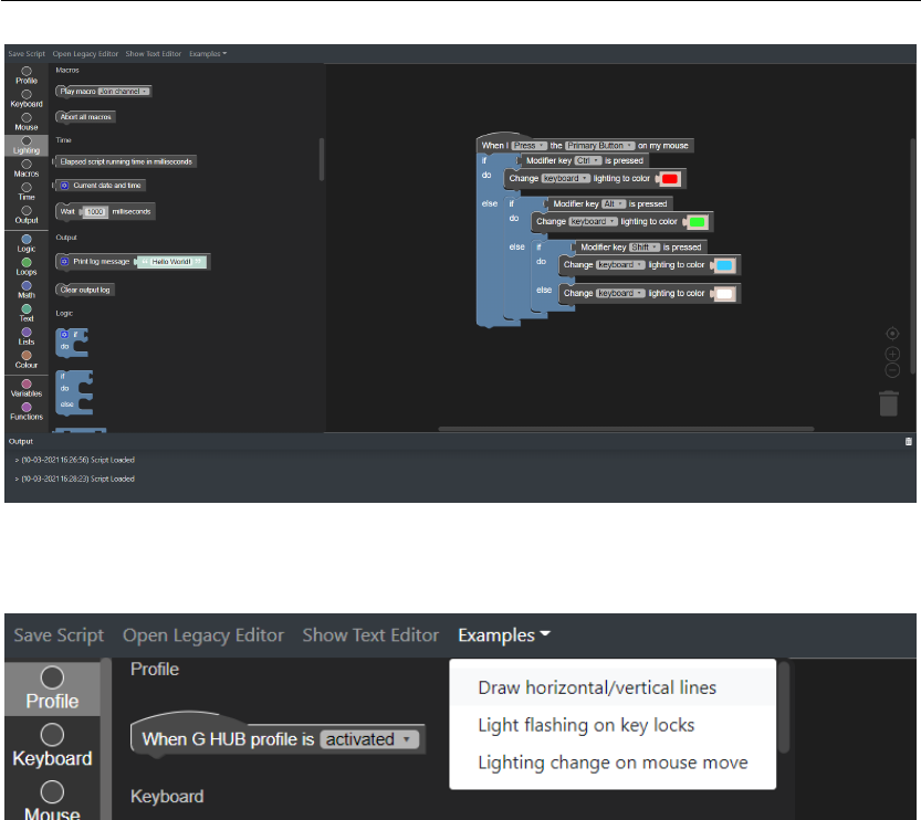
Chapter 7 Implementation
Figure 7.2 – The interface of the high fidelity blocks based prototype with the visual script that
performs the user assigned task.
Figure 7.3 – A menu item that lets users access some pre-built example scripts.
Several participants also stated that having some example pre-configured scripts would have
helped them understand how to use the tool easily. As a result, an option to view some example
visual scripts was also included in the high fidelity prototype. Figure 7.3 shows a close up view
of this menu in the interface. Figure 7.4 shows the three example scripts provided to help users
understand the functionality of the tool better.
Some participants found that certain blocks and sockets having different sizes made it confus-
ing for them to determine whether they would fit or not. To address this issue, as a first step,
the enclosing socket shapes were removed from all the event listener blocks. To make them
still look different from the rest of the blocks, a hat like shape was added to the block. This can
be noted in the event listener blocks shown in Figure 7.5.
Support for commonly used keyboard shortcuts for actions like cut, copy, paste, undo and redo
was also something that was requested by participants during the first iteration of evaluations
and hence they were included in the high fidelity prototype.
Finally, the toolbox was equipped with a variety of new blocks that represent all the Logitech
42

Implementation Chapter 7
G HUB Lua API functions, all varieties of programming constructs, data structures, variables,
functions and literals. Figure 7.5 and Figure 7.6 shows all the blocks that were supported in
the high fidelity prototype. These blocks allow visually representing any general textual Lua
program functionality. This list also includes a block that provides a color palette to choose a
color as was requested by some participants in the first iteration.
Figure 7.2 shows the interface of the high fidelity blocks based prototype developed. The
prototype was made to work completely integrated with the G HUB software and any visual
scripts created using this prototype can be executed in G HUB in the same way a textual
script would execute in the existing textual script editor. The prototype is capable of making
customizations to any gaming keyboard or mouse G HUB recognizes. Similar to the low fidelity
blocks based prototype, this prototype has a toolbox with all the blocks that can be dragged
and dropped on the canvas to create scripts. As the script is built on the canvas visually, the
prototype generates the textual version of the graphical script in the background. A text editor
was also integrated into the same prototype so that the user can view the generated textual
script and modify it if necessary. Figure 7.7 shows this. Saving the script either by the ‘Save
Script‘ button in the interface or by hitting ‘Ctrl+S’ would instantly make the script come to
effect.
Just like the low fidelity prototype, this high fidelity prototype was also implemented as a
web application that runs on a web browser. To support the dynamic features the prototype
needed to provide, the React
I
JavaScript library was used. Accordingly, following the React
approach in building interfaces, the interface was developed as four separate modules: the
top menu bar, the visual script editor, the textual script editor and the output log feed. React
provides the required functionality to support switching between the textual script editor
and the visual script editor. Redux
II
library was used for managing the application state and
communicating state information between sibling modules. The visual programming editor
was implemented using the Blockly
III
JavaScript library. The Monaco Editor
IV
library was used
for implementing the textual script editor. Monaco editor is the library that powers the famous
VS Code code editor and one reason to choose that library was that a VS Code user using the
prototype would find its look and feel familiar. The pre-built HTML components provided by
the Bootstrap
V
library were used for building the prototype UI. Finally, for the prototype to be
able to communicate with the G HUB backend via web socket connections, changes had to be
made to the G HUB backend as well which is implemented in the C++ programming language.
Implementation of some of the blocks that represent G HUB Lua API functions in Blockly
required detailed attention and design. For instance, the
PressKey(keyname[,keyname])
I
React – A JavaScript library for building user interfaces. (n.d.). Retrieved March 12, 2021, from https://reactjs.
org/.
II
Redux - A predictable state container for JavaScript apps. | Redux. (n.d.). Retrieved March 12, 2021, from
https://redux.js.org/.
III
Blockly. (n.d.). Retrieved March 12, 2021, from https://developers.google.com/blockly.
IV
Monaco Editor. (n.d.). Retrieved March 12, 2021, from https://microsoft.github.io/monaco-editor/.
V
Bootstrap. (n.d.). Retrieved March 12, 2021, from https://getbootstrap.com/.
43

Chapter 7 Implementation
G HUB Lua API function accepts a variable number of parameters to support simultaneous
multiple key presses. Representing such a function as a block required additional effort in
implementing a Blockly mutator
VI
for the block that enables dynamically configuring the
block to have any number of input fields. Figure 7.8 shows how the configuration can be done
with the implemented mutator mini canvas.
The implementation of the block for the
GetDate([format[,time]])
G HUB Lua API func-
tion brought even further complexities in implementation. In this situation, the mutator
needed to restrict the additional inputs that can be configured, to a maximum of two, all the
while making sure the first input is always a string input for the ‘format’ and the second ‘time’
input can be added only if the ‘format’ has already been added. To enforce these constraints,
the blocks in the mini canvas had to be tactfully disabled depending on the configuration
state. As shown in Figure 7.9, at first only the ‘Format’ block can be dragged into the ‘Addi-
tional parameters’ block. Once the ‘Format’ block is added, no more ‘Format’ blocks can be
accessed and the ‘Time’ block becomes enabled. Once the ‘Time’ block is also stacked inside
‘Additional parameters’ block, no more ‘Time’ blocks can be accessed as well. To cover all
further corner cases, block reordering inside the ‘Additional parameters’ block was disabled
and the mutator was implemented in a way that any orphan blocks in the mini canvas are
automatically deleted.
VI
Extensions and Mutators | Blockly. (n.d.). Retrieved March 12, 2021, from https://developers.google.com/
blockly/guides/create-custom-blocks/extensions.
44

Implementation Chapter 7
((a)) Example script that configures the mouse arrow to move vertically/horizontally when left clicked while
holding thumb mouse buttons.
((b)) Example script that configures the keyboard to flash in different colors depending on whether the CapsLock,
ScrollLock or the NumLock is turned on or off.
Figure 7.4 – Example scripts provided in the high fidelity prototype.
45

Chapter 7 Implementation
((c)) Example script that configures the keyboard to change lighting color depending on the position of the mouse
arrow on the screen.
Figure 7.4 – Example scripts provided in the high fidelity prototype.
Figure 7.5 – List of all the blocks created to represent the G HUB Lua api functions in the high
fidelity prototype.
46

Implementation Chapter 7
Figure 7.6 – List of the blocks created to represent programming constructs, data structures,
functions, variables, literals and commonly used functions in the high fidelity prototype.
47

Chapter 7 Implementation
Figure 7.7 – The interface of the textual script editor implemented in the high fidelity blocks
based prototype with the generated textual script that performs the user assigned task.
Figure 7.8 – The implemented mutator allows appending any number of additional key input
fields to the block by stacking the same number of ‘keys’ blocks inside the ‘Additional keys’
block.
48

Implementation Chapter 7
Figure 7.9 – Different configuration stages of the mutator implemented for the
GetDate()
G
HUB Lua API function.
49

8 Evaluation - Iteration 2
8.1 Recruiting users
Similar to the procedure followed during iteration 1 and for the same reasons described in
section 6.1, only Logitech internal employees were targeted for the user test. We reached out
only to the employees whose work did not have a direct involvement with the G HUB software
so that opinion biases can be minimized.
Taking into consideration the time constraints of the project as well as the fact that four
participants in general can uncover almost 80% of the usability issues of a prototype (Sova &
Nielsen, 2010), it was decided to limit the number of participants to four. Since this round of
user tests did not involve any kind of A/B testing, there was no need to consider going for odd
numbers for the sake of breaking ties.
8.2 Experiment design
As this experiment involved only one prototype, there was not need to handle effects of order
and learning transfer as was the case with evaluation iteration 1. Nevertheless, recruitment of
the participants were done maintaining a strict balance in the gender and the programming
experience of the participants.
As was mentioned before, the expectations of this experiment was two fold. 1) One objective
of the experiment was to verify from the users any improvements made to the prototype based
on the usability issues found and improvements suggested by the participants in the previous
iteration. 2) The other objective was to uncover any new usability issues users might face with
the improved high fidelity version of the prototype.
51
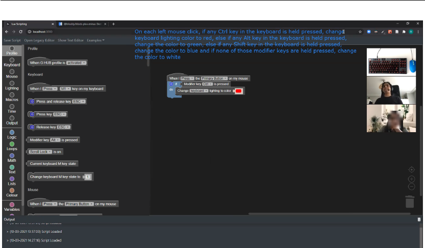
Chapter 8 Evaluation - Iteration 2
Figure 8.1 – Iteration 2 user tests carried out over Zoom showed a real-time video feed of a
keyboard and a mouse for the participant to see the effects of the scripts they make
8.3 Interview and user task
A similar interview guide to that which was used in the iteration 1 of evaluations, was used to
make sure each participant gets exposed to the same set of instructions and information.
A Logitech G915 TKL RGB keyboard and a G102 LIGHTSYNC mouse was used in the user tests
to have the effects of the executed visual scripts demonstrated to the participant real-time.
Due to the ongoing COVID-19 pandemic and social distancing concerns, all the user tests
were carried out remotely using Zoom and a real-time video feed of the keyboard and the
mouse was provided in the Zoom call for the participant to see as can be seen in Figure 8.1.
Similar to the protocol followed in iteration 1, during the user test each participant was asked
to perform a task with the high fidelity prototype. The task was to create a visual script so
that when executed, each time the left mouse button is clicked on the gaming mouse, if any
Ctrl key in the keyboard is held pressed, change keyboard back-light color to red, else if any
Alt key in the keyboard is held pressed, change the keyboard back-light color to green, else if
any Shift key in the keyboard is held pressed, change the keyboard back-light color to blue
and if none of those modifier keys are held pressed, change the keyboard back-light color to
white. Figure 7.2 shows how this task can be programmed using the blocks based setup in
the high fidelity prototype. Figure 7.7 shows the generated textual version of the same visual
script. participants were given remote access to the computer via Zoom to perform the task
and the task description was added on screen as a Zoom annotation. As usual users were
asked to think out loud as they work on the task with the prototype and the Zoom sessions
were recorded for further analysis.
52

Evaluation - Iteration 2 Chapter 8
Table 8.1 shows the details of all the participants of the second iterations of the user study.
Real names of the participants are omitted for privacy reasons.
Table 8.1 – Participants of the second round of user tests.
Gender Age Programmer Location Date/time
P11 Male 20-40 Yes Lausanne, CH 22/02/2021 15:00
P12 Female 20-40 Yes Lausanne, CH 22/02/2021 18:00
P13 Male 20-40 No Lausanne, CH 01/03/2021 17:00
P14 Female 20-40 No Lausanne, CH 10/03/2021 14:00
8.4 Results
8.4.1 Insights on usability
As shown in Figure 7.6, in addition to the configurable ‘if’ block, an ‘if-else’ block was provided
in the toolbox. It was interesting to observe that all the four participants ended up using this
new ‘if-else’ block when performing the task. When inquired why, participant P12 said:
“It’s intriguing to me because the other blocks didn’t have that icon (cogwheel
button). But just looking at the icon, I didn’t expect that it would give me necessar-
ily more options. And once I clicked it I was like ‘okay, there are few blocks here,
what does that mean...? where should I click...?’ But when I saw them connecting
because they had connections... then you start seeing the differences here (on the
original block).. And you are like... ‘Oh! this is a configurator for this block’...”
Participants were also asked about an alternative configuration mechanism for the ‘if’ block
as shown in Figure 8.2. All the four participants confirmed that they think this alternative
configuration mechanism is more intuitive for them. Participant P12 confirmed it saying:
“Yeah this is more intuitive for sure. Maybe instead of having just the + and - sign,
I would have it inside a circle or something... just to not get in the way of this
is part of the block or anything... just that to make clear that it’s a expansion or
contraction of the block”
Participant P13 summed up the same idea with his statement:
“Intuitively i would think there is a +, it means i can do something... so i would
have clicked just to test. But the other one (configuration with cog wheel button) I
thought that I just select one instead of reorganizing them.”
53

Chapter 8 Evaluation - Iteration 2
Figure 8.2 – Alternative configuration mechanism for if block
Another interesting observation was that the use of this new ‘if-else’ block forced the users
to use them in a nested fashion to build ‘if-elseif-else’ like conditional ladders. This seemed
to make comprehension of the program they created more difficult for them. For instance,
participant P11 was confused whether or not the nested ‘if-else’ will get executed in the
program he created. He went on to say
“To me when you code, you have the indentation that is fairly important. I see
that for me it’s like this function is embedded in this one and this is embedded in
this one. I would prefer to have something like this (stacking the ‘if-else’ blocks
one after the other), that would be much cleaner, so when I press this (referring to
the event listener block) I have my 3 conditions... it’s almost like I could use it like
a switch and the case functions in JS (Javascript)”
Figure 7.2 shows the interface of the high fidelity prototype and on the left we can see the
always open continuous toolbox that allows scrolling through all the block categories. Contrary
to the user input received in the first iteration, three of the 4 participants in this iteration found
the new toolbox difficult to use. When shown the previous menu style toolbox, Participants
P12 and P14 stated that they prefer that more. Both of them did not understand how the
categories allow them to quickly scroll to a specific section in the toolbox. While working on
the task participant P12 said:
“The other thing is... like... I didn’t quite see those categories until you said.”
Participant P14 also said at the end of the task:
“To be honest just now I started reading the titles. Earlier the different colors, I
thought like it is a color palette. At first I though this were gonna be the colors that
we were gonna change the keyboard to”
54

Evaluation - Iteration 2 Chapter 8
Participant P12 and P14 went on to further elaborate their opinion:
“I think I like this (menu style toolbox) because then it is very clear... like... ‘OK,
you have the functions, you have the logic, the keyboard...’ because when I was
going through the other one (scroll list toolbox), and I was scrolling here, I was not
necessarily seeing that this (current category shown highlighted) was changing
based on this (list being scrolling). And then I got lost with all the options because
its like... ‘Okay, this is a bit overwhelming with all these things...’, but this one here
(menu style toolbox), I know I wanted to get to the logic one, it would be... like...
easier for me to navigate.”
“Just in terms that it (menu style toolbox) is easier to access, I know I need a
variable so I’d just go to the variable rather than just scrolling... because the list is
long... scrolling all the way to the bottom... all the way to the top...”
Participant P11 preferred neither styles of the toolboxes. He preferred to see something like a
contextually filtered menu appearing on the canvas that lets him type what he wants to do and
the menu shows the filtered list of blocks that matches the search query. He also suggested
greying out blocks in the toolbox that would not fit any existing blocks in the canvas so that
the number of options are narrowed down. These were his words:
“I would like... press black here (on the canvas), no options there (as a toolbox),
I type a sentence and say ‘When...’, and then you give me options - ‘When I
press what, the keyboard, the mouse whatever...’, ‘ok, the mouse...’, ‘what on the
mouse?...’, ‘The primary button...’, ‘ok, what do you wanna do... Do you wanna add
a condition?...’, ‘Yes I wanna add a condition If...’, and then I complete my sentence
and in the end I have only one big sentence and I can change the parameters. As
soon as I finish typing a part of the sentence, I need to be asked or proposed some
logical way, because here I guess as soon as I add that (the event listener block), I
cant probably add some other stuff here (on the toolbox). So maybe those should
be grayed out”
Although several participants in the first iteration stated they would have preferred to look at
some examples, none of the participants in this iteration paid any attention to the examples
menu that was made available in the interface.
It could also be noticed that although the participants did not explicitly mention anything
about keyboard shortcuts, as they worked on the task, they used them to copy and paste or
delete blocks naturally.
It was also interesting to hear from the participants their general impression on the high
fidelity prototype. Participants P13 and P14 who were non-programmers as well as participant
55

Chapter 8 Evaluation - Iteration 2
P12 who had some programming skills stated that they would prefer to use this tool to create a
program rather than write the code textually. Participant P13 said:
“I think it just tells me that I could try to code and its not that difficult in fact. It
kind of breaks the first barrier that you have. Most of the time you see people
coding and its like crazy complicated, but its only logic in the end”
8.4.2 User performance
Table 8.2 lists down the time it took for each participant to complete the given task with the
high fidelity prototype. Participant P13 got stuck with the logic he followed in doing the task
and did not manage to complete it. All the participants, regardless of coding experience
needed different levels of assistance in completing the task. So , just as it was the case in the
iteration 1 as well, these duration values are influenced by the amount of help they received
during the tasks and deriving conclusions from them would not mean anything significant.
Table 8.2 – Time duration taken by each participant to complete the assigned task with each
prototype during the second round of user tests. Durations marked with a
†
imply that the
participant failed to complete the task and the task was given up halfway.
Participant Duration (mm:ss)
P11 19:56
P12 12:12
P13
†
13:23
P14 12:37
56

9
Discussion
The primary objective of the iteration 1 of the user tests was to decide on which visual pro-
gramming setup to proceed with between blocks based setup and nodes based setup. Both of
these visual programming setups have been successfully used in various visual programming
tools and environments that have been built. Yet, as the results showed, in this specific use
case, a majority of the participants preferred the blocks based setup. The nodes based setup is
commonly seen utilized in professional development environments especially in the graphics
industry. Many of the 3D and 2D graphic creation software provides a nodes based editor for
creating textures and materials for the models where the texture can be enhanced step by
step in a sequence with each node adding some visual effect to it. What we noticed is that
these texture generation processes inherently follow a strict sequential flow and never have
conditional flow paths. For our use case, representing a program using such a nodes based
graph will not result in a strict sequential flow of execution when programming constructs like
conditional statements and loops are used. As a result, the execution path of the visual script
along the nodes and connecting lines can go back and forth following different nodes in the
graph and this makes interpreting a nodes based visual program difficult. The observations
we made with the users indicate that this is the reason why most participants did not prefer
the nodes based setup. Even some of the participants that said they preferred the nodes based
setup mentioned that they prefer it because it looks ‘visually cool’.
Due to the time constraints involved with a master thesis project, we limited the number of
participants we recruit for the first iteration of user tests to 10. While we could gather a lot
of useful inputs from the 10 participants, some concern was raised on the confidence of the
choice made with respect to the visual program setup. As the results show, the distribution
of the preference was 60% and 40% for the blocks based setup and the nodes based setup
respectively. This choice percentage of blocks setup cannot be considered a strong majority
and one can argue that the decision could have easily flipped if, for instance, five more
participants were included in the user test. This situation has an even stronger effect on the
results obtained within user groups. For instance, Figure 6.4 shows the preferred choice of
visual programming setup within the user groups of programmers and non-programmers.
57

Chapter 9 Discussion
Here, we can see 3 out of the 5 programmers preferred the blocks based setup. Yet, adding
just one more programmer to the group can make the votes tie. This lack of confidence could
have been minimized by going for a larger number of participants that included both internal
employees as well as external users hired via some agency. In retrospect, a better approach
would have been to conduct a quantitative study rather than a qualitative study so that we can
be confident that the difference in preferences is significant.
As was described in Section 6.1, a screening questionnaire was used to filter out participants
that do not match the expected target user base of the proposed tool. In the questionnaire,
a required question was included to state how familiar the participant is with programming.
Three options were provided: ‘Very much’, ‘I know the basics’ and ‘Never written a single line
of code’ (refer Figure 6.1). Depending on the answers provided on the form, participants were
recruited for the user tests in a way that balances the programming experience among the
total 10 participants. Yet, when the participants were interviewed during the user test, some
participants who had answered on the form that they had never written a single line of code,
spoke of some brief previous coding experience they have had. All of them made it clear that
they were really bad at what they tried to do when they made those attempts at coding or
learning how to code. So it was clear that some participants had answered this particular
question based on the self judgement they had about their coding skills, rather than based on
the real situation. So it should be highlighted that when balancing the participants in terms
of coding experience, their self judgment on their skill level was taking into consideration.
As a result some participants who were categorized as non-programmers might have had
some basic level of programming skills this could have influenced the set of participants to be
unbalanced with respect to coding experience.
Another concern that became clear as the user tests were conducted was that some partici-
pants have never had in them the need to personalize the devices they use. These participants
sometimes struggled to give a personal opinion on certain things simply due to the fact that
they personally have no real preference. This also could be seen as a contributing factor
that hinders the confidence of the choice made on the visual programming setup in the first
iteration. So in retrospect, this information should have been something that was demanded
in the screening questionnaire so that the participants will have stronger choices and opinions.
Section 8.4.1 states how conflicting observations were made in the second iteration and the
first iteration with regard to the setup used for the toolbox. The most probable reason behind
this could be the fact that the low fidelity prototype used in the first iteration supported only a
handful of blocks. As a result, participants could have felt that they could remember all the
blocks available if they were laid out openly. But with the high fidelity prototype, more than 50
blocks were provided in the tool box and the ability have all of them in the memory becomes
an impossible task nobody would attempt to do. When that is the case, having them hidden
under categories would have forced the participant to think first in terms of categories and
then in terms of the exact block, there by making the search for a block more efficient than
scrolling through the whole list.
58

10 Future work
Chapter 8 goes into detail in describing the features of the implemented high fidelity blocks
based prototype. One feature that was discussed there was the ability access the textual script
generated from a created visual script. This feature can prove useful for advanced users with
programming experience by enabling them to further fine tune a program with textual code
that was initially created using the visual scripting tool. At the moment, the tool only support
generating the textual code from a visual script. As a result, if the user makes any change to the
generated code in the textual script editor, the canvas of the visual scripting environment is
cleared out. Implementing a mechanism to generate a visual script from a given textual script
could add a lot of value to the user experience of the tool. This would enable users to move
back and forth between the textual and visual setups, there by continuing the work from the
point they left it off in the other setup. One possible way to implement this feature would be to
traverse through the abstract syntax tree of the textual code and try to map the programming
elements to visual programming blocks.
Another interesting feature that could help users comprehend a certain visual program would
be to have a mechanism that lets them step through the blocks in the program in the order
each block in the program will be executed. This could be something similar to a debugger
that we see in Integrated Development Environments that lets you step from one line of code
to the other. As execution reaches a certain block, the block can be shown visually highlighted
in a certain color. Some controllers need to be provided that allow the user to specify when to
proceed to the next step in the execution.
Going by the it’s commitment to inclusivity and diversity in gaming, Logitech introduced the
Logitech G Adaptive Gaming Kit for users with disabilities and those with a wide variety of
accessibility needs
I
. It would be an interesting avenue to explore how this visual programming
prototype can also be tailored to help such people with special needs. One straight forward
improvement on this regard would be to provide full accessibility to all the features of the tool
only using the keyboard. More insights can be gained by interviewing some users from the
I
When Everyone Plays, We all Win! | logi BLOG. (n.d.). Retrieved March 10, 2021, from https://blog.logitech.
com/2019/11/18/logitech-g-adaptive-gaming-kit/.
59

Chapter 10 Future work
disabled gaming community.
As was stated in Section 8.4.1, none of the participants in the second iteration of user tests
noticed that they had the option to refer some example scripts to get some idea on how to
use the tool. This implies that, to have impact, the tool needs more work in terms of guiding
the user to become familiar with the visual programming environment. A possible solution
would be to have some interactive tutorials designed to make the user accustomed to the
setup when they first open it. These tutorials could take the form of a game where the user is
first shown a sample script that they can test by themselves and then they are shown a script
with missing pieces where they have to figure out what block should go where. Users can
also be given marks based on how fast they complete each step. The tasks can be made to
increase in difficulty in each level and the complete suite of tasks can be designed to cover all
the available functionality provided by the tool.
The results obtained by the second iteration of the user tests show that the prototype needs
further improvement and this calls for several more iterations of user tests. One avenue
that should be worked upon in the immediate next iteration would be to explore ways of
bringing the represented model of the prototype closer to the target users’ mental model.
As described in the book titled ‘About face: the essentials of interaction design’ by Cooper
et al.(2007), providing the users with an overwhelming number of blocks that maps 1-to-1 for
every function will more reflect the infrastructure of engineering efforts, but will bring little
value a user to assist him in achieving his goals. The represented model of the high fidelity
prototype built in the second iteration can be seen to be placed closer to the implementation
model rather than the mental model. Users will use the tool with some end goal in mind
and their mental model of the setup will be to interact with the tool in the same flow as they
would narrate their requirement in natural language. The closer the represented model can
be brought towards the user’s mental model, the easier users will find the application to use
and understand. One way to make this move would be to explore ways of combining multiple
blocks that represent certain G HUB Lua API functions in to a single block in some meaningful
way. This single block could provide configuration options to provide the functionality of
each of the G HUB Lua API functions it represents, yet it would hide the users from having
to worry about that complexity. Another possibility would be to explore alternate solutions
to using a toolbox. This could avoid the need for the user to move back and forth between
the canvas and the toolbox to find the programming elements he want. As was suggested by
participant P11, this can possibly be achieved by using a contextual menu that can be opened
by right-clicking on any empty space on the canvas and the user can then start typing his
requirement in natural language to search for blocks that matches his need.
60

11 Conclusion
Logitech G HUB software lets users personalize their Logitech Gaming gear. To cater for
advanced device customization requirements of the users, G HUB provides a Lua scripting
environment and a set of Lua API functions that can be used within this scripting environment.
This facilitates performing actions such as simulating hardware events, manipulating device
lighting settings, playing pre-configured macros and reading hardware and software states
of the connected gaming devices. In this project we investigated how visual programming
programming solutions can be used to make this existing Lua scripting environment more
approachable and intuitive to use for users without any programming skills.
From initial research, two potential visual programming setups were chosen as candidates.
One used a setup of blocks that fit each other and the other used a notion of nodes that are
connected to each other using lines to specify flow of control and data. Low fidelity prototypes
of each setup were developed and a round of user tests were carried out with the primary target
of identifying which setup to proceed with. 10 internal Logitech employees were recruited
for the study while making sure the genders and the levels of programming experience in the
user group stay balanced. All the participants were given a task to complete with each of the
prototype and the order they test the two prototypes was also balanced.
The results showed that 60% of the participants preferred the blocks based setup. Accordingly,
a high fidelity prototype following the blocks based setup was developed. This prototype was
made fully integrated with the G HUB back-end so that the textual scripts generated by it from
a visual script can be executed on the back-end to have its effects on any connected devices.
Finally, a second iteration of user tests were carried out to evaluate the usability issues this
prototype attempted to solve and discover any new usability issues that were introduced in
the new design.
61

A Appendix
A.1 Interview Guide
Participant Name :
Email :
Gender :
Age :
Position :
Time/Date :
Prototype order :
Note: Timebox for max 40 mins
A.1.1 Introduction and Setup
• Thank for the participation
• Self introductions
• Intro on the user study
– Some questions, no right wrong answers
– Task with prototype, to learn from you what works and what doesn’t.
– Think out loud. What you like, don’t like
•
Zoom recording - “This material will only be used internally and never shared with
anyone else. Will be disposed of at the end of the project”
• Start the recording.
63

Chapter A Appendix
A.1.2 Demographics and Background
Observe the gender and age group of the participant.
• Play video games? If yes
– The last game? How often?
– PC or console?
• Logitech gaming devices? If yes,
– Familiarity with the Logitech G HUB Software? If yes
*
What have you used it for?
*
Lua Script editor of G HUB? If has used
· Liked it? why?
• Coding experience? If yes
– Started when?
• Visual programming?
If yes
– The last VP tool used?
– Impression? Liked? Disliked? Why?
–
What would a VP tool for configuring devices in G HUB be like? (probe for users
mental model)
If no
–
Say it is something that allows you to create code graphically. Thoughts on what it
would be like? (probe for users mental model)
Notes:
• Try to make it more like a conversation and less like a list of formal questions
• Try to refer to experiences eg: last time they used it
64

Appendix Chapter A
A.1.3 Task on the prototype
Start with (node/block) prototype
Share screen
Provide remote access to the user.
• How do you think this tool works? You can play around and try out
Mention
• Low fidelity prototype visual scripting tools
– meaning its not at all complete
– not necessarily what the end product would look like
• 2 versions in 2 different fashions
– blocks and nodes
–
illustration of a mouse used to represent a real Logitech mouse only for the purpose
of feedback
• Task description
– task not representative of how it’s used in real life, just a dummy
–
“Create a script on the canvas such that when it is run, every time you click on
the left click button of the virtual mouse, the color of the G logo changes once,
sequentially going through the colors Red, Green and Blue. For instance, if you
click when the color is Red, the color should change to Green. If you click while
the color is Green, it should change to Blue and finally if you click while the color
is Blue, it should change to Red.”
• Any questions?
Time taken to complete the task
• With blocks:
• With nodes:
65

Chapter A Appendix
Notes:
•
Do not describe how it works,
remind them to think out loud
, see how well they figure it
on their own
•
If they dont think out loud, as the user starts interacting with the interface, ask questions
like ‘how do you think you can use this tool’?
•
Give answers only to the questions the user voices out, ask if they want to know the answer
or want to figure it out on their own
•
When the user seems to have no more feedback to give, try to ask a new question or more
about what they mentioned to avoid moments of silence. Try to keep it as a conversation
A.1.4 Follow up questions
• Which prototype should we build? Why? Anything negative? why?
• Anything positive with the other? Why?
• Any improvements you suggest?
• Anything this sort of interface would help you with in real life?
A.1.5 Wrap up
• Questions?
• Thanks!
66

Bibliography
ai craft, c. (2015). The maturity of visual programming. Retrieved February 26, 2021, from
https://www.craft.ai/blog/the-maturity-of-visual-programming/
Between-Subjects vs. Within-Subjects Study Design. (n.d.). Retrieved March 2, 2021, from
https://www.nngroup.com/articles/between-within-subjects/
Blender.org - Home of the Blender project - Free and Open 3D Creation Software. (n.d.).
Retrieved February 26, 2021, from https://www.blender.org/
Blockly. (n.d.). Retrieved March 12, 2021, from https://developers.google.com/blockly
Blueprint Compiler Overview. (n.d.). Retrieved March 2, 2021, from https://docs.unrealengine.
com/en- US/ProgrammingAndScripting/Blueprints/TechnicalGuide/Compiler/
index.html
Bootstrap. (n.d.). Retrieved March 12, 2021, from https://getbootstrap.com/
BPM software & open source workflow for your processes | Bonitasoft. (n.d.). Retrieved Febru-
ary 26, 2021, from https://www.bonitasoft.com/business-process-management-bpm
Cook, D. D. (2015). Flowgorithm: principles for teaching introductory programming using
flowcharts. Proc. American Society of Engineering Education Pacific Southwest Conf.(ASEE/PSW),
158–167.
Cooper, A., Reimann, R., & Cronin, D. (2007). About face 3: the essentials of interaction design.
John Wiley Sons, Inc.
Craft ai | Explainable AI, as-a-service. (n.d.). Retrieved February 26, 2021, from https://www.
craft.ai/
Extensions and Mutators | Blockly. (n.d.). Retrieved March 12, 2021, from https://developers.
google.com/blockly/guides/create-custom-blocks/extensions
G-series lua api - overview and reference. (n.d.). Retrieved March 2, 2021, from https://douile.
github.io/logitech-toggle-keys/APIDocs.pdf
Havik, B. (2017). User-centered design. Retrieved March 2, 2021, from https://medium.com/
artificial-industry/user-centered-design-ac0889e3e1e2
IFTTT. (n.d.). Retrieved February 26, 2021, from https://ifttt.com
Introduction to Blueprints. (n.d.). Retrieved March 2, 2021, from https://docs.unrealengine.
com/en-US/ProgrammingAndScripting/Blueprints/GettingStarted/index.html
Maloney, J., Resnick, M., Rusk, N., Silverman, B., & Eastmond, E. (2010). The Scratch Program-
ming Language and Environment. ACM Transactions on Computing Education, 10(4),
16:1–16:15. https://doi.org/10.1145/1868358.1868363
67

Chapter A BIBLIOGRAPHY
Monaco Editor. (n.d.). Retrieved March 12, 2021, from https://microsoft.github.io/monaco-
editor/
Notes on User Centered Design Process (UCD). (n.d.). Retrieved March 2, 2021, from https:
//www.w3.org/WAI/redesign/ucd
React – A JavaScript library for building user interfaces. (n.d.). Retrieved March 12, 2021, from
https://reactjs.org/
Redux - A predictable state container for JavaScript apps. | Redux. (n.d.). Retrieved March 12,
2021, from https://redux.js.org/
Repenning, A. (2017). Moving Beyond Syntax: Lessons from 20 Years of Blocks Programing
in AgentSheets. Journal of Visual Languages and Sentient Systems, 3(1), 68–91. https:
//doi.org/10.18293/VLSS2017-010
Resnick, M., Maloney, J., Monroy-Hernández, A., Rusk, N., Eastmond, E., Brennan, K., Millner,
A., Rosenbaum, E., Silver, J., Silverman, B., et al. (2009). Scratch: programming for all.
Communications of the ACM, 52(11), 60–67.
Rete.js. (n.d.). Retrieved March 12, 2021, from https://rete.js.org/#/
Scratch - Imagine, Program, Share. (n.d.). Retrieved March 1, 2021, from https://scratch.mit.
edu/statistics/
Sova, D. H., & Nielsen, J. (2010). 234 tips and tricks for recruiting users as participants in
usability studies.
Unity - Manual: Animation System Overview. (n.d.). Retrieved February 26, 2021, from https:
//docs.unity3d.com/Manual/AnimationOverview.html
Unreal Engine | The most powerful real-time 3D creation platform. (n.d.). Retrieved February
26, 2021, from https://www.unrealengine.com/en-US/
Visual programming language [Page Version ID: 1008802939]. (2021). Retrieved February 26,
2021, from https://en.wikipedia.org/w/index.php?title=Visual_programming_
language&oldid=1008802939
When Everyone Plays, We all Win! | logi BLOG. (n.d.). Retrieved March 10, 2021, from https:
//blog.logitech.com/2019/11/18/logitech-g-adaptive-gaming-kit/
Zapier | The easiest way to automate your work. (n.d.). Retrieved February 26, 2021, from
https://zapier.com/
68
