1
PATIALA LOCOMOTIVE WORKS,
PATIALA

2
INDEX
SN
Topic
Page No.
1
Introduction to NC/CNC machines and Part Programming
03-06
2
Programming Modes
07-09
3
PREPARATORY (G) FUNCTIONS ISO 646
10
4
MISCELLANEOUS (M) FUNCTION ISO 646
11
5
MISCELLANEOUS & CODES & ADDRESSES FOR LATHE MACHINES
12-13
6
SAMPLE PROGRAMS FOR CNC TURNING MACHINES
14-33

3
NC / C N C
Numerical Control (NC) is a method for control of slide motions and auxiliary
motions of machine tools in form of numerical data.
Computer Numerical Control (CNC) is Microprocessor based system to
store and process data for control of slide motions and auxiliary motions of
machine tools.
Development of computer numerically controlled Machine is outstanding
contribution to Manufacturing industry
It has made possible automation of machinery processes with flexibility to
handle as small and medium batch quantities in part production.
Functions of CNC Machines
One or more machine axes slide movements controlled either single of
simultaneously.
Control of feed rate along slide ways and its direction.
Control of spindle rotational speeds (step-less constant surface speed)
Start/Stop of main spindle rotation and change of direction.
Control of coolant, ON/OFF.
Control of tool change, turret head indexing, tool selection, loading of selected
tool from automatic tool changer etc.
Control of numerous other functions e.g. tool wear/breakage monitoring
function, pallet changing, robot loading functions. Also other function related
to operator and/or machine safety system. Software and limit switch
boundaries, chuck guard locks, overload monitoring.
Advantages of CNC Technology:
Due to its flexibility, the machine utilization is very high.
The lead time is very largely reduced thereby prediction of the delivery
schedule is more reliable.
Need of special purpose tooling, jigs and fixtures is mostly eliminated.
Consistency in quality is assured since the manufacture is automatic. This
indirectly reduces the inspection costs.
Handling time is very largely reduced since most of the operations can be
carried out in minimum number of set ups. With facility of automatic tool
changing, pallet change and clamping and unclamping arrangements, the non-
machining time is eliminated to maximum extent.

4
Since a single machining center can perform many operations, large floor area
is saved which otherwise would be required to install a number of
conventional machines.
Since the input instruction can be easily modified, design changes in the
products can easily be incorporated. This is very advantageous in prototype
manufacture or in manufacture of similar parts in small batch size.
Operator’s skill is no longer important since the accuracy is dependent on the
program. This reduces scrap and rework.
Sudden change in demand can be easily handled because the system has in
built flexibility.
Work in progress, handling time and errors due to a number of set ups, as in
conventional manufacture, are reduced to a very large extent when machining
centers are used.
Since mostly all conditions are under control, the estimation of costs involved
can be done quite accurately.
Disadvantages of CNC Technology:
NC essentially calls for very high investment. But this should be carefully
considered in the light of numerous advantages and over a period of time.
Special skills in programming and maintenance are essential.
Redundancy in labour may be there. But this again needs careful consideration.
When planning for NC, retraining of staff for newer requirements must be taken
into account.
Down time of NC systems is very expensive, therefore, it is very essential that
that staff is adequately trained in operation and maintenance at the supplier’s
place before the machine is delivered.
Part Programming
The preparation of a set of instructions to carry out the machining of a work piece
is called part programming. This work is carried out by a part programmer. He
prepares the planning sheet and writes the instructions in a coded form which is
acceptable to the controller of machine tool. Part programming is of two types:-
Manual
Computer assisted
In the former, the programmer prepares the program and uses the tele type to
prepare the punched tale version of the program. In the later, the tape is produced
by the computer after it has been fed simple instructions in proper format which
are different from the one used in manual part programming. Various symbols used
in programming are given below.

5
N : Operation sequence number address
B : Preparatory function address
X, Y, Z, A, B, C : Dimension address with axis Identification.
S : Spindle speed address
G : Feed rate address
T : Tool address
M : Miscellaneous function address.
What the programmer has to do?
1. Study the relevant component drawing thoroughly
2. Identify the type of material to be machined.
3. Determine the specification and function of machine to be used.
4. Decide the dimension and more-metric or inch.
5. Decide the coordinate system –absolute or incremental.
6. Identify the plane of cutting.
7. Determine the cutting parameter for the job/tool combination.
8. Decide the feed rate programming – mm/min or mm/rev.
9. Check the tooling required.
10. Establish the Sequence of machining operations.
11. Identify whether use the special features like subroutines, mirror imaging, etc.
is required or not.
12. Decide the mode of storing the part of program once it is completed.
Structure of a Part Program:
A part program defines a sequence of NC machining operations. The information
contained in the program can be dimensional or non-dimensional like speed, feed,
auxiliary function etc. The basic unit of part program input to the control is called a
block. Each block contains adequate information for the machine to perform a
movement and / or functions. Blocks in turn are made up of words. Each word
consists of number of characters. All blocks are terminated by the block end
character.
A block may contain any or all the following:
Sequence or block number (N)
Preparatory functions (G)
Dimensional information (X, Y, Z etc.)
Decimal point (.)
Feed rate (F)
6
Spindle speed (S)
Tool No. (T)
Tool offset function (D)
Miscellaneous functions (M, H etc.)
End of block (EOB).
Block Example
N1234 G.. X.. Y.. S.. M.. F.. T.. D.. LF
The Word Addressed system is method generally use for writing part program for
the numerical control of the wide range of machines. In this system there is an
identifying letter (alpha character) preceding each data? This alpha character in the
world is known as the address, e.g. G2, N2, etc. A control unit recognizes a word
through its address. A number of the word makes up a block and two blocks are
separated by a marker. Generally, the words need not be programmed in a
particular order. Different word may have a different number of digits; some have
only one digits and other may have up to seven digits. Whenever a word represents
machine movement data, a + or a- may be required between the latter and the
number
Example of a Block
N 1234 G-- X--Y-- S-- M-- F-- T-- D-- LF
Block Address
Block numbers
Preparatory functions
Transient information
Spindle speed functions
Miscellaneous functions
Feed functions
Tool functions
Compunction function
End of block

7
Programming Modes
To prepare the manuscript for manual part programming, the programmer needs to
collect some data pertaining to the work to be carried out.
The data would be follows:-
• Specification of Machine
• Specification of all tools.
• Specification of work material.
• Speed, feed tables etc.
There are two modes of programming in CNC systems
• Absolute mode
• Incremental mode
Absolute Mode:
Movement is programmed as the complete distance from a specified point, say the
start point or the zero point.
Incremental Mode:
In this mode the movement of the tool, slide or table is described or programmed
as the distance from the end point of the previous mode and must be given the
appropriate negative or positive sign.
Diameter and radius program
Some machines are designed to be programmed in diameter or radius mode.
Programming for diameter is done by input of data in diameter mode. The values
are provided for diameter at different locations as per component deg. The
programming for radius is done by input of data in radius mode and the values are
provided for radius at different locations.
Understanding Program Zero:
Every CNC machine has a reference or machine zero. This is a position that is a
constant to the machine. When a machine is first turned on or powered up by an
operator it must be referenced before any programs can be executed. This is a
process that moves the machine to the zero point on all its axes. These points are

8
set by mechanical limit switches. When the machine reaches these limit switches
the control registers this location as home. This home position is kept by the
control until you turn the power off. Using the home position as a reference you
can now tell the control where on the table you expect it to find the piece to be
worked on. To determine this second work reference point you should first
understand how a CNC machine interprets its direction of movement. All
machining centers move on one or more axes. Assuming the machine is vertically
configured; one with the head directly above the table, the standard set of axes is:
• X (left and right)
• Y (forward and back)
• Z (up and down)
Each axis has two possible directions in which it can travel: + (plus) and - (minus).
This is referred to as the Cartesian coordinate system. The Cartesian coordinate
system can be defined as two or three mutually perpendicular axes which intersect
at a common point called the origin.
Types of motions:
Every CNC machining center has only two types of motion.
Linear
Circular
Linear motion is just as it sounds; straight line movement. These moves can be in
any direction and can include all three axes. A linear move must be performed in
one of two modes. Rapid or feed rate. Which mode the motion is executed is
determined by a preparatory G code. G0 initiates a rapid movement and G1 is
interpreted as a movement at a specified feed rate.
Rapid Linear Motion Example G0 G91 X2.0 Y2.0 Z-2.0
Feed Rate Linear Motion Example G1 F25. G91 X2.0 Y2.0 Z-2.0
The second motion type is circular. A circular motion, in contrast to a linear
motion, can only be performed at a specified feed rate. A circular motion can be a
full circle or it can be just a small segment of an arc. There are two event G codes
used to initiate a circular motion. G2 and G3. The first, G2 tells the control that the
following data should be used to create an arc in the clockwise direction. , G3 is
counterclockwise.
Clockwise Circular Motion Example

9
G2 X0 Y0 R2.0
G3 X0 Y0 R2.0
Graphical Simulation
It is advisable to verify all programs in memory using the tool path simulation
facility. This will display immediately, any dimensional program errors by
displaying the bar stock being machined step by step on the VDU.

10
COMMON CODES & ADDRESSES
PREPARATORY (G) FUNCTIONS ISO 646
G01
Positioning at rapid traverse
G 01
Linear interpolation
G 02
Circular Interpolation, clockwise
G 03
Circular Interpolation, counter clockwise
G 04
Programmable dwell
G 06
Parabolic interpolation
G 08
Automatic acceleration to a known speed
G 09
Automatic de-acceleration to a known speed
G 17
Selection of circular interpolation in the XY place, for compensation of rotating
G 18
As above, for ZX plane
G 19
As Above, for YZ plane
G 33
Thread turning constant pitch
G 34
Thread turning increasing pitch
G 35
Thread turning decreasing pitch
G 40
Cancellation of tool compensation
G 41
Rotating tool compensation, right hand side
G 42
Rotating tool compensation, left hand side
G 43
Tool positive compensation move.
G 44
Tool negative compensation move.
G 53
Cancellation of zero point shift
G 54-G60
Zero point shift codes
G 63
Threading by tap
G 70
Programming in inches
G 71
Metric unit programming
G 74
Move to start point
G 80
Cancellation of canned cycle
G 81-G 89
Reserved for canned cycles
G 90
Absolute programming mode
G 91
Incremental programming mode
G 92
Data input to memory in advance
G 93
Feeders value is translated proportional to time
G 94
Feed in mm/min.
G 95
Feed in mm/spindle revolution
G 96
Constant peripheral speed
G 97
Spindle revolutions/min.

11
MISCELLANEOUS (M) FUNCTION ISO 646
M 00
Program stop
M 01
Intermediate stop
M 02
Program end
M 03
Spindle rotation clock wise
M 04
Spindle rotation counter clock wise
M 05
Spindle off: coolant off
M 06
Tool change
M 07
Coolant No. 1 on (e.g. Mist coolant)
M 08
Coolant No. 2 on (e.g. flood coolant)
M 09
Coolant
M 10
Clamping (e.g. tables, slide, work piece, fixture, spindle etc)
M 11
Clamping released
M12
Free 1)
M 19
Spindle stop in specified angular orientation
M 20-M29
Continuous free 2)
M 30
Program end, stop and return to start character
M 31
Clamping override
M32-M39
Free 1)
M40-M45
Change of gear ratio if this required. Otherwise free 1)
M46-M47
Free 1)
M48
Cancels M 49
M 49
Deletion of manually adjusted feed rate or rotation speed, i.e. return to
programmed values
M50-M57
Free 1)
M 58
Cancels M 59
M 59
Maintains the spindle speed constant even though a G 36 initiated (const.
surface speed)
M 60
Work piece change
12
Lay out of new turning program
1
Part program
Program manager—part program---New(File Name)--ok
2
Work piece
Select Various – Blank—(Input of work piece) --Accept
3
Starting Program
Enter –(Starting Program)
4
Contour cal(Cycle
62)
Select Cont. Turn. -Contour –contour cal—(name of sub program)
Accept
5
Stock
Removal(cycle952)
Select Back -Stock Removal (M/C control of program)-Accept
6
End program
Enter-(end program)
7
Sub program
E_LAB_A_(Name of sub program): -enter (sub program or turning tool
path from 1
st
point to end point of job)
8
Numbering
Numbering select(10 or 2) OK
9
simulation
Reset-simulation-edit
10
Tool offset
MDA---MDI, G75x0z0,M06 T01D1 M30–-(Feed 0 check)-cycle start( Go to
home position)--Jog Mode-- measuring tool—manually- touch tool on z
axis- -z 0 –Input --set length-save position-- touch tool on x axis-X25 ( job
diameter)—input-- set length-- save position
11
Execute
Select Program –execute–( check feed switch 0 position)-- auto mode -
-cycle start---Feed increase by manually feed switch
DEFINATION OF SHORT KEYS
JOG
Manual machine movement by feed switch in x or z axis with +or- button
MDA
Manual machine movement by G or M Code in x or z axis - MDA mode (machine data
input ---MDI, G75x0z0, M30 - cycle start( Go to home position)--
AUTO
Program auto start for execute
RESET
Machine reset start from beginning
SBK
Check program in Single block check
MPG
Manual pulls generate MPG-VAR-Select plus co-ordinate-Use hand wheel for x or z axis
WCS
Work coordinate system
MCS
Machine coordinate system
TYPES OF CNC PROGRAM SYSTEM
1
FANUC -- {SIMPLE OLD FUNCTIONE}
2
SIEMENS-- {GOOD FOR BOTH PURPOSE}
3
HAAS-- {GOOD FOR LEARNING AND PROGRAMING}
4
MAZAK-- {ADVANCE TECHANOLGY}
5
HEIDENHIEN-- {CYCLE SYSTEM EASY FOR USING}

13
CODES & ADDRESSES FOR LATHE MACHINES
M CODE - DESCRIPTION
M00 Program stop
M01 Optional stop
M02 program end
M03 spindle CW
M04 Spindle CCW
M05 spindle stop
M06 ATC/ Auto Tool change
M07 flush coolant ON
M08 Coolant ON
M09 Coolant off
M10 Chuck / vice unclamp
M11 Chuck / Vice clamp
M17 Sub program continue
M18 Height tool offset call
M20 Arm IN
M21 Arm out
M24 Tool clamp
M25 Tool unclamp
M30 Program end rewind
M31 X-offset call
M32 Turret CW / X+ offset call
M33 Turret CCW / Z- offset call
M34 Z+ offset call
M35 Drilling tool offset call
M38 Door close
M39 Door open
G CODE- DESCRIPTION
G00 Rapid or idle tool path/motion
G01 Linear or cutting tool path /motion
G02 CW circular tool path/motion
G03 CCW circular tool path/motion
G04 Dwell time/waiting time between two
Function
G70 Inches unit input
G71 Metric unit input
G75 Homing position point
G90 Absolute mode
G91 Incremental mode
G94 Feed/minute
G95 Feed/Revolution
G96 constant cutting speed ON
G97 constant cutting speed Off
14
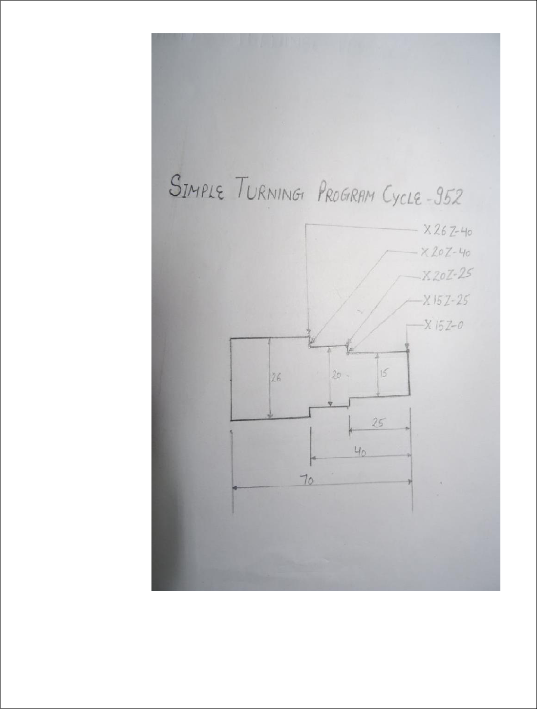
Simple Turning (Using turning cycle 952)
Part
program
MPF/0RST
Description (file name)
Work
piece
Cylinder
XA
26
Dia of work piece
ZA
0
Start- point in z axis
ZL
-70
total length of work piece
ZB
-40
machining length
2
G71 G95;
Metric unit, feed mm/ revolution
4
G75 X0 Z0;
Going to home position
6
T1 D1;
Tool Change position no.1
8
MO3 S1500;
Spindle speed clockwise
10
G00 X26 Z3F.1;
Rapid tool movement
12
Contour call
(Cycle 62)
ST
Sub program call by name
14
Stock
Removal for
turning (Cycle
952)
PRG
OD
Removal prog.name
SC
2.00
Safety distance/clearance
F
.1
Feed mm/revolution
Machining
▼+▼▼▼
Roughing & Finishing
FS
.01
Finishing feed
Longitudinal
Outside
For turning outside
D
0.1
Depth of cut
UX
.020
Finishing allowance X-axis
UZ
.020
Finishing allowance Z-axis
DL
0
Dwell time
BL
Cylinder
Select Blank( types of job)
XD
26
Datum point X-axis-stock start
ZD
2.0
Datum point Z-axis-stock start
Relief cut
NO
Machine relief cut
Limit
NO
Limit machining area
Accept
16
G75 X0 Z0;
Going to home position
18
M05;
Spindle stop
20
M30
Program stop
22
E_LAB_A_ST:
Code (sub prog.+Part prog)
24
G01 X15 Z0
Linear movement
26
G01X15 Z-25
Linear movement
28
G01 X20Z-25
Linear movement
30
G01X20Z-40
Linear movement
32
G01X26Z-40
Linear movement
34
M17
Sub program Exit
15
16
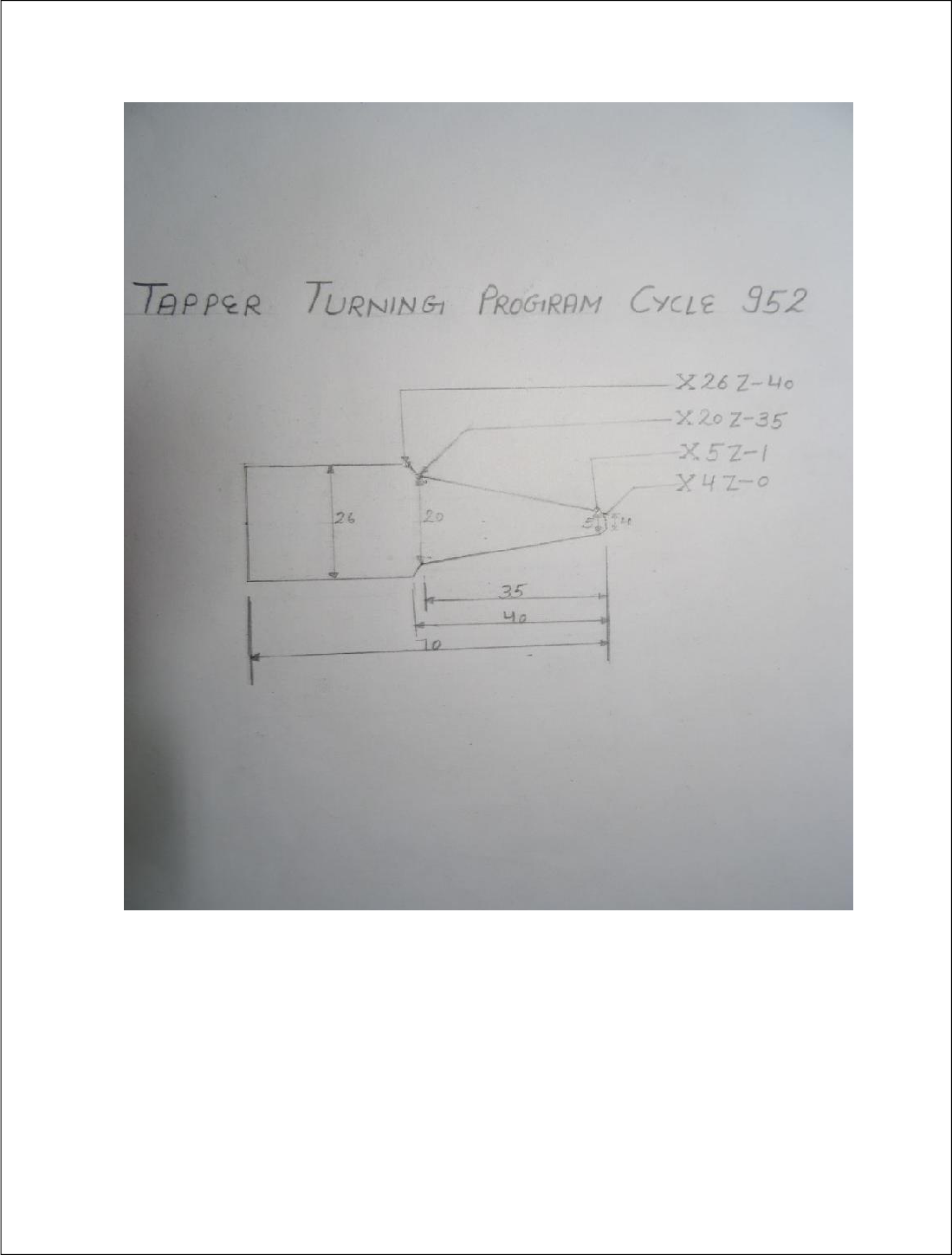
Tapper Turning (Using turning cycle 952)
Part
program
MPF/0RTT
Description (file name)
Work
piece
Cylinder
XA
26
Dia of work piece
ZA
0
Start- point in z axis
ZL
-70
total length of work piece
ZB
-40
machining length
2
G71 G95;
Metric unit , feed mm/
revolution
4
G75 X0 Z0;
Going to home position
6
T1 D1;
Tool Change position no.1
8
MO3 S1500;
Spindle speed clockwise
10
G00 X26 Z3F.1;
Rapid tool movement
12
Contour call
(Cycle 62)
TT
Sub program call by name
14
Stock
Removal for
turning
(Cycle 952)
PRG
OD
Removal prog.name
SC
2.00
Safety distance/clearance
F
.1
Feed/revolution
Machining
▼+▼▼▼
Roughing & Finishing
FS
.01
feed mm/ revolution
Longitudinal
Outside
For turning outside
D
0.1
Depth of cut
UX
.020
Finishing allowance X-axis
UZ
.020
Finishing allowance Z-axis
DL
0
Dwell time
BL
Cylinder
Select Blank type(job)
XD
26
Datum point X-axis-stock start
ZD
2.0
Datum point Z-axis-stock start
Relief cut
NO
Machine relief cut
Limit
NO
Limit machining area
Accept
16
G75 X0 Z0;
Going to home position
18
M05;
Spindle stop
20
M30
Program stop
22
E_LAB_A_TT:
Code (sub prog.+Part prog)
24
G01 X4 Z0
Linear movement
26
G01X5 Z-1
Linear movement
28
G01 X20 Z-35
Linear movement
30
G01X24 Z-35
Linear movement
32
G01X26 Z-40
Linear movement
34
M17
Sub program Exit
17
18
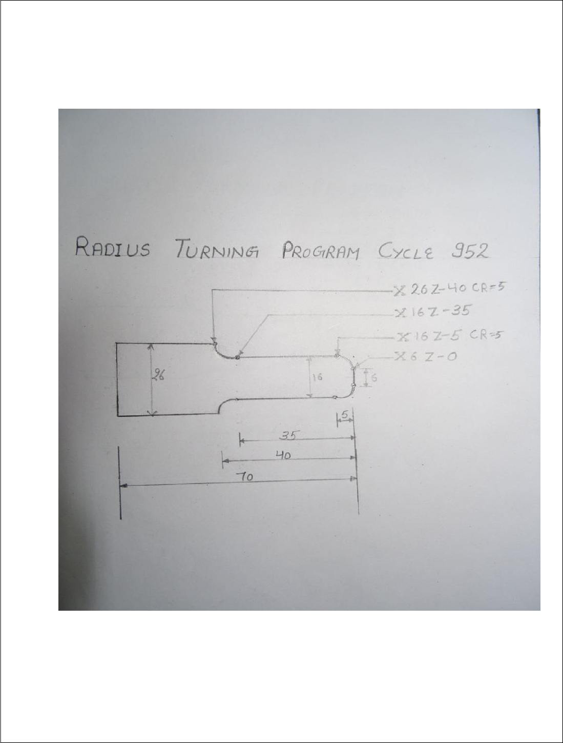
Radius Turning (Using turning cycle 952)
Part
program
MPF/0RADIUS
Description (file name)
Work
piece
Cylinder
XA
26
Dia. of work piece
ZA
0
start point in Z axis
ZL
-70
total length work piece
ZB
-40
machining length
2
G71 G95;
Metric unit , feed mm/ revolution
4
G75 X0 Z0;
Going to home position
6
T1 D1;
Tool Change position no.1
8
MO3 S1500;
Spindle speed clockwise
10
G00 X26 Z3F.1;
Rapid tool movement
12
Contour call
RD
Sub program( Name) call
14
Stock
Removal
for turning
(Cycle 952)
PRG
OD
Removal prog.name
SC
2.00
Safety distance/clearance
F
.1
Feed mm/ revolution
Machining
▼+▼▼▼
Roughing & Finishing
FS
.01
Finishing feed
Longitudinal
Outside
Machining direction position
D
0.4
Depth of cut
UX
.020
Finish allowance X-axis
UZ
.020
Finishing allowance Z-axis
DI
0
Continuous cut at
θ
BL
Cylinder
Select Blank type (job)
XD
26
Datum point X-axis-stock start
ZD
2.0
Datum point Z-axis-stock start
Relief cut
NO
Machine relief cut
Limit
NO
Limit machining area
Accept
16
G75 X0 Z0;
Going to home position
18
M05;
Spindle stop
20
M30
Program stop
22
E_LAB_A_RD:
Code (sub prog.+Part prog)
24
G01 X6 Z0;
Linear movement
26
G03 X16 Z-5 CR=5;
Circular Linear movement
28
G01X16 Z-35;
Linear movement
30
G02 X26 Z-40 CR=5
Circular Linear movement
32
M17
Sub program Exit
19
20
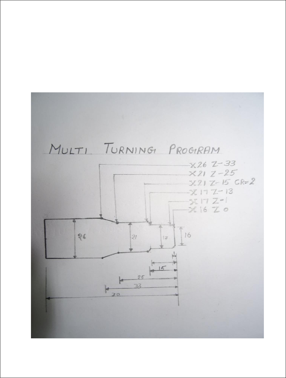
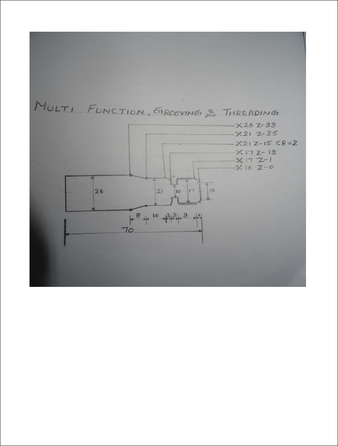
Multi Turning (Using turning cycle 952)
Part
program
MPF/0RMT
Description(file name)
Work
piece
Cylinder
XA
26
Dia of work piece
ZA
0
Start- point in Z axis
ZL
-70
total length of work piece
ZB
-40
machining length
2
G71 G95;
Metric unit , feed / revolution
4
G75 X0 Z0;
Going to home position
6
T1 D1;
Tool Change position no.1
8
MO3 S1500;
Spindle speed clockwise
10
G00 X26 Z3F.1;
Rapid tool movement
12
Contour call
(Cycle 62)
MT
Sub program( Name) call
14
Stock
Removal for
turning
(Cycle 952)
PRG
OD
Removal prog.name
SC
2.00
Safety distance/clearance
F
.1
feed mm/ revolution
Machining
▼+▼▼▼
Roughing & Finishing
FS
.01
Finishing feed
Longitudinal
Outside
For turning outside
D
0.4
Depth of cut
UX
.020
Finish allowance X-axis
UZ
.020
Finishing allowance Z-axis
DL
0
Dwell time
BL
Cylinder
Select Blank type(job)
XD
25
Datum point X-axis-stock start
ZD
2.0
Datum point Z-axis-stock start
Relief cut
NO
Machine relief cut
Limit
NO
Limit machining area
Accept
16
G75 X0 Z0;
Going to home position
18
M05;
Spindle stop
20
M30
Program stop
22
E_LAB_A_MT:
Code (sub prog.+Part prog)
24
G01 X16 Z0
Linear movement
26
G01 X17 Z-1
Linear movement
28
G01X17 Z-13
Linear movement
30
G03X21 Z-15 CR=2
Linear movement
32
G01 X25 Z-25
Linear movement
34
G01X26 Z-33
Linear movement
36
M17
Sub program Exit
21
22
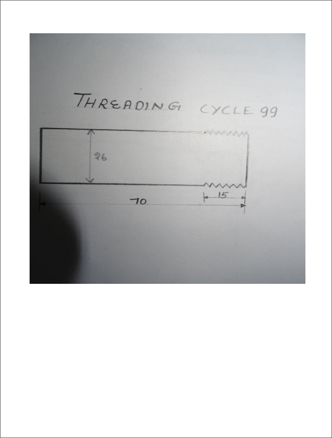
Threading External (Using threading cycle 99)
Part
program
ORTHREADING
Description(file name)
Work
piece--
Cylinder-
XA
26
Dia. of work piece
ZA
0
Start- point in Z axis
ZL
-70
total length work piece
ZB
-40
machining length
2
G71 G95;
Metric unit , feed / revolution
3
G75 X0 Z0;
Going to home position
4
T5 D1;
Tool Change position no.1
5
MO3 S1000;
Spindle speed clockwise
6
G00 X26ZF.1;
Rapid tool movement
Threading
(Cycle99)
Table
ISO
Metric
select
M 10
Select table value
P
1.5
pitch
Machining
▼+▼▼▼
Roughing & Finishing
Linear
External
X
26
Reference point X for thread
Z
0
Reference point Z for thread
ZI
-15
length of thread
LW
2
Thread advance distance
LR
0
Thread run out distance
HI
0.919
Height of thread
αP
30˚
Slope angle of thread
DI
0.1
In feed depth of cut
U
0.01
Finishing allowance
NN
4
No. of idle pass after thread
VR
1
Return safety distance
Multiple
No
Starting No. of thread
α θ
0.000
Starting angle of thread
Accept
7
G75 X0 Z0;
Going to home position
8
M05;
Spindle stop
9
M30
23
24
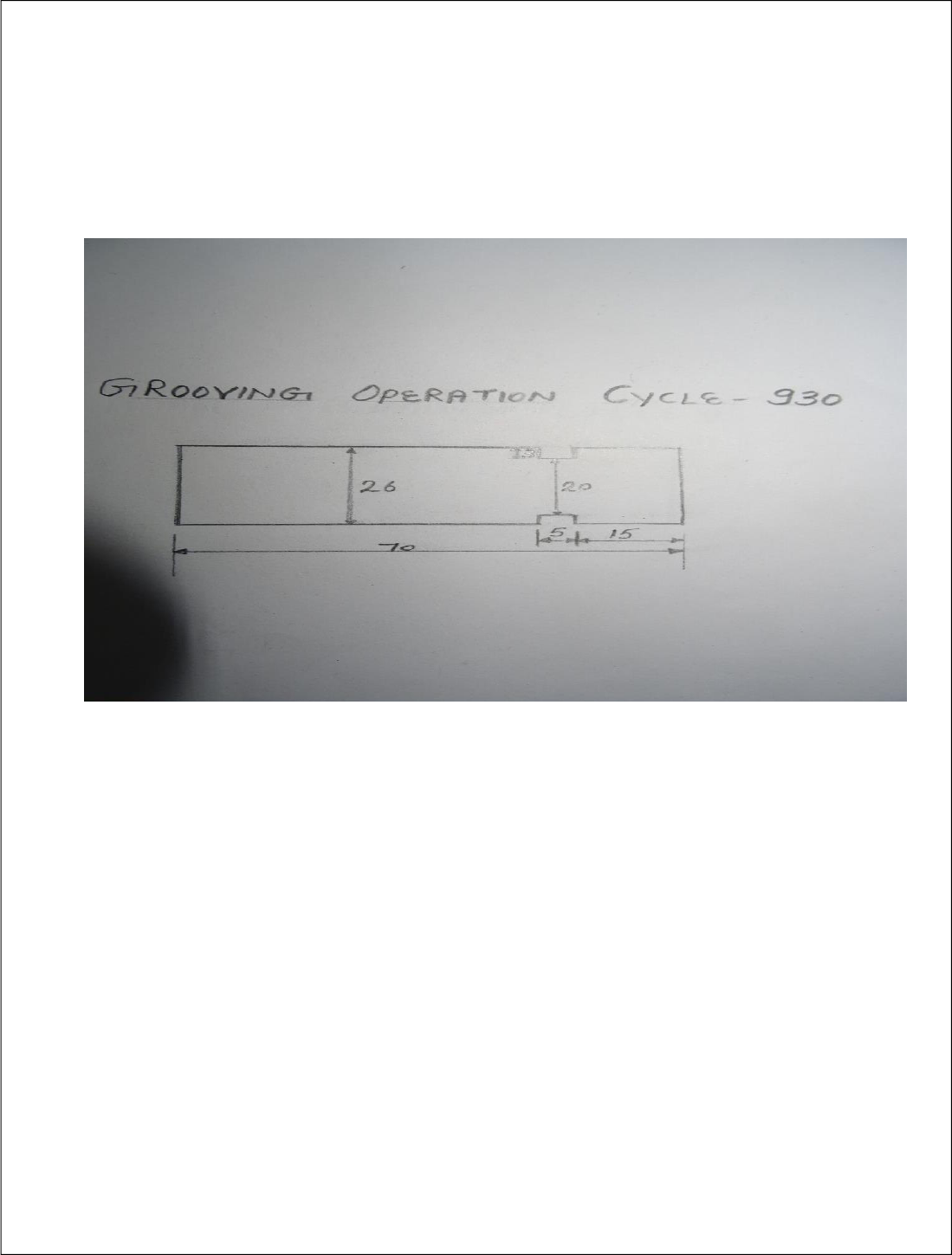
Grooving (Using grooving cycle 930)
Part
program
GROOVING
Description(file name)
Work
piece
Cylinder
XA
26
Dia of work piece
ZA
0
Start- point in Z axis
ZL
-70
total length work piece
ZB
-40
machining length
2
G71 G95;
Metric unit , feed / revolution
3
G75 X0 Z0;
Going to home position
4
T7 D1;
Tool Change position no.1
5
MO3 S1000;
Spindle speed clockwise
6
G00 X26 Z-20F.1;
Rapid tool movement
8
Grooving
(Cycle 930)
SC
2.00
Safety distance/clearance
F
.1
feed mm/ revolution
Machining
▼+▼▼▼
Roughing & Finishing
Pos.
1. Position of machining
2. Reference point
X0
26
Reference point X
Z0
-15
Reference point Z
B1
5
Groove width
T1
20
Un machined up to groove
D
.5
Depth of each cut
UX
0.1
Finishing allowance of X axis
UZ
0.1
Finishing allowance of Z axis
N
01
No. of groove
Accept
9
G75 X0 Z0;
Going to home position
10
M05;
Spindle stop
11
M30
Program stop
25
26
Multi function turning
Part
program
MPF/0RMF
Description(file name)
Work
piece
Cylinder
XA
26
Dia of work piece
ZA
0
Start- point in Z axis
ZL
-70
total length of work piece
ZB
-40
machining length
2
G71 G95;
Metric unit , feed / revolution
4
G75 X0 Z0;
Going to home position
6
T1 D1;
Tool Change position no.1
8
MO3 S2000;
Spindle speed clockwise
10
G00 X26 Z3 F.1;
Rapid tool movement
12
Contour call
(Cycle 62)
MFT
Sub program( Name) call
14
Stock
Removal for
turning(Cycle
952)
PRG
OD
Removal prog.name
SC
2.00
Safety distance/clearance
F
.1
feed mm/ revolution
Machining
▼+▼▼▼
Roughing & Finishing
FS
.01
Finishing feed
Longitudinal
Outside
For turning outside
D
0.1
Depth of cut
UX
.020
Finish allowance X-axis
UZ
.020
Finishing allowance Z-axis
DL
0
Dwell time
BL
Cylinder
Select Blank type(job)
XD
26
Datum point X-axis-stock start
ZD
2.0
Datum point Z-axis-stock start
Relief cut
NO
Machine relief cut
Limit
NO
Limit machining area
Accept
16
G75 X0 Z0;
Going to home position
18
M05;
Spindle stop
20
T7D1
Tool Change position no.2
22
M03 S600
Spindle speed clockwise
24
G00X17.5 Z-13F.1;
Rapid tool movement
28
Grooving
cycle (Cycle
930)
SC
2.00
Safety distance/clearance
F
.01
feed mm/ revolution
Machining
▼+▼▼▼
Roughing & Finishing
Pos.
Position of machining
Reference point
X0
17
Reference point X
Z0
-10
Reference point Z
B1
3
Groove width
T1
10
Un machined up to groove
D
.5
Depth of each cut
UX
0.1
Finishing allowance of X-axis
UZ
0.1
Finishing allowance of Z-axis
N
01
No. of groove
Accept
30
G75 X0 Y0
Going to home position

27
32
M05
Spindle stop
34
T5D1
Tool Change position no.3
36
M04 S600
Spindle speed clockwise
38
G00 X17 Z5
Rapid tool movement
40
External
Table
ISO
Threading
select
M 10
Select table value
cycle
P
1.5
pitch
(Cycle952)
Machining
▼+▼▼
Roughing & Finishing
▼
Linear
External-thread
X
17
Reference point X for thread
Z
0
Reference point Z for thread
ZI
-10
length of thread
LW
2
Thread advance distance
LR
0
Thread run out distance
HI
0.920
Height of thread
αP
30˚
Slope angle of thread
DI
0.1
In feed depth
U
0.01
Finishing allowance
NN
2
No. of idle pass after thread
UR
1
Return safety distance
allowance
Multi-pal
No
Starting No. of thread
αθ
0.000
Starting angle of thread
Accept
42
G75X0Y0
Going to home position
44
M05
Spindle stop
46
M30
Program stop
22
E_LAB_A_MFT:
Code (sub prog.+Part prog)
24
G01 X16 Z0
Linear movement
26
G0X17 Z-1
Linear movement
28
G01X17 Z-13
Linear movement
30
G03X21 Z-15 CR=2
Linear movement
32
G01 X25 Z-25
Linear movement
34
G01X26 Z-33
Linear movement
36
M17
Sub program Exit
28
29
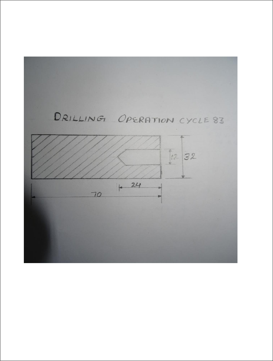
Drilling (Using drilling cycle 83)
Part
program
MPF/ 0R DRILLING
Function
Work
piece--
Cylinder
XA
32
Dia. of work piece
ZA
0
Start- point in Z axis
ZL
-70
total length work piece
ZB
-50
machining length
2
G71 G95;
Metric Unit , feed / revolution
3
G75 X0 Z0;
Going to home position
4
T4 D1;
Tool Change position no.1
5
MO3 S1000;
Spindle speed clockwise
6
G00 X0 Z5F.1;
Rapid tool movement
9
Centering
drill
(Cycle 81)
PL
G17 XY
Machining plane
RP
5.00
Retraction plane
SC
2.00
Safety distance
Z0
0.0
Reference point Z
1. Shank
2. Tip
Select
Drilling depth up to shank
Drilling depth up to tip
Z1
-2
Length of drilling depth
DT
0.00
Dwell time at final depth
Accept
10
G75 X0 Z0;
Going to home position
11
M05;
Spindle stop
12
Going to home position
6
T6 D1;
Tool Change position no.1
8
MO3 S800;
Spindle speed clockwise
10
G00 X0 Z5F.5;
Rapid tool movement
12.
Drilling cycle
(Cycle 83)
PL
G17 XY
Machining plane
RP
5.00
Retraction plane
SC
2.00
Safety distance/clearance
Chip removal
Z0
0
Reference point Z
Shank
select
Drilling depth up to shank
Z1
-24
Length of drilling depth
D
-1.00
1st drilling depth stroke
D1
50.00%
Feed percentage for 1st in feed
DF
100%
Percentage for every further in feed
Lead distance
Automatically / Manually
DTB
0.00 s
Dwell time at drilling depth in
second
DT
0.00 s
Dwell time at final depth in second
DTS
0.00 s
Dwell time for removing chips in
second
14
G75 X0 Z0;
Going to home position
16
M05
Program stop
18
M30
30
31
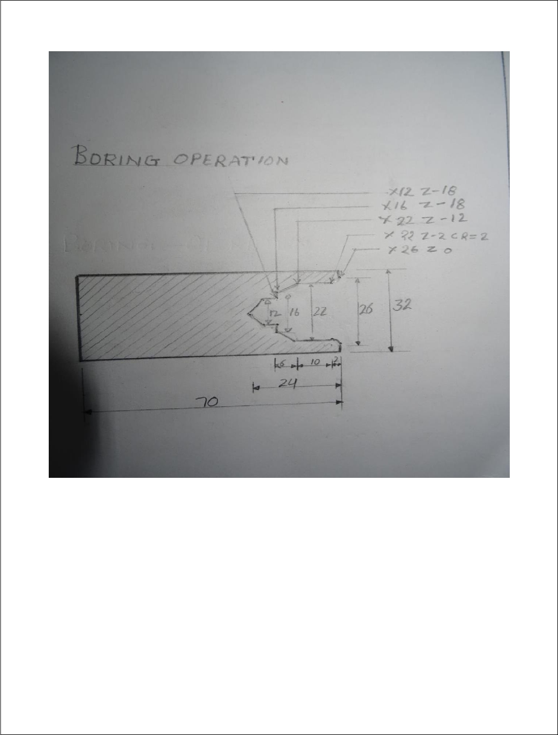
Drilling Boring
Part
progra
m
MPF/0RDB
Function
Work
piece--
Cylinder
XA
32
Dia. of work piece
ZA
0
Start- point in Z axis
ZL
-70
total length work piece
ZB
-40
machining length
2
G71 G95;
Metric Unit, feed / revolution
3
G75 X0 Z0;
Going to home position
4
T4 D1;
Tool Change position no.1
5
MO3 S1000;
Spindle speed clockwise
6
G00 X0 Z5F.1;
Rapid tool movement
9
Centering drill
(Cycle 81)
PL
G17 XY
Machining plane
RP
5.00
Retraction plane
SC
2.00
Safety distance/clearance
Z0
0.0
Reference point Z
1. Shank
2. Tip
Select
Drilling depth related to shaft
Drilling depth related to Tip
Z1
-2
Final drilling depth
DT
0.00
Dwell time at final depth
Accept
10
G75 X0 Z0;
Going to home position
11
M05;
Spindle stop
12
G75 X0 Z0;
Going to home position
6
T6 D1;
Tool Change position no.1
8
MO3 S800;
Spindle speed clockwise
10
G00 X0 Z5F.5;
Rapid tool movement
12.
Drilling cycle
(Cycle 83)
PL
G17 XY
Machining plane
RP
5.00
Retraction plane
SC
2.00
Safety distance/clearance
Chip removal
Z0
0
Reference point Z
Shank
select
Drilling depth up to shank
Z1
-24
Length of drilling depth
D
-1.00
1st drilling depth stroke
D1
50.00%
Feed percentage for 1st in feed
DF
100%
Percentage for every further in
feed
Lead distance
Automatically / Manually
DTB
0.00 s
Dwell time at drilling depth in
second
DT
0.00 s
Dwell time at final depth in
second
DTS
0.00 s
Dwell time for removing chips in
second
14
G75 X0 Z0;
Going to home position
16
M05
Program stop
18
M30
32
20
T2 D1;
Tool Change position no.1
22
MO3 S1500;
Spindle speed clockwise
24
G00 X0 Z5;
Rapid tool movement
26
Contour call
(Cycle62)
BOR
Code name( sub prog.+prog)
Stock
PRG
ID
Removal prog.name
Removal for
SC
2.00
Safety distance/clearance
boring
F
.1
feed mm/ revolution
(Cycle 952)
Machining
▼+▼▼
Roughing & Finishing
▼
FS
.01
Finishing feed
Longitudinal
Inside
RP
0.5
Retraction plane
28
D
0.1
Depth of cut
UX
0.02
Finishing allowance in X-axis
UZ
0.02
Finishing allowance in Z-axis
DI
0.00
Continuous cut
BL
cylinder
Select blank (job)
XD
12
Datum point X-axis-stock start
ZD
2.000
Datum point Z-axis-stock start
Relief cut
NO
Machine relief cut
Limit
NO
Limit machining area
30
G75 X0 Z0;
Going to home position
32
M05;
Spindle stop
46
M30
Contour( sub program) Name
48
E_LAB_A_BOR:
Code (sub prog.+Part prog)
50
G00 X26 Z0;
Rapid movement
52
G02 X22Z-2 CR=2
Linear movement
54
G01X22Z-12
Linear movement
56
G01 X16Z-18;
Linear movement
58
G01 X12Z-18
Linear movement
60
M17
Sub program Exit
33
