SensorView Manual
Page 1 of 123
Using SensorView
SensorView provides a large variety of configuration options to fine tune the connected nLight
network. This section covers common configuration and management tasks that arise when setting up
and maintaining the network over time; as well as step by step instructions for accomplishing a given
task.
The Device Tree: The Device Tree is the foundation for navigating through SensorView and easily
locating a specific device, profile, etc. It is always located in the far left side of the screen, and works in
the same fashion as standard collapsing menus do in other programs. Select which feature of the Device
Tree you wish to learn more about
Device Tree Overview
Tree Layout
Search / Filter / Locate Device
View Device State
View Device Status
Selecting Multiple Devices
FloorPlan: A feature providing a visual layout of the space for the purposes of device and zone selection
and interaction. Contact us to have a layout produced for your nLight installation.
Once a layout is produced and you have received the layout (.mvdb) file, it can be imported into
SensorView by going to Admin > Map and clicking the “Import” button, then browsing to and selecting
the file.
Software and Firmware Updates
Updating Sensorview: This process walks you through upgrading to the latest version of
SensorView, and ensures you are running on the latest build, including the newest patches,
compatibility fixes, and features. This process can only be run by authorized administrators of
SensorView’s host machine, they cannot be performed via the web interface.
Updating Device Firmware: Each nLight device has internal software that can be updated,
usually to add new functionality. This process will ensure your devices are all running on up-to-
date firmware, and can only be performed by authorized nLight network administrators.
Common Procedures: The menu items on the left are the procedures most commonly asked about using
SensorView. If a procedure you are trying to perform is not included in this list, please contact us at
[email protected]om and we will look into adding it for future revisions.
Logging in
Administrative Tasks
o Creating Users
o Modifying Users
o Gateway Page
o Location Page
View Device Properties
Viewing / Editing Device Settings
o Normal Devices
o Scene Selectors / nIOs
SensorView Manual
Page 2 of 123
Viewing / Editing Zone Settings
Managing Profiles
o Create a Profile
o Edit a Profile
o On Demand Profiles
o Delete a Profile
View Reports
Upgrading Devices
SensorView
Step 1: Requirements
Step 2: Pre-Installation
Step 3: Installation
Step 4: Connecting to Gateway
Virtual Wallpods
Configuring SensorView
o Update SensorView
o Virtual Wallpod Server
o Virtual Controls
o Virtual WallPod Switch
o Control Zone
Virtual WallPod Application
iOS App
GreenScreen
Setting up PostgreSQL
Setting up Database Connection
Setting up GreenScreen
SensorView Page Mapping
Overview
Log
[DA1]
Green Screen
Admin: The Admin tabs are for administrators only, and will not be accessed by a day to day end user.
Setup
Updates
Databases
Plugins
Reports
SensorView Manual
Page 3 of 123
Navigation Tabs: Across the top of all pages within SensorView are the Navigation Tabs. Depending on
a user’s permissions only some of these may be available. To learn more about each tab, click from the
list below:
Devices
Control Channels
o Local Channels
o Global Channels
Group Settings
Profiles
Schedules
Users
Glossaries
SensorView Terms
Status Icons
SensorView Manual
Page 4 of 123
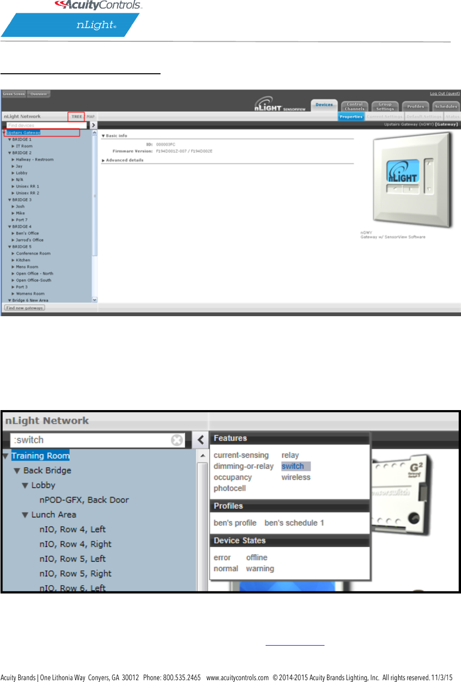
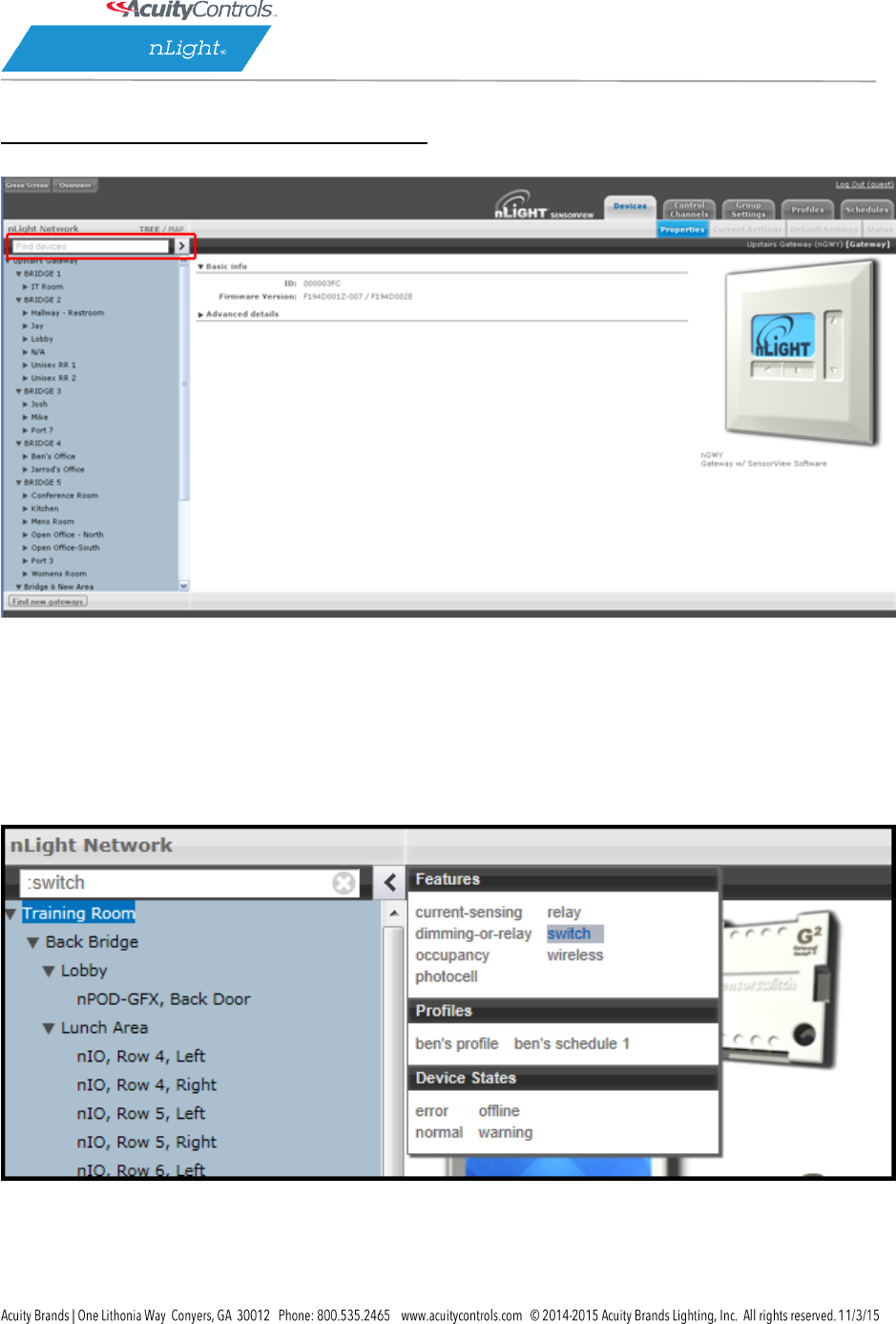
Device Tree Overview
The Device Tree Menu, available from the arrow to the right of the search textbox, contains selection
features that aid in the location / selection of devices. Three primary types of search features
exist: Features, Profiles, and Device States. Features allows for selecting / searching of the tree based
on predefined characteristics of the device, such as whether it has a relay or occupancy sensor; available
options are: current-sensing, occupancy, daylighting, relay, dimming, switch, dimming-or-relay.
Profiles locates or selects devices that are in a particular profile; this is useful when creating a new
profile that operates on all the devices already in an existing profile. As profiles are added or removed
from the system the contents of this selections will change. Device States allows for searching or
selecting devices depending on their current state.

SensorView Manual
Page 5 of 123
SensorView Manual
Page 6 of 123
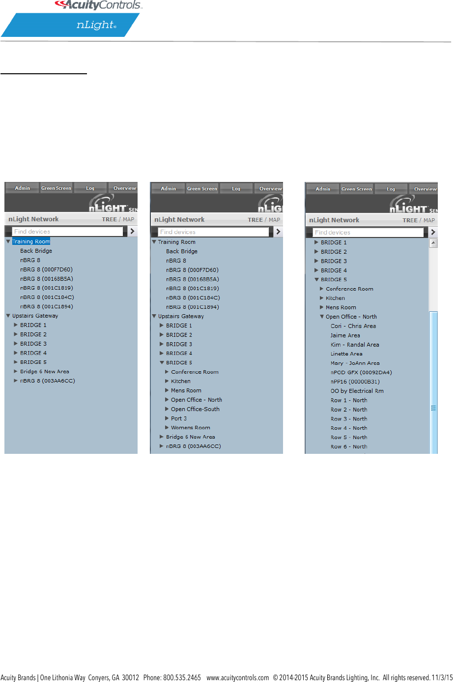
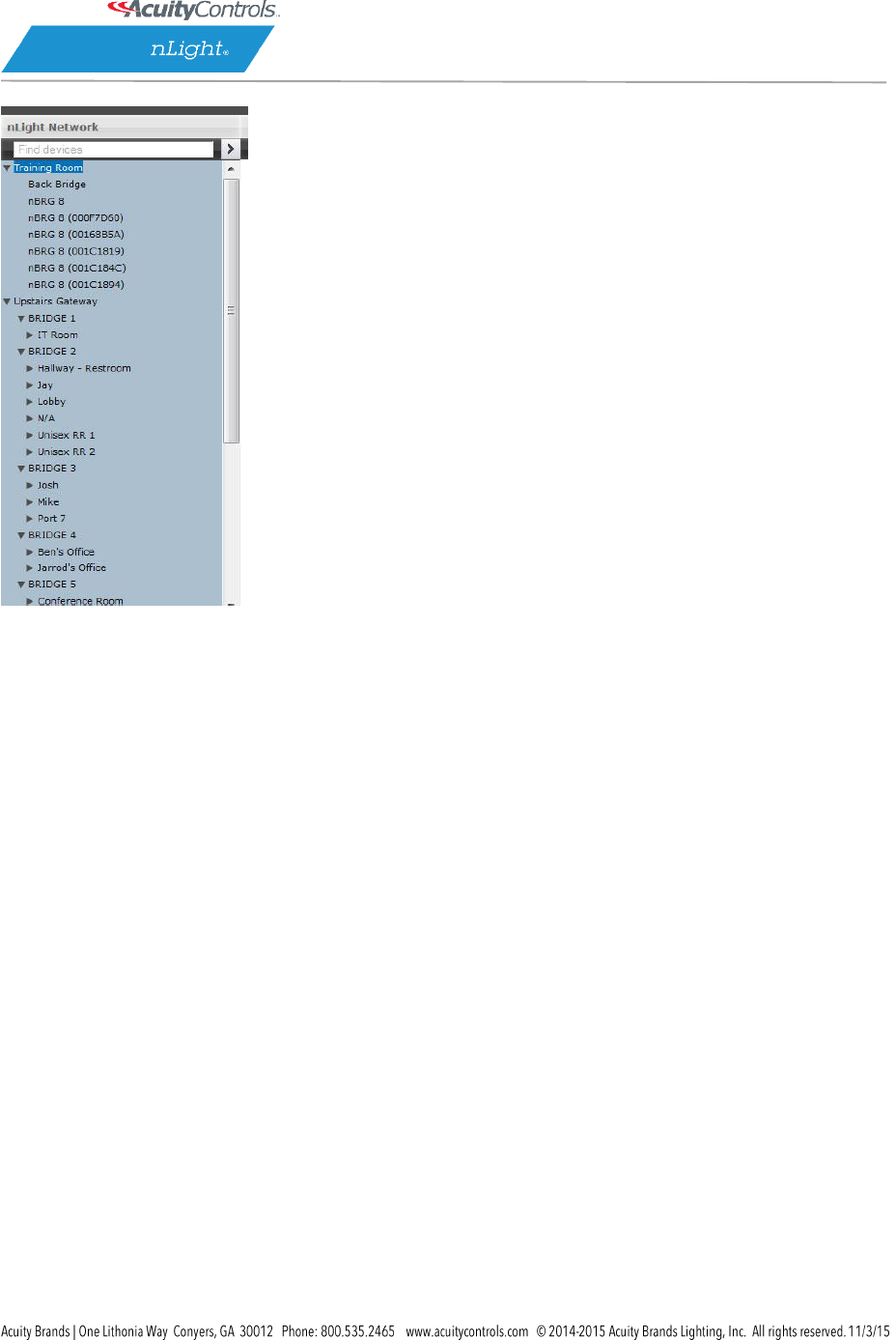
Tree Layout
The layout of the SensorView device tree corresponds closely with the actual wiring of the devices, with
a few notable exceptions:
Bridges are not nested within
their parents
Zones off a bridge are displayed
in ascending alphabetical order
Devices in a zone are displayed in
alphabetical order, not wiring
order
SensorView Manual
Page 7 of 123
Search / Filter / Locate Device
The SensorView tree allows for the user to select or search for devices based on a variety of
parameters. The Device Tree Menu contains numerous options for searching for (“finding”) devices
based on predetermined characteristics (such as device state, or features the device has). The text field
above the device tree also allows for free text search over the devices. A user can type any value into
the field and the tree will automatically begin filtering to display devices with label(s), model(s), or
device ID(s) matching the entered value(s).
There are two primary ways to quickly locate a device: use the device Search, or the prebuiltFeatures.

SensorView Manual
Page 8 of 123
1. Device search (filter) allows a user to immediately begin typing to search for the device (over
device ID, model, or custom label), while
2. Features allows for a user to search for a device based on its
o Hardware capabilities:
current-sensing, dimming-or-relay, occupancy, photocell, relay, switch, wireless
o Profiles
Select by Profile name
o Device state
error, normal, offline, warning
Note that any device matched and displayed will automatically cause the parent zone, bridge, and
gateway to be displayed. When operating in MultiSelect (link) mode, clicking on the parent nodes will
select all the currently visible child nodes, and will omit the ones that have been filtered out.
SensorView Manual
Page 9 of 123
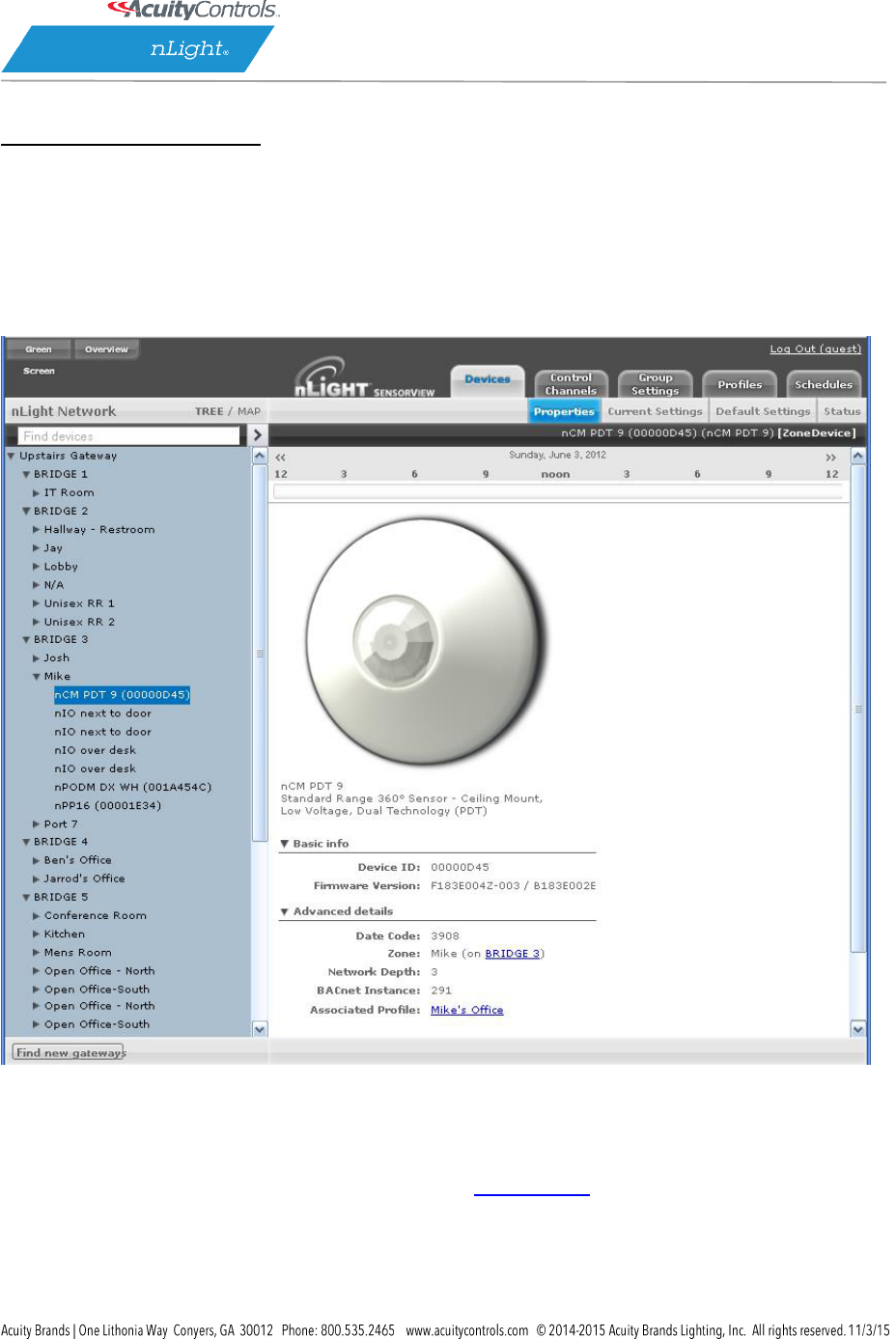
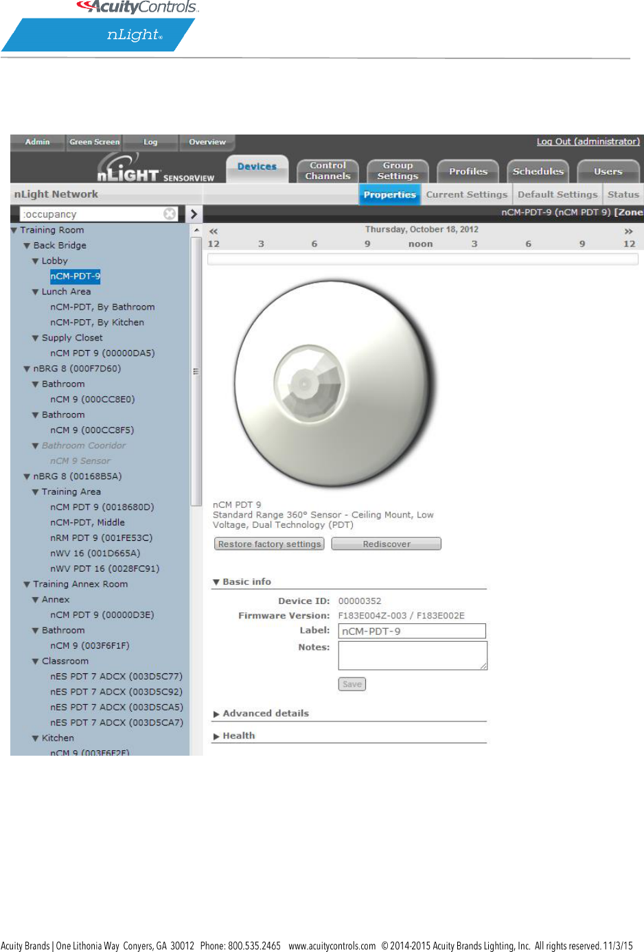
View Device State
For any device selected from the Device Tree (left), SensorView displays data in real time by selecting
one of the available tabs: Properties, Current Settings, Default Settings, and Status. This example shows
the readings from one of the nLight Ceiling-Mount, Passive Dual-Technology sensors covering
approximately an area of 9 meters in diameter (nCM PDT 9) in the Zone called “Mike”, which has been
selected from the device tree menu.
There are 6 possible states that an nLight device can be in. These different generally indicate some sort
of operational problem with a device.
Note: “Device State” (shown below) is not the same as Device Status. Individual device types can have
various “status” conditions, depending on their functions.
Offline – The device is no longer online, check that the device is properly connected

SensorView Manual
Page 10 of 123
Out of Range – The device is online, but communication is restricted due to insufficient signal
strength. This applies to nWiFi devices only. Signal strength for wireless may vary under certain
conditions. Devices downstream from an nWiFi device may also appear Out of Range, if the
parent is.
Bootstrap – The device failed a firmware update and is in bootloader. Any relay or dimming
output will be toggled on, but the device will not respond to any operational changes. Update
the device to resolve this.
Misread – Some properties of the device were not read by the gateway. To resolve state, go to
the device and select “Rediscover” or use Group Select->Rediscover
Incompatible – SensorView is not compatible with this device and is unable to configure it.
Upgrade the device to resolve this.
Mismatched – SensorView has detected that the devices’ settings do not match what is
expected. Synchronize the device (either using SensorView or device’s settings) to resolve.
SensorView Manual
Page 11 of 123
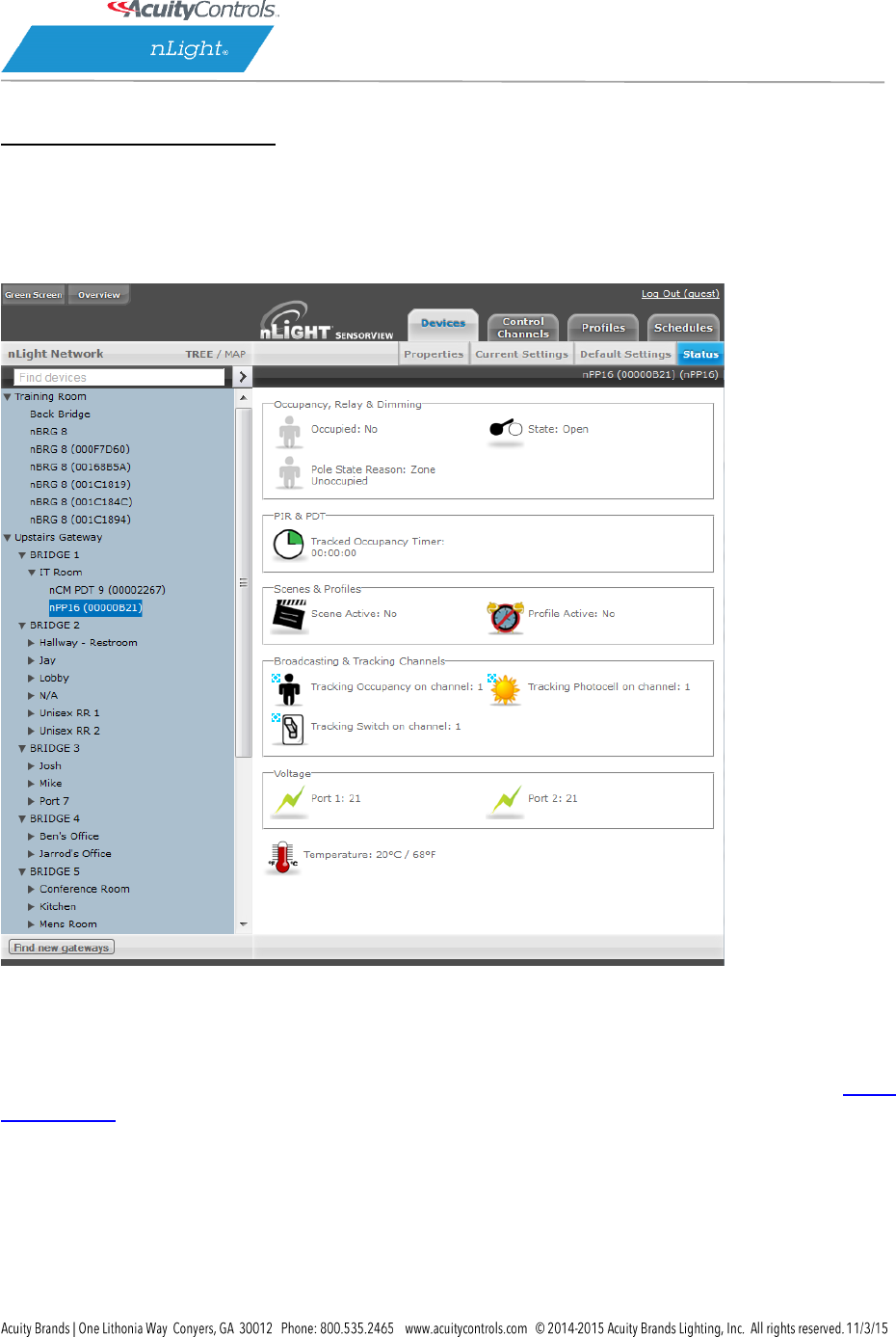
View Device Status
The Status Screen displays the present state of any device selected in the left tree menu. Device types
have different functions. The status pages display parameters specific to the type of device selected,
indicated by icons easily seen at glance.
The current state of the device for each parameter (icon) is also displayed in readable text, which may
include additional information on the particular status of the parameter within the selected device.
For a complete guide to Status Icons or possible conditions for a given device parameter, visit the Status
Icon Glossary.

SensorView Manual
Page 12 of 123
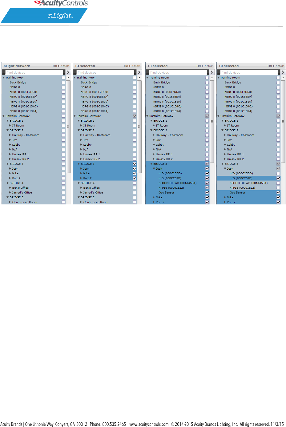
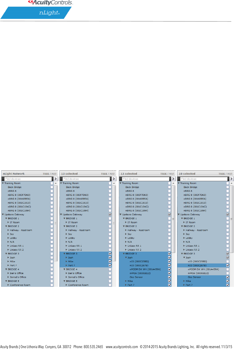
Selecting Multiple Devices
In certain contexts the Device Tree will allow for users to select multiple devices, rather than just
one. This mode of selection is available on Group Settings, Profiles, Global Channels, or Users. This
mode of selection greatly enhances the ability to quickly create system schedules, permissions, or make
wholesale changes to device settings.
To select multiple devices:
Check multiple boxes, each new device will be added to the selection. Checking a selected
device a second time will remove it from the grouping.
Check a Zone / Bridge / Gateway to select all of the devices within that group. Check that
grouping structure a second time to deselect all devices within that Zone / Bridge / Gateway
group.
SensorView Manual
Page 13 of 123
Selecting multiple devices is useful when large amounts of devices are to be operated on
simultaneously. Profiles, Users, Group Settings and Global Channels all support multiple device
selection. All other modes operate in single select, such that selecting any item in the tree displays
information specific to that device.
SensorView Manual
Page 14 of 123
None Selected
(empty Checkboxes)
Bridge Selected
(Parent gateway
checked in gray)
Zone expanded.
All zone devices checked
Specific zone devices
unchecked
SensorView Manual
Page 15 of 123
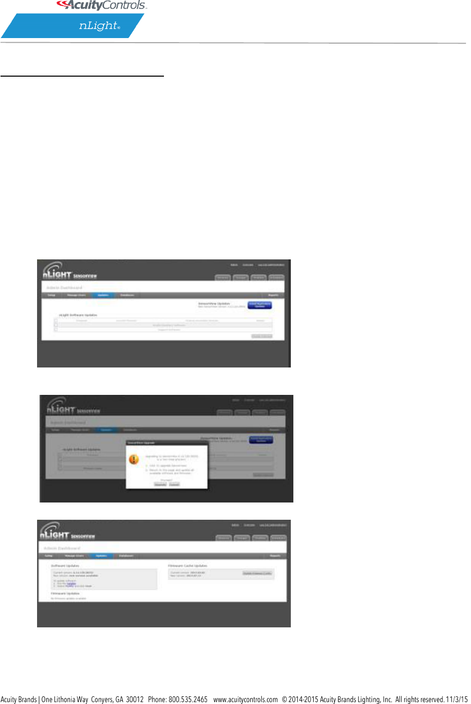
Updating SensorView
Please note that the following procedure must be done from the SensorView host computer, and cannot
be initiated over the web; administrator credentials on the host are also required.
Note: Always retrieve the latest installer to perform the actual update, on occasion SensorView updates
will require subsequent device updates, should this occur the installer will warn you before proceeding
with the update.
Depending on the currently installed version of SensorView the steps to update the software may vary,
for all versions less than 7.0, follow steps A and B. Otherwise, proceed to step B.
A. Updating to 6.14:
1. Visit Updates page in SensorView & initiate upgrade to 6.12.xx:
2. Return to the Updates page & initiate upgrade to 6.14.xx.
3. Return to Updates page & run all available updates on firmware:
4. Return to Updates page & follow instructions to update to 7.x.x:
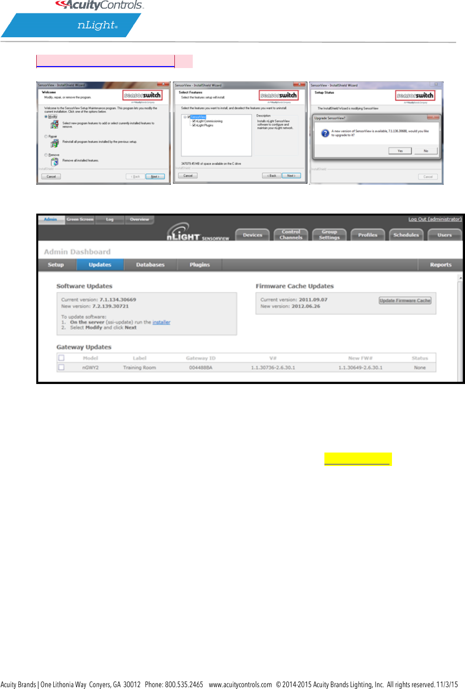
B. Updating to the latest version:
SensorView Manual
Page 16 of 123
1. Download SensorView installer
[DA2]
and run Setup.exe
2. Select Modify when offered and follow the prompts.
3. Return to Updates page & run all available firmware
updates.
Downgrading to Version 6.12.x
If you need to return to SensorView Version 6.12 for any reason, run the 6.12.x installer. Note that you
will have to uninstall the current version of SensorView beforehand.
SensorView Manual
Page 17 of 123
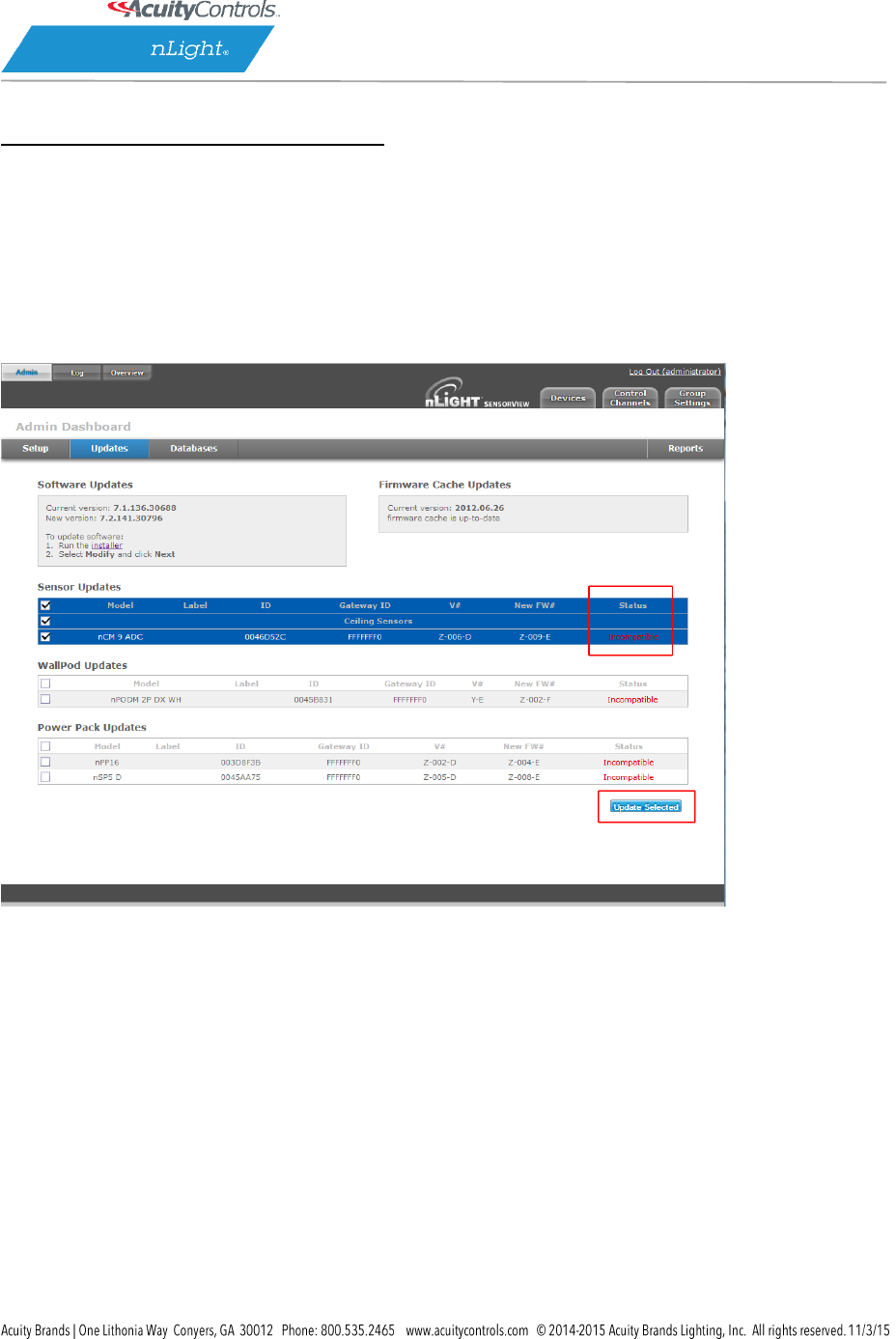
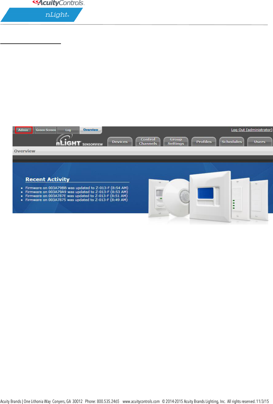
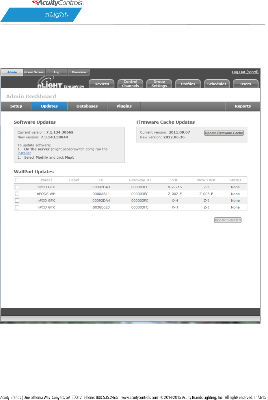
Updating Device Firmware
Select the Admin button at upper left, then select the Updates tab to view all available
updates. Devices will be omitted from the listing if they are currently up to date.
SensorView will retrieve the latest firmware for each device from the internet. If you are not going to
have internet then download and install the firmware cache (top right), which will allow firmware
updates to be performed offline.
The status of the update is displayed in the rightmost column of the blue Status bars, and also at the top
center of the screen:
1. Status: Pending while “Preparing to update firmware …“
2. Status: In Progress while “Updating firmware: X% done“
3. Status: Completed Fast when “100% Done“
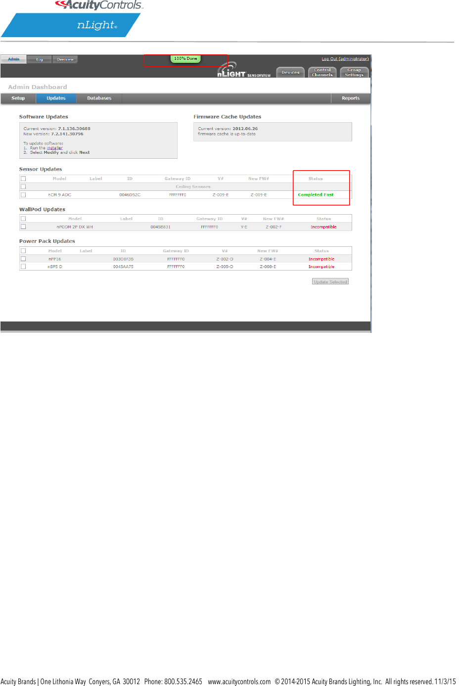
While firmware is being updated by the system, the actual physical device will display a very fast blink of
its green status light, as well as closing relays and dimming to full bright, as appropriate. As the process
nears completion, the device will display a slow, blinking pattern. After a few minutes, the device status
light will return to normal.
SensorView Manual
Page 18 of 123
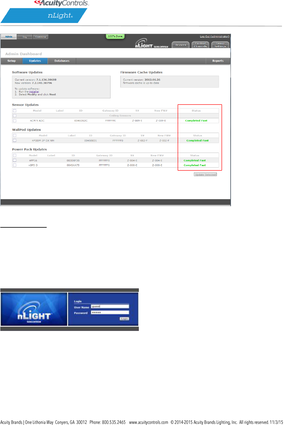
Repeat this process for all devices by selecting any and all (at once) which require firmware updates.
When all devices have been updated, the red Incompatible conditions on the screen will be replaced
by Completed Fast.
SensorView Manual
Page 19 of 123
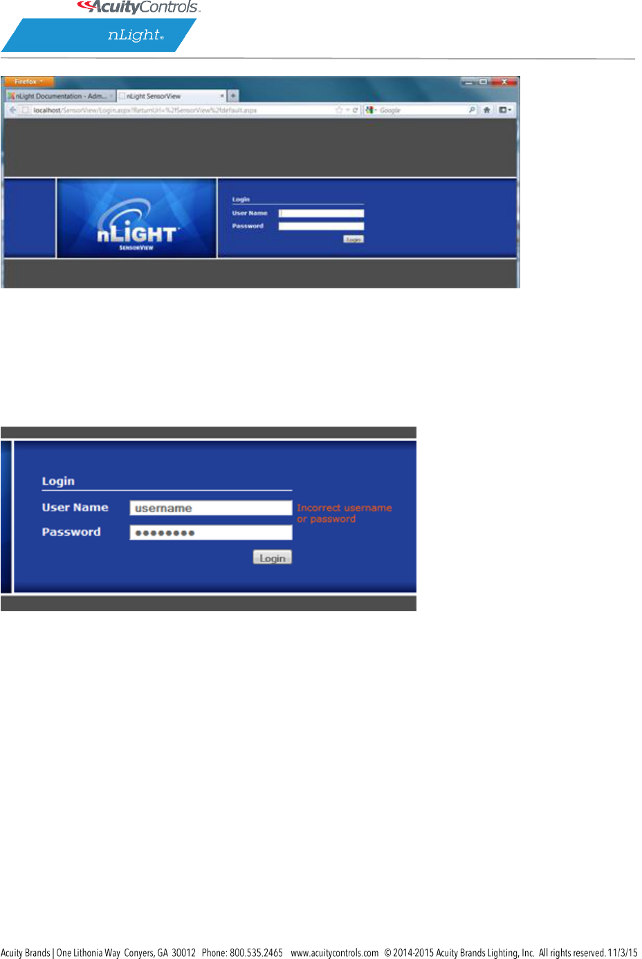
Logging in
Navigate to the SensorView login screen via the Start Menu, desktop shortcut, or by directly typing the
address into the web browser (note: address requires entering the Host Specific Computer Name, which
is installation specific):
http://<Host Computer Name>/SensorView
Enter your case sensitive username and password. Default login is:
Username: administrator
Password: admin
If you have forgotten or do not have your login information, please contact your network administrator.

SensorView Manual
Page 20 of 123
SensorView Manual
Page 21 of 123
Administrative Tasks
Only administrative users have authority to perform these tasks, which involve modifying / creating
users, as well as modifying properties on the Gateway & Location pages.
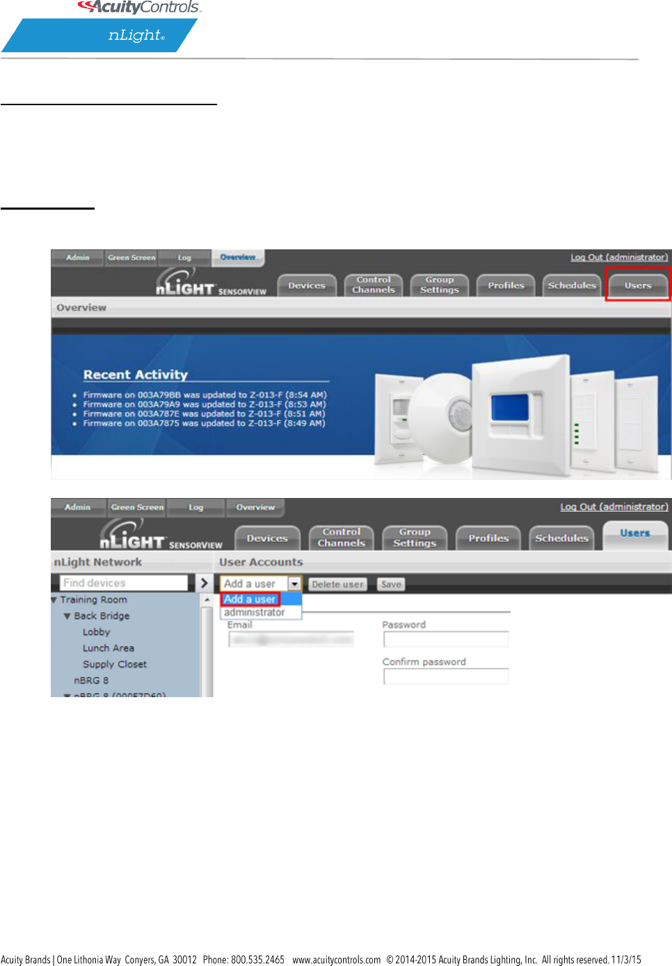
Creating:
1. Click the Users tab
2. Select Add a User from the dropdown
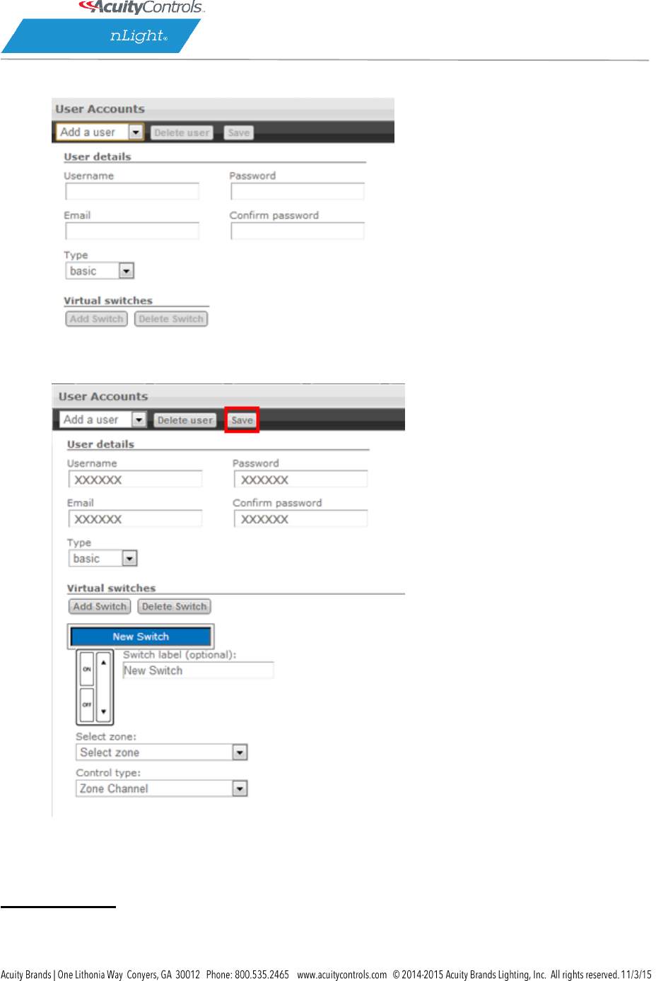
SensorView Manual
Page 22 of 123
3. Fill out all fields, making sure to set the appropriate access level.
4. Click Save
Modifying:

SensorView Manual
Page 23 of 123
1. Click the Users tab
2. Select user from the dropdown
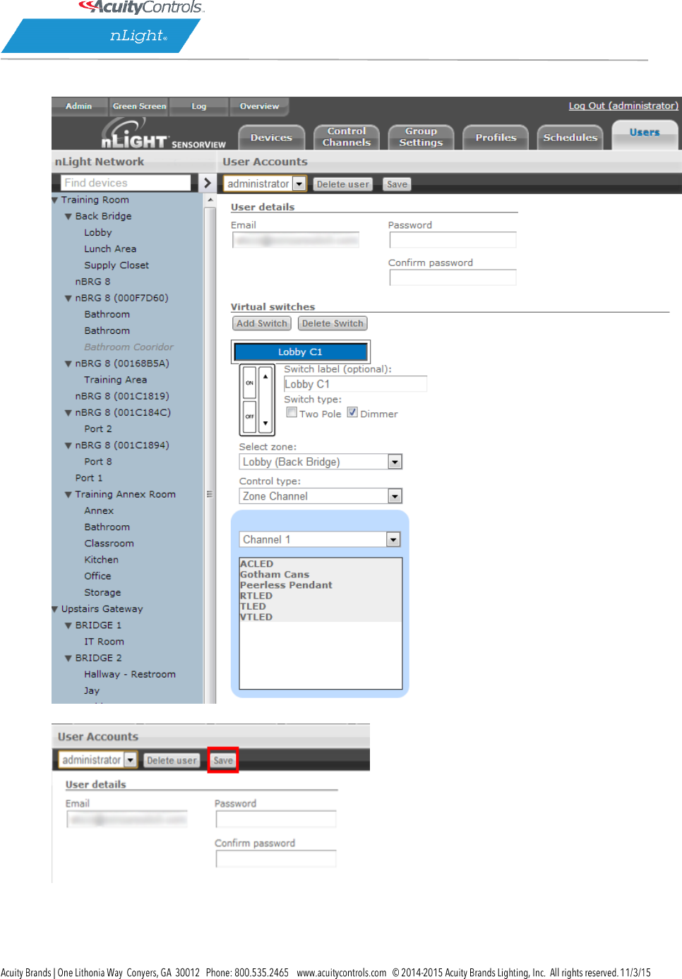
SensorView Manual
Page 24 of 123
3. Change the appropriate information
4. Click Save

SensorView Manual
Page 25 of 123
SensorView Manual
Page 26 of 123
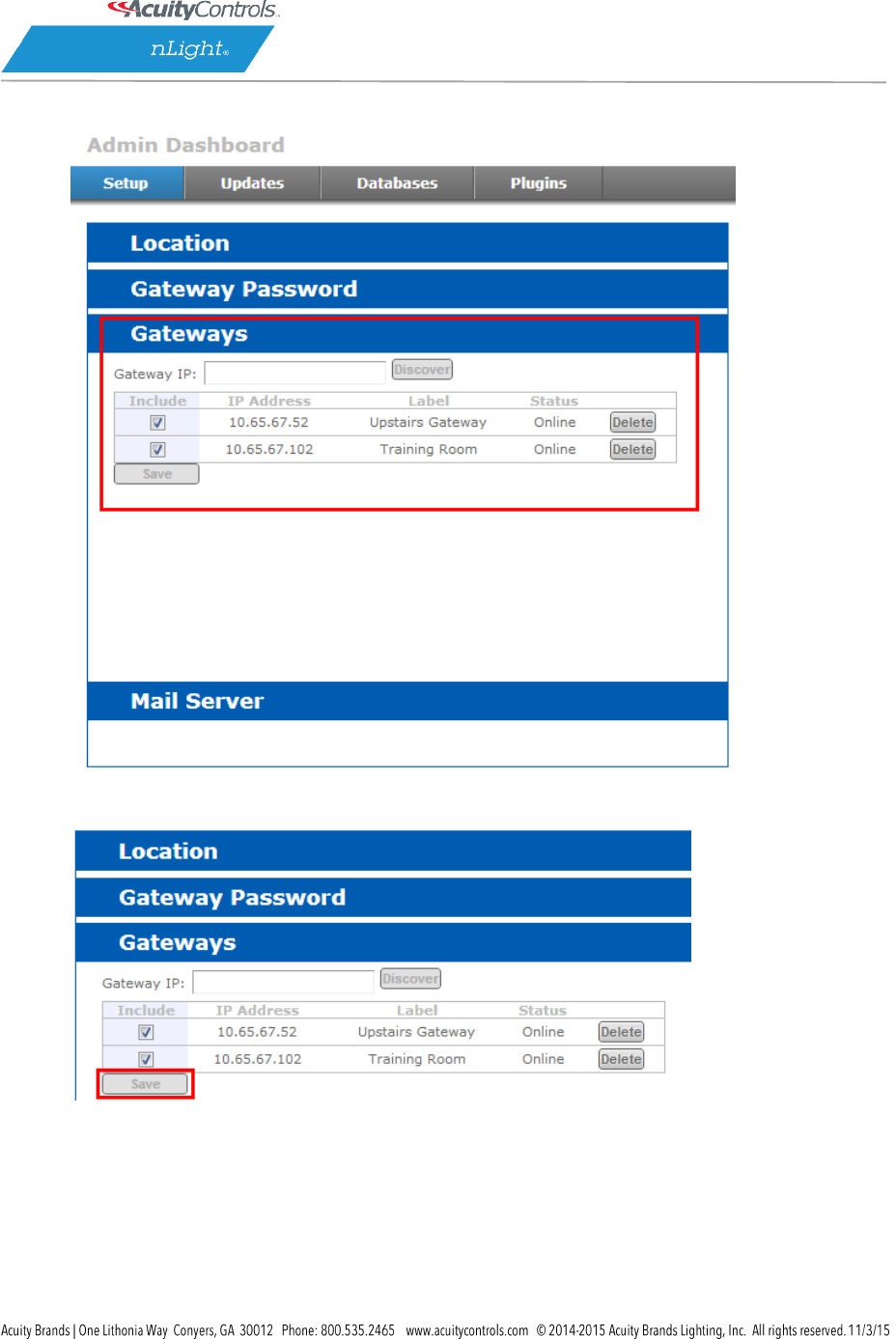
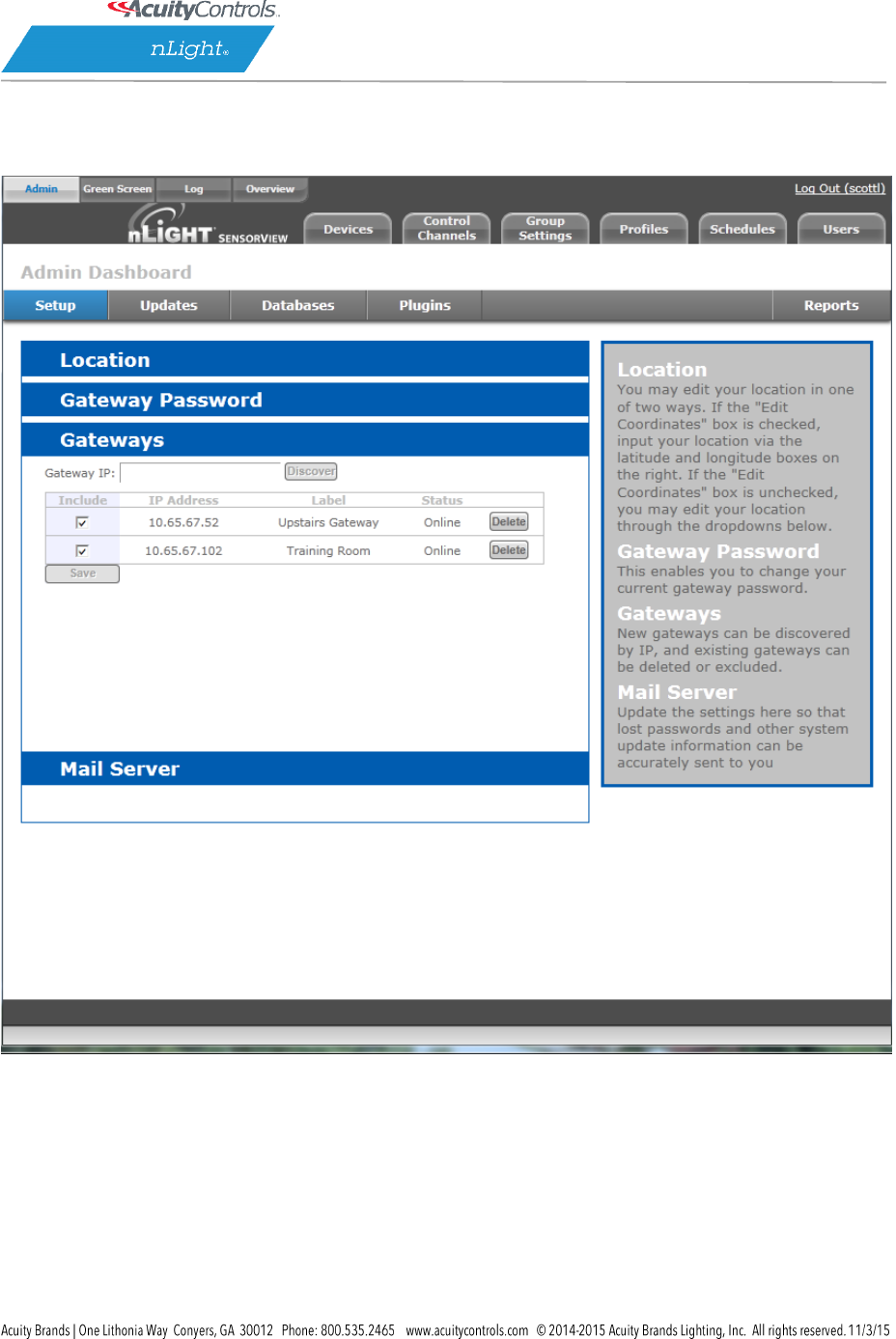
Gateway Page
The Gateways tab allows operators to manage the nGWY devices that are currently managed by
SensorView. nGWY devices running on the same IP Subnet will be discovered automatically by
SensorView; any nGWYs that reside on different segments of the IP network can be added by simply
entering their IP address on the Gateways tab.
Note: Discovering nGWY devices on different segments of the IP network may require for firewalls and
routers to be updated to allow access to the necessary ports.
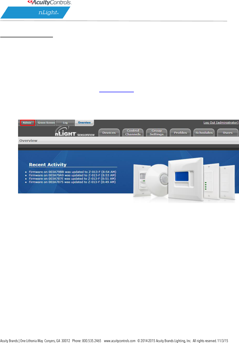
Including / Excluding Gateways:
1. Click the Admin tab
SensorView Manual
Page 27 of 123
2. Click the Gateways section to expand it
SensorView Manual
Page 28 of 123
3. Make any changes to the existing list, such as whether or not to include a particular Gateway
4. Add IP addresses of any required Gateways not auto-detected (requires IP address).
5. Click Save to apply your changes
SensorView Manual
Page 29 of 123
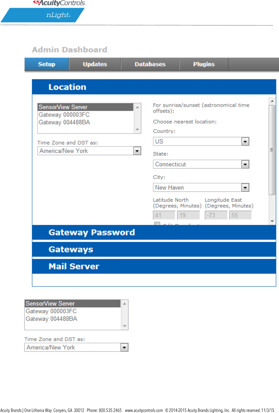
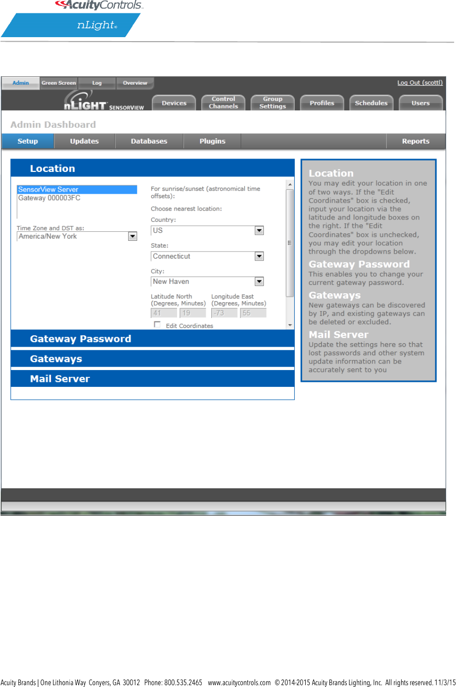
Location Page
Properly configuring the location for all nGWY devices and the SensorView host is required to ensure
that all profiles will run at the proper time. Setting the time zone allows the nGWY devices to properly
update their time throughout the course of the year as Daylight Savings Time comes into effect. The
location parameters allow the nGWY devices and SensorView to properly compute the correct Sunrise
and Sunset times for a given day.
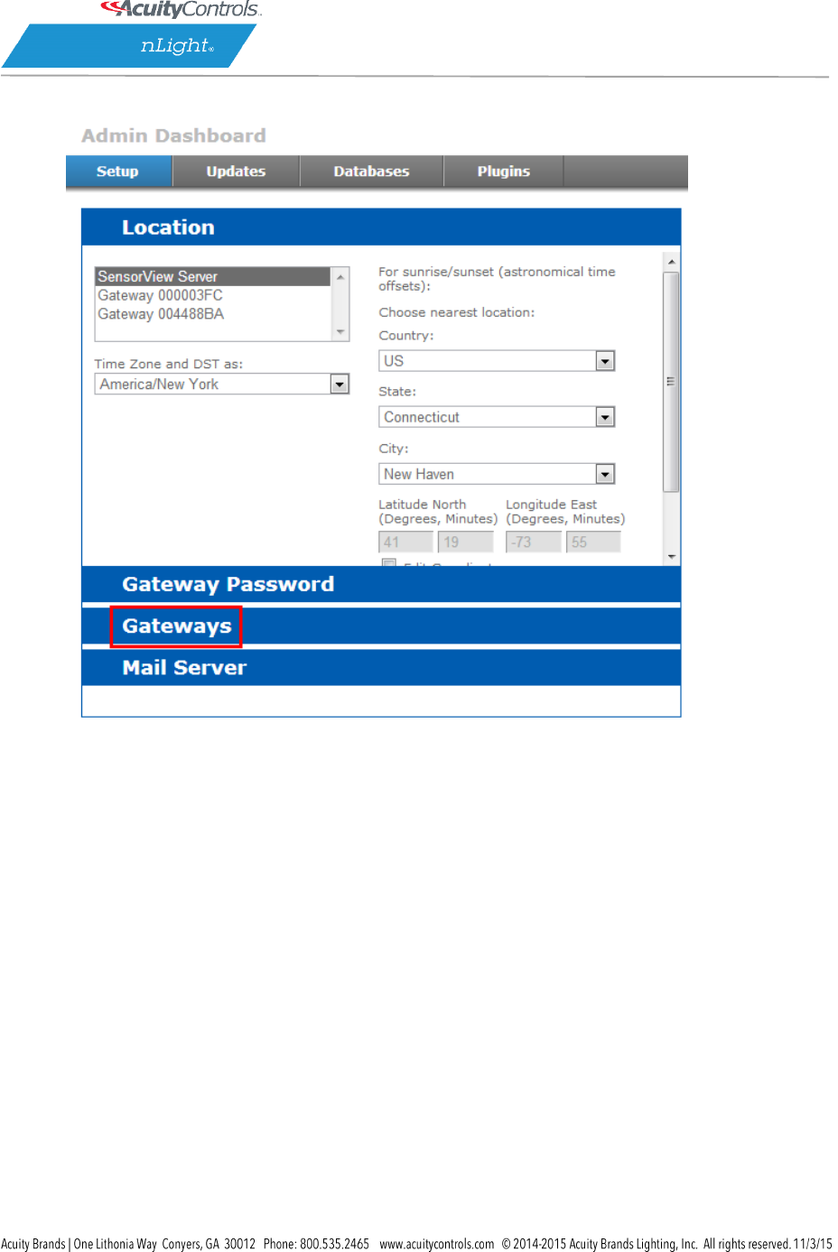
Viewing/Editing Gateway & Server Locations:
1. Click the Admin tab
SensorView Manual
Page 30 of 123
2. The Setup tab should automatically load with the Location section expanded
3. Click the Server or Gateway you wish to edit
SensorView Manual
Page 31 of 123
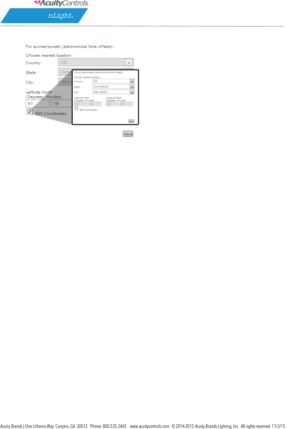
4. Uncheck the Edit Coordinates box to edit the Country/State/City fields
5. Click Save to apply your changes
SensorView Manual
Page 32 of 123
View Device Properties
1. Click the Devices tab
SensorView Manual
Page 33 of 123
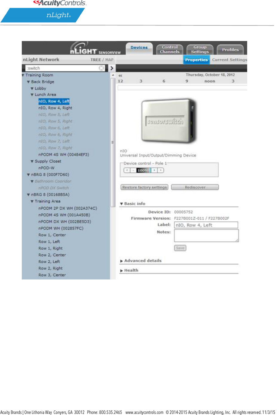
2. Using the nLight Network tree to the left, find the device you wish to view
SensorView Manual
Page 34 of 123
3. Click the desired device; the properties will populate the Devices area to the right
4. Change the Label, Notes, and other areas to your requirements
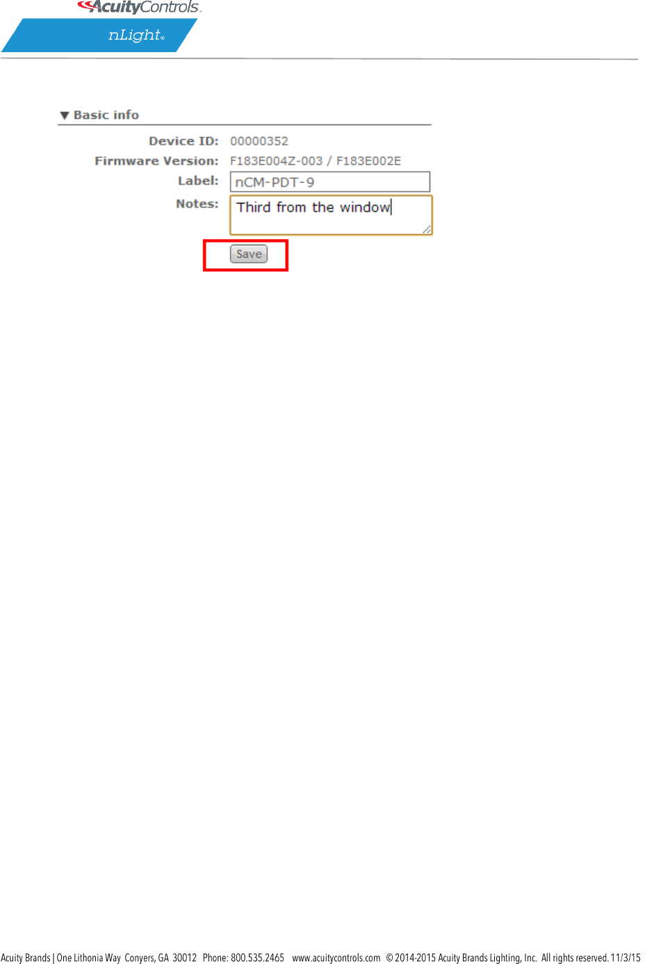
SensorView Manual
Page 35 of 123
5. Click Save to apply your changes
SensorView Manual
Page 36 of 123
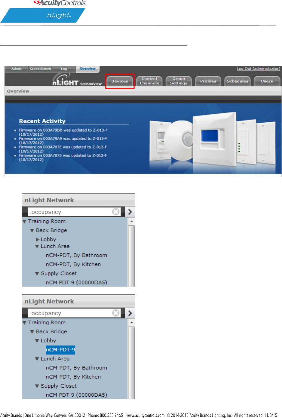
Viewing / Editing Normal Device Settings: Sensors/WallPods/Power Packs
1. Click the Devices tab
2. Using the Device tree to the left, find the device you wish to view
3. Click the desired device
SensorView Manual
Page 37 of 123
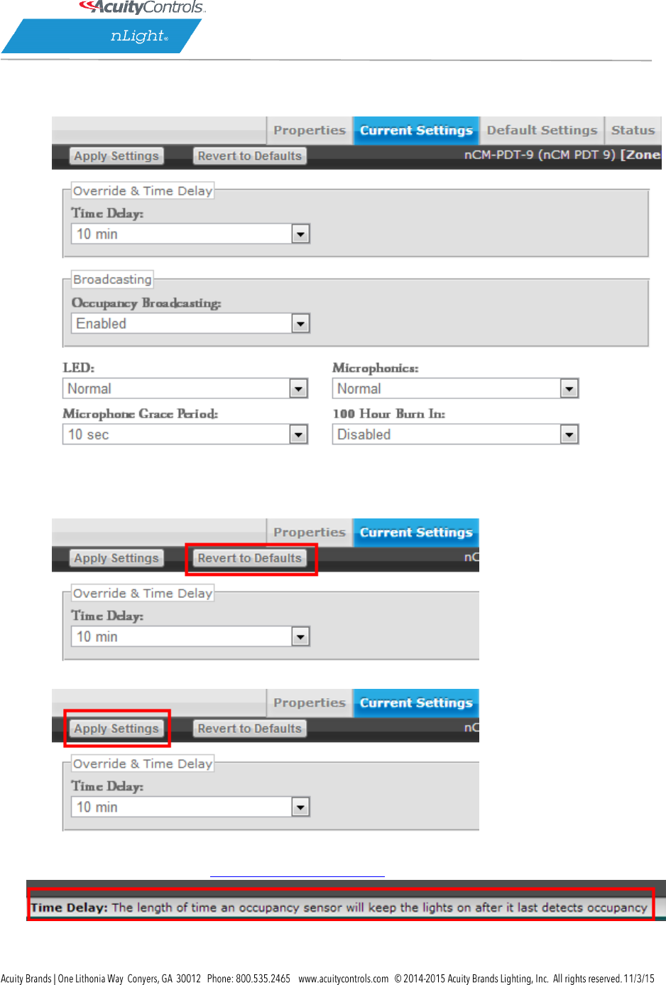
4. Click the Current Settings tab (if it’s grayed out, settings aren’t applicable to the current
selection, & you need to pick another device)
5. Your device’s specific settings (varies from device to device) will show
6. Modify the settings in the dropdown/checkbox fields to your specifications (You may also
revert to device defaults by clicking the button at the top)
7. After you’ve made your changes, click the Apply Settings button to save your modifications
Note: hovering over a setting will cause its definition to appear in the information pane at the
bottom of the page. The SensorView Terms Glossary also lists these definitions.
SensorView Manual
Page 38 of 123
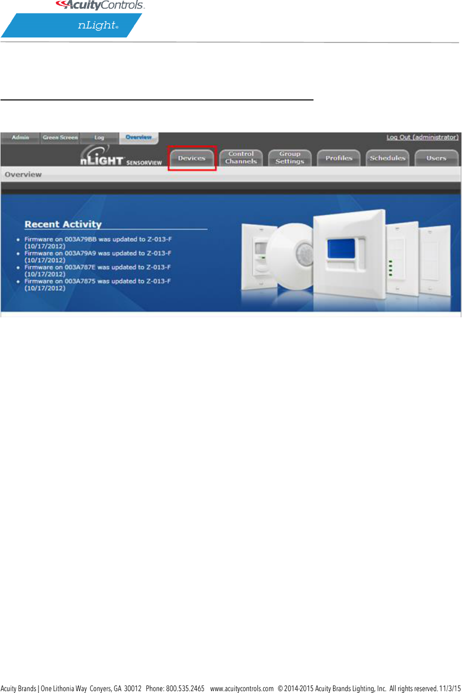
Viewing / Editing Scene Selector / nIO Settings:
1. Click the Devices tab
2. Using the nLight Network tree to the left, find a Scene Selector or nIO

SensorView Manual
Page 39 of 123
3. Click the desired device
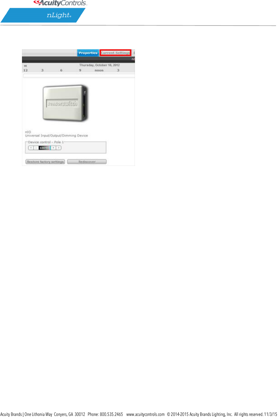
SensorView Manual
Page 40 of 123
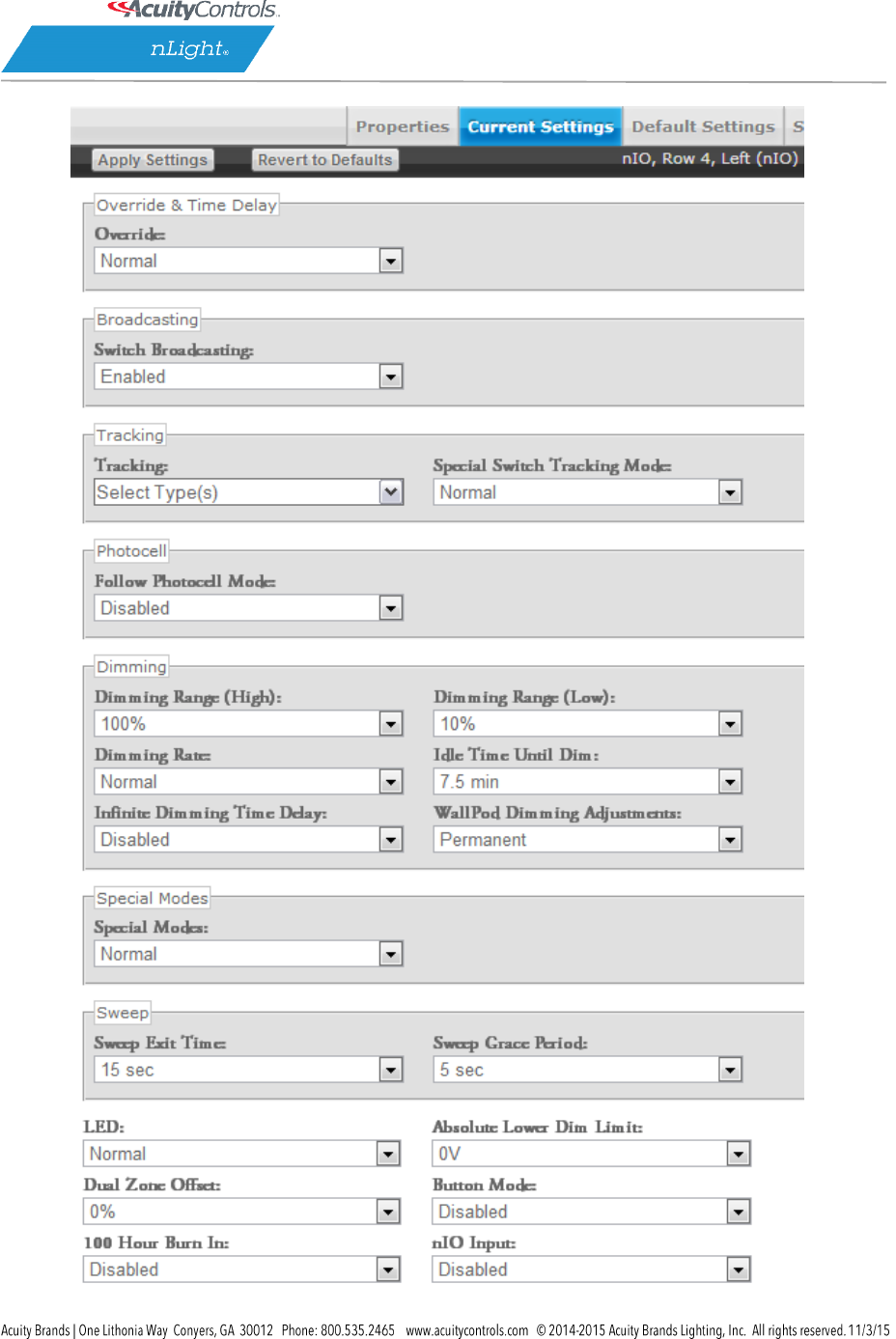
4. Click the Current Settings tab (if it’s grayed out, settings aren’t applicable, & you need to pick
another device)
5. For Scene Selectors, the currently assigned action for each of the four control mode buttons is
displayed. Change settings for each button via the dropdowns. Click Apply Settings to save.
SensorView Manual
Page 41 of 123
SensorView Manual
Page 42 of 123
Control Mode Options (triggered through a button push or nIO input event):
Scene Control – Initiates corresponding scene outlined in Default Settings
Wallpod – On/Off functionality for the associated lights
Sweep – Initiates sweep for the corresponding number in Default Settings
Disabled – Disables the corresponding button
To create Scene Selector / nIO Scenes & Profiles:
1. Click the Devices tab
2. Using the nLight Network tree to the left, find a Scene Selector or nIO
SensorView Manual
Page 43 of 123
3. Click the desired device
SensorView Manual
Page 44 of 123
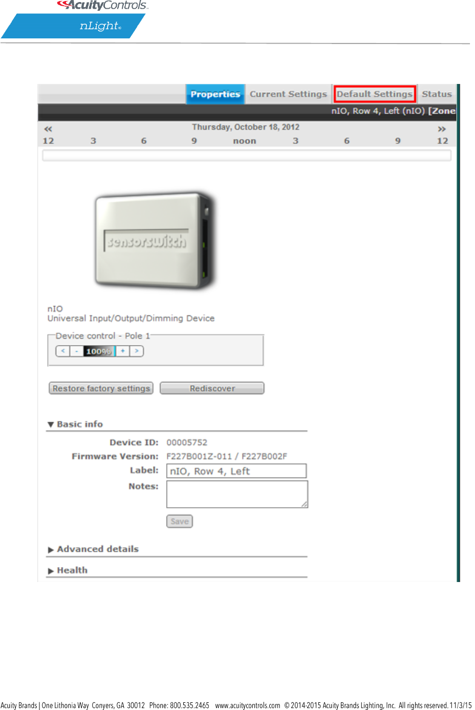
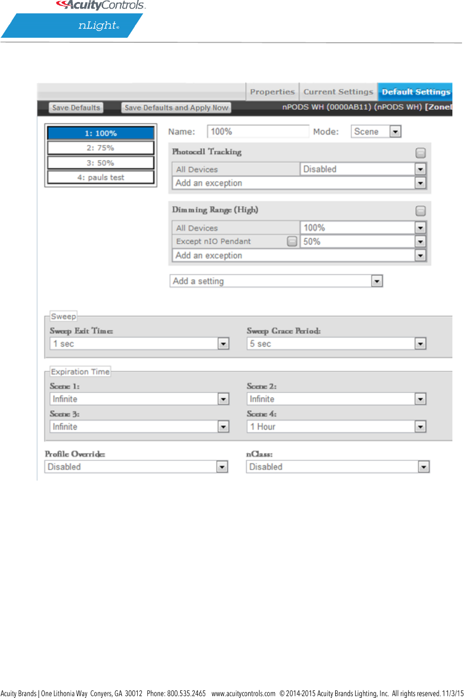
4. Click the Default Settings tab (if grayed out, settings aren’t applicable to the current choice, &
you need to pick a new device)
5. Select a button, type a name to associate with it, then select which mode you wish to run in:
Wallpod – Assigns on/off control to button
Scene – Assigns created scene to button
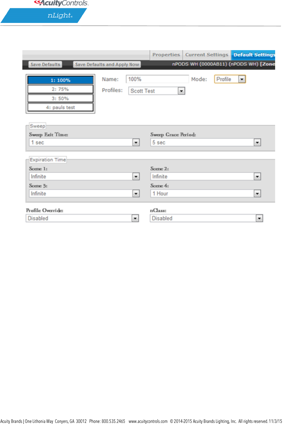
Profile – Assigns an existing profile to button
Sweep – Assigns sweep to selected button
SensorView Manual
Page 45 of 123
For buttons designated with Scene Mode:
Create a scene via the device settings & exceptions dropdowns.
SensorView Manual
Page 46 of 123
For buttons designated with Profile Mode:
Select an existing profile you wish to attach to the selected button.
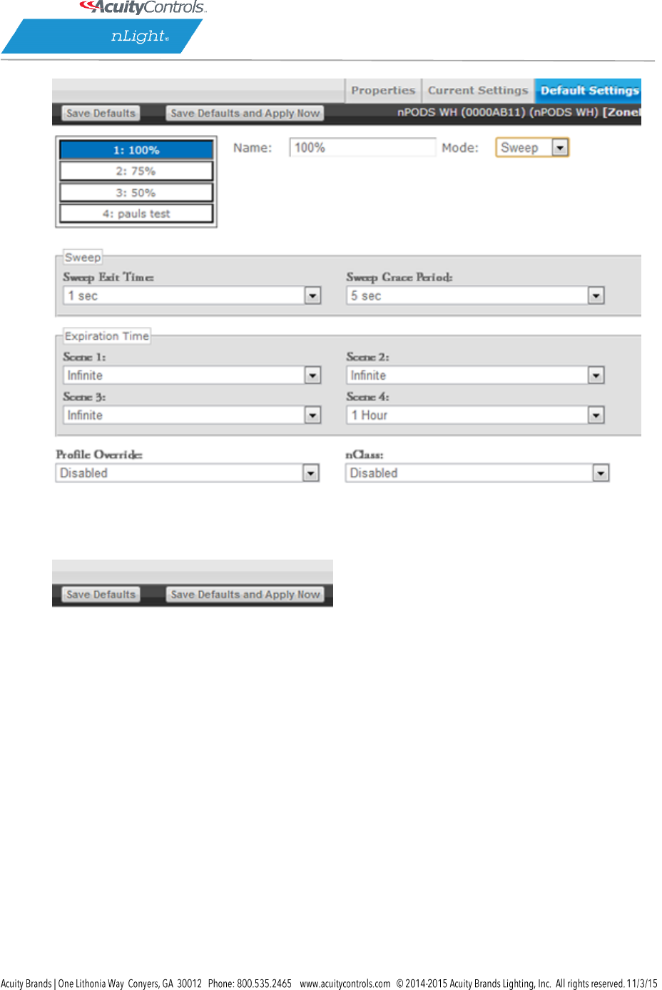
For buttons designated with Sweep Control Mode:
The Sweep Exit and Sweep Grace Period dropdowns allow you to set a time delay, after which
the value of the remaining time delay in all applicable devices will be changed to the input value.
This is helpful if you wish to quickly turn all the lights in a zone or building off without affecting
any of the device settings.
SensorView Manual
Page 47 of 123
6. Click Save Defaults and Apply Now to save, then click another number to change its settings.

SensorView Manual
Page 48 of 123
Viewing / Editing Zone Settings
1. Click the Group Settings tab
2. Using the nLight Network tree to the left, click the checkbox next to the desired Zone to select
all devices within the zone.
Note: Each port of a Bridge is considered a zone
3. Create the list of settings to be modified by selecting settings one at a time from the provided
dropdown field
4. To prevent a device from having a particular setting apply, create an exception
5. After you’ve made your changes, click the Save Defaults button to save your modifications
6. Refer to the Appendix for specific details regarding each setting’s meaning
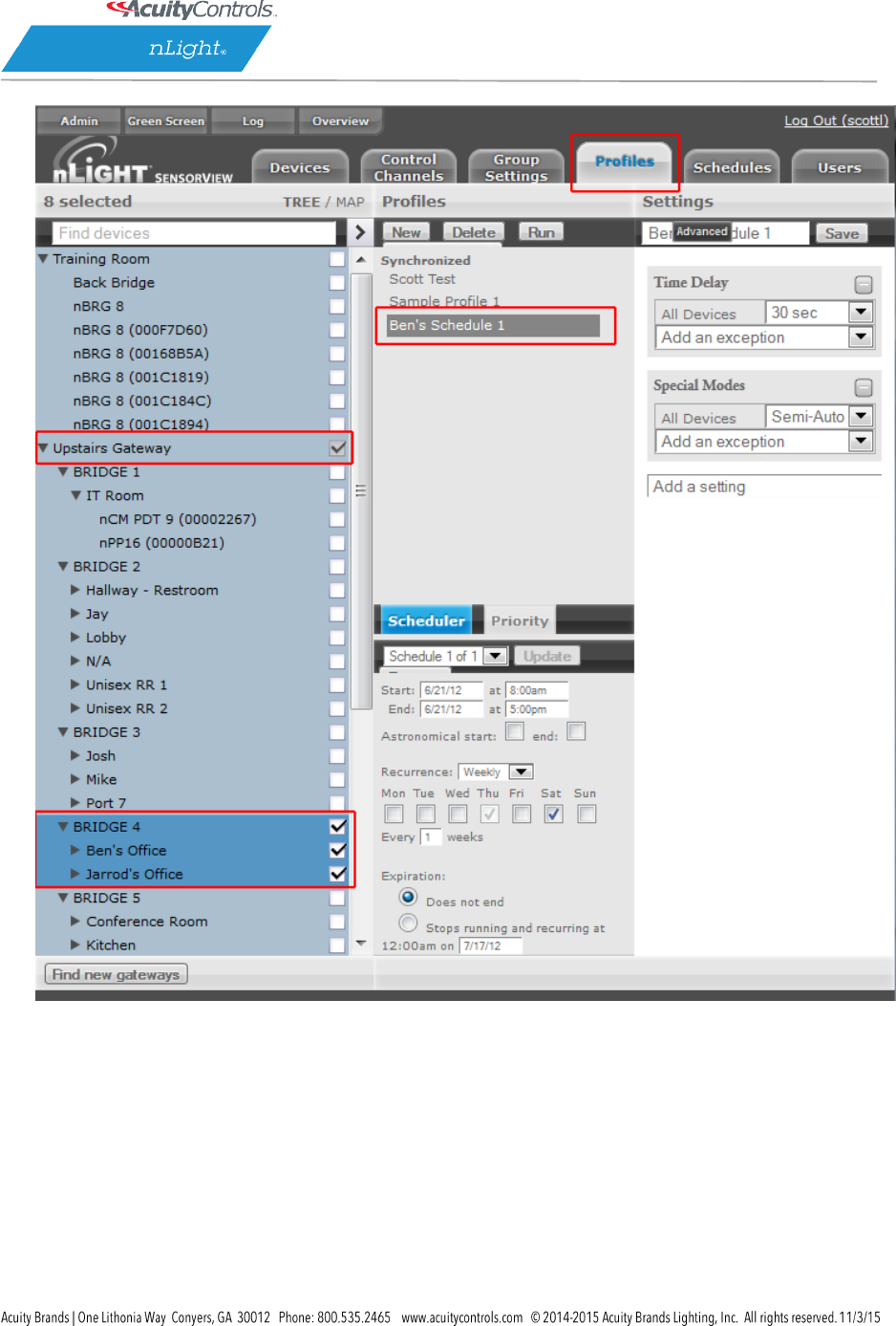
Managing Profiles
The Profiles page provides the ability to create, edit, and delete all Profiles configured within the
system. All Profiles displayed will be grouped with other Profiles sharing the same state: Synchronized,
Mismatched, SensorView Only, or Gateway Only.
While creating or editing a profile the Device tree will operate in MultiSelect mode, there is no limit on
how many devices can participate in a given Profile. As Devices are added to the Profile more settings
may become available on the right, settings are only displayed if there is a Device selected that contains
it, settings will be omitted if no Devices selected support it.
The Scheduler, visible at the bottom of the screen, controls the Schedule for the Profile. Profiles can be
configured to start/stop at a particular time of day, or based on an offset from Sunrise or
Sunset. Recurrences specify how often the Profile should recur in the future, available Recurrences are
Daily, Weekly, Monthly, and Yearly.
The Scheduler also contains a tab for Priority, which allows specification of how Scheduling conflicts
should be handled. If two, or more, Profiles’ execution times overlap then the Priority determines which
Profile will run on each Device. The Schedules section provides a view of exactly how Scheduling
conflicts will be resolved by Priority.
Create a Profile
1. Click the Profiles tab
2. Click on New
3. Profile will show up under the SensorView Only header
4. Select all Devices that should be in the Profile using the Device Tree, as Devices are added more
Settings will become available in the Settings area
SensorView Manual
Page 49 of 123
5. In the Scheduler/Priority section, create a schedule with any required recurrences, then click
Create. For additional schedules select New Schedule in the dropdown and repeat the previous
process.
6. Click the Priority tab to modify the priority of the profile using the arrows. Priority will only
matter if another Profile is scheduled to execute at the same time, on the same Device.
7. Select desired settings to be added / modified by the profile from the Settings dropdowns;
choose values & pick exceptions, if needed.
8. Once all Settings and Schedules have been configured fill in the name for the profile and
click Save, the Profile will then move under the Synchronized header.
Edit a Profile
1. Click the Profiles tab
2. Select a Profile Name
3. Edit the schedule & priority, clicking Update to save your changes when finished
4. Remove any existing settings by clicking the – button, modify the current values, or use the Add
a Setting dropdown to add new ones
5. Repeat for each setting you wish to modify, then click Save
On Demand Profiles
SensorView provides the ability to command a Profile to Run or Stop on demand. This is often utilized
for standard events that don’t recur according to a specific Schedule, but requires the same lighting
configuration.
When a Profile is run on demand it will not stop according to any Schedule, it must be stopped
manually; other Profiles that are scheduled to run at the same time, or afterwards, will still execute
normally. When a Profile is stopped on demand, and it has a schedule, it will still follow the next
Recurrence of the Schedule.
To command a Profile manually:
1. Click the Profiles tab
2. Select a Profile Name
3. Click either Run or Stop to command the Profile
Delete a Profile
1. Click the Profiles tab
2. Select a Profile Name
SensorView Manual
Page 50 of 123
3. Click Delete to permanently remove that profile
4. A pop-up will confirm that you wish to do this. Click Ok.
5. Repeat for each profile you wish to delete
**Please note: deleted profiles are permanently removed. Be certain you wish to delete the
profile before proceeding.
View Reports
SensorView provides a variety of generated reports detailing all configurable aspects of the nLight
network. To view a list of available reports refer to SensorView Reports.
To Generate a Report:
1. Click the Admin link
2. Click the Reports tab
3. Select the report you wish to run. Click Generate Report
4. Once run, print a report using the Print Report button, supported browsers all provide the
option to Print to a PDF
Upgrading Devices
1. Click the Admin link in the top right
2. Click the Updates tab (or click the “Updates” link from the Overview page)
3. Check the selected items you wish to update (unchecked items will not update)
4. Click Submit at the bottom of the page
Downloading Firmware Cache:
Available when internet connection is present & an updated version of SensorView is available,
enabling update downloads that are made available to an offline network.
Note: This process may be lengthy depending on the size of the network.
SensorView Manual
Page 51 of 123
SensorView
Installing SensorView is a multi-step process that should only be completed by a qualified
computer administrator. Before proceeding, please make the following items available to
ensure a successful SensorView Installation:
Windows Installation Disk (Required for Windows XP & Windows Server 2003)
Active Internet Connection
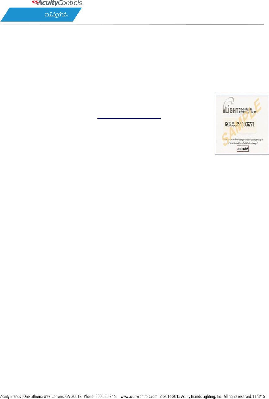
SensorView Registration Key (provided in each Gateway box)
Cross wired CAT-5(e) cable (click here for pinouts)
SensorView Manual
Page 52 of 123
Step 1: Requirements
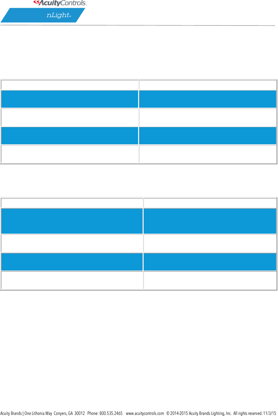
There are two types of installations available for SensorView:
Single-User / Commissioning
For use with any nLight network where a single user operates or commissions the system.
MINIMUM SPECS:
SUGGESTED SPECS:
Operating System:
Windows 7
Operating System:
Windows 7 or 8
Software:
IIS 6.0, .NET 4.5.1
Software:
IIS 8.0, .NET 4.5.1
Hardware:
1 GB RAM, 2 GB Hard Drive
Hardware:
2 GB RAM, 30 GB Hard Drive
Browser:
Firefox, Chrome, Opera, or Internet Explorer 10+
Browser:
Firefox, Chrome, Opera, or Internet Explorer 10+
Multi-User
For use with any nLight network where multiple concurrent web sessions are desired.
MINIMUM SPECS:
SUGGESTED SPECS:
Operating System:
Windows Server 2003, Windows Server Web
Edition, Windows Small Business Server 2003
Operating System:
Windows Server 2008 or 2012
Software:
IIS 6.0, .NET 4.5.1
Software:
IIS 8.0, .NET 4.5.1
Hardware:
1 GB RAM, 2 GB Hard Drive
Hardware:
2 GB RAM, 30 GB Hard Drive
Browser:
Firefox, Chrome, Opera, or Internet Explorer 10+
Browser:
Firefox, Chrome, Opera, or Internet Explorer 10+
SensorView Manual
Page 53 of 123
Step 2: Pre-Installation
SensorView requires pre-installation of both IIS and the Microsoft .NET Framework.
.NET Framework
The .NET Framework 3.0 is automatically installed with Windows Server 2008 & Windows Vista
/ 7 / 8. If you are NOT running either of these operating systems, click here and follow the .NET
installation instructions.
IIS
IIS (Internet Information Services) is a Windows component that allows computers to host web
applications. This component is required for hosting a SensorView installation, and will allow
end users to view and control their SensorView install(s) remotely.
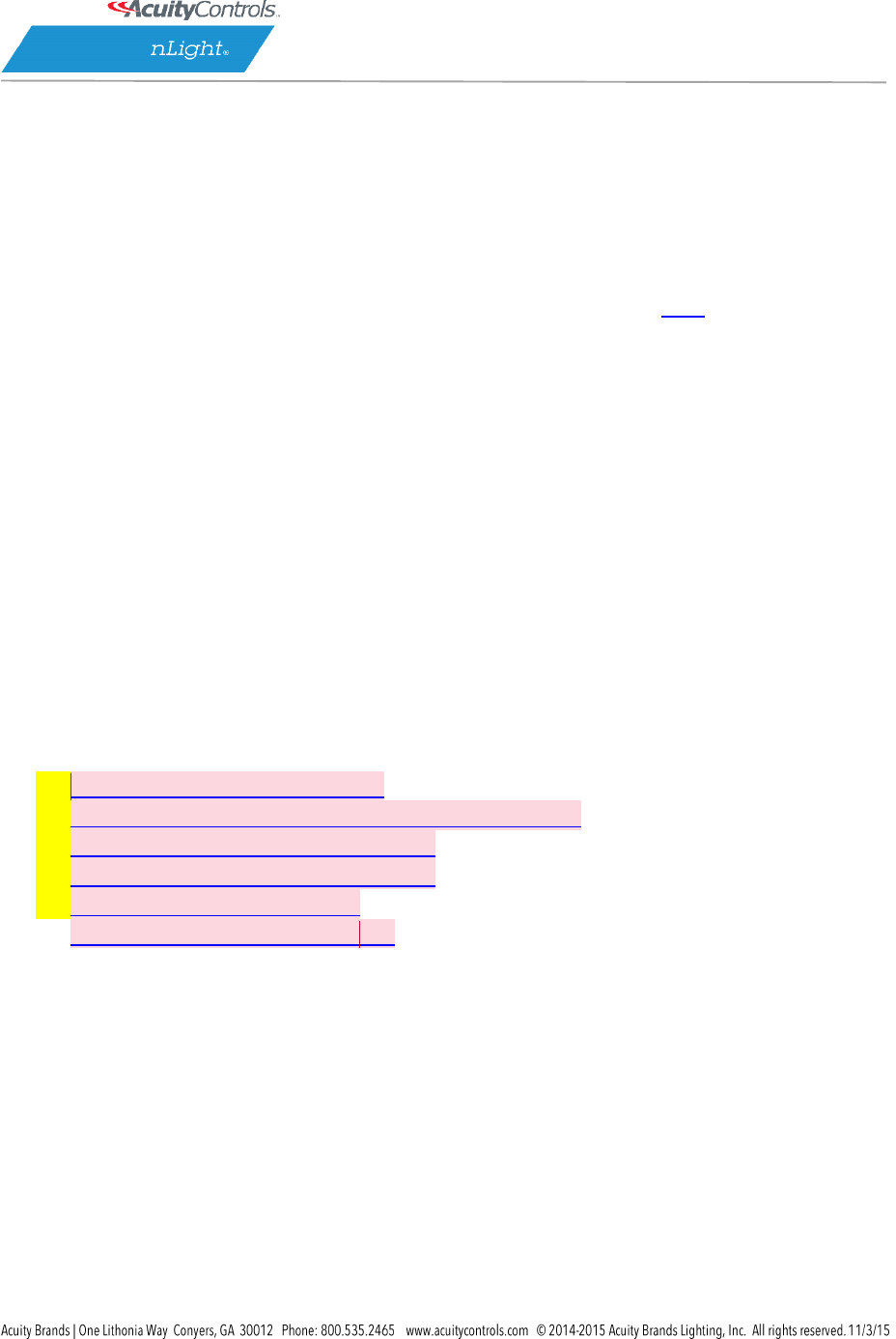
To install IIS, please click the link to your corresponding operating system below and follow the
specific information for installing this component.
Please Note: Both Win XP & Server 2003 require Windows installation disks and are NOT
downloadable from the web. Without Windows discs to install this component, SensorView
installation cannot be completed:
Windows XP Pro (32 bit) – IIS 5.0
Windows Small Business Server 2003 (32 bit) – IIS 6.0
Windows Server 2003 (32 bit) – IIS 6.0
Windows Server 2003 (64 bit) – IIS 6.0
Windows Server 2008 – IIS 7.0
Windows Vista / 7 / 8 – IIS 7.0
[DA3]
SensorView Manual
Page 54 of 123
Step 3: Installation
After completing the successful installation of IIS (and .NET), you are now ready to continue:
Download the nLight SensorView installation package:
1. Download the compressed .zip file (20 mb) from:
http://www.sensorswitch.com/sensorview/setup.zip
2. Unzip the file and run setup.exe.
3. Follow the instructional prompts to complete the installation of the SensorView
application.
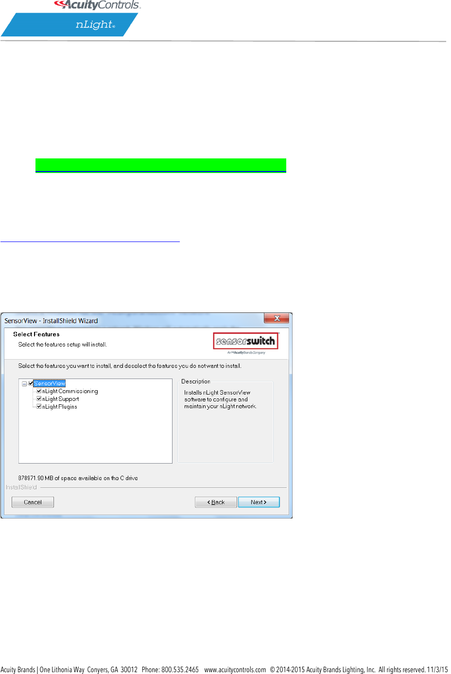
SensorView Installation Best Practices
It is recommended to do a full install of all offered features/plugins.
All boxes are checked by default. If they are not, please check them and click Next.
SensorView will require registration to complete the installation process.
SensorView Registration
This includes a license key as well as information about who is installing
(the registration key is included on a small card with the gateway)
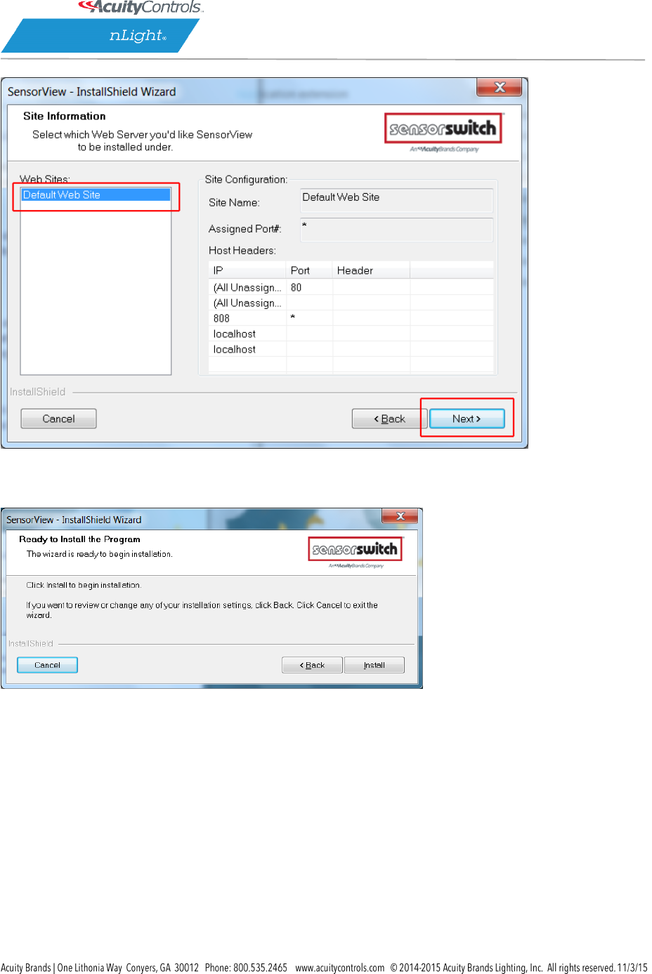
When the Install Shield wizard opens, select “Default Web Site” and click Next.
SensorView Manual
Page 55 of 123
Click Install
The install shield wizard takes a few moments to run.
SensorView Manual
Page 56 of 123
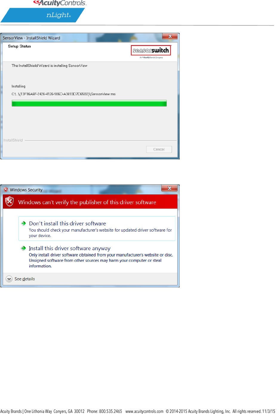
If you see the following message, click “install this driver software anyway”.
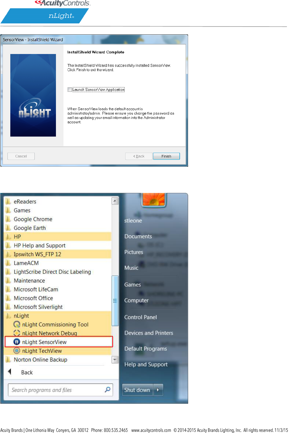
The installation is complete. Click the box to launch SensorView, or
SensorView Manual
Page 57 of 123
Click Start, All Programs, Select nLight SensorView
Launch SensorView on the desktop.
SensorView Manual
Page 58 of 123
A username and password are required to login to SensorView. When SensorView is freshly
installed, use the following:
Default User Name: administrator
Default Password: admin

SensorView Manual
Page 59 of 123
Step 4: Connecting to Gateway
The Gateway uses the port labeled “Ethernet” to communicate with the computer running the
SensorView software. There are several ways to connect to a gateway; please choose the
method you wish to use:
Direct Connection
The following procedure will show you how to establish a direct connection between a laptop
computer and a Gateway:
NOTE: a cross-wired CAT-5(e) cable is only required to connect this way to an nGWY1,
nGWY2 does not require a cross-wired cable
1. If present, disable wireless networking card
2. Connect PC to Gateway’s Ethernet port with cross-wired (cross-over) CAT-5(e) cable
NOTE: a standard patch cable (straight through wired) will not work
3. Turn off/verify DHCP on Gateway
MENU > SETUP OPTIONS > SET [DHCP OFF]
NOTE: if pin is required, enter 1234
4. Enter static IP address for Gateway (for example 192.168.1.2)
MENU > SETUP OPTIONS > TCP/IP
5. Enter static IP address for Laptop (e.g., 192.168.1.5). The following instructions are
for Windows XP. Other operating systems may require different procedures for
changing network address.
1. START > CONTROL PANEL > NETWORK CONNECTIONS > LOCAL
AREA CONNECTION > PROPERTIES
2. Highlight Internet Protocol (TCP/IP) in box and click Properties
3. Click the radio button for “Use the following IP address”
4. Fill in
IP address: 192.168.1.5
Subnet Mask: 255.255.255.0
Default Gateway: 192.168.1.1
5. Click OK
6. Verify “Link Up” message on Gateway LCD screen. If “Link Up” message does not
appear, reboot gateway
MENU > REBOOT
7. Launch SensorView
http://localhost/SensorView
8. Login to SensorView
Default User Name: administrator
Default Password: admin

SensorView Manual
Page 60 of 123
9. Once SensorView detects the Gateway it will appear in device tree
10. If Gateway does not appear in the tree, call tech support; 1.800.535.2465
LAN Connection
The following procedure will show you how to connect to a Gateway over an existing Ethernet
Local Area Network (LAN).
NOTE: if the computer and Gateway are located on different subnets, use the instructions
for connecting over a Wide Area Network (WAN).
1. Connect SensorView’s computer to LAN using a standard patch cable
2. Connect Gateway’s Ethernet port to LAN using a standard patch cable
3. If Link Up message appears on Gateway, go to step e, if not continue to next step
4. The Gateway can either use a dedicated IP address or acquire one from the
network’s DHCP server.
1. To enter a dedicated IP address:
1. Turn off DHCP on Gateway
MENU > SETUP OPTIONS > SET [DHCP OFF]
NOTE: if pin is required, enter 1234
2. Enter static IP address for Gateway (for example 192.168.1.2)
MENU > SETUP OPTIONS > TCP/IP
3. Return to main screen and verify “Link Up” message. If “Link Up”
message does not appear, reboot gateway
MENU > REBOOT
2. To use a DHCP assigned IP address:
1. Turn On / Verify DHCP on Gateway
MENU > SETUP OPTIONS > SET [DHCP ON]
NOTE: if pin is required, enter 1234
2. If DHCP fails, force the Gateway to acquire an address
MENU > GET IP ADDRESS
3. Return to main screen. Verify “Link Up” message
5. Launch SensorView
From host computer: http://localhost/SensorView
From non-host computer on LAN: http://[enter server name]/SensorView
6. Login to SensorView
Default User Name: administrator
Default Password: admin
7. Once SensorView discovers the Gateway it will appear in device tree
8. If Gateway does not appear in tree, call Sensor Switch tech support; 1.800.535.2465
SensorView Manual
Page 62 of 123
Virtual WallPods
With the Virtual WallPod applications, users can control their lighting from their desktop or iOS
mobile device. Designed to look like WallPods®, these applications are an excellent alternative
to remote controls, which are often lost and require battery replacement. Simple user
permissions provide facility managers necessary administrative control.
Configuring SensorView
SensorView is a required component of the Virtual WallPods Plugin. It is used to setup and
configure Users and the Virtual WallPods associated with them; as well as authenticate and
process commands sent by Virtual WallPods.
Use of Virtual WallPods requires SensorView be online and accessible.
SensorView Manual
Page 63 of 123
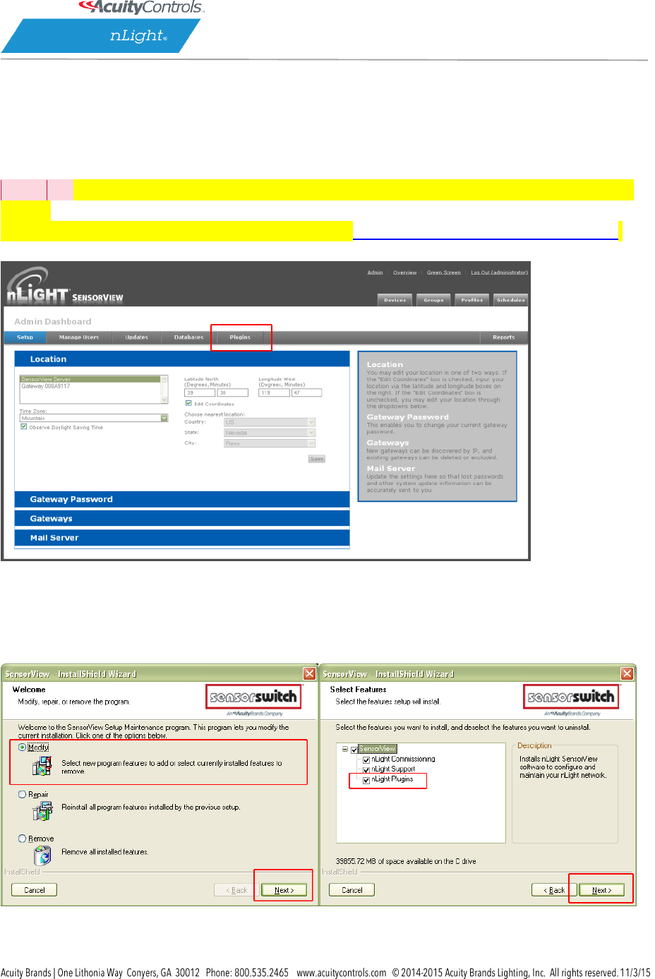
Update SensorView
Step 1
Before
[DA4]
starting, log into your SensorView page and click on Admin at the top right of the
screen.
If you see a Plugins tab, skip Step 1 and proceed to Start the nLight Virtual WallPod Server.
If you do not see a Plugins tab, click the Updates tab and update to the latest version of
SensorView. Once the SensorView application update is finished, run the install file for
SensorView and select Modify.
SensorView Manual
Page 64 of 123
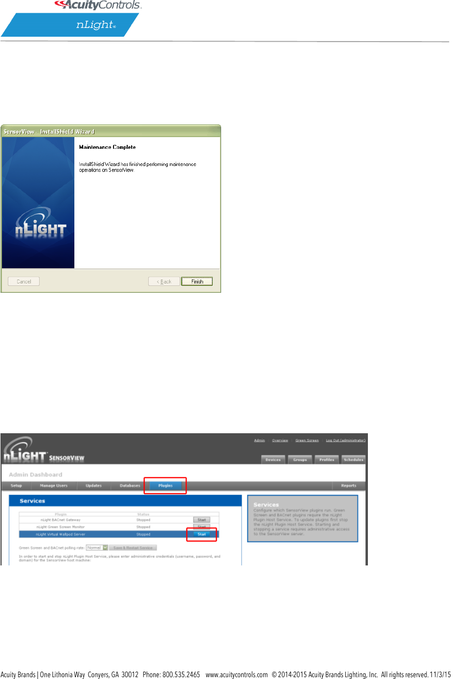
Click Next, and once the proceeding page opens check the nLight Plugins box, followed
by Next.
Once the below screen appears the modification is complete, click Finish to close.
Virtual WallPod Server
Step 2
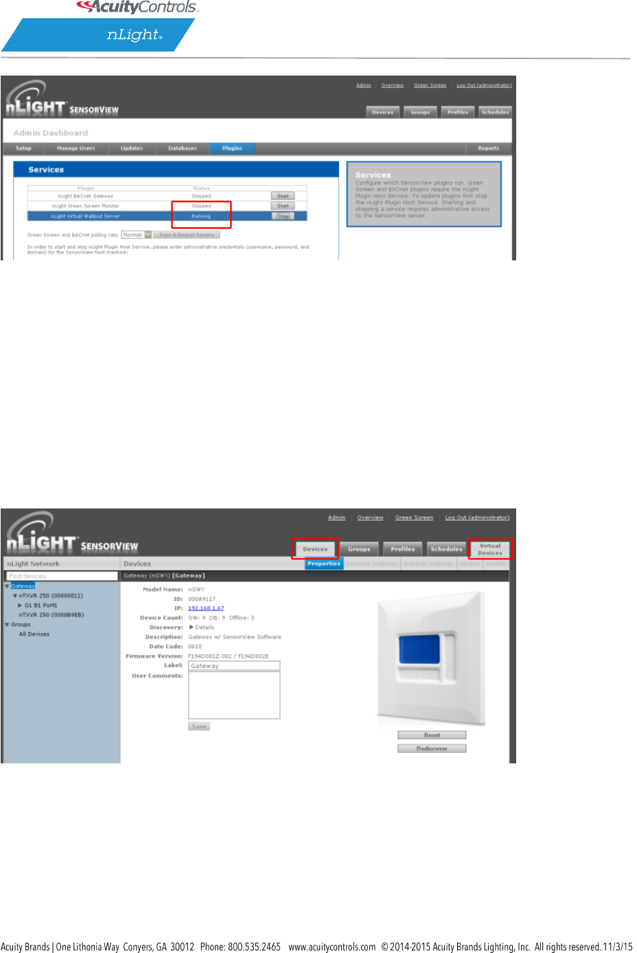
Once at the Admin Dashboard, click Plugins and Start the nLight Virtual WallPod Server.
Notice that stopped will change to running.
SensorView Manual
Page 65 of 123
Virtual Controls
Step 3
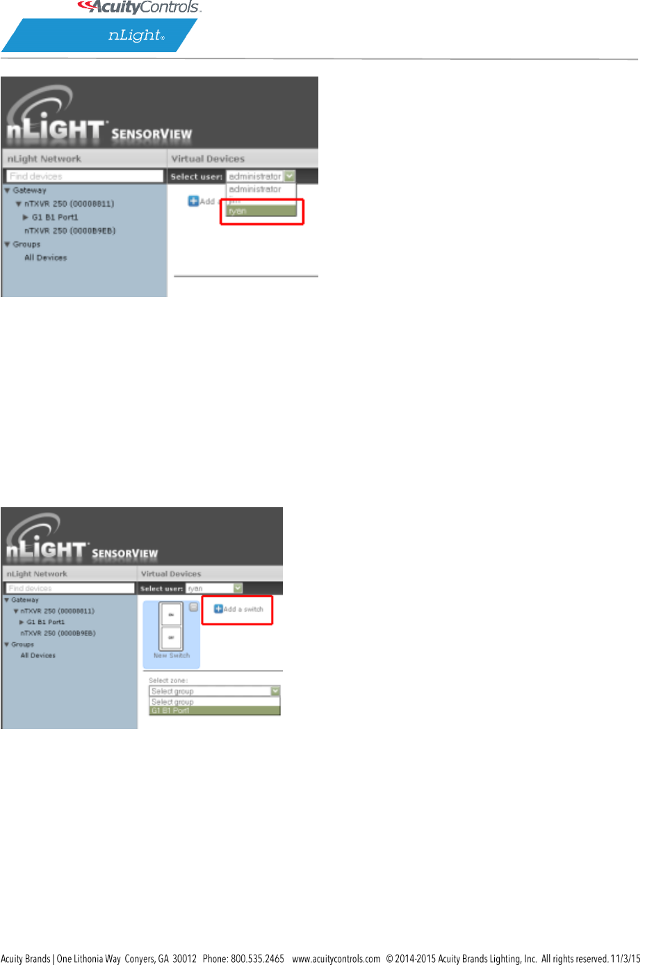
Now that the nLight Virtual WallPod Server is running, go to the device page by clicking
the Devices tab at the top right area of the screen. Once the devices page opens, click on
the Virtual Devices tab, located in the same area.
Select a user by clicking on the dropdown arrow
SensorView Manual
Page 66 of 123
Virtual WallPod Switch
Step 4
Click the Add a switch button.
Control Zone
Step 5
Select a zone (bridge port) to control, as well as an individual device or switch broadcasting
channel. For convenience, only the switch channels that devices are tracking within the zone
will appear in the channel dropdown menu.

SensorView Manual
Page 67 of 123
This screen shows the nLight Virtual WallPod controlling all devices connected to the zone that
are tracking switch via Channel 1 (A).
To control an individual device, select “Individual Device” from the Control Type dropdown (B).
To label the nLight Virtual WallPod, highlight the Switch Label box and enter the preferred
Switch Label (C).
If the nLight Virtual WallPod is to control dimming or a 2-Pole device, check the appropriate
box (D).
SensorView Manual
Page 68 of 123
Virtual WallPod Application
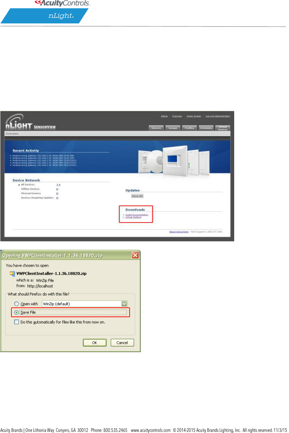
Download the Virtual WallPod application from the Overview page of SensorView. Click the
Overview tab at the top right portion of the screen, then Virtual WallPod under the Downloads
section (bottom right) to download.
Note: The download link will only be shown if the Virtual WallPod Plugin has been enabled.
It is recommended to save this file to a flash drive so that it can be installed to other machines
throughout the network.
Once the files have been downloaded and extracted to a folder, locate it and run setup.exe
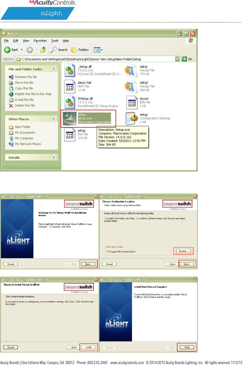
SensorView Manual
Page 69 of 123
Next, follow the setup file’s installation steps.
SensorView Manual
Page 70 of 123
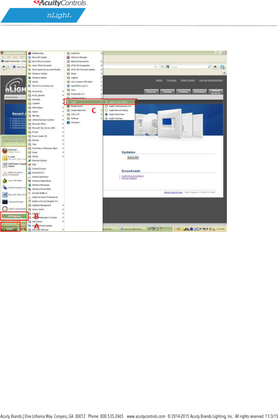
Once the install is complete, follow the path.
Start/All Programs/nLight/nLight Virtual WallPod. (above)
SensorView Manual
Page 71 of 123
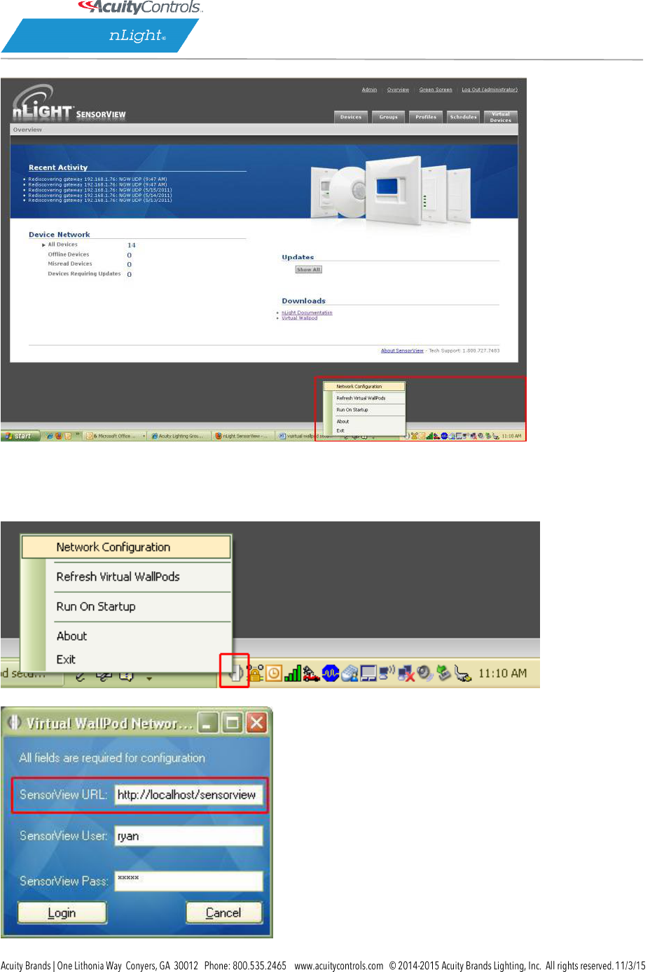
Once the icon for the nLight Virtual WallPod appears in the Taskbar, right-click it and enter the
network configuration.
SensorView Manual
Page 72 of 123
If the nLight Virtual WallPod app is installed to the SensorView host machine, the SensorView
URL will match the (left) screenshot.
If it is installed to a remote machine (that is on the same LAN or subnet) the SensorView URL
will be: http://[host name or IP address]/sensorview
Login as a user assigned one or more Virtual WallPods in SensorView.
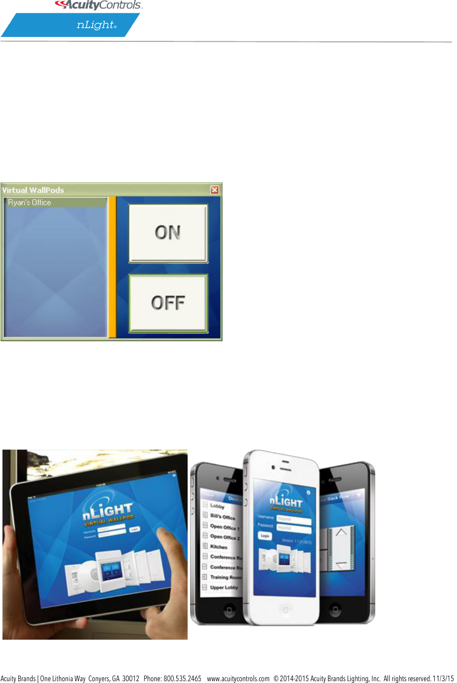
The nLight Virtual WallPod is now running and will control the assigned relays.
Now that setup for the host machine is complete, the iOS app can be downloaded and installed.
Virtual WallPod iOS App
This section details how to install and setup the Virtual WallPod software for iOS devices.
SensorView Manual
Page 73 of 123
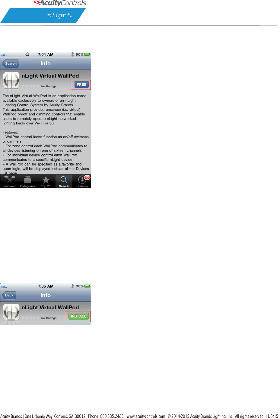
Download and Install iOS application
Go to the App Store on the device that will have the nLight Virtual WallPod installed.
Search for nLight Virtual WallPod.
Note that the App is free of charge, as is all nLight software.
Click FREE, followed by the green INSTALL button that appears.
(note: an iTunes account is required)
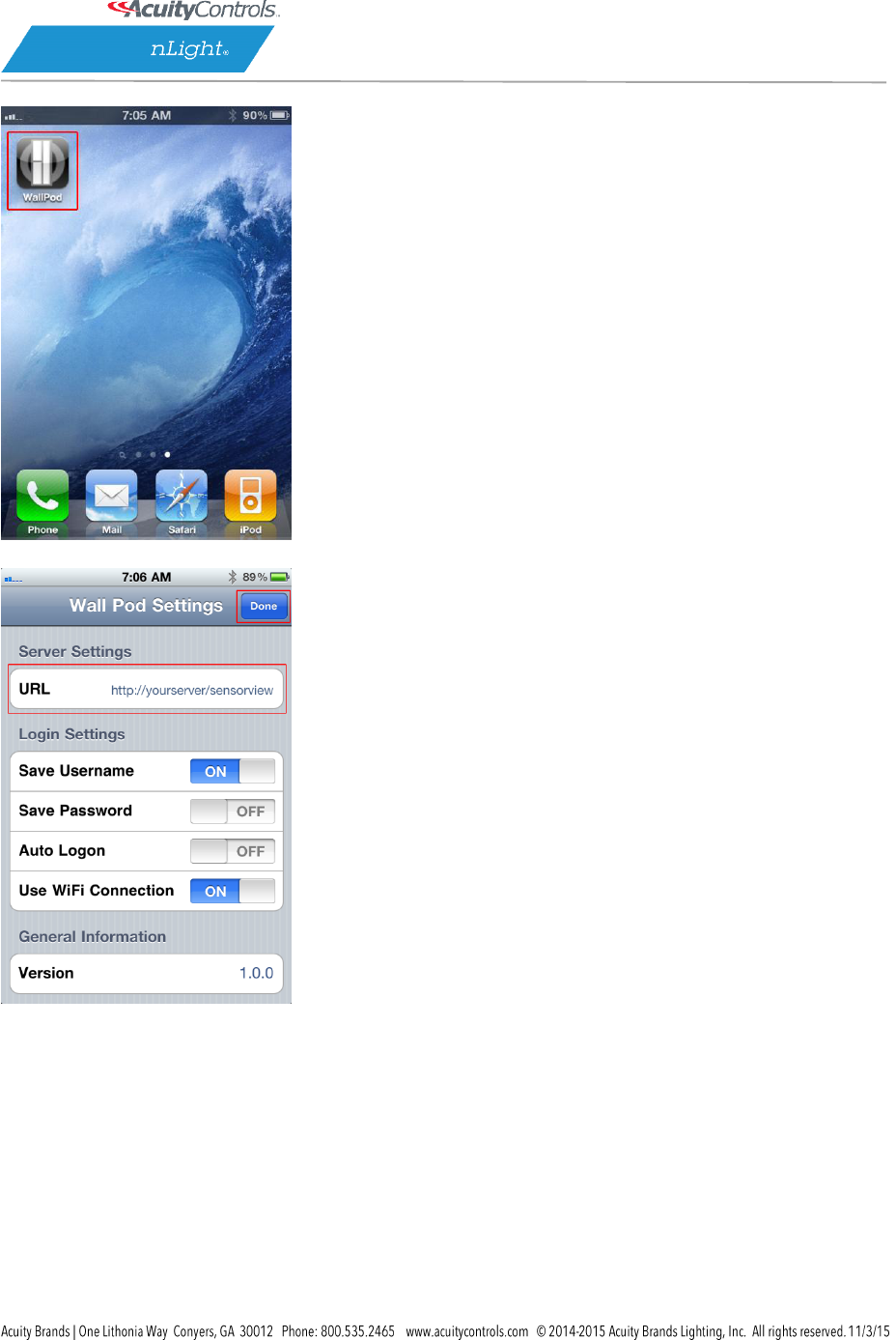
Once installed, click the WallPod App icon to launch.
SensorView Manual
Page 74 of 123
The app will open the WallPod Settings page the first time it’s launched.
Enter the Server Settings URL (replace “yourserver” with host machine’s IP address).
Set Save Password
and Auto Logon to desired settings.
Click Done.
SensorView Manual
Page 75 of 123
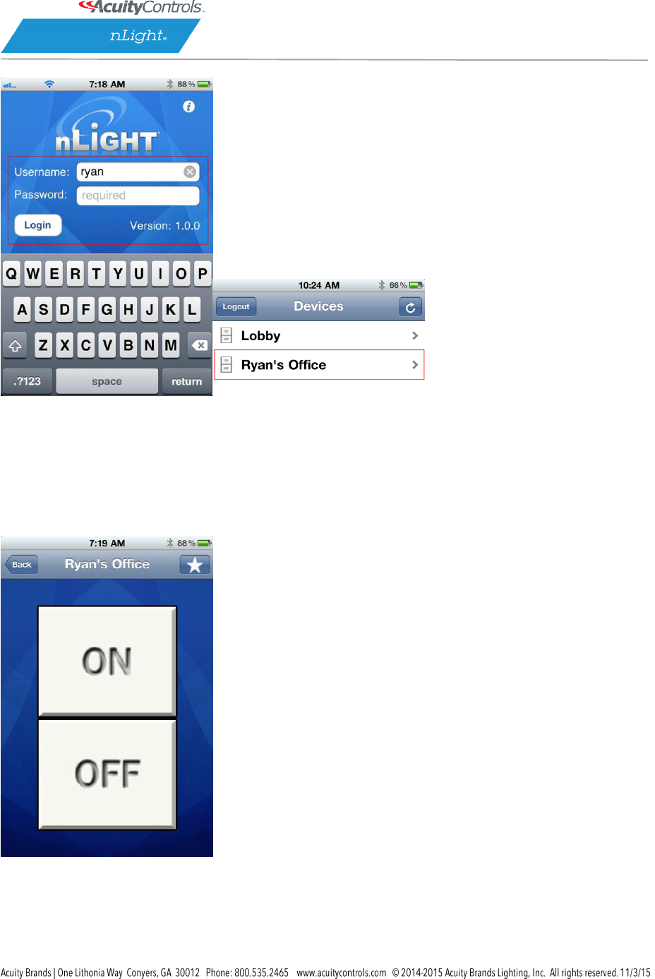
Login with the user credentials for the nLight Virtual WallPod you wish to control. (left)
Select a switch from the devices list. (right)
Installation is now complete.
Notice that the switch is backlit, indicating that the relay controlled by this nLight Virtual
WallPod is closed, i.e., “turned on.”
SensorView Manual
Page 76 of 123
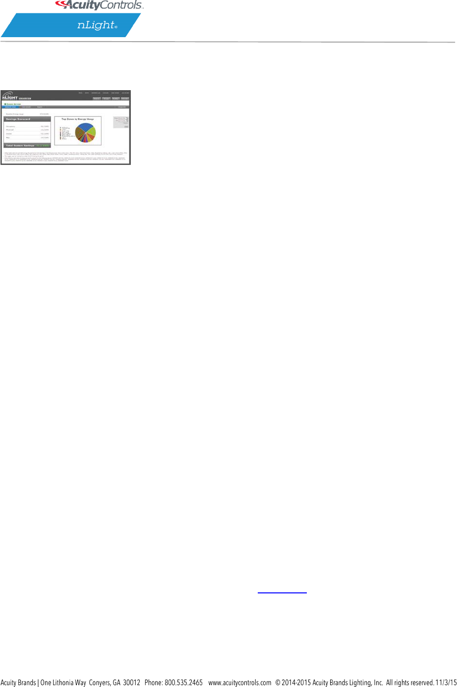
Green Screen
This SensorView module logs and analyzes system and building performance. A “Savings
Scorecard” calculates energy savings in kWH or dollars.
As with SensorView itself, installing the GreenScreen plug-in should be performed by
authorized network administrators.
This will entail installing and setting up a database (PostgreSQL), a driver to connect to the
database, a DSN for the data source, initializing the database, starting GreenScreen, and
configuring GreenScreen options in SensorView.
Setting up PostgresQL
Setting up PostgreSQL on a computer requires downloading and installing the application,
configuring the database to accept remote connections, and restarting the database server.
PostgreSQL is a separate product that is maintained and developed entirely
separate from SensorView and is in no way affiliated with nLight, SensorSwitch, or
Acuity Brands.
For the remainder of this document the phrase “X.Y” will refer to major and
minor versions of the version of PostgreSQL being installed; for example: 9.0, 8.4.
GreenScreen is compatible with PostgreSQL versions 8.4 or higher (9.0 recommended).
1.1: Installing PostgreSQL
SensorView can use an existing PostgreSQL database or a dedicated one. Which option is most
appropriate is at the discretion of the system owner. Download the most recent version for
either Windows x86-64 (64 bit) or x86-32 (32-bit). A few notes on the installer:
Super-User Creation Screen:
The screen below configures the default super-user account for PostgreSQL, take note of these
SensorView Manual
Page 77 of 123
credentials as those will be the default login account and password for the
PostgreSQL database.
Port Configuration Screen:
The screen below allows for configuration of the port that PostgreSQL will use for
connections. Use whatever value is required by system administrator. Note, SensorView and
GreenScreen can be configured to use any port value.
Advanced Options:
The screen below allows for configuration of the locale that PostgreSQL is operating in. The
default is almost always sufficient. If the installation site has specific requirements then
select the most appropriate option from the drop down. The selected option does not seriously
affect GreenScreen operations.
On the final screen, push “Next” to finish the installation of PostgreSQL onto the local
computer.
1.2: Allowing Remote Connections
This step is only necessary if SensorView and the PostgreSQL database reside on separate
computers. By default, PostgreSQL will not allow any remote connections; to change
this, administrative access to the host machine for the database is required. To setup
PostgreSQL to allow remote connections, go to the directory PostgreSQL was installed at (by
default C:\Program Files\PostgreSQL), from that folder open the file at X.Y\data\pg_hba.conf;
this file can be opened in notepad or any generic text editor. For how to configure pg_hba.conf,
as well as any questions, refer to: 8.4 documentation, 9.0 documentation
For all database versions, adding the following line to the bottom of the file to allow ALL remote
connections to the database:
host all 0.0.0.0/0 md5
Note, allowing all connections is a potential security risk that should be weighed by
system owners.
Save the changes and close the file. PostgreSQL will now accept remote connections from the
configured host.
1.3: Tuning PostgreSQL (Optional)
By default PostgreSQL is tuned for systems with low memory sets. By changing a few
configuration parameters GreenScreen database queries can be significantly sped up. To
SensorView Manual
Page 78 of 123
change configuration options go to the directory in which PostgreSQL was installed (by default
C:\Program Files\PostgreSQL). From that folder open the file X.Y\data\postgresql.conf with
notepad or any generic text editor. Note that some of the following setting recommendations
are based on the total system RAM available. Before entering the new values look up how
much total RAM is installed in the computer (right click on My Computer and select Properties)
and convert that value to MB (note that 1GB = 1024 MB).
The following changes are suggested to improve performance (note that leaving a # in front of a
line denotes a comment and the value will be ignored; remove any leading # for the setting to
take effect.
shared_buffers
Set to 25% of system RAM (not exceeding 512MB (256MB recommended for most installs)
default is 32MB
effective_cache_size
50-75% total RAM (in MB)
default is 128MB
After making changes to the configuration the PostgreSQL service must be restarted
(1.4) before the new settings will take effect.
Note: Overall system performance may vary. Modifying values may have a result on overall
system performance and stability, if problems persist revert modified settings to original values.
Sensor Switch is not responsible for any non-SensorView issues this may cause. Additional
tuning considerations.
1.4: Restarting PostgreSQL
PostgreSQL must be restarted before the changes made to pg_hba.conf will take effect. If
no changes were made to pg_hba.conf then this step is unnecessary. Go to Start Menu ->
Control Panel -> Administrative Tools -> Services (Windows XP / Server 2003) or Start Menu ->
Control Panel -> System and Security -> Administrative Tools -> Services (Windows Vista / 7 /
Server 2008).
In the services window select the following service:
8.4
PostgreSQL Server 8.4

SensorView Manual
Page 79 of 123
9.0
(32 bit) postgresql-9.0-PostgreSQL Server 9.0
9.0
(64 bit) Postgresql-x64-9.0
Right click on the relevant service name and select Restart; this will restart the database server.
1.5: Firewall Setup
If the computer running PostgreSQL is a different from the computer running SensorView, then
the firewall on the computer running PostgreSQL may need to be updated to allow for incoming
connections on whichever port PostgreSQL was configured to listen on. This will vary depending
on the firewall software in use.
SensorView Manual
Page 80 of 123
Setting Up Database Connection
A connection to the database that GreenScreen will store data in must be configured.
This involves downloading and installing a driver for the database and configuring a system DSN
that specifies the connection parameters to SensorView and GreenScreen. Both steps 2.1 and
2.2 must be performed on the computer that is running SensorView.
2.1: Installing a PostgreSQL Driver
For SensorView to connect and control the PostgreSQL database a driver must be installed on
the machine hosting SensorView. Download the Windows driver (x32 and x64).
After downloading open the zip file, run psqlodbc.msi, and install the driver.
2.2: DSN Configuration
DSNs provide a way to configure a datasource connection in a standard consistent way that can
be used throughout the machine. A DSN must be configured to allow SensorView
and GreenScreen to connect to the database; this must be done on the machine
running SensorView. A DSN consists of a name, database, server, port, user, password, and
SSL connection requirements. Locating the correct DSN configuration tool varies depending on
the specific version of Windows and whether or not it is 64 bit.
To configure a DSN for Windows XP 32 bit / Server 2003 bit go to:
Start Menu -> Control Panel -> Administrative Tools -> Data Sources (ODBC)
To configure a DSN for all 64 bit variants of Windows go to:
Start Menu -> Run -> type C:\Windows\SysWOW64\odbcad32.exe and press
Enter (Assuming Windows is installed to C:, otherwise substitute correct system path)
To configure a DSN for Windows Vista 32 bit / 7 32 bit / Server 2008 32 bit go to:
Start Menu -> Control Panel -> System and Security -> Administrative Tools -> Data
Sources (ODBC)
Once the Data Sources (ODBC) popup is open, select the tab System DSN, then press Add.
Select a datasource from the list. The name of the driver will vary depending on what was
installed, commonly for 32 bit the name will be “PostgreSQL Unicode”, this is the driver that
was previously installed during PostgreSQL setup (2.1). Select Finish and a form will appear with
additional fields to fill out.
Fill out the form with the following values:
Data Source: A custom name for the DSN that will be put into SensorView
Database: nlight_system_data

SensorView Manual
Page 81 of 123
Server: IP Address or hostname of machine running PostgreSQL server. (127.0.0.1 or
localhost for local computer)
Port: Port PostgreSQL was configured to run on (by default 5432)
User name Account name for the database user
Password: Account password for the database user
SSL Mode: As appropriate for the database (disabled by default)
Select Save. Note, the Data Source name value as this is the field that must be entered
into SensorView later. Note that pressing the Test button will fail with “database not found”
until step 3.1 has been completed. For testing purposes you can change the datasource name
to read ‘postgres’, and then test, if the connection is successful then change the datasource
parameter back to nlight_system_data, otherwise check the other parameters that were
entered.

SensorView Manual
Page 82 of 123
Setting Up GreenScreen
In order to configure and run SensorView the plug-ins component must be installed. For new
installs this can be accomplished by making sure that plug-ins is checked during the feature
select portion of the SensorView install. For existing installations, run the installer and select
Modify, then check plug-ins and push modify. Once the plug-in components have
been installed, open SensorView and go to the Admin page and select Plug-ins.
3.1: Administrator Email (Recommended)
GreenScreen will notify the administrator via email if it encounters any issues while attempting
to start. To configure email notification the administrator use of SensorView must have an
email address entered; additionally the Mail Server section (found at Admin >Setup-
>Mail Server) must be filled out to allow for email to be sent from SensorView. Notification
emails will be sent in two specific instances, if the host Windows service crashes (and the
subsequent automatic restart fails); or if, while starting up, GreenScreen is unable to start due
to version requirements, improper configuration, or any unexpected error.
3.2: Database Initialization
Once PostgreSQL, the database driver, and the system DSN have been set up and
configured, the last step is to build the GreenScreen database and start the service. To build the
database, in SensorView, go to Admin -> Databases. At the bottom of the screen is the
GreenScreen Database Setup section. Input the name of the custom DSN that was previously
configured and SensorView will build the database (upon hitting save). If the credentials
supplied in the DSN do not have the create database privilege, then SensorView will prompt for
credentials that do. SensorView will use those credentials to create the database and give
ownership to the credentials in the DSN. Afterwards the other, higher, set of credentials will be
discarded.
3.3: Starting GreenScreen
In order to start GreenScreen, the plug-ins component must have previously been installed
(3.0); if this has not been done then there will be no Plug-ins tab. Proceed to the Admin screen
in SensorView and select Plug-ins. The host service should already be running; if it is not then
the username, password, and domain (optional) must be filled out, then start the nLight Plug-in
Host Service. Once this is running GreenScreen can be started and stopped in the top window.

SensorView Manual
Page 83 of 123
3.4: GreenScreen Operations
Within the accordion select GreenScreen; on this page options can be set that will configure
how GreenScreen will compute savings and what units to display them in. Note that displaying
savings in dollars requires electrical generation rate information be entered on the Admin-
>Plugins->GreenScreen section.
Display Options:
SensorView can be configured to show savings in dollars or kWh. For CO2 savings, the
generation type for the electricity can be selected that will be used to determine CO2 savings.
Electrical Rates:
SensorView can be configured with the building’s electrical rates. Set the rate and time periods
in which the rate applies. These settings will only be used if SensorView is set to display savings
in dollars.
Baseline Periods:
During these periods, SensorView will assume the building is occupied. Energy savings
(whether in dollars or kWh) are relative to how much energy would have been spent, with
all control points in the system being on for the duration of the baseline periods. Refer to
the GreenScreen data sheet for a more detailed explanation of savings analysis.
Hit Save Settings to save the configuration.
Once SensorView has a valid Data Source which can connect to the database, it will display
the current size of the database and the state of hosting service in the bottom left corner of
the screen (completed in step 3.1).
SensorView Manual
Page 84 of 123
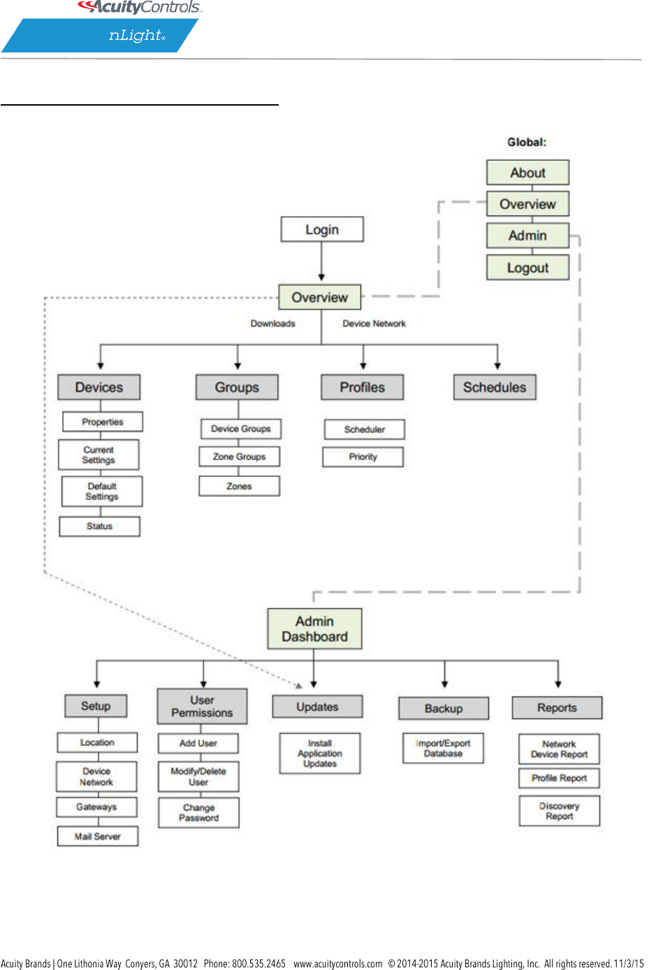
SensorView Page Mapping
SensorView Manual
Page 85 of 123
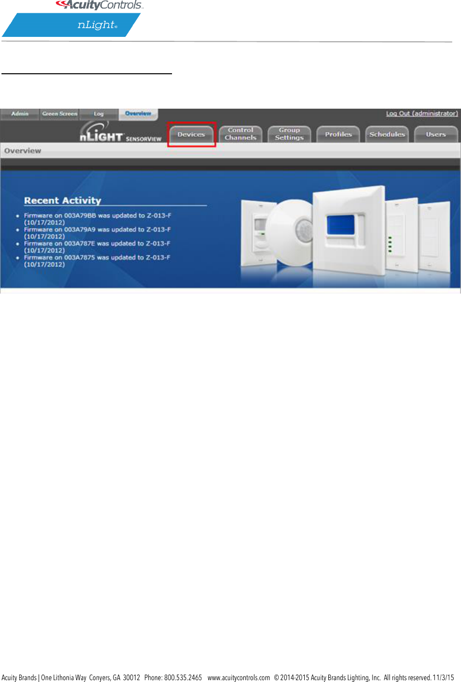
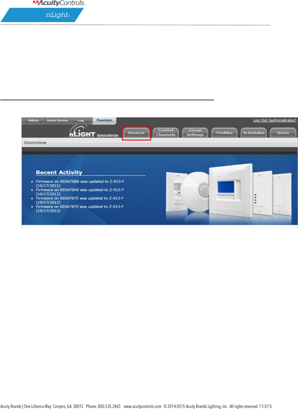
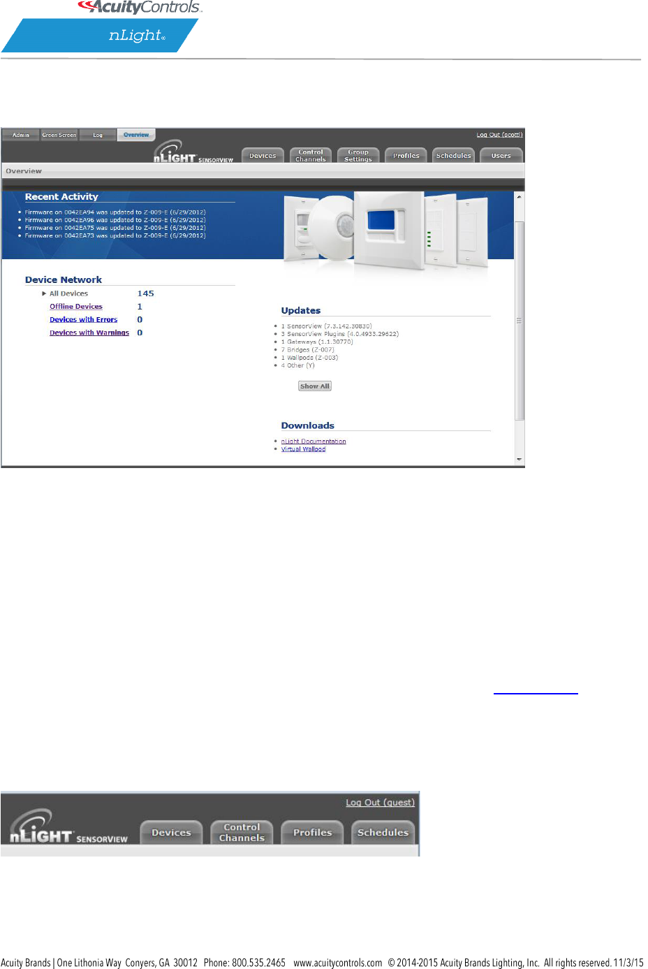
Overview
A successful login opens the Overview page, showing:
a list of all recent activity, including Firmware updates (upper left)
a Device Network report showing a count of offline and total devices (lower left)
a list of all current updates available, with direct links to download and install them. (lower
right)
Upper left
o Admin allows authorized administrators to setup and configure SensorView and
perform updates.
o Green Screen (upper left) provides a historical and real-time status on energy savings
resulting from your installed nLight systems. For in-depth info: Green Screen.
o Log displays troubleshooting data.
o Overview returns users to the Overview Screen.
The Overview page features four clickable tabs along the top.
SensorView Manual
Page 86 of 123
SensorView Manual
Page 87 of 123
Green Screen
This SensorView GreenScreen module logs and analyzes system and building performance. A “Savings
Scorecard” calculates energy savings in kWH or dollars.
Detailed graphs show performance over user selected time scales. This data can be used to monitor
space and lighting usage, optimize time delays, and better utilize available daylight. Data is also provided
to the user in downloadable reports.
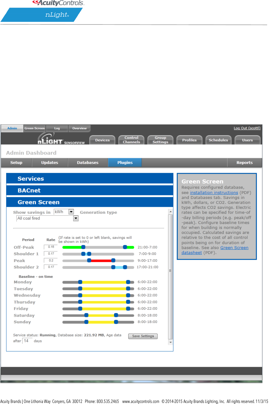
Green Screen Admin
SensorView Manual
Page 88 of 123
Green Screen requires a configured database (see installation instructions and Databases tab).
The top pull-down allows users to select Savings in kWh, dollars, or CO2.
Generation type indicates a rate of CO2 production to energy consumption and affects CO2 savings.
Electric rates can be specified for time-of-day billing periods (e.g. peak/off-peak). Use the sliders to
define time intervals for a specific facility using nLight devices.
Baseline times should be configured for each day of the week, according to normal building occupancy.
Calculated savings are relative to the cost of all control points being on for the duration of the baseline.
The bottom line displays basic statistics and status about GreenScreen. It provides indications about the
current data aging setting, the size of the database on disk, and the current status of the GreenScreen
Plugin.
When configuration or changes are completed, click Save Settings.
See also Green Screen datasheet (PDF).
SensorView Manual
Page 89 of 123
Admin
The Admin tabs are for administrators only, and will not be accessed by a day to day end user.
SensorView Manual
Page 90 of 123
Setup
The Admin Setup screen displays four setup categories:
Location, Gateway Password, Gateways, and Mail Server.
Location
Time zone – Select Time zone from pull-down menu
Select Location – Country, State, nearest City

SensorView Manual
Page 91 of 123
Location settings allow a gateway to be aware of what time zone and daylight savings rules it should
apply. Specifying the location also allows the gateway to determine the proper astronomical time for
schedules using sunrise or sunset.
You may edit your location in one of two ways. If the “Edit Coordinates” box is checked, input your
location via the latitude and longitude boxes on the right.
If the “Edit Coordinates” box is unchecked, you may edit your location through the dropdowns below.
Gateway Password
This enables authorized users to change current gateway password. Configuring a gateway password
ties gateways to your particular SensorView, and prevents unauthorized users from using a different
SensorView to modify the system; as well as restricting direct configuration access to the gateways.
Gateways
New gateways can be discovered by IP, and existing gateways can be deleted or excluded.
Mail Server
Update the settings here in order to receive important system notifications.
SensorView Manual
Page 92 of 123
Updates
On this screen both software and device firmware updates are performed.
All updates are retrieved automatically from the internet and can be applied at the users’
discretion. Additionally a firmware cache component is available that allows users to perform device
updates without an active internet connection. Updates are only shown for components in which an
update is actually available.
It is recommended that users run the latest version of SensorView and device firmware to ensure
maximum efficiency and utility of nLight devices and networks.
SensorView Manual
Page 93 of 123
For step by step information on how to update SensorView please see SensorView Updates.
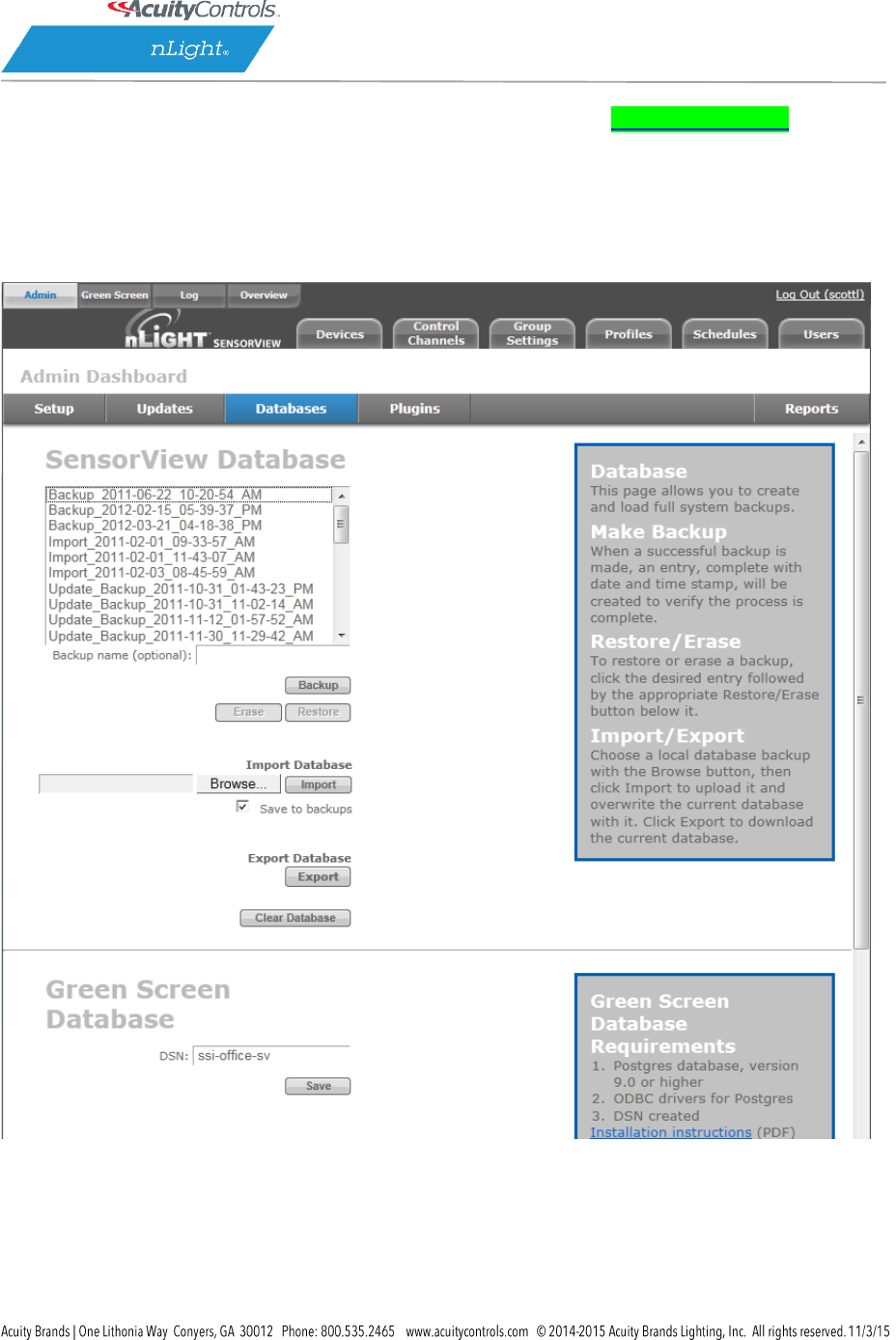
Databases
The Admin Database page allows you to create and load full system backups.
Database Selection (left side of browser) displays all databases available for your admin user account.
There are multiple types of databases from which to select.
Automatic_Backup – Backup of a current or formerly active database. Databases are
automatically backed up daily (by default) and receive this label prefix.

SensorView Manual
Page 94 of 123
Backup – a backup of a database that has been created on an as-needed or as-desired basis.
Administrators may backup the database at any time. To backup a database from the list, select
the desired database, enter a name in the “backup name” field, and click Backup.
Import -an imported database
Update – a database backup created while updating SensorView.
Backup, Erase, Restore Buttons
Any database selected from the list can be Backed up, Erased or Restored.
Make Backup – When a successful backup is made, an entry, complete with date and time
stamp, will be created to verify the process is complete.
Restore/Erase – To restore or erase a backup, click the desired entry followed by the
appropriate button.
Import – Choose a database backup with the Browse button, then click Import to upload it and
overwrite the current database.
Export – Click to download the current database.
SensorView Manual
Page 95 of 123
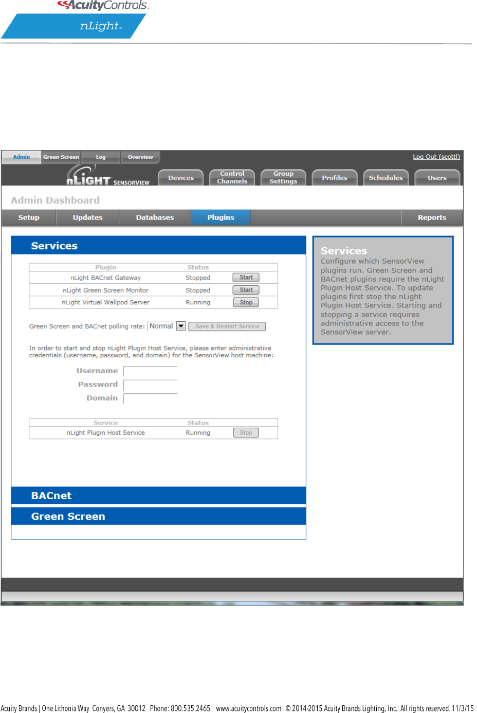
Plugins
The Admin dashboard for Plugins- Services, BACnet and Green Screen.
Services
At upper left of the Services section each Plugin is listed along with its current status, either
Running or Stopped.
Green Screen and BACnet Polling rate
Controls the rate at which these plugins are being polled. Increasing the rate may allow for Change of

SensorView Manual
Page 96 of 123
Value notifications (BACnet) and GreenScreen reporting points to increase, but will result in additional
network traffic. To change the polling rate for these plugins, select a new rate, and click Save & Restart
Service.
The nLight Plugin Host Services status (either running or stopped) is indicated in the table below.
Controlling the nLight Plugin Host Service requires system administrator credentials (not SensorView
credentials). You may have to contact your local IT department to retrieve the proper set of credentials.
Administrators can enter their credentials (Username, Password, and Domain) for the SensorView host
machine, and click Stop or Start.
BACnet Admin Screen
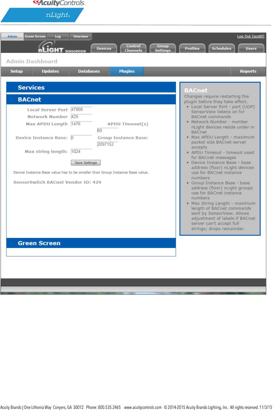
SensorView Manual
Page 97 of 123
BACnet administrative settings displayed are:
Local server port – The port (UDP) on which SensorView receives BACnet commands
Network Number – Number nLight devices reside under in BACnet. Default value is the nLight
BACnet Vendor ID, 429.
Max APDU Length – maximum packet size BACnet server accepts
ADPU timeout(s) – timeout used for BACnet messages
Defined by the ISO 7816 standards, the APDU (Application Protocol Data Unit) is the
communication unit between a reader and a card.
Device Instance Base – base address (floor) nLight devices use for BACnet instance numbers
Group Instance Base – base address (floor) nLight groups use for BACnet instance numbers

SensorView Manual
Page 98 of 123
Max String Length – (default is 1024) maximum length of BACnet commands sent by
SensorView. Allows adjustment of labels if BACnet server can’t accept full strings; drops
remainder.
To change these settings enter the desired value in the appropriate field(s) and click Save Settings.
Device Instance Base must be smaller than Group Instance Base value.
The nLight Plugin Host Service must be restarted before the modified settings will take effect.

SensorView Manual
Page 99 of 123
Reports
Linked directly to the current active SensorView database, authorized administrators can view detailed
reports on the following:
Network Device Report: Creates a printable report containing basic information about the devices in
the network and their basic properties, such as Label, Device ID, Firmware Version, Zone, and parent
Bridge.
Profile & Scene Report: Creates a printable report describing the configuration of all profiles and scenes
currently in the system.
Device Settings Report: Creates a printable report describing the default settings for all nLight devices in
the system.
Global Channels / Preset Report: Creates a printable report listing all configured Global Channels along
with the devices broadcasting and tracking within them. Also listed is all Global Preset configurations
saved to any Global Preset capable device.
Discovery Report: Creates a printable report listing basic discovery statistics about all nGWY devices in
the system. This is generally used for diagnostic purposes only.
BACnet Inventory Report: Creates a CSV report that lists all BACnet devices available in the system. It
lists the Instance Numbers for all BACnet devices, as well as the instance values for all available
properties. This is typically provided directly to the BACnet integrator.
SensorView Manual
Page 100 of 123
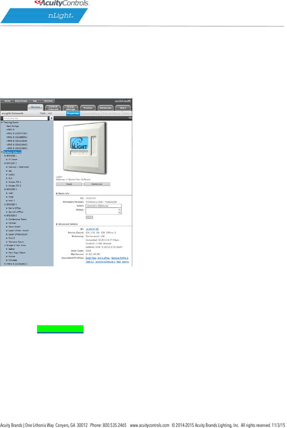
Devices
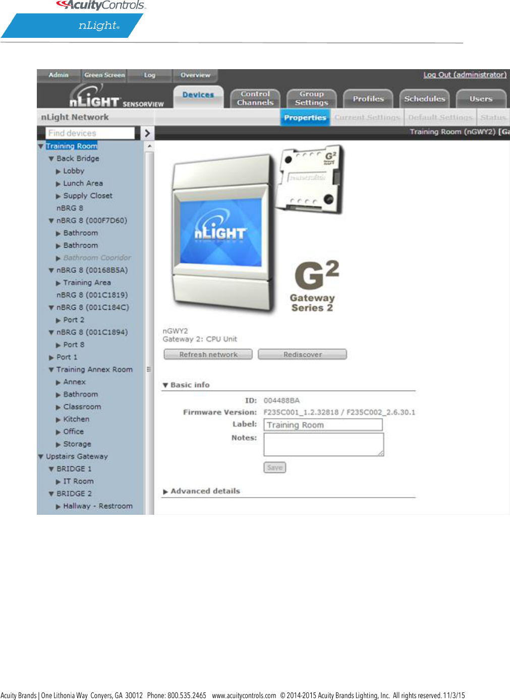
On the SensorView Overview Device Properties page the user selects from the device tree. By default
these devices are listed in hierarchical order: gateways are parents of bridges, which are parents of
zones, each of which contain sensors, switches, relays, dimmers, or other devices.
Gateway Properties
Note that some items on Properties pertain only to certain types of devices and do not appear
otherwise.
Basic Info:
ID: An unique ID assigned to the device.
Firmware Version: Indicates the firmware currently installed and running on the device. If this
number does not match information in the Overview screen under “Updates“, it may be time
for a firmware update.
Label: This custom label should be used to describe and represent the device.
Notes: (optional) Comments on this device or the area it serves.
Load: (in Watts) Shows and/or sets the load on the selected device or devices within the
selected zone; used with Green Screen. Only applicable to devices containing relays or nIO
LEDs.
Update Historical Load Data: This indicates whether to change the load for data points
previously collected for Green Screen (when checked) or leave old load values unaltered
(unchecked). Only applicable to devices containing relays or nIO LEDS.
Advanced detail

SensorView Manual
Page 101 of 123
IP: The IP address of the selected gateway. nGWY only.
Device Count: Shows the number of devices beneath this gateway in the network, including its
bridges and all devices below them. DB shows the number of database records associated with
the selected gateway, which should match the number of devices. Most SensorView users may
ignore this data, which is primarily used for network and system diagnostics. Also indicated are
the number of devices offline, if any. nGWY only.
Discovery: Indicates the last time the selected Gateway was polled by SensorView. This occurs
when an instruction to the device is sent by a SensorView user, or a firmware update. You can
perform discovery any time by clicking Rediscover. nGWY only.
Date Code: Indicates the internal lot number for the device.
NTP Server: Network Time Protocol (NTP) is a protocol for synchronizing the clocks of computer
systems over a network. This is used to keep times on gateways in sync, and the NTP server’s IP
address is listed here. nGWY2 only.
Parent Gateway: The name of the Gateway directly above the selected bridge in the network
hierarchy.
Network Depth: The number of steps below a gateway in the network hierarchy.
Associated Profiles: Profiles which include the selected device.
Zone: The name of the Zone in which the selected device resides.
Parent Device: The name of the device above the selected zone in the network hierarchy.
BACnet Instance (Number) A device’s instance number is used to uniquely identify nLight
devices connected to BACnet.
The instance number is combined with other parameters in BACnet, such as Object Type or Object
Name. Because BACnet services many facilities and many different companies, the instance number
compensates for and eliminates any possibility of duplicate identifiers across the BACnet network. It is
similar to the WHOIS function for domain names on the Internet. Requesting devices across the network
can identify the device, its address information and its relative position in the network hierarchy. More
information on BACnet Instance Numbers.
Output Controls
Provides convenient controls for viewing the current status of the device, as well as modifying the
device’s outputs (relays or dimmers as appropriate).
Health
This section provides diagnostics read-outs for nLight Engineers and Field Techs.

SensorView Manual
Page 102 of 123
Control Channels
nLight Devices exchange control information via the use of Local and Global channels. Communication
performed within a Zone (single nBRG port) is dictated via Local Channels; while Global Channels allow a
device to receive input from any other device on the nLight network.
SensorView allows users to modify both Local and Global Channels to configure the control they
need. Local Channels are commonly used to subdivide a single Zone and allow for switches to control
individual fixtures or switch legs within a Zone, rather than all of them. Global Channels are more
commonly used to provide instantaneous switch control over the entire building with a master switch.
Channels, both Global and Local, can be used to fine tune the control that one devices has over others,
for Occupancy, Switching, and Daylighting.

SensorView Manual
Page 103 of 123
Local Channels
SensorView’s Local Channels tab allows a user to specify the channeling for all devices in the selected
zone. Users can configure Switching, Occupancy, and Photocell channels on a single screen.
Devices tracking a particular channel will respond to commands sent by any device broadcasting on that
channel. To configure one device to control another simply set the broadcasting and tracking numbers
for the devices to the same number. The column on the far right is a combined view, indicating all
devices broadcasting and tracking on the same channel, as changes are made this column will update.
Start by selecting a zone from the tree. Then configure channels (eg. make this switch control only the
lights at the back of the room) change the broadcasting channel of one or more devices to a new
number, and add that number to the tracking channels of one or more devices the broadcaster(s) should
affect. Add or remove tracking channels by expanding a drop-down and checking or unchecking the
SensorView Manual
Page 104 of 123
desired channels. Note that as changes to the channels are made the far right column will update to
indicate which devices are tracking/broadcasting on each channel.
Global Channels
With traditional wired nLight systems, devices within a zone communicate occupancy, photocell and
switch events over local channels.
With global channels, communication of this information is possible between zones as well. This
provides enhanced design flexibility for applications requiring master control stations or centralized
relays. Global channels are set through SensorView.
Select desired Switches from the Tree menu, and Select Switch on the Global Channels screen, and
select the Global Channel on which the desired devices will operate. Click to add desired Switches
(devices) to this
If no channel is yet defined, select New Channel. SensorView will display the next available Global
Channel.
Devices can be added to more than one channel if desired. Click New Channel to see the next available
Global Channel.
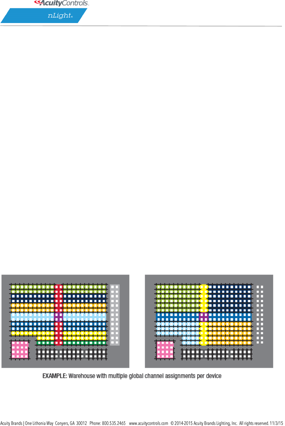
nWiFi Global Channel Functionality
Out of the box nWiFi devices communicate with other devices directly connected to them, but when
configured can use the WiFi network and global channels to link to other devices wirelessly and
communicate switch, occupancy, and/or photocell events.
For example, a common global channel would be tracked by devices within each colored area above.
On/Off & Dim Level control of each area is then possible via a standard WallPod. nWiFi devices can be
set to track any/all of the 128 global channels – providing the flexibility to assign each device into
SensorView Manual
Page 105 of 123
multiple groups based on its location or type (i.e., All Rows, Columns, Alternating, Load Shed eligible,
Custom, etc.). Simultaneous On/Off & Dim Level control of multiple global channel groups (referred to
as “global preset”) is possible via a Scene Selector WallPod.
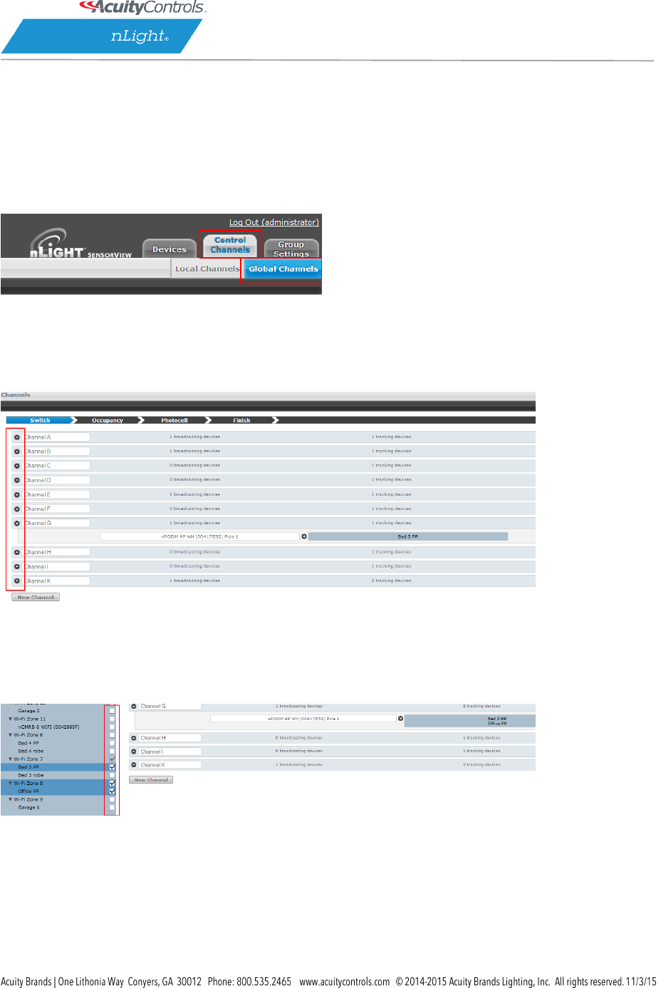
nWiFi Global Commands
To create groups of devices that will switch on and off together, click on the Control Channels tab at the
top right of the page followed by the Global Channels tab. The tree will expand and display all of the
devices that can broadcast and track events over the nWIFI network.
Any Global Channels that have been previously assigned will be displayed. A maximum of 128 Global
Channels are available. To view or edit the devices that are part of a global channel expand the channel
by clicking the arrow next to the channel name. Click the box under Broadcasting Devices or Tracking
Devices to add or remove devices from that group using the device tree.
After setting up the desired channels, click Finish followed by Save Global Channels.
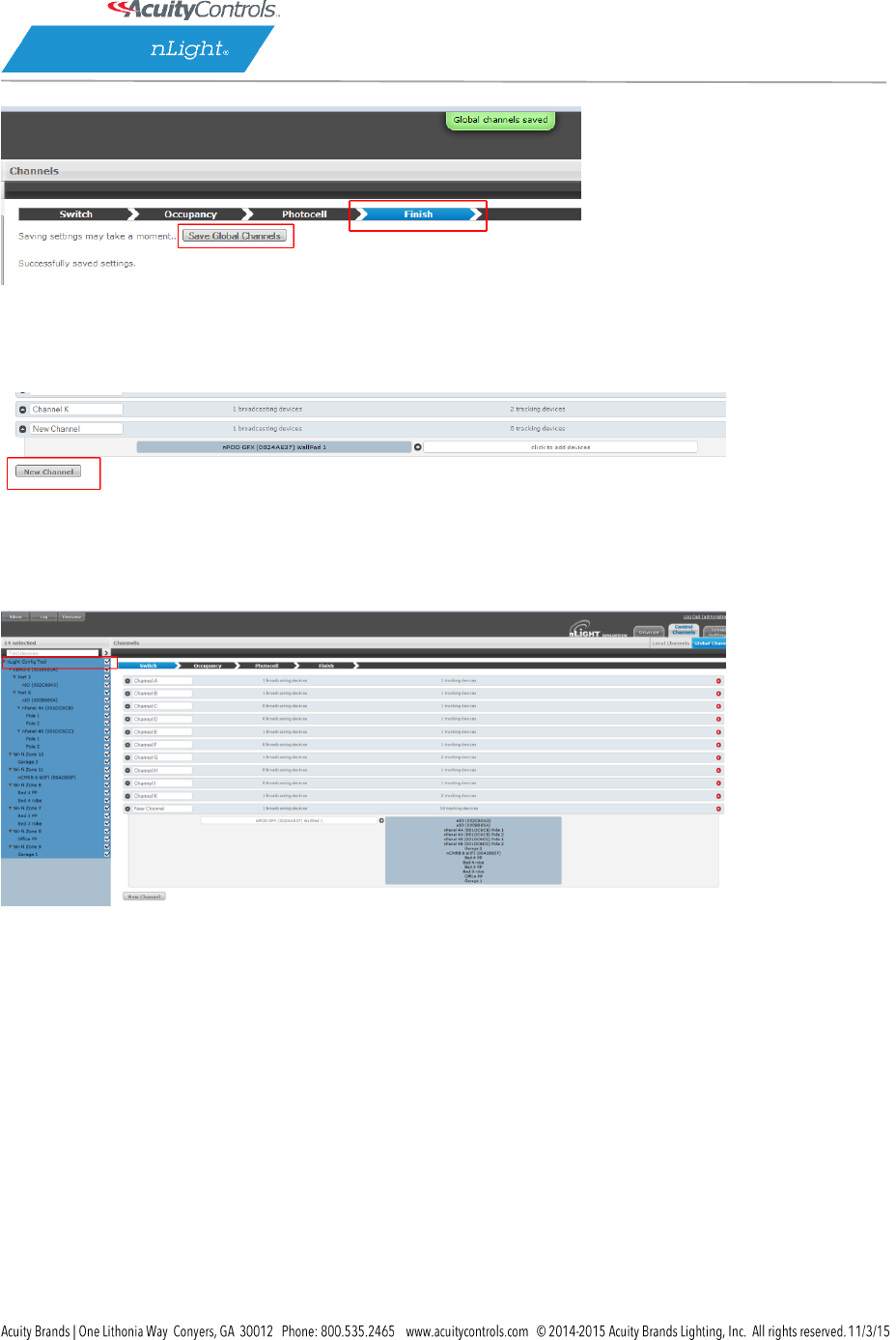
SensorView Manual
Page 106 of 123
To create a new Global Channel click the New Channel button, change the default label if desired, and
select Broadcasting or Tracking to begin adding devices from the tree.
To select (or deselect) multiple devices at once in the tree click the box next to a top-level device, such
as a gateway or nLight Config Tool, to affect everything below it.
Tip: Channels used in a global preset shouldn’t contain the same devices to prevent On/Off conflicts.
e.g., a preset where 50% of all lights go on and the other half go off, two global channels are required
(one for the On command & the other for Off).
Global Preset: a combination of global channels commands (on/off/dim level) activated simultaneously
by a device. Each global preset can feature different commands on different channels. A global preset
can contain between 1 and 80 Global Channels.
For example: a Scene Selector can simultaneously send an On command to all devices tracking global
channel A and an Off command to all devices tracking global channel B.
To set a Global Preset on a Graphic WallPod (nPOD GFX), find the device in the tree on the Devices page
and click the Scenes tab.
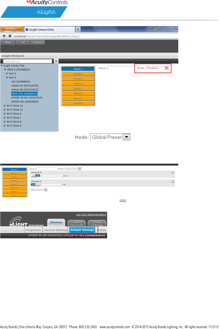
SensorView Manual
Page 107 of 123
Change the mode to Global Preset and select the desired global channels.
Once they have been selected set them to On, Off, or a Dim Level (if dimming hardware is installed) and
click Save.
To set a Global Preset for an nPOD(M) device, find device in the tree on the Devices page and select the
Default Settings tab near the top right of the page.
Change the mode to Global Preset and select the desired global channels. Once selected set them to On,
Off, or a Dim Level (if dimming hardware installed) and click Save.
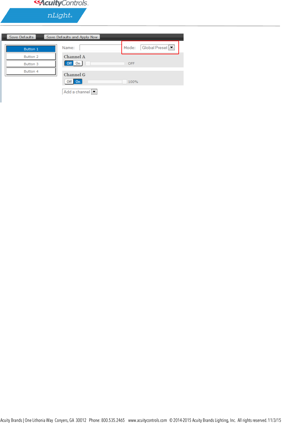
SensorView Manual
Page 108 of 123
Global Presets are resent every time the button on the device is pushed; if any fixture(s) does not
respond to the Global Preset, resend by pressing the button again.
SensorView Manual
Page 109 of 123
Group Settings
Here default settings can be modified for many devices at once. Start by selecting devices from the tree,
which will show a drop-down to add a setting. The list of settings available depends on the devices
selected.
Add one or more settings, then select the desired value(s). When finished, click Save Defaults.
Selecting Multiple Devices from the Tree
MultiSelect is a selection mode offered by SensorView’s tree. When operating in this mode, all line
items displayed in the tree will be given a checkbox which will allow for selection. Single clicking on a
device no longer displays information specific to the device, but rather selects/deselects it.
This mode of selection is used when large amounts of devices are to be operated on simultaneously.
None Selected
(empty Checkboxes)
Bridge Selected
(Parent gateway
checked in gray)
Zone expanded.
All zone devices checked
Specific zone devices
unchecked
Selecting a zone device (a device that exists in a zone) only selects/deselects that device. Selecting a
zone, bridge, or gateway selects/deselects children; this allows for a user to quickly select all devices in a
zone, bridge, or gateway.
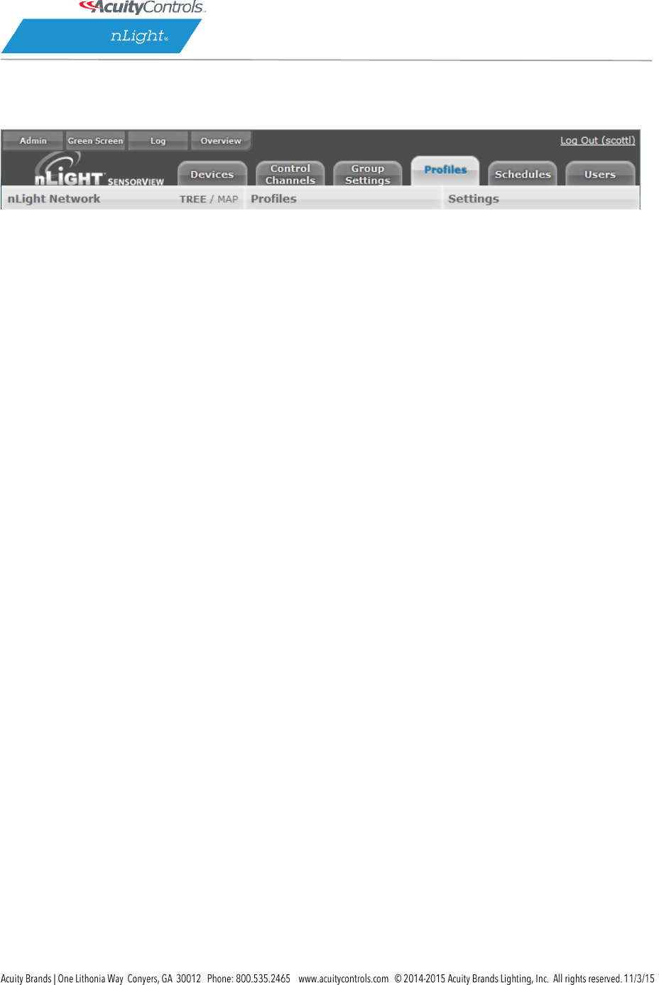
SensorView Manual
Page 110 of 123
Profiles
The Profiles tab is where control modes and settings for a particular group are selected. A schedule
(complete with a recurrence pattern) and priority are also chosen on this page.
Profiles are stored in the database and the Gateway, which administers profiles according to priorities.
The profiles can also be activated on demand via SensorView or the Gateway.
Click New to start creating a new profile, or the name of a profile in the list to edit an existing profile.
Add or remove devices using the checkboxes in the tree on the left. Checked devices can participate in
the profile and receive applicable settings while the profile runs.
Scheduler
Schedule date/hour/minute for any setting change or control mode
Astronomical start/end dates include +/-180 minute deviance from Sunrise/Sunset
Set daily/weekly/monthly/yearly recurrences; drilldown options provide more detailed patterns
Priority:
Select the priority of the profile to change, then use the arrows to move to the appropriate
position, or down into the disabled area
Unlike other systems which allow scheduling of lights on/off or on-demand dimming scene control,
nLight provides users with the ability to schedule changes to almost any operational parameter. This
allows for dynamic sequences of operation that can be tailored to a space across different times of day
and/or dates.

SensorView Manual
Page 111 of 123
Schedules
The Schedules tab shows all scheduled profiles for zones and devices in the nLight network, on a 24-
hour schedule for a given date.
Hovering over a profile name displays the profile’s begin and end times. Clicking the profile name is a
shortcut to editing that profile on the Profiles tab.
When a zone is expanded, individual schedule bars for the zone’s devices are generated. These bars are
colored to denote a specific profile.
Clicking the header with the time markings will bring up a date picker for quick viewing of a future date.
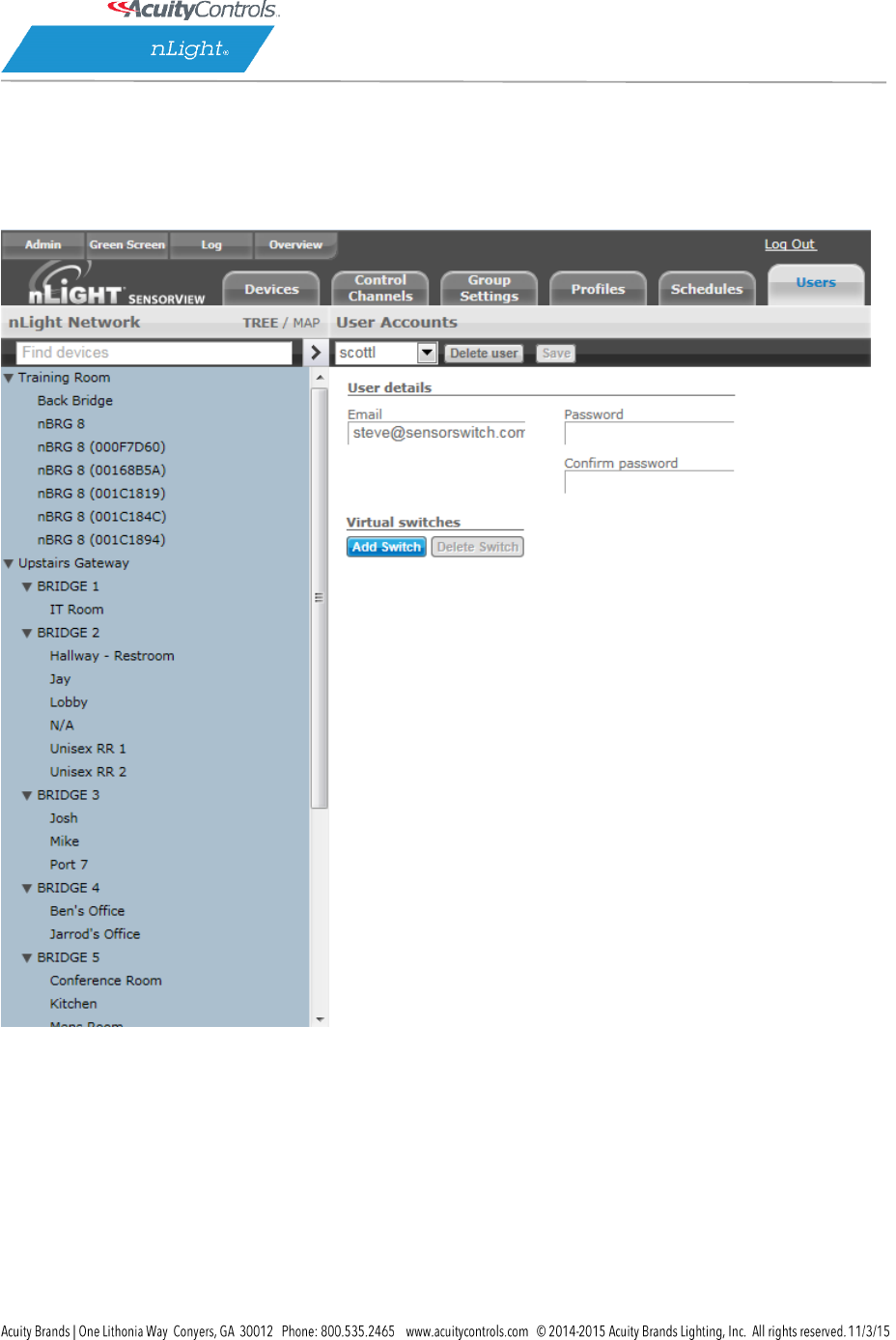
SensorView Manual
Page 112 of 123
Users
The Users tab manages users and their permissions to nLight devices and Virtual WallPods.
At the top, under User Accounts, is a drop-down that lists users. Select a user to display and edit the
user’s details.
You may assign one or more Virtual Switches to a user by clicking Add Switch. The newly added switch
can be labeled using the text field. Select either Zone Channel or an Individual device from the Control
Type drop-down.
For zone channel switches Select Zone from the drop-down. Individual devices associated with that zone
will be displayed beneath. For individual device Select device to control, and it will be added to your list.

SensorView Manual
Page 113 of 123
When finished click Save.
Adding, Modifying, and Deleting Users
To add a user select Add a user from the drop-down. Or select a username to edit that user. Clicking
Delete user will delete the user selected in the drop-down.
Users you control, other than yourself, can be one of several user types, which dictates their level of
capabilities within SensorView.
Read-only users are only allowed to view status and current settings from the devices they are
given permission to; they are not allowed to affect any sort of change to the system.
Basic users are allowed to read and configure the devices within their permissions, including
managing profiles for (just) those devices.
Administrators have access to the Admin page. In addition to Basic User tasks for their
permission set, Administrators are also allowed to run updates and manage SensorView
(location, gateway passwords, mail servers, and users).
SensorView Manual
Page 114 of 123
SensorView Terms
100 Hour Burn-In: Overrides relay on and/or dimming output to full bright (typically
used for lamp seasoning)
Auto Set-Point: Photocell calibration procedure for detecting optimum lighting control
level
Auto to Override On: Special Mode where lights are turned on initially by occupant
detection but then left in the Override On state
BACnet Instance (Number) A device’s instance number is used to uniquely identify
nLight devices connected to BACnet.
The instance number is combined with other parameters in BACnet, such as Object Type
or Object Name. Because BACnet services many facilities and many different companies,
the instance number compensates for and eliminates any possibility of duplicate
identifiers across the BACnet network. It is similar to the WHOIS function for domain
names on the Internet. Requesting devices across the network can identify the device,
its address information and its relative position in the network hierarchy. More
information on BACnet Instance Numbers.
BMS (Building Management System)
A Building Management System (BMS) is a network which monitors and/or controls
devices in a building, campus, or in multiple facilities.
When used for monitoring, the BMS polls and displays information from various types
of equipment. BMS may monitor alarm conditions for equipment dependent up
humidity or temperature. SensorView polls nLight devices, for example, and collect
sensor information on occupancy, light levels, microphonic activity, among others.
When used as a control system, the BMS has the ability to change settings on
networked devices. This can be done manually by facilities/BMS managers, or by pre-
programmed conditions, where settings of devices are modified in response to readings
collected by other networked devices. Slave devices pass data from sensors to the
master, which processes collected data and issues instructions for any necessary
settings changes. Instructions can also be issued to devices based on Profiles which may
be scheduled to start at a certain time of day, or triggered by readings and thresholds of
other devices. nLight products integrate with BMSs using Internet protocols and open
standards such as BACnet.
Broadcast Analog Input: Input mode that senses a 0-10 VDC input
Button Mode: Overrides a device and enables its push-button to toggle the device’s
internal relay(s) or dim level
Dimming Offset: Fixed voltage difference of dimming output from dimming photocell

SensorView Manual
Page 115 of 123
Dimming Rate: The speed at which automatic changes to the light level occur
Dual Technology (Microphonics): A second method of occupancy detection that allows
the sensor to hear occupants
Dual Zone Fan Mode: Dual Zone photocell mode where Zone 2’s photocell control is
disabled
Dual Zone Off-Point: Zone 2’s set-point as a percentage of Zones 1’s set-point (Dual
Zone photocell applications only)
Dual Zone Offset: Fixed voltage increase of Zone 2’s dimming output from Zone 1’s
dimming output (Dual Zone photocell applications only)
Dual Zone Offset Mode: Dual Zone photocell mode where Zone 2’s set-point is a
selected percentage higher than Zones 1’s set-point
DZ Photocell Mode: Indicates a Dual Zone photocell sensor’s method of operation
Enabled – Both Positive and Negative: User can increase or decrease lighting level set by
dimming photocell
Enabled – Negative Only: User can decrease lighting level set by dimming photocell
Follow Photocell Mode: Instructs how a device’s dimming output reacts relative to a
dimming photocell
Idle Time Until Dim: The length of time after last detected occupancy that a sensor will
reduce lighting to unoccupied dim level.
Incremental Set-Point Adjust: Alters the target light level that is to be maintained by
the device (in footcandles)
Invert Relay Logic: Reverses functionality of relays
LED: Indicates the behavior of a device’s LED
Local Only Occupancy Tracking: Instructs a device with a relay and/or dimming output
to react to only its internal occupancy information
Local Only Photocell Tracking: Instructs a device with a relay and/or dimming output to
react to only its internal photocell information
Local Only Switching Tracking: Instructs a device with a relay and/or dimming output to
react to only its own manual switching and/or dimming events
Manual On to Full Auto: Special Mode that initially requires the occupant to manually
turn on the lights, after which the sensor assumes full on/off control
Manual to Override On: Special Mode that requires the occupant to manually turn on
the lights and then leaves them in the Override On state
Microphone Grace Period: The time period after lights are automatically turned off that
they can be reactivated by sound
Momentary: Input mode that senses a pulse style switch
Night Light Brightness: The percent of full brightness the push-buttons LED illuminates
Network Time Protocol (NTP) is a protocol for synchronizing the clocks of computer
systems over a network. nLight gateways are synchronized with an NTP Server.
Occupancy Broadcast Channel: The channel on which a sensor transmits its occupancy
information
Occupancy Broadcasting: Indicates whether a sensor will transmit its occupancy
information to the rest of its zone

SensorView Manual
Page 116 of 123
Occupancy Tracking: Indicates whether a device’s relay and/or dimming output will
react to occupancy information
Occupancy Tracking Channel: The channel on which a relay and/or dimming output
receives occupancy information
Occupied Bright Level: The output level (0-10 VDC) that a dimming sensor sets the
lights when occupancy is detected (not applicable if photocell is enabled).
Override: Indicates whether a device’s relay is forced on/off and/or dimming output is
forced to maximum/minimum
Photocell Broadcast Channel: The channel on which a sensor transmits its photocell
information
Photocell Broadcasting: Indicates whether a sensor will transmit its photocell
information to the rest of its zone
Photocell Dimming Range (High): The maximum output level (0-10 VDC) up to which an
automatic dimming photocell will control
Photocell Dimming Range (Low): The minimum output level (0-10 VDC) down to which
an automatic dimming photocell will control
Photocell Mode: Indicates a photocell sensor’s method of operation. One mode
enables the sensor to turn the lights both on and off while the other mode can only
inhibit (prevent) the lights from turning on
Photocell Tracking: Indicates whether a device’s relay and/or dimming output will react
to photocell information
Photocell Tracking Channel: The channel on which a relay and/or dimming output
receives photocell information
Photocell Transition Off Time: The time period for which a photocell must measure a
light level above the set-point before it will turn the lights off
Photocell Transition On Time: The time period for which a photocell must measure a
light level below the set-point before it will initiate the lights on
Predictive Exit Time: The time period after manually switching lights off for the
occupant to leave the space (Predictive Off mode only)
Predictive Grace Period: The time period after the Predictive Exit Time that the sensor
rescans the room for remaining occupants (Predictive Off mode only)
Predictive Off: When lights are switched off, this Special Mode determines whether
occupants remain or left the room, so as to leave the lights in either the Override Off or
Auto On state.
Profile Mode: Mode that commands a Gateway to run any number of specified profiles
Profile Override: Whether profiles selected via a Scene Controller button will cancel out
or run concurrently with other profiles.
Reduced Turn-On: Reduces the initial PIR detection strength; for use in areas where
reflections are in sensor’s view
Scene Expiration Time: The length of time a selected scene or profile will run before
automatically disengaging and reverting affected devices back to defaults

SensorView Manual
Page 117 of 123
Scene Mode: Mode that causes button to initiate pre-programmed settings on devices
within a local zone
Scene Mode – Momentary: Mode where pre-programmed settings are run on devices
within a local zone when a pulse style switch is sensed from the connected device
Scene Mode – Toggle: Mode where pre-programmed settings are run on devices
within a local zone when an open/close style switch is sensed from the connected
device
Semi-Auto: Special Mode that requires the occupant to manually turn the lights on,
while having them turn off automatically by a sensor
Semi-Auto Grace Period: The time period after lights are automatically turned off that
they can be reactivated with movement
Set-Point: The target light level that is to be maintained by the device (in foot-candles)
Special Modes: Unique defined behaviors for relays and/or dimming outputs
Start-to-High: Lights go to full bright for 20 minutes upon initial power up
Stepped Dimming (DUO) Mode: Dual Zone photocell mode where the appropriate
on/off combination of the two associated relays is maintained in order to always meet
the photocell set-point requirements
Stepped Dimming (DUO) – Never Off: Dual Zone photocell mode where the
appropriate on/off combination of the two associated relays (except both off) is
maintained in order to always meet the photocell set-point requirements
Sunlight Discount Factor: Value used to improve the tracking accuracy of a photocell
during periods of high daylight; decreasing the value will lower the controlled level of
the lights
Sweep Exit Time: The time period before a sweep is executed, setting time delays on
affected devices to zero
Sweep Grace Period: The time delay before a sweep is executed, so a user pressing a
switch to activate the sweep may exit the room or building before the sweep occurs
Sweep Mode: Mode that causes a Scene Controller button to set the remaining time
delay for all devices on a gateway
Sweep Mode – Momentary: Mode that sets the remaining time delay for all devices on
a gateway when a pulse style switch is sensed from the connected device
Sweep Mode – Toggle: Mode that sets the remaining time delay for all devices on a
gateway when an open/close style switch is sensed from the connected device.
Switch Broadcast Channel: The channel on which a device with a manual switch and/or
dimmer transmits
Switch Broadcasting: Indicates whether a device with a manual switch and/or dimmer
will transmit events to the rest of its zone
Switch Tracking: Indicates whether a device’s relay and/or dimming output will react to
manual switching or dimming events
Switch Tracking Channel: The channel on which a relay and/or dimming output receives
manual switching or dimming events

SensorView Manual
Page 118 of 123
Timed Override Delay: The length of time an Override On state that is initiated by a
Special Mode will remain in effect
Toggle Mode: Input mode of a nIO that senses an open/close style switch
Unoccupied Dim Level: The output level (0-10 VDC) a dimming sensor sets the lights
after the idle time until dim timer expires
WallPod Dimming Adjustments: Indicates whether user adjustments to dimming levels
are stored to device defaults (Permanent) or not (Temporary)
Wallpod Mode – Momentary: Mode that creates an equivalent WallPod signal when a
pulse style switch is sensed from the connected device.
Wallpod Mode – Toggle: Mode that creates an equivalent WallPod signal when an
open/close style switch is sensed from the connected device
WallPod Mode: Mode that causes a Scene Controller button to function like a WallPod
SensorView Manual
Page 119 of 123
Status Icons
Voltage Status
Icon
Value
Description
Bridge / Transceiver PowerState
Power Supply Voltage: (VDC)
Device has adequate power (bridge)
Bridge / Transceiver PowerState
Power Supply Voltage: (VDC)
Device is close to low power condition (bridge)
Bridge / Transceiver Power State
Power Supply Voltage: (VDC)
Device is in low power condition (bridge)
Broadcasting & Tracking Status
Icon
Value
Description
Occupancy Broadcasting
Occupancy status broadcast is active
Occupancy Tracking
Occupancy status tracking is active
Photocell Broadcasting
Photocell status broadcast is active
Photocell Tracking
Photocell status tracking is active
Switch Broadcasting
Switch status broadcast is active
Switch Tracking
Switch status tracking is active
Scenes & Profiles Status
Icon
Value
Description
Scene States (per button/nIO)
Scene State: Active
Scene associated with button is active
Scene States (per button/nIO)
Scene State: Idle
Scene associated with button is not active
SensorView Manual
Page 120 of 123
Scene States (per button/nIO)
Scene State: Disabled
Button is disabled
Scene Expiration Time
Indicates when current running scene/profile
will expire
Photocell Not Inhibiting
Indicates that photocell is not preventing
lights from being on
Photocell Status (per pole)
Transition time: (hh:mm:ss)
Indicates when current photocell state will
change
Temperature
Current temperature at the processor of the
device
LightLevel
Measured light level: (fc)
Current foot candle level as measured by the
photocell
Profile Active
Profile is currently active
Profile Inactive
Profile is NOT currently active
Photocell Status
Icon
Value
Description
Photocell Inhibiting
Indicates that photocell is preventing the
lights from being on
Photocell Not Inhibiting
Indicates that photocell is not preventing
lights from being on
Photocell Status (per pole)
Transition time: (hh:mm:ss)
Indicates when current photocell state will
change
LightLevel
Measured light level: (fc)
Current foot candle level as measured by the
photocell
PIR & PDT Status
Icon
Value
Description
SensorView Manual
Page 121 of 123
Time Delay Remaining:
(hh:mm:ss)
Indicates when current occupancy state will
expire
Tracked Occupancy Timer
Reason why pole is open or closed
PIR Activity
PIR Activity detected/detecting occupant
motion
PIR Activity
No PIR Activity. PIR not currently detecting
occupant motion
Microphonic Activity
Microphone has detected a triggering noise
Microphonic Activity
Microphone is not currently detecting noises
Occupancy, Relay & Dimming Status
Icon
Value
Description
Occupied
Room is occupied
Vacant
Room is not occupied
Dimming Output (input) level: (%)
Current % of 0-10 VDC scales
Input Dim Level
Follow Photocell Level: 4.9% or Input Dim
Level: 100%
Pole State Reason
Reason why pole is open or closed
Accumulated Hours
Accumulated Hours: 1272
Compensated Output Level
Compensated Output Level: 0
SensorView Manual
Page 122 of 123
Pole State reason: Manual Switch Override
Off
Relay State (per pole)
Closed
Relay State (per pole)
Open
Wireless Status
Icon
Value
Description
Wireless Signal Strength: (1- 5)
Indicates wireless signal strength (higher is
better)
Wireless PAN ID
Wireless panel identification number
Wireless Node ID
Wireless node identification number
Wireless Channel: (11-26)
Indicates the wireless channel currently being
used
Wireless State:
Wireless States:
Normal
Validating the network
Searching for a network that is
allowing joining
Creating a new network
Allowing joining
Cloning is happening in the system
Multiple SSI networks are allowing
joining
Lost a remote device during OTA
cloning
Wireless device is not responding
Bridge Port Information
Port States:
Polling downstream devices
Upstream port
Commissioning tool connected
Polling downstream bridges
SensorView Manual
Page 123 of 123
Error: Too many adds/deletes (reset
bridge)
Error: Local loop
Error: Non-local loop
Error: Devices connected between
bridges
Number of downstream wireless Bridges
and Transceivers
Transceiver Port Status
Port States:
Polling downstream devices
Upstream port
Commissioning tool connected
Polling downstream bridges
Error: Too many adds/deletes (reset
bridge)
Error: Local loop
Error: Non-local loop
Error: Devices connected between
bridges
Number of downstream wireless Bridges &
Transceivers
