1
UNIVERSAL
AFTERMARKET
LUMBAR SUPPORT
SYSTEMS
REVISED 04/09/09
2
Introduction
Why do we need lumbar support?
A proper lumbar support encourages correct seating posture, which provides:
• reduced strain for the vertebral disks
• improved relaxation
• optimum support for spinal column
• helps prevent back pain
Only Universal Aftermarket Lumbar Support Systems provide the upper back support and lower
pelvic area support with the lumbar region contour necessary for full seating comfort.
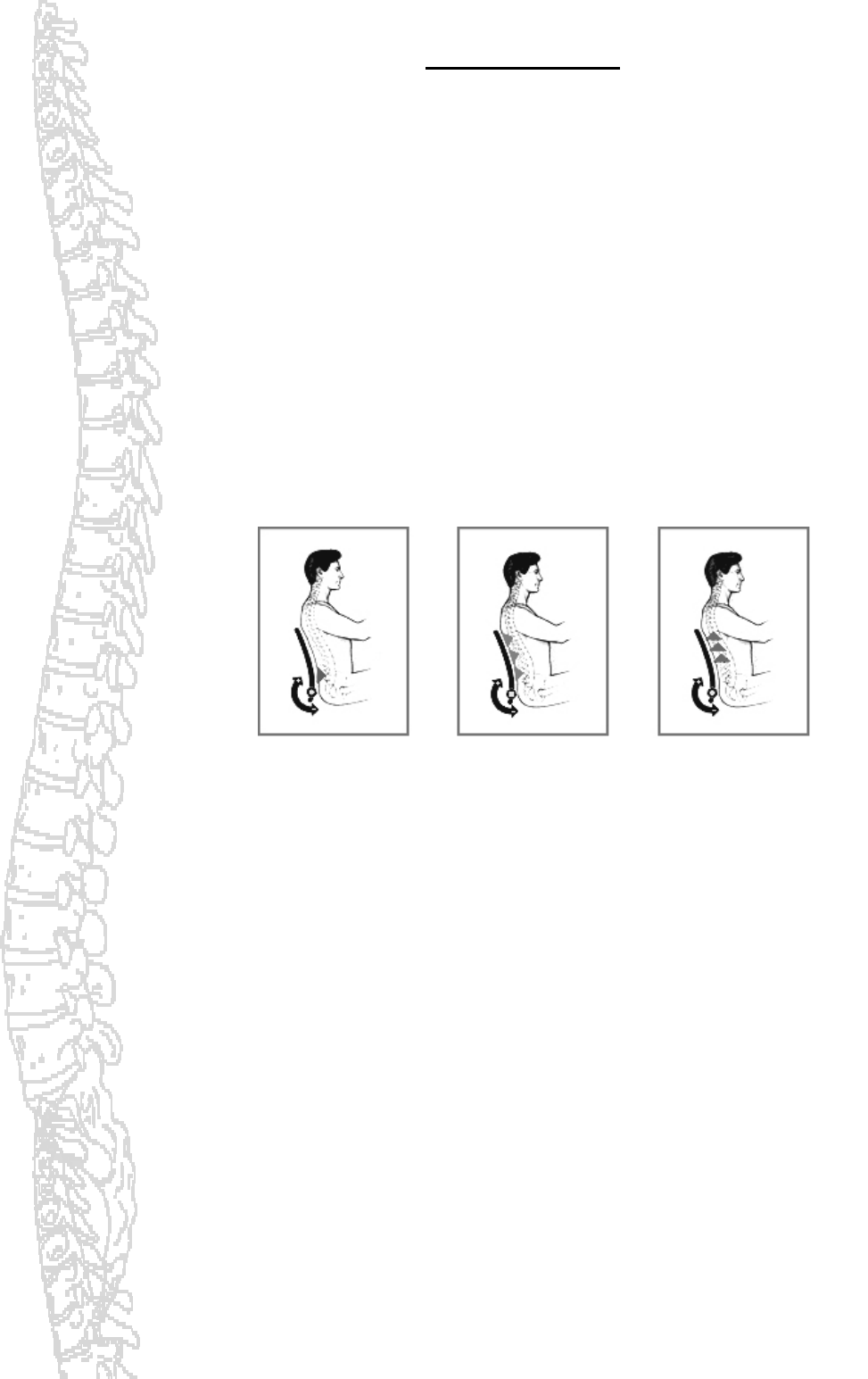
1. Constant
support of the
pelvis,
preventing it
from sliding
backwards and
providing
balance of the
spinal column.
2. Support of
each vertebral
disk in the
lumbar region,
providing relief
for the spinal
column and
relaxation of
back muscle.
3. Vertical
support of the
upper body,
easing neck
tension and
offering relief
for the
vertebral disks.
The spinal column is composed of vertebrae in a vertical arrangement. However, most lumbar
supports offer support in a horizontal orientation. This can result in pressure against the lumbar
vertebrae.
SHUKRA offers the most complete line of Adjustable Lumbar Supports on the market. We offer both
Manual and Electric models, and all of our supports are infinitely adjustable horizontally, to fit the
shape of the spine.
Pic. 1

3
Lumbar Support with Massage
Several of the models we offer, like the 4-Way Lumbar Support with Massage, also offer vertical
adjustment, to suit the height of any individual. The unique roller design and placement gently
massages the back muscles to improve blood flow to the supporting muscles. Increased circulation
relaxes muscle tension, resulting in improved comfort and reduced fatigue. The massage system
enhances comfort by improving blood flow to back muscles.
• Muscle fatigue (as indicated by RMS levels in Pic. 1 on p.2) decreases when the massage feature is
used.
• Proper set-up of massage time and IN/OUT lumbar position relaxes back muscles thus improving
comfort.
If you like to travel or spend all day working in your car, and if you are driving any car, you might
consider having a lumbar support installed.
Chevrolet - Avalanche, Blazer, Silverado 1500 (Work, Base, LS, Z71, SS), Colorado, Tahoe, etc.
Dodge - Caravan, Dakota (ST, SLT), Durango, RAM 1500
Ford - Excursion, Expedition, Explorer (XLS,, XLS Sport)
GMC - Sierra 1500, Safari, Yukon
Honda - Accord (DX, LX), Civic
Toyota - Camry, Corolla, Sequoia, Sienna, Tacoma, Tundra

4
Pacific Restyling Products Ltd
SHUKRA
Electric Lumbar Supports
3 Year Warranty
Manual Lumbar Supports
Limited Lifetime Warranty
Pacific Restyling Products Ltd & Shukra. warrants that we will replace the Universal Aftermarket
Lumbar Support Systems mechanisms for up to 3 years from the date of purchase.
This warranty is extended only to the original purchaser and does not cover collateral damage.
This warranty only covers failures due to defects in materials or workmanship which occur during
normal use.
Any modifications done to the original unit VOID this warranty.
5
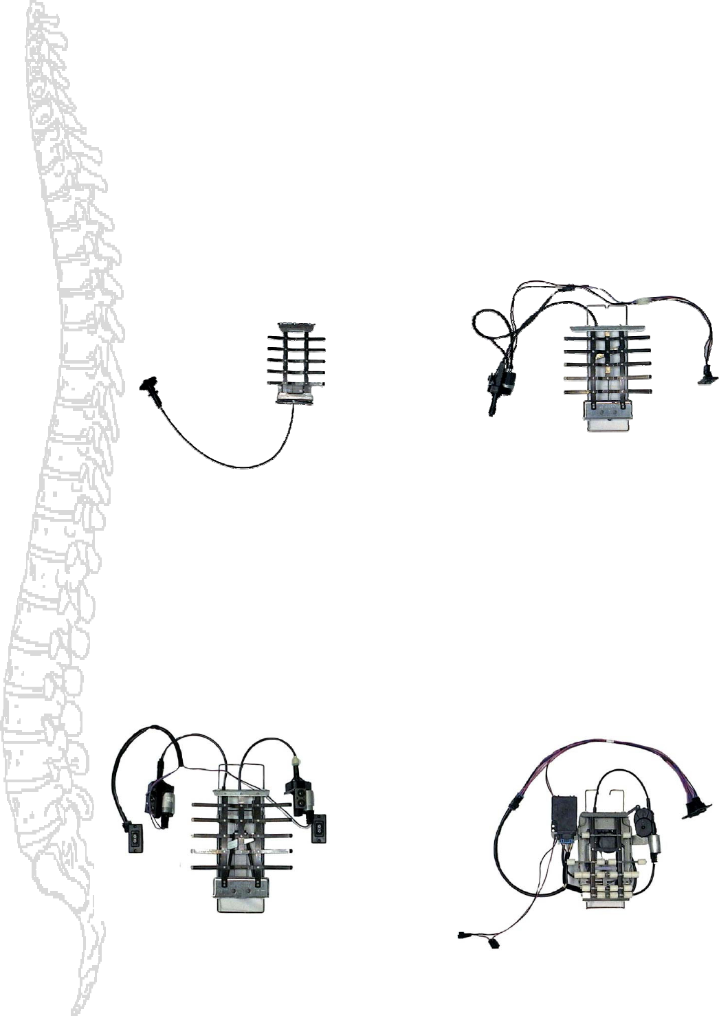
LUMBAR SUPPORT MODELS
MODEL Q
CABLE DRIVEN LUMBAR
2 WAY (IN/OUT)
DRIVER SIDE PART # L181-63-L
PASSANGER SIDE PART # L181-63-R
MODEL L
ELECTRIC LUMBAR
2 WAY (IN/OUT)
PART # L315-06
Pacific Restyling Products Ltd
MODEL N
ELECTRIC LUMBAR
4 WAY (IN/OUT, UP/DOWN)
PART # L316-06
MODEL R
ELECTRIC MASSAGE LUMBAR
4 WAY (IN/OUT, UP/DOWN
W
/VERTICAL ROLLER MOTION MASSAGE)
PART # L320-04
6
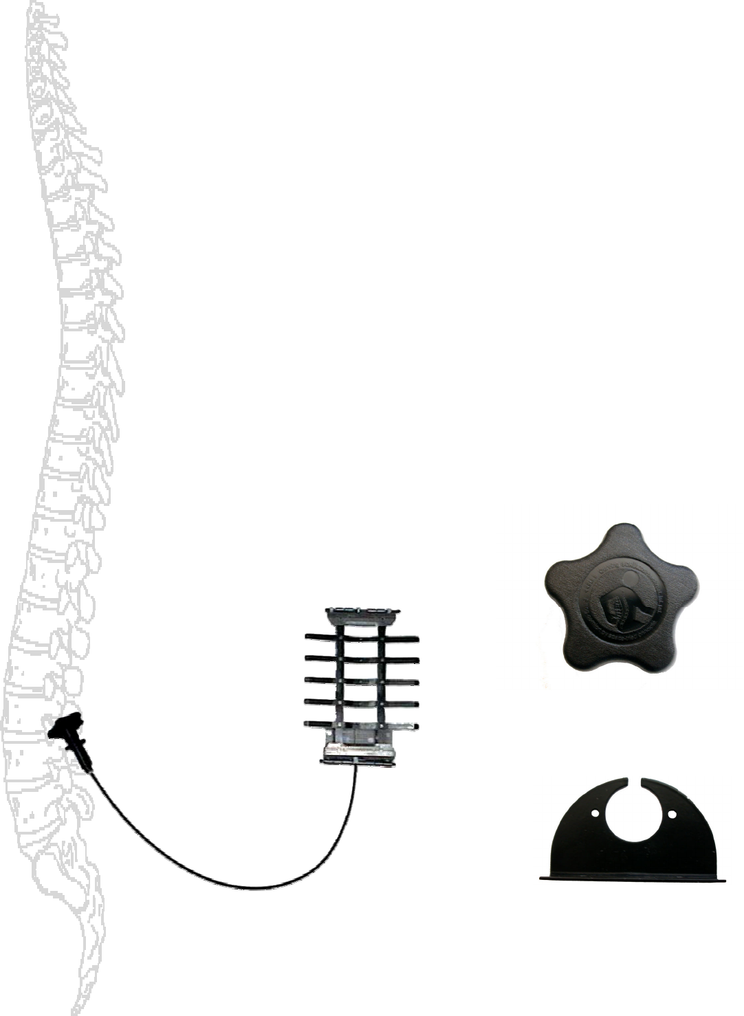
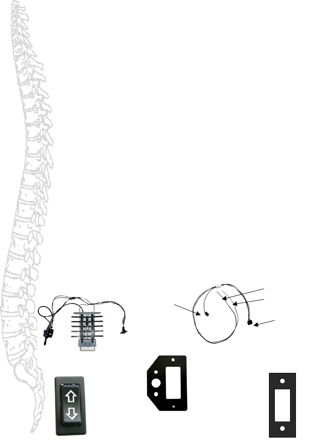
Model Q
L181-63-L & L181-63-R
2-Way Manual Lumbar Support
Installation Instructions and Parts Diagram
*Before installation carefully read the instructions.
1. Check Parts Diagram for list of all parts needed for installation.
2. Remove seat from the vehicle and remove covers from the cushion and back.
3. Remove large seat foam from backrest. Measure approximately 16’’ from top of seat cushion or have the
customer sit on the seat to locate the most appropriate mounting height location.
4. Hollow out foam for lumbar support ribs and motors approximately ¼1/4’’ -1/2’’ or as needed. This will
allow the backrest to lay flat.
5. Attach top cross member to seat frame using supplied bar (or use existing one) at approximately 14.5’’ from
top of seat cushion. Cut excess bar length.. You may also secure the lumbar by means of heavy gage Zip-
ties. This is done by drilling self-tapping screws into the backrest frame and having the zip-ties suspend
from them. Also secure to bottom corners of the lumbar to the backrest frame by zip-tying without screws.
6. Attach universal mounting plate tabs onto top cross member.
7. Attach universal mounting plate to existing bottom cross member (or add a bar if necessary). Screws, cable
ties and other fasteners are suggested. Cut excess bar length.
8. Mount actuator-housing bracket to desired location along side of seat frame. Use your own good judgment
to locate the most likely location for the switch.
9. a) Route conduit to actuator housing bracket and slip into place.
b) Screw actuator into actuator housing bracket.
10. Snap knob into actuator housing.
11. Test lumbar to ensure unit is working properly.
12. Refit covers.
2 WM Lumbar Support
Actuator-Housing Bracket – 1
Part # 174
Knob – 1
Part # 218
7
Model L
L315-06
2-Way Power Lumbar Support
Installation Instructions and Parts Diagram
*Before installation carefully read the instructions. Automotive electrical experience is recommended for this
installation.
1. Check Parts Diagram for list of all parts needed for installation.
2. Remove seat from the vehicle and remove covers from the cushion and back.
3. Remove large seat foam from backrest. Measure approximately 16’’ from top of seat cushion or have
the customer sit on the seat to locate the most appropriate mounting height location.
4. Hollow out foam for lumbar support ribs and motors approximately ¼1/4’’ -1/2’’ or as needed. This
will allow the backrest to lay flat.
5. Attach top cross member to seat frame using supplied bar (or use existing one) at approximately 14.5’’
from top of seat cushion. Cut excess bar length.. You may also secure the lumbar by means of heavy
gage Zip-ties. This is done by drilling self-tapping screws into the backrest frame and having the zip-
ties suspend from them. Also secure to bottom corners of the lumbar to the backrest frame by zip-tying
without screws.
6. Attach universal mounting plate tabs onto top cross member. *A piece of material may be placed
between universal mounting plate and cross members to prevent any rattling.
7. Attach universal mounting plate to existing bottom cross member (or add a bar if necessary). Screws,
cable ties and other fasteners are suggested. Cut excess bar length.
8. Install switch bracket in most convenient location along side of seat frame or centre console if
applicable. Each installation is different. Use your own good judgment to locate the most likely location
for the switch.
9. Use #6, Connector on wire harness diagram for ground and positive wires. Connect positive wire to
closest power source and attach ground wire to floor pan.
10. Install the seat., connect wire harness’s #3, 2-way connector to female terminal # 1 of lumbar supports
attached wire harness.
11. Mount bezel to switch bracket.
12. Route wire harness # 2 switch terminal through switch bracket and bezel. Connect switch to terminal
and snap switch into bezel.
13. Test lumbar to ensure unit is working properly.
14. Refit covers.
2 WP Lumbar Support
Switch Bezel – 1
Part #389
# 2 Switch-
Terminal
# 3, 2-way
Connector
Switch Bracket – 1
Part # 401
Switch -1
Part # 388
# 6 Connector
8
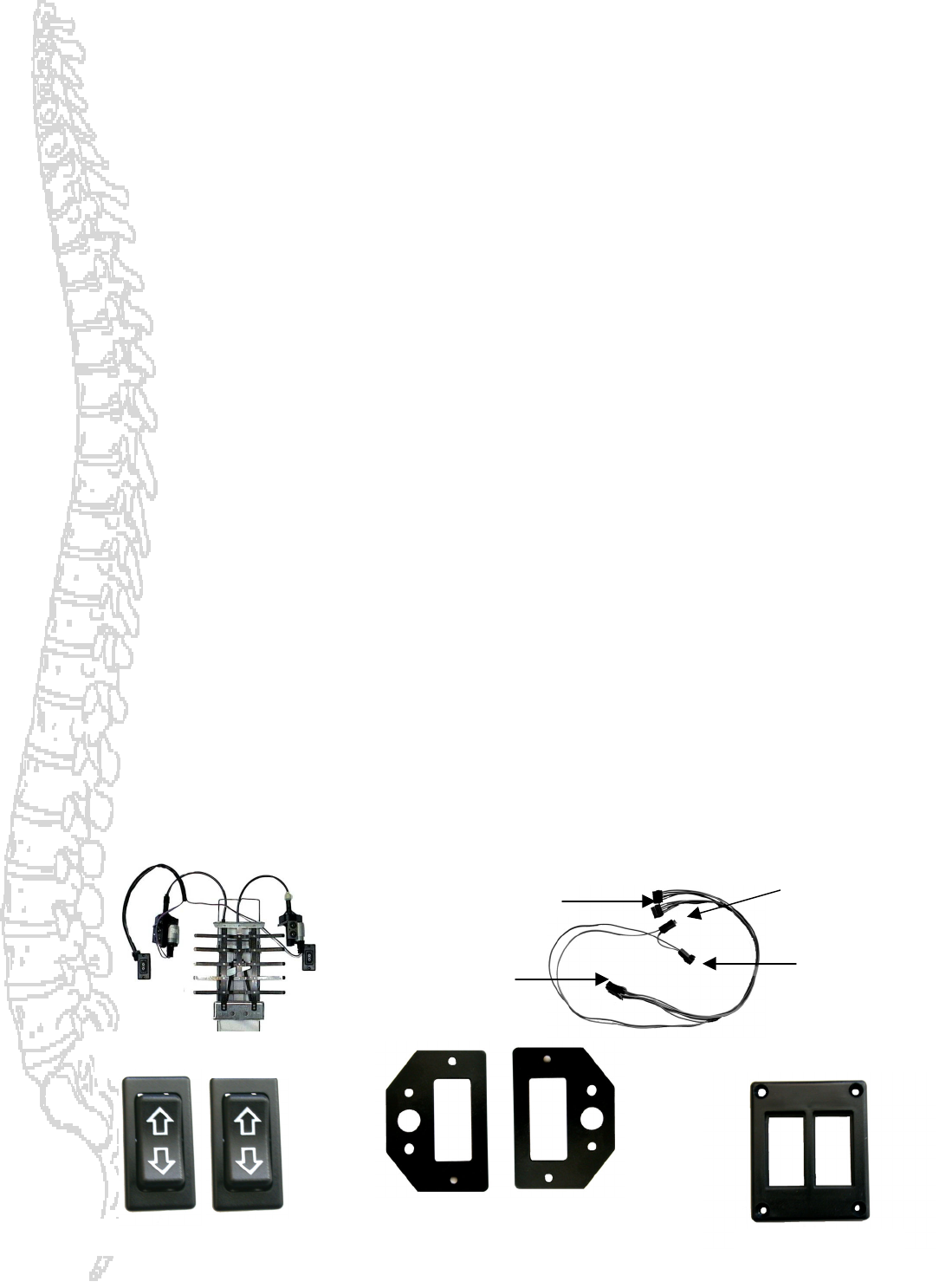
Model N
L316-06
4-Way Power Lumbar Support
Installation Instructions and Parts Diagram
*Before installation carefully read the instructions. Automotive electrical experience is recommended for this
installation.
1. Check Parts Diagram for list of all parts needed for installation.
2. Remove seat from the vehicle and remove covers from the cushion and back.
3. Remove largea seat foam from backrest. Measure approximately 16’’ from top of seat cushion or have
the customer sit on the seat to locate the most appropriate mounting height location.
4. Hollow out foam for lumbar support ribs and motors approximately ¼1/4’’ -1/2’’ or as needed. This
will allow the backrest to lay flat.
5. Attach top cross member to seat frame using supplied bar (or use existing one) at approximately 14.5’’
from top of seat cushion. Cut excess bar length.. You may also secure the lumbar by means of heavy
gage Zip-ties. This is done by drilling self-tapping screws into the backrest frame and having the zip-
ties suspend from them. Also secure to bottom corners of the lumbar to the backrest frame by zip-tying
without screws.
6. Attach universal mounting plate tabs onto top cross member. *A piece of material may be placed
between universal mounting plate and cross members to prevent any rattling.
7. Attach universal mounting plate to existing bottom cross member (or add a bar if necessary). Screws,
cable ties and other fasteners are suggested. Cut excess bar length.
8. Adhere fabric isolator sheet to foam with glue. This will prevent lumbar ribs from catching the foam.
9. Install switch bracket in most convenient location along side of seat frame or centre console if
applicable. Each installation is different. Use your own good judgment to locate the most likely location
for the switch.
10. Use #6, 3M Connector on wire harness diagram for ground and positive wires. Connect positive wire to
closest power source and attach ground wire to floor pan. NOTE: Wire harness uses own 15 Amp fuse.
11. Install the seat., connect wire harness’s #3, 6-way connector to female terminal # 1 of lumbar supports
attached wire harness.
12. Mount bezel to switch bracket.
13. Route wire harness # 2 switch terminal through switch bracket and bezels. Connect switch to terminal
and snap switch into bezel.
14. Test lumbar to ensure unit is working properly.
15. Refit covers.
4 WP Lumbar Support
Switch Bezel – 1
Part #389
# 2 Switch-
Terminals
# 3, 2-way
Connector
Switch Bracket - 2
Part # 401
Switch –2 Part # 388
# 6, 3M
Connector
15 AMP Fuse
9
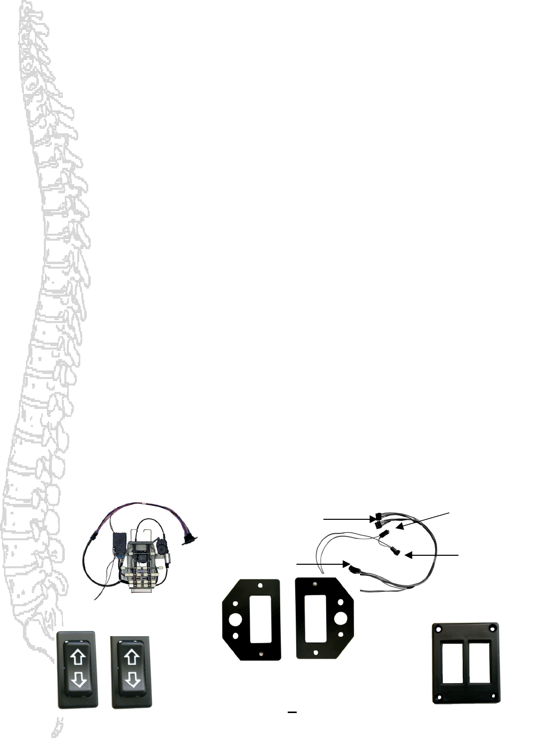
Model R
L320-04
4-Way Power Lumbar Support With Massage
Installation Instructions and Parts Diagram
*Before installation carefully read the instructions. Automotive electrical experience is recommended for this
installation.
1. Check Parts Diagram for list of all parts needed for installation.
2. Remove seat from the vehicle and remove covers from the cushion and back.
3. Remove large seat foam from backrest. Measure approximately 16’’ from top of seat cushion or have
the customer sit on the seat to locate the most appropriate mounting height location.
4. Hollow out foam for lumbar support ribs and motors approximately ¼1/4’’ -1/2’’ or as needed. This
will allow the backrest to lay flat.
5. Attach top cross member to seat frame using supplied bar (or use existing one) at approximately 14.5’’
from top of seat cushion. Cut excess bar length.. You may also secure the lumbar by means of heavy
gage Zip-ties. This is done by drilling self-tapping screws into the backrest frame and having the zip-
ties suspend from them. Also secure to bottom corners of the lumbar to the backrest frame by zip-tying
without screws.
6. Attach universal mounting plate tabs onto top cross member. *A piece of material may be placed
between universal mounting plate and cross members to prevent any rattling.
7. Attach universal mounting plate to existing bottom cross member (or add a bar if necessary). Screws,
cable ties and other fasteners are suggested. Cut excess bar length.
8. Adhere fabric isolator sheet to foam with glue. This will prevent lumbar ribs from catching the foam.
9. Install switch bracket in most convenient location along side of seat frame or centre console if
applicable. Each installation is different. Use your own good judgment to locate the most likely location
for the switch.
10. Use #6, 3M Connector on wire harness diagram for ground and positive wires. Connect positive wire to
closest power source and attach ground wire to floor pan. NOTE: Wire harness uses own 15 Amp fuse.
11. Install the seat., connect wire harness’s #3, 6-way connector to female terminal # 1 of lumbar supports
attached wire harness.
12. Mount bezel to switch bracket.
13. Route wire harness # 2 switch terminal through switch bracket and bezels. Connect switch to terminal
and snap switch into bezel.
14. Test lumbar to ensure unit is working properly.
15. Refit covers.
p
4 WP Lumbar Support
with massage
Switch Bezel – 1
Part #389
# 2 Switch-
Terminals
# 3, 2-way
Connector
Switch Bracket - 2
Part # 401
Switch -2
Part # 388
# 6, 3M
Connector
15 AMP Fuse
10
Massage Lumbar Technical Information
Lumbar Travel – 35 mm In/Out displacement
50 mm Up/Down/Massage displacement
Lumbar movement during a manual move is infinitely adjustable throughout the travel
range by the occupant
Total of 20 independent massage rollers located on massage basket
Compliance spring provided for maximum comfort
RTP – all massage units have a “Return To Position” feature. This ensures that upon
completion or termination of a massage the unit returns to its original vertical position
Driver seats systems have full lumbar memory features
Normal 4-way lumbar functionality exists on all systems
Massage functionality – 10 min cycle once initiated
Up switch input (A Quick Press and Release of switch) of less than 390
milliseconds starts massage
Down switch input (Another Quick Press and Release of switch) of less than
390 milliseconds stops massage cycle at which point the lumbar returns to its
original start location.
In/Out adjustment is possible during massage cycle. Due to the Flex-Mount of
the rollers this is often used to intensify the massage effect.
Applying an Up or Down switch input greater than 410 milliseconds during a
massage cycle moves the lumbar in the desired direction until the switch input is
removed or end of travel has been reached.
Massage cycle time (full up or down) unloaded is approximately 8.5 seconds.
