
11-1
Introduction
Today, helicopters are quite reliable. However, emergencies
do occur, whether a result of mechanical failure or pilot
error, and should be anticipated. Regardless of the cause, the
recovery needs to be quick and precise. By having a thorough
knowledge of the helicopter and its systems, a pilot is able
to handle the situation more readily. Helicopter emergencies
and the proper recovery procedures should be discussed and,
when possible, practiced in flight. In addition, by knowing
the conditions that can lead to an emergency, many potential
accidents can be avoided.
Helicopter Emergencies and
Hazards
Chapter 11

11-2
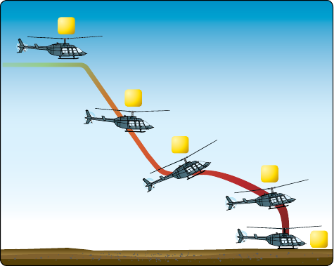
Normal Powered Flight Autorotation
Direction of flight
Direction of flight
Figure 11-1. During an autorotation, the upward flow of relative wind permits the main rotor blades to rotate at their normal speed. In
effect, the blades are “gliding” in their rotational plane.
Several factors affect the rate of descent in autorotation:
bank angle, density altitude, gross weight, rotor rpm, trim
condition, and airspeed. The primary ways to control the rate
of descent are with airspeed and rotor rpm. Higher or lower
airspeed is obtained with the cyclic pitch control just as in
normal powered flight. In theory, a pilot has a choice in the
angle of descent, varying, from straight vertical to maximum
horizontal range (which is the minimum angle of descent).
Rate of descent is high at zero airspeed and decreases to a
minimum at approximately 50–60 knots, depending upon the
particular helicopter and the factors just mentioned. As the
airspeed increases beyond that which gives minimum rate
of descent, the rate of descent increases again.
When landing from an autorotation, the only energy available
to arrest the descent rate and ensure a soft landing is the
kinetic energy stored in the rotor blades. Tip weights can
greatly increase this stored energy. A greater amount of
rotor energy is required to stop a helicopter with a high
rate of descent than is required to stop a helicopter that is
descending more slowly. Therefore, autorotative descents
at very low or very high airspeeds are more critical than
those performed at the minimum rate of descent airspeed.
Refer to the height/velocity diagram discussion in Chapter
7, Helicopter Performance.
Each type of helicopter has a specific airspeed and rotor rpm
at which a power-off glide is most efficient. The specific
airspeed is somewhat different for each type of helicopter,
but certain factors affect all configurations in the same
manner. In general, rotor rpm maintained in the low green
area (see Figure 5-3) gives more distance in an autorotation.
Heavier helicopter weights may require more collective to
control rotor rpm. Some helicopters need slight adjustments
to minimum rotor rpm settings for winter versus summer
Autorotation
In a helicopter, an autorotative descent is a power-off
maneuver in which the engine is disengaged from the
main rotor disk and the rotor blades are driven solely by
the upward flow of air through the rotor. [Figure 11-1] In
other words, the engine is no longer supplying power to
the main rotor.
The most common reason for an autorotation is failure of the
engine or drive line, but autorotation may also be performed
in the event of a complete tail rotor failure, since there is
virtually no torque produced in an autorotation. In both
cases, maintenance has often been a contributing factor to the
failure. Engine failures are also caused by fuel contamination
or exhaustion as well resulting in a forced autorotation.
If the engine fails, the freewheeling unit automatically
disengages the engine from the main rotor, allowing it to
rotate freely. Essentially, the freewheeling unit disengages
anytime the engine revolutions per minute (rpm) is less than
the rotor rpm.
At the instant of engine failure, the main rotor blades are
producing lift and thrust from their angle of attack (AOA)
and velocity. By lowering the collective (which must be done
immediately in case of an engine failure), lift and drag are
reduced, and the helicopter begins an immediate descent,
thus producing an upward flow of air through the rotor disk.
This upward flow of air through the rotor disk provides
sufficient thrust to maintain rotor rpm throughout the descent.
Since the tail rotor is driven by the main rotor transmission
during autorotation, heading control is maintained with the
antitorque pedals as in normal flight.
11-3
conditions, and high altitude versus sea level flights. For
specific autorotation airspeed and rotor rpm combinations for
a particular helicopter, refer to the Rotorcraft Flight Manual
(RFM). The specific airspeed and rotor rpm for autorotation
is established for each type of helicopter based on average
weather, calm wind conditions, and normal loading. When
the helicopter is operated with heavy loads in high density
altitude or gusty wind conditions, best performance is
achieved from a slightly increased airspeed in the descent.
For autorotation at low density altitude and light loading,
best performance is achieved from a slight decrease in
normal airspeed. Following this general procedure of fitting
airspeed and rotor rpm to existing conditions, a pilot can
achieve approximately the same glide angle in any set of
circumstances, and thereby estimate the touchdown point
accurately.
It is important that pilots experience autorotations from
various airspeeds. This provides better understanding of
the necessary flight control inputs to achieve the desired
airspeed, rotor rpm and autorotation performance, such
as the maximum glide or minimum descent airspeed. The
decision to use the appropriate airspeed and rotor rpm for
the given conditions should be instinctive to reach a suitable
landing area. The helicopter glide ratio is much less than
that of a fixed-wing aircraft and takes some getting used to.
The flare to land at 80 knots indicated airspeed (KIAS) will
be significantly greater than that from 55 KIAS. Rotor rpm
control is critical at these points to ensure adequate rotor
energy for cushioning the landing.
Use collective pitch control to manage rotor rpm. If rotor rpm
builds too high during an autorotation, raise the collective
sufficiently to decrease rpm back to the normal operating
range, then reduce the collective to maintain proper rotor rpm.
If the collective increase is held too long, the rotor rpm may
decay rapidly. The pilot would have to lower the collective
in order to regain rotor rpm. If the rpm begins decreasing,
the pilot must again lower the collective. Always keep the
rotor rpm within the established recommended range for the
helicopter being flown.
RPM Control
Rotor rpm in low inertia rotor systems has been studied
in simulator flight evaluations which indicate that the
simultaneous application of aft cyclic, down collective,
and alignment with the relative wind (trim) at a wide range
of airspeeds, including cruise airspeeds, is critical for all
operations during the entry of an autorotation. The applicable
Rotorcraft Flight Manual (RFM) should be consulted to
determine the appropriate procedure(s) for safely entering an
autorotation. This is vitally important since the procedure(s)
for safely entering an autorotation may vary with specific
makes and/or models of helicopters. A basic discussion of
the aerodynamics and control inputs for single rotor systems
is in order here.
Helicopter pilots must understand the use of the collective
for rotor rpm control during power off autorotations in a turn.
Upward movement of the collective reduces the rpm and
downward movement increases the rpm. Cyclic movement
is primarily associated with attitude/airspeed control in
powered flight but may not be given the credit appropriate
for rotor rpm control during practice and emergency power
off autorotations. As long as the line of cyclic movement is
parallel with the flight path of the helicopter (trimmed), the
aft movement of the cyclic also creates greater air flow up
through the bottom of the rotor disk and contributes to an
increase in rotor rpm. If the flight path is 10 degrees to the
right of the longitudinal axis of the helicopter, theoretically,
the cyclic should be moved 10 degrees aft and left of the
longitudinal axis to get maximum air up through the rotor
system.
As the pilot lowers the collective in reaction to a loss of
power during cruise flight there may be a tendency for the
nose of the helicopter to pitch down. As a result, the pilot may
tend to lean forward slightly, which delays the application
of simultaneous aft cyclic to prevent the pitch change and
associated loss of rotor rpm. A slight gain in altitude at cruise
airspeed during the power off entry into an autorotation
should not be of great concern as is the case for the execution
of practice or actual quick stops.
Various accident investigations have concluded that, when
faced with a real power failure at cruise airspeed, pilots are
not simultaneously applying down collective, aft cyclic, and
antitorque pedal inputs in a timely manner. Low inertia rotor
systems store less kinetic energy during autorotation and, as
a result, rotor rpm decays rapidly during deceleration and
touchdown. Conversely, less energy is required to regain
safe rotor rpm during autorotation entry and autorotative
descent. The pilot should immediately apply simultaneous
down collective, aft cyclic and trim the helicopter for entry
into an autorotation initiated at cruise airspeed. If rotor rpm
has been allowed to decrease, or has inadvertently decreased
below acceptable limits, an application of aft cyclic may
help rebuild rotor rpm. This application of aft cyclic must
be made at least at a moderate rate and may be combined
with a turn, either left or right, to increase airflow through
the rotor system. This will work to increase rotor rpm. Care
should be maintained to not over-speed the rotor system as
this is attempted.
Risk Management during Autorotation Training
The following sections describe enhanced guidelines for
autorotations during rotorcraft/helicopter flight training,
as stated in Advisory Circular (AC) 61-140. There are
11-4
1
2
3
4
5
Figure 11-2. Straight-in autorotation.
risks inherent in performing autorotations in the training
environment, and in particular the 180-degree autorotation.
This section describes an acceptable means, but not the
only means, of training applicants for a rotorcraft/helicopter
airman certificate to meet the qualifications for various
rotorcraft/helicopter ratings. You may use alternate methods
for training if you establish that those methods meet the
requirements of the Helicopter Flying Handbook (HFH),
FAA practical test standards (PTS), and the Rotorcraft Flight
Manual (RFM).
Straight-In Autorotation
A straight-in autorotation is one made from altitude with
no turns. Winds have a great effect on an autorotation.
Strong headwinds cause the glide angle to be steeper due
to the slower groundspeed. For example, if the helicopter
is maintaining 60 KIAS and the wind speed is 15 knots,
then the groundspeed is 45 knots. The angle of descent will
be much steeper, although the rate of descent remains the
same. The speed at touchdown and the resulting ground run
depend on the groundspeed and amount of deceleration. The
greater the degree of deceleration, or flare, and the longer
it is held, the slower the touchdown speed and the shorter
the ground run. Caution must be exercised at this point as
the tail rotor will be the component of the helicopter closest
to the ground. If timing is not correct and a landing attitude
not set at the appropriate time, the tail rotor may contact the
ground causing a forward pitching moment of the nose and
possible damage to the helicopter.
A headwind is a contributing factor in accomplishing a slow
touchdown from an autorotative descent and reduces the
amount of deceleration required. The lower the speed desired
at touchdown, the more accurate the timing and speed of the
flare must be, especially in helicopters with low-inertia rotor
disks. If too much collective is applied too early during the
final stages of the autorotation, the kinetic energy may be
depleted, resulting in little or no cushioning effect available.
This could result in a hard landing with corresponding
damage to the helicopter. It is generally better practice to
accept more ground run than a harder landing with minimal
groundspeed. As proficiency increases, the amount of ground
run may be reduced.
Technique (How to Practice)
Refer to Figure 11-2 (position 1). From level flight at
the appropriate airspeed (cruise or the manufacturer’s
recommended airspeed), 500–700 feet above ground level
(AGL), and heading into the wind, smoothly but firmly
lower the collective to the full down position. Use aft cyclic
to prevent a nose low attitude while maintaining rotor rpm
in the green arc with collective. If the collective is in the
full down position, the rotor rpm is then being controlled by
the mechanical pitch stops. During maintenance, the rotor
stops must be set to allow minimum autorotational rpm with
a light loading. This means that collective will still be able
to be reduced even under conditions of extreme reduction of
vertical loading (e.g., very low helicopter weight, at very low-
density altitude). After entering an autorotation, collective
pitch must be adjusted to maintain the desired rotor rpm.
Coordinate the collective movement with proper antitorque
pedal for trim, and apply cyclic control to maintain proper
airspeed. Once the collective is fully lowered, decrease
throttle to ensure a clean split/separation of the needles. This
means that the rotor rpm increases to a rate higher than that of
the engine—a clear indication that the freewheeling unit has
allowed the engine to disconnect. After splitting the needles,
readjust the throttle to keep engine rpm above normal idling
speed, but not high enough to cause rejoining of the needles.
See the RFM for the manufacturer's recommendations for
autorotation rate of descent.
At position 2, adjust attitude with cyclic to obtain the
manufacturer’s recommended autorotation (or best gliding)
speed. Adjust collective as necessary to maintain rotor rpm
in the lower part of the green arc (see page 11-2). Aft cyclic
movements cause an increase in rotor rpm, which is then
controlled by a small increase in collective. Avoid a large
collective increase, which results in a rapid decay of rotor
rpm, and leads to “chasing the rpm.” Avoid looking straight
down in front of the aircraft. Continually crosscheck attitude,
trim, rotor rpm, and airspeed.
At the altitude recommended by the manufacturer (position
3), begin the flare with aft cyclic to reduce forward airspeed
and decrease the rate of descent. Maintain heading with the
antitorque pedals. During the flare, maintain rotor rpm in
11-5
the green range. In the execution of the flare, care must be
taken that the cyclic be moved rearward neither so abruptly
that it causes the helicopter to climb, nor so slowly that it
fails to arrest the descent, which may allow the helicopter
to settle so rapidly that the tail rotor strikes the ground. In
most helicopters, the proper flare attitude is that resulting in a
groundspeed of a slow run. When forward motion decreases
to the desired groundspeed—usually the lowest possible
speed (position 4)—move the cyclic forward to place the
helicopter in the proper attitude for landing.
This action gives the student an idea of airframe attitude to
avoid, because a pilot should never allow ground contact
unless the helicopter is more nose-low than that attitude.
Limiting the flare to that attitude may result in slightly faster
touchdown speeds but will eliminate the possibility of tail
rotor impact on level surfaces.
The landing gear height at this time should be approximately
3–15 feet AGL, depending on the altitude recommended by
the manufacturer. As the apparent groundspeed and altitude
decrease, the helicopter must be returned to a more level
attitude for touchdown by applying forward cyclic. Some
helicopters can be landed on the heels in a slightly nose high
attitude to help decrease the forward groundspeed, whereas
others must land skids or landing gear level, in order to spread
the landing loads equally to all of the landing gear. Extreme
caution should be used to avoid an excessive nose high and
tail low attitude below 10 feet. The helicopter must be close
to the landing attitude to keep the tail rotor from contacting
the surface.
At this point, if a full touchdown landing is to be performed,
allow the helicopter to descend vertically (position 5). This
collective application uses some of the kinetic energy in the
rotor disk to help slow the descent rate of the helicopter.
When the collective is raised, the opposite antitorque pedal
used in powered flight will be needed due to the friction
within the transmission/drive train. Touch down in a level
flight attitude.
Control response with increased pitch angles will be slightly
different than normal. With a decrease in main rotor rpm,
the antitorque authority is reduced (the pedals react more
slowly), requiring larger control inputs to maintain heading
at touchdown.
Some helicopters, such as the Schweitzer 300, have a canted
tail stabilizer. With a canted stabilizer, it is crucial that the
pilot apply the appropriate pedal input at all times during the
autorotation. If not the tailboom tends to swing to the right,
which allows the canted stabilizer to raise the tail. This can
result in a severe nose tuck which is quickly corrected with
right pedal application.
A power recovery can be made during training in lieu of a full
touchdown landing. Refer to the section on power recovery
for the correct technique.
After the helicopter has come to a complete stop after
touchdown, lower the collective pitch to the full-down
position. Do not try to stop the forward ground run with aft
cyclic, as the main rotor blades can strike the tail boom. By
lowering the collective slightly during the ground run, an
increase in weight is placed on the landing carriage, slowing
the helicopter; however, this is dependent on the condition
of the landing surface.
One common error is the holding of the helicopter off the
surface, versus cushioning it onto the surface during an
autorotation. Holding the helicopter in the air by using all of
the rotor rpm kinetic energy usually causes the helicopter to
have a hard landing, which results in the blades flexing down
and contacting the tail boom. The rotor rpm should be used
to cushion the helicopter on to the surface for a controlled,
smooth landing instead of allowing the helicopter to drop
the last few inches.
Common Errors
1. Not understanding the importance of an immediate
entry into autorotation upon powerplant or driveline
failure.
2. Failing to use sufficient antitorque pedal when power
is reduced.
3. Lowering the nose too abruptly when power is
reduced, thus placing the helicopter in a dive.
4. Failing to maintain proper rotor rpm during the
descent.
5. Applying up-collective pitch at an excessive altitude,
resulting in a hard landing, loss of heading control,
and possible damage to the tail rotor and main rotor
blade stops.
6. Failing to level the helicopter or achieve the
manufacturers preferred landing attitude.
7. Failing to minimize or eliminate lateral movement
during ground contact. (Similar for items 8 and 9)
8. Failing to maintain ground track in the air and keeping
the landing gear aligned with the direction of travel
during touchdown and ground contact.
9. Failing (in a practice run) to go around if not within
limits and specified criteria for safe autorotation.
11-6
Autorotation with Turns
Turns (or a series of turns) can be made during autorotation
to facilitate landing into the wind or avoiding obstacles.
Turns during autorotation should be made early so that the
remainder of the autorotation is flown identically to a straight-
in autorotation. The most common turns in an autorotation
are 90 degrees and 180 degrees. The following technique
describes an autorotation with a 180-degree turn.
The pilot establishes the aircraft on a downwind heading
at the recommended airspeed, and parallel to the intended
touchdown point. Then, taking the wind into account, the pilot
establishes the ground track approximately 200 feet laterally
from the desired course line to the touchdown point. In strong
crosswind conditions, the pilot should be prepared to adjust
the downwind leg closer or farther out, as appropriate. The
pilot uses the autorotation entry airspeed recommended by
the RFM. When abeam the intended touchdown point, the
pilot smoothly reduces collective, then reduces power to the
engine to show a split between the rotor rpm and engine rpm
and simultaneously applies appropriate anti-torque pedal
and cyclic to maintain proper attitude/airspeed. Throughout
the autorotation, the pilot should continually crosscheck the
helicopter’s attitude, rotor rpm, airspeed, and verify that the
helicopter is in trim (centered trim ball).
After the descent and autorotation airspeed is established, the
pilot initiates the 180-degree turn. For training operations,
initially roll into a bank of at least 30 degrees, but no more
than 60 degrees. It is important to maintain the proper
airspeed, rotor rpm, and trim (centered trim ball) throughout
the turn. Changes in the helicopter’s attitude and the angle
of bank causes a corresponding change in rotor rpm within
normal limits. Do not allow the nose to pitch up or down
excessively during the maneuver, as it may cause undesirable
rotor rpm excursions.
Pitot-static airspeed indications may be unreliable or lag
during an autorotational turn. The pilot should exercise
caution to avoid using excessive aircraft pitch attitudes and to
avoid chasing airspeed indications in an autorotational turn.
Note: Approaching the 90-degree point, check the position of
the landing area. The second 90 degrees of the turn should
end with a roll-out on a course line to the landing area. If the
helicopter is too close, decrease the bank angle (to increase
the radius of turn); if too far out, increase the bank angle
(to decrease the radius of the turn). A bank angle of no more
than 60 degrees should be encountered during this turn.
Monitor the trim ball (along with one’s kinesthetic sense)
and adjust as necessary with cyclic and anti-torque pedal
to maintain coordinated flight. Prior to passing through
200 feet above ground level (AGL), if landing or making a
surface-level power recovery, the turn should be completed,
and the helicopter aligned with the intended touchdown
area. Upon reaching the course line, set the appropriate
crosswind correction. If the collective pitch was increased
to control the rpm, it may need to be lowered on rollout to
prevent decay in rotor rpm.
This maneuver should be aborted at any point the following
criteria is not met: if the helicopter is not in a stabilized
approach to landing profile (i.e., it is not aligned as close
as possible into the wind with the touchdown point, after
completing the 180-degree turn); if the rotor rpm is not within
limits; if the helicopter is not at a proper attitude/airspeed; or
if the helicopter is not under proper control at 200 feet AGL.
It is essential that the pilot on the controls (or a certificated
flight instructor (CFI), when intervening) immediately abort
the maneuver and execute a smooth power recovery and go-
around. It is important for the CFI who is intervening at this
point to remember that the go-around is a far safer option than
trying to recover lost rotor rpm and reestablish or recover to
the hover or even the preferred hover taxi.
From all entry positions, but particularly true of the
180-degree entry, a primary concern is getting the aircraft
into the course line with as much altitude as possible. Once
the collective has been lowered and the engine set to flight
idle, the helicopter will lose altitude. A delayed turn will
result in a lower altitude when arriving on the course line.
Additionally, an uncoordinated flight condition (trim-ball
not centered) results in an increased sink rate, which may
be unrecoverable if not corrected.
During the turn to the course line, the pilot should use a
scan pattern to see outside as well as inside the cockpit. Of
primary importance outside is maintaining the appropriate
descending attitude and a proper turn rate. Essential items to
scan inside are rotor rpm and centered trim ball. Rotor rpm
will build anytime “G” forces are applied to the rotor system.
Usually, this occurs in the turn to the course line and during
the deceleration flare.
Throughout the maneuver, rotor rpm should be maintained
in the range recommended in the RFM. Rotor rpm outside
of the recommended range results in a higher rate of descent
and less glide-ratio. When the rotor rpm exceeds the desired
value as a result of increased G load in the turn, timely
use of up collective will increase the pitch of the blades
and slow the rotor to the desired rpm. In an autorotation,
rotor rpm is the most critical element, as it provides the lift
required to stabilize an acceptable rate of descent and the
energy necessary to cushion the landing. Collective should
be lowered to the full down position to maintain rotor rpm
immediately following a loss of power. However, rapid or
11-7
abrupt collective movement could lead to mast bumping in
some rotorcraft with teetering rotor systems.
Energy is a very important property of all rotating
components, and the kinetic energy stored in the rotor system
is used to cushion the landing. More lift is produced at the
bottom of an autorotation by raising the collective, which
increases the angle of attack of the blades. The rotor rpm will
also rapidly decay at this point and it is essential to properly
time the flare and the final collective pull to fully arrest the
descent and cushion the landing. Upon arriving into the
course line prior to the flare, the scan should focus almost
entirely outside. The scan should include:
• The horizon for attitude, ground track, and nose
alignment;
• the altitude to set the flare and for closure (groundspeed);
and
• the instrument cross-check of airspeed, rotor rpm, and
engine rpm in the descent.
Every autorotational flare will be different depending on the
existing wind conditions, airspeed, density altitude (DA),
and the aircraft gross weight. A pilot operating a helicopter
at a high DA needs to take into account the effects on the
control of the helicopter when recovering from an aborted
autorotation.
Some effects to consider are:
• Higher rate of descent.
• Reduced rotor rpm builds in autorotation.
• Low initial rotor rpm response in autorotation.
• The requirement for a higher flare height.
• Reduced engine power performance.
Common Errors
The following common errors should be prevented:
1. Entering the maneuver at an improper altitude or
airspeed.
2. Entering the maneuver without a level attitude (or not
in coordinated flight).
3. Entering the maneuver and not correcting from the
initial deceleration to a steady state attitude (which
allows excessive airspeed loss in the descent).
4. Improper transition into the descent on entry.
5. Improper use of anti-torque on entry.
6. Failure to establish the appropriate crosswind
correction, allowing the aircraft to drift.
7. Failure to maintain coordinated flight through the tum.
8. Failure to maintain rotor rpm within the RFM
recommended range.
9. Excessive yaw when increasing collective to slow rate
of descent during power recovery autorotations.
10. During power recovery autorotations, a delay in
reapplying power.
11. Initial collective pull either too high or too low.
12. Improper flare (too much or not enough).
13. Flaring too low or too high (AGL).
14. Failure to maintain heading when reapplying power.
15. Not landing with a level attitude.
16. Landing with aircraft not aligned with the direction
of travel.
17. Insufficient collective cushioning during full
autorotations.
18. Abrupt control inputs on touchdown during full
autorotations.
Practice Autorotation with a Power Recovery
A power recovery is used to terminate practice autorotations
at a point prior to actual touchdown. After the power
recovery, a landing can be made or a go-around initiated.
Technique (How to Practice)
At approximately 3–15 feet landing gear height AGL,
depending upon the helicopter being used, begin to level the
helicopter with forward cyclic control. Avoid excessive nose-
high, tail-low attitude below 10 feet. Just prior to achieving
level attitude, with the nose still slightly up, coordinate
upward collective pitch control with an increase in the
throttle to join the needles at operating rpm. The throttle and
collective pitch must be coordinated properly.
If the throttle is increased too fast or too much, an engine
overspeed can occur; if throttle is increased too slowly or too
little in proportion to the increase in collective pitch, a loss of
rotor rpm results. Use sufficient collective pitch to stop the
descent, but keep in mind that the collective pitch application
must be gradual to allow for engine response. Coordinate
proper antitorque pedal pressure to maintain heading. When
a landing is to be made following the power recovery, bring
the helicopter to a hover and then descend to a landing.
In nearly all helicopters, when practicing autorotations with
power recovery, the throttle should be at the flight setting at
the beginning of the flare. As the rotor disk begins to dissipate
its energy, the engine is up to speed as the needles join when
the rotor decreases into the normal flight rpm.
11-8
Helicopters that do not have the throttle control located on
the collective are generally exceptions to basic technique
and require some additional prudence. The autorotation
should be initiated with the power levers left in the “flight,”
or normal, position. If a full touchdown is to be practiced, it
is common technique to move the power levers to the idle
position once the landing area can safely be reached. In most
helicopters, the pilot is fully committed at that point to make
a power-off landing. However, it may be possible to make
a power recovery prior to passing through 100 feet AGL if
the powerplant can recover within that time period and the
instructor is very proficient. The pilot should comply with
the RFM instructions in all cases.
When practicing autorotations to a power recovery, the
differences between reciprocating engines and turbines
may be profound. The reciprocating powerplant generally
responds very quickly to power changes, especially power
increases. Some turbines have delay times depending on
the type of fuel control or governing system installed. Any
reciprocating engine needing turbocharged boost to develop
rated horse power may have significant delays to demands
for increased power, such as in the power recovery. Power
recovery in those helicopters with slower engine response
times must have the engines begin to develop enough power
to rejoin the needles by approximately 100 feet AGL.
If a go-around is to be made, the cyclic control should be
moved forward to resume forward flight. In transition from
a practice autorotation to a go-around, exercise caution to
avoid an altitude-airspeed combination that would place the
helicopter in an unsafe area of its height/velocity diagram.
This is one of the most difficult maneuvers to perform due to
the concentration needed when transitioning from powered
flight to autorotation and then back again to powered flight.
For helicopters equipped with the power control on the
collective, engine power must be brought from flight power
to idle power and then back to a flight power setting. A delay
during any of these transitions can seriously affect rotor rpm
placing the helicopter in a situation that cannot be recovered.
The cyclic must be adjusted to maintain the required
airspeed without power, and then used for the deceleration
flare, followed by the transition to level hovering flight.
Additionally, the cyclic must be adjusted to remove the
compensation for translating tendency. The tail rotor is
no longer needed to produce antitorque thrust until almost
maximum power is applied to the rotor disk for hovering
flight, when the tail rotor must again compensate for the main
rotor torque, which also demands compensation for the tail
rotor thrust and translating tendency.
The pedals must be adjusted from a powered flight anti-
torque trim setting to the opposite trim setting to compensate
for transmission drag and any unneeded vertical fin thrust
countering the now nonexistent torque and then reset to
compensate for the high power required for hovering flight.
All of the above must be accomplished during the 23 seconds
of the autorotation, and the quick, precise control inputs must
be made in the last 5 seconds of the maneuver.
Common Errors
1. Initiating recovery too late, which requires a rapid
application of controls and results in overcontrolling.
2. Failure to obtain and maintain a level attitude near the
surface.
3. Failure to coordinate throttle and collective pitch
properly, which results in either an engine overspeed
or a loss of rotor rpm.
4. Failure to coordinate proper antitorque pedal with the
increase in power.
5. Late engine power engagement causing excessive
temperature or torque, or rpm drop.
6. Failure to go around if not within limits and specified
criteria for safe autorotation.
Practicing Power Failure in a Hover
Power failure in a hover, also called hovering autorotation, is
practiced so that a pilot can automatically make the correct
response when confronted with engine stoppage or certain
other emergencies while hovering. The techniques discussed
in this section are for helicopters with a counterclockwise
rotor disk and an antitorque rotor.
Technique (How to Practice)
To practice hovering autorotation, establish a normal
hovering height (approximately 2–3 feet) for the particular
helicopter being used, considering load and atmospheric
conditions. Keep the helicopter headed into the wind and
hold maximum allowable rpm.
To simulate a power failure, firmly roll the throttle to the
engine idle position. This disengages the driving force of the
engine from the rotor, thus eliminating torque effect. As the
throttle is closed, apply proper antitorque pedal to maintain
heading. Usually, a slight amount of right cyclic control is
necessary to keep the helicopter from drifting to the left, to
compensate for the loss of tail rotor thrust. However, use
cyclic control, as required, to ensure a vertical descent and
a level attitude. Do not adjust the collective on entry.
11-9
Helicopters with low inertia rotor disks settle immediately.
Keep a level attitude and ensure a vertical descent with cyclic
control while maintaining heading with the pedals. Any lateral
movement must be avoided to prevent dynamic rollover. As
rotor rpm decays, cyclic response decreases, so compensation
for the winds will require more cyclic input. At approximately
1 foot AGL, apply upward collective control, as necessary,
to slow the descent and cushion the landing without arresting
the rate of descent above the surface. Usually, the full amount
of collective is required just as the landing gear touches the
surface. As upward collective control is applied, the throttle
must be held in the idle detent position to prevent the engine
from re-engaging. The idle detention position is a ridged stop
position between idle and off in which the idle release button
snaps into, prevent accidental throttle off.
Helicopters with high-inertia rotor disks settle more slowly
after the throttle is closed. In this case, when the helicopter has
settled to approximately 1 foot AGL, apply upward collective
control while holding the throttle in the idle detent position
to slow the descent and cushion the landing. The timing of
collective control application and the rate at which it is applied
depend upon the particular helicopter being used, its gross
weight, and the existing atmospheric conditions. Cyclic control
is used to maintain a level attitude and to ensure a vertical
descent. Maintain heading with antitorque pedals.
When the weight of the helicopter is entirely resting on
the landing gear, cease application of upward collective.
When the helicopter has come to a complete stop, lower the
collective pitch to the full-down position.
The timing of the collective movement is a very important
consideration. If it is applied too soon, the remaining rpm may
not be sufficient to make a soft landing. On the other hand,
if it is applied too late, surface contact may be made before
sufficient blade pitch is available to cushion the landing.
The collective must not be used to hold the helicopter off
the surface, causing a blade stall. Low rotor rpm and ensuing
blade stall can result in a total loss of rotor lift, allowing the
helicopter to fall to the surface and possibly resulting in blade
strikes to the tail boom and other airframe damage such as
landing gear damage, transmission mount deformation, and
fuselage cracking.
Common Errors
1. Failure to use sufficient proper antitorque pedal when
power is reduced.
2. Failure to stop all sideward or backward movement
prior to touchdown.
3. Failure to apply up-collective pitch properly, resulting
in a hard touchdown.
4. Failure to touch down in a level attitude.
5. Failure to roll the throttle completely to idle.
6. Failure to hover at a safe altitude for the helicopter
type, atmospheric conditions, and the level of training/
proficiency of the pilot.
7. Failure to go around if not within limits and specified
criteria for safe autorotation.
Vortex Ring State
Vortex ring state (formerly referenced as settling-with-
power) describes an aerodynamic condition in which a
helicopter may be in a vertical descent with 20 percent up to
maximum power applied, and little or no climb performance.
The previously used term settling-with-power came from the
fact that the helicopter keeps settling even though full engine
power is applied.
In a normal out-of-ground-effect (OGE) hover, the helicopter
is able to remain stationary by propelling a large mass of air
down through the main rotor. Some of the air is recirculated
near the tips of the blades, curling up from the bottom of
the rotor disk and rejoining the air entering the rotor from
the top. This phenomenon is common to all airfoils and is
known as tip vortices. Tip vortices generate drag and degrade
airfoil efficiency. As long as the tip vortices are small, their
only effect is a small loss in rotor efficiency. However, when
the helicopter begins to descend vertically, it settles into its
own downwash, which greatly enlarges the tip vortices. In
this vortex ring state, most of the power developed by the
engine is wasted in circulating the air in a doughnut pattern
around the rotor.
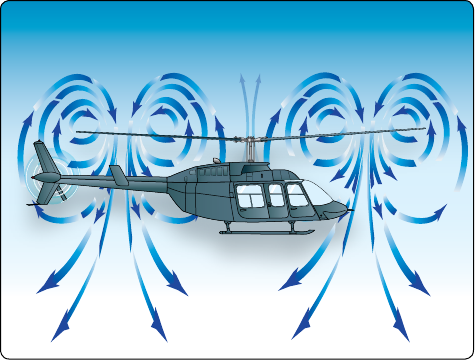
In addition, the helicopter may descend at a rate that exceeds
the normal downward induced-flow rate of the inner blade
sections. As a result, the airflow of the inner blade sections is
upward relative to the disk. This produces a secondary vortex
ring in addition to the normal tip vortices. The secondary
vortex ring is generated about the point on the blade where the
airflow changes from up to down. The result is an unsteady
turbulent flow over a large area of the disk. Rotor efficiency
is lost even though power is still being supplied from the
engine. [Figure 11-3]
A fully developed vortex ring state is characterized by an
unstable condition in which the helicopter experiences
uncommanded pitch and roll oscillations, has little or no
collective authority, and achieves a descent rate that may
approach 6,000 feet per minute (fpm) if allowed to develop.
A vortex ring state may be entered during any maneuver
that places the main rotor in a condition of descending in a
column of disturbed air and low forward airspeed. Airspeeds
11-10
Figure 11-3. Vortex ring state.
that are below translational lift airspeeds are within this
region of susceptibility to vortex ring state aerodynamics.
This condition is sometimes seen during quick-stop type
maneuvers or during recovery from autorotation.
The following combination of conditions is likely to cause
settling in a vortex ring state in any helicopter:
1. A vertical or nearly vertical descent of at least 300
fpm. (Actual critical rate depends on the gross weight,
rpm, density altitude, and other pertinent factors.)
2. The rotor disk must be using some of the available
engine power (20–100 percent).
3. The horizontal velocity must be slower than effective
translational lift.
Situations that are conducive to a vortex ring state condition
are attempting to hover OGE without maintaining precise
altitude control, and approaches, especially steep approaches,
with a tailwind component.
When recovering from a vortex ring state condition, the pilot
tends first to try to stop the descent by increasing collective
pitch. However, this only results in increasing the stalled
area of the rotor, thereby increasing the rate of descent. Since
inboard portions of the blades are stalled, cyclic control
may be limited. The traditional recovery is accomplished
by increasing airspeed, and/or partially lowering collective
to exit the vortex. In most helicopters, lateral cyclic thrust
combined with an increase in power and lateral antitorque
thrust will produce the quickest exit from the hazard. This
technique, known as the Vuichard Recovery (named after the
Swiss examiner from the Federal Office of Civil Aviation
who developed it) recovers by eliminating the descent rate as
opposed to exiting the vortex. If the vortex ring state and the
corresponding descent rate is allowed to progress to what is
called the windmill brake state, the point where the airflow
is completely up through the rotor, the only recovery may
be an autorotation.
Tandem rotor helicopters should maneuver laterally to
achieve clean air in both rotors at the same time.
For vortex ring state demonstrations and training in
recognition and recovery should be performed from a safe
altitude to allow recovery no less than 1000 feet AGL or the
manufacturer’s recommended altitude, whichever is higher.
To enter the maneuver, come to an OGE hover, maintaining
little or no airspeed (any direction), decrease collective
to begin a vertical descent, and as the turbulence begins,
increase collective. Then allow the sink rate to increase to 300
fpm or more as the attitude is adjusted to obtain airspeed of
less than 10 knots. When the aircraft begins to shudder, the
application of additional up collective increases the vibration
and sink rate. As the power is increased, the rate of sink of
the aircraft in the column of air will increase.
If altitude is sufficient, some time can be spent in the
vortices, to enable the pilot to develop a healthy knowledge
of the maneuver. However, helicopter pilots would normally
initiate recovery at the first indication of vortex ring state.
Recovery should be initiated at the first sign of vortex ring
state by applying forward cyclic to increase airspeed and/ or
simultaneously reducing collective. The recovery is complete
when the aircraft passes through effective translational lift
and a normal climb is established.
Common Errors—Traditional Recovery
1. Too much lateral speed for entry into vortex ring state.
2. Excessive decrease of collective.
Common Errors—Vuichard Recovery
1. Excessive lateral cyclic
2. Failure to maintain heading
Retreating Blade Stall
In forward flight, the relative airflow through the main rotor
disk is different on the advancing and retreating side. The
relative airflow over the advancing side is higher due to the
forward speed of the helicopter, while the relative airflow on
the retreating side is lower. This dissymmetry of lift increases
as forward speed increases.
To generate the same amount of lift across the rotor disk,
the advancing blade flaps up while the retreating blade flaps
down. This causes the AOA to decrease on the advancing

11-11
116°
122°
122°
Figure 11-4. Ground resonance.
blade, which reduces lift, and increase on the retreating blade,
which increases lift. At some point as the forward speed
increases, the low blade speed on the retreating blade, and
its high AOA cause a stall and loss of lift.
Retreating blade stall is a factor in limiting a helicopter’s
never-exceed speed (V
NE
) and its development can be felt
by a low frequency vibration, pitching up of the nose, and
a roll in the direction of the retreating blade. High weight,
low rotor rpm, high density altitude, turbulence and/or
steep, abrupt turns are all conducive to retreating blade stall
at high forward airspeeds. As altitude is increased, higher
blade angles are required to maintain lift at a given airspeed.
Thus, retreating blade stall is encountered at a lower forward
airspeed at altitude. Most manufacturers publish charts and
graphs showing a V
NE
decrease with altitude.
When recovering from a retreating blade stall condition
caused by high airspeed, moving the cyclic aft only worsens
the stall as aft cyclic produces a flare effect, thus increasing
the AOA. Pushing forward on the cyclic also deepens
the stall as the AOA on the retreating blade is increased.
While the first step in a proper recovery is usually to reduce
collective, RBS should be evaluated in light of the relevant
factors discussed in the previous paragraph and addressed
accordingly. For example, if a pilot at high weight and high
DA is about to conduct a high reconnaissance prior to a
confined area operation where rolling into a steep turn causes
onset of RBS, the recovery is to roll out of the turn. If the
cause is low rotor rpm, then increase the rpm.
Common Errors
1. Failure to recognize the combination of contributing
factors leading to retreating blade stall.
2. Failure to compute V
NE
limits for altitudes to be flown.
Ground Resonance
Helicopters with articulating rotors (usually designs with
three or more main rotor blades) are subject to ground
resonance, a destructive vibration phenomenon that occurs
at certain rotor speeds when the helicopter is on the ground.
Ground resonance is a mechanical design issue that results
from the helicopter’s airframe having a natural frequency that
can be intensified by an out-of-balance rotor. The unbalanced
rotor disk vibrates at the same frequency (or multiple thereof)
of the airframe’s resonant frequency, and the harmonic
oscillation increases because the engine is adding power
to the system, increasing the magnitude (amplitude) of the
vibrations until the structure or structures fail. This condition
can cause a helicopter to self-destruct in a matter of seconds.
Hard contact with the ground on one corner (and usually
with wheel-type landing gear) can send a shockwave to
the main rotor head, resulting in the blades of a three-blade
rotor disk moving from their normal 120° relationship to
each other. This movement occurs along the drag hinge and
could result in something like 122°, 122°, and 116° between
blades. [Figure 11-4] When another part of the landing gear
strikes the surface, the unbalanced condition could be further
aggravated.
If the rpm is low, the only corrective action to stop ground
resonance is to close the throttle immediately and fully lower
the collective to place the blades in low pitch. If the rpm is in
the normal operating range, fly the helicopter off the ground,
and allow the blades to rephase themselves automatically.
Then, make a normal touchdown. If a pilot lifts off and allows
the helicopter to firmly re-contact the surface before the
blades are realigned, a second shock could move the blades
again and aggravate the already unbalanced condition. This
could lead to a violent, uncontrollable oscillation.
This situation does not occur in rigid or semi-rigid rotor
disks because there is no drag hinge. In addition, skid-type
landing gear is not as prone to ground resonance as wheel-
type landing gear, since the rubber tires' resonant frequency
typically can match that of the spinning rotor, unlike the
condition of a rigid landing gear.
Dynamic Rollover
A helicopter is susceptible to a lateral rolling tendency,
called dynamic rollover, when it is in contact with the surface

11-12
Tail rotor thrust
Tip-path plane neutral cyclic
Tip-path plane full left cyclic
Bank
angle
Pivot point
CG
Weight
Main rotor thrust
Figure 11-5. Forces acting on a helicopter with right skid on the
ground.
during takeoffs or landings. For dynamic rollover to occur,
some factor must first cause the helicopter to roll or pivot
around a skid or landing gear wheel, until its critical rollover
angle is reached. The angle at which dynamic rollover
occurs will vary based on helicopter type. Then, beyond
this point, main rotor thrust continues the roll and recovery
is impossible. After this angle is achieved, the cyclic does
not have sufficient range of control to eliminate the thrust
component and convert it to lift. If the critical rollover angle
is exceeded, the helicopter rolls on its side regardless of the
cyclic corrections made.
Dynamic rollover begins when the helicopter starts to pivot
laterally around its skid or wheel. For dynamic rollover to
occur the following three factors must be present:
1. A rolling moment
2. A pivot point other than the helicopter’s normal CG
3. Thrust greater than weight
This can occur for a variety of reasons, including the failure
to remove a tie down or skid-securing device, or if the skid
or wheel contacts a fixed object while hovering sideward,
or if the gear is stuck in ice, soft asphalt, or mud. Dynamic
rollover may also occur if you use an improper landing or
takeoff technique or while performing slope operations.
Whatever the cause, dynamic rollover is possible if not using
the proper corrective technique.
Once started, dynamic rollover cannot be stopped by
application of opposite cyclic control alone. For example,
the right skid contacts an object and becomes the pivot point
while the helicopter starts rolling to the right. Even with full
left cyclic applied, the main rotor thrust vector and its moment
follows the aircraft as it continues rolling to the right. Quickly
reducing collective pitch is the most effective way to stop
dynamic rollover from developing. Dynamic rollover can
occur with any type of landing gear and all types of rotor disks.
It is important to remember rotor blades have a limited range
of movement. If the tilt or roll of the helicopter exceeds that
range (5–8°), the controls (cyclic) can no longer command a
vertical lift component and the thrust or lift becomes a lateral
force that rolls the helicopter over. When limited rotor blade
movement is coupled with the fact that most of a helicopter’s
weight is high in the airframe, another element of risk is added
to an already slightly unstable center of gravity. Pilots must
remember that in order to remove thrust, the collective must
be lowered as this is the only recovery technique available.
Critical Conditions
Certain conditions reduce the critical rollover angle, thus
increasing the possibility for dynamic rollover and reducing
the chance for recovery. The rate of rolling motion is also
a consideration because, as the roll rate increases, there is
a reduction of the critical rollover angle at which recovery
is still possible. Other critical conditions include operating
at high gross weights with thrust (lift) approximately equal
to the weight.
Refer to Figure 11-5. The following conditions are most
critical for helicopters with counterclockwise rotor rotation:
1. Right side skid or landing wheel down, since
translating tendency adds to the rollover force.
2. Right lateral center of gravity (CG).
3. Crosswinds from the left.
4. Left yaw inputs.
For helicopters with clockwise rotor rotation, the opposite
conditions would be true.
Cyclic Trim
When maneuvering with one skid or wheel on the ground,
care must be taken to keep the helicopter cyclic control
carefully adjusted. For example, if a slow takeoff is attempted
and the cyclic is not positioned and adjusted to account for
translating tendency, the critical recovery angle may be
exceeded in less than two seconds. Control can be maintained
if the pilot maintains proper cyclic position and does not
allow the helicopter’s roll and pitch rates to become too
great. Fly the helicopter into the air smoothly while keeping
movements of pitch, roll, and yaw small; do not allow any
abrupt cyclic pressures.
11-13
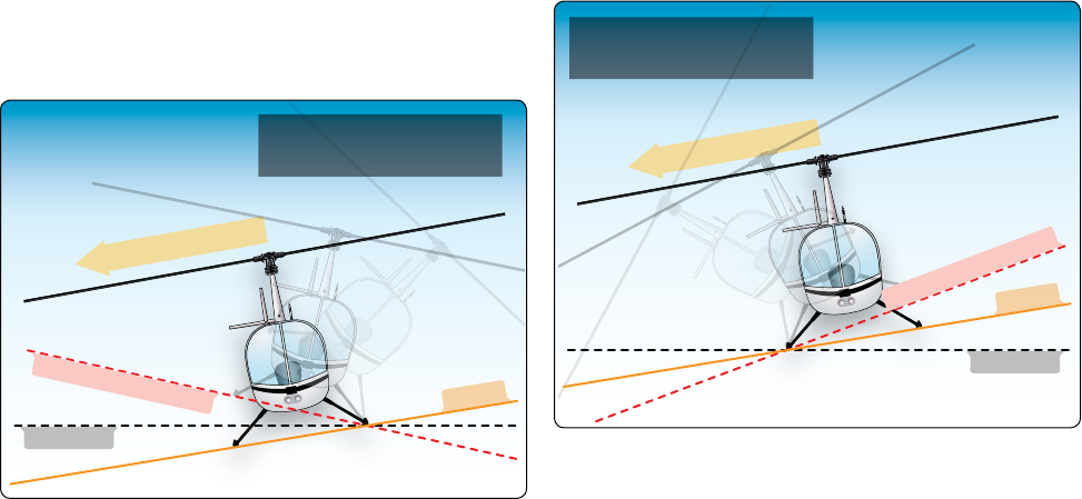
Tail rotor thrust
Area of critical rollover
Horizontal
Slope
Full opposite cyclic limit
to prevent rolling motion
Figure 11-6. Upslope rolling motion.
Tail rotor thrust
Area of critical rollover
Horizontal
Slope
Full opposite cyclic limit
to prevent rolling motion
Figure 11-7. Downslope rolling motion.
Normal Takeoffs and Landings
Dynamic rollover is possible even during normal takeoffs and
landings on relatively level ground, if one wheel or skid is on
the ground and thrust (lift) is approximately equal to the weight
of the helicopter. If the takeoff or landing is not performed
properly, a roll rate could develop around the wheel or skid
that is on the ground. When taking off or landing, perform the
maneuver smoothly and carefully adjust the cyclic so that no
pitch or roll movement rates build up, especially the roll rate.
If the bank angle starts to increase to an angle of approximately
5–8°, and full corrective cyclic does not reduce the angle, the
collective should be reduced to diminish the unstable rolling
condition. Excessive bank angles can also be caused by landing
gear caught in a tie down strap, or a tie down strap still attached
to one side of the helicopter. Lateral loading imbalance (usually
outside published limits) is another contributing factor.
Slope Takeoffs and Landings
During slope operations, excessive application of cyclic
control into the slope, together with excessive collective pitch
control, can result in the downslope skid or landing wheel
rising sufficiently to exceed lateral cyclic control limits, and
an upslope rolling motion can occur. [Figure 11-6]
When performing slope takeoff and landing maneuvers, follow
the published procedures and keep the roll rates small. Slowly
raise the downslope skid or wheel to bring the helicopter level,
and then lift off. During landing, first touch down on the
upslope skid or wheel, then slowly lower the downslope skid
or wheel using combined movements of cyclic and collective.
If the helicopter rolls approximately 5–8° to the upslope side,
decrease collective to correct the bank angle and return to level
attitude, then start the landing procedure again.
Use of Collective
The collective is more effective in controlling the rolling
motion than lateral cyclic, because it reduces the main rotor
thrust (lift). A smooth, moderate collective reduction, at a
rate of less than approximately full up to full down in two
seconds, may be adequate to stop the rolling motion. Take
care, therefore, not to dump collective at an excessively high
rate, as this may cause a main rotor blade to strike the fuselage.
Additionally, if the helicopter is on a slope and the roll starts
toward the upslope side, reducing collective too fast may create
a high roll rate in the opposite direction. When the upslope skid
or wheel hits the ground, the dynamics of the motion can cause
the helicopter to bounce off the upslope skid or wheel, and the
inertia can cause the helicopter to roll about the downslope
ground contact point and over on its side. [Figure 11-7]
Under normal conditions on a slope, the collective should
not be pulled suddenly to get airborne because a large and
abrupt rolling moment in the opposite direction could occur.
Excessive application of collective can result in the upslope
skid or wheel rising sufficiently to exceed lateral cyclic
control limits. This movement may be uncontrollable. If the
helicopter develops a roll rate with one skid or wheel on the
ground, the helicopter can roll over on its side.
Precautions
To help avoid dynamic rollover:
1. Always practice hovering autorotations into the wind,
and be wary when the wind is gusty or greater than 10
knots.
2. Use extreme caution when hovering close to fences,
sprinklers, bushes, runway/taxi lights, tiedown cables,
deck nets, or other obstacles that could catch a skid or
wheel. Aircraft parked on hot asphalt overnight might
find the landing gear sunk in and stuck as the ramp
cooled during the evening.
11-14
3. Always use a two-step lift-off. Pull in just enough
collective pitch control to be light on the skids
or landing wheels and feel for equilibrium, then
gently lift the helicopter into the air. 4.
Hover high enough to have adequate skid or landing
wheel clearance from any obstacles when practicing
hovering maneuvers close to the ground, especially
when practicing sideways or rearward flight.
5. Remember that when the wind is coming from
the upslope direction, less lateral cyclic control is
available.
6. Avoid tailwind conditions when conducting slope
operations.
7. Remember that less lateral cyclic control is available
due to the translating tendency of the tail rotor when
the left skid or landing wheel is upslope. (This is true
for counterclockwise rotor disks.)
8. Keep in mind that the lateral cyclic requirement changes
when passengers or cargo are loaded or unloaded.
9. Be aware that if the helicopter utilizes interconnecting
fuel lines that allow fuel to automatically transfer from
one side of the helicopter to the other, the gravitational
flow of fuel to the downslope tank could change the
CG, resulting in a different amount of cyclic control
application to obtain the same lateral result.
10. Do not allow the cyclic limits to be reached. If the
cyclic control limit is reached, further lowering of the
collective may cause mast bumping. If this occurs,
return to a hover and select a landing point with a
lesser degree of slope.
11. During a takeoff from a slope, begin by leveling the
main rotor disk with the horizon or very slightly into
the slope to ensure vertical lift and only enough lateral
thrust to prevent sliding on the slope. If the upslope
skid or wheel starts to leave the ground before the
downslope skid or wheel, smoothly and gently lower
the collective and check to see if the downslope skid or
wheel is caught on something. Under these conditions,
vertical ascent is the only acceptable method of lift-off.
12. Be aware that dynamic rollover can be experienced
during flight operations on a floating platform if the
platform is pitching/rolling while attempting to land
or takeoff. Generally, the pilot operating on floating
platforms (barges, ships, etc.) observes a cycle of seven
during which the waves increase and then decrease to
a minimum. It is that time of minimum wave motion
that the pilot needs to use for the moment of landing
or takeoff on floating platforms. Pilots operating from
floating platforms should also exercise great caution
concerning cranes, masts, nearby boats (tugs) and nets.
Low-G Conditions and Mast Bumping
“G” is an abbreviation for acceleration due to the earth’s
gravity. A person standing on the ground or sitting in an
aircraft in level flight is experiencing one G. An aircraft in a
tight, banked turn with the pilot being pressed into the seat
is experiencing more than one G or high-G conditions. A
person beginning a downward ride in an elevator or riding
down a steep track on a roller coaster is experiencing less
than one G or low-G conditions. The best way for a pilot to
recognize low G is a weightless feeling similar to the start
of a downward elevator ride.
Helicopters rely on positive G to provide much or all of their
response to pilot control inputs. The pilot uses the cyclic
to tilt the rotor disk, and, at one G, the rotor is producing
thrust equal to aircraft weight. The tilting of the thrust
vector provides a moment about the center of gravity to
pitch or roll the fuselage. In a low-G condition, the thrust
and consequently the control authority are greatly reduced.
Although their control ability is reduced, multi-bladed (three
or more blades) helicopters can generate some moment
about the fuselage independent of thrust due to the rotor
hub design with the blade attachment offset from the center
of rotation. However, helicopters with two-bladed teetering
rotors rely entirely on the tilt of the thrust vector for control.
Therefore, low-G conditions can be catastrophic for two-
bladed helicopters.
At lower speeds, such as initiation of a takeoff from hover
or the traditional recovery from vortex ring state, forward
cyclic maneuvers do not cause low G and are safe to perform.
However, an abrupt forward cyclic input or pushover in
a two-bladed helicopter can be dangerous and must be
avoided, particularly at higher speeds. During a pushover
from moderate or high airspeed, as the helicopter noses over,
it enters a low-G condition. Thrust is reduced, and the pilot
has lost control of fuselage attitude but may not immediately
realize it. Tail rotor thrust or other aerodynamic factors will
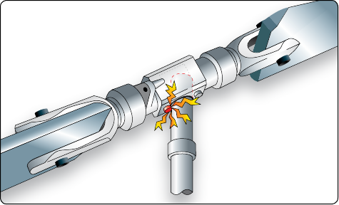
often induce a roll. The pilot still has control of the rotor disk,
and may instinctively try to correct the roll, but the fuselage
does not respond due to the lack of thrust. If the fuselage is
rolling right, and the pilot puts in left cyclic to correct, the
combination of fuselage angle to the right and rotor disk
angle to the left becomes quite large and may exceed the
clearances built into the rotor hub. This results in the hub
contacting the rotor mast, which is known as mast bumping.
[Figure 11-8] Low-G mast bumping has been the cause of
numerous military and civilian fatal accidents. It was initially
encountered during nap-of-the-earth flying, a very low-
altitude tactical flight technique used by the military where
11-15
Figure 11-8. Result of improper corrective action in a low-G
condition.
the aircraft flies following the contours of the geographical
terrain. The accident sequence may be extremely rapid, and
the energy and inertia in the rotor system can sever the mast
or allow rotor blades to strike the tail or other portions of
the helicopter.
Turbulence, especially severe downdrafts, can also cause a
low-G condition and, when combined with high airspeed,
may lead to mast bumping. Typically, helicopters handle
turbulence better than a light airplane due to smaller
surface area of the rotor blades. During flight in turbulence,
momentary excursions in airspeed, altitude, and attitude are
to be expected. Pilots should respond with smooth, gentle
control inputs and avoid overcontrolling. Most importantly,
pilots should slow down, as mast bumping is less likely at
lower airspeeds.
Pilots can avoid mast bumping accidents as follows:
• Avoid abrupt forward cyclic inputs in two-bladed
helicopters. Airplane pilots may find this a difficult
habit to break because pushing the nose down is an
accepted collision avoidance maneuver in an airplane.
Helicopter pilots would accomplish the same rapid
descent by lowering the collective, and airplane pilots
should train to make this instinctual.
• Recognize the weightless feeling associated with the
onset of low G and quickly take corrective action
before the situation becomes critical.
• Recognize that uncommanded right roll for helicopters
with main rotors which rotate counter-clockwise when
viewed from above indicates that loss of control is
imminent, and immediate corrective action must be
taken.
• Recover from a low-G situation by first gently
applying aft cyclic to restore normal G before
attempting to correct any roll.
• If turbulence is expected or encountered, reduce power
and use a slower than normal cruise speed. Turbulence
(where high rotor flapping angles are already present),
and higher airspeeds (where the controls are more
sensitive) both increase susceptibility to low-G
conditions.
• Use a flight simulator to learn to recognize and
experience low G conditions that result in mast
bumping, its correct recovery technique, and the
consequences of using incorrect recovery actions.
Refer to Chapter 14, Simulation.
Multi-bladed rotors may experience a phenomenon similar
to mast bumping known as droop stop pounding if flapping
clearances are exceeded, but because they retain some control
authority at low G, occurrences are less common than for
teetering rotors.
Low Rotor RPM and Rotor Stall
Rotor rpm is a critically important parameter for all helicopter
operations. Just as airplanes will not fly below a certain
airspeed, helicopters will not fly below a certain rotor
rpm. Safe rotor rpm ranges are marked on the helicopter’s
tachometer and specified in the RFM. If the pilot allows the
rotor rpm to fall below the safe operating range, the helicopter
is in a low rpm situation. If the rotor rpm continues to fall,
the rotor will eventually stall.
Rotor stall should not be confused with retreating blade stall,
which occurs at high forward speeds and over a small portion
of the retreating blade tip. Retreating blade stall causes
vibration and control problems, but the rotor is still very
capable of providing sufficient lift to support the weight of
the helicopter. Rotor stall, however, can occur at any airspeed,
and the rotor quickly stops producing enough lift to support
the helicopter, causing it to lose lift and descend rapidly.
Rotor stall is very similar to the stall of an airplane wing
at low airspeeds. The airplane wing relies on airspeed to
produce the required airflow over the wing, whereas the
helicopter relies on rotor rpm. As the airspeed of the airplane
decreases or the speed of the helicopter rotor slows down, the
AOA of the wing/rotor blade must be increased to support
the weight of the aircraft. At a critical angle (about 15°),
the airflow over the wing or the rotor blade will separate
and stall, causing a sudden loss of lift and increase in drag
(refer to Chapter 2, Aerodynamics of Flight). An airplane
pilot recovers from a stall by lowering the nose to reduce the
AOA and adding power to restore normal airflow over the
wing. However, the falling helicopter is experiencing upward
11-16
airflow through the rotor disk, and the resulting AOA is so
high that even full down collective will not restore normal
airflow. In the helicopter when the rotor stalls, it does not do
so symmetrically because any forward airspeed will produce
a higher airflow on the advancing side than on the retreating
side. This causes the retreating blade to stall first, and its
weight makes it descend as it moves aft while the advancing
blade is climbing as it goes forward. The resulting low aft
blade and high forward blade become a rapid aft tilting of
the rotor disc sometimes referred to as rotor “blow back” or
“flap back.” As the helicopter begins to descend, the upward
flow of air acting on the bottom surfaces of the tail boom
and any horizontal stabilizers tend to pitch the aircraft nose
down. These two effects, combined with any aft cyclic by
the pilot attempting to keep the aircraft level, allow the rotor
blades to blow back and contact the tail boom, in some cases
actually severing the tail boom. Since the tail rotor is geared
to the main rotor, in many helicopters the loss of main rotor
rpm also causes a significant loss of tail rotor thrust and a
corresponding loss of directional control.
Rotor stalls in helicopters are not recoverable. At low altitude,
rotor stall will result in an accident with significant damage
to the helicopter, and at altitudes above approximately 50
feet the accident will likely be fatal. Consequently, early
recognition of the low rotor rpm condition and proper
recovery technique is imperative.
Low rotor rpm can occur during power-off and power-on
operations. During power-off flight, a low rpm situation
can be caused by the failure to quickly lower the collective
after an engine failure or by raising the collective at too
great a height above ground at the bottom of an autorotation.
However, more common are power-on rotor stall accidents.
These occur when the engine is operating normally but the
pilot demands more power than is available by pulling up
too much on the collective. Known as “overpitching,” this
can easily occur at higher density altitudes where the engine
is already producing its maximum horsepower and the pilot
raises the collective. The corresponding increased AOA of
the blades requires more engine horsepower to maintain the
speed of the blades; however, the engine cannot produce any
additional horsepower, so the speed of the blades decreases.
A similar situation can occur with a heavily loaded helicopter
taking off from a confined area. Other causes of a power-on
low rotor rpm condition include the pilot rolling the throttle
the wrong way in helicopters not equipped with a governor
or a governor failure in helicopters so equipped.
As the rpm decreases, the amount of horsepower the engine
can produce also decreases. Engine horsepower is directly
proportional to its rpm, so a 10 percent loss in rpm due
to overpitching, or one of the other scenarios above, will
result in a 10 percent loss in the engine’s ability to produce
horsepower, making recovery even slower and more difficult
than it would otherwise be. With less power from the engine
and less lift from the decaying rotor rpm, the helicopter will
start to settle. If the pilot raises the collective to stop the
settling, the situation will feed upon itself rapidly leading
to rotor stall.
There are a number of ways the pilot can recognize the low
rotor rpm situation. Visually, the pilot can not only see the
rotor rpm indicator decrease but also the change in torque
will produce a yaw; there will also be a noticeable decrease in
engine noise, and at higher airspeeds or in turns, an increase in
vibration. Many helicopters have a low rpm warning system
that alerts the pilot to the low rotor rpm condition.
To recover from the low rotor rpm condition the pilot must
simultaneously lower the collective, increase throttle if
available and apply aft cyclic to maintain a level attitude.
At higher airspeeds, additional aft cyclic may be used to
help recover lost rpm. Recovery should be accomplished
immediately before investigating the problem and must be
practiced to become a conditioned reflex.
System Malfunctions
By following the manufacturer’s recommendations regarding
operating limits and procedures and periodic maintenance
and inspections, many system and equipment failures can
be eliminated. Certain malfunctions or failures can be traced
to some error on the part of the pilot; therefore, appropriate
flying techniques and use of threat and error management
may help to prevent an emergency
Antitorque System Failure
Antitorque failure usually falls into one of two categories.
One is failure of the power drive portion of the tail rotor disk
resulting in a complete loss of antitorque. The other category
covers mechanical control failures prohibiting the pilot from
changing or controlling tail rotor thrust even though the tail
rotor may still be providing antitorque thrust.
Tail rotor drive system failures include driveshaft failures,
tail rotor gearbox failures, or a complete loss of the tail rotor
itself. In any of these cases, the loss of antitorque normally
results in an immediate spinning of the helicopter’s nose. The
helicopter spins to the right in a counterclockwise rotor disk
and to the left in a clockwise system. This discussion is for a
helicopter with a counterclockwise rotor disk. The severity of
the spin is proportionate to the amount of power being used
and the airspeed. An antitorque failure with a high-power
setting at a low airspeed results in a severe spinning to the
11-17
right. At low power settings and high airspeeds, the spin is
less severe. High airspeeds tend to streamline the helicopter
and keep it from spinning.
If a tail rotor failure occurs, power must be reduced in order to
reduce main rotor torque. The techniques differ depending on
whether the helicopter is in flight or in a hover, but ultimately
require an autorotation. If a complete tail rotor failure occurs
while hovering, enter a hovering autorotation by rolling off
the throttle. If the failure occurs in forward flight, enter a
normal autorotation by lowering the collective and rolling
off the throttle. If the helicopter has enough forward airspeed
(close to cruising speed) when the failure occurs, and
depending on the helicopter design, the vertical stabilizer
may provide enough directional control to allow the pilot to
maneuver the helicopter to a more desirable landing sight.
Applying slight cyclic control opposite the direction of yaw
compensates for some of the yaw. This helps in directional
control, but also increases drag. Care must be taken not to
lose too much forward airspeed because the streamlining
effect diminishes as airspeed is reduced. Also, more altitude is
required to accelerate to the correct airspeed if an autorotation
is entered at a low airspeed.
The throttle or power lever on some helicopters is not located
on the collective and readily available. Faced with the loss
of antitorque, the pilot of these models may need to achieve
forward flight and let the vertical fin stop the yawing rotation.
With speed and altitude, the pilot will have the time to set
up for an autorotative approach and set the power control
to idle or off as the situation dictates. At low altitudes, the
pilot may not be able to reduce the power setting and enter
the autorotation before impact.
A mechanical control failure limits or prevents control of tail
rotor thrust and is usually caused by a stuck or broken control
rod or cable. While the tail rotor is still producing antitorque
thrust, it cannot be controlled by the pilot. The amount of
antitorque depends on the position at which the controls jam or
fail. Once again, the techniques differ depending on the amount
of tail rotor thrust, but an autorotation is generally not required.
The specific manufacturer’s procedures should always be
followed. The following is a generalized description of
procedures when more specific procedures are not provided.
Landing—Stuck Left Pedal
A stuck left pedal (high power setting), which might be
experienced during takeoff or climb conditions, results in
the left yaw of the helicopter nose when power is reduced.
Rolling off the throttle and entering an autorotation only
makes matters worse. The landing profile for a stuck left
pedal is best described as a normal-to-steep approach angle to
arrive approximately 2–3 feet landing gear height above the
intended landing area as translational lift is lost. The steeper
angle allows for a lower power setting during the approach
and ensures that the nose remains to the right.
Upon reaching the intended touchdown area and at the
appropriate landing gear height, increase the collective
smoothly to align the nose with the landing direction and
cushion the landing. A small amount of forward cyclic is
helpful to stop the nose from continuing to the right and
directs the aircraft forward and down to the surface. In certain
wind conditions, the nose of the helicopter may remain
to the left with zero to near zero groundspeed above the
intended touchdown point. If the helicopter is not turning,
simply lower the helicopter to the surface. If the nose of the
helicopter is turning to the right and continues beyond the
landing heading, roll the throttle toward flight idle, which is
the amount necessary to stop the turn while landing. Flight
idle is an engine rpm in flight at a given altitude with the
throttle set to the minimum, or idle, position. The flight
idling rpm typically increase with an increase in altitude.
If the helicopter is beginning to turn left, the pilot should
be able to make the landing prior to the turn rate becoming
excessive. However, if the turn rate begins to increase prior
to the landing, simply add power to make a go-around and
return for another landing.
Landing—Stuck Neutral or Right Pedal
The landing profile for a stuck neutral or a stuck right pedal
is a low-power approach terminating with a running or roll-
on landing. The approach profile can best be described as a
shallow to normal approach angle to arrive approximately
2–3 feet landing gear height above the intended landing
area with a minimum airspeed for directional control. The
minimum airspeed is one that keeps the nose from continuing
to yaw to the right.
Upon reaching the intended touchdown area and at the
appropriate landing gear height, reduce the throttle as
necessary to overcome the yaw effect if the nose of the
helicopter remains to the right of the landing heading. The
amount of throttle reduction will vary based on power applied
and winds. The higher the power setting used to cushion the
landing, the more the throttle reduction will be. A coordinated
throttle reduction and increased collective will result in a very
smooth touchdown with some forward groundspeed. If the
nose of the helicopter is to the left of the landing heading,
a slight increase in collective or aft cyclic may be used to
align the nose for touchdown. The decision to land or go
around has to be made prior to any throttle reduction. Using
airspeeds slightly above translational lift may be helpful to
11-18
ensure that the nose does not continue yawing to the right. If
a go-around is required, increasing the collective too much or
too rapidly with airspeeds below translational lift may cause
a rapid spinning to the right.
Once the helicopter has landed and is sliding/rolling to a
stop, the heading can be controlled with a combination of
collective, cyclic and throttle. To turn the nose to the right,
raise the collective or apply aft cyclic. The throttle may be
increased as well if it is not in the full open position. To turn
the nose to the left, lower the collective or apply forward
cyclic. The throttle may be decreased as well if it is not
already at flight idle.
Loss of Tail Rotor Effectiveness (LTE)
Loss of tail rotor effectiveness (LTE) or an unanticipated
yaw is defined as an uncommanded, rapid yaw towards the
advancing blade which does not subside of its own accord.
It can result in the loss of the aircraft if left unchecked. It is
very important for pilots to understand that LTE is caused
by an aerodynamic interaction between the main rotor and
tail rotor and not caused from a mechanical failure. Some
helicopter types are more likely to encounter LTE due to the
normal certification thrust produced by having a tail rotor
that, although meeting certification standards, is not always
able to produce the additional thrust demanded by the pilot.
A helicopter is a collection of compromises. Compare the
size of an airplane propeller to that of a tail rotor. Then,
consider the horsepower required to run the propeller. For
example, a Cessna 172P is equipped with a 160-horsepower
(HP) engine. A Robinson R-44 with a comparably sized tail
rotor is rated for a maximum of 245 HP. If you assume the
tail rotor consumes 50 HP, only 195 HP remains to drive
the main rotor. If the pilot were to apply enough collective
to require 215 HP from the engine, and enough left pedal to
require 50 HP for the tail rotor, the resulting engine overload
would lead to one of two outcomes: slow down (reduction
in rpm) or premature failure. In either outcome, antitorque
would be insufficient and total lift might be less than needed
to remain airborne.
Every helicopter design requires some type of antitorque
system to counteract main rotor torque and prevent spinning
once the helicopter lifts off the ground. A helicopter is heavy,
and the powerplant places a high demand on fuel. Weight
penalizes performance, but all helicopters must have an
antitorque system, which adds weight. Therefore, the tail
rotor is certified for normal flight conditions. Environmental
forces can overwhelm any aircraft, rendering the inherently
unstable helicopter especially vulnerable.
As with any aerodynamic condition, it is very important for
pilots to not only to understand the definition of LTE, but
more importantly, how and why it happens, how to avoid
it, and lastly, how to correct it once it is encountered. We
must first understand the capabilities of the aircraft or even
better what it is not capable of doing. For example, if you
were flying a helicopter with a maximum gross weight of
5,200 lb, would you knowingly try to take on fuel, baggage
and passengers causing the weight to be 5,500 lb? A wise
professional pilot should not ever exceed the certificated
maximum gross weight or performance flight weight for any
aircraft. The manuals are written for safety and reliability.
The limitations and emergency procedures are stressed
because lapses in procedures or exceeding limitations can
result in aircraft damage or human fatalities. At the very least,
exceeding limitations will increase the costs of maintenance
and ownership of any aircraft and especially helicopters.
Overloaded parts may fail before their designed lifetime. There
are no extra parts in helicopters. The respect and discipline
pilots exercise in following flight manuals should also be
applied to understanding aerodynamic conditions. If flight
envelopes are exceeded, the end results can be catastrophic.
LTE is an aerodynamic condition and is the result of a control
margin deficiency in the tail rotor. It can affect all single-rotor
helicopters that utilize a tail rotor. The design of main and
tail rotor blades and the tail boom assembly can affect the
characteristics and susceptibility of LTE but will not nullify
the phenomenon entirely. Translational lift is obtained by
any amount of clean air through the main rotor disk. Chapter
2, Aerodynamics of Flight, discusses translational lift with
respect to the main rotor blade, explaining that the more
clean air there is going through the rotor disk, the more
efficient it becomes. The same holds true for the tail rotor.
As the tail rotor works in less turbulent air, it reaches a point
of translational thrust. At this point, the tail rotor becomes
aerodynamically efficient and the improved efficiency
produces more antitorque thrust. The pilot can determine
when the tail rotor has reached translational thrust. As more
antitorque thrust is produced, the nose of the helicopter
yaws to the left (opposite direction of the tail rotor thrust),
forcing the pilot to correct with right pedal application
(actually decreasing the left pedal). This, in turn, decreases
the AOA in the tail rotor blades. Pilots should be aware of the
characteristics of the helicopter they fly and be particularly
aware of the amount of tail rotor pedal typically required for
different flight conditions.
LTE is a condition that occurs when the flow of air through
a tail rotor is altered in some way, by altering the angle or
speed at which the air passes through the rotating blades of
the tail rotor disk. As discussed in the previous paragraph, an
effective tail rotor relies on a stable and relatively undisturbed
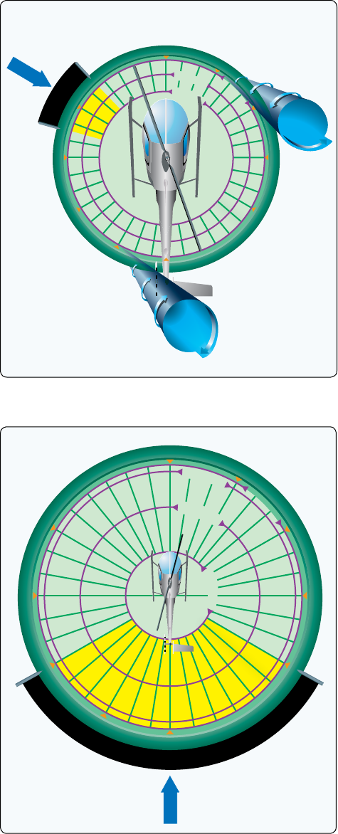
11-19
0°
30°
60°
90°
120°
150°
180°
210°
240°
270°
300°
330°
R
e
g
i
o
n
o
f
d
i
s
k
v
o
r
t
e
x
i
n
t
e
r
f
e
r
e
n
c
e
1
0
k
n
o
t
s
360°
1
5
k
n
o
t
s
2
0
k
n
o
t
s
315°
285°
Wind
Figure 11-9. Main rotor disk vortex interference.
R
e
g
i
o
n
o
f
p
o
s
s
i
b
l
e
y
a
w
i
n
t
r
o
d
u
c
t
i
o
n
b
y
w
e
a
t
h
e
r
c
o
c
k
s
t
a
b
i
l
i
t
y
0°
30°
60°
90°
120°
150°
180°
210°
240°
270°
300°
330°
1
0
k
n
o
t
s
360°
5
k
n
o
t
s
1
5
k
n
o
t
s
1
7
k
n
o
t
s
Wind
Figure 11-10. Weathercock stability.
airflow in order to provide a steady and constant antitorque
reaction. The pitch and AOA of the individual blades will
determine the thrust. A change to either of these alters the
amount of thrust generated. A pilot’s yaw pedal input causes
a thrust reaction from the tail rotor. Altering the amount of
thrust delivered for the same yaw input creates an imbalance.
Taking this imbalance to the extreme will result in the loss
of effective control in the yawing plane, and LTE will occur.
This alteration of tail rotor thrust can be affected by numerous
external factors. The main factors contributing to LTE are:
1. Airflow and downdraft generated by the main rotor
blades interfering with the airflow entering the tail
rotor assembly.
2. Main blade vortices developed at the main blade tips
entering the tail rotor disk.
3. Turbulence and other natural phenomena affecting the
airflow surrounding the tail rotor.
4. A high-power setting, hence large main rotor
pitch angle, induces considerable main rotor blade
downwash and hence more turbulence than when the
helicopter is in a low power condition.
5. A slow forward airspeed, typically at speeds where
translational lift and translational thrust are in the
process of change and airflow around the tail rotor
will vary in direction and speed.
6. The airflow relative to the helicopter;
a. Worst case—relative wind within ±15° of the
10 o’clock position, generating vortices that
can blow directly into the tail rotor. This is
dictated by the characteristics of the helicopters
aerodynamics of tailboom position, tail rotor size
and position relative to the main rotor and vertical
stabilizer, size and shape. [Figure 11-9]
b. Weathercock stability—tailwinds from 120° to
240° [Figure 11-10], such as left crosswinds,
causing high pilot workload.
c. Tail rotor vortex ring state (210° to
330°). [Figure 11-11] Winds within this region
will result in the development of the vortex ring
state of the tail rotor.
7. Combinations (a, b, c) of these factors in a particular
situation can easily require more antitorque than the
helicopter can generate and in a particular environment
LTE can be the result.
Certain flight activities lend themselves to being at higher
risk of LTE than others. For example, power line and pipeline
patrol sectors, low speed aerial filming/photography as well
as in the Police and Helicopter Emergency Medical Services
(EMS) environments can find themselves in low-and-slow
situations over geographical areas where the exact wind speed
and direction are hard to determine.
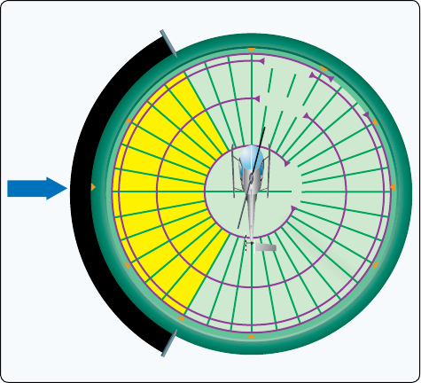
11-20
0°
30°
60°
90°
120°
150°
180°
210°
240°
270°
300°
330°
R
e
g
i
o
n
o
f
r
o
u
g
h
n
e
s
s
d
u
e
t
o
t
a
i
l
r
o
t
o
r
v
o
r
t
e
x
r
i
n
g
s
t
a
t
e
1
0
k
n
o
t
s
360°
5
k
n
o
t
s
1
5
k
n
o
t
s
1
7
k
n
o
t
s
Wind
Figure 11-11. Tail rotor vortex ring state.
Unfortunately, the aerodynamic conditions that a helicopter
is susceptible to are not explainable in black and white terms.
LTE is no exception. There are a number of contributing
factors, but what is more important in preventing LTE is to
note them, and then to associate them with situations that
should be avoided. Whenever possible, pilots should learn
to avoid the following combinations:
1. Low and slow flight outside of ground effect.
2. Winds from ±15º of the 10 o’clock position and
probably on around to 5 o’clock position [Figure 11-9]
3. Tailwinds that may alter the onset of translational lift
and translational thrust, and hence induce high power
demands and demand more anti-torque (left pedal)
than the tail rotor can produce.
4. Low speed downwind turns.
5. Large changes of power at low airspeeds.
6. Low speed flight in the proximity of physical
obstructions that may alter a smooth airflow to both
the main rotor and tail rotor.
Pilots who put themselves in situations where the combinations
above occur should know that they are likely to encounter
LTE. The key is not to put the helicopter in a compromising
condition, while at the same time being educated enough
to recognize the onset of LTE and being prepared to react
quickly to it before the helicopter cannot be controlled.
Early detection of LTE, followed by the immediate flight
control application of corrective action, applying forward
cyclic to regain airspeed, applying right pedal not left as
necessary to maintain rotor rpm, and reducing the collective
(thus reducing the high-power demand on the tail rotor), is the
key to a safe recovery. Pilots should always set themselves
up when conducting any maneuver to have enough height
and space available to recover in the event they encounter
an aerodynamic situation such as LTE.
Understanding the aerodynamic phenomenon of LTE is by
far the most important factor in preventing an LTE-related
accident, and maintaining the ability and option either to go
around if making an approach or pull out of a maneuver safely
and re-plan, is always the safest option. Having the ability to
fly away from a situation and re-think the possible options
should always be part of a pilot's planning process in all phases
of flight. Unfortunately, there have been many pilots who
have idled a good engine and fully functioning tail rotor disk
and autorotated a perfectly airworthy helicopter to the crash
site because they misunderstood or misperceived both the
limitations of the helicopter and the aerodynamic situation.
Main Rotor Disk Interference (285–315°)
Refer to Figure 11-9. Winds at velocities of 10–30 knots from
the left front cause the main rotor vortex to be blown into the
tail rotor by the relative wind. This main rotor disk vortex
causes the tail rotor to operate in an extremely turbulent
environment. During a right turn, the tail rotor experiences a
reduction of thrust as it comes into the area of the main rotor
disk vortex. The reduction in tail rotor thrust comes from the
airflow changes experienced at the tail rotor as the main rotor
disk vortex moves across the tail rotor disk.
The effect of the main rotor disk vortex initially increases the
AOA of the tail rotor blades, thus increasing tail rotor thrust.
The increase in the AOA requires that right pedal pressure
be added to reduce tail rotor thrust in order to maintain the
same rate of turn. As the main rotor vortex passes the tail
rotor, the tail rotor AOA is reduced. The reduction in the
AOA causes a reduction in thrust and right yaw acceleration
begins. This acceleration can be surprising, since previously
adding right pedal to maintain the right turn rate. This thrust
reduction occurs suddenly, and if uncorrected, develops
into an uncontrollable rapid rotation about the mast. When
operating within this region, be aware that the reduction in
tail rotor thrust can happen quite suddenly, and be prepared
to react quickly to counter this reduction with additional left
pedal input.
Weathercock Stability (120–240°)
In this region, the helicopter attempts to weathervane,
or weathercock, its nose into the relative wind.
[Figure 11-10] Unless a resisting pedal input is made, the
helicopter starts a slow, uncommanded turn either to the right
11-21
or left, depending upon the wind direction. If the pilot allows
a right yaw rate to develop and the tail of the helicopter moves
into this region, the yaw rate can accelerate rapidly. In order
to avoid the onset of LTE in this downwind condition, it is
imperative to maintain positive control of the yaw rate and
devote full attention to flying the helicopter.
Tail Rotor Vortex Ring State (210–330°)
Winds within this region cause a tail rotor vortex ring state to
develop. [Figure 11-11] The result is a nonuniform, unsteady
flow into the tail rotor. The vortex ring state causes tail
rotor thrust variations, which result in yaw deviations. The
net effect of the unsteady flow is an oscillation of tail rotor
thrust. Rapid and continuous pedal movements are necessary
to compensate for the rapid changes in tail rotor thrust when
hovering in a left crosswind. Maintaining a precise heading
in this region is difficult, but this characteristic presents
no significant problem unless corrective action is delayed.
However, high pedal workload, lack of concentration, and
overcontrolling can lead to LTE.
When the tail rotor thrust being generated is less than the
thrust required, the helicopter yaws to the right. When
hovering in left crosswinds, concentrate on smooth pedal
coordination and do not allow an uncommanded right yaw to
develop. If a right yaw rate is allowed to build, the helicopter
can rotate into the wind azimuth region where weathercock
stability then accelerates the right turn rate. Pilot workload
during a tail rotor vortex ring state is high. Do not allow a
right yaw rate to increase.
LTE at Altitude
At higher altitudes where the air is thinner, tail rotor thrust
and efficiency are reduced. Because of the high-density
altitude, powerplants may be much slower to respond to
power changes. When operating at high altitudes and high
gross weights, especially while hovering, the tail rotor thrust
may not be sufficient to maintain directional control, and
LTE can occur. In this case, the hovering ceiling is limited
by tail rotor thrust and not necessarily power available. In
these conditions, gross weights need to be reduced and/
or operations need to be limited to lower density altitudes.
This may not be noted as criteria on the performance charts.
Reducing the Onset of LTE
To help reduce the onset of LTE, follow these steps:
1. Maintain maximum power-on rotor rpm. If the main
rotor rpm is allowed to decrease, the antitorque thrust
available is decreased proportionally.
2. Avoid tailwinds below airspeeds of 30 knots. If loss
of translational lift occurs, it results in an increased
power demand and additional antitorque pressures.
3. Avoid OGE operations and high-power demand
situations below airspeeds of 30 knots at low altitudes.
4. Be especially aware of wind direction and velocity
when hovering in winds of about 8–12 knots. A loss
of translational lift results in an unexpected high power
demand and an increased antitorque requirement.
5. Be aware that if a considerable amount of left pedal
is being maintained, a sufficient amount of left pedal
may not be available to counteract an unanticipated
right yaw.
6. Be alert to changing wind conditions, which may be
experienced when flying along ridge lines and around
buildings.
7. Execute right turns slowly. This limits the effects of
rotating inertia, and decreases loading on the tailrotor
to control yawing.
Recovery Technique (Uncontrolled Right Yaw)
If a sudden unanticipated right yaw occurs, the following
recovery technique should be performed. Apply full left
pedal. Simultaneously, apply forward cyclic control to
increase speed. If altitude permits, reduce power. As recovery
is affected, adjust controls for normal forward flight. A
recovery path must always be planned, especially when
terminating to an OGE hover and executed immediately if
an uncommanded yaw is evident.
Collective pitch reduction aids in arresting the yaw rate but
may cause an excessive rate of descent. Any large, rapid
increase in collective to prevent ground or obstacle contact
may further increase the yaw rate and decrease rotor rpm.
The decision to reduce collective must be based on the pilot’s
assessment of the altitude available for recovery.
If the rotation cannot be stopped and ground contact is
imminent, an autorotation may be the best course of action.
Maintain full left pedal until the rotation stops, then adjust to
maintain heading. For more information on LTE, see Advisory
Circular (AC) 90-95, Unanticipated Right Yaw in Helicopters.
Main Drive Shaft or Clutch Failure
The main drive shaft, located between the engine and the main
rotor transmission, provides engine power to the main rotor
transmission. In some helicopters, particularly those with
piston engines, a drive belt is used instead of a drive shaft.
A failure of the drive shaft clutch or belt has the same effect
as an engine failure because power is no longer provided to
the main rotor and an autorotation must be initiated. There
are a few differences, however, that need to be taken into
11-22
consideration. If the drive shaft or belt breaks, the lack of any
load on the engine results in an overspeed. In this case, the
throttle must be closed in order to prevent any further damage.
In some helicopters, the tail rotor drive system continues to
be powered by the engine even if the main drive shaft breaks.
In this case, when the engine unloads, a tail rotor overspeed
can result. If this happens, close the throttle immediately and
enter an autorotation. The pilot must be knowledgeable of the
specific helicopter’s system and failure modes.
Pilots should keep in mind that when there is any suspected
mechanical malfunction, first and foremost they should
always attempt to maintain rotor rpm. If the rotor rpm is at the
normal indication with normal power settings, an instrument
failure might be occurring, and it would be best to fly the
helicopter to a safe landing area. If the rotor rpm is in fact
decreasing or low, then there is a drive line failure.
Hydraulic Failure
Many helicopters incorporate the use of hydraulic actuators to
overcome high control forces. A hydraulic system consists of
actuators, also called servos, on each flight control; a pump,
which is usually driven by the main rotor transmission;
and a reservoir to store the hydraulic fluid. A switch in the
cockpit can turn the system off, although it is left on during
normal conditions. A pressure indicator in the cockpit may
be installed to monitor the system.
An impending hydraulic failure can be recognized by a
grinding or howling noise from the pump or actuators,
increased control forces and feedback, and limited control
movement. The required corrective action is stated in detail
in the RFM. In most cases, airspeed needs to be reduced in
order to reduce control forces. The hydraulic switch and
circuit breaker should be checked and recycled. If hydraulic
power is not restored, make a shallow approach to a running
or roll-on landing. This technique is used because it requires
less control force and pilot workload. Additionally, the
hydraulic system should be disabled by placing the switch
in the off position. The reason for this is to prevent an
inadvertent restoration of hydraulic power, which may lead
to overcontrolling near the ground.
In those helicopters in which the control forces are so high
that they cannot be moved without hydraulic assistance, two
or more independent hydraulic systems are installed. Some
helicopters use hydraulic accumulators to store pressure that
can be used for a short time while in an emergency if the
hydraulic pump fails. This gives enough time to land the
helicopter with normal control.
Governor or Fuel Control Failure
Governors and fuel control units automatically adjust engine
power to maintain rotor rpm when the collective pitch
is changed. If the governor or fuel control unit fails, any
change in collective pitch requires manual adjustment of
the throttle to maintain correct rpm. In the event of a high
side failure, the engine and rotor rpm tend to increase above
the normal range due to the engine being commanded to
put out too much power. If the rpm cannot be reduced and
controlled with the throttle, close the throttle and enter an
autorotation. If the failure is on the low side, the engine
output is allowed to go below the collective and normal
rpm may not be attainable, even if the throttle is manually
controlled. In this case, the collective has to be lowered to
maintain rotor rpm. A running or roll-on landing may be
performed if the engine can maintain sufficient rotor rpm. If
there is insufficient power, enter an autorotation. As stated
previously in this chapter, before responding to any type of
mechanical failure, pilots should confirm that rotor rpm is
not responding to flight control inputs. If the rotor rpm can
be maintained in the green operating range, the failure is in
the instrument, and not mechanical.
Abnormal Vibration
With the many rotating parts found in helicopters, some
vibration is inherent. A pilot needs to understand the
cause and effect of helicopter vibrations because abnormal
vibrations cause premature component wear and may even
result in structural failure. With experience, a pilot learns
what vibrations are normal and those that are abnormal
and can then decide whether continued flight is safe or not.
Helicopter vibrations are categorized into low, medium, or
high frequency.
Low-Frequency Vibrations
Low-frequency vibrations (100–500 cycles per minute) usually
originate from the main rotor disk. The main rotor operational
range, depending on the helicopter, is usually between 320
and 500 rpm. A rotor blade that is out of track or balance will
cause a cycle to occur with every rotation. The vibration may
be felt through the controls, the airframe, or a combination
of both. The vibration may also have a definite direction
of push or thrust. It may be vertical, lateral, horizontal, or
even a combination of these. Normally, the direction of the
vibration can be determined by concentrating on the feel of
the vibration, which may push a pilot up and down, backwards
and forwards, or in the case of a blade being out of phase, from
side to side. The direction of the vibration and whether it is
felt in the controls or the airframe is important information for
the mechanic when he or she troubleshoots the source. Out-
of-track or out-of-balance main rotor blades, damaged blades,
11-23
worn bearings, dampers out of adjustment, or worn parts are
possible causes of low frequency vibrations.
Medium- and High-Frequency Vibrations
Medium-frequency vibrations (1,000–2,000 cycles per
minute) range between the low frequencies of the main rotor
(100–500 cycles per minute) and the high frequencies (2,100
cycles per minute or higher) of the engine and tail rotor.
Depending on the helicopter, medium-frequency vibration
sources may be engine and transmission cooling fans, and
accessories such as air conditioner compressors, or driveline
components. Medium-frequency vibrations are felt through
the entire airframe, and prolonged exposure to the vibrations
will result in greater pilot fatigue.
Most tail rotor vibrations fall into the high-frequency range
(2,100 cycles per minute or higher) and can be felt through
the tail rotor pedals as long as there are no hydraulic actuators
to dampen out the vibration. This vibration is felt by the pilot
through his or her feet, which are usually “put to sleep” by
the vibration. The tail rotor operates at approximately a 6:1
ratio with the main rotor, meaning for every one rotation
of the main rotor the tail rotor rotates 6 times. A main
rotor operating rpm of 350 means the tail rotor rpm would
be 2,100 rpm. Any imbalance in the tail rotor disk is very
harmful as it can cause cracks to develop and rivets to work
loose. Piston engines usually produce a normal amount of
high-frequency vibration, which is aggravated by engine
malfunctions, such as spark plug fouling, incorrect magneto
timing, carburetor icing and/or incorrect fuel/air mixture.
Vibrations in turbine engines are often difficult to detect as
these engines operate at a very high rpm. Turbine engine
vibration can be at 30,000 rpm internally, but common
transmission speeds are in the 1,000 to 3,000 rpm range for
the output shaft. The vibrations in turbine engines may be
short lived as the engine disintegrates rapidly when damaged
due to high rpm and the forces present.
Tracking and Balance
Modern equipment used for tracking and balancing the main
and tail rotor blades can also be used to detect other vibrations
in the helicopter. These systems use accelerometers mounted
around the helicopter to detect the direction, frequency, and
intensity of the vibration. The built-in software can then
analyze the information, pinpoint the origin of the vibration,
and suggest the corrective action.
The use of a system such as a health and usage monitoring
system (HUMS) provides the operator the ability to record
engine and transmission performance and provide rotor track
and balance. This system has been around for over 30 years
and is now becoming more affordable, more capable, and
more commonplace in the rotorcraft industry.
Multiengine Emergency Operations
Single-Engine Failure
When one engine has failed, the helicopter can often maintain
altitude and airspeed until a suitable landing site can be
selected. Whether or not this is possible becomes a function
of such combined variables as aircraft weight, density
altitude, height above ground, airspeed, phase of flight,
and single-engine capability. Environmental response time
and control technique may be additional factors. Caution
must be exercised to correctly identify the malfunctioning
engine since there is no telltale yawing as occurs in most
multiengine airplanes. Shutting down the wrong engine
could be disastrous!
Even when flying multiengine powered helicopters, rotor rpm
must be maintained at all costs, because fuel contamination has
been documented as the cause for both engines failing in flight.
Dual-Engine Failure
The flight characteristics and the required crew member
control responses after a dual-engine failure are similar to
those during a normal power-on descent. Full control of the
helicopter can be maintained during autorotational descent.
In autorotation, as airspeed increases above 70–80 KIAS, the
rate of descent and glide distance increase significantly. As
airspeed decreases below approximately 60 KIAS, the rate
of descent increases and glide distance decreases.
Lost Procedures
Pilots become lost while flying for a variety of reasons, such
as disorientation, flying over unfamiliar territory, or visibility
that is low enough to render familiar terrain unfamiliar. When
a pilot becomes lost, the first order of business is to fly the
aircraft; the second is to implement lost procedures. Keep
in mind that the pilot workload will be high, and increased
concentration will be necessary. If lost, always remember to
look for the practically invisible hazards, such as wires, by
searching for their support structures, such as poles or towers,
which are almost always near roads.
If lost, follow common sense procedures.
• Try to locate any large landmarks, such as lakes, rivers,
towers, railroad tracks, or Interstate highways. If a
landmark is recognized, use it to find the helicopter’s
location on the sectional chart. If flying near a town or
city, a pilot may be able to read the name of the town
on a water tower or even land to ask for directions.
• If no town or city is nearby, the first thing a pilot should
do is climb. An increase in altitude increases radio and
navigation reception range as well as radar coverage.
11-24
risk associated with being lost is waiting too long to land in a
safe area. Helicopter pilots should land before fuel exhaustion
occurs because maneuvering with low fuel levels could cause
the engine to stop due to fuel starvation as fuel sloshes or
flows away from the pickup port in the tank.
If lost and low on fuel, it is advisable to make a precautionary
landing. Preferably, land near a road or in an area that would
allow space for another helicopter to safely land and provide
assistance. Having fuel delivered is a minor inconvenience
when compared to having an accident. Once on the ground,
pilots may seek assistance.
VFR Flight into Instrument Meteorological
Conditions
Helicopters, unlike airplanes, generally operate under Visual
Flight Rules (VFR) and require pilots to maintain aircraft
control by visual cues. However, when unforecast weather
leads to degraded visibility, the pilot may be at increased
risk of Inadvertent flight into Instrument Meteorological
Conditions (IIMC). During an IIMC encounter, the pilot
may be unprepared for the loss of visual reference, resulting
in a reduced ability to continue safe flight. IIMC is a life-
threatening emergency for any pilot. To capture these IIMC
events, the Commercial Aviation Safety Team (CAST) and
International Civil Aviation Organization (ICAO) Common
Taxonomy Team (CICTT) categorizes this occurrence as
Unintended flight in Instrument Meteorological Conditions
(UIMC). This term is also recognized by the National
Transportation Safety Board (NTSB) and Federal Aviation
Administration (FAA). It is used to classify occurrences
(accidents and incidents) at a high level to improve the
capacity to focus on common safety issues and complete
analysis of the data in support of safety initiatives.
The onset of IIMC may occur gradually or suddenly, has
no simple procedural exit, and is unlike flight training by
reference to while in Visual Meteorological Conditions
(VMC). Most training helicopters are not equipped or
certified to fly under Instrument Flight Rules (IFR).
Therefore, General Aviation (GA) helicopter pilots may not
have the benefit of flight in actual Instrument Meteorological
Conditions (IMC) during their flight training. Helicopter
pilots that encounter IIMC may experience physiological
illusions which can lead to spatial disorientation and loss of
aircraft control. Even with some instrument training, many
available and accessible helicopters are not equipped with
the proper augmented safety systems or autopilots, which
would significantly aid in helicopter control during an
IIMC emergency. The need to use outside visual references
is natural for helicopter pilots because much of their flight
training is based upon visual cues, not on flight instruments.
This primacy can only be overcome through significant
instrument training. Additionally, instrument flight may be
• Navigation aids, dead reckoning, and pilotage are
skills that can be used as well.
• Do not forget air traffic control (ATC)—controllers
assist pilots in many ways, including finding a lost
helicopter. Once communication with ATC has been
established, follow their instructions.
These common-sense procedures can be easily remembered by
using the four Cs: Climb, Communicate, Confess, and Comply.
• Climb for a better view, improved communication and
navigation reception, and terrain avoidance.
• Communicate by calling the nearest flight service
station (FSS)/automated flight service station (AFSS)
on 122.2 MHz. If the FSS/AFSS does not respond,
call the nearest control tower, center, or approach
control. For frequencies, check the chart in the vicinity
of the last known position. If that fails, switch to
the emergency radio frequency (121.5 MHz) and
transponder code (7700).
• Report the lost situation to ATC and request help.
• Comply with controller instructions.
Pilots should understand the services provided by ATC and
the resources and options available. These services enable
pilots to focus on aircraft control and help them make better
decisions in a time of stress.
When contacting ATC, pilots should provide as much
information as possible because ATC uses the information
to determine what kind of assistance it can provide with
available assets and capabilities. Information requirements
vary depending on the existing situation, but at a minimum
a pilot should provide the following information:
• Aircraft identification and type
• Nature of the emergency
• Aviator’s desires
To reduce the chances of getting lost in the first place, use
flight following through active contact with an aircraft during
flight either by radio or through automated flight following
systems when it is available, monitor checkpoints no more
than 25 miles apart, keep navigation aids such as Very
High-Frequency Omni-Directional Range (VOR) tuned in,
and maintain good situational awareness. Flight following
provides ongoing surveillance information to assist pilots in
avoiding collisions with other aircraft.
Getting lost is a potentially dangerous situation for any
aircraft, especially when low on fuel. Due to the helicopter’s
unique ability to land almost anywhere, pilots have more
flexibility than other aircraft as to landing site. An inherent
11-25
intimidating to some and too costly for others. As a result,
many helicopter pilots choose not to seek an instrument
rating.
While commercial helicopter operators often prefer their
pilots to be instrument rated, fatal accidents still occur as
a result of IIMC. Many accidents can be traced back to
the pilot’s inability to recover the helicopter after IIMC
is encountered, even with adequate equipment installed.
Therefore, whether instrument rated or not, all pilots should
understand that avoiding IIMC is critical.
A good practice for any flight is to set and use personal
minimums, which should be more conservative than those
required by regulations for VFR flight. In addition, a thorough
preflight and understanding of weather conditions that may
contribute to the risk of IMC developing along a planned
route of flight is essential for safety. Pilots should recognize
deteriorating weather conditions so the route of flight can be
changed or a decision made to terminate the flight and safely
land at a suitable area, well before IIMC occurs. If weather
conditions deteriorate below the pilot’s personal minimums
during flight, a pilot who understands the risks of IIMC
knows that he or she is at an en route decision point, where
it is necessary to either turn back to the departure point or
immediately land somewhere safe to wait until the weather
has cleared. Pilots should recognize that descent below a
predetermined minimum altitude above ground level (AGL)
(for example, 500 feet AGL) to avoid clouds or, slowing
the helicopter to a predetermined minimum airspeed (for
example, slowing to 50 KIAS) to reduce the rate of closure
from the deteriorating weather conditions, indicates the
decision point had been reached. Ceilings that are lower than
reported and/or deteriorating visibility along the route of
flight should trigger the decision to discontinue and amend
the current route to avoid IIMC.
If the helicopter pilot is instrument rated, it is advisable to
maintain instrument currency and proficiency as this may
aid the pilot in a safe recovery from IIMC. A consideration
for instrument rated pilots when planning a VFR flight
should include a review of published instrument charts for
safe operating altitudes, e.g. minimum safe altitude (MSA),
minimum obstruction clearance altitude (MOCA), minimum
in VMC throughout a flight: off-route altitude (MORA),
etc. If IIMC occurs, the pilot may consider a climb to a safe
altitude. Once the helicopter is stabilized, the pilot should
declare an emergency with air traffic control (ATC). It is
imperative that the pilot commit to controlling the helicopter
and remember to aviate, navigate, and finally communicate.
Often communication is attempted first, as it is natural to
look for help in stressful situations. This may distract the
pilot from maintaining control of the helicopter.
If the pilot is not instrument rated, instrument current nor
proficient, or is flying a non-IFR equipped helicopter,
remaining in VMC is paramount. Pilots who are not trained
or proficient in flight solely by reference to instruments have
a tendency to attempt to maintain flight by visual ground
reference, which tends to result in flying at lower altitudes,
just above the trees or by following roads. The thought process
is that, "as long as I can see what is below me, I can continue
to my intended destination." Experience and statistical data
indicate that attempting to continue VFR flight into IMC can
often lead to a fatal outcome as pilots often fixate on what
they see below them and are unable to see the hazards ahead
of them (e.g., power lines, towers, rising terrain, etc.). By
the time the pilot sees the hazard, it is either too late to avoid
a collision, or while successfully maneuvering to avoid an
obstacle, the pilot becomes disoriented.
Flying at night involves even more conservative personal
minimums to ensure safety and avoidance of IIMC than
daytime flying. At night, deteriorating weather conditions
may be difficult to detect. Therefore, pilots should ensure
that they not only receive a thorough weather briefing, but
that they remain vigilant for unforecasted weather during
their flight. The planned route should include preselected
landing sites that will provide options to the pilot in the
event a precautionary landing is required to avoid adverse
weather conditions. As a pilot gains night flight experience
their ability to assess weather during a flight will improve.
Below are some basic guidelines to assist a pilot to remain
in VMC throughout a flight:
1. Slowly turn around if threatened by deteriorating
visual cues and proceed back to VMC or to the first
safe landing area if the weather ahead becomes
questionable. Remember that prevention is paramount.
2. Do not proceed further on a course when the terrain
ahead is not clearly discernible.
3. Delay or consider cancelling the flight if weather
conditions are already questionable, could deteriorate
significantly based on forecasts, or if you are uncertain
whether the flight can be conducted safely. Often, a
gut feeling can provide a warning that unreasonable
risks are present.
4. Always have a safe landing area (such as large open
areas or airports) in mind for every route of flight.
There are five basic steps that every pilot should be familiar
with, and which should be executed immediately at the onset
of IIMC, if applicable. However, remember that if you are
not trained to execute the following maneuvers solely by
reference to instruments, or your aircraft is not equipped

11-26
Food cannot be subject to deterioration due to heat or cold. There
should be at least 10,000 calories for each person on board, and it
should be stored in a sealed waterproof container. It should have
been inspected within the previous 6 months, verifying the amount
and satisfactory condition of the contents.
A supply of water
Cooking utensils
Matches in a waterproof container
A portable compass
An ax weighing at least 2.5 pounds with a handle not less than 28 inches
in length
A flexible saw blade or equivalent cutting tool
30 feet of snare wire and instructions for use
Fishing equipment, including still-fishing bait and gill net with not more
than a two-inch mesh
Mosquito nets or netting and insect repellent sufficient to meet the
needs of all persons aboard, when operating in areas where insects
are likely to be hazardous
A signaling mirror
At least three pyrotechnic distress signals
A sharp, quality jackknife or hunting knife
A suitable survival instruction manual
Flashlight with spare bulbs and batteries
Portable emergency locator transmitter (ELT) with spare batteries
Stove with fuel or a self-contained means of providing heat for cooking
Tent(s) to accommodate everyone on board
Additional items for winter operations:
• Winter sleeping bags for all persons when the
temperature is expected to be below 7 °C
• Two pairs of snow shoes
• Spare ax handle
• Ice chisel
• Snow knife or saw knife
EMERGENCY EQUIPMENT AND SURVIVAL GEAR
Figure 11-12. Emergency equipment and survival gear.
with such instruments, this guidance may be less beneficial
to you and loss of helicopter control may occur:
1. Level the “wings” – level the bank angle using the
attitude indicator.
2. Attitude – set a climb attitude that achieves a safe
climb speed appropriate to your type of helicopter.
This is often no more than 10° of pitch up on the
attitude indicator.
3. Airspeed – verify that the attitude selected has
achieved the desired airspeed. It is critical to
recognize that slower airspeeds, closer to effective
translational lift, may require large control inputs and
will decrease stability, making recover impossible
while in UIMC.
4. Power – adjust to a climb power setting relative to the
desired airspeed. This should be executed concurrent
with steps 2 and 3.
5. Heading and Trim – pick a heading known to be free
of obstacles and maintain it. This will likely be the
heading you were already on, which was planned and
briefed. Set the heading bug, if installed, to avoid over-
controlling your bank. Maintain coordinated flight so
that an unusual attitude will not develop.
Try to avoid immediately turning 180°. Turning around is
not always the safest route and executing a turn immediately
after UIMC may lead to spatial disorientation. If a 180° turn
is the safest option, first note the heading you are on then
begin the turn to the reciprocal heading, but only after stable
flight is achieved (items 1 through 5 above) and maintain
a constant rate of turn appropriate to the selected airspeed.
Each encounter with UIMC is unique, and no single
procedure can ensure a safe outcome. Considerations in
determining the best course of action upon encountering
UIMC should include, at a minimum, terrain, obstructions,
freezing levels, aircraft performance and limitations, and
availability of ATC services.
There are new technologies being developed regarding
aircraft design, enhanced and lower-cost technologies,
and aircraft certification. Because of this promising future,
much of the discussion and guidance in this chapter may
one day become irrelevant. As helicopters integrate more
into the National Airspace System, the IFR infrastructure
and instrument training will become more prevalent. In the
future, UIMC may no longer be the emergency that ends
with a fatality but rather associated with proper prevention,
skilled recovery techniques along with the aid of emerging
new life saving avionics technology. A helicopter instrument
rating may be a life-saving addition to a pilot’s level of
certification. Please refer to the Instrument Flying Handbook
(FAA-H-8083-15, as revised); Advanced Avionics Handbook
(FAA-H-8083-6, as revised); and the Pilot’s Handbook of
Aeronautical Knowledge (FAA-H-8083-25, as revised) for
further exploration of IFR operations and how to obtain an
instrument rating.
When faced with deteriorating weather, planning and
prevention, not recovery, are the best strategies to eliminate
UIMC-related accidents and fatalities.
11-27
Emergency Equipment and Survival Gear
Both Canada and Alaska require pilots to carry survival
gear. Always carry survival gear when flying over rugged
and desolate terrain. The items suggested in Figure 11-12
are both weather and terrain dependent. The pilot also needs
to consider how much storage space the helicopter has and
how the equipment being carried affects the overall weight
and balance of the helicopter.
Chapter Summary
Emergencies should always be anticipated. Knowledge
of the helicopter, possible malfunctions and failures, and
methods of recovery can help the pilot avoid accidents and
be a safer pilot. Helicopter pilots should always expect the
worse hazards and possible aerodynamic effects and plan for
a safe exit path or procedure to compensate for the hazard.
