NEON.DOC.000015 Rev A
See Configuration Management System for approval history.
©2013 NEON Inc. All rights reserved.
The National Ecological Observatory Network is a project solely funded by the National Science Foundation and managed under cooperative
agreement by NEON, Inc. Any opinions, findings, and conclusions or recommendations expressed in this material are those of the author(s) and do
not necessarily reflect the views of the National Science Foundation.
Title: Failure Modes and Effects Analysis Template Author: Byron Murray Date: 5/29/2013
NEON Doc. #: NEON.DOC.000015 Revision: B
PREPARED BY (Name )
ORGANIZATION
DATE
Byron Murray
SYS
5/29/2013
Failure Modes and Effects Analysis Template
APPROVALS (Name)
ORGANIZATION
APPROVAL DATE
Laura Newton CCB DIR SE 6/11/2013
Javier Marti CCB Chair 6/12/2013
Krista Laursen
CCB Chair
6/11/2013
Mike Stewart
CCB SE
6/12/2013
RELEASED BY (Name)
ORGANIZATION
RELEASE DATE
Stephen Craft
CCB Admin
6/12/2013

NEON.DOC.000015 Rev A
NEON Doc. #: NEON.DOC.000015
REVISION DATE ECO#
A 1/1/2012 ECO-00299
B 6/12/2013 ECO-01114
Date: 5/29/2013
Revision: B
Author: Byron MurrayTitle: Failure Modes and Effects Analysis Template
Change Record
DESCRIPTION OF CHANGE
Initial Release
Update examples and add DFMEA Checklist

Failure Mode and Effects Analysis
Definitions and Instructions
NEON.DOC.000015 Rev A
Page 3 of 18
FMEA Purpose: The purpose of FMEA analysis is to provide a systematic analysis method
to identify potential failure modes of systems, components and/or assemblies. The analysis
provides input to the design team on how to mitigate the risk of potential failures to an
acceptable level. Failures should be prioritized according to how serious their consequences
are, how frequently they occur and how easily they can be detected. Action to eliminate or
reduce failures should begin with those with the highest priority.
FMEA – Item / Function Column:
Item: Description for the System/Assembly/Component
Function: What is the design supposed to do?
Write in physical, technical and measureable terms. May reference specification(s).
FMEA - Potential Failure Mode(s) Column:
How can the design fail to meet requirement(s)? Modes can be broken down into the
following categories: Total failure, partial failure, intermittent failure, over-function and
unintended function.
Example for a touch screen interface: Total Failure - Does not accept user input, Partial
Failure - Some screen areas function while other do not, Intermittent Failure - Difficulty
interpreting user entries, Over Function - Interprets single input as double press, Unintended
Function - Misinterprets user entry. Failure modes should be specific, avoiding subjective
terms like “bad”, “not right”, “too loose/tight”, “and improper”, etc. Reference requirement(s)
where possible.
FMEA - Effects of Failure Column:
What is the effect(s) of the failure? To determine the effect(s), view the failure from the eyes
of the end user and list effects in a manner that the customer would describe them. Here are
examples of effects that might be encountered:
Customer effect: noisy; premature failure; intermittent output; unable to output full
power; unacceptable appearance; will not maintain power setting.
FMEA - Severity (SEV) Columns:
How severe is the failure? Severity is a numeric ranking of the seriousness of the failure.
The number shall be assigned using the definitions given in the ratings table found on the
Rating & Scoring Guide tab. Each category covers a range of events. The severity shall be
evaluated relative to the pre-mitigation result and post-mitigation result.

Failure Mode and Effects Analysis
Definitions and Instructions
NEON.DOC.000015 Rev A
Page 4 of 18
FMEA - Potential Cause(s) of Failure Column:
What is the cause or mechanism of the failure? In this column we list at least one specific
cause for each failure mode. Often there are multiple or many causes for any given failure
mode, be sure to include all plausible causes. Be sure to identify the causes for the failure
mode and not the individual effect.
FMEA - Occurrence (OCC) Columns:
How often do we expect to see the failure? Occurrence is a numeric ranking of the probability
of the cause for the failure occurring. This ranking is assigned using definitions given in the
ratings table found on the Rating & Scoring Guide tab. Each category covers a range of
probabilities. The occurrence shall be evaluated relative to the likelihood of the failure
occurring when it is caused by the “cause”. If multiple causes are listed, the occurrence shall
be based on the cause which would result in the highest occurrence rating.
FMEA - Control Column:
List the current system controls in place to prevent the failure mode. There are two types of
design controls to consider:
Prevention: Prevent the cause/mechanism of failure or the failure mode from
occurring, or reduce the rate of occurrence.
• For prevention controls, place a 'P' before each prevention control listed.
• Examples of preventative controls: What has been done to prevent the failure?
Design Reviews, DFM (Design for Manufacturability), Engineering Builds, Drawing
Control Notes (i.e. critical dimensions, coating/finishes, cleanliness, materials), Finite
element analysis, Tolerance stack-up analysis, Simulations, Self-test/diagnostics,
Redundancy, etc.
Detection: Detect the cause/mechanism of failure or the failure mode, and lead to
corrective action(s).
• For detection controls place a 'D' before each detection control listed.
• Examples of detection controls: What tests will be run to assess the likelihood of a
failure? Simulation and verification testing… Functional, Life, HALT (Highly
Accelerated Life Test), HASS (Highly Accelerated Stress Screen), etc.
FMEA - Detection (DET) Column:
How likely will the failure be detected? Detection is a numeric ranking of the ability of the
design to detect a potential cause/mechanism and subsequent failure mode. This ranking is
assigned using definitions given in the ratings table found on the Rating & Scoring Guide tab.

Failure Mode and Effects Analysis
Definitions and Instructions
NEON.DOC.000015 Rev A
Page 5 of 18
FMEA - Scoring the SEV/OCC/DET Columns:
Now that the modes of failure and the effects have been determined, it will be necessary to
decide which of these to focus upon for resolution. It would be inefficient to work on every
failure mode and its potential effect, so a method of prioritization will include:
Severity of the effect (SEV)
Probability of the failure mode occurring (OCC)
Probability of failure detection (DET)
Within the FMEA Score Sheet is a tab containing the ranking criteria for the SEV (Severity),
OCC (Occurrence), and DET (detection). The FMEA team agrees on the appropriate number
for each column score, taking into account the perspective of the customer (internal or
external).
FMEA – Scoring the RPN Column:
This index, called the Risk Priority Number (RPN), helps prioritize our actions for problem
resolution (though safety issues must always receive attention and are indicated by a Severity
(SEV) score of 4 or 5). The RPN is calculated automatically in the form; multiplying the SEV,
OCC and DET:
Risk Priority Number (RPN) = SEV x OCC x DET
FMEA – Scoring the CRIT Column:
This index, called the Criticality Index (CRIT), helps further prioritize our actions for problem
resolution given greater emphasis to the Severity and frequency of Occurrence. The CRIT is
calculated automatically in the form; multiplying the SEV and OCC:
Criticality (CRIT) = SEV x OCC

Failure Mode and Effects Analysis
Definitions and Instructions
NEON.DOC.000015 Rev A
Page 6 of 18
FMEA - Analysis and Recommended Corrective Actions Column
The Risk Priority Number (RPN) and Criticality Index act as tools to help prioritize and focus
the reduction of the overall risks associated with potential failure modes. Once all the RPNs
are calculated, the FMEA team will outline recommended action(s) that should be taken to
reduce the overall RPN for failure modes that are deemed unacceptable and whereby
action(s) are feasible. The risk associated with each failure should be reviewed to ensure it is
ALARP (As low as reasonably practicable). This may include evaluating the feasibility of
each potential corrective action by comparing the cost associated in reducing risk further
versus the potential benefit gained. Reduction of the RPN can be accomplished by lowering
any of the three rankings (severity, occurrence, or detection) by the following methods:
A reduction in the Severity ranking (SEV) is often the most difficult to attain and will most
likely require a design change.
A reduction in the Occurrence ranking (OCC) may accomplished by removing or controlling
the potential cause/mechanisms of failure.
A reduction in the Detection ranking (DET) is accomplished by adding or improving prevention
or detection controls.
In general practice, when a Criticality rating 15 to 25 or a Severity rate of 5 is assigned,
special attention must be given to ensure the risk is addressed through design
actions/controls regardless of the RPN. In all cases (Severity rankings of 4 or 5) where the
effect of an identified potential failure mode(s) could be a potential hazard and cause injury,
preventative/corrective actions shall be taken to avoid the failure mode by eliminating or
controlling the cause(s), or appropriate operator protection should be specified. For these
cases the failures will need to be addressed in the PHA process.
Guideline to Recommended Corrective Actions

Failure Mode and Effects Analysis
Definitions and Instructions
NEON.DOC.000015 Rev A
Page 7 of 18
FMEA - Work Team and JIRA #
Who should resolve the issues?
The FMEA team shall establish the ownership of the work team that will be responsible for
the implementation of the specified corrective action(s). Upon assignment of responsibility,
an entry will be made into JIRA to track the required corrective action(s) through resolution.
The accountable work team and associated number assigned within JIRA shall be recorded
onto the FMEA form.
Note: Work Team and JIRA #s shall only be required for failures where the FMEA team
deems that corrective action will be required.

Failure Mode and Effects Analysis
Rankings and Scoring Guide
5
Critical: Safety issue and/or non-compliance with a government regulation, failure may cause serious injury or death to
the customer or an employee.
4
Serious: Failure results in a loss or reduction of primary function and renders the product inoperable causing a high
degree of customer dissatisfaction or may cause minor injury to the customer or an employee.
3
Moderate: Failure results in a partial malfunction of the product, the performance/functionality loss causes customer
dissatisfaction.
2
Minor:
Failure may not be readily apparent and/or may create a minor nuisance to the customer, but would have minor
effects on the customer’s satisfaction.
1
Negligible: No discernible effect, the failure would not be noticeable to the customer and would not affect the
customer’s process or product.
5
Frequent: One occurrence every month
4
Probable: One occurrence every 1-12 months
3
Occasional: One occurrence every 12 months to 5 years
2
Remote: One occurrence every 5 to 10 years
1
Improbable: One occurrence in greater than 10 years
5
Very Remote: chance the design control will detect a potential cause/mechanism and subsequent failure mode.
4
Low: chance the design control will detect a potential cause/mechanism and subsequent failure mode.
3
Moderate: chance the design control will detect a potential cause/mechanism and subsequent failure mode.
2
High: chance the design control will detect a potential cause/mechanism and subsequent failure mode.
1
Almost certain: chance the design control will detect a potential cause/mechanism and subsequent failure mode.
Risk Priority Number Criticality Index
Severity (1-5) x Occurrence (1-5) x Detection (1-5) Occurrence (OCC)
Frequent 5 5 10 15 20 25
Probable 4 4 8 12 16 20
Intolerable ( 75 - 125 ) Occasional
3 3 6 9 12 15
Review to determine if risk is ALARP ( 25 - 74) Remote
2 2 4 6 8 10
Acceptable ( 1 - 24 ) Improbable 1 1 2 3 4 5
1 2 3 4 5
Severity (SEV)
Negligible Minor Moderate Serious Critical
Intolerable ( 15 - 25 and for all failure modes resulting in a SEV of 5)
Review to determine if risk is ALARP ( 4 - 14 )
Acceptable ( 1 - 3 )
Severity Rankings: (Rankings of 4 or 5 will be carried over to the PHA due to potential for injury!)
Occurrence Rankings (Likelihood of occurrence across the entire Observatory):
Detection Score:
RPN = (SEV)x(OCC)x(DET)
This value should be used to rank order the concerns in the process. Regardless of RPN, special attention should be given when
severity and occurrence are high which is reflected by the Criticality Index (CRIT). Refer to the tables below for guidelines on the
levels for recommendations for corrective actions/mitigation. Note: Whenever a failure poses a potential hazard to personnel,
corrective action shall be taken and failures shall be addressed in a separate Hazard Analysis. To reduce Occurrence and increase
Detection, process and/or design revisions are often required. In most cases, only design revisions can reduce the Severity
ranking.
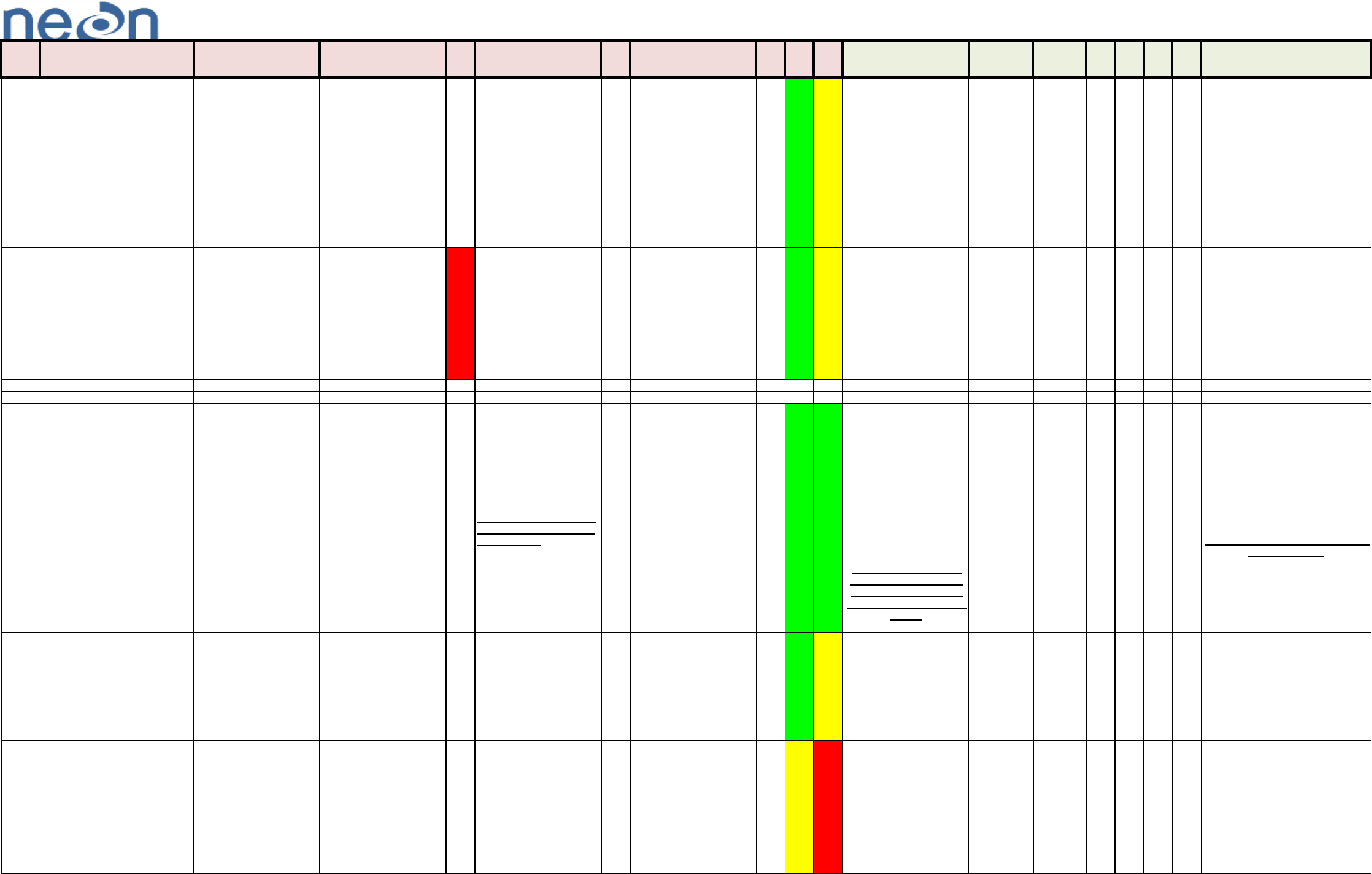
Failure Mode Effect Analysis (FMEA)
NEON.DOC.000015 Rev A Page 9
Document #: ________________ Doc Date (Orig): _______________ Doc (Rev): __________ Facilitator: __________________________
Type:
____________________________________ Rev: __
Team Members:
Ref # Item Description / Function Potential Failure Mode Effects of Failure SEV Potential Cause(s) of Failure OCC Control DET RPN CRIT
Analysis & Recommended
Corrective Actions
Work Team JIRA # SEV OCC DET RPN Comments
0 0 0
0 0 0
0 0 0
0 0 0
0 0 0
0 0 0
0 0 0
0 0 0
0 0 0
0 0 0
0 0 0
0
0 0
0
0 0
Pre-Corrective Action Post Corrective Action
SYSTEM
ASSEMBLY
COMPONENT
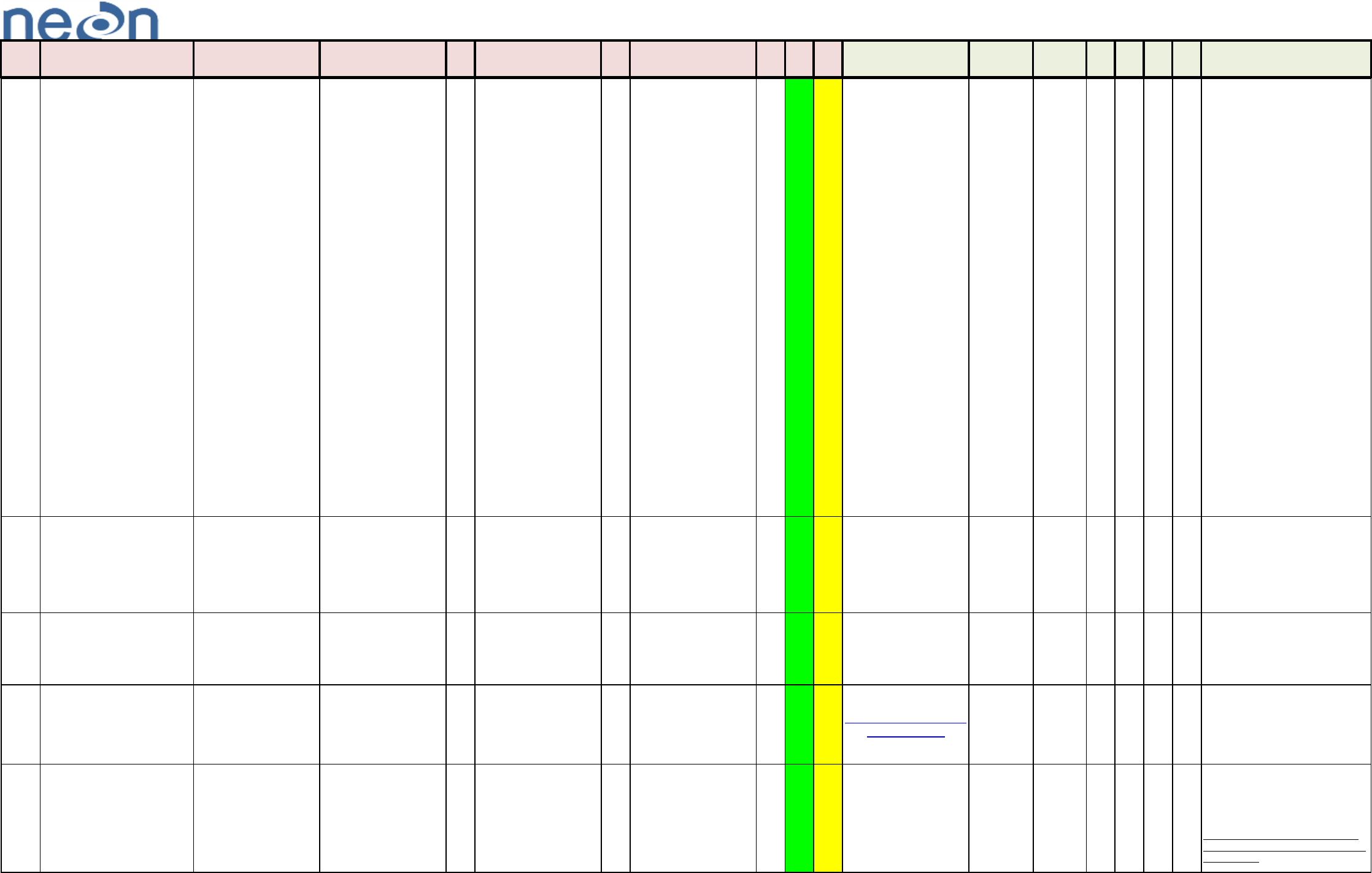
Failure Mode Effect Analysis (FMEA)
NEON.DOC.000015 Rev A Page 10
Document #: __NEON.DOC.000808_______________ Doc Date (Orig): ___1/23/2013____________ Doc (Rev): __________ Facilitator: ____Byron Murray______________________
Type:
________________Soil-Water Content Profile____________________ Rev: __FPDR____4/23/2013
Team Members: Aaron Joos ; Ed Ayres ; John Haywood ; Brad Jarvis; Asa Akers ; Hanne Buur ; Laura Leyba-Newton ; Lloyd Banta ; Alexander Cooper; Robin Hodson; Nicholas Applegate ; Michael Pursley ; Ty Guadagno
Ref # Item Description / Function Potential Failure Mode Effects of Failure SEV Potential Cause(s) of Failure OCC Control DET RPN CRIT
Analysis & Recommended
Corrective Actions
Work Team JIRA # SEV OCC DET RPN Comments
1
Assembly, Soil Water Content
Profile, CF00800000 / sensor
assembly for soil water content
profile
Parts will not fit together and
mount properly Not able to assemble 3
Mount holes under over sized,
miss located or missing
1
Tolerance Analysis
Completed, Inspection
Procedures
1 3 3 1 3 3 9
5 tubes per site, 1 per soil plot, Geo probe for
most installations, site specific requirements,
pvc pipe stays in the ground, edge of soil pit,
near arbor. Grape will be installed on unistrut
at the arbor. 2 to 16 sensors per tube with 8
sensors as the average.
0 0 0
0 0 0
0 0 0
2
Assembly, Soil Water Content
Profile, CF00800000 / sensor
assembly for soil water content
profile
Assembly not properly aligned,
assembly damaged, cables
damaged
Data loss / invalid data 4
Assembly components
under/over sized/missing /miss
aligned/sensor
failure/component failure/miss
calibrated
3
Material analysis & callout,
Cable Routing and anchor
points, Locking hardware, Cert
of compliance will be
requested, CVAL, Eng, SE,
and mfg testing, Maintenance
Procedures, Armored cables
from sensor to Grape
1 12 12
Action Item: Owner
Deployment, Reporter B
Murray, DFMEA Soil Water
Content Profile, Assembly Soil
Water Content Profile
CF00800000, Installation tool
investigation for install and
verification to ensure vertical +-
3 degrees.
4 2 1 8
The pn 0318950000 (Sensor TriSCAN Soil
Water Content and Salinity Sensor) applies
only to the actual blue sensor part of the entire
assembly. Similarly, the other components
have their own pns assigned and can be
found in Agile under Sentek. Because each of
the actual deployed assemblies will be unique,
some to their individual plot, Angelo plans on
assigning each completed sensor assembly
for each plot its own assembly number. In the
mean time I will make a dummy sensor
assembly using the previously stated
assembly number (CF00800000) and Lloyd
and myself will start populating the BOM for
that item.
0 0
Action Item: Owner
Engineering, Reporter B
Murray, DFMEA Soil Water
Content Profile, Assembly Soil
Water Content Profile
CF00800000, Design
connector/cable to be field
replaceable and make the part
a FRU.
0
0 0
Action Item: Owner
Engineering, Reporter B
Murray, DFMEA Soil Water
Content Profile, Assembly Soil
Water Content Profile
CF00800000, Field
Deployment to drill Soil Water
Content Holes at first arrival on
site to allow for Science,
manufacturing, CVAL,
shipment of the configured
sensors.
0
0 0 0
Pre-Corrective Action Post Corrective Action
SYSTEM
ASSEMBLY
COMPONENT

Failure Mode Effect Analysis (FMEA)
NEON.DOC.000015 Rev A Page 11
Ref # Item Description / Function Potential Failure Mode Effects of Failure SEV Potential Cause(s) of Failure OCC Control DET RPN CRIT
Analysis & Recommended
Corrective Actions
Work Team JIRA # SEV OCC DET RPN Comments
3
Assembly, Soil Water Content
Profile, CF00800000 / sensor
assembly for soil water content
profile
Assembly becomes damaged
or becomes unlevel from
original installation or is not
installed optimally
Loss or invalid data 4
1) Insufficient Material strength
2) Service/Installation (Over
torque-Breakage, Under
torque - Loss of hardware)
3) Corrosion
4) Stress Fatigue/Wear
5) Collision
6) Lightning Strike
7) Voids in the soil
8) Rocks against tube
4
1) Material Analysis & Callout
2) Locking hardware
3)Anchoring
4) Torques/Pattern specified
on drawing
5) controlled installation
process and tools
1 16 16
Action Item: Owner
Engineering/Operations
Reporter: B Murray, DFMEA
Soil-Water Content Profile,
CF008000000, Operations
procedure to check oring every
x number of years.
4 2 1 8
Action Item: Owner
Engineering/Operations
Reporter: B Murray, DFMEA
Soil-Water Content Profile,
CF008000000, Operations
procedure / process to have
shop vac to clean and
maintain sensor tube.
0 0 0
4
Assembly, Soil Water Content
Profile, CF00800000, PCBA
that NEON will be modifying
with the One Wire Chip /
sensor assembly for soil water
content profile
PCBA Damage Data loss / invalid data 3
NEON Assembly of One Wire
Chip onto the pins of the
backside of a connector
3
Certified Operators and
Inspection, Epoxy of the chip,
Conformal Coating of the
PCBA.
2 18 9
Action Item: Owner Science,
Reporter: B Murray, DFMEA
Soil-Water Content Profile,
Assembly, Soil Water Content
Profile, CF00800000, PCBA
that NEON will be modifying
with the One Wire Chip. Need
to pursue permission /
warranty information / update
to contract / agreement/ that
NEON will be adding the One
Wire Chip to a PCBA on the
assembly.
3 2 2
12
Failure Mode Effect Analysis (FMEA)
NEON.DOC.000015 Rev A Page 12
Document #: ________NEON.DOC.000309_______ Doc Date (Orig): __05/25/2012__ Doc (Rev): ____A____ Facilitator: _______Asa Akers_________________5/2/2013
Type: System Spectral Photometer Rev: __Engineering Final Design Review__
Team Members: John Staarmann, Drew Schrupp, Aaron Joos, Ken Franzel, Tim Lucera, Guillermo Oviedo, Matt Ventimiglia, Asa Akers, Santiago Bonarrigo, Alan Tennery
Ref # Item/ Function Potential Failure Mode Effects of Failure SEV Potential Cause(s) of Failure OCC Control DET RPN CRIT
Analysis & Recommended
Corrective Actions
Work Team JIRA # SEV OCC DET RPN
Comments
1
Assembly Spectral Photometer
System, CD03060000, Highest level
assembly of the Spectral Photometer
Parts will not fit together /
mount properly in location
Inability to assemble / install
correctly
3
Assembly components are
undersized / oversized /
mislocated / missing.
1
Tolerance Analysis Completed,
Inspection Procedures
1 3 3
2
Assembly Spectral Photometer
System, CD03060000, Highest level
assembly of the Spectral Photometer
Hardware falls from tower
Safety Issue / Loss or invalid
data
5
1) Insufficient Material strength
2) Service/Installation (Over
torque-Breakage, Under torque
- Loss of hardware)
3) Corrosion
4) Stress Fatigue/Wear
5) Mechanical damage to
assembly - environmental
2
1) Material Analysis & Callout
2) Torques/pattern specified on
drawing
3) Material compatability
analysis
4) Material analysis, inspection
5) Upon failure, hardware may
be secured by cable / locking
hardware
1 10 10 0 Will be addressed in PHA
3
Assembly, Spectral Photometer
Control Mounting System,
CD03060300, Mount for sensor
control enclosure and associated
hardware (w/ East shield) (
10
)
Parts will not fit together /
mount properly in location
Inability to assemble / install
correctly
3
Assembly components are
undersized / oversized /
mislocated / missing.
1
Tolerance Analysis Completed,
Inspection Procedures
1 3 3
4
Assembly, Spectral Photometer
Control Mounting System,
CD03060300, Mount for sensor
control enclosure and associated
hardware (w/ East shield) (10)
Assembly not properly aligned
or damaged
Loose hardware, cable strain,
data loss
4
1) Assembly components are
undersized / oversized /
mislocated / missing
2) Hardware failure (strength,
torque, corrosion, fatigue)
3) Mechanical damage to
assembly - environmental
2
1) Tolerance Analysis
Completed, Inspection
Procedures
2) Material compatability and
strength analysis
3) Procedures in place for
install/removal/maintenance
1 8 8
5
Assembly, Spectral Photometer
Control Mounting System,
CD03060300, Mount for sensor
control enclosure and associated
hardware (w/ East shield) (10)
Assembly/components fall from
tower
Loss or invalid data / Safety
Issue
5
1) Insufficient Material strength
2) Service/Installation (Over
torque-Breakage, Under torque
- Loss of hardware)
3) Corrosion
4) Stress Fatigue/Wear
5) Mechanical damage to
assembly - environmental
2
1) Material Analysis & Callout
2) Torques/pattern specified on
drawing
3) Material compatability
analysis
4) Material analysis, inspection
5) Upon failure,components
may be secured by locking
hardware
1 10 10 0 Will be addressed in PHA
6
Assembly, Spectral Photometer
Robots, Mount, CD03060200, Corner
mount arm/bracket and azimuth robot
(20)
Parts will not fit together /
mount properly in location
Inability to assemble / install
correctly
3
Assembly components are
undersized / oversized /
mislocated / missing.
1
Tolerance Analysis Completed,
Inspection Procedures
1 3 3 0
7
Assembly, Spectral Photometer
Robots, Mount, CD03060200, Corner
mount arm/bracket and azimuth robot
(20)
-Assembly not properly
installed / aligned
-Motor Assembly internally fails
/ damaged
-Cables damaged
Data loss / invalid data 4
1) Assembly components are
undersized / oversized /
mislocated / missing
2) Hardware failure (strength,
torque, corrosion, fatigue)
3) Mechanical damage to
assembly - environmental
4) Improper routing of cabling
2
1) Tolerance Analysis
Completed, Inspection
Procedures
2) Material compatability and
strength analysis
3) Procedures in place for
install/removal/maintenance
4) Cables routed away from
potential pinch/shear points
and anchored. Strain relief in
place.
1 8 8
Owner: Engineering, Reporter:
B. Murray, Operations
procedure for leveling Spectral
Photometer
Owner: ENG, Reporter: A.
Akers, Specify how cables will
be secured near mount arm to
standardize routing.
0
Pre-Corrective Action
Post Corrective Action
Failure Mode Effect Analysis (FMEA)
NEON.DOC.000015 Rev A Page 13
Ref # Item/ Function Potential Failure Mode Effects of Failure SEV Potential Cause(s) of Failure OCC Control DET RPN CRIT
Analysis & Recommended
Corrective Actions
Work Team JIRA # SEV OCC DET RPN
Comments
8
Assembly, Spectral Photometer
Robots, Mount, CD03060200,
Corner mount arm/bracket and
azimuth robot (20)
Robot parks in undesirable
state (not at nadir)
Precipitation / animal
contamination enters
collimators (Calibration
traceability issue)
4
1) Power failure to assembly
during automatic routine
2) Disconnection /
intermittent connection of
power cables
2
1, 2) Loss of power to a
sensor/grape/POE switch
*may be* detected by a SOH
scheme. What will be
checked and what will not be
checked is TBD.
3 24 8
JIRA New Feature request.
Owner: ENG, Reporter: A.
Akers, During power
failure/UPS controlled
shutdown, institute a
process to prevent the
sensor from stopping in a
non-parked position.
0
Added after PIDR based on discussion
during the review.
Any ability to falsify a "Wet Detection"
signal to force sensor to park if the Site
power fails (running on UPS)?
From EFDR DFMEA: ENG's preferred
method is, upon power failure and UPS-
powered shutdown, to determine when
the sensor is parked, then shut off
power to the unit before all site power
is lost.
9
Assembly, Spectral Photometer
Robots, Mount, CD03060200, Corner
mount arm/bracket and azimuth robot
(20)
Assembly/component falls from
tower
Loss or invalid data / Safety
Issue
5
1) Insufficient Material strength
2) Service/Installation (Over
torque-Breakage, Under torque
- Loss of hardware)
3) Corrosion
4) Stress Fatigue/Wear
5) Mechanical damage to
assembly - environmental
2
1) Material Analysis & Callout
2) Torques/pattern specified on
drawing
3) Material compatability
analysis
4) Material analysis, inspection
5) Upon failure,components
may be secured by locking
hardware / cable
1 10 10
Owner: Engineering, Reporter:
B. Murray, Investigate Aeronet
braided sleeving cable
recommendation
0 Will be addressed in PHA
10
Sensor Acsry CIMEL Head,
0303660002, Spectral Photometer
head (collimator, zenith motor, optics)
(30)
Parts will not fit together /
mount properly in location
Inability to assemble / install
correctly
3
1, 2) Damage to mounting
surfaces
3) Sensor head is not keyed
when placed in clamp - can
be misinstalled
1
1) COTS part, assembly and fit
would have been checked
during MFG.
2) Components packaged
securely for shipping
3) Documentation?
1 3 3
Owner: MFG, Reporter: A.
Akers, Retain original shipping
box from CIMEL for future
shipping needs to prevent
damage to sensor.
Owner: ENG, Reporter: A.
Akers, Confirm CIMEL
interface cable with 1-wire can
be left at tower / CI isn't
needing matching between
chip and a specific sensor unit.
Owner: ENG, Reporter: A.
Akers, Create sensor head
installation and alignment
procedure for OPS as a part
of UAT.
0
1-wire chip is in cable CA03070000 and
will be left in control enclosure when
sensor is swapped out. Chip will not
follow a specific sensor.
Added after PIDR based on discussion
during the review.
11
Sensor Acsry CIMEL Head,
0303660002, Spectral Photometer
head (collimator, zenith motor, optics)
(30)
Sensor broken / internally fails Loss of data / invalid data 4
1) Cable migration / pinching
2) Micro-switch for 'Park'
position misadjsuted
3) Drive belts too loose
(backlash gear adjustment)
4) Back-up nuts for motor arms
loosen
5) Inconsistent filter quality
(supplier/lot effects)
3
COTS part, "Full Swap Out"
Any field servicable activities?
2 24 12
Owner: ENG, Reporter: A.
Akers, Document which
portions of sensor assembly
should be removed/returned for
various expected failures (e.g.,
motion issue may require both
robots).
0
12
Sensor Acsry CIMEL Head,
0303660002, Spectral Photometer
head (collimator, zenith motor, optics)
(30)
Collimator field of view
insufficient
Invalid data 4
1) Animal activity (bird
droppings, spiders, leaves,
nest(?))
2) Human activity (people on
tower top during measurement,
new buildings in area)
3) Canopy height growth over
time
4 3 48 16
Owner: ENG, Reporter: A.
Akers, Specify cleaning
procedure for collimator (not to
disturb lenses)
0
Collimator cleaning procedure (soft bottle
brush) - what can / can't be cleaned?
Lenses need to be left dirty for post-
deployment cal correction
Method to flag spectral photometer data if
people activity is on top ML? (other than
shut off ML)
What can be done about a change in
canopy height 20 years out?

Failure Mode Effect Analysis (FMEA)
NEON.DOC.000015 Rev A Page 14
Ref # Item/ Function Potential Failure Mode Effects of Failure SEV Potential Cause(s) of Failure OCC Control DET RPN CRIT
Analysis & Recommended
Corrective Actions
Work Team JIRA # SEV OCC DET RPN
Comments
13
Sensor Acsry CIMEL Head,
0303660002, Spectral Photometer
head (collimator, zenith motor, optics)
(30)
Sensor head / component falls
from tower
Loss or invalid data / Safety
Issue
5
1) Insufficient Material strength
2) Service/Installation (Over
torque-Breakage, Under torque
- Loss of hardware)
3) Corrosion
4) Stress Fatigue/Wear
5) Mechanical damage to
assembly - environmental
1
1) Material Analysis & Callout
2) Torques/pattern specified on
drawing
3) Material compatability
analysis
4) Material analysis, inspection
5) Upon failure,components
may be secured by locking
hardware / cable
2 10 5
Owner: ENG, Reporter: A.
Akers, Create
inspection/replacement
procedure for sensor head
clamp since it will remain in
field indefinitely
0
Will be addressed in PHA
Lanyard for the sensor head was
recommended to prevent falling, but not
being adopted by ENG
14
Assembly, Spectral Photometer
Control System, CD03060310,
Enclosure and components for
Spectral Photometer control and DAQ
(40)
Parts will not fit together /
mount properly in location
Inability to assemble / install
correctly
3
Assembly components are
undersized / oversized /
mislocated / missing.
1
Tolerance Analysis Completed,
Inspection Procedures
1 3 3 0
15
Assembly, Spectral Photometer
Control System, CD03060310,
Enclosure and components for
Spectral Photometer control and DAQ
(40)
Assembly falls from tower
Loss or invalid data / Safety
Issue
5
1) Insufficient Material strength
2) Service/Installation (Over
torque-Breakage, Under torque
- Loss of hardware)
3) Corrosion
4) Stress Fatigue/Wear
5) Mechanical damage to
assembly - environmental
2
1) Material Analysis & Callout
2) Torques/pattern specified on
drawing
3) Material compatability
analysis
4) Material analysis, inspection
5) Upon failure,components
may be secured by locking
hardware / cables
1 10 10 0 Will be addressed in PHA
16
Assembly, Spectral Photometer
Control System, CD03060310,
Enclosure and components for
Spectral Photometer control and DAQ
(40)
Corrosion on unprotected
electrical components inside
enclosure
Loss of data / invalid data 4
Enclosure moisture seal points
are insufficient / degrade
2
1) Box was initially NEMA4
rated;
2 16 8 0
Environmental testing needed? What are
the mositure protection ratings of the
Serial to Ethernet Bridge and the CIMEL
white control box / roxtec board?
Failure Mode Effect Analysis (FMEA)
NEON.DOC.000015 Rev A Page 15
Ref # Item/ Function Potential Failure Mode Effects of Failure SEV Potential Cause(s) of Failure OCC Control DET RPN CRIT
Analysis & Recommended
Corrective Actions
Work Team JIRA # SEV OCC DET RPN
Comments
17
Sensor Acsry CIMEL Electronic Box,
0303660003, Control box for Spectral
photometer (white)
Spectral Photometer doesn't
GoSun correctly
Will it still use the Quadcell
to track and find the sun
even if grossly out of
position?
3
1) Incorrect lat/long setting
2) Incorrect Day/time setting
2
1) Lat /long will be verified as
part of acceptance. What
happens with replacement
boxes?
2) LC sets time of day - should
always be correct to 1 second
2 12 6
Owner: CVAL, Reporter: A.
Akers, Define process that
will be used to
configure/reconfigure
Lat/Long values on CIMEL
control boxes for duration of
NEON project (including
future TBD relocatable sites).
Owner: CVAL, Reporter: A.
Akers, Create site-specific
sheet to live inside
enclosure door with CIMEL-
formatted Lat/Long
coordinates for that site
procedure to check/update.
JIRA New Feature request.
Owner: ENG, Reporter: A.
Akers, Write utility to allow
field-verification of CIMEL
Lat/Long for OPS usage
during a control box swap
out.
Owner: S. Bonarrigo (LC),
Reporter: A. Akers, Create
SOH functionality to verify
Lat/Long values in K7 data
files matches expected Site
Lat/Long values.
0
Lat/Long will be set and checked at
Site acceptance - what happens when
control Boxes get swapped - how will
the Lat/Long values for each site be
stored and checked that they are
entered into the box? Who will do this
config?
18
Sensor Acsry CIMEL Electronic Box,
0303660003, Control box for Spectral
photometer (white)
Daughter interface board
becomes disconnected
Loss of signal/control of
instrument.
Loss of data/damage to sensor
4 Thermal cycling 3
1) Unplug / replug in sensor
cable and connector panel
1 12 12
Owner: ENG, Reporter: A.
Akers, Interface board on
CIMEL control box can become
unseated (common issue).
Create OPS procedure to
identify this failure and correct
as needed.
0
19
Sensor Acsry CIMEL Electronic Box,
0303660003, Control box for Spectral
photometer (white)
Battery charge insufficient
(4.8V)
Loss of data 4 Internal battery failure 3
1) Preventive Maintenance
during Annual Calibration
1 12 12
Action Item: Owner:
Engineering, Reporter B.
Murray Replace 4.8V battery
1X per year during Assy,
Spectral Photometer Control
System CVAL.
0
20
Sensor Acsry CIMEL Electronic Box,
0303660003, Control box for Spectral
photometer (white)
Known' bug on Cimel units
model CE318, LCD window
displays only `noise' and the
unit is not operational.
Sensor won't function, loss of
data
4 3 1) Swap out Control box 1 12 12
http://ptr.neon.local/jira/b
rowse/NCP-145
0
This is a known bug ! It arrives to the start
up, supply on. Normally it doesn't arrive in
field.
What you have to do :
remove the batteries and charger (if any)
remove the circuit the RAM memory U7
62256 ( see the photo )
21
Sensor Acsry CIMEL Electronic Box,
0303660003, Control box for Spectral
photometer (white)
Internal Storage fills up Missing data 4
1) Extended loss of power to
DAS
2) DAS comm issue
3
1) External Site generator can
be brought to site
2)
1 12 12 0
Added after PIDR based on discussion
during the review.
What is duration that storage will keep?
How will it handle data in excess of this?
Answer: it will handle roughly one day's
worth of data before it begins scrolling off
the oldest files
Failure Mode Effect Analysis (FMEA)
NEON.DOC.000015 Rev A Page 16
Ref # Item/ Function Potential Failure Mode Effects of Failure SEV Potential Cause(s) of Failure OCC Control DET RPN CRIT
Analysis & Recommended
Corrective Actions
Work Team JIRA # SEV OCC DET RPN
Comments
22
Assembly, Spectral Photometer
Wetness probe, CD03060400,
Detects wetness to prevent
photometer collimator from filling with
precipitation (60)
Sensor fails to detect
precipitation event
invalid data, potential
equipment damage (water
buildup in collimators)
4
1) Gland nut looses, probe
rotates/faces down
2) Probe blocked from seeing
mositure from foreign object
(bird droppings, spider web,
leaves, etc.)
3) Sensor fails (how?)
0 0
Owner: A. Akers:/ENG,
Reporter A. Akers, Identify how
to detect if wet sensor is not
functioning; create design
improvements/procedures to
minimize occurences.
Owner: D. Schrupp, Reporter
A. Akers, Review design to
determine benefit of installing
Wet Sensor at an angle per
CIMEL recommendation (to
induce beading on tip)
0
Robustness tests: Can Wet Sensor fail to
not show when precipitation is occuring
(false negative)? Is this good design
feature to have (instrument protection over
data collection)?
Can Wet Sensor fail to indicate
precipitation when there is none (false
positive)?
How does the system control if it's
unplugged?
What effect would mechanical damage to
probe cause?
23
Assembly, Spectral Photometer
Wetness probe, CD03060400,
Detects wetness to prevent
photometer collimator from filling with
precipitation (60)
Sensor incorrectly reports
precipitation event
Loss of data (sensor never
attempts data acquisition)
4
1) Excessive humidity /
condensation in area
(Is probe
generally exposed to line of
sight of sun?)
0 0
Owner: ENG, Reporter A.
Akers, Create wet sensor
cleaning procedure (most
critical in salty/humid
environments)
0
EFDR DFMEA: Guillermo reported the
wet sensor may not be effective during
some snow events. It can also
permenantly be triggered in humid,
salty environments where conductive
buildup is on tip. Cleaning is critical!
24
Assembly, Shield West Spectral
photometer, CD03200000, radiation
shield for control enclosure (50)
Parts will not fit together /
mount properly in location
Inability to assemble / install
correctly
3
Assembly components are
undersized / oversized /
mislocated / missing.
1
Tolerance Analysis Completed,
Inspection Procedures
1 3 3 0
25
Assembly, Shield West Spectral
photometer, CD03200000, radiation
shield for control enclosure (50)
Assembly falls from tower
Exposure of Control Enclosure
to direct sunlight / Safety issue
5
1) Insufficient Material strength
2) Service/Installation (Over
torque-Breakage, Under torque
- Loss of hardware)
3) Corrosion
4) Stress Fatigue/Wear
5) Mechanical damage to
assembly - environmental
2
1) Lanyard secures shield to
main assembly
1 10 10 0 Will be addressed in PHA
26
Bridge, Ethernet to Serial with PoE,
XXXXXXXXXX, converts Serial to
Ethernet (short term solution until
Grape is enabled to do this)
Bridge damaged / broken Loss of data 4 1) Internal failure (MTBF) 2
1) COTS part
2) MFG testing
1 8 8
Owner: ENG, Reporter A.
Akers, If assemblies will be
deployed with a Serial to
Ethernet Bridge, specify
applicable configuration
procedure.
Can be
deleted? Ask
Santiago.
0 Will this fit in Enclosure CD03060310?
27
PoE splitter, 48VDC output to both
Grape and Bridge
Splitter damaged broken Loss of data 4 1) Internal failure (MTBF) 2
1) COTS part
2) MFG testing
1 8 8
Can be
deleted? Ask
Santiago.
0 Will this fit in Enclosure CD03060310?
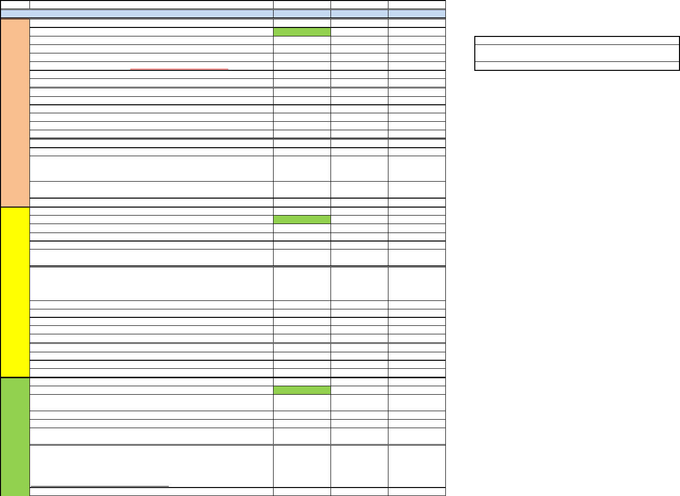
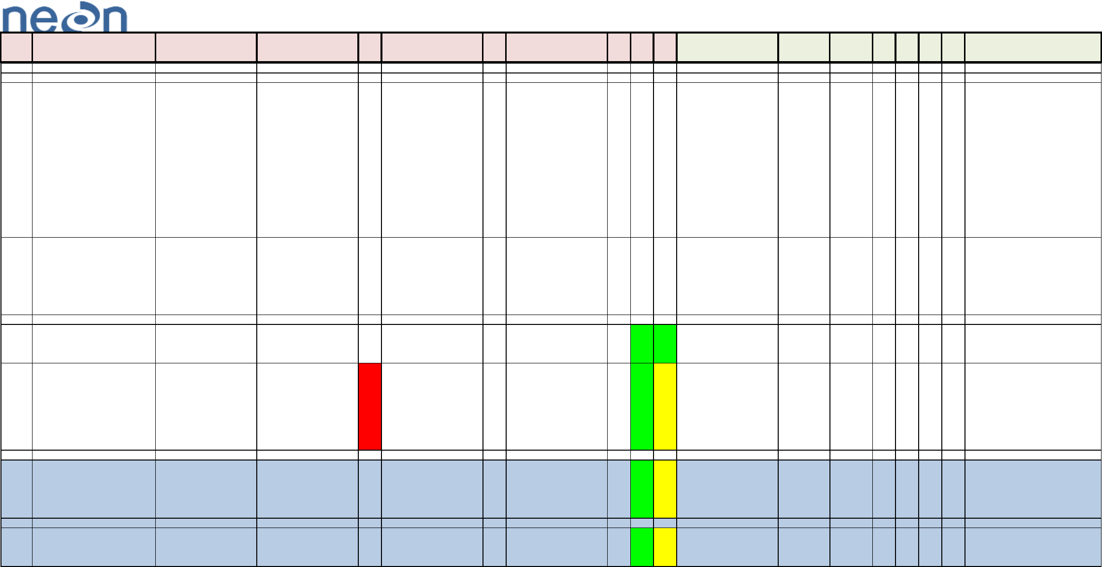
Stage
Task
Subsystem #1 Subsystem #2 Subsystem #3
NEON.DOC.xxxxxx NEON.DOC.xxxxxx NEON.DOC.xxxxxx
Schedule DFMEA one week prior to CDR (Enter Date held)
m/d/yy m/d/yy m/d/yy
Review Sensor Requirements
x
Browse sensor Data Sheet
Discuss initial design concepts with ENG (Mechanical, Electrical)
Get any conceptual drawings from ENG to use for DFMEA meeting
Prepare "DFMEA Initial (CDR).xls" file. See comments for things to consider.
One day prior to DFMEA meeting, e-mail file out to team
Print out "DFMEA Initial (CDR)" (approx 10 copies)
Hold DFMEA meeting, take notes
Integrate notes into "DFMEA (CDR)" file
Create blank Critical Parts file, populate with any known Part numbers (Optional)
Create DFMEA slides for review
Back up files in N:/SYS Meas Sub-system folder
Integrate slides into CDR presentation
Present DFMEA at CDR, note suggested changes
Incorporate any changes into "DFMEA (post-CDR)"
Prior to checking file into Agile remove the NEON Cover Sheet, Examples, and DFMEA
Checklist. The DFMEA checklist should be saved off as a separate file so that you can track
your DFEMEAs
Obtain a document number and Check file into Agile using NEON.DOC.004254 as a guide.
Send Action Items to admin contact for addition into 'the file'
Schedule DFMEA one week prior to PIDR (Enter Date held) m/d/yy m/d/yy m/d/yy
Check CDR DFMEA out of Agile and review for familiarity. x
Request assembly and component Part Numbers from ENG for reference in DFMEA.
Review CDR DFMEA Action Items for familiarity.
Review Critical Parts file.
Print out "DFMEA (CDR)" or "DFMEA (post-CDR)" whichever is most recent (approx 10
copies).
Hold DFMEA meeting, completing the following:
- Review CDR as-left design - ask ENG for any changes to this.
- Review CDR DFMEA action items - ask for updates
- Review Critical Parts list - get a list of all Part Numbers from ENG
Integrate notes into new "DFMEA (PIDR)" file.
Update Critical Parts file (confirm with Byron for 'Quality' vs 'Technical' parts).
Create DFMEA slides for review.
Back up files in N:/SYS Meas Sub-system folder
Integrate slides into PIDR presentation.
Present DFMEA at PIDR, note suggested changes.
Incorporate any changes into "DFMEA (post-PIDR)".
Check file into Agile.
Send Action Items to admin contact for addition into 'the file'.
Schedule DFMEA one week prior to PIDR. (Enter Date held) m/d/yy m/d/yy m/d/yy
Check PIDR DFMEA out of Agile and review for familiarity. x
Request any new assembly and component Part Numbers from ENG for reference in DFMEA.
Review PIDR DFMEA Action Items for familiarity.
Review Critical Parts file.
Print out "DFMEA (PIDR)" or "DFMEA (post-PIDR)" whichever is most recent (approx 10
copies).
Hold DFMEA meeting, completing the following:
- Review PIDR as-left design - ask ENG for any changes to this.
- Review PIDR DFMEA action items - ask for updates
- Review Critical Parts list - get a list of all Part Numbers from ENG
- Add Post-Corrective Action Scoring where possible
Integrate notes into new "DFMEA (EFDR)" file.
NEON Doc #
CDR
PIDR
EFDR
To add more subsystems, Insert columns between existing subsystems to
copy all formatting.
Notes
Enter an "x" in each cell as that task is finished; cell with turn green.

Update Critical Parts file (confirm with Byron for 'Quality' vs 'Technical' parts).
Create DFMEA slides for review.
Back up files in N:/SYS Meas Sub-system folder
Integrate slides into EFDR presentation.
Present DFMEA at EFDR, note suggested changes.
Incorporate any changes into "DFMEA (post-EFDR)".
Check final revision of DFMEA excel file into Agile.
Review Action Item Excel file for resolution of AIs and create list of AIs that need a JIRA ticket
Create Post-corrective action scoring values
Open JIRA tickets for any unresolved Action Items
Set flags for all Quality Critical Parts in Agile
Do 'Unknown Action' for all Technical Quality Parts
