WWW.GLEDHILL.NET
ONE NAME. EVERY SOLUTION.
BOILERMATE
INCLUDING SP, SP PRE-PLUMBED AND OV
PRE-PLUMBED
MAINS PRESSURE HOT WATER THERMAL STORE
FOR USE WITH DOMESTIC AND CENTRAL PLANT BOILERS
INSTRUCTION MANUAL
DESIGN, INSTALLATION & SERVICING

Page 2
The Gledhill BoilerMate range complies with the HWA Specication for hot water only
thermal storage products. The principle was developed in conjunction with British Gas.
This product is manufactured under an ISO 9001:2008 Quality System audited by BSI.
Benchmark places responsibilities on both manufacturers and installers. The purpose is to
ensure that customers are provided with the correct equipment for their needs, that it is
installed, commissioned and serviced in accordance with the manufacturers instructions
by competent persons and that it meets the requirements of the appropriate Building
Regulations. The Benchmark Checklist can be used to demonstrate compliance with
Building Regulations and should be provided to the customer for future reference.
Installers are required to carry out installation, commissioning and servicing work in
accordance with the Benchmark Code of Practice which is available from the Heating
and Hot Water Industry Council who manage and promote the Scheme. Visit www.
centralheating.co.uk for more information.
For further information on the HWA Charter Statement, please refer to the HWA website
hotwater.org.uk.
Section Page
DESIGN
Introduction 3
Model Selection 5
PRODUCT SPECIFICATION
OV PP Components 6
OV PP Technical Specication 7
SP Components 8
SP Technical Specication 9
SP PP Components 10
SP PP Technical Specication 11
TRANSPORTATION
Lifting and Handling 12
INSTALLATION
Domestic Hot Water 13
Central Heating 18
Store Charging 33
COMMISSIONING
Commissioning and checks 35
SERVICING AND MAINTENANCE
Short Parts List 37
Annual Service 38
Changing Components 38
Fault Finding 40
APPENDIX
Appendix A 46
Appendix B 47
Terms & Conditions 48
Benchmark Checklist 50
Benchmark Service Record 51
ISSUE 02: NOVEMBER 2019
Page 3
DESIGN
INTRODUCTION
Any water distribution system/installation must comply with the relevant
recommendations of the current version of the Regulations and British Standards
listed below:-
Gas Safety (Installation and use) Regulations 1998
Building Regulations
Water Supply (Water Fittings) Regulations 1999
Manual Handling Operations Regulations
British Standards
BS EN 806:1-5: BS EN 8558:2011
Requirements for Electrical Installations BS7671:2008 and A2:2013 18th Edition
Most new building work will require the relevant building control body to be notied
prior to the building work commencing. This will not be required if the work is carried
out under a self certication scheme or if the work is not notiable. Full details of the
self certication schemes and work that is not notiable can be obtained from page
9 of Approved Document G, available from www.planningportal.gov.uk.
A suitably competent trades person must install the BoilerMate and carry out any
subsequent maintenance/repairs. The manufacturer’s notes must not be taken as
overriding statutory obligations.
The Domestic Building Services Compliance Guide 2013 denes, one of the xed
building services, as any part of or controls associated with xed systems for domestic
hot water. All xed building services, including theircontrols, should be commissioned
by testing and adjustment to ensure that they use no more fuel and power than is
reasonable in the circumstances. Where commissioning is required, if it is completed
by a person registered with a competent person scheme, the commissioning notice
will be supplied by that person, otherwise the person carrying out the work must notify
the relevant building control body, that commissioning has taken place in accordance
with the Domestic Heating Compliance Guide.The building control body will then be
able to issue a completion certicate. This applies to England, for other jurisdictions in
the UK, it may be necessary to consult their own building regulations and guidance.
The BoilerMate is not intended for use by persons (including children) with reduced
physical, sensory or mental capabilities, or lack of experience or knowledge, unless
they have been given supervision or instruction concerning use of the appliance by
a person responsible for their safety.
Children should be supervised to ensure that they do not play with the appliance.
The information in this manual is provided to assist generally in the selection of
equipment. The responsibility for the selection and specication of the equipment
must however remain that of the customer and any Designers or Consultants
concerned with the design and installation.
Please Note: We do not therefore accept any responsibility for matters of design,
selection or specication or for the eectiveness of an installation containing one of
our products unless we have been specically requested to do so.
All goods are sold subject to our Conditions of Sale, which are set out at the rear of
this manual.
In the interest of continuously improving the BoilerMate range, Gledhill Building
Products Ltd reserve the right to modify the product without notice, and in these
circumstances this document, which is accurate at the time of printing, should be
disregarded. It will however be updated as soon as possible after the change has
occurred.
The Environment
This product has been manufactured using
many recyclable materials, including the
approved HCFC/CFC free polyurethane foam
insulation. At the end of its useful life, it
should be disposed of at a Local Authority
Recycling Centre, to maximise the products full
environmental benets.
Page 4
BoilerMate products are vented cylinders, so there is no requirement for a pressure
and temperature relief valve to be tted to them.
This is a key benet of a thermal store over an unvented cylinder. This enables greater
exibility of location in the building, as there is no requirement to install discharge
pipework with a constant fall to an outside wall, or upgrade the soil and vent pipework
to be able to withstand high temperature discharges.
This unit uses minimal power in stand by mode, and can be turned o if required.
All BoilerMates are supplied with an immersion heater 3kW 240v AC, complete with
a thermostat set at 75°C and an overheat thermostat set at 90°C, which will require
resetting if operated.
The immersion heaters purpose is to provide a backup heat source if the boiler is out
of operation. Please note that this back up facility will only provide sucient input
for the domestic hot water requirement.
The heat losses from thermal stores should not be directly compared with heat losses
from unvented or vented cylinders because they are treated dierently in SAP. This
is because the unvented and vented cylinders are tested at 65°C and the thermal
store at 75°C.
The feed and expansion tank must be located above the thermal store with the
SP and SP PP variants. In the case of the integrated thermal store, BMST-OV PP, the
feed and expansion tank water level must also be a minimum of 300mm above the
highest radiator.
For hot water only BoilerMate SP and SP PP models, the feed and expansion tank must
be above the top of the thermal store.
The maximum working pressure of the thermal store is 1 bar. This means that the feed
and expansion tank can be located up to 10 metres above the base of the thermal store.
The OV model has the option of the top up cistern with ballvalve and warning/overow
pipe which can be supplied as an optional extra if required. However, the standard
preferred arrangement available for the SP models are for the cistern to be manually
lled from a temporary hose connection tted with a double check valve.
The cistern must not be tted more than 10 metres above the BoilerMate CP appliance
itself.
DESIGN
INTRODUCTION
Page 5
DESIGN
INTRODUCTION
1
3
6
7
D
ra
in
Wiring Centre
Immersion
Control Stat
C
y
li
n
d
e
r
C
o
ld
F
e
e
d
(
t
o
F
&
E
)
5
8
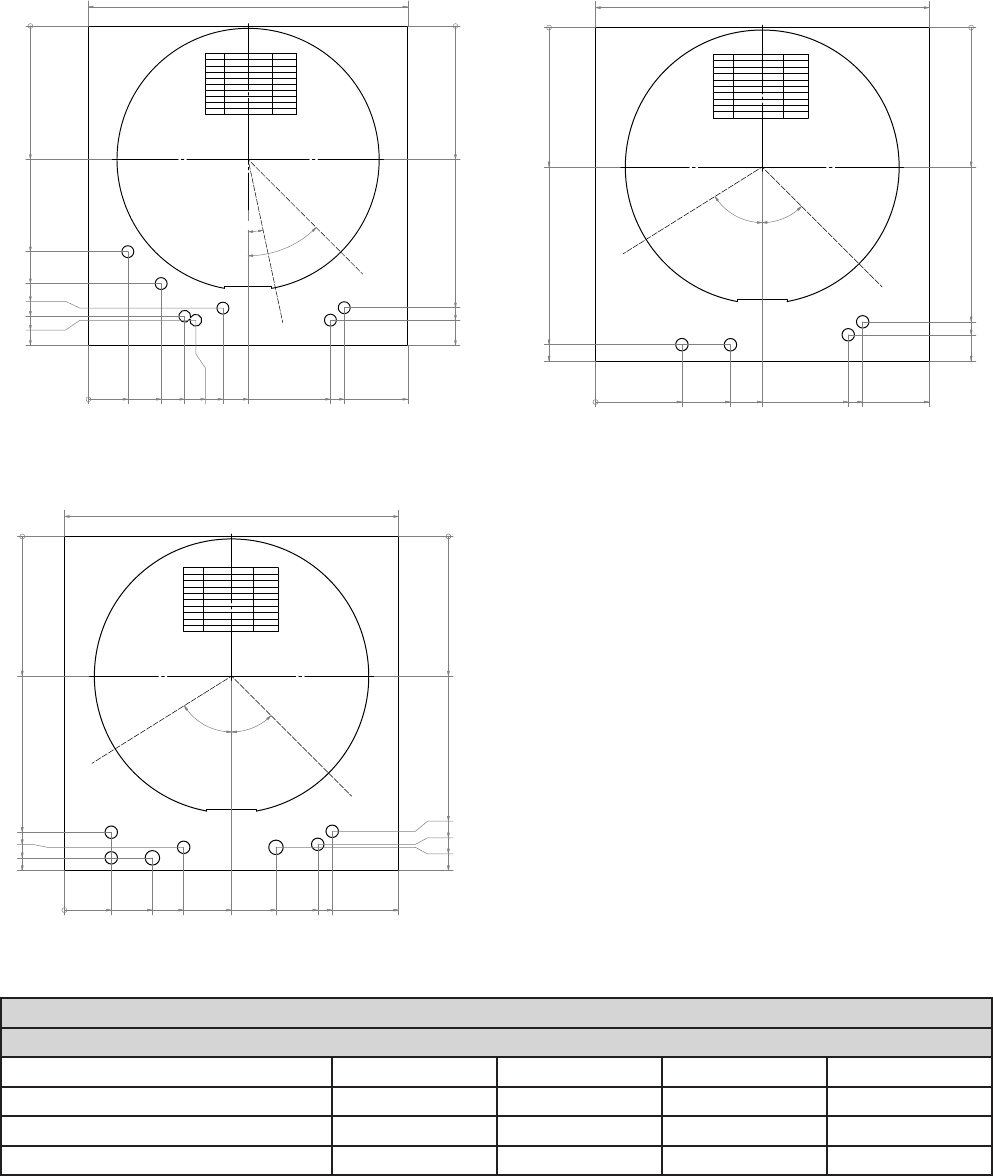
Number
Description
Size (mm)
1
Return To Boiler 22
2
N/a
22
2a
N/a
22
3
Flow From Boiler
22
4
N/a
22
5
Drain Tapping
½" Fem
6 Hot Water Out
22
7
Mains Cold Supply
22
8
Cylinder Cold Feed
22
All pipe holes are optional.
All pipe hole sizes are dictated by the
property / design. Therefore are a general indication.
The template is a general guide for installation
rather than a rule that must be followed without
deviation.
0
280
637
670
0
1
7
4
2
7
1
3
3
5
5
0
8
5
3
7
6
7
0
0
280
591
617
670
670Minimum Cupboard Width =
5
8
°
4
5°
1
2
3
4
6
7
D
r
a
i
n
Wiring Centre
Immersion
Control Stat
2a
C
y
l
i
n
d
e
r
C
o
ld
F
e
e
d
(
t
o
F
&
E
)
8
5
Number
Description
Size (mm)
1
Return To Boiler 22
2
CH Zone 1
22
2a
Optional CH Zone 2
22
3
Flow From Boiler
22
4
CH Return
22
5
Drain
½" Fem
6 Hot Water Out
22
7
Mains Cold Supply
22
8
Cylinder Cold Feed
22
All pipe holes are optional.
All pipe hole sizes are dictated by the
property / design. Therefore are a general indication.
The template is a general guide for installation
rather than a rule that must be followed without
deviation.
0
280
474
540
592
609
617
670
0
8
3
1
5
3
2
0
2
2
2
5
2
8
2
3
3
5
5
0
8
5
3
7
6
7
0
0
280
591
617
670
670Minimum Cupboard Width =
1
2
°
4
5
°
3
2
1
4
6
7
D
ra
in
Wiring Centre
Immersion
Control Stat
2a
5
8
C
y
l
i
n
d
e
r
C
o
ld
F
e
e
d
(
t
o
F
&
E
)
Number
Description
Size (mm)
1
Return To Boiler
28
2
CH Zone 1
22
2a
Optional CH Zone 2
22
3
Flow From Boiler
28
4
CH Return
22
5
Drain Tapping
½" Fem
6 Hot Water Out
22
7
Mains Cold Supply
22
8
Cylinder Cold Feed
22
All pipe holes are optional.
All pipe hole sizes are dictated by the
property / design. Therefore are a general indication.
The template is a general guide for installation
rather than a rule that must be followed without
deviation.
0
280
593
623
644
670
0
9
4
1
7
6
2
3
9
3
3
5
4
2
4
5
0
8
5
3
7
6
7
0
0
280
591
617
623
670
670Minimum Cupboard Width =
5
8
°
45°
Model Selection Guide BoilerMate
Dwelling Type
Bedroom 1-2 2-3 2-3 2-4
Bathroom 1 or 1 1 2
En-suite shower rooms 1 1 2 1
Model size required 150 150 180 210
Notes:-
1. Plastic top up cistern is available as an optional kit, and is supplied separately.
2. A minimum of 40°C temperature rise is achieved at 12.6 litres/min ow rate and assume that recommended pressures and adequate
ow are available at the appliance. The actual ow rate from the appliance is automatically regulated to a maximum of 15 litres/min.
3. The domestic hot water temperature is not user adjustable.
All measurements shown are in millimetres.
BoilerMate OV PP
BoilerMate SP PP
BoilerMate SP
Page 6
Please note that the copper pipework connected to the Boiler Return (19) is only for
support in transit. Replace with the correct length to suit the installation requirement.
SELECTION
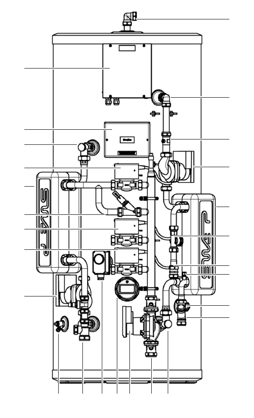
BOILERMATE OV PP
The BoilerMate OV is an integrated thermal store. It is intended to be used in
conjunction with an open vented heat only boiler. The boiler should be plumbed
directly to the thermal store. The boilers purpose is to keep the thermal store hot.
The central heating is intended to be plumbed directly the thermal store, with the
central heating demand being controlled by a timer and room thermostat. The boiler
itself is controlled by the store thermostat.
Domestic hot water is generated instantaneously
by the BoilerMate domestic hot water assembly.
It is supplied to the taps at mains pressure and
at 55°C.
Please see the drawing below for connections,
location size and type.
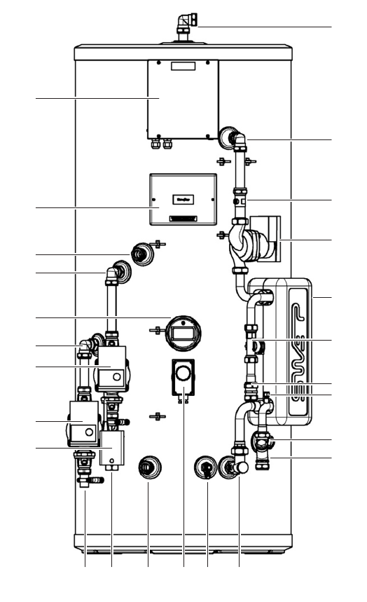
Standard Equipment
The standard conguration of the BoilerMate OV
Pre-Plumbed is shown opposite. It is supplied
with the following factory tted equipment:-
1 90 degree elbow - vent (22mm
compression)
2 Domestic hot water PCB box
3 Compression elbow (22mm)
4 Straight isolator (22mm to FF3/4”)
5 System wiring panel
6 Domestic hot water pump (PWM2)
7 Boiler ow (22mm compression)
8 Compression elbow (22mm)
9 Domestic hot water PHE (insulated) 24
plate
10 3kW immersion heater (backup)
11 Flow sensor and hot water sensor
12 Compression elbow (22mm)
13 Central heating pump (including isolation
valves)
14 Cold water sensor
15 Boiler pump (including isolation valves)
16 Cold feed (22mm compression)
17 Central heating zone valve (22mm)
18 Inline strainer/ow regulator (22mm
compression) mains cold water in
19 Boiler return
20 Central heating ow
21 Central heating return (22mm)
22 Store control thermostat
23 Drain valve
24 Bent isolator - CV tted (22mm to FF3/4”)
25 Hot water outlet (22mm compression)
Optional Equipment Kits For BMST-OVPP
1 Open vented header tank kit (BCK001)
2. Switch Back up conversion 6kW to 3kW
kit (BCK003)
3. Timer kit (BCK004)
4. Second Heating Zone kit (BCK006)
5. Pump over run kit (BCK007)
6. DHW scale prevention kit (BCK008)
Full details of the optional kits, available at the
time of order, on page 34.
1
3
4
6
9
11
14
16
18
25
2
5
7
8
10
12
13
15
17
19 20 21 22 23 24

Page 7
Technical Specication BoilerMate OV Pre-Plumbed
Product Stock Code BMSTOV150PP BMSTOV180PP BMSTOV210PP
Energy eciency class C C C
Heat loss
watts 47 55 62
kWh/24hr 1.48 1.78 2.08
Height mm 1118 1306 1494
Diameter mm 550 550 550
Min cupboard height
1
mm 1668 1856 2044
Min cupboard width mm 670 670 670
Min cupboard depth mm 670 670 670
Weight (empty) kg 38 42 50
Weight (full) kg 189 222 261
Thermal store volume litres 151 181 211
DHW dedicated volume litres 64 77 90
DHW space heating volume litres 85 103 120
Average reheat power
2
kW 24 26 26
Average reheat time
3
mins 16 19 20
Maximum DHW pressure bar 5 5 5
DHW performance (No space heating)
Test ow rate litres/min 12.6 12.6 12.6
Test volume above 40°C litres 138 154 196
Average DHW temperature °C 54 53 52
Average temperature rise °C 44 42 44
Thermal store test temperature °C 75 75 75
DHW performance (Space heating)
Test ow rate litres/min 12.6 12.6 12.6
Test volume above 40°C litres 78 103 137
Average DHW temperature °C 50 49 51
Average temperature rise °C 40 37 42
Thermal store test temperature °C 61 63 63
Notes:-
1. The height stated is to the top of the unit plus 550mm, which should allow for a 25mm thick shelf/board and room for servicing. This
will need to be increased by 125mm if the automatic ll method is chosen.
2. OV model heated by a 30kW boiler at 15 l/m.
3. Full thermal store volume reheated from 35°C to 75°C.
4. Please refer to page 5 for the minimum cupbard space requirement. This can be reduced by approximately 35mm if the insulation
is removed from the plate heat exchanger.
SELECTION
BOILERMATE OV PP
Page 8
The BoilerMate SP is a hot water only thermal store. It is intended to be used in
conjunction with a sealed primary system. This is generally expected to be a system
boiler; however this product can also be in a central plant or district heating system.
Please check the table opposite for the maximum pressures.
Heat energy is input into the store via the store plate heat exchanger, store pump and
associated pipework which is tted to the product. The installer must supply all the
other necessary components to feed the boiler side of the store plate heat exchanger.
Domestic hot water is generated instantaneously
by the BoilerMate domestic hot water assembly.
It is supplied to the taps at mains pressure and
at 55°C. See the domestic hot water installation
section for details.
Please see the drawing below for connections,
location size and type.
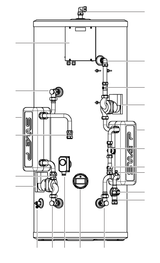
Standard Equipment
The standard conguration of the BoilerMate
SP is shown opposite. It is supplied with the
following factory tted equipment:-
1 90 degree elbow - vent (22mm
compression)
2 Domestic hot water PCB box
3 Compression elbow (22mm)
4 Straight isolator (22mm to FF3/4”)
5 Bent isolator - CV tted (22mm to FF3/4”
6 Domestic hot water pump (PWM2)
7 Store PHE (insulated) 24 plate
8 Boiler ow (22mm compression)
9 Domestic hot water PHE (insulated) 24
plate
10 Flow sensor and hot water sensor
11 Boiler return (22mm compression)
12 Store pump
13 Cold water sensor
14 Cold feed (22mm compression)
15 Inline strainer/ow regulator (22mm
compression) mains cold water in
16 Drain valve
17 Bent isolator (22mm to FF3/4”)
18 Store control thermostat
19 3kW immersion heater (backup)
20 Bent isolator - CV tted (22mm to FF3/4”)
21 Hot water outlet (22mm compression)
Optional Equipment Kits For BMST-SP
1. Sealed primary header tank kit (BCK002)
2. Switch Back up conversion 6kW to 3kW
kit (BCK003)
3. Timer kit (BCK004)
4. Sealed system ROBOKIT (BCK005)
5. Second Heating Zone kit (BCK006)
6. Pump over run kit (BCK007)
7. DHW scale prevention kit (BCK008)
Full details of the optional kits, available at the
time of order, on page 34.
1
3
4
6
9
10
13
21
14
15
2
5
7
8
11
12
16 17 18 19 20
SELECTION
BOILERMATE SP

Page 9
SELECTION
BOILERMATE SP
Technical Specication BoilerMate SP
Product Stock Code BMSTSP150 BMSTSP180 BMSTSP210
Energy eciency class C C C
Heat loss
watts 47 55 62
kWh/24hr 1.48 1.78 2.08
Height mm 1118 1306 1494
Diameter mm 550 550 550
Min cupboard height
1
mm 1668 1856 2044
Min cupboard width mm 670 670 670
Min cupboard depth mm 670 670 670
Weight (empty) kg 38 42 50
Weight (full) kg 189 223 262
Thermal store volume litres 151 181 211
DHW dedicated volume litres 151 181 211
DHW space heating volume litres
Average reheat power
2
kW 21 19 19
Average reheat time
3
mins 18 26 29
Maximum DHW pressure bar 5 5 5
DHW performance
Test ow rate litres/min 12.6 12.6 12.6
Test volume above 40°C litres 138 154 196
Average DHW temperature °C 54 53 55
Average temperature rise °C 41 41 43
Thermal store test temperature °C 75 75 75
Notes:-
1. The height stated is to the top of the unit plus 550mm, which should allow for a 25mm thick shelf/board and room for servicing. This
will need to be increased by 125mm if the automatic ll method is chosen.
2. SP model heated from a heat source at 82.5°C at 16 l/m.
3. Full thermal store volume reheated from 35°C to 75°C.
4. Please refer to page 5 for the minimum cupbard space requirement. This can be reduced by approximately 70mm if the insulation
is removed from the plate heat exchangers.
Page 10
The BoilerMate SP Pre-Plumbed is a hot water only thermal store. It is intended to be
used in conjunction with a sealed primary system. This is generally expected to be a
system boiler; however this product can also be in a central plant or district heating
system. Please check the table opposite for the maximum pressures.
Heat energy is input into the store via the store plate heat exchanger, store pump and
associated pipework which is tted to the product. The installer must supply all the
other necessary components to feed the boiler side of the store plate heat exchanger.
Domestic hot water is generated instantaneously
by the BoilerMate domestic hot water assembly.
It is supplied to the taps at mains pressure and
at 55°C. See the domestic hot water installation
section for details.
Please see the drawing below for connections,
location size and type.
Standard Equipment
The standard conguration of the BoilerMate SP
Pre-Plumbed is shown opposite. It is supplied
with the following factory tted equipment:-
1 90 degree elbow - vent (22mm
compression)
2 Domestic hot water PCB box
3 Compression elbow (22mm)
4 Straight isolator (22mm to FF3/4”)
5 System wiring panel
6 Bent isolator - CV tted (22mm to FF3/4”)
7 Domestic hot water pump (PWM2)
8 Boiler zone valve for store charging
9 Store PHE (insulated) 24 plate
10 Domestic hot water PHE (insulated) 24
plate
11 Auto bypass valve
12 Central heating zone 1
13 Flow sensor and hot water sensor
14 Central heating zone 2
15 Cold water sensor
16 Hot water outlet (22mm compression)
17 Store pump
18 Cold feed (22mm compression)
19 Inline strainer/ow regulator (22mm
compression) mains cold water in
20 Drain valve
21 Central heating boiler return
22 Store control thermostat
23 3kW immersion heater (backup)
24 System pump
25 Boiler ow
26 Bent isolator - CV tted (22mm to FF3/4”)
Optional Equipment Kits For BMST-SPPP
1. Sealed primary header tank kit (BCK002)
2. Switch Back up conversion 6kW to 3kW
kit (BCK003)
3. Timer kit (BCK004)
4. Sealed system ROBOKIT (BCK005)
5. Pump over run kit (BCK007)
6. DHW scale prevention kit (BCK008)
Full details of the optional kits, available at the
time of order, on page 34.
1
3
4
7
10
13
15
16
18
19
2
6
5
9
8
11
12
14
17
20 21 22 23 24 25 26
SELECTION
BOILERMATE SP PP

Page 11
SELECTION
BOILERMATE SP PP
Technical Specication BoilerMate SP Pre-Plumbed
Product Stock Code BMSTSP150PP BMSTSP180PP BMSTSP210PP
Energy eciency class C C C
Heat loss
watts 47 55 62
kWh/24hr 1.48 1.78 2.08
Height mm 1118 1306 1494
Diameter mm 550 550 550
Min cupboard height
1
mm 1668 1856 2044
Min cupboard width mm 670 670 670
Min cupboard depth mm 670 670 670
Weight (empty) kg 42 46 55
Weight (full) kg 193 227 266
Thermal store volume litres 151 181 211
DHW dedicated volume litres 151 181 211
DHW space heating volume litres
Average reheat power
2
kW 21 19 19
Average reheat time
3
mins 18 26 29
Maximum DHW pressure bar 5 5 5
DHW performance
Test ow rate litres/min 12.6 12.6 12.6
Test volume above 40°C litres 138 154 196
Average DHW temperature °C 54 53 55
Average temperature rise °C 41 41 43
Thermal store test temperature °C 75 75 75
Notes:-
1. The height stated is to the top of the unit plus 550mm, which should allow for a 25mm thick shelf/board and room for servicing. This
will need to be increased by 125mm if the automatic ll method is chosen.
2. SP model heated from a heat source at 82.5°C at 16 l/m.
3. Full thermal store volume reheated from 35°C to 75°C.
4. Please refer to page 5 for the minimum cupbard space requirement. This can be reduced by approximately 70mm if the insulation
is removed from the plate heat exchangers.

Page 12
Preparation / Placing The Appliance In Position
The appliance should be handled carefully to avoid damage and the recommended
method is shown above.
Note: Although the above guidance is provided any manual handling/lifting
operations will need to comply with the requirements of the Manual Handling
Operations Regulations issued by the H.S.E.
The appliance can be moved using a sack truck on the rear face although care should
be taken and the route should be even.
In apartment buildings containing a number of storeys we would recommend that
the appliances are moved vertically in a mechanical lift.
If it is proposed to use a crane expert advice should be obtained regarding the need
for slings, lifting beams etc.
Before installation the site requirements should be checked and confirmed as
acceptable.
Manual Handling Of The Appliance
Manual handling means any transporting or supporting of a load (including lifting,
putting down, pushing, pulling, carrying or moving) by hand or bodily force.
Scope
This assessment will cover the largest unit within each product range.
For specic weights and dimensions please refer to technical data section.
Main Hazards
Vision may not be clear due to the size of the products.
Adopting an incorrect method of lifting may cause injury, attempting to lift these
products will require help from others. (Team lifts)
Manual Lifting Procedure
The lift, key factors in safe lifting are:
a. Balance
b. Position of back
c. Positioning of the arms and body
d. The hold
e. Taking the lead for team lifts
a. Balance - Since balance depends essentially upon the position of the feet, they
should be apart about hip breadth with one foot advanced giving full balance
sideways and forward without tension. In taking up this position, lifting is done
by bending at the knees instead of the hips and the muscles that are brought
into use are those of the thigh and not the back.
b. Position of back - Straight - not necessary vertical. The spine must be kept
rigid, this coupled with a bent knee position, allows the centre line of gravity of
the body to be over the weight so reducing strain.
c. Positioning of arms and body - The further arms are away from the side, the
greater the strain on the shoulders, chest and back. Keep elbows close to the
body arms should be straight.
d. The hold - Before lifting ensure you have
a good hold.
e. Taking the lead for team lifts- As more
than one person is required for these
products ensure that one person is taking
the lead. This may be you so ensure that
each person that is helping is made aware
of the weight and of the items listed within
this assessment. Make sure you and any
others helping know the route you intend
to take that it is clear of any obstructions.
Never jerk the load as this will add a little
extra force and can cause severe strain
to the arms, back and shoulders. If there
are steps involved decide on where you
will stop and take a rest period. Move
smoothly and in unison taking care to
look and listen to others helping with the
lift. Where possible use a sack truck to
move the product over long at distances,
only lift the products when necessary. If in
doubt stop and get more help.
Individual Capability
Individual capability plays an important part
in handling these products. Persons above
average build and strength will nd it easier
and should be in good health. Persons below
average build and strength may require more
rest periods during the handling process.
Pregnant women should not carry out this
operation.
Persons who are not in good health should
seek medical advice prior to commencing any
lifting or manual handling operation.
Residual Risk
Following the guidelines given above will
reduce any risk to injury.
All persons carrying out this operation must
be fully trained and copies of the specic risk
assessment made available for inspection and
use in their training process.
Further guidance on Manual Handling can be
obtained from the Health and Safety Executive.
Manual Handling Operations Regulations 1992
(amended by Health and Safety (Miscellaneous
Amendments) Regulations 2002.
TRANSPORT
LIFTING AND HANDLING
Page 13
Hot And Cold Water
An important feature of the BoilerMate is that hot water can be supplied directly from
the mains at conventional flow rates without the need for temperature and pressure
relief safety valves or expansion vessels. This is achieved by passing the mains water
through a plate heat exchanger. The outlet temperature of the domestic hot water is
maintained by a printed circuit control board, which controls the speed of the pump
circulating the primary water from the store through the plate heat exchanger.
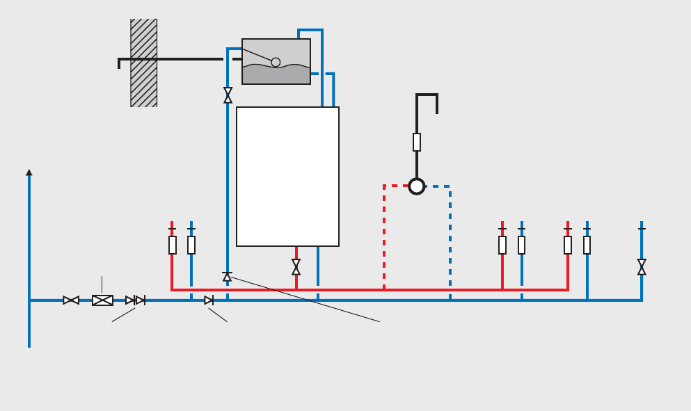
Pressures
A schematic layout of the hot and cold-water services in a typical small dwelling is
shown below. BoilerMate SP will operate at mains pressures as low as 1 bar and as
high as 5 bar although the recommended range is 2-3 bar dynamic at the appliance.
It is also important to check that all other equipment and components in the hot
and cold water system are capable of accepting the mains pressure available to the
property. If the mains pressure can rise above 5 bar or the maximum working pressure
of any item of equipment or component to be tted in the system, a pressure limiting
(reducing) valve set to 3 bar will be required.
If you encounter a situation where the water pressure is adequate but flow rates are
poor please contact our technical helpline for details of an eective solution.
Inline Strainer/Flow Regulator
Each BoilerMate is tted with a strainer and flow regulator on the cold mains supply
connection. If the supply pressure is less than 2 bar or if all taps are provided with flow
regulators the flow regulator on the cold inlet should be removed.
Check Valve Locations
No check valve or similar device should be tted on the cold-water supply branch
to the BoilerMate.
Water Hardness
The Domestic Building Services Compliance
Guide (2013) provides more detailed
information on the guidance contained in
Approval Documents L1A and L1B, guidance
to the Building Regulations. The recommended
minimum standards specify that “where
the mains water hardness exceeds 200ppm
provision should be made to treat the feed
water to water heaters and the hot water circuit
of combination boilers to reduce the rate of
accumulation of lime scale”.
To comply with this requirement the hardness
of the mains water should be checked by the
installer and if necessary, the optional kit,
BCK008, electronic scale inhibitor should be
requested at the time of order for hardness
levels between 200 and 300 ppm (mg/l).
Alternatively, the inline scale inhibitor XB043,
can be ordered which is tted in the cold water
pipework prior to the DHW PHE.
Where the water is very hard i.e. 300ppm (mg/l)
and above a polyphosphate type, inhibitor
should be tted by the installer at a suitable
point in the cold water supply to the appliance.
INSTALLATION
DOMESTIC HOT WATER
Warning/
overflow
pipe
MCWS
Servicing
valve
Safety/open vent
Shower
Expansion/
cold feed
Second
dwelling
Pressure limiting valve
NOT REQUIRED at
pressures below 5 bar
unless any components
have a lower
maximum working
pressure
Double check valve
NOT REQUIRED unless
pipe supplies more
than one dwelling
‘a’ - flow regulator recommended for
better balance of hot and cold
water supplies
MCWS
supply
pipe
Sink
H C
a a
SV
a a a a
Bath
H C
Hand basin
H C
WC - fitted
with BS1212
ballvalve
C
Typical hot and cold water distribution
BOILERMATE
Check valve
NOT REQUIRED unless
chemical water
treatment unit is fitted
If an auto fill top up is fitted, a check valve
can be installed here to prevent
stagnent water from this pipe back flowing
into the mains cold water supply
a
Top up cistern
Page 14
Pipe Sizing / Materials / Push Fit
To achieve even distribution of the available supply of hot and cold water, it is
important in any mains pressure system, that the piping in a dwelling should be sized
in accordance with BS EN 806:1-5: BS EN 8558:2011. This is particularly important in
a large property with more than one bathroom.
However, the following rule of thumb guide lines should be adequate for most smaller
property types as long as water pressures are within the recommended range.
1. A 15mm copper or equivalent external service may be enough for a small 1
bathroom dwelling (depending upon the flow rate available), but the minimum
recommended size for new dwellings is 22mm (25mm MDPE).
2. The internal cold feed from the main incoming stop tap to the BoilerMate SP
should be run in 22mm pipe. The cold main and hot draw-o should also be run
in 22mm as far as the branch to the bath tap.
3. The nal branches to the hand basins and sinks should be in 10mm and to the
baths and showers in 15mm (1-meter minimum).
4. We would recommend that best results for a balanced system are achieved by
tting appropriate flow regulators to each hot and cold outlet. This is particularly
relevant where the water pressures are above the recommended water pressure
range. Details of suitable flow regulators are provided in Appendix A.
All the recommendations with regard to pipework systems in this manual are generally
based on the use of BS/EN Standard copper pipework and ttings.
However, we are happy that plastic pipework systems can be used in place of copper
internally as long as the chosen system is recommended for use on domestic hot
and cold water systems by the manufacturer and is installed fully in accordance with
their recommendations. This is particularly important in relation to use of push t
connections when using the optional flexible hose kits - see installation section of
this manual.
It is also essential that if an alternative pipework material/system is chosen the
manufacturer conrms that the design criteria of the new system is at least equivalent
to the use of BS/EN Standard copper pipework and ttings.
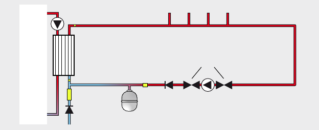
Secondary Circulation
If the length of the hot water draw o pipework is excessive and the delivery time
will be more than 60 seconds before hot water is available at the tap, you may wish to
consider using trace heating to the hot water pipework such as the Raychem HWAT
system. Also, a conventional pumped secondary circulation system (shown below)
can be used with any model of the BoilerMate SP.
INSTALLATION
DOMESTIC HOT WATER
BoilerMate
Inline filter &
flow regulator
Single check
valve
Single
check
valve
Pump isolation
valves
Cold water inlet
Plate heat exchanger
Hot water outlets
Pipework length and
diameter to suit
property demands
Pipework length and
diameter to suit
recirculation flow rate
approx 1-2 l/min
Cold water sensor
Control
stat
Flow switch
Potable water
expansion vessel
Secondary
circulation
pump
A pipe thermostat is incorporated in the circuitry which cuts the supply to the pump
when the water in the return pipe reaches the set temperature. Ensure the hot water
temperature is set correctly to avoid excessively hot water at the outlets and long
pump run times.
Secondary circulation pipework must be
insulated to prevent energy loss in both heated
and unheated areas.
Bath Hot Water Temperature
Bath hot water supplies should be limited to a
maximum of 48°C using an inline blending valve.
Pipe Separation
It is important that the cold-water pipework
is adequately separated/protected from any
heating/hot water pipework to ensure that the
water remains cold and of drinking water quality.
Tap outlets
Aerated taps are recommended to prevent
splashing.
Showers
Any type of shower mixing valve can be used
as long as both the hot and cold supplies
are mains fed. However, all mains pressure
systems are subject to dynamic changes
particularly when other hot and cold taps/
showers are opened and closed, which will
cause changes in the water temperature at
mixed water outlets such as showers. For
this reason and because these are now no
more expensive than a manual shower we
strongly recommend the use of thermostatic
showers with this appliance. The shower
head provided must also be suitable for
mains pressure supplies.
However, if it is proposed to use a ‘whole body’
or similar shower with a number of high flow/
pressure outlets please discuss with the Gledhill
technical department.
Shower Pipework
The hot water supply to a shower-mixing valve
should be fed wherever practical directly from
the BoilerMate or be the rst draw o point on
the hot circuit. The cold supply to a shower-
mixing valve should wherever practical be fed
directly from the rising mains via an independent
branch. The shower must incorporate or be tted
with the necessary check valves to provide back-
siphonage protection in accordance with the
Water Regulations.
Bidet Supply
The supply of hot and cold mains water directly
to a bidet is permitted provided that it is of the
over-rim flushing type and that a type ‘A’ air gap
is incorporated.
Page 15
1
2
3
4
5
6
7
8
9
10
11
12
13
14
1
2
3
4
1
2
3
4
1
2
3
4
5 6 7 8
1
2
1
2
3
4
5
6
7
8
9
1
10
2
3
4
5
6
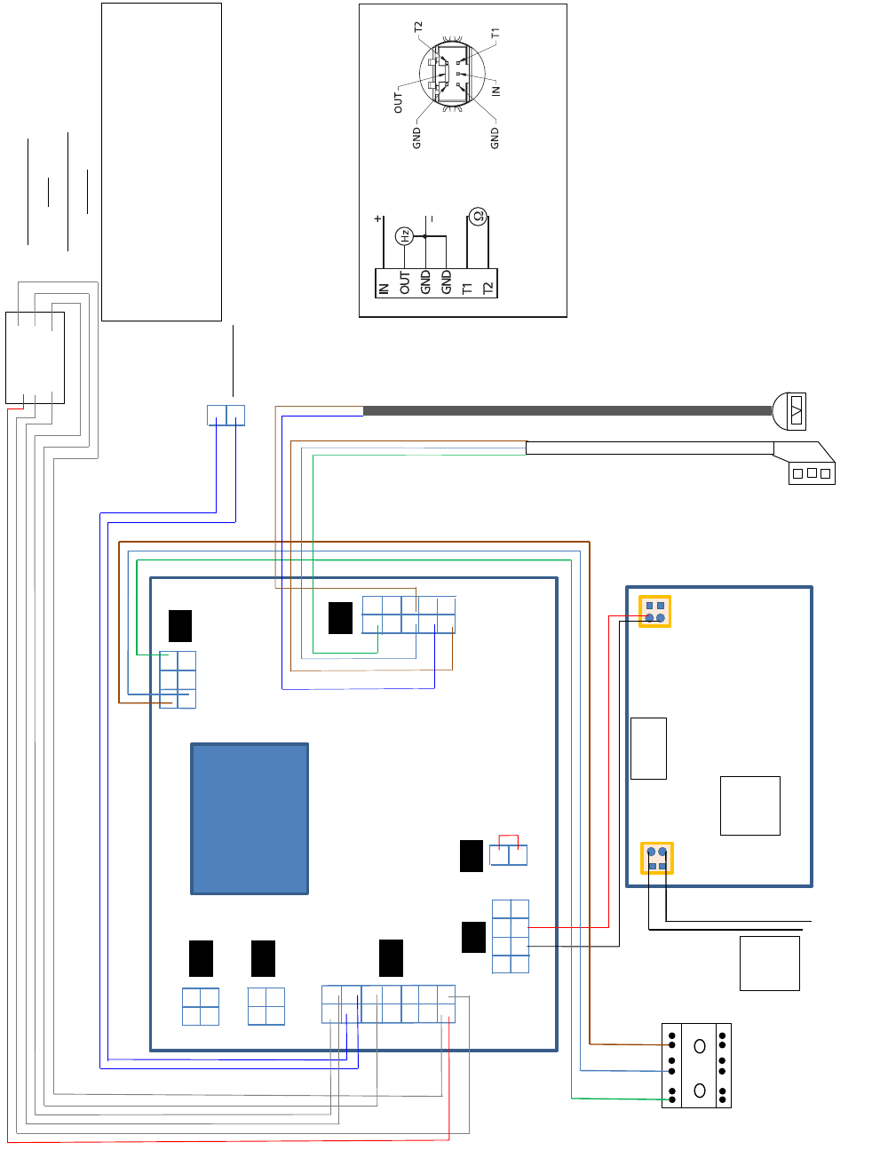
J18
J20
J19
J3
J7
J8
J1
GND GND
IN OUT
T1 T2
CW sensor
1
2
Combined flow
and
HW temperature
sensor
L - Brown
PR61
E – G/Y
N - Blue
PWM -
PWM +
SPARE
Fuse
Dip
Switch
1 2 3 4
To
DHW
pipe
All the these sensor inputs carry a
Voltage of 5V.
The max cable length is 1 meter.
The sensors connected to the control
Should be free from the appliance earth
INSTALLATION
DOMESTIC HOT WATER
Connector 2x3-poles with temperature output
from flow sensor perspective
Domestic Hot Water Controls Wiring
Page 16
INSTALLATION
DOMESTIC HOT WATER
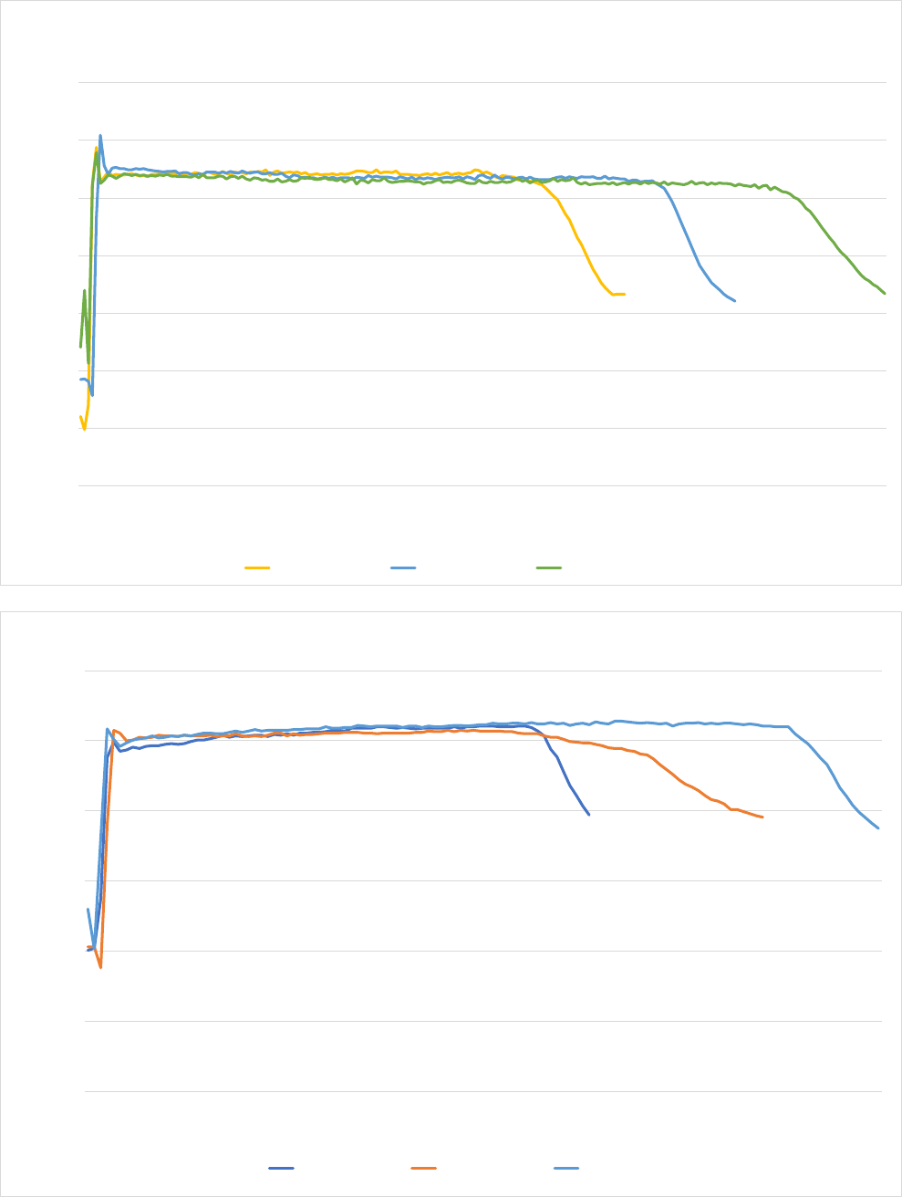
Domestic Hot Water Performance Test Flow rates
0.0
10.0
20.0
30.0
40.0
50.0
60.0
70.0
0.0
0.3
0.7
1.0
1.3
1.7
2.0
2.3
2.7
3.0
3.3
3.7
4.0
4.3
4.7
5.0
5.3
5.7
6.0
6.3
6.7
7.0
7.3
7.7
8.0
8.3
8.7
9.0
9.3
9.7
10.0
10.3
10.7
11.0
11.3
11.7
12.0
12.3
12.7
13.0
13.3
13.7
14.0
14.3
14.7
15.0
15.3
15.7
16.0
16.3
16.7
17.0
DHW Temperature in degress C
Time in mInutes at flow rate in table
DHW performance no space heating load, OV PP
BMSTOV150PP (DITS) BMSTOV180PP (DITS) BMSTOV210PP (DITS)
0.0
10.0
20.0
30.0
40.0
50.0
60.0
0.0
0.3
0.5
0.8
1.0
1.3
1.5
1.8
2.0
2.3
2.5
2.8
3.0
3.3
3.5
3.8
4.0
4.3
4.5
4.8
5.0
5.3
5.5
5.8
6.0
6.3
6.5
6.8
7.0
7.3
7.5
7.8
8.0
8.3
8.5
8.8
9.0
9.3
9.5
9.8
10.0
10.3
DHW temperature in degrees C
Time in minutes at the flow rate in table
DHW performance with simulated space heating load, OV PP
BMSTOV150PP (DITS) BMSTOV180PP (DITS) BMSTOV210PP (DITS)
Page 17
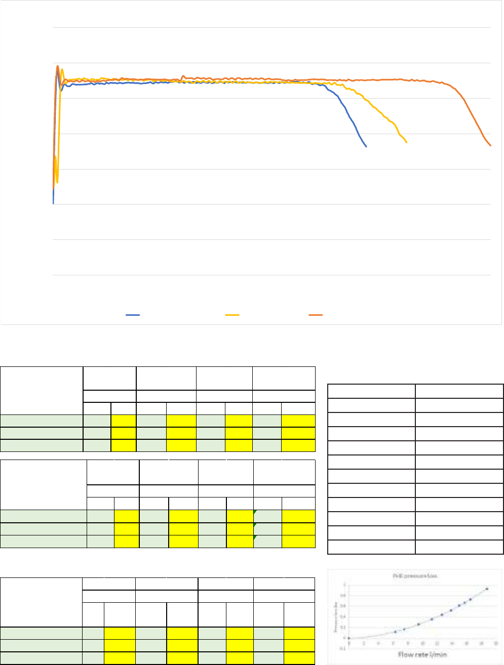
Target Actual Nominal Actual Nominal Actual Min Actual
BMSTOV150PP (DITS) 0.21 0.21 55 54 75 75 94 138
BMSTOV180PP (DITS) 0.21 0.21 55 53 75 75 113 154
BMSTOV210PP (DITS) 0.21 0.21 55 55 75 75 131 196
Product reference
DHW flow rate
Hot water delivery
temperature
Thermal store
temperature
HW delivered above
40 degrees C
[l/sec]
[°C]
[°C]
[Litres]
Target Actual Nominal Actual Nominal Actual Min Actual
BMSTOV150PP (DITS) load 0.21 0.20 55 50 61 61 72 78
BMSTOV180PP (DITS) load 0.21 0.20 55 49 62 63 86 103
BMSTOV210PP (DITS) load 0.21 0.21 55 51 63 63 101 137
HW delivered
[l/sec]
[°C]
[°C]
[Litres]
Product reference
DHW flow rate
Hot water delivery
Thermal store
Target Actual Nominal Actual Nominal Actual Min Actual
BMSTSP150 (IDHWTS) 0.21 0.21 55 54 75 75 0 138
BMSTSP180 (IDHWTS) 0.21 0.21 55 53 75 75 112 154
BMSTSP210 (IDHWTS) 0.21 0.21 55 55 75 75 130 196
Product reference
DHW flow rate
Hot water delivery
temperature
Thermal store
temperature
HW delivered above
40 degrees C
[l/sec]
[°C]
[°C]
[Litres]
INSTALLATION
DOMESTIC HOT WATER
Hot water draw o volume VHW-N
Hot water draw o volume VHW-L
0.0
10.0
20.0
30.0
40.0
50.0
60.0
70.0
0.0
0.3
0.5
0.8
1.1
1.3
1.6
1.9
2.1
2.4
2.7
2.9
3.2
3.5
3.7
4.0
4.3
4.5
4.8
5.1
5.3
5.6
5.9
6.1
6.4
6.7
6.9
7.2
7.5
7.7
8.0
8.3
8.5
8.8
9.1
9.3
9.6
9.9
10.1
10.4
10.7
10.9
11.2
11.5
11.7
12.0
12.3
12.5
12.8
13.1
13.3
13.6
13.9
14.1
14.4
14.7
14.9
15.2
DHW temperature in degrees C
Time in minutes at the flow rate in table
DHW performance no space heating load, SP & SP PP
BMSTSP150 & …PP(IDHWTS) BMSTSP180 (IDHWTS) BMSTSP210 (IDHWTS)
Pressure Flow Characteristics Of The DHW
Heat Exchanger
Flow (l/m) Pressure Drop (bar)
0 0
6.3 0.121516
7.5 0.168105
9.45 0.258502
11.25 0.357679
12.6 0.441755
13.86 0.527598
15 0.611323
15.75 0.669513
16.5 0.730151
18.75 0.926607
Page 18
INSTALLATION
CENTRAL HEATING
Sealed And Open Vented Systems
The Boilermate OV-PP product range is an integrated thermal store which supplies
space heating from the thermal store. The Boilermate SP and SP-PP product ranges
are hot water only thermal stores where the space heating is supplied directly from
the boiler.
In all three ranges the thermal store itself is open vented and requires a correctly sized
feed and expansion tank. The OV-PP product range requires enough expansion for
the space heating and the thermal store volumes. The SP and SP-PP product ranges
expansion only for the thermal store volumes.
In all cases
• Combined cold feed and open vent pipe arrangements must not be used.
• No valve should be tted in the safety open vent.
• The safety vent must be a minimum of 22mm copper pipe or equivalent.
The Boilermate OV-PP’s space heating system and boiler must be open vented. The
Boilermate SP’s and SP-PP’s space heating system and boiler can be either open
vented or sealed; the expansion system for the thermal store and the boiler/space
heating system are separate.
Maximum Installed Radiator Capacity
The maximum radiator capacity is limited by the power of maximum head/pressure
being delivered by the pump, and the maximum power of the boiler. To maximize the
heat output the pipe diameters must be sized to enable the boiler output to reach
the thermal store and the radiators. The boiler should be sized appropriately for the
system that it is being tted into.
It is the systems designer’s responsibility to determine what these are.

Page 19
INSTALLATION
CENTRAL HEATING
Pumps Supplied With BoilerMate Products
GBP part code XB530 XB531 XB532
WILO Pump type Ku15-130/7 iPWM2 25-130/6SC Ku15/6-43/SC
Pump housing type Ku = inline Composite OEM
- = Inline cast iron pump
housing
Ku = inline Composite OEM
Threaded connection DN 15 25 15
Pump housing length 130 130 130
Maximum delivered head 7 6 6
Maximum power
consumption [Watts]
50 43 43
Control box orientation 6 o'clock 6 o'clock 12 o'clock
Function Store pump for DHW PHE
Space heating and/or Boiler
PHE
Store pump for Boiler PHE
Control iPWM 2 SC - Push button
Speed
PWM2 speed controlled by
PCB
Variable Pressure x 3 dened curves
Constant Pressure x 3 dened curves
Constant Speed x 3 dened curves
Product used on
OV-PP x 1 x 2 0
SP-PP x 1 x 1 x 1
SP x 1 x 1 0 x 1
Page 20
INSTALLATION
CENTRAL HEATING
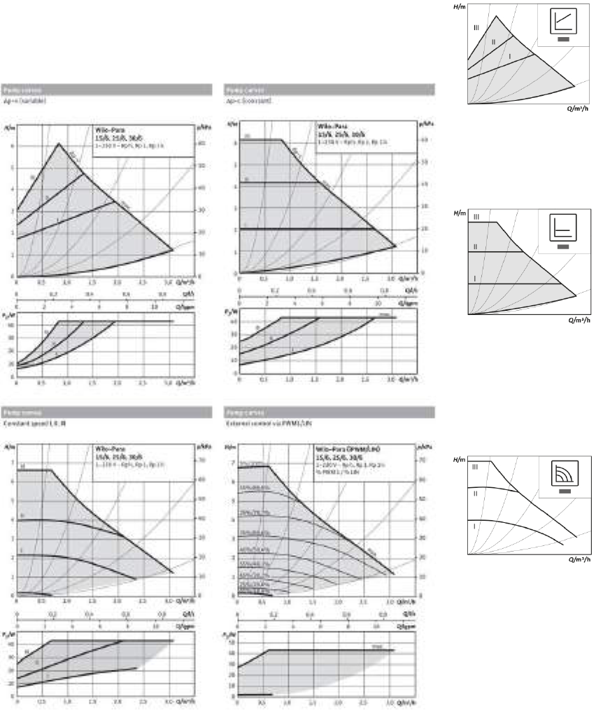
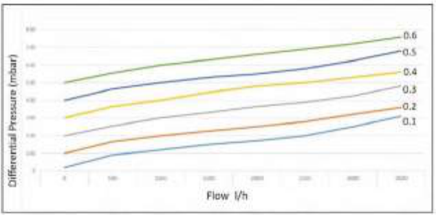
Pump curves:-
The XB530 pump curve is not included below because it is not relevant to the
installation of the product. The XB530 (25/6) and XB531 (15/6) pump curves are
identical and are shown below. Both XB530 and XB531 are supplied set at constant
speed Ι Ι Ι.
Dierential Pressure Variable Δp-v (Ι, Ι Ι, Ι Ι Ι)
Recommended for two-pipe heating systems
with radiators to reduce the flow noises at
thermostatic valves.
Constant dierential pressure Δp-c (Ι, Ι Ι, Ι Ι Ι)
Recommended for underfloor heating or
for large-sized pipes, applications without
a variable pipe network curve (e.g. storage
charge pumps) or single pipe heating systems
with radiators.
Constant speed (Ι, Ι Ι, Ι Ι Ι)
Recommended for systems with xed system
resistance requiring a constant volume ow and
for replacement of AC pumps.
Page 21
INSTALLATION
CENTRAL HEATING
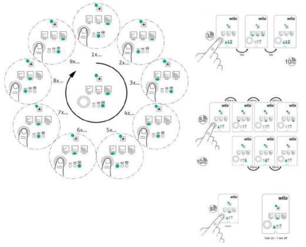
Wilo-Para Self Control / Smart Functions
Air-Venting Mode
Manual Restart
Lock and Unlock
Push To Change The Pump Setting
Page 22
INSTALLATION
CENTRAL HEATING
Automatic Bypass Valve
Some low water content boilers require greater ow rates than the heating load
of the property requires. Please check your boiler manufacturer’s instructions for
requirements.
The system bypass will enable this minimum ow rate to be achieved. The 22mm
straight bypass tted to the SP-PP version has a maximum rating of 30kW. It is
adjustable between 0.05 Bar and 0.5 Bar. Has a maximum working pressure of 16 Bar
and intermittent working temperature of 120°C.
The valve manufacturer recommends that most domestic situations will be set
between 0.2>0.3 Bar. If the ow is too high increase the pressure setting and conversely
if too low decrease the pressure setting.
The bypass valve must be set by the installer to suit the system i.e. to provide minimum
flow required for the boiler when all TRVs are closed, and/or when all the zone valves
are closed. Benets include reduced system noise, reduced pump impeller wear and
enhanced boiler heat exchanger life.
Using the Pump curves in the previous section and the minimum ow from the boiler
manufacturer’s instructions determine the available pump head at the selected pump
speed. Project these values on the chart below to get the valve set point.
e.g For minimum ow 500 l/h and dierential Pressure 200 mbar, set the valve at 0.25
Page 23
INSTALLATION
CENTRAL HEATING
Note:
Please refer to boiler manufacturers instructions if a constant rise from the boiler to
the BoilerMate is not achievable.
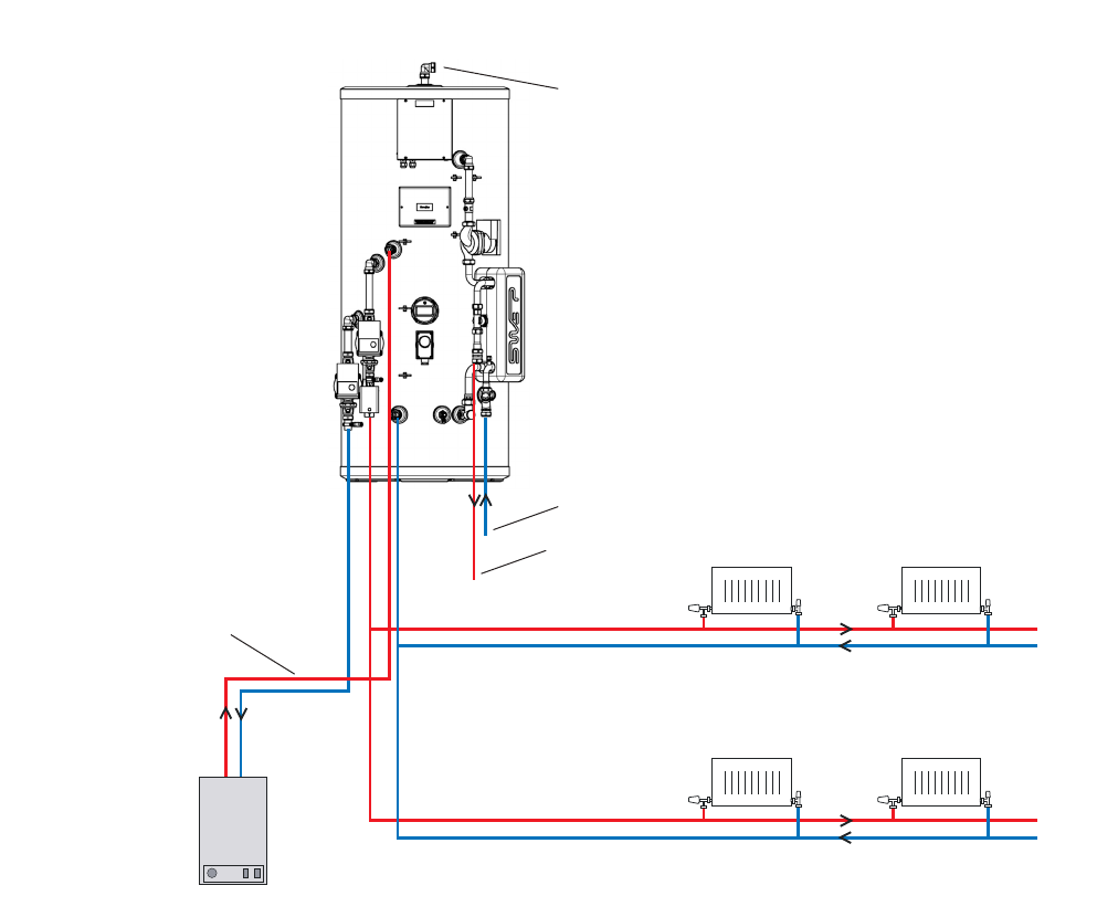
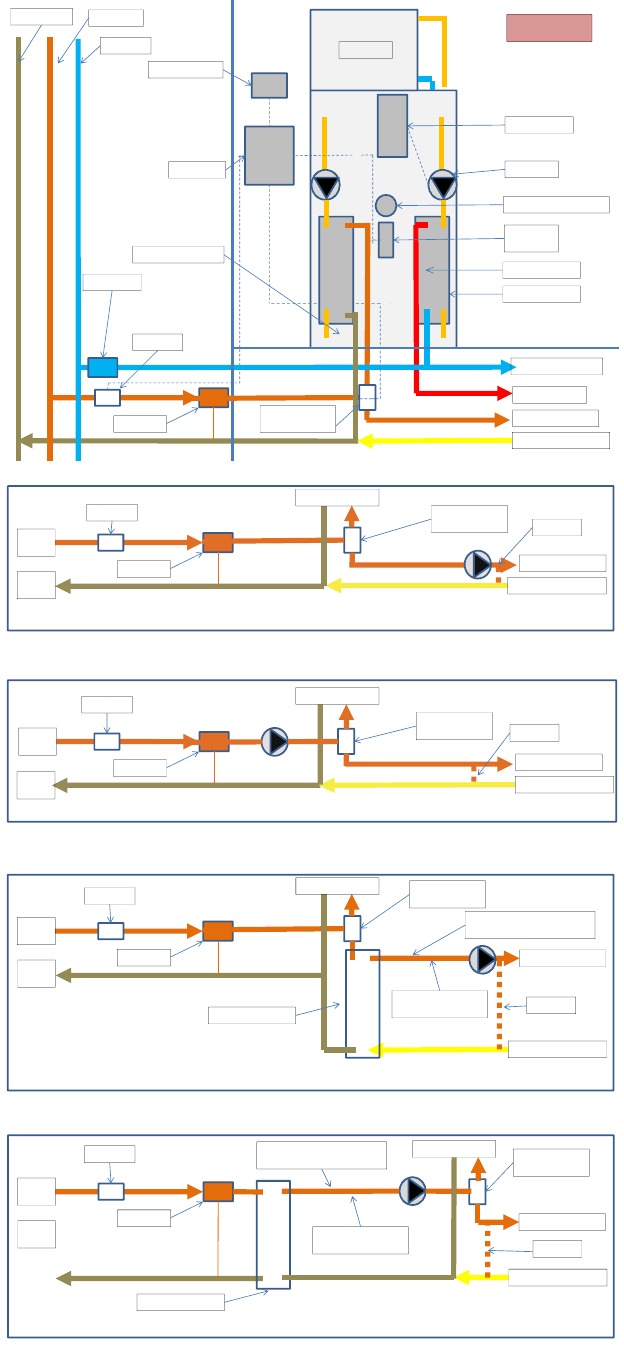
BoilerMate OV PP Plumbing Schematic
Primary
Circuit
Central heating
Central heating
Typical Arrangement / Connection Details
Boiler
No valves to be
fitted onto the
boiler flow
Domestic
hot water
Mains
cold water
Open vent for boiler,
store and central heating
Page 24
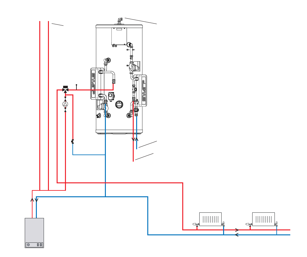
INSTALLATION
CENTRAL HEATING
Central heating
Typical Arrangement / Connection Details
Boiler
Domestic
hot water
Mains
cold water
Open vent for store
Open vent
for boiler
and heating
(connected to
F&E cistern)
BoilerMate SP Plumbing Schematic (Open vented heating system)
Page 25
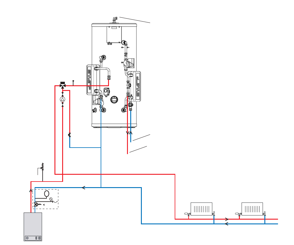
INSTALLATION
CENTRAL HEATING
Central heating zone 1
Typical Arrangement / Connection Details
Boiler
Sealed system kit
Domestic
hot water
Mains
cold water
Open vent for store
PRV
BoilerMate SP Plumbing Schematic (Sealed heating system)

Page 26
Primary
Circuit
Central heating zone 2
Sealed system kit
Central heating zone 1
Typical Arrangement / Connection Details
Boiler
Alternative position
for the safety valve
and discharge
Domestic
hot water
Mains
cold water
Open vent for store
BoilerMate SP PP Plumbing Schematic
INSTALLATION
CENTRAL HEATING
Page 27
INSTALLATION
CENTRAL HEATING
Heatmeter
DiverterValve
(notmidposition)
CHflowtodwelling
CHreturnfromdwelling
Pumppositiontoovercomepressurelossoncentralheatingcircuit– noadditionalrequirementforsystemexpansionorexcesspressure
District
supply
District
return
‐
Coilflowandreturn
CHBypass
Zonevalve
Heatmeter
DiverterValve
(notmidposition)
CHflowtodwelling
CHreturnfromdwelling
District
supply
District
return
Pumppositiontoovercomepressurelossoncentralheatingcircuitandcoil‐ noadditionalrequirementforsystemexpansionorexcesspressure
Coilflowandreturn
CHBypass
Zonevalve
Heatmeter
DiverterValve
(notmidposition)
CHflowtodwelling
CHreturnfromdwelling
Pumpandplateheatexchangerpositiontoovercomepressurelossandadditionalexpansionrequirementoncentralheatingcircuit
– noadditionalrequirementforexcessdistrictpressure.
District
supply
District
return
Coilflowandreturn
Plateheatexchanger
Localexpansionsystem
connectionrequired
Heatmeter
DiverterValve
(notmidposition)
CHflowtodwelling
CHreturnfromdwelling
Pumpandplateheatexchangerpositiontoovercomepressureloss,additionalexpansionrequirementandexcessdistrictpressurerequirements
District
supply
District
return
Coilflowandreturn
Plateheatexchanger
Localexpansionsystem
connectionrequired
CHBypass
CHBypass
Zonevalve
Zonevalve
Openventedfeedandexpansion
OrTemp.fillinglooprequired
Openventedfeedandexpansion
OrTemp.fillinglooprequired
Heatmeter
DiverterValve
(notmidposition)
CHflowtodwelling
CHreturnfromdwelling
Pumpandplateheatexchangerpositiontoovercomepressurelossandadditionalexpansionrequirementoncentralheatingcircuit
– noadditionalrequirementforexcessdistrictpressure.
District
supply
District
return
Coilflowandreturn
Plateheatexchanger
Localexpansionsystem
connectionrequired
Heatmeter
DiverterValve
(notmidposition)
CHflowtodwelling
CHreturnfromdwelling
Pumpandplateheatexchangerpositiontoovercomepressureloss,additionalexpansionrequirementandexcessdistrictpressurerequirements
District
supply
District
return
Coilflowandreturn
Plateheatexchanger
Localexpansionsystem
connectionrequired
CHBypass
CHBypass
Zonevalve
Zonevalve
Openventedfeedandexpansion
OrTemp.fillinglooprequired
Openventedfeedandexpansion
OrTemp.fillinglooprequired
District Heating Systems
The diagram opposite shows the BoilerMate SP
installed to a system where the pumped supply
is adequate to overcome the pressure loss of
the BoilerMate SP heat exchanger coil, the
pressure loss over the central heating system
components and all other components tted to
it. In addition, all the components tted are able
to withstand the pressure in the district system.
In the diagram opposite, the cold water supply
to the feed and expansion cistern is not shown,
and neither is the overow pipe which may by
required if the ball valve is tted to the F & E
cistern. See page 9 for further details. Potentially
a temporary lling loop complying with the
water regulations can be installed.
In this diagram an additional pump is shown
tted because the pressure loss in the central
heating system is too large for the district pump.
The pump is now tted in the district supply
because the pressure loss over the BoilerMate
SP coil is too large.
Here, the plate heat exchanger has been tted
because the expansion requirements of the
central heating system are to be handled in the
dwelling rather than the whole system, or the
components in the central heating system are
not capable of withstanding the pressure of the
district heating system.
In this instance, the plate heat exchanger
provides a full pressure break between the
district heating system and the dwelling system.
The dwelling system will need to cater for
expansion and circulation requirements. This
may be used where excessive district heating
pressure occurs.
Water meter
Heat meter
District ow
Cold water
District return
Programmer
F&E Cistern
DHW Controller
DHW Pump
Room thermostat
Flow sensor
Cylinder
thermostat
Back up immersion heater
Cold water to dwelling
DHW to dwelling
CH ow to dwelling
CH return from dwelling
Boilermate stainless
for District
Coil return
Zone valve
DHW 24 Plate PHE
Diverter Valve
(not mid )
Page 28
INSTALLATION
CENTRAL HEATING
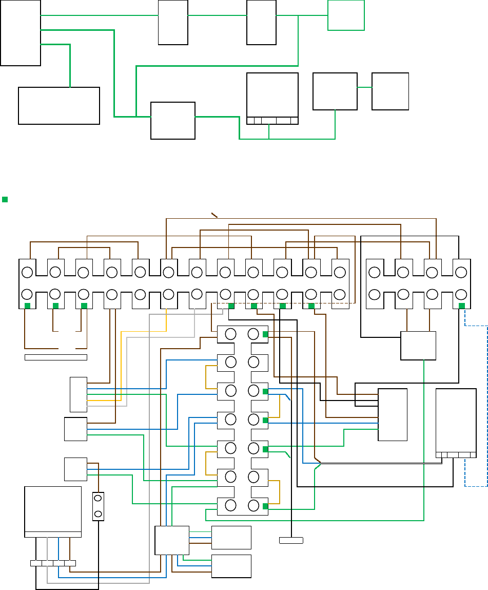
BoilerMate OV PP - 1 Zone Controls Schematic and Wiring Diagram
If independent times are required for each heating zone
Boilermate OV pre-plumbed, 1 x 2 Port Zone Valves, Boiler Pump, CH Pump, Common Heating Time
Use programmable room thermostats and
Delay Timer XB041 fitted by installer if required fit live link between terminal 9 and L or set timer CH to permanent ON
New link Link 12 to 13 Removed
1 2 3 4 5 6 7 8 9 10 11 12 13 14 15 16
L
If compensator connection required
N
wire to supply N terminals
N
L
N
N
PE
PE
3 core cable
PE
*SL2 IS ONLY FITTED FOR
LOGIC HEAT BOILERS WITH
PE
WEATHER COMPENSATION
KITS FITTED
3 core cable
DHW Controller CP006
Scale Inhibitor XB153
13
Control Stat
BOILER
*SL2
BOILER
PUMP
CH PUMP
SUPPLY
SUPPLY
SL1
TIMER
DHW OFF
DHW ON
HTG ON
CP006 Terminal
Block XB521
Ideal wired cylinder using Danfoss wiring centre WC4/B
HTG 1
HTG 2
ROOM THERMOSTATS
HTG 1
Connections made by the installer
Pump
8
N
L
DELAY TIMER XB041
1
2
3
4
HTG ON On ON
DHW ON
Off Off
DHW OFF
On
Off
CH PUMP
BOILER PUMP
SL1
*SL2
TIMER
HTG 1 Room
Stat
HTG 1 Zone
Valves
BOILER
DELAY TIMER
XB041
*SL2 IS ONLY FITTED FOR LOGIC
HEAT BOILERS WITH WEATHER
COMPENSATION KITS FITTED
Control Stat

Page 29
INSTALLATION
CENTRAL HEATING
BoilerMate OV PP - 2 Zone Controls Schematic and Wiring Diagram
Boilermate OV pre-plumbed, 2 x 2 Port Zone Valves, Boiler Pump, CH Pump, Common Heating Times
If independent times are required for each heating zone Link 12 to 13 Removed
Use programmable room thermostats and
fit live link between terminal 9 and L or set timer CH to permanent ON
1 2 3 4 5 6 7 8 9 10 11 12 13 14 15 16
L
If compensator connection required
N
wire to supply N terminals
N
L
N
N
PE
PE
3 core cable
PE
*SL2 IS ONLY FITTED FOR
LOGIC HEAT BOILERS WITH
PE
WEATHER COMPENSATION
KITS FITTED
13
3 core cable
1
2
3
4
SUPPLY
SUPPLY
SL1
*SL2
BOILER
Relay
TIMER
DHW OFF
DHW ON
HTG ON
STAT
CP006 Terminal
Block XB521
DHW Controller
CP006
Ideal wired cylinder using Danfoss wiring centre WC4/B
HTG 1
HTG 2
ROOM THERMOSTATS
Connections made by the installer
CH PUMP
HTG 2
HTG 1
Pump
8
N
L
BOILER
PUMP
DELAY TIMER XB041
HTG ON On ON
DHW ON
Off Off
DHW OFF
On ON
Off Off
On
SL1 *SL2
Off
FOR
BOILER PUMP
*SL2 IS ONLY FITTED FOR LOGIC
HEAT BOILERS WITH WEATHER
COMPENSATION KITS FITTED
HTG 2 Zone
Valves
HTG 2
Room Stat
HTG 1
Room Stat
HTG 1 Zone
Valves
CH PUMP
STAT
BOILER
DELAY TIMER
XB041
TIMER

Page 30
INSTALLATION
CENTRAL HEATING
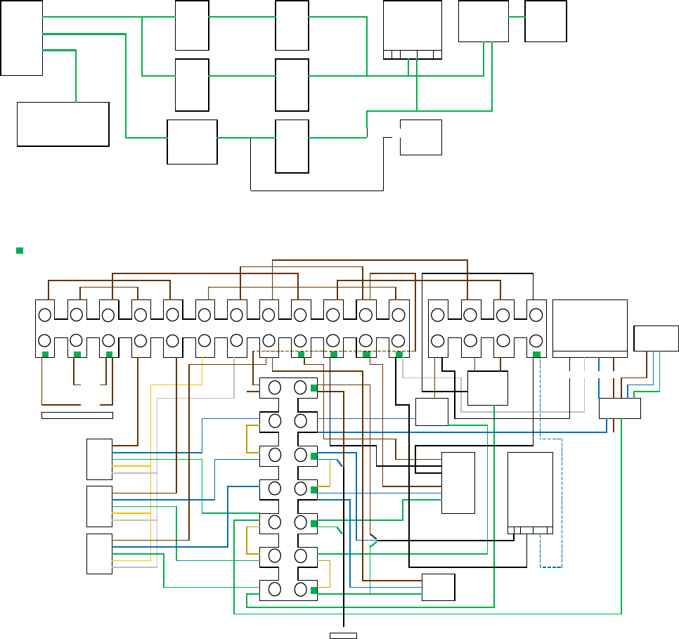
BoilerMate SP - 1 Zone Controls Schematic and Wiring Diagram
Boilermate SP pre-plumbed, 2 x 2 Port Zone Valves, Boiler Pump, Thermal Stor Pump, Common Heating Time
1 2 3 4 5 6 7 8 9 10 11 12 13 14 15 16
L 1 C
2
If compensator connection required
N
wire to supply N terminals
N
L
N
N
PE
PE
3 core cable
PE
*SL2 IS ONLY FITTED FOR
LOGIC HEAT BOILERS WITH
PE
WEATHER COMPENSATION
If independent times are required for each heating zone KITS FITTED
Use programmable room thermostats and
fit live link between terminal 9 and L or set timer CH to permanent ON
3 core cable
*SL2
TIMER
BOILER
ROOM THERMOSTATS
HTG 1
DHW OFF
DHW ON
HTG ON
PE
SUPPLY
SUPPLY
SL1
PUMP
THERMAL
STORE
THERMAL
STORE
BOILER PUMP
Control Stat
Cable 2
Cable 1
Ideal wired cylinder using Danfoss wiring centre WC4/B
HTG 1
HTG 2
Connections made by the installer
Cable 3
HTG ON On ON
DHW ON
Off Off
DHW OFF
On On
Off
Off
BOILER PUMP
THERMAL
STORE Zone
Valves
CONTROL STAT
THERMAL
STORE PUMP
HTG 1 Zone
Valves
TIMER
BOILER
*SL2 IS ONLY FITTED FOR LOGIC
HEAT BOILERS WITH WEATHER
COMPENSATION KITS FITTED
HTG 1 Room
Stat
SL1
*SL2
Page 31
INSTALLATION
CENTRAL HEATING
BoilerMate SP PP - 2 Zone Controls Schematic and Wiring Diagram
Boilermate SP pre-plumbed, 3 x 2 Port Zone Valves, Boiler Pump, Thermal Stor Pump, Common Heating Time
Delay Timer XB041 fitted by installer if required
Link 12 to 13 Removed
1 2 3 4 5 6 7 8 9 10 11 12 13 14 15 16
L
If compensator connection required
N
wire to supply N terminals
N
L
N
N
PE
PE
3 core cable
PE
*SL2 IS ONLY FITTED FOR
LOGIC HEAT BOILERS WITH
PE
WEATHER COMPENSATION
If independent times are required for each heating zone
KITS FITTED
Use programmable room thermostats and
fit live link between terminal 9 and L or set timer CH to permanent ON
3 core cable
BOILER PUMP
DHW Controller
CP006
Ideal wired cylinder using Danfoss wiring centre WC4/B
HTG 1
HTG 2
L
N
12
Pump
DELAY TIMER XB041
1
2
3
4
Connections made by the installer
SUPPLY
SUPPLY
SL1
PUMP
THERMAL
STORE
THERMAL
STORE
*SL2
TIMER
BOILER
ROOM THERMOSTATS
CP006 Terminal
Block XB521
X
HTG 1
HTG 2
STAT
X
DHW OFF
DHW ON
HTG ON
HTG ON On ON
DHW ON
Off Off
DHW OFF
On On
Off Off
On On
Off
Off
ne
DELAY TIMER
XB041
BOILER PUMP
THERMAL
STORE Zone
Valves
STAT
THERMAL
STORE PUMP
HTG 1 Zone
Valves
HTG 2 Zone
Valves
TIMER
BOILER
*SL2 IS ONLY FITTED FOR LOGIC
HEAT BOILERS WITH WEATHER
COMPENSATION KITS FITTED
HTG 1
Room Stat
HTG 2
Room Stat
SL1
*SL2
Page 32
Boiler Thermostat Setting
The BoilerMate OV-PP, SP and SP-PP may be installed with condensing or non-
condensing oil or gas boilers. These boilers should be capable of delivering primary
hot water at a minimum temperature of 80°C. To achieve the highest temperature
in the thermal store and therefore maximise its performance the maximum boiler
control thermostat setting must be selected.
Store Thermostat Setting
The store thermostat should be set at 75°C to achieve the maximum domestic hot
water and the temperature set point of 50-55°C. We recommend this is checked
during the commissioning procedure due to the tolerances on this type of
thermostat.
CH control description and Thermal Store charging.
BoilerMate OV - 1 zone
The timer (programmer) is the key control for the system.
When the Central heating program is calling 240 volt AC is supplied to the Room
thermostat.
If the Room thermostat is closed circuit the 240 volt AC is supplied to the heating
zone valve motor. The motor runs which closes the incorporated micro switch and
240 volt AC is supplied to the central heating pump causing it to run. At the same
time 240 volt AC is supplied from the zone valve micro switch to the thermal store
control thermostat.
When the Hot water program is calling 240 volt AC is supplied to the Thermal store
thermostat.
If the Thermal store control thermostat is closed circuit, then 240 volt AC is supplied
to the boiler switch live and the boiler pump causing it to heat the thermal store.
If the Delay timer is tted and once the thermal store control thermostat is open
circuit, the boiler pump with continue to run for a short period of time to remove any
residual heat from the boiler.
The Boilermate OV is placed on the market with one zone valve. If a second zone
valve is required it can be purchased as a kit. [BCK006]. Please see the wiring diagram
on the next page for the required modications to the above diagram.
BoilerMate OV – 2 zone
The two-zone space heating system runs in a similar manner to the single zone.
However, in this system both heating zone thermostats are supplied with 240 Volt AC
simultaneously. If independent timing of the second zone is required, then another
programmer or programmable room thermostat will be required. Alternatively, two
programmable room thermostats can be used and the heating channel on the main
programmer left permanently on.
When the Hot water program is calling 240 Volt AC is supplied to the Thermal store
thermostat and if the Thermal store control thermostat is closed circuit, then 240
Volt AC is supplied to the boiler switch live and the boiler pump causing it to heat
the thermal store. If the Delay timer is tted and once the thermal store control
thermostat is open circuit, the boiler pump with continue to run for a short period of
time to remove any residual heat from the boiler.
BoilerMate SP PP – 2 zone
The SP two-zone space heating system runs in
the same manner as the OV two zone; where
both heating zone thermostats are supplied
with 240 Volt AC simultaneously. If independent
timing of the second zone is required, then
another programmer or programmable room
thermostat will be required. Alternatively,
two programmable room thermostats can be
used and the heating channel on the main
programmer left permanently on.
The dierence is that the boiler and boiler
pump will always re when there is a central
heating demand.
When the Hot water program is calling 240 Volt
AC is supplied to the Thermal store thermostat
and
If the Thermal store control thermostat is
closed circuit, then 240 Volt AC is supplied
to the thermal store pump causing ti to run;
and to the thermal store zone valve motor.
Once the motor has run the thermal store’s
micro switch will close and 240 Volts Ac will be
supplied to the boiler and boiler pump.
In addition, the delay timer will operate as
described above; if tted.
INSTALLATION
CENTRAL HEATING
Page 33
INSTALLATION
CENTRAL HEATING
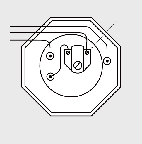
Immersion Heater
The Immersion heater supplied with the Boilermate is a 3 kW 240AC version which
is supplied as a DHW back up heat source should your boiler fail at any time. The
product replacement code is SH003.
Check that the mains supply conforms to this, and all external wiring conforms to
the most recent revision of the IEE wiring regulations. The immersion heater is tted
into the thermal store cylinder using an O-ring. After the unit is lled with water
check for leaks to determine if the O-ring has sealed and tighten carefully using
the appropriate tool. To prevent damage to the O ring do not use excessive force to
tighten the immersion heater.
The immersion thermostat has two terminals L and N. These should be connected
as shown in the diagram. It has been our experience that crimp terminals make
better connections. The immersion heater must be fully earthed (earth post) and
connected via a double pole isolator switch.
The immersion heater is supplied with a thermostat which has been tested for
operation in the thermal store and complies with the European directives for
Electromagnetic compatibility and radio interference. It is Rated at 20 Amp 250V
~AC. The thermostat supplied with this product is set to 75°C with a safety cut out
set at 90°C. The immersion heater thermostats incorporate a manual reset safety/
overheat cut out thermostat. Should this operate, investigate the cause before
pressing the red reset button labelled safety. If there is no apparent fault adjust the
control setting down slightly to prevent nuisance tripping. If another heat source is
used to heat the cylinder and this raises the water temperature excessively then the
overheat thermostat will trip.
Danger of electrocution: before making any adjustments to the thermostat
isolate the immersion heater from the mains electricity supply at the fuse spur
unit.
Thermostat
Immersion Heater Wiring
E
L
N
Page 34
INSTALLATION
CENTRAL HEATING
Kits
Open Vented Header Tank Kit
Expansion tank white c/w lid
Float Plastic Red
1/2 HP PT 2 Ball Valves
Label Water Level
Sealed Primary Header Tank Kit
Expansion tank white c/w lid
Label Sight Glass
22mm Tank Connector (Comp)
Sight Glass Level Indicator
22 mm 90° Compression Elbow
Tube 22 X 0.9mm X 3m
PCS F&E Pipe 22mm
Rubber Grommet
Washer Fibre
Switch Back Up Conversion 6kW to 3kW kit
4Way Garage Board
20A Double Pole Isolator
Single Gang Surface Mounted Box
Timer kit
Horstmann H27 XL
Sealed System ROBOKIT
18Ltr expansion vessel kit incorporating
- 18 litre expansion vessel (heating)
- Expansion Screws
- Filling loop - Double Check Valve
- Filling loop – Hose
- Filling loop - Mini Ball Valves
- ERV
- Gauge
Second Heating Zone kit
Zone valve 22 mm 2 port
22mm equal tee
22mm copper pipe 110mm
22mm 90° elbow
22mm copper pipe 50mm (table Y)
Pump Over Run Kit
Pump delay timer PCB
PCB support
M20 Cable Gland with Locknut
Dhw Scale Prevention Kit
Scale prevention PCB
PCB support
Scale board power harness
Scale pipe wire
• The correct settings for tube diameter 22mm is switch no. 3 on.
• Switch no. 4 can be either on or o.
• If the switch no. 4 is turned on the output electromagnetic eld
is generated harmoniously otherwise the eld is generated
inharmoniously.
(BCK001)
(BCK002)
(BCK003)
(BCK004)
(BCK005)
(BCK006)
(BCK007)
(BCK008)
Page 35
COMMISSIONING
COMMISSIONING
Commissioning and installation checks
All factory tted components are tightened during manufacture, however all should
be checked before installation.
Open the incoming stop valve and ll the domestic mains cold and hot water
systems, the BoilerMate appliance and central heating system. Check the whole of
the domestic hot and cold distribution systems for leaks, and repair if necessary.
Central heating systems should be thoroughly cleaned and ushed out before
installing a new boiler. During the nal lling of the system, a chemical water
treatment inhibitor should be added to the primary circuit to control corrosion and
the formation of scale and sludge. Note the volume of the thermal store must be
included in the calculations of the amount of inhibitor required. The OV will the
combined volumes and the SP will be separate volumes. Please ensure that any
chemical inhibitor used is compatible with all types of stainless steel.
Check the water level in the top up cistern and if a ball valve is tted adjust if
necessary. If a ball valve is provided, turn down the servicing valve once the
system is nally lled to the point where the warning/overflow pipe will
cope with the discharge arising from a ball valve failure. If an overflow is not
provided, ensure the temporary lling hose is isolated and removed from its
connection to the mains water supply.
Fully flush and if necessary, disinfect the hot and cold water system in accordance
with the recommendations in the Water Regulations and BS EN 806:1-5: BS EN
8558:2011. Please note that the whole of the domestic hot and cold water systems
including the appliance, must be adequately flushed after disinfection. Failure to do
this may cause damage to the plate heat exchanger and other components in the
DHW system. In domestic installations disinfection is not normally required.
It is essential that all systems function properly for optimum performance. To achieve
this the flow rate from each tap should be checked and a suitable number of taps
run simultaneously to check the impact of this on the flow rate at individual taps. We
recommend that flow regulators are provided for each tap/terminal tting to
ensure that the available flow is shared evenly - See Appendix A for further details.
Check the Control System
Raise the BoilerMate thermal store to temperature.
During this process switch on the boost immersion heater and check it draws current
using a clamp meter. Check wiring if the immersion is not drawing current.
Check that the store thermostat and immersion thermostats are switching at 75
degrees and adjust if necessary.
Run water from any hot tap to check the temperature is between 50 and 55 °C at a
ow rate of 6-15l/min.
Check that the central heating system works by running it and ensure that the boiler
is red on the BoilerMate OV when the store temperature falls. The boiler should
always re when there is a central heating demand when a BoilerMate SP is tted.
Turn o the central heating and the Boiler and the central heating pump should stop
running; if a pump delay timer is tted then the boiler pump will continue to run. If
not the Boiler pump will also switch o.
If you have any doubts regarding the commissioning seek advice.
See the fault nding section of the manual for further assistance/details.
Page 36
COMMISSIONING
COMMISSIONING
Important Do’s and Don’ts
1. DO check the incoming mains water pressure. The preferred range of mains
pressure is 2 -3 bar.
2. DO check the ow rate of the incoming cold water main is adequate to meet the
maximum hot and cold water simultaneous demands.
3. DO check that all connections are in accordance with the labelling on the thermal
store.
4. DO check the water level is correctly set in the top up cistern when cold and if
tted that there is no overow when the appliance is up to temperature.
5. DO check that the control thermostats switch the immersion heaters o at the
correct set point i.e. approx 75°C.
6. DO insulate any exposed hot water pipework in the BoilerMate cupboard.
7. If the ballvalve in the F & E cistern is permanently connected to the mains cold
water supply DO plumb the overow/warning pipe in a 20mm internal diameter
pipe and ensure it discharges in a conspicuous external position. Use a material
which is suitable for use with heating F & E cisterns in accordance with BS 5449
(such as copper).
8. Once the appliance is lled and commissioned DO leave the electricity switched
on to the appliance to ensure the automatic pump run facility can operate to
prevent the pump sticking.
9. DO ensure that the functioning and control of the system is explained to the
occupant.
10. DON’T place any clothing or other combustible materials against or on top of this
appliance.

Page 37
For any parts not listed above, please contact Gledhill Technical Support on 01253
474584, who will be able to assist (eg washers, bent pipe etc).
Description Stock Code
1 DHW PHE pump iPWM2 XB530
2 Plate heat exchanger (24 plate) GT017
3 Pump isolating valve – outlet (90 valve) GT135
4 Pump isolating valve - inlet (straight) GT133
5 Immersion heater 3kW SH003
6 Immersion thermostat XB081
7 Main PCB controller XB111
8 Sensors GT198
9 Y strainer XB314
10 Flow sensor XB095
11 Expansion tank white c/w lid XB343
12 Float Plastic Red 4.5” FT429
13 1/2 HP PT 2 Ball Valves 6" arm FT206
14 Sight Glass Level Indicator XB443
15 Horstmann H27 XL RP224
16 Sealed system ROBOKIT SG032
17 Zone valve 22 mm 2 port XG083
18 Pump delay timer PCB XB041
19 Scale prevention PCB XB153
20 Space heating and /or Boiler PHE pump XB531
21 Store PHE pump XB532
22 Store Thermostat XC010
SERVICING AND MAINTENANCE
SHORT PARTS LIST
Page 38
SERVICING AND MAINTENANCE
SERVICING
Annual Servicing
No annual servicing of the BoilerMate is necessary.
However, if required, the operation of the controls and a hot water performance
test can be carried out to prove the appliance is working satisfactorily and within its
specication.
If it is decided to carry out the above tests the water level in the top cistern should
also be checked and if necessary topped up.
Changing Components
Free of charge replacements for any faulty components are available from Gledhill
during the in-warranty period on return of the faulty part (normally 12 months).
After this, spares can be obtained direct from Gledhill Spares or through any of the
larger plumbers merchants/specialist heating spares suppliers.
Help and advice is also available from the Technical Helpline on 01253 474584.
However, all components are readily accessible and can be changed quickly and easily
by the installer using common plumbing/electrical practice.
Note: All maintenance work on the BoilerMate appliance must be carried out
by a competent trades person.
Page 39
SERVICING AND MAINTENANCE
FAULT FINDING
Circulating Fluid In Thermal Store Pipework
• The BoilerMate and the thermal store pipework must have completed lling prior
to switching the electricity supply to the PWM controller PCB. If there is no water
in these pipes then there may be signicant wear on the PWM pump.
• This can be conrmed by
- Checking the thermal store pipework servicing valves are open
- Loosening the connection points on the thermal store pipework in a
systematic manner and checking for water presence.
- Conrming that the feed and expansion tank has completed lling and the
servicing valve is open.
Cold Mains Water Supply To Plate Heat Exchanger And Hot Water Taps
• Conrm that the CW mains stop valve is open
• Open all HW taps and conrm that the water runs freely and that any air is bled
from the DHW system
• Determine the maximum flow rate obtained and record
• 15l/min for all BoilerMate products currently limited with a flow restrictor
• If flow rate not as expected determine the cause and rectify
- Clean inline strainer
- Check the flow restrictor is present and not blocked. It is located in the top
of the inline strainer
Power On
• Switch on the Local fuse spur and observe the PWM pump
• Open a HW tap and observe the PWM pump
• The green LED will be constantly lit showing the pump has a power supply and is
running to generate HW
NOTE: -The thermal store will only produce hot water when it is hot enough. A mid
40°C thermal store temperature will provide some hot water, higher thermal store
temperatures will provide more.
Inline Scale Inhibitor (If Fitted)
• Check power supply
• PWM Controller PCB supplies a maximum of 12vDC/300mA to the Scale inhibition
board. (From J3)
• Check dip switches set correctly
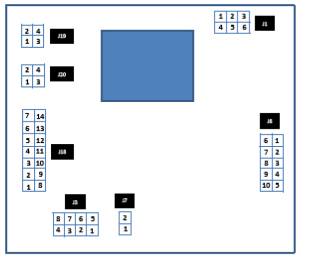
Page 40
SERVICING AND MAINTENANCE
FAULT FINDING
Test Equipment
The initial assumption in this procedure is that the plumbing and water supply is
working eectively. If in doubt please conrm and refer to the end of this section for
advice on specic components.
A multi meter, a weir gauge and a thermometer will be required to conrm that all
the components are working eectively.
The PWM controller PCB manufacturer suggests “Fluke 87 TRUE RMS Multi meter” as
a suitable product. This will be able to measure;
- the frequency output form the Board to the pump
- the Duty cycle % output from the Board to the pump
Connection numbering
For reference the connections to the PCB are numbered below for
Logical sequence;
- check electrical connections fault nding section on page 23 rst to ensure your
own safety. This section will potentially identify any short circuited components
and/or wiring faults that need to be rectied before continuing to work on the
appliance.
- check that the correct information is being supplied to the board. This section will
identify if any sensors are faulty or out of tolerance. These will need to be replaced
before continuing
- check that the overheat link is present
- check that the outputs to the board are being generated. If at this stage the board
does not provide the correct outputs then potentially the board should be replaced
- check the pump electrical circuit

Page 41
SERVICING AND MAINTENANCE
FAULT FINDING
Electrical power connections
Check inputs to the PWM Controller PCB
Reference schematic
opposite
Check procedure
Power supply to PWM
Controller PCB
Electrically isolate power supply at fused spur switch and remove fuse.
Earth continuity test (dead test) – to ensure that the appliance is earthed
Mains voltage test (dead test) - to ensure that the appliance is isolated
Resistance to earth (dead test) – to ensure that the wiring insulation to the product is intact
Short circuit test (dead test) – to ensure that no components in the products circuit have a short circuit
Visually inspect wiring is correct as per g 4.3
Connect supply
Polarity test (live test) - to ensure that the live is connecter to the live etc
• Check 230V ac across L1 to Earth
• Check 230V ac across L1 to N
• Check for 0 to 15V ac N to earth
Reference to “Boilerfault nder.com” gives clear instructions to on how to perform these tests. (Menu
options 1st. Boiler Fault nder 2nd. Electrical safety checks).
Reference schematic
opposite
Check procedure
CW temperature sensor Power o
Disconnect J18
Measure and record the resistance across terminals 6 and 13
Measure the cold water inlet temperature
Compare the resistance measured with chart “Tasseron NTC 12k thermistor”
The reading should make sense taking measurement conditions into consideration
HW temperature sensor Power o
Disconnect J18
Measure and record the resistance across terminals 7 and 14
Measure the Hot water temperature
Compare the resistance measured with chart “HUBA combined ow sensor and NTC 12k thermistor”
The reading should make sense taking measurement conditions into consideration
Flow sensor Power on Sensor requires a 5 VDC power supply
Open a HW tap and set to a ow rate.
Measure and record the frequency across terminals 1 and 12
Compare the frequency measured with chart “ow rate determination”
The reading should make sense taking measurement conditions into consideration
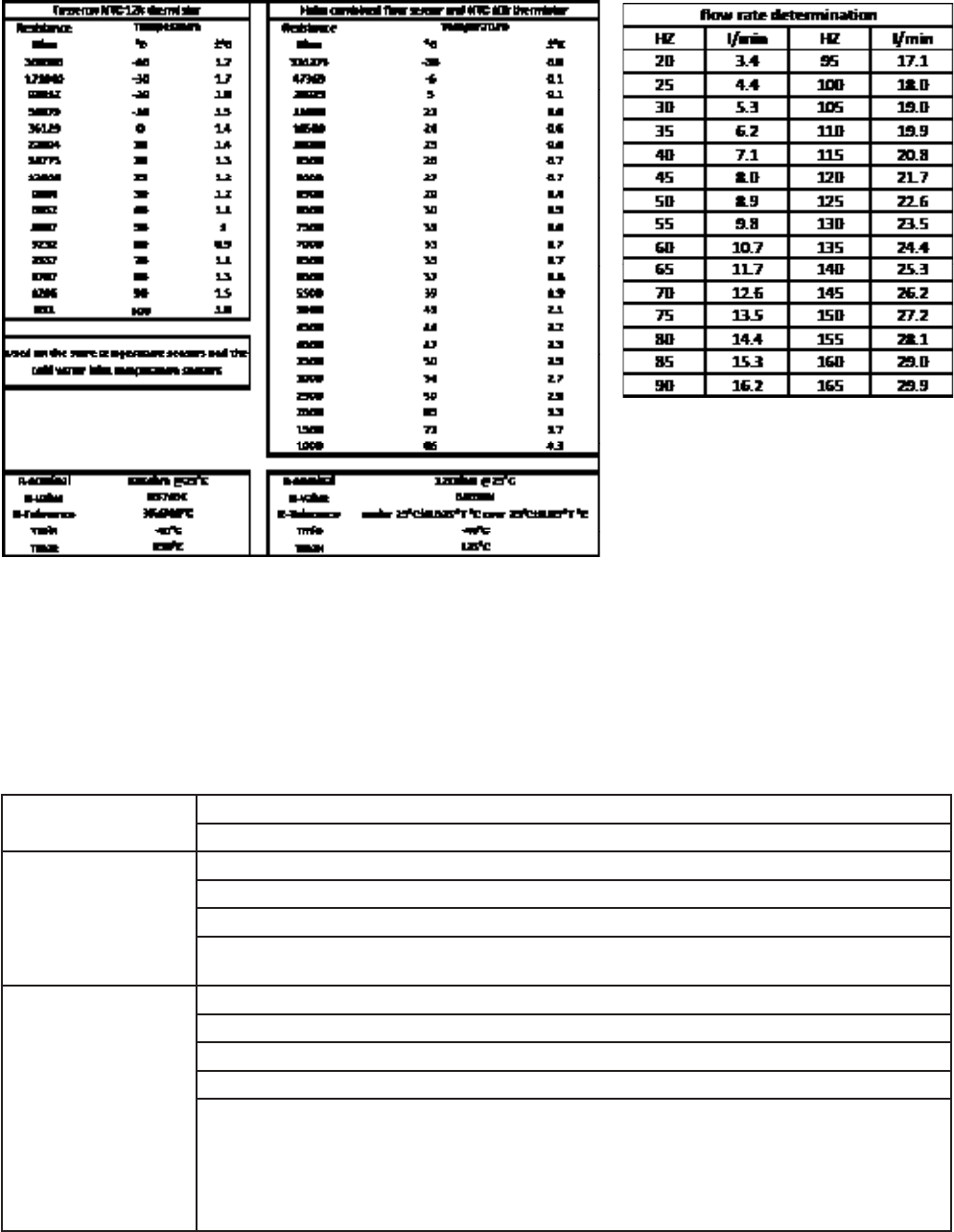
Page 42
SERVICING AND MAINTENANCE
FAULT FINDING
Check for presence of overheat link
An overheat link connection should be present in connection Junction 7. If you are
tting a new board the overheat link that is on the board just removed must be retained
as the newly supplied board will not have one tted.
Check outputs from the PWM controller PCB to the pump
PWM pump power Check 230V ac across Junction 8, L(10) to E(6) and L(10) to N(8) (live test)
Check for 0-15V ac across Junction 8, N(8) to E(6) (live test)
PWM frequency Power on the unit
Set the multi meter to measure the frequency
Measure the PWM frequency produced by the board between pins 3 on J8 and pin 9 on J8
This can be between 100Hz – 5000 Hz (1000Hz nominal)
(Lab tested gure of 562Hz recorded in steady state conditions).
Duty cycle Switch your Multimeter to ‘duty cycle or %’ then it will show a percentage from 0 to 100%.
This percentage is the command for the pump how fast it should run.
When you perform a small DHW tapping, the percentage will be low
When you perform a large DHW tapping, the percentage will be higher
PWM input signal [%] indications
• 0-7 Pump stops (Standby)
• 7-15 Pump runs at minimum speed (operation)
• 12-15 Pump runs at minimum speed (start-up)
• 15-95 Pump speed increases linearly from minimum to maximum
• > 95 Pump runs at maximum speed

Page 43
SERVICING AND MAINTENANCE
FAULT FINDING
Check pump electrical circuits
LED Meaning Diagnosis Cause Remedy
Lights green Normal running Pump runs according
PWM input
Normal operation n/a
Blinks red/ green Abnormal running mode
-pump stopped but still
functional
The pump has stopped
due to external failure
Pump restarts by itself
after the fault has
disappeared
Under voltage U<160 V
or
Over voltage U>253 V
Check voltage supply
195 V <U< 253 V
Pump overheating:
temperature inside motor
too high
Check water and
ambient temperature
Over speed:
the pump rotor is driven
by an external ow above
the maximum allowed
value
Ensure that there is no
other external ow (other
pump running) on
system
Over current:
the stator winding is in
short circuit due to water
Check for leakage
application on
application
Overload of motor:
friction due to particles
and/or impeller blocked
with debris
Check installation water
quality, clean system if
debris
Blinks red Pump out of function Pump stopped (blocked) Blockage:
the pumps is fully
blocked due to debris in
system
Check for blockage.
Turn ON/OFF to reset
the pump by unplugging
the power supply
If the pumps still blinking
red after a power reset
then replace the pump
Faulty electronic module
and/or faulty motor
LED o No power supply No voltage on electronics Pump is not connected to
power supply
Check cable connection
LED is damaged Check if pump is running
Electronics are damaged Replace pump
Check plumbing components
CW In line lter Isolate the CW mains supply at the servicing valve
Open HW taps to relieve the pressure
Undo securing nut ensuring that any remaining water is collected
Remove lter and clean it
The ow regulator can be checked at the same time by removing the upper pipe section.
Thermal store return
check valve + return
servicing valve
Isolate both servicing valves
Drain water from the section between the servicing valves
Remove the bottom pipe section
Check for free movement of the check valve incorporated in the body. Remove and replace if the check
valve sticks.
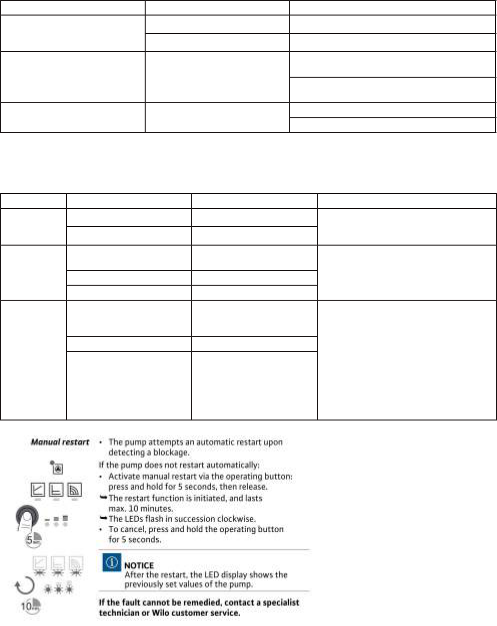
Page 44
SERVICING AND MAINTENANCE
FAULT FINDING
Faults, Causes and Remedies
The troubleshooting must only be carried out by a qualied specialist, and work on
the electrical connection must only be carried out by a qualied electrician.
Fault signals
• The fault signal LED indicates a fault
• The pump switches o (depending on the fault) and attempts a cyclical restart.
Faults Cause Remedy
Pump is not running although the
power supply is switched on
Electrical fuse defective Check fuses
No voltage supply to pump Rectify the power interruption
Noisy pump
Cavitation due to insucient
suction pressure
Increase the system pressure within the permissable
range
Check the delivery head and set it to a lower head if
necessary
Building does not warm up
Thermal output of the heating
surfaces are too low
Increase set point
Change the control mode from Ap-c to Ap-v
LED Faults Cause Remedy
Lights up red
Blocking Rotor blocked
Active manual restart or contact customer
service
Contacting / winding Winding defective
Flashes red
Under / over voltage
Power supply too low / high on
mains side
Check mains voltage and operating
conditions, and request customer serviceExcessive module temperature Module interior too warm
Short circuit Motor current too high
Flashes red /
green
Generator operation
Water is owing through the
pump hydraulics, but there is
no mains voltage at the pump
Check the mains voltage, water quantity /
pressure and the ambiant conditions
Dry run Air in the pump
Overload
Sluggish motor, pump is
operated outside of its
specications (e.g. high
module temperature). The
speed is lower than during
normal operation.

Page 45
SERVICING AND MAINTENANCE
FAULT FINDING
Check
plumbing
TS full
of water?
Water
mains on?
PHE pipework
air locked?
Check
sensors
Overheat link
present in J7
Sensors plugged
in securely?
Sensors providing
correct signal to PCB?
Check Electrical
supply
Electrically
safe?
Components
short circuited?
Wiring as per
circuit diagram?
Pump LED
on?
N
Check cable connecn secure and
resistance in cable
Pump running?
LED is damaged pump replacement opnal
OK?
Y
Resolve
N
Electronics damaged replace pump
LED Blinks red?
Y
Y
Check for blockage in pipework
or pump housing
N
LED
connues to Blink red aer power
reset
Y
Motor or Electronics damaged replace pump
OK?
OK? OK? OK?
OK?
OK?
OK?
Wiring as per circuit diagram
& polarity correct?
OK?
OK?
Sensors in
correct locan?
OK?
OK?
OK?
N
OK?
OK?
LED Blinks red &
green?
Resolve
OK?
Under voltage U<160 V or
Over voltage U>253 V
Resolve
OK?
Pump overheang: Check water
and ambient temperatures
Resolve
Pump Over speed Ensure that there
is no other external w (other
pump running) on system
OK?
Resolve
Over current the stator winding
is in short circuit due to water. Check
for leak
OK?
Resolve
Over load of motor: fricn due to
parcles or impellor blocked. Clean
debris from system
Note pump will restart by itself when
the fault disappears
OK?
Resolve
LED orange?
Normal stopped: pump in standby
Y
N
Check board output to
pump
Check
power output to pump J8 L(10),
N(8), E(6)
Check
PWM frequency
Check
Duty Cycle
Y
Board
electronics
damaged
N
Sophiscated
mul meter
available
Y
N
OK?
OK?
N
N
Turn on hot water
Turn off hot water demand
Pump running without demand: check for leaking hot tap
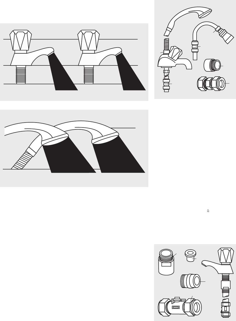
Page 46
APPENDIX
APPENDIX A
Vast quantities of water are needlessly run off to waste due to Taps, Mixers and Showers
discharging flow rates far in excess of the rates required for them to perform their
duties.
The contrasting flow rates shown on this leaflet clearly illustrate the savings that can
be made whilst still providing a good performance.
British made Aquaflow Regulators provide constant flow rates by automatically
compensating for supply pressure changes between 1 bar & 10 bars.
To facilitate installation into the wide range of plumbing equipment which is
encountered in the U.K, Four Fixing Options are available:-
Options For Showers
1. MXF “DW” Range - For fitting behind Fixed Shower Heads or onto Flexible Hoses for
Handshowers (preferably onto the inlet end when lightweight hoses are used).
2. Compression Fitting Range. “In Line” regulators as in Option 4 for Taps & Mixers.
Information by courtesy of
AQUAFLOW REGULATORS LTD
Haywood House, 40 New Road, Stourbridge, West Midlands DY8 1PA
TELEPHONE (01384) 442611 FAX: (01384) 442612
Water Savings
Water Related Costs Can Be Reduced By Good Plumbing Practice
TAPS & MIXERS
SHOWERS
Unregulated
25 - 30 l/m
Regulated
10 - 12 l/m
Over
20 l/m
5, 6 or
8 l/m
2 tap
half open
Fitted with regulator
Unregulated
4 Fixing Options For Taps & Mixers
1. MK Range - Combined Regulators & Aerator
for screwing onto Taps & Mixers with internal
or external threads on their noses. Anti Vandal
models also available.
2. MR05-T Range - Internal Regulators. Push-
fit into Tap or Mixer seats. Produced in
three sizes - 12.5mm (BS1010), 12mm &
10mm, Flangeless models also available for
Taps with Low Lift washers.
3. MXF Standard Range - Screw on tail
models for Taps & Mixers. Fix onto the tails
before fitting the tap connectors. Available
in 3/8", 1/2", 3/4" and 1" BSP.
4. Compression Fitting Range - “In Line”
regulators housed in 15mm & 22mm CXC
Couplers & Isolating Valves. “ ”UK WFBS listed
by the Water Research Centre. Isolation valves
available for slotted screwdriver operation or
with coloured plastic handles. Now available
also in plastic bodied push-fit couplers &
valves.
2
1
1
2
1
2
3
3
1
4
Page 47
APPENDIX
APPENDIX B

Page 48
TERMS AND CONDITIONS
Gledhill (Building Products) Ltd
AMD. APRIL 2018
CONDITIONS OF SALE & GUARANTEE TERMS
1. Gledhill (Building Products) Ltd (“We” or “Gledhills”) only do business upon the Conditions which appear below
and no other. Unless we so agree in writing these Conditions shall apply in full to any supply of goods by us to the
exclusion of any Conditions or terms sought to be imposed by any purchaser. These Conditions of Sale and Warranty
Terms override those which are contained on the Invoice Forms and all Sales are now subject to these Conditions of
Sale and Warranty terms only.
2. PRICE
Once an order or call off has been accepted the price will be held for three months but if delivery is extended
beyond that period at the customer’s request, then we reserve the right to amend the price when necessary.
The company reviews its pricing annually to adjust for changes in our cost base. We reserve the right to alter prices
at any time for severe movements in raw materials (mainly copper and steel). If there is to be a change we will give
customers at least four weeks notice but anything delivered after that date will be at the revised price. An order
may not be cancelled or varied after acceptance without the written consent of the company. Such cancellation or
variation shall be subject to such reasonable charges as may be appropriate.
3. SPECIFICATION
The goods are supplied in accordance with the Specifications (if any) submitted to the Purchaser and any additions
and alterations shall be the subject of an extra charge. Any goods not so specified shall be in accordance with
our printed literature or the literature of any of our component suppliers (subject to any modifications made since
publication). If we adopt any changes in construction or design of the goods, or in the specification printed in our
literature, the Purchaser shall accept the goods so changed in fulfilment of the order.
4. PAYMENT
The buyer shall make payment in full within thirty days from the end of the month in which the invoice is dated. If
we receive payment in full on or before the due date we will allow an appropriate settlement discount except where
we have quoted a special net price. If payment is not received in full on or before the due date we shall be entitled
in addition to the invoice price to:
(i) payment of a sum equal to any increase in the copper price supplement applicable to the particular goods sold
between the date of receipt of order and the date of receipt of payment in full; and
(ii) interest on any part of the invoice price unpaid after the due date at the rate of 3% per annum over the base
rate for the time being of HSBC Bank plc.
5. TIME
We give estimates of delivery dates in good faith and time of delivery is not nor shall be made of the essence of any
contract nor shall we be liable for any loss or damage occasioned by delay in delivery.
6. DELIVERY
Standard delivery is free of charge on normal lead times to mainland UK. We reserve the right to make delivery of
goods contained in one order by more than one consignment and at different times. Where a period is agreed for
delivery and such period is not extended by our Agreement, the Purchaser shall take delivery within that period. If
the Purchaser fails to take delivery, we shall be entitled at the Purchaser’s risk and expense to store the goods at the
Purchaser’s premises or elsewhere and to demand payment as if they had been despatched. Off loading at point of
delivery shall be the responsibility of and be undertaken by the Purchaser.
7. SHORTAGES OR DAMAGE
Goods must be inspected before signature of delivery note and any damage, shortage or discrepancy noted on the
delivery note and the goods returned on the same vehicle. The buyer must also give us immediate written notice of
the damage, shortage or discrepancy so that we may prompt investigation.
8. RETURN OF GOODS
Goods may not be returned to the Company except by prior written permission of an authorised officer of the
Company and such return shall be subject to payment by the Purchaser of handling and re-stocking charges,
transport and all other costs incurred by the Company.
9. COMPANY LIABILITY AND GUARANTEE
9.1. Subject to the terms of these Conditions of Sale and Guarantee Terms Gledhills provide Guarantees in respect
of specific products as set out in this clause.
9.2. Each Guarantee is strictly conditional upon the following:-
9.2.1. Complaints must be given to us immediately, before any action is taken, as responsibility cannot be accepted
if repairs or renewals are attempted on site without our written approval.
9.2.2. The unit has been installed in accordance with our installation and service instructions and all relevant codes
of practice and regulations in force at the time of installation.
9.2.3. All necessary inlet controls and safety valves have been fitted correctly.
9.2.4. The unit has only been used for the storage of potable water supplied from the public mains. The water quality
shall be in accordance with European Council Directive 98/83 EC, or revised version at the date of installation,
and is not fed with water from a private supply. Particular:
Chloride content: Max. 200 mg/l
Sulphate content: Max. 200 mg/l
Combination chloride/sulphate: Max. 300 mg/l (in total)
9.2.5 Where appropriate the unit has been regularly maintained as detailed in the installation and service instructions
9.2.6. Defects caused by corrosion or scale deposits are not covered by any Guarantee.
9.2.7. Where we agree to rectify any defect we reserve the right to undertake the work on our own premises.
9.2.8. We will not accept any labour charges associated with replacing the unit or parts for any of the following
products listed.
9.2.9. If the newly fitted water heater is not in regular use then it must be flushed through with fresh water for at least
15 minutes. Open at least one hot water tap once per week, during a period of at least 4 weeks.
9.3. Guarantees are provided in respect of specified goods supplied by Gledhills as follows:-
(a) Domestic and Commercial Open Vented Cylinders and Tanks.
The storage vessel is guaranteed for ten years and if it proves to be defective either in materials or workmanship,
we reserve the right to either repair or supply replacement at our option with the closest substitute in the case
of any obsolete product to any address in England, Wales and Scotland (excluding all Scottish Islands).
(b) Domestic Mains Fed Products [Primary Stores]
The storage vessel is guaranteed for five years and if it or any integral pipework as part of the storage vessel
assembly proves to be defective either in materials or workmanship, we reserve the right to either repair or
supply replacement at our option with the closest substitute in the case of any obsolete product to any address
in England, Wales and Scotland (excluding all Scottish Islands).
(c) Unvented Cylinders
Gledhill guarantee the components including controls, valves and electrical parts for two years from the date
of purchase. IT SHOULD BE NOTED THAT THE FACTORY FITTED TEMPERATURE AND PRESSURE RELIEF VALVE
MUST NOT BE REMOVED OR ALTERED IN ANY WAY OR THE GUARANTEE WILL NOT BE VALID. GLEDHILL WILL
NOT BE RESPONSIBLE FOR ANY CONSEQUENTIAL LOSS OR DAMAGE HOWEVER IT IS CAUSED.
The guarantee for the stainless steel vessel is
for twenty five years against material defect or
manufacturing faults if the original unit is returned to
us AND PROVIDED THAT:
(i) It has not been modified, other than by Gledhill.
(ii) It has not been subjected to wrong or improper
use or left uncared for.
(iii) It has only been used for the storage of potable
water supplied from the public mains, max
200mg/litre chloride.
(iv) It has not been subjected to frost damage.
(v) The benchmark service record is completed after
each annual service.
(vi) The unit has been serviced annually.
(vii) Any disinfection has been carried out strictly in
accordance with BS6700.
If the stainless steel vessel proves to be defective
either in materials or workmanship we reserve the
right to either repair or supply replacement at our
option with the closest substitute in the case of any
obsolete product to any address in England, Wales and
Scotland (excluding all Scottish Islands).
ACTION IN THE EVENT OF FAILURE
We will require the return of a cylinder which develops
a leak for inspection. If our examination confirms a
failure then an appropriate level of credit against the
cost of the original cylinder will be issued in line with
the terms of our warranty.
Please note:
- Installation must have been carried out by a
licensed specialized company (heating contractor
or plumber) following the version of installation
instructions in force.
- Gledhill or its representative was given the
opportunity to check complaints on site
immediately after any defect occurred.
- Confirmation exists that the system was
commissioned properly and that the system
was checked and maintenance was performed
annually by a specialised company licensed for
this purpose.
(d) Components of our products other than
Storage Vessels and Integral Pipework.
We will either extend to the purchaser the same terms
of warranty as we are given by the manufacturer of the
component or if the manufacturer does not give any
warranty, replace free of charge any component which
becomes defective within two years after the date of the
delivery by us and is returned to us at the purchaser’s
expense but we shall not meet the cost of removal or
shipping or return of the component or any other cost
charges or damages incurred by the purchaser.
9.4.
9.4.1. In respect of goods supplied by us and in respect of
any installation work carried out by or on our behalf,
our entire liability and the purchaser’s sole remedies
(subject to the Guarantees) shall be as follows:-
(a) We accept liability for death or personal injury to
the extent that it results from our negligence or
that of our employees
(b) Subject to the other provisions of this clause 9
we accept liability for direct physical damage
to tangible property to the extent that such
damage is caused by our negligence or that of our
employees, agents or subcontractors.
(c) Our total liability to the purchaser over and above
any liability to replace under the Guarantees
(whether in contract or in tort including
negligence) in respect of any one cause of loss or
damage claimed to result from any breach of our
obligations hereunder, shall be limited to actual
money damages which shall not exceed £20,000
provided that such monetary limit shall not apply
to any liability on the part of ourselves referred to
in paragraph (a) above
(d) Except as provided in paragraph (a) above but
otherwise not withstanding any provision herein
contained in no event shall we be liable for the
following loss or damage howsoever caused and
even if foreseeable by us or in our contemplation:-
(i) economic loss which shall include loss
of profits, business revenue, goodwill or
anticipated savings
Page 49
TERMS AND CONDITIONS
(ii) damages in respect of special indirect or consequential loss or damage (other than death, personal
injury and damage to tangible property)
(iii) any claim made against the purchaser by any other party (save as expressly provided in paragraph (b)
above)
(e) Except in respect of our liability referred to in paragraph (a) above no claim may be made or action brought
(whether in contract or in tort including negligence) by the purchaser in respect of any goods supplied by
us more than one year after the date of the invoice for the relevant goods.
(f) Without prejudice to any other term we shall not be liable for any water damage caused directly or
indirectly as a result of any leak or other defect in the goods. We cannot control the conditions of use of
the goods or the time or manner or location in which they will be installed and the purchaser agrees to be
fully responsible for testing and checking all works which include the goods at all relevant times (up to,
including and after commissioning) and for taking all necessary steps to identify any leaks and prevent any
damage being caused thereby.
(g) Nothing in these Conditions shall confer on the purchaser any rights or remedies to which the purchaser
would not otherwise be legally entitled
10. LOSS OR INJURY
Notwithstanding any other provision contained herein the purchaser’s hereby agree to fully indemnify us against
any damages losses costs claims or expenses incurred by us in respect of any claim brought against us by any third
party for:-
(a) any loss injury or damage wholly or partly caused by any goods supplied by us or their use.
(b) any loss injury or damage wholly or partly caused by the defective installation or substandard workmanship or
materials used in the installation of any goods supplied by us.
(c) any loss injury or damage in any way connected with the performance of this contract.
(d) any loss resulting from any failure by the purchaser to comply with its obligations under these terms as to
install and/or check works correctly.
PROVIDED that this paragraph will not require the purchaser to indemnify us against any liability for our own acts of
negligence or those of our employees agents or sub-contractors
FURTHER in the case of goods supplied by us which are re-sold and installed by a third party by the purchaser it will
be the sole responsibility of the purchaser to test the goods immediately after their installation to ensure that inter
alia they are correctly installed and in proper working order free from leaks and are not likely to cause any loss injury
or damage to any person or property.
11. VARIATION OF WARRANTY AND EXCLUSION
Should our warranty and exclusion be unacceptable we are prepared to negotiate for variation in their terms but
only on the basis of an increase in the price to allow for any additional liability or risk which may result from the
variation. Purchasers are advised to insure against any risk or liability which they may incur and which is not covered
by our warranty.
12. ADVICE
Any advice or assistance given by the Company is provided without charge and is in good faith without undertaking,
representation or warranty, and we will not accept any liability, whether consequential or compensatory, for advice
or assistance given.
13. RISK AND RETENTION OF TITLE
(a) goods supplied by us shall be at the Purchaser’s risk immediately upon delivery to the Purchaser or into
custody on the Purchaser’s behalf or to the Purchaser’s Order. The Purchaser shall effect adequate insurance
of the goods against all risks to the full invoice value of the goods, such insurance to be effective from the time
of delivery until property in the goods shall pass to the Purchaser as hereinafter provided.
(b) property in the goods supplied hereunder will pass to the Purchaser when full payment has been made by the
Purchaser to us for :-
(i) the goods of the subject of this contract.
(ii) all other goods the subject to of any other contract between the Purchaser and us which, at the time of
payment of the full price of the goods sold under this contract, have been delivered to the Purchaser but
not paid for in full.
(c) until property in the goods supplied hereunder passes to the Purchaser in accordance with paragraph (2)
above.
(i) the Purchaser shall hold the goods in a fiduciary capacity for us and shall store the same separately from
any other goods in the Purchaser’s possession and in a manner which enables them to be identified as our
goods.
(ii) the Purchaser shall immediately return the goods to us should our authorised representative so request.
All the necessary incidents associated with a fiduciary relationship shall apply.
(d) the Purchaser’s right to possess the goods shall cease forthwith upon the happening of any of the following
events, namely :-
(i) if the Purchaser fails to make payment in full for the goods within the time stipulated in clause 4 hereof.
(ii) if the Purchaser, not being a company, commits any act of bankruptcy, makes a proposal to his or her
creditors for a compromise or does anything which would entitle a petition for a Bankruptcy Order to be
presented.
(iii) if the Purchaser, being a company, does anything or fails to do anything which would entitle an
administrator or an administrative receiver or a receiver to take possession of any assets or which would
entitle any person to present a petition for winding up or to apply for an administration order.
(e) the Purchaser hereby grants to us an irrevocable licence to enter at any time any vehicle or premises owned
or occupied by the Purchaser or in the possession of the Purchaser for the purposes of repossessing and
recovering any such goods the property in which has remained in us under paragraph (2) above. We shall not
be responsible for and the Purchaser will indemnify us against liability in respect of damage caused to any
vehicle or premises in such repossession and removal being damaged which it was not reasonably practicable
to avoid.
(f) notwithstanding paragraph (3) hereof and subject to paragraph (7) hereof, the Purchaser shall be permitted
to sell the goods to third parties in the normal course of business. In this respect the Purchaser shall act in the
capacity of our commission agent and the proceeds of such sale :-
(i) shall be held in trust for us in a manner which enables such proceeds to be identified as such, and:
(ii) shall not be mixed with other monies nor paid into an overdrawn bank account.
We, as principal, shall remunerate the Purchaser as commission agent a commission depending upon the
surplus which the Purchaser can obtain over and above the sum, stipulated in this contract of supply which
will satisfy us.
(g) in the event that the Purchaser shall sell any of the goods pursuant to clause (6) hereof, the Purchaser shall
forthwith inform us in writing of such sale and of the identity and address of the third party to whom the goods
have been sold.
(h) if, before property in the goods passes to the
Purchaser under paragraph (2) above the goods are or
become affixed to any land or building owned by the
Purchaser it is hereby agreed and declared that such
affixation shall not have the effect of passing property
in the goods to the Purchaser. Furthermore if, before
property in the goods shall pass to the Purchaser
under paragraph (2) hereof, the goods are or become
affixed to any land or building (whether or not owned
by the Purchaser), the Purchaser shall:-
(i) ensure that the goods are capable of being removed
without material injury to such land or building.
(ii) take all necessary steps to prevent title to the
goods from passing to the landlord of such land or
building.
(iii) forthwith inform us in writing of such affixation and
of the address of the land or building concerned.
The Purchaser warrants to repair and make good
any damage caused by the affixation of the goods
to or their removal from any land or building and to
indemnify us against all loss damage or liability we
may incur or sustain as a result of affixation or removal.
(i) in the event that, before property in the goods
has passed to the Purchaser under paragraph (2)
hereof, the goods or any of them are lost, stolen,
damaged or destroyed :-
(ii) the Purchaser shall forthwith inform us in writing
of the fact and circumstances of such loss, theft,
damage or destruction.
(iii) the Purchaser shall assign to us the benefit of any
insurance claim in respect of the goods so lost,
stolen, damaged or destroyed.
14. NON-PAYMENT
If the Purchaser shall fail to make full payment for the goods
supplied hereunder within the time stipulated in clause 4
hereof or be in default of payment for any other reason then,
without prejudice to any of our other rights hereunder, we
shall be entitled to stop all deliveries of goods and materials
to the Purchaser, including deliveries or further deliveries of
goods under this contract. In addition we shall be entitled to
terminate all outstanding orders.
15. VALUE ADDED TAX
All prices quoted are exclusive of Value Added Tax which
will be charged at the rate ruling at the date of despatch of
invoice.
16. TRADE SALES ONLY
We are only prepared to deal with those who are not
consumers within the terms of the Unfair Contract Terms
Act 1977, the Sale of Goods Act 1979 and the Supply of
Goods and Services Act 1982. Accordingly any person who
purchases from us shall be deemed to have represented that
he is not a consumer by so purchasing.
17. JURISDICTION
The agreement is subject to English law for products
delivered in England and Scottish law for products delivered
in Scotland and any dispute hereunder shall be settled in
accordance therewith dependent upon the location.
18. PRODUCT DEVELOPMENT
Gledhill have a policy of continuous product development
and may introduce product modifications from time to time.

Page 50
BENCHMARK
This Commissioning Checklist is to be completed in full by the competent person who commissioned the storage system as a means of
demonstrating compliance with the appropriate Building Regulations and then handed to the customer to keep for future reference.
Failure to install and commission this equipment to the manufacturer’s instructions may invalidate the warranty but does not affect statutory rights.
MAINS PRESSURE HOT WATER STORAGE SYSTEM COMMISSIONING CHECKLIST
Customer name: Telephone number:
Address:
Cylinder Make and Model
Cylinder Serial Number
Commissioned by (PRINT NAME): Registered Operative ID Number
Company name: Telephone number:
Company address:
Commissioning date:
To be completed by the customer on receipt of a Building Regulations Compliance Certicate*:
Building Regulations Notication Number (if applicable)
ALL SYSTEMS PRIMARY SETTINGS (indirect heating only)
Is the primary circuit a sealed or open vented system? Sealed Open
What is the maximum primary ow temperature? °C
ALL SYSTEMS
What is the incoming static cold water pressure at the inlet to the system? bar
Has a strainer been cleaned of installation debris (if tted)? Yes No
Is the installation in a hard water area (above 200ppm)? Yes No
If yes, has a water scale reducer been tted? Yes No
What type of scale reducer has been tted?
What is the hot water thermostat set temperature? °C
What is the maximum hot water ow rate at set thermostat temperature (measured at high ow outlet)? I/min
Time and temperature controls have been tted in compliance with Part L of the Building Regulations? Yes
Type of control system (if applicable) Y Plan S Plan Other
Is the cylinder solar (or other renewable) compatible? Yes No
What is the hot water temperature at the nearest outlet? °C
All appropriate pipes have been insulated up to 1 metre or the point where they become concealed Yes
UNVENTED SYSTEMS ONLY
Where is the pressure reducing valve situated (if tted)?
What is the pressure reducing valve setting? bar
Has a combined temperature and pressure relief valve and expansion valve been tted and discharge tested? Yes No
The tundish and discharge pipework have been connected and terminated to Part G of the Building Regulations Yes
Are all energy sources tted with a cut out device? Yes No
Has the expansion vessel or internal air space been checked? Yes No
THERMAL STORES ONLY
What store temperature is achievable? °C
What is the maximum hot water temperature? °C
ALL INSTALLATIONS
The hot water system complies with the appropriate Building Regulations Yes
The system has been installed and commissioned in accordance with the manufacturer’s instructions Yes
The system controls have been demonstrated to and understood by the customer Yes
The manufacturer’s literature, including Benchmark Checklist and Service Record, has been explained and left with the customer Yes
Commissioning Engineer’s Signature
Customer’s Signature
(To conrm satisfactory demonstration and receipt of manufacturer’s literature)
* All installations in England and Wales must be notied to Local Authority Building Control (LABC) either directly or through a
Competent Persons Scheme. A Building Regulations Compliance Certicate will then be issued to the customer.
To be completed by the customer on receipt of a Building Regulations Compliance Certicate*:
Building Regulations Notication Number (if applicable)
What is the maximum primary ow temperature?
Has a strainer been cleaned of installation debris (if tted)?
If yes, has a water scale reducer been tted?
What type of scale reducer has been tted?
What is the maximum hot water ow rate at set thermostat temperature (measured at high ow outlet)?
Time and temperature controls have been tted in compliance with Part L of the Building Regulations?
Where is the pressure reducing valve situated (if tted)?
Has a combined temperature and pressure relief valve and expansion valve been tted and discharge tested?
Are all energy sources tted with a cut out device?
(To conrm satisfactory demonstration and receipt of manufacturer’s literature)
* All installations in England and Wales must be notied to Local Authority Building Control (LABC) either directly or through a
Competent Persons Scheme. A Building Regulations Compliance Certicate will then be issued to the customer.
© Heating and Hotwater Industry Council (HHIC)
www.centralheating.co.uk
While this Checklist can be used for any installation covered by its description, only appliances manufactured by Scheme Members will
be covered by the rules and requirements of the Benchmark Scheme.

Page 51
BENCHMARK
It is recommended that your hot water system is serviced regularly and that the appropriate Service Record is completed.
Service Provider
Before completing the appropriate Service Record below, please ensure you have carried out the service as described in the manufacturer’s instructions.
SERVICE RECORD
SERVICE 01
Date:
Engineer name:
Company name:
Telephone No:
Comments:
Signature
SERVICE 03
Date:
Engineer name:
Company name:
Telephone No:
Comments:
Signature
SERVICE 05
Date:
Engineer name:
Company name:
Telephone No:
Comments:
Signature
SERVICE 07
Date:
Engineer name:
Company name:
Telephone No:
Comments:
Signature
SERVICE 09
Date:
Engineer name:
Company name:
Telephone No:
Comments:
Signature
SERVICE 02
Date:
Engineer name:
Company name:
Telephone No:
Comments:
Signature
SERVICE 04
Date:
Engineer name:
Company name:
Telephone No:
Comments:
Signature
SERVICE 06
Date:
Engineer name:
Company name:
Telephone No:
Comments:
Signature
SERVICE 08
Date:
Engineer name:
Company name:
Telephone No:
Comments:
Signature
SERVICE 10
Date:
Engineer name:
Company name:
Telephone No:
Comments:
Signature

Gledhill Building Products Limited
Sycamore Estate,
Squires Gate,
Blackpool FY4 3RL
T: 01253 474550
Due to a programme of continuous improvement Gledhill Building Products
reserve the right to modify products without prior notice. It is advisable to check
the product technical detail by using the latest design and installation manuals
available from our technical support team or on our website.It is an oence
to copy or adapt this document without consent of the owner.
WWW.GLEDHILL.NET
TO REGISTER
CALL: 08000 420 430
VISIT: WWW.GLEDHILL.NET/UNIT-REGISTRATION
FOR TECHNICAL SUPPORT:
01253 474584
FOR ANNUAL SERVICE AND MAINTENANCE:
0800 3800 129
FOR SPARE PARTS:
01253 474412
OR
WWW.GLEDHILL-SPARES.NET
