REPORT ON GEOTECHNICAL INVESTIGATION
NEW CHEMICAL SYSTEMS FEED BUILDING
CITY OF FLINT WATER TREATMENT PLANT
FLINT, MICHIGAN
Owner:
City of Flint Water Treatment Plant
4500 Dort Highway
Flint, Michigan 48506
Prepared for:
645 Griswold Street, Suite 3770
Detroit, Michigan 48226
2019071A
July 3, 2019

3031 W. Grand Blvd., Suite 228, Detroit, Michigan 48202 web: www.somateng.com phone: 313-963-2721 email: [email protected]
Infrastructure Engineering Solutions
July 03, 2019
2019071A
Mr. James Broz, P.E.
CDM Smith
645 Griswold Street, Suite 3770
Detroit, Michigan 48226
RE: Report on Geotechnical Investigation
New Chemical Systems Feed Building
Flint Water Treatment Plant
Flint, Michigan
Dear Mr. Broz:
We have completed the report on the geotechnical investigation for the proposed Chemical
Systems Feed Building at the Flint Water Treatment Plant in Flint, Michigan. This report
presents the results of our observations, geotechnical recommendations, and construction
considerations.
The soil samples collected during our field investigation will be retained in our laboratory for 90
days from the date of this final report, at which time these samples will be discarded unless
otherwise directed by you.
It was a pleasure working with you on this project. If you have any questions regarding this
report, please do not hesitate to contact us.
Sincerely,
Somat Engineering, Inc.
Jane M. Abadir, P.E. LEED A.P.
Project Manager
JA/JSS/RA/nf

REPORT SUMMARY
A general summary of the report conclusions and recommendations is provided below:
1. Based on the subsurface findings, shallow spread, continuous, or mat foundations appear to
be feasible options for the support of the proposed chemical building structure. These
foundation systems should bear at a minimum of 3.5 feet below final site grade (frost depth)
(El. 729 feet±) below the finished floor elevation of 732.5 feet±. The foundation soils at this
bearing elevation are anticipated to consist of either the existing fill soils or the native
granular soils (with an apparent density of loose to very loose) extending to a depth of about
5.5 to 7.5 feet below the foundations and overlying stiff to hard clay soils.
2. To minimize the potential of differential settlement and cracking in the floor slab due to the
very loose condition of the subgrade soils, we recommend utilizing a system of geogrids and
new aggregate fill below the proposed footings and the floor slabs.
3. For the spread, continuous, or mat foundations bearing on the subgrade soils that have been
modified/stabilized as described in this report, we recommend a net allowable soil bearing
pressure of 2,500 psf with a factor of safety of 3 on the ultimate bearing capacity. For design
of the rigid mat design, we recommend using a modulus of subgrade reaction, k, of 100 kcf.
We estimate the total settlement for these foundations, using the recommended bearing
pressure, should be less than 1 inch, assuming the bearing soils are not disturbed. The
differential settlement is anticipated to be one-half of the estimated total settlement.
4. It will be necessary to lower the groundwater table a minimum
of 2 feet below the bottom of
the excavations to protect the bottom stability of the excavations and to allow for proper
compaction of the subgrade soils. Groundwater control measures by means of specialized
dewatering methods such as downhole pumps in slotted casings or wellpoints, will be
required. Alternatively, constructing steel sheet pile enclosures toed adequately into the
underlying clay soils in conjunction with sump pits and pumping methods could be utilized
for groundwater control measures.
5. Based on borings B-03 and B-04, the subgrade soils supporting the proposed pavement are
anticipated to be comprised of fill soils consisting of sand and slag aggregate which extended
to a depth of about 2 feet (El. 729 feet±) below existing grades. These soils are not
considered suitable for supporting the proposed pavement due to the excessive fines content
and susceptibility to frost heave. The slag that was observed in the fill soils was friable and
deleterious. These fill soils should be removed, within the new pavement limits, down to the
complete vertical extent of this material. The recommended backfill will consist of a system
of geogrid and fabrics for the support of the paving equipment and the new pavement
section.

REPORT ON GEOTECHNICAL INVESTIGATION 07/03/2019
NEW CHEMICAL SYSTEMS FEED BUILDING 2019071A
CITY OF FLINT WATER TREATMENT PLANT
FLINT, MICHIGAN
6. Using the modified geogrid subgrade described in the report, we recommend the following
pavement design soil parameters:
¾ For rigid pavement design, we recommend a modulus of subgrade reaction (k) of 100
psi/in for Portland cement concrete pavement. The concrete should be air-entrained
and have a flexural strength of 650 psi and a compressive strength of 3,500 psi or
greater. The length to width ratio of the joints should not exceed 1.25.
¾ For flexible pavement design, based on our experience with similar soil conditions,
we recommend a CBR of 10 and subgrade resilient modulus of 9,400 psi.
7. We recommend implementing a geotechnical instrumentation program to monitor potential
settlement and harmful vibrations due to the construction methods used such as dewatering
activities and driving sheet piles. We understand there is an existing 48-inch diameter
concrete water main that is located about 15 feet east from the proposed building footprint.
This water main and any other above or below grade structures located within a minimum
radius of 35 feet from the dewatering wells or the source of vibration should be monitored on
continuous basis. For underground concrete sewer structures, we recommend a threshold
vibration level consisting of a peak particle velocity (PPV) of 2.0 inches per second along
with a frequency of 10 Hz or greater.
The summary presented above is general in nature and should not be considered apart from the
entire text of the report with all the qualifications and considerations mentioned therein. Details
of our findings and recommendations are discussed in the report.
REPORT PREPARED BY: REPORT REVIEWED BY:
Jane M. Abadir, P.E. LEED A.P. Jennifer S. Schmitzer
Project Manager Quality Manager
Richard O. Anderson, P.E., Dist .M. ASCE
Principal Engineer

REPORT ON GEOTECHNICAL INVESTIGATION
NEW CHEMICAL SYSTEMS FEED BUILDING
CITY OF FLINT WATER TREATMENT PLANT
FLINT, MICHIGAN
T
ABLE OF CONTENTS
1.0 INTRODUCTION .............................................................................................................................................. 1
1.1 GENERAL ............................................................................................................................................... 1
1.2 PROJECT INFORMATION .................................................................................................................... 1
1.3 SITE CONDITIONS ................................................................................................................................ 1
2.0 SUBSURFACE INVESTIGATION .................................................................................................................. 2
2.1 FIELD EXPLORATION .......................................................................................................................... 2
2.1.1 Drilling ................................................................................................................................... 2
2.1.2 Sampling ................................................................................................................................. 2
2.1.3 Standard Penetration Test (SPT) ........................................................................................... 3
2.1.4 Groundwater Level Observation Procedures ......................................................................... 3
2.2 LABORATORY TESTING ..................................................................................................................... 4
2.3 LIMITATIONS ........................................................................................................................................ 5
3.0 SUBSURFACE CONDITIONS ......................................................................................................................... 5
3.1 SOIL STRATIFICATION ....................................................................................................................... 5
3.2 GROUNDWATER LEVEL OBSERVATIONS ...................................................................................... 7
3.3 GRAIN SIZE ANALYSIS RESULTS ..................................................................................................... 7
4.0 ANALYSIS AND RECOMMENDATIONS ..................................................................................................... 8
4.1 FOUNDATION RECOMMENDATIONS .............................................................................................. 8
4.1.1 Groundwater Management Considerations ......................................................................... 12
4.1.2 Seismic Site Classification Recommendations ........................................................................ 15
4.1.3 Coefficient of Friction and Side Wall Friction ........................................................................ 15
4.1.4 Lateral Earth Pressure Recommendations........................................................................... 15
4.1.5 Geotechnical Instrumentation .............................................................................................. 17
4.2 PAVEMENT DESIGN RECOMMENDATIONS ................................................................................. 17
4.2.1 General Site Preparation, Drainage, and Earthwork Recommendations ............................ 20
5.0 GENERAL EXCAVATION CONSIDERATIONS ....................................................................................... 21
6.0 GENERAL ENGINEERED FILL REQUIREMENTS ................................................................................. 23
7.0 GENERAL QUALIFICATIONS .................................................................................................................... 23
APPENDIX A .................................................................................. Soil Boring Location Diagram
APPENDIX B ................................................................... Logs of Test Borings and General Notes
APPENDIX C ............................................................................ Results of the Grain Size Analysis
APPENDIX D ................... “Important Information about This Geotechnical-Engineering Report”

REPORT ON GEOTECHNICAL INVESTIGATION
NEW CHEMICAL SYSTEMS FEED BUILDING
CITY OF FLINT WATER TREATMENT PLANT
FLINT, MICHIGAN
1.0 INTRODUCTION
1.1 GENERAL
Upon authorization from CDM Smith (CDM), Somat Engineering, Inc. (Somat) has conducted the
geotechnical investigation for the proposed Chemical Systems Feed Building at the City of Flint
Water Treatment Plant (WTP), in Flint, Michigan. The geotechnical investigation was performed in
accordance with Somat’s Proposal No. P180008R, dated May 23, 2019.
The following sections of this report will provide our understanding of the project, a description of
our field investigation, the results of the field and laboratory tests, the logs of test borings, our
interpretation of subsoil and groundwater conditions, and recommendations related to the
geotechnical aspects of the proposed construction.
1.2 PROJECT INFORMATION
Based on the project information provided by the project designer, CDM, the City of Flint WTP
is undertaking the development of a new chemical building within its property located at 4500
Dort Highway in Flint Michigan. The proposed building has a plan area of 57 feet by 52 feet and
is expected to house seven (7) tanks ranging in capacity between 100 and 6,000 gallons. The
building will not have a basement. The proposed site development plan also includes new
driveways servicing the proposed building.
1.3 SITE CONDITIONS
The proposed chemical building will be located within the City of Flint WTP towards the
northeast corner of the plant. The proposed footprint of the chemical building is covered in grass
and the topography of the site is generally flat. The site is bound on the east and northeast sides

REPORT ON GEOTECHNICAL INVESTIGATION JULY 03, 2019
NEW CHEMICAL SYSTEMS FEED BUILDING 2019071A
CITY OF FLINT WATER TREATMENT PLANT
FLINT, MICHIGAN PAGE 2
by the Flint River. The Flint River is about 800 feet east of the site. We understand the 100-year
floodplain level is approximately 716.9 feet±.
2.0 SUBSURFACE INVESTIGATION
2.1 FIELD EXPLORATION
The field exploration program consisted of performing a total of four (4) soil borings for the
project. Two (2) of the soil borings, B-01 and B-02, were performed within the proposed
footprint of the chemical building and were planned to extend to a depth of 30 feet below
existing grades. However, B-01 terminated at 22 feet due to encountering an unknown
obstruction. Boring B-02 extended to the 30 foot depth below existing grades. Two (2) soil
borings, B-03 and B-04, were performed near the alignments of the proposed driveways that will
service the new building. Borings B-03 and B-04 extended to a depth of 7.5 feet and 6.5 feet
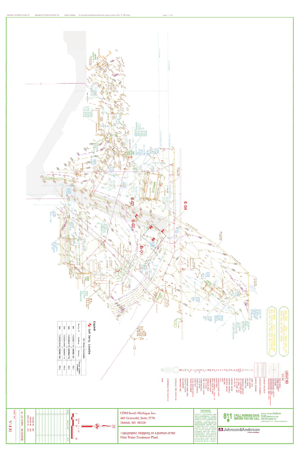
below existing grades, respectively. The number and locations of the borings, as well as the
depths of the borings, were selected by CDM and Somat, based on the preliminary site plan.
Somat staked the boring locations in the field, taking into account the locations of existing
utilities, underground and overhead. Ground surface elevations and State Plane Coordinates
were estimated at the boring locations based on our handheld GPS unit and the site topographic
maps. A soil boring location diagram, is presented in Appendix A.
2.1.1 Drilling
The drilling operations were performed on June 11, 2019. The borings were drilled using 2¼
inch diameter hollow-stem augers. Upon completion, the boreholes were backfilled to the
surface with soil cuttings.
2.1.2 Sampling
Soil samples were recovered using split-spoon sampling procedures in accordance with ASTM
Standard D-1586 (“Standard Method for Penetration Tests and Split Barrel Sampling of Soils”).
In borings B-01 and B-02, the samples were generally obtained at a regular interval of 2½ feet

REPORT ON GEOTECHNICAL INVESTIGATION JULY 03, 2019
NEW CHEMICAL SYSTEMS FEED BUILDING 2019071A
CITY OF FLINT WATER TREATMENT PLANT
FLINT, MICHIGAN PAGE 3
for the upper 10 feet of the borings, then at a 5 foot interval to the exploration depths of the
borings. In borings B-03 and B-04, the samples were obtained continuously from the surface to
the exploration depths of the borings. The split-spoon samples were sealed in glass jars in the
field to protect the soil and maintain the soil’s natural moisture content. All soil samples were
transported to Somat’s laboratory for further analysis and testing.
The soil samples collected for this investigation will be retained in our laboratory for a period of
90 days from the date of the final report, after which they will be discarded unless we are
notified otherwise.
2.1.3 Standard Penetration Test (SPT)
Soil samples collected during the field portion of the subsoil exploration were labeled with the
soil boring designation and a unique sample number. Most of the soil samples were obtained by
Standard Penetration Tests in accordance with ASTM D1586 procedures, whereby a
conventional 2-inch O.D. split-spoon sampler is driven into the soil with a 140-pound hammer
repeatedly dropped through a free-fall distance of 30 inches. The sampler is generally driven
three successive 6 inch increments, with the blows for each 6 inch increment being recorded.
The number of blows required to advance the sampler through 12 inches after an initial
penetration of 6 inches is termed the Standard Penetration Test resistance (N-value) and is
presented graphically on the individual Logs of Test Borings. As added information, the number
of blows for each 6 inch increment is also presented on the boring logs.
2.1.4 Groundwater Level Observation Procedures
Whenever possible, groundwater level observations were made during the drilling operations and
are shown on the individual Logs of Test Borings. During drilling, the depth at which free water
was observed, where drill cuttings became saturated or where saturated samples were collected,
was indicated as the groundwater level during drilling. In granular, pervious soils, the indicated
water levels are considered relatively reliable when solid or hollow-stem augers are used for
drilling. However, in cohesive soils, groundwater observations are not necessarily indicative of

REPORT ON GEOTECHNICAL INVESTIGATION JULY 03, 2019
NEW CHEMICAL SYSTEMS FEED BUILDING 2019071A
CITY OF FLINT WATER TREATMENT PLANT
FLINT, MICHIGAN PAGE 4
the static water table due to the low permeability rates of the soils, and due to the sealing off of
natural paths of groundwater flow during drilling operations.
It should be noted that seasonal variations and recent precipitation conditions may influence the
level of the groundwater table significantly. Groundwater observation wells are generally used if
precise groundwater table information is needed; however the installation of groundwater
monitoring wells was not included in the scope of the investigation. Therefore, the discussion
and recommendations provided within the report are based on our knowledge of the soil and
groundwater conditions in this area, which should provide for a reasonable approximation of the
groundwater level.
2.2 LABORATORY TESTING
Representative soil samples were subjected to laboratory tests consisting of moisture content
determinations, hand penetrometer tests, and unconfined compressive strength tests. These tests
were performed on portions of the cohesive samples obtained. All samples were classified in
accordance with the Unified Soil Classification System.
In the hand penetrometer test, the unconfined compressive strength of a cohesive soil sample is
estimated by measuring the resistance of the sample to the penetration of a small, calibrated
spring-loaded cylinder. The maximum capacity of the penetrometer is 4.5 tons per square foot.
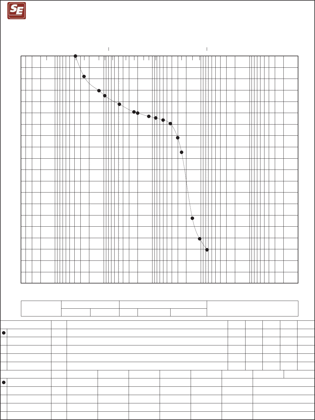
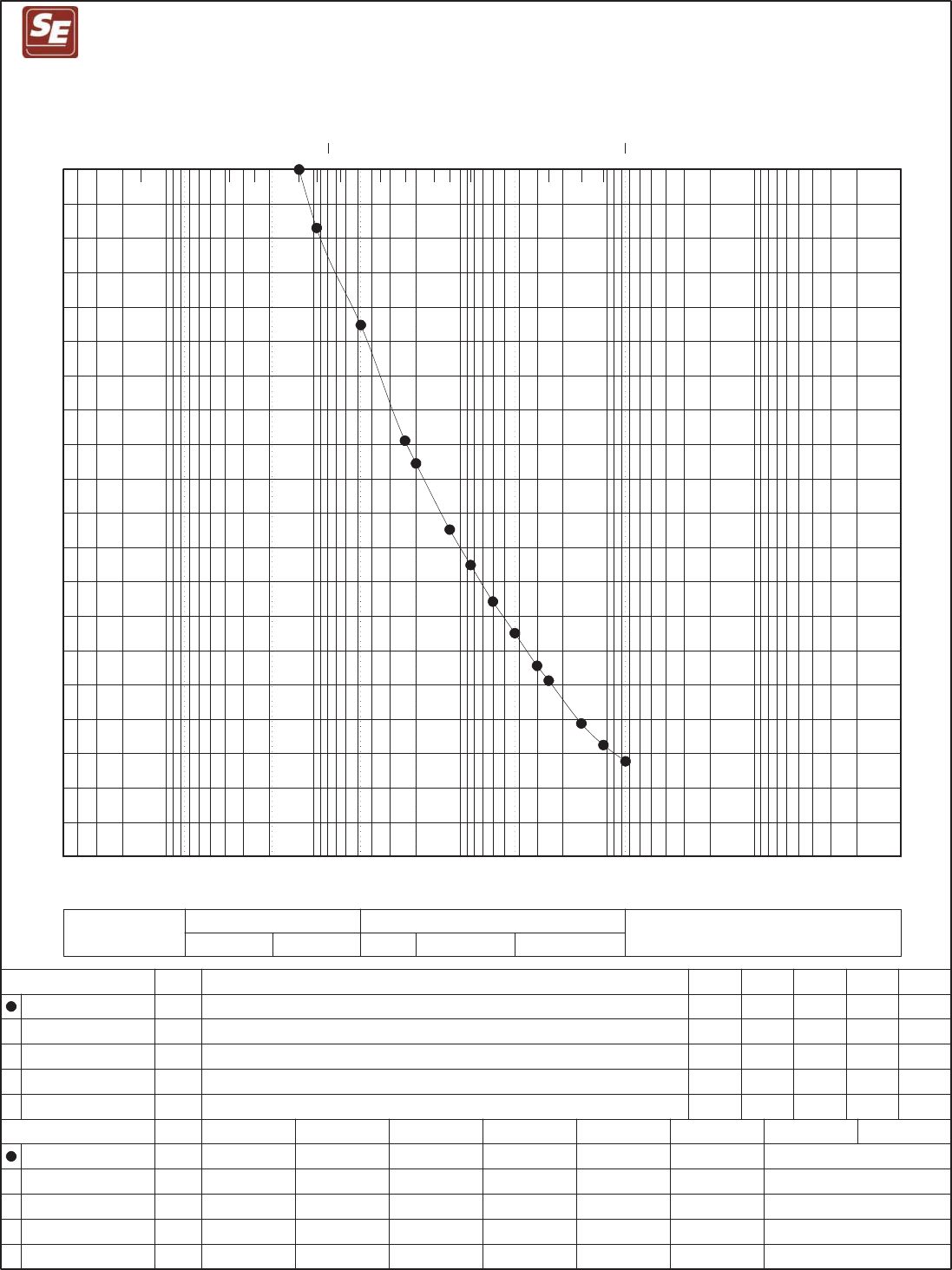
Grain size analyses were performed according to ASTM D422 92007) on two (2) selected samples
from borings B-01 at a depth of 6 feet and B-03 at a depth of 1.5 feet. Results of the grain size
analyses are presented graphically in Appendix C of this report.
Loss-on-Ignition (LOI) tests were performed on samples suspected to contain excessive organic
material. In the LOI test, a sample is superheated as a means to burn off all of the organic matter.
The organic content is then calculated as a ratio of the weight of organic material to the weight of the
overall sample.

REPORT ON GEOTECHNICAL INVESTIGATION JULY 03, 2019
NEW CHEMICAL SYSTEMS FEED BUILDING 2019071A
CITY OF FLINT WATER TREATMENT PLANT
FLINT, MICHIGAN PAGE 5
The results of the soil classifications and testing are included on the respective logs of test
borings in Appendix B. All laboratory tests were performed in accordance with applicable ASTM
procedures.
2.3 LIMITATIONS
The scope of our services was strictly geotechnical and did not include any environmental
assessment or investigation for the presence or absence of wetlands or hazardous or toxic materials
in the soil, surface water, groundwater or air, on, below or around this site.
Somat has made no observations or recommendations with regard to the presence or absence of
mold or other biological contaminants (such as spores, fungi, bacteria, viruses and the
byproducts of such organisms), now or in the future, on this site or within or on any structures to
be constructed on this site. Any consideration with regard to the presence of mold, or the
possibility of mold growth in or on the structure to be constructed on this site are not within our
scope of services on this project.
3.0 SUBSURFACE CONDITIONS
3.1 SOIL STRATIFICATION
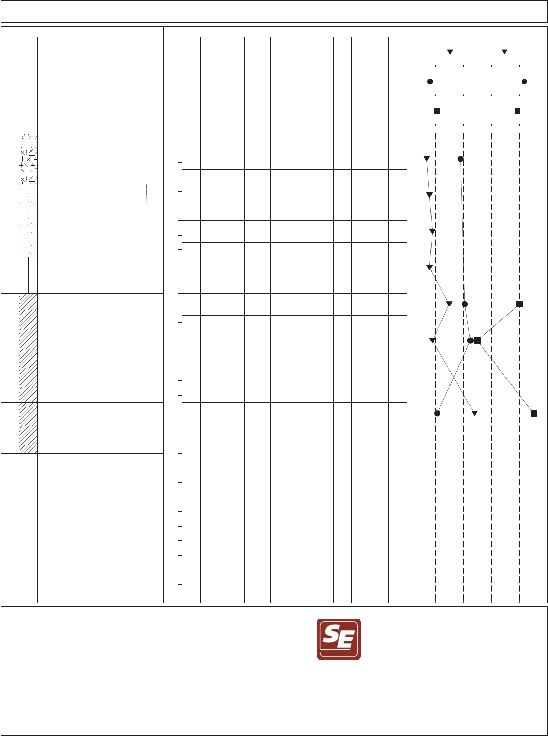
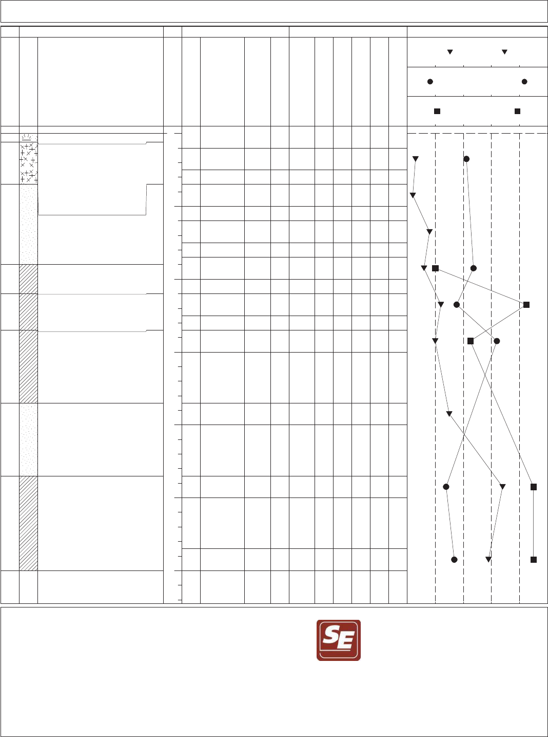
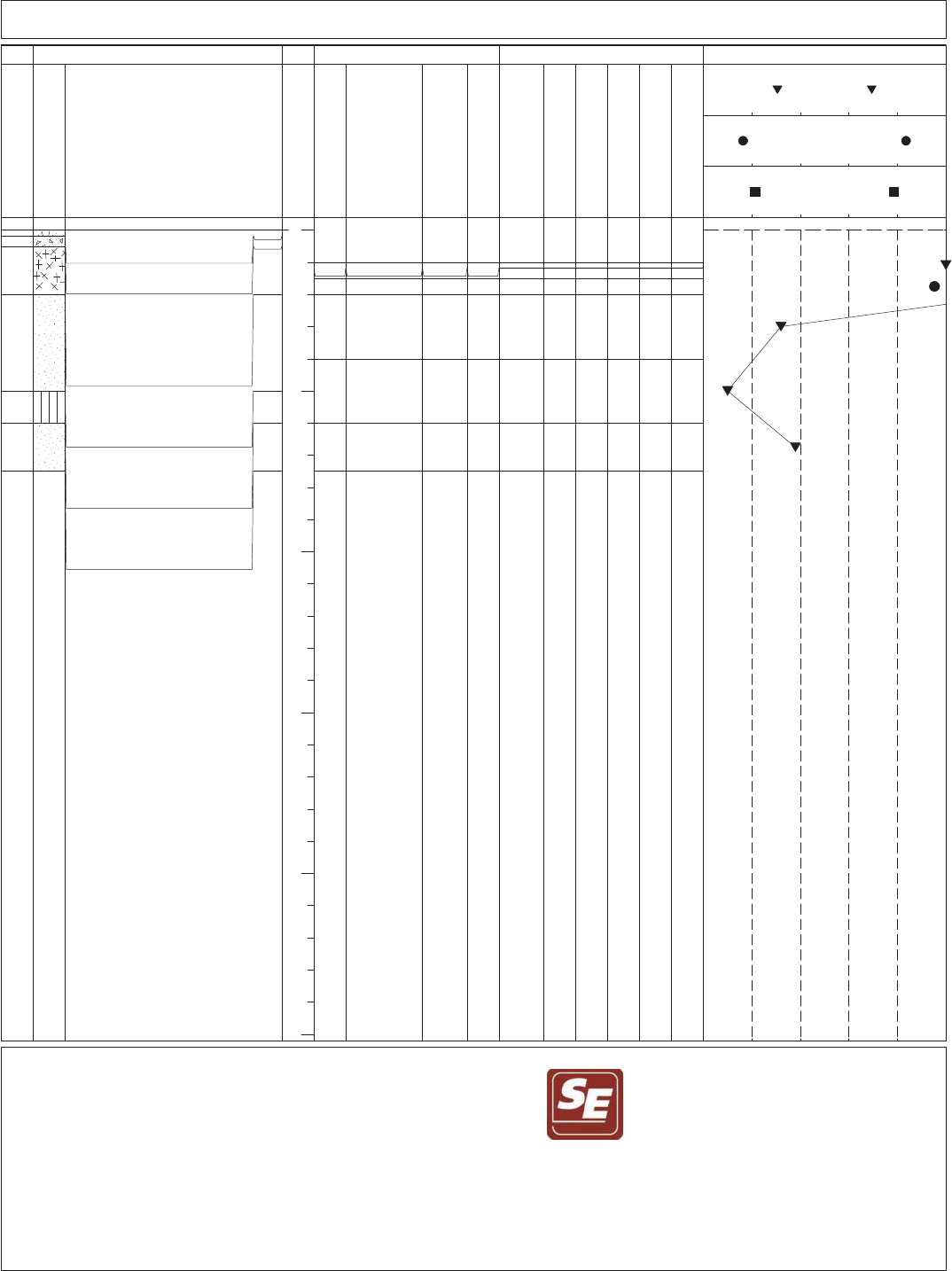
Soil conditions encountered at the test boring locations have been evaluated and are presented in
the form of Logs of Test Borings. The Logs of Test Borings presented in Appendix B include
approximate soil stratification with detailed soil descriptions and selected physical properties for
each stratum encountered in the test borings. In addition to the observed subsoil stratigraphy, the
boring logs present information relating to sample data, Standard Penetration Test results,
groundwater level conditions observed in the boring, personnel involved, and other pertinent
data. For information, and to aid in understanding the data as presented on the boring logs,
General Notes defining nomenclature used in soil descriptions are presented immediately
following the Logs of Test Borings in Appendix B. It should be noted that the Logs of Test

REPORT ON GEOTECHNICAL INVESTIGATION JULY 03, 2019
NEW CHEMICAL SYSTEMS FEED BUILDING 2019071A
CITY OF FLINT WATER TREATMENT PLANT
FLINT, MICHIGAN PAGE 6
Borings included with this report have been prepared on the basis of laboratory classifications
and testing as well as field logs of the soils encountered.
A generalized description of the soils encountered, beginning at the existing ground surface and
proceeding downward, is provided below:
Surface Materials.
¾ Topsoil was encountered at the surface of borings B-01 and B-02 in thicknesses of
7 inches and 12 inches, respectively.
¾ Pavement consisting of 2 inches of asphalt cement concrete over 4 inches of
Portland cement concrete was encountered at the surface of boring B-03.
¾ Road gravel fill layer was encountered at the surface of boring B-04 and was
approximately 6 inches in thickness.
Fill. Fill soils consisting of silty sand, fine sand, silty slag sand, and/or a mixture of these
soils were encountered below the surface materials in all the borings and extended to
depths ranging between 2 and 3.5 feet below existing grades (EL. 729.2 to 728.2 feet±).
The fill soils contained trace roots and organic material. LOI tests performed on fill soil
samples obtained from a depth between about 2 and 2.5 feet in borings B-01, B-02, and B-
03 had organic contents ranging between 4 and 11%. The apparent density of the fill soils
ranged from medium dense to very loose.
Sand and Silt. Native soils consisting of sand, silty sand, and silt, or a mixture of these
soils, were encountered below the fill soils in all the borings and extended to depths of
about 9 to 11 feet (EL. 723 to 721 feet±) below existing grades in borings B-01 and B-02,
and to the explored depths of 7.5 feet (EL. 723.5 feet±) and 6.5 feet (EL. 724.7 feet±)
below existing grade in borings B-03 and B-04, respectively. The apparent density of these
soils ranged between medium dense and very loose.
Clay. Natural hard to stiff gray lean clay was encountered below the native sand and silt in
borings B-01 and B-02 and extended to the exploration depth of the borings at 22 feet (EL.
709.7 feet±) below existing grade and 30 feet (EL. 702.1 feet±) below existing grade,
respectively. The clay had moisture content ranging between 11% and 32%. A layer of
medium dense sand was encountered in the clay soils from a depth of about 18.5 to 23.5
feet below existing grade in boring B-02.
Please refer to the boring logs for the soil conditions at the specific boring locations. It is
emphasized that the stratification lines shown on the Logs of Test Borings are approximate
indications of change from one soil type to another at the locations of the boreholes. The actual

REPORT ON GEOTECHNICAL INVESTIGATION JULY 03, 2019
NEW CHEMICAL SYSTEMS FEED BUILDING 2019071A
CITY OF FLINT WATER TREATMENT PLANT
FLINT, MICHIGAN PAGE 7
transition from one stratum to the next may be gradual, and may vary within the area represented by
the test boring.
3.2 GROUNDWATER LEVEL OBSERVATIONS
Groundwater seepage was reported during drilling and upon completion of drilling in all THE
soil borings. Table 1 below summarizes the groundwater information:
Table 1: Summary table of the groundwater information
Boring ID
Groundwater depth reported
during drilling (Elevation)
Groundwater depth reported upon
completion of drilling (Elevation)
B-01 3.5 feet (EL. 728.2 feet) 3.5 feet (EL. 728.2 feet)
B-02 3.5 feet (EL. 728.5 feet) 3.5 feet (EL. 728.5 feet)
B-03 2.0 feet (EL. 729.0 feet) 2.0 feet (EL. 729.0 feet)
B-04 2.5 feet (EL. 728.7 feet) 2.0 feet (EL. 729.2 feet)
It should be noted that the elevation of the natural groundwater table is likely to vary throughout
the year depending on the amount of precipitation, runoff, evaporation and percolation in the
area, as well as on the water level in the Flint River in the vicinity affecting the groundwater
flow pattern.
3.3 GRAIN SIZE ANALYSIS RESULTS
Grain size analyses were performed on two (2) selected samples from boring B-01 at a depth of 6
feet and B-03 at a depth of 1.5 feet below existing grade. Based on the results, the “fines” content
(silt and clay) ranged between 14% and 15%. A graphical presentation of the results is presented in
Appendix C.

REPORT ON GEOTECHNICAL INVESTIGATION JULY 03, 2019
NEW CHEMICAL SYSTEMS FEED BUILDING 2019071A
CITY OF FLINT WATER TREATMENT PLANT
FLINT, MICHIGAN PAGE 8
4.0 ANALYSIS AND RECOMMENDATIONS
Based on the preliminary plans for the proposed chemical building, Sheet V-101 dated May 23,
2019, we understand the building footprint is about 57 feet by 52 feet and the building will be
constructed at grade (with no basement). The finished floor is expected to be situated at elevation
732.5 feet±. The proposed building will contain several storage tanks and a few small metering
pumps as summarized below:
¾ Two 3,000 gallon sodium hypochlorite bulk storage tanks,
¾ One 6,000 gallon sodium hydroxide bulk storage tank,
¾ One 2,100 gallon orthophosphate bulk storage tank, and
¾ Three 100 gallon days tanks.
The proposed site development plan also includes new driveways for the chemical trucks access
to the proposed building. The following sections of this report address the foundation system
options and geotechnical pavement design recommendations.
4.1 FOUNDATION RECOMMENDATIONS
Based on the subsurface data obtained from the borings B-01 and B-02 performed within the
proposed building footprint, shallow spread, continuous foundations, or mat foundations appear
to be feasible options for supporting the proposed chemical building. These foundation systems
should be designed to bear at a minimum depth of 3.5 feet or at elevation 729 feet± (Frost depth
for SE Michigan) below the finished grade of 732.5 feet±. At this elevation, both borings B-01
and B-02 indicate this is the elevation where the soils transition from the fill soil stratum to the
native sand and silt stratum. We do not recommend constructing new foundations on these
existing fill soils. The existing fill soils may be undercut and replaced with new engineered fill
as described below and the foundations can then be supported at standard frost depth.
The native granular soils below the fill soils are also considered unsuitable for supporting the
proposed foundations if left in their current condition due to their current very loose condition
and due to the excessive fines content in the silty sand in boring B-01. The loose soils will not

REPORT ON GEOTECHNICAL INVESTIGATION JULY 03, 2019
NEW CHEMICAL SYSTEMS FEED BUILDING 2019071A
CITY OF FLINT WATER TREATMENT PLANT
FLINT, MICHIGAN PAGE 9
adequately support the new foundations resulting in settlement of the footings and the floor
slabs. The excessive fines may negatively impact the drainage of the foundations bearing soils.
Therefore, supporting the proposed footings and the floor slabs on these soils without bearing
soil/subgrade modification is not recommended due to the risk of differential settlement and
potential cracking in the proposed floor slabs.
Attempting to compact loose granular soils would typically improve the density of the soils.
However, these poor soils conditions extend deep below the foundations and are mostly situated
below the long-term groundwater table (saturated) which does not allow for proper compaction
or for a stable excavation. Attempting to utilize deep compaction methods such as the
vibroflotation methods is not recommended due to the risk of liquefying the soils and further
disturbing the subgrade soils.
As an alternative to dealing with the saturated loose sand soils, we also looked at a system of
Geopiers (stone columns) or helical piers to support the proposed building. These foundation
systems would be feasible, but very expensive given the smaller size and the magnitude of the
project. Rather, we recommend utilizing a system of geogrids and aggregate fill below the
foundations and the floor slabs. The resulting reinforced soil section will help distribute the load
uniformly, bridge over any loose/very loose areas and, minimize the potential for settlement,
differential settlement, and cracking of the floor slabs.
It will be necessary to lower the groundwater table a minimum
of 2 feet below the bottom
of the excavations to protect the bottom stability of the excavations and to allow for proper
compaction of the subgrade soils. Please refer to the groundwater control discussed in
Section 4.1.1 for the dewatering requirements.
The following sections address the recommendations for modifying the foundations soils under
the footings and the floor slabs using a system of geogrids.

REPORT ON GEOTECHNICAL INVESTIGATION JULY 03, 2019
NEW CHEMICAL SYSTEMS FEED BUILDING 2019071A
CITY OF FLINT WATER TREATMENT PLANT
FLINT, MICHIGAN PAGE 10
Footing Areas: Beginning at the bottom of footing elevation, excavate down an additional 12
inches, at a total width of 12 inches beyond each side of the footing. The plan area of soil
removal should extend out from the edge of the footing a distance of one foot for every two feet
of excavation below the footing level. In other words, the soil to be undercut should be removed
at a minimum 1H:2V slope from the edge of the footing to the edge of the undercut excavation to
provide suitable bearing for the footing. Compact the bearing soils with a vibratory roller or
plate compactor until subsequent passes result in no downward displacement. Place a
continuous strip of Tensar TX160 geogrid (or Engineer approved equivalent) over the compacted
subgrade. Backfill with 6 inches of clean, drainable, and well compacted engineered fill that
meets the gradation of MDOT 21AA stone. Compact with one pass of roller or plate compactor
with minimal vibration. Place a second layer of the same geogrid equal in width to the first
layer, on the compacted 21AA stone. Place another 6-inch lift of 21AA stone on top of this
second geogrid layer and compact with one pass of a roller or plate compactor with minimal
vibration. Form and pour the footers over the modified soil subgrade section.
Floor Slab Areas
: In areas of the proposed floor slabs, excavate down an additional 12 inches
below floor slab bottom elevation. Compact existing subgrade with a vibratory roller or plate
compactor until subsequent passes result in no downward displacement. Place a continuous strip
of Tensar TX160 geogrid (or Engineer approved equivalent) over the compacted subgrade.
Backfill with 6 inches of MDOT 21AA stone. Compact with one pass of roller or plate
compactor with minimal vibration. Place a second layer of the same geogrid equal in width to
the first layer, on the compacted 21AA stone. Place another 6-inch lift of 21AA stone on top of
this second geogrid layer and compact with 1 or 2 passes of a roller or plate compactor with
minimal vibration, such that compaction is complete. Place a vapor barrier at the top of the stone
lift and then per the published recommendations of Building Science Inc., pour the slabs directly
on the vapor barrier, even if it results in some perforations in the vapor barrier.
For the foundations and the floor slab areas, we recommend a 2 foot minimum overlap of the
geogrid in conformance with manufacturer’s recommendations to promote continuity of its load
distribution performance.
For the spread, continuous, or mat foundations bearing on the stabilized soils as described above,
we recommend a net allowable soil bearing pressure of 2,500 psf. This maximum net allowable

REPORT ON GEOTECHNICAL INVESTIGATION JULY 03, 2019
NEW CHEMICAL SYSTEMS FEED BUILDING 2019071A
CITY OF FLINT WATER TREATMENT PLANT
FLINT, MICHIGAN PAGE 11
soil bearing pressures incorporates a minimum factor of safety of 3 on the ultimate bearing
capacity.
For design of the mat foundation (assuming a rigid mat design), we recommend using a modulus
of subgrade reaction, k, of 100 kcf, which is an estimated value normalized to a 1-foot square
plate.
We estimate total settlement for spread, continuous, or mat foundations bearing on the soil-
geogrid reinforced section as described above and using the recommended bearing pressure,
should be less than 1 inch, assuming the bearing soils are not disturbed. The differential
settlement is anticipated to be one-half of the estimated total settlement.
Trench footings (earth-formed footings) will likely not be suitable when extending through
existing fill soils, natural sand or granular engineered fill soils due to the potential for caving and
sloughing of these materials. Rather, the footing excavations may have to be sloped back and
the footings formed in these soil conditions.
For bearing capacity and settlement considerations, isolated spread footing type foundations
should be at least 30 inches wide, and continuous strip foundations should be at least 18 inches
wide. Foundations along exterior walls, or in any unheated areas, should be situated a minimum
of 42 inches below final site grade for protection against frost heave during normal winters.
Also, for frost heave considerations, footings subject to frost action should be constructed with
vertical sides and should not be allowed to “mushroom out” at the top.
Careful probing and visual observations should be made during construction to make sure
foundations are not constructed on any organic soils (topsoil) or existing unsuitable fill soils or
on disturbed soils. Any existing underground utility lines to be abandoned within the footprint
of the building should be removed or grouted in place. Footings should extend through the level

REPORT ON GEOTECHNICAL INVESTIGATION JULY 03, 2019
NEW CHEMICAL SYSTEMS FEED BUILDING 2019071A
CITY OF FLINT WATER TREATMENT PLANT
FLINT, MICHIGAN PAGE 12
of any abandoned utilities and utility backfill, or the new foundations should be designed to span
over these areas.
4.1.1 Groundwater Management Considerations
Based on groundwater information observed in the borings, we estimate the long-term
groundwater level at this site to be situated at about elevation 729 to 728 feet±, or approximately
2 to 3.5 feet depth below existing grades. Based on the undercut and subgrade modifications
recommendations provided above, we expect the excavations for constructing the foundations of
the chemical building will extend to a minimum depth of 4.5 feet (EL. 727.5 feet to 726.5 feet)
below existing grades. As such, the long-term groundwater table is anticipated to be situated at a
depth of about 2.5 feet above the bottom of the excavations. Prior to excavating
, the
groundwater level should be lowered a minimum
of 2 feet below the bottom of the excavation, to
allow for proper compaction and to protect the stability of the base of the excavations. Sump pit
and conventional pumping methods will NOT
be adequate to control the groundwater flow into
the excavations. Therefore, specialized dewatering methods will be required to control the
groundwater during the excavations for the foundations. These special dewatering procedures
could include, but are not limited to, downhole pumps in slotted casings or wellpoints.
Alternatively, if steel sheeting is used to maintain the stability of the excavation sides, toeing the
sheeting into the underlying lean clay soils may be an effective method of temporarily sealing off
the groundwater from flowing into the excavation. The steel sheeting should be toed a minimum
of 2 feet (at about elevation 718 feet±) into the underlying clay soils to provide the necessary
seal. The steel sheeting closure would then make it feasible to control the groundwater flow into
the excavation by standard sump pit and pumping techniques.
If special dewatering procedures are required, loss of fines should be carefully checked during
dewatering operations at this site because of the fine gradation of the silt and clay encountered in
the soil borings. The loss of fines through dewatering should be carefully monitored to protect

REPORT ON GEOTECHNICAL INVESTIGATION JULY 03, 2019
NEW CHEMICAL SYSTEMS FEED BUILDING 2019071A
CITY OF FLINT WATER TREATMENT PLANT
FLINT, MICHIGAN PAGE 13
against the settlement of surrounding structures (i.e. building structures and existing utilities),
and should be limited to 3 parts per million, based on volume measurements.
The dewatering system will need to be designed by a knowledgeable dewatering contractor.
Dewatering should be performed with care and sufficiently localized so as not to cause harmful
settlements of nearby foundations, utilities, or pavements.
The Michigan Department of Environmental, Great Lakes and Energy (EGLE), formerly known
as Michigan Department of Environmental Quality (MDEQ), regulates the water withdrawal
from Michigan’s water resources in order to prevent adverse impacts on the surface and
groundwater resources of the State of Michigan. The EGLE’s withdrawal assessment process is
used to regulate new or increased large quantity withdrawals (more than 100,000 gallons of
water per day) from any source. The Owner (City of Flint) or the Owner’s Prime Consultant
(CDM Smith) will need to verify the dewatering requirements and secure potential provisional
dewatering permits (if needed) prior to the Contractor’s selection.
To facilitate decision making, an internet based screening tool was developed by EGLE to
estimate the volume of water that will be depleted and the resulting impact of withdrawing water
on the nearby stream ecosystems. This tool’s legal name is the Water Withdrawal Assessment
Tool (2008 PA189; Michigan Legislature 2008b) and can be accessed using the following link:
https://www.egle.state.mi.us/wwat
Use of this no-fee screening tool avoids the cost of having every withdrawal individually
evaluated by professional staff as would happen in a conventional permitting program.
The screening tool processes data about factors such as stream flows, pumping frequency, well
depth, watershed areas, soil types, and the flow needs of the characteristic fish community. If the
screening tool determines the withdrawal is not likely to cause an adverse impact, the
Owner/Contractor may register their withdrawal through the screening tool and proceed with the

REPORT ON GEOTECHNICAL INVESTIGATION JULY 03, 2019
NEW CHEMICAL SYSTEMS FEED BUILDING 2019071A
CITY OF FLINT WATER TREATMENT PLANT
FLINT, MICHIGAN PAGE 14
withdrawal without any additional contact with the EGLE. If the proposed withdrawal screening
fails, then a site-specific review and a permit will be needed. In order to assist in evaluating a
withdrawal, EGLE assigned a series of “zones” A through D; that quantify the associated risk on
the water resources.
We performed the on-line screening task and we used the following input parameters
assumptions:
¾ Withdrawal Source: Groundwater,
¾ Pumping Capacity: 400 gpm,
¾ Well Casing Depth: 11 feet,
¾ Aquifer Type: Glacial,
¾ Hydraulic conductivity, Km: 0.0033 ft/s (for silty sand).
Based on the results of our screening for this site, the withdrawal request has passed the
screening process and was assigned zone “A”. Prior to the construction, this screening should be
re-run by the Owner or the Prime Consultant and a registration should be completed for this
requested withdrawal. A registration is valid for 18 months; the withdrawal capacity must be
installed within that 18 months or the registration becomes void.
Another consideration would be the discharge of the groundwater. Based on Section B (e) of the
MDEQ publication “Instructions for Groundwater Discharge Permit Applications” revised
September, 2014; water from a well used temporarily for dewatering at a construction site does
not need a permit to be discharged to surface water or an existing sewerage system if the water
pumped does not create a site of environmental contamination under Part 201.
Based on the findings of our limited geotechnical investigation, we did not report a smell or
color indication of potential soil contamination; however our scope of services was strictly
geotechnical and did not include environmental screening, sampling or testing of the soils or
groundwater. We are not aware of any Phase I or Phase II Environmental Site Assessment (ESA)
report for this site. The Owner may be able to provide information regarding any known
contamination based on the past use history of the site. The Owner may request the Prime

REPORT ON GEOTECHNICAL INVESTIGATION JULY 03, 2019
NEW CHEMICAL SYSTEMS FEED BUILDING 2019071A
CITY OF FLINT WATER TREATMENT PLANT
FLINT, MICHIGAN PAGE 15
Consultant to perform environmental sampling and testing to verify and document the
groundwater conditions per Part 201. We advise to have proper documentation to proceed with
discharging groundwater to the surface water without treatment, if deemed necessary.
4.1.2 Seismic Site Classification Recommendations
Based on our knowledge of the general geotechnical conditions in the vicinity of the project, we
classify this site as Site Class D, as per the Michigan 2006 Building Code Table 1615.1.5.
4.1.3 Coefficient of Friction and Side Wall Friction
For mass concrete (i.e. concrete spread, continuous or mat foundations) that is subjected to
lateral loads, and not supported by deep foundations, some of the lateral loads may be resisted by
the friction between the concrete and the underlying soil. We recommend the following
allowable coefficients of friction, applied to the forces normal to the sliding surface, between the
cast-in-place concrete and the underlying soils:
Soil Type Coefficient of Friction
Sand Fill 0.40
Native Sand 0.45
4.1.4 Lateral Earth Pressure Recommendations
Below grade structures with unbalanced grade levels on opposite sides, such as the temporary
cantilever sheet piles that the Contractor may elect to use for shoring and/or groundwater cut-off,
should be designed to account for the recommended lateral earth pressures summarized in the
following table:

REPORT ON GEOTECHNICAL INVESTIGATION JULY 03, 2019
NEW CHEMICAL SYSTEMS FEED BUILDING 2019071A
CITY OF FLINT WATER TREATMENT PLANT
FLINT, MICHIGAN PAGE 16
Recommended Lateral Earth Pressures
(A,B,C)
Soil Granular
C
Clay Random Fill MDOT Class II MDOT 21AA
Consistency Loose Dense Hard Stiff Soft ---
95% ASTM 1557 95% ASTM 1557
ACTIVE
Lateral Translation to
Mobilize
1
(0.003)H (0.001)H (0.01)H (0.02)H (0.05)H (0.02)H (0.002)H (0.001)H
Active Coefficient (K
a
) 0.32 0.28 0.45 0.50 0.60 0.60 0.31 0.22
Equivalent Fluid Active
Earth Pressure
2
40 psf 35 psf 65 psf 70 psf 75 psf 80 psf 40 psf 30 psf
Lateral Surcharge (q)
Effect
3
0.32*q 0.28*q 0.45*q 0.50*q 0.60*q 0.60*q 0.31*q 0.22*q
AT-REST
At-Rest Coefficient (K
o
) 0.48 0.44 0.63 0.67 0.75 0.75 0.47 0.36
Equivalent Fluid At-Rest
Earth Pressure
2
60 psf 55 psf 90 psf 90 psf 95 psf 100 psf 55 psf 50 psf
Lateral Surcharge (q)
Effect
3
0.48*q 0.44*q 0.63*q 0.67*q 0.75*q 0.75*q 0.47*q 0.36*q
PASSIVE
Passive Coefficient (K
p
) 3.12 3.54 2.20 2.00 1.67 1.67 3.25 4.60
Equivalent Fluid Passive
Earth Pressure
2,
375 psf 440 psf 320 psf 270 psf 210 psf 220 psf 405 psf 640 psf
Lateral Bearing Capacity
for Transient Loading
4
--- --- 6 x Clay Cohesion --- --- ---
Notes:
1
– For active earth pressures, the structure must rotate about the base, with the top of the structure laterally translating
between 0.001 and 0.05 of the exposed height to fully mobilize the active earth pressures. Otherwise the structure should
be considered to be in an At-Rest condition.
2
– Equivalent Fluid Earth Pressures should be applied in a triangular distribution laterally against the structure.
3
– The lateral effect of a surcharge, q, on ground surface at the top of the structure should be applied uniformly against the
structure.
4
– Passive pressures for long term loading conditions. For transient loads, i.e. wind or traffic loading, short term lateral loads
will mobilize the cohesion in the clay soils and may be resisted by the “lateral bearing capacity” of the clay soils. However,
long term or permanent lateral loads applied to the stiff to soft clays will cause the soils to creep and lose the horizontal
resistance. Therefore, the lateral resistance from the clay soils for the life time of the structure will shift from the cohesive
“lateral bearing capacity” to the equivalent fluid pressures as the pore water pressure dissipates.
A
– All earth pressures provided are for the drained condition. If drainage is not provided behind the structure or a soil strata
is situated below the long term ground water table, then the equivalent earth pressures should be recalculated using the
buoyant unit weight of the soil and include the hydrostatic pressure from the long term groundwater table.
B
– No factors of safety have been applied to any of the recommended lateral earth pressures. It is anticipated that these
factors will be applied with the required load reductions in the design of the structure.
C
– Granular soils may consist of sand, silt, gravel or a mixture of these soils.
The application of the earth pressures in the design of below grade structures will be influenced
by the geometry of the structure, the fixity conditions imposed on the structure, the method and
material used for construction and soil and groundwater conditions. As noted, the recommended
lateral earth pressures do not include a factor of safety, nor include hydrostatic pressures or
account for the long term groundwater level. We anticipate that the necessary factors of safety
will be indirectly applied to these recommended pressures through the load reduction factors
applied in the structural design. Applying factors of safety to the above recommended pressures

REPORT ON GEOTECHNICAL INVESTIGATION JULY 03, 2019
NEW CHEMICAL SYSTEMS FEED BUILDING 2019071A
CITY OF FLINT WATER TREATMENT PLANT
FLINT, MICHIGAN PAGE 17
before their use in the design calculations would effectively double the safety reductions as these
loads are carried through the design, unnecessarily penalizing the design.
4.1.5 Geotechnical Instrumentation
We recommend implementing a geotechnical instrumentation program to monitor any potential
settlement and harmful vibrations due to the construction methods used. Settlement should be
monitored using settlement points situated on the ground surface or directly over structures to be
protected during the dewatering operations. If sheet piles will be driven to seal off the
groundwater flow into the excavations, then the induced vibrations should be monitored on
ground surface or directly over the structures to be protected. We understand there is an existing
48-inch diameter water main that is located about 15 feet east from the proposed building
footprint. This water main and any other above or below grade structures located within a
minimum radius of 35 feet from the dewatering wells or the source of vibration should be
monitored on continuous basis. For underground concrete sewer structures, we recommend a
threshold vibration level consisting of a peak particle velocity (PPV) of 2.0 inches per second
(ips) along with a frequency of 10 Hz or greater.
4.2 PAVEMENT DESIGN RECOMMENDATIONS
As we understand, the pavement sections for the access driveways servicing the new building
will consist of either Portland cement concrete or asphaltic cement concrete. The new access
driveways will be constructed at about the existing grade.
Based on borings B-03 and B-04, performed within the proposed driveways, the subgrade soils
supporting the proposed pavement are anticipated to consist of sand and slag sand fill soils
which extended to a depth of about 2 feet (El. 729 feet±) below existing grades. These soils are
not considered suitable for supporting the proposed pavement due to the excessive fines
content, causing susceptibility to frost heave, and the high organic content of the existing soils.
The slag that was observed in the fill soils was friable and deleterious. Loss-On –Ignition (LOI)
test performed on a fill soil sample obtained from a depth of 2 feet in boring B-03 had an organic

REPORT ON GEOTECHNICAL INVESTIGATION JULY 03, 2019
NEW CHEMICAL SYSTEMS FEED BUILDING 2019071A
CITY OF FLINT WATER TREATMENT PLANT
FLINT, MICHIGAN PAGE 18
content of 11%. These organics may decompose and result in settlement and cracking in the new
pavement. Therefore, these fill soils, encountered within the new pavement limits, should be
removed to the complete vertical extent of this material.
Below these unsuitable fill soils, native granular soils were encountered and extended to the
explored depths of the borings at 6.5 and 7.5 feet below existing grades. These native soils were
very loose to medium dense and hence are not considered to be suitable for supporting the new
pavement structure, if left in their current condition. Compaction will typically improve the
density of the surface layers only but it will not be effective at deeper depths, which may later
consolidate and cause the new pavement to settle and crack.
After undercutting the upper 2 feet, we expect the remaining subgrade soils to be saturated based
on the groundwater levels encountered during the time of drilling our soil borings. If these soils
are saturated during the construction, then we would not recommend to proofroll or compact it as
this procedure will tend to further disturb the subgrade soils. If the rough grade is dry, however,
we recommend proofrolling per project specifications. The site earthwork should preferably be
performed during the typically drier May to September construction season, if possible. We
recommend the following backfill section starting from the bottom and proceeding to the
surface.
¾ 200-pound woven geotextile fabric, such as GeoTurfW200 or Engineer approved
equivalent,
¾ Geogrid, such as Tensar TX190L or Engineer approved equivalent. Installing this
geogrid at the bottom of the excavation will help protect the granular subgrade soils from
rutting by construction traffic during the placement of the new base material.
¾ 1 x 3 inch stone backfill stabilization layer for support of the paving equipment. This
material is self-leveling stone requiring minimal compaction and hence minimizes the
disturbance of the saturated granular subgrade soils (minimum thickness 6 inches).
¾ 200-pound woven geotextile fabric, such as Turf W200 or Engineer approved equivalent,
¾ Geogrid, such as Tensar TX7 or Engineer approved equivalent,
¾ New subbase and base material such as MDOT 21AA or equivalent gradation as
determined by the pavement designer,
¾ New asphalt or Portland cement concrete pavement layer.

REPORT ON GEOTECHNICAL INVESTIGATION JULY 03, 2019
NEW CHEMICAL SYSTEMS FEED BUILDING 2019071A
CITY OF FLINT WATER TREATMENT PLANT
FLINT, MICHIGAN PAGE 19
The geogrid will help distribute the load and bridge over any loose areas and minimize the
potential of pavement cracking, faulting, and uneven settlement. The fabric separators should be
placed immediately below the geogrids and their purpose is to help minimize the migration of
fines into the aggregates and also provide some tensile strength to address the anticipated
fluctuation of the groundwater table. There is no need to wrap the geogrids around the
aggregates since the aggregates should not translate laterally; however wrapping the fabric
around the sides of the aggregate lifts is a common practice that helps mitigating the migration of
fines along the edges of the slopes. As such, the fabric would be wrapped up and around the side
of the aggregate lift and the fabric edges can be weighed down by the subsequent upper lift of
aggregates.
We recommend a minimum overlap (typically 2 feet) of the geogrid and fabric in general
conformance with manufacturer’s recommendations to promote continuity of its load distribution
performance. The subgrade modification should extend a minimum of 3 feet horizontally from
the edges of the new pavement or a minimum of 2 feet horizontally from the edges of the
unpaved shoulders; whichever is wider.
The thicknesses of the layers of this backfill and pavement section will be determined by the
pavement design engineer based on the anticipated traffic loads and the pavement soil design
parameters provided below:
¾ For rigid pavement design, we recommend a modulus of subgrade reaction (k) of 100
psi/in for Portland cement concrete pavement. The concrete should be air-entrained and
have a flexural strength of 650 psi and a compressive strength of 3,500 psi or greater.
The length to width ratio of the joints should not exceed 1.25.
¾ For flexible pavement design, using the modified subgrade section as described above,
we recommend a CBR of 10 and subgrade resilient modulus of 9,400 psi.

REPORT ON GEOTECHNICAL INVESTIGATION JULY 03, 2019
NEW CHEMICAL SYSTEMS FEED BUILDING 2019071A
CITY OF FLINT WATER TREATMENT PLANT
FLINT, MICHIGAN PAGE 20
The engineer preparing the final pavement designs should consider other factors in addition to
the subgrade modulus values. These factors may include, but are not limited to, adequate
subgrade preparation, adequate placement of engineered fill and pavement layers, and surface
and subsurface drainage. Somat’s services related to pavement design and construction on this
project were limited to preparing general guidelines for subgrade conditions and estimation of
modulus values from the surficial soils encountered at the soil boring locations. The estimates
were based on our experience with similar soil conditions.
4.2.1 General Site Preparation, Drainage, and Earthwork Recommendations
Once rough grade has been achieved and prior to placement of engineered fill, the exposed
subgrade should be visually checked for the presence of debris, organic matter and other
unsuitable materials. If unsuitable or organic subgrade soils (organic content over 4 percent) are
encountered at subgrade level during earthwork operations at other locations, these soils should
be removed within the proposed slab areas to their full depth, and be replaced with engineered
fill.
Within any new pavement construction and pavement removal and replacement areas, the top 12
inches of subgrade should be compacted to a minimum of 95 percent of the maximum dry
density as determined by ASTM D-1557 (Modified Proctor). It may be necessary in some of
these areas to remove disturbed subgrade soils and replace them with a stabilization layer of
engineered crushed aggregate fill. The thickness and extent of the required aggregate
stabilization layer can be determined in the field by the site geotechnical engineer. We
recommend crushed limestone aggregate meeting the gradation requirements of MDOT 21AA
material.
A provision for edge drains wrapped in a fabric sock should be considered to enhance drainage
conditions in surface pavement areas and to reduce the effects of frost heave. This will help
guard against frost heave and freeze/thaw cracking. We recommend 6 inch diameter or greater

REPORT ON GEOTECHNICAL INVESTIGATION JULY 03, 2019
NEW CHEMICAL SYSTEMS FEED BUILDING 2019071A
CITY OF FLINT WATER TREATMENT PLANT
FLINT, MICHIGAN PAGE 21
perforated or slotted PVC underdrain piping with the pipe center located at the bottom elevation
of the 1 x 3 inch stone to make sure that the entire pavement section is adequately drained. The
site grading would then direct the drainage to a catch basin or day lighted into a ditch.
5.0 GENERAL EXCAVATION CONSIDERATIONS
Excavation is recognized as one of the most hazardous construction operations. An excavation is
any man-made cut, cavity, trench, or depression in an earth surface formed by earth removal.
Trenching and excavation hazards are addressed in specific standards for the general industry in
OSHA Part 1926 Subpart P “Excavations”, specifically 29 CFR 1926.650, .651, and .652. The
project must comply with the most stringent trenching and excavation requirements of these
standards, MIOSHA Construction Safety Standard Part 9 “Excavation, Trenching, and Shoring”,
or other OSHA approved requirements.
We anticipate excavations in site fill and sand soils will be prone to caving and sloughing of the
excavation sidewalls, especially in areas where the soil conditions are in a loose condition (N
value of 9 or less). Appropriate measures will be required to maintain the stability of excavation
sidewalls. The required measures will depend on the subsurface materials encountered for the
full depth of the excavation, the depth and width of excavation, and groundwater conditions at
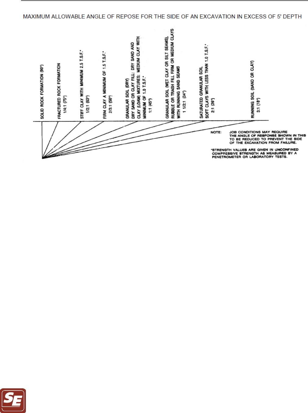
specific locations. In general, excavation walls should be sloped back to a stable angle in
accordance with published MIOSHA guidelines. The side of an excavation more than 5 feet
deep shall be sloped as prescribed in the following MIOSHA table (from Part 9), unless the
excavation is made entirely in stable rock or supported by a protective system as prescribed in
the referenced standards. An excavation less than 5 feet may also require protection if a
competent person determines that hazardous earth movement is anticipated.
REPORT ON GEOTECHNICAL INVESTIGATION JULY 03, 2019
NEW CHEMICAL SYSTEMS FEED BUILDING 2019071A
CITY OF FLINT WATER TREATMENT PLANT
FLINT, MICHIGAN PAGE 22
Sloping or benching systems for excavations less than 20 feet deep shall be in accordance with
maximum allowable slopes and based on the soil or rock type encountered as prescribed in the
standards. If sufficient room is not available for sloping the excavation walls, then shoring, by
means such as trench boxes, sliding trench shields or sheeting, will be required to maintain the
stability of the sidewalls. The design of support systems, shield systems, and other protective
systems shall be in accordance with OSHA 29 CFR 1926.652. Excavations 20 feet deep or
greater require that sloping or benching systems, or a protective system, be designed by a
registered professional engineer (or approved by a registered professional engineer in accordance
with OSHA 29 CFR 1926.652).
Construction traffic, stockpiles of soil and construction materials should be kept away from the
edges of the excavations for a distance equal to the depth of the excavation. If such clearances
cannot be maintained, the resulting surcharge loads should be considered in the design of the
shoring system. However, no loads shall be placed within 2 feet of an excavation edge for any
unsupported excavation in which a worker is required to enter (unless a proper shoring system is
in place).

REPORT ON GEOTECHNICAL INVESTIGATION JULY 03, 2019
NEW CHEMICAL SYSTEMS FEED BUILDING 2019071A
CITY OF FLINT WATER TREATMENT PLANT
FLINT, MICHIGAN PAGE 23
Proper testing for atmospheric hazards such as low oxygen, hazardous fumes, and toxic gases
should occur prior to worker entry when excavations are greater than 4 feet deep. Daily
inspections of an excavation, adjacent area, and any protective system should be made by a
competent person prior to the start of work, following a rainstorm or other water intrusion, or
during/after any occurrence that could change the conditions of the trench.
In all cases, MIOSHA and other applicable requirements must be followed and adequate
protection provided for workers.
Care should be exercised when excavating near existing pavement, utilities, and structures that
are to remain, to protect them from damage. Mechanical excavations near existing utilities may
also pose a physical hazard to workers if the utility is damaged. The contractor should be aware
of existing utility locations before excavating and be prepared to expose them for verification
and to support or brace them, as required.
6.0 GENERAL ENGINEERED FILL REQUIREMENTS
Any fill placed below proposed grade slab or pavement areas should be an approved, engineered
material, free of frozen soil, organics, or other deleterious material. Engineered fill should be
spread in level layers, not exceeding 9 inches in loose thickness, and should be compacted to a
minimum of 95 percent of the maximum dry density as determined by ASTM D-1557 (Modified
Proctor). Fill should not be placed on frozen subgrades.
7.0 GENERAL QUALIFICATIONS
All earthwork and below grade construction activities, including testing and observation of
subgrades for foundations and pavement, should be monitored by a qualified engineering

REPORT ON GEOTECHNICAL INVESTIGATION JULY 03, 2019
NEW CHEMICAL SYSTEMS FEED BUILDING 2019071A
CITY OF FLINT WATER TREATMENT PLANT
FLINT, MICHIGAN PAGE 24
inspector, under the direction of a qualified geotechnical engineer, to verify conditions are as
presented in this report. Earthwork operations around the proposed project area and in the
vicinity of existing structures should also be closely monitored. This report and the attached
Logs of Test Borings are instruments of service, which have been prepared in accordance with
generally accepted soil and foundation engineering practices. We make no warranties either
expressed or implied as to the professional advice included in this report.
The contents of this report have been prepared in order to aid in the evaluation of expected
subsoil properties to assist the engineer in the design of this project at the site specified herein.
The contents of this report should not be relied upon for other projects or purposes. In the event
that any changes are made in the geotechnically related aspects of this project, however slight,
the conclusions and recommendations contained in this report shall not be considered valid
unless the changes are reviewed, and the conclusions of this report are modified in writing by
our office.
Since the information obtained from the soil borings is specific to the exact test locations, soil
and water conditions could be different from those occurring at other locations of the site. This
report does not reflect variations which may occur between the soil borings. The nature and
extent of these variations may not become evident until the time of construction. If significant
variations become evident, it may be necessary for us to re-evaluate the recommendations
provided in this report. This report and the associated Logs of Test Borings should be made
available to bidders prior to submitting their proposals and to the successful contractor and
subcontractors for their information only, and to supply them with facts relative to the subsurface
investigation, laboratory tests, etc.
Somat is not responsible for failure to provide services that other project participants, apart from
our client, have assigned to Somat either directly or indirectly. Somat is not responsible for
failing to comply with the requirements of design manuals or other documents specified by other
project participants that impart responsibilities to the geotechnical engineer without our

REPORT ON GEOTECHNICAL INVESTIGATION JULY 03, 2019
NEW CHEMICAL SYSTEMS FEED BUILDING 2019071A
CITY OF FLINT WATER TREATMENT PLANT
FLINT, MICHIGAN PAGE 25
knowledge and written consent. We are not liable for services related to this project that are not
outlined in our scope of services, detailed in our project proposal.
The discussions and recommendations submitted in this report are based on the soil information
contained in the Logs of Test Borings and test results appended to this report. We expect that
the Logs of Test Borings included in this report along with our discussions and conclusions will
assist you in the design of the proposed project. If you have any questions regarding this report,
please contact us. Please review the important information regarding geotechnical reports
included in Appendix D.

APPENDIX A
____________________________________________________
S
OIL BORING LOCATION DIAGRAM

APPENDIX B
____________________________________________________
L
OGS OF TEST BORINGS AND GENERAL NOTES
!"#$%&
#'(')#*+,-'(.%++,
''/0-(1,+$20+,+/)-(+034.
1(0,'#'5/1#6-7)1#
8
9:
;
-(76
<
<
"=&
"=&
'/>1(+
+(+,/')+,+/
-$,?/3+01)#*+
= 8
;
@@"#7%&
!"%,&
!
'/,6-(5.
1$,-(5.
!"%,&
@A
!"#$%&
B@
!""##
-/$,(7'?(,+/+0.%++,
"#!!!"$ 22
/'?(0?/%17+*+>1,-'(%,
+)1/C$.
<
# # %"##
22
#!&'(&
)!*
!
+,&
D
/-**-(5')#1(4./1E/-**-(5
/-**-5.
(5-(++/'(-5.1*C-($
/-**-(5+,6'0.!
+,6'0',+$.
!1))+/4#+.?,')1,-7
17C%-**+0;-,6.?,,-(5$
6+7C+04.
D2D4.F
<
%,
"#!# !"$ 22
')1,(5-(++/-(5
; ;! F22
-(76+$'%
''$+$-*,4%-(+$1(0G
,/17+,'#$'-*G,/17+/'',$G
,/17+5/1>+*G01/C3/'H(G
)'-$,"&
"/51(-7'(,+(,1,%,
I=&
''$+@
H-,65/1>+*G3/'H(GH+,
"&
''$+G,/17+$1(0G
3/'H(,'5/14"2&
!1/0,'>+/4$,-%%
@G,/17+$1(0G,/17+
5/1>+*G'771$-'(1*$-*,
#1/,-(5$13'>+%,G
5/14"&
!1/0@G%+H
$1(0G,/17+5/1>+*G5/14
"&
(0'%'/-(51,%,
"'/-(5,+/)-(1,+0'(
'3$,/?7,-'(&
!"#$%&
#'(')#*+,-'(.%++,
''/0-(1,+$20+,+/)-(+034.
1(0,'#'5/1#6-7)1#
8
9:
;
-(76
<
<
"=&
"=&
'/>1(+
+(+,/')+,+/
-$,?/3+01)#*+
= 8
;
@@"#7%&
!"%,&
!
'/,6-(5.
1$,-(5.
!"%,&
@A
!"#$%&
B@
!""##
-/$,(7'?(,+/+0.%++,
"#!!!"$ 22
/'?(0?/%17+*+>1,-'(%,
+)1/C$.
<
# # %"##
22
#!&'(&
)!*
!
+,-
D
/-**-(5')#1(4./1E/-**-(5
/-**-5.
(5-(++/'(-5.1*C-($
/-**-(5+,6'0.!
+,6'0',+$.
!1))+/4#+.?,')1,-7
17C%-**+0;-,6.?,,-(5$
6+7C+04.
D2D4.F
<
%,
"#!# !"$ 22
')1,(5-(++/-(5
; ;! F22
-(76+$'%
<+/4*''$+$-*,4%-(+
$1(0G,/17+,'#$'-*G,/17+
7*14G,/17+/'',$13'>+
%,G3/'H(1(001/C3/'H(G
)'-$,"&
"/51(-7'(,+(,1,%++,
I=&
<+/4*''$+,'*''$+#''/*4
5/10+0G,/17+
$-*,G,/17+5/1>+*G3/'H(G
H+," &
,-%%@G,/17+
$1(0G,/17+5/1>+*G%/+J?+(,
$-*,*14+/$G5/14"&
!1/0@G,/17+
$1(0G,/17+5/1>+*G
'771$-'(1*$-*,#1/,-(5$G
5/14"&
<+/4$,-%%@G
,/17+$1(0G,/17+5/1>+*G
5/14"&
+0-?)0+($+#''/*4
5/10+0
G,/17+$-*,G,/17+
5/1>+*G5/14GH+," &
!1/0@G,/17+
$1(0G,/17+5/1>+*G%/+J?+(,
$-*,$+1)$G5/14"&
(0'%'/-(51,%,
2K
!"#$%&
#'(')#*+,-'(.%++,
''/0-(1,+$20+,+/)-(+034.
1(0,'#'5/1#6-7)1#
8
9:
;
-(76
<
<
"=&
"=&
'/>1(+
+(+,/')+,+/
-$,?/3+01)#*+
= 8
;
@@"#7%&
!"%,&
!
'/,6-(5.
1$,-(5.
!"%,&
@A
!"#$%&
B@
!""##
-/$,(7'?(,+/+0.%++,
"#!!!"$ 22
/'?(0?/%17+*+>1,-'(%,
+)1/C$.
<
# # %"##
22
#!&'(&
)!*
!
+,.
D
/-**-(5')#1(4./1E/-**-(5
/-**-5.
(5-(++/'(-5.1*C-($
/-**-(5+,6'0.!
+,6'0',+$.
!1))+/4#+.?,')1,-7
17C%-**+0;-,6.?,,-(5$
6+7C+04.
D2D4.F
<
%,
"#!# !"$ 22
')1,(5-(++/-(5
; ;! F22
-(76+$'% !
-(76+$'%
-*,4%-(+,'7'1/$+
$*15$1(0H-,65/1>+*G
3*17CG)'-$,,'H+," &
"/51(-7'(,+(,1,%++,
I=&
+0-?)0+($+,'*''$+
#''/*45/10+0%-(+$1(0G
,/17+$-*,G,/17+5/1>+*G
3/'H(GH+," &
''$+@G%+H
$-*,G'771$-'(1*5/14%-(+
$1(0*14+/$G3*17CGH+,
"&
+0-?)0+($+#''/*4
5/10+0G,/17+
$-*,G,/17+5/1>+*G5/14GH+,
" &
(0'%'/-(51,%,
::

!"#$%&
#'(')#*+,-'(.%++,
''/0-(1,+$20+,+/)-(+034.
1(0,'#'5/1#6-7)1#
8
9:
;
-(76
<
<
"=&
"=&
'/>1(+
+(+,/')+,+/
-$,?/3+01)#*+
= 8
;
@@"#7%&
!"%,&
!
'/,6-(5.
1$,-(5.
!"%,&
@A
!"#$%&
B@
!""##
-/$,(7'?(,+/+0.%++,
"#!!!"$ 22
/'?(0?/%17+*+>1,-'(%,
+)1/C$.
<
# # %"##
22
#!&'(&
)!*
!
+,/
D
/-**-(5')#1(4./1E/-**-(5
/-**-5.
(5-(++/'(-5.1*C-($
/-**-(5+,6'0.!
+,6'0',+$.
!1))+/4#+.?,')1,-7
17C%-**+0;-,6.?,,-(5$
6+7C+04.
D2D4.F
<
%,
"#!# !"$ 22
')1,(5-(++/-(5
; ;! F22
-(76+$'%5/1>+*
"'101,+/-1*&
+0-?)0+($+
#''/*45/10+0%-(+$1(0
H-,6$-*,G,/17+5/1>+*G3/'H(
1(001/C3/'H(G)'-$,
" &
+0-?)0+($+,'*''$+
#''/*45/10+0%-(+,'
7'1/$+$1(0G,/17+$-*,G%+H
5/1>+*G01/C3/'H(GH+,
" &
<+/4*''$+$-*,4%-(+$1(0G
,/17+7*14G,/17+5/1>+*G
01/C3/'H(GH+,"&
.-+*0(5-(++/
/+#'/,+0$,'(+-(7?,$6'+
(0'%'/-(51,%,

A
PPENDIX C
____________________________________________________
G
RAIN SIZE ANALYSIS RESULTS
!"#"$
%
&'(
)*&+,-.-&/ -0-+-1 1 1 1)- / -0-1/,2-&
-&-1.3 1-&2*4- ).
#!
.+&5*
&5 1 6- 1, ,-.-&
$(
51
!
"
!"#"$
"7
#"
$( #
+22-
&50-
&5 1 6-3 1.4.1-4)-, 528+,5..
5 !"#$%&' &()*!$)!+,
($!+'-#'..#' +'$#+'
$"-99
!"#"$
%
&'(
)*&+,-.-&/ -0-+-1 1 1 1)- / -0-1/,2-&
-&-1.3 1-&2*4- ).
#!
/
.+&5*
&5 1 6- 1, ,-.-&
$(
51
!
"
!"#"$
"7
#"
$( #
+22-
&50-
&5 1 6-3 1.4.1-4)-, 528+,5..
5 !"#$%&' &()*!$)!+,
($!+'-#'..#' +'$#+'
$"-99

A
PPENDIX D
____________________________________________________
“I
MPORTANT INFORMATION ABOUT THIS GEOTECHNICAL-ENGINEERING
REPORT”

Geotechnical-Engineering Report
Important Information about This
Subsurface problems are a principal cause of construction delays, cost overruns, claims, and disputes.
While you cannot eliminate all such risks, you can manage them. The following information is provided to help.
The Geoprofessional Business Association (GBA)
has prepared this advisory to help you – assumedly
a client representative – interpret and apply this
geotechnical-engineering report as effectively
DVSRVVLEOH,QWKDWZD\FOLHQWVFDQEHQH¿WIURP
a lowered exposure to the subsurface problems
that, for decades, have been a principal cause of
construction delays, cost overruns, claims, and
disputes. If you have questions or want more
information about any of the issues discussed below,
contact your GBA-member geotechnical engineer.
Active involvement in the Geoprofessional Business
Association exposes geotechnical engineers to a
wide array of risk-confrontation techniques that can
EHRIJHQXLQHEHQH¿WIRUHYHU\RQHLQYROYHGZLWKD
construction project.
Geotechnical-Engineering Services Are Performed for
6SHFL¿F3XUSRVHV3HUVRQVDQG3URMHFWV
Geotechnical engineers structure their services to meet the specic
needs of their clients. A geotechnical-engineering study conducted
for a given civil engineer will not likely meet the needs of a civil-
works constructor or even a dierent civil engineer. Because each
geotechnical-engineering study is unique, each geotechnical-
engineering report is unique, prepared solely for the client. ose who
rely on a geotechnical-engineering report prepared for a dierent client
can be seriously misled. No one except authorized client representatives
should rely on this geotechnical-engineering report without rst
conferring with the geotechnical engineer who prepared it. And no one
– not even you – should apply this report for any purpose or project except
the one originally contemplated.
Read this Report in Full
Costly problems have occurred because those relying on a geotechnical-
engineering report did not read it in its entirety. Do not rely on an
executive summary. Do not read selected elements only. Read this report
in full.
You Need to Inform Your Geotechnical Engineer
about Change
Your geotechnical engineer considered unique, project-specic factors
when designing the study behind this report and developing the
conrmation-dependent recommendations the report conveys. A few
typical factors include:
• the client’s goals, objectives, budget, schedule, and
risk-management preferences;
• the general nature of the structure involved, its size,
conguration, and performance criteria;
• the structure’s location and orientation on the site; and
• other planned or existing site improvements, such as
retaining walls, access roads, parking lots, and
underground utilities.
Typical changes that could erode the reliability of this report include
those that aect:
• the site’s size or shape;
• the function of the proposed structure, as when it’s
changed from a parking garage to an oce building, or
from a light-industrial plant to a refrigerated warehouse;
• the elevation, conguration, location, orientation, or
weight of the proposed structure;
• the composition of the design team; or
• project ownership.
As a general rule, always inform your geotechnical engineer of project
changes – even minor ones – and request an assessment of their
impact. e geotechnical engineer who prepared this report cannot accept
responsibility or liability for problems that arise because the geotechnical
engineer was not informed about developments the engineer otherwise
would have considered.
This Report May Not Be Reliable
Do not rely on this report if your geotechnical engineer prepared it:
• for a dierent client;
• for a dierent project;
• for a dierent site (that may or may not include all or a
portion of the original site); or
• before important events occurred at the site or adjacent
to it; e.g., man-made events like construction or
environmental remediation, or natural events like oods,
droughts, earthquakes, or groundwater uctuations.
Note, too, that it could be unwise to rely on a geotechnical-engineering
report whose reliability may have been aected by the passage of time,
because of factors like changed subsurface conditions; new or modied
codes, standards, or regulations; or new techniques or tools. If your
geotechnical engineer has not indicated an “apply-by” date on the report,
ask what it should be, and, in general, if you are the least bit uncertain
about the continued reliability of this report, contact your geotechnical
engineer before applying it. A minor amount of additional testing or
analysis – if any is required at all – could prevent major problems.
Most of the “Findings” Related in This Report Are
Professional Opinions
Before construction begins, geotechnical engineers explore a site’s
subsurface through various sampling and testing procedures.
Geotechnical engineers can observe actual subsurface conditions only at
those specic locations where sampling and testing were performed. e
data derived from that sampling and testing were reviewed by your
geotechnical engineer, who then applied professional judgment to
form opinions about subsurface conditions throughout the site. Actual
sitewide-subsurface conditions may dier – maybe signicantly – from
those indicated in this report. Confront that risk by retaining your
geotechnical engineer to serve on the design team from project start to
project nish, so the individual can provide informed guidance quickly,
whenever needed.

This Report’s Recommendations Are
&RQ¿UPDWLRQ'HSHQGHQW
e recommendations included in this report – including any options
or alternatives – are conrmation-dependent. In other words, they are
not nal, because the geotechnical engineer who developed them relied
heavily on judgment and opinion to do so. Your geotechnical engineer
can nalize the recommendations only aer observing actual subsurface
conditions revealed during construction. If through observation your
geotechnical engineer conrms that the conditions assumed to exist
actually do exist, the recommendations can be relied upon, assuming
no other changes have occurred. e geotechnical engineer who prepared
this report cannot assume responsibility or liability for conrmation-
dependent recommendations if you fail to retain that engineer to perform
construction observation.
This Report Could Be Misinterpreted
Other design professionals’ misinterpretation of geotechnical-
engineering reports has resulted in costly problems. Confront that risk
by having your geotechnical engineer serve as a full-time member of the
design team, to:
• confer with other design-team members,
• help develop specications,
• review pertinent elements of other design professionals’
plans and specications, and
• be on hand quickly whenever geotechnical-engineering
guidance is needed.
You should also confront the risk of constructors misinterpreting this
report. Do so by retaining your geotechnical engineer to participate in
prebid and preconstruction conferences and to perform construction
observation.
Give Constructors a Complete Report and Guidance
Some owners and design professionals mistakenly believe they can shi
unanticipated-subsurface-conditions liability to constructors by limiting
the information they provide for bid preparation. To help prevent
the costly, contentious problems this practice has caused, include the
complete geotechnical-engineering report, along with any attachments
or appendices, with your contract documents, but be certain to note
conspicuously that you’ve included the material for informational
purposes only. To avoid misunderstanding, you may also want to note
that “informational purposes” means constructors have no right to rely
on the interpretations, opinions, conclusions, or recommendations in
the report, but they may rely on the factual data relative to the specic
times, locations, and depths/elevations referenced. Be certain that
constructors know they may learn about specic project requirements,
including options selected from the report, only from the design
drawings and specications. Remind constructors that they may
perform their own studies if they want to, and be sure to allow enough
time to permit them to do so. Only then might you be in a position
to give constructors the information available to you, while requiring
them to at least share some of the nancial responsibilities stemming
from unanticipated conditions. Conducting prebid and preconstruction
conferences can also be valuable in this respect.
Read Responsibility Provisions Closely
Some client representatives, design professionals, and constructors do
not realize that geotechnical engineering is far less exact than other
engineering disciplines. at lack of understanding has nurtured
unrealistic expectations that have resulted in disappointments, delays,
cost overruns, claims, and disputes. To confront that risk, geotechnical
engineers commonly include explanatory provisions in their reports.
Sometimes labeled “limitations,” many of these provisions indicate
where geotechnical engineers’ responsibilities begin and end, to help
others recognize their own responsibilities and risks. Read these
provisions closely. Ask questions. Your geotechnical engineer should
respond fully and frankly.
Geoenvironmental Concerns Are Not Covered
e personnel, equipment, and techniques used to perform an
environmental study – e.g., a “phase-one” or “phase-two” environmental
site assessment – dier signicantly from those used to perform
a geotechnical-engineering study. For that reason, a geotechnical-
engineering report does not usually relate any environmental ndings,
conclusions, or recommendations; e.g., about the likelihood of
encountering underground storage tanks or regulated contaminants.
Unanticipated subsurface environmental problems have led to project
failures. If you have not yet obtained your own environmental
information, ask your geotechnical consultant for risk-management
guidance. As a general rule, do not rely on an environmental report
prepared for a dierent client, site, or project, or that is more than six
months old.
2EWDLQ3URIHVVLRQDO$VVLVWDQFHWR'HDOZLWK0RLVWXUH
,Q¿OWUDWLRQDQG0ROG
While your geotechnical engineer may have addressed groundwater,
water inltration, or similar issues in this report, none of the engineer’s
services were designed, conducted, or intended to prevent uncontrolled
migration of moisture – including water vapor – from the soil through
building slabs and walls and into the building interior, where it can
cause mold growth and material-performance deciencies. Accordingly,
proper implementation of the geotechnical engineer’s recommendations
will not of itself be sucient to prevent moisture inltration. Confront
the risk of moisture inltration by including building-envelope or mold
specialists on the design team. Geotechnical engineers are not building-
envelope or mold specialists.
Copyright 2016 by Geoprofessional Business Association (GBA). Duplication, reproduction, or copying of this document, in whole or in part, by any means whatsoever, is strictly
prohibited, except with GBA’s specic written permission. Excerpting, quoting, or otherwise extracting wording from this document is permitted only with the express written permission
of GBA, and only for purposes of scholarly research or book review. Only members of GBA may use this document or its wording as a complement to or as an element of a report of any
kind. Any other rm, individual, or other entity that so uses this document without being a GBA member could be committing negligent
Telephone: 301/565-2733
e-mail: info@geoprofessional.org www.geoprofessional.org
