
Americas Headquarters
Cisco Systems, Inc.
170 West Tasman Drive
San Jose, CA 95134-1706
USA
https://www.cisco.com
Tel: 408 526-4000
800 553-NETS (6387)
Fax: 408 527-0883
Enterprise Chat and Email Installation and
Configuration Guide, Release 12.0(1)
For Unified Contact Center Enterprise
First Published: June, 2019
Last Updated: March, 2023
THE SPECIFICATIONS AND INFORMATION REGARDING THE PRODUCTS IN THIS MANUAL ARE SUBJECT TO CHANGE WITHOUT NOTICE. ALL
STATEMENTS, INFORMATION, AND RECOMMENDATIONS IN THIS MANUAL ARE BELIEVED TO BE ACCURATE BUT ARE PRESENTED WITHOUT
WARRANTY OF ANY KIND, EXPRESS OR IMPLIED. USERS MUST TAKE FULL RESPONSIBILITY FOR THEIR APPLICATION OF ANY PRODUCTS.
THE SOFTWARE LICENSE AND LIMITED WARRANTY FOR THE ACCOMPANYING PRODUCT ARE SET FORTH IN THE INFORMATION PACKET THAT
SHIPPED WITH THE PRODUCT AND ARE INCORPORATED HEREIN BY THIS REFERENCE. IF YOU ARE UNABLE TO LOCATE THE SOFTWARE LICENSE
OR LIMITED WARRANTY, CONTACT YOUR CISCO REPRESENTATIVE FOR A COPY.
The Cisco implementation of TCP header compression is an adaptation of a program developed by the University of California, Berkeley (UCB) as part of UCBs public
domain version of the UNIX operating system. All rights reserved. Copyright 1981, Regents of the University of California.
NOTWITHSTANDING ANY OTHER WARRANTY HEREIN, ALL DOCUMENT FILES AND SOFTWARE OF THESE SUPPLIERS ARE PROVIDED "AS IS" WITH
ALL FAULTS. CISCO AND THE ABOVE-NAMED SUPPLIERS DISCLAIM ALL WARRANTIES, EXPRESSED OR IMPLIED, INCLUDING, WITHOUT
LIMITATION, THOSE OF MERCHANTABILITY, FITNESS FOR A PARTICULAR PURPOSE AND NONINFRINGEMENT OR ARISING FROM A COURSE OF
DEALING, USAGE, OR TRADE PRACTICE.
IN NO EVENT SHALL CISCO OR ITS SUPPLIERS BE LIABLE FOR ANY INDIRECT, SPECIAL, CONSEQUENTIAL, OR INCIDENTAL DAMAGES, INCLUDING,
WITHOUT LIMITATION, LOST PROFITS OR LOSS OR DAMAGE TO DATA ARISING OUT OF THE USE OR INABILITY TO USE THIS MANUAL, EVEN IF CISCO
OR ITS SUPPLIERS HAVE BEEN ADVISED OF THE POSSIBILITY OF SUCH DAMAGES.
Any Internet Protocol (IP) addresses and phone numbers used in this document are not intended to be actual addresses and phone numbers. Any examples, command display
output, network topology diagrams, and other figures included in the document are shown for illustrative purposes only. Any use of actual IP addresses or phone numbers in
illustrative content is unintentional and coincidental.
Cisco and the Cisco logo are trademarks or registered trademarks of Cisco and/or its affiliates in the U.S. and other countries. To view a list of Cisco trademarks, go to
https://www.cisco.com/go/trademarks. Third-party trademarks mentioned are the property of their respective owners. The use of the word partner does not imply a partnership
relationship between Cisco and any other company. (1110R)
Enterprise Chat and Email Installation Guide: For Unified Contact Center Enterprise. March 3, 2023
Copyright © 2016–2020, Cisco Systems, Inc. All rights reserved.
Contents
Preface ...............................................................................................................................................10
About This Guide . . . . . . . . . . . . . . . . . . . . . . . . . . . . . . . . . . . . . . . . . . . . . . . . . . . . . . . 11
Change History . . . . . . . . . . . . . . . . . . . . . . . . . . . . . . . . . . . . . . . . . . . . . . . . . . . . . . . . . 11
Related Documents . . . . . . . . . . . . . . . . . . . . . . . . . . . . . . . . . . . . . . . . . . . . . . . . . . . . . . 12
Communications, Services, and Additional Information . . . . . . . . . . . . . . . . . . . . . . . . . 12
Cisco Bug Search Tool . . . . . . . . . . . . . . . . . . . . . . . . . . . . . . . . . . . . . . . . . . . . . . . . 13
Field Alerts and Field Notices . . . . . . . . . . . . . . . . . . . . . . . . . . . . . . . . . . . . . . . . . . . . . 13
Documentation Feedback . . . . . . . . . . . . . . . . . . . . . . . . . . . . . . . . . . . . . . . . . . . . . . . . . 13
Document Conventions. . . . . . . . . . . . . . . . . . . . . . . . . . . . . . . . . . . . . . . . . . . . . . . . . . . 13
Chapter 1: Planning..........................................................................................................................14
Identifying Components . . . . . . . . . . . . . . . . . . . . . . . . . . . . . . . . . . . . . . . . . . . . . . . . . . 15
File Server Component . . . . . . . . . . . . . . . . . . . . . . . . . . . . . . . . . . . . . . . . . . . . . . . . 15
Database Server Component . . . . . . . . . . . . . . . . . . . . . . . . . . . . . . . . . . . . . . . . . . . . 15
Messaging Server Component . . . . . . . . . . . . . . . . . . . . . . . . . . . . . . . . . . . . . . . . . . 15
Application Server Component. . . . . . . . . . . . . . . . . . . . . . . . . . . . . . . . . . . . . . . . . . 16
Web Server Component . . . . . . . . . . . . . . . . . . . . . . . . . . . . . . . . . . . . . . . . . . . . . . . 16
Services Server Component . . . . . . . . . . . . . . . . . . . . . . . . . . . . . . . . . . . . . . . . . . . . 17
Understanding Deployment Models for ECE . . . . . . . . . . . . . . . . . . . . . . . . . . . . . . . . . . 17
Collocated Deployment for ECE. . . . . . . . . . . . . . . . . . . . . . . . . . . . . . . . . . . . . . . . . 17
Distributed-Server Deployment . . . . . . . . . . . . . . . . . . . . . . . . . . . . . . . . . . . . . . . . . 17
Planning Components for Specific Configurations and High Availability. . . . . . . . . . . . 18
Planning the File Server . . . . . . . . . . . . . . . . . . . . . . . . . . . . . . . . . . . . . . . . . . . . . . . 18
Planning the Database Server . . . . . . . . . . . . . . . . . . . . . . . . . . . . . . . . . . . . . . . . . . . 18
Installing the Application on a SQL Server 2016 Cluster. . . . . . . . . . . . . . . . . . 18
Planning Database Server Distribution . . . . . . . . . . . . . . . . . . . . . . . . . . . . . . . . 19
Choosing Authentication Method for Database Connectivity. . . . . . . . . . . . . . . 19
Planning Messaging Servers . . . . . . . . . . . . . . . . . . . . . . . . . . . . . . . . . . . . . . . . . . . . 19
Planning Services Servers . . . . . . . . . . . . . . . . . . . . . . . . . . . . . . . . . . . . . . . . . . . . . . 19
Planning Application Servers . . . . . . . . . . . . . . . . . . . . . . . . . . . . . . . . . . . . . . . . . . . 20
Planning Web Servers . . . . . . . . . . . . . . . . . . . . . . . . . . . . . . . . . . . . . . . . . . . . . . . . . 20
Load Balancing Considerations . . . . . . . . . . . . . . . . . . . . . . . . . . . . . . . . . . . . . . . . . 20
Planning for High Availability Across Geographies. . . . . . . . . . . . . . . . . . . . . . . . . . 20
4 Enterprise Chat and Email Installation and Configuration Guide
For 400 Agent Deployments . . . . . . . . . . . . . . . . . . . . . . . . . . . . . . . . . . . . . . . . 21
For 401 to 1500 Agent Deployments . . . . . . . . . . . . . . . . . . . . . . . . . . . . . . . . . 22
Installing ECE. . . . . . . . . . . . . . . . . . . . . . . . . . . . . . . . . . . . . . . . . . . . . . . . . . . . . . . . . .23
Chapter 2: Pre-Installation Tasks..................................................................................................24
Disabling Loopback Adapter Configuration. . . . . . . . . . . . . . . . . . . . . . . . . . . . . . . . . . . 25
Verifying Network Configuration. . . . . . . . . . . . . . . . . . . . . . . . . . . . . . . . . . . . . . . . . . . 25
Configuring Port Numbers Between Components . . . . . . . . . . . . . . . . . . . . . . . . . . . . . . 26
Setting Up User Accounts and Permissions . . . . . . . . . . . . . . . . . . . . . . . . . . . . . . . . . . . 28
Setting Up Domain Account . . . . . . . . . . . . . . . . . . . . . . . . . . . . . . . . . . . . . . . . . . . . 29
Configuring Permissions on Active Directory Server. . . . . . . . . . . . . . . . . . . . . . . . . 29
Setting up Distributed File System (DFS) . . . . . . . . . . . . . . . . . . . . . . . . . . . . . . . . . . . . 31
Enabling PowerShell Remote Commands . . . . . . . . . . . . . . . . . . . . . . . . . . . . . . . . . . . . 32
Preparing Database Server VMs. . . . . . . . . . . . . . . . . . . . . . . . . . . . . . . . . . . . . . . . . . . . 32
Setting up for Always On Availability Group Clustering. . . . . . . . . . . . . . . . . . . . . . 32
Installing SQL Server Management Studio (SSMS). . . . . . . . . . . . . . . . . . . . . . . . . . 32
Verifying Microsoft SQL Server Features . . . . . . . . . . . . . . . . . . . . . . . . . . . . . . . . . 33
Verifying Collation Settings . . . . . . . . . . . . . . . . . . . . . . . . . . . . . . . . . . . . . . . . . . . . 33
Creating SQL User for Installing ECE Databases . . . . . . . . . . . . . . . . . . . . . . . . . . . 33
Assigning Permissions to Domain User . . . . . . . . . . . . . . . . . . . . . . . . . . . . . . . . . . . 33
Configuring Database Servers. . . . . . . . . . . . . . . . . . . . . . . . . . . . . . . . . . . . . . . . . . . 33
Configuring Microsoft DTC Settings . . . . . . . . . . . . . . . . . . . . . . . . . . . . . . . . . . . . . 34
Configuring SQL Server Integration Service on the Reports Database . . . . . . . . . . . 35
Configuring Permissions for User Accounts. . . . . . . . . . . . . . . . . . . . . . . . . . . . 35
Verifying Server Privileges . . . . . . . . . . . . . . . . . . . . . . . . . . . . . . . . . . . . . . . . . 35
Creating Directory for Data Files . . . . . . . . . . . . . . . . . . . . . . . . . . . . . . . . . . . . 36
Running Services. . . . . . . . . . . . . . . . . . . . . . . . . . . . . . . . . . . . . . . . . . . . . . . . . . . . . 36
Preparing Web Server VMs . . . . . . . . . . . . . . . . . . . . . . . . . . . . . . . . . . . . . . . . . . . . . . . 37
Configuring Roles and Features . . . . . . . . . . . . . . . . . . . . . . . . . . . . . . . . . . . . . . . . . 37
Installing Modules on Web Servers . . . . . . . . . . . . . . . . . . . . . . . . . . . . . . . . . . . . . . 38
Configuring Permissions on IIS Config Folder. . . . . . . . . . . . . . . . . . . . . . . . . . . . . . 39
Running the World Wide Web Publishing Service. . . . . . . . . . . . . . . . . . . . . . . . . . . 39
Configuring Virus Scanners . . . . . . . . . . . . . . . . . . . . . . . . . . . . . . . . . . . . . . . . . . . . . . . 39
Configuring SMTP Port in Virus Scanners. . . . . . . . . . . . . . . . . . . . . . . . . . . . . . . . . 39
Configuring Virus Scanning Exclusions . . . . . . . . . . . . . . . . . . . . . . . . . . . . . . . . . . . 39
Verifying Unified CCE Configuration . . . . . . . . . . . . . . . . . . . . . . . . . . . . . . . . . . . . . . . 40
Contents 5
Chapter 3: Preparing Unified CCE for the Integration................................................................42
Relationship Between Objects in Unified CCE and ECE. . . . . . . . . . . . . . . . . . . . . . . . . 43
Designing Your Installation . . . . . . . . . . . . . . . . . . . . . . . . . . . . . . . . . . . . . . . . . . . . . . . 43
Installing Unified CCE . . . . . . . . . . . . . . . . . . . . . . . . . . . . . . . . . . . . . . . . . . . . . . . . . . . 43
Setting up Agent Desktops for Voice Call Routing . . . . . . . . . . . . . . . . . . . . . . . . . . . . . 44
Planning Unified CCE Configuration. . . . . . . . . . . . . . . . . . . . . . . . . . . . . . . . . . . . . . . . 44
Configuring Unified CCE . . . . . . . . . . . . . . . . . . . . . . . . . . . . . . . . . . . . . . . . . . . . . . . . . 45
Configuring Application Instance . . . . . . . . . . . . . . . . . . . . . . . . . . . . . . . . . . . . . . . . 45
About Media Classes. . . . . . . . . . . . . . . . . . . . . . . . . . . . . . . . . . . . . . . . . . . . . . . . . . 46
Configuring Media Classes . . . . . . . . . . . . . . . . . . . . . . . . . . . . . . . . . . . . . . . . . 46
Configuring Media Routing Domains (MRDs) . . . . . . . . . . . . . . . . . . . . . . . . . . . . . 47
Configuring Network VRU. . . . . . . . . . . . . . . . . . . . . . . . . . . . . . . . . . . . . . . . . . . . . 48
Configuring Network VRU Scripts. . . . . . . . . . . . . . . . . . . . . . . . . . . . . . . . . . . . . . . 49
Configuring Call Types. . . . . . . . . . . . . . . . . . . . . . . . . . . . . . . . . . . . . . . . . . . . . . . . 49
Configuring Media Routing Peripheral Gateways (MR PGs) . . . . . . . . . . . . . . . . . . 49
Configuring Agent Desk Settings . . . . . . . . . . . . . . . . . . . . . . . . . . . . . . . . . . . . . . . . 51
Configuring Agent Peripheral Gateway (Agent PG) . . . . . . . . . . . . . . . . . . . . . . . . . 51
Configuring Application Path . . . . . . . . . . . . . . . . . . . . . . . . . . . . . . . . . . . . . . . . . . . 52
Configuring Agents . . . . . . . . . . . . . . . . . . . . . . . . . . . . . . . . . . . . . . . . . . . . . . . . . . . 53
Configuring Skill Groups . . . . . . . . . . . . . . . . . . . . . . . . . . . . . . . . . . . . . . . . . . . . . . 54
Configuring Dialed Number/Script Selectors . . . . . . . . . . . . . . . . . . . . . . . . . . . . . . . 55
Creating Scripts . . . . . . . . . . . . . . . . . . . . . . . . . . . . . . . . . . . . . . . . . . . . . . . . . . . . . . 56
Configuring Device Targets . . . . . . . . . . . . . . . . . . . . . . . . . . . . . . . . . . . . . . . . . . . . 58
Configuring Expanded Call Context (ECC) Variables . . . . . . . . . . . . . . . . . . . . . . . . 59
Configuring Precision Routing . . . . . . . . . . . . . . . . . . . . . . . . . . . . . . . . . . . . . . . . . . 60
Creating Attributes . . . . . . . . . . . . . . . . . . . . . . . . . . . . . . . . . . . . . . . . . . . . . . . 60
Assigning Attributes to Agents . . . . . . . . . . . . . . . . . . . . . . . . . . . . . . . . . . . . . . 61
Creating Precision Queues . . . . . . . . . . . . . . . . . . . . . . . . . . . . . . . . . . . . . . . . . 61
Adding Precision Queue Node to the Scripts . . . . . . . . . . . . . . . . . . . . . . . . . . . 61
Creating Objects in Unified CCE for Personalized Activity Assignment . . . . . . . . . 61
Creating Enterprise Skill Group . . . . . . . . . . . . . . . . . . . . . . . . . . . . . . . . . . . . . 62
Creating Enterprise Routes . . . . . . . . . . . . . . . . . . . . . . . . . . . . . . . . . . . . . . . . . 62
Adding the Queue to Agent Node in Scripts. . . . . . . . . . . . . . . . . . . . . . . . . . . . 62
Adding MR PIM for ECE . . . . . . . . . . . . . . . . . . . . . . . . . . . . . . . . . . . . . . . . . . . . . . . . . 63
Adding Agent PG PIM for ECE . . . . . . . . . . . . . . . . . . . . . . . . . . . . . . . . . . . . . . . . . . . . 64
Adding CTI for ECE. . . . . . . . . . . . . . . . . . . . . . . . . . . . . . . . . . . . . . . . . . . . . . . . . . . . . 65
6 Enterprise Chat and Email Installation and Configuration Guide
Configuring the System for Multiple Agent PGs . . . . . . . . . . . . . . . . . . . . . . . . . . . . . . . 65
Configuring Finesse . . . . . . . . . . . . . . . . . . . . . . . . . . . . . . . . . . . . . . . . . . . . . . . . . . . . . 66
Chapter 4: Installation Process......................................................................................................67
Installation Overview . . . . . . . . . . . . . . . . . . . . . . . . . . . . . . . . . . . . . . . . . . . . . . . . . . . . 68
For 400 Agent Deployments . . . . . . . . . . . . . . . . . . . . . . . . . . . . . . . . . . . . . . . . . . . . 68
For 400 Agent Deployments (HA) . . . . . . . . . . . . . . . . . . . . . . . . . . . . . . . . . . . . . . . 68
For 400+ Agent Deployments. . . . . . . . . . . . . . . . . . . . . . . . . . . . . . . . . . . . . . . . . . . 69
For 400+ Agent Deployments (HA) . . . . . . . . . . . . . . . . . . . . . . . . . . . . . . . . . . . . . . 69
Installing ECE. . . . . . . . . . . . . . . . . . . . . . . . . . . . . . . . . . . . . . . . . . . . . . . . . . . . . . . . . .70
Installation Details . . . . . . . . . . . . . . . . . . . . . . . . . . . . . . . . . . . . . . . . . . . . . . . . . . . . . .72
File Server Details. . . . . . . . . . . . . . . . . . . . . . . . . . . . . . . . . . . . . . . . . . . . . . . . . . . . 72
Database Server Details . . . . . . . . . . . . . . . . . . . . . . . . . . . . . . . . . . . . . . . . . . . . . . . 73
Web Server Details . . . . . . . . . . . . . . . . . . . . . . . . . . . . . . . . . . . . . . . . . . . . . . . . . . . 79
Messaging Server Details . . . . . . . . . . . . . . . . . . . . . . . . . . . . . . . . . . . . . . . . . . . . . . 80
Application Server Details . . . . . . . . . . . . . . . . . . . . . . . . . . . . . . . . . . . . . . . . . . . . . 81
Services Server Details . . . . . . . . . . . . . . . . . . . . . . . . . . . . . . . . . . . . . . . . . . . . . . . . 82
Chapter 5: Post-Installation Tasks ................................................................................................83
Configuring Permissions on IIS Config Folder . . . . . . . . . . . . . . . . . . . . . . . . . . . . . . . . 85
Assigning Permissions on ECE Home Directory . . . . . . . . . . . . . . . . . . . . . . . . . . . . . . . 85
Configuring SSL for Secure Connections. . . . . . . . . . . . . . . . . . . . . . . . . . . . . . . . . . . . . 85
Always On Availability Group Clustering Tasks . . . . . . . . . . . . . . . . . . . . . . . . . . . . . . . 85
Creating an Encrypted SQL Server Database. . . . . . . . . . . . . . . . . . . . . . . . . . . . . . . . . . 86
Encrypting Primary Node . . . . . . . . . . . . . . . . . . . . . . . . . . . . . . . . . . . . . . . . . . . . . . 86
Encrypting Other Nodes . . . . . . . . . . . . . . . . . . . . . . . . . . . . . . . . . . . . . . . . . . . . . . . 87
Configuring SMTP Server Relay Address List. . . . . . . . . . . . . . . . . . . . . . . . . . . . . . . . . 88
Configuring Finesse . . . . . . . . . . . . . . . . . . . . . . . . . . . . . . . . . . . . . . . . . . . . . . . . . . . . . 89
Configuring Finesse Settings and Layout . . . . . . . . . . . . . . . . . . . . . . . . . . . . . . . . . . 89
Configuring Single Sign-On . . . . . . . . . . . . . . . . . . . . . . . . . . . . . . . . . . . . . . . . . . . . . . . 91
Starting ECE . . . . . . . . . . . . . . . . . . . . . . . . . . . . . . . . . . . . . . . . . . . . . . . . . . . . . . . . . . .91
Troubleshooting Application Start-Up Issues . . . . . . . . . . . . . . . . . . . . . . . . . . . . . . . 92
Stopping ECE . . . . . . . . . . . . . . . . . . . . . . . . . . . . . . . . . . . . . . . . . . . . . . . . . . . . . . . . . .92
Signing in to ECE . . . . . . . . . . . . . . . . . . . . . . . . . . . . . . . . . . . . . . . . . . . . . . . . . . . . . . . 93
Contents 7
Signing in to Agent Console . . . . . . . . . . . . . . . . . . . . . . . . . . . . . . . . . . . . . . . . . . . . 93
Signing in to All Other Consoles . . . . . . . . . . . . . . . . . . . . . . . . . . . . . . . . . . . . . . . . 93
Integrating ECE with Unified CCE . . . . . . . . . . . . . . . . . . . . . . . . . . . . . . . . . . . . . . . . . 93
Configuring Important Settings . . . . . . . . . . . . . . . . . . . . . . . . . . . . . . . . . . . . . . . . . . . . 95
Mandatory Settings . . . . . . . . . . . . . . . . . . . . . . . . . . . . . . . . . . . . . . . . . . . . . . . . . . . 95
Optional Settings . . . . . . . . . . . . . . . . . . . . . . . . . . . . . . . . . . . . . . . . . . . . . . . . . . . . . 96
Adding Data Source in CUIC for ECE Reports . . . . . . . . . . . . . . . . . . . . . . . . . . . . . . . . 96
Creating a Database User on ECE Reports Database . . . . . . . . . . . . . . . . . . . . . . . . . 97
Adding Data Source in CUIC for ECE Reports . . . . . . . . . . . . . . . . . . . . . . . . . . . . . 97
Uninstalling ECE . . . . . . . . . . . . . . . . . . . . . . . . . . . . . . . . . . . . . . . . . . . . . . . . . . . . . . . 98
Preparing to Uninstall . . . . . . . . . . . . . . . . . . . . . . . . . . . . . . . . . . . . . . . . . . . . . . . . . 98
Stopping the Application. . . . . . . . . . . . . . . . . . . . . . . . . . . . . . . . . . . . . . . . . . . 98
Stopping IIS. . . . . . . . . . . . . . . . . . . . . . . . . . . . . . . . . . . . . . . . . . . . . . . . . . . . . 98
Uninstalling ECE. . . . . . . . . . . . . . . . . . . . . . . . . . . . . . . . . . . . . . . . . . . . . . . . . . . . . 98
Performing Post Uninstallation Tasks. . . . . . . . . . . . . . . . . . . . . . . . . . . . . . . . . . . . . 99
Starting IIS. . . . . . . . . . . . . . . . . . . . . . . . . . . . . . . . . . . . . . . . . . . . . . . . . . . . . . 99
Chapter 6: Single Sign-On Configuration...................................................................................100
About Single Sign-On with Cisco IDS . . . . . . . . . . . . . . . . . . . . . . . . . . . . . . . . . . . . . . 101
Configuring Single AD FS Deployment. . . . . . . . . . . . . . . . . . . . . . . . . . . . . . . . . . . . . 101
Configuring Relying Party Trust for ECE. . . . . . . . . . . . . . . . . . . . . . . . . . . . . . . . . 101
Configuring Split AD FS Deployment . . . . . . . . . . . . . . . . . . . . . . . . . . . . . . . . . . . . . . 109
Adding Security Certificates for the AD FS Domains . . . . . . . . . . . . . . . . . . . . . . . 109
Configuring Relying Party Trust for Shared AD FS in Customer AD FS . . . . . . . . 110
Configuring Claims Provider Trust for Customer AD FS in Shared AD FS . . . . . . 114
Configuring Relying Party Trust for ECE in Shared AD FS . . . . . . . . . . . . . . . . . . 118
Configuring Single Sign-On in ECE. . . . . . . . . . . . . . . . . . . . . . . . . . . . . . . . . . . . . . . . 125
Chapter 7: SSL Configuration .......................................................................................................126
Installing a Security Certificate. . . . . . . . . . . . . . . . . . . . . . . . . . . . . . . . . . . . . . . . . . . . 127
Generating a Certificate Signing Request . . . . . . . . . . . . . . . . . . . . . . . . . . . . . . . . . 127
Submitting the Certificate Request . . . . . . . . . . . . . . . . . . . . . . . . . . . . . . . . . . . . . . 129
Installing the Certificate on the Web Server . . . . . . . . . . . . . . . . . . . . . . . . . . . . . . . 129
Binding the Certificate to the Application Website . . . . . . . . . . . . . . . . . . . . . . . . . . . . 131
Testing SSL Access . . . . . . . . . . . . . . . . . . . . . . . . . . . . . . . . . . . . . . . . . . . . . . . . . . . . 132
8 Enterprise Chat and Email Installation and Configuration Guide
Configuring SSL or TLS for Retriever and Dispatcher Services . . . . . . . . . . . . . . . . . . 132
On the File Server . . . . . . . . . . . . . . . . . . . . . . . . . . . . . . . . . . . . . . . . . . . . . . . . . . . 133
Installing Certificates. . . . . . . . . . . . . . . . . . . . . . . . . . . . . . . . . . . . . . . . . . . . . 133
Deleting Certificates . . . . . . . . . . . . . . . . . . . . . . . . . . . . . . . . . . . . . . . . . . . . . 134
In the Administration Console . . . . . . . . . . . . . . . . . . . . . . . . . . . . . . . . . . . . . . . . . 134
Chapter 8: Setting Up Integrated Objects ..................................................................................136
Configuring Variables in ECE . . . . . . . . . . . . . . . . . . . . . . . . . . . . . . . . . . . . . . . . . . . . 137
Verifying Mapping of Objects in the Administration Console. . . . . . . . . . . . . . . . . . . . 137
Setting up Business Objects in the Administration Console. . . . . . . . . . . . . . . . . . . . . . 138
Setting Up Services in the System Console . . . . . . . . . . . . . . . . . . . . . . . . . . . . . . . . . . 139
Setting Up Web Links for Chat and Callback. . . . . . . . . . . . . . . . . . . . . . . . . . . . . . . . . 140
Configuring Dynamic Messages for Integrated Chats . . . . . . . . . . . . . . . . . . . . . . . . . . 141
Related Documentation. . . . . . . . . . . . . . . . . . . . . . . . . . . . . . . . . . . . . . . . . . . . . . . . . . 141
Appendix A: Distributed File System Configuration ................................................................142
Installing DFS Management . . . . . . . . . . . . . . . . . . . . . . . . . . . . . . . . . . . . . . . . . . . . . . 143
Creating Shared Folders . . . . . . . . . . . . . . . . . . . . . . . . . . . . . . . . . . . . . . . . . . . . . . . . . 143
Creating New Namespace. . . . . . . . . . . . . . . . . . . . . . . . . . . . . . . . . . . . . . . . . . . . . . . . 143
Adding Namespace Server . . . . . . . . . . . . . . . . . . . . . . . . . . . . . . . . . . . . . . . . . . . . . . . 144
Adding Folders and Configuring Replication. . . . . . . . . . . . . . . . . . . . . . . . . . . . . . . . . 144
Appendix B: SQL Always-On Configuration..............................................................................145
About Always On Availability Group Clustering. . . . . . . . . . . . . . . . . . . . . . . . . . . . . . 146
Pre-Installation Tasks . . . . . . . . . . . . . . . . . . . . . . . . . . . . . . . . . . . . . . . . . . . . . . . . . . . 146
Installing Failover Clustering Feature. . . . . . . . . . . . . . . . . . . . . . . . . . . . . . . . . . . . 146
Creating Prestage Cluster Computer Objects in Active Directory Domain Services (AD
DS) . . . . . . . . . . . . . . . . . . . . . . . . . . . . . . . . . . . . . . . . . . . . . . . . . . . . . . . . . . . . . . 146
Prestaging the CNO in AD DS . . . . . . . . . . . . . . . . . . . . . . . . . . . . . . . . . . . . . 147
Granting User Permissions to Create Cluster . . . . . . . . . . . . . . . . . . . . . . . . . . 147
Granting the CNO Permissions to the OU . . . . . . . . . . . . . . . . . . . . . . . . . . . . 147
Creating Windows Failover Cluster . . . . . . . . . . . . . . . . . . . . . . . . . . . . . . . . . . . . . 148
Configure Cluster Quorum Settings . . . . . . . . . . . . . . . . . . . . . . . . . . . . . . . . . . . . . 148
Enabling Always On Availability Groups Feature on SQL . . . . . . . . . . . . . . . . . . . 149
Configuring SQL Server Always On Availability Groups . . . . . . . . . . . . . . . . . . . . 149
Contents 9
Install the Application. . . . . . . . . . . . . . . . . . . . . . . . . . . . . . . . . . . . . . . . . . . . . . . . . . . 150
Post-Installation Tasks . . . . . . . . . . . . . . . . . . . . . . . . . . . . . . . . . . . . . . . . . . . . . . . . . . 150
Verifying Recovery Model . . . . . . . . . . . . . . . . . . . . . . . . . . . . . . . . . . . . . . . . . . . . 150
Backing up ECE Databases. . . . . . . . . . . . . . . . . . . . . . . . . . . . . . . . . . . . . . . . . . . . 150
Adding Databases to Availability Group . . . . . . . . . . . . . . . . . . . . . . . . . . . . . . . . . 151
Run reports DB utility to configure secondary nodes . . . . . . . . . . . . . . . . . . . . . . . . 151
Running the Reports Database Utility . . . . . . . . . . . . . . . . . . . . . . . . . . . . . . . . 151
Creating Jobs to Take Log backups on All Nodes . . . . . . . . . . . . . . . . . . . . . . . . . . 152
Appendix C: Convert Existing Deployment to HA.....................................................................153
Converting Existing Two Server Installation to HA (Windows 2016). . . . . . . . . . . . . . 154
Converting Existing File Server to DFS . . . . . . . . . . . . . . . . . . . . . . . . . . . . . . . . . . 155
Setting up Distributed File System (DFS). . . . . . . . . . . . . . . . . . . . . . . . . . . . . 155
Updating Files to Use DFS . . . . . . . . . . . . . . . . . . . . . . . . . . . . . . . . . . . . . . . . 155
Installing Second Messaging, Services, and Application Server Components. . . . . 155
Installing Second Web Server Component . . . . . . . . . . . . . . . . . . . . . . . . . . . . . . . . 155
Converting Databases to SQL Server to Always On Configuration . . . . . . . . . . . . . 155
Stopping ECE Application and Disable SQL Jobs.. . . . . . . . . . . . . . . . . . . . . . 156
Converting SQL Authentication to Windows Authentication. . . . . . . . . . . . . . 156
Backing up and Restoring Databases . . . . . . . . . . . . . . . . . . . . . . . . . . . . . . . . 157
Updating Files and Databases with New Listener Names. . . . . . . . . . . . . . . . . 157
Starting the SQL Jobs and ECE Application. . . . . . . . . . . . . . . . . . . . . . . . . . . 159
Updating Finesse Files . . . . . . . . . . . . . . . . . . . . . . . . . . . . . . . . . . . . . . . . . . . . . . . 159
Converting Existing Two Server Installation to HA (Windows 2012). . . . . . . . . . . . . . 160
Converting Existing File Server to DFS . . . . . . . . . . . . . . . . . . . . . . . . . . . . . . . . . . 160
Installing Second Messaging and Application Server Components . . . . . . . . . . . . . 160
Installing Second Services Server Component . . . . . . . . . . . . . . . . . . . . . . . . . . . . . 160
Installing Second Web Server Component . . . . . . . . . . . . . . . . . . . . . . . . . . . . . . . . 160
Converting Databases to SQL Server to Always On Configuration . . . . . . . . . . . . . 161
Updating Finesse Files . . . . . . . . . . . . . . . . . . . . . . . . . . . . . . . . . . . . . . . . . . . . . . . 161
Converting Existing Distributed Server Installation to HA (Windows 2012 & 2016) . . 161
Converting Existing File Server to DFS . . . . . . . . . . . . . . . . . . . . . . . . . . . . . . . . . . 162
Setting up Distributed File System (DFS). . . . . . . . . . . . . . . . . . . . . . . . . . . . . 162
Updating Files to Use DFS . . . . . . . . . . . . . . . . . . . . . . . . . . . . . . . . . . . . . . . . 162
Installing Second Messaging Server Component . . . . . . . . . . . . . . . . . . . . . . . . . . . 162
Installing Second Services Server Component . . . . . . . . . . . . . . . . . . . . . . . . . . . . . 162
Installing Additional Application Server Components . . . . . . . . . . . . . . . . . . . . . . . 162
Installing Additional Web Server Components . . . . . . . . . . . . . . . . . . . . . . . . . . . . 162

Preface 11
Welcome to the Enterprise Chat and Email (ECE) feature, which provides multichannel interaction software
used by businesses all over the world as a core component to the Unified Contact Center Enterprise product
line. ECE offers a unified suite of the industry’s best applications for chat and email interaction management
to enable a blended agent for handling of web chat, email and voice interactions.
About This Guide
Enterprise Chat and Email Installation and Configuration Guide is intended for installation engineers,
system administrators, database administrators, and others who are responsible for installing and configuring
Enterprise Chat and Email (ECE) installations that are integrated with Cisco Unified Contact Center
Enterprise (Unified CCE).
The best way to use the installation guide is to print it, read the entire guide, and then start at the beginning
and complete each pre-installation, installation, and post-installation task, in sequence.
Change History
This table lists changes made to this guide. Most recent changes appear at the top.
Important: New installations for ECE 12.0(1) are not supported on Windows Server 2012.
If you need to access the archived documentation for the old platform, please contact Cis-
co Support.
Change See Date
Added a note about manually adding the
ECC variables when multiple payloads are
configured.
“Configuring Expanded Call Context (ECC)
Variables” on page 59
March, 2023
Updated the image for selecting the
website name step.
“Binding the Certificate to the Application
Website” on page 131
June, 2022
Added information about manually deleting
components after Uninstalling ECE.
“Uninstalling ECE” on page 98 Feb, 2022
Updated description of Max field in the
Configuring Media Routing Domains
section.
“Configuring Media Routing Domains
(MRDs)” on page 47
April, 2020
12 Enterprise Chat and Email Installation and Configuration Guide
Related Documents
The latest versions of all Cisco documentation can be found online at https://www.cisco.com
Communications, Services, and Additional
Information
To receive timely, relevant information from Cisco, sign up at Cisco Profile Manager.
To get the business impact you’re looking for with the technologies that matter, visit Cisco Services.
To submit a service request, visit Cisco Support.
To discover and browse secure, validated enterprise-class apps, products, solutions and services, visit
Cisco Marketplace.
To obtain general networking, training, and certification titles, visit Cisco Press.
To find warranty information for a specific product or product family, access Cisco Warranty Finder.
Enhanced the Planning Components for
Specific Configurations and High
Availability section with more details
about High Availability options.
“Planning Components for Specific
Configurations and High Availability” on
page 18
October, 2019
Added information about number of VMs
needed for installing the application.
“Installation Overview” on page 68
Added details about encrypting primary
and secondary nodes.
“Creating an Encrypted SQL Server
Database” on page 86
New chapter added: Distributed File
System Configuration
“Appendix A: Distributed File System
Configuration” on page 142
New chapter added: SQL Always-On
Configuration
“Appendix B: SQL Always-On Configuration”
on page 145
New chapter added: Convert Existing
Deployment to HA
“Appendix C: Convert Existing Deployment to
HA” on page 153
Change See Date
Subject Link
Complete documentation for Enterprise
Chat and Email, for both Cisco Unified
Contact Center Enterprise (UCCE) and Cisco
Packaged Contact Center Enterprise (PCCE)
https://www.cisco.com/c/en/us/support/contact-center/enterprise-chat-
email-12-0-1/model.html

Preface 13
Cisco Bug Search Tool
Cisco Bug Search Tool (BST) is a web-based tool that acts as a gateway to the Cisco bug tracking system
that maintains a comprehensive list of defects and vulnerabilities in Cisco products and software. BST
provides you with detailed defect information about your products and software.
Field Alerts and Field Notices
Cisco can modify its products or determine key processes to be important. These changes are announced
through use of the Cisco Field Alerts and Cisco Field Notices. You can register to receive Field Alerts and
Field Notices through the Product Alert Tool on Cisco.com. This tool enables you to create a profile to
receive announcements by selecting all products of interest.
Sign in www.cisco.com and then access the tool at
https://www.cisco.com/?cisco/?support/?notifications.html.
Documentation Feedback
To provide comments about this document, send an email message to the following address:
We appreciate your comments.
Document Conventions
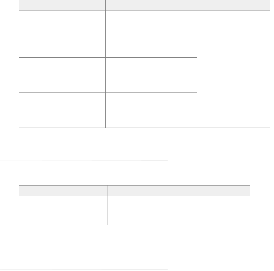
This guide uses the following typographical conventions.
Document conventions
Convention Indicates
Italic Emphasis.
Or the title of a published document.
Bold Labels of items on the user interface, such as buttons, boxes, and lists.
Or text that must be typed by the user.
Monospace
The name of a file or folder, a database table column or value, or a command.
Variable User-specific text; varies from one user or installation to another.


Planning 15
ECE can be installed in multiple configurations, ranging from a simple collocated installation, to many flavors of
distributed installations. This chapter lists the components that make up ECE deployment and available
configuration options. It also helps you plan your installation.
Identifying Components
All ECE installations have the following six components:
File Server Component
Database Server Component
Messaging Server Component
Application Server Component
Web Server Component
Services Server Component
File Server Component
The file server is used to store application files, reports templates, and reports output files. In non HA
environment, there is only one file server in a deployment. HA deployments use DFS.
Database Server Component
All ECE databases are created on the database server. The installation program creates the following databases:
A master database, that stores system configuration information to manage services.
An active database, where all business and interaction data is stored. This is also referred to as the partition
database.
A reports database, where all data used by the reports module is stored.
The master and active databases are installed on the same instance. The reports database can be installed on a
different instance.
Messaging Server Component
The messaging server provides a centralized location for the exchange of information asynchronously among
various components of ECE application through the sending and receiving of messages.
For example,
The application server publishes a message to the workflow cache process to refresh its cache when a user
modifies a workflow in the Administration Console.
A deployment can have a cluster of messaging servers.

16 Enterprise Chat and Email Installation and Configuration Guide
Components that use messaging are listed in the following table.
Application Server Component
The application server houses the business logic responsible for interactive responses to all user-interface
requests–across all classes of users including customers, agents, administrators, knowledge authors, system
administrators. It handles requests for operations from a user (the web client), interprets user requests and
delivers responses as web pages, constructed dynamically using JSP (based on the user request).
A deployment can have more than one application server. The number of application servers in a deployment
will depend on the amount of user load to be handled. For details about sizing, see the Enterprise Chat and
Email Design Guide.
Web Server Component
The web server is used to serve static content to the browser.
It gets requests from, and serves static content such as images, java applets, and client-side JavaScript code to a
web browser. All dynamic requests are routed to the application server for further processing and generation of
dynamic content. The web server component is always installed on a separate VM.
Installing the web server does not need access to any other ECE component. The web server can be installed
outside firewall. A deployment can have multiple web servers, with a one-to-one mapping between a web server
and an application server. The web servers can be separated from their corresponding application servers across
a firewall.
No user identification is required at the web server. Access to the application functionality is controlled at the
application server layer.
Component Use
Email Workflow The Workflow Assignment Service publishes a message to application servers when a
new email is assigned to a user.
The application server publishes a message to Workflow Cache Service when any
workflow is created or modified from the Administration Console. The Workflow Cache
Service publishes a message to the Workflow Service after it rebuilds its cache.
Email Retriever and
Dispatcher
The application server publishes a message to the Retriever and Dispatcher Services when an
email alias is created or modified from the Administration Console.
Miscellaneous
The Scheduler Service publishes a message to the Reports Service when the schedule for
a report fires.
The application server publishes a message to the Distributed Services Manager (DSM)
whenever an agent logs in to or logs out of the application.
The application server publishes a message to all other application servers and services
when a Custom attribute is created from the Tools Console.
The application server publishes a message to other application servers every time an
article or topic is added, modified, or removed.
Planning 17
Services Server Component
ECE has processes that perform specific business functions, such as fetching emails from a POP3 or IMAP
server, sending emails through an SMTP server, processing workflows, assigning chats to agents, etc. All
services run on the services server and are managed by the Distributed Service Manager (DSM). Framework
services that manage these remote services also run on the services server.
A deployment can have two services servers.
Understanding Deployment Models for ECE
With its modular, component-based architecture ECE caters effortlessly to the growing demands for increased
concurrent user loads. To provide the flexibility to suit deployments of varied sizes, ECE supports components
that may be distributed across various servers in a deployment. This section provides details of the possible
deployment options.
Collocated Deployment for ECE: The web server is installed on a separate VM and all other components
are installed on one VM. The web server may be installed outside the firewall, if required.
Distributed-server deployment: Components are distributed over two or more servers. A wide range of
options are available for distributed-server deployment. The database is usually installed on a dedicated
server, and the other components are installed on a separate server or spread over two or more servers.
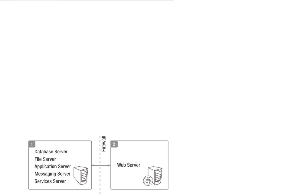
Collocated Deployment for ECE
The web server is installed on a separate VM outside the firewall.
Collocated deployment for ECE
Distributed-Server Deployment
In this configuration, each component is on a separate VM, with the web servers installed outside the firewall.
The application, messaging, services, and web servers in this configuration can be restarted without restarting
any other servers.
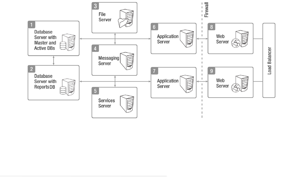
18 Enterprise Chat and Email Installation and Configuration Guide
Multiple web-application server pairs are used with a load balancer.
Complex distributed-server configuration
Planning Components for Specific Configurations and
High Availability
Planning the File Server
Use Windows Distributed File System to achieve high availability for the File Server. For details about
Windows Distributed File System, refer the Microsoft documentation: https://docs.microsoft.com/en-
us/windows/desktop/dfs/distributed-file-system
Planning the Database Server
Installing the Application on a SQL Server 2016 Cluster
ECE can be installed in a Microsoft SQL Server 2016 clustered environment using the Always On
Availability Group cluster option to achieve high availability. To install and configure the SQL Server
cluster, follow the instructions in the Microsoft SQL Server 2016 documentation.
Things to note:
Clustering feature is available only for Enterprise Edition of MSSQL.
When using Always On Availability Group clustering, you must use the Windows Authentication
mode.

Planning 19
Planning Database Server Distribution
The master and active databases are installed on the same database server. The reports database can be
installed on the same instance as the master and active databases or on a different instance.
If the reports database is to be installed on a different instance, make sure that you complete the steps
described in the “Configuring Database Servers” on page 33. You may also need to complete certain tasks
described in “Setting Up User Accounts and Permissions” on page 28.
Choosing Authentication Method for Database Connectivity
The application supports two methods of authentication for connecting to the database.
SQL Server authentication
Windows authentication
As part of the installation process, you will be asked to select the authentication method. Your selection will
depend on the security policies of your organization, and should be consistent with the authentication
method configured in SQL Server.
If you choose Windows authentication, certain additional steps must be completed before you begin
installing the application. These steps are outlined in the “Setting Up User Accounts and Permissions” on
page 28. Also refer to “Configuring Database Servers” on page 33.
Planning Messaging Servers
ECE can be installed with a cluster of messaging servers to achieve high availability. After deploying the
cluster, when the application is started, it connects to one messaging server in the cluster. If at any time that
messaging server goes down, the application connects to the next available messaging server in the cluster.
For 400 Agent deployments, the messaging server component is collocated with other components. For
400+ agent deployments, the messaging server component is always installed on a dedicated VM.
If the messaging server is on a separate VM, it can be restarted independently, without affecting application
usage.
Planning Services Servers
For high availability support, you can install two services servers. When the application starts, one server
will become primary services server and other server will be secondary services server. The ECE application
will need to be started on both the services servers, however, all the service processes (for example, retriever,
dispatcher, etc.) will run only on the primary services server. All service processes will automatically
failover to the secondary services server when the primary server is unavailable because of network
connection failure or hardware issues. You can identify the primary services server from the System Console
of the application. For details, see the Enterprise Chat and Email Administrator’s Guide to System Console.
Important: If you are planning to use Always On Availability Group clustering, you must use
Windows Authentication.
20 Enterprise Chat and Email Installation and Configuration Guide
Planning Application Servers
ECE can be installed with multiple application servers to achieve high availability. The number of
application servers in your deployment depends on the total number of concurrent agents to be supported.
If any of the application servers go down, a load balancer can help handle the failure through routing
requests to alternate application servers through the web server.
Planning Web Servers
ECE can be installed with multiple web servers. The number of web servers in a deployment depends on the
number of application servers in the deployment.
If any of the web servers go down, a load balancer can help handle the failure through routing requests to
alternate web servers. The load balancer detects web server failure and redirects requests to another web
server.
Load Balancing Considerations
A load balancer may be used in a distributed installation of the application so that requests from agents and
customers are either routed to the least-loaded web servers, or evenly distributed across all the available web
servers.
While the application is agnostic to the particular brand of load balancer used in the configuration, it does
require that the load balancer is configured to support “sticky sessions” with cookie-based persistence.
Planning for High Availability Across Geographies
To achieve high availability across geographies, ECE can be deployed across two different geographical
locations. The load balancer needs to be configured so that at any given point of time, all requests are
redirected to web servers in one location.
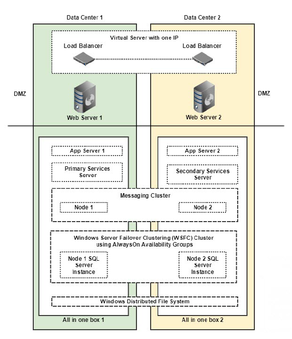
Planning 21
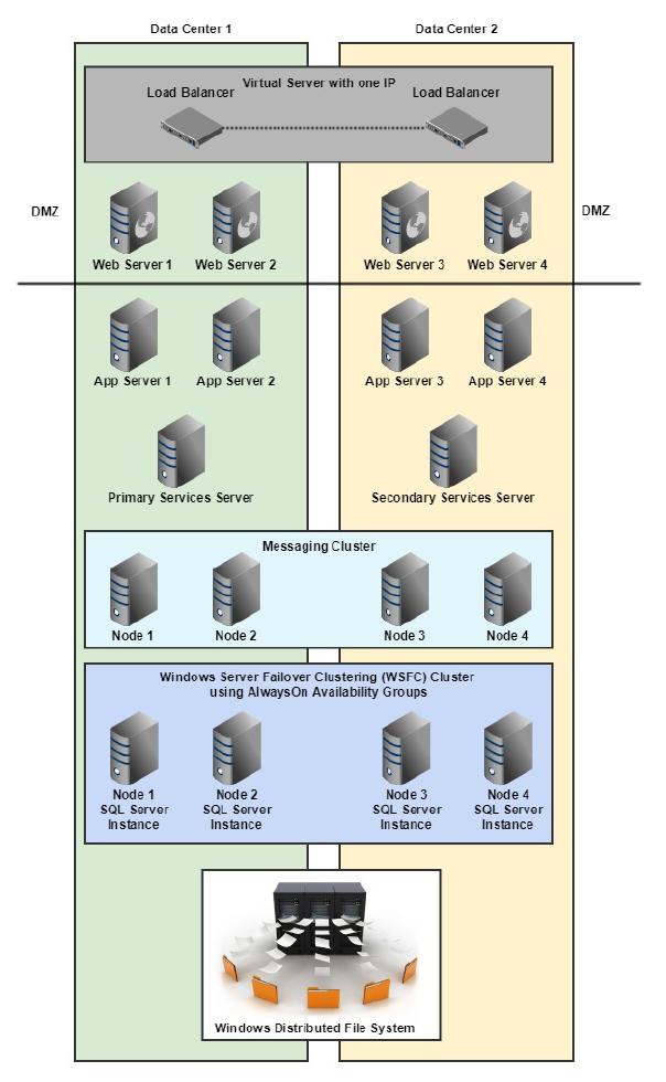
For 400 Agent Deployments
High Availability Across Geographies
In this deployment, the ECE components are installed on four VMs:
On Side A:
VM-1A: File server (Windows Distributed File System Node1), Database server (Always On
Availability Group), Messaging server, Application server, Services server
VM-2A: Web Server
On Side B:
VM-1B: File server (Windows Distributed File System Node2), Database server (Always On
Availability Group), Messaging server, Application server, Services server
VM-2B: Web Server
22 Enterprise Chat and Email Installation and Configuration Guide
For 401 to 1500 Agent Deployments
High Availability Across Geographies
In this deployment, the ECE components are installed on 30 VMs:
On Side A:
VM-1A: File server (Windows Distributed File System Node1)
VM-2A: Database server (active and master databases)
VM-3A: Database server (reports database)

Planning 23
VM-4A: Messaging server
VM-5A: Services server
VM-6A to VM-10A: Application server
VMA-11A to VM-15A: Web Server
On Side B:
VM-1B: File server (Windows Distributed File System Node 2)
VM-2B: Database server (active and master databases)
VM-3B: Database server (reports database)
VM-4B: Messaging server
VM-5B: Services server
VM-6B to VM-10B: Application server
VM-11B to VM-15B: Web Server
Installing ECE
Follow the pre-installation tasks (page 24), installation tasks (page 67), and post-installation tasks (page 83),
to install ECE. To set up SSL, follow instructions in the “SSL Configuration” on page 126.

Pre-Installation
Tasks
Disabling Loopback Adapter Configuration
Verifying Network Configuration
Configuring Port Numbers Between Components
Setting Up User Accounts and Permissions
Enabling PowerShell Remote Commands
Preparing Database Server VMs
Preparing Web Server VMs
Configuring Virus Scanners
Verifying Unified CCE Configuration

Pre-Installation Tasks 25
This chapter describes pre-installation procedures that need to be completed before beginning the installation
process. As you need to prepare the installation environment in advance, read this installation guide and the
following documents before planning and implementing the installation:
System Requirements for Enterprise Chat and Email
Enterprise Chat and Email Design Guide
Disabling Loopback Adapter Configuration
ECE cannot be installed on VMs where Microsoft Loopback Adapter is configured. Before you proceed with the
installation, disable Loopback Adapter configuration on all VMs in the deployment.
Skip this section if the VMs in the configuration do not use the Loopback Adapter.
To disable Loopback Adapter:
1. Go to Start > Control Panel.
2. In the Control Panel window, click Hardware.
3. In the Devices and Printers section, click the Device Manager link.
4. In the Device Manager window, go to Network adapters and locate Microsoft Loopback Adapter.
5. Right-click Microsoft Loopback Adapter and select Disable.
Verifying Network Configuration
These tasks must be completed in all configurations in which components are installed on more than one VM.
To verify network configuration:
1. Internet Protocol Version 6 (IPv6) must be disabled on all servers.
2. Ensure that all the VMs are either assigned static IP addresses, or in cases where the IP address is assigned
dynamically, are set to renew the same IP address upon lease expiration.
3. Ensure that all VMs other than the web servers, are in the same Active Directory domain. The web servers
do not need to be installed in the same domain as other Enterprise Chat and Email components. They can be
located anywhere, for example, in a DMZ. Note that the application cannot be installed in a workgroup.
4. Ensure that all the required inbound and outbound ports that need to be opened for the flow of requests
between the various components have been opened before you begin the installation. For details, see the
“Configuring Port Numbers Between Components” on page 26.
5. For messaging, application, and services servers the
nslookup
of the IP addresses should map to the fully
qualified domain names of the servers. Similarly, the
nslookup
of the fully qualified domain names should
map to the IP addresses of those servers.
6. Ensure that all the VMs are in the same LAN.
26 Enterprise Chat and Email Installation and Configuration Guide
7. Ensure that the system clocks of all the VMs are synchronized.
8. Ensure that all the servers, except the web server, are able to communicate with the database server at the
time of installation.
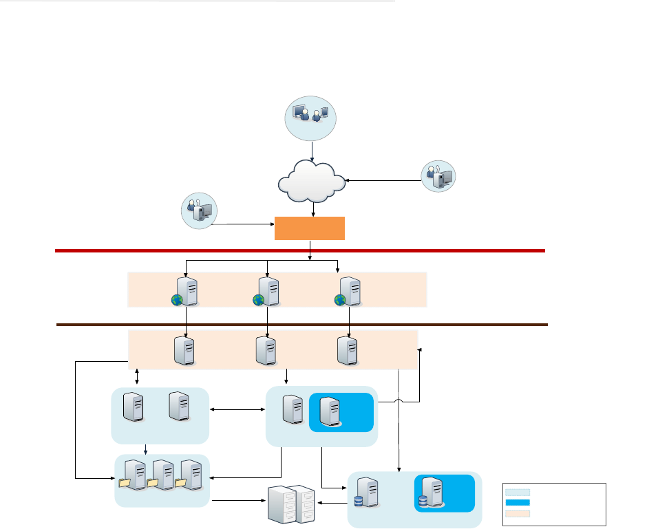
Configuring Port Numbers Between Components
This section describes the ports that need to be opened for the flow of requests between the various components.
The following diagram shows the ECE system architecture. This will help you understand the communication
between the different components.
System architecture
Database Server Cluster
File Server Cluster
Database
Server 1
Database
Server 2
Services
Server 1
Services
Server 2
Internet
Web Server 1 Web Server 2 Web Server n
Application
Server 1
Application
Server 2
Application
Server n
Local Agent
Remote Agent
Firewall 1
Firewall 2
Active
Active Standby
Horizontal Scaling
Load Balancer
Customers
SAN Based Storage
RMI
Messaging
Server 1
Messaging
Server 2

Pre-Installation Tasks 27
The following table lists the inbound and outbound ports that need to be opened for the flow of requests between
the various components. The default port numbers are listed here. Ports that can be modified at the time of
installation, or by editing property files are identified with an asterisk (*).
From Server To Server Default Destination Ports and Protocols
Agent Workstation (Internet) Web Server 80 [Protocol: HTTP]
443 [Protocol: HTTPS]
Finesse Desktop (Internet) Web Server
80 [Protocol: HTTP]
443 [Protocol: HTTPS]
Application Server Services Server
15099 (RMI Registry port) [Protocol: RMI]*
49152 – 65535 (Dynamic port range used by RMI server
objects) [Protocol: TCP]
Application Server File Server 139 or 445 [Protocol: NETBIOS - TCP]
Application Server Database Server 1433 [Protocol: TCP] *
Application Server Messaging Server 15097 [Protocol: TCP] *
Application Server Application Server
2434 [Protocol: TCP]*
6701 [Protocol: TCP]*
Application Server SMTP Server 25 [Protocol: SMTP]
Application Server SMTP or ESMTP Server (with SSL
enabled)
587 [Protocol: SMTP or ESMTP]
Application Server IMAP Server 143 [Protocol: IMAP]
Application Server IMAP Server (with SSL enabled) 993 [Protocol: IMAP]
Web Server Application Server 9001 [Protocol: TCP]*
Messaging Server File Server 139 or 445 [Protocol: NETBIOS - TCP]
Messaging Server Messaging Server 15097 [Protocol - TCP]*
Messaging Server Database Server 1433 [Protocol: TCP]*
Services Server File Server 139 or 445 [Protocol: NETBIOS - TCP]
Services Server Database Server 1433 [Protocol: TCP] *
Services Server Messaging Server 15097 [Protocol: TCP]*
Services Server Services Server 47500 [Protocol: TCP]*
Services Server SMTP or ESMTP Server 25 [Protocol: SMTP or ESMTP]
Services Server SMTP or ESMTP Server (with SSL
enabled)
587 [Protocol: SMTP or ESMTP]
Services Server POP3 Server 110 [Protocol: POP3]
Services Server POP3 Server (with SSL enabled) 995 [Protocol: POP3]
Services Server IMAP Server 143 [Protocol: IMAP]

28 Enterprise Chat and Email Installation and Configuration Guide
Setting Up User Accounts and Permissions
You will need administrator privileges on the local system to perform the installation and run the ECE services
after installing the application.
Services Server IMAP Server (with SSL enabled) 993 [Protocol: IMAP]
Active Database Server File Sever Not applicable
Reports Database Server Active Database Server
1433 [Protocol: TCP]*
135 [Port for Remote Procedure Call (RPC)]
5000-5020 (Port range for RPC ports required for
MSDTC to work across firewall)
Services Server Primary CTI Server 42027*
Services Server Secondary CTI Server 42028*
Services Server Media Routing Peripheral Gateway 38002*
Services Server Primary Administration
Workstation Database
1433 [Protocol: TCP]*
Application Server Primary Administration
Workstation Database
1433 [Protocol: TCP]*
From Server To Server Default Destination Ports and Protocols
Important: For all servers other than the ECE web server, you must use the same domain ac-
count to install the software environment and ECE. This account is also used to run the ECE
services after installing the application (page 91). ECE web server can be installed in DMZ and
can have a different domain account.

Pre-Installation Tasks 29
Setting Up Domain Account
Request your IT department to create the following accounts.
Configuring Permissions on Active Directory Server
If you are using Windows authentication database connectivity, or the configuration includes more than one
database server VMs, perform these additional tasks on the Active Directory server. You will need administrator
privileges to complete these tasks. Contact your IT administrator for assistance if required.
To configure permissions:
1. Go to Start > Run > Command to launch the command window and run the following command. This sets
the Service Principal Names (SPN) to the domain account for MSSQL service on the database servers.
setspn -A MSSQLSvc/
HOST:PORT
accountname
setspn -A MSSQLSvc/
HOST:instancename accountname
Run this command for both short and fully qualified host names for all database servers. Use the SQL
Services Account for these tasks. If you did not create one, use the Service Account (page 28). For example,
if there are two database servers,
serv234
and
serv235
, with instance name as
MSSQLSERVER
and port as
1433, with the user account
SQLSERVICEUSER
in the domain1 domain, then run the following commands.
If you are using Always On Availability Group clustering, then use the Listener Name (page 149) instead
of the server name.
Caution: The recommendation is that you do not change the password of the Service Account
and SQL Services Account after the application is installed. If you must change it, make sure
that you update the login information for all Windows and MSSQL services that use these
accounts.
Account Type Description Privileges Required
Installation Account You will use this account to install ECE. This account will also be
used in future to install ECE updates and do version upgrades.
This can be an existing user with Administrator privileges on the
server.
Administrator
Service Account This account is used to run the ECE Windows service after
installing the application.
This is an exclusive user for use by the ECE application.
Log on as Service
SQL Services Account Dedicated domain user account for configuring and running SQL
server services.
This is an optional account. You would create this account If you
do not want the Service account to be used for running SQL
services.
This is an exclusive user for use by the ECE application.
Log on as Service
Manage Services Account This account is used to start and stop the ECE service. This can be
a local user or domain user.
This can be an existing user with Manage Service privileges on
the server.
Manage Service
30 Enterprise Chat and Email Installation and Configuration Guide
setspn -A MSSQLSvc/serv234.company.na:1433 domain1\SQLSERVICEUSER
setspn -A MSSQLSvc/serv234.company.na:MSSQLSERVER domain1\SQLSERVICEUSER
setspn -A MSSQLSvc/serv234:1433 domain1\SQLSERVICEUSER
setspn -A MSSQLSvc/serv234:MSSQLSERVER domain1\SQLSERVICEUSER
setspn -A MSSQLSvc/serv235.company.na:1433 domain1\SQLSERVICEUSER
setspn -A MSSQLSvc/serv235.company.na:MSSQLSERVER domain1\SQLSERVICEUSER
setspn -A MSSQLSvc/serv235:1433 domain1\SQLSERVICEUSER
setspn -A MSSQLSvc/serv235:MSSQLSERVER domain1\SQLSERVICEUSER
2. Go to Start > Control Panel > Administrative Tools > Active Directory Users and Computers.
3. Navigate to the domain user account used for MSSQL service on the database servers. Right-click and select
Properties.
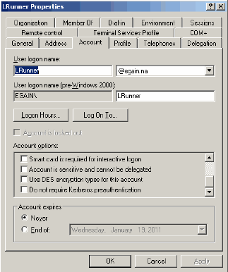
a. In the Properties window, click the Account tab. Ensure that the following options are not selected:
Account is sensitive and cannot be delegated.
Do not require Kerberos preauthentication.
Set account properties for domain user account
Pre-Installation Tasks 31
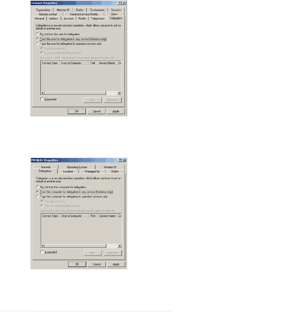
b. Click the Delegation tab. Ensure that the domain user account is trusted for delegation.
Set delegation properties for domain user account
4. In the Active Directory Users and Computers tree, navigate to the database server. Ensure that it is trusted
for delegation. Repeat this step for each database server.
Set delegation properties for database server
Setting up Distributed File System (DFS)
You need to perform this task if you are planning an HA deployment. For details, see “Appendix A: Distributed
File System Configuration” on page 142.

32 Enterprise Chat and Email Installation and Configuration Guide
Enabling PowerShell Remote Commands
Perform these tasks on the file server and reports database server.
To enable PowerShell remote commands:
1. On the file and reports database servers, ensure the Windows service Windows Remote Management
Service is running. If file server is going to be installed on NAS or DFS, then run this service on the server
from where you will install the file server and the databases.
2. On the reports database server, start
powershell
as an administrator. Run the following command
Enable-PSRemoting –Force.
This will enable the PowerShell Remoting (PSRemoting) Feature.
The following two steps are required only when the file and databases servers are going to be installed on
separate VMs.
3. On the file server, add the fully qualified domain name (FQDN) of the reports database server in the list of
trusted hosts in Windows Remote Management Service (WinRM). If file server is going to be installed on
NAS or DFS, then perform this task on the server from where you will install the file server and the
databases. Sample powershell command:
winrm s winrm/config/client
'@{TrustedHosts="ReportsDB.company.com"}
'
4. On the reports database server, add the fully qualified domain name (FQDN) of the file server in the list of
trusted hosts in Windows Remote Management Service (WinRM). If file server is going to be installed on
NAS or DFS, then add the server from where you will install the file server and the databases. Sample
powershell command:
winrm s winrm/config/client
'@{TrustedHosts="FileServer.company.com"}
Preparing Database Server VMs
Setting up for Always On Availability Group Clustering
You need to perform this task if you are planning an HA deployment. For details, see “Appendix B: SQL
Always-On Configuration” on page 145.
Installing SQL Server Management Studio (SSMS)
Install SSMS tool on the database server. Install a version that is compatible with Microsoft SQL 2016.
Refer the Microsoft documentation for details about doing this task.
Important: The High Availability feature is available only for installations using Enterprise Edi-
tion of MSSQL.
Pre-Installation Tasks 33
Verifying Microsoft SQL Server Features
Ensure that the following Microsoft SQL Server features are installed.
Instance Feature:
Database Engine Services > Full Text and Semantic Extraction for Search
Shared Features
Client Tools Connectivity
Integration Services
Client Tools SDK
SQL Client Connectivity SDK
Verifying Collation Settings
Collation settings are typically chosen while installing SQL Server 2016. Since collations specify the rules
for how strings of character data are sorted and compared, based on particular languages, a particular type of
collation is required for the application to process and present information accurately.
On the Collation settings screen, choose SQL Collations and select the following option: Dictionary order,
case-insensitive, for use with 1252 Character Set. For example, SQL_Latin1_General_CP1_C1_AS.
Although this is the recommended collation, it is not mandatory. Any ASCII, case insensitive collation can
be used. If you have already installed SQL Server 2016, consult your DBA and verify that the collation
setting chosen is ASCII (case insensitive). The application databases will be installed using the collation that
is configured for MSSQL Server.
Creating SQL User for Installing ECE Databases
Skip this section if you want to use the default
SA
user to install the ECE databases.
Create a user for installing the ECE databases and make sure the following roles are assigned to the user:
dbcreator, securityadmin, sysadmin
Assigning Permissions to Domain User
Give
sysadmin
permission to the Service Account created for running the application. If you have created
a separate SQL Service Account for the database services, then assign the permission to that user (page 28).
Configuring Database Servers
Skip this section if the reports database is on the same instance as the active and master databases. If any
database is on a different instance, consult your administrator and verify that:
All database server VMs used in the configuration are in the same domain as all the other Enterprise
Chat and Email servers.
34 Enterprise Chat and Email Installation and Configuration Guide
All databases must be either on named instances or on default instances. For example, if you are using
the default instance for the active and master databases, then use the default instance for the other
databases as well.
If you are using Windows authentication, also ensure that the steps outlined in the following section
have been completed: “Configuring Permissions on Active Directory Server” on page 29. After you
have completed these tasks, you should be able to run a linked server query on each database from a
third machine acting as a SQL client.
Enable mixed-mode authentication if you plan to use SQL authentication for database connectivity.
Configuring Microsoft DTC Settings
The Microsoft Distributed Transaction Coordinator (DTC) service, a component of Microsoft Windows, is
responsible for coordinating transactions that span multiple resources like databases. MSDTC settings must be
configured on all the database servers in a configuration.
Enable network DTC access on each database server VM.
To enable network DTC access:
1. Go to Start > Control Panel > Administrative Tools > Component Services.
2. In the console tree, browse Component Services > Computers > My Computer > Distributed
Transaction Coordinator > Local DTC.
3. Right-click Local DTC and from the menu select Properties.
4. In the Local DTC Properties window, go to the Security tab and set the following:
a. In the Security Settings section, select the following two options:
Network DTC Access
Enable XA Transactions
b. Within the Network DTC Access section, select the following four options:
Allow Remote Clients
Allow Remote Administration
Transaction Manager Communication - Allow Inbound
Transaction Manager Communication - Allow Outbound
c. In the DTC Logon Account section, set the value in the Account field to NT
Authority\NetworkService.
Click OK.
5. In the DTC Console Message box, click Yes.
6. Restart the machine.
7. Go to Start > All Programs > Administrative Tools > Services.
8. In the Services window, locate the following two services and stop them.
Distributed Transaction Coordinator
SQL Server (MSSQLSERVER) for Microsoft SQL 2016.
Pre-Installation Tasks 35
9. Now, start the two services in the following order:
a. Distributed Transaction Coordinator
b. SQL Server (MSSQLSERVER) for Microsoft SQL 2016.
10. Next, go to Start > All Programs > Control Panel.
11. Open Windows Firewall, and in the Windows Firewall window, click the Allow an app or feature through
Windows Firewall link.
12. In the Allowed Programs window, click the Change Settings link and select the Distributed Transaction
Coordinator option. Click OK.
Configuring SQL Server Integration Service on the Reports Database
The application uses the functionality provided by the SQL Server Integration Services (SSIS) to allow custom
data to be available for inclusion in data extracts. Note that custom data is not available in the reports that are
included out-of-the-box. There are three parts to completing this task:
1. Configuring permissions for user accounts. (page 35).
2. Verify Replace a process-level token privilege has been enabled for the server (page 35).
3. Finally, create a folder on the VM where all data files will be created by the application (page 36).
Configuring Permissions for User Accounts
This task is required while using Windows or SQL Authentication. Perform this task for the Install Account
(page 29) created for installing the application.
To configure permissions:
1. From the SQL Management studio, add the user account to Security > Logins. Assign the
sysadmin
role
to this user.
2. From the Computer Management Console, add this user to the Remote Management Users Group.
Verifying Server Privileges
Ensure that the “Replace a process level token” privilege is enabled for the NT Service\MSSQL Server.
To verify server privileges:
1. On the database server where the Reports database is to be installed, open the command prompt and run
gpedit.msc. The Local Group Policy Management Editor opens.
2. Navigate to Local Computer Policy > Windows Settings > Security Settings > Local Policies > User
Right Assignment > Replace a process level token.
3. From the policy list, double-click Replace a process level token.
4. In the window that opens, click the Add User or Group... button.
5. Add the
NT_SERVICE\
DB_Instance_Name service account to the privilege.
36 Enterprise Chat and Email Installation and Configuration Guide
If you are using the default instance name for the reports database, it will be
NT_SERVICE\MSSQLSERVER
.
If the reports database is installed with a named instance, add the service account
NT_SERVICE\MSSQL
DB_Instance_Name.
6. To apply your changes, restart the ECE server. If the privileges were already enabled on the service account,
a reboot is not necessary.
Creating Directory for Data Files
Create a directory on the reports server VM, for example, D:\ssis_data and ensure that the SQL Services
Account that you have created for the ECE application has write and modify permissions on this folder. If
you didn’t create a SQL Services Account, check the permissions of the Service Account created for the
ECE application (page 29).
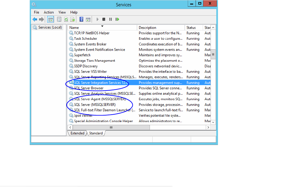
Running Services
Make sure the following services are running. These services should be started using the SQL Services Account
that you have created for the ECE application. If you didn’t create a SQL Services Account, use the Service
Account created for the ECE application (page 29).
SQL Server Service
SQL Full-text Filter Daemon Launcher Service: This service is required for text searches.
SQL Server Agent Service: This service is used by the Reports module.
SQL Server Integration Service: This service is used by the Reports module.
SQL Server Browser Service: In configurations where database servers are configured to run on named
instances, and no listener port is configured, the SQL Server Browser service needs to be running when you
run the installer. This service does not have to be running if the database servers are configured to run on the
default instance. It is also not required if the database servers are configured to run on named instances, and
specific, static listener ports are configured for the named instances.
Windows Remote Management Service: This service is required only on the reports database.
Distributed Transaction Coordinator Service
To start the services:
1. Go to Start > Programs > Administrative Tools > Services.
2. For all the services, do the following:
a. Select a service and right-click to open the menu.
b. From the menu select Properties.
c. In the Properties window, go to Log On tab and ensure the service is started using the correct domain
account. These services should be started using the SQL Services Account that you have created for
the ECE application. If you didn’t create a SQL Services Account, use the Service Account created
for the ECE application (page 29).
Pre-Installation Tasks 37
3. Ensure that the SQL Server Service, SQL Full-text Filter Daemon Launcher, SQL Server Agent, Windows
Remote Management Service, SQL Server Integration Service, and SQL Server Browser services are
running.
4. If they are not running, select the services one by one, and click Start to start the service.
Start the SQL services
Preparing Web Server VMs
Configuring Roles and Features
This task is performed automatically by the installation program. You can choose to do it manually before
running the installation program.
Ensure that the following Roles and Features are installed for IIS.
.NET Extensibility 4.6
ASP
CGI
ISAPI Extensions
ISAPI Filters
Server Side Includes
Static Content
Static Content Compression
Dynamic Content Compression
38 Enterprise Chat and Email Installation and Configuration Guide
Directory Browsing
Default Document
Ensure that the following feature is not installed for IIS.
WebDAV Publishing
To install the roles and features:
1. Go to Start > Control Panel > Administrative Tools > Server Manager.
2. In the Server Manager window, go to IIS section. In the IIS section, locate the Roles and Features section.
3. In the Role and Features section, check if the required role services are installed.
4. If any of the roles and features are not installed, from the Tasks menu, click the Add Roles and Features
button and run through the wizard to install the missing services. In the Server Roles section, expand the
Web Server (IIS) > Web Server list, and select the following:
In the Common HTTP Features list, select:
Default Document
Directory Browsing
Static Content
In the Performance list, select:
Static Content Compression
Dynamic Content Compression
In the Application Development list, select:
.NET Extensibility 4.6
ASP
CGI
ISAPI Extensions
ISAPI Filters
Server Side Includes
5. In the Role and Features section, check if the WebDAV Publishing feature is installed. If the feature is
installed, you need to uninstall it. From the Tasks menu, click the Remove Roles and Features button and
run through the wizard to uninstall the feature.
Installing Modules on Web Servers
This task is performed automatically by the installation program. You can choose to do it manually before
running the installation program.
The Application Request Routing and URL Rewrite modules are required to be installed on the web server.
Download and install the modules from the Microsoft website. The installation programs are also available
in the
Environment\Web Server
folder of the installation package. After installing the module, restart
IIS.

Pre-Installation Tasks 39
Configuring Permissions on IIS Config Folder
Ensure that the user account you are going to use for installing the application (page 29) has read
permissions on the following folder:
%systemroot%\system32\inetsrv\config
Running the World Wide Web Publishing Service
On all VMs where the web server is to be installed, ensure that the World Wide Web Publishing Service is
running.
Configuring Virus Scanners
Configuring SMTP Port in Virus Scanners
Ensure that the virus scanner is configured to allow emails to be sent through the SMTP port (Port 25). In a
distributed installation, configure this setting on the services server and all application servers.
Configuring Virus Scanning Exclusions
To ensure that virus and malware scanning software on the servers do not interfere with the performance of the
application, certain folders and files must be excluded from continuous virus scanning. Since no files are
downloaded to these locations from the internet, it is safe to exclude these directories from virus scanning.
On the File, Messaging, Services, Application, and Web Servers
Follow the instructions for your virus scanning software to exclude the following folders and file types. On a
Windows 2016 Server machine, these exclusions must also be setup for Windows Defender.
Item Exclude Subfolders? Execute permissions
Windows File Protection -- Read, Write
All files of type LOG -- Read, Write
Pagefile.sys No Read, Write
Drive:\ECE_Home\ Yes [other than Storage] Read, Write
*.rll No Read, Write

40 Enterprise Chat and Email Installation and Configuration Guide
On the Database Servers
Follow the instructions for your virus scanning software to exclude the following folders and file types. On a
Windows 2016 Server machine, these exclusions must also be setup for the Windows Defender.
Verifying Unified CCE Configuration
Verify that Unified CCE and Microsoft Active Directory (AD) have been installed on separate servers. Refer
to Unified CCE documentation for more details.
Verify that the Unified CCE and AD servers are in the same network as the ECE servers and are accessible
from the ECE servers.
Verify that the items to be used in ECE are configured in Unified CCE. These include:
Peripherals
Application Instance
Media Classes
Media Routing Domains (MRDs)
Network Voice Response Units (Network VRUs)
Call Type
Media Routing Peripheral Gateways (MR PGs)
Script Selector
Agent Peripheral Gateway (Agent PG)
Network Trunk Groups
Network Trunks
Item Exclude Subfolders? Permissions
Windows File Protection -- Read, Write
All files of type LOG, if any -- Read, Write
Pagefile.sys No Read, Write
Drive:\Path_to_datafile
Yes Read, Write
Drive:\Path_to_SSIS_d
atafile
Yes Read, Write
*.mdf No Read, Write
*.ldf No Read, Write
*.ndf No Read, Write
*.dat No Read, Write
*.rll No Read, Write

Preparing Unified
CCE for the
Integration
Relationship Between Objects in Unified CCE and ECE
Designing Your Installation
Installing Unified CCE
Setting up Agent Desktops for Voice Call Routing
Planning Unified CCE Configuration
Configuring Unified CCE
Adding MR PIM for ECE
Adding Agent PG PIM for ECE
Adding CTI for ECE
Configuring the System for Multiple Agent PGs
Configuring Finesse

Preparing Unified CCE for the Integration 43
This chapter provides an overview of the process of setting up an integrated ECE–Unified CCE system. It
includes a note about the relationship between objects in the two systems.
Relationship Between Objects in Unified CCE and
ECE
This section provides a brief introduction to the relationship or “mapping” between objects that are used in both
Unified CCE and ECE.
The following table provides a high-level view of the relationship between various objects.
Typically, the mapping between these objects is set up by using the import feature available in the ECE
Administration Console. Once imported, these objects can be viewed from the department level nodes for these
objects (Queues, Users, and User Groups) in the Administration Console in ECE.
Designing Your Installation
See the Enterprise Chat and Email Design Guide (for Unified CCE) to evaluate available deployment models
and design the installation.
Installing Unified CCE
Ensure that Unified CCE is installed and available for use. Verify that the following items are installed:
Unified CCE Instance
Call Router Side A
Call Router Side B
Logger Side A
Logger Side B
Unified CCE object Mapped in ECE to Notes
Agent
Supervisor
Administrator
User An agent belongs to a peripheral.
A peripheral belongs to an agent
peripheral gateway (PG).
Skill group User group
A skill group belongs to a peripheral.
A peripheral belongs to an agent PG.
Media routing domain
(MRD)
Queue (Only selected skill groups and PQs of
the MRD)
Multiple queues can belong to a single
MRD.
Script selector Queue A script selector can belong to only
one queue.

44 Enterprise Chat and Email Installation and Configuration Guide
Primary Admin Workstation
Secondary Admin Workstation
Historic Data Server
Network Interface Controllers (NIC) (Only required for Pre-routing)
Agent Peripheral Gateway (Agent PG)
Media Routing Peripheral Gateway (MR PG)
CTI Server
CUIC Database
Java Telephony Application Programming Interface (JTAPI)
Cisco Finesse
See the following documents for help with installing and configuring the system:
Getting Started with Cisco Unified Contact Center Enterprise
Cisco Unified Contact Center Enterprise Installation Guide
Setting up Agent Desktops for Voice Call Routing
A phone account must be configured for agents to be able to log in to Finesse.
Planning Unified CCE Configuration
To integrate Unified CCE with ECE, multiple objects have to be configured in Unified CCE. The specific
objects that have to be configured will depend on the activities (email, chat etc.) supported by the integrated
installation. This section describes the objects required for each activity type—inbound email, outbound email,
chat, callback, and delayed callback.
For deployments migrating from earlier Unified CCE versions with ECE, customers can choose to create new
Media Routing Domains and Media Classes for ECE or rename the existing ECE MRDs to match the ECE
MRDs detailed in this guide, using the Media Routing Domain and Media Class List tools.
The following objects must be configured in the order in which they are presented here. For configuration
details, refer to the following section: “Configuring Unified CCE” on page 45.
1. Application instance (page 45)
2. Media classes (page 46)
3. Media routing domains (MRD) (page 47)
4. Network voice response unit (Network VRU) (Not required for outbound email activities) (page 48)
5. Network voice response unit script (Network VRU script) (Not required for inbound email and outbound
email activities) (page 49)
6. Call type (page 49)

Preparing Unified CCE for the Integration 45
7. Media routing peripheral gateway (MR PG) (page 49)
8. Agent desk settings (page 51)
9. Agent peripheral gateway (Agent PG) (page 51)
10. Application path (page 52)
11. Agents (page 53)
12. Skill groups (page 54)
13. Script selector (page 55)
14. Scripts (Not required for outbound email activities) (page 56)
15. Device target (Not required for inbound email, outbound email, and chat activities) (page 58)
16. Expanded Call Context (ECC) variables (page 59)
17. Cisco Finesse (page 66)
Configuring Unified CCE
This section describes the process of configuring Unified CCE objects that are required for the integration with
ECE. These objects must be configured in the order in which they are presented here. For details of these objects
refer to the Online Help and printed documentation for Unified CCE.
Configuring Application Instance
Application instances are configured for each installation of a multi-media feature in the configuration.
Configure a single application instance for integrating with ECE. This application instance is used for inbound
email, outbound email, chat, callback, and delayed callback activities.
To configure an application instance:
1. Go to Start > All Programs > Cisco Unified CCE Tools > Administration Tools > Configuration
Manager. You can also access the Configuration Manager using the Unified CCE Administration Tools
desktop shortcut.
2. In the Configuration Manager window, browse to Tools > List Tools > Application Instance List.
3. Double-click Application Instance List.
4. In the Application Instance List window, in the Select filter data section, click Retrieve. Then, in the
Application Instance section, click Add.
A new entry is created in the Application Instance section and the Attributes tab becomes editable.
5. On the Attributes tab, provide the following details:
Name: Provide a name for the application instance.
Application key: Provide a unique value for the key. Please note that ECE uses the application instance
name and not the application key to connect to Unified CCE.
46 Enterprise Chat and Email Installation and Configuration Guide
Application type: Set it to <Other>.
Permission level: Set it to Read only.
Click Save.
About Media Classes
A media class defines the type of requests you want to set up for routing on Unified CCE. Configure a media
class for each media supported by the ECE deployment. A media class is required for creating MRDs. It helps
categorize the MRDs based on media type (email, for example).
Create the following media classes:
An email media class for inbound emails.
An email media class for outbound emails.
A chat media class for chat.
Callback and Delayed callback use the existing
Cisco_Voice
media class, which is already created by the
system.
Once a media-class for a particular media is created, all other objects required for that media class must also be
configured.
For more details about Media Classes, see the Scripting and Media Routing Guide for Cisco Unified
ICM/Contact Center Enterprise available at https://www.cisco.com/c/en/us/support/customer-
collaboration/unified-contact-center-enterprise/products-user-guide-list.html
Configuring Media Classes
To configure a media class:
1. Open the Configuration Manager.
2. In the Configuration Manager window, browse to Tools > List Tools > Media Class List.
3. Double-click Media Class List.
4. In the Media Class List window, in the Select filter data section, click Retrieve. Then, in the Media Class
section, click Add.
A new entry is created in the Media Class section and the Attributes tab becomes editable.
5. On the Attributes tab, provide the following details:
Name: Provide a name for the media class. If the media class is meant to be used in ECE, use one of
the following names. Note that the names of media classes are case sensitive. Make sure that you use
the exact names as provided here.
ECE_Email (for inbound email)
ECE_Outbound (for outbound email)
ECE_Chat (for chat)
Media classes are set in the ECE partition level setting - Media Classes - as ECE_Email,
ECE_Outbound, and ECE_Chat. If you use names other than these, you must change them in the
Preparing Unified CCE for the Integration 47
partition level setting from the ECE Administration Console. Note that the names of media classes are
case sensitive.
In the Task section, set the following.
Life: Set the value to 300 seconds.
Start timeout: Set the value to 30 seconds.
Max Duration: Set the value to 28800 seconds.
6. Click Save.
Configuring Media Routing Domains (MRDs)
An MRD is a collection of skill groups and services that are associated with a common communication medium.
Unified CCE uses an MRD to route tasks to agents who are associated with a skill group and a particular
medium. A media routing domain is created in Unified CCE for mapping to queues in ECE.
Create the following media routing domains:
For inbound email media class, create only one email media routing domain.
For outbound email media class, create only one email media routing domain.
For chat, create only one chat media routing domain.
For callback and delayed callback, use the existing voice media routing domain (
Cisco_Voice
) created by
the system.
For more details about Media Routing Domains, see the Scripting and Media Routing Guide for Cisco Unified
ICM/Contact Center Enterprise available at https://www.cisco.com/c/en/us/support/customer-
collaboration/unified-contact-center-enterprise/products-user-guide-list.html
To configure a media routing domain:
1. Open the Configuration Manager.
2. In the Configuration Manager window, browse to Tools > List Tools > Media Routing Domain List.
3. Double-click Media Routing Domain List.
4. In the Media Routing Domain List window, in the Select filter data section, click Retrieve. Then, in the
Media Routing Domain section, click Add.
A new entry is created and the Attributes tab becomes editable.
5. On the Attributes tab, provide the following details:
Name: Provide a name for the media routing domain.
Media class: Select a media class created for ECE (page 46). Make sure that you select the correct
media class for the MRD. For example:
For inbound email MRD, select the ECE_Email media class.
For outbound email MRD, the ECE_Outbound media class.
For chat MRD, select the ECE_Chat media class.

48 Enterprise Chat and Email Installation and Configuration Guide
Interruptible: You must select this option while creating MRDs for inbound and outbound emails.
In the Calls in Queue section, set the following:
Max: Defines the maximum number of activities to be queued for the MRD. Refer the Solution Design
Guide for Cisco Unified Contact Center Enterprise for guidelines for maximum limits.
If agents are on holiday or the business is not available for elongated times to cater to emails due to Bank
holiday, long weekends or other reasons, emails go into the Default Exception Queue as no agent was
available in Unified CCE to cater to emails. This results in a lot of abandoned tasks in reporting.
Based on the business needs, it is recommended to update the Max time in queue value of inbound email
MRD. It is recommended to put the value as Total anticipated wait time/4. Total anticipated wait time can
be defined as the duration when the business is not able to respond to emails, for example, if it is a long
weekend, then 3 days no agent is available + some buffer time of 2 hours before agents can start responding,
so the value should be:
3 Days (3 * 24 * 60 * 60) = 259200 sec
2 Hours (2 * 60 * 60) = 7200 sec
Recommended value for Max time in queue = (259200 + 7200)/4 = 66600 sec
6. Click Save.
Configuring Network VRU
A Network VRU is required for supporting incoming activities to Unified CCE. Note that this Network VRU
configuration has no relationship with any physical Network VRU existing in your environment.
Configure a single Network VRU for ECE. This network VRU is used by inbound email, chat, callback, and
delayed callback activities. It is not required for outbound email activities.
To configure a Network VRU:
1. Open the Configuration Manager.
2. In the Configuration Manager window, browse to Tools > Explorer Tools > Network VRU Explorer.
3. Double-click Network VRU Explorer.
4. In the Network VRU window, in the Select filter data section, click Retrieve. Then, click [1] Add Network
VRU.
A new entry is created and a new set of tabs appear.
5. On the Network VRU tab, provide the following details:
Name: Provide a name for the network VRU.
Type: Set it to Type 2.
6. Click Save.
Important: MRDs for emails cannot be non-interruptible.
Preparing Unified CCE for the Integration 49
Configuring Network VRU Scripts
Configure Network VRU scripts if you want to display dynamic content to chat customers (for example, wait
time, activity ID, etc) while chat requests are being processed by the system. This is an optional feature. The
dynamic messages are configured in ECE (See page 141 for details). The name of the Network VRU script that
is configured here is used while configuring the dynamic messages.
Network VRU scripts need to be configured only for chat, callback, and delayed callback activities.
To configure a Network VRU script:
1. Open the Configuration Manager.
2. In the Configuration Manager window, browse to Tools > List Tools > Network VRU Script List.
3. In the Network VRU Script List window, provide a Name and VRU script name and select the Network
VRU created for ECE (page 48).
4. Click the Save button.
Configuring Call Types
A call type is required to categorize a dialed number (for voice) or a script selector (for email). Call types are
used in configuring routing scripts.
Individual call types are required for the following activities: inbound email, outbound email, chat, callback, and
delayed callback activities. Make sure you complete these steps for each type of activity.
To configure a call type:
1. Open the Configuration Manager.
2. In the Configuration Manager window, browse to Tools > List Tools > Call Type List.
3. Double-click Call Type List.
4. In the Call Type List window, in the Select filter data section, click Retrieve. Then, in the Call Type section,
click Add.
A new entry is created and the Attributes tab becomes editable.
5. On the Attributes tab, in the Name field, provide a name for the call type. Click Save.
Configuring Media Routing Peripheral Gateways (MR PGs)
An MR PG handles new activity routing requests initiated by ECE, over the connection established by the
embedded MR PIM (side A or side B). The MR PG provides routing instructions to ECE, while the Agent PG is
used to report agent state and status to Unified CCE. Also note that agents are not configured on MR PG. They
are always configured on the Agent PG.
Configure a single MR PG for ECE. This MR PG is used for inbound email, outbound email, chat, callback, and
delayed callback activities.
The MR PG configuration involves three steps:
Configuring MR PG using the Configuration Manager: The details are described in this section.

50 Enterprise Chat and Email Installation and Configuration Guide
Installing MR PG: For details, see the Unified CCE Installation Guide.
Creating MR PIM for the installed MR PG: You need to create a single MR PIM for ECE. For details, see
the Unified CCE Installation Guide. While creating the MR PIM, you are asked to provide the Application
Connection Port number. As a best practice, use a port number that is greater than 2000. This port number is
required while configuring the External Agent Assignment Server (EAAS) (page 140).
To configure a media routing peripheral gateway (MR PG):
1. Open the Configuration Manager.
2. In the Configuration Manager window, browse to Tools > Explorer Tools > PG Explorer.
3. Double-click PG Explorer.
4. In the PG Explorer window, in the Select filter data section, click Retrieve. Then, click [1] Add PG.
5. On the Logical Controller tab, provide the following details:
Name: Provide a name for the media routing peripheral gateway.
Client type: Set it to MediaRouting.
6. Click [2] Add Peripheral.
A new set of tabs appear.
7. On the Peripheral tab, provide the following details:
Client type: Select MediaRouting.
Default desk settings: Select None.
Enable Post Routing: Select the option.
8. On the Advanced tab, in the Network VRU field, from the dropdown list, select the Network VRU
configured for ECE (page 48).
9. On the Routing client tab, provide the following details:
Name: Provide a name for the routing client.
Default media routing domain: From the dropdown list, select None.
Default call type: From the dropdown list, select None.
Client type: Set it to MediaRouting.
Click Save.
10. On the Default route tab, in the Media Routing Domain field, ensure that the Route: field is set to None.
11. Click Save. Note down the Logical controller ID generated in the Logical Controller tab. It is needed while
configuring MR PIM.
Important: Now install the MR PG and configure the MR PIM. For more information, see the
Unified CCE Installation Guide.
Preparing Unified CCE for the Integration 51
Configuring Agent Desk Settings
Agent desk settings are a common set of properties for a group of agents working on voice call requests. This is
required for configuring an Agent PG. At least one Agent Desk Setting must be configured for ECE.
To configure agent desk settings:
1. Open the Configuration Manager.
2. In the Configuration Manager window, browse to Tools > List Tools > Agent Desk Settings List.
3. Double-click Agent Desk Settings List.
4. In the Agent Desk Settings List window, in the Select filter data section, click Retrieve. Then, in the Agent
Desk Settings section, click Add.
A new entry is created and the Attributes tab becomes editable.
5. On the Attributes tab, in the Name field, provide a name for the agent desk setting group. Click Save.
Configuring Agent Peripheral Gateway (Agent PG)
An Agent PG is required for creating one or more peripherals that manage agent distribution within Unified
CCE. Configure an Agent PG using the Configuration Manager and then install it on the appropriate machine.
These Agent PGs are used for inbound email, outbound email, chat, callback, and delayed callback activities.
Note that you can also use an existing Agent PG if it is of the type Call Manger/Soft ACD.
To configure an agent peripheral gateway:
1. Open the Configuration Manager.
2. In the Configuration Manager window, browse to Tools > Explorer Tools > PG Explorer.
3. Double-click PG Explorer.
4. In the PG Explorer window, in the Select filter data section, click Retrieve. Then, click [1] Add PG.
5. On the Logical Controller tab, provide the following details:
Name: Provide a name for the agent peripheral gateway.
Client type: Set it to CUCM or Generic.
Primary CTI address: Provide the address of the primary CTI server in the format
IP_Address:Port_Number. You can either provide the IP address, or the host name. You do not need to
configure this option if you are using Unified CCE 12.0(1).
Secondary CTI address: Provide the address of the secondary CTI server in the format
IP_Address:Port_Number. You can either provide the IP address, or the host name. The secondary CTI
address is needed only if the Unified CCE system is duplexed. You do not need to configure this option
if you are using Unified CCE 12.0(1).
6. Click [2] Add Peripheral.
A new set of tabs appear.
7. On the Peripheral tab, do the following:
52 Enterprise Chat and Email Installation and Configuration Guide
Default desk settings: From the dropdown list, select the agent desk settings configured for ECE
(page 51).
Enable post routing: Select the option.
8. On the Routing client tab, in the Name field, provide a name for the routing client.
9. On the Agent Distribution tab, do the following:
a. Click New.
b. Select the Enable agent reporting option.
c. Select the Agent event detail option.
d. In the Currently Selected Site section, set the following:
Administration & Data Server site name: Provide the host name of the machine where
distributor is installed.
Agent Real time data: Select the option.
10. Click Save.
Configuring Application Path
An application path is required to open a communication channel with a CTI server associated with an Agent
PG. It is used for agent and task status reporting. For each Agent PG, create an application path that ECE will
use to connect to the Agent PG. You must create a new application path for ECE.
Create a single application path and add all the MRD-peripheral combinations for the Agent PG to the
application path member list. The application path is used for inbound email, outbound email, chat, callback, and
delayed callback activities.
Access to the application object filter is restricted. Log in as a super user to enable or disable the application
object filter. For details about the super user password, see the Configuration Guide for Cisco Unified
ICM/Contact Center Enterprise available at
https://www.cisco.com/en/US/products/sw/custcosw/ps1844/products_installation_and_configuration_guides_lis
t.html
To configure an application path:
1. Open the Configuration Manager.
2. In the Configuration Manager window, from the menu, go to Options > Application Object Filter.
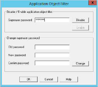
Preparing Unified CCE for the Integration 53
3. In the Application Object Filter window, in the Disable / Enable application object filter section, in the
Superuser password field, provide the password of the superuser and click the Disable button. Click OK.
Provide the password of the superuser
4. In the Configuration Manager window, browse to Tools > List Tools > Application Path List.
5. Double-click Application Path List.
6. In the Application Path List window, in the Select filter data section, in the Application Instance field select
the application instance configured for ECE (page 45). Click Retrieve.
7. In the Application Path section, click Add.
A new entry is created and the Attributes tab becomes editable.
8. On the Attributes tab, provide the following details:
Application Instance: From the dropdown list, select the application instance configured for ECE
(page 45).
Peripheral Gateway: From the dropdown list, select an agent peripheral gateway configured for ECE
(page 51).
Name: This field is auto-populated.
In the Application Path Members section, click the Add button and set the following:
Peripheral: From the dropdown list, select the agent peripheral configured for ECE (page 51).
Media routing domain: From the dropdown list, select an MRD configured for ECE (page 47).
Add all the MRD-peripheral combinations for the Agent PG to the application path member list.
Click Save.
9. In the Configuration Manager window, go to Options > Application Object Filter.
10. In the Application Object Filter window, in the Disable / Enable application object filter section, click the
Enable button. Click OK.
Configuring Agents
An agent is created in Unified CCE for mapping to users in ECE. Create all agents for whom routing or reporting
is done in Unified CCE. If you plan to use Precision Routing, you need to assign attributes to agents. For details,
see “Assigning Attributes to Agents” on page 61.

54 Enterprise Chat and Email Installation and Configuration Guide
Create agents for handling inbound email, outbound email, chat, callback, and delayed callback activities.
To configure an agent:
1. Open the Configuration Manager.
2. In the Configuration Manager window, browse to Tools > Explorer Tools > Agent Explorer.
3. Double-click Agent Explorer.
4. In the Agent Explorer window, in the Select filter data section, in the Peripheral field select an agent
peripheral. Click Retrieve.
5. Click the [1]Add Agent button.
A new entry is created and a new set of tabs appear.
6. On the Agent tab, provide the following details:
Enable logins: Select the option.
Enable Single sign-on (SSO): Select this option if you want to use single sign-on for the agent.
Password fields are disabled if you select this option.
First name: Provide the first name.
Last name: Provide the last name.
Login name: Provide the login name for the agent. For callback and delayed callback agents, the login
name should match the User ID provided while configuring End users from the Cisco Unified
Communication Manager Administration user interface.
Password: Provide the password for the agent. Make sure the password does not contain the following
characters: = (equal to) and ; (semicolon) as ECE does not allow the users to login if these characters
are present in the passwords. Password fields are disabled if single sign-on option is selected for the
agent.
Enterprise name: This field is auto-populated.
7. Click Save.
Configuring Skill Groups
A skill group is created in Unified CCE for mapping to user groups in ECE. The skill group members (agents)
are administered and managed in Unified CCE. A skill group (with associated skill group members) is used in
scripts to facilitate routing through Unified CCE to the skill group. This is used for inbound email, outbound
email, chat, callback, and delayed callback activities.
To configure a skill group:
1. Open the Configuration Manager.
2. In the Configuration Manager window, browse to Tools > Explorer Tools > Skill Group Explorer.
3. Double-click Skill Group Explorer.
Important: If you are planning to have multiple departments in ECE, then ensure that you create
department specific skill groups.

Preparing Unified CCE for the Integration 55
4. In the Skill Group Explorer window, in the Select filter data section, select an agent peripheral. Click
Retrieve.
5. Click the [1]Add Skill group button.
A new entry is created and a new set of tabs appear.
6. On the Skill Group tab, provide the following details:
Media routing domain: From the dropdown list, select an MRD configured for ECE (page 47).
Peripheral number: Provide a unique peripheral number.
Peripheral name: Provide a name for the skill group.
Name: This field is auto-populated.
ICM picks the agent: Select the option.
7. On the Skill Group Members tab, do the following:
a. Click the Add button.
b. From the Add Skill Group Member window, select the agents to be added in the skill group. Click OK.
8. Click the Add Route button.
A new tab appears.
9. On the Route tab, in the Name field provide the name for the route and click Save.
Configuring Dialed Number/Script Selectors
A script selector is a keyword that identifies the routing script for an activity request from ECE to Unified CCE.
Script selectors are used in routing scripts as part of the Dialed Number node.
Individual script selectors are required for the following activities: inbound email, outbound email, chat,
callback, and delayed callback activities. Make sure to complete these steps for each type of activity.
To configure a script selector:
1. Open the Configuration Manager.
2. In the Configuration Manager window, browse to Tools > List Tools > Dialed Number/ Script Selector
List.
3. Double-click Dialed Number/ Script Selector List.
4. In the Dialed Number/ Script Selector List window, in the Select filter data section, in the Routing client
field select the routing client configured for MR PG (page 50). Click Retrieve.
5. In the Dialed Number/ Script Selector section, click Add.
A new entry is created and the Attributes tab becomes editable.
6. On the Attributes tab, provide the following details:
Important: If you are planning to have multiple departments in ECE, then ensure that you create
department specific script selectors.
56 Enterprise Chat and Email Installation and Configuration Guide
Routing client: From the dropdown list, select the routing client configured for the MR PG in step 9 in
“Configuring Media Routing Peripheral Gateways (MR PGs)” on page 49.
Media routing domain: From the dropdown list, select the MRD configured for ECE (page 47).
Name: Provide a name for the script selector.
7. Click the Dialed Number Mapping tab. Click Add.
8. On the Dialed Number Map Entry window, associate the script selector with a call type.
9. Click OK to save the entry. Then click Save to save the script selector configuration.
Creating Scripts
A routing script determines the path and target object for an activity routed from ECE to Unified CCE. Individual
routing scripts are required for the following activities: inbound email, chat, callback, and delayed callback
activities. Make sure to complete these steps for all these activities. You do not need routing scripts for outbound
email activities.
Universal queues and Precision queues can be used in the scripts configured for ECE. Precision queues cannot be
used if you are using Unified CCE 11.0(1) version.
For details about creating universal queues, see the Scripting and Media Routing Guide for Unified CCE
available at https://www.cisco.com/en/US/products/sw/custcosw/ps1844/products_user_guide_list.html. Make
sure to use the guide that matches the version of the product that you are using. To find the right version, refer
to the Cisco Unified Contact Center Enterprise (Unified CCE) Software Compatibility Guide available at
https://www.cisco.com/en/US/products/sw/custcosw/ps1844/products_device_support_tables_list.html.
For details about configuring Precision Routing, see “Configuring Precision Routing” on page 60.
To use the Personalized Activity Assignment feature available in ECE, you need to create some addition objects
(Enterprise Skill Groups and Enterprise Routes) and the scripts need to be configured a certain way. For details,
see “Creating Objects in Unified CCE for Personalized Activity Assignment” on page 61.
The following procedure shows how to set up a particular script. To find out more about setting up different
types of scripts to meet your routing requirements, see the Scripting and Media Routing Guide for Unified CCE.
To create a script:
1. Go to Start > All Programs > Cisco Unified CCE Tools > Administration Tools > Script Editor. You
can also access the Script Editor using the Unified CCE Administration Tools desktop shortcut.
2. In the Script Editor window, click the New button.
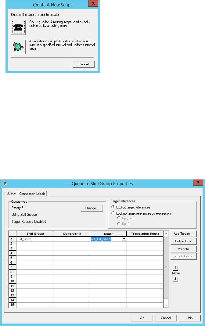
Preparing Unified CCE for the Integration 57
3. In the Create A New Script window, select the Routing script option.
Select the Routing Script option
A new script editor opens. The Start node is added by default to the script editor.
4. In the Script Editor window, go to View > Palette.
The Palette window opens.
5. In the Palette window, on the Queue tab, click the Queue button, and click in the script editor. The Queue to
Skill Group node is added to the script editor.
6. Double-click the Queue to Skill Group node to open the Queue to Skill Group Properties window.
7. In the Queue to Skill Group Properties window, on the Queue tab, in the Skill Group column, select a skill
group.
Select a skill group
8. Next, in the Palette window, on the General tab, click the Line Connector button and configure the success
and error paths for each node. This creates the routing path of the script.
9. Click the Validate Script button to check if the script is created properly. If there are any errors, fix them.
10. Click the Save button to save the script.
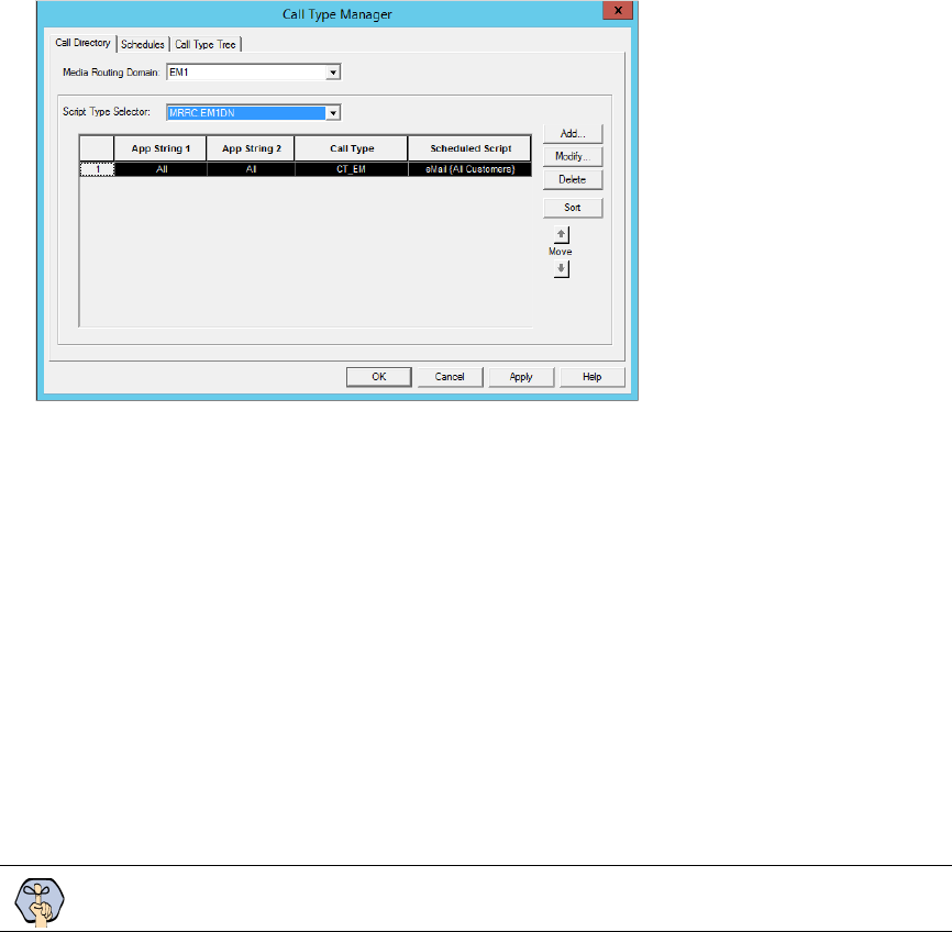
58 Enterprise Chat and Email Installation and Configuration Guide
To display dynamic content (page 141) to chat customers (for example, wait time, activity ID, etc.) while chat
requests are being processed by the system, ensure that the Run External Script node is configured.
11. In the ICM script, add the Run External Script node and select the Network VRU script created on page 49.
After creating a script, map the script to a call type, MRD, and script selector. Also set the run schedule for the
script.
12. In the Script Editor window, go to Script > Call Type Manager.
13. In the Call Type Manager window, in the Call Directory tab, do the following:
a. In the Media Routing Domain field, from the dropdown list, select the MRD configured for ECE
(page 47).
b. In the Script Type Selector field, from the dropdown list, select the script selector created for the MRD
(page 55).
c. Next, click the Add button. The Add Call Type Selector Entry window appears. In the Call type field,
select the call type configured for ECE (page 49). Click OK.
Map the script to a call type, MRD, and script selector
14. In the Call Type Manager window, in the Schedule tab, do the following:
a. In the Call type field, from the dropdown list, select the same call type you selected in Step 13.
b. Next, click the Add button. In the Add Call Type Schedule window that appears, do the following:
i. In the Script tab, select the script configured for ECE (page 56).
ii. In the Period tab, set a schedule for the script.
iii. Click OK.
15. Click OK to close the Call Type Manager window.
Configuring Device Targets
Important: Skip this section if you are using Agent targeting rules.

Preparing Unified CCE for the Integration 59
Individual device targets are required for routing voice calls for callback and delayed callback activities.
Complete these steps for all these activities. Device targets are not needed for inbound email, outbound email,
and chat activities.
To configure a device target:
1. Open the Configuration Manager.
2. In the Configuration Manager window, browse to Tools > Explorer Tools > Device Target Explorer.
3. Double-click Device Target Explorer.
4. In the Device Target Explorer window, click Add Device Target.
5. Provide the name and global address, which is the host name of the Unified CCE server followed by the
agent extension, in the following format:
Unified_CCE_Server Agent_Extension
6. Provide the configuration parameter in the following format. The string before the agent extension must be
exactly as specified:
/devtype CiscoPhone /dn
Agent_Extension
7. Click the Add Label button.
The Label tab appears.
8. On the Label tab, set the following:
Routing client: From the dropdown list, select the MR PG configured for ECE (page 49).
Label: Provide the name of the label. The label name must be the Agent_Extension.
9. Click Save.
Configuring Expanded Call Context (ECC) Variables
ECC variables are used in Unified CCE scripts to facilitate and influence routing. ECC variables have a
maximum length of 256 characters. Both Scalar and Array ECC variables are supported.
ECC variables are required for inbound email, outbound email, chat, callback, and delayed callback activities.
Create the following ECC variables:
For chat, inbound and outbound email activities:
user.ece.activity.id
For callback and delayed callback activities:
user.ece.activity.id
,
user.ece.customer.name
To configure an ECC variable:
1. Open the Configuration Manager.
2. In the Configuration Manager window, browse to Tools > Miscellaneous Tools > System Information.
3. In the System Information window, in the General section, select the Expanded call context enabled
option. Click Save.
Important: The two ECC variables (user.ece.activity.id and user.ece.customer.name) in ICM are
automatically added to the default ECC variable payload if there no other payloads configured.
However, if you have already configured multiple payloads, the variables are not added to any of
them, and you need to add them manually to the default payload.

60 Enterprise Chat and Email Installation and Configuration Guide
4. In the Configuration Manager window, browse to Tools > List Tools > Expanded Call Variable List.
5. Double-click Expanded Call Variable List.
6. In the Expanded Call Variable List window, in the Select filter data section, click Retrieve. Then, in the
Expanded Call Variable section, click the Add button.
7. Type the name and length of the ECC variable. A maximum of 256 characters are allowed. Make sure to use
the exact names as provided here.
user.ece.activity.id
(needed for all types of activities)
user.ece.customer.name
(needed for callback and delayed callback activities)
8. Click Save.
Configuring Precision Routing
Precision Routing provides multidimensional routing with simple configuration, scripting, and reporting. For
details about Precision Routing, see the Precision Queues chapter in Administration Guide for Cisco Unified
Contact Center Enterprise.
To configure precision routing, create the following objects:
1. Create attributes (page 60)
2. Assign attributes to agents (page 61)
3. Create precision queues (page 61)
4. Add precision queue node to the scripts (page 61)
Creating Attributes
To create an attribute:
1. Launch the CCE Web Administration page, using the URL:
https://
Server_Name
/cceadmin/
2. Login using the administrator credentials.
3. Navigate to Organization > Skills. Click the Attributes tab to configure attributes.
4. In the Attributes tab, click New.
5. In the Name field, type a unique attribute name.
6. From the Type dropdown list, select the type of attribute, which can be Boolean or Proficiency.
7. From the Default dropdown list, select from True or False for Boolean or a number between 1-10 for
Proficiency.
8. Click Save.
Important: If you are planning to have multiple departments in ECE, then ensure that you
configure department specific precision queues.
Preparing Unified CCE for the Integration 61
Assigning Attributes to Agents
To assign attributes to agents:
1. Launch the CCE Web Administration page, using the URL:
https://
Server_Name
/cceadmin/
2. Login using the administrator credentials.
3. Navigate to Users > Agent.
4. In the list of agents, select an agent to assign attributes.
5. On the Attributes tab add the required attributes to agent and set the values for the attributes. click Save.
Creating Precision Queues
To create a precision queue:
1. Launch the CCE Web Administration page, using the URL:
https://
Server_Name
/cceadmin/
2. Login using the administrator credentials.
3. Navigate to Organization > Skills. Click the Precision Queues tab.
4. In the Precision Queues tab, click New.
5. On the New Precision Queue page, provide the following details:
a. Provide a name for the queue.
b. Select a Media Routing Domain (page 47) created for ECE.
c. Set the values for Service Level Type, Service Level Threshold, Agent Order, Bucket Interval to meet
your business needs.
d. Create the steps for the precision queue and in the expressions use the attributes created for ECE.
Adding Precision Queue Node to the Scripts
In the scripts for ECE, add the precision Queue node. For details about doing this task see the Precision
Queues chapter in the Administration Guide for Cisco Unified Contact Center Enterprise.
Creating Objects in Unified CCE for Personalized Activity Assignment
The personalized activity assignment feature in ECE allows you to assign activities pertaining to a case to the
agent who last sent a response for that case. For details about personalized activity assignment settings and how
to configure these in ECE, see the Enterprise Chat and Email Administrator’s Guide to Administration Console.
Along with these settings in ECE, you need to configure the scripts in Unified CCE in a certain way to support
personalized activity assignment.
Create the following objects in Unified CCE:
1. Create Enterprise Skill Groups (page 62).
2. Create an Enterprise Route (page 62).
62 Enterprise Chat and Email Installation and Configuration Guide
3. Add the Queue to Agent node in the routing script (page 62).
Creating Enterprise Skill Group
To create enterprise skill groups:
1. Open the Configuration Manager.
2. In the Configuration Manager window, browse to Tools > List Tools > Enterprise Skill Group List.
3. Double-click Enterprise Skill Group List.
4. In the Enterprise Skill Group List window, in the Select filter data section, click Retrieve.
5. Click the Add button.
A new entry is created and the Attributes tab appears.
6. On the Attributes tab, do the following:
a. Provide a name for the enterprise skill group.
b. In the Skill Groups section, click the Add button and from the Add Skill Groups window, select the
skill groups created for working on emails (page 54). Click OK to close the window.
7. Click the Save button.
Creating Enterprise Routes
To create enterprise routes:
1. Open the Configuration Manager.
2. In the Configuration Manager window, browse to Tools > List Tools > Enterprise Route List.
3. Double-click Enterprise Route List.
4. In the Enterprise Route List window, in the Select filter data section, click Retrieve.
5. Click the Add button.
A new entry is created and the Attributes tab appears.
6. On the Attributes tab, do the following:
a. Provide a name for the enterprise route.
b. In the Routes section, click the Add button and from the Add Routes window, select the Routes created
for emails (page 55). Click OK to close the window.
7. Click the Save button.
Adding the Queue to Agent Node in Scripts
To add the Queue to Agent Node in scripts:
1. Open the script you are using for routing emails in ECE.
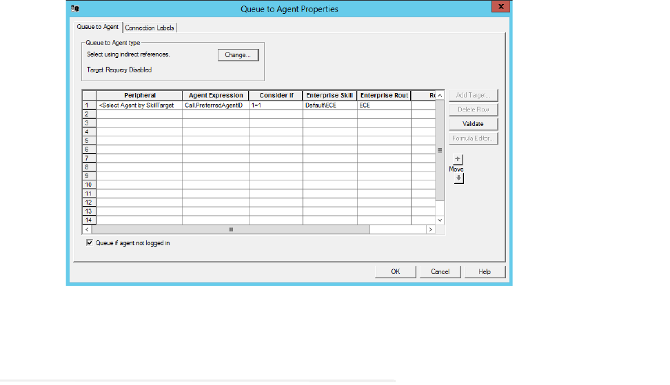
Preparing Unified CCE for the Integration 63
2. Add the Queue to Agent node in the script and configure the following:
a. Peripheral: Select the <Select Agent by SkillTargetID> option.
b. Agent Expression: Set the value as Call.PreferredAgentID.
c. Consider If: Set the value as 1=1.
d. Enterprise Skill Group: Select the enterprise skill group created on page 62.
e. Enterprise Route: Select the enterprise route created on page 62.
f. Queue if agent not logged in: Select this option if personalized emails should queue when an agent is
not available.
g. Click OK to close the window.
Configure the Queue to Agent node
Adding MR PIM for ECE
To add PG and PIM for MRPG:
1. On the CCE Call Server on Side A, from Cisco Unified CCE Tools, click Peripheral Gateway Setup.
2. On the Components Setup screen, in the Instance Components panel, click the Add button.
3. On the Components Setup screen, in the Instance Components panel, click on peripheral gateway.
4. In the Peripheral Gateways Properties screen, slosh client type as Media routing. Then click Next.
5. In the Peripheral Interface Manager pane of the Peripheral Gateway Component Properties dialog box, click
Add, select PIM1, and configure with the Client Type of Media Routing as follows:
a. Check Enabled.
b. In the Peripheral name field, enter MR.

64 Enterprise Chat and Email Installation and Configuration Guide
c. In the Peripheral ID field, enter the Peripheral ID for the Media Routing Peripheral Gateway that you
are not using for any other purpose.
d. In the Application Hostname (1) field, enter the hostname or the IP address of the ECE services server
VM. If you have installed two services servers for high availability, provide the information for the
primary services server on Side A.
e. In the Application Connection Port (1) field, enter the port number on the ECE services server VM
that the PIM will use to communicate with the application. The default port is 38001.
f. In the Application Hostname (2) field, enter the enter the hostname or the IP address of the secondary
ECE services server VM on Side B. Set this value only if you have installed two services servers for
high availability.
g. In the Application Connection Port (2) field, enter the port number on the ECE services server VM
that the PIM will use to communicate with the application. The default port is 38001. Set this value
only if you have installed two services servers for high availability.
h. In the Heartbeat interval (sec) field, enter 5.
i. In the Reconnect interval (sec) field, enter 10.
j. Select the Enable Secured Connection option if you want to use the secure PII feature. You will be
prompted to update the Application connection ports. Check the Port Utilization Guide for Cisco
Unified Contact Center to find the port number to be used for secure connection.
k. Click OK.
6. Accept defaults and click Next until the Setup Complete screen opens.
7. On the Setup Complete screen, check Yes to start the service. Then click Finish.
8. Click Exit Setup.
Repeat these steps for the CCE Call Server on Side B.
Adding Agent PG PIM for ECE
To add PG and PIM for Agent PG:
1. On the CCE Call Server on Side A, from Cisco Unified CCE Tools, click on Peripheral Gateway Setup.
2. On the Components Setup screen, in the Instance Components panel, click the Add button.
3. Select peripheral gateway and click it. PG1A will be created.
4. On the Components Setup screen, in the Instance Components panel, click on peripheral gateway.
5. In the Peripheral Gateways Properties screen, slosh client type as CUCM. Then click Next.
6. In the Peripheral Interface Manager pane of the Peripheral Gateway Component Properties dialog box, click
Add, select PIM1, and configure with the Client Type of CUCM as follows:
a. Check Enabled.
b. In the Peripheral name field, enter Agent PG.

Preparing Unified CCE for the Integration 65
c. In the Peripheral ID field, enter the Peripheral ID for the Agent PG that you are not using for any
other purpose.
d. In the CUCM section, provide the CUCM server details with username and password.
e. Click the OK button.
7. Click Next until the Setup Complete screen opens.
8. On the Setup Complete screen, check Yes to start the service. Then click Finish.
9. Click Exit Setup.
Repeat these steps for the CCE Call Server on Side B.
Adding CTI for ECE
To add CTI for ECE:
1. On the CCE Call Server on Side A, from Cisco Unified CCE Tools, click on Peripheral Gateway Setup.
2. On the Components Setup screen, in the Instance Components panel, click the Add button.
The Component selection screen opens.
3. Click on CTI server. In the CTI server component screen, select the check box for secure port, if you want
to use secure port. Click the Next button.
4. Click Next until the Setup Complete screen opens.
5. On the Setup Complete screen, check Yes to start the service. Then click Finish.
6. Click Exit Setup.
Repeat these steps for the CCE Call Server on Side B.
Configuring the System for Multiple Agent PGs
Multiple Agent PGs can be used for Unified CCE installations. Note that a unique application path and
associated application path members are needed for each Agent PG. The application path is used by the EAMS
Service to connect and communicate with the Agent PG.
To configure the system for multiple Agent PGs:
1. Create the Agent PGs. For Unified CCE installations, see page 51.
2. In Unified CCE, configure agents (page 53) and skill groups (page 54).
3. From the ECE Administration Console, add the new Agent PG. For each Agent PG that is added, a EAMS
instance is created in the System Console. Refer to the Enterprise Chat and Email Administrators Guide to
Administration Console for details about adding new Agent PGs.
4. Log in to the ECE System Console.

66 Enterprise Chat and Email Installation and Configuration Guide
5. Browse to Shared Resource > Services > Unified CCE > EAMS. In the List pane, select the EAMS
process. In the Properties pane, in the Maximum number of instances field increase the value to match the
number of Agent PGs you are adding.
6. Browse to Partitions >
Partition. In the Properties pane, on the Services tab, set the number of instances for
the EAMS service to match the number of Agent PGs you are adding.
For details about steps 4-6, see the Enterprise Chat and Email Administrator's Guide to System Console.
Configuring Finesse
Agents always access ECE through Finesse. After installing ECE, configure Finesse to add the ECE gadget. For
details about doing this task, “Configuring Finesse” on page 89.


68 Enterprise Chat and Email Installation and Configuration Guide
This chapter provides an overview of how to install the application. Before beginning the installation, ensure that
you have complied with all the prerequisites listed in “Pre-Installation Tasks” on page 24.
Installation Overview
You can do a collocated deployment, where all components, except for the web server, are installed on the same
VM and the web server is installed on a separate VM. The web server may be installed outside the firewall, if
required. Or, you can do a distributed-server installation, where each component is installed on a separate VM.
When each component is on a different VM, the installation program is run on each server separately. Make sure
you install the file server first, followed by the database server. Since the database is installed remotely, you can
install both the file server and the database components at the same time. The program will ask you for the
details of the database server as you work through the installation.
If you are installing two components, for example, application and services server components, on the same VM,
make sure that you install both application server and services server at the same time. The installation program
can only be run once per server.
The valid sequence for running the installation program is:
1. File server + database server
2. Messaging server
3. Application server
4. Web Server
5. Services server
If you plan to have multiple application and web servers, run the installer on all the VMs where these
components need to be installed. If you plan to install a cluster of messaging servers, make sure you install all
the messaging servers. Likewise, if you are planning to have two services server, then make sure you install both
the services servers.
For 400 Agent Deployments
Install the components on two VMs:
VM-1: File server, Database server, Messaging server, Application server, Services server
VM-2: Web Server
For 400 Agent Deployments (HA)
Install the components on four VMs:
On Side A:
VM-1A: File server (Windows Distributed File System Node1), Database server (Always On
Availability Group), Messaging server, Application server, Services server
VM-2A: Web Server
Installation Process 69
On Side B:
VM-1B: File server (Windows Distributed File System Node2), Database server (Always On
Availability Group), Messaging server, Application server, Services server
VM-2B: Web Server
For 400+ Agent Deployments
Install the components on following VMs:
VM-1: File server
VM-2: Database server (active and master databases)
VM-3: Database server (Reports database)
VM-4: Messaging server
VM-5: Services Server
VM-6-VM10: Application server
VM-11-15: Web Server
For 400+ Agent Deployments (HA)
Install the components on following VMs:
On Side A:
VM-1A: File server (Windows Distributed File System Node1)
VM-2A: Database server (active and master databases)
VM-3A: Database server (reports database)
VM-4A: Messaging server
VM-5A: Services server
VM-6A to VM-10A: Application server
VMA-11A to VM-15A: Web Server
On Side B:
VM-1B: File server (Windows Distributed File System Node 2)
VM-2B: Database server (active and master databases)
VM-3B: Database server (reports database)
VM-4B: Messaging server
VM-5B: Services server
VM-6B to VM-10B: Application server
VM-11B to VM-15B: Web Server
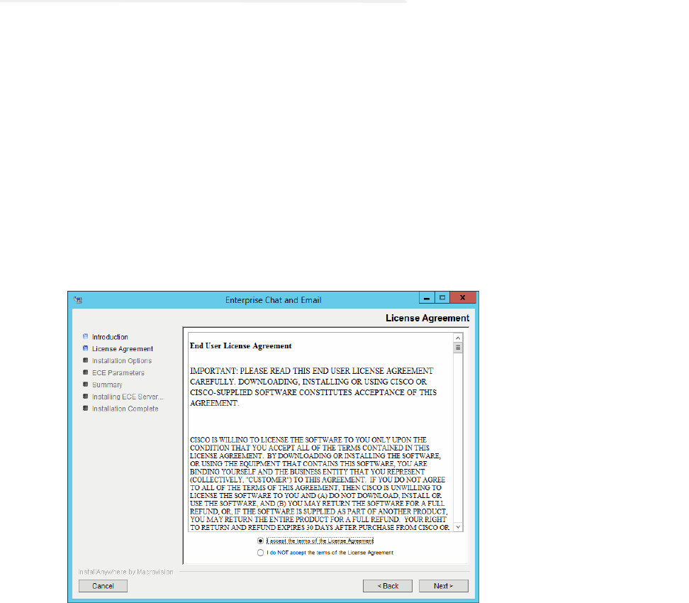
70 Enterprise Chat and Email Installation and Configuration Guide
Installing ECE
This section talks about installing the application. In a distributed-server installation, repeat these tasks on all
VMs in your configuration.
To install ECE:
1. Start the installation by using the physical installation media or a mounted ISO file. Run
setup_wsjb.exe
to launch the installation program.
Alternatively, you can create a temporary directory on any drive on your server. For example,
C:\Temp. Copy
the contents of the installation package to the
Temp folder on your local machine where you are running the
installer. Run
setup_wsjb.exe
from the C:\Temp
\Application
directory.
2. When the Introduction window appears, read the installation instructions. Click Next.
3. In the License Agreement window, review the licensing terms and select the I accept the terms of the
License Agreement option. Click Next.
Read and accept the terms of the License Agreement
4. In the Installation Options window, select from the following components. Make sure you select all the
components you wish to install. For details, see “Installation Overview” on page 68.
File Server
Messaging Server
Application Server
Web Server
Services Server
Database
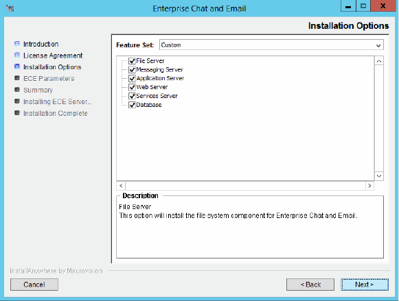
Installation Process 71
Click Next.
Select installation options
Based on the components you choose to install, you will see a different set of screens. The installation program
for ECE has on-screen help that describes the information that needs to be provided for each screen. If you need
to refer to the fields that each screen displays, see the following sections.
File Server Details on page 72
Database Server Details on page 73
Web Server Details on page 79
Messaging Server Details on page 80
Application Server Details on page 81
Services Server Details on page 82
5. Review the information displayed in the Summary window, and click Install.
6. In the Install Complete window, click the Finish button to complete the installation process.
A summary of the installation is saved in
Cisco_Home
\eService\installation\logs\installation_summary_
Server_Name
.txt.
After the installation is completed, perform the post-installation tasks (page 83).

72 Enterprise Chat and Email Installation and Configuration Guide
Installation Details
File Server Details
File server details
# Field Name Description Value
Enterprise Chat and Email Home Directory
1. File Server Directory/NAS
path
Provide the path of the directory where you would like to
install Enterprise Chat and Email. For example,
C:\Cisco
,
or
\\SharedSpace\Cisco
, if the file server is installed on a
NAS device or DFS.
Note: Make sure that the path and folder name do not
contain any of the following characters: *?<>|+^'"%`,@
Domain User Account Parameters
2. Domain user name User name of the domain user account created for use by
the application. For more information, refer to “Setting Up
User Accounts and Permissions” on page 28. User name
should be provided in the format:
Domain\username
3. Domain user password Password for the domain user.

Installation Process 73
Database Server Details
# Field Name Description Value
File Sever Parameters
1. File Server Name/NAS Path The fully qualified domain name of the file server. If the file
server is installed on a NAS device or DFS, provide the
path to the shared folder. For example,
\\SharedSpace\Cisco.
Note: Make sure you provide the DNS host name and not
the IP address of the server.
Cisco Application Context Root
2. Context Root Name The name used to identify the document root of the Web
Server. The context root of a web application determines
which URLs are delegated to the web application.
Note: Make sure there are no spaces or special
characters in the name of the context root.
system
Cisco System Administrator Account
3. User name User name for the system administrator. This is the first
user that gets created for accessing the system partition.
sa
4. Password Password for the system administrator.
Note: The password should have at least eight characters
and should be a mix of numbers and letters. For example,
password@123.
Do not use the following characters in the password:
< (less than), > (greater than), ; (semi colon), : (colon),
= (equal to), \ (back slash)
Cisco Partition Administrator Account and Partition Details
5. User name User name for the partition administrator. This is the first
user that gets created for accessing the business
partition.
pa
6. Password Password for the partition administrator.
Note: The password should have at least eight characters
and should be a mix of numbers and alphabets. For
example,
password@123.
Do not use the following characters in the password:
< (less than), > (greater than), ; (semi colon), : (colon),
= (equal to), \ (back slash)
7. Partition name Name for the business partition. Make sure that the name
does not contain any spaces or special characters. Also,
the partition name should be different than the context
root name.
default
8. Description of partition Description for the partition.
Installation Identifiers

74 Enterprise Chat and Email Installation and Configuration Guide
9. Unique name for this
installation
Provide a unique name for this installation. For example:
PROD, PRD1, TEST, TST2, or DEMO. The length of the
name must be between 1 and 4 characters long. The
name must not contain any spaces or special characters.
10. 4-digit identifier for this
installation
Provide a 4-digit numerical value, between 2001 and 9998,
that will be used internally as system ID.
Knowledge Base Primary Language
11. Knowledge Base Primary
Language
The default language for the Knowledge Base. English (US)
Default Notification Parameters
12. Default SMTP server The SMTP server to be used to send email notifications.
13. Notification mail redirection
from address
All notification emails are sent from this email address.
14. Notification mail redirection
to address
All notification emails are sent to this email address.
SQL Server Database Authentication
15. Authentication Authentication type to be used while connecting to the
database. Set the value as SQL Server Authentication
mode or Windows Authentication mode. If you are using
MSSQL Server Always On Availability Group Clustering,
select the authentication type as Windows
Authentication.
Note: If you selected Windows Authentication as the only
mode of authentication while installing SQL Server, you
must set the value as Windows Authentication mode.
Master Database Parameters
16. Server name Name of the local or remote server on which you want to
install the master database. If you are using MSSQL
Server Always On Availability Group clustering, specify
the Listener name (page 149).
Note: Make sure you provide the DNS host name and not
the IP address.
17. Database name Name of the master database. The installation program
creates a database with the name you provide here.
18. Server instance name Name of the MSSQL Server instance to be used while
creating the database. Set this value only if you are using
a named instance, and not the default instance. If you are
using MSSQL Server Always On Availability Group
clustering, provide the name of the Listener instance.
19. Database listener port Port number of the MSSQL Server. 1433
# Field Name Description Value

Installation Process 75
20. Datafile path Path to the folder on the database server, where you want
to create the data file. For example,
D:\MSSQL\Data
.
21. Datafile initial size (MB) Minimum size of the data file for the database. 100
22. Datafile maximum size (MB) Maximum size of the data file for the database. Unlimited
23. Datafile increment size (MB) Additional file size limit that will be allocated to the
database after the initial size is full.
10
24. Logfile initial size (MB) Minimum size of the log file. 25
25. Logfile maximum size (MB) Maximum size of the log file. Unlimited
26. Database administrator user
name
User name of the database administrator for MSSQL
Server. If you have created a separate user for installing
Enterprise Chat and Email databases, provide the name of
that user (page 33).
Note: This property needs to be configured only if you are
using the SQL Server Authentication mode.
27. Database administrator
password
Password of the database administrator.
Note: This property needs to be configured only if you are
using the SQL Server Authentication mode.
28. Cisco Database user name User name required to connect to the master database.
The installation program creates the database and its
user.
29. Cisco Database password Password for the master database user.
Active Database Parameters
30. Server name Name of the local or remote server on which you want to
install the active database.
Note: It must be the same server on which the master
database is installed.
31. Database name Name of the active database. The installation program
creates a database with the name you provide here.
32. Server instance name Name of the MSSQL Server instance to be used while
creating the database. This should match the value set for
the master database instance name.
33. Database listener port Port number of MSSQL Server. This should match the
value set for the master database.
1433
34. Datafile path Path to the folder on the database server, where you want
to create the data file. For example,
C:\MSSQL\Data
.
35. Datafile initial size (MB) Minimum size of the data file for the database. 2048
36. Datafile maximum size (MB) Maximum size of the data file for the database. Unlimited
37. Datafile increment size (MB) Additional file size limit that will be allocated to the
database after the initial size is full.
500
# Field Name Description Value

76 Enterprise Chat and Email Installation and Configuration Guide
38. Logfile initial size (MB) Minimum size of the log file. 1024
39. Logfile maximum size (MB) Maximum size of the log file. Unlimited
40. Database administrator user
name
User name of the database administrator for MSSQL
Server. If you have created a separate user for installing
Enterprise Chat and Email databases, provide the name of
that user (page 33).
Note: This property needs to be configured only if you are
using the SQL Server Authentication mode.
41. Database administrator
password
Password of the database administrator.
Note: This property needs to be configured only if you are
using the SQL Server Authentication mode.
42. Cisco Database user name User name required to connect to the database. The
installation program will create this user.
Note: This property needs to be configured only if you are
using the SQL Server Authentication mode.
43. Cisco Database password Password for the database user.
Note: This property needs to be configured only if you are
using the SQL Server Authentication mode.
Active Database Filegroup Parameters
44. Filegroup Datafile 1 Name Provide the name of the first file group to be created for
the active database.
45. Filegroup Datafile 1 Path Provide the location for the first filegroup. Make sure you
provide the path to the drive that is created for storing file
groups.
46. Filegroup Datafile 2 Name Provide the name of the second file group to be created
for the active database.
47. Filegroup Datafile 2 Path Provide the location for the second filegroup. Make sure
you provide the path to the drive that is created for storing
file groups.
48. Filegroup Datafile 3 Name Provide the name of the third file group to be created for
the active database.
49. Filegroup Datafile 3 Path Provide the location for the third filegroup. Make sure you
provide the path to the drive that is created for storing file
groups.
50. Filegroup Datafile 4 Name Provide the name of the fourth file group to be created for
the active database.
51. Filegroup Datafile 4 Path Provide the location for the fourth filegroup. Make sure
you provide the path to the drive that is created for storing
file groups.
Reports Database Parameters
# Field Name Description Value

Installation Process 77
52. Server name Name of the local or remote server on which the reports
database should be installed. If you are using MSSQL
Server Always On Availability Group clustering, specify
the Listener name for the reports database (page 149).
Note: Make sure you provide the DNS host name and not
the IP address of the server.
53. Database name Name of the reports database. The installation program
creates a database with the name you type here.
54. Database server instance Name of the MSSQL Server instance to be used while
creating the database. Set this value only if you are using
a named instance, and not the default instance.
Note: The name of the instance should match the name
given when you verify the server privileges while
configuring the SQL Server Integration Service (page 35).
If you are using MSSQL Server Always On Availability
Group clustering, provide the name of the Listener
instance.
55. Database listener port Port number of the MSSQL Server. 1433
56. Datafile path Path to the folder on the database server, where you want
to create the data file. For example,
D:\MSSQL\Data
.
57. Datafile initial size (MB) Minimum size of the data file for the database. 1024
58. Datafile maximum size (MB) Maximum size of the data file for the database. Unlimited
59. Datafile increment size (MB) Additional file size limit that will be allocated to the
database after the initial size is full.
500
60. Logfile initial size (MB) Minimum size of the log file. 512
61. Logfile maximum size (MB) Maximum size of the log file. Unlimited
62. Database administrator user
name
User name of the database administrator for MSSQL
Server. If you have created a separate user for installing
Enterprise Chat and Email databases, provide the name of
that user (page 33).
Note: This property needs to be configured only if you are
using the SQL Server Authentication mode.
63. Database administrator
password
Password of the database administrator.
Note: This property needs to be configured only if you are
using the SQL Server Authentication mode.
64. Cisco Database user name User name required to connect to the reports database.
The installation program will create this user.
Note: This property needs to be configured only if you are
using the SQL Server Authentication mode.
65. Cisco Database password Password for the database user.
Note: This property needs to be configured only if you are
using the SQL Server Authentication mode.
Reports Database Filegroup Parameters
# Field Name Description Value

78 Enterprise Chat and Email Installation and Configuration Guide
Database server details
66. Filegroup Datafile 1 Name Provide the name of the first file group to be created for
the reports database.
67. Filegroup Datafile 1 Path Provide the location for the first filegroup. Make sure you
provide the path to the drive that is created for storing file
groups.
68. Filegroup Datafile 2 Name Provide the name of the second file group to be created
for the reports database.
69. Filegroup Datafile 2 Path Provide the location for the second filegroup. Make sure
you provide the path to the drive that is created for storing
file groups.
70. Filegroup Datafile 3 Name Provide the name of the third file group to be created for
the reports database.
71. Filegroup Datafile 3 Path Provide the location for the third filegroup. Make sure you
provide the path to the drive that is created for storing file
groups.
72. Filegroup Datafile 4 Name Provide the name of the fourth file group to be created for
the reports database.
73. Filegroup Datafile 4 Path Provide the location for the fourth filegroup. Make sure
you provide the path to the drive that is created for storing
file groups.
Reports Database SSIS Parameters
74. SSIS Datafile Path Provide the path of the SSIS Directory created on the
reports database server (page 36). For example,
D:\ssis_data
75. Domain User Name User name of the Install Account created for use by the
application. (page 29). User name should be provided in
the format:
Domain\username
76. Domain User Password Password of the domain user account.
Reports Database SSIS Catalog Parameters
77. SSIS Catalog Encryption
Password
Provide a password to encrypt the SSIS catalog.
78. Verify SSIS Catalog Password Verify SSIS catalog encryption password.
Domain User Account Parameters
79. Domain user name User name of the domain user account you created for
use by the application. For more information, refer to
“Setting Up User Accounts and Permissions” on page 28.
User name should be provided in the format:
Domain\username
80. Domain user password Password for the domain user.
# Field Name Description Value

Installation Process 79
Web Server Details
The installation program automatically installs and configures IIS on the web server. If IIS is already installed, it
will be used by the application. The installation program will check to see if all the required components and
extensions are available. If not, it will prompt for confirmation to make changes to IIS. If you prefer to make
these changes manually, follow instructions in “Preparing Web Server VMs” on page 37.
Web server details
# Field Name Description Value
Application Server Parameters
1.
Application server name Type the name of the application server for which you want
to configure the web server.
Note: Make sure you provide the DNS host name and not
the IP address of the server.
2.
Jetty HTTP Port Jetty HTTP listener port of the application server where all
the HTTP requests are handled.
Note: This port should match the port number provided
while installing the application server (page 81).
Enterprise Chat and Email Directory
3.
Enterprise Chat and Email
Home Directory
Provide the path of the directory where you would like to
install ECE. For example,
C:\Cisco.
Note: Make sure that the path and folder name do not
contain any of the following characters: *?<>|+^'"%`,@
IIS Web Site Parameters
4.
IIS Web Site Name Name of the IIS Web Site on which the application is to be
configured.
Default Web Site
Cisco Application Context Root
5. Context Root Name Provide the same context root name which was provided at
the time of installing the Cisco database server (page 73).
Cisco Partition Name
6. Partition Name Provide the name for the business partition. Make sure you
provide the same name which was provided at the time of
installing the Cisco database server (page 73).
Domain User Account Parameters
7. Domain user name User name of the domain user account you created for use
by the application. For more information, refer to “Setting
Up User Accounts and Permissions” on page 28. User
name should be provided in the format:
Domain\username
8. Domain user password Password for the domain user.

80 Enterprise Chat and Email Installation and Configuration Guide
Messaging Server Details
The installation program automatically installs and configures JDK and ActiveMQ as part of the installation.
These software are installed in the ECE Home directory. For example,
C:\Cisco\jdk
.
Messaging server details
# Field Name Description Value
File Server Parameters
1. File Server name/NAS Path The fully qualified domain name of the file server. If the file
server is installed on a NAS device or DFS, provide the path
to the shared folder. For example,
\\SharedSpace\Cisco
.
Note: Make sure you provide the DNS host name and not
the IP address of the server.
Enterprise Chat and Email Home Directory
2. Enterprise Chat and Email
Home Directory
Provide the path of the directory where you would like to
install Enterprise Chat and Email. For example,
C:\Cisco
.
The installation program also installs ActiveMQ and JDK at
the same location.
Note: Make sure that the path and folder name do not
contain any of the following characters: *?<>|+^'"%`,@
ActiveMQ Parameters
3. ActiveMQ Port ActiveMQ listener port used by JMS clients to connect to
ActiveMQ messaging server. The port number can be
between 1024-65535.
15097
4. Admin ActiveMQ Port ActiveMQ Admin listener port used for administering and
monitoring resources on the server. The port number can
be between 1024-65535.
15096
Domain User Account Parameters
5. Domain user name User name of the domain user account you created for use
by the application. For more information, refer to “Setting
Up User Accounts and Permissions” on page 28. User
name should be provided in the format:
Domain\username
6. Domain user password Password for the domain user.

Installation Process 81
Application Server Details
The installation program automatically installs and configures JDK and Jetty as part of the installation. These
software are installed in the ECE Home directory. For example,
C:\Cisco\jdk
.
Application server details
# Field Name Description Value
File Server Parameters
1. File Server name/ NAS
Path
The fully qualified domain name of the file server. If the file
server is installed on a NAS device or DFS, provide the path to
the shared folder. For example,
\\SharedSpace\Cisco
Note: Make sure you provide the DNS host name and not the IP
address of the server.
Enterprise Chat and Email Home Directory
2. Enterprise Chat and
Email Home Directory
Provide the path of the directory where you would like to install
ECE. For example,
C:\Cisco
. The installation program also
installs Jetty and JDK at the same location.
Note: Make sure that the path and folder name do not contain
any of the following characters: *?<>|+^'"%`,@
Jetty Parameters
3. Jetty HTTP port Jetty HTTP listener port where all the HTTP requests are
handled. The port number can be between 1024-65535.
9001
4. Jetty HTTP SSL Port Jetty HTTPS listener port where all the SSL requests are
handled. The port number can be between 1024-65535.
9002
5. Jetty Stop Port Jetty shutdown command listener port. This port is used for
issuing shutdown command to stop Jetty. The port number can
be between 1024-65535.
15095
Domain User Account Parameters
6. Domain user name User name of the domain user account you created for use by
the application. For more information, refer to “Setting Up User
Accounts and Permissions” on page 28. User name should be
provided in the format:
Domain\username
7. Domain user password Password for the domain user.

82 Enterprise Chat and Email Installation and Configuration Guide
Services Server Details
The installation program automatically installs and configures JDK as part of the installation. JDK is installed in
the ECE Home directory. For example,
C:\Cisco\jdk
.
Services server details
# Field Name Description Value
File Server Parameters
1. File Server name/NAS Path The fully qualified domain name of the file server. If the file
server is installed on a NAS device or DFS, provide the path
to the shared folder. For example,
\\SharedSpace\Cisco
Note: Make sure you provide the DNS host name and not
the IP address of the server.
Enterprise Chat and Email Home Directory
2. Enterprise Chat and Email
Home Directory
Provide the path of the directory where you would like to
install ECE. For example,
C:\Cisco
. The installation
program also installs JDK at the same location.
Note: Make sure that the path and folder name do not
contain any of the following characters: *?<>|+^'"%`,@
RMI and RMID Parameters
3. RMI registry port Port number used by the Remote Method Invocation (RMI)
registry naming service.
15099
4. RMI activation port Port number used by the RMI Daemon Process. 15098
Organization Information
5. Name Provide the name of the organization. Make sure that the
name does not contain any special characters.
6. Business Unit Provide the business unit name. Make sure that the value
does not contain any special characters.
7. Location Provide the location of your organization. Make sure that
the value does not contain any special characters.
8. Country Select the country from the dropdown list.
Domain User Account Parameters
9. Domain user name User name of the domain user account you created for use
by the application. For more information, refer to “Setting
Up User Accounts and Permissions” on page 28. User name
should be provided in the format:
Domain\username
10. Domain user password Password for the domain user.

Post-Installation
Tasks
Configuring Permissions on IIS Config Folder
Assigning Permissions on ECE Home Directory
Configuring SSL for Secure Connections
Always On Availability Group Clustering Tasks
Creating an Encrypted SQL Server Database
Configuring SMTP Server Relay Address List
Configuring Finesse
Configuring Single Sign-On
Starting ECE
Stopping ECE
Signing in to ECE
Integrating ECE with Unified CCE
Configuring Important Settings
Adding Data Source in CUIC for ECE Reports

Post-Installation Tasks 85
This chapter guides you through the tasks to be performed after installing the system. It also describes the
process of uninstalling ECE.
Configuring Permissions on IIS Config Folder
Skip this task if it was done as part of the pre-installation tasks (page 39). Ensure that the user account that
you used for installing the application (page 28) has read permissions on the following folder on the web
server:
%systemroot%\system32\inetsrv\config.
Assigning Permissions on ECE Home Directory
The Service Account created for running the ECE application needs Full Control permission on the ECE home
directory. You must perform this task on the file server before starting the application.
To assign permissions on the ECE home directory:
1. Right-click the ECE home directory.
2. Select Properties.
3. In the Properties window, go to the Sharing tab and click Advanced Sharing.
4. In the Advanced Sharing window, click Permissions.
5. In the Permissions window, click the Add button and add the Service Account (page 28) created for ECE.
Assign the Full Control permission to the user.
Click Apply.
Configuring SSL for Secure Connections
You must set up Secure Sockets Layer (SSL) for more secure connections between browsers and the servers
in your installation. This is a required step. See “SSL Configuration” on page 126 for details.
Always On Availability Group Clustering Tasks
Perform all the tasks listed in “Post-Installation Tasks” on page 150.

86 Enterprise Chat and Email Installation and Configuration Guide
Creating an Encrypted SQL Server Database
This is an optional task and you need to do it only if you want to encrypt the databases. This feature is available
only for the Enterprise edition of MSSQL. You can do this task any time after installing the ECE application.
If you are using Always On Availability Group clustering, perform this task on all the nodes.
Encrypting Primary Node
Perform these tasks on the primary node.
To create an encrypted SQL server database:
1. Create a master key in the master database. This key is then used to create the server certificate that can be
used to secure the database encryption key. Connect to the master database and run the following query.
USE master
GO
CREATE MASTER KEY ENCRYPTION BY PASSWORD = 'company@123'
GO
2. Backup the master key. This creates a certificate in the master database.
BACKUP MASTER KEY TO FILE = 'c:\temp\masterkey'
ENCRYPTION BY PASSWORD = 'company@123'
GO
3. Now create the server certificate database encryption key ("DEK").
USE master
GO
CREATE CERTIFICATE DEKCert WITH SUBJECT = 'DEK Certificate'
GO
4. Create a backup of the server certificate database encryption key (“DEK”).
BACKUP CERTIFICATE DEKCert TO FILE = 'c:\DEKCert'
WITH PRIVATE KEY ( FILE = 'c:\temp\DEKCertPrivKey' ,
ENCRYPTION BY PASSWORD = 'company@123' )
GO
5. Create database encryption key for the database where you wish to configure transparent data encryption. In
the following query,
eGActiveDB_name is the name of the active database.
USE
eGActiveDB_name
GO
CREATE DATABASE ENCRYPTION KEY
WITH ALGORITHM = AES_128
ENCRYPTION BY SERVER CERTIFICATE DEKCert
Post-Installation Tasks 87
GO
You now have all the prerequisites for enabling transparent data encryption, so database encryption can be
enabled.
6. Enable database encryption. Run the following query where
eGActiveDB_name is the name of the active
database.
ALTER DATABASE
eGActiveDB_name
SET ENCRYPTION ON
By setting encryption on, a background task starts encrypting all the data pages and the log file. This can
take a considerable amount of time, depending on the size of the database.
Database maintenance operations should not be performed when this encryption scan is running.
7. To query the status of the database encryption and its percentage completion, query the new
sys.dm_database_encryption_keys DMV
.
SELECT DB_NAME(e.database_id) AS DatabaseName,
e.database_id,
e.encryption_state,
CASE e.encryption_state
WHEN 0 THEN 'No database encryption key present, no encryption'
WHEN 1 THEN 'Unencrypted'
WHEN 2 THEN 'Encryption in progress'
WHEN 3 THEN 'Encrypted'
WHEN 4 THEN 'Key change in progress'
WHEN 5 THEN 'Decryption in progress'
END AS encryption_state_desc,
c.name,
e.percent_complete
FROM sys.dm_database_encryption_keys AS e
LEFT JOIN master.sys.certificates AS c
ON e.encryptor_thumbprint = c.thumbprint
Encrypting Other Nodes
To encrypt other nodes:
1. Copy the
c:\temp
folder from the first node to the other nodes.
2. Create a master key in the master database. This key is then used to create the server certificate that can be
used to secure the database encryption key. Connect to the master database and run the following query.
USE master
GO
CREATE MASTER KEY ENCRYPTION BY PASSWORD = 'company@123'
GO

88 Enterprise Chat and Email Installation and Configuration Guide
3. Now create the server certificate.
USE master
GO
CREATE CERTIFICATE TDE_Test_Cert FROM FILE = 'c:\temp\DEKCert'
WITH PRIVATE KEY (FILE = 'c:\temp\DEKCertPrivKey',
DECRYPTION BY PASSWORD = 'company@123'); GO
4. Enable database encryption. Run the following query where eGActiveDB_name is the name of the active
database.
ALTER DATABASE
eGActiveDB_name
SET ENCRYPTION ON
By setting encryption on, a background task starts encrypting all the data pages and the log file. This can
take a considerable amount of time, depending on the size of the database.
Database maintenance operations should not be performed when this encryption scan is running.
5. To query the status of the database encryption and its percentage completion, query the new
sys.dm_database_encryption_keys DMV
.
SELECT DB_NAME(e.database_id) AS DatabaseName,
e.database_id,
e.encryption_state,
CASE e.encryption_state
WHEN 0 THEN 'No database encryption key present, no encryption'
WHEN 1 THEN 'Unencrypted'
WHEN 2 THEN 'Encryption in progress'
WHEN 3 THEN 'Encrypted'
WHEN 4 THEN 'Key change in progress'
WHEN 5 THEN 'Decryption in progress'
END AS encryption_state_desc,
c.name,
e.percent_complete
FROM sys.dm_database_encryption_keys AS e
LEFT JOIN master.sys.certificates AS c
ON e.encryptor_thumbprint = c.thumbprint
Configuring SMTP Server Relay Address List
The default SMTP server configured during the installation process is used to send notifications.
To allow the system to successfully send such emails, verify that the IP addresses of all the application
servers in the configuration are added to the relay address list of the SMTP server.

Post-Installation Tasks 89
Configuring Finesse
Perform these tasks after installing ECE. Cisco Finesse enables the use of custom gadgets for Voice &
Multichannel (ECE), facilitating the ECE user interface to be embedded within a gadget to provide contact
center agents a unified desktop experience.
Configuring Finesse Settings and Layout
Perform these tasks from any local machine. You will need access to the following
xml
files on the ECE web
server:
ECE_Home
\eService\templates\finesse\gadget\layout:
agent.xml
solve.xml
cobrowse.xml
To configure the Finesse settings and layout:
1. Launch the URL:
https://
Finesse_Server_Name
/cfadmin
Login as a finesse administrator.
Important: Before you begin the configuration, ensure that the Finesse VM and software are
installed and ready for use. Also, ensure that ECE is installed.
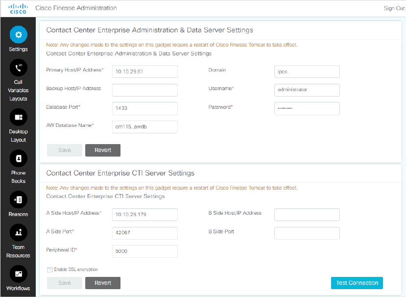
90 Enterprise Chat and Email Installation and Configuration Guide
2. Configure the Contact Center CTI Server Settings and Contact Center Enterprise Administration & Data
Server Settings. To configure a secure connection, select the Enable SSL encryption option in the Contact
Center CTI Server Settings section and provide the secure ports. For details about doing this configuration,
see the Cisco Finesse Administration Guide.
Configure the settings
3. From the Desktops Layout section, configure the layout for ECE, Solve, and Cobrowse gadgets. XML
contents for the ECE, Solve, and Cobrowse gadget tabs are available in the following files on the ECE web
server:
ECE_Home
\eService\templates\finesse\gadget\layout\agent.xml
: After copying the
content of the
agent.xml
file, in the
gadget
tag, replace the web server name with the host name of
the load balancer used for ECE web servers. This task needs to be performed only if you are using a
load balancer for ECE web servers.
ECE_Home
\eService\templates\finesse\gadget\layout\solve.xml:
After copying the
content of the
solve.xml
file, make the following changes in the
gadget
tag:
i. Replace
EGAIN_WEBSERVER_OR_LOADBALANCER
with the eGain Solve for Cisco web server. If the
installation has more than one web servers, provide the name of the load balancer.
ii. Replace
CONTEXT_ROOT
with the context root of eGain Solve for Cisco.
ECE_Home
\eService\templates\finesse\gadget\layout\cobrowse.xml
: You need to
configure this only if you are using the Cobrowse gadget in Finesse. After copying the content of the
cobrowse.xml
file, make the following changes in the in the
gadget
tag:
i. Replace the
EGAIN_WEBSERVER_OR_LOADBALANCER
with the eGain Solve for Cisco web server. If
the installation has more than one web servers, provide the name of the load balancer.

Post-Installation Tasks 91
ii. Replace the
CONTEXT_ROOT
with the context root of eGain Solve for Cisco.
Refer the Finesse documentation to see how gadgets are added in Finesse.
Configuring Single Sign-On
Single sign-on is available for all users of the application. For details about doing this task, see the
Enterprise Chat and Email Administrator’s Guide to Administration Console (For UCCE). If you are
planning to use single sign-on while accessing any of the ECE consoles outside of Finesse, you must also
complete the tasks in the section: “Single Sign-On Configuration” on page 100.
Starting ECE
There is no mandatory sequence that should be followed while starting ECE. All the VMs on which components
are installed should be running and available on the network.
To start ECE:
If you get the following error while starting the Cisco Service, see “Troubleshooting Application Start-Up
Issues” on page 92:
Error 1069: The service did not start due to login failure.
In collocated installation:
On the server where application, messaging, services, file, and database components are installed, start
the Cisco Service from the Windows Services panel.
In a distributed-server installation:
Ensure that all the VMs in the configuration are available and connected to the network.
a. Start Cisco Service on the messaging server by starting the Cisco Windows service from the Windows
Services panel. If you have installed a cluster of messaging servers, you would need to start the
application on all the servers in the cluster.
b. On each services server, start the application by starting the Cisco Windows service from the Windows
Services panel.
c. On each application server, start the application by starting the Cisco Windows service from the
Windows Services panel.
Important: Run the application using the same domain account that was used for installing
the application (page 28).

92 Enterprise Chat and Email Installation and Configuration Guide
Troubleshooting Application Start-Up Issues
Perform these tasks if you get the following error while starting the Cisco service:
Error 1069: The
service did not start due to login failure.
To troubleshoot:
1. In the Windows service panel, right-click the Cisco Service and from the menu select Properties.
2. In the Properties window, go to the Log On tab and provide the password of the domain user account
(page 28) and click Apply.
3. Start the Cisco Service.
Stopping ECE
If you need to stop the application at any point during the post-installation tasks, follow the steps in this section.
In a distributed environment, stop the application on the following servers. There is no mandatory sequence that
should be followed while stopping the application.
The application servers
The messaging servers
The services servers
To stop ECE:
In a collocated installation:
On the server where application, web, messaging, services, file, and database components are installed,
stop the Cisco Service from the Windows Services panel.
In a distributed-server installation:
a. On each application server VM, stop the Cisco Service from the Windows Services panel. Open the
Windows Task Manager and verify that none of the
java
processes are running.
b. On the messaging server VM, stop the Cisco Service from the Windows Services panel. If you have
installed a cluster of messaging servers, you would need to stop the application on all the servers in the
cluster. Open the Windows Task Manager and verify that none of the
java
processes are running.
c. On each services server VM, stop the Cisco Service from the Windows Services panel. If you have
installed two services servers, stop the application on both servers. Open the Windows Task Manager
and verify that none of the
java
processes (the services) are running.

Post-Installation Tasks 93
Signing in to ECE
Signing in to Agent Console
To sign in to the Agent Console:
1. Ensure that the desktops meet the requirements outlined in System Requirements for Enterprise Chat and
Email.
2. Access the Finesse URL from a browser and sign in to Finesse:
https://
Finesse_Server_Name
/desktop
3. Click on the Manage Chat and Email tab. If Single Sign-On is enabled, then the agent will be logged in
automatically. If not, enter the username and password and click Sign In.
Signing in to All Other Consoles
A system partition and a business partition are created during the installation. To begin using the application, you
log in to the business partition.
To sign in to the business partition:
1. Ensure that you have followed the instructions in the Enterprise Chat and Email Browser Settings Guide
document to configure your browser, and that the desktops meet the requirements outlined in System
Requirements for Enterprise Chat and Email.
2. Type the URL
http://
Web_server.company.com
/
Partition_name in your browser, where
Web_server.company.com is the fully qualified domain name of your web server and Partition_name is the
virtual directory created for this partition. During the installation, you are prompted to provide the partition
name in the Partition Administrator Account and Partition window. This is used to create the virtual
directory. If you have configured the web server to use SSL, then the URL is
https://
Web_Server.company.com
/
Partition_name.
Always use the fully qualified domain name of the web server when you type the URL to access ECE.
3. In the Sign In window, type the user name and password you had set up for the partition administrator in the
Partition Administrator Login Parameters window during the installation. Click the Log In button.
Integrating ECE with Unified CCE
Integration between ECE and Unified CCE is enabled and configured through the Administration Console.
To integrate ECE with Unified CCE:
1. Sign in to the Administration Console as a partition administrator.
2. In the Tree pane, browse to Administration > Partition:
Partition Name > Integration > Unified CCE >
Unified CCE.
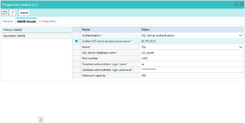
94 Enterprise Chat and Email Installation and Configuration Guide
3. Go to the AWDB Details tab and provide the following details for the Primary AWDB. If any of these
configurations change at a later point in Unified CCE, you must update the details here as well.
Authentication: Select from Windows Authentication or SQL Authentication.
Unified CCE administration host name: The server name or IP address of the Unified CCE host.
Active: Set to Yes.
SQL server database name: The name of the AWDB database.
Port number: Set the value to match the port configured in Unified CCE. By default the value is set to
1433.
Database administrator login name: The database administrator’s user name. This value needs to be
set only when using SQL Authentication.
Database administrator login password: The database administrator password. This value needs to be
set only when using SQL Authentication.
Maximum capacity: The maximum number of allowed connections to be made to the AWDB. By
default, this is set to 360.
Provide the primary AWDB server details
4. If you have a secondary AWDB and wish to apply it to your integration, click the Secondary AWDB section
and provide the necessary details.
5. Click the Save button.
6. In the Properties pane, on the Configuration tab, set the following:
Select the Application Instance.
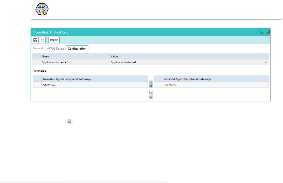
Post-Installation Tasks 95
Select any Agent Peripheral Gateways that apply.
Provide configuration details
7. Click the Save button. Your system is now connected with Unified CCE. To complete the integration,
you must configure your media classes. and import the MRDs users and skill groups from the Unified CCE
system. For details about doing this task, see the Enterprise Chat and Email Administrator’s Guide to
Administration Console.
Configuring Important Settings
This section introduces the main settings that allow you to configure various aspects of the application. Some
settings are configured at the partition level, while others have to be set up for each department.
These settings are of two types:
1. Mandatory settings: These settings are configured during installation, and must be verified before using the
application. Settings related to ESMTP protocol, must be configured manually if you are using ESMTP
protocol for email notifications.
2. Optional settings: Although it is not mandatory to change these settings, you are likely to feel the need to
configure them for your business.
Mandatory Settings
At the partition level
The following setting must be configured:
Web server URL or Load Balancer URL
The following settings are updated during installation, but we recommend that you log in to the application as a
partition administrator, and verify and update them from the Administration Console, if required. The application
starts using this information as soon as the installation is complete.
Important: When you save your changes, your system is permanently connected to your Uni-
fied CCE installation. This cannot be undone.

96 Enterprise Chat and Email Installation and Configuration Guide
Default SMTP Server Settings
From: address for notification from Service
To: address for notification from Service
At the department level
This setting is automatically updated for the first department created by the installation program. For all
subsequent departments, the administrator must configure it.
From email address for alarm
Optional Settings
Although it is not mandatory to change these settings, you are likely to feel the need to configure them for your
business.
At the partition level
Customer departmentalization
Session time out
Inactive time out
Chat auto-pushback settings
At the department level
Business calendar time zone
Autopushback time (minutes after logout)
For a complete list of all available settings, refer to the Enterprise Chat and Email Administrator’s Guide to
Administration Console.
Adding Data Source in CUIC for ECE Reports
The following ECE reports can be accessed in the Cisco Unified Intelligence Center (CUIC) via historical
templates:
Chat Volume by Queue
Email Volume By Queue
Agent Work Summary
To access these reports from CUIC, you need to add the ECE Reports Database as a data source in CUIC.
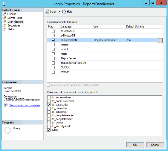
Post-Installation Tasks 97
Creating a Database User on ECE Reports Database
If the reports database is part of the always-on group, create the database login with the same name on all nodes
of the cluster starting with the current primary node and map database login to reports database of each node.
Refer to the Microsoft documentation for maintaining SQL logins and permissions for user databases in always
on cluster.
To create a database user on ECE reports database:
1. Create a SQL login on the reports database server, for example,
ReportsDataReader
.
2. Map the user to the ECE reports database and set the Default Schema as dbo.
3. Assign the following database role memberships to the database user
ReportsDataReader
:
public
db_datareader
Create a database user
Adding Data Source in CUIC for ECE Reports
See the Cisco Unified Intelligence Center Report Customization Guide for steps on adding a data source in
CUIC.
Make sure you set the following values on the data source details page:
In the Datasource Host field, provide the name of the server where the ECE reports database is installed. In
case of always on cluster for reports database, connect to the reports database using always on default cluster
name or load balancer name.
In the Database name field, provide the name of the ECE reports database.

98 Enterprise Chat and Email Installation and Configuration Guide
In the Database User ID field, provide the name of the SQL user created on the ECE reports database
server (page 97).
Uninstalling ECE
The application needs to be uninstalled from the following servers. The uninstallation program can be run in any
order on these servers.
Application Server
Messaging Server
Services Server
Web Server
File Server
To ensure that critical data is not lost, the program does not uninstall the following components:
The databases
The following folders on the file server:
Cisco_Home
\eService\storage
Cisco_Home
\eService\logs
Preparing to Uninstall
Stopping the Application
Before you begin the uninstallation process, make sure you stop ECE. For details, refer to “Stopping ECE”
on page 92.
Stopping IIS
Stop IIS (World Wide Web Publishing Service) on all web servers in the installation.
Uninstalling ECE
To uninstall ECE:
1. Go to Start > Settings > Control Panel.
2. Click Programs in the Control Panel window.
Important: After the uninstaller runs on all the servers, you must delete these components
manually to make the servers ready for the reinstallation of ECE on the same servers.
Post-Installation Tasks 99
3. Click Programs and Features in the Programs window.
4. From the list of currently installed programs, right-click Enterprise Chat and Email and select
Uninstall/Change.
5. In the Uninstall Enterprise Chat and Email window, click the Uninstall button.
6. When the uninstallation is complete, you are given a choice of restarting the server right away, or doing it
later.
7. On the database server, go to the SQL Server Management Studio and delete the following, if required.
Go to Databases and delete the databases.
Go to Security > Logins and delete the logins created for the databases.
Go to SQL Server Agent > Jobs and delete the SQL Jobs for the databases. The jobs related to your
databases will have the database name in the end. For example,
populatesmy_
eGReportsDB.
8. On the file server, manually delete the following folders:
Cisco_Home
\eService\storage
Cisco_Home
\eService\logs
Performing Post Uninstallation Tasks
Starting IIS
Start IIS (World Wide Web Publishing Service) on all web servers in the installation.

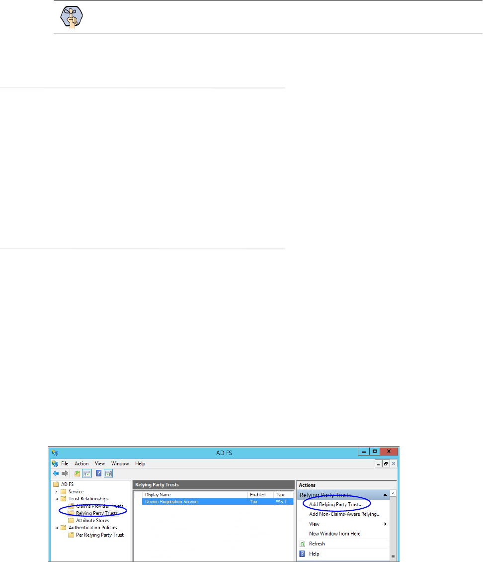
Single Sign-On Configuration 101
About Single Sign-On with Cisco IDS
Single Sign-On with Cisco IDS requires that ECE is connected to Active Directory Federation Services (AD FS).
You can use one of the following options for AD FS:
Single AD FS: In a single AD FS deployment, Resource Federation Server and Account Federation Server
are installed on the same machine (page 101).
Split AD FS: In a split AD FS deployment, Resource Federation Server and Account Federation Server are
installed on separate machines (page 109).
Configuring Single AD FS Deployment
In a single AD FS deployment, Resource Federation Server and Account Federation Server are installed on the
same machine.
Configuring Relying Party Trust for ECE
Perform these tasks on the server where Resource Federation Server and Account Federation Server are installed.
To configure relying party trust for ECE in single AD FS:
1. Go to the Start menu and open AD FS Management console.
2. In the AD FS Management console, navigate to AD FS > Trust Relationships > Relying Party Trust.
3. In the Actions section, go to Relying Party Trust, and click Add Relying Party Trust...
4. In the Add Relying Party Trust Wizard that appears, do the following:
a. On the Welcome screen, click Start.
Important: Perform these tasks only if you are planning to use single sign-on while accessing
any of the ECE consoles outside of Finesse.
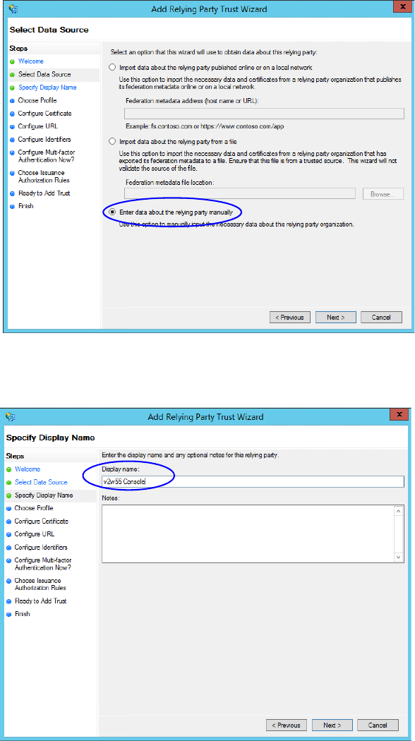
102 Enterprise Chat and Email Installation and Configuration Guide
b. On the Select Data Source screen, select the Enter data about the reply party manually option and
click Next.
Select the Enter data about the reply party manually option
c. On the Specify Display Name screen, provide a Display name for the relying party. Click Next.
Provide a display name
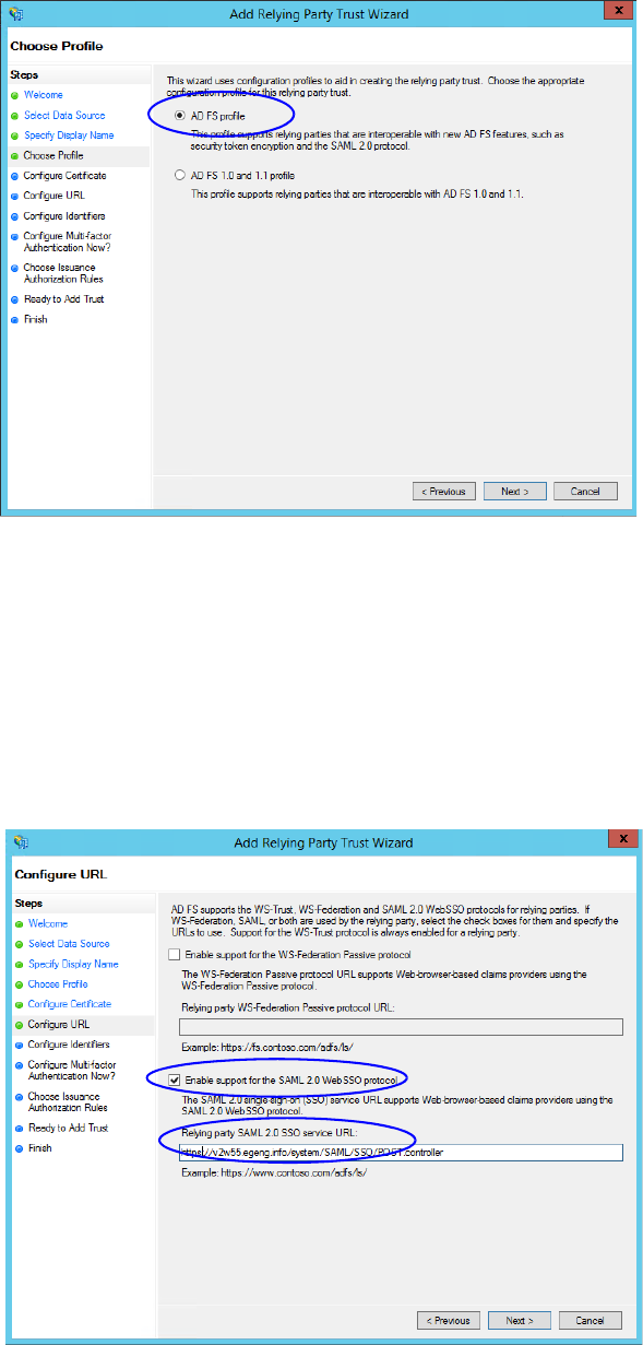
Single Sign-On Configuration 103
d. On the Choose Profile screen, select AD FS profile and click Next.
Select AD FS profile
e. On the Configure Certificate screen, click Next.
f. On the Configure URL screen, set the following:
i. Select the Enable support for the SAML 2.0 Web SSO protocol option.
ii. In the Relying Party SAML 2.0 SSO server URL field provide the URL in the format:
https://
Web_Server_Or_Load_Balancer_Server
/system/SAML/SSO/POST.controller.
R
eplace Web_Server_Or_Load_Balancer_Server with the ECE web server name or the Load balancer
server name.
Configure the URL
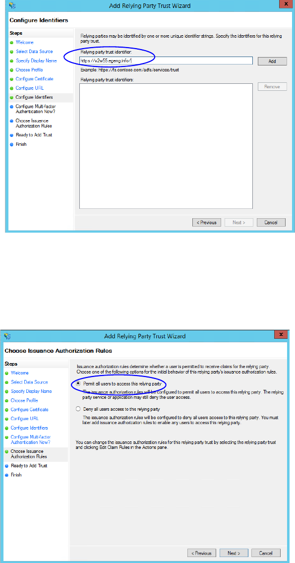
104 Enterprise Chat and Email Installation and Configuration Guide
g. On the Configure Identifiers screen, provide the Replying party trust identifier and click Add. Value
should be in the format:
https://
Web_Server_Or_Load_Balancer_Server
/
.
R
eplace
Web_Server_Or_Load_Balancer_Server with the ECE web server name or the Load balancer server name.
Click Next.
Configure the identifiers
h. On the next screen, select the I do not want to configure multi-factor authentication settings for the
relying party trust at this time option.
i. On the Choose Issuance Authorization Rules screen, select the Permit all users to access this relying
party option.
Select the Permit all users to access this relying party option
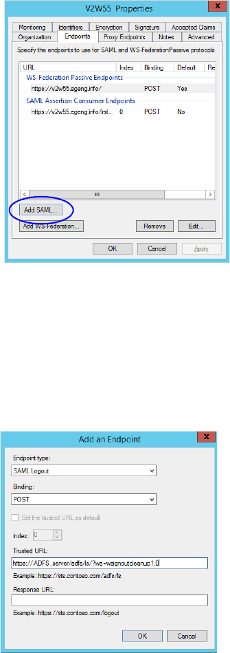
Single Sign-On Configuration 105
j. On the Ready to add trust screen, click Next.
k. Uncheck the Open the Edit Claim Rules dialogue for this relying party trust when the wizard
closes option and click Close. At the end, an entry is created in the Relying Provider Trusts list.
5. In the Relying Provider Trusts list, select the trust created for ECE, and in the actions section click
Properties.
6. In the Properties window, go to the Endpoints tab and click the Add SAML.. button.
Click Add SAML
7. In the Add an Endpoint window, set the following:
a. Select the Endpoint type as SAML Logout.
b. Specify the Trusted URL as
https://
ADFS_server
/adfs/ls/?wa=wsignoutcleanup1.0
. Replace
ADFS_server with the single AD FS server name.
c. Click OK.
Create an end point
8. In the Relying Provider Trusts list, select the trust created for ECE, and in the actions section click Edit
Claim Rules.
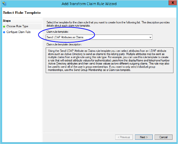
106 Enterprise Chat and Email Installation and Configuration Guide
9. In the Edit Claim Rules window, in the Issuance Transform Rules tab, click the Add Rule... button.
In the Add Transform Claim Rule wizard that opens, do the following:
a. On the Choose Rule Type screen, from the Claim rule template dropdown, select Send LDAP
Attributes as Claims. Click Next.
Select the claim rule template
b. On the Configure Rule screen, set the following:
i. Provide the Claim rule name.
ii. Define mapping of LDAP attribute and the outgoing claim type. Select Name ID as the outgoing
claim type name. Click Finish to go back to the Edit Claim Rules for single AD FS window.
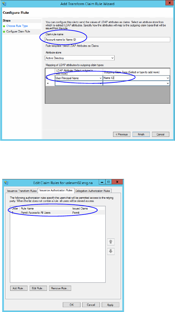
Single Sign-On Configuration 107
Configure the rule
10. In the Edit Claim Rules window, in the Issuance Authorization Rules tab, ensure that the rule permits access
to all users. Click OK to close the window.
Check the authorization rules
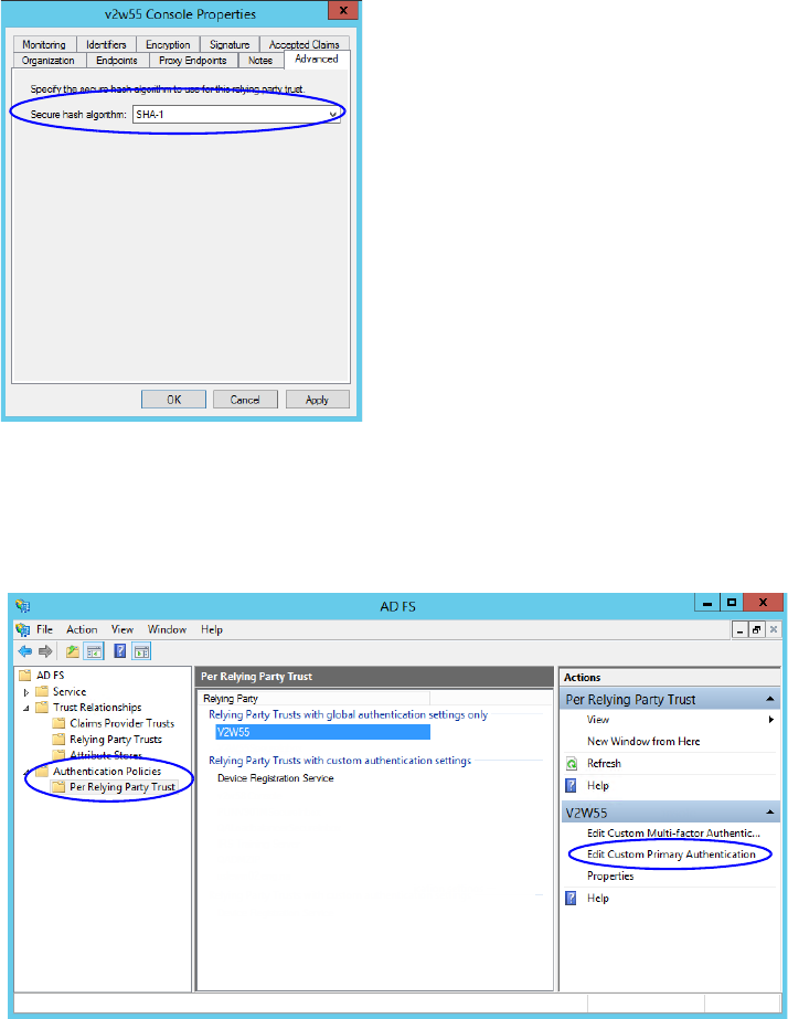
108 Enterprise Chat and Email Installation and Configuration Guide
11. In the Relying Provider Trusts list, double-click the relying party trust which you created. In the Properties
window that opens, go to the Advanced tab and set the Secure hash algorithm to SHA-1. Click OK to
close the window.
Set the secure hash algorithm
12. Next, in the AD FS Management console, go to the Authentication Policy > Per Relying Party Trust.
Locate the Relying Party Trust created for ECE, and in the Actions section click Edit Custom Primary
Authentication.
Change the authentication policy for ECE
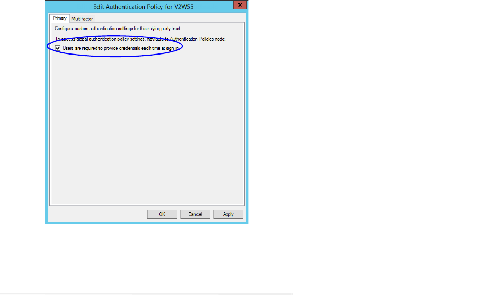
Single Sign-On Configuration 109
13. In the Edit Authentication Policy window, in the Primary tab, select the Users are required to provide
credentials each time at sign in option. Click OK to close the window.
Edit the authentication policy
Configuring Split AD FS Deployment
In a split AD FS deployment, Resource Federation Server and Account Federation Server are installed on
separate machines. Resource Federation Server acts as shared AD FS and Account Federation Server acts as
customer AD FS.
Configuring split AD FS includes:
Adding Security Certificates for the AD FS Domains
Configuring Relying Party Trust for Shared AD FS in Customer AD FS
Configuring Claims Provider Trust for Customer AD FS in Shared AD FS
Configuring Relying Party Trust for ECE in Shared AD FS
Adding Security Certificates for the AD FS Domains
If Customer AD FS and Shared AD FS are installed in different domain, you need to add certificates of the
domains to the Trusted Root Certification Authorities store of the servers. On the Customer AD FS server,
add the certificate of the Shared AD FS and vice versa. Contact your IT department to do this task.
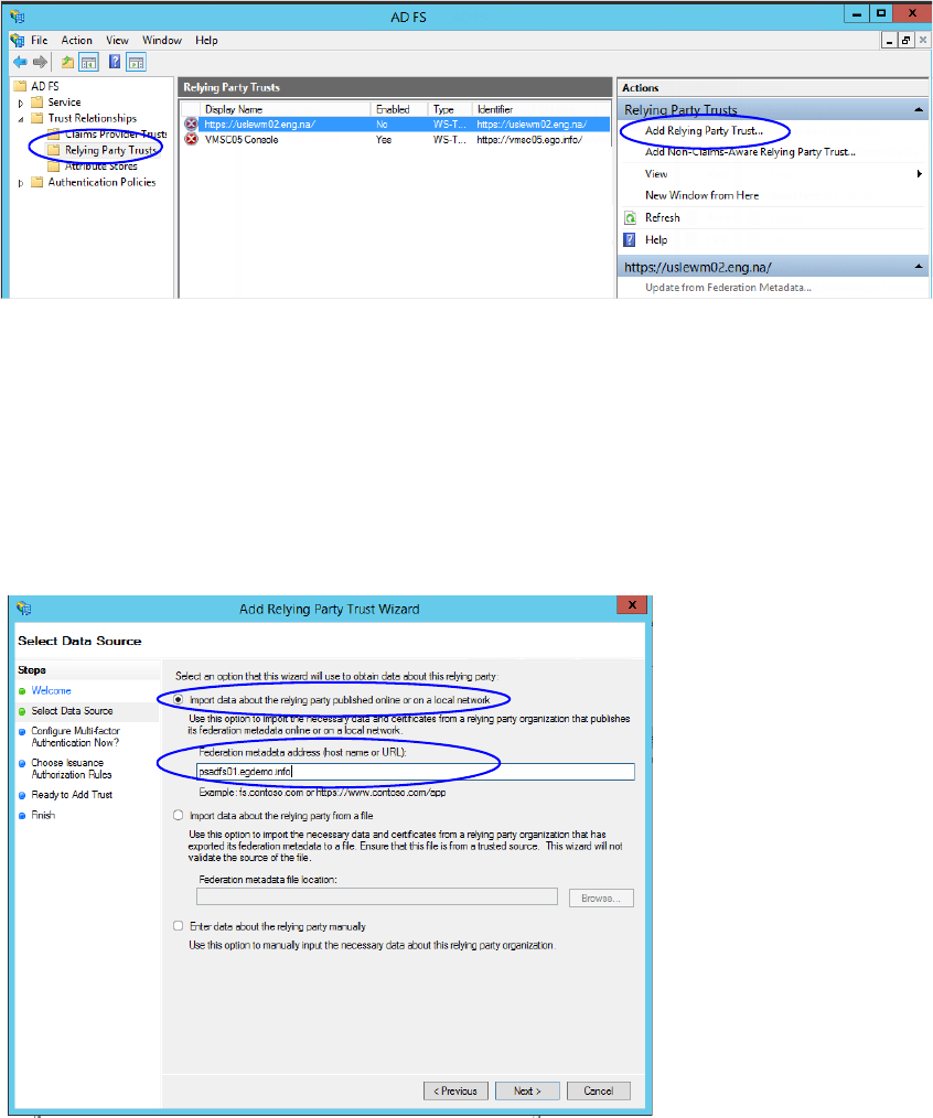
110 Enterprise Chat and Email Installation and Configuration Guide
Configuring Relying Party Trust for Shared AD FS in Customer AD FS
Perform these tasks on the server where customer AD FS is installed.
To configure replying party trust for shared AD FS in customer AD FS:
1. Go to the Start menu and open the AD FS Management console.
2. In the AD FS Management console, navigate to AD FS > Trust Relationships > Relying Party Trust.
3. In the Actions section, go to Relying Party Trust, and click Add Relying Party Trust...
Click Add Relying Party Trust
4. In the Add Relying Party Trust Wizard that appears, do the following:
a. On the Select Data Source screen, set the following options:
i. Select the Import data about the relying party published on online or on a local network
option.
ii. In the Federation metadata address field, provide the Shared AD FS server name.
iii. Click Next.
Select the data source options
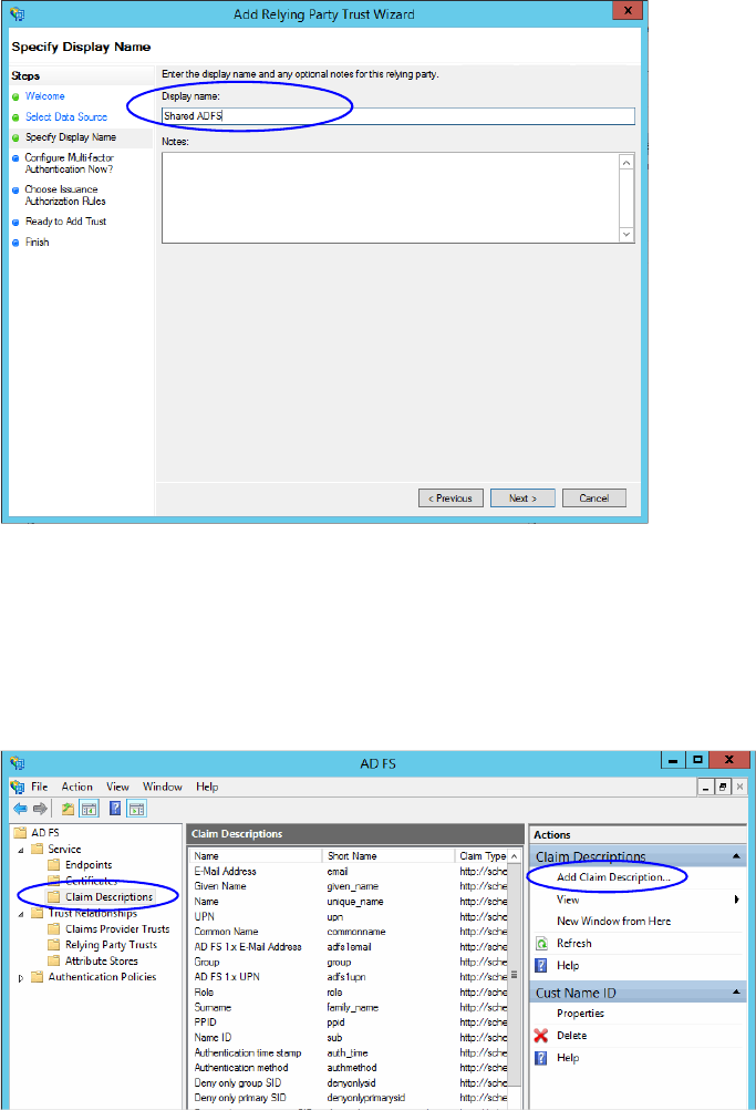
Single Sign-On Configuration 111
b. On the Specify Display Name screen, provide the Display name. Click Next.
Provide a display name
c. In the screens that follow, do not alter the default values. Continue to click the Next button in the
wizard until a trust is created. At the end, an entry is created in the Relying Party Trusts list.
5. In the AD FS Management console, navigate to Services > Claim Descriptions.
6. In the Actions section, go to Claim Descriptions, and click Add Claim Descriptions...
Click Add Claim Description
7. In the Add a Claim Description window, provide the following details:
a. Set the Display name as Cust Name ID.
b. Set the Claim identifier as http://schemas.xmlsoap.org/ws/2005/05/identity/claims/CustNameID
c. Select the Publish the claim description in federation metadata as a claim type that this
Federation Service can accept option.
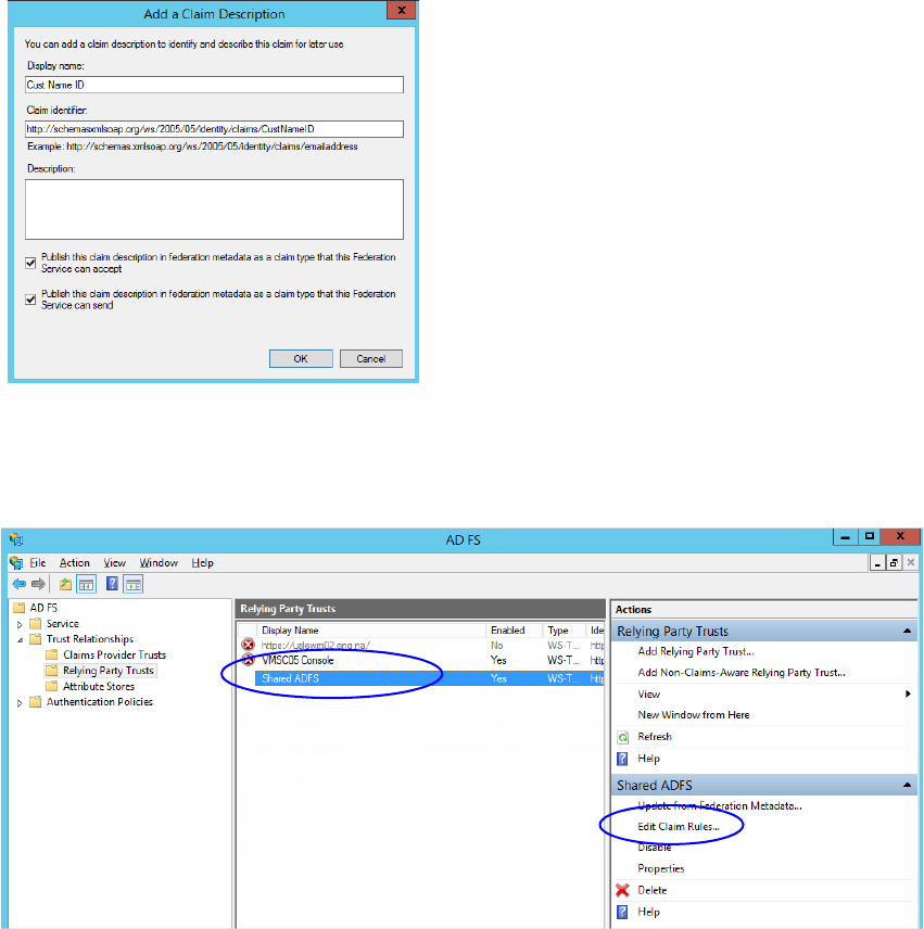
112 Enterprise Chat and Email Installation and Configuration Guide
d. Select the Publish the claim description in federation metadata as a claim type that this
Federation Service can send option.
e. Click OK to close the window.
Provide the claim description
8. In the Relying Party Trusts list, select the Shared AD FS entry and in the Actions section, click Edit Claims
Rules.
Click Edit Claims Rules
9. In the Edit Claim Rules for Shared AD FS window, in the Issuance Transform Rules tab, click the Add
Rule... button.
In the Add Transform Claim Rule wizard that opens, do the following:
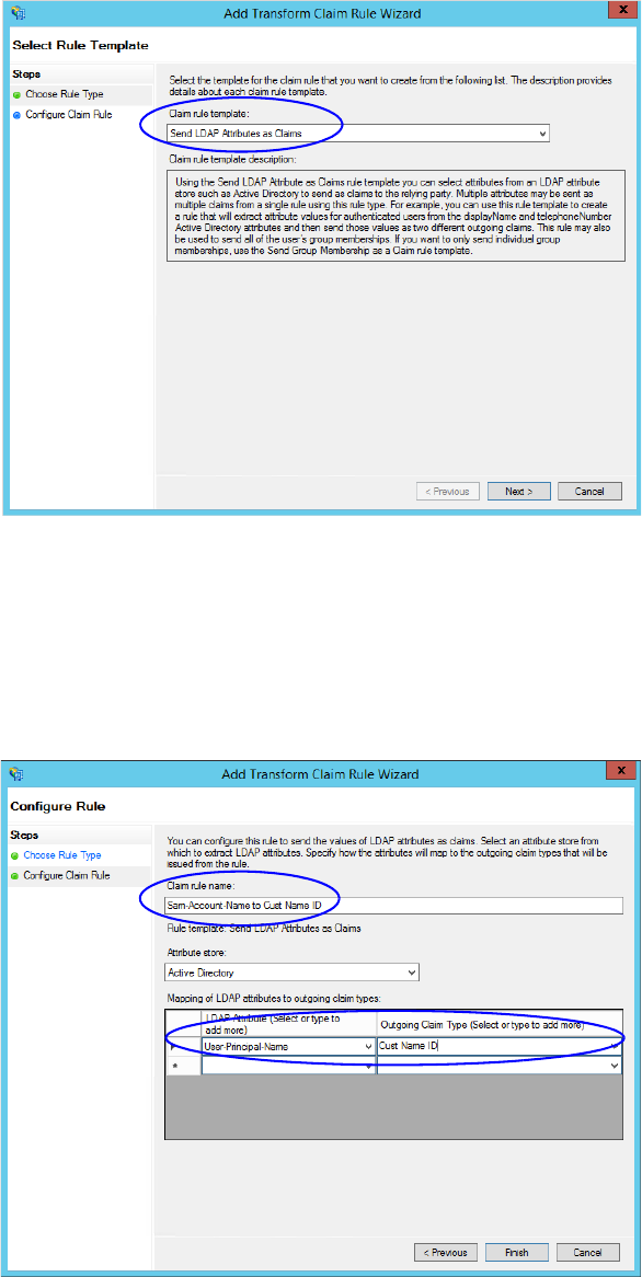
Single Sign-On Configuration 113
a. On the Choose Rule Type screen, from the Claim rule template, select Send LDAP Attributes as
Claims. Click Next.
Select the claim rule template
b. On the Configure Claim Rule screen, do the following:
i. Provide a claim rule name.
ii. Define mapping of LDAP attribute and the outgoing claim type. The outgoing claim type name must
be unique across all the claims defined in all relying party trusts created on this AD FS server. Click
Finish to go back to the Edit Claim Rules for Shared AD FS window.
Configure the claim rule
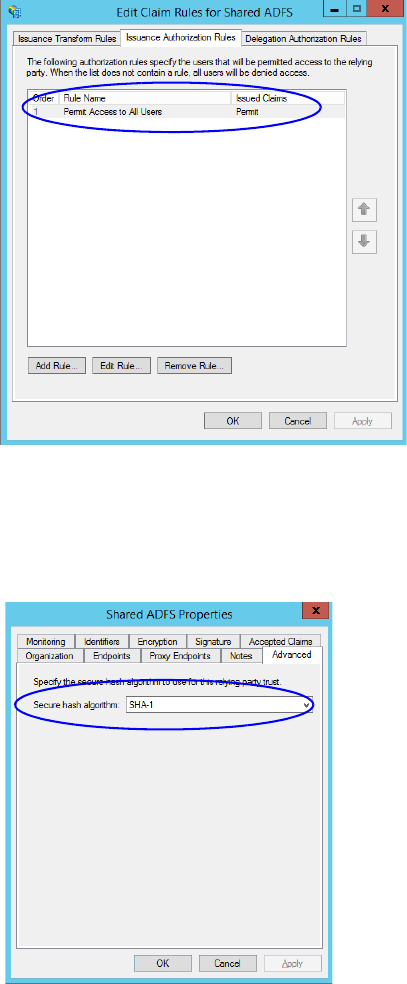
114 Enterprise Chat and Email Installation and Configuration Guide
10. In the Edit Claim Rules for Shared AD FS window, in the Issuance Authorization Rules tab, ensure that the
rule permits access to all users. Click OK to close the window.
Check the authorization rules
11. In the Relying Party Trusts list, double-click the relying party trust which you created. In the Properties
window that opens, go to the Advanced tab and set the Secure hash algorithm to SHA-1. Click OK to
close the window.
Set the secure hash algorithm
Configuring Claims Provider Trust for Customer AD FS in Shared AD FS
Perform these tasks on the server where shared AD FS is installed.
To configure claims provider trust for customer AD FS in shared AD FS:
1. Go to the Start menu and open the AD FS Management console.
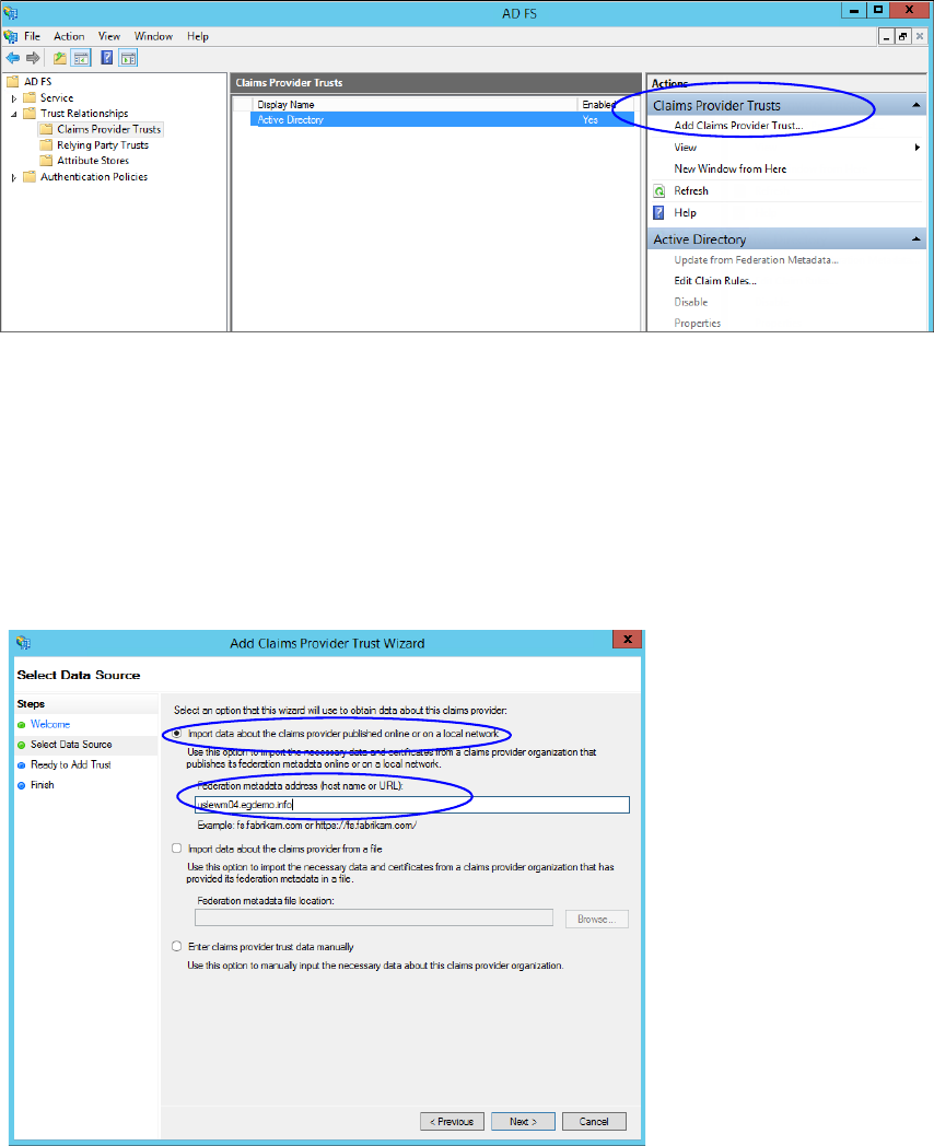
Single Sign-On Configuration 115
2. In the AD FS Management console, navigate to AD FS > Trust Relationships > Claims Provider Trust.
3. In the Actions section, go to Claim Provider Trusts, and click Add Claims Provider Trust...
Add claims provider trust
4. In the Add Claims Provider Trust Wizard that appears, do the following:
a. On the Select Data Source screen, set the following options:
i. Select the Import data about the claims provider published on online or on a local network
option.
ii. In the Federation metadata address field, provide the Customer AD FS server name.
iii. Click Next.
Set the data source
b. In the Specify Display Name screen, provide the Display name. Click Next.
c. In the screens that follow, do not alter the default values. Continue to click the Next button in the
wizard until a trust is created. At the end, an entry is created in the Claim Provider Trusts list.
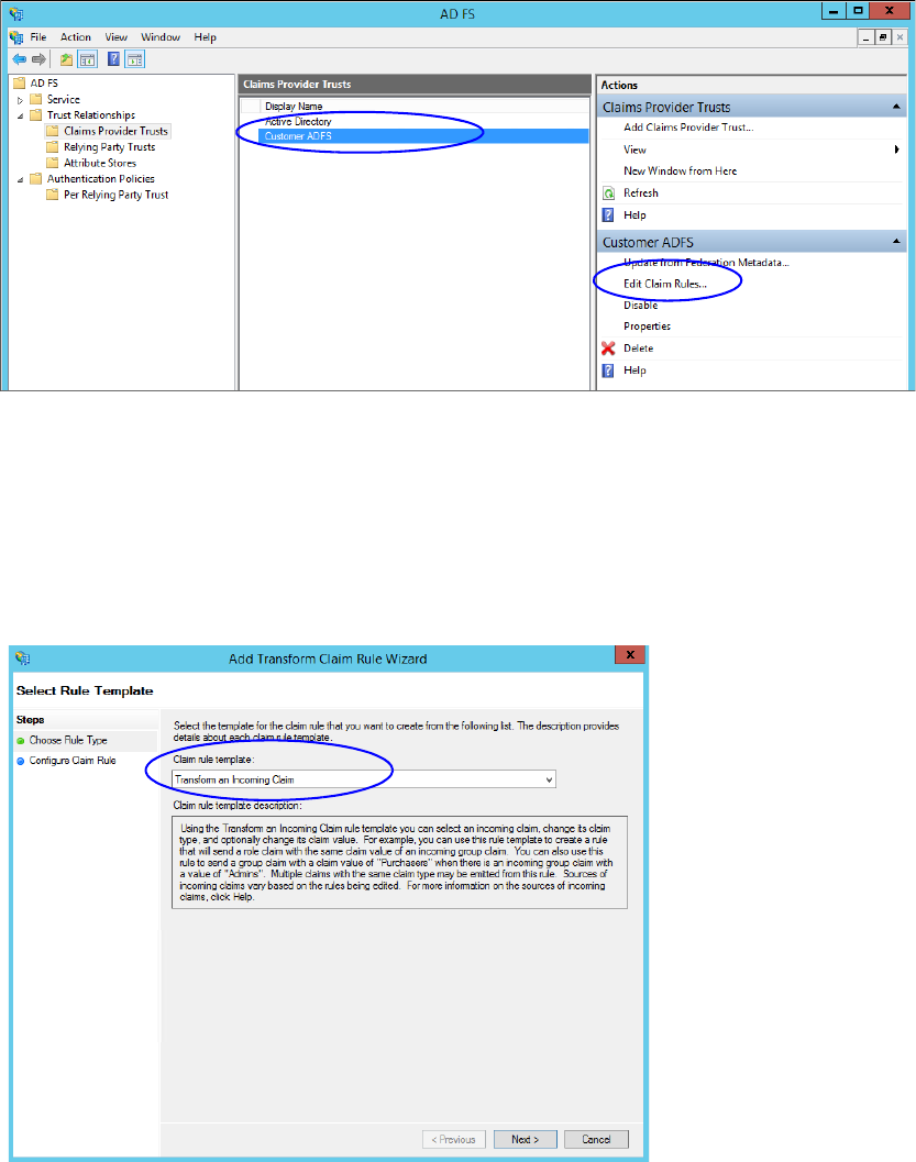
116 Enterprise Chat and Email Installation and Configuration Guide
5. In the Claim Provider Trusts list, select the Shared AD FS entry and click Edit Claim Rules.
Edit the claim rules
6. In the Edit Claim Rules for Customer AD FS window, in the Acceptance Transform Rules tab, click the Add
Rule... button.
In the Add Transform Claim Rule wizard that opens, do the following:
a. On the Choose Rule Type screen, select Transform an Incoming Claim as the claim rule template.
Click Next.
Choose the claim rule template
b. On the Configure Claim Rule screen, set the following:
i. Provide the claim rule name as Cust Name ID.
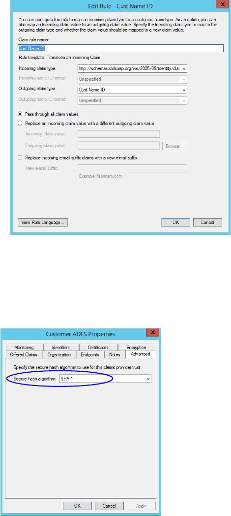
Single Sign-On Configuration 117
ii. In the Incoming claim type field provide the name as
http://schemas.xmlsoap.org/ws/2005/05/identity/claims/CustNameID. This is the same value as
provided while creating the claim rule description (page 111).
iii. Set the Outgoing claim type as Cust Name ID.
iv. Select the Pass through all claim values option.
Configure the claim rule
c. Click Finish. Claim is created and is displayed in the Edit Claim Rules for Customer AD FS window.
7. In the Claim Provider Trusts list, double-click the claim provider trust which you created. In the Properties
window that opens, go to the Advanced tab and set the Secure hash algorithm to SHA-1. Click OK to
close the window.
Set the secure hash algorithm
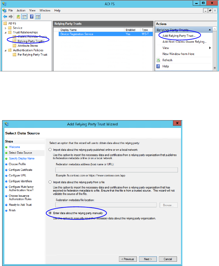
118 Enterprise Chat and Email Installation and Configuration Guide
Configuring Relying Party Trust for ECE in Shared AD FS
Perform these tasks on the server where shared AD FS is installed.
To configure relying party trust for ECE in shared AD FS:
1. Go to the Start menu and open AD FS Management console.
2. In the AD FS Management console, navigate to AD FS > Trust Relationships > Relying Party Trust.
3. In the Actions section, go to Relying Party Trust, and click Add Relying Party Trust...
4. In the Add Relying Party Trust Wizard that appears, do the following:
a. On the Welcome screen, click Start.
b. On the Select Data Source screen, select the Enter data about the reply party manually option and
click Next.
Select the Enter data about the reply party manually option

Single Sign-On Configuration 119
c. On the Specify Display Name screen, provide a Display name for the relying party. Click Next.
Provide a display name
d. On the Choose Profile screen, select AD FS profile and click Next.
Select AD FS profile
e. On the configure Certificate screen, click Next.
f. On the Configure URL screen, set the following:
i. Select the Enable support for the SAML 2.0 Web SSO protocol option.
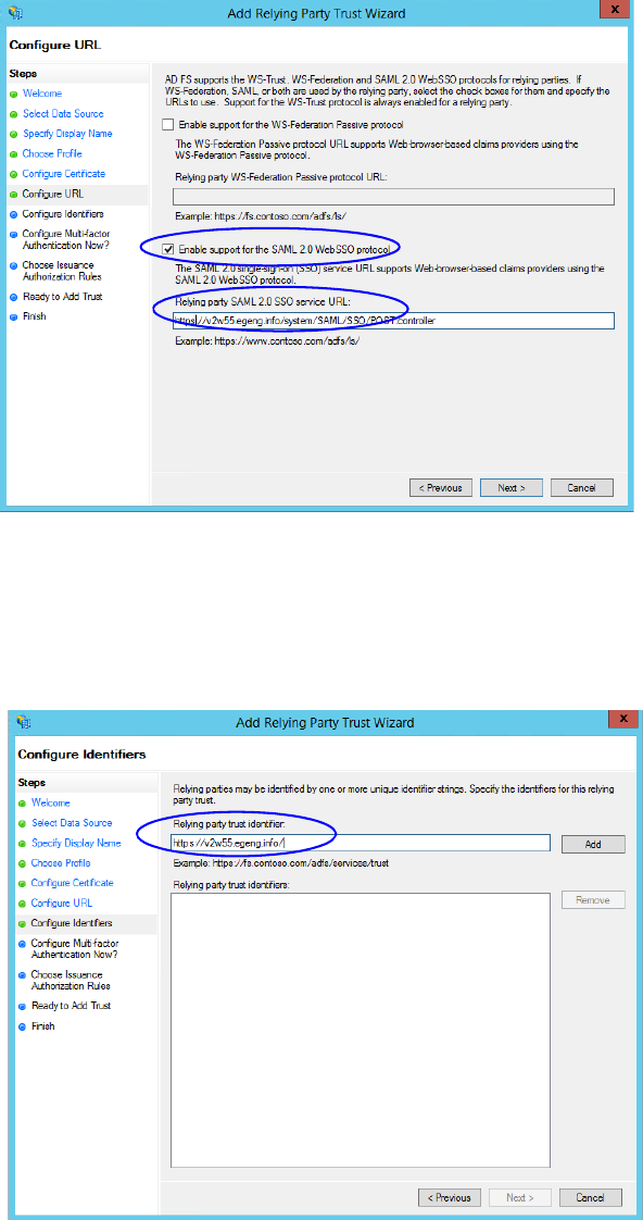
120 Enterprise Chat and Email Installation and Configuration Guide
ii. In the Relying Party SAML 2.0 SSO server URL field provide the URL in the format:
https://
Web_Server_Or_Load_Balancer_Server
/system/SAML/SSO/POST.controller.
R
eplace Web_Server_Or_Load_Balancer_Server with the ECE web server name or the Load balancer
server name.
Configure the URL
g. On the Configure Identifiers screen, provide the Replying party trust identifier and click Add. Value
should be in the format:
https://
Web_Server_Or_Load_Balancer_Server
/
.
R
eplace
Web_Server_Or_Load_Balancer_Server with the ECE web server name or the Load balancer server name.
Click Next.
Configure the identifiers
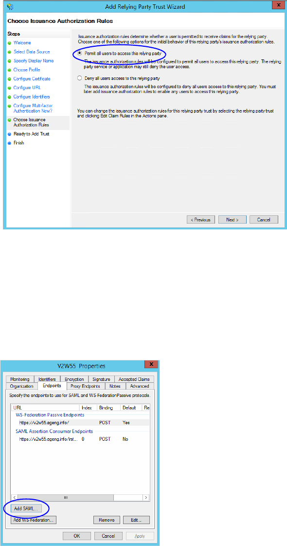
Single Sign-On Configuration 121
h. On the next screen, select the I do not want to configure multi-factor authentication settings for the
relying party trust at this time option.
i. On the Choose Issuance Authorization Rules screen, select the Permit all users to access this relying
party option.
Select the Permit all users to access this relying party option
j. On the Ready to add trust screen, click Next.
k. Uncheck the Open the Edit Claim Rules dialogue for this relying party trust when the wizard
closes option and click Close. At the end, an entry is created in the Relying Provider Trusts list.
5. In the Relying Provider Trusts list, select the trust created for ECE, and in the actions section click
Properties.
6. In the Properties window, go to the Endpoints tab and click the Add SAML.. button.
Click Add SAML
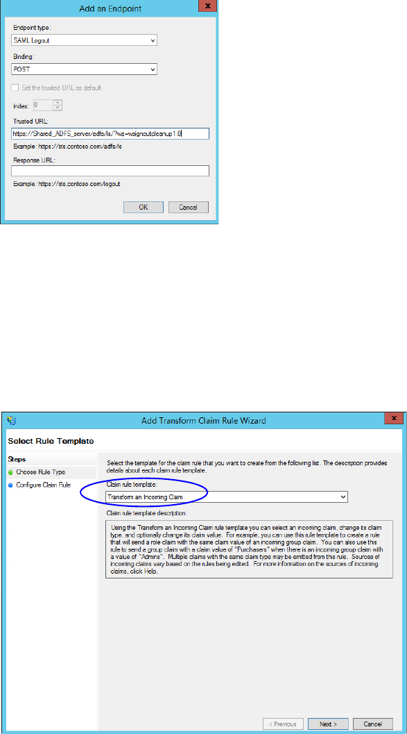
122 Enterprise Chat and Email Installation and Configuration Guide
7. In the Add an Endpoint window, set the following:
a. Select the Endpoint type as SAML Logout.
b. Specify the Trusted URL as
https://
Shared_ADFS_server
/adfs/ls/?wa=wsignoutcleanup1.0
.
Replace
Shared_ADFS_server with the Shared AD FS server name.
c. Click OK.
Create an end point
8. In the Relying Provider Trusts list, select the trust created for ECE, and in the actions section click Edit
Claim Rules.
9. In the Edit Claim Rules window, in the Issuance Transform Rules tab, click the Add Rule... button.
In the Add Transform Claim Rule wizard that opens, do the following:
a. On the Select Rule Template screen, from the Claim rule template dropdown, select Transform an
Incoming Claim. Click Next.
Select the claim rule template
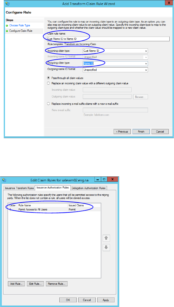
Single Sign-On Configuration 123
b. On the Configure Rule screen, set the following:
i. Provide the Claim rule name.
ii. In the Incoming claim type field provide the name of the outgoing claim specified in the Relying
Party trust wizard (page 113).
iii. In the Outgoing claim type dropdown, select the Name ID option.
Configure the rule
10. In the Edit Claim Rules window, in the Issuance Authorization Rules tab, ensure that the rule permits access
to all users. Click OK to close the window.
Check the authorization rules

124 Enterprise Chat and Email Installation and Configuration Guide
11. In the Relying Provider Trusts list, double-click the relying party trust which you created. In the Properties
window that opens, go to the Advanced tab and set the Secure hash algorithm to SHA-1. Click OK to
close the window.
Set the secure hash algorithm
12. Next, in the AD FS Management console, go to the Authentication Policy > Per Relying Party Trust.
Locate the Relying Party Trust created for ECE, and in the Actions section click Edit Custom Primary
Authentication.
Change the authentication policy for ECE

Single Sign-On Configuration 125
13. In the Edit Authentication Policy window, in the Primary tab, select the Users are required to provide
credentials each time at sign in option. Click OK to close the window.
Edit the authentication policy
Configuring Single Sign-On in ECE
Follow instruction in the “Single Sign-On” chapter of the Enterprise Chat and Email Administrator’s Guide
to Administration Console to complete the single sign-on configuration in ECE.

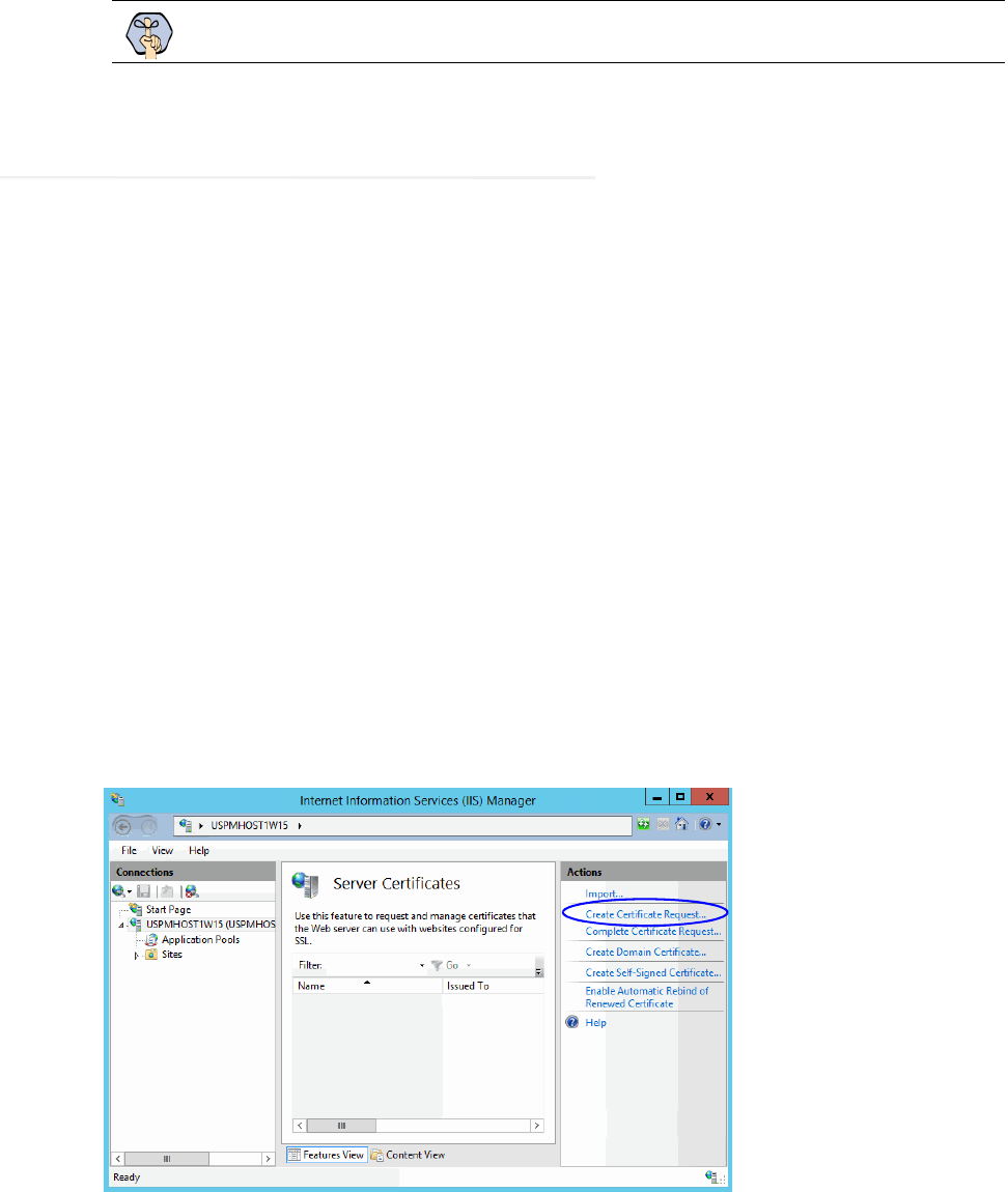
SSL Configuration 127
Secure Sockets Layer (SSL) is widely used to create a secure communication channel between web browsers and
servers. Set up SSL for more secure connections to your ECE installation by following the procedures described
in this chapter. If the configuration uses a load balancer, configure SSL on the load balancer.
Installing a Security Certificate
This section explains the procedures that you must perform to acquire a certificate and install it on the web
server. These include:
Generating a Certificate Signing Request
Submitting the Certificate Request
Installing the Certificate on the Web Server
Generating a Certificate Signing Request
This procedure creates a new certificate request, which is then sent to a Certificate Authority (CA) for
processing. If successful, the CA will send back a file containing a validated certificate.
To generate a certificate request:
1. Click the Start menu, go to Control Panel > Administrative Tools, and select Internet Information
Services (IIS) Manager.
2. In the Connections pane, select the name of the server, and when the page is refreshed, double-click Server
Certificates. The window is refreshed.
3. In the Actions pane on the right, click the Create Certificate Request... link.
Click the Create Certificate Request link
Important: You must perform these tasks before using the application.
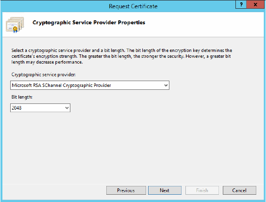
128 Enterprise Chat and Email Installation and Configuration Guide
4. In the Distinguished Name Properties window, enter information about the company and the site to be
secured:
Common Name: The fully qualified domain name (FQDN) of your server. This must match exactly
what users type in the web browser to get to the application. If you are using a load balancer, enter the
name of the server on which the load balancer is installed.
Organization: The legal name of your organization. This should not be abbreviated and should include
suffixes such as Inc, Corp, or LLC.
Organizational Unit: The division of your organization handling the certificate.
City/locality: The city where your organization is located.
State/province: The complete name of the state or region where your organization is located.
Country/region: The two-letter ISO code for the country where your organization is located.
Click Next.
5. In the Cryptographic Service Provider window, select a cryptographic service provider and set the required
bit length. The greater the bit length, the stronger the security. Click Next.
Select a cryptographic service provider and bit length
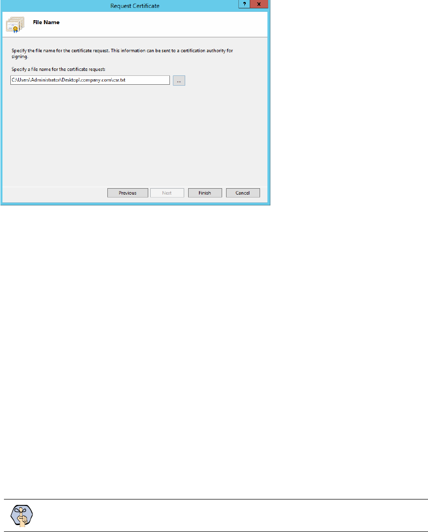
SSL Configuration 129
6. In the File Name window, click the Assistance ... button and browse to the location where you wish to save
the certificate signing request file. Ensure that you enter a file name for the certificate signing request file.
Click Finish.
Enter the location and file name
Once you have generated a certificate signing request, you can submit the certificate request to a certificate
authority.
Submitting the Certificate Request
To submit the certificate request:
Go to the website of the company that issues SSL certificates (such as VeriSign), and submit your certificate
request. Make sure you provide the same information as you provided while generating the certificate
signing request. To submit the request, you will need the certificate request file that you generated
(page 127).
Once the request is processed, the vendor will generate the certificate and send it to you.
Installing the Certificate on the Web Server
Once you receive the certificate from your vendor, install it on all web servers. If you are using load balancer,
install it on the load balancer server.
To install the certificate on the web server:
1. Click the Start menu, go to Administrative Tools, and select Internet Information Services (IIS)
Manager.
Important: You need to install the certificate for the website that was specified when the web
server component was installed.
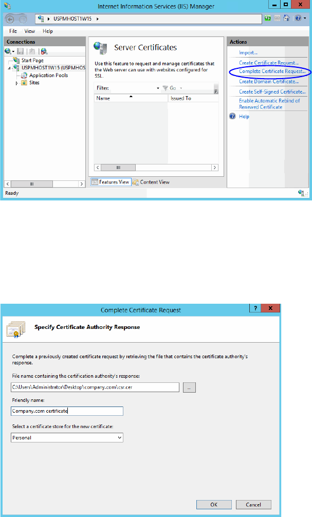
130 Enterprise Chat and Email Installation and Configuration Guide
2. In the Connections pane, select the name of the server, and when the page is refreshed, double-click Server
Certificates. The window is refreshed.
3. In the Actions pane on the right, click the Complete Certificate Request... link.
Click the Complete Certificate Request link
4. In the Specify Certificate Authority Response window, complete these tasks:
Click the Assistance ... button and select the server certificate that you received from the certificate
authority. If the certificate doesn't have a .cer file extension, select to view all types.
Enter a name for the certificate. Click OK.
Browse to the server certificate file
5. Verify that the certificate is added to the list of server certificates.
Repeat this process on all web servers.
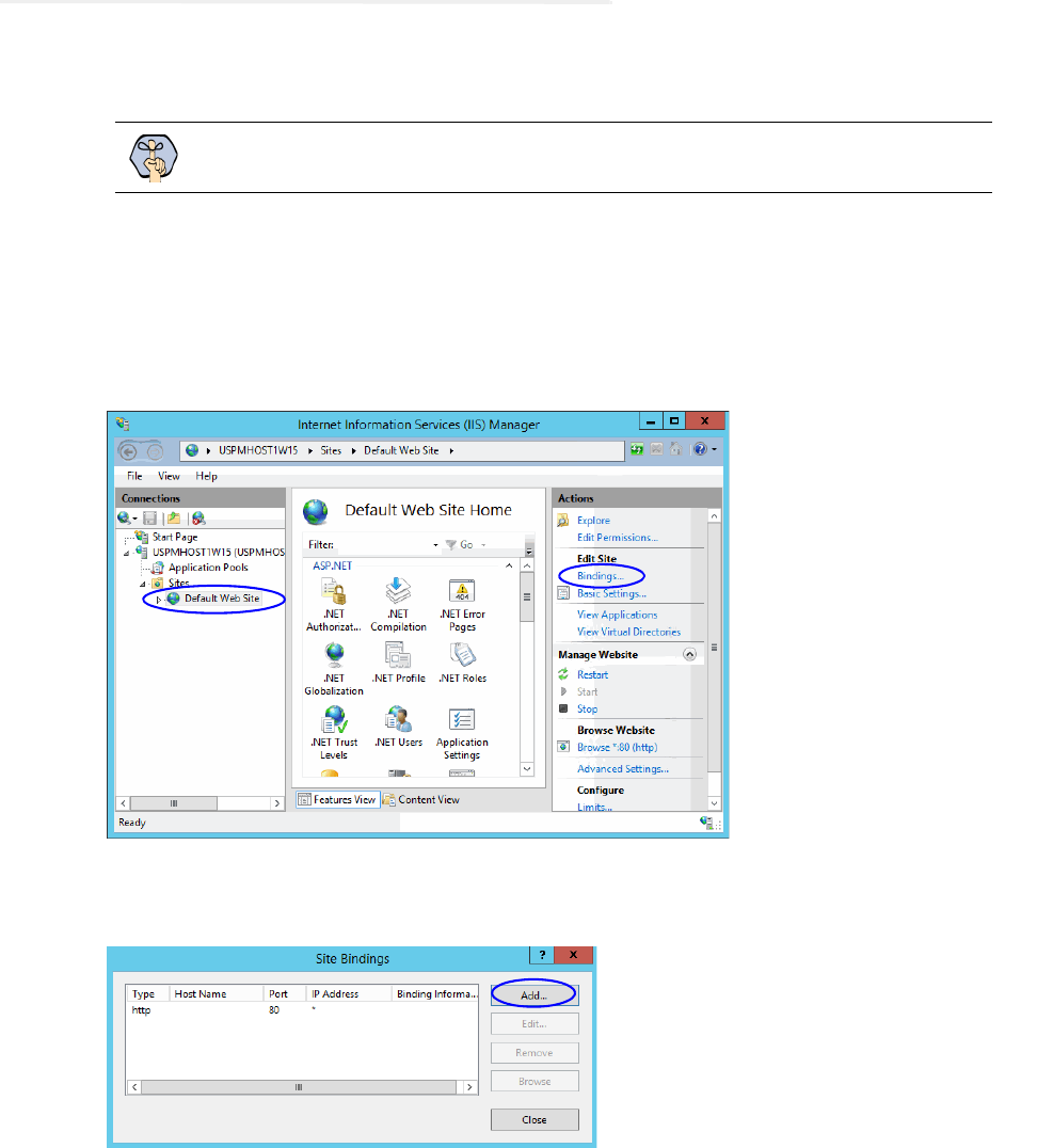
SSL Configuration 131
Binding the Certificate to the Application Website
This procedure uses Internet Services Manager to configure the virtual directory to require SSL for access to the
application URL.
To bind the certificate to the application URL:
1. Click the Start menu, go to Administrative Tools, and select Internet Information Services (IIS)
Manager.
2. In the Connections pane, select the name of the server and browse to Sites >
Web_Site_Name.
3. In the Actions pane on the right, from the Edit Site section, click the Bindings... link.
Select the Web_Site_Name
4. In the Site Bindings window, click the Add... button.
Click the Add button
5. In the Add Site Bindings window, complete these tasks:
Type: Select https.
IP address: Select All Unassigned.
Port: Default value is 443. If IIS is configured to use a different port for https, enter that port number.
Important: You need to configure the SSL access for the website that was selected when
the web server component was selected.
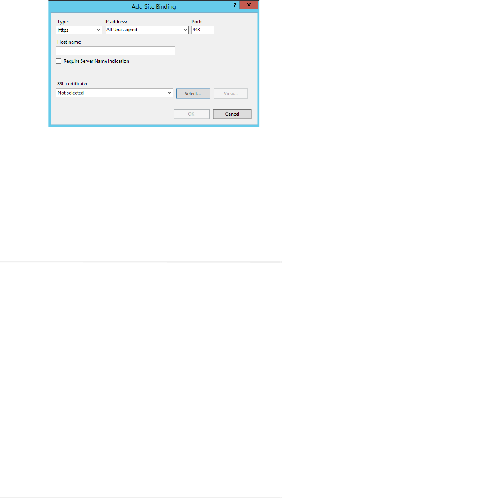
132 Enterprise Chat and Email Installation and Configuration Guide
SSL certificate: Select the certificate that you installed. Click OK.
Select SSL certificate
6. The site binding for port 443 is displayed.
7. Restart the IIS Service. Make sure that both websites have started.
Clients browsing to this virtual directory must now use HTTPS.
Testing SSL Access
To test SSL access to ECE:
1. Open your web browser.
2. Use HTTP in the URL for the application. For example,
http://
Web_server_FQDN
/
Partition_name
You should see a message asking you to view the page over a secure channel.
3. Now use HTTPS in the URL for the application. For example,
https://
Web_Server_FQDN
/
Partition_name.
4. In the security message that appears, click the View certificate button.
5. After verifying the certificate information, click OK, then click Yes to proceed to the URL.
The ECE login window appears.
Configuring SSL or TLS for Retriever and Dispatcher
Services
You need to perform these tasks only if you want to enable the retriever and dispatcher services to work with
SSL or TLS enabled mail servers. POP3, IMAP, SMTP, and ESMTP protocols are supported.
To configure TLS and SSL, you must:
Install the certificates on the file server. (page 133)
a. Modify the alias configuration (page 134)
SSL Configuration 133
On the File Server
If your POP3, IMAP, SMTP, and ESMTP servers are installed on different machines, obtain the certificates for
all the servers and install them on the file server.
Perform these tasks on the file server. In case of Distributed File Server, perform these tasks on the Active Node.
Installing Certificates
To configure SSL or TLS on the file server:
1. Obtain the certificate for the SSL or TLS enabled mail server on which the email alias is configured. If your
POP3, IMAP, SMTP, and ESMTP servers are installed on different machines, obtain the certificates for all
the servers.
2. Copy the certificates to a location in
Cisco_Home.
3. Open the Command window and navigate to the
bin
folder in the
jre
folder in JDK_Home, the installation
folder for JDK. For example, the command will look like:
cd C:\InstallFolder\Java\jdk1.8.0_60\jre\bin
4. Execute the following command to install the certificate:
keytool -import -trustcacerts -alias
ALIAS_NAME
-keystore
"..\lib\security\cacerts" -file "
CERTIFICATE_FILE_PATH
"
where:
CERTIFICATE_FILE_PATH is the complete path to the certificate that you copied in Step 2, including the
name of the file.
Alias_Name is any name you want to assign to the certificate.
For example the command will look like:
keytool -import -trustcacerts -alias emailcertificate -keystore
"..\lib\security\cacerts" -file "D:\eG\ms_exchange_certificate.cer"
5. When prompted, provide the keystore password. If you had changed the keystore password earlier, provide
that password. If not, provide the default password,
changeit
.
6. Confirm the action when prompted.
7. To verify that the certificate is installed successfully, run the following command:
keytool -list -v -keystore "..\lib\security\cacerts" -alias
ALIAS_NAME
where Alias_Name is the name you assigned to the certificate in Step 4.
For example, the command will look like:
keytool -list -v -keystore "..\lib\security\cacerts" -alias emailcertificate
8. When prompted, provide the keystore password.
The output will list the installed certificate.

134 Enterprise Chat and Email Installation and Configuration Guide
Deleting Certificates
Certificates generally have an expiry date. When your certificate expires, you might need to delete the old
certificates and install new ones. The following section describes the steps for deleting the certificates. After
deleting the certificates, repeat the steps in “Installing Certificates” on page 133 to install new certificates.
To delete a certificate:
1. Open the Command window and navigate to the
bin
folder in the
jre
folder in JDK_Home, the installation
folder for JDK. For example, the command will look like:
cd C:\InstallFolder\Java\jdk1.8_65\jre\bin
2. Execute the following command to delete the certificate:
keytool -delete -alias
ALIAS_NAME
-keystore "..\lib\security\cacerts"
where:
Alias_Name is the name you assigned to the certificate in Step 4.
For example the command will look like:
keytool -delete -alias emailcertificate -keystore "..\lib\security\cacerts"
3. When prompted, provide the keystore password. If you had changed the keystore password earlier, provide
that password. If not, provide the default password,
changeit
.
In the Administration Console
To enable SSL for specific aliases:
1. Log into the application as an administrator who can modify the email alias configuration and go to the
Administration Console.
2. In the Tree pane, browse to Administration > Departments >
Department_Name > Email > Aliases.
3. In the List pane, select the appropriate email alias.
4. In the Properties pane, go to the Servers tab and edit the following fields.
Connection type: Set this to SSL or TLS.
Port: Enter the secure port number.
Configure the alias properties
SSL Configuration 135
5. Repeat these steps for the Outgoing mail server, if required.
6. Save the changes.

Setting Up
Integrated
Objects
Configuring Variables in ECE
Verifying Mapping of Objects in the Administration Console
Setting up Business Objects in the Administration Console
Setting Up Services in the System Console
Setting Up Web Links for Chat and Callback
Configuring Dynamic Messages for Integrated Chats
Related Documentation

Setting Up Integrated Objects 137
This chapter provides an overview of the process of setting up ECE–Unified CCE objects.
Configuring Variables in ECE
While sending new activity requests from a queue to Unified CCE, EAAS sends call variables and ECC
variables to Unified CCE as task context. By default, the following activity attributes are sent to Unified CCE as
ECC variables.
For inbound and outbound email activities: activity_id
For chat activities: activity_id
For callback and delayed callback activities: activity_id, customer_name
If you need to pass on other attributes of the activity as call variables or ECC variables to Unified CCE, you need
to configure them in ECE. These variables can then be used in Unified CCE scripts to configure conditions. For
details, see the Unified CCE scripts documentation. If you plan to configure these variables as ECC variables in
ECE, you need to first create the ECC variables in Unified CCE. For details, see the Unified CCE
documentation.
You can also create variables for custom activity attributes. For details about creating variables, see the “Call
Variables” chapter in the Enterprise Chat and Email Administrator's Guide to Routing and Workflows.
Verifying Mapping of Objects in the Administration
Console
To verify that Unified CCE objects have been mapped correctly in the ECE
Administration Console:
1. Launch the URL: http://ECE_Web_Server/Default_Partition.
2. Log in as the partition administrator (user name and password that were configured during the installation of
ECE). Go to the Administration Console.
3. Under the appropriate department, browse to the User > Users node in the Administration tree, to verify that
all users mapping to the administrators, supervisors, and agents, which were selected at the time of
importing the objects, are displayed. For details, see the Enterprise Chat and Email Administrator’s Guide
to Administration Console.
4. Under the appropriate department, click the User > Groups node in the Administration tree to verify that all
user groups mapping to the skill groups, which were selected at the time of importing the objects, are
displayed. For details, see the Enterprise Chat and Email Administrator’s Guide to Administration Console.
5. Under the appropriate department, click the Workflow > Queues node in the Administration tree, and verify
that all queues mapping to the MRDs, which were selected at the time of importing the objects, are
displayed. For details, see the Enterprise Chat and Email Administrator’s Guide to Routing and Workflows.

138 Enterprise Chat and Email Installation and Configuration Guide
Setting up Business Objects in the Administration
Console
See the following guides for the details of the procedures mentioned in this section:
Enterprise Chat and Email Administrator’s Guide to Routing and Workflows
Enterprise Chat and Email Administrator’s Guide to Email Resources
Enterprise Chat and Email Administrator’s Guide to Chat and Collaboration Resources
To set up ECE business objects in the Administration Console:
1. Launch the URL: http://ECE_Web_Server/Default_Partition.
2. Log in as the partition administrator and go to the Knowledge Base Console.
3. In the Knowledge Base tree, browse to Departments >
Department_Name > Content > Shared > Standard
> Email. Create an article in each of the sub-nodes to set up one option each for a header, greeting,
signature, footer, and auto acknowledgements that can be used in responses to incoming activities in the
department.
4. Go to the Administration Console.
5. In the Administration tree, browse to the Administration > Departments >
Department_Name >
Classifications > Categories node. Create categories.
These categories will be used later in a workflow (see page 138).
6. Now, browse to the Email > Aliases node. Create an alias to serve as the entry point for emails into the
system.
7. Then, browse to the Workflow > Workflows > Inbound node to create an inbound workflow for this alias.
The workflow will route incoming emails. Add the alias created in Step 6 to the Start node. Add the email
queue to the Queue node. Select the auto-acknowledgement KB article created earlier (see page 138) for the
Auto-acknowledgement node. Select the categories created in Step 5 for the Classifications node.
8. Browse to the Chat > Entry points node. Create new entry points by assigning the appropriate templates.
To route chats and call back activities that enter from this entry point, use an auto-configured queue. Make
the entry points active. The configuration steps for entry points are different for different types of activities
and routing options.
The activity types for which you need to create entry points are: Chat, Callback, Delayed callback.
9. In the Properties pane, click the Show HTML button. The code used to generate a chat hyperlink to that
entry point is displayed. Copy this link code into a Notepad file. Edit the code as explained in the Enterprise
Chat and Email Administrator’s Guide to Chat and Collaboration Resources.

Setting Up Integrated Objects 139
Setting Up Services in the System Console
Service processes are managed at the system level as shared resources across partitions. Service instances are
managed within partitions.
See Enterprise Chat and Email Administrator's Guide to System Console for the details of the procedures
mentioned in this section.
This section helps you set up processes and instances for the following services:
Retriever: Gets incoming emails from configured aliases and parses them.
Workflow Cache: Maintains the files that store information about objects used in workflows.
Workflow Engine: Applies workflows on emails to automate their routing and handling.
Dispatcher: Sends outgoing emails out of the system.
External Agent Assignment Service (EAAS): Identifies new activities that arrive into an external
assignment queue, and routes requests for each of these activities to Unified CCE for routing to take place
through Unified CCE.
External Agent Messaging Service (EAMS): Assigns activities to target agents or user groups (skill
groups) identified by Unified CCE, and reports the status of both the activity and the agent to Unified CCE
throughout the life cycle of the given activity.
Context Service: This service synchronizes activities and customer’s information between the Cisco ECE
and Cisco Context Service. This service only applies to systems using Cisco Context Service. For details on
Context Service availability, visit https://help.webex.com/community/context-service. Note that Cisco
Context Service is deprecated from Release 12.0(1) onward.
To set up ECE services in the System Console:
See Enterprise Chat and Email Administrator's Guide to System Console for the details of the procedures
mentioned in this section.
1. Open a new browser window, and launch the URL:
http://
ECE_Web_Server
/
Context_Root
.
Log in as the
system administrator (user name and password that were configured during the installation of ECE). Go to
the System Console.
2. Browse to the Partitions >
Partition > Services > Email > Retriever node. Click the Retriever instance to
use in the partition, and select the email alias that you had created earlier in the Administration Console (see
page 138).
3. Restart the Retriever process and instance based on the notification message that appears. Browse to Shared
Resource > Services > Retriever, and stop and start the Retriever process for the system. Also ensure that
the start type for the service process is set to automatic.
4. Navigate back to the Partitions >
Partition > Services > Retriever node. Ensure that the start type for the
service instance is set to automatic. Stop and start the Retriever instance.
5. Browse to Shared Resource > Services > Workflow > Workflow Cache and verify that the Workflow
Cache process is running. If the process is in a stopped state, start the process by clicking the Run button.
Also ensure that the start type for the service process is set to automatic.
6. Browse to Partitions >
Partition > Services > Workflow > Workflow Cache and ensure that the start type
for the service instance is set to automatic. Start the Workflow Cache instance.

140 Enterprise Chat and Email Installation and Configuration Guide
7. Browse to Shared Resource > Services > Workflow > Workflow Engine and verify that the Workflow
Engine process is running. If the process is in a stopped state, start the process by clicking the Run button.
Also ensure that the start type for the service process is set to automatic.
8. Browse to Partitions >
Partition > Services > Workflow > Workflow Engine and ensure that the start type
for the service instance is set to automatic. Start the Workflow Engine instance.
9. Browse to Shared Resource > Services > Email > Dispatcher and verify that the Dispatcher process is
running. If the process is in a stopped state, start the process by clicking the Run button. Also ensure that the
start type for the service process is set to automatic.
10. Browse to Partitions >
Partition > Services > Email > Dispatcher and ensure that the start type for the
service instance is set to automatic. Start the Dispatcher instance.
11. Browse to Shared Resource > Services > Unified CCE > EAMS and verify that the EAMS process is
running. If the process is in a stopped state, start the process by clicking the Run button. Also ensure that the
start type for the service process is set to automatic.
12. Browse to Partitions >
Partition > Services > Unified CCE > EAMS. Verify that the EAMS instance for
the Agent PG is automatically created. Also ensure that the start type for the instance is set to automatic.
Then start the EAMS instance.
13. Browse to Shared Resource > Services > Unified CCE > EAAS and verify that the EAAS process is
running. If the process is in a stopped state, start the process by clicking the Run button. Also ensure that the
start type for the service process is set to automatic.
14. Browse to Partitions >
Partition > Services > Unified CCE > EAAS. Configure the EAAS instance by
providing the MR Connection port number you provided while creating the MR PG (page 49). Also ensure
that the start type for the instance is set to automatic. Start the EAAS instance.
15. Browse to Shared Resource > Services > Unified CCE > Context Service and verify that the Context
Service process is running. If the process is in a stopped state, start the process by clicking the Run button.
Also ensure that the start type for the service process is set to automatic. If the ECE services server is behind
a firewall and does not have direct access to the internet, the Proxy Server URL should be provided so that
the server can connect to the Cisco Context Service. Format of the URL is:
http://ProxyServerName:Port
or
https://ProxyServerName:Port
16. Browse to Partitions > Partition > Services > Unified CCE > Context Service. Ensure that the start type
for the instance is set to automatic. Then start the Context Service instance.
Setting Up Web Links for Chat and Callback
To create a chat and collaboration link on your web site:
Open the code view of the host web page and add the edited link code (see page 138) from the entry point
properties at the appropriate point. You may need to ask your web master to perform this task.
ECE is now ready for use. To verify, log in as an agent, supervisor, or administrator and perform basic tasks.

Setting Up Integrated Objects 141
Configuring Dynamic Messages for Integrated Chats
Dynamic Run Application Script Request (DRASR) allows you to display wait messages with dynamic text
(such as expected wait time) to customers while chat and call requests are being processed by the ECE and
Unified CCE integrated systems. You can use ECC variables and call variables to display the dynamic content.
For details about configuring DRASR, refer the Enterprise Chat and Email Administrator’s Guide to Chat and
Collaboration Resources.
Related Documentation
Refer to the following ECE User’s Guides (for the Unified CCE integration) for more information about
configuring and using ECE.
Enterprise Chat and Email Administrator’s Guide to Administration Console helps administrators set up
and manage business objects.
Enterprise Chat and Email Administrator’s Guide to Chat and Collaboration Resources helps
administrators set up templates and entry points.
Enterprise Chat and Email Administrator’s Guide to Email Resources helps administrators set up
aliases, blocked addresses, delivery exceptions, and blocked file extensions.
Enterprise Chat and Email Administrator’s Guide to Routing and Workflows helps administrators set up
service levels, queues, and workflows.
Enterprise Chat and Email Administrator’s Guide to System Console helps system administrators set up
and manage services, loggers, and system monitors.
Enterprise Chat and Email Administrator’s Guide to Tools Console helps administrators add custom
attributes.
Enterprise Chat and Email Supervisor’s Guide helps supervisors set up and use agent and queue
monitors.
Enterprise Chat and Email Administrator’s Guide to Reports Console helps managers and supervisors
to set up and run reports to analyze various aspects of the system.
Enterprise Chat and Email Agent’s Guide helps agents handle email and chat interactions.

143
Installing DFS Management
Perform these tasks on both the servers where you want to store the ECE file share for DFS.
To install DFS by using Server Manager
1. Open Server Manager, click Manage, and then click Add Roles and Features. The Add Roles and Features
Wizard appears.
2. On the Server Selection page, select the server on which you want to install DFS.
3. On the Server Roles page, in File and Storage Services > File and iSCSI Services, select DFS
Namespaces and DFS Replication. Run through the wizard to complete the installation.
Creating Shared Folders
Perform these tasks on all the servers where you want to store the ECE file share for DFS.
To create a shared folder:
1. Create a folder on the server where you want to store the ECE file share for DFS.
2. Right-click the folder and select Properties. Set the following in the properties window:
a. Go to the Security tab and click the Edit button. Add the Service account and assign the Service
account Modify permissions on the folder.
b. Go to the Sharing tab and click Advanced Sharing and select the Share this folder option in the
Advanced Sharing window. Click the Permissions button and in the Permissions window, assign the
Service account Full Control permission on the folder.
c. From the Sharing tab, copy the Network Path of the shared folder and access it from the second server
to make sure it is accessible. Create a test folder in the shared folder to test the permissions.
Repeat these steps on the other servers.
Creating New Namespace
Perform these tasks on one of the file servers where you want to store the ECE file share for DFS.
To add new namespaces:
1. In the DFS Management window, browse to DFS Management > Namespaces.
2. Right-click Namespaces and select New Namespaces from the context-menu.
3. In the New Namespace Wizard, set the following:
a. On the Namespace Server screen, click the Browse button and provide the name of the server where
you created the shared folder. Click Next.

144 Enterprise Chat and Email Installation and Configuration Guide
b. On the Namespace Name and Settings screen, provide a name for the namespace. Click the Edit
Settings button. In the Edit Settings window, select the Administrators have full access; other users
have read-only permissions option. Click Next.
If you are converting an exiting non-HA deployment to HA, you may see the following prompt:
A
shared folder
Folder_Name
already exists on the server. If the existing share
folder is used, the security setting specified within the Edit Setting
dialog box will not apply.
Click Yes to continue.
c. On the Namespace Type screen, select Domain-based namespace. Click Next.
d. On the Review Settings and Create Namespace screen, click Create.
4. Click Close to exit the wizard.
Adding Namespace Server
Perform these tasks on other file servers in the deployment.
To add the namespace server:
1. In the DFS Management window, browse to DFS Management > Namespaces.
2. Right-click the namespace you created on page 143 and select Add Namespace Server from the context-
menu.
3. In the Add Namespace Server window, click Browse in the Namespace server field. In the Select Computer
window provide the name of the second server where you created the shared folder. Click the Edit Settings
button. In the Edit Settings window, select the Administrators have full access; other users have read-
only permissions option. Click OK.
Adding Folders and Configuring Replication
To add folders and configure replication:
1. In the DFS Management window, browse to DFS Management > Namespaces > DFS created for ECE.
2. In the Actions section, click the New Folder button. Set the following in the New Folder window.
Provide a name for the folder. For example,
ECE
.
In the Folder targets, add the network path of both the shared folders created on the ECE servers.
3. When prompted to create a Replication group, click Yes.
4. Run through the Replicate Folder Wizard to set up replication. When prompted to select the Primary
Member, select any one server to be the primary server.
5. Once replication is setup, set the Staging folder quota for the replication. You must set a number based on
the available bandwidth and the size of the files to be replicated. Follow Microsoft documentation for
guidelines for setting the quota numbers.

146 Enterprise Chat and Email Installation and Configuration Guide
About Always On Availability Group Clustering
This chapter talks about an Always On cluster configuration with two nodes. You can add more nodes, if
required. The two deployment models supported are:
1. Reports database and active and master databases are on the same node with a common availability group
for the databases.
2. Reports database is on one node and active and master databases are on a separate node with respective
availability groups for each node.
Pre-Installation Tasks
Installing Failover Clustering Feature
Perform this task on for all nodes of active and reports databases.
To install the failover cluster feature:
1. Open Server Manager, click Manage, and then click Add Roles and Features. The Add Roles and Features
Wizard appears.
2. On the Server Selection page, select the server on which you want to install the Failover Clustering.
3. On the Features page, select Failover Clustering. Run through the wizard to complete the installation.
Creating Prestage Cluster Computer Objects in Active Directory Domain
Services (AD DS)
To create the cluster name object (CNO) automatically, the user who creates the failover cluster must have the
Create Computer objects permission to the organizational unit (OU) or the container where the servers that will
form the cluster reside.
To enable a user or group to create a cluster without having this permission, a user with appropriate permissions
in AD DS (typically a domain administrator) can prestage the CNO in AD DS.
These tasks are done by a network administrator.
Important: ECE supports the clustering feature only for installations using the Enterprise Edi-
tion of MSSQL.
Important: Ensure that all the databases related pre-installation and post-installation tasks
are performed on all nodes in the cluster.
147
Prestaging the CNO in AD DS
To prestage the CNO in AD DS:
1. On a computer that has the AD DS Tools installed from the Remote Server Administration Tools, or on a
domain controller, open Active Directory Users and Computers. To do this on a server, open Server
Manager and from the Tools menu, select Active Directory Users and Computers.
2. In Active Directory Users and Computers, on the View menu, make sure that Advanced Features is
selected.
3. Create an OU, if it does not exists. For the cluster computer objects, right-click the domain name or an
existing OU, and select New > Organizational Unit. In the Name box, enter the name of the OU, and then
click OK.
4. In the console tree, right-click the OU where you want to create the CNO, point to New, and then select
Computer.
5. In the Computer name box, enter the name that will be used for the failover cluster, and then select OK.
6. As a best practice, right-click the computer account that you just created, click Properties, and then click
the Object tab. On the Object tab, select the Protect object from accidental deletion check box, and then
click OK.
7. Right-click the computer account that you just created, and then select Disable Account. Select Yes to
confirm, and then select OK. You must disable the account so that during cluster creation, the cluster
creation process can confirm that the account is not currently in use by an existing computer or cluster in the
domain.
Granting User Permissions to Create Cluster
To grant user permissions to create cluster:
1. In Active Directory Users and Computers, on the View menu, make sure that Advanced Features is
selected.
2. Locate and then right-click the CNO, and then click Properties.
3. On the Security tab, click Add.
4. In the Select Users, Computers, or Groups dialog box, specify the user account or group that you want to
grant permissions to, and then click OK.
5. Select the user account or group that you just added, and then next to Full control, select the Allow check
box.
6. Select OK.
Granting the CNO Permissions to the OU
To grant the CNO permissions to the OU:
1. In Active Directory Users and Computers, on the View menu, make sure that Advanced Features is
selected.
148 Enterprise Chat and Email Installation and Configuration Guide
2. Right-click the OU where you created the CNO (page 147) and then select Properties.
3. On the Security tab, select Advanced.
4. In the Advanced Security Settings dialog box, select Add.
5. Next to Principal, select Select a principal.
6. In the Select User, Computer, Service Account, or Groups dialog box, select Object Types, select the
Computers check box, and then select OK.
7. Under Enter the object names to select, enter the name of the CNO, select Check Names, and then select
OK. In response to the warning message that says that you are about to add a disabled object, select OK.
8. In the Permission Entry dialog box, make sure that the Type list is set to Allow, and the Applies to list is set
to This object and all descendant objects.
9. Under Permissions, select the Create Computer objects and Delete Computer Object check boxes.
10. Select OK until you return to the Active Directory Users and Computers snap-in.
Creating Windows Failover Cluster
Perform this task on one active server node and one reports database node.
To install Windows server failover cluster:
1. Open Server Manager and from the Tools menu, select Failover Cluster Manager.
2. In the Failover Cluster Manager, right-click Failover Cluster Manager and select Create Cluster from the
menu.
3. In the Create Cluster Wizard, on the Select Servers screen, enter the Server Name for both active database
servers to be added to the cluster and Click Add.
4. On the Validation Warning screen, select Yes to validate the cluster nodes. The program will run you through
the validation process.
5. On the Access Point for Administering the Cluster screen, provide the Cluster Name. This is the name of
the computer object created in the Active Directory. Enter the IP address reserved for the Windows Cluster
Name Object. You will need two IPs for the Cluster if the target servers are at two different subnets. Click
Next.
6. On the Confirmation screen, uncheck the Add all eligible storage to the cluster option. Click Next.
7. Click Finish on the Summary screen.
Repeat this task for the reports database node. In Step 3, add the reports database servers.
Configure Cluster Quorum Settings
Quorum is a configuration database for the cluster and is stored on a shared location, accessible to all of the
nodes in a cluster.
In Case of even number of nodes (but not a multi-site cluster) Node and Disk Majority Quorum configuration
is recommended. If you don't have a shared storage, Node and File Share Majority is recommended. Here it
will be configuring a FileShare Witness quorum.
149
It is recommended that you configure the quorum size to be 500 MB. This size is the minimum required for an
efficient NTFS partition. Larger sizes are allowable but are not currently needed.
Perform this task on one active server node and one reports database node.
To configure cluster quorum
settings:
1. In the Failover Cluster Manager, right-click the cluster you added. From the context-menu, go to More
Actions > Configure Cluster Quorum Settings.
2. Run through the Configure Cluster Quorum Wizard.
3. On the Select Quorum Configuration Option screen, select the Select the quorum witness option.
4. On the Select Quorum Witness screen, select the Configure a file share witness option.
5. On the Configure File Share Witness screen, type the path of the shared folder that you want to use. Click
Next. It is recommended to have the share folder on a different node than the participating nodes on cluster.
6. Run through the rest of the wizard to complete the configuration.
Enabling Always On Availability Groups Feature on SQL
Perform this task on one active server node and one reports database node.
To enable always-on availability groups feature:
1. Open the SQL Server Configuration Manager and browse to SQL Server Services.
2. In the list pane, right-click SQL Server service and select Properties.
3. In the Properties window, go to the AlwaysOn High Availability tab and select the Enable AlwaysOn
Availability Groups option. You will be prompt to restart the SQL Server service. Click OK.
Perform this task on both servers (primary and secondary).
4. Change the service account of all SQL server services to the SQL Services Account that you have created
for the ECE application. If you didn’t create a SQL Services Account, use the Service Account created for
the ECE application (page 28).
5. Restart the SQL Server services.
Configuring SQL Server Always On Availability Groups
Perform this task on one active server node and one reports database node.
To configure SQL server always on availability group:
1. First, create a temporary database. This database is required only for creating the availability group. The
database should be in fully recovery model and at least one full backup of the database must be performed.
2. Go to Management Studio, right click AlwaysOn High Availability and select New Availability Group
Wizard.
3. In the Specify Availability Group Name screen, provide a name for the group. Click Next.
4. In the Select Database screen, select the temporary database created in Step 1.

150 Enterprise Chat and Email Installation and Configuration Guide
5. In the Replica screen, set the following:
On the Replicas tab, click the Add Replica button to add all the nodes. Select the Synchronous
Commit option for both nodes.
On the Endpoints tab, verify the server names and endpoint URLs.
On the Backup Preferences tab, select the Any Replica option to allow backup operation at both
primary and secondary servers.
On the Listener tab, provide a fully qualified listener name, which is registered with the DNS, port
(default 1433), and select the Static IP option. Click the Add button. In the Add IP Address window,
add a static IP address. Like cluster creation, here also you will need two IPs if the target servers are on
two different subnets. Select the respective subnet from the dropdown and add the respective IP
address for that.
6. On the Select Initial Data Synchronization page, select the Full option. Click Next.
7. On the Validation screen, review the validations run by the wizard. Click Next.
8. On the Summary screen, verify the choices made in the wizard. Click Finish to start the process.
9. The Results screen shows if all the tasks are completed successfully. Click Close.
Install the Application
Install the ECE application. See “Installation Process” on page 67.
Post-Installation Tasks
Verifying Recovery Model
Verify that the recover model for ECE databases is set to
full
.
To view or change the recovery model:
1. In the SQL Server Management Studio, browse to the ECE databases.
2. Right-click the database, and from the context menu select Properties.
3. In the Database Properties window, go to the Options section and set the Recovery model to Full.
4. Click OK.
Backing up ECE Databases
Take a full backup of all ECE databases - Active database, Master database and Reports database. As per
availability group requirements, the database must be backed up once in full recovery mode.

151
Adding Databases to Availability Group
To add databases to the availability group:
1. Open SQL Server Management Studio and connect with the primary database server or Listener.
2. Go to AlwaysOn High Availability > Availability Groups >
Your Availability Group.
3. Right-click the availability group and from the context menu select Add database.
4. On the Select Databases page, select the databases from the list of available databases and click Next.
5. On the Select Data Synchronization page, select the Join Only option. Click Next.
6. In the next window click Connect to check the connection with the secondary server then click on Next.
7. You will be notified if the connection is successful.
Run reports DB utility to configure secondary nodes
Running the Reports Database Utility
This utility needs to be run to complete the reports database configurations on the secondary nodes. Perform this
task on the file server.
To run the utility:
1. From the installation package, copy the ReportsDB Utility (SQL Server Always On) folder on the file
server.
2. The file server needs to have JDK 1.8 Update 65 or higher installed on the machine. The installation
package for JDK is available in the
Environment\Server Side Java
folder of the installation
package.
3. Open the
reportsdb_utility.bat
file in a text editor.
4. Locate the
SET JAVA_HOME
property and set the value to the location where JDK 1.8 Update 65 or higher
is installed on your machine. For example,
C:\Java\jdk1.8.0_65
.
5. Open the
reportsdb_utility.properties
file in a text editor and set the following properties:
EGAIN_HOME_DIR: Provide the location of the ECE home directory.
IS_WINDOWS_AUTHENTICATION: Value is set to
true
and should not be changed.
CREATE_DBLINK_FROM_CONNPOOLMAP: Value is set to
true
and should not be changed.
REPORTS_DB_SERVER_NAME: Server name of the secondary node for the reports database.
REPORTS_DB_LST_PORT: Provide the port number.
REPORTS_DB_INSTANCE_NAME: Provide the instance name.
REPORTS_DB_NAME: Provide the name of the reports database.
ACT_DB_SERVER_NAME: Server name of the secondary node for the active database.
Important: If the file server is installed on a NAS device or DFS, run the utility from any other
server like, services server, messaging server. The utility cannot be run from the web server.
152 Enterprise Chat and Email Installation and Configuration Guide
ACT_DB_LST_PORT: Provide the port number.
ACT_DB_INSTANCE_NAME: Provide the instance name.
ACT_DB_NAME: Provide the name of the active database.
SSIS_INSTALL_PATH:
Provide the path of the SSIS Directory created on the secondary node. For
example,
D:\ssis_data
SSIS_PKG_OVERWRITE: Set this to
true
.
SSIS_USER_ID: User name of the Install Account created for use by the application.
SSIS_USER_PASSWORD: Password of the user.
SSIS_CATALOG_PASSWORD: Provide a password to encrypt the SSIS catalog.
6. Open the command prompt as an administrator and navigate to the utility folder.
7. Run the following command:
Utility_Location
\reportsdb_utility.bat createDBObjects
For example,
D:\utility\reportsdb_utility.bat createDBObjects
8. The following log files are created at the same location from where the utility is run:
reportsdb_validation.log:
Check this file to verify that no errors are logged in the file.
eg_log_serv234_ReportsDBUtil.log
: Check the file to see the status of the utility. You will see
the following message when all the tasks are completed -
ReportsDB utility is executed
successfully
Creating Jobs to Take Log backups on All Nodes
Perform this task on all active server nodes and all reports database nodes. Create jobs on all databases to take
backups of logs every 30 minutes. This is required as the database log grows rapidly when the Always On
Availability feature is enabled.
You can use the following script to create jobs for log backups:
BACKUP LOG [
eGActiveDB
] TO DISK = ‘
Path
\eGActiveDB_LOG_backup.trn’ WITH INIT
BACKUP LOG [
eGMasterDB
] TO DISK = ‘
Path
\eGMasterDB_LOG_backup.trn’ WITH INIT
BACKUP LOG [
eReportsDB
] TO DISK = ‘
Path
\eGReportsDB_LOG_backup.trn’ WITH INIT
Replace, eGActiveDB, eGMasterDB, and eReportsDB with the database names.
Replace
Path with the backup folder path.
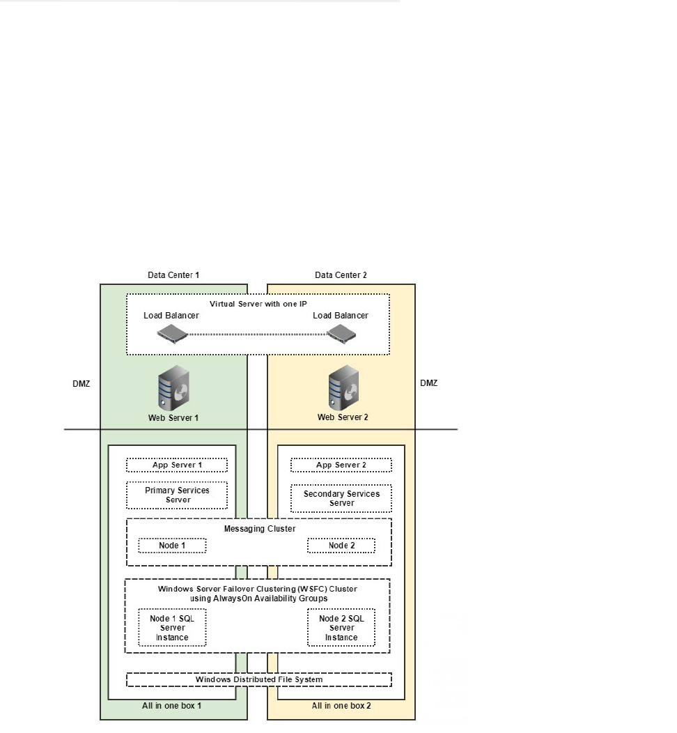
154 Enterprise Chat and Email Installation and Configuration Guide
Converting Existing Two Server Installation to HA
(Windows 2016)
This section helps you convert your existing two server installation into an HA installation.
Existing installation and VMs:
VM-A: ECE All-in-One server (file, messaging, application, services and database components are installed
on this server). This will become the Windows Distributed File System Node1 for file server.
VM-B: ECE Web server component
Acquire New VMs for Side B (Windows 2016):
VM-C: For installing second Messaging, Services, and Application server components. This will become
the Windows Distributed File System Node2 for file server.
VM-D: For second web server component

155
Converting Existing File Server to DFS
Setting up Distributed File System (DFS)
Install and Enable DFS Namespace and DFS Replication roles and features on VM-A and VM-C. For
details, see “Appendix A: Distributed File System Configuration” on page 142.
Updating Files to Use DFS
To update files on original ECE server (VM-A) to use new DFS location:
1. Browse to Cisco_Home
\eService\bin\platform\windows
2. Open the following files in a text editor:
egainstart.bat
and
egainstop.bat
files.
3. Locate the property
env.fs.shared.location
in both the files and change the value to point to the new
DFS location. For example, the property will look like
SET
env.fs.shared.location=\\egeng.info\DFS1\ECE\eService
Installing Second Messaging, Services, and Application Server Components
Install the new components on VM-C. While installing:
In the Installation Options window, select Messaging Server, Services Server, and Application Server.
In the File Server Parameters window, provide the new DFS location.
Installing Second Web Server Component
Install the new component on VM-D. While installing:
In the Installation Options window, select Web Server.
In the File Server Parameters window, provide the new DFS location.
Converting Databases to SQL Server to Always On Configuration
Perform all the tasks listed in the following table in the order defined.
Task Notes
Perform all the required pre-installation tasks on the new database
servers. “Pre-Installation Tasks” on page 24
“Stopping ECE Application and Disable SQL Jobs.” on page 156
If your existing database uses SQL Authentication, convert SQL
Authentication to Windows Authentication.
“Converting SQL Authentication to Windows Authentication” on page 156
“Installing Failover Clustering Feature” on page 146

156 Enterprise Chat and Email Installation and Configuration Guide
Stopping ECE Application and Disable SQL Jobs.
1. Stop the ECE application. See “Stopping ECE” on page 92.
2. Disable the following jobs on ECE database machines.
EG_Offers_Summarization_Active_Database_Name
EGICM_data_cleanup_job_Active_Database_Name
EGICM_reindex_active_job_Active_Database_Name
EGPL_rebuild_indexes_Active_Database_Name
EGPL_update_fulltext_Active_Database_Name
EGICM_reindex_reports_job_Reports_Database_Name
populatesmy_Reports_Database_Name
Converting SQL Authentication to Windows Authentication
To convert SQL authentication to Windows authentication:
1. Stop the ECE application.
“Creating Prestage Cluster Computer Objects in Active Directory Domain
Services (AD DS)” on page 146
“Creating Windows Failover Cluster” on page 148
“Configure Cluster Quorum Settings” on page 148
“Enabling Always On Availability Groups Feature on SQL” on page 149
“Configuring SQL Server Always On Availability Groups” on page 149
In Step 4, select existing ECE active, master, and reports databases.
In Step 6, select Join option.
“Verifying Recovery Model” on page 150
“Backing up and Restoring Databases” on page 157
“Adding Databases to Availability Group” on page 151
“Updating Files and Databases with New Listener Names” on page 157
“Run reports DB utility to configure secondary nodes” on page 151
“Creating Jobs to Take Log backups on All Nodes” on page 152
“Creating an Encrypted SQL Server Database” on page 86
“Starting the SQL Jobs and ECE Application” on page 159
Task Notes
Important: Windows Authentication is required for setting Always On. You need to perform this
task only if your existing installation does not use Windows Authentication.
157
2. Follow steps to configure Windows Authentication on MSSQL Server as mentioned in the installation guide.
3. On the file server, go to the ECE installation folder.
4. Make the following changes in the file:
Cisco_Home
\eService\installation\dataaccess\egpl_ds_connpool_map.xml
&
a. Locate <conn_pool_list.
b. In all connpool nodes in the list, remove the values of User and Password nodes.
c. In all connpool nodes in the list, for the Url node, change all references of
integratedSecurity=false
to
integratedSecurity=true
For example, change:
<User egid="3026">eGActiveDB</User>
<Password egid="3027">36423441363</Password>
<Url
egid="3028">jdbc:sqlserver://ussuh23:1433;integratedSecurity=false;databaseName
=eGActiveDB</Url>
to
<User egid="3026"></User>
<Password egid="3027"></Password>
<Url
egid="3028">jdbc:sqlserver://ussuh23:1433;integratedSecurity=true;databaseName=
eGActiveDB</Url>
5. Browse to Cisco_Home
\eService\lib\deployment.zip
extract
\dataaccess\egpl_ds_connpool_map.xml
. Make the changes listed in Step 4. Add the updated file in
deployment.zip
.
Backing up and Restoring Databases
To backup and restore databases:
1. Take Full backups of active, master, and reports database in primary server location.
2. Share folder path with secondary server.
3. Take Transaction Log backup of active, master, and reports database in primary server location (same folder
path where full backup was saved).
4. Restore all three full backups and transaction log backups with NORECOVERY at the secondary database
server.
Updating Files and Databases with New Listener Names
Modifying Reports Database
158 Enterprise Chat and Email Installation and Configuration Guide
Perform this task on the primary node.
To modify the database server names:
1. Connect to the SQL server with the listener name.
2. In the Microsoft SQL Server Management Studio, browse to Integration Services Catalogs > SSISDB> >
EG_
Reports_DatabseName > Environments > EG_eGReportsDB.
3. Right-click EG_eGReportsDB and from the context menu, select Properties.
4. In the Environment Properties window, go to the Variables section, and edit the values of the following
variables.
Destination_ConnectionString: Replace the server name with the listener name of the reports
database. If all databases are installed on same node, then it will be common listener name for both
active and reports database.
Destination_Server: Replace the server name with the listener name of the reports database.
Source_ConnectionString: Replace server name with the listener name of the active database. If all
databases are installed on same node, then it will be common listener name for both active and reports
database.
Source_Server: Replace server name with the listener name of the active database.
Modifying Master Database
Perform this task on the primary node.
To modify the database server name for master database:
Run the following query on the ECE master database:
UPDATE [dbo].[EGPL_DSM_HOST]
SET [HOST_NAME] = '
<Listener Name>
'
WHERE [DESCRIPTION] = 'Database Server'
Replace <Listener Name> with the cluster listener name.
Modifying Connpool File
Perform this task on the file server.
To modify the connpool files:
1. Stop the ECE application.
2. On the file server, go to the ECE installation folder.
3. Make the following changes in the file:
Cisco_Home
\eService\installation\dataaccess\egpl_ds_connpool_map.xml
a. Locate <conn_pool_list.
b. In all connpool nodes in the list, locate the URL property and replace the database server name with
the listener name.
For example, change:
159
<Url
egid="3018">jdbc:sqlserver://
masterussuh50
:1433;integratedSecurity=true;databa
seName=eGMasterDB</Url>
to:
<Url
egid="3018">jdbc:sqlserver://
HAlistenerCluster
:1433;integratedSecurity=false;data
baseName=eGMasterDB</Url>
4. Browse to Cisco_Home
\eService\lib\deployment.zip
extract
\dataaccess\egpl_ds_connpool_map.xml
. Make the changes listed in Step 3. Add the updated file in
deployment.zip
.
Starting the SQL Jobs and ECE Application
1. Enable the following jobs on ECE database machines.
EG_Offers_Summarization_Active_Database_Name
EGICM_data_cleanup_job_Active_Database_Name
EGICM_reindex_active_job_Active_Database_Name
EGPL_rebuild_indexes_Active_Database_Name
EGPL_update_fulltext_Active_Database_Name
EGICM_reindex_reports_job_Reports_Database_Name
populatesmy_Reports_Database_Name
2. Start the ECE application. See “Starting ECE” on page 91.
Updating Finesse Files
The Desktop Layout gadget in Finesse points to the ECE web server in the installation. If you are using a load
balancer, after converting the deployment to HA, you must update the layout to point to the load balancer.
To update the Finesse layout settings:
1. Launch the URL:
https://
Finesse_Server_Name
/cfadmin
. Login as a finesse administrator.
2. In the Desktops Layout section, locate the node for
ece.xml.
In the value, replace the web server name
with the host name of the load balancer used for ECE web servers.
For example, change:
<gadgets>
<gadget>https://
ECEWebServer.domain.com
/system/templates/finesse/gadget/agent/ece.xm
l</gadget>
</gadgets>
to
<gadgets>
<gadget>https://
ECELoadBalancer.domain.com
/system/templates/finesse/gadget/agent/ece
.xml</gadget>

160 Enterprise Chat and Email Installation and Configuration Guide
</gadgets>
3. Save the changes.
Converting Existing Two Server Installation to HA
(Windows 2012)
This section helps you convert your existing two server installation into an HA installation.
Existing installation and VMs:
VM-A: ECE All-in-One server (file, messaging, application, services and database components are installed
on this server) This will become the Windows Distributed File System Node1 for file server.
VM-B: ECE Web server component
Acquire New VMs for Side B:
VM-C: For installing second Messaging and Application server components. This will become the
Windows Distributed File System Node2 for file server.
VM-D: For installing second services server component
VM-E: For second web server component
Converting Existing File Server to DFS
For details see “Converting Existing File Server to DFS” on page 155.
Installing Second Messaging and Application Server Components
Install the new components on VM-C. While installing:
In the Installation Options window, select Messaging Server and Application Server.
In the File Server Parameters window, provide the new DFS location.
Installing Second Services Server Component
Install the new component on VM-D. While installing:
In the Installation Options window, select Services Server.
In the File Server Parameters window, provide the new DFS location.
Installing Second Web Server Component
Install the new component on VM-E. While installing:
In the Installation Options window, select Web Server.

161
In the File Server Parameters window, provide the new DFS location.
Converting Databases to SQL Server to Always On Configuration
For details see “Converting Databases to SQL Server to Always On Configuration” on page 155.
Updating Finesse Files
For details see “Updating Finesse Files” on page 159.
Converting Existing Distributed Server Installation to
HA (Windows 2012 & 2016)
This section helps you convert your existing distributed server installation into an HA installation.
Existing installation and VMs:
VM-1A: File server
VM-2A: Database server (active and master databases)
VM-3A: Database server (Reports database)
VM-4A: Messaging server
VM-5A: Services Server
VM-6A to VM-10A: Application server
VM-11A to VM-15A: Web Server
Acquire New VMs for Side B:
VM-1B: File server (Windows Distributed File System Node 2)
VM-2B: Database server (active and master databases)
VM-3B: Database server (reports database)
VM-4B: Messaging server
VM-5B: Services server
VM-6B to VM-10B: Application server
VM-11B to VM-15B: Web Server
162 Enterprise Chat and Email Installation and Configuration Guide
Converting Existing File Server to DFS
Setting up Distributed File System (DFS)
Install and Enable DFS Namespace and DFS Replication roles and features on VM-1A and VM1-B. For
details, see “Appendix A: Distributed File System Configuration” on page 142.
Updating Files to Use DFS
To update files on original ECE server (VM-1A) to use new DFS location:
1. Browse to Cisco_Home
\eService\bin\platform\windows
2. Open the following files in a text editor:
egainstart.bat
and
egainstop.bat
files.
3. Locate the property
env.fs.shared.location
in both the files and change the value to point to the new
DFS location. For example, the property will look like
SET
env.fs.shared.location=\\egeng.info\DFS1\ECE\eService
Installing Second Messaging Server Component
Install the new messaging server component on VM-4B. While installing:
In the Installation Options window, select Messaging Server.
In the File Server Parameters window, provide the new DFS location.
Installing Second Services Server Component
Install the new services server component on VM-5B. While installing:
In the Installation Options window, select Services Server.
In the File Server Parameters window, provide the new DFS location.
Installing Additional Application Server Components
Install the new application server component on VM-6B to VM10B. While installing:
In the Installation Options window, select Application Server.
In the File Server Parameters window, provide the new DFS location.
Installing Additional Web Server Components
Install the new web server component on VM-11B to VM-15B. While installing:
In the Installation Options window, select Application Server.
In the File Server Parameters window, provide the new DFS location.
