PUB # 31-9071 02/01
MODEL SERIES:
TECHNICAL SERVICE GUIDE
GE Consumer Home Services Training
General Electric Side-by-Side
Knob Control/Metal Liner Refrigerator
GSS20
GSS22
GSS25
ESS22
ESS25
HSS22
HSS25
SSS25

IMPORTANT SAFETY NOTICE
The information in this service guide is intended for use by
individuals possessing adequate backgrounds of electrical,
electronic, and mechanical experience. Any attempt to repair a
major appliance may result in personal injury and property
damage. The manufacturer or seller cannot be responsible for the
interpretation of this information, nor can it assume any liability in
connection with its use.
WARNING
To avoid personal injury, disconnect power before servicing this
product. If electrical power is required for diagnosis or test
purposes, disconnect the power immediately after performing the
necessary checks.
RECONNECT ALL GROUNDING DEVICES
If grounding wires, screws, straps, clips, nuts, or washers used
to complete a path to ground are removed for service, they must
be returned to their original position and properly fastened.
GE Consumer Home Services Training
Technical Service Guide
Copyright © 2001
All rights reserved. This service guide may not be reproduced in whole or in part
in any form without written permission from the General Electric Company.
!

– 1 –
TT
TT
T
able of Contentsable of Contents
able of Contentsable of Contents
able of Contents
IntroductionIntroduction
IntroductionIntroduction
Introduction
. . . . . . . . . . . . . . . . . . . . . . . . . . . . . . . . . . . . . . . . . . . . . . . . . . . . . . . . . . . . . . . . . . . . . . . . . . . . . .
. . . . . . . . . . . . . . . . . . . . . . . . . . . . . . . . . . . . . . . . . . . . . . . . . . . . . . . . . . . . . . . . . . . . . . . . . . . . . .
. . . . . . . . . . . . . . . . . . . . . . . . . . . . . . . . . . . . . . .
22
22
2
InstallationInstallation
InstallationInstallation
Installation
. . . . . . . . . . . . . . . . . . . . . . . . . . . . . . . . . . . . . . . . . . . . . . . . . . . . . . . . . . . . . . . . . . . . . . . . . . . . . . . .
. . . . . . . . . . . . . . . . . . . . . . . . . . . . . . . . . . . . . . . . . . . . . . . . . . . . . . . . . . . . . . . . . . . . . . . . . . . . . . . .
. . . . . . . . . . . . . . . . . . . . . . . . . . . . . . . . . . . . . . . .
33
33
3
SpecificationsSpecifications
SpecificationsSpecifications
Specifications
. . . . . . . . . . . . . . . . . . . . . . . . . . . . . . . . . . . . . . . . . . . . . . . . . . . . . . . . . . . . . . . . . . . . . . . . . . . .
. . . . . . . . . . . . . . . . . . . . . . . . . . . . . . . . . . . . . . . . . . . . . . . . . . . . . . . . . . . . . . . . . . . . . . . . . . . .
. . . . . . . . . . . . . . . . . . . . . . . . . . . . . . . . . . . . . .
44
44
4
NomenclatureNomenclature
NomenclatureNomenclature
Nomenclature
. . . . . . . . . . . . . . . . . . . . . . . . . . . . . . . . . . . . . . . . . . . . . . . . . . . . . . . . . . . . . . . . . . . . . . . . . . . .
. . . . . . . . . . . . . . . . . . . . . . . . . . . . . . . . . . . . . . . . . . . . . . . . . . . . . . . . . . . . . . . . . . . . . . . . . . . .
. . . . . . . . . . . . . . . . . . . . . . . . . . . . . . . . . . . . . .
55
55
5
WW
WW
W
arranty Informationarranty Information
arranty Informationarranty Information
arranty Information
. . . . . . . . . . . . . . . . . . . . . . . . . . . . . . . . . . . . . . . . . . . . . . . . . . . . . . . . . . . . . . . . . . . .
. . . . . . . . . . . . . . . . . . . . . . . . . . . . . . . . . . . . . . . . . . . . . . . . . . . . . . . . . . . . . . . . . . . .
. . . . . . . . . . . . . . . . . . . . . . . . . . . . . . . . . .
66
66
6
Operating CharacteristicsOperating Characteristics
Operating CharacteristicsOperating Characteristics
Operating Characteristics
. . . . . . . . . . . . . . . . . . . . . . . . . . . . . . . . . . . . . . . . . . . . . . . . . . . . . . . . . . . . . .
. . . . . . . . . . . . . . . . . . . . . . . . . . . . . . . . . . . . . . . . . . . . . . . . . . . . . . . . . . . . . .
. . . . . . . . . . . . . . . . . . . . . . . . . . . . . . .
77
77
7
General Locator ViewsGeneral Locator Views
General Locator ViewsGeneral Locator Views
General Locator Views
. . . . . . . . . . . . . . . . . . . . . . . . . . . . . . . . . . . . . . . . . . . . . . . . . . . . . . . . . . . . . . . .
. . . . . . . . . . . . . . . . . . . . . . . . . . . . . . . . . . . . . . . . . . . . . . . . . . . . . . . . . . . . . . . .
. . . . . . . . . . . . . . . . . . . . . . . . . . . . . . . .
1313
1313
13
Mechanical DisassemblyMechanical Disassembly
Mechanical DisassemblyMechanical Disassembly
Mechanical Disassembly
. . . . . . . . . . . . . . . . . . . . . . . . . . . . . . . . . . . . . . . . . . . . . . . . . . . . . . . . . . . .
. . . . . . . . . . . . . . . . . . . . . . . . . . . . . . . . . . . . . . . . . . . . . . . . . . . . . . . . . . . .
. . . . . . . . . . . . . . . . . . . . . . . . . . . . . .
1515
1515
15
DiagnosticsDiagnostics
DiagnosticsDiagnostics
Diagnostics
. . . . . . . . . . . . . . . . . . . . . . . . . . . . . . . . . . . . . . . . . . . . . . . . . . . . . . . . . . . . . . . . . . . . . . . . . . . .
. . . . . . . . . . . . . . . . . . . . . . . . . . . . . . . . . . . . . . . . . . . . . . . . . . . . . . . . . . . . . . . . . . . . . . . . . . . .
. . . . . . . . . . . . . . . . . . . . . . . . . . . . . . . . . . . . . .
3232
3232
32
Component and Connector Locator ViewsComponent and Connector Locator Views
Component and Connector Locator ViewsComponent and Connector Locator Views
Component and Connector Locator Views
. . . . . . . . . . . . . . . . . . . . . . . . . . . . . . . . . . . . . . . .
. . . . . . . . . . . . . . . . . . . . . . . . . . . . . . . . . . . . . . . .
. . . . . . . . . . . . . . . . . . . .
5050
5050
50
SchematicsSchematics
SchematicsSchematics
Schematics
. . . . . . . . . . . . . . . . . . . . . . . . . . . . . . . . . . . . . . . . . . . . . . . . . . . . . . . . . . . . . . . . . . . . . . . . . . . .
. . . . . . . . . . . . . . . . . . . . . . . . . . . . . . . . . . . . . . . . . . . . . . . . . . . . . . . . . . . . . . . . . . . . . . . . . . . .
. . . . . . . . . . . . . . . . . . . . . . . . . . . . . . . . . . . . . .
5454
5454
54
Illustrated Parts CatalogIllustrated Parts Catalog
Illustrated Parts CatalogIllustrated Parts Catalog
Illustrated Parts Catalog
. . . . . . . . . . . . . . . . . . . . . . . . . . . . . . . . . . . . . . . . . . . . . . . . . . . . . . . . . . . . . .
. . . . . . . . . . . . . . . . . . . . . . . . . . . . . . . . . . . . . . . . . . . . . . . . . . . . . . . . . . . . . .
. . . . . . . . . . . . . . . . . . . . . . . . . . . . . . .
5858
5858
58
– 2 –
Introduction
2001 Energy SxS models are being introduced in
response to the requirement for more energy-
efficient refrigerators by mid year 2001, along with
having feature and operation enhancements. The
primary differences in this refrigeration system are
the adaptive defrost system (see Pub. # 31-9062),
control board, software, and control systems that
operate independently in fresh food and freezer
sections. The new high-efficiency control system
has the ability to cycle components and adjust fan
speeds as required to maintain temperature-
setting ranges in freezer and fresh food sections.
Feedback systems are digital inputs and relay
outputs. Sensors (thermistors) are used to
measure temperature with communications to a
main PC board, which controls the unit
components. The refrigerator has versions that
have control knobs or touchpads (Profile models)
to provide inputs to a microprocessor. The freezer/
fresh food controls are temperature setpoint type
and have settings of 0-9 with 9 being the coldest
temperature possible. The new NO CLEAN
condenser is serviceable from the rear and is
designed to prevent the customer from having to
clean the condenser in normal usage conditions.
Sealed system operation and compressor are
functionally the same as previous models, with
some minor changes.
The 20', 22', and 25' side-by-side models are the
models affected. These models are available with
through-the-door chilled water and ice dispenser,
and built-in water filter feature. On models
requiring icemaker, the newest electronic
icemaker (see Pub. # 31-9063) has been or can
be installed.
The freezer has adjustable shelves, slide-out
Spillproof shelf, QuickSpace shelf, and deep door
shelves, based on model. The fresh food section
has a baking soda holder, fruit and vegetable
drawer, drawer dividers, adjustable humidity
drawer, and convertible meat drawer.
This new high-efficiency refrigerator is a
combination of the most efficient refrigeration
system and the most desirable customer features
available.
– 3 –
Installation
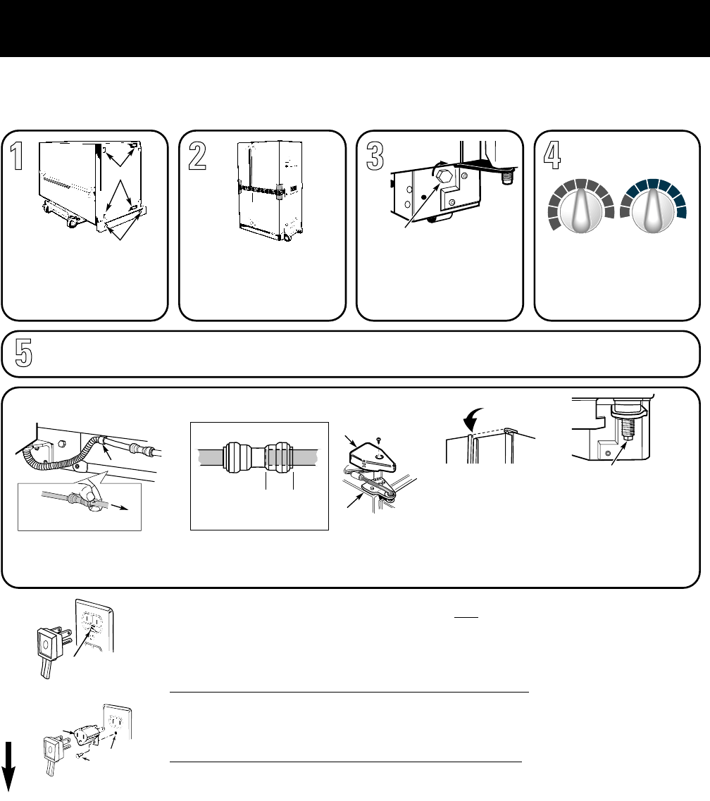
ATTENTION INSTALLER:
FOR A QUALITY INSTALLATION,
FOLLOW THESE INSTRUCTIONS.
• REMOVE AND DISCARD
SKIDBOARDS and bolts used to
hold skidboards.
• Use PADDED HAND TRUCK
to protect refrigerator finish.
• LEAVE TAPE ON DOORS until
refrigerator is in its final location.
• ADJUST FRONT ROLLERS
so that refrigerator is solid and
doors close easily.
• MAKE SURE DOORS ARE EVEN
AT TOP. Check gasket seal.
• SET BOTH CONTROLS TO “5”.
• SET ICEMAKER TO OFF until
water line is connected.
• IMPORTANT: IMMEDIATELY REMOVE ALL CLEAR PROTECTIVE TAPE FROM TRIM.
• TO REMOVE TAPE RESIDUE AND HANDPRINTS, USE APPLIANCE POLISH.
• REMOVE ALL TAPE AND OTHER PACKAGING MATERIAL FROM INSIDE REFRIGERATOR. DO NOT REMOVE SERIAL PLATE.
IMPORTANT: PLEASE READ CAREFULLY
FOR PERSONAL SAFETY, THIS APPLIANCE MUST BE PROPERLY GROUNDED.
The power cord of this appliance is equipped with a three-prong (grounding) plug that mates with a standard three-prong (grounding) wall receptacle to minimize the
risk of electric shock hazard from this appliance. The customer should have the wall receptacle and circuit checked by a qualified electrician to make sure the receptacle
is properly grounded.
Where a standard two-prong wall receptacle is encountered, it is the personal responsibility and obligation of the customer to have it replaced with a properly grounded
three-prong wall receptacle.
DO NOT, UNDER ANY CIRCUMSTANCES, CUT OR REMOVE THE THIRD (GROUND) PRONG FROM THE POWER CORD.
USAGE
SITUATIONS WHERE THE APPLIANCE’S POWER CORD WILL BE DISCONNECTED INFREQUENTLY
Because of potential safety hazards under certain conditions, we strongly recommend against the use of an adapter plug. However, if you still elect to use an adapter,
where local codes permit, a TEMPORARY CONNECTION may be made to a properly grounded two-prong wall receptacle by the use of a UL listed adapter which is
available at most hardware stores. The larger slot of the adapter must be aligned to provide proper polarity in the connection of the power cord.
CAUTION: Attaching the adapter ground terminal to the wall receptacle cover screw does not ground the appliance unless the cover screw is metal, and not insulated,
and the wall receptacle is grounded through the house wiring. The customer should have the circuit checked by a qualified electrician to make sure the receptacle is
properly grounded. When disconnecting the power cord from the adapter, always hold the adapter with one hand. If this is not done, the adapter ground terminal is very
likely to break with repeated use. Should this happen, DO NOT USE the appliance until a proper ground has again been established.
USAGE
SITUATIONS WHERE THE APPLIANCE’S POWER CORD WILL BE DISCONNECTED FREQUENTLY
Do not use an adapter plug in these situations because frequent disconnecting of the power cord places undue strain on the adapter and leads to eventual failure of the
adapter ground terminal. The customer should have the two-prong wall receptacle replaced with a three-prong (grounding) receptacle by a qualified electrician before
using the appliance.
MAKE SURE PROPER
GROUND EXISTS
BEFORE USE
PREFERRED
METHOD
ENSURE PROPER
GROUND AND
FIRM CONNECTION
BEFORE USE
TEMPORARY METHOD
(Adapter plugs not
permitted in Canada)
197D3266P001 31-5087 9-00 JR
FRANÇAIS • ESPANOL
HEX-HEAD BOLTS (4)
ROLLERS
TRUCK FROM
SIDE ONLY
CARDBOARD
PROTECTS
DOOR EDGES
MAKE SURE FRONT
ROLLERS DO NOT
REST ON TRUCK
DO NOT
OVER-
TIGHTEN
STRAP
ROLLER
ADJUSTMENT
RAISE
9 IS COLDEST
0 IS OFF
FREEZER FRESH FOOD
5
8
9
4
3
2
1
0
6
7
5
8
9
4
3
2
1
6
7
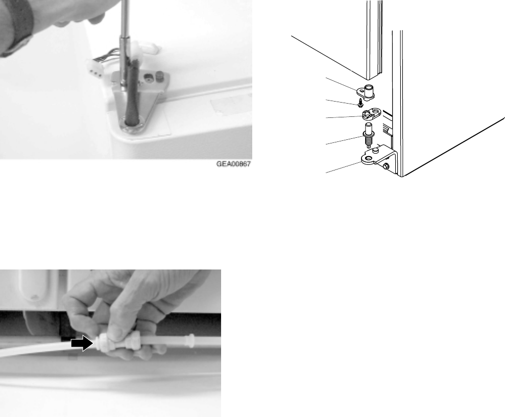
• At lower left hinge, remove tubing
from the clip.
• Disconnect the water line.
IF NECESSARY TO REMOVE DOORS, REMOVE ALL HINGES.
FOR DISPENSER MODELS:
COLLAR
PRESS THE WHITE COLLAR AS
YOU PULL OUT THE TUBING.
• Push tubing into connector
(
5
⁄
8
″ to
3
⁄
4
″) to prevent leakage.
WHEN INSTALLING DOORS...
5
⁄
8
″ –
3
⁄
4
″
• At upper hinges, disconnect wiring connectors.
• Remove both hinges with each door to prevent
damage to tubing or wiring.
• Reinstall lower hinges and tighten hinge screws firmly.
• Place door on lower hinge pin and install upper hinges.
Tighten upper hinge screws firmly.
• Align both doors evenly at top by adjusting pin on lower
fresh food hinge.
• Reconnect wiring connectors and reinstall hinge covers.
• Reinstall tubing by pushing tubing into connector.
• Put tubing back into clip.
TO REINSTALL DOORS...
HINGE COVER
WIRING
CONNECTORS
TUBING CLIP
FRESH FOOD HINGE
ADJUSTMENT PIN
ALIGN DOORS EVENLY
AT TOP
– 4 –
Specifications
– 5 –
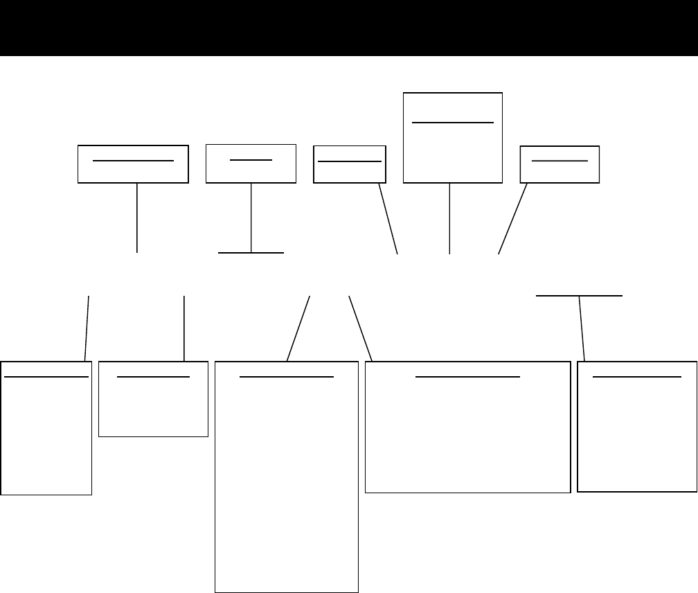
Nomenclature
GSS25IFMAFWW
G= GE
H = HOTPOINT
P = PROFILE (GE)
E = ETERNA (GE)
R = RCA
S = SELECT (GE)
BRAND/PRODUCT
S = STANDARD DEPTH
T = TROPICAL
G = GLOBAL
DEPTH/POWER
A = LEADER WIRE
D = DELUXE WIRE
I = DELUXE GLASS
K = SPILL PROOF/SLIDE-OUT
GLASS
M = SPILL PROOF/SLIDE-OUT
GLASS & QUICK SPACE
Q = SHOWCASE DERIVATIVE
U = AVB DERIVATIVE
W= HPS (CONTRACT)
DERIVATIVE
X = REGIONAL DERIVATIVE
INTERIOR/SHELVES
B = NON-DISPENSER / ICE-MAKER READY
D = CUBED ICE / WATER
E = CUBED & CRUSHED ICE / WATER
F = 6 MO. FILTER / CUBED & CRUSHED ICE
G = 1 YR. FILTER / CUBED & CRUSHED ICE
I = IN-LINE FILTER / INDICATOR & C/C/W
ICEMAKER/EXTERIOR
WW= WHITE/WHITE
AA = ALMOND/ALMOND
BB = BLACK/BLACK
CC = BISQUE/BISQUE
WH = WHITE/BLACK
AD = ALMOND/BLACK
EXTERIOR COLOR
S = SIDE-BY-SIDE REF.
CONFIGURATION
20 / 22 / 25 CU. FT.
VOLUME
M = 2001
MODEL YEAR
A = INIITIAL DESIGN
B = 1ST REVISION
ETC.
ENGINEERING
NOMENCLATURE
F = FLAT DOOR
DOOR TYPE
GEA00687
Note: Mini Manual/Tech Data Sheet is located in a
plastic bag in the control console.
– 6 –
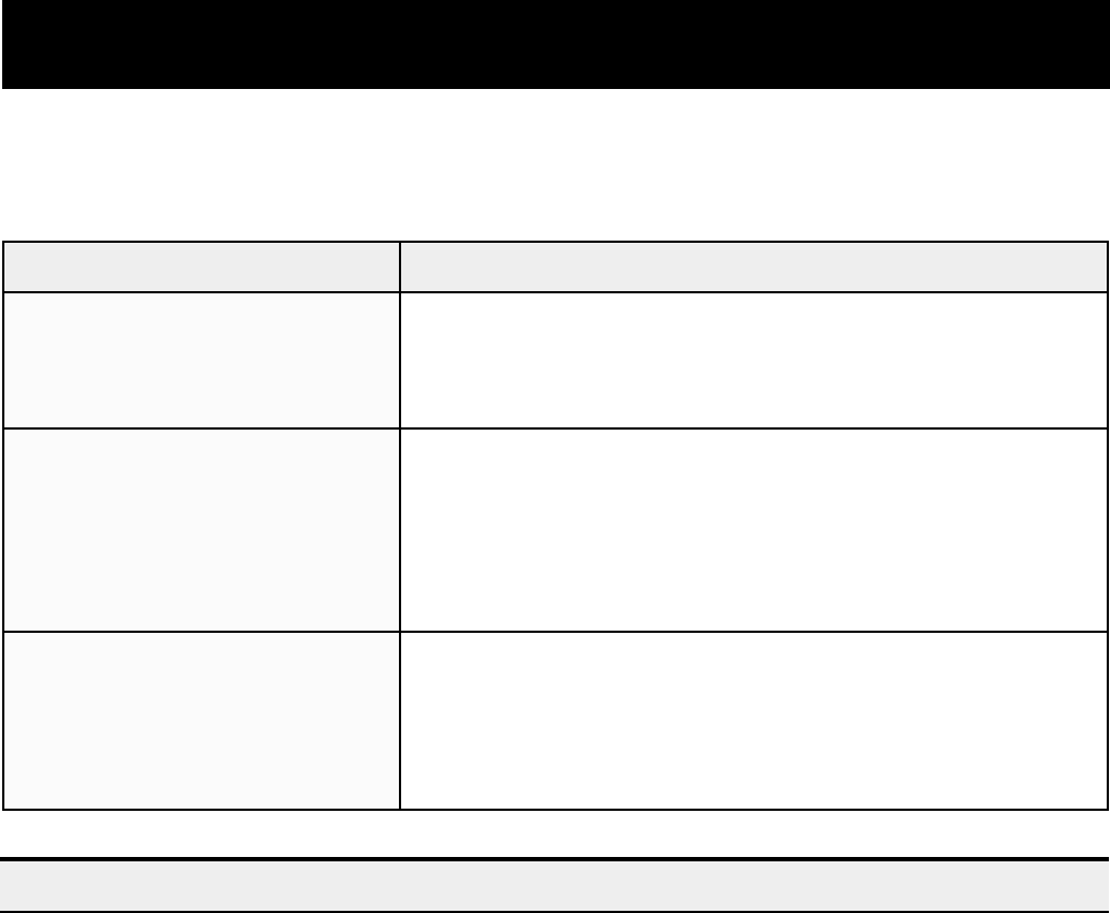
Warranty Information
• Service trips to your home to teach you
how to use the product.
• Improper installation.
• Failure of the product if it is abused or
used for other than the intended purpose
or used commercially.
• Loss of food due to spoilage.
• Replacement of house fuses or resetting of
circuit breakers.
• Replacement of the water filter cartridge
due to water pressure that is outside the
specified operating range or due to exces-
sive sediment in the water supply.
• Replacement of water filter cartridge after
its expected useful life, 30 days.
• Damage to the product caused by accident,
fire, floods, or acts of God.
• Incidental or consequential damage caused
by possible defects with this appliance.
This warranty is extended to the original purchaser and any succeeding owner for products purchased
for home use within the USA. In Alaska, the warranty excludes the cost of shipping or service calls to
your home.
Some states do not allow the exclusion or limitation of incidental or consequential damages. This war-
ranty gives you specific legal rights, and you may also have other rights which vary from state to state.
To know what your legal rights are, consult your local or state consumer affairs office or your state’s
Attorney General.
Warrantor: General Electric Company. Louisville, KY 40225
Sales slip or cancelled check is required as proof of original purchase date to obtain service
under warranty. Note: Water filter cartridge warranty is 30 days.
All warranty service is provided by our Factory Service Centers or an authorized Customer Care®
technician.
:revoCtoNlliWEGtahW
:fOdoirePehTroF :ecalpeRlliWEG
raeYenO
lanigiroehtfoetadehtmorF
esahcrup
trapynA nitcefedaoteudsliafhcihwrotaregirferehtfo
sihtgniruD.pihsnamkrowroslairetam ,ytnarrawraey-enolluf
,edivorposlalliwEG ,egrahcfoeerf emoh-nidnaroballla
.trapevitcefedehtecalperotecivres
sraeYeviF
lanigiroehtfoetadehtmorF
esahcrup
metsysgnitaregirferdelaesehtfotrapynA eht(
gnitcennoclladna,rotaropave,resnednoc,rosserpmoc
liafhcihw)gnibut
roslairetamnitcefedaoteuds
sihtgniruD.pihsnamkrow ,ytnarrawraey-evif oslalliwEG
,edivorp ,egrahcfoeerf otecivresemoh-nidnaroballla
trapevitcefedehtecalper
.metsysgnitaregirferdelaesehtni
.t
emitefiL
lanigiroehtfoetadehtmorF
esahcrup
rewardronaphguorht-eesynA ehthtiwdehsinruf
lamrongnirudskaerbrewardronapehtfirotaregirfer
gniruD.dedulcnitonerasrevocrewarD.esudlohesuoh
siht ytnarrawemitefildetimil rofelbisnopsereblliwuoy,
.stsocecivresemoh-nirorobalyna

– 7 –
Operating Characteristics
Table of Contents
Normal Operating Characteristics That Are Different from Previous Models
. . 8
Abnormal Operating Characteristics (Incorrect Operation) . . . . . . . . . . . . . . . 8
Adaptive Defrost . . . . . . . . . . . . . . . . . . . . . . . . . . . . . . . . . . . . . . . . . . . . . . . . . . 8
Cooling Operation (Adaptive Defrost) . . . . . . . . . . . . . . . . . . . . . . . . . . . . . . . . 8
Pre-Chill Operation (Adaptive Defrost). . . . . . . . . . . . . . . . . . . . . . . . . . . . . . . . 8
Defrost Heater Operation (Adaptive Defrost). . . . . . . . . . . . . . . . . . . . . . . . . . . 9
Dwell Period (Adaptive Defrost) . . . . . . . . . . . . . . . . . . . . . . . . . . . . . . . . . . . . . 9
Post Dwell (Adaptive Defrost) . . . . . . . . . . . . . . . . . . . . . . . . . . . . . . . . . . . . . . . 9
Liner Protection Mode . . . . . . . . . . . . . . . . . . . . . . . . . . . . . . . . . . . . . . . . . . . . . 9
Dispensing Functions. . . . . . . . . . . . . . . . . . . . . . . . . . . . . . . . . . . . . . . . . . . . . . 9
Dispenser Light . . . . . . . . . . . . . . . . . . . . . . . . . . . . . . . . . . . . . . . . . . . . . . . . . . . 9
Dispenser Lock . . . . . . . . . . . . . . . . . . . . . . . . . . . . . . . . . . . . . . . . . . . . . . . . . . . 10
Filters . . . . . . . . . . . . . . . . . . . . . . . . . . . . . . . . . . . . . . . . . . . . . . . . . . . . . . . . . . . 10
Hinge System and Door Closure . . . . . . . . . . . . . . . . . . . . . . . . . . . . . . . . . . . . . 10
Airflow (Cabinet Interior) . . . . . . . . . . . . . . . . . . . . . . . . . . . . . . . . . . . . . . . . . . . 11
“Jelly Roll” Condenser . . . . . . . . . . . . . . . . . . . . . . . . . . . . . . . . . . . . . . . . . . . . . 11
Main Control Board. . . . . . . . . . . . . . . . . . . . . . . . . . . . . . . . . . . . . . . . . . . . . . . . 12
– 8 –
Normal Operating Characteristics That Are
Different from Previous Models
•
Icemaker auger rotates clockwise.
• Evaporator fan running, without compressor or
condenser fan.
• Post Dwell (Adaptive Defrost), compressor,
and condenser fan on with evaporator fan off
after defrost cycle.
• Liner Protection Mode, fan comes on when the
doors are open for 3 minutes.
• Evaporator fan and compressor can run
continuously for 2 hours (Adaptive Defrost).
• Different sound levels can be heard when the
fan changes speed.
• Response time for drastic temperature change
is 2 to 10 minutes. The main control board will
only respond to 8 degrees (Fahrenheit) of
temperature change per minute as determined
by resistance of sensor.
Abnormal Operating Characteristics
(Incorrect Operation)
• Evaporator fan on, compressor off, and
damper shut (except liner protection mode).
• Rapid fan speed changes, fan takes at least 1
minute to change speeds.
• Compressor running without the condenser
fan. The compressor and condenser fan
should always run at the same time.
Adaptive Defrost
Adaptive Defrost can be described as a defrost
system that adapts to a refrigerator’s surrounding
environment and household usage.
Unlike conventional defrost systems that use
electromechanical timers with a fixed defrost cycle
time, Adaptive Defrost utilizes an intelligent,
electronic control to determine when the defrost
cycle is necessary. In order to accomplish the
correct defrost cycle time, the main control board
monitors the following refrigerator operations:
• Length of time the refrigerator doors were open
since the last defrost cycle.
• Length of time the compressor has run since
the last defrost cycle.
• Amount of time the defrost heaters were on in
the last defrost cycle.
Adaptive Defrost is divided into 5 separate cycles.
Those operations are:
• Cooling Operation
• Pre-Chill Operation
• Defrost Heater Operation
• Dwell Period
• Post Dwell
(See Pub. #31-9062 for more information on
Adaptive Defrost.)
Cooling Operation (Adaptive Defrost)
During the cooling operation, the main control
board monitors door opening (fresh food and
freezer doors) and compressor run times. The
board counts the time the doors are open. It
reduces the length between defrosts by 255
seconds (multiplication factor) for each second
that each door is open. If both doors are open, it
reduces it by twice the amount. The multiplication
factor reduces compressor run time. If the doors
are not opened, the compressor will run up to 60
hours between defrosts. If the doors are opened
frequently and/or for long periods of time, the
compressor run time between defrosts will be
reduced to as little as 8 hours.
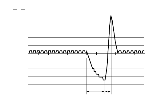
Pre-Chill Operation (Adaptive Defrost)
09:00
10:00
11:00
12:00
13:00
14:00
15:00
16:00
17:00
18:00
F
R
E
E
Z
E
R
A
I
R
T
E
M
P
E
R
A
T
U
R
E
S
DefrostPre-Chill
08:00
25˚ / -4˚
20˚ / -7˚
15˚ / -9˚
10˚ / -12˚
5˚ / -15˚
0˚ / -18˚
-5˚ / -21˚
-10˚ / -23˚
-15˚ / -26˚
-20˚ / -29˚
F˚ / C˚
PRE-CHILL MODE
When the main control board determines that
defrost is necessary, it will force the refrigerator
– 9 –
into a continuous cool mode (pre-chill). During pre-
chill, the freezer temperature may be driven below
the set point. However, the fresh food temperature
will be regulated by the damper. Pre-chill will last
for 2 hours. These models do not have a defrost
holdoff.
Defrost Heater Operation (Adaptive
Defrost)
After 2 hours of pre-chill operation, the main
control board turns off the compressor, condenser
fan, and evaporator fan.
During defrost operation, the main control board
monitors the evaporator temperature using
evaporator thermistor inputs. The thermistor will
terminate defrost heater operation in less than 45
minutes. Typical defrost time is 20-30 minutes.
Maximum defrost cycle is 45 minutes with heater
on, 5 minutes in dwell.
The defrost system is protected by a defrost
safety thermostat (switch). The thermostat opens
when the evaporator temperature raises to 140° F
and closes when the evaporator temperature
lowers to 110° F.
Dwell Period (Adaptive Defrost)
After defrost heater operation has been terminated
by the main control board, a 5-minute dwell period
occurs. During this period, the compressor,
condenser fan, and the evaporator fan remain off.
The remaining frost melting from the evaporator
will continue to drip and drain so that prior to the
cooling operation, the evaporator will be totally
clear of any moisture. After the 5-minute dwell
period, the unit goes into post dwell.
Post Dwell (Adaptive Defrost)
The post dwell period is designed to cool the
evaporator before circulating air within the
refrigerator. This prevents any residual heat on the
evaporator from being distributed in the freezer.
During this period, the compressor is on and the
condenser fan is on, but the evaporator fan is off,
and the damper is closed. Post dwell lasts 10
minutes on these models.
Liner Protection Mode
The liner protection mode will activate if either of
the doors have been open for 3 minutes. This
mode will start the evaporator fan and close the
damper.
This mode is controlled by 2 timers. Timer #1
monitors door-open time. A 3-minute door-open
count begins when the door is opened. If 3
minutes elapse before the door is closed, the liner
protection mode will become active. Once the
door is closed, timer #1 resets and liner protection
mode goes into standby. In standby, normal fan
and damper operations resume and timer #2
begins a 3-minute door-closed count. If 3 minutes
elapse without a door opening, liner protection
mode will completely deactivate. If a door is
opened within the timer #2 door-closed count, the
remaining time in the door-closed count will be
deducted from the timer #1 door-open count.
Dispensing Functions
The water, crushed ice, and cubed ice functions
are controlled by the main control board. To select
a function, press the appropriate pad on the
dispenser. The LED will light to identify the
selection.
To dispense the selected item, depress the
dispenser cradle located in the dispenser recess.
The solenoid and linkage assembly will open the
ice chute door to dispense the ice. If cubed ice is
selected, the crushed ice bypass solenoid will
allow cubed ice to bypass the ice crusher. The ice
chute door must remain open for 5 second after
dispensing ceases. After this 5 second delay, the
solenoid and linkage assembly will shut the ice
chute door.
The dispenser light will come on automatically
when the dispenser cradle is depressed and will
fade out 5 seconds after it is released.
Dispenser Light
The LIGHT pad turns the dispenser light on and
off. When the light is turned off, it will fade out. The
dispenser light will come on automatically when
the dispenser cradle is depressed and will fade
out 5 seconds after it is released. The LIGHT pad
will not turn off the light during dispense.
– 10 –
Dispenser Lock
When the dispenser system is locked, no
dispenser command will be accepted. This
includes the dispenser cradle and will prevent
accidental dispensing that may be caused by
children or pets. If a pad is pressed with the
system locked, it will be acknowledged with 3
pulses of the LOCK LED accompanied by an
audible tone.
To lock or unlock communication between the
dispenser and main control board, press the
LOCK pad and hold it for 3 seconds. The LOCK
LED will flash while the LOCK pad is pressed.
When the communication is locked, the LOCK
LED will be illuminated.
The status of other functions selected prior to the
initiation of the lock feature will be displayed. If the
lock is engaged while a mode is active, the LED
will remain on until that mode times out.
If the lock is engaged when the filter timer expires,
the LED will come on but cannot be reset until the
lock is turned off.
The lock feature will be restored in the event of a
power disruption.
Filters
Some models are equipped with a water filter
located in the upper right-hand corner of the fresh
food compartment. The filter is designed to be
used for up to 8 hours of open valve time or 1 year
of calendar time.
When 90% of filter time (dependant on model) has
elapsed (open valve time or calendar time,
whichever comes first), the main control board will
illuminate the filter reminder LED (amber). When
100% of the filter time has elapsed, the main
control board will illuminate the filter reminder LED
(red).
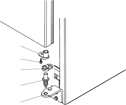
Hinge System and Door Closure
The hinge brackets are not adjustable on the
cabinet. The fresh food door can be adjusted up
and down by using the hinge adjustment pin
(located on the fresh food lower door hinge).
The fresh food and freezer lower door hinges are
equipped with replaceable cam risers. The cam
risers assist in door closure. If the fresh food door
is adjusted too high, cam riser will not be engaged,
and the fresh food door will not close properly.
IMPORTANT: The refrigerator rollers must be
adjusted correctly for proper door closure. When
the rollers are adjusted correctly, the door should
close easily when open approximately 45 degrees
(halfway)
GEA00909
Screw
Hinge
Adjustment
Pin
Hinge
Cam Riser
Cam with
Thimble
– 11 –
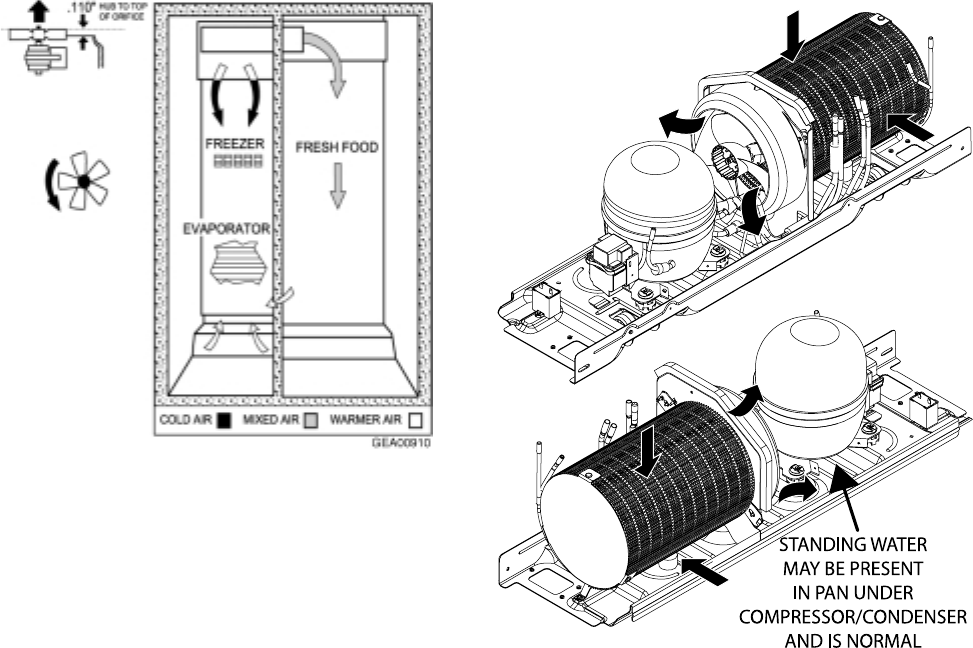
“Jelly Roll” Condenser
The new NO CLEAN condenser is accessed from
the rear and is designed to be tolerant of up to 2
inches of lint. The idea is that the consumer, in
normal operating conditions, will never have to
clean the condenser. If necessary, only an
ordinary appliance brush is used. Air is drawn in
from the outside diameter of the condenser and
pulled out by the condenser fan. A condenser fan
baffle is located at the rear to direct airflow through
the condenser. Functionally, the condenser does
the same job as previous models. Air is drawn in
from front left and rear left and exits out front right
side of refrigerator.
Airflow (Cabinet Interior)
The freezer compartment is designed so that
when the evaporator fan is operating, air is drawn
into the bottom of the air tunnel and through the
evaporator. The cold air is then pushed out into
the top of the freezer.
The fresh food compartment receives chilled air
via an electronic damper positioned at the top, rear
of the refrigerator between the freezer
compartment and the fresh food compartment.
The damper is controlled by the main control
board and when open, allows chilled air from the
freezer air tunnel to move into the fresh food
compartment.
Air returns from the fresh food compartment to the
freezer compartment via a vent located to the left
of the FRESH PRODUCE drawer.
– 12 –
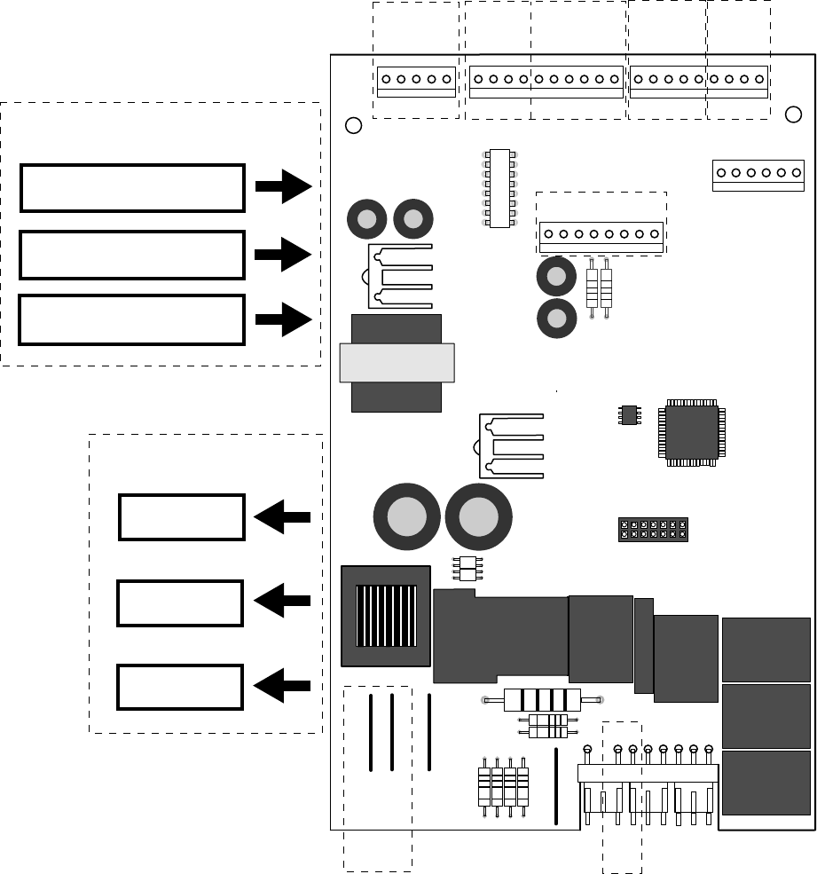
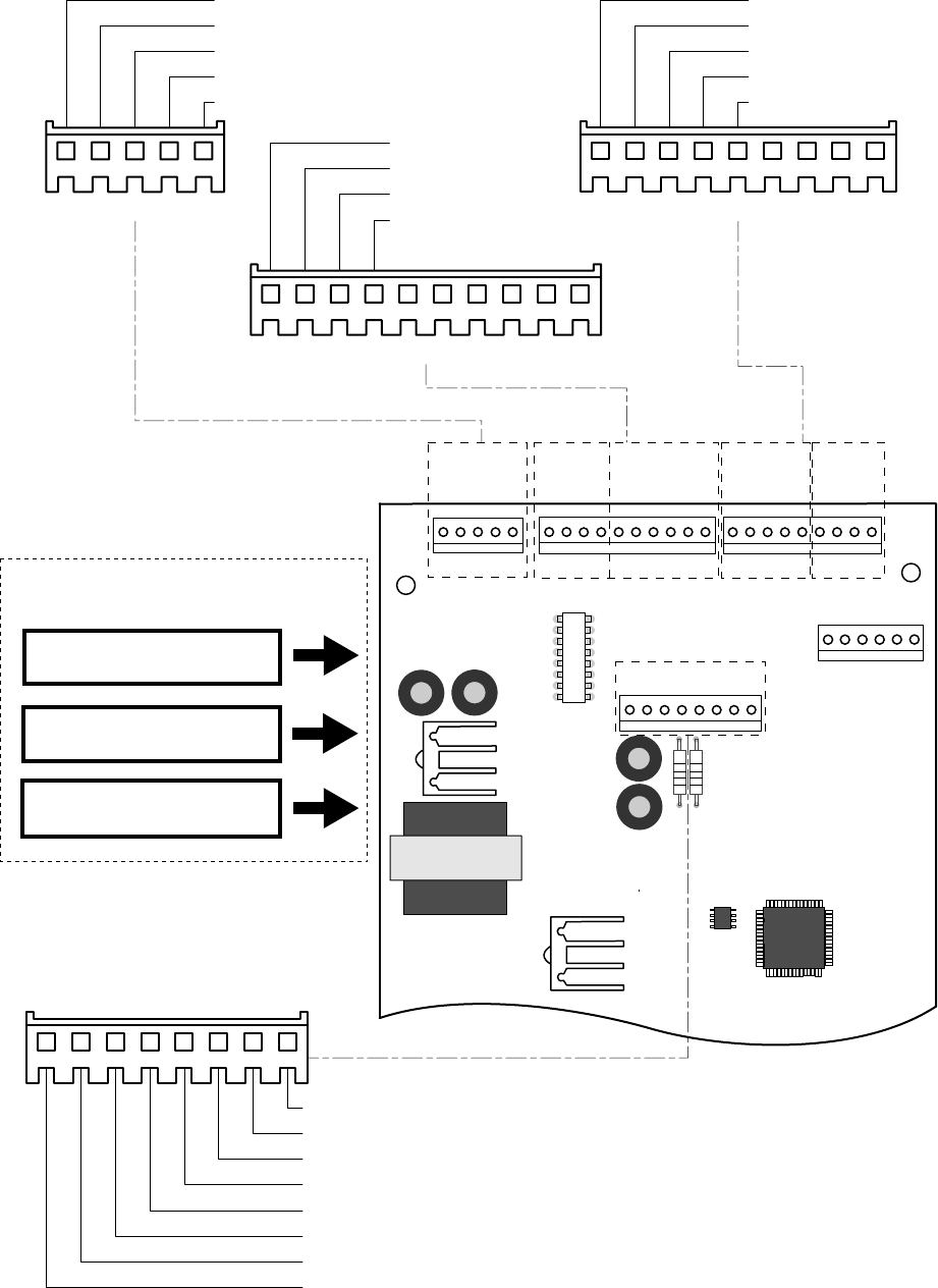
Main Control Board
PAN_HTR
AUGER
1
5
1
10
1
9
J1
J5
6
J3
J2
1
N
DFZ
DFF
OCH
COMMON
WATER
CRUSHER
QC
K5
DEFROST
K3
L1
COMP
DEFR
LINE
1 COMM
2 +12V
3 -COM
4 DI
5 DO
2
1
J6
K7
PAN/HTR
K6
WATER
AUGER
K1
C/CR
K2
K4
COMP
J4
1
8
J7
DEFROST
COOLING
PRE-CHILL
DEFROST HEATER ON TIME
(MINUTES)
COMPRESSOR RUN TIME
(MINUTES)
ACCUMULATED FF AND FRZ
DOOR OPENINGS (MINUTES)
THERMISTOR
INPUTS
ENCODER
INPUTS
MODEL
SELECT
COMMUNICATION
INPUT/OUTPUT
DAMPER
COILS
FAN OUTPUTS
DOOR
SWITCH
INPUTS
COMPRESSOR
DEFROST
OUTPUTS
AND
INPUTS
OUTPUTS
PROCESSING
UNIT
– 13 –
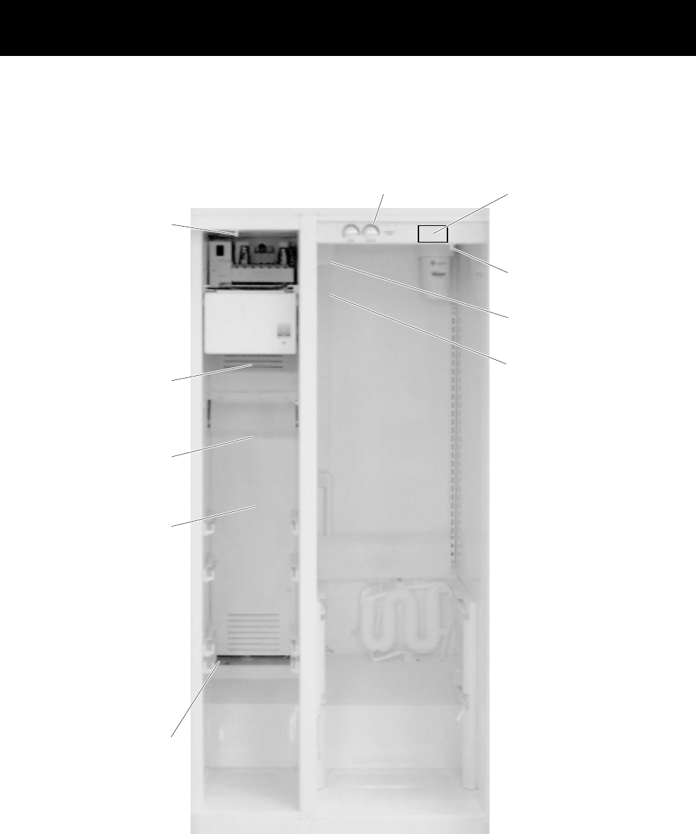
General Locator Views
GEA00914
Fresh Food
Light Switch
Fresh Food
Light Switch
Tech Data Sheet
Location
Tech Data Sheet
Location
Temperature
Controls
Temperature
Controls
DamperDamper
Fresh Food
Thermistor
Fresh Food
Thermistor
Freezer Light
Switch
Freezer Light
Switch
Evaporator
Fan
Evaporator
Fan
Evaporator
Thermistor
Evaporator
Thermistor
EvaporatorEvaporator
Freezer
Thermistor
Freezer
Thermistor

– 14 –
GEA00917
Main
Control
Board
Main
Control
Board
Jelly Roll
Condenser
Jelly Roll
Condenser
CompressorCompressor
CapacitorCapacitor Overload
Overload
and Relay
(under cover)
Overload
and Relay
(under cover)
Condenser
Fan
Condenser
Fan
Water
Water
Solenoids
Water
Solenoids

– 15 –
Mechanical Disassembly
Table of Contents
Door Gasket. . . . . . . . . . . . . . . . . . . . . . . . . . . . . . . . . . . . . . . . . . . . . . . . . . . . . . 17
Door Handles. . . . . . . . . . . . . . . . . . . . . . . . . . . . . . . . . . . . . . . . . . . . . . . . . . . . . 17
Doors and Door Hinges . . . . . . . . . . . . . . . . . . . . . . . . . . . . . . . . . . . . . . . . . . . . 17
Door Removal . . . . . . . . . . . . . . . . . . . . . . . . . . . . . . . . . . . . . . . . . . . . . . . . . . . . 17
Fresh Food Door Adjustment . . . . . . . . . . . . . . . . . . . . . . . . . . . . . . . . . . . . . . . 18
Control Panel. . . . . . . . . . . . . . . . . . . . . . . . . . . . . . . . . . . . . . . . . . . . . . . . . . . . . 18
Fresh Food Light . . . . . . . . . . . . . . . . . . . . . . . . . . . . . . . . . . . . . . . . . . . . . . . . . . 19
Freezer Door Light Switch . . . . . . . . . . . . . . . . . . . . . . . . . . . . . . . . . . . . . . . . . . 19
Water Filter Cartridge . . . . . . . . . . . . . . . . . . . . . . . . . . . . . . . . . . . . . . . . . . . . . . 19
Shelves. . . . . . . . . . . . . . . . . . . . . . . . . . . . . . . . . . . . . . . . . . . . . . . . . . . . . . . . . . 20
Drawers and Bins . . . . . . . . . . . . . . . . . . . . . . . . . . . . . . . . . . . . . . . . . . . . . . . . . 20
Door Shelf Extenders . . . . . . . . . . . . . . . . . . . . . . . . . . . . . . . . . . . . . . . . . . . . . . 21
Freezer Light . . . . . . . . . . . . . . . . . . . . . . . . . . . . . . . . . . . . . . . . . . . . . . . . . . . . . 21
Icemaker. . . . . . . . . . . . . . . . . . . . . . . . . . . . . . . . . . . . . . . . . . . . . . . . . . . . . . . . . 21
Ice Dispenser Drive . . . . . . . . . . . . . . . . . . . . . . . . . . . . . . . . . . . . . . . . . . . . . . . . 22
Evaporator Fan . . . . . . . . . . . . . . . . . . . . . . . . . . . . . . . . . . . . . . . . . . . . . . . . . . . 22
Defrost Heater and Freezer Thermistor . . . . . . . . . . . . . . . . . . . . . . . . . . . . . . . 23
Overtemperature Thermostat and Evaporator Thermistor . . . . . . . . . . . . . . . . 24
– 16 –
Fresh Food Thermistor . . . . . . . . . . . . . . . . . . . . . . . . . . . . . . . . . . . . . . . . . . . . . 24
Door Dispenser Control Panel. . . . . . . . . . . . . . . . . . . . . . . . . . . . . . . . . . . . . . . 24
Door Dispenser Target Switch . . . . . . . . . . . . . . . . . . . . . . . . . . . . . . . . . . . . . . . 24
Ice Crusher . . . . . . . . . . . . . . . . . . . . . . . . . . . . . . . . . . . . . . . . . . . . . . . . . . . . . . 25
Ice Dispenser Drive Motor . . . . . . . . . . . . . . . . . . . . . . . . . . . . . . . . . . . . . . . . . . 25
Ice Cube Solenoid . . . . . . . . . . . . . . . . . . . . . . . . . . . . . . . . . . . . . . . . . . . . . . . . . 26
Evaporator . . . . . . . . . . . . . . . . . . . . . . . . . . . . . . . . . . . . . . . . . . . . . . . . . . . . . . . 26
Condenser Fan . . . . . . . . . . . . . . . . . . . . . . . . . . . . . . . . . . . . . . . . . . . . . . . . . . . 27
Dispenser Heater. . . . . . . . . . . . . . . . . . . . . . . . . . . . . . . . . . . . . . . . . . . . . . . . . . 27
Main Control Board. . . . . . . . . . . . . . . . . . . . . . . . . . . . . . . . . . . . . . . . . . . . . . . . 28
Roller Assembly . . . . . . . . . . . . . . . . . . . . . . . . . . . . . . . . . . . . . . . . . . . . . . . . . . 28
Water Solenoid . . . . . . . . . . . . . . . . . . . . . . . . . . . . . . . . . . . . . . . . . . . . . . . . . . . 28
Fresh Food Air Damper . . . . . . . . . . . . . . . . . . . . . . . . . . . . . . . . . . . . . . . . . . . . 29
– 17 –
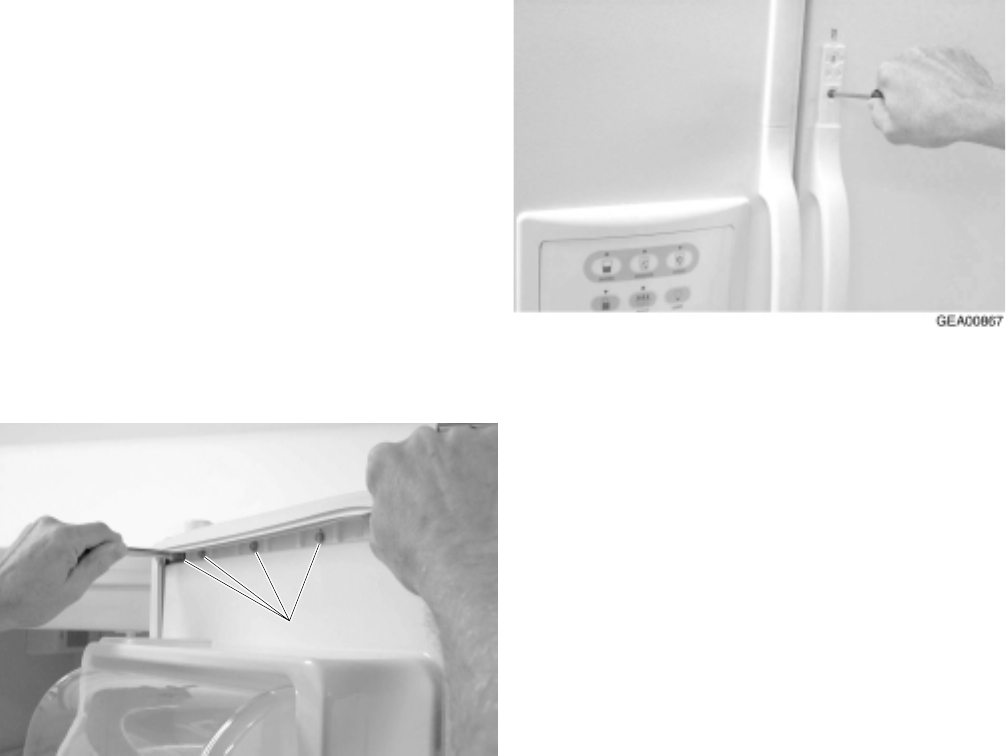
Door Gasket
The rear flange of the gasket is positioned
between the inner and outer door panels. The
screws under the gasket flap must be loosened.
1. Remove the door bins.
2. Loosen 40 screws located under the door
gasket.
3. Remove the gasket from the interior of the
door liner.
Note: The back side of the door liner has double-
sided tape at the corners.
GEA00866
ScrewsScrews
Door Handles
Door handles are front mounted and secured with
Torx-style screws.
1. Remove the handle trim covers by inserting a
thin flat-blade screwdriver about 2 in. from the
end of top cover trim. Pry up enough to insert
your fingers and lift to free trim from 2 plastic
locking tabs inserted in rectangle door holes.
Reverse to reinstall, taking care to align cover
trim correctly. The top and bottom are not
interchangeable.
2. Remove 2 T-20 Torx screws from the upper
and lower ends of the handle.
3. Remove the handle.
Doors and Door Hinges
IMPORTANT: The freezer door is not adjustable.
The fresh food door can be adjusted up and down
to match the height of the freezer door. Adjust the
fresh food door up or down using the hinge
adjustment pin (located on the fresh food lower
door hinge).
The fresh food and freezer lower door hinges are
equipped with replaceable cam risers. Cam risers
assist in door closure.
When the fresh food door is adjusted too high, the
cam riser will not be engaged. If the cam riser is
not engaged, the door will not close properly. Refer
to the Fresh Food Door Adjustment section in this
chapter for more information.
IMPORTANT: The refrigerator rollers must be
adjusted correctly to ensure proper door closure.
Refer to the Roller Assembly section in this
chapter for more information.
Door Removal
1. Remove the upper hinge cover by removing
the Phillips screw.
2. With the door in the closed position, disconnect
the wiring harness (freezer side only).
– 18 –
3. Remove the base grille.
4. Disconnect the water supply tube. To
disconnect the tube, push in the white collar on
the quick connector and pull the tube out.
GEA00869
5. Remove the water tube protection (black
collar).
6. Remove 2 upper hinge screws.
7. Lift the upper hinge and move it to the side (the
gasket is located under the hinge).
CAUTION: Do not side-load hinges.
NOTE: Freezer door only - Guide the water line
through hinge while lifting the door from hinge.
8. Open the door 90 degrees and lift the door
straight up and off the lower hinge.
GEA00909
Screw
Hinge
Adjustment
Pin
Hinge
Cam Riser
Cam with
Thimble
9. Remove the screw, hinge cam, and thimble
from the bottom of the door.
10. Fresh Food Door Only: Remove the hinge
adjustment pin and cam riser from the lower
hinge.
11. Freezer Door Only: Remove the cam riser
and washer from the lower hinge.
12. Remove 2 screws and lower hinge from
cabinet.
Fresh Food Door Adjustment
IMPORTANT: The refrigerator rollers must be
adjusted correctly to ensure proper door closure.
Refer to the Roller Assembly section in this
chapter for more information.
The freezer door is not adjustable. The fresh food
door can be adjusted to match the height of the
freezer door.
1. Remove the base grille (opening the door
makes grille removal easier).
2. Turn the hinge adjustment pin (located on the
fresh food lower hinge) clockwise to raise the
door and counterclockwise to lower the door.
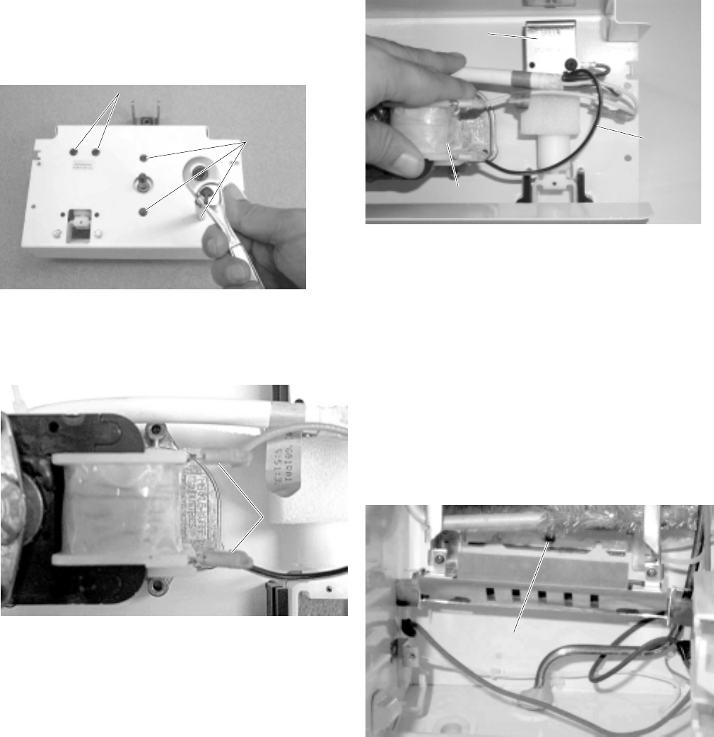
Control Panel
The control panel, located at the front of the fresh
food compartment, contains temperature control
encoders for fresh food and freezer sections and
the fresh food door light switch.
1. Remove 2 screws located in the bottom of the
control panel. Slide the panel down.
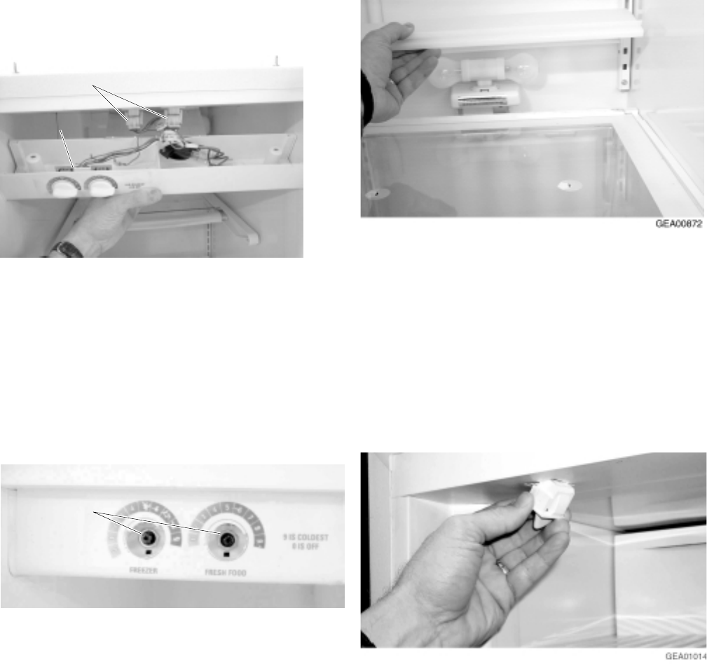
– 19 –
2. Disconnect the connectors for the door light
switch and temperature control switches.
GEA00870
ConnectorsConnectors
Encoder
Board
Encoder
Board
3. Disconnect the connectors for the light and
temperature control encoders.
4. Disconnect the temperature control encoder
connector.
5. Remove the mounting nuts for both encoders.
Note: Both switches must be replaced because
they are mounted on a common circuit board.
GEA00871
Mounting
Nuts
Mounting
Nuts
6. Disconnect the refrigerator door light switch
supply connector.
7. Push the locking tab in and slide the switch out
of the panel.
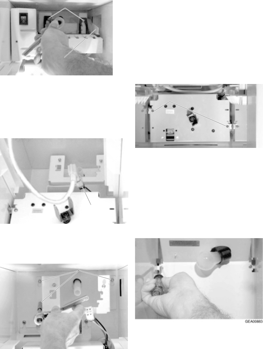
Fresh Food Light
The lower fresh food light is located under an
opaque cover in the lower portion of the fresh food
compartment in some models.
Note: The upper light cover removal is covered in
the previous procedure.
1. Remove the lower light cover by lifting it off the
dowels.
2. Remove 2 40-watt appliance light bulbs.
Freezer Door Light Switch
The freezer door light switch is located on the left
of the freezer compartment.
1. Slide a small flat-blade screwdriver under the
switch and push the locking tab. Pull out the
switch.
2. Disconnect the harness connector and remove
the switch.
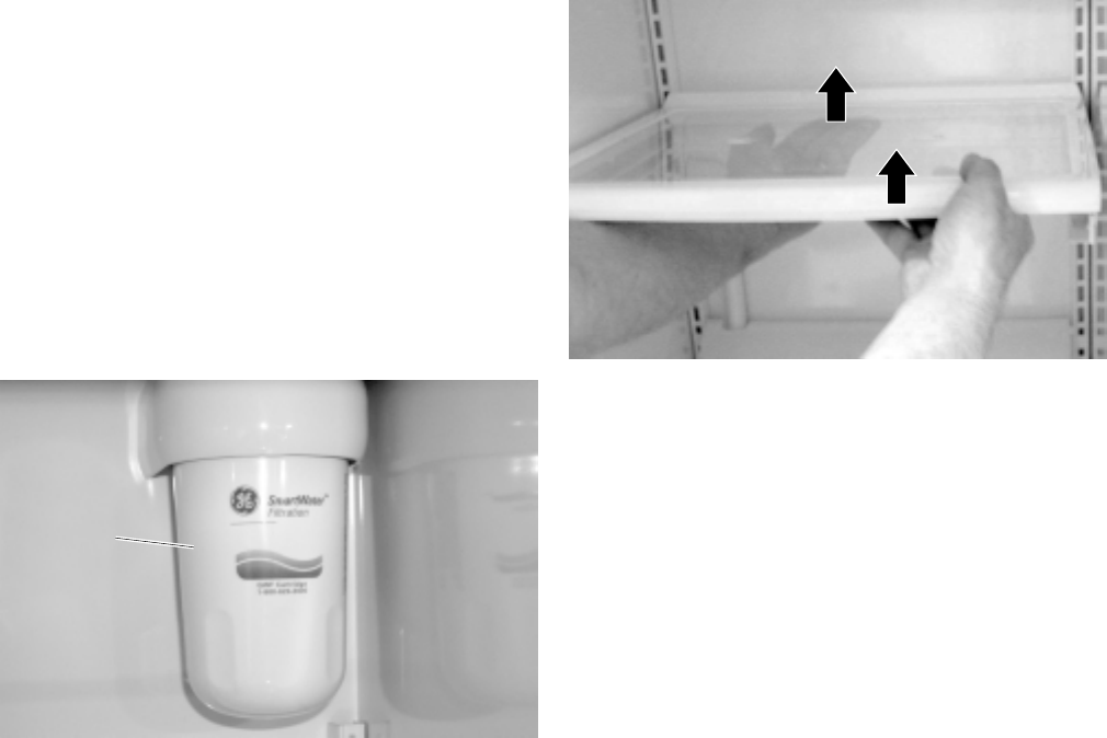
Water Filter Cartridge
Note: The water filter should be replaced every 6
months. Warranty life is 30 days.
The water filter cartridge is located in the upper
right corner of the fresh food compartment. When
the LED illuminates, change the water filter. On
those models without the LED, change the filter
when the water flow decreases to the dispenser or
icemaker.
1. Remove the old cartridge by slowly turning it to
the left. Do not pull the cartridge down. A small
amount of water may drip when the cartridge is
removed.
– 20 –
2. On models without a replacement LED, apply
the year and month sticker to the new
cartridge.
3. Line up the arrow on the cartridge with the
cartridge holder. Place the new cartridge up
and inside the holder. Do not push it into the
holder.
4. Slowly turn the cartridge to the right until it
stops (about 1/2 turn). Do not overtighten. The
cartridge will automatically raise itself into
position.
5. Run water from the dispenser for 3 minutes
(about 1-1/2 gallons) to clear the system and
prevent sputtering.
6. On models with the LED, press and hold the
RESET WATER FILTER pad on the dispenser.
Note: A filter bypass plug must be used if a
replacement filter is not available. The dispenser
and icemaker will not operate without a filter or the
filter bypass plug installed.
GEA00729
Water
Water
Filter
Filter
Cartridge
Cartridge
Water
Filter
Cartridge
Shelves
The slide-out and Spillproof shelves allow access
to items stored behind other items. Spillproof
shelves have special edges to help prevent spills
from dripping onto lower shelves.
The QuickSpace shelf splits in half and slides
under itself to allow for storage of tall items on the
shelf below. To adjust this shelf:
1. Tilt the shelf up until the tab disengages from
the shelf track.
2. Lift the lower tab out of the shelf track.
3. Slide the front half of the shelf under the back
half.
GEA00873
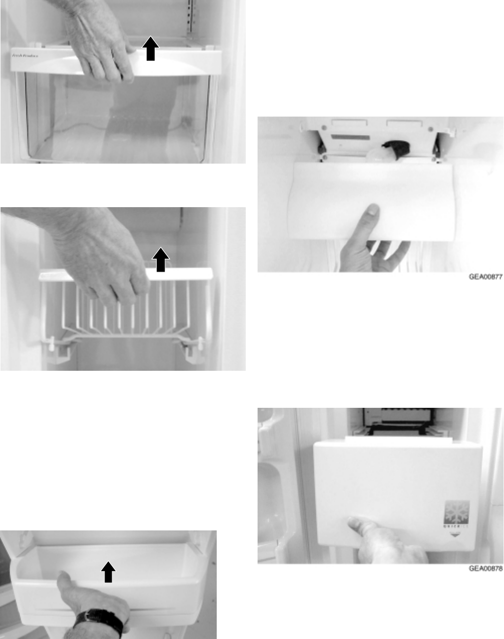
Drawers and Bins
The refrigerator uses drawers (fresh food) and
bins (freezer) to store food.
Adjustable humidity drawers allow vegetables to
be stored at high humidity or fruits at low humidity.
A convertible meat drawer with variable control
regulates cold air from the freezer compartment to
circulate around the drawer.
1. Pull out the drawer or bin until it reaches the
mechanical stops.
2. Lift the drawer or bin up and pull it out of the
compartment.
– 21 –
GEA00874
GEA00875
Door Shelf Extenders
Detachable shelf extenders deepen and enclose
fixed door shelves, providing more storage and
greater storage flexibility.
1. Lift the shelf extender straight up until it
disengages from the locking device.
2. Pull out the shelf extender.
GEA00876
Freezer Light
The freezer light is attached to the evaporator fan
housing.
1. Remove the light cover by lifting it off the tabs.
2. Replace the appliance light bulb.
Icemaker
The icemaker is located in the rear of the freezer
compartment. The icemaker must be replaced as
a complete unit.
1. Slide out the upper icemaker dispenser tray
and drawer.
2. Loosen 2 mounting screws.
– 22 –
GEA00879
Mounting Screws
Mounting Screws
Mounting Screws
Splash BaffleSplash Baffle
3. Lift up the icemaker and slide it out until the
cable connection is exposed.
Note: When replacing the icemaker, the fill cup
and splash baffle must be reused.
4. Disconnect the cable connector.
GEA00880
Cable
Connector
Cable
Connector
5. Loosen 3 screws on the icemaker bracket.
6. Lift up the bracket and slide it out.
GEA00881
3 Screws
3 Screws
3 Screws
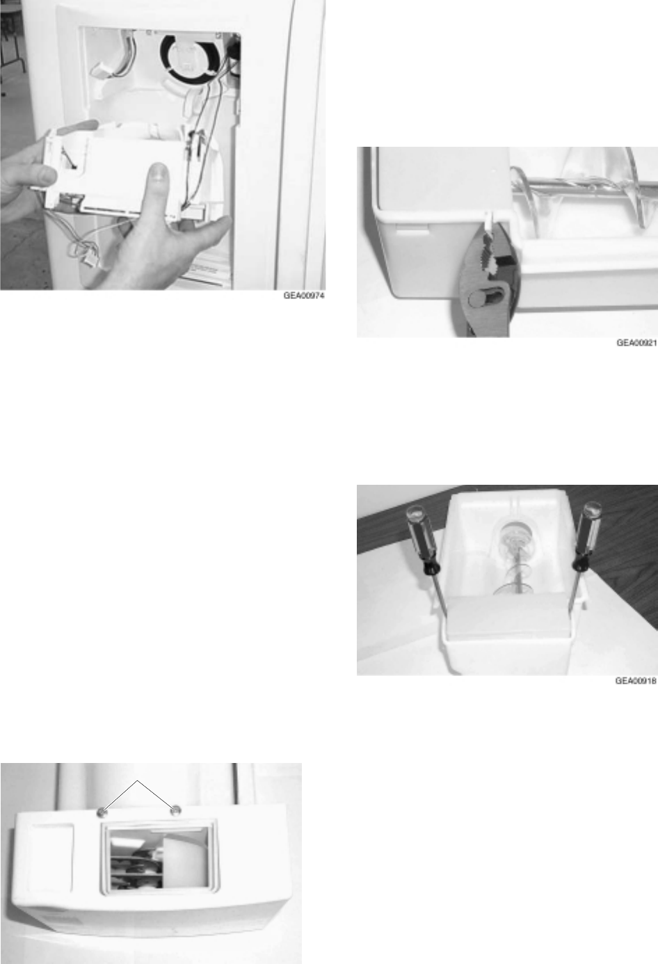
Ice Dispenser Drive
The ice dispenser drive turns the ice dispenser
auger in either crushed or cube mode.
1. Remove 2 Phillips screws from the ice
dispenser drive.
2. Slide the dispenser out until the cable
connector is visible.
3. Disconnect the cable and remove the
dispenser drive.
GEA00882
2 Screws2 Screws
Evaporator Fan
The evaporator fan, located in the upper portion of
the freezer compartment, circulates cold air
through the fresh food and freezer compartments.
1. Remove auger motor housing.
2. Loosen 4 Phillips screws located in the lower
portion of the evaporator fan duct.
3. Lift up the duct and slide it out.
– 23 –
4. Remove 4 Phillips screws from the evaporator
cover.
5. Remove the evaporator cover.
6. Disconnect the evaporator fan cable
connectors and the ground wire.
7. Loosen 2 Phillips screws from the evaporator
fan mounting.
GEA00884
2 Connectors2 Connectors
2 Screws2 Screws
8. Pull out the fan and remove the light and
defrost heater wiring harness.
9. Remove the fan.
GEA00885
Heater Wiring Harness
Heater Wiring Harness
Heater Wiring Harness
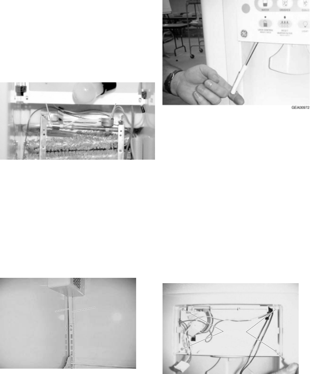
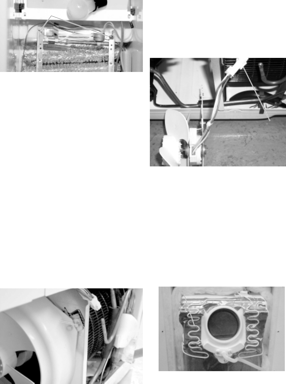
Defrost Heater and Freezer Thermistor
The defrost heater warms the evaporator during
the defrost mode of operation. The freezer
thermistor, located at the bottom left side of the
freezer compartment, senses the temperature in
the freezer.
1. Complete steps 4 and 5 in the previous
procedure.
2. Remove 2 Phillips screws from the defrost
heater.
3. Remove the heater.
GEA00886
2 Screws2 Screws
4. Remove the freezer thermistor.
GEA00887
Freezer Thermistor
Freezer Thermistor
Freezer Thermistor
– 24 –
Overtemperature Thermostat and
Evaporator Thermistor
The main control board monitors the resistance of
the evaporator thermistor. The main control board
will terminate the defrost cycle when a
predetermined temperature (60° F) is reached. The
over-temperature thermostat is a redundant
defrost terminating device. It will also terminate
defrost in the event of a failure of the evaporator
thermistor.
1. Remove the overtemperature thermostat.
2. Remove the evaporator temperature
thermistor.
GEA00888
Over-Temperature
Over-Temperature
Thermistor
Thermistor
Over-Temperature
Thermistor
Evaporator Temperature
Evaporator Temperature
Thermistor
Thermistor
Evaporator Temperature
Thermistor
Fresh Food Thermistor
The fresh food thermistor, located in the top, left of
the fresh food compartment, hidden behind the bin
track at the top left, senses the compartment
temperature.
1. Disengage the plastic track by sliding upward
and remove the housing.
2. Remove the thermistor from the housing.
GEA00976
Thermistor
Thermistor
Track
Cover
Thermistor
Track
Cover
Slide upward
to remove
to remove
Slide upward
to remove
Door Dispenser Control Panel
The door dispenser control panel allows the
consumer to select water, crushed ice, or ice
cubes. It is an interface to the main control board.
1. Use a screwdriver to unlock the tabs at the
bottom of the control panel. Slide the bottom
out and down.
2. Disconnect the wiring harness connectors.
Note: Inner door panel must be removed to
remove recess trim.
Door Dispenser Target Switch
When depressed, the door dispenser target switch
allows water, ice cubes, or crushed ice to be
dispensed.
1. Remove door dispenser control panel (see
previous procedure).
2. Remove 4 Phillips screws in the door
dispenser housing.
GEA00975
ScrewsScrews
3. Slide out the housing and disconnect the target
switch and dispenser light connectors.
– 25 –
4. Spread out the locking tabs and remove the
switch.
5. Push the chute duct door locking tabs back
and raise the assembly above the locking
tabs.
6. Push the lower armature locking tabs (under
the assembly) back and lift up the entire
assembly.
Ice Crusher
The ice crusher uses a deflector. When the
deflector is UP (“Crushed Ice” is selected on the
dispenser control panel), the ice crusher operates.
When the deflector panel is DOWN (“Cubed Ice”
is selected on the dispenser control panel), the
deflector is normally up.
1. Remove the ice dispenser tray and assembly
(see page 21).
2. Remove 2 Phillips screws from the ice
dispenser cover.
GEA00920
ScrewsScrews
8. Slide the back cover off the auger. The back
cover must be replaced because of tabs
broken off for disassembly.
9. With a flat-head screwdriver, remove the C-clip
from the end of the auger.
10. Remove the auger and ice crusher blade
assembly.
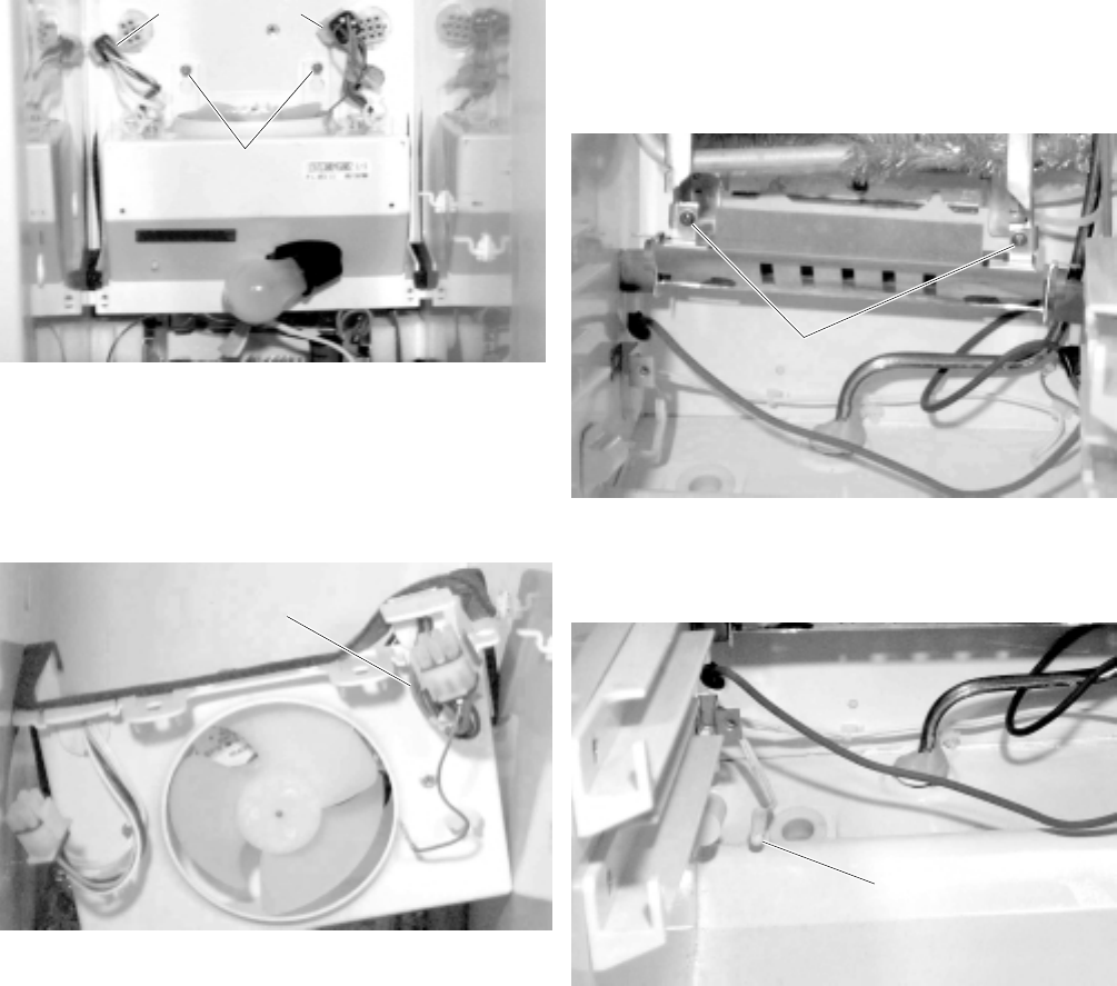
Ice Dispenser Drive Motor
The ice dispenser drive motor turns the auger in
the crushed or cube mode.
1. Remove the ice dispenser tray and assembly.
3. Turn over the ice bucket and ice dispenser
cover. Remove the Phillips screw.
4. Remove the cover.
5. Remove the Phillips screw for the ice cube
control linkage and slide the linkage to the rear
of the ice bucket.
6. Using a pair of pliers, break the tabs off the
back cover.
7. Using 2 flat blade screwdrivers, disengage the
locking tabs at either side of the ice crusher
and remove the assembly.
– 26 –
2. Remove 2 Phillips mounting screws.
3. Pull out the motor.
4. Disconnect the wire connectors.
5. Remove the drive fork and nut.
GEA00919
Solenoid Mounting ScrewsSolenoid Mounting Screws
Motor
Mounting
Screws
Motor
Mounting
Screws
6. Disconnect the motor wiring connectors.
GEA00892
Wiring
Wiring
Connectors
Connectors
Wiring
Connectors
7. Remove 3 motor mounting screws.
8. Remove the motor from the housing.
Ice Cube Solenoid
The ice cube solenoid energizes when the cube
mode is selected on the dispenser control panel.
1. Remove the ice dispenser tray and assembly
(see page 21).
2. Remove 2 Phillips mounting screws.
3. Pull out the motor.
4. Disconnect the wire connectors.
5. Remove the ground wire to the ice cube
solenoid.
6. Disconnect the wire connectors.
GEA00695
Solenoid
Solenoid
Solenoid
Motor
Motor
Motor
Ground
Ground
Wire
Wire
Ground
Wire
7. Remove 2 solenoid mounting screws.
8. Slide the solenoid out of the housing.
Evaporator
Air is driven across the evaporator coils to
produce cold air for the freezer and fresh food
compartments. Evaporator is replace like previous
models.
1. Complete steps 4 and 5 in the
Evaporator
Fan
procedure.
GEA00893
ScrewScrew
2. Remove 3 Phillips screws from the evaporator
mounting.
3. Cut the capillary and suction line.
4. Remove the evaporator.
– 27 –
GEA00894
ScrewsScrews
5. With a file, score the capillary tube just above
the soldered section. Break off the soldered
section of the capillary tube. This helps prevent
solder from plugging the tube during assembly.
6. Place a new evaporator into the freezer and
insert the suction line and capillary tube into
the evaporator.
7. Braze the suction line and capillary tube to the
evaporator using silfos.
8. Install a replacement dryer.
9. Evacuate and recharge the system using
currently accepted procedures.
Condenser Fan
The condenser fan provides forced-draft cooling
for the condenser coil.
1. Remove the machine compartment access
cover.
2. Remove 1 screw from the condenser fan
mounting bracket.
GEA00895
ScrewScrew
3. Entire fan motor bracket and shroud assembly
can be pulled out.
4. Remove 2 screws from the condenser fan
cover.
5. Pull out the fan until the electrical connector is
exposed.
6. Disconnect the electrical connector.
GEA00725
Electrical
Connector
Electrical
Connector
Dispenser Heater
The dispenser heater ensures that the dispensing
recess does not sweat in high humidity.
1. Remove 40 door liner mounting screws.
2. Remove the door liner.
Note: The door liner has double-sided tape on the
inside corners.
3. Remove the styrofoam dispenser cover.
4. Disconnect the wires and remove the heater.
GEA00981
Dispenser HeaterDispenser Heater
– 28 –
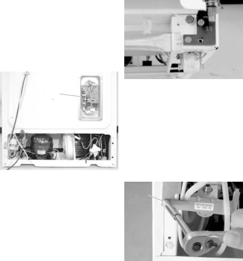
Main Control Board
The main control board is located in the back of
the unit. This board controls the operation of the
unit.
1. Unplug the unit and remove the cover.
2. Disconnect all wiring harness connectors from
the main control board.
3. Remove the board by unlocking the four
plastic board standoffs located on the board.
Note: If standoffs are broken during disassembly,
order new parts.
GEA00896
Main
Main
Processor
Card
Card
Main
Processor
Card
Roller Assembly
Adjustable roller assemblies are located at the
bottom front of the unit. They are adjustable and
replaceable.
1. Unsnap the base grille from the bottom of the
unit.
2. Remove the guide pin with a flat-head
screwdriver.
IMPORTANT: To ensure proper door closure, the
refrigerator rollers must be adjusted to level the
refrigerator. This is different from previous models.
GEA00898
Adjusting
Screw
Adjusting
Screw
Guide Pin
Guide Pin
Guide Pin
RollerRoller
3. Turn the adjusting screw counterclockwise
until it disengages from the assembly.
4. Remove the roller from the slot.
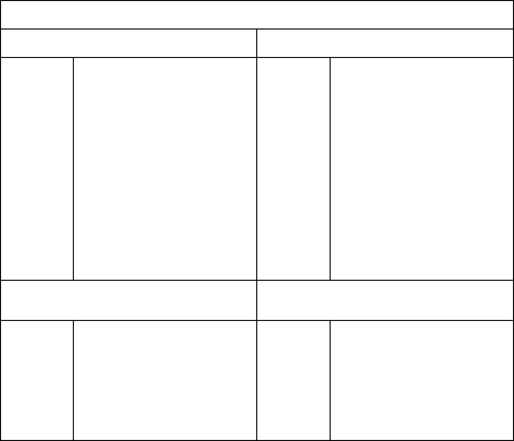
Water Solenoid
When the solenoids receive a signal from the
processor, they route water to the water filter,
cooler, and icemaker.
1. Remove the access cover.
2. Remove the solenoid bank bracket screw.
GEA00899
Bracket
Screw
Bracket
Screw
3. Pull out and disconnect the cable connector.

– 29 –
GEA00900
Cable
Connector
Cable
Connector
4. Remove 2 Phillips screws from the solenoid
connection.
5. Disconnect the water tube and remove the
solenoid.
Fresh Food Air Damper
The fresh food air damper is located in the upper
left corner of the fresh food compartment. The
damper opens to allow cold air to circulate from
the freezer to the fresh food compartment.
1. Remove 2 damper cover screws.
2. Remove the damper cover.
3. Using a flat-head screwdriver, remove the
damper assembly from the mullion divider until
the wire connector is exposed.
4. Disconnect the motor wire connectors.
5. Damper will be replaced as an assembly.

– 30 –
Notes

– 31 –
Notes

– 32 –
Diagnostics
Table of Contents
Efficient Use of Diagnostics. . . . . . . . . . . . . . . . . . . . . . . . . . . . . . . . . . . . . . . . . 32
Failure Causes (Table 1) . . . . . . . . . . . . . . . . . . . . . . . . . . . . . . . . . . . . . . . . . . . . 33
Main Control Board (Low-Voltage Side) . . . . . . . . . . . . . . . . . . . . . . . . . . . . . . . 34
Main Control Board (120 VAC Side). . . . . . . . . . . . . . . . . . . . . . . . . . . . . . . . . . . 35
Main Control Board Locator Table (Low-Voltage Side) . . . . . . . . . . . . . . . . . . . 36
Main Control Board Locator Table (120 VAC Side) . . . . . . . . . . . . . . . . . . . . . . 38
Fresh Food Warm - Freezer Warm (Diagnostic Chart) . . . . . . . . . . . . . . . . . . . . 39
Freezer Warm - Fresh Food Normal (Diagnostic Chart) . . . . . . . . . . . . . . . . . . 40
Fresh Food Warm - Freezer Normal (Diagnostic Chart) . . . . . . . . . . . . . . . . . . 41
Fresh Food Too Cold - Freezer Normal (Diagnostic Chart) . . . . . . . . . . . . . . . 42
Refrigerator Dead - No Sound, No Cooling (Diagnostic Chart) . . . . . . . . . . . . 43
Evaporator Fan Not Running (Diagnostic Chart) . . . . . . . . . . . . . . . . . . . . . . . 44
Condenser Fan Not Running (Diagnostic Chart). . . . . . . . . . . . . . . . . . . . . . . . 45
Damper Door Not Operating (Diagnostic Chart) . . . . . . . . . . . . . . . . . . . . . . . . 46
Compressor Not Running (Diagnostic Chart) . . . . . . . . . . . . . . . . . . . . . . . . . . 47
Heavy Frost On Evaporator (Diagnostic Chart) . . . . . . . . . . . . . . . . . . . . . . . . . 48
Thermistor Values (Table 2) . . . . . . . . . . . . . . . . . . . . . . . . . . . . . . . . . . . . . . . . . 49
Efficient Use of Diagnostics
For most efficient use of the diagnostics, find the appropriate diagnostic chart and proceed as directed
in the chart. When directed to take a thermistor reading, refer to Table 2, Thermistor Values.
– 33 –
sesuaCeruliaF.1elbaT
tnemtrapmoCrezeerFtnemtrapmoCdooFhserF
51evobA
tiehnerhaF
rotsimrehtrezeerfecnatsiser-hgiH
rotsimrehtrotaropaveecnatsiser-woL
eruliafnafrosnednoC
eruliafnafrotaropavE
nokcutsretaehtsorfeD
eruliafhctiwsrooD
ytluafdraoblortnocniaM
ytluafssenraH
nepopalfresnepsiD
kaelteksagrooD
neporooD
eruliafmetsysdelaeS
05evobA
tiehnerhaF
doofhserfecnatsiser-hgiH
rotsimrehttnemtrapmoc
desolcrepmaD
eruliafnafrotaropavE
eruliafhctiwsrooD
ytluafdraoblortnocniaM
ytluafssenraH
kaelteksagrooD
neporooD
lamroNelcyC
)tiehnerhaF41-dna41neewteb(
lamroNelcyC
)tiehnerhaF33dna94neewteb(
51-woleB
tiehenrhaF
desolckcutsrepmaD
rotsimrehtrezeerfniecnatsiserwoL
ytluafdraoblortnocniaM
ytluafssenraH
23woleB
tiehnerhaF
nepokcutsrepmaD
doofhserfecnatsiser-woL
rotsimrehttnemtrapmoc
ytluafdraoblortnocniaM
06woleberutarepmettneibmA
ytluafssenraH
– 34 –
Main Control Board (Low-Voltage Side)
(Sample only, check schematic shipped with product)
1
5
1
10
1
9
J1
J5
6
J3
J2
1
1 COMM
2 +12V
3 -COM
4 DI
5 DO
J4
1
8
DEFROST HEATER ON TIME
(MINUTES)
COMPRESSOR RUN TIME
(MINUTES)
ACCUMULATED FF AND FRZ
DOOR OPENINGS (MINUTES)
THERMISTOR
INPUTS
ENCODER
INPUTS
MODEL
SELECT
COMMUNICATION
INPUT/OUTPUT
DAMPER
COILS
FAN OUTPUTS
INPUTS
PROCESSING
UNIT
1 - Tan
2 - 13VDC Red
3 - Blk-DC Common
4 - Violet
5 - Wht
1 - Blu / Yel
2 - Wht / Brn
3 - Red / Blk
4 - Yel
1 - Not Used
2 - Yel / Blu Band
3 - Wht / Blu Band
4 - Brn
PERSONALITY PIN
- NONE - 20 Cu. Ft.
- Pin 8 - 22 Cu. Ft.
- Pin 9 - 25 Cu. Ft.
5 - 5VDC Blu / Wht
J4
J2
J3
J1
8 - Red-13VDC
7 - Not Used
6 - Not Used
5 - Yel
4 - Yel / Blk
3 - Wht-DC Common
2 - Not Used
1 - Blu
GEA00904
– 35 –
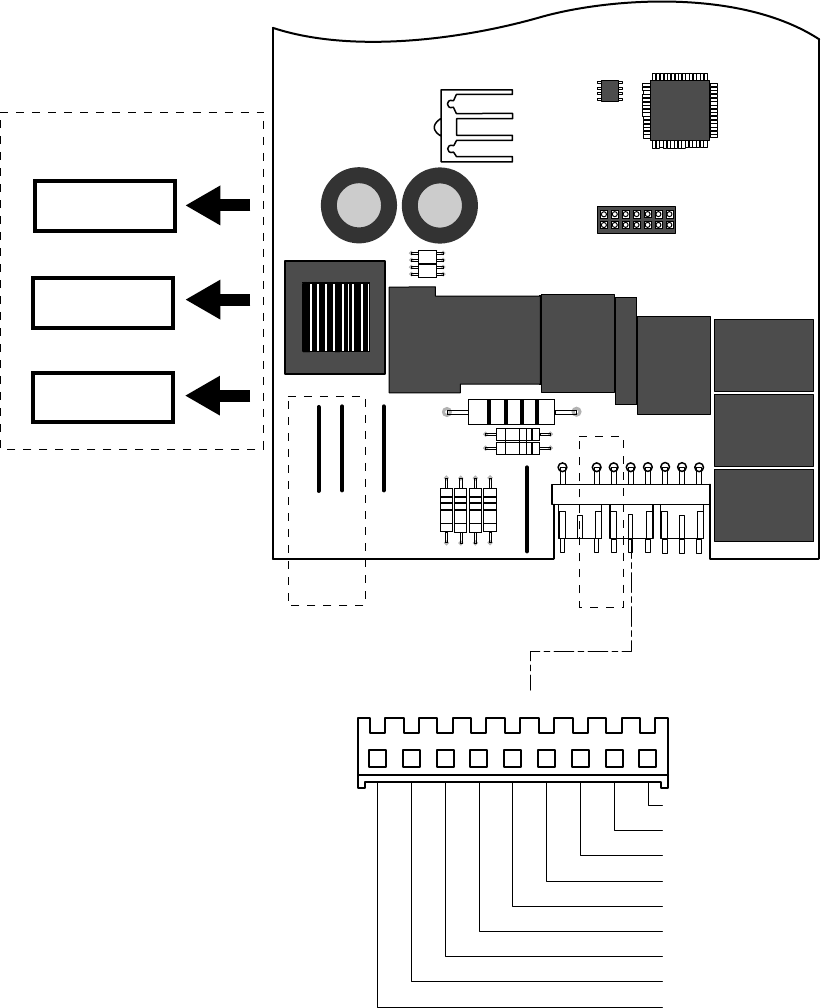
Main Control Board (120 VAC Side)
J7
1 - Blk / Wht
2 - Violet / Blk
3 - Yel
4 - Gry
5 - Not Used
6 - Violet
7 - Red
8 - Blk
9 - Orn
GEA00905
PAN_HTR
AUGER
N
DFZ
DFF
OCH
COMMON
WATER
CRUSHER
QC
K5
DEFROST
K3
L1
COMP
DEFR
LINE
2
1
J6
K7
PAN/HTR
K6
WATER
AUGER
K1
C/CR
K2
K4
COMP
J7
DEFROST
COOLING
PRE-CHILL
DOOR
SWITCH
INPUTS
COMPRESSOR
DEFROST
OUTPUTS
AND
OUTPUTS
PROCESSING
UNIT

– 36 –
elbaTrotacoLdraoBlortnoCniaM
)ediSegatloV-woL(
rotcennoCniProloCeriW
tnenopmoC
noitanimreT
gnidaeRegatloVniP-ot-niP
1J1 desutoNdesutoNdesutoN
1J2 dnaBeulB/wolleY1#rotsimrehtdoofhserF
5.3ot8.2=5nipot2nip1J
CDV
1J3 dnaBeulB/etihWrotsimrehtrezeerF
5.3ot8.2=5nipot3nip1J
CDV
1J4nworBrotsimrehtrotaropavE
5.3ot8.2=5nipot4nip1J
CDV
1J5 etihW/eulBCDV5
ylppusrotsimrehT
)CDV5(egatlov
CDV5=3nip4Jot5nip1J
2J1eulB
nafrotaropavE
retemohcat
CDV3.6=3nipot1nip2J
2J2 desutoNdesutoNdesutoN
2J3 nommocCD-etihWnommocnaFCDV21=8nipot3nip2J
2J4 kcalB/wolleYnafrotaropavE
CDV4.21=3nipot4nip2J
wol(CDV8,)deepshgih(
)deeps
2J5wolleYnafresnednoC
CDV4.31=8nipot5nip2J
elgnissinafresnednoc(
)deeps
2J6 desutoNdesutoNdesutoN
2J7 desutoNdesutoNdesutoN
2J8 CDV31-deR
egatlovylppusnaF
CDV4.31=6nipot8nip2J
.egaptxennodeunitnoC

– 37 –
elbaTrotacoLdraoBlortnoCniaM
)ediSegatloV-woL(
rotcennoCniProloCeriW
tnenopmoC
noitanimreT
gnidaeRegatloVniP-ot-niP
3J1 wolleY/eulBrepmaD
=3nip4Jot1nip3J
CDV0.6egatloVgnilevarT
3J2 nworB/etihWrepmaD
=3nip4Jot2nip3J
CDV0.6egatloVgnilevarT
3J3 kcalB/deRrepmaD
=3nip4Jot3nip3J
CDV0.6egatloVgnilevarT
3J4wolleYrepmaD
=3nip4Jot4nip3J
CDV0.6egatloVgnilevarT
4J1naT
draobresnepsiD
nommoc
eviecer/timsnart
citamehcseeS
4J2deR
draobresnepsiD
nommoc
CDV31
citamehcseeS
4J3 nommocCD-kcalB
draobresnepsiD
dnuorgnommoc
citamehcseeS
4J4teloiV1tupnidraobresnepsiDcitamehcseeS
4J5etihW2tupnidraobresnepsiDcitamehcseeS
.egaptxennodeunitnoC

– 38 –
elbaTrotacoLdraoBlortnoCniaM
)ediSCAV-021(
rotcennoCniProloCeriW
tnenopmoC
noitanimreT
gnidaeRegatloVniP-ot-niP
7J1 etihW/kcalBrotomreguA
021=9nip7Jot1nip7J
*CAV
7J2 kcalB/teloiVdionelosebuC
021=9nip7Jot2nip7J
*CAV
7J3wolleYevlavretaW
021=9nip7Jot3nip7J
*CAV
7J4yarGkcolretnirotomreguA
CAV021=9nip7Jot4nip7J
)tuhsroodrezeerf(
7J5 desutoNdesutoNdesutoN
7J6teloiV
thgilrooddoofhserF
kcabdeefhctiws
CAV021=9nip7Jot6nip7J
)neporooddoofhserf(
7J7deR
hctiwsthgilroodrezeerF
kcabdeef
CAV021=9nip7Jot7nip7J
)neporoodrezeerf(
7J
8kcalBdesutoNdesutoN
7J9egnarOlartueNlartueN
* When activated
– 39 –
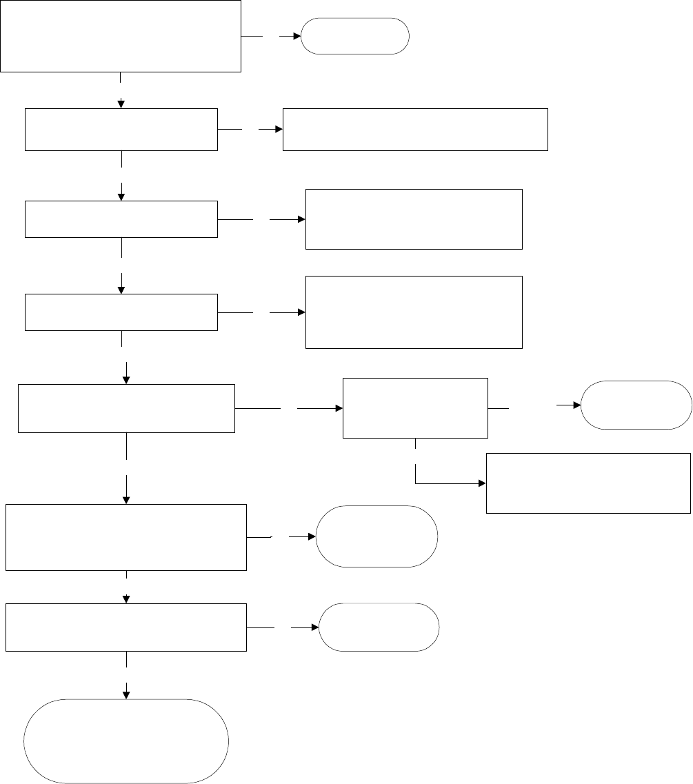
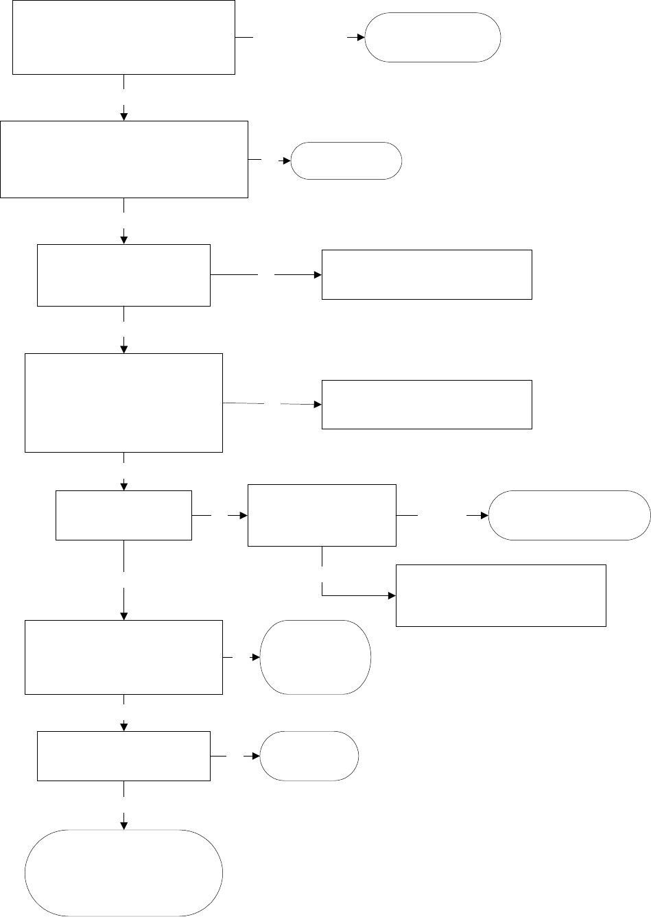
Fresh Food Warm - Freezer Warm
Basic refrigerator checks:
Basic refrigerator checks:Basic refrigerator checks:
Basic refrigerator checks:
Door gasket seal OK?
Door switch - light turning off with door closed?
Dispenser duct door closing properly?
Repair as
necessary
Is the condenser fan running?
Is the compressor running?
Is the evaporator fan running?
Is the airflow within the freezer normal? No
Go to
Condenser Fan Not Running Flowchart
page 45
Go to
Evaporator Fan Not Running Flowchart
page 44
Go to
Compressor Not Running Flowchart
page 47
No
No
No
Check sealed system
Does system check okay?
Unit tests OK
Run checks again
Reset electronics by unplugging
Reset electronics by unpluggingReset electronics by unplugging
Reset electronics by unplugging
refrigerator for 15 seconds
refrigerator for 15 secondsrefrigerator for 15 seconds
refrigerator for 15 seconds
Look for usage problem
Repair
sealed system
No
No
Yes
Yes
Yes
Yes
Yes
Yes
Look for blockage at vents
or heavy frost on
evaporator cover
Blockage
Go to
Heavy Frost on Evaporator Flowchart
page 48
Remove blockage
from evaporator cover
vent area
Heavy frost
Verify thermistors are within proper range using
temperature resistance chart on page 49
Is the resistance within range?
Check wiring
connections
If wiring is OK,
replace thermistor
No
Yes
– 40 –
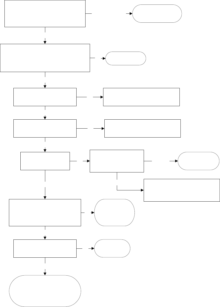
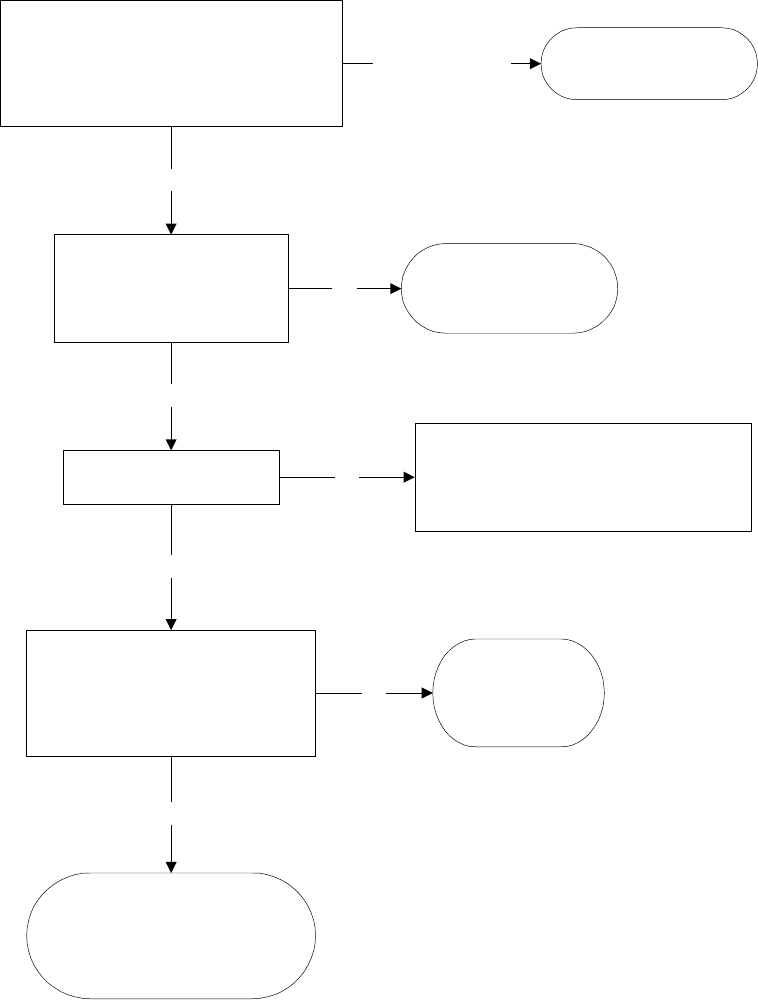
Freezer Warm - Fresh Food Normal
Check control settings and temperatures
Check control settings and temperaturesCheck control settings and temperatures
Check control settings and temperatures
Food at a setting of 5 and 5 with no
door openings for 12 hours should be:
Fresh food 34 F to 42 F
Freezer -8 F to +6 F
Adjust settings and allow
24 hrs to stabilize
Control settings
require adjustment
Basic refrigerator checks:
Basic refrigerator checks:Basic refrigerator checks:
Basic refrigerator checks:
Door gasket seal OK?
Door switch - light turning off with door closed?
Dispenser duct door closing properly?
Control settings OK
Repair as
necessary
No
Is the condenser fan running? No
Is the airflow within the
freezer normal?
Yes
Look for blockage at vents
or heavy frost on
evaporator cover
No Blockage
Go to
Heavy Frost on Evaporator Flowchart
page 48
Check sealed system
Does system check ok?
Yes
Repair
sealed system
Remove blockage
from evaporator cover
vent area
No
Yes
U n i t t e s t s O K
Run checks again
Reset electronics by unplugging
Reset electronics by unpluggingReset electronics by unplugging
Reset electronics by unplugging
refrigerator for 15 seconds
refrigerator for 15 secondsrefrigerator for 15 seconds
refrigerator for 15 seconds
Look for usage problem
Yes
Is the evaporator fan running?
Go to
Evaporator Fan Not Running Flowchart
page 44
No
Go to
Condenser Fan Not Running Flowchart
page 45
Yes
Verify thermistors are within proper
range using temperature resistance
chart on page 49
Is the resistance within range?
Yes
Check wiring
connections
If wiring is OK,
replace thermistor
No
Heavy frost
– 41 –
Fresh Food Warm - Freezer Normal
Check control settings and temperatures
Check control settings and temperaturesCheck control settings and temperatures
Check control settings and temperatures
Food at a setting of 5 and 5 with no
door openings for 12 hours should be:
Fresh food 34 F to 42 F
Freezer -8 F to +6 F
A d j u s t s e t t i n g s a n d a l l o w
24 hrs to stabilize
Control settings
require adjustment
Basic refrigerator checks:
Basic refrigerator checks:Basic refrigerator checks:
Basic refrigerator checks:
Door gasket seal OK?
Door switch - light turning off with door closed?
Control settings OK
Repair as
necessary
No
Is the evaporator fan running? No
Is the airflow within the
fresh food normal?
Yes
Look for blockage at vents
or heavy frost on
evaporator cover
No Blockage
Go to
Heavy Frost on Evaporator Flowchart
page 48
Check sealed system
Does system check ok?
Yes
Repair
sealed system
Remove blockage
from evaporator cover
vent area
No
Yes
U n i t t e s t s O K
Run checks again
Reset electronics by unplugging
Reset electronics by unpluggingReset electronics by unplugging
Reset electronics by unplugging
refrigerator for 15 seconds
refrigerator for 15 secondsrefrigerator for 15 seconds
refrigerator for 15 seconds
Look for usage problem
Yes
Unplug refrigerator
Set temperature controls to 5 and 5.
Reconnect power.
Does damper door open
after immediately
reconnecting power?
Go to
Damper Door Not Operating Flowchart
page 46
No
Go to
Evaporator Fan Not Running Flowchart
page 44
Yes
Verify thermistors are within proper
range using temperature resistance
chart on page 49
Is the resistance within range?
Yes
Check wiring
connections
If wiring is OK,
replace thermistor
No
Heavy frost
– 42 –
Fresh Food Too Cold - Freezer Normal
Check control settings and temperatures
Food at a setting of 5 and 5 with no
door openings for 12 hours should be:
Fresh food 34 F to 42 F
Freezer -8 F to +6 F
Adjust settings and allow
24 hours to stabilize
Control settings
require adjustment
Low ambient?
Is the room temperature
above 55 F?
Control settings OK
Advise consumer of
refrigerator installation
requirements
No
Is the damper closed?
Yes
Go to Damper Not Operating Flowchart
Go to Damper Not Operating FlowchartGo to Damper Not Operating Flowchart
Go to Damper Not Operating Flowchart
page 46
Damper should be closed when
FF temperatures are too cold
No
Verify thermistors are within proper
range using temperature resistance
chart on page 49
Is the resistance within range?
Yes
Check wiring
connections
If wiring is OK,
replace thermistor
No
U n i t t e s t s O K
Run checks again
Reset electronics by unplugging
Reset electronics by unpluggingReset electronics by unplugging
Reset electronics by unplugging
refrigerator for 15 seconds
refrigerator for 15 secondsrefrigerator for 15 seconds
refrigerator for 15 seconds
Look for usage problem
Yes
– 43 –
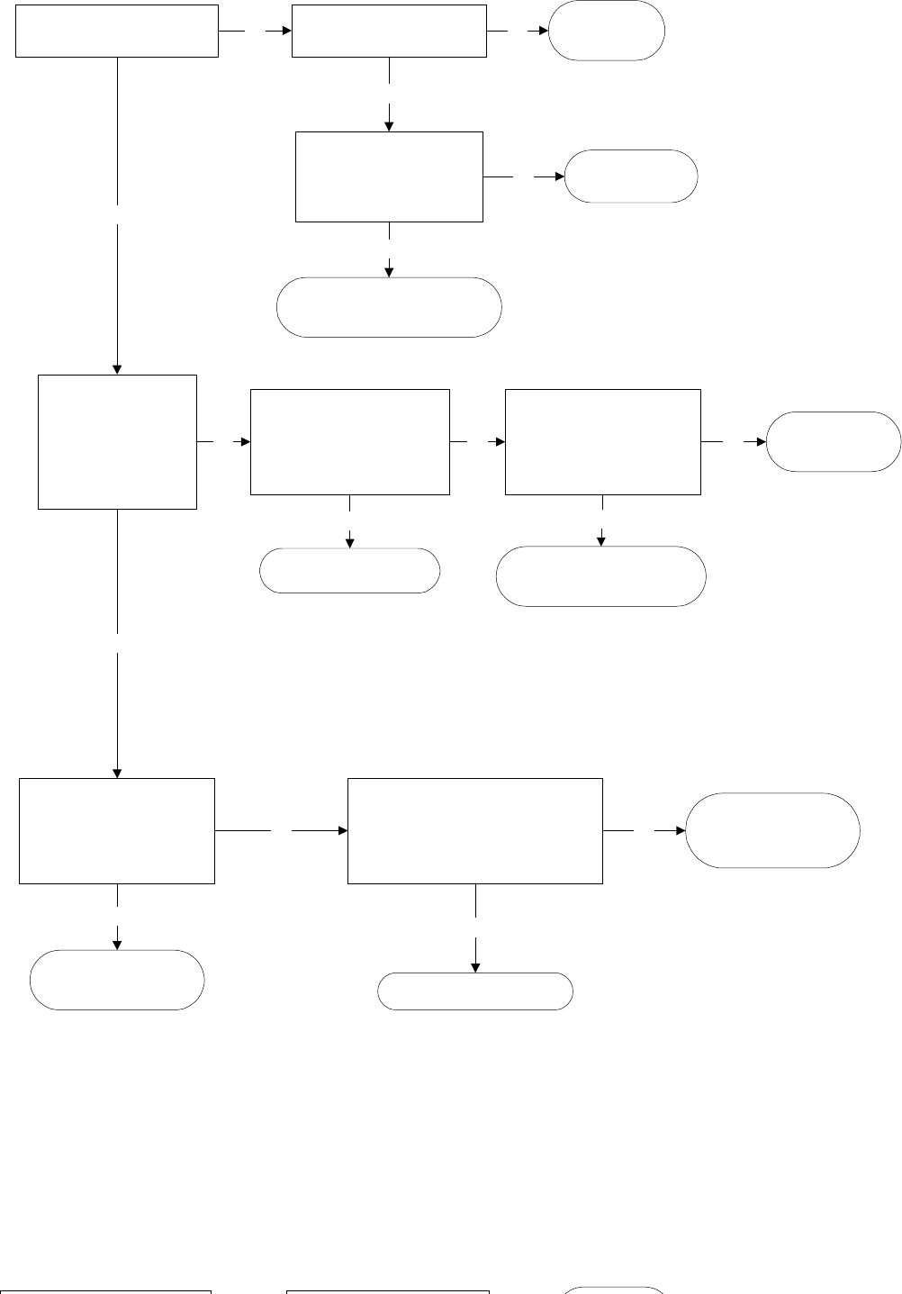
Refrigerator Dead, No Sound, No Cooling
Are the interior lights on?
Check for 120VAC at 6 pin
connector at rear of unit.
Do you have 120VAC?
Check house supply voltage.
Do you have 120VAC?
House wiring
problem
No
Verify thermistors are within proper
range using temperature resistance
chart on page 49.
Is the resistance within range?
Replace main control board
No
Repair wiring connections
at 6 pin connector
Yes
If dispenser model,
does dispenser
operate?
(If non-dispenser,
follow No statement
path first)
Yes
No
No
Yes
Yes
Repair or replace
power cord
No
Unplug J2 connector from
main control board.
Check for 12 VDC at control
board pins J2-3 to J2-8.
Do you have voltage?
Yes
Check wiring connections
If wiring is OK,
replace thermistor
Unplug encoder
(temperature control)
harness. Does the
refrigerator start once the
harness is unplugged?
Yes
Replace encoder board
(temperature control)
Yes
No
Unplug J4 connector from
main control board.
Check for 12 VDC at control
board pins J4-2 to J4-3.
Do you have voltage?
No
Short in fan motor circuit
Go to fan flowcharts
Short in dispenser control
circuit. Repair short or replace
dispenser board.
Yes
Replace main
control board
No
NOTE:
NOTE:NOTE:
NOTE: check all fan
motors circuit for shorts.
If short is detected, repair
short or replace fan motor.
Failure to replace shorted
component will damage
the new control board
upon installation
– 44 –
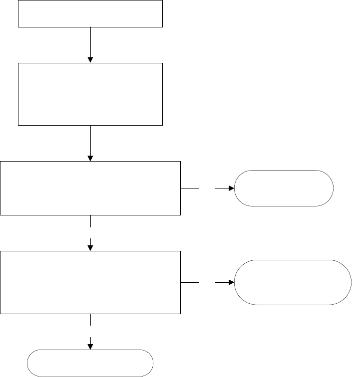
Evaporator Fan Not Running
At the evaporator fan connector, check
for 13VDC from the red to white wire and
8-13VDC from the white to yellow wire.
Is the voltage correct for both?
Unplug J2 connector on the main control board.
Check for 13VDC between pins J2-3 and J2-8
and 8-13VDC between pins J2-3 and J2-4.
Is the voltage correct for both?
No
No
Yes
Yes
Unplug refrigerator to reset
main control board.
Warm freezer thermistor to 70 F
and set temperature controls
to 5 and 5. Reconnect power.
Replace evaporator
fan motor
Repair wiring
between main control board
and evaporator fan motor
Replace main control board
NOTE:
NOTE:NOTE:
NOTE: When no voltage at main
control board, make certain to
check for shorted fan motor (less
than 1K ohm between white to red
or white to yellow). A shorted fan
motor will damage the replacement
main board.
Always check fan for obstruction first.
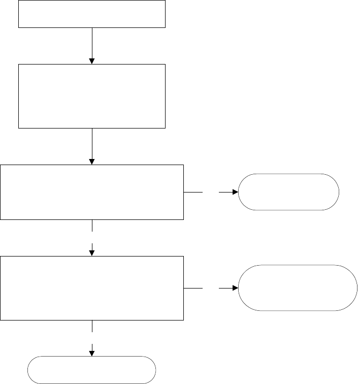
– 45 –
Condenser Fan Not Running
At the condenser fan connector, check
for 13VDC from the red to white wire and
11-13VDC from the white to yellow wire.
Is the voltage correct for both?
Unplug J2 connector on the main control board.
Check for 13VDC between pins J2-3 and J2-5
and 11-13VDC between pins J2-3 and J2-8.
Is the voltage correct for both?
No
No
Yes
Yes
Unplug refrigerator to reset
main control board.
Warm freezer thermistor to 70 F
and set temperature controls
to 5 and 5. Reconnect power.
Replace condenser
fan motor
Repair wiring
between main control board
and condenser fan motor
Replace main control board
NOTE:
NOTE:NOTE:
NOTE: When no voltage at main
control board, make certain to
check for shorted fan motor (less
than 1K ohm between white to red
or white to yellow). A shorted fan
motor will damage the replacement
main board.
Always check fan for obstruction first.

– 46 –
Damper Door Not Operating
Push damper halfway closed.
Unplug refrigerator to reset
main control board.
Set temperature controls to 5 and 5
Reconnect power.
Does damper door move
after immediately
reconnecting power?
(you have 10 seconds to check)
Yes
Push on damper door to check
manual movement.
Is the damper door stuck?
Damper jammed
Remove blockage or
replace damper
Yes
Unplug J3 connector from main control
board. Unplug refrigerator to
reset, then reconnect power.
Do you have 6VDC between pins
J4-3 (common) and each of the
pins J3-1, J3-2, J3-3 and J3-4?
(you have 10 seconds to check)
Unplug harness connector at damper.
Measure resistance between the
yellow
and red/black wires and between the
white/brown and blue/yellow wires.
Do you measure approximately
420 ohms for both readings?
Replace main
control board
Replace damper
Yes
Verify thermistors are within proper
range using temperature resistance
chart on page 49
Is the resistance within range?
Check wiring connections
I f w i r i n g i s O K ,
replace thermistor
No
Look for wiring problem
between main control board
and damper. If wiring is OK,
replace damper.
Yes
No
Replace main
control board
Yes
No
No
No
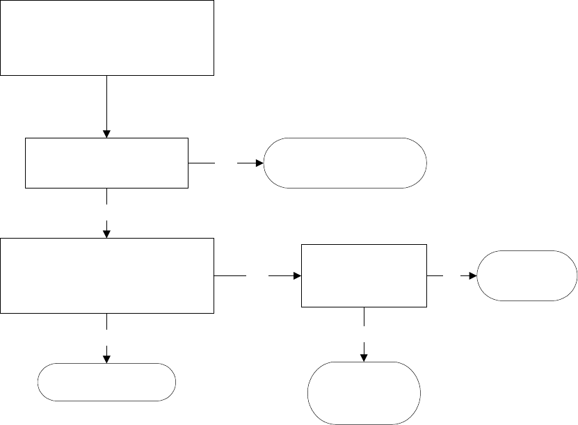
– 47 –
Compressor Not Running
Unplug refrigerator
Warm freezer thermistor to 70 F
Connect power and set temperature
controls to 5 and 5.
Is the compressor running?
Adjust settings and allow
24 hours to stabilize
Yes
Check for 120VAC at connector J7-9
orange wire to TERMINAL-J8 black wire.
Do you have 120VAC?
Replace
compressor
Yes No
Check wiring to
compressor,
overload & relay
Yes
Replace main board
No
No
Direct test the
compressor.
Did it start?
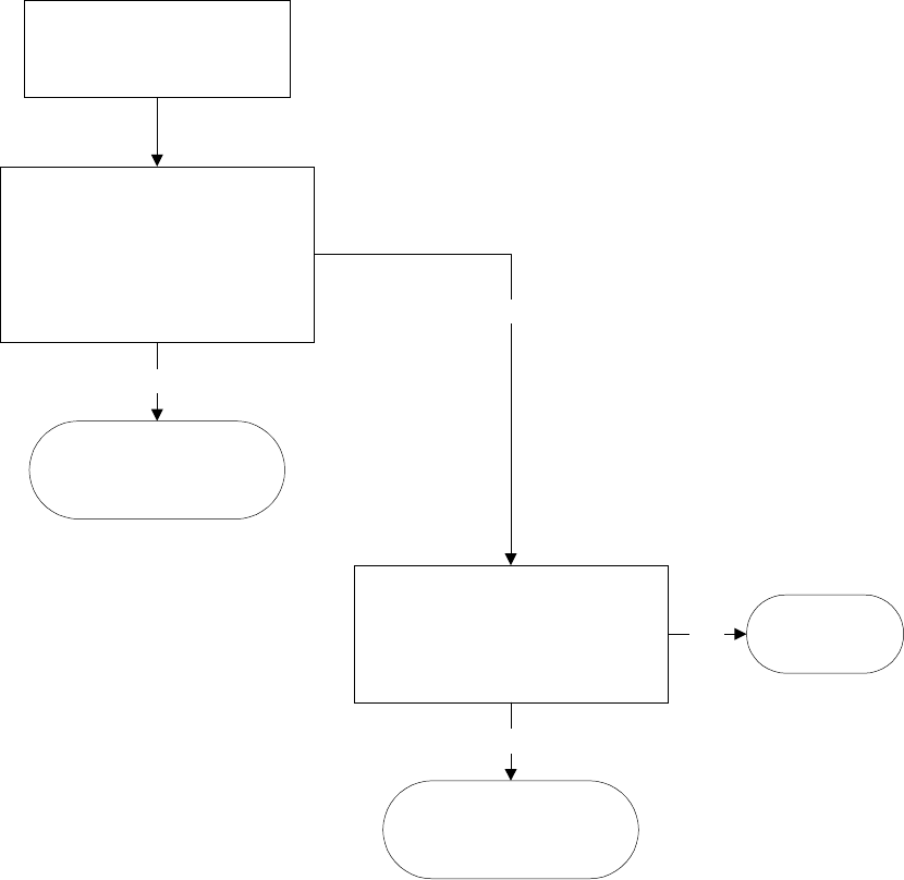
– 48 –
Heavy Frost on Evaporator
Unplug refrigerator from power.
Unplug blue connector from main
board. Measure between blue wire
on connector and neutral orange
wire on main board J7, pin 9.
Is there approximately 22
Ω
?
Verify thermistors are within proper
range using temperature resistance
chart on page 49
Is the resistance within range?
No
Yes
No
Replace
main board
Check wiring connections
If wiring is OK,
replace thermistor
Check wiring harness
Check defrost heater
Check defros safety thermostat
First, always check door ajar,
customer usage - numerous
door openings, etc...
Yes

– 49 –
NOTE: The thermistor’s resistance has a negative coefficient. As the temperature increases, the
thermistor’s resistance decreases.
seulaVrotsimrehT.2elbaT
erutarepmeT
)C(seergeD
erutarepmeT
)F(seergeD
-oliKniecnatsiseR
smhO
04-04-k8.661 Ω
53-13-k5.021 Ω
03-22-k88 Ω
52-31-k56 Ω
02-4-k4.84 Ω
51-5 k4.63 Ω
01-41k6.72 Ω
5-32k12 Ω
023k3.61 Ω
514k7.21 Ω
0105k01 Ω
5195k8.7 Ω
0286k2.6 Ω
5277k5 Ω
0368k4 Ω
5359k2.3 Ω
04401k6.2 Ω
54311k2.2 Ω
05221k8.1 Ω
55131k5.1 Ω
06041k2.1 Ω
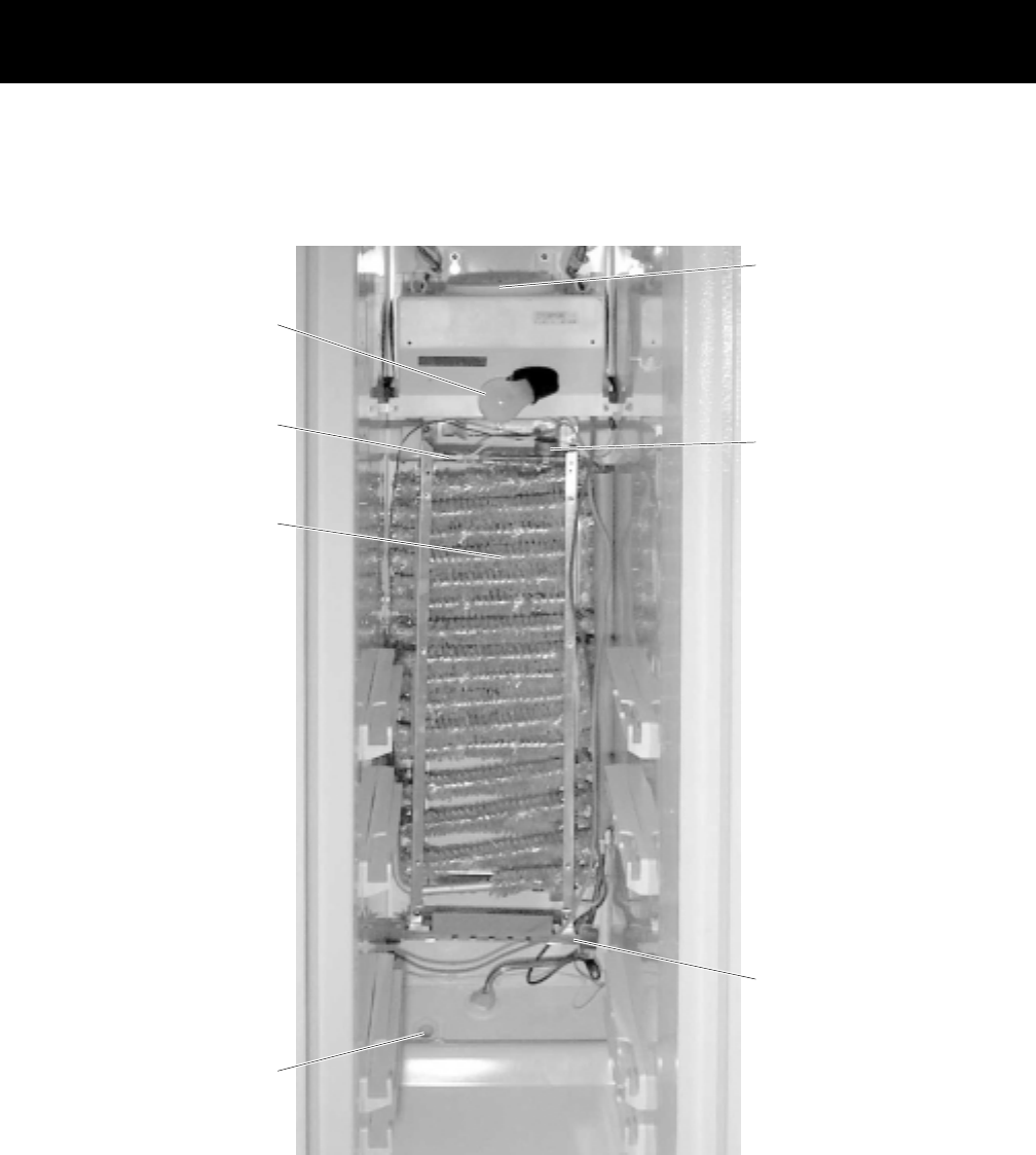
– 50 –
Component and Connector Locator Views
GEA00916
Evaporator
Fan
Evaporator
Fan
Defrost
Thermostat
Thermostat
Defrost
Thermostat
LightLight
Evaporator
Thermistor
Thermistor
Evaporator
Thermistor
EvaporatorEvaporator
Defrost
Heater
Defrost
Heater
Freezer
Thermistor
Thermistor
Freezer
Thermistor
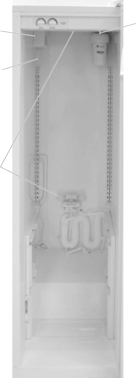
– 51 –
GEA00913
Fresh Food
Light Switch
Fresh Food
Light Switch
Fresh Food
Thermistor
Fresh Food
Thermistor
DamperDamper
Fresh Food
Lights
Fresh Food
Lights
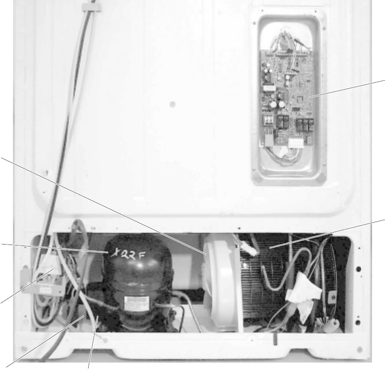
– 52 –
GEA00917
Main
Control
Board
Main
Control
Board
Jelly Roll
Condenser
Jelly Roll
Condenser
CompressorCompressor
CapacitorCapacitor Overload
Overload
and Relay
(under cover)
Overload
and Relay
(under cover)
Condenser
Fan
Condenser
Fan
Water
Water
Solenoids
Water
Solenoids

– 53 –
J7
1 - Blk / Wht
2 - Violet / Blk
3 - Yel
4 - Gry
5 - Not Used
6 - Violet
7 - Red
8 - Blk
9 - Orn
GEA00905
PAN_HTR
AUGER
N
DFZ
DFF
OCH
COMMON
WATER
CRUSHER
QC
K5
DEFROST
K3
L1
COMP
DEFR
LINE
2
1
J6
K7
PAN/HTR
K6
WATER
AUGER
K1
C/CR
K2
K4
COMP
J7
DEFROST
COOLING
PRE-CHILL
DOOR
SWITCH
INPUTS
COMPRESSOR
DEFROST
OUTPUTS
AND
OUTPUTS
PROCESSING
UNIT
NOTE: Refer to the Main Control Board Locator Tables in the Diagnostics chapter for more
information.
Main Control Board (120 VAC Side)
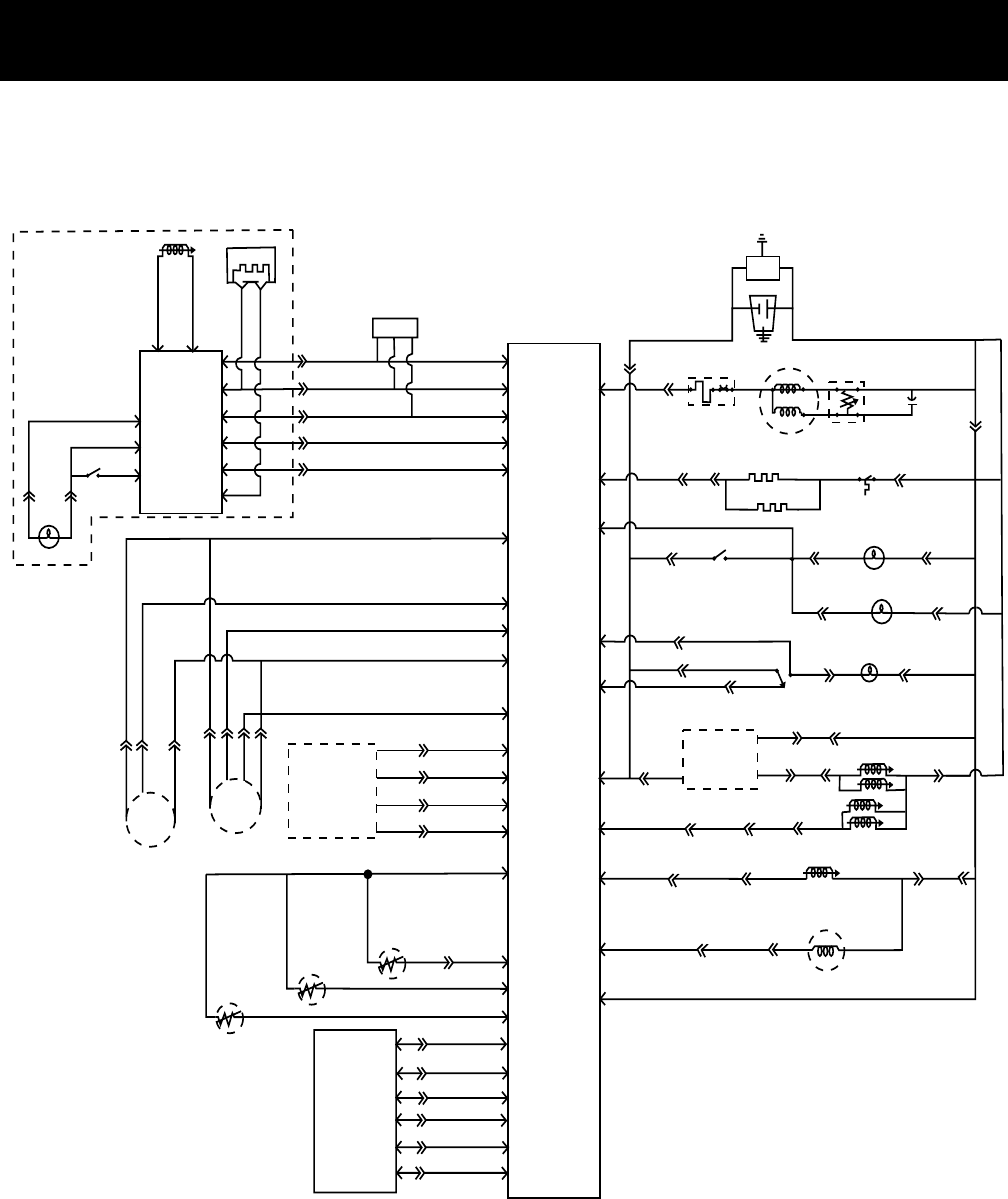
– 54 –
Schematics
PINK
BLUE
14
TAN
+13V RED
+ 13V RED
YELLOW
YELLOWYELLOW
YELLOW/BLACK
RED/BLACK
RED
RED
YELLOW
BLUE
WHITE
RED
YELLOW
WHITE
WHITE/BROWNWHITE
WHITE (COMM)
BLUE/YELLOW
BROWN
BLUE ON WHITEWHITE
WHITE
YELLOW ON WHITEWHITE
+5V
BLUE
WHITE
WHITE
WHITE
BLUE (RPM)
BLACK (Comm)
VIOLET
WHITE
TAN
B/W
YELLOW
RED
RED
BLACK
YELLOWWHITE
GRAY
DEP. SWITCH
DISP. LIGHT
RED
BLACK
VIOLET
WHITE
TAN
HTR
RED
BLACK
VIOLET
WHITE
BLACK
BLACK
BLACK
DUCT SOLENOID
J1-1
J1-2
J4-1J4-2J4-3
J2-2J2-3J2-4
J4-4J4-5J4-6
J4-1
J4-2J4-3
J-8J-9J-11J7-3J7-2J7-1J7-9 J7-6J7-7J7-4
J4-4J4-5
J2-8
J2-6 J2-7J2-5
MAIN CONTROL BOARD
J2-4J2-3J2-2
(SEE INDIVIDUAL DIAGRAM)
J2-1J3-4J3-3J3-2J3-1J1-5J1-4J1-3J1-2J3-10J3-9J3-8
(SEE INDIVIDUAL
DIAGRAM)
(SEE
INDIVIDUAL
DIAGRAM)
(SEE
INDIVIDUAL
DIAGRAM)
EVAP. FAN
COND. FAN
DAMPER
THERMISTOR EVAP.
THERMISTOR FZ
THERMISTOR FF
DC
AC
BROWN
BROWN
BROWN
BROWN BROWN
ORANGE
ORANGE
ORANGEORANGE
ORANGE
ORANGE
ORANGE
ORANGE
ORANGE
ORANGE
ORANGE
ORANGE
ORANGE
ORANGEORANGE
ORANGE
BROWN
OVERLOAD
COMPRESSOR
RELAY
WHITE
CAPACITOR
BLACK
VIOLET
VIOLET
ORANGEVIOLET
VIOLET
FF SWITCH
FRESH FOOD LIGHT
(TOP)
FRESH FOOD LIGHT(S)
(MID.)
FREEZER LIGHT
FREEZER DOOR
INTERLOCK
GRAY
(AUGER INPUT)
WHITE WHITE WHITE
RED
RED
(SEE INDIVIDUAL
DIAGRAM)
ICE MAKER
YELLOW
YELLOW
VIOLET/BLACK
VIOLET/BLK
BLACK/WHITE
B/W
CUBE
DISPENSER WATER VALVE
AUGER
DISPENSER BOARD
(SEE INDIVIDUAL DIAGRAM)
J3-7J3-6J3-5
FF Control
ENCODER
BOARD
J1-1
J1-2 J1-3
J1-4
J1-5
J1-6
GRAY
RED/YELLOW
VIOLET/BLACK
WHITE
PINK/BLACK
PINK
I/M WATER VALVE
FREEZER DOOR
BLACK
BLACK/WHITE
VIOLET/BLACK
O
R
A
N
G
E
3 2 1
Test Point
R=13Ω
R= 2Ω
R= 39Ω
R=320Ω Each
R=180Ω Each
YELLOW
YELLOW
LINE VOLTAGE
LOW VOLTAGE DC
R = 48Ω
R 3.37 Ω
S 4.64Ω
EMI FILTER (WHEN APPLICABLE)
ORANGE
OVER TEMPERATURE
THERMOSTAT
PINK
DEFROST HEATER
BLUE
R=18Ω
R=3400Ω
FILL TUBE HEATER
(When Apllicable)
BLUE/WHITE
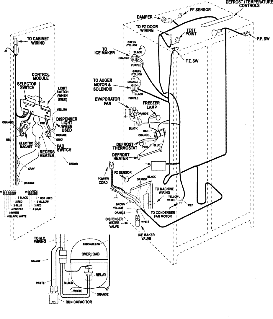
– 55 –
– 56 –
Pin 1 J8
Compressor
Pin 1 J9
Defrost Heater
Pin 1 J11
Line
Evaporator Fan Tach.
J2 Pin 1
Personality Input 5
Pin 2
Fan Common
Pin 3
Evaporator Fan
Pin 4
Condenser Fan
Pin 5
FF Fan
Pin 6
QuickChill Damper1 +
J5 Pin 1
QuickChill Damper1 -
Pin 2
QuickChill Damper2 +
Pin 3
QuickChill Damper2 -
Pin 4
+5V
Pin 5
QuickChill Thermistor
Pin 6
QuickChill Fan
Pin 7
Fan +12V
Pin 8
FF1 Thermistor
J1 Pin 1
FF2 Thermistor
Pin 2
FZ Thermistor
Pin 3
Evaporator Thermistor
Pin 4
+5V
Pin 5
Personality Input 1
Pin 6
Personality Input 2
Pin 7
Personality Input 3
Pin 8
Personality Input 4
Pin 9
Damper - Blue
J3 Pin 1
Damper - White
Pin 2
Damper - Red
Pin 3
Damper - Yellow
Pin 4
FF Encoder Select
Pin 5
Comm. Tx/Rx
J4 Pin 1
Comm. +12V
Pin 2
Comm. Common
Pin 3
Discrete Disp. Input 1
Pin 4
Discrete Disp. Input 2
Pin 5
FZ Encoder Select
Pin 6
Encoder Signal
Pin 7
Encoder Signal
Pin 8
Encoder Signal
Pin 9
Encoder Signal
Pin 10
Pin 1 J12
Monogram Drain Pan Heater
Pin 9 J7
Neutral
Pin 8
NIC
Pin 7
FZ Door Switch
Pin 6
FF Door Switch
Pin 5
QuickChill Heater
Pin 4
Auger Motor Interlock
Pin 3
Water Valve
Pin 2
Crusher Solenoid
Pin 1
Auger Motor
Pin 1
QuickChill Htr.
Pin 2
QuickChill Htr.
REV H and higher
Low Voltage DC
120 VAC

– 57 –
Notes
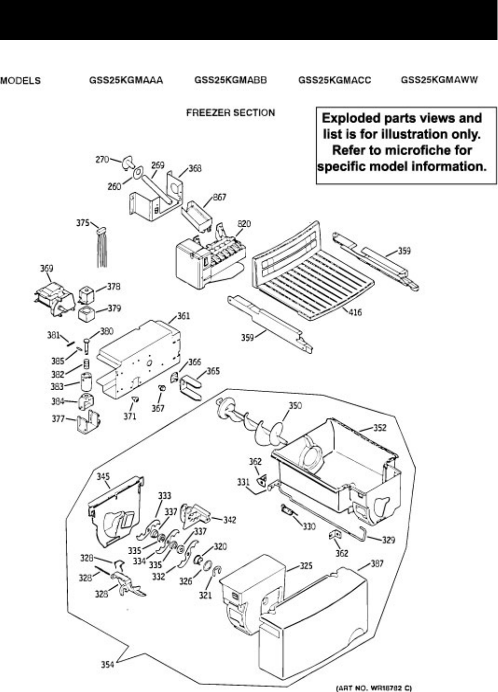
– 58 –
Illustrated Parts Catalog
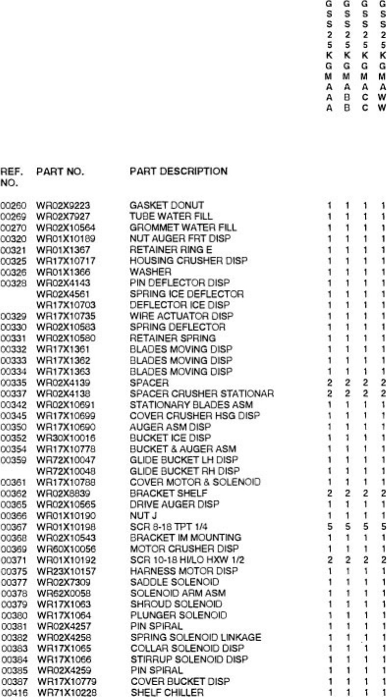
– 59 –
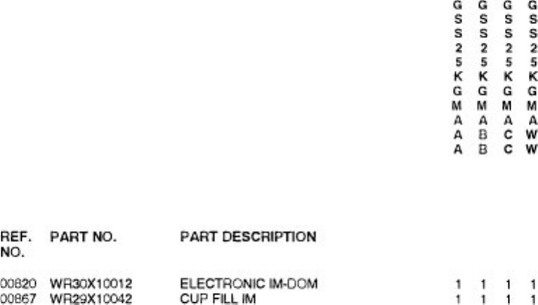
– 60 –
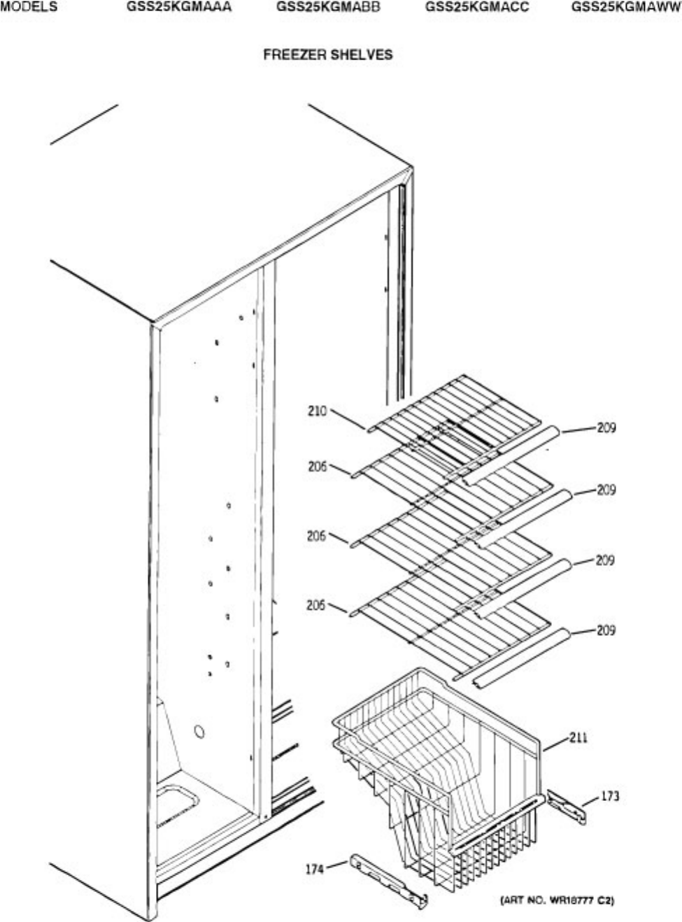
– 61 –
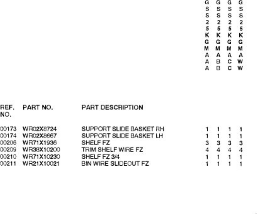
– 62 –
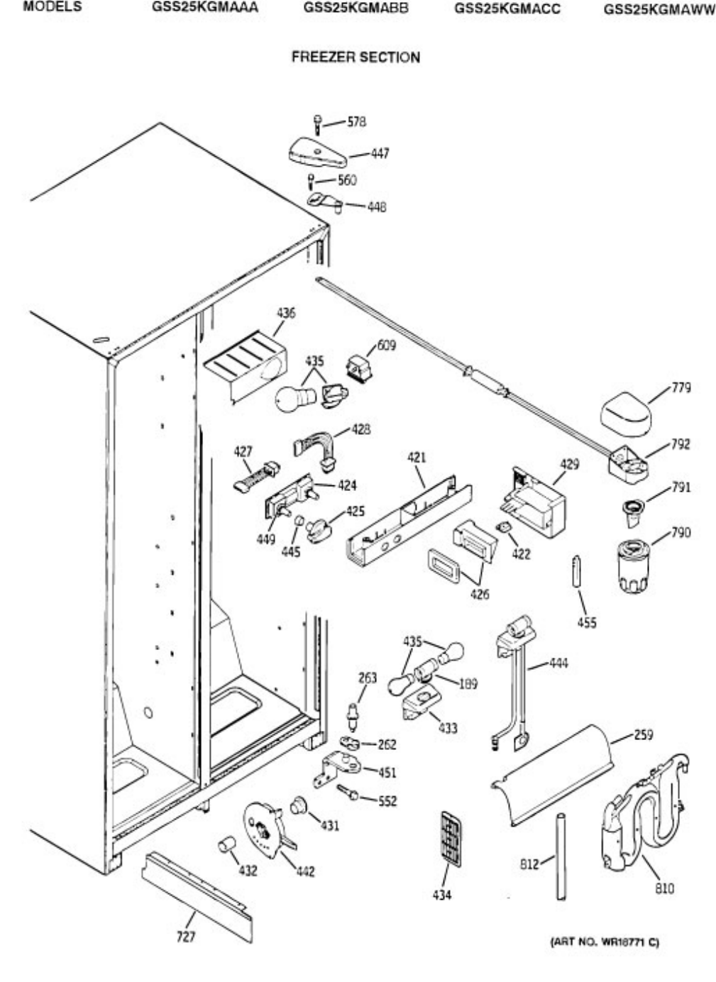
– 63 –
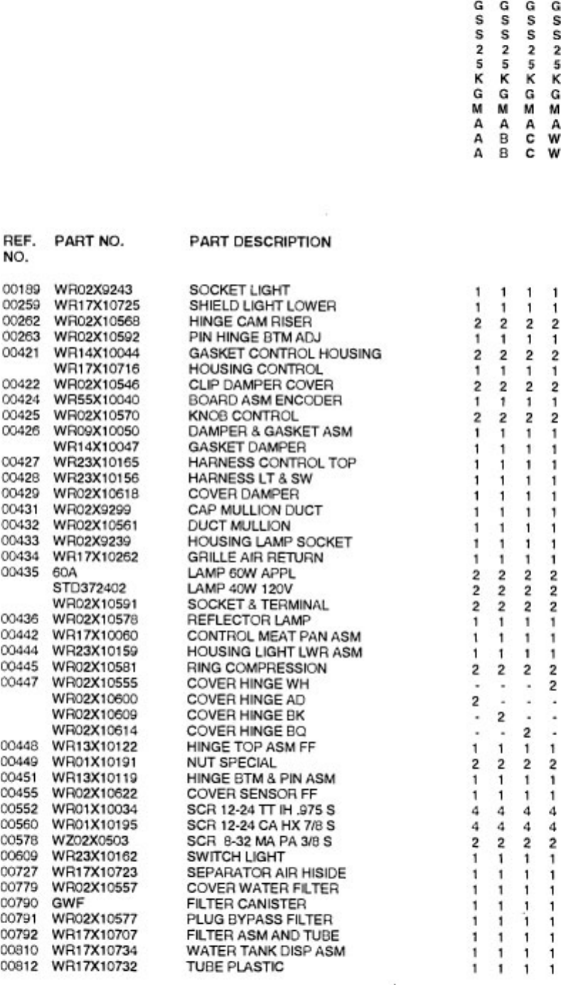
– 64 –
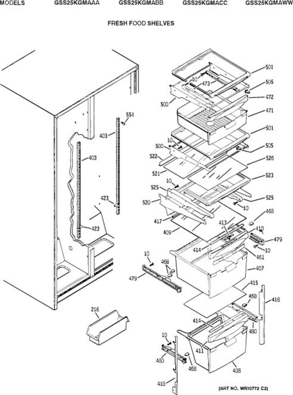
– 65 –
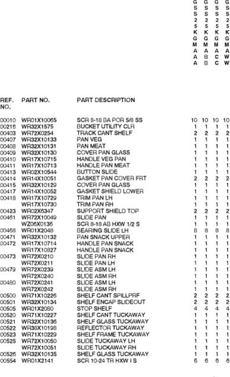
– 66 –
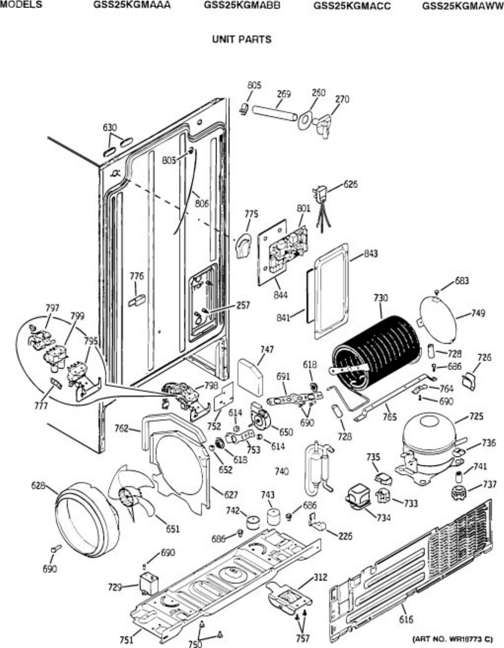
– 67 –
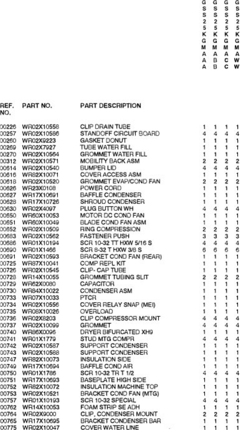
– 68 –
