Primary Aluminium
Alloys for Pressure Die Casting
RHEINFELDEN ALLOYS

Table of contents RHEINFELDEN ALLOYS –
Aluminium Alloys for Pressure Die Casting
General
Alloys
Processing datasheets
Technical information
ALUMINIUM RHEINFELDEN group
RHEINFELDEN FAST ALLOYS
Forms of delivery
Customer support and research and development
Aluminium casting alloys by RHEINFELDEN ALLOYS
Profile of the alloys for the die casters
Publications
Castasil
®
-37
– AlSi9MnMoZr
Castasil
®
-21
– AlSi9Sr
Silafont
®
-36
– AlSi10MnMg
Silafont
®
-38
– AlSi9MnMgZn
Castaman
®
-35
– AlSi10MnMg
Thermodur
®
-72/-73
– AlMg7Si3Mn – AlSi11Cu2Ni2Mg2Mn
Magsimal
®
-59
– AlMg5Si2Mn
Technical informations / Processing datasheets
Castasil
®
-37
Castasil
®
-21
Silafont
®
-36
Silafont
®
-38
Thermodur
®
-72
Magsimal
®
-59
Surface coating
Joining techniques for die castings
Eight target levels for HPDC
Disclaimer and imprint
2
3
4
5
6 – 7
8 – 9
10
11 – 20
21 – 24
25 – 36
37 – 38
39 – 40
41 – 42
43 – 53
54
55
56
57
58
59
60
61 – 62
63
64
65
1
ALUMINIUM RHEINFELDEN group
“Progress by tradition”
ALUMINIUM RHEINFELDEN group: This history of aluminium
in Germany started at Rheinfelden. In 1898 Europe’s first
river power station brought about the establishment of the first
aluminium smelter in Germany, at Rheinfelden, Baden.
The company has always operated in three business segments
and in October 2008 restructuring turned ALUMINIUM
RHEINFELDEN GmbH into a holding company and the former
ALLOYS, SEMIS and CARBON divisions became independent
GmbH & Co. KGs.
www.rheinfelden-group.eu
RHEINFELDEN ALLOYS GmbH & Co. KG: Products of
RHEINFELDEN ALLOYS can be found wherever steel designs
or iron casts can be replaced by light aluminium casts.
RHEINFELDEN ALLOYS is a powerful partner, especially to
the automotive and mechanical engineering sectors in provid-
ing alloys designed to the process and cast part based on the
customer’s particular needs.
www.rheinfelden-alloys.eu · Tel. +49 7623 93 490
RHEINFELDEN SEMIS GmbH & Co. KG
www.rheinfelden-semis.eu
RHEINFELDEN CARBON GmbH & Co. KG
www.rheinfelden-carbon.eu
Our policy
Our
RHEINFELDEN ALLOYS GmbH & Co. KG innovative char-
acter is what allows us to adapt rapidly to fast changing market
needs. The agility of a private family owned operated company,
the central geographic location in the European cast metal
market, the know-how and experience of our team, are factors
making a difference for Customers looking for reliable tradition
and modern innovation. Efficient and effective use of cast alu-
minum is on the forefront of our new developments in materials.
It is RHEINFELDEN ALLOYS philosophy to fulfill also the newest
requested standards of quality, either ISO or VDA. Please ask for
our actual certificates or have a look at our homepage.
We offer customized alloys and new solutions for high perfor-
mance materials and light weight components with focus on low
carbon foot print products. Everywhere where steel construction,
cast iron or composites can be replaced by light-weight cast
aluminum, we’re at work !
2
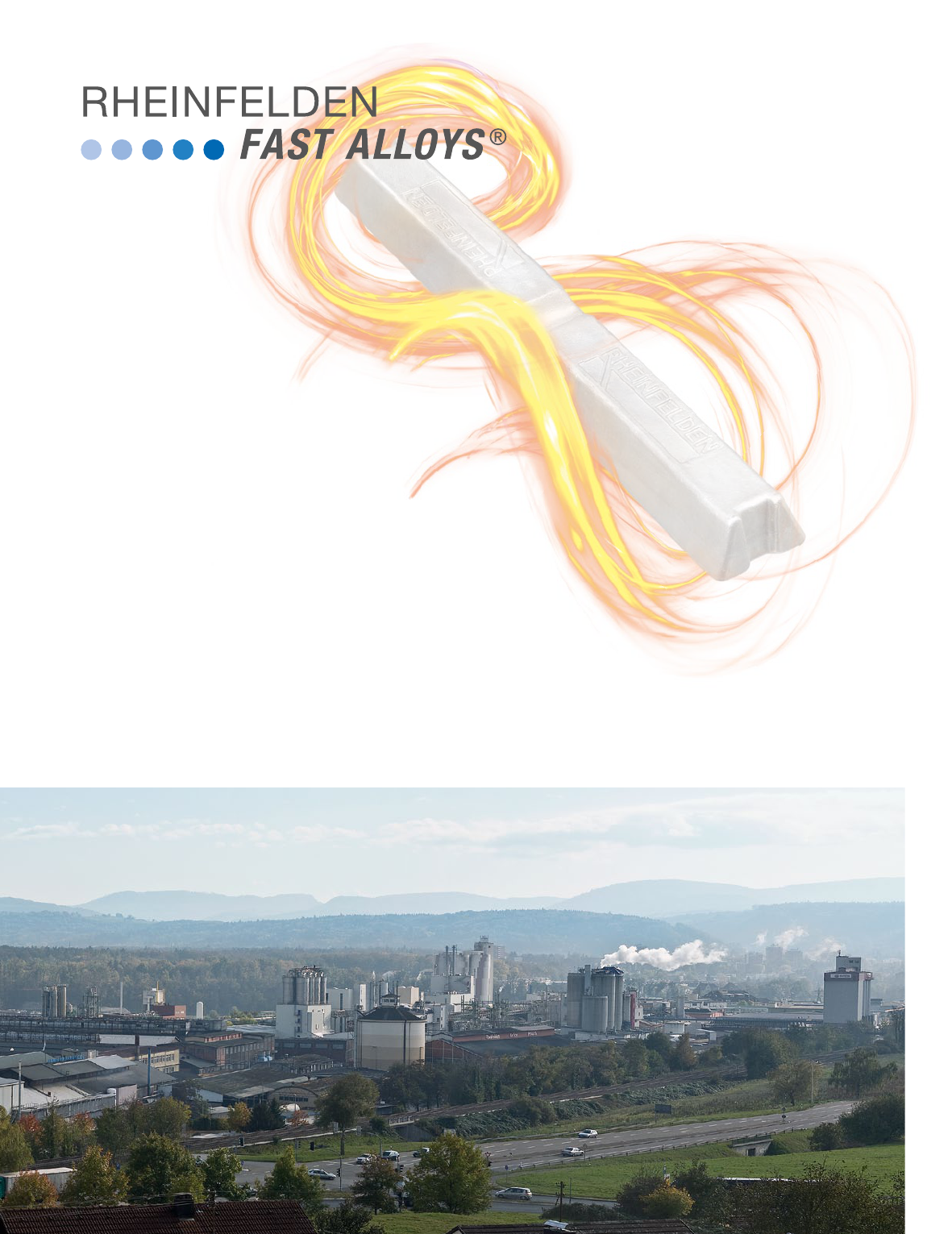
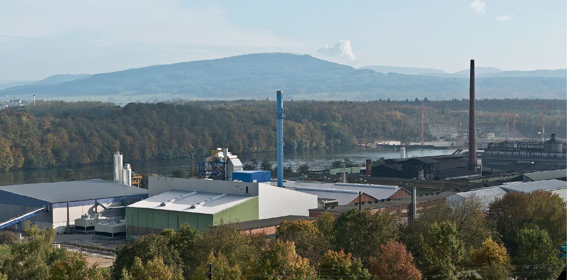
RHEINFELDEN FAST ALLOYS
Panoramic view of the entire complex
Seven good reasons for RHEINFELDEN FAST ALLOYS
• No storage costs
• No nance costs
• No LME speculation
• No supply bottleneck
• Flexibility for your production
• Contemporary reaction to market change
• Higher exibility close to your costumer’s request
Ordered today
Produced tomorrow
Ready for shipment one day later
3
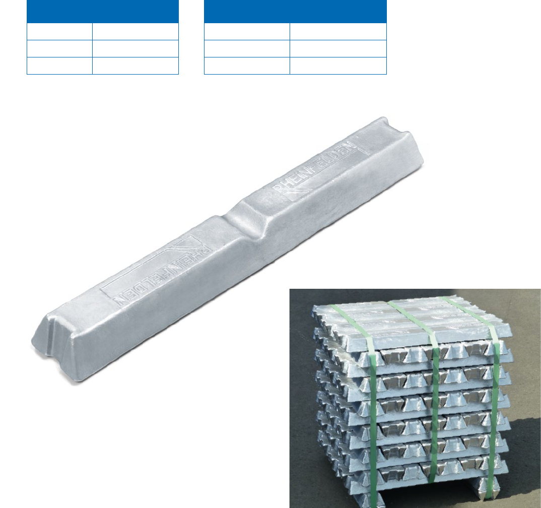
Forms of delivery
RHEINFELDEN-Ingot: Since the new RHEINFELDEN Production System came on line, all our
materials have been supplied in the form of RHEINFELDEN ingots. This ingot form is replacing
the HSG ingot yet retains all the advantages of the old form of delivery.
Liquid metal: If you want us to deliver metal to go straight into production, we can also supply
liquid metal.
Chemical analysis: The delivery slip contains the average actual batch analysis.
Stack labelling: Each stack features an information box containing the brand name and/or alloy
group name, internal material number, stack weight and on request a colour marking. The batch
number consists of the year in the sequential production number and the number in the sequenze.
Machine-readable bar codes can be printed in this box.
RHEINFELDEN-Ingot
The stack of RHEINFELDEN ALLOYS is built
with 95 single ingots including the 4 base ingots;
here the highest stack with 13 layers of ingots.
Ingot
Weight 6 – 8 kg
Surface 716 × 108 mm
Height bis 52 mm
Stack of 13 layers
Stack weight 760 kg
Stack surface 716 × 716 mm
Stack height 780 mm
4
Customer support and research and development
When RHEINFELDEN ALLOYS develop new materials we always aim to achieve efficient and
specific use of aluminium cast. Through the use of materials tailored and refined to increase perfor-
mance, RHEINFELDEN ALLOYS is constantly striving to help reduce vehicle weight and therefore
cut fuel consumption and CO
2
-emissions.
Every product and every customer has individual requirements of the material. The Customer
Support team at RHEINFELDEN ALLOYS has the job of anticipating these needs and producing
tailored materials, fitting the casts and your requirements.
RHEINFELDEN Customer Support
Please contact our customer support team and use our TechCenter installations at RHEINFELDEN
ALLOYS also for your foundry concerns. We can advise on the use of aluminium cast, the design of
casts and the choice of alloy. Use our experience for your success.
RHEINFELDEN technical center
Time is increasingly of the essence when our customers experience casting technology problems.
It is therefore crucial that we have the facilities to allow us to quickly solve problems through
experimentation and immediately incorporate new findings into production. This technical support,
renowned throughout the industry, is available exclusively to RHEINFELDEN ALLOYS customers.
Goals of research and development
The technical center assists the customer support team and runs development projects with the
following goals:
• To optimise the mechanical and cast properties of our aluminium cast alloys
• To develop alloys under consideration of the appropriate casting method
• To collaborate with designers on use of our cast alloy most suited to their applications,
including testing mechanical properties
RHEINFELDEN sales service
The portfolio of RHEINFELDEN ALLOYS sales department is always adjusted to the request of
our costumer. RHEINFELDEN ALLOYS has the possibility to offer different commercial strategies.
RHEINFELDEN Internet portal www.rheinfelden-alloys.eu
We at RHEINFELDEN ALLOYS development use also phase
simulation software for calculations and optimization of our
wide range of cast alloys. Highlighted is here the solidification and
phase growing simulation of Magsimal-59.
5
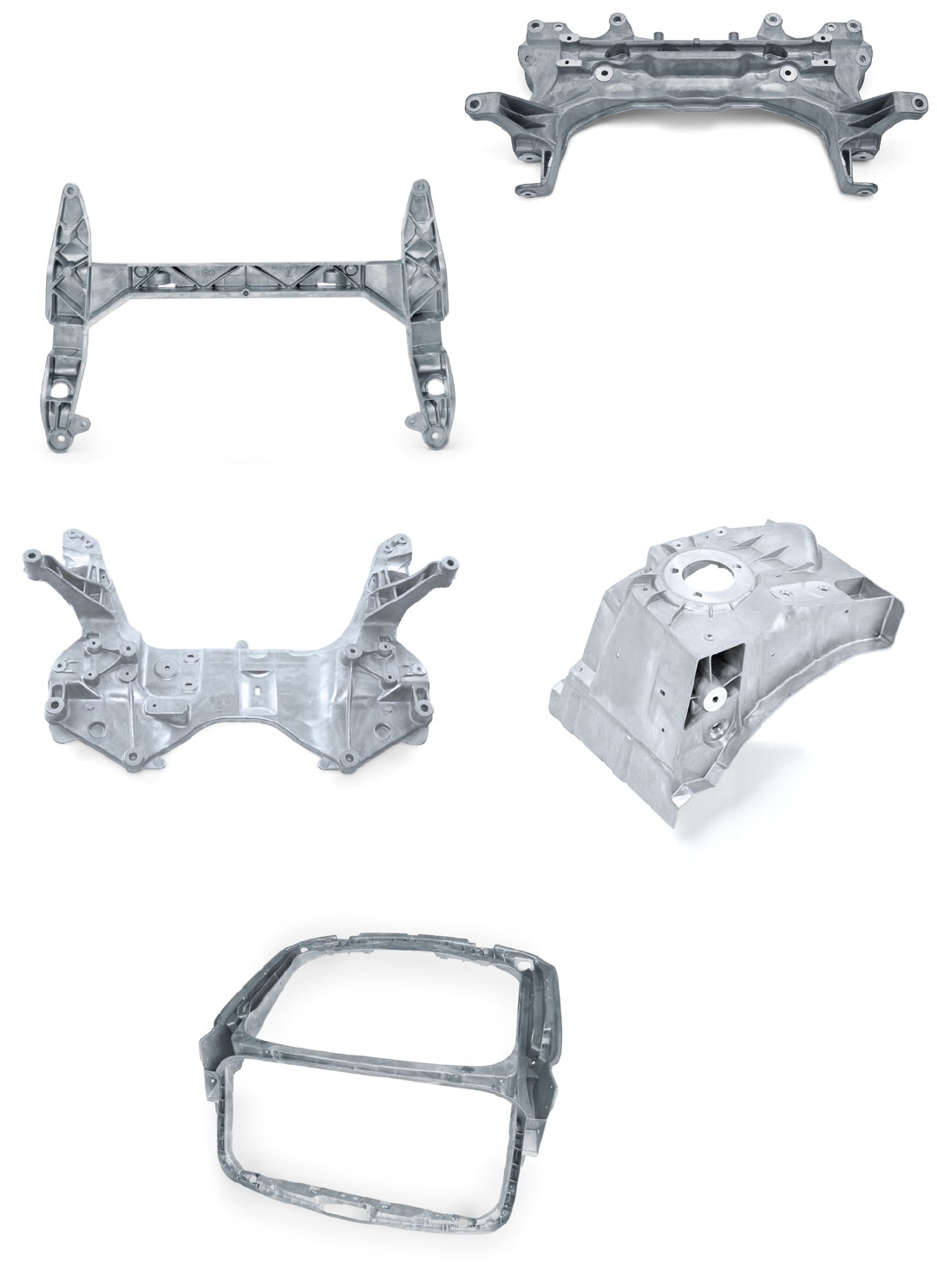
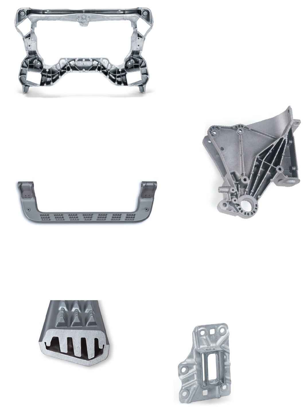
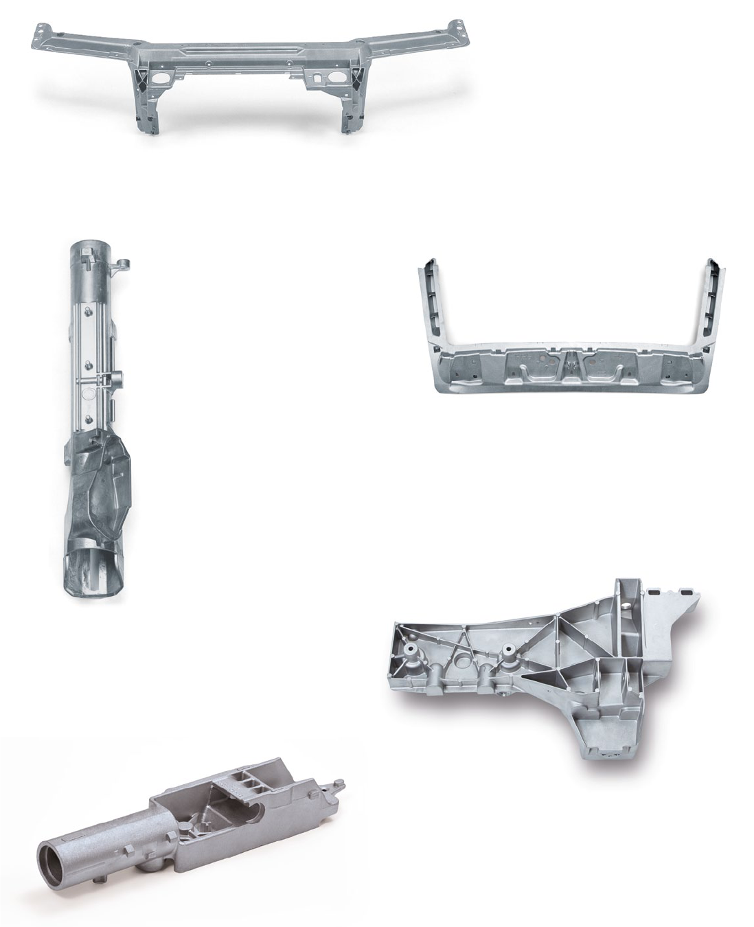
Aluminium casting alloys by RHEINFELDEN ALLOYS
Get the spirit of RHEINFELDEN
Quick finder for selecting the right alloy
The following table provides an overview of RHEINFELDEN ALLOYS, which are used
in the car building industry either for structural and chassis parts or either for
heat conducting parts. Further on table presents some details of the alloy properties.
excellent
very good
good
OK
poor
— not applicable
Alloy
Chemical
denomination
Flangeability
Electrical conductivity
Suitable for technical anodising
Suitable for punch riveting
Strength in as-cast state
Elongation
Hardness
Corrosion resistance
For constructions with thin walls
Impact toughnes s / ductilit y
Machinability at F
Machinability following T6
Mechanical properties at elevated
temperatures (200 °C)
Weldability
Sand casting
Gravity die
HPDC
Appropriate
casting method
Conducting
parts
Structural and chassis parts
—
— —
— –
— —
—
— —
— —
— —
—
— —
—
—
—
— —
–
– –
– –
– – –
–
– –
– – – – –
– – – –
– –
– – – –
– – –
– – – – –
– – –
– – –
–
Anticorodal-70 AlSi7Mg0.3
Silafont-36 AlSi10MnMg
Silafont-38 AlSi10MnMgZn
Silafont-09 AlSi9
Silafont-20 AlSi11Mg
Castaman-35 AlSi10MnMg
Castasil-37 AlSi9MnMoZr
Unifont-94 AlZn10Si8Mg
Castadur-30 AlZn3Mg3Cr
Magsimal-59 AlMg5Si2Mn
Alufont-52 AlCu4Ti
Thermodur-72 AlMg7Si3Mn
Thermodur-73 AlSi11Cu2Ni2Mg2Mn
Anticorodal-71 AlSi7Mg0.3
Rotoren-Al 99.7 Al99.7 E
Castasil-21 AlSi9Sr
6

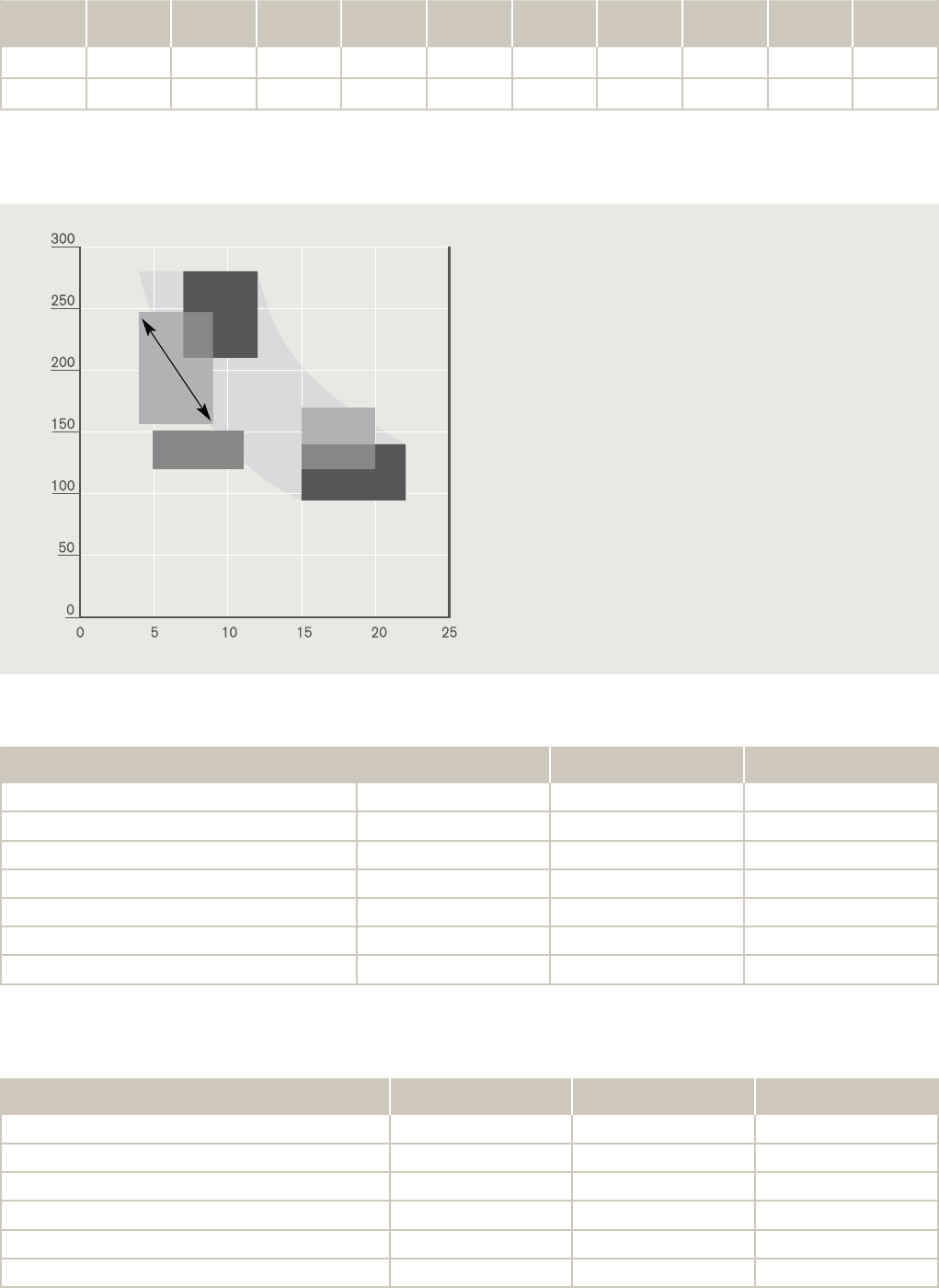
An alloy, produced for large high pressure die cast structural parts in the automotive con-
struction industry. In the meantime several OEMs recognised the advantages of these alloys
for car structural or electrical applications: high dimensional stability, can be used without
heat treatment, shape well and easy to weld, or by Castasil-21 with highest electrical or heat
conductivity.
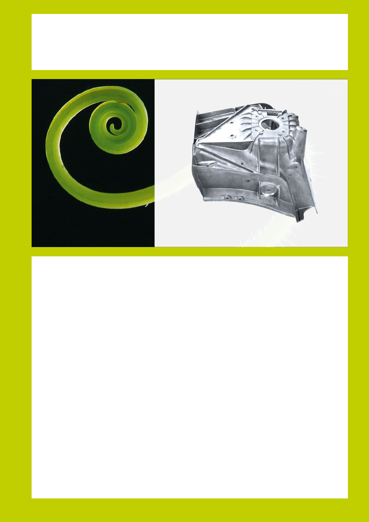
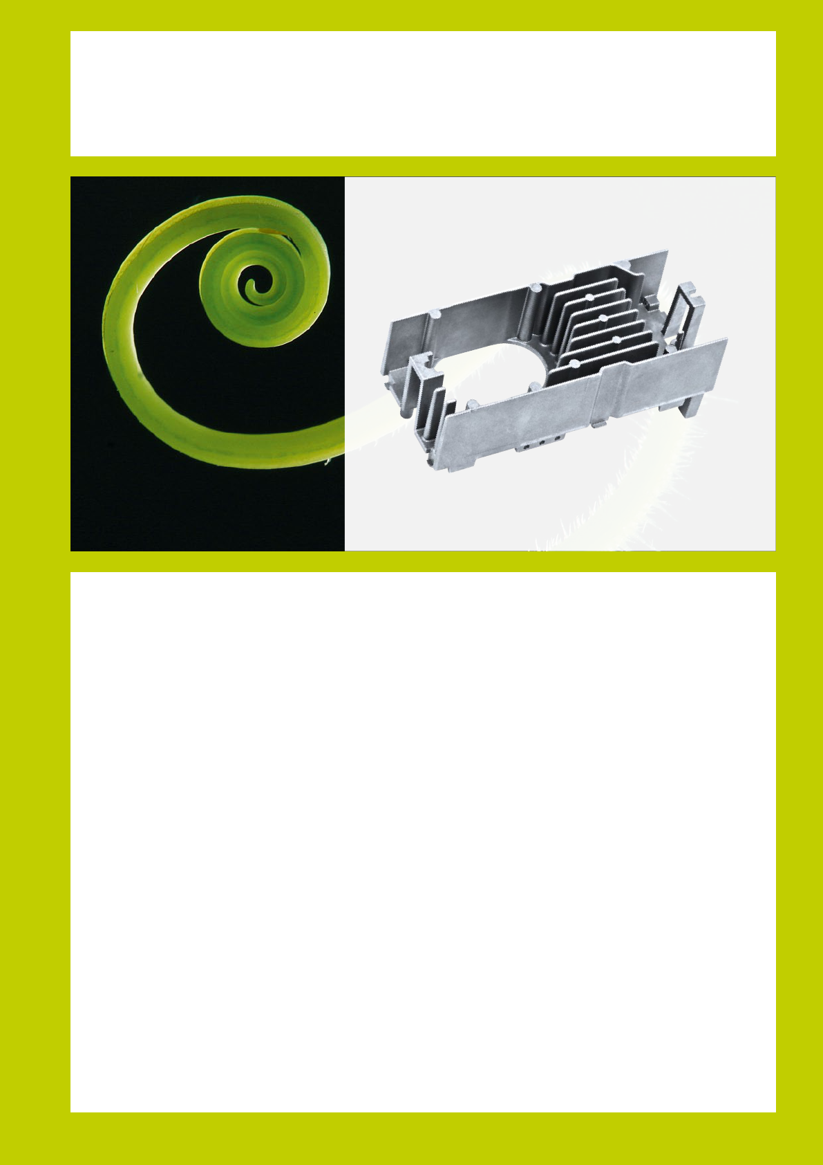
Nature’s equivalent: the vine branch which turns towards the sun, exible, elastic and yet
incredibly tough and strong. > page 11
Castasil
®
– large surface, high dimensional stability, fantastic to cast
A family of materials which can be adapted to the part specifications and to the customer’s
individual production process with ultimate precision. Can be processed using any casting
procedure, outstanding ow properties, can be modied with sodium or strontium to further
enhance properties. Silafont is for complex, delicate components which have to satisfy precisely
defined requirements and, if they feature the right components, make maximum production
efficiency possible.
Silafont emulates owing water,that ows around every stone and lls every cavity. > page 25
Silafont
®
– an infinite wealth of properties
An alloy family, that uses the possibilities of recycling, for a desired high sustainability –
represented in carbon footprint counter.
Nature’s role model: the lupine, growing from the humus of last year’s crop. > page 39
Castaman
®
– Reducing the Carbon-Footprint
A new material that withstands high temperatures like never before, allowing to play a key
role in increased efficiency in combustion engines: increased output, lower fuel consumption,
greater durability and lower CO
2
emissions.
This alloy simulates the spider’s silk: outstanding mechanical properties, maximum strength,
stable, resilient and incredibly light. > page 41
Thermodur
®
– a glimpse into the future
An alloy for delicate parts which need to retain their strength and precise form over
a long period. Good weldability, high resilience, can be used in virtually any application.
Supreme corrosion resistance, even to salt water.
Parts which simulate the structure of the wings of a dragony: wafer thin, elastic and
yet offering incredible strength and resilience, they enable this dainty insect to y
distances that never cease to amaze. > page 43
Magsimal
®
– of filigree lightness, but extremely resilient
7

Profile of the alloys for the die casters
Sil afont
®
- 36 [ AlSi10MnMg ]
Sil afont
®
- 38 [ AlSi9MnMgZn ]
• excellent castability
• applicable to thinnest wall designs
• magnesium content adjustable
to a wide range of requirements
• applicable to thinnest wall
designs and complex designs
• an air cooling after solutionizing
reduce casting distorsion
• no heat treatment needed to
reach high elongation
• good die cast ejectability;
usable even for thinnest wall
thicknesses
• highest heat and electrical
conductivity compaired to AlSi
die casting alloys due to low
distorbing impurities
Castasil
®
- 21 [ AlSi9Sr ]
• good die cast ejectability
• heat treatable to highest
elongation and ductility
• very high corrosion resistance
• alloying elements enables
highest strength and good
crash properties
• very high corrosion resistance due
to exact alloy limits
• long-term stability
• high yield strength and excellent
elongation in the as-cast state
• very good corrosion resistance
• thin wall design possible
• good die cast ejectability
• long-term stability after
temper O
• high properties
• excellent weldability and machinability
• suitable for anging, clinching or
self piercing
• high fatigue properties
• excellent weldability and
machinability
• suitable for self piercing
• high fatigue stress resistance;
highest compaired to AlSi-alloys
• excellent weldability; Suitable for
anging, clinching or self piercing
• high yield strength and elongation in
the as-cast state or after temper O
• suitable to anging, clinching or
self piercing, especially in temper O
Castasil
®
- 37 [ AlSi9MnMoZr ]
Treatment state R
p0.2
[ M Pa ] R
m
[ M Pa ] A [ % ] Hardness [ H BW ]
F 120 – 150 250 – 290 5 – 11 75 – 95
T7 120 – 170 200 – 240 15 – 2 0 60 – 75
Treatment state R
p0.2
[ M Pa ] R
m
[ M Pa ] A [ % ] Hardness [ H BW ]
water-T6 23 0 – 270 300 – 345 6 – 9 90 – 115
air-T6 180 – 20 0 250 – 275 8 – 10 80 – 110
Treatment state R
p0.2
[ M Pa ] R
m
[ M Pa ] A [ % ]
Conductibility [ M S /m ]
F 90 – 10 0 200 – 230 6 – 9 23 – 25
O 80 – 9 0 170 – 190 9 – 14 25 – 28
Treatment state Wall thickness [ mm ] R
p0.2
[ M Pa ] R
m
[ M Pa ] A [ % ]
F 2 – 3 120 – 150 260 – 300 10 – 14
F 3 – 5 100 – 130 230 – 280 10 – 14
8
Thermodur
®
- 73 [ AlSi11Cu2Ni2Mg2Mn ]
Magsimal
®
- 59 [ AlMg5Si2Mn ]
Thermodur
®
- 72 [ AlMg7Si3Mn ]
• usage in the as-cast state also for thick
wall HPDC
• low melt oxidation due to patented alloy addition
• no sticking to the die
• excellent castability, also for thick wall HPDC
• reducing distorsion is possible due to stabilising T5
• high corrosion resistance due to exact alloy limits
• high fatigue strength due to low iron content
• usage in the as-cast state for HPDC with
2 to 8 mm wall thickness
• low melt oxidation due to patented alloy addition
• no sticking to the die
• higher shrinkage in comparision to AlSi-alloys
• very high corrosion resistance,
no stress corrosion
• very high fatigue strength
• excellent weldability, suitable for anging,
clinching and self piercing
• higher shrinkage in comparision to AlSi-alloys
• high elongation even at room temperature
• high temperature strength, especially at > 225 °C
• very high corrosion resistance
• excellent machinability
• very high hardness
• high temperature strength
Castaman
®
- 35 [ AlSi10MnMg ]
• outstanding castability, even for bigger
die casting designs
• magnesium content adjustable to a wide
range of requirements
• good die cast ejectability
• heat treatment T6 enables wide range of mechanical
properties
• very high corrosion resistance with high fatigue properties
• excellent weldability and machinability
• suitable to t for anging, clinching or self piercing
Treatment state R
p0.2
[ M Pa ] R
m
[ M Pa ] A [ % ] Hardness [ H BW ]
F 120 – 150 200 – 270 4 – 9 75 – 90
T6 180 – 280 250 – 340 6 – 12 80 – 110
Ageing R
p0.2
[ M Pa ] R
m
[ M Pa ] A [ % ] Hardness [ H BW ]
2 0 ° C 190 – 20 0 350 – 380 7 – 10 80 – 100
2 2 5 ° C / 5 0 0 h 150 – 175 180 – 205 < 20
Ageing R
p0.2
[ M Pa ] R
m
[ M Pa ] A [ % ] Hardness [ H BW ]
1 5 0 ° C / 5 0 0 h 2 80 – 310 330 – 355 < 1 130 – 150
2 2 5 ° C / 5 0 0 h 130 – 155 250 – 280 1 – 2
Treatment state Wall thickness [ m m ] R
p0.2
[ M Pa ] R
m
[ M Pa ] A [ % ]
F 2 – 4 160 – 2 20 310 – 340 12 – 18
F 4 – 6 140 – 170 250 – 320 9 – 14
9
Publications
Catalogues
Primary aluminium casting alloys Manual
Primary aluminium casting alloys Leporello
Manuals and processing data sheets Code
Anticorodal-70/72 Ac-70, Ac-72 501
Silafont-36 Sf-36 518
Silafont-38 Sf-38 519
Silafont-09 Sf-09 516
Castasil-21 Ci-21 562
Castasil-37 Ci-37 561
Castaman-35 Cm-35 571
Thermodur-73 Td-73
Unifont-94 Uf-94 532
Magsimal-59 Ma-59 545
Alum inium for rot ors Al 9 9.7 - E 551
Reports based on real-life use and on the development of aluminium Code
Producing Low-iron Ductile Aluminium Die Casting in Silafont-36 630
Experiences of series production of high pressure die cast steering wheel frames in Magsimal-59 632
Melt testing in the aluminium foundry with a focus on quality 623
The possibilities of aluminium high pressure die casting – using this technology close to the limits; Sf-36 und Ma-59 635
Potentials of aluminium pressure die casting – application of this technology close to the limits; Sf-36 and Ma-59 636
31 reasons for using aluminium casting 629
Ductile high pressure die casting alloy with low iron content; Silafont-36 803
Recently developed high pressure die casting alloy with outstanding mechanical properties when cast; Magsimal-59 804
Non-ageing ductile high pressure die casting alloy for automotive construction; Castasil-37 806
http://rheinfelden-alloys.eu/en/downloads/
10
Castasil
®
-37
Large areas, high dimensional stability, fantastic to cast
Development by RHEINFELDEN ALLOYS Castasil-37
shows good mechanical properties, especially elongation,
which are superior to those of conventional AlSi-type alloys.
Out-standing castability and weldability enable the casting
of complex designs. Self-piercing riveting trials in the as-
cast state led for example to good results.
The properties are mainly inuenced by alloying with silicon,
manganese, molybdenum and strontium. A low magnesium
content is essential for the excellent stability of long-term
stability of mechanical properties.
Specially chosen chemical composition enables the follow-
ing casting properties:
• excellent castability
• suitable for minimum wall thicknesses
• no sticking to the die
With increasing number of applications, mainly in car
manufacturing, other properties of Castasil-37 became
also important:
• high fatigue strength
• very good corrosion resistance
• excellent weldability
• excellent machinability
• suitable for self-piercing riveting and clinching
• suitable for glueing connections in car design
11

Physical composition
Processing properties compared to standard pressure die casting alloys
Chemical composition of Castasil - 37, AlSi9MnMoZr
Mechanical properties
Castasil
®
- 37 – Properties at a glance
Wall thickness
[ mm ]
YTS
R
p0.2
[ M Pa ]
UTS
R
m
[ M Pa ]
Elongation
A [ % ]
2 – 3 120 – 150 260 – 300 10 – 14
3 – 5 10 0 – 13 0 230 – 280 10 – 14
5 – 7 80 – 110 200 – 250 10 – 14
Unit Validity range
Solidification range 595 – 550 °C
Density 2.69 kg / dm
3
20 °C
Young’s modulus 68 – 75 GPa 20 °C
Linear thermal expansion coefficient 21 1 / K × 10
-6
20 – 200 °C
Thermal conductivity 1.3 W / (K × cm) 20 – 200 °C
Electrical conductivity 18 – 22
MS / m o r m / (Ω × mm
2
)
20 °C
Fatigue strength (r = -1); as-cast state (F);
form factor K
t
= 1.2
86 MPa 10
6
cycles
Alloy type Castasil-37 Silafont-36 AlSi9Cu3(Fe)
Stability of mechanical properties very good medium good
Hot crack tendency low low low
Sticking tendency low low low
Die life > 80 % > 80 % 100 %
Linear shrinkage 0.4 – 0.6 % 0.4 – 0.6 % 0.4 – 0.6 %
[%] Si Fe Cu Mn Mg Zn Mo Zr Ti Sr others
min. 8.5 0.35 0.1 0.1 0.006
max. 10.5 0.15 0.05 0.6 0.06 0.07 0.3 0.3 0.15 0.025 0.10
Note chapter “Technical Information”!
12
Castasil
®
- 37 [ AlSi9MnMoZr ]
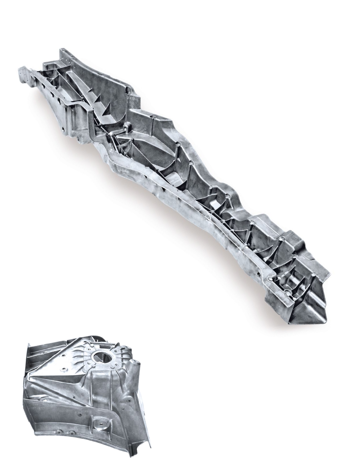
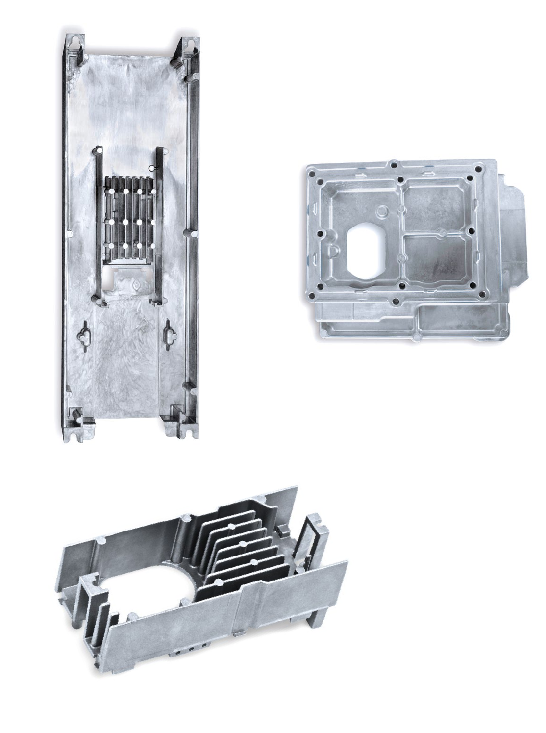
Longitudinal carrier / Audi A8
Castasil-37; as-cast
1400 × 600 × 300 mm; weight: 10 kg
The extraordinary properties of Castasil-37 in the as-cast
state result together with a well running HPDC process
to the recommended high strength (YTS > 120 MPa) and
very high ductility (elongation > 10 %).
From one side these casted structural nodes reduced
the BIW weight by 200 kg. On the other side they are
reducing the “Carbon footprint” even during production
by energy low casting process and further on during
the long-term usage of the car.
Suspension-strut dome
Castasil-37; as-cast
Wall thickness 5 mm
430 × 330 × 340 mm; weight: 4.4 kg
More and more cars are designed with compact suspension
strut domes, produced in HPDC with vacuum application.
The showed suspension strut dome in Castasil-37 has several
integrated design elements and is used in the front BIW
without any additional heat treatment like T6/T7.
This is substituting a complex multi-part sheet design.
These die casted suspension strut domes have good weldability,
rivet deformability and are easy to glue. In addition they
have high dynamic strength and reduce weight and production
cost due to lower connecting areas and stiffer BIW structure.
13
Castasil
®
- 37 [ AlSi9MnMoZr ]
Crosswise reinforcement/sports car
Castasil-37; as-cast
370 × 70 × 60 mm; weight: 0.18 kg
Internal door parts for a sports car
Castasil-37; as-cast
620 × 340 × 170 mm; weight: 1.2 kg
700 × 340 × 170 mm; weight: 2.1 kg
Cover for switching electronics
Castasil-37; as-cast
365 × 270 × 45 – 65 mm; weight: 0.69 – 1.5 kg
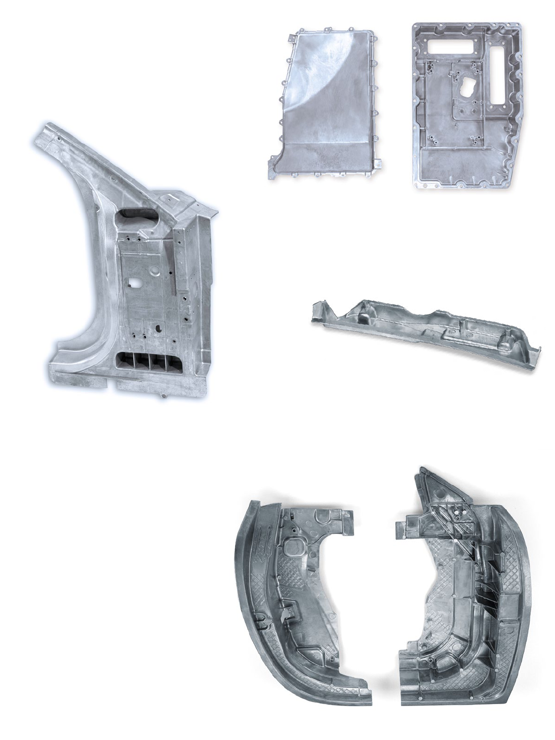
A-pillar car / Audi
Castasil-37; as-cast; weldable
815 × 575 × 190 mm; weight: 6 kg
As part of the structural design for cars this
part is responsible for crash safety a lot
and has to implement or carry several other
elements. Also parts of the car electronic
are mounted, by using the quite high heat
transfer of this Castasil-37 cast.
14
Castasil
®
- 37 [ AlSi9MnMoZr ]
Rear connecting nodes of aluminium body / Lamborghini
Castasil-37; as-cast; weldable
320 × 210 × 200 mm; weight: 2.0 kg
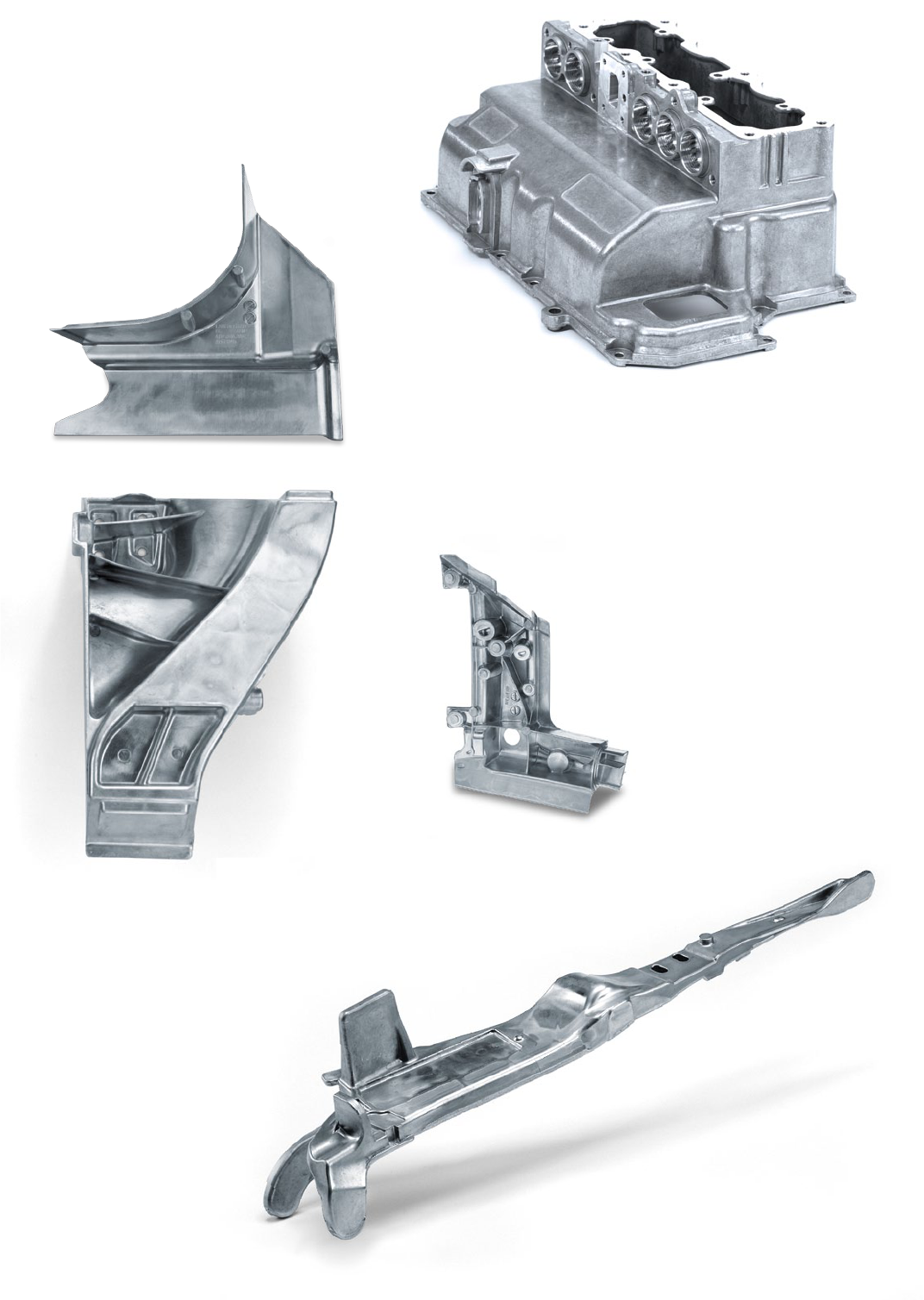
Convertible soft-top lever / VW
Castasil-37; as-cast
510 × 100 × 80 mm; weight: 0.56 kg
In the event of a crash the hinged levers of the folding top
are particularly close to the passengers in the vehicles and
are therefore subject to especially high ductility require-
ments. These components must be prevented from breaking
off. Castasil-37 fulfils the particular requirements of this
folding top lever.
Reinforcement for convertible soft-top
Castasil-37; as-cast; weldable
260 × 220 × 60 mm; weight: 0.6 kg
Upper safety housing for high voltage plug connectors
Castasil-37; as-cast
210 × 330 × 140 mm; weight: 1.5 kg
In hybrid or electric cars the power electronic has to be
sheltered separately and is covered with a crash safe
housing to avoid unexpected contact. Additionally there is
a die casted cover, to avoid plug-off without intension
during a service run.
15
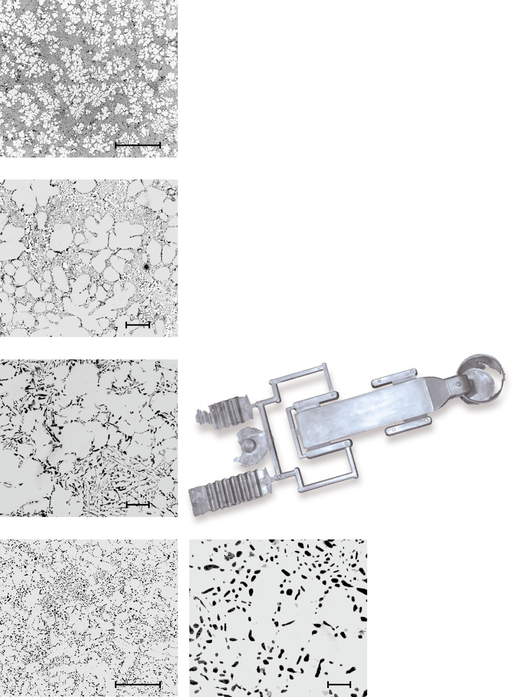
20 μm
Al
12
Mn
3
Si
2
Castasil
®
- 37 – Chemical composition
Table 1 shows the typical chemical composition. The silicon
content of 8.5 to 10.5 % enables good castability and outstand-
ing die filling capabilities. This is important for casting large
components and for filling complex designed structures. Silicon
growth during solidification leads to less shrinkage and hot
crack tendency of the alloy compared to other alloy systems.
Strontium modifies the eutectic silicon, which is very important
for ductility. The addition of strontium changes the morphology
of the silicon from lamellar or plate-like into a sponge-like coral
one. As strontium promotes hydrogen absorption, an effective
degassing of the melt with a rotating impeller is necessary.
This keeps the hydrogen content low and thus reduces poros-
ity and improves weldability. High elongation essentially results
from the high cooling rate of the pressure die casting process,
the modification with strontium and the very finely distributed
eutectic. These raise the elongation values up to more than 12 %.
The difference between a very fine Castasil-37 eutectic and a
modified, but coarser Silafont-36 eutectic is shown in figure 1
respectively figure 4 on page 32. The microstructures are taken
from 3 or 4 mm thick die cast sample plates.
An iron content below 0.15 % minimizes the formation of AlFeSi-
phases, which have a needlelike shape in the microstructure. Due
to their shape, these phases signicantly inuence the strength,
elongation and fatigue strength and promote crack formation
under load. Manganese is used instead of iron to avoid sticking to
the die. Manganese forms Al
12
Mn
3
Si
2
-phases, which can be seen
as globulitic particles in the microstructure, see figure 1a.
Magnesium is kept very low as it determines long-term ageing
behaviour.
Tab. 1: Chemical composition of Castasil-37, AlSi9MnMoZr in the ingot (weight in %)
Fig. 2: Yield strenght depending on the magnesium content in temper F, after
1000 h at 120 °C and after 3 h at 180 °C. Sample plate: 220 × 60 × 3 mm
180
Magnettafeln Roadshow
alter Katalog S.31
Yield strenght R
p0,2
[MPa]
Magnesium content [%]
120 °C
1000 h
0.040.003 0.08
170
160
150
140
130
120
0.120.100.060.02
Increasing
ageing
180 °C
3 h
As-cast state
Fig. 1: Microstructure of Castasil-37, AlSi9MnMoZr, in the as-cast state,
3 mm sample plate
[%] Si Fe Cu Mn Mg Zn Mo Zr Ti Sr others
min. 8.5 0.35 0.1 0.1 0.006
max. 10.5 0.15 0.05 0.6 0.06 0.07 0.3 0.3 0.15 0.025 0.10
16

Castasil
®
- 37 – Mechanical properties
Effect of magnesium on ageing behaviour
Figure 2 gives an overview of the properties of Castasil-37 in the
as-cast state, after 3 hours at 180 °C and after ageing at 120 °C
for 1000 hours (almost 6 weeks). The material properties change
during the course of time, whereby the effect of the magne-
sium on ageing behaviour becomes obvious. Artificial ageing is
necessary in order to avoid this natural ageing or to minimize its
effect. The following trials should indicate with which magnesium
contents no ageing occurs and how the mechanical properties
are inuenced.
Table 3 shows the chemical analyses of the tested variants. Mag-
nesium was added in quantities between 0.003 % and 0.1 %.
The manganese content was maintained at an optimum level of
0.6 % and strontium at 120 ppm for a good modification of the
eutectic silicon. Sample plates 220 × 60 × 3 mm were cast in a
single-cavity die in order to determine the mechanical properties.
The test samples were cast on a 400 t Bühler B machine with
a forced venting system. The melt was cleaned and degassed
by means of a rotating impeller and the density was checked
by means of a low-pressure density sample. A density index
between 3 % and 5 % was established prior to degassing, there-
after below 2 %.
Samples were artificially aged at 120 °C for 1000 hours to simu-
late long-term ageing in the as-cast state.
Figure 2 shows the impact of magnesium content on the yield
strength in temper F (as-cast state), O (180 °C / 3 h) and O
(120 °C / 1000 h). If the samples are left at room temperature in
the as-cast state, the yield point remains approximately at the
same level with different magnesium contents. However, with
increased temperature the material properties change percep-
tibly with increasing magnesium content. Ageing starts from a
magnesium content between 0.04 % and 0.08 %. 0.06 % can
be assumed as the limit value. No significant dependence on
the magnesium content was established with regard to ultimate
tensile strength and elongation. Elongation values between 10 %
and 12 % were established in all tempers, which is rather high for
an AlSialloy without deep changes of the microstructure.
The mechanical properties of Castasil-37 depend to a slight
extent on the wall thickness and therefore on the solidification
conditions. The elongation values are impressive: 11.6 % with
2 mm wall thickness and even 14 % with wall thickness between
3 and 6 mm.
Yield strenght and ultimate tensile strenght react as known to
thicker walls and therefore longer solidification times.
Castasil-37 reached on our at tensile samples a yield strenght
of 139 MPa with 2 mm wall thickness, falling down to 95 MPa
with 6 mm-thick samples (fig. 3). The yield strenght is therefore
almost two times higher than the one of other magnesium-free
AlSi-pressure die casting alloys. At the same time elongation
remains steadily above 12 %, which reveals very important for
modern applications in crashrelevant bodywork manufacturing.
Tab. 2: Chemical compositions of trial series with different magnesium content in weight %
No. Si Fe Cu Mn Mg Zn Ti Sr
1 10.2 0.09 0.001 0.60 0.003 0.005 0.08 0.0126
2 10.1 0.09 0.001 0.60 0.020 0.005 0.08 0.0121
3 10.5 0.10 0.002 0.60 0.040 0.006 0.08 0.0150
4 10.3 0.09 0.002 0.59 0.082 0.005 0.08 0.0120
5 10.3 0.09 0.002 0.61 0.102 0.005 0.08 0.0120
17
Castasil
®
- 37 – Mechanical properties
Fig. 4: Stress-strain curve for Castasil-37, AlSi9MnMoZr, in the as-cast state (F)
Heat treatment
Castasil-37 can be annealed to temper O (without solutionizing)
in order to further increase its elongation. Figure 5 indicates the
mechanical properties for annealed states over different periods.
The yield point of 114 MPa in the as-cast state gradually falls to
93 MPa after 90 minutes at an annealing temperature of 350 °C.
The ultimate tensile strength behaves in a similar way. Yield
strength and ultimate tensile strength can be assumed to be stable
from a technical point of view! Elongation, on the other hand,
increases continuously from 14 % to 16,5 % after 90 minutes.
This means that elongation can be increased in Castasil-37 by
a single-step annealing to temper O.
Fatigue strength
In addition to the properties under static load, the designer
needs information on the dynamic load-bearing capacity of a
material. Samples were taken from temper F die cast plates with
4 mm wall thickness in order to determine the fatigue limit under
alternating loads. The sample geometry has a decisive inuence
on the number of load alternations achieved. Form factor K
t
= 1.2
was selected in this case. The results of the fatigue test are
shown in figure 6. The progress of the curves in figure 6 is deter-
mined according to the common assessment method of 2007.
Wöhler curves show the fatigue strength under alternating
load with 5 %, 50 % and 95 % fracture probability. Castasil-37
endures one million loads alternations to an amplitude of 86 MPa
(5 % fracture probability) and the same number of cycles to an
amplitude of 103 MPa with 50 % fracture probability. This equals
39 % of the static notch-ultimate tensile strength in relation
to the sample shape used. Experience shows that cast samples
of conventional aluminium alloys in the heat-treated state only
achieve a far lower value.
High speed test for deformability
There is a difference in material performance either measuring
the tension test at high speed or with normal low speed with
0.02 mm/s. Therefor a tension test was run with 6 m/s similar to
the crash test velocity.
With Castasil-37 we measured a high positive effect for the yield
strength of 35 – 40 %, like demonstrated in fig. 7.
Fig. 3: Mechanical properties of Castasil-37, AlSi9MnMoZr, in the as-cast
state (F), depending on the wall thickness
Wall thickness [mm]
Stress R [MPa]
1 72 3 4 5 6
0
2
16
14
12
10
8
6
4
R
p0.2
R
m
A
Elongation A [%]
Elongation A [%]
Stress R [MPa]
The extremely regular stress-strain curve in figure 4 results from
a finely modified microstructure with no strenghtening effect of
magnesium in solid solution.
One of the advantages of Castasil-37 are good mechanical
properties in the ascast state in order to save the time and costs
of heat treatments with solutionizing, which produces component
distortion and needs an additional straightening process.
Temper F
R
p0.2
= 125 MPa
R
m
= 277 MPa
A = 14.9 %
F
18
Castasil
®
- 37 – Mechanical properties
Fig. 5: Mechanical properties of Castasil-37 in the as-cast state (F) and various
annealed states. Test samples: 4 mm pressure die casting plate
Stress R [MPa]
Elo ngat ion A [ % ]
300
250
200
150
100
50
0
18
16
14
12
10
8
6
4
2
0
F
350 °C /
30 min.
350 °C /
60 min.
350 °C /
90 min.
R
p0.2
R
m
A
R
p0.2
R
m
A
R
p0.2
R
m
A
R
p0.2
R
m
A
Melting
Castasil-37 ingots can generally be processed into pressure die
castings in the foundry without special treatment. However, in
order to produce casts of high consistent quality, following points
must be noted.
The good properties of Castasil-37 are based essentially on the
production of this alloy from very pure electrolytic metal. Metallic
impurities in the melt like magnesium, iron zinc and copper should
be avoided. Rapid melting is important in order to avoid strong
oxidation of the melt and the formation of segregations. Oxides
have a negative impact on the casting behaviour and on the prop-
erties of the cast to a large extent. Melt cleaning, preferably
with an impeller, is necessary in order to avoid this with Castasil-37.
This cleaning of oxides and dissolved hydrogen should be car-
ried out in the melting furnace as far as possible, otherwise a
low-turbulence metal pouring is necessary in each step of the
process.
The strontium loss must be kept at a minimum in order to main-
tain good mechanical and technical properties. A strontium loss
of 0.004 % can normally be expected per melting procedure.
In practice, a minimum content of 60 ppm and an upper limit
of 250 ppm strontium in the melting furnace have proved to be
successful for a good strontium modification. Higher strontium
contents may possibly lead to increased hydrogen absorption in
the melt, which should however be avoided for weldable casts.
A reduction in elongation can be expected with lower contents
of strontium.
The melt temperature should not exceed 780 °C. Otherwise,
increased strontium loss and increased oxide formation are to
be expected. A casting temperature of 680 to 720 °C is recom-
mended. The casting temperature depends on the shape, ow
distance and wall thickness of the casts but also on the dosing
system from the melting furnace and on the eventual presence
of a shot sleeve heating device.
Casting
Common guidelines apply to the configuration and design of
pressure die castings with regard to wall thicknesses, avoidance
of material accumulations, radii of edges, corners and transi-
tion points, chamfers and undercuts. Some points are specified
below:
A linear shrinkage of 0,4 – 0,6 % is assumed for pressure die
casting dies designed for this AlSi-alloy with 9 % silicon.
Fig. 6: Wöhler’s diagram for Castasil-37, AlSi9MnMoZr, in the as-cast state (F)
Stress R [MPa]
Number of load cycles [n]
95 %
5 %
10
6
10
7
10
8
10
5
50 %
200
180
160
140
120
100
80
60
40
20
0
Wöhler's diagram for Castasil-37
Stress ratio r = -1
4 mm wall thickness, form factor K
t
= 1,2
5 %, 50 %, 95 % fracture probability
10
4
Fig. 7: Average strain velocity value for Castasil-37 as-cast state (F) at high speed
tension test
Stress R
[MPa]
Average strain velocity [m/s]
0.01 1000.0001 1
400
350
300
250
200
150
100
50
0
1000100.10.001
R
p0.2
40
35
30
25
20
15
10
5
0
A
A [%]
R
m
19
100 μm
100 μm
Castasil
®
- 37 – Application
The shrinkage depends locally on the die configuration, e. g.
when casts have varying rib patterns. Good ejection behaviour
enables draft angles starting from 1.0 °C. Lower draft angles shall
be defined with the die designer.
Conventional die-release agents and their mix ratios can be used.
The release agent quantity and its application must be adapted
to special cast requirements such as those of welded structural
parts, parts assembled by anging or with a top-quality painting.
Pre-solidification
Deformation-intensive casts react sensitively to internal notches.
Pre-solidifications from the shot sleeve form defects such as
those shown in Figure 8a and thereby reduce the achievable de-
formation. Pre-solidifications can be metallographically detected
on the basis of the different solidification microstructure as
shown on an etched sample in Figure 8b. Investigations with
a thermoregulated shot sleeve on a 400 t pressure die casting
machine have demonstrated that pre-solidifications no longer oc-
cur in test plates starting from a sleeve temperature over 190 °C.
The lower the filling level of the chamber, the higher this tempera-
ture should be.
Fig. 8b: Micro of an etched pre-solidification
Joining technology
Also in chapter “Joining techniques for die casting” there are
details described for welding, riveting with glueing and anging
of Castasil-37 casts.
Applications
Castasil-37 was developed for pressure die castings requiring
high elongation and a specific yield strength in the as-cast state.
These are, for example, structural components such as nodes for
SpaceFrame designs or pillars for car bodies. Today the majority
of these components are manufactured in AlSi-alloys and costin-
tensively heat treated in order to obtain the required properties.
Thin-walled components may distort during heat treatment with
solutionizing, calling for an additional process step to straighten
the component.
Castasil-37 with a yield strength of at least 120 MPa and elonga-
tion of more than 12 % provides in the as-cast state mechanical
properties which are adequate for many structural components
in cars. Elongation can be further increased with single-step
annealing at 350 °C for 30 to 90 minutes. In addition to the
good properties in the as-cast state, Castasil-37 is resistant to
long-term ageing thanks to the absence of magnesium. Long-
term trials at high temperatures (120 °C /1000 h) have shown
that mechanical properties remain at least at the high level of the
as-cast state.
Bibliography
Rheinfelden brochure Code 637, “Optimizing the Magnesium
and Manganese content for the structural part application”,
published for NADCA 2003, 10/2003.
Rheinfelden brochure Code 638, “Economic production of
ductile and weldable aluminium castings”, published
by Dr.-Ing. Stuart Wiesner, 02/2006 in CPT International.
Fig. 8a: Micro of a pressure die casting with crack along a pre-solidification
20
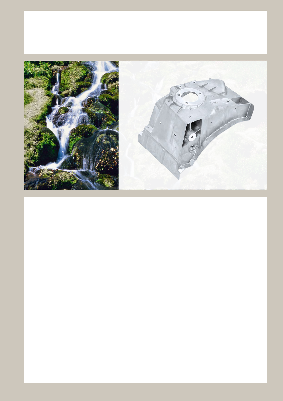
Castasil-21 is a HPDC alloy developed by RHEINFELDEN
ALLOYS for casts with outstanding requirements in terms
of electrical or thermal conductivity.
Aluminium 99,7 for rotors has indeed higher electrical
conductivity, but in praxis you need lower contraction for
huge casts, like with an alloy with more than 8 % silicon.
The application of Castasil-21 may help to lower the weight
of HPDC, especially for the light weight design of cars
with their additional casts like battery housing, conductor
plate for electronics, LED-lighting, but also for general
purposes of heating and cooling.
Chemical composition was optimized in order to have
high conductivity (up to 30 %) compare with usual HPDC
aluminium alloys.
The specially chosen chemical composition results in
following casting properties:
• excellent casting ability with good ejectability
• well usable for thin wall ns
More and more applications either in car design or in
telecommunication area need also following properties:
• very good corrosion resistance to weather
• good mechanical strength; excellent machinability
• angeable or deformable to x parts together
• suitable for glueing connections in car design
• electrical conductivity comes up to 45 % IACS,
to substitute Cu in the idea of light weight design or
Al 99,7 in rotors
Castasil
®
-21
Large areas, high dimensional stability, fantastic to cast
21

Physical composition
Processing properties compared to standard pressure die casting alloys
Chemical composition of Castasil-21, AlSi9Sr
Mechanical properties
Castasil
®
- 21 – Properties at a glance
Temper
YTS
R
p0.2
[ M Pa ]
UTS
R
m
[ M Pa ]
Elongation
A [ % ]
F 90 – 100 200 – 230 6 – 9
O 80 – 9 0 170 – 19 0 9 – 14
Unit Validity range
Solidification range 595 – 550 °C
Density 2.65 kg / dm
3
20 °C
Young’s modulus 62 – 78 GPa 20 °C
Linear thermal expansion coefficient 21 1 / K × 10
-6
20 – 200 °C
Thermal conductivity temper O < 1.7 W / (K × cm) 20 – 200 °C
Electrical conductivity temper F 23 – 25
MS / m o r m / (Ω × mm
2
)
20 °C
Electrical conductivity temper O 25– 28
MS / m o r m / (Ω × mm
2
)
20 °C
Alloy type Castasil-21 Silafont-36 Rotoren-Al 99.7
Stability of mechanical properties very good medium very good
Hot crack tendency very low very low high
Sticking tendency low low high
Die life 100 % 100 % 80 %
Linear shrinkage 0.4 – 0.6 % 0.4 – 0.6 % 0.8 – 1.2 %
Note chapter “Technical Information”!
[%] Si Fe Cu Mn Mg Zn Ti Sr others
min. 8,0 0,5 0,01
max. 9,0 0,7 0,02 0,01 0,03 0,07 0,01 0,03 0,10
22
Castasil
®
- 21 [ AlSi9Sr ]
Heatsink for electronic device
Castasil-21; temper O
170 × 70 × 70 mm; weight: 0.4 kg
This cast with fixed electrical divice has to diffuse
the hot spot of heat through the massive plate
and the casted fins and should lower the maximum
temperature ever.
Higher heat conductivity of the alloy results directly
in lower temperature. It is not necessary to design
longer fins or add forced air ventilation.
Heatsink for electronics box
Castasil-21; temper 0
460 × 160 × 65 mm; weight: 1.5 kg
Heat conducting housing for switching electronics in cars
Castasil-21; temper 0
160 × 200 × 55 mm; weight: 0.57 kg
23
Castasil
®
- 21 [ AlSi9Sr ] – Properties
Chemical composition
Table 1 shows the Castasil-21 composition with a silicon content
of 8 to 9 %. Thus, the processing temperature is 680 – 750 °C, an
area with typical thermal shock wear of die chamber and cavity.
Strontium causes a further lowering of the eutectic point, that is
the melting temperature, of about 6 – 8 °C. In die casting alloys
Strontium reduces the affinity of the melt to the die mold, i.e. the
tendency to stick on, although Castasil-21 is already alloyed with
an Fe content from 0.5 to 0.7 %.
As an impurity in this conductive alloy are magnesium and zinc
contents of more than 0.08 % and a copper content more than
0.02 %. While forming the conductivity disturbing solid solution
phases these elements are already at lower levels, but this is
negligible compared to the effects from the die casting process
(Fig. 1). Not so with the manganese and titanium content.
Here a value of only 0.01 % should not be exceeded in order to
keep the conductivity high. Because Castasil-21 is produced
with primary aluminum as base, further accompanying elements
are also kept very low.
Electrical conductivity
But more important is the modification of the silicon crystal during
solidification. The strontium addition causes a coralline
solidification structure of the Si crystal in the eutectic, the so
called modification. The relevant Castasil-21 advantage of this
modification is the higher conductivity of plus 2 – 4 MS /m.
Heat treatment
The processing in the die casting is characterized by a very rapid
solidification. Although this achieves higher strength and hard-
ness, this microstructure is negative for achieving high conductiv-
ity ! Castings out of Castasil-21 can even further be increased
in their conductivity by one-stage heat treatment, whereby
the internal stress of the cast structure is equalized than. In the
as-cast state a die cast with 6 mm wall thickness may reach
even 25 MS/m.
A heat treatment of 350 °C for 2 h or 250 °C for 3 h provides
superior conductivity of around 28 MS/m (Fig. 2). In this state,
the die casts have 83 % of the conductivity of Al 99.7. Upon
the cooling of the components after the stress-relieving may
only slowly air cooling to be made.
Handling instructions
Cleaning and processing the melt should result in a low achieved
oxide impurity. A strontium content of 100 to 350 ppm ensures
the modification. Ingate design and die cast parameters must be
optimized to result in a solid structure without pores, due to these
technically disturb the conductivity. Handling instructions for melt
preparation on page 56.
Electrical conductivity [ m/(Ω × mm
2
) ]
35
34
33
32
31
30
29
28
27
26
25
24
23
22
21
20
19
18
17
16
15
AlSi12(Fe) 170 °C 250 °C 350 °C Al for rotors
1h 2 h 3 hFF F 1h 2 h 3 h 1h 2 h 3 h
Castasil-21
Conductivity [MS/m]
Content of alloying element [%]
35
30
25
20
15
10
Cr
Mn
Zr
Ti
Cu
Fe
Zn
Si
0 0.2 0.4 0.6 0.8 1.0 1.2 1.4
37
Tab. 1: Chemical composition of Castasil-21, AlSi9Sr in the ingot (weight in %)
Fig. 1: Relationship between electrical conductivity of Al99,9 and added alloying
elements
Fig. 2: Electrical conductivity of Castasil-21 through heat treatment of the HPDC
Mg
[%] Si Fe Cu Mn Mg Zn Ti Sr others
min. 8,0 0,5 0,01
max. 9,0 0,7 0,02 0,01 0,03 0,07 0,01 0,03 0,10
24
Silafont
®
-36
An infinite wealth of properties
The pressure die casting alloy Silafont-36 was developed
by RHEINFELDEN ALLOYS in order to obtain maximum
elongation after heat treatment with average strength
values compared to standard pressure die casting alloys.
Mechanical properties at Silafont-36 can be further
improved by various heat treatments. Silafont-36 can thus
achieve elongation values over 15 % or yield strength
values around 260 MPa.
Besides these particular good mechanical properties,
Silafont-36 has also following properties required for
the pressure die casting process:
• excellent die cast castability
• no sticking to the die
• excellent machinability
In more and more applications, mainly in car manufac-
turing, other properties of Silafont-36 are of increasing
importance:
• very good corrosion resistance
• high fatigue strength
• excellent weldability for aluminium prol-cast designs
• suitable for self-piercing riveting and similar joining
processes
• suitable for glueing connections in car design
25
Physical composition
Processing properties compared to standard pressure die casting alloys
F: As-cast state
Heat treatment without solutionizing:
T5: Quenched directly after removal from the die
and artificially aged
Heat treatment with solutionizing:
T4: Solutionized, quenched and naturally aged for
more than 6 days
T6: Solutionized, quenched and artificially aged
T7: Solutionized, quenched and overaged
It should be taken into account that the magnesium
content must be tuned according to the required
property profile. Higher elongation values are linked to
lower values for yield strength and vice versa.
Elongation A [%]
Yield strength R
p0.2
[ MPa ]
Low
magnesium
T 5
F
T 7
T 4
High
magnesium
T 6
Mechanical properties
Yield strength and elongation in various heat treatment states and magnesium contents
Chemical composition of Silafont-36, AlSi10MnMg
Silafont
®
- 36 – Properties at a glance
Unit Validity range
Solidification range
590 – 550 °C
Density
2.64 kg / dm
3
20 °C
Young’s modulus
74 – 83 GPa 20 °C
Linear thermal expansion coefficient
21 1 / K × 10
-6
20 – 200 °C
Thermal conductivity temper O
1.5 W / (K × cm) 20 – 200 °C
Electrical conductivity temper F
21 – 26 MS / m o r m / (Ω × mm
2
) 20 °C
Fatigue strength (r = -1) in the as-cast state (F)
89 MPa 50 × 10
6
cycles
Alloy type Silafont-36 AlSi10Mg(Fe) AlSi9Cu3(Fe)
Heat treatment for property improvement very good good medium
Hot crack tendency low low low
Sticking tendency low low low
Joining potential high medium low
Die life > 80 % > 80 % 100 %
Linear shrinkage 0.4 – 0.6 % 0.4 – 0.6 % 0.4 – 0.6 %
Note chapter “Technical Information”!
[%] Si Fe Cu Mn Mg Zn Ti Sr P others
min. 9.5 0.5 0.1 0.04 0.010
max. 11. 5 0.15 0.03 0.8 0.5 0.07 0.15 0.025 0.001 0.10
26
Silafont
®
- 36 [ AlSi10MnMg ]
Cross member off-road vehicle
Silafont-36; as-cast
1020 × 690 × 280 mm; weight: 10.3 kg
Suspension strut dome
Silafont-36; as-cast
420 × 350 × 330 mm; weight: 4.3 kg
To cast a suspension dome reduce the overall produc-
tion effort a lot in comparision to a sheet design, and
give an weight reduction advantage too. In addition the
Silafont-36 with Mg 0,25 – 0,35 % is easy to cast
worldwide even with some integrated design elements.
Cross member / Fiat
Silafont-36; temper T5
450 × 930 × 220 mm; weight: 10.7 kg
Cross member / Porsche Cayman
Silafont-36; temper T6
610 × 830 × 80 mm; weight: 6.5 kg
Rear lid frame
Silafont 36; as-cast
710 × 1180 × 280 mm; weight 9.5 kg
27
Silafont
®
- 36 [ AlSi10MnMg ]
Engine Cradle / Daimler
Silafont-36; temper O
920 × 580 × 170 mm; weight: 10.0 kg
This pressure die casting replaces a heavier,
painted sheetsteel welded structure. As a cast
part, it integrates further functions at the same
time. The high deformation capability of this
Silafont-36 pressure die casting was achieved
by heat treatment in Temper O. This engine
cradle was-cast in a die-cavity provided with a
forced venting system in order to obtain high
product safety.
Frontplate, front bumper bar
Silafont-36; temper T7
195 × 145 × 55 mm; weight: 0.75 kg
Truck cab tilting joint / Lkw Renault
Silafont-36; temper T5
560 × 460 × 250 mm; weight: 9.5 kg
This 9,5 kg-pressure die cast replaces a
heat-treated gravity cast. This Silafont-36
component supports the driver’s cab and
locks the forward tilted driver’s cab when
the engine compartment is open.
Foot board for truck bumper, electron beam welded
Silafont-36; as-cast
190 × 640 × 110 mm; weight 2.8 kg
Extraordinary safety requirements and a life time over 20 years
in public cars can be fulfilled with this two casts design.
The single casts are produced in Silafont-36 with 0,35 % Mg
and welded together in the as-cast state.
Electron beam welding without any added material enables
a distortion free but heavy loadable design in best surface
shape.
28
Silafont
®
- 36 [ AlSi10MnMg ]
Front section frame / BMW 3 Series Cabrio
Silafont-36; as-cast
1250 × 350 × 250 mm; weight: 4.5 kg
As this cast is the top part of the car front section,
it must absorb as much kinetic energy as
possible through deformation. The torsional rigidity
of the component gives an additional advantage
during mounting into the convertible car.
This was made possible thanks to a strong rib pattern
design on the component underside and by the
material Silafont-36 with 0,24 % magnesium.
Steering column / Daimler
Silafont-36; as-cast
450 × 70 × 90 mm; weight: 0.96 kg
Filigree guide surfaces to be cast with high
dimensional accuracy, deformation with-
out fracture edges in the event of a crash and
maximum rip-out resistance strength in
the ignition lock area are the decisive require-
ments for Silafont-36 with a magnesium
content around 0,24 %.
Tailgate frame / BMW
Silafont-36; temper F
510 × 1130 × 320 mm; weight: 3.3 kg
Frame side rail, rear node / Alfa Giulia
Silafont-36; temper T5
210 × 550 × 340 mm; weight: 4.8 kg
Housing for rollover bar mechanism / Opel
Silafont-36; as-cast, crimped pipe
45 × 250 × 40 mm; weight: 0.37 kg
Integrated into the driver’s seat this mechanism device
has to push out and to fix the roll over savety bar in case
of a crash. A angable edge of the pipe with the SRS
explosive and the high stability of the light weight cast
are the advantages of Silafont-36 with 0,20 % Mg.
29

Silafont
®
- 36 – Chemical composition
Silafont-36 is a pressure die casting AISi9MgMn-type alloy with
strontium, which is produced on the basis of aluminium metal with
99.8 % purity. The alloy constituent elements (tab.1) with narrow
tolerances produce constant good cast quality. Strontium is
included for modification, i.e. for the modification of the eutectic
silicon.
The magnesium content is further adjusted according to the
various applications. The cast composition can have a higher limit
for iron, copper and zinc. This results from the conditions in the
pressure die casting foundry, but is determined by the require-
ments on the component.
A silicon content of around 10.5 % enables an excellent die filling
capability, and therefore an excellent castability.
In order to ensure that the silicon phase is already finely distribut-
ed in the as-cast state, the aluminium-silicon eutectic is modified
by the addition of strontium. This leads to high elongation values
in the as-cast state and also helps the spheroidisation of silicon
in case of following heat treatments.
As high deformation values are required, the iron content was
kept as low as possible in order to keep the share of the plate-
type AIFeSi-phases occurring in the structure as low as possible.
These phases are the essential cause of low strength and elon-
gation values, as they act as the starting point for crack forma-
tion by reason of their morphology in case of a deformation and
especially in presence of dynamic loads.
The manganese content was increased to approximately 0.65 %
in order to reduce the sticking tendency and to increase the form
strength of the casts.
Manganese has the same effect as iron with regarding the
reduction of the sticking tendency to the die. However, in contrast
to iron, the precipitations occurring during solidification are
globulitic and not acicular.
Variation of magnesium
The required ductility and strength especially of this AlSiMg-
pressure die casting alloy can actually be adjusted with the
most appropriate magnesium content to meet the component
requirements, particularly if the casts are to be heat treated.
Fife alloy variants emerged for Silafont-36 with these focus:
0.13 – 0.19 % Mg for crash-relevant components and
anging technology.
0.18 – 0.28 % Mg for rigid and even crash safety com-
ponents in presence of fatigue loads.
0.24 – 0.35 % Mg for components with high operating
strength against impact stress.
0.28 – 0.35 % Mg for heat-treated components with air
quenching after solutionizing.
0.35 – 0.45 % Mg For designs focused on strength in
as-cast state or after O, T4 or T6
Effect of manganese
From the literature it is well known that manganese should
reduce elongation in an AlSiMg-alloy, when its content exceeds
0.2 %. For this reason manganese is not recommended as an
addition to pressure die casting alloys as a substitute for or in
combination with iron. A series of tests was carried out with
manganese contents ranging between 0.04 % and 1.2 % in
order to better understand its effect on properties. At the same
time, the iron content was kept below 0.15 %. The magnesium
content was on average 0.19 %. The strontium content was
between 130 and 170 ppm in order to guarantee a good eutectic
modification.
Chemical composition of Silafont-36, AlSi10MnMg
[%] Si Fe Cu Mn Mg Zn Ti Sr P others
min. 9.5 0.5 0.1 0.04 0.010
max. 11. 5 0.15 0.03 0.8 0.5 0.07 0.15 0.025 0.001 0.10
Tab. 1: Chemical composition of Silafont-36, AlSi10MnMg in the ingot (weight in %)
30

Silafont
®
- 36 – Chemical properties
The test samples were cast on a 400 t Bühler B Machine with a
forced venting system. A four-cavity die was used with standard
machine conditions, i.e. melt temperature at 710 to 720 °C, melt
density index < 1 % (80 mbar low pressure density test), die tem-
perature 200 °C on both die halves, die lubricant dilution 1:180,
gate speed 30 to 40 m/s. The test bars had a cross-section of
3 × 10 mm in the gauge length according to DIN 50 125 Form E.
The tensile tests were carried out two days after casting in order
to ensure that the samples were in a stable condition. The tensile
tests were carried out in as-cast state (temper F) and in temper
T6 under the following conditions:
solutionizing at 520 °C for 1 hour, quenching in water and
artificial ageing at 160 °C for 6 hours. It was stated that in the
absence of manganese, the tendency of sticking to the die was
very pronounced, even if it was a simple die design. The stick-
ing tendency decreased with an increasing manganese content
and the required behaviour became apparent above content of
0.4 %. In the as-cast state it can be seen that there is only a
slight difference in ultimate tensile and yield strength with varying
manganese content as shown in figure 1a.
The same progression can be observed in temper T6 (Fig. 1b).
Only samples without manganese manifest different behaviour.
This might be caused by the strong sticking tendency as de-
scribed above. The components showed surface cracks and the
heat treatment may have caused surface damages leading to
poor results. The elongation, as seen in fig. 1c, shows a different
progression in both conditions. In both cases, elongation is low
without manganese by reason of the strong sticking tendency.
In the as-cast state, elongation increases steadily up to a
manganese content of 0.4 %. It is still above 8 % even with high
manganese contents. The optimum manganese content for
maximum elongation values in the as-cast state is between 0.5 %
and 0,8 % .
Elongation in temper T6 behaves differently. The highest value
was recorded with 0.2 % manganese. Elongation is approximately
at a level between 12 % and 14 % with 0.4 % to 1.0 % manga-
nese. On the other hand, the optimum range for a stable condi-
tion is between 0.5 % and 0.8 % manganese.
The different elongation values depending on the manganese
content may be caused by the T6 heat-treatment. During solution-
izing the intermetallic manganese phases tend to assume a
globulitic form. Surrounded by a ductile matrix, these globulitic
particles might increase elongation in comparison to the as-cast
state.
Fig. 1a: Mechanical properties depending on manganese content
in the as-cast state (F)
Fig. 1b: Mechanical properties depending on manganese content in temper T6
Fig. 1c: longation depending on manganese content in the as-cast state (F)
and in temper T6
R
m
As-cast state
R
p0.2
As-cast state
Sticking tendency
Manganese content [%]
Stre ss [ N/mm
2
]
R
m
Temper T6
R
p0.2
Temper T6
Sticking tendency
Manganese content [%]
Stre ss [ N/mm
2
]
A
Temper T6
A
As-cast state
Sticking tendency Loss of elongation
Manganese content [%]
Elongation [A]
31
100 μm
100 μm
10 μm
10 μm
10 μm
Silafont
®
- 36 – Mechanical properties
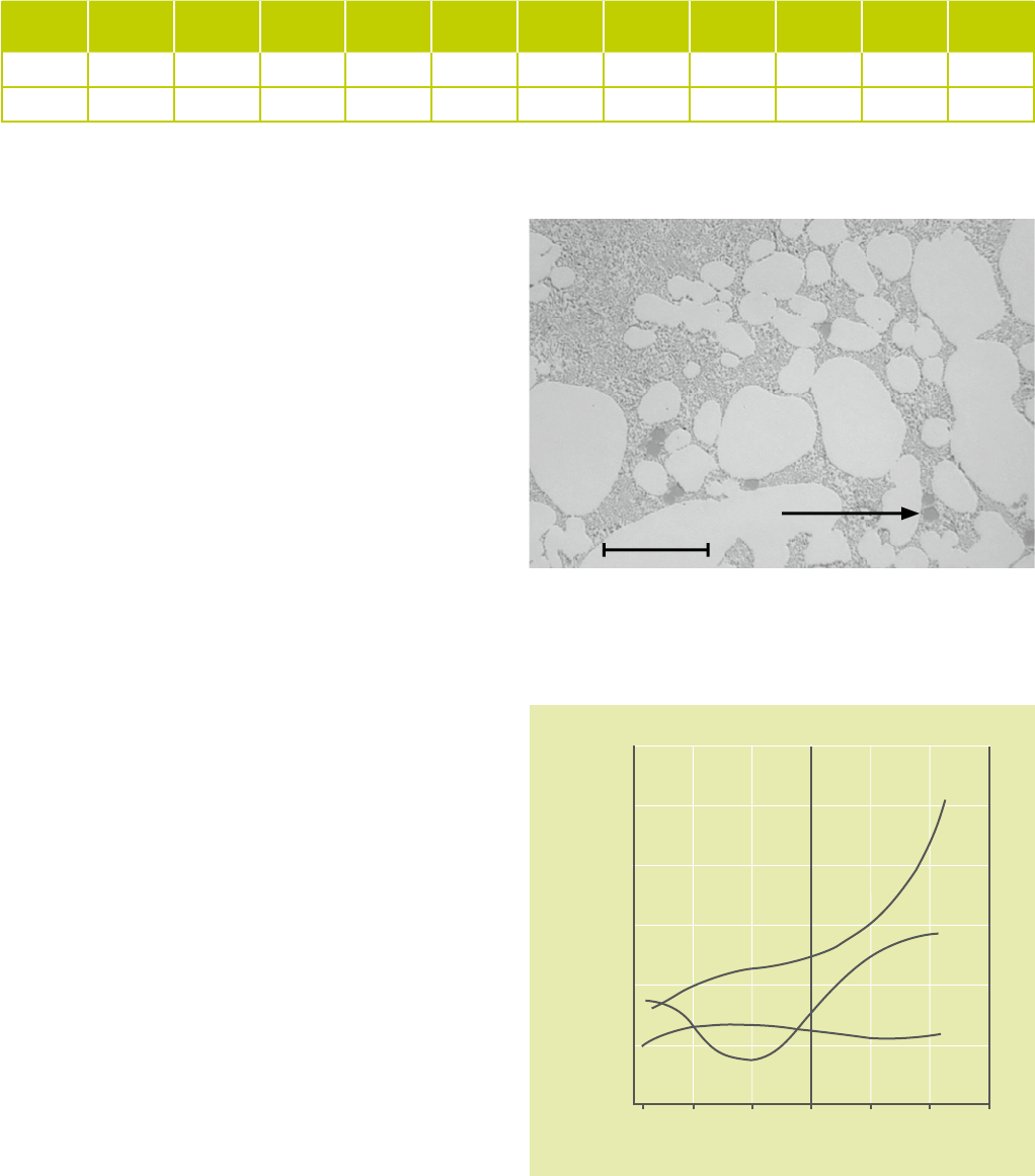
The microstructures (figures 3, 4 and 5) are taken from pressure die cast plates with
dimensions 220 × 60 × 4 mm (fig. 2).
The eutectic aluminium-silicon matrix is almost globulitically modified alongside the
clearly recognizable bright α-aluminium dendrites. Al
12
Mn
3
Si
2
-phases also appear in
the eutectic as bright-gray phases in its globulitic shape.
At higher magnesium contents the Mg
2
Si-intermetallic phase is still present, light
optically hardly perceptible.
The rapid cooling rate in pressure die casting is by itself not enough to produce a
sufficiently fine cast microstructure and therefore the required high elongation
values. Only the modification with strontium produces a sufficiently fine eutectic
casting microstructure. Fig. 5 shows the structure of a sample which was produced
from the same alloy type however without modification.
A comparison with fig. 4 clearly shows that the eutectic silicon is considerably finer
thanks to modification. The achievable elongation to fracture increases from 5 % to
10 %. This effect is also visible with a solutionizing. Figures 6 and 7 show the struc-
ture of a 6 mm pressure die casting sample after solutionizing for 3 hours at 490 °C.
The silicon has coarsened somewhat but is still globulitically modified. Further trials
showed that the spheroidization of the eutectic silicon is achieved already at 350 °C.
Fig. 3: Silafont-36, AlSi10MnMg, as-cast state
Fig. 4: Silafont-36, AlSi10MnMg, as-cast state
Fig. 5: AlSi10MnMg without strontium, as-cast state Fig. 2: HPDC test plate from the TechCenter
Fig. 6: Silafont-36, AlSi10MnMg, temper T4 Fig. 7: Silafont-36, AlSi10MnMg, temper T4
32
Mg-content
[%]
R
p0.2
[MPa]
R
m
[MPa]
A
[%]
Casting description
0.15 117 250 11. 2 Rear side members 2.5 mm
0.28 121 264 10.2 Rear side members 3 mm
0.30 133 279 8.1 Test plate (Fig. 2) 4 mm
0.33 141 261 6.3 Cylinder head cover 3.8 mm
0.42 146 286 5.8 Test plate (Fig. 2) 4 mm
Silafont
®
- 36 – Mechanical properties
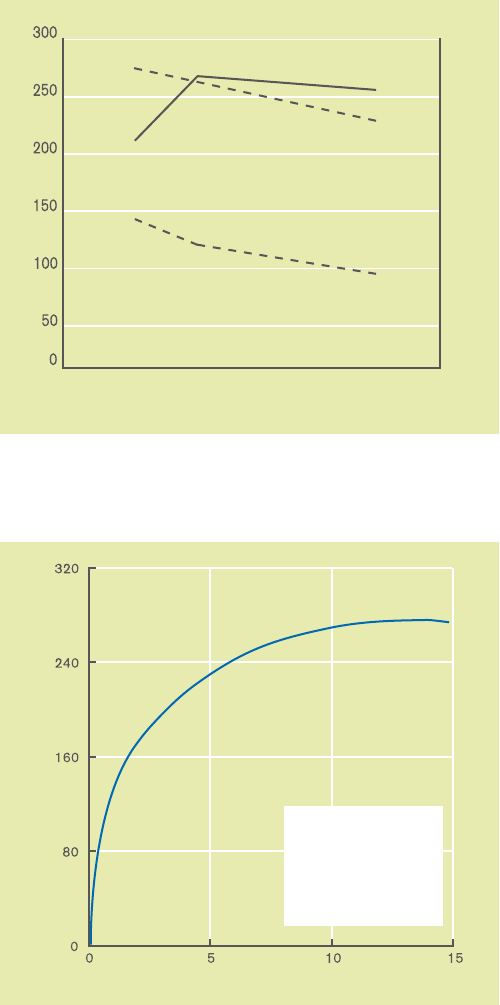
Fig. 8: Stress-strain curve for Silafont-36, AlSi10MnMg, as-cast state, temper T5 and T7
Tab. 2: Mechanical properties of Silafont-36, AlSi10MnMg,
in the as-cast state depending on magnesium content
320
240
160
80
0
0 5 10 15 20
Elongation A [%]
Stress R [MPa]
T 5
F
T 7
Effect of magnesium content on
mechanical properties in the as-cast state
The extraordinarily high elongation amongst
AlSiMg-alloys is the distinguishing characteristic
of Silafont-36. Figure 8 shows the stress-strain
curve for Silafont-36 in the as-cast state.
The curves for T5 (artificially aged) and T7
(overaged) tempers, are also reported.
Yield strength rises with increasing magnesium
content, whereas elongation decreases. If high
yield strength is required, the magnesium content
should therefore be set in the upper range of
the alloy standards, i.e. at 0,3 – 0,4 %. If higher
elongation is required and yield strength does not
play a significant role, a low magnesium content
of 0.15 % is preferred.
Table 2 is a summary of mechanical properties
for various magnesium contents. The correspond-
ing trials were conducted with casts which were
produced in accordance with the parameters in
table 3.
Elongation drops from 11.2 to 5.8 % with increas-
ing magnesium contents, while yield strength
increases from 117 to 146 MPa. Ultimate tensile
strength is also increased from 250 to 286 MPa
by increasing magnesium contents.
Therefore, in the as-cast state a wide range of
mechanical properties can be fulfilled.
Magnesium contents above 0.5 % produce no
further increase in yield strength, as excess
magnesium precipitates as the Mg
2
Si-phase
and no longer contributes to the hardening of
the aluminium solid solution.
Temper F
R
p0.2
= 123 MPa
R
m
= 265 MPa
A = 11.4 %
Temper T5
R
p0.2
= 211 MPa
R
m
= 313 MPa
A = 8 .1 %
Temper T7
R
p0.2
= 148 MPa
R
m
= 206 MPa
A = 14.2 %
33

Tab. 3: Mechanical properties in temper T5, 0.30 % magnesium content;
test plate 4 mm
Tab. 4: Mechanical properties in temper T5, 0.33 % magnesium content;
test plate head cover 3.8 mm
Tab. 5: Mechanical properties in temper T5 with different storage times prior to
ageing at 200 °C for 1 hour, test plate 4 mm, 0.32 % magnesium content
Effect of heat treatment on mechanical properties
The mechanical properties of Silafont-36 can be targeted by
means of specific heat treatment, as well as with varying magne-
sium contents.
There are two completely different possibilities in the event of
heat treatment: with or without solutionizing.
The following heat treatments can be carried out with Silafont-36
without solutionizing:
• O: Annealed at low temperature
• T5: Quenched directly after removal from the die and
artificially aged
The desired spheroidisation of the eutectic silicon requires the
following heat treatments with solutionizing:
• T4: Solutionized, quenched, naturally aged for more than 6 days
• T6: Solutionized, quenched and articially aged
• T7: Solutionized, quenched and overaged
Heat treatments without solutionizing
Temper O
An increase in yield strength or elongation can be achieved to
a slight extent with this heat treatment without risk of casting dis-
tortion. Two different variants for this temper are actually defined:
• O(I): annealed at lower temperature (320 °C / 30 – 60 min.)
• O(II): annealed at higher temperature (380 °C / 30 – 60 min.)
An increase in yield strength to 140 – 160 MPa with 8 – 12 %
elongation is achievable on thin samples with up to 3 mm wall
thickness and magnesium contents of 0,2 % in temper O(I).
Identical samples in temper O(II) achieve elongation of 12 – 16 %
with yield strength of 100 – 130 MPa.
Temper T5
The mechanical properties of Silafont-36 T5 are given in tables 4
and 5 for two different magnesium contents of the various casts.
Thanks to the T5 heat treatment, yield strength can be increased
by almost 100 MPa compared to the as-cast state.
It is particularly interesting to note that elongation does not de-
crease, but remains between 5 and 9 %. The highest increases
in yield strength are achieved with Silafont-36 with over 0.30 %
magnesium, if there are at least 10 hours storage time between
casting and ageing, as visible in table 5.
Silafont
®
- 36 – Mechanical properties
Ageing
temperature
[°C]
Ageing
time
[h]
R
p0.2
[MPa]
R
m
[MPa]
A
[%]
170 1.0 157 291 7.1
170 2.0 169 292 5.0
170 3.0 185 302 6.0
170 4.0 188 305 8.5
170 5.0 197 309 7.1
170 6.0 195 309 8.5
170 8.0 201 313 8.9
200 0.5 211 316 8.4
200 1.0 212 314 7.9
Ageing
temperature
[°C]
Ageing
time
[h]
R
p0.2
[MPa]
R
m
[MPa]
A
[%]
170 3.0 193 290 4.5
170 4.0 199 295 4.8
170 6.0 206 300 5.0
200 0.5 193 290 5.7
200 1.0 200 297 5.6
220 0.5 199 293 5.8
250 0.5 180 268 3.5
Interim storage time
[h]
R
p0.2
[MPa]
R
m
[MPa]
A
[%]
1 207 307 6.9
10 233 324 6.6
72 h or 3 days 232 324 6.8
34
Tab. 6 Mechanical properties of Silafont-36, AlSi10MnMg, in temper T4 depending
on magnesium content
Fig. 9: Mechanical properties of Silafont-36, AlSi10MnMg, with a magne-
sium content of 0.3 % as a function of the ageing time (solutionizing at
490 °C for 3 hours, quenching in water and ageing at 170 °C)
Heat treatments with solutionizing
Temper T4
Table 7 lists the mechanical properties after solutionizing
(490 °C / 3 h) with subsequent quenching in water.
The spheroidisation of the silicon and the other intermetallic
phases achieved in this way produce an increase in elongation
to 15 % and more, depending on magnesium content.
Yield strength increases to 141 MPa from 94 MPa of the
as-cast state. The ultimate tensile strength range of 206 to
259 MPa is somewhat lower than in the as-cast state.
Temper T6
Temper T6 produces maximum strength. For this purpose a
magnesium content above 0.3 % in the pressure die casting
should be aimed at, in order to exploit the hardening potential
of the alloy. Elongation settles to lower values. Figure 9 shows
graphically the mechanical properties over the ageing time
for a magnesium content of 0.3 %. The point of maximum
strength is at a yield strength of 240 MPa and ultimate tensile
strength of 310 MPa, however with an elongation of 7.1 %.
Single trials with higher magnesium contents have demon-
strated that yield strength can be increased to over 280 MPa,
whereby elongation is still above 3 % nevertheless.
Temper T7
The curve progression in figure 9 indicates that elongation
again increases with increasing ageing time, i.e. in an in-
creasingly overaged state. Trials with real casts have shown
that with targeted heat treatments, elongations up to 20 %
can be achieved; yield strength then reaches values of
120 – 130 M Pa .
Air quenching
Quenching with air instead of water is carried out after the
solutionizing in order to minimize the distortion of pressure
die castings. Yield strength of over 120 MPa can only be
achieved with a magnesium content of 0,3 %, if a subsequent
ageing for 2 hours at a temperature of 170 °C is performed.
320
280
240
200
160
120
0 1 2 3 4 5 6 7 8
Strenght [MPa]
Elongation A [%]
20
16
12
10
8
0
Ageing time [h]
R
m
R
p0.2
A
Silafont
®
- 36 – Mechanical properties
Overview of mechanical properties
The figure on page 26 provides an overview of the ranges
of mechanical properties which can be achieved with the various
heat treatments.
It should be taken into account that the magnesium content
must be tuned according to the required property profile.
Higher elongation values are linked to lower values for yield
strength and vice versa.
Mg-content
[%]
R
p0.2
[MPa]
R
m
[MPa]
A
[%]
Casting
description
0.15 94 206 20.6
Rear side members
2.5 mm
0.20 107 223 20.4
Rear side members
2.5 mm
0.25 119 229 17.3
Rear side members
2.5 mm
0.28 121 242 16.7
Rear side members
2.5 mm
0.42 141 259 15.0 Test plate 4 mm
35
Stress R [MPa]
200
180
160
140
120
100
80
60
40
20
0
Number of load cycles [n]
0 10
5
10
6
10
7
10
8
Fig. 10: Wöhler’s curve for Silafont-36, AlSi10MnMg, in the as-cast state
Tab. 7: Mechanical properties in different heat treatment states of sand casting
prototypes in Silafont-36, AlSi10MnMg, with 0,29 % magnesium
Fig. 11: Sample for sand cast prototypeing
Silafont
®
- 36 – Mechanical properties
Fatigue strength
Fatigue strengths for pressure die cast plates with 4 mm wall
thickness are shown in Figure 11 in the as-cast state accord-
ing to Wöhler’s curves. The trials were conducted on a high
frequency pulse generator with a frequency of around 117 Hz.
The stress ratio was r = -1 on a normal sample geometry.
Figure 11 shows that the fatigue strength reaches 89 MPa
under these test conditions; this equals approximately 66 % of
the yield strength.
Corrosion behaviour
The corrosion behaviour can be compared to an aluminium-
silicon primary alloy. Silafont-36 is not susceptible to corrosion
and does not manifest any tendency to stress corrosion cracking.
As visible in the application examples, the alloy is used,
among other things, for uncoated bodywork and car chassis
components.
Melting and Casting
The detailed description on page 19 is also usable for handling
Silafont-36. But the strontium content should be leveled
higher than 80 ppm to assure a fine modified AlSi eutectic with
high elongation.
Handling instructions for melt preparation is on page 57.
Prototypes
Dimensionally identical prototypes of high pressure die castings
in Silafont-36 can be produced with the same alloy in sand cast-
ing, or even better in low-pressure sand casting. The mechanical
properties, particularly elongation, are lower due to a lower
cooling rate. The strontium content and the heat treatment
parameters have to be adapted when using Silafont-36 for sand
casting prototypes. The mechanical properties achieved in
this way are indicated in table 8 for various heat treatments on
Silafont-36 with 0.29 % magnesium.
Some sand prototype casts can more than double the achievable
elongation by the application of chills. Only with this solution
and an additional T4 heat treatment will the sand prototype partially
correspond with regard to its mechanical properties to the follow-
ing pressure die casting in the as-cast state.
Bibliography
Broschure Rheinfelden Code 630, “Producing Low-iron
Ductile Aluminium Die Casting in Silafont-36”, published on
NADCA 1995, 10/1995.
95 %
50 %
5 %
Heat
treatment
R
p0.2
[MPa]
R
m
[MPa]
A
[%]
HB
F 96 175 2 61
T4 133 229 4 77
T6 250 299 1 109
T7 222 260 1 90
Stress ratio r = -1
4 mm wall thickness, frequency 117 Hz
5 %, 50 %, 95 % fracture probability
36
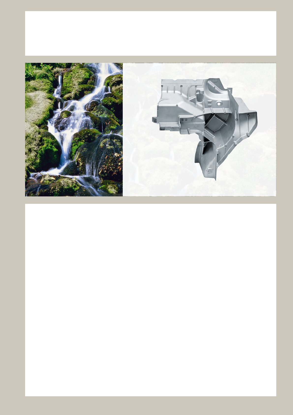
37
Silafont
®
-38
An infinite wealth of properties
The HPDC alloy Silafont-38 was developed by RHEIN-
FELDEN ALLOYS to further increase yield strength
in compare to Silafont-36 without significant change in
ductility.
Even with an air cooling to lower distorsion the complex
alloyed Silafont-38 reaches 180 MPa yield strength.
Besides these moderate cooling rates it is possible to
cool down with water after the solutionizing treatment to
achive highest strength.
Additionally Silafont-38 has also following properties
required for the pressure die casting process:
• excellent castability even with varying wall thicknesses
• no sticking to the die; the low-iron Silafont-38 is there
for alloyed with manganese and strontium
• excellent machinability
In more and more applications, mainly in car manufac-
turing, other properties of Silafont-36 are of increasing
importance:
• very good corrosion resistance due to specially balanced
composition
• high fatigue strength and crash performance due to
reduced effect of disturbing Fe and Si phases
• excellent weldability for aluminium prol-cast designs
• suitable for self-piercing riveting
37
Areas of use
Weight reduced car body structures for vehicles, mechanical engineering
Distinguishing charcteristics
Casting alloy with very high mechanical properties after T6 treatment including a air queching for reduced
distorsion. Very high yield strenght combined with high values of elongation for crash relevant structural die castings.
Silafont-38 substitutes sheet designs in vehicle design and offers high cost and weight reduction.
Alloy denomination
Chemical denomination: AlSi9MnMgZn
Chemical composition [ % of mass ]
Mechanical properties
Processing properties compared to standard pressure die casting alloys
Silafont
®
- 38 [ AlSi9MnMgZn ]
Alloy type Silafont-38 Silafont-36 Silafont-09
Sticking tendency low low low
Die life 100 % 100 % 100 %
Linear shrinkage 0.4 – 0.6 % 0.4 – 0.6 % 0.4 – 0.6 %
Casting
method
Treatment
state
Quenching
cooling
YTS
R
p0.2
[ M Pa ]
UTS
R
m
[ M Pa ]
Elongation
A [ % ]
HPDC F 140 – 160 270 – 300 3 – 7
HPDC T6 Water 230 – 270 300 – 345 6 – 9
HPDC T6 Air 180 – 20 0 250 – 275 8 – 10
Note chapter “Technical Information”!
350
300
250
200
150
100
50
0
0 2 4 6 8 10 12
Elongation A [%]
Stress R [MPa ]
[%] Si Fe Cu Mn Mg Zn Ti Sr others
min. 8.0 0.1 0.5 0.1 0.1 0.010
max. 10.0 0.15 0.4 0.8 0.5 0.4 0.15 0.02 0.10
T 6
Air
F
T 6
Water
Temper T6 Air
R
p0.2
= 185 MPa
R
m
= 278 MPa
A = 10 %
Temper T6 Water
R
p0.2
= 272 MPa
R
m
= 344 MPa
A = 6 %
Temper F
R
p0.2
= 147 MPa
R
m
= 290 MPa
A = 5.5 %
38

Castaman
®
-35
Reducing the Carbon Footprint
The HPDC alloy Castaman-35 was developed by
RHEINFELDEN ALLOYS to allow the use of high quality
recycling material.
The same strength values and a similarly high elonga-
tion compared to primary aluminum die casting alloy
Silafont-36 could be reached, despite the increasing iron
content.
The designer has in addition the possibility to arise strength
by two step heat treatment, solutionizing included.
Castaman-35 in 3 mm thickness can archive 8 % elonga-
tion and 260 MPa yield strength by this.
Besides these particular mechanical properties,
Castaman-35 has also following properties required for
the pressure die casting process:
• excellent castability
• no sticking to the die
• excellent machinability
In more and more applications, mainly in car manufac-
turing, other properties of Castaman-35 are of increasing
importance:
• very high corrosion resistance
• high fatigue strength
• excellent weldability, also for aluminium prol-cast
designs
• suitable for self-piercing riveting and similar joining
processes, glueing connections
• suitable for glueing connections in car design
39
Castaman
®
- 35 [ AlSi10MnMg ]
Areas of use
Large and huge structural car body cast, lighting, automotive engineering, mechanical engineering
Distinguishing characteristics
High pressure die casting alloy with very good casting properties, even with thick-walled designs.
Very good corrosion resistance to weathering and water.
Alloy denomination
Chemical denomination: AlSi10MnMg Numerical denomination: 43 500
Chemical composition [ % of mass]
Mechanical properties
Processing properties compared to standard pressure die casting alloys
Note chapter “Technical Information”!
300
250
200
150
100
50
0
0 2 4 6 8 10 12
Elongation A [%]
Stress R
p0.2
[ M Pa ]
[%] Si Fe
Cu
Mn Mg
Zn Ti
others
min. 9.5 0.5 0.2
max. 11.0 0.2
0.03
0.8 0.5
0.1 0.15
Sr
Alloy type Castaman-35 Silafont-36 Silafont-09
Sticking tendency low low low
Die life 100 % 100 % 100 %
Linear shrinkage 0.4 – 0.6 % 0.4 – 0.6 % 0.4 – 0.6 %
Casting
method
Treatment
state
YTS
R
p0.2
[ M Pa ]
UTS
R
m
[ M Pa ]
Elongation
A [ % ]
Brinell hardness
[ HBW ]
HPDC T6 180 – 280 250 – 340 6 – 12 80 – 110
Temper T6
R
p0.2
= 178 MPa
R
m
= 254 MPa
A = 8.5 %
T 6
40
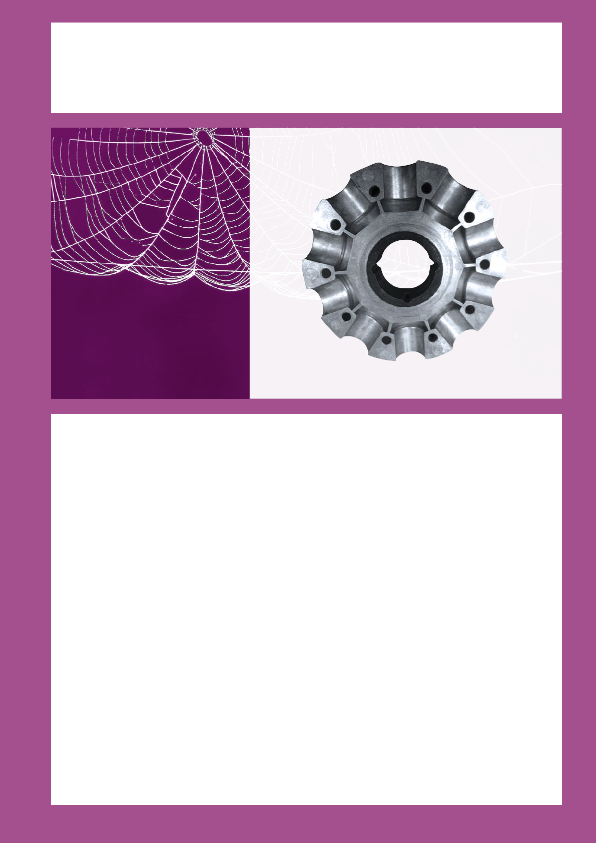
Thermodur
®
-72 / -73
A glimpse into the future
Thermodur
®
-72
RHEINFELDEN ALLOYS developed this heat-resistant die
cast alloy on the base of AlMg alloys for the production of
casts in the engine compartment such as crank case and a
number of other – the engine block near – assemblies.
Beside this Thermodur-72 can be used for particularly high-
strength components in addition to Magsimal-59 or instead
Peraluman-90, AlMg9 as a particularly corrosion-resistant
die cast alloy.
Thermodur-72 has following properties:
• well usable for AlMg die cast with thick walls
• low oxidation of the melt due to patended
alloying elements
• with high temparature higher strength than with
AlSi-alloys
Thermodur
®
-73
RHEINFELDEN ALLOYS RHEINFELDEN ALLOYS has
developed on the base of the piston alloy Silafont-70 a
heat-resistant die cast alloy. The structure posess no
primary silicon and is modified with strontium. The high
alloy contents of Cu and Ni allow the heat resistance of
the alloy.
Excellent casting characteristics and a very good ma-
chinability allow the various component designs, such as
reduced-weight engine blocks or as thick walled fan hub.
Thermodur-73 has following properties:
• easy handling in the die cast or shop
• low shrinkage behavior enables even bigger iron inserts
• very high pressure toughness
41
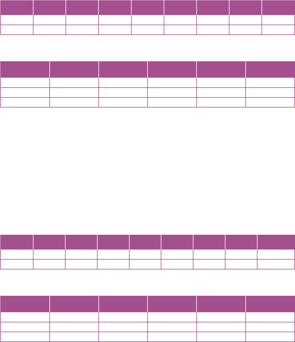
Chemical composition [ % of mass]
Mechanical properties Tested at temperature indicated
Areas of use
Manufacture of engines, crankcases,
engine components, turbo charge housing
Areas of use
Cars, manufacture of engines, fan design
Distinguishing characteristics
High pressure die casting alloy for the manufacture of engines for parts that
require very good mechanical properties at elevated temperatures and
high corrosion resistance.
Distinguishing characteristics
Very good hardness and high strength in as-cast state, very good mechanical
properties at elevated temperatures. Good castability in sand, chill and high pressure
die casting. Excellent weldability and machinability.
Chemical composition [ % of mass]
Mechanical properties Tested at temperature indicated
Thermodur
®
- 72 [ AlMg7Si3Mn ]
Thermodur
®
- 73 [ AlSi11Cu2Ni2Mg2Mn ]
[%] Si Fe Cu Mn Mg Zn Ti others
min. 2.8 0.5 7.0
max. 3.2 0.15 0.03 0.8 8.8 0.07 0.15 0.004 Be
[%] Si Fe Cu Mn Mg Zn Ti others
min. 10.0 1.8 1.8
max. 11.8 0.15 2.3 0.4 2.3 0.10 0.10 1.8 – 2.3 Ni; Sr
Ageing
temperature
Ageing
time
YTS
R
p0.2
[ M Pa ]
UTS
R
m
[ M Pa ]
Elongation
A [ % ]
Brinell hardness
[ HBW ]
20 °C 190 – 220 350 – 380 7 – 10 80 – 10 0
150 °C 50 0 h 220 – 245 260 – 290 > 15
225 °C 5 00 h 150 – 175 180 – 205 > 20
Ageing
temperature
Ageing
time
YTS
R
p0.2
[ M Pa ]
UTS
R
m
[ M Pa ]
Elongation
A [ % ]
Brinell hardness
[ HBW ]
20 °C 270 – 300 300 – 320 < 1 130 – 150
150 °C 50 0 h 280 – 310 330 – 355 < 1
225 °C 5 00 h 130 – 155 250 – 280 1 – 2
Note chapter “Technical Information”!
Note chapter “Technical Information”!
42
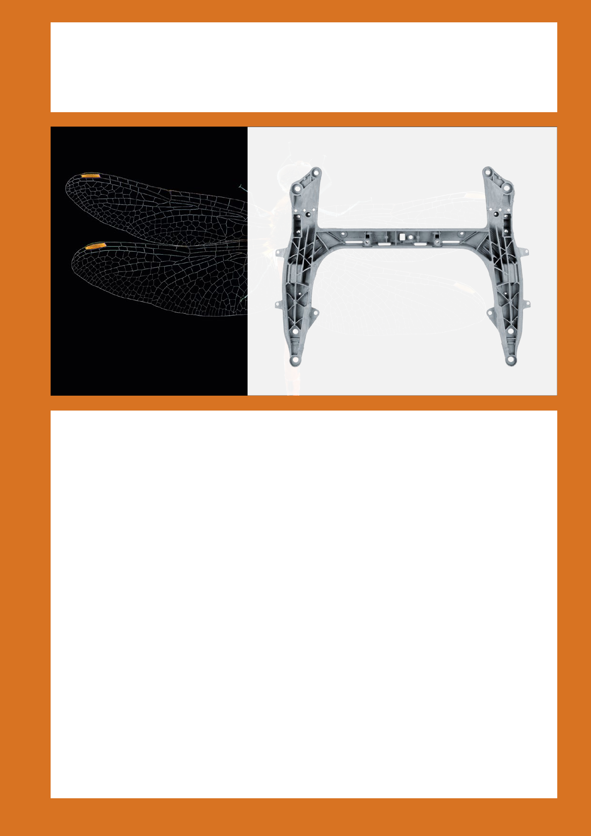
Magsimal
®
-59
Of filigree lightness, but extremely resilient
Magsimal-59 developed by RHEINFELDEN ALLOYS
is a widely used HPDC alloy for automotive applications.
This alloy type has excellent properties in the as-cast state,
i.e. high yield strength in conjunction with high ductility.
Energy absorption capacity, e.g. in the event of a crash.
The fatigue strength is also higher than for conventional
pressure die cast alloys.
Most applications are therefore safety components with
high performance requirements e.g. safety-belt pretensioners,
steering wheel frames, crossbeams, motorbike wheel rims,
control arm, suspension-strut brackets and other ap or
chassis components.
While the properties of Magsimal 59 depend on the wall
thickness, a special heat treatment is suggested to compen-
sate the difference and to enable either high cast
rigidity or high ductility. This heat treatment do not require
the water quenching, and the aging is performed below
the blister formation temperature. Air cooling is also possible
to exclude distortions.
The alloy Magsimal-59 is produced on a primary metal
basis and therefore manifests high analytical purity.
This produces as a consequence outstanding mechanical
strength and an excellent corrosion behavior.
Specially chosen chemical composition enables the
following casting properties:
• very good castability
• suitable for minimum wall thicknesses
• low sticking to the die
• excellent properties in the as-cast state
With increasing number of applications, mainly in car
manufacturing, other properties of Magsimal-59 became
also important:
• high yield strength in conjunction with high ductility
• very high energy absorption capacity
• very high fatigue strength
• excellent corrosion behavior
• suitable for self-piercing riveting
• excellent suitable for glueing connections in car design
43

Magsimal
®
- 59 – Properties at a glance
Chemical composition of Magsimal- 59, AlMg5Si2Mn
Mechanical properties in the as-cast state depending on wall thickness of test samples
Physical properties in the as-cast state
Processing properties compared to standard pressure die casting alloys
Wall thickness
[ mm ]
YTS
R
p0.2
[ M Pa ]
UTS
R
m
[ M Pa ]
Elongation
A [ % ]
< 2 > 220 > 300 10 – 15
2 – 4 160 – 220 310 – 340 12 – 18
4 – 6 140 – 170 250 – 320 9 – 14
6 – 12 120 – 145 220 – 260 8 – 12
Unit Validity range
Solidification range
618 – 580 °C
Density
2.65 kg / dm
3
20 °C
Young’s modulus
68 – 75 GPa 20 °C
Linear thermal expansion coefficient
24 1 / K × 10
-6
20 – 200 °C
Thermal conductivity
1.1 W / (K × cm) 20 – 200 °C
Electrical conductivity
14 – 16 MS / m ode r m / ( Ω × mm
2
) 20 °C
Fatigue strength (r = -1) 4 mm wall thickness 100 MPa 10
6
cycles
Alloy type Magsimal-59 AlMg3Mn AlSi10Mg(Fe)
Heat treatment no no yes
Hot crack tendency low high no
Sticking tendency low high low
Tendency to increased dross formation medium high low
Die life > 90 % > 70 % 10 0 %
Linear shrinkage 0.6 – 1.1 % 0.9 – 1.3 % 0.4 – 0.6 %
[%] Si Fe Cu Mn Mg Zn Ti Be others
min. 1.8 0.5 5.0
max. 2.6 0.2 0.03 0.8 6.0 0.07 0.20 0.004 0.2
Note chapter “Technical Information”!
44
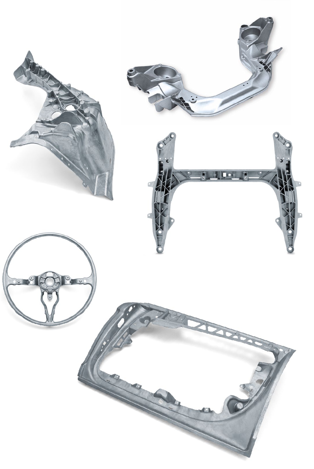
Magsimal
®
- 59 [ AlMg5Si2Mn ]
Door design for four-door sports car
Magsimal-59; as-cast
Wall thickness 2 mm
1140 × 690 × 155 mm; weight: 4.1 kg
Steering-wheel frame / VW New Beetle
Magsimal-59; as-cast
Ø 370 × 125 mm; weight: 0.85 kg
Cr oss mem be r fo r 4 x 4 SUV
Magismal-59; as-cast
710 × 910 × 85 mm; weight: 7.6 kg
This crossbeam replaces a considerably heavier gravity
casting variant made with a heat-treated AlSiMg-alloy.
The lightweight construction with corresponding thin wall
thickness of this die cast design is particularly economic,
if no heat treatment with solutionizing is performed.
Considerable component distortion would otherwise have
to be rectified, which would again introduce stresses
into the component.
Cross member for off-roadcars / BMW
Magsimal-59; as-cast; weldable
770 × 460 × 200 mm; weight: 4.8 kg
Strut mounting for sports car
Magsimal-59; as-cast
Wall thickness 3 mm
590 × 450 × 340 mm; weight: 3.0 kg
45
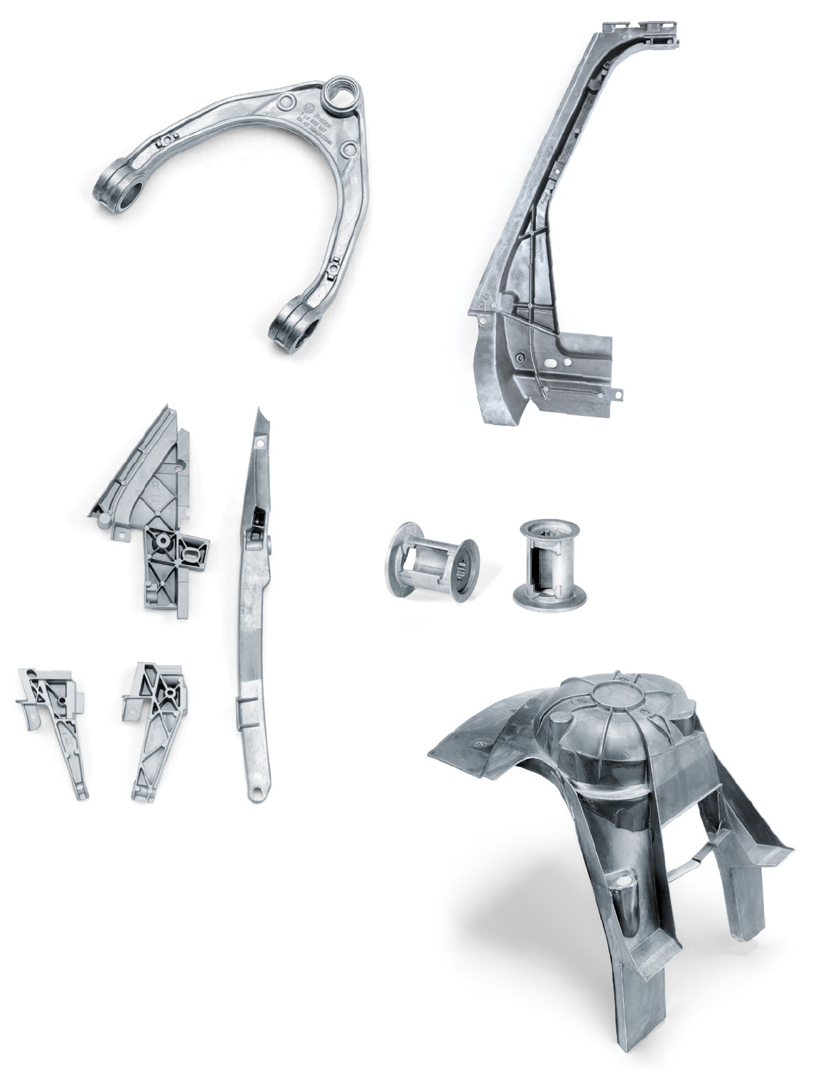
Front-wheel suspension strut support / BMW 5er, 6er
Magsimal 59; as-cast
Wall thickness 2.5 mm
500 × 380 × 500 mm; weight: 2.3 kg
This component is subject to maximum dynamic loads in
the aluminium front section of the BMW 5 and 6 Series.
Different jointing technologies require maximum casting
quality and extremely good material performance:
modern self-piercing riveting joints with multi-layered sheet
metal, under current welded joints, permanent glued joints,
structural screw connections of the cross-brace.
The thin component configuration with only 2,5 mm wall
thickness complies with the material behaviour, which
shows its best properties with these solidification conditions.
Suspension-strut bracket / Porsche Cayenne
Magsimal-59; as-cast
Wall thickness 6 mm
340 × 370 × 60 mm; weight: 0.9 kg
Belt furling spindle/ Saab, Daimler
Magsimal-59; as-cast
Wall thickness 1.0 – 5.0 mm
Ø 56 × 55 mm; weight: 0.066 kg
Magsimal
®
- 59 [ AlMg5Si2Mn ]
Internal door part for vehicle
Magsimal-59; as-cast; suited to welding
610 × 250 × 100 mm; weight: 1.0 kg
Node for window frame
Magsimal-59; as-cast; weldable
Up to 510 mm long; weight: 0.20 – 0.35 kg
46
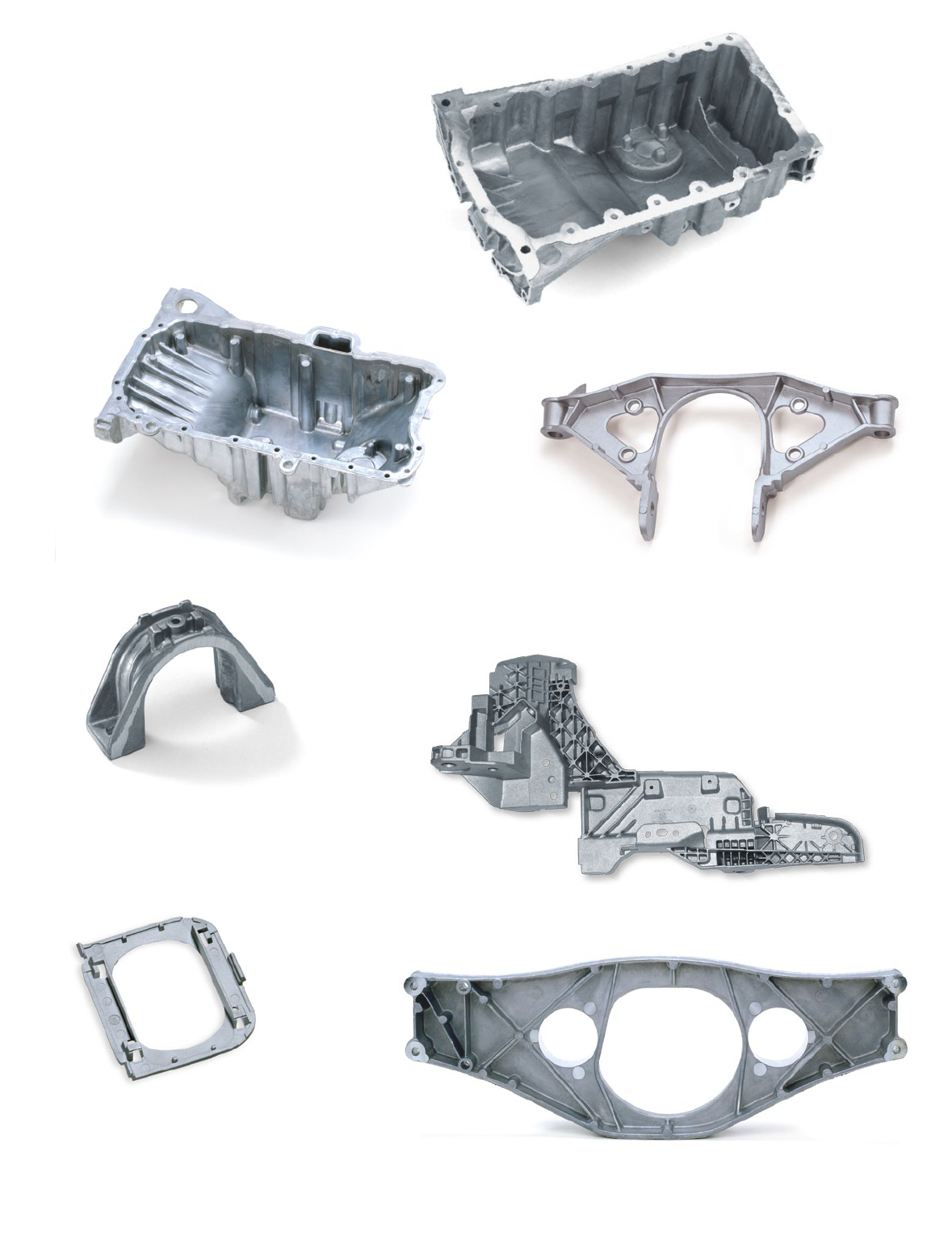
Transmission crossrail / Porsche
Magismal-59; as-cast
160 × 320 × 55 mm; weight: 0.34 kg
Gearbox crossbeam / Daimler
Magsimal-59; as-cast
Wall thickness 4 mm
610 × 210 × 75 mm; weight: 2.3 kg
Rain sensor housing
Magsimal-59; as-cast
70 × 65 × 8 mm; weight: 0.013 kg
Magsimal-alloy family guarantees an extraordinary high stiffness
also on this 0,44 mm-thin housing. The long-term reliability
of the glue jointing between glas and cast was decisive for the
choice of Magsimal.
Magsimal
®
- 59 [ AlMg5Si2Mn ]
Oilpans
Magsimal-59; as-cast
Weight: 3.0 – 4.2 kg
Oil pans for sports cars must have ductile oors in order
to be able to reduce the eventual impact stresses, e.g. due to
stones shooting up from the road or touching the ground
without cracking.
A high degree of hardness in the screw-on ange must be
guaran- teed due to high surface pressure during assembly.
Stabiliser rod bracket / BMW 5-er
Magsimal-59; as-cast
135 × 90 × 50 mm; weight: 0.18 kg
Base plate for convertible soft-top hinge
Magsimal-59; as-cast
Wall thickness 2 – 5 mm
600 × 350 × 280 mm; weight: 3.2 kg
47
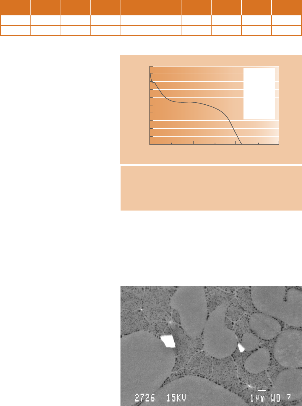
0 2.5 5.0 7.5
640
630
620
610
600
590
580
570
560
550
540
Reactions
618 °C Liquid –
α -Aluminium
594 °C Liquid – Mg
2
Si + Al
6
Mn oder Al
12
(Mn,Fe)
3
Si
2
594 °C – 580 °C not determined
Time [min]
Temperature [°C]
[°C]
T
G
= 657.1
T
Lu
= 618.9
T
Lo
= 619.8
dT
L
= 0.9
T
Su
= 594.0
T
So
= 594.3
dT
S
= 0.3
Fig. 1: Thermal analysis of Magsimal-59, AlMg5Si2Mn, in a Quick-Cup-Crucible
Fig. 2: SEM-image of Magsimal-59, AlMg5Si2Mn, not etched
Magsimal
®
- 59 – Chemical composition
Table 1 gives the chemical composition of the
alloy Magsimal-59. The magnesium / silicon ratio
ensures good castability and good feeding during
solidification. The eutectic share in the structure
is approximately 40 – 50 % (area %). Excess
magnesium promotes the formation of Mg
2
Si
compounds. This is important because for a good
corrosion behaviour it must be ensured that no
free silicon is available. Furthermore, the excess
magnesium ensures a high yield strength. Calcium
and sodium must be kept to a minimum as these
elements have a negative effect on casting
behaviour, e.g. through an increased hot cracking
tendency. Phosphorus must also be kept to a
minimum as this element has a negative effect on
the formation of the Al-Mg
2
Si eutectic and there-
fore on the ductility.
AlMg-alloy melts with a magnesium content of
> 2 % have a tendency towards increased dross
formation, if the melt remains in the furnace
for a long time and the melting temperature is
particularly high. A cauliower-type dross is then
produced which is difficult to remove. Therefore,
beryllium is added into the alloy. This element
increases the density of the oxide skin and
therefore less aluminium and magnesium diffuse
towards the outside and can oxidize there.
The thermal analysis of Magsimal-59 is shown
in figure 1. The temperature curve was recorded
with a Quick-Cup-crucible (in Croning sand). The
liquidus temperature is approximately 618 °C and
the solidus temperature is approximately 594 °C.
A pronounced holding point can be detected at
592 °C. The AlMg
2
Si-eutectic solidifies at this
point. The structure of the pressure die casting,
that means the presence of a very high cooling
rate, results in a uniform
α-phase. The bright par-
ticles in figure 2 are the Al
6
Mn-phase. Manganese
prevents sticking to the die.
Tab. 1: Chemical composition of Magsimal-59, AlMg5Si2Mn in the ingot (weight in %)
The α-aluminium and Mg
2
Si-eutectic is distributed around the α-dendrites.
No coarse phases are to be seen in this image (see also front page of manual)
and the eutectic is fine and spherical; therefore, this is a very ductile structure.
[%] Si Fe Cu Mn Mg Zn Ti Be others
min. 1.8 0.5 5.0
max. 2.6 0.2 0.03 0.8 6.0 0.07 0.20 0.004 0.2
48
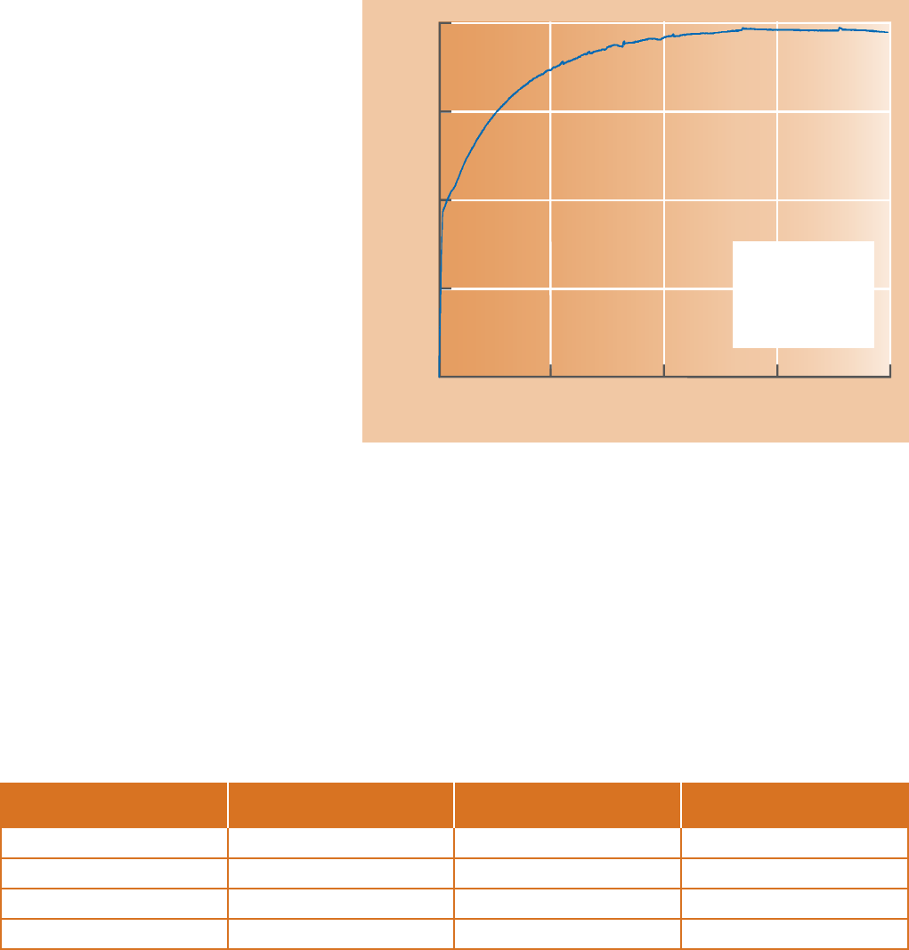
Tab. 2: Mechanical properties of Magsimal-59, AlMg5Si2Mn, in the as-cast state depending on wall thickness of separately cast test samples
Wall thickness [mm] R
p0.2
[MPa] R
m
[MPa] A [%]
< 2 > 220 > 300 10 – 15
2 – 4 160 – 220 310 – 340 12 – 18
4 – 6 140 – 170 250 – 320 9 – 14
6 – 12 120 – 145 220 – 260 8 – 12
Fig. 3: Stress-strain curve for Magsimal-59, AlMg5Si2Mn, in the as-cast state.
Wall thickness of samples: 3 mm
Elongation A [%]
320
240
160
80
0
0 5 10 15 20
Stress R [MPa]
Magsimal
®
- 59 – Mechanical properties
Mechanical properties in the as-cast state
Brief details of a characteristic material property
during static testing of AlMg alloys should be
given at this point. Small “peaks” can be detected
in the stressstrain curve during the tensile test.
These are not incipient cracks in the material but
in fact “strain-induced ageing”. This phenomen
occurs in the plastic area of the stress-strain
curve, and, from an atomistic point of view, it is
an interaction between solid solution atoms and
migratory dislocations in the structure (Portevin-
Chatelier effect), which causes a momentary low
stress reduction in the stressstrain curve. Figure 3
shows a typical example of such behaviour.
The mechanical properties of Magsimal-59 are
dependent on the wall thickness and thus on the
solidification conditions.
Table 2 shows the mechanical property ranges.
These mechanical properties were obtained
from real casts and from separately cast sample
bars and plates. It must be noted that the values
can disperse within the cast and, as a rule,
they are better in proximity to the gate rather than
in remote or gate-opposite areas. This effect
can be reduced by providing overows.
Therefore, appropriate cut off areas of test samples from pressure die castings
are critical and must be accurately defined between foundryman and designer
in any case. Required mechanical properties and dimensions must be agreed.
Temper F
R
p0.2
= 178 MPa
R
m
= 313 MPa
A = 20.6 %
49
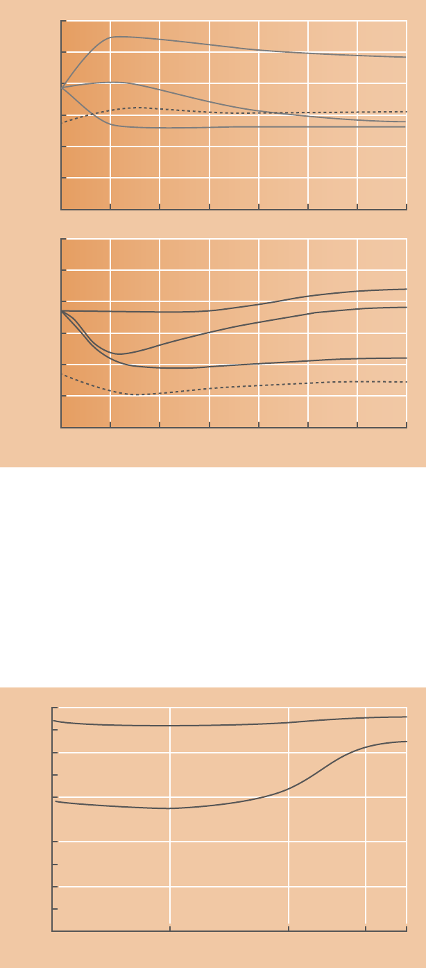
0 20 40 60 80 100 120 140
24
20
16
12
8
4
0
Ageing time [min]
Elongation A [%]
380 °C
350 °C
250 °C
250 °C
------ 3 mm wall thickness ---- 6 mm wall thickness
Temper T5 and Temper O
Yield strength decreases more and more with
increasing wall thicknesses and then values
approaches to gravity permanent mould casting
values. Now there are certainly applications,
which fall partially into these thickness ranges,
but where the required hardness values are no
longer achieved by the casts. The strength
properties can then be increased by a T5 treat-
ment of the cast.
It has been proved that the cast must be
quenched immediately after removal from the die
so that the corresponding increase in strength can
be achieved during hardening. Air cooling after
removal from the die does not produce the desired
effect. The change in mechanical properties
is shown in figures 4. It can be concluded that a
stable state is achieved after approximately
60 minutes ageing.
A yield strength of approximately 200 MPa can be
achieved with 6 mm wall thickness. A higher yield
strength is achieved with the 3 mm samples.
However, the strength properties in this wall
thickness are not very different for a T5 state. In
contrast, elongation elongation is greatly depend-
ent on wall thickness. After 60 minutes artificial
ageing at 250 °C the 3 mm samples still have
approximately 10 % elongation, whereas the 6 mm
plates show a total elongation of approximately
4 %. However, strength is normally more important
than ductility in areas with high wall thickness, e.g.
at screw-on points or in nodal areas.
This behaviour of the alloy in material accumula-
tions or thick-walled areas can accordingly be
defined as uncritical; however, it should be neces-
sarily taken into account by the designer.
Age hardening provides a method of improving
strength in areas with high wall thickness. If an
ageing temperature of 350 °C is selected, yield
strength is reduced to 130 MPa to 150 MPa
depending on the starting value and elongation is
greatly increased. Higher ductility can be achieved
if the values in the as-cast state should not be
sufficient for the requirement profile.
Magsimal
®
- 59 – Mechanical properties
0 20 40 60 80 100 120 140
300
250
200
150
100
50
0
Yield strength R
p0.2
[MPa]
250 °C
350 °C
380 °C
250 °C
------ 3 mm wall thickness ---- 6 mm wall thickness
Fig. 4: Yield strength at different ageing temperatures, Magsimal-59, AlMg5Si2Mn,
3 mm and 6 mm wall thickness
Fig. 5: Ageing of Magsimal-59 with water- or air-cooling after ejecting out of the die
1 10 100 480 1000
200
180
160
140
120
100
Waiting time before test [h]
Yield strength R
p0.2
[MPa]
20 Days
Natural aging
Especially with thin-walled casts in Magsimal-59, AlMg5Si2Mn, water quenched
after ejecting from the die an aging can be observed at room temperature.
After 20 days the yield strength is 30 MPa higher with the water quenched casts,
on the other hand with air-cooled are higher by only 5 MPa. However, the elong-
ation hardly decreases. Figure 5 shows this at 3 mm die cast plates.
water-cooling
air-cooling
3 mm wall thickness
50
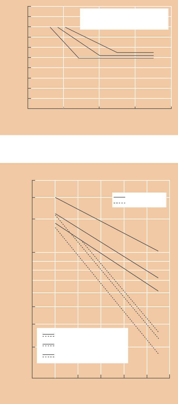
Fatigue strength
The fatigue strength is a significant criterion
for the designer. It depends on the material, solidi-
fi-cation conditions, casting defects and surface
conditions of the cast. Therefore, the transfer-
ability of measurements is only possible to a limited
extent. Figure 6 indicates the fatigue strength of
Magsimal-59 with a stress ratio r of -1. This means
that the average stress is zero. Measurement
was carried out with 4 mm thick pressure die cast
plates on a highfrequency pulse generator
(approx. 110 Hz). The curves were determined for
different fracture probabilities.
As a rule the 5 % fracture probability curve is al-
ways used for calculations. It is evident from the
curves that the fatigue strength of Magsimal-59
is 100 MPa in the as-cast state.
Corrosion resistance
AlMg-alloys are usually very corrosion resistant
and are therefore used in a salt-water atmosphere
too. As this alloy type is also used for safety com-
ponents, a test to determine the tendency towards
stress cracking corrosion is unavoidable.
For this purpose, Magsimal-59 samples were
loaded to the 75 % of the yield strength by means
of clamping and subjected to sea water immersion
test in a 35 g / l-NaCl solution over a period of
30 days (ASTM G 47-90). The stress has not to be
reduced after the test. A comparison of different
materials with regard to fatigue behaviour with-
out and in a corrosive atmosphere is shown in
figure 7. It is evident that the alloy Magsimal-59
is superior under the inuence of corrosion to the
well-known alloy AlSi7Mg0.3 T6.
Magsimal
®
- 59 – Mechanical properties
Fig. 6: Wöhler’s curve for Magsimal-59, AlMg5Si2Mn, in the as-cast state
10
5
10
6
10
7
10
8
200
180
160
140
120
100
80
60
40
20
0
Number of load cycles [n]
Stress R [MPa]
% 95
% 50
% 5
Stress ratio r = -1
Wall thickness 4 mm
5 %, 50 %, 95 % fracture probability
Fig. 7: Effect of corrosion on the fatigue properties of aluminium alloys
Load cycles to fracture [n]
10
4
10
5
10
6
10
7
10
8
10
9
10
10
Stress amplitude [MPa]
200
150
100
50
40
30
20
3
2
1
1
2
3
20 °C
Under corrosion
1
Pressure die casting AIMg5Si2Mn
2
Thixocasting AISi7Mg0.3 T6
3
Sheet metal AIMg0.6Si0.8 T6
51
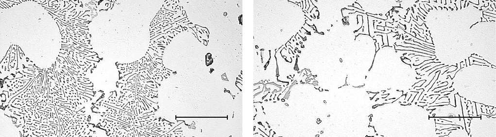
50 µm
50 µm
Melting
Magsimal-59 has a special long-term grain refinement particularly
affecting the AlMg
2
Si-eutectic. The eutectic fineness degree
determines the elongation and therefore the toughness of the
cast (Fig. 8). A special melting process during alloy production
greatly reduces the oxidation of the melt, which is a particular
charac-teristic of the AlMg-alloys. The strong presence of oxides
leads to a considerable reduction in elongation. With Magsi-
mal-59 agglomerations of oxides rarely form on bath surfaces
and on the furnace oor.
All these advantages can be maintained only if after a rapid
melting of the ingots a deep melt cleaning by means of a gas-
impeller is carried out and no melt process salts, grain-refining
and modification agents, substances containing phosphorus,
alkalis and alkaline earth, and other foreign metal or impurities
are added to the melt. The AlMg
2
Si-eutectic is greatly affected
and coarsened thereby (Fig. 9). The melt temperature, during
melting, should not exceed 780 °C.
Furnaces, which keep the melt moving through heat convection,
prevent segregation and the formation of a dross-cover due
to melt oxidation reactions. This also applies to furnaces in which
the bath stirring is carried out by means of rotors or circulating
gas injection through the bottom of the furnace. Furnaces
with over-head heating without bath circulation cause problems
for AlMg-alloys especially during long holding times without
refilling due to production breakdowns.
Melts of all aluminium alloys and also Magsimal-59 do not react
with the refractory material, if this contains more than 85 %
aluminium oxide, Al
2
O
3
. New granulation mixes result in a partic-
ularly dense refractory material, in which infiltration and thus an
undesired reaction is avoided.
The re-melting of ingots, returns, etc., does not pose a problem.
However, it should be ensured that no mixing with other alloys
can take place.
This can have a negative effect on the mechanical properties.
Good melt cleaning by means of argon or nitrogen rotor
degassing is absolutely essential when using returns, as oxide
inclusions, oxide skins etc. must be removed. Otherwise a
long-term melt pollution takes place, which results in a negative
effect on the properties of cast components. The metal con-
tent of the drosses formed thereby can be reduced with particular
melt process salts specially developed for Magsimal-59.
Casting
The eutectic temperature for Magsimal-59 and therefore the
casting temperature is approx. 20 °C above the AlSi10Mg(Fe)
one and must be taken into account in the die life calculation,
if heat is dissipated mainly over the die surface by water spraying.
Dies provided with cooling water systems through heat ex-
changers for heat dissipation have longer service lives.
Despite greater shrinkage forces, the casts are easy to remove
from the die because the high manganese content prevents
sticking and increases the hightemperature resistance and
therefore the fatigue strength of the alloy. Nevertheless, the draft
angles of the dies should be more than 1.5 °.
The die release agent shall be applied with 30 – 50 % higher
concentration than normal for AlSi-alloys. Commercially available
release agents can be used. Restrictions must be imposed
for weldable pressure die castings. In this case the release agent
must be used in accordance with the process.
Handling instructions for melt preparation is on page 60 and an
eight-target-level diagram for HPDC requirements on page 64.
Magsimal
®
- 59 – Processing instructions
Fig. 8: Fine Al-Mg
2
Si-eutectic of Magsimal-59, AlMg5Si2Mn Fig. 9: Coarse Al-Mg
2
Si-eutectic of Magsimal-59, AlMg5Si2Mn
52
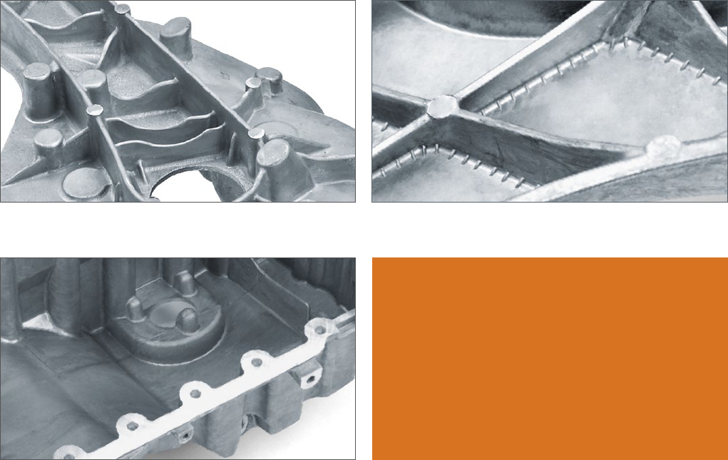
Fig. 11: An example of good rib design. An example of good design using
Magsimal-59, AlMg5Si2Mn, without nodal points.
Fig. 10: An example of good rib design Fig. 12: An example of solving inner edge problems through “crow’s feet”
Magsimal
®
- 59 – Processing instruc tions / de sign guideline s
For the processing of AlMg-alloys newly developed mold release
agents improve the castability, the lubrication during ejection and
the weldability of die casts.
Surface treatment
Magsimal-59 can be painted or powdercoated and also polished
or anodised. Polishing produces a typical light blue colour of
the surface gloss. It should be noted that anodising produces a
typical shade of grey due to the silicon content. Therefore, the
application of a chromium coating or polishing is recommended
for decorative purposes.
Design guidelines
The design of the ribs can be too thin, which produces a highly
undesirable rigidity in the ribs themselves. Deformation
then occurs only partially at the end” of the ribs, i.e. in the wall.
1 – 2 mm ribs are for example not recommended into a 6 mm
wall-thick U-profile (Fig. 10).
Examples of good design using Magsimal-59:
• Eliminate nodal points so that sinks are not occuring on the
opposite side of the wall. The high volume contraction
causes on larger nodes these visible external sinks (Fig. 11).
• Material agglomerations on internal radii cause sinking points
as mentioned above. A solution is given by “crow’s feet” as
shown in figure 12.
Center line shrinkage can become very long in unfavourable
solidification conditions. However, as these shrinkages are
located in the central position (neutral fibres), they do not have
any evident effect on component strength. It is essential in
this instance that the shrinkage does not have any contact with
the open surface in the heavy-duty cast surface area.
Components for self-piercing riveting should not be thicker
than 3 mm in order to guarantee the required component wall
deformability.
Assistance on site
Our foundry engineers will be happy to discuss any queries with
you regarding the technicalities of Magsimal-59.
Bibliography
Rheinfelden brochure Code 637, “Optimizing the Magnesium
and Manganese content for the structural part application”,
published for NADCA 2003, 10/2003.
Rheinfelden brochure Code 635, “Möglichkeiten des
Aluminiumdruckgießens; Anwendungen dieser Technologie
im Grenzbereich”, published by Dr.-Ing. Norbert Grov e.a.,
in GIESSEREI No.7 2003.
53

1 Reinigung
2 Einschmelzen der Masseln
3 Salzbehandlung
4 Strontiumabbrand
5 Abk rätzen
6 Temperatur nach dem
Einschmelzen und im
Warmhalteofen
7 Entgasen und Reinigen
der Schmelze
8 Abk rätzen
9 Gießtemp eratur ( Richtwerte )
10 Formtemperatur
11 Gießwerkzeug- und
Gießkammer-Temperatur
Castasil
®
- 37 [ AlSi9MnMoZr ]
Arbeitsfolge bei der Herstel lung von Druckgussstücken aus Castasil-37
Öfen, Tiegel, Behandlungs- und Gießwerkzeuge reinigen, um Verunreinigungen mit
unerwünschten Elementen wie Cu, Zn und insbesondere Mg zu vermeiden !
Die Schmelze sollte zügig über 670 °C gebracht werden, um Seigerungen, z. B. des
Mn-haltigen Mischkristalles in der Schmelze zu vermeiden. Die Schmelzetemperatur
sollte 780 °C nicht übersteigen. Ei n Abbrand von Sr beim Schmelzen und Warm-
halten ist zu erwarten – und umso s tärker, je höher die Temperatur ist. Besonders
beim Einschmelzen von Kreislaufmaterial is t der Sr-Abbrand zu beachten und eine
Entgasungsbehandlung zum Entfernen von H
2
und Oxiden empfohlen. Mit zuneh-
mendem Sr-Gehalt steigt die Neigung der Schmelze Wasserstoff aufzunehmen;
daher sollte dieser nicht über 350 ppm liegen.
beim Schmelzen nicht nötig
üblicherweise Abbrand von 30 – 50 ppm je Schmelzung; Sr ist nur aufzulegieren,
wenn der Gehalt in der Schmelze unterhalb von 6 0 ppm liegt, mit AlSr5 oder AlSr10.
Bei erstmaligem Aufschmelzen in einem neuen Tiegel oder einem Tiegel, der
bisher nicht für Sr-veredelte Legierungen ver wendet wurde, fällt der Sr-Gehalt sta rk
ab. Dabei diffundiert Stro ntium in den Tiegel; eine Sättigun g ist nach erstem Auf-
schmelzen erreicht.
nach dem Einschmelzen erforderlich; kalte Werkzeuge führen, neben ihrem
Gefährdungspotenzial, eventuell zur Sei gerung von Molybdän.
Dauertemperatur: maximal 780 °C ( Temperatur kontrollieren ! ); nicht unter 680 °C
sinken lassen und für Schmelzebewegung sorgen
• im Transporttiegel, b esser im Gießofen bzw. Dosierofen; wirkungs volle Reinigung
und schnellste Methode mit schnell laufendem Rotor zur Gaseinleitung,
7 – 10 l/min Argon oder Stickstoff, 6 – 10 min; bei der Entgasung im Transport-
tiegel ist mit einer Abkühlung von 30 – 50 °C zu rechnen
• Spüllanze mit feinporösem Kopf be nötigt längere Behandlungszeiten ( Abkühlung ! )
nach dem Entgasen erforderlich ; der Metallgehalt der Krätze kann durc h die Zugabe
von Schmelzhilfssalzen bei oder nach Impellerbehandlung reduziert werden
680 – 720 °C abhän gig von Gestalt, Fließweg und Wanddicke de s Druckgussstückes,
aber auch von Fließrinnenlänge und -is olierung des Dosierofens sowie vom Einsatz
einer Füllbüchsenheizung
Temperaturverluste können Vorerstarrungen verursachen und sind daher zu
vermeiden.
200 – 300 °C, je nach Gus sstück und Anforderungen an die mechanisch en
Eigenschaften
Generell gilt: je wärmer die Form , desto höher ist die Dehnung und niedriger die
Festigkeit, aber je wärmer die For m, desto dünnwandiger kann das Gussstüc k
gegossen werden, desto länger sind die realisierbaren Fließlängen in der Form.
Gießwerkzeug-Oberfläche: zwischen 250 und 350 °C
(abhängig von Gussstückgröße und -wand dicke)
Gießkammer elektrisch oder über Thermoöl temperiert > 200 °C
1 Einschmelzen der Masseln
2 Salzbehandlung
3 Magnesiumabbrand
4 Strontiumabbrand
5 Abk rätzen
6 Temperatur
7 Entgasen und Reinigen
der Schmelze
8 Abk rätzen
9 Gießtemp eratur ( Richtwerte )
10 Formtemperatur
11 Aushärtung durch T5
12 Lösungsglühen
13 Abkühlen von
Lösungsglühtemperatur
14 Zwischenlagerzeit vor dem
Warmauslagern
15 Vollaushärtung T6
16 Überalterung T7
Silafont
®
- 36 [ AlSi10MnMg ]
Arbeitsfolge bei der Herste llung von Druckgussstücken aus Silafont-36
möglichst rasch in leistungsfähige n Öfen, damit Magnesium-Abbrand, Ga saufnahme
und Oxidation der Schmelze gering bleiben; nachsetzen von vorgewärmten Masseln
und Kreislaufmaterial in kleinen Mengen, sonst Seigerungen und Oxideinschlüsse;
Kreislaufanteil kann bis 50 % betragen
beim Schmelzen nicht nötig
normalerweise Abbrand von 0,03 % je Schmelzung; ist nur zu kompensieren, wenn
der Magnesium-Gehalt der Schme lze außerhalb der Toleranz liegt, mit Magnesium-
Vorlegierung oder Reinmagnesium
üblicherweise Abbrand von 30 – 50 ppm je Schmelzung; Sr ist nur aufzulegieren,
wenn der Gehalt in der Schmelze unterhalb von 8 0 ppm liegt, mit AlSr5 oder AlSr10.
Bei erstmaligem Aufschmelzen in einem neuen Tiegel oder einem Tiegel, der
bisher nicht für Sr-veredelte Legierungen ver wendet wurde, fällt der Sr-Gehalt sta rk
ab. Dabei diffundiert Stro ntium in den Tiegel, eine Sättigung ist n ach erstem Auf-
schmelzen erreicht.
nach dem Einschmelzen erforderlich
Dauertemperatur: nach dem Einschmelzen maximal 780 °C ( Temperatur kontrollieren ! )
• im Transporttiegel, b esser im Warmhaltetiegel, -gefäß oder i m Dosierofen mit
Bodensteinen; wirkungsvolle Reinigung und schnellste Methode mit schnell
laufendem Rotor zur Gaseinleitung, 7 – 10 l/min Argon oder Stickstoff, 6 – 10 min
• Spüllanze mit feinporösem Kopf benöti gt längere Behandlungszeiten ( Abkühlung ! )
• Stickstoff abgebende Spülgastabletten im Tauchglockenverfahren sind wenig geeignet.
nach dem Entgasen erforderlich ; der Metallgehalt der Krätze kann durc h die Zugabe
von Schmelzhilfssalzen bei oder nach der Impellerbehandlung reduziert werden
680 – 710 °C – abhängi g von Gestalt, Fließweg und Wanddicke de s Druckguss-
stückes, aber auch von Fließrinne nlänge des Dosierofens und von evtl. Kamm erheizung
200 – 250 °C je nach Gus sstück;
Gießwerkzeug-Oberfläche: zwischen 250 und 350 °C
Wasserabschrecken direkt nach der Gussentnahme, möglichst hohe Temperatur
( dann auslagern wie 15/16 )
480 – 490 °C / 2 – 3 Stunden
für Sonderbauteile möglich: Absenkung bis 400 °C / 0,5 Stunden
möglichst ohne Verzögerung in Wasser ( 10 – 60 °C ); bei Abkühlung an Luft erreicht
man nur eine erheblich geringere Dehngrenze
nur wenn Richtarbeit notwendig, üblicherweise maximal 12 Stunden
155 – 170 °C / 2 – 3 Stunden
190 – 230 °C / 2 – 3 Stunden
Die angegebenen Glüh- und Auslagerungszeiten gelten ohne Aufheizdauer.
1 Einschmelzen der Masseln
2 Salzbehandlung
3 Magnesiumabbrand
4 Strontiumabbrand
5 Abk rätzen
6 Temperatur
7 Entgasen und Reinigen
der Schmelze
8 Abk rätzen
9 Gießtemp eratur ( Richtwerte )
10 Formtemperatur
11 Aushärtung durch T5
12 Lösungsglühen
13 Abkühlen von
Lösungsglühtemperatur
14 Zwischenlagerzeit vor dem
Warmauslagern
15 Vollaushärtung T6
Thermodur
®
- 72 [ AlMg7Si3Mn ]
Arbeitsfolge bei der Herstellung von Druckgussstücken aus Themodur-72
möglichst rasch in leistungsfähige n Öfen, damit Magnesium-Abbrand, Gas aufnahme
und Oxidation der Schmelze gering bleiben; nachsetzen von vorgewärmten Masseln
und Kreislaufmaterial in kleinen Mengen, sonst Seigerungen und Oxideinschlüsse;
Kreislaufanteil kann bis 50 % betragen
beim Schmelzen nicht nötig
normalerweise Abbrand von 0,03 % je Schmelzung; ist nur zu kompensieren, wenn
der Magnesium-Gehalt der Schme lze außerhalb der Toleranz liegt, mit Magnesium-
Vorlegierung oder Reinmagnesium
üblicherweise Abbrand von 30 – 50 ppm je Schmelzung; Sr ist nur aufzulegieren,
wenn der Gehalt in der Schmelze unterhalb von 8 0 ppm liegt, mit AlSr5 oder AlSr10.
Bei erstmaligem Aufschmelzen in einem neuen Tiegel oder einem Tiegel, der
bisher nicht für Sr-veredelte Legierungen ver wendet wurde, fällt der Sr-Gehalt star k
ab. Dabei diffundiert Stro ntium in den Tiegel, eine Sättigung ist na ch erstem Auf-
schmelzen erreicht.
nach dem Einschmelzen erforderlich
Dauertemperatur: nach dem Einschmelzen maximal 780 °C ( Temperatur kontrollieren ! )
• im Transporttiegel , besser im Warmhaltetiegel, -gefäß oder im D osierofen mit
Bodensteinen; wirkungsvolle Reinigung und schnellste Methode mit schnell
laufendem Rotor zur Gaseinleitung, 7 – 10 l/min Argon oder Stickstoff, 6 – 10 min
• Spüllanze mit feinporösem Kopf benöti gt längere Behandlungszeiten ( Abkühlung ! )
• Stickstoff abgebende Spülgastabletten im Tauchglockenverfahren sind wenig geeignet.
nach dem Entgasen erforderlich ; der Metallgehalt der Krätze kann durc h die Zugabe
von Schmelzhilfssalzen bei oder nach der Impellerbehandlung reduziert werden
680 – 710 °C – abhängi g von Gestalt, Fließweg und Wanddicke de s Druckguss-
stückes, aber auch von Fließrinnen länge des Dosierofens und von evtl. Kamme rheizung
200 – 250 °C je nach Gus sstück;
Gießwerkzeug-Oberfläche: zwischen 250 und 350 °C
Wasserabschrecken direkt nach der Gussentnahme, möglichst hohe Temperatur
( dann auslagern wie 15/16 )
480 – 490 °C / 2 – 3 Stunden
für Sonderbauteile möglich: Absenkung bis 400 °C / 0,5 Stunden
möglichst ohne Verzögerung in Wasser ( 10 – 60 °C ); bei Abkühlung an Luft erreicht
man nur eine erheblich geringere Dehngrenze
nur wenn Richtarbeit notwendig, üblicherweise maximal 12 Stunden
180 – 210 °C / 2 – 3 Stunden
1 Einschmelzen der Masseln
2 Salzbehandlung
beim Einschmelzen
3 Magnesiumabbrand
4 Abk rätzen
5 Temperatur nach dem Einschmelzen
6 Temperatur im Warmhalteofen
7 Entgasen und Reinigen
der Schmelze
8 Abk rätzen
9 Kornfeinen
10 Veredelung
11 Gießtemperatur ( Richtwerte )
12 Gießwerkzeug- und
Gießkammer-Temperatur
13 Abschrecken der Gussstücke
14 Wärmebehandlung
15 Entspannungsglühen
Magsimal
®
- 59 [ AlMg5Si2Mn ]
Arbeitsfolge bei der Herstellung von Druckgussstücken aus Magsimal-59
möglichst zügig in leistungsfähigen Ö fen, damit Mg-Abbrand, Gasaufnahm e und
Oxidation der Schmelze gering bleiben; nachsetzen von vorgewärmten Masseln und
grobstückigem Kreislaufmaterial in kleinen Mengen, sonst Seigerungen möglich;
Feuerfestmassen mit hohem Tonerdeanteil oder dichte Stampfmassen verwenden;
Phosphor- und Natrium-Aufnahme vermeiden!
Übliches Schmelzhilfssalz verboten ! Es besteht die Gefahr der N a-Aufnahme.
normalerweise Abbrand von 0,1 % je Schmelzung, Korrektur unüblich; bei einem
Mg-Gehalt erheblich unter 5,0 % Zugabe von bis zu 0,5 % Reinmagnesium möglich
nach dem Einschmelzen erforderlich
Dauertemperatur: maximal 780 °C ( Temperatur kontrollieren ! )
nicht unter 650 °C sinken lassen und für Schmelzebewegung sorgen durch:
• Wärmekonvektion
• Rotor ( Impeller )
• Spülgaseinleitung am besten üb er Bodensteine
• Schmelze-Nachfüllung
keine tiefen Öfen mit Deckenheizung bei ruhender Schmelze verwenden !
• wirkungsvolle Reinigung und schnellste Methode mit schnell laufendem Rotor zur
Gaseinleitung, 7 – 10 l/min Argon oder Stickstoff, 6 – 10 min
• Spüllanze mit feinporösem Kopf benöti gt längere Behandlungszeiten ( Abkühlung ! )
• Spülgastabletten erreichen nicht die erforderliche Wirkung !
sorgfältiges Abkrätzen erforderlich
Um den Metallgehalt der Krätze zu ver ringern, dürfen nur ausgesprochen Na-frei e
Salze verwendet werden !
verboten ! TiB
2 als Kornfeiner vergröbert das Eutektikum
verboten ! Die erreichbare Dehnung würde erheblich gesenkt werden.
690 – 730 °C, va riiert je nach Gestalt, Größ e und Wanddicke der Druckgussstücke
Gießwerkzeug-Oberfläche: zwischen 250 und 350 °C
(abhängig von Gussstückgröße und -wand dicke)
Gießkammer elektrisch oder über Thermoöl temperiert > 200 °C
Sofortiges Abschrecken in Wasser senk t die Dehngrenze und steigert die Dehnung
(bis 70 °C) .
Normalerweise keine
nur in Sonderfällen T5 und O; T5 je nach Be darf auslagern bis 250 °C und bis 9 0 min,
wobei Dehngrenze ansteigt und Dehnung abnimmt ; O je nach Bedarf über 320 °C
bis 380 °C und bis 90 min, wobei Dehngrenze abnimmt und Dehnung ansteigt
Technical informations
This chapter is provided on how to work with our casting alloys in the melt process and how to gain optimum pour-
ing results. In the various steps in the die cast process as possible grain refinement, strontium modification, quality of
melt, heat treatment for HPDC, surface coating, and joining techniques for the HPDC is hereby received.
We consider this a very important part of the manual as it isn’t just the quality of casting alloy used which is key
to successful applications, the right way of working before, during and after pouring is also of great importance.
More questions will certainly arise during your work and as new developments enter the market. The RHEIN-
FELDEN ALLOYS foundry specialists will happily answer these.
The mechanical properties are based on in-house measurements of our alloys and most exceed the values stipulated
in the EN 1706 European standard.
The mechanical values were measured at tensile bars, machined from HPDC. The ranges of mechanical properties
stated indicate the performance of the alloys and the amount of scatter depending on material and pouring. The re-
spective maximum value is for the designer’s information. These values can also be reached in the cast or sub-areas
with favorable casting conditions and corresponding casting technology work.
The HPDC alloys supplied by RHEINFELDEN ALLOYS have small and precisely defined analysis ranges in order to
ensure good uniformity in the casting process and other properties.
Processing datasheets
RHEINFELDEN ALLOYS provides the following processing data sheets in order to detail how
to work with the various alloys. If you use our casting alloys, please feel free to copy the
following pages and use them in your company. They contain practical instructions and
demonstrate the processes step by step.
Not all alloys are listed here, but the processing data sheet from within the corresponding
alloy family can be used. The recommendations correspond to typical foundry circumstances.
For example a crucible or shaft melting furnace is considered for melting down;
the circumstances in a huge melting furnace may differ from the recommen-dations. Fine returns should also
not be used for primary aluminium high pressure die casting alloys.
The volumes listed here are all percentages by weight, calculated for the charge weight. The temperatures quoted all
relate to the temperature of melt, even for casting. The heat treatment recommendations apply for the standard process
and may be varied, to minimise distortion for example.
If you have any questions relating to your specific alloy application and processing, please contact our foundry experts.
54

1 Refining
2 Melting down the ingots
3 Salt treatment
4 Strontium burnout
5 Skimming
6 Temperature after melting down
7 Degassing and refining the melts
8 Skimming
9 Pouring temperature ( approx. values )
10 Mould temperature
11 Die chamber temperature
Castasil
®
- 37 [ AlSi9MnMoZr ]
Sequence of work when producing high pressure die castings from Castasil-37
Clean furnace, crucible, treatment and casting tools to avoid impurities from
unwanted elements such as Cu, Zn and especially Mg !
The melt should be quickly heated to above 670 °C to avoid segregations, e. g. of the
solid solution containing Mn in the melt. The temperature of melt should not exceed
780 °C. An Sr melting loss should be expected when melting and keeping warm –
the higher the temperature, the greater the loss. Sr melting loss should be expected
in particular when melting down returns and degassing treatment is recommended to
remove the H
2
and oxides. As the Sr content increases, so does the tendency for the
melt to absorb hydrogen; this should not therefore exceed 350 ppm.
Not needed when melting
Usually melting loss of 30 – 50 ppm per fusion; Sr should only be added if the Sr
content of the melts is less than 60 ppm, add AlSr5 or AlSr10.
When fusing for the first time in a new crucible or in a crucible which has not yet
been used for Sr-modified alloys, the Sr content falls sharply. Strontium will diffuse
into the crucible; saturation is reached after the first fusion
Needed after melting down; as well as their potential for danger, cold tools may
result in molybdenum segregation
After melting down maximum of 780 °C for holding temperature. Don’t keep the melt
at temperature below 680 °C and steer melt if possible
• In the transport crucible, better in casting or dosing furnace; effective rening and
fastest method using quick-running rotor for gas feeding, 7 – 10 l/min argon or ni-
trogen, 6 – 10 min; during degassing in the transport crucible, cooling of 30 – 50 °C
should be expected
• Gas ushing lance with ne porous head, needs longer treatment times ( cooling ! )
• Tablets for melt cleaning are inefcient
Required after degassing; the metal content of the skimmings may be reduced by
adding melt uxes during or after impeller treatment
680 – 720 °C depends on design, ow path and wall thickness of high pressure
die casting, but also on the length and insulation of the ow channel from the dosing
furnace and on use of shot sleeve heating.
Temperature losses may cause initial solidification and should therefore be avoided
250 – 350 °C, depending on cast and requirements of mechanical properties
As a rule: the warmer the mould, the higher the elongation and the lower the
strength.
Preheat the chamber electrical or with oil > 200 °C
55

Castasil
®
- 21 [ AlSi9Sr ]
Sequence of work when producing high pressure die castings from Castasil-21
1 Refining
2 Melting down the ingots
3 Salt treatment
4 Strontium burnout
5 Skimming
6 Temperature after melting down
7 Degassing and refining the melts
8 Skimming
9 Pouring temperature ( approx. values )
10 Mould and chamber temperature
11 Annealing to high conductivity by T5
Clean furnace, crucible, treatment and casting tools to avoid impurities from
unwanted elements such as Cu, Zn and especially Mg!
The melt should be quickly heated to above 670 °C to avoid segregations, e. g. of the
solid solution containing Mn in the melt. The temperature of melt should not exceed
780 °C. An Sr melting loss should be expected when melting and keeping warm –
the higher the temperature, the greater the loss. Sr melting loss should be expected
in particular when melting down returns and degassing treatment is recommended to
remove the H
2
and oxides. As the Sr content increases, so does the tendency for the
melt to absorb hydrogen; this should not therefore exceed 350 ppm.
Not needed when melting
Usually melting loss of 30 – 50 ppm per fusion; Sr should only be added if the Sr
content of the melts is less than 60 ppm, add AlSr5 or AlSr10.
When fusing for the first time in a new crucible or in a crucible which has not yet
been used for Sr-modified alloys, the Sr content falls sharply. Strontium will diffuse
into the crucible; saturation is reached after the first fusion
Needed after melting down; as well as their potential for danger, cold tools may
result in molybdenum segregation
After melting down maximum of 780 °C for holding temperature. Don’t keep the melt
at temperature below 680 °C and steer melt if possible
• In the transport crucible, better in casting or dosing furnace; effective rening and
fastest method using quick-running rotor for gas feeding, 7 – 10 l/min argon or ni-
trogen, 6 – 10 min; during degassing in the transport crucible, cooling of 30 – 50 °C
should be expected
• Gas ushing lance with ne porous head, needs longer treatment times ( cooling ! )
• Tablets for melt cleaning are less efcient
Required after degassing; the metal content of the skimmings may be reduced by
adding melt uxes during or after impeller treatment
680 – 720 °C depends on design, ow path and wall thickness of high pressure
die casting, but also on the length and insulation of the ow channel from the dosing
furnace and on use of shot sleeve heating.
Temperature losses may cause initial solidification and should therefore be avoided
250 – 350 °C, depending on cast and requirements of mechanical properties
As a rule: the warmer the mould, the higher the elongation and the lower the
strength. Preheat the chamber electrical or with oil > 200 °C
250 – 350 °C / 2 – 3 hours
The annealing and ageing times stated apply without a heating-up time
56

1 Melting down the ingots
2 Salt treatment
3 Magnesium burnout
4 Strontium burnout
5 Skimming
6 Temperature
7 Degassing and refining the melts
8 Skimming
9 Pouring temperature (approx. values )
10 Mould temperature
11 Ageing by T5
12 Solution heat treatment
13 Cooling after
solution heat treatment
14 Delay time before artificial ageing
15 Full artificial ageing T6
16 Overageing T7
Silafont
®
- 36 [ AlSi10MnMg ]
Sequence of work when producing high pressure die castings from Silafont-36
As quickly as possible in efficient furnaces to keep magnesium melting loss, gas
absorption and oxidation of melts low; replenish preheated ingots and returns
in small volumes to avoid segregation and entrapped oxides; proportion of returns
may extend to 50 %
Not needed when melting
Normally a melting loss of 0.03 % per fusion; compensation is only required if the
magnesium content of the melts is outside tolerance, add magnesium master alloy
or pure magnesium
Usually melting loss of 30 – 50 ppm per fusion; Sr should only be added if the Sr
content of the melts is less than 80 ppm, add AlSr5 or AlSr10.
When fusing for the first time in a new crucible or in a crucible which has not yet
been used for Sr- modified alloys, the Sr content falls sharply. Strontium will diffuse
into the crucible, saturation is reached after the first fusion
Needed after melting down
After melting down maximum of 780 °C for holding temperature
• In the transport crucible, better in a holding crucible or receptacle or in a dosing
furnace with bottom blocks; effective refining and fastest method using
quick- running rotor for gas feeding, 7 – 10 l/min argon or nitrogen, 6 – 10 min
• Gas ushing lance with ne porous head, needs longer treatment times ( cooling ! )
• Gas ushing tablets emitting nitrogen in the bell plunger procedure are not very
suitable
Required after melting down; the metal content of the skimmings may be reduced
by adding melt uxes within or after the impeller treatment
680 – 710 °C – depends on design, ow path and wall thickness of high pressure die
casting, but also on the length of the ow channel in the dosing furnace and possibly on
chamber heating
Die surface temperature 250 – 350 °C
Water quenching immediately after the casting is taken out as high a temperature as
possible (then age as 15)
480 – 490 °C / 2 – 3 hours; for special components: 400 °C / 0.5 hours
In water ( 10 – 60 °C ) without a delay wherever possible to < 200 °C;
if cooling in the air, only a significantly lower yield tensile strength can be obtained
Only if dressing is needed, usually maximum of 12 hours
155 – 170 °C / 2 – 3 hours
190 – 230 °C / 2 – 3 hours
The annealing and ageing times stated apply without a heating-up time
57

58
1 Melting down the ingots
2 Salt treatment
3 Magnesium burnout
4 Strontium burnout
5 Skimming
6 Temperature
7 Degassing and refining the melts
8 Skimming
9 Pouring temperature (approx. values )
10 Mould temperature
11 Solution heat treatment
12 Cooling with air
13 Cooling with water
14 Delay time before artificial ageing
15 Full artificial ageing T6
Silafont
®
- 38 [ AlSi9MnMgZn ]
Sequence of work when producing high pressure die castings from Silafont-38
As quickly as possible in efficient furnaces to keep magnesium melting loss, gas
absorption and oxidation of melts low; replenish preheated ingots and returns
in small volumes to avoid segregation and entrapped oxides; proportion of returns
may extend to 50 %
Not needed when melting
Normally a melting loss of 0.03 % per fusion; compensation is only required if the
magnesium content of the melts is outside tolerance, add magnesium master alloy
or pure magnesium
Usually melting loss of 30 – 50 ppm per fusion; Sr should only be added if the Sr
content of the melts is less than 80 ppm, add AlSr5 or AlSr10.
When fusing for the first time in a new crucible or in a crucible which has not yet
been used for Sr- modified alloys, the Sr content falls sharply. Strontium will diffuse
into the crucible, saturation is reached after the first fusion
Needed after melting down
After melting down maximum of 780 °C for holding temperature
• In the transport crucible, better in a holding crucible or receptacle or in a dosing
furnace with bottom blocks; effective refining and fastest method using
quick- running rotor for gas feeding, 7 – 10 l/min argon or nitrogen, 6 – 10 min
• Gas ushing lance with ne porous head, needs longer treatment times ( cooling ! )
• Gas ushing tablets emitting nitrogen in the bell plunger procedure are not very
suitable
Required after melting down; the metal content of the skimmings may be reduced
by adding melt uxes within or after the impeller treatment
680 – 710 °C – depends on design, ow path and wall thickness of high pressure die
casting, but also on the length of the ow channel in the dosing furnace and possibly
on chamber heating
Die surface temperature 250 – 350 °C
480 – 490 °C / 2 – 3 hours; for special components: 400 °C / 0.5 hours
Immediate air cooling with a cooling rate of > 4 °C / s is only achieved with an inten-
sive air stream (down to 200 °C) and results in lower distorsion. If cooling in the air,
only a significantly lower yield tensile strength can be obtained
In water ( 10 – 60 °C ) without a delay wherever possible
Only if dressing is needed, usually maximum of 12 hours
155 – 170 °C / 2 – 3 hours
The annealing and ageing times stated apply without a heating-up time
58

1 Melting down the ingots
2 Salt treatment
3 Magnesium burnout
4 Skimming
5 Temperature after melting down
6 Temperature in holding furnace
7 Degassing and refining the melts
8 Skimming
9 Grain refining
10 Modification
11 Pouring temperature ( approx. values )
12 Die temperature and
die chamber temperature
13 Quenching casts after removal
from mould
14 Hea t treat men t
15 stress-relief annealing
Thermodur
®
- 72 [ AlMg7Si3Mn ]
Sequence of work when producing high pressure die castings from Thermodur
-72
As quickly as possible in efficient furnaces to keep Mg melting loss, gas absorption
and oxidation of melts low; replenish preheated ingots and returns in small volumes to
avoid segregation; use refractory materials with a high clay content; avoid phospho-
rous and sodium absorption
Prohibited to use usual salt ! There is a risk of Na pick up
Normally melting loss of 0.1 % per fusion, correction not normally needed; if the Mg
content is significantly below 7.0 %, add pure magnesium of maximum 0.5 %
Needed after melting down
Ma xi mum of 780 °C ( c heck temp erat ure ! )
Holding furnance temerature: 700 – 720 °C
Do not allow to fall below 650 °C and keep melt moving by means of:
• convection
• rotor ( impeller )
• use bottom injection of N
2
• melt pouring
Do not use deep furnace with cover heating if melt is calm !
• Effective rening and fastest method using quick-running rotor for gas feeding,
7 – 10 l/min argon or nitrogen, 6 – 10 min
• Gas ushing lance with ne porous head, needs longer treatment times ( cooling ! )
• Gas ushing tablets do not achieve the necessary effect !
Careful skimming needed
Only totally Na-free salts may be used to reduce the metal content of skimmings!
Proh ibite d !
Prohibited ! The elongation achievable would be reduced considerably
690 – 730 °C, varies depending on design, size and wall thickness of high pressure
die castings
Die surface temperature 250 °C to 350 °C, depending on cast and requirements of
mechanical properties
As a rule: the warmer the mould, the higher the elongation and the lower the strength.
Preheat the chamber electrical or with oil > 200 °C
Immediate quenching in water reduces the yield tensile strength and
increases elongation
Normally none
Only in special cases for T5 and O; if necessary, age T5 at up to 250 °C and
for up to 90 min, the yield tensile strength will increase and elongation decrease;
if necessary, age O at between 320 °C and 380 °C and for up to 90 min,
the yield tensile strength will decrease and elongation increase
59

1 Melting down the ingots
2 Salt treatment
3 Magnesium burnout
4 Skimming
5 Temperature after melting down
6 Temperature in holding furnace
7 Degassing and refining the melts
8 Skimming
9 Grain refining
10 Modification
11 Pouring temperature ( approx. values )
12 Die temperature and
die chamber temperature
13 Quenching casts after removal
from mould
14 Hea t treat men t
15 stress-relief annealing
Magsimal
®
- 59 [ AlMg5Si2Mn ]
Sequence of work when producing high pressure die castings from Magsimal
®
-59
As quickly as possible in efficient furnaces to keep Mg melting loss, gas absorption
and oxidation of melts low; replenish preheated ingots and returns in small volumes to
avoid segregation; use refractory materials with a high clay content; avoid phospho-
rous and sodium absorption
Prohibited to use usual salt ! There is a risk of Na pick up
Normally melting loss of 0.1 % per fusion, correction not normally needed; if the Mg
content is significantly below 5.0 %, add pure magnesium of maximum 0.5 %
Needed after melting down
Ma xi mum of 780 °C ( c heck temp erat ure ! )
Holding furnance temerature: 700 – 720 °C
Do not allow to fall below 650 °C and keep melt moving by means of:
• convection
• rotor ( impeller )
• use bottom injection of N
2
• melt pouring
Do not use deep furnace with cover heating if melt is calm !
• Effective rening and fastest method using quick-running rotor for gas feeding,
7 – 10 l/min argon or nitrogen, 6 – 10 min
• Gas ushing lance with ne porous head, needs longer treatment times ( cooling ! )
• Gas ushing tablets do not achieve the necessary effect !
Careful skimming needed
Only totally Na-free salts may be used to reduce the metal content of skimmings!
Proh ibite d !
Prohibited ! The elongation achievable would be reduced considerably
690 – 730 °C, varies depending on design, size and wall thickness of high pressure
die castings
Die surface temperature 250 °C to 350 °C, depending on cast and requirements of
mechanical properties
As a rule: the warmer the mould, the higher the elongation and the lower the strength.
Preheat the chamber electrical or with oil > 200 °C
Immediate quenching in water reduces the yield tensile strength and
increases elongation
Normally none
Only in special cases for T5 and O; if necessary, age T5 at up to 250 °C and
for up to 90 min, the yield tensile strength will increase and elongation decrease;
if necessary, age O at between 320 °C and 380 °C and for up to 90 min,
the yield tensile strength will decrease and elongation increase
60
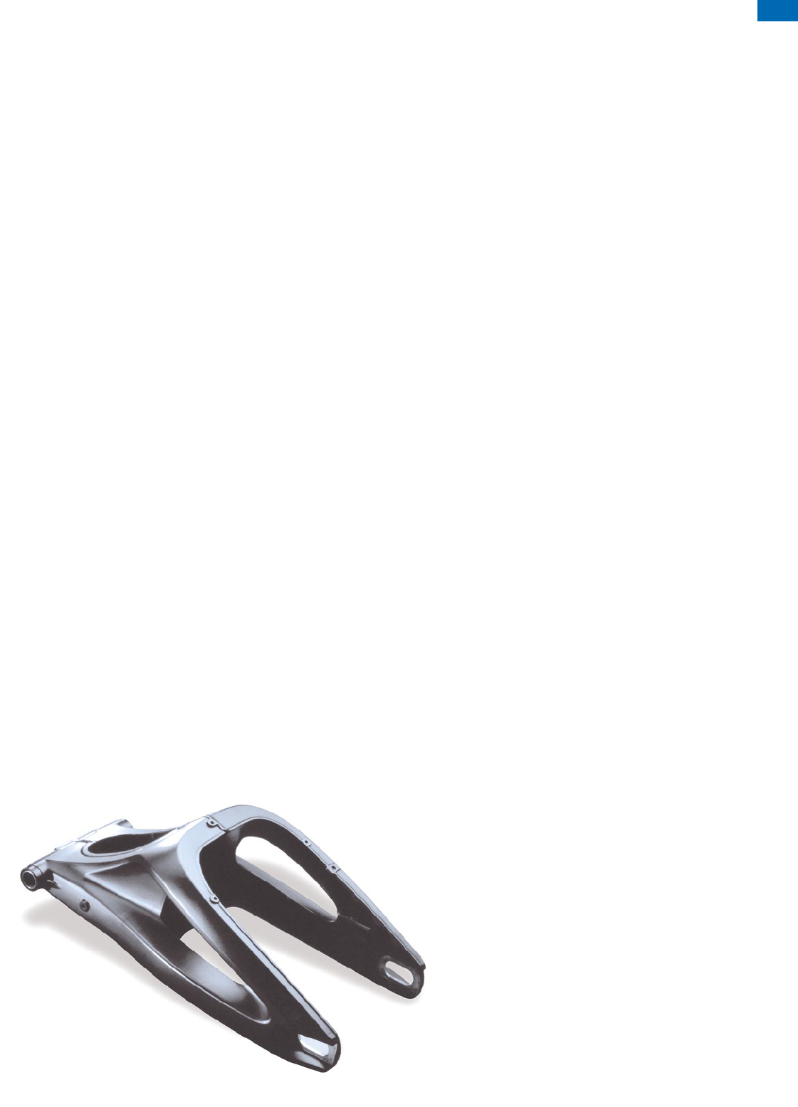
Surface coating
Surface coating
For pressure die castings maximum surface condition require-
ments are defined for pressure die castings which are to be
coated. This applies specifically to top-quality coatings which
must meet maximum requirements, with regard to decorative
appearance and resistance to corrosion for example in the
automotive or aviation industry.
The following parameters have considerable inuence on
awless coating:
• Pressure die casting design and process
• Die design
• Testing and machining
Here some design and processing tips are reported to help
preventing detrimental inuences on the coating.
Design
The cast design should have no sharp edges and small radii
below 2 mm. “Thinning-out” causes running away of the
coating film at the edges during baking with significantly lower
coating thicknesses.
Undercuts and bores always present problem areas in the
frequently applied electrostatic coating technology, which can
only be covered evenly with electro-dip painting.
Die design
Sufficient die conicity must be taken into account at the die
design, as too low draft angles in long designs can produce draw-
ing grooves resulting in their turn in depressions in the coating.
At least 1 % die inclination for Silafont-36 and Castasil-37 and
at least 1,5 % for Magsimal-59 should be assumed. Fine narrow
burrs and ashes form on the die and core slide during ejection.
Hot cracks can appear in thermally loaded areas of the cast with
older dies. These burrs and the die crack marks must be removed
as they cause “paint thinning” on their sharp edges. Deep die
cavities without melt ow through possibility must be designed
with overows so that no air, release agent residues or any oxide
skins are included in the cast during the die filling, which may
cause blister formation during baking of the coating.
Pressure die casting process
Die release agents, preferably water based, are used for smooth
removal of casts from the die. Some of these burn into the cast
skin. Release agents containing silicon or graphite can thus
cause considerable problems. The gate area is in some cases
additionally greased in order to prevent soldering to the die due
to increased thermal load. These lubricants also cause adhesion
losses for coatings. Therefore a very economical use of these
lubricants is recommended for casts to be coated.
Die-lling simulations may help to avoid high ow speeds,
which lead to surface aws in the cast with consequently uneven
decorative coating.
The pressure die casting gate should not be in the visible area
of the cast as far as possible. The die would be under greatest
stress in this area and would undergo premature hot crack forma-
tions. In turn this would become visible as depressions in the cast
and must be mechanically removed prior to any coating.
Fig. 1: Two die casts for rear swinging fork for motorbike; multi-pat welded structure in stiff design; powder coated
61
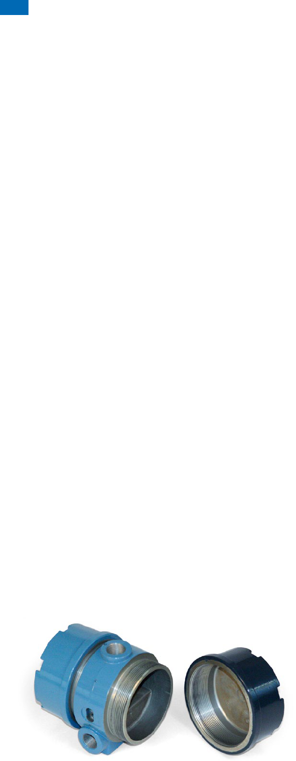
Fig. 2: Flow load cell for jet fuel; chromated before lacquering
Crack testing
A penetration crack test is often carried out on Magsimal-59
pressure die casting alloys. Test agent residues on surface
aws or pores must be removed by intensive cleaning, e.g. using
ultra sounds, otherwise there will be discolorations in the
coatings or adhesion losses.
Heat treatment
Heat treatments at solutionizing temperatures above 480 °C,
such as T4, T6 and T7 for Silafont-36, produce highly
oxidised surfaces which must be considered during surface
pre-treatment.
Machining
When using coolants for precision machining, it must be taken
into account that they have to be completely removed immedi-
ately afterwards by degreasing. Coolants attacking aluminium
must not be used. Material compatibility and removableness of
coolants must determine their selection.
Machining allowances should be kept to an absolute minimum
for pressure die castings in order to remove only a little of the
fast solidified cast surface.
Surface pre-treatment
The mechanical effect of frequently applied vibratory grinding
processes is often insufficient to reliably remove cast skins,
so that a blasting process is recommended.
Ceramic media, such as corundum in particular, are very suitable
blasting media. Glass beads or aluminium granules produce
only slight material removal. Not suitable are metals and plastics,
which cause painting adhesion losses due to the penetration
of akes into the workpiece surface. Residual iron particles also
form nuclei for pitting corrosion.
It is necessary to degrease the work piece prior to blasting as
lubricant residues can be driven into the workpiece surface
by the blasting process. Large quantities of the die release
agents and piston lubricants are particularly problematic as they
cause burnt oil carbon residues on the cast.
Alkaline and acid pickling
Alkaline pickling processes for targeted roughening of the
surface are not recommended for the surface treatment of
AlSiMg-pressure die castings. The high silicon alloy contents
cause dark, insoluble residues during alkaline pickling.
Subsequent acid pickling is then unavoidable for removing this
“pickling deposit”.
Effect of baking temperatures
Electrostatically adhering powder particles should be melt
together and cross linked on pressure die castings at target tem-
peratures of 120 to maximum 200 °C. A change occurs in
the mechanical properties of Silafont-36 during the coating pro-
cess starting from 150 °C; with Magsimal-59 this happens only
above 180 °C; Castasil-37 shows no changes.
To optimize the paint adhesion with Silafont-36, Silafont-38 and
Castaman-35 we suggest a chromate pre-treatment.
Glueing techniques for die castings
Glueing
Magsimal-59 and Castasil-37 are die casting alloys with the
requested properties for structural application in the as-cast state.
There is no dimensional correction needed due to the missing
heat treatment. That gives high benefit to the assembling with
glueing.
Joining techniques for die castings
Flanging
Silafont-36 with a magnesium content of approx. 0,16 % can be
used particularly for anging technology. The designer can
thus join the aluminium pressure die castings to other materials
such as steel and plastic. This can be applied as fixing but
also as structural joining technology with appropriate construc-
tion design (Fig. 1, page 63). The conguration of the anging
edge mostly requires an elongation of at least 8 % on the
pressure die cast material. Therefore high internal quality require-
ments are set on this area of the cast. As consequence,
in this kind of applications the design of the die must guarantee
good metal ow in the anging edge, what has to be kept in
mind especially with Magsimal-59.
Surface coating
62
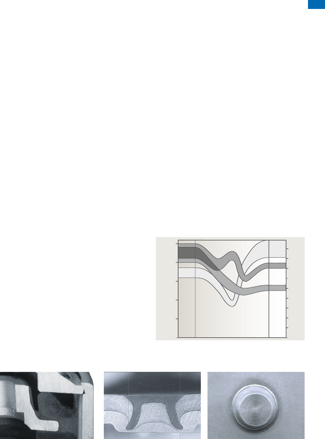
Joining techniques for die castings
feature a low number of pores and are virtually free of the oxide
skin after any T7 heat treatment undertaken.
Fig. 3 states the mechanical values in the heat inuence zone.
Unlike elongation, the strength values in this zone are hardly
inuenced.
Magsimal-59 and Thermodur-72 have a higher shrinkage rate and
force than AlSi high pressure die casting alloys. Mould release
agents recently developed for work with this alloy improve both
the ease of ow, i.e. ability to slide during ejection, and therefore
the suitability of the high pressure die castings for welding.
Design welding with casts made from Magsimal-59 is undertaken
with the AlMg4.5MnZr addition material using the TIG method
or laser/electron beam welding method. Unlike the case with
elongation, the mechanical properties in the heat inuence zone
are hardly affected. If the SG-AlSi5 welding addition material is
used, the elongation values fall yet further.
All here mentioned HPDC alloys are suitable for friction stir
welding or spot-welding.
Self-piercing riveting
Joints, in which the cast is the lower layer in the riveting joint,
have particularly high requirements concerning the absence
of defects in the cast material. Figures 2a and 2b show the result
of a self-piercing riveting trial in our laboratory.
It should be noted that Castasil-37 can be self-piercing riveted in
the as-cast state also under these severe design conditions, i.e.
using a rivet die with at geometry. The Castasil-37 batch used
for this trial had a yield strenght of 114 MPa, an ultimate tensile
strength of 255 MPa and 14 % elongation. A further improvement
in deformability is achieved in temper O.
Welding
The suitability of high pressure die castings for welding is highly
dependent on the melt and high pressure die casting process.
Casting materials and melt and high pressure die casting meth-
ods which ensure low gas absorption and oxide impurity during
high pressure die casting are needed.
The designer may place weld seams in zones with less loading,
but, for a high pressure die casting, they should also be close to
the ingate.
Fig. 4 shows eight target levels of the high pressure die casting,
the final one being a cast suitable for welding and heat treatment.
The high pressure die casting methods and stages required
for these are illustrated in terms of removing air, transport of melt
and application of mould release agent.
High pressure die castings made from Silafont-36 and
Castasil-37 are particularly well suited to welding, with both MIG
and TIG standard methods. The AlSi5 or AlSi10 welding
addition material is preferred for welded designs with AlMgSi0.5
wrought alloys. The weld seams and/or heat inuence zones
between components made from aluminium wrought alloys and
high pressure die castings made from Silafont-36 and
Castasil-37 withstand repeated loads perfectly if the cast edges
Fig. 2a: Cross section of a self-piercing riveting trial,
5 mm semi-tubular rivet, 1.5 mm AlMg3 sheet
metal, 4 mm Castasil-37 die cast plate in the
as-cast state (F)
Fig. 1: Vibration damper housing made of
Silafont-36, AlSi10MnMg, with structural
anging
Fig. 2b: View from below
Fig. 3: Strength values of the heat inuence zone of MIG welding with
AlSi12 addition material
Strenght R [MPa]
250
200
150
100
50
0
18
16
14
12
10
8
6
4
2
0
A
R
m
R
p0.2
Silafont-36 T7
wall thickness 3 mm
AlMgSi0.5
2 mm sheet metal
Heat inuence zone
Elongation A [%]
63
The following mechanical properties applicable to manual MIG
welding with the AlMg4.5Mn addition material illustrate how
the mechanical properties of Magsimal-59 in the heat inuence
zone are hardly affected compared with elongation.
Eight Target levels for HPDC
Fig. 4 shows eight target levels of the high pressure die cast, the final one being a cast suitable for
welding and heat treatment.
There are higher requirements for the production of crash relevant structural casts than for general
purposes. Depending on your requested targets shows the eight-level-staircase the right alloy and
for the main areas of HPDC some suggestions. We divide between dosing technique, air reduction in
the cavity, melt handling and application of die release agent.
A requested high cast quality requires on the one hand the use of high-quality die-cast aluminum
alloys, also with a metallurgically proper handling of the returns. On the other hand is the consistent
application necessary by die cast fundamentals for technical cast design, such as gate design.
Wall thickness
4 mm
R
p02
[MPa]
R
m
[MPa]
A
[%]
Not welded 165 287 17
Welded 148 246 6
Joining techniques for die castings
Suitable high pressure die casting alloys
Fig. 4: Eight target levels of high pressure die casting with details of the alloys to use and the high pressure die casting method and stages required
Magsimal-59
AlS i10M g ( Fe )
Silafont-36
T5 Mg > 0,3 %
Dimension
Light and
thin
High yield
tensile
strength
Flanging
Glueing,
riveting
Can be subject
to high dynamic
loads
Welding
Solution
heat
treatment
AlS i9 Cu3 ( Fe )
and others
AlS i12 ( Fe )
and others
Silafont-36
Castasil-37
Silafont-09
Castaman-35
Silafont-36
Magsimal-59
Castasil-37
Silafont-09
Castaman-35
Magsimal-59
Castasil-37
Thermodur-72
Thermodur-73
Silafont-36
Castasil-37
Magsimal-59
Silafont-38
Castaman-35
Silafont-36
Castasil-37
Silafont-38
Castaman-35
Dry piston lubricant
Minimisation of mould release agent
Modern mould release agent
Mould re-
lease agent
Controlled transport of melt
1st phase with less turbulence
Refining treatment of melt
Melt
Vacuum
Enforced bleeding
Wash board ventilation
Tie down overflows better ( simulation )
Air
Vacuum supported
Closed holding furnace
Crucible, electrical heated
Isolation of liner / ladle
Dosing
technique
High pressure die casting method and stages needed
Eight Target levels for HPDC
64
We would like to thank all our business partners who have provided castings or photographs for this
publication.
All the details in this publication have been checked and are provided to the best of our knowledge.
But just like all technical recommendations for applications, they are not binding, are not covered
by our contractual obligations ( this also applies to copyrights of third parties ) and we do not assume
liability for them. In particular they are not promises of characteristics and do not exempt the user from
checking the products we supply for suitability for their intended purpose. Reprints, translations and
copies, including extracts, require our express approval. New alloy developments made as technology
progresses after printing are included in later versions.
Version 3 – 12/2015
GRUPPE DREI
®
122015
RHEINFELDEN ALLOYS GmbH & Co. KG
A company of the ALUMINIUM RHEINFELDEN group
Sales and Customer Support
Friedrichstraße
80
D-79618 Rheinfelden
Tel.
+ 49 . 76 23 . 93-490
Fax
+ 49 . 76 23 . 93-546
alloys @ rheinfelden-alloys.eu
www.rheinfelden-alloys.eu
