
2-1
NADCA Product Specication Standards for Die Castings / 2015
Tooling for Die Casting
2
s e c t i o n
2
Section Contents NADCA No. Format Page
Frequently Asked Questions (FAQ) 2-2
1 Introduction 2-3
2 Types of Die Casting Dies 2-4
2.1 Prototyping 2-4
2.2 Rapid Tooling Dies 2-4
2.3 Production Dies 2-5
2.4 Unit Dies 2-6
2.5 Trim Dies 2-6
3 Casting Features and Die Considerations 2-7
3.1 Core Slide Requirements 2-8
3.2 Parting Line: Cover & Ejector Die Halves 2-8
3.3 Ejector Pins 2-9
3.4 Cast-in Inserts 2-9
4 Die Materials 2-10
4.1 Die and Cavity Materials 2-10
4.2 Die Cavity Insert Materials 2-10
4.3 Die Steel Heat Treatment 2-11
5 Controlling Die Performance 2 -11
5.1 Porosity Control: Gating, Venting, Vacuum 2-11
5.2 Thermal Balancing 2-12
5.3 Oil Heating Lines 2-12
5.4 Alternate Surface Textures 2-12
5.5 Extended Die Life 2-12
6 Secondary Machining Preplanning 2-14
7 Gaging Considerations 2-14
8 Inherited Tooling 2-15
9 Engineering Consultation 2-15
10 Database Guidelines 2-16
11 New Die/Inherited Die Specifications 2-16
12 Die Life 2-16
13 Checklist for Die Casting Die Specifications T-2-1-12 Checklist 2-17
14 Guidelines to Increase Die Life T-2-2-12 Guideline 2-19
CLICK HERE TO RETURN TO A&B DIE CASTING HOME PAGE
2-2
NADCA Product Specication Standards for Die Castings / 2015
Tooling for Die Casting
RUNNER
& GATE
MOVING/EJECTOR
MOLDBASE
RETAINER AND
EJECTOR PLATE
GUIDED EJECTION
ASSEMBLY
STATIONARY &
MOVING CAVITY
INSERTS
RUNNER
& GATE
COLD
CHAMBER
STATIONARY/COVER
MOLDBASE
RAIL
EJECTOR PIN
RETURN PIN
CORE
DIE CAVITY
SUPPORT
POST/PILLAR
STOP
PIN
BUSHING
RAIL
LEADER/GUIDE PIN
CLAMPING SLOTS
COOLING LINE
PARTING LINE
LEADER/GUIDE PIN BUSHING
SPRUE
HOLE
&
SPRUE
PIN
E
L
N
M
O
L
P
B
A
B
C
D
E
F
G
H
I
J
K
F
1
HOT CHAMBER DIE
COLD CHAMBER DIE
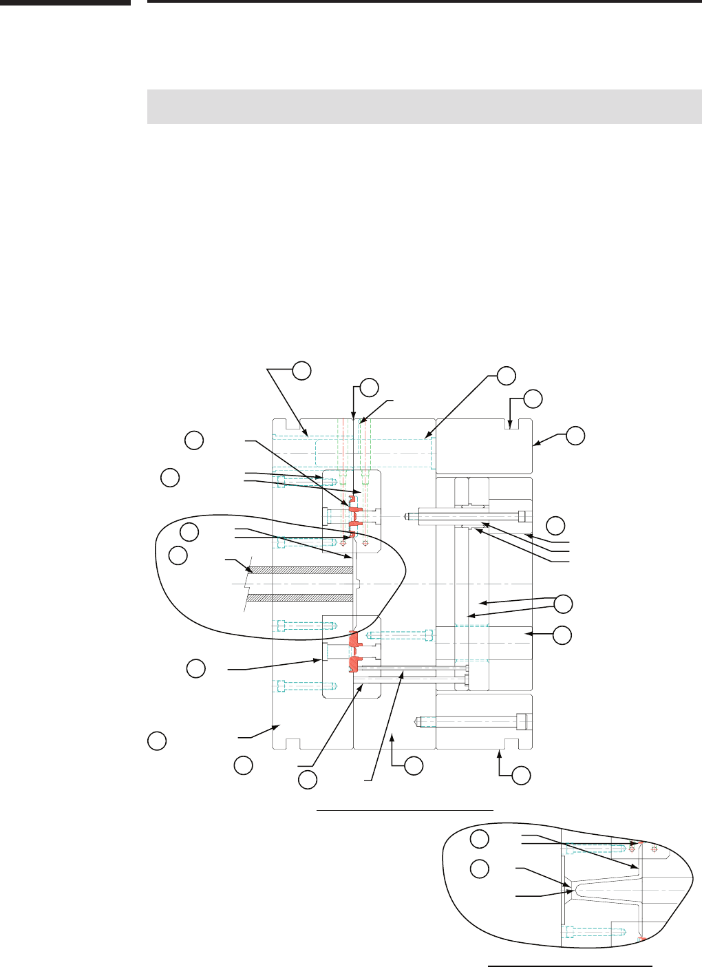
Figure2-1Shownaboveisamultiple-cavitycold
chamberdiecastingdie.Withthisprocessthemetal
entersthedierunners,gatesandcavitythroughthecold
chamber.eSpruereplacesthecoldchamberinthe
hotchamberprocesswhichisusedforzincandsmaller
magnesiumcomponents.
Frequently Asked Questions (FAQ)
1) What type of material should be used for die cavity inserts?
See page 2-10, Die Materials
2) What is the proper heat treatment procedure for dies?
See page 2-11, Die Steel Heat Treatment
3) What is the dierence between a Prototype Die and a Rapid Tooled Die?
See pages 2-4, Prototype Dies and 2-5, Rapid Tooled Dies.
4) Why are trim dies used?
See page 2-6, Trim Dies.
5) What is the dierence between a unit die and a self-contained die?
See pages 2-3 through 2-6, Types of Die Casting Dies.
6) What types of venting air are possible on a die?
See page 2-11.
A-PARTING LINE
Surface where two die halves
come together.
B-LEADER/GUIDE
PIN & BUSHING
Guides the two die halves
together and maintains die
alignment.
C-DIE CAVITY
Die recess in which casting is
formed.
D-STATIONARY &
MOVING CAVITY INSERT
Premium grade tool steel
containing the cavity details.
E-RUNNER & GATES
Precisely designed passage
thru which metal flows from
sprue hole or cold chamber
into die cavity.
F-COLD CHAMBER
Passage thru which metal
enters runners and gates.
F1-SPRUE HOLE
& SPRUE PIN
Forms passage thru which
metal enters runners & gates
in a hot chamber die.
G-CORE
Usually a round tapered pin
used to cast various hole
details.
H-STATIONARY/COVER
MOLDBASE
Stationary holder that
contains and supports the
cover inserts.
I-RETURN PIN
Large ejector pin that resets
ejection system.
J-EJECTOR PIN
Pin which pushes casting from
die cavity.
K-MOVING/EJECTOR
MOLDBASE
Movable holder that contains
and supports the ejector
inserts.
L-RAILS
Supports the ejector side
moldbase and contains
clamp slots.
M-RETAINER AND
EJECTOR PLATE
Contains and pushes the
ejector pins.
N-SUPPORT POST/PILLAR
Additional support members
to resist die deflection.
O-GUIDED EJECTION ASSEMBLY
(STOP, PIN & BUSHING)
Supports and guides the
ejection system.
P-CLAMPING SLOTS
Opening for die clamps to
mount die halves to machine
platens.
2-3
NADCA Product Specication Standards for Die Castings / 2015
Tooling for Die Casting
2
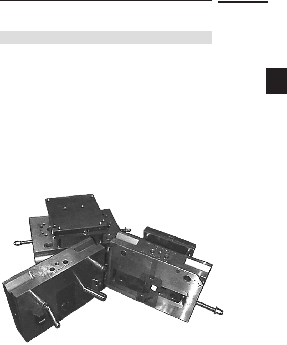
Figure2-2A“unit”diecastingdie,liketheoneabove,allowsuseofreplaceablecavitiesinstandardizedmaindie
framesforlowerdiecosts.
1 Introduction
e die casting die, or mold, is a closed vessel into which molten metal is injected under high
pressure and temperature, then rapidly cooled until the solidied part is suciently rigid to
permit ejection from the mold.
For longevity of operation in this environment the die casting die must be built from high-quality tool
steel, heat-treated to the required hardness and structure, with dimensions of the die and cavity machined
to exacting specications. e two die halves run in a die casting machine that is operated at the required
temperatures and pressures to produce a quality part to net-shape or near-net-shape customer specications.
e customer’s product design requirements directly aect the size, type, features, and cost of
the required tooling. e items involved in the tooling decision include the number of cavities,
number of core or slide requirements, weight of the die, machining, nish requirements, polishing
and plating to name just a few. A convenient checklist of die construction considerations, intended
for use in discussion with your custom die caster, appears at the end of this section (page 2-17).
Explanation of the most important terms related to die design are given in the following sec-
tions of this chapter. A complete glossary of die casting terms appears at the end of this volume.
e discussion in this section provides a guide to aid the die casting specier in understanding
the requirements of the die caster that will be necessary to produce the optimum die casting, by
the most economical production methods.
e various alloys available for die casting, from aluminum to zinc, require unique and special
features in the die that produces them. Because of these dierences, the descriptions and param-
eters described in this text are generic. Where possible, options are listed but should be used only
as a general guide, with the nal decisions discussed between the customer and the die caster.
2-4
NADCA Product Specication Standards for Die Castings / 2015
Tooling for Die Casting
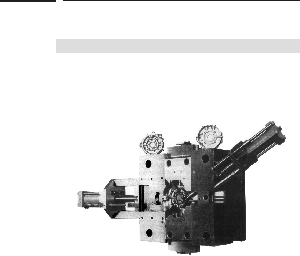
Figure2-3issinglecavitydieusesthemoveablediecomponents(slides)toproducecomplexfeaturesin
thepartshown.
2 Types of Die Casting Dies
ere are various types of die casting dies and each serves a critical need for the customer. e
choice of which type of die casting die the customer requires is usually determined by the following:
•Sizeoftheparttobecast
•Volumeofpartsrequired
•Requirementsfor“ family”setsofparts
•Desirabilityofcoreslides
•Requirementsforcast-ininserts.
2.1 Prototyping
Prototypes are usually requested by the customer to produce a small number of castings under
production conditions. ey enable thorough product testing and market exposure before com-
mitting to full production dies.
Only production from an actual die casting die can yield a part with precise die cast character-
istics. However, there is a range of prototyping strategies that can be employed to approximate
a die cast part for eventual production die casting. Among them: gravity casting, including the
plaster mold process; machining from previously die cast parts or from wrought and sheet stock;
and rapid prototyping techniques such as stereolithography (See the NADCA design manual,
Product Design for Die Casting.)
2.2 Rapid Tooled Dies
Rapid tooling is a term that refers to dies and inserts produced by methods shorter in lead-time
than the conventional method of rough machining, heat treating, and nish machining. Rapid
tooling methods include processes such as LENS (Laser Engineered Net Shaping), EBM (Elec-
tron Beam Melting), RSP (Rapid Solidication Process), SLS (Selective Laser Sintering), DMD
(Direct Metal Deposition), and high speed machining of unhardened steel or pre-hardened tool
steel. Investment casting, and KTEL may also be used. Tools produced by these methods may
be utilized as prototype or production dies. Production volume requirements may dictate which
rapid tooling methods are most viable.
2-5
NADCA Product Specication Standards for Die Castings / 2015
Tooling for Die Casting
2
Unit Holder + Cavity Block or Replaceable + Cavity
Cavity Unit` Insert
Customer Owned
Die Caster
Owned
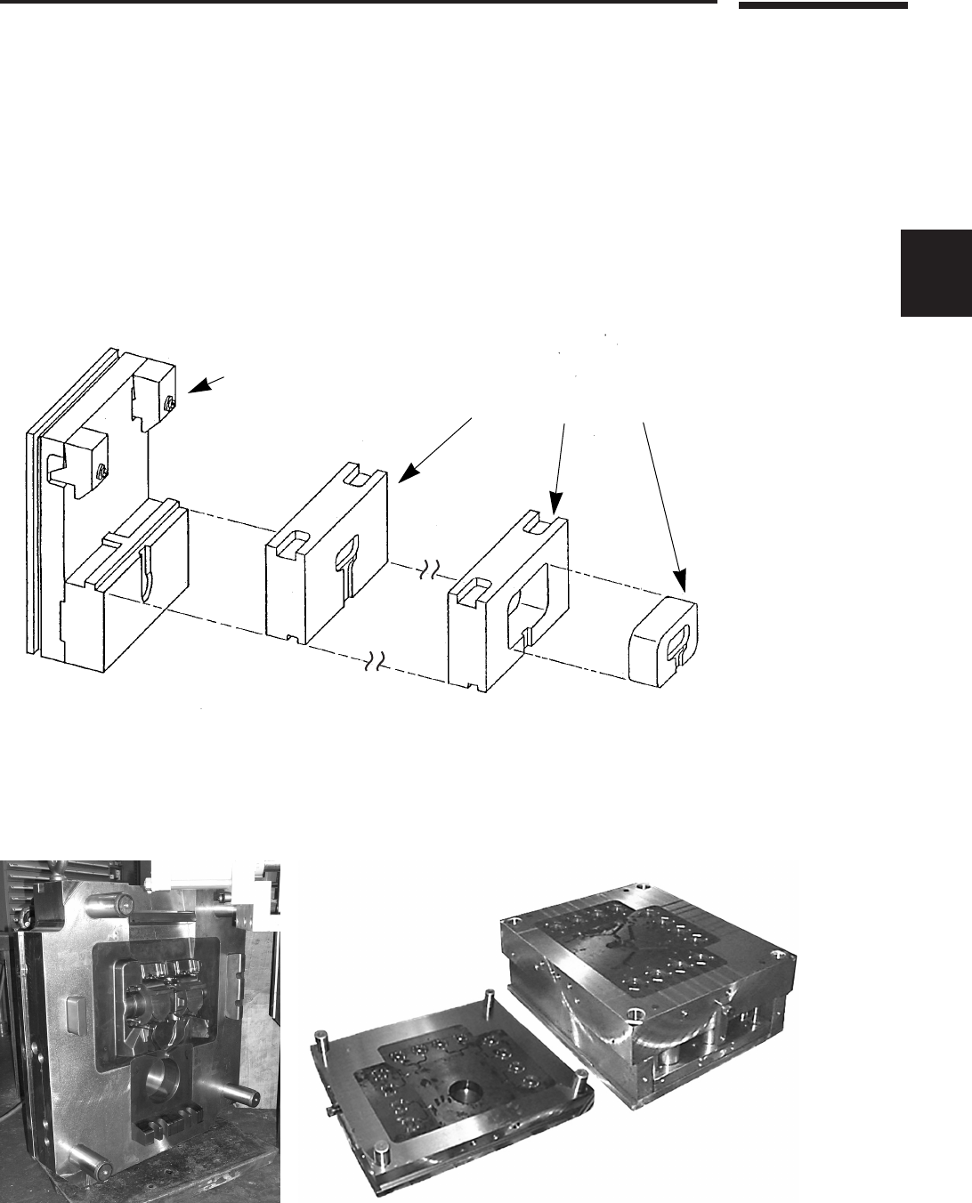
Figure2-4Componentsofaunitdieillustrateeachpartoftheassemblyandthedieconstructionoptionofacavity
blockoraholderblockwithcavityinsert.
Single-CavityDie
Multiple-CavityDie
2.3 Production Dies
ese are the most common types of tools produced. ey range from a single-cavity die, with
no slides, to a mulitple-cavity die with any number of slides. e cavities are made from high-
quality tool steel, retained in a quality holder block.
Production dies are built to critical dimensions, coring the maximum amount of stock from
the casting, and allowing the agreed-upon amount of machining. A unit die is a special type of
production die.

2-6
NADCA Product Specication Standards for Die Castings / 2015
Tooling for Die Casting
Figure2-5Photoonleftshowsuntrimmedzincdiecastingasitcomesfromthedie.Atright,thesamecasting
aftertrimming.
FamilyDie
2.4 Unit Dies
A unit die is a lower cost production tool that has a standardized main die frame and replaceable
cavity units. ese replaceable units are designed to be removed from the main die frame without
removing the standard frame from the die casting machine.
e most common commercial types of unit dies are single and double unit holders. ese
types of dies are generally used for smaller parts, or a family of parts, with no slides or a mini-
mum number of slides. Unit dies limit the use of core slides because of the conguration needed
for interchangeable unit inserts and the limited space available.
2.5 Trim Dies
e trim die is a tool that trims the runner, overows, and ash from the casting. e trim dies
are single or multiple cavity tools, made in the same conguration as the die casting die.
Depending on the shape of the casting, the trim die may be a simple open-and-close trim die
or it may include as many slides as the die casting tool. In some cases multiple station trim dies
will be used for successive trimming operations.
Trim dies require as much attention to detail in design as the die casting tools and the use of
quality materials should be specied to extend their productive life.
2-7
NADCA Product Specication Standards for Die Castings / 2015
Tooling for Die Casting
2
Figure2-6Mostcrackingcanbeeliminatedwithlargerradii.
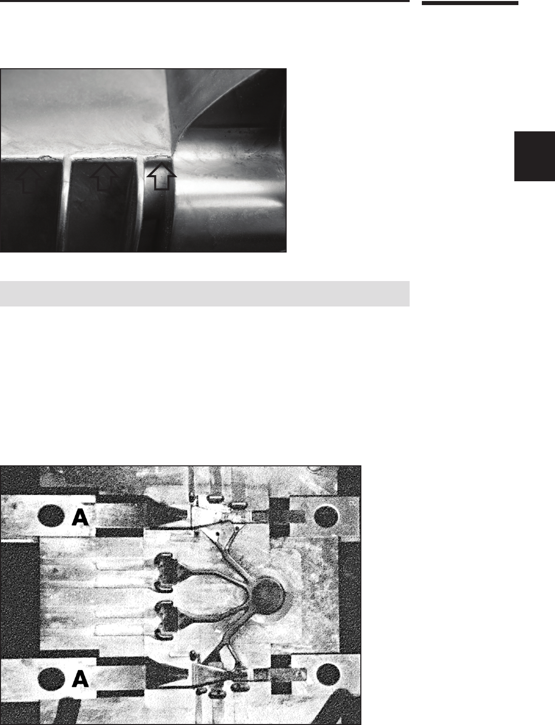
Figure2-7isejectordiehalfshowsthetwomoveablecone-shapedcoreslides,A,atleftwhichformthe
interiorofthediecastingsinthistwo-cavitydie.Oppositeslidesareattheright.
3 Casting Features and Die Considerations
e features that are required of a cast part determine the complexity of the die. e simpler the
part, the lower the cost of the die casting tool.
e customer should look at the casting in terms of total manufacturing cost. e die caster
will aid the customer in examining not only the part design’s castability, but also all of the
secondary operations that may be required.
Castability and die cost will be determined by answers to the following: Are the wall thick-
nesses as well as the ribs constant, or do they vary greatly? If bosses exist, do they vary widely in
diameter? Will any thin channels on the design create thin standing slivers of steel on the die? Is
the part number and other engraving recessed into, rather than raised out of, the casting, making
the die more dicult to machine? Are the cored holes that may be called for extremely small
in diameter and thus dicult to cast? Is the part designed with sharp corners, promoting stress
cracks or with generous radii? See the gure 2-6 and llet information on page 6-4.
2-8
NADCA Product Specication Standards for Die Castings / 2015
Tooling for Die Casting
Parting
Line "A"
Parting
Line "B"
Parting
Parting
Line “B”
Line “A”
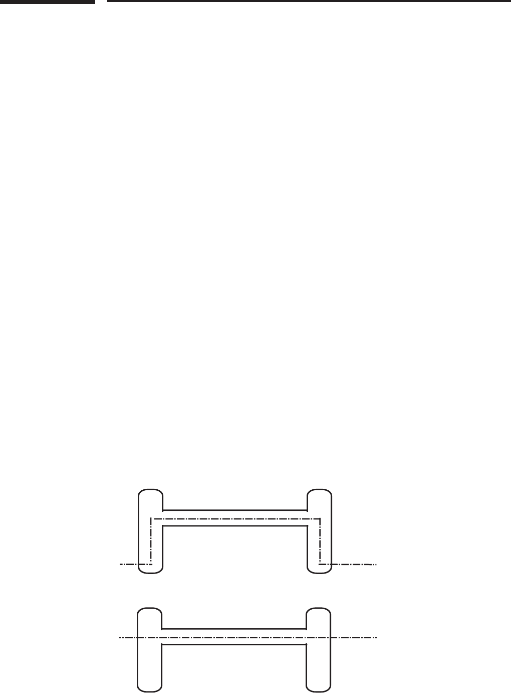
Figure2-8Steppartingline“A,”originallyplacedonthiscastingdrawingwouldnot
haveproducedthebestproductionresults.elocationofthepartingline“B”inthebottom
drawingwillallowbettercastingllandcleanercastingtrim,plusprovidelongerdielife
andalesscostlydietobuild.
For the proper design of production tooling, pressure tightness, secondary machining and
surface nishing specications must be understood in detail. Areas of the casting subject to
machining must be fully discussed at the outset, so that the die can be designed to reduce to an
absolute minimum the presence of porosity in those areas. Cosmetic surface requirements for the
casting will require specic steps in nishing the cavities of the die.
ese are among the types of questions that the customer should be prepared to discuss with
the die caster while reviewing the supplementary checklist at the end of this section.
e Engineering and Design sections provide detailed treatment of the tolerancing implications of
various casting design features, as well as guidelines which apply under diering casting conditions.
3.1 Core Slide Requirements
Fixed cores and core slides (or pulls) can be designed in the die to cast selected features in place,
eliminating the need for most – or all – secondary machining of the cast part.
Core slides, similar to collet or cam movements, can be activated by various sources of motion.
Two of the most common are angle pins and hydraulic cylinders.
e angle pin is a mechanical source of motion that is activated by the die opening and closing.
Its advantages are that it does not require hydraulics or limit switches, and is generally more
economical to manufacture. Its limitations are that it can be used only for short slide travel and
there is no control over the cycle of the slide pull. It is not recommended for use on top slides.
Although the use of springs can make this possible.
e hydraulic method of slide motion permits: a choice of cycles, the placement of slides on the top of
the die, and avoids interference when removing the casting from the die (as is the case with the angle pin).
Among the other methods of motion are rack and pinion, ejector lifter, and cam bars. e choice
of motion depends on factors such as production volume, size of die, length of travel of slide, size of
area being cored out and the conguration of the part. e die caster should be relied upon for the
optimum recommendations on core slides, also called moving die components or moving die parts.
3.2 Parting Line: Cover and Ejector Die Halves
e parting line is that perimeter on the casting which is the separation point of the two halves of the die
casting die. is line aects which half will be the “cover” die half and which will be the “ejector” half.
is line also inuences any tolerances that must be held in this area of the casting. Toler-
ancing standards specic to part characteristics at the parting line are presented in Engineer-
ing and Design, Section 4A.
2-9
NADCA Product Specication Standards for Die Castings / 2015
Tooling for Die Casting
2
Ejector Die
Die Casting
Û
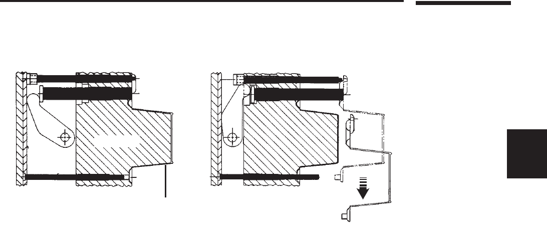
Figure2-9Ejectorpins,showninblack,arerecessedasthemetalllsthediecavity(aboveleft);thenactuate
sequentiallytoreleasethecastingfromthedie(above,right).
It is not obvious where the parting line on a casting drawing should be placed. Where the
parting line is indicated by the part designer, it is necessary for the die caster to conrm the
designer’s determination. Agreement on the optimum parting line location is essential for the
casting to be produced to the desired specications.
In the case of a part that must have a cosmetic surface, the cover half will generally be used to produce
the cosmetic surface. is permits the ejector half to contain the ejector pins, inserts and any engraving.
If there is no cosmetic surface requirement, the casting can be oriented to suit the most
favorable casting conditions. On cosmetic parts, the customer must discuss with the die caster
where the gate, overows and vents will be, to be certain that there is no interference or
blemish on the important cosmetic surfaces.
Where there are cosmetic requirements, since normal, incremental die erosion is inherent in
the die casting production process, the customer will want to discuss special die maintenance
procedures to extend the ability of the die to produce parts with the required high-quality
surface nish. Secondary operations to the surface of the part, such as polishing or bung,
should also be discussed to maintain cast part specications.
3.3 Ejector Pins
Ejector pins are used to push the casting out of the die after the metal shot has been made and
casting solidied. e location and size of the ejector pins are dependent on the conguration,
size, and other requirements of the casting.
e die caster will always attempt to locate ejector pins in a nonfunctional area of the casting, such as
in an overow, on a boss, in the bottom of a deep pocket, or the bottom of a rib. His recommendations
are important as to the size, location and number of ejector pins required for successful part production.
Each ejector pin must be sized to suit the casting conguration in the selected area and will leave
a slight impression on the cast surface. For this reason, they are not placed against the cosmetic
surface side of the part.
Product standards related to ejector pin locations are discussed in Engineering and Design, Section 6.
3.4 Cast-in Inserts
In some castings, there may be a need for a bearing surface, internal thread, or some other
unique feature that could be accommodated by an insert molded into the casting. is require-
ment can often be met by the die caster within the normal operation of the casting process.
is “insert molding” oers the advantage of rmly setting an insert into the casting so that it
can be machined, drilled and tapped. is advantage, however, rarely osets the added costs of the
insert casting operation.
e added costs result from reduced machine cycle time, due to loading the insert into the die
and the heating procedure required to heat the inserts before they are placed into the die half. is
preheating is recommended to avoid putting moisture into the die, allowing metal to chill around
the insert and causing the insert to loosen.

2-10
NADCA Product Specication Standards for Die Castings / 2015
Tooling for Die Casting
4 Die Materials
e grade of tooling materials to be used in the construction of a die casting die should be
specied as high quality, at a minimum, and preferable premium quality. ese requirements are
based on the extremely high temperatures and pressures used in die casting production.
Tooling grade requirements will vary depending on the tooling component, the alloy being die cast,
the critical character of the cast part design and the long-term production quantities desired. Every
aspect of the proposed product’s design and production specications must be discussed with the die
caster before tooling material can be selected. e following are typical tooling lowest requirements:
4.1 Die and Cavity Materials
• DieCastingDiesforZincAlloys:P-20,H-11,H13,PremiumGradeH13(PerNADCANo.229),
SuperiorGradeH13(PerNADCANo.229),orothergradesasdenedinNADCANo.229..
e zinc alloys, which cast at the lowest temperature in the nonferrous family, cause the least wear on
their tooling and thus permit the use of non-premium die material, such as P-20, in cases where part
designs are relatively simple. Purchasers are cautioned, however, to be aware of the unwise investment
in non-premium grade tooling for zinc parts if there is any possibility that production quantities may
reach higher levels than originally anticipated. At higher production levels, such tooling may expire
and the cost of replacement dies will far outweigh an original investment in premium material.
• DieCastingsDiesforAluminum,Magnesium&ZAAlloys
(Noncriticalpartdesigns,lowvolume):H-10,H-11,H13.
Aluminum, magnesium and ZA die casting dies require high quality tool steel, as above.
If part designs have very critical features or if high production runs are being contemplated,
however, premium grade tooling will always be the wisest investment.
• DieCastingDiesforAluminum,Magnesium,ZA-12&ZA-27Alloys
(Criticalpartdesigns,highervolume):PremiumGradeH13(PerNADCANo.229),Superior
GradeH13(PerNADCANo.229),orothergradesasdenedinNADCANo.229.
For Al, Mg, ZA-12, and ZA-27 die cast parts, H13 Premium or Superior Grade tool steel
is recommended whenever part design features are intricate and specications tight, and when
production volumes will be high. In such cases, non-premium grade tooling will nearly always
result in costly premature die failure.
• DieCastingDiesforBrassAlloys:H13
Since copper alloy die castings are cast at the highest temperatures of the nonferrous alloys,
only H13 high grade tool steel is recommended for brass die casting dies.
Metal certications for the material grades listed, provided by quality tooling material suppliers,
will be made available for inspection by the die caster. e H13 Premium or Superior Grade should
meet the NADCA No. 229 tool steel standard (Special Quality Die Steel and Heat Treatment
Acceptance Criteria for Die Casting Dies).
4.2 Die Cavity Insert Materials
e materials recommended for use as tool steel for die cavity inserts parallel the recommenda-
tions for die cavities, above, with some additions.
In addition to H13 Premium or Superior Grade, the maraging and speciality tool steels* are
used for die inserts needing higher hardness to improve their resistance to the heat checking
(thermal fatigue cracking) or crazing of the insert’s surface caused by thermal cycling of the
die from the high temperature molten alloy and die spray/die cooling. e ne cracks that may
result can produce corresponding veins on castings.
In high wear (erosion/washout) and temperature areas, especially if internal cooling and/or die
spray is dicult, small cores and inserts in aluminum die casting dies can eventually break or
wash away due to the velocity of the aluminum entering the cavity. Tungsten- and molybdenum-
based alloys are occasionally used successfully in these areas to resist these conditions. Although
these materials show superior physical properties compared to conventional steels at high
working temperatures, care must be used in machining them. Also, their increased cost must be
considered in the overall cost of the die and number of shots required (life of the die).
Note:
There are many die materi-
als available that vary in
both their chemical com-
positions and mechanical
properties. Developments
in high speed machining
and Wire EDM have led to
the use of a wide variety of
tool steels based on cavity
complexity and position
as the material relates to
the gate location. Specialty
tool steels have their own
specic properties but, if
used correctly, can increase
tool life by up to a factor
of two or more. It is also
important to note that they
usually are more costly as
noted in section 4.2. This
increased cost can be more
than offset by the increase
in die life achievable so it
is best to consult with the
die caster as to what some
of the options might be for
a given casting design. Spe-
cialty tool steels that do not
require heat treat or are pre-
heat treated before machin-
ing have been successfully
used in both Prototype and
Rapid Tooled Dies for early
production starts.
Some of the (but not limited
to) manufactures of these
specialty steels are Aubert
& Duval, Bohler, CMW,
Daido, Dunn Specialty
Steel, Elwood Specialty
Steel, Kind, Nippon
Koshuha, Schmolz & Bick-
enbach, and Uddeholm. It
is best to consult with the
die caster as to what some
of the tool steel options
are for individual casting
designs and die construc-
tion.
2-11
NADCA Product Specication Standards for Die Castings / 2015
Tooling for Die Casting
2
Conventional
Vent
Vacuum
Valve
Figure2-10Conventionalventinginadiecastingdie,shownatleft,ventsairtotheatmosphere.With
avacuum-equippeddie,metalispulledintoaclosedsystem,withairdrawnbythevacuummechanism.
Asignicantreductioninairentrappedinthecastingresultsinlowerporosity.
4.3 Die Steel Heat Treatment
e quality of the heat treatment of the die steel is a very critical step in the tool building process. e
use of high quality rapid quenching heat treatment procedures is essential to normal die life. Care
must be exercised in the heat treatment procedure to balance the issues of distortion with metallurgial
properties that result from rapid quenching. e recommendations of the die caster should be respected.
Just as tool steel source certications are made available by the die caster, so are the heat treat
certications from the selected heat treatment sources. is documentation will certify that the
heat treat was properly carried out to achieve the correct hardness and microstructure.
Tool steel heat treatment should be expected to follow NADCA No. 229 heat treatment guidelines
(Recommended Procedures for H13 Tool Steel) and the recommendations of the tool steel manufacturer.
5 Controlling Die Performance
5.1 Porosity Control: Gating, Venting and Vacuum
Although die castings can be expected to exhibit high strength and integrity, some product require-
ments can call for additional steps in the part design, die design and on-line production stages.
Designers seeking to avoid porosity concerns will be alert to such techniques as eliminating
thick wall sections in their designs. (See Product Design for Die Casting for general guidelines).
For specic designs, the engineer should always consult with an experienced die caster before
design parameters are locked in.
Given the nal part design, the die caster will follow specied die design guidelines, and
ow simulation (if available), incorporating die gating, overow and venting congurations to
evacuate air properly from the die cavity and reduce porosity to an acceptable level. Where pres-
sure tightness is not a casting specication, the process can be designed so that residual porosity
enters only non-functional, internal areas of the casting. Porosity is acceptable in non-critical areas.
While not a substitute for sound product and die design, a vacuum system can also be used to
enhance die ll, reduce gas porosity, and improve mechanical properties. A vacuum system is
designed to evacuate ambient air from within the die cavity during casting and create a negative
pressure or a vacuum. e die must be specially built to accept a vacuum system, so discussions
of acceptable porosity levels should be held well in advance of die design.
2-12
NADCA Product Specication Standards for Die Castings / 2015
Tooling for Die Casting
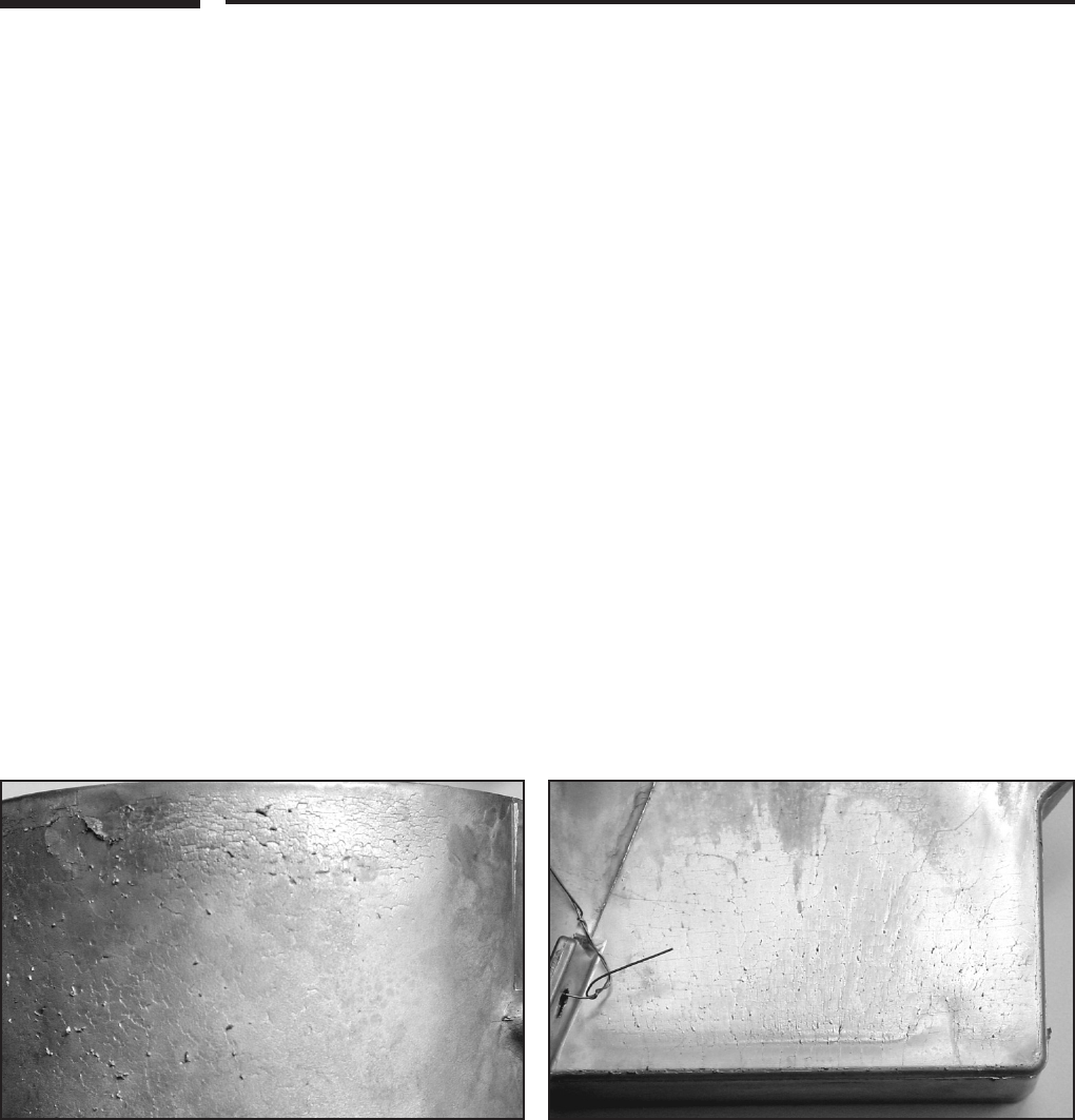
Figure2-11Heatcheckingasseenonacasting.
Figure2-12Washoutasseenonacasting.
5.2 Thermal Balancing
To achieve maximum product quality, the dies are required to run at a precise, specied tem-
perature. is temperature will vary with such factors as the size of the casting, number of die
cavities, alloy being cast and machine cycle time.
e alloy is injected into the die at this exact temperature at high speeds and then rapidly
cooled for ejection. is extremely fast and repeated cooling requires careful engineering of a
complex network of internal die temperature lines. Infrared imaging and thermocouples placed
in the die can help measure and maintain correct die temperatures.
Proper thermal balancing through the strategic placement of these lines reduces die casting
cycle time, improves casting quality, and lengthens the life of the die.
Dierent areas of the die can be heated or cooled to dierent temperatures, i.e., dierent cover
half and ejector half temperatures can be used to aid control of part density or surface nish.
5.3 Oil Heating Lines
In some cases dierential heating of various areas of the die to produce specic casting design
features will be achieved by the use of hot oil lines in the die.
Hot oil systems heat a special oil to a given elevated temperature and pipe it through the die in
the same manner as water cooling lines. Both water cooling and hot oil heating lines may be used.
5.4 Alternate Surface Textures
Using photoengraving techniques in making the die cavities, a wide range of patterns, grainings
and textures can be selected for permanent die casting into the surface of a part. e die caster
can exhibit actual samples of the common die cast textures possible. (For illustrations of sample
textures, see the Surface Treatment chapter of Product Design for Die Castings.)
5.5 Extended Die Life
While optimum die life begins with high quality tool steel, several patented processes are available
which can be used to extend the life of a die casting die. ese processes involve shot peening tech-
niques, submersion in special baths, and chemical treatments of the die. e die caster can discuss the
projected eectiveness of such steps to reduce premature die wear in the case of specic part design.
A typical failure mode of dies is heat checking or thermal fatigue cracking.
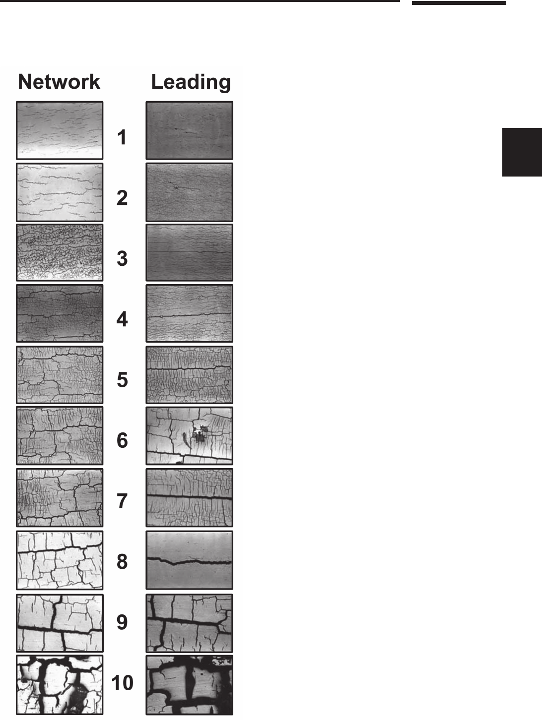
5.5.1 Heat Checking. Die Casting tools show small cracks (network) as well as bigger (leading)
cracks after some time in use, due to thermal fatigue. Both are important to tool life.
e scale in gure 2-13 is designed to give you a combined grading using both network and
leading crack values.
Compare the scales with your tool. Give the tool a grading from both scales. Add the two
gradings. ese two combined readings give you the degree of heat checking.
2-13
NADCA Product Specication Standards for Die Castings / 2015
Tooling for Die Casting
2
Figure2-13Photosofdiesurfacecrack
patternsreproducedapproximately70%of
actualsize.ediesteelheatcheckcondi-
tionsisreectedasraisedmaterialonthe
surfaceofthecasting.
CourtesyofUDDEHOLM

2-14
NADCA Product Specication Standards for Die Castings / 2015
Tooling for Die Casting
Determine at what point the die will no longer be useful. For critical surfaces, such as those to
be polished or chrome plated, you might stop using the die at a combined rating of six. For other
surfaces, especially those not seen by users of the nished product, the die might be used until
the rating is judged to be greater than 14. As the rating goes up, there is not only an aesthetic
loss but an economic loss in the production of the parts.
e scale also provides a concrete basis of comparison between dierent tools and number of shots.
6 Secondary Machining Preplanning
While most die castings are produced to near-net-shape, and many to net-shape, the close
tolerances possible with die casting and the repeatability of the process suits die cast parts to
economical high-precision secondary machining operations.
A die casting can be designed to accurately adapt to machining xtures by casting in locator
holes or casting a ush locating datum surface. Die castings can be drilled, tapped, reamed,
punched, or have nearly any type of machining operation performed on them.
Machining operations, including gaging and any other secondary operations that may be
required, can be performed by the die caster. Properly designing the part and the die for
optimum quality and economy in secondary machining will have an important impact on
reducing nal part costs. Detailed discussions should be held with die caster engineering
personnel to establish such machining parameters as the precise location, extent, and depth of
the machining required; the surface nish required; and any other specication necessary to
result in a quality component.
Decisions on special machining equipment ownership, maintenance and replacement must
also be discussed. Such matters are outlined in the Commercial Practices section of this manual
(page 8-1).
7 Gaging Considerations
What gages will be used in casting production and in secondary machining, and what they will
check, are important elements of the die casting program.
Gages may be used to check the casting in its as-cast state and again after machining. e gage may
be an attribute gauge, which is basically a “go” or “no-go” check and results in either a good or bad part.
A variable gage may also be employed which, used with a computer, can document variables,
collect data, and record Cpk’s.
More than one gage may be needed to check a casting: one to check it in its as-cast condition
and another to check the casting in a fully machined condition. ere may be a need for plug and
thread gages as well as nished gages or standards for painted surfaces.
e gaging should be considered by the customer as part of the tooling package. Gaging
requirements should be resolved early by the quality assurance managers of both the customer
and the die caster, so no questions remain on meeting the part print requirements.

2-15
NADCA Product Specication Standards for Die Castings / 2015
Tooling for Die Casting
2
8 Inherited Tooling
In some instances a customer may transfer a die casting die from one die caster to another.
is generally will raise some operational questions for the receiving die caster of which the
customer should be aware.
e die may need to be put into a dierent type of die casting machine. is may require some
modications to the die’s ejector system as well as to the shot sleeve, i.e. the entry for molten metal.
e die’s gate and runner system may also need to be modied to suit the new machine
conditions. It may be necessary for any residual oil in the hydraulic system of the die to be sent
out for sampling to assure that it does not contain any contaminants.
e die must be evaluated by the customer and the die caster’s tool room superintendent to
assure that there are no visual problems with the die. ey should also determine whether the die
arrived with any required limit switches and hydraulic cylinders.
Upon this review an adaptation cost can be established and agreed upon before the receiving
die caster has invested a large amount of time and expense in preproduction work.
Checklist T-2-1, at the end of this section, will aid in addressing questions regarding trans-
ferred or “inherited” tooling.
Die or tooling ownership and replacement is often a point of discussion. Information regard-
ing this topic can be found in Section 8.
9 Engineering Consultation
e customer company, in the person of its engineering and quality assurance personnel, will usu-
ally be requested to meet with the custom die caster’s engineering and quality assurance personnel
as early as possible to discuss the design and function of the part design proposed for die casting.
ey will discuss the design’s function, t and precise assembly with other components.
e die casting process uniquely lends itself to parts consolidation, decreasing the number of
components in a product assembly.
Early involvement with the die caster is essential in avoiding expensive corrective steps in later die
construction. It can often simplify product assembly and signicantly reduce total product costs.
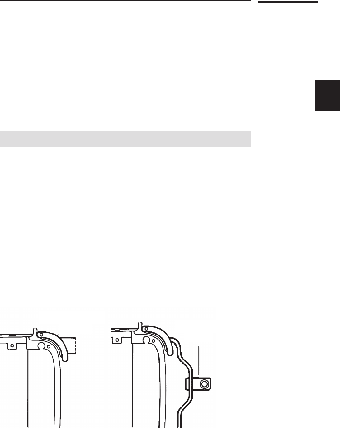
For example, an attached hinge bracket could be die cast as an integral part of the casting. A
slight design modication could assure clearance for a close assembly.
e die caster may be able to cast an integral bearing in the part that the customer was
planning to press in. Or the die caster may be able to perform a complete or partial assembly
operation more economically, such as installing a gasket after painting the casting, and shipping
the part ready for assembly. Many die casters have in-house capabilities for operations such as
pressure testing, impregnating, machining, surface nishing and subassembly.
e experienced die caster should be regarded as a invaluable source of expertise in the die
casting production and assembly process.
Depending on part conguration, very small high-volume zinc parts, weighing fractions of an
ounce, may be recommended for production on special hot-chamber zinc die casting machines.
Such parts, usually called “miniature” or “microminiature” die castings, can be cast ash-free,
with zero draft, to very close net-shape tolerances.

2-16
NADCA Product Specication Standards for Die Castings / 2015
Tooling for Die Casting
10 Database Guidelines
When databases are utilized, quotations for castings are often based on the assumption that any
CAD databases provided to build tooling and produce parts are complete, usable and are without
need of updating.
Databases may be deemed incomplete and unusable if:
1. egeometryofthepartisnotphysicallymoldable.
2. enecessarydraftandradiiarenotincorporated.
3. Lineandsurfacegeometryarenotconnectedwithin0.001”.
4.Partinglineisnotfullydeveloped.
Note: e database le format may not be compatible with existing capabilities and may
require a translator. STL les are usually only used for creation of prototype parts.
Any necessary database manipulation that is caused by incompleteness as described above
could add cost and extended lead-time to tooling.
If databases are designed only to nominal dimensions, tool life and casting tolerances may be
adversely impacted.
If solid model databases are used for tool construction, they should be accompanied by a
limited dimension part print (either paper or database) that contains all tolerancing information
and information pertaining to any secondary machining that is to be performed to the part.
e revision control for databases should be as agreed upon between the die caster and customer.
11 New Die/Inherited Die Specifications
Checklist T-2-1, which follows, will aid in discussions between the customer and the die caster
regarding the important considerations in the design of a new die casting die or in the produc-
tion of parts from “inherited” tooling.
12 Die Life
Die casters are frequently asked the question, “How many shots will I get from the die before
it needs to be replaced?” or “How many shots will you guarantee the die for?” A better question
might be, “What can we do to maximize die life and to minimize replacement costs?”
Aluminum and Copper die casting dies wear out due to the aggressive nature and high
melting temperatures of the materials being die cast.
Die life is a consideration of part design, part function, internal part requirements and part
cosmetics. In general, cosmetic areas of the part do not last as long as functional areas.
e following is a suggested approach to be used by the customer and die caster at the time of
part design. e intent is to dene critical areas of the die casting before the start of tool design.
is allows areas to be inserted to maximize die life and minimize the replacement costs.
First, is to develop a rating scale by which this information can be used to relate part considerations
to estimated tool life. A guideline (T-2-2) has been developed and includes; a Die Life Checklist,
sample part, example of tool steel inserting and identication matrix starting on page 2-19

2-17
NADCA Product Specication Standards for Die Castings / 2015
Tooling for Die Casting
2
13 Checklist for Die Casting Die Specifications (To be used in consultation with your Die Caster)
Part 1 — New Die Casting Dies: Items to be Addressed
In the case of new die casting dies, all of the items in Part 1, below, should be reviewed. Note, in
the case of tooling to be transferred to, or “inherited” by a die caster, the items asterisked (*) in
Part 1 should be addressed, plus the items noted in Part 2 on the next page.
Type of
New Die
Prototype Die Casting Die
Production Die Casting Die
Cavity Steel*
H13
Premium Grade H13
Superior Grade H13
Othe r To ol S t eel: __________________________________________________
NADCA No. 229 Certification Required: Yes No Grade Class
Cavity Steel
Heat Treat*
Hardness Required:
T ou ghn e s s R equ ir e d: ______ f t.- lbs
NADCA No. 229 Certification Required: Yes No
Cored Holes*
All Holes Cored
Cored Holes As Noted On Print
No Cored Holes
Die Operation
for Part
Features*
Mechanical Movement
Hydraulic Movement
Features To Be Achieved By Secondary Operations
Estimated
Part Volume
Mon thly : _______________________________________________________________
Ann ual: ________________________________________________________________
E xpec t e d P rod uct L ife: _________________________________________________
Casting Alloy*
Aluminum
Copper
Magnesium
Zinc
ZA
Alloy
_____________________
_____________________
_____________________
_____________________
_____________________
_____________________
Casting Weight
Est i mate d Ca s ting We ight : _____________________________________________
As-cast Part
Finish*
Mechanical Grade (Functional Finish) (Ref. 125 Ra)
Painting Grade (Ref 63 Ra)
Highest Quality (Cosmetic Finish) For Plating, Etc. (Ref. 32 Ra)
*Die wear can affect surface finish over the life of the die.
Class of Die
Unit Die
Conventional Die
Single Cavity
Multiple Cavity
Multiple Cavity - Family Die
Cast-In Date
Insert*
In Die Cavity
Othe r Require ment s : ______________________________________________
Not Required
Cast-In Part
Number*
In Die Cavity
Othe r Require ment s : ______________________________________________
Not Required
Other
Write in any other special requirements (ie. tolerances, leak testing, x-rays):
____________________________________________________________________________________
NADCA
T-2-1-15
Checklist
This two-part specification
checklist is intended for
use in consultation with
your die caster prior to
estimation of new die
design and construction,
or prior to die casting
production using “inher-
ited” tooling. It should be
used in combination with
checklists C-8-1 and C-8-2
in Commercial Practices,
Section 8.

2-18
NADCA Product Specication Standards for Die Castings / 2015
Tooling for Die Casting
Part 2 — New Die Casting Dies: Items to be Addressed (Continued)
Cast-In Logo,
Lettering*
In Die Cavity Other
Inc lude: ________________________________________________________________
Customer Logo Cavity No.
Supplier Logo Revision No.
Recycling Logo Part Number
Die Layout
Customer to Approve Layout
Approval by Die Caster
First-Piece
Approval
Customer Approval Before Production Run Required
Run on Die Caster Approval PPAP
Gages*
Customer to Supply Special Gages
Die Caster to Supply Special Gages
Trim Die
Mechanical Movement
Hydraulic Movement
Features To Be Achieved By Secondary Operations
Machining
Fixtures
No Secondary machining required
Machining reguired, no special fixtures
Special machining fixtures required, customer to supply
Special machining fixtures required, die caster to supply
Special Items
Special Items to be included in the tooling package:
_________________________________________________________________________
_________________________________________________________________________
Part 3 — Inherited Die Casting Dies: Additional Items to be Addressed
In the case of inherited tooling, not the asterisked items (*) in Part 1, plus the items below.
Note that with transferred, or “inherited,” tooling for die casting production the existing die casting
die, the trim die, and, if required, the secondary machining xtures, must be available for review and
evaluation to determine whether the dies and xtures are capable of producing to specications and the
extent of maintenance and/or rework required before the onset of production. is would include any
adaptations of the die caster’s equipment to accommodate production using the inherited dies. Final
production estimates will be based on this review.
Inherited Die
Die Casting Die Available for Evaluation
Die to be Availa ble for E va luat ion (d ate): __________________________
Inherited
Trim Die
Trim Die Not Required
Trim Die Available for Evaluation
Trim Di e to be Avail able for Eva lua t ion (date): _____________________
Inherited
Machining
Fixtures
Special Machining Fixtures Not Required
Machining Fixtures Available for Evaluation
Mac hining Fixtures to b e Ava ila ble f or E val uati on (d a te): __________
Actual Casting
Weight
Wei ght of Actua l Ca stin g: ______________________________________________
Size of Die
Siz e of Ca s ting Die (for equ ipme nt limi tatio ns): _________________________
Weight of Die
Wei ght of Cas t ing Die (f or c ran e li mit a t ion s): ___________________________
Availability
of Die Design
Yes
No
PublishergrantspermissiontoreproducethischecklistaspartofadiecastingRequestforQuotationorProductionSpecication.
NADCA
T-2-1-15
Checklist
This two-part specification
checklist is intended for
use in consultation with
your die caster prior to
estimation of new die
design and construction,
or prior to die casting
production using “inher-
ited” tooling. It should be
used in combination with
checklists C-8-1 and C-8-2
in Commercial Practices,
Section 8.

2-19
NADCA Product Specication Standards for Die Castings / 2015
Tooling for Die Casting
2
14 Guidelines to Increase Die Life
Before the start of tooling
1)Redesignofparttoreduceoreliminatesharpinternalscornersorfea-
turesthatwillpromoteearlycrackingofthetoolsteel.
2)Useofspecialtoolsteelsinareaswherehighwearisexpected(increases
toolcosts).
3)Insertarea’sofcavityblocksformoreeconomicalreplacement(may
increasetoolcosts)aftertoolwearhasoccurred.
4)Doasurfacetreatment(shotblasting)tothetoolsteeltohelpreduce
heatcheckingandcracking(addstotoolcost).Note:iswilladda
surfacetexturetothediecastpart.
5)Addavibratory,shotblastordeburringoperationtotheparttohelp
extendtoollife(addedpartcost).
6)Addamachiningoperationtoremoveheatcheckingand/orcrackingin
areasthatarecriticalonthepart(addstopartcost).
7)Reclaimthesurfacehardness,ifpossible,whenitdropsfromthe40’s
HRCtothehigh30’sHRC.
8)Coatingscanbeappliedtothediesurfacetoreducewearandsoldering.
9)Useinternalcoolinginsteadofdiespraytocoolthedie.Sprayisonlyto
beusedasareleaseagent.
Die Life Checklist
Class
Part
Consideration
A
Critical to
Function &
Cosmetic
B
Cosmetic,
No Function
C
Critical to
Function
D
Not Critical
but Functional
E
No Function
Class
Estimated
Die Life/Shots
1
Less than
10,000
2
10,000 to
25,000
3
25,000 to
50,000
4
50,000 to
100,000
5
More than
100,000
Using the above will
develop and itemize the
areas of concern of a
sample part.
NADCA
T-2-2-15
Guideline

2-20
NADCA Product Specication Standards for Die Castings / 2015
Tooling for Die Casting
Sample Part
Sharp Corners
Non-Functional
Functional
Cosmetic
Non-Functional
Sealing Surface
Mounting Surface
O-ring Surface
Tool Steel Insert Construction
Insert #
Part Consideration
Estimated Die Life
Radius
B5
C3
E5
E5
D4
C3
C3
1
32
6
7
5
4
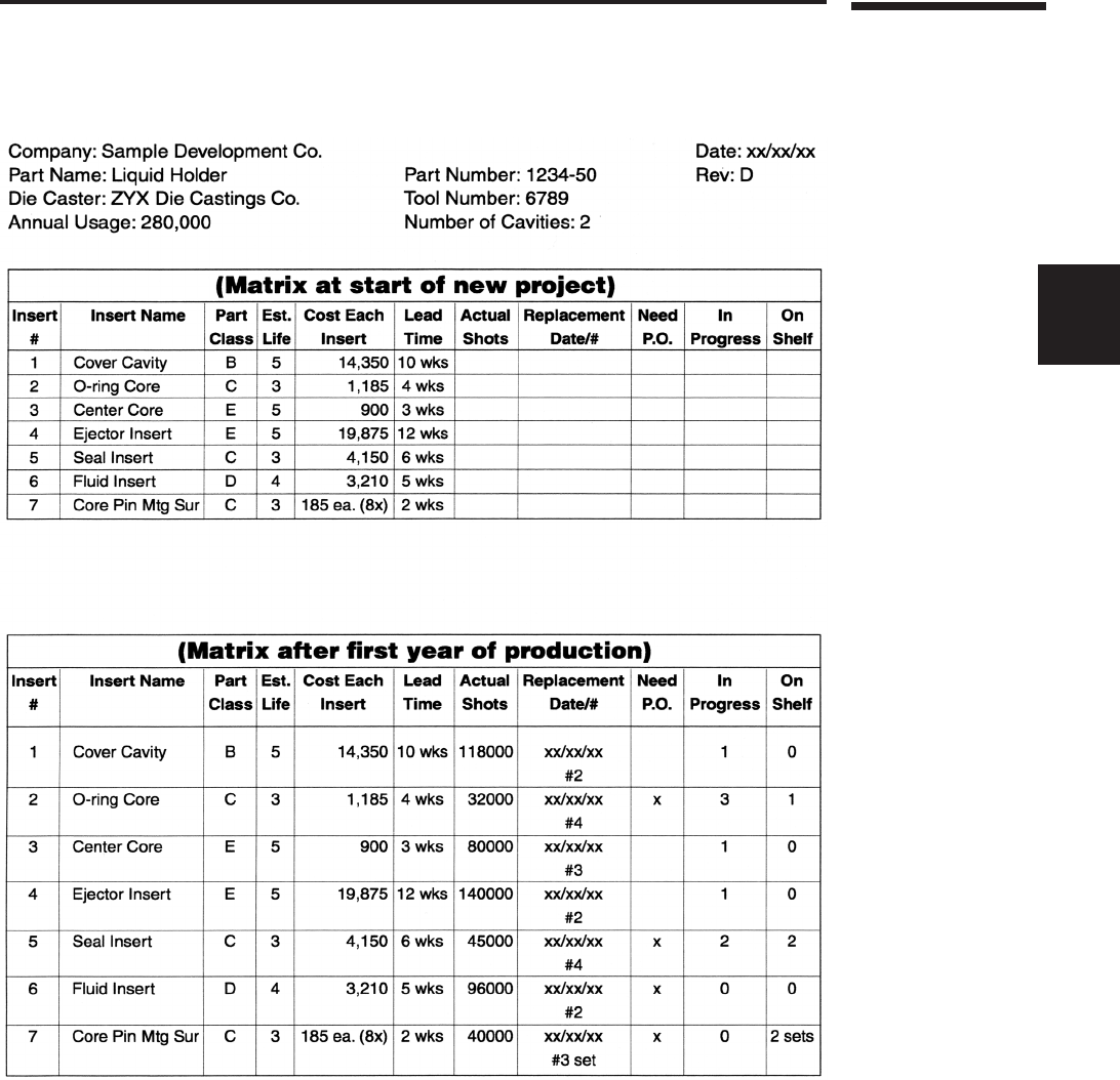
Using the sample, the next step is to develop an inserting plan for the tool steel construction.
Last is to develop the matrix for communication of tool steel replacement needs and to develop
history on each insert. (e information shown in this example represents only what can be
done. e actual information to be included should be determined by the customer and the die
caster). Two examples of this type of matrix are shown, at the start of a new project and the other
as it may appear after the rst year of production.
2-21
NADCA Product Specication Standards for Die Castings / 2015
Tooling for Die Casting
2
As mentioned earlier this is just a suggested approach to improving die life and reducing replace-
ment costs. Die casting dies do wear out. It is an advantage to both the customer and the die
casters benet to layout a plan at the start of the project. is allows inserts to be replaced before
any actual failure thus preventing any possible loss of production. e examples shown are only
one of many possible methods to achieve this. If the customer and die caster choose to use this
type of approach, it should be on a part by part basis. e information in the matrix should be
relevant to the actual tool construction and the actual annual usage.

2-22
NADCA Product Specication Standards for Die Castings / 2015
Tooling for Die Casting
