TC900EPWR04-02T-14446
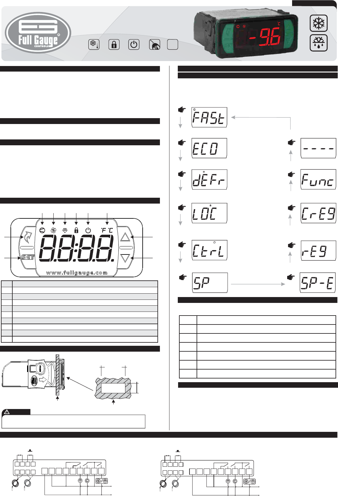
4. INDICATIONS AND KEYS
1
2
3
4
5
6
7
8
9
10
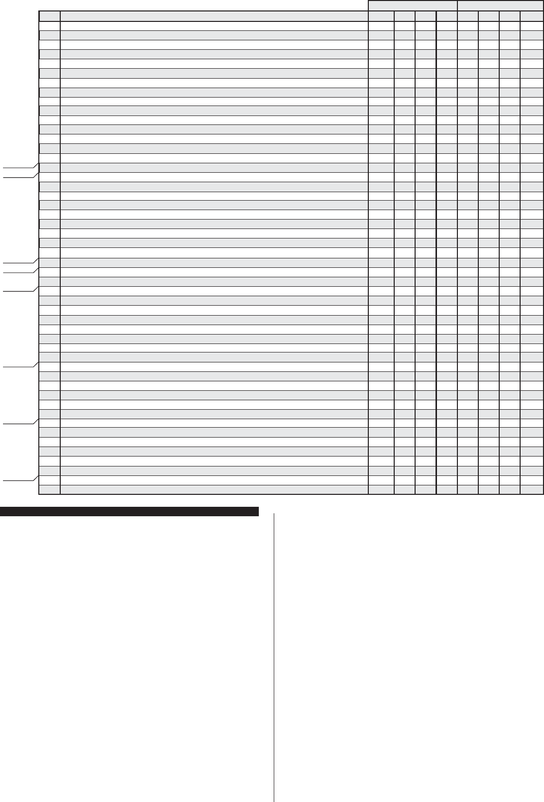
5.1 INSTALLATION - ELECTRICAL CONNECTIONS
6. OPERATIONS
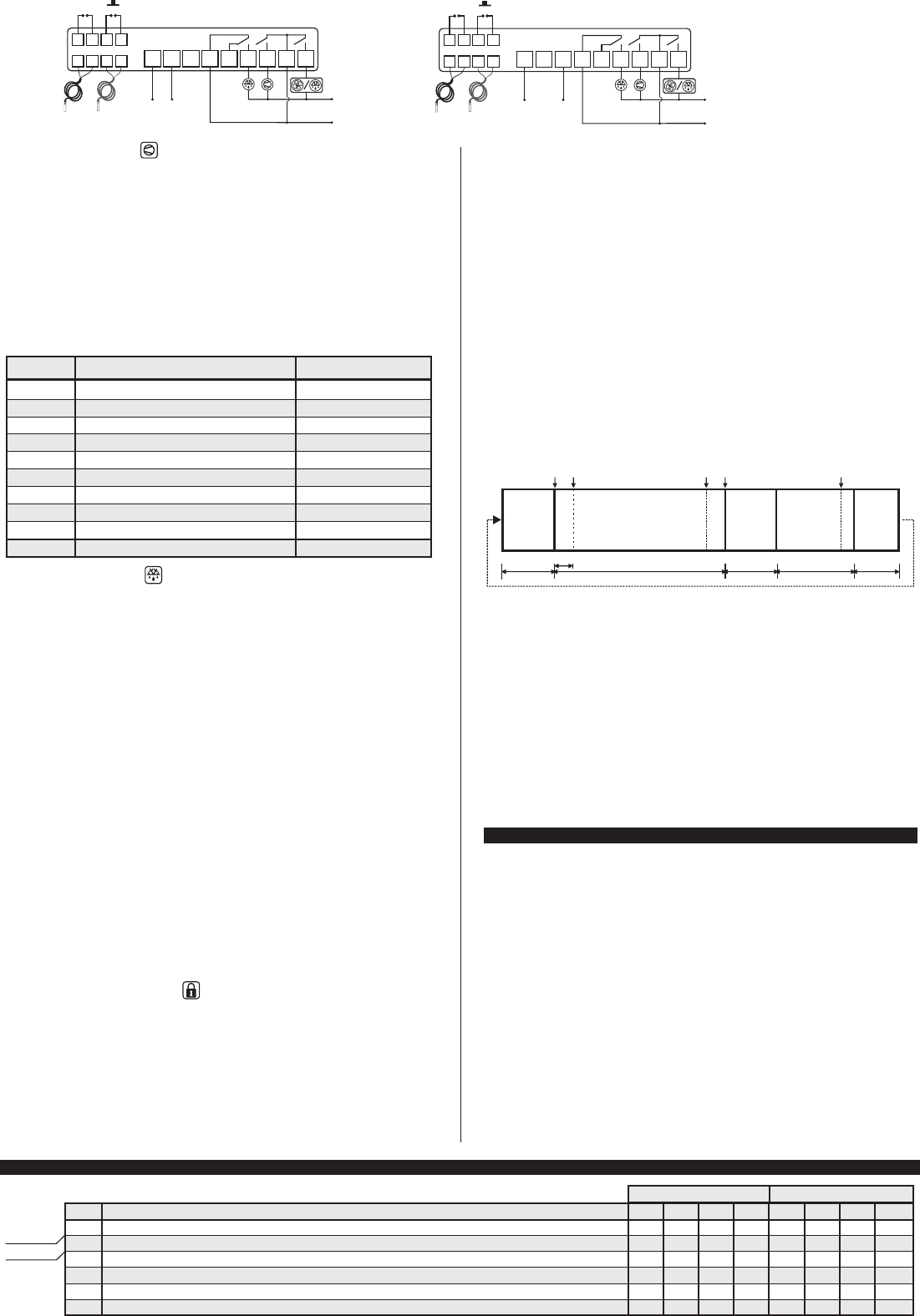
6.1 Quick Access Menu Map
To access or navigate the quick access menu using the ;(short press) key while the controller is
displaying the temperature. For every touch, the next function in the list is displayed. To confirm, use the
/(short press) key.
5
43
2
9
8
7
6
1
10
6.2 QUICK ACCESS KEYS MAP
When the controller is on temperature display, the following keys serve as a shortcut for the following
functions:
1. DESCRIPTION
2. APPLICATION
3. TECHNICAL SPECIFICATIONS
For frozen products, it automates the defrost processes according to the need of installation (smart
defrost). The ambient temperature control has a normal setpoint and an economic setpoint, apart from
the fast freezing function and alarm functions indicating open door. Its 16A relay directly controls
compressors of up to 1HP and its defrost output has a current capacity of 10A.
It also features a digital filter, intended to simulate a mass increase in the ambient sensor (S1), thus
increasing its response time (thermal inertia) and avoiding unnecessary drives of the compressor. It also
includes a smart key, lock system and a control functions shutdown mode.
To drive inductive loads (motors and pumps) of up to 2HP, use the eTC-900 2HP.
• Cold Storage Rooms
• Display freezers
- Power supply: TC-900 E POWER: 115 or 230Vac ±10% (50/60Hz)
TC-900 EL POWER: 12 or 24Vac/dc ±10%
- Control temperature: -50°C to 105°C / -58°F to 221°F
- Operating temperature: 0 to 50°C / 32 to 122°F
- Load current (outputs): COMP: 12(8)A / 240Vac 1HP
DEFR: 10A / 240Vac 1/4HP
FANS: 5(3)A / 240Vac
- Operating humidity: 10 to 85 %RH (without condensation)
- Dimensions: 76 x 34 x 77 mm (WxHxD)
- Dimensions of the clipping for fixing of the instrument: 71 ± 0,5 x 29 ± 0,5 mm (see item 5)
evolution
TC-900 e POWER
Ver
.04
Connection 115 Vac
TC-900 e POWER
/
<
<
<
<
Pressed for 2 seconds: Setpoint adjustment.
Short press: Displays process status.
Short press: display of minimum and maximum measurement records.
Enters the functions selection.
6.3 BASIC OPERATIONS
6.3.1Setting the desired temperature
To access the setpoints setup menu press / for 2 seconds. The message [SP,,] will appear on the
display followed by the normal setpoint set value. Use the > or< to modify the value and confirm by
pressing /. Immediately, the message [SP-e] appears indicating the setting of the economic
setpoint. Again, use the > or < keys to modify the value and confirm by pressing /. Finally, the
[----] indication signals the setup completion. The setpoints can also be adjusted individually in the
quick access menu.
TC-900
e
POWER
TC-900
e
POWER
<
Pressed for 2 seconds: inhibits audible alarm.
<
Pressed for 2 seconds: when displaying records, it cleans the history.
1
5
6
7
8
2
3
4
9 10
11 12
13
14
15 16
17
Sensor S1
D1/S3
D2
Sensor S2
230 Vac
COMP
DEFR
FANS /
Panel (Front View)
Panel
(Side View)
Dimension of the clipping
for fixing of the
instrument in panel
71 mm± 0,5
29 mm± 0,5
FOR INSTALLATIONS WHERE A SEALING IS REQUIRED TO AVOID LIQUID CONTACT, THE CUT FOR THE CONTROLLER
MUST BE OF 70,5x29mm MAXIMUM. THE SIDE LOCKS MUST BE FIXED SO IT PRESSES THE RUBBER SEALING
AVOIDING INFILTRATION BETWEEN THE CUT AND THE CONTROLLER.
ATTENTION
DEFR 2
;
Enters the quick access menu.
1
5
6
7
8
2
3
4
9 10
11 12
13
14
15 16
17
Sensor S1
D1/S3
D2
Sensor S2
COMP
DEFR
Connection 230 Vac
115 Vac
FANS /
DEFR 2
5. INSTALLATION - ASSEMBLING
and
Control functions
shutdown
Functions
lockdown
Serial
programming
Protection
level
IP 65
FRONT
Fast Freezing
FAST FREEZING (ON/OFF)
;
TC-900 e POWER
;
ECONOMIC SETPOINT(ON/OFF)
TC-900 e POWER
;
DEFROST (ON/OFF)
TC-900 e POWER
;
FUNCTIONS LOCKDOWN
TC-900 e POWER
;
CONTROL FUNCTIONS
(ON/OFF)
TC-900 e POWER
NORMAL SETPOINT
;
TC-900 e POWER
ECONOMIC SETPOINT
;
TC-900 e POWER
MAX. AND MIN. TEMPERATURE
RECORD
;
TC-900 e POWER
ERASE MAX. AND MIN.
VALUES
;
TC-900 e POWER
EXIT FUNCTION
;
TC-900 e POWER
FUNCTION SELECTION
;
TC-900 e POWER
*The sensor S1 (black)
must be in the ambient.
*The sensor S2 (gray) must
be placed in the evaporator
through metallic cramp.
Set key
Quick Access Menu Key
Compressor output indication LED
Fan/defrost indication LED 2
Defrost indication LED
Functions lock indication LED
Control functions shutdown indication LED
Temperature unit indication LED
Increase key
Decrease key
DIGITAL CONTROLLER FOR
REFRIGERATION AND DEFROST
6.3.8 Control functions shutdown
The shutdown of the control functions allows the controller to operate only as a temperature indicator,
keeping the control outputs and alarms off. The use of this feature is enabled or disabled by the
shutdown function of the control functions (F56). When enabled, the control functions and alarms are
switched off ([CTRL][OFF,]) or on ([Ctrl][ON,,]) in the quick access menu through the
[Ctrl] option. When the control functions are off, the message [OFF,]is displayed alternating with
the temperature and other messages.
6.3.9 Stage of the process, elapsed time and temperature in
sensors S2 and S3
The operating status of the controller can be displayed by pressing the > key (short press). A
sequence of messages will be shown, indicating the current process, time (hh:mm) already elapsed in
this stage, temperature in the evaporator (S2) and temperature in S3. If the sensors are disabled, their
measurements will not be displayed.
Stages of the process:
[dEL,] Initial delay (delay at start of the instrument)
[Fan,] Fan-delay (delay for return of the fan)
[rEFr] Cooling
[Pre,] Pre-Defrost
[dEFr] Defrost
[dRAi] Drainage
[OFF,] Control functions off
6.3.10 Minimum and Maximum Temperature Record
The display of the minimum and maximum temperature record can be requested through the quick
access menu or by pressing the < key while displaying the temperature. The minimum and maximum
temperatures recorded for each sensor are displayed in sequence preceded by identification messages
[rEg,], [,t-1] for ambient sensor (S1), [,t-2] for S2 (when active) and [,t-3] for S3 (when
active). To delete the minimum and maximum recorded values, hold the < button for 2s when
displaying records or use the [CrEg]option in the quick access menu. The [rSET] message
indicates that the records have been deleted.
6.3.11 Unit Selection
To select the unit in which the instrument will operate enter the [,F01] function with access code
[,231] and press the / key. Then, select the desired unit [,=C,] or [,=F,] using the
<>keys. To confirm, press /. Whenever the unit is changed, the function settings assume the
default value, therefore needing to be reconfigured.
6.3.7 Functions Lockdown
The use of the functions lockdown provides greater safety for the instrument's operation. With it active,
the setpoint and other parameters are visible to the user, but protected against unauthorized changes.
To activate the functions lockdown, access the[LOC,]function in the quick access menu. The
message [no,,](lockdown must be enabled and deactivated), with it on display hold down the>
key for the time set for functions lockdown (F55), the activation is indicated by the message [LOC,]
[On,,]. To enable the use of this function it is necessary that the time for functions lockdown (F55) is
set to a value greater than or equal to 15 seconds. The [LOC,] message when trying to change the
parameters indicates that the functions lockdown is active. To deactivate it, turn the controller off and on
again with the > key pressed. Keep the key pressed until the message [LOC,][OFF,] indicates
unlocking (10 seconds).
6.4 ADVANCED OPERATIONS
The functions menu can be accessed through the quick access menu, option [Func] or
simultaneously pressing < and > while displaying the temperature. To allow changing the
parameters, enter [,F01] by pressing / (short press), and using the < or > keys enter code 123
(one hundred and twenty three). Confirm with /. To modify the other functions, navigate the menu
using the < or > keys and follow the same procedure to set them. To exit the menu and return to
normal operation, press and hold/ until [----] appears.
NOTE: If the functions lockdown is active when pressing the < or > keys, the controller will show the
[LOC,] message on the display and will not allow the setting of parameters.
6.3.2 - Fast Freezing
In the fast freezing mode the cooling output remains permanently activated, thus accelerating the
cooling or freezing process. This operating mode can be activated or deactivated in the quick access
menu through the [FASt] option or through an external switch connected to the digital input (F49 or
F50). It can also be deactivated automatically by time (F15) or by low temperature (F14). During
operation in the fast freezing mode, the compressor on indication flashes quickly and defrost keeps
happening. If, when activating the fast freezing mode, the controller identifies that there is a defrost
scheduled to start by time in this period, the defrost will be performed immediately before entering the
fast freezing mode.
6.3.3 - Economic setpoint (SPE)
The [SP-E] provides the system with greater economy by using more flexible parameters for
temperature control (F06 - Economic Setpoint and F07 - Control Differential). When active, the
[ECO,] message is displayed alternating with the temperature and other messages. The operation in
economy mode can be activated or deactivated through the commands:
Function
Command
Action
6.3.4 Manual defrost
The defrost process can be activated/deactivated manually in the quick access menu through the
[defr]option or the external switch connected to the digital input (F49 or F50). Activation or
deactivation will be indicated by the messages [defr][On,,] or [defr][OFF,] respectively.
6.3.5 How to determine the end of defrost by temperature
a) Reconfigure the listed functions at the end of the defrost to the maximum value:
- Cooling time (Interval between defrosts) F3=999min
- Evaporator temperature to end defrost F28=105°C / 221°F
- Maximum defrost time F23=0 (OFF)
b) Wait for a while until a layer of ice forms in the evaporator.
c) Perform a manual defrost (using the ;scroll key up to [dEFr] and press /).
d) Follow the melting process.
e) Wait until all of the ice in the evaporator has melted to consider the process completed.
f) With the defrost finished, check the evaporator temperature (S2) using the > key (see section
6.3.9).
g) Using the value read in S2, set the temperature for end of defrost
- Evaporator temperature for end of defrost F28 =Temp. S2
h) For safety, reset the (maximum defrost time), according to the type of defrost set.
Eg:
- Electrical defrost (by resistance) F23=45min
- Hot gas defrost F23=20min
i)Finally, set the cooling time (F3) at the desired value.
6.3.6 Defrost with two evaporators
With S3 configured for the 2nd evaporator (F49), the Fan output allows control of the second resistance.
Defrost always starts with the two outputs triggered. The resistors are shut down individually as their
evaporators reach the temperature to end defrost. With the two outputs off or having the maximum
defrost time elapsed, the draining process is started. With these settings, all the features of the Fan are
disregarded, including the Fan Delay process.
FAN-DELAY COOLING
PRE-DEFROST
MAX. F33 IF F25=0 F03 F22
F31
F34
Unlock
the indication
IF F25=1
F27
Lock the display
if enabled on F31
DEFROST DRAINAGE
MAX. F23 F32
F28
Connection 12 Vac/dc
1
5
6
7
8
2
3
4
9 10
11 12
13
14
15 16
17
Sensor S1
D1/S3
D2
Sensor S2
COMP
DEFR
FANS /
DEFR 2
24 Vac/dc
1
5
6
7
8
2
3
4
9 10
Sensor S1
D1/S3
D2
Sensor S2
Connection 24 Vac/dc
11 12
13
14
15 16
17
COMP
DEFR
FANS /
DEFR 2
12 Vac/dc
6.5 TABLE OF PARAMETERS
CELSIUS
FAHRENHEIT
Min
Max
Unit
Fun
[,F01]
[,F02]
[,F03]
[,F04]
[,F05]
[,F06]
Min
Max
Unit
Access code: 123 (one hundred and twenty-three)
Delay at start (energization)
Cooling time (interval between defrosts)
Normal setpoint
Normal setpoint control differential (hysteresis)
Economic setpoint
Loads supply
Initial delay
Cooling
*The sensor S1 (black)
must be in the ambient.
*The sensor S2 (gray) must
be placed in the evaporator
through metallic cramp.
Description
Standard Standard
Loads supply
-
F49 / F50
F10
F11
F12
F49 / F50
F13
F13
-
-
Activates / Deactivates
Activates / Deactivates
Activates
Deactivates
Stays activated
Stays deactivated
Deactivates
Stays deactivated
Stays deactivated
Deactivates
Action through quick access menu ([ECO,])
External key (digital input)
Closed door time to activate
S3-S1 temperature difference to deactivate
S3-S1 temperature difference to activate
Open door indication (digital input)
Maximum time in economy mode
Maximum time in economy mode =0(no)
Error in ambient temperature reading (S1)
When switching on the instrument
0
0 (no)
1
-50
0.1
-50
999
30
999
105
20
105
-
min.
min.
°C
º C
º C
0
0 (no)
240
-15
2.0
-10
-
min.
min.
°F
°F
°F
0
0
1
-58
-58
-58
999
30
999
221
36
221
0
0 (no)
240
5
3
14
F01-Access code:
It is necessary when one wants to modify the configuration parameters or the temperature unit. To only
view the adjusted parameters, it is not required to enter any access code.
[,123] It allows modifying the advanced parameters
[,231] It allows choosing the temperature unit, Celsius or Fahrenheit
F02 - Delay at start (energization):
With this function enabled, when the instrument is energized it only indicates temperature, remaining
with all the outputs off during the set time. In installations with multiple equipment, assigning different
values for the delay time at the start of each instrument, it is possible to avoid power surges by activating
the loads at different times.
F03 - Cooling time (interval between defrosts):
When defrost is set to start by time (F25), this function sets the maximum time for the cooling process. In
this case defrost will start whenever the elapsed time in cooling mode reaches the value set in this
function. If the condition for starting defrost is temperature in the evaporator and the controller is not
indicating a reading error in this sensor, the cooling time will not be taken into account.
F04 - Normal setpoint:
It is the desired temperature in the room to be cooled. It is the reference value for temperature control.
F05 - Control differential (normal hysteresis):
It is the temperature difference (hysteresis) between TURNING ON and OFF the cooling control output
in normal and Fast Freezing mode.
F06 - Economic setpoint (SPE):
It is the desired temperature in the room to be cooled when the instrument is operating in economy
mode.
F07 - Control differential (economic hysteresis):
It is the temperature difference (hysteresis) between TURNING ON and OFF the cooling control output
in economy mode.
6.5.1 Description of parameters
F08 - Minimum setpoint allowed to the end user:
Electronic stop whose purpose is to prevent that, by mistake, the setpoint temperature is set
unreasonably low.
F09 - Maximum setpoint allowed to the end user:
Electronic stop whose purpose is to prevent that, by mistake, the setpoint temperature is set
unreasonably high.
F10 - Time for closed door to enter economy mode:
If the door is kept closed for a time greater than or equal to that set in this function and the normal setpoint
is or has already been reached, the controller activates the economy mode. With this, it starts operating
with the economic setpoint until any condition for deactivation is met (see 6.3.3). This function is disabled
when set to [no,,](0).
F11 - Temperature difference (S3-S1) below which the economic setpoint is activated:
When the temperature difference between sensor 3 and sensor 1 is less than the value set in this
parameter, the controller starts operating in economy mode
F12 - Temperature difference (S3-S1) above which the normal setpoint is activated:
When the temperature difference between sensor 3 and sensor 1 is greater than the value set in this
parameter, the controller starts operating with normal setpoint.
F13 - Maximum time in economy mode:
It allows setting the maximum time of operation of the economy mode. After this time, the setpoint returns
to normal operating mode. If configured as[tOFF]this time is disregarded.
F14 - Temperature limit for Fast Freezing:
It is the minimum temperature that the instrument can achieve during the fast freezing.
F15 -Fast Freezing time:
It is the duration of the fast freezing process.
F17]
[,F18]
[,F19]
[,F20]
[,F21]
[,F22]
[,F23]
[,F24]
[,F25]
[,F26]
[,F27]
[,F28]
[,F29]
[,F30]
[,F31]
[,F32]
[,F33]
[,F34]
[,F35]
[,F36]
[,F37]
[,F38]
[,F39]
[,F40]
[,F41]
[,F42]
[,F43]
[,F44]
[,F45]
[,F46]
[,F47]
[,F48]
[,F49]
[,F50]
[,F51]
[,F52]
[,F53]
[,F54]
[,F55]
[,F56]
[,
Fan on time
Fan off time
Compressor status with ambient sensor (S1) disconnected
Compressor on time in case of S1 failure
Compressor off time in case of S1 failure
Time for gas collection before starting defrost
Maximum defrost time
Defrost type (0-Electric / 1-Hot gas)
Condition for starting defrost (0-Time / 1-Temperature)
Time of open door for instant defrost
Temperature at evaporator (S2 / S3*) to start defrost
Temperature at evaporator (S2 / S3*) to determine the end of defrost
Fan on during defrost
Defrost at start of instrument
Temperature indication (S1) locked during defrost
Draining time (dripping of defrost water)
Maximum time for fan return after drainage (fan-delay)
Evaporator temperature (S2) for fan return after drainage
Minimum time for compressor on
Minimum time for compressor off
Fan stop for high temperature in evaporator (S2)
Time of open door to shut down fan
Time of open door to shut down control outputs
Maximum temperature at condenser (S3) to shut down control outputs
Control differential for maximum temperature in the condenser (hysteresis)
Compressor on time without reaching the setpoint to shut down the control outputs
Low ambient temperature alarm (S1)
High ambient temperature alarm (S1)
Ambient temperature alarm inhibition time
High temperature in condenser alarm (S3)
Time of open door to give alarm
Enable Buzzer (0-Disabled / 1-Enabled)
Digital input 1 function / Sensor S3
Digital input 2 function
Ambient temperature S1 indication offset
Evaporator temperature S2 indication offset
Temperature indication offset of sensor S3
Intensity of digital filter applied to sensor 1 (0-deactivated)
Time for functions lockdown
Control functions shutdown
CELSIUS
FAHRENHEIT
Min
Max
Standard
Unit
Description
Fun
F07]
[,F08]
[,F09]
[,F10]
[,F11]
[,F12]
[,F13]
[,F14]
[,
Min
Max
Unit
[,F15]
[,F16]
Economic setpoint control differential (hysteresis)
Minimum set point allowed to the end user
Maximum set point allowed to the end user
Time for closed door to enter economy mode
Temperature difference (S3-S1) below which the economic setpoint is activated
Temperature difference (S3-S1) above which the normal setpoint is activated
Maximum time in economy mode
Temperature limit for Fast Freezing
Maximum time of Fast Freezing
Fan operating mode during cooling
Pre-defrost
Defrost
Drainage
Fan-delay
Protections
Alarms
Inputs
Operation
Standard
1
1
0
0
0
0 (no)
0 (no)
0
0
0 (no)
-50
-50
OFF
0 (no)
-1 (no)
0 (no)
0 (no)
-50
0 (no)
0 (no)
-50
-1 (no)
0 (no)
0 (no)
0.1
0 (no)
-50
-50
0 (no)
0
0 (no)
OFF
0 (OFF)
0 (OFF)
-20
-20.1 (OFF)
-20
0
14 (no)
0 (no)
99
99
2
999
999
999
90
1
1
999
105
105
On
1
99
99
30
105
999
999
105
999
999
105
20
999
105
105
99
105
999
On
13
10
20
20
20
9
60
2
min.
min.
-
min.
min.
min.
min.
-
-
min.
°C
º C
-
-
min.
min.
min.
º C
sec.
sec.
º C
min.
min.
º C
°C
min.
º C
º C
min.
º C
min.
-
-
-
º C
º C
º C
-
sec.
-
2
8
1
0
0
0 (no)
30
0
0
0 (no)
-5.0
30.0
On
0 (no)
-1 (no)
1
1
20.0
60
60
30.0
-1 (no)
0 (no)
55.0
1.0
0 (no)
-50
105
0 (no)
45.0
0 (no)
OFF
0 (OFF)
0 (OFF)
0.0
0.0
0.0
0
14 (no)
0 (no)
min.
min.
-
min.
min.
min.
min.
-
-
min.
°F
°F
-
-
min.
min.
min.
°F
sec.
sec.
°F
min.
min.
°F
°F
min.
°F
°F
min.
°F
min.
-
-
-
°F
°F
°F
-
sec.
-
1
1
0
0
0
0 (no)
0 (no)
0
0
0 (no)
-58
-58
OFF
0 (no)
-1 (no)
0 (no)
0
-58
0 (no)
0 (no)
-58
-1 (no)
0 (no)
32 (no)
1
0 (no)
-58
-58
0 (no)
32
0 (no)
OFF
0 (OFF)
0 (OFF)
-36
-36 (OFF)
-36
0
14 (no)
0 (no)
99
99
2
999
999
999
90
1
1
999
221
221
On
1
99
99
30
221
999
999
221
999
999
221
36
999
221
221
99
221
999
On
13
10
36
36
36
9
60
2
2
8
1
0
0
0 (no)
30
0
0
0 (no)
23
86
On
0 (no)
-1 (no)
1
1
68
60
60
86
-1 (no)
0 (no)
131
1
0 (no)
-58
221
0 (no)
113
0 (no)
OFF
0 (OFF)
0 (OFF)
0
0
0
0
14 (no)
0 (no)
0.1
-50
-50
0 (no)
0.1
0.1
0 (no)
-50
0 (no)
0
20
105
105
999
20
20
100(tOFF)
105
999
7
º C
º C
º C
min.
°C
°C
h
º C
min.
-
2.0
-50
105
0 (no)
2.0
5.0
0 (no)
-25
0 (no)
0
°F
°F
°F
min.
°F
°F
h
°F
min.
-
1
-58
-58
0 (no)
1
1
0 (no)
-58
0 (no)
0
36
221
221
999
36
36
100(tOFF)
221
999
7
3
-58
221
0 (no)
3
9
0 (no)
-13
0 (no)
0

F34 - Evaporator temperature (S2 / S3) for fan return after drainage:
After drainage starts the fan-delay cycle. The compressor is driven immediately, because the evaporator
temperature is high, but the fan is only activated after the temperature in the evaporator decreases from
the set value. This process is necessary to remove the heat still existing in the evaporator because of the
defrost, thus avoiding throwing it into the environment.
F35 - Minimum time for compressor on:
It is the minimum time the compressor will stay on, that is, the time interval between the last start and the
next stop. It serves to prevent voltage spikes in the power grid.
F36 - Minimum time for compressor off:
It is the minimum time the compressor will stay off, that is, the time interval between the last stop and the
next start. It serves to relieve discharge pressure and increase the service life of the compressor.
F37 - Fan stop for high temperature in evaporator:
The purpose of this function is to shut the evaporator fan down until the ambient temperature
approaches that predicted in the refrigerating installation project, avoiding high temperatures and
suction pressures that can damage the compressor. During the cooling process, if the evaporator
temperature exceeds the set value, the fan is turned off, turning it on again with a hysteresis fixed at
0,1°C/1°F. This is a valuable feature when, for example, refrigeration equipment that has been inactive
for days is put into operation or when storage rooms or display freezers are restocked.
F38 - Open door time to shut down fan:
For safety reasons, after an open door time greater than or equal to that defined in this function has
elapsed, the fan will be shut down in the cooling stage. This function is disabled when set to [no,,]
(-1).
F39 - Open door time to shut down control outputs:
For safety reasons, after an open door time greater than or equal to that defined in this function has
elapsed, the outputs will be shut down (compressor, fan and defrost). This function is disabled when set
to[no,,] (0).
F40 - Maximum temperature at condenser (S3) to shut down control outputs:
Above this temperature, beyond the visual and sound alarm indications ([aC2,]), the loads activated
by the outputs will be disconnected. In case the S3 input is set (F49) for another function, this alarm is
deactivated. This alarm is ignored until the instrument reaches the control temperature for the first time.
F41- Control differential (hysteresis) for sensor S3 when set as sensor of the condenser:
For the loads to be reconnected, the temperature of sensor S3 (condenser) will need to descend to the
value set in F40 minus the value set in this parameter.
F42 - Compressor on time without reaching the setpoint to shut down the control outputs:
It is the maximum time until which the compressor can remain on without reaching the setpoint during the
cooling process. When this time has elapsed, the outputs will be shut down (compressor, defrost fan)
and a visual and sound alarm [ALrC] will also be triggered. This function can be disabled if set to the
minimum value [no,,] (0).
F43 - Low ambient temperature alarm (S1):
It is the ambient temperature (S1) below which the instrument will indicate a low temperature visual and
sound alarm ([alo,]) (F48). The differential for the alarm's shutdown is fixed at 0.1°C/1°F. This alarm
is ignored until the instrument reaches the control temperature for the first time. During the Fast Freezing
operation mode, the low temperature alarm is disabled; it will be enabled automatically when the Fast
Freezing process finishes and the temperature reaches a value highter than the alarm value.
F44 - High ambient temperature alarm (S1):
It is the ambient temperature (S1) above which the instrument will indicate a high temperature visual and
sound alarm ([aHi,]) (F48). The differential for the alarm's shutdown is fixed at 0.1°C/1°F. This alarm
considers the temperature shown on the display, being so influenced, by temperature indication locked
during defrost (F31). The alarm is ignored until the instrument reaches the control temperature for the
first time.
F45 - Alarm inhibition time by temperature:
With this configuration active, the temperature will need to remain in the alarm condition during the
inhibition time set, for the alarm to be indicated. That way one can prevent alerts resulting from specific
temperature variations, and after defrost.
F46 - Temperature of sensor S3 (condenser) to give an alarm:
It is the condenser's temperature (S1) above which the instrument will indicate a high temperature visual
and sound alarm ([aC1,]) (F48). In case the S3 input is set (F49) for another function, this alarm is
deactivated. This alarm is ignored until the instrument reaches the control temperature for the first time.
F47 - Time of open door to give an alarm:
If the door is left open for a time greater than or equal to that set in this parameter, the controller will
activate a visual and sound "open door" alarm (F48). The alarms are suspended upon closing the door.
The audible alert can be inhibited by pressing the > key (hold for 2s). For the "open door" alarm to
operate, it is necessary to configure one of the digital inputs as door contact (F49 and F50). This function
is disabled when set to [no,,] (0).
F48 - Enabling the buzzer:
It allows enabling and disabling the internal buzzer for alarm signaling.
F49 - Function of digital input1 / sensor S3:
[Off,]Not in use
[,,,1]Digital input: Activate economic setpoint (N.O. push-button)
[,,,2]Digital input: Perform defrost (N.O. push-button)
[,,,3]Digital input: Perform fast freezing (N.O. push-button)
[,,,4]Digital input: External alarm (N.O.)
[,,,5]Digital input: Door contact (N.O.)
[,,,6]Digital input: Activate economic setpoint (N.C. push-button)
[,,,7]Digital input: Perform defrost (N.C. push-button)
[,,,8]Digital input: Perform fast freezing (N.C. push-button)
[,,,9]Digital input: External alarm (N.C.)
[,,10]Digital input: Door contact (N.C.)
[,,11]Sensor S3: Temperature differential for economic setpoint (S3-S1)
[,,12]Sensor S3: Condenser temperature control
[,,13]Sensor S3: Temperature control of second evaporator
F50 - Function of digital input 2:
[Off,]Not in use
[,,,1]Digital input: Activate economic setpoint (N.O. push-button)
[,,,2]Digital input: Perform defrost (N.O. push-button)
[,,,3]Digital input: Perform fast freezing (N.O. push-button)
[,,,4]Digital input: External alarm (N.O.)
[,,,5]Digital input: Door contact (N.O.)
F19 - Compressor status with ambient sensor (S1) disconnected:
If the ambient temperature sensor (S1) is short-circuited, disconnected or out of the measuring range,
the compressor assumes the set status in this function.
[,,,0]Compressor off
[,,,1]Compressor on
[,,,2]Cycling according to the times defined in F20 and F21.
F20 - Compressor on time in case of S1 failure:
F21 - Compressor off time in case of S1 failure:
They define the length of time the compressor is on and off, in case it is being driven in cyclic mode. This
condition occurs if sensor S1 is disconnected (or faulty) and if parameter F19 is set to [,,,2].
F22 - Time for gas collection before starting defrost:
When defrost starts, the controller will maintain, during this time, only the fan on exploiting the residual
energy of the gas. In the case of defrost in energization, this time will be disregarded.
F23 - Maximum defrost time:
This parameter is used to set the maximum allowed time for the defrost process. If at the end of this
period the defrost process is not finished by temperature, a dot will stay flashing on the lower right-hand
corner of the display. If sensor 2 is shut down, the end of the defrost process will always be determined
by time, so there is no need for a warning sign. When the maximum ice time is set to 0 ([no,,]) the
defrost process stops.
F24 - Defrost type:
[,,,0] Electrical defrost (by resistance), where only the defrost output is triggered
[,,,1] Hot gas defrost, where the compressor and defrost outputs are triggered
F25 - Condition for starting defrost (0-time / 1-temperature):
It sets the condition for starting the defrost process:
[,,,0]Time
[,,,1]Temperature
Before entering the defrost process, the controller will respect the compressor's minimum time on or off
(F35 and F36) and the gas collection stage (F22).
F26 - Maximum open door time for instant defrost:
If in the cooling stage the door is kept open for a period greater than that defined in this function, instant
defrost will occur. In case the door is open at the beginning of the cooling process, the count of this time
is restarted. This function is disabled when set to [no,,] (0).
F27 - Temperature at evaporator (S2 / S3) to start defrost:
When the evaporator temperature is lower than the value set in this function, the controller will start
defrost. If sensor S3 is set as a sensor of the second evaporator (F49), the controller will start the defrost
soon as any of the two sensors, S2 or S3, meets this condition. In case the condition to start defrost
(F25) is time, this function is ignored.
F28 - Temperature at evaporator (S2 / S3) to determine the end of defrost:
When the evaporator temperature is greater than or equal to the value set in this function, defrost will be
terminated. If sensor S3 is set as a sensor of the second evaporator (F49), the controller will shut down
the defrost outputs individually and the defrost process will be terminated when the two of them are off.
F29 - Fan on during defrost:
It defines whether the fan will always stay on or off during defrost. They are examples using the fan on, in
cases of natural defrost and defrost by finned resistors installed outside the evaporator.
F30 - Defrost at start of instrument:
It allows defrost to happen at the time the controller is energized, like for example when power returns
(in case of power failure).
F31 - Temperature indication (S1) locked during defrost:
This function is intended to prevent the visualization of a rise in ambient temperature due to defrost.
During defrost, the last temperature measured in the cooling cycle will be locked on the display. The
indication will be released after the start of the next cooling cycle, when this temperature is reached
again or exceeds the time set in this function (whichever comes first). This function can be disabled if set
to [no,,] (-1) .
F32 - Draining time (dripping of defrost water):
Time required for dripping, i.e. to drain the last drops of water from the evaporator. During this period, all
outputs remain off. If this step is not desired, set this time to [no,,].
F33 - Maximum time for fan return after drainage (fan-delay):
For safety reasons, in case the evaporator temperature does not reach the set value in function F34 or
sensor (S2 / S3) is disconnected, the fan return will happen after the time set in this function has
elapsed.
F17 - Time of fan on:
F18 - Time of fan off:
They define the length of time the fan is on and off, in case it is operating in cyclic mode.
0
1
2
3
4
5
6
7
Fan Relay ON
Fan Relay ON
Fan Relay ON
Fan Relay ON
Fan Relay ON
Fan Relay ON
Fan Relay ON
Fan Relay ON
Mode
Comp. Relay ON
Fan Relay CYCLING
Fan Relay CYCLING
Fan Relay CYCLING
Fan Relay ON
Fan Relay ON
Fan Relay ON
Fan Relay OFF
Fan Relay OFF
Comp. Relay off with
Normal or FF SP
Comp. Relay off with
Economic SP
Fan Relay CYCLING
Fan Relay ON
Fan Relay OFF
Fan Relay CYCLING
Fan Relay ON
Fan Relay OFF
Fan Relay CYCLING
Fan Relay OFF
F16 - Fan operating mode:
This parameter allows setting how the fan output will behave during the cooling cycle. In this case, its
operating options consider the compressor's output status and the setpoint the instrument is operating
with. When set to cycle, the on and off times are defined by F17 and F18.
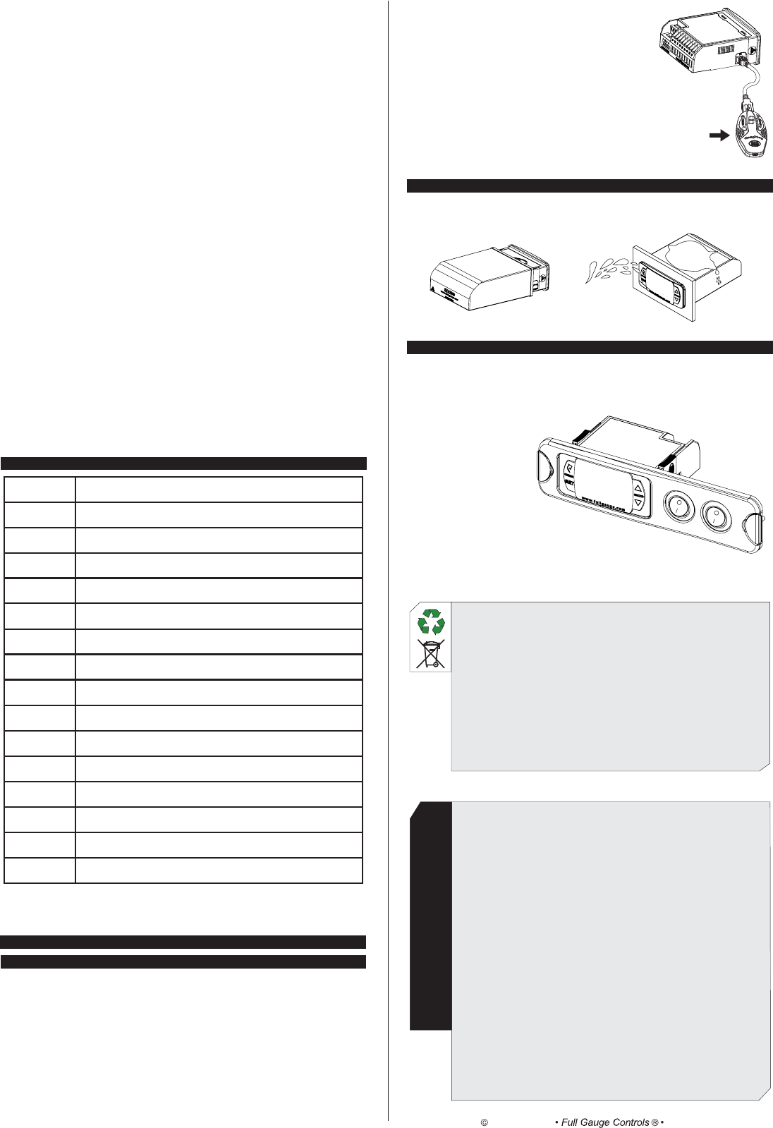
8. OPTIONAL ITEMS - Sold Separately
8.1 EasyProg ver. 02
It is an accessory that has as its main function to store the parameters of the controllers. At any time, you
can load new parameters of a controller and unload them on a production line (of the same controller), for
example. It has three types of connections to load or unload the parameters:
- Serial RS-485: It connects via RS-485 network to the controller (only for controllers that have RS-485).
- USB: it can be connected to the computer via the USB port, using Sitrad's Recipe Editor. The parameters
can be copied, edited and saved in EasyProg ver. 02. The USB port can also have the function of
electrically feeding the EasyProg ver. 02 and the controller (when the USB and Serial TTL are
used together).
ENVIRONMENTAL INFORMATION
Packaging:
The materials used in the packaging of Full Gauge products are 100% recyclable. Try to
perform disposal through specialized recyclers.
Product:
The components used in Full Gauge controllers can be recycled and reused if
disassembled by specialized companies.
Disposal:
Do not incinerate or dispose the controllers that have reached the end of their service as
household garbage. Observe the laws in your area regarding disposal of electronic
waste. If in doubt, please contact Full Gauge Controls.
8.2 Ecase
Protective cover for controllers (Evolution line), which prevents the entrance of water and inner moisture. It
protects the product when washing is carried out in the location where the controller is installed.
- Serial TTL: The controller can be connected directly to EasyProg
ver. 02 by the TTL Serial connection. Thus the EasyProg ver.
02 may be fed by , or vice versa. TC-900 e POWER
8.3 Extension Frame
The Full Gauge Controls extension frame allows the installation of Evolution / Ri line with measures
76x34x77 mm (dimensions of the clipping for fixing in the extension frame is 71x29mm) in varied
situations, since it eliminates precision cut to embed the instrument. Allows customization via a sticker with
the brand and the company contact, and accompany two 10A (250 Vac) switches that can trigger internal
light, air curtain, on / off system or fan.
WARRANTY - FULL GAUGE CONTROLS
Products manufactured by Full Gauge Controls, as of May 2005, have a two (02) year
warranty, as of the date of the consigned sale, as stated on the invoice. They are guaranteed
against manufacturing defects that make them unsuitable or inadequate for their intended
use.
EXCEPTIONS TO WARRANTY
The Warranty does not cover expenses incurred for freight and/or insurance when sending
products with signs of defect or faulty functioning to an authorized provider of technical
support services. The following events are not covered either: natural wear and tear of parts;
external damage caused by falls or inadequate packaging of products.
LOSS OF WARRANTY
Products will automatically lose its warranty in the following cases:
- The instructions for assembly and use found in the technical description and installation
procedures in Standard IEC60364 are not obeyed;
- The product is submitted to conditions beyond the limits specified in its technical
description;
- The product is violated or repaired by any person not a member of the technical team
of Full Gauge Controls;
- Damage has been caused by a fall, blow and/or impact, infiltration of water, overload
and/or atmospheric discharge.
USE OF WARRANTY
To make use of the warranty, customers must send the properly packaged product to Full
Gauge Controls together with the invoice or receipt for the corresponding purchase. As much
information as possible in relation to the issue detected must be sent to facilitate analysis,
testing and execution of the service.
These procedures and any maintenance of the product may only be provided by Full
Gauge Controls Technical Support services in the company's headquarters at Rua Júlio de
Castilhos, 250 - CEP 92120-030 - Canoas - Rio Grande do Sul – Brasil
---
EasyProg ver. 02
Copyright 2013
All rights reserved.
Rev. 03
[Err1]
[Err2]
[Err3]
[eCAL]
[ALrE]
[eCO,]
[Opn,]
[AOPn]
[Ahi,]
[Alo,]
[AC1,]
[AC2,]
[ALrC]
[OFF,]
[,,,,.]
[pppp]
7. SIGNALS
Ambient sensor disconnected or out of range.
Evaporator sensor disconnected or out of range.
Sensor 3 disconnected or out of range.
Instrument not calibrated.
External alarm (digital input).
Operating with economic setpoint.
Open door indication.
Open door alarm indication.
High ambient temperature alarm (sensor1).
Low ambient temperature alarm (sensor1).
High temperature in condenser alarm (level 1).
High temperature in condenser alarm (level 2).
Compressor reached the maximum time on without reaching the SP.
Control routines off.
It indicates that the temperature for end of defrost has not been reached.
Loss of parameters.
[,,,6]Digital input: Activate economic setpoint (N.C. push-button)
[,,,7]Digital input: Perform defrost (N.C. push-button)
[,,,8]Digital input: Perform fast freezing (N.C. push-button)
[,,,9]Digital input: External alarm (N.C.)
[,,10]Digital input: Door contact (N.C.)
F51- Ambient temperature S1 indication offset:
This function allows compensating for eventual deviations in the ambient temperature reading (S1),
resulting from the change of sensor or modification of the cable length.
F52 - Evaporator S2 temperature indication offset:
This function allows compensating for eventual deviations in the evaporator temperature reading (S2),
resulting from the change of sensor or modification of the cable length. Sensor S2 can be shut down by
setting this function at minimum until the message [,OFF] appears. In this condition, all functions
dependent on the reading of sensor S2 cease to operate.
F53 - Sensor S3 temperature indication offset:
This function allows compensating for eventual deviations in the reading of sensor S3 temperature,
resulting from the change of sensor or modification of the cable length. Sensor S3 can be shut down by
setting the function of digital input 1 / Sensor S3 (F49) with the [,OFF](0) value, or making it operate
as a digital input.
F54 - Intensity of digital filter applied to sensor 1 (0-deactivated):
This filter is intended to simulate an increase in thermal mass in the sensor thereby increasing its
response time (thermal inertia). The higher the value set in this function, the greater the response time
of the sensor.
F55 - Time for functions lockdown:
It authorizes the locking of the control functions (see section 6.3.7).
[,,,0] - It does not authorize the locking of functions.
[,,15] - [,,60]- It authorizes the locking of functions and sets the time in seconds for the
command to activate.
F56 - Control functions shutdown:
It authorizes the shutdown of the control functions (see section 6.3.8).
[,,,0]It disables the shutdown of the control functions.
[,,,1]It enables to activate/deactivate the control functions only if the functions are unlocked.
[,,,2]It enables to activate/deactivate the control functions even if the functions are locked.
