MICROPROCESSOR CONTROL
Form S70-200 OM (DEC 1999)
OPERATION - MAINTENANCE
File: SERVICE MANUAL - Section 70
Replaces: S70-200 OM/MAR 99
Dist: 3, 3a, 3b, 3c
THIS MANUAL CONTAINS OPERATION AND MAINTENANCE
INSTRUCTIONS. READ THOROUGHLY BEFORE BEGINNING
INSTALLATION. FAILURE TO FOLLOW THESE INSTRUCTIONS
COULD RESULT IN DAMAGE OR IMPROPER OPERATION
OF THE UNIT.

RWB II PLUS MICROPROCESSOR CONTROL
OPERATION - MAINTENANCE
S70-200 OM (DEC 99)
Page 2
Contents
MICROPROCESSOR CONTROL PANEL ..................................................................................................................................... 3
KEYS AND KEY FUNCTIONS ...................................................................................................................................................... 4
TO CHANGE THE ADJUSTABLE SETPOINTS: ........................................................................................................................... 6
HOW TO DETERMINE ADJUSTABLE SETPOINTS: .................................................................................................................... 7
TEMPERATURE-PRESSURE CONTROL PROGRAM (OPTION) .............................................................................................. 10
LEAD-LAG OPTION .................................................................................................................................................................... 12
COMMUNICATIONS TROUBLESHOOTING ...............................................................................................................................13
HOW THE MICROPROCESSOR WORKS - SUMMARY - .......................................................................................................... 13
MULTIPLE COMPRESSOR SEQUENCING ............................................................................................................................... 14
SUGGESTED PROGRAMMABLE CONTROLLER PROGRAM TO DECODE
MICROPROCESSOR OUTPUT DATA CODES ................................................................................................................... 14
MICROPROCESSOR OUTPUT DATA CODE .............................................................................................................................15
MICROPROCES SOR TEL ECOM MUNICATIONS ....................................................................................................................... 16
COMMUNICATIONS PROTOCOL SPECIFICATIONS: ............................................................................................................... 16
TROUBLESHOOTING THE RWB II PLUS MICROPRO CESSOR .............................................................................................. 20
GENERAL INFORMATION ..........................................................................................................................................................20
TROUBLESHOOTING FRICK SBC MICROPROC ESSOR SYSTEM .........................................................................................20
TESTING MICRO-PANEL ALARMS/CUTOUTS .........................................................................................................................23
EPROM MEMORY I/C CHIP REPLACEMENT ...........................................................................................................................25
SBC BOARD REPLACEMENT ....................................................................................................................................................25
MICROPROCESSOR DISPLAY REPLACEMENT ...................................................................................................................... 25
OUTPUT FUSE REPLACEMENT ............................................................................................................................................... 25
SBC WIRING DIAGRAM ............................................................................................................................................................. 26
POINT-TO-POINT FIELD WIRING DIAGRAM ............................................................................................................................. 26
MICRO COMPONENT PLACEMENT DIAGRAM ........................................................................................................................27
RWB II PLUS TELECOMMUNICATIONS ....................................................................................................................................27
MICROPANEL ASSEMBLY WIRING DIAGRAMS .......................................................................................................................28
RWB II PLUS MICROPROCESSOR CONTROL
OPERATION
S70-200 OM (DEC 99)
Page 3
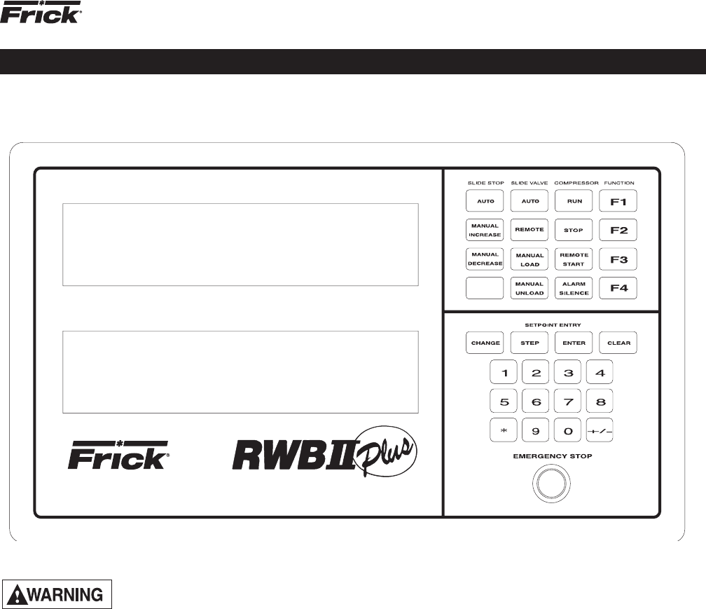
MICROPROCESSOR CONTROL PANEL
The following must be read in addi-
tion to the Operation and Start-up in-
structions in S70-200 IOM before at-
tempting to start or operate the unit.
The RWB II PLUS compressor is controlled by a state-of-
the-art microproces sor control system. The microprocessor
continuously monitors the com pressor unit’s condition and
operation. The mi croprocessor also directs instructions to
the various compressor unit subsystems.
The microprocessor has a membrane switch keyboard.
Pressing the keyboard in the area outlined as a key will cause
that function to be recognized by the microproces sor. The
keyboard has 32 membrane type keys.
In addition to the keyboard, there is an emergency stop but-
ton. Pushing the emer gency stop will by pass the computer
and remove all power from the outputs.
This will shut down the compressor motor and all high voltage
to the compressor auxiliary systems such as the oil pump
and liquid injection solenoid. THE EMERGEN CY STOP
BUTTON IS FOR EMERGENCY SHUTDOWN SITU ATIONS
ONLY and MUST NOT BE USED TO ROUTINE LY SHUT
OFF THE COMPRESSOR.
The microprocessor continuously monitors the state of the
battery which maintains setpoints and vari ous other data. If
the battery voltage is low, the message “LOW BATTERY” will
fl ash in the lower right hand corner of the bottom display (see
S70-200 IOM for description of battery backup).
The microprocessor hardware contains an output watchdog
circuit. If the microprocessor should fail, this circuit will disable
(turn off) all outputs.
Operation

RWB II PLUS MICROPROCESSOR CONTROL
OPERATION
S70-200 OM (DEC 99)
Page 4
KEYS AND KEY FUNCTIONS
NOTE: The microprocessor will automatically return to
the main operating display after 60 seconds of keybo ard
nonactivity.
The [CHANGE] key rotates the dual display screen through
six display modes. The [CHANGE] key is also used to change
the status of various setpoints.
The [STEP] key steps or moves a set of fl ashing brackets
through the variable setpoints on the Adjustable setpoints
display, the Auto-cycle display, the Security display and the
Setback display. The setpoint enclosed within the fl ashing
brackets may be changed or updated. The [STEP] key is
also used when the annun ciator display is selected to step
through the annunciator’s four information displays.
NOTE: The [ * ] key is used to step or move the fl ashing
brackets, described above, backwards.
The [ENTER] key is used to enter new setpoint limits.
The [CLEAR] key will reset an alarm or cutout indica tion on
the annunciator screen and will clear the micropro cessor
to allow continued opera tion or restart ing if all conditions
have returned to normal and no other control lockouts are
in force.
The [NUMERIC KEYPAD] is used to introduce new setpoint
limits.
The [+/-] key is used to toggle between pounds per square
inch gauge (g) and inches of mercury (hg).
The [RUN], [STOP], and [REMOTE START] keys control the
starting and stopping of the compressor unit.
The [ALARM SILENCE] key will de-energize the alarm
horn output.
The [AUTO], [REMOTE], and [MANUAL] keys control the
operation of the compressor slide valve and moveable slide
stop.
The [F1] function key will return the operator to the main
operating display. This function may be invoked at any time,
even during setpoint entry.
The [F2] function key will call up the Security display. NOTE:
Press the [F2] key, as prompted by the dis play, to return
to the previously selected display.
The [F3] function key will call up the Setback display.
NOTE: To exit the Setback display, press the [F1] key
as prompted by the display.
The [F4] function key will call up the Auto Cycle display.
NOTE: To exit the Auto Cycle display, press the [F1] key
as prompted by the display.
The [DISPLAY BACKLIGHT] key will toggle the dual LCD
display backlights on and off. A preset delay will shut off the
backlight after ten minutes elapsed time.
The microprocessor has two liquid crystal displays in an 8 line
by 40 character format, for a total of 320 characters. There are
9 different display modes. When power is fi rst applied to the
control panel, the unit will be in the Operat ing display mode.
To change to a different display mode, press the [CHANGE]
key. The display modes in their order of rotation are:
1. Operating display
2. Adjustable Setpoints display
3. Adjustable Setpoints display #2
4. Fixed Setpoints display
5. Annunciator display (4 pages)
6. Shutdown Record display
7. Freeze display
[F1] Operating display
[F2] Security display
[F3] Setback display
[F4] Auto Cycle display
NOTE: On initial powering of the microprocessor, and
any time power has been removed from the micropro-
cessor, only the Operating, Setpoints, Annunciator, and
Shutdown displays will display information. The freeze
display will appear as a dark screen. The Freeze display
will only be pre sent after a compres sor unit cutout and
power has not been interrupted to the microprocessor.
The cutout must be on a safety setpoint. When power is
lost to the micro, it will not show the freeze display.
OPERATING DISPLAY *
OPERATING DISPLAY: Thu 10-01-87 15:33:36
Suction Disch Oil Filter Compressor
20.0 g 180 g 170 g 01PSID MAN Mode
+015 F 140 F 135 F RUNNING
V Ratio S V Pos Pump %FLA Sep 132 F
4.6 090% OFF 080% HTR off
Auto D Auto L FORCED UNLD ALARM
C.C.=20.0 g LOW-BATTERY
*Display for illustrative purposes only.
The Operating display is continuously updated and provides
a variety of information in regard to the current status of the
compressor’s condition and performance.
The information furnished by the Operating display is as
follows:
The DAY, DATE, and TIME are displayed at the top right of
the display.
NOTE: To set day, date, and time; see TO CHANGE THE
ADJUSTABLE SETPOINTS.
SUCTION - Suction Pressure and Temperature are measured
at the compressor inlet and are, respec tively, displayed in
pounds per square inch gauge (g) or inches of mercury (hg)
and degrees Fahren heit.
DISCH - Discharge Pressure and Temperature are measur ed
at the compressor outlet and are, respec tively, dis played
in
pounds per square inch gauge (g) and degrees Fahrenheit.
OIL - Oil Pressure and Temperature are measured prior to
entering the compressor and are, respec tively, displayed in
pounds per square inch gauge (g) and degrees Fahren heit.
FILTER - Pressure drop across the oil fi lter. On the model
676 only, the bearing oil fi lter pressure drop is displayed.
The main oil injection feed fi lter pressure drop is shown on
a unit mounted gauge.

RWB II PLUS MICROPROCESSOR CONTROL
OPERATION
S70-200 OM (DEC 99)
Page 5
NOTE: Consult Motor Manufacturer for the recom-
mended duration of the Recycle Delay.
If the [RUN] key is pushed while
the unit is in Recycle Delay, the
compressor will start at the end of
the delay period.
C.C. - Capacity Control, located at the bottom left of the
display, indicates the current capaci ty control suction pres-
sure setpoint in pounds per square inch gauge (g) or inches
of mercury (hg).
ADJUSTABLE SETPOINTS DISPLAY *
ADJUSTABLE SETPOINTS: ID=[33] [10-01-87]
Cap. Control---[20.0 g ] Thu [15:33:36]
Lo Suct Cutout-[12.0 g ] Baud----[ 2400]
Lo Suct Alarm--[16.0 g ]
Hi Disch Cutout-[225 g ] Aux1[Alarm][NO]
Hi Disch Alarm--[215 g ] Aux2[Shutd][NC]
M.L.C. Stop Load--[095%] CT Factor-[078]
M.L.C. Force Unld-[100%] Recy.Delay-[30]
The Adjustable Setpoints display lists the adjust able set-
points which defi ne the limits of the compressor package
operation. When these limits are reached, or exceeded,
an
alarm or compressor shutdown will occur. The informa
tion
furnished by the Adjustable Set points display is as follows:
CAP CONTROL - The Capacity Control setpoint, re ported
in pounds per square inch gauge (g) or inches of mercury
(hg), controls the loading and unloading of the compres sor
when SV POS is in the automatic (AUTO) mode.
LO SUCT CUTOUT - The Low Suction Pressure Cutout, re-
ported in pounds per square inch gauge (g) or inches of mer-
cury (hg), will shut down the compres sor if the suction pressure
drops to this limit, or lower, for 120 seconds or longer.
LO SUCT ALARM - The Low Suction Pressure Alarm,
reported in pounds per square inch gauge (g) or inches of
mercury (hg), will trigger a prealarm if the suction pressure
drops to this limit, or lower.
HI DISCH CUTOUT - The High Discharge Pressure Cutout,
reported in pounds per square inch gauge (g), will shut
down the compressor if the discharge pressure equals, or
exceeds, this setpoint.
HI DISCH ALARM - The High Discharge Pressure Alarm,
reported in pounds per square inch gauge (g) will trigger
a pre-alarm if the discharge pressure equals, or exceeds,
this setpoint.
M.L.C. STOP LOAD - The Motor Load Control Stop Load,
reported as a percentage of the motor full load amps (FLA),
will prevent the compressor slide valve from loading when
the setpoint is equaled, or exceeded. NOTE: Con sult motor
nameplate for recommended setpoint.
M.L.C. FORCE UNLD - The motor Load Control Force Un-
load, reported as a percentage of the motor full load amps
(FLA), will force the compressor to unload until the motor full
load amps (FLA) fall within 1% of the setpoint, or lower.
NOTE: Consult motor nameplate for recom mended
setpoint.
*Display for illustrative purposes only.
COMPRESSOR - Compressor displays the status of the
compressor unit. The mode of operation will be indicated as
either manual (MAN MODE) when the [RUN] key has been
pressed, automatic (AUTO MODE) when Auto Cycle has
been activated, remote (RMT MODE) when the [REMOTE]
key has been pressed, or off (OFF MODE).
V RATIO - Volume Ratio is the ratio selected by the micropro-
cessor to provide the highest effi ciency at any given suction
and discharge pressure condition. Im mediately below this,
an information space has been provided to indicate whether
V ratio is in the automatic (AUTO) or the manual (MAN)
mode. The microprocessor will control this function only in
the automatic mode. To the right of the mode indicator, two
other messages may appear:
I - Indicates V Ratio increase.
D - Indicates V Ratio decrease.
SV POS - Slide valve position is displayed as a per centage.
This percentage refl ects the mechani cal position of the slide
valve and does not refl ect the percentage of full load opera-
tion. Immediately below this information, space has been pro-
vided to indicate whether SV Pos is in the automatic (AUTO),
manual (MAN), or remote (RMT) mode. The micro processor
will control this function in the auto matic mode. To the right of
the mode indicator, two other messages may appear:
L - Indicates Slide Valve loading.
U - Indicates Slide Valve unloading.
PUMP - Pump displays the current status of the oil pump. The
display will read ON or OFF whenever the HAND-OFF -AUTO
switch is selected to AUTO and the compressor is running.
% FLA - Percent Full Load Amps displays the per centage
of the drive motor full load amperage rating that the motor
is currently using.
SEP - Separator displays the oil separator temper ature in
degrees Fahrenheit.
HTR - Heater displays the condition of the oil separator
heater(s), indicating ON or OFF.
ALARM/CUTOUT - An Alarm or Cutout message indi cates
an Alarm or Cutout setpoint has been reach ed, or ex ceeded.
Rotate the display mode to the Annunciator display for de-
tails. In the event of a cutout, rotate to the Freeze display for
further details.
FORCED UNLD - A Forced Unload message indicates that
the percentage of motor full load amps has exceeded the
maximum limit and the microprocessor is unloading the
compressor until the percentage FLA falls back to normal
limits.
RECYCLE DELAY - A Recycle Delay message indicates that
the compressor has started and has shut down within the
time delay set point period. The Recycle Delay will prevent
the compressor from starting until the delay time expires
and is intended to prevent damage to the com pressor motor
from suc cessive restarts. During Recycle Delay, the micro-
processor will alternatively fl ash “RECYCLE DELAY” and the
remaining delay time in minutes.
RWB II PLUS MICROPROCESSOR CONTROL
OPERATION
S70-200 OM (DEC 99)
Page 6
Cycle Time - Cycle time is the amount of time between the
beginning of each load/unload response. Ten seconds is
the default value. “Cycle Time” is adjustable between 5 and
30 seconds in 5 second intervals. The “Step” key is used
to select a setpoint; then press the “Change” key to toggle
through the selections.
Low % FLA - This setpoint is used to determine if the cou-
pling has broken. 20% is the default value. It is adjustable
from 0 to 100% FLA. Use the “Step” key to select a setpoint;
then enter the desired setpoint and press the “Enter” key.
TO CHANGE THE ADJUSTABLE SETPOINTS:
Adjustable Setpoints are stored in RAM (random access
memory) and are easily changed in the fi eld.
Adjustable Setpoints are lost if
power is interrupted and the battery
is not fully charged. To facilitate
reentry, we suggest that a list of Adjustable Setpoints
be affi xed to one end of the microprocessor cabinet for
reference. For your convenience, a blank Adjust able set-
points display which may be photocopied has been provided
(See page 10).
NOTE: The following procedure also applies to the
changing of the Security, Setback, and Auto Cycle dis-
play setpoints.
1. Press the [CHANGE] key to rotate the display to the
Adjustable Setpoints display.
2. Press the [STEP] key to move or step a set of fl ashing
brackets through the various set points. A setpoint is selected
for change or update when it is enclosed by the fl ashing
brackets.
NOTE: The DAY indicator, itself, will fl ash when selec ted
for change or update.
3. Having selected the setpoint to be changed, the [NU-
MERIC KEYPAD] may be used to enter the new setpoint.
NOTE: All digits must be entered, including zeros. For
example, (01.0).
NOTE: The DAY, AUX 1, and AUX 2 setpoints, once selected,
are changed or updated by pressing the [CHAN GE] key.
NOTE: Certain setpoints may be reported in either pounds
per square inch gauge (g) or inches of mer cury (hg). To
toggle between (g) and (hg), having selected the setpoint,
press the [+/-] key to toggle between (g) and (hg).
4. In the event that an incorrect setpoint is keyed in all or
part, press the [CLEAR] key to restore the original setpoint.
Pressing the [CLEAR] key a second time will eliminate the
fl ashing brackets.
5. Having keyed the desired setpoint, press the [ENTER] key.
The new setpoint will be entered and the fl ashing brackets
will move or step to the next setpoint.
NOTE: A setpoint entry outside the parameters of the
Adjustable Setpoint display will be refused and the
original Adjustable setpoint will be re stored.
NOTE: To clear any time values [STEP] to the desired
setpoint, press [CHANGE] and then press [CLEAR].
*Display for illustrative purposes only.
ID - The ID number is a programmable identifi cation code
used in telecommunications to access a speci fi c compres-
sor.
DATE - The Date displays the current date in the following
format: Month - Day - Year.
DAY - Day will display the current day of the week.
TIME - The Time displays the current time in the following
format: Hours - Minutes - Seconds. The time is in 24:00:00
hour clock format.
BAUD - Shows the baud rate of the RS422 communica tion
ports 1 and 2. Both ports are confi gured as follows: word = 8
bit, parity = none or even, stop = 1 bit. The communications
ports are programmable from 300 to 19200 baud.
AUX 1 and AUX 2 - May be confi gured for either an alarm or
shutdown and with either a normally closed (NC) or normally
open (NO) contact.
CT FACTOR - The Current Transformer Factor records the
proper current transformer factor to match the com pressor
motor FLA rating to the current trans former primary rating.
The CTF factor is program mable and its correct value is
determined by the following formula:
CTF = 1024 x FLA (Full Load Amps)
10 x CT (Current Transformer Primary Amps)
EXAMPLE: FLA = 230 Amps
CT = 300 (300:5)
CTF = 1024x 230 = 78 (Round to whole number)
10 x 300
RECY. DELAY - The Recycle Delay displays the cur rent
recycle delay setpoint in minutes. NOTE: Consult motor
manufacturer for recommended setpoint.
ADJUSTABLE SETPOINTS PAGE 2 *
ADJUSTABLE SETPOINTS Page 2:
Start Diff Press--[100g]
Dead Band--[1.0#]
Prop. Band-[10 %]
Cycle Time-[10 sec]
Low % FLA--[020 %]
Dead Band - This is a + (plus) or - (minus) value above or
below the setpoint at which the compressor will neither
load nor unload. A dead band of 1 is the default value. It
is adjustable between .5 lbs. to 5 lbs. in increments of .5.
The “Step” key is used to select this setpoint; then press the
“Change” key to toggle through the selections.
Proportional Band - This setpoint is used to determine the
amount of time the load/unload solenoid is energized, ac-
cording to how far from the setpoint the actual control pres-
sure is. The smaller the number, the longer a load/unload
signal will be sent. 10% is the default value. Selections are
2, 5, 10, 15, 20, or 25%. The “Step” key is used to select
this setpoint; then press the “Change” key to toggle through
the selections.

RWB II PLUS MICROPROCESSOR CONTROL
OPERATION
S70-200 OM (DEC 99)
Page 7
HOW TO DETERMINE
ADJUSTABLE SETPOINTS:
Adjustable Setpoints should refl ect values compat ible with
normal system operation. Too high a Low Suction Pres sure
Alarm setpoint may cause nuisance prealarms. Similarly,
cutout setpoints should not fall within what are considered
normal plant oper ation. As a rule of thumb, set the Low Suc-
tion Pressure Alarm 5 PSIG lower than the lowest normal
suction pressure. The Low Suction Pressure Cutout should
be 5 to 10 PSIG lower than the Low Suction Pressure Alarm
setpoint.
The High Discharge Pressure Cutout should be set at 90%
of the setting of the lowest high side relief valve. The High
Discharge
Pressure Alarm should be set 10 PSIG lower than
the Cutout.
The Capacity Control setpoint should be the equi valent of
the normal suction condition.
FIXED SETPOINTS DISPLAY *
FIXED SETPOINTS: HIGH STAGE PRELUBE
OIL PUMP PGM/A
Hi Disch Cut----[212F]
Hi Disch Alarm--[194F] Liq Inj Con 113F
Hi Oil Temp Cut-[167F] Filter------[25]
Hi Oil Temp Alarm[158F]Oil Heater[113F]
Lo Oil Temp Cut--[49F] Lo Oil Cut-[030]
Lo Oil Temp Alarm[58F] Lo Oil Alrm[025]
The Fixed Setpoints display lists all fi xed set points, program
version, plus low oil alarm and low oil cutout setpoints.
Fixed Setpoints defi ne the limits of acceptable compressor
operation. Fixed Setpoints are factory determined, stored in
programmed memory (PROM), and will remain in memory
if power to the micro processor is interrupted.
HI DISCH CUT - The High Discharge Temperature Cutout,
reported in degrees Fahrenheit, will shut down the com-
pressor if the discharge temperature equals or exceeds this
setpoint.
HI DISCH ALARM - The High Discharge Temperature Alarm,
reported in degrees Fahrenheit, will trig ger a prealarm if the
discharge temperature equals or exceeds this setpoint.
HI OIL TEMP CUT - The High Oil Temperature Cutout, re-
ported in degrees Fahrenheit, will shut down the com pressor
if the oil temperature equals or ex ceeds this setpoint.
HI OIL TEMP ALARM - The High Oil Temperature Alarm,
reported in degrees Fahrenheit, will trig ger a prealarm if the
oil temperature equals or exceeds this setpoint.
LOW OIL TEMP CUT - The Low Oil Temperature Cutout,
reported in degrees Fahrenheit, will shut down the com-
pressor if the separator oil temperature equals or falls below
this setpoint.
LOW OIL TEMP ALARM - The Low Oil Temperature Alarm,
reported in degrees Fahrenheit, will trig ger a prealarm if
the separator oil temperature equals or falls below this
setpoint.
HIGH STAGE or BOOSTER - Compressor application
indicator.
*Display for illustrative purposes only.
PRELUBE, FULL LUBE, or CYCLING - Pump type will be
indicated.
PGM/ - Microprocessor Program version.
LIQ INJ CON - The Liquid Injection Control, re ported in
degrees Fahrenheit, will shut off the liquid refrigerant sup-
ply to the compressor if the oil temperature equals or falls
below this set point.
FILTER - The Oil Filter setpoint will trigger an alarm when the
differential pressure across the oil fi lter equals or exceeds 25
pounds per square inch (PSI) for 15 seconds, or longer.
OIL HEATER - The Oil Heater setpoint, reported in degrees
Fahrenheit, turns on the oil separator heater(s) when the oil
temperature equals or falls below this setpoint whenever the
compressor is NOT running.
Compressor Differential Cutout - The differential cutout
has been lowered from 55 lb to 25 lb. Cutout will occur after
fi ve minutes. To allow operation at low differential pressures,
the micro will take the following steps:
A. Force unload the compressor to 50% and display an "F
Unload" when the oil pressure is within 10 lb of the main oil
injection port pressure and the slide valve position is greater
than 50%.
B. Prohibit the compressor from loading and display a "Ld
Inhib" message when the differential is within 15 lb of the
main oil injection port pressure.
Oil Pressure Alarm and cutout - Logic has been revised
to same logic as currently used on RXB/RXF. The new logic
is as follows:
Prelube and Cycling Oil Pump version when pump is not run-
ning. Alarm will occur if oil pressure is 25 lb below discharge
pressure or within 10 lb of suction pressure for 30 seconds.
Cutout occurs if oil pressure is 30 lb below discharge pres-
sure or if oil pressure is within 7 lb of suction pressure for 10
seconds and alarm has already been set.
Full Lube and Cycling Oil Pump version when oil pump is run-
ning. Alarm occurs if oil pressure is within 10 lb of discharge
pressure for 30 seconds. Cutout occurs when oil pressure
is within 5 lb of discharge pressure for 10 seconds and oil
pressure alarm has been set.
Cycling Oil Pump Control - The oil pump will cut off when
differential pressure between suction and discharge pressure
is 55 lb or greater. Upon pump termination the above cutout
logic (pump not running) is utilized. Pump cut-in occurs when
the differential pressure between suction and discharge is 45
lb or less. Oil pressure alarm and cutout logic (pump running)
begins after a 30 second delay which allows the oil pump
to build pressure.

RWB II PLUS MICROPROCESSOR CONTROL
OPERATION
S70-200 OM (DEC 99)
Page 8
When a prealarm or cutout occurs, a fl ashing ALARM or
CUTOUT indicator will appear in the lower right hand corner
of the Operating display. To determine the fault, rotate to the
Annunciator display by pres sing the [CHANGE] key.
The Annunciator display lists all key operative points on four
sequential displays. These displays can be rotated from page
#1 through page #4 by pres sing the [STEP] key. When a
prealarm or cutout is triggered, the pertinent point will fl ash,
and the time of the occurrence will be recorded to the right
of the alarm. Prealarms are self- clear ing. At this time the
alarm will stop fl ashing, but the time of the fi rst occurrence
will still be recorded to the right of the alarm. Pressing the
[CLEAR] key while at the Annunciator display will clear all
alarms and/or cutouts.
In order to restore the Annunciator display and resume
normal operation it will be necessary to go through the fol-
lowing steps:
1. Correct the conditions causing the alarm.
2. Press the [ALARM SILENCE] key. (This action may pre-
cede correcting the conditions causing the alarm).
3. To clear or reset the Annunciator pages, press the
[CLEAR] key. This will also clear the ALARM or CUTO UT
indicator from the Operating display.
4. Press [F1] to call up the Operating dis play. If the condi-
tions causing the alarm have not been cor rect ed or a new
fault has occurred, a new ALARM or CUTOUT message
will appear.
NOTE: Use of the Emergency Stop Button may trip one
or more alarm setpoints.
SHUTDOWN RECORD DISPLAY *
SHUTDOWN RECORD: Thu 10-01-87 15:33:36
(Use STEP key to advance PAGE)
Hi Oil Temp Cutout Wed 09-30-87 16:22:54
Comp Auxiliary Sat 08-22-87 09:47:02
Low Temp Cutout Thu 08-20-87 11:17:33
Pump Auxiliary Mon 08-17-87 18:53:11
Disch. Temp Cutout Tue 07-14-87 06:22:09
Oil Pres Cutout Fri 07-08-87 14:06:21
The Shutdown Record display keeps a record of the last six
shutdowns (cutouts). This information will help troubles hoot
persistent operational problems. The most recent cutout will
appear on the top line of the display with the oldest ap pearing
on the last or bottom line. When a cutout occurs, all informa-
tion is moved down one line and the new cutout appears at
the top. When the dis play is full, the oldest record is dropped
off the display and is not retained in memory. The informa tion
presented is echoed from the Annunciator display; providing
the type of cutout, the day, the date, and the time. NOTE: This
information will not be lost due to power failure.
FREEZE DISPLAY *
FREEZE DISPLAY: Thu 10-01-87 15:33:36
Suction Disch Oil Filter Compressor
20.0 g 225 g 170 g 01PSID OFF Mode
+015 F 140 F 135 F RECYCLE
V Ratio S V Pos Pump %FLA Sep 132 F
4.6 090% OFF 080% HTR off
Auto Auto CUTOUT
C.C.=20.0 g
The Freeze display has the same appearance and con tains
the same information as the Operating display. (For a de-
scription of the information presented by the Freeze display,
refer to the Operating display.) The Freeze display freezes
the information of the Operating display AT THE MOMENT
OF A COMPRESSOR CUTOUT. The informa tion on the
Freeze display can help the operator to identify the cause
of a fault which occurred when no one was present. The
Freeze display will retain the information generated by a
cutout until a new cutout occurs or power is removed from
the micro processor.
Do not confuse the Freeze display
with the Operating display. In order
to avoid confusion remember that
the displayed information on the Operating display is
constantly being updated and changed. The Freeze dis-
play is fi xed and FREEZE DISPLAY appears in the upper
left hand corner of the display.
NOTE: The Freeze display will appear as a blank screen
when power is initially furnished to the unit, and it will
return to a blank screen anytime power is removed from
the microproce ssor.
*Display for illustrative purposes only.
ANNUNCIATOR DISPLAY *
ANNUNCIATOR: PG-1 Thu 10-01-87 15:33:36
(Use STEP key to advance PAGE)
High Press. Cutout *********************
High Press. Alarm *********************
Low Press. Cutout *********************
Low Press. Alarm *********************
Oil Press. Cutout *********************
Oil Press. Alarm *********************
ANNUNCIATOR: PG-2 Thu 10-01-87 15:33:36
(Use STEP key to advance PAGE)
Hi Oil Temp Cutout *********************
Hi Oil Temp Alarm *********************
Low Temp Cutout *********************
Low Temp Alarm *********************
Disch. Temp Cutout *********************
Disch. Temp Alarm *********************
ANNUNCIATOR: PG-3 Thu 10-01-87 15:33:36
(Use STEP key to advance PAGE)
Comp. Auxiliary *********************
Pump Auxiliary *********************
Oil Level *********************
Comp. Differential *********************
Dirty Filter *********************
ANNUNCIATOR: PG-4 Thu 10-01-87 15:33:36
(Use STEP key to advance PAGE)
Aux. 1 (Alarm) *********************
Aux. 2 (Shutdown) *********************
Low Motor Amps
Sensor Fault

RWB II PLUS MICROPROCESSOR CONTROL
OPERATION
S70-200 OM (DEC 99)
Page 9
*Display for illustrative purposes only.
SECURITY DISPLAY *
SECURITY DISPLAY: Thu 10-01-87 15:33:36
Setpoints Access---[Enabled ] Keyboard
Enter Access Code---[*****]
Press F2 To Exit
The [F2] function key will call up the Security display. The
Security display allows the operator to either enable or dis-
able the microprocessor’s keyboard and, thereby, prevent
unauthorized tam pering with the various adjustable setpoints.
When enabled, the microprocessor keyboard is fully opera-
tive and the security lockout is not in ef fect. When disabled,
the keyboard is rendered partially nonfunc tional. All displays
will still be accessible through the keyboard. If any attempt
is made to enter new adjustable setpoints, how ever, the
microprocessor will default to the Se curity display.
TO ENABLE THE KEYBOARD, press the [STEP] key so that
the brackets beside Enter Access Code fl ash, key the proper
fi ve digit access code, and press [ENTER]. The Setpoints
Access will toggle from disabled to enabled and adjustable
set point entry is now possible.
TO DISABLE THE KEYBOARD, press the [F2] function
key to call up the Security display. Press the [STEP] key
until the brackets beside Enter Access Code fl ash, key the
proper fi ve digit access code, and press [ENTER]. Now,
press the [STEP] key until the brackets beside Setpoints
Access fl ash and press the [CHANGE] key to toggle from
enabled to disabled.
TO CHANGE THE ACCESS CODE, press the [F2] function
key to call up the Security display. Press the [STEP] key until
the brackets beside Enter Access Code fl ash, key the proper
fi ve digit access code, and press [ENTER]. Now, select the
Enter Access Code a second time by pressing the [STEP]
key until the brackets beside Setpoints Access fl ash, key in
the new fi ve digit access code, and press [ENTER].
NOTE: Power loss will not effect the Security display.
NOTE: IF NO ACCESS CODE WAS ENTERED AND THE
DIS ABLED COMMAND WAS SELECTED, THE ACCESS
CODE IS [00000].
LOST OR FORGOTTEN ACCESS CODE: Consult Frick
Com pany for assistance.
SETBACK DISPLAY *
SETBACK DISPLAY: Thu 10-01-87 15:33:36
Press F1 To Exit
Setback Setpoint-[05.0 g ] Active-[No ]
Start Stop Start Stop
Mon-[--:--]-[06:00] Fri-[16:00]-[--:--]
Tue-[--:--]-[--:--] Sat-[--:--]-[--:--]
Wed-[--:--]-[--:--] Sun-[--:--]-[--:--]
Thu-[--:--]-[--:--]
The [F3] function key will call up the Setback display. The
Setback feature enables automatic operation at two separate
suction conditions on a preset time schedule. Having entered
the desired Setback setpoint, enter the start and stop time
or times, and select Active: (Yes) or (No).
NOTE: To change the Setback setpoints, refer to “TO
CHANGE THE ADJUSTABLE SETPOINTS”
AUTO CYCLE DISPLAY *
AUTO CYCLE Thu 10-01-87 16:33:36
DISPLAY: Press F1 To Exit
Suction Pressure--------[20.0 g ]
Compressor Start--------[20.0 g ]
Compressor Stop---------[18.0 hg]
Minimum Slide Valve-----[00%]
Auto Cycle Active-------[No ]
The Auto Cycle display provides for independently adjus table
setpoints to turn the compressor on and off in response to
the suction pressure or as an adjustable setpoint to limit the
minimum slide valve position.
NOTE: To change the Auto Cycle setpoints, refer to
“TO CHANGE THE ADJUSTABLE SETPOINTS”
SUCTION PRESSURE - Constantly monitors and dis plays
the suction pressure in pounds per square inch gauge (g)
or inches of mercury (hg).
COMPRESSOR START - Compressor Start-up will bring
the compressor back on line when the suction pres sure rises
to the displayed setpoint.
COMPRESSOR STOP - Compressor Stop will shut down the
unit if the suction pressure drops to or below the displayed
setpoint limit. NOTE: This limit must be set higher than Low
Suction Pressure Cut out and the Low Suction Pressure
Alarm setpoints.
MINIMUM SLIDE VALVE - Minimum Slide Valve Posi tion,
shown as a percentage, will limit the slide valve position to
the displayed setpoint.
AUTO CYCLE ACTIVE - Indicates whether Auto Cycle is ac-
tive (YES) or not active (NO). Press the [CHANGE] key while
at this setpoint to change the status. Upon deactiva tion, the
compressor will return to the previous mode of operation.
ANALOG OFFSET DISPLAY*
ANALOG OFFSET:
Suc Disch Oil Sep Filt Spare Econ
Temp +0 +0 +0 +0 +0.0
Pres +0.0 +0 +0 +0 +0
Channel 10 12 13
Press +0 +0 0
The Analog Offset Display is accessed by pressing +/- key.
All analog values can be offset + or - 3 to 9 units depend-
ing on which value is being adjusted. Use the [STEP] key
to step to the desired setpoint. Press the [CHANGE] key to
change the value of the offset by 1. The actual analog value
will be displayed on the top line of the display. The “Econ”
and channels 10, 12, 13 are displayed but do not pertain to
the standard program.

RWB II PLUS MICROPROCESSOR CONTROL
OPERATION
S70-200 OM (DEC 99)
Page 10
Sensor Fault Failure - A “Sensor Fault” cutout was added
to the program to stop the compressor if a temperature or
pressure sensor is at its minimum or maximum limit for 5
seconds. The following channels and conditions will cause
this cutout:
Channel 1 - Suction Temp Low or High (-67 to 113
O
F)
Channel 2 - Low or High Discharge Temp (32 or 212
O
F)
Channel 3 - Low or High Oil Temp (0 or 180
O
F)
Channel 4 - Low or High Separator Temp (0 or 180
O
F)
Channel 6 - Low or High Oil Pressure (<0 g or 285 g)
Channel 8 -
Low or High Discharge Pressure (<0 g or 285 g)
Channel 9 - Low Suction Pressure (29 hg only)
Pulse Load Signal at 100% Slide Valve Position - This
new feature will stop loading the compressor when 100%
slide valve is displayed. The load signal will pulse for 2 sec-
onds every minute when the slide valve is at 100% and the
pressure is above setpoint.
TEMPERATURE-PRESSURE CONTROL
PROGRAM (OPTION)
NOTE: The following displays are provided only when
the Temperature-Pressure Control Program option has
been ordered with the RWB II Plus Rotary Screw Com-
pressor Unit.
SETPOINTS DISPLAY PAGE 1 *
SETPOINTS PAGE 1 Capacity Control=Press
C.C. CUTOUT ALARM PB DB CT
Press 25.3g 01.3g 05.3g 10 1.0 10
Temp +40.0F +32.0F +33.0F 10 0.5 10
offset-act
Sup Heat-Alarm-10F-no
Sep Cond-Alarm-10F-no
* Display for illustrative purposes only.
The Setpoints Display is accessed by pressing the
[CHANGE] key.
CONTROL - This setpoint is used to select either Pressure
Capacity Control or Temperature Capacity Control. NOTE:
There are only two setpoints, press for pressure capacity
control and temp for temperature capacity control.
CC - The capacity control setpoint is for normal operation,
not setback.
CUTOUT -This setpoint will stop the compressor if the suction
pressure drops below the pressure setpoint for 90 seconds or
if the CC Temperature drops below the temperature setpoint.
There is no time delay on the temperature cutout.
ALARM - An alarm will be activated if the suction pressure
drops below the pressure setpoint or if the CC Temperature
drops below the temperature setpoint. There is no time delay
for either.
PB - The Proportional Band (PB) is used to determine the
amount of time the load/unload solenoid is energized, ac-
cording to how far away from the setpoint the actual control
pressure or temperature is. The smaller the number, the
more load/unload will be sent. A PB of 10% is default. It is
adjustable to 2, 5, 10, 15, 20, or 25 percent.
DB - The Dead Band (DB) is a + (plus) or - (minus) value
above or below the setpoint which the compressor will neither
load nor unload. It is adjustable between .5 and 5.0 psig or
degrees, in increments of .5 units.
CT - The Cycle Time (CT) setpoint is the amount of time
between the beginning of each load/unload response. It is
adjustable to 5, 10, 15, 20, 25, or 30 seconds.
Use the [STEP] key to step to the desired setpoint, then press
the [CHANGE] key to change the CC, PB, DB and CT values.
Enter the desire value for the remaining setpoints and press
[ENTER] when complete.
ADJUSTABLE SETPOINTS FORM
ADJUSTABLE SETPOINTS: ID = [ ] [ - - ]
Cap. Control ———[ ] Thu [ : : ]
Lo Suct Cutout ——[ ] Baud ———————[ ]
Lo Suct Alarm ———[ ]
Hi Disch Cutout ——[ ] Aux 1 [ ] [ ]
Hi Disch Alarm ——[ ] Aux 2 [ ] [ ]
M.L.C. Stop Load —[ ] CT Factor ———[ ]
M.L.C. Force Unld —[ ] Recy. Delay ——[ ]
Photocopy and fi ll in applicable data for your unit. Retain for reference if reentry is required.

RWB II PLUS MICROPROCESSOR CONTROL
OPERATION
S70-200 OM (DEC 99)
Page 11
TEMPERATURE-PRESSURE CONTROL
PROGRAM (OPTION) (continued)
The new setpoints provided on this display allow monitoring
of compressor superheat and condensing in the separator.
The following setpoints apply to the monitoring of the super-
heat and condensing in the separator.
ALARM/(SHUTDOWN) -The Alarm/(shutdown) setpoints
select the conditions for an alarm or shutdown. If alarm is
selected, the alarm will occur after a 30 second delay. If
shutdown is selected, the shutdown will occur 60 seconds
after the alarm.
OFFSET - This setpoint is the degrees F above the satura-
tion point temperature where the alarm or shutdown will
occur.
ACT - The function selects whether the alarm/shutdown is
activated or not.
Use the [STEP] key to step to the desired setpoint, then press
the [CHANGE] key to change the setpoint. Press [ENTER]
when all desired setpoint changes have been made.
SETBACK DISPLAY *
SETBACK DISPLAY: Tue 04-10-90 08:44:50
Press Setpoint-[25.3g ] F1 To Exit
Temp Setpoint—[+50.0F] Active-[No ]
Stop Start Start Stop
Mon-[—:—}-[—:—] Fri-[—:—]-[—:—]
Tue-[—:—}-[—:—] Sat-[—:—]-[—:—]
Wed-[—:—}-[—:—] Sun-[—:—]-[—:—]
Thu-[—:—}-[—:—]
The Setback Display is accessed by pressing the [F3] key.
PRESS SETPOINT - The capacity control setpoint used
when in the Setback mode and Pressure is selected as the
capacity control desired.
TEMP SETPOINT - The capacity control setpoint used when
in the Setback mode and Temperature is selected as the
capacity control desired.
NOTE: To change the Setback setpoints, refer to “TO
CHANGE THE ADJUSTABLE SETPOINTS”.
The Auto Cycle display provides for independently adjus table
setpoints to turn the compressor on and off in response to
the suction pressure or as an adjustable setpoint to limit the
minimum slide valve position. The compressor can be started
and stopped by the following pressure setpoints even if the
capacity control is selected to temperature.
AUTO CYCLE PRESS CONTROL DISPLAY *
AUTO CYCLE PRESS Tue 04-10-90 08:44:57
DISPLAY: Press F1 To Exit
Suction Pressure--------[06.5 g ]
Comp Start - [99.0 g } Timer—[00 min]
Comp Stop— [29.0 hg] Timer—[00 min]
Min SV———[50%]
Active———[No ] * for Temp Menu
NOTE: To change the Auto Cycle setpoints, refer to “TO
CHANGE THE ADJUSTABLE SETPOINTS”
SUCTION PRESSURE - Constantly monitors and dis plays
the suction pressure in pounds per square inch gauge (g)
or inches of mercury (hg).
COMP START - The suction pressure must be greater than
or equal to the “START” setpoint in order to start the com-
pressor. This setpoint works in conjunction with the “TIMER”
setpoint located to the right of it on the display.
TIMER - This is a time delay used to start the compressor.
The timer only accumulates time whenever the pressure
rises to or above the “START” setpoint and will reset if the
pressure drops below the “START” setpoint.
COMP STOP - Compressor Stop will shut down the unit if
the suction pressure drops to or below the displayed “STOP”
setpoint limit. This setpoint works in conjunction with the
“TIMER” setpoint located to the right of it on the display.
NOTE: This limit must be set higher than Low Suction
Pressure Cut out and the Low Suction Pressure Alarm
setpoints.
(STOP) TIMER - The (stop) TIMER is a time delay used
to stop the compressor. The timer only accumulates time
whenever the pressure drops to or below the “STOP” set-
point and will reset if the pressure rises above the “STOP”
setpoint.
MINIMUM SLIDE VALVE - Minimum Slide Valve Posi tion,
shown as a percentage, will limit the slide valve position to
the displayed setpoint.
ACTIVE - Indicates whether Auto Cycle is active or not.
Press the [CHANGE] key while at this setpoint to change
the status. Upon deactiva tion, the compressor will return to
the previous mode of operation.
AUTO CYCLE TEMP CONTROL DISPLAY *
AUTO CYCLE TEMP Tue 04-10-90 08:45:40
DISPLAY: Press F1 To Exit
Cap Control Temperature—[+50.5 F]
Comp Start-[+50.0 F] Timer—[01 min]
Comp Stop—[+20.0 F] Timer—[01 min]
Min SV——[50%]
Active——[Yes] * for Press Menu
The Auto Cycle Temperature Control Display is accessed by
pressing F4 and then the * keys. NOTE: The compressor
can be started and stopped by the following tempera-
ture setpoints even if the capacity control is selected
to pressure.
CAP CONTROL TEMPERATURE - Constantly monitors and
dis plays the suction temperature.
COMP START - The CC (capacity control) Temperature
must be greater than or equal to the “START” setpoint in
order to start the compressor. This setpoint works in con-
junction with the “TIMER” setpoint located to the right of it
on the display.
(Start) TIMER - This is a time delay used to start the compres-
sor. The timer only accumulates time whenever the CC Tem-
perature rises to or above the “START” setpoint and will reset
if the CC Temperature drops below the “START” setpoint.
*Display for illustrative purposes only.

RWB II PLUS MICROPROCESSOR CONTROL
OPERATION
S70-200 OM (DEC 99)
Page 12
COMP STOP - The CC Temperature must be less than or
equal to the “STOP” setpoint in order to stop the compressor.
This setpoint works in conjunction with the “TIMER” setpoint
located to the right of it on the display.
(STOP) TIMER - The (stop) TIMER is a time delay used
to stop the compressor. The timer only accumulates time
whenever the CC Temperature drops to or below the “STOP”
setpoint and will reset if the CC Temperature rises above the
“STOP” setpoint.
MINIMUM SLIDE VALVE - Minimum Slide Valve Posi tion,
shown as a percentage, will limit the slide valve position to
the displayed setpoint.
ACTIVE - Indicates whether Auto Cycle is active or not.
Press the [CHANGE] key while at this setpoint to change
the status. Upon deactivation, the compressor will return to
the previous mode of operation.
LEAD-LAG OPTION
The lead-lag compressor sequencing option provides the
controls for operating two RWB II compressors in one
system.
AUTO CYCLE DISPLAY *
AUTO CYCLE Tue 04-10-90 08:44:57
DISPLAY: Press F1 To Exit
Suction Pressure--------[06.5 g ]
Comp Start - [99.0 g } Timer—[00 min]
Comp Stop— [29.0 hg] Timer—[00 min]
Min SV———[50%] Lead—[YES]
Active———[No ]
*Display for illustrative purposes only.
The software includes user adjustable setpoints on the Auto
Cycle setpoints screen (F4 on Main Menu) for the following:
START - The suction pressure must be greater than or equal
to the “START” setpoint in order to start the compressor. This
setpoint works in conjunction with the “Timer” setpoint located
to the right of it on the Auto Cycle setpoints screen.
TIMER - This is a time delay used to start the compressor.
The timer only accumulates time whenever the pressure
rises to or above the “START” setpoint and will reset if the
pressure drops below the “START” setpoint.
STOP - The suction pressure must be less than or equal to
the “STOP” setpoint in order to stop the compressor. This
setpoint works in conjunction with the “Timer” setpoint located
to the right of it on the Auto Cycle setpoints screen.
TIMER - This is a time delay used to stop the compressor.
The timer only accumulates time whenever the pressure
drops to or below the “STOP” setpoint and will reset if the
pressure rises above the “STOP” setpoint.
MIN SV -This setpoint is the minimum slide valve position,
shown as a percentage, it will limit the slide valve position
to the displayed setpoint.
LEAD - This setpoint assigns the compressor as the lead or
the lag unit. Press the [CHANGE] key while at this setpoint
to change the status.
ACTIVE - This setpoint indicates whether the Auto Cycle
Mode is active or not. Press the [CHANGE] key while at this
setpoint to change the status.
OPERATION
For operation of the LEAD-LAG sequence, both units must
be in Auto Cycle compressor mode, one compressor micro
selected as the LEAD compressor, the other compressor
selected as the LAG compressor and the slide valves in
Auto mode.
With NO Compressor Running
The lead will start when its “START” setpoint is reached for
the amount of time selected for the “TIME” setpoint.
With ONE Compressor Running
If the load rises:
The lag compressor will start when its “START” setpoint
is reached for the amount of time selected for the “TIME”
setpoint and the lead compressor is running at 100% slide
valve or running with the motor load inhibit or lead cutout or
lead in recycle.
If the load falls:
The lead compressor will stop when its “STOP” setpoint
is reached for the amount of time selected for the “TIME”
setpoint.
With TWO Compressors Running
If the load rises:
The lead and lag compressor will load independently.
If the load falls:
The lag compressor will unload to its “MIN SV” setpoint. Then
the lead compressor will unload to its “MIN SV” setpoint. The
lag compressor will stop when the suction pressure drops
below the “STOP” setpoint for the amount of time selected
for the “TIME” setpoint.
NOTE: Be careful not to select both compressors as
lead compressors or as lag compressors as improper
operation will result.
NOTE: One compressor will operate as a normal auto
cycle compressor when any one of the following oc-
curs:
a. Power is removed from one of the two compressors,
b. Either of the compressors is NOT selected to “AUTO”,
or
c. If communications is lost between the compressors for
any reason.

RWB II PLUS MICROPROCESSOR CONTROL
OPERATION
S70-200 OM (DEC 99)
Page 13
COMMUNICATIONS TROUBLESHOOTING
Troubleshooting the communications:
Go to the FIXED SETPOINTS PAGE by using the “CHANGE”
key and the “ * ” key. The display will appear as:
FIXED SETPOINTS DISPLAY *
FIXED SETPOINTS: HIGH STAGE PRELUBE
COMM ACTIVITY—[ ] OIL PUMP PGM/A
Hi Disch Cut----[212F]
Hi Disch Alarm--[194F] Liq Inj Con 113F
Hi Oil Temp Cut-[167F] Filter------[25]
Hi Oil Temp Alarm[158F]Oil Heater[113F]
Lo Oil Temp Cut--[49F] Lo Oil Cut-[030]
Lo Oil Temp Alarm[58F] Lo Oil Alrm[025]
If the microprocessor is receiving information in the com-
munications port from the other compressor, a “2” will fl ash
between the brackets. During normal operation a “2” will fl ash
every 5 seconds.
At the same time information is display on the lower right
hand corner of the Auto Cycle display concerning the lead-
lag information:
AUTO CYCLE DISPLAY *
AUTO CYCLE Tue 04-10-90 08:44:57
DISPLAY: Press F1 To Exit
Suction Pressure--------[06.5 g ]
Comp Start - [99.0 g } Timer—[00 min]
Comp Stop— [29.0 hg] Timer—[00 min]
Min SV———[50%] Lead—[YES]
Active———[No ] 0111 111
This information is either “0” or “1” and represents what is be-
ing sent from the other compressor. Consult Frick Company
if additional information is required.
HOW THE MICROPROCESSOR WORKS
- SUMMARY -
The Frick microprocessor has 4 major components and a va-
riety of sensors. The major components are the SBC (single
board computer), two display screens, and the keyboard.
The SBC can be considered the brain of the micro proces sor
control console. The SBC contains the logic center which
provides the rules by which the micro pro cessor will oper-
ate, the integrated cir cuit chips which store the burned-in
memory of how the compres sor unit is to behave, an analog
input to convert VDC from the various sensors into computer
binary language, and RAM (random access memory) inte-
grated circuit chips to store information which can be readily
changed by the microprocessor or, as in the case of adjust-
able setpoints, by the operator. The SBC collects information,
processes the information, and delivers instructions to the
displays and to the output modules.
The SBC gathers information from several sources on the
compressor unit. Pressure transducers sense changes in
pressure and return a variable DC volt age of 1 to 5 VDC to
the SBC. The signals are converted into binary code which
the microproces sor under stands. The microproces sor scans
the incoming data many times per second and compares
the information it receives with the instructions programmed
in the PROM chips, information stored in the RAM chips,
and instructions it has received from the console keyboard.
As operating conditions change, the microprocessor also
forwards the infor mation it is receiving to the display screen.
When an operating condition or conditions develop which
the micropro cessor program identifi es as requiring a specifi c
action, the microprocessor generates an instruction which is
forwarded to the output mod ules. The instruction triggers a
solid state out put device capable of handling control voltage
and the instruc tion is executed. In some cases, such as load
and unload instructions, the computer dis plays the instruction
on the Operating display with an L (load) or U (unload) symbol
at the same time as the appropriate output is energized.
If the microprocessor receives information that indicates an
abnormal operating condition has been reached or is present,
it will generate one or more of the following instructions:
1. If a subsystem on the compressor unit, such as the oil
heater(s) or liquid injection, can correct the problem, the
microprocessor will energize or deenergize this system.
2. If a prealarm setpoint has been reached the micro processor
will trigger the prealarm and display this information on the
Operating dis play and the Annunciator display.
3. If a cutout setpoint has been reached, the microprocessor
will shut down the compressor. The microprocessor will indi-
cate CUTOUT on the Operating dis play and the information
present on the Operating display at the moment of cutout
will be stored and can be retrieved by rotating displays to
the Freeze display. Additional information will be available
through the Annunciator and Shutdown Record displays.
* Display for illustrative purposes only.
ARE ON THE SAME SKID
WIRED AT FRICK IF BOTH UNITS
DE-9P DE-9P
ON BOTH CONNECTORS
JUMPER PIN 1 TO 6 AND 2 TO 7
SBCSBC
WIRING FOR LEAD-LAG SEQUENCING
WITH DBCH-9 HOOD (2 THUS)
CONNECTORS-#DE-9P MALE
FROM ALL OTHER WIRING
RS 422 WIRING SHALL BE SEPARATE
COLOR CODING SHOWN IS BELDEN #8777
USE BELDEN #8777 OR EQUAL (3 TWISTED PAIRS)
BLK
RED
BLK
GRN
4
5
8
9
33
9
8
5
4
+RX +RX
+TX +TX
-RX -RX
-TX -TX
COM COM
UNIT "B"
PORT 2
RS422
UNIT "A"
PORT 2
RS422
OPTIONAL
NOTE: WHEN USING THE RS422 PORTS FOR LEAD-LAG, THEY
CANNOT BE USED FOR ANY OTHER COMMUNICATIONS.

RWB II PLUS MICROPROCESSOR CONTROL
OPERATION
S70-200 OM (DEC 99)
Page 14
A typical example of how the microprocessor re sponds can
be illustrated by the responses gener ated by the micro-
processor as oil temperature increases. Assume that the
ambient temperature and compressor unit temperature are
45°F and you have just pressed the [RUN] key to start the
compressor unit:
AT 45° F.
The microprocessor receives information that the oil tempera-
ture is below 49
O
F, the Low Oil Temperature Cutout setpoint,
and and shuts down the unit. The micropro cessor will prevent
the compressor package from running. The microproces sor
also instructs the oil heater(s) output to ener gize the oil
heater(s).
AT 50° F.
When the oil temperature reached 50
O
F the micropro cessor
would allow the Low Oil Temperature Cutout to be cleared and
the compressor unit could now be started. (Assume that the
[RUN] key has been pressed and that the com pressor has
now started.) The Low Oil Temperature Alarm would still be
engaged and cannot be cleared until oil temperature exceeds
58
O
F. The oil heater(s) shut off on compressor start.
AT 113° F
The microprocessor instructs the liquid-injection solenoid
output to deenergize the liquid-injection solenoid.
AT 122° F
The microprocessor instructs the liquid-injection solenoid
output to energize.
AT 110° F TO 150° F.
Normal operating range. The microprocessor contin ues
monitoring oil temperature and reporting this informa tion on
the Operating display.
AT 158° F.
The microprocessor triggers the High Oil Temperature Alarm
and displays the alarm on the Operating display and the
Annunciator display.
AT 167° F.
The microprocessor instructs the compressor motor to shut
down and displays a CUTOUT indication on the Operating
display. It stores the operating conditions at the moment of
cutout in the Freeze display. Informa tion regarding the cutout
will also be retained by the Annun ciator and the Shutdown
Record displays.
NOTE: If the operator makes an error by at tempting to
start the compressor under condi tions outside safe
normal operating conditions, the micropro cessor will
prevent start-up and ad vise the operator of the fault.
MULTIPLE COMPRESSOR SEQUENCING
FOR RWB II COMPRESSOR UNITS WITH
MICROPROCESSOR CONTROLS
A - The standard microprocessor panel includes:
1. Remote Run Input
2. Remote Load Input
3. Remote Unload Input
The remote run input is only recognized when the remote
run mode has been selected by pressing the “remote start”
key on the front panel of the micropro cessor.
The remote load and unload inputs can only be recog nized
when the “remote” key in the slide valve column on the front
panel of the microprocessor has been pressed.
B - If master sequencing between multiple compressors in
parallel on a common suction is desired. This output data
will permit the compres sor microproc essor to be interfaced
with a master sequence controller. See electri cal diagram
for details.
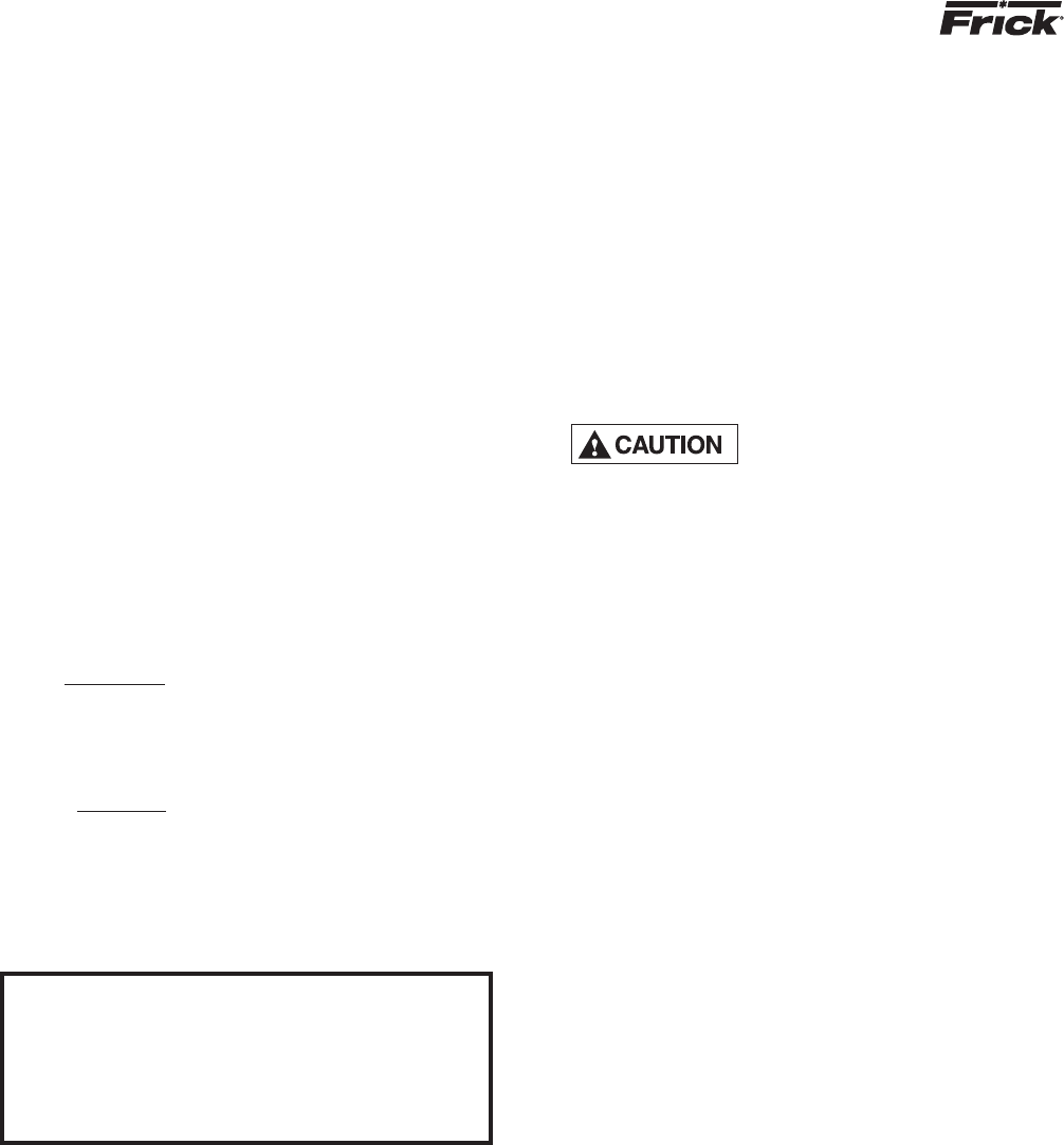
SUGGESTED PROGRAMMABLE
CONTROLLER PROGRAM TO DECODE
MICROPROCESSOR OUTPUT DATA CODES
RWB II PLUS MICROPROCESSOR CONTROL
OPERATION
S70-200 OM (DEC 99)
Page 15
OUTPUT NO.
TERMINAL NO.
MNEMONIC
Compressor Off
Running
Slide
Valve Posi-
tion
HEX
CODES
13
34
BIT
0
0
1
0
1
0
1
0
1
0
1
0
33
14
BIT
1
0
15
32
BIT
2
0
16
31
BIT
3
0
MEANING
OUTPUT DATA CODE
Running with MLC Inhibit
Lockout on Recycle Delay
Cutout
Undefi ned
Undefi ned
1101
0011
1011
0111
1111
B
C
D
E
F
C - A master sequence controller must be installed to pro-
vide the signals to remote start and stop the compres sors
and remote load and unload the compres sors based on
the common suction pressure or other parameter and the
com pressor status based on the optional microproces sor
output data feedback. The customer may supply his own
master sequencer panel (usually a programmable control-
ler) or Frick, can supply this sequencer if desired (contact
Frick for pricing).
MASTER SEQUENCE CONTROLLER (USUALLY
PROGRAMMABLE CONTROLLER) I/O
(TYPICAL FOR EACH COMPRESSOR)
RWB II COMPRESSOR
WITH MICROPROCESSOR
(TYPICAL FOR EACH COMPRESSOR)
INPUTS
OUTPUTS
RUN COMPRESSOR
LOAD COMPRESSOR
UNLOAD COMPRESSOR
SPARE
BIT 1
BIT 0
BIT 2
BIT 3
INPUTS
OUTPUTS
MASSEQ1
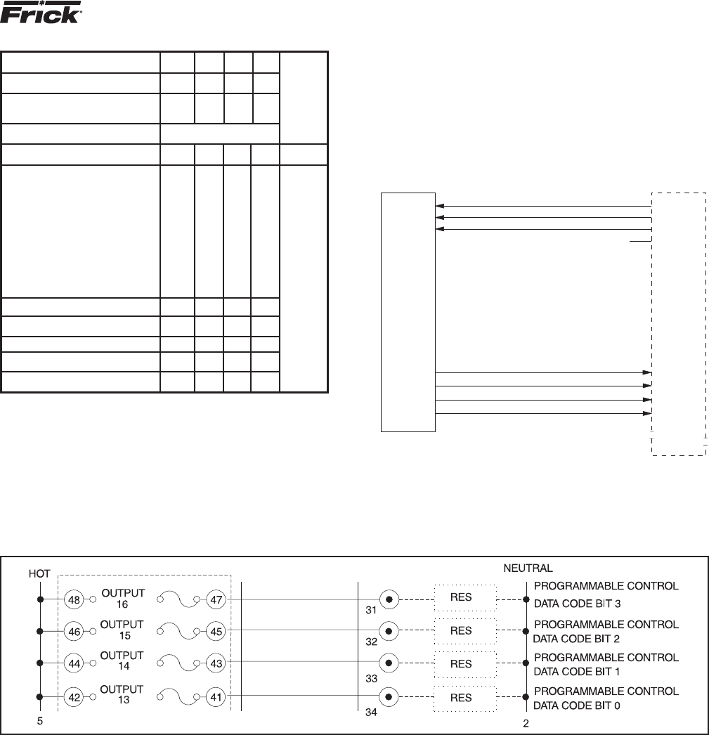
MICROPROCESSOR OUTPUT DATA CODE
A 3.5 K OHM, 10 watt resistor (RES) must be fi eld installed, as shown below, when the 120 VAC outputs of the RWB II PLUS are
driving 120 VAC solid state input devices such as programmable controllers.
10%
20%
30%
40%
50%
60%
70%
80%
90%
100%
0
0
0
0
1
1
1
1
0
0
0
0
0
0
0
0
0
0
1
1
1
0
1
1
0
0
1
1
0
0
1
1
2
3
4
5
6
7
8
9
A

RWB II PLUS MICROPROCESSOR CONTROL
OPERATION
S70-200 OM (DEC 99)
Page 16
COMPRESSOR STOP COMMANDS: #01S01
# Start command sequence.
01 Compressor ID code.
S Stop compressor command.
01 ID code repeated for verification
NOTE: The compressor must be in the remote
start mode for this command to be executed.
Returned answer: A01
Character Description
Position of returned data
1 Acknowledge of command sent.
2,3 ID code of compressor.
(Carriage return, line feed.)
MICROPROCES SOR
TEL ECOM MUNICATIONS
The following details are typical and
may or may not match the software
supplied on your compressor. The
telecommunications capabilities are continuously being
expanded and improved. Therefore, you MUST consult
FRICK Company for the exact details on your particular
unit(s) before developing system software to interface
with your compressors.
The Frick RWB II PLUS Microproce ssor comes with an on
board telec om munications interface. The telecom munica tions
feature permits interfac ing the micro processor with a modem,
remote data communica tions terminal, or master computer
via RS-422 protocol. In the case of a modem, telephone
lines are used for the actual transmis sion of data permitt ing
com munications from a remote location.
The components necessary to utilize the telecom munica tions
feature will vary with the applica tion. Information concerning
these items may be obtained from Frick Company, Waynes-
boro, Pa.
COMMUNICATIONS PROTOCOL
SPECIFICATIONS:
All commands must be in ASCII (CAPS) to be recog nized. A
compressor with an ID code of [00] is considered disabled.
ID Codes from [01] through [99] are valid and are recognized
by the microproces sor.
The following is a complete list of available command types:
COMMAND CODE and DESCRIPTION
I = Returns compressor status information.
R = Compressor start command.
S = Compressor stop command.
V = Compressor slide valve control command.
D = Compressors display screens command.
P = Return Pressures information.
T = Return Temperatures information.
A = Return full load amps information.
C = Enter Change setpoints mode.
The following is a detailed description of each command:
RETURN COMPRESSOR STATUS INFORMATION: #01I
# Start of command sequence.
01 Compressor ID code.
I Return Status information command.
RETURNED ANSWER, ie: 090RRRN340
Character Description
Position of returned data
1,2,3 Slide valve position.
4 Rem o te, Auto, Manual (slide valve)
5 Del a y-recycle, Run n ing, Off.
6 Rem, Man, Off, Auto (Compres sor mode)
7 Cutout, Alarm, Normal.
8,9,10 Suction in PSIA.
(Carriage return, line feed.)
COMPRESSOR START COMMAND: #01R01
# Start command sequence.
01 Compressor ID code.
R Start compressor command.
01 ID code repeated for verification
NOTE: The compressor must be in the remote
start mode for this command to be executed.
Returned answer: A01
Character Description
Position of returned data
1 Acknowledge of command sent.
2,3 ID code of compressor.
(Carriage return, line feed.)
SLIDE VALVE CONTROL COMMANDS: #01VLXX
#01VUXX
#01VS
# Start command sequence.
01 Compressor ID code.
V Compressor control command.
L Load Slide valve command.
U Unload slide valve command.
XX = 00 Turns selected output off.
XX = 01 to 15 Turns selected output on
for XX seconds.
XX = 99 Turns selected output on.
S Return slide valve position value.
If the command was #01VL00, then the load
slide valve output on compressor #1 would
be turned off. If the command was #01VL05,
then the load slide valve output on com-
pressor #1 would be turned on for 5 sec
onds, and would then automatically turn
off. NOTE: the slide valve must be in the
remote mode for this command to be executed.
RETURNED ANSWER (for L or U commands): A01
Character Description
Position of returned data
1 Acknowledge of command sent.
2,3 ID code of compressor.
(Carriage return, line feed.)
RETURNED ANSWER (for S command), ie. 090
1,2,3 Slide valve position.

RWB II PLUS MICROPROCESSOR CONTROL
OPERATION
S70-200 OM (DEC 99)
Page 17
QUERY SETPOINTS DATA - #IDQ1 will return
Pos # Byte(s) Setpoint (Name/Comment)
1 1 Always “O”
2,3,4,5 4 Ccsp. 3 chars followed by
g or h
6,7,8,9 4 Low suct. press. cutout. 3
chars followed by g or h
10,11,12,13 4 Low suct. press. alarm. 3
chars followed by g or h
14,15 2 Prop. band
16,17 2 Dead band
18,19 2 Cycle time
20,21,22,23 4 Future
24,25,26,27 4 Future
28,29,30,31 4 Future
32,33 2 Future
34,35 2 Future
36,37 2 Future
38,39,40,41 4 Hpco
42,43,44,45 4 Hpa
46 1 ID (tenths position byte)
47 1 ID (ones position byte)
48 1 Checksum of all data (pos. 1
to 47)
49 1 CR code 13
50 1 LF code 10
51 1 O null terminator char.
COMPRESSOR DISPLAY SCREENS COMMAND: #01DXN
# Start command sequence.
01 Compressor ID code.
D Compressor control command.
X = 0 Operating display.
X = S Adjustable setpoints display.
X = D2 Adjustable setpoints Page 2.
X = X Fixed setpoints display.
X = R Shutdown record display.
X = F Freeze display.
X = C Autocycle display.
X = P Security display.
X = B Setback display.
X = + Analog offset display.
X = AN Annunciator display page “N”
N = 1 Display page #1. NOTE: “N” para-
N = 2 Display page #2. meter uses to
N = 3 Display page #3. access annunci-
N = 4 Display page #4. ator pages.
If the command was #01DA1, then the micro-
processor would dump the annunciator display
page number one. Display dumps consist of
336 characters each.
RETURN PRESSURES COMMAND: #01PX
# Start command sequence.
01 Compressor ID code.
P Return pressures command.
X = S Return suction pressure (PSIA).
X = D Return discharge pressure (g/hg).
X = O Return oil pressure (g).
X = F Return filter differential pressure.
X = A Return all pressures.
If the command was #01PS, then the micro-
processor would dump the suction pressure.
RETURNED ANSWER
XXX = 3 characters followed by a carriage
return, line feed.
If using the “A” command, then the returned
data would be:
XXXXXXXXXXXX = 12 characters followed by a
carriage return, line feed.
RETURN FULL LOAD AMPS COMMAND: #01A
# Start command sequence.
01 Compressor ID code.
A Return full load amps command.
If the command was #01A, then the micro
processor would dump the full load amps value.
RETURNED ANSWER:
XXX = 3 characters followed by a carriage
return, line feed.
RETURN TEMPERATURES COMMAND: #01TX
# Start command sequence.
01 Compressor ID code.
T Return temperature command.
X = S Return suction temperature.
X = D Return discharge temperature.
X = O Return oil temperature.
X = P Return separator temperature.
X = A Return all temperatures as a string
of data.
If the command was #01TS, then the micro-
processor would dump the suction temperature.
RETURNED ANSWER:
XXX = 3 characters followed by a carriage
return, line feed.
If using the “A” command, then the returned
data would be:
XXXXXXXXXXXXX = 13 characters followed by a
carriage return, line feed.
NOTE: The “S” command will return four (4)
characters followed by a carriage re
turn, a line feed and “+ or - .xxx”.

RWB II PLUS MICROPROCESSOR CONTROL
OPERATION
S70-200 OM (DEC 99)
Page 18
QUERY SETPOINTS DATA - #IDQ2 will return
Pos # Byte(s) Setpoint (Name/Comment)
1,2,3 3 Future
4,5,6 3 Future
7,8,9 3 Mlc amps stop load
10,11,12 3 Mlc amps force unload
13,14,15 3 Ctf
16,17 2 Recycle delay (setpoint, not
time left)
18 1 Aux 1 0=alarm, 1=shutdown
19 1 Aux 1 0=NO, 1=NC
20 1 Aux 2 0=alarm, 1=-shutdown
21 1 Aux 2 0=NO, 1=NC
22 1 Future
23,24 2 Future
25 1 Future
26 1 Future
27,28 2 Future
29 1 Future
30 1 ID (tenths position byte)
31 1 ID (ones position byte)
32 1 Checksum of all data (pos. 1
to 31)
33 1 CR code 13
34 1 LF code 10
35 1 0 null terminator char.
QUERY SETPOINTS DATA - #IDQ3 will return
Pos # Byte(s) Setpoint (Name/Comment)
1,2,3,4 4 Setback setpoint
5,6,7,8 4 Future
9 1 Setback active 1=yes, 0=no
10,11,12,13 4 Autocycle comp. start
14,15,16,17 4 Autocycle comp. stop
18,19 2 Future
20,21 2 Future
22,23 2 Autocycle min. sv.
24 1 Autocycle active 1=yes, 0=no
25,26,27,28 4 Future
29,30,31,32 4 Future
33,34 2 Future
35,36 2 Future
37,38 2 Future
39 1 Future
40 1 ID (tenths position byte)
41 1 ID (ones position byte)
42 1 Checksum of all data (pos. 1
to 41)
43 1 CR code 13
44 1 LF code 10
45 1 0 null terminator char.
g or h must be lower case - exception to "All commands
must be caps" statement at beginning of section.
CHANGE SETPOINTS COMMAND: #01C
# Start command sequence.
01 Compressor ID code.
C Change setpoint command.
xxx New setpoint
xx New setpoint
y g or h for gauge or inches
The following is the complete list of the
setpoints that may be changed while in the
change setpoints command:
01xxxy Capacity Control Setpoint
("y" deleted for KpaA & BarA ver.)
02xxxy Change Low Pressure Cutout Setpoint.
("y" deleted for KpaA & BarA ver.)
03xxxy Change Low Pressure Alarm Setpoint.
("y" deleted for KpaA & BarA ver.)
04xxx Change High Pressure Cutout Setpoint.
("xxxx" is used for KpaA & BarA ver.)
05xxx Change High Pressure Alarm Setpoint.
("xxxx" is used for KpaA & BarA ver.)
06xxx Change MLC Stop Load Setpoint.
07xxx Change MLC Force Unload Setpoint.
08xx Change Recycle Delay Setpoint.
09xxx Change CTF Setpoint.
10xx Proportional Band (PB)
11xx Dead Band (DB)
12xx Cycle Time (CT)
01 Compressor ID code.
PB 02, 05, 10, 15, 20, 25
DB 05, 10, 15, 20, 25, 30, 35, 40, 45, 50,
(decimal is assumed i.e. 01 = 0.1)
CT 05, 10, 15, 20, 25, 30
RETURNED ANSWER:
Axxxx The new setpoint which was sent
followed by a carriage return,
line feed.
“BAD” followed by the “ID”, “CR”,“LF”
if unsuccessful.
If the command was sent #01C01300g01, the
capcity control setpoint would be changed to
30.0g and the returned answer is A300g
followed by a carriage return, line feed.
If the command sent was #01C0711001, the MLC
force unload setpoint would be changed to 110%
and the returned answer is A110 followed by
a carriage return, line feed.
If the command sent was #01C0520002, the
returned answer is “BAD” followed by the ID
number and a carriage return, line feed.

RWB II PLUS MICROPROCESSOR CONTROL
OPERATION
S70-200 OM (DEC 99)
Page 19
CHANGE COMPRESSOR MODE COMMAND:
#IDMCmlD Change mode to m.
O=off A=autocycle R=remote
Return message - “A” followed by the “lD”,
CR”, “LF” if successful.
CHANGE SLIDE VALVE MODE COMMAND:
#IDMVmlD Change Slide Valve mode.
to m. A=auto R=remote
Return message - “A” followed by the “ID”,
“CR”, “LF” if successful.
CLEAR FAILURE COMMAND:
#IDKFID Clear Fails
Return message - “A” followed by the “lD”,
“CR”, “LF” if successful.
CLEAR ANTIRECYCLE COMMAND:
#IDKRID Clear Recycle Delay
Return message - “A” followed by the “ID”,
“CR”, “LF” if successful.
RETURN AC IO COMMAND:
#IDX Return Descrete AC IO Status Command:
Returns a 24 char data string followed by ID,
CR, LF. The 1st data
element represents input #1, the last element
represents output # 16.
1=energized or on, 0=deenergized or off.
RETURN FAILURE COMMAND:
#IDF Return Descrete Failure List Command:
Returns a 24 char data string followed by ID,
LF.
The 1st data element represents the 1st failure
on page 1 of the annunciator, the
last element represents the last failure on
annunciator page 4.
1=failed, 0=safe.
NOTE: not all pages or annunciator failure el-
ements are defined.
READ CONTROL TEMPERATURE COMMAND:
#JDTT Reads the control temp. from TE-5 (chan-
nel 5).
Returned Answer: +lll, CR, LF The + represents
the sign of the temperature.
The decimal is assumed between the third and
fourth character.
TEMPERATURE/PRESSURE CONTROL
COMMUNlCATlONS DATA
ADDITIONAL DISPLAY DUMP COMMAND:
#IDD1 Will dump SETPOINTS PAGE 1 (new display)
#IDDS Will dump ADJUSTABLE SETPOINTS (std
display)
#IDDC Will dump AUTO-CYCLE SETPOINTS (std
Pressure display)
#IDDT Will dump AUTO-CYCLE SETPOINTS (new
Temperature display)
CHANGE SETPOINTS COMMAND:
# Start command sequence
ID Compressor ID code
C Change setpoint command
x numeric datum field
y g or h for gauge or inches datum field
+ + or- Sign datum field
Command Prefix #IDC##datumID
## datum Description of setpoint
01xxxy Capacity Control
(“y” is deleted for KpaA & BarA ver.)
02xxxy Low Press. Cutout
(“y” is deleted for KpaA & BarA ver.)
03xxxy Low Press. Alarm
(“y” is deleted for KpaA & BarA ver.)
04xxx High Press. Cutout
(“xxxx” is used for KpaA & BarA ver.)
05xxx High Press. Alarm
(“xxxx” is used for KpaA & BarA ver.)
06xxx MLC Stop Load
07xxx MLC ForceUnload
08xx Recycle Delay
O9xxx CTF
10xx Press. Proportional Band
11xx Press. Dead Band
12xx Press. Cycle Time
13+xxx Temp. Capacity Control
14+xxx Temp. Low Temp Cutout
l5+xxx Temp. Low Temp Alarm
16xx Temp. Proportional Band
17xx Temp. Dead Band
18xx Temp. CycleTime
19x Pressure / Temperature mode. ( x=1 for
temp. x=0 for pressure )
Ranges for PB, DB, CT pressure control
setpoints: (allowable entries)
PB 02, 05, 10, 15, 20, 25
DB 05, 10, 15, 20, 25, 30, 35, 40, 45, 50
(decimal is assumed eg. 01 = 0.1)
CT 05, 10, 15, 20, 25, 30
Ranges for PB, DB, CT temperature control
setpoints: (allowable entries)
PB 02, 05, 10, 15, 20, 25
DB 01 through 30 (decimal is assumed eg. 01
= 0.1)
CT 05, 10, 15, 20, 25, 30
RETURNED ANSWER:
Axxxx The new setpoint which was sent
followed by a carriage return,
line feed.
“BAD” followed by the “ID”, “CR”, “LF”
if unsuccessful.
RWB II PLUS MICROPROCESSOR CONTROL
MAINTENANCE
S70-200 OM (DEC 99)
Page 20
Maintenance
TROUBLESHOOTING THE RWB II PLUS
MICROPRO CESSOR
This section contains information on troubleshooting and
making corrections to the microprocessor and control cir-
cuits of the RWB II PLUS unit. The section is composed of
four parts: a general information section, a troubleshoot ing
guide, a repair procedure guide, and a section with illustrative
schematics and data.
GENERAL INFORMATION
THE COMPONENTS WITHIN THE
MICRO PROCESSOR CONSOLE
CAN BE INADVERTENTLY DAM-
AGED BY STATIC ELECTRICITY OR MIS HANDLING.
ONLY QUALIFIED TECH NICIANS SHOULD DIRECTLY
HANDLE THESE COMPONENTS.
1. DO NOT REMOVE the microprocessor console cover or
attempt to make corrections to the microprocessor power
supply without shutting off the control power. Accidental
shorts can irreparably damage the SBC (single board com-
puter) or the display screens.
2. DO NOT HANDLE the SBC or the display screen boards
when their cables are disconnected without fi rst attaching
a ground strap to prevent static electrical discharge from
your body.
Most problems encountered with the microprocessor and
control circuits will be the result of a wiring fault, blown fuse,
or failure of a peripheral control such as a solenoid coil or
a pressure transducer. Faults in the computer, while pos-
sible, are unlikely. If a fault develops in the computer, the
probability is that all functions will cease and the display
screens will go blank.
The control system of the RWB II PLUS compressor consists
of a 120 volt AC (high voltage) side and a 0-15 volt DC (low
voltage) side. The 120 volt side actuates solenoids, relays,
alarms, and other electro mechanical functions. The 0-15
volt DC side operates the computer and its various sensors.
The microproces sor console contains the SBC (single board
computer) and two display screens.
When working within the micropro-
cessor console, 120 VOLTS CAN
CAUSE INJURY OR DEATH.
To troubleshoot the low voltage side of the RWB II PLUS
control circuits, it is necessary to have the following tools:
1. Accurate digital multimeter.*
2. Small wire stripper.
3. Small screwdriver.
4. Small snip nose pliers.
5. 15 watt soldering iron (no larger).
6. .032,60/40 rosin core solder.
7. IC chip extraction and insertion tools.*
8. Grounding strap.*
9. Static free grounded work surface.
* Available from Frick. Order kit 451862.
TROUBLESHOOTING FRICK SBC MICROPROC ESSOR SYSTEM
(REFER TO WIRING DIAGRAMS)
SYMPTOM PROBABLE CAUSES and CORRECTIONS
DISPLAYS ARE INOPERATIVE Check the 10 amp fuse (2FU) which controls all voltage going to the
micro processor.
Shut off power to the microprocessor. Remove the console cover and confi rm
that all cable and wire connections are made.
OIL PUMP DOES NOT START Verify that the Oil Pump HAND-OFF-AUTO switch (1SS) is in the AUTO
position and that the Emergency Stop Button is not depressed.
Output 11 controls the Oil Pump Starter Relay (3CR) when in the AUTO mode.
If HAND is selected on 1SS, Output 11 will not have any effect on the
operation of the oil pump starter.
If AUTO has been selected and the oil pump does not start, check for 120VAC
between Wires 39 and 2. If 120VAC is not found when the LED for Output 11
is on, check the fuse (FU11). If the problem persists, check the control
relay (3CR).
The Oil Pump Starter Auxiliary Contact switches voltage to Input 6 (Wires
28 and 2) when the auxiliary contacts are closed and the AUTO mode is
selected on 1SS. If the Input does not turn on and voltage is present at
Input 6, consult Frick Company.

RWB II PLUS MICROPROCESSOR CONTROL
MAINTENANCE
S70-200 OM (DEC 99)
Page 21
TROUBLESHOOTING FRICK SBC MICROPROCESSOR SYSTEM (Continued)
SYMPTOM PROBABLE CAUSES and CORRECTIONS
OIL PUMP IS RUNNING BUT THE The (HAND-OFF-AUTO) Oil Pump Selector Switch (1SS) controls oil pump operation
COMPRESSOR DOES NOT START and must be in the AUTO position before the compressor can be started.
Verify that the Slide Valve has unloaded to 5% or less. If the Slide Valve
has not unloaded, trouble shoot the hydraulic system. Compressor will not
start until the Slide Valve is unloaded.
Output 1 controls the motor starter. Check between terminals 38 and 2 for
120VAC. If 120VAC is not found when the LED for Output 1 is on, check
the 1.5 amp fuse (FU1).
COMPRESSOR AUXILIARY Output 1 controls the Compressor Start Relay (2CR). If the compressor does
SHUTDOWN not start and the LED for Output 1 is on, check the fuse (FU1). If the
problem persists, check the interposing relay (2CR).
The Compressor Starter Auxiliary Contacts turn on Input 5 when they are
closed. These contacts are located on the Compressor Starter.
OIL HEATERS DO NOT OPERATE The oil heaters should operate only when the compres sor is NOT running and
the oil in the separator sump is cold.
If the oil heaters do not work check fuse 1FU (15 amp). If the fuse is not
blown, check between Wires 25 and 2 and between Wires 26 and 2 for 120VAC.
If 120VAC is not found, check between wires 25 and 26. If 120VAC is found
between wires 25 and 26, the Oil Heater Relay is defective. Next, check
the voltage between Wires 9 and 2. If 120 VAC is present, the Oil Heater
Relay is defective.
If you do not read 120VAC between Wires 9 and 2 when the LED for output 10
is on, check the fuse (FU10).
SLIDE VALVE DOES NOT LOAD Verify that the Slide Valve is in the AUTO mode and that capacity control
and/or UNLOAD is calling for loading or unloading (AUTO L or AUTO U will appear on the Operating display).
Output 2 controls the Slide Valve Load Solenoid. If 120VAC is found across
Wires 17 and 2, the Slide Valve Load Solenoid should be energized. If not,
the solenoid is defective. If 120VAC is not found when the LED for Output 2
is on, check the fuse (FU2).
Output 3 controls the Slide Valve Unload Solenoid. If 120VAC is found
across Wires 16 and 2, the Slide Valve Unload Solenoid should be energized.
If not, the solenoid is defective. If 120VAC is not found across Wires 16
and 2 when the LED for Output 3 is on, check the fuse (FU3).
NOTE: Verify that the proper setpoint has been programmed into C.C.
(Capacity Control) on the Adjustable Setpoints display.
SLIDE STOP DOES NOT INCREASE Verify that the Slide Stop is in the AUTO mode and that the Vi Ratio is
and/or DECREASE calling for a Vi increase or a Vi decrease (AUTO I or AUTO D will appear
on the Operating display).
Output 4 controls the Slide Stop Increase Solenoid. If 120VAC is found
across Wires 15 and 2, the Slide Stop Increase Solenoid should be
energized. If not, the solenoid is defective. If 120VAC is not found across
Wires 15 and 2 when the LED for Output 4 is on, check the fuse (FU4).
Output 5 controls the Slide Stop Decrease Solenoid. If 120VAC is found
across Wires 14 and 2, the Slide Stop Decrease Solenoid should be
energized. If not, the solenoid is defective. If 120VAC is not found across
Wires 14 and 2 when the LED for Output 5 is on, check the fuse (FU5).

RWB II PLUS MICROPROCESSOR CONTROL
MAINTENANCE
S70-200 OM (DEC 99)
Page 22
TROUBLESHOOTING FRICK SBC MICROPROC ESSOR SYSTEM (Continued)
SYMPTOM PROBABLE CAUSES and CORRECTIONS
LIQUID INJECTION SOLENOID Verify that the Liquid Injection TXV is modulating properly and not feeding
DOES NOT ENERGIZE (LIQUID excessive liquid to the compressor. When oil temperature drops too low, the
INJECTION REFRIGERANT CUTOUT microprocessor SHOULD de-energize this solenoid.
- LICO)
Output 6 controls the Liquid Injection Solenoid. If 120VAC is found across
Wires 13 and 2, the Liquid Injection Solenoid should be energized. If not,
the solenoid is defective. If 120VAC is not found when the LED for Output 6
is on, check the fuse (FU6).
HI VI LIQUID INJECTION PORT Output 7 controls the Hi Vi Liquid Injection Port solenoid. If 120VAC is
(OPTIONAL) SOLENOID DOES NOT found across Wires 12 and 2, the Hi Vi Liquid Injection Port Solenoid
ENERGIZE should be energized. If not, the solenoid is defective. If 120VAC is not
found when the LED for output 7 is on, check the fuse (FU7).
NOTE: This output should only be on when the Vi is above 3.4
ECONOMIZER (OPTIONAL) Output 8 controls the Economizer Solenoid Valve. If 120VAC is found across
SOLENOID DOES NOT ENERGIZE Wires 11 and 2, the Economi zer Solenoid should be energized. If not, the
solenoid is defective. If 120VAC is not found when the LED for Output 8
is on, check the fuse (FU8).
NOTE: The economizer output should only be on when the slide valve is at or
above the 90% position.
ALARM HORN DOES NOT ENERGIZE Output 9 controls the Alarm Horn. The Alarm should turn on only when there
is a prealarm. If the Alarm does not sound when these conditions are
found, check for 120VAC across Wires 10 and 2. If 120VAC is not found,
check the fuse (FU9).
CONTROL PANEL DOES NOT Inputs 2 through 4 can be used to operate the compressor from a remote
RESPOND TO REMOTE CONTROL location. NOTE: Check the Operating display to verify that the compressor
SIGNALS and the slide valve are in the REMOTE MODE.
If 120VAC is found (across Wires 21 and 2, 22 and 2, and 23 and 2) and the
input does not turn on, consult Frick Company.
MOTOR LOAD CONTROL The current transducer is used to convert the AC motor amps to a DC voltage
(FORCED UNLOAD) OCCURS signal for the micropro cessor. If the %FLA reading from the Operating
AT LOW MOTOR AMPS display is incorrect, consult Frick.
PRESSURES ON THE OPERATING TEST 1 - Shut down the compressor and allow pressures to equalize. Suction
DISPLAY DO NOT APPEAR pressure, discharge pressure, and oil pressure should have the same reading.
CORRECT
TEST 2 - If either oil pressure or discharge pressure read different
pressures, one or both transducers are at fault. Valve off the suction
transducer from the unit and open the vent valve on transducer manifold to
atmosphere. If the suction transducer reads atmos pheric pressure, then the
high pressure transducer which agreed with the suction transducer in Test 1
is correct. The transducer which disagreed is defective.
NOTE: A 1% tolerance is allowed for all transducers.
COMPRESSOR DOES NOT AUTO- Verify that the [AUTO] key has been pressed and AUTO appears under SV Pos
MATICALLY LOAD OR UNLOAD on the Operating display.
If the problem persists, see the Troubleshooting section SLIDE VALVE
DOES NOT LOAD and/or UNLOAD.
DISPLAY SCREENS DISPLAY A loose or improper connection between the displays and the SBC is
SCRAMBLED PATTERN OR indicated. Remove fuse (2FU, 10 amp) for 15 seconds and, then, restore to
LISTS ALPHABET reset the displays.

RWB II PLUS MICROPROCESSOR CONTROL
MAINTENANCE
S70-200 OM (DEC 99)
Page 23
Testing Micro-Panel Alarms / Cutouts
The following are testing proce-
dures that may be used as a means
of testing the standard safeties
provided on the RWB II Frick Rotary Screw Compressor
Unit with a RWB II Plus microprocessor. They should
only be completed by a competent individual with full
understanding of safe operating procedures as they ap-
ply to industrial refrigeration. If there are any questions
in regard to any one of these procedures, do not attempt
prior to consulting Frick at (717) 762-2121.
High Discharge Press. Alarm / Cutout
1. Once the machine is up and running and maintaining an
even discharge pressure, go to the adjustable setpoints
display (record the values for the Hi Disch Alarm and
Cutout).
2. Step down to the Hi Disch Alarm setpoint and enter a
value of 10 psig lower than the current running Discharge
Pressure.
3. Then go back to the operating display to check for an
alarm. If no alarm exists, ensure that the current discharge
pressure is indeed above the new alarm value.
4. If you do have an alarm, go to Hi Disch Cutout and reset
the value to 5 psig below the current running pressure.
5. You should instantly receive the cutout. If the cutout was
not received, ensure that the value is still lower than the
running pressure.
6. If a cutout was received return to the adjustable setpoints
screen and reenter the original alarm and cutout value.
Clear the alarm and cutout.
7. Allow the recycle delay to elapse and proceed to the next
test.
Low Suction Press. Alarm / Cutout
1. With the machine running and maintaining an even suction
pressure, go to the adjustable setpoints screen (record
the values for the Lo Suct Alarm and Cutout).
2. Step to the Lo Suct Alarm and enter a value 3 psig or 3
in. hg higher than the current running pressure.
3. Return to the operating display and check for an alarm.
If no alarm exists check to ensure that the current run-
ning suction pressure is indeed lower than the new alarm
value.
4. If an alarm was received, go to the Lo Suct Cutout and
set the value 5 psig or 5 in. hg higher than the current
running pressure.
5. Once the cutout occurs, go back and reset to the original
values, and clear the cutout and alarm. Allow the recycle
delay to elapse and proceed.
Note: The Lo Suct Cutout has a 90 second delay.
Oil Pressure Alarm / Cutout
1. Push the +/- button and record the Oil Pressure value
from the analog offset display (Example: +2).
2. With the machine running and maintaining good, even oil
pressure, push the [+/-] button to access the analog offset
screen.
3. Step to the oil pressure value and max it out to +9. This
must be done to avoid a sensor fault failure.
4. At the transducer manifold, close the valve for the oil
pressure transducer (PE-1) and then open the vent valve
which exposes the transducer to atmosphere.
5. Once the time delays have expired (30 seconds for the
alarm and an additional 10 seconds for the cutout), an
alarm and cutout will occur.
6. Place valves back into their operating position and replace
the pipe plug in the vent.
7. Return to the analog offset screen and reset the offset
back to the original value.
8. Clear the alarm and cutout. Allow the recycle delay to
elapse, then proceed to the next test.
Hi Oil Temp Alarm / Cutout
1. Record the values for Hi Oil Temp Alarm and Cutout
stated on the fi xed setpoints display.
2. Carefully remove temperature probe TE-3, located down-
stream from the oil fi lter.
3. Slowly apply heat to the probe with a forced-air device
such as a heat gun or blower dryer.
4. Once the temperature rises to the alarm value stated on
the fi xed setpoints display, an alarm should be received
with no delay.
5. Allow the temperature to continue rising until the cutout
temperature is met and the cutout is received with no
delay. Allow probe to cool then reinstall in the well.
6. Allow the recycle delay to elapse and proceed with the
next test.
Lo Oil Temp Alarm / Cutout
1. Record the values for Lo Oil Temp Alarm and Cutout
from the fi xed setpoints display.
2. Carefully remove TE-4 from the belly of the separator and
immerse the probe into a crushed ice water bath.
3. Once the temperature drops to the alarm value the alarm
will be received without delay. Allow the temperature to
continue falling until the cutout value is met and occurs
without delay. Reinstall TE-4.
4. Clear the alarm and cutout. Allow the recycle delay to
elapse and proceed to the next test.
Hi Disch Temp Alarm / Cutout
1. Record the Hi Disch Temp Alarm and Cutout values
from the fi xed setpoints display.
2. With the machine running, remove the discharge tempera-
ture probe TE-2 located on the discharge pipe between
the compressor and the separator.
3. Using a forced-air heat source, such as a heat gun or
blow dryer, slowly add heat to the probe and monitor the
operating display until the temperature exceeds the alarm
value and the alarm sounds.
4. Continue adding heat until the cutout value is met and
exceeded. The cutout should be received without delay.
Reinstall TE-2.
5. Clear the alarm and cutout. Allow the recycle delay to
elapse and proceed to the next test.
Never expose the probe to a direct
open fl ame during test. Rapid tem-
perature rise could cause the probe
to stick or short in the closed position which would
require the probe to be changed.
Comp. Auxiliary
1. Remove #20 wire from terminal strip P3 and place a wire
nut over the end.
2. Push the RUN button.
3. If the input #5 does not receive a signal from the Compres-
sor Auxiliary Contact, the machine will cut out 16 seconds
after 2CR is energized.
4. Replace the #20 wire.
5. Clear the Cutout.
6. Allow the recycle delay to elapse and proceed to the next
test.

RWB II PLUS MICROPROCESSOR CONTROL
MAINTENANCE
S70-200 OM (DEC 99)
Page 24
Pump Auxiliary
1. Remove #19 wire from terminal strip P3 and place a wire
nut over the end.
2. Push the RUN button.
3. If input #6 does not receive a signal after 2 1/2 seconds
from the time 3CR was energized, a cutout will occur.
4. Replace the #19 wire.
5. Clear the cutout and proceed to the next test.
Oil Level
1. Remove wire #24 from terminal strip P3 and place a wire
nut over it.
2. Push the RUN button.
3. If input #1 does not receive a signal within 5 minutes, a
cutout will occur.
4. Replace wire #24.
5. Clear the cutout.
6. Allow the recycle delay to elapse and proceed to the next
test.
NOTE: The oil level cutout is not present on units with
full lube pumps. If you are unsure of the pump type on
your unit, contact Frick Service for confi rmation.
Dirty Filter
1. Push the [+/-] key and record the Oil Pressure value from
the analog offset display (Example: +2).
2. With the machine running and maintaining good pres-
sures and temperatures, push the +/- button to access
the analog offset screen. Step to the oil pressure value
and max it out to +9. This must be done to avoid a sensor
fault cutout.
3. At the transducer manifold, close the valve for transducer
PE- 1 and open the bleed valve for that transducer to at-
mosphere which will bring the pressure down to 0 psig.
4. In about 15 seconds, a dirty fi lter alarm will occur.
5. Quickly close the bleed valve and open the valve to PE-1
to avoid an oil pressure alarm/cutout.
6. Clear the alarm.
7. If cutout occurs, ensure that the valves are in their oper-
ating position, and the plug has been put back into the
vent.
8. Return to the analog offset screen and reset the offset
back to the original value.
9. Allow for the recycle delay to elapse and restart the ma-
chine.

RWB II PLUS MICROPROCESSOR CONTROL
MAINTENANCE
S70-200 OM (DEC 99)
Page 25
EPROM MEMORY I/C CHIP REPLACEMENT
Microprocessor EPROM memory I/C chips are located inside
the microprocessor console on the SBC board. A special
tool is required to remove these chips to lessen the chance
of damaging them (See Troubleshooting The Microproces-
sor). The procedure to replace EPROM memory chips is
outlined below:
1. Shut off control power.
2. Remove the microprocessor console cover.
3. Using a chip extraction tool, remove the old EPROM chips
from the SBC board. Pay particular attention to the orienta-
tion of the notch on the end of the chip; then install new chip
with the notch in the same position. NOTE: The chip labeled
4 must be in serted into socket U4 and the chip labeled
5 must be inserted into socket U5.
SBC BOARD REPLACEMENT
The procedure to replace SBC boards is outlined below:
1. Shut off control power.
2. Remove the old board from the machine and the new
board from its packing and place both on an antistatic
surface.
3. Remove the program chip(s) from the defective board and
install them in the replacement board.
Pay particular attention to the ori-
entation of the notch(es) on the end
of the chip(s). Install the chip(s) on
the replacement board in exactly the same position as
they were on the defective board.
4. IMPORTANT: Before installing the new board, determine
if there are gray/yellow wires from P15 (see the SBC wiring
diagram for location) on the old board. If they are present, the
display is the old style and the new board can be installed
without modifi cation.
5. If the gray/yellow wires are not present on the old SBC,
the machine is equipped with a new style display. Resistor
R6 must be removed from the new board by cutting the wire
leads on either side of the resistor.
6. Then install the modified replacement board in the
panel.
MICROPROCESSOR DISPLAY
REPLACEMENT
The procedure to replace the microprocessor display is
outlined below:
1. Shut off control power.
2. Remove the defective display(s).
3. Install the new display(s).
4. If present, remove the grey/yellow wires from P15 (see
the SBC wiring diagram for location) to the display(s) as they
are no longer needed.
5. If resistor R6 is present on the SBC, cut off the wire leads
on both sides (see the SBC wiring diagram for location) and
remove it. This resistor is no longer needed.
OUTPUT FUSE REPLACEMENT
1. Shut off control power.
2. Remove the microprocessor console cover.
3. Identify the faulty fuse.
4. Use a voltmeter to verify that no voltage is present on
either side of the fuse.
5. Remove the faulty fuse using a fuse puller or screw-
driver.
6. Install a new plug-type fuse.
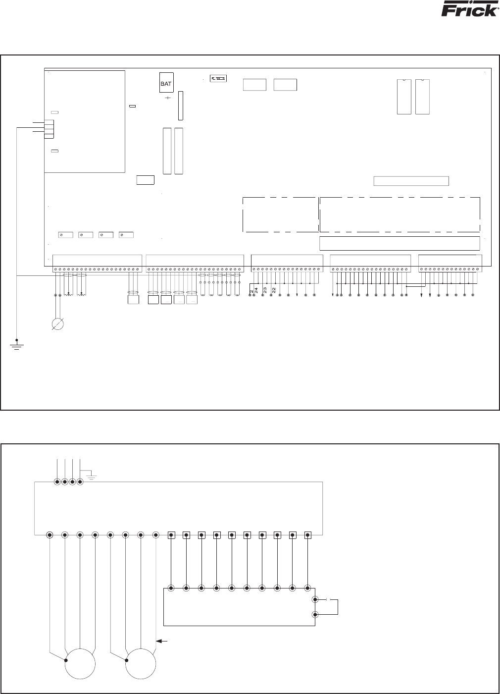
RWB II PLUS MICROPROCESSOR CONTROL
MAINTENANCE
S70-200 OM (DEC 99)
Page 26
P2
18
6
GROUND
LUG
RED
3
RED
4
1
3
3
1
RED
BLK
WHT
RED
2
BLK
WHT
2
R
AMPS
R
MOTOR
VALVE
B
R
W
P5
B
W
R
SLIDE
STOP
SLIDE
SLIDE STOP
SLIDE STOP
SPAN
ZERO
TEMP
P4
WHT
SUCT
-
+
S
+
BLK
WHT
RED
RED
PRES
SPARE
SPARE
ECON
PRES
SPARE
--
SS
+ +
-
S
BLK
WHT
RED
BLK
BLK
WHT
RED
+
-
S
W
BLK
WHT
RED
BLK
BLK
W
B
B
FILTER
PRES
DISCH
PRES
PRES
SPARE
PRES
OIL
TEMP
SEP
ANALOG
EXPANSION
SLIDE VALVE
SLIDE VALVE
SPAN
ZERO
1
1
1
DIGITAL INPUTS
6
BLK
B
BLK
W
B
W
BLK
B
W
TEMP
DISCH
TEMP
OIL
SUCT
TEMP
1
2
3
1
2
P3
4
3
5
30
28
20
21
29
38
13
4
5
6
8
7
9
10
11
12
1
8
7
14
15
16
17
MODULES
DIGITAL INPUT
230
NEU
GND
115
2
5
BATTERY
P12
P15
P10
P6
P11
P9
OFF
ON
PORT
2
3
PORT
1
3
DIGITAL OUTPUTS
14
16
17
15
13
12
11
DIGITAL OUTPUTS
5
4
3
2
22
21
20
19
25
24
23
7
6
8
29
28
27
26
32
31
30
35
9
10
5
7
34
33
37
11
10
9
34
33
36
35
P1
12
13
14
41
40
39
38
44
43
42
DIG I/O EXPANSION
MODULES
DIGITAL OUTPUT
32
31
15
16
48
47
46
45
U5
U4
CHANNEL 16
CHANNEL 15
CHANNEL 14
CHANNEL 13
CHANNEL 12
CHANNEL 11
CHANNEL 10
CHANNEL 9
CHANNEL 8
CHANNEL 7
CHANNEL 6
CHANNEL 5
CHANNEL 4
CHANNEL 3
CHANNEL 2
CHANNEL 1
NEUTRAL
OIL LEVEL SWITCH
REMOTE RUN
REMOTE LOAD
REMOTE UNLOAD
COMPRESSOR AUX
COMPRESSOR START RELAY
OIL PUMP SEL SW
AUX 2
POWER
POWER
DATA BIT 0
DATA BIT 1
DATA BIT 2
DATA BIT 3
OIL HEATER RELAY
OIL PUMP SEL SW
SPARE ON ALL UNITS EXCEPT 496 & 676
WHERE USED AS INLET BEARING FEED
SLIDE VALVE LOAD
SLIDE VALVE UNLOAD
SLIDE STOP INCREASE
SLIDE STOP DECREASE
LIQUID INJECTION
HI VI LIQ INJ
ECONOMIZER
ALARM
AUX 1
TE-5
TE-4
TE-3
TE-2
TE-1
MOTOR
AMPS
SLIDE STOP
POSITION 3
SLIDE VALVE
POSITION 1
RWBP60
FRICK REV D
RWBII PLUS
---- ----
-----
POWER
SUPPLY
++++ ++++
+++++
SSSS SSSS
FUSES FU1 - FU6
F1
P13
F2
SBC WIRING DIAGRAM
POINT-TO-POINT FIELD WIRING DIAGRAM
RWBII PLUS
RXB PLUS
RDB PLUS
RXF
GND
20
18
19
4
3
5
8
1
2
T3
T2
T1
GNDGND
T1
T2
T3
3 PHASE LINE
GND
1
2
3
4
5
8
18
19
20
GND
FRICK MICRO ENCLOSURE
OIL
PUMP
MOTOR
3 PHASE SUPPLY TO MOTOR
MOTOR
COMPR
T3
T2
T1
GND
T3
T2
T1
GND
FRICK SUPPLIED
1. REFER TO MOTOR NAMEPLATE
FOR CORRECT MOTOR CONNECTION.
2. SEPARATE CONDUIT RUNS FOR
CONTROL VOLTAGE WIRING AND MOTOR
CONNECTION WIRING.
3. CONDUIT GROUNDS ARE NOT ACCEPTABLE.
4. ALL WIRING MUST BE PER LATEST EDITION
OF THE NEC AND LOCAL CODES.
5. ALL CONTROL VOLTAGE WIRING TO
14 AWG STRANDED COPPER WIRE.
T1
T2
T3
GND
CONSULT STARTER AND MOTOR WIRING DIAGRAMS
FOR EXACT WIRING CONFIGURATION.
HI-LEVEL CUTOUT AND/OR OTHER FIELD SAFETY
CUTOUTS AS REQUIRED.
NOTES:
COMBINATION STARTER PACKAGE
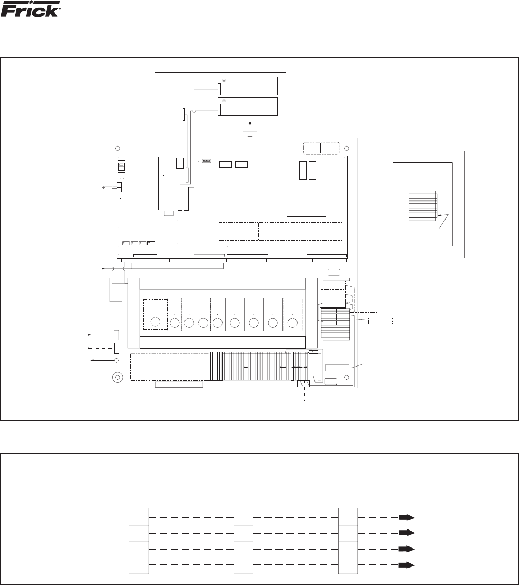
RWB II PLUS MICROPROCESSOR CONTROL
MAINTENANCE
S70-200 OM (DEC 99)
Page 27
MICRO COMPONENT PLACEMENT DIAGRAM
ANALOG
WIRING
THIS STUD NOT REQ'D
IF GROUNDING WASHER &
STUD ON SIDE ARE USED
TO DOOR & STUD
ON FRONT PANEL
CUSTOMER'S
GROUND WIRE
ANALOG
DRAIN WIRES
1A
INDICATES DEVICES SUPPLIED ONLY WHEN OPTIONAL OR REQUIRED
COPPER CONDUCTORS ONLY
GROUNDING WASHER
.
STUD
PA N EL
GREEN
LUG
GND
LUG
GND
TOROID
1TR
41
42
37
36
34
SPARE
CRCR CR CR
2 FU
REPLACEMENT
10 AMPTYPE FNM
250 VOLTS
42 TERMINALS
CUSTOMER'S CONTROL
POWER CONNECTION
L2 L1
5
17
23
30
33
32
31
29
24
20
22
21
20
19
18
11
14
16
15
13
12
10
8
7
5
6
5
2CR3CR 1CR
2
4
3
2
2
2
1
1
2
2FU
115 VOLTS
12 TERMS
1
1CR1
2A
27
27A
SPARE
SPARE
26
25
25
1FU
1A
1A
2A
2A
CUST'S HTR CONNECTION
IF SEPARATE FROM CONTROL
AT STOCK LEVEL, PLACE
115 VOLT LABEL HERE.
PLACE 230 VOLT LABEL OVER
IT IF CONTROL & HEATERS
ARE 230 VOLTS.
1
2
230 VOLTS
PLACE 230 VOLT LABEL
HERE IF ONLY HEATERS
ARE 230 VOLT
1A
WIREWAY-AC WIRING ONLY
3
DIGITAL INPUT
ZERO
POT
ZERO
C.T.
TERM
SPAN
SPAN
S.S.
POTPOT
1
POT
23
S.V.
F2
ANALOG TERMS
1
RWB II PLUS
FRICK REV D
P11
ANALOG
EXPANSION
4
P12
P9
11
SUPPLY
POWER
115V
P13
GND
230
NEU
115
F1
1
P15
P10
+
BAT
BATTERY
2
PORT
OFF
ON
DIG I/O EXPANSION
34
FUSES FU1-FU16
DIGITAL OUTPUT
16
DIG I/O TERMS
17
MODULES MODULES
35 48
P6
PORT
1
3 U5 U4
C.T. & SBC POWER
SUPPLY WIRING
1A FU
1B FU
1A FU OR
1B FU OR
1 FU
REPLACEMENT
TYPE BAF
250 VOLTS
15 AMP
CSA ONLY
WARN ING
MORE THAN ONE
LIVE CIRCUIT
SEE DIAGRAM
AVERTISSEMENT
CET EQUIPMENT
RENFERME PLUSIEURS
CIRCUITS SOUS TENSION.
VOIR L E SCH EMA
FRONT PANEL (REAR VIEW)
12 COND
1
1
26 COND
26 COND
1
GREEN WIRE
DISPLAY
CONTRAST POT
DISPLAY
CONTRAST POT
4DW
(IF REQ'D)
SP FU'S
1A
FOR DRAIN WIRE
OF CHANNEL 4
DO NOT GROUND HERE
JUNCTION BOX FOR SPLIT SKID UNITS WITH
VERTICAL SEPARATORS-(2 REQUIRED)
5
24
26
2A
4+
4S
SPARE
27
2A
WIRING BY OTHERS
AC-422 Asychronous Adapter Card Pinout RWB II PLUS MICRO Ports 1 and 2 Pinout
1,3 Ground 3 Ground
9 - RX (Receive) 2 - CTS (Clear To Send)
8 + RX (Receive) 1 + CTS (Clear To Send)
5 - TX (Transmit) 5 - RX (Receive)
4 + TX (Transmit) 4 + RX (Receive)
7 - RTS (Request To Send)
RS-422 Communication Ports 1 and 2 6 + RTS (Request To Send)
9 - TX (Transmit)
Word = 8 bit 8 + TX (Transmit)
Parity = None or Even NOTE: Jumper Pin 1 to 6 and
Stop = 1 Bit Jumper Pin 2 to 7
If RTS is “+”, CTS are not used.
RWB II PLUS TELECOMMUNICATIONS
8
88
9
99
4
44
5
55
COMPUTER TO RWB II MICROPROCESSOR WIRING DIAGRAM
COMPUTER
COMMUNICATIONS
PORT: AC-422
COMPRESSOR #1
PORT #1
COMPRESSOR #2
PORT #1
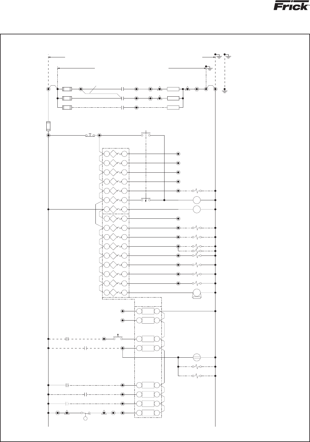
RWB II PLUS MICROPROCESSOR CONTROL
MAINTENANCE
S70-200 OM (DEC 99)
Page 28
30 7 29
HI VI LIQ INJ (IF REQ'D)
19
REMOTE START/RUN/STOP
REMOTE LOAD
38
39
5
37
36
35
34
33
REMOTE UNLOAD
22
(SAFE)
1 LSL
24
23
21
COMPR. AUX
31
32
30
OIL PUMP AUX
29
28
27
26
20
FROM LN.15
(00X)
19 28
B
30
29
25
24
23
22
21
20
FU1
18 1 17
FU2
FU3
20 2
22 3
19
21
FU5
FU4
24 4
26 5
23
25
FU6
28 6 27
LIQUID INJECTION
(FULL & CYCLING OIL PUMP)
ONLY USED WITH VERT. SEP'RS.)
MAIN OIL INJ. FEED
OIL LEVEL
(NOT REQUIRED WITH
FULL LUBE OIL PUMP)
REMOTE START/RUN/STOP
REMOTE LOAD
REMOTE UNLOAD
(ONLY ON BOOSTERS WITH LIQ INJ)
PRESSURE REGULATOR
21
42
1
3
6
8
3
4
5
7
2
FOR SECOND LIQ INJ (IF REQ'D)
COMPR. RUN TIME METER
( IF REQ'D)40
COMPRESSOR AUX
OIL PUMP AUX
AUX 1 (SEE NOTE B)
AUX 2 (SEE NOTE B)
COMPR START/RUN
SLIDE VALVE LOAD
SLIDE VALVE UNLOAD
SLIDE STOP INCREASE
SLIDE STOP DECREASE
LIQUID INJECTION (IF REQ'D)
10 5
12 6
9
11
14 7
16 8
13
15
17
38
16
15
14
13
12
NOTE C
SEE
CR
2
60
A SEPARATE 115 OR 230 VAC SOURCE TO 1A & 2A
CUSTOMER SUPPLIED 115 OR 230 VAC CONTROL TRANSFORMER POWER SOURCE IS REQUIRED
REMOVE JUMPERS 1 TO 1A & 2 TO 2A & CONNECT
IF SEPARATE FEED OR VOLTAGE FOR HEATER CIRCUIT IS DESIRED,
ALL POWER SOURCES SHALL BE GROUNDED ON ONE SIDE
-ISOLATED AND SEPARATED FROM OTHER INDUCTIVE LOADS SUCH AS LIGHTING CIRCUITS
-OR FROM FRICK SUPPLIED OR SPECIFIED STARTER, USE MINIMUM #12 AWG FOR FEED
RED
25B
12
18
17
16
15
14
13
FU10
FU7
FU8
32 8 31
FU9
34 9
36 10
33
35
FU11
38 11
40 12
37
39
FU12
FU13
42 13 41
11
10
09
2 FU
10
07
08
5
06
FU14
FU15
44 14
46 15
43
45
SBC TERMINALS
FOR DIGITAL I/O
FU16
48 16 47
EMERGENCY
STOP
6
FOR 1 KW, 115 V HTR'S, MOVE
WIRE TO 1A FU & NUMBER 25A
ADD 1B FU FOR 3rd HTR
ADD 1A FU FOR 115V-1KW HTR'S
05
04
#14
03
02
1
#12
1A FU
15
1B FU
15
15
1 FU
1A
HOT
01
HOT
25A
25
1CR
1CR
1CR
27A
ALL HEATER WIRING
3,4,(5)
ALARM (PRE & CUTOUT)
RELAY &/OR LAMP OPTIONAL
EXCEPT WHERE NOTED
WIRING TO BE WHITE
ALL NEUTRAL (EXP: 2 & 2A)
TO BE #14 AWG
ON RWB'S 316-676 IF REQ'D
BALANCE PISTON
RELAY &/OR LAMP OPTIONAL
ALARM (PRE & CUTOUT)
OIL PUMP START/RUN
SPARE ON ALL OTHERS
DATA CODE BIT 0
PROGRAMMABLE CONTROL
DATA CODE BIT 1
PROGRAMMABLE CONTROL
DATA CODE BIT 2
PROGRAMMABLE CONTROL
DATA CODE BIT 3
PROGRAMMABLE CONTROL
ECONOMIZER (IF REQ'D)
OIL HEATER
33
10
11
99
(OOX)
TO LN.30
35
B
39
7
34
CR
1
CR
3
63
32
31
AUTO
OIL PUMP
(XOO)
HAND
A
OFF
39
3rd HEATER WHEN REQUIRED
EARTH BUSBAR AT
POWER SOURCE
GROUND BAR IN MICRO
1 KW HTR'S OPTIONAL
.5 KW HTR'S
SEPARATOR OIL HEATERS
27
26
HEATER
HEATER
HEATER
2A 2
#12
NEUTRAL
NEUTRAL
TIE NEUTRAL TO GROUND
AT SOURCE
ALL NEUTRALS ENTERING
THIS ENCLOSURE SHALL
BE TIED TOGETHER AT
SOURCE, NOT IN THIS
ENCLOSURE
MICROPANEL ASSEMBLY WIRING DIAGRAM
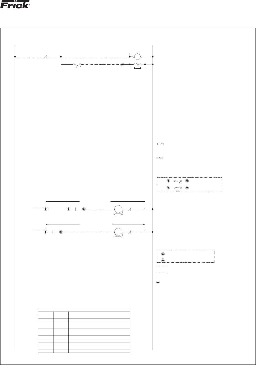
RWB II PLUS MICROPROCESSOR CONTROL
MAINTENANCE
S70-200 OM (DEC 99)
Page 29
3
HOT
HOT
SHT.2-3,4
31
30
60
60
63
63
LINE NO.
3
2CR
58
77
78
5
76
75
74
73
72
70
71
69
68
67
66
65
SEE NOTE A
IF REQ'D
JUMP TO 6
64
63
62
SEE NOTE A
IF REQ'D
JUMP TO 6
61
60
59
36
51
57
56
55
54
53
52
50
49
48
46
47
45
44
43
42
41
5
40
ENTERING OR LEAVING MICRO PANEL
OR BE RUN IN SAME CONDUIT AS ANY MICRO CONTROL WIRING
SEE FRICK PUBLICATION S90-400 SB/ SERVICE MANUAL.
FOR PROPER INSTALLATION OF ELECTRONIC EQUIPMENT,
NO SINGLE PHASE OVER 300 VOLTS SHALL ENTER OR LEAVE MICRO PANEL
NO THREE PHASE WIRING SHALL ENTER OR LEAVE MICRO PANEL
FOR HIGH POT TEST PROCEDURE, SEE MMIB NO. 4.11.10.7
AND EPROMS, SEE MMIB NO. 4.11.10.11
FOR INSTALLATION OF MICROPROCESSOR BOARD
TEST PROCEDURE, SEE MMIB NO. 4.11.10.4
FOR RWB II PLUS PACKAGE/MICROPROCESSOR
SEE 640D0019 FOR STANDARD CONTROL CENTER ASSEMBLY
ALL CONTROL CENTER WIRING TO BE #16 AWG
STRANDED WIRE UNLESS SPECIFIED OTHERWISE.
TERMINALS IN JUNCTION BOXES FOR SPLIT SKID UNITS
(OPT.)
CIRCUIT DESCRIPTION
CUSTOMER'S CONNECTIONS TO CONTROL CIRCUIT (MINIMUM OPTIONS)
CONTROL POWER
OIL HEATER POWER
CURRENT TRANSFORMER
COMPRESSOR AUX
COMPR. STARTER ISOLATED CONTACT
COMPR. STARTER (SEE NOTE A) OR
OIL PUMP STARTER ISOLATED CONTACT
OIL PUMP STARTER (SEE NOTE A) OR8,2
5,19
3,4
5,20
18,2
36,18
37,8
OIL PUMP AUX
1A,2A,GND
TERM NO.
1,2,GND
2
3CR CONTACT IS USED
WIRING IF ISOLATED
2CR CONTACT IS USED
WIRING IF ISOLATED
18
837
(Y)
3CR
(Y)
SEE NOTE B
JUMPER
(Y)
(Y)(Y)
42
2CR
SEE NOTE A
MS
SEE NOTE A
MS
(SEE NOTE C)
COMPR MOTOR STARTER
AT EACH COIL (SEE NOTE C)
PUMP STARTER COIL
INSTALLED AT OIL
SUPPRESSOR OR VARISTOR
IF STARTER CONTAINS MULTIPLE
CONTACTORS, RELAYS, & TIMERS,
ADD SUPPRESSORS OR VARISTORS
OIL PUMP STARTER
OL
NEU
OL
NEU
INDICATES DEVICES SUPPLIED ONLY
WHEN OPTIONAL OR REQUIRED
WIRING BY OTHERS- ALL WIRING ENTERING CONTROL
CENTER (INCLUDING GROUND & NEUTRAL) TO BE #14
AWG STRANDED WIRES UNLESS SPECIFIED OTHERWISE.
APPLICABLE ONLY IF REQUIRED
TERMINALS IN CONTROL CENTER
ON SEPARATOR SKID
TERMINALS IN JUNCTION BOX
ON COMPRESSOR SKID
TERMINALS IN JUNCTION BOX
GE #V250LA10A OR EQUAL FOR 230 VOLTS
GE #V130LA10A OR EQUAL FOR 115 VOLTS
METAL OXIDE VARISTOR (MOV) SPECIFICATIONS:
USE ELECTROCUBE #RG2031-3-6 OR EQUAL.
VDC IN SERIES WITH A 47 OHM RESISTOR.
RC NETWORK CONSISTING OF A .1 MFD CAPACITOR, 600
SUPPRESSOR SPECIFICATIONS:
ALL INDUCTIVE LOADS IN CONTROL CENTER.
A SURGE SUPPRESSOR OR MOV TO BE INSTALLED ACROSS
NOR. OPEN OR NOR. CLOSED.
AUX 1 & AUX 2 CAN BE PROGRAMMED TO ALARM OR SHUTDOWN,
PROGRAM AUX AS ABOVE. SEE 1 PSH WIRING BELOW FOR EXAMPLE.
ISOLATED CONTACT SHOULD BE INSERTED BETWEEN 5 & 29 OR 30.
REMOVE JUMPER 36 TO 42 & INSERT ISOLATED CONTACT(S). A SEPARATE
WHEN USING 2CR AS A ISOLATED CONTACT (PARAGRAPH 2, NOTE A),
PROGRAM AUX TO SHUTDOWN-NORMALLY CLOSED.
CONTACT(S). JUMP 42 TO EITHER 29 OR 30 (AUX 1 OR AUX 2).
(PARAGRAPH 1-NOTE A), REMOVE JUMPER 36 TO 42 & INSERT ISOLATED
WHEN REFERENCING MICRO POWER TO OPERATE COMPR. MOTOR STARTER
FOR OPTIONAL ALARMS & SHUTDOWNS: (HIGH LEVEL SHUTDOWN ETC.)
SAME NOTES APPLY TO OIL PUMP STARTER CIRCUIT ON LINE 63.
NOTE C:
NOTE B:
NOTE A:
THE HOT & NEUTRAL LINES ON LINE 60.
IF 2CR IS USED AS A ISOLATED CONTACT, WIRE AS SHOWN BETWEEN
ONLY. JUMP TERM 6 TO 36.
CONFORMS TO FRICK STARTER SPECS, WIRE AS SHOWN ON LINE 60
IF COMPR. MOTOR STARTER IS A FRICK SUPPLIED STARTER OR
13
40
1TR
41
MANUFACTURE IF
ADDED AT TIME OF
POWER ASSIST IS
POWER ASSIST
41
POWER ASSIST
SEE NOTE C
INTERVAL
15 SEC
TR
6
2
10
1
SPECIFIED
2
NOR. CLOSED
SHUTDOWN
PROGRAM AUX 1 AS
HIGH DISCH PRESS SWITCH CUTOUT OPTION
HPCO
1-PSH
36
5
42
30
SURGE SUPPRESSOR
VARISTOR
MICROPANEL ASSEMBLY WIRING DIAGRAM
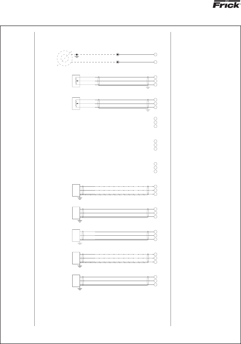
RWB II PLUS MICROPROCESSOR CONTROL
MAINTENANCE
S70-200 OM (DEC 99)
Page 30
19
WHITE
38
39
5
37
36
35
34
33
PE-1
-
S
BLACK
31
32
30
29
28
27
26
RED
+
PE-2
-
S
+
RED
BLACK
WHITE
PE-3
S
-
+
WHITE
BLACK
RED
25
24
23
22
21
20
-
PE-4
S
+
BLACK
WHITE
RED
PE-5
S
-
+
WHITE
BLACK
RED
(CHANNEL 6)
OIL PRESS
1-5 VDC
TYPICAL
DO NOT GROUND PE'S AT PANEL
CABLE #6
2
S
-
IF REQUIRED
RWB II 496 & 676 ONLY
BALANCE PISTON REG
(IF REQ'D)
FILTER PRESS
1-5 VDC
(CHANNEL 7)
(CHANNEL 10)
1-5 VDC
SUCT PRESS
1-5 VDC
(CHANNEL 9)
(CHANNEL 8)
1-5 VDC
DISCH PRESS
CABLE #7
CABLE #8
+
-
+
S
-
S
+
CABLE #9
CABLE #10
-
+
S
-
S
SPARE
+
12
18
17
16
15
14
13
POT-2
SLIDE VALVE
POSITION
POTENTIOMETER
POT-1
SLIDE STOP
POSITION
POTENTIOMETER
11
10
09
07
08
06
RED
1
3
2
WHITE
BLACK
3
2
1
BLACK
WHITE
RED
MOTOR JUNCT. BOX (BY OTHERS)
C.T. MOUNTED IN STARTER OR
05
04
03
02
OF MOTOR
ONE PHASE
AMPS
MOTOR
01
5
0-5 AMP AC
SECONDARY
ECON PRESS
1-5 VDC
(CHANNEL 11)
(CHANNEL 12)
1-5 VDC
SPARE PRESS
1-5 VDC
(CHANNEL 13)
SLIDE VALVE
CHANNEL 14
SLIDE STOP
(CHANNEL 15)
-
S
+
-
S
+
-
SPARE
CABLE #14
CABLE #15
W
+
S
B
R
W
B
R
FOR C.T. WIRE SIZING
SEE RWB IOM MANUAL
(CHANNEL 16)
0-5 AMP AC
MOTOR AMPS
3
4
R
R
2
MICROPANEL ASSEMBLY WIRING DIAGRAM
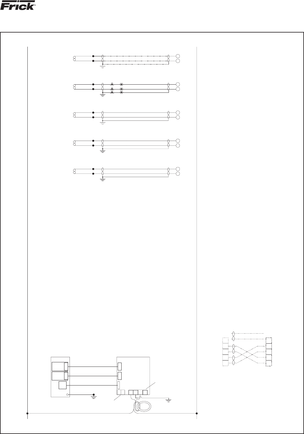
RWB II PLUS MICROPROCESSOR CONTROL
MAINTENANCE
S70-200 OM (DEC 99)
Page 31
P1
P1
FRONT PANEL
STUD
58
PA D
77
78
5
76
75
74
73
72
KEY
DISPLAY
BOTTOM
DISPLAY
TOP
70
71
69
68
67
66
65
64
63
62
61
60
59
51
57
56
55
54
53
52
TE-1
50
49
48
TE-2
46
47
45
TE-3
44
43
42
41
TE-4
40
5
TE-5
COLOR CODING SHOWN IS BELDEN #8777
FOR GROUNDED CIRCUITS
NO CONNECTION ON 230
SET SW 1 TO CORRECT VOLTAGE
WRAP WIRES THROUGH TOROID TWO (2)
TIMES, ALL IN THE SAME DIRECTION
12 COND RIBBON CABLE
GREEN WIRE
STUD
26 COND RIBBON CABLE
26 COND RIBBON CABLE
1
1
1
P13
NEU
230
115
SW1
GND
115
RING
TOROID
FERRITE
230
GREEN
P10
1
1
P12
SBC
1
P11
2
ARE ON THE SAME SKID
WIRED AT FRICK IF BOTH UNITS
FROM ALL OTHER WIRING
RS-422 WIRING SHALL BE SEPARATE
IF TEMPERATURE SENSOR WIRING IS IN CONDUIT, USE
#8761 BELDEN CABLE OR EQUAL. IF OPEN WIRING, USE
#8760 BELDEN CABLE OR EQUAL. GROUND DRAIN WIRE
AT PANEL END ONLY ON 4" SENSORS.
GROUND AT SENSOR END ONLY ON 1" SENSORS.
INSULATE DRAIN WIRE AT OPPOSITE END.
2000 FT. MAX. DISTAMCE.
TEMPERATURE WIRING SPECIFICATIONS:
SEE 640C0031 FOR TEMPERATURE SENSOR
ASSEMBLY-640C0031G11
ALL ANALOG LOW VOLTAGE WIRING TO BE RUN
IN SEPARATE CONDUIT FROM ALL OTHER WIRING
TEMP PROBE-FRICK P/N - 640A0035H01
WELL FOR ABOVE, 3/4"MPT WELL CONNECTION,
HEAT TRANSFER COMPOUND-P/N - 111Q0831807
1/2" FPT FOR CONNECTION BOX- P/N - 990A0062H01
SPECIFICATIONS FOR TEMP. CAPACITY CONTROL
-TEMP PROBE SIZE- .31 DIA x 1" LONG
-MOUNTING IN WELL IS DESIRABLE
-WIRE AS SHOWN IN SEPARATE CONDUIT
-SETPOINT RANGE: -50°F. TO 100°F.
NOTE 2A:
CABLE #4
BLACK
CABLE #1
BLACK
WHITE
BLACK
BLACK
CABLE #2
WHITE
BLACK
CABLE #3
BLACK
WHITE
SUCT TEMP
(CHANNEL 1)
+
-
(CHANNEL 2)
DISCH TEMP
(CHANNEL 3)
-
+
+
-
OIL TEMP
2000 FT. MAX. DISTANCE
TYPICAL
BLACK
COLOR MAY VARY
#22 AWG TWISTED PAIR
BLACK
CABLE #5
DW
4B
4W
BLACK
WHITE
BLACK
WHITE
SEE NOTE 2A
WIRING BY OTHERS
CAPACITY CONTROL (OPTIONAL)
REMOTE TEMPERATURE
SPARE TEMP
(CHANNEL 5)
(CHANNEL 4)
-
+
SEP TEMP
+
-
2
WIRING FOR LEAD-LAG SEQUENCING
USE BELDEN #8777 OR EQUAL (3 TWISTED PAIRS)
9
PORT 2
UNIT "A"
SBC
RS-422
5
8
4
3
(NOT USED)
OPTIONAL
GRN
UNIT "B"
PORT 2
BLK
9
RED
BLK
5
8
4
RS-422
SBC
WHT
BLK
3
USE HEAT TRANSFER COMPOUND
304 S.S. WITH (2) 24" LEADS
FROM ALL OTHER WIRING
USE BELDEN #8761 CABLE OR EQUAL
MICROPANEL ASSEMBLY WIRING DIAGRAM

© 2007 Johnson Controls Inc. • ALL RIGHTS RESERVED • Subject to change without notice • Printed in USA - GUI 1M • Supersedes: S70-200 OM (399) • Form S70-200 OM (1299)
www.frickcold.com
100 CV Avenue
Waynesboro, PA USA 17268
Phone: 717-762-2121
FAX: 717-762-8624
www.johnsoncontrols.com
Q-NET
™
network
technology...
Connect Your PC
with QUANTUM
™
!
Take full advantage of Q-NET
™
technology with all Frick
®
products!
System integration is what we do...
I Q-NET
™
... supports open-protocols for SCADA systems (i.e. Allen-Bradley
®
DF1, Modbus RTU,
Modbus ASCII, and Industrial Ethernet Protocols)
I Q-NET
™
... connects instantly for local or remote access; no software required
I Q-NET
™
... can be applied to both new and existing systems
I Q-NET
™
means precise control 24 hours a day, seven days a week
I Q-NET
™
distributed architecture mean faster, easier, economical installations
I Q-NET
™
delivers increased operating effi ciency and lowers energy costs
Available on Frick screw compressors, condensers, evaporators, AcuAir
®
hygienic air handlers,
and refrigerant vessels.
Take Control.
™
