Installation
ProMix
®
2KS
Plural Component Proportioner
312778G
EN
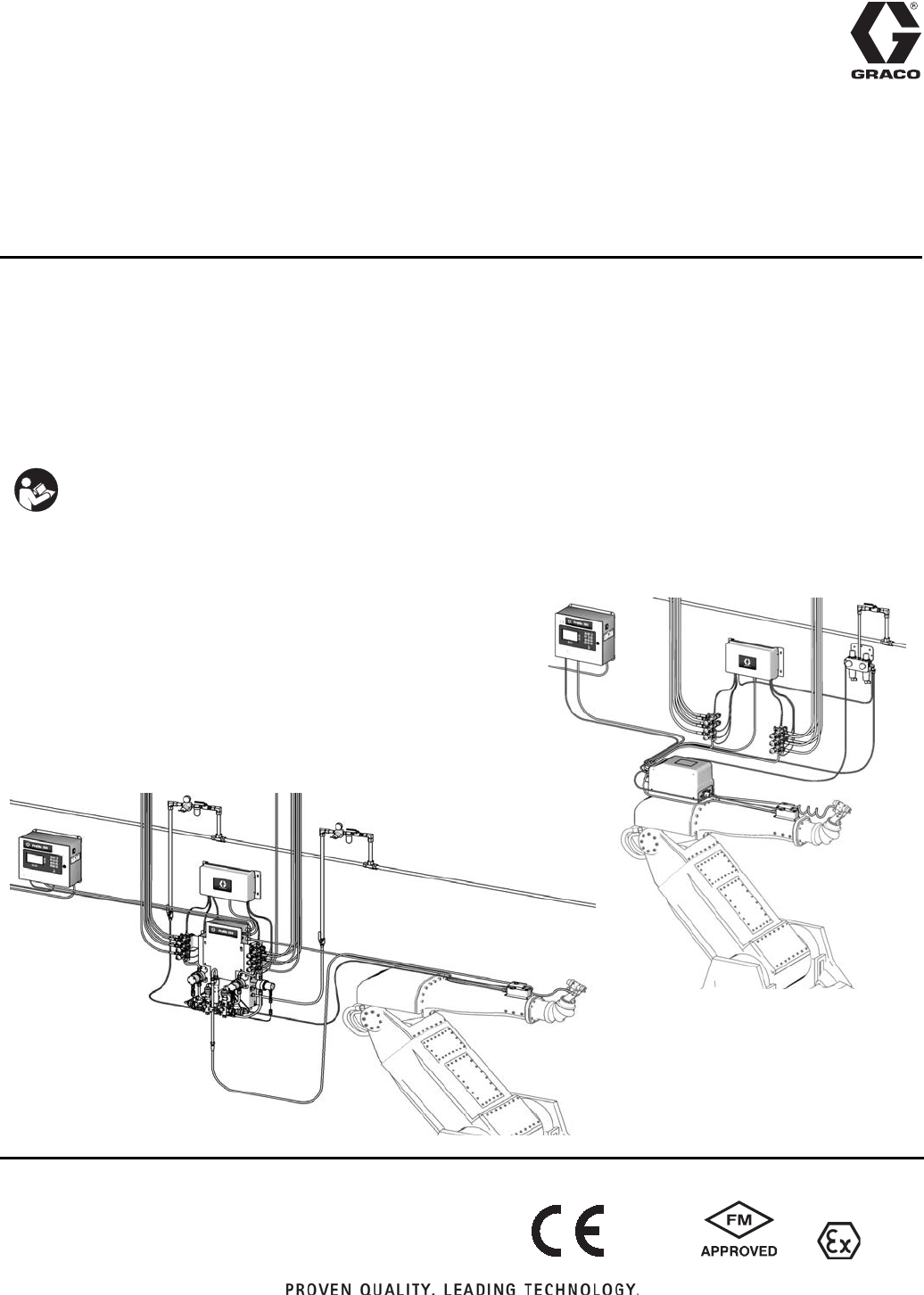
Automatic system for proportional mixing of plural component coatings, with Wall Mount
Fluid Station or RoboMix Fluid Station. For professional use only.
Approved for use in explosive atmospheres (except the EasyKey).
See pages 4-7 for model information, including maxi-
mum working pressure. Equipment approval labels are
on page 3. Some components shown are not included
with all systems.
Important Safety Instructions
Read all warnings and instructions in this
manual. Save these instructions.
Automatic System with Wall Mount Fluid Station
Automatic System with RoboMix Fluid Station
TI12553a
TI12552a
#53
II 2 G0359
2 312778G
Contents
Related Manuals . . . . . . . . . . . . . . . . . . . . . . . . . . . 3
15V256 Automatic Upgrade Kit . . . . . . . . . . . . . . . 3
Equipment Approvals . . . . . . . . . . . . . . . . . . . . . . . 3
System Configuration and Part Numbers . . . . . . . 4
Wall Mount Fluid Station Configurator Key . . . . . 4
RoboMix Fluid Station Configurator Key . . . . . . . 6
Accessories . . . . . . . . . . . . . . . . . . . . . . . . . . . . . . . 9
2KS Accessories . . . . . . . . . . . . . . . . . . . . . . . . . 9
2KS Acid Compatible Accessories . . . . . . . . . . . 9
Warnings . . . . . . . . . . . . . . . . . . . . . . . . . . . . . . . . 10
Important Two-Component Material Information 12
Isocyanate Conditions . . . . . . . . . . . . . . . . . . . . 12
Material Self-ignition . . . . . . . . . . . . . . . . . . . . . 12
Keep Components A and B Separate . . . . . . . . 12
Moisture Sensitivity of Isocyanates . . . . . . . . . . 13
Changing Materials . . . . . . . . . . . . . . . . . . . . . . 13
Important Acid Catalyst Information . . . . . . . . . . 14
Acid Catalyst Conditions . . . . . . . . . . . . . . . . . . 14
Moisture Sensitivity of Acid Catalysts . . . . . . . . 14
Component Identification and Definition . . . . . . 15
Location . . . . . . . . . . . . . . . . . . . . . . . . . . . . . . . . . 20
Location Requirements . . . . . . . . . . . . . . . . . . . 20
Intrinsically Safe Installation Requirements . . . 20
Optional Cables . . . . . . . . . . . . . . . . . . . . . . . . 20
General Information . . . . . . . . . . . . . . . . . . . . . . . 22
Wall Mounting . . . . . . . . . . . . . . . . . . . . . . . . . . . . 22
Air Supply . . . . . . . . . . . . . . . . . . . . . . . . . . . . . . . . 22
Requirements . . . . . . . . . . . . . . . . . . . . . . . . . . 22
Air Connections . . . . . . . . . . . . . . . . . . . . . . . . . 22
Fluid Supply . . . . . . . . . . . . . . . . . . . . . . . . . . . . . . 24
Requirements . . . . . . . . . . . . . . . . . . . . . . . . . . 24
Fluid Connections . . . . . . . . . . . . . . . . . . . . . . . 24
Setup the Fluid Manifold for Dynamic Dosing . . 26
Solvent Meter Accessory . . . . . . . . . . . . . . . . . . 28
Flow Control . . . . . . . . . . . . . . . . . . . . . . . . . . . . . . 29
Electrical . . . . . . . . . . . . . . . . . . . . . . . . . . . . . . . . . 30
Requirements . . . . . . . . . . . . . . . . . . . . . . . . . . 30
Connect Main Power . . . . . . . . . . . . . . . . . . . . . 30
Connect EasyKey to Fluid Station Control . . . . 31
Fluid Station Control Board Switch Settings . . . 32
Connect Color Change Module . . . . . . . . . . . . . 33
Grounding . . . . . . . . . . . . . . . . . . . . . . . . . . . . . 36
Check Resistance . . . . . . . . . . . . . . . . . . . . . . . 36
Install Automatic Upgrade Kit 15V256 . . . . . . . . . 38
15V256 Kit Parts . . . . . . . . . . . . . . . . . . . . . . . . 38
Before Installation . . . . . . . . . . . . . . . . . . . . . . . 38
Install the Auto Key Board . . . . . . . . . . . . . . . . . 38
Install the Discrete I/O Board . . . . . . . . . . . . . . . 39
Install the I/O Terminal Strips . . . . . . . . . . . . . . 39
Schematic Diagrams . . . . . . . . . . . . . . . . . . . . . . . 43
System Pneumatic Schematic . . . . . . . . . . . . . . 43
System Electrical Schematic . . . . . . . . . . . . . . . 44
Dimensions and Mounting Hole Layouts . . . . . . 46
Dynamic Dosing Restrictor Selection Graphs . . 48
Technical Data . . . . . . . . . . . . . . . . . . . . . . . . . . . . 55
Graco Standard Warranty . . . . . . . . . . . . . . . . . . . 56
Related Manuals
312778G 3
Related Manuals
Component Manuals in English
15V256 Automatic
Upgrade Kit
Upgrades a ProMix 2KS manual system to an automatic
system. Includes the 255766 Discrete I/O Board. See
page 38.
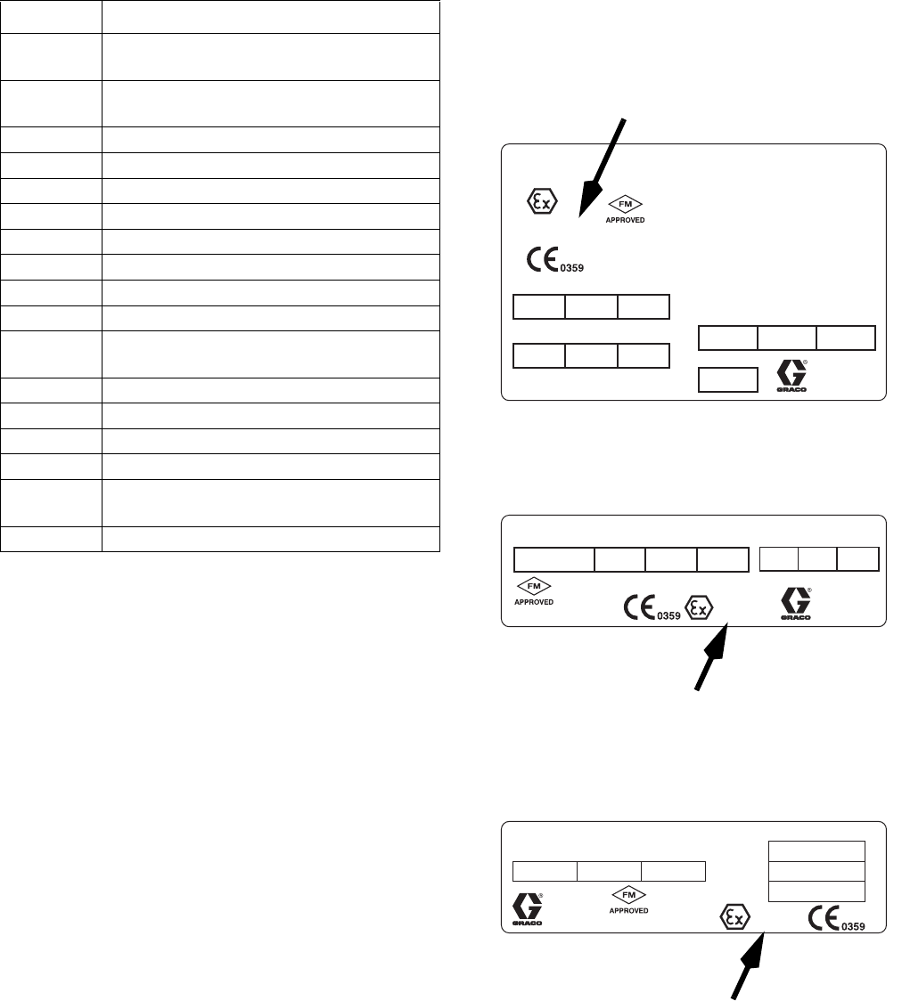
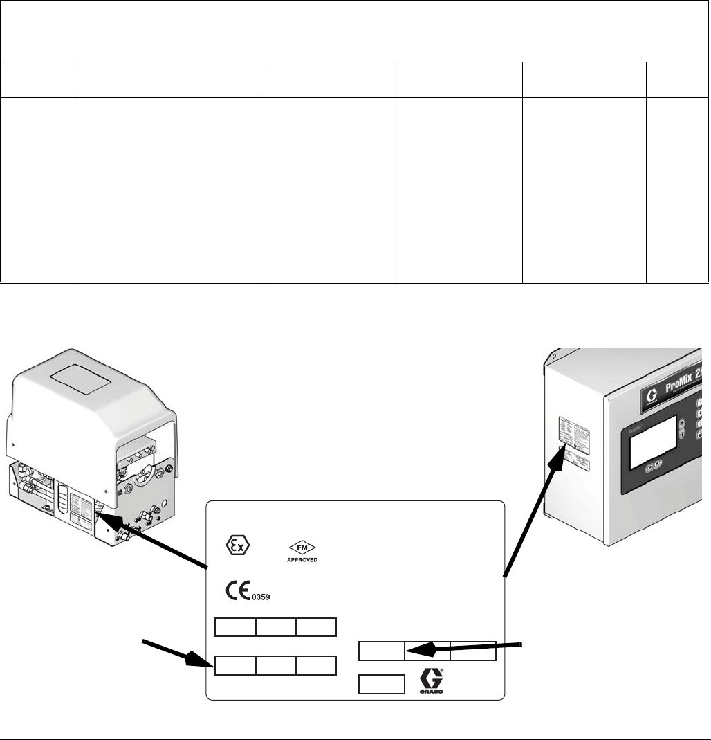
Equipment Approvals
Equipment approvals appear on the following labels
which are attached to the Fluid Station and EasyKey
™
.
See F
IG. 1 on page 4 and FIG. 2 on page 6 for label loca-
tions.
Manual Description
312779 ProMix 2KS Automatic System
Operation
312780 ProMix 2KS Automatic System
Repair-Parts
312781 Fluid Mix Manifold
312782 Dispense Valve
312783 Color Change Valve Stacks
312787 Color Change Module Kit
312784 Gun Flush Box Kits
310745 Gun Air Shutoff Kit
312786 Dump Valve and Third Purge Valve Kits
312785 Network Communication Kits
308778 G3000/G3000HR/G250/G250HR Flow
Meter
313599 Coriolis Flow Meter
313212 Gun Flush Box Integration Kit
313290 Floor Stand Kit
313542 Beacon Kit
313386 Basic Web Interface/Advanced Web
Interface
406800 15V825 Discrete I/O Board Kit
Artwork No. 293538
GRACO INC.
P.O. Box 1441
Minneapolis, MN
55440 U.S.A.
.7 7
MAX AIR WPR
MPa bar PSI
FLUID PANEL
ProMix 2KS
100
PART NO. SERIES SERIAL MFG. YR.
CUS
Intrinsically safe equipment
for Class I, Div 1, Group D, T3
Ta = -20°C to 50°C
Install per 289833
FM08ATEX0073
II 2 G
Ex ia IIA T3
®
Artwork No. 293467
SERIES NO. MFG. YR.
PART NO.
AMPS
VOLTS
85-250 ~
2 AMPS MAX
POWER REQUIREMENTS
GRACO INC.
P.O. Box 1441
Minneapolis, MN
55440 U.S.A.
II (2) G
[Ex ia] IIA
FM08ATEX0072
Intrinsically safe connections
for Class I, Div 1, Group D
Ta = -20°C to 50°C
Install per 289833
CUS
50/60 Hz
ProMix 2KS
®
Um: 250 V
ATEX Certificate is listed here
ATEX Certificate is listed here
ATEX Certificate is listed here
TI13581a
TI13582a
EasyKey Label
Fluid Station Label
EasyKey and Fluid Station Label
System Configuration and Part Numbers
4 312778G
System Configuration and Part Numbers
Wall Mount Fluid Station Configurator Key
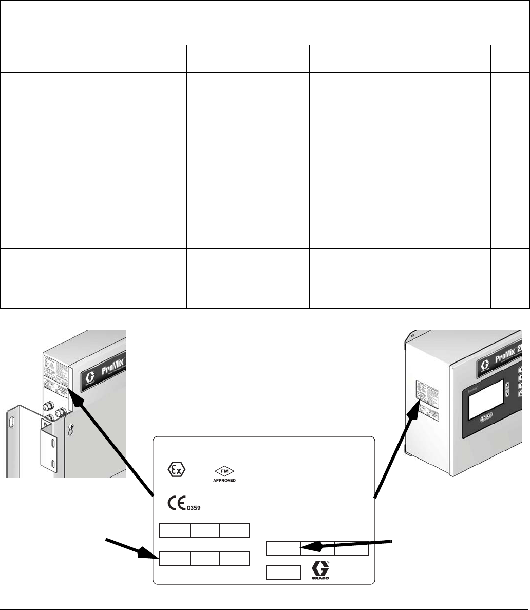
The configured part number for your equipment is printed on the equipment identification labels. See FIG. 1
for location of the identification labels. The part number includes one digit from each of the following six
categories, depending on the configuration of your system.
Automatic
System
Control and Display A and B Meter Color Valves Catalyst Valves Flow
Control
A D = EasyKey with LCD Display 0 = No Meters
1 = G3000 (A and B)
2 = G3000HR (A and B)
3 = 1/8 in. Coriolis (A) and
G3000 (B)
4 = G3000 (A) and 1/8 in.
Coriolis (B)
5 = 1/8 in. Coriolis (A) and
G3000HR (B)
6 = G3000HR (A) and 1/8
in. Coriolis (B)
7 = 1/8 in. Coriolis (A and B)
0 = No Valves
(single color)
1 = Two Valves
(low pressure)
2 = Four Valves
(low pressure)
3 = Seven Valves
(low pressure)
4 = Twelve Valves
(low pressure)
0 = No Valves
(single catalyst)
1 = Two Valves
(low pressure)
2 = Four Valves
(low pressure)
N = No
Y = Yes
A
(acid
models)
E = EasyKey with LCD Display 1 = G3000 (A) and G3000A
(B)
0 = No Valves
(no color; need to
order acid kit
26A096-26A100;
see page 9)
0 = No Valves
(single catalyst)
N = No
FIG. 1: Identification Label, Wall Mount Fluid Station Systems
Maximum Fluid
Working Pressure
is listed here
TI12418aTI12423a
Label Location
on EasyKey
Label Location
on Fluid Station
Configured Part Number
System Configuration and Part Numbers
312778G 5
Standard Features
Hazardous Location Approval
Models using a G3000, G3000HR, G3000A, or intrinsically safe Coriolis meter for both A and B meters are
approved for installation in a Hazardous Location - Class I, Div I, Group D, T3 or Zone I Group IIA T3.
Maximum Working Pressure
Maximum working pressure rating is dependent on the fluid component options selected. The pressure rating is
based on the rating of the lowest rated fluid component. Refer to the component pressure ratings below.
Example: Model AD110Y has a maximum working pressure of 190 psi (1.31 MPa, 13.1 bar).
Check the identification label on the EasyKey or fluid station for the system maximum working pressure.
See F
IG. 1.
ProMix Fluid Components Maximum Working Pressure
Base System (no meters [option 0], no color/catalyst change [option 0],
and no flow control [option N]) . . . . . . . . . . . . . . . . . . . . . . . . . . . . . . . . . . . . . . . 4000 psi (27.58 MPa, 275.8 bar)
Meter Option 1 and 2 (G3000 or G3000HR) . . . . . . . . . . . . . . . . . . . . . . . . . . . . 4000 psi (27.58 MPa, 275.8 bar)
Meter Option 3, 4, 5, 6, and 7 (one or two Coriolis Meters) . . . . . . . . . . . . . . . . . 2300 psi (15.86 MPa, 158.6 bar)
Meter Option 8 (G3000 and G3000A) . . . . . . . . . . . . . . . . . . . . . . . . . . . . . . . . . 4000 psi (27.58 MPa, 275.8 bar)
Color Change Option 1, 2, 3 and 4 and
Catalyst Change Option 1 and 2 (low pressure valves) . . . . . . . . . . . . . . . . . . . . . . . 300 psi (2.07 MPa, 20.6 bar)
Flow Control Option Y (Yes). . . . . . . . . . . . . . . . . . . . . . . . . . . . . . . . . . . . . . . . . . . . 190 psi (1.31 MPa, 13.1 bar)
Flow Meter Fluid Flow Rate Range
G3000 and G3000A . . . . . . . . . . . . . . . . . . . . . . . . . . . . . . . . . . . . . . . . . . . . 75-3800 cc/min. (0.02-1.0 gal./min.)
G3000HR . . . . . . . . . . . . . . . . . . . . . . . . . . . . . . . . . . . . . . . . . . . . . . . . . . . 38-1900 cc/min. (0.01-0.50 gal./min.)
Coriolis Meter . . . . . . . . . . . . . . . . . . . . . . . . . . . . . . . . . . . . . . . . . . . . . . 20-3800 cc/min. (0.005-1.00 gal./min.)
S3000 Solvent Meter (accessory) . . . . . . . . . . . . . . . . . . . . . . . . . . . . . . . . 38-1900 cc/min. (0.01-0.50 gal./min.)
Feature
EasyKey with LCD
Fiber Optic and Power Cables, 50 ft (15.25 m)
Wall Mount Fluid Station, 50 cc Integrator and Static Mixer
Discrete I/O Board
A Side Dump Valve, if color valve(s) selected
B Side Dump Valve, if catalyst valve(s) selected
Flow Control with 15 ft (4.57 m) Cable (if selected)
Basic Web Interface
System Configuration and Part Numbers
6 312778G
RoboMix Fluid Station Configurator Key
The configured part number for your equipment is printed on the equipment identification labels. See FIG. 2
for location of the identification labels. The part number includes one digit from each of the following six
categories, depending on the configuration of your system.
RoboMix
System
Control and Display A and B Meter Color Valves Catalyst Valves Flow
Control
R D = EasyKey with LCD Display 0 = No Meters
1 = G250 (A and B)
2 = G250HR (A and B)
0 = No Valves
(single color)
1 = Two Valves
(low pressure)
2 = Four Valves
(low pressure)
3 = Seven Valves
(low pressure)
4 = Twelve Valves
(low pressure)
0 = No Valves
(single catalyst)
1 = Two Valves
(low pressure)
2 = Four Valves
(low pressure)
N = No
Y = Yes
FIG. 2: Identification Label, RoboMix Fluid Station Systems
Label Location
on EasyKey
Label Location on
RoboMix Fluid Station
Maximum Fluid
Working Pressure
is listed here
TI12418aTI12512a
Configured Part Number
System Configuration and Part Numbers
312778G 7
Standard Features
Hazardous Location Approval
Models using a G250 or G250HR for both A and B meters are approved for installation in a Hazardous Location -
Class I, Div I, Group D, T3 or Zone I Group IIA T3.
Maximum Working Pressure
Maximum working pressure rating for RoboMix Systems is 190 psi (1.31 MPa, 13.1 bar).
Check the identification label on the EasyKey or RoboMix fluid station for the system maximum working
pressure. See F
IG. 2.
ProMix RoboMix Systems Maximum Working Pressure
RoboMix Fluid Station Options (all) . . . . . . . . . . . . . . . . . . . . . . . . . . . . . . . . . . . . . . 190 psi (1.31 MPa, 13.1 bar)
Flow Meter Fluid Flow Rate Range
G250 Meter. . . . . . . . . . . . . . . . . . . . . . . . . . . . . . . . . . . . . . . . . . . . . . . . . . . 75-3800 cc/min. (0.02-1.0 gal./min.)
G250HR Meter . . . . . . . . . . . . . . . . . . . . . . . . . . . . . . . . . . . . . . . . . . . . . . . 38-1900 cc/min. (0.01-0.50 gal./min.)
Feature
EasyKey with LCD
RS 485 Network Cable, 50 ft (15.25 m)
Fiber Optic and Power Cables, 50 ft (15.25 m)
Remote Fluid Station, 25 cc Integrator
Discrete I/O Board
A Side Dump Valve, if color valve(s) selected
B Side Dump Valve, if catalyst valve(s) selected
Flow Control with 15 ft (4.57 m) Cable (if selected)
Basic Web Interface

System Configuration and Part Numbers
8 312778G

Accessories
312778G 9
Accessories
2KS Accessories
2KS Acid Compatible
Accessories
Intended for use with acid catalyst materials.
NOTE: This is not a complete list of available accesso-
ries and kits. Refer to the Graco website for more infor-
mation about accessories available for use with this
product.
Accessory
15V354 Third Purge Valve Kit
15V202 Third Purge Valve Kit
15V536 Solvent Flow Switch Kit
15V213 Power Cable, 100 ft (30.5 m)
15G710 Fiber Optic Cable, 100 ft (30.5 m)
15G614 Flow Control Extension Cable, 40 ft (12.2 m)
15U955 Injection Kit for Dynamic Dosing
15V034 10 cc Integrator Kit
15V033 25 cc Integrator Kit
15V021 50 cc Integrator Kit
24B618 100 cc Integrator Kit
15W034 Strobe Light Alarm Indicator Kit
15V331 Gateway Ethernet Communication Kit
15V963 Gateway DeviceNet Communication Kit
15V964 Gateway Profibus Communication Kit
15V337 Advanced Web Interface
280555 S3000 Solvent Flow Meter Kit
Accessory
26A096 No Color /1 Catalyst Change Kit
26A097 2 Color/1 Catalyst Change Kit
26A098 4 Color/1 Catalyst Change Kit
26A099 7 Color/1 Catalyst Change Kit
26A100 12 Color/1 Catalyst Change Kit
Warnings
10 312778G
Warnings
The following warnings are for the setup, use, grounding, maintenance, and repair of this equipment. The exclama-
tion point symbol alerts you to a general warning and the hazard symbols refer to procedure-specific risks. When
these symbols appear in the body of this manual, refer back to these Warnings. Product-specific hazard symbols and
warnings not covered in this section may appear throughout the body of this manual where applicable.
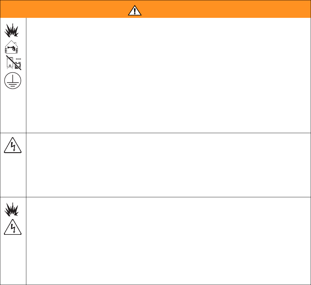
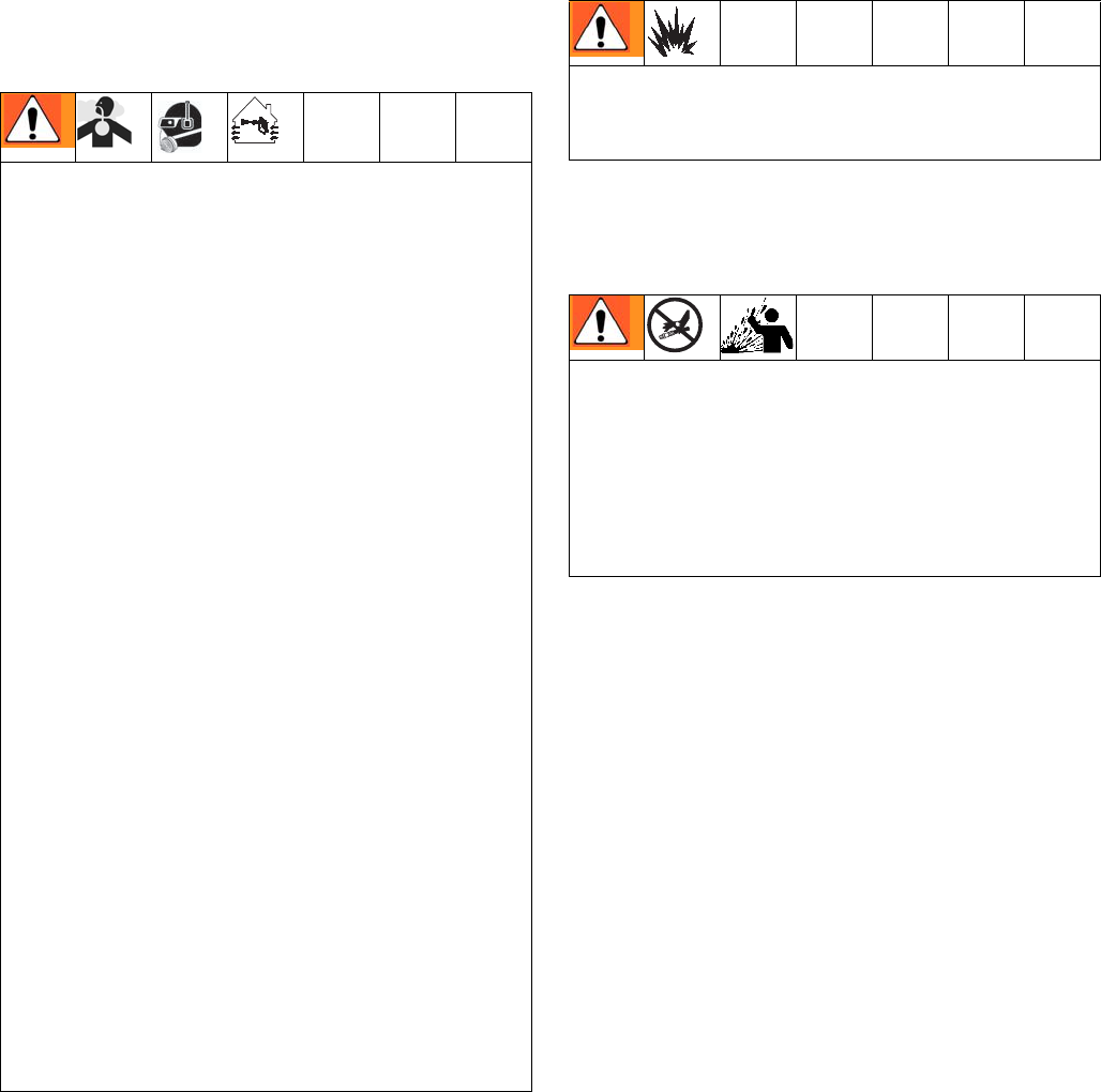
WARNING
FIRE AND EXPLOSION HAZARD
Flammable fumes, such as solvent and paint fumes, in work area can ignite or explode. To help prevent
fire and explosion:
• Use equipment only in well ventilated area.
• Eliminate all ignition sources; such as pilot lights, cigarettes, portable electric lamps, and plastic drop
cloths (potential static arc).
• Keep work area free of debris, including solvent, rags and gasoline.
• Do not plug or unplug power cords, or turn power or light switches on or off when flammable fumes
are present.
• Ground all equipment in the work area. See Grounding instructions.
• Use only grounded hoses.
• Hold gun firmly to side of grounded pail when triggering into pail.
• If there is static sparking or you feel a shock, stop operation immediately. Do not use equipment
until you identify and correct the problem.
• Keep a working fire extinguisher in the work area.
ELECTRIC SHOCK HAZARD
This equipment must be grounded. Improper grounding, setup, or usage of the system can cause
electric shock.
• Turn off and disconnect power at main switch before disconnecting any cables and before servicing
equipment.
• Connect only to grounded power source.
• All electrical wiring must be done by a qualified electrician and comply with all local codes and
regulations.
INTRINSIC SAFETY
Intrinsically safe equipment that is installed improperly or connected to non-intrinsically safe equipment
will create a hazardous condition and can cause fire, explosion, or electric shock. Follow local
regulations and the following safety requirements.
• Only models with a G3000, G250, G3000HR, G250HR, G3000A, or intrinsically safe Coriolis meter
are approved for installation in a Hazardous Location - Class I, Div I, Group D, T3 or Zone I Group
IIA T3.
• Do not install equipment approved only for a non-hazardous location in a hazardous area. See the
ID label for the intrinsic safety rating of your model.
• Do not substitute or modify system components as this may impair intrinsic safety.
Warnings
312778G 11
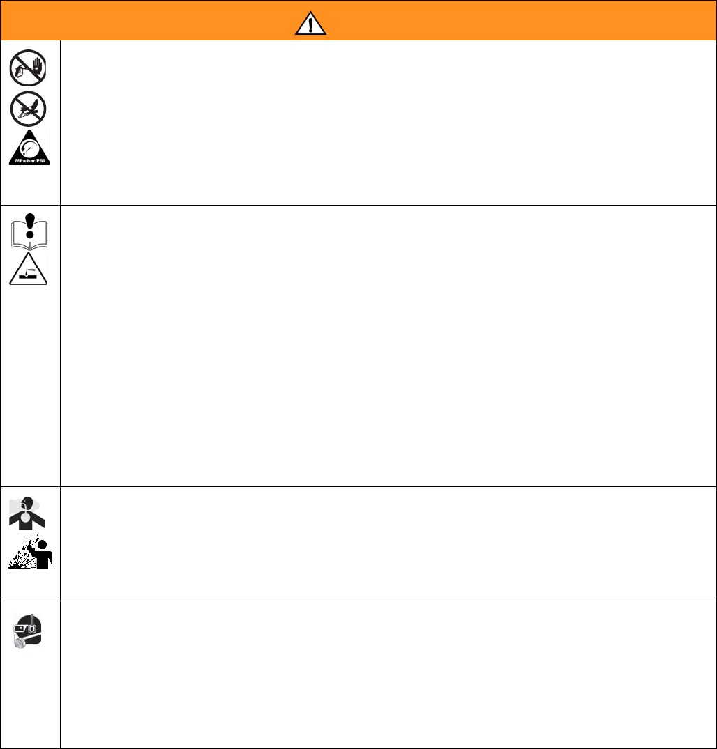
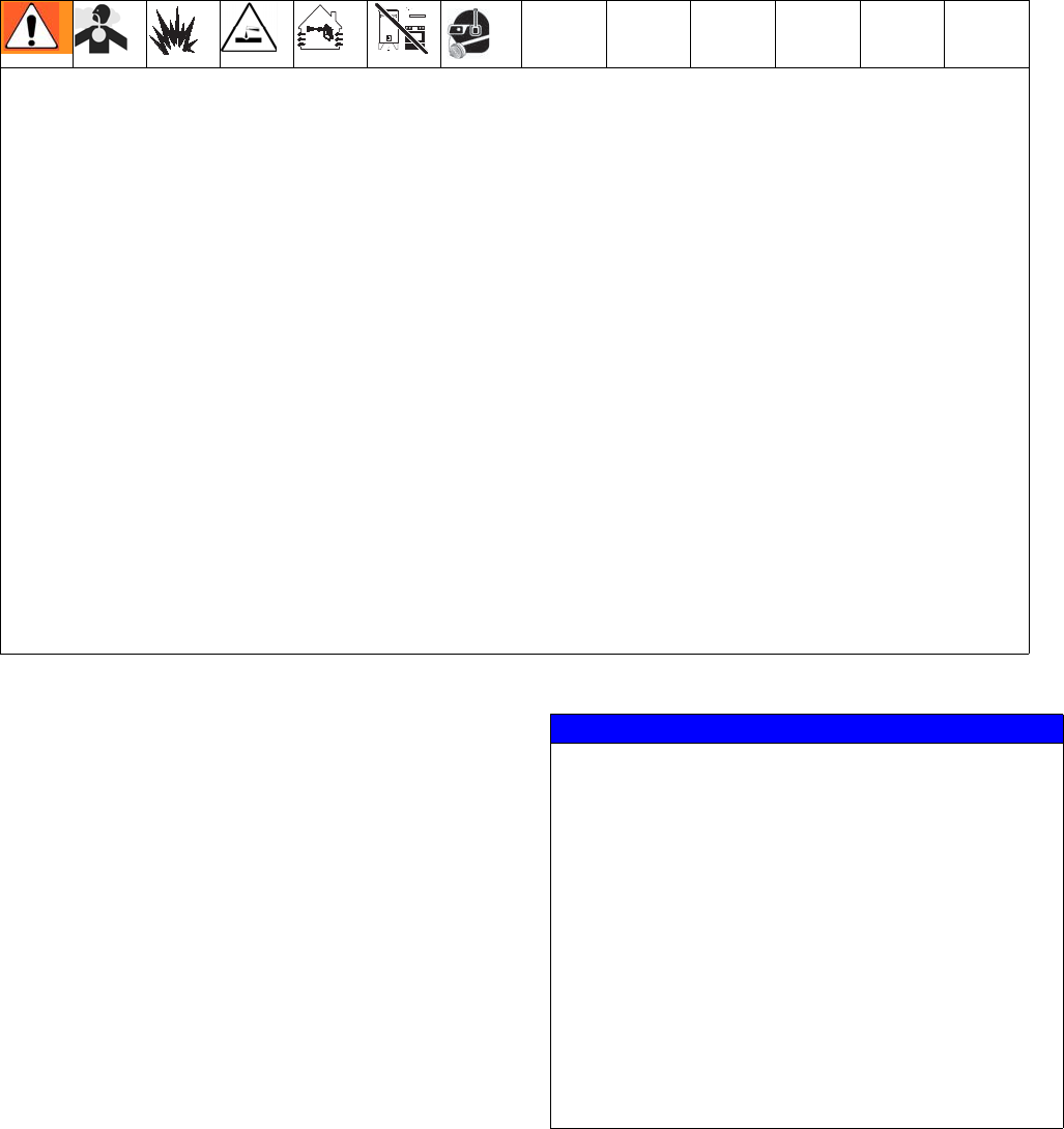
SKIN INJECTION HAZARD
High-pressure fluid from gun, hose leaks, or ruptured components will pierce skin. This may look like just
a cut, but it is a serious injury that can result in amputation. Get immediate surgical treatment.
• Tighten all fluid connections before operating the equipment.
• Do not point gun at anyone or at any part of the body.
• Do not put your hand over the spray tip.
• Do not stop or deflect leaks with your hand, body, glove, or rag.
• Follow Pressure Relief Procedure in the Operation manual, when you stop spraying and before
cleaning, checking, or servicing equipment.
EQUIPMENT MISUSE HAZARD
Misuse can cause death or serious injury.
• Do not operate the unit when fatigued or under the influence of drugs or alcohol.
• Do not exceed the maximum working pressure or temperature rating of the lowest rated system
component. See Technical Data in all equipment manuals.
• Use fluids and solvents that are compatible with equipment wetted parts. See Technical Data in all
equipment manuals. Read fluid and solvent manufacturer’s warnings. For complete information
about your material, request MSDS forms from distributor or retailer.
• Check equipment daily. Repair or replace worn or damaged parts immediately with genuine manu-
facturer’s replacement parts only.
• Do not alter or modify equipment.
• Use equipment only for its intended purpose. Call your distributor for information.
• Route hoses and cables away from traffic areas, sharp edges, moving parts, and hot surfaces.
• Do not kink or over bend hoses or use hoses to pull equipment.
• Keep children and animals away from work area.
• Comply with all applicable safety regulations.
TOXIC FLUID OR FUMES HAZARD
Toxic fluids or fumes can cause serious injury or death if splashed in the eyes or on skin, inhaled, or
swallowed.
• Read MSDS’s to know the specific hazards of the fluids you are using.
• Store hazardous fluid in approved containers, and dispose of it according to applicable guidelines.
• Always wear chemically impermeable gloves when spraying or cleaning equipment.
PERSONAL PROTECTIVE EQUIPMENT
You must wear appropriate protective equipment when operating, servicing, or when in the operating
area of the equipment to help protect you from serious injury, including eye injury, inhalation of toxic
fumes, burns, and hearing loss. This equipment includes but is not limited to:
• Protective eyewear
• Clothing and respirator as recommended by the fluid and solvent manufacturer
• Gloves
• Hearing protection
WARNING
Important Two-Component Material Information
12 312778G
Important Two-Component Material Information
Isocyanates (ISO) are catalysts used in two component
materials.
Isocyanate Conditions
Material Self-ignition
Keep Components A and B
Separate
Spraying or dispensing materials that contain
isocyanates creates potentially harmful mists,
vapors, and atomized particulates.
• Read and understand the fluid manufacturer’s
warnings and Safety Data Sheet (SDS) to know
specific hazards and precautions related to
isocyanates.
• Use of isocyanates involves potentially hazardous
procedures. Do not spray with this equipment
unless you are trained, qualified, and have read
and understood the information in this manual and
in the fluid manufacturer’s application instructions
and SDS.
• Use of incorrectly maintained or mis-adjusted
equipment may result in improperly cured
material. Equipment must be carefully maintained
and adjusted according to instructions in the
manual.
• To prevent inhalation of isocyanate mists, vapors,
and atomized particulates, everyone in the work
area must wear appropriate respiratory protection.
Always wear a properly fitting respirator, which
may include a supplied-air respirator. Ventilate the
work area according to instructions in the fluid
manufacturer’s SDS.
• Avoid all skin contact with isocyanates. Everyone
in the work area must wear chemically
impermeable gloves, protective clothing and foot
coverings as recommended by the fluid
manufacturer and local regulatory authority.
Follow all fluid manufacturer recommendations,
including those regarding handling of
contaminated clothing. After spraying, wash
hands and face before eating or drinking.
Some materials may become self-igniting if applied
too thick. Read material manufacturer’s warnings and
Safety Data Sheet (SDS).
Cross-contamination can result in cured material in
fluid lines which could cause serious injury or
damage equipment. To prevent cross-contamination:
• Never interchange component A and component
B wetted parts.
• Never use solvent on one side if it has been
contaminated from the other side.

Important Two-Component Material Information
312778G 13
Moisture Sensitivity of
Isocyanates
Exposure to moisture (such as humidity) will cause ISO
to partially cure; forming small, hard, abrasive crystals,
which become suspended in the fluid. Eventually a film
will form on the surface and the ISO will begin to gel,
increasing in viscosity.
NOTE: The amount of film formation and rate of crystal-
lization varies depending on the blend of ISO, the
humidity, and the temperature.
Changing Materials
NOTICE
Partially cured ISO will reduce performance and the
life of all wetted parts.
• Always use a sealed container with a desiccant
dryer in the vent, or a nitrogen atmosphere.
Never store ISO in an open container.
• Keep the ISO pump wet cup or reservoir (if
installed) filled with appropriate lubricant. The
lubricant creates a barrier between the ISO and
the atmosphere.
• Use only moisture-proof hoses compatible with
ISO.
• Never use reclaimed solvents, which may
contain moisture. Always keep solvent
containers closed when not in use.
• Always lubricate threaded parts with an
appropriate lubricant when reassembling.
NOTICE
Changing the material types used in your equipment
requires special attention to avoid equipment damage
and downtime.
• When changing materials, flush the equipment
multiple times to ensure it is thoroughly clean.
• Always clean the fluid inlet strainers after
flushing.
• Check with your material manufacturer for
chemical compatibility.
• When changing between epoxies and urethanes
or polyureas, disassemble and clean all fluid
components and change hoses. Epoxies often
have amines on the B (hardener) side. Polyureas
often have aminies on the A (resin) side.
Important Acid Catalyst Information
14 312778G
Important Acid Catalyst Information
The 2KS Plural Component Proportioner is designed for acid catalysts (“acid”) currently used in two-component,
wood-finishing materials. Current acids in use (with pH levels as low as 1) are more corrosive than earlier acids.
More corrosion-resistant wetted materials of construction are required, and must be used without substitution, to
withstand the increased corrosive properties of these acids.
Acid Catalyst Conditions
Moisture Sensitivity of Acid
Catalysts
Acid catalysts can be sensitive to atmospheric moisture
and other contaminants. It is recommended the catalyst
pump and valve seal areas exposed to atmosphere are
flooded with ISO oil, TSL, or other compatible material
to prevent acid build-up and premature seal damage
and failure.
Acid is flammable, and spraying or dispensing acid creates potentially harmful mists, vapors, and atomized
particulates. To help prevent fire and explosion and serious injury:
• Read and understand the fluid manufacturer’s warnings and Safety Data Sheet (SDS) to know specific
hazards and precautions related to the acid.
• Use only genuine, manufacturer’s recommended acid-compatible parts in the catalyst system (hoses,
fittings, etc). A reaction may occur between any substituted parts and the acid.
• To prevent inhalation of acid mists, vapors, and atomized particulates, everyone in the work area must
wear appropriate respiratory protection. Always wear a properly fitting respirator, which may include a
supplied-air respirator. Ventilate the work area according to instructions in the acid manufacturer’s SDS.
• Avoid all skin contact with acid. Everyone in the work area must wear chemically impermeable gloves,
protective clothing, foot coverings, aprons, and face shields as recommended by the acid manufacturer
and local regulatory authority. Follow all fluid manufacturer recommendations, including those regarding
handling of contaminated clothing. Wash hands and face before eating or drinking.
• Regularly inspect equipment for potential leaks and remove spills promptly and completely to avoid direct
contact or inhalation of the acid and its vapors.
• Keep acid away from heat, sparks, and open flames. Do not smoke in the work area. Eliminate all ignition
sources.
• Store acid in the original container in a cool, dry, and well-ventilated area away from direct sunlight and
away from other chemicals in accordance with acid manufacturer’s recommendations. To avoid corrosion
of containers, do not store acid in substitute containers. Reseal the original container to prevent vapors
from contaminating the storage space and surrounding facility.
NOTICE
Acid build-up will damage the valve seals and reduce
the performance and life of the catalyst pump. To pre-
vent exposing acid to moisture:
• Always use a sealed container with a desiccant
dryer in the vent, or a nitrogen atmosphere.
Never store acids in an open container.
• Keep the catalyst pump and the valve seals filled
with the appropriate lubricant. The lubricant
creates a barrier between the acid and the
atmosphere.
• Use only moisture-proof hoses compatible with
acids.
• Always lubricate threaded parts with an
appropriate lubricant when reassembling.
Component Identification and Definition
312778G 15
Component Identification and Definition
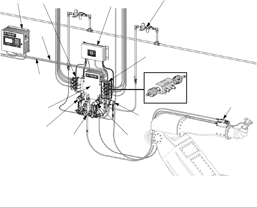
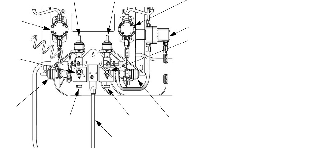
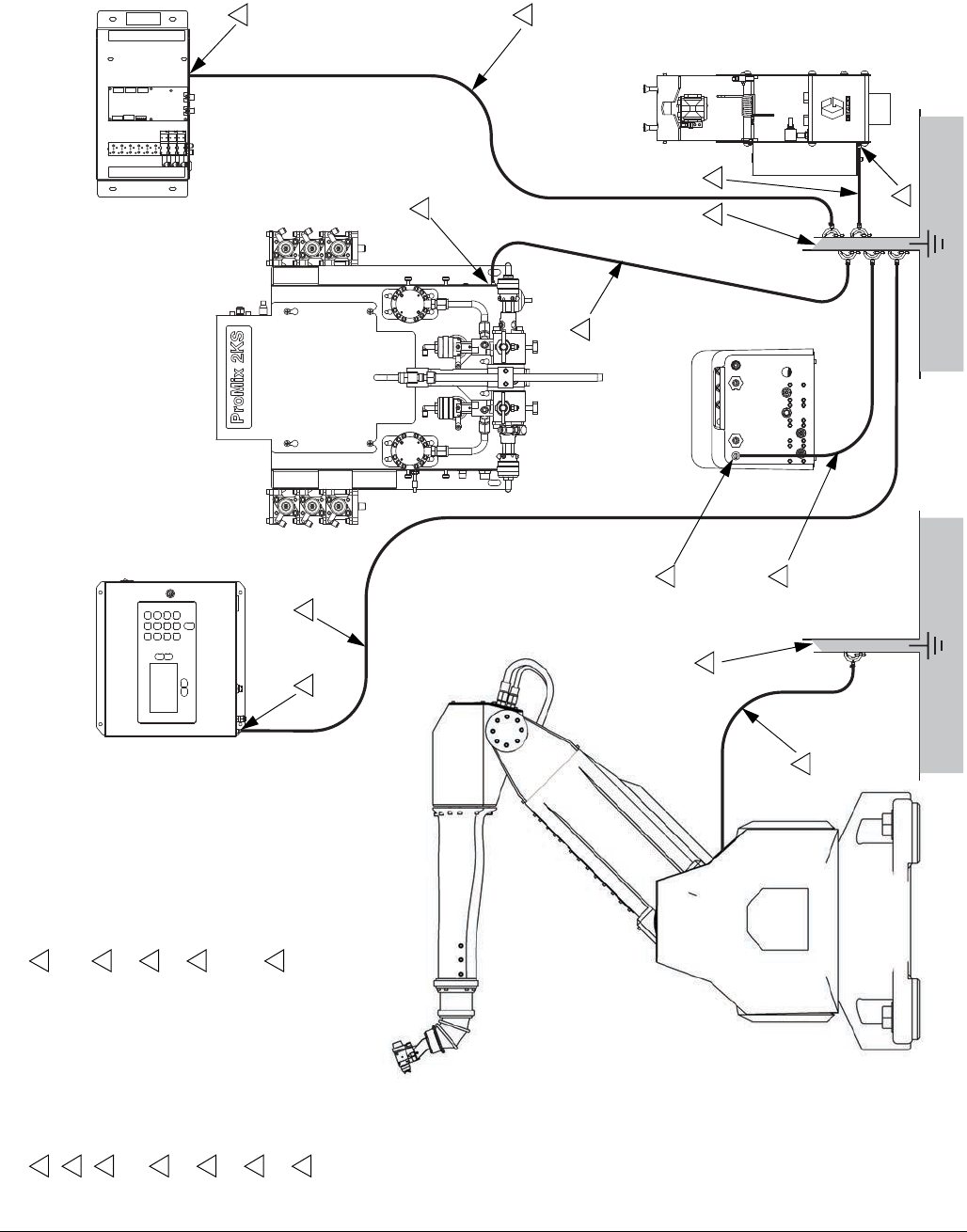
See Table 1, and FIG. 3 for the wall mount system components and FIG. 4 for the RoboMix system components.
F
IG. 3. Wall Mount System, shown with G3000 Meters, Color/Catalyst Change, Accessory Solvent Meter, and
Flow Control
TI29654a
FO*
FC
PS*
EK
ST
ACV
CCM
MS
MA
MB
FM
BCV
Air Controls/
Filter
* See the ProMix 2KS
Repair-Parts manual for
optional cable lengths.
BCV - acid model

Component Identification and Definition
16 312778G
Table 1: Component Descriptions
Component Description
EasyKey (EK)
Used to set up, display, operate, and monitor the system. The EasyKey accepts 85-250
VAC, 50/60 Hz line power and converts that power to acceptable low voltage and optical
signals used by other system components.
Wall Mount Fluid
Station (ST, used on
ADxxxx and AExxxx
Models only)
Includes air control solenoids, flow switches, and mountings for the fluid flow meters, and
the fluid manifold assembly. Its control board manages all proportioning functions.
RoboMix Fluid
Station (ST, used on
RDxxxx and RExxxx
Models only)
Includes air control solenoids, flow switches, fluid flow meters, and the fluid manifold
assembly to control and monitor fluid dispensing. Its control board manages all propor-
tioning functions.
Fluid Manifold (FM)
• Pneumatically Operated Dose Valves for component A and B
• Purge Valves for solvent and air purge
• Sampling Valves for calibrating the flow meters and performing ratio checks (Wall
Mount Panel only)
• Shutoff Valves for component A and B to close their fluid passages to the mix mani-
fold, to allow for accurate calibration and ratio checks (Wall Mount Panel only)
• Mix Manifold, which includes the fluid integrator and static mixer.
Fluid Integrator is the chamber where component A and B align at the
selected ratio and begin to mix.
Static Mixer has 24 elements to uniformly blend the materials downstream
of the fluid integrator.

Component Identification and Definition
312778G 17
Flow Meters (MA,
MB, MS)
The following optional flow meters are available from Graco:
• G3000 is a general purpose gear meter typically used in flow ranges of 75-3800
cc/min. (0.02–1.0 gal/min.), pressures up to 4000 psi (28 MPa, 276 bar), and viscosi-
ties of 20–3000 centipoise. The K-factor is approximately 0.119 cc/pulse.
• G3000A is a gear meter for use with acid catalyst fluids. It is typically used in flow
ranges of 75-3800 cc/min. (0.02–1.0 gal/min.), pressures up to 4000 psi (28 MPa,
276 bar), and viscosities of 20–3000 centipoise. The K-factor is approximately 0.119
cc/pulse.
• G3000HR is a high resolution version of the G3000 meter. It is typically used in flow
ranges of 38–1900 cc/min. (0.01–0.5 gal/min.), pressures up to 4000 psi (28 MPa,
276 bar). and viscosities of 20–3000 centipoise. The K-factor is approximately 0.061
cc/pulse.
• G250 is a general purpose gear meter, used in RoboMix systems. It is typically used
in flow ranges of 75-3800 cc/min. (0.02–1.0 gal/min.), pressures up to 300 psi (2.1
MPa, 21 bar), and viscosities of 20–3000 centipoise. The K-factor is approximately
0.119 cc/pulse.
• G250HR is a high resolution version of the G250 meter, used in RoboMix systems. It
is typically used in flow ranges of 38–1900 cc/min. (0.01–0.5 gal/min.), pressures up
to 300 psi (2.1 MPa, 21 bar). and viscosities of 20–3000 centipoise. The K-factor is
approximately 0.061 cc/pulse.
• S3000 is a gear meter used for solvents in flow ranges of 38-1900 cc/min. (0.01–0.50
gal/min.), pressures up to 3000 psi (21 MPa, 210 bar), and viscosities of 20–50 centi-
poise. The K-factor is approximately 0.021 cc/pulse. Required to use the Solvent
Push feature.
• Coriolis is a specialty meter capable of a wide range of flow rates and viscosities.
This meter is available with 1/8 in. or 3/8 in. diameter fluid passages. For detailed
information on the Coriolis meter, see manual 313599.
The K-factor is user-settable; at lower flow rates use a lower K-factor.
1/8 in. fluid passages: set K-factor to .020 or .061.
3/8 in. fluid passages: set K-factor to .061 or 0.119.
Color Change
Valves (ACV) and
Color Change
Module (CCM)
An optional component. It is available as a color change valve stack for either low or high
pressure with up to 30 color change valves. Each stack includes one additional valve for
solvent to clean the fluid line between color changes.
Catalyst Change
Valves (BCV)
An optional component. It is available as a catalyst change valve stack for either low or
high pressure with up to 4 catalyst change valves. Each stack includes one additional
valve for solvent to clean the fluid line between catalyst changes.
A different catalyst change valve used on acid catalyst systems.
Dual Fiber Optic
Cable (FO)
Used to communicate between the EasyKey and Wall Mount Fluid Station or RoboMix.
Fluid Station Power
Supply Cable (PS)
Used to provide power to the Wall Mount Fluid Station or RoboMix.
Flow Control
Regulator
Assembly (FC)
Includes an air operated fluid pressure regulator, fluid pressure sensor, voltage to air
pressure transducer and circuit board. The function of this unit is to receive the flow ana-
log signal and drive (manage) the desired flow rate.
Table 1: Component Descriptions
Component Description
Component Identification and Definition
18 312778G
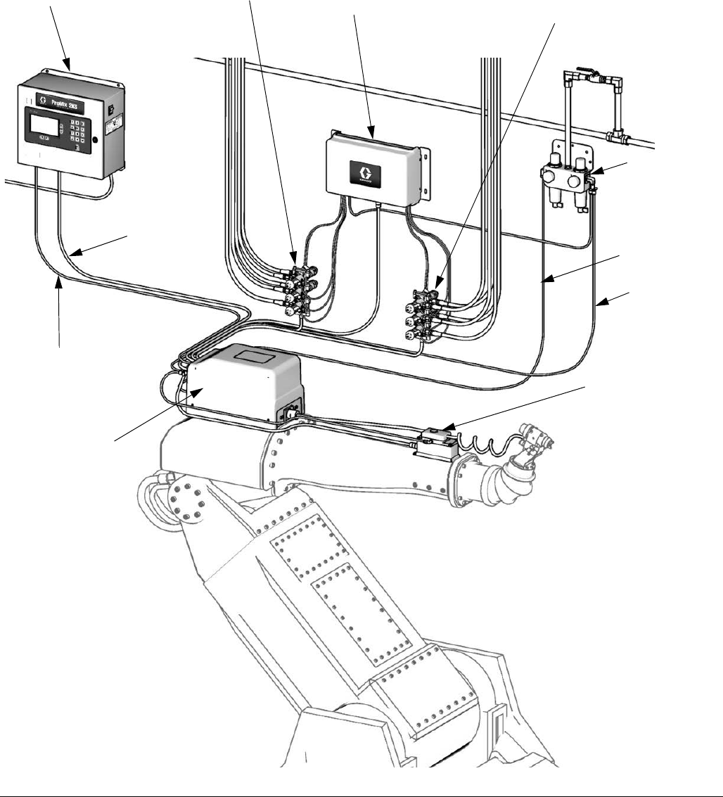
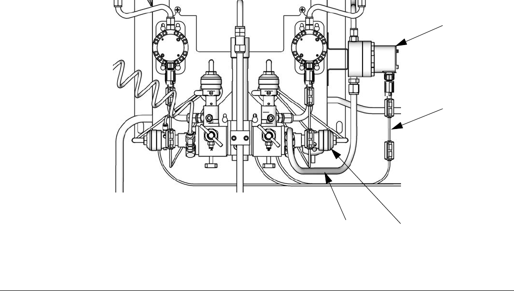
FIG. 4. RoboMix System shown with Color/Catalyst Change and Flow Control
TI12552a
Purge Air
RoboMix
Control Air
Air Controls/
Filters
FO*
FC
PS*
EK
ST
ACV
CCM
BCV
* See the ProMix 2KS
Repair-Parts manual for
optional cable lengths.
Component Identification and Definition
312778G 19
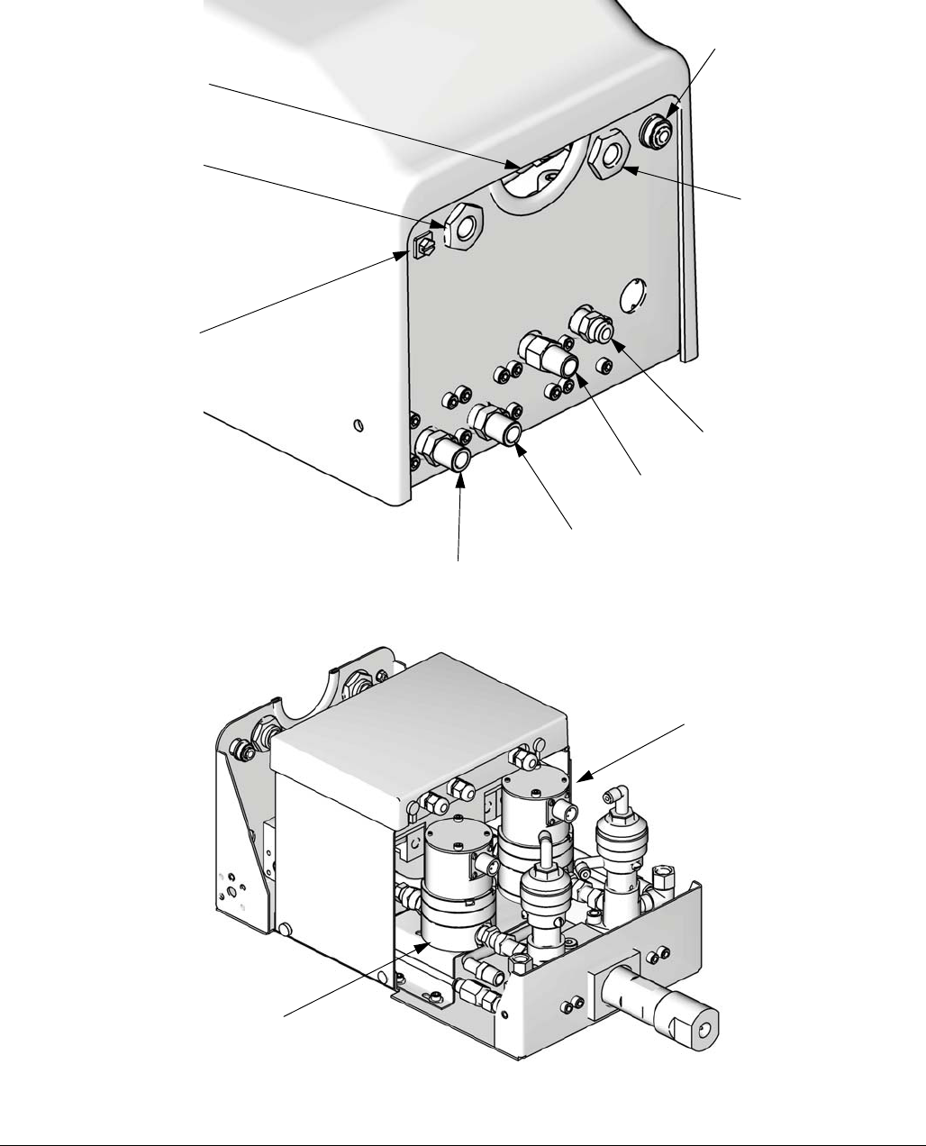
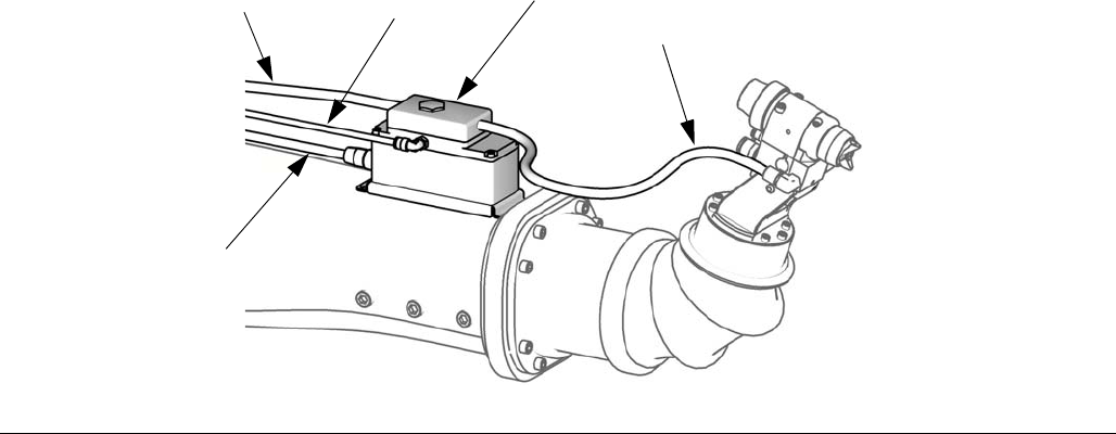
FIG. 5: Details of RoboMix Fluid Station
Cover is removed for clarity
A Supply (1/4 npt)
B Supply (1/4 npt)
Solvent Supply
(1/4 npt)
Air Purge
Cable Path
Air Logic In
A Dump Out
B Dump Out
TI12511a
TI12579a
Ground Screw
MA
MB
Location
20 312778G
Location
Location Requirements
• Mount EasyKey and Fluid Station within 50 ft (15.2
m) of each other, using 15U533 cable.
NOTE: An optional 15V213 100 ft (30.5 m) cable is
also available.
• EasyKey: Install in the non-hazardous area at a
convenient location for the operator to view and
operate.
• Fluid Station: Install according to requirements for
Intrinsically Safe Installation (F
IG. 6) and at a conve-
nient location to connect to paint and solvent sup-
plies.
NOTE: For an Intrinsically Safe Installation, the
Fluid Station may be located inside or outside the
hazardous location. Install according to appropriate
electrical codes.
Intrinsically Safe Installation
Requirements
See FIG. 6 on page 21.
1. The non-intrinsically safe terminals (power rail) must
not be connected to any device which uses or gen-
erates more than 250 Vrms or dc unless it has been
determined that the voltage has been adequately
isolated.
2. The installation must meet the requirements of the
National Electric Code, Canadian Electrical Code
Part I, NFPA 70, Article 504 Resp., Article 505 and
ANSI/ISA 12.06.01.
3. Multiple earthing of components is allowed only if
high integrity equipotential system is realized
between the points of bonding.
4. Do not operate system with safety barrier cover
removed.
5. For ATEX, install per EN 60079-14 and applicable
local and national codes.
6. For power connection to Coriolis: Install Coriolis
flow meters as explosion proof (USA, Can-
ada)/flameproof Ex d (ATEX) per the manufacturer’s
installation instructions and applicable codes.
7. For signal to 2KS: Terminals 24 and 25 of optional
Endress+Hauser Coriolis flow meters installed using
intrinsically safe wiring methods.
8. For ATEX installations, interconnecting cabling
specified is Type A cable in accordance with EN
60079-14.
Optional Cables
Optional CAN cables and fiber optic cables are available
from Graco. See the ProMix 2KS Repair-Parts manual
for available part numbers and lengths.
Do not substitute or modify system components as this
may impair intrinsic safety. For installation, mainte-
nance or operation instructions, read instruction manu-
als. Do not install equipment approved only for
non-hazardous location in a hazardous area. See the
identification label (F
IG. 1 and FIG. 2) on the EasyKey
or fluid station for the intrinsic safety rating for your
model.
Location
312778G 21
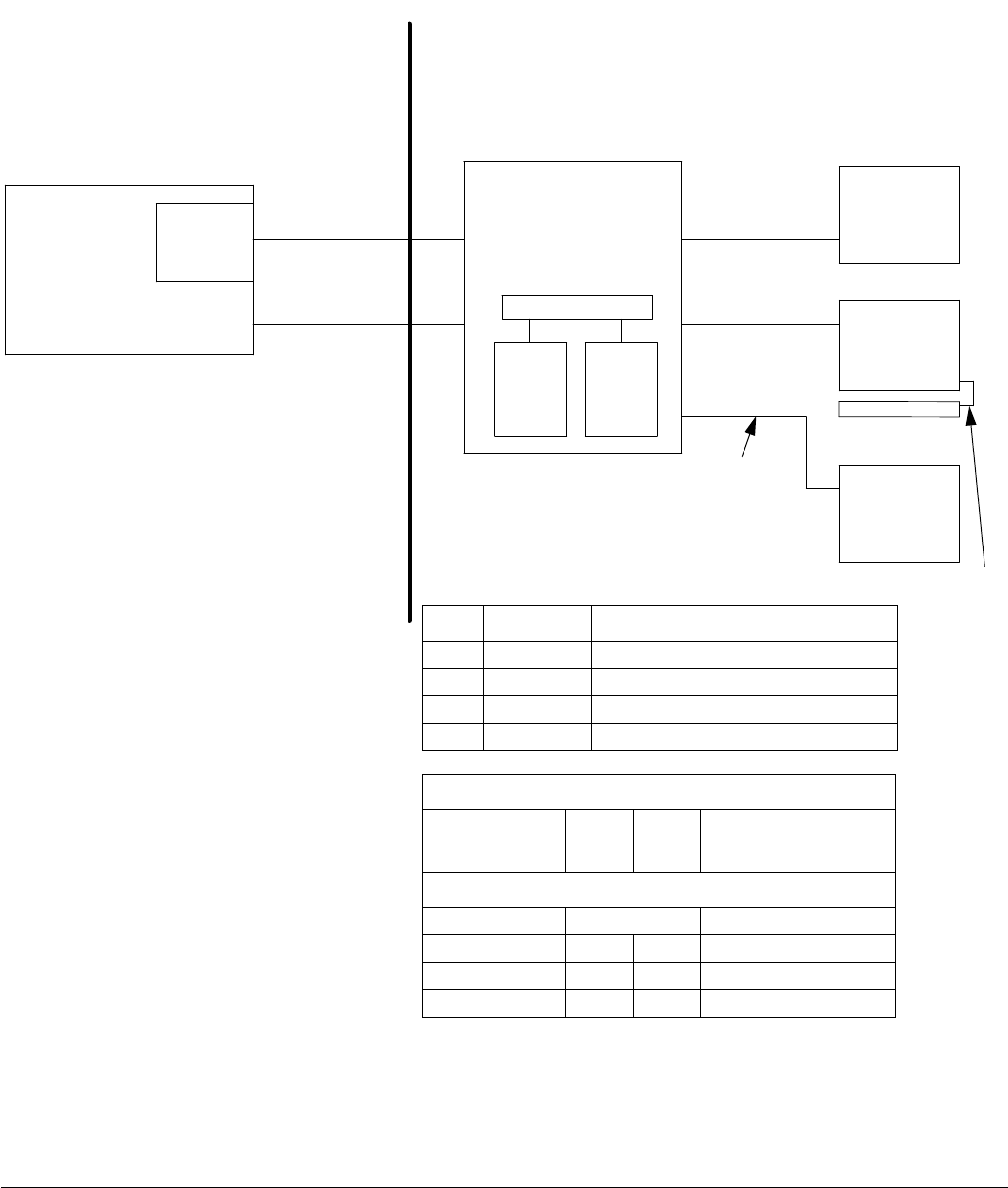
FIG. 6. Intrinsically Safe Installation
NON-HAZARDOUS
LOCATION ONLY
HAZARDOUS (CLASSIFIED) LOCATION
CLASS I, DIV I, GROUP D, T3 (US AND CANADA)
CLASS I, ZONE I GROUP IIA T3 (ATEX ONLY)
TAUB = -20°C TO 50°C
ProMix 2KS
EasyKey Interface
Safety
Barrier
ProMix 2KS Smart Fluid Plate
(Wall Panel or RoboMix
Flow
Meter
A
Flow
Meter
B
Booth Control
Module
FM08ATEX007
Color & Catalyst
Change
Module 1
FM08ATEX007
250 VAC Maximum
Supply Voltage
50’ I/S Power Cable
(3’, 6’, 10’, 15’, 25’,
100’ options)
50’ Fiber Optic
Communication
Cable (100’ option)
10’ I/S Power and
Communication
Cable (40’
extension option)
IS Control Drawing 289833
Cable
Module 2
FM08ATEX007
Flow Control
Regulator
Module
FM08ATEX0073
3’ CAN Color
Change Interface
(6’, 10’, 15’, 25’,
50’ 100’ options)
50’ CAN Booth
Control Interface
(3’, 6’, 10’, 15’,
25’, 100’ options)
3’ CAN
Network
Cable
NOTE: See Intrinsically Safe Installation
Requirements on page 20.
WARNING: Substitution of components
may impair intrinsic safety. For installation,
maintenance or operation instructions, see
instruction manual.
ADVERTISSEMENT: La substitution de
composants peut compromettre la securite
intrinseque.
FM08ATEX0074
SYSTEM ASSEMBLY CERTIFICATE
FM08ATEX0072
ASSOCIATED APPARATUS
FM08ATEX0073 INTRINSIC
SAFE APPARATUS
Coriolis Meter Options, DMT 00 ATEX E 074 X (No exceptions):
Size Graco P/N Endress+Hauser P/N
1/8” 15T633* 80A-04-A-SVW-9-A-N-A-B-B-A-S
3/8” 15T634* 801-08-A-999-9-A-N-A-B-B-A-S
1/8” 16M510* 8CN04-84S89AABA9AC
1/4” 16M519* 8CN06-84S89AABA9AC
Power
EasyKey
+24 Vdc
Common
Meter Terminal Block #
1
2
Signal
Fluid Plate Board J3 Terminal Meter Terminal Block #
Meter Position A B
Signal 3 6 24
Common 2 5 25
* For P/N 15T633 order Coriolis Meter Kit 15V806.
For P/N 15T634 order Coriolis Meter Kit 258151.
For P/N 16M510 order Coriolis Meter Kit 24M260.
For P/N 16M519 order Coriolis Meter Kit 24M261.
General Information
22 312778G
General Information
• Reference numbers and letters in parentheses in
the text refer to numbers and letters in the illustra-
tions.
•F
IG. 3 on page 15 shows the basic components of
an automatic wall mount system. F
IG. 4 on page 18
shows the basic components of an automatic Robo-
Mix system. Contact your Graco distributor for
actual system designs.
• Be sure all accessories are adequately sized and
pressure-rated to meet system requirements.
• There must be a shutoff valve between each fluid
supply line and the ProMix system.
• A 100 mesh minimum fluid filter must be installed on
component A and B fluid supply lines.
• To protect the EasyKey screens from paints and
solvents, clear-plastic protective shields are avail-
able in packs of 10 (Part No. 197902). Clean the
screens with a dry cloth if necessary.
Wall Mounting
1. See Dimensions and Mounting Hole Layouts,
page 46.
2. Ensure that the wall and mounting hardware are
strong enough to support the weight of the equip-
ment, fluid, hoses, and stress caused during opera-
tion.
3. Using the equipment as a template, mark the
mounting holes on the wall at a convenient height
for the operator and so equipment is easily accessi-
ble for maintenance.
4. Drill mounting holes in the wall. Install anchors as
needed.
5. Bolt equipment securely.
Air Supply
Requirements
• Compressed air supply pressure: 75-100 psi
(517-700 kPa, 5.2-7 bar).
• Air hoses: use grounded hoses that are correctly
sized for your system.
• Air regulator and bleed-type shutoff valve:
include in each air line to fluid supply equipment.
Install an additional shutoff valve upstream of all air
line accessories to isolate them for servicing.
• Air line filter: a 10 micron or better air filter is rec-
ommended to filter oil and water out of the air supply
and help avoid paint contamination and clogged
solenoids. See F
IG. 3 or FIG. 4.
Air Connections
See the System Pneumatic Schematic on page 43.
1. Tighten all ProMix system air and fluid line connec-
tions as they may have loosened during shipment.
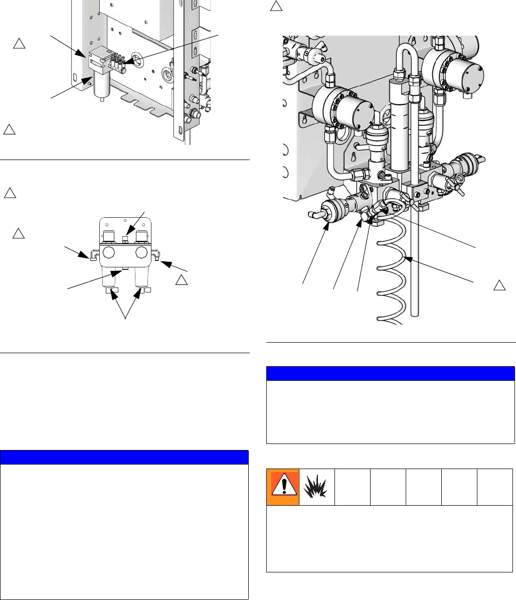
2. Install a bleed-type air shutoff valve into the control
air filter inlet. See F
IG. 7 for Wall Mount systems and
F
IG. 8 for RoboMix systems.
3. Connect a clean, dry, main air supply line to the
bleed-type air shutoff valve at the main air inlet. This
air line supplies air to operate the gun, solenoids,
and dispense valves.
NOTE: See Technical Data on page 55 for additional
air supply/consumption information.
4. lnstall a bleed-type shutoff valve into the air purge
valve line.
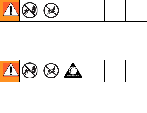
Trapped air can cause a pump or dispense valve to
cycle unexpectedly, which could result in serious injury
from splashing or moving parts. Use bleed-type shutoff
valves.
Air Supply
312778G 23
5. See FIG. 9. Install the supplied elbow (E), check
valve (CV), and tube fitting (F) at the inlet of the air
purge valve (APV). Use the 25 ft (7.6 m), 1/4 in. (6
mm) OD purge air tubing (AT, supplied) to connect
a clean, dry air supply to the fitting (F) at the air
purge valve inlet. Install filters/dryers as needed.
F
IG. 7. Wall Mount Air Supply Inlet
F
IG. 8. RoboMix Air Supply Control
NOTICE
Use a separate purge air supply line for the air purge
valve (APV). Do not connect the air purge valve to the
unit’s main air supply or to the air manifold (AM, F
IG.
7), to avoid contaminating the solenoids, air logic
lines, or unit’s main air supply with fluid if the air purge
valve (APV) and check valve (CV) fail.
Do not shorten the 25 ft (7.6 m), 1/4 in. (6 mm) OD
purge air tubing (AT). Check daily for any visible sol-
vent accumulation. Notify your supervisor if solvent is
present.
TI13069a
1
Install a bleed-type air shutoff valve here.
1
Main Air
Inlet
Air Filter
AM
TI11895a
1
Install a bleed-type air
shutoff valve here.
1
1
For Fluid
Station
Controls
Main Air Inlet
For Air
Purge Valve
For Air
Flow Switch
Air Filters
FIG. 9. Purge Air Supply Tube and Check Valve
NOTICE
The ProMix potlife timer will not function properly
when used with multiple guns operating simultane-
ously. To avoid having mixed material set in the
equipment, carefully monitor potlife by some other
means.
If using a Graco electrostatic PRO
™
Gun, a shutoff
valve must be installed in the gun air line to shutoff the
atomizing and turbine air to the gun. Contact your
Graco distributor for information on air shutoff valves
for electrostatic applications.
AT
TI16793a
CV
APV
F
E
Purge air line (AT) must be a separate air supply, connected
to the check valve (CV). Do not connect the purge air line to
the unit’s main air supply or to the air manifold.
2
2
Fluid Supply
24 312778G
Fluid Supply
Requirements
ProMix models are available to operate air spray or
air-assisted systems with a capacity of up to 3800
cc/min.
• Fluid supply pressure tanks, feed pumps, or circu-
lating systems can be used.
• Materials can be transferred from their original con-
tainers or from a central paint recirculating line.
• For an airless system, the user must supply a gun
trigger signal to the ProMix 2KS.
• See manual 313599 for Coriolis meter installation
and operation instructions.
• If you are using dynamic dosing, see Fluid Connec-
tions at right and also see Setup the Fluid Mani-
fold for Dynamic Dosing on page 26.
NOTE: The fluid supply must be free of pressure spikes,
which are commonly caused by pump stroke change-
over. If necessary, install pressure regulators or a surge
tank on the ProMix fluid inlets to reduce pulsation. Con-
tact your Graco distributor for additional information.
Fluid Connections
1. Connect the solvent supply lines.
a. Connect the solvent supply line to the 1/4 npt(f)
solvent purge valve inlet. See F
IG. 10.
b. Multiple color system: also connect a solvent
supply line to the color change stack (Q), top
valve 4 or 5. See F
IG. 11.
2. Connect the component A supply line(s).
Single color system: connect component
supply line to the component A flow meter
inlet.
Multiple color system: connect compo-
nent A supply lines to the color change
valve stack (S) inlets. See F
IG. 11. The
color number is marked on the valve air
supply line.
NOTE: Paint Recirculating System Only
• The color change valves have two fluid
ports for each individual valve. If you are
recirculating paint, plumb the valves in one
port and out the other.
• Another option is to use a tee fitting to recir-
culate.
NOTE: Verify that all unused fluid ports on the color
change valve stack are plugged before operation. An
open port will leak fluid.
3. Connect the component B line to the component B
flow meter inlet.
NOTE: The component A and B fluid meter inlets have
fluid check valves to prevent backflow from fluid supply
pressure fluctuations. Backflow can cause ratio inaccu-
racies.
4. Connect the gun fluid supply line between the fluid
manifold static mixer outlet and the gun fluid inlet.
Do not exceed the pressure rating of the lowest rated
component. See the identification label (F
IG. 1 on page
4 and F
IG. 2 on page 6).
To reduce the risk of injury, including fluid injection,
you must install a shutoff valve between each fluid sup-
ply line and the fluid manifold assembly. Use the
valves to shut off fluid during maintenance and service.
Fluid Supply
312778G 25
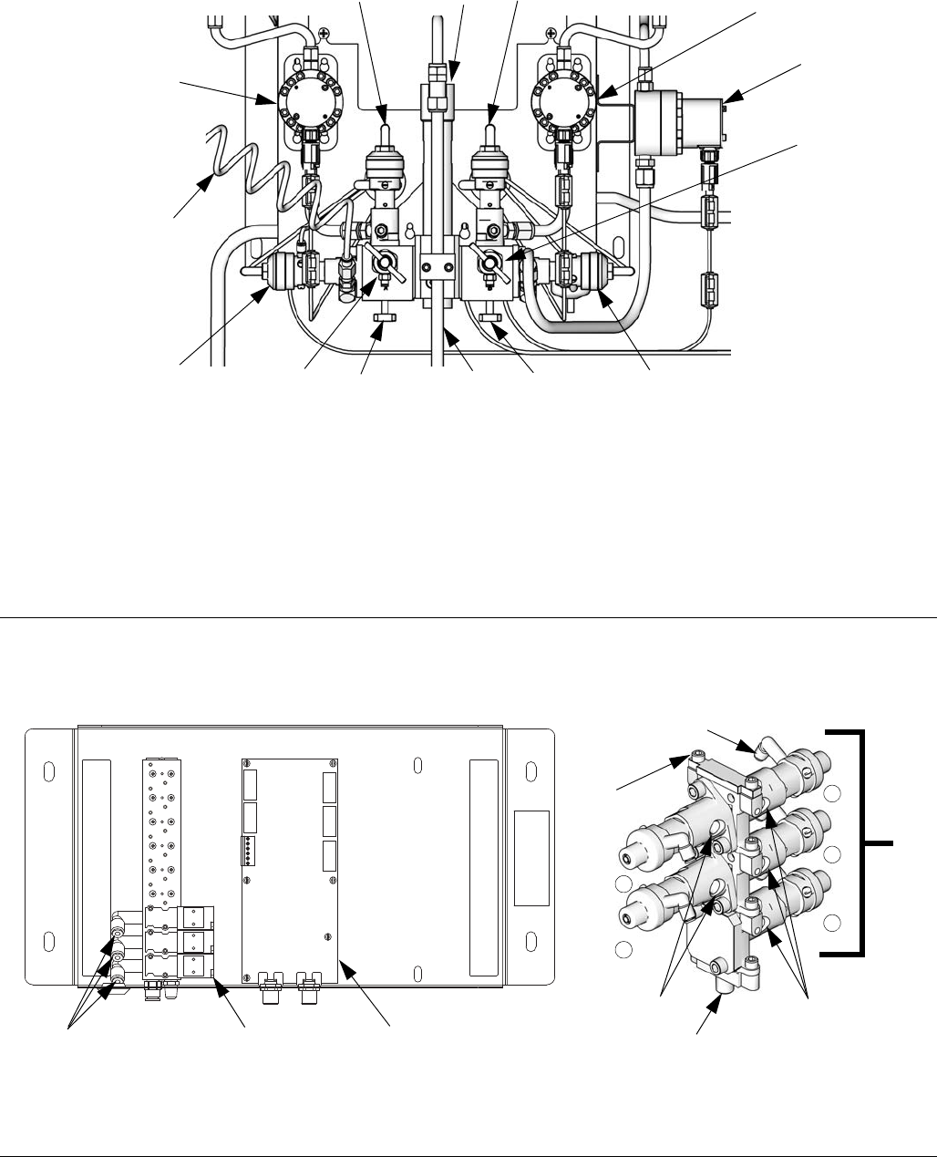
FIG. 10. Wall Mount Fluid Station, Sequential Dosing
TI12556b
Key:
MA Component A Meter
DVA Component A Dose Valve
RVA Component A Sampling Valve
SVA Component A Shutoff Valve
MB Component B Meter
DVB Component B Dose Valve
RVB Component B Sampling Valve
SVB Component B Shutoff Valve
MS Solvent Meter (accessory)
SPV Solvent Purge Valve
APV Air Purge Valve
SM Static Mixer
FI Fluid Integrator
AT Air Purge Valve Air Supply Tube
MA
MB
DVB
MS
SPV
DVA
APV
SM
FI
SVA SVB
RVB
RVA
AT
FIG. 11. Color Change Valves Air and Fluid Connections
Q
S
1
2
4
5
3
Connect solvent valve
air line here
Color Change Board and Solenoid Valves
Color Change BoardSolenoids
Color Change Valve Stack
Connect air lines to
valves here
Fluid Inlets Fluid Inlets
Fluid Outlet
TI12824a
TI11668a
Fluid Supply
26 312778G
Setup the Fluid Manifold for Dynamic Dosing
If you will be operating using dynamic dosing, the fluid
manifold must be setup properly for your application.
Order the 15U955 Injection Kit (accessory).
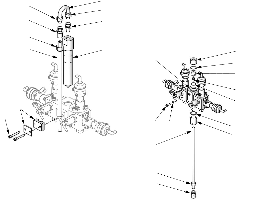
1. Remove the screws (A) and static mixer bracket
assembly (B). See F
IG. 12.
2. Loosen the static mixer nut (N1). Remove and retain
the static mixer (SM).
3. Loosen the u-tube nuts (N2 and N3). Discard the
u-tube (C) and the static mixer fitting (D).
4. Remove and retain the 1/4 npt(m) fitting (F).
Remove the integrator (G) and discard.
5. See F
IG. 13. Remove the remaining parts from the
restrictor housing (H). Retain the plug (J) and base
(K). Discard all the used o-rings,
6. Rotate the restrictor housing (H) 180° so the set-
screw (S) is at top left, as shown in F
IG. 13. Remove
and retain the two setscrews (S). Discard the
o-rings (L3). The position of these screws will be
reversed when reassembled.
7. Install one larger o-ring (L1*) in the housing (H).
Screw the injection cap (M*) into the housing.
8. Determine the desired flow range for your applica-
tion. Select the appropriate size restrictor for your
selected flow and ratio, using the Dynamic Dosing
Restrictor Selection Graphs on pages 48-53 as a
guide. Install the restrictor (R*) in the base (K).
9. Assemble the smaller manifold o-ring (L2*), restric-
tor (R*) and base (K), one larger o-ring (L1*), and
plug (J) as shown.
F
IG. 12. Disassemble Integrator and Static Mixer
N1
A
B
SM
C
D
TI15004a
F
G
N2
N3
FIG. 13. Install 15U955 Injection Kit
L1*
L2*
H
K
M*
SM
J
N1
TI13360b
L1*
F
S
R*
* These parts are included in the
15U955 Injection Kit.
L3*
Fluid Supply
312778G 27
10. Install the two setscrews and o-rings (L3*). Install
the long setscrew (S) at the front of the housing, for
ease of access.
11. Screw the static mixer (SM) into the injection cap
(M*). Install the retained fitting (F) on the static
mixer tube and secure with the nut (N1).
12. Follow instructions under Fluid Connections on
page 24.
NOTE: Use a minimum 20 ft (6.1 m) x 1/4 in. (6 mm) ID
gun fluid supply hose when using dynamic dosing. If the
material is harder to integrate, use a longer hose.
13. Tune the fluid pressure and flow as explained in the
ProMix 2KS Operation Manual.
NOTE: When using dynamic dosing it is very important
to maintain a constant, well-regulated fluid supply. To
obtain proper pressure control and minimize pump pul-
sation, install a fluid regulator on the A and B supply
lines upstream of the meters. In systems with color
change, install the regulator downstream of the
color/catalyst valve stack.
F
IG. 14. Wall Mount Fluid Station, Dynamic Dosing
TI13874b
MA
MB
DVB
MS
SPV
DVA
APV
SM
SVA SVB
RVB
RVA
Key:
MA Component A Meter
DVA Component A Dose Valve
RVA Component A Sampling Valve
SVA Component A Shutoff Valve
MB Component B Meter
DVB Component B Dose Valve
RVB Component B Sampling Valve
SVB Component B Shutoff Valve
MS Solvent Meter (accessory)
SPV Solvent Purge Valve
APV Air Purge Valve
SM Static Mixer
Fluid Supply
28 312778G
Solvent Meter Accessory
The ProMix 2KS Solvent Push feature requires installa-
tion of the accessory solvent meter (MS). Order Graco
Part No. 280555 S3000 Solvent Meter Kit. See manual
308778.
NOTE: You must assemble the meter sensor to the
meter body before connecting the cable to the sensor
for the meter to function properly.
1. See F
IG. 15. Install the solvent meter (MS) on the
side of the fluid station, using the bracket and hard-
ware provided with the meter. Connect the solvent
meter cable (SMC) to Pins 1, 2, and 3 of J12 on the
fluid panel control board. See the System Electri-
cal Schematic on page 45. Connect the cable
ground wire to the fluid station ground terminal.
2. Connect a solvent supply line (SS) from the outlet of
the solvent meter (MS) to the inlet of the solvent
purge valve (SPV).
NOTE: If you are using a 3rd purge valve instead of the
solvent purge valve to run the Solvent Push feature,
connect the solvent supply line from the solvent meter to
the inlet of the 3rd purge valve.
3. Connect the main solvent supply to the inlet of the
solvent meter (MS).
F
IG. 15. Solvent Meter
TI12556b
Key:
MS Solvent Meter (accessory)
SPV Solvent Purge Valve
SMC Solvent Meter Cable
SS Solvent Supply Line
MS
SPV
SMC
SS
Flow Control
312778G 29
Flow Control
The intrinsically safe flow regulator (FC) is required to
use flow control in your system.
1. Connect a 1/4 in. (6 mm) OD air supply line to the
air inlet fitting of the flow regulator (FC). Connect the
other end of this line as follows:
a. Wall Mount Systems: Connect to the air mani-
fold at the rear of the wall mount fluid station.
b. RoboMix Systems: Install a 1/4 in. (6 mm) OD
tube tee at the air logic inlet of the RoboMix.
Connect the flow control air line to one branch
of the tee and the main air line to the other
branch.
2. Connect a fluid inlet line from the static mixer tube at
the fluid station to the 1/8 npt(f) inlet of the flow reg-
ulator (FC).
3. Connect a fluid outlet line from the 1/8 npt(f) outlet
of the flow regulator (FC) to the spray gun inlet.
4. Connect the flow control cable to J5 on the fluid sta-
tion control board and to the cable connector on the
flow regulator (FC).
F
IG. 16. Flow Control Regulator
TI13656a
FC
Fluid Outlet to Gun
Fluid Inlet from
Fluid Station
Air Line from
Fluid Station
Cable from
Fluid Station
Electrical
30 312778G
Electrical
Requirements
NOTE: All options ordered on the ProMix system are
electrically tested at the factory.
The ProMix operates with 85-250 VAC, 50/60 Hz input
power, with a maximum of 2 amp current draw. The
power supply circuit must be protected with a 15 amp
maximum circuit breaker.
Not included with system:
• Power supply cord compatible to your local power
configuration. Wire gauge size must be 8-14 AWG.
• The input power access port
is 22.4 mm
(0.88 in.) diameter. It accepts a bulkhead strain
relief fitting or conduit. See F
IG. 18.
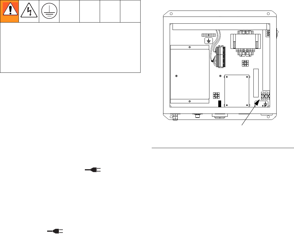
Connect Main Power
1. Provide power to the EasyKey. Install a bulkhead
strain relief or conduit bulkhead through the
EasyKey port . See F
IG. 18.
2. See F
IG. 17 and the System Electrical Schematic
on page 44 for the L1, N, and ground wiring connec-
tions inside the EasyKey.
3. Ground the EasyKey to a true earth ground. See
Grounding, page 36.
All electrical wiring must be completed by a qualified
electrician and comply with all local codes and regula-
tions.
Enclose all cables routed in the spray booth and high
traffic areas in conduit to prevent damage from paint,
solvent, and traffic.
FIG. 17. Main Power Connection
TI13349a
Input Power
Terminal Block
Electrical
312778G 31
Connect EasyKey to Fluid
Station Control
There are two 50 ft (15.2 m) cables to route between the
EasyKey and Fluid Station Control: the Fluid Station
Power Cable and the Fiber Optic Cable.
1. Connect the appropriate Fluid Station Power Cable
end to the EasyKey connector . See F
IG. 18.
2. Connect the other cable end to the Fluid Station
Control connector (J10). See F
IG. 20.
3. The Fiber Optic Cable is shipped from the factory
attached to the Fluid Station connector .
See F
IG. 18.
NOTE: If you need to detach the Fiber Optic Cable from
the Fluid Station, note how the cable is routed inside the
enclosure. Never cut the fiber optic cable. Cutting can
damage the cable and will defeat the color-coded cable
connections.
4. Route the opposite Fiber Optic Cable end through
the EasyKey strain relief connector . Do not
route the cable with tight bends or kinks.
NOTE: The fiber optic cable has a minimum bend radius
of 1.6 in. (40 mm).
5. Route the fiber optic cable end through the square
adhesive backed tie holder. Connect the blue and
black cable connectors to the matching connectors
on the EasyKey circuit board. See F
IG. 19. Insert the
cable connectors until they bottom out (approxi-
mately ¼ in. [6 mm]), then tighten the threaded con-
nector.
6. Tighten the strain relief connector .
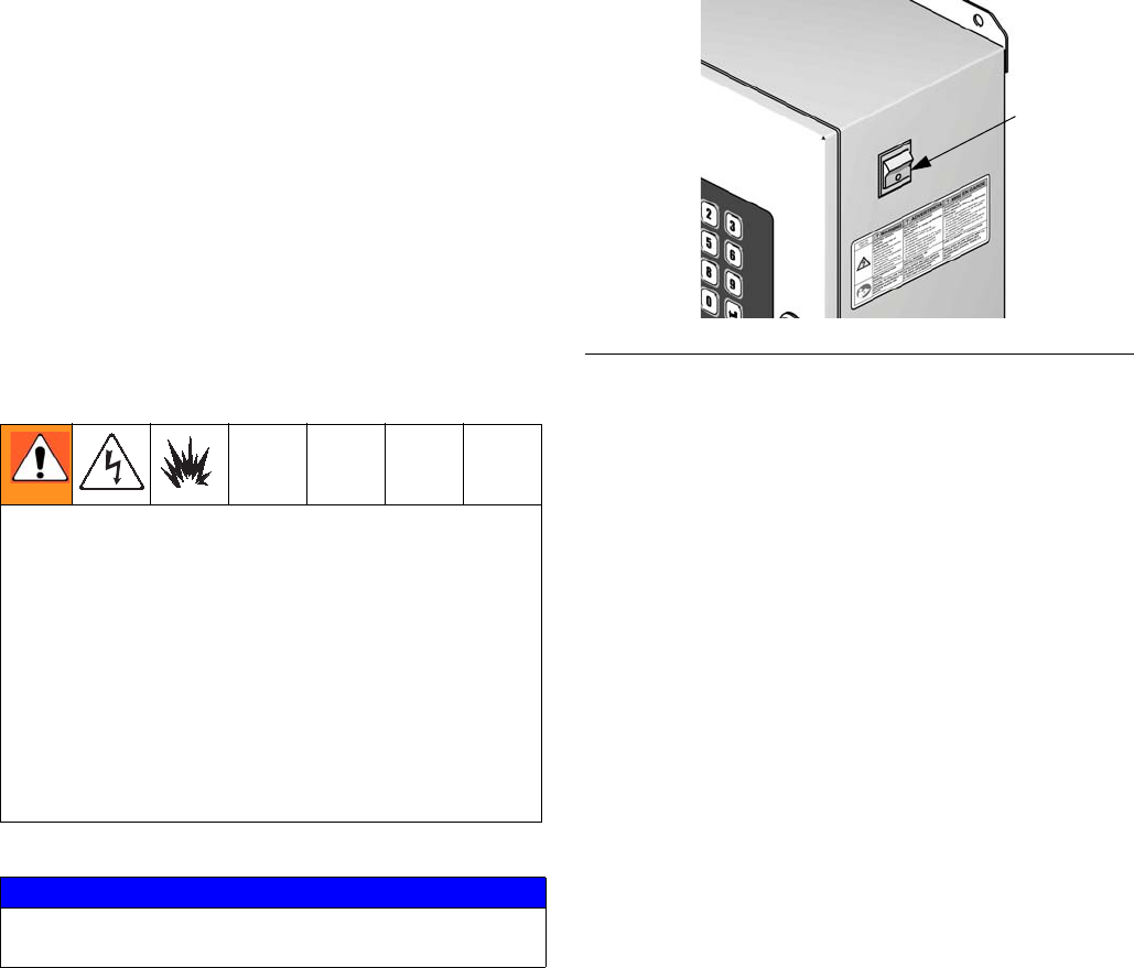
F
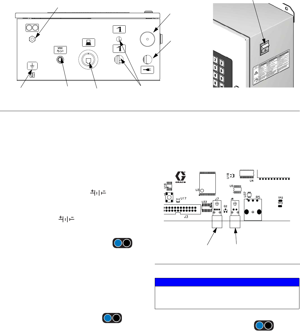
IG. 18. EasyKey Connections and AC Power Switch
AC Power Switch
Graco Web
Interface
Audible Alarm
Fiber Optic Strain
Relief Port
I/S Power Discrete I/O Cable
Connector Ports
Ground Screw
Main Power
Access Port
TI12638a
TI12657a
VDC
VDC
FIG. 19 EasyKey Circuit Board
NOTICE
To avoid cracking the circuit board, do not
over-tighten or cause excessive stress on the circuit
board connector.
J7 (F.O In-black) J8 (F.O Out - blue)
Electrical
32 312778G
Fluid Station Control Board Switch Settings
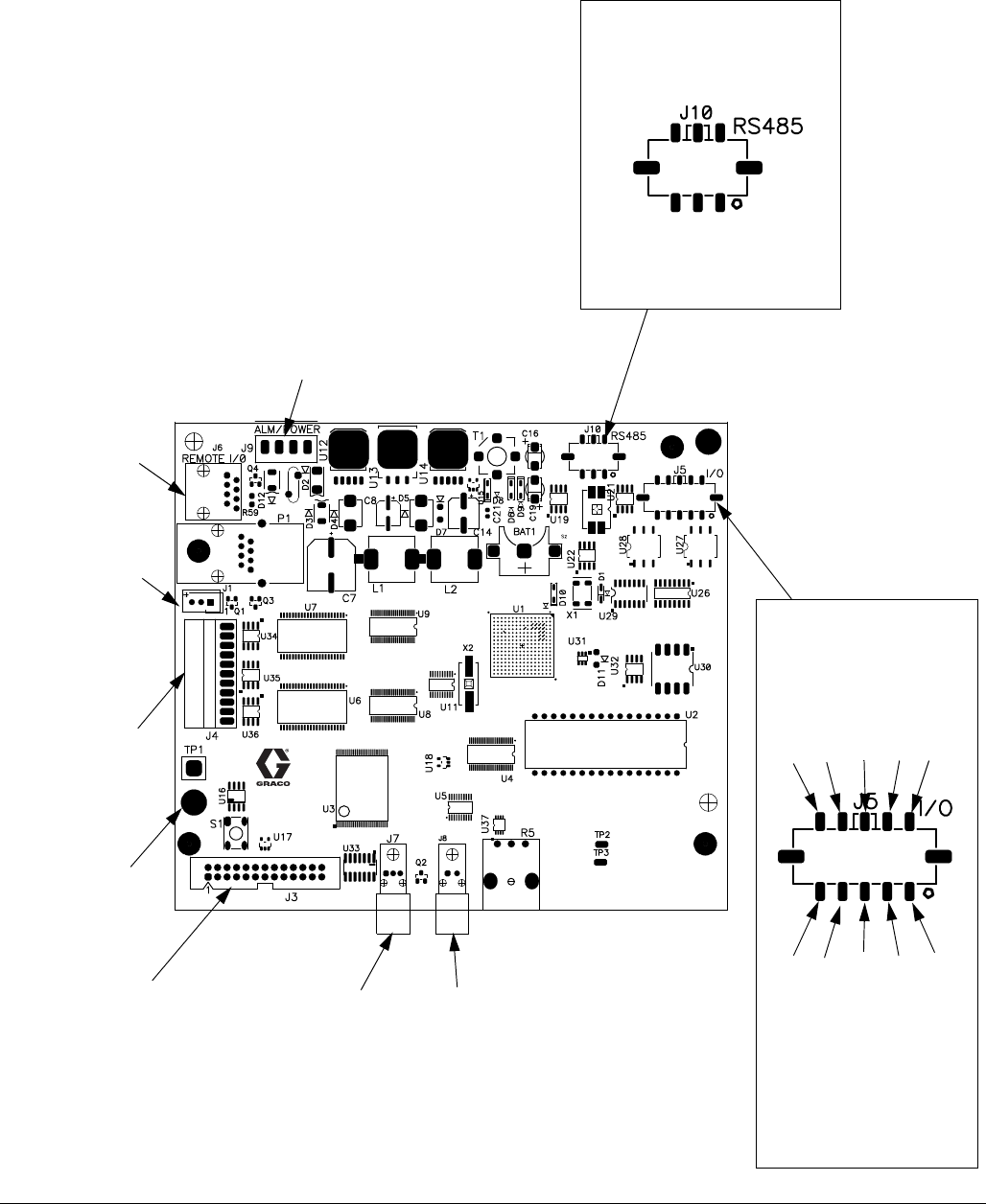
On the 2KS fluid station control board, set switch S1 to ON (down) or OFF (up), as shown in FIG. 20.
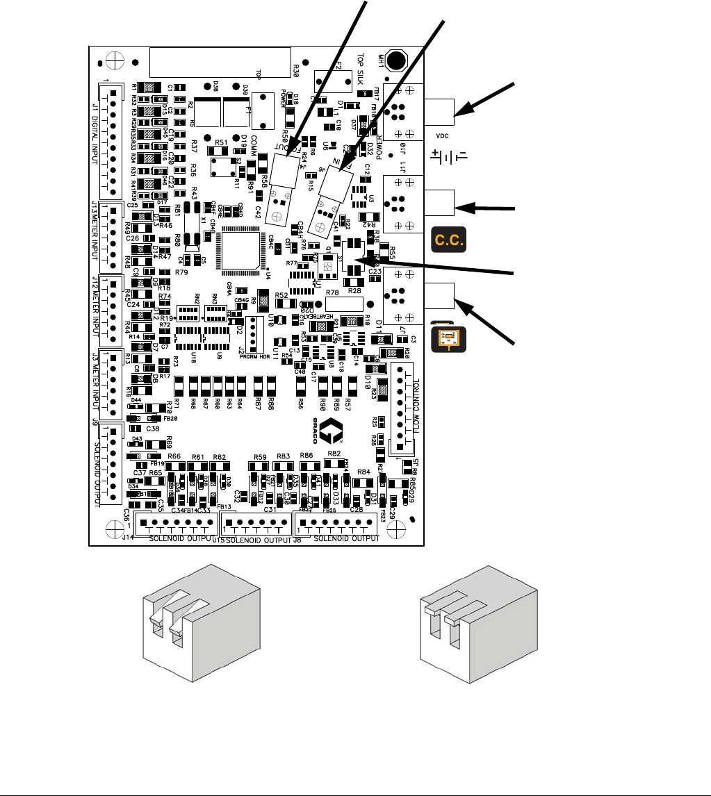
F
IG. 20. Fluid Station Board Connections
VDC
J10
(Power Input)
J11
(Color Change
Module)
J7
(Booth Control)
J4
(Fiber Optic Output - blue)
J6
(Fiber Optic Input - black)
Set Switch S1
as shown below.
Set switch S1 to ON (down) if
system has Booth Control
OR Color Change, or neither.
Set switch S1 to OFF (up) if system
has Booth Control AND Color Change.
TI15224a TI15223a
Electrical
312778G 33
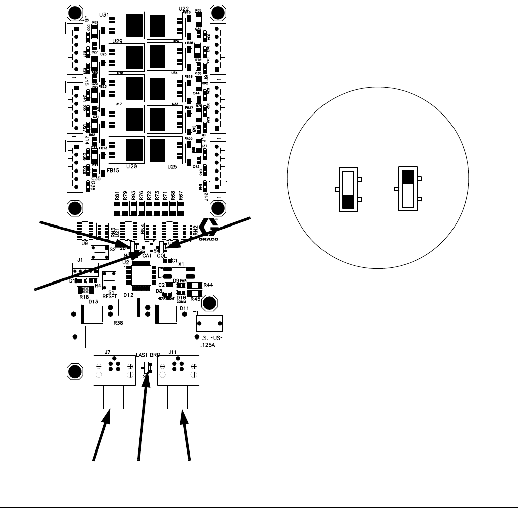
Connect Color Change Module
To install the color change module(s), see manual
312787.
Connect a 5-pin electrical cable from the labeled con-
nection port
(J11) on the fluid station control
board to the color change board. See F
IG. 21.
If you are using two color change modules to add colors,
connect a 5-pin electrical cable from the first color
change board to the second color change board.
Set switches S3-S6 on the color change board(s) as
shown in Table 2 and F
IG. 21, depending on the number
of color change boards and color change modules being
used in your system.
For wiring between the color change board and the sole-
noids, see the color change module electrical sche-
matic, F
IG. 22.
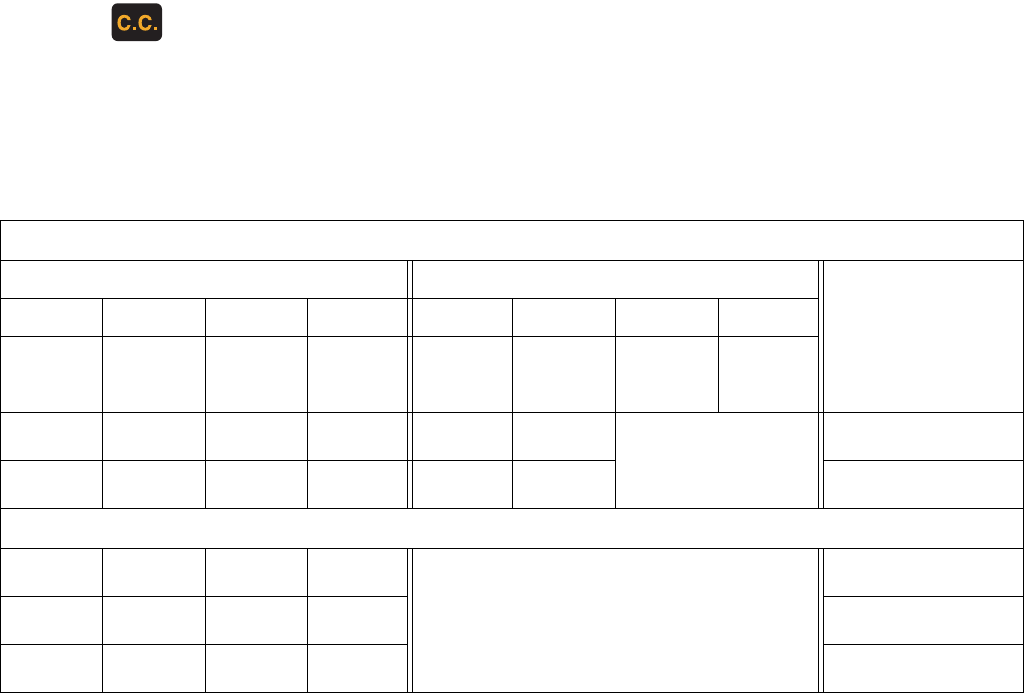
Table 2: Color Change Board Switch Settings
Two Color Change Boards
Color Change Board 1 Color Change Board 2
Effect on System
S3 S6 S5 S4 S3 S6 S5 S4
Terminatio
n
Resistor Board ID
Catalyst
On/Off
Color
On/Off
Terminatio
n
Resistor Board ID
Catalyst
On/Off
Color
On/Off
OFFONONONONOFF
NOT USED
4 catalyst valves, 30 color
valves
OFF ON OFF ON ON OFF 0 catalyst valves, 30 color
valves
One Color Change Board
ON ON ON ON
NOT PRESENT
4 catalyst valves, 12 color
valves
ON ON ON OFF 4 catalyst valves, 0 color
valves
ON ON OFF ON 0 catalyst valves, 12 color
valves
Electrical
34 312778G
FIG. 21. Color Change Board Switches S3-S6
S3
S4
S5
S6
OFF
ON
OFF
ON
Switch S3-S6
Positions
J7
J11
TI13661a
Electrical
312778G 35
FIG. 22. Color Change Module Electrical Schematic
WIRING DIAGRAM
COM
+12VDC
COM
+12VDC
COM
+12VDC
COM
+12VDC
COM
+12VDC
COM
+12VDC
COM
+12VDC
COM
+12VDC
COM
+12VDC
J8
J15
J14
J9
J16
J10
COLOR 8 (21)
COLOR 7 (20)
COLOR 6 (19)
COLOR 5 (18)
COLOR 4 (17)
COLOR 3 (16)
COLOR 2 (15)
COLOR 1 (14)
COLOR FLUSH (13)
COLOR 9 (22)
COLOR 10 (23)
COLOR 11 (24)
COLOR 12 (25)
CATALYST 4 (26)
CATALYST 3 (27)
CATALYST 2 (28)
CATALYST 1 (29)
CATALYST FLUSH (30)
+12VDC
COM
+12VDC
COM
+12VDC
COM
+12VDC
COM
+12VDC
COM
+12VDC
COM
+12VDC
COM
+12VDC
COM
+12VDC
COM
Electrical
36 312778G
Grounding
Ground the ProMix system as instructed here and in the
individual component manuals. A ground wire and
clamp, part no. 223547, is available from Graco.
NOTE: To prevent electrical noise interference from
high voltage equipment, do not connect the robot
ground to the same ground point used by these ProMix
2KS components.
NOTE: Different ground points (unequal potential) may
cause current to flow through component cables, caus-
ing incorrect signals.
EasyKey
Connect a ground wire from the EasyKey ground screw
to a true earth ground. F
IG. 23.
Gun Flush Box (Manual or Semi-automatic
mode only)
Connect a ground wire from the Gun Flush Box ground
lug to a true earth ground. F
IG. 23.
Wall Mount Fluid Station
Connect a ground wire from the Wall Mount Fluid Sta-
tion ground screw to a true earth ground. F
IG. 23.
RoboMix Fluid Station
Connect a ground wire from the RoboMix Fluid Station
ground lug to a true earth ground. F
IG. 23.
Color Change Module
Connect a ground wire from the Color Change Module
ground screw to a true earth ground. A ground wire and
clamp, part no. 223547, is available from Graco. F
IG. 23.
Flow Meters
Connect the meter cables as shown in the System
Electrical Schematic Hazardous Area on page 45.
Failure to properly connect the shield may cause incor-
rect signals.
Feed Pumps or Pressure Pots
Connect a ground wire and clamp from a true earth
ground to the pumps or pots. See pump or pressure pot
manual.
Air and Fluid Hoses
Use grounded hoses only.
Spray Gun
Follow the grounding instructions in your gun manual.
Fluid Supply Container
Follow local code.
Object Being Sprayed
Follow local code.
All Solvent Pails Used When Purging
Follow local code. Use only conductive metal pails/con-
tainers placed on a grounded surface. Do not place the
pail/container on a nonconductive surface, such as
paper or cardboard, which interrupts the grounding con-
tinuity.
Check Resistance
Have a qualified electrician check resistance between
each ProMix component and true earth ground. If resis-
tance is greater than 1 ohm, a different ground site may
be required. Do not operate the system until the problem
is corrected.
Your system must be grounded. Read Warnings,
page 10. For intrinsic safety, ground wires for the
EasyKey, Fluid Station, and Gun Flush Box must all be
connected to the same true earth ground. See F
IG. 23,
page 37.
To ensure proper grounding, resistance between Pro-
Mix components and true earth ground must be less
than 1 ohm. Read Warnings, page 10.
Electrical
312778G 37
FIG. 23: Grounding
Wall Mount Fluid Station
(if used)
EasyKey Display
1 2
3
4
5
6
7
8
RoboMix Fluid Station
(if used)
TI13897a
Key:
EasyKey ground screw
EasyKey ground wire
Wall Mount Fluid Station
ground screw
Wall Mount Fluid Station
ground wire
RoboMix Fluid Station
ground screw
RoboMix Fluid Station
ground wire
Color Control Module
ground screw
Color Control Module
ground wire (Part No.
223547)
Gun Flush Box ground
wire connection point
Gun Flush Box ground
wire
Robot ground wire.
Connect to separate
ground point; see NOTE
on page 36.
True Earth Ground -
check your local code for
requirements
1
2
3
4
5
6
7
8
9
10
11
12
Gun Flush Box
(if used)
Color Change Module
Robot
12
11
10
9
12
Install Automatic Upgrade Kit 15V256
38 312778G
Install Automatic Upgrade Kit 15V256
Use this kit to upgrade a ProMix 2KS manual system to
an automatic system.
15V256 Kit Parts
Parts labeled n/a are not available separately.
Before Installation
Install the Auto Key Board
1. Shut off ProMix 2KS power (0 position). FIG. 24.
Also shut off power at main circuit breaker.
2. Unlock and open EasyKey door with its key.
3. Locate the display board (C). F
IG. 26.
4. Remove one screw (E) from the display board
assembly. F
IG. 25.
5. Align connector J4 on the underside of the auto key
board (6) with J3 on the display board. Press them
together. F
IG. 26.
6. Secure the auto key board (6) with the screw (7).
Ref.
No. Part No. Description Qty
1 15V825 KIT, board, discrete I/O; includes 2,
3, and 4
1
2 n/a SUPPORT, board 4
3 n/a CONNECTOR, plug, 6 position 2
4 n/a CONNECTOR, plug, 8 position 2
5 n/a HARNESS, wire 1
6 n/a BOARD, automatic key 1
7 n/a SCREW, machine, pan-hd; 4-40 x
1-1/2 in. (38 mm)
1
• To avoid electric shock, turn off EasyKey power
before servicing.
• Servicing EasyKey exposes you to high voltage.
Shut off power at main circuit breaker before open-
ing enclosure.
• All electrical wiring must be done by a qualified
electrician and comply with all local codes and reg-
ulations.
• Do not substitute or modify system components as
this may impair intrinsic safety.
• Read Warnings, page 10.
NOTICE
To avoid damaging circuit board when servicing, wear
grounding strap on wrist and ground appropriately.
FIG. 24: Power Off
0 = OFF
TI12657a
Install Automatic Upgrade Kit 15V256
312778G 39
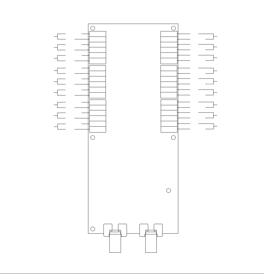
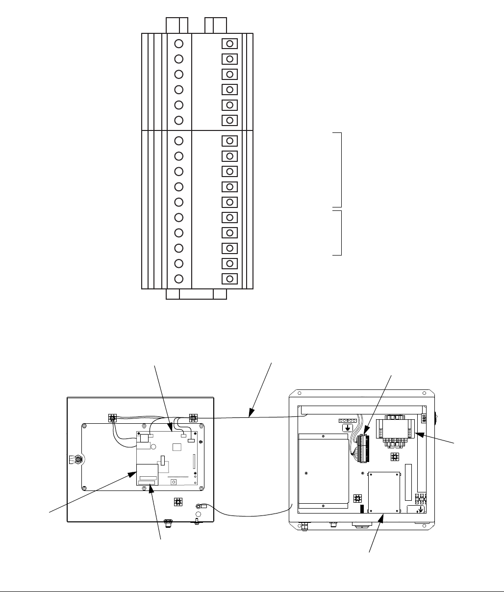
Install the Discrete I/O Board
Install the Discrete I/O board (1) in the position shown in
F
IG. 26, using the four board supports (2) supplied in the
kit. See F
IG. 27 for board orientation.
Install the I/O Terminal Strips
1. Install the supplied din rail to the left of the power
supply (PS) as shown in F
IG. 26, using two 6-32 x
1/4 in. (6 mm) machine screws supplied with the
wire harness (5).
2. The supplied wire harness has one 28 in. (711 mm)
cable with a 10-pin terminal strip, one 28 in. (711
mm) cable with a 6-pin terminal strip, and a 3 ft
(0.92 m) CAT 5 cable.
a. Install the 6-pin terminal strip (6T) and 10-pin
terminal strip (10T) on the din rail. See F
IG. 26.
b. Connect the CAT 5 cable to J1 on the I/O board.
c. Route the wire harness cables through the wire
channel of the EasyKey to the display board
(C).
d. Connect the CAT 5 cable to J6 on the display
board.
e. Connect the 6-pin cable to J10 on the display
board.
f. Connect the 10-pin cable to J5 on the display
board.
3. See the System Electrical Schematic on page 44
for complete board wiring information.
4. Close and lock the EasyKey door.
Install Automatic Upgrade Kit 15V256
40 312778G
FIG. 25: 255767 Display Board Connectors
RT1
J6
(Remote I/O)
J4 (Membrane
Ribbon Cable)
J9 (Power Input/Alarm)
J8 (F.O. Out - blue)
J7 (F.O. In - black)
J5 (Inputs/Outputs)
J1 (Graphic
Display)
TI12924a
TI12923a
Multiple Station
Integration Control
GND
GND
A
B
A
B
Analog In Common
Reset Alarm
Remote Stop
Input Common
Gun Trigger
Flow Control Calibrate
Analog In Signal
Potlife Alarm
Output Common
General Alarm
J10 (Inputs/Outputs)
J3 (Auto Key
Board Plug-in)
Remove Screw
(E)
Install Automatic Upgrade Kit 15V256
312778G 41
FIG. 26: EasyKey Control Boards
C
1 (see FIG. 27)
TI12496a
Pin 1
Pin 1
TI12958a
RS485 Integration A
RS485 Integration B
RS485 Integration Ground
RS485 Network A
RS485 Network B
RS485 Network Ground
6T and 10T (see
detail above)
I/O Terminal Strip Detail
6
5
PS
J4 (on underside
of board 6)
Flow Rate Analog Common
Alarm Reset
Remote Stop
Digital Common
Gun Trigger
Flow Control Calibrate
Flow Rate Analog In
Potlife Alarm
Digital Common
General Alarm
INPUTS
OUTPUTS
Install Automatic Upgrade Kit 15V256
42 312778G
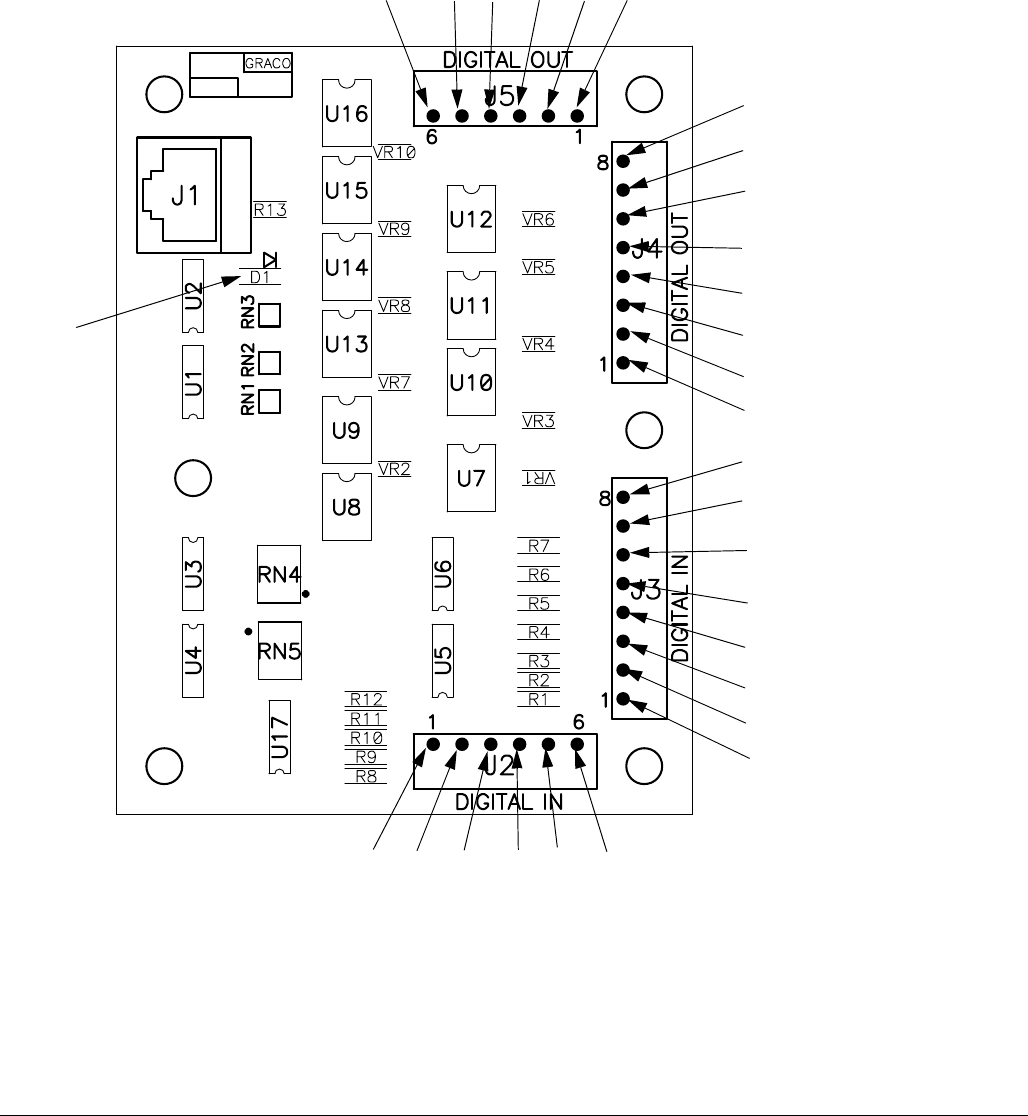
FIG. 27: 255766 Discrete I/O Board
JLS
Purge Input
Job Complete Input
External Color Change Ready
Spare
Digital Input Common
Special Output #4
Mix Input
Recipe Change Input
Recipe Bit 0 Input
Flow Rate Alarm Output
Flow Calibrate Active
Fill Active
Mix Ready Output
Mix Active Output
Purge/Recipe Change Active Output
Digital Output Common/Power
Digital Output Common/Power
Digital Output
Common/Power
Special Output #3
Special Output #2
Special Output #1
Digital Input Common
Recipe Bit 5 Input
Recipe Bit 4 Input
Recipe Bit 3 Input
Recipe Bit 2 Input
Recipe Bit 1 Input
Digital Output
Common/Power
LED D1
(green)
Schematic Diagrams
312778G 43
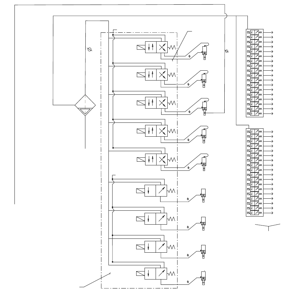
Schematic Diagrams
System Pneumatic Schematic
3/8 AIR FILTER
MANUAL DRAIN
5 MICRON
WALL MOUNT ONLY
FLUSH AIR TO FLUID INLET 1/4 TUBE
TO MANIFOLD 1/4 TUBE
4-WAY SOLENOID
12 VDC
PURGE A
VALVE
DUMP A
VALVE
(OPTIONAL)
4-WAY SOLENOID
12 VDC
3-WAY SOLENOID
12 VDC
3-WAY SOLENOID
12 VDC
MANIFOLD
AIR EXHAUST MUFFLER
OPEN
CLOSE
OPEN
5/32 TUBE
5/32 TUBE
PURGE B
VALVE
4-WAY SOLENOID
12 VDC
CLOSE
OPEN
5/32 TUBE
DUMP B
VALVE
(OPTIONAL)
4-WAY SOLENOID
12 VDC
OPEN
5/32 TUBE
A
B
A
B
A
B
A
B
A
A
DOSE A
VALVE
CLOSE
OPEN
5/32 TUBE
DOSE B
VALVE
CLOSE
OPEN
5/32 TUBE
3-WAY SOLENOID
12 VDC
GFB 1
VALVE
(OPTIONAL)
5/32 TUBE
A
COLOR 1
COLOR 2
COLOR 3
COLOR 4
COLOR 5
COLOR 6
COLOR 7
COLOR 8
COLOR SOLVENT
COLOR 9
COLOR 10
COLOR 11
COLOR 12
CATALYST 1
CATALYST 2
CATALYST 3
CATALYST 4
CATALYST SOLVENT
COLOR
CHANGE
CONTROL
COLOR
VALVE
STACKS
MAC
36 SERIES SOLENOID VALVES
05
COLOR 13
COLOR 14
COLOR 15
COLOR 16
COLOR 17
COLOR 18
COLOR 19
COLOR 20
COLOR 21
COLOR 22
COLOR 23
COLOR 24
COLOR 25
COLOR 26
COLOR 27
COLOR 28
COLOR 29
COLOR 30
PURGE C
VALVE
(OPTIONAL)
4-WAY SOLENOID
12 VDC
CLOSE
OPEN
5/32 TUBE
A
B
AIR EXHAUST MUFFLER
3-WAY SOLENOID
12 VDC
GFB 2
VALVE
(OPTIONAL)
OPEN
5/32 TUBE
A
OPEN
MANIFOLD
AIR INPUT
AIR INPUT
PURGE AIR
CONTROL AIR
Schematic Diagrams
44 312778G
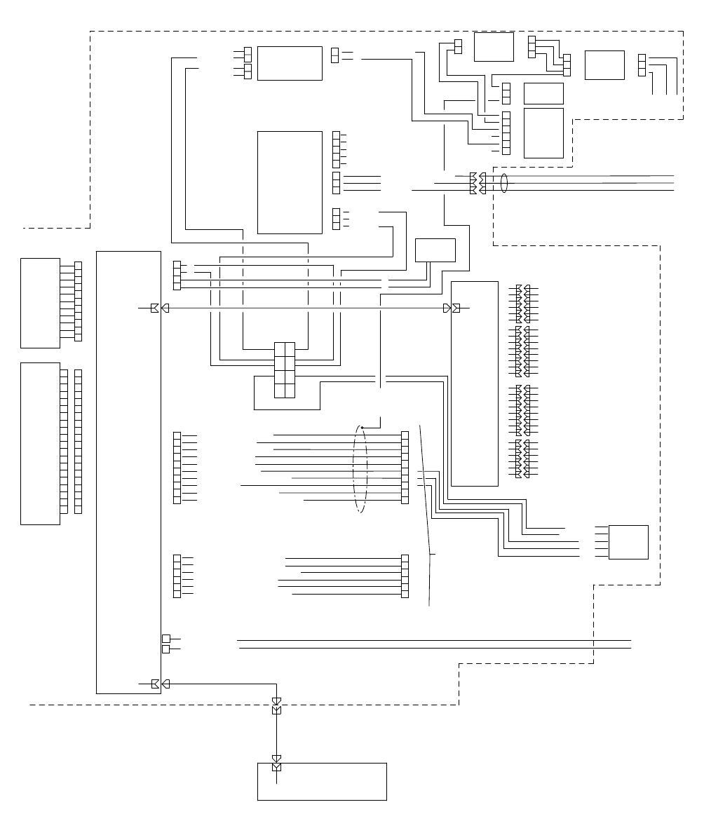
System Electrical Schematic
NOTE: The electrical schematic illustrates all possible wiring expansions in a ProMix 2KS system. Some compo-
nents shown are not included with all systems.
Non-Hazardous Area
BARRIER
BOARD
OPERATOR INTERFACE
1
2
L1
N
85-250
VAC
GND N L1
85-250 VAC
1
2
3
J5
+12VDC I/S (RED)
COM (BLACK)
SHIELD
1
2
3
J4
+24VDC
OPEN
COMMON
DISPLAY
BOARD
NON-HAZARDOUS AREA
1
2
3
4
J9
+
-
FO IN (BLK)
FO OUT (BLU)
1
2
3
4
5
6
7
8
9
10
11
J4
1
2
3
4
5
6
7
8
9
10
11
12
13
14
15
16
17
18
19
20
DISPLAY
MEMBRANE
SWITCH
WITH
RIBBON
CABLE
CABLE
HARNESS
TERMINAL
BLOCK
1
2
3
GND LUG
1
2
1A
1B
2A
2B
POWER
ROCKER
SWITCH
1
2
3
4
5
J1
OPEN
OPEN
ALARM
CABLE
(50' STD.)/
(100' OPTION)
1
2
3
4
5
6
J10
1
2
3
4
5
6
7
8
9
10
J5
J7
J8
RJ45
MIX INPUT
PURGE INPUT
JOB COMPLETE INPUT
EXTERNAL CLR CHG READY
RESET ALARM INPUT
DIGITAL INPUT COMMON
1
2
3
4
5
6
RJ45
POWER
SUPPLY
RS485 INTEGRATION A (WHT/BLU)
RS485 INTEGRATION B (BLU/WHT)
RS485 INTEGRATION GROUND (SHIELD)
RS485 NETWORK A (WHT/ORG)
RS485 NETWORK B (ORG/WHT)
RS485 NETWORK GROUND (SHIELD)
FLOW CONTROL CAL. (BLK)
GUN TRIGGER (WHT)
DIGITAL IN COMMON (RED)
REMOTE STOP (GRN)
ALARM RESET (BRN)
ALARM OUTPUT (BLU)
DIGITAL OUTPUT COMMON (ORG)
POT LIFE (YEL)
FLOW RATE ANALOG IN (PUR)
FLOW RATE ANALOG COMMON (GRAY)
1
2
3
4
5
6
7
8
DIGITAL INPUT COMMON
RECIPE BIT 0 INPUT
RECIPE BIT 1 INPUT
RECIPE BIT 2 INPUT
RECIPE BIT 3 INPUT
RECIPE BIT 4 INPUT
RECIPE BIT 5 INPUT
RECIPE CHANGE INPUT
1
2
3
4
5
6
7
8
DIGITAL OUTPUT COMMON/POWER
PURGE/RECIPE CHG ACTIVE OUTPUT
MIX ACTIVE OUTPUT
MIX READY OUTPUT
FILL ACTIVE
FLOW CAL. ACTIVE
FLOW RATE ALARM OUTPUT
DIGITAL OUTPUT COMMON/POWER
DIGITAL OUTPUT COMMON/POWER
SPECIAL OUTPUT #1
SPECIAL OUTPUT #2
SPECIAL OUTPUT #3
SPECIAL OUTPUT #4
DIGITAL OUTPUT COMMON/POWER
1
2
3
4
5
6
REMOTE
I/O
INTEGRATION
BOARD
J2
J3
J4
J5
RJ45
RJ45
P1
J6
WEB SERVER
MODULE
RJ45
RJ45
RJ45
RJ45
TERMINAL
BLOCKS
+
+
-
-
DC OK
COMMON
+24 VDC
COMMON
+
-
J2
SHIELD
+
+
+
+
-
-
-
-
POWER DIST.
TERMINAL
BLOCKS
3'
3'
(25'-200' OPTIONS)
1
2
3
4
5
6
7
8
9
10
1
2
3
4
5
6
RJ45
BULKHEAD
3'
I/O HARNESSES
POWER HARNESS
BEACON
(+24) YEL
(COM) GRAY
ORG
BRN
RED
UNUSED
UNUSED
UNUSED
UNUSED
UNUSED
L1
N
GND
L1
N
LINE
FILTER
L1
N
GND
L1
N
GND
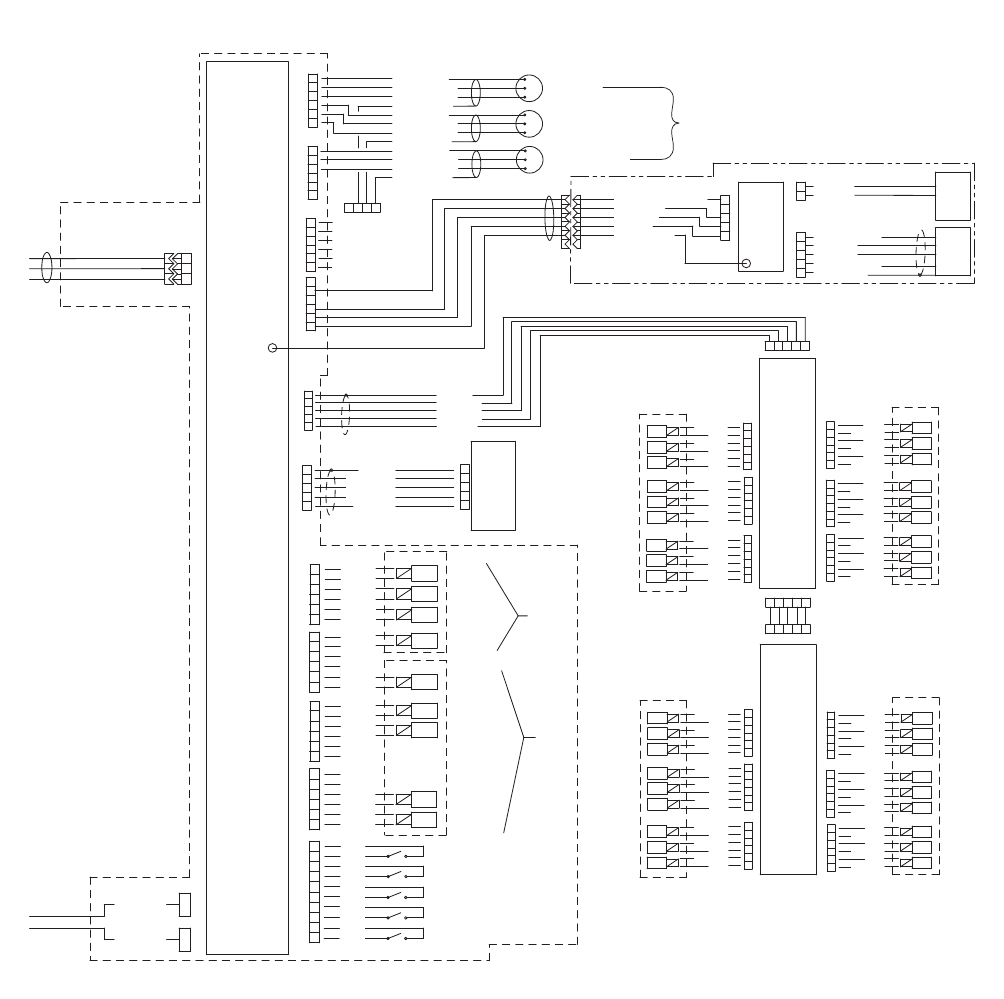
Schematic Diagrams
312778G 45
System Electrical Schematic
NOTE: The electrical schematic illustrates all possible wiring expansions in a ProMix 2KS system. Some compo-
nents shown are not included with all systems.
Hazardous Area
HAZARDOUS AREA
+12VDC I/S
COM
SHIELD
J10
1
2
3
1
2
3
4
5
6
J3
PWR (RED)
COM (BLACK)
SIG (WHITE)
SHIELD/GRN
PWR (RED)
COM (BLACK)
SIG (WHITE)
SHIELD/GRN
PWR (RED)
COM (BLACK)
SIG (WHITE)
SHIELD/GRN
FLUID
PANEL
CONTROL
BOARD
FLUID PANEL CONTROL BOX
FLOW METER A
FLOW METER B
1
2
3
4
5
6
J5
1
2
3
4
5
FLOW
CONTROL
BOARD
6
5
4
3
2
1
J9
BLACK
RED
BLACK
RED
BLACK
RED
MANIFOLD
NOT USED
DOSE B
DOSE A
1
2
3
4
5
6
7
8
9
10
J1
SIG
COM
SIG
COM
SIG
COM
SIG
COM
SIG
COM
AIR FLOW SWITCH 1
FO OUT
(BLU)
FO IN
(BLK)
1
2
J1
J2
3X CABLE
FLOW METER SOLVENT
1
2
3
4
5
TECNO
V/P
FLUID
PRESS.
SENS.
J4
SIG (RED)
COM (BLK)
+ PRESSURE (GRN)
COM (RED)
EX+ (WHT )
- PRESSURE (BLK)
SHIELD (BARE)
3
2
5
4
1
J11
GRD (BLK)
+12VDC (RED)
SHIELD (BARE)
CAN H (WHT )
CAN L (BLU)
J7/J11
1 4 5 2 3
COLOR
BOARD 1
(COLORS
1 THRU 12,
CATALYST
1 THRU 4)
CLR 9
CLR 10
CLR 11
1 4 5 2 3
V/P ANALOG OUT (WHT)
PRESS. (GRN)
+12 V (RED)
GND (BLK)
CHASSIS (BARE)
MH2
(10')/
(40')
6' STD.
6' STD.
(3'-100' OPTIONS)
I.S. METERS
3
2
5
4
1
GRD (BLK)
+12VDC (RED)
SHIELD (BARE)
CAN H (WHT )
CAN L (BLU)
3
2
5
4
1
BOOTH
CONTROL
BOARD
6
5
4
3
2
1
J14
BLACK
RED
BLACK
RED
BLACK
RED
AIR FLOW SWITCH 2
SOLVENT FLOW SWITCH
GFB 1 PRESSURE SWITCH
GFB 2 PRESSURE SWITCH
PURGE B
PURGE A
NOT USED
6
5
4
3
2
1
BLACK
RED
BLACK
RED
BLACK
RED
DUMP A
NOT USED
PURGE C
MANIFOLD
6
5
4
3
2
1
BLACK
RED
BLACK
RED
BLACK
RED
DUMP B
GFB #1
GFB #2
12 VDC
3-WAY SOLENOID
J15
J8
12 VDC
4-WAY SOLENOID
1
2
3
4
5
6
J12
J13
1
2
3
4
5
6
UNUSED
UNUSED
UNUSED
UNUSED
UNUSED
UNUSED
GROUND
TERMINAL
50' STD.
1
2
3
4
5
6
+12VDC
COM
+12VDC
COM
+12VDC
COM
MANIFOLD
1
2
3
4
5
6
+12VDC
COM
+12VDC
COM
+12VDC
COM
1
2
3
4
5
6
+12VDC
COM
+12VDC
COM
+12VDC
COM
1 4 5 2 3
MANIFOLD
6
5
4
3
2
1
COM
+12VDC
COM
+12VDC
COM
+12VDC
COM
+12VDC
COM
+12VDC
COM
+12VDC
COM
+12VDC
COM
+12VDC
COM
+12VDC
6
5
4
3
2
1
6
5
4
3
2
1
CLR 12
CAT 4
CAT 3
CAT 2
CAT 1
SOL CAT
CLR 8
CLR 7
CLR 6
CLR 5
CLR 4
CLR 3
CLR 2
CLR 1
SOL CLR
COLOR
BOARD 2
(COLORS
13 THRU 30)
CLR 22
CLR 23
CLR 24
1
2
3
4
5
6
+12VDC
COM
+12VDC
COM
+12VDC
COM
MANIFOLD
1
2
3
4
5
6
+12VDC
COM
+12VDC
COM
+12VDC
COM
1
2
3
4
5
6
+12VDC
COM
+12VDC
COM
+12VDC
COM
MANIFOLD
6
5
4
3
2
1
COM
+12VDC
COM
+12VDC
COM
+12VDC
COM
+12VDC
COM
+12VDC
COM
+12VDC
COM
+12VDC
COM
+12VDC
COM
+12VDC
6
5
4
3
2
1
6
5
4
3
2
1
CLR 25
CLR 26
CLR 27
CLR 28
CLR 29
CLR 30
CLR 21
CLR 20
CLR 19
CLR 18
CLR 17
CLR 16
CLR 15
CLR 14
CLR 13
J8
J8
J15
J15
J14
J14
J9
J9
J16
J10
J10
J16
J4
J6
J7
J7/J11
J7/J11
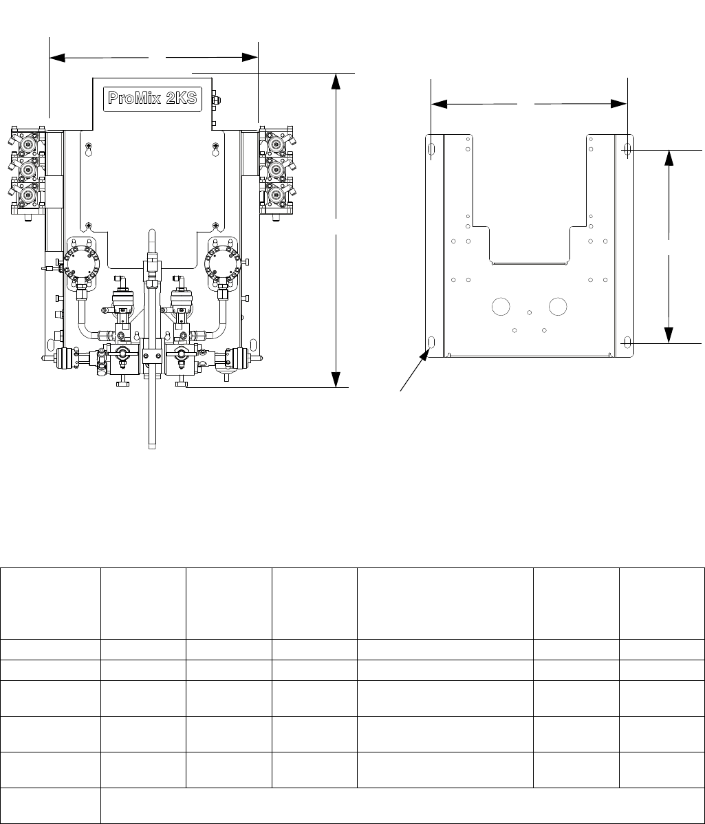
Dimensions and Mounting Hole Layouts
46 312778G
Dimensions and Mounting Hole Layouts
Wall Mount Fluid Station
TI14134a
TI11894b
Mounting plate only shown, for clarity
NOTE: Height is shown from top of panel to fluid shutoff
valves, and does not include the effect of variable fluid
integrator heights. Width of panel does not include
optional color/catalyst valve stacks.
A
D
C
B
E
Module
A
Overall
Width
in. (mm)
Overall
Depth
in. (mm)
B
Overall
Height
in. (mm)
Mounting Dimensions,
Width (C) x Height (D)
in. (mm)
E
Mounting
Hole Size
in. (mm)
Weight
lb (kg)
EasyKey 14.0 (355.6) 6.6 (167.6) 13.5 (342.9) 12.0 x 12.75 (304.8 x 323.9) 0.3 (7.6) 22.2 (10.1)
Wall Panel 17.5 (444.5) 11.0 (279.4) 27.0 (685.8) 16.5 x 16.25 (419.1 x 412.8) 0.5 (12.7) 50 (22.7)
Air Supply
Control
8.9 (226.1) 3.8 (96.5) 9.9 (251.5) 4.75 (120.7) 0.34 (8.73) 4.65 (2.12)
RoboMix 19.45
(494.0)
8.875
(225.4)
9.0 (228.6) 8.5 x 5.5 (215.9 x 139.7) 0.44 (11.1) 29.65
(13.46)
Flow Control
Module
7.13 (181.1) 2.52 (64.0) 3.86 (98.0) 6.63 x 1.50 (168.4 x 38.1) 0.25 (6.3) 3.9 (1.78)
Color Change
Module
See Color Change Module manual 312787.

Dimensions and Mounting Hole Layouts
312778G 47
EasyKey
TI11891a
TI11895a
Air Supply Control
TI13659a
Flow Control Module
RoboMix Fluid Station
TI13658a
TI14135a
D
C
E
A
B
A
B
C
D
E
E
C
E
TI14133a
A
B
C
D

Dynamic Dosing Restrictor Selection Graphs
48 312778G
Dynamic Dosing Restrictor Selection Graphs
Use the graphs on pages 49- 53 as a guide to determine
the correct restrictor size for your desired flow and mate-
rial viscosity. Table 3 lists the available restrictor sizes.
Example:
Application: air spray system with a 5:1 mix ratio
Fluid Supply: 1:1 pumps at 100 psi (7 bar, 0.7 MPa)
Flow Rate: 300 cc/min at the gun
Select the Restrictor Size: choose either the .040 or
.070 orifice, to ensure that the pressure differential
is not more than 10-20 psi (0.7-1.4 bar, .07-0.14
MPa), provided the fluid viscosities are similar to
those tested.
• If the viscosity of component B is lower than the vis-
cosity of the chart used for selection you may need
to use a smaller restrictor or decrease the pressure
differential.
• If the viscosity of component B is higher than the
viscosity of the chart used for selection you may
need to use a larger restrictor or increase the pres-
sure differential.
• In systems using an air-assisted gun, if the fluid
pressure of component A is higher than the compo-
nent A pressure from the charts you may need to
use a larger restrictor or increase the pressure dif-
ferential.
* These restrictors are included in Injection Kit
15U955.
These restrictors are optional sizes, not included in
the Injection Kit.
Table 3: Restrictor Sizes
Size Code Orifice Size Part No.
2* .020 15U936
3* .030 15U937
4* .040 15U938
5 .050 15U939
6 .060 15U940
7* .070 15U941
8 .080 16D554
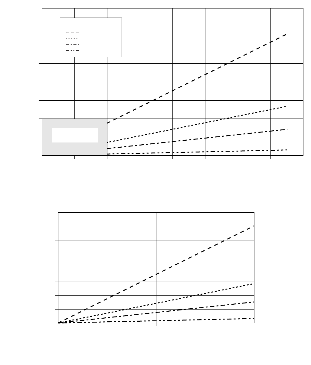
Dynamic Dosing Restrictor Selection Graphs
312778G 49
FIG. 28. Dynamic Dosing Performance (1:1 Ratio, 90 centipoise fluid, 100 psi A side pressure)
0
500 1000 1500 2000 30002500 35000
Flow Rate (cc/min)
Differential Pressure between A and B
psi
(bar, MPa)
4000
(276, 27.6)
3500
(241, 24.1)
3000
(207, 20.7)
2500
(172, 17.2)
2000
(138, 13.8)
1500
(103, 10.3)
1000
(69, 6.9)
4000
500
(34, 3.4)
Detail View
500
(34, 3.4)
500
Key
1000
250
(17, 1.7)
125
(8.6, 0.86)
750
(52, 5.2)
1000
(69, 6.9)
375
(26 2.6)
0
0
#2 Restrictor
#3 Restrictor
#4 Restrictor
#7 Restrictor
See Detail View
Below
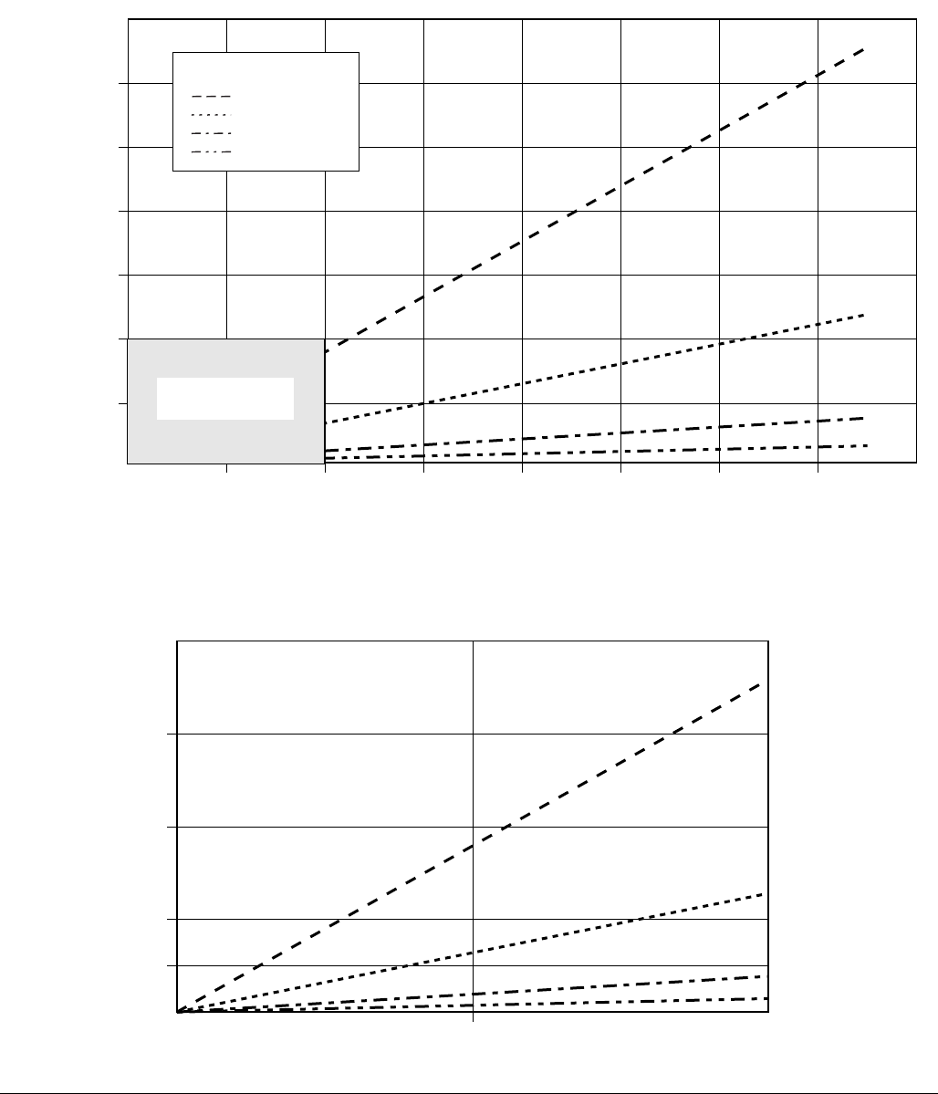
Dynamic Dosing Restrictor Selection Graphs
50 312778G
FIG. 29. Dynamic Dosing Performance (5:1 Ratio, 90 centipoise fluid, 100 psi A side pressure)
0
500 1000 1500 2000 30002500 35000
Flow Rate (cc/min)
Differential Pressure between A and B
psi
(bar, MPa)
1400
(97, 9.7)
1200
(83, 8.3)
1000
(69, 6.9)
800
(55, 5.5)
600
(41, 4.1)
400
(28, 2.8)
4000
200
14, 1.4)
Detail View
200
(14, 1.4)
500 1000
100
(7, 0.7)
50
(3.4, 0.34)
300
(21, 2.1)
400
(28, 2.8)
0
0
Key
#2 Restrictor
#3 Restrictor
#4 Restrictor
#7 Restrictor
See Detail View
Below
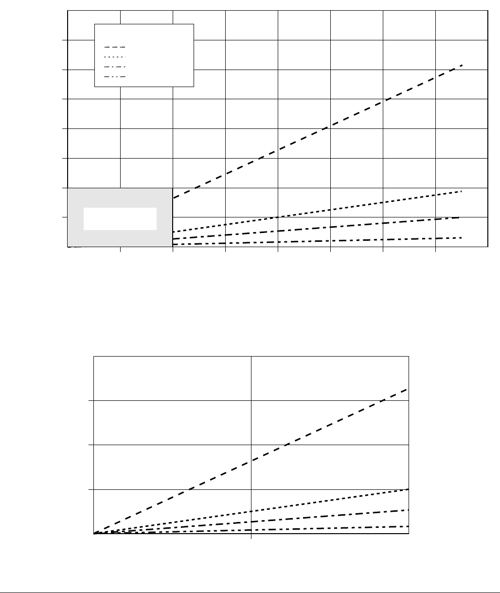
Dynamic Dosing Restrictor Selection Graphs
312778G 51
FIG. 30. Dynamic Dosing Performance (10:1 Ratio, 90 centipoise fluid, 100 psi A side pressure)
0
500 1000 1500 2000 30002500 35000
Flow Rate (cc/min)
Differential Pressure between A and B
psi
(bar, MPa)
800
(55, 5.5)
700
(48, 4.8)
600
(41, 4.1)
500
(34, 3.4)
400
(28, 2.8)
300
(21, 2.1)
200
(14, 1.4)
4000
100
(7, 0.7)
Detail View
200
(14, 1.4)
500 1000
100
(7, 0.7)
50
(3.4, 0.34)
150
(10, 1.0)
0
0
Key
#2 Restrictor
#3 Restrictor
#4 Restrictor
#7 Restrictor
See Detail View
Below
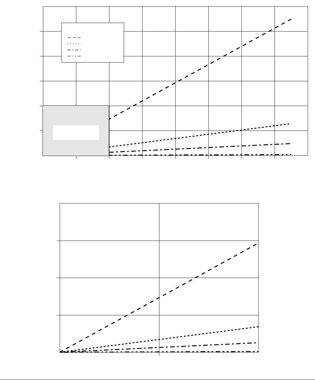
Dynamic Dosing Restrictor Selection Graphs
52 312778G
FIG. 31. Dynamic Dosing Performance (20:1 Ratio, 90 centipoise fluid, 100 psi A side pressure)
0
500 1000 1500 2000 30002500 35000
Flow Rate (cc/min)
Differential Pressure between A and B
psi
(bar, MPa)
300
(21, 2.1)
250
(17.2, 1.72)
200
(14, 1.4)
150
10.3, 1.03)
100
(7.0, 0.7)
4000
50
(3.4, 0.34)
Detail View
75
(5.2, 0.52)
500 1000
100
(7, 0.7)
50
(3.4, 0.34)
25
(1.7, 0.17)
0
0
Key
#2 Restrictor
#3 Restrictor
#4 Restrictor
#7 Restrictor
See Detail View
Below
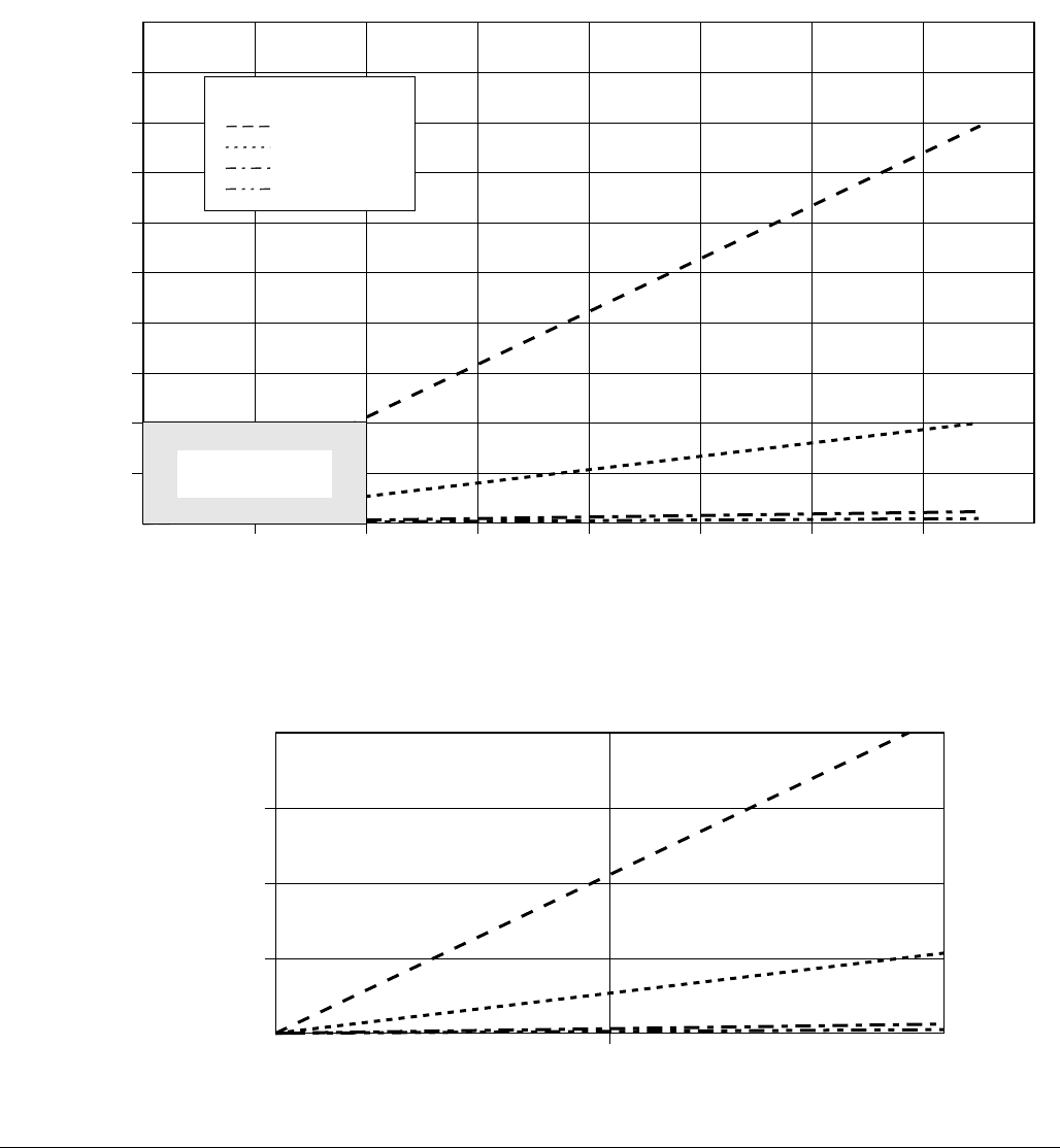
Dynamic Dosing Restrictor Selection Graphs
312778G 53
FIG. 32. Dynamic Dosing Performance (30:1 Ratio, 90 centipoise fluid, 100 psi A side pressure)
0
500 1000 1500 2000 30002500 35000
Flow Rate (cc/min)
Differential Pressure between A and B
psi
(bar, MPa)
160
(11, 1.1)
140
9.7, 0.9)
120
8.3, 0.8)
100
(7, 0.7)
80
(5.5, 0.55)
60
(4.1, 0.41)
40
(2.8, 0.28)
4000
20
(1.4, 0.14)
180
(12.4, 1.2
200
(14, 1.4
Detail View
30
(2.1, 0.21)
500 1000
40
(2.8, 0.28)
20
(1.4, 0.14)
10
(0.7, 0.07)
0
0
Key
#2 Restrictor
#3 Restrictor
#4 Restrictor
#7 Restrictor
See Detail View
Below

Dynamic Dosing Restrictor Selection Graphs
54 312778G

Technical Data
312778G 55
Technical Data
* Dependent on programmed K-factor and application. The maximum allowable flow meter pulse frequency is 425
Hz (pulses/sec). For more detailed information on viscosities, flow rates, or mixing ratios, consult your Graco dis-
tributor.
See individual component manuals for additional technical data.
Maximum fluid working pressure . . . . . . . . . . . . . . . Base system: 4000 psi (27.58 MPa, 275.8 bar)
Low pressure color change: 300 psi (2.07 MPa, 20.6 bar)
High pressure color change: 3000 psi (21 MPa, 210 bar)
Coriolis meter: 2300 psi (15.86 MPa, 158.6 bar)
RoboMix system: 190 psi (1.31 MPa, 13.1 bar)
Flow control: 190 psi (1.31 MPa, 13.1 bar)
Maximum working air pressure . . . . . . . . . . . . . . . . 100 psi (0.7 MPa, 7 bar)
Air supply . . . . . . . . . . . . . . . . . . . . . . . . . . . . . . . . . 75 - 100 psi (0.5 - 0.7 MPa, 5.2 - 7 bar)
Air filter inlet size . . . . . . . . . . . . . . . . . . . . . . . . . . . 3/8 npt(f)
Air filtration for air logic and purge air
(Graco-supplied). . . . . . . . . . . . . . . . . . . . . . . . . . . . 5 micron (minimum) filtration required; clean and dry air
Air filtration for atomizing air (user-supplied) . . . . . . 30 micron (minimum) filtration required; clean and dry air
Mixing ratio range. . . . . . . . . . . . . . . . . . . . . . . . . . . 0.1:1- 50:1*
On-ratio accuracy . . . . . . . . . . . . . . . . . . . . . . . . . . . up to +
1%, user selectable
Fluids handled . . . . . . . . . . . . . . . . . . . . . . . . . . . . . one or two component:
• solvent and waterborne paints
• polyurethanes
•epoxies
• acid catalyzed varnishes
• moisture sensitive isocyanates
Viscosity range of fluid . . . . . . . . . . . . . . . . . . . . . . . 20- 5000 cps*
Fluid filtration (user-supplied). . . . . . . . . . . . . . . . . . 100 mesh minimum
Fluid flow rate range*
G3000, G250, G3000A Meter . . . . . . . . . . . . . .
G3000HR, G250HR Meter. . . . . . . . . . . . . . . . .
Coriolis Meter. . . . . . . . . . . . . . . . . . . . . . . . . . .
S3000 Solvent Meter (accessory) . . . . . . . . . . .
75 - 3800 cc/min. (0.02-1.00 gal./min.)
38 - 1900 cc/min. (0.01-0.50 gal./min.)
20 - 3800 cc/min. (0.005-1.00 gal./min.)
38 - 1900 cc/min. (0.01-0.50 gal./min.)
Fluid inlet sizes
Flow Meter . . . . . . . . . . . . . . . . . . . . . . . . . . . . .
Dose Valve/Color Valve Adapters . . . . . . . . . . .
1/4 npt(f)
1/4 npt(f)
Fluid outlet size (static mixer). . . . . . . . . . . . . . . . . . 1/4 npt(f)
External Power Supply Requirements . . . . . . . . . . . 85 - 250 Vac, 50/60 Hz, 2 amps maximum draw
15 amp maximum circuit breaker required
8 to 14 AWG power supply wire gauge
Operating temperature range. . . . . . . . . . . . . . . . . . 41- 122° F (5-50° C)
Environmental Conditions Rating . . . . . . . . . . . . . . . indoor use, pollution degree (2), installation category II
Noise Level
Sound pressure level . . . . . . . . . . . . . . . . . . . . .
Sound power level . . . . . . . . . . . . . . . . . . . . . . .
below 70 dBA
below 85 dBA
Wetted parts. . . . . . . . . . . . . . . . . . . . . . . . . . . . . . . 303, 304 SST, Tungsten carbide (with nickel binder),
perfluoroelastomer; PTFE
Wetted materials on acid model
(AE100N) . . . . . . . . . . . . . . . . . . . . . . . . . . . . . . . . .
316, 17-4 SST; PEEK,
perfluoroelastomer; PTFE

All written and visual data contained in this document reflects the latest product information available at the time of publication.
Graco reserves the right to make changes at any time without notice.
Original instructions. This manual contains English. MM 312778
Graco Headquarters: Minneapolis
International Offices: Belgium, China, Japan, Korea
GRACO INC. AND SUBSIDIARIES • P.O. BOX 1441 • MINNEAPOLIS MN 55440-1441 • USA
Copyright 2009, Graco Inc. is registered to ISO 9001
www.graco.com
Revision G, December 2016
Graco Standard Warranty
Graco warrants all equipment referenced in this document which is manufactured by Graco and bearing its name to be free from defects in
material and workmanship on the date of sale to the original purchaser for use. With the exception of any special, extended, or limited warranty
published by Graco, Graco will, for a period of twelve months from the date of sale, repair or replace any part of the equipment determined by
Graco to be defective. This warranty applies only when the equipment is installed, operated and maintained in accordance with Graco’s written
recommendations.
This warranty does not cover, and Graco shall not be liable for general wear and tear, or any malfunction, damage or wear caused by faulty
installation, misapplication, abrasion, corrosion, inadequate or improper maintenance, negligence, accident, tampering, or substitution of
non-Graco component parts. Nor shall Graco be liable for malfunction, damage or wear caused by the incompatibility of Graco equipment with
structures, accessories, equipment or materials not supplied by Graco, or the improper design, manufacture, installation, operation or
maintenance of structures, accessories, equipment or materials not supplied by Graco.
This warranty is conditioned upon the prepaid return of the equipment claimed to be defective to an authorized Graco distributor for verification of
the claimed defect. If the claimed defect is verified, Graco will repair or replace free of charge any defective parts. The equipment will be returned
to the original purchaser transportation prepaid. If inspection of the equipment does not disclose any defect in material or workmanship, repairs
will be made at a reasonable charge, which charges may include the costs of parts, labor, and transportation.
THIS WARRANTY IS EXCLUSIVE, AND IS IN LIEU OF ANY OTHER WARRANTIES, EXPRESS OR IMPLIED, INCLUDING BUT NOT
LIMITED TO WARRANTY OF MERCHANTABILITY OR WARRANTY OF FITNESS FOR A PARTICULAR PURPOSE.
Graco’s sole obligation and buyer’s sole remedy for any breach of warranty shall be as set forth above. The buyer agrees that no other remedy
(including, but not limited to, incidental or consequential damages for lost profits, lost sales, injury to person or property, or any other incidental or
consequential loss) shall be available. Any action for breach of warranty must be brought within two (2) years of the date of sale.
GRACO MAKES NO WARRANTY, AND DISCLAIMS ALL IMPLIED WARRANTIES OF MERCHANTABILITY AND FITNESS FOR A
PARTICULAR PURPOSE, IN CONNECTION WITH ACCESSORIES, EQUIPMENT, MATERIALS OR COMPONENTS SOLD BUT NOT
MANUFACTURED BY GRACO. These items sold, but not manufactured by Graco (such as electric motors, switches, hose, etc.), are subject to
the warranty, if any, of their manufacturer. Graco will provide purchaser with reasonable assistance in making any claim for breach of these
warranties.
In no event will Graco be liable for indirect, incidental, special or consequential damages resulting from Graco supplying equipment hereunder, or
the furnishing, performance, or use of any products or other goods sold hereto, whether due to a breach of contract, breach of warranty, the
negligence of Graco, or otherwise.
FOR GRACO CANADA CUSTOMERS
The Parties acknowledge that they have required that the present document, as well as all documents, notices and legal proceedings entered into,
given or instituted pursuant hereto or relating directly or indirectly hereto, be drawn up in English. Les parties reconnaissent avoir convenu que la
rédaction du présente document sera en Anglais, ainsi que tous documents, avis et procédures judiciaires exécutés, donnés ou intentés, à la suite
de ou en rapport, directement ou indirectement, avec les procédures concernées.
Graco Information
For the latest information about Graco products, visit www.graco.com.
For patent information, see www.graco.com/patents.
TO PLACE AN ORDER, contact your Graco distributor or call to identify the nearest distributor.
Phone: 612-623-6921 or Toll Free: 1-800-328-0211 Fax: 612-378-3505
