
Engineering Guide
Terminal Units
SECTION F
F-2
All Metric dimensions ( ) are soft conversion. © Copyright Price Industries Limited 2014.
Imperial dimensions are converted to metric and rounded to the nearest millimetre.
ENGINEERING GUIDE - TERMINAL UNITS
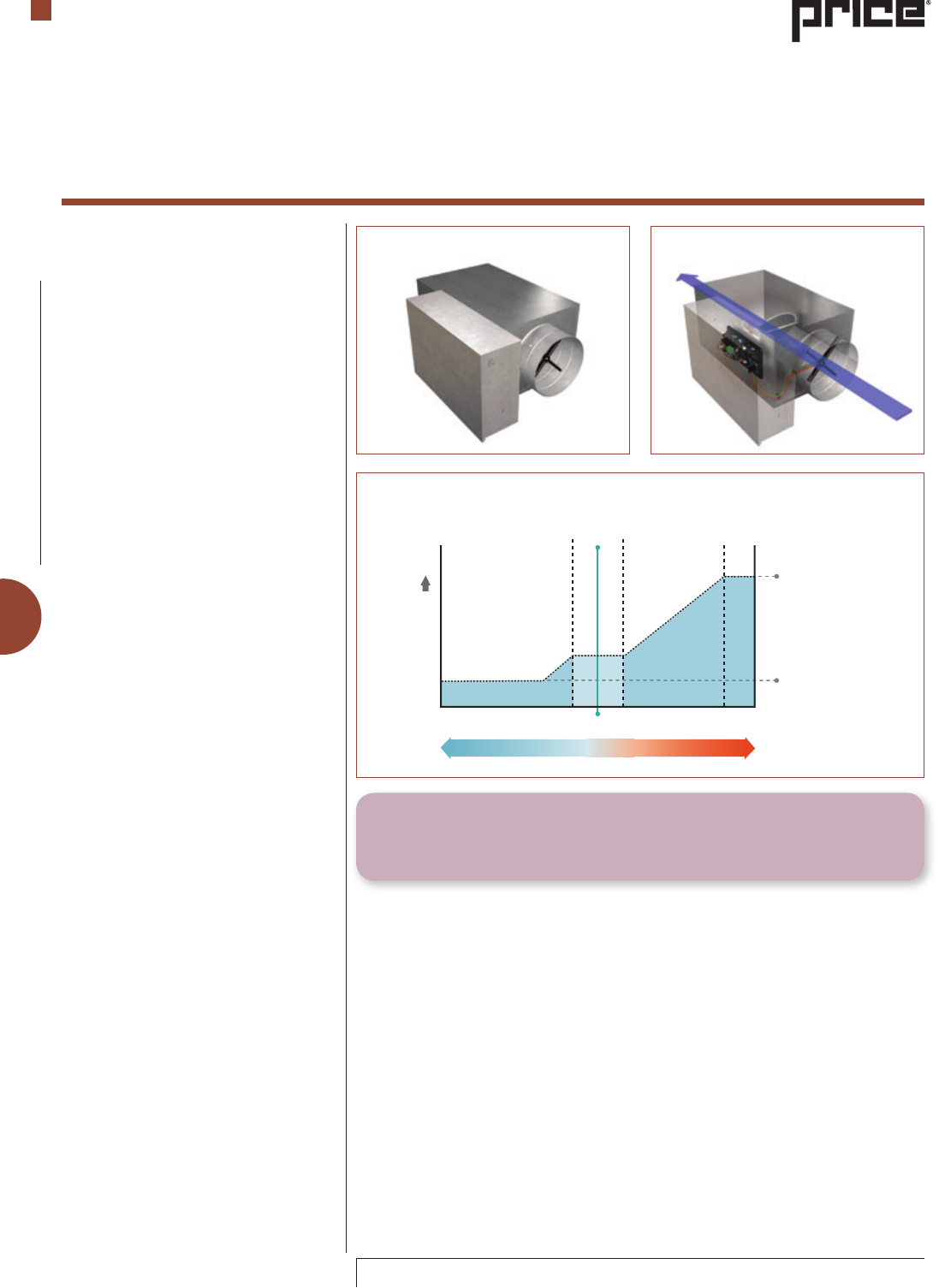
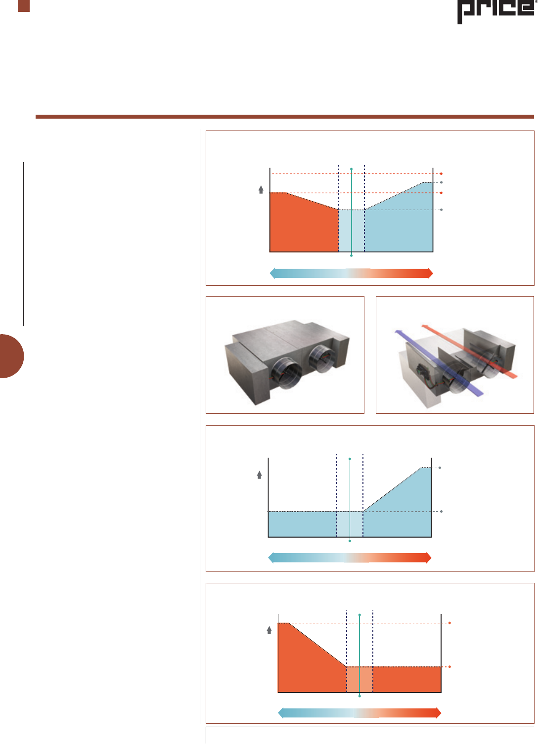
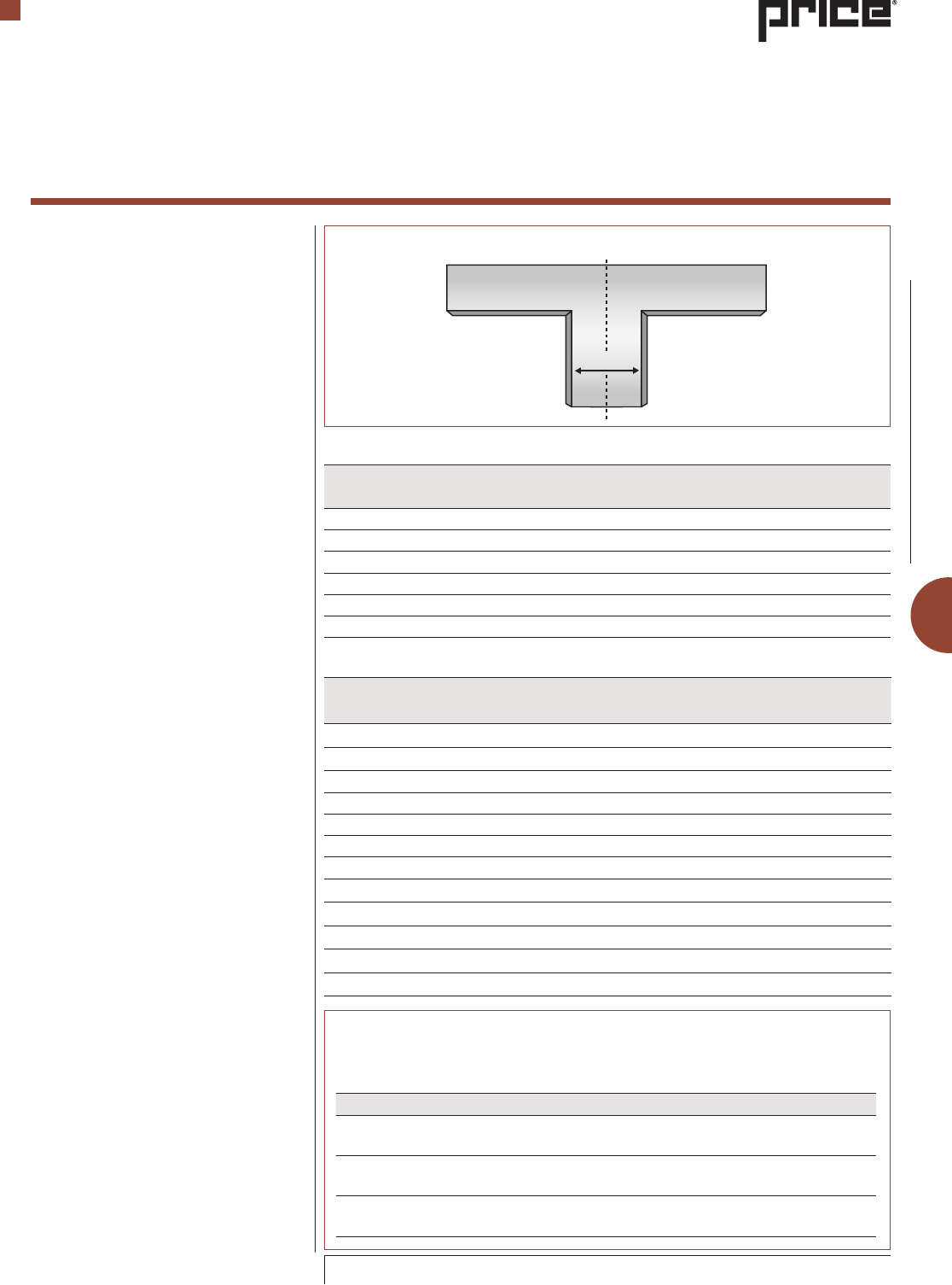
Figure 1: Single Duct Terminal
Single Duct Terminal
A single duct terminal consists of an air
inlet assembly, housing with an insulation
liner and a discharge outlet. Typical
accessories for this unit include a variety
of liners, discharge attenuators, access
doors and multiple outlets plenums. Low
profile configurations can be used to
suit applications where plenum space is
restricted. A low profile configuration is
defined as a terminal unit whose overall
height does not exceed 12 ½ in. A round
inlet and round discharge is also available.
The round outlet unit is often used for retrofit
applications or laboratory applications. The
single duct terminal is also available in a low
temperature construction. Low temperature
construction is recommended when low
temperature air distribution is used and in
areas with a condensation risk.
Constant Volume Single Duct
A single duct terminal with constant volume
operation may or may not have an actuator,
flow sensor and controls. If the unit does
not have an actuator it is typically supplied
with a manually locking quadrant allowing
the damper blade to be locked into a single
position.
Variable Volume Single Duct
A variable volume single duct will have a
flow sensor, an actuator and some type of
controls. Depending on the control scheme
selected, the VAV single duct will typically
either provide a constant air volume or
constant discharge pressure control.
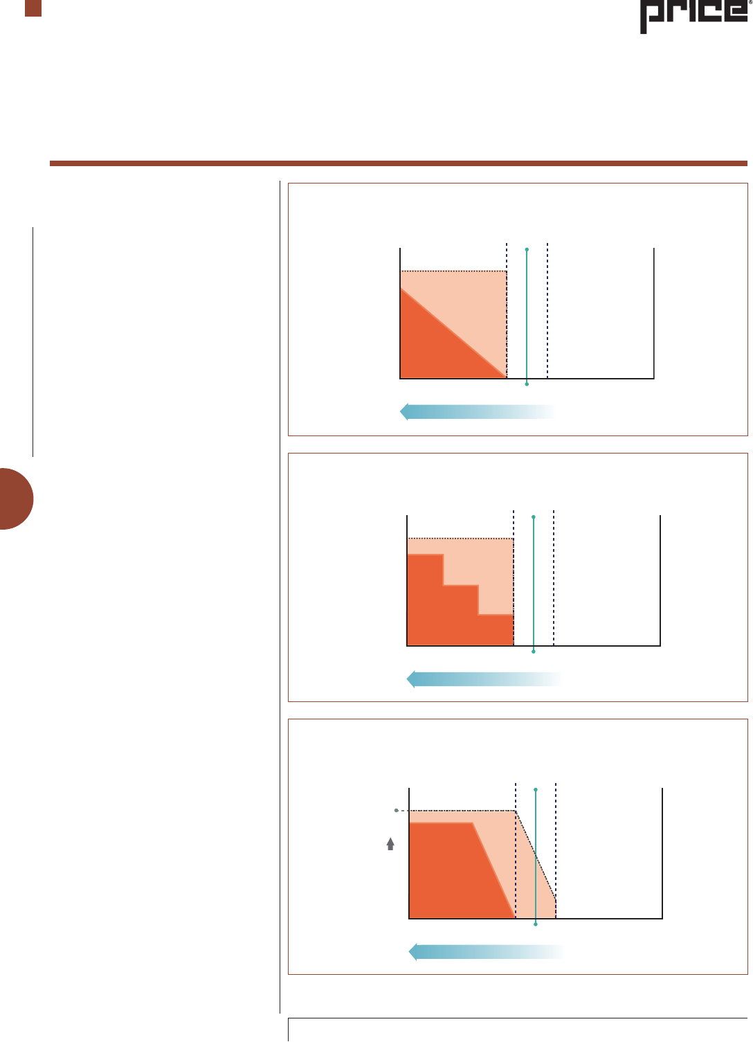
VAV terminal units are controlled with
automatic controls that operate as either
pressure-dependent or as pressure-
independent. Pressure-dependent control
is where the terminal unit damper is
modulated in response to zone temperature.
Pressure-dependent controlled terminal
units may experience air volume flow that
increases or decreases as the static pressure
in the main duct varies.
Pressure-independent control is where the
air volume is measured and controlled by
modulating the terminal unit damper in
response to both zone temperature and air
volume.
An example of a common system-level
control sequence is shown in Figure 3
This sequence (cooling only) controls
the zone temperature by varying the
volume of cooling air to the zone based
on thermostat demand. The dead band
shown is typically ± 2 °F. In the example
shown, there is a minimum airflow that can
either be a predetermined volume (based
on occupancy or other concern) or can act
as a shut off valve by closing completely.
Terminal Unit Types
Terminal Units
Engineering Guide
CONTROL TIP
It is important to properly size the inlet valve to obtain the proper level of control
at the desired minimum airflow rate.
Figure 2: Single Duct Terminal Air Path
Max. Cooling
Min. Cooling
Dead Band
Air Volume
Tset-point
Room Condition
Cool Warm
Figure 3: Typical single duct VAV control sequence with max and min airflows
F-3
© Copyright Price Industries Limited 2014. All Metric dimensions ( ) are soft conversion.
Imperial dimensions are converted to metric and rounded to the nearest millimetre.
ENGINEERING GUIDE - TERMINAL UNITS
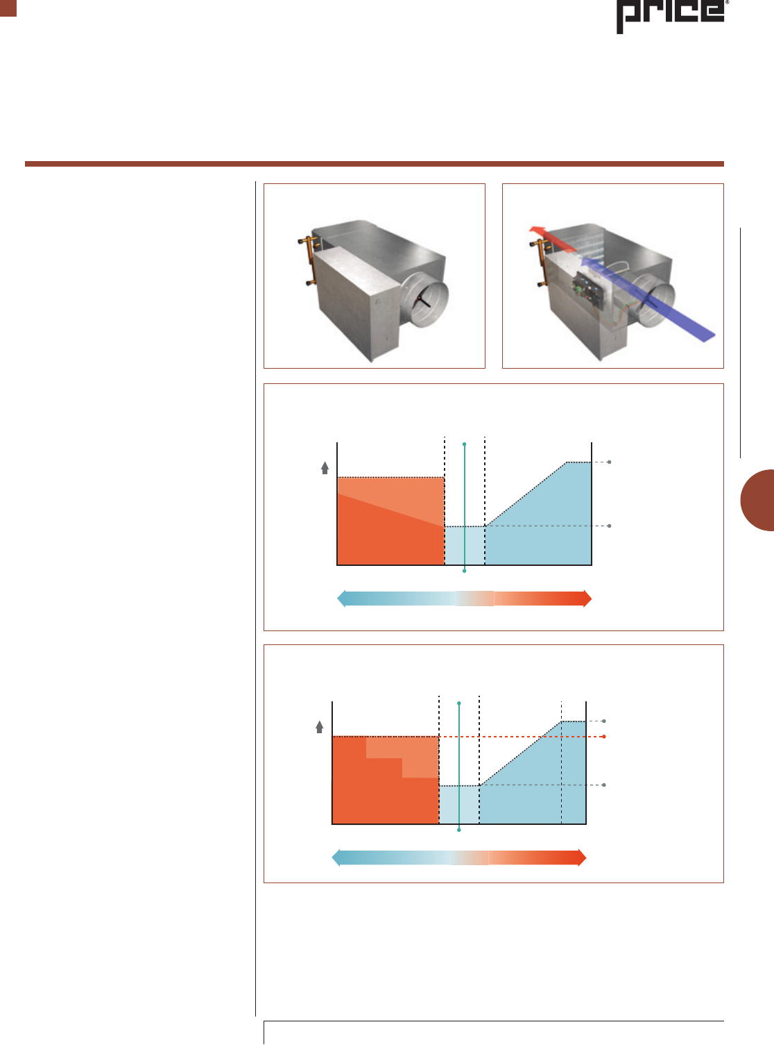
Single Duct Terminal with Reheat
The basic single duct terminal unit with
reheat is similar to the single duct, but has
a reheat option built into the unit. The reheat
option is either a water coil, or an electric
heater. Accessories for the single duct with
a water coil include access doors in the coil
section upstream and downstream of the
water coil.
Single duct with reheat is often used for zones
which require a source of supplemental
heat. Usually, the single duct with reheat
operates at some minimum airflow rate to
minimize the amount of heat required to
offset the conditioned air being supplied to
the zone.
Common Applications Include:
Exterior zones (adjacent to outside walls or
the upper floor in the case of multiple story
buildings) where heat losses through the
exterior walls create a needed for heating.
Interior and exterior zones where the
minimum volume of ventilation air exceeds
the volume of conditioned air required to
satisfy the cooling load which leads to an
overcooling of the zone. Reheat is often used
when this condition occurs.
There are two different commonly used ways
to provide supplemental heat to the zone,
hot water and electric heat. An example of
a system-level control sequence is shown
in Figure 6. This is the use of hot water as
a source of the supplemental heat. In this
sequence, there is a minimum cooling air
volume, maximum cooling volume and a
reheat air volume. During cooling mode
the temperature in the zone is moderated by
modulating the damper position, increasing
or decreasing the volume of cool air to the
zone. In heating mode, when the zone
temperature drops below the lower dead
band limit, the controller increases the
supply air volume to the reheat volume.
At the same time, the hot water valve is
opened. As the zone calls for additional
heat, the hot water valve will continue to
open until at some point the valve is fully
open. Other common control schemes for
hot water reheat include on/off valve control
and mixing valve (3 way valve) control.
Electric reheat is shown in Figure 7 and
has the same control cycle as the hot water
reheat sequence shown in Figure 6. In
heating mode, when the zone temperature
drops below the lower dead band limit, the
controller increases the supply air to the
reheat air volume. As the same time, the
first stage of electric heat is activated. As
the zone temperature continues to drop,
the additional stages of electric heat are
activated (if present).
Terminal Unit Types
Terminal Units
Engineering Guide
Max. Air Flow
Min. Air Flow
Dead Band
Heating Air Flow
Hot Water Reheat
Air Volume
Tset-point
Room Condition
Cool Warm
Max. Cooling
Min. Cooling
Dead Band
Stage 3
Stage 2
Stage 1
Air Volume
Tset-point
Cool Warm
Room Condition
Max. Heating
Figure 7: Single duct with reheat (3 stage electric), typical VAV control sequence
Figure 4: Single Duct Terminal with
water reheat coil
Figure 5: Single Duct Terminal with
water reheat Air Pathway
Figure 6: Single duct with reheat (hot water coil), typical VAV control sequence
F-4
All Metric dimensions ( ) are soft conversion. © Copyright Price Industries Limited 2014.
Imperial dimensions are converted to metric and rounded to the nearest millimetre.
ENGINEERING GUIDE - TERMINAL UNITS
Desired Point
of Operation
Dead Band
Damper Opening
Damper
Stationary
Damper Closing
Air Volume
Pset-point
Pressure Signal Decreasing Pressure Signal Increasing
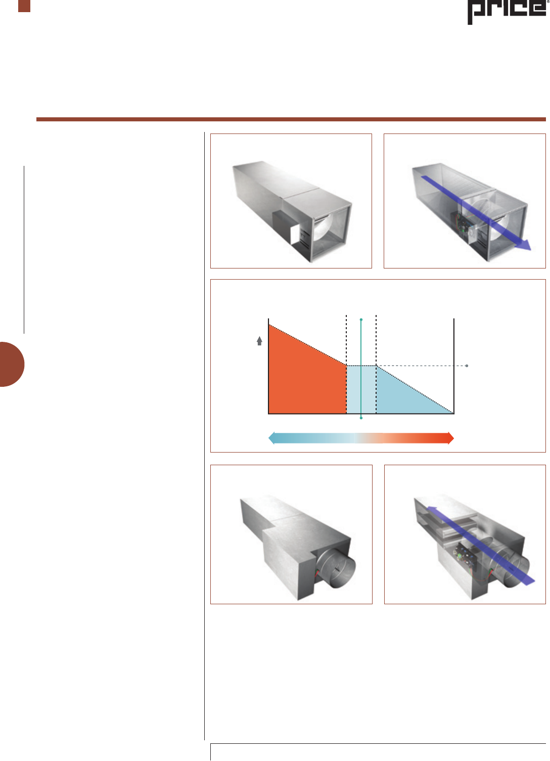
Figure 8: Exhaust Single Duct
Terminal Unit
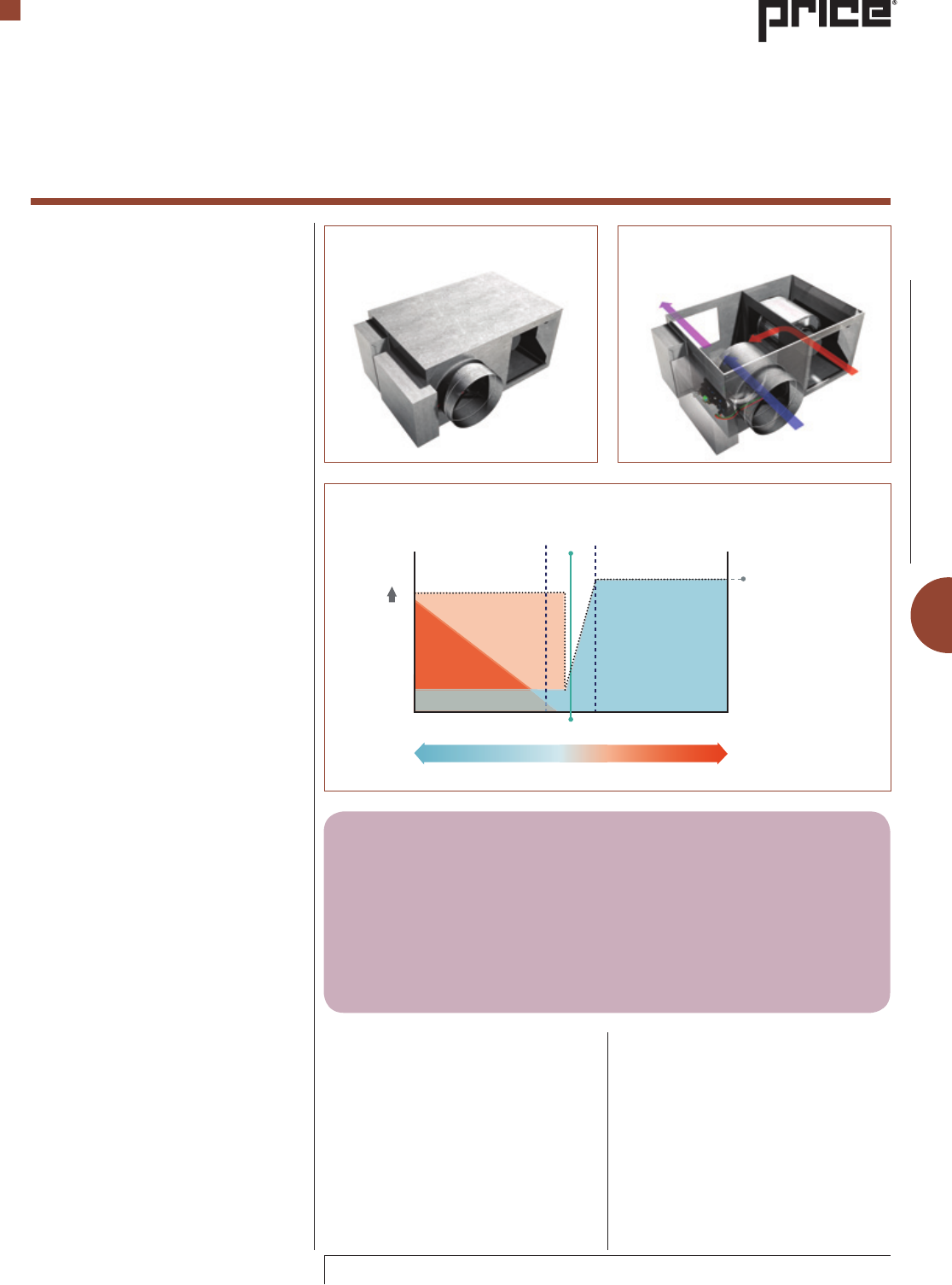
Exhaust Single Duct Terminal
A single duct terminal that is configured
to control exhaust air has the same basic
components as a standard single duct
terminal. However, the airflow direction
is reversed and typically there is an inlet
attenuator section. The inlet attenuator is
used to help lower the sound generation
by the valve when it is operating in a less
than full open position.
The exhaust single duct terminal is
commonly used in spaces that require
either exhaust air volume control, or space
pressurization control. They may also be
found in applications that use a supply-
exhaust tracking control scheme. The
supply-exhaust tracking control scheme
requires both a supply and an exhaust
single duct terminal where the supply will
be controlled by the thermostat demand
and the exhaust by either a percentage of
supply air volume or direct pressurization
control of the occupied space.
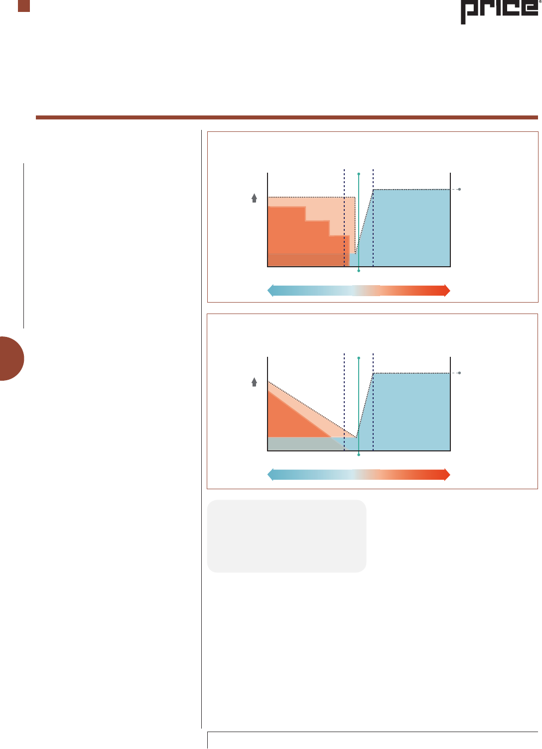
Single Duct Terminal with
Integral Silencer
A sound sensitive space often requires more
attenuation in the air duct system to prevent
too much discharge noise from making it
into the occupied space. Spaces such as
conference rooms, private offices, music
studios, concert halls, classrooms, etc. often
benefit from using a single duct terminal
with an integral silencer.
The difference between a standard single
duct attenuator and a silencer is significant
when it comes to sound attenuation. A
silencer that is just attached to a single
duct may not provide the same amount of
sound attenuation, as does the integrated
unit that is manufactured and certified as
an assembly. A common issue in taking two
different components such as a single duct
terminal and a silencer and simply fastening
them together is called system effect.
System effect is the additional pressure drop
and sound generation due to duct elements
that are placed too close together with
less than ideal inlet conditions. Additional
information on the system effect is located
in Chapter 8—Introduction to Duct Design
of the Price Engineer's HVAC Handbook.
The integrated single duct with silencer is
designed to minimize the system effect and
maximize the sound control characteristics
of the silencer.
For more on how a silencer operates and
sound attenuation characteristics, see the
Silencer section of Chapter 10—Introduction
to Noise Control in the Price Engineer's HVAC
Handbook. For a discussion on the impact
of system effect on ductwork pressure drop,
see the System Effect section of Chapter
10—Introduction to Noise Control of the
Price Engineer's HVAC Handbook.
Terminal Unit Types
Terminal Units
Engineering Guide
Figure 10: Single duct exhaust terminal, pressure differential control sequence
Figure 9: Exhaust Single Duct
Terminal Air Pathway
Figure 11: Single Duct Terminal with
Integral silencer
Figure 12: Single Duct Terminal with
Integral silencer Air Pathway
F-5
© Copyright Price Industries Limited 2014. All Metric dimensions ( ) are soft conversion.
Imperial dimensions are converted to metric and rounded to the nearest millimetre.
ENGINEERING GUIDE - TERMINAL UNITS
Bypass cfm
Zone cfm
Terminal Unit Types
Bypass Terminals
A Bypass terminal unit is designed to
maintain a constant volume of supply air,
while varying the amount of supply air to the
control zone in response to a control signal,
such as a thermostat. Bypass terminals are
often used with air handling equipment such
as packaged rooftop equipment (RTU) that
have a direct expansion coil to minimize the
risk of coil freeze-up at partial airflow rates.
This system design approach typically has
a low first cost, but does not provide the
energy saving advantages of a true VAV
system. The bypassed air is either dumped
into the return air plenum or ducted back
to the RTU.
The most common sequence of operation
for a bypass terminal is to provide a
constant airflow through a rooftop unit
while maintaining the proper flow or static
pressure to the zone ductwork (see Figure
15). As the zone calls for less air, the bypass
damper passes more air from the rooftop
unit to the return which maintains the total
flow rate through the rooftop unit. It is
common to need a constant airflow across
a DX coil that is being used for latent heat
removal / humidity control. Should the
airflow drop, there is a distinct chance
that the DX coil may freeze and this will
potentially lead to higher than desirable
humidity levels in the zone.
Another common sequence for a bypass
terminal is shown in Figure 16. This
sequence adds supplemental heat to the
zone, perhaps baseboard heat or an optional
downstream heater.
Terminal Units
Engineering Guide
Dead Band
Zone cfm
Bypass cfm
Air Volume
Tset-point
Zone calls for less cool air Zone calls for more cool air
Max. Cooling, zone
Rooftop cfm
Tset-point zone cfm
Min. Cooling, zone
Figure 16: Bypass cooling with auxiliary perimeter heating (Heating is not in the
airflow, nor from RTU)
Dead Band
Zone cfm
Air Volume
Tset-point
Zone calls for less cool air Zone calls for more cool air
Max. Cooling
Rooftop cfm
Tset-point zone cfm
Min. Cooling
Aux. Heat
Figure 15: Total airflow through rooftop equipment and to zone through
bypass terminal
Figure 13: Bypass Terminal Unit
Figure 14: Bypass Terminal Air Pathway
F-6
All Metric dimensions ( ) are soft conversion. © Copyright Price Industries Limited 2014.
Imperial dimensions are converted to metric and rounded to the nearest millimetre.
ENGINEERING GUIDE - TERMINAL UNITS
The changeover temperature is the point
where the heat gain to the space is balanced
by the volume of conditioned air to the
space. Below this point, cooling is not
required and if the zone temperature drops,
the unit will change to heating mode. This
sequence is shown in Figure 17.
Dead Band
Zone cfmAux. Heat
Air Volume
Tset-point
Zone calls for less cool air Zone calls for more cool air
Max. Cooling
Max. Heating
Rooftop cfm
Tset-point zone cfm
Min. Cooling
Terminal Unit Types
Terminal Units
Engineering Guide
Dead Band
Air Volume
Tset-point
Zone calls for less cool air Zone calls for more cool air
Max. Heating
Min. Heating
Dead Band
Air Volume
Tset-point
Zone calls for less cool air Zone calls for more cool air
Max. Cooling, zone
Min. Cooling, cfm
Figure 17: Bypass cooling with auxiliary duct heating (Heat / Cool changeover)
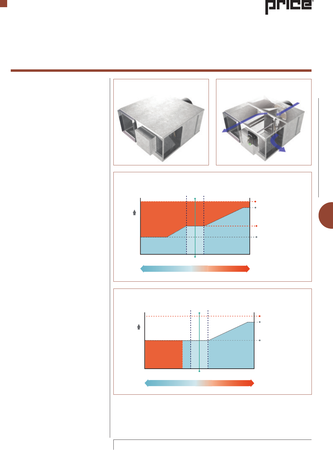
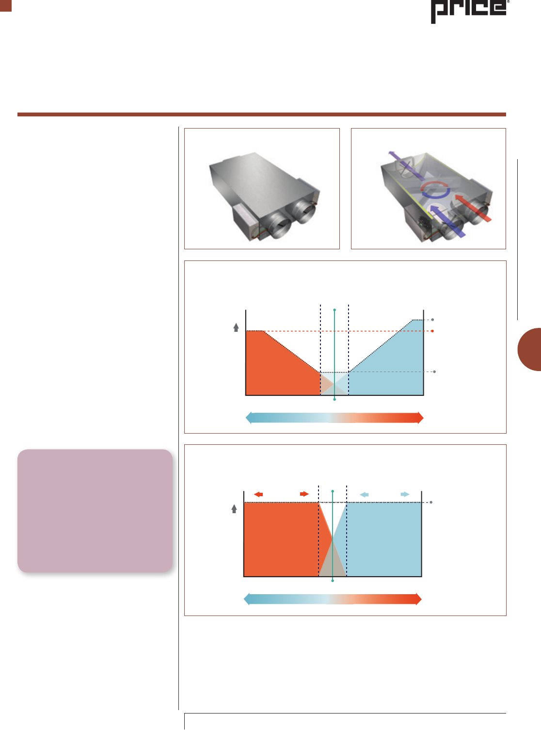
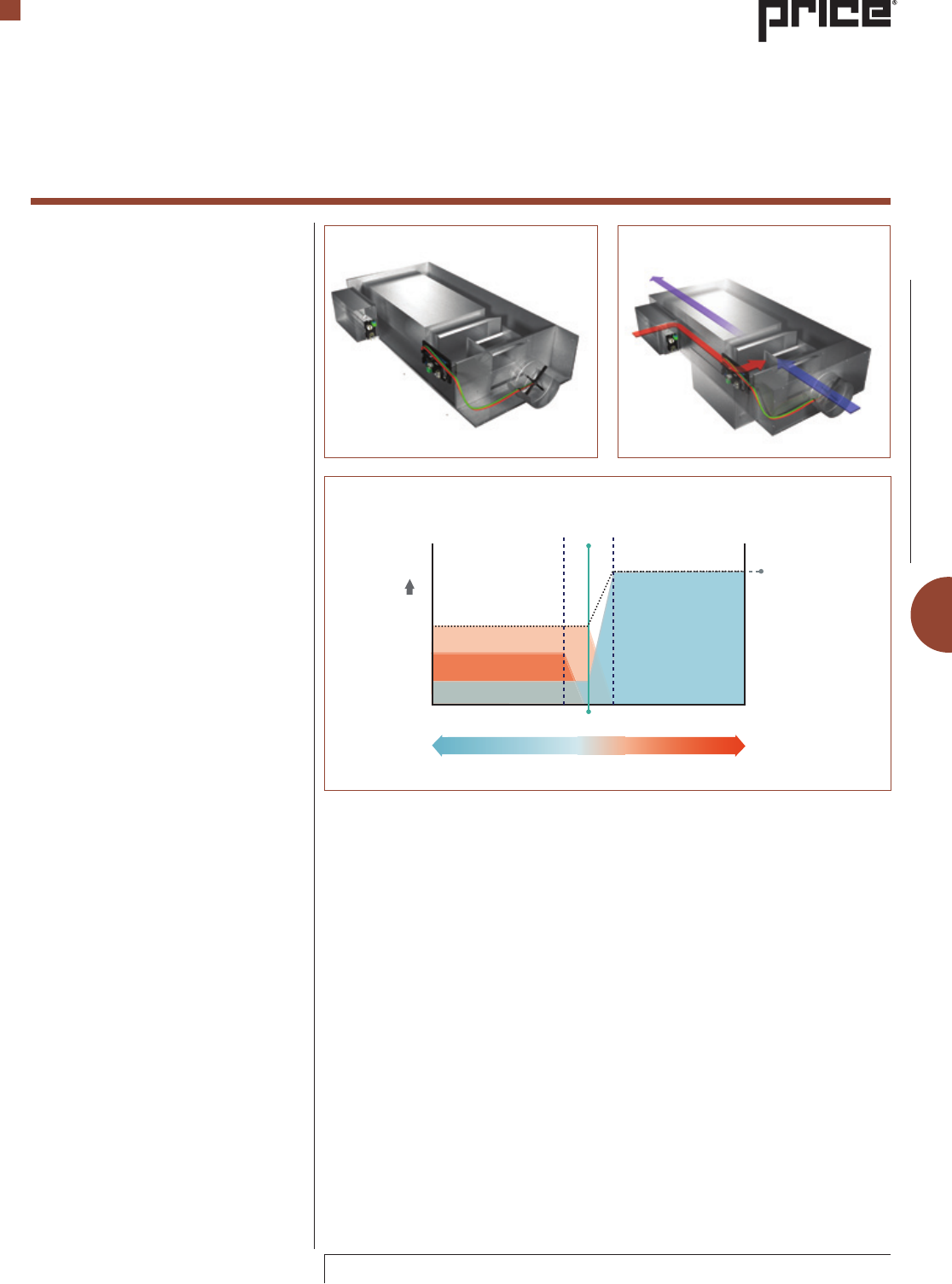
Figure 18: Dual Duct Terminal Unit
(non-mixing)
Figure 19: Dual Duct Terminal Unit
(non-mixing) Air Pathway
Figure 20: Non-Mixing Dual Duct - Cooling Mode
Figure 21: Non-Mixing Dual Duct - Heating Mode
Dual Duct Terminals (Non-Mixing)
A non-mixing dual duct terminal is essentially
two single ducts fastened together with one
common discharge opening. The inlets are
connected to two of the following types of
air supply: cold air supply; warm air supply;
or fresh air supply. The non-mixing type of
dual duct terminal has the potential to have
thermally stratified discharge air and should
have a minimum of three to five equivalent
diameters of discharge duct to allow the
different temperature air to mix.
Non-Mixing Dual ducts are commonly used
for exterior zones in buildings where the use
of auxiliary reheat (such as water coils) is not
desired and where a zero minimum flow is
acceptable during changeover from heating
to cooling (see Figure 18 for a typical non-
mixing dual duct terminal)
F-7
© Copyright Price Industries Limited 2014. All Metric dimensions ( ) are soft conversion.
Imperial dimensions are converted to metric and rounded to the nearest millimetre.
ENGINEERING GUIDE - TERMINAL UNITS
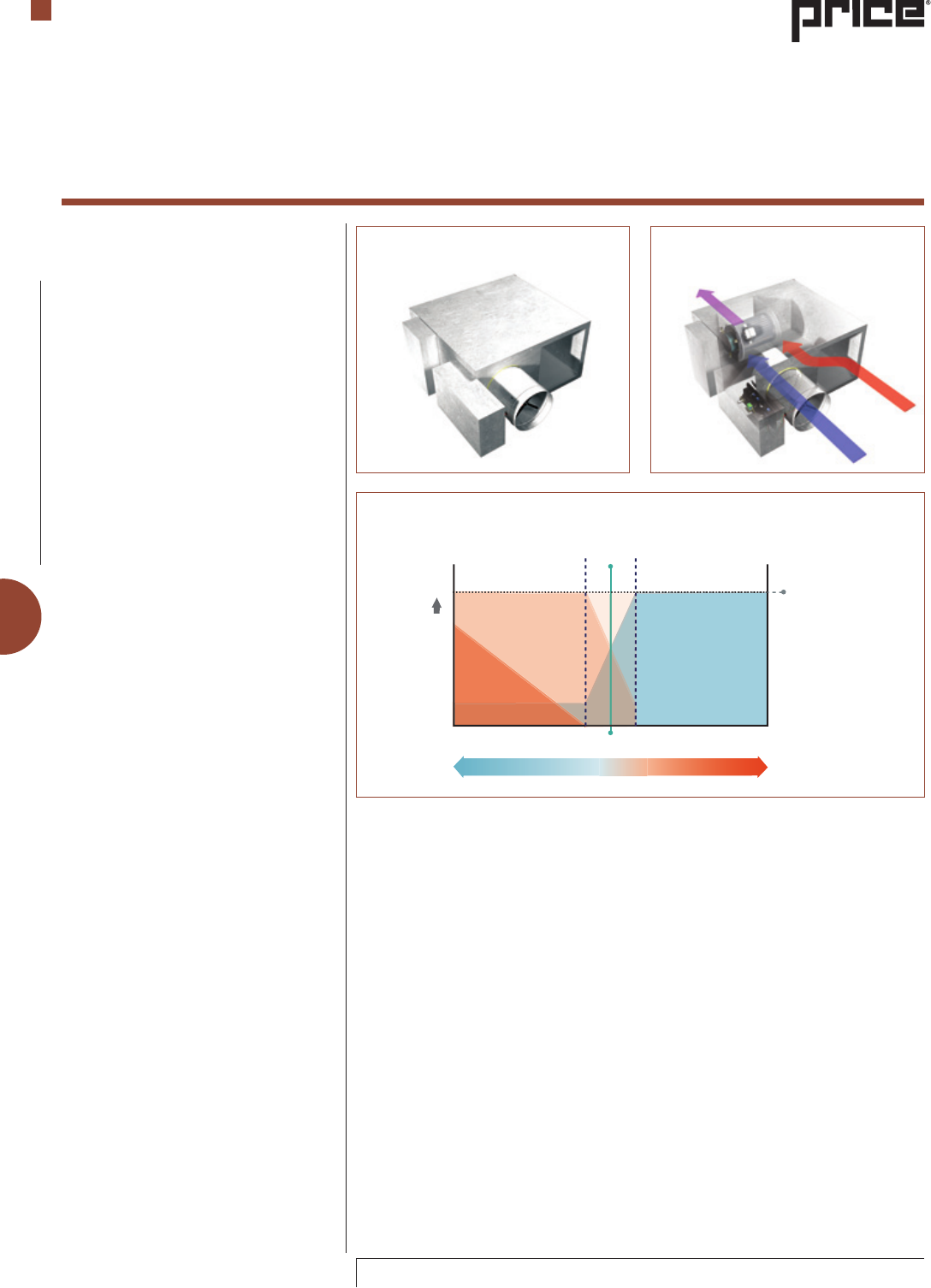
Dual Duct Terminals (Mixing)
A dual duct with integral mixing is similar
to the non-mixing type, but has an integral
mixing section between the two supply
valves and the discharge duct connection
(see Figures 22 and 23). Different levels
of mixing performance are available. The
standard mixing dual duct should provide, at
a downstream distance of three equivalent
diameters from the dual duct, a uniform
discharge air temperature profile (±1 °F). A
high mixing performance dual duct should
provide, at a discharge of six in., a uniform
discharge air temperature profile (±1 °F).
Mixing dual ducts are used in both interior
and exterior zones in buildings such as
hospitals, or buildings where the use of
auxiliary reheat such as hot water or electric
reheat is not desirable.
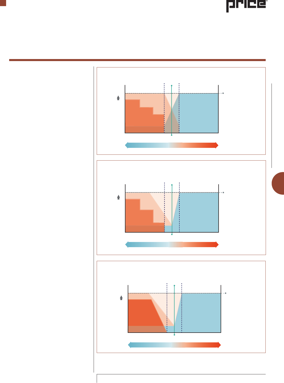
A typical VAV sequence of operation is
shown in Figure 24. In this control scheme,
the zone air volume is allowed to vary based
on thermostat demand while maintaining
a minimum airflow to the zone. For this
sequence, it is common to measure the cold
air and hot air volumes.
A constant volume sequence of operation is
shown in Figure 25. In this control scheme,
the total volume of air is maintained by
varying the percentages of cold and hot air.
For this sequence, it is common to measure
the volume of the cold air and the volume
of the discharge air.
Terminal Unit Types
Terminal Units
Engineering Guide
Figure 24: Dual duct terminal with different maximum heating and cooling airflows
and zero minimum airflows, but with a minimum zone airflow requirement.
Dead Band
Zone cfmAux. Heat
Air Volume
Tset Point
Zone calls for heating Zone calls for cooling
Max. Cooling
Max. Heating
Min. cfm
Dead Band
Air Volume
Tset-point
Zone calls for heating Zone calls for cooling
Constant cfm
Heating Cooling
Figure 25: Dual duct terminal with a constant zone supply air volume and zero
minimum cooling and heating airflows
CONTROL TIP
Dual duct systems have the potential
to maintain high levels of occupant
comfort, but may not be as energy
efficient as other design approaches.
The inefficiency in design is due to
the continuous mixing of warm and
cool air during all seasons of the year.
To improve the efficiency, the system
design should minimize the call for
mixing of the warm and cool air.
Figure 22: Dual Duct (mixing) Figure 23: Dual Duct Mixing Air
Pathway
F-8
All Metric dimensions ( ) are soft conversion. © Copyright Price Industries Limited 2014.
Imperial dimensions are converted to metric and rounded to the nearest millimetre.
ENGINEERING GUIDE - TERMINAL UNITS
Fan Powered - Series (Overhead
Applications)
The basic series fan powered terminal
(sometimes referred to as constant
volume or constant fan) consists of an air
inlet assembly similar to a single duct, a
housing, a blower/motor assembly, a return
air opening/plenum opening and a high
voltage connection (Figures 26 and 27).
All discharge air from the series fan powered
terminal goes through the blower/motor
assembly. Discharge air from the blower/
motor assembly is a mixture of supply air
from the air inlet assembly and the return
air opening. The percentage of supply air
and percentage of return/plenum air will
vary based on the regulation of the supply
air inlet valve due to room cooling calls by
the thermostat. The fan volume for a series
fan powered terminal is sized to handle the
cooling load in the zone.
Standard accessories for a series fan powered
terminal include: inlet and discharge
attenuators, discharge silencer, different
liners, low temperature construction,
electric reheat, hot water reheat, return air
filter, ECM, and PSC motor.
Due to access requirements for high voltage
electrical enclosures, it is recommended that
the designer consider using a door interlock
switch. Most local codes require a main
disconnect and the integral interlock switch
is an economical choice. Also, most local
codes require a minimum of 3 ft clearance
in front of a high voltage enclosure. As a
result, care should be taken when selecting
an installation location for the terminal unit.
A standard height series fan powered
terminal has the blower/motor assembly
installed with the blower inlets and the
motor oriented in the horizontal position.
The standard height series fan powered
terminal is typically no taller than 20 in.
A low profile construction style is available
with a typical height no taller than
12.5 in. Due to the height restrictions, the
typical low profile series fan powered
terminal will have the blower motor
installed such that the motor and blower
intake opening are oriented to the bottom
of the terminal housing.
The overhead series fan powered terminal
unit typically has bottom access panels to
allow maintenance. There are some models
that have a combination of side, top and
bottom access openings.
Terminal Unit Types
Terminal Units
Engineering Guide
Dead Band
Re-circulated Air
Reheat
Min. Primary Air
Max. Primary Air
Max. Cooling
Air Volume
Tset-point
Zone calls for heating Zone calls for cooling
Constant cfm
to Zone
Figure 26: Series Fan Powered
Terminal Unit (Overhead Applications)
Figure 27: Series Fan powered
terminal unit (Overhead Applications)
Air Pathway
Figure 28: Constant or series FPU with minimum primary air and proportional hot
water reheat
F-9
© Copyright Price Industries Limited 2014. All Metric dimensions ( ) are soft conversion.
Imperial dimensions are converted to metric and rounded to the nearest millimetre.
ENGINEERING GUIDE - TERMINAL UNITS
Series fan powered terminals are commonly
used in exterior zones where the heating
and cooling loads vary. They are also used
in buildings to provide heat during periods
of non-occupancy where it is desirable to
leave the central air handling system off.
For most typical sequences, the fan in a
series FPU will operate at the maximum
cooling air volume. Alternative sequences
that allow the fan volume to vary based on
zone thermostat call for cooling or heating
are sometimes used in an attempt to
minimize the potential for over-supplying
air to the occupied zone.
One of the main benefits of the series fan
powered terminal is the consistent delivery
of the same air volume to the occupied zone.
Many occupants prefer the consistent air
movement and consistent ambient sound
levels.
One weakness in a series fan powered
terminal is that they can generate significant
levels of sound power, in particular radiated
sound. Care should be taken to not select
too large of a fan capacity and to locate
the unit over an unoccupied space in
the building such as a closet or hallway.
To minimize potential noise complaints
most designers prefer to limit the overall
airflow capacity of the series fan powered
terminal to no more than 3000 cfm, with
many preferring no greater than 2500 cfm
depending upon the type of occupancy and
building construction.
There are two common types of electric
motors used in fan powered terminals: the
permanent split capacitor (PSC) and the
electrically commutated motor (ECM). For
a complete description of these two motor
types, please see the section on motors later
in this chapter.
A common sequence of operation is shown
in Figures 28 and 29. In these control
sequences, the primary air valve is varied
from minimum airflow volume which is
typically determined by the minimum zone
fresh air volumes required for the zone
occupancy type. The maximum cooling
airflow rate is typically determined by the
maximum anticipated cooling load for that
zone. As the demand for cooling varies,
the percentage of return air vs. primary air
will vary while the total volume of air to the
zone is held constant. As in other reheat
sequences, the hot water coil or electric
reheat coil will be activated when the zone
temperature falls below the lower dead
band limit.
Figure 29: Constant or series FPU with minimum primary air and 3 stage electric
reheat
Figure 30: Constant or series FPU with ECM motor and variable fan volume, minimum
primary air, and 3 stage electric reheat
Terminal Unit Types
Dead Band
Re-circulated Air
Electric Reheat
Min. Primary Air
Max. Primary Air
Max. Cooling
Air Volume
Tset-point
Zone calls for heating Zone calls for cooling
Constant cfm
to Zone
Stage 3
Stage 2
Stage 1
Dead Band
Re-circulated Air
Electric Reheat
Min. Primary Air
Max. Primary Air
Max. Cooling
Air Volume
Tset-point
Zone calls for heating Zone calls for cooling
Full Volume
cfm to Zone
Stage 3
Stage 2
Stage 1
Terminal Units
Engineering Guide
Figure 31: Constant or series FPU with ECM motor and variable fan volume,
minimum primary air, and hot water reheat
Dead Band
Re-circulated Air
Max. Primary Air
Max. Cooling
Air Volume
Tset-point
Zone calls for heating Zone calls for cooling
Full Volume
cfm to Zone
Reheat
Min. Primary Air
F-10
All Metric dimensions ( ) are soft conversion. © Copyright Price Industries Limited 2014.
Imperial dimensions are converted to metric and rounded to the nearest millimetre.
ENGINEERING GUIDE - TERMINAL UNITS
Some designers prefer to use the series
fan powered unit (FPU) for reheat during
periods of unoccupancy and will shut down
the central fan during these periods. See
Figures 30 to 34 for common control
sequences. At the start of occupied mode it
is important to start the series FPU before the
central fan to prevent dumping of primary air
into the return plenum. It is also important to
do this because there is a slight potential for
the blower to spin backward due to the flow
of primary air through the blower when the
motor is not in operation. It is possible that
if the blower is spinning backward, when
power is applied to the motor, the blower
will continue to operate with the reversed
rotation. This reverse operation will result
in lower air volumes, potential noise issues
and motor overheating.
Terminal Unit Types
Figure 32: Constant or Series FPU, Min. Primary Air, Water Reheat, Night Set Back/
Unoccupied Mode/Operation
Figure 33: Constant or Series FPU, Min. Primary Air, Electric Reheat, Night Set
Back/Unoccupied Mode/Operation
Dead Band
Reheat
Re-circulated Air
Reheat Air Flow to Zone,
No Primary Air
Tset-point
Zone calls for heating
Dead Band
Reheat
Re-circulated Air
Reheat Air Flow to Zone,
No Primary Air
Tset-point
Zone calls for heating
Stage 3
Stage 2
Stage 1
Terminal Units
Engineering Guide
Figure 34: Constant or series FPU with ECM motor and variable fan volume, minimum
primary air, and hot water reheat
Dead Band
Tset-point
Zone calls for heating
Constant
cfm to Zone
Air Volume
Hot Water
Reheat
Min. Primary Air
Re-circulated Air
F-11
© Copyright Price Industries Limited 2014. All Metric dimensions ( ) are soft conversion.
Imperial dimensions are converted to metric and rounded to the nearest millimetre.
ENGINEERING GUIDE - TERMINAL UNITS
Terminal Unit Types
Fan Powered- Parallel
The basic parallel fan powered terminal
(sometimes referred to as Intermittent)
consists of an air inlet assembly similar to
a single duct, a housing, a blower/motor
assembly with back draft damper, a mixing
chamber, a return air opening/plenum
opening and a high voltage connection
(see Figures 35 and 36). The discharge
air from the parallel fan powered terminal
is a combination of primary air and fan air
volume. During cooling operation, the fan
is not in operation and only the primary air
is discharged. During heating operation, the
fan is energized which pumps plenum air
into the mixing plenum where it is mixed
with the primary air and then discharged
from the terminal unit. The fan in a parallel
fan terminal is sized for the heating airflow
required for the zone.
Standard accessories for a parallel fan
powered terminal include: inlet and
discharge attenuators, different liners, low
temperature, electric reheat, hot water
reheat, return air filter, ECM motor, PSC
motor.
Due to access requirements for high voltage
electrical enclosures where the connections
for the terminal controls and motor are
contained as well as fused (if present), it is
recommended that the designer consider
using a door interlock switch. Most local
codes require a main disconnect and the
integral interlock switch is an economical
choice. Also, most local codes require a
minimum of 3 ft clearance in front of a high
voltage enclosure. Care should be taken
when selecting an installation location for
the terminal unit.
A standard height parallel fan powered
terminal has the blower/motor assembly
installed with the blower inlets and the
motor oriented in the horizontal position.
The standard height parallel fan powered
terminal is typically no taller than 20 in.
A low profile construction style is available
with a typical height no taller than 12.5 in.
Due to the height restrictions, the typical
low profile parallel fan powered terminal
will have the blower motor installed such
that the motor and blower intake opening
are oriented to the bottom of the terminal
housing.
The overhead parallel fan powered terminal
unit typically has bottom access panels to
allow maintenance.
One weakness in a parallel fan powered
terminal is that when the fan is in operation,
they can generate significant levels of sound
power, in particular radiated sound. Also,
when the fan cycles on and off, there is a
change in the ambient background noise
that occupants can become aware of and
in some cases, may lead to complaints
about noise. Care should be taken to not
Terminal Units
Engineering Guide
CONTROL TIP
When using a parallel FPU for reheat when the central air handler is not in operation,
it is advised to ensure that the control sequence closes the primary valve prior to
turning on the fan, particularly when using electric reheat. The issue is that the
fan discharge air will take the path of least resistance and if the primary air valve
is open, without the air handler in operation, there is a chance that some of the
fan discharge air will not go through the electric reheat coils and then to the zone,
but instead will discharge through the primary air valve. If there is not sufficient
airflow across the electric reheat coils, nuisance tripping of the electric reheat
thermal limits is a distinct possibility.
Dead Band
Reheat
Re-circulated Air
Max. Primary Air
Max. Cooling
Air Volume
Tset-point
Zone calls for heating Zone calls for cooling
Full Volume
cfm to Zone
Min. Primary Air
select too large of a capacity and to locate
the unit over an unoccupied space in
the building such as a closet, or hallway.
Most designers prefer to limit the overall
airflow capacity of the parallel fan powered
terminal to no more than 3,000 cfm, with
many preferring no greater than 2,500 cfm
depending upon the type of occupancy and
building construction.
Another weakness in parallel FPUs is the
leakage of primary air through the back draft
damper on the fan and the mixing chamber
housing. Recent research by ASHRAE and
Texas A and M University (Furr, 2007) have
demonstrated that many of the energy
savings due to the intermittent fan cycling
are offset and in fact may be significantly
less than the energy loss associated with
the conditioned primary air leaking into the
return plenum space through the back draft
damper and the mixing chamber housing.
It is recommended that if leakage through
the back draft damper is of concern that
the designer either use a different terminal
type, or require that the leakage from the
terminal housing as an assembly be limited
and certified to some specified amount.
Figure 35: Parallel or Intermittent Fan
Powered Terminal
Figure 36: Parallel or Intermittent Fan
Powered Terminal Air Pathway
Figure 37: Variable or Parallel FPU with Minimum Primary Air and Water reheat
F-12
All Metric dimensions ( ) are soft conversion. © Copyright Price Industries Limited 2014.
Imperial dimensions are converted to metric and rounded to the nearest millimetre.
ENGINEERING GUIDE - TERMINAL UNITS
A commonly specified leakage rate for
certification is 2% of nominal primary
airflow. The ability to certify the leakage of
a parallel terminal back draft damper and
mixing chamber housing is not common in
all manufacturers of these devices.
Parallel fan powered terminals are
commonly used in exterior zones where
the heating and cooling loads vary. They
are also used in buildings to provide heat
during periods of un-occupancy where it is
desirable to leave the central air handling
system off.
The fan is usually sized for the heating air
volume and not operated during cooling
mode. Energy consumption due to air
leakage through the backdraft damper
should be evaluated when determining
which type of FPU terminal to select.
There are two common types of electric
motors used in fan powered terminals, the
permanent split capacitor (PSC) and the
electrically commutated motor (ECM). For
a complete description of these two motor
types, please see the section on motors later
in this chapter.
A common sequence of operation is shown
in Figures 37 and 38. In these control
sequence, the primary air valve is varied
from minimum airflow volume which is
typically determined by the minimum zone
fresh air volumes required for the zone
occupancy type. The maximum cooling
airflow rate is typically determined by the
maximum anticipated cooling load for that
zone. As the demand for cooling varies, the
volume of primary air will vary. When reheat
is activated, the fan will energize and, the
hot water coil or electric reheat coil will be
activated when the zone temperature falls
below the lower dead band limit.
It is possible to operate the parallel FPU with
a variable fan volume during reheat as is
shown in Figure 39. This is not a common
sequence, but there has been some interest
in this as a way of saving fan energy.
Terminal Unit Types
Terminal Units
Engineering Guide
Dead Band
Electric Reheat
Re-circulated Air
Min. Primary Air
Max. Primary Air
Max. Cooling
Air Volume
Tset-point
Zone calls for heating Zone calls for cooling
Full Volume
cfm to Zone
Stage 3
Stage 2
Stage 1
Dead Band
Reheat
Re-circulated Air
Min. Primary Air
Max. Primary Air
Max. Cooling
Air Volume
Tset-point
Zone calls for heating Zone calls for cooling
Full Volume
cfm to Zone
Figure 38: Variable or Parallel FPU with Minimum Primary Air and 3 Stage Electric
Reheat
Figure 39: Variable or Parallel FPU with ECM, Variable Fan Volume, Minimum Primary
Air, and Water Reheat
PRODUCT TIP
Certified leakage in parallel FPUs is
not standard construction and would
require special manufacturing. This
is not a standard unit offered by any
manufacturer.
F-13
© Copyright Price Industries Limited 2014. All Metric dimensions ( ) are soft conversion.
Imperial dimensions are converted to metric and rounded to the nearest millimetre.
ENGINEERING GUIDE - TERMINAL UNITS
Induction Terminals
The induction terminal is designed to
induce warm air from the ceiling plenum
without a fan/blower by utilizing a variable
aperture 'flow nozzle' (see Figure 41).
When conditioned air is not required, warm
air from the ceiling plenum is introduced,
thereby increasing comfort by maintaining
airflow in the room.
This unit can be used instead of fan powered
terminal units. The traditional induction
terminal is a high inlet pressure supply
device. Modern induction terminals can
operate properly as long as the inlet static
pressure is greater than 0.5 in. w.g.
An induction terminal uses the larger and
more energy efficient central fan to provide
pressurized supply air to induce the room
air rather than the lower efficiency motor/
blower in a FPU.
The basic unit consists of a conditioned
supply air inlet, with combination damper/
jet flow nozzle, actuator, velocity sensor and
related controls, a return air damper and
related controls.
Optional accessories include water reheat
and electric reheat and various liner types.
The sequence of operation is shown in
Figure 42. The primary air volume is
regulated by closing or opening the primary
induction aperture, with the volume of
primary air based on the zone cooling
requirements. The supply air to the zone is
a mixture of the primary air and the induced
return air. The amount of induced return
air is regulated by the return air damper
and will vary between full open at the set-
point to full close at the peak cooling call.
Optional reheat will activate when the zone
temperature drops below the set-point.
Terminal Unit Types
Dead Band
Max. Primary Air
Max. Cooling
Air Volume
Tset-point
Zone calls for heating Zone calls for cooling
Full Volume
cfm to Zone
Reheat
Induced Plenum/Return Air
Min. Primary Air
Terminal Units
Engineering Guide
Figure 40: Induction Terminal Unit Figure 41: Induction Terminal Air
Pathway
Figure 42: Induction Terminal with Minimum Primary Air and Water Reheat
F-14
All Metric dimensions ( ) are soft conversion. © Copyright Price Industries Limited 2014.
Imperial dimensions are converted to metric and rounded to the nearest millimetre.
ENGINEERING GUIDE - TERMINAL UNITS
Acoustical Selection Procedure
Estimating Sound Levels:
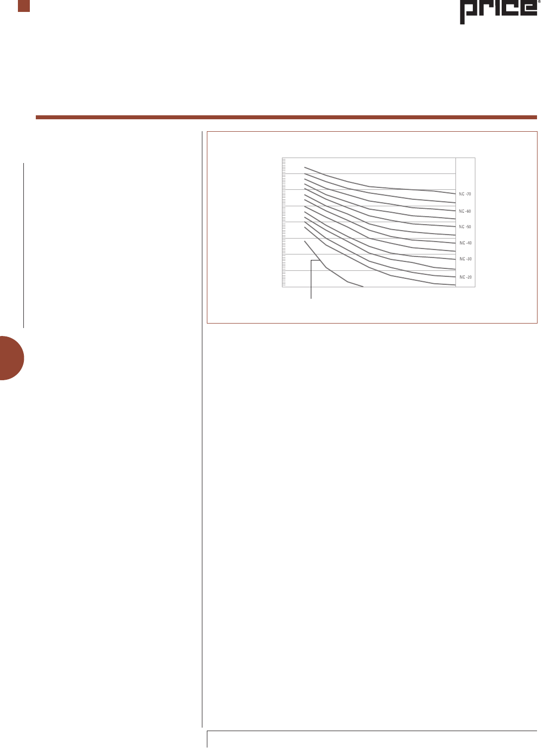
Noise Criteria – NC
Noise Criteria or NC level values have
become widely accepted as a measure of
room noise levels and as a rating scale for
equipment that is expected to stay within
those levels.
When deriving NC levels for terminal
units, the sound pressure level of octave
bands two through seven (125 to 4000 Hz)
should be considered. These pressure levels
are plotted on a standard NC curve form
(Figure 43). The highest pressure level
when measured against the NC curves,
regardless of frequency, determines the
NC of the unit.
Table 1 illustrates the ASHRAE
recommended space NC values for many
commercial air conditioning applications
(ASHRAE, 2007). Terminal units should be
selected so that the tabulated NC levels
are within these design goals. Most
manufacturers’ catalog data for terminal
units lists the sound power levels at various
operating conditions. To determine the
actual sound pressure level in the space,
we must evaluate which attenuation factors
are present in the system and subtract these
values from the manufacturers’ sound power
levels. The Air-Conditioning, Heating and
Refrigeration Institute (AHRI) has published
“A Procedure for Estimating Occupied
Space Sound Levels in the Application of Air
Terminals and Air Outlets," known as AHRI
Standard 885-2008. This standard forms the
basis for the sound estimation guidelines
presented on the following pages. These
guidelines are offered for typical conditions.
For a more detailed analysis, refer to AHRI
Standard 885-2008 and the ASHRAE HVAC
Applications Handbook (ASHRAE, 2007)
Approximate Threshold of
Hearing for Continuous Noise
90
80
70
60
50
40
30
20
10
63 125 250 500
Band Center Frequencies, Hz
Spl, Octave Band Sound Pressure Level, Db,
Re 0.0002 Microbar
1000 2000 4000 8000
Terminal Units
Engineering Guide
Figure 43: Noise Criteria Curves
F-15
© Copyright Price Industries Limited 2014. All Metric dimensions ( ) are soft conversion.
Imperial dimensions are converted to metric and rounded to the nearest millimetre.
ENGINEERING GUIDE - TERMINAL UNITS
Acoustical Selection Procedure
Room Types
RC(N)
(QAI[5 dB
a,b
)
Private residences 25-35
Hotels/Motels
Individual rooms or suites 25-35
Meeting/banquet rooms 25-35
Corridors, lobbies 35-45
Service/support areas 35-45
Office Buildings
Executive and private offices 25-35
Conference rooms 25-35
Tele-conference rooms < 25
Open-plan offices < 40
- With sound masking < 35
Corridors and lobbies 40-45
Hospitals and clinics
Private rooms 25-35
Wards 30-40
Operating rooms 25-35
Corridors and public areas 30-45
Performing Arts Spaces
Drama theatres 25
Music teaching studios 25
Music practice rooms 30-35
Schools
d
Classrooms
25-30
Large lecture rooms
25-30
Large lecture rooms, without speech amplification
25
Laboratories (with Fume Hoods)
Testing/research, minimal speech communication
45-55
Research, extensive telephone use, speech communication
40-50
Group teaching
35-45
Church, Mosque, Synagogue
General assembly 25-35
With critical music programs c
Libraries 30-40
Courtrooms
Un-amplified speech 25-35
Amplified speech 30-40
Indoor Stadiums, Gymnasiums
Gymnasiums and natatoriums
e
40-50
Large seating-capacity spaces with speech amplification
e
45-55
a
The values and ranges are based on judgment
and experience, not quantitative evaluations of
human reactions. They represent general limits of
acceptability for typical building occupancies. Higher
or lower values may be appropriate and should be
based on a careful analysis of economics, space use
and user needs.
b
When quality of sound in the space is important,
specify criteria in terms of RC(N). If the quality of
the sound in the space is of secondary concern, the
criteria may be specified in terms of NC or NCB levels
of similar magnitude.
c
An experienced acoustical consultant should be
retained for guidance on acoustically critical spaces
(below RC 30) and for all performing arts spaces.
d
Some educators and others believe that HVAC-related
sound criteria for schools, as listed in previous
editions of this table, are too high and impede
learning for affected groups of all ages. See ANSI
Standard S12.60-2002 for classroom acoustics and a
justification for lower sound criteria in schools. The
HVAC component of total noise meets the background
noise requirement of that standard if HVAC-related
background sound is [ RC 25(N).
e
RC or NC criteria for these spaces need only be
selected for the desired speech.
Reference•2007ASHRAEApplicationsHandbook,
Table42,page47.34
•AHRIStandard885-2008,Table15,
page 31
Table 1: Design Guidelines for HVAC System Noise in Unoccupied Spaces
Terminal Units
Engineering Guide
F-16
All Metric dimensions ( ) are soft conversion. © Copyright Price Industries Limited 2014.
Imperial dimensions are converted to metric and rounded to the nearest millimetre.
ENGINEERING GUIDE - TERMINAL UNITS
Octave Band Mid Frequency, Hz 2 3 4 5 6 7
Type 1: Mineral Tile
5
/8 in. – 20#/ft
3
18 19 20 26 31 36
Type 4: Glass Fiber
5
/8 in. – 4 #/ft
3
19 19 21 25 29 35
Type7:SolidGypsumBoard
5
/8 in. – 43 #/ft
3
23 26 25 27 27 28
Reference •AHRIStandard885-2008,AppendixD,TableD15,page54
Environmental Adjustment Factors
According to AHRI Standard 885-2008, an
environmental adjustment factor must be
applied to manufacturers' data if the sound
power data has been obtained in accordance
with AHRI Standard 880-2008. Sound power
levels obtained in accordance with Standard
880 are based on a free field calibration of
the reference sound source. According to
AHRI, real rooms at low frequencies behave
acoustically more like reverberant rooms
than open spaces (free field). Because of
this, it is necessary to adjust power levels
obtained in accordance with AHRI Standard
880-2008 by the Environmental Adjustment
Factor listed in Table 2.
Sound Paths
In order to estimate the sound level in the
occupied space, one must first identify the
sound source and determine by which paths
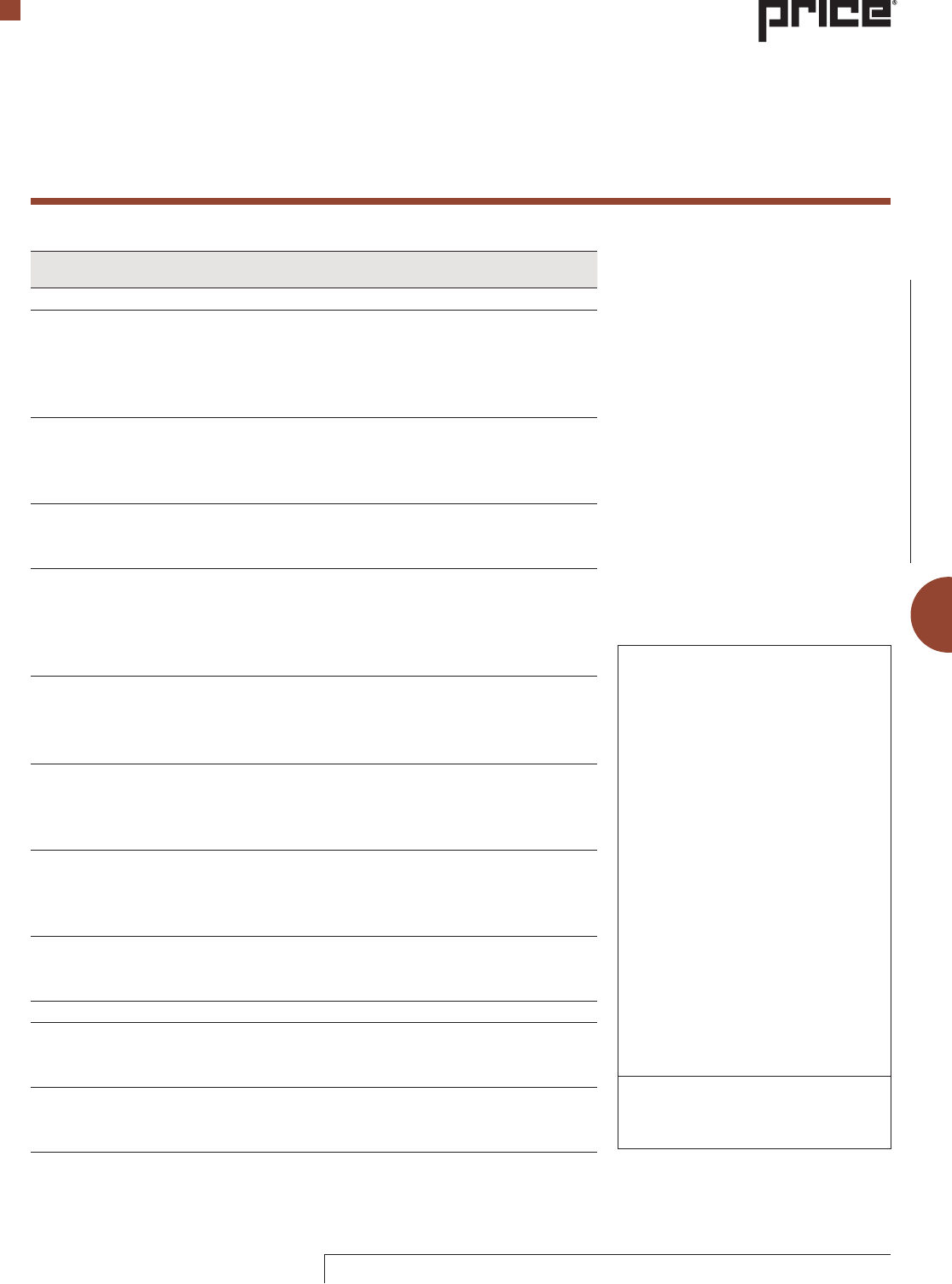
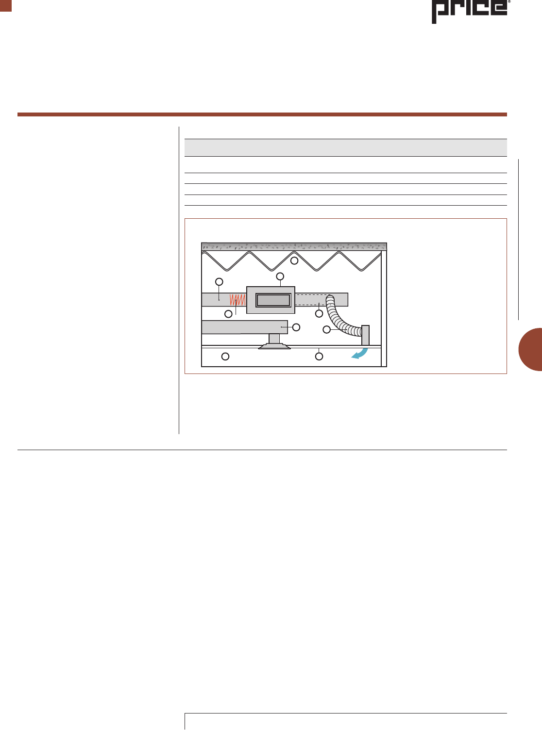
the sound enters the occupied space. Figure
44 illustrates a fan powered terminal as an
example of a sound source and identifies
five sound paths. These sound paths are as
follows.
• UpstreamDuctBreakoutRadiated-This
is the noise generated by the terminal
that is transmitted through the upstream
ductwork.
• Inlet and Casing Radiated - This is the
noise generated by the terminal that is
transmitted through the terminal casing or
which escapes out the return air opening.
• DischargeDuctBreakoutRadiated-This
is the noise generated by the terminal
unit which is transmitted through the
downstream ductwork.
• Outlet Discharge - This is the noise
generated by the terminal that travels
down the duct and escapes at the air outlet.
• Outlet Generated - This is the noise
generated by the air outlet. Since the
discharge and upstream duct breakout
noise paths are functions of the quality of
the ductwork construction and installation
rather than the terminal unit performance,
they are not dealt with in the following
estimating procedure. Generally, if care is
taken in the design and installation of the
ductwork, breakout noise will not be a
contributing factor to the occupied level.
However, for a detailed analysis of duct
breakout noise, please refer to AHRI
Standard 885-2008.
Now that we have identified the relevant
sound paths, we can evaluate the attenuation
factors for each.
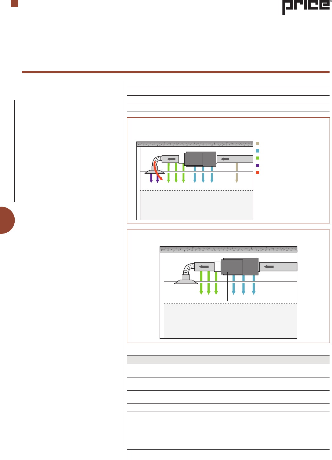
Radiated Sound
Figure 45 illustrates the sound path for inlet
and casing radiated sound. The attenuation
factors that apply to this sound path are
Ceiling / Space Effect and Environmental
Adjustment Factor. The Environmental
Adjustment Factor was presented earlier
in the Engineering Guide.
Acoustical Selection Procedure
Table 2: Environmental Adjustment Factor
Octave Band Mid Frequency, Hz 2 3 4 5 6 7
Environmental Adjustment Factor, dB 2 1 0 0 0 0
Reference:AHRIStandard885-2008,AppendixC,TableC1,page385.
Terminal Units
Engineering Guide
Fan Powered Induction Terminal
Occupied Zone
Air Flow
Cross-Section View
Upstream Duct Breakout Radiated
Unit Inlet & Casing Radiated
Discharge Duct Breakout Radiated
Outlet Discharge/Outlet Generated
Duct Breakout Radiated
Figure 44: Fan Powered Terminal or Induction Terminal Acoustical Model.
Figure 45: Fan Powered / Induction Terminal Acoustical Model - Radiated Sound Path
Table 3: Ceiling/Space Effect, dB
Air Flow
Fan Powered Induction Terminal
Occupied Zone
F-17
© Copyright Price Industries Limited 2014. All Metric dimensions ( ) are soft conversion.
Imperial dimensions are converted to metric and rounded to the nearest millimetre.
ENGINEERING GUIDE - TERMINAL UNITS
Ceiling / Space Effect
To calculate the sound level in a space
resulting from a sound source located in
the ceiling cavity, a transfer function is
provided which is used to calculate the
sound pressure in the space. This transfer
function includes the combined effect of
the absorption of the ceiling tile, plenum
absorption and room absorption.
The procedure assumes the following
conditions:
a. The plenum is at least 3 ft [0.9 m] deep.
b. The plenum space is either wide (over
30 ft [9 m]) or lined with insulation.
c. The ceiling has no significant penetrations
directly under the unit.
Table 3 provides typical values for ceiling
space effect of several ceiling types from
manufacturers’ sound power level data.
Price tests all terminal units in accordance
with AHRI Standard 880-2008, therefore
these corrections should be applied when
estimating the sound power in occupied
spaces.
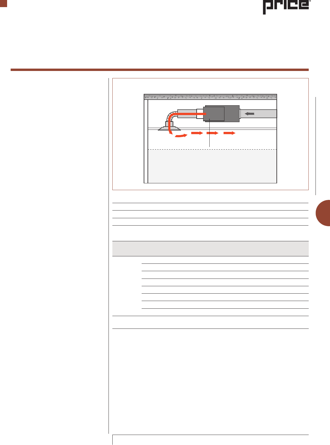
Discharge Sound
Figure 46 illustrates the sound path for
outlet discharge sound. The attenuation
factors which apply to this sound path are:
• BranchPowerDivision
• DuctInsertionLoss
• LinedFlexibleDuctInsertionLoss
• ElbowandTeeLoss
• EndReectionFactor
• SpaceEffect
Branch Power Division
At branch take-offs, acoustic energy is
distributed between the branches and/or the
main duct in accordance with the ratio of
the branch cross-sectional area to the total
cross-sectional area of all ducts leaving the
take-off. In other words, the acoustic energy
is divided in proportion to the flow division
of the take-off. Table 4 lists the attenuation
of various percentages of total flow carried
by the branch ductwork.
Duct Insertion Loss
Acoustically lined ductwork is effective in
absorbing sound as it travels down the
duct. Table 5 lists the attenuation in dB/
linear ft for various duct sizes coinciding
with the outlet size of commonly used
Price terminals. Data is based on discharge
duct that is the same size as the unit outlet,
lined with 1 in.,1.5 lb/ft
3
insulation. A more
complete list of duct sizes and the method
of calculating custom sizes is outlined in the
AHRI 885-2008 Standard, Appendix D.
Acoustical Selection Procedure
Terminal Units
Engineering Guide
Model Type
Discharge Duct
(in.) [mm]
Octave Band
2 3 4 5 6 7
Fan Powered
Single Duct
12x8[305x203] 0.4 1.0 2.1 4.5 4.9 3.2
12x10[305x254] 0.4 0.9 2.0 4.2 4.4 2.9
14x12½[356x318] 0.3 0.8 1.8 3.9 3.7 2.6
16x15[406x381] 0.3 0.7 1.7 3.5 3.3 2.4
20x17½[508x445] 0.3 0.6 1.5 3.2 2.8 2.1
24x18[610x457] 0.3 0.5 1.5 3.1 2.5 2.0
28x17½[711x445] 0.2 0.5 1.4 3.0 2.4 1.9
34x17½[864x445] 0.2 0.5 1.4 2.9 2.3 1.8
Reference•AHRIStandard885-2008,AppendixD,TableD8,page47
•2007ASHRAEHandbook,HVACApplications,Chapter4,Table12
Table 5: Sound Insertion Loss / Attenuation in Straight Lined Metal Ducts
Table 4: Flow Division
% Total Flow 5 10 15 20 30 40 50 60
dB Attenuation 13 10 8 7 5 4 3 2
Reference •AHRIStandard885-2008,AppendixD,TableD2,page40
Air Flow
Fan Powered Induction Terminal
Occupied Zone
Figure 46: Discharge Sound

F-18
All Metric dimensions ( ) are soft conversion. © Copyright Price Industries Limited 2014.
Imperial dimensions are converted to metric and rounded to the nearest millimetre.
ENGINEERING GUIDE - TERMINAL UNITS
Acoustical Selection Procedure
Duct Diameter
(in. ] [mm]
Duct Length
(in. ] [mm]
Octave Band Mid Frequency
2 3 4 5 6 7
6[150] 3[0.9] 5 6 13 17 19 11
6[150] 5[1.5] 6 9 18 22 24 15
8[200] 3[0.9] 4 7 14 15 16 8
8[200] 5[1.5] 6 10 18 20 21 12
10[250] 3[0.9] 4 7 14 12 13 6
10[250] 5[1.5] 5 11 18 18 18 9
12[300] 3[0.9] 3 6 12 10 11 4
12[300] 5[1.5] 4 9 16 16 15 7
14[350] 3[0.9] 2 4 10 9 9 4
14[350] 5[1.5] 3 7 14 14 13 6
16[400] 3[0.9] 1 0 8 8 8 4
16[400] 5[1.5] 2 2 11 12 11 5
Reference•AHRIStandard885-2008,AppendixD,TableD9,page48
Table 6: Lined Flexible Duct Insertion Loss, dB
Model Type Duct Diameter
Octave Band Mid Frequency
2 3 4 5 6 7
Unlined Duct
5-10[100-125] 0 0 1 5 8 4
11-20[260-700] 1 5 5 8 4 3
21-40[710-1000] 5 5 8 4 3 3
41-80[1010-2000] 5 8 4 3 3 3
Lined Duct
5-10[100-125] 0 0 1 6 11 10
11-20[260-700] 1 6 6 11 10 10
21-40[710-1000] 6 6 11 10 10 10
41-80[1010-2000] 6 11 10 10 10 10
Reference•AHRIStandard885-2008,AppendixD,TableD12,page51
•2007ASHRAEHandbook,HVACApplications,Chapter47,Table17
Model Type Duct Diameter
Octave Band Mid Frequency
2 3 4 5 6 7
Unlined Duct
5-10[100-125] 0 0 1 4 6 4
11-20[260-700] 1 4 6 4 4 3
21-40[710-1000] 4 4 6 4 4 3
41-80[1010-2000] 4 6 6 4 4 3
Lined Duct
5-10[100-125] 0 0 1 4 7 7
11-20[260-700] 1 4 7 7 7 7
21-40[710-1000] 4 7 7 7 7 7
41-80[1010-2000] 4 7 7 7 7 7
Reference•AHRIStandard885-2008,AppendixD,TableD12,page51
•2007ASHRAEHandbook,HVACApplications,Chapter47,Table19
Table 8: Insertion Loss of Unlined and Lined Elbows with Turning Vanes, dB
Table 7: Insertion Loss of Unlined and Lined Elbows without Turning Vanes, dB
Terminal Units
Engineering Guide
Lined Flexible Duct Insertion Loss
Nonmetallic insulated flexible ducts
can significantly reduce airborne noise.
Insertion loss values for specified duct
diameters and lengths are given in Table
6. Recommended duct lengths are normally
from 3 to 5 ft Care should be taken to keep
flexible ducts straight; bends should have
as long a radius as possible. While an
abrupt bend may provide some additional
insertion loss, the airflow generated noise
associated with the airflow in the bend may
be unacceptably high.
Because of potentially high duct breakout
sound levels associated with flexible ducts,
care should be exercised when using
flexible ducts above sound sensitive spaces.
The data in Table 6 is based on solid core
flexible duct (non-perforated or woven] with
a 1 in. [25 mm] thick insulation and plastic
jacket.
Elbow and T Loss
Lined and unlined rectangular elbows
provide attenuation as per Tables 7 and
8. Tables 7 and 8 apply only where the
duct is lined before and after the elbow.
Attenuation of a tee fitting can be estimated
by considering the tee as two elbows placed
side by side as is illustrated in Figure 47.
End Reflection Factor
When low frequency plane sound waves
pass from a small space such as a duct into
a large space the size of a room, a certain
amount of sound is reflected back into the
duct, significantly reducing low frequency
sound. Table 9 lists the attenuation values
for end reflection. The values of Table 9
apply to straight runs of duct entering a
room therefore caution should be exercised
when a condition differs drastically from the
test conditions used to derive the table.
F-19
© Copyright Price Industries Limited 2014. All Metric dimensions ( ) are soft conversion.
Imperial dimensions are converted to metric and rounded to the nearest millimetre.
ENGINEERING GUIDE - TERMINAL UNITS
D
Mean Duct Width = D/2
Space Effect
A sound source terminating in the occupied
space is assumed to be a point source. The
calculation of the sound pressure level Lp
in rooms for the entering sound power level
Lw can be accomplished using the Schultz
equation:
Lp = Lw - 10 x log(r) - 5 x log(V) -
3 x log( f )+ 25
where:
r = the shortest distance in ft [m] from noise
source to the receiver.
V = the room volume in ft
3
[m
3
]
f = the octave band mid frequency of interest,
in Hz
The Schultz equation is to be used for
a single sound source in the room. This
includes a diffuser, and is also valid for
computing the sound traveling from an
air terminal through the supply ductwork
and entering the room through the diffuser.
The sound generated by the diffuser and the
air terminal sound transmitted through the
diffuser should be logarithmically added per
the following equation.
Lp = 10 log (10
Lp
1
/10
+ 10
Lp
2
/10
+ ... 10
Lp
n
/10
)
where:
n = the number of sound sources being added
logarithmically.
Lp = the sound pressure level.
In order to compare the noise levels of
different systems at the design stage
where exact room dimensions are not
known, the following default room values
are suggested.
1. Small room, single outlet, 1500 ft
3
[42 m
3
]
2. Large rooms, four outlets or more, 8000
ft
3
[220 m
3
]
It is also recommended that noise level
predictions be made at heights 5 ft [1.5 m]
above the floor when no specific height is
specified.
Outlet Generated Sound
This is the sound generated by the air
outlet itself. In many cases, for outlets,
manufacturers publish only a single NC
diffuser rating. In this case, a conservative
estimate of outlet generated sound power
levels can be obtained by assuming the
individual octave band sound pressure
levels associated with the published NC
rating and then adding to these values 10
dB for the manufacturer’s assumed room
attenuation to each value.
To arrive at the final sound power level you
will need to add the 10 dB room absorption
to the value of the sound pressure found in
Table 10. Table 10 provides a comparison
of NC versus sound pressure.
Acoustical Selection Procedure
Figure 47: Tee Fitting Loss
Terminal Units
Engineering Guide
Duct Diameter
(in.) [mm]
Octave Band Mid Frequency
2 3 4 5 6 7
6[150] 12 6 3 1 0 0
8[200] 9 5 2 0 0 0
10[250] 8 3 1 0 0 0
12[300] 6 3 1 0 0 0
16[400] 5 2 0 0 0 0
Reference•AHRIStandard885-2008,AppendixD,TableD13,page47.ISOStandard5135
Table 9: End reflection, dB
NC
Octave Band Mid Frequency
2 3 4 5 6 7
15 36 29 22 17 14 12
20 40 33 26 22 19 17
25 44 37 31 27 24 22
30 48 41 35 31 29 28
35 52 45 40 36 34 33
40 56 50 45 41 39 38
45 60 54 49 46 44 43
50 64 58 54 51 49 48
55 67 62 58 56 54 53
60 71 67 63 61 59 58
65 75 71 88 66 64 63
Reference•AHRIStandard885-2008,Table13,page27
Table 10: NC versus Sound Pressure Level (dB]
Octave Band Mid Frequency 2 3 4 5 6 7
Octave Band Lp for NC = 20 (see Table 10) 40 33 26 22 19 17
+10 dB Typical Room Attenuation Assumption 10 10 10 10 10 10
Estimated Outlet Generated Lw 50 43 36 22 29 27
Example 1 - Estimating Sound Power of Outlets
An SCD 12 x 12 square cone diffuser with a neck size of 6 in. at 176 cfm provides a
NC level of 20. The individual octave band power levels can be estimated by adding
10 dB room absorption to the values found in Table 10.
F-20
All Metric dimensions ( ) are soft conversion. © Copyright Price Industries Limited 2014.
Imperial dimensions are converted to metric and rounded to the nearest millimetre.
ENGINEERING GUIDE - TERMINAL UNITS
Acoustical Selection Procedure
Terminal Units
Engineering Guide
Multiple Sound Sources
All outlet sound data is for a single source.
Allowances must be made for multiple
outlets when this occurs in a space since the
overall noise level may be the resultant of
more than one outlet or sound source. One
way to calculate the sound pressure level
in a room associated with multiple sound
sources is to first use the Schultz equation
to calculate the sound pressure levels
associated with each individual air outlet
at specified locations in the room. Then
logarithmically add the sound pressure
levels associated with each diffuser at each
observation point.
This calculation procedure can be very
tedious and time consuming for a large
number of air outlets. For the special case
of a distributed ceiling array of air outlets
where all of the sources have the same Lw,
the calculation can be greatly simplified by
using the following equation for space effect.
Sa = Lw - Lp = 5log(x)+ 28log(h) -
1.13log(N) + 3log(f )- 31 dB
where:
Sa= Distributed Ceiling Array Space Effect
x = Ratio of oor area served by each outlet to
the square of the ceiling height, ft [m]
h
= ceiling height in ft [m]
N = number of evenly spaced outlets in the
room, minimum four
f
= octave band center frequency in Hz
Data based on the above calculation method
is presented for an array of four outlets for
four different room heights, three different
outlet areas in Table 12. The table assumes
an array of four diffusers.
Note: this table does not apply for a row of
linear diffusers.
Table 12: Room Sound Attenuation For an Outlet Array, 4 Outlets
Ceiling Height Ceiling Height
Octave Band Mid Frequency
2 3 4 5 6 7
200 ft
2
[20 m
2
]
8ft[2.4m]
2 3 4 5 6 7
300 ft
2
[30 m
2
] 3 4 5 6 7 8
400 ft
2
[40 m
2
] 4 5 6 7 7 8
200 ft
2
[20 m
2
]
9ft[2.7m]
3 4 5 6 7 8
300 ft
2
[30 m
2
] 4 5 6 7 8 9
400 ft
2
[40 m
2
] 5 6 7 8 8 9
200 ft
2
[20 m
2
]
10ft[3.0m]
4 5 6 7 8 9
300 ft
2
[30 m
2
] 5 6 7 8 9 10
400 ft
2
[40 m
2
] 6 7 7 8 9 10
200 ft
2
[20 m
2
]
12ft[3.6m]
6 6 7 8 9 10
300 ft
2
[30 m
2
] 6 7 8 9 10 11
400 ft
2
[40 m
2
] 7 8 9 10 11 12
Reference•AHRIStandard885-2008,AppendixD,TableD17,Page55

F-21
© Copyright Price Industries Limited 2014. All Metric dimensions ( ) are soft conversion.
Imperial dimensions are converted to metric and rounded to the nearest millimetre.
ENGINEERING GUIDE - TERMINAL UNITS
Radiated Sound
Table E1 of Appendix E AHRI Standard 885-2008 provides typical radiated sound attenuation
values. The following table provides total deduction values for several different types
of Mineral Fiber ceilings:
The ceiling/space effect assumes the following conditions:
1.
5
/8 in. tile, 20 lb/ft
3
density
2. The plenum is at least 3 ft [0.9 m] deep
3. The plenum space is either wide (over 30 ft [9 m]) or lined with insulation
4. The ceiling has no significant penetration directly under the unit
1. Small Box (8 in. x 8 in. [0.2 m x 0.2 m]) <300 cfm [0.14 m3/s]
2. Medium Box (12 in. x 12 in. [0.3 m x 0.3 m]) 300 to 700 cfm [0.14 to 0.33 m3/s]
3. Large Box (15 in. x 15 in. [0.4 m x 0.4 m]) > 700 cfm [0.33 m3/s]
Diffuser Sound
Table E1 of Appendix E of AHRI Standard 885-2008 provides typical discharge sound
room attenuation values. The deduction of 10 dB is taken in all bands before computing
diffuser NC.
Discharge Sound
Table E1 of Appendix E provides typical discharge sound attenuation values. The following
table provides the total deduction values for several sizes of terminal boxes. For standard
construction style, the manufacturer should provide NC values that have been estimated
with the appropriate attenuation factors taken from AHRI Standard 885-2008.
NC
Octave Band Mid Frequency
2 3 4 5 6 7
Type 1,
Mineral Fiber Tile
16 18 20 26 31 36
Octave Band Mid Frequency
2 3 4 5 6 7
Small Box 24 28 39 53 59 40
Medium Box 27 29 40 51 53 39
Large Box 29 30 41 51 52 39
Typical Sound Attenuation Values
NC levels presented in the Typical Selection
Guide are based on typical attenuation
values as outlined in AHRI Standard
885-2008, Appendix E. AHRI Standard
885-2008, Appendix E provides typical
sound attenuation values for air terminal
discharge and radiated sound. The typical
attenuation values are intended for use
by manufacturers to estimate application
sound levels. In the product catalog, end use
environments are not known and the factors
presented in AHRI Standard 885-2008 are
provided as typical attenuation values. Use
of these values will allow better comparison
between manufacturers and provide the
end user a value that will be expected to
be applicable for many types of spaces.
The typical attenuation values in Appendix
E are required for use by manufacturers to
estimate NC values printed in catalogs. If
a terminal has a liner or construction style
that differs from the standard construction
style, the manufacturer should provide NC
values that have been estimated with the
appropriate attenuation factors taken from
AHRI Standard 885-2008.
NC vs. Sound Power Levels
– Compare Them Carefully
Sound performance data for terminal
units is provided in two manners:
• SoundPower
• NC
The laboratory attained discharge and
radiated sound power levels for each unit
at various flows and inlet static pressures
is presented as acoustical data tables. This
data is derived in accordance with AHRI
Standard 880-2008 and shows the “raw”
sound power levels of the terminal in the
second through seventh octave bands with
NO attenuation allowances.
The attenuation allowances listed are based
on values provided in AHRI Standard 885-
2008, Appendix E. The attenuation allowances
are intended to be representative of typical
jobsite construction. If your conditions differ
significantly from these it is recommended
you utilize the sound power level data and
the procedures outline in AHRI Standard
885-2008.
If the NC levels listed in the Price catalog
or performance sheets are being compared
to other manufacturers’ cataloged NC
information, a careful review of the other
manufactures’ attenuation allowances must
be made. If allowances other than AHRI
Standard 885-2008, Appendix E are used,
a fair comparison of NC levels cannot be
performed.
Acoustical Selection Procedure
Terminal Units
Engineering Guide
Table 13: Ceiling/space effect, dB (AHRI Standard 885-2008, Appendix E, Table E1)
Table 14: Terminal sound power, dB (AHRI Standard 885-2008, Appendix E, Table E1)
Table 15: Attenuation factors for dual density fiberglass
Large box, >700 cfm [330 L/s]
Octave Band Mid Freq, Hz
2 3 4 5 6 7
125 250 500 1000 2000 4000
Lining Reduction
(1 in. fiberglass, 15 x 15 in. duct)
2 3 9 18 17 12
Power Splits (3 diffusers) 5 5 5 5 5 5
EndReection(8in.duct) 9 5 2 0 0 0
FlexDuctReduction(8in.duct) 6 10 18 20 21 12
Environmental Adj. Factor 2 1 0 0 0 0
Room Attenuation 2400 ft
3
5 6 7 8 9 10
Total Attenuation 29 30 41 51 52 39
Reference•AHRIStandard885-2008,AppendixE,DischargeSoundAttenuationFactors
F-22
All Metric dimensions ( ) are soft conversion. © Copyright Price Industries Limited 2014.
Imperial dimensions are converted to metric and rounded to the nearest millimetre.
ENGINEERING GUIDE - TERMINAL UNITS
Table 16: Adjusted attenuation factors for solid metal liner
Large box, >700 cfm [330 L/s]
Octave Band Mid Freq, Hz
2 3 4 5 6 7
125 250 500 1000 2000 4000
Lining Reduction
(solid metal liner, 15 x 15 in. duct)
0 0 0 0 0 0
Power Splits (3 diffusers) 5 5 5 5 5 5
EndReection(8in.duct) 9 5 2 0 0 0
FlexDuctReduction(8in.duct) 6 10 18 20 21 12
Environmental Adj. Factor
2 1 0 0 0 0
Room Attenuation 2400 ft
3
5 6 7 8 9 10
Total Attenuation
27 27 32 33 35 27
Table 17: Adjusted attenuation factors for fiber free foam liner
Large box, >700 cfm [330 L/s]
Octave Band Mid Freq, Hz
2 3 4 5 6 7
125 250 500 1000 2000 4000
Lining Reduction
(fiber free foam liner, 15 x15 in. duct)
0 1 0 2 3 2
Power Splits (3 diffusers) 5 5 5 5 5 5
EndReection(8in.duct) 9 5 2 0 0 0
FlexDuctReduction(8in.duct) 6 10 18 20 21 12
Environmental Adj. Factor
2 1 0 0 0 0
Room Attenuation 2400 ft
3
5 6 7 8 9 10
Total Attenuation
27 28 32 35 38 29
Table 18: Price SDV, 12 in. single duct with 2000 cfm air volume
Discharge NC Values
Pressure drop across terminal unit, in. w.c.
0.5 1.0 1.5 2.0 3.0
UsingAHRI885-2008,AppendixE,
1 in. fiberglass 15 x 15 in. duct
<20 23 27 31 35
Using adjusted factors for solid metal 30 36 40 43 46
Using adjusted factors for fiber free foam 20 28 32 35 40
If a liner other than 1 in. fiberglass is
selected, the designer is urged to consider
the impact that this will make on the
estimated sound values in the space. It is
suggested that for liner types other than
1 in. dual density fiberglass (which is the
‘standard construction’), attenuation factors
should be adjusted to reflect this change. For
instance, if the design intent is a terminal
unit with solid metal liner (no exposed
insulating material) then the standard AHRI
Standard 885-2008, appendix E attenuation
factors for lined ductwork downstream of
the terminal unit should not be used. If
the attenuation factors are not adjusted by
removing the estimated absorption of the
fiberglass liner, the actual sound values in
the occupied space will vary significantly
from the estimate provided by the Appendix
E attenuation factors and may lead to an
overestimate of how much sound power will
be absorbed by the ductwork. This can lead
to loud spaces.
Discharge Sound Attenuation Factors
For Alternative Liners
For liner types such as foil faced fiberglass
liner, fiber free liner, or solid metal liner on
single duct, the attenuation factors used for
estimating the sound values in the space are
modified by using the attenuation factors
shown in tables 16 and 17. The attenuation
factors values for the fiber free foam are
not generally available and are shown for
illustration purposes only as they are from
only one brand/type of foam insulation.
Due to different materials used in the
manufacturing of the foam insulation liner,
it is recommended that the designer use
the attenuation factors for solid metal for
all liner types other than 1 in. fiberglass.
As an example, three different liner types
are explored for a large terminal unit.
The discharge sound attenuation factors
are shown by type of factor. In tables 15,
16 and 17, it is easy to see that the solid
metal liner has the lowest attenuation of
discharge sound, and that the fiber free
foam falls between the standard fiberglass
liner and the solid metal in discharge sound
attenuation. This difference in attenuation
is magnified when the terminal unit is
operating with pressure drops over 1 in.
w.c. (see Table 18).
Acoustical Selection Procedure
Terminal Units
Engineering Guide
PRODUCT TIP
The attenuation for fiber free foam
liners is based on the data from one
manufacturer of this product type, and
may not be available from all vendors.
To be safe, it is suggested that the
designer use the attenuation factors
for solid metal liners.
F-23
© Copyright Price Industries Limited 2014. All Metric dimensions ( ) are soft conversion.
Imperial dimensions are converted to metric and rounded to the nearest millimetre.
ENGINEERING GUIDE - TERMINAL UNITS
Acoustical Selection Procedure
Terminal Units
Engineering Guide
Radiated Sound For Alternative Liners
For liner types such as foil faced fiberglass
liner, fiber free liner or solid metal liner on
terminals, the attenuation factors used for
estimating the sound values in the space
are the same for standard fiberglass. The
only absorbing factors in the sound path
from the terminal unit to the receiver (space
occupant) are distance and ceiling type. The
designer is cautioned that the radiated sound
power levels from the terminal unit will not
be the same as for standard fiberglass liner.
That means that when a terminal unit is
selected with a liner other than fiberglass,
the radiated sound power levels will always
be different than that for the standard
fiberglass liner. The designer is urged to
consider the accuracy of the supplied data
from a vendor when the radiated sound
power levels for an alternative liner (as
outlined on the submittal) are the same as
the sound power levels for the standard
fiberglass liner (as printed in the vendor
literature). This is a common complaint
item from design engineers. Price tests
all of our terminal units with fiber free, foil
faced, metal lined (solid and perforated) and
provides the adjusted radiated sound power
levels when using our terminal selection
program. See Table 19 for a comparison
between radiated sound power levels for a
typical single duct terminal using different
liner types and different pressure drops
across the terminal unit.
Table 19: Price SDV, 12 in. single duct with 2000 cfm air volume
Radiated NC Values
Pressure drop across terminal unit, in. w.c.
0.5 1.0 1.5 2.0 3.0
UsingAHRIStandard885-2008,Appendix E
1 in. fiberglass 15 x 15 in. duct
<20 24 28 31 33
Using Solid Metal liner <20 <20 20 23 27
Using Aluminum Foil Faced Insulation 20 26 29 31 35
Using Fiber Free Foam Insulation 22 29 33 35 39
6
8
7
4
3
Acoustic Design Considerations
1. Selection
2. Inlet Static Pressure
3. Location
4. Discharge Ductwork
5. Duct Breakout Noise
6. Ceiling Plenum
7. Ceiling Construction
8. Return Air Opening
9. Acoustic Flex
9
1
2
5
Figure 49: Acoustical design considerations
Terminal Unit Acoustical Design Considerations
To ensure an acceptable NC level in the occupied space, several design con siderations should be taken into account.
5. Flex duct and fiberglass duct board allow significantly greater
breakout noise than metal duct and should be avoided. Flex
duct can also generate sound if bending, folding or sagging
take place.
6. Locate terminal units in the largest plenum volume available
for increased reduction of radiated noise.
7. A ceiling with high transmission loss will help reduce radiated
sound.
8. Avoid locating terminals near return air openings. This allows a
direct path for radiated noise to enter the space.
9. The use of acoustically lined flex duct on the diffuser will reduce
discharge sound.
1. Select a terminal which will operate in the mid to low area of its
operating range. Lower fan speeds produce lower sound levels.
2. Design duct systems to provide adequate but not excessive
static pressure at the primary air inlet. Excess static pressure
generates noise.
3. Locate terminals above non-critical areas like corridors, closets
or file areas. This will isolate critical areas from potential
sources of radiated noise.
4. Locate terminal to allow maximum length of lined discharge
duct work. Consider a larger number of smaller diffusers to
minimize discharge sound.
F-24
All Metric dimensions ( ) are soft conversion. © Copyright Price Industries Limited 2014.
Imperial dimensions are converted to metric and rounded to the nearest millimetre.
ENGINEERING GUIDE - TERMINAL UNITS
Price Catalog Data Updated According to
New ANSI/AHRI Standard 880 - 2011
Terminal Units
Engineering Guide
New AHRI regulations require manufacturers to catalog discharge
sound power levels with duct end reflection corrections by January
1, 2013. This will result in published discharge sound power levels
appearing higher than before, and possibly higher than other
manufacturers who have not yet updated their data. In addition
certified ratings must now be imbedded with application rating
tables.
Catalog Highlight 1 – Updated Discharge Sound with Duct
End Reflection Corrections
Discharge sound power levels for all Price terminals have been
updated to include duct end reflection corrections to comply with
the 2011 version of ANSI/AHRI Standard 880 – Performance Rating
of Air Terminals.
How Does This Affect Data?
Discharge Sound Power Levels
Duct end reflection is a calculated value that is dependent on octave
band center frequency and equivalent discharge duct diameter. The
correction is highest at low frequencies and small discharge duct
sizes. As a result, the new published discharge sound power levels
will be higher than previous levels, particularly for small terminals
in the low octave bands. For an example, see the following table of
duct end reflection corrections for Price single duct terminal model
SDV. The updated catalog sound power levels will be higher than
previous by the decibel amount tabulated below.
Unit Size
Octave Band Center Frequency
125 250 500 1000 2000 4000
4
8 3 1 0 0 0
5
8 3 1 0 0 0
6
8 3 1 0 0 0
7
7 3 1 0 0 0
8
7 3 1 0 0 0
9
6 2 1 0 0 0
10
6 2 1 0 0 0
12
5 2 0 0 0 0
14
4 1 0 0 0 0
16
3 1 0 0 0 0
24x16 2 1 0 0 0 0
Noise Criteria (NC) Table
Size
cfm Old NC New NC
4
225 27 34
6
400 23 30
8
700 24 30
10
1100 24 26
12
1800 27 31
14
2500 29 31
16
3500 30 33
24x16
6000 39 41
Discharge NC Levels
Note that the resultant catalog discharge noise criteria (NC) levels
will also increase in most cases. This does not mean that actual
room noise levels will be affected since the actual terminal sound
output has not changed. Field measurements are not affected by
this new calculation procedure; however, HVAC designers may find
that a certain terminal model size at a certain flow rate may no
longer meet their room NC specification based on the new catalog
values. Remember that the terminal is not actually any louder than
before and the same noise level will be heard or measured in the
field. Relaxing the room NC specification may be the best option.
Otherwise a quieter terminal will need to be selected which usually
carries a cost premium. The table below illustrates how the updated
Price single duct terminal (SDV) NC values compare with previous
cataloged values. Note that the small size units increase the most.
Comparing Data
According to the deadline imposed by AHRI, manufacturers have
until January 1, 2013 to catalog discharge sound power levels with
duct end reflection corrections. Until that time it will be important
to understand if cataloged discharge performance data includes
duct end reflection corrections or not. Discharge sound power level
or NC level comparisons cannot be made between manufacturers
unless both are based on the same calculation procedure.
F-25
© Copyright Price Industries Limited 2014. All Metric dimensions ( ) are soft conversion.
Imperial dimensions are converted to metric and rounded to the nearest millimetre.
ENGINEERING GUIDE - TERMINAL UNITS
New Price AIO Catalog Data Adheres to
New ANSI/AHRI Standard 880-2011
Terminal Units
Engineering Guide
As stated on the previous page, the new AIO catalog provides
discharge sound data with duct end reflection corrections applied
for all Price terminals. This fact is clearly stated in the performance
notes on each page of the performance data, and can be seen in
the example below.
Performance Notes:
1. Test data obtained in accordance with AHRI Standard 880-2011 and ASHRAE
Standard130-2008.
2. SoundpowerlevelsincludeductendcorrectionsperAHRIStandard880-2011.
3. Airflow giving in Pa and in. w.g.
4. AHRI certified data is highlighted in blue. All other data are application ratings.
5. ApplicationratingsareoutsidethescopeoftheARI880CerticationProgram.
Catalog Highlight 2 – Application Data with Embedded
Certified Ratings
To comply with AHRI Standard 880-2011, manufacturers must
rate their equipment at ‘standard rating conditions’ as specified
by AHRI. Data based on these conditions are defined as Standard
Ratings. The Standard Ratings for Price certified products are listed
with the performance data tables for each certified product and
are identified with the AHRI seal. In addition to Standard Ratings,
Price as well as most manufacturers also publishes application
ratings. These application ratings are based on tests performed
at conditions other than the Standard Rating conditions and are
not certified. All tests are, however, performed in accordance with
AHRI Standard 880-2011. These application ratings give the design
engineer a wider range of data from which to make a selection.
The new AHRI Standard 880-2011requires that certified standard
ratings are imbedded with application rating tables and that they
be clearly designated as such. To comply with this requirement,
Price has updated application rating tables to include the certified
ratings which are consistently highlighted in blue, as seen in the
example below.
Discharge Sound Power Levels, Basic Assembly
Performance Notes:
1. Test data obtained in accordance with AHRI Standard
880-2011andASHRAEStandard130-2008.
2. Sound power levels include duct end corrections per
AHRIStandard880-2011.PleaserefertopageF25for
more details.
3. Airflow given in L/s and cfm.
4. Pressure is given in Pa and in.w.g.
5. AHRI certified data is highlighted in blue. All other data
are application ratings.
6. Application ratings are outside the scope of the AHRI
880CerticationProgram.
7. Asterisks(*) indicateminimum static pressureof the
unit exceeds the minimum operating pressure across
the unit.
Sound Power Levels Lw dB re 10
-12
Watts
0.5 in. w.g. [125 Pa] 1.0 in. w.g. [250 Pa] 1.5 in. w.g. [375 Pa] 3.0 in. w.g. [750 Pa]
Unit Airflow Octave Band Octave Band Octave Band Octave Band
Size L/s cfm 2 3 4 5 6 7 2 3 4 5 6 7 2 3 4 5 6 7 2 3 4 5 6 7
4 35 75 56 49 41 37 36 29 58 52 46 41 42 36 59 53 48 44 46 40 60 55 53 49 52 48
59 125 64 57 47 43 40 32 65 59 52 47 46 40 66 61 54 50 50 44 68 63 59 55 56 52
71 150 67 60 49 45 42 34 68 62 54 49 48 41 69 63 56 52 51 46 70 66 61 57 57 53
106 225 73 66 54 49 45 37 74 68 58 54 51 44 75 70 61 57 55 49 76 72 65 61 61 56
5 59 125 57 46 43 38 36 32 60 50 48 43 42 39 62 53 51 46 46 43 64 57 56 51 52 51
94 200 64 53 48 43 39 35 66 57 53 48 46 42 68 59 56 51 49 47 70 63 61 56 55 54
118 250 66 56 50 45 41 37 69 60 55 50 47 44 71 62 58 53 51 48 73 66 63 58 57 55
165 350 71 60 54 49 43 39 74 64 59 54 49 46 75 66 62 57 53 50 78 70 66 61 59 58
6 71 150 58 49 38 36 34 28 62 54 43 41 41 36 65 57 47 44 44 41 68 62 52 50 51 48
106 225 63 54 43 40 37 31 66 59 49 45 44 39 69 62 52 49 47 43 73 67 58 54 54 51
142 300 66 58 47 43 39 33 69 63 53 48 46 41 72 66 56 52 49 45 76 71 62 57 56 53
189 400 68 62 51 46 41 35 72 67 57 51 48 42 75 70 60 55 51 47 79 75 66 60 58 55
212 450 70 63 53 47 42 36 74 68 58 53 49 43 76 71 62 56 52 48 80 77 67 61 59 55
7 118 250 60 54 42 40 38 34 64 60 49 46 44 41 66 63 53 49 48 45 70 68 60 55 55 52
165 350 63 58 46 43 40 36 67 63 53 48 46 43 69 67 57 52 50 47 73 72 64 58 57 54
212 450 66 60 49 45 41 37 69 66 56 50 48 45 72 69 60 54 51 49 75 75 66 60 58 56
260 550 68 63 51 46 42 39 71 68 58 52 49 46 73 71 62 56 53 50 77 77 69 61 59 57
307 650 69 64 53 48 43 40 73 70 60 54 50 47 75 73 64 57 54 51 79 79 70 63 60 58
8 189 400 62 56 44 42 39 34 66 62 51 48 45 41 69 65 55 51 49 45 73 71 62 57 56 53
236 500 64 58 46 44 40 35 68 64 53 50 47 42 71 67 57 53 50 47 75 73 64 59 57 54
283 600 66 59 48 46 41 36 70 66 55 51 47 43 72 69 59 55 51 48 76 75 66 61 58 55
330 700 67 61 50 47 42 37 71 67 57 53 48 44 74 71 61 56 52 49 78 77 68 62 59 56
378 800 69 62 51 48 42 38 73 68 58 54 49 45 75 72 63 57 53 49 79 78 70 63 59 57

F-26
All Metric dimensions ( ) are soft conversion. © Copyright Price Industries Limited 2014.
Imperial dimensions are converted to metric and rounded to the nearest millimetre.
ENGINEERING GUIDE - TERMINAL UNITS
References
Terminal Units
Engineering Guide
AHRI (2001). Standard 410-2001—Forced circulation air-cooling and air heating coils. Arlington,VA: American
Heating and Refrigeration Institute.
AHRI (2008a). Standard 880-2008—Performance rating of air terminals. Arlington,VA: American Heating and
Refrigeration Institute.
AHRI (2008b). Standard 885-2008—Procedure for estimating occupied space sound levels in the application
of air terminals and air outlets. Arlington,VA: American Heating and Refrigeration Institute.
ASHRAE (2004). Standard 62.1-2004—Ventilation for acceptable indoor air quality. Atlanta, GA: American
Society for Heating, Refrigerating and Air Conditioning Engineers.
ASHRAE, (2007). ASHRAE handbook—HVAC applications. Atlanta, GA: American Society of Heating,
Refrigeration and Air-Conditioning Engineers.
ASHRAE, (2008a). ASHRAE handbook—HVAC systems and equipment. Atlanta, GA: American Society of
Heating, Refrigeration and Air-Conditioning Engineers.
ASHRAE (2008b). Standard 170-2008—Ventilation of health care facilities. Atlanta, GA: American Society for
Heating, Refrigerating and Air Conditioning Engineers.
ASHRAE (2008c). Standard 130-2008—Methods of testing air terminal units. Atlanta, GA: American Society
for Heating, Refrigerating and Air Conditioning Engineers.
ASHRAE, (2009). ASHRAE handbook— Fundamentals. Atlanta, GA: Atlanta, GA: American Society of Heating,
Refrigeration and Air-Conditioning Engineers.
Avallone, E. A., Baumeister III, T., eds. (1987). Marks standard handbook for mechanical engineers (9th ed.).
New York, NY: McGraw-Hill Book Company.
Clifford, G. (1984). Modern heating, ventilating and air conditioning. Englewood Cliffs, NJ: Prentice Hall.
E.H. Price (2007). Catalog 6, volume 3: Price terminals. Winnipeg, MB: E.H. Price Ltd.
Furr, J. C., O’Neal, D. L., Davis, M., Bryant, J. A., & Cramlet, A. (2007). Phase 1 Final report for ASHRAE RP-
1292: Comparison of the total energy consumption of series versus parallel fan powered VAV terminal
units. Atlanta, GA: American Society of Heating, Refrigeration and Air-Conditioning Engineers.
International Agency for Research on Cancer (IARC) (2001). Press release No. 137: IARC monographs on the
evaluation of carcinogenic risks to humans: Man-made vitreous fibres. Lyon, France: WHO/IARC.
Janis, R. R., & Tao, W. K. Y. (2009). Mechanical and electrical systems in buildings (4th ed.). Upper Saddle
River, NJ: Pearson Prentice Hall.
Oliver, P., Dyck, A. & Sipes, J. (2011). Close coupling duct silencers with terminal units [unpublished study].
Winnipeg, MB: E.H. Price Ltd.
Price Industries (2011). Price engineer's HVAC handbook—A comprehensive guide to HVAC fundamentals.
Winnipeg, MB: Price Industries Limited.
Sun, T (1994). Air handling system design. New York, NY: McGraw-Hill Book Company.
U.S. Department of Health and Human Services, Agency for Toxic Substance and Disease Registry (ATSDR)
(2004). Toxicological profile for synthetic vitreous fibers. Washington, D.C.: ATSDR.
U.S. National Academy of Sciences, Committee on Toxicology (2000). Review of the U.S. Navy’s exposure
standard for manufactured vitreous fibers. Washington, D.C.: National Academy Press.
Underwriters Laboratories (1995). UL 1995—Heating and cooling equipment. Camas, WA: Underwriters
Laboratories Inc.
