
March 2022
VVAAVV--PPRRCC001122AACC--EENN
Product Catalog
VariTrane™™ Products
Parallel and Series Fan-Powered
VPCF, VPWF, VPEF, VSCF, VSWF, VSEF, LPCF,
LPWF, LPEF, LSCF, LSWF, LSEF

©2022 Trane
VAV-PRC012AC-EN
Introduction
This catalog includes parallel and series fan-powered VAV terminals, including standard and low
height models. As an option, these terminals can be equipped with hot-water heating coils or
electric heaters.
Figure 1. Parallel fan-powered terminal unit (VPCF) Figure 2. Series fan-powered terminal unit (VSCF)
Figure 3. Low height series: LSCF Figure 4. Low height series: LSWF
Figure 5. Low height series: LSEF Figure 6. Low height parallel: LPCF
Figure 7. Low height parallel: LPWF Figure 8. Low height parallel: LPEF

VAV-PRC012AC-EN
3
Copyright
This document and the information in it are the property of Trane, and may not be used or
reproduced in whole or in part without written permission. Trane reserves the right to revise this
publication at any time, and to make changes to its content without obligation to notify any
person of such revision or change.
Trademarks
All trademarks referenced in this document are the trademarks of their respective owners.
Revision History
Revised Performance data fan curves for Parallel 04SQ, 05SQ, VPxF 04SQ and Series 04SQ,
05SQ, 06SQ in Performance Data chapter.
IInnttrroodduuccttiioonn

4
VAV-PRC012AC-EN
Features and Benefits. . . . . . . . . . . . . . . . . . . . . . . . . . . . . . . . . . . . . . . . . . . . . . . . . . . . . . . . . . 7
VariTrane — VAV Leadership . . . . . . . . . . . . . . . . . . . . . . . . . . . . . . . . . . . . . . . . . . . . . . . . . 7
Energy Efficient Earthwise Systems . . . . . . . . . . . . . . . . . . . . . . . . . . . . . . . . . . . . . . . . . . . 7
Construction . . . . . . . . . . . . . . . . . . . . . . . . . . . . . . . . . . . . . . . . . . . . . . . . . . . . . . . . . . . . . . . 10
Fan-Powered VAV Units Model Number Descriptions . . . . . . . . . . . . . . . . . . . . . . . . 16
DDC Controls . . . . . . . . . . . . . . . . . . . . . . . . . . . . . . . . . . . . . . . . . . . . . . . . . . . . . . . . . . . . . . . . . 19
Controllers . . . . . . . . . . . . . . . . . . . . . . . . . . . . . . . . . . . . . . . . . . . . . . . . . . . . . . . . . . . . . . . . . 19
DDC Remote Heat Control Options . . . . . . . . . . . . . . . . . . . . . . . . . . . . . . . . . . . . . . . . . . . 20
Symbio 210, Symbio 210e, Tracer UC400 and UC210 Programmable BACnet
Controllers . . . . . . . . . . . . . . . . . . . . . . . . . . . . . . . . . . . . . . . . . . . . . . . . . . . . . . . . . . . . . . . . . 23
Control Logic . . . . . . . . . . . . . . . . . . . . . . . . . . . . . . . . . . . . . . . . . . . . . . . . . . . . . . . . . . . . . . . 27
Trane LonMark® DDC VAV Controller . . . . . . . . . . . . . . . . . . . . . . . . . . . . . . . . . . . . . . . . 35
Direct Digital Controller—Unit Control Module . . . . . . . . . . . . . . . . . . . . . . . . . . . . . . . . 43
Air-Fi Wireless Communications Interface (WCI) . . . . . . . . . . . . . . . . . . . . . . . . . . . . . . . 44
Air-Fi Wireless Communications Sensor (WCS). . . . . . . . . . . . . . . . . . . . . . . . . . . . . . . . 46
DDC Zone Sensor . . . . . . . . . . . . . . . . . . . . . . . . . . . . . . . . . . . . . . . . . . . . . . . . . . . . . . . . . . . 48
CO
2
Wall Sensor and Duct CO
2
Sensor . . . . . . . . . . . . . . . . . . . . . . . . . . . . . . . . . . . . . . . 48
DDC Zone Sensor with LCD . . . . . . . . . . . . . . . . . . . . . . . . . . . . . . . . . . . . . . . . . . . . . . . . . . 50
Zone Occupancy Sensor. . . . . . . . . . . . . . . . . . . . . . . . . . . . . . . . . . . . . . . . . . . . . . . . . . . . . 50
Factory- or Field-wired Auxiliary Temperature Sensor . . . . . . . . . . . . . . . . . . . . . . . . . 51
Control Relay . . . . . . . . . . . . . . . . . . . . . . . . . . . . . . . . . . . . . . . . . . . . . . . . . . . . . . . . . . . . . . . 51
Trane Control Valves . . . . . . . . . . . . . . . . . . . . . . . . . . . . . . . . . . . . . . . . . . . . . . . . . . . . . . . . 52
Belimo Control Valves. . . . . . . . . . . . . . . . . . . . . . . . . . . . . . . . . . . . . . . . . . . . . . . . . . . . . . . 53
VAV Piping Package. . . . . . . . . . . . . . . . . . . . . . . . . . . . . . . . . . . . . . . . . . . . . . . . . . . . . . . . . 54
Differential Pressure Transducer . . . . . . . . . . . . . . . . . . . . . . . . . . . . . . . . . . . . . . . . . . . . . 55
Transformers. . . . . . . . . . . . . . . . . . . . . . . . . . . . . . . . . . . . . . . . . . . . . . . . . . . . . . . . . . . . . . . 55
Trane Actuator – 90 Second at 60 Hz Drive Time . . . . . . . . . . . . . . . . . . . . . . . . . . . . . . . 56
Belimo Actuator – 95 Second Drive Time. . . . . . . . . . . . . . . . . . . . . . . . . . . . . . . . . . . . . . 56
Trane Spring Return Actuator . . . . . . . . . . . . . . . . . . . . . . . . . . . . . . . . . . . . . . . . . . . . . . . . 57
Electric Heater Silicon-Controlled Rectifier (SCR) . . . . . . . . . . . . . . . . . . . . . . . . . . . . . . 58
Controls Specifications . . . . . . . . . . . . . . . . . . . . . . . . . . . . . . . . . . . . . . . . . . . . . . . . . . . . . . 59
Table of Contents

VAV-PRC012AC-EN
5
Application Considerations . . . . . . . . . . . . . . . . . . . . . . . . . . . . . . . . . . . . . . . . . . . . . . . . . . . 63
VAV System . . . . . . . . . . . . . . . . . . . . . . . . . . . . . . . . . . . . . . . . . . . . . . . . . . . . . . . . . . . . . . . . 63
VariTrane VAV Terminal Units . . . . . . . . . . . . . . . . . . . . . . . . . . . . . . . . . . . . . . . . . . . . . . . 63
VAV Terminal Unit Types . . . . . . . . . . . . . . . . . . . . . . . . . . . . . . . . . . . . . . . . . . . . . . . . . . . . 65
Parallel vs. Series . . . . . . . . . . . . . . . . . . . . . . . . . . . . . . . . . . . . . . . . . . . . . . . . . . . . . . . . . . . 66
Low-Temperature Air . . . . . . . . . . . . . . . . . . . . . . . . . . . . . . . . . . . . . . . . . . . . . . . . . . . . . . . 67
Benefits of Low-Temperature Air . . . . . . . . . . . . . . . . . . . . . . . . . . . . . . . . . . . . . . . . . . . . . 68
System Operation . . . . . . . . . . . . . . . . . . . . . . . . . . . . . . . . . . . . . . . . . . . . . . . . . . . . . . . . . . 68
Considerations for VAV products. . . . . . . . . . . . . . . . . . . . . . . . . . . . . . . . . . . . . . . . . . . . . 68
Selection Procedure . . . . . . . . . . . . . . . . . . . . . . . . . . . . . . . . . . . . . . . . . . . . . . . . . . . . . . . . . . 85
Air Valve Selection. . . . . . . . . . . . . . . . . . . . . . . . . . . . . . . . . . . . . . . . . . . . . . . . . . . . . . . . . . 85
Heating Coil Selection. . . . . . . . . . . . . . . . . . . . . . . . . . . . . . . . . . . . . . . . . . . . . . . . . . . . . . . 85
Fan Size and Selection . . . . . . . . . . . . . . . . . . . . . . . . . . . . . . . . . . . . . . . . . . . . . . . . . . . . . . 86
Acoustics . . . . . . . . . . . . . . . . . . . . . . . . . . . . . . . . . . . . . . . . . . . . . . . . . . . . . . . . . . . . . . . . . . 86
Selection Example—Parallel With Hot Water Heat . . . . . . . . . . . . . . . . . . . . . . . . . . . . . 87
Selection Example—Series With Hot Water Heat and ECM . . . . . . . . . . . . . . . . . . . . . 89
Performance Data . . . . . . . . . . . . . . . . . . . . . . . . . . . . . . . . . . . . . . . . . . . . . . . . . . . . . . . . . . . . 92
Parallel Fan-Powered Terminal Units . . . . . . . . . . . . . . . . . . . . . . . . . . . . . . . . . . . . . . . . . 92
Series Fan-Powered Terminal Units . . . . . . . . . . . . . . . . . . . . . . . . . . . . . . . . . . . . . . . . . 106
Low Height Parallel Fan-Powered Terminal Units . . . . . . . . . . . . . . . . . . . . . . . . . . . . . 120
Performance Data Fan Curves. . . . . . . . . . . . . . . . . . . . . . . . . . . . . . . . . . . . . . . . . . . . . . . 122
Water Coil Notes (I-P) . . . . . . . . . . . . . . . . . . . . . . . . . . . . . . . . . . . . . . . . . . . . . . . . . . . . . . 123
Water Coil Notes (SI) . . . . . . . . . . . . . . . . . . . . . . . . . . . . . . . . . . . . . . . . . . . . . . . . . . . . . . . 124
Low Height Series Fan-Powered Terminal Units . . . . . . . . . . . . . . . . . . . . . . . . . . . . . . 125
Electrical Data . . . . . . . . . . . . . . . . . . . . . . . . . . . . . . . . . . . . . . . . . . . . . . . . . . . . . . . . . . . . . . . 131
Parallel Fan-Powered Terminal Units . . . . . . . . . . . . . . . . . . . . . . . . . . . . . . . . . . . . . . . . 131
Series Fan-Powered Terminal Units . . . . . . . . . . . . . . . . . . . . . . . . . . . . . . . . . . . . . . . . . 135
Low Height Parallel Fan-Powered Terminal Units . . . . . . . . . . . . . . . . . . . . . . . . . . . . . 140
Low Height Series Fan-Powered Terminal Units . . . . . . . . . . . . . . . . . . . . . . . . . . . . . . 141
Formulas. . . . . . . . . . . . . . . . . . . . . . . . . . . . . . . . . . . . . . . . . . . . . . . . . . . . . . . . . . . . . . . . . . 144
Acoustics Data. . . . . . . . . . . . . . . . . . . . . . . . . . . . . . . . . . . . . . . . . . . . . . . . . . . . . . . . . . . . . . . 148
Parallel Fan-Powered Terminal Units . . . . . . . . . . . . . . . . . . . . . . . . . . . . . . . . . . . . . . . . 148
Series Fan-Powered Terminal Units . . . . . . . . . . . . . . . . . . . . . . . . . . . . . . . . . . . . . . . . . 160
Low Height Parallel Fan-Powered Terminal Units . . . . . . . . . . . . . . . . . . . . . . . . . . . . . 169
Low Height Series Fan-Powered Terminal Units . . . . . . . . . . . . . . . . . . . . . . . . . . . . . . 181
TTaabbllee ooff CCoonntteennttss

6
VAV-PRC012AC-EN
Dimensional Data. . . . . . . . . . . . . . . . . . . . . . . . . . . . . . . . . . . . . . . . . . . . . . . . . . . . . . . . . . . . 191
Parallel Fan-Powered Terminal Units . . . . . . . . . . . . . . . . . . . . . . . . . . . . . . . . . . . . . . . . 191
Series Fan-Powered Terminal Units . . . . . . . . . . . . . . . . . . . . . . . . . . . . . . . . . . . . . . . . . 200
Low-Height Parallel Fan-Powered Terminal Units . . . . . . . . . . . . . . . . . . . . . . . . . . . . . 211
Low-Height Series Fan-Powered Terminal Units . . . . . . . . . . . . . . . . . . . . . . . . . . . . . . 222
Mechanical Specifications: Fan-Powered . . . . . . . . . . . . . . . . . . . . . . . . . . . . . . . . . . . . 238
MODELS: VPCF, VPWF, VPEF, VSCF, VSWF, VSEF, LPCF, LPWF, LPEF, LSCF,
LSWF, & LSEF . . . . . . . . . . . . . . . . . . . . . . . . . . . . . . . . . . . . . . . . . . . . . . . . . . . . . . . . . . . . . 238
TTaabbllee ooff CCoonntteennttss
VAV-PRC012AC-EN
7
Features and Benefits
VariTrane — VAV Leadership
VariTrane™ variable-air-volume (VAV) units lead the industry in quality and reliability and are
designed to meet the specific needs of today’s applications. This generation of VariTrane units
builds upon the history of quality and reliability and expands the products into the most
complete VAV offering in the industry.
PPaarraalllleell ffaann--ppoowweerreedd uunniittss offer energy savings due to intermittent fan control. The fan
energizes only in heating mode when the space needs heat. When energized, the fan can be
controlled for constant-speed or variable-speed operation. Additional energy savings are
obtained by using warm plenum air for free reheat. Motor heat is never wasted in parallel units.
They are an excellent choice when minimal zone heating is needed.
SSeerriieess ffaann--ppoowweerreedd uunniittss have fans which are always energized in occupied mode. When
energized, the fan can be controlled for constant-speed or variable-speed operation. They are
common in applications such as conference rooms, cafeterias, etc., that desire higher supply
airflow rates at all conditions.
LLooww--hheeiigghhtt ppaarraalllleell uunniittss casing height is 10.5 inches. This is a good choice for tight plenum
spaces. Low-height series units have been used for years in projects with strict plenum height
requirements.
LLooww--hheeiigghhtt sseerriieess uunniittss have been used for years in projects with strict plenum height
requirements. The height for available units is 10.5 inches and 12 inches.
Energy Efficient Earthwise Systems
Figure 9. Rooftop VAV system (office building)
A significant consumer of energy in commercial buildings is heating and air conditioning. One of
the most energy-efficient HVAC solutions is the VAV system. This inherent system efficiency,
along with high-quality, affordable DDC controls, has steadily increased demand for VAV
systems over the years. VAV systems save significant energy, are able to deliver the required
amount of ventilation air, and provide reliable occupant comfort.
Energy saving features must go beyond a simple VAV unit to incorporate VAV unit level and
system level control strategies like:
• Ventilation Optimization—Combines demand-controlled ventilation (using either a time-of-
day schedule, an occupancy sensor, or a carbon dioxide sensor) at the zone level with
ventilation reset at the system level to deliver the required amount of outdoor air to each
zone, while minimizing costly over-ventilation.

8
VAV-PRC012AC-EN
• Fan Pressure Optimization—Reduces supply fan energy by intelligently reducing the pressure
in the air distribution system to the lowest possible level without impacting occupant
comfort.
• Night setback—Reduces energy consumption during unoccupied periods by raising or
lowering space temperature setpoints.
• Supply Air Temperature Reset—Reduces overall system energy use (balancing reduced
cooling and reheat energy with increased fan energy) by raising the supply air temperature at
part load, while avoiding elevated space humidity levels.
• Electrically Commutated Motors (ECM)—Improve the efficiency of fan-powered VAV units.
• Low Temperature Air Distribution—Can decrease overall system energy use by reducing
airflows and the fan energy needed to move that air through the system.
To determine the potential energy savings a VAV system can bring to your applications, Trane
offers energy-modeling software like System Analyzer™ and TRACE 700®. When TRACE™ was
introduced into the HVAC industry in 1972, the HVAC design and analysis program was the first
of its kind and quickly became a de facto industry standard. It continues to grow with the industry
meeting requirements for ASHRAE Standard 140, ASHRAE 90.1, and the LEED® Green Building
Rating System and has now been approved by the IRS to certify energy savings for building
owners. Contact your local Trane Sales Engineer for additional information.
A
B
C
D
EF
G
H
I
A Rugged Air Valve—Trane air valves are heavy gage steel with a continuously welded seam to limit inlet
deformation. This provides consistent and repeatable airflow across the flow ring with performance you can
count on.
B
Technologically Advanced “SQ” Units—New super-quiet (SQ) fan/motor/wheel assemblies are engineered as
an air delivery system to provide the most efficient design available in the industry. For quiet comfort, you can
trust and rely on Trane SQ units.
C Tough Interlocking Panels—Ruggedness and rigidity are assured with Trane’s patent-pending interlocking
panel construction.
D Superior Metal Encapsulated Edges—All VariTrane Units are complete with metal encapsulated edges to arrest
cut insulation fibers and prevent erosion in the airstream.
E Full Range of Insulation—Whether seeking optimal acoustical performance or cleanability, Trane has a
complete line of insulation options, including double-wall, matte-faced, foil-faced, closed cell, etc.
F
Optional Narrow Corridor Unit Configuration—Designed to minimize building material expenses by squeezing
more into less space. Meets all NEC jumpback clearance requirements for these extra-tight areas. Narrow
Corridor Configuration not pictured here. Refer to Series Fan-Powered dimensional data for reference
drawings.
FFeeaattuurreess aanndd BBeenneeffiittss
VAV-PRC012AC-EN
9
G Service Friendly:
• Internal shaft visible through control box cover sight hole for blade orientation verification.
• Same-side NEC jumpback clearance provides all high-voltage and low-voltage components on the same
side to minimize field labor.
• SQ fan-powered units have improved accessability to internal components. Sliding panels are standard,
which improve safety and allow servicing with a single technician.
H
Control Flexibility—Trane factory installs more VAV controllers than any other manufacturer in the industry. In
addition to Trane DDC controls and simple factory-mounting of non-Trane VAV controllers, Trane now offers a
LonMark® controller that is completely factory commissioned to maximize installation quality and system
reliability. Labor savings are maximized with Trane factory-commissioned controllers.
I
Accurate Flow Ring—Housed and recessed within the air valve to provide flow ring handling and shipping
protection. The patented flow ring provides unmatched airflow measurement accuracy.
FFeeaattuurreess aanndd BBeenneeffiittss

10
VAV-PRC012AC-EN
Construction
UL-Listed Products
All VariTrane™ units are listed in accordance with UL -1995 as terminal units. This listing
includes the terminal with electric heaters. Additionally, all insulation materials pass UL 25/50
smoke and flame safety standards.
AHRI Certified Performance
All VariTrane™ units are AHRI certified. AHRI 880 guarantees the pressure drop, flow
performance, and acoustical performance provided is reliable and has been tested in accordance
with industry accepted standards. AHRI 885 uses AHRI 880 performance and applies accepted
industry methods to estimate expected “NC” sound levels within the occupied space.
Casing Design
Interlocking Panels – Patent-pending interlocking panels are designed using integral I-beam
construction technology. This minimizes deformation and creates tremendous product rigidity.
An additional benefit is a smooth unit exterior with few exposed screws - ideal for exposed
ceiling applications. VariTrane™ units are designed for use in systems that operate up to 5" w.c.
of inlet static pressure.
Metal Encapsulated Edges— All VariTrane™
units are complete with encapsulated edges
to arrest cut fibers and prevent insulation
erosion into the airstream. This is important
for applications concerned with fiberglass
erosion or projects with either double-wall or
externally wrapped duct work.
Trane Air Valve— Primary airflow is
measured and controlled here for VariTrane™
units. VariTrane™ products are the most
rugged and reliable available.
18-gauge Cylinder—The 18–gauge cylinder limits deformation or damage during shipment and
job site handling, and provides even airflow distribution across the flow ring for unmatched
airflow measurement accuracy.
Flow Ring—The Trane flow ring is time tested
to perform under the most demanding
conditions. Trane’s patented flow ring is
recessed within the air valve cylinder to
reduce the potential for damage during job
site handling and installation.
External Shaft—This simple design provides
controller flexibility and is designed to
facilitate actuator field replacement.
Position Indicator—The position indicator shows current air valve position to aid in system
commissioning. Many times this can be seen from the floor without climbing a ladder.
External Actuator—This feature increases serviceability, control system compatibility, and
actuator clutch access for simplified commissioning.
FFeeaattuurreess aanndd BBeenneeffiittss

VAV-PRC012AC-EN
11
Indoor Air Quality (IAQ) Features
System design should consider applicable ventilation and IAQ standards.(Contact your local
Trane Sales Engineer for additional information). Good indoor air quality results from units and
systems which:
• Provide the required amount of outdoor air to each zone during all operating conditions.
• Limit particulates from entering occupied spaces.
• Allow proper access for periodic cleaning.
Access made easy on VariTrane units, as shown on
this Series Fan-Powered unit.
VariTrane™ units are designed with simplified access and a full line of insulation options
including:
Matte-faced—Typical industry standard with reduced first cost.
Closed-cell—This insulation has an R-value and performance equivalent to matte-faced
insulation. The main difference is the reduction of water vapor transmission. Closed-cell is
designed for use in installations with a high chance of water formation. (It has been used to coat
the exterior of chiller evaporator barrels for many years.)
Foil-faced—A fiberglass insulation with a thin aluminum coating on the air stream side to prevent
fibers from becoming airborne. The aluminum lining is acceptable for many applications,
however it is not as rugged as double-wall.
Double-wall—Premium insulation often used in many health care applications with insulation
locked between metal liners. This eliminates the possibility for insulation entering the airstream
and allows for unit interior wipe-down as needed.
VariTrane™ VAV units are the most prepared IAQ units in the industry. The end result is a reliable
product designed for peak performance, regardless of job site conditions or handling.
Indoor Air Quality Management During Construction
LEED wrap option is a pressure sensitive
covering that prevents contamination of the
VAV box during the construction phase. It is
utilized to seal all openings without
constraining the installation process.
Tracer Building Automation System
Tracer® Building Automation Systems ensure comfort within your building.
FFeeaattuurreess aanndd BBeenneeffiittss
12
VAV-PRC012AC-EN
Building controls have a bigger job description than they did a few years ago. It’s no longer
enough to control heating and cooling systems and equipment. Sophisticated buildings require
smarter technology that will carry into the future. Tracer controls provide the technology
platform – mobile, easy-to-use, cloud-based, scalable and open - for the next generation of data-
driven, technology-enabled services that are creating high performance buildings.
With a Trane Tracer® Building Automation System, you’ll:
• Reduce operating costs through energy management strategies.
• Consistently provide occupant comfort.
• Enjoy reliable operation with standard, pre-engineered and pretested applications.
• Easily troubleshoot and monitor either on site or from a remote location.
• Reduce installation time and simplify troubleshooting.
Whether factory-mounted or field-installed, Trane offers a wide range of controllers to suit
virtually any application. These units are compatible with a variety of building types and can be
used for new construction or renovation. Through extensive usability testing internally and with
building operators, we’ve designed our controls for real world ease of use.
(Additional control options and sequence-of-operations are located in the “Controls” section.)
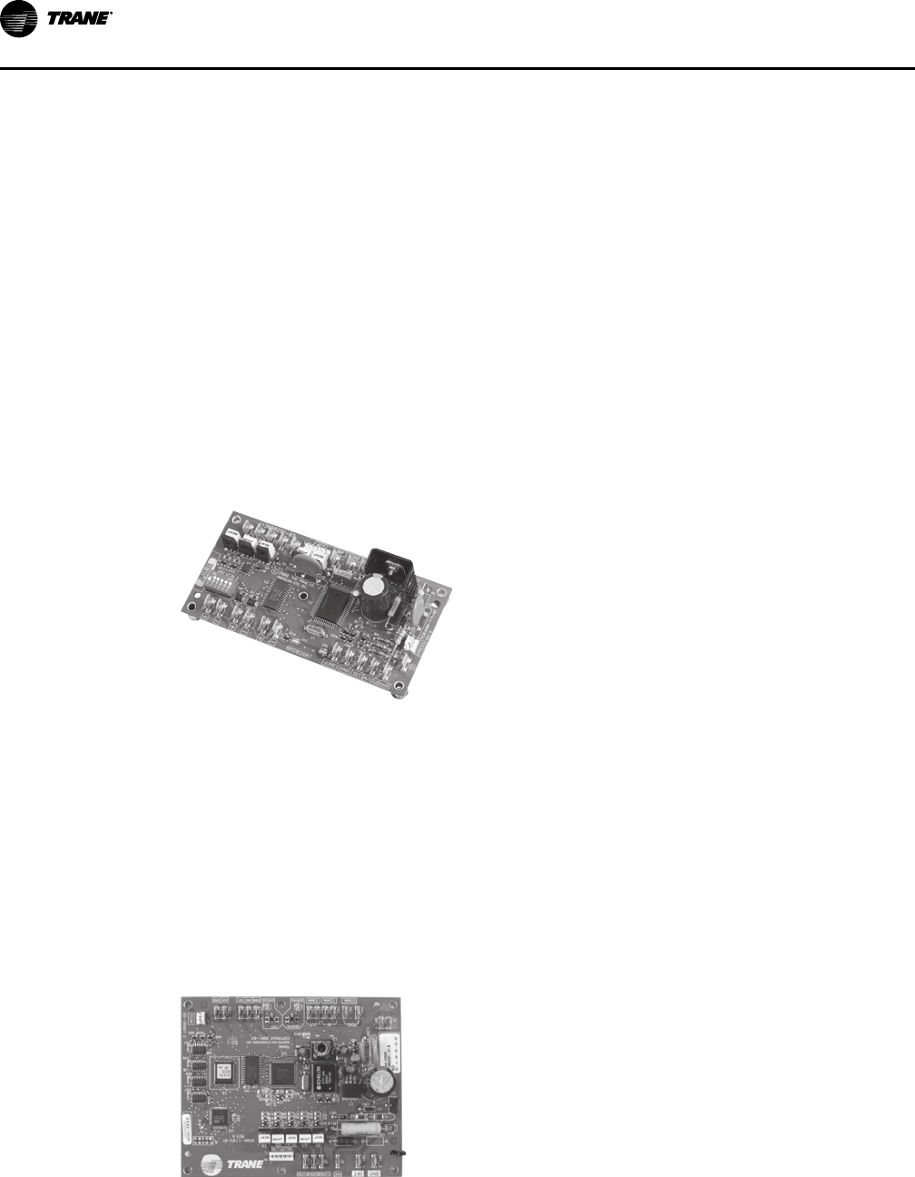
Trane VAV DDC UCM Controller
DDDDCC ((ccoommmmuunniiccaattiinngg eelleeccttrroonniicc))——DDC controllers
provide system-level data used to optimize overall
SYSTEM performance. Variables such as occupied/
unoccupied, minimum and maximum airflows and
temperature, valve position, ventilation fraction, and so
on are available on a simple Trane Comm3/4 protocol
twisted-shielded wire pair.
NNoottee:: One of many Trane DDC Control Options which are factory-installed, wired, calibrated, and
fully tested before shipment.
Trane DDC controllers provide Trane-designed solid-state electronics intended specifically for
temperature and ventilation control in space comfort applications. DDC control capabilities
include:
• Pressure-independent (PI) operation—Provides airflow required by the zone temperature
sensor to maintain occupant comfort. The controller automatically adjusts valve position to
maintain required airflow. Minimum and maximum airflow is factory-set and field-adjustable.
• Factory-set airflow and temperature setpoints.
• Most advanced system integration in the industry.
Tracer VV550 LonTalk Controllers
Trane offers a full line of LonTalk® controllers designed
for simple integration into ANY system which can
communicate via the LonTalk® Space Comfort Control
(SCC) protocol. These controllers are also completely
factory-commissioned.
FFeeaattuurreess aanndd BBeenneeffiittss

VAV-PRC012AC-EN
13
Tracer BACnet Controllers
Trane offers a full line of programmable BACnet® controllers designed for simple integration
into any system which can communicate via the BACnet® protocol. These controllers are factory-
downloaded, commissioned, and shipped ready to be installed.
UC210 BACnet
®
Controller
Symbio 210 BACnet
®
Controller
Symbio 210e BACnet
®
Controller
UC400 BACnet
®
Controller
Air-Fi Wireless System
For more detailed information on Air-Fi® Wireless systems and devices, see:
• BAS-SVX40*–EN Air-Fi
®
Wireless Installation, Operation, and Maintenance
• BAS-PRD021*–EN Air-Fi
®
Wireless Product Data Sheet
• BAS-SVX55*–EN Air-Fi
®
Wireless Network Design Best Practices
Air-Fi Wireless Communications Interface (WCI)
A factory-installed Air-Fi® Wireless Communications
Interface (WCI) provides wireless communication between
the Tracer® SC, Tracer® UC210/UC400 VAV unit controllers
and optionally, Air-Fi® Wireless Communication sensors.
The Air-Fi® WCI’s wireless mesh network is the perfect
alternative to a wired communication link. Eliminating the
low-voltage wire between the zone sensor and the terminal
unit controller, and between the unit controllers and the
system controller has substantial benefits:
• Reduced installation time and associated risks.
• Completion of projects with fewer disruptions.
• Easier and more cost-effective re-configurations,
expansions, and upgrades.
NNoottee:: WCI is not compatible with the Trane VAV UCM or
Tracer
®
VV550 LonTalk
®
controller.
FFeeaattuurreess aanndd BBeenneeffiittss

14
VAV-PRC012AC-EN
Air-Fi Wireless Communication Sensor (WCS)
The Wireless Communications Sensor (WCS)
communicates wirelessly to a Tracer® BACnet® unit
controller that has an Air-Fi® WCI installed. A WCS is an
alternative to a wired sensor when access and routing of
communication cable are issues. It also allows flexible
mounting and relocation. Also available are a non-display
version of the WCS with a temperature set point knob, an
occupancy / CO
2
sensor / zone temperature version of the
WCS, and a Relative Humidity (RH) sensor add-on daughter
board accessory.
Factory-installed vs. Factory-commissioned
The terms factory-installed and factory-commissioned are often used interchangeably. Trane
takes great pride in being the industry leader in factory-commissioned DDC controllers. The
following table differentiates these concepts.
Factory-commissioned controllers provide the highest quality and most reliable units for your
system. Additional testing verifies proper unit operation including occupied/unoccupied airflow
and temperature setpoints, communication link functionality, and output device functionality.
The benefits of factory-commissioning are standard on VariTrane™ terminal units with Trane
DDC controls. This means that factory-commissioned quality on VariTrane™ units is now
available on ANY manufacturer’s control system that can communicate using the L
ONMARK®
Space Comfort Control (SCC) protocol or the BACnet® protocol. (See Controls section for
complete listing of variables which are communicated.)
Table 1. Factory-installed vs. factory-commissioned
Factory-installed
Factory-
commissioned
Transformer installed (option)
X X
Wires terminated in reliable/consistent setting
X X
Controller mounted X X
Electric heat contactors and fan relay wired
X X
Controller addressing and associated testing
— X
Minimum and Maximum airflows settings (occupied/unoccupied)
— X
Minimum and Maximum temperature setpoints (occupied/unoccupied)
— X
Minimum ventilation requirements
— X
Heating offset
— X
Trane Air-Fi® wireless communications modules (WCI)
X X
Trane Air-Fi® Wireless Communications Sensor (WCS)
— —
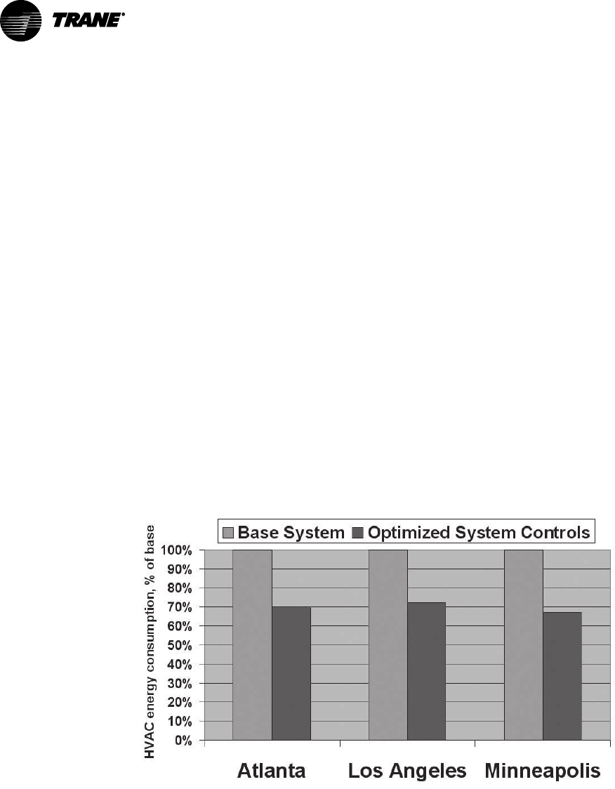
Trane VAV Systems — Proven Performance
Trane is the industry leader in VAV systems, including factory-commissioned controls and
integration with other control systems. This leadership began with customers seeking the most
reliable VAV products in the industry. The solution was factory-commissioned controls (see
“Factory-installed vs. Factory-commissioned,” p. 14). Since then, it has developed to include
optimized system control strategies.
Control strategies are often made more complicated than necessary. VariTrane™ DDC controls
simplify control strategies by pre-engineering control logic and sequencing into the controller.
This information is available via a twisted-shielded wire pair or wireless communication, and
accessible via a Trane Tracer® SC.
FFeeaattuurreess aanndd BBeenneeffiittss

VAV-PRC012AC-EN
15
Optimized system control strategies, such as ventilation optimization, fan-pressure optimization,
and optimal start/stop, are pre-engineered in VariTrane™ unit-level DDC controllers and the
Tracer® SC building automation system.
This allows a Trane VAV system to meet or exceed the latest ASHRAE 90.1 Energy Efficiency
standards. Pre-engineered controls allow consistent, high quality installations which are very
repeatable. The end result is PROVEN control strategies you can rely on to perform.
Purchasing VAV controllers and VAV hardware from a single manufacturer provides a single
contact for all HVAC system related questions.
FFeeaattuurreess aanndd BBeenneeffiittss

16
VAV-PRC012AC-EN
Fan-Powered VAV Units Model Number Descriptions
Digit 1, 2— Unit Type
VP = VariTrane™ Fan-Powered Parallel
VS = VariTrane™ Fan-Powered Series
LP = VariTrane™ Fan-Powered Low Height
Parallel
LS = VariTrane™ Fan-Powered Low Height
Series
Digit 3— Reheat
C = Cooling Only
E = Electric Heat
W = Hot Water Heat
Digit 4 — Development Sequence
F = Sixth
Digit 5, 6 — Primary Air Valve
04 = 4" inlet (225 cfm)
05 = 5" inlet (350 cfm)
06 = 6" inlet (500 cfm)
08 = 8" inlet (900 cfm)
10 = 10" inlet (1400 cfm)
12 = 12" inlet (2000 cfm
14 = 14" inlet (3000 cfm)
16 = 16" inlet (4000 cfm)
RT = 8" x 14" inlet (1800 cfm)
Note: 10, 12, 14, and 16 not available on low
height units.
Digit 7, 8— Secondary Air Valve Used
00 = N/A
Digit 9 — Fan
A = DS02 Fan (1300 nom cfm)
B = DS03 Fan (1950 nom cfm)
C = PS02 Fan (1160 nom cfm)
P = 02SQ Fan (500 nom cfm)
Q =03SQ Fan (1100 nom cfm)
R = 04SQ Fan (1350 nom cfm)
S = 05SQ Fan (1550 nom cfm)
T =06SQ Fan (1850 nom cfm)
U = 07SQ Fan (2000 nom cfm)
Digit 10, 11— Design Sequence
** = Factory Assigned
Digit 12, 13, 14, 15 — Controls
DD01 = Cooling Only Control
DD02 = N.C. On/Off Hot Water
DD03 = Prop Hot Water
DD04 = Staged On/Off Elec Heat
DD05 = Pulse Width Mod of Elect Heat
DD07 = N.O. On/Off Hot Water
DD11 = VV550 DDC- Controller, Cooling Only
DD12 = VV550 DDC- Control w/N.C. On/Off
HW Valve
DD13 = VV550 DDC- Control w/Prop. Hw
Valve
DD14 = VV550 DDC- Control On/Off Electric
Heat
DD15 = VVV550 DDC- Control w/Pulse Width
Modulation
DD17 = VVV550 DDC- Control w/N.O On/Off
HW Valve
DD41 = UC400 DDC- Basic (No water or
electric heat)
DD42 = UC400 DDC- Basic (Water heat- N.C.
2-position)
DD43 = UC400 DDC- Basic (Water heat-
Modulating)
DD44 = UC400 DDC- Basic (Electric heat-
Staged)
DD45 = UC400 DDC- Basic (Electric heat-
PWM)
DD47 = UC400 DDC- Basic (Water heat- N.O.
2-position)
DD53 = UC400 DDC- Basic plus- Local
(Electric heat- PWM) Remote (Staged EH)
DD58 = UC400 DDC- Basic plus- Local
(Water heat- Modulating) Remote (Water-
N.O. 2-position)
DD59 =UC400 DDC- Basic plus Local (Water
heat- Modulating) Remote (Water- N.C.
2-position)
DD60 = UC400 DDC- Basic Plus Local (Water
Heat- N.O. 2-position) Remote Water- N.C.
2-position)
DD61 = UC400 DDC- Basic plus- Local
(Water heat- N.C. 2-position) Remote
(Water- N.O. 2-position)
DD62 = UC400 DDC- Basic plus- Local
(Electric heat- Staged) Remote (Staged EH)
DD65 = UC400 Basic (Electric Heat
Modulating SCR)
DD66 = UC400 Basic plus- Local (Electric
heat-Modulating SCR) Remote (Staged EH)
Digit 12, 13, 14, 15 — Controls
(continued)
DD71 = UC210 DDC- Basic (No water or
electric heat)
DD72 = UC210 DDC- Basic (Water heat- N.C.
2-position)
DD73 = UC400 DDC- Basic (Water heat-
Modulating)
DD74 = UC210 DDC- Basic (Electric heat-
Staged)
DD75 = UC210 DDC- Basic (Electric heat-
PWM)
DD77 = UC210 DDC- Basic (Water heat- N.O.
2-position)
DD83 = UC210 DDC- Basic plus- Local
(Electric heat- PWM) Remote (Staged EH)
DD84 = UC210 DDC- Basic plus- Local
(Water heat- Modulating) Remote (Water-
N.C. 2-position)
DD85 = UC210 DDC- Basic plus- Local
(Water heat- Modulating) Remote (Water-
N.O. 2-position)
DD86 = UC210 DDC- Basic plus- Local
(Water heat- N.O. 2-position) Remote
(Water- Modulating)
DD87 = UC210 DDC- Basic plus- Local
(Water heat- N.C. 2-position) Remote
(Water- Modulating)
DD88 = UC210 DDC- Basic plus- Local
(Water heat- N.O. 2-position) Remote
(Water- N.O. 2-position)
DD89 = UC210 DDC-Basic plus- Local (Water
heat- N.C. 2-position) Remote (Water- N.C.
2-position)
DD90 = UC210 DDC- Basic plus- Local
(Water heat- N.O. 2-position) Remote
(Water- N.C. 2-position)
DD91 = UC210 DDC- Basic plus- Local
(Water heat- N.C. 2-position) Remote
(Water- N.O. 2-position)
DD92 = UC210 DDC- Basic plus- Local
(Electric heat- Staged) Remote (Staged)
DD95 = UC210 Basic (Electric Heat
Modulating SCR)
DD96 = UC210 Basic plus- Local (Electric
heat-Modulating SCR) Remote (Staged EH)
DD00 = Trane Actuator Only
ENCL = Shaft Only in Enclosure
FM00 = Other Actuator and Control
FM01 = Trane Supplied Actuator, Other Ctrl
SY71 = Symbio 210 DDC - Basic (Cooling
only)
SY72 = Symbio 210 DDC - Basic (Water
heat- N.C.- 2 position)
SY73 = Symbio 210 DDC - Basic (Water
heat- Modulating)
SY74 = Symbio 210 DDC - Basic (Electric
heat-staged)
SY75 = Symbio 210 DDC - Basic (Electric
heat-PWM)

VAV-PRC012AC-EN
17
Digit 12, 13, 14, 15 — Controls
(continued)
SY77 = Symbio 210 DDC -Basic (Water heat
-N.O.- 2 position)
SY83 = Symbio 210 DDC- Basic plus- Local
(Electric heat- PWM) Remote (Staged)
SY84 = Symbio 210 DDC- Basic plus- Local
(Water heat- Modulating) Remote (Water-
N.C. 2-position)
SY85 = Symbio 210 DDC- Basic plus- Local
(Water heat- Modulating) Remote (Water-
N.O. 2-position)
SY86 = Symbio 210 DDC- Basic plus- Local
(Water heat- N.O. 2-position) Remote
(Water- Modulating)
SY87 = Symbio 210 DDC- Basic plus- Local
(Water heat- N.C. 2-position) Remote
(Water- Modulating)
SY88 = Symbio 210 DDC- Basic plus- Local
(Water heat- N.O. 2-position) Remote
(Water- N.O. 2-position)
SY89 = Symbio 210 DDC-Basic plus- Local
(Water heat- N.C. 2-position) Remote
(Water- N.C. 2-position)
SY90 = Symbio 210 DDC- Basic plus- Local
(Water heat- N.O. 2-position) Remote
(Water- N.C. 2-position)
SY91 = Symbio 210 DDC- Basic plus- Local
(Water heat- N.C. 2-position) Remote
(Water- N.O. 2-position)
SY92 = Symbio 210 DDC- Basic plus- Local
(Electric heat- Staged) Remote (Staged)
SY95 = Symbio 210 DDC - Control with
Modulating SCR
SY96 = Symbio 210 DDC - Space Temp
Control with Local SCR and Remote Staged
Electric heat
SE71 = Symbio 210e DDC - Basic (Cooling
only)
SE72 = Symbio 210e DDC - Basic (Water
heat- N.C.- 2 position)
SE73 = Symbio 210e DDC - Basic (Water
heat- Modulating)
SE74 = Symbio 210e DDC - Basic (Electric
heat-staged)
SE75 = Symbio 210e DDC - Basic (Electric
heat-PWM)
SE77 = Symbio 210e DDC -Basic (Water heat
-N.O.- 2 position)
SE83 = Symbio 210 DDC- Basic plus- Local
(Electric heat- PWM) Remote (Staged)
SE84 = Symbio 210e DDC- Basic plus- Local
(Water heat- Modulating) Remote (Water-
N.C. 2-position)
SE85 = Symbio 210e DDC- Basic plus- Local
(Water heat- Modulating) Remote (Water-
N.O. 2-position)
Digit 12, 13, 14, 15 — Controls
(continued)
SE86 = Symbio 210e DDC- Basic plus- Local
(Water heat- N.O. 2-position) Remote
(Water- Modulating)
SE87 = Symbio 210e DDC- Basic plus- Local
(Water heat- N.C. 2-position) Remote
(Water- Modulating)
SE88 = Symbio 210e DDC- Basic plus- Local
(Water heat- N.O. 2-position) Remote
(Water- N.O. 2-position)
SE89 = Symbio 210e DDC-Basic plus- Local
(Water heat- N.C. 2-position) Remote
(Water- N.C. 2-position)
SE90 = Symbio 210e DDC- Basic plus- Local
(Water heat- N.O. 2-position) Remote
(Water- N.C. 2-position)
SE91 = Symbio 210e DDC- Basic plus- Local
(Water heat- N.C. 2-position) Remote
(Water- N.O. 2-position)
SE92 = Symbio 210e DDC- Basic plus- Local
(Electric heat- Staged) Remote (Staged)
SE95 = Symbio 210e DDC - Control with
Modulating SCR
SE96 = Symbio 210e DDC - Space Temp
Control with Local SCR and Remote Staged
Electric heat
Digit 16 — Insulation
A = 1/2” Matte-faced
B = 1” Matte-faced
D = 1” Foil-faced
F = 1” Double Wall
G = 3/8” Closed-cell
Digit 17— Motor Type
D = PSC Motor
E = High-efficiency Electronically
Commutated Motor (ECM)
F = Variable Speed High-efficiency
Electronically Commutated Motor (ECV)
Digit 18— Motor Voltage
1 = 115/60/1
2 = 277/60/1
3 = 347/60/1
4 = 208/60/1
5 = 230/50/1
Digit 19— Outlet Connection
1 = Flanged
2 = Slip–and-Drive Connection
Digit 20— Attenuator
0 = None
B = Suppressor
T = Thinline Suppressor
Digit 21— Water Coil
0 = None
1 = 1 Row, Plenum Inlet Installed RH
2 = 2 Row, Plenum Inlet Installed RH
3 = 1 Row, Discharge Installed LH
4 = 1 Row, Discharge Installed RH
5 = 2 Row, Discharge Installed LH
6 = 2 Row, Discharge Installed RH
A = 1 Row Premium, Water Coil Inlet
B = 2 Row Premium, Water Coil Inlet
C = 1 Row Premium, Hot Coil on Discharge LH
D = 1 Row Premium, Hot Coil on Discharge
RH
E = 2 Row Premium, Hot Coil on Discharge LH
F = 2 Row Premium, Hot Coil on Discharge RH
Digit 22— Electrical Connections
F = Flippable Left and Right Hand
L = Left, Airflow hits in face
R = Right, Airflow hits in face
W = Narrow Corridor LH, High Voltage, Inlet
Facing
X = Narrow Corridor RH, High Voltage, Inlet
Facing
Note: Digits W and X, fan-powered series
only.
Digit 23— Transformer
0 = Not Applicable
Digit 24 — Disconnect Switch
0 = None
W = With
Note: Electric reheat w/door interlocking
power disconnect, cooling only and
water reheat w/toggle disconnect.
Digit 25 — Power Fuse
0 = None
W = With
Digit 26 — Electric Heat Voltage
0 = None
A = 208/60/1
B = 208/60/3
C = 240/60/1
D = 277/60/1
E = 480/60/1
F = 480/60/3
G = 347/60/1
H = 575/60/3
J = 380/50/3
K = 120/60/1
Note: Digit K not available wit low height.
FFaann--PPoowweerreedd VVAAVV UUnniittss MMooddeell NNuummbbeerr DDeessccrriippttiioonnss

18
VAV-PRC012AC-EN
Digit 27, 28, 29— Electric Heat kW
000 = None
010 = 1.0 kW
015 = 1.5 kW
460 = 46.0 kW
Notes:
• 0.5 to 8.0 kW in 1/2 kW
increments
• 8.0 to 18.0 kW in 1 kW
increments
• 18.0 to 46.0 kW in 2 kW
increments
Digit 30 — Electric Heat Stages
0 = None
1 = 1 Stage
2 = 2 Stages Equal
3 = 3 Stages Equal
Note: Digit 3 not available with low height.
Digit 31 — Electric Heat Contactors
0 = None
1 = 24V Magnetic
5 = 0-10 Vdc SCR Heat; UC400
6 = 0-10 Vdc SCR Heat; FMTD/ENCL/DD00
7 = 24V SSR (Solid State Relay)
Notes: SCR cannot be selected with the
following:
• kW>10,208V, 3Ph, Low Height
• kW>22,480V, 3Ph, Low Height
• Voltage = 575V
Digit 32— Air Switch
0 = Not Applicable
W = With
Digit 33— Not Used
0 = Not Applicable
Digit 34 — Actuator
0 = Standard
A = Belimo™ Actuator
G = Trane Analog Actuator (UC210 or UC400
only)
Digit 35 — Wireless Sensors
0 = None
3 = Trane Air-Fi® Wireless Communications
Interface
Note: All sensors selected in accessories.
Digit 36 — Pre-wired Factory
Solutions
0 = None
1 = Factory-mounted DTS
2 = HW Valve Harness
3 = Both DTS/HW Valve Harness
Digit 37 — Bottom Access
0 = None
W = Access Left Side Terminal Unit
Digit 38 —Piping Package
0 = None
A = 2–Way Automatic Balancing
B = 3–Way Automatic Balancing
C = 2-Way Standard Valve Only, Floating
Point Actuator
D = 3-Way Standard Valve Only, Floating
Point Actuator
E = 2-Way Standard Valve Piping Package,
Floating Point Actuator
F = 3-Way Standard Valve Piping Package,
Floating Point Actuator
G = 2-Way Belimo Valve Only, Floating Point
Actuator
H = 3-Way Belimo Valve Only, Floating Point
Actuator
J = 2-Way Belimo Valve Piping Package,
Floating Point Actuator
K = 3-Way Belimo Valve Piping Package,
Floating Point Actuator
L = 2-Way Belimo Valve Only, Analog
Actuator
M = 3-Way Belimo Valve Only, Analog
Actuator
N = 2-Way Belimo Valve Piping Package,
Analog Actuator
P = 3-Way Belimo Valve Piping Package,
Analog Actuator
Digit 39 — Water Valve
0 = None
1 = Trane HW Valve 0.7 Cv
2 = Trane HW Valve 2.7 Cv
5 = Analog HW Valve, Field Provided (UC210
or UC400 only)
6 = Trane HW Valve 1.7 Cv
7 = Trane HW Valve 5.0 Cv
A = Belimo HW Valve, 0.3 Cv
B = Belimo HW Valve, 0.46 Cv
C = Belimo HW Valve, 0.8 Cv
D = Belimo HW Valve, 1.2 Cv
E = Belimo HW Valve, 1.9 Cv
F = Belimo HW Valve, 3.0 Cv
G = Belimo HW Valve, 4.7 Cv
Digit 40 — Flow Rate
0 = None
A = 0.5 gpm, 0.03 l/s
B = 1.0 gpm, 0.06 l/s
C = 1.5 gpm, 0.09 l/s
D = 2.0 gpm, 0.13 l/s
E = 2.5 gpm, 0.16 l/s
F = 3.0 gpm, 019 l/s
G = 3.5 gpm, 0.22 l/s
H = 4.0 gpm, 0.25 l/s
J = 4.5 gpm, 0.28 l/s
K = 5.0 gpm, 0.31 l/s
L = 5.5 gpm, 0.35 l/s
M = 6.0 gpm, 0.38 l/s
N = 6.5 gpm, 0.41 l/s
P = 7.0 gpm, 0.44 l/s
Q = 7.5 gpm, 0.47 l/s
FFaann--PPoowweerreedd VVAAVV UUnniittss MMooddeell NNuummbbeerr DDeessccrriippttiioonnss

VAV-PRC012AC-EN
19
DDC Controls
Controllers
DDC controllers are today’s industry standard. DDC controllers provide system-level data used to
optimize system performance. Variables such as occupied/unoccupied status, minimum and
maximum primary and fan airflow setpoints, current zone temperature and temperature
setpoints, valve position, fan status (on or off, and mode of operation), heat status (on or off), and
air valve size, temperature correction offsets, flow correction values, etc. are available on a
simple twisted-shielded wire pair or communicated wirelessly.
Trane® DDC controllers provide Trane-designed, solid-state electronics intended specifically for
terminal unit control in space comfort applications.
DDC control capabilities include:
• Proportional plus integral control loop algorithm for determining required airflow needed to
control room temperature. Airflow is limited by active minimum and maximum airflow
setpoints.
• Pressure-independent (PI) operation, which automatically adjusts valve position to maintain
required primary airflow. In certain low-flow situations or in cases where the flow
measurement has failed, the DDC controller will operate in a pressure-dependent (PD) mode
of operation.
• Cooling and heating control action of air valve. In cooling control action, the DDC controller
matches cooling primary airflow to cooling load. In heating control action, the DDC controller
matches the heating primary airflow to heating load. The DDC controller will automatically
change over to cooling control action if the supply air temperature is below the room
temperature and will automatically change over to heating control action if the supply air
temperature is 10°F or more above the room temperature. If the supply air temperature is
between the room temperature and the room temperature plus 10°F, then the DDC controller
will provide the active minimum primary airflow. The DDC controller first chooses the
Tracer® SC supplied supply air temperature value to use for auto changeover. If this is not
available, it uses the temperature provided by the optional auxiliary temperature sensor. If
this is also not available, it uses the heating/cooling mode assigned by Tracer SC or the DDC
controller’s service tool (Everyware™, Rover™, or Tracer TU).
• Multiple reheat control options including staged electric, staged hot-water (normally on or
normally off), modulating hot-water, and slow pulsed width modulation. Modulating reheat
options utilize a separate reheat proportional-plus-integral control loop from that controlling
airflow into the room. Staged reheat options utilize a control algorithm based on heating
setpoint and room temperature.
• Series or parallel fan can be configured to operate at a constant speed or controlled for
variable-speed operation
• 24 VAC binary input that can be configured as a generic input or as occupancy input. When
the DDC controller is operation with Tracer® SC, the status of the input is provided to Tracer®
SC for its action. In stand-alone operation and when configured for an occupancy input, the
input will control occupancy status of the DDC controller.
• Auxiliary temperature analog input that can be configured for an auxiliary temperature
sensor or a 2-to-10 VDC CO
2
sensor. When sensor is mounted in the supply air duct
(upstream of the VAV terminal unit) and configured for temperature, the value of the input is
used as status-only by Tracer SC if Tracer SC is providing a supply air temperature to the DDC
controller.

20
VAV-PRC012AC-EN
Figure 10. Flow sensor single vs. airflow delivery
0.01
0.1
1
5
10 100 1,000 10,000
Air Valve Airflow, cfm
Flow Sensor DP (In. wg)
4"
12"
10"
8"
6"
5"
14"
16"
DDC Remote Heat Control Options
The following subsections describe the operating characteristics of the four basic types of
VariTrane™ DDC terminal reheat for fan-powered terminal units.
On/Off Hot Water Reheat
Two stages of on/off hot water reheat are available. The water valves used are two-position and
are either fully opened or fully closed.
Stage 1 heat is energized when the zone temperature drops below the active heating setpoint;
Stage 2 is energized when the zone temperature drops to 1°F (0.56°C) or more below the active
heating setpoint. Stage 2 is de-energized when the zone temperature rises to warmer than 0.5°F
(0.28°C) below the active heating setpoint; Stage 1 is de-energized when the zone temperature
rises to warmer than 0.5°F (0.28°C) above the active heating setpoint.
Modulating Hot Water Reheat
Modulating hot water reheat uses 3-wire floating-point-actuator technology and analog actuator
technology.
The degree to which the hot water valve opens is dependent on both the degree that zone
temperature is below the active heating setpoint and the time that the zone temperature has
been below the active heating setpoint. If not already closed, the water valve fully closes when
the zone temperature rises above the active heating setpoint by 0.5 °F (0.28 °C).
On/Off Electric Reheat
Two stages of staged electric reheat are available.
Stage 1 heat is energized when the zone temperature drops below the active heating setpoint;
Stage 2 is energized when the zone temperature drops to 1°F (0.56°C) or more below the active
heating setpoint. Stage 2 is de-energized when the zone temperature rises to warmer than 0.5°F
(0.28°C) below the active heating setpoint; Stage 1 is de-energized when the zone temperature
rises to warmer than 0.5°F (0.28°C) above the active heating setpoint.
DDDDCC CCoonnttrroollss

VAV-PRC012AC-EN
21
Pulse-Width Modulation of Electric Heat
Electric heat is modulated by energizing for a portion of a three-minute time period. This allows
exact load matching for energy efficient operation, and optimum zone temperature control. One
or two stages can be used.
The amount of reheat supplied is dependent on both the degrees that zone temperature is below
the active heating setpoint and the time that the zone temperature has been below the active
heating setpoint. If not already off, reheat de-energizes when the zone temperature rises 0.5°F
(0.28°C) above the active heating setpoint. The Stage 1 “on” time is proportional to the amount
of reheat required. For example, when 50% of stage 1 capacity is required, reheat is on for 90
seconds and off for 90 seconds. When 75% of stage 1 capacity is required, reheat is on for 135
seconds and off for 45 seconds. When 100% of stage 1 capacity is required, reheat is on
continuously.
Stage 2 uses the same “on” time logic as stage 1 listed above, except stage 1 is always
energized. For example, when 75% of unit capacity is required, stage 1 is energized continuously,
and stage 2 is on for 90 seconds and off for 90 seconds.
DDDDCC CCoonnttrroollss

22
VAV-PRC012AC-EN
Heat Controls
24-VAC Fan/Staged
2nd
1st
C
Fan
Load: 10 VA (MAGN)
Load: 12 VA (MERC)
Load: 6.5 VA
FAN RELAY
2
1
3
5
4
2
1
HEATER CONTROL BOX
3rd
2
3
4
Damper
Actuator
Line Voltage
CW
COM
CCW
24 VAC, 50 VA
Transformer
Load: 4 VA
24-VAC to
Customer
Controls
By Others
Damper Controls
24-VAC
M
Load: 4 VA
Actuator
Damper
24-VAC
Damper Controls
By Others
COM
CW
CCW
M
Y
BL
NOTES:
1.
Factory-installed
Field Wiring
Optional or installed by others
2.
Only available with fan-powered units.
3.
4.
Located in Heater Terminal box.
DD00—Available for all VariTrane Units
(Trane actuator for field-installed DDC controls)
A unit controller is not provided. The air damper actuator is provided with an integral screw terminal block.
The fan contactor (fan-powered units), 24-VAC control power transformer (optional for single- and dual-duct
units), and factory-installed electric heater contactor wires are attached to the outside of the unit for field
connection of controls.
Located in Control Box on all fan-powered units.
DDDDCC CCoonnttrroollss

VAV-PRC012AC-EN
23
LO
1st stage
2nd stage
3rd stage
24VAC (hot) common
CCW
COM
CW
24 VAC
Y
BL
24 VAC, 50va
Standard – (Fan-pow
ered)
Transformer
Customer-furnished
Controller
Electric
Reheat
Contactors
Hot Water
Reheat
Fan
Relay
Actuator
Customer-furnished
or Trane-supplied
Trane-supplied
(Fan-powered only)
Trane-supplied
Available on all VariTrane Units
FM00 – Customer-supplied actuator and DDC controller factory-installed.
FM01 – Trane actuator and customer-supplied DDC controller factory-installed
Optional or installed by others
NOTES:
1.
Factory-installed
Field Wiring
Optional
Trane-supplied
water valve
field-wired
to controller.
Airflow
Sensor
LO HI
Trane-supplied
All customer furnished controllers and actuators are installed and wired per control manufacturer's specifications.
Metal control enclosure is standard.
2.
NEMA-1 Enclosure provided.
Symbio 210, Symbio 210e, Tracer UC400 and UC210 Programmable
BACnet Controllers
Introduction
The Symbio 210, Symbio 210e, Tracer® UC210 and UC400 direct digital control unit control
modules are microprocessor-based terminal unit controllers with non-volatile memory which
provide accurate airflow and room temperature control of Trane and non-Trane VAV air terminal
units. Symbio 210, Symbio 210e, Tracer® UC210 and UC400 provide simple open protocol to
allow integration of Trane VAV units and controls into other existing control systems. The
controller can operate in pressure-independent or pressure-dependent mode and uses a
proportional plus integral control algorithm.
The controller monitors zone temperature setpoints, zone temperature and its rate of change and
valve airflow (via flow ring differential pressure). The controller also accepts an auxiliary duct
temperature sensor input or a supply air temperature value from Tracer SC. Staged electric heat,
pulse width modulated electric heat, modulating hot water heat or on/off hot water heat control
are provided when required. The control board operates using 24-VAC power. The Symbio 210,
Symbio 210e, UC210 and UC400 are also members of the Trane Integrated Comfort™ systems
DDDDCC CCoonnttrroollss

24
VAV-PRC012AC-EN
(ICS) family of products. When used with a Tracer® SC or other Trane controllers, zone grouping
and unit diagnostic information can be obtained. Also part of ICS is the factory-commissioning of
parameters specified by the engineer. (See "Factory-Installed vs. Factory-Commissioned" in the
Features and Benefits section for more details).
The Symbio 210, Symbio 210e, Tracer® UC400 and UC210 controllers are programmable general
purpose BACnet®, microprocessor-based, Direct Digital Controllers (DDC). When factory
installed on Trane (variable air volume) VAV terminal units, they are factory downloaded with
appropriate VAV programs and configuration settings. Trane VAV units have been made with
either pneumatic, analog electronic, or microprocessor controls (DDC VAV).
The Symbio 210, Symbio 210e, Tracer® UC400 or UC210 controller can be configured from the
factory with three different application programs: space temperature control (STC), ventilation
flow control (VFC), and flow tracking control (FTC):
• STC — Modulates a VAV's damper blade based on a zone temperature, measured airflow,
and setpoints to continuously control conditioned air delivery to the space. The volume of
incoming air is monitored and the damper adjusts to provide accurate control independent of
the duct pressure. The damper modulates between operator setpoints depending on space
conditions. Additionally, fan speed can be modulated and heat outputs may be energized
depending on the application.
• VFC — Can be applied to a VAV terminal and used to temper cold outdoor air (OA) that is
brought into a building for ventilation purposes. The tempered air is intended to supply an
air-handling unit (AHU), which provides comfort control to the zones it is serving. The VAV
terminal supplies the correct amount of ventilation air, and when reheat is added, tempers
the ventilation air to reduce the load on the air handler by sensing the discharge air
temperature of the VAV unit and controlling its long-term average to the discharge air
temperature setpoint.
• FTC — Two VAV units with Tracer UC210 or UC400 controllers working together provide flow
tracking control. One controller is configured from the factory with the space temperature
control and the other is downloaded with the FTC program. The STC airflow output is bound
to the flow tracking controller airflow setpoint input. The flow tracking controller adds the
configured airflow tracking offset (positive or negative) to the airflow setpoint (communicated
airflow setpoint) and controls the airflow to this setpoint.
The Symbio 210, Symbio 210e, Tracer UC400 or UC210 controller is BTL compliant with
BACnet®, an open standard building automation protocol. It meets the application specific
controller (ASC) profile per ASHRAE 135–2004. This allows the Tracer® UC400 or UC210
controller to integrate with other BACnet® systems.
Specifications
SSuuppppllyy VVoollttaaggee
24 VAC, 50/60 Hz
MMaaxxiimmuumm VVAA LLooaadd
NNoo HHeeaatt oorr FFaann
8 (9.5 for Symbio 210/210e)VA (Board, Transducer, Zone Sensor, and Actuator)
NNoottee:: If using field-installed heat, 24 VAC transformer should be sized for additional load.
OOuuttppuutt RRaattiinnggss
Actuator Output: 24 VAC at 12 VA
1st Stage Reheat: 24 VAC at 12 VA
2nd Stage Reheat: 24 VAC at 12 VA
3rd Stage Reheat: 24 VAC at 12 VA
BBiinnaarryy IInnppuutt
24 VAC, occupancy or generic.
AAuuxxiilliiaarryy IInnppuutt
Can be configured for discharge or primary air temperature sensor.
OOppeerraattiinngg EEnnvviirroonnmmeenntt
DDDDCC CCoonnttrroollss

VAV-PRC012AC-EN
25
32 to 140°F, (0 to 60°C)
5% to 95% RH, Non-condensing
SSttoorraaggee EEnnvviirroonnmmeenntt
-40 to 180°F (-40 to 82.2°C),
5% to 95% RH, Non-Condensing
PPhhyyssiiccaall DDiimmeennssiioonnss
Width: 5.5–in. (139.7 mm)
Length: 4.5–in. (69.85 mm)
Height: 2.0–in. (44.45 mm)
CCoonnnneeccttiioonnss
1/4–in. (6.35 mm) Stab Connections
CCoommmmuunniiccaattiioonnss
Tracer® UC400– Space Comfort Control (SCC) profile with FTT-10 transceiver
22 awg. unshielded level 4 communication wire
FFaann CCoonnttrrooll
Series fan: On unless unoccupied and min. flow has been released. Constant-speed or variable-
speed fan control available.
Parallel fan: On when zone temperature is less than heating setpoint plus fan offset. Off when
zone temperature is more than heating setpoint plus fan offset plus 0.5°F (0.28°C). Constant-
speed or variable-speed fan control available.
HHeeaatt SSttaaggiinngg
Staged electric or hot water modulating or pulse-width modulation
Available Inputs
Inputs include a twisted/shielded communication link, zone sensor, duct temperature sensors
(optional), occupancy sensor (optional), discharge air temperature (DAT) and/or supply air
temperature (SAT), CO
2
sensor, and 24 VAC power. In addition to the points used for the VAV
application, the spare inputs and outputs on the Tracer UC400 or UC210 controller may be used
for ancillary control, which can be programmed using Tracer TU Tracer Graphical Programming
2 (TGP2).
NNoottee:: For more information on using spare points, see BAS-SVX20*-EN Tracer UC400
Programmable Controller Installation, Operation, and Maintenance.
General Features and Benefits
Assured Accuracy
• Proportional-plus-integral control loop algorithm for determining required airflow needed to
control zone temperature. Airflow is limited by active minimum and maximum airflow
setpoints.
• Pressure-independent (PI) operation that automatically adjusts air valve position to maintain
required primary airflow. In certain low-flow situations or in cases where the flow
measurement has failed, the DDC controller will operate in a pressure-dependent (PD) mode
of operation.
• When combined with the patented Trane flow ring and pressure transducer, flow is
repeatable to +/- 5% accuracy across the pressure independent (PI) flow range. (See Valve/
Controller Airflow Guidelines section).
• Improved 2-Point air balancing is available – Assures optimized flow-sensing accuracy across
the operating range. This provides a more accurate airflow balancing method when
compared to typical single-point flow correction air balancing.
• Analog input resolution of +/- 1/8°F within the comfort range maximizes zone temperature
control yielding excellent comfort control.
DDDDCC CCoonnttrroollss

26
VAV-PRC012AC-EN
Reliable Operation
• Built for life – Trane products are designed to stand the test of time, with a proven design life
that exceeds 20 years.
• Fully factory tested – Fully screened and configured at the factory. All features are tested
including fan and reheat stage energization, air valve modulation, and controller inputs and
outputs.
Safe Operation
• All components, including the controller, pressure transducer, transformer, etc. are mounted
in a NEMA 1 sheet metal enclosure and are tested as an assembly to UL1995 standards. The
result is a rugged and safe controller, and thus, overall unit.
• When in PI-mode, electric heat is disabled when the sensed flow is below the minimum
required.
• Hot-water coil units in ventilation flow control (VFC) have a freeze protection algorithm to
protect the water coil and the internal space from water damage. This is accomplished by
driving the water valve to maximum position on alarm conditions.
System-level Optimization
Trane controllers are designed to integrate into Trane Tracer® SC and leverage clear and clean
unit-controller related data for system level control decisions. Integrating a Trane UC210 or
UC400 controller into a Tracer® SC Control System provides the next step in building
automation.
Specifically, system-level decisions on how to operate all components can be made. Energy
efficient optimization strategies, like static pressure optimization, can be employed with the
simple press of a button. The end-result is the most efficient and reliable building automation
system available.
Simplified Installation
Factory Commissioned Quality – All Trane DDC VAV controllers are factory-commissioned. This
means that the DDC boards are powered and run-tested with your specific sequence parameters.
They are connected to a communication link to make sure that information and diagnostic data
function properly. Before any unit ships it must pass a rigorous quality control procedure. You
can be assured that a Trane VAV unit with Trane DDC controls will work right out of the crate.
Tenant-Finish Heat Mode – In some office projects, the building is being constructed as tenants
are being identified. Tenant-finish heat mode is designed for applications when a given floor has
not been occupied. The main AHU is used for heat and because the internal furnishings are not
complete, the sensors have not been installed. In this case, the primary valve drives open using
the heat of the main AHU to keep plumbing lines from freezing. Operation of the VAV unit fan
(series or parallel) remains unaffected.
Controller Flexibility
• 24 Vac binary input that can be configured as a generic input or as occupancy input. When the
DDC controller is operating with Tracer® SC, the status of the input is provided to Tracer® SC
for its action. In stand-alone operation and when configured for an occupancy input, the input
will control occupancy status of the DDC controller.
• Auxiliary temperature analog input configured for an auxiliary temperature sensor. The value
of the input is used as status-only by Tracer® SC if it is providing a supply air temperature
(upstream of the terminal unit) to the DDC controller. Otherwise, the input will be used for
determining heating/cooling control action of the VAV unit. When the auxiliary temperature
sensor is located in the discharge of the unit, and attached to a Trane Tracer® SC BAS,
additional test sequencing and reporting is available to maximize VAV system capabilities
and simplify system commissioning.
• Symbio 210, Symbio 210e, Tracer® UC400 or UC210 Programmable BACnet® Controller
certified performance ensures that a Trane VAV unit with controller will provide state-of-the-
art, consistent open communication protocol for integration with the industry’s latest (Non-
Trane) building automation control systems, including Johnson Control, Andover, Siemens,
Honeywell, etc.
DDDDCC CCoonnttrroollss

VAV-PRC012AC-EN
27
• CO
2
demand controlled ventilation enables the terminal unit controller to adjust ventilation
air flow setpoint based on the current occupancy in the zone. Trane demand controlled
ventilation strategies are pre-defined for simplified application and can be easily customized
to meet the needs of a specific system.
• Supports discharge air temp reset with modulating hot-water and SCR electric heat on units
with mulitpoint-DAT sensor.
Control Logic
Direct Digital Control (DDC) controllers are today’s industry standard. DDC controllers share
system-level data to optimize system performance (including changing ventilation requirements,
system static pressures, supply air temperatures, and so on). Variables available via a simple
twisted-shielded wire pair include occupied/unoccupied status, minimum and maximum airflow
setpoints, zone temperature and temperature setpoints, air valve position,primary airflow, fan
status (on or off), fan operation mode (parallel or series), reheat status (on or off), VAV unit type,
air valve size, temperature correction offsets, flow correction values, ventilation fraction, and so
on.
With the advent of the BTL compliant Tracer® UC400 and UC210 controllers, the most reliable
VAV controller is now available for ANY system. Gone are the days of being locked into a single
supplier. Trane DDC controllers provide Trane-designed solid-state electronics intended
specifically for VAV applications including:
• Space temperature control
• Ventilation flow control (100% outside air applications)
• Flow tracking space pressurization control
Space Temperature Control
Space temperature control (STC) logic modulates primary airflow, reheat (either local or remote),
and fan airflow to maintain the desired temperature in the zone. Following are high-level
descriptions of the STC control logic during occupied mode, for various fan and reheat
configurations.
Series Fan-Powered Terminal:
Constant-Speed Fan Control
The terminal fan operates continuously during all occupied modes.
When the zone temperature is in the deadband between the active heating and cooling setpoints,
the controller reduces primary airflow to the minimum primary airflow setpoint, while reheat is
off.
When the zone temperature rises above the active cooling setpoint, the controller modulates
primary airflow, between the minimum and maximum airflow setpoints, to maintain zone
temperature at the active cooling setpoint, while reheat is off.
For units equipped with staged heat (on/off hot water or on/off electric):
When the zone temperature drops below the active heating setpoint, the controller stages heat
on/off to maintain zone temperature at the active heating setpoint, while primary airflow is
controlled to the minimum heating primary airflow setpoint. Stage 1 heat is energized when the
zone temperature drops below the active heating setpoint; Stage 2 is energized when the zone
temperature drops to 1°F (0.56°C) or more below the active heating setpoint. Stage 2 is de-
energized when the zone temperature rises to warmer than 0.5°F (0.28°C) below the active
heating setpoint; Stage 1 is de-energized when the zone temperature rises to warmer than 0.5°F
(0.28°C) above the active heating setpoint.
For units equipped with modulated heat (modulated hot water or SCR electric):
When the zone temperature drops below the active heating setpoint, the controller modulates
the hot-water valve (or SCR electric heater) to maintain zone temperature at the active heating
setpoint, while primary airflow is controlled to the minimum heating primary airflow setpoint.
DDDDCC CCoonnttrroollss

28
VAV-PRC012AC-EN
Figure 11. Series fan with constant-speed fan control
Deadband
Cooling Loop Signal
Maximum
Reheat
Minimum
Primary
Airflow
Maximum
Primary Air
Reheat Off
Fan Cool
Maximum
Speed
Reheat Capacity %
Fan Heat
Maximum
Speed
Heating Loop Signal
100
0
100
0
0
100
0
100
0
100
Primary Airflow %
Fan Airflow %
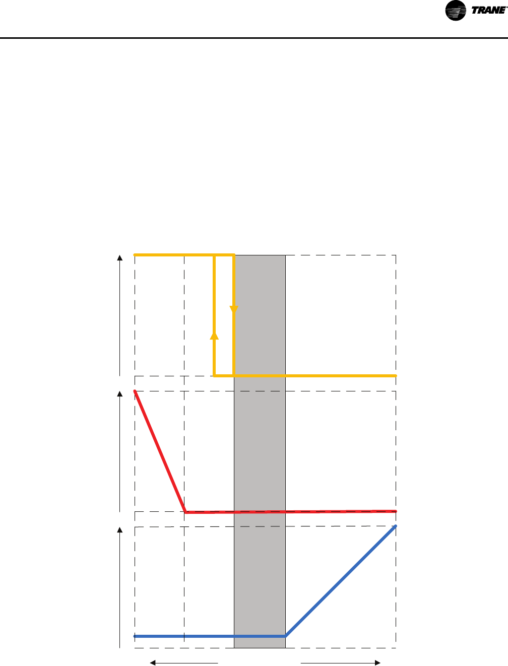
Series Fan-Powered Terminal:
Variable-Speed Fan Control
When the zone temperature is in the deadband between the active heating and cooling setpoints,
the controller reduces primary airflow to the minimum primary airflow setpoint and operates the
fan at the minimum fan airflow setpoint, while reheat is off.
When the zone temperature rises above the active cooling setpoint, the controller modulates
both primary airflow and fan airflow simultaneously, between their respective minimum and
maximum airflow setpoints, to maintain zone temperature at the active cooling setpoint, while
reheat is off.
For units without heat or equipped with staged heat (on/off hot water or on/off electric):
When the zone temperature drops below the active heating setpoint, the controller modulates
the fan between its minimum and maximum fan airflow setpoints to maintain zone temperature
at the active heating setpoint, while primary airflow is at the minimum primary airflow setpoint
and reheat remains off. If the requested heating capacity has increased to the point where the fan
has reached its maximum fan airflow setpoint, the controller stages heat on/off to maintain zone
DDDDCC CCoonnttrroollss

VAV-PRC012AC-EN
29
temperature at the active heating setpoint, while the fan continues to operate at the maximum
fan airflow setpoint and primary airflow remains at the minimum primary airflow setpoint.
Figure 12. Series fan with variable-speed fan control and staged heat
Deadband
Cooling Loop Signal
Maximum
Reheat
Minimum
Fan Speed
Minimum
Primary
Airflow
Maximum
Primary Air
Reheat Off
Fan Cool
Maximum
Speed
Reheat Capacity %
Fan Heat
Maximum
Speed
Heating Loop Signal
100 0
100
0
0
100
0
100
0
100
Primary Airflow %
Fan Airflow %
1
st
Stage Heating
2
nd
Stage
Heating
For units equipped with modulated heat (modulated hot water or SCR electric):
When the zone temperature drops below the active heating setpoint, the controller modulates
the hot-water valve (or SCR electric heater) to maintain zone temperature at the active heating
setpoint, while primary airflow is at the minimum primary airflow setpoint and the fan is at the
minimum fan airflow setpoint. If the requested heating capacity has increased to the point where
the discharge air temperature reaches the design heating discharge air temperature setpoint
(adjustable), the controller modulates the fan between its minimum and maximum fan airflow
setpoints to maintain zone temperature at the active heating setpoint, while the hot-water valve
(or SCR electric heater) modulates to maintain discharge air temperature at the design heating
discharge air temperature setpoint and primary airflow remains at the minimum primary airflow
setpoint. If the requested heating capacity has increased to the point where the fan reaches the
maximum fan airflow setpoint, the controller modulates the hot-water valve (or SCR electric
heater) to maintain zone temperature at the active heating setpoint, while the fan continues to
DDDDCC CCoonnttrroollss

30
VAV-PRC012AC-EN
operate at the maximum fan airflow setpoint and primary airflow remains at the minimum
primary airflow setpoint.
Figure 13. Series fan with variable-speed fan control and modulated heat
Deadband
Cooling Loop Signal
Reheat DAT
High Limit
Minimum
Fan Speed
Minimum
Primary
Airflow
Maximum
Primary Air
Reheat Off
Fan Cool
Maximum
Speed
Reheat Capacity %
Fan Heat
Maximum
Speed
Heating Loop Signal
100 0
100
0
0
100
0
100
0
100
Primary Airflow %
Fan Airflow %
1
st
Stage
Heating
2
nd
Stage
Heating
Reheat DAT
Heat Set
Point + 20F
3
rd
Stage
Heating
Parallel Fan-Powered Terminal:
Intermittent, Constant-Speed Fan Control
When the zone temperature is in the deadband between the active heating and cooling setpoints,
the controller reduces primary airflow to the minimum primary airflow setpoint, while the fan
and reheat are off.
When the zone temperature rises above the active cooling setpoint, the controller modulates
primary airflow, between the minimum and maximum primary airflow setpoints, to maintain
zone temperature at the active cooling setpoint, while the fan and reheat are off.
When the zone temperature is below the fan on/off setpoint (active heating setpoint plus fan
offset), the controller turns on the fan, while primary airflow is controlled to the minimum
DDDDCC CCoonnttrroollss
VAV-PRC012AC-EN
31
primary airflow setpoint and the reheat remains off. The fan is turned off when the zone
temperature rises to warmer than 0.5°F (0.28°C) above the fan on/off setpoint.
For units equipped with staged heat (on/off hot water or on/off electric):
When the zone temperature drops below the active heating setpoint, the controller stages heat
on/off to maintain zone temperature at the active heating setpoint, while primary airflow is
controlled to the minimum heating primary airflow setpoint. Stage 1 heat is energized when the
zone temperature drops below the active heating setpoint; Stage 2 is energized when the zone
temperature drops to 1°F (0.56°C) or more below the active heating setpoint. Stage 2 is de-
energized when the zone temperature rises to warmer than 0.5°F (0.28°C) below the active
heating setpoint; Stage 1 is de-energized when the zone temperature rises to warmer than 0.5°F
(0.28°C) above the active heating setpoint.
For units equipped with modulated heat (modulated hot water or SCR electric):
When the zone temperature drops below the active heating setpoint, the controller modulates
the hot-water valve (or SCR electric heater) to maintain zone temperature at the active heating
setpoint, while primary airflow is controlled to the minimum heating primary airflow setpoint.
Figure 14. Parallel fan with constant-speed fan control
Deadband
Cooling Loop Signal
Maximum
Reheat
Minimum
Primary
Airflow
Maximum
Primary Air
Reheat Off
Reheat Capacity %
Fan Heat
Maximum
Speed
Heating Loop Signal
100
0
100
0
0
100
0
100
0
100
Primary Airflow %
Fan Airflow %
Fan Off
DDDDCC CCoonnttrroollss

32
VAV-PRC012AC-EN
Parallel Fan-Powered Terminal:
Variable-Speed Fan Control
When the zone temperature is in the deadband between the active heating and cooling setpoints,
the controller reduces primary airflow to the minimum primary airflow setpoint, while the fan
and reheat are off.
When the zone temperature rises above the active cooling setpoint, the controller modulates
primary airflow, between the minimum and maximum primary airflow setpoints, to maintain
zone temperature at the active cooling setpoint, while the fan and reheat are off.
For units without heat or equipped with staged heat (on/off hot water or on/off electric):
When the zone temperature drops below the active heating setpoint, the controller turns on the
fan and modulates its speed, between the minimum and maximum fan airflow setpoints, to
maintain zone temperature at the active heating setpoint, while primary airflow is at the
minimum primary airflow setpoint and reheat remains off. If the requested heating capacity has
increased to the point where the fan has reached its maximum fan airflow setpoint, the controller
stages heat on/off to maintain zone temperature at the active heating setpoint, while the fan
continues to operate at the maximum fan airflow setpoint and primary airflow remains at the
minimum primary airflow setpoint.
DDDDCC CCoonnttrroollss
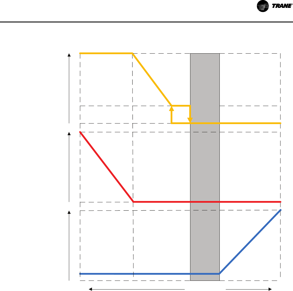
VAV-PRC012AC-EN
33
Figure 15. Parallel fan with variable-speed fan control and staged heat
Deadband
Maximum
Reheat
Minimum
Fan Speed
Minimum
Primary
Airflow
Maximum
Primary Air
Reheat Off
Reheat Capacity %
Fan Heat
Maximum
Speed
100 0
100
0
0
100
0
100
0
100
Primary Airflow %
Fan Airflow %
1
st
Stage Heating
2
nd
Stage
Heating
Fan Off
For units equipped with modulated heat (modulated hot water or SCR electric):
When the zone temperature drops below the active heating setpoint, the controller turns on the
fan and operates it at the minimum fan airflow setpoint. If additional heating capacity is needed,
the controller modulates the hot-water valve (or SCR electric heater) to maintain zone
temperature at the active heating setpoint, while primary airflow is at the minimum primary
airflow setpoint and the fan is at the minimum fan airflow setpoint. If the requested heating
capacity has increased to the point where the discharge air temperature reaches the design
heating discharge air temperature setpoint (adjustable), the controller modulates the fan
between its minimum and maximum fan airflow setpoints to maintain zone temperature at the
active heating setpoint, while the hot-water valve (or SCR electric heater) modulates to maintain
discharge air temperature at the design heating discharge air temperature setpoint and primary
airflow remains at the minimum primary airflow setpoint. If the requested heating capacity has
increased to the point where the fan reaches the maximum fan airflow setpoint, the controller
modulates the hot-water valve (or SCR electric heater) to maintain zone temperature at the active
heating setpoint, while the fan continues to operate at the maximum fan airflow setpoint and
primary airflow remains at the minimum primary airflow setpoint.
DDDDCC CCoonnttrroollss
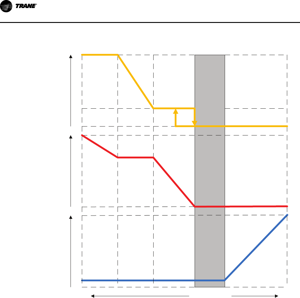
34
VAV-PRC012AC-EN
Figure 16. Parallel fan with variable-speed fan control and modulating heat
Deadband
Cooling Loop Signal
Reheat DAT
High Limit
Minimum
Primary
Airflow
Maximum
Primary Air
Reheat Off
Fan Heat
Maximum
Speed
Heating Loop Signal
100 0
100
0
1
st
Stage
Heating
2
nd
Stage
Heating
Reheat DAT
Heat Set
Point + 20F
3
rd
Stage
Heating
Minimum
Fan Speed
Fan Off
Reheat Capacity %
0
0
100
0
100
Primary Airflow %
Fan Airflow %
Ventilation Control
Ventilation control enhances the usability of Trane DDC controllers in more select applications
that require measurement of outside air (ventilation). Ventilation control is designed for use with
constant volume single-duct VAV units which modulate the primary damper and associated
reheat to maintain an average constant discharge air temperature. The reheat is modulated to
provide discharge air temperature consistent with AHU supply air temperature (typically 50º–
60ºF). This is critical to ensure that ASHRAE Standard 62 Ventilation standards are attained,
consistently maintained, and monitored. When connected to a Trane Building Automation
System, trend logging, remote alarming, etc. is available. In fact, the Trane Tracer® SC control
system can provide unmatched “peace of mind” by calling/paging the appropriate person(s)
when specific alarms occur.
DDDDCC CCoonnttrroollss

VAV-PRC012AC-EN
35
Flow Tracking Control
This enhanced VAV DDC controller feature allows two Trane VV550 controllers to coordinate
modulation simultaneously. This allows a specific CFM offset to be maintained. The CFM offset
provides pressurization control of an occupied space, while maintaining the comfort and energy
savings of a VAV system. A flow tracking system in a given zone consists of a standard Space
Comfort Control VAV (see B) unit plus a single-duct, cooling-only, exhaust VAV unit (see C). As
the supply VAV unit modulates the supply airflow through the air valve to maintain space
comfort, the exhaust box modulates a similar amount to maintain the required CFM differential.
This is a simple, reliable means of pressurization control, which meets the requirements of the
majority of zone pressurization control applications. Typical applications include:
• School and university laboratories
• Industrial laboratories
• Hospital operating rooms
• Hospital patient rooms
• Research and development facilities
• And many more …
The CFM offset is assured and can be monitored and documented when connected to a Trane
Tracer® SC Building Automation System. Flow Tracking Control is designed to meet most
pressurization control projects. If an application calls for pressure control other than flow
tracking, contact your local Trane Sales Office for technical support.
Figure 17. Flow tracking operation
B
A
C
Exhaust
Communication link
Supply VAV
To other VAVs or
Main Control Panel
How Does It Operate?
T
Primary Air
from Main
AHU
Occupied Space
Trane LONMARK®® DDC VAV Controller
Introduction
This LONMARK® certified controller uses the Space Comfort Controller (SCC) profile to exchange
information over a LonTalk® network. Networks with L
ONMARK certified controllers provide the
latest open protocol technology. Being L
ONMARK® certified guarantees that owners and end-users
have the capability of adding Trane products to other “open” systems and relieves owners of the
pressure and expense of being locked into a single DDC supplier. The Trane VV550 VAV
controller with VariTrane VAV units can be applied to more than just Trane systems. When a
customer buys a Trane VAV unit with Trane DDC controller, they take advantage of:
DDDDCC CCoonnttrroollss
36
VAV-PRC012AC-EN
• Factory-commissioned quality
• Knowing they have selected the most reliable VAV controllers in the industry
• Trane as a single source to solve any VAV equipment, or system-related issues
• The most educated and thorough factory service technicians in the controls industry
• Over 150 local parts centers throughout North America that can provide what you need, when
you need it
Don’t let your existing controls supplier lock you out of the most recognized name in VAV system
control in the industry. Specify Trane open-protocol systems.
What are the new features of this controller? Read on to find out more.
The Trane LONMARK® direct digital controller Unit Control Module (DDCUCM) is a
microprocessor-based terminal unit with non-volatile memory which provides accurate
airflow and room temperature control of Trane and non-Trane VAV air terminal units.
L
ONMARK provides a simple open protocol to allow integration of Trane VAV units and
controls into other existing control systems. The UCM can operate in pressure-
independent or pressure-dependent mode and uses a proportional plus integral control
algorithm.
The controller monitors zone temperature setpoints, zone temperature and its rate of change and
valve airflow (via flow ring differential pressure). The controller also accepts an auxiliary duct
temperature sensor input or a supply air temperature value from Tracer® SC. Staged electric
heat, pulse width modulated electric heat, modulating hot water heat or on/off hot water heat
control are provided when required. The control board operates using 24-VAC power. The Trane
L
ONMARK® DDC-UCM is also a member of the Trane Integrated Comfort™ systems (ICS) family of
products. When used with a Trane Tracer® SC or other Trane controllers, zone grouping and unit
diagnostic information can be obtained. Also part of ICS is the factory-commissioning of
parameters specified by the engineer (see "Factory-Installed vs. Factory-Commissioned" in the
Features and Benefits section for more details).
NNoottee:: Trane L
ONMARK
®
DDC-UCM controllers can also take advantage of factory-commissioned
quality on non-Trane systems through L
ONMARK
®
open protocol.
Specifications
SSuuppppllyy VVoollttaaggee 24 VAC, 50/60 Hz
MMaaxxiimmuumm VVAA LLooaadd ((NNoo
HHeeaatt oorr FFaann))
8 VA (Board, Transducer, Zone Sensor, and Actuator)
NNoottee:: If using field-installed heat, 24 VAC transformer should be
sized for additional load.
OOuuttppuutt RRaattiinnggss Actuator Output: 24 VAC at 12 VA, 1st Stage Reheat: 24 VAC at
12 VA, 2nd Stage Reheat: 24 VAC at 12 VA, 3rd Stage Reheat: 24
VAC at 12 VA
BBiinnaarryy IInnppuutt 24 VAC, occupancy or generic
AAuuxxiilliiaarryy IInnppuutt Can be configured for discharge or primary air temperature
sensor
OOppeerraattiinngg EEnnvviirroonnmmeenntt 32 to 140°F, (0 to 60°C), 5% to 95% RH, Non-condensing
SSttoorraaggee EEnnvviirroonnmmeenntt -40 to 180°F (-40 to 82.2°C), 5% to 95% RH, Non-Condensing
PPhhyyssiiccaall DDiimmeennssiioonnss
Width: 5.5" (139.7 mm) Length: 4.5" (69.85 mm) Height: 2.0"
(44.45 mm)
CCoonnnneeccttiioonnss
1/4" (6.35 mm) Stab Connections
CCoommmmuunniiccaattiioonnss
L
ONMARK® – Space Comfort Control (SCC) profile with FTT-10
transceiver.22 awg. unshielded level 4 communication wire.
DDDDCC CCoonnttrroollss
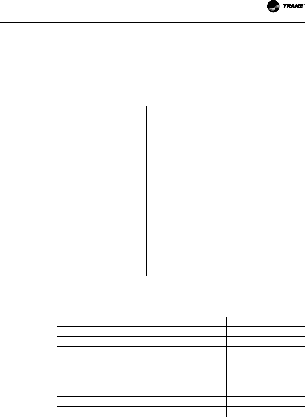
VAV-PRC012AC-EN
37
FFaann CCoonnttrrooll Series fan: On unless unoccupied and min. flow has been
released. Parallel fan: On when zone temperature is less than
heating setpoint plus fan offset. Off when zone temperature is
more than heating setpoint plus fan offset plus 0.5°F (0.28°C).
HHeeaatt SSttaaggiinngg Staged electric or hot water modulating or pulse-width
modulation
The following table provides an input listing for Tracer® VV550/551 VAV controllers. The content
of the list conforms to both the L
ONMARK® SCC functional profile 8500 and the node object.
Table 2. Input listing
Input description
Input SNVT type
Space temperature nviSpaceTemp SNVT_temp_p
Setpoint nviSetpoint SNVT_temp_p
Occupancy, schedule nviOccSchedule SNVT_tod_event
Occupancy, manual command nviOccManCmd SNVT_occupancy
Occupancy sensor nviOccSensor SNVT_occupancy
Application mode nviApplicMode SNVT_hvac_mode
Heat/cool mode input nviHeatCool SNVT_hvac_mode
Fan speed command nviFanSpeedCmd SNVT_switch
Auxiliary heat enable nviAuxHeatEnable SNVT_switch
Valve override nviValveOverride SNVT_hvac_overid
Flow override nviFlowOverride SNVT_hvac_overid
Emergency override nviEmergOverride SNVT_hvac_emerg
Source temperature nviSourceTemp SNVT_temp_p
Space CO2 nviSpaceCO2 SNVT_ppm
Clear alarms/diagnostics nviRequestPart of the node object SNVT_obj_request
Air flow setpoint input nviAirFlowSetpt SNVT_flow
The following table provides an output listing for Tracer® VV550/551 VAV controllers. The
content of the lists conforms to both the L
ONMARK® SCC functional profile 8500 and the node
object.
Table 3. Output listing
Output description Output SNVT type
Space temperature nvoSpaceTemp SNVT_temp_p
Unit status, mode nvoUnitStatus SNVT_hvac_status
Effective setpoint nvoEffectSetpt
SNVT_temp_p
Effective occupancy nvoEffectOccup SNVT_occupancy
Heat cool mode nvoHeatCool SNVT_hvac_mode
Setpoint nvoSetpoint SNVT_temp_p
Discharge air temperature nvoDischAirTemp SNVT_temp_p
Space CO2 nvoSpaceCO2 SNVT_ppm
Effective air flow setpoint nvoEffectFlowSP SNVT_flow
DDDDCC CCoonnttrroollss

38
VAV-PRC012AC-EN
Table 3. Output listing (continued)
Air flow nvoAirFlow SNVT_flow
File table address nvoFileDirectory
(a)
SNVT_address
Object status nvoStatus(a) SNVT_obj_status
Alarm message nvoAlarmMessage SNVT_str_asc
(a)
Part of the node object.
The following table provides the configuration properties for the controller. The content of the
lists conforms to both the L
ONMARK® SCC functional profile 8500 and the node object.
Table 4. Configuration properties
Configuration property
description
Configuration
property
SNVT type
SCPT reference
Send heartbeat nciSndHrtBt SNVT_time_sec SCPTmaxSendTime (49)
Occ temperature setpoints nciSetpoints SNVT_temp_setpt SCPTsetPnts (60)
Minimum send time nciMinOutTm SNVT_time_sec SCPTminSendTime (52)
Receive heartbeat nciRecHrtBt SNVT_time_sec SCPTmaxRcvTime (48)
Location label nciLocation SNVT_str_asc SCPTlocation (17)
Local bypass time nciBypassTime SNVT_time_min SCPTbypassTime (34)
Manual override time nciManualTime SNVT_time_min SCPTmanOverTime (35)
Space CO2 limit nciSpaceCO2Lim SNVT_ppm SCPTlimitCO2 (42)
Nominal air flow nciNomFlow SNVT_flow SCPTnomAirFlow (57)
Air flow measurement gain nciFlowGain SNVT_multiplier SCPTsensConstVAV (67)
Minimum air flow nciMinFlow SNVT_flow SCPTminFlow (54)
Maximum air flow nciMaxFlow SNVT_flow SCPTmaxFlow (51)
Minimum air flow for heat nciMinFlowHeat SNVT_flow SCPTminFlowHeat (55)
Maximum air flow for heat nciMaxFlowHeat SNVT_flow SCPTmaxFlowHeat (37)
Minimum flow for standby nciMinFlowStdby SNVT_flow SCPTminFlowStby (56)
Firmware major version nciDevMajVer
(a)
n/a SCPTdevMajVer (165)
Firmware minor version nciDevMinVer(a) n/a SCPTdevMinVer (166)
Flow offset for tracking
applications
nciFlowOffset SNVT_flow_f SCPToffsetFlow (265)
Local heating minimum air flow nciMinFlowUnitHt SNVT_flow SCPTminFlowUnitHeat
(270)
Minimum flow for standby heat nciMnFlowStbyHt SVNT_flow SCPTminFlowStbyHeat
(263)
(a)
Part of the node object.
General Features and Benefits
AAssssuurreedd AAccccuurraaccyy
• Proportional-plus-integral control loop algorithm for determining required airflow needed to
control zone temperature. Airflow is limited by active minimum and maximum airflow
setpoints.
• Pressure-independent (PI) operation that automatically adjusts air valve position to maintain
required primary airflow. In certain low-flow situations or in cases where the flow
DDDDCC CCoonnttrroollss

VAV-PRC012AC-EN
39
measurement has failed, the DDC controller will operate in a pressure-dependent (PD) mode
of operation.
• When combined with the patented Trane Flow ring and pressure transducer, flow is
repeatable to +/- 5% accuracy across the Pressure Independent (PI) flow range. (See Valve/
Controller Airflow Guidelines section).
• Improved 2-Point Air Balancing is available – Assures optimized flow-sensing accuracy across
the operating range. This provides a more accurate airflow balancing method when
compared to typical single-point flow correction air balancing.
• Analog input resolution of +/- 1/8°F within the comfort range maximizes zone temperature
control yielding excellent comfort control.
RReelliiaabbllee OOppeerraattiioonn
• Built for life – Trane products are designed to stand the test of time, with a proven design life
that exceeds 20 years.
• Fully factory tested – fully screened and configured at the factory. All features are tested
including fan and reheat stage energization, air valve modulation, and controller inputs and
outputs.
SSaaffee OOppeerraattiioonn
• All components, including the controller, pressure transducer, transformer, etc. are mounted
in a NEMA 1 sheet metal enclosure and are tested as an assembly to UL1995 standards. The
result is a rugged and safe VAV, controller, and thus, overall unit.
• When in PI-mode, electric heat is disabled when the sensed flow is below the minimum
required.
• Hot water coil units in ventilation flow control (VFC) have a Freeze protection algorithm to
protect the water coil and the internal space from water damage. This is accomplished by
driving the water valve to maximum position on alarm conditions.
SSyysstteemm--LLeevveell OOppttiimmiizzaattiioonn
Trane controllers are designed to integrate into Trane Tracer® Building Automation Systems and
leverage clear and clean unit-controller related data for system level control decisions.
Integrating a Trane VV550 controller into a Tracer Control System provides the next step in
building system control.
Specifically, system-level decisions on how to operate all components can be made. Energy
efficient optimization strategies like Static Pressure Optimization, Ventilation Reset, and CO
2
Demand-controlled Ventilation can be employed with the simple press of a button. The end-
result is the most efficient and reliable building automation system available.
SSiimmpplliiffiieedd IInnssttaallllaattiioonn
Factory Commissioned Quality – All Trane DDC VAV controllers are factory-commissioned. This
means that the DDC boards are powered and run-tested with your specific sequence parameters.
They are connected to a communication link to make sure that information and diagnostic data
function properly. Before any VariTrane VAV unit ships they must pass a rigorous quality control
procedure. You can be assured that a Trane VAV unit with Trane DDC VAV controls will work
right out of the crate.
Zone sensor air balance – When applied to a Trane zone sensor with thumbwheel and on/cancel
buttons, a balancing contractor can drive the primary air valve to maximum or minimum airflow
from the sensor to determine the point of calibration to be used (maximum will result in
optimum performance). The flow reading can then be calibrated from the sensor, without the use
of additional service tools. (Non-LCD versions)
Tenant-Finish Heat Mode – In some office projects, the building is being constructed as tenants
are being identified. Tenant-finish heat mode is designed for applications when a given floor has
not been occupied. The main AHU is used for heat and because the internal furnishings are not
complete, the sensors have not been installed. In this case, the primary valve drives open using
the heat of the main AHU to keep plumbing lines from freezing. Operation of the VAV unit fan
(series or parallel) remains unaffected.
CCoonnttrroolllleerr FFlleexxiibbiilliittyy
DDDDCC CCoonnttrroollss

40
VAV-PRC012AC-EN
• 24 VAC binary input that can be configured as a generic input or as occupancy input. When
the DDC controller is operating with Tracer SC, the status of the input is provided to Tracer for
its action. In stand-alone operation and when configured for an occupancy input, the input
will control occupancy status of the DDC controller.
• Auxiliary temperature analog input configured for an auxiliary temperature sensor. The value
of the input is used as status-only by Tracer SC if Tracer SC is providing a supply air
temperature (upstream of the terminal unit) to the DDC controller. Otherwise, the input will
be used for determining heating/cooling control action of the VAV unit. When the auxiliary
temperature sensor is located in the discharge of the unit, and attached to a Trane Tracer
Building Automation System, additional test sequencing and reporting is available to
maximize VAV system capabilities and simplify system commissioning.
• L
ONMARK® certified performance ensures that a Trane VAV with controller will provide state-
of-the-art, consistent open communication protocol for integration with the industry’s latest
(Non-Trane) building automation control systems, including Johnson Control, Andover,
Siemans, Honeywell, and so on.
• CO
2
demand controlled ventilation enables the terminal unit controller to adjust ventilation
air flow setpoint based on the current occupancy in the zone. Trane demand controlled
ventilation strategies are pre-defined for simplified application and can be easily customized
to meet the needs of a specific system.
Control Logic
Direct Digital Control (DDC) controllers are today’s industry standard. DDC controllers share
system-level data to optimize system performance (including changing ventilation requirements,
system static pressures, supply air temperatures, etc.). Variables available via a simple twisted-
shielded wire pair include occupied/unoccupied status, minimum and maximum airflow
setpoints, zone temperature and temperature setpoints, air valve position, airflow cfm, fan status
(on or off), fan operation mode (parallel or series), reheat status (on or off), VAV unit type, air
valve size, temperature correction offsets, flow correction values, ventilation fraction, and so on.
With the advent of L
ONMARK® open protocol, the most reliable VAV controller is now available for
ANY system. Gone are the days of being locked into a single supplier. Trane DDC controllers
provide Trane-designed solid-state electronics intended specifically for VAV applications
including:
• Space temperature control
• Ventilation flow control (100% outside air applications)
• Flow tracking space pressurization control
DDDDCC CCoonnttrroollss

VAV-PRC012AC-EN
41
Figure 18. Flow sensor single vs. airflow delivery
Space Temperature Control
Space temperature control (STC) logic modulates primary airflow, reheat (either local or remote),
and fan airflow to maintain the desired temperature in the zone. Following are high-level
descriptions of the STC control logic during occupied mode, for various fan and reheat
configurations:
Series Fan-Powered Terminal
The terminal fan operates continuously during all occupied modes.
When the zone temperature is in the deadband between the active heating and cooling setpoints,
the controller reduces primary airflow to the minimum primary airflow setpoint, while reheat is
off.
When the zone temperature rises above the active cooling setpoint, the controller modulates
primary airflow, between the minimum and maximum airflow setpoints, to maintain zone
temperature at the active cooling setpoint, while reheat is off.
For units equipped with staged heat (on/off hot water or on/off electric):
When the zone temperature drops below the active heating setpoint, the controller stages heat
on/off to maintain zone temperature at the active heating setpoint, while primary airflow is
controlled to the minimum heating primary airflow setpoint. Stage 1 heat is energized when the
zone temperature drops below the active heating setpoint; Stage 2 is energized when the zone
temperature drops to 1°F (0.56°C) or more below the active heating setpoint. Stage 2 is de-
energized when the zone temperature rises to warmer than 0.5°F (0.28°C) below the active
heating setpoint; Stage 1 is de-energized when the zone temperature rises to warmer than 0.5°F
(0.28°C) above the active heating setpoint.
For units equipped with modulated heat (modulated hot water or SCR electric):
When the zone temperature drops below the active heating setpoint, the controller modulates
the hot-water valve (or SCR electric heater) to maintain zone temperature at the active heating
setpoint, while primary airflow is controlled to the minimum heating primary airflow setpoint.
Parallel Fan-Powered Terminal
When the zone temperature is in the deadband between the active heating and cooling setpoints,
the controller reduces primary airflow to the minimum primary airflow setpoint, while the fan
and reheat are off.
DDDDCC CCoonnttrroollss

42
VAV-PRC012AC-EN
When the zone temperature rises above the active cooling setpoint, the controller modulates
primary airflow, between the minimum and maximum primary airflow setpoints, to maintain
zone temperature at the active cooling setpoint, while the fan and reheat are off.
When the zone temperature is below the fan on/off setpoint (active heating setpoint plus fan
offset), the controller turns on the fan, while primary airflow is controlled to the minimum
primary airflow setpoint and the reheat remains off. The fan is turned off when the zone
temperature rises to warmer than 0.5°F (0.28°C) above the fan on/off setpoint.
For units equipped with staged heat (on/off hot water or on/off electric):
When the zone temperature drops below the active heating setpoint, the controller stages heat
on/off to maintain zone temperature at the active heating setpoint, while primary airflow is
controlled to the minimum heating primary airflow setpoint. Stage 1 heat is energized when the
zone temperature drops below the active heating setpoint; Stage 2 is energized when the zone
temperature drops to 1°F (0.56°C) or more below the active heating setpoint. Stage 2 is de-
energized when the zone temperature rises to warmer than 0.5°F (0.28°C) below the active
heating setpoint; Stage 1 is de-energized when the zone temperature rises to warmer than 0.5°F
(0.28°C) above the active heating setpoint.
For units equipped with modulated heat (modulated hot water or SCR electric):
When the zone temperature drops below the active heating setpoint, the controller modulates
the hot-water valve (or SCR electric heater) to maintain zone temperature at the active heating
setpoint, while primary airflow is controlled to the minimum heating primary airflow setpoint.
Ventilation Control
Ventilation control enhances the usability of Trane DDC controllers in more select applications
that require measurement of outside air (ventilation). Ventilation control is designed for use with
constant volume single-duct VAV units which modulate the primary damper and associated
reheat to maintain an average constant discharge air temperature. The reheat is modulated to
provide discharge air temperature consistent with AHU supply air temperature (typically 50º–
60ºF). This is critical to ensure that ASHRAE Standard 62 Ventilation standards are attained,
consistently maintained, and monitored. When connected to a Trane Building Automation
System, trend logging, remote alarming, etc. is available. In fact, the Trane Tracer® SC control
system can provide unmatched “peace of mind” by calling/paging the appropriate person(s)
when specific alarms occur.
Flow Tracking Control
This enhanced VAV DDC controller feature allows two Trane VV550 controllers to coordinate
modulation simultaneously. This allows a specific CFM offset to be maintained. The CFM offset
provides pressurization control of an occupied space, while maintaining the comfort and energy
savings of a VAV system. A flow tracking system in a given zone consists of a standard Space
Comfort Control VAV (see B) unit plus a single-duct, cooling-only, exhaust VAV unit (see C). As
the supply VAV unit modulates the supply airflow through the air valve to maintain space
comfort, the exhaust box modulates a similar amount to maintain the required CFM differential.
This is a simple, reliable means of pressurization control, which meets the requirements of the
majority of zone pressurization control applications. Typical applications include:
• School and university laboratories
• Industrial laboratories
• Hospital operating rooms
• Hospital patient rooms
• Research and development facilities
• And many more …
The CFM offset is assured and can be monitored and documented when connected to a Trane
Tracer® SC Building Automation System. Flow Tracking Control is designed to meet most
pressurization control projects. If an application calls for pressure control other than flow
tracking, contact your local Trane Sales Office for technical support.
DDDDCC CCoonnttrroollss

VAV-PRC012AC-EN
43
Figure 19. Flow tracking operation
B
A
C
Exhaust
Communication link
Supply VAV
To other VAVs or
Main Control Panel
How Does It Operate?
T
Primary Air
from Main
AHU
Occupied Space
Direct Digital Controller—Unit Control Module
The Trane direct digital controller Unit Control Module (DDC-
UCM) is a microprocessor-based terminal unit with non-
volatile memory that provides accurate airflow and room
temperature control of Trane VAV air terminal units. The UCM
can operate in a pressure-independent or a pressure-
dependent mode and uses a proportional plus integral control
algorithm. The controller monitors zone temperature
setpoints, zone temperature and its rate of change and valve
airflow (via flow ring differential pressure).
The controller also accepts an auxiliary duct temperature sensor input or a supply air
temperature value from Tracer® SC. Staged electric heat, pulse width modulated electric heat,
modulating hot water heat or on/off hot water heat control are provided when required. The
control board operates using 24-VAC power. The Trane DDC-UCM is a member of the Trane
Integrated Comfort™ systems (ICS) family of products. When used with a Trane Tracer Building
Automation System or other Trane controllers, zone grouping and unit diagnostic information
can be obtained. Also part of ICS is the factory-commissioning of parameters specified by the
engineer (see “Factory-Installed vs. Factory-Commissioned” in the Features and Benefits section
for more details).
SSuuppppllyy VVoollttaaggee 24 VAC, 50/60 Hz
MMaaxxiimmuumm VVAA LLooaadd ((NNoo
HHeeaatt oorr FFaann))
12 VA (Board, Transducer, Zone Sensor, and Actuator)
NNoottee:: If using field-installed heat, 24 VAC transformer should be
sized for additional load.
OOuuttppuutt RRaattiinnggss Actuator Output: 24 VAC at 12 VA
1st Stage Reheat: 24 VAC at 12 VA
2nd Stage Reheat: 24 VAC at 12 VA
3rd Stage Reheat: 24 VAC at 12 VA
BBiinnaarryy IInnppuutt 24 VAC
DDDDCC CCoonnttrroollss

44
VAV-PRC012AC-EN
AAuuxxiilliiaarryy IInnppuutt
Can be configured for an optional 2–10 VDC CO
2
sensor, or
auxiliary temperature sensor.
OOppeerraattiinngg EEnnvviirroonnmmeenntt 32 to 140°F, (0 to 60°C)
5% to 95% RH, Non-condensing
SSttoorraaggee EEnnvviirroonnmmeenntt
-40 to 180°F (-40 to 82.2°C),
5% to 95% RH, Non-Condensing
PPhhyyssiiccaall DDiimmeennssiioonnss
Width: 5.5–in. (139.7 mm)
Length: 2.8–in. (69.85 mm)
Height: 1.8–in. (44.45 mm)
CCoonnnneeccttiioonnss
1/4–in. (6.35 mm) Stab Connections
CCoommmmuunniiccaattiioonnss RS-485; Stranded wire, twisted pair, shielded, copper conductor
only, 18–20 awg
22 awg. unshielded level 4 communication wire.
FFaann CCoonnttrrooll Series fan: On unless unoccupied and min. flow has been
released.
Parallel fan: On when zone temperature is less than heating
setpoint plus fan offset. Off when zone temperature is more than
heating setpoint plus fan offset plus 0.5°F (0.28°C).
HHeeaatt SSttaaggiinngg Staged electric or hot water modulating or pulse-width
modulation
Air-Fi Wireless Communications Interface (WCI)
WWCCII
The Trane Air-Fi® Wireless Communications Interface (WCI) enables
wireless communication between system controls, unit controls, and
wireless sensors for Trane control products that use the BACnet®
protocol. The WCI replaces the need for communications wire in all
system applications.
NNoottee:: See BAS-SVX40*-EN, Installation, Operation and Maintenance,
Wireless Comm for more information.
Table 5. Air-Fi network specifications
QQuuaannttiittyy ooff AAiirr--FFii®®
DDeevviicceess ppeerr NNeettwwoorrkk
Each Air-Fi® should be limited, in addition to the coordinator
WCI and, at times, one TU Adapter, to a maximum of 30 other
WCIs and a total of 60 Air-Fi devices (WCIs and WCSs).
QQuuaannttiittyy ooff NNeettwwoorrkkss ppeerr
TTrraacceerr®® SSCC
Tracer SC can support up to 8 wireless networks.
NNoottee:: The number of WCIs that can be installed at a site is
determined by the applicable Trace SC license, which
specifies the total number of controllers.
DDDDCC CCoonnttrroollss
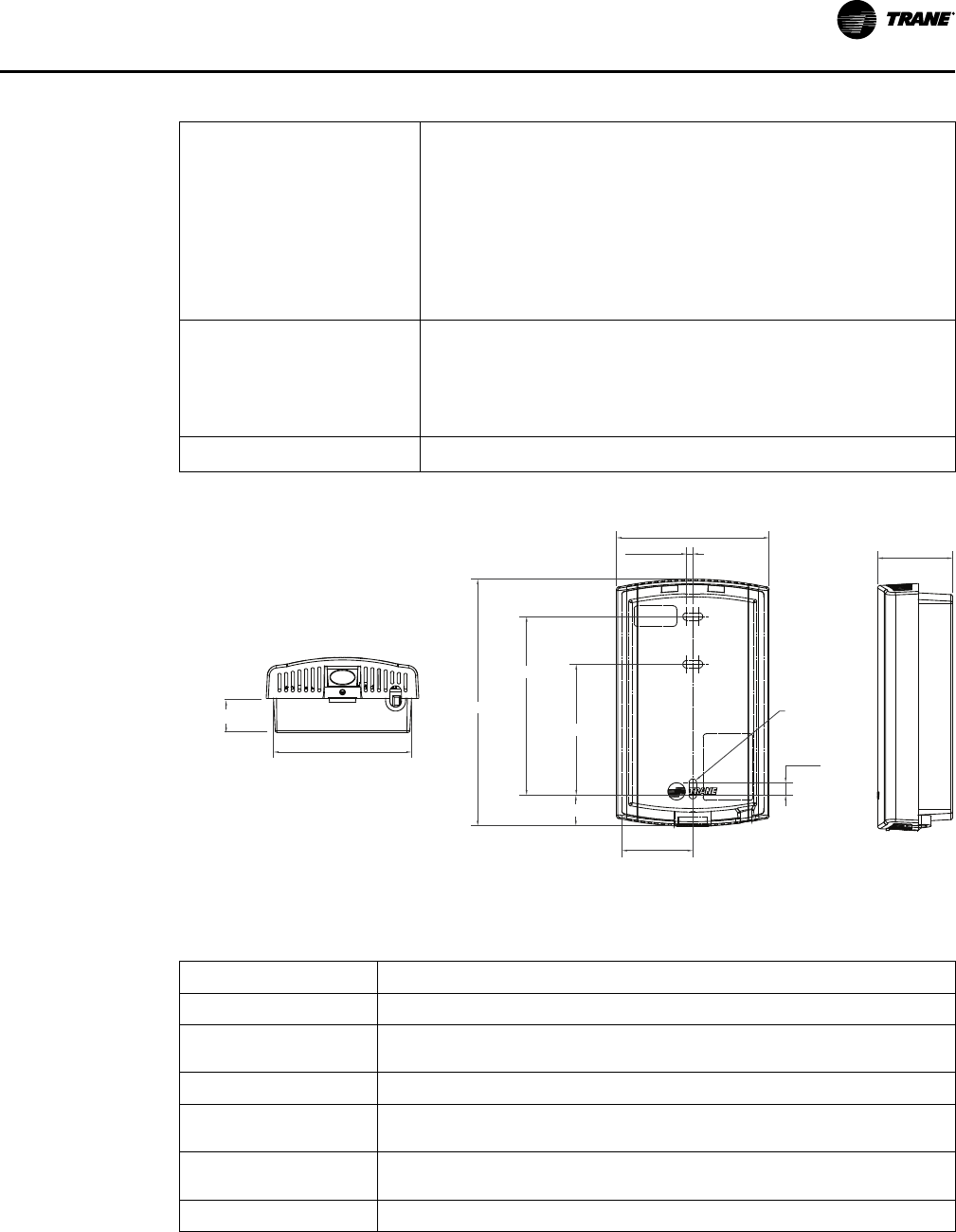
VAV-PRC012AC-EN
45
Table 5. Air-Fi network specifications (continued)
AAuuttoommaattiicc NNeettwwoorrkk
FFoorrmmaattiioonn
When a WCI is connected to a Tracer SC, it is auto-assigned as
the coordinator. To enable the coordinator, Tracer® SC must be
configured for wireless communication. The coordinator WCI
opens the network to allow all WCIs having matching addresses
to automatically join the network.
If no Tracer® SC is present, a centrally located WCI must be
designated to act as the coordinator. You can manually set the
coordinator WCI so that all WCIs having matching addresses
automatically join the network.
CCoommppaattiibbiilliittyy wwiitthh
PPrreevviioouuss GGeenneerraattiioonn
WWiirreelleessss ZZoonnee PPrroodduuccttss
Our previous line of wireless zone sensors (WZS, WTS, and
WDS) are not compatible with the Air Fi Wireless
Communications Interface (WCI).
The new Air-Fi® Wireless Communications Sensor (WCS) is
compatible with old WCIs that have updated firmware.
WWiirreedd ZZoonnee SSeennssoorrss Wired zone sensors can be used with Air-Fi® wireless systems.
Dimensions
2.896 in (73.55 mm)
0.118 in
(3.00 mm)
4.677 in (118.8 mm)
3.385 in (86.0 mm)
2.480 in (63.0 mm)
R0.71 in
(R1.80 mm) TYP
0.236 in
(6.0 mm)
1.344 in (34.14 mm)
1.419 in (36.03 mm)
0.650 in (16.50 mm)
2.62 in (66.55 mm)
Specifications
Table 6. WCI specifications
Operating Temperature 32 to 122ºF (0 to 50ºC)
Storage temperature -40 to 185ºF (-40 to 85°C)
Storage and operating
humidity range
5% to 95% relative humidity (RH), non-condensing
Voltage 24 Vac/Vdc nominal ± 10%. If using 24 Vac, polarity must be maintained.
Receiver power
consumption
<2.5 VA
Housing material Polycarbonate/ABS (suitable for plenum mounting), UV protected, UL 94: 5 VA
flammability rating
Mounting 3.2 in (83 mm) with 2 supplied mounting screws
DDDDCC CCoonnttrroollss

46
VAV-PRC012AC-EN
Table 6. WCI specifications (continued)
Range Open range: 2,500 ft (762 m) with packet error rate of 2%
Indoor: Typical range is 200 ft (61 mm); actual range is dependent on the
environment. See BASSVX55 for more detail.
Note: Range values are estimated transmission distances for satisfactory operation.
Actual distance is job specific and must be determined during site evaluation.
Placement of the WCI is critical to proper system operation. In most general
office space installations, distance is not the limiting factor for proper signal
quality. Signal quality is more greatly affected by walls, barriers, and general
clutter. Note that sheetrock walls and ceiling tiles offer little restriction to the
propagation of the radio signal throughout the building as opposed to concrete
or metal barriers. More details information, including wiring schematics, are
available at http://www.trane.com.
Output power
North America: 100 mW
Radio frequency 2.4 GHz (IEEE Std 802.15.4-2003 compliant) (2405–2480 MHz, 5 MHz spacing)
Radio channels 16
Address range Group 0–8, Network 1–9
Mounting Fits a standard 2 in. by 4 in. junction box (vertical mount only). Mounting holes are
spaced 3.2 in. (83 mm) apart on vertical center line. Includes mounting screws for
junction box or wall anchors for sheet-rock walls. Overall dimensions: 2.9 in. (74 mm)
by 4.7 in. (119 mm)
Wireless protocol ANSI/ASHRAE Standard 135–2016 (BACnet®/ZigBee®
(a)
)
(a)
ZigBee is a registered trademark of the ZigBee Alliance.
Air-Fi Wireless Communications Sensor (WCS)
The Air-Fi® Wireless Communications Sensor (WCS) is compatible with any Trane controller that
uses a WCI. The WCS provides the same functions as many currently available Trane wired
sensors. No further software or hardware is necessary for site evaluation, installation, or
maintenance. Space temperature is standard on all models.
NNoottee:: A service tool cannot be connected to a Trane wireless sensor.
Three WCS models are available:
• Digital display (WCS-SD) model
• Base (WCS-SB) model has no exposed display or user interface
• 2% relative humidity sensor module (WCS-SH), which can be field installed inside either the
WCS-SD or WCS-SB.
In most applications, one WCS-SD or WCS-SB sensor will be used per WCI acting as a router.
However, up to 6 WCS-SD or WCS-SB sensors can be associated to a single equipment controller
or BCI.
DDDDCC CCoonnttrroollss

VAV-PRC012AC-EN
47
Dimensions
2.9"
(73.5 mm)
2.9"
(73.5 mm)
1.08"
(27.5 mm)
2.62"
(66.5 mm)
0.77"
(19.6 mm)
3.27"
(83 mm)
2.36"
(60 mm)
0.12"
(3 mm)
4.75"
(120.6 mm)
0.07"
(1.8 mm)
Specifications
Table 7. Air-Fi network specifications
AAccccuurraaccyy
0.5ºF for a range of 55 to 85ºF (12.8 to 29.4ºC)
RReessoolluuttiioonn
+0.125ºF over a range of 60ºF to 80ºF (15.56ºC to 25.57ºC)/±0.25ºF
outside this range
SSeettppooiinntt ffuunnccttiioonnaall rraannggee
45ºF to 95ºF (7.22ºC to 35ºC)
SSeennssoorr bbaatttteerryy Two AA lithium 1.5 V batteries, 2800 mA with an expected life of
15 years under typical operating conditions
AAddddrreessss rraannggee 000 to 999
MMaaxxiimmuumm ttiimmee bbeettwweeeenn
ttrraannssmmiissssiioonnss
15 minutes
MMiinniimmuumm ttiimmee bbeettwweeeenn
ttrraannssmmiissssiioonnss
10 seconds; time between transmissions can be shorter during
user interaction
MMoouunnttiinngg
Fits a standard 2 in. by 4 in. junction box (vertical mount only).
Mounting holes are spaced 3.2 in. (83 mm) apart on vertical
center line. Includes mounting screws for junction box or wall
anchors for sheet-rock walls. Overall dimensions: 2.9 in. (74 mm)
by 4.7 in. (119 mm)
DDDDCC CCoonnttrroollss

48
VAV-PRC012AC-EN
DDC Zone Sensor
The DDC zone sensor is used in conjunction
with the Trane direct digital controller to
sense the space temperature and to allow
for user adjustment of the zone setpoint.
Models with external zone setpoint
adjustments and occupied mode override
pushbuttons are available.
Table 8. Air-Fi network specifications
TThheerrmmiissttoorr RReessiissttaannccee
RRaattiinngg
10,000 Ohms at 77°F (25°C)
SSeettppooiinntt RReessiissttaannccee
RRaattiinngg
Setpoint potentiometer is calibrated to produce 500 Ohms at a
setting of 70°F (21.11°C)
EElleeccttrriiccaall CCoonnnneeccttiioonnss Terminal Block – Pressure Connections
Communications Jack – WE-616 (available for field installation)
PPhhyyssiiccaall DDiimmeennssiioonnss
Width: 2.75" (69.85 mm)
Height: 4.5" (114.3 mm)
Depth: 1.0" (25.4 mm)
CO
2
Wall Sensor and Duct CO
2
Sensor
Figure 20. CO
2
wall sensor (L) and duct CO
2
sensor (R)
The wall- and duct-mounted carbon dioxide (CO
2
) sensors are designed for use with Trane DDC/
UCM control systems. Installation is made simple by attachment directly to the DDC/ UCM
controller. This allows the existing communication link to be used to send CO
2
data to the higher-
level Trane control system.
Wall-mounted sensors can monitor individual zones, and the duct-mounted sensor is ideal for
monitoring return air of a given unit. Long-term stability and reliability are assured with
advanced silicon based Non-Dispersive Infrared (NDIR) technology.
When connected to a building automation system with the appropriate ventilation equipment,
the Trane CO
2
sensors measure and record carbon dioxide in parts-per-million (ppm) in occupied
building spaces. These carbon dioxide measurements are typically used to identify under-
ventilated building zones and to override outdoor airflow beyond design ventilation rates if the
CO
2
exceeds acceptable levels.
DDDDCC CCoonnttrroollss

VAV-PRC012AC-EN
49
Specifications
MMeeaassuurriinngg RRaannggee
0–2000 parts per million (ppm)
AAccccuurraaccyy aatt 7777°°FF ((2255°°CC))
< ± (40 ppm CO
2
+ 3% of reading) (Wall only)
< ± (30 ppm CO
2
+ 3% of reading)
RReeccoommmmeennddeedd ccaalliibbrraattiioonn iinntteerrvvaall
5 years
RReessppoonnssee TTiimmee
1 minute (0–63%)
OOppeerraattiinngg TTeemmppeerraattuurree
59 to 95°F (15 to 35°C) (Wall only)
23 to 113°F (-5 to 45°C)
SSttoorraaggee TTeemmppeerraattuurree
-4 to 158°F (-20 to 70°C)
HHuummiiddiittyy RRaannggee
0–85% relative humidity (RH)
OOuuttppuutt SSiiggnnaall ((jjuummppeerr sseelleeccttaabbllee))
4-20 mA, 0–20 mA,
0–10 VDC
RReessoolluuttiioonn ooff AAnnaalloogg OOuuttppuuttss
10 ppm CO
2
PPoowweerr SSuuppppllyy
Nominal 24 VAC
PPoowweerr CCoonnssuummppttiioonn
<5 VA
HHoouussiinngg MMaatteerriiaall
ABS plastic
DDiimmeennssiioonnss
4 1/4" x 3 1/8" x 1 7/16" (Wall only)
(108 mm x 80 mm x 36 mm) (Wall only)
3 1/8" x 3 1/8" x 7 ¾"
(80 mm x 80 mm x 200 mm)
DDDDCC CCoonnttrroollss

50
VAV-PRC012AC-EN
DDC Zone Sensor with LCD
The DDC zone sensor with LCD has the look and functionality of
the standard Trane DDC zone sensor but has a LCD display. The
sensor includes setpoint adjustment, the display of the ambient
temperature, a communication jack, and occupied mode
override pushbuttons. Also, it can be configured in the field for
either a Fahrenheit or Celsius display, a continuous display of
the setpoint and the offset of displayed temperatures.
Specifications
Table 9. Air-Fi network specifications
TThheerrmmiissttoorr RReessiissttaannccee
RRaattiinngg
10,000 Ohms at 77°F (25°C)
SSeettppooiinntt RReessiissttaannccee
RRaattiinngg
Setpoint potentiometer is calibrated to produce 500 Ohms at a
setting of 70°F (21.11°C)
TTeemmppeerraattuurree RRaannggee
Displays 40 to 99
o
F (5 to 35
o
C)
With Setpoints 50 to 90
o
F (10 to 32
o
C)
EElleeccttrriiccaall CCoonnnneeccttiioonnss Terminal Block – Pressure Connections
Communications Jack – WE-616
4 VA maximum power input
PPhhyyssiiccaall DDiimmeennssiioonnss
Width: 2.8" (71.12 mm)
Height: 4.5" (114.3 mm)
Depth: 1.1" (27.94 mm)
Zone Occupancy Sensor
The zone occupancy sensor is ideal for spaces with intermittent
occupancy. It is connected to the Trane DDC UCM and allows the
zone to shift to unoccupied setpoints for energy savings when
movement is not detected in the space.
The zone occupancy sensor has a multi-cell, multi-tier lens with a
maximum field of view of 360°. The maximum coverage area of the
sensor is 1200 square feet with a maximum radius of 22 feet from
the sensor when mounted at 8 feet above the floor.
Specifications
Maximum VA Load 0.88 VA @ 24 VAC
0.72 VA @ 24 VDC
Isolated Relay Rating 1 A @ 24 VAC or 24 VDC
DDDDCC CCoonnttrroollss

VAV-PRC012AC-EN
51
Operating Temperature 32 to 131°F (0 to 55°C)
Storage Temperature -22 to 176°F (-30 to 80°C)
Humidity Range 0 to 95% non-condensing
Effective Coverage Area 1200 sq ft
Effective Coverage Radius 22 feet
Housing Material ABS Plastic
Dimensions 3.3" dia. x 2.2" deep (85 mm x 56 mm). Protrudes 0.36" (9 mm) from ceiling
when installed
Factory- or Field-wired Auxiliary Temperature Sensor
The auxiliary temperature sensor is used in conjunction with the
Trane DDC controller to sense duct temperature. When the DDC
controller is used with a Building Automation System, the sensor
temperature is reported as status only. When the DDC control is
used as stand alone configuration and the sensor is placed in the
supply air duct, the sensor determines the control action of the
UCM in a heat/cool changeover system.
When factory mounted, the sensor is terminated. If sensor is field
mounted, it is shipped loose and is terminated in the field.
Specifications
Sensing Element Thermistor 10,000 Ohms @ 77°F (25°C)
Operating Environment -4 to 221°F (-20 to 105°C), 5%-95%RH
Non-Condensing
Wiring Connection 8 ft 18 awg
Sleeving for wire leads is acyrlic #5 awg grade C rated @ 155°C
Probe Dimensions 3.4" long x 5/16" diameter
(86 mm x 7.9 mm diameter)
Mounting In any position on duct.
Mount the sensor to the duct using
#10 x ¾" (19.05 mm) sheet metal screws
Control Relay
The control relay is an output device used to provide on/off
control of electrical loads. The SPST relay also will isolate the
electrical load from the direct digital controller.
DDDDCC CCoonnttrroollss

52
VAV-PRC012AC-EN
Specifications
Coil Rating 24 VAC, 50/60 Hz, pull in at 85%
4 VA inrush, 3 VA sealed, Class B insulation
Contact Rating 120 VAC, 12 FLA , 60 LRA, 18A Resistive Pilot Duty – 125 VA/3A
277 VAC, 7 FLA, 42 LRA, 18A Resistive Pilot Duty – 277 VA/3A
347 VAC, 25 FLA, 50 LRA, 30A Resistive
Trane Control Valves
The modulating water valve is used to provide accurate
control of a hot water heating coil to help maintain a zone
temperature setpoint. The valve plug is an equal
percentage design and comes available in four different
flow capacities for proper controllability. The valves are
field-adjustable for use as a two- or three-way
configuration. The valves ship in a two-way configuration
with a cap over the bottom port. Conversion to three-way
operation is accomplished by removing the plug from the
"B" port. The valve actuator contains a three-wire
synchronous motor.
The direct digital controller uses a time-based signal to
drive the motor to its proper position. When power is
removed from the valve, it remains in its last controlled
position.
Specifications
VVaalluuee DDeessiiggnn
Ball valve constructions designed for chilled/hot water or water with up to 50% glycol
TTeemmppeerraattuurree LLiimmiittss
• 32 to 201°F (0 to 94°C) Fluid
• 23 to 122°F (-5 to 50°C) Ambient
RRaatteedd BBooddyy PPrreessssuurree
300 psi (2.06 mPa)
MMaaxxiimmuumm AAccttuuaattoorr CClloossee--OOffff PPrreessssuurree
60 psi (0.4 mPa)
EElleeccttrriiccaall RRaattiinngg MMoottoorr VVoollttaaggee
24 VAC, 50/60 Hz
PPoowweerr CCoonnssuummppttiioonn
3.0 VA at 24 VAC
VVaallvvee OOffffeerriinnggss
All valves are modulating control with ½–in. (12.7 mm) O.D. NPT connections Cv offered:
0.7, 1.7, 2.7, 5.0
DDDDCC CCoonnttrroollss

VAV-PRC012AC-EN
53
Belimo Control Valves
The modulating water valve is used to provide accurate
control of a hot water heating coil to help maintain a zone
temperature setpoint. The valves available in seven
different flow capacities for proper controllability. The
valves are selectable in a two- or three-way configuration.
The valve actuator contains a three-wire synchronous
motor. The direct digital controller uses a time-based signal
to drive the motor to its proper position. When power is
removed from the valve, it remains in its last controlled
position.
Specifications
VVaalluuee DDeessiiggnn
Ball valve constructions designed for chilled/hot water or water with up to 50% glycol
TTeemmppeerraattuurree LLiimmiittss
• 32 to 201°F (0 to 94°C) Fluid
• -22 to 122°F (-30 to 50°C) Ambient
RRaatteedd BBooddyy PPrreessssuurree
600 psi (4.14 mPa)
MMaaxxiimmuumm AAccttuuaattoorr CClloossee--OOffff PPrreessssuurree
200 psi (1.38 mPa)
EElleeccttrriiccaall RRaattiinngg MMoottoorr VVoollttaaggee
24 VAC or 2V-10V, 50/60 Hz
PPoowweerr CCoonnssuummppttiioonn
1.0 VA at 24 VAC
VVaallvvee OOffffeerriinnggss
All valves are modulating control with ½–in. (12.7 mm) O.D. NPT connections Cv offered:
0.3, 0.46, 0.8, 1.2, 1.9, 3.0, 4.7
DDDDCC CCoonnttrroollss

54
VAV-PRC012AC-EN
VAV Piping Package
Figure 21. Standard
valve piping package
Figure 22. Belimo
valve piping package
• Offered in both 2-way and 3-way configurations
• The Automatic Balancing Flow Control sized for the specified VAV
coil and gpm.
• Field connections are NPT with Coil connections Sweat to match
the Trane VAV water coil copper
• For 3-way configuration the connections between the ATC valve
and the supply shut off assembly are sweat to allow for field
installation of hose or piping connection between the supply and
return lines. Included in the package are:
– P/T Ports for pressure and temperature measurement on both
the supply and return sections.
– Blow down drainable filter on the supply.
– Y-Ball Combination Mesurflo Automatic Balance Valve on the
Return side to isolate the coil.
– Y-Ball Combination Strainer on the supply to isolate the coil.
• Each piping package is tagged to match the VAV terminal tag it is specified for.
• Each piping package includes a 24v floating point control modulating control ball valve or a
2V-10V analog control ball valve.
• The Cv is sized to match the specified gpm/coil performance of the VAV terminal unit.
Package includes unions with sweat connections to the coil.
Specifications
Differential Operating Pressure:
• 2519 (2–80 psid 0.5-3.0 gpm) / (3-80 psid 3.50 – 5.00 gpm)
• 2515 (3-80 psid 5.50 – 7.50 gpm)
• ± 10% accuracy of published flow
DDDDCC CCoonnttrroollss
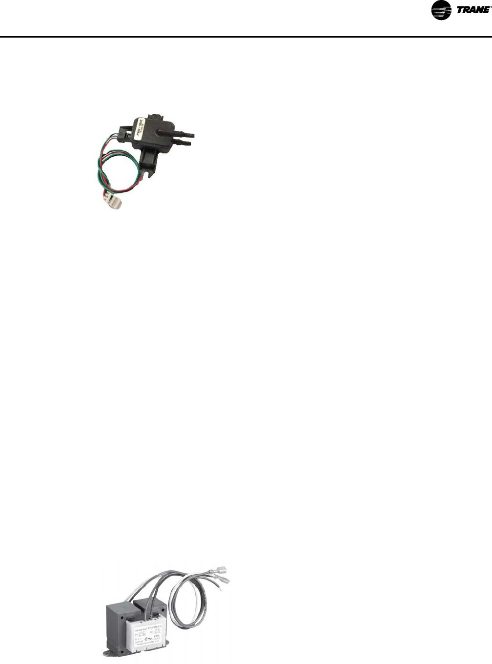
VAV-PRC012AC-EN
55
OOppeerraattiinngg TTeemmppeerraattuurree::
• 32 to 225°F
Differential Pressure Transducer
The differential pressure transducer is used in conjunction
with the Trane direct digital controller and analog electronic
controller. The pressure transducer measures the difference
between the high-pressure and low-pressure ports of the
Trane flow ring. The transducer is self-adjusting to changes
in environmental temperature and humidity.
Specifications
IInnppuutt PPrreessssuurree RRaannggee
0.0 to 5.0 in. wg
(Maximum input pressure 5 psig)
OOppeerraattiinngg EEnnvviirroonnmmeenntt
32 to 140°F, (0 to 60°C)
5% to 95% RH, Non-Condensing
SSttoorraaggee EEnnvviirroonnmmeenntt
-40 to 18°F, (-40 to 82.°C)
5% to 95%RH, Non-condensing
EElleeccttrriiccaall CCoonnnneeccttiioonnss
V
in
= 5.0 VDC nominal
(4.75 to 5.25 VDC acceptable)
Current Draw = 5 mA maximum
Null Voltage = 0.250 VDC ± 0.06 VDC
Span = 3.75 VDC ± 0.08 VDC
NNoottee:: Null and Span are ratio-metric with V in
PPhhyyssiiccaall DDiimmeennssiioonnss
Width: 2.5 inch (63.5 mm)
Length: 3.0 inch (76.2 mm)
Height: 1.5 inch (38.1 mm)
PPrreessssuurree CCoonnnneeccttiioonnss
1/8 inch (3.175 mm) barbed tubing connections
Transformers
The transformer converts primary power supply voltages to
the voltage required by the direct digital controller and
analog. The transformer also serves to isolate the controller
from other controllers which may be connected to the same
power source.
DDDDCC CCoonnttrroollss

56
VAV-PRC012AC-EN
Specifications
PPrriimmaarryy VVoollttaaggee
120 VAC
208 VAC
240 VAC
277 VAC
347 VAC
480 VAC
575 VAC
SSeeccoonnddaarryy VVoollttaaggee 24 VAC
PPoowweerr RRaattiinngg
50 VA
PPhhyyssiiccaall DDiimmeennssiioonnss
For all voltages:
The transformers will be no larger than the following dimensions:
Width: 2.63" (66.7 mm)
Length: 2.50" (63.5 mm)
Height: 2.30" (58.4 mm)
Trane Actuator – 90 Second at 60 Hz Drive Time
This actuator is used with DDC controls and retrofit kits. It is available with a 3-wire floating-point
control device. It is a direct-coupled over the shaft (minimum shaft length of 2.1"), enabling it to
be mounted directly to the damper shaft without the need for connecting linkage. The actuator
has an external manual gear release to allow manual positioning of the damper when the
actuator is not powered.
Specifications
Actuator Design 3-wire, 24-AC floating-point control. Non-spring return
Actuator Housing Housing type-NEMA 1
Rotation Range 90° clockwise or counterclockwise
Electrical Rating Power Supply –24 VAC (20 to 30 VAC) at 50/60 Hz
Power Consumption – 1.8 VA maximum, Class
Electrical Connection Box Lug Terminals
Manual Override External clutch release lever
Shaft Requirement ½" round
2.1" length
Humidity 5% to 95% RH, Non-Condensing
Temperature Rating Ambient operating: 32 to 125°F (0 to 52°C)
Shipping and storage: -20 to 130°F (-29 to 66°C)
Torque Running: 35 in.-lb (4 N-m)
Breakaway: 35 in.-lb (4 N-m) minimum
Stall: 60 in.-lb (4.5 N-m) minimum
Belimo Actuator – 95 Second Drive Time
This actuator is used with DDC controls and retrofit kits. It is available with a 3-wire floating-point
control device. it is a direct-coupled over the shaft enabling it to be mounted directly to the
damper shaft without the need for connecting linkage. The actuator has an external manual gear
DDDDCC CCoonnttrroollss

VAV-PRC012AC-EN
57
release to allow manual positioning of the damper. The actuator is UL listed and caries the CE
mark.
Specifications
Actuator Design 3-wire, 24-AC floating-point control. Brushless DC motor with internal
control electronics and constant drive time.
Rotation Range 95° clockwise or counterclockwise
Electrical Rating Reference Belimo Product Literature for Model LMB24-3-T
Electrical Connection Three box-type terminals for bare wire connections
Manual Override External clutch release lever
Shaft Requirement ½" round
2.1" length
Humidity Reference Belimo Product Literature for Model LMB24-3-T
Temperature Rating Reference Belimo Product Literature for Model LMB24-3-T
Torque 45 in.-lb (5 N-m)
Trane Spring Return Actuator
This actuator is used with DDC controls and is a floating-
point control device. It is direct-coupled over the shaft
(minimum shaft length of 2.1"), enabling it to be mounted
directly to the damper shaft without the need for
connecting linkage. The actuator is Underwriters
Laboratories Standard 60730 and Canadian Standards
Association C22.2 No. 24-93 certified as meeting correct
safety requirements and recognized industry standards.
Specifications
AAccttuuaattoorr DDeessiiggnn
24-VAC, floating-point control. Spring return
AAccttuuaattoorr HHoouussiinngg
Housing Type-NEMA IP54
RRoottaattiioonn RRaannggee
Adjustable from 0 to 90°F at 5° intervals, clockwise or counterclockwise
EElleeccttrriiccaall RRaattiinngg
Power Supply – 24 VAC (19.2 to 28.8 VAC) at 50/60 Hz
Power Consumption – 4VA holding, 5VA running maximum, Class 2
EElleeccttrriiccaall CCoonnnneeccttiioonn
6-pin female connector for Trane UCM (for Trane DDC controls)
MMaannuuaall OOvveerrrriiddee
Manual override key provided
Shaft requirement:
DDDDCC CCoonnttrroollss
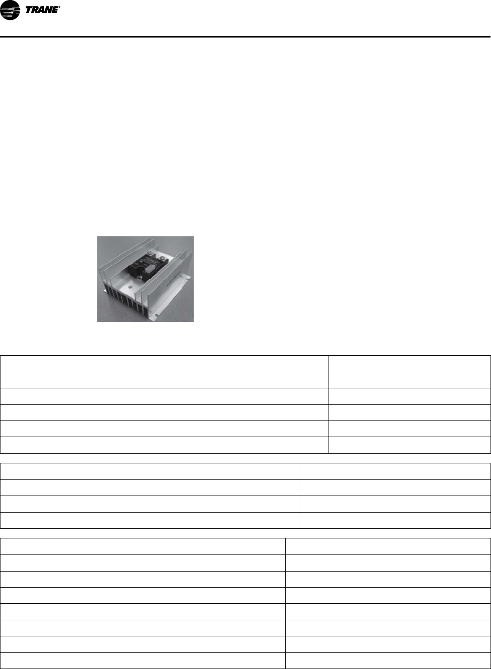
58
VAV-PRC012AC-EN
¼–in. to ¾–in. round
2.1" length
HHuummiiddiittyy
95% RH, Non-Condensing
TTeemmppeerraattuurree RRaattiinngg
Ambient operating: 32 to 130°F
(0 to 54°C)
Shipping and storage: -40 to 158°F
(-40 to 70°C)
TToorrqquuee
62 in.-lbs (7 Nm)
Electric Heater Silicon-Controlled Rectifier (SCR)
• Microprocessor based burst-fire controller / SSR
• Low-voltage control
• Output status indicator
• 0-100% Control Range
• Synchronized triggering output (P3)
• 20 AC Cycles Base Period
Specifications
Input Specifications
DC Control
Supply Voltage Range (VDC) (P1)
8-28
Input Current Range [mA]
20-30
Nominal Input Impedance [Ohms]
30K
PLV Range [VDC][P4]
0–10
Nominal Input Impedance [ohms][P4]
20K
Output Status Functions
LED
Initial Logic Supply On
Flash Once
Load Voltage Missing / Load Open (W/ PLV = 0V) Flash Once Intermittently
Load Voltage Missing / Load Open (W/ PLV > 0V) Flash Twice Intermittently
General Specifications
Parameters
Dielectric Strength, Input/Output/Base (50/60Hz)
4000 Vrms
Minimum Insulation Resistance (@ 500 V DC)
10
9
Ohm
Maximum Capacitance, Input/Output 10 pF
Ambient Operating Temperature Range
-20 to 80°C
Ambient Storage Temperature Range
-40 to 125 °C
Encapsulation Thermally conductive Epoxy
Input connector
Header Connector 3.5mm
DDDDCC CCoonnttrroollss

VAV-PRC012AC-EN
59
General Specifications
Parameters
Output Terminals Screws and Saddle Clamps Furnished, Installed
Output Max Wire Size Output:2 x AWG 8 (3.8mm)
Output Screws Maximum Torque 20 in lbs (2.2 Nm)
Assembly Specifications
Weight (typical) 1.38 Lb (0.628 Kg.)
Heat Transfer Material Used Thermal Pad
Material Steel
Finish Nickel Plate
Torque Applied
20 in/lbs ± 10%.
Controls Specifications
For all VariTrane™ units, the unit controller continuously monitors the zone temperature and
varies the primary airflow as required to meet zone temperature and ventilation setpoints.
Airflow is limited by adjustable minimum and maximum airflow setpoints.
Additionally, for series fan-powered units, the controller will start and run the fan continuously
during the occupied mode and intermittently during the unoccupied mode. Upon a further call
for heat, any hot water or electric heat associated with the unit is enabled.
For parallel fan-powered units, the controller energizes the fan upon a call for heat. Upon a
further call for heat, reheat is enabled.
Direct Digital Controls (DDC)
LLOONNMMAARRKK®® DDiirreecctt DDiiggiittaall CCoonnttrroolllleerr
Trane-designed L
ONMARK® certified controller uses the space comfort control (SCC) profile to
exchange information over a LonTalk® Network. L
ONMARK® networks provide the latest open
protocol technology.
DDiirreecctt DDiiggiittaall CCoonnttrroolllleerr
The microprocessor-based terminal unit controller provides accurate, pressure-independent
control through the use of a proportional integral control algorithm and direct digital control
technology. The UCM, monitors zone temperature setpoints, zone temperature, the rate of
temperature change, and valve airflow. With the addition of optional sensors, room occupancy or
supply duct air temperature can be monitored. The controller is provided in an enclosure with 7/
8” (22 mm) knockouts for remote control wiring. A Trane DDC zone sensor is required.
DDDDCC AAccttuuaattoorr
Trane 3-wire, 24-VAC, floating-point quarter turn control actuator with linkage release button.
Actuator has a constant drive rate independent of load, a rated torque of 35 in-lb, a 90-second
drive time, and is non-spring return. Travel is terminated by end stops at fully opened and closed
positions. An integral magnetic clutch eliminates motor stall.
DDDDCC AAccttuuaattoorr -- BBeelliimmoo
LMB24-3-T TN 3-wire, 24 VAC/DC, floating-point, quarter turn actuator with linkage release
button. Actuator has a constant drive rate independent of load, a rated torque of 45 in-lb, a 95
second drive time, and is non-spring return. Travel is terminated by end stops at fully-opened
and -closed positions. Internal electronic control prevents motor stall when motor reaches end
stops.
DDDDCC ZZoonnee SSeennssoorr
DDDDCC CCoonnttrroollss

60
VAV-PRC012AC-EN
The UCM controller measures zone temperature through a sensing element located in the zone
sensor. Other zone sensor options may include an externally-adjustable setpoint,
communications jack for use with a portable service tool, and an override button to change the
individual controller from unoccupied to occupied mode. The override button has a cancel
feature that will return the system to unoccupied. Wired zone sensors utilize a thermistor to vary
the voltage output in response to changes in the zone temperature. Wiring to the UCM controller
must be 18 to 22 awg. twisted pair wiring. The setpoint adjustment range is 50–88ºF (10–31°C)
Depending upon the features available in the model of sensor selected, the zone sensor may
require from a 2-wire to a 7-wire connection. Wireless zone sensors report the same zone
information as wired zone sensors, but do so using radio transmitter technology. No wiring from
the zone sensor to the UCM controller is necessary.
DDiiggiittaall DDiissppllaayy ZZoonnee SSeennssoorr wwiitthh LLiiqquuiidd CCrryyssttaall DDiissppllaayy ((LLCCDD))
The direct digital zone sensor contains a sensing element which sends a signal to the UCM. A
Liquid Crystal Display (LCD) indicates setpoint, or space temperature. Sensor buttons allow
setpoint adjust, and allow space temperature readings to be turned on or off. The digital display
zone sensor also includes a communication jack, for use with a portable edit device, and an
override button to change the UCM from unoccupied to occupied. The override button has a
cancel feature, which returns the system to unoccupied mode. The digital display zone sensor
requires seven wires, one for 24 VAC power.
System Communications
The Controller UCM sends and receives data from a Tracer® SC or other Trane Controller.
Current unit status and setpoints may be monitored and/or edited via this data communication
feature. The network type is a twisted wire pair shielded serial communication.
The following direct digital control features are available with VariTrane terminal units:
• Controls Option – DD00: Trane actuator for field-installed DDC controllers
• Controls Option – DD01: Cooling Only (DDC/UCM)
• Controls Option – DD02: Cooling with Normally-Closed On/Off hot water valve (Normally-
Open outputs) (DDC/UCM)
• Controls Option – DD03: Cooling with modulating hot water valve with optional spare On/Off
Output) (DDC/UCM)
• Controls Option – DD04: Cooling with staged On/Off electric heat (DDC/UCM)
• Controls Option – DD05: Cooling with pulse-width modulation electric heat (DDC/UCM)
• Controls Option – DD07: Cooling with Normally-Open On/Off hot water valve (Normally-
Closed outputs) (DDC/UCM)
• Controls Option – DD08: Cooling and Heating - Dual-Duct Constant Volume (DDC/UCM)
• Controls Option – FM00: Factory installation of customer supplied actuator and DDC controls.
Controls supplier is responsible for providing factory-installation and wiring instructions.
• Controls Option – FM01: Trane actuator with factory installation of customer supplied DDC
controls. Controls supplier is responsible for installing and wiring instructions.
• Control Mode – The UCM Control Mode may be edited from occupied to unoccupied to
accommodate night setback/setup.
• Control Action –The Control Action may be edited from cooling to heating, changing the
primary air damper to a heating source. This will accommodate a cooling/heating changeover
system.
• Control Offset – Enabling Control Offset will increase the cooling temperature setpoint and
decrease the heating temperature setpoint by a control-offset value (Stored at limiting in the
occupied mode).
• Drive damper fully open
• Drive damper fully closed
• Drive damper to maximum airflow setpoint
• Drive damper to minimum airflow setpoint
• Disable unit heat
DDDDCC CCoonnttrroollss

VAV-PRC012AC-EN
61
• Reset-Enabling the reset function forces the controller and the flow sensor to recalibrate
• Programmable hot water valve drive time
• Programmable air damper drive time
The following unit setpoints reside in the UCM in nonvolatile memory. These setpoints are
editable from the Tracer® via the communications link.
• Occupied cooling temperature setpoint (60–80ºF (15–26°C))
• Occupied heating temperature setpoint (60–80ºF (15–26°C))
• Unoccupied cooling temperature setpoint (60–100ºF (15–37°C))
• Unoccupied heating temperature setpoint (30–100ºF (15–37°C))
• Minimum cooling flow setpoint (0, 10–110% of unit equivalent nominal airflow)
• Minimum heating flow setpoint (0, 10–110% of unit equivalent nominal airflow)
• Maximum flow setpoint (0, 50–100% of unit equivalent nominal airflow)
• Fan Control Offset – This determines at what operating point the fan in a parallel fan-powered
unit is energized. This can be specified as a function of temperature, degrees above heating
setpoint, or primary airflow (0–10°F (-17–12°C) or 0,10–100% of unit equivalent nominal
airflow).
• Heating Setpoint Offset – This determines at what point the first stage of reheat turns on.
Expressed in degrees below cooling setpoint. (Only applicable when local thumbwheel is
enabled.)
• Zone temperature, auxiliary temperature, and zone setpoint calibration corrections
(adjustable from +/-10.0ºF (+/- -12°C)).
• Flow measurement calibration correction (50–150%)
• Cooling Setpoint Low Limit – Applies low limit to programmed occupied cooling setpoint or
zone sensor cooling setpoint (30–100°F (-1–37°C)).
• Heating Setpoint High Limit – Applies high limit to programmed occupied heating setpoint or
zone sensor heating setpoint (30–100ºF (-1–37°C)).
• RTD / Thermistor – Determines what type of zone temperature sensor will be used.
• Occupied and Unoccupied Outside Air Requirements – Determines the percent of outdoor air
required in the zone for air quality requirements.
• Series Fan Configuration – allows option of series fan-powered box to shut off fan and close
air valve when unit is unoccupied. Fan will operate in unoccupied mode if reheat is active.
• Heating setpoint low limit.
• Cooling setpoint high limit.
• Local heating flow setpoint enable/disable and setpoint.
• Auxiliary analog input mode select for either auxiliary temperature sensor or CO
2
detector.
• Binary input mode select for either generic or occupancy detector. In addition to the above
setpoints, the following status information can be transmitted to a Tracer® SC or other Trane
controllers.
• Active cooling temperature setpoint
• Active heating temperature setpoint
• Current unit primary airflow
• Current zone temperature
• Re-heat status (On/Off)
• Auxiliary Air Temperature – Available only if the unit has an auxiliary temperature sensor.
• Failure Indicators – The UCM will indicate the following: 1) Temperature Sensor Failure; 2)
Flow Sensor Failure; and 3) Local Zone Sensor Setpoint Failure.
• Ventilation Ratio
• Fan Status (on/off)
DDDDCC CCoonnttrroollss

62
VAV-PRC012AC-EN
• Calibration Status (calibration/not-calibrating)
• BIP state
• CO
2
Concentration—Available only if the unit has an auxiliary CO
2
sensor. This mode and
auxiliary air temperature are mutually exclusive.
Options
PPoowweerr FFuussee ((ccoooolliinngg oonnllyy aanndd hhoott wwaatteerr uunniittss,, aanndd VVDDDDFF))
An optional fuse is factory-installed in the primary voltage hot leg.
TTrraannssffoorrmmeerr ((SSttaannddaarrdd oonn ffaann--ppoowweerreedd,, ooppttiioonnaall oonn VVCCCCFF,, VVCCWWFF,, VVDDDDFF))
The 50-VA transformer is factory-wired and installed in an enclosure with 7/8–inch (22 mm)
knockouts to provide 24 VAC for controls.
Other Options Available
• DDC Zone Sensors - wired or wireless
• Modulating Water Valves
• Control Transformer (Ships loose with mounting plate for 4x4 junction box)
• Auxiliary Temperature Sensor
• Zone Occupancy Sensors
• CO
2
Sensors (Room- or duct-mounted)
DDDDCC CCoonnttrroollss

VAV-PRC012AC-EN
63
Application Considerations
VAV System
No Heat
CCeennttrraall CCoooolliinngg OOnnllyy——In some systems, the central air handler provides only cooling and
ventilation during zone occupied periods. The supply air is maintained at a constant temperature
and the supply airflow is modulated to match the VAV airflow rate with the zone cooling
requirements.
Central Heat
CCeennttrraall HHeeaatt ffoorr MMoorrnniinngg WWaarrmm--uupp——Many buildings cool down during the night. To be at a
comfortable temperature in the morning when the building is again occupied, heat must be
added to the spaces. Heat provided by the central air handler for morning warm-up is supplied at
constant air volume to the zones, prior to the time of occupancy. During the morning warm-up
period, the VAV terminal units must open to allow heated air to flow into the zones. In most
instances very little additional heat is needed once the building is occupied.
CCeennttrraall OOccccuuppiieedd HHeeaattiinngg--CChhaannggeeoovveerr——Some buildings use the same air handler to provide
both occupied cooling and occupied heating. This is commonly referred to as a changeover
system. The system changes between heating and cooling depending on the need of the zones
on the system. In a changeover system, the operation of the VAV terminal units must also
change over, opening to provide heat in the heating mode and opening to provide cooling in the
cooling mode.
Terminal Heat
PPaarraalllleell FFaann--PPoowweerreedd HHeeaatt——In some zones of a single-duct VAV system, cool supply air at
minimum flow is mixed with warm plenum air before entering the zone. A fan in the terminal
unit, in parallel with the central fan, draws air from the plenum whenever the zone requires heat.
Additional heat can be provided by an electric resistance heater or hot water coil.
SSeerriieess FFaann--PPoowweerreedd HHeeaatt——In some zones of a single-duct VAV system, the airflow to the zone
is held constant (although the fan can also be controlled for variable-speed operation), during
both heating and cooling, by a terminal unit fan that is in series with the central fan. The terminal
unit fan runs continuously. When the zone requires heat, cool supply air at minimum flow is
mixed with warm, return plenum air before entering the zone. Additional heat can be provided by
an electric resistance heater or hot water coil.
VariTrane VAV Terminal Units
VariTrane™ units are available with microprocessor-based DDC controls. Factory-installed
controls are available with all types of terminal units.


VAV-PRC012AC-EN
65
Figure 25. Series fan-powered unit cooling only (L) and series fan-powered unit with hot water
coil (R)
VAV Terminal Unit Types
Parallel Fan-Powered
Parallel fan-powered units are commonly used in zones which require some degree of heat
during occupied hours—when the primary supply air is cool. The terminal unit fan is in parallel
with the central unit fan; no primary air from the central fan passes through the terminal unit fan.
The terminal unit fan draws air from the space ceiling plenum.
When no heat is needed, the local parallel fan is off and a backdraft damper on the fan’s
discharge is closed to prevent cool air entry into the plenum. When cool primary airflow to the
zone is at a minimum and the zone temperature drops below heating setpoint, the local parallel
fan is turned on and the backdraft damper opens. The fan can deliver either a constant or variable
volume of warm plenum air, which is mixed with cool primary air at a minimum flow. Remote
heat or terminal reheat can provide additional local heating.
Series Fan-Powered
Series fan-powered terminal units are used commonly in VAV zones that require heat during
occupied hours and design higher supply airflows during all conditions. The terminal unit fan is
in series with the central fan. Primary air from the central fan always passes through the terminal
unit fan.
The local series fan within the terminal unit operates whenever the unit is in the occupied mode.
The fan can deliver either a constant or variable volume of air to the zone. As the zone requires
less cooling, the primary air damper closes. As the primary air damper closes, the air mixture
supplied to the zone contains less cool air and more warm plenum air. Remote heat or terminal
reheat can provide additional local heating.
Series fan-powered terminal units are also useful in low supply air temperature systems, since
the terminal unit fan can be sized so that warm plenum air is always mixed with low temperature
supply air. This raises the supply air temperature to an acceptable distribution level and reduces
condensation potential.
Low-Height Fan-Powered
Low-height fan-powered terminal units are a slightly modified version of a fan-powered terminal
unit. As its name suggests, the low-height fan-powered unit has a shorter height dimension to
accommodate applications where ceiling space is limited. To reduce the height, shorter terminal
unit fans are integrated into the standard height series or parallel terminal unit. The result is a
unit with a maximum height of 10.5" to 12.0". For low-height units with the smaller fan sizes
(sizes PS02, DS02 and DS03), a single low-profile fan is used. The fans still remain in series or
AApppplliiccaattiioonn CCoonnssiiddeerraattiioonnss

66
VAV-PRC012AC-EN
parallel with the primary system central fan. Low acoustic levels are much more challenging in
these low ceiling space applications, due to the reduced radiated ceiling pleunum effect.
The operation of the low-height terminal unit is exactly the same as that of a series or parallel
terminal unit, as are the options for high-efficiency ECMs, insulation options, etc. As with the
other fan-powered terminal units, additional local heating can be provided by remote heat or
terminal reheat.
Parallel vs. Series
In many climates, fan-powered systems are a lower operating cost alternative than single-duct
systems. The energy inefficiencies inherent in reheating cold primary air can be eliminated with a
key design characteristic of fan-powered terminal units, plenum air heating. Heating with warmer
plenum air allows for recovery of heat from lighting and other heat sources in the building.
Comparison of Parallel and Series Models
Once it has been determined that a fan-powered system is to be specified, the designer must
decide between parallel and series configurations. Each model carries its own characteristics of
delivered airflow, energy consumption, and acoustics. For the end user, the designer might
consider three goals: a comfortable and productive tenant environment, acceptable installed
cost, and low operating costs.
Parallel and series fan-powered terminal units offer specific advantages for particular
applications. The table which follows in this section compares the key similarities and differences
between the models that the designer should consider in performing an engineering analysis.
Typical Application of Parallel Units
Parallel intermittent fan-powered terminal units are very common in perimeter zones or
buildings where loads vary during occupied hours. Core zones, which maintain a more constant
cooling requirement, are better suited for variable airflow (single-duct) units. Typical jobs
combine parallel fan-powered units (exterior) and single-duct units (interior) to provide an
efficient system with lowest first cost. Although the overall NC of parallel systems is lower than
an equivalent series system, the intermittent fan is sometimes noticed when energized. To
minimize the impact of this NC change, an ECM (Electrically Commutated Motor) can be used
which has soft-start technology.
Typical Application of Series Units
Applications requiring constant air movement or blending utilize series constant fan-powered
terminal units. Conference rooms, laboratories, and lobbies are common applications. Because
the series fan also adds to the system external static pressure, office buildings take advantage of
this design feature and down size main air handling equipment. Finally, series terminals are used
in low-temperature air systems to temper cold primary air with warm plenum air and deliver it to
the zone.
Table 10. Parallel vs. series
Parallel Series
Fan Operation
Intermittent operation during occupied and
unoccupied modes.
Continuous operation during the occupied modes.
Intermittent operation during unoccupied mode.
Operating Sequence
Variable-volume, constant-temperature device
during cooling. Constant-volume, variable-
temperature during heating.
Constant-volume, variable-temperature device at
all times. Delivers design airflow regardless of the
load.
Fan Energization
Based on zone temperature deviation from setpoint.
No interlock with central system fan required.
Interlocked with central system fan to deliver
required air to the zone in both heating and cooling
modes.
Terminal Fan Operating and
Size
Fan runs during heating load. Size for design
heating load. Typically this is 40 to 60% of design
primary cooling airflow.
Fan runs continually. Fan sizing should meet the
greater of design cooling or heating airflow to the
zone.
Air valve Sizing Design cooling airflow. Design cooling airflow.
AApppplliiccaattiioonn CCoonnssiiddeerraattiioonnss

VAV-PRC012AC-EN
67
Table 10. Parallel vs. series (continued)
Parallel Series
Minimum Inlet Static
Pressure Required for Central
Fan Sizing
Sufficient to overcome unit, heating coil,
downstream duct and diffuser pressure losses.
Sufficient to overcome air valve pressure loss only.
Acoustics
When operating under cooling loads the terminal
fan does not run, offering superior acoustic
performance similar to single-duct VAV. Under
heating loads, the fan operates intermittently.
Acoustical impact can be minimized by use of a
ECM.
Produces slightly higher background sound
pressure levels in the occupied space. This sound
level remains constant and is less noticeable than
intermittent fan operation with PSC motors.
Figure 26. Parallel and series fan-powered terminal
Low-Temperature Air
Figure 27. Low temperature air system layout
AApppplliiccaattiioonn CCoonnssiiddeerraattiioonnss

68
VAV-PRC012AC-EN
Benefits of Low-Temperature Air
The benefits of low-temperature air systems include reduced first cost, reduced operating cost
and increased revenue potential. Since low-temperature air transports more energy per cubic
foot, smaller fans and ducts can be used. An EarthWise™ system takes that a step farther and
includes optimizing the waterside of the HVAC system as well with low flow rates through the
chilled water and condenser loops.
Since low-temperature water can transport more thermal energy per gallon, smaller pumps,
pipes, and valves can be used. Smaller HVAC equipment consumes less energy so both electrical
demand and consumption are lowered, reducing operating costs. The amount of revenue
generated by a commercial building is related to the amount and quality of rental floor space.
The amount of rental floor space is increased in a low-temperature air system, since air handlers,
riser ducts, and equipment rooms are smaller. Since smaller ducts reduce the required ceiling
plenum, additional floors may be included without increasing building height.
The concept of the EarthWise system is to deliver superior comfort and be less expensive to
install and operate. The method to do this involves both waterside optimization and airside
optimization. The waterside is optimized using techniques of low water flow through the
evaporator and condenser of the chiller as well as using chiller-tower optimization control
strategies. For more information on the waterside of the EarthWise system, contact your local
Trane representative or visit www.trane.com.
Airside savings are obtained using a combination of lower air temperature and intelligent control
strategies. The ability of the VAV unit to communicate information is vital to system
coordination.
System Operation
A low-temperature air system could be done with chilled water or direct expansion equipment. A
chilled water system includes a chiller plant, VAV air handlers, and series or parallel fan-powered
VAV terminal units. The VAV air handlers use cold water, typically around 40°F (4.4°C), from the
chiller plant, to cool the supply air to 45–50°F (7.2–10°C). The volume of supply air is determined
by the airflow needs of the VAV terminal units. A direct-expansion system would include a VAV
air handler or rooftop with series or parallel fan-powered VAV terminal units. The supply air
would be cooled to 48–52°F (8.9–11.1°C).
The VAV terminal units include a parallel or series fan with the central air handler or rooftop fan.
The terminal unit fan operates continuously, mixing 45-50°F (7.2–10°C) supply air with warm
plenum air, to provide 50–55°F (10–12.8°C) cooling air to the occupied space at design conditions.
As the cooling load in the space decreases, the VAV terminal air valve closes to reduce the flow
of cold supply air and increase the flow of warm plenum air in the case of series terminal units.
The temperature of air supplied to the space rises, but the volume flow rate to the space is
constant for the series unit.
Considerations for VAV products
To achieve the maximum benefit from the low-temperature air system, several VAV
considerations must be addressed.
Insulation
The units must be insulated to ensure that no condensation occurs on the units. How much
insulation is needed? Trane has tested its insulation with the goal of developing a thermal
resistance ratio for each type of insulation. The thermal resistance (TR) ratio can be used, along
with the properties of the insulation and the system operating conditions to determine the
necessary insulation thickness required.
In the low-temperature air system with fan-powered units, the ducts and diffusers downstream
from the terminal unit handle air that is 55°F (12.8°C) or warmer. Therefore, condensation
considerations are no different from conventional systems. Linear slot diffusers are
recommended to take advantage of the Coanda effect described in the Diffusers section later in
the catalog.
AApppplliiccaattiioonn CCoonnssiiddeerraattiioonnss

VAV-PRC012AC-EN
69
Terminal unit surfaces that are traditionally not insulated—electric and hot water reheat coils and
the primary air inlet for example—should be thoroughly field-insulated.
Leakage
When the terminal unit fan is off, the air valve will close, and not leak. Ducts upstream of the
terminal unit must also be thoroughly insulated and constructed for very low leakage.
Duct and terminal unit insulation can be internal or external. Keep in mind that internal insulation
has hidden thermal leaks at joints and seams. These areas must be located and insulated
externally to avoid condensation. External Insulation, on the other hand, allows a complete,
uniform thermal seal.
Minimum settings and IAQ
Indoor air quality is usually best when a specific quantity of outside ventilation air reaches each
building occupant. Maintaining a minimum ventilation rate is a challenge in any VAV system
because the amount of supply air that reaches a particular space decreases as the cooling load
decreases. To insure that a minimum amount of supply air reaches the space at all times, a
minimum flow setting on the terminal unit is used. In low-temperature air systems, when the
space needs heating, this minimum flow setting results in increased heating load. Therefore, it is
important to include the additional load imposed by the cold supply air when calculating heating
loads. Reheat may be required since the ventilation values are absolute requirements and not
percentage of total airflow requirements.
EarthWise or Low-Temperature Air Distribution Design Considerations with Parallel Fan-
powered Terminal Units
The parallel fan-powered unit needs to be set up to run continuously rather than intermittently.
Since it is in parallel, the airflow required by the fan is less than a comparable series unit. This
results in energy savings. Running the parallel fan continuously will take some minor control
changes. It will, however, create a better acoustical installation.
The parallel fan should be large enough to temper the design cooling airflow at 45–50°F to 50–55°
F (7.2–10°C to 10–12.8°C). For instance, if the design cooling airflow is 1000 cfm at 55°F (472 L/s at
12.8°C), you will need 781 cfm of 48°F (368 L/s of 8.9°C) supply air and 219 cfm of 80°F (103 L/s of
26.7°C) plenum air. The parallel fan can be sized for the 219 cfm (103 L/s) rather than the total
room airflow.
The fan airflow plus the minimum primary airflow must be checked with the minimum airflow of
the diffuse
rs to insure that dumping doesn’t occur. If that is a concern, the minimum could be adjusted up
or the fan airflow could be adjusted up.
As the valve closes, the downstream static pressure will decrease because the pressure is related
to the airflow. The fan will supply more air at the valve minimum condition than at design due to
the decreased static pressure. This should be a consideration when calculating how much airflow
would occur at the minimum valve plus fan airflow condition. The new fan airflow would be
found by looking at a fan curve at the new SP point. The new SP can be calculated:
The following table can be used to determine what percentage of the total airflow should come
from the fan to temper the supply air, assuming 80°F (26.7°C) plenum air.
AApppplliiccaattiioonn CCoonnssiiddeerraattiioonnss
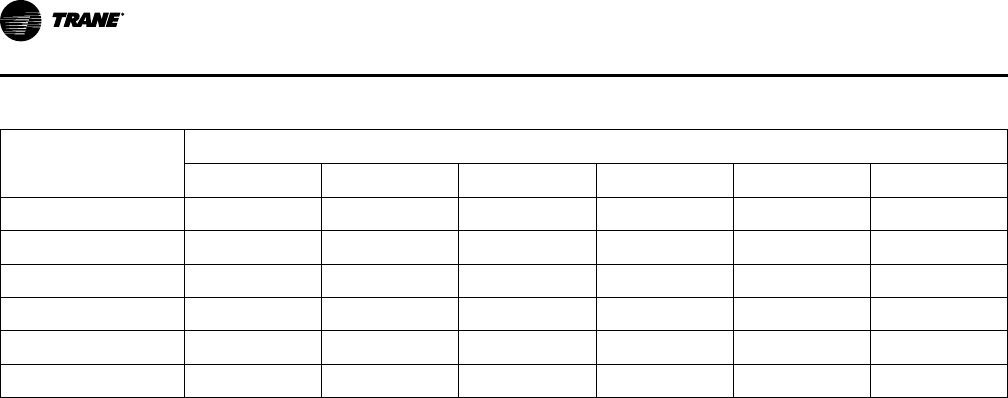
70
VAV-PRC012AC-EN
Table 11. Percentage of airflow from fan
Supply Air Temp.
°F (°C)
Primary Air Temperature — °F (°C)
45 (7.2) 46 (7.8) 47 (8.3) 48 (8.8) 49 (9.4) 50 (10)
50 (0)
14% 12% 9% 6% 3% 0%
51 (10.6)
17% 15% 12% 9% 6% 3%
52 (11.1)
20% 18% 15% 13% 10% 7%
53 (11.7)
23% 21% 18% 16% 13% 10%
54 (12.2)
26% 24% 21% 19% 16% 13%
55 (12.8)
29% 26% 24% 22% 19% 17%
If anything other than 80°F (26.7°C), the following equation can be used to calculate the
percentage:
Supply Temperature = (% * primarytemperature) + (1-%) * plenum temperature
Low-Temperature Air Distribution Design Considerations with Series Fan-powered
Terminal Units
The VAV terminal unit includes a fan that operates continuously. The series fan should be large
enough to insure that the mixture of cold supply air and warm plenum air is 50–55°F (10–12.8°C)
at design cooling flow conditions. In these types of systems, it is a good design practice to
develop the system based upon 55°F (12.8°C) air being provided to the space from the fan-
powered terminal unit. If a lower temperature air is used downstream of the VAV terminal unit,
the system designer will have some concerns related to condensation on diffusers and other low-
pressure ductwork accessories. For instance, if the occupied space must receive 1000 cfm of 55°F
(472 L/s at 12.8°C) air to satisfy to design cooling load, 715 cfm must be 45°F (337 L/s must be at
7.2°C) supply air and 285 cfm must be 80°F (135 L/s must be 26.7°C) plenum air. Therefore, the
series fan-powered terminal must be sized to have the air valve deliver 715 cfm (337 L/s) of
supply air at design conditions, but the fan must be sized to deliver 1000 cfm (472 L/s).
Airside System Factors
A couple of system related factors should be noted as they apply to condensation. The first is the
advantage the colder primary air has from a humidity standpoint. As noted in the description
above, the low-temperature system operates at space relative humidity of 30–45% while a
standard system operates at space relative humidity of 50–60%. The drier zone air means that the
plenum air returning to the series terminal unit will also be drier and, therefore, less of a problem
with condensation.
The second condensation factor to note is related to systems that shut down in the evening.
Many people believe that immediately sending low-temperature primary air to these boxes that
have been off for some time will cause a shock to the system and may cause condensation
problems at startup. The solution to this has been the advent of gradual pull-down or “soft start”
systems. In this type of system, the primary air temperature is higher on initial startup (typically
55°F(12.8°C)) and then gradually reduced to the normal operating point over the next 30 to 60
minutes.
Energy Savings and System Controls
Electrically Commutated Motor
The ECM provides an additional energy-saving option to the system designer. Some of the
advantages of the motor include high efficiency, variable-speed operation, quiet operation, short
payback, and easy installation. There are several considerations that need to be addressed when
deciding whether to use these motors or not. The primary benefit may be seen as increased
efficiency.
Operating Hours—The added cost of an ECM can be offset more quickly in applications which
require a relatively high number of hours of operation. However, if a space does not require
AApppplliiccaattiioonn CCoonnssiiddeerraattiioonnss
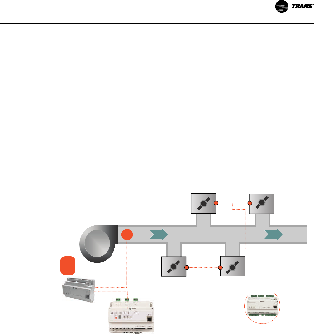
VAV-PRC012AC-EN
71
extensive running time for the unit fan, then it may not be a good candidate for this type of motor
based solely on payback. Therefore, the decision about using the ECM may be based on other
benefits, depending on the needs of the customer.
Airflow Flexibility—The ECM allows a greater airflow range per fan size. If a space is going to
change uses and load components frequently, the ability to change supply airflow with the ECM
without changing units will be a benefit.
Airflow Balancing—The ability of the ECM motor to self-balance to an airflow regardless of
pressure can be an asset when trying to air balance a job. This will help eliminate additional
dampers or changes to downstream ductwork to ensure proper airflow. For more information,
please contact your local Trane sales engineer.
Fan-Pressure Optimization
With Trane's Tracer bulding automation system, the information from VAV terminal units can be
used for other energy-saving strategies. Fan-pressure optimization is the concept of reducing the
supply fan energy usage based on the position of the terminal unit dampers.
The control system polls the VAV units for the air valve damper position on each unit. The duct
static pressure setpoint for the supply fan is reset downward until the furthest open damper is
nearly wide open. The correct airflow is still being sent to each zone since the air valve controls
of the VAV units are pressure-independent, but the supply fan uses less energy since it is able to
generate less pressure, which results in fan energy savings.
Figure 28. Optimized static-pressure control
static
pressure
sensor
P
supply
fan
RTU controller
Tracer SC
VAV boxes with
DDC controllers
VFD
Ventilation Reset
The Ventilation Reset control strategy enables a building ventilation system to bring in an
appropriate amount of outdoor air per AASSHHRRAAEE SSttaannddaarrdd 6622..11. The basis for the strategy is
measuring airflow at each zone, calculating current system ventilation efficiency using the
multiple-zone system equations of the standard, and communicating a new outdoor airflow
setpoint to the air handler.
This strategy continually monitors the zone ventilation needs and system outdoor air intake flow,
minimizing the amount of ventilation air and increasing the energy efficiency of the system. This
ensures that the right amount of air is brought in at all times and that proper ventilation can be
AApppplliiccaattiioonn CCoonnssiiddeerraattiioonnss

72
VAV-PRC012AC-EN
documented. Trane has integrated this control ability into the VAV controls, air-handler controls,
and building controls.
Figure 29. Ventilation reset
OA
SA RA
VAV Controllers
• Required outdoor airflow
• Current primary airflow
• Current OA fraction
Tracer SC
• Find highest OA fraction
• Calculate current system
intake airflow (ASHRAE 62.1)
RTU controller
• Reset intake airflow
Control Types
VAV terminal units are available with many different options. These options fall into three main
categories of controls: direct digital (DDC), pneumatic, and analog electronic. All of these control
types can be used to perform the same basic unit control functions, yet differences exist in
accuracy of performance, versatility, installed cost, operating cost, and maintenance cost.
Direct Digital Control (DDC) Systems
DDiirreecctt ddiiggiittaall ccoonnttrrooll ((DDDDCC)) ssyysstteemmss became available as advances in computer technology
made small microprocessors available and affordable. Much of the hardware in DDC systems is
similar to analog electronic systems. The primary difference is that DDC controllers allow system
integration, remote monitoring, and adjustment. The microprocessor is programmed using
software that gives the controller a higher level of capability than either the pneumatic or analog
electronic options.
BBeenneeffiittss
Performance—DDC controls offer PI control capability. A PI control scheme is the most accurate
and repeatable control scheme available in the VAV terminal unit industry.
Versatility—DDC controls Symbio 210 and Symbio 210e accepts software commands to
determine how its outputs will be controlled. When a control sequence must be modified,
making changes to the software instructions is easier and quicker than changing hardware.
Operating and Maintenance Costs—DDC controls can be networked together to provide system-
control strategies for energy savings. Multiple controllers can be easily monitored and adjusted
from a remote location. DDC controls also have system and individual diagnostic capability.
DDC Controls Basic Information
DDC controls are the industry standard for VAV terminal unit control systems. DDC systems use
electronic field devices such as a flow transducer, a primary air modulating damper, and an
electronic temperature sensor. These field devices report software instructions of how the
outputs are positioned in relation to the inputs to a controller. The VariTrane™ system uses a
AApppplliiccaattiioonn CCoonnssiiddeerraattiioonnss

VAV-PRC012AC-EN
73
primary air valve and flow transducer for both DDC systems and analog electronic systems.
However, the DDC zone sensor is different from the analog electronic thermostat.
DDC controls provide flexibility and considerable diagnostic capability. DDC controllers can be
connected together to form a network of controllers which can be can be monitored from a
remote location to ensure proper operation. Commands and overrides can be sent for groups of
controllers at one time to make system-wide changes. Commands and overrides can be sent to
individual unit controllers to allow problem diagnosis, temporary shutdown, startup schedules or
other specialized changes. When integrated into a building automation system, the operation of
the VAV terminal units can be coordinated with other components of the overall system to
ensure comfortable, efficient operation and even reduce energy use.
DDC control of VAV terminal units is a key element in providing intelligent and responsive
building automation. Precision control, flexible comfort, and after hours access are all available
with the DDC control system for VAV terminal units.
Key features of the system include:
• An advanced unit controller
• Flexible system design
• User-friendly interaction
Flow Measurement and Control
One of the most important characteristics of a VAV terminal unit
is its ability to accurately sense and control airflow. The
VariTrane™ terminal unit was developed with exactly that goal
in mind. The patented, multiple-point, averaging flow ring
measures the velocity of the air at the unit primary air inlet.
The differential pressure signal output of the flow ring provides
the terminal unit controller a measurement of the primary
airflow through the inlet. The terminal unit controller then opens
or closes the inlet damper to maintain the controller airflow
setpoint.
Flow Measurement
Most of these terminal units contain a differential pressure airflow measurement device,
mounted at the primary air inlet, to provide a signal to the terminal unit controller. Numerous
names exist for the differential pressure measurement device—flow sensor, flow bar, flow ring.
The differential pressure measured at the inlet varies according to the volumetric flow rate of
primary air entering the inlet.
The total pressure and the static pressure are measurable quantities. The flow measurement
device in a VAV terminal unit is designed to measure velocity pressure. Most flow sensors
consist of a hollow piece of tubing with orifices in it. The VariTrane™ air valve contains a flow
ring as its flow measuring device. The flow ring is two round coils of tubing. Evenly spaced
orifices in the upstream coil are the high-pressure taps that average the total pressure of air
flowing through the air valve. The orifices in the downstream ring are low-pressure taps that
average the air pressure in the wake of flow around the tube. By definition, the measurement of
static pressure is to occur at a point perpendicular to the airflow. The low-pressure taps on the
VariTrane™ flow ring measure a pressure that is parallel to the direction of flow but in the
opposite direction of the flow. This “wake pressure” that the downstream ring measures is lower
than the actual duct static pressure. The difference between the “wake pressure” and the static
pressure can be accounted for so that the above relationship between flow and differential
pressure remain valid. The difference also helps create a larger pressure differential than the
velocity pressure. Since the pressures being measured in VAV terminal unit applications are
small, this larger differential allows transducers and controllers to measure and control at lower
flow settings than would otherwise be possible.
The average velocity of air traveling through the inlet is expressed in the equation:
FPM = 1096.5
VP
DENS
AApppplliiccaattiioonn CCoonnssiiddeerraattiioonnss

74
VAV-PRC012AC-EN
Where:
• FPM = Velocity of air in feet per minute
• 1096.5 = A constant
• VP = The velocity pressure of the air expressed in inches of water
• DENS = The density of the air expressed in pounds per cubic foot
Often, the density is assumed to be a constant for dry air at standard conditions [68°F (20°C)] and
sea level pressure of 14.7 psi (101.4 kPa). These conditions yield the following commonly used
equation:
FPM = 4005
VP
The amount of air traveling through the inlet is related to the area of the inlet and the velocity of
the air:
AIRFLOW (cubic feet per minute, cfm) = AREA (square feet) x AVERAGE VELOCITY (feet per
minute)
Accuracy
The multiple, evenly spaced orifices in the flow ring of the VariTrane™ terminal unit provide
quality measurement accuracy even if ductwork turns or variations are present before the unit
inlet. For the most accurate readings, a minimum of 1½ diameters, and preferably 3 diameters, of
straight-run ductwork is recommended prior to the inlet connection. The straight-run ductwork
should be of the same diameter as the air valve inlet connection. If these recommendations are
followed, and the air density effects mentioned below are addressed, the flow ring will measure
primary airflow within ±5% of unit nominal airflow.
Figure 30. Air pressure measurement orientations
Air Density Effects
Changes in air density due to the conditions listed below sometimes create situations where the
standard flow sensing calibration parameters must be modified. These factors must be
accounted for to achieve accuracy with the flow sensing ring. Designers, installers, and air
balancers should be aware of these factors and know of the necessary adjustments to correct for
them.
EElleevvaattiioonn
At high elevations the air is less dense. Therefore, when measuring the same differential
pressure at elevation versus sea level the actual flow will be greater at elevation than it would be
at sea level. To calculate the density at an elevation other than standard conditions (most
manufacturers choose sea level as the point for their standard conditions), you must set up a
ratio between the density and differential pressure at standard conditions and the density and
differential pressure at the new elevation.
Standard Conditions
∆
P
DENS Standard Conditions
∆
P
New Conditions
DENS New Conditions
=
AApppplliiccaattiioonn CCoonnssiiddeerraattiioonnss

VAV-PRC012AC-EN
75
Since the data from the manufacturer is published at standard conditions, this equation should
be solved for the differential pressure at standard conditions and the other quantities substituted
to determine the ratio for the differential pressure measured at the new conditions.
DDuucctt PPrreessssuurree aanndd AAiirr TTeemmppeerraattuurree VVaarriiaattiioonnss
While changes in these factors certainly affect the density of air, most operating parameters
which systems need keep these effects very small. The impact on accuracy due to these changes
is less than one half of one percent except in very extreme conditions. Extreme conditions are
defined as those systems with inlet static pressures greater than 5 in. wg (1245 Pa) and primary
air temperatures greater than 100°F (37.8°C). Since those types of systems occur so infrequently,
we assume the effects of duct pressure and air temperature variations to be negligible.
AApppplliiccaattiioonn CCoonnssiiddeerraattiioonnss

76
VAV-PRC012AC-EN
LLiinneeaarriittyy
With the increased use of DDC controls instead of pneumatic controls, the issue of linearity is not
as great as it once was. The important aspect of flow measurement versus valve position is the
accuracy of the controller in determining and controlling the flow. Our units are tested for
linearity and that position versus airflow curve is downloaded and commissioned in the factory
to ensure proper control of the unit.
Reheat Options
Hot Water Heating Coil
Figure 31. Hot water coil Figure 32. Trane hot water valve Figure 33. Belimo hot water valve
Hot water heating coils are generally applied on VAV terminal units as reheat devices. When
applying these coils it is important to make sure that they are operating in the proper air flow and
water flow range. (See tables in Performance Data chapter for airflow and water flow rates.)
Either a two-way or a three-way valve controls the coils.
The most important factor when sizing valves is the coefficient of velocity or C
v
. This coefficient
of velocity, which is commonly called the flow coefficient, is an industry standard rating. Valves
having the same flow coefficient rating, regardless of manufacturer, will have the same
waterside performance characteristics.
The preferred method is to size the valve for 3 to 5 psi for pressure drop when full open.
Generally the rule of thumb is to use 4 psi.
C
v
= GPM / 2 or GPM = 2 * C
v
(since square root of 4 = 2)
This formula is very easy to use and is as accurate as any other method. Size the valve for a C
v
=
1/2 the GPM it must pass in modulating applications
The equation that governs valve sizing is:
C
v
=
GPM
∆
P
Where
• C
v
= Flow coefficient
• GPM = The maximum water flow rate through the valve in gallons per minute
• ΔP = The maximum allowable differential pressure across the valve in psi
The flow and differential pressure are generally the known quantities. The equation is solved for
the flow coefficient. The flow coefficient is then compared to the published C
V
values for the
control valves that are available. The control valve with the C
V
that is the closest, but greater
than, the calculated flow coefficient is the correct choice for the control valve. This choice will
keep the valve pressure drop below the maximum allowable valve pressure drop. The valve
pressure drop should then be checked against the coil pressure drop. If the coil pressure drop is
appreciably larger than the valve pressure drop, a valve with a smaller C
V
should be selected to
produce a larger control valve pressure drop. If this new valve has a pressure drop that is much
AApppplliiccaattiioonn CCoonnssiiddeerraattiioonnss

VAV-PRC012AC-EN
77
larger than the maximum allowable pressure drop for valves, the system designer should be
consulted to make sure that the system hot water pumps can deliver the water at the new
conditions.
Electric Reheat
Electric heating coils are applied on VAV terminal units as terminal reheat devices. Electric heat
coil capacity is rated in kilowatts (kW). Coils are available with the total capacity divided into one,
two, or three stages
Electric heat coils are available in single-phase or three-phase models. This refers to the type of
power source connected to the coil. Single-phase models have resistance elements internally
connected in parallel. Three- phase models have resistance elements internally connected in a
delta or a wye configuration.
The current draw for the electric coil will depend upon whether it is a single-phase or three-phase
coil. The current draw is necessary for determining what size wire should be used to power the
electric coil and how big the primary power fusing should be. The equations for current draw for
these coils are:
3φamps
kW 1000×
PrimaryVoltage 3
--------------------------------------------------
=
1φamps
kW 1000×
--------------------------------------------------
=
PrimaryVoltage
VariTrane™ three-phase electric heat is available in balanced configurations. For example, a 9
kW three-phase coil, each stage would carry 1/3 or 3 kW of the load.
It is important to note that these coils have certain minimum airflow rates for each amount of kW
heat the coil can supply to operate safely. These airflow values are based upon a maximum rise
across the electric heater of 50°F (28°C).
The equation that relates the airflow across an electric coil to the temperature rise and the coil
change in temperature is:
CF M
kW 3145×
∆T
---------------------------
=
Where
• CFM = Minimum airflow rate across the coil
• kW = The heating capacity of the electric coil
• 3145 = a constant
• ΔT = The maximum rise in air temperature across the coil, usually 50°F (28°C)
Electric heat coils are available with magnetic or solid state relays. Magnetic contactors are less
expensive than solid state relay contactors. However, solid state relay contactors can be cycled at
a more rapid rate without failing.
Insulation
Insulation in a VariTrane™ terminal unit is used to
avoid condensation on the outside of the unit, to
reduce the heat transfer from the cold primary air
entering the unit, and to reduce the unit noise. The
VariTrane™ line offers four types of unit insulation.
The type of facing classifies the types of insulation.
To enhance IAQ effectiveness, edges of aallll
iinnssuullaattiioonn ttyyppeess hhaavvee mmeettaall eennccaappssuullaatteedd eeddggeess..
MMaattttee--FFaacceedd
AApppplliiccaattiioonn CCoonnssiiddeerraattiioonnss

78
VAV-PRC012AC-EN
This type of insulation is used for typical applications. It consists of a fiberglass core covered by a
high-density skin. The dual-density construction provides good sound attenuation and thermal
performance.
FFooiill--FFaacceedd
This type of insulation is used in applications where there is some concern regarding airborne
contaminants entering the space, or dirt being trapped in the fibers of the insulation. The
insulation is composed of a fiberglass core laminated to a foil sheet. Foil-faced insulation will
provide the same sound attenuation performance as matte-faced insulation.
DDoouubbllee--WWaallll
This type of insulation is used in applications where there is extreme concern regarding airborne
contaminants entering the space or dirt being trapped in the fibers of the insulation. The
insulation is the same as the matte-faced insulation. However, after the insulation is installed, a
second solid wall of 26-gauge steel covers the insulation. All wire penetrations of this insulation
are covered by a grommet. This type of insulation will result in higher discharge and radiated
sound power.
CClloosseedd--CCeellll
This type of insulation is used in applications where IAQ and fibers are of primary concern. The
acoustics of the closed-cell insulation are similar to double-wall insulation. The thermal
properties are similar to fiberglass insulation. This insulation contains no fiberglass.
Acoustics
Acoustical Best Practices
Acoustics with terminal units is sometimes more confusing than it needs to be. As we know,
lower velocities within a unit leads to improved acoustical performance. Additionally, if the VAV
terminal unit has a fan, lower RPM provides better acoustical performance. It is as simple as that
—there are some catches, however.
Additional considerations will be discussed in more detail throughout this portion of Application
Considerations, such as unit size and type, appurtenance affects (due to insulation, attenuation,
etc.), certification, and computer modeling. Let’s take a look at the first consideration, sizing of
units.
Sizing of Units
Before blindly increasing the size of units, we must first understand what is setting the acoustics
within the space. In general, over 95% of acoustics in VAV terminal units, which set the sound
pressure levels and ultimately the NC within the space, is from radiated sound. This is readily
known for fan-powered units, but less commonly known for single- and dual-duct units. Radiated
sound emanates from the unit and enters the occupied space via means other than through the
supply ductwork. The most typical path is through the plenum space, then through the ceiling,
then into the occupied space. While discharge sound should never be ignored, radiated sound is
the most dominant and usually the most critical sound source.
When increasing aaiirr vvaallvvee sizes, BE CAREFUL. OOvveerrssiizziinngg aann aaiirr vvaallvvee ccaann aaddvveerrsseellyy iimmppaacctt
tthhee aabbiilliittyy ttoo mmoodduullaattee aanndd pprrooppeerrllyy ccoonnttrrooll tteemmppeerraattuurree iinn tthhee ssppaaccee.. In extremely
oversized situations, the air valve will operate like a two-position controlled device, with air either
being “on”, or “off”, and not really much in between. The best way to avoid this is to understand
that the minimum air velocity for most air valves is 300 FPM. This is a function of the flow
sensing device and the ability of the pressure transducer and controller to properly read and
report flow. This is not manufacturer specific, as physics applies to all. Therefore, when sizing air
valves, minimum velocity for proper pressure independent flow is 300 FPM.
Modulation capability and range is vital for proper operation of VAV systems. With oversized
units, the unit will act as a constant volume system eliminating the energy savings and individual
zone control advantages of VAV systems. A good rule of thumb is to size cooling airflow for
around 2000 FPM. VAV systems only operate at full flow when there is a maximum call for
cooling in the zone. The greatest portion of the time, an air valve will be operating at partial
flows.
AApppplliiccaattiioonn CCoonnssiiddeerraattiioonnss
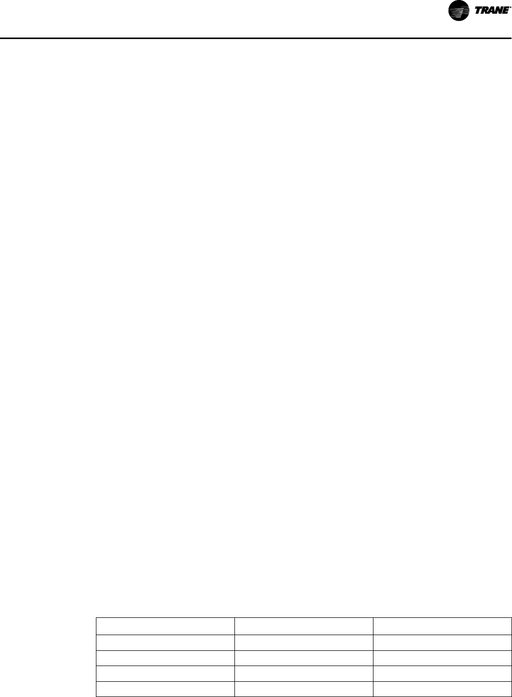
VAV-PRC012AC-EN
79
When sizing fan-powered units, the fan airflow range can be determined by looking at the fan-
curve. For parallel and series fan-powered units that operate at a constant fan speed, selections
can be made all the way to the lowest flow ranges of the fan curve. A good balance of
performance and cost is to select fans at 70-80% of maximum fan flow.
Insulation Types
Insulation is a factor to consider when dealing with the acoustics of terminal units. Most
insulation types will provide similar acoustical results, but there are exceptions. Double-wall and
closed-cell foam insulation will generally increase your sound levels because of the increased
reflective surface area that the solid inner-wall and closed-cell construction provides. This
increase in sound will have to be balanced with the IAQ and cleanability considerations of the
dual-wall and closed-cell construction.
Series vs. Parallel Fan Units
Acoustical considerations may affect whether a series or parallel fan-powered terminal unit is
selected. Both units have their advantages.
The parallel unit has the advantage of fan energization and fan acoustical impact only when
heating is needed. Parallel fans are smaller than series units because they are sized for 30–60% of
total unit flow. This creates a unit which is quieter than series units. The disadvantage of the
parallel unit is intermittent sound. This impact can be minimized by using an ECM, which has
slow fan ramp-up speed and can be configured for variable-speed fan control.
The primary acoustic benefit of a series fan-powered unit configured for constant-speed fan
control is that the fan runs at the same speed continuously. Sometimes the unit can be selected
at slightly higher sound levels due to the constant nature of the sound.
The primary acoustic disadvantage of the series unit is the need to size the unit fan for the total
room airflow. Series units require a larger, louder fan than parallel configurations.
NNoottee:: Operating parallel units with a continuously operating fan may be considered for some
applications. This provides the quietest overall fan-powered system with the benefit of
continuous fan operation. See your local Trane sales engineer for more details.
Placement of Units
Unit placement in a building can have a significant impact on the acceptable sound levels.
Locating units above non-critical spaces (hallways, closets, and storerooms) will help to contain
radiated sound from entering the critical occupied zones.
Unit Attenuation
Terminal unit-installed attenuators are an option available to provide path sound attenuation.
Manufacturer-provided attenuators on the discharge of a terminal unit are targeted at reducing
discharge path noise and are typically a simple lined piece of ductwork. It would often be easier
and less expensive to design the downstream ductwork to be slightly longer and require the
installing contractor to include lining in it. Attenuators on the plenum inlet of fan-powered
terminals are targeted at reducing radiated path noise since the plenum opening on a fan-
powered terminal unit is typically the critical path sound source. Significant reduction in radiated
path noise can result from a well-designed inlet attenuator. The attenuation from these
attenuators is due to simple absorption from the attenuator lining and occupant line of sight
sound path obstruction. Therefore, longer attenuators and attenuators that require the sound to
turn multiple corners before reaching the occupied space provide superior results, particularly in
the lower frequency bands.
Table 12. Octave band frequencies
Octave Band
Center Frequency Band Edge Frequencies
1 63 44.6-88.5
2 125 88.5-177
3 250 177-354
4 500 354-707
AApppplliiccaattiioonn CCoonnssiiddeerraattiioonnss
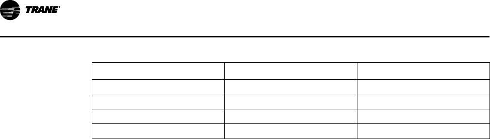
80
VAV-PRC012AC-EN
Table 12. Octave band frequencies (continued)
Octave Band
Center Frequency Band Edge Frequencies
5 1000 707-1414
6 2000 1414-2830
7 4000 2830-5650
8 8000 5650-11300
Attenuators that are simple “cups” at the plenum inlet(s) have been shown in Trane’s acoustical
mock-up to provide no measurable reduction in sound pressure in the critical octave bands
which set the occupied space noise criteria.
Certification and Testing
Terminal units should be submitted based on the same criteria. There are several ways to ensure
this by certification and testing.
Raw unit sound data can be good measurement criteria for evaluation. In using this as a basis for
comparison, the designer needs to make sure that the information is based on the AHRI Standard
880-2011 that gives the procedure for testing.
Specifying NC or RC sound levels is a possible comparison, but the designer needs to be sure the
comparison is fair. Two options are to specify the attenuation effect on which you would like the
units to be evaluated or to specify that AHRI Standard 885-2008 transfer functions be used. The
importance of AHRI Standard 885-2008 is that it is the first AHRI Standard that specifies exact
transfer functions to be used for evaluation. Previous versions of the standard gave guidelines,
but the manufacturers could choose their own set of factors.
Path Attenuation
Sound generated by a terminal unit can reach the occupied space along several paths. The
terminal unit generated sound will lose energy — i.e. the energy is absorbed by path obstacles—
as it travels to the occupied space. This acoustical energy dissipation as it travels to the occupied
space is called path attenuation. The amount of energy lost along a particular path can be
quantified and predicted using the procedure outlined in AHRI-885. Each path must be
considered when determining acceptable sound power generated by a terminal unit.
The term “transfer function” is often used to describe the entire path attenuation value for each
octave band (i.e., the sum of all components of a particular path).
Examples of path attenuation include locating the terminal unit away from the occupied space,
increasing the STC (sound transmission classification) of the ceiling tile used, internally lining
ductwork, drywall lagging the ceiling tiles or enclosing the terminal unit in drywall. All of these
choices have costs associated with them that must be weighed against the benefits. Some of
these alternatives can be acoustically evaluated from application data provided in AHRI-885.
Others may require professional analysis from an acoustical consultant.
Computer Modeling
Computer modeling of acoustical paths is available to help estimate sound levels and determine
problem sources. The software used by Trane for computer modeling is called Trane Acoustics
Program (TAP™).
This software can analyze different room configurations and materials to quickly determine the
estimated total sound levels (radiated and discharged) in a space. The Trane Official Product
Selection System Trane Select Assist™ can also be used to determine sound levels of terminal
units. You can base selections on a maximum sound level and enter your own attenuation
factors (defaults based on AHRI-885 are also available).
Other Resources
Refer to Additional Resources at the end of this chapter to see a list of publications to help with
the basics of acoustical theory and modeling. You can also contact your local Trane salesperson
to discuss the issue.
AApppplliiccaattiioonn CCoonnssiiddeerraattiioonnss

VAV-PRC012AC-EN
81
Duct Design
Designing cost-effective VAV duct systems is challenging. Some duct design methods result in
better pressure balance than others do. Duct shape and duct material can influence duct system
design and cost. In addition, duct layout is properly designed for optimal duct installation and
operation.
Duct Design Program
Trane has developed a computer program, VariTrane™ Duct Designer, to aid in the duct design
process. This program is used to calculate duct sizes, fitting sizes, terminal unit sizes, and
pressure drops according to the equal friction or static regain method. The duct design program
can be easily incorporated into the selection of VAV terminal units. The inputs and outputs for
the program enable VariTrane™ units to be selected based on the conditions you require. This
makes selecting and scheduling units much easier. Contact the local sales office or the Trane C.D.
S.™ department for more details on this program.
Design Methods
The two most widely used supply duct design methods—equal friction and static regain—are
discussed below.
EEqquuaall FFrriiccttiioonn – Using this method, ducts are sized at design flow to have roughly the same
static pressure drop for every 100 feet of duct. Static pressures throughout the duct system can
be balanced at design flow using balancing dampers, but are no longer balanced at part load
flows. For this reason, equal friction duct designs are better suited for constant volume systems
than for VAV systems. If the equal friction method is used for the VAV supply duct design, the
terminal units usually require pressure-independent (PI) control capability to avoid excessive
flow rates when duct pressures are high.
In VAV systems, the ducts located downstream of the terminal unit are usually sized for equal
friction. The advantage of this design method is its simplicity. Often, calculations can be made
using simple tables and duct calculators. Drawbacks include increased higher total pressure
drops and higher operating costs.
SSttaattiicc RReeggaaiinn – In the static regain method, ducts are sized to maintain constant static pressure
in each section, which is achieved by balancing the total and velocity pressure drops of each
section. In other words, static pressure is “regained” by the loss of velocity pressure. Since the
static pressures throughout the duct system are roughly balanced at design and part load flow,
static regain duct designs can be used successfully for either constant volume or VAV systems.
When the static regain method is used, the system is roughly pressure balanced at design.
Advantages of the static regain method include reduced total pressure drops, lower operating
costs, and balanced pressures over a wide range of flows. The drawback of this design is the
time-consuming, iterative calculation procedure and for large systems, it is essential to have a
duct design computer program.
Best Practices
Common Mistakes
Some of the most common system or installation errors are discussed below.
RReedduucceerrss aatt UUnniitt IInnlleett
This problem is a very common issue that is seen in applications of VariTrane products. It is often
mistaken by those in the field as an unacceptably large static pressure drop through the unit. It is
also sometimes mistaken as a malfunctioning flow ring or pressure transducer.
This problem is sometimes unknowingly encountered because of the capability of the VariTrane
unit to allow greater airflow for a specific size duct than other terminal units. For example, a
project engineer specifies an 8" (203 mm) round take off from the main duct trunk to the VAV
terminal unit. The person supplying the VAV terminal unit checks the required airflow and finds
that a VariTrane unit with a 6" (152 mm) inlet will provide the specified terminal unit
performance. The terminal unit supplier submits, receives approval, and orders the 6" (152 mm)
inlet unit. While this is happening, the installing contractor has run the connecting duct from the
main trunk to the terminal unit in the specified 8" (152 mm) round. The unit arrives at the job site,
and the installer notices that the 8" (203 mm) duct and the 6" (152 mm) terminal unit inlet do not
AApppplliiccaattiioonn CCoonnssiiddeerraattiioonnss

82
VAV-PRC012AC-EN
match. To get the unit installed, an 8- to 6-inch reducer is placed at the inlet to the terminal unit
air valve.
The reducer will cause a phenomenon called flow separation at the unit inlet. Fluid dynamics
analysis can present a detailed technical explanation of flow separation, but the characteristics
important to this discussion are the production of pressure loss and turbulence. The reducer will
have a significant static pressure drop associated with it since the air velocity is increased (i.e.,
static pressure is given up for increased velocity pressure). The pressure loss is sometimes
mistaken as a loss due to the function of the terminal unit. The turbulence is at its greatest just
downstream of the reducer. Unfortunately, this is the location of the flow ring at the air-valve
inlet. The reducer will cause the flow ring to give an inaccurate and inconsistent reading because
of the turbulent air.
The solutions to this situation are:
• Locate the reducer upstream of the terminal unit at least three duct diameters to eliminate
flow separation and turbulence at the unit inlet and to improve the airflow measurement
accuracy.
• Consider proper sizing of the terminal unit in the duct design and account for the pressure
loss of the reducer in the central fan selection if a reducer is required. Be cautious of
“oversizing” a VAV terminal. It is good practice to make sure that the inlet duct velocity at the
minimum airflow setting is no lower than 500 feet per minute.
IImmpprrooppeerr UUssee ooff FFlleexxiibbllee DDuuccttwwoorrkk
While flexible ductwork has many benefits, improper use can cause numerous problems in a
VAV system. Flexible ductwork causes turbulent airflow and relatively large static pressure
drops. Flexible ductwork at a primary damper inlet (i.e., the flow sensor location) may cause flow
accuracy and repeatability problems due to turbulence. The use of flexible ductwork should be
primarily limited to the downstream side of the terminal units in a VAV system. Use of flexible
ductwork upstream of terminal units should be kept to an absolute minimum. All runs of flexible
ductwork should be kept as short as possible. While most know these guidelines, the ease of
installation which flexible ductwork provides is always an enticement to push the limits of what
are acceptable practices.
SSttaattiicc PPrreessssuurree MMeeaassuurreemmeenntt EErrrroorrss
Improper measurement techniques for static pressure can lead many to mistakenly believe that
the terminal unit is causing a large pressure drop in the system. The chief error made here is
taking a static pressure measurement in turbulent locations such as flexible ductwork or near
transitions. This produces invalid static pressure readings. Another error commonly made is
trying to read the static pressure at the same point as the flow sensing device. The inlets to VAV
terminal units produce turbulence and will give poor readings. Flow sensors with their multiple-
point averaging capability are best equipped to deal with this type of flow, while a single-point
static probe is not. Another common error is the incorrect orientation of the static pressure
probe. The static pressure is correctly measured when the probe is oriented perpendicular to the
direction of airflow. The probe, or a part of it, should never be facing the direction of airflow,
because the total pressure will influence the reading of the probe.
Unit Conversions
Table 13. Conversions of length and area
To convert From To
Multiply by
Length
in. m 0.0254
ft m 0.3048
m in. 39.3701
m ft 3.28084
Area
in
2
m
2
0.00064516
ft
2
m
2
0.092903
m
2
in
2
1550
m
2
ft
2
10.7639
AApppplliiccaattiioonn CCoonnssiiddeerraattiioonnss

VAV-PRC012AC-EN
83
Table 14. Conversions of velocity, pressure, and flow rate
To convert From To
Multiply by
Velocity
ft/min M/s
0.00508
M/s ft/min
196.850
Pressure
Psi Pa 6894.76
ft of water Pa 2988.98
in of water Pa 249.082
Pa Psi 0.0001450380
Pa ft of water 0.000334562
Pa in of water 0.00401474
Flow Rate
Cfm
L/s
0.4719
Cfm
m
3
/s
0.000471947
Gpm
L/s
0.0630902
m
3
/s
Cfm 2118.88
L/s
Cfm 2.1191
L/s
Gpm
15.8503
Additional VAV System and Product References
VAV Systems Air Conditioning Clinic
This clinic is designed to explain the system components, the system configurations, many of the
VAV system options and applications. A great resource for VAV system understanding.
Literature Order Number: TRG-TRC014-EN
Intelligent Variable Air —
An EarthWise System from Trane for chilled-water applications
This catalog describes Trane's EarthWise™ approach to chilled-water VAV systems, which
includes pre-packaged, optimized system controls to consistently deliver energy savings,
interactive operator dashboards that demonstrate real time savings, and intelligent analytics that
identify efficiency improvement opportunities, helping sustain a high level of performance for
life.
Literature Order Number: APP-PRC002-EN
Intelligent Variable Air —
An EarthWise System from Trane for packaged DX applications
This catalog describes Trane's EarthWise™ approach to packaged DX rooftop VAV systems,
which includes pre-packaged, optimized system controls to consistently deliver energy savings,
interactive operator dashboards that demonstrate real time savings, and intelligent analytics that
identify efficiency improvement opportunities, helping sustain a high level of performance for
life.
Literature Order Number: APP-PRC003-EN
Rooftop VAV Systems Applications Engineering Manual
Discusses proper design and application of packaged rooftop, VAV systems. Topics include:
basic system operation, benefits and drawbacks of a rooftop VAV system, in-depth coverage of
system components (packaged rooftop unit, VAV terminal units, air distribution system, hot
water heating system), solutions to address common design challenges (thermal zoning,
ventilation, humidity control, energy efficiency, acoustics), several system variations (cold air
distribution, single-zone VAV, air-to-air energy recovery), and common unit-level and system-
level control functions (including system optimization strategies).
Literature order Number: SYS-APM007-EN
AApppplliiccaattiioonn CCoonnssiiddeerraattiioonnss

84
VAV-PRC012AC-EN
Chilled-water VAV Systems Applications Engineering Manual
Discusses proper design and application of chilled-water, VAV systems. Topics include: basic
system operation, benefits and drawbacks of a chilled-water VAV system, in-depth coverage of
the components that make up the system (VAV air-handling units, VAV terminal units, air
distribution system, chilled-water system, hot water heating system), solutions to address
common design challenges (thermal zoning, ventilation, humidity control, energy efficiency,
acoustics), several system variations (cold air distribution, single-zone VAV, air-to-air energy
recovery, dual-duct VAV systems), and common unit-level and system-level control functions
(including system optimization strategies)
Literature order Number: SYS-APM008-EN
Acoustics in Air Conditioning Applications Engineering Manual
This manual describes the basic fundamentals, behavior, measurement, and control of sound, all
directed at the design of quiet systems.
Literature Order Number: ISS-APM001-EN
ASRAE Handbooks
• ASHRAE Handbook of Fundamentals
• ASHRAE Handbook of HVAC Systems and Equipment
• ASHRAE Handbook of HVAC Applications
• ASHRAE Handbook of Refrigeration
Websites
• www.ashrae.org
• www.ahrinet.org
• www.trane.com
AApppplliiccaattiioonn CCoonnssiiddeerraattiioonnss

VAV-PRC012AC-EN
85
Selection Procedure
This section describes elements and process required to properly select fan-powered VAV
terminals and includes a specific examples. Selection procedure is iterative in nature, which
makes computer selection desirable. Selection of fan-powered VAV terminals involves four
elements:
• Air valve selection
• Heating coil selection
• Fan size and selection
• Acoustics
NNoottee:: Use the same selection procedures and elements for selecting Low-Height Fan-
Powered Units.
Air Valve Selection
Provided in the Performance Data—Air Pressure Requirements section of the catalog is the unit
air pressure drop at varying airflows. To select an air valve, determine the airflow required at
design cooling. Next, select an air valve diameter that will allow proper airflow modulation, (a
velocity of 1600 – 2000 FPM is recommended). Keep in mind that mmoodduullaattiioonn bbeellooww 330000 FFPPMM iiss
nnoott rreeccoommmmeennddeedd.. Proper selection requires defining the minimum valve airflow (in either
heating or cooling) and maintaining at least 300 FPM through the air valve. The minimum is
typically set based on ventilation requirements. If zone ventilation does not come through the
VAV unit, a minimum valve position can also be zero.
Heating Coil Selection
Supply Air Temperature
The first step required when selecting a heating coil is to determine the heating supply air
temperature to the space, calculated by using the heat transfer equation. A recommended value
is 90°F, although values between 85°F and 95°F are common. Discharge air temperatures that
exceed 20 degrees above space temperature are not recommended for proper diffuser operation.
Air temperature difference is defined as the heating supply air temperature to the space minus
the winter room design temperature. The zone design heat loss rate is denoted by the letter Q.
Supply air temperature to the space equals the leaving air temperature (LAT) for the terminal
unit.
Coil Leaving Air Temperature
Once the terminal unit LAT is determined, the heating requirements for the coil can be calculated.
The leaving air temperature for the coil of a parallel fan-powered terminal unit varies based on
the type of unit installed heat being selected. Series unit leaving air temperatures do not vary
because in each case the coil is located on the unit discharge.
Electric coil LAT equals terminal unit LAT because the coil is located on the unit discharge. Hot
water coils can be located on either the discharge or, for maximum system efficiency, the plenum
inlet when located on the entering air side of the fan. Coil LAT is calculated by using a mixing
equation. Given the unit heating airflow and LAT, minimum primary airflow at its supply air
temperature, and the volume of heated plenum air, the leaving air temperature for the hot water
coil can be determined (see the unit selection example that follows for more details).
Coil Entering Air Temperature
The entering air temperature (EAT) to the coil also varies based on the coil position on the unit
for parallel units. The unit heat is mounted on the discharge of a series unit. Therefore the EAT
equals the temperature of blended primary and plenum air.
Parallel electric coils are mounted on the unit discharge. Hot water coils can be mounted on the
discharge or on the plenum inlet. Plenum inlet mounting creates a more efficient VAV system.

86
VAV-PRC012AC-EN
This is because the parallel fan is energized only when in heating mode, and thus, when in
cooling mode, the water coil is not in the air stream.
The EAT for discharge mounted coils equals the temperature of blended primary air and plenum
air. For plenum inlet mounted water coils, the EAT equals the plenum air temperature.
Capacity Requirement
Once both coil EAT and LAT are determined, the heat transfer (Q) for the coil must be calculated
using the heat transfer equation. For electric heat units, the Q value must be converted from Btu
to kW for heater selection. The required kW should be compared to availability charts in the
performance data section for the unit selected. For hot water heat units, reference the capacity
charts in the performance data section for the required heat transfer Q and airflow to pick the
appropriate coil.
Fan Size and Selection
Fan Airflow
Fan airflow is determined by calculating the difference between the unit design heating airflow
and minimum primary airflow.
Fan External Static Pressure
Fan external static pressure is the total resistance experienced by the fan, which may include
downstream ductwork and diffusers, heating coils, and sound attenuators. As total airflow varies
so will static pressure, making calculation of external static pressure dependent on unit type.
In many applications of parallel terminals, a minimum primary airflow must be maintained to
meet ventilation requirements. This primary airflow contributes to the total resistance
experienced by the fan and should be accounted for in all components downstream of the fan
itself, including electric coils. Hot water coils positioned on the fan inlet are not affected by the
additional primary airflow. The static pressure resistance experienced by the fan due to the hot
water coil is based on fan airflow only, not the total heating airflow.
With series fan-powered terminal units, all airflow passes through the fan. External static
pressure requirements are the sum of the individual component pressure retirements at the
design airflow of the unit.
Fan Motor Type
The fan motor type that will be used for the unit will need to be known before fan selection can
begin. The ECM motor offers more efficient operation than the standard single-speed PSC motor
and will use different fan curves. Because series fans operate in both heating and cooling mode,
payback is typically 2–3 years for the premium ECM option. Refer to “Features and Benefits,” p.
7, to determine which motor is more appropriate for the unit
Selection
Once fan airflow and external static pressure are determined, reference the fan curves in the
performance data section. Cross plot both airflow and external static pressure on each applicable
graph. A selection between the minimum and maximum airflow ranges for the fan is required.
It is common to identify more than one fan that can meet the design requirements. Typically,
selection begins with the smallest fan available to meet capacity. If this selection does not meet
acoustical requirements, upsizing the fan and operating it at a slower speed can be done for
quieter operation.
Acoustics
Air Valve Generated Noise
To determine the noise generated by the air valve, two pieces of information are required; design
airflow and design air pressure drop. The design air pressure drop is determined by taking the
difference between design inlet and static pressure (the valve’s most over-pressurized condition)
SSeelleeccttiioonn PPrroocceedduurree

VAV-PRC012AC-EN
87
and external static pressure at design cooling flow. This represents a worst-case operating
condition for the valve.
Fan Generated Noise
To determine fan noise levels, fan airflow, external static pressure and speed information is
required.
Evaluation Elements
For parallel fan-powered terminal units, the air valve and fan operation must be evaluated
separately because these operations are not simultaneous. For series fan-powered units, the air
valve and fan are evaluated together because they have simultaneous operation. Access the
appropriate acoustics table(s) of the catalog and determine the sound power and NC prediction
for both the discharge and radiated paths. It is important to understand that discharge air noise is
generally not a concern with fan-powered terminals. Radiated noise from the unit casing typically
dictates the noise level of the space. If the entire unit or any element of it is generating noise in
excess of the noise criteria requirements, the size of the appropriate portion of the terminal
should be increased. Because the selection procedure is iterative, care should be taken by the
designer to confirm that the change in selection does not affect other elements of the unit or
system design.
Selection Example—Parallel With Hot Water Heat
Air Valve Selection
Design cooling airflow: 1000 cfm
Minimum ventilation airflow: 200 cfm
Maximum unit APD: 0.25 in. wg
Choose 10" air valve
Check—Is minimum airflow above 300 FPM
A 10" air valve is selected with unit pressure drop = 0.01 in. wg
Heating Coil Selection
RReeqquuiirreedd IInnffoorrmmaattiioonn::
Zone design heat loss: 20000 Btu/hr
Unit heating airflow: 600 cfm
Winter room design temp.: 68ºF
Coil entering water temp.: 180ºF
Minimum primary airflow: 200 cfm
Fan airflow: 400 cfm
Plenum air temperature: 70ºF
Coil flow rate: 2 gpm
Primary air temperature: 55ºF
HHeeaatt TTrraannssffeerr EEqquuaattiioonn ((BBttuu//hhrr)):: Q = 1.085 ×× cfm ×× Temperature Difference
For the heating zone, the cfm is the unit heating airflow, and the temperature difference is the
zone supply air temperature (SAT) minus the winter room design temperature.
18000 Btu/hr = 1.085 ×× 600 cfm×× (SAT - 68ºF)
SAT = 95.6ºF
Because the designer chose to maximize system efficiency by having the hot water coil on the
plenum inlet, the unit supply air temperature is equal to the mix of the heated plenum air from
the fan and the minimum primary airflow.
600 cfm ×× 95.6ºF = 200 cfm ×× 55ºF + (600 cfm - 200 cfm) ×× Coil LAT
Coil LAT = 116ºF
For the heating coil, the temperature difference is the calculated coil LAT minus the coil EAT
(Plenum Air Temperature).
Coil Q = 1.085 ×× 400 cfm xx (116°F - 70°F) = 19,964 Btu/hr = 19.96 MBh
SSeelleeccttiioonn PPrroocceedduurree

88
VAV-PRC012AC-EN
Coil Performance Table
SSeelleeccttiioonn::
Size 02SQ fan, 1-row coil with 2 gpm = 20.53 MBh (at 400 cfm)
1-row coil with 2 gpm = 2.57 ft WPD
Fan Selection
Required Information:
Design airflow: 400 cfm
Downstream static pressure at design airflow: 0.25 in. wg
Fan external static pressure equals downstream static pressure (ductwork and diffusers) plus coil
static pressure. The coil static pressure that the fan experiences is at the fan airflow (400 cfm).
The downstream static pressure the fan experiences is at fan airflow plus minimum primary
airflow. The sum of fan airflow and minimum primary airflow (600 cfm) is less than design
airflow (1000 cfm) and therefore the 0.25 in. wg downstream static pressure at design airflow
must be adjusted for the lower heating airflow.
PPaarraalllleell ffaann--ppoowweerreedd uunniitt wwiitthh wwaatteerr ccooiill ((22 ooppttiioonnss))
Figure 34. Plenum inlet mounted
\
Figure 35. Dicharge mounted
Using fan law two:
Heating downstream static pressure = (600 cfm/1000 cfm) 2 ×× 0.25 in. wg = 0.09 in. wg
A size 02SQ fan has the capability to deliver approximately 650 cfm at 0.09 downstream static
pressure.
Acoustics
RReeqquuiirreedd IInnffoorrmmaattiioonn::
Design inlet static press.: 1.0 in. wg
NC criteria: NC-35
The selection is a VPWF Parallel Fan-powered Terminal Unit, 10" primary, parallel fan size 02SQ,
with a 1-row hot water coil.
Determine the casing radiated noise level because it typically dictates the sound level (NC) of the
space. With a parallel unit, two operating conditions must be considered, design cooling and
design heating.
Design Cooling (1000 cfm)
Radiated valve typically sets the NC for parallel units in cooling mode. The closest tabulated
condition (1100 cfm at 1.0 in. wg ISP) has an NC=31. (A more accurate selection can be done via
Trane Select Assist™ electronic selection program.)
SSeelleeccttiioonn PPrroocceedduurree

VAV-PRC012AC-EN
89
Table 15. Selection program output (radiated valve)
Octave Band 2 3 4 5 6 7 NC
Sound Power 65 60 53 48 41 32 30
Design Heating (200 cfm valve, 400 cfm fan, 0.25 in. wg DSP)
Radiated fan typically sets the NC for parallel units in heating mode. The closest cataloged
condition (430 fan cfm, 0.25 in. wg DSP) has an NC = 32. (A more accurate selection can be done
via Trane Select Assist™ electronic selection program.)
Table 16. Selection program output (radiated fan)
Octave Band 2 3 4 5 6 7 NC
Sound Power 66 58 56 52 48 41 31
The predicted NC level for design cooling is NC-30 and for design heating is NC-31. If the catalog
path attenuation assumptions are acceptable, this unit meets all of the design requirements and
the selection process is complete.
Selection Example—Series With Hot Water Heat and ECM
Air Valve Selection
Required Information:
Design cooling airflow: 1000 cfm
Minimum ventilation airflow: 200 cfm
Maximum unit APD: 0.40 in. wg
A 10" air valve is selected.
Check—Is minimum airflow above 300 FPM?
Answer—Yes. Minimum cfm allowable = 165 cfm. (See General Data—Valve/
Controller Guidelines pp FPS 8).
The 03SQ fan will be used in this instance. By interpolating, you can choose a 10" air
valve with wide-open air pressure drop of 0.32 in. wg.
Heating Coil Selection
RReeqquuiirreedd IInnffoorrmmaattiioonn::
Zone design heat loss: 30000 Btu/hr
Design heating airflow: 1000 cfm
Winter room design temp.: 68ºF
Coil entering water temp.: 180ºF
Minimum primary airflow: 200 cfm
Plenum temperature: 70ºF
Primary air temperature: 55ºF
Coil flow rate: 2 gpm
Heat transfer equation (Btu/hr) Q = 1.085 ×× cfm ×× Temperature Difference
For the heating zone, the cfm is the design heating airflow and the temperature difference is the
zone supply air temperature (SAT) minus the winter room design temperature.
30000 Btu/hr = 1.085 ×× 1000 cfm ×× (SAT - 68°F)
SAT = 96ºF
SSeelleeccttiioonn PPrroocceedduurree

90
VAV-PRC012AC-EN
Because the hot water coil is on the unit discharge of a series fan-powered unit, the unit supply
air temperature is equal to the coil LAT. Coil entering air temperature (EAT) is a mix of plenum air
and the minimum primary airflow.
1000 cfm ×× Coil EAT = 200 cfm ×× 55ºF + (1000 cfm - 200 cfm) ×× 70ºF
Coil EAT = 67ºF
For the heating coil, the temperature difference is the calculated coil LAT minus the coil EAT
(plenum air temperature).
Coil Q = 1.085 ×× 1000 cfm ×× (96°F - 70°F) = 31,465 Btu/hr = 31.47 MBh
On a series unit the hot water coil is located on the discharge, so the total heating airflow, 1000
cfm, passes through the coil.
Coil Performance Table
SSeelleeccttiioonn::
Performance:
Size 03SQ fan, 1-row coil at 2 gpm = 32.23 MBh
1-row coil at 2 gpm= 0.83 ft WPD
Fan Selection
RReeqquuiirreedd IInnffoorrmmaattiioonn::
Fan airflow: 1000 cfm
Downstream static pressure at design airflow: 0.25 in. wg
A size 03SQ fan can operate at up to 1150 cfm (1-row coil) or 1100 (2-row coil) and 0.25"
downstream static pressure. Inlet and coil selections should be verified with Trane Select
Assist™ electronic selections.
Acoustics
RReeqquuiirreedd IInnffoorrmmaattiioonn::
Design inlet static press: 0.75 in. wg
NC criteria (general office space): NC-40
The selection is a VSWF Series Fan-Powered Terminal Unit, 10" primary, series fan size 03SQ,
with a 1-row hot water coil.
DDeetteerrmmiinnee tthhee ccaassiinngg rraaddiiaatteedd nnooiissee lleevveell bbeeccaauussee iitt ttyyppiiccaallllyy ddiiccttaatteess tthhee ssoouunndd lleevveell ((NNCC))
ooff tthhee ssppaaccee.. With a series unit, the air valve and fan operate simultaneously, so the chart for air
valve and fan sound data must be consulted.
The results in the below table are for the acoustics value of a size 10" air valve with a size 03SQ
fan.
The predicted NC level for design conditions is NC-38.
Table 17. Selected program output
Octave Band 2 3 4 5 6 7 NC
Sound Power 70 65 63 61 59 59 38
NNoottee:: Ensure water coil acoustical impact is considered. For this example, the appurtenance
effect adds one NC to fan-only radiated sound. Because this does not set NC for this
selection, it can be overlooked. The addition of an attenuator (see same appurtenance
effect tables) reduces the NC four points, resulting in a final selection NC = 30 (if required).
Do not overlook the water coil impact on acoustics. A good rule of thumb is that it will add
1 to 2 NC to “fan only” radiated sound for most applications.
Computer Selection
Trane has developed a computer program to schedule, size, and select VAV terminal units. The
software is called the Trane Select Assist™.
SSeelleeccttiioonn PPrroocceedduurree

VAV-PRC012AC-EN
91
The Trane Select Assist™ program will take the input specifications and output the properly sized
VariTrane™ VAV terminal unit along with the specific performance for that size unit.
The program has several required fields, denoted by red shading in the Trane Select Assist
screen, and many other optional fields to meet the criteria you have. Required values include
maximum and minimum airflows, control type, and model. If selecting models with reheat, you
will be required to enter information to make that selection also. The user is given the option to
look at all the information for one selection on one screen or as a schedule with the other VAV
units on the job.
User can select single-duct, dual-duct, and fan-powered VAV boxes with the program, as well as
most other Trane® products, allowing selection of all Trane equipment with one software
program.
The program will also calculate sound power data for the selected terminal unit. The user can
enter a maximum individual sound level for each octave band or a maximum NC value. The
program will calculate acoustical data subject to default or user supplied sound attenuation data.
Schedule View
The program has many time-saving features such as:
• Copy/paste from spreadsheets like Microsoft® Excel
• Easily arranged fields to match your schedule
• Time-saving templates to store default settings
User can also export Schedule View to Excel to modify and put into a CAD drawing as a
schedule.
Specific details regarding program, its operation, and how to obtain a copy of it are available
from your local Trane sales office.
SSeelleeccttiioonn PPrroocceedduurree
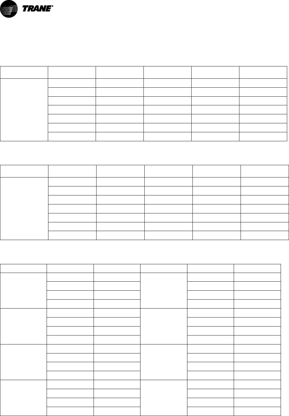
92
VAV-PRC012AC-EN
Performance Data
Parallel Fan-Powered Terminal Units
Table 18. Primary airflow control factory settings—IP
Control Type Air Valve Size (in.)
Maximum Valve
Cfm
Maximum
Controller Cfm
Minimum
Controller Cfm
Constant Volume
Cfm
Direct Digital Control/
UCM, VV550, UC210,
and UC400
5 350 40-350
0, 40-350
40-350
6 500 60-500
0, 60-500
60-500
8 900 105-900
0, 105-900
105-900
10 1400 165-1400
0, 165-1400
165-1400
12 2000 240-2000
0, 240-2000
240-2000
14 3000 320-3000
0, 320-3000
320-3000
16 4000 420-4000
0, 420-4000
420-4000
Note: Maximum airflow must be greater than or equal to minimum airflow.
Table 19. Primary airflow control factory settings—SI
Control Type Air Valve Size (in.)
Maximum Valve L/
s
Maximum
Controller L/s
Minimum
Controller L/s
Constant Volume
L/s
Direct Digital Control/
UCM, VV550, UC210,
and UC400
5 165 19-165
0, 19-350
19-350
6 236 28-236
0, 28-236
28-236
8 425 50-425
0, 50-425
50-425
10 661 77-661
0, 77-661
77-661
12 944 111-944
0, 111-944
111-944
14 1416 151-1416
0, 151-1416
151-1416
16 1888 198-1888
0, 198-1888
198-1888
Note: Maximum airflow must be greater than or equal to minimum airflow.
Table 20. Unit air pressure drop—in. wg (I-P)
Fan / Inlet Size
Airflow Size
Cooling Only
Fan / Inlet Size
Airflow Cfm
Cooling Only
02SQ-05
40 0.01
05SQ-10
165 0.01
150 0.03 550 0.01
250 0.08 950 0.01
350 0.17 1400 0.01
02SQ-06
60 0.01
05SQ-12
240 0.01
200 0.05 750 0.01
350 0.17 1350 0.01
500 0.35 2000 0.01
02SQ-08
105 0.01
05SQ-14
320 0.01
350 0.03 1200 0.01
600 0.09 2100 0.01
900 0.21 3000 0.01
02SQ-10
165 0.01
06SQ-10
165 0.01
550 0.01 550 0.01
950 0.01 950 0.01
1400 0.01 1400 0.01

VAV-PRC012AC-EN
93
Table 20. Unit air pressure drop—in. wg (I-P) (continued)
Fan / Inlet Size
Airflow Size
Cooling Only
Fan / Inlet Size
Airflow Cfm
Cooling Only
03SQ-06
60 0.01
06SQ-12
240 0.01
200 0.06 750 0.01
350 0.19 1350 0.01
500 0.40 2000 0.01
03SQ-08
105 0.01
06SQ-14
320 0.01
350 0.03 1200 0.01
600 0.08 2100 0.01
900 0.20 3000 0.01
03SQ-10
165 0.01
07SQ-16
420 0.01
550 0.01 1600 0.01
950 0.02 2800 0.01
1400 0.05 4000 0.01
03SQ-12
240 0.01
07SQ-10
165 0.01
750 0.01 550 0.01
1350 0.01 950 0.01
2000 0.01 1400 0.01
04SQ-08
105 0.01
07SQ-12
240 0.01
350 0.03 750 0.01
600 0.08 1350 0.01
900 0.20 2000 0.01
04SQ-10
165 0.01
07SQ-14
320 0.01
550 0.01 1200 0.01
950 0.02 2100 0.01
1400 0.05 3000 0.01
04SQ-12
240 0.01
07SQ-16
420 0.01
750 0.01 1600 0.01
1350 0.01 2800 0.01
2000 0.01 4000 0.01
04SQ-14
320 0.01
1200 0.01
2100 0.01
3000 0.01
Note: Unit pressure drops do not include hot water coil pressure drops.
PPeerrffoorrmmaannccee DDaattaa

94
VAV-PRC012AC-EN
Table 21. Coil air pressure drop—in. wg (I-P)
Fan Size Airflow Cfm
1-Row HW (in. wg) 2-Row HW (in. wg)
02SQ
100 0 0
200 0.01 0.01
300 0.01 0.02
400 0.02 0.03
500 0.02 0.05
03SQ
04SQ
05SQ
250 0.01 0.02
500 0.02 0.04
750 0.04 0.08
1000 0.07 0.13
1250 0.10 0.19
1400 0.12 0.23
06SQ
07SQ
600 0.02 0.04
900 0.04 0.07
1200 0.06 0.11
1500 0.09 0.16
1800 0.12 0.22
2000 0.15 0.27
Note: HW coil only pressure drops do not include unit pressure drop.
Table 22. Coil air pressure drop—Pa (SI)
Fan Size
Airflow L/s
1-Row HW (Pa) 2-Row HW (Pa)
02SQ
200 0 1
300 1 3
400 2 5
500 4 8
600 6 12
03SQ
04SQ
05SQ
118 2 4
236 5 11
354 10 21
472 17 33
590 25 47
661 31 57
06SQ
07SQ
900 5 10
1200 9 18
1500 15 28
1800 22 41
2150 30 56
2500 36 67
Note: HW coil only pressure drops do not include unit pressure drop.
PPeerrffoorrmmaannccee DDaattaa

VAV-PRC012AC-EN
95
Table 23. Unit air pressure drop—Pa (SI)
Fan / Inlet Size Airflow L/s
Cooling Only
Fan / Inlet Size Airflow L/s
Cooling Only
02SQ-05
19 2
04SQ-14
151 2
71 7 566 2
118 20 991 2
165 41 1416 2
02SQ-06
28 28
05SQ-10
78 2
94 94 260 2
165 165 448 2
236 236 661 2
02SQ-08
50 50
05SQ-12
113 2
165 165 354 2
283 283 637 2
425 425 944 2
02SQ-10
78 78
05SQ-14
151 2
260 2 566 2
448 2 991 2
661 3 1416 2
03SQ-06
28 2
06SQ-10
78 2
94 15 260 2
165 48 448 2
236 99 661 2
03SQ-08
50 2
06SQ-12
113 2
165 6 354 2
283 21 637 2
425 49 944 2
03SQ-10
78 2
06SQ-14
151 2
260 2 566 2
448 6 991 2
661 13 1416 2
03SQ-12
113 2
07SQ-16
198 2
354 2 755 2
637 2 1321 2
944 2 1888 2
04SQ-08
50 2
07SQ-10
78 2
165 6 260 2
283 21 448 2
425 49 661 2
04SQ-10
78 2
07SQ-12
113 2
260 2 354 2
448 6 637 2
661 13 944 2
PPeerrffoorrmmaannccee DDaattaa

96
VAV-PRC012AC-EN
Table 23. Unit air pressure drop—Pa (SI) (continued)
Fan / Inlet Size Airflow L/s
Cooling Only
Fan / Inlet Size Airflow L/s
Cooling Only
04SQ-12
113 2
07SQ-14
151 2
354 2 566 2
637 2 991 2
944 2 1416 2
07SQ-16
198 2
755 2
1321 2
1888 2
Note: Unit pressure drops do not include hot water coil pressure drops.
Figure 36. Performance data fan curves, parallel 02SQ—PSC
744354.058144.0002
35.002135.0021
0.01
0.15
0.02
0.25
0.03
0.35
0.04
0.45
0.50
0.55
0.60
0 100 200 300 400 500 600 700
Airflow
CFM
L/s
Pa in.wg
149
74
87
100
112
125
137
25
37
50
62
0 47 94 142
189 236 283 330
Discharge Static Pressure
120 cfm
(57L/s)
VPCF and VPEF Maximum
Mininum
1 ‐ Row Coil Maximum
2 ‐ Row Coil Maximum
Figure 37. Performance data fan curves, parallel 03SQ—PSC
0.10
0.20
0.30
200 300 400 500
Airflow
Discharge Static Pressure
25
50
75
94 142 189 236
cfm
L/s
Pa In. wg
0.80199
0.70174
0.60150
0.50125
0.40100
1300
614
1200
566
1100
519
1000
472
900
425
800
378
700
330
600
283
250 cfm min
(118 L/s)
VPCF and VPEF maximum
Min
imum
1-row coil maximum
2-row coil maximum
PPeerrffoorrmmaannccee DDaattaa

VAV-PRC012AC-EN
97
Figure 38. Performance data fan curves, parallel 04SQ—PSC
0.1
0.2
0.3
0.4
0.5
0.6
0.7
0.8
200 400 600 800 1000 1200 1400 1600
Discharge Static Pressure
Airflow
VPCF and VPEF Maximum
Mininum
2-Row Coil Maximum
1-Row Coil Maximum
CFM
L/s
Pa in.wg
174
75
100
125
150
25
50
94
199
189 283 378 472 566 661 755
300 CFM
(142 L/s)
Figure 39. Performance data fan curves, parallel 05SQ—PSC
0.10
0.20
0.30
0.40
0.50
0.60
0.70
0.80
300 500 700 900 1100 1300 1500 1700
Discharge Static Pressure
Airflow
VPCF and VPEF Maximum
Mininum
2-Row Coil Maximum
1-Row Coil Maximum
CFM
L/s
Pa in.wg
199
75
100
125
150
25
50
142 519 614
174
236 330 425 708 802
350 CFM
(165 L/s)
Figure 40. Performance data fan curves, parallel 06SQ—PSC
0.10
0.20
0.30
400
Airflow
Discharge Static Pressure
25
50
100
189
378
566 850
1038
cfm
L/s
Pa In. wg
600 800 1000
1200
1400
1600 1800 2000 2200
0.40
0.50
0.60
0.70
0.80
199
174
150
125
75
755661472
283
944
530 cfm min
(250 L/s)
VPCF and VPEF maximum
Minimum
1-row coil maximum
2-row coil maximum
PPeerrffoorrmmaannccee DDaattaa
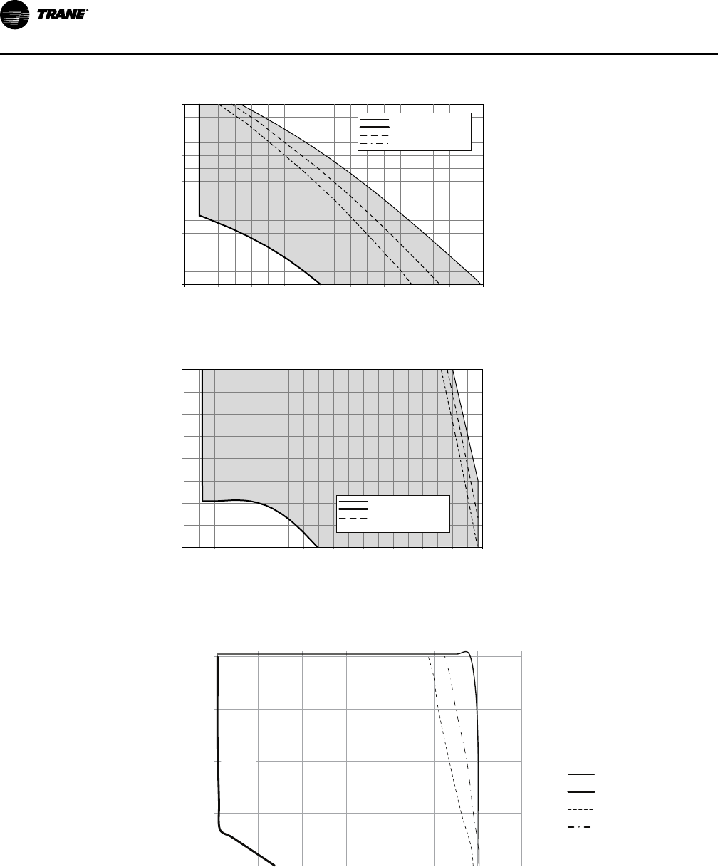
98
VAV-PRC012AC-EN
Figure 41. Performance data fan curves, parallel 07SQ—PSC
Airflow
Discharge Static Pressure
25
50
75
236 519
708 897 1086
cfm
L/s
Pa In. wg
0.10
0.20
0.30
0.50
0.60
0.70
0.80
500 700 900 1100
1300
1500 1700
1900 2100
0.40
2300
425330
991802614
199
174
150
125
100
585 cfm min
(276 L/s)
VPCF and VPEF maximum
Minimum
1-row coil maximum
2-row coil maximum
Figure 42. Performance data fan curves, VPxF 03SQ—ECM
Airflow
Discharge Static Pressure
25
50
75
47
142
283 378 519
cfm
L/s
Pa In. wg
0.10
0.20
0.30
0.40
0.50
100 200 300 400 500 600 700 800 900 1000 1100
125
100
236 330 425 47294 189
160 cfm min
(76 L/s)
Notes:
• ECMs (electronically commutated motors) are ideal for systems seeking maximum motor efficiency.
VPCF and VPEF maximum
Minimum
1-row coil maximum
2-row coil maximum
Figure 43. Performance data fan curves, VPxF 04SQ—ECM
0.10
0.20
0.30
0.40
0.50
200 400 600 800 1000 1200 1400 1600
Discharge Static Pressure
Airflow
VPCF and VPEF Maximum
Mininum
2-Row Coil Maximum
1-Row Coil Maximum
CFM
L/s
Pa in.wg
74
100
125
25
50
94 472 566189 283 378 755661
220 CFM
(104 L/s)
PPeerrffoorrmmaannccee DDaattaa

VAV-PRC012AC-EN
99
Figure 44. Performance data fan curves, VPxF 05SQ—ECM
Airflow
Discharge Static Pressure
25
50
75
94 189
944
cfm
L/s
Pa In. wg
0.10
0.20
0.30
0.40
0.50
200 400 600 800 1000 1200 1400 1800 2000
125
100
661566472378
283 850
1600
755
280 cfm min
(132 L/s)
Notes:
• ECMs (electronically commutated motors) are ideal for systems seeking maximum motor efficiency.
VPCF and VPEF maximum
Minimum
1-row coil maximum
2-row coil maximum
Figure 45. Performance data fan curves, VPxF 06SQ—ECM
Airflow
Discharge Static Pressure
25
50
100
189
cfm
L/s
Pa In. wg
0.10
0.20
0.30
0.40
0.50
400 600 800 1000 1200 1400 1600 1800 2000 2200
75
125
850755661566472378283
189
944 1038
530 cfm min
(250 L/s)
VPCF and VPEF maximum
Minimum
1-row coil maximum
2-row coil maximum
Notes:
• ECMs (electronically commutated motors) are ideal for systems seeking maximum motor efficiency.
Table 24. Heating capacity (MBh)—fan size 02SQ (I-P)
Rows
Gpm
Water
Pressure
Drop (ft)
Airflow (cfm)
100 150 200 250 300 350 400 450 500 550 600
1-Row
Capacity
MBh
0.5 0.22 – – – – – – – – – – –
1.0 0.76 9.20 11.49 13.14 14.45 15.56 16.52 17.38 18.16 18.93 19.64 20.30
2.0 2.65 9.79 12.50 14.52 16.17 17.60 18.87 20.02 21.09 22.08 23.02 23.90
3.0 5.54 10.01 12.87 15.04 16.84 18.39 19.79 21.07 22.26 23.38 24.44 25.44
4.0 9.39 10.12 13.07 15.32 17.19 18.82 20.29 21.64 22.90 24.09 25.22 26.29
5.0 14.17 10.19 13.19 15.49 17.41 19.09 20.60 22.00 23.30 24.54 25.71 26.83
2-Row
Capacity
MBh
1.0 1.30 9.97 13.83 17.07 19.81 22.13 24.13 25.85 27.35 28.67 29.83 30.86
2.0 4.41 10.29 14.58 18.39 21.78 24.82 27.56 30.03 32.27 34.31 36.18 37.90
3.0 9.08 10.40 14.83 18.83 22.46 25.76 28.77 31.54 34.09 36.45 38.63 40.67
4.0 15.18 10.45 14.95 19.05 22.80 26.23 29.40 32.32 35.04 37.56 39.92 42.13
5.0 22.66 10.48 15.03 19.18 23.00 26.52 29.78 32.80 35.62 38.25 40.72 43.03
Notes:
1. Fouling factor = 0.0005°F ft
2
h/Btu.
2. Capacity based on 70°F entering air temperature and 180°F entering water temperature.
PPeerrffoorrmmaannccee DDaattaa

100
VAV-PRC012AC-EN
Table 25. Heating capacity (MBh)—fan sizes 03SQ—05SQ (I-P)
Rows
Gpm
Water
Pressure
Drop (ft)
Airflow (Cfm)
150 300 450 600 750 900 1050 1200 1350 1500 1650
1-Row
Capacity
MBh
1.0 0.28 – – – – – – – – – – –
2.0 1.02 13.14 18.63 22.21 25.01 27.36 29.41 31.30 33.00 34.54 35.94 37.23
3.0 2.22 13.62 19.69 23.78 27.05 29.86 32.34 34.58 36.63 38.52 40.31 41.99
4.0 3.85 13.88 20.27 24.65 28.20 31.28 34.03 36.54 38.84 40.98 42.99 44.86
5.0 5.92 14.04 20.64 25.21 28.95 32.21 35.14 37.82 40.31 42.62 44.80 46.85
6.0 8.41 14.14 20.89 25.59 29.46 32.85 35.92 38.73 41.35 43.80 46.10 48.28
7.0 11.32 14.22 21.08 25.88 29.85 33.34 36.50 39.41 42.13 44.67 47.08 49.36
8.0 14.65 14.28 21.22 26.10 30.15 33.71 36.95 39.94 42.73 45.36 47.85 50.21
9.0 18.40 14.33 21.33 26.28 30.38 34.01 37.31 40.36 43.22 45.91 48.46 50.89
10.0 22.57 14.37 21.42 26.42 30.57 34.25 37.60 40.71 43.62 46.36 48.97 51.45
2-Row
Capacity
MBh
1.0 0.35 – – – – – – – – – – –
2.0 1.28 15.08 25.87 33.70 39.58 44.13 47.77 50.73 53.20 55.29 57.08 58.63
3.0 2.74 15.36 27.00 35.94 42.99 48.69 53.40 57.36 60.74 63.66 66.21 68.46
4.0 4.72 15.50 27.57 37.11 44.82 51.20 56.57 61.15 65.13 68.60 71.68 74.42
5.0 7.20 15.59 27.92 37.83 45.97 52.78 58.59 63.60 67.99 71.85 75.30 78.39
6.0 10.18 15.64 28.15 38.31 46.74 53.87 59.99 65.32 70.00 74.15 77.87 81.23
7.0 13.64 15.68 28.31 38.66 47.31 54.67 61.02 66.58 71.49 75.86 79.80 83.36
8.0 17.59 15.71 28.44 38.93 47.74 55.28 61.81 67.55 72.64 77.19 81.29 85.01
9.0 22.03 15.74 28.54 39.13 48.08 55.76 62.44 68.32 73.55 78.24 82.48 86.33
10.0 26.94 15.76 28.62 39.30 48.35 56.15 62.95 68.95 74.30 79.10 83.45 87.42
Table 26. Heating capacity (MBh)—fan sizes 06SQ & 07SQ (I-P)
Rows
Gpm
Water
Pressure
Drop (ft)
Airflow (Cfm)
900 1000 1100 1200 1300 1400 1500 1600 1700 1800 1900
1-Row
Capacity
MBh
0.5 0.11 – – – – – – – – – – –
1.0 0.36 – – – – – – – – – – –
2.0 1.24 32.17 33.60 34.93 36.17 37.34 38.43 39.47 40.45 41.38 42.27 43.12
3.0 2.57 35.12 36.76 38.31 39.77 41.16 42.50 43.81 45.07 46.27 47.42 48.53
4.0 4.32 36.78 38.60 40.32 41.95 43.51 45.01 46.44 47.82 49.14 50.42 51.68
5.0 6.49 37.86 39.79 41.63 43.38 45.05 46.66 48.21 49.70 51.14 52.53 53.88
6.0 9.04 38.61 40.63 42.55 44.38 46.14 47.83 49.46 51.04 52.56 54.04 55.47
7.0 11.99 39.17 41.25 43.23 45.13 46.95 48.70 50.40 52.04 53.62 55.16 56.66
2-Row
Capacity
MBh
1.0 0.68 – – – – – – – – – – –
2.0 2.24 51.03 53.38 55.46 57.32 58.98 60.47 61.83 63.07 64.20 65.24 66.20
3.0 4.57 56.65 59.74 62.53 65.06 67.37 69.48 71.42 73.20 74.86 76.40 77.83
4.0 7.59 59.73 63.27 66.50 69.46 72.18 74.69 77.02 79.18 81.19 83.08 84.84
5.0 11.29 61.67 65.51 69.04 72.28 75.29 78.08 80.67 83.09 85.36 87.50 89.50
6.0 15.64 63.00 67.05 70.79 74.24 77.45 80.44 83.24 85.86 88.31 90.63 92.81
7.0 20.61 63.97 68.18 72.07 75.69 79.05 82.19 85.14 87.90 90.51 92.96 95.28
PPeerrffoorrmmaannccee DDaattaa

VAV-PRC012AC-EN
101
Table 27. Heating capacity (kW)—fan size 02SQ (SI)
Rows
L/s
Water
Pres-
sure
Drop
(kPa)
Airflow L/s
47 71 94 118 142 165 189 212 236 260 283
1-Row
Capacity
kW
0.03 0.66 – – – – – – – – – – –
0.06 2.26 2.69 3.37 3.85 4.24 4.56 4.84 5.09 5.32 5.55 5.76 5.76
0.13 7.91 2.87 3.66 4.26 4.74 5.16 5.53 5.87 6.18 6.47 6.75 6.75
0.19 16.57 2.93 3.77 4.41 4.93 5.39 5.8 6.18 6.52 6.85 7.16 7.16
0.25 28.08 2.97 3.83 4.49 5.04 5.52 5.95 6.34 6.71 7.06 7.39 7.39
0.32 42.34 2.99 3.87 4.54 5.1 5.59 6.04 6.45 6.83 7.19 7.53 7.53
2-Row
Capacity
kW
0.06 3.89 2.92 4.05 5 5.8 6.49 7.07 7.58 8.02 8.4 8.74 8.74
0.13 13.19 3.02 4.27 5.39 6.38 7.27 8.08 8.8 9.46 10.06 10.6 10.6
0.19 27.13 3.05 4.35 5.52 6.58 7.55 8.43 9.24 9.99 10.68 11.32 11.32
0.25 45.38 3.06 4.38 5.58 6.68 7.69 8.62 9.47 10.27 11.01 11.7 11.7
0.32 67.73 3.07 4.4 5.62 6.74 7.77 8.73 9.61 10.44 11.21 11.93 11.93
Table 28. Heating capacity (kW)—fan sizes 03SQ—05SQ (SI)
Rows
L/s
Water
Pressure
Drop
(kPa)
Airflow (L/s)
71 142 212 283 354 425 495 566 637 708 779
1-Row
Capacity
kW
0.06 0.82 – – – – – – – – – – –
0.13 3.06 3.85 5.46 6.51 7.33 8.02 8.62 9.17 9.67 10.12 10.53 10.53
0.19 6.63 3.99 5.77 6.97 7.93 8.75 9.48 10.14 10.74 11.29 11.81 11.81
0.25 11.51 4.07 5.94 7.22 8.27 9.17 9.97 10.71 11.38 12.01 12.60 12.60
0.32 17.68 4.11 6.05 7.39 8.48 9.44 10.30 11.08 11.81 12.49 13.13 13.13
0.38 25.13 4.15 6.12 7.50 8.64 9.63 10.53 11.35 12.12 12.84 13.51 13.51
0.44 33.83 4.17 6.18 7.58 8.75 9.77 10.70 11.55 12.35 13.09 13.80 13.80
0.50 43.79 4.19 6.22 7.65 8.83 9.88 10.83 11.71 12.52 13.29 14.02 14.02
0.57 55.00 4.20 6.25 7.70 8.90 9.97 10.93 11.83 12.67 13.46 14.20 14.20
0.63 67.45 4.21 6.28 7.74 8.96 10.04 11.02 11.93 12.78 13.59 14.35 14.35
2-Row
Row
Capacity
kW
0.06 1.06 – – – – – – – – – – –
0.13 3.83 4.42 7.58 9.88 11.60 12.93 14.00 14.87 15.59 16.20 16.73 16.73
0.19 8.20 4.50 7.91 10.53 12.60 14.27 15.65 16.81 17.80 18.66 19.40 19.40
0.25 14.11 4.54 8.08 10.88 13.14 15.01 16.58 17.92 19.09 20.11 21.01 21.01
0.32 21.52 4.57 8.18 11.09 13.47 15.47 17.17 18.64 19.92 21.06 22.07 22.07
0.38 30.42 4.58 8.25 11.23 13.70 15.79 17.58 19.14 20.51 21.73 22.82 22.82
0.44 40.78 4.60 8.30 11.33 13.87 16.02 17.88 19.51 20.95 22.23 23.39 23.39
0.50 52.59 4.61 8.33 11.41 13.99 16.20 18.12 19.80 21.29 22.62 23.82 23.82
0.57 65.84 4.61 8.36 11.47 14.09 16.34 18.30 20.02 21.56 22.93 24.17 24.17
0.63 80.52 4.62 8.39 11.52 14.17 16.45 18.45 20.20 21.77 23.18 24.46 24.46
PPeerrffoorrmmaannccee DDaattaa

102
VAV-PRC012AC-EN
Table 29. Heating capacity (kW)—fan sizes 06SQ and 07SQ (SI)
Rows
L/s
Water
Pressure
Drop
(kPa)
Airflow (L/s)
425 472 519 566 613 661 708 755 802 849 897
1-Row
Capacity
Kw
0.03 0.33 – – – – – – – – – – –
0.06 1.09 – – – – – – – – – – –
0.13 3.71 9.43 9.85 10.24 10.60 10.94 11.26 11.57 11.86 12.13 12.39 12.39
0.19 7.68 10.29 10.77 11.23 11.66 12.06 12.46 12.84 13.21 13.56 13.90 13.90
0.25 12.92 10.78 11.31 11.82 12.30 12.75 13.19 13.61 14.01 14.40 14.78 14.78
0.32 19.39 11.10 11.66 12.20 12.71 13.20 13.67 14.13 14.57 14.99 15.40 15.40
0.38 27.04 11.32 11.91 12.47 13.01 13.52 14.02 14.50 14.96 15.40 15.84 15.84
0.44 35.84 11.48 12.09 12.67 13.23 13.76 14.27 14.77 15.25 15.72 16.17 16.17
2-Row
Row
Capacity
kW
0.06 2.02 – – – – – – – – – – –
0.13 6.70 14.96 15.64 16.25 16.80 17.28 17.72 18.12 18.48 18.82 19.12 19.12
0.19 13.65 16.60 17.51 18.33 19.07 19.74 20.36 20.93 21.45 21.94 22.39 22.39
0.25 22.70 17.51 18.54 19.49 20.36 21.15 21.89 22.57 23.20 23.80 24.35 24.35
0.32 33.76 18.07 19.20 20.23 21.18 22.06 22.88 23.64 24.35 25.02 25.64 25.64
0.38 46.74 18.46 19.65 20.75 21.76 22.70 23.58 24.39 25.16 25.88 26.56 26.56
0.44 61.61 18.75 19.98 21.12 22.18 23.17 24.09 24.95 25.76 26.52 27.24 27.24
Water Coil Performance Notes (I-P)
• Fouling factor = 0.0005.
• The off-coil temperature of the hot water coil on parallel fan-powered units must not exceed
140°F when mounted on plenum inlet.
• Use the following equations to calculate leaving air temperature (LAT) and water temperature
difference (WTD).
WTD = EWT - LWT =
Gpm
2 x MBh
• Capacity based on 70°F entering air temperature and 180°F entering water temperature. Refer
to correction factors for different entering conditions.
Table 30. Temperature correction factors for water pressure drop (ft)
Average Water Temperature
200 190 180 170 160 150 140 130 120 110
Correction Factor 0.970 0.985 1.00S 1.020 1.030 1.050 1.080 1.100 1.130 1.150
Table 31. Temperature correction factors for coil capacity (MBh)
Entering Water Minus Entering Air
40 50 60 70 80 90 100 110 120 130
Correction Factor 0.355 0.446 0.537 0.629 0.722 0.814 0.907 1.000 1.093 1.187
PPeerrffoorrmmaannccee DDaattaa

VAV-PRC012AC-EN
103
Table 32. Heating capacity (kW)—fan size 02SQ (SI)
Rows
L/s
Water
Pressure
Drop (kPa)
Airflow L/s
47 71 94 118 142 165 189 212 236 260 283
1-Row
Ca-
pacity
kW
0.03 0.66 – – – – – – – – – – –
0.06 2.26 2.69 3.37 3.85 4.24 4.56 4.84 5.09 5.32 5.55 5.76 5.76
0.13 7.91 2.87 3.66 4.26 4.74 5.16 5.53 5.87 6.18 6.47 6.75 6.75
0.19 16.57 2.93 3.77 4.41 4.93 5.39 5.8 6.18 6.52 6.85 7.16 7.16
0.25 28.08 2.97 3.83 4.49 5.04 5.52 5.95 6.34 6.71 7.06 7.39 7.39
0.32 42.34 2.99 3.87 4.54 5.1 5.59 6.04 6.45 6.83 7.19 7.53 7.53
2-Row
Ca-
pacity
kW
0.06 3.89 2.92 4.05 5.00 5.80 6.49 7.07 7.58 8.02 8.40 8.74 8.74
0.13 13.19 3.02 4.27 5.39 6.38 7.27 8.08 8.80 9.46 10.06 10.6 10.6
0.19 27.13 3.05 4.35 5.52 6.58 7.55 8.43 9.24 9.99 10.68 11.32 11.32
0.25 45.38 3.06 4.38 5.58 6.68 7.69 8.62 9.47 10.27 11.01 11.7 11.7
0.32 67.73 3.07 4.4 5.62 6.74 7.77 8.73 9.61 10.44 11.21 11.93 11.93
Table 33. Heating capacity (kW)—fan sizes 03SQ—05SQ (SI)
Rows
L/s
Water
Pressure
Drop (kPa)
Airflow (L/s)
71 142 212 283 354 425 495 566 637 708 779
1-Row
Ca-
pacity
kW
0.06 0.82 – – – – – – – – – – –
0.13 3.06 3.85 5.46 6.51 7.33 8.02 8.62 9.17 9.67 10.12 10.53 10.53
0.19 6.63 3.99 5.77 6.97 7.93 8.75 9.48 10.14 10.74 11.29 11.81 11.81
0.25 11.51 4.07 5.94 7.22 8.27 9.17 9.97 10.71 11.38 12.01 12.60 12.60
0.32 17.68 4.11 6.05 7.39 8.48 9.44 10.3 11.08 11.81 12.49 13.13 13.13
0.38 25.13 4.15 6.12 7.5 8.64 9.63 10.53 11.35 12.12 12.84 13.51 13.51
0.44 33.83 4.17 6.18 7.58 8.75 9.77 10.7 11.55 12.35 13.09 13.80 13.8
0.5 43.79 4.19 6.22 7.65 8.83 9.88 10.83 11.71 12.52 13.29 14.02 14.02
0.57 55.00 4.20 6.25 7.70 8.90 9.97 10.93 11.83 12.67 13.46 14.20 14.20
0.63 67.45 4.21 6.28 7.74 8.96 10.04 11.02 11.93 12.78 13.59 14.35 14.35
2-Row
Ca-
pacity
kW
0.06 1.06 – – – – – – – – – – –
0.13 3.83 4.42 7.58 9.88 11.60 12.93 14.00 14.87 15.59 16.20 16.73 16.73
0.19 8.20 4.50 7.91 10.53 12.60 14.27 15.65 16.81 17.80 18.66 19.40 19.4
0.25 14.11 4.54 8.08 10.88 13.14 15.01 16.58 17.92 19.09 20.11 21.01 21.01
0.32 21.52 4.57 8.18 11.09 13.47 15.47 17.17 18.64 19.92 21.06 22.07 22.07
0.38 30.42 4.58 8.25 11.23 13.70 15.79 17.58 19.14 20.51 21.73 22.82 22.82
0.44 40.78 4.60 8.30 11.33 13.87 16.02 17.88 19.51 20.95 22.23 23.39 23.39
0.50 52.59 4.61 8.33 11.41 13.99 16.20 18.12 19.80 21.29 22.62 23.82 23.82
0.57 65.84 4.61 8.36 11.47 14.09 16.34 18.30 20.02 21.56 22.93 24.17 24.17
0.63 80.52 4.62 8.39 11.52 14.17 16.45 18.45 20.20 21.77 23.18 24.46 24.46
PPeerrffoorrmmaannccee DDaattaa

104
VAV-PRC012AC-EN
Table 34. Heating capacity (kW)—fan sizes 06SQ and 07SQ (SI)
Rows
L/s
Water
Pressure
Drop (kPa)
Airflow (L/s)
425 472 519 566 613 661 708 755 802 849 897
1-Row
Ca-
pacity
kW
0.03 0.33 – – – – – – – – – – –
0.06 1.09 – – – – – – – – – – –
0.13 3.71 9.43 9.85 10.24 10.60 10.94 11.26 11.57 11.86 12.13 12.39 12.39
0.19 7.68 10.29 10.77 11.23 11.66 12.06 12.46 12.84 13.21 13.56 13.90 13.90
0.25 12.92 10.78 11.31 11.82 12.30 12.75 13.19 13.61 14.01 14.40 14.78 14.78
0.32 19.39 11.10 11.66 12.20 12.71 13.20 13.67 14.13 14.57 14.99 15.40 15.40
0.38 27.04 11.32 11.91 12.47 13.01 13.52 14.02 14.50 14.96 15.40 15.84 15.84
0.44 35.84 11.48 12.09 12.67 13.23 13.76 14.27 14.77 15.25 15.72 16.17 16.17
2-Row
Ca-
pacity
kW
0.06 2.02 – – – – – – – – – – –
0.13 6.70 14.96 15.64 16.25 16.80 17.28 17.72 18.12 18.48 18.82 19.12 19.12
0.19 13.65 16.60 17.51 18.33 19.07 19.74 20.36 20.93 21.45 21.94 22.39 22.39
0.25 22.70 17.51 18.54 19.49 20.36 21.15 21.89 22.57 23.20 23.80 24.35 24.35
0.32 33.76 18.07 19.20 20.23 21.18 22.06 22.88 23.64 24.35 25.02 25.64 25.64
0.38 46.74 18.46 19.65 20.75 21.76 22.70 23.58 24.39 25.16 25.88 26.56 26.56
0.44 61.61 18.75 19.98 21.12 22.18 23.17 24.09 24.95 25.76 26.52 27.24 27.24
Water Coil Performance Notes (SI)
• Fouling factor = 0.0005.
• The off-coil temperature of the hot water coil on parallel fan-powered units must not exceed
60°C when mounted on plenum inlet.
• Use the following equations to calculate leaving air temperature (LAT) and water temperature
difference (WTD).
• Capacity based on 21°C entering air temperature and 82°C entering water temperature. Refer
to correction factors for different entering conditions.
Table 35. Temperature correction factors for water pressure drop (kPa)
Average Water Temperature
93 88 82 77 71 66 60 54 49 43
Correction Factor 0.970 0.985 1.000 1.020 1.030 1.050 1.080 1.100 1.130 1.150
Table 36. Temperature correction factors for coil capacity (kW)
Entering Water Minus Entering Air
22 27 33 38 44 50 55 61 67 72
Correction Factor 0.355 0.446 0.537 0.629 0.722 0.814 0.907 1.000 1.093 1.187
Water Coil Notes (I-P)
• Fouling factor = 0.0005.
PPeerrffoorrmmaannccee DDaattaa
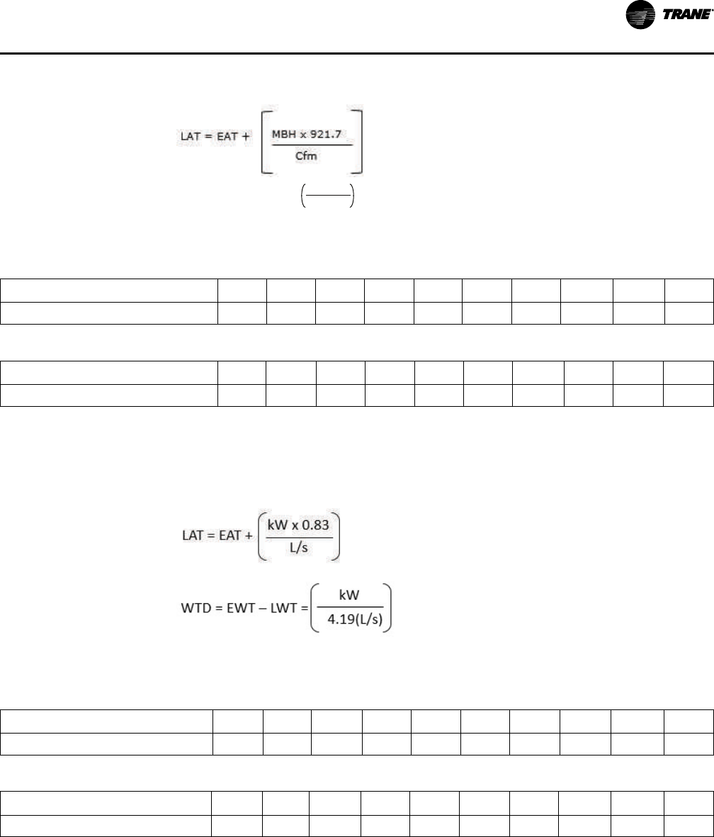
VAV-PRC012AC-EN
105
• Use the following equations to calculate leaving air temperature (LAT) and water temperature
difference (WTD):
WTD = EWT - LWT =
Gpm
2 x MBh
• Capacity based on 70°F entering air temperature and 180°F entering water temperature. Refer
to correction factors for different entering conditions.
Table 37. Temperature correction factors for water pressure drop (ft)
Average Water Temperature
200 190 180 170 160 150 140 130 120 110
Correction Factor 0.970 0.985 1.000 1.020 1.030 1.050 1.080 1.100 1.130 1.150
Table 38. Temperature correction factors for coil capacity (MBh)
Entering Water Minus Entering Air
40 50 60 70 80 90 100 110 120 130
Correction Factor 0.355 0.446 0.537 0.629 0.722 0.814 0.907 1.000 1.093 1.187
Water Coil Notes (SI)
• Fouling factor = 0.0005.
• Use the following equations to calculate leaving air temperature (LAT) and water temperature
difference (WTD).
• Capacity based on 21°C entering air temperature and 82°C entering water temperature. Refer
to correction factors for different entering conditions.
Table 39. Temperature correction factors for water pressure drop (kPa)
Average Water Temperature
93 88 82 77 71 66 60 54 49 43
Correction Factor 0.970 0.985 1.000 1.020 1.030 1.050 1.080 1.100 1.130 1.150
Table 40. Temperature correction factors for coil capacity (kW)
Entering Water Minus Entering Air
22 27 33 38 44 50 55 61 67 72
Correction Factor 0.355 0.446 0.537 0.629 0.722 0.814 0.907 1.000 1.093 1.187
PPeerrffoorrmmaannccee DDaattaa

106
VAV-PRC012AC-EN
Series Fan-Powered Terminal Units
Table 41. Primary airflow control factory setttings—I-P
Control Type Air Valve Size (in.)
Maximum Valve
Cfm
Maximum
Controller Cfm
Minimum
Controller Cfm
Constant Volume
Cfm
Direct Digital Control/
UCM, VV550, UC210,
and UC400
4 225 25-225
0, 25-225
25-225
5 350 40-350
0, 40-350
40-350
6 500 60-500
0, 60-500
60-500
8 900 105-900
0, 105-900
105-900
10 1400 165-1400
0, 165-1400
165-1400
12 2000 240-2000
0, 240-2000
240-2000
14 3000 320-3000
0, 320-3000
320-3000
16 4000 420-4000
0, 420-4000
420-4000
Note: Maximum airflow must be greater than or equal to minimum airflow.
Table 42. Primary airflow control factory settings—SI
Control Type Air Valve Size (in.)
Maximum Valve L/s
Maximum
Controller L/s
Minimum Controller
L/s
Constant Volume
L/s
Direct Digital Control/
UCM, VV550, UC210,
and UC400
4 106 12-106
0, 12-106
12-106
5 165 19-165
0, 19-165
19-165
6 236 28-236
0, 28-236
28-236
8 425 50-425
0, 50-425
50-425
10 661 77-661
0, 77-661
77-661
12 944 111-944
0, 111-944
111-944
14 1416 151-1416
0, 151-1416
151-1416
16 1888 198-1888
0, 198-1888
198-1888
Note: Maximum airflow must be greater than or equal to minimum airflow.
PPeerrffoorrmmaannccee DDaattaa

VAV-PRC012AC-EN
107
Table 43. Unit air pressure drop—in. wg (I-P)
Fan/Inlet
Size
Airflow Cfm Unit
Fan/Inlet
Size
Airflow Cfm Unit
Fan/Inlet
Size
Airflow Cfm Unit
2SQ-04
200 0.03
04SQ-06
330 0.16
6SQ-10
700 0.01
225 0.03 400 0.29 950 0.03
2SQ-05
200 0.03 450 0.35 1200 0.12
250 0.04 400 0.48 1400 0.22
300 0.06
04SQ-08
900 0.04
6SQ-12
700 0.01
350 0.09 330 0.12 1150 0.01
2SQ-06
200 0.03 500 0.25 1600 0.12
300 0.06 700 0.44 2000 0.27
400 0.12
04SQ-10
330 0.02
6SQ-14
700 0.01
500 0.19 700 0.12 1350 0.04
2SQ-08
200 0.01 1050 0.29 2000 0.19
400 0.05 1400 0.54 2600 0.41
550 0.1
04SQ-12
330 0.02
7SQ-10
850 0.01
700 0.16 750 0.11 1000 0.05
2SQ-10
200 0.01 1150 0.28 1200 0.12
400 0.02 1550 0.51 1400 0.22
550 0.06
04SQ-14
330 0.02
6SQ-16
700 0.01
700 0.11 750 0.11 1350 0.04
03SQ-06
250 0.1 1150 0.26 2000 0.19
300 0.15 1550 0.48 2600 0.41
400 0.34
05SQ-10
400 0.01
7SQ-10
850 0.01
500 0.45 750 0.08 1000 0.05
03SQ-08
250 0.05 1100 0.22 1200 0.12
500 0.16 1400 0.39 1400 0.22
700 0.31
05SQ-12
400 0.01
7SQ-12
850 0.01
900 0.49 900 0.09 1200 0.02
03SQ-10
250 0.03 1400 0.28 1600 0.12
550 0.11 1900 0.58 2000 0.27
850 0.24
05SQ-14
400 0.01
7SQ-14
850 0.01
1200 0.44 900 0.09 1550 0.07
03SQ-12
250 0.01 1400 0.26 2250 0.27
550 0.07 1900 0.53 3000 0.59
850 0.16
7SQ-16
850 0.01
1200 0.32 1550 0.07
2250 0.27
3000 0.59
PPeerrffoorrmmaannccee DDaattaa

108
VAV-PRC012AC-EN
Table 44. Coil air pressure drop—in. wg (I-P)
Fan Size Airflow Cfm
1-Row HW
(in. wg)
2-Row HW
(in. wg)
Fan Size Airflow Cfm
1-Row HW
(in. wg)
2-Row HW
(in. wg)
02SQ
200 0.01 0.03
05SQ
400 0.01 0.03
300 0.02 0.05 700 0.04 0.08
400 0.04 0.08 1000 0.07 0.13
500 0.06 0.11 1250 0.10 0.19
600 0.08 0.15 1500 0.14 0.26
03SQ 04SQ
250 0.01 0.02 1750 0.19 0.34
500 0.02 0.05
06SQ
07SQ
600 0.02 0.04
750 0.05 0.10 1000 0.04 0.08
1000 0.08 0.15 1500 0.08 0.15
1250 0.12 0.22 2000 0.13 0.23
1500 0.16 0.30 2500 0.19 0.34
3000 0.27 0.47
Note: HW Coil Only pressure drops do not include unit pressure drop.
Table 45. Coil air pressure drop—Pa (SI)
Fan Size
Airflow L/ s
1-Row HW (Pa) 2-Row HW (Pa)
Fan Size
Airflow L/s
1-Row HW (Pa)
2-Row HW
(Pa)
02SQ
250 3 7
05SQ
189 4 8
400 6 12 330 9 19
500 10 19 472 17 33
600 14 28 590 25 48
700 20 38 708 35 65
118 2 5 826 47 85
03SQ 04SQ
236 6 13
06SQ
07SQ
850 4 9
354 12 24 1300 9 19
472 19 38 1700 19 36
590 29 55 2150 31 58
708 40 7 2550 47 85
3000 66 117
Note: HW Coil Only pressure drops do not include unit pressure drop.
PPeerrffoorrmmaannccee DDaattaa
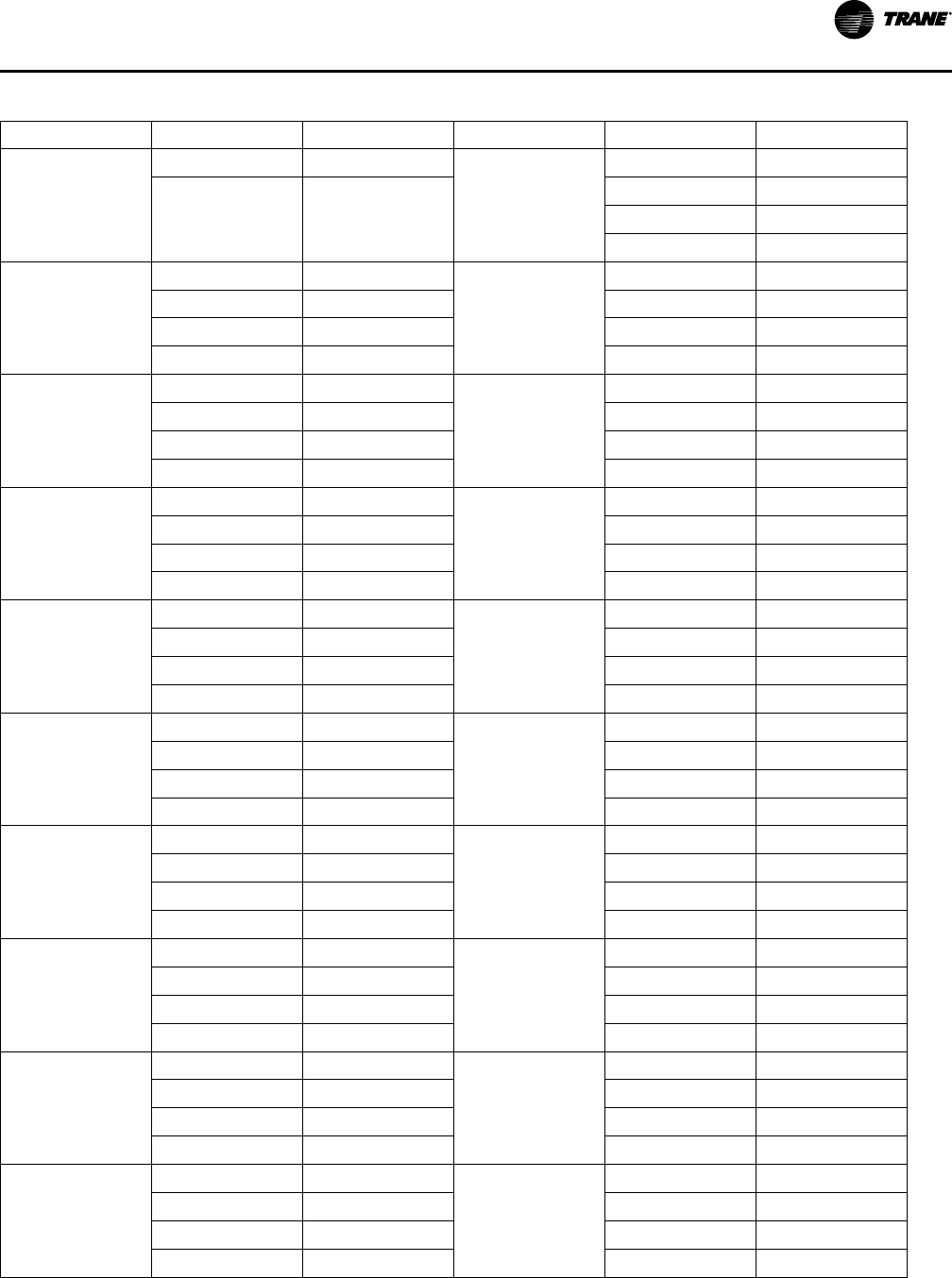
VAV-PRC012AC-EN
109
Table 46. Unit air pressure drop—Pa (SI)
Fan/Inlet Size
Airflow Cfm Unit
Fan/Inlet Size
Airflow Cfm Unit
2SQ-04
94 7
04SQ-14
156 5
106 9
354 27
543 65
731 120
2SQ-05
94 7
05SQ-10
189 1
118 11 354 20
142 16 519 55
165 22 661 98
2SQ-06
94 7
05SQ-12
189 2
142 16 425 23
189 29 661 71
236 46 897 144
2SQ-08
94 2
05SQ-14
189 2
189 12 425 21
260 24 661 65
330 39 897 131
2SQ-10
94 2
6SQ-10
330 2
189 5 448 8
260 14 566 31
330 39 661 55
03SQ-06
118 25
6SQ-12
330 2
142 38 543 3
189 85 755 31
236 112 944 68
03SQ-08
118 12
6SQ-14
330 2
236 41 637 9
330 76 944 47
425 123 1227 101
03SQ-10
118 8
6SQ-16
330 2
260 28 637 9
401 59 944 47
566 110 1227 101
03SQ-12
118 4
7SQ-10
401 2
260 17 472 12
401 40 566
566 79 661 55
04SQ-06
156 40
7SQ-12
401 2
189 73 472 12
212 88 566
236 119 661 55
PPeerrffoorrmmaannccee DDaattaa

110
VAV-PRC012AC-EN
Table 46. Unit air pressure drop—Pa (SI) (continued)
Fan/Inlet Size
Airflow Cfm Unit
Fan/Inlet Size
Airflow Cfm Unit
04SQ-08
156 10
7SQ-14
401 2
236 29 731 18
330 63 1062 67
425 109 1416 147
04SQ-10
156 5
7SQ-16
401 2
330 30 731 18
495 73 1062 67
661 135 1416 147
04SQ-12
156 5
354 28
543 69
731 127
Note: Unit pressure drops do not include hot water coil pressure drops.
Figure 46. Performance data fan curves, series 02SQ—PSC
Airflow
Discharge Static Pressure
0
25
50
75
47 94 142 189 236
cfm
L/s
Pa In. wg
0.00
0.10
0.20
0.30
0.40
0.50
0.60
100 200 300 400 500 600 700 800
378
330283
150
125
100
190 cfm min
(90 L/s)
VSCF and VSEF maximum
Minimum
1-row coil maximum
2-row coil maximum
Figure 47. Performance data fan curves, series 03SQ—PSC
0.00
0.20
0.40
0.60
0.80
200 300 400 500 600 700 800 900 1000 1100 1200 1300 1400
Airflow
Discharge Static Pressure
0.10
0.30
0.50
0.70
199
174
150
125
100
75
50
25
0
94 142
189 236 283 330 378 425 472 519 566 614 661
Pa
In. wg
cfm
L/s
250 cfm min
(118 L/s)
VSCF and VSEF maximum
Minimum
1-row coil maximum
2-row coil maximum
PPeerrffoorrmmaannccee DDaattaa

VAV-PRC012AC-EN
111
Figure 48. Performance data fan curves, series 04SQ—PSC
0.00
0.10
0.20
0.30
0.40
0.50
0.60
0.70
0.80
300 400 500 600 700 800 900 1000 1100 1200 1300 1400 1500 1600 1700
142 189 236 283 330 378 425 472 519 566 614 661 708 755 802
Discharge Static Pressure
Airflow
VPCF and VPEF Maximum
Mininum
2-Row Coil Maximum
1-Row Coil Maximum
CFM
L/s
Pa in.wg
199
75
100
150
125
174
25
50
0
330 CFM
(156 L/s)
Figure 49. Performance data fan curves, series 05SQ—PSC
0.00
0.10
0.20
0.30
0.40
0.50
0.60
0.70
0.80
300 500 700 900 1100 1300 1500 1700 1900
Discharge Static Pressure
Airflow
VPCF and VPEF Maximum
Mininum
2-Row Coil Maximum
1-Row Coil Maximum
CFM
L/s
Pa in.wg
199
75
100
125
150
175
25
50
142 519 614
0
400 CFM
(189 L/s)
897802708425330236
Figure 50. Performance data fan curves, series 06SQ—PSC
0
0.1
0.2
0.3
0.4
0.5
0.6
0.7
0.8
400 600 800 1000 1200 1400 1600 1800 2000 2200 2400 2600 2800
Discharge Static Pressure
Airflow
VPCF and VPEF Maximum
Mininum
2-Row Coil Maximum
1-Row Coil Maximum
CFM
L/s
Pa in.wg
199
75
100
150
125
174
25
50
189 566 661
0
700 CFM
(330 L/s)
1322122711331038944850755472378283
PPeerrffoorrmmaannccee DDaattaa

112
VAV-PRC012AC-EN
Figure 51. Performance data fan curves, series 07SQ—PSC
Airflow
Discharge Static Pressure
0
25
50
75
378 1322 1605
cfm
L/s
Pa In. wg
0.00
0.10
0.20
0.30
0.40
0.50
0.60
0.70
0.80
800 1000 1200 1400 1600 1800 2000 2200 2400 2600 2800 3000 3200 3400
199
174
150
125
100
15101416122711331038944850755661566472
850 cfm min
(401 L/s)
VSCF and VSEF maximum
Minimum
1-row coil maximum
2-row coil maximum
Figure 52. Performance data fan curves, VSxF 03SQ—ECM
Airflow
Discharge Static Pressure
25
50
75
47 94 142 189 236
cfm
L/s
Pa In. wg
0.00
0.10
0.20
0.30
0.40
0.50
100 200 300 400 500 600 700 800 900 1000 1100 1200
125
100
0
566519472425378330283
200 cfm min
(94 L/s)
Notes:
• ECMs (electronically commutated motors) are ideal for systems seeking maximum motor efficiency.
VSCF and VSEF maximum
Minimum
1-row coil maximum
2-row coil maximum
Figure 53. Performance data fan curves, VSxF 04SQ—ECM
Airflow
Discharge Static Pressure
0
25
50
75
94 189
cfm
L/s
Pa In. wg
125
100
755
566472378283
0.00
0.10
0.20
0.30
0.40
0.50
200 400 600 800 1000 1200 1400 1600
661
240 cfm min
(113 L/s)
Notes:
• ECMs (electronically commutated motors) are ideal for systems seeking maximum motor efficiency.
VSCF and VSEF maximum
Minimum
1-row coil maximum
2-row coil maximum
PPeerrffoorrmmaannccee DDaattaa

VAV-PRC012AC-EN
113
Figure 54. Performance data fan curves, VSxF 05SQ—ECM
Airflow
Discharge Static Pressure
0
25
50
75
142 236
cfm
L/s
Pa In. wg
125
100
708
614519425330
0.00
0.10
0.20
0.30
0.40
0.50
300 500 700 900 1100 1300 1500 1700 1900 2100
991897
802
350 cfm min
(165 L/s)
VSCF and VSEF maximum
Minimum
1-row coil maximum
2-row coil maximum
Notes:
• ECMs (electronically commutated motors) are ideal for systems seeking maximum motor efficiency.
Figure 55. Performance data fan curves, VSxF 06SQ—ECM
Airflow
Discharge Static Pressure
0
25
50
75
283 472
661 944
cfm
L/s
Pa In. wg
0.00
0.10
0.20
0.30
0.40
0.50
600 800 1000 1200 1400 1800 2000 2200 2400 2600
1600
125
100
566 1038850755 12271133378
700 cfm min
(330 L/s)
Notes:
• ECMs (electronically commutated motors) are ideal for systems seeking maximum motor efficiency.
VSCF and VSEF maximum
Minimum
1-row coil maximum
2-row coil maximum
Table 47. Heating capacity (MBh)—fan size 02SQ (I-P)
Rows
Gpm
Water
Pressure
Drop (ft)
Airflow (Cfm)
150 200 250 300 350 400 450 500 550 600 700
1-Row
Capacity
MBh
0.5 0.16 – – – – – – – – – – –
1.0 0.53 9.14 10.34 11.34 12.20 12.97 13.67 14.32 14.93 15.51 16.05 17.02
2.0 1.85 9.94 11.40 12.63 13.73 14.73 15.66 16.52 17.33 18.10 18.82 20.18
3.0 3.85 10.25 11.80 13.14 14.34 15.43 16.45 17.41 18.32 19.18 20.01 21.56
4.0 6.51 10.41 12.02 13.41 14.66 15.81 16.89 17.90 18.87 19.78 20.66 22.32
5.0 9.79 10.51 12.15 13.58 14.87 16.05 17.17 18.21 19.21 20.17 21.08 22.81
2-Row
Capacity
MBh
1.0 1.00 12.59 15.23 17.40 19.21 20.74 22.06 23.19 24.19 25.07 25.85 27.19
2.0 3.42 13.42 16.60 19.34 21.73 23.84 25.71 27.39 28.90 30.27 31.52 33.72
3.0 7.05 13.71 17.08 20.04 22.66 25.00 27.12 29.03 30.77 32.37 33.84 36.46
4.0 11.82 13.86 17.33 20.40 23.14 25.62 27.86 29.90 31.77 33.50 35.10 37.96
5.0 17.68 13.94 17.48 20.62 23.44 25.99 28.32 30.44 32.40 34.21 35.89 38.92
PPeerrffoorrmmaannccee DDaattaa

114
VAV-PRC012AC-EN
Table 48. Heating capacity (MBh)—fan sizes 03SQ 04SQ (I-P)
Rows
Gpm
Water
Pressure
Drop (ft)
Airflow (Cfm)
200 300 400 550 700 850 1000 1150 1300 1450 1600
1-Row
Capacity
MBh
1.0 0.27 – – – – – – – – – – –
2.0 1.01 15.03 18.19 20.63 23.57 26.00 28.09 29.99 31.71 33.27 34.68 35.97
3.0 2.19 15.70 19.23 22.00 25.41 28.29 30.81 33.08 35.15 37.05 38.83 40.51
4.0 3.81 16.06 19.80 22.76 26.44 29.59 32.38 34.91 37.23 39.38 41.38 43.26
5.0 5.85 16.29 20.16 23.24 27.11 30.43 33.40 36.11 38.60 40.93 43.10 45.15
6.0 8.32 16.45 20.41 23.58 27.57 31.02 34.12 36.96 39.58 42.03 44.34 46.51
7.0 11.20 16.56 20.59 23.82 27.91 31.46 34.66 37.59 40.31 42.86 45.26 47.54
8.0 14.50 16.65 20.73 24.01 28.18 31.80 35.07 38.08 40.88 43.51 45.99 48.34
9.0 18.22 16.72 20.84 24.17 28.39 32.08 35.41 38.48 41.34 44.03 46.57 48.99
10.0 22.35 16.78 20.93 24.29 28.56 32.30 35.68 38.80 41.71 44.46 47.05 49.52
2-Row
Capacity
MBh
1.0 0.39 – – – – – – – – – – –
2.0 1.41 18.93 25.58 30.93 37.20 41.99 45.78 48.85 51.38 53.52 55.34 56.92
3.0 3.01 19.46 26.72 32.79 40.20 46.12 50.97 55.02 58.45 61.41 63.98 66.24
4.0 5.16 19.72 27.30 33.75 41.80 48.38 53.88 58.54 62.56 66.05 69.14 71.88
5.0 7.84 19.88 27.65 34.34 42.79 49.81 55.73 60.81 65.23 69.11 72.55 75.63
6.0 11.06 19.98 27.88 34.74 43.47 50.79 57.01 62.40 67.10 71.26 74.98 78.31
7.0 14.81 20.06 28.05 35.02 43.96 51.50 57.96 63.57 68.49 72.87 76.79 80.32
8.0 19.07 20.12 28.18 35.24 44.34 52.05 58.68 64.46 69.57 74.11 78.19 81.88
Table 49. Heating capacity (MBh)—fan size 05SQ (I-P)
Rows
Gpm
Water
Pressure
Drop (ft)
Airflow (Cfm)
350 500 650 800 1000 1200 1400 1600 1800 2000 2150
1-Row
Capacity
MBh
1.0 0.29 – – – – – – – – – – –
2.0 1.08 21.67 25.25 28.09 30.49 33.30 35.79 37.96 39.88 41.61 43.17 44.25
3.0 2.33 23.02 27.14 30.49 33.38 36.75 39.71 42.39 44.89 47.17 49.26 50.73
4.0 4.03 23.76 28.20 31.85 35.03 38.78 42.12 45.14 47.92 50.48 52.91 54.64
5.0 6.18 24.23 28.87 32.72 36.10 40.11 43.71 46.98 50.01 52.81 55.44 57.30
6.0 8.76 24.55 29.34 33.34 36.86 41.05 44.83 48.29 51.50 54.50 57.30 59.30
7.0 11.79 24.79 29.69 33.79 37.42 41.75 45.67 49.28 52.63 55.76 58.71 60.82
8.0 15.24 24.97 29.95 34.14 37.85 42.29 46.33 50.05 53.51 56.76 59.82 62.01
2-Row
Capacity
MBh
1.0 0.39 – – – – – – – – – – –
2.0 1.39 29.95 37.69 43.62 48.30 53.17 56.95 59.97 62.43 64.49 66.24 67.38
3.0 2.96 31.40 40.36 47.58 53.51 59.95 65.16 69.45 73.07 76.15 78.82 80.59
4.0 5.08 32.14 41.74 49.69 56.37 63.77 69.90 75.05 79.45 83.26 86.60 88.84
5.0 7.72 32.58 42.59 51.00 58.16 66.21 72.97 78.72 83.68 88.02 91.85 94.45
6.0 10.90 32.87 43.16 51.88 59.39 67.90 75.11 81.30 86.69 91.42 95.63 98.49
7.0 14.59 33.08 43.57 52.53 60.28 69.14 76.69 83.22 88.93 93.97 98.47 101.54
8.0 18.79 33.24 43.88 53.02 60.96 70.09 77.91 84.70 90.66 95.95 100.69 103.93
PPeerrffoorrmmaannccee DDaattaa

VAV-PRC012AC-EN
115
Table 50. Heating capacity (MBh)—fan size 06SQ and 07SQ (I-P)
Rows
Gpm
Water
Pressure
Drop (ft)
Airflow (Cfm)
700 900 1100 1300 1500 1700 1900 2100 2300 2500 2700
1-Row
Capacity
MBh
0.5 0.12 – – – – – – – – – – –
1.0 0.40 – – – – – – – – – – –
2.0 1.37 31.21 34.50 37.47 40.06 42.33 44.37 46.21 47.89 49.43 50.85 52.16
3.0 2.83 33.81 37.76 41.19 44.25 47.10 49.74 52.17 54.40 56.49 58.43 60.24
4.0 4.76 35.27 39.61 43.42 46.86 50.00 52.91 55.63 58.24 60.68 62.97 65.14
5.0 7.13 36.20 40.80 44.87 48.57 51.97 55.12 58.07 60.84 63.46 66.00 68.41
6.0 9.93 36.85 41.64 45.90 49.78 53.36 56.70 59.83 62.79 65.59 68.24 70.77
2-Row
Capacity
MBh
1.0 0.77 – – – – – – – – – – –
2.0 2.58 47.79 54.01 58.79 62.56 65.61 68.13 70.25 72.05 73.60 74.95 76.14
3.0 5.27 52.10 60.08 66.51 71.79 76.21 79.96 83.19 86.00 88.47 90.65 92.61
4.0 8.78 54.37 63.38 70.82 77.06 82.39 86.98 91.00 94.54 97.69 100.51 103.06
5.0 13.07 55.77 65.44 73.55 80.45 86.40 91.60 96.18 100.26 103.91 107.20 110.19
6.0 18.13 56.71 66.85 75.43 82.80 89.22 94.86 99.86 104.34 108.37 112.03 115.36
Table 51. Heating capacity (kW)— fan size 02SQ (SI)
Rows
L/s
Water
Pressure
Drop
(kPa)
Airflow (L/s)
71 94 118 142 165 189 212 236 260 283 330
1-Row
Capacity
kW
0.03 0.47 – – – – – – – – – – –
0.06 1.59 2.68 3.03 3.32 3.58 3.80 4.01 4.20 4.38 4.55 4.70 4.70
0.13 5.52 2.91 3.34 3.70 4.02 4.32 4.59 4.84 5.08 5.30 5.52 5.52
0.19 11.51 3.00 3.46 3.85 4.20 4.52 4.82 5.10 5.37 5.62 5.86 5.86
0.25 19.45 3.05 3.52 3.93 4.30 4.63 4.95 5.25 5.53 5.80 6.06 6.06
0.32 29.27 3.08 3.56 3.98 4.36 4.71 5.03 5.34 5.63 5.91 6.18 6.18
2-Row
Capacity
kW
0.06 3.00 3.69 4.46 5.10 5.63 6.08 6.46 6.80 7.09 7.35 7.58 7.58
0.13 10.21 3.93 4.86 5.67 6.37 6.99 7.54 8.03 8.47 8.87 9.24 9.24
0.19 21.07 4.02 5.01 5.87 6.64 7.33 7.95 8.51 9.02 9.49 9.92 9.92
0.25 35.33 4.06 5.08 5.98 6.78 7.51 8.16 8.76 9.31 9.82 10.29 10.29
0.32 52.84 4.09 5.12 6.04 6.87 7.62 8.30 8.92 9.50 10.03 10.52 10.52
PPeerrffoorrmmaannccee DDaattaa
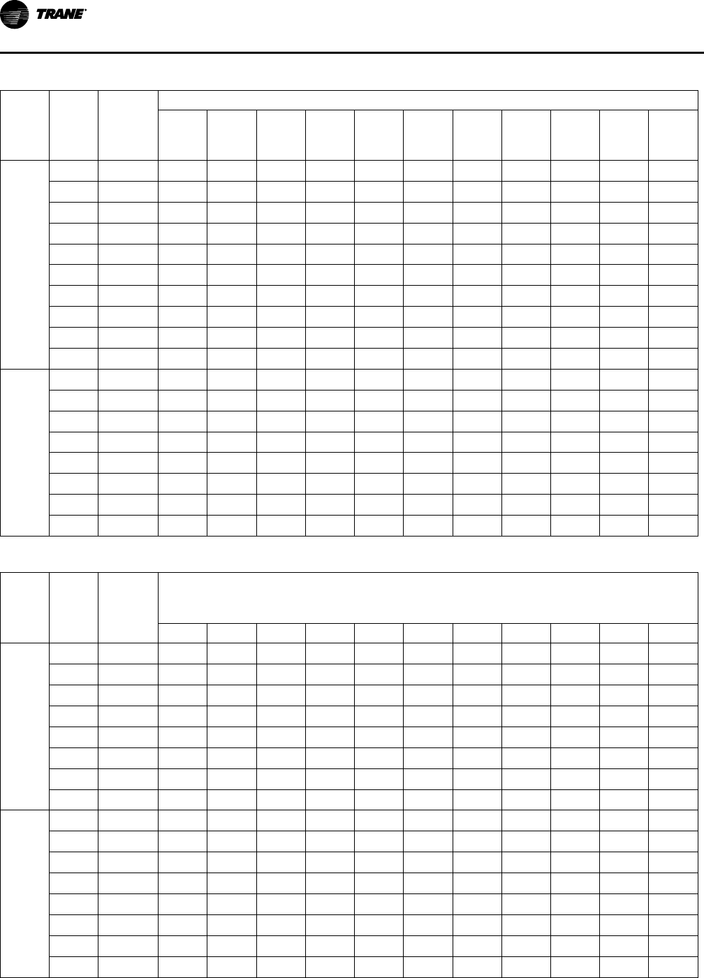
116
VAV-PRC012AC-EN
Table 52. Heating capacity (kW—fan sizes 03SQ 04SQ(SI)
Rows
L/s
Water
Pressure
Drop
(kPa)
Airflow (L/s)
94 142 189 260 330 401 472 543 613 684 755
1-Row
Capacity
kW
0.06 0.81 – – – – – – – – – – –
0.13 3.02 4.40 5.33 6.04 6.91 7.62 8.23 8.79 9.29 9.75 10.16 10.16
0.19 6.56 4.60 5.64 6.45 7.45 8.29 9.03 9.70 10.30 10.86 11.38 11.38
0.25 11.39 4.71 5.80 6.67 7.75 8.67 9.49 10.23 10.91 11.54 12.13 12.13
0.32 17.49 4.77 5.91 6.81 7.94 8.92 9.79 10.58 11.31 11.99 12.63 12.63
0.38 24.86 4.82 5.98 6.91 8.08 9.09 10.00 10.83 11.60 12.32 12.99 12.99
0.44 33.49 4.85 6.03 6.98 8.18 9.22 10.16 11.02 11.81 12.56 13.27 13.27
0.50 43.36 4.88 6.08 7.04 8.26 9.32 10.28 11.16 11.98 12.75 13.48 13.48
0.57 54.46 4.90 6.11 7.08 8.32 9.40 10.38 11.28 12.12 12.90 13.65 13.65
0.63 66.80 4.92 6.13 7.12 8.37 9.47 10.46 11.37 12.22 13.03 13.79 13.79
2-Row
Capacity
kW
0.06 1.18 – – – – – – – – – – –
0.13 4.22 5.55 7.50 9.07 10.90 12.31 13.42 14.32 15.06 15.68 16.22 16.22
0.19 8.99 5.70 7.83 9.61 11.78 13.52 14.94 16.12 17.13 18.00 18.75 18.75
0.25 15.41 5.78 8.00 9.89 12.25 14.18 15.79 17.16 18.33 19.36 20.26 20.26
0.32 23.45 5.83 8.10 10.06 12.54 14.60 16.33 17.82 19.12 20.25 21.26 21.26
0.38 33.07 5.86 8.17 10.18 12.74 14.88 16.71 18.29 19.67 20.89 21.97 21.97
0.44 44.26 5.88 8.22 10.26 12.88 15.09 16.99 18.63 20.07 21.36 22.50 22.50
0.50 57.00 5.90 8.26 10.33 12.99 15.25 17.20 18.89 20.39 21.72 22.92 22.92
Table 53. Heating capacity (kW)—fan size 05SQ(SI)
Rows
L/s
Water
Pressure
Drop
(kPa)
Airflow (L/s)
165 236 307 378 472 566 661 755 849 944 1015
1-Row
Capacity
kW
0.06 0.87 – – – – – – – – – – –
0.13 3.22 6.35 7.40 8.23 8.94 9.76 10.49 11.12 11.69 12.19 12.65 12.65
0.19 6.95 6.75 7.95 8.94 9.78 10.77 11.64 12.42 13.16 13.82 14.44 14.44
0.25 12.04 6.96 8.26 9.33 10.27 11.37 12.34 13.23 14.04 14.79 15.51 15.51
0.32 18.46 7.10 8.46 9.59 10.58 11.76 12.81 13.77 14.66 15.48 16.25 16.25
0.38 26.20 7.19 8.60 9.77 10.80 12.03 13.14 14.15 15.09 15.97 16.79 16.79
0.44 35.23 7.26 8.70 9.90 10.97 12.24 13.39 14.44 15.42 16.34 17.21 17.21
0.50 45.57 7.32 8.78 10.01 11.09 12.40 13.58 14.67 15.68 16.63 17.53 17.53
2-Row
Capacity
kW
0.06 1.16 – – – – – – – – – – –
0.13 4.16 8.78 11.05 12.78 14.16 15.58 16.69 17.57 18.30 18.90 19.41 19.41
0.19 8.85 9.20 11.83 13.94 15.68 17.57 19.10 20.35 21.41 22.32 23.10 23.10
0.25 15.17 9.42 12.23 14.56 16.52 18.69 20.48 21.99 23.28 24.40 25.38 25.38
0.32 23.09 9.55 12.48 14.95 17.04 19.41 21.38 23.07 24.52 25.80 26.92 26.92
0.38 32.57 9.63 12.65 15.21 17.40 19.90 22.01 23.83 25.41 26.79 28.03 28.03
0.44 43.60 9.70 12.77 15.39 17.67 20.26 22.48 24.39 26.06 27.54 28.86 28.86
0.50 56.16 9.74 12.86 15.54 17.87 20.54 22.83 24.82 26.57 28.12 29.51 29.51
PPeerrffoorrmmaannccee DDaattaa

VAV-PRC012AC-EN
117
Table 54. Heating capacity (kW)—fan sizes 06SQ and 07SQ (SI)
Rows
L/s
Water
Pressure
Drop
(kPa)
Airflow (L/s)
330 425 519 613 708 802 897 991 1085 1180 1274
1-Row
Capacity
Kw
0.03 0.36 – – – – – – – – – – –
0.06 1.20 – – – – – – – – – – –
0.13 4.10 9.15 10.11 10.98 11.74 12.41 13.00 13.54 14.03 14.49 14.90 14.90
0.19 8.46 9.91 11.07 12.07 12.97 13.80 14.58 15.29 15.94 16.55 17.12 17.12
0.25 14.22 10.34 11.61 12.73 13.73 14.66 15.51 16.30 17.07 17.78 18.46 18.46
0.32 21.30 10.61 11.96 13.15 14.23 15.23 16.15 17.02 17.83 18.60 19.34 19.34
0.38 29.68 10.80 12.20 13.45 14.59 15.64 16.62 17.54 18.40 19.22 20.00 20.00
2-Row
Capacity
kW
0.06 2.31 – – – – – – – – – – -
0.13 7.71 14.01 15.83 17.23 18.33 19.23 19.97 20.59 21.11 21.57 21.97 21.97
0.19 15.74 15.27 17.61 19.49 21.04 22.33 23.43 24.38 25.20 25.93 26.57 26.57
0.25 26.24 15.94 18.58 20.75 22.58 24.14 25.49 26.67 27.71 28.63 29.46 29.46
0.32 39.08 16.34 19.18 21.55 23.58 25.32 26.85 28.19 29.38 30.45 31.42 31.42
0.38 54.19 16.62 19.59 22.11 24.27 26.15 27.80 29.27 30.58 31.76 32.83 32.83
Table 55. Heating capacity (MBh)—fan size 02SQ (I-P)
Rows
Gpm
Water
Pressure
Drop (ft)
Airflow (Cfm)
150 200 250 300 350 400 450 500 550 600 700
1-Row
Ca-
pacity
MBh
0.5 0.16 – – – – – – – – – – –
1.0 0.53 9.14 10.34 11.34 12.20 12.97 13.67 14.32 14.93 15.51 16.05 17.02
2.0 1.85 9.94 11.4 12.63 13.73 14.73 15.66 16.52 17.33 18.1 18.82 20.18
3.0 3.85 10.25 11.8 13.14 14.34 15.43 16.45 17.41 18.32 19.18 20.01 21.56
4.0 6.51 10.41 12.02 13.41 14.66 15.81 16.89 17.9 18.87 19.78 20.66 22.32
5.0 9.79 10.51 12.15 13.58 14.87 16.05 17.17 18.21 19.21 20.17 21.08 22.81
2-Row
Ca-
pacity
MBh
1.0 1.00 12.59 15.23 17.40 19.21 20.74 22.06 23.19 24.19 25.07 25.85 27.19
2.0 3.42 13.42 16.6 19.34 21.73 23.84 25.71 27.39 28.9 30.27 31.52 33.72
3.0 7.05 13.71 17.08 20.04 22.66 25.00 27.12 29.03 30.77 32.37 33.84 36.46
4.0 11.82 13.86 17.33 20.4 23.14 25.62 27.86 29.9 31.77 33.50 35.10 37.96
5.0 17.68 13.94 17.48 20.62 23.44 25.99 28.32 30.44 32.40 34.21 35.89 38.92
PPeerrffoorrmmaannccee DDaattaa

118
VAV-PRC012AC-EN
Table 56. Heating capacity (MBh)—fan sizes 03SQ 04SQ (I-P)
Rows
Gpm
Water
Pressure
Drop (ft)
Airflow (Cfm)
200 300 400 550 700 850 1000 1150 1300 1450 1600
1-Row
Ca-
pacity
MBh
1.0 0.27 – – – – – – – – – – –
2.0 1.01 15.03 18.19 20.63 23.57 26.00 28.09 29.99 31.71 33.27 34.68 35.97
3.0 2.19 15.7 19.23 22.00 25.41 28.29 30.81 33.08 35.15 37.05 38.83 40.51
4.0 3.81 16.06 19.80 22.76 26.44 29.59 32.38 34.91 37.23 39.38 41.38 43.26
5.0 5.85 16.29 20.16 23.24 27.11 30.43 33.40 36.11 38.60 40.93 43.1 45.15
6.0 8.32 16.45 20.41 23.58 27.57 31.02 34.12 36.96 39.58 42.03 44.34 46.51
7.0 11.2 16.56 20.59 23.82 27.91 31.46 34.66 37.59 40.31 42.86 45.26 47.54
8.0 14.5 16.65 20.73 24.01 28.18 31.80 35.07 38.08 40.88 43.51 45.99 48.34
9.0 18.22 16.72 20.84 24.17 28.39 32.08 35.41 38.48 41.34 44.03 46.57 48.99
10.0 22.35 16.78 20.93 24.29 28.56 32.30 35.68 38.80 41.71 44.46 47.05 49.52
2-Row
Ca-
pacity
MBh
1.0 0.39 – – – – – – – – – – –
2.0 1.41 18.93 25.58 30.93 37.20 41.99 45.78 48.85 51.38 53.52 55.34 56.92
3.0 3.01 19.46 26.72 32.79 40.20 46.12 50.97 55.02 58.45 61.41 63.98 66.24
4.0 5.16 19.72 27.30 33.75 41.80 48.38 53.88 58.54 62.56 66.05 69.14 71.88
5.0 7.84 19.88 27.65 34.34 42.79 49.81 55.73 60.81 65.23 69.11 72.55 75.63
6.0 11.06 19.98 27.88 34.74 43.47 50.79 57.01 62.40 67.10 71.26 74.98 78.31
7.0 14.81 20.06 28.05 35.02 43.96 51.50 57.96 63.57 68.49 72.87 76.79 80.32
8.0 19.07 20.12 28.18 35.24 44.34 52.05 58.68 64.46 69.57 74.11 78.19 81.88
Table 57. Heating capacity (MBh)—fan size 05SQ (I-P)
Rows
Gpm
Water
Pressure
Drop (ft)
Airflow (Cfm)
350 500 650 800 1000 1200 1400 1600
180-
0 2000 2150
1-Row
Capacity
MBh
1.0 0.29 – – – – – – – – – – –
2.0 1.08 21.67 25.25 28.09 30.49 33.30 35.79 37.96 39.88 41.61 43.17 44.25
3.0 2.33 23.02 27.14 30.49 33.38 36.75 39.71 42.39 44.89 47.17 49.26 50.73
4.0 4.03 23.76 28.20 31.85 35.03 38.78 42.12 45.14 47.92 50.48 52.91 54.64
5.0 6.18 24.23 28.87 32.72 36.10 40.11 43.71 46.98 50.01 52.81 55.44 57.30
6.0 8.76 24.55 29.34 33.34 36.86 41.05 44.83 48.29 51.50 54.50 57.30 59.30
7.0 11.79 24.79 29.69 33.79 37.42 41.75 45.67 49.28 52.63 55.76 58.71 60.82
8.0 15.24 24.97 29.95 34.14 37.85 42.29 46.33 50.05 53.51 56.76 59.82 62.01
2-Row
Capacity
MBh
1.0 0.39 – – – – – – – – – – –
2.0 1.39 29.95 37.69 43.62 48.30 53.17 56.95 59.97 62.43 64.49 66.24 67.38
3.0 2.96 31.40 40.36 47.58 53.51 59.95 65.16 69.45 73.07 76.15 78.82 80.59
4.0 5.08 32.14 41.74 49.69 56.37 63.77 69.90 75.05 79.45 83.26 86.60 88.84
5.0 7.72 32.58 42.59 51.00 58.16 66.21 72.97 78.72 83.68 88.02 91.85 94.45
6.0 10.90 32.87 43.16 51.88 59.39 67.90 75.11 81.30 86.69 91.42 95.63 98.49
7.0 14.59 33.08 43.57 52.53 60.28 69.14 76.69 83.22 88.93 93.97 98.47 101.54
8.0 18.79 33.24 43.88 53.02 60.96 70.09 77.91 84.70 90.66 95.95 100.69 103.93
PPeerrffoorrmmaannccee DDaattaa
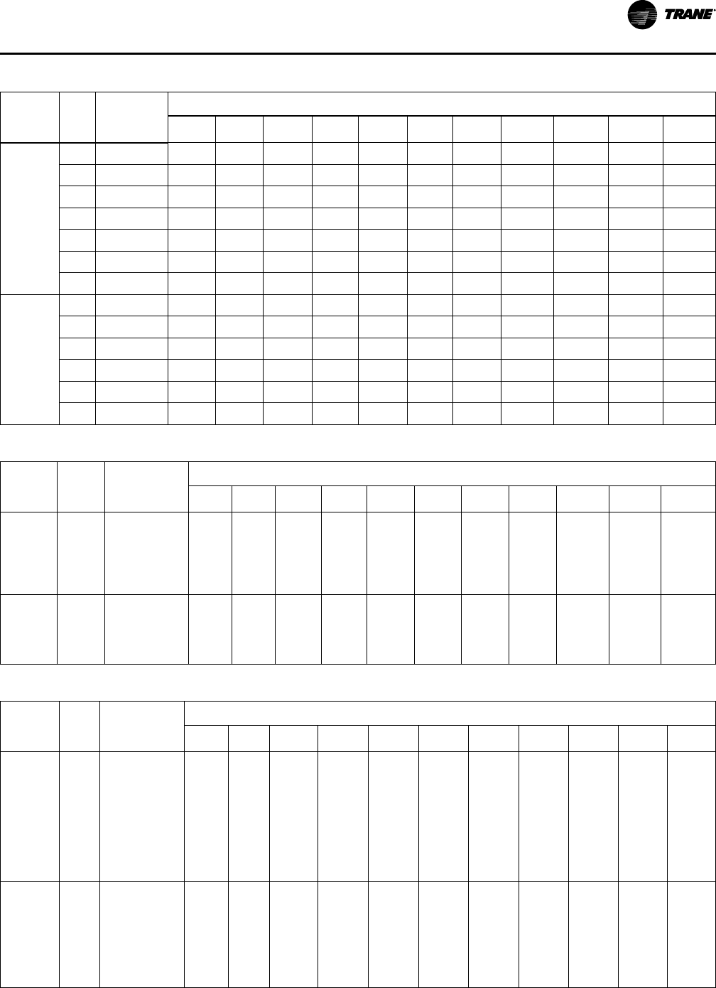
VAV-PRC012AC-EN
119
Table 58. Heating capacity (MBh)—fan size 06SQ and 07SQ (I-P)
Rows
Gp-
m
Water
Pressure
Drop (ft)
Airflow (Cfm)
700 900 1100 1300 1500 1700 1900 2100 2300 2500 2700
1-Row
Capacity
MBh
0.5 0.12 – – – – – – – – – – –
1.0 0.40 – – – – – – – – – – –
2.0 1.37 31.21 34.50 37.47 40.06 42.33 44.37 46.21 47.89 49.43 50.85 52.16
3.0 2.83 33.81 37.76 41.19 44.25 47.10 49.74 52.17 54.40 56.49 58.43 60.24
4.0 4.76 35.27 39.61 43.42 46.86 50.00 52.91 55.63 58.24 60.68 62.97 65.14
5.0 7.13 36.20 40.80 44.87 48.57 51.97 55.12 58.07 60.84 63.46 66.00 68.41
6.0 9.93 36.85 41.64 45.90 49.78 53.36 56.70 59.83 62.79 65.59 68.24 70.77
2-Row
Capacity
MBh
1.0 0.77 – – – – – – – – – – –
2.0 2.58 47.79 54.01 58.79 62.56 65.61 68.13 70.25 72.05 73.60 74.95 76.14
3.0 5.27 52.10 60.08 66.51 71.79 76.21 79.96 83.19 86.00 88.47 90.65 92.61
4.0 8.78 54.37 63.38 70.82 77.06 82.39 86.98 91.00 94.54 97.69 100.51 103.06
5.0 13.07 55.77 65.44 73.55 80.45 86.40 91.60 96.18 100.26 103.91 107.20 110.19
6.0 18.13 56.71 66.85 75.43 82.80 89.22 94.86 99.86 104.34 108.37 112.03 115.36
Table 59. Heating capacity (kW)— fan size 02SQ (SI)
Rows
L/s
Water
Pressure
Drop (kPa)
Airflow (L/s)
71 94 118 142 165 189 212 236 260 283 330
1-Row
Capacity
kW
0.03
0.06
0.13
0.19
0.25
0.32
0.47
1.59
5.52
11.51
19.45
29.27
–
2.68
2.91
3.00
3.05
3.08
–
3.03
3.34
3.46
3.52
3.56
–
3.32
3.70
3.85
3.93
3.98
–
3.58
4.02
4.20
4.30
4.36
–
3.80
4.32
4.52
4.63
4.71
–
4.01
4.59
4.82
4.95
5.03
–
4.20
4.84
5.10
5.25
5.34
–
4.38
5.08
5.37
5.53
5.63
–
4.55
5.30
5.62
5.80
5.91
–
4.70
5.52
5.86
6.06
6.18
–
4.70
5.52
5.86
6.06
6.18
2-Row
Capacity
kW
0.06
0.13
0.19
0.25
0.32
3.00
10.21
21.07
35.33
52.84
3.69
3.93
4.02
4.06
4.09
4.46
4.86
5.01
5.08
5.12
5.10
5.67
5.87
5.98
6.04
5.63
6.37
6.64
6.78
6.87
6.08
6.99
7.33
7.51
7.62
6.46
7.54
7.95
8.16
8.30
6.80
8.03
8.51
8.76
8.92
7.09
8.47
9.02
9.31
9.50
7.35
8.87
9.49
9.82
10.03
7.58
9.24
9.92
10.29
10.52
7.58
9.24
9.92
10.29
10.52
Table 60. Heating capacity (kW—fan sizes 03SQ 04SQ(SI)
Rows
L/s
Water
Pressure
Drop (kPa)
Airflow (L/s)
94 142 189 260 330 401 472 543 613 684 755
1-Row
Capacity
kW
0.06
0.13
0.19
0.25
0.32
0.38
0.44
0.50
0.57
0.63
0.81
3.02
6.56
11.39
17.49
24.86
33.49
43.36
54.46
66.80
–
4.40
4.60
4.71
4.77
4.82
4.85
4.88
4.90
4.92
–
5.33
5.64
5.80
5.91
5.98
6.03
6.08
6.11
6.13
–
6.04
6.45
6.67
6.81
6.91
6.98
7.04
7.08
7.12
–
6.91
7.45
7.75
7.94
8.08
8.18
8.26
8.32
8.37
–
7.62
8.29
8.67
8.92
9.09
9.22
9.32
9.40
9.47
–
8.23
9.03
9.49
9.79
10.00
10.16
10.28
10.38
10.46
–
8.79
9.70
10.23
10.58
10.83
11.02
11.16
11.28
11.37
–
9.29
10.30
10.91
11.31
11.60
11.81
11.98
12.12
12.22
–
9.75
10.86
11.54
11.99
12.32
12.56
12.75
12.90
13.03
–
10.16
11.38
12.13
12.63
12.99
13.27
13.48
13.65
13.79
–
10.16
11.38
12.13
12.63
12.99
13.27
13.48
13.65
13.79
2-Row
Capacity
kW
0.06
0.13
0.19
0.25
0.32
0.38
0.44
0.50
1.18
4.22
8.99
15.41
23.45
33.07
44.26
57.00
–
5.55
5.70
5.78
5.83
5.86
5.88
5.90
–
7.50
7.83
8.00
8.10
8.17
8.22
8.26
–
9.07
9.61
9.89
10.06
10.18
10.26
10.33
–
10.90
11.78
12.25
12.54
12.74
12.88
12.99
–
12.31
13.52
14.18
14.60
14.88
15.09
15.25
–
13.42
14.94
15.79
16.33
16.71
16.99
17.20
–
14.32
16.12
17.16
17.82
18.29
18.63
18.89
–
15.06
17.13
18.33
19.12
19.67
20.07
20.39
–
15.68
18.00
19.36
20.25
20.89
21.36
21.72
–
16.22
18.75
20.26
21.26
21.97
22.50
22.92
–
16.22
18.75
20.26
21.26
21.97
22.50
22.92
PPeerrffoorrmmaannccee DDaattaa

120
VAV-PRC012AC-EN
Table 61. Heating capacity (kW)—fan size 05SQ(SI)
Rows
L/s
Water
Pressure
Drop (kPa)
Airflow (L/s)
165 236 307 378 472 566 661 755 849 944 1015
1-Row
Capacity
kW
0.06
0.13
0.19
0.25
0.32
0.38
0.44
0.50
0.87
3.22
6.95
12.04
18.46
26.20
35.23
45.57
–
6.35
6.75
6.96
7.10
7.19
7.26
7.32
–
7.40
7.95
8.26
8.46
8.60
8.70
8.78
–
8.23
8.94
9.33
9.59
9.77
9.90
10.01
–
8.94
9.78
10.27
10.58
10.80
10.97
11.09
–
9.76
10.77
11.37
11.76
12.03
12.24
12.40
–
10.49
11.64
12.34
12.81
13.14
13.39
13.58
–
11.12
12.42
13.23
13.77
14.15
14.44
14.67
–
11.69
13.16
14.04
14.66
15.09
15.42
15.68
–
12.19
13.82
14.79
15.48
15.97
16.34
16.63
–
12.65
14.44
15.51
16.25
16.79
17.21
17.53
–
12.65
14.44
15.51
16.25
16.79
17.21
17.53
2-Row
Capacity
kW
0.06
0.13
0.19
0.25
0.32
0.38
0.44
0.50
1.16
4.16
8.85
15.17
23.09
32.57
43.60
56.16
–
8.78
9.20
9.42
9.55
9.63
9.70
9.74
–
11.05
11.83
12.23
12.48
12.65
12.77
12.86
–
12.78
13.94
14.56
14.95
15.21
15.39
15.54
–
14.16
15.68
16.52
17.04
17.40
17.67
17.87
–
15.58
17.57
18.69
19.41
19.90
20.26
20.54
–
16.69
19.10
20.48
21.38
22.01
22.48
22.83
–
17.57
20.35
21.99
23.07
23.83
24.39
24.82
–
18.30
21.41
23.28
24.52
25.41
26.06
26.57
–
18.90
22.32
24.40
25.80
26.79
27.54
28.12
–
19.41
23.10
25.38
26.92
28.03
28.86
29.51
–
19.41
23.10
25.38
26.92
28.03
28.86
29.51
Table 62. Heating capacity (kW)—fan sizes 06SQ and 07SQ (SI)
Rows
L/s
Water
Pressure
Drop (kPa)
Airflow (L/s)
330 425 519 613 708 802 897 991 1085 1180 1274
1-Row
Capacity
kW
0.03
0.06
0.13
0.19
0.25
0.32
0.38
0.36
1.20
4.10
8.46
14.22
21.30
29.68
–
–
9.15
9.91
10.34
10.61
10.80
–
–
10.11
11.07
11.61
11.96
12.20
–
–
10.98
12.07
12.73
13.15
13.45
–
–
11.74
12.97
13.73
14.23
14.59
–
–
12.41
13.80
14.66
15.23
15.64
–
–
13.00
14.58
15.51
16.15
16.62
–
–
13.54
15.29
16.30
17.02
17.54
–
–
14.03
15.94
17.07
17.83
18.40
–
–
14.49
16.55
17.78
18.60
19.22
–
–
14.90
17.12
18.46
19.34
20.00
–
–
14.90
17.12
18.46
19.34
20.00
2-Row
Capacity
kW
0.06
0.13
0.19
0.25
0.32
0.38
2.31
7.71
15.74
26.24
39.08
54.19
–
14.01
15.27
15.94
16.34
16.62
–
15.83
17.61
18.58
19.18
19.59
–
17.23
19.49
20.75
21.55
22.11
–
18.33
21.04
22.58
23.58
24.27
–
19.23
22.33
24.14
25.32
26.15
–
19.97
23.43
25.49
26.85
27.80
–
20.59
24.38
26.67
28.19
29.27
–
21.11
25.20
27.71
29.38
30.58
–
21.57
25.93
28.63
30.45
31.76
–
21.97
26.57
29.46
31.42
32.83
-
21.97
26.57
29.46
31.42
32.83
Low Height Parallel Fan-Powered Terminal Units
Table 63. Primary airflow control factory settings—I-P
Control Type Air Valve Size (in.)
Maximum Valve
Cfm
Maximum
Controller Cfm
Minimum
Controller Cfm
Constant Volume
Cfm
Direct Digital
Control/UCM, VV550,
UC210, and UC400
5 350 40-350
0, 40-350
40-350
6 500 60-500
0, 60-500
60-500
8 900 105-900
0, 105-900
105-900
8x14 2200 200-2200
0, 220-2200
220-2200
Table 64. Primary airflow control factory settings—SI
Control Type Air Valve Size (in.)
Maximum Valve
Cfm
Maximum
Controller Cfm
Minimum
Controller Cfm
Constant Volume
Cfm
Direct Digital
Control/UCM, VV550,
UC210, and UC400
5 165 19-165
0, 19-165
19-165
6 236 28-236
0, 28-236
28-236
8 425 50-425
0, 50-425
50-425
8x14 1038 104-1038
0, 104-1038
104-1038
Note: Maximum airflow must be greater than or equal to minimum airflow.
PPeerrffoorrmmaannccee DDaattaa
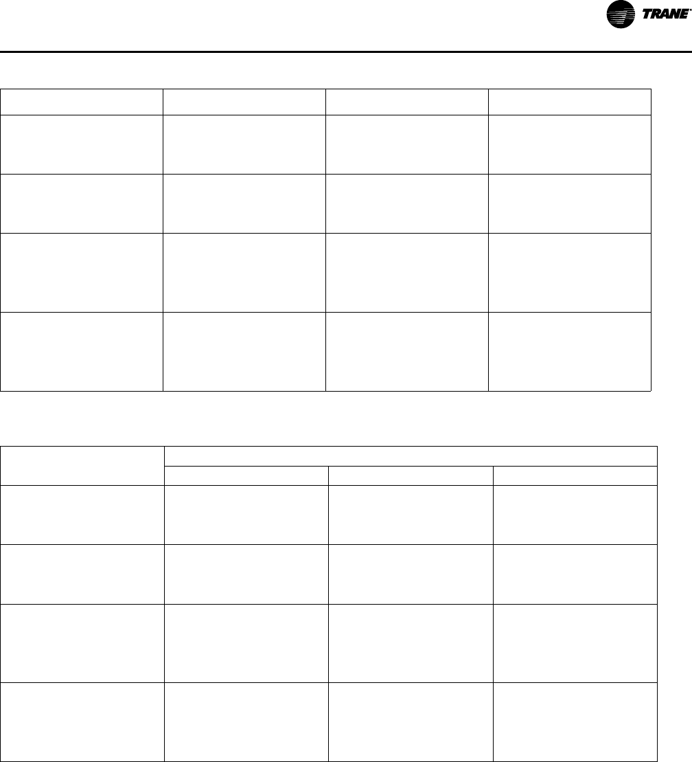
VAV-PRC012AC-EN
121
Table 65. Unit air pressure drop—in. wg (I-P)
Airflow Cfm Inlet Valve
Cooling Only Unit (in. wg)
DS02/PS02-05
150 0.01 0.02
250 0.01 0.07
350 0.02 0.13
DS02/PS02-06
100 0.01 0.01
300 0.10 0.01
500 0.22 0.02
DS02/PS02-08
400 0.01 0.02
600 0.04 0.02
750 0.07 0.02
900 0.09 0.02
DS02/PS02-8x14
600 0.01 0.03
825 0.01 0.06
1025 0.01 0.10
1300 0.01 0.15
Note: Units with Electric Coils per fan size add 0.01" (3 Pa) to cooling only value.
Table 66. Unit air pressure drop—Pa (SI)
Fan/Inlet Size
Pa (SI)
Airflow L/s
Inlet Valve
Cooling Only Unit (Pa)
DS02/PS02-05
71 2 5
118 2 17
165 5 32
DS02/PS02-06
47 2 2
142 25 2
236 55 5
DS02/PS02-08
189 2 5
283 10 5
354 17 5
425 20 5
DS02/PS02-8x14
283 2 7
389 2 15
484 2 25
614 2 37
Note: Units with Electric Coils per fan size add 0.01" (3 Pa) to cooling only value.
PPeerrffoorrmmaannccee DDaattaa

122
VAV-PRC012AC-EN
Table 67. Coil air pressure drop
in.wg (I-P) Pa (SI)
Fan Size Airflow Cfm
1-Row HW
(in. wg)
2-Row HW
(in. wg)
Fan Size
Airflow L/ s
1-Row HW
(Pa)
2-Row HW
(Pa)
DS02
PS02
100 0.01 0.01
DS02
PS02
47 2.5 2.5
250 0.01 0.04 118 2.5 10
500 0.04 0.11 236 10 27
750 0.10 0.19 354 25 47
1000 0.18 0.30 472 45 75
1300 0.32 0.44 614 80 110
Note: HW Coil Only pressure drops do not include unit pressure drop.
Performance Data Fan Curves
Figure 56. Performance data fan curves, low-height parallel PS02—PSC
0.1
0.2
0.3
0.4
0.5
0.6
0.7
0.8
0.9
1
100 300 500 700 900 1100 1300
Dishcarge Stac Pressure
Fan Airflow
LPCF and LPEF maximum
Minimum
2-row coil maximum
cfm
47 142 236 330 425 519 613
L/s
50
100
Pa
In.wg
250
200
225
175
150
125
PPeerrffoorrmmaannccee DDaattaa

VAV-PRC012AC-EN
123
Figure 57. Performance data fan curves, LPxF DS02—ECM
0.1
0.4
0.7
1
1.3
0 200 400 600 800 1000 1200 1400
Discharge Sta!c Pressure
Fan Airflow
Min Boundary
2-row coil maximum
LPCF and LPEF maximum
324
25
100
173
249
Pa
In.wg
0 94 189 283 378 472 566 661
L/s
cfm
1.5
375
Table 68. Heating capacity (MBh)—fan size DS02 and PS02 (I-P)
Rows
Gpm
Water
Pressure
Drop (ft)
Airflow (Cfm)
100 200 300 400 500 600 700 800 900 1000 1100 1200 1300
1
1.0 0.15 6.87 9.06 10.47 11.53 12.40 13.14 13.77 14.32 14.80 15.07 15.44 15.78 16.09
2.0 0.58 7.70 10.70 12.78 14.46 15.90 17.15 18.27 19.28 20.20 20.48 21.23 21.93 22.57
3.0 1.27 7.92 11.16 13.45 15.34 16.97 18.42 19.73 20.92 22.01 23.02 23.83 24.70 25.53
4.0 2.24 8.08 11.48 13.94 15.98 17.76 19.36 20.82 22.16 23.39 24.54 25.41 26.41 27.36
5.0 3.48 8.17 11.69 14.25 16.39 18.28 19.99 21.54 22.98 24.32 25.57 26.47 27.57 28.61
6.0 4.98 8.24 11.83 14.47 16.69 18.65 20.43 22.06 23.58 24.99 26.31 27.24 28.41 29.51
2
1.0 0.76 9.04 14.59 18.26 20.87 22.83 24.35 25.53 26.58 27.42 28.14 28.81 29.34 29.81
2.0 2.60 9.45 15.95 20.70 24.34 27.24 29.61 31.59 33.28 34.74 36.02 37.48 38.49 39.40
3.0 5.39 9.59 16.43 21.60 25.68 29.01 31.78 34.14 36.17 37.95 39.53 41.45 42.17 43.86
4.0 9.06 9.66 16.68 22.08 26.40 29.96 32.96 35.54 37.78 39.75 41.51 43.75 45.19 46.49
5.0 13.57 9.70 16.83 22.37 26.85 30.56 33.71 36.43 38.80 40.90 42.78 45.25 46.80 48.21
Water Coil Notes (I-P)
• Fouling factor = 0.0005.
• The off-coil temperature of the hot water coil on parallel fan-powered units must not exceed
140°F when mounted on plenum inlet.
• Use the following equations to calculate leaving air temperature (LAT) and water temperature
difference (WTD).
PPeerrffoorrmmaannccee DDaattaa

124
VAV-PRC012AC-EN
WTD = EWT - LWT =
Gpm
2 x MBh
Capacity based on 70°F entering air temperature and 180°F entering water temperature.
Refer to correction factors for different entering conditions.
Table 69. Temperature correction factors for water pressure drop (WPD)
Average Water
Temperature
200 190 180 170 160 150 140 130 120 110
Correction Factor 0.970 0.985 1.000 1.020 1.030 1.050 1.080 1.100 1.130 1.150
Table 70. Temperature correction factors for coil capacity (MBh)
Entering Water Minus
Entering Air
40 50 60 70 80 90 100 110 120 130
Correction Factor 0.355 0.446 0.537 0.629 0.722 0.814 0.907 1.000 1.093 1.187
Table 71. Heating capacity (kW)—fan sizes DS02 and PS02 (SI)
Rows
L/s
Water
Pressure
Drop
(kPa)
Airflow (L/s)
47 94 142 189 236 283 330 378 425 472 519 566 614
1-Row
Capacity
MBh
0.06 0.45 2.01 2.66 3.07 3.38 3.64 3.85 4.04 4.20 4.34 4.42 4.53 4.62 4.72
0.13 1.73 2.26 3.14 3.75 4.24 4.66 5.03 5.36 5.65 5.92 6.00 6.22 6.43 6.61
0.19 3.80 2.32 3.27 3.94 4.50 4.97 5.40 5.78 6.13 6.45 6.75 6.98 7.24 7.48
0.25 6.70 2.37 3.36 4.09 4.68 5.20 5.67 6.10 6.49 6.86 7.19 7.45 7.74 8.02
0.32 10.40 2.39 3.43 4.18 4.80 5.36 5.86 6.31 6.74 7.13 7.49 7.76 8.08 8.38
0.38 14.89 2.41 3.47 4.24 4.89 5.47 5.99 6.47 6.91 7.32 7.71 7.98 8.33 8.65
2-Row
Capacity
MBh
0.06 2.27 2.65 4.28 5.35 6.12 6.69 7.14 7.49 7.79 8.04 8.25 8.44 8.60 8.74
0.13 7.77 2.77 4.67 6.07 7.13 7.98 8.68 9.26 9.75 10.18 10.56 10.98 11.28 11.55
0.19 16.11 2.81 4.82 6.33 7.53 8.50 9.31 10.01 10.60 11.12 11.58 12.15 12.36 12.85
0.25 27.08 2.83 4.89 6.47 7.74 8.78 9.66 10.42 11.07 11.65 12.16 12.82 13.24 13.62
0.32 40.56 2.84 4.93 6.56 7.87 8.96 9.88 10.68 11.37 11.99 12.54 13.26 13.72 14.13
Water Coil Notes (SI)
• Fouling factor = 0.0005.
• Use the following equations to calculate leaving air temperature (LAT) and water temperature
difference (WTD).
• Capacity based on 21°C entering air temperature and 82°C entering water temperature. Refer
to correction factors for different entering conditions.
PPeerrffoorrmmaannccee DDaattaa

VAV-PRC012AC-EN
125
Table 72. Temperature correction factors for water pressure drop (kPa)
Average Water Temperature
93 88 82 77 71 66 60 54 49 43
Correction Factor 0.970 0.985 1.000 1.020 1.030 1.050 1.080 1.100 1.130 1.150
Table 73. Temperature correction factors for coil capacity (kW)
Entering Water Minus Entering Air
22 27 33 38 44 50 55 61 67 72
Correction Factor 0.355 0.446 0.537 0.629 0.722 0.814 0.907 1.000 1.093 1.187
Low Height Series Fan-Powered Terminal Units
Table 74. Primary airflow control factory settings-I-P
Control Type Air Valve Size (in.)
Maximum Valve
(cfm)
Maximum
Controller (cfm)
Minimum
Controller (cfm)
Constant Volume
(cfm)
Direct Digital Control/
UCM, VV550, UC210,
and UC400
4 225 25-225
0, 25-225
25-225
5 350 40-350
0, 40-350
40-350
6 500 60-500
0, 60-500
60-500
8 900 105-900
0, 105-900
105-900
10 1400 165-1400
0, 165-1400
165-1400
8x14 2200 200-2200
0, 220-2200
220-2200
Table 75. Primary airflow control factory settings - SI
Control Type Air Valve Size (in.)
Maximum Valve
(cfm)
Maximum
Controller (cfm)
Minimum
Controller (cfm)
Constant Volume
(cfm)
Direct Digital Control/
UCM, VV550, UC210,
and UC400
4 106 12-106
0, 12-106
12-106
5 165 19-165
0, 19-165
19-165
6 236 28-236
0, 28-236
28-236
8 425 50-425
0, 50-425
50-425
10 661 77-661
0, 77-661
77-661
8x14 1038 104-1038
0, 104-1038
104-1038
Note: Maximum airflow must be greater than or equal to minimum airflow.
Table 76. Unit air pressure drop — in. wg (I-P)
in. wg (I-P) Pa (SI)
Fan/Inlet Size
Airflow Cfm Inlet Valve
Cooling Only Unit
Airflow L/s
Inlet Valve
Cooling Only Unit
DS02-04
50 0.01 0.01 24 2 2
150 0.01 0.01 70 2 2
225 0.01 0.07 106 2 17
DS02-05
150 0.01 0.01 71 2 2
250 0.01 0.03 118 2 7
350 0.02 0.20 165 5 50
DS02-06
100 0.01 0.01 47 2 2
300 0.10 0.02 142 25 5
500 0.22 0.25 236 55 62
DS02-08
400 0.01 0.01 189 2 2
600 0.04 0.12 283 10 30
750 0.07 0.23 354 17 57
900 0.09 0.36 425 20 90
PPeerrffoorrmmaannccee DDaattaa

126
VAV-PRC012AC-EN
Table 76. Unit air pressure drop — in. wg (I-P) (continued)
in. wg (I-P) Pa (SI)
Fan/Inlet Size
Airflow Cfm Inlet Valve
Cooling Only Unit
Airflow L/s
Inlet Valve
Cooling Only Unit
DS02-8x14
600 0.01 0.06 283 2 15
825 0.01 0.30 389 2 75
1025 0.01 0.55 484 2 137
1300 0.01 0.92 614 2 229
PS02-04
50 0.01 0.01 24 2 2
150 0.01 0.02 70 2 5
225 0.01 0.03 106 2 7
PS02-05
150 0.01 0.01 71 2 2
250 0.01 0.11 118 2 27
350 0.02 0.28 165 5 70
PS02-06
100 0.01 0.01 47 2 2
300 0.10 0.07 142 25 17
500 0.22 0.34 236 55 85
PS02-08
400 0.01 0.14 189 2 35
600 0.04 0.29 283 10 72
750 0.07 0.44 354 17 110
900 0.09 0.63 425 20 157
PS02-8x14
600 0.01 0.17 283 2 42
825 0.01 0.37 389 2 92
1025 0.01 0.57 484 2 142
1300 0.01 0.90 614 2 224
DS03-06
100 0.01 0.02 47 7 1
300 0.01 0.19 142 48 3
500 0.03 0.48 236 120 7
DS03-08
400 0.02 0.08 189 21 4
600 0.04 0.19 283 46 10
750 0.06 0.28 354 71 16
900 0.09 0.40 425 101 23
DS03-10
400 0.02 0.07 189 16 4
750 0.06 0.21 354 53 16
1050 0.13 0.40 496 99 31
1400 0.22 0.67 661 168 56
DS03-8x14
600 0.04 0.17 283 41 10
825 0.08 0.31 389 76 19
1025 0.12 0.46 484 115 30
1950 0.44 1.58 920 394 109
PPeerrffoorrmmaannccee DDaattaa
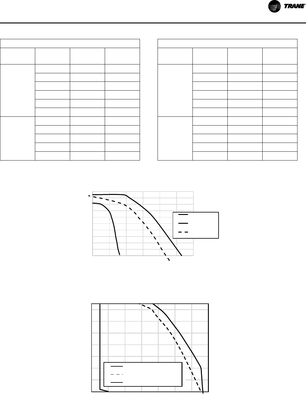
VAV-PRC012AC-EN
127
Table 77. Coil air pressure drop
in.wg (I-P) Pa (SI)
Fan Size
Airflow
(cfm)
1-Row HW
(in. wg)
2-Row HW
(in. wg)
Fan Size
Airflow L/s
1-Row HW
(Pa)
2-Row HW
(Pa)
DS02 PS02
100 0.01 0.01
DS02 PS02
47 2.5 2.5
250 0.01 0.04 118 2.5 10
500 0.04 0.11 236 10 27
750 0.10 0.19 354 25 47
1000 0.18 0.30 472 45 75
1300 0.32 0.44 614 80 110
DS03
900 0.13 0.26
DS03
425 32 65
1100 0.18 0.34 519 45 85
1400 0.25 0.49 661 62 122
1700 0.33 0.65 802 82 162
1950 0.40 0.80 920 100 199
Figure 58. Performance data fan curves, low-height series PS02—PSC
0
0.1
0.2
0.3
0.4
0.5
0.6
0.7
0.8
0.9
1
100 300 500 700 900 1100 1300
Dishcarge Static Pressure
Fan Airflow
LSCF and LSEF
maximum
Minimum
2-row coil
maximum
cfm
47 142 236 330 425 519 613 L/s
0
50
100
Pa
In.wg
250
200
225
175
150
125
75
25
Figure 59. Performance data fan curves, LSxF DS02 —ECM
0
0.2
0.4
0.6
0.8
1
1.2
1.4
0 200 400 600 800 1000 1200 1400
Discharge Static Pressure
Fan Airflow
Min Boundary
2-row coil maximum
LSCF and LSEF maximum
350
50
0
100
150
200
250
300
Pa
In.wg
0 94 189 283 378 472 566 661
L/s
cfm
1.5
375
PPeerrffoorrmmaannccee DDaattaa

128
VAV-PRC012AC-EN
Figure 60. Performance data fan curves, LSxF DS03—ECM
Airflow
Discharge Static Pressure
0
25
50
75
142 330236 425 897
cfm
L/s
Pa In. wg
0.00
0.10
0.20
0.30
0.40
0.50
300 500 700 900 1100 1300 1500 1700 1900
125
100
519 614 708 802
400 cfm min
(189 L/s)
LSCF and LSEF maximum
Minimum
1-row coil maximum
2-row coil maximum
Notes:
• ECMs (electronically commutated motors) are ideal for systems seeking maximum motor efficiency.
Table 78. Heating capacity (MBh)—fan sizes DS02 and PS02 (I-P)
Rows
Gpm
Water
Pressure
Drop (ft)
Airflow (Cfm)
100 200 300 400 500 600 700 800 900 1000 1100 1200 1300
1
1.0 0.15 6.87 9.06 10.47 11.53 12.40 13.14 13.77 14.32 14.80 15.07 15.44 15.78 16.09
2.0 0.58 7.70 10.70 12.78 14.46 15.90 17.15 18.27 19.28 20.20 20.48 21.23 21.93 22.57
3.0 1.27 7.92 11.16 13.45 15.34 16.97 18.42 19.73 20.92 22.01 23.02 23.83 24.70 25.53
4.0 2.24 8.08 11.48 13.94 15.98 17.76 19.36 20.82 22.16 23.39 24.54 25.41 26.41 27.36
5.0 3.48 8.17 11.69 14.25 16.39 18.28 19.99 21.54 22.98 24.32 25.57 26.47 27.57 28.61
6.0 4.98 8.24 11.83 14.47 16.69 18.65 20.43 22.06 23.58 24.99 26.31 27.24 28.41 29.51
2
1.0 0.76 9.04 14.59 18.26 20.87 22.83 24.35 25.53 26.58 27.42 28.14 28.81 29.34 29.81
2.0 2.60 9.45 15.95 20.70 24.34 27.24 29.61 31.59 33.28 34.74 36.02 37.48 38.49 39.40
3.0 5.39 9.59 16.43 21.60 25.68 29.01 31.78 34.14 36.17 37.95 39.53 41.45 42.17 43.86
4.0 9.06 9.66 16.68 22.08 26.40 29.96 32.96 35.54 37.78 39.75 41.51 43.75 45.19 46.49
5.0 13.57 9.70 16.83 22.37 26.85 30.56 33.71 36.43 38.80 40.90 42.78 45.25 46.80 48.21
Table 79. Heating capacity (MBh)—fan size DS03 (I-P)
Rows
Gpm
Water
Pressure
Drop (ft)
Airflow (cfm)
900 1050 1200 1350 1500 1650 1800 1950
1-Row
Capacity
MBh
1.0 0.13 15.68 16.14 16.50 16.79 17.01 17.19 17.34 17.46
2.0 0.52 21.12 22.04 22.77 23.36 23.83 24.22 24.54 24.79
3.0 1.14 23.53 24.65 25.56 26.30 26.92 27.43 27.85 28.19
4.0 2.01 24.96 26.24 27.27 28.12 28.82 29.40 29.88 30.28
5.0 3.12 25.92 27.30 28.43 29.36 30.13 30.76 31.28 31.71
6.0 4.46 26.61 28.07 29.27 30.26 31.07 31.75 32.31 32.77
2-Row
Capacity
MBh
1.0 0.75 31.24 32.55 33.67 34.66 35.55 36.36 37.10 37.78
2.0 2.55 40.58 43.10 45.35 47.42 49.35 51.15 52.85 54.46
3.0 5.25 44.69 47.89 50.82 53.54 56.11 58.56 60.90 63.14
4.0 8.79 47.00 50.62 53.95 57.09 60.08 62.95 65.72 68.40
5.0 13.14 48.47 52.37 55.99 59.42 62.70 65.87 68.94 71.93
PPeerrffoorrmmaannccee DDaattaa

VAV-PRC012AC-EN
129
Table 80. Heating capacity (kW)—fan size DS02 and PS02 (SI)
Rows
L/s
Water
Pressure
Drop
(kPa)
Airflow (L/s)
47 94 142 189 236 283 330 378 425 472 519 566 614
1-Row
Capacity
MBh
0.06 0.45 2.01 2.66 3.07 3.38 3.64 3.85 4.04 4.20 4.34 4.42 4.53 4.62 4.72
0.13 1.73 2.26 3.14 3.75 4.24 4.66 5.03 5.36 5.65 5.92 6.00 6.22 6.43 6.61
0.19 3.80 2.32 3.27 3.94 4.50 4.97 5.40 5.78 6.13 6.45 6.75 6.98 7.24 7.48
0.25 6.70 2.37 3.36 4.09 4.68 5.20 5.67 6.10 6.49 6.86 7.19 7.45 7.74 8.02
0.32 10.40 2.39 3.43 4.18 4.80 5.36 5.86 6.31 6.74 7.13 7.49 7.76 8.08 8.38
0.38 14.89 2.41 3.47 4.24 4.89 5.47 5.99 6.47 6.91 7.32 7.71 7.98 8.33 8.65
2-Row
Capacity
MBh
0.06 2.27 2.65 4.28 5.35 6.12 6.69 7.14 7.49 7.79 8.04 8.25 8.44 8.60 8.74
0.13 7.77 2.77 4.67 6.07 7.13 7.98 8.68 9.26 9.75 10.18 10.56 10.98 11.28 11.55
0.19 16.11 2.81 4.82 6.33 7.53 8.50 9.31 10.01 10.60 11.12 11.58 12.15 12.36 12.85
0.25 27.08 2.83 4.89 6.47 7.74 8.78 9.66 10.42 11.07 11.65 12.16 12.82 13.24 13.62
0.32 40.56 2.84 4.93 6.56 7.87 8.96 9.88 10.68 11.37 11.99 12.54 13.26 13.72 14.13
Table 81. Heating capacity (kW)—fan size DS03 (SI)
Rows
L/s
Water
Pressure Drop
(kPa)
Airflow (L/s)
425 496 566 637 708 779 850 920
1-Row
Capacity kW
0.06 0.39 4.60 4.73 4.84 4.92 4.99 5.04 5.08 5.12
0.13 1.55 6.19 6.46 6.67 6.85 6.98 7.10 7.19 7.27
0.19 3.41 6.90 7.22 7.49 7.71 7.89 8.04 8.16 8.26
0.25 6.01 7.32 7.69 7.99 8.24 8.45 8.62 8.76 8.87
0.32 9.33 7.60 8.00 8.33 8.60 8.83 9.01 9.17 9.29
0.38 13.33 7.80 8.23 8.58 8.87 9.11 9.31 9.47 9.60
2-Row
Capacity kW
0.06 2.24 9.16 9.54 9.87 10.16 10.42 10.66 10.87 11.07
0.13 7.62 11.89 12.63 13.29 13.90 14.46 14.99 15.49 15.96
0.19 15.69 13.10 14.04 14.89 15.69 16.44 17.16 17.85 18.50
0.25 26.27 13.77 14.84 15.81 16.73 17.61 18.45 19.26 20.05
0.32 39.28 14.21 15.35 16.41 17.41 18.38 19.30 20.20 21.08
Water Coil Notes (SI)
• Fouling factor = 0.0005
• Use the following equations to calculate leaving air temperature (LAT) and water temperature
difference (WTD).
• Capacity based on 21°C entering air temperature and 82°C entering water temperature. Refer
to correction factors for different entering conditions.
PPeerrffoorrmmaannccee DDaattaa

130
VAV-PRC012AC-EN
Table 82. Temperature correction factors for water pressure drop (kPa)
Average Water Temperature (°C)
93 88 82 77 71 66 60 54 49 43
Correction Factor 0.970 0.985 1.000 1.020 1.030 1.050 1.080 1.100 1.130 1.150
Table 83. Temperature correction factors for coil capacity (kW)
Entering Water Minus Entering Air (°C)
22 27 33 38 44 50 55 61 67 72
Correction Factor 0.355 0.446 0.537 0.629 0.722 0.814 0.907 1.000 1.093 1.187
Water Coil Notes (I-P)
• Fouling factor = 0.0005
• Use the following equations to calculate leaving air temperature (LAT) and water temperature
difference (WTD).
• Capacity based on 70°F entering air temperature and 180°F entering water temperature. Refer
to correction factors for different entering conditions.
Table 84. Temperature correction factors for water pressure drop (ft)
Average Water Temperature (°F)
200 190 180 170 160 150 140 130 120 110
Correction Factor 0.970 0.985 1.000 1.020 1.030 1.050 1.080 1.100 1.130 1.150
Table 85. Temperature correction factors for coil capacity (MBh)
Entering Water Minus Entering
Air (°F)
40 50 60 70 80 90 100 110 120 130
Correction Factor 0.355 0.446 0.537 0.629 0.722 0.814 0.907 1.000 1.093 1.187
PPeerrffoorrmmaannccee DDaattaa
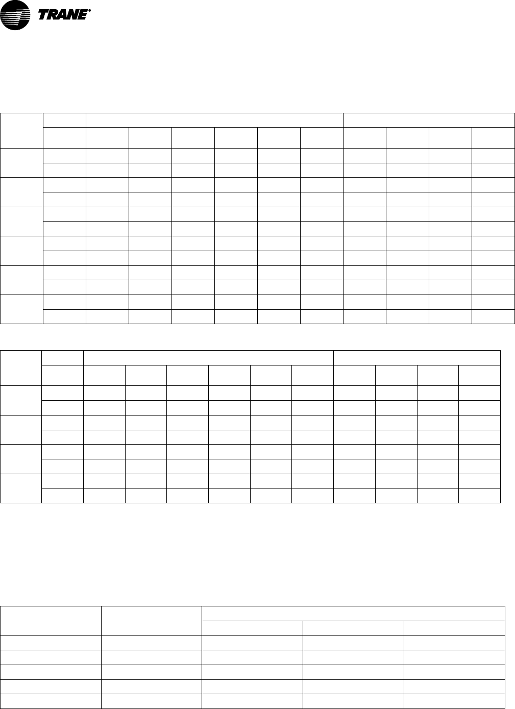
VAV-PRC012AC-EN
131
Electrical Data
Parallel Fan-Powered Terminal Units
Table 86. PSC motor units—electric coil kW guidelines—minimum to maximum (VPEF)
Fan Size
Single-Phase Voltage Three-Phase Voltage
Stages
120V 208V 240V 277V 347V 480V 208V 480V 600V
380V/
50Hz
02SQ
1 0.5-5.0 0.5-6.0 0.5-6.0 0.5-6.0 0.5-6.0 0.5-6.0 0.5-6.0 1.0-6.0 1.5-6.0 1.0-6.0
2 0.5-5.0 0.5-6.0 0.5-6.0 1.0-6.0 1.0-6.0 1.0-6.0 1.0-6.0 2.0-6.0 3.0-6.0 1.5-6.0
03SQ
1 0.5-5.0 0.5-9.0 0.5-10.0 0.5-11.0 0.5-11.0 0.5-11.0 0.5-11.0 1.0-11.0 1.5-11.0 1.0-11.0
2 0.5-5.0 0.5-9.0 0.5-10.0 1.0-11.0 1.0-11.0 1.0-11.0 1.0-11.0 2.0-11.0 3.0-11.0 1.5-11.0
04SQ
1 0.5-4.5 0.5-8.0 0.5-10.0 0.5-12.0 0.5-14.0 0.5-14.0 0.5-14.0 1.0-14.0 1.5-14.0 1.0-14.0
2 0.5-4.5 0.5-8.0 0.5-10.0 1.0-12.0 1.0-14.0 1.0-14.0 1.0-14.0 2.0-14.0 3.0-14.0 1.5-14.0
05SQ
1 0.5-4.5 0.5-8.0 0.5-9.0 0.5-12.0 0.5-15.0 0.5-18.0 0.5-14.0 1.0-18.0 1.5-18.0 1.0-18.0
2 0.5-4.5 0.5-8.0 0.5-9.0 1.0-12. 1.0-15.0 1.0-18.0 1.0-14.0 2.0-18.0 3.0-18.0 1.5-18.0
06SQ
1 – 0.5-9.0 – 0.5-12.0 0.5-15.0 0.5-16.0 0.5-15.0 1.0-16.0 1.5-16.0 1.0-16.0
2 – 0.5-9.0 – 1.0-12.0 1.0-15.0 1.0-16.0 1.0-15.0 2.0-16.0 3.0-16.0 1.5-16.0
07SQ
1 – 0.5-8.0 – 0.5-11.0 0.5-15.0 0.5-20.0 0.5-14.0 1.0-20.0 1.5-20.0 1.0-20.0
2 – 0.5-8.0 – 1.0-11.0 1.0-15.0 1.0-20.0 1.0-14.0 2.0-20.0 3.0-20.0 1.5-20.0
Table 87. ECM units—electric coil kW guidelines—minimum to maximum (VPEF)
Fan Size
Single-Phase Voltage Three-Phase Voltage
Stages
120V 208V 240V 277V 347V 480V 208V 480V 600V
380V
/50Hz
03SQ
1 0.5-4.5 0.5-8.0 0.5-10.0 0.5-11.0 – 0.5-11.0 0.5-11.0 1.0-11.0 – –
2 0.5-4.5 0.5-8.0 0.5-10.0 1.0-11.0 – 1.0-11.0 1.0-11.0 2.0-11.0 – –
04SQ
1 0.5-8.0 0.5-8.0 0.5-9.0 0.5-12.0 – 0.5-14.0 0.5-14.0 1.0-14.0 – –
2 0.5-4.5 0.5-8.0 0.5-9.0 1.0-12.0 – 1.0-14.0 1.0-14.0 2.0-14.0 – –
05SQ
1 0.5-4.5 0.5-7.0 0.5-8.0 0.5-11.0 – 0.5-18.0 0.5-12.0 1.0-18.0 – -
2 0.5-8.0 0.5-7.0 0.5-8.0 1.0-11.0 – 1.0-18.0 1.0-12.0 2.0-18.0 – -
06SQ
1 0.5-4.0 0.5-7.0 0.5-8.0 0.5-11.0 – 0.5-16.0 0.5-12.0 1.0-16.0 – –
2 0.5-4.0 0.5-7.0 0.5-8.0 1.0-11.0 – 1.0-16.0 1.0-12.0 2.0-16.0 – –
Notes:
1. Coils available with 24-VAC magnetic or solid state relays contactors, load carrying P.E. switches, and P.E. switch with magnetic or solid state
relays contactors.
2. Available kW increments are by 0.5 from 0.5 kW to 8.0 kW, by 1.0 kW from 9.0 to 18.0 kW, and by 2.0 kW from 18.0 to 20.0 kW.
3. Each stage will be equal in kW output.
4. All heaters contain an auto reset thermal cutout and a manual reset cutout.
5. See section “Formulas,” p. 80 for formulas used to calculate the current amp draw for the heater elements. Recommended coil temperature rise
= 20° to 30°F (-7° to -1°C). Maximum temperature rise = 55°F (12°C).
6. Heaters should not operate at cfms below the nameplate minimum.
Table 88. Fan electrical performance (PSC)
Fan Size HP
Maximum Fan Motor Amperage (FLA)
115 VAC 208 VAC 277 VAC
02SQ
1/8
1.6 – 0.7
03SQ
1/3
4.3 – 1.6
04SQ
1/3
5.5 - 2.0
05SQ
1/2
6.7 – 2.4
06SQ
1/2
– 4.6 3.8
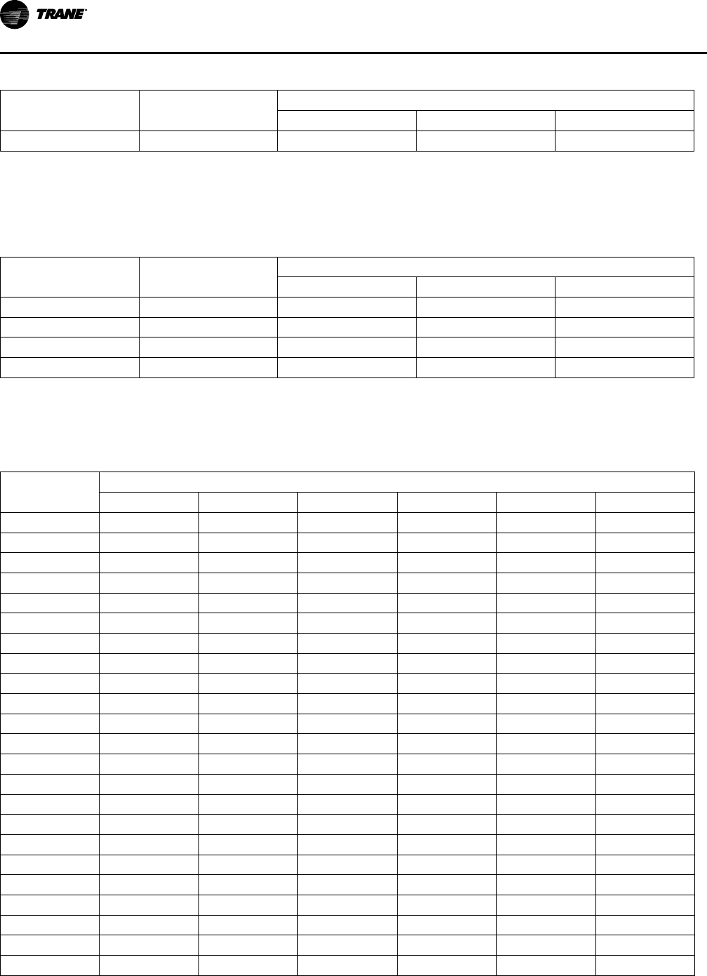
132
VAV-PRC012AC-EN
Table 88. Fan electrical performance (PSC) (continued)
Fan Size HP
Maximum Fan Motor Amperage (FLA)
115 VAC 208 VAC 277 VAC
07SQ
1 – 6.6 4.7
Notes:
1. Electric Heat Units - Units with fan sizes 02SQ to 05SQ and a primary voltage of 208/60/1, 208/60/3, or 240/60/1 have 115/60/1 VAC fan motors.
Fan sizes 06SQ and 07SQ with the same voltages, have 208/60/1 VAC motors.
2. Electric Heat Units - Units with primary voltage of 277/60/1, 480/60/1 or 480/60/3 use 277 VAC fan motors.
3. Electric Heat Units - Units with primary voltage of 347/60/1 or 575/60/3 use 347 VAC fan motors.
4. With 380/50/3 and 230/50/1, use 230/50 motors.
Table 89. Fan electrical performance (ECM)
Fan Size HP
Maximum Fan Motor Amperage (FLA)
115 VAC 208 VAC 277 VAC
03SQ
1/3
4.5 3.0 2.4
04SQ
1/2
6.5 5.0 3.5
05SQ
1 10.1 9.4 5.4
06SQ
1 10.1 9.4 5.4
Notes:
1. Electric heat units-units with primary voltages of 208/60/1 and 208/60/3 have optional 115-VAC or 208-VAC fan motors.
2. Electric heat units-units with primary voltages of 240/60/1 have 115-VAC fan motors.
3. Electric heat units—units with primary voltages of 277/60/1, 480/60/1, or 480/60/3 have 277-VAC fan motors.
4. 347/60/1 and 230/50/1 voltage motors not available with ECMs.
Table 90. Minimum unit electric heat Cfm guidelines (PSC)
Unit kW
Cfm
02SQ 03SQ 04SQ 05SQ 06SQ 07SQ
0.5 118 200 315 350 533 585
1 118 200 315 350 533 585
1.5 118 200 315 350 533 585
2 118 200 315 350 533 585
2.5 146 200 315 350 533 585
3 174 200 315 350 533 585
3.5 201 200 315 350 533 585
4 229 230 315 350 533 585
4.5 257 260 315 350 533 585
5 285 290 315 350 533 585
5.5 312 315 315 350 533 585
6 340 350 350 350 533 585
6.5 - 375 375 375 533 585
7 - 400 400 400 533 585
7.5 - 430 430 430 533 585
8 - 460 460 460 533 585
9 - 515 515 515 589 633
10 - 575 575 575 645 682
11 - 630 630 630 701 730
12 - - 690 690 758 779
13 - - 745 745 814 827
14 - - 810 810 870 876
15 - - - 860 926 924
EElleeccttrriiccaall DDaattaa

VAV-PRC012AC-EN
133
Table 90. Minimum unit electric heat Cfm guidelines (PSC) (continued)
Unit kW
Cfm
02SQ 03SQ 04SQ 05SQ 06SQ 07SQ
16 - - - 920 982 972
17 - - - 973 - 1021
18 - - - 1030 - 1069
20 - - - - - 1166
Table 91. Minimum unit electric heat L/s guidelines (PSC)
Unit kW
L/s
02SQ 03SQ 04SQ 05SQ 06SQ 07SQ
0.5 56 94 149 165 252 276
1 56 94 149 165 252 276
1.5 56 94 149 165 252 276
2 56 94 149 165 252 276
2.5 69 94 149 165 252 276
3 82 94 149 165 252 276
3.5 95 94 149 165 252 276
4 108 109 149 165 252 276
4.5 121 123 149 165 252 276
5 134 137 149 165 252 276
5.5 147 149 149 165 252 276
6 160 165 165 165 252 276
6.5 - 177 177 177 252 276
7 - 189 189 189 252 276
7.5 - 203 203 203 252 276
8 - 217 217 217 252 276
9 - 243 243 243 278 299
10 - 271 271 271 305 322
11 - 297 297 297 331 345
12 - - 326 326 358 367
13 - - 352 352 384 390
14 - - 382 382 410 413
15 - - - 406 437 436
16 - - - 434 463 459
17 - - - 459 - 482
18 - - - 486 - 505
20 - - - - - 550
Table 92. Minimum unit electric heat Cfm guidelines (ECM)
Unit kW
Cfm
03SQ 04SQ 05SQ 06SQ
0.5 200 315 350 560
1 200 315 350 560
1.5 200 315 350 560
EElleeccttrriiccaall DDaattaa

134
VAV-PRC012AC-EN
Table 92. Minimum unit electric heat Cfm guidelines (ECM) (continued)
Unit kW
Cfm
03SQ 04SQ 05SQ 06SQ
2 200 315 350 560
2.5 200 315 350 560
3 200 315 350 560
3.5 200 315 350 560
4 230 315 350 560
4.5 260 315 350 560
5 290 315 350 560
5.5 315 315 350 560
6 350 350 350 560
6.5 375 375 375 560
7 400 400 400 560
7.5 430 430 430 560
8 460 460 460 560
9 515 515 515 604
10 575 575 575 649
11 630 630 630 693
12 - 690 690 738
13 - 745 745 782
14 - 810 810 826
15 - - 860 871
16 - - 920 915
17 - - 973 -
18 - - 1030 -
Table 93. Minimum unit electric heat L/s guidelines (ECM)
Unit kW
Cfm
03SQ 04SQ 05SQ 06SQ
0.5 94 149 165 264
1 94 149 165 264
1.5 94 149 165 264
2 94 149 165 264
2.5 94 149 165 264
3 94 149 165 264
3.5 94 149 165 264
4 109 149 165 264
4.5 123 149 165 264
5 137 149 165 264
5.5 149 149 165 264
6 165 165 165 264
6.5 177 177 177 264
7 189 189 189 264
7.5 203 203 203 264
EElleeccttrriiccaall DDaattaa
VAV-PRC012AC-EN
135
Table 93. Minimum unit electric heat L/s guidelines (ECM) (continued)
Unit kW
Cfm
03SQ 04SQ 05SQ 06SQ
8 217 217 217 264
9 243 243 243 285
10 271 271 271 306
11 297 297 297 327
12 - 326 326 348
13 - 352 352 369
14 - 382 382 390
15 - - 406 411
16 - - 434 432
17 - - 459 -
18 - - 486 -
Series Fan-Powered Terminal Units
Table 94. VSEF—electric coil kW guidelines—minimum to maximum (PSC motor units)
Fan Size
Single—Phase Voltage Three-Phase Voltage
Stages
120V 208V 240V 277V 347V 480V 208V 480V 600V
380V/
50Hz
02SQ
1 0.5-5.0 0.5-7.0 0.5-7.0 0.5-7.0 0.5-7.0 1.0-7.0 0.5-7.0 1.0-7.0 1.5-7.0 1.5-7.0
2 0.5-5.0 0.5-7.0 0.5-7.0 1.0-7.0 1.0-7.0 1.5-7.0 1.0-7.0
3.5 -7.0
(a)
- 2.5-7.0
03SQ
1 0.5-5.0 0.5-9.0 0.5-10.0 0.5-12.0 0.5-14.0
1.0-13.0
(b)
0.5-14.0 1.0-12.0 1.5-13.0
1.0-14
(c)
2 0.5-5.0 0.5-9.0 0.5-10.0 1.0-12.0 1.0-14.0
1.5-13.0
(b)
1.0-14.0
3.5-12.0
(a)
-
2.5-13
(c)
04SQ
1 0.5-4.5 0.5-8.0 0.5-10.0 0.5-12.0 0.5-16.0 0.5-18.0 0.5-15.0 1.0-18.0
1.5-18.0
(d)
1.0-18
2 0.5-4.5 0.5-8.0 0.5-10.0 1.0-12.0 1.0-16.0 1.0-18.0 1.0-15.0 2.5-18.0 4.0-15.0 1.5-18
05SQ
1 0.5-4.5 0.5-8.0 0.5-9.0 0.5-12.0 0.5-15.0 0.5-20.0 0.5-14.0 1.0-20.0 1.5-22.0 1.0-22.0
2 0.5-4.5 0.5-8.0 0.5-9.0 1.0-12.0 1.0-15.0 1.0-20.0 1.0-14.0 2.5-20.0
4.0-20.0
(e)
1.5-22.0
06SQ
1 - 0.5-9.0 - 0.5-12.0 0.5-15.0 0.5-22.0 0.5-15.0 1.0-22.0 1.5-22.0 1.0-22
2 - 0.5-9.0 - 1.0-12.0 1.0-15.0 1.0-22.0 1.0-15.0 2.0-22.0 3.0-22.0 1.5-22
07SQ
1 - 0.5-8.0 - 0.5-11.0 0.5-15.0 0.5-20.0 0.5-14.0 1.0-24.0 1.5-24.0 -
2 - 0.5-8.0 - 1.0-11.0 1.0-15.0 1.0-20.0 1.0-14.0 2.0-24.0 3.0-24.0 -
(a)
4.5, 5.5, 6.5, 9, 11, 13 kW not available
(b)
12 kW not available
(c)
10, 13 kW not available
(d)
16, 17 kW not available
(e)
18 kW not available
Table 95. VSEF—electric coil kW guidelines—minimum to maximum (ECM units)
Fan Size
Single-Phase Voltage Three-Phase Voltage
Stages
120V 208V 240V 277V 347V 480V 208V 480V 600V
380V/
50Hz
03SQ
1 0.5-4.5 0.5-8.0 0.5-10.0 0.5-12.0 -
1.0-13.0
(a)
0.5-14.0 1.0-12.0 - -
2 0.5-4.5 0.5-8.0 0.5-10.0 1.0-12.0 -
1.5-13.0
(a)
1.0-14.0
3.5-12.0
(b)
- -
04SQ
1 0.5-4.5 0.5-8.0 0.5-9.0 0.5-12.0 - 0.5-18.0 0.5-14.0
1.0-18.0
(c)
- -
2 0.5-4.5 0.5-8.0 0.5-9.0 1.0-12.0 - 1.0-18.0 1.0-14.0 2.5-15.0 - -
EElleeccttrriiccaall DDaattaa

136
VAV-PRC012AC-EN
Table 95. VSEF—electric coil kW guidelines—minimum to maximum (ECM units) (continued)
Fan Size
Single-Phase Voltage Three-Phase Voltage
Stages
120V 208V 240V 277V 347V 480V 208V 480V 600V
380V/
50Hz
05SQ
1 0.5-4.0 0.5-7.0 0.5-8.0 0.5-11.0 - 0.5-18.0 0.5-12.0 1.0-22.0 - -
2 0.5-4.0 0.5-7.0 0.5-8.0 1.0-11.0 - 1.0-18.0 1.0-12.0 2.5-20.0 - -
06SQ
1 0.5-4.0 0.5-7.0 0.5-8.0 0.5-11.0 - 0.5-22.0 0.5-12.0 1.0-22.0 - -
2 0.5-4.0 0.5-7.0 0.5-8.0 1.0-11.0 - 1.0-22.0 1.0-12.0 2.0-22.0 - -
Notes:
1. Coils available with electric, 24 VAC magnetic or contactors, load carrying P.E. switches, and P.E. switches with magnetic or solid state relays
contactors.
2. Available kW increments are by 0.5 from 0.5 to 8.0 kW, by 1.0 kW from 9.0 to 17.0 kW, and by 2.0 kW from 18.0 to 24.0 kW.
3. Each stage will be equal in kW output.
4. All heaters contain an auto reset thermal cutout and a manual reset cutout.
5. See section “Formulas,” p. 80 for formulas used to calculate the current amp draw for the heater elements.
6. Recommended coil temperature rise = 20°-30°F (-7° to -1°C). Maximum temperature rise = 55°F (12°C).
7. Heaters should not operate at cfms below the nameplate minimum.
(a)
12 kW not available.
(b)
4.5, 5.5, 6.5, 9, 11 kW not available.
(c)
16,17 kW not available.
Table 96. Fan electrical performance (PSC)
Fan Size HP
Maximum Fan Motor Amperage (FLA)
115 VAC 208 VAC 277 VAC
02SQ
1/8
1.6 – 0.7
03SQ
1/3
4.3 – 1.6
04SQ
1/3
5.5 - 2.0
05SQ
1/2
6.7 – 2.4
06SQ
1/2
– 4.6 3.8
07SQ
1 – 6.6 4.7
Notes:
1. Electric Heat Units - Units with fan sizes 02SQ to 05SQ and a primary voltage of 208/60/1, 208/60/3, or 240/60/1 have 115/60/1 VAC fan motors.
Fan sizes 06SQ and 07SQ with the same voltages, have 208/60/1 VAC motors.
2. Electric Heat Units - Units with primary voltage of 277/60/1, 480/60/1 or 480/60/3 use 277 VAC fan motors.
3. Electric Heat Units - Units with primary voltage of 347/60/1 or 575/60/3 use 347 VAC fan motors.
4. With 380/50/3 and 230/50/1, use 230/50 motors.
Table 97. Fan electrical performance (ECM)
Fan Size HP
Maximum Fan Motor Amperage (FLA)
115 VAC 208 VAC 277 VAC
03SQ
1/3
4.5 3.0 2.4
04SQ
1/2
6.5 5.0 3.5
05SQ
1 10.1 9.4 5.4
06SQ
1 10.1 9.4 5.4
Notes:
1. Electric heat units-units with primary voltages of 208/60/1 and 208/60/3 have optional 115-VAC or 208-VAC fan motors.
2. Electric heat units-units with primary voltages of 240/60/1 have 115-VAC fan motors.
3. Electric heat units—units with primary voltages of 277/60/1, 480/60/1, or 480/60/3 have 277-VAC fan motors.
4. 347/60/1 and 230/50/1 voltage motors not available with ECMs.
Table 98. Minimum unit electric — heat Cfm guidelines PSC
Unit kW
Heat Cfm Guidelines (PSC)
02SQ 03SQ 04SQ 05SQ 06SQ 07SQ
0.5 191 260 315 400 700 850
1 191 260 315 400 700 850
1.5 191 260 315 400 700 850
EElleeccttrriiccaall DDaattaa
VAV-PRC012AC-EN
137
Table 98. Minimum unit electric — heat Cfm guidelines PSC (continued)
Unit kW
Heat Cfm Guidelines (PSC)
02SQ 03SQ 04SQ 05SQ 06SQ 07SQ
2 191 260 315 400 700 850
2.5 191 260 315 400 700 850
3 214 260 315 400 700 850
3.5 236 260 315 400 700 850
4 259 260 315 400 700 850
4.5 282 260 315 400 700 850
5 304 290 315 400 700 850
5.5 327 315 315 400 700 850
6 350 350 350 400 700 850
6.5 372 375 375 400 700 850
7 395 400 400 400 700 850
7.5 - 430 430 430 700 850
8 - 460 460 460 700 850
9 - 515 515 515 700 850
10 - 575 575 575 700 850
11 - 630 630 630 713 850
12 - 690 690 690 792 902
13 - 745 745 745 872 954
14 - 810 810 810 951 1006
15 - - 860 860 1031 1057
16 - - 920 920 1110 1109
17 - - 973 973 1190 1161
18 - - 1030 1030 1269 1213
20 - - - 1150 1428 1317
22 - - - 1260 1587 1420
24 - - - - - 1524
Table 99. Minimum unit electric — heat L/s guidelines PSC
Unit kW
Heat L/s Guidelines (PSC)
02SQ 03SQ 04SQ 05SQ 06SQ 07SQ
0.5 90 123 149 189 330 401
1 90 123 149 189 330 401
1.5 90 123 149 189 330 401
2 90 123 149 189 330 401
2.5 90 123 149 189 330 401
3 101 123 149 189 330 401
3.5 112 123 149 189 330 401
4 122 123 149 189 330 401
4.5 133 123 149 189 330 401
5 144 137 149 189 330 401
5.5 154 149 149 189 330 401
6 165 165 165 189 330 401
EElleeccttrriiccaall DDaattaa

138
VAV-PRC012AC-EN
Table 99. Minimum unit electric — heat L/s guidelines PSC (continued)
Unit kW
Heat L/s Guidelines (PSC)
02SQ 03SQ 04SQ 05SQ 06SQ 07SQ
6.5 176 177 177 189 330 401
7 186 189 189 189 330 401
7.5 - 203 203 203 330 401
8 - 217 217 217 330 401
9 - 243 243 243 330 401
10 - 271 271 271 330 401
11 - 297 297 297 336 401
12 - 326 326 326 374 426
13 - 352 352 352 411 450
14 - 382 382 382 449 475
15 - - 406 406 486 499
16 - - 434 434 524 524
17 - - 459 459 562 548
18 - - 486 486 599 572
20 - - - 543 674 621
22 - - - 595 749 670
24 - - - - - 719
Table 100. Minimum unit electric — heat Cfm guidelines ECM
Unit kW
Heat Cfm Guidelines (ECM)
03SQ 04SQ 05SQ 06SQ
0.5 260 315 400 943
1 260 315 400 943
1.5 260 315 400 943
2 260 315 400 943
2.5 260 315 400 943
3 260 315 400 943
3.5 260 315 400 943
4 260 315 400 943
4.5 260 315 400 943
5 290 315 400 943
5.5 315 315 400 943
6 350 350 400 943
6.5 375 375 400 943
7 400 400 400 943
7.5 430 430 430 943
8 460 460 460 943
9 515 515 515 943
10 575 575 575 975
11 630 630 630 1006
12 690 690 690 1038
13 745 745 745 1069
EElleeccttrriiccaall DDaattaa

VAV-PRC012AC-EN
139
Table 100. Minimum unit electric — heat Cfm guidelines ECM (continued)
Unit kW
Heat Cfm Guidelines (ECM)
03SQ 04SQ 05SQ 06SQ
14 810 810 810 1101
15 - 860 860 1133
16 - 920 920 1164
17 - 973 973 1196
18 - 1030 1030 1228
20 - - 1150 1291
22 - - 1260 1354
Table 101. Minimum unit electric — heat L/s guidelines ECM
Unit kW
Heat L/s Guidelines (ECM)
03SQ 04SQ 05SQ 06SQ
0.5 123 149 189 445
1 123 149 189 445
1.5 123 149 189 445
2 123 149 189 445
2.5 123 149 189 445
3 123 149 189 445
3.5 123 149 189 445
4 123 149 189 445
4.5 123 149 189 445
5 137 149 189 445
5.5 149 149 189 445
6 165 165 189 445
6.5 177 177 189 445
7 189 189 189 445
7.5 203 203 203 445
8 217 217 217 445
9 243 243 243 445
10 271 271 271 460
11 297 297 297 475
12 326 326 326 490
13 352 352 352 505
14 382 382 382 520
15 - 406 406 535
16 - 434 434 549
17 - 459 459 564
18 - 486 486 579
20 - - 543 609
22 - - 595 639
EElleeccttrriiccaall DDaattaa

140
VAV-PRC012AC-EN
Low Height Parallel Fan-Powered Terminal Units
Table 102. LPEF—electric coil kW guidelines—minimum to maximum (PSC units)
Fan Size
Single-Phase Voltage Three-Phase Voltage
Stages
120V 208V 240V 277V 347V 480V 208V 480V 600V
380V/
50Hz
PS02
1 1.0-5.5 1.0–9.0 1.0–11.0 1.0–12.0 - 1.0–12.0 1.0–12.0 1.0–12.0 - -
2 1.0-5.5 1.0–9.0 1.0–11.0 1.0–12.0 - 1.0–12.0 1.0–12.0 2.0–12.0 - -
Table 103. LPEF—electric coil kW guidelines—minimum to maximum (ECM units)
Fan Size
Stages
Single-Phase Voltage Three-Phase Voltage
120V 208V 240V 277V 347V 480V 208V 480V 600V
380V/
50Hz
DS02
1 1.0-4.5
1.0-9.0
(a)
1.0-9.0 1.0-13.0 - 1.0–14.0
1.0–14.0
(b)
1.0–14.0 - -
2 1.0-4.5
1.0-9.0
(a)
1.0-9.0 1.0-13.0 - 1.0–14.0
1.0–14.0
(b)
1.0–14.0 - -
(a)
8-9 kW not available with 115V motor.
(b)
14 kW not available with 115V motor.
Table 104. Fan electrical performance (PSC)
Fan Size HP
Maximum Fan Motor Amperage (FLA)
115 VAC 277 VAC 347 VAC
PS02
1/3
5.5 2 —
Notes:
1. Electric heat units with primary voltages of 208/60/1, 208/60/3 or 240/60/1 use 115 VAC fan motors.
2. Electric heat units with primary voltages of 277/60/1, 480/60/1 or 480/60/3 use 277 VAC fan motors.
3. Values are for standard, single-speed, permanent split capacitor type motors. Consult factory for non-standard motor performance.
Table 105. Fan electrical performance (ECM)
Fan Size HP
Maximum Fan Motor Amperage (FLA)
115 VAC 208 VAC 277 VAC
DS02 0.75 9.6 6.6 5.2
Notes:
1. Electric heat units with primary voltages of 208/60/1 and 208/60/3 have optional 115-VAC or 208-VAC fan motors.
2. Electric heat units with primary voltages of 240/60/1 have 115-VAC fan motors.
3. Electric heat units with primary voltages of 277/60/1, 480/60/1 or 480/60/3 use 277 VAC fan motors.
Table 106. Minimum unit electric heat guidelines (PSC)
Unit kW
PS02
Cfm
L/s
1 400 189
1.5 400 189
2 400 189
2.5 400 189
3 189 90
3.5 221 105
4 252 119
4.5 284 135
5 315 149
5.5 346 164
6 378 179
6.5 409 194
7 441 209
EElleeccttrriiccaall DDaattaa

VAV-PRC012AC-EN
141
Table 106. Minimum unit electric heat guidelines (PSC) (continued)
Unit kW
PS02
Cfm
L/s
7.5 472 223
8 504 238
9 567 268
10 629 297
11 692 327
12 755 357
Table 107. Minimum unit electric heat guidelines (ECM)
Unit kW
DS02
Cfm
L/s
1 100 47
1.5 100 47
2 126 60
2.5 158 75
3 189 90
3.5 221 105
4 252 119
4.5 284 135
5 315 149
5.5 346 164
6 378 179
6.5 409 194
7 441 209
7.5 472 223
8 504 238
9 567 268
10 629 297
11 692 327
12 755 357
13 818 387
14 881 416
Low Height Series Fan-Powered Terminal Units
Table 108. LSEF—electric coil kW guidelines—minimum to maximum (PSC motor units)
Fan Size
Stages
Single-Phase Voltage Three-Phase Voltage
120V 208V 240V 277V 347V 480V 208V 480V 600V
380V/
50Hz
PS02
1 1.0–5.5 1.0–9.0 1.0–11.0 1.0-12.0 - 1.0-12.0 1.0-12.0 1.0-12.0 - -
2 1.0–5.5 1.0–9.0 1.0–11.0 1.0-12.0 - 1.0-12.0 1.0-12.0 2.0-12.0 - -
EElleeccttrriiccaall DDaattaa

142
VAV-PRC012AC-EN
Table 109. LSEF—electric coil kW guidelines—minimum to maximum (ECM units)
Fan Size
Stages
Single-Phase Voltage Three-Phase Voltage
120V 208V 240V 277V 347V 480V 208V 480V 600V
380V/
50Hz
DS02
1 1.0–4.5
1.0–9.0
(a)
1.0–9.0 1.0–13.0 - 1.0–14.0
1.0–14.0
(b)
1.0-14.0 - -
2 1.0–4.5
1.0–9.0
(a)
1.0–9.0 1.0–13.0 - 1.0–14.0
1.0–14.0
(b)
1.0-14.0 - -
DS03
1 -
7.0–9.0
(a)
7.0-9.0 7.0-13.0 - 7.0-16.0
7.0-14.0
(b)
7.0-16.0 - -
2 -
7.0–9.0
(a)
7.0-9.0 7.0-13.0 - 7.0-16.0
7.0-14.0
(b)
7.0-16.0 - -
(a)
8-9 kW not available with 115V motor.
(b)
14 kW not available with 115V motor.
Table 110. Fan electrical performance (PSC)
Fan Size HP
Maximum Fan Motor Amperage (FLA)
115 VAC 277 VAC 347 VAC
PS02
1/3
5.5 2 —
Notes:
1. Electric heat units with primary voltages of 208/60/1, 208/60/3 or 240/60/1 use 115 VAC fan motors.
2. Electric heat units with primary voltages of 277/60/1, 480/60/1 or 480/60/3 use 277 VAC fan motors.
3. Electric heat units with primary voltages of 347/60/1 or 575/60/3 use 347 VAC fan motors.
4. Values are for standard, single-speed, permanent split capacitor type motors. Consult factory for non-standard motor performance.
Table 111. Fan electrical performance (ECM)
Fan Size HP
Maximum Fan Motor Amperage (FLA)
115 VAC 208 VAC 277 VAC
DS02 0.75 9.6 6.6 5.2
DS03 0.75 9.6 6.6 5.2
Notes:
1. Electric heat units with primary voltages of 208/60/1 and 208/60/3 have optional 115-VAC or 208-VAC fan motors.
2. Electric heat units with primary voltages of 240/60/1 have 115-VAC fan motors.
3. Electric heat units with primary voltages of 277/60/1, 480/60/1, or 480/60/3 use 277 VAC fan motors.
EElleeccttrriiccaall DDaattaa
VAV-PRC012AC-EN
143
Table 112. Minimum unit electric heat guidelines (PSC)
Unit kW
Cfm
Unit kW
L/s
PS02 PS02
0.5 - 0.5 -
1 400 1 189
1.5 400 1.5 189
2 400 2 189
2.5 400 2.5 189
3 400 3 189
3.5 400 3.5 189
4 400 4 189
4.5 400 4.5 189
5 400 5 189
5.5 400 5.5 189
6 400 6 189
6.5 409 6.5 194
7 441 7 209
7.5 472 7.5 223
8 504 8 238
9 567 9 268
10 629 10 297
11 692 11 327
12 755 12 357
13 - 13 -
14 - 14 -
15 - 15 -
16 - 16 -
17 - 17 -
18 - 18 -
EElleeccttrriiccaall DDaattaa

144
VAV-PRC012AC-EN
Table 113. Minimum unit electric heat guidelines (ECM)
Unit kW
Cfm
Unit kW
L/s
DS02 DS03 DS02 DS03
0.5 - - 0.5 - -
1 100 - 1 47 -
1.5 100 - 1.5 47 -
2 126 - 2 60 -
2.5 158 - 2.5 75 -
3 189 - 3 90 -
3.5 221 - 3.5 105 -
4 252 - 4 119 -
4.5 284 - 4.5 135 -
5 315 - 5 149 -
5.5 346 - 5.5 164 -
6 378 - 6 179 -
6.5 409 - 6.5 194 -
7 441 480 7 209 227
7.5 472 505 7.5 223 238
8 504 530 8 238 250
9 567 580 9 268 274
10 629 630 10 297 297
11 692 680 11 327 321
12 755 730 12 357 345
13 818 779 13 387 368
14 881 829 14 416 391
15 - 879 15 - 415
16 - 929 16 - 438
17 - 979 17 - 462
18 - 1029 18 - 486
Formulas
Fan-Powered Parallel
MMiinniimmuumm cciirrccuuiitt AAmmppaacciittyy ((MMCCAA)) EEqquuaattiioonn
MCA = 1.25 x (s motor amps + heater amps)
Motor amps is the sum of all motor current draws if more than one is used in the unit.
MMaaxxiimmuumm OOvveerrccuurrrreenntt PPrrootteeccttiioonn ((MMOOPP)) EEqquuaattiioonn
MOP = (2.25 x motor1 amps) + motor2 amps + heater amps
motor1 amps = current draw of largest motor
motor2 amps = sum of current of all other motors used in unit
GGeenneerraall SSiizziinngg RRuullee::
• If MOP = 15, then fuse size = 15
• If MOP = 19, then fuse size = 15 with one exception. If heater amps x 1.25 > 15, then fuse size =
20.
• If MOP is equal to or less than MCA, then choose next fuse size greater than MCA.
EElleeccttrriiccaall DDaattaa

VAV-PRC012AC-EN
145
• Control fusing not applicable.
• Standard Fuse Sizes: 15, 20, 25, 30, 35, 40, 45, 50, and 60.
EExxaammppllee::
A model VPEF, electric reheat unit size 10-05SQ has 480/3 phase, 12 kW electric reheat with 2
stages and 277-Volt motor.
• For MOP of fan-powered unit:
– 12 kW-480/3 heater:12x1000/480x1.73=14.45 amps
– MCA = (2.4 + 14.45) x 1.25 = 21.06, MOP = (2.25 x 2.4) + 14.45 = 19.9.
– Since MOP is less than or equal to MCA, then MOP = 25.
• For total current draw of unit:
– 12kW-480/3 heater:12x1000/480x1.73=14.45
– Two heat outputs (2 stages) @0.5 amps max each=1.00
– Motor amps: 277 V (Fan size 0517) =2.4
– Amps Max: 18.35
UUsseeffuull FFoorrmmuullaass:: See “Useful Formulas,” p. 146 .
Fan-Powered Series
MMiinniimmuumm CCiirrccuuiitt AAmmppaacciittyy ((MMCCAA)) EEqquuaattiioonn
MCA = 1.25 x (Smotor amps + heater amps)
Here motor amps is the sum of all motor current draws if more than one is used in the unit.
MMaaxxiimmuumm OOvveerrccuurrrreenntt PPrrootteeccttiioonn ((MMOOPP)) EEqquuaattiioonn
MOP = (2.25 x motor 1amps) + motor2 amps + heater amps motor1 amps = current draw of
largest motor
motor2 amps = sum of current draw of all other motors used in units
GGeenneerraall SSiizziinngg RRuulleess
• If MOP = 15, then fuse size = 15
• If MOP = 19, then fuse size = 15 with one exception. If heater amps x 1.25 > 15, then fuse size =
20.
• If MOP is less than/equal to MCA, then choose next fuse size greater than MCA.
• Control fusing not applicable.
• Standard Fuse Sizes: 15, 20, 25, 30, 35, 40, 45, 50, and 60.
EExxaammppllee::
A model VSEF, electric reheat unit size 10-0517 has 480/3 phase, 12 kW electric reheat with 2
stages and 277-Volt motor.
• For MOP of fan-powered unit:
– 12 kW - 480/3 heater: 12x1000/480x1.73=14.45 amps.
– MCA=(2.4 + 14.45) x 1.25 = 21.06, MOP = (2.25 x 2.4) + 14.45 = 19.9.
– Since MOP is less than/equal to MCA, then MOP = 25.
• For total current draw of unit:
– 12 kW—480/3 heater: 12x1000/480x1.73=14.45
– Two heat outputs (2 stages)@0.5 amps max each=1.00
– Motor amps: 277 V (Fan size 0517)=2.4
– Total amps max: 18.35
UUsseeffuull FFoorrmmuullaass:: See “Useful Formulas,” p. 146.
EElleeccttrriiccaall DDaattaa

146
VAV-PRC012AC-EN
Low-Height Parallel Fan-Powered
MMiinniimmuumm CCiirrccuuiitt AAmmppaacciittyy ((MMCCAA)) EEqquuaattiioonn
MCA = (2.25 x motor amps + heater amps) x 1.25
MMaaxxiimmuumm OOvveerrccuurrrreenntt PPrrootteeccttiioonn ((MMOOPP)) EEqquuaattiioonn
MOP = (2.25 x motor amps) + heater amps
GGeenneerraall SSiizziinngg RRuulleess
• If MOP = 15, then fuse size = 15
• If MOP = 19, then fuse size = 15 with one exception. If heater amps x 1.25 > 15, then fuse size =
20.
• If MOP is less than/equal to MCA, then choose next fuse size greater than MCA.
• Control fusing not applicable.
• Standard Fuse Sizes: 15, 20, 25, 30, 35, 40, 45, 50, and 60.
UUsseeffuull FFoorrmmuullaass:: See “Useful Formulas,” p. 146.
Low-Height Series Fan-Powered
MMiinniimmuumm CCiirrccuuiitt AAmmppaacciittyy ((MMCCAA))
(MCA) = (motor amps + heater amps) x 1.25
MMaaxxiimmuumm OOvveerrccuurrrreenntt PPrrootteeccttiioonn ((MMOOPP))
(MOP) = (2.25 x motor amps) + heater amps
GGeenneerraall SSiizziinngg RRuulleess::
• If MOP = 15, then fuse size = 15
• If MOP = 19, then fuse size = 15 with one exception. If heater amps x 1.25 > 15, then fuse size =
20.
• If MOP is less than or equal to MCA, then choose next fuse size greater than MCA.
• Control fusing not applicable.
• Standard Fuse Sizes: 15, 20, 25, 30, 35, 40, 45, 50, and 60.
UUsseeffuull FFoorrmmuullaass:: See “Useful Formulas,” p. 146.
Useful Formulas
The following formulas apply to the previous equipment types: Fan-Powered Parallel, Fan-
Powered Series, Low Height Parallel Fan-Powered, and Low-Height Series Fan-Powered.
EElleeccttrriiccaall DDaattaa


148
VAV-PRC012AC-EN
Acoustics Data
Parallel Fan-Powered Terminal Units
Table 114. Discharge sound power (dB)—valve only (Part 1)
Fan
Size
Inlet
Size
(in)
Cfm
l/s
0.5" Inlet Pressure DPs 1.0" Inlet Pressure DPs
1.5" Inlet Pressure DPs
(a)
2 3 4 5 6 7 2 3 4 5 6 7 2 3 4 5 6 7
02SQ
5 250 118 65 57 54 53 50 47
02SQ
6
200 94 55 51 44 43 38 30 57 52 48 47 43 39
300 142 60 53 49 48 44 35 62 56 54 53 50 43
400 189 62 54 49 47 42 36 67 60 58 57 54 46 67 61 59 60 57 49
500 236 64 57 53 51 47 41 70 63 60 59 55 47
02SQ
8
350 165 56 49 46 45 40 33 60 54 51 48 46 45
520 245 61 54 50 49 44 37 64 58 55 52 50 47
700 330 66 60 55 53 49 42 68 63 60 57 54 49 69 65 63 60 57 52
900 425 70 64 59 57 52 45 73 67 64 61 57 52
02SQ
10
550 260 63 55 52 52 49 39 67 60 57 57 55 47
820 387 66 58 56 56 54 44 71 64 61 61 59 51
1100 519 69 61 59 59 58 48 73 67 64 65 63 55 77 70 68 68 66 58
1400 661 71 65 62 62 60 51 76 70 67 67 65 57
03SQ
6
100 47 48 45 41 37 33 30 49 46 44 39 37 39
200 94 52 48 43 40 35 29 55 51 47 44 41 40
300 142 57 51 46 43 36 32 60 56 51 47 44 40
400 189 59 53 48 44 38 34 64 59 54 50 46 42 65 61 57 53 50 46
600 283 63 59 56 50 46 44 65 61 57 53 48 46
03SQ
04SQ
8
175 83 48 45 42 39 34 30 50 47 44 41 41 42
350 165 52 48 44 41 35 31 56 52 49 46 43 41
525 248 57 53 49 47 42 34 61 57 54 51 47 42
700 330 62 57 53 51 47 40 64 60 57 55 51 45 66 63 60 57 54 49
1050 496 68 64 60 59 51 46 72 68 65 63 59 53
03SQ
04SQ
05SQ
10
275 130 52 48 46 44 38 32 54 51 49 47 46 47
550 260 57 52 50 47 42 35 60 57 54 51 48 43
825 389 61 56 53 50 46 39 64 61 58 56 52 46
1100 519 64 60 57 54 50 43 67 64 62 59 55 49 70 67 65 62 59 53
1640 774 69 66 63 59 54 48 73 70 68 64 61 55
03SQ
04SQ
05SQ
12
385 182 52 48 47 41 38 34 56 52 51 46 43 41
775 366 58 53 52 49 43 37 63 59 57 54 50 47
1160 547 62 57 55 51 47 41 67 62 60 57 54 49
1550 732 65 60 58 54 50 44 70 65 63 60 57 51
1600 755 74 68 66 64 61 55
2350 1109 70 66 65 60 56 50 75 71 69 65 61 55
04SQ
05SQ
14
525 248 55 50 48 45 41 35 59 54 53 50 48 44
1050 496 61 56 54 51 51 40 67 62 60 57 54 49
1575 743 64 59 57 54 52 44 71 65 63 60 57 52
2100 991 67 62 60 57 53 47 72 68 66 62 59 56 76 72 69 66 63 59
3200 1510 72 68 67 63 59 55 77 72 71 67 64 59

VAV-PRC012AC-EN
149
Table 114. Discharge sound power (dB)—valve only (Part 1) (continued)
Fan
Size
Inlet
Size
(in)
Cfm
l/s
0.5" Inlet Pressure DPs 1.0" Inlet Pressure DPs
1.5" Inlet Pressure DPs
(a)
2 3 4 5 6 7 2 3 4 5 6 7 2 3 4 5 6 7
02SQ
5 250 118 65 57 54 53 50 47
06SQ
07SQ
10
550 260 53 49 46 43 38 31 56 54 51 49 45 41
800 378 57 53 50 46 41 34 60 58 55 52 48 42
1000 472 60 56 53 49 44 36 63 61 58 54 50 43
1100 519 66 65 62 58 54 49
1200 566 62 59 56 52 46 39 66 64 61 57 52 46
1350 637 64 61 58 54 48 42 68 66 63 59 54 48
06SQ
07SQ
12
800 378 63 56 55 54 51 42 68 62 61 61 59 51
1100 519 65 57 56 54 52 43 72 65 63 63 60 53
1400 661 66 59 58 54 52 44 74 67 64 64 62 54
1600 755 78 72 69 69 67 60
1700 802 67 61 60 55 52 44 75 69 66 65 62 55
2000 944 69 63 61 55 52 46 76 70 67 65 63 55
06SQ
07SQ
14
1100 519 60 54 53 51 48 41 65 60 58 57 54 48
1600 755 64 58 56 55 52 45 69 64 62 61 58 52
2100 991 67 61 60 57 55 47 72 67 66 64 61 55 75 70 68 67 64 58
2500 1180 70 64 63 60 57 50 74 69 67 66 63 56
3000 1416 73 67 66 63 60 53 77 71 69 68 65 58
06SQ
07SQ
16
1400 661 62 57 54 54 51 43 67 63 61 60 57 52
2100 991 64 60 58 56 54 46 71 66 63 62 60 55
2700 1274 67 63 61 59 56 49 73 68 66 65 62 57
2800 1321 77 71 69 68 66 61
3400 1605 70 65 64 62 58 52 75 70 68 66 64 58
4000 1888 73 68 67 64 61 55 77 72 70 68 65 60
Notes:
1. All data are measured in accordance with Industry Standard AHRI 880-2011.
2. All sound power levels, dB re: 10
-12
Watts.
3. Where DPs is the inlet static pressure minus discharge static.
4. Application ratings are outside the scope of the certification program.
(a)
Data in this column constitute AHRI 880-2011 Standard Rating Conditions.
Table 115. Discharge sound power (dB)—valve only (Part 2)
Fan
Size
Inlet
Size
(in)
Cfm
l/s
2" Inlet Pressure DPs 3" Inlet Pressure DPs
2 3 4 5 6 7 2 3 4 5 6 7
02SQ
5 250 118
02SQ
6
200 94 60 54 54 53 51 50 63 56 57 57 56 56
300 142 64 58 57 56 54 50 66 60 61 59 57 55
400 189 68 62 60 61 58 52 69 64 63 63 60 56
500 236 71 65 64 65 62 55 73 68 66 68 65 58
02SQ
8
350 165 63 58 56 53 52 51 65 60 59 56 55 55
520 245 66 62 60 57 55 52 68 64 63 60 58 56
700 330 70 67 65 62 59 54 72 69 67 65 62 57
900 425 74 70 69 66 62 57 76 72 71 68 65 60
AAccoouussttiiccss DDaattaa

150
VAV-PRC012AC-EN
Table 115. Discharge sound power (dB)—valve only (Part 2) (continued)
Fan
Size
Inlet
Size
(in)
Cfm
l/s
2" Inlet Pressure DPs 3" Inlet Pressure DPs
2 3 4 5 6 7 2 3 4 5 6 7
02SQ
5 250 118
02SQ
10
550 260 71 65 62 62 59 54 73 67 65 65 62 58
820 387 76 70 67 67 65 58 78 72 70 70 67 61
1100 519 79 72 70 70 68 60 82 75 73 74 71 64
1400 661 82 75 72 73 71 63 85 78 76 76 74 67
03SQ
6
100 47 50 48 47 43 45 47 51 48 47 45 49 53
200 94 57 53 52 48 47 48 58 55 54 50 51 54
300 142 62 59 56 52 50 49 63 60 59 55 54 54
400 189 66 63 59 55 52 49 68 64 62 58 56 54
600 283 73 68 64 61 56 52 75 70 68 64 60 56
03SQ
04SQ
8
175 83 53 49 47 45 47 49 55 50 49 48 51 53
350 165 60 57 55 52 51 51 62 58 58 54 54 55
525 248 65 61 59 56 53 51 66 63 62 58 56 56
700 330 68 65 63 60 56 52 70 67 66 62 59 57
1050 496 73 70 68 67 63 57 75 72 71 69 65 60
03SQ
04SQ
05SQ
10
275 130 56 54 53 51 50 49 58 56 56 54 54 53
550 260 63 62 60 57 55 54 65 64 63 60 58 56
825 389 67 66 64 60 58 53 70 69 68 64 62 59
1100 519 72 69 67 64 61 56 74 71 70 67 64 60
1640 774 76 74 72 69 66 60 79 77 75 73 70 64
03SQ
04SQ
05SQ
12
385 182 59 57 57 52 50 48 59 59 60 55 54 53
775 366 67 65 63 59 55 52 69 67 66 61 58 55
1160 547 73 68 67 64 61 55 76 71 70 67 64 59
1550 732 77 71 69 67 64 58 80 75 73 71 68 62
1600 755
2350 1109 81 75 73 71 68 62 84 79 77 75 72 66
04SQ
05SQ
14
525 248 63 59 59 55 53 52 64 62 62 58 56 55
1050 496 70 68 66 62 59 56 72 70 69 65 62 58
1575 743 75 72 70 67 63 59 77 75 73 70 67 62
2100 991 79 74 72 70 66 61 82 78 76 73 70 65
3200 1510 83 78 76 73 70 65 87 82 79 77 74 69
06SQ
07SQ
10
550 260 60 60 58 54 52 54 62 63 62 58 56 54
800 378 64 63 61 57 54 53 66 66 65 61 59 56
1000 472 67 65 63 60 56 52 69 68 67 64 61 57
1100 519
1200 566 70 68 66 62 58 53 72 70 69 66 62 58
1350 637 72 70 68 64 60 54 74 72 71 67 63 59
06SQ
07SQ
12
800 378 71 67 65 66 64 57 73 70 68 69 67 60
1100 519 75 71 69 70 67 60 77 74 72 73 71 64
1400 661 79 73 71 72 70 62 81 77 74 76 74 66
1600 755
1700 802 82 75 72 73 71 63 84 79 76 77 76 68
2000 944 84 77 74 74 71 64 86 81 78 78 77 69
AAccoouussttiiccss DDaattaa

VAV-PRC012AC-EN
151
Table 115. Discharge sound power (dB)—valve only (Part 2) (continued)
Fan
Size
Inlet
Size
(in)
Cfm
l/s
2" Inlet Pressure DPs 3" Inlet Pressure DPs
2 3 4 5 6 7 2 3 4 5 6 7
02SQ
5 250 118
06SQ
07SQ
14
1100 519 69 66 64 61 60 55 73 71 69 64 62 59
1600 755 74 70 68 66 64 59 77 73 71 69 67 62
2100 991 77 72 71 69 67 61 80 76 74 72 70 65
2500 1180 80 74 72 71 69 63 83 77 76 74 72 66
3000 1416 83 76 74 73 71 65 87 79 78 76 74 68
06SQ
07SQ
16
1400 661 72 70 67 65 62 57 75 75 72 67 65 61
2100 991 76 73 71 69 67 62 78 76 74 72 70 65
2700 1274 79 74 72 71 69 64 82 78 76 75 73 68
2800 1321
3400 1605 82 75 74 72 70 65 86 79 77 76 74 69
4000 1888 84 77 75 74 71 66 89 80 78 77 75 70
Notes:
1. All data are measured in accordance with Industry Standard AHRI 880-2011.
2. All sound power levels, dB re: 10
-12
Watts.
3. Where DPs is the inlet static pressure minus discharge static.
4. Application ratings are outside the scope of the certification program.
Table 116. Radiated sound power (dB)—valve only (Part 1)
Fan
Size
Inlet
Size
(in)
Cfm
l/s
0.5" Inlet Pressure DPs 1.0" Inlet Pressure DPs
1.5" Inlet Pressure DPs
(a)
2 3 4 5 6 7 2 3 4 5 6 7 2 3 4 5 6 7
02SQ
5 250 118 50 48 46 42 38 30
02SQ
6
200 94 48 40 38 35 31 25 48 44 42 37 33 26
300 142 51 45 42 35 29 24 54 49 46 39 33 26
400 189 54 48 46 38 32 25 58 53 49 42 35 26 60 54 51 44 37 29
500 236 52 50 48 40 33 27 62 56 52 45 37 29
02SQ
8
350 165 53 45 40 37 31 23 55 49 44 39 35 30
520 245 57 49 44 40 34 26 59 53 48 42 37 31
700 330 61 53 48 43 37 29 63 57 52 46 40 33 66 59 55 48 43 39
900 425 66 58 53 47 41 33 68 62 56 50 44 37
02SQ
10
550 260 57 50 44 39 32 25 61 54 48 42 36 28
820 387 59 52 46 41 34 25 64 58 52 46 40 31
1100 519 62 56 50 44 41 26 66 61 54 49 42 33 70 64 58 52 45 36
1400 661 65 60 53 47 44 30 68 64 57 52 45 36
03SQ
6
100 47 49 44 38 37 31 24 50 46 41 41 35 29
200 94 50 44 39 37 31 24 53 48 43 41 36 29
300 142 52 45 40 38 31 25 54 50 45 42 36 30
400 189 54 47 42 39 33 26 57 53 48 44 38 31 59 55 51 46 41 35
600 283 58 53 50 45 40 34 58 56 54 48 42 35
03SQ
04SQ
8
175 83 52 45 39 36 33 26 54 47 42 41 36 30
350 165 57 50 43 38 33 26 59 52 46 42 37 30
525 248 58 51 45 39 34 27 61 55 48 43 38 31
700 330 60 53 47 42 36 30 63 56 51 45 39 33 64 58 53 47 42 35
1050 496 63 59 55 49 42 35 68 62 57 51 45 38
AAccoouussttiiccss DDaattaa

152
VAV-PRC012AC-EN
Table 116. Radiated sound power (dB)—valve only (Part 1) (continued)
Fan
Size
Inlet
Size
(in)
Cfm
l/s
0.5" Inlet Pressure DPs 1.0" Inlet Pressure DPs
1.5" Inlet Pressure DPs
(a)
2 3 4 5 6 7 2 3 4 5 6 7 2 3 4 5 6 7
03SQ
04SQ
05SQ
10
275 130 55 49 43 38 34 27 57 51 45 42 37 30
550 260 59 54 47 40 34 28 61 56 50 45 39 34
825 389 61 55 49 42 36 29 63 58 53 46 40 35
1100 519 62 56 50 44 38 32 66 60 54 49 43 37 68 62 57 51 46 40
1640 774 65 61 55 50 43 37 70 65 58 53 46 40
03SQ
04SQ
05SQ
12
385 182 52 47 42 40 36 30 55 50 45 43 40 35
775 366 59 51 45 40 35 28 63 55 48 43 38 33
1160 547 63 54 47 41 35 30 67 58 51 46 39 35
1550 732 66 58 50 43 37 31 71 62 54 48 42 36
1600 755 73 64 57 51 44 39
2350 1109 69 64 55 49 42 36 74 68 59 52 45 40
04SQ
05SQ
14
525 248 58 51 45 40 34 27 61 53 48 44 38 31
1050 496 62 56 49 42 37 30 66 59 52 46 42 34
1575 743 65 59 52 44 37 31 70 62 55 48 42 35
2100 991 67 60 54 45 38 33 72 64 58 50 43 36 75 66 60 53 46 40
3200 1510 72 66 59 51 44 38 77 70 63 55 48 42
06SQ
07SQ
10
550 260 51 44 42 40 37 32 54 49 45 44 42 38
800 378 53 48 43 41 37 32 57 52 47 45 42 38
1000 472 55 51 44 42 38 33 59 55 48 46 42 38
1100 519 63 59 53 49 46 42
1200 566 58 53 47 43 38 33 62 58 51 47 42 38
1350 637 60 55 49 44 39 34 64 60 53 48 43 39
06SQ
07SQ
12
800 378 58 50 44 40 33 26 62 55 49 45 38 31
1100 519 60 52 46 40 33 27 65 58 51 47 40 33
1400 661 62 54 46 40 34 27 67 60 53 48 41 34
1600 755 73 65 58 53 46 40
1700 802 64 56 48 42 34 28 68 62 54 48 41 35
2000 944 65 58 49 47 36 31 70 63 55 50 42 35
06SQ
07SQ
14
1100 519 56 49 44 40 32 25 61 55 48 44 38 30
1600 755 59 53 47 42 35 27 65 59 52 48 41 33
2100 991 64 57 51 46 38 29 68 61 55 50 43 35 72 64 58 53 46 38
2500 1180 67 59 53 48 40 31 71 63 57 52 44 36
3000 1416 71 62 56 50 42 33 74 66 59 54 46 38
06SQ
07SQ
16
1400 661 63 54 48 41 36 29 67 59 53 46 42 35
2100 991 66 57 51 44 39 32 71 63 56 49 45 38
2700 1274 68 60 54 46 41 34 73 65 59 51 47 40
2800 1321 76 69 62 55 51 44
3400 1605 70 63 57 51 46 42 76 68 61 54 48 42
4000 1888 73 66 60 56 52 50 78 70 63 56 50 45
Notes:
1. All data are measured in accordance with Industry Standard AHRI 880-2011.
2. All sound power levels, dB re: 10
-12
Watts.
3. Where DPs is the inlet static pressure minus discharge static.
4. Application ratings are outside the scope of the certification program.
(a)
Data in this column constitute AHRI 880-2011 Standard Rating Conditions.
AAccoouussttiiccss DDaattaa

VAV-PRC012AC-EN
153
Table 117. Radiated sound power (dB)—valve only (Part 2)
Fan
Size
Inlet
Size
(in)
Cfm
l/s
2.0" Inlet Pressure DPs 3.0" Inlet Pressure DPs
2 3 4 5 6 7 2 3 4 5 6 7
02SQ
5 250 118
02SQ
6
200 94 53 48 47 43 38 33 54 50 47 44 41 37
300 142 57 51 50 44 38 32 60 55 53 48 42 37
400 189 61 55 52 47 40 33 63 57 55 49 43 37
500 236 65 59 56 50 42 34 65 60 57 52 45 38
02SQ
8
350 165 60 53 50 45 41 36 62 55 52 48 45 40
520 245 64 57 53 47 43 38 66 59 56 51 46 41
700 330 68 61 57 50 45 40 70 63 60 54 48 42
900 425 72 65 61 53 48 42 73 67 63 56 50 44
02SQ
10
550 260 65 58 52 46 40 34 67 60 56 50 43 38
820 387 69 63 56 51 44 37 71 66 60 54 47 40
1100 519 72 66 60 54 48 39 75 68 63 57 51 42
1400 661 74 69 63 57 50 41 77 71 66 60 53 44
03SQ
6
100 47 52 47 44 46 41 36 53 48 45 48 45 40
200 94 56 51 47 46 42 36 59 53 49 49 45 40
300 142 59 53 50 47 42 37 60 55 53 49 45 40
400 189 61 55 52 48 43 38 62 57 55 50 46 41
600 283 64 61 58 51 45 39 67 62 60 53 48 42
03SQ
04SQ
8
175 83 57 50 45 46 42 36 59 52 46 49 45 39
350 165 61 54 50 47 43 37 63 55 52 50 46 40
525 248 64 57 53 48 44 37 66 58 56 51 47 41
700 330 66 60 55 49 44 37 68 62 58 52 48 41
1050 496 72 65 60 54 48 41 74 67 63 56 50 43
03SQ
04SQ
05SQ
10
275 130 58 53 48 47 43 36 59 54 50 50 46 40
550 260 63 58 53 51 45 41 64 60 56 54 51 44
825 389 66 61 57 51 46 41 69 64 60 54 50 44
1100 519 70 64 59 53 48 43 72 66 62 56 51 46
1640 774 76 69 64 58 51 45 79 72 67 61 55 49
03SQ
04SQ
05SQ
12
385 182 59 53 48 47 44 39 61 55 50 50 47 42
775 366 66 59 52 48 44 39 69 62 56 52 48 42
1160 547 72 63 56 51 45 40 75 67 60 54 49 43
1550 732 75 66 59 53 46 41 78 70 63 56 50 44
1600 755
2350 1109 79 72 64 57 50 44 82 75 67 60 54 47
04SQ
05SQ
14
525 248 64 56 51 49 44 37 66 59 54 51 47 40
1050 496 71 63 57 51 46 39 74 66 60 54 49 42
1575 743 75 67 61 54 48 40 78 70 64 57 51 43
2100 991 78 69 63 56 49 43 83 74 68 61 54 46
3200 1510 83 75 68 60 53 47 86 78 71 63 56 50
AAccoouussttiiccss DDaattaa

154
VAV-PRC012AC-EN
Table 117. Radiated sound power (dB)—valve only (Part 2) (continued)
Fan
Size
Inlet
Size
(in)
Cfm
l/s
2.0" Inlet Pressure DPs 3.0" Inlet Pressure DPs
2 3 4 5 6 7 2 3 4 5 6 7
06SQ
07SQ
10
550 260 58 55 49 49 48 45 61 58 52 52 52 49
800 378 62 58 52 50 48 45 65 61 55 53 52 49
1000 472 65 61 54 51 48 45 68 63 57 54 52 49
1100 519
1200 566 67 63 56 52 48 45 70 65 59 56 52 49
1350 637 69 65 58 53 49 45 72 67 61 57 53 49
06SQ
07SQ
12
800 378 66 60 54 50 43 36 68 63 56 52 46 39
1100 519 70 64 58 53 46 39 72 66 60 56 50 42
1400 661 73 66 60 55 48 41 75 69 64 58 52 44
1600 755
1700 802 76 68 61 56 49 42 78 72 66 60 54 46
2000 944 77 70 62 57 50 43 79 73 67 61 55 48
06SQ
07SQ
14
1100 519 66 61 54 49 43 36 69 66 57 51 45 40
1600 755 70 64 58 53 46 39 74 68 61 55 49 42
2100 991 74 67 61 55 49 41 77 70 64 59 52 45
2500 1180 76 68 62 56 50 42 79 72 66 60 54 46
3000 1416 78 70 64 58 51 44 82 74 68 62 56 48
06SQ
07SQ
16
1400 661 70 66 58 52 48 40 72 70 61 54 50 43
2100 991 75 69 63 56 52 44 77 72 66 59 55 47
2700 1274 78 72 66 59 54 47 80 75 69 62 58 50
2800 1321
3400 1605 81 74 68 60 56 48 83 76 70 64 59 52
4000 1888 83 75 70 62 57 50 85 78 72 65 60 53
Notes:
1. All data are measured in accordance with Industry Standard AHRI 880-2011.
2. All sound power levels, dB re: 10
-12
Watts.
3. Where DPs is the inlet static pressure minus discharge static.
4. Application ratings are outside the scope of the certification program.
Table 118. Fan only sound power
Fan
Outlet
SP
CFM
l/s
Discharge Lw (dB) Octave Bands Radiated Lw (dB) Octave Bands
2 3 4 5 6 7 2 3 4 5 6 7
02SQ
0.25
200 94 59 51 50 46 42 35 63 55 53 50 44 37
280 132 61 53 51 48 44 38 65 57 54 52 46 40
350 165 62 54 52 50 46 40 66 58 55 52 48 42
430 203 65 56 54 52 49 43 68 60 57 54 50 45
500
(a)
236 66 57 55 53 50 46 69 61 58 56 52 48
03SQ
0.25
250 118 57 50 51 45 40 39 61 55 53 49 42 35
400 189 60 52 53 46 42 41 64 56 55 51 45 40
610 288 67 59 57 53 48 47 70 62 60 56 51 48
850 401 69 60 60 56 52 51 72 63 62 59 55 53
1090
(a)
514 74 65 65 63 58 58 77 68 66 64 60 59
AAccoouussttiiccss DDaattaa

VAV-PRC012AC-EN
155
Table 118. Fan only sound power (continued)
Fan
Outlet
SP
CFM
l/s
Discharge Lw (dB) Octave Bands Radiated Lw (dB) Octave Bands
2 3 4 5 6 7 2 3 4 5 6 7
04SQ
0.25
300 142 59 52 52 47 41 38 61 56 54 49 43 34
530 250 60 54 55 50 45 42 63 57 56 51 47 41
790 373 66 59 59 55 50 48 69 62 60 56 52 49
1100 519 69 63 64 60 56 55 72 66 64 60 57 55
1300
(a)
614 71 65 66 64 59 58 74 68 66 63 60 59
1350 637 72 66 66 65 60 59 75 69 67 64 61 60
05SQ
0.25
350 165 60 53 54 46 40 37 63 57 54 48 42 35
650 307 62 56 57 50 45 42 65 60 57 51 47 43
970 458 65 61 62 57 51 50 68 63 62 57 53 51
1300 614 68 64 66 63 58 57 71 67 65 62 59 57
1550
(a)
732 70 66 67 66 61 60 74 69 68 65 62 61
06SQ
0.25
920 434 66 61 60 56 51 48 71 64 62 56 51 47
1200 566 69 64 61 59 54 51 73 65 63 59 53 51
1400 661 71 65 63 61 56 54 75 67 64 60 55 53
1700 802 73 68 65 63 58 57 77 69 66 63 58 56
1960
(a)
925 75 70 68 66 62 60 79 71 67 64 61 59
07SQ
0.25
1050 496 62 61 61 55 49 46 67 61 62 56 50 46
1300 614 65 65 62 58 53 50 69 64 66 58 54 50
1500 708 67 67 64 61 56 53 70 65 68 60 56 52
1800 850 69 68 68 65 60 57 73 68 68 63 59 56
2020
(a)
953 70 69 69 66 62 59 74 69 69 65 61 58
06SQ
ECM
0.25
800 378 68 61 60 57 51 49 71 65 63 57 52 49
1100 519 71 64 62 59 54 52 73 66 64 58 54 51
1500 708 74 67 65 63 58 56 76 70 66 62 57 55
1800 850 76 69 67 66 60 58 78 72 67 64 60 58
2100 991 78 71 69 68 63 62 80 74 69 66 63 61
Notes:
1. All data are measured in accordance with Industry Standard AHRI 880-2011.
2. All sound power levels, dB re: 10
-12
Watts.
3. Application ratings are outside the scope of the certification program.
(a)
AHRI 880-2011 section 7.2 Standard Rating Conditions.
AAccoouussttiiccss DDaattaa

156
VAV-PRC012AC-EN
Table 119. Sound noise criteria (NC)—fan only
Fan Outlet SP CFM
l/s
Fan-Only
0.25" Disch. Pres.
Discharge
Radiated
02SQ
0.25
200 94 – 27
280 132 – 29
350 165 – 30
430 203 17 33
500
(a)
236 19 34
03SQ
0.25
250 118 – 27
400 189 – 30
610 288 17 35
850 401 20 38
1090
(a)
514 26 44
04SQ
0.25
300 142 – 28
530 250 – 31
790 373 16 35
1100 519 21 39
1300
(a)
614 23 41
1350 637 24 43
05SQ
0.25
350 165 – 28
650 307 – 32
970 458 18 37
1300 614 22 40
1550
(a)
732 24 44
06SQ
0.25
920 434 18 37
1200 566 21 39
1400 661 23 42
1700 802 26 44
1960
(a)
925 29 47
07SQ
0.25
1050 496 18 37
1300 614 23 41
1500 708 25 44
1800 850 26 44
2020
(a)
953 27 45
06SQ ECM
0.25
800 378 18 38
1100 519 22 39
1500 708 26 43
1800 850 29 45
2100 991 31 48
Notes:
1. “–” represents NC levels below NC 15.
2. NC values are calculated using modeling assumptions based on AHRI 885-2008 Appendix E.
3. Application ratings are outside the scope of the certification program.
(a)
AHRI 880-2011 section 7.2 Standard Rating Conditions.
AAccoouussttiiccss DDaattaa

VAV-PRC012AC-EN
157
Table 120. AHRI 885-2008 discharge transfer function assumptions:
Octave Band
2 3 4 5 6 7
Small Box (<300 Cfm)
-24 -28 -39 -53 -59 -40
Medium Box (300-700 Cfm)
-27 -29 -40 -51 -53 -39
Large Box (>700 Cfm)
-29 -30 -41 -51 -52 -39
Notes:
1. Subtract from terminal unit sound power to determine discharge sound pressure in the space.
2. NC Values are calculated using current Industry Standard AHRI 885-2008. Radiated Transfer Function obtained from Appendix E, Type 2 Mineral
Fiber Insulation.
3. Application ratings are outside the scope of the Certification Program.
Table 121. AHRI 885-2008 radiated transfer function assumptions:
Octave Band
2 3 4 5 6 7
Type 2- Mineral Fiber Insulation
-18 -19 -20 -26 -31 -36
Total dB reduction -18 -19 -20 -26 -31 -36
Notes:
1. Subtract from terminal unit sound power to determine discharge sound pressure in the space.
2. NC Values are calculated using current Industry Standard AHRI 885-2008. Radiated Transfer Function obtained from Appendix E, Type 2 Mineral
Fiber Insulation.
3. Application ratings are outside the scope of the Certification Program.
Table 122. Sound noise criteria (NC)—valve only
Fan
Size
Inlet
Size
(in)
CFM
l/s
Discharge Inlet Pressure (DPs) Radiated Inlet Pressure (DPs)
0.5" 1.0" 1.5" 2.0" 3.0" 0.5" 1.0" 1.5" 2.0" 3.0"
02SQ
5 250 118 21 20
02SQ
6
200 94 – – – 20 – 15 21 21
300 142 – – 16 19 15 20 24 27
400 189 – 20 20 21 23 20 23 25 26 30
500 236 16 23 25 28 22 26 31 32
02SQ
8
350 165 – – 16 19 – 18 24 26
520 245 – 16 21 23 19 22 27 31
700 330 18 22 24 26 29 24 26 30 33 35
900 425 23 27 30 32 30 33 38 39
02SQ
10
550 260 – 17 23 25 19 24 29 31
820 387 16 22 29 31 21 27 34 37
1100 519 20 25 30 32 36 25 31 35 38 42
1400 661 23 29 36 40 30 34 40 44
03SQ
6
100 47 – – – 17 – – 18 20
200 94 – – – 18 – 16 21 23
300 142 – – 17 18 – 19 24 27
400 189 – 17 19 22 23 15 22 25 26 30
03SQ
04SQ
8
175 83 – – – 17 – 15 19 21
350 165 – – – 19 19 21 24 26
525 248 – – 19 22 20 24 27 31
700 330 – 18 22 24 26 22 26 27 30 33
1050 496 23 28 30 32 30 33 38 40
AAccoouussttiiccss DDaattaa

158
VAV-PRC012AC-EN
Table 122. Sound noise criteria (NC)—valve only (continued)
Fan
Size
Inlet
Size
(in)
CFM
l/s
Discharge Inlet Pressure (DPs) Radiated Inlet Pressure (DPs)
0.5" 1.0" 1.5" 2.0" 3.0" 0.5" 1.0" 1.5" 2.0" 3.0"
03SQ
04SQ
10
275 130 – – – 17 17 19 22 24
550 260 – – 19 22 23 25 27 31
825 389 – 18 24 28 24 27 32 35
1100 519 17 22 25 28 30 25 30 33 35 38
1640 774 24 29 34 37 31 36 43 47
03SQ
04SQ
05SQ
12
385 182 – – – 17 15 19 22 24
775 366 – 16 23 25 21 26 30 34
1160 547 – 19 26 30 26 31 38 42
1550 732 17 23 30 35 30 36 42 45
1600 755 26 39
2350 1109 24 30 35 40 34 40 47 51
04SQ
05SQ
14
525 248 – – 16 19 20 24 27 30
1050 496 – 19 26 29 25 30 36 40
1575 743 16 23 31 35 29 35 42 45
2100 991 19 26 31 34 38 31 38 42 45 52
3200 1510 26 31 38 43 38 44 52 56
06SQ
07SQ
10
550 260 – – 18 20 15 19 24 27
800 378 – – 20 24 16 21 27 31
1000 472 – 18 23 26 19 24 31 33
1100 519 23 28
1200 566 16 21 26 29 21 27 33 36
1350 637 18 24 29 31 24 30 36 38
06SQ
07SQ
12
800 378 – 19 25 29 20 25 30 33
1100 519 15 24 30 33 22 29 35 38
1400 661 16 27 33 37 25 31 39 42
1600 755 32 39
1700 802 18 28 37 39 27 33 43 45
2000 944 20 29 39 42 29 35 44 47
06SQ
07SQ
14
1100 519 – 17 24 30 18 24 31 37
1600 755 – 21 29 32 21 29 35 40
2100 991 18 25 29 31 36 27 33 38 40 44
2500 1180 21 27 34 38 31 36 43 47
3000 1416 25 30 38 43 36 40 45 51
06SQ
07SQ
16
1400 661 – 20 29 35 26 31 37 42
2100 991 17 24 32 36 30 36 42 44
2700 1274 20 26 33 38 33 39 45 48
2800 1321 30 43
3400 1605 23 29 37 42 35 43 49 52
4000 1888 26 31 39 46 39 45 52 54
Notes:
1. “–” represents NC levels below NC 15.
2. NC Values are calculated using modeling assumptions based on AHRI 885-98-02 Addendum.
3. Data at 1.5” inlet pressure constitute AHRI 880-2011 Standard Rating Conditions.
4. Data at 0.5”, 1.0”, 2.0” and 3.0” are application ratings. These ratings are outside the scope of the certification program.
AAccoouussttiiccss DDaattaa

VAV-PRC012AC-EN
159
Table 123. Parallel cabinet lining appurtenance effects (fan noise and valve noise)
Fan
Discharge Sound Effect
(a)
(dB)
Radiated Sound Effect
(a)
(dB)
2 3 4 5 6 7 2 3 4 5 6 7
Solid double-wall
02SQ
3 1 1 -1 1 3 1 0 0 1 4 7
03SQ
04SQ
05SQ
1 -1 1 3 4 5 1 0 2 5 8 8
06SQ
07SQ
3 1 1 1 3 5 -1 -1 -1 -1 4 5
Closed-cell insulation
02SQ
1 1 1 0 1 4 0 0 2 2 5 7
03SQ
04SQ
05SQ
1 1 2 2 2 3 1 2 4 4 4 5
06SQ
07SQ
1 1 2 1 2 4 1 0 3 4 5 6
Notes:
1. All data are measured in accordance with Industry Standard AHRI 880-2011.
2. All sound power levels, dB re: 10
-12
Watts.
3. Application ratings are outside the scope of the certification program.
(a)
Add to sound power, a negative effect represents a sound reduction, a positive effect represents a sound increase.
Table 124. Parallel heating coil appurtenance effects
Fan
Discharge Sound Effect
(a)
(dB) Radiated Sound Effect
(a)
(dB)
2 3 4 5 6 7 2 3 4 5 6 7
Matte-faced and foil-faced insulation, solid double-wall
(b)
02SQ
-1 0 -1 -1 0 -1 -1 -1 0 -1 -1 -3
03SQ
04SQ
05SQ
2 2 2 2 2 1 1 1 1 1 0 0
06SQ
07SQ
2 1 0 -1 0 0 0 0 0 -1 0 -1
Closed-cell insulation
(c)
02SQ
0 0 0 -1 -2 -1 0 0 0 0 0 0
03SQ
04SQ
05SQ
0 0 0 0 0 1 0 0 0 0 0 0
06SQ
07SQ
3 4 3 2 4 4 1 0 0 0 0 0
Notes:
1. All data are measured in accordance with Industry Standard AHRI 880-2011.
2. All sound power levels, dB re: 10
-12
Watts.
3. Application ratings are outside the scope of the certification program.
(a)
Add to sound power, a negative effect represents a sound reduction, a positive effect represents a sound increase.
(b)
Attenuators on double-wall units contain foil-faced insulation.
(c)
Add to both fan sound and valve sound.
Table 125. Parallel fan powered VAV suppressor appurtenance effects
Fan Size
Radiated Sound Effect
(a) (b)
(dB)
2 3 4 5 6 7
02SQ
0 -1 -6 -11 -10 10
03SQ, 04SQ, 05SQ, 06SQ, 07SQ
-1 -6 -11 -10 -10 -10
Notes:
1. All data are measured in accordance with Industry Standard AHRI 880-2011.
2. All sound power levels, dB re: 10
-12
Watts.
3. Application ratings are outside the scope of the certification program.
4. Applies to radiated fan inlet acoustical performance.
(a)
Add to sound power, a negative effect represents a sound reduction, a positive effect represents a sound increase.
AAccoouussttiiccss DDaattaa

160
VAV-PRC012AC-EN
Table 125. Parallel fan powered VAV suppressor appurtenance effects (continued)
(b)
Suppressors on double-wall units contain closed cell foam insulation, otherwise the insulation type corresponds to the unit insulation.
Series Fan-Powered Terminal Units
Table 126. Discharge sound power (dB)—fan and 100% primary (part 1)
Fan
Size
Inlet
Size
(in)
Cfm
l/s
0.5" Inlet Pressure DPs 1.0" Inlet Pressure DPs
2 3 4 5 6 7 2 3 4 5 6 7
02SQ
10
200 94 71 55 54 52 49 45 72 61 56 54 52 51
300 142 71 56 55 52 49 46 72 61 57 54 52 52
500 236 71 57 56 52 49 47 72 61 58 54 52 53
600 283 72 60 59 55 52 50 74 63 60 56 54 55
700 330 73 62 61 57 55 53 75 64 61 58 56 56
03SQ
10
250 118 57 49 47 43 38 34 57 50 48 43 39 34
480 227 61 53 52 49 45 43 62 55 53 49 46 43
720 340 66 58 58 55 53 52 68 60 59 56 54 52
960 453 71 63 63 61 59 59 72 64 63 62 59 59
1200 566 76 67 67 66 64 65 77 68 67 66 64 64
04SQ
12
330 156 58 52 49 45 39 34 59 53 49 45 40 35
620 293 62 55 54 51 46 43 63 57 54 51 47 44
930 439 66 59 59 57 54 53 68 61 59 57 55 53
1250 590 72 64 64 63 60 60 74 66 65 64 61 61
1550 732 77 69 68 68 66 66 77 70 68 69 66 66
05SQ
12
400 189 56 52 52 46 40 38 57 53 52 47 41 39
760 359 61 58 58 54 49 48 62 58 57 54 49 48
1140 538 67 64 64 62 59 58 67 63 63 61 58 57
1500 708 73 69 69 68 65 64 73 69 69 67 65 64
1900 897 77 74 73 74 71 71 78 74 73 74 71 70
06SQ
16
700 330 57 53 53 49 46 41 70 59 55 52 51 50
1200 566 63 59 58 55 52 48 72 63 60 57 55 54
1600 755 69 63 62 59 56 54 74 67 64 61 59 58
2100 991 75 69 67 65 62 61 77 71 69 66 63 62
2500 1180 77 72 69 67 65 64 79 74 71 69 66 65
07SQ
16
850 401 62 58 51 53 47 51 66 60 53 54 47 52
1400 661 65 61 59 56 52 53 69 63 61 57 55 57
1900 897 69 66 65 61 58 57 73 67 66 61 59 60
2250 1062 72 69 68 64 62 61 75 70 69 64 62 62
2500 1180 74 71 71 67 65 63 76 72 71 67 65 65
3000 1416 77 75 75 71 69 68 79 75 75 71 69 69
04SQ
ECM
12
275 130 56 51 49 44 38 37 57 52 49 44 38 38
620 293 61 55 54 51 46 45 63 57 54 51 47 46
930 439 66 59 59 57 54 53 68 61 59 57 55 53
1250 590 72 64 64 63 60 60 74 66 65 64 61 61
1550 732 77 69 68 68 66 66 77 70 68 69 66 66
1660 783 79 71 69 70 68 68 78 71 69 71 68 68
AAccoouussttiiccss DDaattaa

VAV-PRC012AC-EN
161
Table 126. Discharge sound power (dB)—fan and 100% primary (part 1) (continued)
Fan
Size
Inlet
Size
(in)
Cfm
l/s
0.5" Inlet Pressure DPs 1.0" Inlet Pressure DPs
2 3 4 5 6 7 2 3 4 5 6 7
05SQ
ECM
14
350 165 57 51 50 45 39 39 57 52 50 45 40 39
760 359 62 58 57 54 49 49 62 58 57 53 49 48
1140 538 67 64 64 62 59 58 67 63 63 61 58 57
1500 708 73 69 69 68 65 64 73 69 69 67 65 64
1900 897 77 74 73 74 71 71 78 74 73 74 71 70
2350 1109 81 78 77 78 76 76 82 78 77 78 76 76
06SQ
ECM
16
700 330 57 53 53 49 46 41 70 59 55 52 51 50
1200 566 63 59 58 55 52 48 72 63 60 57 55 54
1600 755 69 63 62 59 56 54 74 67 64 61 59 58
2100 991 75 69 67 65 62 61 77 71 69 66 63 62
2500 1180 77 72 69 67 65 64 79 74 71 69 66 65
1500 708
Notes:
1. All data are measured in accordance with Industry Standard AHRI 880-2011.
2. All sound power levels, dB re: 10
-12
Watts.
3. Where DPs is the inlet static pressure minus discharge static.
4. Application ratings are outside the scope of the certification program.
Table 127. Discharge sound power (dB)—fan and 100% primary (part 2)
Fan
Size
Inlet
Size
(in)
Cfm
l/s
2" Inlet Pressure DPs 3" Inlet Pressure DPs
2 3 4 5 6 7 2 3 4 5 6 7
02SQ
10
200 94 74 70 66 62 59 55 74 64 63 61 59 59
300 142 74 69 65 61 58 56 75 67 66 63 60 60
500 236 74 68 64 60 57 59 76 74 73 67 63 63
600 283 75 67 64 60 58 59 76 72 69 64 61 62
700 330 75 66 63 59 58 58 76 69 64 61 59 60
03SQ
10
250 118 58 52 48 44 40 36 59 53 48 45 41 39
480 227 63 57 53 49 46 44 64 59 53 50 47 45
720 340 68 63 58 55 53 52 70 65 59 55 53 52
960 453 74 67 64 62 60 60 74 68 64 62 60 59
1200 566 79 71 68 67 65 65 79 72 68 68 65 65
04SQ
12
330 156 62 57 50 46 40 38 63 59 51 46 42 40
620 293 67 62 55 52 47 46 68 64 55 52 48 47
930 439 72 67 60 58 55 54 73 69 60 58 55 54
1250 590 76 69 65 65 62 62 78 72 66 65 63 62
1550 732 80 72 69 70 67 67 81 75 70 70 68 67
05SQ
12
400 189 59 54 52 47 42 40 60 56 53 48 43 41
760 359 65 60 57 53 49 48 66 62 58 54 50 48
1140 538 71 66 63 60 57 56 73 69 64 61 58 56
1500 708 75 70 69 68 65 64 77 72 69 68 65 64
1900 897 79 74 73 73 70 70 79 75 73 73 70 70
06SQ
16
700 330 75 71 65 62 56 56 78 71 69 65 60 58
1200 566 77 72 67 64 60 60 80 75 71 67 64 62
1600 755 79 74 69 66 62 62 82 77 73 69 66 64
2100 991 81 76 72 69 66 66 84 80 75 72 70 68
2500 1180 83 78 74 71 69 68 86 82 77 74 72 70
AAccoouussttiiccss DDaattaa

162
VAV-PRC012AC-EN
Table 127. Discharge sound power (dB)—fan and 100% primary (part 2) (continued)
Fan
Size
Inlet
Size
(in)
Cfm
l/s
2" Inlet Pressure DPs 3" Inlet Pressure DPs
2 3 4 5 6 7 2 3 4 5 6 7
07SQ
16
850 401 69 63 56 56 52 58 75 69 62 59 54 63
1400 661 74 68 64 59 57 61 77 72 67 62 59 63
1900 897 77 71 68 63 61 63 80 75 70 65 63 64
2250 1062 79 73 71 65 64 65 82 77 72 67 65 66
2500 1180 79 74 73 67 66 67 83 77 73 69 67 67
3000 1416 81 77 76 71 70 70 85 79 76 72 70 70
04SQ
ECM
12
275 130 58 53 49 44 39 39 59 55 50 45 41 40
620 293 65 60 55 51 47 47 66 62 55 52 48 47
930 439 72 67 60 58 55 54 73 69 60 58 55 54
1250 590 76 69 65 65 62 62 78 72 66 65 63 62
1550 732 80 72 69 70 67 67 81 75 70 70 68 67
1660 783 81 73 70 72 69 69 82 76 71 72 70 69
05SQ
ECM
14
350 165 57 53 49 46 40 40 59 54 50 47 42 41
760 359 64 60 56 53 49 48 66 62 57 54 50 49
1140 538 71 66 63 60 57 56 73 69 64 61 58 56
1500 708 75 70 69 68 65 64 77 72 69 68 65 64
1900 897 79 74 73 73 70 70 79 75 73 73 70 70
2350 1109 83 79 77 78 76 76 83 79 77 78 76 76
06SQ
ECM
16
700 330 75 71 65 62 56 56 78 71 69 65 60 58
1200 566 77 72 67 64 60 60 80 75 71 67 64 62
1600 755 79 74 69 66 62 62 82 77 73 69 66 64
2100 991 81 76 72 69 66 66 84 80 75 72 70 68
2500 1180 83 78 74 71 69 68 86 82 77 74 72 70
1500 708 75 74 70 68 64 63 76 74 70 69 64 63
Notes:
1. All data are measured in accordance with Industry Standard AHRI 880-2011.
2. All sound power levels, dB re: 10
-12
Watts.
3. Where DPs is the inlet static pressure minus discharge static.
4. Application ratings are outside the scope of the certification program.
Table 128. Radiated sound power (dB)—fan and 100% primary (Part 1)
Fan
Size
Inlet
Size
(in)
Cfm
l/s
0.5" Inlet Pressure DPs 1.0" Inlet Pressure DPs
1.5" Inlet Pressure DPs
(a)
2 3 4 5 6 7 2 3 4 5 6 7 2 3 4 5 6 7
02SQ
10
200 94 65 53 53 52 49 45 66 59 55 54 52 51
300 142 65 54 54 52 49 46 66 59 56 54 52 52
500 236 65 55 55 52 49 47 66 59 57 54 52 53
600 283 66 58 58 54 52 50 68 60 58 56 54 54
700 330 67 60 60 57 55 53 69 62 60 58 56 56 69 64 61 59 57 58
03SQ
8
250 118 53 49 47 44 40 35 56 51 49 47 44 42
480 227 58 54 52 49 45 42 61 56 53 51 48 48
720 340 63 59 57 54 51 50 66 61 58 55 53 54
960 453 68 63 61 59 57 57 71 65 63 60 58 59
1100 519 74 69 66 63 61 63
1200 566 72 67 65 63 61 62 75 69 66 64 62 63
AAccoouussttiiccss DDaattaa
VAV-PRC012AC-EN
163
Table 128. Radiated sound power (dB)—fan and 100% primary (Part 1) (continued)
Fan
Size
Inlet
Size
(in)
Cfm
l/s
0.5" Inlet Pressure DPs 1.0" Inlet Pressure DPs
1.5" Inlet Pressure DPs
(a)
2 3 4 5 6 7 2 3 4 5 6 7 2 3 4 5 6 7
04SQ
10
330 156 56 51 49 44 41 37 58 54 52 47 46 47
620 293 60 55 54 49 46 44 62 58 55 51 50 51
930 439 64 60 59 54 52 51 67 62 59 55 54 56
1250 590 69 65 63 59 58 57 72 66 64 60 59 60
1500 708 77 71 68 65 64 65
1550 732 74 69 67 65 63 63 76 71 68 65 64 64
05SQ
12
400 189 57 54 50 45 44 40 60 56 53 49 50 50
760 359 61 58 55 51 50 47 64 60 57 53 54 54
1140 538 65 63 60 57 56 54 68 65 61 58 58 58
1500 708 69 67 65 63 62 60 72 69 65 63 62 62
1900 897 74 72 69 68 67 66 76 73 70 69 67 67 76 73 70 68 67 67
06SQ
16
700 330 54 52 53 49 46 41 67 58 55 52 51 50
1200 566 60 58 58 55 52 48 69 62 60 57 55 54
1600 755 66 62 62 59 56 54 71 66 64 61 59 58
2100 991 72 68 67 65 62 61 74 70 68 66 63 62
2500 1180 74 71 69 67 65 64 76 73 70 69 66 65 78 75 72 70 68 67
07SQ
16
850 401 59 57 51 53 47 51 63 59 53 54 47 52
1400 661 62 60 59 56 52 53 66 62 61 57 55 57
1900 897 66 65 65 61 58 57 70 66 66 61 59 60
2250 1062 69 68 68 64 62 60 72 69 69 64 62 62
2500 1180 71 70 71 67 65 63 73 71 71 67 65 65
2800 1321 76 74 74 69 68 68
3000 1416 74 74 75 71 69 68 76 74 75 71 69 69
04SQ
ECM
12
275 130 56 52 49 44 41 38 59 54 52 47 46 47
620 293 60 56 54 49 47 45 63 58 56 51 50 52
930 439 64 60 59 54 52 51 67 62 59 55 54 56
1250 590 69 65 63 59 58 57 72 66 64 60 59 60
1550 732 74 69 67 65 63 63 76 71 68 65 64 64
1660 783 76 70 68 67 65 65 77 73 69 67 66 65
05SQ
ECM
14
350 165 53 50 48 46 42 38 55 52 50 48 46 47
760 359 58 56 54 51 49 46 61 58 56 53 51 52
1140 538 63 62 60 56 55 53 66 63 61 57 56 57
1500 708 69 67 65 62 61 60 70 67 65 62 62 61
1900 897 73 71 69 68 66 66 74 71 69 67 66 66
2350 1109 75 74 72 72 71 71 77 75 72 72 71 71
06SQ
ECM
10
700 330 54 52 53 49 46 41 67 58 55 52 51 50
1200 566 60 58 58 55 52 48 69 62 60 57 55 54
1600 755 66 62 62 59 56 54 71 66 64 61 59 58
2100 991 72 68 67 65 62 61 74 70 68 66 63 62
2500 1180 74 71 69 67 65 64 76 73 70 69 66 65
Notes:
1. All data are measured in accordance with Industry Standard AHRI 880-2011.
2. All sound power levels, dB re: 10
-12
Watts.
3. Where DPs is the inlet static pressure minus discharge static.
4. Application ratings are outside the scope of the certification program.
(a)
Data in this column constitute AHRI 880-2011 Standard Rating Conditions.
AAccoouussttiiccss DDaattaa

164
VAV-PRC012AC-EN
Table 129. Radiated sound power (dB)—fan and 100% primary (Part 2)
Fan
Size
Inlet
Size
(in)
Cfm
l/s
2.0" Inlet Pressure DPs 3.0" Inlet Pressure DPs
2 3 4 5 6 7 2 3 4 5 6 7
02SQ
10
200 94 68 68 65 62 59 55 68 62 62 61 59 59
300 142 68 67 64 61 58 56 69 65 65 63 60 60
500 236 68 66 63 60 57 59 70 72 72 67 63 63
600 283 69 66 63 60 58 60 71 72 70 66 62 63
700 330 70 67 63 61 59 60 72 71 68 66 62 63
03SQ
8
250 118 58 54 53 52 49 48 59 56 56 55 52 52
480 227 63 59 57 55 52 53 65 62 60 58 55 56
720 340 69 65 61 58 56 59 71 68 64 61 58 61
960 453 73 69 65 62 59 62 74 71 68 64 61 63
1100 519
1200 566 77 72 68 66 63 65 78 74 70 67 64 66
04SQ
10
330 156 62 58 56 53 51 53 64 60 59 57 54 56
620 293 67 63 60 56 54 57 69 65 63 60 57 60
930 439 73 68 64 59 58 62 74 71 67 63 60 65
1250 590 76 71 66 62 61 65 78 74 69 65 63 67
1500 708
1550 732 79 73 69 66 65 67 80 76 72 68 66 68
05SQ
12
400 189 63 60 57 53 52 55 65 62 60 57 54 57
760 359 68 64 60 56 55 59 70 67 64 60 57 61
1140 538 73 69 64 60 59 63 75 73 68 63 61 65
1500 708 76 72 68 64 63 65 78 75 70 66 65 67
1900 897 79 75 71 68 67 68 81 77 72 69 68 69
06SQ
16
700 330 72 70 65 62 56 56 75 70 69 65 60 58
1200 566 74 71 67 64 60 60 77 74 71 67 64 62
1600 755 76 73 69 66 62 62 79 76 73 69 66 64
2100 991 78 74 72 69 66 66 81 79 75 72 70 68
2500 1180 80 76 74 71 69 68 83 81 77 74 72 70
07SQ
16
850 401 66 62 56 56 52 58 72 68 62 59 54 63
1400 661 71 67 64 59 57 61 74 71 67 62 59 63
1900 897 74 70 68 63 61 63 77 74 70 65 63 64
2250 1062 75 72 71 65 64 65 79 75 72 67 65 66
2500 1180 76 73 73 67 66 67 80 76 73 69 67 67
2800 1321
3000 1416 78 76 76 71 70 70 82 78 76 72 70 70
04SQ
ECM
12
275 130 62 58 56 53 51 52 64 60 59 56 54 56
620 293 68 63 60 56 55 57 69 66 63 60 57 61
930 439 73 68 64 59 58 62 74 71 67 63 60 65
1250 590 76 71 66 62 61 65 78 74 69 65 63 67
1550 732 79 73 69 66 65 67 80 76 72 68 66 68
1660 783 80 74 70 67 66 68 81 77 73 69 67 68
AAccoouussttiiccss DDaattaa

VAV-PRC012AC-EN
165
Table 129. Radiated sound power (dB)—fan and 100% primary (Part 2) (continued)
Fan
Size
Inlet
Size
(in)
Cfm
l/s
2.0" Inlet Pressure DPs 3.0" Inlet Pressure DPs
2 3 4 5 6 7 2 3 4 5 6 7
05SQ
ECM
14
350 165 57 55 54 53 51 51 60 58 57 56 54 55
760 359 64 61 59 57 55 57 66 64 62 59 58 60
1140 538 71 67 63 60 59 62 72 70 66 62 61 64
1500 708 72 68 66 63 62 63 73 70 66 64 63 65
1900 897 76 73 69 68 67 68 77 75 71 68 67 69
2350 1109 79 77 73 72 72 72 81 78 74 73 72 73
06SQ
ECM
10
700 330 72 70 65 62 56 56 75 70 69 65 60 58
1200 566 74 71 67 64 60 60 77 74 71 67 64 62
1600 755 76 73 69 66 62 62 79 76 73 69 66 64
2100 991 78 74 72 69 66 66 81 79 75 72 70 68
2500 1180 80 76 74 71 69 68 83 81 77 74 72 70
Notes:
1. All data are measured in accordance with Industry Standard AHRI 880-2011.
2. All sound power levels, dB re: 10
-12
Watts.
3. Where DPs is the inlet static pressure minus discharge static.
4. Application ratings are outside the scope of the certification program.
Table 130. Fan only sound power (dB)
Fan
Outlet
SP
CFM
l/s
Discharge Lw (dB) Octave Bands Radiated Lw (dB) Octave Bands
2 3 4 5 6 7 2 3 4 5 6 7
02SQ
0.25
200 94 64 53 52 46 41 33 56 49 47 43 36 28
300 142 65 52 51 47 42 34 57 48 48 44 39 32
500 236 70 58 56 54 50 47 61 56 54 50 47 43
600 283 73 61 59 57 53 52 64 59 57 53 50 48
690
(a)
326 76 64 61 59 56 55 66 61 59 56 53 51
700 330 76 64 61 60 56 55 66 62 60 56 53 51
03SQ
0.25
250 118 57 50 48 45 40 34 52 49 47 43 37 28
480 227 60 52 54 49 45 41 55 52 51 47 42 39
720 340 64 56 58 54 52 51 60 57 56 53 50 49
960 453 71 62 63 61 59 58 67 63 61 59 56 56
1100
(a)
519 74 65 65 64 62 62 70 65 64 61 59 60
1200 566 76 67 67 67 64 64 73 67 65 63 61 62
04SQ
0.25
330 156 58 51 48 45 40 34 56 51 48 42 37 30
620 293 61 54 53 51 47 44 59 54 53 47 44 40
930 439 66 59 59 58 54 53 63 58 58 53 51 49
1250 590 74 66 65 65 62 61 69 64 63 59 58 56
1500
(a)
708 77 70 68 68 65 65 74 68 66 63 62 61
1550 732 78 71 68 69 66 66 75 69 66 64 63 62
05SQ
0.25
400 189 58 54 52 48 42 39 54 52 51 44 40 33
760 359 62 57 56 54 50 48 58 56 53 49 47 43
1140 538 68 63 64 62 59 58 63 62 60 57 55 52
1500 708 73 69 69 68 65 65 69 67 64 62 60 59
1900 897 78 73 73 73 70 70 73 71 68 67 66 65
AAccoouussttiiccss DDaattaa

166
VAV-PRC012AC-EN
Table 130. Fan only sound power (dB) (continued)
Fan
Outlet
SP
CFM
l/s
Discharge Lw (dB) Octave Bands Radiated Lw (dB) Octave Bands
2 3 4 5 6 7 2 3 4 5 6 7
06SQ
0.25
700 330 57 56 52 50 44 39 58 55 52 47 41 34
1200 566 59 58 57 55 51 49 60 58 58 51 47 44
1600 755 64 62 62 61 57 56 63 62 62 57 53 51
2100 991 69 67 67 67 64 64 68 67 66 62 60 59
2500
(a)
1180 73 71 71 71 69 69 72 71 69 66 64 63
07SQ
0.25
850 401 57 61 53 50 45 41 55 56 52 48 41 36
1400 661 63 67 59 56 54 54 59 62 58 54 50 48
1900 897 68 69 65 62 60 61 63 64 64 60 56 55
2250 1062 71 72 69 66 64 65 66 67 68 64 61 59
2500 1180 73 74 72 69 67 68 69 69 70 66 64 62
2800
(a)
1321 75 75 74 72 69 70 70 71 71 68 66 65
3000 1416 76 76 76 73 71 72 71 72 72 70 68 67
03SQ
ECM
0.25
200 94 56 49 47 44 38 37 51 48 48 42 35 34
480 227 58 51 53 48 45 43 53 50 51 46 42 40
720 340 64 56 57 54 52 51 57 55 55 51 49 47
960 453 71 63 63 62 59 59 67 62 61 59 56 56
1175 555 76 67 67 66 63 63 70 66 64 62 60 60
04SQ
ECM
0.25
275 130 56 51 48 45 39 37 52 49 48 42 37 35
620 293 60 54 55 51 48 47 55 52 52 48 45 43
930 439 63 59 59 57 55 55 59 58 58 54 53 52
1250 590 70 65 65 65 63 63 65 64 64 61 60 59
1550 732 76 71 69 69 67 68 68 67 67 65 64 63
1660 783 78 73 70 70 68 70 69 68 68 66 65 64
05SQ
ECM
0.25
350 165 57 52 50 46 40 39 52 49 47 43 38 34
760 359 60 55 55 52 49 48 56 52 51 48 46 43
1140 538 65 61 62 60 57 57 61 59 58 55 54 52
1500 708 72 67 68 66 64 64 67 65 63 61 61 60
1900
(a)
897 77 72 72 72 70 70 72 70 68 67 66 66
2350 1109 82 77 76 77 75 76 76 75 72 71 71 71
06SQ
ECM
0.25
700 330 56 52 53 51 45 44 56 50 50 46 43 36
1200 566 60 57 57 55 50 49 57 54 55 51 48 45
1600 755 63 61 61 59 55 55 60 57 60 56 52 51
2100 991 69 67 67 66 62 63 66 63 64 62 59 58
2500
(a)
1180 73 71 70 70 66 67 70 67 68 66 63 62
Notes:
1. All data are measured in accordance with Industry Standard AHRI 880-2011.
2. All sound power levels, dB re: 10
-12
Watts.
3. Application ratings are outside the scope of the certification program.
(a)
AHRI 880-2011 section 7.2 Standard Rating Conditions.
AAccoouussttiiccss DDaattaa
VAV-PRC012AC-EN
167
Table 131. Sound noise criteria (NC) fan and 100% primary
Fan Size
Inlet
Size (in)
CFM
l/s
Discharge Inlet Pressure (DPs) Radiated Inlet Pressure (DPs)
0.5" 1.0" 2.0" 3.0" 0.5" 1.0" 1.5" 2.0" 3.0"
02SQ
10
200 94 25 26 30 28 29 30 40 37
300 142 25 26 29 30 29 31 39 40
500 236 25 26 28 35 30 32 38 48
600 283 26 28 30 32 33 33 38 46
700 330 27 30 30 31 35 35 36 38 44
03SQ
10
250 118 – – – – 21 23 27 31
480 227 – – – 16 26 27 32 35
720 340 16 18 21 23 32 33 36 39
960 453 23 24 26 27 36 38 40 44
1100 519 41
1200 566 29 30 33 33 40 42 44 46
04SQ
12
330 156 – – – 16 23 26 31 34
620 293 – – 19 22 28 30 35 38
930 439 17 18 25 28 34 34 39 43
1250 590 24 26 29 31 38 39 43 46
1500 708 44
1550 732 30 30 34 35 43 44 47 49
05SQ
12
400 189 – – – – 24 27 32 35
760 359 – – 17 19 30 32 35 39
1140 538 22 21 24 27 35 36 40 45
1500 708 28 28 29 31 40 40 44 47
1900 897 34 33 33 35 45 46 46 47 50
06SQ
16
700 330 – 21 30 32 27 31 42 45
1200 566 15 24 31 34 33 35 43 47
1600 755 20 26 33 37 37 39 45 49
2100 991 28 30 36 40 43 44 48 52
2500 1180 31 33 38 43 45 46 48 50 55
07SQ
16
850 401 – 17 22 28 26 28 32 39
1400 661 18 21 26 31 34 36 39 43
1900 897 24 25 30 34 40 41 44 46
2250 1062 27 28 33 37 44 45 47 48
2500 1180 30 31 33 38 47 47 49 49
2800 1321 50
3000 1416 34 34 37 41 51 51 52 52
04SQ
ECM
12
275 130 – – – – 23 26 31 34
620 293 – – 17 19 28 31 35 38
930 439 17 18 25 28 34 34 39 43
1250 590 24 26 29 31 38 39 43 46
1550 732 30 30 34 35 43 44 47 49
1660 783 33 31 35 36 44 45 48 50
AAccoouussttiiccss DDaattaa

168
VAV-PRC012AC-EN
Table 131. Sound noise criteria (NC) fan and 100% primary (continued)
Fan Size
Inlet
Size (in)
CFM
l/s
Discharge Inlet Pressure (DPs) Radiated Inlet Pressure (DPs)
0.5" 1.0" 2.0" 3.0" 0.5" 1.0" 1.5" 2.0" 3.0"
05SQ
ECM
14
350 165 – – – – 22 24 28 32
760 359 – – 17 19 28 31 34 37
1140 538 22 21 24 27 35 36 38 42
1500 708 28 28 29 31 40 40 41 42
1900 897 34 33 33 35 45 45 45 47
2350 1109 39 39 39 39 48 48 50 51
06SQ
ECM
16
700 330 – 21 30 32 27 31 42 45
1200 566 15 24 31 34 33 35 43 47
1600 755 20 26 33 37 37 39 45 49
2100 991 28 30 36 40 43 44 48 52
2500 1180 31 33 38 43 45 46 50 55
Notes:
1. “–” represents NC levels below NC 15.
2. NC Values are calculated using modeling assumptions based on AHRI 885-98-02 Addendum.
3. Data at 1.5” inlet pressure constitute AHRI 880-2011 Standard Rating Conditions.
4. Where DPs is the inlet static pressure minus discharge static.
5. Data at 0.5”, 1.0”, 2.0” and 3.0” are application ratings. These ratings are outside the scope of the certification program.
Table 132. AHRI 885-2008 discharge transfer function assumptions
Octave Band
2 3 4 5 6 7
Small Box (<300 Cfm)
-24 -28 -39 -53 -59 -40
Medium Box (300-700 Cfm)
-27 -29 -40 -51 -53 -39
Large Box (>700 Cfm)
-29 -30 -41 -51 -52 -39
Notes:
1. Subtract from terminal unit sound power to determine discharge sound pressure in the space.
2. NC Values are calculated using current Industry Standard AHRI 885-2008.
3. Application ratings are outside the scope of the Certification Program.
4. Where DPs is inlet static pressure minus discharge static pressure.
Table 133. AHRI 885-2008 radiated transfer function assumptions
Octave Band
2 3 4 5 6 7
Type 2- Mineral Fiber Insulation
-18 -19 -20 -26 -31 -36
Total dB reduction -18 -19 -20 -26 -31 -36
Subtract from terminal unit sound power to determine discharge sound pressure in the space.
NC Values are calculated using current Industry Standard AHRI 885-2008.
Where DPs is inlet static pressure minus discharge static pressure.
Application ratings are outside the scope of the Certification Program.
Table 134. Series cabinet lining appurtenance effects
Fan
Discharge Sound Effect
(a)
(dB)
Radiated Sound Effect
(a)
(dB)
2 3 4 5 6 7 2 3 4 5 6 7
Solid double-wall
02SQ
0 0 0 0 0 0 0 0 0 2 3 3
03SQ
04SQ
05SQ
0 0 0 0 0 0 0 0 1 2 3 4
AAccoouussttiiccss DDaattaa
VAV-PRC012AC-EN
169
Table 134. Series cabinet lining appurtenance effects (continued)
Fan
Discharge Sound Effect
(a)
(dB)
Radiated Sound Effect
(a)
(dB)
2 3 4 5 6 7 2 3 4 5 6 7
06SQ
07SQ
0 0 0 0 0 0 1 3 2 5 8 8
Closed-cell insulation
02SQ
0 0 0 0 0 0 –1 –1 0 1 1 2
03SQ
04SQ
05SQ
0 0 0 0 0 0 1 1 2 2 2 2
06SQ
07SQ
0 0 0 0 0 0 1 5 3 4 6 6
Notes:
1. All data are measured in accordance with Industry Standard AHRI 880-2011.
2. All sound power levels, dB re: 10
-12
Watts.
3. Application ratings are outside the scope of the certification program.
(a)
Add to sound power, a negative effect represents a sound reduction, a positive effect represents a sound increase.
Table 135. Series heating coil appurtenance effects
Fan
Discharge Sound Effect
(a)
(dB) Radiated Sound Effect
(a)
(dB)
2 3 4 5 6 7 2 3 4 5 6 7
Matte-faced and foil-faced insulation, solid double-wall
(b)
02SQ
1 2 2 1 2 2 2 2 2 2 2 2
03SQ
04SQ
05SQ
1 3 1 2 2 1 0 2 1 2 2 2
06SQ
07SQ
2 6 4 4 4 3 6 5 2 2 2 3
Closed-cell insulation
02SQ
-4 -1 0 0 1 0 -1 0 -1 0 0 0
03SQ
04SQ
05SQ
2 1 2 1 -1 –1 0 1 1 1 1 1
06SQ
07SQ
4 4 2 2 3 1 2 3 3 4 3 2
Notes:
1. All data are measured in accordance with Industry Standard AHRI 880-2011.
2. All sound power levels, dB re: 10
-12
Watts.
3. Application ratings are outside the scope of the certification program.
(a)
Add to sound power, a negative effect represents a sound reduction, a positive effect represents a sound increase.
(b)
Radiated effect applies to “fan only” sound only. Do not apply to fan + valve sound.
Table 136. Series fan powered VAV suppressor appurtenance effects
Fan Size
Radiated Sound Effect
(a) (b)
(dB)
2 3 4 5 6 7
02SQ
0 -1 -6 -11 -10 10
03SQ, 04SQ, 05SQ, 06SQ, 07SQ
-1 -6 -11 -10 -10 -10
Notes:
1. All data are measured in accordance with Industry Standard AHRI 880-2011.
2. All sound power levels, dB re: 10
-12
Watts.
3. Application ratings are outside the scope of the certification program.
4. Applies to radiated fan/air inlet acoustical performance.
(a)
Add to sound power, a negative effect represents a sound reduction, a positive effect represents a sound increase.
(b)
Suppressors on double-wall units contain closed cell foam insulation, otherwise the insulation type corresponds to the unit insulation.
Low Height Parallel Fan-Powered Terminal Units
Contact Product Support for low height parallel acoustics information, including:
• Discharge sound power
AAccoouussttiiccss DDaattaa

170
VAV-PRC012AC-EN
• Radiated sound power
• Fan-only sound power
• AHRI 885-2008 discharge transfer function assumptions
• AHRI 885-2008 radiated transfer function assumptions
• Sound noise criteria (valve only)
• Sound noise criteria (fan only)
• Discharge sound power – AHRI conditions (fan only)
• Radiated sound power – AHRI conditions (fan only)
• Inlet attenuator appurtenance effects (fan noise only)
• Cabinet lining appurtenance effects (fan noise and valve noise)
• Heating coil appurtenance effects
AAccoouussttiiccss DDaattaa

VAV-PRC012AC-EN
171
Table 137. Discharge sound power (dB) — 100% Primary Air — Cooling Cycle — PS02
Fan
Size
Inlet
Size
(in.)
Air Flow
Fan and 100% Primary Air - Octave Band Sound Power @ Primary Air Inlet Static
Pressure Indicated
CFM
L/s
0.5" w.g. 1.0" w.g.
2 3 4 5 6 7 2 3 4 5 6 7
PS02 5
260 123 60 49 42 38 32 27 64 56 50 45 41 40
350 165 64 53 46 42 38 28 69 60 54 50 46 41
PS02 6
260 123 56 46 39 35 30 27 62 55 49 44 40 39
400 189 63 51 44 41 37 30 68 60 54 50 47 42
500 236 66 54 47 44 41 32 71 63 57 53 51 43
PS02 8
260 123 53 44 39 34 29 27 58 51 47 41 37 38
300 142 55 45 40 36 30 28 60 52 48 43 38 39
500 236 61 52 46 43 38 33 67 59 54 50 46 44
700 330 66 57 51 48 45 38 71 64 59 55 53 48
900 425 70 61 55 53 50 42 75 68 63 60 58 52
PS02 8x14
260 123 57 51 43 36 32 29 61 56 48 42 37 36
400 189 61 54 47 41 37 33 65 59 52 46 42 39
700 330 66 59 52 47 44 39 70 64 57 53 50 45
1000 472 70 62 56 52 49 43 74 67 61 57 54 50
1160 547 72 64 57 54 51 45 76 69 63 59 56 52
Fan
Size
Inlet
Size
(in.)
Air Flow
Fan and 100% Primary Air - Octave Band Sound Power @ Primary Air Inlet Static
Pressure Indicated
CFM
L/s
1.5" w.g. 2.0" w.g.
2 3 4 5 6 7 2 3 4 5 6 7
PS02 5
260 123 66 58 52 47 44 44 67 60 54 49 45 46
350 165 70 62 56 52 49 45 71 63 58 53 51 47
PS02 6
260 123 64 57 52 47 43 43 65 59 54 49 45 45
400 189 70 63 57 52 50 45 71 65 59 54 52 48
500 236 73 66 60 55 54 47 74 68 62 57 56 49
PS02 8
260 123 60 53 49 43 39 41 61 54 50 45 41 44
300 142 62 54 50 45 41 42 63 56 52 46 42 45
500 236 68 61 56 52 49 47 69 62 58 53 50 49
700 330 73 66 61 57 55 51 74 67 62 59 57 54
900 425 77 70 65 62 61 55 78 71 66 64 62 57
PS02 8x14
260 123 64 59 51 45 41 39 65 61 54 47 43 42
400 189 67 62 55 49 46 43 69 64 57 51 48 46
700 330 73 67 60 56 53 49 74 69 63 58 55 52
1000 472 77 70 64 60 58 54 78 72 66 62 60 56
1160 547 78 72 66 62 60 56 80 74 68 64 62 58
Notes:
1. All data measured in accordance with industry standard AHRI 880-2011.
2. Sound power levels are in decibels, dB re 10
-12
watts.
3. Discharge static pressure is 0.25" w.g.
4. AHRI 880-2011 certification points appear shaded, remaining application points are beyond the scope of the certification program.
AAccoouussttiiccss DDaattaa
172
VAV-PRC012AC-EN
Table 138. Discharge sound power (dB) — 100% Primary Air — Cooling Cycle — DS02
Fan
Size
Inlet
Size
(in.)
Air Flow
Fan and 100% Primary Air - Octave Band Sound Power @ Primary Air Inlet Static
Pressure Indicated
CFM
L/s
0.5" w.g. 1.0" w.g.
2 3 4 5 6 7 2 3 4 5 6 7
DS02
ECM
5
100 47 49 42 37 30 24 29 52 46 41 34 29 36
225 106 60 51 44 40 34 33 62 54 49 43 39 39
350 165 66 56 50 46 42 34 69 60 54 50 46 41
DS02
ECM
6
100 47 47 40 35 29 24 29 50 44 40 34 29 35
225 106 57 48 43 38 33 32 60 53 48 42 38 38
400 189 65 56 49 45 42 36 68 60 54 50 47 42
500 236 69 59 52 48 46 38 71 63 57 53 51 43
DS02
ECM
8
100 47 45 39 38 32 28 33 48 43 41 36 32 39
300 142 57 49 44 39 34 34 60 52 48 43 38 39
500 236 64 55 50 46 42 38 67 59 54 50 46 44
700 330 69 60 55 52 49 43 71 64 59 55 53 48
900 425 72 64 59 57 54 47 75 68 63 60 58 52
DS02
ECM
8X14
100 47 52 46 37 28 22 24 56 52 43 34 28 31
400 189 61 54 47 41 37 33 65 59 52 46 42 39
700 330 66 59 52 47 44 39 70 64 57 53 50 45
1000 472 70 62 56 52 49 43 74 67 61 57 54 50
1300 614 73 65 59 55 52 47 77 70 64 60 58 53
Fan
Size
Inlet
Size
(in.)
Air Flow
Fan and 100% Primary Air - Octave Band Sound Power @ Primary Air Inlet Static
Pressure Indicated
CFM
L/s
1.5" w.g. 2.0" w.g.
2 3 4 5 6 7 2 3 4 5 6 7
DS02
ECM
5
100 47 53 48 43 36 31 40 54 49 45 38 33 43
225 106 64 56 51 45 41 43 65 58 53 47 43 46
350 165 70 62 56 52 49 45 71 63 58 53 51 47
DS02
ECM
6
100 47 52 47 43 36 32 39 53 49 45 38 34 41
225 106 62 55 50 45 41 42 63 57 53 47 43 45
400 189 70 63 57 52 50 45 71 65 59 54 52 48
500 236 73 66 60 55 54 47 74 68 62 57 56 49
DS02
ECM
8
100 47 49 45 44 38 34 42 50 46 45 39 36 44
300 142 62 54 50 45 41 42 63 56 52 46 42 45
500 236 68 61 56 52 49 47 69 62 58 53 50 49
700 330 73 66 61 57 55 51 74 67 62 59 57 54
900 425 77 70 65 62 61 55 78 71 66 64 63 58
DS02
ECM
8X14
100 47 58 55 46 37 31 34 60 57 48 39 34 37
400 189 67 62 55 49 46 43 69 64 57 51 48 46
700 330 73 67 60 56 53 49 74 69 63 58 55 52
1000 472 77 70 64 60 58 54 78 72 66 62 60 56
1300 614 80 73 67 64 62 57 81 75 69 66 64 60
Notes:
1. All data measured in accordance with industry standard AHRI 880-2011.
2. Sound power levels are in decibels, dB re 10
-12
watts.
3. Discharge static pressure is 0.25" w.g.
AAccoouussttiiccss DDaattaa

VAV-PRC012AC-EN
173
Table 139. Radiated sound power (dB)— 100% Primary Air — Cooling Cycle — PS02
Fan
Size
Inlet
Size
(in.)
Air Flow
Fan and 100% Primary Air - Octave Band Sound Power @ Primary Air Inlet Static
Pressure Indicated
CFM
L/s
0.5" w.g. 1.0" w.g.
2 3 4 5 6 7 2 3 4 5 6 7
PS02 5
260 123 47 38 28 19 14 9 53 46 40 32 27 24
350 165 52 42 32 22 17 10 58 50 43 35 30 25
PS02 6
260 123 46 38 32 25 21 13 53 47 42 34 30 24
400 189 52 44 37 31 26 16 59 53 47 40 35 27
500 236 55 48 40 34 29 17 62 56 50 43 38 29
PS02 8
260 123 42 35 32 26 16 13 50 44 41 36 28 24
300 142 44 36 33 27 17 13 51 45 42 37 29 24
500 236 51 43 38 32 22 15 58 52 48 41 34 26
700 330 56 48 42 35 26 18 63 57 52 45 38 29
900 425 60 53 45 38 30 21 68 62 55 48 42 31
PS02 8x14
260 123 51 44 37 30 24 25 54 48 42 35 30 30
400 189 55 48 40 33 26 25 59 52 45 38 32 31
700 330 60 54 46 37 31 28 64 58 50 43 36 33
1000 472 64 58 50 41 35 30 68 62 54 47 40 36
1160 547 66 59 51 43 37 32 70 64 56 48 42 37
Fan
Size
Inlet
Size
(in.)
Air Flow
Fan and 100% Primary Air - Octave Band Sound Power @ Primary Air Inlet Static
Pressure Indicated
CFM
L/s
1.5" w.g. 2.0" w.g.
2 3 4 5 6 7 2 3 4 5 6 7
PS02 5
260 123 55 49 44 36 31 29 57 50 46 38 34 32
350 165 60 52 47 38 34 29 61 54 49 41 36 32
PS02 6
260 123 55 49 45 37 32 27 56 51 47 39 34 30
400 189 61 55 50 42 38 30 63 57 52 44 40 33
500 236 65 59 53 46 41 32 66 61 55 47 43 34
PS02 8
260 123 52 46 44 38 32 27 53 48 46 40 34 29
300 142 53 48 45 39 33 27 55 50 47 41 35 29
500 236 60 54 50 44 37 29 62 56 52 46 40 32
700 330 66 60 54 48 42 32 67 62 56 50 44 34
900 425 70 64 57 51 46 35 72 66 59 53 48 37
PS02 8x14
260 123 57 51 45 39 33 33 58 53 47 41 35 35
400 189 61 55 48 41 35 34 62 57 50 43 37 36
700 330 67 61 53 46 39 36 68 62 55 48 41 38
1000 472 71 64 57 50 43 39 72 66 59 52 46 41
1160 547 72 66 59 52 45 40 74 68 61 54 48 42
Notes:
1. All data measured in accordance with industry standard AHRI 880-2011.
2. Sound power levels are in decibels, dB re 10
-12
watts.
3. AHRI 880-2011 certification points appear shaded, remaining application points are beyond the scope of the certification program.
4. Discharge static pressure is 0.25" w.g.
AAccoouussttiiccss DDaattaa

174
VAV-PRC012AC-EN
Table 140. Radiated sound power (dB) — 100% Primary Air — Cooling Cycle — DS02
Fan
Size
Inlet
Size
(in.)
Air Flow
Fan and 100% Primary Air - Octave Band Sound Power @ Primary Air Inlet Static
Pressure Indicated
CFM
L/s
0.5" w.g. 1.0" w.g.
2 3 4 5 6 7 2 3 4 5 6 7
DS02
ECM
5
100 47 37 32 26 19 16 16 40 36 32 25 22 23
225 103 48 40 33 24 20 17 51 44 39 31 27 24
350 165 55 46 37 28 23 17 58 50 43 34 30 25
DS02
ECM
6
100 47 37 31 28 23 18 14 40 35 33 27 23 20
225 103 47 40 35 28 24 18 51 45 40 33 28 23
400 189 55 49 42 35 31 21 59 53 47 40 35 27
500 236 59 52 45 39 34 23 62 56 50 43 38 29
DS02
ECM
8
100 47 38 33 31 26 23 22 41 37 36 31 29 27
300 142 48 41 38 32 23 18 51 45 42 37 29 24
500 236 55 47 43 36 28 21 58 52 48 41 34 26
700 330 60 53 47 40 32 23 63 57 52 45 38 29
900 425 64 57 50 43 36 26 68 62 55 48 42 31
DS02
ECM
8X14
100 47 47 42 37 35 32 35 49 45 40 38 35 38
400 189 59 52 45 38 32 31 61 55 48 41 35 34
700 330 64 58 50 43 36 33 67 61 53 46 39 36
1000 472 68 62 54 47 40 36 71 64 57 50 43 39
1300 614 71 65 57 50 44 38 74 67 60 53 47 41
Fan
Size
Inlet
Size
(in.)
Air Flow
Fan and 100% Primary Air - Octave Band Sound Power @ Primary Air Inlet Static
Pressure Indicated
CFM
L/s
1.5" w.g. 2.0" w.g.
2 3 4 5 6 7 2 3 4 5 6 7
DS02
ECM
5
100 47 42 38 36 29 26 27 44 40 38 32 29 30
225 103 53 47 42 35 30 28 54 49 45 37 33 31
350 165 60 52 47 38 34 29 61 54 49 41 36 32
DS02
ECM
6
100 47 43 38 36 30 25 23 44 40 38 31 27 26
225 103 53 47 43 35 31 27 54 49 45 37 33 29
400 189 61 55 50 42 38 30 63 57 52 44 40 33
500 236 65 59 53 46 41 32 66 61 55 47 43 34
DS02
ECM
8
100 47 43 40 39 34 32 31 45 42 41 36 35 33
300 142 53 48 45 39 33 27 55 50 47 41 35 29
500 236 60 54 50 44 37 29 62 56 52 46 40 32
700 330 66 60 54 48 42 32 67 62 56 50 44 34
900 425 70 64 58 51 46 35 72 66 59 53 48 37
DS02
ECM
8X14
100 47 49 45 40 38 35 38 51 46 42 40 37 40
400 189 61 55 48 41 35 34 62 57 50 43 37 36
700 330 67 61 53 46 39 36 68 62 55 48 41 38
1000 472 71 64 57 50 43 39 72 66 59 52 46 41
1300 614 74 67 60 53 47 41 75 69 62 55 49 44
Notes:
1. All data measured in accordance with industry standard AHRI 880-2011.
2. Sound power levels are in decibels, dB re 10
-12
watts.
3. AHRI 880-2011 certification points appear shaded, remaining application points are beyond the scope of the certification program.
4. Discharge static pressure is 0.25" w.g.
AAccoouussttiiccss DDaattaa

VAV-PRC012AC-EN
175
Table 141. Fan only sound power (dB)— Heating Cycle — PS02
Fan
Size
Inlet
Size
(in.)
Airflow
Discharge
Radiated
CFM
L/s
2 3 4 5 6 7 2 3 4 5 6 7
PS02 5
260 123 59 53 52 42 33 34 61 54 58 46 32 24
350 165 59 54 53 43 35 36 61 55 58 45 32 24
PS02 6
260 123 57 52 51 40 32 32 60 53 57 44 29 21
400 189 63 57 55 47 39 41 63 57 60 48 36 29
500 236 64 58 56 49 41 44 64 58 61 49 36 29
PS02 8
260 123 57 52 51 40 32 32 60 53 57 44 29 21
300 142 58 53 52 42 33 34 61 54 58 45 31 23
500 236 64 58 56 49 41 44 64 58 61 49 36 29
700 330 71 65 62 57 51 54 68 64 64 55 46 40
900 425 73 67 65 60 55 58 70 67 65 58 47 41
PS02 8x14
260 123 57 52 51 40 32 32 60 53 57 44 29 21
400 189 61 55 54 45 37 39 62 56 59 46 33 26
700 330 69 63 61 55 49 52 67 63 63 53 42 35
1000 472 77 71 67 64 60 62 73 69 65 61 52 49
1160 547 78 72 69 65 62 64 74 70 67 62 52 47
Notes:
1. All data measured in accordance with industry standard AHRI 880-2011.
2. Sound power levels are in decibels, dB re 10
-12
watts.
3. AHRI 880-2011 certification points appear shaded, remaining application points are beyond the scope of the certification program.
4. Discharge static pressure is 0.25" w.g.
AAccoouussttiiccss DDaattaa

176
VAV-PRC012AC-EN
Table 142. Fan only sound power (dB) — Heating Cycle — DS02
Fan
Size
Inlet
Size
(in.)
Airflow
Discharge
Radiated
CFM
L/s
2 3 4 5 6 7 2 3 4 5 6 7
DS02
ECM
5
100 47 55 47 40 38 23 25 55 52 49 44 30 23
225 106 56 53 48 42 31 33 55 52 50 45 32 27
350 165 59 56 52 46 37 39 56 55 53 47 35 29
DS02
ECM
6
100 47 55 47 40 38 23 25 55 52 49 44 30 23
225 106 56 53 48 42 31 33 55 52 50 45 32 27
400 189 60 58 54 48 40 41 58 56 54 48 36 31
500 236 63 61 57 51 44 45 60 59 57 50 39 34
DS02
ECM
8
100 47 55 47 40 38 23 25 55 52 49 44 30 23
300 142 57 55 50 44 35 36 55 53 51 46 33 28
500 236 63 61 57 51 44 45 60 59 57 50 39 34
700 330 68 66 63 57 51 53 65 64 62 55 45 40
900 425 74 70 67 62 57 60 71 69 66 60 50 45
DS02
ECM
8x14
100 47 55 47 40 38 23 25 55 52 49 44 30 23
400 189 60 58 54 48 40 41 58 56 54 48 36 31
700 330 68 66 63 57 51 53 65 64 62 55 45 40
1000 472 76 72 69 64 60 62 73 71 68 62 52 48
1300 614 83 77 74 71 67 70 80 78 72 67 58 56
Notes:
1. All data measured in accordance with industry standard AHRI 880-2011.
2. Sound power levels are in decibels, dB re 10
-12
watts.
3. AHRI 880-2011 certification points appear shaded, remaining application points are beyond the scope of the certification program.
4. Discharge static pressure is 0.25" w.g.
AAccoouussttiiccss DDaattaa

VAV-PRC012AC-EN
177
Table 143. Sound noise criteria (NC)—fan and 100% primary Air — Cooling Cycle — PS02
Fan
Size
Inlet
Size
(in.)
Airflow
NC Levels @ Primary Air Inlet Static Pressure Indicated
CFM
L/s
Discharge
Radiated
Fan
Only
0.5"
w.g.
1.0"
w.g.
1.5"
w.g.
2.0"
w.g.
3.0"
w.g.
Fan
Only
0.5"
w.g.
1.0"
w.g.
1.5"
w.g.
2.0"
w.g.
3.0"
w.g.
PS02 5
260 123 11 14 20 22 23 25 32 5 14 17 20 24
350 165 14 20 26 27 29 31 33 12 20 22 24 27
PS02 6
260 123 11 10 18 20 21 24 32 4 15 18 20 24
400 189 16 18 25 28 29 31 34 12 21 24 26 29
500 236 19 22 29 32 33 35 36 16 25 28 30 33
PS02 8
260 123 11 6 12 14 16 18 32 4 15 17 20 23
300 142 13 8 15 17 18 20 33 6 16 19 21 24
500 236 19 16 23 25 27 29 36 11 21 24 26 29
700 330 26 23 29 31 33 35 39 17 27 30 32 35
900 425 32 27 34 36 37 39 41 23 32 35 37 40
PS02 8x14
260 123 11 11 16 19 22 25 32 11 16 19 21 24
400 189 16 16 21 24 26 29 34 16 21 24 26 29
700 330 26 23 28 31 33 36 39 23 28 31 33 36
1000 472 34 28 33 36 38 41 41 28 33 36 38 41
1160 547 37 30 35 38 41 44 42 30 35 38 40 43
Notes:
1. “–” represents NC levels below NC 15.
2. NC values are calculated using modeling assumptions based on AHRI 885-2008 Appendix E.
AAccoouussttiiccss DDaattaa
178
VAV-PRC012AC-EN
Table 144. Sound noise criteria (NC)—fan and 100% primary Air — Cooling Cycle — DS02
Fan
Size
Inlet
Size
(in.)
Airflow
NC Levels @ Primary Air Inlet Static Pressure Indicated
CFM
L/s
Discharge
Radiated
Fan
Only
0.5"
w.g.
1.0"
w.g.
1.5"
w.g.
2.0"
w.g.
3.0"
w.g.
Fan
Only
0.5"
w.g.
1.0"
w.g.
1.5"
w.g.
2.0"
w.g.
3.0"
w.g.
DS02
ECM
5
100 47 9 1 4 6 7 10 23 -2 5 8 11 15
225 106 10 15 18 20 21 23 24 7 12 16 19 22
350 165 14 23 26 27 29 31 27 16 20 22 24 27
DS02
ECM
6
100 47 9 -2 2 4 6 9 23 1 6 9 11 14
225 106 10 11 15 17 19 21 24 8 13 16 19 22
400 189 16 22 25 28 29 31 28 16 21 24 26 29
500 236 20 26 29 32 33 35 31 21 25 28 30 33
DS02
ECM
8
100 47 9 -3 2 5 7 11 23 4 9 12 14 17
300 142 13 11 15 17 18 20 25 11 16 19 21 24
500 236 20 20 23 25 27 29 31 16 21 24 26 29
700 330 26 26 29 31 33 35 37 22 27 30 32 35
900 425 32 31 34 36 37 39 41 28 32 35 37 40
DS02
ECM
8x14
100 47 9 4 9 12 15 19 23 5 10 13 15 18
400 189 16 16 21 24 26 29 28 16 21 24 26 29
700 330 26 23 28 31 33 36 37 23 28 31 33 36
1000 472 35 28 33 36 38 41 43 28 33 36 38 41
1300 614 45 32 37 40 42 45 50 32 37 40 42 45
Notes:
1. “–” represents NC levels below NC 15.
2. NC values are calculated using modeling assumptions based on AHRI 885-2008 Appendix E.
AAccoouussttiiccss DDaattaa

VAV-PRC012AC-EN
179
Table 145. AHRI 885-2008 add discharge transfer function assumptions
Octave Band
2 3 4 5 6 7
Small Box (<300 Cfm)
-24 -28 -39 -53 -59 -40
Medium Box (300-700 Cfm)
-27 -29 -40 -51 -53 -39
Large Box (>700 Cfm)
-29 -30 -41 -51 -52 -39
Notes:
1. Subtract from terminal unit sound power to determine discharge sound pressure in the space.
2. NC Values are calculated using current Industry Standard AHRI 885-2008.
3. Application ratings are outside the scope of the Certification Program.
Table 146. AHRI 885-2008 radiated transfer function assumptions
Octave Band
2 3 4 5 6 7
Type 2- Mineral Fiber Insulation
-18 -19 -20 -26 -31 -36
Total dB reduction -18 -19 -20 -26 -31 -36
Notes:
1. Subtract from terminal unit sound power to determine discharge sound pressure in the space.
2. NC Values are calculated using current Industry Standard AHRI 885-2008. Radiated Transfer Function obtained from Appendix E, Type 2 Mineral
Fiber Insulation.
3. Application ratings are outside the scope of the Certification Program.
Table 147. Cabinet lining appurtenance effects (fan noise and valve noise)
Fan
Discharge Sound Effect
(a)
(dB)
Radiated Sound Effect
(a)
(dB)
2 3 4 5 6 7 2 3 4 5 6 7
Solid double-wall
DS02, PS02
10 7 16 15 12 14 1 1 1 1 9 16
Closed-cell insulation
DS02, PS02
4 5 5 5 7 7 3 6 4 1 3 2
Notes:
1. All data are measured in accordance with Industry Standard AHRI 880-2011.
2. All sound power levels, dB re: 10
-12
Watts.
3. Application ratings are outside the scope of the certification program.
(a)
Add to sound power, a negative effect represents a sound reduction, a positive effect represents a sound increase.
AAccoouussttiiccss DDaattaa

180
VAV-PRC012AC-EN
Table 148. Heating coil appurtenance effects
Fan
Discharge Sound Effect
(a)
(dB) Radiated Sound Effect
(a)
(dB)
2 3 4 5 6 7 2 3 4 5 6 7
Hot Water Coil
(b)
DS02, PS02
0 -1 -2 -2 -2 -2 1 1 1 1 1 2
Electric Heat
(b)
DS02, PS02
-3 -2 -4 -4 -6 -6 1 1 1 1 0 -1
Notes:
1. All data are measured in accordance with Industry Standard AHRI 880-2011.
2. All sound power levels, dB re: 10
-12
Watts.
3. Application ratings are outside the scope of the certification program.
(a)
Add to sound power, a negative effect represents a sound reduction, a positive effect represents a sound increase.
(b)
Radiated effect applies to “fan only” sound only. Do not apply to fan + valve sound.
AAccoouussttiiccss DDaattaa

VAV-PRC012AC-EN
181
Low Height Series Fan-Powered Terminal Units
Table 149. Discharge sound power (dB) — PSC fan configuration
Fan
Size
Inlet
Size
(in.)
Air Flow
Fan and 100% Primary Air - Octave Band Sound Power @ Primary Air Inlet Static
Pressure Indicated
CFM
L/s
0.5" w.g. 1.0" w.g.
2 3 4 5 6 7 2 3 4 5 6 7
PS02 5
260 123 65 59 56 47 43 39 68 63 56 47 43 39
350 165 68 61 56 49 44 41 71 65 56 49 45 42
PS02 6
260 123 62 56 56 47 42 39 64 58 56 47 42 39
400 189 65 58 57 50 46 43 68 61 57 50 46 43
500 236 68 61 59 54 49 48 70 63 59 54 49 48
PS02 8
260 123 64 57 56 47 42 39 66 60 56 47 43 39
300 142 65 58 56 48 43 40 67 61 56 48 43 40
500 236 70 62 59 54 49 48 72 66 59 54 50 48
700 330 74 67 64 61 57 56 76 69 64 61 57 56
900 425 80 72 69 67 64 64 81 73 69 67 64 64
PS02 8x14
260 123 61 56 56 47 42 39 64 58 56 47 43 39
400 189 64 58 57 51 46 43 66 60 57 51 46 43
700 330 72 66 64 61 57 56 73 67 64 61 57 56
1000 472 83 74 72 70 67 68 83 75 72 70 67 68
1160 547 88 79 75 75 72 73 88 79 75 75 72 73
Fan
Size
Inlet
Size
(in.)
Air Flow
Fan and 100% Primary Air - Octave Band Sound Power @ Primary Air Inlet Static
Pressure Indicated
CFM
L/s
1.5" w.g. 2.0" w.g.
2 3 4 5 6 7 2 3 4 5 6 7
PS02 5
260 123 70 65 56 48 43 39 72 67 57 48 43 39
350 165 73 68 57 50 45 42 75 70 57 50 45 42
PS02 6
260 123 65 60 56 47 42 39 66 61 56 47 42 39
400 189 69 63 57 51 46 43 71 65 57 51 46 43
500 236 72 65 59 54 49 48 73 67 59 54 49 48
PS02 8
260 123 68 63 56 47 43 39 69 65 56 48 43 39
300 142 69 64 56 48 44 40 70 66 56 49 44 40
500 236 74 69 59 54 50 48 75 71 60 55 50 48
700 330 78 71 64 61 57 56 79 73 65 61 57 56
900 425 82 75 69 68 64 64 83 76 69 68 64 64
PS02 8x14
260 123 66 60 56 48 43 39 67 62 56 48 43 39
400 189 68 62 57 51 46 43 70 64 57 52 46 43
700 330 75 68 64 61 57 56 76 69 64 61 57 56
1000 472 83 75 72 71 67 68 84 76 72 71 67 68
1160 547 88 79 75 75 72 73 88 80 75 75 73 73
Notes:
1. All data measured in accordance with industry standard AHRI 880-2011.
2. Sound power levels are in decibels, dB re 10
-12
watts.
3. Discharge static pressure is 0.25" w.g.
AAccoouussttiiccss DDaattaa

182
VAV-PRC012AC-EN
Table 150. Discharge sound power (dB) — ECM fan configuration
Fan
Size
Inlet
Size
(in.)
Air Flow
Fan and 100% Primary Air - Octave Band Sound Power @ Primary Air Inlet Static
Pressure Indicated
CFM
L/s
0.5" w.g. 1.0" w.g.
2 3 4 5 6 7 2 3 4 5 6 7
DS02
ECM
5
100 47 65 56 46 46 40 34 65 57 46 47 40 34
225 106 65 59 53 50 43 40 67 62 53 50 43 40
350 165 69 62 56 53 47 45 72 66 56 53 47 45
DS02
ECM
6
100 47 65 55 46 46 40 34 65 56 46 46 40 34
225 106 63 57 52 49 43 40 64 58 52 49 43 40
400 189 66 60 57 54 48 47 68 62 57 54 48 47
500 236 69 62 60 57 52 51 71 64 60 57 52 51
DS02
ECM
8
100 47 65 55 46 46 40 34 65 56 46 47 40 34
300 142 66 59 55 51 45 43 68 62 55 52 46 43
500 236 71 63 60 57 52 51 73 66 61 57 52 51
700 330 75 68 66 63 59 58 77 70 66 63 59 58
900 425 80 73 72 68 65 64 81 74 72 69 65 64
DS02
ECM
8X14
100 47 65 56 46 47 41 36 65 58 48 47 41 37
400 189 65 60 57 54 48 47 67 61 57 54 49 47
700 330 73 67 66 63 59 58 74 68 66 63 59 58
1000 472 83 75 74 71 68 67 83 76 74 71 68 67
1300 614 91 83 80 78 76 75 91 83 80 78 76 75
Fan
Size
Inlet
Size
(in.)
Air Flow
Fan and 100% Primary Air - Octave Band Sound Power @ Primary Air Inlet Static
Pressure Indicated
CFM
L/s
1.5" w.g. 2.0" w.g.
2 3 4 5 6 7 2 3 4 5 6 7
DS02
ECM
5
100 47 66 58 46 47 40 34 66 59 47 47 41 34
225 106 69 64 53 50 44 40 70 66 54 50 44 41
350 165 74 68 57 53 47 45 75 71 57 53 47 45
DS02
ECM
6
100 47 65 56 46 46 40 34 65 57 46 46 40 34
225 106 65 60 53 49 43 40 66 61 53 50 43 40
400 189 70 64 57 54 48 47 71 65 58 54 48 47
500 236 72 66 61 57 52 51 74 67 61 57 52 51
DS02
ECM
8
100 47 65 56 46 47 40 34 65 56 46 47 41 34
300 142 69 64 55 52 46 43 71 66 55 52 46 43
500 236 74 69 61 57 52 51 76 71 61 58 52 51
700 330 78 72 67 63 59 58 79 74 67 63 59 58
900 425 82 75 72 69 65 64 83 76 72 69 65 64
DS02
ECM
8X14
100 47 66 60 49 48 42 39 67 61 50 49 43 40
400 189 69 63 58 55 49 47 70 65 58 55 49 47
700 330 75 69 66 63 59 58 76 70 67 63 59 58
1000 472 83 76 74 71 68 67 84 77 74 71 68 67
1300 614 91 83 80 78 76 75 91 83 80 78 76 75
Notes:
1. All data measured in accordance with industry standard AHRI 880-2011.
2. Sound power levels are in decibels, dB re 10
-12
watts.
3. Discharge static pressure is 0.25" w.g.
AAccoouussttiiccss DDaattaa

VAV-PRC012AC-EN
183
Table 151. Radiated sound power (dB)— PSC fan configuration
Fan
Size
Inlet
Size
(in.)
Air Flow
Fan and 100% Primary Air - Octave Band Sound Power @ Primary Air Inlet Static
Pressure Indicated
CFM
L/s
0.5" w.g. 1.0" w.g.
2 3 4 5 6 7 2 3 4 5 6 7
PS02 5
260 123 60 58 59 44 37 33 63 61 60 46 41 39
350 165 63 60 59 46 39 36 67 64 61 49 44 42
PS02 6
260 123 56 53 56 39 30 30 58 55 56 41 34 36
400 189 59 56 55 42 33 33 62 58 56 44 37 39
500 236 61 58 56 44 35 35 64 61 57 46 39 41
PS02 8
260 123 58 56 59 43 34 32 60 58 59 45 39 38
300 142 59 57 58 43 35 33 61 59 59 45 40 38
500 236 63 61 59 47 38 36 66 64 60 49 43 41
700 330 67 65 61 51 42 38 69 67 63 53 46 44
900 425 70 68 63 56 45 40 72 70 65 57 49 45
PS02 8x14
260 123 58 56 59 44 37 31 60 60 61 50 45 39
400 189 60 59 58 46 38 31 63 61 61 51 45 39
700 330 65 65 61 51 41 34 67 66 62 54 47 41
1000 472 71 69 64 57 46 39 73 70 65 58 50 44
1160 547 75 71 65 60 50 42 76 72 66 61 52 45
Fan
Size
Inlet
Size
(in.)
Air Flow
Fan and 100% Primary Air - Octave Band Sound Power @ Primary Air Inlet Static
Pressure Indicated
CFM
L/s
1.5" w.g. 2.0" w.g.
2 3 4 5 6 7 2 3 4 5 6 7
PS02 5
260 123 66 63 61 48 44 43 67 65 62 50 46 45
350 165 69 66 62 51 47 46 70 68 64 53 49 48
PS02 6
260 123 60 57 56 43 37 39 62 59 57 44 39 42
400 189 64 60 57 46 40 43 66 62 59 48 42 46
500 236 66 63 59 49 42 45 68 64 60 51 44 48
PS02 8
260 123 62 60 60 47 42 41 64 62 61 48 44 43
300 142 63 61 60 48 43 42 65 63 61 49 45 44
500 236 68 66 62 52 46 45 70 68 64 53 48 48
700 330 71 69 64 55 49 47 73 71 66 57 51 50
900 425 74 71 67 58 51 49 76 73 68 60 53 51
PS02 8x14
260 123 63 63 63 54 49 43 65 65 65 58 52 47
400 189 65 64 63 55 49 44 67 66 66 58 52 48
700 330 69 68 65 57 51 46 71 69 67 60 54 50
1000 472 74 71 67 60 53 48 75 72 69 63 56 51
1160 547 76 73 68 62 54 49 77 74 70 64 57 52
Notes:
1. All data measured in accordance with industry standard AHRI 880-2011.
2. Sound power levels are in decibels, dB re 10
-12
watts.
3. AHRI 880-2011 certification points appear shaded, remaining application points are beyond the scope of the certification program.
4. Discharge static pressure is 0.25" w.g.
AAccoouussttiiccss DDaattaa

184
VAV-PRC012AC-EN
Table 152. Radiated sound power (dB) — ECM fan configuration
Fan
Size
Inlet
Size
(in.)
Air Flow
Fan and 100% Primary Air - Octave Band Sound Power @ Primary Air Inlet Static
Pressure Indicated
CFM
L/s
0.5" w.g. 1.0" w.g.
2 3 4 5 6 7 2 3 4 5 6 7
DS02
ECM
5
100 47 52 50 47 43 33 28 54 51 48 44 36 33
225 103 58 54 50 44 36 32 62 58 53 46 40 38
350 165 63 59 54 47 39 36 66 63 58 49 44 42
DS02
ECM
6
100 47 50 46 43 39 28 26 51 47 44 40 31 30
225 103 54 49 45 39 29 29 56 52 47 41 33 35
400 189 58 52 48 42 33 33 61 56 52 45 37 39
500 236 60 54 51 45 35 35 63 58 54 47 39 41
DS02
ECM
8
100 47 51 49 47 43 33 28 53 50 48 44 36 33
300 142 57 54 50 44 35 33 61 58 53 46 40 38
500 236 62 58 54 48 38 36 65 62 57 50 43 41
700 330 66 61 58 52 42 38 69 65 61 54 46 44
900 425 69 65 62 56 45 40 72 68 64 57 48 45
DS02
ECM
8X14
100 47 53 54 52 45 41 31 57 59 58 50 48 39
400 189 58 55 52 47 38 32 62 60 58 51 45 40
700 330 64 60 58 52 41 34 67 63 61 55 46 42
1000 472 70 66 64 58 45 39 72 68 65 59 49 44
1300 614 77 72 70 63 51 44 77 73 70 64 53 47
Fan
Size
Inlet
Size
(in.)
Air Flow
Fan and 100% Primary Air - Octave Band Sound Power @ Primary Air Inlet Static
Pressure Indicated
CFM
L/s
1.5" w.g. 2.0" w.g.
2 3 4 5 6 7 2 3 4 5 6 7
DS02
ECM
5
100 47 55 53 50 44 39 36 57 54 51 45 41 38
225 103 64 61 56 48 43 41 65 63 57 49 45 44
350 165 69 66 61 51 47 46 70 68 62 53 49 48
DS02
ECM
6
100 47 52 49 45 40 33 34 54 50 46 41 34 36
225 103 58 55 49 42 36 38 60 57 51 44 38 41
400 189 64 59 55 47 40 43 65 62 56 48 42 46
500 236 66 61 57 49 42 45 67 64 59 51 44 48
DS02
ECM
8
100 47 55 52 49 45 39 36 56 53 51 46 41 38
300 142 63 61 56 48 43 42 65 63 58 50 45 44
500 236 68 65 60 52 46 45 69 67 62 54 48 48
700 330 71 68 63 55 48 47 73 70 66 57 51 50
900 425 74 70 66 59 51 49 75 72 68 60 53 51
DS02
ECM
8X14
100 47 60 63 62 54 52 44 62 65 65 58 55 47
400 189 65 63 62 55 49 44 67 66 65 58 52 48
700 330 69 66 64 58 51 46 71 68 67 60 54 50
1000 472 73 70 67 61 53 48 75 71 69 63 56 51
1300 614 78 74 71 65 55 50 79 75 72 66 58 53
Notes:
1. All data measured in accordance with industry standard AHRI 880-2011.
2. Sound power levels are in decibels, dB re 10
-12
watts.
3. AHRI 880-2011 certification points appear shaded, remaining application points are beyond the scope of the certification program.
4. Discharge static pressure is 0.25" w.g.
AAccoouussttiiccss DDaattaa

VAV-PRC012AC-EN
185
Table 153. Fan only sound power (dB)— PSC fan configuration
Fan
Size
Inlet
Size
(in.)
Airflow
Discharge
Radiated
CFM
L/s
2 3 4 5 6 7 2 3 4 5 6 7
PS02 5
260 123 60 55 56 47 42 39 55 52 55 38 24 18
350 165 60 56 56 49 44 41 56 53 55 39 25 19
PS02 6
260 123 60 55 56 47 42 39 55 52 55 38 24 18
400 189 61 57 57 50 46 43 57 55 55 40 27 20
500 236 64 59 59 54 49 48 59 57 55 42 29 22
PS02 8
260 123 60 55 56 47 42 39 55 52 55 38 24 18
300 142 60 55 56 48 43 40 55 53 55 38 25 18
500 236 64 59 59 54 49 48 59 57 55 42 29 22
700 330 72 65 64 61 57 56 63 61 57 47 35 28
900 425 79 71 69 67 64 64 68 64 59 51 40 34
PS02 8x14
260 123 60 55 56 47 42 39 55 52 55 38 24 18
400 189 61 57 57 50 46 43 57 55 55 40 27 20
700 330 72 65 64 61 57 56 63 61 57 47 35 28
1000 472 83 74 71 70 67 68 71 66 61 53 43 36
1160 547 88 79 75 75 72 73 75 68 62 56 47 41
Notes:
1. All data measured in accordance with industry standard AHRI 880-2011.
2. Sound power levels are in decibels, dB re 10
-12
watts.
3. AHRI 880-2011 certification points appear shaded, remaining application points are beyond the scope of the certification program.
4. Discharge static pressure is 0.25" w.g.
AAccoouussttiiccss DDaattaa
186
VAV-PRC012AC-EN
Table 154. Fan only sound power (dB) — ECM fan configuration
Fan
Size
Inlet
Size
(in.)
Airflow
Discharge
Radiated
CFM
L/s
2 3 4 5 6 7 2 3 4 5 6 7
DS02
ECM
5
100 47 65 55 46 46 40 34 49 46 43 39 27 21
225 106 61 57 52 49 43 40 52 46 43 39 24 19
350 165 62 58 56 53 47 45 53 47 44 40 25 20
DS02
ECM
6
100 47 65 55 46 46 40 34 49 46 43 39 27 21
225 106 61 57 52 49 43 40 52 46 43 39 24 19
400 189 63 59 57 54 48 47 55 48 45 41 26 22
500 236 66 61 60 57 52 51 57 50 48 43 29 24
DS02
ECM
8
100 47 65 55 46 46 40 34 49 46 43 39 27 21
300 142 62 58 55 51 45 43 53 47 44 39 24 20
500 236 66 61 60 57 52 51 57 50 48 43 29 24
700 330 73 67 66 63 59 58 62 55 53 48 34 29
900 425 79 72 72 68 65 64 67 60 58 52 39 34
DS02
ECM
8x14
100 47 65 55 46 46 40 34 49 46 43 39 27 21
400 189 63 59 57 54 48 47 55 48 45 41 26 22
700 330 73 67 66 63 59 58 62 55 53 48 34 29
1000 472 82 75 74 71 68 67 69 62 60 54 42 37
1300 614 91 83 80 78 76 75 76 69 66 59 49 44
Notes:
1. All data measured in accordance with industry standard AHRI 880-2011.
2. Sound power levels are in decibels, dB re 10
-12
watts.
3. AHRI 880-2011 certification points appear shaded, remaining application points are beyond the scope of the certification program.
4. Discharge static pressure is 0.25" w.g.
AAccoouussttiiccss DDaattaa
VAV-PRC012AC-EN
187
Table 155. Sound noise criteria (NC)—fan and 100% primary— PSC fan configuration
Fan
Size
Inlet
Size
(in.)
Airflow
NC Levels @ Primary Air Inlet Static Pressure Indicated
CFM
L/s
Discharge
Radiated
Fan
Only
0.5"
w.g.
1.0"
w.g.
1.5"
w.g.
2.0"
w.g.
3.0"
w.g.
Fan
Only
0.5"
w.g.
1.0"
w.g.
1.5"
w.g.
2.0"
w.g.
3.0"
w.g.
PS02 5
260 123 14 18 22 24 27 29 30 34 35 36 37 38
350 165 15 21 25 28 30 32 29 34 36 37 39 42
PS02 6
260 123 14 17 20 21 23 25 30 30 31 31 32 33
400 189 16 21 24 27 28 31 29 30 31 32 33 36
500 236 20 25 28 30 32 34 30 31 32 34 35 38
PS02 8
260 123 14 16 19 21 23 27 30 33 34 35 36 38
300 142 14 17 20 23 25 29 30 33 34 35 36 38
500 236 20 23 27 29 31 34 30 34 35 37 39 42
700 330 29 29 32 34 35 37 32 36 38 40 42 46
900 425 39 37 38 39 40 41 35 39 41 43 45 48
PS02 8x14
260 123 14 13 16 18 20 24 30 34 36 38 41 45
400 189 16 15 19 21 24 27 29 33 36 38 41 46
700 330 29 27 28 30 31 34 32 36 38 40 43 47
1000 472 44 40 40 41 41 42 37 40 41 43 45 49
1160 547 50 47 47 47 47 48 41 43 44 45 46 50
Notes:
1. “–” represents NC levels below NC 15.
2. NC values are calculated using modeling assumptions based on AHRI 885-2008 Appendix E.
AAccoouussttiiccss DDaattaa

188
VAV-PRC012AC-EN
Table 156. Sound noise criteria (NC)—fan and 100% primary — ECM fan configuration
Fan
Size
Inlet
Size
(in.)
Airflow
NC Levels @ Primary Air Inlet Static Pressure Indicated
CFM
L/s
Discharge
Radiated
Fan
Only
0.5"
w.g.
1.0"
w.g.
1.5"
w.g.
2.0"
w.g.
3.0"
w.g.
Fan
Only
0.5"
w.g.
1.0"
w.g.
1.5"
w.g.
2.0"
w.g.
3.0"
w.g.
DS02
ECM
5
100 47 21 17 18 18 19 20 17 21 22 24 25 27
225 106 16 17 20 23 25 28 16 24 28 30 33 36
350 165 18 22 26 28 30 34 18 29 33 36 39 42
DS02
ECM
6
100 47 21 21 21 21 21 22 17 17 18 19 20 22
225 106 16 18 20 21 22 24 16 18 21 23 26 29
400 189 19 23 25 27 29 31 19 22 26 29 32 35
500 236 23 26 29 31 32 34 22 25 29 32 34 38
DS02
ECM
8
100 47 21 17 17 17 17 18 17 21 22 23 25 27
300 142 17 18 21 23 25 29 17 24 28 31 33 37
500 236 23 24 27 29 31 34 22 28 32 36 38 42
700 330 31 30 32 34 35 37 27 33 36 39 41 45
900 425 39 37 38 39 40 41 33 37 40 42 44 48
DS02
ECM
8x14
100 47 21 17 18 19 20 23 17 26 33 37 41 45
400 189 19 17 20 22 24 27 19 27 33 37 41 45
700 330 31 28 29 30 32 34 27 32 36 39 42 47
1000 472 43 40 40 41 41 42 35 39 41 43 45 49
1300 614 54 51 51 51 51 51 43 45 46 47 48 51
Notes:
1. “–” represents NC levels below NC 15.
2. NC values are calculated using modeling assumptions based on AHRI 885-2008 Appendix E.
AAccoouussttiiccss DDaattaa

VAV-PRC012AC-EN
189
Table 157. AHRI 885-2008 add discharge transfer function assumptions
Octave Band
2 3 4 5 6 7
Small Box (<300 Cfm)
-24 -28 -39 -53 -59 -40
Medium Box (300-700 Cfm)
-27 -29 -40 -51 -53 -39
Large Box (>700 Cfm)
-29 -30 -41 -51 -52 -39
Notes:
1. Subtract from terminal unit sound power to determine discharge sound pressure in the space.
2. NC Values are calculated using current Industry Standard AHRI 885-2008. Radiated Transfer Function obtained from Appendix E, Type 2 Mineral
Fiber Insulation.
3. Application ratings are outside the scope of the Certification Program.
Table 158. AHRI 885-2008 radiated transfer function assumptions
Octave Band
2 3 4 5 6 7
Type 2- Mineral Fiber Insulation
-18 -19 -20 -26 -31 -36
Total dB reduction -18 -19 -20 -26 -31 -36
Notes:
1. Subtract from terminal unit sound power to determine discharge sound pressure in the space.
2. NC Values are calculated using current Industry Standard AHRI 885-2008. Radiated Transfer Function obtained from Appendix E, Type 2 Mineral
Fiber Insulation.
3. Application ratings are outside the scope of the Certification Program.
Table 159. Cabinet lining appurtenance effects
Fan
Discharge Sound Effect
(a)
(dB)
Radiated Sound Effect
(a)
(dB)
2 3 4 5 6 7 2 3 4 5 6 7
Solid double-wall
DS02, PS02
0 0 0 0 0 0 -1 -1 -3 5 14 15
Closed-cell insulation
DS02, PS02
0 0 0 0 0 0 1 4 4 7 10 8
Notes:
1. All data are measured in accordance with Industry Standard AHRI 880-2011.
2. All sound power levels, dB re: 10
-12
Watts.
3. Application ratings are outside the scope of the certification program.
(a)
Add to sound power, a negative effect represents a sound reduction, a positive effect represents a sound increase.
AAccoouussttiiccss DDaattaa
190
VAV-PRC012AC-EN
Table 160. Heating coil appurtenance effects
Fan
Discharge Sound Effect
(a)
(dB) Radiated Sound Effect
(a)
(dB)
2 3 4 5 6 7 2 3 4 5 6 7
Hot Water Coil
(b)
DS02, PS02
-1 1 2 1 1 2 2 3 3 2 3 4
Electric Heat
(b)
DS02, PS02
-1 0 0 1 0 0 1 3 6 5 7 5
Notes:
1. All data are measured in accordance with Industry Standard AHRI 880-2011.
2. All sound power levels, dB re: 10
-12
Watts.
3. Application ratings are outside the scope of the certification program.
(a)
Add to sound power, a negative effect represents a sound reduction, a positive effect represents a sound increase.
(b)
Radiated effect applies to “fan only” sound only. Do not apply to fan + valve sound.
AAccoouussttiiccss DDaattaa

VAV-PRC012AC-EN
191
Dimensional Data
Parallel Fan-Powered Terminal Units
Figure 61. Parallel — cooling only (VPCF)
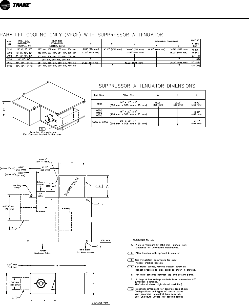


VAV-PRC012AC-EN
197
Figure 67. Paralllel - hot water coil assembly (2-rows)
Use port at bottom for inlet and top for outlet on single row coils.
For multirow coils, always plumb in counter flow orientation.
Water inlet always on the downstream side side of the hot water coil.
Water outlet always on the upstream side of the hot water coil.
DDiimmeennssiioonnaall DDaattaa


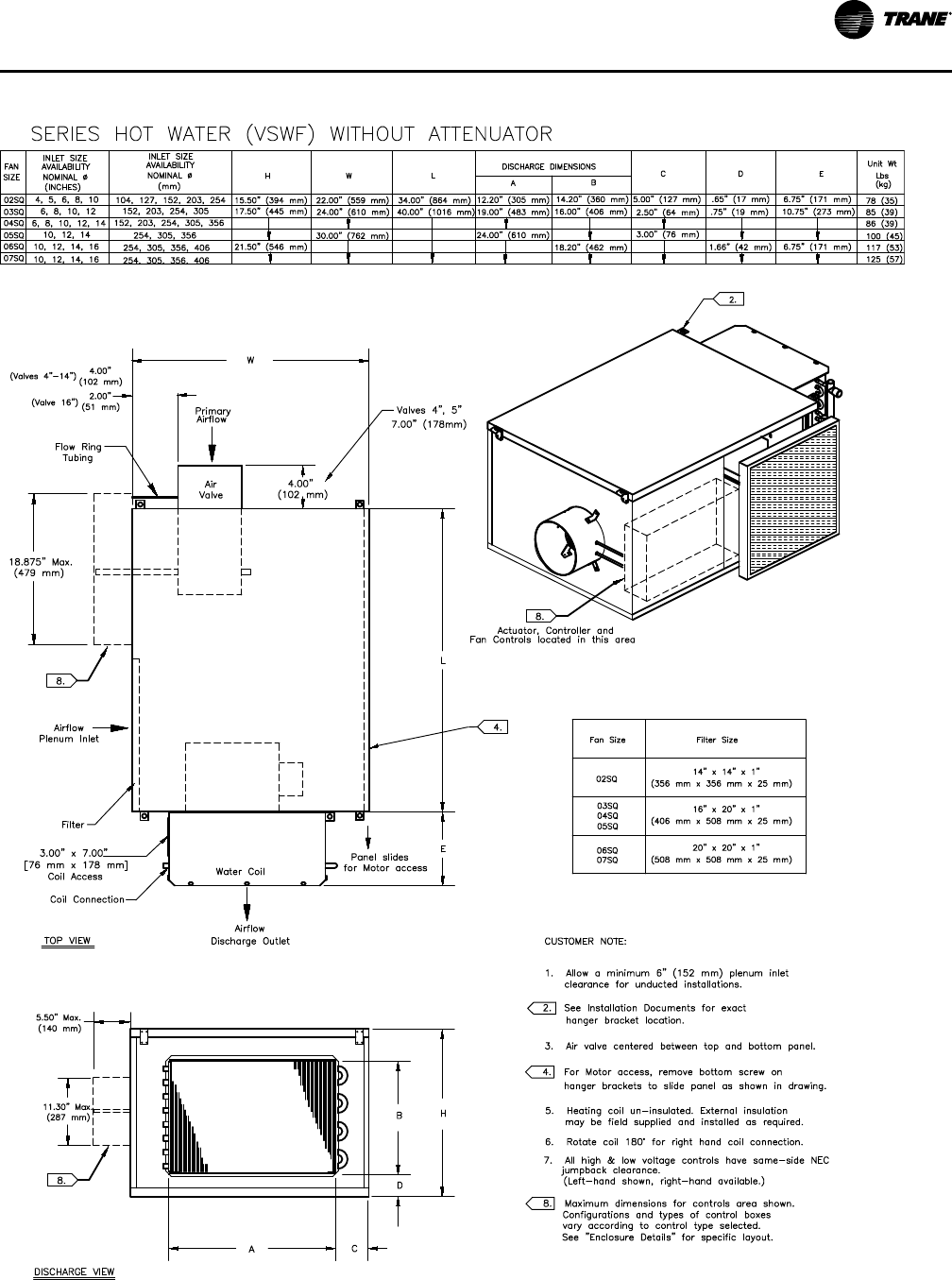


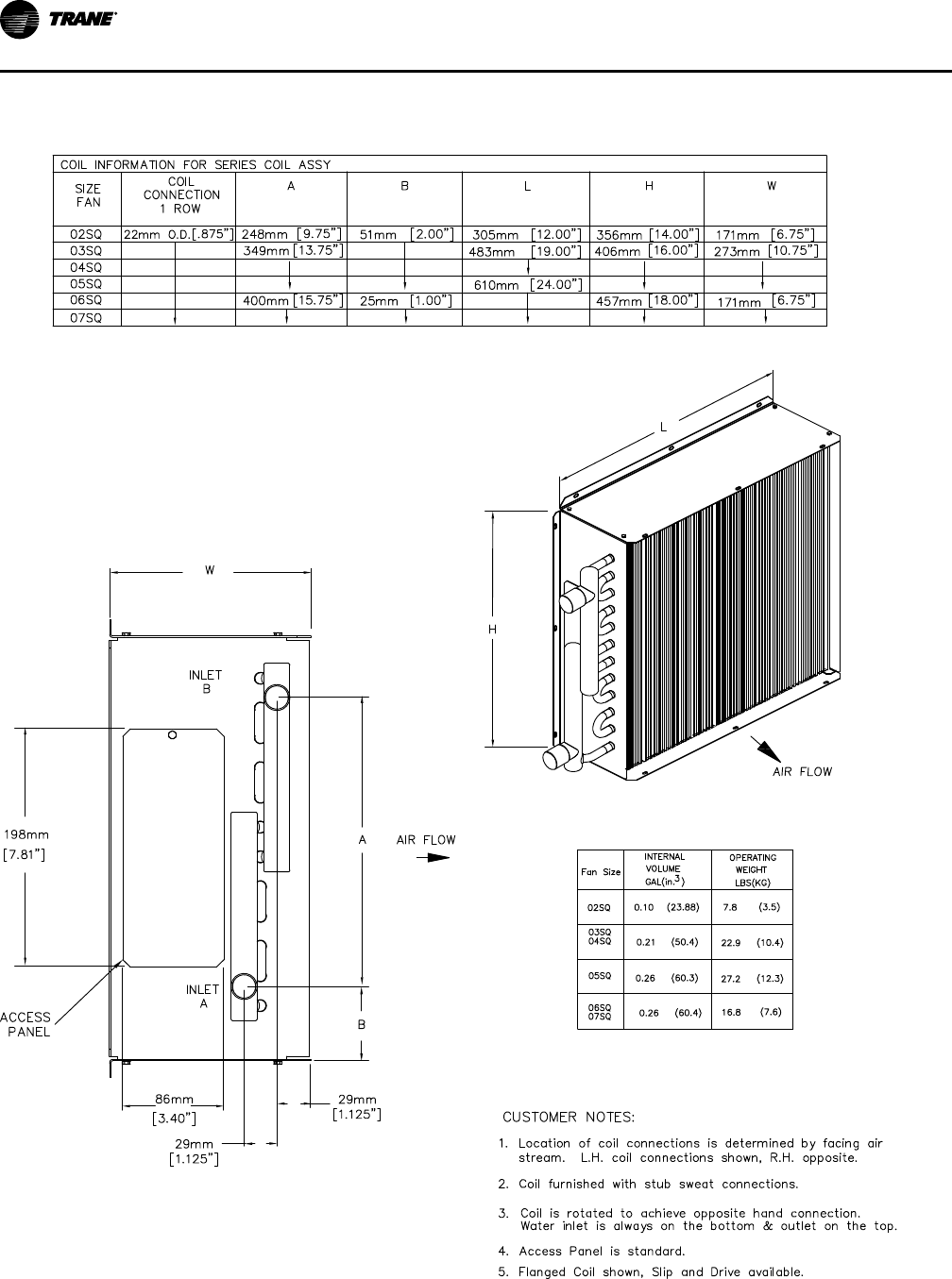
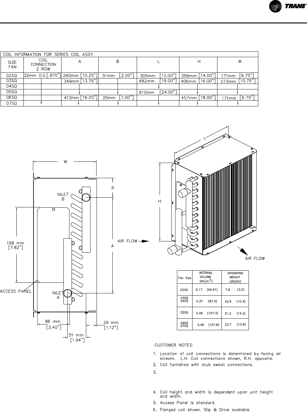
VAV-PRC012AC-EN
207
Figure 77. Series coil assembly (2-rows)
COIL INFORMATION FOR SERIES 2-ROW COILS
Use port at bottom for inlet and top for outlet on single row coils.
For multirow coils, always plumb in counter flow orientation.
Water inlet always on the downstream side side of the hot water coil.
Water outlet always on the upstream side of the hot water coil.
DDiimmeennssiioonnaall DDaattaa


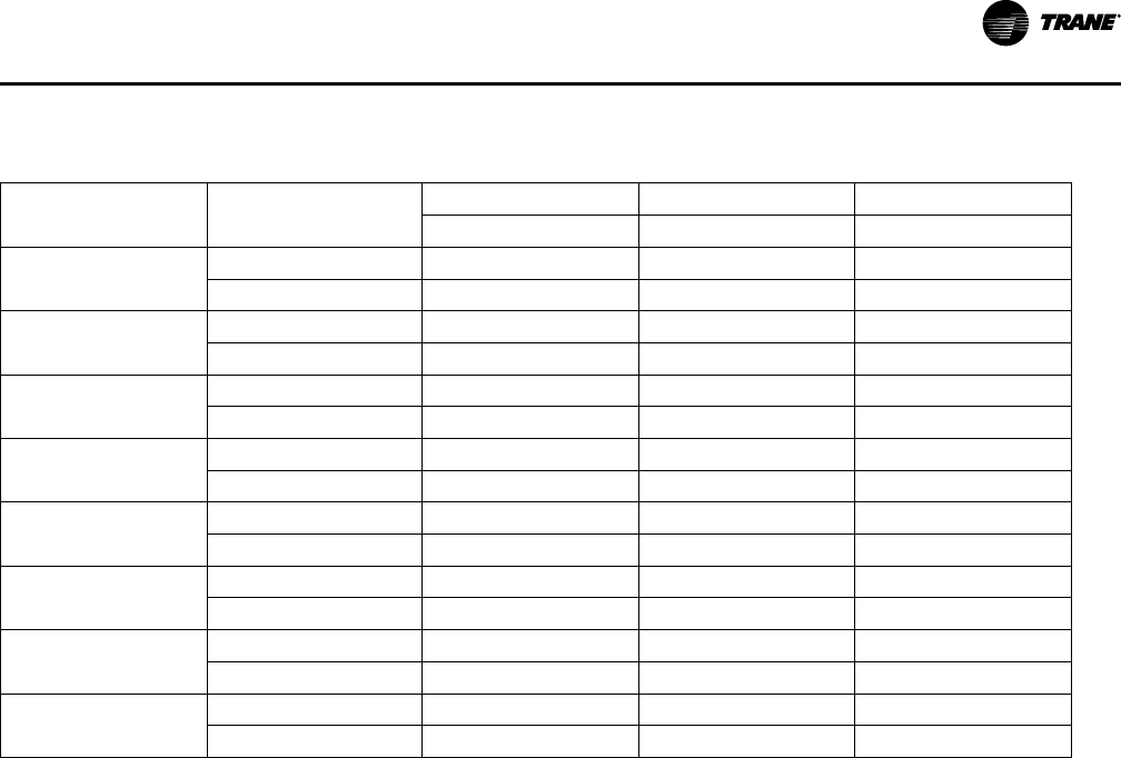
VAV-PRC012AC-EN
211
Low-Height Parallel Fan-Powered Terminal Units
Table 161. Low height parallel general and dimensional data — PS02, DS02
Description
Units
Cooling Only
Hot Water Electric Heat
LPCF LPWF LPEF
Filter Size
in 9 x18x1 9 x18x1 9 x18x1
mm 229x457x25 229x457x25 229x457x25
Inlet Size Availability
in
5, 6, 8, 8x14 5, 6, 8, 8x14 5, 6, 8, 8x14
mm
127, 152, 203, 203x355 127, 152, 203, 203x355 127, 152, 203, 203x355
Unit Weight
lb 92 98 110
kg
42 44 50
Height (H)
in 10.5 10.5 10.5
mm 267 267 267
Width (W)
in 40 40 40
mm 1016 1016 1016
Length (L)
in 35 35 35
mm 889 889 889
Discharge (A)
in 18 18 14
mm 457 457 365
Discharge (B)
in 10 10 9
mm 254 254 229
DDiimmeennssiioonnaall DDaattaa


218
VAV-PRC012AC-EN
Figure 87. Low-height parallel coil assembly (1 row)
AIR FLOW
INLET
ACCESS PANEL
A
H
L
B
A
1.00”
[25mm]
7
13
/
16
”
[198mm]
6
7
/
8
”
[172mm]
3
13
/
32
”
[86mm]
2.00”
[51mm]
B
INLET
AIR FLOW
Fan
Size
Coil
Connection
(O.D.)
in (mm)
A
in (mm)
B
in (mm)
L
in (mm)
H
in (mm)
Internal
Volume
gal (in
3
)
Operating
Weight
lb (kg)
DS02/
PS02
0.875 (22) 7.75 (197) 1.50 (38) 18.00 (457) 10.00 (254) 0.07 (17.02) 10.4 (4.7)
NNootteess::
1. Location of coil connections is determined by facing air stream. R.H. Coil connections shown, L.H. not
available.
2. Coil furnished with stub sweat connections.
3. Access Panel is standard.
DDiimmeennssiioonnaall DDaattaa

VAV-PRC012AC-EN
219
Figure 88. Low-height parallel coil assembly (2 row)
AIR FLOW
A
B
INLET
ACCESS PANEL
INLET
B
H
L
A
6
7
/
8
”
[172mm]
7
13
/
16
”
[198mm]
3
13
/
32
”
[86mm]
1
15
/
16
”
[51mm]
1
1
/
8
”
[29mm]
AIR FLOW
Fan
Size
Coil
Connection
(O.D.)
in (mm)
A
in (mm)
B
in (mm)
L
in (mm)
H
in (mm)
Internal
Volume
gal (in
3
)
Operating
Weight
lb (kg)
DS02/
PS02
0.875 (22) 6.25 (159) 1.50 (38) 18.00 (457) 10.00 (254) 0.10 (23.88) 7.8 (3.5)
NNootteess::
1. Location of coil connections is determined by facing air stream. R.H. Coil connections shown, L.H. not
available.
2. Coil furnished with stub sweat connections.
3. Access Panel is standard.
DDiimmeennssiioonnaall DDaattaa

220
VAV-PRC012AC-EN
Figure 89. Low-height parallel discharge water coil assembly (1 row)
AIR FLOW
INLET
ACCESS PANEL
A
H
L
B
A
1.00”
[25mm]
7
13
/
16
”
[198mm]
6
7
/
8
”
[172mm]
3
13
/
32
”
[86mm]
2.00”
[51mm]
B
INLET
AIR FLOW
Fan
Size
Coil
Connection
(O.D.)
in (mm)
A
in (mm)
B
in (mm)
L
in (mm)
H
in (mm)
Internal
Volume
gal (in
3
)
Operating
Weight
lb (kg)
DS02/
PS02
0.875 (22) 7.75 (197) 1.50 (38) 18.00 (457) 10.00 (254) 0.07 (17.02) 10.4 (4.7)
NNootteess::
1. Location of coil connections is determined by facing air stream. L.H. Coil connections shown, R.H. opposite.
2. Coil furnished with stub sweat connections.
3. Coil is rotated to achieve opposite hand connection. Water inlet is always on the bottom and outlet on the
top.
4. Access Panel is standard.
DDiimmeennssiioonnaall DDaattaa

VAV-PRC012AC-EN
221
Figure 90. Low-height parallel discharge water coil assembly (2 row)
AIR FLOW
A
B
INLET
ACCESS PANEL
INLET
B
H
L
A
6
7
/
8
”
[172mm]
7
13
/
16
”
[198mm]
3
13
/
32
”
[86mm]
1
15
/
16
”
[51mm]
1
1
/
8
”
[29mm]
AIR FLOW
Fan
Size
Coil
Connection
(O.D.)
in (mm)
A
in (mm)
B
in (mm)
L
in (mm)
H
in (mm)
Internal
Volume
gal (in
3
)
Operating
Weight
lb (kg)
DS02/
PS02
0.875 (22) 6.25 (159) 1.50 (38) 18.00 (457) 10.00 (254) 0.10 (23.88) 7.8 (3.5)
NNootteess::
1. Location of coil connections is determined by facing air stream. L.H. Coil connections shown, R.H. opposite.
2. Coil furnished with stub sweat connections.
3. Use port at bottom for inlet and port at top for outlet. For 2–row coils, always plumb in counter flow
orientation: Left hand unit’s water inlet on bottom, and outlet on the top. Right hand unit’s water inlet on top
and outlet on the bottom.
4. Access Panel is standard.
DDiimmeennssiioonnaall DDaattaa
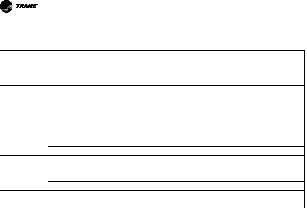
222
VAV-PRC012AC-EN
Low-Height Series Fan-Powered Terminal Units
Table 162. Low height series general and dimensional data — PS02, DS02
Description
Units
Cooling Only
Hot Water Electric Heat
LSCF LSWF LSEF
Filter Size
in 9 x18x1 9 x18x1 9 x18x1
mm 229x457x25 229x457x25 229x457x25
Inlet Size Availability
in
4, 5, 6, 8, 8x14 4, 5, 6, 8, 8x14 4, 5, 6, 8, 8x14
mm
102, 127, 152, 203, 203x355 102, 127, 152, 203, 203x355 102, 127, 152, 203,203x355
Unit Weight
lb 88 94 106
kg
40 43 49
Height (H)
in 10.5 10.5 10.5
mm 267 267 267
Width (W)
in 35 35 35
mm 889 889 889
Length (L)
in 40 40 40
mm 1016 1016 1016
Discharge (A)
in 18 18 14
mm 457 457 365
Discharge (B)
in 10 10 9
mm 254 254 229
DDiimmeennssiioonnaall DDaattaa


VAV-PRC012AC-EN
229
Table 163. Low height series general and dimensional data — DS03
Description
Units
Cooling Only
Hot Water Electric Heat
LSCF LSWF LSEF
Filter Size
in 10x20x1 10x20x1 10x20x1
mm 254x508x25 254x508x25 254x508x25
Inlet Size Availability
in
6, 8, 10, 8x14 6, 8, 10, 8x14 6, 8, 10, 8x14
mm
152, 203, 254, 203x355 1152, 203, 254, 203x355 152, 203, 254, 203x355
Unit Weight
lb 100 118 110
kg
46 54 50
Height (H)
in 12 12 12
mm 305 305 305
Width (W)
in 35 35 35
mm 889 889 889
Length (L)
in 40 40 40
mm 1016 1016 1016
Discharge (A)
in 18 18 14
mm 457 457 365
Discharge (B)
in 10 10 9
mm 254 254 229
DDiimmeennssiioonnaall DDaattaa


236
VAV-PRC012AC-EN
Figure 103. Low-height series coil assembly (1 row)
Fan
Size
Coil
Connection
(O.D.)
in (mm)
A
in (mm)
B
in (mm)
L
in (mm)
H
in (mm)
Internal
Volume
gal (in
3
)
Operating
Weight
lb (kg)
DS02/
DS03/
PS02
0.875 (22) 7.75 (197) 1.50 (38) 18.00 (457) 10.00 (254) 0.07 (17.02) 10.4 (4.7)
NNootteess::
1. Location of coil connections is determined by facing air stream. L.H. Coil connections shown, R.H. opposite.
2. Coil furnished with stub sweat connections.
3. Coil is rotated to achieve opposite hand connection. Water inlet is always on the bottom and outlet on the
top.
4. Access Panel is standard.
DDiimmeennssiioonnaall DDaattaa
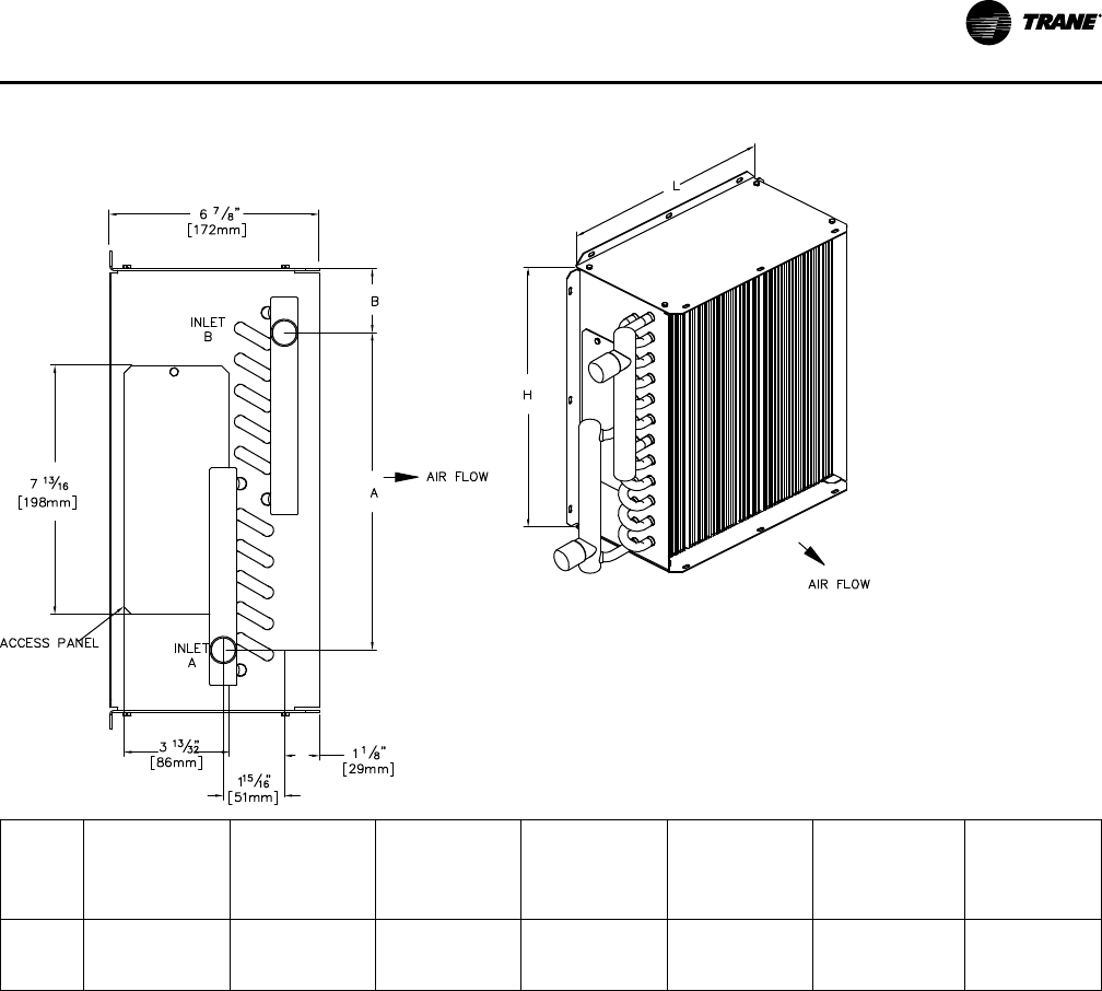
VAV-PRC012AC-EN
237
Figure 104. Low-height series coil assembly (2 row)
Fan
Size
Coil
Connection
(O.D.)
in (mm)
A
in (mm)
B
in (mm)
L
in (mm)
H
in (mm)
Internal
Volume
gal (in
3
)
Operating
Weight
lb (kg)
DS02/
DS03/
PS02
0.875 (22) 6.25 (159) 1.50 (38) 18.00 (457) 10.00 (254) 0.10 (23.88) 7.8 (3.5)
NNootteess::
1. Location of coil connections is determined by facing air stream. L.H. Coil connections shown, R.H. opposite.
2. Coil furnished with stub sweat connections.
3. Use port at bottom for inlet and port at top for outlet. For 2–row coils, always plumb in counter flow
orientation: Left hand unit’s water inlet on bottom, and outlet on the top. Right hand unit’s water inlet on top
and outlet on the bottom.
4. Access Panel is standard.
DDiimmeennssiioonnaall DDaattaa

238
VAV-PRC012AC-EN
Mechanical Specifications: Fan-Powered
MODELS: VPCF, VPWF, VPEF, VSCF, VSWF, VSEF, LPCF, LPWF, LPEF,
LSCF, LSWF, & LSEF
VP, LP = Parallel Fan Powered Units
VS, LS = Series Fan Powered Units
Note: L = Low Height
Model Details
• VPCF, VSCF, LPCF, & LSCF = cooling only
• VPWF, VSWF, LPWF, & LSWF = with hot water coil
• VPEF, VSEF, LPEF, & LSEF = with electric coil
Casing
22-gage galvanized steel. Hanger brackets, side access (standard height—V model numbers) or
bottom access (low height—L model numbers) and plenum filter are provided as standard.
Agency Listing
Unit is UL and Canadian UL Listed as a room air terminal unit. Control # 9N65. AHRI 880 Certified.
Insulation
11//22––iinncchh ((1122..77 mmmm)) MMaattttee--ffaacceedd IInnssuullaattiioonn——Interior surface of unit casing is acoustically and
thermally lined with ½-inch, 1.5 lb/ft
3
(12.7 mm, 24.0 kg/m
3
) composite density glass fiber with a
high-density facing. Insulation R-Value is 1.9. Insulation is UL listed and meets NFPA-90A and UL
181 standards. There are no exposed edges of insulation (complete metal encapsulation).
11––iinncchh ((2255..44 mmmm)) MMaattttee--ffaacceedd IInnssuullaattiioonn——Interior surface of unit casing is acoustically and
thermally lined with 1-inch, 1.0 lb/ft
3
(25.4 mm, 16.0 kg/m
3
) composite density glass fiber with a
high-density facing. Insulation R-Value is 3.85. Insulation is UL listed and meets NFPA-90A and
UL 181 standards. There are no exposed edges of insulation (complete metal encapsulation).
11––iinncchh ((2255..44 mmmm)) FFooiill--ffaacceedd IInnssuullaattiioonn—— Interior surface of unit casing is acoustically and
thermally lined with 1-inch, 1.0 lb/ft
3
(25.4 mm, 16.0 kg/m
3
) density glass fiber with foil facing.
Insulation R-Value is 3.85. Insulation is UL listed and meets NFPA-90A and UL 181 standards and
bacteriological standard ASTM C 665. There are no exposed edges of insulation (complete metal
encapsulation).
11––iinncchh ((2255..44 mmmm)) DDoouubbllee--wwaallll IInnssuullaattiioonn——Interior surface of unit casing is acoustically and
thermally lined with a 1-inch, 1.0 lb./ft
3
(25.4 mm, 16.0 kg/m
3
) composite density glass fiber with
high-density facing. Insulation R-value is 3.85. Insulation is UL listed and meets NFPA-90A and
UL 181 standards. Insulation is covered by interior liner made of 26-gage galvanized steel. All
wire penetrations are covered by grommets. There are no exposed edges of insulation (complete
metal encapsulation).
33//88––iinncchh ((99..55 mmmm)) CClloosseedd--cceellll IInnssuullaattiioonn——Interior surface of the unit casing is acoustically and
thermally lined with 3/8-inch, 4.4 lb/ft
3
(9.5 mm, 70.0 kg/m
3
) closed-cell insulation. Insulation is
UL listed and meets NFPA-90A and UL 181 standards. Insulation has an R-Value of 1.4. There are
no exposed edges of insulation (complete metal encapsulation).
Primary Air Valve
AAiirr VVaallvvee RRoouunndd——The primary (ventilation) air inlet connection is an 18-gauge galvanized steel
cylinder sized to fit standard round duct. A multiple-point, averaging flow sensing ring is
provided with balancing taps for measuring +/-5% of unit cataloged airflow. An airflow-versus-
pressure differential calibration chart is provided. The damper blade is constructed of a closed-
cell foam seal that is mechanically locked between two 22-gauge galvanized steel disks. The

VAV-PRC012AC-EN
239
damper blade assembly is connected to a cast zinc shaft supported by self-lubricating bearings.
The shaft is cast with a damper position indicator. The valve assembly includes a mechanical
stop to prevent over-stroking.
AAiirr VVaallvvee RReeccttaanngguullaarr——Inlet collar is constructed of 22-gauge galvanized steel sized to fit
standard rectangular duct. An integral multiple-point, averaging flow-sensing ring provides
primary airflow measurement within +/-5% of unit cataloged airflow. Damper is 22-gauge
galvanized steel. The damper blade assembly is connected to a cast zinc shaft supported by self-
lubricating bearings. The shaft is cast with a damper position indicator. The valve assembly
includes a mechanical stop to prevent over-stroking.
Table 164. Fan/inlet combinations
Inlet
(in)
VPxF VSxF
02SQ 03SQ 04SQ 05SQ 06SQ 07SQ 02SQ 03SQ 04SQ 05SQ 06SQ 07SQ
4 X
5 X X
6 X X X X X
8 X X X X X X
10 X X X X X X X X X X X X
12 X X X X X X X X X X
14 X X X X X X X X
16 X X X
Table 165. Fan/inlet combinations — low height
Inlet (in.)
LPxF LSxF
DS02/PS02 DS02/PS02
DS03
4 X
5 X X
6 X X X
8 X X X
10 X
8 x 14 X X X
Fan Motor
PSC
Single-speed, direct-drive, permanent split capacitor type. Thermal overload protection provided.
Motors will be designed specifically for use with an open SCR. Motors will accommodate anti-
backward rotation at start up. Motor and fan assembly are isolated from terminal unit.
ECM
Electrically commutated motor (ECM) is designed for high-efficient operation with over 70%
efficiency throughout the operating range. .
Fan Speed Control
VVaarriiaabbllee SSppeeeedd CCoonnttrrooll SSwwiittcchh ((SSCCRR))
The SCR speed control device is provided as standard and allows the operator infinite fan speed
adjustment.
Transformer
The 50-VA transformer is factory installed in the fan control box to provide 24 VAC for controls.
MMeecchhaanniiccaall SSppeecciiffiiccaattiioonnss:: FFaann--PPoowweerreedd

240
VAV-PRC012AC-EN
Disconnect Switch
A toggle disconnect is provided as standard and allows the operator to turn the unit on or off by
toggling to the appropriate setting. This switch breaks both legs of power to the fan and the
electronic controls (if applicable).
Outlet Connection
Flanged connection—Rectangular opening on unit discharge to accept 90° flanged ductwork
connection.
Filter
A 1" (25 mm) filter is provided on the plenum inlet and attaches to the unit with a filter frame.
Suppressor Attenuator
The Suppressor sound attenuator option is factory assembled and installed on plenum air inlet
which is also the controls inlet side. The exclusive Trane design provides acoustical attenuation
with a compact footprint. Unit sound performance is assured through rigorous testing in
accordance with AHRI 880 test procedures.
Suppressor casing is constructed of 22 gauge galvanized steel, and lined with 1-inch glass fiber
with high density facing or 1-inch glass density fiber with foil facing. Suppressor insulation liner
will be 1-inch glass fiber with high density facing when unit insulation liner is 1/2-inch or 1-inch
glass fiber with high density facing. For all other unit insulation liners, the Suppressor insulation
liner will be 3/8-inch closed cell foam. The insulation is UL listed and meets NFPA 90A and UL 181
requirements. Foil faced insulation also meets bacteriological standard ASTM C 665.
Thinline Suppressor Attenuator
The Thinine Suppressor sound attenuator option is factory assembled and installed on plenum
air inlet which is opposite the controls inlet side. The exclusive Trane design provides acoustical
attenuation with a compact footprint. Unit sound performance is assured through rigorous
testing in accordance with AHRI 880 test procedures.
Thinline Suppressor casing is constructed of 22 gauge galvanized steel, and lined with 1-inch
glass fiber with high density facing or 1-inch glass density fiber with foil facing. Suppressor
insulation liner will be 1-inch glass fiber with high density facing when unit insulation liner is 1/2-
inch or 1-inch glass fiber with high density facing. For all other unit insulation liners, the
Suppressor insulation liner will be 3/8-inch closed cell foam. The insulation is UL listed and
meets NFPA 90A and UL 181 requirements. Foil faced insulation also meets bacteriological
standard ASTM C 665.
Hot Water Coil
Parallel Water Coils
Factory installed on the plenum inlet. The coil has 1-row with 144 aluminum-plated fins per foot
(.305 m), and if needed 2-row with 144 aluminum-plated fins per foot (.305 m). Full fin collars
provided for accurate fin spacing and maximum fin-tube contact. The 3/8" (9.5 mm) OD seamless
copper tubes are mechanically expanded into the fin collars. Coils are proof tested at 450 psig
(3102 kPa) and leak tested at 300 psig (2068 kPa) air pressure under water. Coil connections are
brazed.
Series Water Coils
Factory installed on the fan discharge. The coil has 1-row with 144 aluminum-plated fins per foot
(.305 m) and, if needed, 2-row with 144 aluminum-plated fins per foot (.305 m). Full fin collars
provided for accurate fin spacing and maximum fin-tube contact. The 3/8" (9.5 mm) OD seamless
copper tubes are mechanically expanded into the fin collars. Coils are proof tested at 450 psig
(3102 kPa) and leak tested at 300 psig (2068 kPa) air pressure under water. Coil connections are
brazed. Gasketed access panels, which are standard, are attached with screws.
MMeecchhaanniiccaall SSppeecciiffiiccaattiioonnss:: FFaann--PPoowweerreedd

VAV-PRC012AC-EN
241
Electric Heat Coil
The electric heater is a factory-provided and installed, UL recognized resistance open-type
heater. It also contains a disc-type automatic pilot duty thermal primary cutout, and manual reset
load carrying thermal secondary device. Heater element material is nickel-chromium. The heater
terminal box is provided with 7/8" (22 mm) knockouts for customer power supply. Terminal
connections are plated steel with ceramic insulators. All fan-powered units with electric reheat
are single-point power connections.
Electric Heat Options
SSiilliiccoonn--CCoonnttrroolllleedd RReeccttiiffiieerr ((SSCCRR)) ——Optional 0–10Vdc electric heat control that provides
modulation.
SSoolliidd SSttaattee RReellaayy ((SSSSRR)) –– Optional electric 24 VAC solid-state contactor(s) for use with direct
digital controls.
MMaaggnneettiicc CCoonnttaaccttoorr ——Optional electric heater 24V contactor(s) for use with direct digital
controls.
AAiirrffllooww SSwwiittcchh —— Optional air pressure device designed to disable heater when terminal fan is
off.
PPoowweerr FFuussee ——If a power fuse is chosen with a unit containing electric heat, then a safety fuse is
located in the electric heater’s line of power to prevent power surge damage to the electric
heater. Any electric heat unit with a calculated MCA greater than or equal to 30 will have a fuse
provided.
DDiissccoonnnneecctt SSwwiittcchh ——A factory-provided door interlocking disconnect switch on the heater
control panel disengages primary voltage to the terminal.
Unit Controls Sequence Of Operation
See DDC Controls section for sequence of operations.
Direct Digital Controls
DDDDCC AAccttuuaattoorr ——Trane 3-wire, 24-VAC, floating-point quarter turn control actuator with linkage
release button. Actuator has a constant drive rate independent of load, a rated torque of 35 in-lb,
a 90-second drive time, and is non-spring return. Travel is terminated by end stops at fully-
opened and -closed positions. An integral magnetic clutch eliminates motor stall.
DDDDCC AAccttuuaattoorr ((BBeelliimmoo)) —— LMB24-3-T TN 3-wire, 24 VAC/DC, floating-point, quarter turn
actuator with linkage release button. Actuator has constant drive rate independent of load, rated
torque 45 in-lb, 95 sec drive time, and non-spring return. Travel is terminated by end stops at
fully-opened and -closed positions. Internal electronic control prevents motor stall when motor
reaches end stops.
DDiirreecctt DDiiggiittaall CCoonnttrroolllleerr ——Microprocessor-based terminal unit controllers provide accurate,
pressure-independent control through the use of proportional integral control algorithm and
direct digital control technology.
Controllers monitor zone temperature setpoints, zone temperature, zone temperature rate of
change, and valve airflow. They can also monitor supply duct air temperature, CO
2
concentration and discharge air temperature via appropriate sensors. Controller is provided in an
enclosure with 7/8–in. (22mm) knockouts for remote control wiring. Trane UCM zone sensor or
Air-Fi® Receiver Interface Module paired with a Wireless Communications Sensor (WCS) is
required.
DDDDCC ZZoonnee SSeennssoorr ——The UCM controller senses zone temperature through a sensing element
located in the zone sensor. In addition to the sensing element, zone sensor options may include
an externally-adjustable setpoint, communications jack for use with a portable edit device, and
an override button to change the individual controller from unoccupied to occupied mode. The
override button has a cancel feature that will return the system to unoccupied. Wired zone
sensors utilize a thermistor to vary the voltage output in response to changes in the zone
temperature. Wiring to the UCM controller must be 18- to 22-awg. twisted pair wiring. The
setpoint adjustment range is 50 to 88°F (10 to 31°C). Depending upon the features available in the
model of sensor selected, the zone sensor may require from a 2-wire to a 5-wire connection.
MMeecchhaanniiccaall SSppeecciiffiiccaattiioonnss:: FFaann--PPoowweerreedd

242
VAV-PRC012AC-EN
Wireless zone sensors report the same zone information as wired zone sensors, but do so using
radio transmitter technology. Therefore with wireless, wiring from the zone sensor to the UCM is
unnecessary.
DDiiggiittaall DDiissppllaayy ZZoonnee SSeennssoorr wwiitthh LLiiqquuiidd CCrryyssttaall DDiissppllaayy ((LLCCDD)) —— Digital display zone sensor
contains a sensing element, which signals the UCM. A Liquid Crystal Display (LCD) displays
setpoint or zone temperature. Sensor buttons allow user to adjust setpoints, and allow zone
temperature readings to be turned on or off. Digital display zone sensor also includes a
communication jack for use with a portable edit device, and an override button to change UCM
from unoccupied to occupied. Override button cancel feature returns system to unoccupied
mode.
TTrraannee LLoonnTTaallkk®®//BBAACCnneett®® — The controller is designed to send and receive data using
LonTalk® or BACnet®. Current unit status conditions and setpoints may be monitored and/or
edited from any of several LonTalk® or BACnet® compatible system-level controllers.
Unit Options
Power Fuse (VPCF, VPWF)
Optional fuse is factory installed in the primary voltage hot leg.
Hot Water Valves
Trane Water Valve
The valve is a field-adaptable, 2-way or 3-way configuration and ships with a plug in B port. This
configures the valve for 2-way operation. For 3-way operation, remove the plug. The intended
fluid is water or water and glycol (50% maximum glycol). The actuator is a synchronous motor
drive. The valve is driven to a predetermined position by the UCM controller using a proportional
plus integral control algorithm. If power is removed, the valve stays in its last position. The
actuator is rated for plenum applications under UL 2043 and UL 873 standards.
• Pressure and temperature ratings: The valve is designed and tested in full compliance with
ANSI B16.15 Class 250 pressure/temperature ratings, ANSI B16.104 Class IV control shutoff
leakage, and ISA S75.11 flow characteristic standards.
• Flow capacity: 0.70 Cv, 1.7 Cv, 2.7 Cv, 5.0 Cv
• Overall diameter: ½–in. NPT
• Maximum allowable pressure: 300 psi (2068 kPa)
• Maximum operating fluid temperature: 201ºF (94°C)
• Maximum close-off pressure: 60 psi (0.4 MPa)
• Electrical rating: 3VA at 24 VAC
• 8–in. plenum rated cable with AMP Mate-N-Lok connector
Belimo Water Valve
The intended fluid is water or water and glycol (50% maximum glycol). The actuator is a
synchronous motor drive. The valve is driven to a predetermined position by the UCM controller
using a proportional plus integral control algorithm. If power is removed, the valve stays in its
last position. The actuator is rated for plenum applications under UL 2043 and UL 873 standards.
• Pressure and temperature ratings: The valve is designed and tested in full compliance with
ANSI B16.15 Class 250 pressure/temperature ratings, ANSI B16.104 Class IV control shutoff
leakage, and ISA S75.11 flow characteristic standards.
• Flow capacity: 0.3 Cv, 0.46 Cv, 0.8 Cv, 1.2 Cv, 1.9 Cv, 3.0 Cv, 4.7 Cv
• Overall diameter: ½–in. NPT
• Maximum allowable pressure: 600 psi (4137 kPa)
• Maximum operating fluid temperature: 201ºF (94°C)
• Maximum close-off pressure: 200 psi (1379 kPa)
• Electrical rating: 1VA at 24 VAC
MMeecchhaanniiccaall SSppeecciiffiiccaattiioonnss:: FFaann--PPoowweerreedd


The AHRI Certified mark indicates Trane U.S. Inc. participation in the AHRI Certification program. For verification of individual certified
products, go to ahridirectory.org.
Trane - by Trane Technologies (NYSE: TT), a global innovator - creates comfortable, energy efficient
indoor environments for commercial and residential applications. For more information, please visit
trane.com or tranetechnologies.com.
Trane has a policy of continuous product and product data improvements and reserves the right to change design and specifications without
notice. We are committed to using environmentally conscious print practices.
VAV-PRC012AC-EN 05 Mar 2022
Supersedes VAV-PRC012AB-EN (December 2021)
©2022 Trane
