
NASA TECHNICAL
STANDARD
ANNEX to
NASA-STD-8719.24
Revision B
National Aeronautics and Space Administration
Washington, DC 20546
Approved: 2022-03-30
Superseding: Annex To NASA-STD-
8719.24 Revision A with Change 2
ANNEX TO NASA-STD-8719.24
NASA PAYLOAD SAFETY REQUIREMENTS:
REQUIREMENTS TABLE
Measurement System Identification:
Metric (English)

Annex to NASA-STD-8719.24B
Page 2 of 455
DOCUMENT HISTORY LOG
Status
Document
Revision
Approval Date
Description
Baseline
2011-08-26
Initial Release
(JWL4)
Change
1
2012-01-26
- Page 3: Corrected PSWG Chair signature block;
- Pages 187 Vol 3, para13.1.1.1 and Vol 7, removed
revision from ST/SG/AC.10.1;
- Vol 7 page 404, bolded “hazardous materials”
definition header
(JWL4)
Change
2
2012-06-19
Throughout document: Corrected 18 typographical
errors (Administrative Change)
(JWL4)
Revision
A
2015-09-30
Added Attachment 5 to Volume 1 on Payload Safety
Introduction Briefing (PSIB) and related information that
is to be presented at the PSIB. Added NASA electronic
forms NF 1825, NASA ELV Payload Safety Hazard
Report Form; NF 1826, NASA ELV Payload Safety Post-
Tailoring Equivalent Level of Safety Request; and NF
1827, NASA ELV Payload Safety Waiver Request.
Added requirements addressing pyrovalves (Vol. 3,
Section12.1.2.6) and payload recovery missions
involving sample or payload returns. Added some
additional requirements for Composite Overwrapped
Pressure Vessels (COPVs) and a COPV Mechanical
Damage Control Plan (Vol. 3, Section 12.2.5). Revised
definition for “catastrophic.” Numerous improvements to
requirements to improved clarity and correctness.
(SH)
Change
1
2018-03-05
Typing errors and format issues are corrected. An
obsolete Air Force reference is removed. A NASA spec
for pyrovalves is added and revisions are made to
payload lifting requirements to reflect updates to NASA's
lifting standard and allow for non-load test slings to be
used verses tailoring the requirements. Wording for
clarity updated and a definition.
Change
2
2018-06-13
Updated the hyperlink
(http://kscsma.ksc.nasa.gov/ELVPayloadSafety) for the
NASA Expendable Launch Vehicle (ELV) Payloads
website throughout the document.
Revision
B
2022-03-30
Revision B incorporates Revision A w/Change 2.
Removed Expendable Launch Vehicle (ELV) from
document title changing title to NASA Payload Safety
Requirements. Revised Forward to remove ELV
reference and change signature block from T. Wilcutt to
W. DeLoach. General document revision include
editorial updates of applicable and reference
documents, terms and acronyms to ensure accuracy
and consistency with U.S. Air Force Space Command,
the United States Space Force Space Command,
Range Safety User Requirements 91-710 and NASA
program documentation, e.g., NPR 8715.1, NASA
Safety & Health Programs and NPR 8715.7, NASA
Payload Safety Program.

Annex to NASA-STD-8719.24B
Page 3 of 455
FOREWORD
This NASA technical standard provides uniform engineering and technical requirements for
processes, procedures, practices, and methods that have been endorsed as standard for NASA
programs and projects, including requirements for selection, application, and design criteria of an
item. This standard establishes technical safety requirements for unmanned orbital and unmanned
deep space payloads that fly onboard launch vehicles. The requirements contained in this Annex
to NASA-STD-8719.24 were developed jointly by NASA and United States Space Force (USSF)
Space Launch Delta (SLD) 30 and SLD 45 Safety representatives using 91-710, Range Safety
User Requirements, and NASA safety standards. The requirements of this document comply with
the requirements of 91-710, Range Safety User Requirements, and are acceptable to NASA and
the Space Force ranges. As such, they provide a streamlined starting point for the safety
requirements tailoring process. These requirements are provided in a matrix format that was
developed to facilitate project-specific tailoring of the safety requirements for each NASA payload
project.
This standard was developed by the NASA Office of Safety and Mission Assurance (OSMA).
Requests for information, corrections, or additions to this standard should be submitted to the
OSMA by email to Agency-SMA-Policy-[email protected] or via the “Email Feedback”
link at; https://standards.nasa.gov.
William Russ DeLoach Approval Date
Chief, Safety & Mission Assurance
Annex to NASA-STD-8719.24B
Page 4 of 455
Project Safety Requirements
Effective Date:
Project Safety Requirements
Revision: Basic
NASA PAYLOAD SAFETY
REQUIREMENTS
NASA PAYLOAD PROJECT
(NAME)
Project Contract No:
Contract Date:
NASA CENTER: (name)
Proprietary
The information contained in the document is technical in content and may be
proprietary as defined by the International Traffic in Arms Regulations (ITAR) or
by Export Administration Regulations (EAR) requirements. Contact the NASA
KSC Export Control Office, 321-867-9209, for an ITAR or EAR regulatory
determination. If not required delete this statement.
NASA Payload Safety Program
Office of Safety and Mission Assurance
National Aeronautics and Space Administration
Washington, D.C. 20546

Annex to NASA-STD-8719.24B
Page 5 of 455
Prepared by:
Name
Title
Organization
Date:
Concurrence:
Name
NASA Payload Project Manager
NASA Center:
Date:
Concurrence:
Name
NASA Payload S&MA Technical Authority
NASA Center:
Date:
Concurrence:
Name
USSF Space Launch Delta Range Safety Authority
Date:
Concurrence:
Name
Chairperson
NASA Payload Safety Working Group
NASA Center:
Date:

Annex to NASA-STD-8719.24B
Page 6 of 455
PREFACE
The Original Text column of the following requirements matrix contains the National Aeronautics and Space
Administration (NASA) payload safety requirements that are to be tailored for each NASA Payload project, as
required by NPR 8715.7, “NASA Payload Safety Program.” The NASA Payload safety requirements are the result
of a joint effort by NASA and the United States Space Force (USSF) Space Launch Delta (SLD) 30 and SLD 45
Range Safety representatives to establish an approved baseline from the USSF 91-710, “Range Safety User
Requirements,” and applicable NASA safety requirements and also address unique issues associated with NASA
payload safety design and operations. The NASA Payload safety requirements apply to all NASA Payload projects
launched from a USSF, NASA, or other range/launch site.
The NASA Payload safety requirements supplement NPR 8715.7 and satisfy USSF 91-710, when applied to NASA
launches from USSF launch ranges. As such, they provide a streamlined starting point for the safety requirements
tailoring process that is required for each NASA Payload project per NPR 8715.7.
The NASA Payload safety requirements (as tailored for each specific project) are mandatory for each NASA Payload
project and are to be applied to associated contracts and/or agreements. Additional requirements may be imposed by
other organizations, including other launch ranges, commercial payload processing facility operators, or launch
vehicle contractors. This document does not alter or otherwise modify the authority or roles and responsibilities
delineated by statute or policy applicable to the USSF, NASA, or other organizations participating in a NASA Payload
project. As outlined in USSF 91-710, the SLD Commanders have overall launch authority and responsibility for
public safety from USSF ranges. The Directors of NASA Wallops Flight Facility (WFF), and the Kennedy Space
Center (KSC), have authority and responsibility for launches originating from WFF and KSC respectively.
USSF 91-710 range safety requirements not applicable to NASA Payloads were eliminated from the following NASA
Payload safety requirements. Additionally, in some cases, entire volumes or chapters are not applicable and are not
included in the requirements matrix. This results in irregular numbering of paragraphs where certain paragraph(s)
were removed that were not applicable. The absence of these requirements does not alter USSF SLD 30 and SLD 45
Range Safety authority. The project may add back any USSF 91-710 requirements that are pertinent to their project
upon agreement by the project’s Payload Safety Working Group (PSWG) and SLD 30th and SLD 45th Range Safety
representatives.
Questions pertaining to the requirements in this document and applicable local safety requirements should be brought
to the attention of the payload project’s PSWG. Per NPR 8715.7, Payload Project Offices will contact the NASA
Payload Safety Manager as early as practical in the project’s Concept and Technology Development, Phase A, to
establish the project’s PSWG and initiate the payload safety review and approval process, which includes the
requirements tailoring process.
The NASA Payload Safety Manager is responsible for maintaining and keeping the NASA Payload safety
requirements current and coordinating all changes with the NASA Payload Safety Agency Team and the USSF SLD
30 and SLD 45 Range Safety Offices. The NASA Payload Safety Manager contact information and the NASA
Payload safety requirements tailoring matrix are available on the NASA Payload Safety Program website at:
https://kscsma.ksc.nasa.gov/PayloadSafety.
Note: This Preface provides background information that is applicable to all NASA Payload projects. It is not to be
tailored and shall remain as part of each final project-specific safety requirements document.
Annex to NASA-STD-8719.24B
Page 7 of 455
TABLE OF CONTENTS
VOLUME 1: POLICIES AND PROCEDURE REQUIREMENTS ......................................... 14
INTRODUCTION .................................................................................................... 14
Objective ........................................................................................................................................... 14
Applicability ..................................................................................................................................... 14
Basis for the Requirements .............................................................................................................. 16
RESPONSIBILITIES AND AUTHORITIES ....................................................... 17
General .............................................................................................................................................. 17
Headquarters Space Systems Command Responsibilities .............................................................. 17
Space Launch Delta Responsibilities ............................................................................................... 17
Federal Aviation Administration Responsibilities .......................................................................... 18
Payload Project Responsibilities ...................................................................................................... 18
RANGE SAFETY POLICY .................................................................................... 20
General .............................................................................................................................................. 20
Prelaunch and Launch Operations ................................................................................................... 20
Launch Area Safety .......................................................................................................................... 20
Launch Complex Safety ................................................................................................................... 24
PSWG and RANGE SAFETY PROCESSES ....................................................... 25
PSWG, Range Safety and Payload Projects Interface Process ....................................................... 25
Equivalent Level of Safety (ELS) Determinations and Waivers .................................................... 25
SAFETY AUTHORIZATIONS, SAFETY APPROVALS, AND
DOCUMENTATION ........................................................................................................................ 27
General .............................................................................................................................................. 27
INVESTIGATING AND REPORTING MISHAPS AND INCIDENTS .......... 28
Mishaps and Incidents Involving Space Force Personnel and Resources ...................................... 28
Non-Space Force Personnel and Resources on Space Force Property ........................................... 28
Reporting Space Launch System Anomalies ................................................................................... 28
CHANGES TO THIS PUBLICATION ................................................................. 29
ATTACHMENT 1 POLICIES AND PROCEDUREs ................................................................. 30
NASA PAYLOAD SAFETY REQUIREMENTS TAILORING PROCESS ............................... 30
ATTACHMENT 2 SAFETY PLAN REQUIREMENTS ............................................................ 35
Introduction ....................................................................................................................................... 35
System Safety Plan Tasks ................................................................................................................ 35
ATTACHMENT 3 SUBMITTING NONCOMPLIANCE REQUESTS ................................... 48
Introduction ....................................................................................................................................... 48
Submitting Noncompliance Requests .............................................................................................. 49
Annex to NASA-STD-8719.24B
Page 8 of 455
ATTACHMENT 4 ACCEPTABLE RISK CRITERIA ............................................................... 51
INTRODUCTION ............................................................................................................................ 51
ATTACHMENT 5 PAYLOAD SAFETY INTRODUCTION BRIEFING ............................... 52
Introduction ....................................................................................................................................... 52
Payload safety introduction briefing (PSIB) .................................................................................... 52
VOLUME 3: PAYLOADS AND GROUND SYSTEMS REQUIREMENTS .......................... 54
INTRODUCTION .................................................................................................... 54
General .............................................................................................................................................. 54
Organization of the Volume ............................................................................................................. 54
RESPONSIBILITIES AND AUTHORITIES ....................................................... 56
Payload Safety Working Group (PSWG) ........................................................................................ 56
Payload Project Responsibilities ...................................................................................................... 56
GENERAL DESIGN POLICY ............................................................................... 58
General .............................................................................................................................................. 58
Systems Without Specific Design Criteria ...................................................................................... 58
DOCUMENTATION REQUIREMENTS............................................................. 59
System Safety Plan and Hazard Analyses ....................................................................................... 59
Safety Data Package (SDP)/MISSILE SYSTEM PRELAUNCH SAFETY PACKAGE (MSPSP)
.......................................................................................................................................................... 59
SDP Associated Test Plans and Test Results .................................................................................. 60
Nondestructive Examination Plans .................................................................................................. 60
Pad Safety Console Design ....................................................................................... 62
MATERIAL HANDLING EQUIPMENT, Cranes, Hoist AND PERSONNEL
WORK PLATFORMS. ....................................................................... Error! Bookmark not defined.
Overview ........................................................................................................................................... 63
Material Handling Equipment (MHE) ............................................................................................. 63
Removable, Extendible, and/or Hinged Personnel Work Platforms ............................................... 74
Lifting Personnel with a Crane ........................................................................................................ 75
Flight Hardware Used to Lift Critical Loads and Clampbands. ...................................................... 76
ACOUSTIC HAZARDS .......................................................................................... 77
Acoustic Design Standards............................................................................................................... 77
Acoustic Data Requirements ............................................................................................................ 77
NON-IONIZING RADIATION SOURCES.......................................................... 78
ELECTROMAGNETIC RADIATION Emitters ............................................................................ 78
Laser Systems (Class 1M, 2M, 3B, and 4) ...................................................................................... 80
RADIOACTIVE (IONIZING) RADIATION SOURCES ................................... 85
Radioactive Source Design Standards and Controls ....................................................................... 85
Radioactive Sources Carried on Payloads ....................................................................................... 86
Annex to NASA-STD-8719.24B
Page 9 of 455
HAZARDOUS MATERIALS ............................................................................... 89
Hazardous Materials Selection Criteria ........................................................................................... 89
Hazardous Materials Test Requirements ......................................................................................... 89
Hazardous Materials Environmental Requirements ........................................................................ 91
Hazardous Materials Data Requirements ........................................................................................ 91
Process Safety Management and Risk Management Plan .............................................................. 91
GROUND SUPPORT PRESSURE, VACUUM, AND HAZARDOUS
STORAGE SYSTEMS ..................................................................................................................... 92
Ground Support Pressure, Vacuum, and Storage Systems Requirements ...................................... 92
Ground Support Pressure Systems Requirements ........................................................................... 92
Ground Support Pressure Systems Certification and Recertification ........................................... 130
FLIGHT HARDWARE PRESSURE SYSTEMS AND PRESSURIZED
STRUCTURES ................................................................................................................................ 135
Flight Hardware Pressure System and Pressurized Structure General Requirements. ................. 135
Flight Hardware Pressure Vessel Design, Analysis, and Test Requirements ............................... 156
Flight Hardware Metallic Pressurized Structure Analysis and Test Requirements. ..................... 170
Flight Hardware Special Pressurized Equipment Design, Analysis, and Test Requirements ...... 173
Flight Hardware Pressure System Component Design and Test Requirements ........................... 178
Flight Hardware Pneumatic System Design Requirements .......................................................... 190
Flight Hardware Hydraulic System Design and Test Requirements ............................................ 193
Flight Hardware Hypergolic Propellant System Design and Test Requirements ........................ 195
Flight Hardware Cryogenic Systems Design and Test Requirements .......................................... 200
12.10 Flight Hardware Pressure Systems Data Requirements ................................................................ 205
ORDNANCE SYSTEMS ..................................................................................... 207
Ordnance Hazard Classification ..................................................................................................... 207
Ordnance System General Requirements ...................................................................................... 207
Ordnance Electrical Circuits and Optical Circuits......................................................................... 208
Initiator Electrical Circuits ............................................................................................................. 212
Ordnance Safety Devices ............................................................................................................... 213
Ordnance Initiating Devices ........................................................................................................... 220
Explosive Transfer Systems and Receptor Ordnance ................................................................... 224
Ordnance Test Equipment .............................................................................................................. 225
Ordnance and Non-Explosive Initiator Data Requirements .......................................................... 226
ELECTRICAL AND ELECTRONIC EQUIPMENT ..................................... 228
Electrical and Electronic Ground Support Equipment and Flight Hardware General Design
Requirements and Standards .......................................................................................................... 228
EGSE Design Requirements .......................................................................................................... 234
Electrical and Electronic Flight Hardware ..................................................................................... 239
MOTOR VEHICLES ........................................................................................... 245
General ............................................................................................................................................ 245
Motor Vehicles Other Than Lift Trucks ........................................................................................ 245
Lift Trucks ...................................................................................................................................... 246
Annex to NASA-STD-8719.24B
Page 10 of 455
COMPUTER SYSTEMS AND SOFTWARE................................................... 248
General ............................................................................................................................................ 248
Determination of Safety Critical Computer System Functions ..................................................... 249
Hardware and Software Safety Design Requirements .................................................................. 251
Software Requirements .................................................................................................................. 254
Computer System and Software Data Requirements .................................................................... 257
Independent Verification and Validation (IV&V) Analysis Support ........................................... 258
WESTERN RANGE SEISMIC DESIGN .......................................................... 259
Applicability of Design and/or Anchorage or Restraint Requirements ........................................ 259
Basis for Design.............................................................................................................................. 259
WR Seismic Data Requirements .................................................................................................... 260
Earthquake Emergency Planning and Post Recovery Response ................................................... 260
SOLID ROCKET MOTORS, ROCKET MOTOR SEGMENTS, AND
ROCKET MOTOR COMPONENTS .......................................................................................... 262
General ............................................................................................................................................ 262
Failure Modes, Effects, and Criticality Analysis (FMECA) and Operating & Support Hazards
Analysis (O&SHA) ........................................................................................................................ 262
Lightning Effects Hazard Analysis ................................................................................................ 262
Solid Rocket Motor and Motor Segment Data Requirements ...................................................... 262
ATTACHMENT 1 SAFETY DATA PACKAGE ....................................................................... 263
Introduction ..................................................................................................................................... 263
Preparation Instructions .................................................................................................................. 263
Modifications to the Safety DATA PACKAGE (SDP) ................................................................ 291
VOLUME 6: GROUND AND LAUNCH PERSONNEL, EQUIPMENT, SYSTEMS AND
MATERIAL, GROUND OPERATIONS SAFETY REQUIREMENTS ................................ 292
INTRODUCTION .................................................................................................. 293
Applicability ................................................................................................................................... 293
Organization of the Volume ........................................................................................................... 293
Compliance Documents ................................................................................................................. 294
RESPONSIBILITIES AND AUTHORITIES ..................................................... 295
Payload Safety Working Group ..................................................................................................... 295
Payload Project Responsibilities .................................................................................................... 297
GROUND OPERATIONS POLICIES ................................................................ 301
Personnel Safety ............................................................................................................................. 301
Stopping Unsafe Operations .......................................................................................................... 301
DOCUMENTATION REQUIREMENTS........................................................... 302
Ground Operations Plans ............................................................................................................... 302
Test and Inspection Plans ............................................................................................................... 302
Safety and Emergency Plans .......................................................................................................... 303
Procedures ....................................................................................................................................... 303
Range User Training Plan .............................................................................................................. 304
Annex to NASA-STD-8719.24B
Page 11 of 455
Mishap Reporting ........................................................................................................................... 304
Safety for Return-to Earth Payloads or Sample Returns ............................................................... 305
GROUND OPERATIONS SAFETY REQUIREMENTS ................................. 308
Ground Operations Personnel Requirements ................................................................................ 308
Hazardous Ground Operations General Requirements ................................................................. 310
Personal Protective Equipment ...................................................................................................... 313
Fall Protection ................................................................................................................................. 314
Smoking Areas ............................................................................................................................... 315
Operating Restrictions Due to Adverse Weather .......................................................................... 316
Operating Restrictions Due to High Winds ................................................................................... 318
Facility Use ..................................................................................................................................... 319
Hazardous Operation Support Requirements ................................................................................ 320
MATERIAL HANDLING EQUIPMENT, CRANE, HOIST, PERSONNEL
PLATFORM, POWERED INDUSTRIAL TRUCK, AND ELEVATOR OPERATIONS ... 322
Material Handling Equipment Operations ..................................................................................... 322
Crane and Hoist Operations ........................................................................................................... 328
Personnel Work Platform Operations ............................................................................................ 337
Powered Industrial Trucks ............................................................................................................. 338
Elevator Usage ................................................................................................................................ 339
ACOUSTIC HAZARD OPERATIONS ............................................................... 340
Acoustic Hazard Operating Standards ........................................................................................... 340
Acoustic Hazard Operations Personnel Protection Requirements ................................................ 340
Acoustic Operations ....................................................................................................................... 340
NON-IONIZING RADIATION OPERATIONS ................................................ 341
Non-Ionizing Radiation Operating Standards ............................................................................... 341
Radio Frequency Procedures.......................................................................................................... 341
EMFR Operations ........................................................................................................................... 341
Class 1M, 2M, 3B, and 4 Optical/Laser Operations ...................................................................... 343
RADIOACTIVE (IONIZING) RADIATION SOURCES OPERATIONS .... 346
HAZARDOUS MATERIALS OPERATIONS ................................................. 347
Hazardous Materials Operating Standards .................................................................................... 347
Hazardous Materials Operations Personal Protective Equipment (PPE) ...................................... 347
Hazardous Materials Procedures .................................................................................................... 347
Hazardous Materials Operations .................................................................................................... 347
Restrictions on the Use of Plastic Films, Foams, and Adhesive Tapes (PFAs) and other Static-
Producing and Flammable Materials ............................................................................................. 348
Hazardous Commodity Lockers..................................................................................................... 350
Disposal of Contaminated Liquid Propellant, Gas, or Other Regulated Wastes .......................... 350
GROUND SUPPORT AND FLIGHT HARDWARE PRESSURE SYSTEMS
OPERATIONS ................................................................................................................................ 352
Pressure Systems Operating Standards .......................................................................................... 352
Pressure Systems Personnel Requirements ................................................................................... 352
Annex to NASA-STD-8719.24B
Page 12 of 455
Pressure Systems Procedures ......................................................................................................... 355
Pressure Systems Test, Inspection, and Maintenance Requirements............................................ 356
Pressure Systems Operating Requirements ................................................................................... 358
RESERVED ........................................................................................................... 371
ORDNANCE OPERATIONS ............................................................................. 371
Ordnance Operations Procedure Requirements ............................................................................. 371
Ordnance Transportation, Receipt, and Storage ............................................................................ 371
Ordnance Systems Grounding ....................................................................................................... 374
Ordnance Operations ...................................................................................................................... 378
Explosive Ordnance Disposal ........................................................................................................ 384
Ordnance Facilities Operations ...................................................................................................... 384
ELECTRICAL SYSTEMS OPERATIONS ...................................................... 385
Electrical Systems Operating Standards and Definitions .............................................................. 385
Electrical Systems Operations Personnel and Special Insulated Equipment ................................ 389
Electrical Systems Procedures ....................................................................................................... 389
Electrical Equipment and Systems Test, Inspection, and Maintenance Requirements ................ 389
Electrical Systems Operating Requirements ................................................................................. 391
Battery Operations .......................................................................................................................... 393
MOTOR VEHICLE OPERATIONS ................................................................. 397
Motor Vehicle Operating Standards .............................................................................................. 397
Motor Vehicle Operating Requirements ........................................................................................ 397
Special-Purpose Trailers Used to Transport Critical or Hazardous Loads. .................................. 398
CONVOY OPERATIONS ................................................................................... 400
General ............................................................................................................................................ 400
Convoy Operations Procedures ...................................................................................................... 400
Convoy Operations Requirements ................................................................................................. 400
LAUNCH OPERATIONS ................................................................................... 402
SOLID ROCKET MOTORS AND ROCKET, ROCKET MOTOR
SEGMENTS, AND ROCKET MOTOR OPERATIONS .......................................................... 402
Solid Rocket Motors and Rocket Motor Segments Operations General Requirements ............... 402
Solid Rocket Motor and Rocket Motor Segment Transportation ................................................. 402
Solid Rocket Motor and Rocket Motor Segment Inspections ....................................................... 403
Solid Rocket Motor and Rocket Motor Segment Processing and Handling ................................ 404
ATTACHMENT 1 GROUND OPERATIONS PLAN ............................................................... 408
Introduction ..................................................................................................................................... 408
Preparation Instructions .................................................................................................................. 408
ATTACHMENT 2 HAZARDOUS AND SAFETY CRITICAL PROCEDURES ................. 412
Introduction ..................................................................................................................................... 412
Preparation Instructions .................................................................................................................. 413
Classification of Hazardous Procedures ........................................................................................ 418

Annex to NASA-STD-8719.24B
Page 13 of 455
Eastern and Western Range Operations/Areas Safety Plans ......................................................... 420
Launch Commit Criteria ................................................................................................................. 420
VOLUME 7: INDEX OF APPLICABLE AND REFERENCE DOCUMENTATION,
TERMS AND SUPPORTING INFORMATION ....................................................................... 421
Applicable Documents................................................................................................................................ 421
Reference Documents ................................................................................................................................. 427
Abbreviations and Acronyms ..................................................................................................................... 429
Definitions ................................................................................................................................................... 436
Annex to NASA-STD-8719.24B Payload Project Name Rev: Basic
I – Information/Title N/A – Not Applicable C – Compliant T – Tailored NC – Noncompliant
Page 14 of 455
VOLUME 1: POLICIES AND PROCEDURE REQUIREMENTS
STATUS
TAILORED
TEXT
RATIONALE/
COMMENTS
INTRODUCTION
I
Objective
I
The objective of this publication is to establish and enforce NASA payload project requirements to ensure the safety of the
public, launch area, payload processing facility, and launch complex personnel and resources and to ensure that all aspects of
prelaunch and launch operations adhere to applicable public laws. These safety requirements safeguard people and resources
(including flight hardware, ground support equipment (GSE) and facilities) from hazards associated with payloads that will
fly on unmanned Launch Vehicles (i.e. Payloads), including hazards associated with payload related GSE. This document is
a baseline and shall be tailored for each NASA payload project (mission). The contents of this publication are to be used in
conjunction with NASA Procedural Requirements (NPR) 8715.7, Payload Safety Program, by the payload project to develop
and process their payloads safely throughout the project’s life cycle. The requirements of this document comply with the
requirements of 91-710, Range Safety User Requirements, and are acceptable to NASA and the Space Force ranges. The
Payload Safety Working Group (PSWG) is the payload project’s primary interface for the safety review and approval process,
where all documentation required by this publication and safety concerns or issues start. The PSWG members represent their
respective organizations and are responsible for coordinating, as necessary, with their organization to ensure payload project
compliance with their organization’s safety policies, processes, and requirements whenever the payload is being processed on
their organizations property or in their jurisdiction. The PSWG shall include the NASA (or JPL) Payload Project System
Safety Engineer, the payload contractor safety representative(s), the NASA Kennedy Space Center (KSC) Launch Services
Division Safety Engineer (or equivalent) who typically chairs the PSWG, the launch vehicle contractor safety engineer, the
launch site range safety engineer, the payload processing facility safety engineer, and other invitees such as the mission’s
Launch Site Integration Manager (LSIM) and subject matter experts (see Volume 3, Paragraph 2.1) and payload or sample
recovery organization safety representative as needed. PSWG activities typically conclude with the signing of the Certificate
of Payload Safety Compliance. If there are any open action items, the payload project will provide the appropriate local safety
authorities and mission officials with updates and complete the Safety Verification Tracking Log (SVTL). NPR 8715.7, this
publication, and the PSWG safety review and approval process upholds and does not remove or alter the safety responsibility
and authority of any organization having safety authority jurisdiction where the payload project is processed. The paragraph
sections of this document follow the same paragraph sections of USSF 91-710. The mutual goal of NASA, the payload project,
and Range Safety shall be to conduct their missions safely, with a strong commitment to public safety.
Note: Range Safety is a member of the PSWG working as a PSWG member in the project’s safety review and approval
process. All correspondence (safety submittals, review comments, etc.) is processed and coordinated through the PSWG.
The phrase “PSWG and Range Safety” is used throughout this document not to imply that Range Safety is separate from
the PSWG but to emphasize Range Safety’s role, authority, and responsibility in public safety and launch site safety.
Select Status
Applicability
I

Annex to NASA-STD-8719.24B Payload Project Name Rev: Basic
I – Information/Title N/A – Not Applicable C – Compliant T – Tailored NC – Noncompliant
Page 15 of 455
VOLUME 1: POLICIES AND PROCEDURE REQUIREMENTS
STATUS
TAILORED
TEXT
RATIONALE/
COMMENTS
1.2.1. Payload Projects. The requirements, policies, processes, procedures, and approvals defined in this publication and
NPR 8715.7 shall be applicable to all NASA Payload projects. The requirements in this document apply to each payload
project and its design, fabrication, launch area testing, vehicle integration, launch processing, launch, ascent flight phase
through payload separation, and planned recovery; payload-provided upper stages; interface hardware that is flown as part of
a payload; and GSE (Ground Support Equipment) used to support payload-related operations. During the period from post
launch ascent flight phase through payload separation the requirements of this document apply only to the extent that a hazard
could credibly result in a mishap causing a fatal injury or loss of the flight termination system. This document does not address
in-flight spacecraft operational safety. This document applies to payload processing facilities and the launch site area and
does not apply to payload integration, operations and testing performed at NASA Centers, JPL and other contractor facilities
that take place prior to payload shipment to the launch site area. The mission success and any scientific objectives of the
payload are the responsibility of the Payload Project Office and are beyond the scope of this document. When conflicting
safety requirements are encountered, the most stringent shall be applied. When additional safety requirements are needed,
NPR 8715.7, USSF 91-710, and local safety requirements shall be applied as determined by the PSWG and Range Safety.
Select Status
1.2.2. Tailoring:
I
1.2.2.1. This document is a template for developing a specific payload project's safety requirements document. The tailored
edition shall be placed on contract, other agreement, or effected through the applicable range Universal Documentation
System. Requirements were identified to address the safe design and operational concerns encountered in a 'typical' spacecraft.
Every attempt was made to capture the intent of all original requirements from applicable baseline requirements (e.g., USSF
91-710). The contents of this publication provide additional clarification, remove non-applicable requirements, and reflect
current practices and procedures of Ranges, Launch Vehicle Contractors, Payload Processing Facility Contractors, etc. The
PSWG and Range Safety reserves the right to identify applicable requirements not addressed, and any oversights, omissions,
or inaccuracies during the tailoring process with the payload project office. See Attachment A1.1 of this volume, for further
tailoring instructions.
Select Status
1.2.2.2. Developing a tailored edition of this document. The tailored edition should look like this document with the following
exceptions:
Select Status
1.2.2.2.1. The tailored edition shall be constructed in the following manner:
Select Status
1.2.2.2.1.1. Insert a document heading/title that reads, "NASA Payload Safety Requirements" for Project Name, date of the
applicable contract/agreement/ etc.", centered at the top of each page.
Select Status
1.2.2.2.1.2. Date of tailored edition.
Select Status
1.2.2.2.1.3. The term "PROPRIETARY" shall be placed on page 1, centered directly over the ITAR/EAR regulatory
determination statement for each payload project.
Select Status
1.2.2.2.2. Remaining heading information shall be left justified.
Select Status
1.2.3. New Programs. This publication and NPR 8715.7 are applicable to all NASA Payload projects under all new programs.
Select Status

Annex to NASA-STD-8719.24B Payload Project Name Rev: Basic
I – Information/Title N/A – Not Applicable C – Compliant T – Tailored NC – Noncompliant
Page 16 of 455
VOLUME 1: POLICIES AND PROCEDURE REQUIREMENTS
STATUS
TAILORED
TEXT
RATIONALE/
COMMENTS
1.2.4. Previous Approvals. All new NASA Payload projects must comply with the requirements in this document. However,
similar previously approved projects, systems or operations and related noncompliances may be updated and submitted for
consideration by the PSWG in assessing the safety of the new payload project. Existing projects and noncompliance approvals
approved before the initial publication of this document shall be updated to reflect any changes since last approval and
resubmitted to the PSWG for PSWG and Range Safety assessment.
Select Status
Basis for the Requirements
I
This publication is based on, but not limited to, the responsibilities or standards contained in or applied by NPR 8715.7 Preface
and AFSPCMAN 91-710, Volume 1, Section 1.3.
I
Annex to NASA-STD-8719.24B Payload Project Name Rev: Basic
I – Information/Title N/A – Not Applicable C – Compliant T – Tailored NC – Noncompliant
Page 17 of 455
VOLUME 1: POLICIES AND PROCEDURE REQUIREMENTS
STATUS
TAILORED
TEXT
RATIONALE/
COMMENTS
RESPONSIBILITIES AND AUTHORITIES
I
General
I
The roles, responsibilities, and authorities for ensuring safety for NASA Payload projects are provided in NPR 8715.7, USSF
91-710, and below. For NASA Payload safety roles, responsibilities and safety review and approval processes, see NPR
8715.7. For Space Force Range Safety roles, responsibilities, and safety review and approval processes, see USSF 91-710.
I
Headquarters Space Systems Command Responsibilities
I
The Headquarters, Space Systems Command (HQ SSC) operates the USSF ranges, including providing base support,
personnel, and other government assets. The SSC Commander (SSC/CC) is responsible for establishing range safety policy
for USSF ranges as outlined in Air Force Space Command Instruction (AFSPCI) 91-701, Range Safety Program Policy and
Requirements. HQ SSC is also responsible for establishing common range safety user requirements as outlined in this
publication for the SSC SLD 30 and SLD 45 to implement and enforce.
I
Space Launch Delta Responsibilities
I
2.3.1. Commanders, SLD 30 and SLD 45:
I
2.3.1.1. The SLD Commanders (SLD/CCs) have overall authority and responsibility for public safety at USSF ranges as
directed by the USSF/CC. This delegation is provided via the MAJCOM chain of command and AFI 91-202, as supplemented.
I
2.3.5. Range Safety Offices. Unless otherwise noted, the use of the term Range Safety in this publication refers to SLD
30/SE, SLD 45/SE, or other local range safety organization.
I
2.3.5.1. Enforcing safety requirements to ensure that public safety, launch area safety, and launch complex safety are provided
by and for all programs using the ranges.
I
2.3.5.3. Providing oversight, review, approval, and monitoring for all public safety and launch area safety concerns during
prelaunch operations at the launch complex and launch vehicle or SLD 30 and SLD 45 payload processing facilities.
I
2.3.5.5. Reviewing and approving flight plans, design, inspection, procedures, testing, and documentation of all hazardous
and safety critical launch vehicles, payloads, and ground support equipment, systems, subsystems, facilities, and material to
be used at the Eastern Range (ER) and Western Range (WR).
I
Annex to NASA-STD-8719.24B Payload Project Name Rev: Basic
I – Information/Title N/A – Not Applicable C – Compliant T – Tailored NC – Noncompliant
Page 18 of 455
VOLUME 1: POLICIES AND PROCEDURE REQUIREMENTS
STATUS
TAILORED
TEXT
RATIONALE/
COMMENTS
Federal Aviation Administration Responsibilities
I
In accordance with 49 U.S.C., Subtitle IX, Commercial Space Transportation, Chapter 701, Commercial Space Launch
Activities, U.S.C. §§ 70101 - 70121, the FAA has responsibility for public safety of licensed launches. The Range Safety
requirements in this publication have been written with the intent of achieving commonality with the FAA requirements. The
FAA performed launch site safety assessments of the two United States Space Air Force Space Command (AFSPC) national
launch ranges and determined the level of safety obtained by the existing range safety process to be adequate. The FAA will
not require a license applicant to demonstrate the adequacy of the range services it proposes to use if the applicable launch site
safety assessment included those services and if those services remain adequate. SLD Commander discretion to accept higher
risk for the launch of government payloads does not apply to licensed launches without a Range User obtaining relief from
the FAA. (“Memorandum of Agreement between the Department of the Air Force and Federal Aviation Administration on
Safety for Space Transportation and Range Activities,” dated 16 January 2001).
FAA documents can be found on the FAA/AST web site at: http://www.faa.gov/about/office_org/headquarters_offices/ast/.
I
Payload Project Responsibilities
I
2.5.2. The payload Project Manager (PM) shall be responsible for payload project safety and for developing and maintaining
a safety management program encompassing all applicable safety requirements, identifying a qualified key system safety
person with authority for resolution of identified hazards and direct access to the PM, and establishing and funding a supporting
system safety organization/function with direct interfaces and access to other functional elements of the project. Once assigned
a project the PM shall notify the NASA Payload Safety Manager of the new project as early as possible, obtain a Payload
Project System Safety Engineer, help coordinate the establishment of the PSWG, and ensure compliance with their
responsibilities and the safety review and approval process listed in NPR 8715.7. The payload project shall provide a System
Safety Plan (SSP), detailing the safety program, for review and approval in accordance with Attachment A1.2 of this volume.
Select Status
2.5.3. Design, Test, and Inspection Requirements Payload projects shall be responsible for the design, inspection, and
testing of all hazardous and safety critical payload, project provided ground support equipment, systems, subsystems, facilities,
and materials to be used in accordance with the requirements of this publication and applicable local safety requirements.
Payload project requests to eliminate or reduce testing shall be justified with clear and convincing evidence presented to Range
Safety and the PSWG for approval. Payload project responsibilities include the following:
Select Status
2.5.3.1. Providing safe systems, equipment, facilities, and materials in accordance with this publication.
Select Status
2.5.3.2. Developing and obtaining PSWG and Range Safety review and approval for all required data and/or documents
necessary for their planned operations. The submittal, review, and approval of data are defined by this document and NPR
8715.7.
Select Status
2.5.3.5. Performing risk analyses and implementing design and mission plans consistent with acceptable risk to the general
public for deorbiting spacecraft in accordance with NASA-STD-8719.14 Process for Limiting Orbital Debris.
Select Status

Annex to NASA-STD-8719.24B Payload Project Name Rev: Basic
I – Information/Title N/A – Not Applicable C – Compliant T – Tailored NC – Noncompliant
Page 19 of 455
VOLUME 1: POLICIES AND PROCEDURE REQUIREMENTS
STATUS
TAILORED
TEXT
RATIONALE/
COMMENTS
2.5.3.6. Coordinating their safety programs with the PSWG in conjunction with Range Safety and any additional safety
authorities needed to ensure their activities meet national policy goals and provide for public, payload processing facility and
launch site safety and resource protection while minimizing impact on mission requirements.
Select Status
2.5.3.8. Verifying compliance with this publication. The use of subcontractors does not relieve the payload project of
responsibility. The payload project shall provide contractual direction and monitor subcontractor performance to verify
compliance.
Select Status
2.5.3.9. As applicable, when involved in joint projects, interfacing and integrating with other payload projects or associated
contractors in their safety programs.
Select Status
2.5.4 Radioactive Material Launches. Payload projects shall be responsible for notifying the NASA Nuclear Flight Safety
Officer (NFSO), the PSWG, and Range Safety and ensuring compliance with National Security Presidential Memorandum
(NSPM-20), dated 20 August 2019, Presidential Memorandum on Launch of Spacecraft Containing Space Nuclear
Systems. NSPM-20 has superseded Paragraph 9 of PD/NSC-25, dated 08 May 1996, Scientific or Technological
Experiments with Possible Large-Scale Adverse Environmental Effects and Launch of Nuclear Systems into Space, with
implementation through DAFMAN 91-110, Nuclear Safety Review and Launch Approval for Space or Missile Use of
Radioactive Material and Nuclear Systems and USSF 91-710, Range Safety User Requirements.
Select Status
2.5.5. Conduct of Operations. Payload projects shall be responsible for the conduct of operations as outlined below and in
Volume 6 and its attachments:
Select Status
2.5.5.1. Conducting operations in a safe manner.
Select Status
2.5.5.2. Plan and conduct hazardous and safety critical operations potentially affecting launch area personnel and/or public in
accordance with (IAW) SLD 30 or SLD 40 Safety approved procedures and IAW the current edition of the applicable
operations safety plan (OSP) for the launch complex, recovery site, facility, or area in use and for ordnance and propellant
operations and areas.
Select Status
2.5.5.3. Observing, evaluating, and enforcing compliance with safety requirements.
Select Status
2.5.7. Occupational Safety and Health:
I
2.5.7.1. Payload projects are fully responsible for the safety and health of their employees and shall comply with NPR 8715.1,
NASA Safety and Health Programs, NASA Agency health management policy and programs as defined in NPD 1800.2,
NASA Occupational Health Program, NPR 1800.1, NASA Occupational Health Program Procedures and the Occupational
Safety and Health Administration (OSHA) regulations/standards. Further, they have an inherent responsibility to protect any
government employees and property when such are involved in contractor operations or on contractor-leased facilities. Space
Force Range Safety shall assume no liability for payload project or contractor compliance or noncompliance with OSHA
requirements.
Select Status
2.5.8. Resource Safety. Payload projects are responsible for resource safety of their owned or leased facilities, equipment,
and flight hardware.
Select Status
Annex to NASA-STD-8719.24B Payload Project Name Rev: Basic
I – Information/Title N/A – Not Applicable C – Compliant T – Tailored NC – Noncompliant
Page 20 of 455
VOLUME 1: POLICIES AND PROCEDURE REQUIREMENTS
STATUS
TAILORED
TEXT
RATIONALE/
COMMENTS
RANGE SAFETY POLICY
I
General
I
3.1.1. Each Launch Vehicle shall have a risk management plan consistent with AFSPC range launch risk guidance. The
payload project shall demonstrate an acceptable level of mishap risk to the PSWG through the completion of the system safety
hazard analyses and risk assessments described in Attachment A1.2.
Select Status
Prelaunch and Launch Operations
I
3.2.1.1. Range Safety shall review, approve, and through Pad Safety, monitor, and impose safety holds, when necessary, on
all prelaunch and launch operations conducted on the ranges. These actions are required to ensure that the hazards associated
with propellants, ordnance, radioactive material, and other hazardous systems do not expose the public, launch area, or launch
complex to risks greater than those considered acceptable by public law and state documents. These documents include but
are not limited to PL 99-499 42 U.S.C. 11001-11050, Superfund Amendments and Reauthorization Act (SARA), Title III:
Emergency Planning and Community Right-to-Know Act (CPRCA); 29 CFR 1910.119, Process Safety Management of
Highly Hazardous Chemicals; 40 CFR 355, Emergency Planning and Notification; 40 CFR 68, Chemical Accident Prevention
Provisions, subpart G, Risk Management Plan; Executive Order 12856, Federal Compliance with Right-to-Know Laws and
Pollution Prevention Requirements; and, for the Western Range, California Occupational Safety and Health Administration
(CAL-OSHA).
Select Status
3.2.1.2. Range Safety shall conduct and oversee launch vehicle, payload, mission flight control, and Range Safety launch
support operations to ensure that risks to the public, launch area, and launch complex do not exceed acceptable limits consistent
with mission and national needs.
Select Status
Launch Area Safety
I
The following requirements are in addition to those specifically identified for launch area safety in 3.2.1 of this volume. (See
Attachment 4 of this volume and Volume 7 of this publication for the definitions of terms related to risk.)
Select Status
3.3.1. The ranges shall ensure that all personnel and USAF or third party resources located on any AFSPC range, including
Cape Canaveral Space Force Station (CCSFS) or Vandenberg Space Force Base (VSFB) or on any supporting site within the
ER or WR, are provided an acceptable degree of protection from the hazards associated with range operations.
Select Status
3.3.2. Table 3.2 shows nominal launch area and launch complex hazard consequence and probability categories correlated to
different levels of acceptability for prelaunch hazards not associated with launch or Range Safety launch commit criteria.
Numbers provided in Table 3.2 are guides only and are not necessarily hard limits. NASA safety risks assessment often do
not address specific monetary values or downtime. NASA safety risks focus more on credible scenarios that may result in
loss of life, personal injury, illness, mission loss, or system loss or damage.
Select Status

Annex to NASA-STD-8719.24B Payload Project Name Rev: Basic
I – Information/Title N/A – Not Applicable C – Compliant T – Tailored NC – Noncompliant
Page 21 of 455
VOLUME 1: POLICIES AND PROCEDURE REQUIREMENTS
STATUS
TAILORED
TEXT
RATIONALE/
COMMENTS
3.3.7. Range Safety shall evaluate all launch vehicle, payload, ground support, and facility systems used on the ranges to test,
checkout, assemble, handle, support, or launch space launch vehicles or payloads with regard to their hazard potential and
ensure they are designed to minimize risks to personnel and fall within acceptable exposure levels for launch area and launch
complex safety.
Select Status
Annex to NASA-STD-8719.24B Payload Project Name Rev: Basic
I – Information/Title N/A – Not Applicable C – Compliant T – Tailored NC – Noncompliant
Page 22 of 455
Table 3.2. Acceptability Guidelines for Launch and Recovery Sites Hazard Consequences and Probability Categories
Hazard Severity
Potential Consequences
Probability*
Category
Injury/Illness/Environment
Equipment Loss ($)
Unit Downtime
Data Compromise
A
B
C
D
E
I
Catastrophic
Could result in one or more of the
following: death, permanent total
disability, irreversible significant
environmental impact.
>10,000,000
>4 Months
Data is never recoverable or primary
program objectives are lost.
II
Critical
Could result in one or more of the
following: permanent partial
disability, injuries or occupational
illness that may result in
hospitalization of at least three
personnel, reversible significant
environmental impact.
1,000,000
to
10,000,000
2 Weeks
to
4 Months
May cause repeat of test program.
III
Marginal
Could result in one or more of the
following: injury or occupational
illness resulting in one or more lost
workday(s), reversible moderate
environmental impact.
100,000
to
1,000,000
1 Day
to
2 Weeks
May cause repeat of test period.
IV
Negligible
Could result in one or more of the
following: minor injury or
occupational illness not resulting
in a lost workday, minimal
moderate environmental impact.
< 100,000
< One Day
May cause repeat of data point, or
data may require minor manipulation.
Risk Priority: High-Unacceptable Serious – Waiver Required Medium - ELS Required Low – Operation Permitted
*Probability refers to the probability that the potential consequence will occur in the life cycle of the system (test/activity/operation).

Annex to NASA-STD-8719.24B Payload Project Name Rev: Basic
I – Information/Title N/A – Not Applicable C – Compliant T – Tailored NC – Noncompliant
Page 23 of 455
Table 3.2. ( Continued) Acceptability Guidelines for Pre-Launch Area and Launch Complex Hazard Consequences and Probability Categories
Use the following list to determine the appropriate Risk Level.
Probability
Description**
Probability Range
Specific Individual Item
Fleet or Inventory***
A
Frequent
3 x 10
-2
to 3 x 10
-1
Likely to occur repeatedly
Continuously experienced
B
Probable
3 x 10
-3
to 3 x 10
-2
Likely to occur several times
Will occur frequently
C
Occasional
3 x 10
-4
to 3 x 10
-3
Likely to occur sometime
Will occur several times
D
Remote
8 x 10
-5
to 3 x 10
-4
Unlikely to occur, but possible
Unlikely, but can reasonably be expected to occur
E
Improbable
1 x 10
-6
to 8 x 10
-5
Very unlikely to occur, but still possible
Unlikely to occur, but possible
**Definitions of descriptive words may need to be modified based on the quantity involved
*** The size of the fleet or inventory as well as the system life cycle shall be defined.

Annex to NASA-STD-8719.24B Payload Project Name Rev: Basic
I – Information/Title N/A – Not Applicable C – Compliant T – Tailored NC – Noncompliant
Page 24 of 455
VOLUME 1: POLICIES AND PROCEDURE REQUIREMENTS
STATUS
TAILORED
TEXT
RATIONALE/
COMMENTS
Launch Complex Safety
I
The following requirements are in addition to those also specifically identified for launch complex safety in 3.2.1 and 3.3 of
this volume.
I
3.4.4. When hazards extend to range assets or the general public, the SLD Commander has the ultimate responsibility to
ensure proper safety through an appropriate level of oversight into payload project operations.
I
Annex to NASA-STD-8719.24B Payload Project Name Rev: Basic
I – Information/Title N/A – Not Applicable C – Compliant T – Tailored NC – Noncompliant
Page 25 of 455
VOLUME 1: POLICIES AND PROCEDURE REQUIREMENTS
STATUS
TAILORED
TEXT
RATIONALE/
COMMENTS
PSWG and RANGE SAFETY PROCESSES
I
PSWG, Range Safety and Payload Projects Interface Process
I
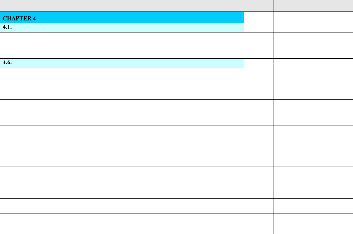
4.1.1 The safety review and approval process are covered in the NPR 8715.7 and allows for Range Safety approval processes.
A Payload Safety Introduction Briefing (PSIB) is typically the first meeting of the PSWG followed by other meetings to
complete Safety Review I, II, and III in accordance with NPR 8715.7. The PSIB shall cover the listed information in
Attachment A1.5 of this Volume.
Select Status
Equivalent Level of Safety (ELS) Determinations and Waivers
I
4.6.1. General. Payload projects shall identify the need for any potential Equivalent Level of Safety (ELS) determination
and/or waiver regarding requirements in this publication to PSWG and Range Safety for resolution. Potential ELS
determinations or waivers shall be identified and presented to the PSWG and Range Safety approval authority at the earliest
possible time. Details and requirements for submitting noncompliance requests can be found in Attachment A1.3 of this
volume.
Select Status
4.6.2. ELS Determination. The phrase “ELS” means an approximately equal level of safety. An ELS may involve a change
to the level of expected risk that is not statistically or mathematically significant as determined by qualitative or quantitative
risk analysis. ELS determination made by NASA and AFSPC ranges have been referred to in the past as meets intent
certifications. ELS determinations are normally incorporated during the tailoring process.
I
4.6.3. Waivers:
I
4.6.3.1. The term “waiver” refers to a decision that allows a payload project to continue with a launch, including launch
process, even though the payload project does not satisfy a specific safety requirement and is not able to demonstrate an ELS.
A waiver applies where a failure to satisfy a safety requirement involves a statistically or mathematically significant increase
in expected risk as determined through quantitative or qualitative risk analysis, and the activity may or may not exceed the
public risk criteria.
I
4.6.3.2. It is the policy of the NASA and the ranges to avoid the use of waivers. Waivers to the requirements shall be granted
only in extremely unique or compelling circumstances and only when the mission objectives of the payload project cannot
otherwise be achieved. PSWG, Range Safety, and the payload project shall jointly endeavor to ensure that all requirements
of this publication are met as early in the design and operation process as possible to limit the number of required waivers to
an absolute minimum.
Select Status
4.6.3.3. Waivers shall always have the effectivity designated. A "get-well" plan shall be required except for those with lifetime
effectivity.
Select Status
4.6.3.4. The FAA shall be included in the waiver process for licensed programs at USSF ranges per the memorandum of
agreement between Headquarters USSF and FAA/AST on Resolving Requests for Relief from Common Launch Safety
Requirements.
Select Status

Annex to NASA-STD-8719.24B Payload Project Name Rev: Basic
I – Information/Title N/A – Not Applicable C – Compliant T – Tailored NC – Noncompliant
Page 26 of 455
VOLUME 1: POLICIES AND PROCEDURE REQUIREMENTS
STATUS
TAILORED
TEXT
RATIONALE/
COMMENTS
4.6.3.5. The SLD Commanders shall approve or disapprove all waivers affecting public safety as defined in AFSPCMAN 91-
710, Volume 1, Chapter 3, Table 3.1 and Table 3.2, for a specific mission based on national or mission needs. When the
specific mission risks are greater than an expected casualty (Ec) of 300 x 10
-6
, the SLD Commanders shall advise the 14
AF/CC. Refer to AFSPCI 91-701 for risk approval levels. The latest prescribed Space Force noncompliance request format
shall be used.
Select Status
4.6.3.6. The Chiefs of Safety or their designated representatives shall approve or disapprove all USSF waivers other than
those affecting public safety.
Select Status
4.6.4. Submittal. The payload project shall submit all waiver requests for review and approval separately. ELS
determinations shall normally be documented as part of the tailoring process. All approved waivers and ELS determinations
shall be included in the appropriate safety data package.
Select Status
4.6.5. Every applicable waiver shall be reviewed for validity prior to each launch or launch cycle. The payload project shall
present a synopsis of each applicable waiver with the rationale concerning its viability for review and approval by Range
Safety and the PSWG.
Select Status

Annex to NASA-STD-8719.24B Payload Project Name Rev: Basic
I – Information/Title N/A – Not Applicable C – Compliant T – Tailored NC – Noncompliant
Page 27 of 455
VOLUME 1: POLICIES AND PROCEDURE REQUIREMENTS
STATUS
TAILORED
TEXT
RATIONALE/
COMMENTS
SAFETY AUTHORIZATIONS, SAFETY APPROVALS, AND
DOCUMENTATION
I
General
I
The overall safety review and approval process for NASA Payloads is contained in NPR 8715.7.
I
Annex to NASA-STD-8719.24B Payload Project Name Rev: Basic
I – Information/Title N/A – Not Applicable C – Compliant T – Tailored NC – Noncompliant
Page 28 of 455
VOLUME 1: POLICIES AND PROCEDURE REQUIREMENTS
STATUS
TAILORED
TEXT
RATIONALE/
COMMENTS
INVESTIGATING AND REPORTING MISHAPS AND INCIDENTS
I
Mishaps and Incidents Involving Space Force Personnel and Resources
I
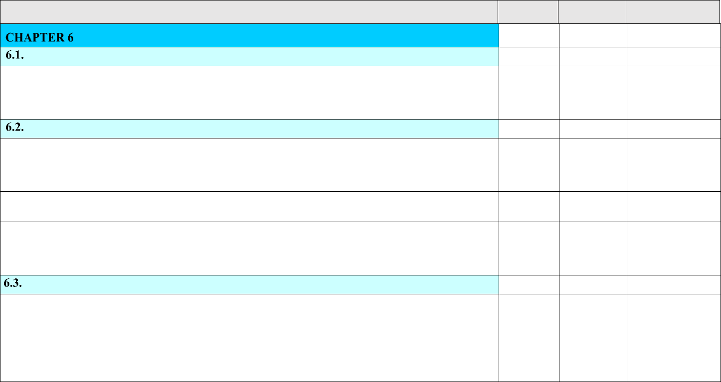
6.1.1. NPR 8621.1, NASA Procedural Requirements for Mishap and Close Call Reporting, Investigating, and Recordkeeping,
applies to all NASA mishaps and close calls. For mishaps and incidents occurring on a Space Force range, AFI 91-204, Safety
Investigations and Reports, also applies and the ranges shall investigate and report all mishaps and incidents involving USAF
personnel and resources.
Select Status
Non-Space Force Personnel and Resources on Space Force Property
I
6.2.1. The AFSPC ranges shall not report or investigate non-Space Force mishaps under AFI 91-204 auspices. However,
Range Safety shall assist and participate in non-Space Force mishap investigations that affect or could affect public safety,
launch area safety, or Space Force resources and may assist in non-Space Force mishap investigations that affect or could
affect launch complex safety or non-Space Force third party resources.
Select Status
6.2.2. The PSWG and Range Safety shall be provided with the investigation results of any mishaps or incidents occurring on
the ranges.
Select Status
6.2.3. Regardless of the payload project or Range User, the SLD Commander may conduct formal investigations into any
mishap and incident on Space Force property that affects or could affect public safety, launch area safety, or launch complex
safety. However, the scope of such an investigation into contractor mishaps is limited to the protection of the public, other
Range Users, and Space Force personnel and resources.
I
Reporting Space Launch System Anomalies
I
6.3.1. Any anomaly with potential safety implications and close calls shall be reported in accordance with NPR 8621.1, NASA
Procedural Requirements for Mishap and Close Call Reporting Investigating, and Recordkeeping. Any anomaly with potential
safety implications occurring in a system during prelaunch processing, launch, flight, or post-launch processing shall be
promptly reported to the PSWG and Range Safety for review. Anomalies occurring during launch, flight, or post-launch shall
be promptly reported to Range Safety and local safety authorities. Payload projects shall notify the PSWG and Range Safety
office of all anomaly reviews/meetings prior to the review/meeting and shall provide copies of the briefings, reports, meeting
minutes, and actions identified and taken to address the anomalies.
Select Status

Annex to NASA-STD-8719.24B Payload Project Name Rev: Basic
I – Information/Title N/A – Not Applicable C – Compliant T – Tailored NC – Noncompliant
Page 29 of 455
VOLUME 1: POLICIES AND PROCEDURE REQUIREMENTS
STATUS
TAILORED
TEXT
RATIONALE/
COMMENTS
CHANGES TO THIS PUBLICATION
I
7.1. This publication shall be updated as needed to coincide with updates to USSF 91-710, Range Safety and NASA
requirements and to incorporate document improvements. The latest version with any changes shall be provided on the NASA
Payload Safety Program website at https://kscsma.ksc.nasa.gov/PayloadSafety.
Select Status
7.2. Requests for changes to Annex to NASA-STD-8719.24 Revision B shall be submitted via a hot link on NASA Technical
Standards web page: https://standards.nasa.gov/standard/NASA/NASA-STD-871924-ANNEX.
Select Status
7.3. All changes to this publication shall first be coordinated jointly among the NASA Payload Safety Agency Team and the
Space Force Space Command Ranges (SLD 30 and SLD 45 Safety Offices). All affected NASA payload projects shall be
informed of any changes to this publication. The NASA Payload Safety Manager is responsible for keeping this document
current and incorporating changes.
Select Status
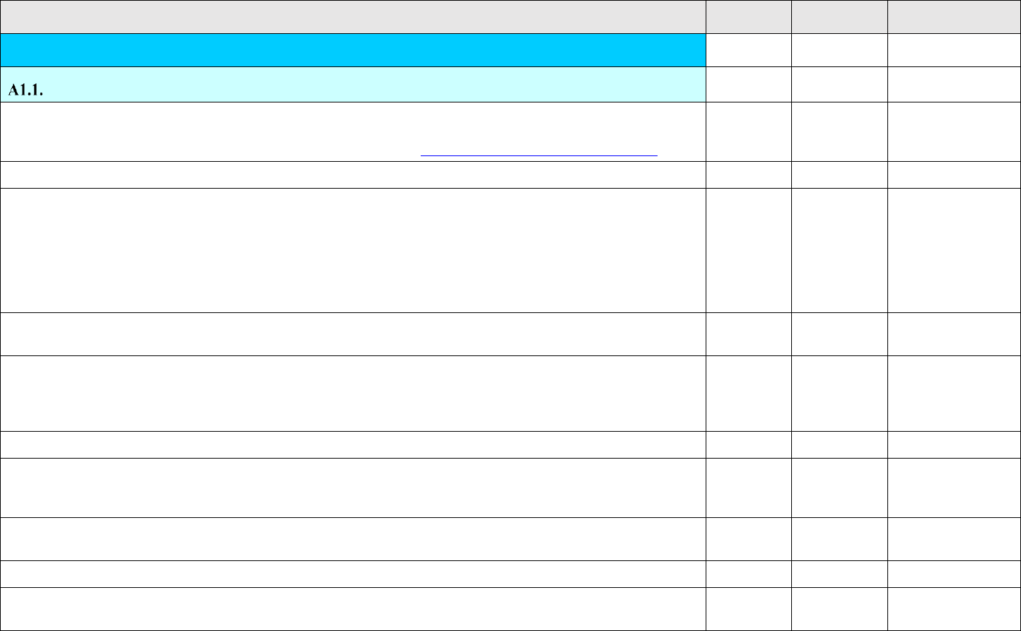
Annex to NASA-STD-8719.24B Payload Project Name Rev: Basic
I – Information/Title N/A – Not Applicable C – Compliant T – Tailored NC – Noncompliant
Page 30 of 455
VOLUME 1: POLICIES AND PROCEDURE REQUIREMENTS
STATUS
TAILORED
TEXT
RATIONALE/
COMMENTS
ATTACHMENT 1 POLICIES AND PROCEDURES
I
NASA PAYLOAD SAFETY REQUIREMENTS TAILORING PROCESS
I
A1.1.1. Scope. This attachment describes the rationale for tailoring, the tailoring process, and the requirements for
documenting tailored editions of the publication. This NASA Payload Safety Requirements tailoring matrix baseline
document may be found on the NASA Payload Safety Program website at https://kscsma.ksc.nasa.gov/PayloadSafety.
I
A1.1.2. Applicability. The tailoring process is applicable to all NASA Payload projects.
Select Status
A1.1.3. Purpose. Tailoring provides a means for formulating a specific edition of this publication, incorporating only those
requirements that apply to a particular project. Additionally, tailoring allows for the project to propose whether or not they
will meet the requirements as written or achieve an ELS through an acceptable alternative. A tailored version of the publication
is denoted by the project’s name in the title. Departures from this policy shall be approved by the PSWG and Range Safety.
Tailoring refers to the process used of assessing the applicability of requirements and evaluating the project’s potential
implementation in order to generate a set of specific requirements for the project. The tailored edition shall be placed on the
payload project’s contract, grants, cooperative agreements, or other agreements.
Select Status
A1.1.4. Formation of a Payload Safety Working Group. A PSWG shall be formed to assist the project as needed in
tailoring per this publication.
Select Status
A1.1.5. Tailoring Rationale. Tailoring shall be accomplished based on the following rationale described below. Alternative
means of identifying deletions, changes, additions, and payload project information are allowable provided that they are
distinguishable from the original text and each other and are mutually agreed to by the payload project, PSWG, and Range
Safety.
Select Status
A1.1.6. Deletion of a Requirement:
I
A1.1.6.1. When a requirement is going to be complied with and is applicable to the project, a “C” shall remain in the STATUS
column of the tailored document. When a requirement is not applicable to a specific payload project, then a “N/A” shall be
placed in the STATUS column and rationale provided under the RATIONALE/COMMENTS column.
Select Status
A1.1.6.2. The original paragraph number and headings shall remain, but the non-applicable text shall be identified with the
abbreviation N/A in the STATUS column with rationale provided in RATIONALE/COMMENTS column.
Select Status
A1.1.7. Change to a Requirement: Equivalent Level of Safety
I
A1.1.7.1. Equivalent Level of Safety (ELS) determinations may be provided and approved by the PSWG and Range Safety
through the change process.
I
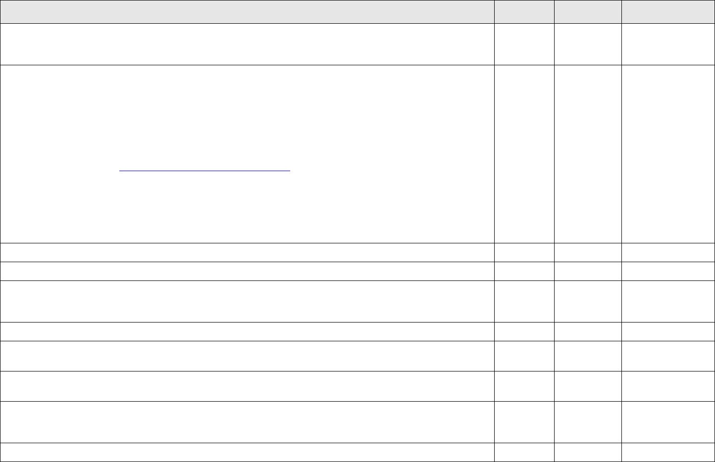
Annex to NASA-STD-8719.24B Payload Project Name Rev: Basic
I – Information/Title N/A – Not Applicable C – Compliant T – Tailored NC – Noncompliant
Page 31 of 455
VOLUME 1: POLICIES AND PROCEDURE REQUIREMENTS
STATUS
TAILORED
TEXT
RATIONALE/
COMMENTS
A1.1.7.2. A change is allowed to tailor the requirement to a particular system as long as the intent of the requirement is met
and the ELS is maintained. An “NC” for noncompliance shall be placed in the tailored STATUS column and sufficient
rationale is provided in the RATIONALE/COMMENTS column to allow for PSWG and Range Safety assessment.
I
A1.1.7.3. The change shall be fully captured by showing the entire new paragraph with the change in the TAILORED TEXT
column of the tailored document. When the change is an ELS, the abbreviation “NC” shall be placed in the STATUS column
of the tailored document following the paragraph number. The new paragraph with the change shall be provided under the
TAILORED TEXT column with sufficient rationale provided under the RATIONALE/COMMENTS column for PSWG and
Range Safety assessment. If additional space is needed for the rationale (i.e. to show analysis or data, or to provide lengthy
rationale) then an addendum to the tailored document should be used referencing the paragraph number. ELS’ that are
requested after the final project specific tailored document has been completed and signed shall be requested using the NASA
Payload Safety Post Tailoring Equivalent Level of Safety (ELS) Request NASA Form NF 1826 found on the NASA Payload
Safety Program website at https://kscsma.ksc.nasa.gov/PayloadSafety under the “Payload Safety Forms” button or an
equivalent form that contains all information required on NF 1826. When the change is merely an administrative change then
the abbreviation “T” shall be placed in the STATUS column of the tailored document after the paragraph number. The new
paragraph with the change shall be placed under the TAILORED TEXT column and rationale provided under the
RATIONALE/COMMENTS column. When the paragraph is not a requirement and is for information only the STATUS
column of the tailored shall be marked with an “I” and rationale provided if deemed necessary under the
RATIONALE/COMMENTS column.
Select Status
A1.1.7.4. The existing numbering system shall remain the same to the maximum extent possible.
Select Status
A1.1.7.5. Additional paragraphs may be added; however, using the remaining unaffected paragraph numbers is not allowed.
I
A1.1.7.6. All changes shall be captured in the TAILORED TEXT column of the project specific tailored document. All
changes shall be highlighted in bold. Deletions of text, including partial deletions, shall be shown with the original text marked
with strikethrough. Insertions of text, including partial insertions, shall be shown with the new text marked with underline.
Select Status
A1.1.8. Addition to a Requirement:
I
A1.1.8.1. An addition to a requirement is allowed when there are no existing requirements addressing new technology, when
unforeseen hazards are discovered, when federal or industry standards change, and for similar reasons.
Select Status
A1.1.8.2. An addition shall be added with new paragraph numbers in the section for which it is appropriate or in a new section
if no other section applies.
Select Status
A1.1.8.3. Additions shall be placed in the TAILORED TEXT column in the tailored document with a “T” placed in the
STATUS column and rationale provided under the RATIONALE/COMMENTS column. All changes shall be highlighted in
bold. Insertions/ additions of text, including partial insertions, shall be shown with the new text underlined.
Select Status
A1.1.9. Payload Project Information Only
I

Annex to NASA-STD-8719.24B Payload Project Name Rev: Basic
I – Information/Title N/A – Not Applicable C – Compliant T – Tailored NC – Noncompliant
Page 32 of 455
VOLUME 1: POLICIES AND PROCEDURE REQUIREMENTS
STATUS
TAILORED
TEXT
RATIONALE/
COMMENTS
A1.1.9.1. Requirements having only an indirect effect on the payload project, but which are still required of the project as a
whole shall remain in the tailored publication as information only. Examples of such requirements include Pad Safety
responsibilities, other range contractor responsibilities, and payload project facilities manager responsibilities.
Select Status
A1.1.10. Waivers
I
A1.1.10.1. Waivers are not rationale for the deletion of requirements. The requirements shall remain in the tailored document
and the waiver process shall be used for the disposition of the requirement. When a requirement is not going to be met and
there is a resultant increase in risk as determined by the PSWG in conjunction with Range Safety then a waiver request must
be submitted. If the waiver is approved, then a “NC” is placed in the STATUS column of the tailored document. The waiver
title and number(s) shall be placed under the RATIONALE/COMMENTS column. The NF 1827 NASA Payload Safety
Waiver Request may be found on the NASA Payload Safety Program website at https://kscsma.ksc.nasa.gov/PayloadSafety.
This form is used for all waivers. Additionally, if the waiver is impacting Space Force property and resources, then the LSRRR
(Launch Safety Requirements Relief Request) form shall be submitted, and the USSF 91-710, range safety user requirement
waiver process will be followed.
Select Status
A1.1.11. Risk-Cost Benefit Analysis:
I
A1.1.11.1. Technical issues regarding such items as applicable requirements, policy, criteria, or data may be evaluated on a
risk-cost benefit basis to determine if the risk is acceptable to waive the requirements.
I
A1.1.11.2. A risk-cost benefit analysis, based on the criteria defined in AFSPCMAN 91-710, Volume 1, Chapter 3, Table 3.1
and Chapter 3, Table 3.2 of this volume may be submitted to Range Safety.
I
A1.1.11.3. Based on risk-cost benefit analysis data, Range Safety and the Range User shall reach agreement on the disposition
of the requirement in question.
I
A1.1.11.4. If the application of a USSF 91-710 range safety user requirement, results in significant reduction in risk at a
significant cost benefit, it may be determined by Range Safety to be sufficient to impose the requirement; however, if the
benefit is insignificant and/or the cost is high, the requirement may be waived or determined to provide an ELS, all with
consideration for public safety.
I
A1.1.12. Preparation of a Project Specific Draft Tailored Edition of NASA Payload Safety Requirements document:
I
A1.1.12.1. The payload project shall produce a payload project mission specific draft edition of this document per NPR 8715.7
and this standard. The NASA Payload Safety Requirements tailoring matrix is found on the NASA Payload Safety Program
website at https://kscsma.ksc.nasa.gov/PayloadSafety.
Select Status
A1.1.12.2. The purpose of a draft project specific tailored matrix version is to eliminate all non-applicable requirements,
leaving only applicable requirements from which detailed tailoring can be performed and to allow for PSWG and Range Safety
review prior to finalizing.
Select Status

Annex to NASA-STD-8719.24B Payload Project Name Rev: Basic
I – Information/Title N/A – Not Applicable C – Compliant T – Tailored NC – Noncompliant
Page 33 of 455
VOLUME 1: POLICIES AND PROCEDURE REQUIREMENTS
STATUS
TAILORED
TEXT
RATIONALE/
COMMENTS
A1.1.12.3. The project specific draft shall be delivered to the PSWG as part of Safety Review I no later than 30 days prior to
the project’s mission PDR, in accordance with NPR 8715.7, Table 3-1. Overview of Deliverables for the Payload Safety
Process and Approvals.
Select Status
A1.1.13. Final Publication of the Project Specific NASA Payload Safety Requirements:
I
A1.1.13.1. The goal for final publication of the project specific tailored matrix is as soon as possible but should be no later
than 30 days prior to the project’s mission CDR or as scheduled by the PSWG (see NPR 8715.7 for deliverables schedule).
Tailoring can be an ongoing process and tailored documents should be considered living documents that may change
throughout the life of the project.
Select Status
A1.1.13.2. The tailoring process and delivery schedule is found in NPR 8715.7, Table 3-1. Overview of Deliverables for the
Payload Safety Process and Approvals.
I
A1.1.14. The tailored edition shall look like this NASA Payload Safety Requirements tailoring matrix with the
following exceptions:
Select Status
A1.1.14.1. The document title/heading on page 1 shall read, “NASA Payload Safety Requirements and the Payload Project
name. The “Payload Project Name” shall be centered at the top of each page.
Select Status
A1.1.14.2. The date of the applicable contract/CSOSA/agreement/etc. shall be shown under the title on page 1.
Select Status
A1.1.14.3. The date of the tailored edition shall be on the cover page of the document.
Select Status
A1.1.14.4. The information contained in the document is technical in content and may be proprietary as defined by the
International Traffic in Arms Regulations (ITAR) or by Export Administration Regulations (EAR) requirements. Each payload
project shall contact the NASA KSC Export Control Office, 321-867-9209, for an ITAR or EAR regulatory determination. If
not required delete this statement. The term "PROPRIETARY" shall be placed on page 1, centered directly over the
ITAR/EAR regulatory determination statement for each payload project.
Select Status
A1.1.14.5. All deleted information shall be marked as “N/A” under the STATUS column of the project’s tailored version of
this document.
Select Status
A1.1.15. Effectivity of Tailored Project Specific NASA Payload Safety Requirements document:
I
A1.1.15.1. Each project specific version of the NASA Payload Safety Requirements document shall contain a preface
paragraph detailing its effectivity.
Select Status
A1.1.15.2. At a minimum, the payload and the time period to which the project specific NASA Payload Safety Requirements
applies shall be addressed.
Select Status
A1.1.16. Assumptions:
I

Annex to NASA-STD-8719.24B Payload Project Name Rev: Basic
I – Information/Title N/A – Not Applicable C – Compliant T – Tailored NC – Noncompliant
Page 34 of 455
VOLUME 1: POLICIES AND PROCEDURE REQUIREMENTS
STATUS
TAILORED
TEXT
RATIONALE/
COMMENTS
A1.1.16.1. Each project specific tailored version of the NASA Payload Safety Requirements tailoring matrix shall contain a
preface paragraph detailing the critical assumptions that were made in writing the tailored edition.
Select Status
A1.1.16.2. The nature of the assumptions shall be such that a change may invalidate the tailored document or require a change
or update. An example of such a critical assumption is that the design of any hazardous system does not change from that
presented before publication of the project specific tailored document.
Select Status
A1.1.16.3. The assumption(s) described in the tailored document shall include sufficient detail to categorize the scope of the
tailored requirement to the specific systems or subsystems affected by the proposed change. If two or more
systems/subsystems are affected by the tailored paragraph, then the assumption(s) shall state which of those
systems/subsystems is intended to be included in the scope of the tailoring. If there is a difference in the tailoring for the two
or more systems/subsystems, then the tailored paragraph shall be repeated with appropriate tailoring unique to each individual
system/subsystem.
Select Status
A1.1.17. Approvals:
I
A1.1.17.1. Once completed and finalized the project specific Payload Safety Requirements shall be approved and signed by
the Project Manager (PM), the preparer, the project’s NASA SMA Technical Authority, Range Safety Representative, PSWG
Chairperson and others as deemed necessary by the PSWG in accordance with NPR 8715.7 and this standard. Once signed
each significant addition, change, or deletion shall be approved in accordance with this document and NPR 8715.7. Changes
that are ELS that come up after the tailoring was completed shall be recorded on NF 1826 NASA Payload Safety Post-Tailoring
Equivalent Level of Safety (ELS) Request or an equivalent form that contains all information required on NF 1826. Waivers
(increased risk changes) shall be recorded on the NF 1827 NASA Payload Safety Waiver Request. If deemed necessary by
the Space Force, an Space Force Relief request will also be required. The NASA Payload Safety ELS and Waiver Requests
as well as the Space Force Range Safety Relief Request are found on the NASA Payload Safety Program website under Forms
at https://kscsma.ksc.nasa.gov/PayloadSafety.
Select Status
A1.1.17.2. Each complete, final project-specific tailored document affecting public safety shall be approved and signed by
the SW Commander.
Select Status
A1.1.17.3. Any revisions to the project-specific tailored version of the NASA Payload Safety Requirements document shall
be made in accordance with NPR 8715.7 and USSF 91-710 change processes.
Select Status
Annex to NASA-STD-8719.24B Payload Project Name Rev: Basic
I – Information/Title N/A – Not Applicable C – Compliant T – Tailored NC – Noncompliant
Page 35 of 455
VOLUME 1: POLICIES AND PROCEDURE REQUIREMENTS
STATUS
TAILORED
TEXT
RATIONALE/
COMMENTS
ATTACHMENT 2 SAFETY PLAN REQUIREMENTS
I
INTRODUCTION
I
A2.1.1. Purpose. This attachment establishes the minimum requirements for a payload project’s System Safety Plan (SSP).
The payload project SSP shall be consistent with MIL-STD-882, Standard Practice for System Safety, Task 101, System
Safety Program Plan. The payload project SSP shall include the key system safety roles, responsibilities, and interfaces of the
payload contractor, NASA, and other relevant organizations. The program includes the corresponding requirements for a
payload project SSP and identifies hazard analysis and risk assessment requirements.
Select Status
A2.1.2. Tailoring. Tailoring of this attachment and the requisite SSP is highly recommended. The tailoring process is defined
in Attachment A1.1 of this volume. When conflicting requirements or deficiencies are identified in safety requirements the
payload project shall submit notification, with proposed solutions or alternatives and supporting rationale, to the PSWG and
Range Safety for resolution.
Select Status
A2.1.3. Demonstration of an Acceptable Level of Mishap Risk. Payload projects shall demonstrate an acceptable level of
mishap risk to the PSWG and Range Safety through the completion of the system safety hazard analyses and risk assessments
described in this attachment.
Select Status
SYSTEM SAFETY PLAN TASKS
I
A2.2.1. To achieve the system safety objectives and obtain the PSWG and Range Safety approval, the following tasks shall
be completed by the payload project in the approximate order that they are listed and in conjunction with the milestones that
are identified.
Select Status
A2.2.1.1. Task 1: Establish a Payload Project System Safety Plan. By the time of the payload project's Payload Safety
Introduction Briefing, the payload project shall have established a Safety Program documented in the project’s SSP (see
A2.2.2) that meets the tailored requirements of this publication which includes the following:
Select Status
A2.2.1.2. Project Manager (PM). Establishing a safety management system. The payload Project Manager (PM) shall be
responsible for the following:
Select Status
A2.2.1.2.1. Establishing, controlling, incorporating, directing, and implementing the system safety plan policies.
Select Status

Annex to NASA-STD-8719.24B Payload Project Name Rev: Basic
I – Information/Title N/A – Not Applicable C – Compliant T – Tailored NC – Noncompliant
Page 36 of 455
VOLUME 1: POLICIES AND PROCEDURE REQUIREMENTS
STATUS
TAILORED
TEXT
RATIONALE/
COMMENTS
A2.2.1.2.2. Ensuring that mishap risk is identified and eliminated or controlled within established program risk acceptability
parameters. Decisions regarding resolution of identified hazards shall be based on assessment of the risk involved. To aid in
the achievement of the objectives of system safety, hazards shall be characterized as to hazard severity categories and hazard
probability levels, when possible. Since the priority for system safety is eliminating hazards by design, a risk assessment
procedure, considering only hazard severity, will generally suffice during the early design phase to minimize risk. When
hazards are not eliminated during the early design phase, a risk assessment procedure based upon the hazard probability, hazard
severity, as well as risk impact, shall be used to establish priorities for corrective action and resolution of identified hazards.
All catastrophic and critical hazards shall be documented on the NASA Form NF 1825 NASA Payload Safety Hazard Report
(see A2.2.1.8.1) or an equivalent form that contains all information required on NF 1825.
Select Status
A2.2.1.2.3. Establishing internal reporting systems and procedures for investigation and disposition of system related mishaps
and safety incidents, including close calls involving flight hardware and ground support equipment and reporting such matters
as required by NPR 8621.1. See Volume 6, 4.6.2 for the Accident Notification Plan. For all such situations at the payload
processing facility and launch site area, the local safety authority and the PSWG Chairperson shall be contacted immediately
after initial mishap response. The SW Commander and NASA may conduct formal investigations into any mishap and
incident that affects or could affect public safety, launch area safety, or launch complex safety. However, the scope of such
an investigation into contractor mishaps is limited to the protection of the public, other payload projects, and Space Force
personnel and resources.
Select Status
A2.2.1.2.4. Reviewing and approving the safety analyses, reports, and documentation required by this publication and
submitted to the PSWG for the PSWG and Range Safety to establish knowledge and acceptance of residual risks.
Select Status
A2.2.1.3. Payload Project System Safety Engineer. Establishing a Payload Project System Safety Engineer safety position
for each project in accordance with NPR 8715.7. The individual in this position shall be directly responsible to the payload
Project Manager for safety matters. At a minimum, the Payload Project System Safety Engineer shall be responsible for the
requirements in NPR 8715.7 and for the following:
Select Status
A1.2.2.1.3.1. Reviewing and approving all safety analyses, reports, and documentation required by this publication and
submitted to PSWG for PSWG and Range Safety review and approval.
Select Status
A1.2.2.1.3.2. Reviewing and approving all hazardous and safety critical test plans and procedures and verifying that all safety
requirements are incorporated.
Select Status
A1.2.2.1.3.3. Developing a planned approach for safety task accomplishment, providing qualified people to accomplish the
tasks, establishing the authority for implementing the safety tasks through all levels of management, and allocating appropriate
resources, both manning and funding, to ensure the safety tasks are completed.
Select Status
A1.2.2.1.3.4. Establishing a system safety organization or function and lines of communication within the project organization
and with associated organizations (government and contractor).
Select Status
A2.2.1.3.5. Establishing interfaces between system safety and other functional elements of the project, as well as between
other safety disciplines such as nuclear, range, explosive, chemical, and biological.
Select Status

Annex to NASA-STD-8719.24B Payload Project Name Rev: Basic
I – Information/Title N/A – Not Applicable C – Compliant T – Tailored NC – Noncompliant
Page 37 of 455
VOLUME 1: POLICIES AND PROCEDURE REQUIREMENTS
STATUS
TAILORED
TEXT
RATIONALE/
COMMENTS
A2.2.1.3.6. Designating the organizational unit responsible for executing each safety task.
Select Status
A2.2.1.3.7. Establishing the authority for resolution of identified hazards.
Select Status
A2.2.1.3.8. Establishing a single closed-loop hazard tracking system by development of a method or procedure to document
and track hazards and their controls and providing an audit trail of hazard mitigation.
Select Status
A2.2.1.3.9. Maintaining and making available to the PSWG and Range Safety Hazard Reports of all identified hazards.
Hazard Reports shall be documented on NF 1825 NASA Payload Safety Hazard Report Form and instructions found on the
NASA Payload Safety Program website https://kscsma.ksc.nasa.gov/PayloadSafety under “Payload Safety Forms” or an
equivalent form that contains all information required on NF 1825. The payload project shall track until closed all open hazards
using a Safety Verification Tracking Log (SVTL), of which an example is also found on the NASA Payload Safety Program
website, to track identified hazards to closure. Establishing the order of precedence for satisfying system safety requirements
and resolving identified hazards as follows:
Select Status
A2.2.1.3.9.1. Designing for Minimum Risk. From program inception, design to eliminate hazards. If an identified hazard
cannot be eliminated, reduce the associated risk to an acceptable level, as defined by PSWG and Range Safety, through design
selection.
I
A2.2.1.3.9.2. Incorporating Safety Devices. If identified hazards cannot be eliminated or their associated risk reduced through
design selection, that risk shall be reduced to a level acceptable to the PSWG and Range Safety through the use of fixed,
automatic, or other protective safety design features or devices. Provisions shall be made for periodic functional checks of
safety devices when applicable.
Select Status
A2.2.1.3.9.3. Providing Warning Devices. When neither design nor safety devices can effectively eliminate identified hazards
or reduce associated risk, devices shall be used to detect the condition and to produce a warning signal to alert personnel of
the hazard. Warning signals and their application shall be designed to minimize the probability of incorrect personnel reaction
to the signals and shall be standardized within like types of systems.
Select Status
A2.2.1.3.9.4. Developing Procedures and Training. Where it is impractical to eliminate hazards through design selection or
reduce the associated risk with safety and warning devices, procedures and training may be used when acceptable to the PSWG
and Range Safety. Procedures may include the use of personal protective equipment. Precautionary notations shall be
standardized as specified by the PSWG and Range Safety. Tasks and activities judged to be safety critical by the PSWG and
Range Safety require certification of personnel proficiency.
Select Status
A2.2.1.3.9.5. Defining system safety plan milestones and relate them to major program milestones, project element
responsibility, and required inputs and outputs.
Select Status
A2.2.1.3.9.6. Establishing System Safety Plan reviews and audits.
Select Status
A2.2.1.3.9.7. Conducting, documenting, and making the following documentation available to the PSWG and Range Safety
upon request:
Select Status

Annex to NASA-STD-8719.24B Payload Project Name Rev: Basic
I – Information/Title N/A – Not Applicable C – Compliant T – Tailored NC – Noncompliant
Page 38 of 455
VOLUME 1: POLICIES AND PROCEDURE REQUIREMENTS
STATUS
TAILORED
TEXT
RATIONALE/
COMMENTS
A2.2.1.3.9.7.1. The payload project system safety plan and supporting risk assessment data.
Select Status
A2.2.1.3.9.7.2. Associate contractor system safety plan and supporting risk assessment data.
Select Status
A2.2.1.3.9.7.3. Support contractor system safety plan and supporting risk assessment data.
Select Status
A2.2.1.3.9.7.4. Subcontractor system safety plan and supporting risk assessment data.
Select Status
A2.2.1.3.9.7.5. Providing support for the following:
Select Status
A2.2.1.3.9.7.5.1. Safety reviews and audits performed by representatives of the PSWG, Payload Safety Agency Team, or
others.
Select Status
A2.2.1.3.9.7.5.2. Presentations to government certifying activities such as phase safety reviews, munitions safety boards,
nuclear safety boards, NPR 8715.26, NASA Nuclear Flight Safety program review or flight safety review boards to the extent
specified by this publication. These may also include special reviews such as flight and article readiness reviews or pre-
construction briefings.
Select Status
A2.2.1.3.9.7.6. Safety reviews shall be held in accordance with NPR 8715.7 and are in association with the project’s schedule
per NPR 7120.5. Generally, the safety reviews shall address the following:
Select Status
A2.2.1.3.9.7.6.1. Program systems and operations overview.
Select Status
A2.2.1.3.9.7.6.2. Presentation of required documentation and hazard analyses.
Select Status
A2.2.1.3.9.7.6.3. Noncompliances to the project specific tailored requirements.
Select Status
A2.2.1.3.9.7.6.4. Open safety issues.
Select Status
A2.2.1.3.9.8. Establishing an incident alert and notification, investigation, and reporting process, to include notification of the
PSWG Chairperson and Range Safety.
Select Status
A2.2.1.3.9.9. Establishing a process to evaluate engineering change proposals (ECPs), specification change notices (SCNs),
software problem reports (SPRs), program or software trouble reports (PTRs, STRs) for their safety impact on the system, and
notify the PSWG and Range Safety if the level of risk of the system changes.
Select Status

Annex to NASA-STD-8719.24B Payload Project Name Rev: Basic
I – Information/Title N/A – Not Applicable C – Compliant T – Tailored NC – Noncompliant
Page 39 of 455
VOLUME 1: POLICIES AND PROCEDURE REQUIREMENTS
STATUS
TAILORED
TEXT
RATIONALE/
COMMENTS
A2.2.2. Task 2: Develop a System Safety Plan. The payload project shall develop and implement a PSWG and Range
Safety approved System Safety Plan (SSP) encompassing the total safety program for payload design, production, processing
and testing, vehicle integration, and launch through payload separation from the launch vehicle. For any planned return-to-
earth recovery or sample return missions see Volume 6, section 4.7. The SSP shall describe in detail tasks and activities of
system safety management and system safety engineering required to identify, evaluate, and eliminate or control hazards, to
reduce the associated risk to a level acceptable to the PSWG and Range Safety. The plan provides a formal basis of
understanding between the payload project and the PSWG and Range Safety on how the SSP will be conducted to meet the
requirements of NPR 8715.7 and this publication. The plan shall account for all required tasks and responsibilities on an item-
by-item basis. The payload project shall submit a draft SSP to the PSWG, including Range Safety for review at the Payload
Safety Introduction Briefing. A final SSP shall be submitted no later than 30 days prior to project’s mission PDR, or as
scheduled by the PSWG, for review and approval (see NPR 8715.7 for review and approval process). The SSP shall comply
with this document and include the following information:
Select Status
A2.2.2.1. System Safety Organization. The System Safety Organization section shall describe the following:
Select Status
A2.2.2.1.1. The location of the system safety and flight safety analysis organizations or functions within the overall project
organization, using charts to show the organizational and functional relationships and lines of communication.
Select Status
A2.2.2.1.2. The organizational relationship between other project functional elements having responsibility for tasks with
range safety impacts and the system safety management and engineering organization.
Select Status
A2.2.2.1.3. Review and approval authority of applicable tasks by key system safety personnel.
Select Status
A2.2.2.1.4. The responsibility and authority of key system safety personnel, other payload project organizational elements
involved in the range safety effort, contractors, and system safety groups.
Select Status
A2.2.2.1.5. A description of the methods by which safety personnel may raise issues of concern directly to the Project Manager
(PM) or the project manager's supervisor within the corporate organization.
Select Status
A2.2.2.1.6. Identification of the organizational unit responsible for executing each task.
Select Status
A2.2.2.1.7. Identification of the authority in regard to resolution of all identified hazards.
Select Status
A2.2.2.1.8. The staffing of the system safety organization for the duration of the program to include personnel loading and a
summary of the qualifications of key system safety personnel assigned to the effort, including those personnel identified with
approval authority for the payload project prepared documentation.
Select Status
A2.2.2.1.9. The process by which the payload project management decisions will be made, including such decisions as timely
notification of unacceptable risks, necessary action, incidents, or malfunctions, or request for noncompliances to safety
requirements or project waivers.
Select Status
A2.2.2.1.10. Details of how resolution and action relative to system safety will be accomplished at the project management
level possessing resolution authority.
Select Status

Annex to NASA-STD-8719.24B Payload Project Name Rev: Basic
I – Information/Title N/A – Not Applicable C – Compliant T – Tailored NC – Noncompliant
Page 40 of 455
VOLUME 1: POLICIES AND PROCEDURE REQUIREMENTS
STATUS
TAILORED
TEXT
RATIONALE/
COMMENTS
A2.2.2.2. System Safety Plan Milestones. The SSP shall:
Select Status
A2.2.2.2.1. Define system safety project milestones and relate them to major project milestones, program element
responsibility, and required inputs and outputs.
Select Status
A2.2.2.2.2. Provide and maintain a program schedule of safety tasks, including start and completion dates, reports, and
reviews.
Select Status
A2.2.2.2.3. Identify subsystem, component, or software safety activities as well as integrated system level activities such as
design analyses, tests, and demonstrations applicable to the SSP but specified in other engineering studies and development
efforts to preclude duplication.
Select Status
A2.2.2.3. System Safety Data. The SSP shall:
Select Status
A2.2.2.3.1. Identify deliverable data by title, number, and means of delivery such as hard copy or electronic submission.
Note: NPR 8715.7, this publication and MIL-STD-882 provide initial Data Item Descriptions and deliverables
identification. Electronic submittals are preferred, and secure websites shall be used to allow for PSWG and Range Safety
review.
Select Status
A2.2.2.3.2. Identify non-deliverable system safety data and describe the procedures for accessibility by the PSWG and Range
Safety and retention of data of historical value.
Select Status
A2.2.2.4. System Safety Interfaces. The SSP shall identify, in detail:
Select Status
A2.2.2.4.1. The interface between system safety and all other applicable safety disciplines such as USSF Range Safety, NASA
Range Safety, the NASA Nuclear Flight Safety Officer (NFSO), the NASA Center safety, local facility safety, explosive and
ordnance safety, chemical and biological safety, laser safety, and any others.
Select Status
A2.2.2.4.2. The interface between system safety, design and/or systems engineering, and all other support disciplines such as
maintainability, quality control, reliability, software development, human factors engineering, occupational health support
(health hazard assessments), and any others.
Select Status
A2.2.2.4.3. The interface between system safety and all system integration and test disciplines.
Select Status

Annex to NASA-STD-8719.24B Payload Project Name Rev: Basic
I – Information/Title N/A – Not Applicable C – Compliant T – Tailored NC – Noncompliant
Page 41 of 455
VOLUME 1: POLICIES AND PROCEDURE REQUIREMENTS
STATUS
TAILORED
TEXT
RATIONALE/
COMMENTS
A2.2.3. Task 3: Perform and Document a Preliminary Hazard Analysis. The payload project shall perform and document
a preliminary hazard analysis (PHA) to identify safety critical areas, to provide an initial assessment of hazards, and to identify
requisite hazard controls and follow-on actions. A preliminary hazard list shall be provided at the Payload Safety Introduction
Briefing (PSIB). The results of the PHA shall be submitted with the SDP I (preliminary MSPSP) for the project’s mission
PDR Safety Review 1 meeting in accordance with NPR 8715.7. Based on the best available data, including mishap data from
similar systems and other lessons learned, hazards associated with the proposed design or function shall be evaluated for
hazard severity, hazard probability, and operational constraint. Safety and health studies identifying provisions and
alternatives needed to eliminate hazards or reduce their associated risk to a level acceptable to the PSWG and Range Safety
shall be included. Hazards identified shall be documented on the NF1825 NASA Payload Safety Hazard Report found on the
NASA Payload Safety Program website at https://kscsma.ksc.nasa.gov/PayloadSafety or an equivalent form that contains all
information required on NF 1825. At a minimum, the PHA shall consider the following for identification and evaluation of
hazards:
Select Status
A2.2.3.1. Hazardous components such as fuels, propellants, lasers, explosives, toxic substances, hazardous construction
materials, pressure systems, and other energy sources.
Select Status
A2.2.3.2. Safety related interface considerations among various elements of the system such as material compatibility,
electromagnetic interference, inadvertent activation, fire and explosive initiation and propagation, and hardware and software
controls. This shall include consideration of the potential contribution by software, including software developed by other
contractors and sources, to subsystem and system mishaps.
Select Status
A2.2.3.3. Safety design criteria to control safety-critical software commands and responses such as inadvertent command,
failure to command, untimely command or responses, inappropriate magnitude, or designated undesired events shall be
identified and appropriate action taken to incorporate them in the software and related hardware specifications.
Select Status
A2.2.3.4. Environmental constraints including the operating environments such as drop, shock, vibration, extreme
temperatures, humidity, noise, exposure to toxic substances, health hazards, fire, electrostatic discharge, lightning,
electromagnetic environmental effects, ionizing and non-ionizing radiation including laser radiation.
Select Status
A2.2.3.5. Operating, test, maintenance, built-in-tests, diagnostics, and emergency procedures (human factors engineering,
human error analysis of operator functions, tasks, and requirements; effect of factors such as equipment layout, lighting
requirements, potential exposures to toxic materials, effects of noise or radiation on human performance; explosive ordnance
render safe and emergency disposal procedures; life support requirements and their safety implications in manned systems,
crash safety, egress, rescue, survival, and salvage).
Select Status
A2.2.3.6. Those test unique hazards that will be a direct result of the test and evaluation of the article or vehicle.
Select Status
A2.2.3.7. Facilities, real property installed equipment, support equipment such as provisions for storage, assembly, checkout,
proof testing of hazardous systems and assemblies that may involve toxic, flammable, explosive, corrosive, or cryogenic
materials and wastes; radiation or noise emitters; electrical power sources.
Select Status

Annex to NASA-STD-8719.24B Payload Project Name Rev: Basic
I – Information/Title N/A – Not Applicable C – Compliant T – Tailored NC – Noncompliant
Page 42 of 455
VOLUME 1: POLICIES AND PROCEDURE REQUIREMENTS
STATUS
TAILORED
TEXT
RATIONALE/
COMMENTS
A2.2.3.8. Training and certification pertaining to hazardous and safety critical operations and maintenance of hazardous and
safety critical systems.
Select Status
A2.2.3.9. Safety related equipment, safeguards, and possible alternate approaches such as interlocks; system redundancy; fail-
safe design considerations using hardware or software controls; subsystem protection; fire detection and suppression systems;
personal protective equipment; heating, ventilation, and air-conditioning; and noise or radiation barriers.
Select Status
A2.2.3.10. Malfunctions to the system, subsystems, or software. Each malfunction shall be specified, the cause and resulting
sequence of events determined, the degree of hazard determined, and appropriate specification and/or design changes
developed.
Select Status
A2.2.4. Task 4: Perform and Document Subsystem, System, Facility, and Operating and Support Hazard Analyses:
Select Status
A2.2.4.1. Subsystem Hazard Analysis - The payload project shall perform and document a subsystem hazard analysis
(SSHA) to identify all components and equipment that could result in a hazard or whose design does not satisfy safety
requirements. The purpose of the SSHA is to verify subsystem compliance with safety requirements contained in subsystem
specifications and other applicable documents; identify previously unidentified hazards associated with the design of
subsystems including component failure modes, critical human error inputs, and hazards resulting from functional
relationships between components and equipment comprising each subsystem; and recommend actions necessary to eliminate
identified hazards or control their associated risk to acceptable levels. The SSHA shall include government furnished
equipment, non-developmental items, and software. Areas to consider are performance, performance degradation, functional
failures, timing errors, design errors or defects, or inadvertent functioning. The human shall be considered a component within
a subsystem, receiving both inputs, and initiating outputs, during the conduct of this analysis. The SSHA may indicate the
need for revised tailoring of some requirements of this publication depending on the level of risk identified or the discovery
of any previously unidentified hazards. Hazards identified shall be documented on the NF 1825 NASA Payload Safety Hazard
Report found on the NASA Payload Safety Program website at https://kscsma.ksc.nasa.gov/PayloadSafety or an equivalent
form that contains all information required on NF 1825. The analysis shall include a determination of the following:
Select Status
A2.2.4.1.1. The modes of failure that could impact safety including reasonable human errors as well as single point and
common mode failures, and the effects on safety when failures occur in subsystem components.
Select Status
A2.2.4.1.2. The potential contribution of hardware and software, including that which is developed by other contractors and
sources, events, faults, and occurrences such as improper timing on the safety of the subsystem.
Select Status
A2.2.4.1.3. That the safety design criteria in the hardware, software, and facilities specifications have been satisfied.
Select Status
A2.2.4.1.4. A general assertion that the method of implementation of hardware, software, and facilities design requirements
and corrective actions has not impaired or decreased the safety of the subsystem nor has it introduced any new hazards or
risks.
Select Status

Annex to NASA-STD-8719.24B Payload Project Name Rev: Basic
I – Information/Title N/A – Not Applicable C – Compliant T – Tailored NC – Noncompliant
Page 43 of 455
VOLUME 1: POLICIES AND PROCEDURE REQUIREMENTS
STATUS
TAILORED
TEXT
RATIONALE/
COMMENTS
A2.2.4.1.5. The implementation of safety design requirements from top level specifications to detailed design specifications
for the subsystem. The implementation of safety design requirements developed as part of the PHA shall be analyzed to ensure
that it satisfies the intent of the requirements.
Select Status
A2.2.4.1.6. Test plan and procedure recommendations to integrate safety testing into the hardware and software test programs.
Select Status
A2.2.4.1.7. That system level hazards attributed to the subsystem are analyzed and control of the potential hazard is
implemented in the design.
Select Status
A2.2.4.1.8. SSHA Analysis Techniques. If no specific analysis techniques are directed or if the payload project recommends
that a different technique other than that specified by the PSWG and Range Safety should be used, the payload project shall
obtain approval of techniques to be used before performing the analysis.
Select Status
A2.2.4.1.9. SSHA Software:
I
A2.2.4.1.9.1. Software used to control safety critical computer system functions shall be developed in accordance with
Volume 3, Chapter 16 of this publication. Safety related software problems detected during or after software verification (and
prior to launch) shall be reported to the PSWG and Range Safety in time to support the ongoing phase of the software
development process.
Select Status
A2.2.4.1.9.2. Payload projects shall identify all safety critical computer system functions in accordance with Volume 3,
Chapter 16 and develop a SSHA for each.
Select Status
A2.2.4.1.9.3. Software shall be put under formal configuration control of a Software Configuration Control Board (SCCB) in
accordance with Volume 3, Chapter 16 as soon as a baseline is established. This will ensure that hardware/software changes
do not conflict with or introduce potential safety hazards due to hardware/software incompatibilities.
Select Status
A2.2.4.1.9.4. Safety-critical software, as defined per NASA-STD-8739.8, NASA Software Assurance and Software Safety
Standard, that have problems identified during or after software verification (and prior to launch) shall be reported to the
PSWG and Range Safety.
Select Status
A2.2.4.1.10. Updating the SSHA. The payload project shall update the SSHA as a result of any system design changes,
including software design changes that affect system safety.
Select Status
A2.2.4.1.11 SSHA Submittal. A draft SSHA shall be submitted with or included in Safety Data Package II (updated MSPSP)
no later than 30 days prior to project’s mission CDR and the finalized SSHA shall be submitted with or included in Safety
Data Package III (final MSPSP) (See Attachment V3.1 of Volume 3).
Select Status

Annex to NASA-STD-8719.24B Payload Project Name Rev: Basic
I – Information/Title N/A – Not Applicable C – Compliant T – Tailored NC – Noncompliant
Page 44 of 455
VOLUME 1: POLICIES AND PROCEDURE REQUIREMENTS
STATUS
TAILORED
TEXT
RATIONALE/
COMMENTS
A2.2.4.2. System Hazard Analysis. The payload project shall perform and document a system hazard analysis (SHA) to
identify hazards and make a general determination of the safety risk posture of the total system design, including software,
and specifically of the subsystem interfaces. The purpose of the SHA is to verify system compliance with safety requirements
contained in system specifications and other applicable documents; identify previously unidentified hazards associated with
the subsystem interfaces and system functional faults; assess the risk associated with the total system design, including
software, and specifically of the subsystem interfaces; and recommend actions necessary to eliminate identified hazards and/or
control their associated risk to acceptable levels. The SHA may indicate the need for revised tailoring of some requirements
of this publication depending on the level of risk identified or the discovery of any previously unidentified hazards. This
analysis shall include a review of subsystem interrelationships to determine the following:
Select Status
A2.2.4.2.1. Compliance with specified safety design criteria.
Select Status
A2.2.4.2.2. Possible independent, dependent, and simultaneous hazardous events including system failures; failures of safety
devices; common cause failures and events; and system interactions that could create a hazard or result in an increase in mishap
risk.
Select Status
A2.2.4.2.3. Degradation in the safety of a subsystem or the total system from normal operation of another subsystem.
Select Status
A2.2.4.2.4. Design changes that affect subsystems.
Select Status
A2.2.4.2.5. Effects of reasonable human errors.
Select Status
A2.2.4.2.6. Potential contribution of hardware and software, including that which is developed by other payload projects and
other sources or commercial off-the-shelf hardware or software, events, faults, and occurrences such as improper timing on
the safety of the system.
Select Status
A2.2.4.2.7. That the safety design criteria in the hardware, software, and facilities specifications have been satisfied.
Select Status
A2.2.4.2.8. That the method of implementation of the hardware, software, and facilities design requirements and corrective
actions has not impaired or degraded the safety of the system nor has introduced any new hazards.
Select Status
A2.2.4.2.9. SHA Analysis Techniques. If no specific analysis techniques are directed or if the payload project recommends
that a different technique than that specified by the PSWG and Range Safety should be used, the payload project shall obtain
approval of techniques to be used before performing the analysis. The SHA may be combined with and/or performed using
similar techniques to those used for the SSHA.
Select Status
A2.2.4.2.10. SHA Software:
I
A2.2.4.2.10.1. Software used to control safety critical computer system functions shall be developed in accordance with
Volume 3, Chapter 16 of this publication.
Select Status
A2.2.4.2.10.2. Payload projects shall identify all safety critical computer system functions in accordance with Volume 3,
Chapter 16 and develop a SHA for each.
Select Status

Annex to NASA-STD-8719.24B Payload Project Name Rev: Basic
I – Information/Title N/A – Not Applicable C – Compliant T – Tailored NC – Noncompliant
Page 45 of 455
VOLUME 1: POLICIES AND PROCEDURE REQUIREMENTS
STATUS
TAILORED
TEXT
RATIONALE/
COMMENTS
A2.2.4.2.10.3. Software shall be put under formal configuration control of a Software Configuration Control Board (SCCB)
in accordance with Volume 3, Chapter 16 as soon as a baseline is established. This will ensure that hardware/software changes
do not conflict with or introduce potential safety hazards due to hardware/software incompatibilities.
Select Status
A2.2.4.2.10.4. Problems identified that require the reaction of the software developer shall be reported to Range Safety in
time to support the ongoing phase of the software development process.
Select Status
A2.2.4.2.11. Updating the SHA. The payload project shall update the SHA as a result of any system design changes, including
software design changes that affect system safety.
Select Status
A2.2.4.2.12. SHA Submittal. A draft SHA shall be submitted with or in Safety Data Package II (updated MSPSP) no later
than 30 days prior to project’s mission CDR and the finalized SHA shall be submitted with or included in the Safety Data
Package III (final MSPSP) (See Volume 3, Attachment A1).
Select Status
A2.2.4.3. Operating and Support Hazard Analyses. The payload project shall perform and document an operating and
support hazard analysis (O&SHA) to examine procedurally controlled activities. The purpose of the O&SHA is to evaluate
activities for hazards or risks introduced into the system by operational and support procedures and to evaluate adequacy of
operational and support procedures used to eliminate, control, or abate identified hazards or risks. The O&SHA identifies and
evaluates hazards resulting from the implementation of operations or tasks performed by persons, considering the following
criteria: the planned system configuration and/or state at each phase of activity; the facility interfaces; the planned
environments or the ranges thereof; the supporting tools or other equipment, including software controlled automatic test
equipment, specified for use; operational and/or task sequence, concurrent task effects and limitations; biotechnological
factors, regulatory or contractually specified personnel safety and health requirements; and the potential for unplanned events
including hazards introduced by human errors. The human shall be considered an element of the total system, receiving both
inputs and initiating outputs during the conduct of this analysis. The O&SHA shall identify the safety and occupational health
requirements, or alternatives needed to eliminate, or control identified hazards or to reduce the associated risk to a level that
is acceptable under either regulatory or local specified criteria. The O&SHA may indicate the need for revised tailoring of
some requirements of this publication depending on the level of risk identified or the discovery of any previously unidentified
hazards. Hazards identified shall be documented on the NF 1825 NASA Payload Safety Hazard Report found on the NASA
Payload Safety Program website at https://kscsma.ksc.nasa.gov/PayloadSafety or an equivalent form that contains all
information required on NF 1825. The analysis shall identify the following:
Select Status
A1.2.2.4.3.1. Activities that occur under hazardous conditions, their time periods, and the actions required to minimize risk
during these activities and time periods.
Select Status
A2.2.4.3.2. Changes needed in functional or design requirements for system hardware and software, facilities, tooling, or
support and test equipment to eliminate or control hazards or reduce associated risks.
Select Status
A2.2.4.3.3. Requirements for safety devices and equipment, including personnel safety and life support equipment.
Select Status

Annex to NASA-STD-8719.24B Payload Project Name Rev: Basic
I – Information/Title N/A – Not Applicable C – Compliant T – Tailored NC – Noncompliant
Page 46 of 455
VOLUME 1: POLICIES AND PROCEDURE REQUIREMENTS
STATUS
TAILORED
TEXT
RATIONALE/
COMMENTS
A2.2.4.3.4. Warnings, cautions, and special emergency procedures such as egress, rescue, escape, render safe, explosive
ordnance disposal, and back out, including those necessitated by failure of a computer software-controlled operation to produce
the expected and required safe result or indication.
Select Status
A2.2.4.3.5. Requirements for packaging, handling, storage, transportation, maintenance, and disposal of hazardous materials.
Select Status
A2.2.4.3.6. Requirements for safety training and personnel certification.
Select Status
A2.2.4.3.7. Effects of non-developmental hardware and software across the interface with other system components or
subsystems.
Select Status
A2.2.4.3.8. Potentially hazardous system states under operator control.
Select Status
A2.2.4.3.9. Assessment of Procedures. The O&SHA shall document system safety assessment of procedures involved in
system production, deployment, installation, assembly, test, operation, maintenance, servicing, transportation, storage,
modification, demilitarization, and disposal.
Select Status
A2.2.4.3.10. O&SHA Analysis Techniques. If no specific analysis techniques are directed or if the payload project
recommends that a different technique other than that specified by the PSWG and Range Safety should be used, the Range
User shall obtain approval of techniques to be used before performing the analysis.
Select Status
A2.2.4.3.11. Updating the O&SHA. The payload project shall update the O&SHA as a result of any system design or
operational changes.
Select Status
A2.2.4.3.12. O&SHA Submittal. A draft O&SHA shall be submitted as part of Safety Data Package III at least 90 days
prior to the payload shipment to the processing site and finalized as part of Safety Review III (See Attachment A2.1 of Volume
6).
Select Status
A2.2.5. Task 5: Perform and Document an Overall Payload Project Safety Assessment. The payload project shall
perform and document an overall Safety Assessment. The purpose of this task is to perform and document a comprehensive
evaluation of the mishap risk being assumed before payload processing or testing with considering all potential hazards. The
Safety Assessment shall be developed using data from the hazard analyses required in Task 4 (A2.2.4) and data packages
required by this publication and NPR 8715.7, and shall summarize the following information:
Select Status
A2.2.5.1. The safety criteria and methodology used to classify and rank hazards, plus any assumptions on which the criteria
or methodologies were based or derived including the definition of acceptable risk as specified by the PSWG and Range
Safety.
Select Status
A2.2.5.2. The results of analyses performed to identify hazards inherent in the system, including those hazards that still have
a residual risk and the actions that have been taken to reduce the associated risk to a level specified as acceptable by the PSWG
and Range Safety. See Table 3.2 of this volume.
Select Status

Annex to NASA-STD-8719.24B Payload Project Name Rev: Basic
I – Information/Title N/A – Not Applicable C – Compliant T – Tailored NC – Noncompliant
Page 47 of 455
VOLUME 1: POLICIES AND PROCEDURE REQUIREMENTS
STATUS
TAILORED
TEXT
RATIONALE/
COMMENTS
A2.2.5.3. The results of the safety program efforts, including a list of all significant hazards along with specific safety
recommendations or precautions required to ensure safety of personnel, property, or the environment. The list shall be
categorized as to whether or not the risks may be expected under normal or abnormal operating conditions.
Select Status
A2.2.5.4. Conclusion with the payload project safety manager and the payload Project Manager signed statement that all
identified hazards have been eliminated or their associated risks controlled to levels acceptable to the PSWG and Range Safety
and that the payload and its systems are ready to test and ready for payload processing.
Select Status
A2.2.5.5. Recommendations applicable to hazards at the interface of payload project systems with other systems, as required.
Select Status
A2.2.5.6. A formal request for approval to conduct operations at the payload processing facility and the range.
Select Status
Annex to NASA-STD-8719.24B Payload Project Name Rev: Basic
I – Information/Title N/A – Not Applicable C – Compliant T – Tailored NC – Noncompliant
Page 48 of 455
VOLUME 1: POLICIES AND PROCEDURE REQUIREMENTS
STATUS
TAILORED
TEXT
RATIONALE/
COMMENTS
ATTACHMENT 3 SUBMITTING NONCOMPLIANCE REQUESTS
I
INTRODUCTION
I
A3.1.1. Purpose. Equivalent levels of safety (ELS) and waivers are used when payload projects cannot meet the requirements
of this publication.
I
A3.1.2. Content. This attachment describes the noncompliance categories and the process for submitting ELSs and waivers.
I
A3.1.3. Applicability:
I
A3.1.3.1. The noncompliance process is applicable to all projects and is provided as the waiver process in NPR 8715.7 for
NASA waivers and for AF Range Safety noncompliances follow USSF 91-710. The PSWG will provide guidance on these
noncompliance and waiver processes.
I
A3.1.3.3. The flight plan approval process does not fall within the intent of this attachment except when it involves launch
vehicle and/or payload hardware.
I
A3.1.4. Grandfathering Criteria. Previously approved systems with or without granted ELSs and waivers are required to
be resubmitted for review and approval by the project specific PSWG and Range Safety.
Select Status
A3.1.5. Noncompliance Categories. Noncompliances shall be processed and approved by NASA in accordance with NPR
8715.7 and this publication. In addition, noncompliances impacting Space Force Range Safety responsibilities shall be
submitted to the PSWG to be processed and approved by the Space Force in accordance with the following:
Select Status
A3.1.5.1. Public Safety. Public safety noncompliance deals with safety requirements involving risks to the public, including
foreign countries, their personnel, and/or their resources.
Select Status
A3.1.5.2. Launch Area Safety. Launch area safety noncompliances deal with safety requirements involving risks that are
limited to personnel and/or resources on AFSPC ranges, including CCSFS and VSFB and may be extended to KSC. Launch
area safety involves multiple licensed users, government tenants, or USAF squadrons.
Select Status
A3.1.5.3. Launch Complex Safety. Launch complex safety noncompliances deal with safety requirements involving risk
that is limited to the personnel and/or resources under the control of a single licensed user, full time government tenant
organization, or USAF squadron/detachment (control authority). Launch complex safety is limited to risks confined to a
physical space for which the single control authority is responsible.
Select Status
A3.1.6. Effectivity of Noncompliances: Duration of the noncompliance (if approved) shall be stated on the noncompliance
request.
Select Status
A3.1.7. Conditions for Issuance of ELSs and Waivers:
I
Annex to NASA-STD-8719.24B Payload Project Name Rev: Basic
I – Information/Title N/A – Not Applicable C – Compliant T – Tailored NC – Noncompliant
Page 49 of 455
VOLUME 1: POLICIES AND PROCEDURE REQUIREMENTS
STATUS
TAILORED
TEXT
RATIONALE/
COMMENTS
A3.1.7.1. Hazard Mitigation. All reasonable steps shall be taken to meet the intent of the publication requirements and
mitigate associated hazards to acceptable levels, including design and operational methods.
Select Status
A3.1.8. Risk-Cost Benefit Analysis: When required, a risk-cost benefit analysis, based on the criteria defined in AFSPCMAN
91-710, Volume 1, Chapter 3, Table 3.1 and Chapter 3, Table 3.2 of this volume, may be submitted to Range Safety.
I
SUBMITTING NONCOMPLIANCE REQUESTS
I
A3.2.1. Format. ELSs proposed during project specific NASA Payload Safety Requirements tailoring do not require the
submittal of NF 1826 NASA Payload Safety Post-Tailoring Equivalent Level of Safety (ELS) Request (See Attachment A1.1
of this Volume). Payload projects shall submit noncompliances to the PSWG in writing using the approved NASA
noncompliance forms, NF 1826 NASA Payload Safety Post-Tailoring Equivalent Level of Safety (ELS) Request, or an
equivalent form, that contains all information required on NF 1826, and NF 1827 NASA Payload Safety Waiver Request.
Additionally, the payload project shall submit the appropriate Space Force noncompliance relief request for all
noncompliances to USSF 91-710 impacting Space Force Ranges. These forms are found on the Payload Safety Program
website at https://kscsma.ksc.nasa.gov/PayloadSafety under the "Payload Safety Forms" button.
Select Status
A3.2.3. Process: The PSWG in conjunction with Range Safety can provide guidance in the noncompliance submittal process.
NASA noncompliance process is found in NPR 8715.7 and this publication. The Space Force noncompliance process is as
follows:
Select Status
A3.2.3.1. Requests for ELS s and waivers shall be submitted through the PSWG to the appropriate local safety authority.
ELSs or waivers impacting USSF Range Safety shall be submitted through the PSWG to the office of the appropriate Space
Wing Chief of Safety as early as they are known to be necessary.
Select Status
A3.2.3.2. Public safety ELSs and waivers such as those including flight plan approval, FTS design, and toxic propellant
storage normally require extensive risk analyses that can take one to two years to perform; therefore, these ELSs and waivers
shall be initiated during the planning phase and be closed out by Range Safety (ELSs) or the Space Wing Commander (waivers)
approval or design change before manufacture of the booster, spacecraft, FTS, or other system in question.
Select Status
A3.2.3.3. Launch area safety and launch complex safety ELSs and waivers normally require two weeks to two months to
process depending on the nature of the noncompliance and the requested effectivity.
I
A3.2.3.4. The Space Wing shall coordinate all noncompliance requests with affected agencies, as appropriate. A coordinated
review and resolution of requests for relief from common AF-FAA launch safety requirements shall be per procedures
developed between the AFSPC and the FAA. The Space Wing shall also coordinate all noncompliance requests with the
affected Range User.
I
A3.2.4. Approvals: The PSWG in conjunction with Range Safety can provide guidance on the noncompliance approval
process. NASA noncompliances shall be approved in accordance with NPR 8715.7. The Space Force s approvals are as
follows:
Select Status

Annex to NASA-STD-8719.24B Payload Project Name Rev: Basic
I – Information/Title N/A – Not Applicable C – Compliant T – Tailored NC – Noncompliant
Page 50 of 455
VOLUME 1: POLICIES AND PROCEDURE REQUIREMENTS
STATUS
TAILORED
TEXT
RATIONALE/
COMMENTS
A3.2.4.1. Programs launching from only the ER or WR require only the appropriate SLD30/SE or SLD45/SE approvals.
Select Status
A3.2.4.2. Programs launching from both ranges require approvals from SLD30/SE or SLD45/SE.
Select Status
A3.2.4.3. Waivers dealing with public safety shall be approved by the SLD Commanders.
Select Status
A3.2.4.4. Waivers other than public safety shall be approved by the Chiefs of Safety or their designated representatives.
Select Status
A3.2.4.5. ELSs shall be approved by appropriate SLD30/SE or SLD45/SE Chiefs of Safety or their designated representatives.
Select Status

Annex to NASA-STD-8719.24B Payload Project Name Rev: Basic
I – Information/Title N/A – Not Applicable C – Compliant T – Tailored NC – Noncompliant
Page 51 of 455
VOLUME 1: POLICIES AND PROCEDURE REQUIREMENTS
STATUS
TAILORED
TEXT
RATIONALE/
COMMENTS
ATTACHMENT 4 ACCEPTABLE RISK CRITERIA
I
INTRODUCTION
I
Per NPR 7120.5, NASA Space Flight Program and Project Management Processes and Requirements, the payload project will
implement the NASA continuous risk management process and develop a stand-alone Risk Management Plan that includes
the content required by NPR 8000.4, Risk Management Procedural Requirements. The payload project shall follow KSC’s
Safety and Mission Assurance Launch Services Division Risk Management System for risks impacting NASA KSC or KSC
contracted facilities and shall apply USSF 91-710 for risks impacting Space Force Ranges.
Note: See Volume 1 Chapter 3 of this document and NASA Payload Safety Hazard Report NF 1825 for additional guidance.
Select Status

Annex to NASA-STD-8719.24B Payload Project Name Rev: Basic
I – Information/Title N/A – Not Applicable C – Compliant T – Tailored NC – Noncompliant
Page 52 of 455
VOLUME 1: POLICIES AND PROCEDURE REQUIREMENTS
STATUS
TAILORED
TEXT
RATIONALE/
COMMENTS
ATTACHMENT 5 PAYLOAD SAFETY INTRODUCTION BRIEFING
I
INTRODUCTION
I
A5.1.1. Purpose. To identify the information to be presented at the Payload Safety Introduction Briefing (PSIB).
I
A5.1.2. Content. This attachment lists and describes the information to be presented at the PSIB.
I
PAYLOAD SAFETY INTRODUCTION BRIEFING (PSIB)
I
A5.2.1. The Payload Safety Introduction Briefing (PSIB) is normally the first formal meeting of the PSWG. PSIB presenters
typically include the payload project, PSWG Chairperson, Range Safety, Launch Site Integration Manager (or equivalent),
and other members of the PSWG as needed. The payload project is expected to provide the following information to a level
of detail that is based on information availability and is consistent with the complexity of the mission, the maturity of the
conceptual design, and the launch vehicle and launch site location.
Select Status
A5.2.1.1. Overview of the System Safety Plan as defined by the project's DRAFT System Safety Plan (see Volume 3,
paragraph 4.1.1.).
Select Status
A5.2.1.2. Identification of organizational roles and responsibilities.
Select Status
A5.2.1.3. Description of payload, instruments, and anticipated ground support equipment.
Select Status
A5.2.1.4. Description of the flight path in terms of azimuth and trajectory. Identification and description of planned return-
to-earth payload recovery or sample return activities and support if applicable.
Select Status
A5.2.1.5. Identification of potential mission-unique ground support equipment required for pad operations.
Select Status
A5.2.1.6. Identification and a preliminary assessment of potential hazards associated with payload and payload to launch
vehicle integration, multiple payloads from the same or other projects, and ground systems documented in a preliminary hazard
list.
Select Status
A5.2.1.7. Overview of the project's requirements tailoring process and planned activities for tailoring NASA-STD-8719.24
Annex, identifying any known critical concerns to be addressed during the tailoring process.
Select Status
A5.2.1.8. Identification of non-applicable chapters and sections using the NASA-STD-8719.24 Annex Table of Contents,
Volume 3 and Volume 6, as they relate to payload systems, instruments, operations and hazards known to date.
Note: A NASA-STD-8719.24 Annex Table of Contents Form is provided on Payload Safety Program website at
https://kscsma.ksc.nasa.gov/PayloadSafety under the “Forms” button.
Select Status
A5.2.1.9. A list of any known tailoring issues, previously approved noncompliances (i.e., waivers, ELS), and previously
approved alternative approaches.
Select Status

Annex to NASA-STD-8719.24B Payload Project Name Rev: Basic
I – Information/Title N/A – Not Applicable C – Compliant T – Tailored NC – Noncompliant
Page 53 of 455
VOLUME 1: POLICIES AND PROCEDURE REQUIREMENTS
STATUS
TAILORED
TEXT
RATIONALE/
COMMENTS
A5.2.1.10. Any potential hazardous failure modes, failure probability, and performance characteristics of the payload during
ground operations.
Select Status
A5.2.1.11. Identification of planned studies and analyses that support safety requirements, including scheduled completion.
Select Status
A5.2.1.12. Description of processing flow and anticipated schedule, integrated with major project milestones.
Select Status
A5.2.1.13. Identification of facility requirements, including launch complex, hazardous assembly and checkout areas, and
ordnance and propellant storage requirements.
Select Status
A5.2.1.14. Identification and discussion of potential contingency operations, for example, depressurization, propellant offload,
and accessibility after fairing installation.
Select Status
A5.2.1.15. Recommendations for future safety Technical Interchange Meetings, reviews, working groups, subject matter
expert support, resolution of unmet requirements, Design Reviews, and other topics as deemed necessary.
Select Status
A5.2.2. The PSWG Chairperson, in conjunction with Range Safety, presents an overview of the payload safety review process
including PSWG membership activities, safety review milestones, and deliverables. Additionally, the payload project is
reminded to follow NPR 8621.1 NASA Procedural Requirements for Mishap and Close Call Reporting, Investigating, and
Recordkeeping for mishaps, close calls and contingencies.
Note: Mishap and close call reporting, investigating, and record keeping as well as contingency preparedness and planning
fall under the NASA Program Manager for Mishap Investigations and the various programs and projects in accordance
with NPR 8621.1 and are not under the purview of the NASA Payload Safety Program.
Select Status
A5.2.3. The Launch Site Integration Manager (or equivalent), as the payload project’s liaison at the launch site, typically
provides an overview covering their coordination efforts and support for the payload at the processing facility.
Select Status
Annex to NASA-STD-8719.24B Payload Project Name Rev: Basic
I – Information/Title N/A – Not Applicable C – Compliant T – Tailored NC – Noncompliant
Page 54 of 455
VOLUME 3: PAYLOADS AND GROUND SYSTEMS REQUIREMENTS
STATUS
TAILORED
TEXT
RATIONALE/
COMMENTS
INTRODUCTION
I
General
I
1.1.1. All NASA Payload projects are subject to the requirements of this volume to ensure safety by design, testing, inspection,
and hazard analysis.
I
Organization of the Volume
I
1.2.1. Main Chapters. The main chapters of this volume include common requirements for all payloads. Appendices include
additional requirements to supplement the main chapters.
I
1.2.2. Open Text. The open text contains the actual mandatory performance-based requirements. The only tailoring expected
for these requirements would be the deletion of non-applicable requirements. For example, solid rocket motor performance
requirements would be deleted for payloads that do not use solid rocket motors.
I
1.2.3. Bordered Paragraphs:
I
1.2.3.1. Bordered paragraphs are non-mandatory and are used to identify some of the potential detailed technical solutions
that meet the performance requirements. In addition, the bordered paragraphs contain lessons learned from previous
applications of the performance requirement, where a certain design may have been found successful, or have been tried and
failed to meet the requirement. These technical solutions are provided for the following reasons:
I
1.2.3.1.1. To aid the tailoring process between the PSWG and payload projects in evaluating a potential system against all the
performance requirements.
I
1.2.3.1.2. To aid the PSWG and payload projects in implementing lessons learned.
I
1.2.3.1.3. To provide benchmarks that demonstrate what the PSWG in conjunction with Range Safety considers an acceptable
technical solution/ implementation of the performance requirement and to help convey the level of safety the performance
requirement is intended to achieve.
I
1.2.3.2. The technical solutions in the bordered paragraphs may be adopted into the tailored version of the requirements for a
specific program when the payload project intends to use that solution to meet the performance requirement. At this point,
they become mandatory requirements to obtain PSWG and Range Safety approval. This process is done to:
I
1.2.3.2.1. Provide an appropriate level of detail necessary for contractual efforts and to promote efficiency in the design
process.
I
1.2.3.2.2. Avoid contractual misunderstandings that experience has shown often occur if an appropriate level of detail is not
agreed to. The level of detail in the bordered paragraphs is necessary to avoid costly out-of-scope contractual changes and to
prevent inadvertently overlooking a critical technical requirement.
I

Annex to NASA-STD-8719.24B Payload Project Name Rev: Basic
I – Information/Title N/A – Not Applicable C – Compliant T – Tailored NC – Noncompliant
Page 55 of 455
VOLUME 3: PAYLOADS AND GROUND SYSTEMS REQUIREMENTS
STATUS
TAILORED
TEXT
RATIONALE/
COMMENTS
1.2.3.3. The payload project always has the option to propose alternatives to the bordered paragraph solutions. Payload project
proposed solutions shall be evaluated against requirements in this manual. Payload project proposed alternative solutions shall
achieve an Equivalent Level of Safety and be approved by the PSWG and Range Safety. After meeting these two
requirements, the Range User proposed solutions become part of the tailored requirements for that specific program.
I
1.2.3.4. The PSWG and Range Safety shall determine whether payload project proposed detailed technical solutions meet the
intent of the requirements contained in this publication.
Select Status
Annex to NASA-STD-8719.24B Payload Project Name Rev: Basic
I – Information/Title N/A – Not Applicable C – Compliant T – Tailored NC – Noncompliant
Page 56 of 455
VOLUME 3: PAYLOADS AND GROUND SYSTEMS REQUIREMENTS
STATUS
TAILORED
TEXT
RATIONALE/
COMMENTS
RESPONSIBILITIES AND AUTHORITIES
I
Payload Safety Working Group (PSWG)
I
2.1.1. A unique PSWG is established for each NASA payload project. The PSWG consists of safety engineers and personnel
from the NASA payload project (NASA and contractor), launch services provider contractor organization (NASA Kennedy
Space Center Launch Services SMA for projects using NASA Launch Services Program), launch site range safety, the launch
services provider contractor organization, the payload processing facility safety representative, the payload or sample recovery
organization (as needed), subject matter experts and others as needed, and with participation from the Launch Site Integration
Manager (LSIM) as required. The PSWG proactively works with the project to identify potential hazards and safety issues
and advises on strategies for early abatement, mitigation, or resolution. The PSWG is responsible for the review and approval
of the safety deliverables required by this document. Specific responsibilities of the PSWG include review and approval of
documents such as project specific tailored NASA Payload Safety Requirements document, the Safety Data Packages
(SDPs)/Missile System Prelaunch Safety Packages (MSPSPs), System Safety Plans (SSPs), test plans, test reports, and other
documents as specified in this standard. PSWG activities typically conclude with the signing of the Certificate of Payload
Safety Compliance. If there are any open action items, the payload project will provide the appropriate local safety authorities
and mission officials with updates and complete the Safety Verification Tracking Log (SVTL). Test and operational
procedures are approved by the local safety authority responsible for ensuring safety in the area where the test or operation is
to take place.
Select Status
2.1.2. During the review and approval process, the PSWG in coordination with Range Safety and the payload project shall
ensure timely coordination with other authorities as appropriate. Other authorities include, but are not limited to, Radiation
Protection Officer (RPO)/Radiation Safety Officer (RSO), Occupational Health, Bioenvironmental Engineering, Civil
Engineering, Environmental Planning, Explosive Ordnance Disposal, and the Fire Department.
Select Status
Payload Project Responsibilities
I
Payload projects are responsible for establishing and maintaining a system safety plan in accordance with Volume 1,
Attachment A1.2 of this publication, and the design, inspection, and testing of all hazardous and safety critical payloads and
payload-related ground support equipment, systems, subsystems, and materials to be used at the payload processing facility
and launch site area in accordance with the requirements of this volume and NPR 8715.7. These responsibilities include the
following:
Select Status
2.2.1. Timely submission of an SSP.
Select Status
2.2.2. Timely submission of hazard analyses.
Select Status
2.2.3. Timely submission of all required SDPs/MSPSPs including Hazard Reports.
Select Status
2.2.4. Timely submission of all SDPs associated Test Plans and Test Reports.
Select Status
2.2.5. Coordinating with and supporting local safety authorities in carrying out tasks necessary for approval of design,
inspection, and testing.
Select Status

Annex to NASA-STD-8719.24B Payload Project Name Rev: Basic
I – Information/Title N/A – Not Applicable C – Compliant T – Tailored NC – Noncompliant
Page 57 of 455
VOLUME 3: PAYLOADS AND GROUND SYSTEMS REQUIREMENTS
STATUS
TAILORED
TEXT
RATIONALE/
COMMENTS
2.2.6. Timely submission of safety data deliverables per NPR 8715.7 and this document.
Select Status
Annex to NASA-STD-8719.24B Payload Project Name Rev: Basic
I – Information/Title N/A – Not Applicable C – Compliant T – Tailored NC – Noncompliant
Page 58 of 455
VOLUME 3: PAYLOADS AND GROUND SYSTEMS REQUIREMENTS
STATUS
TAILORED
TEXT
RATIONALE/
COMMENTS
GENERAL DESIGN POLICY
I
General
I
3.1.1. All systems shall be designed to tolerate a minimum number of credible failures, based on the degree of fault tolerance
required.
Select Status
3.1.2. The number of designed inhibits required to prevent an overall system failure or mishap is based on the failure or
mishap result. Specific inhibit requirements are addressed in the design criteria for each of the systems addressed in this
volume.
Select Status
It is the payload project’s responsibility (with support as needed from the launch services provider) to provide
relevant analysis or data to the PSWG to characterize system failure or mishap results when determining the proper
number of inhibits.
I
Systems Without Specific Design Criteria
I
Those systems that do not have specific design criteria or systems not addressed in this volume shall be designed to the
following general criteria:
Select Status
3.2.1. If a system failure may lead to a catastrophic hazard, the system shall have no less than three inhibits (dual failure
tolerant).
Select Status
3.2.2. If a system failure may lead to a critical hazard, the system shall have no less than two inhibits (single failure tolerant).
Select Status
3.2.3. If a system failure may lead to a marginal hazard, the system shall have a single inhibit (no failure tolerant).
Select Status
3.2.5. Systems shall be able to be brought to a safe state with the loss of an inhibit.
Select Status
3.2.6. Independent and Verifiable Inhibits.
Select Status
3.2.6.1. Each design inhibit shall be independent of any other inhibit (i.e., loss or removal of one inhibit shall not result in the
loss or removal of any other inhibit). Additionally, control of inhibits shall also be independent.
Select Status
3.2.6.2. Each design inhibit shall be verifiable after installation or through a process of pre-installation testing and
implementation of written procedures that ensure the integrity of the inhibit during and after installation.
Select Status
3.2.6.3 Two or more design inhibits that protect against a specific failure shall have design and/or implementation differences
between them to protect against a common cause failure of the inhibits. Inhibits are not considered independent if a single
failure can negate more than one inhibit.
Select Status
3.2.7. Design inhibits shall consist of electrical and/or mechanical hardware.
Select Status
3.2.8. Operator controls shall not be considered a design inhibit. Operator controls are considered a control of an inhibit. This
includes software controls.
Select Status
Annex to NASA-STD-8719.24B Payload Project Name Rev: Basic
I – Information/Title N/A – Not Applicable C – Compliant T – Tailored NC – Noncompliant
Page 59 of 455
VOLUME 3: PAYLOADS AND GROUND SYSTEMS REQUIREMENTS
STATUS
TAILORED
TEXT
RATIONALE/
COMMENTS
DOCUMENTATION REQUIREMENTS
I
System Safety Plan and Hazard Analyses
I
4.1.1. Documentation requirements and submittal timeframes are provided in NPR 8715.7 and this publication. A preliminary
System Safety Plan (SSP) shall be developed in accordance with Volume 1, Attachment A1.2 of this publication and shall be
provided at the Payload Safety Introduction Briefing (PSIB). Additionally, a preliminary hazard list, a preliminary list of
known tailoring issues, a Ground Operations Flow Overview, and a list of non-applicable chapters and sections from the Table
of Contents, Volume 3 and 6 sections (see Volume 1, Attachment A1.5) shall be provided at the PSIB.
Select Status
4.1.2. The final SSP shall be developed in accordance with Volume 1, Attachment A1.2 of this publication and submitted to
the PSWG no later than 30 days prior to the project’s mission PDR timeframe.
Note: When necessary, changes to the final SSP may be made in coordination with the PSWG and Range Safety.
Select Status
4.1.3. Preliminary Hazard analyses with Hazard Reports developed to date shall be developed and submitted to the PSWG
no later than 30 days prior to the project’s mission PDR timeframe for review and approval in accordance with Volume 1,
Attachment A1.2 of this publication.
Select Status
4.1.3.2. Final plan for resolution of all hazards identified in the hazard analyses shall be submitted to the PSWG no later than
90 days prior to payload shipment to the processing site for review and approval. All open hazard control verifications still
requiring verifications shall be listed on a Safety Verification Tracking Log or equivalent (see Payload Safety Program website
at https://kscsma.ksc.nasa.gov/PayloadSafety under “Payload Safety Forms”) until closed. After Safety Review III, Safety
Verification Tracking Logs (SVTLs) shall be updated at least weekly and provided with the related Hazard Reports to the
impacted local safety authorities.
Select Status
4.1.3.3. SSPs and hazard analyses shall comply with this publication and the intent of MIL-STD-882, Department of Defense
Standard Practice for System Safety, data requirements or commercial equivalent for commercial FAA-licensed programs.
Hazard Reports shall be prepared on NF 1825 NASA Payload Safety Hazard Report Form found on the Payload Safety
Program’s website at https://kscsma.ksc.nasa.gov/PayloadSafety under “Payload Safety Forms” or an equivalent form that
contains all information required on NF 1825.
Select Status
Safety Data Package (SDP)/MISSILE SYSTEM PRELAUNCH SAFETY PACKAGE
(MSPSP)
I
4.2.1. SDP Submittal, Review, and Approval Process:
Select Status
4.2.1.1. Payload projects shall submit an SDP for each project to the PSWG in accordance with NPR 8715.7 and this
publication.
Select Status
The NASA SDP is equivalent to the USSF 91-710 Missile System Prelaunch Safety Package (MSPSP).
I
Annex to NASA-STD-8719.24B Payload Project Name Rev: Basic
I – Information/Title N/A – Not Applicable C – Compliant T – Tailored NC – Noncompliant
Page 60 of 455
VOLUME 3: PAYLOADS AND GROUND SYSTEMS REQUIREMENTS
STATUS
TAILORED
TEXT
RATIONALE/
COMMENTS
4.2.2. SDP Preparation. An SDP shall be developed in three phases, SDP I, SDP II, and SDP III corresponding to Safety
Review I, II, and III. The level of technical detail for each phase shall be commensurate with the level of project detail
available. SDPs shall be developed in accordance with Attachment A1 of this volume.
Select Status
SDP Associated Test Plans and Test Results
I
4.3.1. Test plans shall be identified and summarized in the SDP. Plans for any tests requested for review by the PSWG and
Range Safety shall be submitted to the PSWG before the intended use and allowing adequate time for review and approval.
Select Status
4.3.2. Test plans submitted for approval to the PSWG and Range Safety are required to be approved before test performance.
Test plans, test reports and test operating procedures for hazardous operations must be approved by the local safety authority
responsible for the area where the tests are to take place. Disapproved test plans shall be resubmitted.
Select Status
4.3.3. Test reports shall be submitted at least 45 calendar days before intended system use.
Select Status
4.3.4. PSWG, Range Safety, and appropriate local safety authorities shall review, comment, and approve test reports within
10 calendar days of receipt. Disapproved test reports shall be resubmitted. An approved test report is required before system
use.
Select Status
Nondestructive Examination Plans
I
4.4.1. Nondestructive examination (NDE) inspections for fracture control shall be performed in accordance with NASA-STD-
5009 Nondestructive Evaluation Requirements for Fracture Critical Metallic Components and meet the intent of MIL-HDBK-
6870 Inspection Program Requirements Nondestructive for Aircraft and Missile materials and Parts. Unless otherwise
specified in a separate part of this document that addresses a particular class of system or equipment, an NDE plan shall
include the following:
Select Status
4.4.1.1. NDE technique and acceptance criteria to be used on each single failure point (SFP) component or SFP weld after
initial proof and periodic load tests. NDE shall be performed in accordance with procedures and by qualified and certified
preapproved personnel in accordance with written practices meeting the requirements contained in American Society for
Nondestructive Testing (ASNT) SNT-TC-1A Recommended Practices for Personnel Qualifications and Certification in
Nondestructive Testing.
Select Status
4.4.1.2. Detailed engineering rationale for each technique and acceptance criteria.
Select Status
Detailed engineering rationale may include manufacturer stated requirements/recommendations or recognized industry
standards such as ANSI and ASME.
I
4.4.1.3. A determination of whether the equipment is dedicated to only one function or whether it is multipurpose.
Select Status
4.4.1.4. The environment and/or conditions under which the equipment will be used and stored.
Select Status
4.4.1.5. The existence of any SFP component and weld materials susceptible to stress corrosion.
Select Status

Annex to NASA-STD-8719.24B Payload Project Name Rev: Basic
I – Information/Title N/A – Not Applicable C – Compliant T – Tailored NC – Noncompliant
Page 61 of 455
VOLUME 3: PAYLOADS AND GROUND SYSTEMS REQUIREMENTS
STATUS
TAILORED
TEXT
RATIONALE/
COMMENTS
4.4.1.6. Corrosion protection and maintenance plans.
Select Status
4.4.2. Unless otherwise specified in a separate part of this document that addresses a particular class of system or equipment,
the NDE plan shall be submitted to the PSWG and Range Safety for review and approval as soon as developed and no later
than 30 days prior to the project Safety Review I meeting at project’s mission PDR, unless otherwise agreed to by the PSWG.
Select Status

Annex to NASA-STD-8719.24B Payload Project Name Rev: Basic
I – Information/Title N/A – Not Applicable C – Compliant T – Tailored NC – Noncompliant
Page 62 of 455
VOLUME 3: PAYLOADS AND GROUND SYSTEMS REQUIREMENTS
STATUS
TAILORED
TEXT
RATIONALE/
COMMENTS
PAD SAFETY CONSOLE DESIGN
I
Pad safety console design requirements are specified in AFSPCMAN 91-710, Volume 3, Chapter 5, Pad Safety Console.
I
Annex to NASA-STD-8719.24B Payload Project Name Rev: Basic
I – Information/Title N/A – Not Applicable C – Compliant T – Tailored NC – Noncompliant
Page 63 of 455
MATERIAL HANDLING EQUIPMENT, CRANES, HOIST AND PERSONNEL
WORK PLATFORMS.
I
Overview
I
6.1.1. This chapter is divided into three major types of equipment: Material Handling Equipment (MHE) , cranes and hoists,
and Personnel Work Platforms. If the payload project is providing a crane or hoist for payload processing use, then
AFSPCMAN 91-710, Section 6.2 shall be tailored into this document, as applicable.
Select Status
6.1.2. MHE is comprised of below-the-hook lifting devices (BTHLD), handling structures, support structures, slings, load
positioning (e.g., Hydra Set ®) and load indicating devices (LID), lifting assemblies, and rigging hardware. Slings, BTHLDs,
lifting assemblies, rigging hardware, and LIDs are governed by industry standards (e.g., Occupational Safety and Health
Administration [OSHA], ASME). Handling structures, support structures, and LPDs are governed by accepted engineering
practices and requirements of this Chapter. Data requirements are provided in Attachment 2 of this volume. These
requirements are applicable to new or modified MHE. The requirements are also applicable to permanent or short-term use
MHE and apply whether the equipment is owned, rented, or leased by the government, contractors, or commercial operators.
Periodic/recurring test and inspection requirements are found in Volume 6, 6.1.8.
Select Status
6.1.3 Periodic load test intervals may be extended by no more than 90 days from the original lifting device expiration date
due to programmatic or institutional needs, subject to the center LDEM, PSWG and Range approval. To extend the periodic
load test interval, the following conditions shall be met: a. The payload project provides documented rationale to the
LDEM, PSWG and Range Safety, and b. The LDEM, PSWG and Range Safety determines there is no increase in risk.
Select Status
Material Handling Equipment (MHE)
I
The design and initial test requirements for MHE used at the payload processing facility and launch site area for handling
(lifting, supporting, or manipulating) critical and non-critical hardware are included below.
Select Status
6.2.1. MHE General Requirements:
Select Status
6.2.1.1. MHE Requirements Validation:
Select Status
6.2.1.1.1. The Range User shall validate the requirements by providing a Compliance Check List in accordance with
Attachment 1, A1.3.
Select Status
6.2.1.1.2. The payload project certifies the design is in accordance with the requirements, provides documentation verifying
compliance through Safety Data Package submittal or reference documents, and maintains all MHE under a documented
configuration management system. Operation, testing, inspection, and maintenance of slings shall be in accordance with
manufacturer recommendations, this standard, NASA-STD-8719.9, and OSHA.
Select Status
6.2.1.1.3. Supporting data for leased and/or commercial-off-the-shelf (COTS) equipment shall include the following
information:
Select Status
6.2.1.1.3.1. COTS name, description, model number, and part number.
Select Status
6.2.1.1.3.2. Rated capacity (allowable working load).
Select Status
Annex to NASA-STD-8719.24B Payload Project Name Rev: Basic
I – Information/Title N/A – Not Applicable C – Compliant T – Tailored NC – Noncompliant
Page 64 of 455
6.2.1.1.3.3. Certifications of compliance with industry consensus standards from a Nationally Recognized Testing Laboratory
(NRTL), manufacturer, or other qualified organization.
Select Status
6.2.1.1.3.4. MHE shall have documented traceability of material, manufacturer, and acceptance testing to required codes and
standards (e.g., OSHA, ASME).
Select Status
6.2.1.1.3.5. Applicable operating and maintenance (O&M) information, data, and/or manuals.
Select Status
6.2.1.2. MHE Single Fault Tolerance:
I
6.2.1.2.1. Critical MHE shall be designed without single failure points (SFPs).
Select Status
6.2.1.2.2. Exceptions shall be identified, justified, and submitted to the PSWG for Range Safety and PSWG approval.
Supporting data shall include the following information: (See also Attachment 1, A1.2.5.6 of this volume.)
Select Status
6.2.1.2.2.1. A list of all identified SFPs.
Select Status
6.2.1.2.2.2. Risk assessment.
Select Status
6.2.1.2.2.3. Risk mitigation considerations and inhibits.
Select Status
6.2.1.2.2.4. A map of SFP locations (for example, weld map, system components).
Select Status
6.2.1.2.2.5. Inspection and NDE requirements.
Select Status
6.2.1.2.3. SFP components and welds shall be accessible for nondestructive inspection, maintenance, and repair.
Select Status
6.2.1.3. MHE Inspection and Test Requirements:
I
6.2.1.3.1. MHE Test Weights and Load Test Devices:
I
6.2.1.3.1.1. Load tests shall be conducted with certified weights and/or certified weight fixtures.
Select Status
6.2.1.3.1.2. These weights shall be identified and permanently and clearly marked with the total weight and owner or agency
identification number.
Select Status
An example of marking requirements for test weights can be found in KSC-DE-512-SM, Ground Systems
Development Standard
I
6.2.1.3.1.3. Reinforcing steel (rebar) shall not be used for lift points.
Select Status
6.2.1.3.1.4. Calibrated load devices such as dynamometers may be used to test slings and other lifting devices except cranes
and hoists.
Select Status
6.2.1.3.1.5. Requirements for Fabrication of New Test Weights and Weight Fixtures.
I
6.2.1.3.1.5.1. Weight fixtures shall be designed, and load tested in accordance with requirements contained in 6.2.3.1.
Select Status
Annex to NASA-STD-8719.24B Payload Project Name Rev: Basic
I – Information/Title N/A – Not Applicable C – Compliant T – Tailored NC – Noncompliant
Page 65 of 455
6.2.1.3.1.5.2. Weight fixtures shall be designed so that the loaded fixture center of gravity is centered below the crane hook
for all required weight combinations.
Select Status
6.2.1.3.1.5.3. Lifting lugs shall be provided if required to enable handling of empty test weight fixtures.
Select Status
Table 6.1. Attachment Point Preferences.
I
A single crane hook attachment points on the fixture (e.g., a screw operated pin) is preferable to multiple attachment
points that require use of slings.
I
6.2.1.3.1.5.4. Weight interlocking features shall be provided on both the weight fixture and the weights to help prevent sliding
of weights and to help even stacking.
Select Status
6.2.1.3.1.5.5. Weight lifting lugs shall be proof tested to 125% of the total weight before initial weight use.
Select Status
6.2.1.3.2. MHE Non Destructive Evaluation (NDE):
I
6.2.1.3.2.1. NDE plans shall be developed for MHE used to handle critical systems and equipment and MHE containing SFPs.
Surface inspections and volumetric inspections shall be performed on all MHE per PSWG and Range Safety approved NDE
plan after load tests.
Select Status
6.2.1.3.2.2. The NDE plan shall include detailed methodology, acceptance criteria, frequency of inspection, and a clear
schematic showing the exact location of the items to be inspected. For details of the NDE plan, see 4.4 of this volume.
Select Status
6.2.1.3.2.3. NDE shall be performed by qualified and certified personnel in accordance with written practices meeting the
requirements contained in American Society for Nondestructive Testing (ASNT) SNT-TC-1A Recommended Practice for
Personnel Qualifications and Certification in Nondestructive Testing.
Select Status
6.2.1.4. MHE Marking and Tagging Requirements:
I
6.2.1.4.1. Marking Requirements. All equipment (new and modified) shall be permanently marked in accordance with
applicable ASME B30 series standards, codes, and standards and have a permanently attached identification tag with the
following information:
Select Status
6.2.1.4.1.1. Manufacturer.
Select Status
6.2.1.4.1.2. Part number.
Select Status
6.2.1.4.1.3. Serial number.
Select Status
6.2.1.4.1.4. Date of manufacture or initial acceptance.
Select Status
6.2.1.4.1.5. Rated capacity.
Select Status
6.2.1.4.1.6. Weights of the top assembly and separate subassemblies.
Select Status
6.2.1.4.1.7. Weight of bridge and trolley (cranes only).
Select Status
Annex to NASA-STD-8719.24B Payload Project Name Rev: Basic
I – Information/Title N/A – Not Applicable C – Compliant T – Tailored NC – Noncompliant
Page 66 of 455
6.2.1.4.2. Tagging Requirements:
I
6.2.1.4.2.1. Systems/equipment requiring periodic testing shall be tagged and test data included in its data package.
Select Status
6.2.1.4.2.2. The tags shall be of durable material, preferably corrosion resistant metal, properly secured with corrosion and
abrasion resistant wire or string, and marked (stamped or etched) with the following minimum information:
Select Status
6.2.1.4.2.2.1. Part number, serial number, or other unique identifier (reference designator).
Select Status
6.2.1.4.2.2.2. Date of most recent certification/test.
Select Status
6.2.1.4.2.2.3. Test load.
Select Status
6.2.1.4.2.2.4. Date of next load test or certification as applicable.
Select Status
6.2.1.4.2.2.5. Date of most recent NDE (if applicable).
Select Status
6.2.1.4.2.2.6. Date of next NDE (if applicable).
Select Status
6.2.1.4.2.2.7. A quality assurance or quality control indication certifying the data on the tag.
Select Status
6.2.1.4.2.3. The tags shall be accessible for inspection.
Select Status
6.2.1.4.2.4. If a lifting assembly is disassembled for testing or inspection, each component and subassembly shall be
individually tagged with the reference designator; for example, removal and separate storage of a shackle bolt from the shackle
after the proof load.
Select Status
Load-bearing components not traceable to a load test will invalidate the load test of the whole assembly.
I
Lifting equipment that has the necessary design features, maintenance/inspection, and test intervals to lift critical loads will be
marked conspicuously so that the operator and assurance personnel can distinguish that the equipment (unless a permanent
part of lifting device) is qualified for critical lifts.
I
6.2.1.4.2.4.1. The PSWG and Range Safety will accept the tethering of the shackle pin to the associated shackle as a method
of validating the proofed assembly. This is a substitute to tagging the pin individually. The methods above apply for shackle/
shackle pin verification as a proofed assembly. Tethering requirements in accordance with paragraph 5.2.6, are always
applicable in the prevention of a dropped object hazard.
Select Status
6.2.1.5. All MHE designs shall include a center-of-gravity analysis to ensure that the MHE/GSE/Flight Hardware does not
tip, fall, slide, or allow any sudden load shift.
Select Status
6.2.2. Slings:
I
A sling is a flexible lifting assembly used between the load and hoisting device hook, including one or multiple lengths of wire
rope, synthetic fiber materials, or steel chains made into forms for handling loads. Slings sometimes incorporating hooks and
associated attachment rigging hardware such as shackles, D-rings, turnbuckles, and eyebolts used to lift, lower, and position a
I
Annex to NASA-STD-8719.24B Payload Project Name Rev: Basic
I – Information/Title N/A – Not Applicable C – Compliant T – Tailored NC – Noncompliant
Page 67 of 455
load. Common types of slings include wire rope slings, synthetic round slings, metal mesh slings, synthetic web slings, and chain
slings. Rigging hardware are components used to lift, lower, and position a load and are typically used in combination with slings
and below-the-hook lifting devices (BTHLD). Common types include shackles, links, rings, swivels, turnbuckles, eyebolts, hoist
rings, wire rope clips, wedge sockets, and rigging blocks. Although slings and BTHLDs may use rigging hardware as part of
their assembly, each of these three, slings, BTHLDs, and rigging hardware, follow this standard, NASA-STD-8719.9, and OSHA
(slings only), and is addressed by a different ASME B30 series standard (i.e., ASME B30.9 for Slings, ASME B30.20 for
BTHLDs, and ASME B30.26 for Rigging Hardware). A “structural sling” is a rigid or semi-rigid fixture used between the actual
object being lifted and the lifting device like lifting beams or spreader bars. “Structural slings” are considered a BTHLD per
ASME B30 series standards (ASME B30.20) (See 6.2.3 below).
6.2.2.1. Sling Design Standards and Requirements:
I
6.2.2.1.1. Slings shall be designed and manufactured in accordance with, NASA-STD-8719.9, American Society of
Mechanical Engineers (ASME) B30.9, Slings, and 29 CFR 1910.184, Slings. Sling design shall maintain the minimum design
factors listed in Table 6-1.
Select Status
6.2.2.1.2. Carbon steel or wrought iron chain slings shall not be used.
Select Status
6.2.2.1.3. Wire rope slings shall be formed with swaged or zinc-poured sockets or spliced eyes.
Select Status
6.2.2.1.4. Wire rope clips or knots shall not be used to form wire rope slings.
Select Status
6.2.2.1.5. All synthetic slings shall be designed with an ultimate factor of safety of 5 or higher.
Select Status
6.2.2.1.6. Natural fiber rope or natural fiber web slings shall not be used.
Select Status
6.2.2.1.7. Rotation resistant rope shall not be used for fabricating slings.
Select Status
6.2.2.2. Sling Inspection and Test Requirements:
I
6.2.2.2.1. Before their first operational use at the payload processing facility and launch site area, and following modifications
or repairs, slings and rigging hardware shall be inspected and Proof Load tested to 200% of their rated load in accordance V3,
Table 6.1. NDE shall be performed in accordance with paragraph 6.2.1.3.2. MHE NDE.
Select Status
6.2.2.2.2 For slings used to support critical operations, volumetric and surface NDE testing shall be performed on all sling
assembly SFP components, such as pins, bolts, shackles, and links after the proof load test IAW the PSWG and Range Safety
approved NDE plan in accordance with paragraph 4.4 of this volume.
Select Status
Note: Slings and rigging hardware designated as non-load test slings or rigging hardware by the lifting device owner’s qualified person
and approved as such by the PSWG, Range Safety, and the payload Center’s LDEM in accordance with NASA-STD-8719.9 are exempt
from periodic testing (see 6.1.3). Slings, rigging hardware, and BTHLDs may be designated as non-load test slings/rigging
hardware/BTHLDs due to considerations such as usage, inspection and testing history, and potential for test-induced damage, subject
to PSWG, Range Safety, and payload Center’s LDEM approval. Non-load test slings/rigging hardware/BTHLDs are not subject to
periodic load testing requirements.
I
Annex to NASA-STD-8719.24B Payload Project Name Rev: Basic
I – Information/Title N/A – Not Applicable C – Compliant T – Tailored NC – Noncompliant
Page 68 of 455
VOLUME 3: PAYLOADS AND GROUND SYSTEMS REQUIREMENTS
STATUS
TAILORED
TEXT
RATIONALE/
COMMENTS
Table 6-1: Slings, Rigging Hardware, and BTHLDs Design Minimum Requirements
Equipment
Design Load
Safety Factor
1
Proof Load
Test Factor
4
Periodic Load
Test Factors
3
Alloy Steel Chain Slings
5
2.0
1.0
Wire Rope Slings
5
2.0
1.0
Metal Mesh Slings
5
2.0
1.0
Synthetic Web Slings
5
2.0
1.0
Linear Fiber Slings
5
2.0
1.0
Structural Slings and
BTHLDs
Lesser of 3 times yield
or 5 times ultimate
1.25
2
1.0
Rigging Hardware
(Shackles, D-rings,
Turnbuckles, Eye
Bolts, Lifting Lugs,
Safety Hoist Rings, etc.)
5
5
2.0
1.0
Annex to NASA-STD-8719.24B Payload Project Name Rev: Basic
I – Information/Title N/A – Not Applicable C – Compliant T – Tailored NC – Noncompliant
Page 69 of 455
VOLUME 3: PAYLOADS AND GROUND SYSTEMS REQUIREMENTS
STATUS
TAILORED
TEXT
RATIONALE/
COMMENTS
Table 6-1: Slings, Rigging Hardware, and BTHLDs Design Minimum Requirements (Continued)
1. Design factor based on ultimate material strength, except for structural slings.
2. Unless otherwise specified by design, due to material characteristics, geometry, design factors, etc., but in any case, at least 125 percent of the slings rated capacity.
3. Based on manufacturer’s rated load. Not applicable to non-load test slings, rigging hardware, or BTHLDs.
4. Proof load test shall be performed only by manufacturer or an equivalent entity approved by the PSWG, Range Safety, and the payload Center’s LDEM. If the sling is fabricated of components from
different sources (COTS or unique in-house manufactured parts) the manufacturer is the entity that fabricates the entire sling.
• Note 1: Equivalent entity is an organization capable of testing in accordance with the manufacturer’s procedure, and with sufficient knowledge and experience with design and properties of the
lifting device in question to understand when a test might be harmful or otherwise inappropriate for that lifting device, and knowledgeable of required points of inspection.
• Note 2: Periodic load test shall be accomplished within 1 year prior to use unless sling, rigging hardware, or BTHLD is designated as a non-load test sling, rigging hardware, or BTHLD. Safety
factor is defined as the ratio of a load that predicts a failure to a rated load. A 3:1 safety factor against the worst case failure mode that will result in local yielding is acceptable.
5. Shackles, D-rings, turnbuckles, eye bolts, lifting lugs , safety hoist rings, etc. are considered rigging hardware are typically used with slings and BTHLDs, and may be tested as part of the sling assembly,
individually, or both, as dictated by worst case stress and stability considerations per NASA-STD-8719.9, Lifting Standard
6.2.2.2.3 Synthetic round slings with internal cores shall be inspected prior to first use at the payload processing facility and
launch site area to detect damaged internal core (e.g., hand-over-hand tactile inspection; fiber-optic light transmission) that
may not be evident from visual inspection of the external surface.
Select Status
6.2.3. Below-the-Hook Lifting Devices (BTHLDs):
I
A BTHLD are all structural and mechanical lifting devices and equipment, except for slings, LPDs, and load cells,
used to connect a crane/hoist hook and a load being lifted, including lifting beams (and arms) and attachment
hardware such as bolts and pins (lifting assemblies). See 6.2.2 above for slings and rigging hardware requirements.
Standards for BTHLDs are covered by ASME B30.20, Below-the Hook Lifting Devices, but the device may contain
components such as slings, hooks, and rigging hardware addressed by other ASME B30 series standards (Safety
Standard for Cableways, Cranes, Derricks, Hoist, Hooks, Jacks, and Slings) or other standards.
I
6.2.3.1. BTHLD Design Standards and Requirements:
Select Status
6.2.3.1.1. BTHLDs shall be designed by a structural engineer and manufactured to the specified rated loads and load geometry
of Design Category B (with a minimum yield safety factor of 3) in accordance with ASME BTH-1, Design of Below-the-
Hook Lifting Devices, and ASME B30.20. A structural analysis that qualifies the unit for 125 percent initial Proof Load test,
and an NDE plan, shall be submitted to the PSWG, Range Safety, and the LDEM for review and approval. See Table 6-1 for
Proof Load Test Factors.
Select Status
6.2.3.1.2. Material used in the construction of BTHLDs shall exhibit a ductile failure mode (for example, ultimate strain not
less than 20 percent elongation). The intent is to have advanced warning of an upcoming failure via visually detectable
deformation of structural components.
Select Status
6.2.3.2. BTHLD Inspection and Test Requirements:
Select Status
Annex to NASA-STD-8719.24B Payload Project Name Rev: Basic
I – Information/Title N/A – Not Applicable C – Compliant T – Tailored NC – Noncompliant
Page 70 of 455
VOLUME 3: PAYLOADS AND GROUND SYSTEMS REQUIREMENTS
STATUS
TAILORED
TEXT
RATIONALE/
COMMENTS
6.2.3.2.1. Before their first operational use by the project at the payload processing facility and launch site area and following
modifications or repairs, BTHLDs shall be inspected and Proof Load tested to 125% of the rated load in accordance with
ASME B30.20 methodology and the PSWG and Range Safety approved NDE plan. The rated load shall not exceed 80% of
the actual test load. If the BTHLD contains components such as slings and shackles, then these components shall be Proof
Load tested individually to their respective proof load levels (200% of the rated load for slings and shackles) and the whole
assembly then Proof Load tested to 125% of the rated load.
Select Status
6.2.3.2.2. For BTHLDs used to support critical operations, volumetric and surface NDE shall be performed on all SFP
components and welds after the initial Proof Load test IAW a PSWG and Range Safety approved NDE plan. See paragraph
6.2.1.3.2. Material Handling Equipment Non Destructive Examination requirements.
Select Status
6.2.3.2.3. A BTHLD Periodic Load test shall be performed in accordance with V6, 6.1.8.2.
Select Status
6.2.3.2.4. BTHLDs are the structural, mechanical, and electrical components used to lift, support, and position a load.
Common BTHLDs include spreader bars, beam clamps, barrel lifters, and vacuum lifts and the associated slings, hooks, and
other rigging hardware. Some BTHLDs are referred to as structural slings. While slings and rigging may be part of a BTHLD,
they are not, by themselves, considered BTHLDs. With the exception of slings, load leveling devices, e.g., Hydra Sets, and
load cells, all structural and mechanical lifting devices and equipment used to connect a crane/hoist hook and a load being
lifted are BTHLDs, including lifting beams (and arms) and attachment hardware like bolts and pins. See 6.2.2 above for slings
and rigging hardware requirements.
I
6.2.3.2.5 When BTHLDs are composed of more than one lifting device or rigging hardware component, the components
shall be tested as an assembly, individually, or both, as dictated by worst case stress considerations. When testing as an
assembly, the load test value shall be based upon the rated load for the assembly.
Select Status
When BTHLDs are composed of more than one lifting device or rigging hardware component, the components
shall be tested as an assembly, individually, or both, as dictated by worst case stress considerations. When testing
as an assembly, the load test value shall be based upon the rated load for the assembly.
I
When testing as individual components, rigging hardware periodic test intervals may be in accordance with the
rigging hardware requirements of section 6.2.2.2, and individual BTHLDs and rigging hardware component load
test values may be based upon the component rated load within the assembly rather than the individual component
rated load.
I
6.2.4. Handling Structures:
I
Handling structures are those structures used to handle and manipulate hardware or equipment, such as spin
tables, equipment racks, and rotating devices.
I
6.2.4.1. Handling Structure Design Standards and Requirements:
I
Annex to NASA-STD-8719.24B Payload Project Name Rev: Basic
I – Information/Title N/A – Not Applicable C – Compliant T – Tailored NC – Noncompliant
Page 71 of 455
VOLUME 3: PAYLOADS AND GROUND SYSTEMS REQUIREMENTS
STATUS
TAILORED
TEXT
RATIONALE/
COMMENTS
6.2.4.1.1. Handling structures shall be designed with a yield factor of safety of 3 based on rated loads.
Select Status
6.2.4.1.2. Handling structures whose failure would not result or propagate into a catastrophic event may be designed to a yield
factor of safety of 2 based on limit loads.
Select Status
6.2.4.1.3. Handling structures shall be designed to accommodate the worst case seismic load as specified by that location’s
building code and approving authorities. Handling structures at the WR shall be designed to accommodate the worst case
seismic load in accordance with Chapter 17.
Select Status
6.2.4.1.4. Material (including fittings and attachment hardware) used in the construction of handling structures shall exhibit
a ductile failure mode (ultimate strain not less than 20 percent elongation). The intent is to have advanced warning of an
upcoming failure via visually detectable plastic deformation of structural components. Exceptions may be considered with
PSWG and Range Safety approval, on a case-by-case basis.
Select Status
6.2.4.2. Handling Structure Inspection and Test Requirements:
I
6.2.4.2.1. Before their first operational use, all new, altered, modified or repaired handling structures shall be inspected in
accordance with applicable industry methodology and the PSWG and Range Safety approved NDE plan and load tested to
150 percent of the rated load.
Select Status
6.2.4.2.2. Handling structures designed to a factor of safety less than 3, but greater than or equal to 2, shall be initially inspected
and load tested to 125 percent of rated load.
Select Status
6.2.4.2.3. For handling structures used to support critical operations, volumetric and surface NDE shall be performed on all
SFP components and welds after the initial proof load test in accordance with PSWG and Range Safety approved NDE plan.
Select Status
6.2.5. Support Structures: Support structures are those structures used to support hardware or equipment, such as support
stands and fixed and portable launch support frames.
I
6.2.5.1. Support Structure Design Standards and Requirements:
I
6.2.5.1.1. Support structures shall be designed with a yield factor of safety of 3 based on rated loads.
Select Status
For large structures, requirements from American Institute of Steel Construction (AISC), American Society of
Civil Engineers (ASCE) 7 and pertinent building codes may also be considered.
I
6.2.5.1.2. Support structures whose failure would not result or propagate into a catastrophic event may be designed to a yield
factor of safety of 2 based on rated loads.
Select Status
6.2.5.1.3. Material (including fittings and attachment hardware) used in the construction of support structures shall exhibit a
ductile failure mode (for example, ultimate strain not less than 20 percent elongation). The intent is to have advanced warning
of an upcoming failure via visually detectable deformation of structural components. Exceptions may be considered with
PSWG and Range Safety approval, on a case-by-case basis.
Select Status
Annex to NASA-STD-8719.24B Payload Project Name Rev: Basic
I – Information/Title N/A – Not Applicable C – Compliant T – Tailored NC – Noncompliant
Page 72 of 455
VOLUME 3: PAYLOADS AND GROUND SYSTEMS REQUIREMENTS
STATUS
TAILORED
TEXT
RATIONALE/
COMMENTS
6.2.5.1.4. Support structures whose materials of construction do not meet the ductile material failure criteria above shall be
designed to an ultimate factor of safety of 5. Also, the design analysis shall include a fracture mechanics analysis to show a
service life cycle factor of safety of 100:1 and/or detailed NDE surface and/or volumetric requirements.
Select Status
6.2.5.1.5. Portable ground support equipment, such as equipment racks, shall be designed not to tip when fully loaded and/or
moved. For heavy moveable support and handling equipment, lifting lugs and forklift handling, such as fork tubes, shall be
incorporated to provide for safe handling.
Select Status
6.2.5.2. Support Structure Inspection and Test Requirements:
I
6.2.5.2.1. Before their first operational use, all new, altered, modified, or repaired support structures designed to a yield factor
of safety of at least 3 shall be inspected and Proof Load tested to 150 percent of rated load in accordance with applicable
industry methodology. A PSWG and Range Safety approved NDE plane shall be performed in accordance with paragraph 4.4
of this volume.
Select Status
6.2.5.2.2. Support structures designed to a factor of safety less than 3 but greater than or equal to 2 shall be inspected and
Proof Load tested to 125 percent of rated load. A PSWG and Range Safety approved NDE plane shall be performed in
accordance with paragraph 4.4 of this volume.
Select Status
6.2.5.2.3. Before every use, support structures shall be visually inspected in accordance with applicable industry methodology
and the PSWG approved NDE plan. Structures showing evidence of damage or rejectable criteria shall not be used in
operations.
Select Status
6.2.5.2.4. Support structures shall be periodically inspected, and rated load tested within four years of intended use in
accordance with applicable industry methodology and the PSWG and Range Safety approved NDE plan to the same load level
used in the initial testing.
Select Status
6.2.5.2.5. For support structures used to support critical loads or that create critical hazards, volumetric and surface NDE shall
be performed on all SFP components and welds after the initial proof load, inspected and load tested to the same level used in
initial testing within one year of intended use in accordance with applicable industry methodology and the PSWG and Range
Safety approved NDE plan.
Select Status
6.2.5.2.6. Support structures fabricated (including fittings and attachment hardware) of ductile materials at the operating
environmental conditions may be exempted by the PSWG, Range Safety or local safety authorities from periodic load testing
on a case-by-case basis.
Select Status
6.2.6. Load Positioning Device (LPD) and Load Measuring/Indicating Devices (LID) (e.g., Hydra Set ®)
I
Load positioning devices (LPD) are mechanical devices (e.g., Hydra Set ®), attached to a crane/hoist hook, and
used to make fine adjustments to the load position during lifting operations. Load indicating devices (LID) are
mechanical devices (e.g., load cells, dynamometers), attached to a crane/hoist hook, and used to measure the weight
of the load being lifted.
I

Annex to NASA-STD-8719.24B Payload Project Name Rev: Basic
I – Information/Title N/A – Not Applicable C – Compliant T – Tailored NC – Noncompliant
Page 73 of 455
VOLUME 3: PAYLOADS AND GROUND SYSTEMS REQUIREMENTS
STATUS
TAILORED
TEXT
RATIONALE/
COMMENTS
6.2.6.1. LPD and LID Design Standards and Requirements. LPD and LID design allows use for a range of loads, with a
specification of not-to-exceed rating. These devices should be used within 20% to 80% range of their rated load capacity due
to lower accuracy in the extreme low and high ranges of the rated load.
Select Status
6.2.6.1.1. LPD and LID design shall ensure that positive control is maintained at all times, and no actions are initiated or
continued without the appropriate controls command being given.
Select Status
6.2.6.1.2. Failure of the LPD or LID shall not result in dropping or un-commanded movement of the suspended or supported
load.
Select Status
6.2.6.1.3. LPD shall be designed with a minimum ultimate factor of safety of 5.
Select Status
6.2.6.1.4. LIDs shall be designed in accordance with ASME B30.26, Rigging Hardware.
Select Status
6.2.6.1.5. A LPD and/or LID inspection plan, identifying all SFP and NDE requirements, methodology, and acceptance
criteria, shall be submitted to the PSWG and Range Safety for review and approval.
Select Status
6.2.6.1.6. Operator Training. Hydra-Set operators shall be trained and certified.
Select Status
6.2.6.2. LPD and LID Inspection and Test Requirements:
I
6.2.6.2.1. Before their first operational use, new, altered, repaired, or modified and LIDs shall be inspected and load tested
to 200 percent of rated load to verify controls and performance (for example, structural, mechanical, electrical). LPD and
LIDs shall be load tested by the manufacturer or if authorized, in accordance with the manufacturer instructions to prevent
system damage.
Select Status
6.2.6.2.2. NDE shall be performed during inspection and test per the NDE plan.
Select Status
6.2.6.2.3. For LPDs and LIDs used to support critical operations, volumetric and surface NDE shall be performed on all SFP
components and welds after the initial proof load test IAW the PSWG and/or SLD 30/SE and SLD 45/SE approved NDE plan.
Select Status
6.2.6.2.4. Before every use, LPDs and LIDs shall be visually inspected for proper function, loose hardware, excessive wear
and contamination, corrosion, cracks, or damage, and hydraulic system deterioration. Hydra-Sets or load cells showing
evidence of damage or rejectable criteria shall not be used in operations.
Select Status
6.2.6.2.5. LPDs and LIDs used to support critical lifts shall be inspected and load tested to 100 percent of the rated load within
1 year of intended use and calibrated in accordance with manufacturer instructions. Load testing to 100 percent shall be
performed in accordance with the manufacturer instructions to prevent system damage.
Select Status
6.2.6.2.6. LPDs and LIDs used to support critical lifts shall undergo operational tests in conjunction with proof and periodic
load tests and at least once per year. The LPD shall be operated to approximately the mid-stroke position with a test load of
50 to 100 percent of the LPD rated capacity. Using a dial indicator or equivalent, the load should not move up or down more
than .005 inches in 5 minutes. No hydraulic leaks, or structural damage or corrosion of the piston rod should be visible.
Select Status

Annex to NASA-STD-8719.24B Payload Project Name Rev: Basic
I – Information/Title N/A – Not Applicable C – Compliant T – Tailored NC – Noncompliant
Page 74 of 455
VOLUME 3: PAYLOADS AND GROUND SYSTEMS REQUIREMENTS
STATUS
TAILORED
TEXT
RATIONALE/
COMMENTS
6.2.7. Rigging Hardware. Rigging hardware consists of shackles, links, rings, swivels, turnbuckles, eyebolts, hoist rings, wire
rope clips, wedge sockets, rigging blocks, etc., and may be components of BTHLDs.
Select Status
6.2.7.1. Rigging Hardware Design Standards and Requirements. All rigging hardware shall be designed, manufactured,
handled, and stored in accordance with ASME B30.26. All hardware will be marked and identified accordingly.
Select Status
6.2.7.2. Rigging Hardware Inspection and Test Requirements.
Select Status
6.2.7.2.1. Before first use, all new, modified, or repaired rigging hardware shall be load tested to the proof loads specified in
ASME B30.26 prior to initial use.
Select Status
6.2.7.2.2. For rigging hardware used to support critical operations, volumetric and surface NDE shall be performed on all SFP
components and welds after the initial proof load test IAW the SLD 30/SE and SLD 45/SE approved NDE plan. Any rigging
hardware meeting removal criteria outlined in ASME B30.26 shall be removed from service.
Select Status
6.2.8. MHE Data Requirements. MHE initial and recurring data requirements shall be submitted in accordance with
Attachment 1 of this volume, A1.2.4.6.2 and A1.2.5.6. MHE periodic/recurring data requirements shall be submitted in
accordance with requirements in Volume 6.
Select Status
6.2.8.1. For MHE used in safety critical operations, provide initial proof load test plans and test results.
Select Status
6.2.8.2. Data Requirements Submission for Major Item MHE Designs. Unless otherwise agreed to by PSWG and Range
Safety or otherwise stated in this Chapter, all design engineering documents pertaining to major MHE items, such as cranes,
shall be submitted to the PSWG and Range Safety for review and approval 30 days prior to the following design review
meetings: introductory; conceptual (30%); preliminary (60%); critical (90%); and final (100%). All design engineering
drawings and specification packages shall have a space or block on the first drawing sheet reserved for the approval signature
of the Range Safety reviewing official. All Review Item Discrepancies (RID) shall be addressed at each design review and
resolved as soon as possible.
Select Status
Removable, Extendible, and/or Hinged Personnel Work Platforms
I
Requirements for the design, inspection, and test of personnel work platforms are included below.
I
6.4.1. Removable, Extendible, and/or Hinged Personnel Work Platform Design Requirements:
I
6.4.1.1. Safety factors for the design of platforms shall be consistent with those of the overall structures on which they are
permanently mounted. In no case shall the safety factors be less than that of the overall structure, the applicable national
consensus standard AISC, the Aluminum Association, or a yield factor of safety of 2, whichever is greater.
Select Status
6.4.1.2. Hinges, attaching points, and other high stress or abuse prone components and their interface hardware shall be
designed with a yield factor of safety of at least 3. Yield strength shall be less than or equal to 85 percent of ultimate strength
or the ultimate factor of safety shall be 5.
Select Status
6.4.1.3. The greater of (1) a minimum of 60 pounds per square foot or (2) 300 pounds per occupant shall be used for the
uniformly distributed live load.
Select Status

Annex to NASA-STD-8719.24B Payload Project Name Rev: Basic
I – Information/Title N/A – Not Applicable C – Compliant T – Tailored NC – Noncompliant
Page 75 of 455
VOLUME 3: PAYLOADS AND GROUND SYSTEMS REQUIREMENTS
STATUS
TAILORED
TEXT
RATIONALE/
COMMENTS
6.4.1.4. A minimum of 2,000 pounds shall be used for concentrated loading (point loading).
Select Status
6.4.1.5 Guardrail systems and toe boards shall be provided and designed in accordance with 29 CFR 1910 Subpart D , Walking
-Working Surfaces
Select Status
6.4.1.6. Personnel platforms shall have a means of positive mechanical restraint when in the open, raised, folded back, or use
position to prevent unintentional movement. Bolting shall not be acceptable. Latches, levers, tethered pins shall be used.
Select Status
6.4.1.7. Movable platform structures shall be grounded with the bonding conductor size in accordance with the NEC Article
250-102, Bonding Jumpers.
Select Status
6.4.2. Removable, Extendible, and Hinged Personnel Work Platform Marking Requirements.
I
6.4.2.1. All platforms shall be clearly marked with two-inch letters minimum indicating maximum load capacity.
Select Status
6.4.2.2. The following information shall be imprinted on a metal tag attached to the platform:
Select Status
6.4.2.2.1. Maximum distributed load.
Select Status
6.4.2.2.2. Maximum concentrated load (point load).
Select Status
6.4.3. Removable, Extendible, and/or Hinged Personnel Work Platform Inspection and Test Requirements. At a minimum,
the following tests shall be performed:
Select Status
6.4.3.1. All new, repaired, or modified platforms shall be load tested to 125 percent of their rated capacity before initial use.
After the proof load test, volumetric NDE testing shall be performed on all SPF components and welds in accordance with the
PSWG and Range Safety approved NDE plan. For repaired or modified platforms, volumetric NDE testing of all repaired or
modified SPF components and welds is required. Periodic inspection requirements for work platforms are found in Volume
6.
Select Status
6.4.3.2. Visual inspection shall be performed annually on all hinges, attaching points, and other high stress or abuse prone
components on all platforms.
Select Status
6.4.4. Removable, Extendible, and/or Hinged Personnel Work Platform Data Requirements. Personnel work platform
data shall be submitted in accordance with Attachment 1, A1.2.5.8 of this volume.
Select Status
Lifting Personnel with a Crane
I
Personnel shall not ride the hook or load at any time. Conventional methods of reaching a worksite shall be utilized unless
they would be more hazardous or not possible.
Select Status
6.5.1 Man-Rated Baskets and personnel platforms used with cranes shall be designed, certified and load tested, and operated
in accordance with 29 CFR 1926.550, Cranes and Derricks, ASME B30.23, Personnel Lifting Systems and 29 CFR 1926.1427,
Operator Training, Certification, and Evaluation for all lifts of personnel. Manlifts and extensible boom platforms are also
discussed in 29 CFR 1910.67, Vehicle-mounted Elevating and Rotating Work Platforms
Select Status
Annex to NASA-STD-8719.24B Payload Project Name Rev: Basic
I – Information/Title N/A – Not Applicable C – Compliant T – Tailored NC – Noncompliant
Page 76 of 455
VOLUME 3: PAYLOADS AND GROUND SYSTEMS REQUIREMENTS
STATUS
TAILORED
TEXT
RATIONALE/
COMMENTS
Flight Hardware Used to Lift Critical Loads and Clampbands.
I
6.6.1. Flight Hardware Used to Lift Critical Loads Design Requirements. Lift fittings such as lugs and plates permanently
attached to flight hardware shall be designed so that the loss of one fitting and/or structure will not result in the dropping of
the load. If this requirement cannot be met, the minimum ultimate factor of safety shall be 1.5.
Select Status
Flight hardware used to lift critical loads includes clamp bands.
I
6.6.2. Flight and GSE Clampbands. Flight and GSE clampbands shall be designed with a minimum ultimate safety factor of
1.5 x limit load. Limit load shall include the effects of all expected lateral, compressive and tensile loads experienced by
clampbands during ground and flight environments.
Select Status
6.6.3. Flight Hardware Used to Lift Critical Loads and Clampband Initial Test Requirements. At a minimum, the
following tests shall be performed on permanently attached flight hardware lift fittings and clampbands prior to their first
operational use at the Ranges:
Select Status
6.6.3.1. Clampbands and lift fittings shall be load tested to 100 percent of limit load as an integral part of the lifting assembly
during structural load testing. All components shall be tested together as a system, if practical.
Select Status
6.6.3.2. After the load test, volumetric and surface NDE testing shall be performed on all clampbands, lift fitting SFP
components and SFP welds.
Select Status
6.6.4. Flight Hardware Used to Lift Critical Loads and Clampband Data Requirements. Data requirements for flight
hardware used to lift critical loads and clampbands shall be submitted in accordance with Volume 3, Attachment 1, A1.2.5.6.8.
Select Status
Annex to NASA-STD-8719.24B Payload Project Name Rev: Basic
I – Information/Title N/A – Not Applicable C – Compliant T – Tailored NC – Noncompliant
Page 77 of 455
VOLUME 3: PAYLOADS AND GROUND SYSTEMS REQUIREMENTS
STATUS
TAILORED
TEXT
RATIONALE/
COMMENTS
ACOUSTIC HAZARDS
I
Acoustic Design Standards
I
7.1.1. Equipment and systems shall be procured, designed and operated to ensure that personnel are not exposed to hazardous
continuous and impulsive noise levels that exceed the limits established by NPR 1800.1, Occupational Health Program
Procedures, latest revision, Hearing Conservation Section. In all cases, noise shall be at the lowest practical levels. Any work
area where environmental noise level is at or above 85 dB A-weighted or where the environmental impulse noise level is at
or above 140 dB C-weighted, regardless of duration of exposure of number of impulses, shall constitute a hazardous noise
area. NASA’s allowable noise exposure limit is the equivalent to an 85 dBA, 8-hour TWA exposure using a 3 dB exchange
rate as calculated by the following formula where L stands for exposure level and T stands for duration: T(min) = 480/2(L-
85)/3 . Exposures exceeding those calculated by the preceding formula levels shall be controlled, reduced, or eliminated
through a hierarchical combination of engineering controls, administrative controls, and hearing protection devices. Noise
dose shall include all impact/impulse noise measured up to and including 140 dB peak. The action level is 82 dBA, 8 hour
TWA, using a 3 dB exchange rate.
Select Status
7.1.2. “Buy Quiet and Quiet by Design” provisions are integral to the site selection and design of new or modified facilities
and equipment.
Select Status
7.1.3. Workspace noise shall be reduced to levels that permit necessary direct person-to-person and telephone communication.
Areas requiring occasional telephone use or occasional direct talk at distances up to 1.5 m (5 ft) shall not exceed 75 dBA.
Areas requiring frequent telephone use or direct talk at distances up to 1.5 m (5 ft) shall not exceed 65 dBA.
Select Status
7.1.4. Payload project shall coordinate with local authorities to ensure that potential acoustic hazards are evaluated by qualified
personnel.
Select Status
7.1.5. Caution alarms and audio warning signals shall be distinguishable by their intensity, duration and source, and be
compatible with the acoustical environment of the intended receiver as well as other personnel in the signal areas.
Select Status
Acoustic Data Requirements
Select Status
Acoustic data requirements shall be submitted in accordance with Attachment A1.2.4.12.2 of this volume.
Select Status
Annex to NASA-STD-8719.24B Payload Project Name Rev: Basic
I – Information/Title N/A – Not Applicable C – Compliant T – Tailored NC – Noncompliant
Page 78 of 455
VOLUME 3: PAYLOADS AND GROUND SYSTEMS REQUIREMENTS
STATUS
TAILORED
TEXT
RATIONALE/
COMMENTS
NON-IONIZING RADIATION SOURCES
I
ELECTROMAGNETIC RADIATION Emitters
I
The following requirements apply to electromagnetic radiation emitters unless exempted by AFI 48-109, Electromagnetic
Field Radiation (EMFR) Occupational and Environmental Health Program, any Wing Supplements/Instructions and local
authorities as identified by the PSWG in conjunction with Range Safety.
Select Status
The following general categories of RF and microwave radiation devices are typically exempt from review, unless
the results of a hazard analysis indicate that personnel and/or an integrated systems hazard exists, requiring
mitigation by design or operational controls:
- Devices with transmitter power of 7 watts or less and an antenna gain of unity (walkie-talkies, car phones,
cellular phones).
- RF/microwave radiation devices designed for and operated in a completely enclosed configuration where no
open-air transmission is possible.
- RF/microwave radiation devices designed to operate in a hard-lined, closed loop configuration where no open-
air transmission is possible.
I
8.1.1. Electromagnetic Field Radiation (EMFR) Emitter Design Standards:
I
8.1.1.1. EMFR emitters shall be designed to ensure that personnel are not exposed to hazardous energy levels in accordance
with ANSI/IEEE C95.1, Safety Levels with Respect to Human Exposure to Radio Frequency Electromagnetic Fields, 3 Khz.
to 300 Ghz, AFI 48-109, any Wing Supplements/Instructions and local guidance and requirements as identified by the PSWG
and Range Safety.
Note: Kennedy NASA Procedural Requirement KNPD 1860.1, KSC Radiation Protection Program provide local
requirements for KSC.
Select Status
8.1.1.2. Where total protection is not possible through the design process, clearance areas and access controls shall be
established.
Select Status
8.1.1.3. The payload project shall contact the local range and/or facility authorities with responsibility for EFMR safety and
deconflicting EMFR transmissions as identified by the PSWG in conjunction with Range Safety and provide EMFR system
design data as needed for the authorities to evaluate EMFR levels, determine the hazard potential for personnel, and ultimately
provide approval of the EMFR system.
Select Status
8.1.2. EMFR Emitter Design:
I
8.1.2.1. EMFR Emitter General Design Requirements:
I

Annex to NASA-STD-8719.24B Payload Project Name Rev: Basic
I – Information/Title N/A – Not Applicable C – Compliant T – Tailored NC – Noncompliant
Page 79 of 455
VOLUME 3: PAYLOADS AND GROUND SYSTEMS REQUIREMENTS
STATUS
TAILORED
TEXT
RATIONALE/
COMMENTS
8.1.2.1.1. EMFR emitters shall be designed and located to allow test and checkout without presenting a hazard to personnel,
ordnance, or other electronic equipment. All systems shall be reviewed by PSWG, Range Safety, and the local Radiation
Protection Officer (RPO) or equivalent e.g., Radiation Safety Officer (RSO), and when required obtain the appropriate
approvals.
Select Status
8.1.2.1.2. Where necessary, safety devices shall be provided to protect operating personnel and exposed initiators during
ground operations
Select Status
Interlocks and interrupts are examples of safety devices that may be used to protect operating personnel and exposed
initiators during EMFR emitter ground operations.
I
8.1.2.1.4. Fail-safe systems shall be incorporated so that inadvertent operation of any hazardous EMFR emitting system is
prevented.
Select Status
8.1.2.2. Special Considerations for Electroexplosive and Critical Subsystem Exposure to Electro Magnetic Frequency
Radiation (EMFR):
I
8.1.2.2.1. Electroexplosive subsystems shall not be exposed to EMFR that is capable of firing the electroexplosive device
(EED) by pin-to-pin bridge wire heating or pin-to-case arcing.
Select Status
8.1.2.2.2. EMFR power at the EED shall not exceed 20 dB below the pin-to-pin direct current (DC) no-fire power of EED.
Select Status
8.1.2.2.3. EMFR shielding of pyrotechnics/explosives shall be IAW AIAA S-113A-2016, Criteria for Explosive Systems and
Devices on Space and Launch Vehicles, paragraph, 5.1.7.3 Electromagnetic Compatibility (EMC): The shielding for firing
circuits shall provide a minimum 20 dB safety margin between worst-case electrical noise and the electrical explosive device
demonstrated no-fire rating. Shielding for other circuits shall provide a minimum 6 dB safety margin between worst-case
electrical noise and the minimum activation power/no-damage rating.
To verify EMFR emitters, in proximity to Electro Explosive Devices (EED’s), or other ordnance subsystems, are below the
EED no-fire threshold, an analysis shall be performed in accordance with NASA-STD-8719.12, Safety Standard for
Explosives, Propellants, and Pyrotechnics, Appendix B; Hazards of Electromagnetic Radiation to EED’s, to determine safe
separation distances between EMFR Radio Frequency(RF) source emitters and EED’s and other exposed ordnance
subsystems.
Select Status
NASA-STD-7002, Payload Test Requirements, defines EMI test program requirements.
I
8.1.2.2.4. The effect of payload and launch system emitters on their own electroexplosive subsystem shall be evaluated by
analysis or electromagnetic compatibility (EMC) testing.
Select Status
8.1.3. EMFR Emitter Initial Test Requirements:
I
8.1.3.1. All EMFR emitters shall have their EMFR hazard area verified by the RPO/RSO or a designated representative before
the first operation and/or test.
Select Status
Annex to NASA-STD-8719.24B Payload Project Name Rev: Basic
I – Information/Title N/A – Not Applicable C – Compliant T – Tailored NC – Noncompliant
Page 80 of 455
VOLUME 3: PAYLOADS AND GROUND SYSTEMS REQUIREMENTS
STATUS
TAILORED
TEXT
RATIONALE/
COMMENTS
8.1.3.2. Safety features shall be tested, verified and documented before first operation/test.
Select Status
8.1.3.2.1. Test plans shall be submitted for review and approval to the appropriate local safety authority as identified by the
PSWG and Range Safety.
Select Status
8.1.3.2.2. Test results shall be submitted to local safety authorities as identified by the PSWG and Range Safety.
Select Status
8.1.4. EMFR Emitter Data Requirements:
I
8.1.4.2. EMFR Emitter Design and Test Data. The EMFR emitter design and test data requirements shall be submitted in
accordance with Attachment 1, A1.2.4.10.2.2 of this volume.
Select Status
Laser Systems (Class 1M, 2M, 3B, and 4)
I
8.2.1. Laser System Design Standards:
Select Status
8.2.1.1. Laser systems shall be designed to ensure that personnel are not exposed to hazardous emissions in accordance with
the requirements of ANSI Z136.1, Safe Use of Lasers, 21 CFR 1040, Performance Standards for Light Emitting Products,
AFI 48-139, Laser and Optical Radiation Protection Program and local guidance as defined by the appropriate local authorities
as identified by the PSWG and Range Safety.
Select Status
8.2.1.2. Where total protection against exposure is not possible through the design process, clearance areas and access controls
shall be established.
Select Status
8.2.1.3. The payload project shall contact the appropriate local authorities as identified by the PSWG in conjunction with
Range Safety and provide the laser system data for all Class 1M, 2M, 3B and 4 lasers and operations data for use in evaluation
and approval of the laser system. The appropriate local authorities shall evaluate laser levels and determine the hazard potential
for personnel.
Select Status
8.2.2. Laser System General Design Requirements. Requirements found in ANSI Z136.1 apply to Class 1M, 2M, 3B and
4 laser systems that may pose harm, unless exempted by AFI 48-139. The following requirements apply to all laser systems
unless exempted by the appropriate local authorities as identified by the PSWG in conjunction with Range Safety
Select Status
The following general categories of laser and LED devices, products and systems are typically exempt from
emitted laser radiation hazards:
- Class I and II laser devices and products, except for those that allow access to other classes of laser radiation
during servicing operations, provided that the laser product is maintained as a Class I or II laser product
through its useful life.
- Service Group 1 (SG1) fiber optic devices/systems.
- Laser Pointers (Class II), laser printers, laser copiers, image scanners, CD ROM players, and other devices,
such as those as defined and operated in KNPD 1860.1, KSC Radiation Protection Program.
I
Annex to NASA-STD-8719.24B Payload Project Name Rev: Basic
I – Information/Title N/A – Not Applicable C – Compliant T – Tailored NC – Noncompliant
Page 81 of 455
VOLUME 3: PAYLOADS AND GROUND SYSTEMS REQUIREMENTS
STATUS
TAILORED
TEXT
RATIONALE/
COMMENTS
8.2.2.1. Control measures shall be designed into laser systems to reduce the possibility of human exposure to hazardous
laser radiation.
Select Status
Interlocks and interrupts are examples of safety devices that may be used to protect operating personnel and exposed initiators
from laser emissions.
I
8.2.2.2. Fail-safe systems shall be incorporated so that inadvertent operation of the laser system is prevented.
Select Status
8.2.2.3. Automatic, independent, redundant controls shall be provided to positively prohibit harmful radiation from areas
outside the intended operating area.
Select Status
8.2.2.3.1. Mechanical stops or barriers shall be used for Class 4 laser systems that may lead to a catastrophic hazard in the
event of a mishap.
Select Status
8.2.2.3.2. Electrical/software inhibits shall be used to shutter or shut down the laser before or when mechanical stops are
encountered.
Select Status
8.2.2.4. In addition to automatic controls, emergency laser shutdown or shuttering capability shall be provided.
Select Status
8.2.2.5. Emergency shutdown or shuttering shall be fail-safe or redundant.
Select Status
8.2.2.6. Laser platforms shall comply with the requirements for mechanical ground support equipment used to handle critical
hardware as described in Chapter 6 of this volume.
Select Status
8.2.2.7. Laser system mounts installed on moving or airborne vehicles shall be designed to compensate for the motion of the
vehicle.
Select Status
8.2.2.8. Heating effects on unprotected laser platforms shall be considered when siting and setting elevation and azimuth
stops.
Select Status
8.2.2.9. Hazardous materials used in laser systems shall meet the ground support requirements of Chapter 10 of this volume.
Select Status
8.2.2.10. Laser systems with pressurized subsystems such as cryogenic fluids shall meet the requirements of Chapter 11 of
this volume.
Select Status
8.2.2.11. Electrical ground systems used in laser systems shall meet the requirement of Chapter 14 of this volume.
Select Status
8.2.3. Laser System Test Requirements:
I
8.2.3.1. The payload project shall contact the appropriate local safety authority as identified by the PSWG in conjunction with
Range Safety and/or the RPO/RSO for hazard area verification before first operation and test.
Select Status
8.2.3.2. Safety features shall be verified before first operational use or test at the payload processing facility and launch site
area.
Select Status

Annex to NASA-STD-8719.24B Payload Project Name Rev: Basic
I – Information/Title N/A – Not Applicable C – Compliant T – Tailored NC – Noncompliant
Page 82 of 455
VOLUME 3: PAYLOADS AND GROUND SYSTEMS REQUIREMENTS
STATUS
TAILORED
TEXT
RATIONALE/
COMMENTS
8.2.3.3. Test plans and test results shall be submitted for review and approval to the appropriate local safety authorities as
identified by the PSWG and Range Safety.
Select Status
8.2.4. Laser System Data Requirements:
I
8.2.4.1. Laser system data requirements shall be submitted in accordance with Attachment 1, A1.2.4.10.3 of this volume.
Select Status
8.2.4.2. Hazard Evaluation Data. Analysis and supporting data outlining possible laser system failures for all phases of laser
system uses shall be submitted in accordance with Attachment 1, A1.2.4.10.3.7 of this volume.
Select Status
8.2.4.3. Biophysiological Data. Biophysiological data requirements shall be submitted in accordance with Attachment 1,
A1.2.4.10.3.8 of this volume.
Select Status
8.2.4.4. Test Plans and Test Results. Test plan and test results data requirements shall be submitted in accordance with 8.2.3.
Note: In addition to the hazards associated with exposure to the laser beam, non-beam hazards can result, and
ancillary systems require compliance to the applicable section(s) of this document. Examples of these hazards
include electrical, fire, explosion, laser generated air contaminants, ionizing and non-ionizing radiation,
compressed gases, laser dyes, and acoustic hazards.
Select Status
8.2.5. Engineering Controls. The following engineering controls are mandatory for Class 4 Lasers or laser systems and
should be applied to Class 3b Lasers or systems. Mandatory compliance to specific requirements may also be required by the
RPO/RSO or local health and safety authority, or as specified in the following paragraphs:
Select Status
8.2.5.1. Protective Housings shall be provided for all classes of lasers or laser systems, except as allowed by ANSI Z136.1
section 4.3.1.1. The protective housing may require interlocks and labels.
Note: In some circumstances such as research and development and manufacture/assembly of lasers, operation
of the laser or laser system without a protective cover may become necessary. In such cases, the appropriate local
safety authority and RPO/RSO shall determine the hazard and assure that controls are instituted appropriate to
the class of maximum accessible emission to assure safe operation. These controls may include, but not be limited
to:
(1) access restrictions
(2) eye protection
(3) area controls
(4) barriers, beam stops, shrouds, etc.
(5) administrative and procedural controls
(6) education and training.
Select Status
8.2.5.2 A master switch shall be operated by a key, or by coded access (computer code).
Select Status

Annex to NASA-STD-8719.24B Payload Project Name Rev: Basic
I – Information/Title N/A – Not Applicable C – Compliant T – Tailored NC – Noncompliant
Page 83 of 455
VOLUME 3: PAYLOADS AND GROUND SYSTEMS REQUIREMENTS
STATUS
TAILORED
TEXT
RATIONALE/
COMMENTS
8.2.5.2.1 The authority for access to the master switch shall be vested in the Area Radiation Officer (ARO)/Laser Safety
Officer (LSO) for the laser or laser device.
Select Status
8.2.5.2.2 The master switch shall be disabled (key removed or equivalent) when the laser or laser system is not intended to
be used.
Select Status
8.2.5.3 All energy sources associated with the laser or laser system shall be designed to comply with lockout/tagout
requirements required by OSHA.
Select Status
8.2.5.4 Viewing Portals, Collecting Optics and Display Screens
Select Status
8.2.5.4.1. All viewing portals and display screens included as an integral part of a Class 2, Class 3a, Class 3b, or Class 4 laser
or laser system shall incorporate a suitable means (filters, interlocks, attenuators) to maintain the laser radiation at the viewing
position at or below the applicable MPE for all conditions of operation and maintenance.
Note: Flammability and decomposition products of viewing portals and display screens are important in the
selection of material unless proper safeguards are in place to ensure personnel safety.
Select Status
8.2.5.4.2. All collecting optics, such as lenses, telescopes, microscopes, endoscopes, etc., intended for viewing use with a
Class 3b, or Class 4 laser or laser system shall incorporate a suitable means (filters, interlocks, attenuators) to maintain the
laser radiation at the viewing position at or below the applicable MPE for all conditions of operation and maintenance.
Note: Normal or prescription eyewear is not considered collecting optics.
Select Status
8.2.5.5 Remote interlock connector. The interlock connector facilitates electrical connections to an emergency master
disconnect interlock, or to a room, entry way, floor, or area interlock.
Select Status
8.2.5.5.1 When the terminals of the remote interlock connector are open circuited, the accessible radiation level shall not
exceed the appropriate MPE levels.
Select Status
8.2.5.6 Beam Stops or Attenuators shall be capable of preventing access to laser radiation in excess of the appropriate MPE
level when the laser or laser system output is not required.
Select Status
8.2.5.7 Laser Activation and Warning Systems
Select Status
8.2.5.7.1 An audible alarm, a warning light (visible through protective eyewear), or a verbal countdown command should be
used for Class 3b and shall be used for Class 4 lasers or laser systems during activation or startup.
Select Status
8.2.5.7.2 The audible warnings shall be distinctive and clearly identifiable sounds which are uniquely associated with the
emission of laser radiation.
Select Status
8.2.5.7.3 For Class 4 lasers or laser systems, the warning system shall be activated a sufficient time prior to emission of laser
radiation (emission delay) to allow appropriate action to be taken to avoid exposure to the laser radiation.
Select Status
8.2.5.8 Remote Firing and Monitoring
Select Status

Annex to NASA-STD-8719.24B Payload Project Name Rev: Basic
I – Information/Title N/A – Not Applicable C – Compliant T – Tailored NC – Noncompliant
Page 84 of 455
VOLUME 3: PAYLOADS AND GROUND SYSTEMS REQUIREMENTS
STATUS
TAILORED
TEXT
RATIONALE/
COMMENTS
8.2.5.8.1 Unless approved by the cognizant RPO/RSO Class 4 lasers and laser systems should be monitored and fired from
remote positions.
Select Status
8.2.5.8.1.1. The remote console should also include a laser activation warning system.
I
8.2.6 Use of Lasers in Navigable Airspace
I
8.2.6.1 Laser experiments or programs that involve the use of lasers or laser systems in laser experiments or programs (other
than Class 1 or Class 2) in navigable airspace shall ensure the safety of aircraft and the protection of people and property on
the ground.
Select Status
8.2.6.2 Early coordination with the appropriate local authorities as identified by the PSWG in conjunction with Range Safety
and Federal Aviation Administration shall occur in the planning stages to ensure proper control of any hazard to airborne
personnel or equipment. In accordance with NPR 1800.1, the Senior Environmental Health Officer shall be advised of
coordination with the FAA.
Select Status
Annex to NASA-STD-8719.24B Payload Project Name Rev: Basic
I – Information/Title N/A – Not Applicable C – Compliant T – Tailored NC – Noncompliant
Page 85 of 455
VOLUME 3: PAYLOADS AND GROUND SYSTEMS REQUIREMENTS
STATUS
TAILORED
TEXT
RATIONALE/
COMMENTS
RADIOACTIVE (IONIZING) RADIATION SOURCES
I
Radioactive Source Design Standards and Controls
I
9.1.1 Radioactive systems shall conform to the requirements specified in 10CFR, Energy, 49CFR, Transportation,
AFMAN 40-201, Radioactive Material (RAM) Management, and AFMAN 91-110, Nuclear Safety Review and Launch
Approval for Space or Missile Use of Radioactive Material and Nuclear Systems, NASA NPR 8715.1, Safety & Health
Programs and any payload processing facility requirements as specified by the PSWG and Range Safety.
Select Status
9.1.2 Radioactive sources shall be designed to prevent the release of radioactive material.
Select Status
9.1.3 Radioactive sources shall incorporate shielding in the design to ensure minimum exposure to personnel. Where total
protection from radiation exposure by use of shielding is not feasible, access controls shall be used.
Select Status
9.1.4 Radiation hazard warning signs and/or labels shall be fixed to the container or housing as directed by the Installation
Radiation Safety Officer (IRSO)
Select Status
9.1.5 High voltage sources shall be evaluated to determine their capability of producing X-rays.
Select Status
9.1.6 High voltage sources shall be properly shielded and shall use interlocks on cabinet doors to interrupt power when a door
is open.
Select Status
9.1.7 Control measures for flight systems shall be handled on a case-by-case basis.
Select Status
9.1.8 Range Users shall comply with requirements in Air Force Environmental Policy and the National Environmental
Policy Act and provide compliance documentation to the IRSO on the ER and/or the Radiation Safety Committee on the
WR.
Select Status
9.1.9 Application for USAF permits shall be submitted in accordance with AFMAN 40-201, Radioactive Material (RAM)
Management and any Wing Supplements/Instructions.
Select Status
9.1.10 The Nuclear Regulatory Commission (NRC) license holder or Range User shall submit 3 copies of the NRC license
with the USAF permit to the IRSO and SLD 30/SE and SLD 45/SE at least 90 calendar days before planned entry to the
range. Note: Licensing and permitting requirements and procedures are specified in 10 CFR, AFMAN 40-201, Radioactive
Material (RAM) Management and any Wing Supplements/Instructions.
Select Status
The USAF AFMAN 40-201, Radioactive Materials (RAM) Management has superseded AFI 40-201, Managing Radioactive
Materials in the USAF, and, AFI 40-201 45TH Space Wing Supplement Radioactive Material (RAM) Management has
superseded 45 SWI 40-201, Radiation Protection Program. KSC Requirements are provided in KNPR 1860.1, KSC Ionizing
Radiation Protection Program.
I
9.1.11. Radioactive sources shall be handled under the supervision of the designated Range User or the Radiation Protection
Officer named on the NRC license, state license, or USAF permit as described in AFMAN 40-201 Radioactive Materials
(RAM) Management.
Select Status

Annex to NASA-STD-8719.24B Payload Project Name Rev: Basic
I – Information/Title N/A – Not Applicable C – Compliant T – Tailored NC – Noncompliant
Page 86 of 455
VOLUME 3: PAYLOADS AND GROUND SYSTEMS REQUIREMENTS
STATUS
TAILORED
TEXT
RATIONALE/
COMMENTS
9.1.12. Written approval for use of radioactive materials on AFSPC ranges is provided by the Wing Radiation Safety
Committee. Range Users shall brief the Radiation Safety Committee on the hazards and procedures concerning the handling
of radioactive sources and shall comply with any unique requirements of AFMAN 40-201 Radioactive Materials (RAM)
Management., and any Wing Supplements or Instructions.
Select Status
9.1.13. The Safety Analysis Summary (SAS) and Radiation Protection Plan shall be submitted at least 180 calendar days
before launch.
Select Status
9.1.2. Additional ER and WR Design Controls:
I
9.1.2.1. Additional ER Design Controls:
I
9.1.2.1.1. Written approval for use of radioactive materials on CCSFS is provided by the SLD45/SE Radiation Safety
Committee (RSC). ER payload projects shall brief the RSC on the hazards and procedures concerning the handling of
radioactive sources and shall comply with any unique requirements of 45
th
Space Wing Supplement AFI 40-201.
Select Status
9.1.2.1.2. Radioactive sources shall be handled under the supervision of the payload project or the RPO/RSO named on the
Nuclear Regulatory Commission (NRC) license, state license or USAF permit.
Select Status
9.1.2.2. Additional WR Design Controls:
I
9.1.2.2.1. Written approval for use of radioactive materials on VSFB is provided by the SLD30/SE RADSAFCOM. WR
payload projects shall brief the RADSAFCOM on the hazards and procedures concerning the handling of radioactive sources
and shall comply with any unique requirements of SLD 30 Supplement 1 to AFMAN 91-110, Nuclear Safety Review and
Launch Approval for Space or Missile Use of Radioactive Material and Nuclear Systems.
Select Status
9.1.2.2.2. Radioactive sources shall be handled under the supervision of a designated payload project or the RPO/RSO named
on the NRC license, state license, or USAF permit as described in AFMAN 40-201.
Select Status
9.1.2.2.3. The final Safety Analysis Summary (SAS) and AFMAN 91-110, Nuclear Safety Review and Launch Approval for
Space or Missile Use of Radioactive Material and Nuclear Systems shall be submitted 180 days before each launch.
Select Status
Radioactive Sources Carried on Payloads
I
9.2.1. Radioactive Sources Carried on Payloads General Design Requirements - In addition to the design requirements
noted in 9.1.1, radioactive materials carried on payloads shall meet the following requirements:
Select Status
9.2.1.1. Radioactive materials carried aboard launch vehicles and payloads shall comply with AFMAN 91-110 public safety
launch risk constraints.
Select Status
9.2.1.2. Radioactive materials carried aboard payloads shall be compatible with and have no adverse safety effects on
ordnance items, propellants, high pressure systems, critical structural components, or flight termination systems.
Select Status
Annex to NASA-STD-8719.24B Payload Project Name Rev: Basic
I – Information/Title N/A – Not Applicable C – Compliant T – Tailored NC – Noncompliant
Page 87 of 455
VOLUME 3: PAYLOADS AND GROUND SYSTEMS REQUIREMENTS
STATUS
TAILORED
TEXT
RATIONALE/
COMMENTS
9.2.1.3. Radioactive materials carried aboard payloads shall be designed so that they may be installed as late in the countdown
as possible, particularly if personnel will be required to work within the system controlled radiation area (as defined in
AFMAN 40-201, and any Wing Supplements/Instructions)) while performing other tasks on payloads.
Select Status
9.2.2. Radioactive Sources Carried on Payloads Test Requirements:
Select Status
9.2.2.1. General. To launch radioactive materials, tests shall be performed to characterize the survivability of the radioactive
materials and any containment system, in the launch, abort, and destruct environments. The payload project shall also quantify
any release of radioactive materials from these environments and provide the information to the appropriate local safety
authority as identified by the PSWG and Range Safety.
Select Status
Abort and destruct environments may induce damaging effects due to reentry, ground impact, explosion and fragment impact,
fire, or mechanical crushing.
I
9.2.2.2. Test Plans, Test Analyses, and Test Results:
I
9.2.2.2.1. The appropriate local safety authority as identified by the PSWG and Range Safety shall approve test plans,
analyses, and results.
Select Status
9.2.2.2.2. The payload projects shall perform and document the results of radiation surveys of their radioactive sources before
coming to the payload processing facility and launch site area.
Select Status
9.2.2.2.3. The payload project shall coordinate and allow an initial radiation survey to be performed by the RPO/RSO the first
time the source arrives at the payload processing facility and launch site area. Follow-on surveys may be required by the
RPO/RSO and shall be coordinated and allowed.
Select Status
9.2.2.2.4. Safeguards, such as interlocks and leak tests, shall be tested and verified by the payload project before bringing a
radiation source to the ranges.
Select Status
9.2.3. Radioactive Sources Carried on Payloads Launch Approval Requirements:
I
9.2.3.1. A payload project contemplating launch of any radioactive source shall notify Range Safety and PSWG of any
intended launch of radioactive materials during the concept phase of the program and comply with AFMAN 91-110, and any
Wing Supplements/Instructions.
Select Status
9.2.3.2. Certification of compliance with an equivalent government agency safety review and launch approval process is
required for all payload projects.
Select Status

Annex to NASA-STD-8719.24B Payload Project Name Rev: Basic
I – Information/Title N/A – Not Applicable C – Compliant T – Tailored NC – Noncompliant
Page 88 of 455
VOLUME 3: PAYLOADS AND GROUND SYSTEMS REQUIREMENTS
STATUS
TAILORED
TEXT
RATIONALE/
COMMENTS
9.2.3.3. Radioactive Material Launches. Payload projects shall be responsible for notifying the NASA Nuclear Flight
Safety Officer (NFSO), the PSWG and Range Safety and ensuring compliance with National Security Presidential
Memorandum (NSPM-20), dated 20 August 2019, Presidential Memorandum on Launch of Spacecraft Containing Space
Nuclear Systems. NSPM-20 has superseded Paragraph 9 of PD/NSC-25, dated 08 May 1996, Scientific or Technological
Experiments with Possible Large-Scale Adverse Environmental Effects and Launch of Nuclear Systems into Space, with
implementation through DAFMAN 91-110, Nuclear Safety Review and Launch Approval for Space or Missile Use of
Radioactive Material and Nuclear Systems and USSF 91-710, Range Safety User Requirements.
Select Status
NSPM-20 establishes an Interagency Nuclear Safety Review Board (INSRB) for major sources. DoD, NASA, and FAA are all
members of that Board, and therefore may have insight in to related testing and analysis (e.g., launch abort data and evaluation;
failure mode, breakup, and blast data) of relevance to Range Safety.
I
9.2.4. Radioactive Sources Launch Approval Data Requirements. Radioactive sources launch approval data requirements
shall be submitted in accordance with Attachment 1, A1.2.4.11 of this volume.
Select Status
9.2.5. Radiation Producing Equipment and Devices Data Requirements. Radiation producing equipment and devices
data requirements shall be submitted in accordance with Attachment 1, A1.2.5.13 of this volume.
Select Status
Annex to NASA-STD-8719.24B Payload Project Name Rev: Basic
I – Information/Title N/A – Not Applicable C – Compliant T – Tailored NC – Noncompliant
Page 89 of 455
VOLUME 3: PAYLOADS AND GROUND SYSTEMS REQUIREMENTS
STATUS
TAILORED
TEXT
RATIONALE/
COMMENTS
HAZARDOUS MATERIALS
I
Hazardous Materials Selection Criteria
I
The requirements for preventing or minimizing the consequences of catastrophic releases of toxic, reactive, flammable, or
explosive materials that may result in toxic, fire, or explosion hazards are described in this part. The requirements apply to all
of the chemicals included in, but not limited to, those specified in 29 CFR 1910.119, Process Safety Management of Highly
Hazardous Chemicals. These requirements also apply to explosives and pyrotechnics as defined in 29 CFR 1910.109,
Explosives and Blasting Agents.
Select Status
10.1.1. Hazardous Materials Flammability and Combustibility:
I
10.1.1.1. The least flammable material that meets design requirements while minimizing potential ignition sources and fire
propagation paths shall be used.
Select Status
10.1.1.2. Materials that will not burn readily upon ignition shall be used.
Select Status
10.1.2. Hazardous Materials Toxicity:
I
10.1.2.1. If more than one material satisfies the performance requirement, the least toxic material shall be used.
Select Status
10.1.2.2. Material that give off a toxic gas if ignited shall not be used if it is determined in a materials assessment that the
material could credibly come in contact with ignition or high heat source(s)
Select Status
10.1.3. Hazardous Materials Compatibility:
I
10.1.3.1. Materials, including leakage, shall not come in contact with a non-compatible material that can cause a hazard.
Select Status
10.1.3.2. Compatibility shall be determined on a case-by-case basis. If contact of material with a non-compatible material can
cause a critical or catastrophic hazard, the hazard shall be mitigated to a level acceptable to the PSWG and Range Safety.
Select Status
10.1.3.3. Non-Flight materials used in processing and testing of flight hardware shall not cause degradation of the flight
hardware.
Select Status
10.1.4. Hazardous Materials Electrostatic Buildup. Hazardous materials shall not retain a static charge that presents an
ignition source to ordnance or propellants or a shock hazard to personnel.
Select Status
Hazardous Materials Test Requirements
I
10.2.1. Materials Test Requirements and Databases. Material properties shall be determined by test processes defined in
this section or be selected from the PSWG and Range Safety approved material databases.
Select Status
Annex to NASA-STD-8719.24B Payload Project Name Rev: Basic
I – Information/Title N/A – Not Applicable C – Compliant T – Tailored NC – Noncompliant
Page 90 of 455
VOLUME 3: PAYLOADS AND GROUND SYSTEMS REQUIREMENTS
STATUS
TAILORED
TEXT
RATIONALE/
COMMENTS
Table 10-1. Potential Sources of Hazardous Material Information.
1) NASA Material and Process Technical Information System (MAPTIS) contains material codes and ratings for materials,
standard and commercial parts, and components. MAPTIS is accessible via the Internet at http://maptis.nasa.gov
2) Material selection from this or other approved NASA material data base, for example, KTI-5212, Material Selection List for
Plastic Films, Foams, and Adhesive Tapes.
I
10.2.1.1. Plastic materials that may pose a hazard because of compatibility or toxicity shall be tested in accordance with the
requirements described in NASA-STD-6001, Flammability, Offgassing and Compatibility Requirements and Test Procedures.
Select Status
10.2.1.2. Plastic materials that may pose a hazard because of flammability shall be tested in accordance with the requirements
described in NASA-STD-6001, Flammability, Offgassing, and Compatibility Requirements and Test Procedures.
Select Status
10.2.1.3. Plastic materials that may pose a hazard because of electrostatic discharge shall be tested in accordance with the
requirements described in KSC/MMA-1985-79, Standard Test Method for Evaluating Triboelectric Charge Generation and
Decay.
Select Status
10.2.1.4. Plastic materials that may pose a hazard because of hypergolic propellant ignition/breakthrough shall be tested in
accordance with the requirements described in KSC/MTB-175-88, Procedure for Casual Exposure of Materials to Hypergolic
Fluids, Exothermic Reaction Test Method.
Select Status
10.2.1.5. The results of these tests shall be submitted to the PSWG and Range Safety for review and approval, based on use.
Select Status
10.2.2. Other Hazardous Material Test Requirements:
I
10.2.2.1. Testing of materials whose hazardous properties are not well defined may be required by the PSWG and Range
Safety.
Select Status
10.2.2.2. Toxicity, reactivity, compatibility, flammability and/or combustibility testing requirements shall be determined on
a case-by-case basis by the PSWG and Range Safety.
Select Status
10.2.2.3. Testing shall consider the following material characteristics:
Select Status
10.2.2.3.1. Ability to build up a charge (triboelectric test).
Select Status
10.2.2.3.2. Ability of that charge to decay (triboelectric test).
Select Status
A material is considered to have good electrostatic dissipation properties if it can dissipate voltage down to 350 volts
in 5 seconds using the triboelectric test.
I
10.2.2.3.3. Flammability.
Select Status
10.2.2.3.4. Compatibility with other materials and liquids the material may come into contact with.
Select Status
Annex to NASA-STD-8719.24B Payload Project Name Rev: Basic
I – Information/Title N/A – Not Applicable C – Compliant T – Tailored NC – Noncompliant
Page 91 of 455
VOLUME 3: PAYLOADS AND GROUND SYSTEMS REQUIREMENTS
STATUS
TAILORED
TEXT
RATIONALE/
COMMENTS
Issues with material compatibility may result in operational restrictions.
I
10.2.2.4. Material restrictions may also arise from other limitations such as being humidity dependent (for charge dissipation)
or degradable in sunlight (ultraviolet).
Select Status
Hazardous Materials Environmental Requirements
I
10.3.1. The use of ozone-depleting chemicals and hazardous materials that result in the generation of regulated hazardous
waste shall be minimized to the greatest extent possible in accordance with federal and state regulations.
Select Status
10.3.2. Appropriate Environmental Planning organizations as determined by the PSWG and Range Safety shall review and
approve hazardous waste management and disposal procedures and plans.
Select Status
10.3.3. Payload project business plans shall comply with the range Hazardous Materials (HAZMAT) Plan.
Select Status
Hazardous Materials Data Requirements
I
10.4.1. Hazardous materials data requirements shall be submitted in accordance with Attachment 1, A1.2.4.13 of this
volume.
Select Status
Process Safety Management and Risk Management Plan
I
10.5.1. The payload project shall comply with 29 CFR 1910.119 and 40 CFR 68, AFMAN 91-203, Air Force Occupational
Safety, Fire and Health Standards, for Process Safety Management (PSM) and Risk Management Plan (RMP) and will be
identified in the System Safety Plan (SSP).
Select Status
10.5.2. PSWG shall confirm KSC representation on the SLD 45 Process Safety Management (PSM) team.
Select Status
Annex to NASA-STD-8719.24B Payload Project Name Rev: Basic
I – Information/Title N/A – Not Applicable C – Compliant T – Tailored NC – Noncompliant
Page 92 of 455
VOLUME 3: PAYLOADS AND GROUND SYSTEMS REQUIREMENTS
STATUS
TAILORED
TEXT
RATIONALE/
COMMENTS
GROUND SUPPORT PRESSURE, VACUUM, AND HAZARDOUS
STORAGE SYSTEMS
I
These requirements establish minimum safety design, fabrication, installation, testing, inspection, recertification, and data
requirements for fixed, portable, or mobile ground support hazardous pressure systems. Ground support systems include
aerospace ground equipment (AGE), ground support equipment (GSE), missile support systems, real property installed
equipment (RPIE), and industrial property.
I
Ground support hazardous pressure systems are defined as follows:
(1) pressurized systems used to store and transfer hazardous fluids such as cryogens, flammables, combustibles, and
hypergols.
(2) systems with operating pressures that exceed 150 psig.
(3) systems with stored energy levels exceeding 14,240 foot pounds.
(4) pressurized systems that are identified as Safety Critical by the PSWG and Range Safety.
I
Ground Support Pressure, Vacuum, and Storage Systems Requirements
I
11.1.1. Pressure and vacuum systems shall be designed, fabricated, inspected, tested, and installed in accordance with NASA-
STD-8719.17, and with accepted national industry standards such as ASME, American Petroleum Institute (API), Department
of Transportation (DOT), National Board Inspection Code (NBIC) NB-23, NFPA, UL, T.O. 00-25-223, Integrated Pressure
Systems and Components (Portable and Installed), and federal, state, and local environmental regulations. Ground-based
pressure vessels must be ASME code stamped and registered with the National Board of Boiler and Pressure Vessel Inspectors.
Vessels, cylinders, and tanks used for ground transportation must be DOT stamped in accordance with Title 49 of the Code
of Federal Regulations (49CFR) .
Select Status
11.1.1.1. Negative pressure protection shall be provided for vessels and systems not designed to withstand pressure below 1
atmosphere. This can be accomplished by the use of vacuum relief valves, check valves, ambient automatic pressure valves
or other suitable relief devices. Vacuum systems shall be designed in accordance with T.O. 00-25-223, Integrated Pressure
Systems and Components (Portable and Installed) and NASA-STD-8719.17. Safety relief devices shall be periodically retested
in accordance with NASA STD 8719.17 and NBIC NB-23.
Select Status
11.1.3. The requirements for operating hazardous pressure systems found in Volume 6 of this document shall be taken into
consideration in the design and testing of these systems.
Select Status
Ground Support Pressure Systems Requirements
I
11.2.1. Generic Ground Support Pressure System Requirements
I
Annex to NASA-STD-8719.24B Payload Project Name Rev: Basic
I – Information/Title N/A – Not Applicable C – Compliant T – Tailored NC – Noncompliant
Page 93 of 455
VOLUME 3: PAYLOADS AND GROUND SYSTEMS REQUIREMENTS
STATUS
TAILORED
TEXT
RATIONALE/
COMMENTS
11.2.1.1. Generic Ground Support Pressure System Service Life. All pressure system components shall operate safely
and reliably during their intended period of service (service life). Components shall not fail at operating conditions in a time
period that is four times the service life of the components. In-service inspections, certification (for non-excluded PVS per
NASA STD 8719.17), normal preventive maintenance and calibration shall be performed to maintain the service life in
accordance with NASA-STD-8719.17, NASA Requirements for Ground-Based Pressure Vessels and Pressurized Systems
(PVS). The source documents for the service life are the ASME Boiler and Pressure Vessel Code (BPVC), API (American
Petroleum Institute), etc.
Select Status
11.2.1.1.2. Other components shall be designed to have a service life of not less than 5,000 cycles.
Select Status
Normal preventive maintenance and calibration may be performed to maintain the service life. The source
document for the service life is the ASME Boiler and Pressure Vessel Code.
I
11.2.1.2. Generic Ground Support Pressure System Safety Factor. Safety factor for pressure systems is the ratio of design
burst pressure over the maximum allowable working pressure (MAWP) or design pressure, whichever is greater. The safety
factor can also be expressed as the ratio of tensile strength over the maximum allowable stress for the material. ASME or
DOT codes are specified as compliance documents for various components such as pressure vessels and piping throughout
this part. Acceptable safety factors have already been incorporated into the specified code. If an ASME or DOT code is not
specified in this part as a compliance document for a component (applicable code does not exist), the minimum safety factor
for the component shall be 4 , or burst shall be 4 times MAWP.
Select Status
11.2.1.3. Generic Ground Support Pressure System Failure Tolerance
I
11.2.1.3.1. Ground support pressure systems shall be designed to ensure that no two failures can result in a catastrophic event
and no single failure (component fails to function or human operator error) can result in a critical event.
Select Status
11.2.1.3.2. Single-failure tolerant systems shall have at least two, PSWG and Range Safety approved, independent and
verifiable inhibits in place during all periods when the critical hazard exists. The structural failure of tubing, piping, welded
fittings, or pressure vessels are not to be considered single failure.
Select Status
11.2.1.3.3. Dual-failure tolerant systems shall have at least three, PSWG and Range Safety approved, independent and
verifiable inhibits in place during all periods when the catastrophic hazard exists.
Select Status
11.2.1.4. Generic Ground Support Pressure System Material Selection and Compatibility
I
11.2.1.4.1. Materials shall be compatible throughout their intended service life with the service fluids and the materials such
as supports, anchors, and clamps used in construction and installation of tankage, piping, and components as well as
nonmetallic items such as gaskets, seals, packing, seats, and lubricants.
Select Status
11.2.1.4.2. At a minimum, material compatibility shall be determined in regard to the following criteria: permeability,
flammability, ignition and combustion, functional and material degradation, contamination, toxicity, pressure and temperature
extremes, shock, oxidation, and corrosion.
Select Status
Annex to NASA-STD-8719.24B Payload Project Name Rev: Basic
I – Information/Title N/A – Not Applicable C – Compliant T – Tailored NC – Noncompliant
Page 94 of 455
VOLUME 3: PAYLOADS AND GROUND SYSTEMS REQUIREMENTS
STATUS
TAILORED
TEXT
RATIONALE/
COMMENTS
11.2.1.4.3. Brittle materials shall not be used for pressure system components. The nil-ductility transition temperature of
materials shall be below the service temperatures. PVS Minimum Design Metal Temperature (MDMT) shall be determined
in accordance with ASME BPVC and B31 piping code. Charpy impact and lateral expansion testing of base materials and
welds shall be performed as required in accordance with ASME BPVC and B31 piping code.
Select Status
Material Selection and Testing
Material properties should be selected in accordance with reputable government and industry sources such as
MAPTIS (Materials and Processing Technical Information Systems) or material test results when testing was done
in accordance with Range Safety approved testing methods. Reliable sources include the Department of
Transportation, Federal Aviation Administration, Office of Aviation Research (DOT/FAA/AR) Metallic Materials
Properties Development and Standardization (MMPDS) Handbook; Composite Materials Handbook (CMH)-
17;American Society for Testing Materials (ASTM) standards, and the Air Force Damage Tolerant Design
Handbook should be used to verify material is not crack sensitive.
I
11.2.1.4.4. Materials that could come in contact with fluid from a ruptured or leaky tank, pipe, or other components that store
or transfer hazardous fluids shall be compatible with the fluid so that they do not create a flammable, combustible, or toxic
hazard.
Select Status
11.2.1.4.5. Compatible materials selection shall be obtained from one of the following sources:
Select Status
11.2.1.4.5.1. Integrated Pressure Systems and Components (Portable and Installed) T.O. 00-25-223.
Select Status
11.2.1.4.5.2. Chemical Propulsion Information Agency (CPIA) 394, Hazards of Chemical Rockets and Propellants.
Select Status
11.2.1.4.5.3. NASA-STD-6016 B Standard Materials and Processes Requirements for Spacecraft
Select Status
11.2.1.4.5.4. NASA-STD-6001, Flammability, Offgassing, and Compatibility Requirements and Test Procedures
Select Status
11.2.1.4.5.5. The NASA Material and Process Technical Information System (MAPTIS). MAPTIS is accessible via the
Internet at http://maptis.nasa.gov
Select Status
11.2.1.4.5.6. KTI-5212, NASA/KSC Material Selection List for Plastic Films, Foams, and Adhesive Tapes.
Select Status
11.2.1.4.5.7. MSFC-STD-3029, NASA/MSFC Guidelines for the Selection of Metallic Materials for Stress Corrosion
Cracking Resistance in Sodium Chloride Environments.
Select Status
11.2.1.4.5.8. Other sources and documents approved by PSWG and Range Safety sources and documents.
Select Status
11.2.1.4.6. Compatibility Testing
Select Status
11.2.1.4.6.1. Materials shall be tested for compatibility if data does not exist.
Select Status
11.2.1.4.6.2. If compatibility testing is performed, the test plan shall be submitted to the PSWG for PSWG and Range Safety
review and approval.
Select Status
Annex to NASA-STD-8719.24B Payload Project Name Rev: Basic
I – Information/Title N/A – Not Applicable C – Compliant T – Tailored NC – Noncompliant
Page 95 of 455
VOLUME 3: PAYLOADS AND GROUND SYSTEMS REQUIREMENTS
STATUS
TAILORED
TEXT
RATIONALE/
COMMENTS
11.2.1.4.7. Compatibility Analysis. A compatibility analysis containing the following information shall be prepared:
Select Status
11.2.1.4.7.1. List of all materials used in system.
Select Status
11.2.1.4.7.2. Service fluid in contact with each material.
Select Status
11.2.1.4.7.3. Materials that may come in contact with leaking fluid.
Select Status
11.2.1.4.7.4. As requested, source document or test results showing material compatibility in regard to permeability,
flammability, ignition and combustion, functional and material degradation, contamination, toxicity, pressure and temperature
extremes, shock, oxidation, corrosion, and environmental conditions.
Select Status
11.2.1.4.8. Metallic components for pressure vessels, pipes, valves, and fittings shall be fabricated from low carbon stainless
steel or other alloys that provide adequate strength, corrosion resistance, and material compatibility. Materials specifications
shall be in accordance with ASME BPVC and B31 piping code. Material specifications for PVS used for ground transportation
shall be in accordance with 49 CFR.
Select Status
11.2.1.5. Generic Ground Support Pressure System Corrosion Control. Although corrosion control is primarily the
responsibility of the maintainer of the equipment, the designer is responsible for providing hardware that cannot present safety
problems caused by corrosion. As a minimum, the following potentially critical areas shall be evaluated and appropriately
protected:
Select Status
Table 11.1 Corrosion Control Guidance
A Range Safety approved corrosion control standard, such as NASA-STD-5008, Protective Coating Of Carbon
Steel, Stainless Steel, And Aluminum On Launch Structures, Facilities, And Ground Support Equipment, or NACE
RP0285-latest version, Corrosion Control of Underground Storage Tank Systems by Cathodic Protection (published
by the National Association of Corrosion Engineers), should be used as guidance for corrosion control. Corrosion
protection of fixed outdoor pressure systems includes supports, anchors, and clamps. Avoid use of 17-4PH stainless
steel wherever possible due to its susceptibility to stress corrosion cracking at low heat treatment levels. Any 17-
4PH stainless steel specified should be heat treated to condition H1025 or higher. Where 300-series stainless steels
are specified, type 303 should be avoided wherever possible due to susceptibility to stress corrosion cracking.
I
11.2.1.5.1. Carbon steel surfaces exposed to atmospheric corrosion shall be protected by the application of zinc coatings
(inorganic zinc or hot dip galvanizing) or equivalent means.
Select Status
11.2.1.5.2. Stainless steel surfaces exposed to rocket engine exhaust impingement or acid deposits from solid rocket motor
exhaust shall be coated with inhibitive poly amide epoxy primer and aliphatic polyurethane topcoat in accordance with NASA-
STD-5008, Protective Coating of Carbon Steel, Stainless Steel, and Aluminum on Launch Structures.
Select Status
Nitrile, rubber-based, aluminum-pigmented coating (AR-7) is no longer recommended for coating stainless steel
surfaces because it has a high volatile organic compound content and is generally unavailable through commercial
suppliers.
I
Annex to NASA-STD-8719.24B Payload Project Name Rev: Basic
I – Information/Title N/A – Not Applicable C – Compliant T – Tailored NC – Noncompliant
Page 96 of 455
VOLUME 3: PAYLOADS AND GROUND SYSTEMS REQUIREMENTS
STATUS
TAILORED
TEXT
RATIONALE/
COMMENTS
11.2.1.5.3. Exterior stainless steel surfaces of pressure systems with potential for exposure to hypergolic propellant shall be
coated with a compatible inhibitive coating applied in accordance with NASA-STD-5008 unless usage, storage, care, and
maintenance processes are in place to prevent any surface corrosion.
Select Status
Where exterior stainless steel surfaces of GSE pressure systems could be exposed to hydrazine, the surfaces could
be coated with inhibitive polyamide epoxy primer and aliphatic polyurethane topcoat that is hydrazine compatible
per NASA-STD-6001, Flammability, Offgassing, and Compatibility Requirements and Test Procedures, and
applied in accordance with NASA-STD-5008.
I
11.2.1.5.6. Dissimilar metals shall be protected through mutual isolation.
Select Status
11.2.1.6. Generic Ground Support Pressure System Contamination Control
I
11.2.1.6.1. To avoid a hazardous failure, adequate levels of contamination control shall be established by relating the
cleanliness requirements to the actual needs and nature of the system and components.
Select Status
KSC-C-123, Surface Cleanliness of Fluid Systems, Specifications for, or T.O. 42C-1-11, Cleaning, and Inspection
Procedures for Ballistic Missile Systems, should be used as guidance in relating cleanliness requirements to the
actual needs and nature of the system and components.
I
11.2.1.6.2. Materials and fluids used in the design shall be selected to reduce internally generated contamination caused by
rate of wear, friction, and fluid decomposition.
Select Status
11.2.1.6.3. Systems shall have acceptable contamination tolerance levels. The tolerance level of the system and/or
components shall be based on considerations of the overall functional requirements and service life.
Select Status
11.2.1.6.4. The system shall be designed to verify, through sampling, that the lines and components are clean after flushing
and purging of the system.
Select Status
11.2.1.6.5. Each component or section of a system shall be cleaned to the appropriate level before installation. Immediately
following cleaning, all components or sections of a system shall be protected to prevent contamination.
Select Status
11.2.1.6.6. Equipment designed to be cleaned or recleaned in place without significant disassembly shall be provided with
high point bleeds and low point drains to facilitate introduction and removal of cleaning fluid.
Select Status
11.2.1.6.7. Filters shall be installed immediately downstream of all interfaces where control of particulate matter is critical
and at other appropriate points as required to control particulate migration.
Select Status
11.2.1.6.8. Filter design shall permit easy servicing and ready accessibility.
Select Status

Annex to NASA-STD-8719.24B Payload Project Name Rev: Basic
I – Information/Title N/A – Not Applicable C – Compliant T – Tailored NC – Noncompliant
Page 97 of 455
VOLUME 3: PAYLOADS AND GROUND SYSTEMS REQUIREMENTS
STATUS
TAILORED
TEXT
RATIONALE/
COMMENTS
11.2.1.7. Generic Ground Support Pressure System Identification and Marking. All hazardous pressure system
components shall be identified as to function, content, applicable hazard, and, if applicable, direction of flow. The marking
and identification shall be accomplished by some means that cannot cause “stress concentration” or otherwise reduce the
integrity of the system. Minimum identification and marking requirements are as follows:
Select Status
11.2.1.7.1. Fixed Pressure Vessels.
I
11.2.1.7.1.1. Fixed pressure vessels shall be code stamped IAW the ASME Boiler and Pressure Vessel Code, Section VIII,
Division 1, Rules for Construction of Pressure Vessels, or ASME Boiler and Pressure Vessel Code, Section VIII, Division 2,
Alternative Rules – Rules for Construction of Pressure Vessels.
Select Status
11.2.1.7.1.2. The maximum pressure at which fixed pressure vessels shall be normally operated and the name of the working
fluid shall be painted in a conspicuous location on the vessel facing the roadway approach, if possible. This additional labeling
shall be legible at a distance of 50 feet under clear daytime conditions.
Select Status
11.2.1.7.2. Portable and mobile pressure vessels shall be marked in accordance with the applicable DOT specifications.
Select Status
11.2.1.7.3. Individual lengths or fabricated assemblies of pipe and tubing shall be identified with part number and/or contractor
tracking number, pipe or tube size, schedule number or wall thickness, test pressure, and the date of hydrostatic and/or
pneumatic test. Identification data shall be affixed to fabricated assemblies by means of an attached stainless steel band or
“dog tag” that has been stamped or electrochemically etched. When the tag does not contain the above identification data,
data shall be made available for review on site.
Select Status
11.2.1.7.4. Fixed ground support piping and tubing runs external to regulation and control panels and consoles shall be
identified and marked with commodity, maximum operating pressure (MOP) and flow direction along with applicable hazard
warnings and symbols identified and marked in accordance with ASME A13.1, Scheme for the Identification of Piping
Systems.
Select Status
11.2.1.7.5. Fixed ground support piping and tubing runs shall be identified in accordance with MIL-STD-101C, Color Code
for Pipelines and for Compressed Gas Cylinders or equivalent.
Select Status
11.2.1.7.6. Shutoff and metering valves, pressure relief valves, regulators, gauges, check valves, quick disconnect ground half
couplings, and filters shall have the manufacturer part number, unique serial number, and system reference designation for the
component (i.e., CV1, CV2), permanently attached to the body by stamping, engraving, or tagging when acceptable to the
PSWG and Range Safety. The following information shall be provided in the SDP (MSPSP):
Select Status
11.2.1.7.6.1. Manufacturer and/or contractor name.
Select Status
11.2.1.7.6.2. Manufacturer part number.
Select Status
11.2.1.7.6.3. Applicable design pressure rating.
Select Status
11.2.1.7.6.4. Service media.
Select Status

Annex to NASA-STD-8719.24B Payload Project Name Rev: Basic
I – Information/Title N/A – Not Applicable C – Compliant T – Tailored NC – Noncompliant
Page 98 of 455
VOLUME 3: PAYLOADS AND GROUND SYSTEMS REQUIREMENTS
STATUS
TAILORED
TEXT
RATIONALE/
COMMENTS
11.2.1.7.6.5. Month and year of most recent calibration for gauges and transducers.
Select Status
11.2.1.7.6.6. Flow direction arrow, if applicable.
Select Status
11.2.1.7.6.7. System reference designation for the component, such as CV1, CV2.
Select Status
11.2.1.7.6.8. Unique serial number.
Select Status
11.2.1.7.7. All manual pressure system regulation and control panels and consoles shall be clearly marked with a flow
schematic, operating parameters, and component identification.
Select Status
11.2.1.7.8. The system shall be designed or marked to prevent incorrect installation of filters.
Select Status
11.2.1.7.9. Flexible hoses shall be provided with an identification tag that is permanently and legibly marked with the
manufacturer part number, unique serial number, and system reference designation for the hose (i.e., FH1, FH2), and the
following shall be provided in the SDP:
Select Status
11.2.1.7.9.1. Manufacturer name.
Select Status
11.2.1.7.9.2. Manufacturer and/or contractor part number.
Select Status
11.2.1.7.9.3. Hose size, date of manufacture, and effective shelf/use life.
Select Status
11.2.1.7.9.4. Maximum allowable working pressure (MAWP) or manufacturer rated working pressure.
Select Status
11.2.1.7.9.5. Service media.
Select Status
11.2.1.7.9.6. Month and year of most recent hydrostatic test and test pressure.
Select Status
11.2.1.7.9.7. System reference designation for the hose, such as FH1, FH2.
Select Status
11.2.1.7.9.8. Unique serial number.
Select Status
11.2.1.7.10. Pressure relief devices shall be permanently and legibly marked in accordance with ASME BPVC. Pressure
relief valves which have been periodically set point tested in accordance with NASA-STD-8719.17 and NBIC NB-23 shall
have repair or test only nameplates permanently affixed and marked in accordance with NBIC NB-23 with the appropriate
"T/O" or "VR" stamp.
Select Status

Annex to NASA-STD-8719.24B Payload Project Name Rev: Basic
I – Information/Title N/A – Not Applicable C – Compliant T – Tailored NC – Noncompliant
Page 99 of 455
VOLUME 3: PAYLOADS AND GROUND SYSTEMS REQUIREMENTS
STATUS
TAILORED
TEXT
RATIONALE/
COMMENTS
11.2.1.8. Generic Ground Support Pressure System Bonding and Grounding.
Electrical bonds are classified according to the purpose for the bond: Class C for power return, Class H for shock hazard, Class
R for radio frequency, Class L for lightning, and Class S for electrostatic charge. There may be more than one purpose for
bonding a specific interface, and the bond shall meet the requirements of each applicable class maintaining all conductive
external parts and surfaces at ground potential at all times and in all anticipated conditions. At a minimum electrostatic charge
build-up must be addressed. NASA-STD-4003, Electrical Bonding for NASA Launch Vehicles, Spacecraft, Payloads, and
Flight Equipment, and NFPA 77, Recommended Practices on Static Electricity, shall be used for guidance. All pressure
systems shall be designed to ensure that all piping, tubing, external parts, shields, and surfaces are at ground potential at all
times. To control and dissipate the build-up of electrostatic charges, all pressure systems shall be properly bonded, grounded,
and constructed to provide the following:
Select Status
11.2.1.8.1. Any single joint measurement shall exhibit a DC resistance of 1.0 ohm or less.
Select Status
11.2.1.8.2. DC resistance from any point in the piping and tubing system to the nearest earth electrode ground plate shall be
1.0 ohm or less.
Select Status
11.2.1.8.3. A low-impedance path to earth shall be provided for electrical currents resulting from lightning discharges or
electrical power system faults to minimize abnormal voltage rises that might injure personnel or damage equipment.
Select Status
11.2.1.8.4. A discharge path shall be provided between distribution piping and tubing and earth to prevent the buildup of static
electricity.
Select Status
11.2.1.8.7. Flanged joints are acceptable if the flanges are stainless steel or the flanged areas in contact with the bolt heads
and washers are clean and bright. In addition, the bolts and nuts shall be equipped with serrated or spring washers to maintain
tightness.
Select Status
11.2.1.8.8. Tubing sections joined with fittings that seat metal-to-metal are considered adequately bonded.
Select Status
11.2.1.8.9. All mobile equipment shall be equipped for connection to bonding and grounding stations at fixed facility transfer
apron areas.
Select Status
11.2.1.8.10. Grounds shall be provided for propellant loading systems (flight propulsion systems or ground propellant tanks)
to allow for common grounding and bonding during propellant transfer operations. Loading systems include portable vessels
and units.
Select Status
11.2.1.8.11. The use of interconnecting dissimilar ground metals that could lead to increased resistance due to galvanic
corrosion over a relatively short time period shall be avoided.
Select Status
11.2.1.8.12. Nonmetallic plumbing installations shall be designed so that the static voltage, generated by fluid flow, will not
exceed 350 volts at any point outside the pipes, tubes, or hoses.
Select Status
11.2.1.8.13. The resistance of nonmetallic hoses shall not exceed 1.0 megohm per meter of length so as to dissipate charges
developing within the fluid or between fluid and the hose.
Select Status
Annex to NASA-STD-8719.24B Payload Project Name Rev: Basic
I – Information/Title N/A – Not Applicable C – Compliant T – Tailored NC – Noncompliant
Page 100 of 455
VOLUME 3: PAYLOADS AND GROUND SYSTEMS REQUIREMENTS
STATUS
TAILORED
TEXT
RATIONALE/
COMMENTS
11.2.1.9. Generic Ground Support Pressure System Physical Arrangement and Human Factors. Pressure systems shall
be designed to provide adequate accessibility, clearance, and operating safety.
Select Status
MIL-STD-1472 or the equivalent should be used as guidance in designing pressure system operating consoles.
I
11.2.1.9.1. Hypergolic propellant system design shall take into consideration the limitations imposed on individuals dressed
in Self-Contained Atmospheric Protective Ensemble (SCAPE) suits or Propellant Handlers Ensemble (PHE).
Select Status
11.2.1.9.2. All components and piping shall be located so they are readily accessible for maintenance, inspection, and
calibration. All piping shall be located to preclude a hazard to personnel (tripping or head injury).
Select Status
11.2.1.9.3. Tubing shall be located and protected so that damage cannot occur due to being stepped on, used as handholds, or
by manipulation of tools during maintenance.
Select Status
11.2.1.9.4. Pressure lines shall clear all structures, components, and other lines by not less than 1/4 inch under the most
adverse conditions of service to ensure that abrasive chafing does not occur.
Select Status
11.2.1.9.5. Piping, tubing, and other components shall be routed or located to provide protection from other operational
hazards, including moveable equipment. Where such exposure is unavoidable, safeguards that minimize the effects of such
exposure shall be incorporated in the design.
Select Status
11.2.1.9.6. Maximum spacing shall be provided between oxidizer and fuel lines to preclude mixing and combustion. A
minimum of 24 inches shall be provided.
Select Status
11.2.1.9.7. Pipes containing liquids shall not be attached or secured to electrical lines or conduit.
Select Status
11.2.1.9.8. A two-inch space shall be maintained between electrical conduits and pressure lines.
Select Status
11.2.1.9.9. Vent outlets shall be located far enough away from incompatible propellant systems and incompatible materials
to ensure that no contact is made during vent operations.
Select Status
11.2.1.9.10. System connections for incompatible propellants shall be keyed, sized, or located so that it is physically
impossible to interconnect them.
Select Status
11.2.1.9.11. Safety relief valves and burst diaphragms shall be located so that their discharge is directed away from personnel
and any safety critical equipment to prevent injury to personnel or damage to safety critical equipment. If this requirement
cannot be met, safety valves and burst diaphragms shall be equipped with deflection devices. Consideration shall be given to
minimizing the noise hazard of high pressure venting.
Select Status
11.2.1.9.12. Vent lines for flammable and combustible vapors, toxic gases, and gas streams that may be contaminated with
toxic vapors shall be extended away from work areas to prevent accidental ignition of vapors and/or injury to personnel.
Select Status
11.2.1.9.13. Pipe or flexible hose routing shall not block personnel egress routes.
Select Status

Annex to NASA-STD-8719.24B Payload Project Name Rev: Basic
I – Information/Title N/A – Not Applicable C – Compliant T – Tailored NC – Noncompliant
Page 101 of 455
VOLUME 3: PAYLOADS AND GROUND SYSTEMS REQUIREMENTS
STATUS
TAILORED
TEXT
RATIONALE/
COMMENTS
11.2.1.9.14. Pressure systems shall be designed so that the operator is not required to leave the operating control station to
monitor the hazard level of that system.
Select Status
11.2.1.9.15. Valves carrying hazardous liquids shall not be located overhead in the area of an operating station.
Select Status
11.2.1.9.16. Manually operated liquid valves shall be located to permit operation from the side or above to prevent spillage
of service fluid on the operator due to leak or failure of the valve seals.
Select Status
11.2.1.9.17. For systems with failure modes that could result in a time-critical emergency, provision shall be made for
automatic switching to a safe mode of operation. Caution and warning signals shall be provided for these time-critical
functions.
Select Status
11.2.1.9.18. Pressure systems shall be designed so that removal and replacement of tubing can be accomplished with minimal
removal of other system components.
Select Status
11.2.1.9.19. Systems shall be designed with accessibility to perform end-to-end static ground system checks.
Select Status
11.2.1.9.20. Pipes containing hazardous liquids shall be routed with a continuous downward slope to prevent the accumulation
of trapped liquid fluids and allow draining of the lines.
Select Status
11.2.1.9.21. Where possible, pipes carrying hazardous liquids shall be mounted so that the liquid cannot be trapped in internal
cavities when it is drained.
Select Status
11.2.1.9.22. High pressure lines and components shall be protected from damage due to leakage, servicing, or other
operational hazards created by other systems.
Select Status
11.2.1.9.24. Components shall be located, and lines routed to minimize the risk of ignition should a leak or rupture occur.
Select Status
11.2.1.9.25. Pressure lines shall not be installed inside conduit, large pipe, or tubing for protective support.
Exception: Lines may be enclosed in protective conduit, pipes, or tubing when routed under roadways, obstructions, and
through thick walls.
Select Status
11.2.1.9.26. System components such as a hand regulator and gauge that are closely related shall be arranged to allow
operation and surveillance from a common point.
Select Status
11.2.2. Ground Support Pressure System Hardware Design Requirements
I
11.2.2.1. Ground support pressure systems shall be designed IAW the ASME Boiler and Pressure Vessel Code, Section VIII,
Division 1, 2, or 3, ASME Code for Pressure Piping, B31, and all other applicable consensus standards and requirements
contained in paragraph section 11.2.2. Pressure systems test shall be performed IAW paragraph section 11.2.3. Ground
Support Pressure System Testing.
Select Status
11.2.2.2. Propellant systems shall be designed to ensure separation of fuels and oxidizers to prevent inadvertent mixing during
operations.
Select Status
Annex to NASA-STD-8719.24B Payload Project Name Rev: Basic
I – Information/Title N/A – Not Applicable C – Compliant T – Tailored NC – Noncompliant
Page 102 of 455
VOLUME 3: PAYLOADS AND GROUND SYSTEMS REQUIREMENTS
STATUS
TAILORED
TEXT
RATIONALE/
COMMENTS
11.2.2.3. All calibration adjustments shall be designed so that the setting, position, or adjustment cannot be inadvertently
altered.
Select Status
11.2.2.4.12. If DOT vessels are used in portable GSE, maintenance and operating procedures for periodic hydrostatic tests
shall be in accordance with DOT regulations.
Select Status
11.2.2.4.13. All pressure vessels shall be designed to allow for a minimum 10-percent ullage space at full-load conditions.
Select Status
11.2.2.5. Portable or Mobile Pressure Vessel
I
11.2.2.5.1. Mobile equipment for public and range highway use shall be designed, fabricated, inspected, tested, and
periodically retested and requalified IAW all requirements in 49 CFR. A copy of any DOT-approved exemptions shall be
provided to the appropriate local safety authority as identified by the PSWG and Range Safety.
Select Status
11.2.2.5.2. DOT pressure vessels shall be protected against overpressure in accordance with 49 CFR.
Select Status
11.2.2.5.3. DOT pressure vessels used and approved for use in a fixed ground-based system shall be provided overpressure
protection in accordance with ASME BPVC. DOT specification vessels in permanent or semi-permanent installations that do
not strictly comply with 49 CFR 171-180 shall be designated and certified as non-Code PVS and all requirements within
NASA-STD-8719.17 Sections 4.7.8 and 4.10.6 apply which includes ASME Equivalent Derating. The original cylinder
working pressure shall be de-rated for NASA use, based on equivalent stress ratio between DOT and ASME, to increase the
material FS to be FS =4 (or other appropriate FS applicable to the time and material of construction).
Select Status
11.2.2.6. Ground Support Pressure System Piping. At a minimum, all piping installations shall be designed in accordance
with ASME B31.3, Process Piping, in addition to the following:
Select Status
11.2.2.6.1. Pipe material shall be in accordance with ASTM A312 /A312M, Standard Specifications for Seamless and
Welding Austenitic Stainless Steel Pipes, and ANSI/ASME B36.10M, Welded and Seamless Wrought Steel Pipe or B36.19M,
Stainless Steel Pipe.
Select Status
Recommended pipe material is cold-drawn seamless, ASTM A312 grade TP304L or TP316L stainless steel.
I
11.2.2.6.2. Weld fittings such as tees, crosses, elbows, and reducers shall be of the butt-weld type in accordance with
ANSI/ASME B16.9, Factory Made Wrought Steel Butt Welding Fittings.
Select Status
Butt-weld fittings should be constructed of ASTM A403, grade WP-316L or WP-304Lwrought stainless steel.
I
11.2.2.6.3. Mechanical joints shall be made of forged ASTM A182 F340L or F316 butt-weld hubs, ASTM A182 F304 or
F316 clamp assemblies, and type 17-4PH Teflon-coated seal rings. Where system design dictates the use of industrial flanged-
type mechanical joints, they shall be in accordance with ANSI B16.5, Pipe Flanges and Flanged Fittings. Flange serrations
shall be of concentric design. Flange gaskets shall conform to ANSI/ASME B16.21, Nonmetallic Flat Gaskets for Pipe Flange,
and be compatible with the media.
Select Status
Annex to NASA-STD-8719.24B Payload Project Name Rev: Basic
I – Information/Title N/A – Not Applicable C – Compliant T – Tailored NC – Noncompliant
Page 103 of 455
VOLUME 3: PAYLOADS AND GROUND SYSTEMS REQUIREMENTS
STATUS
TAILORED
TEXT
RATIONALE/
COMMENTS
11.2.2.6.4. Threaded National Pipe (NPT) thread connectors shall not be used in hazardous pressure systems unless approved
by PSWG, Range Safety, and the Center Pressure Systems Manager.
Exception: With prior approval from PSWG and Range Safety, NPT connectors may be used for selected supply
components in some compressed nitrogen (GN
2
) or helium (GHe) gas pipeline metering and letdown stations. The
following guidelines will apply:
Select Status
11.2.2.6.4.1. Maximum Operating Pressure shall not exceed 6,000 psig.
Select Status
11.2.2.6.4.2. NPT connection size shall not exceed 1-inch nominal pipe size.
Select Status
11.2.2.6.4.3. Selected components are sample ports, vent/blowdown valves, pressure indicators, thermowells, and pressure
regulation sensors.
Select Status
11.2.2.6.4.4. NPT connectors used for connections that do not require repeated demating/mating shall have effective corrosion
control applied to the exposed threads to prevent external corrosion from weakening the high stress points.
Select Status
11.2.2.6.4.5. All of the selected components installed with NPT connections shall face away from high traffic areas and be
anchored or shielded to mitigate projectile risk if an NPT connector does fail.
Select Status
11.2.2.6.4.6. Signs shall be placed in the metering and letdown stations warning personnel not to step on or grab the pipe or
components protruding from the pipe due to use of NPT connectors in the pressure system.
Select Status
11.2.2.6.4.7. All connections that require periodic demating/mating for periodic maintenance purposes (such as relief valve
functional testing) shall use MS or equal straight thread connectors; NPT connectors shall not be used.
Select Status
11.2.2.6.4.8. Pressure reducing regulators and control valves shall not be installed in the pipeline using NPT (tapered thread)
fittings. Connections such as hub and seal ring connectors or flanged connections are recommended. Pipe hubs are specifically
designed for large, high-pressure connections.
Select Status
11.2.2.6.5. Socket welded flanges shall not be used in hazardous pressure system piping.
Select Status
11.2.2.6.6. All piping welds shall be of the full penetration butt-weld type.
Select Status
11.2.2.6.7. All piping and fitting butt welds used to fabricate hazardous pressure systems shall be 100 percent visually and
radiographically inspected. Accept/reject criteria shall be in accordance with ASME B31.3, Table 341.3.2A or Table
K341.3.2A for pressure systems equal to or greater than 6,000 psi.
Select Status
11.2.2.6.8. Cryogenic piping systems shall provide for thermal expansion and contraction without imposing excessive loads
on the system.
Select Status
Offset bends and loops rather than bellows should be used for this purpose wherever possible.
I
11.2.2.6.10. All piping shall be located so that it is not hazardous to working personnel.
Select Status
Annex to NASA-STD-8719.24B Payload Project Name Rev: Basic
I – Information/Title N/A – Not Applicable C – Compliant T – Tailored NC – Noncompliant
Page 104 of 455
VOLUME 3: PAYLOADS AND GROUND SYSTEMS REQUIREMENTS
STATUS
TAILORED
TEXT
RATIONALE/
COMMENTS
11.2.2.6.11. Cryogenic Pipe Weld Inspection
Select Status
11.2.2.6.11.1. All inner pipe welds shall be 100 percent radiographically inspected.
Select Status
11.2.2.6.11.2. The accept/reject criteria shall be in accordance with Table 341.3.2A of ASME B31.3, or Table K341.3.2A for
pressures equal to or above 6000 psi.
Select Status
11.2.2.7. Ground Support Pressure System Tubing. Tubing connections can be of a butt-weld type or by use of precision
37-degree fittings.
Select Status
If welded, pneumatic distribution tubing should be annealed seamless, stainless steel type 304/316 or 304L/316L.
I
11.2.2.7.1. If 37-degree flared end fittings are used, they shall be designed in accordance with precision type AN, MS, or
KSC-GP-425, Fluid Fitting Engineering Standards, standards.
Select Status
The material used to join 37-degree flared end fittings should be type 316 stainless steel.
I
11.2.2.7.2. If butt-weld fittings are used to join tubing, they shall be designed in accordance with KSC-GP-425 or equivalent.
Select Status
The material should be type 304L or 316L stainless steel.
I
11.2.2.7.3. All tubing and butt-weld fitting welds shall be 100 percent visually and radiographically inspected. The accept
and reject criteria shall be in accordance with Table 341.3.2 of ASME B31.3.
Select Status
11.2.2.7.4. Tubing used with AN or MS fittings shall be flared per SAE AS4330, Design Standard - Standard Dimensions for
Flared Tubing, and tubing used with KSC-GP-425 fittings shall be flared per KSC-GP-425. “Crush” washers are prohibited.
Select Status
11.2.2.7.5. Since flared tubing is not designed for service above 6,000 psig, PSWG, Range Safety, and the Center Pressure
Systems Manager approved super pressure tubing shall be used for service above 6,000 psig.
Select Status
11.2.2.7.6. Fabrication and installation of tubing using KSC-GP-425 fittings shall be in accordance with KSC-SPEC-Z-0008,
Fabrication and Installation of Flared Tube Assemblies and Installation of Fittings and Fitting Assemblies.
Select Status
11.2.2.7.7. Tube fittings with NPT connectors shall not be used in hazardous pressure systems.
Select Status
11.2.2.7.8. The number of mechanical joints in tubing systems shall be kept to a minimum.
Select Status
Table 11.4 Steel Types for Pressure System Tubing
All pressure gauge material that normally contacts the service fluid should be type 316 stainless steel.
Exception: Bourdon-tube bleed screws may be constructed of any 300-series stainless steel.
I
11.2.2.7.9. Tubing shall be seamless, stainless steel per ASTM A269, Seamless and Welded Austenitic Stainless Steel Tubing.
Select Status

Annex to NASA-STD-8719.24B Payload Project Name Rev: Basic
I – Information/Title N/A – Not Applicable C – Compliant T – Tailored NC – Noncompliant
Page 105 of 455
VOLUME 3: PAYLOADS AND GROUND SYSTEMS REQUIREMENTS
STATUS
TAILORED
TEXT
RATIONALE/
COMMENTS
11.2.2.8. Ground Support Pressure System Regulators
I
11.2.2.8.1. Regulators shall be sized to accurately control the pressure to be used in the system.
Select Status
11.2.2.8.2. Manually operated regulators shall be selected so that over torqueing the regulator cannot damage soft seats to the
extent that seat failure occurs.
Select Status
11.2.2.8.3. Regulators shall be designed so that a functional failure cannot create a hazard to personnel.
Select Status
11.2.2.8.4. Dome loaded pressure regulators shall be designed to withstand a differential pressure across the diaphragm and/or
piston equal to the maximum rated inlet pressure without damage. A means of venting the dome loading circuit shall be
provided.
Select Status
11.2.2.8.5. Pressure regulator actuators shall be capable of shutting off the fluid when the system is at the maximum possible
flow and pressure.
Select Status
11.2.2.8.6. A regulator shall not be used as a safety critical component or be required to function to prevent a failure that
might injure personnel.
Select Status
11.2.2.8.7. For each stage of regulation, the ratio of upstream-to-downstream pressure shall not exceed 10:1 for optimum
control.
Select Status
11.2.2.8.8. Regulators shall be selected so their working pressure falls within the center 50 percent of the total pressure range
if it is susceptible to inaccuracies or creep at either end of the pressure range.
Select Status
11.2.2.8.9. Regulator designs using uncontained seats shall not be used.
Select Status
11.2.2.8.10. The use of a sheathed flexible actuator such as push-pull wires and torque wires for regulator control is prohibited.
Select Status
11.2.2.8.11. Remote readout pressure transducers are required to monitor hazardous operations from a remote location.
Select Status
11.2.2.9. Ground Support Pressure System Valves
I
11.2.2.9.1. Both manual and automatic valve actuators shall be operable under maximum design flow and pressure for
complete opening and closing the respective valve.
Select Status
11.2.2.9.2. Remotely operated valves shall be designed to be fail-safe if pneumatic or electric control power is lost.
Select Status
11.2.2.9.3. Designs using uncontained seats shall not be used.
Select Status
11.2.2.9.4. Use of metal-to-metal seats without prior PSWG, Range Safety, and Center Pressure Systems Manager
concurrence is prohibited.
Select Status
Annex to NASA-STD-8719.24B Payload Project Name Rev: Basic
I – Information/Title N/A – Not Applicable C – Compliant T – Tailored NC – Noncompliant
Page 106 of 455
VOLUME 3: PAYLOADS AND GROUND SYSTEMS REQUIREMENTS
STATUS
TAILORED
TEXT
RATIONALE/
COMMENTS
Metal-to-metal seats are not suited for frequent mate/demate activities, as the seats are subject to scratching and
damage when demated, which leads to increased leakage. They are suitable for permanent or rarely demated
connections.
I
11.2.2.9.5. Inlet and outlet isolation valves (shutoff valves) and appropriate intermediate vent valves shall be provided for
shutdown and maintenance.
Select Status
11.2.2.9.6. Valve stem travel shall be limited by a positive stop at each extreme position.
Select Status
11.2.2.9.7. The application or removal of force to the stem positioning device shall not cause disassembly of the pressure
containing structure of the valve.
Select Status
11.2.2.9.8. Manually operated valves shall be designed so that over torqueing the valve stem cannot damage soft seats to the
extent that seat failure occurs.
Select Status
11.2.2.9.9. Inlet and outlet isolation valves shall be capable of isolating the maximum allowable working pressure in both
directions without seat failure.
Select Status
11.2.2.9.10. Fast opening valves that can produce high velocity kinetic effects or heating effects due to rapid pressurization
shall not be used.
Select Status
11.2.2.9.11. Systems shall have shutoff valves located as close to the supply vessel as practical and be readily accessible.
Select Status
11.2.2.9.12. Remotely controlled valves shall provide for remote monitoring of open and closed positions.
Select Status
11.2.2.9.13. Local or remote stem position indicators shall sense the position of the stem directly, not the position of the
actuating device.
Select Status
11.2.2.9.14. For remotely controlled valves, positive indication of actual valve position shall be displayed at the control
station. Indication of valve stem position or flow measurement is an acceptable indication. Indication of a remote command
being initiated is not a positive indication of valve position.
Select Status
11.2.2.9.15. Valves used in flared tubing system applications shall be designed for panel or other rigid mounting.
Select Status
11.2.2.9.16. All pressure system valves that are required to be in a closed or open position during system operation shall be
protected against inadvertent actuation by physical means.
Select Status
Examples of physical means to protect against inadvertent actuation are mechanical stops, lock wires, or access
control.
I
11.2.2.9.17. Valves that are not intended to be reversible shall be designed or marked so that they cannot be connected in a
reverse mode.
Select Status
11.2.2.9.17.1. Check valves shall be provided where back flow of fluids would create a hazard.
Select Status

Annex to NASA-STD-8719.24B Payload Project Name Rev: Basic
I – Information/Title N/A – Not Applicable C – Compliant T – Tailored NC – Noncompliant
Page 107 of 455
VOLUME 3: PAYLOADS AND GROUND SYSTEMS REQUIREMENTS
STATUS
TAILORED
TEXT
RATIONALE/
COMMENTS
11.2.2.9.17.2. Check valves shall be the spring-loaded type with soft seats.
Select Status
11.2.2.9.18. The use of sheathed flexible actuators, such as push/pull wires and cables, for valve control is prohibited.
Select Status
11.2.2.9.19. All electrical control circuits for remote activation shall be shielded or otherwise protected from hazardous stray
energy.
Select Status
11.2.2.9.20. Balanced manual valves that use external balancing ports or vents open to the atmosphere shall not be used.
Select Status
11.2.2.9.21. Remotely operated flow control valves shall be operated pneumatically, electrically, or hydraulically and shall
be capable of fail-safe operation to either the open or closed position. Determination of fail-safe mode (the open or closed
position) shall depend on the system characteristics.
Select Status
11.2.2.10. Ground Support Pressure System Vents, Drains, Low Points, Bleeds, Test Ports, and Sampling Ports. All
pressure and propellant systems shall have a low-point drain capability unless prohibited by the DOT, as well as a high-point
bleed capability with easy accessibility.
Select Status
11.2.2.10.1. Pressure and propellant systems shall be designed so that commodities cannot be trapped in any part of the system
without vent capability.
Exception: Loosening of fittings to vent trapped pressure is allowed when the fluid under pressure is non-
hazardous and only for the purpose of calibrating or replacing pressure gauges or transducers that are provided
with an upstream isolation valve where the total trapped volume does not exceed 1.5 cubic inches.
Select Status
11.2.2.10.2. Vent system outlets shall be in a location normally inaccessible to personnel and shall be conspicuously identified.
Select Status
11.2.2.10.3. Vent outlets shall be protected against rain intrusion and entry of birds, insects, and animals.
Select Status
11.2.2.10.4. Oxidizer and fuel vent outlets to the atmosphere shall be separated sufficiently to prevent mixing of vented
fluids/gases.
Select Status
11.2.2.10.5. All vent outlets shall be designed to preclude accumulation of vented fluid in dangerous concentrations in areas
frequented by unprotected personnel or motor vehicles.
Select Status
11.2.2.10.6. Vent line supports shall be designed to withstand reaction loads due to the actuation of safety relief devices in
accordance with ASME B31.3, paragraph 322.6.2.
Select Status
11.2.2.10.7. Each line venting into a multiple-use vent system shall be protected against back pressurization by a check valve
if the upstream system cannot withstand the back pressure or where contamination of the upstream system cannot be tolerated.
Select Status
11.2.2.10.8. Incompatible fluids shall not be discharged into the same vent or drain system.
Select Status
11.2.2.10.9. Fuel and oxidizer vent systems shall be equipped with a means of purging the system with an inert gas to prevent
explosive mixtures.
Select Status

Annex to NASA-STD-8719.24B Payload Project Name Rev: Basic
I – Information/Title N/A – Not Applicable C – Compliant T – Tailored NC – Noncompliant
Page 108 of 455
VOLUME 3: PAYLOADS AND GROUND SYSTEMS REQUIREMENTS
STATUS
TAILORED
TEXT
RATIONALE/
COMMENTS
11.2.2.10.10. Vent systems shall be sized to provide minimum back pressures consistent with required venting flow rates. In
no case shall back pressures interfere with proper operation of relief devices. The calculated capacity of any pressure relief
system may be determined by analyzing the total system resistance to flow. This analysis shall take into consideration the flow
resistance of the piping and piping components including the exit nozzle on the vessels, elbows, tees, reducers, and valves.
The calculation shall be made using accepted engineering practices for determining fluid flow through piping systems. This
calculated relieving capacity shall be multiplied by a factor of 0.90 or less to allow for uncertainties inherent in this method.
The aggregate capacity of the open flow paths, or vents, shall be sufficient to prevent overpressure in excess of those specified
in ASME BPVC Division 1, UG-125(c). When the MAWP is 15 psi (105 kPa) or less, in no case shall the pressure be allowed
to rise more than 21% above the MAWP.
Select Status
11.2.2.10.11. Personnel and critical equipment shall be protected from potential venting hazards.
Select Status
11.2.2.10.12. Bleed ports shall be located so that they can be operated with minimal removal of other components and permit
the attachment of a hose to direct the bleed-off material into a container, away from the positions of the operators.
Select Status
11.2.2.10.13. Test points shall be provided on pressure systems so that disassembly for test is not required.
Select Status
11.2.2.10.14. Test points shall be easily accessible for attachment of ground test equipment.
Select Status
11.2.2.10.15. A sampling port shall be provided upstream and downstream of each regulator in any pneumatic branch line
that interfaces with a hypergolic propellant system to permit periodic sampling and analysis of the medium for contamination.
Select Status
11.2.2.10.16. Sample ports shall be provided at cryogenic system low points.
Select Status
11.2.2.10.17. A single pressure gauge shall be provided at some point downstream either in the pneumatic system or the
propellant system to indicate the pressure in the propellant system.
Select Status
11.2.2.10.18. Gauge calibration ports shall be designed to limit potential impingement of contaminated gas on personnel.
Select Status
11.2.2.10.20. Normal discharge of the protective purge gas from a hazard proofed-enclosure outlet shall be to an unclassified
location, or to a Division 2 or Zone 2 location if the equipment does not create ignition capable particles during normal
operation.
Select Status
11.2.2.11. Ground Support Pressure System Indicating Devices
Select Status
11.2.2.11.1. All pressure gauges shall conform to the requirements of ASME B40.1, Gauges, Pressure Indicating Dial Type.
Exception: Pressure gauges that are part of a cylinder regulator assembly such as those used with cutting,
welding, or other industrial equipment are exempt from these requirements as are gauges associated with
pneumatic controllers, positioners, and other standard process control equipment.
Select Status
11.2.2.11.2. A pressure indicating device shall be connected downstream of each pressure regulator, on each storage system,
and on any section of the system where pressure can be trapped.
Select Status
11.2.2.11.3. Gauges shall be sized to accurately display the pressure to be used in the system.
Select Status

Annex to NASA-STD-8719.24B Payload Project Name Rev: Basic
I – Information/Title N/A – Not Applicable C – Compliant T – Tailored NC – Noncompliant
Page 109 of 455
VOLUME 3: PAYLOADS AND GROUND SYSTEMS REQUIREMENTS
STATUS
TAILORED
TEXT
RATIONALE/
COMMENTS
11.2.2.11.4. All pressure gauges shall be equipped with a full diameter pressure release back that shall be sized for maximum
flow without case rupture.
Select Status
11.2.2.11.5. Gauges shall be securely attached to a panel or other rigid mounting.
Select Status
11.2.2.11.6. If pressure gauge isolation valves are used, they shall be designed so that they can be secured in the open position.
Select Status
Lock wiring is an acceptable means of securing pressure gauge isolation valves in the open position.
I
11.2.2.11.7. Gauge installations shall be designed to have a minimum of one-inch clearance to allow unrestricted venting in
the event the gauge vents. Personnel and equipment shall be protected from the vent area.
Select Status
11.2.2.11.8. Gauges shall be selected so that the normal operating pressure falls between 25 percent and 75 percent of the
scale range, except for gauges used in applications that require a wide range of operating pressure, which shall not exceed 95
percent of scale range of the gauge.
Select Status
11.2.2.11.9. Remote readout pressure transducers shall be used when it is necessary to monitor hazardous operations from a
remote location.
Select Status
11.2.2.11.10. Pressure gauges shall be of one-piece, solid-front, metal-case construction, using an optically clear shatterproof
window made of high-impact, non-cracking plastic, heat-treated glass, or laminated glass.
Select Status
11.2.2.11.11. Liquid system liquid sensors suitable for indicating the presence or absence of liquid shall be provided.
Select Status
Metals that could come in contact with the service medium should be compatible, such as type 304 or 316 stainless
steel.
I
11.2.2.11.12. Liquid system liquid level indicators that contain welded portions (typically magnetic float type) shall be
constructed of stainless steel.
Select Status
Low carbon stainless steels such as type 304L or 316L should be used for welded parts.
I
11.2.2.11.13. For liquid systems, the use of glass-faced or radiation source emitting liquid level indicators is prohibited. Other
prohibited types include capacitance, conductive, and pressure/density types due to historical operational failures and
continuous maintenance problems.
Select Status
11.2.2.11.14. Liquid system sight glasses used for liquid level indicators shall be protected from physical damage.
Select Status
11.2.2.11.15. As required, pressure gauges shall allow for precision cleaning and verification of cleanliness by particle
analysis and non-volatile residue analysis; for example, a bourdon tube tip bleeder or equivalent.
Select Status
Annex to NASA-STD-8719.24B Payload Project Name Rev: Basic
I – Information/Title N/A – Not Applicable C – Compliant T – Tailored NC – Noncompliant
Page 110 of 455
VOLUME 3: PAYLOADS AND GROUND SYSTEMS REQUIREMENTS
STATUS
TAILORED
TEXT
RATIONALE/
COMMENTS
11.2.2.11.16. Each pressure-indicating device shall be provided with an isolation valve and a test connection (test port)
between the isolation valve and the pressure-indicating device. Trapped volume between the isolation valve and the pressure-
indicating device shall not exceed 1 inch
3
.
Select Status
11.2.2.11.17. The operating range-of-pressure transducers used for monitoring pressures during hazardous operations shall
not be less than 1.2 and not more than 2.0 times the system MOP.
Select Status
11.2.2.12. Ground Support Pressure System Flexible Hoses - Flexible hoses shall be used only when required for hookup
of portable equipment or to provide for movement between interconnecting fluid lines when no other feasible means is
available.
Select Status
11.2.2.12.1. Unless otherwise specified, each flexible hose assembly shall be hydrostatically tested to a minimum 1.5 times
the hose's MAWP at the time of manufacture/fabrication and retested if they are modified or repaired. The hose shall not be
damaged or deformed nor leak when subjected to its required pressure.
Select Status
11.2.2.12.2. Flexible hoses shall consist of a flexible inner pressure carrier tube (compatible with the service fluid) constructed
of [typically poly-tetrafluoroethylene (PTFE) for hypergolic fluid] or corrugated metal (typically 300-series stainless steel)
material reinforced by one or more layers of 300-series stainless steel wire and/or fabric braid.
Select Status
In applications where stringent permeability and leakage requirements apply, hoses with a metal inner pressure carrier tube
should be used. Where these hoses are used in a highly corrosive environment, consideration should be given to the use of
Hastalloy C-22 in accordance with ASTM B575 for the inner pressure carrier tube and C-276 material for the reinforcing braid.
I
11.2.2.12.3. Flexible hoses shall be provided with 300-series stainless steel end fittings of the coupling nut, 37-degree flared
type or with fittings to mate with the appropriately sized ASME B16.5 flange or KC159 hub. Other end fittings may be used
for unique applications, with prior PSWG and Range Safety approval.
Select Status
11.2.2.12.4. Flexible hoses shall not be interchanged among incompatible service media. Permeation is not totally negated
by any cleaning process. Hoses shall be dedicated to a service media.
Select Status
11.2.2.12.5. Flexible hoses that could subject personnel to injury or cause damage or loss of safety critical or mission essential
hardware, to a whipping hazard in the event of end connection failure, shall meet the following restraint requirements:
Select Status
11.2.2.12.5.1. Flexible hoses shall be restrained at each end by an approved stainless resistant device and securely attached
across each union or splice at intervals not to exceed 6 feet. Flexible hose installations that are 6 feet long or longer shall be
configured so that restraint is provided on both the hose and adjacent structure at no greater than 6-foot intervals and at each
end to prevent personnel injury in the event of a flexible hose rupture or breakaway.
Select Status
11.2.2.12.5.2. Hose end restraints shall be securely attached to the structure in a manner that does not interfere with the hose
flexibility.
Select Status
11.2.2.12.5.3. Flexible hose restraint devices shall be capable of withstanding not less than 1.5 times the open line pressure
force. See Table 11.2 below.
Select Status
Annex to NASA-STD-8719.24B Payload Project Name Rev: Basic
I – Information/Title N/A – Not Applicable C – Compliant T – Tailored NC – Noncompliant
Page 111 of 455
VOLUME 3: PAYLOADS AND GROUND SYSTEMS REQUIREMENTS
STATUS
TAILORED
TEXT
RATIONALE/
COMMENTS
11.2.2.12.5.4. The design safety factor for restraint devices shall not be less than 3 on material yield strength.
Select Status
11.2.2.12.5.5. Temporary flexible hose installations may be weighted with 50-pound sandbags, lead ingots, or other suitable
weights at intervals not to exceed 6 feet.
Select Status
11.2.2.12.5.6. Hose clamp-type restraining devices shall not be used.
Select Status
11.2.2.12.6. Flexible hose installation shall be designed to avoid abrasive contact with adjacent structures or moving parts.
Select Status
11.2.2.12.7. Flexible hose assemblies shall not be installed in a manner that will place a mechanical load on the hose or hose
fittings to an extent that will degrade hose strength or cause the hose fitting to loosen.
Select Status
11.2.2.12.8. Flexible hose shall not be supported by rigid lines or components if excessive loads from flexible hose motion
can occur.
Select Status
11.2.2.12.9. Flexible hose between two components may have excessive motion restrained where necessary but shall never
be rigidly supported by a tight rigid clamp around the flexible hose.
Select Status
11.2.2.12.10. Flexible hoses shall not be exposed to temperatures that exceed the rated temperature of the hose.
Select Status
Table 11.2 Open Line Force Calculation Factor
11.2.2.12.8. Flexible hose shall not be supported by rigid lines or components if excessive loads from flexible hose motion
can occur.
Select Status
Diameter Opening (inch)
Calculated Force Factor for Each psi of Source
Pressure (psi)
1/8
0.18506
1/4
0.28320
3/8
0.38140
1/2
0.47960
5/8
0.57770
3/4
0.67590
7/8
0.77410
1.0
0.87230
To calculate the force acting on line opening, select the applicable diameter opening
and multiply the right-hand column by the source pressure (psi).
Annex to NASA-STD-8719.24B Payload Project Name Rev: Basic
I – Information/Title N/A – Not Applicable C – Compliant T – Tailored NC – Noncompliant
Page 112 of 455
VOLUME 3: PAYLOADS AND GROUND SYSTEMS REQUIREMENTS
STATUS
TAILORED
TEXT
RATIONALE/
COMMENTS
11.2.2.12.9. Flexible hose between two components may have excessive motion restrained where necessary but shall never
be rigidly supported by a tight rigid clamp around the flexible hose.
Select Status
11.2.2.12.10. Flexible hoses shall not be exposed to temperatures that exceed the rated temperature of the hose.
Select Status
11.2.2.12.11. Flexible hoses that are permitted to pass close to a heat source shall be protected with a fireproof boot metal
baffle.
Select Status
11.2.2.12.12. Designs using convoluted, unlined bellows, or flexible metal hoses shall be analyzed to verify premature failure
caused by flow-induced vibration is precluded.
Select Status
11.2.2.12.13. Acoustic coupling that can intensify the stresses caused by flow-induced vibration shall be avoided by ensuring
that normal fluid flow requirements do not exceed a velocity of Mach 0.2.
Select Status
A guidance document for performing the flow-induced vibration analysis is MSFC-SPEC-3746, Flow-Induced
Vibration Assessment Requirements for Metal Bellows and Flex hoses.
I
11.2.2.12.14. The bend radius of flexible hoses shall be designed to be no less than the safe minimum bend radius
recommended in authoritative specifications for the particular hose and in no case less than five times the outside diameter of
the hose.
Select Status
11.2.2.12.15. A means of plugging or capping flexible hoses shall be provided when the hose is not in use.
Select Status
11.2.2.12.16. Ground Support Cryogenic System Flexible Hoses:
Select Status
11.2.2.12.16.1. Flexible hoses shall be used only when required to isolate vibration and piping movement and for hookup of
portable and mobile equipment.
Select Status
11.2.2.12.16.2. Flexible hoses shall be of the single-wall, double-wall, or double-wall vacuum-jacketed type.
Select Status
11.2.2.12.16.3. All convoluted portions of flexible hoses shall be covered with stainless steel wire braid.
Select Status
11.2.2.12.17 Flexible hoses whose rupture would cause unacceptable hazard to personnel or risk to mission shall be retested
at the flexible hose MAWP no less frequently than every 5 years. A flexible hose that is permanently installed by welding or
brazing does not require retesting IAW NASA STD-8719.17 section 4.10.4
Select Status
11.2.2.12.18 A flexible hose exhibiting major defects as classified in SAE ARP 1658B, shall be removed from service IAW
NASA STD-8719.17 section 4.10.4.7
Select Status
11.2.2.13. Ground Support Pressure System Relief Devices
I
11.2.2.13.1. All fixed pressure vessels shall be protected against overpressure by means of at least one conventional safety
relief valve or pilot-operated pressure relief valve in accordance with ASME Boiler and Pressure Vessel Code, Section VIII,
Division 1. Rupture disks alone shall not be used to protect against overpressure.
Select Status
Annex to NASA-STD-8719.24B Payload Project Name Rev: Basic
I – Information/Title N/A – Not Applicable C – Compliant T – Tailored NC – Noncompliant
Page 113 of 455
VOLUME 3: PAYLOADS AND GROUND SYSTEMS REQUIREMENTS
STATUS
TAILORED
TEXT
RATIONALE/
COMMENTS
11.2.2.13.2. A rupture disc may be installed between the pressure relief valve and the vessel provided that the limitations of
ASME Boiler and Pressure Vessel Code, Section VIII, Division 1, Paragraphs UG-127(a)(3)(b) and UG 127(a)(3)(c) are met.
Select Status
11.2.2.13.3. Particular care shall be taken to monitor and/or vent the space between the rupture disc and the relief valve as
required. The space between a rupture disc and a relief valve shall be designed to allow annual testing for leakage and/or
contamination.
Select Status
11.2.2.13.4. All rupture discs installed in hazardous fluid systems shall be replaced every two years.
Select Status
A non-fragmenting rupture disc should be used when a rupture disc is used between a pressure vessel and a relief
valve to prevent contamination or damage to the relief valve.
I
11.2.2.13.5. Installation of the pressure relief devices shall be in accordance with ASME Boiler and Pressure Vessel Code,
Section VIII, Division 1.
Select Status
1.2.2.13.6. The flow capacity for all relief devices shall be certified in accordance with ASME Boiler and Pressure Vessel
Code, Section VIII, Division 1, Paragraphs UG-130 through UG-134.
Select Status
11.2.2.13.7. The total required relieving capacity of pressure relief devices shall be determined in accordance with ASME
BPVC, Section VIII, Division 1, API 520, API 521, and/or CGA (S-1.1, S-1.2, S-1.3, 341, E-4 etc.) requirements as applicable
for all relevant failure scenarios. The required relieving capacity shall be provided by a single valve where possible.
Select Status
11.2.2.13.8. Pressure relief devices shall be set to operate at a pressure not to exceed the MAWP of the vessel or the design
pressure of a system. See ASME Boiler and Pressure Vessel Code, Section VIII, Division 1, Paragraph UG-134. If multiple
relief devices are required see UG-134 for the requirements.
Select Status
11.2.2.13.9. The relieving capacity of the safety relief valve shall be equal to or greater than the maximum calculated required
flow capacity to prevent PVS overpressure 10% above MAWP (or piping system design pressure) for normal operating
contingency failure scenarios (i.e. full open failure of upstream pressure reducing devices, heat exchanger/vessel block outlets,
cooling water failure, overfilling, loss of automated controls, power failure, etc...), and no more than 21% above MAWP for
fire scenarios. See ASME BPVC Div. 1, UG-125 and API 520. If multiple relief devices are required see UG-125 for the
requirements.
Select Status
11.2.2.13.10. Pressure relief valves shall be set to operate at a pressure not to exceed 110 percent of the system MOP or that
allowed by ASME B31.3, whichever is less.
Select Status
11.2.2.13.11. Negative pressure protection shall be provided for vessels not designed to withstand pressures below one
atmosphere if the pressure vessel feed system or operational use renders it susceptible to negative gauge pressure.
Select Status
Negative pressure protection may be accomplished by the use of check valves or negative pressure relief devices.
I
Annex to NASA-STD-8719.24B Payload Project Name Rev: Basic
I – Information/Title N/A – Not Applicable C – Compliant T – Tailored NC – Noncompliant
Page 114 of 455
VOLUME 3: PAYLOADS AND GROUND SYSTEMS REQUIREMENTS
STATUS
TAILORED
TEXT
RATIONALE/
COMMENTS
11.2.2.13.12. Pressure vessel relief devices shall be located so that other components cannot render them inoperative except
as specified in ASME Boiler and Pressure Vessel Code, Section VIII, Division 1, Paragraphs UG-135(d)(1), UG-135(d)(2),
and Appendix M, Installation and Operations, Paragraphs M-5, and M-6. When a full-area stop valve is allowed in accordance
with ASME Boiler and Pressure Vessel Code, the valve type shall have provisions for being locked in the open or closed
position.
Select Status
Safety wiring is an acceptable means of locking shutoff valves in the open or closed position.
I
11.2.2.13.13. The shutoff valve associated with the relief device shall have permanent marking clearly identifying its position
(OPEN or CLOSED).
Select Status
The body and other pressure containing parts for pressure relief devices should be 300-series stainless steel.
Exception: DOT cylinders or trailer relief devices may contain parts of brass or bronze.
I
11.2.2.13.14. A pressure relief valve shall be installed downstream of the last GSE regulator before flight hardware interface
and before entering a container and/or black box purge system.
Select Status
11.2.2.13.15. All relief valves and piping shall be structurally restrained to eliminate any thrust effects from transferring
moment forces to the vessel nozzles or lines.
Select Status
11.2.2.13.16. The effects of the discharge from relief devices shall be assessed and analyzed to ensure that operation of the
device cannot be hazardous to personnel or equipment. Items to be analyzed are thrust loads, noise, impingement of high
velocity gas or entrained particles, toxicity, oxygen enrichment, flammability, and oxygen deprivation.
Select Status
11.2.2.13.17. All relief devices shall be vented separately unless the following can be positively demonstrated:
Select Status
11.2.2.13.17.1. The creation of a hazardous mixture of gases in the vent system and the migration of hazardous gases into an
unplanned environment is impossible.
Select Status
11.2.2.13.17.2. The capacity of the vent system is adequate to prevent a pressure rise more than 20 percent above MOP or
exceed 10 percent of the set pressure of the valve in accordance with ASME Boiler and Pressure Vessel Code, Section VIII,
Division 1, Appendix M, Paragraph M-8. The analysis shall assume that all relief valves connected to the vent system are
open and flowing full capacity.
Select Status
11.2.2.13.17.3. Relief devices vented to a common header shall be pressure balanced bellows type or appropriate pilot
operated type relief valves for which set pressure is unaffected by the vent header superimposed back pressure. Conventional
relief valves shall only be used if an analysis of failure scenarios confirm that multiple devices are not needed for any failure
scenario.
Select Status
Annex to NASA-STD-8719.24B Payload Project Name Rev: Basic
I – Information/Title N/A – Not Applicable C – Compliant T – Tailored NC – Noncompliant
Page 115 of 455
VOLUME 3: PAYLOADS AND GROUND SYSTEMS REQUIREMENTS
STATUS
TAILORED
TEXT
RATIONALE/
COMMENTS
11.2.2.13.18. Both the inlet and discharge sides of a relief valve shall be hydrostatically or pneumatically tested. When the
discharge side has a lower pressure rating than the inlet side, they are to be hydrostatically or pneumatically tested
independently. Prior approval of the plan for pneumatic testing shall be obtained from the PSWG, Range Safety, and Center
Pressure Systems Manager.
Select Status
11.2.2.13.19. Pressure relief valves shall be tested for proper setting before installation and annually thereafter.
Select Status
11.2.2.13.20. Pressure relief devices shall be marked in accordance with ASME Boiler and Pressure Vessel Code, Section
VIII, Division 1, Paragraphs UG-129, UG-130, UG-131, and UG-132 as applicable.
Select Status
11.2.2.13.21. A pressure relief valve shall be installed as close as is practical downstream of each pressure reducing device
(regulator, orifice) or downstream of any source of pressure such as compressors, gas rechargers, and tube bank trailer
whenever any portion of the downstream system cannot withstand the full upstream pressure. The criteria for “withstand” is
that the upstream pressure shall not exceed the MAWP of any pressure vessel or component downstream of the regulator or
pressure source.
Select Status
11.2.2.13.22. A three-way valve with dual relief valve is required where continuous operation of the system is needed during
relief valve calibration.
Select Status
11.2.2.13.23. Pressure system relief devices shall have no intervening stop valves between piping being protected and the
relief devices or between the relief device and the point of discharge except as allowed by ASME B31.3, Paragraph 322.6.1.
When a full-area stop valve is allowed in accordance with the ASME code, the valve shall have provisions for being locked
in the open or closed position. The valve shall have permanent marking clearly identifying its position (OPEN or CLOSED).
Select Status
11.2.2.13.24. Pressure relief valve set point testing shall be performed in accordance with NASA-STD-8719.17 and NBIC
NB-23. Set point testing shall only be performed by organizations that possess current National Board Certificate of
Authorization for the repair of pressure relief valves (VR Stamp) or Test Only Certificate (T/O Stamp).
Select Status
Mandatory
Safety wiring is an acceptable means of locking shutoff valves in the open or closed position.
I
11.2.2.14. Ground Support Pressure System Supports, Anchors, Clamps, and Other Restraints
I
11.2.2.14.1. All piping supports, anchors, hangers, and other restraints shall conform to the requirements of ASME B31.3,
Paragraph 321.
Select Status
11.2.2.14.2. Line Restraints.
I
11.2.2.14.2.1. Where line restraint is required, anchors, guides, pivots, or restraints shall be fabricated or purchased and
assembled in such a form as to secure the desired points of piping in relatively fixed positions.
Select Status
11.2.2.14.2.2. Line restraints shall permit the line to expand and contract freely in opposite directions away from the anchored
or guided point.
Select Status
11.2.2.14.2.3. Line restraints shall be designed to withstand the thrust, torsional forces, and load conditions of operation.
Select Status

Annex to NASA-STD-8719.24B Payload Project Name Rev: Basic
I – Information/Title N/A – Not Applicable C – Compliant T – Tailored NC – Noncompliant
Page 116 of 455
VOLUME 3: PAYLOADS AND GROUND SYSTEMS REQUIREMENTS
STATUS
TAILORED
TEXT
RATIONALE/
COMMENTS
11.2.2.14.2.4. Line restraints shall contain the line in case of line failure.
Select Status
11.2.2.14.2.5. The support shall be capable of withstanding no less than two times the available force as a result of thrust
generated from component failure under pressure.
Select Status
11.2.2.14.3. All relief valves and attached vent piping shall be designed to withstand any thrust caused by venting fluids.
Select Status
11.2.2.14.4. All rigid tubing assemblies shall be supported by rigid structures using cushioned steel clamps or suitable multiple
tube, block-type clamps.
Select Status
11.2.2.14.5. Tubing supports within consoles or modules shall be spaced according to the maximum spacing listed in Table
11.3.
Select Status
11.2.2.14.6. Tubing supports between consoles and modules shall be spaced according to the maximum spacing listed in
Table 11.4.
Select Status
11.2.2.14.7. Components within a system shall be supported by a firm structure and not the connecting tubing or piping unless
it can be shown by analysis that the tubing or piping can safely support the component with a safety factor of 3 against yield.
Select Status
11.2.2.14.8. Hazardous pressure system piping shall be installed with sufficient flexibility to prevent static or dynamic flow-
induced loads and thermal expansion or contraction from causing excessive stresses to be induced in the system, excessive
bending moments at joints, or undesirable forces or moments at points of connection to equipment or at anchorage or guide
points.
Select Status

Annex to NASA-STD-8719.24B Payload Project Name Rev: Basic
I – Information/Title N/A – Not Applicable C – Compliant T – Tailored NC – Noncompliant
Page 117 of 455
VOLUME 3: PAYLOADS AND GROUND SYSTEMS REQUIREMENTS
STATUS
TAILORED
TEXT
RATIONALE/
COMMENTS
11.2.2.14.7. Components within a system shall be supported by a firm structure and not the connecting tubing or piping unless
it can be shown by analysis that the tubing or piping can safely support the component with a safety factor of 3 against yield.
Select Status
11.2.2.14.8. Hazardous pressure system piping shall be installed with sufficient flexibility to prevent static or dynamic flow-
induced loads and thermal expansion or contraction from causing excessive stresses to be induced in the system, excessive
bending moments at joints, or undesirable forces or moments at points of connection to equipment or at anchorage or guide
points.
Select Status
11.2.2.15. Reserved
I
11.2.2.16. Ground Support Pressure System Pumps
I
11.2.2.16.1. The Standards of the Hydraulic Institute should be used as a guide in selecting a safe pump.
Select Status
11.2.2.16.2. Gear pumps shall not be used for high pressure applications involving flammable and/or hazardous fluids.
Select Status
11.2.2.16.3. The inlet pressure of hydraulic pumps shall be controlled to prevent cavitation effects in the pump passage or
outlets.
Select Status
11.2.2.16.4. Hydraulic pumps required to provide emergency power shall not be used for any other function.
Select Status
11.2.2.16.5. Hydraulic pressure systems shall have regulators with a pressure relieving or self-bleeding feature.
Select Status
Table 11.3. Spacing for Tubing Supports Within Consoles or Modules.
Nominal Tubing Diameter (inches)
Maximum Distance Between Tubing Support
(inches)
1/8 through 3/8
1/2 through 3/4
1 and over
18
25
30
Table 11.4. Spacing for Tubing Supports between Consoles or Modules.
Nominal Tubing Diameter (inches)
Maximum Distance Between Tubing Support
(feet)
1/8 through 3/8
1/2 through 3/4
1 through 2
4
6
9

Annex to NASA-STD-8719.24B Payload Project Name Rev: Basic
I – Information/Title N/A – Not Applicable C – Compliant T – Tailored NC – Noncompliant
Page 118 of 455
VOLUME 3: PAYLOADS AND GROUND SYSTEMS REQUIREMENTS
STATUS
TAILORED
TEXT
RATIONALE/
COMMENTS
11.2.2.16.6. Pumps used in hypergolic propellant systems shall be of the centrifugal type specifically designed for pumping
hypergolic propellants.
Select Status
11.2.2.17. Ground Support Hydraulic System Hardware
I
11.2.2.17.1. General Ground Support Hydraulic System Design
I
11.2.2.17.1.1. For all power-generating components, pump pulsations shall be controlled to a level that does not adversely
affect system tubing, components, and support installation.
Select Status
11.2.2.17.1.2. When two or more hydraulic actuators are mechanically tied together, only one lock valve shall be used to
hydraulically lock all the actuators.
Select Status
11.2.2.17.1.3. The ambient operating temperature for hydraulic systems shall not exceed 275
o
F for systems using petroleum-
based fluids.
Select Status
11.2.2.17.1.4. Fluids for systems operating at temperatures higher than 275
o
F shall be fire resistant or fireproof for the intended
service.
Select Status
11.2.2.17.1.5. Where system leakage can expose hydraulic fluid to potential ignition sources, fire resistant or flameproof
hydraulic fluid shall be used.
Select Status
11.2.2.17.1.6. All hydraulic piping installations shall be designed, installed, and tested in accordance with ASME B31.3.
Select Status
11.2.2.17.1.7. Pressure snubbers shall be used with all hydraulic pressure transmitters, hydraulic pressure switches, and
hydraulic pressure gauges. Exception: Pneumatic pressure gauges are excluded from this requirement.
Select Status
11.2.2.17.1.8. A gauge indicating accumulator gas pressure shall never be used to indicate equivalent hydraulic pressure.
Select Status
11.2.2.17.1.9. Pressure system relief devices shall have no intervening stop valves between piping being protected and the
relief devices or between the relief device and the point of discharge, except as allowed per ASME B31.3.
Select Status
11.2.2.17.1.10. When a full-area stop valve is allowed in accordance with the ASME Boiler and Pressure Vessel Code, the
valve type shall have provisions for being secured in the open or closed position.
Select Status
11.2.2.17.1.11. The shutoff valve shall have permanent marking clearly identifying its position (OPEN or CLOSED).
Select Status
11.2.2.17.1.12. Thermal expansion relief valves shall be installed as necessary to prevent system damage from thermal
expansion of hydraulic fluid.
Select Status
11.2.2.17.1.13. The liquid thermal expansion relief valve setting shall not exceed 120 percent of the system design pressure
in accordance with ASME B31.3 paragraph 322.6.3 (b).
Select Status
11.2.2.17.2. Ground Support Hydraulic System Accumulators and Reservoirs
Select Status

Annex to NASA-STD-8719.24B Payload Project Name Rev: Basic
I – Information/Title N/A – Not Applicable C – Compliant T – Tailored NC – Noncompliant
Page 119 of 455
VOLUME 3: PAYLOADS AND GROUND SYSTEMS REQUIREMENTS
STATUS
TAILORED
TEXT
RATIONALE/
COMMENTS
11.2.2.17.2.1. Accumulators and reservoirs that are pressurized with gas (within the scope of ASME BPVC VIII Div. 1 U-1)
shall be designed, constructed, tested, certified, and code stamped in accordance with ASME Boiler and Pressure Vessel Code,
Section VIII, Division 1 or Division 2 and registered with the National Board.
Select Status
11.2.2.17.2.2. Hydraulic system reservoirs shall be provided with a fluid level indicator. If a sight glass is used for a liquid
level indicator, it shall be properly protected from physical damage.
Select Status
11.2.2.17.2.3. Only inert gases shall be used in pressurization accumulators in systems operating at pressures in excess of 200
psig or temperatures over 160
o
F unless adequate fire and explosion resistance is demonstrated.
Select Status
11.2.2.17.2.4. For a gas-pressurized reservoir, the gas pressure shall be controlled by an externally nonadjustable pressure
regulating device to control the gas pressure in the reservoir.
Select Status
11.2.2.17.2.5. Hydraulic systems having reservoir filling caps shall include design provisions that will automatically vent the
reservoir opening.
Select Status
11.2.2.18. Ground Support Hypergolic Propellant System Hardware. The minimum design requirements for all mobile,
or portable equipment used to handle hypergolic propellants (Nitrogen Tetroxide [N
2
O
4
], Hydrazine [N
2
H
4
,] Unsymmetrical
Dimethylhydrazine [UDMH], Aerozine 50 [A-50], Monomethyl hydrazine [MMH]) shall comply with NASA-STD-5005
Standard for The Design and Fabrication of Ground Support Equipment and the requirements described below.
Select Status
11.2.2.18.3. Components used in any fuel or oxidizer system shall not be interchanged after exposure to the respective media.
Select Status
11.2.2.18.5. Bi-propellant propellant systems shall have the capability of loading and off-loading fuel and oxidizer systems
one at a time.
Select Status
11.2.2.18.6. The minimum design requirements for controlling the migration of liquid or gas hypergolic propellant into an
associated pneumatic system are as follows:
Select Status
11.2.2.18.6.1. Each pneumatic branch line that interfaces with a hypergolic propellant system shall be single failure tolerant
to permit positive shutoff of the pneumatic supply and prevent back flow through the branch. A pressure gauge shall be
provided at some point downstream either in the pneumatic system or the hypergols system of each check valve to indicate
the pressure in the hypergolic propellant system.
Select Status
A hand-operated, shutoff valve upstream of a regulator and a spring-loaded, poppet-type check valve to permit
positive shutoff of the pneumatic supply and prevent back flow through the branch is an acceptable solution.
I
11.2.2.18.6.2. Each pneumatic branch supply shall interface with only one type of hypergolic propellant (fuel or oxidizer).
Select Status
11.2.2.18.6.3. Downstream of the pneumatic pressure regulator, the pneumatic system shall be identified and marked as a
hypergolic propellant system.
Select Status
11.2.2.18.6.4. Hypergolic propellant system GSE shall be designed to interface with facility scrubber or incinerator.
Select Status
Annex to NASA-STD-8719.24B Payload Project Name Rev: Basic
I – Information/Title N/A – Not Applicable C – Compliant T – Tailored NC – Noncompliant
Page 120 of 455
VOLUME 3: PAYLOADS AND GROUND SYSTEMS REQUIREMENTS
STATUS
TAILORED
TEXT
RATIONALE/
COMMENTS
11.2.2.18.6.5. Interfaces with scrubber and incinerator designs and qualification tests shall be reviewed and approved by the
appropriate local safety authorities as identified by the PSWG and Range Safety.
Select Status
11.2.2.18.6.6. Each line venting into a multiple-use vent system shall be protected against back pressurization by means of a
check valve if the upstream system cannot withstand the back pressure or where contamination of the upstream system cannot
be tolerated.
Select Status
11.2.2.18.7. Copper, bronze, or other alloys that might form copper oxides shall be avoided in hydrazine areas. If used, they
shall be positively protected by distance, sealing in a compatible material, or use of a splash guard.
Select Status
11.2.2.18.8. GSE used to handle propellant systems shall be designed to ensure that all incompatible fuels and oxidizers are
separated so that operations during the prelaunch phase cannot cause inadvertent mixing of the propellants.
Select Status
11.2.2.18.9. Downstream of the pneumatic pressure regulator, including the regulator seat, the pneumatic system shall be
constructed of materials that are compatible with all of the hypergolic propellants serviced by the pneumatic supply.
Select Status
11.2.2.18.10. The area in close proximity to the hardware containing and/or transporting hydrazine-based fuels shall be
maintained free of surface corrosion and its associated oxidation byproducts.
Select Status
11.2.2.18.11. All hypergolic fuel and oxidizer transportation and storage containers shall have the capability to be grounded.
Select Status
11.2.2.18.12. Flexible non-metallic Carbon-filled, Teflon-lined flexible hoses blister when used for N
2
H
4
, MMH, for N
2
O
4
service shall be replaced after 2 years of cumulative exposure to any of these fluids. For guidance, see KSC-STD-Z-0006,
Design of Hypergolic Propellants Ground Support Equipment.
Select Status
11.2.2.19. Ground Support Cryogenic System Hardware. The minimum design requirements for all mobile, and portable
equipment used to handle liquid oxygen (LO
2
or LOX), or liquid hydrogen (LH
2
), liquid helium (LHe), liquid nitrogen (LN
2
),
liquefied natural gas (LNG) and their respective vent gases are as follows:
Select Status
The inner shell and piping in the annular space should be type 304 or 316 (304L or 316L, if welded) stainless steel.
The outer shell and supports may be stainless steel or carbon steel.
I
11.2.2.19.1. Cryogenic systems shall be insulated with compatible material or be vacuum-jacketed to avoid liquefaction of
air. Drip pans or other equivalent means shall be provided under flanges when there exists the possibility of leaking liquefied
air.
Select Status
11.2.2.19.2. Cryogenic fuel and oxidizer systems shall have the capability of loading and off-loading one commodity at a
time.
Select Status
11.2.2.19.3. Vacuum-jacketed systems shall be capable of having the vacuum verified.
Select Status
11.2.2.19.4. Purge gas for LH
2
and cold gaseous hydrogen (GH
2
) lines shall be gaseous helium (GHe). Neither GN
2
nor LN
2
shall be introduced into any LH
2
line that interfaces with a liquid storage tank cold port.
Select Status
Annex to NASA-STD-8719.24B Payload Project Name Rev: Basic
I – Information/Title N/A – Not Applicable C – Compliant T – Tailored NC – Noncompliant
Page 121 of 455
VOLUME 3: PAYLOADS AND GROUND SYSTEMS REQUIREMENTS
STATUS
TAILORED
TEXT
RATIONALE/
COMMENTS
11.2.2.19.5. Cryogenic systems shall be designed to ensure the separation of fuels and oxidizers and to prevent inadvertent
mixing.
Select Status
11.2.2.19.6. Precautions shall be taken to prevent cross mixing of media through common purge lines by use of check valves
to prevent back flow from a system into a purge distribution manifold.
Select Status
11.2.2.19.7. Cross connection of GN
2
and GH
e
systems is prohibited.
Select Status
11.2.2.19.8. All permanently installed cryogenic vessels shall consist of an inner and an outer shell.
Select Status
11.2.2.19.9. The annular space between the inner and outer shell shall be insulated and may be vacuum-jacketed or purged.
Exception: LH
2
and LHe vessels shall be vacuum-jacketed.
Select Status
11.2.2.19.10. The inner pressure vessel shall be designed, constructed, examined, tested, certified, registered with the National
Board, and code stamped on the exterior of the vessel in compliance with ASME Boiler and Pressure Vessel Code, Section
VIII, Division 1 or Division 2.
Select Status
An additional nameplate marked “DUPLICATE” may be attached to the support structure.
I
11.2.2.19.12. The outer vessel shall be designed for 15.0 psia external pressure.
Select Status
11.2.2.19.13. For nonvacuum-jacketed vessels, the annular space shall be protected by means of a vacuum breaker.
Select Status
11.2.2.19.14. Local and remote readout liquid level indicators shall be provided for LH
2
and storage vessels.
Select Status
11.2.2.19.15. At a minimum, local readout capability shall be provided for all other cryogenic storage vessels.
Select Status
11.2.2.19.16. Cryogenic piping systems shall provide for thermal expansion and contraction without imposing excessive loads
on the system.
Select Status
11.2.2.19.17. Cryogenic systems shall be designed to ensure icing does not render any valve or system component inoperable.
Select Status
11.2.2.19.18. Cryogenic valves with extended stems shall be installed with the actuator approximately vertical above the
valve.
Select Status
11.2.2.19.19. GH
2
and liquefied natural gas (LNG) shall be vented to the atmosphere through a burner system.
Select Status
11.2.2.19.20. GH
2
and liquefied natural gas (LNG) burner design and testing requirements shall be approved by the
appropriate local safety authority as identified by the PSWG and Range Safety.
Select Status
11.2.2.19.21. Pressure vessels shall be designed with an opening for inspection purposes.
Select Status
11.2.2.19.22. All inner vessel pressure retaining welds including shell, head nozzle, and nozzle-to-head and shell welds shall
be 100 percent inspected by radiographic and/or ultrasonic volumetric NDE.
Select Status
Annex to NASA-STD-8719.24B Payload Project Name Rev: Basic
I – Information/Title N/A – Not Applicable C – Compliant T – Tailored NC – Noncompliant
Page 122 of 455
VOLUME 3: PAYLOADS AND GROUND SYSTEMS REQUIREMENTS
STATUS
TAILORED
TEXT
RATIONALE/
COMMENTS
11.2.2.19.23. All inner vessel attachment welds for items such as supports, lugs, and pads shall be 100 percent inspected by
liquid penetrant, ultrasonic, magnetic particle, eddy current, and/or radiographic surface NDE.
Select Status
11.2.2.19.24. Welded attachments to the inner vessel such as stiffening rings or supports shall be continuously welded.
Select Status
11.2.2.19.25. All attachments to the inner shell shall be positioned so that no attachment weld overlaps any Category A or B
weld as defined in ASME Boiler and Pressure Vessel Code, Section VIII, Division 1, Paragraph UW-3.
Select Status
11.2.2.19.26. Cryogenic systems shall be provided with readily accessible low-point drain capability to allow draining of
tanks and piping systems. Small volumes contained in valves, filters, and other containers that will boil-off in a short period
of time do not require low-point drain capability.
Select Status
11.2.2.19.27. Vacuum-jacketed or other types of thermal insulation shall be based on system heat leak rate and failure mode
and effect determination.
Select Status
11.2.2.19.28. Guidelines for oxygen systems design, material selection, operations, storage, and transportation can be found
in ASTM Manual MNL36, Safe Use of Oxygen and Oxygen Systems: Handbook for Design, Operation, and Maintenance.
Select Status
11.2.2.19.29. For failure modes that could result in a time-critical emergency condition, provisions shall be made for automatic
switching to a safe mode of operation. Caution and warning signals shall be provided for these time-critical functions.
Select Status
11.2.2.19.30. Flight propulsion systems and/or propellant tanks and their associated propellant loading system (including
portable vessels and units) shall be designed such that propellant transfer operations are commonly bonded and grounded.
Select Status
11.2.2.19.31. Titanium and titanium alloys shall not be used where there is possible exposure to gaseous oxygen (cryogenic
boil-off) or liquid oxygen.
Select Status
11.2.2.20. Ground Support Cryogenic Piping System Joints, Connections, and Fittings
I
11.2.2.20.1. Cryogenic piping design shall be in accordance with ASME B31.3, Process Piping.
Select Status
11.2.2.20.2. Joints in piping systems shall be of the butt-weld, flanged, bayonet, or hub type in accordance with KSC-GP-
425, KC159/KC163, or the commercial equivalent.
Select Status
11.2.2.20.3. Butt-welded joint designs shall meet the requirements of ASME B31.3.
Select Status
11.2.2.20.4. Flanged joints shall be either weld neck or lap joint, raised face type conforming to ASME B16.5 and shall be
constructed of forged ASTM A182 304L or 316L material. The use of slip-on flanges shall be avoided.
Select Status
The preferred materials for welded pipe fittings are 304L or 316L stainless steel.
I
11.2.2.20.5. Flange faces or lap-joint stub end faces shall be concentrically serrated conforming to Manufacturers
Standardization Society of the Valve and Fittings Industry Standard Practice, MSS-SP-6, Standard Finishes for Contact Faces
of Pipe Flanges and Connecting End Flanges of Valves and Fittings.
Select Status
Annex to NASA-STD-8719.24B Payload Project Name Rev: Basic
I – Information/Title N/A – Not Applicable C – Compliant T – Tailored NC – Noncompliant
Page 123 of 455
VOLUME 3: PAYLOADS AND GROUND SYSTEMS REQUIREMENTS
STATUS
TAILORED
TEXT
RATIONALE/
COMMENTS
11.2.2.20.6. LH
2
vent system flanged joints shall be metal-to-metal and welded in accordance with applicable ASME B31.3,
Process Piping requirements.
Select Status
11.2.2.20.7. Flange bolting and studs shall conform to ASME B18.2.1, Square and Hex Bolts and Screw Inch Series
recommended dimensions with rolled threads conforming to ASME B1.1, Unified Inch Screw Threads.
Select Status
11.2.2.20.8. Bolt materials shall be per ASTM A193 or ASTM A320.
Select Status
11.2.2.20.9. Nuts for flange bolting and studs shall be ASTM A194, conforming to ASME B18.2.2, Square and Hex Nuts
(Inch Series), heavy hex type and shall use ASME B1.1 thread.
Select Status
Type 304 or 316 stainless steel are the preferred materials for nuts, bolts, and studs used for flange bolting.
I
11.2.2.20.10. Pipe fittings such as tees, elbows, crosses, reducers, and lap joint stub ends shall be full penetration butt weld
type only, conforming to ASME B16.9 and ASTM A403.
Select Status
ASTM A403 grade WP304L or WP316L wrought stainless steel is the preferred materials for pipe fittings.
I
11.2.2.20.11. Bayonet fittings shall be used on vacuum-jacketed lines where butt welding is not practical, and a mechanical
joint is required.
Select Status
11.2.2.20.12. Metal-to-metal couplings shall be the butt-welded types. The gaskets (not reusable) shall be constructed of
stainless steel only. The V-band clamps shall be constructed of stress-corrosion-resistant material.
Select Status
11.2.2.20.13. Vacuum-jacketed pipe shall not use bellows in the inner pipe. Allowance for differential expansion between
inner and outer pipe shall be provided by bellows in the outer pipe.
Select Status
11.2.3. Ground Support Pressure System Testing
I
11.2.3.1. Testing Ground Support Pressure Systems Before Assembly
I
11.2.3.1.2. Fluid system components such as piping, tubing, flexible hoses, valves, filters, fittings, and pressure regulators
(not including pressure gauges, transducers, and pressure relief devices) shall be pressure tested in accordance with methods
and criteria contained in ASME B31.3.
Select Status
11.2.3.1.3. Pressure vessels designed to meet DOT specifications shall undergo qualification and hydrostatic testing in
accordance with 49 CFR and DOT requirements.
Select Status
11.2.3.1.4. Hydrostatic or pneumatic testing shall demonstrate that there is no distortion, damage, or leakage of components
at the appropriate test level pressure.
Select Status
11.2.3.1.5. The following inspections shall be performed after hydrostatic testing:
Select Status

Annex to NASA-STD-8719.24B Payload Project Name Rev: Basic
I – Information/Title N/A – Not Applicable C – Compliant T – Tailored NC – Noncompliant
Page 124 of 455
VOLUME 3: PAYLOADS AND GROUND SYSTEMS REQUIREMENTS
STATUS
TAILORED
TEXT
RATIONALE/
COMMENTS
11.2.3.1.5.1. Mechanical components such as valves, regulators, piping, and fittings shall be inspected for distortion or other
evidence of physical damage. Damaged components shall be rejected.
Select Status
11.2.3.1.5.2. A component functional and leak test shall be performed at the MAWP of the component.
Select Status
11.2.3.1.6. Pressure relief devices, gauges and transducers shall be calibrated before installation and yearly thereafter.
Select Status
11.2.3.1.7. For pressure gauges, transducers, or rupture discs and other components not covered by ASME B31.3, pneumatic
testing to 1.25 times maximum operating pressure (MOP/MEOP) (not to exceed MAWP), in lieu of hydrostatic testing, is
permissible if hydrostatic testing is impractical, impossible, or jeopardizes the integrity of the component or system.
Pneumatic testing to 1.1 times design pressure for components covered by ASME B31.3 in lieu of hydrostatic testing, is
permissible if hydrostatic testing is impractical, impossible, or jeopardizes the integrity of the component or system. Prior
approval for pneumatic proof testing at the ranges shall be obtained from SLD 30/SE and SLD 45/SE.
Select Status
11.2.3.1.8. Certain critical system components may require further testing (helium mass spectrometer) in accordance with
ASME Boiler and Pressure Vessel Code, Section V, Nondestructive Examination, Article 10, Leak Testing.
Select Status
11.2.3.1.9. All valves used for hypergolic propellant systems shall be tested for both external and internal leakage at MAWP
using an inert gas (helium/nitrogen) consisting of at least 10 percent helium. The use of argon as a testing medium is
prohibited.
Select Status
11.2.3.1.9.1. No external leakage is allowed (bubble-tight).
Select Status
11.2.3.1.9.2. Internal leakage of valves shall not exceed limits specified in the valve performance specification.
Select Status
11.2.3.1.9.3. Where no valve specification exists, the leak rate shall not exceed 1x10⁻⁶ cc/sec at standard temperature and
pressure.
Select Status
11.2.3.2. Testing Ground Support Pressure Systems After Assembly
I
11.2.3.2.1. Ground Support Pressure System Hydrostatic Tests
I
11.2.3.2.1.1. All newly assembled pressure systems shall be hydrostatically tested to 1.5 times system design pressure before
use. When the design temperature is greater than the test temperature the minimum test pressure shall be adjusted in
accordance with ASME B31.3 par. 345.4.2(b). Where this is not possible adequate rational and data supporting the adequacy
of component testing and alternate means of testing the assembled system shall be submitted for review and approval by the
PSWG, Range Safety, and the Center Pressure Systems Manager. Pneumatic testing at 1.1 times the system design pressure
is acceptable in lieu of hydrostatic testing at 1.5 times the design pressure. Prior approval of the plan for pneumatic testing
shall be obtained from the PSWG, Range Safety, and the Center Pressure Systems Manager.
Select Status
11.2.3.2.1.2. All cryogenic systems shall be hydrostatically tested to at least 1.25 times system MOP using an inert cryogenic
fluid at or below the expected lowest temperature.
Select Status

Annex to NASA-STD-8719.24B Payload Project Name Rev: Basic
I – Information/Title N/A – Not Applicable C – Compliant T – Tailored NC – Noncompliant
Page 125 of 455
VOLUME 3: PAYLOADS AND GROUND SYSTEMS REQUIREMENTS
STATUS
TAILORED
TEXT
RATIONALE/
COMMENTS
11.2.3.2.1.3. Cryogenic systems that cannot be chilled and hydrostatically tested with an inert fluid at or below the lowest
expected temperature shall require a cold shock demonstration test, a hazard analysis, and a fracture mechanics safe-life
analysis. The test and analysis methodology is subject to review and approval by the PSWG, Range Safety, and the Center
Pressure Systems Manager.
Select Status
11.2.3.2.1.4. The hydrostatic test or cold shock/soak test (for at least 1 hour) shall demonstrate that the system or components
shall sustain test pressure level and temperature gradient without distortion, damage, or leakage.
Select Status
11.2.3.2.1.5. The following inspections shall be performed on vacuum-jacketed systems:
Select Status
11.2.3.2.1.5.1. An examination for cold spots on vacuum jackets. Cold spots in the outer line shall not be more than 5
o
C
colder than the surrounding area, except in cases where system heat-leak requirements permit colder temperatures, such as
around low-point drain valves, relief valves, or other areas where a direct thermal path is available.
Select Status
11.2.3.2.1.5.2. Vacuum readings for all vacuum volumes shall be taken and recorded. These readings shall be taken before,
during, and after the test.
Select Status
11.2.3.2.1.5.3. The vacuum readings after the hydrostatic or cold shock/soak using a cryogenic fluid shall be taken when the
system returns to ambient temperature.
Select Status
11.2.3.2.2. Ground Support Pressure System Leak Tests
I
11.2.3.2.2.1. For systems with a hazardous fluid, after hydrostatic testing and before the introduction of propellant, a
pneumatic leak test of completely assembled systems shall be conducted at the system MOP using an inert gas
(helium/nitrogen) consisting of at least 10 percent helium. The use of argon as a testing medium is prohibited.
Select Status
11.2.3.2.2.2. After successful completion of the hydrostatic test using a cryogenic fluid, a pneumatic leak test of the complete
system shall be performed at the system MOP using helium or a mixture of nitrogen with a minimum of 25 percent helium.
There shall be no leakage into the vacuum volume in excess of 1.0E-06 cc/sec. The sensitivity of the instrumentation used to
measure leak rate shall be a minimum of 1.0E-09 std cm3/sec/div in accordance with Article 10 of the ASME Boiler and
Pressure Vessel Code.
Select Status
11.2.3.2.2.3. All newly assembled pressure systems, except systems designed, fabricated, inspected, and tested in accordance
with DOT requirements, shall be leak tested at the system MOP before first use at the payload processing facility and launch
site area.
Select Status
11.2.3.2.2.4. This test shall be conducted at the payload processing facility and launch site area unless prior approval from
the PSWG and Range Safety has been obtained.
Select Status
11.2.3.2.2.5. Minimum test requirements:
I
11.2.3.2.2.5.1. The gas used during the leak test shall be the same as the system fluid media except that for hazardous gas
systems, a system compatible, non-hazardous gas may be used that has a density as near as possible to the system fluid; for
example, helium should be used to leak test a gaseous hydrogen system.
Select Status
Annex to NASA-STD-8719.24B Payload Project Name Rev: Basic
I – Information/Title N/A – Not Applicable C – Compliant T – Tailored NC – Noncompliant
Page 126 of 455
VOLUME 3: PAYLOADS AND GROUND SYSTEMS REQUIREMENTS
STATUS
TAILORED
TEXT
RATIONALE/
COMMENTS
11.2.3.2.2.5.2. Mechanical connections, gasketed joints, seals, valve bonnets, and weld seams shall pass a mass spectrometer
helium leak check or shall be visually bubble tight for a minimum of 1 minute when leak tested with MIL-PRF-25567, Leak
Detection Compound, Oxygen Systems, Type 1 or equivalent leak test solution.
Select Status
Alternate methods of leak testing may be approved on a case-by-case basis.
I
11.2.3.2.2.5.3. Non-hazardous liquid systems may be leak tested using the normal system service.
Select Status
11.2.3.2.3. Ground Support Pressure System Validation and Functional Tests
I
11.2.3.2.3.1. All newly assembled pressure systems shall have a system validation test and a functional test of each component
at system MOP before first operational use at the payload processing facility and launch site area.
Select Status
11.2.3.2.3.2. These tests shall be conducted at the payload processing facility and launch site area unless prior approval from
the PSWG and Range Safety has been obtained.
Select Status
11.2.3.2.3.3. Minimum test requirements:
I
11.2.3.2.3.3.1. Tests shall demonstrate the functional capability of all components such as valves, regulators, orifices, pumps,
flexible hose connections, and gauges.
Select Status
11.2.3.2.3.3.2. All operational sequences for the system shall be executed including emergency shutdown and safing
procedures.
Select Status
11.2.3.2.3.3.3. All shutoff and block valves shall be leak checked downstream to verify their shutoff capability in the closed
position.
Select Status
11.2.3.2.3.3.4. The intended service fluid shall be used as the test fluid where practical. PSWG and Range Safety approved
inert service fluid may be used in place of the service fluid if the intent of the test (equivalent effect on the system) is
demonstrated.
Select Status
11.2.3.2.3.3.5. Systems shall be tested to verify bonding and grounding.
Select Status
11.2.3.3. Ground Support Pressure System Periodic Testing and Maintenance
I
11.2.3.3.1. Uninstalled flexible hoses shall be hydrostatically proof tested to 1.5 times their MAWP within one year before
use, or pneumatically tested to 1.1 times MAWP once every two years unless otherwise approved by the PSWG or Range
Safety. Installed flexible hoses in functional use shall be hydrostatically tested to 1.5 times their MAWP once a year.
Exception: This requirement does not apply to flexible hoses that are permanently installed, located, and operated in an environment
that does not exceed the rated temperature, pressure, and shelf life of the hose.
Select Status
11.2.3.3.2. Prior to project use and at least annually, all flexible hoses shall be visually inspected over their entire length.
Those with damaged fittings, broken braid, kinks, flattened areas, or other evidence of degradation shall be removed from
service. A flexible hose exhibiting major defects as classified in SAE ARP 1658, shall be removed from service.
Select Status

Annex to NASA-STD-8719.24B Payload Project Name Rev: Basic
I – Information/Title N/A – Not Applicable C – Compliant T – Tailored NC – Noncompliant
Page 127 of 455
VOLUME 3: PAYLOADS AND GROUND SYSTEMS REQUIREMENTS
STATUS
TAILORED
TEXT
RATIONALE/
COMMENTS
11.2.3.3.3. Pressure gauges and transducers shall be calibrated within one year before use. Pressure gauges and transducers
in functional use shall be calibrated once a year.
Select Status
11.2.3.3.4. Pressure relief valves shall be tested for proper setting and operation once a year. Pressure relief valve set point
testing shall be performed in accordance with NASA-STD-8719.17 and NBIC NB-23. Set point testing shall only be
performed by organizations that poses current National Board Certificate of Authorization for the repair of pressure relief
valves (VR Stamp) or Test Only Certificate (T/O Stamp).
Select Status
11.2.3.4. Testing Modified and Repaired Ground Support Pressure Systems
I
11.2.3.4.1. After repairs and/or modifications to existing tankage, piping, and other system components, tests shall be
performed to the same standards, codes, and requirements for which a new system would be designed, fabricated, and tested.
Minor refurbishment, such as replacement of gaskets, seals, and valve seats that does not affect structural integrity, does not
require a requalification test.
Select Status
11.2.3.4.2. Any pressure system component covered by ASME B31.3, including piping, tubing, fittings, or welds, that has
been repaired, modified, or possibly damaged, having been hydrostatically or pneumatically tested, shall be retested
hydrostatically to 1.5 time MAWP or pneumatically to 1.1 times MAWP before reuse. Any pressure system component that
may be damaged during testing, including pressure gauges, transducers, or rupture discs and other components shall be retested
hydrostatically to 1.5 times MOP (not to exceed MAWP) before reuse. Pneumatic testing requires prior approval by the
PSWG, Range Safety, and the Center Pressure Systems Manager.
Select Status
11.2.3.4.3. After hydrostatic testing, modified or repaired systems shall be leak tested at the system MOP before placing them
back in service. This test shall be conducted at the payload processing facility and launch site area unless prior approval has
been obtained from the PSWG and Range Safety.
Select Status
11.2.3.4.4. After hydrostatic testing, modified or repaired systems shall be functionally tested at the system MOP before reuse.
Select Status
11.2.3.4.5. All system mechanical joints affected in the disconnection, connection, or replacement of components shall be
leak tested at the system MOP before being placed back in service.
Select Status
11.2.3.4.6. Gaskets shall not be reused.
Select Status
11.2.4. Ground Support Pressure System Analysis and Documentation Requirements
Select Status
11.2.4.1. Ground Support Pressure System Hazard Analysis
Select Status
11.2.4.1.1. As applicable, a hazard analysis shall be performed on all hazardous systems hardware and software in accordance
with a jointly tailored SSP. (See Volume 1, Attachment 2.)
Select Status
11.2.4.1.2. At a minimum, the hazard analysis shall include the analysis requirements in AFI 10-2501, Air Force Emergency
Management Program, and AFMAN 91-203, Air Force Occupational Safety, Fire and Health Standards, for toxic, reactive,
flammable, and explosive fluids and 29 CFR 1910.119 for highly hazardous chemicals, as applicable. Additional hazard
analysis may be required by the PSWG and Range Safety regarding emergency planning and response of hazardous materials.
Select Status

Annex to NASA-STD-8719.24B Payload Project Name Rev: Basic
I – Information/Title N/A – Not Applicable C – Compliant T – Tailored NC – Noncompliant
Page 128 of 455
VOLUME 3: PAYLOADS AND GROUND SYSTEMS REQUIREMENTS
STATUS
TAILORED
TEXT
RATIONALE/
COMMENTS
11.2.4.2. Engineering Assessment, Data, and Analysis Requirements
I
11.2.4.2.1. An engineering assessment and analysis IAW NASA STD 8719.17 shall be performed before the start of the first
recertification period.
Select Status
11.2.4.2.2. The engineering assessment of the design, fabrication, material, service, inspection, and testing shall be evaluated
against the latest codes, standards, regulations, and requirements identified in this volume.
Select Status
11.2.4.2.3. Discrepancies with the latest requirements shall be resolved by repair, modification, analysis, inspection, or test.
Select Status
11.2.4.2.4. Design, Fabrication, and Installation Deficiencies. At a minimum, the following potential design, fabrication, and
installation type deficiencies shall be assessed:
Select Status
11.2.4.2.4.1. Design deficiencies such as design notches, weld joint design, and reinforcements.
Select Status
11.2.4.2.4.2. Material deficiencies such as laminations, laps, seams, cracks, hardness variations, and notch brittleness.
Select Status
11.2.4.2.4.3. Welding deficiencies such as cracks, incomplete fusion, lack of penetration, overlap, undercut, arc strikes,
porosity, slag inclusions, weld spatter, residual stresses, and distortion.
Select Status
11.2.4.2.4.4. Installation deficiencies such as fit up, alignment, attachments, and supports.
Select Status
11.2.4.2.4.5. Operation and Maintenance Deficiencies. At a minimum, the following potential operation and maintenance
deficiencies shall be assessed:
Select Status
11.2.4.2.4.5.1. Refurbishment damage.
Select Status
11.2.4.2.4.5.2. Modification and/or repair deficiencies.
Select Status
11.2.4.2.4.5.3. Operation beyond allowable limits or improper sequence.
Select Status
11.2.4.2.4.5.4. Maintenance deficiencies.
Select Status
11.2.4.3. Inservice Operating, Maintenance, and Inspection Plan. The payload project responsible for the design of
hazardous pressure systems shall prepare an in-service operating, maintenance, and inspection plan. This plan shall be referred
to as the Inservice Inspection (ISI) Plan. The ISI Plan shall be IAW NASA-STD-8719.17 section 4.8.3 and shall address and
provide the following:
Select Status
Table 11.9. In-service Operating, Maintenance, and Inspection Plan Guidance.
Guidance for preparing an ISI Plan can be found in ASME Post Construction Committee (PCC)-3, Inspection Planning Using
Risk-Based Methods.
Petroleum storage systems designed, operated, and maintained in accordance with OSHA and/or other identified standards
are not generally considered hazardous and thus do not require ISI plans. Compressed air (shop air) systems designed,
operated, and maintained in accordance with 29 CFR.169 also do not require an ISI Plan.
I
Annex to NASA-STD-8719.24B Payload Project Name Rev: Basic
I – Information/Title N/A – Not Applicable C – Compliant T – Tailored NC – Noncompliant
Page 129 of 455
VOLUME 3: PAYLOADS AND GROUND SYSTEMS REQUIREMENTS
STATUS
TAILORED
TEXT
RATIONALE/
COMMENTS
11.2.4.3.1. Credible damage mechanisms that may cause service-related failures of the system during its service life shall be
analyzed.
Select Status
11.2.4.3.2. Methods such as “eliminated,” “controlled by design,” “controlled by procedure,” or “controlled by corrosion
protection” used to eliminate and control these failure mechanisms shall be identified.
Select Status
Failure mechanisms to be evaluated include corrosion, stress, fatigue, creep, design fabrication, installation,
operation, and maintenance deficiencies.
I
11.2.4.3.3. Using the results of the above failure mechanism analysis, the following minimum requirements for an operating,
maintenance, and inspection plan shall be defined:
Select Status
11.2.4.3.3.1. Operating plans shall address operating constraints such as maximum pressure, MAWP, MOP, minimum and
maximum temperature, vibration, and maximum cycles.
Select Status
11.2.4.3.3.2. Maintenance plans shall address corrosion protection, maintenance schedule, soft-good replacement program,
refurbishment, calibration, and other maintenance requirements.
Select Status
Hazardous pressure systems intended for one-time use can usually be exempted from the cited maintenance plan
requirements. Typically, a Launch Site Requirements Relief Request (LSRRR) provides the basis for this
exemption.
I
11.2.4.3.3.3. Inspection plans shall identify the type and frequency of inspections such as visual, surface, and volumetric NDE
required for each vessel and system to detect the types of failure mechanisms identified in 11.2.4.3.1 above.
Select Status
11.2.4.3.3.4. Hazardous pressure systems shall be maintained and periodically inspected in accordance with the ISI Plan.
Select Status
11.2.4.3.3.5. Unacceptable findings from the performance of periodic inspections shall be resolved with the PSWG, Range
Safety, and the Center Pressure Systems Manager participation.
Select Status
11.2.4.4. Ground Support Pressure System Data Requirements. The minimum data required to certify compliance with
the design, analysis, and test requirements of ground support pressure systems are listed below. The data required shall be
incorporated into the Safety Data Package (MSPSP) or submitted as a separate package when appropriate. Certification data
shall be placed in a certification file to be maintained by the hazardous pressure system operator. The PSWG, Range Safety,
and the Center Pressure Systems Manager shall review and approve this data before first operational use of new, modified, or
repaired hazardous pressure systems at the payload processing facility and launch site area.
Select Status
11.2.4.4.1. Ground Support Pressure System General Data Requirements. The following general ground support
equipment data shall be submitted as part of the MSPSP.
Select Status
11.2.4.4.1.1. Hazard analysis of hazardous pressure systems in accordance with the SSP (Volume 1, Attachment 2).
Select Status
11.2.4.4.1.2. A compliance checklist of all design, test, analysis, and data submittal requirements in this volume.
Select Status
Annex to NASA-STD-8719.24B Payload Project Name Rev: Basic
I – Information/Title N/A – Not Applicable C – Compliant T – Tailored NC – Noncompliant
Page 130 of 455
VOLUME 3: PAYLOADS AND GROUND SYSTEMS REQUIREMENTS
STATUS
TAILORED
TEXT
RATIONALE/
COMMENTS
11.2.4.4.1.3. The material compatibility analysis in accordance with the 11.2.1.4 of this chapter.
Select Status
11.2.4.4.1.4. Inservice operating, maintenance, and inspection plan in accordance with 11.2.4.3 of this chapter.
Select Status
11.2.4.4.1.5. Physical and chemical properties and general characteristics of propellants, test fluids, and gases data.
Select Status
11.2.4.4.1.6. For hazardous propellants, fluids, and gases, data shall be submitted in accordance with 3.10.4 and Attachment
1, A1.2.4.7.1.3 of this volume.
Select Status
11.2.4.4.2. Ground Support Pressure System Design Data Requirements. Ground support pressure systems design data
shall be submitted in accordance with Attachment 1, A1.2.5.9 of this volume.
Select Status
11.2.4.4.3. Ground Support Pressure System Component Design Data Requirements. Ground support pressure systems
component design data shall be submitted in accordance with Attachment 1, A1.2.5.9.3 of this volume.
Select Status
11.2.4.4.4. Ground Support Pressure System Test Procedures and Reports
Select Status
11.2.4.4.4.1. All test plans, test procedures and test reports required in Chapter 11 of this volume shall be submitted to the
PSWG, in conjunction with Range Safety and the Center Pressure Systems Manager for review and approval.
Select Status
11.2.4.4.4.2. A list and synopsis of all hazardous pressure system operational procedures to be performed at the payload
processing facility and launch site areas shall be provided to the appropriate local safety authority responsible for the procedure
review at the location where the operations are to take place.
Select Status
Ground Support Pressure Systems Certification and Recertification
I
11.3.1. Ground Support Pressure Systems Recertification Test Requirements. Testing requirements for recertification
of components and systems are as follows:
Select Status
11.3.1.1. Vessels and packaging designed to 49 CFR specifications shall be retested to DOT requirements.
Select Status
11.3.1.2. All ground support pressure systems, except DOT vessels shall be pressure tested in accordance with ASME Boiler
and Pressure Vessel Code, Section VIII, Division 1, or Division 2, as applicable to the year of construction of the vessel.
Select Status
11.3.1.3. All piping and tubing system components shall be pressure tested in accordance with methods and criteria contained
in ASME B31.3.
Select Status
11.3.1.4. Cryogenic systems shall be retested in accordance with 11.2.3.2 of this volume.
Select Status
11.3.1.5. 100 percent visual inspection of all joints and connections shall be performed before and after hydrostatic or
pneumatic pressure tests. Parts that indicate a change in volume, permanent deformation, leakages, or cracks shall be rejected.
Select Status
11.3.1.6. 100 percent visual inspection of the external surfaces of a vessel and system and 100 percent of the internal surfaces
for vessels shall be performed before and after hydrostatic or pneumatic pressure tests.
Select Status

Annex to NASA-STD-8719.24B Payload Project Name Rev: Basic
I – Information/Title N/A – Not Applicable C – Compliant T – Tailored NC – Noncompliant
Page 131 of 455
VOLUME 3: PAYLOADS AND GROUND SYSTEMS REQUIREMENTS
STATUS
TAILORED
TEXT
RATIONALE/
COMMENTS
11.3.1.6.1. Any sign of corrosion, dents, or other damages shall be identified and annotated on permanently maintained
recertification documents.
Select Status
11.3.1.6.2. For corroded areas, the corrosion shall be removed.
Select Status
11.3.1.6.3. Using ultrasonic testing (UT), the entire surface area affected by corrosion shall be measured and the remaining
wall thickness determined.
Select Status
11.3.1.6.4. Wall areas that are below the minimum required thickness and other unacceptable findings shall be fixed before
placing the system back into service.
Select Status
11.3.1.6.5. The susceptibility effects of corrosion such as cracking, delamination, or intergranular attack should be addressed.
Select Status
11.3.1.7. All weld joints on vessels and systems with pressure greater than 500 psig or containing a hazardous fluid shall be
100 percent volumetrically and surface NDE inspected.
Select Status
11.3.1.7.1. Radiographic examination shall be used to the maximum extent possible.
Select Status
11.3.1.7.2. UT shall be used if radiographic testing (RT) is determined to be ineffective.
Select Status
11.3.1.7.3. NDE surface and volumetric testing shall be performed after the hydrostatic/pneumatic pressure test.
Select Status
11.3.1.8. All components and systems shall be leak checked in accordance with paragraph 11.2.3.2.2., Ground Support
Pressure System Leak Tests and functionally tested in accordance with 11.2.3.2.3., Ground Support Pressure System
Validation and Functional Tests.
Select Status
11.3.1.9. Leaks shall be repaired and components that do not function properly shall be repaired or replaced before starting
the subsequent recertification period.
Select Status
11.3.2. Ground Support Pressure Systems General Recertification Requirements. Requirements for performing
recertification are found in NASA-STD-8719.17 and the following:
I
11.3.2.1. The recertification period for vessels and systems shall comply with local requirements and shall not exceed the
shortest period resulting from or determined by the following criteria:
Select Status
11.3.2.1.1. The shortest service life shall be determined based on the system and components design performance parameters,
operational requirements, and inspection and test results. PVS shall be recertified on or before one-half the documented initial
service life or one-half the recertified remaining life and not to exceed 20 years IAW NASA STD 8719.17, 4.11.2.3 and
4.8.2.7.
Select Status
11.3.2.1.2. Twenty years for systems and for vessels that can be 100 percent inspected both internally and externally.
Select Status
11.3.2.1.3. Ten years for systems and for vessels that cannot be 100 percent inspected internally but can be 100 percent
inspected externally.
Select Status
11.3.2.1.4. Five years for systems and for vessels that cannot be 100 percent inspected either internally or externally.
Select Status

Annex to NASA-STD-8719.24B Payload Project Name Rev: Basic
I – Information/Title N/A – Not Applicable C – Compliant T – Tailored NC – Noncompliant
Page 132 of 455
VOLUME 3: PAYLOADS AND GROUND SYSTEMS REQUIREMENTS
STATUS
TAILORED
TEXT
RATIONALE/
COMMENTS
11.3.2.1.5. Manufacturer recommendations.
Select Status
11.3.2.1.6. Recertification of cryogenic vessels shall be accomplished at a minimum of every 20 years with an internal
inspection every 10 years.
Select Status
11.3.2.3. Portable or mobile vessels used for transportation and/or storage of pressurized or hazardous commodities shall be
designed, maintained, and recertified in accordance with 49 CFR or applicable codes.
Select Status
11.3.2.4. Inspections and maintenance shall be performed on hazardous pressure systems and integrated portable or mobile
vessels in accordance with local requirements and a system inspection and maintenance plan developed by the system operator
approved by the PSWG, Range Safety and the Center Pressure Systems Manager.
Select Status
11.3.2.5. The hazardous pressure system operator shall retain all documentation generated as a result of the recertification
effort and place a copy of this documentation in the system certification and recertification file located at the ranges.
Select Status
11.3.3. Ground Support Pressure Systems Certification
I
11.3.3.1. Ground Support Pressure Systems Certification Files General Requirements
I
11.3.3.1.1. Certification files shall be maintained and updated in an appropriate configuration management system acceptable
to the responsible pressure systems manager. These files shall be available at the payload processing facility and launch site
area and accessible for PSWG and Range Safety review. Vessels and systems, including mobile and portable systems, that
do not have current certification files shall be deactivated and removed from service.
Select Status
11.3.3.1.2. Certification files shall be updated within 90 calendar days of completion of periodic inspections and tests.
Select Status
11.3.3.1.3. Updated information shall include any changes to the current certification files and the following:
Select Status
11.3.3.1.3.1. Temperature, pressurization history, and pressurizing fluid for both the tests and operations.
Select Status
11.3.3.1.3.2. Results of any inspection conducted, including the name of the inspector, inspection dates, inspection techniques
used, location and character of defects, defect origin, and defect cause.
Select Status
11.3.3.1.3.3. Maintenance and corrective actions performed from the time of manufacture throughout operational life,
including refurbishment.
Select Status
11.3.3.1.3.4. Sketches and photographs to show areas of structural damage and extent of repairs.
Select Status
11.3.3.1.3.5. Certification and recertification tests performed, including test conditions and results.
Select Status
11.3.3.2. Ground Support Pressure System Certification Data
I
11.3.3.2.1. The certification file for each hazardous pressure system shall contain all the data required to justify system
certification IAW NASA-STD-8719.17.
Select Status
11.3.3.2.2. The data shall include, but not be limited to, the following:
Select Status

Annex to NASA-STD-8719.24B Payload Project Name Rev: Basic
I – Information/Title N/A – Not Applicable C – Compliant T – Tailored NC – Noncompliant
Page 133 of 455
VOLUME 3: PAYLOADS AND GROUND SYSTEMS REQUIREMENTS
STATUS
TAILORED
TEXT
RATIONALE/
COMMENTS
11.3.3.2.2.1. Design calculations for stress, fatigue, and other items that verify compliance with applicable code requirements
such as ASME, ANSI, and DOT.
Select Status
11.3.3.2.2.3. In-process fabrication and construction inspection plans and results.
Select Status
11.3.3.2.2.4. Pressure vessel manufacturer data reports (ASME Form U-1 or Form U-1A).
Select Status
11.3.3.2.2.5. Specification drawings and documents for all components.
Select Status
11.3.3.2.2.6. If available, maintenance manuals for all components.
Select Status
11.3.3.2.2.7. If available, component operating manual.
Select Status
11.3.3.2.2.8. As required, a cross-sectional assembly drawing of the component to assess the safety aspects of the internal
elements.
Select Status
11.3.3.2.2.9. System operating and maintenance plans and procedures.
Select Status
11.3.3.2.2.10. Welding Procedure Specifications (WPS), Procedure Qualification Records (PQR), and Welder Performance
Qualifications (WPQ) in accordance with ASME BPVC, B31 piping codes and Section IX.
Select Status
11.3.3.2.2.11. Unique qualification and acceptance test plans and test reports.
Select Status
11.3.3.2.2.12. Certification documentation showing that vessels are designed, fabricated, and tested in accordance with ASME
Boiler and Pressure Vessel Code, Section VIII, Division 1/Division 2 or 49 CFR.
Select Status
11.3.3.2.2.13. Certification that all components, including pipe and tube fittings have successfully passed a hydrostatic or
pneumatic pressure test.
Select Status
11.3.3.2.2.14. A controlled pressure system drawing (Piping and Instrumentation Diagram or a schematic) and component
sheets that reflect the current system configuration.
Select Status
11.3.3.2.2.15. All system Non-Destructive Examination reports.
Select Status
11.3.4. Ground Support Pressure System Analyses. An engineering analysis shall be performed as follows:
Select Status
11.3.4.1. A stress analysis of all vessels and piping shall be available for evaluation or performed to verify that stresses are
within allowable limits of current codes, standards, and regulations as identified in this volume and NASA-STD-8719.17.
Select Status
11.3.4.2. The number of stress cycles experienced by the vessel during the certification period shall be determined.
Select Status
11.3.4.3. Using fracture mechanics analysis, the cyclic limits for vessels with pressures greater than 2,500 psig, burst-before-
leak failure mode, or corrosive and/or toxic fluids shall be determined.
Select Status
Annex to NASA-STD-8719.24B Payload Project Name Rev: Basic
I – Information/Title N/A – Not Applicable C – Compliant T – Tailored NC – Noncompliant
Page 134 of 455
VOLUME 3: PAYLOADS AND GROUND SYSTEMS REQUIREMENTS
STATUS
TAILORED
TEXT
RATIONALE/
COMMENTS
11.3.4.4. The safe-life analysis shall be performed under the assumption of pre-existing cracks. This does not imply that
cracks are allowed. All unacceptable indications shall be repaired. The safe-life analysis shall be conducted in accordance
with the following requirements:
Select Status
11.3.4.4.1. The analysis shall show that the vessel will service at least 4 times the cycles expected during the recertification
period.
Select Status
11.3.4.4.2. The analysis shall calculate and evaluate the results from the worst combination of crack sizes (for guidance refer
to NASA-STD-5009 Nondestructive Evaluation Requirements for Fracture-Critical Metallic Components and locations such
as boss transition area, heat affected area, weld joint, and membrane section within the vessel.
Select Status
11.3.4.4.3. The appropriate stress component in the vessel shall be used in the analysis.
Select Status
11.3.4.4.4. The initial flaw size used in the safe-life analysis shall be based on either the hydrostatic test pressure or the
detection limits of the appropriate NDE techniques. Flaw shapes (a/2c) ranging from 0.1 to 0.5 shall be considered.
Select Status
Refer to NASA-STD-5009 and ASME Section VIII for guidance.
I
11.3.4.4.5. Calculated cycles to failure shall be based on the maximum and minimum operating pressure.
Select Status
11.3.4.4.6. A linear elastic fracture mechanic parameter (stress-intensity factors) shall be used to determine critical crack
sizes. The most conservative deformation mode shall be used to determine the appropriate stress-intensity factors (fracture
toughness) as appropriate for the parent, weld, and joint materials.
Select Status
11.3.4.4.7. Fracture mechanics shall only be used to predict the subcritical crack propagation life before unstable crack growth.
Select Status
11.3.4.4.8. The safe-life analysis results shall be reduced by a factor of 4 in conjunction with assuming the most conservative
bounds on material properties and crack growth data for the vessel environment.
Select Status
11.3.4.4.9. Failure mode determination shall be in accordance with API-579/ASME-FFS-1, Fitness for Service, or equivalent
standard and shall consider operations in hazardous area classification zones as defined by Volume 6, Chapter 14, Section
14.1.2.
Select Status
11.3.4.4.10. Vessels subject to stress corrosion (sustained stress) shall show that the corresponding applied stress intensity
during operation is less than the threshold stress intensity in the intended environment.
Select Status
11.3.4.4.11. Corrosion allowance and the remaining wall shall be determined based on MIL-HDBK-729, Corrosion and
Corrosion Prevention Metals.
Select Status
Annex to NASA-STD-8719.24B Payload Project Name Rev: Basic
I – Information/Title N/A – Not Applicable C – Compliant T – Tailored NC – Noncompliant
Page 135 of 455
VOLUME 3: PAYLOADS AND GROUND SYSTEMS REQUIREMENTS
STATUS
TAILORED
TEXT
RATIONALE/
COMMENTS
FLIGHT HARDWARE PRESSURE SYSTEMS AND PRESSURIZED
STRUCTURES
I
This chapter establishes minimum design, fabrication, installation, testing, inspection, certification, and data requirements
for flight aerospace vehicle equipment (AVE) and pressurized systems, pressure vessels, and pressurized structures.
I
Flight Hardware Pressure System and Pressurized Structure General Requirements.
I
Hazardous flight hardware pressure systems are defined as follows:
(1) Flight systems containing hazardous fluids such as cryogens, flammables, combustibles, and toxics.
(2) Systems used to transfer hazardous fluids such as cryogens, flammables, combustibles, and hypergols.
(3) Systems with operating pressures that exceed 100 psig.
(4) Systems with stored energy levels exceeding 14,240 foot pounds; and
(5) Systems that are identified by Payload Safety Working Group (PSWG) as safety critical.
I
12.1.1. Flight Hardware Pressure System and Pressurized Structure General Design Requirements
I
12.1.1.1. The structural design of all pressure vessels and pressurized structures shall use industry or government standard
processes and procedures for manufacture and repair.
Select Status
12.1.1.2. The design shall provide for access, inspection, service, repair, refurbishment, and pre-launch servicing as
required.
Select Status
The Payload Project System Safety Engineer must ensure that all of the requirements in this chapter and
document are well understood and incorporated by the spacecraft design engineers or tailored appropriately.
I
12.1.1.3. For all reusable pressure vessels and pressurized structures, the design shall permit hardware to be maintained in
and refurbished to a flightworthy condition. To be considered flightworthy, repaired, or refurbished hardware items shall pass
all the applicable acceptance tests and inspections required for new flight hardware.
Select Status
12.1.1.4. Repaired, refurbished, or hardware transferred from another payload project shall meet the same conditions of
flightworthiness as new hardware. To be considered flight worthy, repaired, refurbished, or hardware transferred from another
payload project, items shall pass all the applicable qualification, acceptance tests and inspections required for new flight
hardware.
Select Status
12.1.2. Flight Hardware Pressure System and Pressurized Structure Failure Tolerance
I
12.1.2.1. Payload/Spacecraft hazardous pressure systems shall be designed to be single fault tolerant against inadvertent
actuations (including leakage) or component failure that could result in a critical hazard during prelaunch operations.
Select Status
Annex to NASA-STD-8719.24B Payload Project Name Rev: Basic
I – Information/Title N/A – Not Applicable C – Compliant T – Tailored NC – Noncompliant
Page 136 of 455
VOLUME 3: PAYLOADS AND GROUND SYSTEMS REQUIREMENTS
STATUS
TAILORED
TEXT
RATIONALE/
COMMENTS
12.1.2.2. Payload/Spacecraft hazardous pressure systems shall be designed to be dual fault tolerant against inadvertent
actuations (including leakage) or component failure that could result in a catastrophic hazard during prelaunch operations.
Exception: Structural failure (i.e., rupture or leakage) of tubing, piping, vessels, components featuring machined parent metal
or all-welded construction (e.g. valves, regulators, transducers, heat exchangers, etc.), and normally closed pyrovalves with
machined parent metal shear sections shall not be considered credible single-barrier failures provided they meet the applicable
requirements of this volume. Normally closed pyrovalves used in propellant/pressurization systems without additional barriers
to leakage shall be considered hazardous ordnance devices per Chapter 13 of this volume and shall meet the tubing and fitting
requirements of this volume.
Select Status
12.1.3. Flight Hardware Pressure System Offloading
I
12.1.3.1. For contingency safing operations, hazardous pressure systems shall be designed so that depressurization and drain
fittings are accessible and do not create a personnel or equipment hazard for offloading hazardous fluids at the launch complex.
Select Status
12.1.3.2. System design and accessibility shall permit the offload of propellant and pressure systems at any point after
pressurization or loading, including the ability to offload all systems at the launch pad and/or vehicle integration facilities.
This shall occur without de-mating of the spacecraft from the launch vehicle or any other disassembly of vehicle systems
unless approved by the appropriate authorities as identified by the PSWG and Range Safety.
Select Status
System design and contingency planning shall permit for safe movement of the payload. Planning shall address
the worst-case scenario.
Accessibility through payload fairing door(s) is the desired approach. Verification/validation of the design for
accessibility is best achieved through a high fidelity modeling or mock-up of hardware, including required GSE,
tooling, PPE, etc., or by demonstrating similarity to accepted design and processes.
Early coordination with the launch vehicle supplier is necessary to establish required payload fairing door size
and placement, operational support, and ability to perform contingency support in hazardous and/or explosive
environments. Also, see 12.1.10.1.
I
12.1.3.3. If the payload project and the local safety authority decide that depressurizing and/or offloading the pressure systems
of a spacecraft is necessary, spacecraft offload procedures shall be approved by the local safety authority prior to use, in
accordance with Volume 6 section 4.4 and attachment 2 of this publication or as required by the local safety authority.
Select Status
12.1.3.4. Flight hardware propellant systems shall be designed to permit propellant loading or offloading without the need for
internal or external power to re-configure propulsion system components.
Select Status
12.1.4. Flight Hardware Pressure System Operations. The requirements for operating hazardous pressure systems found
in Volume 6 of this publication shall be taken into consideration in the design and testing of these systems in addition to the
general requirements identified in 12.5 of this chapter.
Select Status
12.1.5. Flight Hardware Pressure System and Pressurized Structure Analyses
I
12.1.5.1. Flight Hardware Pressure System and Pressurized Structure Hazard Analysis
I

Annex to NASA-STD-8719.24B Payload Project Name Rev: Basic
I – Information/Title N/A – Not Applicable C – Compliant T – Tailored NC – Noncompliant
Page 137 of 455
VOLUME 3: PAYLOADS AND GROUND SYSTEMS REQUIREMENTS
STATUS
TAILORED
TEXT
RATIONALE/
COMMENTS
12.1.5.1.1. A hazard analysis shall be performed on all hazardous systems hardware and software (if applicable) in accordance
with a PSWG approved SSP (Volume 1, Attachment 2).
Select Status
12.1.5.1.2. Hazards related to the test, integration, and planned and contingency operations of these systems in payload
processing facility and launch site area shall be analyzed.
Select Status
12.1.5.2. Flight Hardware Pressure System and Pressurized Structure Functional Analysis
I
12.1.5.2.1. A detailed system functional analysis shall be performed to determine that the operation, interaction, or sequencing
of components shall not lead to damage to the launch vehicle, payload, or associated ground support equipment.
Select Status
This requirement is generally satisfied in the subsystem/system hazard analysis.
I
12.1.5.2.2. The analysis shall identify all possible malfunctions or personnel errors in the operation of any component that
may create conditions leading to an unacceptable risk to personnel or equipment.
Select Status
12.1.5.2.3. The analysis shall also evaluate any credible secondary or subsequent occurrence, failure, or component
malfunction that, initiated by a primary failure, could result in personnel injury.
Select Status
12.1.5.2.4. Items identified by the hazard analyses shall be designated safety critical and shall require the following
considerations:
Select Status
12.1.5.2.4.1. Hazard identification and proposed corrective action.
Select Status
12.1.5.2.4.2. Design action.
Select Status
12.1.5.2.4.3. Safety procedures and operating requirements.
Select Status
12.1.5.2.4.4. Safety supervision.
Select Status
12.1.5.2.5. Systems analysis data shall show that:
Select Status
12.1.5.2.5.1. The system provides the capability of maintaining all pressure levels in a safe condition in the event of the
interruption of any process or control sequence at any time during test or countdown.
Select Status
12.1.5.2.5.2. Redundant pressure relief devices have mutually independent pressure escape routes.
Select Status
12.1.5.2.5.3. In systems where pressure regulator failure may result in a critical hazard to personnel or hardware safety
systems, regulation is redundant and, where passive redundant systems are specified, includes automatic switchover.
Select Status
12.1.5.2.5.4. When the hazardous effects of safety critical failures or malfunctions are prevented through the use of redundant
components or systems, all such redundant components or systems shall be operational before the initiation of irreversible
portions of safety critical operations or events.
Select Status
12.1.5.3. Flight Hardware Pressure System and Pressurized Structure Stress Analysis
I

Annex to NASA-STD-8719.24B Payload Project Name Rev: Basic
I – Information/Title N/A – Not Applicable C – Compliant T – Tailored NC – Noncompliant
Page 138 of 455
VOLUME 3: PAYLOADS AND GROUND SYSTEMS REQUIREMENTS
STATUS
TAILORED
TEXT
RATIONALE/
COMMENTS
12.1.5.3.1. General Requirements
I
12.1.5.3.1.1. A detailed and comprehensive stress analysis of each pressure vessel and pressurized structure shall be conducted
under the assumption of no crack-like flaws in the structure.
Select Status
12.1.5.3.1.2. The analysis shall determine stresses resulting from the combined effects of internal pressure, ground or flight
loads, and thermal gradients.
Select Status
12.1.5.3.1.3. Both membrane stresses and bending stresses resulting from internal pressure and external loads shall be
calculated to account for the effects of geometrical discontinuities, design configuration, and structural support attachments.
Select Status
12.1.5.3.1.4. Loads shall be combined by using the appropriate design limit or ultimate safety factors on the individual loads
and comparing the results to material allowable loads.
Select Status
12.1.5.3.1.5. Safety factors shall be as determined in 12.2.
Select Status
12.1.5.3.1.6. Safety factors on external (support) loads shall be as assigned to the primary structure supporting the pressurized
system.
Select Status
12.1.5.3.2. Metallic Pressure Vessels and Pressurized Structures Stress Analysis
Select Status
12.1.5.3.2.1. For metallic pressure vessels and pressurized structures, classical solutions are acceptable if the design
geometries and loading conditions are simple and the results are sufficiently accurate (as determined by PSWG and Range
Safety) to warrant their application.
Select Status
12.1.5.3.2.2. Finite element or other equivalent structural analysis techniques shall be used to calculate the stresses, strains,
and displacements for complex geometries and loading conditions.
Select Status
12.1.5.3.2.3. As necessary, local structural models shall be constructed to augment the overall structural model in areas of
rapidly varying stresses.
Select Status
12.1.5.3.2.4. Minimum material gauge as specified in the design drawings shall be used in calculating stresses.
Select Status
12.1.5.3.2.5. The allowable material strengths shall reflect the effects of temperature, thermal cycling and gradients,
processing variables, and time associated with the design environments.
Select Status
12.1.5.3.2.6. Minimum margins of safety associated with the parent materials, weldments, and heat-affected zones shall be
calculated and tabulated for all pressure vessels and pressurized structures along with their locations and stress levels.
Select Status
12.1.5.3.2.7. The margins of safety shall be positive against the strength and stiffness requirements of 12.1.7 and 12.1.8.
Select Status
12.1.5.3.3. Composite Hardware Stress Analysis
I
Annex to NASA-STD-8719.24B Payload Project Name Rev: Basic
I – Information/Title N/A – Not Applicable C – Compliant T – Tailored NC – Noncompliant
Page 139 of 455
VOLUME 3: PAYLOADS AND GROUND SYSTEMS REQUIREMENTS
STATUS
TAILORED
TEXT
RATIONALE/
COMMENTS
12.1.5.3.3.1. Composite overwrapped pressure vessels (COPVs) constructed with a metallic liner and a carbon fiber polymer
overwrap material, shall be analyzed in accordance with ANSI/American Institute of Aeronautics and Astronautics (AIAA)
S-081B-2018, Space Systems - Composite Overwrapped Pressure Vessels (COPVs). All other metallic lined COPV’s using
a composite overwrap material or a non-metallic lined pressure vessel manufactured of a composite material shall be analyzed
in accordance with BPVC-X-2019 ASME Boiler and Pressure Vessel Code Section X Fiber-Reinforced Plastic Pressure.
Select Status
12.1.5.3.3.2. Interlamination normal and shear stresses as well as in-plane stress components shall be calculated.
Select Status
12.1.5.3.3.3. Effects of ply orientation, stacking sequence, and geometrical discontinuities shall be accounted for.
Select Status
12.1.5.4. Flight Hardware Pressure System and Pressurized Structure Fatigue Analysis. When conventional fatigue
analysis is used to demonstrate the fatigue-life of an unflawed pressure vessel or pressurized structure, nominal values of
fatigue-life characteristics including stress-life (S-N) and strain-life (Se - N) data of the structural materials shall be used.
Select Status
12.1.5.4.1. These data shall be taken from reliable sources or other sources approved by the payload project and the PSWG.
Select Status
Fatigue-life characteristics data are available from reliable sources such as MIL-HDBK-5.
I
12.1.5.4.2. The analysis shall account for the spectra of expected operating loads, pressure, and environments.
Select Status
12.1.5.4.3. Fatigue damage cumulative technique (such as Miner's rule) is an acceptable method for handling variable
amplitude fatigue cyclic loadings.
Select Status
12.1.5.5. Flight Hardware Pressure System and Pressurized Structure Safe-Life Analysis
I
12.1.5.5.1. When crack growth safe-life analysis is used to demonstrate the safe-life of a pressure vessel or a pressurized
structure, undetected flaws shall be assumed to be in the critical locations and in the most unfavorable orientation with respect
to the applied stress and material properties.
Select Status
12.1.5.5.2. The size of the flaws (cracks) shall be based on the appropriate NDE techniques and flaw detection capabilities.
Proof test logic shall not be used to determine the initial flaw size for fracture analysis.
Select Status
12.1.5.5.3. The crack growth safe-life analysis shall be based on fracture mechanics methodology that has been submitted to
the PSWG for PSWG and Range Safety review and approval.
Select Status
12.1.5.5.4. Nominal values of fracture toughness and fatigue crack growth rate data associated with each alloy, temper,
product form, and thermal and chemical environments shall be used in the safe-life analysis.
Select Status
12.1.5.5.5. Pressure vessels or pressurized structures that experience sustained stresses shall also show that the corresponding
maximum stress intensity factor (K
max
) during sustained load in operation is less than the stress-corrosion cracking threshold
(K
ISCC
) data in the appropriate environment, K
max
< K
ISCC
.
Select Status
12.1.5.5.6. A crack growth software package accepted by the PSWG and Range Safety shall be used to conduct the safe-life
analysis.
Select Status

Annex to NASA-STD-8719.24B Payload Project Name Rev: Basic
I – Information/Title N/A – Not Applicable C – Compliant T – Tailored NC – Noncompliant
Page 140 of 455
VOLUME 3: PAYLOADS AND GROUND SYSTEMS REQUIREMENTS
STATUS
TAILORED
TEXT
RATIONALE/
COMMENTS
12.1.5.5.7. Aspect ratio (a/2c) changes shall be accounted for in the analysis.
Select Status
12.1.5.5.8. Retardation effects on crack growth rates from variable amplitude loading shall not be considered without approval
by the payload project.
Select Status
12.1.5.5.9. Tensile residual stresses shall be included in the analysis.
Select Status
12.1.5.5.10. The safe-life analysis shall be included in the stress analysis report. In particular, loading spectra, environments,
assumed initial flaw sizes, crack-growth models, fatigue crack growth rate, and fracture data shall be delineated. A summary
of significant results shall be clearly presented.
Select Status
12.1.6. Flight Hardware Pressure Vessel and Pressurized Structure Loads, Pressures, and Environments
I
12.1.6.1. The entire anticipated load-pressure-temperature history and associated environments throughout the service life
shall be determined in accordance with specified mission requirements.
Select Status
12.1.6.2. At a minimum, the following factors and their statistical variations shall be considered:
Select Status
12.1.6.2.1. The environmentally induced loads and pressures.
Select Status
12.1.6.2.2. The environments acting simultaneously with these loads and pressures with their proper relationships.
Select Status
12.1.6.2.3. The frequency of application of these loads, pressures, environments, and their levels and duration.
Select Status
12.1.7. Flight Hardware Pressure Vessel and Pressurized Structure Strength Requirements
I
12.1.7.1. All pressure vessels and pressurized structures shall possess sufficient strength to withstand limit loads and
maximum operating pressure (MOP) in the expected operating environments throughout their respective service lives without
experiencing detrimental deformation.
Select Status
12.1.7.2. All pressure vessels and pressurized structures shall also withstand ultimate loads and design burst pressure in the
expected operating environments without experiencing rupture or collapse.
Select Status
12.1.7.3. Pressure vessels and pressurized structures shall be capable of withstanding ultimate external loads and ultimate
external pressure (destabilizing) without collapse or rupture when internally pressurized to the minimum anticipated operating
pressure.
Select Status
12.1.7.4. All pressure vessels and pressurized structures shall sustain proof pressure without incurring gross yielding or
detrimental deformation and shall sustain design burst pressure without rupture.
Select Status
12.1.7.5. When proof tests are conducted at temperatures other than design temperatures, the change in material properties at
the proof temperature shall be accounted for in determining proof pressure.
Select Status
12.1.7.6. Pressurized structures subject to instability modes of failure shall not collapse under ultimate loads nor degrade the
functioning of any system due to elastic buckling deformation under limit loads.
Select Status

Annex to NASA-STD-8719.24B Payload Project Name Rev: Basic
I – Information/Title N/A – Not Applicable C – Compliant T – Tailored NC – Noncompliant
Page 141 of 455
VOLUME 3: PAYLOADS AND GROUND SYSTEMS REQUIREMENTS
STATUS
TAILORED
TEXT
RATIONALE/
COMMENTS
12.1.7.7. Evaluation of buckling strength shall consider the combined action of primary and secondary stresses and their
effects on general instability, local or panel instability, and crippling.
Select Status
12.1.7.8. Design loads for buckling shall be ultimate loads, except that any load component that tends to alleviate buckling
shall not be increased by the ultimate design safety factor.
Select Status
12.1.7.9. Destabilizing pressures shall be increased by the ultimate design factor, but internal stabilizing pressures shall not
be increased unless they reduce structural capability.
Select Status
12.1.7.10. The margin of safety shall be positive and shall be determined by analysis or test at design ultimate and design
limit levels, when appropriate, at the temperatures expected for all critical conditions.
Select Status
12.1.8. Flight Hardware Pressure Vessel and Pressurized Structure Stiffness Requirements
I
12.1.8.1. Pressure vessels and pressurized structures shall possess adequate stiffness to preclude detrimental deformation at
limit loads and pressures in the expected operating environments throughout their respective service lives.
Select Status
12.1.8.2. The stiffness properties of pressure vessels and pressurized structures shall be such as to prevent all detrimental
instabilities of coupled vibration modes, minimize detrimental effects of the loads and dynamics response that are associated
with structural flexibility, and avoid adverse contact with other vehicle systems.
Select Status
12.1.9. Flight Hardware Pressure Vessel and Pressurized Structure Thermal Requirements
Select Status
12.1.9.1. Thermal effects, including heating rates, temperatures, thermal gradient, thermal stresses and deformations, and
changes in the physical and mechanical properties of the material of construction shall be considered in the design of all
pressure vessels and pressurized structures.
Select Status
12.1.9.2. These effects shall be based on temperature extremes that simulate those predicted for the operating environment
plus a design margin as specified in NASA-STD-7002 Payload Test Requirements, Space and Missile Systems Center (SMC)
Standard, SMC-S-016, Test Requirements for Launch, Upper-stage, and Space Vehicles, or equivalent.
Select Status
12.1.10. Physical Arrangement of Flight Hardware Pressure Systems and System Components
I
12.1.10.1. Flight Hardware Pressure System and System Component General Requirements
I
12.1.10.1.1. The design of hypergolic propellant systems shall take into consideration limitations imposed on individuals
dressed in SCAPE or other approved propellant handling ensembles during fill and drain operations.
Select Status
12.1.10.1.2. Sufficient clearances are needed for the insertion of assembly tools.
Select Status
12.1.10.1.3. Redundant pressure components and systems shall be separated from main systems to decrease the chance of
total system failure in case of damage, fire, or malfunction.
Select Status
12.1.10.1.4. Pressure systems shall be shielded from other systems to protect against hazards caused by proximity to
combustible gases, heat sources, and electrical equipment.
Select Status
Annex to NASA-STD-8719.24B Payload Project Name Rev: Basic
I – Information/Title N/A – Not Applicable C – Compliant T – Tailored NC – Noncompliant
Page 142 of 455
VOLUME 3: PAYLOADS AND GROUND SYSTEMS REQUIREMENTS
STATUS
TAILORED
TEXT
RATIONALE/
COMMENTS
12.1.10.1.5. Any failure in any such adjacent system shall not result in combustion, explosion, or release of pressure fluids.
Select Status
12.1.10.1.6. Safety critical pressure systems shall be designed so that special tools are not required for removal and
replacement of components unless it can be shown that the use of special tools does not create additional hazards and the
special tools will be made available throughout testing, ground processing and launch.
Select Status
12.1.10.2. Flight Hardware Pressure System Components and Fittings
I
12.1.10.2.1. Components shall be designed so that, during the assembly of parts, sufficient clearance exists to permit assembly
of the components without damage to seals, O-rings, or backup rings where they pass over threaded parts or sharp corners.
Select Status
12.1.10.2.2. All incompatible propellant system connections shall be designed to be physically impossible to interconnect.
Select Status
Incompatible propellant system connections should be keyed, sized, or located so that it is physically impossible to
interconnect them.
I
12.1.10.2.3. Quick Disconnect Couplings
Select Status
The quick disconnect assembly consists of both the ground-half and air-half couplings.
I
12.1.10.2.3.1. All quick disconnect couplings shall be designed with a factor of safety of not less than 2.5.
Select Status
12.1.10.2.3.2. Quick disconnect coupling bodies and appropriate parts shall be constructed of 304, 304L, 316, or 316L series
stainless steel. All parts that contact the fluid shall be compatible with the fluid.
Select Status
12.1.10.2.3.3. The quick disconnect ground-half coupling shall withstand being dropped from a height of six feet on to a metal
deck/grating or concrete floor without leaking or becoming disassembled.
Select Status
12.1.10.2.3.4. When uncoupled, the quick disconnect shall seal the air-half and ground-half couplings and shall not permit
external leakage. Both halves of the coupling shall seal under both low and high pressure. In cryogenic systems only, quick
disconnects used in vent coupling assemblies shall allow gaseous cryogenic flow through the coupling whether connected or
disconnected.
Select Status
12.1.10.2.3.5. When coupled, the quick disconnect shall permit fluid flow in either direction.
Select Status
12.1.10.2.3.6. The quick disconnect shall not permit external leakage during any phase of coupling or uncoupling.
Select Status
12.1.10.2.3.7. The quick disconnect shall be designed so that coupling and uncoupling can be performed with simple motions.
Select Status
12.1.10.2.3.8. The quick disconnect coupling shall contain a positive locking device that will automatically lock the
connection of the coupling halves. It shall be possible by visual inspection to determine that the quick disconnect is completely
coupled and locked. The quick disconnect shall not have any partially coupled unlocked position in which the coupling can
remain stable and permit fluid flow.
Select Status

Annex to NASA-STD-8719.24B Payload Project Name Rev: Basic
I – Information/Title N/A – Not Applicable C – Compliant T – Tailored NC – Noncompliant
Page 143 of 455
VOLUME 3: PAYLOADS AND GROUND SYSTEMS REQUIREMENTS
STATUS
TAILORED
TEXT
RATIONALE/
COMMENTS
12.1.10.2.3.9. Special care shall be taken in the quick disconnect design to ensure that the possibility of inadvertent uncoupling
and/or coupling external leakage due to side and axial loads is minimized.
Select Status
12.1.10.2.3.10. The quick disconnect shall be designed to couple/uncouple without imparting adverse loads on fluid lines that
could cause flight hardware damage.
Select Status
12.1.10.2.3.11. Quick disconnects shall be designed to ensure that all incompatible fuel and oxidizer couplings cannot be
inadvertently connected, causing mixing of propellants.
Select Status
12.1.10.2.3.12. All quick disconnect ground half couplings shall be identified in accordance with the requirements of
11.2.1.7.6 of this volume.
Select Status
12.1.10.2.4. Pressure fluid tanks shall be shielded or isolated from combustion apparatus or other heat sources.
Select Status
12.1.10.3. Flight Hardware Pressure System Tubing and Piping
I
12.1.10.3.1. In general, tubing and piping shall be located so that damage cannot occur due to being stepped on, used as
handholds, or by manipulation of tools during installation.
Select Status
12.1.10.3.2. Straight tubing and piping runs shall be avoided between two rigid connection points.
Select Status
12.1.10.3.3. Where such straight runs are necessary, provisions shall be made for expansion joints, motion of the units, or
similar compensation to ensure that no excessive strain is applied to the tubing and fittings.
Select Status
12.1.10.3.4. Line bends shall be used to ease stresses induced in tubing by alignment tolerances and vibration.
Select Status
12.1.10.4. Flight Hardware Pressure System Flexible Hose Requirements
I
12.1.10.4.1. Flight pressure system Flexible hose shall be designed, qualified and acceptance tested in accordance with
ANSI/AIAA S-080-2018 Space Systems – Metallic Pressure Vessels, Pressurized Structures, and Pressure Components.
Select Status
12.1.10.4.2. Flexible hoses shall be used only when required to provide movement between interconnecting fluid lines when
no other means are available.
Select Status
12.1.10.4.3. Flexible hose systems shall be designed to prevent kinking, avoid abrasive chafing from the restraining device,
and avoid abrasive contact with adjacent structure or moving parts that may cause reduction in strength.
Select Status
12.1.10.4.4. Flexible hoses shall not be supported by rigid lines or components if excessive loads from flexible hose motion
can occur.
Select Status
12.1.10.4.5. Flexible hose assemblies shall not be installed in a manner that will place a mechanical load on the hose or hose
fittings to an extent that will degrade hose strength or cause the hose fitting to loosen.
Select Status
12.1.10.4.6. Flexible hoses shall be designed such that the bend radius is not less than the minimum bend radius recommended
in authoritative specifications for the particular hose.
Select Status
Annex to NASA-STD-8719.24B Payload Project Name Rev: Basic
I – Information/Title N/A – Not Applicable C – Compliant T – Tailored NC – Noncompliant
Page 144 of 455
VOLUME 3: PAYLOADS AND GROUND SYSTEMS REQUIREMENTS
STATUS
TAILORED
TEXT
RATIONALE/
COMMENTS
12.1.10.4.7. Flexible hoses shall not be exposed to internal temperatures that exceed the rated temperature of the hose.
Select Status
12.1.10.4.8. Flexible hoses shall not be permitted to pass close to a heat source unless approved by the PSWG and Range
Safety and sufficiently protected from the heat source.
Select Status
12.1.10.4.9. All flexible hoses that are not lined shall be subjected to a flow-induced vibration analysis, performed in
accordance with MSFC-SPEC-3746, Flow-Induced Vibration Assessment Requirements for Metal Bellows and Flexible
hoses.
Select Status
MSFC-SPEC-3746 provides guidance for performing flow-induced vibration analysis.
I
12.1.10.4.10. Flexible hoses shall consist of a flexible inner pressure carrier tube (compatible with the service fluid)
constructed of elastomeric (typically polytetrafluoroethylene [PTFE]) for hypergolic fluid) or corrugated metal (typically 300
series stainless steel) material reinforced by one or more layers of 300 series stainless steel wire and/or fabric braid.
Select Status
In applications where stringent permeability and leakage requirements apply, hoses with a metal inner pressure
carrier tube should be used. If these hoses will be used in a highly corrosive environment, consideration should be
given to the use of Hastalloy C-22 in accordance with ASTM B575 for the inner pressure carrier tube and C-276
material for the reinforcing braid.
I
12.1.10.4.11. Flexible hose restraining devices shall be designed and demonstrated to contain a force not less than 1.5 times
the open line pressure force (see Table 12.1).
Select Status
12.1.10.4.11.1. The restraint design safety factor shall not be less than 3 on material yield strength.
Select Status
12.1.10.4.11.2. Hose clamp-type restraining devices shall not be used.
Select Status
12.1.10.4.12. Flexible hose installations shall be designed to produce no stress or strain in the hard lines or components.
Stresses induced because of dimensional changes caused by pressure or temperature variations or torque forces induced in the
flexible hose shall be included in the analysis.
Select Status
12.1.10.4.13. Flexible hose assemblies that exhibit operational use anomalies conditions shall be identified, documented, and
tracked IAW paragraph 12.1.18.3. Flight Hardware Pressure System and Pressurized Structure Inspection and Maintenance.
Flexible hoses exhibiting major defects as classified in SAE ARP 1658, shall be removed from service.
Select Status
Annex to NASA-STD-8719.24B Payload Project Name Rev: Basic
I – Information/Title N/A – Not Applicable C – Compliant T – Tailored NC – Noncompliant
Page 145 of 455
VOLUME 3: PAYLOADS AND GROUND SYSTEMS REQUIREMENTS
STATUS
TAILORED
TEXT
RATIONALE/
COMMENTS
Table 12.1. Open Line Force Calculation Factor
Diameter Opening (inch)
Calculated Force Factor for Each psi of Source
Pressure (psi)
1/8
0.18506
1/4
0.28320
3/8
0.38140
1/2
0.47960
5/8
0.57770
3/4
0.67590
7/8
0.77410
1
0.87230
To calculate the force acting on line opening, select the applicable diameter opening
and multiply he right-hand column by the source pressure (psi)
Annex to NASA-STD-8719.24B Payload Project Name Rev: Basic
I – Information/Title N/A – Not Applicable C – Compliant T – Tailored NC – Noncompliant
Page 146 of 455
12.1.10.5. Flight Hardware Pressure System Valves, Vents, Vent Lines, and Drains
I
12.1.10.5.1. Manually operated valves shall be located to permit operation from the side or above to prevent spillage of
“hazardous” service fluid on the operator due to leak or failure of the valve seals.
Select Status
12.1.10.5.2. For remotely controlled non-pyrotechnically actuated valves, positive indication of actual valve position shall
be displayed at the control station.
Select Status
Indication of valve stem position or flow measurement is an acceptable indication. Indication of an electrical
control circuit actuation is not a positive indication of valve position.
I
12.1.10.5.3. Vent lines for flammable and combustible vapors shall be extended away from work areas to prevent accidental
ignition of vapors and/or injury to personnel.
Select Status
12.1.10.5.4. Vent outlets shall be located far enough away from incompatible propellants systems and incompatible materials
to ensure no contact is made during vent operations.
Select Status
12.1.10.5.5. Safety valves and burst diaphragms shall be located so that their operation cannot cause injury to personnel
standing close by or damage to the installation or equipment, or they shall be equipped with deflection devices to protect
personnel and equipment.
Select Status
12.1.10.5.6. Lines, drains, and vents shall be separated or shielded from other high-energy systems; for example, heat, high
voltage, combustible gases, and chemicals.
Select Status
12.1.10.5.7. Drain and vent lines shall not be connected to any other lines in any way that could generate a hazardous mixture
in the drain/vent line or allow feedback of hazardous substances to the components being drained or vented.
Select Status
12.1.10.5.8. Systems containing liquid explosives, flammable liquids, or explosive waste shall be designed so that a complete
offload/drainage of the system is achievable by gravity or pneumatics.
Select Status
12.1.10.5.9. For systems designed for gravity drainage, the pipe/tube slope shall be not less than 1/4 inch per foot at any
point. Drain lines designed for positive pressure purges do not have a slope requirement.
Select Status
12.1.10.5.10. The drain system shall include a sump or basin where the fluid can safely collect. This sump or basin shall be
designed so that it can be easily cleaned, and drainage easily removed.
Select Status
12.1.10.6. Flight Hardware Pressure System Test Points
I
12.1.10.6.1. If required, test points shall be provided so that disassembly for test is not required.
Select Status
12.1.10.6.2. The test points shall be easily accessible for attachment of ground test equipment.
Select Status
12.1.10.6.3. Common-plug test connectors for pressure and return sections shall be designed to require positive removal of
the pressure connection before unsealing the return connections.
Select Status
12.1.10.6.4. Individual pressure and return test connectors shall be designed to positively prevent inadvertent cross-
connections.
Select Status
Annex to NASA-STD-8719.24B Payload Project Name Rev: Basic
I – Information/Title N/A – Not Applicable C – Compliant T – Tailored NC – Noncompliant
Page 147 of 455
12.1.11. Flight Hardware Pressure System and Pressurized Structure Supports and Clamps
I
12.1.11.1. All rigid pipe and tubing assemblies shall be supported by a firm structure to restrain destructive vibration, shock,
and acceleration.
Select Status
12.1.11.2. Components within a system shall be supported by a firm structure and not the connecting tubing or piping unless
it can be shown by analysis that the tubing or piping can safely support the component.
Select Status
12.1.11.3. Pipe and tube accessories such as supports, anchors, and braces shall be compatible with hypergolic propellant
vapors when installed in a hypergolic propellant system.
Select Status
12.1.11.4. All threaded parts in safety critical components shall be securely locked to resist uncoupling forces by acceptable
safe design methods.
Select Status
Safety wiring and self-locking nuts are examples of acceptable safe design.
I
12.1.11.5. Torque for threaded parts in safety critical components shall be specified and documented.
Select Status
12.1.11.6. Friction-type locking devices shall be avoided in safety critical applications.
Select Status
12.1.11.7. Star washers and jam nuts shall not be used as locking devices.
Select Status
12.1.11.8. The design of internally threaded bosses shall preclude the possibility of damage to the component or the boss
threads because of screwing universal fittings to excessive depths in the bosses.
Select Status
12.1.11.9. Retainers or snap rings shall not be used in pressure systems where failure of the ring would allow connection
failures or blow-outs caused by internal pressure.
Select Status
12.1.11.10. Snubbers shall be used with all bourdon-type pressure transmitters, pressure switches, and pressure gauges, except
air pressure gauges.
Select Status
12.1.12. Flight Hardware Pressure System Bonding and Grounding
I
12.1.12.1. Hazardous pressure systems shall be designed so that the flight system being loaded or unloaded, and the ground
support loading system can be commonly grounded and bonded during transfer operations. When the flight system and the
ground system are connected, maximum DC resistance from any flight system tubing or tanks to the nearest earth electrode
plate shall be 1.0 ohm or less. See 11.2.1.8.
Select Status
12.1.12.2. Propellant system components and lines shall be grounded to metallic structures.
Select Status
12.1.12.3. All hazardous pressure systems shall be electrically bonded to the flight vehicle to minimize the DC resistance
between the hazardous pressure system and the flight vehicle.
Select Status
12.1.13. Flight Hardware Pressure System and Pressurized Structure Material Compatibility and Selection
I
12.1.13.1. Material Compatibility
I

Annex to NASA-STD-8719.24B Payload Project Name Rev: Basic
I – Information/Title N/A – Not Applicable C – Compliant T – Tailored NC – Noncompliant
Page 148 of 455
12.1.13.1.1. Materials shall be compatible throughout their intended service life with the service fluids and the materials used
in the construction and installation of tankage, piping, and components as well as with nonmetallic items such as gaskets,
seals, packing, seats, and lubricants.
Select Status
12.1.13.1.2. At a minimum, material compatibility shall be determined in regard to flammability, ignition and combustion,
toxicity, and corrosion.
Select Status
12.1.13.1.3. Materials that could come in contact with fluid from a ruptured or leaky tank, pipe, or other components that
contain hazardous fluids shall be nonflammable and non-combustible.
Select Status
12.1.13.1.4. Compatible materials selection shall be obtained from one of the following sources:
Select Status
12.1.13.1.4.1. T.O. 00-25-223.
Select Status
12.1.13.1.4.2. CPIA (Chemical Propulsion Information Agency) 394.
Select Status
12.1.13.1.4.3. NASA-STD-6016, Standard Materials and Processes Requirements for Spacecraft.
Select Status
12.1.13.1.4.4. NASA-STD-6001, Flammability, Offgassing, and Compatibility Requirements and Test Procedures
Select Status
12.1.13.1.4.5. The NASA Material and Process Technical Information System (MAPTIS). MAPTIS is accessible via the
Internet at http://maptis.nasa.gov
Select Status
12.1.13.1.4.6. KTI-5212, NASA/KSC Material Selection List for Plastic Films, Foams, and Adhesive Tapes.
Select Status
12.1.13.1.4.7. MSFC-STD-3029, NASA/MSFC Guidelines for the Selection of Metallic Materials for Stress Corrosion
Cracking Resistance in Sodium Chloride Environments.
Select Status
12.1.13.1.4.8. Other sources and documents approved by the PSWG and Range Safety.
Select Status
12.1.13.1.5. Compatibility Testing. When compatibility data cannot be obtained from a PSWG and Range Safety approved
source, compatibility tests shall be performed. Test procedures, pass/fail criteria, and test results shall be submitted to the
PSWG for PSWG and Range Safety review and approval.
Select Status
12.1.13.1.6. Compatibility Analysis. The payload project shall prepare a compatibility analysis containing the following
information:
Select Status
12.1.13.1.6.1. List of all materials used in system.
Select Status
12.1.13.1.6.2. Service fluid in contact with each material.
Select Status
12.1.13.1.6.3. Source document or test results showing material compatibility in regard to flammability, toxicity, corrosion,
and ignition and combustion.
Select Status
12.1.13.2. Material Selection
I
12.1.13.2.1. Material "A" allowable values shall be used for pressure vessels and pressurized structures where failure of a
single load path would result in loss of structural integrity.
Select Status

Annex to NASA-STD-8719.24B Payload Project Name Rev: Basic
I – Information/Title N/A – Not Applicable C – Compliant T – Tailored NC – Noncompliant
Page 149 of 455
12.1.13.2.2. For redundant pressurized structures where failure of a structural element would result in a safe redistribution of
applied loads to other load-carrying members, material "B" allowables may be used.
Select Status
12.1.13.2.3. The fracture toughness shall be as high as practical within the context of structural efficiency and fracture
resistance.
Select Status
12.1.13.2.4. For pressure vessels and pressurized structures to be analyzed with linear elastic fracture mechanics, fracture
properties shall be accounted for in material selection. These properties include fracture toughness; threshold values of stress
intensity under sustained loading; sub-critical crack-growth characteristics under sustained and cyclic loadings; the effects of
fabrication and joining processes; the effects of cleaning agents, dye penetrants, coatings, and proof test fluids; and the effects
of inspection couplants or materials, temperature, load spectra, and other environmental conditions.
Select Status
12.1.13.2.5. Materials that have a low K
ISCC
in the expected operating environments shall not be used in pressure vessels and
pressurized structures unless adequate protection from the operating environments can be demonstrated by tests and reviewed
and approved by the PSWG and Range Safety.
Select Status
12.1.13.2.6. If the material has a K
ISCC
less than 60 percent of the plane-strain fracture toughness, K
IC
under the conditions
of its application, it shall be mandatory to show, by a “worst case” fracture mechanics analysis, that the low K
ISCC
factor will
not precipitate premature structural failure.
Select Status
12.1.14. Flight Hardware Pressure System Contamination and Cleanliness Requirements
I
12.1.14.1. Adequate levels of contamination control shall be established by relating the cleanliness requirements to the actual
needs and nature of the system and components.
Select Status
12.1.14.2. General contamination control requirements are as follows:
Select Status
12.1.14.2.1. Components and systems shall be protected from contaminants by filtration, sealed modules, clean fluids, and
clean environment during assembly, storage installation, and use.
Select Status
12.1.14.2.2. Systems shall be designed to allow verification that the lines and components are clean after flushing and purging
the system.
Select Status
12.1.14.2.3. Systems shall be designed to ensure that contaminants or waste fluids can be flushed and purged after fill and
drain operations.
Select Status
12.1.15. Flight Hardware Pressure System Components Service Life and Safe-Life
I
12.1.15.1. All hazardous pressure system components shall be designed for safe endurance against hazardous failure modes
for not less than 400 percent of the total number of expected prelaunch cycles.
Select Status
12.1.15.2. The safe-life for pressure vessels and pressurized structures shall be established assuming the existence of pre-
existing initial flaws or cracks in the vessel and shall cover the maximum expected operating loads and environments. The
safe-life shall be at least four times the specified life for those pressure vessels not accessible for periodic inspection and
repair.
Select Status
Annex to NASA-STD-8719.24B Payload Project Name Rev: Basic
I – Information/Title N/A – Not Applicable C – Compliant T – Tailored NC – Noncompliant
Page 150 of 455
12.1.15.3. For those pressure vessels and pressurized structures that are readily accessible for periodic inspection and repair,
the safe-life, as determined by analysis and test, shall be at least four times the interval between scheduled inspection and/or
refurbishment.
Select Status
12.1.15.4. All pressure vessels and pressurized structures that require periodic refurbishment to meet safe-life requirements
shall be recertified after each refurbishment by the same techniques and procedures used in the initial certification, unless an
alternative recertification plan has been approved by the payload project and the PSWG and Range Safety.
Select Status
12.1.16. Flight Hardware Metallic Materials
I
12.1.16.1. Selection. Metallic materials shall be selected on the basis of proven environmental compatibility, material
strengths, fracture properties, fatigue-life, and crack growth characteristics consistent with the overall program requirements.
Select Status
12.1.16.2. Evaluation. Metallic material evaluation shall be conducted based on the following considerations:
Select Status
12.1.16.2.1. The metallic materials selected for design shall be evaluated with respect to material processing, fabrication
methods, manufacturing operations, refurbishment procedures and processes, and other pertinent factors that affect the
resulting strength and fracture properties of the material in the fabricated as well as the refurbished configurations.
Select Status
12.1.16.2.2. The evaluation shall ascertain that the mechanical properties, strengths, and fracture properties used in design
and analyses shall be realized in the actual hardware and that these properties are compatible with the fluid contents and the
expected operating environments.
Select Status
12.1.16.2.3. Materials that are susceptible to stress-corrosion cracking or hydrogen embrittlement shall be evaluated by
performing sustained threshold stress intensity tests when applicable data are not available
Select Status
12.1.16.3. Characterization. Metallic material characterization shall be based on the following considerations:
Select Status
12.1.16.3.1. The allowable mechanical properties, strength and fracture properties of all metallic materials selected for
pressure vessels and pressurized structures shall be characterized in sufficient detail to permit reliable and high confidence
predictions of their structural performance in the expected operating environments unless these properties are available from
reliable or other sources approved by the payload project, PSWG and Range Safety.
Select Status
Strength and fracture properties of metallic materials selected for pressure vessels and pressurized structures are
available from references such as DOT/FAA/AR-MMPDS, ASTM Standards, the Air Force Damage Tolerant
Design Handbook, military specifications, and the Aerospace Structural Metals Handbook.
I
12.1.16.3.2. Where material properties are not available, they shall be determined by test methods approved by the payload
project, and the PSWG and Range Safety.
Select Status
12.1.16.3.3. The characterization shall produce the following strength and fracture properties for the parent metals,
weldments, and heat-affected zones as a function of the fluid contents, loading spectra, and the expected operating
environments, including proof test environments, as appropriate:
Select Status
12.1.16.3.3.1. Tensile yield strength, Fy, and ultimate tensile strength, Fu.
Select Status
Annex to NASA-STD-8719.24B Payload Project Name Rev: Basic
I – Information/Title N/A – Not Applicable C – Compliant T – Tailored NC – Noncompliant
Page 151 of 455
12.1.16.3.3.2. Fracture toughness, K
Ic
, K
Ie
, K
c
, K
ISCC
.
Select Status
12.1.16.3.3.3. Sustained-stress crack-growth data, da/dt versus K
max
.
Select Status
12.1.16.3.3.4. Fatigue crack growth data, da/dn versus K
I
and load ratio, R.
Select Status
12.1.16.3.4. Proven test procedures shall be used for determining material fracture properties as required. These procedures
shall conform to recognized standards.
Select Status
Recognized standards include those developed by the ASTM.
I
12.1.16.3.5. The test specimens and procedures used shall provide valid test data for the intended application.
Select Status
12.1.16.3.6. Sufficient tests shall be conducted so that meaningful nominal values of fracture toughness, fatigue data and
crack growth rate data corresponding to each alloy system, temper, product form, thermal and chemical environments, and
loading spectra can be established to evaluate compliance with safe-life requirements.
Select Status
12.1.16.3.7. If the conventional fatigue analysis is to be performed, the stress-life (S-N) or the strain-life (Se-N) fatigue data
shall be generated in accordance with the standard test methods developed by ASTM.
Select Status
12.1.16.4. Fabrication and Process Control
I
12.1.16.4.1. Proven processes and procedures for fabrication and repair shall be used to preclude damage or material
degradation during material processing, manufacturing operations, and refurbishment.
Select Status
12.1.16.4.2. In particular, the melt process, thermal treatment, welding process, forming, joining, machining, drilling,
grinding, repair and rewelding operations, and other operations shall be within the state-of-the-art and have been used on
currently approved hardware.
Select Status
12.1.16.4.3. The fracture toughness, mechanical and physical properties of the parent materials, weldments and heat-affected
zones shall be within established design limits after exposure to the intended fabrication processes.
Select Status
12.1.16.4.4. The machining, forming, joining, welding, dimensional stability during thermal treatments, and through-
thickness hardening characteristics of the material shall be compatible with the fabrication processes to be encountered.
Select Status
12.1.16.4.5. Fracture control requirements and precautions shall be defined in applicable drawings and process specifications.
Select Status
12.1.16.4.6. Detailed fabrication instructions and controls shall be provided to ensure proper implementation of the fracture
control requirements.
Select Status
12.1.16.4.7. Special precautions shall be exercised throughout the manufacturing operations to guard against processing
damage or other structural degradation. In addition, procurement requirements and controls shall be implemented to ensure
that suppliers and subcontractors use fracture control procedures and precautions consistent with the fabrication and inspection
processes intended for use during actual hardware fabrication.
Select Status
12.1.17. Flight Hardware Pressure Vessel and Pressurized Structure Quality Assurance Program Requirements
I

Annex to NASA-STD-8719.24B Payload Project Name Rev: Basic
I – Information/Title N/A – Not Applicable C – Compliant T – Tailored NC – Noncompliant
Page 152 of 455
12.1.17.1. A quality assurance (QA) program shall be established to ensure that the necessary NDE and acceptance tests are
effectively performed to verify that the product meets the requirements of this publication. The QA program shall be based
on a comprehensive study of the product and engineering requirements, drawings, material specifications, process
specifications, workmanship standards, design review records, stress analysis, failure mode analysis, safe-life analysis, and
the results from development and qualification tests.
Select Status
12.1.17.2. The program shall ensure that materials, parts, subassemblies, assemblies, and all completed and refurbished
hardware conform to applicable drawings and process specifications; that no damage or degradation has occurred during
material processing, fabrication, inspection, acceptance tests, shipping, storage, operational use and refurbishment; and that
defects that could cause failure are detected or evaluated and corrected.
Select Status
12.1.17.3. QA program Inspection Plan. At a minimum, the following considerations shall be included in structuring the
quality assurance program:
Select Status
12.1.17.3.1. An inspection master plan shall be established before the start of fabrication.
Select Status
12.1.17.3.2. The plan shall specify appropriate inspection points and inspection techniques for use throughout the program,
beginning with material procurement and continuing through fabrication, assembly, acceptance proof test, operation, and
refurbishment, as appropriate.
Select Status
12.1.17.3.3. In establishing inspection points and inspection techniques, consideration shall be given to the material
characteristics, fabrication processes, design concepts, structural configuration, and accessibility for inspection and detection
of discontinuities or flaws.
Select Status
12.1.17.3.4. For metallic hardware, the flaw geometries shall encompass defects commonly encountered, including surface
crack at the open surface, corner crack, or through-the-thickness crack at the edge of fastener hole, and surface crack at the
root of intersecting prismatic structural elements.
Select Status
12.1.17.3.5. Acceptance and rejection standards shall be established for each phase of inspection and for each type of
inspection technique.
Select Status
12.1.17.3.6. For COPVs and other composite hardware, laminate defects, such as delamination, fiber breakage, surface cuts,
porosity, air bubbles, cracks, dents, and abrasions, shall be considered.
Select Status
12.1.17.3.7. All inspections shall be performed by inspectors qualified and certified in inspection techniques according to the
American Society for Nondestructive Testing recommended practices (SNT-TC-1A) or PSWG and Range Safety approved
equivalent.
Select Status
12.1.17.3.8. For COPVs, inspectors shall also be certified to American Society for Nondestructive Testing (ASNT) Level II
(or PSWG and Range Safety approved equivalent) and shall be familiar with laminate production processes and composite
shell defects. Inspectors shall be certified to inspect specific types of COPVs using specific inspection techniques in
accordance with ASNT standards.
Select Status
12.1.17.4. Inspection Techniques. At a minimum, the following considerations shall be included in determining the
appropriate inspection techniques:
Select Status

Annex to NASA-STD-8719.24B Payload Project Name Rev: Basic
I – Information/Title N/A – Not Applicable C – Compliant T – Tailored NC – Noncompliant
Page 153 of 455
12.1.17.4.1. The selected NDE inspection techniques shall have the capability to determine the size, geometry, location, and
orientation of suspect discontinuities; a flaw or defect; to obtain, where multiple flaws exist, the location of each with respect
to the other and the distance between them; and to differentiate among defect shapes, from tight cracks to spherical voids.
Select Status
12.1.17.4.2. Two or more NDE methods shall be used for a part or assembly that cannot be adequately examined by only one
method.
Select Status
12.1.17.4.3. The flaw detection capability of each selected NDE technique shall be based on past experience on similar
hardware.
Select Status
12.1.17.4.4. Where this experience is not available or is not sufficiently extensive to provide reliable results, the capability,
under production or operational inspection conditions, shall be determined experimentally and demonstrated by tests approved
by the payload project on representative material product form, thickness, and design configuration.
Select Status
12.1.17.4.5. The flaw detection capability shall be expressed in terms of detectable crack length, crack depth, and crack area.
For COPVs, the detection of laminate defects, such as delamination, fiber breakage, and air bubbles, shall also be addressed.
Select Status
12.1.17.4.6. The selected NDE should be capable of detecting allowable initial flaw size corresponding to a 90 percent
probability of detection at a 95 percent confidence level.
Select Status
12.1.17.4.7. The most appropriate NDE technique(s) for detecting commonly encountered flaw types shall be used for all
metallic pressure vessels, COPVs, pressurized structures, and other hardware based on their flaw detection capabilities.
Select Status
12.1.17.5. Inspection Data. At a minimum, inspection data shall be dispositioned as follows:
Select Status
12.1.17.5.1. Inspection data in the form of flaw histories shall be maintained throughout the life of the pressure vessel or
pressurized structure. The inspection data shall be stored in the system certification file.
Select Status
12.1.17.5.2. These data shall be periodically reviewed and assessed to evaluate trends and anomalies associated with the
inspection procedures, equipment and personnel, material characteristics, fabrication processes, design concept, and structural
configuration.
Select Status
12.1.17.5.3. The result of this assessment shall form the basis of any required corrective action.
Select Status
12.1.17.5.4. For suspect COPVs, the payload project shall ensure a Material Review Board (MRB) is initiated to evaluate the
NDE results and recommend disposition. The MRB shall consist of the procuring agency (Range User), the COPV
manufacturer, and Range Safety. Findings of the MRB shall be briefed to the payload project and the PSWG and Range
Safety. The MRB shall use NDE comparison, past experience, additional NDE, and other qualitative and quantitative methods
to recommend the acceptability of a suspect vessel. Data collected from the MRB process shall be input into the inspection
database and system certification file.
Select Status
12.1.17.6. Acceptance Proof Test
Select Status
12.1.17.6.1. All pressure vessels, pressurized structures, and pressure components shall be proof pressure tested in accordance
with the requirements of 12.2 through 12.5, as applicable, to verify that the hardware has sufficient structural integrity to
sustain the subsequent service loads, pressure, temperatures, and environments.
Select Status

Annex to NASA-STD-8719.24B Payload Project Name Rev: Basic
I – Information/Title N/A – Not Applicable C – Compliant T – Tailored NC – Noncompliant
Page 154 of 455
12.1.17.6.2. For pressure vessels, pressurized structures, and other pressurized components, the temperature shall be
consistent with the critical use temperature; or, as an alternative, tests may be conducted at an alternate temperature if the test
pressures are suitably adjusted to account for temperature effects on strength and fracture toughness.
Select Status
12.1.17.6.3. Proof test fluids shall be compatible with the structural materials in the pressure vessels and pressurized
structures.
Select Status
12.1.17.6.4. Proof test fluids shall not pose a hazard to test personnel.
Select Status
12.1.17.6.5. If such compatibility data is not available, required testing shall be conducted to demonstrate that the proposed
test fluid does not deteriorate the test article.
Select Status
12.1.17.6.6. Accept/reject criteria shall be formulated before the acceptance proof test.
Select Status
12.1.17.6.7. Every pressure vessel and pressurized structure shall not leak, rupture, or experience gross yielding during
acceptance testing.
Select Status
12.1.18. Flight Hardware Pressure System and Pressurized Structure Operations and Maintenance
I
12.1.18.1. Flight Hardware Pressure System and Pressurized Structure Safe Operating Limits
I
12.1.18.1.1. Safe operating limits shall be established for each pressure vessel and each pressurized structure based on the
appropriate analysis and testing used in its design and qualification in accordance with 12.2, 12.3, and 12.4.
Select Status
12.1.18.1.2. These safe operating limits shall be summarized in a format that provides rapid visibility of the important
structural characteristics and capability.
Select Status
12.1.18.2. Flight Hardware Pressure System and Pressurized Structure Operating Procedures
I
12.1.18.2.1. Operating procedures shall be established for each pressure vessel and pressurized structure.
Select Status
12.1.18.2.2. These procedures shall be compatible with the safety requirements and personnel control requirements at the
facility where the operations are conducted.
Select Status
12.1.18.2.3. Step-by-step directions shall be written with sufficient detail to allow a qualified technician or mechanic to
accomplish the operations.
Select Status
12.1.18.2.4. Schematics that identify the location and pressure limits of relief valves and burst discs shall be provided when
applicable, and procedures to ensure compatibility of the pressurizing system with the structural capability of the pressurized
hardware shall be established.
Select Status
12.1.18.2.5. Before initiating or performing a procedure involving hazardous operations with pressure systems, practice runs
shall be conducted on non-pressurized systems until the operating procedures are well rehearsed.
Select Status
12.1.18.2.6. Initial tests shall then be conducted at pressure levels not to exceed 50 percent of the normal operating pressures
until operating characteristics can be established and stabilized.
Select Status
12.1.18.2.7. Only qualified and trained personnel shall be assigned to work on or with high pressure systems.
Select Status

Annex to NASA-STD-8719.24B Payload Project Name Rev: Basic
I – Information/Title N/A – Not Applicable C – Compliant T – Tailored NC – Noncompliant
Page 155 of 455
12.1.18.2.8. Warning signs with the hazard(s) identified shall be posted at the operations facility before pressurization.
Select Status
12.1.18.3. Flight Hardware Pressure System and Pressurized Structure Inspection and Maintenance
I
12.1.18.3.1. The results of the appropriate stress and safe-life analyses shall be used in conjunction with the appropriate
results from the structural development and qualification tests to develop a quantitative approach to inspection and repair.
Select Status
12.1.18.3.2. Allowable damage limits shall be established for each pressure vessel and pressurized structure so that the
required inspection interval and repair schedule can be established to maintain hardware to the requirements of this volume.
Select Status
12.1.18.3.3. NDE technique(s) and inspection procedures to reliably detect characteristic discontinuities, defects and
determine flaw size under the condition of use shall be developed for use in the field and at payload processing facilities.
Select Status
12.1.18.3.4. Procedures shall be established for recording, tracking, and analyzing operational data as it is accumulated to
identify critical areas requiring corrective actions.
Select Status
12.1.18.3.5. Analyses shall include prediction of remaining life and reassessment of required inspection intervals.
Select Status
12.1.18.4. Flight Hardware Pressure System and Pressurized Structure Repair and Refurbishment
I
12.1.18.4.1. When inspections reveal structural damage or defects exceeding the permissible levels, the damaged hardware
shall be repaired, refurbished, or replaced, as appropriate.
Select Status
12.1.18.4.2. All repaired or refurbished hardware shall be recertified after each repair and refurbishment by the applicable
acceptance test procedure for new hardware to verify their structural integrity and to establish their suitability for continued
service.
Select Status
12.1.18.5. Flight Hardware Pressure System and Pressurized Structure Storage Requirements
I
12.1.18.5.1. When pressure vessels and pressurized structures are prepared for transportation or storage, they shall be
protected against exposure to adverse environments that could cause corrosion or other forms of material degradation.
Select Status
12.1.18.5.2. Pressure vessels and pressurized structures shall be protected against mechanical degradation resulting from
scratches, dents, or accidental dropping of the hardware.
Select Status
12.1.18.5.3. Induced stresses due to storage fixture constraints shall be minimized by suitable storage fixture design.
Select Status
12.1.18.5.4. In the event storage requirements are violated, recertification shall be required before acceptance for use.
Select Status
12.1.18.6. Flight Hardware Pressure System and Pressurized Structure Reactivation
I
12.1.18.6.1. Pressure vessels and pressurized structures that are reactivated for use after an extensive period in either an
unknown, unprotected, or unregulated storage environment shall be recertified to ascertain their structural integrity and
suitability for continued service before commitment to flight.
Select Status
12.1.18.6.2. Recertification tests for pressurized hardware shall be in accordance with the appropriate Recertification Test
Requirement. (See 12.2.2.8.)
Select Status
Annex to NASA-STD-8719.24B Payload Project Name Rev: Basic
I – Information/Title N/A – Not Applicable C – Compliant T – Tailored NC – Noncompliant
Page 156 of 455
12.1.19. Flight Hardware Pressure System and Pressurized Structure Documentation Requirements
I
12.1.19.1. Inspection, maintenance, and operation records shall be kept and maintained throughout the life of each pressure
vessel and each pressurized structure.
Select Status
12.1.19.2. At a minimum, the records shall contain the following information:
Select Status
12.1.19.2.1. Temperature, pressurization history, and pressurizing fluid for both tests and operations.
Select Status
12.1.19.2.2. Number of pressurizations experienced as well as number allowed in safe-life analysis.
Select Status
12.1.19.2.3. Results of any inspection conducted, including the inspector, inspection dates, inspection techniques employed,
location and character of defects, defect origin, and cause.
Select Status
12.1.19.2.4. Storage condition.
Select Status
12.1.19.2.5. Maintenance and corrective actions performed from manufacturing to operational use, including refurbishment.
Select Status
12.1.19.2.6. Sketches and photographs to show areas of structural damage and extent of repairs.
Select Status
12.1.19.2.7. Acceptance and recertification tests performed, including test conditions and results.
Select Status
12.1.19.2.8. Analyses supporting the repair or modification that may influence future use capability.
Select Status
Flight Hardware Pressure Vessel Design, Analysis, and Test Requirements
I
12.2.1. Flight Hardware Metallic Pressure Vessel General Design, Analysis, and Verification Requirements. Three
approaches for the design, analysis and verification of metallic pressure vessels can be selected as shown in Figure 12.1.
Selection of the approach to be used depends on the desired efficiency of design coupled with the level of analysis and
verification testing required.
Select Status
12.2.1.1. Approach A. Approach A in Figure 12.1 shows the steps required for verification of a metallic pressure vessel
designed with a burst factor equal to 1.5 or greater.
Select Status
12.2.1.1.1. Based on the results of the failure mode determination, one of two distinct verification paths shall be satisfied:
(Path 1) Leak-before-burst (LBB) with leakage of the contents not creating a condition that could lead to a mishap (such as
toxic gas venting or pressurization of a compartment not capable of the pressure increase) or (Path 2) Brittle fracture failure
mode or hazardous LBB in which, if allowed to leak, the leak would cause a hazard.
Select Status
12.2.1.1.2. The verification requirements for Path 1 are delineated in 12.2.2 and the verification requirements for Path 2 in
12.2.3.
I
12.2.1.2. Approach B. Approach B, Figure 12.1 shows the steps required for verification of flight hardware metallic pressure
vessels designed using the ASME Boiler and Pressure Vessel Code in accordance with paragraph 12.2.4., or with 49 CFR
DOT Pressure Vessel Codes.
Select Status
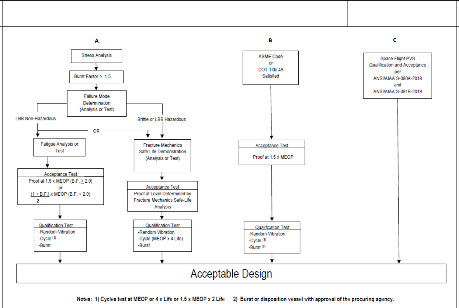
Annex to NASA-STD-8719.24B Payload Project Name Rev: Basic
I – Information/Title N/A – Not Applicable C – Compliant T – Tailored NC – Noncompliant
Page 157 of 455
12.2.1.3. Approach C. Approach C, Figure 12.1 – Approach C specifies the design, qualification, and acceptance test
requirements of flight hardware metallic PVS shall be in accordance with ANSI/AIAA S-080A-2018, Space Systems –
Metallic Pressure Vessels, Pressurized Structures, and Pressure Components.
Select Status

Annex to NASA-STD-8719.24B Payload Project Name Rev: Basic
I – Information/Title N/A – Not Applicable C – Compliant T – Tailored NC – Noncompliant
Page 158 of 455
VOLUME 3: PAYLOADS AND GROUND SYSTEMS REQUIREMENTS
STATUS
TAILORED
TEXT
RATIONALE/
COMMENTS
Figure 12.1. Pressure Vessel Design Verification Approach
12.2.2. Path 1. Flight Hardware Metallic Pressure Vessels with Non-Hazardous LBB Failure Mode
I
12.2.2.1. The LBB failure mode shall be demonstrated analytically or by test showing that an initial surface flaw with a shape
(a/2c) ranging from 0.05 to 0.5 will propagate through the vessel thickness to become a through-the-thickness crack with a
length less than or equal to 10 times the vessel thickness and still be stable at MOP/MEOP.
Select Status
12.2.2.2. Fracture mechanics shall be used if the failure mode is determined by analysis.
Select Status
12.2.2.3. A pressure vessel that contains non-hazardous fluid and exhibits LBB failure mode is considered a non-hazardous
LBB pressure vessel.
Select Status
12.2.2.4. Flight Hardware Metallic Pressure Vessels with Non-Hazardous LBB Failure Mode Factor of Safety
Requirements
I
12.2.2.4.1. Metallic pressure vessels that satisfy the non-hazardous LBB failure mode criterion may be designed
conventionally, wherein the design factors of safety and proof test factors are selected on the basis of successful past
experience.
Select Status
12.2.2.4.2. Unless otherwise specified, the minimum burst factor shall be 1.5.
Select Status
12.2.2.5. Flight Hardware Metallic Pressure Vessels with Non-Hazardous LBB Failure Mode Fatigue-Life
Demonstration
I
12.2.2.5.1. After completion of the stress analysis conducted in accordance with the requirements of 12.1.5.3, conventional
fatigue-life analysis shall be performed, as appropriate, on the unflawed structure to ascertain that the pressure vessel, acted
upon by the spectra of operating loads, pressures, and environments meets the life requirements.
Select Status
12.2.2.5.2. A life factor of 4 shall be used in the analysis.
Select Status
12.2.2.5.3. Testing of unflawed specimens to demonstrate fatigue-life of a specific pressure vessel together with stress analysis
is an acceptable alternative to fatigue test of the vessel.
Select Status
12.2.2.5.4. Fatigue-life requirements are considered demonstrated when the unflawed specimens that represent critical areas
such as membrane section, weld joints, heat-affected zone, and boss transition section successfully sustain the limit loads and
MEOP/MOP in the expected operating environments for the specified test duration without rupture.
Select Status
12.2.2.5.5. The required test duration is 4 times the specified service life.
Select Status
12.2.2.6. Flight Hardware Metallic Pressure Vessels with Non-Hazardous LBB Failure Mode Qualification Test
Requirements
I
12.2.2.6.1. Qualification tests shall be conducted on flight quality hardware to demonstrate structural adequacy of the design.
Select Status

Annex to NASA-STD-8719.24B Payload Project Name Rev: Basic
I – Information/Title N/A – Not Applicable C – Compliant T – Tailored NC – Noncompliant
Page 159 of 455
VOLUME 3: PAYLOADS AND GROUND SYSTEMS REQUIREMENTS
STATUS
TAILORED
TEXT
RATIONALE/
COMMENTS
12.2.2.6.2. The test fixtures, support structures, and methods of environmental application shall not induce erroneous test
conditions.
Select Status
12.2.2.6.3. The types of instrumentation and their locations in qualification tests shall be based on the results of the stress
analysis of 12.1.5.3.
Select Status
12.2.2.6.4. The instrumentation shall provide sufficient data to ensure proper application of the accept/reject criteria, which
shall be established before test.
Select Status
12.2.2.6.5. The sequences, combinations, levels, and duration of loads, pressure, and environments shall demonstrate that
design requirements have been met.
Select Status
12.2.2.6.6. Qualification testing shall include random vibration testing and pressure testing. The following delineates the
required tests:
Select Status
12.2.2.6.6.1. Random Vibration Testing. Random vibration qualification testing shall be performed in accordance with the
requirements of NASA-STD-7001, Payload Vibroacoustic Test Criteria, SMC-S-016 or equivalent unless it can be shown that
the vibration requirement is enveloped by other qualification testing performed.
Select Status
12.2.2.6.6.2. Pressure Testing. Required qualification pressure testing levels are shown in Table 12.2. Requirements for
application of external loads in combination with internal pressures during testing shall be evaluated based on the relative
magnitude and/or destabilizing effect of stresses due to the external load. If limit-combined tensile stresses are enveloped by
test pressure stresses, the application of external loads shall not be required. If the application of external loads is required,
the load shall be cycled to limit for 4 times the predicted number of operating cycles of the most severe design condition (for
example, destabilizing load with constant minimum internal pressure or maximum additive load with a constant maximum
expected operating pressure). Qualification test procedures shall be approved by the payload project, the PSWG, the
appropriate launch or test range approval authority, and other necessary approval authorities as identified by the PSWG and
Range Safety.
Select Status
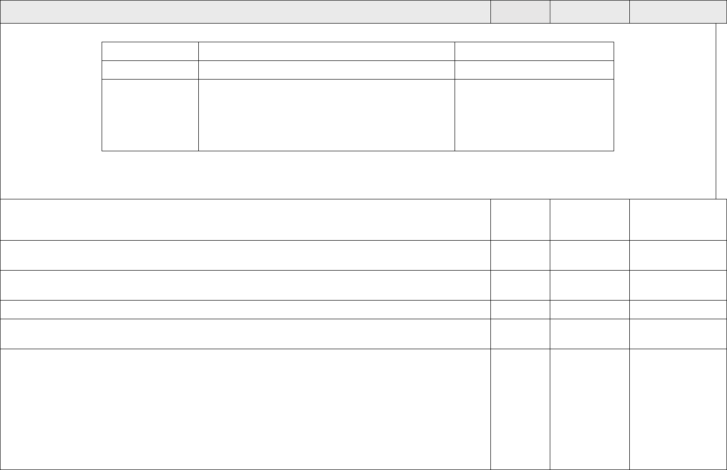
Annex to NASA-STD-8719.24B Payload Project Name Rev: Basic
I – Information/Title N/A – Not Applicable C – Compliant T – Tailored NC – Noncompliant
Page 160 of 455
VOLUME 3: PAYLOADS AND GROUND SYSTEMS REQUIREMENTS
STATUS
TAILORED
TEXT
RATIONALE/
COMMENTS
Table 12.2. Qualification Pressure Test Requirements.
Test Item
No Yield After
No Burst at (1)
Vessel # 1(2)
Burst Factor x MOP
Vessel # 2
Cycle at 1.5 x MOP for 2x predicted number of service life.
(50 cycles minimum)
Cycle at 1.0 x MOP for 4x predicted number of service life.
(50 cycles minimum)
Burst Factor x MOP
(1) Unless otherwise specified, after demonstrating no burst at the design burst pressure test level, increase pressure to actual
burst of vessel. Record actual burst pressure.
(2) Test may be deleted at discretion of the payload project.
12.2.2.7. Flight Hardware Metallic Pressure Vessels with Non-Hazardous LBB Failure Mode Acceptance Test
Requirements. Every pressurized system element shall be proof tested to verify that the materials, manufacturing processes,
and workmanship meet design specifications and that the hardware is suitable for flight.
Select Status
12.2.2.7.1. Acceptance tests shall be conducted on every pressure system element before commitment to flight. Accept/reject
criteria shall be formulated before tests.
Select Status
12.2.2.7.2. The test fixtures and support structures shall be designed to permit application of all test loads without jeopardizing
the flightworthiness of the test article.
Select Status
12.2.2.7.3. At a minimum, the following are required as part of the acceptance process:
I
12.2.2.7.3.1. Nondestructive Inspection. A complete inspection by the selected nondestructive inspection (NDE) technique(s)
shall be performed before the proof pressure test to establish the initial condition of the hardware.
Select Status
12.2.2.7.3.2. Proof Pressure Test. Every pressure vessel shall be proof pressure tested to verify that the item has sufficient
structural integrity to sustain the subsequent service loads, pressure, temperatures, and environments. The proof test fixture
shall simulate the structural response or reaction loads of the flight mounting configuration when vessel mounting induces
axial or radial restrictions on the pressure driven expansion of the vessel. Test temperature shall be consistent with the critical
use temperature, or the test pressure shall be adjusted to account for temperature effects on material properties. The minimum
proof pressure shall be:
P = ((1 + Burst Factor)/2) x MOP for a burst factor less than 2.0, or
P = 1.5 x MOP for a burst factor equal or greater than 2.0.
The minimum hold time at proof pressure shall be 5 minutes.
Select Status

Annex to NASA-STD-8719.24B Payload Project Name Rev: Basic
I – Information/Title N/A – Not Applicable C – Compliant T – Tailored NC – Noncompliant
Page 161 of 455
VOLUME 3: PAYLOADS AND GROUND SYSTEMS REQUIREMENTS
STATUS
TAILORED
TEXT
RATIONALE/
COMMENTS
12.2.2.8. Flight Hardware Metallic Pressure Vessels with Non-Hazardous LBB Failure Mode Recertification Test
Requirements. All refurbished pressure system elements shall be recertified after each refurbishment by the acceptance test
requirements for new hardware to verify their structural integrity and to establish their suitability for continued service before
commitment to flight. Pressure vessels that have exceeded the approved storage environment (temperature, humidity, time,
and others) shall also be recertified by the acceptance test requirements for new hardware.
Select Status
12.2.2.9. Special Provisions. For one-of-a-kind applications, a proof test of each flight unit to a minimum of 1.5 times MOP
and a conventional fatigue analysis showing a minimum of 10 design lifetimes may be used in lieu of the required pressure
testing as defined in 12.2.2.6. The implementation of this option needs prior approval by the payload project, the PSWG, and
any other necessary approval authorities identified by the PSWG and Range Safety.
Select Status
12.2.3. Path 2. Flight Hardware Metallic Pressure Vessels with Brittle Fracture or Hazardous LBB Failure Mode
I
12.2.3.1. Flight Hardware Metallic Pressure Vessels with Brittle Fracture or Hazardous LBB Failure Mode Factor of
Safety Requirements
I
12.2.3.1.1. Safe-life design methodology based on fracture mechanics techniques shall be used to establish the appropriate
design factor of safety and the associated proof factor for metallic pressure vessels that exhibit brittle fracture or hazardous
LBB failure mode.
Select Status
12.2.3.1.2. The loading spectra, material strengths, fracture toughness, and flaw growth rates of the parent material and
weldments, test program requirements, stress levels, and the compatibility of the structural materials with the thermal and
chemical environments expected in service shall be taken into consideration.
Select Status
12.2.3.1.3. Nominal values of fracture toughness and flaw growth rate data corresponding to each alloy system, temper, and
product form shall be used along with a life factor of 4 on specified service life in establishing the design factor of safety and
the associated proof factor.
Select Status
12.2.3.1.4. Unless otherwise specified, the minimum burst factor shall be 1.5.
Select Status
12.2.3.2. Flight Hardware Metallic Pressure Vessels with Brittle Fracture or Hazardous LBB Failure Mode Safe-Life
Demonstration Requirements
I
12.2.3.2.1. After completion of the stress analysis conducted in accordance with the requirements of 12.1.5.3, a safe-life
analysis of each pressure vessel covering the maximum expected operating loads and environments shall be performed under
the assumption of preexisting initial flaws or cracks in the vessel.
Select Status
12.2.3.2.2. The analysis shall show that the metallic pressure vessel with flaws placed in the most unfavorable orientation
with respect to the applied stress and material properties, of sizes defined by the acceptance proof test or NDE and acted upon
by the spectra of expected operating loads and environments, meets the safe-life requirements of 12.1.15.
Select Status
12.2.3.2.3. Nominal values of fracture toughness and flaw growth rate data associated with each alloy system, temper, product
form, thermal and chemical environments, and loading spectra shall be used along with a life factor of 4 on specified service
life in all safe-life analyses.
Select Status

Annex to NASA-STD-8719.24B Payload Project Name Rev: Basic
I – Information/Title N/A – Not Applicable C – Compliant T – Tailored NC – Noncompliant
Page 162 of 455
VOLUME 3: PAYLOADS AND GROUND SYSTEMS REQUIREMENTS
STATUS
TAILORED
TEXT
RATIONALE/
COMMENTS
12.2.3.2.4. Pressure vessels that experience sustained stress shall also show that the corresponding applied stress intensity
(K
I
) during operation is less than K
ISCC
in the appropriate environment.
Select Status
12.2.3.2.5. Testing of metallic pressure vessels under fracture control in lieu of safe-life analysis is an acceptable alternative,
provided that, in addition to following a quality assurance program (12.1.17) for each flight article, a qualification test program
is implemented on pre-flawed specimen’s representative of the structure design.
Select Status
12.2.3.2.6. These flaws shall not be less than the minimum detectable flaw sizes established by the selected NDE method(s).
Proof test logic shall not be used to determine minimum flaw size.
Select Status
12.2.3.2.7. Safe-life requirements of 12.1.15 are considered demonstrated when the pre-flawed test specimens successfully
sustain the limit loads and pressure cycles in the expected operating environments without rupture.
Select Status
12.2.3.2.8. A life factor of 4 on specified service life shall be applied in the safe-life demonstration testing.
Select Status
12.2.3.2.9. A report that documents the fracture mechanics safe-life analysis or safe-life testing shall be prepared to delineate
the following:
Select Status
12.2.3.2.9.1. Fracture mechanics data (fracture toughness and fatigue crack growth rates).
Select Status
12.2.3.2.9.2. Loading spectrum and environments.
Select Status
12.2.3.2.9.3. Initial flaw sizes.
Select Status
12.2.3.2.9.4. Analysis assumptions and rationales.
Select Status
12.2.3.2.9.5. Calculation methodology.
Select Status
12.2.3.2.9.6. Summary of significant results.
Select Status
12.2.3.2.9.7. References.
Select Status
12.2.3.2.10. This report shall be closely coordinated with the stress analysis report and shall be periodically revised and
updated during the life of the program.
Select Status
12.2.3.3. Flight Hardware Metallic Pressure Vessels with Brittle Fracture or Hazardous LBB Failure Mode Qualification Test
Requirements. Qualification testing shall meet requirements of 12.2.2.6.
Select Status
12.2.3.4. Flight Hardware Metallic Pressure Vessels with Brittle Fracture or Hazardous LBB Failure Mode Acceptance Test
Requirements. Acceptance test requirements for pressure vessels that exhibit brittle fracture, or hazardous LBB failure mode
are identical to those with ductile fracture failure mode as defined in 12.2.2.7 except that the test level shall be that defined by
the fracture mechanics analysis. Surface and volume NDE shall be performed before and after proof test on the weld joints
as a minimum. Cryo-proof acceptance test procedures may be required to adequately verify initial flaw size. The pressure
vessel shall not rupture or leak at the acceptance test pressure.
Select Status

Annex to NASA-STD-8719.24B Payload Project Name Rev: Basic
I – Information/Title N/A – Not Applicable C – Compliant T – Tailored NC – Noncompliant
Page 163 of 455
VOLUME 3: PAYLOADS AND GROUND SYSTEMS REQUIREMENTS
STATUS
TAILORED
TEXT
RATIONALE/
COMMENTS
12.2.3.5. Flight Hardware Metallic Pressure Vessels with Brittle Fracture or Hazardous LBB Failure Mode Recertification
Test Requirements. Recertification testing shall meet the requirements of 12.2.2.8.
Select Status
12.2.3.6. Flight Hardware Metallic Pressure Vessels with Brittle Fracture or Hazardous LBB Failure Mode Special
Provisions. For one-of-a-kind applications, a proof test of each flight unit to a minimum of 1.5 times MOP and a conventional
fatigue analysis showing a minimum of 10 design lifetimes may be used in lieu of the required pressure testing as defined in
12.2.2.6 for qualification. The implementation of this option needs prior approval by the PSWG and Range Safety.
Select Status
12.2.4. Approach B, Flight Hardware Metallic Pressure Vessels Designed Using ASME Boiler and Pressure Vessel
Code. Metallic pressure vessels may be designed and manufactured per the rules of the ASME Boiler and Pressure Vessel
Code, Section VIII, Divisions 1 or 2.
Select Status
12.2.4.1. Flight Hardware Metallic Pressure Vessels Designed Using ASME Boiler and Pressure Vessel Code Qualification
Test Requirements. Qualification testing shall meet the requirements of 12.2.2.6.
Select Status
12.2.4.2. Flight Hardware Metallic Pressure Vessels Designed Using ASME Boiler and Pressure Vessel Code
Acceptance Test Requirements
Select Status
12.2.4.2.1. A proof test shall be performed as specified in ASME Boiler and Pressure Vessel Code.
Select Status
12.2.4.2.2. NDE shall be performed in accordance with the ASME Code and RT and/or UT as appropriate to quantify defects
in all full penetration welds after the proof test.
Select Status
12.2.5. Flight Hardware Composite Overwrapped Pressure Vessels. Flight Hardware Composite Overwrapped Pressure
Vessels (COPV). Flight Hardware COPV's shall be designed, qualified, and acceptance tested using Approach A, Approach
B, or Approach C as shown in Figure 12.1.
Select Status
12.2.5.1. Approach A. Flight COPVs designed using Approach A in Figure 12.1 shall have a design burst pressure equal to
1.5 or greater. The COPV failure mode shall be demonstrated by applicable fracture mechanics analysis, test, or similarity,
as approved by the PSWG and Range Safety.
Select Status
12.2.5.1.1. Manufacturers of COPVs using non-metallic liners or new composite over wrap materials (other than carbon,
aramid, or glass fibers in epoxy resins) and their customers shall conduct the necessary development test program that is
acceptable to the PSWG and Range Safety to substantiate a level of safety that is comparable to conventional metal-lined
COPVs.
Select Status
12.2.5.1.2. Based on the results of the failure mode determination, one of two distinct Paths shall be satisfied:
1) (Path 1) LBB, in which leakage of the contents will not create a hazard, or
2) (Path 2) Brittle fracture failure mode or hazardous LBB, in which, if allowed to leak, the leak would cause a hazard
(such as release of toxic gas, damage to nearby safety critical components, or over-pressurization of a closed
compartment).
Select Status
12.2.5.1.3. The verification requirements for path 1 (LBB) are delineated in 12.2.6 and the verification requirements for path
2 (brittle fracture/hazardous LBB) are delineated in 12.2.7.
Select Status

Annex to NASA-STD-8719.24B Payload Project Name Rev: Basic
I – Information/Title N/A – Not Applicable C – Compliant T – Tailored NC – Noncompliant
Page 164 of 455
VOLUME 3: PAYLOADS AND GROUND SYSTEMS REQUIREMENTS
STATUS
TAILORED
TEXT
RATIONALE/
COMMENTS
12.2.5.1.4. Failure mode and safe-life testing using coupons or subscale vessels shall not be used unless approved by the
PSWG and Range Safety.
Select Status
12.2.5.1.5. COPVs with metal liners, evaluated by similarity (in other words, comparison with a vessel that has already been
tested and documented having similar fiber, epoxy, matrix design, and geometry) may not require a demonstration test, if
approved by the PSWG and Range Safety.
Select Status
12.2.5.1.6. For COPVs subjected to sustained load conditions, stress rupture life shall be considered. The operating strain in
the fiber shall be below 50 percent of the ultimate fiber strain at burst during ground pressurization, storage, integration, and
flight operations. Operating strain may exceed 50 percent of the ultimate fiber strain during transportation proof or other proof
testing when personnel are not present.
Select Status
12.2.5.2. Approach B. Approach B, in Figure 12-1, shows the steps required for verification of a COPV designed using
ASME Boiler and Pressure Vessel Code, Section X, or DOT Title 49 Exemptions with a burst factor equal to 3.0 or greater.
Select Status
12.2.5.3. Approach C. Approach C specifies that COPV’s, constructed with a metal liner and a carbon fiber/polymer matrix
overwrap, shall be designed, qualified and acceptance tested in accordance with ANSI/AIAA S-081B-2018.
Select Status
12.2.5.4. Damage Control Plan (DCP). Damage control plan(s) shall be developed to identify and mitigate credible sources
of mechanical and other forms of damage to the COPV during manufacturing and throughout service life. The DCP shall be
developed in accordance with ANSI/AIAA S-081B-2018, section 5.3, and shall include the use of protective covers. The DCP
may include additional protections, as necessary, such as damage indicators.
Select Status
12.2.5.4.1. Damage Control Test (DCT). The ability of the DCP to mitigate credible sources of damage to the COPV during
manufacturing and throughout the service life shall be verified by test. DCT procedures shall be developed and performed in
accordance with ANSI/AIAA S-081B-2018, section 10.3.
Select Status
12.2.5.4.2. The DCP and DCT procedures shall be submitted to Range Safety for review and approval prior to implementation
Select Status
12.2.5.5. COPV Prelaunch Inspection and Pressure Test Requirements
I
12.2.5.5.1. Before the first pressurization of a COPV at a NASA facility, a NASA contracted commercial payload processing
facility, or at the launch site, compliance with the Mechanical Damage Control Plan (DCP) shall be verified. A trained COPV
inspector certified in accordance with ANSI/AIAA S-081B requirements and Section 12.1.17.3 shall perform the inspection.
If this inspection is not possible at the launch base (in other words, the COPV is not accessible), then it shall be conducted the
last time the vessel is accessible for inspection.
Select Status
12.2.5.5.2. An inspection of the vessel shall be conducted to determine if there is any evidence of visible damage or evidence
of damage to the composite shell.
Select Status

Annex to NASA-STD-8719.24B Payload Project Name Rev: Basic
I – Information/Title N/A – Not Applicable C – Compliant T – Tailored NC – Noncompliant
Page 165 of 455
VOLUME 3: PAYLOADS AND GROUND SYSTEMS REQUIREMENTS
STATUS
TAILORED
TEXT
RATIONALE/
COMMENTS
12.2.5.4.3. After arrival at the prelaunch processing facility and completion of the inspection with no evidence of damage to
the COPV, but prior to propellant loading or pressurization, COPVs shall be pressure tested to 100% of the maximum ground
operating pressure. The minimum hold time for this pressure test shall be 5 minutes. This pressurization shall be conducted
remotely, or a blast shield shall be used to protect personnel. Personnel will not approach the COPV for a minimum of 10
minutes following the pressurization.
Select Status
12.2.6. COPVs with Non-Hazardous LBB Failure Mode
I
12.2.6.1. General
I
12.2.6.1.1. The failure mode designation for COPVs shall be based on the liner and the composite overwrap.
Select Status
12.2.6.1.2. For metal-lined COPVs, the LBB failure mode shall be demonstrated by applicable fracture mechanics analysis
and/or test or similarity, as approved by the PSWG and Range Safety. The effects of the liner sizing operation on the fracture
mechanics characteristics of the metal liner shall be accounted for in the LBB evaluation. For non-metallic lined COPVs, the
LBB failure mode shall be demonstrated by test.
Select Status
12.2.6.1.3. The demonstration of the LBB failure mode by test of a COPV shall include a pre-flawed liner (flaw size
determined by analysis of the liner material and flaw detection capabilities of the selected NDE techniques). Surface cracks
shall be put into the liner at locations and orientations that are most critical to the LBB response. An inert fluid shall be used
to pressurize the COPV. Pressure cycles shall be applied to the COPV with the upper pressure limit equal to the MOP. The
LBB failure mode shall be demonstrated if one or more of the cracks leak pressure from the COPV at MOP before catastrophic
failure occurs.
Select Status
12.2.6.2. COPVs with Non-Hazardous LBB Failure Mode Factor of Safety Requirements. Nonmetallic pressure vessels
that satisfy the non-hazardous LBB failure mode criterion may be designed conventionally, wherein the design factors of
safety and proof test factors are selected on the basis of successful past experience. The minimum burst factor shall be 1.5.
Select Status
12.2.6.3. COPVs with Non-Hazardous LBB Failure Mode Fatigue-Life Demonstration
I
12.2.6.3.1. After completion of the stress analysis, a fatigue-life demonstration shall be performed for the liner, bosses, and
composite shell of an unflawed COPV. Fatigue-life shall be demonstrated either by test or analysis, as approved by the PSWG
and Range Safety. The test or analysis shall account for the spectra of expected loads, pressures, and environments.
Select Status
12.2.6.3.2. The minimum fatigue life for COPVs shall be 4 times the service life. The planned number of cycles for the
COPV service life shall account for any cycles to be performed at the payload processing facility and launch site area, a launch
base pressure test at 1.0 times the ground MOP, in addition to cycles at the manufacturer’s facility.
Select Status
12.2.6.4. COPVs with Non-Hazardous LBB Failure Mode Qualification Test Requirements. Qualification testing shall meet
the requirements of 12.2.2.6.
Select Status
12.2.6.5. COPVs with Non-Hazardous LBB Failure Mode Acceptance Test Requirements. Acceptance testing shall be
in accordance with 12.2.2.7 and the additional requirements of 12.2.6.5.1 through 12.2.6.5.3 below.
Select Status

Annex to NASA-STD-8719.24B Payload Project Name Rev: Basic
I – Information/Title N/A – Not Applicable C – Compliant T – Tailored NC – Noncompliant
Page 166 of 455
VOLUME 3: PAYLOADS AND GROUND SYSTEMS REQUIREMENTS
STATUS
TAILORED
TEXT
RATIONALE/
COMMENTS
12.2.6.5.1. Nondestructive Inspection. In accordance with 12.2.2.7.3.1, every COPV shall be subjected to visual and other
nondestructive inspection before and after proof testing. All inspections shall be conducted by specially trained COPV
inspectors certified in accordance with ANSI/AIAA S-081B requirement and Section 12.1.17.3.
Select Status
12.2.6.5.2. Proof Pressure Test. Every COPV shall be proof pressure tested in accordance with 12.2.2.7.3.2.
Select Status
12.2.6.5.3. Liner Inspection. Following completion of the autofrettage cycle and the proof pressure test, every COPV shall
be inspected internally for liner buckling, debonding, or other gross internal defects.
Select Status
12.2.6.5.4. Prelaunch Inspection and Pressure Test. Before a COPV is used in operations an inspection and pressure test shall
be conducted in accordance with 12.2.5.3.
Select Status
12.2.6.6. COPVs with Non-Hazardous LBB Failure Mode Recertification Test Requirements. Recertification testing shall
meet the requirements of 12.2.2.8.
Select Status
12.2.7. Flight Hardware COPVs with Brittle Fracture or Hazardous LBB Failure Mode. The requirements described
below are applicable only to flight hardware COPVs that exhibit brittle fracture or hazardous LBB failure modes.
Select Status
12.2.7.1. COPVs with Brittle Fracture or Hazardous LBB Failure Mode Factor of Safety Requirements. The minimum burst
factor shall be 1.5.
Select Status
12.2.7.2. COPVs with Brittle Fracture or Hazardous LBB Failure Mode Safe-Life Demonstration Requirements
I
12.2.7.2.1. In addition to performing a stress analysis as specified in 12.1.5.3, a safe-life demonstration of each pressure
vessel, covering the maximum expected operating loads and environments, shall be performed assuming pre-existing initial
flaws or cracks in the vessel. For metal-lined COPVs, safe-life shall be demonstrated either by test, analysis, similarity, or
any combination thereof. For non-metallic lined COPVs, the safe-life shall be demonstrated by test, similarity, or both.
Select Status
12.2.7.2.2. Specifically, the analysis shall show that the metal-lined COPV (with liner flaws placed in the most unfavorable
orientation with respect to the applied stress and material properties, of sizes defined by the NDE flaw detection capabilities,
and acted upon by the spectra of expected operating loads) shall meet the safe-life requirements specified by 12.1.15.
Select Status
12.2.7.2.3. For metallic liners, the nominal values of fracture toughness and flaw growth rate data associated with each alloy
system, temper, product form, thermal and chemical environments, and loading spectra shall be used in all safe-life analyses.
Select Status
12.2.7.2.4. Metal-lined COPVs that experience sustained stress shall also show that the corresponding stress intensity factor
(K
I
) applied to the metal liner during the operation is less than K
ISCC
in the appropriate environment. For all liner materials
for which data do not exist, the sustained load crack behavior of the liner material shall be determined by test for all fluids that
are introduced into the COPV under pressure.
Select Status
12.2.7.2.5. Testing of metal-lined COPVs under fracture control is an acceptable alternative to safe-life analysis, provided
that, in addition to following a quality assurance program (12.1.17) for each flight article, a qualification test program is
implemented on pre-flawed specimen’s representative of the structure design. For non-metallic lined COPVs, safe-life
demonstrations shall be performed by test.
Select Status

Annex to NASA-STD-8719.24B Payload Project Name Rev: Basic
I – Information/Title N/A – Not Applicable C – Compliant T – Tailored NC – Noncompliant
Page 167 of 455
VOLUME 3: PAYLOADS AND GROUND SYSTEMS REQUIREMENTS
STATUS
TAILORED
TEXT
RATIONALE/
COMMENTS
12.2.7.2.6. These flaws shall not be less than the minimum detectable flaw sizes established by the selected NDE method(s).
Proof test logic shall not be used to determine minimum flaw size.
Select Status
12.2.7.2.7. Safe-life requirements of 12.1.15 are considered demonstrated when the pre-flawed test specimens successfully
sustain the limit loads and pressure cycles in the expected operating environments without rupture.
Select Status
12.2.7.2.8. The safe-life shall be 4 times the service life for all safe-life demonstrations. The planned number of cycles for
the COPV service life shall account for any cycles to be performed at the payload processing facility and launch site area in
addition to a launch base pressure test at 1.1 times the ground MOP and cycles at the manufacturer’s facility.
Select Status
12.2.7.2.9. A report that documents the fracture mechanics safe-life analysis (for metal liners only) or safe-life testing shall
be prepared to delineate the following:
Select Status
12.2.7.2.9.1. Fracture mechanics data for metal liners, including fracture toughness and fatigue crack growth on launch
vehicles.
Select Status
12.2.7.2.9.2. Loading spectrum and environments.
Select Status
12.2.7.2.9.3. Initial flaw sizes.
Select Status
12.2.7.2.9.4. Analysis assumptions and rationales.
Select Status
12.2.7.2.9.5. Calculation methodology.
Select Status
12.2.7.2.9.6. Summary of significant results.
Select Status
12.2.7.2.9.7. References.
Select Status
12.2.7.2.10. This report shall be closely coordinated with the stress analysis report and shall be periodically revised and
updated during the life of the program.
Select Status
12.2.7.3. COPVs with Brittle Fracture or Hazardous LBB Failure Mode Fatigue-Life Demonstration. For fatigue-life
demonstration requirements, see 12.2.2.6.
Select Status
12.2.7.4. COPVs with Brittle Fracture or Hazardous LBB Failure Mode Qualification Test Requirements. Qualification
testing shall meet the requirements of 12.2.2.6.
Select Status
12.2.7.5. COPVs with Brittle Fracture or Hazardous LBB Failure Mode Acceptance Test Requirements. Acceptance
testing shall be in accordance with 12.2.2.7 and the additional requirements of 12.2.7.5.1 through 12.2.7.5.3 below.
Select Status

Annex to NASA-STD-8719.24B Payload Project Name Rev: Basic
I – Information/Title N/A – Not Applicable C – Compliant T – Tailored NC – Noncompliant
Page 168 of 455
VOLUME 3: PAYLOADS AND GROUND SYSTEMS REQUIREMENTS
STATUS
TAILORED
TEXT
RATIONALE/
COMMENTS
12.2.7.5.1. Nondestructive Inspection. In accordance with 12.2.2.7.3.1, every COPV shall be subjected to visual and other
nondestructive inspection prior to proof testing. In addition, following completion of the proof test, every COPV shall be
inspected internally for liner buckling, debonding, or other gross internal defects. All inspections shall be conducted by
specially trained COPV inspectors certified in accordance with ANSI/AIAA S-081B requirement and Section 12.1.17.3. If
this inspection is not possible at the payload processing launch site area (i.e., the COPV is not accessible), then it shall be
conducted the last time the COPV is accessible for inspection.
Select Status
12.2.7.5.2. Proof Pressure Test. Every COPV shall be proof pressure tested in accordance with 12.2.2.7.3.2.
Select Status
12.2.7.5.3. Prelaunch Inspection and Pressure Test. Before a COPV is used in prelaunch operations at the payload processing
facility or launch area, a prelaunch inspection and pressure test shall be conducted in accordance with 12.2.5.3.
Select Status
12.2.7.6. COPVs with Brittle Fracture or Hazardous LBB Failure Mode Recertification Test Requirements. Recertification
testing shall meet the requirements of 12.2.2.8.
Select Status
12.2.8. COPV Data Requirements. The following data and documentation shall be provided for flight COPVs in addition
to the data required in section 12.10 for all flight pressure systems and vessels.
Select Status
12.2.8.1. COPV Design Data.
Select Status
12.2.8.1.1. Design specifications.
Select Status
12.2.8.1.2. Design drawings.
Select Status
12.2.8.1.3. Design calculations.
Select Status
12.2.8.1.4. Material manufacturer's specification sheets for resin, fiber reinforcement, promoters, catalyst, and other
components used in laminate construction.
Select Status
12.2.8.1.5. Properly certified documentation for parts of the vessel fabricated by other fabricators.
Select Status
12.2.8.1.6. Process specifications, giving the fabrication procedures used to fabricate both the prototype vessel(s) and all
production vessels.
Select Status
12.2.8.2. COPV Validation Data. A summary of the design, analysis, and development test data that validates the design
burst pressure, failure mode (LBB or brittle fracture), and material (liner and over wrap) compatibility with propellants and
other service fluids.
Select Status
12.2.8.3. COPV Test Data
I
12.2.8.3.1. Qualification test report.
Select Status
12.2.8.3.2. Quality control and production test reports.
Select Status
12.2.8.3.3. Acceptance test report.
Select Status

Annex to NASA-STD-8719.24B Payload Project Name Rev: Basic
I – Information/Title N/A – Not Applicable C – Compliant T – Tailored NC – Noncompliant
Page 169 of 455
VOLUME 3: PAYLOADS AND GROUND SYSTEMS REQUIREMENTS
STATUS
TAILORED
TEXT
RATIONALE/
COMMENTS
12.2.8.3.4. Prelaunch inspection and pressure test reports.
Select Status
12.2.8.3.5. In-service inspection and recertification test reports for reusable flight COPVs.
Select Status
12.2.8.4. Other Required COPV Documentation
I
12.2.8.4.1. Ground processing plans and procedures for the launch sites, including all operations and activities involving to
the COPV.
Select Status
12.2.8.4.2. A risk assessment of the COPV during ground processing.
Select Status
12.2.8.4.3. A description and the analysis of the protection system(s) used to prevent impact damage.
Select Status
12.2.8.4.4. Description of the protective coating/covers or splash shields used to guard against contact with incompatible
commodities.
Select Status
12.2.8.4.5. History of pressure cycles (rate, magnitude, and duration) along with the design limitations.
Select Status
12.2.8.4.6. Data to verify design limits have not been exceeded for specified storage and transport environmental conditions.
Select Status
12.2.8.4.7. Reports of inspections or observations that identified COPV exposure to abnormal conditions, such as impacts,
chemical exposure, excessive environmental loads (such as vibration, acceleration, temperature).
Select Status
12.2.8.4.8. Mechanical Damage Control Plan (MDCP) shall be created and implemented that assures the COPV will not fail
due to mechanical damage during manufacturing, testing, shipping, installation, or flight.
Select Status
12.2.8.4.8.1. MDCP shall identify all credible mechanical damage threats starting from the point of manufacture to the end-
of-service life.
Select Status
12.2.8.4.8.2. Mechanical damage mitigation plans and procedures, and inspection points, shall be defined.
Select Status
12.2.8.4.8.3. Comprehensive operating/handling/shipping procedures shall be prepared and included in the MDCP to ensure
the COPV does not receive critical mechanical damage.
Select Status
12.2.8.4.8.4. One or more of the following approaches shall be selected to satisfy the appropriate safety authorities that a
mechanically damaged COPV will meet the minimum burst factor requirement.
Select Status
12.2.8.4.8.4.1. Protective Covers. Covers may be used to isolate and protect the COPV. This approach requires that the cover
be tested to demonstrate that the worst-case credible mechanical damage threat results in 5 ft-lb or less energy imparted to the
COPV. If the energy imparted to the COPV is greater than 5 ft-lbs., then an impacted dedicated test article vessel must be
pressure tested to demonstrate that the burst factor requirement of Section 12.2.2.6 of this chapter.
Select Status
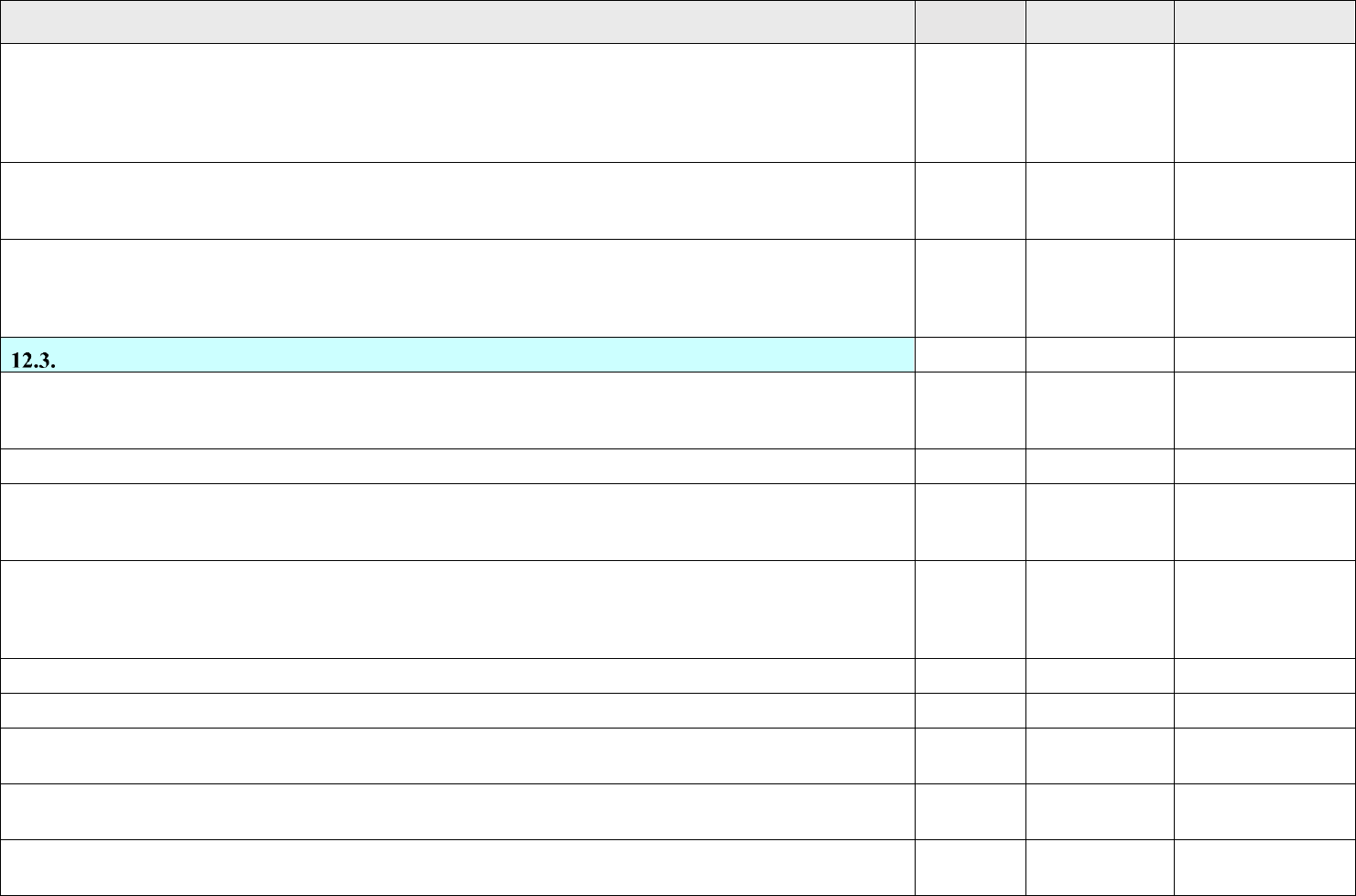
Annex to NASA-STD-8719.24B Payload Project Name Rev: Basic
I – Information/Title N/A – Not Applicable C – Compliant T – Tailored NC – Noncompliant
Page 170 of 455
VOLUME 3: PAYLOADS AND GROUND SYSTEMS REQUIREMENTS
STATUS
TAILORED
TEXT
RATIONALE/
COMMENTS
12.2.8.4.8.4.2. Damage Indicators. Indicators may be used to clearly show whether a COPV has received critical damage.
This approach requires that the indicators be tested to demonstrate that they can sense and indicate a mechanical damage event
over the range of 5 ft-lbs. to the maximum credible threat level. If the indicator’s minimum sensing energy is above 5 ft-lbs.,
then a dedicated test article COPV must be impacted at that energy level and pressure tested to demonstrate that the burst
factor requirement of Section 12.2.2.6 of this chapter is met.
Select Status
12.2.8.4.8.4.3. Worst-Case Threat Damage Tolerance Testing. A dedicated test article COPV may be tested to demonstrate
it can withstand 1.25 x the worst-case credible mechanical damage and still meet the burst factor requirement of Section
12.2.2.6 of this chapter.
Select Status
12.2.8.4.8.4.4. Visual Mechanical Damage Threshold Testing. A dedicated test article COPV may be tested to demonstrate
that the mechanical damage threshold energy creates a visually detectable damage indication that will survive the pressure test
for the burst factor requirement of Section 12.2.2.6 of this chapter. This approach requires the COPV to be accessible for
100% visual inspection after the threat exposure and prior to pressurization.
Select Status
Flight Hardware Metallic Pressurized Structure Analysis and Test Requirements.
I
12.3.1. Flight Hardware Metallic Pressurized Structure General Requirements. For pressurized structures made of metallic
materials such as the fuel tanks of a launch or an upper-stage vehicle, the design approach may be based on successful past
experience when appropriate. However, the analysis and verification requirements specified in this part shall be met.
Select Status
12.3.2. Flight Hardware Metallic Pressurized Structures with Non-Hazardous LBB Failure Mode.
Select Status
12.3.2.1. Flight Hardware Metallic Pressurized Structure Factor of Safety Requirements. Unless otherwise specified, metallic
pressurized structures that satisfy the LBB failure mode may be designed with a minimum ultimate safety factor of 1.25 for
unmanned systems and 1.40 for manned systems.
Select Status
12.3.2.2. Flight Hardware Metallic Pressurized Structure Fatigue-Life Demonstration. In addition to the stress analysis
conducted IAW section 12.1.5.3, a conventional fatigue-life analysis shall be performed, as appropriate, on the unflawed
structure to ascertain that the pressure vessel, acted upon by the spectra of operating loads, pressures, and environments meet
the life requirements. A life factor of 4 shall be used in the analysis.
Select Status
12.3.2.3. Flight Hardware Metallic Pressurized Structure Qualification Test Requirements.
I
12.3.2.3.1. Qualification tests shall be conducted on flight quality hardware to demonstrate structural adequacy of the design.
Select Status
12.3.2.3.2. Because of the potential test facility size limitation, the qualification testing may be conducted at the component
level provided that the boundary conditions are correctly simulated.
Select Status
12.3.2.3.3. The test fixtures, support structures, and methods of environmental application shall not induce erroneous test
conditions.
Select Status
12.3.2.3.4. The sequences, combinations, levels, and duration of loads, pressure and environments shall demonstrate that
design requirements have been met.
Select Status

Annex to NASA-STD-8719.24B Payload Project Name Rev: Basic
I – Information/Title N/A – Not Applicable C – Compliant T – Tailored NC – Noncompliant
Page 171 of 455
VOLUME 3: PAYLOADS AND GROUND SYSTEMS REQUIREMENTS
STATUS
TAILORED
TEXT
RATIONALE/
COMMENTS
12.3.2.3.5. Qualification testing shall include pressure cycle testing and burst testing. The following delineates the required
tests:
Select Status
12.3.2.3.5.1. Pressure Cycle Testing.
I
12.3.2.3.5.1.1. Requirements for application of external loads in combination with internal pressure during testing shall be
evaluated based on the relative magnitude and on the destabilizing effect of stresses due to the external loads.
Select Status
12.3.2.3.5.1.2. If limit-combined tensile stresses are enveloped by the MOP stress, the application of an external load is not
required.
Select Status
12.3.2.3.5.1.3. Unless otherwise specified, the peak pressure shall be equal to the MOP during each pressure cycle, and the
number of cycles shall be 4 times the predicted number of operating cycles or 50 MOP cycles, whichever is greater.
Select Status
12.3.2.3.5.2. Burst Testing.
I
12.3.2.3.5.2.1. After the pressure cycle testing, the test article shall be pressurized (pneumatically or hydrostatically, as
applicable and safe) to the design burst pressure, while simultaneously applying the ultimate external loads, if appropriate.
Select Status
12.3.2.3.5.2.2. The design burst pressure shall be maintained for a sufficient period of time to ensure that the proper pressure
is achieved.
Select Status
12.3.2.4. Flight Hardware Metallic Pressurized Structure Acceptance Test Requirements. Every pressurized structure shall be
proof tested to verify that the materials, manufacturing processes, and workmanship meet design specifications and that the
hardware is suitable for flight. Acceptance testing shall meet the requirements of section 12.2.2.7. Exception: If personnel are
exposed to the structure when pressurized above 50% of MOP, the minimum proof factor shall be 2.5. If personnel are not
exposed to the structure when pressurized, the proof pressure factor shall be 1.1 times MOP.
Select Status
12.3.2.5. Flight Hardware Metallic Pressurized Structure Recertification Test Requirements. Recertification testing shall meet
the requirements of paragraph 12.2.2.8.
Select Status
12.3.3. Flight Hardware Metallic Pressurized Structures with Hazardous LBB or Brittle Failure Mode.
I
12.3.3.1. Flight Hardware Metallic Pressurized Structures with Hazardous LBB or Brittle Failure Mode Factor of Safety
Requirements. Unless otherwise specified, metallic pressurized structures that satisfy the LBB failure mode may be designed
with a minimum ultimate safety factor of 1.25 for unmanned systems and 1.40 for manned systems.
Select Status
12.3.3.2. Flight Hardware Metallic Pressurized Structures with Hazardous LBB or Brittle Failure Mode Safe-Life
Demonstration.
Select Status
12.3.3.2.1. Safe-life analysis of each pressurized structure shall be performed under the assumption of pre-existing initial
flaws or cracks in the structure as specified in section 12.1.5.5.
Select Status

Annex to NASA-STD-8719.24B Payload Project Name Rev: Basic
I – Information/Title N/A – Not Applicable C – Compliant T – Tailored NC – Noncompliant
Page 172 of 455
VOLUME 3: PAYLOADS AND GROUND SYSTEMS REQUIREMENTS
STATUS
TAILORED
TEXT
RATIONALE/
COMMENTS
12.3.3.2.2. In particular, the analysis shall show that the pressurized structure with flaws placed in the most unfavorable
orientation with respect to the applied stress and material properties, of sizes defined by the acceptance proof test or NDE and
acted upon by the spectra of expected operating loads, pressure, and environments meets the safe-life requirements of section
12.1.15.
Select Status
12.3.3.2.3. Nominal values of fracture toughness and flaw growth rate data associated with each alloy system, temper, product
form, thermal and chemical environments, and loading spectra shall be used along with a life factor of 4 on specified service
life in all safe-life analysis.
Select Status
12.3.3.2.4. Safe-life testing in lieu of safe-life analysis is an acceptable alternative, provided that, in addition to following a
quality assurance program (see section 12.1.17) for each flight article, a qualification test program is implemented on pre-
flawed specimen’s representative of the structural design.
Select Status
12.3.3.2.5. These flaws shall not be smaller than the minimum detectable flaw sizes established by the selected NDE
method(s). Proof test logic shall not be used to determine minimum flaw size.
Select Status
12.3.3.2.6. Safe-life requirements of section 12.1.15 are considered demonstrated when the pre-flawed test specimens
successfully sustain the limit loads and pressure cycles in the expected operating environments.
Select Status
12.3.3.2.7. A life factor of 4 on specified pressure cycles in the service life shall be applied in the safe-life demonstration
testing.
Select Status
12.3.3.3. Flight Hardware Metallic Pressurized Structures with Hazardous LBB or Brittle Failure Mode Qualification Test
Requirements. Qualification testing shall include pressure cycle testing and burst testing. The following delineates the required
tests:
Select Status
12.3.3.3.1. Pressure Cycle Testing.
I
12.3.3.3.1.1. Requirements for application of external loads in combination with internal pressure during testing shall be
evaluated based on the relative magnitude and on the destabilizing effect of stresses due to the external loads.
Select Status
12.3.3.3.1.2. If limit-combined tensile stresses are enveloped by the MOP stress, the application of external load is not
required.
Select Status
12.3.3.3.1.3. Unless otherwise specified, the peak pressure shall be equal to the MOP during each pressure cycle, and the
number of cycles shall be 4 times the predicted number of operating cycles or 50 MOP cycles, whichever is greater.
Select Status
12.3.3.3.1.4. If the application of external loads is required, the load shall be cycled 4 times the predicted number of operating
cycles of the most severe design condition; for example, destabilizing load with constant minimum internal pressure or
maximum additive load with MOP.
Select Status
12.3.3.3.2. Burst Testing.
I
12.3.3.3.2.1. After the pressure cycle testing, the test article shall be pressurized (pneumatically or hydrostatically, as
applicable and safe) to the design burst pressure while simultaneously applying the ultimate external loads, if appropriate.
Select Status
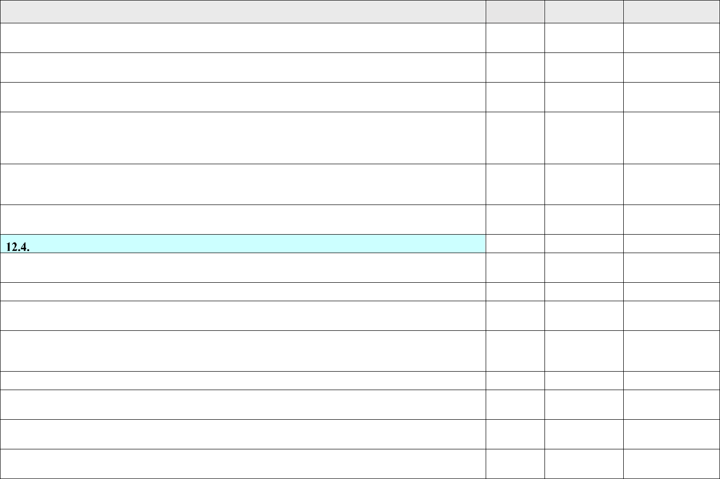
Annex to NASA-STD-8719.24B Payload Project Name Rev: Basic
I – Information/Title N/A – Not Applicable C – Compliant T – Tailored NC – Noncompliant
Page 173 of 455
VOLUME 3: PAYLOADS AND GROUND SYSTEMS REQUIREMENTS
STATUS
TAILORED
TEXT
RATIONALE/
COMMENTS
12.3.3.3.2.2. The design burst pressure shall be maintained for a period of time sufficient to ensure that the proper pressure is
achieved.
Select Status
12.3.3.3.2.3. Unless otherwise specified, the minimum design burst pressure shall be 1.25 times MOP for unmanned systems,
and 1.4 times for manned systems.
Select Status
12.3.3.4. Flight Hardware Metallic Pressurized Structures with Hazardous LBB or Brittle Failure mode Acceptance Test
Requirements.
I
12.3.3.4.1. The acceptance test requirements for pressurized structures that exhibit brittle fracture failure mode, or hazardous
LBB failure mode are identical to those with non-hazardous LBB failure mode as defined in section 12.3.2 except that the
selected NDE techniques shall be capable of detecting flaws or cracks smaller than the allowable initial flaw size as determined
by safe-life analysis.
Select Status
12.3.3.4.2. Surface and volumetric NDE shall be performed on welds before and after proof testing if personnel are exposed
to the structure when pressurized above 50% of MOP. If personnel will not be exposed to pressures greater than 50%, surface
and volumetric NDE shall be performed on welds after the proof test.
Select Status
12.3.3.5. Flight Hardware Metallic Pressurized Structures with Hazardous LBB or Brittle Failure Mode Recertification Test
Requirements. Recertification testing shall meet the requirements of paragraph 12.2.2.8.
Select Status
Flight Hardware Special Pressurized Equipment Design, Analysis, and Test Requirements
I
The detailed design, analysis, and test requirements for cryostats (or dewars), heat pipes, and sealed containers, which are
classified as special pressurized equipment, are described below.
I
12.4.1. Flight Hardware Cryostats or Dewars with LBB Failure Mode
I
12.4.1.1. Flight Hardware Cryostats or Dewars with LBB Failure Mode General Requirements. Pressure containers of
the cryostat or Dewar shall be demonstrated to exhibit LBB failure mode in accordance with the following criteria:
Select Status
12.4.1.1.1. The LBB failure mode shall be demonstrated analytically or by test showing that an initial surface flaw with a
shape (a/2c) ranging from 0.05 to 0.5 will propagate through the vessel thickness to become a through-the-thickness crack
with a length 10 times the vessel thickness and still remain stable at MOP.
Select Status
12.4.1.1.2. Fracture mechanics shall be used if the failure mode is determined by analysis.
Select Status
12.4.1.1.3. A pressure vessel that contains non-hazardous fluid and exhibits LBB failure mode is considered as a non-
hazardous LBB pressure vessel.
Select Status
12.4.1.2. Flight Hardware Cryostats or Dewars with LBB Failure Mode Factor of Safety Requirements. Unless
otherwise specified, the minimum burst factor for the pressure container of a cryostat shall be 1.5.
Select Status
12.4.1.3. Flight Hardware Cryostats or Dewars with LBB Failure Mode Qualification. Qualification tests shall be
conducted on flight quality hardware to demonstrate structural adequacy of the design. The following tests are required:
Select Status

Annex to NASA-STD-8719.24B Payload Project Name Rev: Basic
I – Information/Title N/A – Not Applicable C – Compliant T – Tailored NC – Noncompliant
Page 174 of 455
VOLUME 3: PAYLOADS AND GROUND SYSTEMS REQUIREMENTS
STATUS
TAILORED
TEXT
RATIONALE/
COMMENTS
12.4.1.3.1. Random Vibration Testing. Random vibration testing shall be performed on cryostats per the requirements of
SMC-S-016.
Select Status
12.4.1.3.2. Pressure Testing. The cryostat (Dewar) shall be pressurized to the design burst pressure that is 1.5 times MOP of
the pressure container. The design burst pressure shall be maintained for a period of time sufficient to ensure that the proper
pressure was achieved.
Select Status
12.4.1.4. Flight Hardware Cryostats or Dewars with LBB Failure Mode Acceptance Test Requirements
I
12.4.1.4.1. Acceptance tests should be conducted on every cryostat (or Dewar) before being committed to flight.
Select Status
12.4.1.4.2. The following tests are required:
Select Status
12.4.1.4.2.1. Proof-Pressure Test. Cryostats shall be proof-pressure tested to 1.25 times the MOP of the pressure container.
Select Status
12.4.1.4.2.2. Nondestructive Examination. Surface and volumetric selected NDE techniques shall be performed after the
proof-pressure test.
Select Status
12.4.1.5. Flight Hardware Cryostats or Dewars with LBB Failure Mode Recertification Test Requirements. Recertification
testing shall meet the requirements of 12.2.2.8.
Select Status
12.4.1.6. Flight Hardware Cryostats or Dewars with LBB Failure Mode Special Requirements. Outer shells (vacuum
jackets) shall have pressure relief capability to preclude rupture in the event of pressure container leakage. If pressure
containers do not vent external to the cryostats (or dewars) but instead vent into the volume contained by outer shells, the relief
devices of outer shells shall be capable of safely venting at a rate to release full flow without outer shells rupturing. Relief
devices shall be redundant and individually capable of full flow. Furthermore, pressure relief devices shall be certified to
operate at the required condition of use without frozen moisture or fluid preventing proper operation.
Select Status
12.4.2. Flight Hardware Cryostats or Dewars with Brittle Fracture Failure Mode
I
12.4.2.1. Flight Hardware Cryostats or Dewars with Brittle Fracture Failure Mode Factor of Safety Requirements
I
12.4.2.1.1. Safe-life design methodology based on fracture mechanics techniques shall be used to establish the appropriate
design factor of safety and the associated proof factor for metallic pressure vessels that exhibit brittle fracture or hazardous
leak-before-burst failure mode.
Select Status
12.4.2.1.2. The loading spectra, material strengths, fracture toughness, and flaw growth rates of the parent material and
weldments, test program requirements, stress levels, and the compatibility of the structural materials with the thermal and
chemical environments expected in service shall be taken into consideration.
Select Status
12.4.2.1.3. Nominal values of fracture toughness and flaw growth rate data corresponding to each alloy system, temper, and
product form shall be used along with a life factor of 4 on specified service life in establishing the design factor of safety and
the associated proof factor.
Select Status
12.4.2.1.4. Unless otherwise specified, the minimum burst factor shall be 1.5.
Select Status

Annex to NASA-STD-8719.24B Payload Project Name Rev: Basic
I – Information/Title N/A – Not Applicable C – Compliant T – Tailored NC – Noncompliant
Page 175 of 455
VOLUME 3: PAYLOADS AND GROUND SYSTEMS REQUIREMENTS
STATUS
TAILORED
TEXT
RATIONALE/
COMMENTS
12.4.2.2. Flight Hardware Cryostats or Dewars with Brittle Fracture Failure Mode Safe-Life Demonstration
Requirements
I
12.4.2.2.1. After completion of the stress analysis conducted in accordance with the requirements of 12.1.15.3, safe-life
analysis of each pressure container covering the maximum expected operating loads and environments, shall be performed
under the assumption of pre-existing initial flaws or cracks in the vessel.
Select Status
12.4.2.2.2. In particular, the analysis shall show that the metallic cryostat with flaws placed in the most unfavorable orientation
with respect to the applied stress and material properties, of sizes defined by the acceptance proof test or NDE and acted upon
by the spectra of expected operating loads and environments, meet the safe-life requirements of 12.1.15.
Select Status
12.4.2.2.3. Nominal values of fracture toughness and flaw growth rate data associated with each alloy system, temper, product
form, thermal and chemical environments, and loading spectra shall be used along with a life factor of 4 on specified service
life in all safe-life analyses.
Select Status
12.4.2.2.4. Cryostats that experience sustained stress shall also show that the corresponding applied stress intensity (K
I
) during
operation is less than K
ISCC
in the appropriate environment.
Select Status
12.4.2.2.5. Testing of metallic cryostats under fracture control in lieu of safe-life analysis is an acceptable alternative, provided
that, in addition to following a quality assurance program (12.1.17.) for each flight article, a qualification test program is
implemented on pre-flawed specimen’s representative of the structure design.
Select Status
12.4.2.2.6. These flaws shall not smaller than the minimum detectable flaw sizes established by the acceptance proof test or
the selected NDE method(s). Proof test logic shall not be used to determine minimum flaw size.
Select Status
12.4.2.2.7. Safe-life requirements of 12.1.15 are considered demonstrated when the pre-flawed test specimens successfully
sustain the limit loads and pressure cycles in the expected operating environments without rupture.
Select Status
12.4.2.2.8. A life factor of 4 on specified service life shall be applied in the safe-life demonstration testing.
Select Status
12.4.2.2.9. A report that documents the fracture mechanics safe-life analysis or safe-life testing shall be prepared to delineate
the following:
Select Status
12.4.2.2.9.1. Fracture mechanics data (fracture toughness and fatigue crack growth rates).
Select Status
12.4.2.2.9.2. Loading spectrum and environments.
Select Status
12.4.2.2.9.3. Initial Flaw sizes.
Select Status
12.4.2.2.9.4. Analysis assumptions and rationales.
Select Status
12.4.2.2.9.5. Calculation methodology.
Select Status
12.4.2.2.9.6. Summary of significant results.
Select Status
12.4.2.2.9.7. References:
Select Status

Annex to NASA-STD-8719.24B Payload Project Name Rev: Basic
I – Information/Title N/A – Not Applicable C – Compliant T – Tailored NC – Noncompliant
Page 176 of 455
VOLUME 3: PAYLOADS AND GROUND SYSTEMS REQUIREMENTS
STATUS
TAILORED
TEXT
RATIONALE/
COMMENTS
12.4.2.2.10. This report shall be closely coordinated with the stress analysis report and shall be periodically revised and
updated during the life of the program.
Select Status
12.4.2.3. Flight Hardware Cryostats or Dewars with Brittle Fracture Failure Mode Qualification Test Requirements.
Qualification testing shall meet the requirements of 12.2.2.6.
Select Status
12.4.2.4. Flight Hardware Cryostats or Dewars with Brittle Fracture Failure Mode Acceptance Test Requirements
I
12.4.2.4.1. The acceptance test requirements for cryostats that exhibit brittle fracture, or hazardous LBB failure mode are
identical to those for metallic pressure vessels with ductile fracture failure mode as defined in 12.2.2.7 except that test level
shall be that defined by the fracture mechanics analysis whenever possible.
Select Status
12.4.2.4.2. At a minimum, surface and volumetric NDE technique shall be performed on all weld joints before and after the
proof test.
Select Status
12.4.2.4.3. Cryo-proof acceptance test procedures may be required to adequately verify initial flaw size.
Select Status
12.4.2.4.4. The pressure container shall not rupture or leak at the acceptance test pressure.
Select Status
12.4.2.5. Flight Hardware Cryostats or Dewars with Brittle Fracture Failure Mode Recertification Test Requirements.
Recertification testing shall meet the requirements of 12.2.2.8.
Select Status
12.4.2.6. Flight Hardware Cryostats or Dewars with Brittle Fracture Failure Mode Special Provisions
I
12.4.2.6.1. For one-of-a-kind applications, a proof test of each flight unit to a minimum of 1.5 times MOP and a conventional
fatigue analysis showing a minimum of 10 design lifetimes may be used in lieu of the required pressure testing as defined in
12.2.4 or 12.2.3.3, as applicable, for qualification.
Select Status
12.4.2.6.2. Outer shells (vacuum jackets) shall have pressure relief capability to preclude rupture in the event of pressure
container leakage. If pressure containers do not vent external to the cryostats or dewars, but instead vent into the volume
contained by outer shells, the relief devices of outer shells shall be capable of venting at a rate to release full flow without the
outer shall rupturing. Pressure relief devices shall be certified to operate at the required condition of use.
Select Status
12.4.2.6.3. The implementation of this option needs prior approval by the payload project and the PSWG and Range Safety.
Select Status
12.4.3. Flight Hardware Heat Pipe Requirements
I
12.4.3.1. Flight Hardware Heat Pipe Factor of Safety
I
12.4.3.1.1. Unless otherwise specified, the minimum burst factors for heat pipes with a diameter greater than 1.5 inches shall
be 2.5.
Select Status
12.4.3.1.2. For heat pipes with a diameter less than or equal to 1.5 inches, the minimum burst factor shall be 4.0.
Select Status
12.4.3.2. Flight Hardware Heat Pipe Qualification Test Requirements. Pressure testing shall be conducted to demonstrate
no failure at the design burst pressure.
Select Status

Annex to NASA-STD-8719.24B Payload Project Name Rev: Basic
I – Information/Title N/A – Not Applicable C – Compliant T – Tailored NC – Noncompliant
Page 177 of 455
VOLUME 3: PAYLOADS AND GROUND SYSTEMS REQUIREMENTS
STATUS
TAILORED
TEXT
RATIONALE/
COMMENTS
12.4.3.3. Flight Hardware Heat Pipe Acceptance Test Requirements
I
12.4.3.3.1. All fusion joints or full penetration welds on the heat pipes that contain hazardous fluids shall be inspected using
acceptable surface and volumetric NDE techniques.
Select Status
12.4.3.3.2. A proof pressure test shall be conducted to a minimum level of 1.5 times MOP on all heat pipes.
Select Status
12.4.3.4. Flight Hardware Heat Pipe Recertification Test Requirements. Recertification testing shall meet the requirements
of 12.2.2.8.
Select Status
12.4.3.5. Flight Hardware Heat Pipe Special Requirements. The heat pipe material shall satisfy the material compatibility
requirements defined in 12.1.16 for the contained fluid at both the proof test temperature and operational temperature.
Select Status
12.4.4. Flight Hardware Sealed Containers
I
12.4.4.1. Sealed Containers with Non-Hazardous LBB Failure Mode. The LBB failure mode shall be demonstrated as
defined in 12.2.2.
Exception: Those containers made of aluminum, stainless steel, or titanium sheets that are acceptable as LBB
designs do not have to demonstrate LBB failure mode.
Select Status
12.4.4.1.1. Sealed Containers with Non-Hazardous LBB Failure Mode Factor of Safety. Unless otherwise specified, the
minimum burst factor shall be 1.5.
Select Status
12.4.4.1.2. Sealed Containers with Non-Hazardous LBB Failure Mode Qualification Test Requirements
I
12.4.4.1.2.1. Sealed containers containing non-electronic equipment shall only be subjected to pressure testing.
Select Status
12.4.4.1.2.2. For sealed containers containing safety-related electronic equipment, other qualification tests including
functional, thermal vacuum, thermal cycling, random vibration, and pyro shock shall be conducted per SMC-S-016 or
equivalent.
Select Status
12.4.4.1.3. Sealed Containers with Non-Hazardous LBB Failure Mode Acceptance Test Requirements. Sealed
containers shall be proof-pressure tested to a minimum level of 1.25 times maximum design pressure differential.
Select Status
12.4.4.1.4. Sealed Containers with Non-Hazardous LBB Failure Mode Recertification Test Requirements
I
12.4.4.1.4.1. All refurbished sealed containers shall be recertified after each refurbishment by the acceptance test requirements
for new hardware to verify their structural integrity and to establish their suitability for continued service before commitment
to flight.
Select Status
12.4.4.1.4.2. Sealed containers that have exceeded the approved storage environment (temperature, humidity, time, and
others) shall also be recertified by the acceptance test requirements for new hardware.
Select Status
12.4.4.2. Sealed Containers with Brittle Fracture or Hazardous LBB Failure Mode
I
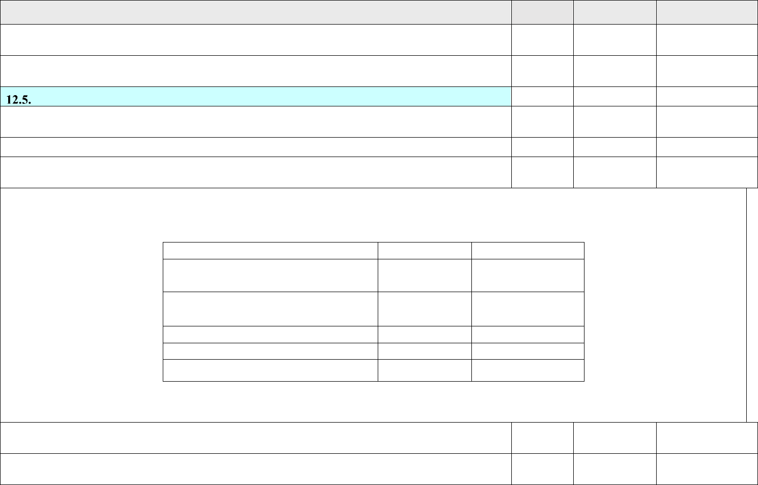
Annex to NASA-STD-8719.24B Payload Project Name Rev: Basic
I – Information/Title N/A – Not Applicable C – Compliant T – Tailored NC – Noncompliant
Page 178 of 455
VOLUME 3: PAYLOADS AND GROUND SYSTEMS REQUIREMENTS
STATUS
TAILORED
TEXT
RATIONALE/
COMMENTS
12.4.4.2.1. Sealed containers that exhibit a brittle fracture failure mode or contain hazardous fluid, or both, shall meet the
requirements of 12.2.3.
Select Status
12.4.4.2.2. For sealed containers containing safety-related electronic equipment, qualification tests including functional,
thermal vacuum, thermal cycling, and pyro shock shall be conducted in addition to random vibration and pressure testing.
Select Status
Flight Hardware Pressure System Component Design and Test Requirements
I
The requirements for the design and testing of flight hardware pressure system components are described below. Included
are hydraulic, pneumatic, hypergolic, and cryogenic fluid and propellant system components.
I
12.5.1. Flight Hardware Pneumatic and Hydraulic Pressure System Components
I
12.5.1.1. Factor of Safety Requirements. Flight hardware pneumatic and hydraulic pressure system components shall be
designed to the minimum factors shown in Table 12.3.
Select Status
12.5.1.2. Flight Hardware Pneumatic and Hydraulic Pressure System Component General Selection and Design
Requirements
I
12.5.1.2.1. Components shall be selected to ensure that misconnections or reverse installations within the subsystem are not
possible. Color codes, labels, and directional arrows shall be used to identify hazards and direction of flow.
Select Status
Table 12.3. Pressure Components Safety Factors
Component
Proof
Design Burst
Lines and fittings diameter < 1.5 inches (38 mm)
1.5
4.0
Lines and fittings diameter > 1.5 inches (38 mm)
1.5
2.5
Fluid Return Sections
1.5
3.0
Fluid Return Hose
1.5
5.0
Other Pressure Components
1.5
2.5
1) Components subject to low or negative pressure shall be evaluated at 2.5 times
maximum external pressure expected during service life.

Annex to NASA-STD-8719.24B Payload Project Name Rev: Basic
I – Information/Title N/A – Not Applicable C – Compliant T – Tailored NC – Noncompliant
Page 179 of 455
VOLUME 3: PAYLOADS AND GROUND SYSTEMS REQUIREMENTS
STATUS
TAILORED
TEXT
RATIONALE/
COMMENTS
12.5.1.2.2. The maximum fluid temperature shall be estimated early in design as part of data for selection of safety critical
components, such as system fluid, pressurizing gas, oil coolers, and gaskets.
Select Status
12.5.1.2.3. Components that are capable of safe actuation under pressure equal to the maximum relief valve setting in the
circuit in which they are installed shall be specified.
Select Status
12.5.1.2.4. Pumps, valves and regulators, hoses, and all such prefabricated components of a pressure system shall have proven
pressure service ratings equal to or higher than the limit load (MOP) and rated life of the system.
Select Status
12.5.1.2.5. The Standards of the Hydraulic Institute shall be used in evaluating safety in pump selection.
Select Status
12.5.1.2.6. Where leakage or fracture is hazardous to personnel or critical equipment, valves shall be selected so that failure
occurs at the outlet threads of valves before the inlet threads or body of the valve fails under pressure.
Select Status
12.5.1.2.7. Pressure regulators shall be selected to operate in the center 50 percent of their total pressure range and avoid creep
and inaccuracies at either end of the full operating range.
Select Status
12.5.1.2.8. In all cases, flareless tube fittings shall be properly preset before pressure application.
Select Status
12.5.1.2.9. Where system leakage can expose hydraulic fluid to potential ignition sources or is adjacent to a potential fire zone
and the possibility of flame propagation exists, fire-resistant or flame-proof hydraulic fluid shall be used.
Select Status
12.5.1.3. Flight Hardware Oxygen System Components
I
12.5.1.3.1. For oxygen systems of 3,000 psi or higher, valves and other components that are slow opening and closing types
shall be selected to minimize the potential for ignition of contaminants.
Select Status
12.5.1.3.2. Oxygen systems shall require electrical grounding to eliminate the possibility of the buildup of static electrical
charges.
Select Status
12.5.1.3.3. Oxygen system components, design, and material selection shall conform to ASTM MNL 36.
Select Status
12.5.1.4. Flight Hardware Pneumatic and Hydraulic System Manual Valves and Regulators
I
12.5.1.4.1. Manually operated valves and regulators shall be selected so that over-torqueing of the valve stem of the regulator
adjustment cannot damage soft seats to the extent that failure of the seat will result.
Select Status
12.5.1.4.2. Valve designs that use uncontained seals are unacceptable and shall not be selected.
Select Status
12.5.1.5. Flight Hardware Pneumatic and Hydraulic System Warning Devices and Safety Critical Components
I
12.5.1.5.1. Warning devices that are activated by hazardous over or under pressure shall be selected whenever necessary.
Select Status
12.5.1.5.2. The warning device shall either activate automatic response mechanisms or shall notify operational personnel of
impending hazards.
Select Status

Annex to NASA-STD-8719.24B Payload Project Name Rev: Basic
I – Information/Title N/A – Not Applicable C – Compliant T – Tailored NC – Noncompliant
Page 180 of 455
VOLUME 3: PAYLOADS AND GROUND SYSTEMS REQUIREMENTS
STATUS
TAILORED
TEXT
RATIONALE/
COMMENTS
12.5.1.5.3. Warning devices to indicate hazardous over or under pressures to operating personnel shall be specified.
Select Status
12.5.1.5.4. These warning devices shall actuate at predetermined pressure levels designed to allow time for corrective action.
Select Status
12.5.1.5.5. Safety critical actuation of pneumatic systems shall not be adversely affected by any back pressure resulting from
concurrent operations of any other parts of the system under any set of conditions.
Select Status
12.5.1.5.6. Components that can be isolated and contain residual pressure shall be equipped with gage reading and bleed
valves for pressure safety checks.
Select Status
12.5.1.5.7. Bleed valves shall be directed away from operating personnel.
Select Status
12.5.1.5.8. Fittings or caps for bleeding pressure are not acceptable.
Select Status
12.5.1.5.9. Pressurized reservoirs that are designed for gas/fluid separation with provisions to entrap gas that may be hazardous
to the system or safety critical actuation and prevent its recirculation in the system shall be specified. Specific instructions
shall be posted adjacent to the filling point for proper bleeding when servicing.
Select Status
12.5.1.5.10. Compressed gas emergency systems shall be bled directly to the atmosphere away from the vicinity of personnel
rather than to reservoir.
Select Status
12.5.1.5.11. If the gas is combustible, safety critical components shall be utilized and methods for reducing the potential for
accidental ignition or explosion shall be assessed, controlled as required, and verified and documented through a hazard
analysis.
Select Status
12.5.1.5.12. Where necessary to prevent a hazardous sequence of operations and provide a fail-safe capability at all times,
interlocks shall be specified. For example, the OPEN position of remotely controlled valves that can hazardously pressurize
lines leading to remotely controlled (or automatic) disconnect couplings shall be interlocked to preclude the OPEN valve
position coincident with the disconnected condition of the couplings.
Select Status
12.5.1.5.13. Pressure systems that combine several safety critical functions shall have sufficient controls for isolating failed
functions for the purpose of safely operating the remaining functions.
Select Status
12.5.1.5.14. All pressure systems shall have pressure indicating devices to monitor critical flows and pressures marked to
show safe upper and lower limits of system pressure.
Select Status
12.5.1.5.15. The pressure indicators shall be located to be readily visible to the operating crew.
Select Status
12.5.1.5.16. All systems shall be protected for pressure above 500 psi in all areas where damage can occur during servicing
or other operational hazards.
Select Status
12.5.1.5.17. Pressure lines and components of 500 psi or higher that are adjacent to safety critical equipment shall be shielded
to protect such equipment in the event of leakage or burst of the pressure system.
Select Status
Annex to NASA-STD-8719.24B Payload Project Name Rev: Basic
I – Information/Title N/A – Not Applicable C – Compliant T – Tailored NC – Noncompliant
Page 181 of 455
VOLUME 3: PAYLOADS AND GROUND SYSTEMS REQUIREMENTS
STATUS
TAILORED
TEXT
RATIONALE/
COMMENTS
12.5.1.5.18. Automatic disengagement or bypass shall be provided for pneumatic systems that provide for manual takeover
in the event of a hazardous situation.
Select Status
12.5.1.5.19. Positive indication of disengagement shall be provided.
Select Status
12.5.1.5.20. Safety critical pneumatic actuators shall have positive mechanical stops at the extremes of safe motion.
Select Status
12.5.1.5.21. Adjustable orifice restrictor valves shall not be used in safety critical pneumatic systems.
Select Status
12.5.1.6. Flight Hardware System Pneumatic Components
I
12.5.1.6.1. Pneumatic components (other than tanks) for safety critical systems shall exhibit safe endurance against hazardous
failure modes for not less than 400 percent of the total number of expected cycles including system tests.
Select Status
12.5.1.6.2. The configuration of pneumatic components shall permit bleeding of entrapped moisture, lubricants, particulate
material, or other foreign matter hazardous to the system.
Select Status
12.5.1.6.3. Compressors that are designed to sustain not less than 2.5 times delivery pressure after allowance for loss of
strength of the materials equivalent to not less than that caused by 1,000 hours aging at 275
o
F shall be selected.
Select Status
12.5.1.7. Flight Hardware Pneumatic and Hydraulic System Design Loads
I
12.5.1.7.1. Installation of all lines and components to withstand all expected acceleration and shock loads shall be specified.
Select Status
Shock isolation mounts may be used if necessary, to eliminate destructive vibration and interference collisions.
I
12.5.1.7.2. The mounting of components, including valves, on structures having sufficient strength to withstand torque and
dynamic loads and not supported by the tubing shall be specified.
Select Status
12.5.1.7.3. Light-weight components that do not require adjustment after installation (for example, check valves) may be
supported by the tubing, provided that a tube clamp is installed on each such tube near the component.
Select Status
12.5.1.7.4. Tubing shall be supported by cushioned steel tube clamps or by multiple-block type clamps that are suitably spaced
to restrain destructive vibration.
Select Status
12.5.1.8. Flight Hardware Pneumatic and Hydraulic System Electrical and Electronic Devices
I
12.5.1.8.1. Electrical components for use in potentially ignitable atmospheres shall be demonstrated to be incapable of causing
an explosion in the intended application.
Select Status
12.5.1.8.2. Electrically energized hydraulic components shall not propagate radio-frequency energy that is hazardous to other
subsystems in the total system or interfere in the operation of safety critical electronic equipment. (See MIL-STD-464, Systems
Electromagnetic Environmental Effects Requirements.)
Select Status
12.5.1.8.3. Pressure system components and lines shall be electrically grounded to metallic structures.
Select Status
Annex to NASA-STD-8719.24B Payload Project Name Rev: Basic
I – Information/Title N/A – Not Applicable C – Compliant T – Tailored NC – Noncompliant
Page 182 of 455
VOLUME 3: PAYLOADS AND GROUND SYSTEMS REQUIREMENTS
STATUS
TAILORED
TEXT
RATIONALE/
COMMENTS
12.5.1.8.4. All solenoids shall be capable of safely withstanding a test voltage of not less than 1500 V rms at 60 cps for 1
minute between terminals and case at the maximum operating temperature of the solenoid in the functional envelope.
Select Status
12.5.1.8.5. Electric motor-driven pumps used in safety critical systems shall not be used for ground test purposes unless the
motor is rated for reliable, continuous, and safe operation. Otherwise, the test parameters may perturb reliability calculations.
Select Status
12.5.1.9. Flight Hardware Pneumatic and Hydraulic System Pressure Relief Devices
I
12.5.1.9.1. Pressure relief devices shall be specified on all systems having a pressure source that can exceed the MAWP of
the system or where the malfunction/failure of any component can cause the MAWP to be exceeded.
Select Status
12.5.1.9.2. Relief devices are required downstream of all regulating valves and orifice restrictors unless the downstream
system is designed to accept full source pressure.
Select Status
12.5.1.9.3. On space systems, where operational or weight limitations preclude the use of relief valves and systems operate
in an environment not hazardous to personnel, they can be omitted if (1) the ground or support system contains such devices
and they cannot be isolated from the airborne system during the pressurization cycle, and (2) the space vehicle cannot provide
its own protection.
Select Status
12.5.1.9.3.1. Where a ground system is specifically designed to service an unmanned flight vehicle, pressure relief protection
may be provided within the ground equipment, if no capability exists to isolate the pressure relief protection from the flight
vehicle during the pressurization cycle.
Select Status
12.5.1.9.4. Where safety factors of less than 2.0 are used in the design of flight hardware pressure vessels, a means for
automatic relief, depressurization, and pressure verification of safety critical vessels in the event of launch abort shall be
provided. Spacecraft (payload) pressure vessels may be designed without automatic relief (other means of safe relief shall be
provided) if a safety analysis validates that a rupture will not damage the safety systems.
Select Status
12.5.1.9.5. Whenever any pressure volume can be confined and/or isolated by system valving, an automatic pressure relief
device shall be provided.
Select Status
12.5.1.9.6. Pressure relief devices shall vent toxic or inert gases to safe areas, away from the vicinity of personnel. Scrubbers
or vapor disposal systems shall also be used at a safe distance from personnel.
Select Status
Pop-valves, rupture disks, blow-out plugs, armoring, and construction to contain the greatest possible overpressure
that may develop are examples of corrective measures for system safety.
I
12.5.1.9.7. Shut-off valves for maintenance purposes on the inlet side of pressurized relief valves are permissible if a means
for monitoring and bleeding trapped pressure is provided and the requirements of ASME Boiler and Pressure Vessel (BPVC)
Code for unfired pressure vessels, Section VIII Appendix M, Paragraph M-5 are met. It is mandatory that the valve be locked
open when the system is re-pressurized.
Select Status

Annex to NASA-STD-8719.24B Payload Project Name Rev: Basic
I – Information/Title N/A – Not Applicable C – Compliant T – Tailored NC – Noncompliant
Page 183 of 455
VOLUME 3: PAYLOADS AND GROUND SYSTEMS REQUIREMENTS
STATUS
TAILORED
TEXT
RATIONALE/
COMMENTS
12.5.1.9.8. Hydrostatic testing systems for vessels that are not designed to sustain negative internal pressure shall be equipped
with fail-safe devices for relief of hazardous negative pressure during the period of fluid removal.
Select Status
Check valves and valve interlocks are examples of devices that can be used for this purpose.
I
12.5.1.9.9. Vessels that can be collapsed by a negative pressure shall have negative pressure relief and/or prevention devices
for safety during storage and transportation.
Select Status
12.5.1.9.10. Pressurized reservoirs shall be designed so that all ullage volumes are connected to a relief valve that shall protect
the reservoir and power pump from hazardous overpressure or back pressure of the system.
Select Status
12.5.1.9.11. The air pressure control for pressurized reservoirs shall be an externally nonadjustable, pressure regulating device.
If this unit also contains a reservoir pressure relief valve, it shall be designed so that no failure in the unit permits over-
pressurization of the reservoir.
Select Status
12.5.1.10. Flight Hardware Pneumatic and Hydraulic System Contamination. Contamination shall be prevented from
entering or developing in safety and safety critical flight hardware pneumatic or hydraulic system components. Safety and
safety critical systems shall be designed to include provisions for detection, filtration, and removal of contaminants.
Select Status
Annex to NASA-STD-8719.24B Payload Project Name Rev: Basic
I – Information/Title N/A – Not Applicable C – Compliant T – Tailored NC – Noncompliant
Page 184 of 455
VOLUME 3: PAYLOADS AND GROUND SYSTEMS REQUIREMENTS
STATUS
TAILORED
TEXT
RATIONALE/
COMMENTS
1. The following contamination-related considerations should be addressed in the design of pressurized systems. Contamination includes
solid, liquid, and gaseous material.
a. Contamination should be prevented from entering or developing within the system.
b. The system should be designed to include provisions to detect contamination.
c. The system should be designed to include provisions for removal of contamination and provisions for initial purge with fluid or gas
that cannot degrade future system performance. The system should be designed to be tolerant of contamination.
2. All pressurizing fluids entering safety critical system should be filtered through a 10 micron filter, or finer, before entering the system.
3. All pressure systems should have fluid filters in the system, designed and located to reduce the flow of contaminant particles to a safe
minimum.
4. All of the circulating fluid in the system should be filtered downstream from the pressure pump or immediately upstream from safety
critical actuators.
5. Entrance of contamination at test points or vents should be minimized by downstream filters.
6. The bypass fluid or case drain flow on variable displacement pumps should be filtered.
7. When the clogging of small orifices could cause a hazardous malfunction or failure of the system, they should be protected by a filter
element designed to prevent clogging of the orifice. Note that this includes servo valves.
8. Filters or screens should not be used in suction lines of power pumps or hand pumps of safety critical systems.
9. Air filters should be specified for hydraulic reservoir air pressurization circuits and located to protect the pressure regulating
equipment from contamination.
10. Dry compressed air should be specified for hydraulic reservoir pressurization.
11. A moisture removal unit should be specified to protect the pressure regulation lines and equipment.
12. Unpressurized Reservoirs. Unpressurized hydraulic reservoirs should have filters and desiccant units at the breather opening to
preclude introduction of moisture and contaminants into the reservoir.
I
12.5.1.11. Flight Hardware Pneumatic and Hydraulic System Bleed Ports
I
12.5.1.11.1. Where necessary, bleed ports shall be provided to remove accumulations of residue or contaminants.
Select Status
12.5.1.11.2. High point bleed ports shall be provided where necessary for removal of trapped gases.
Select Status
12.5.1.11.3. The bleed valve shall be directed away from operating personnel and possible ignition sources.
Select Status
12.5.1.11.4. Components, cavities, or lines that can be isolated shall be equipped with bleed valves that can be used to release
retained pressure, or they shall indicate that continued pressure exists in the system.
Select Status
12.5.1.11.5. Bleed valves used for reducing pressure on systems containing hazardous fluids shall be routed to a safe disposal
area.
Select Status
12.5.1.11.6. Auxiliary Bleed Ports
Select Status
12.5.1.11.6.1. Auxiliary bleed ports shall be provided where necessary to allow bleed off for safety purposes.
Select Status
Annex to NASA-STD-8719.24B Payload Project Name Rev: Basic
I – Information/Title N/A – Not Applicable C – Compliant T – Tailored NC – Noncompliant
Page 185 of 455
VOLUME 3: PAYLOADS AND GROUND SYSTEMS REQUIREMENTS
STATUS
TAILORED
TEXT
RATIONALE/
COMMENTS
12.5.1.11.6.2. Bleeder valves shall be located so that they can be operated without removal of other components and shall
permit the attachment of a hose to direct the bleed-off fluid into a container.
Select Status
12.5.1.11.7. Reservoir filler caps shall include design provisions that shall automatically bleed the reservoir on opening so
that possible ullage pressure cannot impart hazardous kinetic energy to either the filler caps, the fluid in the reservoir, or the
system.
Select Status
12.5.1.12. Flight Hardware Pneumatic and Hydraulic System Control Devices
I
12.5.1.12.1. Safety critical pressure systems incorporating two or more directional control valves shall be designed to preclude
the possibility of inadvertently directing the flow or pressure from one valve into the flow path or pressure path intended for
another valve, with any combination of valve settings possible in the total system.
Select Status
12.5.1.12.2. Control devices shall be designed to prevent overtravel or under travel that may contribute to a hazardous
condition or damage to the valve.
Select Status
12.5.1.12.3. All pressure and volume controls shall have stops, or equivalent, to prevent settings outside their nominal safe
working ranges.
Select Status
12.5.1.12.4. Control components that have integral manually operated levers and stops shall be capable of withstanding the
following limit torques in Table 12.4.
Select Status
Table 12.4. Limit Torque Requirements
12.5.1.13. Flight Hardware Pneumatic and Hydraulic System Manually Operated Levers
I
12.5.1.13.1. Components that have integrated manually operated levers shall provide levers and stops capable of withstanding
the limit torques specified by MIL-STD-1472.
Select Status
12.5.1.13.2. Levers and stops shall be provided on remote controls capable of withstanding a limit torque of 1,800 inch-
pounds.
Select Status
12.5.1.13.3. Because jamming is possible, sheathed flexible actuators shall not be used for valve controls in safety critical
pressure systems (for example, push-pull wires and torque wires that are sheathed are not acceptable).
Select Status
12.5.1.14. Flight Hardware Pneumatic and Hydraulic System Accumulators
Select Status
Lever Radius
Design Torque
Less than 3 inches
50 x R inch-pound
3 to 6 inches
75 x R inch-pound
Over 6 inches
150 x R inch-pound

Annex to NASA-STD-8719.24B Payload Project Name Rev: Basic
I – Information/Title N/A – Not Applicable C – Compliant T – Tailored NC – Noncompliant
Page 186 of 455
VOLUME 3: PAYLOADS AND GROUND SYSTEMS REQUIREMENTS
STATUS
TAILORED
TEXT
RATIONALE/
COMMENTS
12.5.1.14.1. Accumulators shall be designed in accordance with the pressure vessel standards for ground systems and located
for minimal probability of mechanical damage and for minimum escalation of material damage or personnel injury in the
event of a major failure such as tank rupture.
Select Status
12.5.1.14.2. Accumulator gas pressure gauges shall not be used to indicate system pressure for operational or maintenance
purposes.
Select Status
12.5.1.14.3. Gas type and pressure level shall be posted on, or immediately adjacent to, the accumulator.
Select Status
12.5.1.15. Flight Hardware Pneumatic and Hydraulic System Flexible Hose. Flexible hose requirements are specified in
12.1.10.4.
Select Status
12.5.1.16. Flight Hardware Pneumatic and Hydraulic System Qualification Test Requirements. Qualification tests are
not required on lines and fittings. Internal/external pressure testing shall be conducted on all other pressure components to
demonstrate no failure at the design burst pressure. Seamless lines, tubing, and pipe are exempt.
Select Status
12.5.1.17. Flight Hardware Pneumatic and Hydraulic System Acceptance Test Requirements
I
12.5.1.17.1. Testing Flight Hardware Pneumatic and Hydraulic Components Before Assembly
I
12.5.1.17.1.1. All pressurized components such as valves, pipe, tubing, and pipe and tube fittings shall be hydrostatically
proof tested to a minimum of 1.5 times the component MAWP for a minimum of 5 minutes.
Note: In the event that component testing before assembly is not feasible, components may be hydrostatically tested after assembly into
a subsystem or system to 1.5 times the system MOP. This approach shall be approved by PSWG and Range Safety.
Select Status
12.5.1.17.1.2. Proof testing shall demonstrate that the components sustain proof pressure levels without distortion, damage,
or leakage.
Select Status
12.5.1.17.1.3. Both the inlet and discharge sides of a relief valve shall be proof tested. When the discharge side has a lower
pressure rating than the inlet, they are to be proof tested independently.
Select Status
12.5.1.17.1.4. The following inspections shall be performed after proof testing:
Select Status
12.5.1.17.1.4.1. Mechanical components such as valves and regulators shall be inspected for external deformation,
deterioration, or damage.
Select Status
12.5.1.17.1.4.2. Damaged, distorted, or deteriorated parts shall be rejected and replaced and the test repeated.
Select Status
12.5.1.17.1.5. Functional and leak tests shall be performed at the component MAWP after the proof test.
Select Status
12.5.1.17.1.6. Pneumatic pressure system components shall undergo sufficient qualification and acceptance testing to
demonstrate that the system and components meet design and safety requirements when subjected to prelaunch and launch
environments such as vibration, shock, acceleration, and temperature.
Select Status
12.5.1.17.1.7. Test plans and test reports shall be submitted to the PSWG and made available to the PSWG and Range Safety.
Select Status

Annex to NASA-STD-8719.24B Payload Project Name Rev: Basic
I – Information/Title N/A – Not Applicable C – Compliant T – Tailored NC – Noncompliant
Page 187 of 455
VOLUME 3: PAYLOADS AND GROUND SYSTEMS REQUIREMENTS
STATUS
TAILORED
TEXT
RATIONALE/
COMMENTS
12.5.1.17.1.8. Pressure relief valves shall be tested for proper setting and flow capacity before installation and first use on the
ranges.
Select Status
12.5.1.17.1.9. Pressure gauges and transducers shall be hydrostatically tested to a minimum of 1.5 times the system
MOP/MEOP.
Note: Depending upon the manufacturer or model of the pressure transducer, it may not be possible to hydrostatically
test it to a minimum 1.5 times MOP without causing a shift in the transducer. This is dependent on the transducer’s
specification and manufacturer’s recommendations for the transducer.
Select Status
12.5.1.17.1.10. Pressure gauges and transducers shall be calibrated before installation and periodically thereafter as
recommended by the manufacturer.
Select Status
12.5.1.17.1.11. Components may be initially hydrostatically proof tested after being assembled into a subsystem to 1.5 times
the system MOP. This approach requires prior approval from the PSWG and Range Safety.
Select Status
12.5.1.17.1.12. Pneumatic proof testing to a proof pressure of 1.25 times MAWP is permissible only if hydrostatic proof
testing is impractical, impossible, or jeopardizes the integrity of the system or system element. Prior approval for pneumatic
proof testing at the payload processing facility and/or launch site area shall be obtained from the local safety authority.
Select Status
12.5.1.17.2. Testing Flight Hardware Pneumatic and Hydraulic Systems After Assembly. All newly assembled pressure
systems shall be hydrostatically tested to 1.5 times MOP before use. MOP here refers to the maximum operating pressure that
personnel are exposed to. Where this is not possible, the PSWG and Range Safety shall determine the adequacy of component
testing and alternate means of testing the assembled system.
Select Status
12.5.1.17.3. Flight Hardware Pneumatic and Hydraulic System Leak Tests
I
12.5.1.17.3.1. All newly assembled pressure systems shall undergo a dedicated leak test at the system MOP before first use
at any payload processing facility and launch site area.
Select Status
12.5.1.17.3.2. This test shall be conducted at the payload processing facility and launch site area unless prior approval from
the PSWG and Range Safety has been obtained.
Select Status
12.5.1.17.3.3. Minimum test requirements are as follows:
Select Status
12.5.1.17.3.3.1 The gas used during the leak test shall be the same as the system fluid media except that for
hazardous gas systems, a system compatible, non-hazardous gas may be used that has a density as near as
possible to the system fluid; for example, helium should be used to leak test a gaseous hydrogen system.
Select Status
12.5.1.17.3.3.2. Mechanical connections, gasketed joints, seals, weld seams, and other items shall be visually bubble tight for
a minimum of 1 minute when an approved leak test solution is applied.
Select Status
12.5.1.17.3.3.3. Alternate methods of leak testing (such as the use of portable mass spectrometers) may be specified when
required on a case-by-case basis.
Select Status

Annex to NASA-STD-8719.24B Payload Project Name Rev: Basic
I – Information/Title N/A – Not Applicable C – Compliant T – Tailored NC – Noncompliant
Page 188 of 455
VOLUME 3: PAYLOADS AND GROUND SYSTEMS REQUIREMENTS
STATUS
TAILORED
TEXT
RATIONALE/
COMMENTS
12.5.1.17.4. Flight Hardware Pneumatic and Hydraulic System Validation and Functional Tests
I
12.5.1.17.4.1. All newly assembled pressure systems shall have a system validation test and a functional test of each
component at system MOP before first use at the payload processing facility and/or launch site area.
Select Status
12.5.1.17.4.2. These tests shall be conducted at the payload processing facility and launch site area unless prior approval from
the PSWG and Range Safety has been obtained.
Select Status
12.5.1.17.4.3. Minimum test requirements are as follows:
Select Status
12.5.1.17.4.3.1. These tests shall demonstrate the functional capability of all non-passive components such as valves,
regulators, and transducers.
Select Status
12.5.1.17.4.3.2. All prelaunch operational sequences for the system shall be executed.
Select Status
12.5.1.17.4.3.3. All parallel or series redundant components shall be individually tested to ensure all failure tolerant
capabilities are functional before launch.
Select Status
12.5.1.17.4.3.4. All shutoff and block valves shall be leak checked downstream to verify their shutoff capability in the
CLOSED position.
Select Status
12.5.1.17.5. Flight Hardware Pneumatic and Hydraulic System Bonding and Grounding Tests. All newly assembled
pressure systems containing flammable and combustible fluids or media shall be tested to verify that the requirements of
12.1.12 of this volume have been met.
Select Status
12.5.1.17.6. Test Requirements for Modified and Repaired Flight Hardware Pneumatic Systems
I
12.5.1.17.6.1. Any pressure system element, including fittings or welds, that has been repaired, modified, or possibly damaged
before having been proof tested, shall be retested at proof pressure before its normal use.
Select Status
12.5.1.17.6.2. A modified or repaired pressure system shall be leak tested at the system MOP before its normal use. This test
shall be conducted at the ranges unless prior approval from the PSWG and Range Safety has been obtained.
Select Status
12.5.1.17.6.3. A modified or repaired pressure system shall be revalidated and functionally tested at the system MOP before
its normal use.
Select Status
12.5.1.17.6.4. If any pressure system element such as a valve, regulator, gauges, or tubing has been disconnected or
reconnected for any reason, the affected system or subsystem shall be leak tested at MOP.
Select Status
12.5.2. Flight Hardware Hazardous Fluid System Components, Including Hypergolic, Cryogenic, and Hydraulic
Systems. Hypergolic and cryogenic components are required to meet the requirements in 12.6, 12.7, 12.8, and 12.9 in addition
to the following:
Select Status
12.5.2.1. Cycling capability for safety critical components shall be not less than 400 percent of the total number of expected
cycles, including system tests, but not less than 2,000 cycles.
Select Status
Annex to NASA-STD-8719.24B Payload Project Name Rev: Basic
I – Information/Title N/A – Not Applicable C – Compliant T – Tailored NC – Noncompliant
Page 189 of 455
VOLUME 3: PAYLOADS AND GROUND SYSTEMS REQUIREMENTS
STATUS
TAILORED
TEXT
RATIONALE/
COMMENTS
12.5.2.2. For service above a temperature of 160ºF an additional cycling capability equivalent to the above shall be required
as a maximum.
Select Status
The intent of this requirement is twofold: (1) to prevent viscosity breakdown from heat in hydraulic systems, and
(2) to consider the effects of elevated temperature in determining the safe cycle life of the components.
I
12.5.2.3. Safety critical actuators shall have positive mechanical stops at the extremes of safe motion.
Select Status
12.5.2.4. Hydraulic fluid reservoirs and supply tanks shall be equipped with remotely operated shutoff valves.
Select Status
12.5.2.5. Shuttle valves shall not be used in safety critical hydraulic systems where the event of a force balance on both inlet
ports may occur, causing the shuttle valve to restrict flow from the outlet port.
Select Status
12.5.2.6. Systems incorporating accumulators shall be interlocked to either vent or isolate accumulator fluid pressure when
power is shutoff.
Select Status
12.5.2.7. Adjustable orifice restrictor valves shall not be used in safety critical systems.
Select Status
12.5.2.8. When two or more actuators are mechanically tied together, only one lock valve shall be used to lock all the actuators.
Select Status
12.5.2.9. Lock valves shall not be used for safety critical lockup periods likely to involve extreme temperature changes unless
fluid expansion and contraction effects are safely accounted for.
Select Status
12.5.2.10. Flight Hardware Hazardous Fluid System Reservoirs:
Select Status
12.5.2.10.1. Whenever possible, the hydraulic reservoir should be located at the highest point in the system.
Select Status
12.5.2.10.2. If the requirement in 12.5.2.10.1 is not possible in safety critical systems, procedures shall be developed to detect
air in actuators or other safety critical components and to ensure that the system is properly bled before each use.
Select Status
12.5.2.11. Systems installations shall be limited to a maximum pressure of 15,000 psig.
Select Status
There is no intent to restrain development of systems capable of higher pressures; however, the use of such systems
shall be preceded by complete development and qualification that includes appropriate safety tests.
I
12.5.2.12. The inlet pressure of pumps in safety critical systems shall be specified to prevent cavitation effects in the pump
passages or outlets.
Select Status
12.5.2.13. Safety critical systems shall have positive protection against breaking the fluid column in the suction line during
standby.
Select Status
12.5.2.15. Systems that provide for manual takeover shall automatically disengage or allow by-pass of the act of manual
takeover.
Select Status
Annex to NASA-STD-8719.24B Payload Project Name Rev: Basic
I – Information/Title N/A – Not Applicable C – Compliant T – Tailored NC – Noncompliant
Page 190 of 455
VOLUME 3: PAYLOADS AND GROUND SYSTEMS REQUIREMENTS
STATUS
TAILORED
TEXT
RATIONALE/
COMMENTS
12.5.2.16. Safety critical systems or alternate bypass systems provided for safety shall not be rendered inoperative because of
back pressure under any set of conditions.
Select Status
12.5.2.17. The system shall be designed so that a lock resulting from an unplanned disconnection of a self-seating coupling
or other component shall not cause damage to the system or to adjacent property or injury to personnel.
Select Status
12.5.2.18. Systems using power-operated pumps shall include a pressure regulating device and an independent safety relief
valve.
Select Status
12.5.2.19. Flight Hardware Hazardous Fluid System Thermal Pressure Relief Valves:
Select Status
12.5.2.19.1. Thermal expansion relief valves shall be installed as necessary to prevent system damage from thermal expansion
of hydraulic fluid as in the event of gross overheating.
Select Status
12.5.2.19.2. Internal valve leakage shall not be considered an acceptable method of providing thermal relief.
Select Status
12.5.2.19.3. Thermal relief valve settings shall not exceed 150 psi above the value for system relief valve setting.
Select Status
12.5.2.19.4. Vents shall outlet only to areas of relative safety from a fire hazard.
Select Status
12.5.2.19.5. Hydraulic blow-out fuses (soft plugs) shall not be used in systems having temperatures above 160
o
F.
Select Status
12.5.2.20. Pressure relief valves shall be located in the systems wherever necessary to ensure that the pressure in any part of
a power system shall not exceed the safe limit above the regulated pressure of the system.
Select Status
Flight Hardware Pneumatic System Design Requirements
I
Specific requirements for the design of flight hardware pneumatic systems and specific pneumatic system components are
described below:
I
12.6.1. Flight Hardware Pneumatic System Piping
I
12.6.1.1. NPT connectors shall not be used in hazardous pressure system piping.
Select Status
12.6.1.2. Socket-welded flanges shall not be used in hazardous pressure system piping.
Select Status
12.6.1.3. All piping and fitting welds shall be 100% radiographically inspected.
Select Status
12.6.2. Flight Hardware Pneumatic System Tubing. All tubing and fitting welds shall be 100% radiographically inspected
before and after the pressure test and inspected by surface NDE techniques before and after the pressure test.
Select Status
12.6.2.1. Welded connections shall meet the requirements of AWS D17.1, Specification for Fusion Welding for Aerospace
Applications, as prescribed by NASA-STD-5006, General Fusion Welding Requirements for Aerospace Materials Used in
Flight Hardware.
Select Status

Annex to NASA-STD-8719.24B Payload Project Name Rev: Basic
I – Information/Title N/A – Not Applicable C – Compliant T – Tailored NC – Noncompliant
Page 191 of 455
VOLUME 3: PAYLOADS AND GROUND SYSTEMS REQUIREMENTS
STATUS
TAILORED
TEXT
RATIONALE/
COMMENTS
12.6.2.2. Tube and fitting welded joints shall meet the inspection requirements of AIA/NAS 1514, Radiographic Standard for
Classification of Fusion Weld Discontinuities, and ASTM E1742, Standard Practice for Radiographic Examination.
Qualification of visual inspection personnel shall be a minimum of VT Level II as per SNT-TC-1A. Surface inspection, if
applicable, shall meet the requirements of ASTM E1417, Standard Practice for Liquid Penetrant Inspection.
Select Status
12.6.3. Flight Hardware Pneumatic System Regulators
I
12.6.3.1. Regulators shall be selected so that their working pressure falls within the center 50 percent of their total pressure
range if it is susceptible to inaccuracies or creep at either end of its pressure range.
Select Status
12.6.3.2. Pressure regulator actuators shall be capable of shutting off the fluid when the system is at the maximum possible
flow and pressure.
Select Status
12.6.3.3. Designs using uncontained seats are unacceptable.
Select Status
12.6.3.4. Systems that contain regulators that are remotely operated during prelaunch operations shall be designed to be fail-
safe if pneumatic or electric control power to the regulator is lost.
Select Status
12.6.4. Flight Hardware Pneumatic System Valves
I
12.6.4.1. Valve actuators shall be operable under maximum design flow and pressure.
Select Status
12.6.4.2. Manually operated valves shall be designed so that over torqueing the valve stem cannot damage soft seats to the
extent that seat failure occurs.
Select Status
12.6.4.3. Designs using uncontained seats are prohibited.
Select Status
12.6.4.4. Valves that are not intended to be reversible shall be designed or marked so that they shall not be connected in a
reverse mode.
Select Status
12.6.4.5. All electrical control circuits for remotely actuated valves shall be shielded or otherwise protected from hazardous
stray energy.
Select Status
12.6.4.6. Remotely controlled valves shall provide for remote monitoring of OPEN and CLOSED positions during prelaunch
operations.
Select Status
12.6.4.7. Systems that contain remotely operated valves shall be designed to be fail-safe if pneumatic or electric control power
to the valve is lost during prelaunch operations.
Select Status
12.6.4.8. Check valves shall be provided where back flow of fluids or media would create a hazard.
Select Status
12.6.4.9. Special care shall be taken in the design of oxygen systems to minimize the heating effect due to rapid increases in
pressure. Fast opening valves that can produce high velocity kinetic effects and rapid pressurization shall be avoided.
Select Status
12.6.4.10. Valve stem travel on manual valves shall be limited by a positive stop at each extreme position.
Select Status

Annex to NASA-STD-8719.24B Payload Project Name Rev: Basic
I – Information/Title N/A – Not Applicable C – Compliant T – Tailored NC – Noncompliant
Page 192 of 455
VOLUME 3: PAYLOADS AND GROUND SYSTEMS REQUIREMENTS
STATUS
TAILORED
TEXT
RATIONALE/
COMMENTS
12.6.4.11. The application or removal of force to the valve stem positioning device shall not cause disassembly of the pressure-
containing structure of the valve.
Select Status
12.6.5. Flight Hardware Pneumatic System Pressure Indicating Devices
I
12.6.5.1. A pressure indicating device shall be located on the downstream side of each pressure regulator and on any storage
system.
Select Status
12.6.5.2. These pressure indicating devices shall be designed to be remotely monitored during prelaunch operations.
Select Status
12.6.6. Flight Hardware Pneumatic System Flexible Hoses. Flexible hose requirements are specified in 12.1.10.4.
Select Status
12.6.7. Flight Hardware Pneumatic System Pressure Relief Devices
Select Status
12.6.7.1. Pressure relief devices shall be installed on all systems having an on-board pressure source that can exceed the
MAWP of any component downstream of that source unless the system is single failure tolerant against over pressurization
during prelaunch operations.
Select Status
12.6.7.2. Flight systems that require on-board pressure relief capability shall be designed to the following minimum
requirements:
Select Status
12.6.7.2.1. The pressure relief device shall be installed as close as practical downstream of the pressure reducing device or
source of pressure such as a compressor and gas generator.
Select Status
12.6.7.2.2. Pressure relief devices should be set to operate at a pressure not to exceed 110 percent of the system MOP/MEOP.
Select Status
12.6.7.2.3. The relieving capacity of the relief device and any vent outlet piping shall be equal to or greater than the maximum
flow capability of the upstream pressure reducing device or pressure source and should prevent the pressure from rising more
than 20 percent above the system MOP/MEOP.
Select Status
12.6.7.2.4. The relief device vent outlet piping shall be sized to prevent excessive back pressure from adversely affecting the
function of the relief device.
Select Status
12.6.7.2.5. All relief devices and associated piping shall be structurally restrained to minimize any thrust effects on the
pressure system vessels or piping.
Select Status
12.6.7.2.6. The effects of the discharge from relief devices shall be assessed and analyzed to ensure that operation of the
device shall not be hazardous to personnel or equipment. Items to be analyzed are thrust loads, noise, impingement of high
velocity gas or entrained particles, toxicity, oxygen enrichment, and flammability.
Select Status
12.6.7.2.7. All pressure relief devices shall be vented separately unless the following can be positively demonstrated:
Select Status
12.6.7.2.7.1. The creation of a hazardous mixture of gases in the vent system and the migration of hazardous substances into
an unplanned environment is impossible.
Select Status
Annex to NASA-STD-8719.24B Payload Project Name Rev: Basic
I – Information/Title N/A – Not Applicable C – Compliant T – Tailored NC – Noncompliant
Page 193 of 455
VOLUME 3: PAYLOADS AND GROUND SYSTEMS REQUIREMENTS
STATUS
TAILORED
TEXT
RATIONALE/
COMMENTS
12.6.7.2.7.2. The capacity of the vent system is adequate to prevent a pressure rise of more than 20 percent above MOP when
all attached pressure relief devices are wide open, and the system is at full pressure and volume generating capacity.
Select Status
12.6.7.2.8. No obstructions shall be placed downstream of the relief device.
Select Status
12.6.7.2.9. Relief devices shall be located so that other components cannot render them inoperative.
Select Status
12.6.8. Flight Hardware Pneumatic System Vents
I
12.6.8.1. Pressure systems shall be designed so that pressure cannot be trapped in any part of the system without vent
capability.
Select Status
12.6.8.2. Vent system outlets should be in a location normally inaccessible to personnel or shall be conspicuously identified.
Select Status
12.6.8.3. Vent outlets shall be protected against rain intrusion and entry of birds, insects, and animals.
Select Status
12.6.8.4. Oxidizer and fuel vent outlets to the atmosphere shall be separated sufficiently to prevent mixing of vented fluids.
Select Status
12.6.8.5. All vent outlets shall be designed to prevent accumulation of vented gases in dangerous concentrations (oxygen rich)
in areas frequented by unprotected personnel.
Select Status
12.6.8.6. Hydrogen vents shall discharge to atmosphere through an approved burner.
Select Status
12.6.8.7. Special attention shall be given to the design of vent line supports at vent outlets due to potential thrust loads.
Select Status
12.6.8.8. Each line venting into a multiple-use vent system shall be protected against back pressurization by means of a check
valve if the upstream system cannot withstand the back pressure or where contamination of the upstream system cannot be
tolerated.
Select Status
Flight Hardware Hydraulic System Design and Test Requirements
Select Status
In addition to the following requirements, flight hardware hydraulic systems shall meet the minimum design fabrication and
test requirements of 12.5.1 and 12.5.2.
Select Status
12.7.1. Flight Hardware Hydraulic System General Design Requirements
Select Status
12.7.1.1. Where necessary, hydraulic system low-points shall be provided a drain fitting (bleed ports) to allow draining of
condensates or residue for safety purposes.
Select Status
Entrapped air, moisture, and cleaning solvents are examples of foreign substances that may be hazardous to the
system, component, or control equipment.
I
12.7.1.2. Bleed ports shall be located so that they can be operated without removal of other components and shall permit the
attachment of a hose to direct the bleed off material into a container away from the positions of the operators.
Select Status
12.7.1.3. Test points shall be provided on hydraulic systems so that disassembly for test is not required.
Select Status

Annex to NASA-STD-8719.24B Payload Project Name Rev: Basic
I – Information/Title N/A – Not Applicable C – Compliant T – Tailored NC – Noncompliant
Page 194 of 455
VOLUME 3: PAYLOADS AND GROUND SYSTEMS REQUIREMENTS
STATUS
TAILORED
TEXT
RATIONALE/
COMMENTS
12.7.1.4. Test points shall be easily accessible for the attachment of ground test equipment.
Select Status
12.7.1.5. For all power-generating components, pump pulsations shall be controlled to a level that does not adversely affect
system tubing, components, and support installation.
Select Status
12.7.1.6. Where system leakage can expose hydraulic fluid to potential ignition sources, fire resistant, or flameproof hydraulic
fluid shall be used.
Select Status
12.7.2. Flight Hardware Hydraulic System Accumulators and Reservoirs. All accumulators and reservoirs that are
pressurized with gas to pressures greater than 100 psig shall be designed in accordance with 12.2.
Select Status
12.7.3. Flight Hardware Hydraulic System Pressure Indicating Devices
I
12.7.3.1. A pressure indicating device shall be located on any pressurized storage system with a pressure greater than 100
psig.
Select Status
12.7.3.2. These devices shall be designed to be remotely monitored during prelaunch operations.
Select Status
12.7.4. Flight Hardware Hydraulic System Pressure Relief Devices
I
12.7.4.1. Pressure relief devices shall be installed on all systems having an on-board pressure source that can exceed the
MAWP of any component downstream of that source unless the system is single failure tolerant against over pressurization
during prelaunch operations.
Select Status
12.7.4.2. Flight systems that require on-board pressure relief capability shall meet the following minimum requirements:
Select Status
12.7.4.2.1. The pressure relief device shall be installed as close as practical downstream of the pressure sources such as pumps,
turbines, or gas generators.
Select Status
12.7.4.2.2. Pressure relief devices shall be set to operate at a pressure not to exceed 110 percent of the system MOP.
Select Status
12.7.4.2.3. The relieving capacity of the relief device shall be equal to or greater than the maximum flow capability of the
upstream pressure source and should prevent the pressure from rising more than 20 percent above the system MOP.
Select Status
12.7.4.2.4. The effects of discharge from relief devices shall be assessed and analyzed to ensure that operation of the device
shall not be hazardous to personnel or equipment. Items to be analyzed include thrust loads, toxicity, combustibility,
flammability, and others as necessary.
Select Status
12.7.4.2.5. Relief devices shall be located so that other components cannot render them inoperative.
Select Status
12.7.4.2.6. No obstructions shall be placed downstream of the relief valve or burst disk outlet.
Select Status
12.7.5. Flight Hardware Hydraulic System Vent and Drain Systems. Hydraulic systems shall be designed so that pressure
and fluids cannot be trapped in any part of the system without vent and/or drain capability.
Select Status
Annex to NASA-STD-8719.24B Payload Project Name Rev: Basic
I – Information/Title N/A – Not Applicable C – Compliant T – Tailored NC – Noncompliant
Page 195 of 455
VOLUME 3: PAYLOADS AND GROUND SYSTEMS REQUIREMENTS
STATUS
TAILORED
TEXT
RATIONALE/
COMMENTS
12.7.6. Testing Flight Hardware Hydraulic System Components Before Assembly. All system elements pressurized with
gas to pressures greater than 100 psig shall be qualification tested in accordance with 12.2.4.1 and acceptance tested in
accordance with 12.2.4.2 and 12.5.1.17.1.
Select Status
12.7.7. Testing Flight Hardware Hydraulic Systems After Assembly
I
12.7.7.1. Tests shall meet the requirements of 12.5.1.17.2.
Select Status
12.7.7.2. Leak tests shall meet the requirements of 12.5.1.17.3.
Select Status
12.7.7.3. System validation and functional tests shall meet requirements of 12.5.1.17.4.
Select Status
12.7.7.4. Modified and repaired flight hardware shall meet the requirements of 12.5.1.17.6.
Select Status
Flight Hardware Hypergolic Propellant System Design and Test Requirements
I
12.8.1. Flight Hardware Hypergolic Propellant System General Design Requirements
I
12.8.1.1. Propellant systems shall have low point drain capability unless designed for positive pressure purging.
Select Status
12.8.1.2. Low point drains shall be accessible and located in the system to provide the capability of removing propellant from
the tanks, piping, lines, and components at all times after loading. Estimated residual and locations shall be identified.
Note: The design goal is the ability to depressurize and/or offload the entire quantity of propellant, if necessary, to safe the system
for transport to a payload processing facility. The maximum residual quantity of propellant remaining after contingency offloading
operations should be identified in contingency plans and procedures that reflect the required actions necessary for subsequent safing,
transportation, decontamination, and processing activities.
Select Status
12.8.1.3. Propellant systems shall be designed to be flushed with compatible fluids and purged with inert gas.
Select Status
12.8.1.4. For prelaunch failure modes that could result in a time-critical emergency, provision shall be made for automatic
switching to a safe mode of operation. Caution and warning signals shall be provided for these time-critical functions.
Select Status
12.8.1.5. Propellant systems shall also comply with the pneumatic system requirements of 12.6.
Select Status
12.8.1.6. Items used in any fuel or oxidizer system shall not be interchanged after exposure to the respective media.
Select Status
12.8.1.7. Bi-propellant systems shall have the capability of loading and/or unloading the fuel and oxidizer one at a time.
Select Status
12.8.1.8. Propellant (liquid or gas) migration into an associated pneumatic system shall be controlled.
Select Status
The pneumatic system should be compatible with all of the propellants served by the pneumatic supply.
I
12.8.2. Flight Hardware Hypergolic Propellant System Piping and Tubing
I
Annex to NASA-STD-8719.24B Payload Project Name Rev: Basic
I – Information/Title N/A – Not Applicable C – Compliant T – Tailored NC – Noncompliant
Page 196 of 455
VOLUME 3: PAYLOADS AND GROUND SYSTEMS REQUIREMENTS
STATUS
TAILORED
TEXT
RATIONALE/
COMMENTS
12.8.2.1. All flight hardware hypergolic propellant system piping and tubing connectors and fittings shall be welded in
accordance with the design, performance and quality requirements prescribed in SAE Aerospace Recommended Practices
(ARP) 899, Tube Fittings, Fluid Systems, Permanent Type, General Requirements for.
Select Status
12.8.2.2. Fittings and connectors with NPT or socket weld flanges shall not be used in hypergolic propellant systems.
Select Status
Certain mechanically attached tube connections have been allowed in previous payload hypergolic propellant systems via the
NASA waiver process. Nonwelded fittings and connectors in hypergolic propellant systems may be considered on a case-by-case
basis but shall be used only in applications where additional hazard mitigations
are
included (i.e. upstream isolation valves, toxic
vapor detection, restrictions on personnel access during ground processing, etc.). The payload project must provide sufficient
details to allow for evaluation by the PSWG and Range Safety. All proposed applications of nonwelded fittings and connectors
in hypergolic propellant systems must be approved by the PSWG and Range Safety. The level of system details and the required
hazard mitigations will be determined by the PSWG and Range Safety based on fitting design, heritage, reliability, application,
quantity of propellant, response plans, etc
.
I
12.8.2.3. All pipe and tube welded joints shall be 100% radiographically inspected before and after the acceptance pressure
test and inspected by surface NDE techniques before and after the pressure test.
Select Status
12.8.3. Flight Hardware Hypergolic Propellant System Valves
Select Status
12.8.3.1. Valve actuators shall be operable under maximum design flow and pressure.
Select Status
12.8.3.2. A remotely operated flow control valve shall be installed as close as practical to tanks to allow for isolating the
tank(s) from the rest of the system when necessary. The valve shall be designed to be fail-safe if pneumatic or electric control
power is lost during prelaunch operations.
Select Status
12.8.3.3. Check valves shall be provided where back flow of fluids would create a hazard.
Select Status
12.8.3.4. Valve connectors and connections shall be designed, selected, or located, or, as a last resort, marked to prevent
connection to an incompatible system.
Select Status
12.8.3.5. Remotely controlled valves shall provide for remote monitoring of open and closed positions during prelaunch
operations. Monitoring of remotely controlled, pyrotechnically operated valve open and closed positions shall not be required
if the function power is deenergized (in other words, an additional fourth inhibit is in place between the power source and the
three required inhibits) and the control circuits for the three required inhibits are disabled (in other words, no single failure in
the control circuitry will result in the removal of an inhibit) until the hazard potential no longer exists.
Select Status
12.8.3.6. All electrical control circuits for remotely actuated valves shall be shielded or otherwise protected from hazardous
stray energy.
Select Status
12.8.3.7. Designs using uncontained seats are prohibited.
Select Status
Annex to NASA-STD-8719.24B Payload Project Name Rev: Basic
I – Information/Title N/A – Not Applicable C – Compliant T – Tailored NC – Noncompliant
Page 197 of 455
VOLUME 3: PAYLOADS AND GROUND SYSTEMS REQUIREMENTS
STATUS
TAILORED
TEXT
RATIONALE/
COMMENTS
12.8.3.8. Valves that are not intended to be reversible shall be designed or marked so that they cannot be connected in a
reverse mode.
Select Status
12.8.3.9. Manually operated valves shall be designed so that over torqueing the valve stem cannot damage soft seats to the
extent that seat failure occurs.
Select Status
12.8.3.10. Valve stem travel on manual valves shall be limited by a positive stop at each extreme position.
Select Status
12.8.3.11. The application or removal of force to the stem positioning device shall not cause disassembly of the pressure
containing structure of the valve.
Select Status
12.8.3.12. All electromechanical actuator electric wiring shall be sealed to prevent fluid ignition.
Select Status
12.8.4. Flight Hardware Hypergolic Propellant System Pressure Indicating Devices
I
12.8.4.1. A pressure indicating device shall be located on any storage vessel and on any section of the system where
pressurized fluid can be trapped.
Select Status
12.8.4.2. These pressure indicating devices shall be designed to be remotely monitored during prelaunch operations.
Select Status
12.8.5. Flight Hardware Hypergolic Propellant System Flexible Hoses. Flexible hose requirements are specified in
12.1.10.4 in addition to the following:
Select Status
12.8.5.1. Flexible hoses shall consist of a flexible inner pressure carrier tube (compatible with the service fluid). This tube
shall be constructed of plastic (typically polytetrafluoroethylene [PTFE]) or corrugated metal (typically 300 series stainless
steel) material reinforced by one or more layers of 300 series stainless steel wire and/or fabric braid.
Select Status
In applications where stringent permeability and leakage requirements apply, hoses with a metal inner pressure carrier tube
should be used. Where these hoses are used in a highly corrosive environment, consideration should be given to the use of
Hastalloy C-22 in accordance with ASTM B575 for the inner pressure carrier tube and C-276 material for the reinforcing braid.
I
12.8.5.2. Flexible hoses shall be dedicated to a service media. Interchanging of flexible hoses used in incompatible service
media, such as hypergolic propellants, is not permitted. Permeation is not totally negated by the cleaning process.
Select Status
12.8.6. Flight Hardware Hypergolic Propellant System Pressure Relief Devices
I
12.8.6.1. Pressure relief devices shall be installed on all systems having an on-board pressure source that can exceed the
MAWP or MOP of any component downstream of that source unless the system is single failure tolerant against over
pressurization during prelaunch operation.
Select Status
12.8.6.2. Flight systems that require on-board pressure relief capability shall be designed to the following minimum
requirements:
Select Status
12.8.6.2.1. The pressure relief device shall be installed as close as is practical downstream of the pressure reducing device or
source of pressure such as a compressor or gas generator.
Select Status

Annex to NASA-STD-8719.24B Payload Project Name Rev: Basic
I – Information/Title N/A – Not Applicable C – Compliant T – Tailored NC – Noncompliant
Page 198 of 455
VOLUME 3: PAYLOADS AND GROUND SYSTEMS REQUIREMENTS
STATUS
TAILORED
TEXT
RATIONALE/
COMMENTS
12.8.6.2.2. Pressure relief devices should be set to operate at a set pressure not to exceed 110% of the system MOP.
Select Status
12.8.6.2.3. The relieving capacity of the relief device shall be equal to or greater than the maximum flow capability of the
upstream pressure reducing device or pressure source and should prevent the pressure from rising more than 20% above the
system MOP.
Select Status
12.8.6.3. The relief device vent outlet piping shall be sized to prevent excessive back pressure from adversely affecting the
relief device function.
Select Status
12.8.6.4. All relief devices and associated piping shall be structurally restrained to minimize any thrust effects to the pressure
system vessels or piping.
Select Status
12.8.6.5. The effects of the discharge from relief devices shall be assessed and analyzed to ensure that operation of the device
shall not be hazardous to personnel or equipment. Items to be analyzed are thrust loads, toxicity, combustibility, flammability,
and others as deemed necessary by PSWG and Range Safety.
Select Status
12.8.6.6. All pressure relief devices shall be vented separately unless the following criteria can be positively demonstrated:
Select Status
12.8.6.6.1. The creation of a hazardous mixture of gases in the vent system and the migration of hazardous substances into an
unplanned environment is impossible.
Select Status
12.8.6.6.2. The capacity of the vent system is adequate to prevent a pressure rise more than 20% above MOP when all attached
pressure relief devices are fully opened, and the system is at full pressure and volume generating capacity.
Select Status
12.8.6.7. No obstructions shall be placed downstream of the relief device.
Select Status
12.8.6.8. Relief devices shall be located so that other components cannot render them inoperative.
Select Status
12.8.7. Flight Hardware Hypergolic Propellant Vent Systems.
I
12.8.7.1. All vent effluent resulting from routine operations shall be scrubbed and/or incinerated before venting to the
atmosphere through vent stacks.
Select Status
12.8.7.2. Hypergolic systems shall be designed so that vapors or liquids cannot be trapped in any part of the system without
vent and/or drain capability.
Select Status
12.8.7.3. Vent system outlets shall be in a location normally inaccessible to personnel and shall be conspicuously identified.
Select Status
12.8.7.4. Vent outlets shall be protected against rain intrusion and entry of birds, insects, and animals.
Select Status
12.8.7.5. Oxidizer and fuel vent outlets to the atmosphere shall be separated sufficiently to prevent mixing of vented fluids.
Select Status
12.8.7.6. Special attention shall be given to the design of vent line supports at vent outlets due to potential thrust loads.
Select Status

Annex to NASA-STD-8719.24B Payload Project Name Rev: Basic
I – Information/Title N/A – Not Applicable C – Compliant T – Tailored NC – Noncompliant
Page 199 of 455
VOLUME 3: PAYLOADS AND GROUND SYSTEMS REQUIREMENTS
STATUS
TAILORED
TEXT
RATIONALE/
COMMENTS
12.8.7.7. Each line venting into a multiple-use vent system shall be protected against back pressurization by means of a check
valve if the upstream system cannot withstand the back pressure or where contamination of the upstream system cannot be
tolerated.
Select Status
12.8.7.8. Pressure relief vents shall be designed and located so that vapors cannot enter any inhabited areas.
Select Status
12.8.7.9. Incompatible fluids shall not be discharged into the same vent or drain system.
Select Status
12.8.7.10. Fuel and oxidizer vent systems shall be equipped with a means of purging the system with an inert gas to prevent
explosive mixtures.
Select Status
12.8.8. Testing Flight Hardware Hypergolic Propellant System Components Before Assembly
I
12.8.8.1. All systems elements shall be qualification tested in accordance with 12.2.2.6 and acceptance tested in accordance
with 12.2.2.7 and 12.5.1.17.1.
Select Status
12.8.8.2. Pneumatic proof testing to a proof pressure of 1.25 times MOP/MEOP (not to exceed MAWP) is permissible only
if hydrostatic proof testing is impractical, impossible, or jeopardizes the integrity of the system or system element. Prior
approval for pneumatic proof testing at the payload processing facility and launch site area shall be obtained from PSWG and
Range Safety.
Select Status
12.8.8.3. All hypergolic propellant valves shall be tested for both internal and external leakage at their MAWP.
Select Status
12.8.8.3.1. No external leakage is allowed. Valves shall be visually bubble tight, using approved soap solution and techniques.
Internal leakage of valves shall not exceed limits specified in the valve performance specification.
Select Status
12.8.8.3.2. Certain critical system components may require helium leak checks using a mass spectrometer to verify leak rates
not to exceed 1 x 10
-6
cc/sec of helium gas at standard temperature and pressure (STP).
Select Status
12.8.9. Testing Flight Hardware Hypergolic Propellant Systems After Assembly. All newly assembled propellant
pressure systems shall meet the test requirements of 12.5.1.17.2 after assembly.
Select Status
12.8.9.1. Flight Hardware Hypergolic Propellant System Leak Tests
I
12.8.9.1.1. Pneumatic leak testing at system MOP/MEOP of all completely assembled and cleaned vessel pipe and tubing
sections, with components installed, shall be completed before introduction of propellant.
Select Status
12.8.9.1.2. Minimum test requirements are as follows:
Select Status
12.8.9.1.2.1. Test gas should use a minimum volume of 10 percent helium.
Select Status
12.8.9.1.2.2. All mechanical joints such as gasket joints, seals, and threaded joints and weld seams shall be visually bubble
tight, using approved soap solution and techniques.
Select Status
Annex to NASA-STD-8719.24B Payload Project Name Rev: Basic
I – Information/Title N/A – Not Applicable C – Compliant T – Tailored NC – Noncompliant
Page 200 of 455
VOLUME 3: PAYLOADS AND GROUND SYSTEMS REQUIREMENTS
STATUS
TAILORED
TEXT
RATIONALE/
COMMENTS
12.8.9.1.2.3. The functional validity of installed block valves should be checked by incrementally venting downstream
sections and pin hole leak checking. This test shall be conducted as a preparation to propellant loading operations at the
payload processing facility unless prior approval from PSWG and Range Safety has been obtained.
Select Status
12.8.9.1.3. When required, a more sensitive method of leak detection (e.g. mass spectrometers) may be specified on a case-
by-case basis.
Select Status
12.8.9.2. Flight Hardware Hypergolic Propellant System Validation and Functional Tests. All newly assembled
pressure systems shall meet the system validation and functional testing requirements of 12.5.1.17.4.
Select Status
12.8.9.3. Flight Hardware Hypergolic Propellant Systems Bonding and Grounding. All newly assembled pressure
systems shall meet the bonding and grounding requirements of section 12.1.12
Select Status
12.8.10. Testing Modified and Repaired Flight Hardware Hypergolic Propellant Systems. Modified and repaired flight
hardware propellant systems shall meet the test requirements of 12.5.1.17.6.
Select Status
Flight Hardware Cryogenic Systems Design and Test Requirements
I
12.9.1. Flight Hardware Cryogenic System General Design Requirements
I
12.9.1.1. Propellant systems shall have low point drain capability.
Select Status
12.9.1.1.1. Low point drains shall be accessible and located in the system to provide the capability of removing propellant
from the tanks, piping, lines, and components.
Select Status
12.9.1.1.2. In addition, the cryogenic fuel system shall be designed to be purged with inert fluids.
Select Status
12.9.1.2. Bi-propellant systems shall have the capability of loading the fuel and oxidizer one at the time.
Select Status
12.9.1.3. For prelaunch failure modes that could result in a time-critical emergency, provision shall be made for automatic
switching to a safe mode of operation. Caution and warning signals shall be provided for these time-critical functions.
Select Status
12.9.1.4. Pneumatic systems servicing cryogenic systems shall comply with the pneumatic pressure system requirements of
12.6.
Select Status
12.9.1.5. Cryogenic systems shall be designed to control liquefaction of air.
Select Status
12.9.1.6. For systems requiring insulation, nonflammable materials shall be used in compartments or spaces where fluids
and/or vapors could invade the area.
Select Status
12.9.1.7. Vacuum-jacketed systems shall be capable of having the vacuum verified.
Select Status
12.9.1.8. Purge gas for LH
2
and cold GH
2
lines should be gaseous helium (GH
e
).
Select Status
12.9.1.9. Precautions shall be taken to prevent cross-mixing of media through common purge lines by use of check valves to
prevent back flow from a system into a purge distribution manifold.
Select Status
Annex to NASA-STD-8719.24B Payload Project Name Rev: Basic
I – Information/Title N/A – Not Applicable C – Compliant T – Tailored NC – Noncompliant
Page 201 of 455
VOLUME 3: PAYLOADS AND GROUND SYSTEMS REQUIREMENTS
STATUS
TAILORED
TEXT
RATIONALE/
COMMENTS
12.9.1.10. Titanium and titanium alloys shall not be used where exposure to GOX (cryogenic) or LO
2
(LOX) is possible.
Select Status
12.9.2. Flight Hardware Cryogenic System Vessels and Tanks. Cryogenic vessels and tanks shall be designed in
accordance with the requirements in 12.2.
Select Status
12.9.3. Flight Hardware Cryogenic System Piping and Tubing
I
12.9.3.1. The amount and type of thermal insulation (insulation material or vacuum-jacketed) shall be determined from system
thermal requirements.
Select Status
12.9.3.2. The use of slip-on flanges shall be avoided.
Select Status
12.9.3.3. Flanged joints in LH
2
systems shall be seal welded.
Select Status
12.9.3.4. Flanged joint gaskets shall not be reused.
Select Status
12.9.3.5. Cryogenic systems shall provide for thermal expansion and contraction without imposing excessive loads on the
system.
Select Status
Bellows, reactive thrust bellows, or other suitable load relieving flexible joints may be used.
I
12.9.3.6. All pipe and tube welded joints shall be 100 percent radiographically inspected before and after the acceptance proof
test. The accept/reject criteria shall be submitted to PSWG and Range Safety for review and approval.
Select Status
12.9.3.6.1. Welded connections shall meet the requirements of AWS D17.1, Specification for Fusion Welding for Aerospace
Applications, as prescribed by NASA-STD-5006, General Fusion Welding Requirements for Aerospace Materials Used in
Flight Hardware.
Select Status
12.9.3.6.2. Tube and fitting welded joints shall meet the inspection requirements of AIAA/NAS 1514-72, Radiographic
Standard for Classification of Fusion Weld Discontinuities, and ASTM E 1742, Standard Practice for Radiographic
Examination, and be visually inspected using appropriate mechanical aids as needed to ensure compliance with weld
specifications and requirements in accordance with aerospace industry practices. Surface inspection, if applicable, shall meet
the requirements of ASTM E 1417, Standard Practice for Liquid Penetrant Inspection.
Select Status
12.9.4. Flight Hardware Cryogenic System Valves
I
12.9.4.1. Cryogenic systems shall be designed to ensure icing does not render the valve inoperable.
Select Status
12.9.4.2. Remotely controlled valves shall provide for remote monitoring of the open and closed positions.
Select Status
12.9.4.3. Remotely operated valves shall be designed to be fail-safe if pneumatic or electric control power is lost during
prelaunch operations.
Select Status
12.9.4.4. All electrical control circuits for remotely actuated valves shall be shielded or otherwise protected from hazardous
stray energy.
Select Status

Annex to NASA-STD-8719.24B Payload Project Name Rev: Basic
I – Information/Title N/A – Not Applicable C – Compliant T – Tailored NC – Noncompliant
Page 202 of 455
VOLUME 3: PAYLOADS AND GROUND SYSTEMS REQUIREMENTS
STATUS
TAILORED
TEXT
RATIONALE/
COMMENTS
12.9.4.5. Manually operated valves shall be designed so that over torqueing the valve stem cannot damage seats to the extent
that seat failure occurs.
Select Status
12.9.4.6. Valve stem travel on manual valves shall be limited by a positive stop at each extreme position.
Select Status
12.9.4.7. The application or removal of force to the stem positioning device shall not cause disassembly of the pressure
containing structure of the valve.
Select Status
12.9.4.8. Manual or remote valve actuators shall be operable under maximum design flow and pressure.
Select Status
12.9.4.9. Valves that are not intended to be reversible shall be designed or marked so that they cannot be connected in a
reverse mode.
Select Status
12.9.4.10. Stem position local or remote indicators shall sense the position of the stem directly, not the position of the actuating
device.
Select Status
12.9.4.11. All electromechanical actuator electrical wiring shall be sealed to prevent fluid ignition.
Select Status
12.9.5. Flight Hardware Cryogenic System Pressure Indicating Devices
I
12.9.5.1. A pressure indicating device shall be located on any cryogenic vessel and/or tank and on any section of the system
where cryogenic liquid can be trapped.
Select Status
12.9.5.2. These pressure indicating devices shall be designed to be remotely monitored during prelaunch operations.
Select Status
12.9.6. Flight Hardware Cryogenic System Flexible Hoses. Flexible hose requirements are specified in 12.1.10.4 in
addition to the following:
Select Status
12.9.6.1. Flexible hoses used in cryogenic system shall be of the single-wall, double-wall, or double-wall, vacuum-jacketed
type.
Select Status
12.9.6.2. All convoluted portions of flexible hoses shall be covered with stainless steel wire band.
Select Status
12.9.7. Flight Hardware Cryogenic System Pressure Relief Devices
I
12.9.7.1. All cryogenic vessels and tanks shall be protected against overpressure by means of at least one pressure relief valve.
Select Status
12.9.7.2. Minimum design requirements are as follows:
Select Status
12.9.7.2.1. The pressure relief device shall be installed as close as practical to the cryogenic vessel or tank.
Select Status
12.9.7.2.2. Pressure relief valves shall be set to operate at pressures determined on a case-by-case basis by the payload project.
Select Status
12.9.7.2.3. The relieving capacity of the relief valve shall be determined on a case-by-case basis by the payload project.
Select Status
12.9.7.3. All pressure relief devices shall be vented separately unless the following can be positively demonstrated:
Select Status
Annex to NASA-STD-8719.24B Payload Project Name Rev: Basic
I – Information/Title N/A – Not Applicable C – Compliant T – Tailored NC – Noncompliant
Page 203 of 455
VOLUME 3: PAYLOADS AND GROUND SYSTEMS REQUIREMENTS
STATUS
TAILORED
TEXT
RATIONALE/
COMMENTS
12.9.7.3.1. The creation of a hazardous mixture of gases in the vent system and the migration of hazardous substances into an
unplanned environment is impossible.
Select Status
12.9.7.3.2. The capacity of the vent system is adequate to prevent a pressure rise more than 20 percent above MOP when all
attached pressure relief devices are fully opened, and the system is at full pressure and volume generating capacity.
Select Status
12.9.7.4. All relief devices and associated piping shall be structurally restrained to eliminate any deleterious thrust effects on
cryogenic system vessels or piping.
Select Status
12.9.7.5. The effects of the discharge from relief devices shall be assessed and analyzed to ensure that operation of the device
shall not be hazardous to personnel or equipment.
Select Status
Items to be analyzed are thrust loads, impingement of high velocity gas or entrained particles, toxicity, oxygen
enrichment, and flammability.
I
12.9.7.6. No obstructions shall be placed downstream of the relief valves.
Select Status
12.9.7.7. Relief valves shall be located so that other components cannot render them inoperative.
Select Status
12.9.8. Flight Hardware Cryogenic System Vents
I
12.9.8.1. GH
2
shall be vented to atmosphere through a burner system.
Select Status
12.9.8.2. Cryogenic systems shall be designed so that fluids cannot be trapped in any part of the system without drain or vent
(relief valve or vent valve) capability.
Select Status
12.9.8.3. Each line venting into a multiple-use vent system shall be protected against back pressurization by a check valve if
the upstream system cannot withstand the back pressure or where contamination of the upstream system cannot be tolerated.
Select Status
12.9.8.4. Vents shall be placed in a location normally inaccessible to personnel and at a height or location where venting is
not normally deposited into habitable spaces.
Select Status
12.9.8.5. Each vent shall be conspicuously identified using appropriate warning signs, labels, and markings.
Select Status
12.9.8.6. Vent outlets shall be located far enough away from incompatible propellant systems and incompatible materials to
ensure no contact is made during vent operations.
Select Status
12.9.8.7. Incompatible fluids shall not be discharged into the same vent or drain system.
Select Status
12.9.8.8. Fuel vent systems shall be equipped with a means of purging the system with an inert gas to prevent explosive
mixtures.
Select Status
12.9.8.9. Vent outlets shall be protected against rain intrusion and entry of birds, insects, and animals.
Select Status
12.9.8.10. Special attention shall be given to the design of vent line supports at vent outlets due to potential thrust loads.
Select Status

Annex to NASA-STD-8719.24B Payload Project Name Rev: Basic
I – Information/Title N/A – Not Applicable C – Compliant T – Tailored NC – Noncompliant
Page 204 of 455
VOLUME 3: PAYLOADS AND GROUND SYSTEMS REQUIREMENTS
STATUS
TAILORED
TEXT
RATIONALE/
COMMENTS
12.9.9. Testing Flight Hardware Cryogenic System Components Before Assembly
I
12.9.9.1. All cryogenic vessels and tanks shall be qualification tested in accordance with 12.2.2.6 and acceptance tested in
accordance with 12.2.2.7.
Select Status
12.9.9.2. Flight hardware cryogenic system components shall meet the test requirements of 12.5.1.17.1 before assembly.
Select Status
12.9.10. Testing Flight Hardware Cryogenic Systems After Assembly
I
12.9.10.1. Flight hardware cryogenic systems shall meet the test requirements of 12.5.1.17.2 after assembly.
Select Status
12.9.10.2. All newly assembled cryogenic systems shall be leak tested.
Select Status
12.9.10.3. The system shall be pressurized to the system MOP using gaseous helium for LH
2
systems and GN
2
for LO
2
(LOX)
systems.
Select Status
12.9.10.4. Following the leak test, all newly assembled cryogenic systems shall have a system validation test performed at
system MOP before first operational use at the payload processing facility and launch site area.
Select Status
12.9.10.5. Minimum test requirements are as follows:
Select Status
12.9.10.5.1. The intended service fluid (LO
2
[LOX], LH
2
) shall be used as the validation test fluid.
Select Status
12.9.10.5.2. The functional capability of all components and subsystems shall be validated.
Select Status
12.9.10.5.3. All prelaunch operational sequences for the system shall be exercised, including emergency shutdown, safing,
and unloading procedures.
Select Status
12.9.10.5.4. Vacuum readings of all vacuum volumes shall be taken and recorded before, during, and after the test.
Select Status
12.9.10.5.5. No deformation, damage, or leakage is allowed.
Select Status
12.9.11. Testing Modified and Repaired Flight Hardware Cryogenic Systems
I
12.9.11.1. Any cryogenic system element, including fittings or welds, that have been repaired, modified, or possibly damaged
before the system leak test shall be retested.
Select Status
12.9.11.2. The component retest sequence shall be as follows:
Select Status
12.9.11.2.1. The component shall be hydrostatically proof tested at ambient temperature to 1.5 times the component
MOP/MEOP (not to exceed MAWP).
Select Status
12.9.11.2.2. The component shall be reinstalled into the cryogenic system and a leak check performed at system MOP/MEOP.
Select Status
12.9.11.2.3. The functional capability of the modified and/or repaired component shall be revalidated using the intended
service fluid at system MOP.
Select Status
Annex to NASA-STD-8719.24B Payload Project Name Rev: Basic
I – Information/Title N/A – Not Applicable C – Compliant T – Tailored NC – Noncompliant
Page 205 of 455
VOLUME 3: PAYLOADS AND GROUND SYSTEMS REQUIREMENTS
STATUS
TAILORED
TEXT
RATIONALE/
COMMENTS
12.9.11.3. If any cryogenic system elements such as valves, regulators, gauges, or pipes have been disconnected or
reconnected for any reason, the affected connection shall be leak checked at MOP/MEOP.
Select Status
Flight Hardware Pressure Systems Data Requirements
I
12.10.1. General. The minimum data required to certify compliance with the design, analysis, and test requirements of this
chapter are described below.
I
12.10.1.1. Data required by 12.10.2 through 12.10.5 shall be incorporated into the Missile System Prelaunch Safety Package
(MSPSP) or submitted as a separate package when appropriate.
Select Status
12.10.1.2. Data required by 12.10.2 through 12.10.6 shall be placed in a system certification file that shall be to be maintained
and updated by the hazardous pressure system operator.
Select Status
12.10.1.3. This data shall be reviewed and approved by the PSWG and Range Safety before the first operational use of
hazardous pressure systems at the payload processing facility and launch site area.
Select Status
12.10.2. Flight Hardware Pressure Systems General Data Requirements. The following general flight hardware pressure
systems data is required:
Select Status
12.10.2.1. Hazard analysis of hazardous pressure systems in accordance with a jointly tailored SSP. (See Volume 1,
Attachment 3.)
Select Status
12.10.2.2. A material compatibility analysis shall be performed in accordance with the requirements specified in 12.1.13 and
12.1.16 of this chapter.
Select Status
12.10.2.3. General flight hardware pressure systems data shall be submitted in accordance with Attachment 1, A1.2.4.7.1of
this volume.
Select Status
12.10.3. Flight Hardware Pressure System Design Data Requirements. Flight hardware pressure system design data shall
be provided in accordance with Attachment 1, A1.2.4.7.2 of this volume.
Select Status
12.10.4. Flight Hardware Pressure System Component Design Data
I
12.10.4.1. Identification of each component with a reference designation permitting cross-reference with the system
schematic.
Select Status
12.10.4.2. MAWP for all pressure system components and the MOP the component will see when installed in the system.
Select Status
12.10.4.3. Safety factors or design burst pressure for all pressure system components and identification of actual burst
pressures, if available.
Select Status
12.10.4.4. Proof pressure for each system component and identification of the proof pressure the component will see after
installation in the system, if applicable.
Select Status

Annex to NASA-STD-8719.24B Payload Project Name Rev: Basic
I – Information/Title N/A – Not Applicable C – Compliant T – Tailored NC – Noncompliant
Page 206 of 455
VOLUME 3: PAYLOADS AND GROUND SYSTEMS REQUIREMENTS
STATUS
TAILORED
TEXT
RATIONALE/
COMMENTS
12.10.4.5. Materials used in the fabrication of each element within the component including soft goods and other internal
elements.
Select Status
12.10.4.6. Cycle limits if fatigue is a factor of the component.
Select Status
12.10.4.7. Temperature limits of each system component.
Select Status
12.10.4.8. Component information shall be placed in tables.
Select Status
12.10.5. Flight Hardware Pressure System Test Procedures and Reports
I
12.10.5.1. All test plans, test procedures and test reports required by this chapter shall be submitted to the PSWG for PSWG
and Range Safety review and approval.
Select Status
12.10.5.2. A list and synopsis of all hazardous pressure system test procedures shall be submitted to the PSWG for PSWG
and Range Safety review and approval.
Select Status
12.10.6. Flight Hardware Pressure System Certification Files
I
12.10.6.1. Certification files shall be maintained and updated by the hazardous pressure system operator.
Select Status
12.10.6.2. These files shall be accessible for PSWG review and located at the ranges.
Select Status
12.10.6.3. The certification file for each hazardous pressure system shall contain the data required in 12.10.1 through 12.10.5
in addition to the following:
Select Status
12.10.6.3.1. As applicable, stress, safe-life, fatigue, and fracture mechanics analysis in accordance with 12.1.5.3, 12.1.5.4,
and 12.1.5.5.
Select Status
12.10.6.3.2. Specification drawings and documents for all components.
Select Status
12.10.6.3.3. If necessary, a cross-sectional assembly drawing of the component to assess the safety aspects of the internal
elements.
Select Status
12.10.6.3.4. Certification that welding and weld NDE meet applicable standards and have been performed by certified
personnel.
Select Status
12.10.6.3.5. Qualification and acceptance test plans and test reports.
Select Status
12.10.6.3.6. Certification documentation describing how pressure systems, vessels, and pressurized structures are designed,
fabricated, and tested in accordance with 12.1, 12.2, and 12.3, as applicable.
Select Status
12.10.6.3.7. Certification that all components, including pipe and tube fittings, have successfully passed a hydrostatic proof
test.
Select Status
Annex to NASA-STD-8719.24B Payload Project Name Rev: Basic
I – Information/Title N/A – Not Applicable C – Compliant T – Tailored NC – Noncompliant
Page 207 of 455
VOLUME 3: PAYLOADS AND GROUND SYSTEMS REQUIREMENTS
STATUS
TAILORED
TEXT
RATIONALE/
COMMENTS
ORDNANCE SYSTEMS
I
Ordnance Hazard Classification
I
Safety requirements for non-explosive actuators, ordnance devices, and circuits specific for NASA Payloads are
provided in this publication.
Note: For purposes of these requirements the term ordnance items is meant to include non-explosive actuators such as, paraffin
actuators, phase change devices, and others as determined by the PSWG and Range Safety.
I
13.1.1. Ordnance General Classification
I
13.1.1.1. Ordnance items shall be assigned the appropriate DoD and United Nations (UN) hazard classification and storage
compatibility group in accordance with DESR 6055.09_AFMAN 91-201, Explosive Safety Standard and NASA-STD-
8719.12, Safety Standard for Explosives, Propellants, and Pyrotechnics.
Select Status
13.1.1.2. Items that have not previously been classified and cannot be classified based on similarity with previously classified
items shall be tested in accordance with AFTO 11A-1-47/ (NAVSEAINST 8020.3/TB700-2/DLAR 8220.1), Explosive
Hazard Classification Procedures, and classified accordingly.
Select Status
13.1.1.3. Ordnance items shall also have a DOT classification. The payload project is responsible for obtaining DOT
classification.
Select Status
13.1.1.4. The payload project shall provide the UNO, DoD, and DOT documentation demonstrating proper classification for
review and approval by PSWG and Range Safety before delivering ordnance.
Select Status
Ordnance System General Requirements
I
All the remaining parts of this chapter establish the design requirements for hazardous ordnance and ordnance systems
during transportation, handling, storage, installation, testing, and connection on the ranges. Hazard division 1.4S ordnance
and ordnance systems, considered as articles that present no significant hazard, do not have to meet the design requirements
identified in this chapter; however, they shall meet the operational requirements identified in Volume 6 of this publication.
Select Status
13.2.1. Ordnance Subsystem Identification. Ordnance systems include the following subsystems. All of these subsystems
are subject to the design requirements described below.
Select Status
13.2.1.1. Power Source. The firing power source may be a battery, a dedicated power bus, or a capacitor.
Select Status
13.2.1.2. Firing Circuit (the path between the power source and the initiating device). The firing circuit includes the electrical
path and the optical path for laser initiated ordnance.
Select Status
13.2.1.3. Control Circuit. The control circuit activates and deactivates the safety devices in the firing circuit.
Select Status
13.2.1.4. Monitor Circuit. The monitor circuit monitors status of the firing circuits.
Select Status
Annex to NASA-STD-8719.24B Payload Project Name Rev: Basic
I – Information/Title N/A – Not Applicable C – Compliant T – Tailored NC – Noncompliant
Page 208 of 455
VOLUME 3: PAYLOADS AND GROUND SYSTEMS REQUIREMENTS
STATUS
TAILORED
TEXT
RATIONALE/
COMMENTS
13.2.1.5. Initiating Device. The initiating device converts electrical, mechanical, or optical energy into explosive energy.
Select Status
13.2.1.6. Receptor Ordnance. Receptor ordnance includes all ordnance items such as the explosive transfer system (ETS),
separation charge, explosive bolt installed downstream of the initiating devices.
Select Status
13.2.2. Preclusion of Inadvertent Firing. Ordnance devices and systems shall be designed to preclude inadvertent firing of
any explosive or pyrotechnic components when subjected to environments encountered during ground processing including
shock, vibration, and static electricity encountered during ground processing.
Select Status
13.2.3. Failure Mode Effects and Criticality Analysis. A comprehensive FMECA shall be performed on all ordnance systems
in accordance with MIL-STD-1629 Procedures for Performing a Failure Mode Effects and Criticality Analysis, or equivalent.
Select Status
Ordnance Electrical Circuits and Optical Circuits
I
13.3.1. Ordnance Electrical Circuit General Design Requirements
Select Status
13.3.1.1. Ordnance system circuitry shall be protected to preclude energy sources such as electromagnetic energy or stray
light from the ranges and/or launch vehicle from causing undesired output of the system.
Select Status
Solutions for protection of ordnance system circuitry include shielding, filtering, grounding, and other isolation techniques that
can preclude the energy sources such as electromagnetic energy or stray light from the ranges and/or launch vehicle from
causing undesired output of the system.
I
13.3.1.2. Hazardous ordnance systems shall be designed so that the initiating devices can be installed in the system just
before final electrical and/or optical hookup on the launch pad.
Select Status
It is understood that the requirement for designing ordnance so that the initiating devices can be installed in the system just
before final electrical hookup on the launch pad cannot always be met. Exceptions are handled on a case-by-case basis where
the payload processing facility and/or launch site user has demonstrated compliance with the intent.
I
13.3.1.2.1. Initiating device locations shall be accessible to facilitate installation and removal and electrical and/or optical
connections as late as possible in the launch countdown.
Select Status
13.3.1.2.2. Access required at the launch complexes shall be identified and demonstrated to accommodate this accessibility
requirement.
Select Status
13.3.1.3. Separate power sources and/or busses shall be required for ordnance initiating systems.
Select Status
13.3.1.4. RF energy shall not be used to ignite initiating devices.
Select Status
13.3.1.5. Electrical firing circuits shall be isolated from the initiating ordnance case, electronic case, and other conducting
parts of the flight hardware.
Select Status
Annex to NASA-STD-8719.24B Payload Project Name Rev: Basic
I – Information/Title N/A – Not Applicable C – Compliant T – Tailored NC – Noncompliant
Page 209 of 455
VOLUME 3: PAYLOADS AND GROUND SYSTEMS REQUIREMENTS
STATUS
TAILORED
TEXT
RATIONALE/
COMMENTS
13.3.1.5.1. If a circuit is grounded, there shall be only one interconnection (single ground point) with other circuits. Static
bleed resistors of 10 kilo-ohms to 100 kilo-ohms are not considered to violate the single point ground.
Select Status
13.3.1.5.2. This interconnection shall be at the power source only.
Select Status
13.3.1.5.3. Other ground connections with equivalent isolation shall be handled on a case-by-case basis.
Select Status
13.3.1.6. Ungrounded circuits capable of building up static charge shall be connected to the structure by static bleed resistors
of between 10 kilo-ohms and 100 kilo-ohms.
Select Status
13.3.1.7. Firing circuit design shall preclude sneak circuits and unintentional electrical paths due to such faults as ground
loops and failure of solid state switches.
Select Status
13.3.1.8. Redundant circuits shall be required if loss of power or signal may result in injury to personnel or be a detriment to
safety critical systems.
Select Status
13.3.1.9. The elements of a redundant circuit shall not be terminated in a single connector where the loss of such connector
will negate the redundant feature.
Select Status
Redundant circuits should be separated to the maximum extent possible.
I
13.3.2. Ordnance Electrical Circuit Shielding
I
13.3.2.1. Shields shall not be used as intentional current-carrying conductors.
Select Status
13.3.2.2. Electrical firing circuits shall be completely shielded or shielded from the initiating ordnance back to a point in the
firing circuit at which filters, or absorptive devices eliminate RF entry into the shielded portion of the system.
Select Status
13.3.2.3. RF shielding shall provide a minimum of 85 percent of optical coverage ratio.
Select Status
Optical coverage ratio is the percentage of the surface area of the cable core insulation covered by a shield. A solid shield rather
than a mesh shield would have 100 percent coverage.
I
13.3.2.4. There shall be no gaps or discontinuities in the termination at the back faces of the connectors or apertures in any
container that houses elements of the firing circuit.
Select Status
13.3.2.5. Electrical shields terminated at a connection shall be joined around the full 360 degree circumference of the shield.
Select Status
13.3.2.6. All metallic parts of the initiating ordnance subsystem that are physically connected shall be bonded with a DC
resistance of less than 2.5 milliohms.
Select Status
13.3.2.7. Firing, control, and monitor circuits shall all be shielded from each other.
Select Status
13.3.3. Ordnance Electrical Circuits Wiring
I

Annex to NASA-STD-8719.24B Payload Project Name Rev: Basic
I – Information/Title N/A – Not Applicable C – Compliant T – Tailored NC – Noncompliant
Page 210 of 455
VOLUME 3: PAYLOADS AND GROUND SYSTEMS REQUIREMENTS
STATUS
TAILORED
TEXT
RATIONALE/
COMMENTS
13.3.3.1. Twisted shielded pairs shall be used unless other configurations such as coaxial leads can be shown to be more
effective.
Select Status
13.3.3.2. For low voltage circuits, insulation resistance between the shield and conductor at 500 volts DC minimum shall be
greater than 2 megaohms.
Select Status
13.3.3.3. For high voltage circuits, insulation resistance between the shield and conductor at 150 percent of rated output
voltage or 500 volts, whichever is greater, shall be greater than 50 mega-ohms.
Select Status
13.3.3.4. Wires shall be of sufficient size to adequately handle 150 percent of the design load for continuous duty signals (100
seconds or more) on the safety critical circuit.
Select Status
13.3.3.5. Splicing of firing circuit wires or overbraid shields is prohibited.
Select Status
13.3.3.6. The use of wire wrap to connect wire shields is prohibited.
Select Status
13.3.4. Ordnance Electrical Connectors
I
13.3.4.1. The outer shells of electrical connectors shall be made of metal.
Select Status
13.3.4.2. Electrical connectors shall be selected to eliminate the possibility of mis-mating. Mis-mating includes improper
installation as well as connecting wrong connectors.
Select Status
13.3.4.3. Electrical connectors shall be of the self-locking type or lock wiring shall be used to prevent accidental or inadvertent
demating.
Select Status
13.3.4.4. The design shall ensure that the shielding connection for an electrical connector is complete before the pin
connection.
Select Status
13.3.4.5. Shields need not be carried through a connector if the connector can provide RF attenuation and electrical
conductivity at least equal to that of the shield.
Select Status
13.3.4.6. Circuit assignments and the isolation of firing pins within an electrical connector shall be so that any single short
circuit occurring as a result of a bent pin shall not result in more than 10 percent of the no-fire current. A bent pin analysis
shall be performed on all electrical connectors.
Select Status
13.3.4.7. There shall be only one wire per pin and in no case shall an electrical connector pin be used as a terminal or tie-point
for multiple connections.
Select Status
13.3.4.8. Spare pins shall be allowed in electrical connectors except where a broken spare pin may have an adverse effect on
a firing or control circuit.
Select Status
13.3.4.9. Source circuits shall terminate in an electrical connector with female contacts.
Select Status
13.3.4.10. Electrical connectors shall not rely on spring force to mechanically lock mating halves together if they are to be
used on safety critical circuits.
Select Status

Annex to NASA-STD-8719.24B Payload Project Name Rev: Basic
I – Information/Title N/A – Not Applicable C – Compliant T – Tailored NC – Noncompliant
Page 211 of 455
VOLUME 3: PAYLOADS AND GROUND SYSTEMS REQUIREMENTS
STATUS
TAILORED
TEXT
RATIONALE/
COMMENTS
13.3.4.11. Electrical connectors shall be capable of adequately handling 150 percent of the designed electrical load continuous
duty signal (100 seconds or more) on safety critical circuits.
Select Status
13.3.4.13. Separate cables and connectors shall be used when redundant circuits are required.
Select Status
13.3.5. Ordnance Electrical Circuit Switches and Relays
I
13.3.5.1. Switches and relays shall be designed to function at expected operating voltage and current ranges under worst case
ground environmental conditions, including maximum expected cycle life.
Select Status
13.3.5.2. Switches and relays used for inhibits shall not be considered adequate for RF isolation and absorption unless
demonstrated by analysis and test for the specific environment of use.
Select Status
13.3.6. Ordnance Electrical Monitoring, Checkout, and Control Circuits
I
13.3.6.1. All circuits used to arm or disarm the firing circuit shall contain means to provide remote electrical indication of
their armed or safe status.
Select Status
13.3.6.1.1. These inhibits shall be directly monitored.
Select Status
13.3.6.1.2. GSE shall be provided to electrically monitor arm and safe status of the firing circuit at all processing facilities
including launch complexes up to launch.
Select Status
13.3.6.2. Monitoring, control, and checkout circuits shall be completely independent of the firing circuits and shall use a
separate and non-interchangeable electrical connector.
Select Status
13.3.6.3. Monitoring, control, and checkout circuits shall not be routed through arm or safe plugs.
Select Status
13.3.6.4. The electrical continuity of one status circuit (safe or arm) shall completely break before the time that electrical
continuity is established for the other status circuit (arm or safe).
Select Status
13.3.6.5. The safety of the ordnance system shall not be affected by the external shorting of a monitor circuit or by the
application of any positive or negative voltage between 0 and 35 volts DC to a monitor circuit.
Select Status
13.3.6.6. Monitoring and checkout of current in a low voltage electro-explosive system firing line shall not exceed 1/10 the
no-fire current of the EED or 50 milliamperes, whichever is less.
Select Status
13.3.6.7. Monitor circuits shall be designed so that the application of the operational voltage will not compromise the safety
of the firing circuit nor cause the ordnance system to be armed.
Select Status
13.3.6.8. Tolerances for monitor circuit outputs shall be compatible with the tolerances specified for the PSWG and Range
Safety required parameter to be verified. Tolerances for monitor circuit outputs shall be specified for both RF and hardline.
Select Status
13.3.6.9. Maximums and minimums for monitor circuit outputs shall be specified.
Select Status
Annex to NASA-STD-8719.24B Payload Project Name Rev: Basic
I – Information/Title N/A – Not Applicable C – Compliant T – Tailored NC – Noncompliant
Page 212 of 455
VOLUME 3: PAYLOADS AND GROUND SYSTEMS REQUIREMENTS
STATUS
TAILORED
TEXT
RATIONALE/
COMMENTS
13.3.6.10. No single point failure in monitoring, checkout, or control circuitry and equipment shall compromise the safety
of the firing circuit.
Select Status
13.3.6.11. Firing circuits that do not share a common fire command shall be electrically isolated from one another so that
current in one firing circuit does not induce a current greater than 20 dB below the no-fire current in any firing output circuit.
Control circuits shall be electrically isolated so that a stimulus in one circuit does not induce a stimulus greater than 20 dB
below the activation level in any firing circuit.
Select Status
13.3.6.12. The monitor circuit that applies current to the EED shall be defined to limit the open circuit output voltage to 1
volt.
Select Status
Initiator Electrical Circuits
I
13.4.1. Electrical Low Voltage Electromechanical Circuits Design Requirements
Select Status
13.4.1.1. All solid rocket motor ignition circuits and other high hazard ordnance systems (as determined by the PSWG and
Range Safety) using low voltage initiators shall provide a minimum of three independent inhibits.
Select Status
The term high hazard refers to specific catastrophic events such as the inadvertent firing of a solid rocket motor or actuation of
a destruct system that could result in multiple fatalities, typically threatening more than just the ordnance technicians handling
the hazardous item, and/or "total" destruction of high value hardware such as the payload, launch vehicle, or facility.
I
13.4.1.2. EED ordnance systems other than solid rocket motor ignition circuits and other high hazard ordnance systems shall
provide two independent inhibits. At least one inhibit shall be a mechanical device like a safing plug. Any alternative not
including such a mechanical device requires PSWG and Range Safety approval.
Select Status
Table 13.1. Clarification on Valid and Independent Inhibits.
A key consideration in providing inhibits in an ordnance circuit is that they be both valid and independent. Valid means
that the inhibits reside in the direct current path for firing the EED, not in the control circuit used to change the status of an
inhibit. For example, if a two-inhibit compliance approach is to close two control circuit relays to close a single firing line
relay, it is not compliant because there are not two valid inhibits. In other words, the single firing line relay is the only
inhibit. Independent means a singular action to remove a singular inhibit. Two inhibits is possible; for example, two open
relays in a firing line. However, if a single command removes both inhibits, (for example, closes both relays), then the inhibits
are not independent. In other words, there are not two independent inhibits. A concept that is often overlooked is that
inhibits are not independent if a single failure can negate both inhibits.
I
13.4.1.3. The safe plug shall provide interruption of the circuit after the “enable” and “fire” switches and as close to the end
item ordnance as possible.
Select Status
13.4.1.4. The final electrical connection of an EED to the firing circuit shall be as close to the EED as possible.
Select Status
Annex to NASA-STD-8719.24B Payload Project Name Rev: Basic
I – Information/Title N/A – Not Applicable C – Compliant T – Tailored NC – Noncompliant
Page 213 of 455
VOLUME 3: PAYLOADS AND GROUND SYSTEMS REQUIREMENTS
STATUS
TAILORED
TEXT
RATIONALE/
COMMENTS
13.4.1.5. EEDs shall be protected from electrostatic hazards by the placement of resistors from line-to-line and line-to-ground
(structure). The placement of line-to-structure static bleed resistances is not considered to violate the single point ground
requirement as long as the parallel combination of these resistors is 10 kilo-ohms or more.
Select Status
13.4.1.6. The system circuitry shall be designed and/or located to limit RF power at each EED (produced by range and/or
vehicle transmitter) to a level at least 20 dB below the pin-to-pin DC no-fire power of the EED.
Select Status
Electromagnetic environment evaluation should either be by analysis or electromagnetic compatibility (EMC)
testing. RF power density levels for facilities are available from the SLD 30 and SLD 45 for VSFB and CCSFS,
respectively, and the KSC Electromagnetics Lab.
I
13.4.2. High Voltage Exploding Bridgewire Circuits
I
13.4.2.1. Launch vehicles and payloads using exploding bridgewire (EBW) systems shall include an EBW-firing unit (EBW-
FU) or an electronic safe-and-arm-device firing unit (ESAD-FU).
Select Status
13.4.2.2. An EBW-FU shall be required on all other EBW systems. A manual arming and safing plug may also be required
depending on the degree of hazard and confidence in inhibits as determined by the PSWG and Range Safety.
Select Status
Ordnance Safety Devices
I
13.5.1. Ordnance Safety Device General Design Requirements. Ordnance safety devices are electrical, electromechanical,
or mechanical devices used in all ordnance subsystems to provide isolation between the power source to firing circuits and
firing circuits to initiating devices or receptor ordnance.
Select Status
Examples of ordnance safety devices include S&A devices, arm/disarm devices, relays, switches, EBW-FUs, and manual
arming/safing plugs.
I
13.5.1.1. Electrical and electronic safety devices shall remain or transfer back to their safe state in the event of input power
loss.
Select Status
13.5.1.2. All safety devices shall be capable of being functionally tested by ground test equipment.
Select Status
13.5.1.3. Manual safety devices on the payload that are required to be in place in order for the launch pad to be open for
normal work shall be accessible up to launch, requiring only a minimal crew to access the device and safe it.
Select Status
Maintaining accessibility to manual safety devices up to launch and maintaining accessibility to remotely
activated devices up to launch and after launch abort cannot always be met. Exceptions are handled on a case-
by-case basis and supported with the detailed system design and hazard assessment.
I
13.5.1.4. The arrangement of safety devices shall maximize safety by placing the most positive and reliable form of interruption closest to
the initiating device.
Select Status
Annex to NASA-STD-8719.24B Payload Project Name Rev: Basic
I – Information/Title N/A – Not Applicable C – Compliant T – Tailored NC – Noncompliant
Page 214 of 455
VOLUME 3: PAYLOADS AND GROUND SYSTEMS REQUIREMENTS
STATUS
TAILORED
TEXT
RATIONALE/
COMMENTS
For example, a safe plug would be located downstream of a solid state switch.
I
13.5.1.5. Ordnance mechanical barriers used for safety devices shall demonstrate a reliability of 0.999 at the 95 percent
confidence level to prevent initiation of the receptor ordnance. The test method shall be a Bruceton procedure or other
statistical testing method acceptable to the PSWG and Range Safety.
Select Status
13.5.1.6. Safety devices shall not require adjustment throughout their service life.
Select Status
13.5.1.7. Each safety device shall be designed for a service life of at least 10 years after passing the acceptance test.
Select Status
13.5.2. Ordnance Arming and Safing Plugs
I
13.5.2.1. Safing plugs shall be designed to be manually installed to provide electrical isolation of the input power from the
electrical and optical ordnance firing circuits.
Select Status
13.5.2.2. Arming plugs shall be designed to be manually installed to provide electrical continuity from the input power to the
electrical and optical ordnance firing circuits.
Select Status
13.5.2.3. Safe and arm plugs on the payload that are required to be in place in order for the launch pad or processing facility
to be open for normal work shall be accessible at all times, requiring only a minimal crew to access the plug and remove/install
it.
Select Status
Maintaining accessibility to arming and safing plugs up to just before final launch complex clear cannot always be
met. Exceptions are handled on a case-by-case basis and supported with detailed system design and hazard
assessments.
I
13.5.2.4. Arming and safing plugs shall be designed to be positively identifiable by color, shape, and name.
Select Status
13.5.2.5. For low voltage systems (EEDs) that use a safing plug instead of an electromechanical S&A, the safing plug shall
be designed to electrically isolate and short the initiator side of the firing circuit. Isolation shall be a minimum of 10 kilo-
ohms.
Select Status
13.5.3. Low Voltage EED Electromechanical S&As
I
13.5.3.1. Electromechanical S&As shall provide mechanical isolation of the EED from the explosive train and electrical
isolation of the firing circuit from the EEDs.
Select Status
13.5.3.2. When the S&A is in the safe position, the power and return lines of the firing circuit shall be disconnected. The
bridgewire shall be shorted and grounded through a 10 kilo-ohm to 100 kilo-ohm resistor and the explosive train shall be
interrupted by a mechanical barrier capable of containing the EED output energy without initiating the explosive.
Select Status

Annex to NASA-STD-8719.24B Payload Project Name Rev: Basic
I – Information/Title N/A – Not Applicable C – Compliant T – Tailored NC – Noncompliant
Page 215 of 455
VOLUME 3: PAYLOADS AND GROUND SYSTEMS REQUIREMENTS
STATUS
TAILORED
TEXT
RATIONALE/
COMMENTS
13.5.3.3. Transition from the safe to arm position shall require 90 degrees of rotation of the mechanical barrier for rotating
S&As containing ordnance in the barrier. Safe to arm transition tolerances for other electromechanical S&A devices require
PSWG and Range Safety approval.
Select Status
13.5.3.4. The S&A device shall not be capable of propagating the detonation with the barrier rotated at least 50 degrees from
safe for a 90-degree rotational barrier. This position shall be 50 percent of the travel distance between arm and safe for sliding
barriers.
Select Status
13.5.3.5. The mechanical lock in the S&A shall prevent inadvertent transfer from the arm to safe position (or vice versa)
under all ground operational environments without the application of any electrical signal.
Select Status
13.5.3.6. S&A design shall incorporate provisions to safe the ordnance train from any rotor and/or barrier position.
Select Status
13.5.3.7. S&As shall be capable of being remotely safed and armed. They shall not be capable of being manually armed but
shall be capable of being manually safed.
Select Status
13.5.3.8. Remote and manual safing shall be accomplished without passing through the arm position.
Select Status
13.5.3.9. The S&A safe signal shall not be indicated visually or remotely unless the device is less than 10 degrees from the
safe position for rotating systems or 10 percent from the safe position for sliding barriers.
Select Status
13.5.3.10. No visual indication of safe or arm shall appear if the device is in between the safe and arm positions. The S&A
will be considered “not safe” or armed if the indicator does not show “safe.”
Select Status
13.5.3.11. The electrical continuity of one status circuit of the S&A device (safe or arm) shall completely break before the
time that the electrical continuity is established for the other status circuit (arm or safe).
Select Status
13.5.3.12. A remote status indicator shall be provided to show the armed or safed condition.
Select Status
13.5.3.12.1. The device shall also indicate its arm or safe status by visual inspection.
Select Status
13.5.3.12.2. There shall be easy access to this visual indication throughout ground processing.
Select Status
13.5.3.13. S&A device locations on the vehicle shall be accessible to facilitate installation and removal and electrical and
ordnance connections during final vehicle closeout.
Select Status
13.5.3.14. A safing pin shall be used in the S&A to prevent movement from the safe to the arm position when the arming
signal is applied.
Select Status
13.5.3.14.1. Rotation and/or transition of the mechanical barrier to align the explosive train and electrical continuity of the
firing circuit to the EEDs shall not be possible with the safing pin installed.
Select Status
13.5.3.14.2. When inserted and rotated, the pin shall manually safe the device.
Select Status
13.5.3.14.3. Safing pins on the launch vehicle and the payload that are required to be in place in order for the launch pad to
be open for normal work shall be accessible up to launch, requiring only a minimal crew to access the device and safe it.
Select Status
Annex to NASA-STD-8719.24B Payload Project Name Rev: Basic
I – Information/Title N/A – Not Applicable C – Compliant T – Tailored NC – Noncompliant
Page 216 of 455
VOLUME 3: PAYLOADS AND GROUND SYSTEMS REQUIREMENTS
STATUS
TAILORED
TEXT
RATIONALE/
COMMENTS
13.5.3.14.4. Safing pin insertion shall require a reasonable force of resistance.
Select Status
The force required for safing pin insertion should be between 20 and 40 pounds and/or 20 to 40 inch-pounds of torque.
I
13.5.3.14.5. The safing pin shall provide a means of attaching warning streamers.
Select Status
13.5.3.14.6. When installed, each safing pin shall be marked by a red streamer.
Select Status
13.5.3.14.7. The following requirements apply whenever the arm command has been energized:
Select Status
13.5.3.14.7.1. Removal of the safing pin shall not be possible if the arming circuit is energized.
Select Status
13.5.3.14.7.2. The safing pin retention mechanism shall be capable of withstanding applied forces of tension or torque without
failure.
Select Status
Typical values for previously approved designs had the S&A safing pin retention mechanism capable of withstanding an applied
force of at least 100 pounds tension or a torque of at least 100 inch-pounds without failure.
I
13.5.3.14.8. The following requirements apply whenever the arm command is not energized:
Select Status
13.5.3.14.8.1. Removal of the safing pin shall not cause the S&A to automatically arm.
Select Status
13.5.3.14.8.2. Removal of the safing pin shall be inhibited by a locking mechanism requiring 90 degrees rotation of the pin.
Select Status
The removal force should be 3 to 10 inch-pounds of torque.
I
13.5.3.15. All S&A devices shall be designed to withstand repeated cycling from arm to safe for at least 1,000 cycles, or at
least 5 times the expected number of cycles, whichever is greater, without any malfunction, failure, or deterioration in
performance.
Select Status
13.5.3.16. A constant 1-hour application of S&A arming voltage with the safing pin installed shall not cause the explosive in
the unit to function or degrade to a point that it will no longer function if such a failure could create a hazard.
Select Status
13.5.3.17. The time required to arm or safe an S&A device shall not exceed 1 second after application of the actuation signal.
Select Status
13.5.3.18. The S&A shall not initiate and shall be safe to handle for subsequent disposal after being subjected to a 20-foot
drop on to a steel plate.
Select Status
13.5.3.19. The S&A shall have shielding caps attached on the firing connectors during storage, handling, transportation, and
installation up to firing line connection.
Select Status
13.5.3.20. The shielding cap shall have a solid metal outer shell that makes electrical contact with the firing circuit case in the
same manner as the mating connector.
Select Status
Annex to NASA-STD-8719.24B Payload Project Name Rev: Basic
I – Information/Title N/A – Not Applicable C – Compliant T – Tailored NC – Noncompliant
Page 217 of 455
VOLUME 3: PAYLOADS AND GROUND SYSTEMS REQUIREMENTS
STATUS
TAILORED
TEXT
RATIONALE/
COMMENTS
13.5.4. Mechanical S&As
I
13.5.4.1. Electrically actuated S&As shall be used unless justification for mechanical S&As is provided to and approved by
PSWG and Range Safety.
Select Status
13.5.4.2. Mechanical S&As shall incorporate the same features as electrically actuated devices except that arming and safing
is performed mechanically.
Select Status
Normally, these devices are armed by a liftoff lanyard or by stage separation.
I
13.5.4.3. These S&As shall be designed to withstand repeated cycling from the arm to the safe position for at least 300 cycles
without malfunction, failure, or deterioration in performance.
Select Status
13.5.5. EBW-Firing Units (FUs)
I
13.5.5.1. The EBW-FU shall provide circuits for capacitor charging, bleeding, charge interruption, and triggering.
Select Status
13.5.5.2. The charged capacitor circuit shall have a dual bleed system with either system capable of independently bleeding
off the stored capacitor charge.
Select Status
The time interval for bleeding of stored capacitor charge should be based on the level of associated hazard and concept of
operations, but not to exceed 5 minutes after power removal.
I
13.5.5.3. Two separate and independent ground command actions shall be required for removing capacitor charging inhibits
and shall be positively locked out and limited to only authorized personnel.
Select Status
13.5.5.4. EBW-FU design shall provide a positive remotely controlled means of interrupting the capacitor charging circuit.
Select Status
13.5.5.5. A gap tube shall be provided that interrupts the EBW trigger circuit.
Select Status
13.5.5.6. EBW-FUs shall be designed to be discriminatory to spurious signals in accordance with MIL-STD-461 G,
Requirements for the Control of Electromagnetic Interference Characteristics of Subsystems and Equipment.
Select Status
13.5.5.7. At a minimum, EBW-FU monitor circuits shall provide the status of the trigger capacitor, high voltage capacitor,
arm input, inhibit input (if used), and power.
Select Status
13.5.5.8. The insulation resistance between each EBW-FU high voltage output circuit and the case shall be designed to not
be less than 50 mega-ohms at 500 VDC.
Select Status
13.5.5.9. The isolation resistance between EBW-FU output circuits and any other circuits shall not be less than 50 mega-
ohms at 500 VDC.
Select Status
13.5.5.10. Remote discharged indicators for EBW-FUs shall not appear unless the capacitor bank voltage is one-tenth or less
of the no-fire voltage of the EBW. The EBW-FU shall be considered “not safe” if the indicator does not show “discharged.”
Select Status

Annex to NASA-STD-8719.24B Payload Project Name Rev: Basic
I – Information/Title N/A – Not Applicable C – Compliant T – Tailored NC – Noncompliant
Page 218 of 455
VOLUME 3: PAYLOADS AND GROUND SYSTEMS REQUIREMENTS
STATUS
TAILORED
TEXT
RATIONALE/
COMMENTS
13.5.5.11. The EBW-FU shall be capable of being remotely safed and armed.
Select Status
13.5.6. Laser Firing Units, Optical Barriers, Optical S&As, and Ordnance S&As
Note: Laser Firing Units, Optical Barriers, Optical S&As are not anticipated to be used. If they are used, they must comply with
AFSPCMAN 91-710, Volume 3, section 13.5.6.
I
13.5.6.6. Ordnance S&As
I
13.5.6.6.1. Ordnance S&A General Design Requirements
Select Status
13.5.6.6.1.1. Ordnance S&As shall provide mechanical isolation of the explosive train.
Select Status
13.5.6.6.1.2. When the device is in the safe position, the explosive train shall be interrupted by a mechanical barrier capable
of containing the explosive.
Select Status
13.5.6.6.1.3. Safe to Arm Transition
Select Status
13.5.6.6.1.3.1. Transition from the safe to arm position shall require 90 degrees of rotation of the mechanical barrier for
rotating S&As containing ordnance in the barrier.
Select Status
13.5.6.6.1.3.2. Safe to arm transition tolerances for other electromechanical S&A devices shall be approved by PSWG and
Range Safety.
Select Status
13.5.6.6.1.4. Detonation Propagation
Select Status
13.5.6.6.1.4.1. The device shall not be capable of propagating the detonation with the barrier rotated less than 50 degrees from
safe for a 90-degree rotational barrier.
Select Status
13.5.6.6.1.4.2. The device shall not be capable of propagating the detonation with the barrier at 50 percent of the travel
distance between arm and safe for sliding barriers.
Select Status
13.5.6.6.1.5. Ordnance S&A device locations shall be accessible to facilitate installation and/or removal of ordnance
connections, including accessibility on the launch pad.
Select Status
13.5.6.6.1.6. The S&A shall not initiate and shall be safe to handle for subsequent disposal after being subjected to a 20-foot
drop on to a steel plate.
Select Status
13.5.6.6.2. Ordnance S&A Arm and Safe Mechanisms
Select Status
13.5.6.6.2.1. The S&A device shall be designed to incorporate provisions to safe the ordnance train from any rotor or barrier
position.
Select Status
13.5.6.6.2.2. The time required to arm or safe an S&A device shall not exceed one second after application of the actuation
signal.
Select Status

Annex to NASA-STD-8719.24B Payload Project Name Rev: Basic
I – Information/Title N/A – Not Applicable C – Compliant T – Tailored NC – Noncompliant
Page 219 of 455
VOLUME 3: PAYLOADS AND GROUND SYSTEMS REQUIREMENTS
STATUS
TAILORED
TEXT
RATIONALE/
COMMENTS
13.5.6.6.2.3. All S&A devices shall be designed to withstand repeated cycling from arm to safe for at least 1,000 cycles or at
least 5 times the expected number of cycles, whichever is greater, without any malfunction, failure, or deterioration in
performance.
Select Status
13.5.6.6.2.4. A mechanical lock in the S&A shall prevent inadvertent transfer from the arm to safe position or the safe to arm
position under all operating environments without the application of any electrical signal.
Select Status
13.5.6.6.2.5. S&As shall be capable of being remotely safed and armed.
Select Status
13.5.6.6.2.6. Ordnance S&As shall not be capable of being manually armed but they shall be capable of being manually safed.
Select Status
13.5.6.6.2.7. Remote and manual safing shall be accomplished without passing through the armed position.
Select Status
13.5.6.6.3. Ordnance S&A Status Indicators
Select Status
13.5.6.6.3.1. The electrical continuity of one status circuit of the S&A device (safe or arm) shall completely break before the
time that the electrical continuity is established for the other status circuit (arm or safe).
Select Status
13.5.6.6.3.2. Ordnance S&A Remote and Visual Status Indicators
Select Status
13.5.6.6.3.2.1. A remote status indicator shall be provided to show the armed or safed condition.
Select Status
13.5.6.6.3.2.2. A visual status indicator shall be provided to show the armed or safed condition by simple visual inspection.
Select Status
13.5.6.6.3.2.3. Easy access to the visual status indicator shall be provided throughout ground processing.
Select Status
13.5.6.6.3.3. The S&A safe signal shall not be indicated visually or remotely unless the device is less than 10 degrees from
the safe position for rotating systems or 10 percent from the safe position for sliding barriers.
Select Status
13.5.6.6.3.4. No visual indication of safe or arm shall appear if the device is in between safe and arm positions. The S&A
will be considered “not safe” or armed if the indicator does not show “safe.”
Select Status
13.5.6.6.4. Ordnance S&A Safing Pins
Select Status
13.5.6.6.4.1. A safing pin shall be used in the S&A device to prevent movement from the safe to the arm position when an
arming signal is applied.
Select Status
13.5.6.6.4.2. Rotation and/or transition of the mechanical barrier to align the explosive train shall not be possible with the
safing pin installed.
Select Status
13.5.6.6.4.3. When inserted and rotated, the pin shall manually safe the device.
Select Status
13.5.6.6.4.4. Safing pins on the payload that are required to be in place in order for the launch pad to be open for normal work
shall be accessible up to launch, requiring only a minimal crew to access the device and safe it.
Select Status
13.5.6.6.4.5. Safing pin insertion shall require a reasonable force of resistance.
Select Status

Annex to NASA-STD-8719.24B Payload Project Name Rev: Basic
I – Information/Title N/A – Not Applicable C – Compliant T – Tailored NC – Noncompliant
Page 220 of 455
VOLUME 3: PAYLOADS AND GROUND SYSTEMS REQUIREMENTS
STATUS
TAILORED
TEXT
RATIONALE/
COMMENTS
The force required for safing pin insertion should be between 20 and 40 pounds and/or 20 to 40 inch-pounds of torque.
I
13.5.6.6.4.6. The safing pin shall provide a means of attaching warning streamers.
Select Status
13.5.6.6.4.7. When installed, each safing pin shall be marked by a red streamer.
Select Status
13.5.6.6.4.8. A constant one-hour application of S&A arming voltage, with the safing pin installed, shall not cause the
explosive in the unit to function.
Select Status
13.5.6.6.4.9. The following requirements apply whenever the arm command has been energized:
Select Status
13.5.6.6.4.9.1. Removal of the safing pin shall not be possible if the arming circuit is energized.
Select Status
13.5.6.6.4.9.2. The safing pin retention mechanism shall be capable of withstanding applied forces of tension or torque without
failure.
Select Status
Typical values for previously approved designs had the S&A safing pin retention mechanism capable of withstanding an applied
force of at least 100 pounds tension or a torque of at least 100 inch pounds without failure.
I
13.5.6.6.4.10. The following requirements apply whenever the arm command is not energized:
Select Status
13.5.6.6.4.10.1. Removal of the safing pin shall not cause the S&A to automatically arm.
Select Status
13.5.6.6.4.10.2. Removal of the safing pin shall be inhibited by a locking mechanism requiring 90 degrees rotation of the pin.
Select Status
The removal force should be 3 to 10 inch-pounds of torque.
I
Ordnance Initiating Devices
I
13.6.1. Ordnance Initiating Device General Design Requirements
Select Status
13.6.1.1. The explosive or pyrotechnic mix shall not degrade, decompose, or change chemically over its service life,
causing a more sensitive device.
Select Status
13.6.1.2. Periodic testing of ordnance to verify that no sensitivity changes have occurred shall be in accordance with AIAA
S-113A-2016, Criteria for Explosive Systems and Devices on Space and Launch Vehicles , unless it can be shown that
sensitivity with aging is not a credible concern with the specific explosive composition.
Select Status
13.6.1.3. Ordnance should be designed for a service life of at least 10 years with a design goal of 15 years.
Select Status
13.6.1.4. The decomposition, cook-off, and melting temperatures of all explosives shall be at least 30
o
C higher than the
maximum predicted environmental temperature to which the material will be exposed during storage, handling, transportation,
and launch.
Select Status

Annex to NASA-STD-8719.24B Payload Project Name Rev: Basic
I – Information/Title N/A – Not Applicable C – Compliant T – Tailored NC – Noncompliant
Page 221 of 455
VOLUME 3: PAYLOADS AND GROUND SYSTEMS REQUIREMENTS
STATUS
TAILORED
TEXT
RATIONALE/
COMMENTS
13.6.2. Low Voltage EEDs
I
13.6.2.1. One amp/one watt no-fire survivability of low voltage EEDs is required, as determined from the 0.1 percent firing
level of the EED with 95 percent confidence using the Bruceton test or other statistical testing methods acceptable to the
PSWG and Range Safety.
Select Status
13.6.2.2. EEDs shall be designed to withstand a constant DC firing pulse of one ampere and one watt power for a period of
five minutes without initiation or deterioration of performance.
Select Status
13.6.2.3. The EED main body shall not rupture or fragment when the device is fired. Displacement or deformation of the
connector and main housing is permissible; rupture or deformation of the outer end is permissible.
Select Status
13.6.2.4. The auto-ignition temperature shall not be less than 150
o
C.
Select Status
13.6.2.5. Carbon bridgewires and conductive mixes without bridgewires are prohibited.
Select Status
13.6.2.6. EEDs shall not fire or deteriorate in performance (if failure can create a hazard) as a result of being subjected to an
electrostatic discharge of 25 kV from a 500 picofarad capacitor applied in the pin-to-case mode without a series resistor, and
in the pin-to-pin mode with a 5 kilo-ohms resistor in series.
Select Status
13.6.2.7. The EED shall not initiate and will perform to specification (if failure can create a hazard) after being subjected to
a 6-foot drop on to a steel plate.
Select Status
13.6.2.8. The EED shall not initiate or be damaged to the extent it is unsafe to handle after being subjected to a 40-foot drop
on to a steel plate.
Select Status
13.6.2.9. Insulation resistance between pin-to-case shall not be less than 2 mega-ohms at 500 VDC.
Select Status
13.6.2.10. The outer case of the EED main body shall be made of conductive material, preferably metal.
Select Status
13.6.2.11. RF survivability shall meet the testing criteria described in AIAA S-113A-2016, Criteria for Explosive Systems
and Devices on Space and Launch Vehicles.
Select Status
13.6.2.12. Shielding caps shall be provided and placed on the EED during shipment, storage, handling, and installation up to
the point of electrical connection.
Select Status
13.6.2.12.1. The shielding cap shall have an outer shell made of conductive material that provides an RF shield and makes
electrical contact with the EED case.
Select Status
13.6.2.12.2. There shall be no RF gaps around the full 360-degree mating surface between the shielding cap and EED case.
Select Status
13.6.2.12.3. The shielding cap shall be designed to accommodate the torque tool during installation.
Select Status
13.6.2.12.4. Shorting plugs (caps) shall not be used as a substitute for shielding caps.
Select Status
13.6.3. High Voltage Exploding Bridgewires
I
Annex to NASA-STD-8719.24B Payload Project Name Rev: Basic
I – Information/Title N/A – Not Applicable C – Compliant T – Tailored NC – Noncompliant
Page 222 of 455
VOLUME 3: PAYLOADS AND GROUND SYSTEMS REQUIREMENTS
STATUS
TAILORED
TEXT
RATIONALE/
COMMENTS
13.6.3.1. Explosive materials shall be secondary explosives.
Select Status
Examples of secondary explosives include pentaerythritoltetranitrate (PETN) or cyclotrimethylenetrinitramine (RDX).
I
13.6.3.2. Insulation resistance pin-to-case shall be designed to not be less than 50 mega-ohms at 500 VDC.
Select Status
13.6.3.3. A voltage blocking gap shall be provided.
Select Status
13.6.3.3.1. The gap breakdown voltage shall not be less than 650 VDC when discharged from a 0.025 +10 percent microfarad
capacitor.
Select Status
13.6.3.3.2. The nominal gap breakdown voltage tolerance shall be specified and approved by the PSWG and Range Safety.
Select Status
13.6.3.4. The EBW shall not fire or deteriorate in performance (if failure can create a hazard) upon being subjected to a
voltage of 125 to 130 volts root mean square (Vrms) at 60 Hz applied across the terminals or between the terminals and the
EBW body for 5 minutes +10 sec.
Select Status
13.6.3.5. The EBW shall not fire or degrade to the extent that it is unsafe to handle when 230 +10 Vrms at 60 Hz is applied
across the terminals or between the terminals and EBW body for 5 minutes +10 sec.
Select Status
13.6.3.6. The EBW shall not fire or deteriorate in performance (if failure can create a hazard) upon being subjected to a source
of 500 +25 VDC having an output capacitance of 1.0 +10 percent microfarads applied across the terminals or between the
terminals and the EBW body for 60 to 90 seconds.
Select Status
13.6.3.7. The EBW shall not fire or deteriorate in performance (if failure can create a hazard) after exposure to that level of
power equivalent to absorption by the test item of 1.0 watt average power at any frequency within each RF energy range, as
specified in Table 13.3. The frequency shall be applied across the input terminals of the EBW detonator for 5.0 to 6.0 seconds.
Select Status
Annex to NASA-STD-8719.24B Payload Project Name Rev: Basic
I – Information/Title N/A – Not Applicable C – Compliant T – Tailored NC – Noncompliant
Page 223 of 455
VOLUME 3: PAYLOADS AND GROUND SYSTEMS REQUIREMENTS
STATUS
TAILORED
TEXT
RATIONALE/
COMMENTS
13.6.3.8. The EBW shall not fire or deteriorate in performance (if failure can create a hazard) as a result of being subjected to
an electrostatic discharge of 25 kV from a 500 picofarad capacitor applied in the pin-to-case mode without a series resistor
and in the pin-to-pin mode with a 5 kilo-ohm resistor in series.
Select Status
13.6.3.9. The autoignition temperature of the EBW shall not be less than 150
o
C.
Select Status
13.6.3.10. The EBW shall not initiate and shall perform to specification (if failure can create a hazard) after being subjected
to a 6-foot drop on to a steel plate.
Select Status
13.6.3.11. The EBW shall not initiate or be damaged to the extent it is unsafe to handle after being subjected to a 40-foot drop
on to a steel plate.
Select Status
13.6.4. Laser Initiated Devices
Note: Laser initiated devices are not anticipated to be used. If they are used, they must comply with AFSPCMAN 91-710, Volume 3
section 13.6.4.
I
13.6.5. Percussion Activated Devices
I
13.6.5.1. Stab initiation of percussion activated devices (PADs) is prohibited.
Select Status
Frequency (in MHz.)
Type
5 – 100
Continuous Wave
250 – 300
Continuous Wave
400 – 500
Continuous Wave
800 – 1,000
Continuous Wave
2,000 – 2,400
Continuous Wave
2,900 – 3,100
Continuous Wave
5,000 – 6,000
Continuous Wave
9,800 – 10,000
Continuous Wave
16,000 – 23,000
Pulse Wave *
32,000 – 40,000
Pulse Wave *
* Pulsed repetition frequency shall not be less than 100 Hz and
the pulse width shall be a minimum of 1.0 microseconds.
Table 13.3. RF Sensitivity
Annex to NASA-STD-8719.24B Payload Project Name Rev: Basic
I – Information/Title N/A – Not Applicable C – Compliant T – Tailored NC – Noncompliant
Page 224 of 455
VOLUME 3: PAYLOADS AND GROUND SYSTEMS REQUIREMENTS
STATUS
TAILORED
TEXT
RATIONALE/
COMMENTS
13.6.5.2. Each initiator shall have a positive safety interrupter feature that can be mechanically locked in place.
Select Status
13.6.5.3. The initiator and its interrupter shall be designed to withstand all transportation, handling, and installation
environments.
Select Status
13.6.5.4. The interrupter safety lock shall be designed to remain in place during and after installation.
Select Status
13.6.5.5. The interrupter safety lock shall be designed to be removed after installation.
Select Status
13.6.5.6. The design shall ensure the PAD cannot be assembled without the interrupter.
Select Status
13.6.5.7. Percussion initiators shall be designed so that the operating energy is at least twice the all-fire energy.
Select Status
13.6.5.8. Percussion initiator no-fire energy shall be such that the percussion initiator shall not fire when subjected to an
energy of 50 percent of the all-fire energy.
Select Status
13.6.6. Non-Explosive Initiators. Non-explosive initiators (NEI s) shall be handled on a case-by-case basis to ensure safety
of the system design.
Select Status
Explosive Transfer Systems and Receptor Ordnance
I
Explosive Transfer Systems and Receptor Ordnance. Explosive transfer systems (ETS) are used to transmit the initiation
reaction from the initiator to the receptor ordnance. ETSs shall be designed to meet the applicable safety sections of AIAA
S-113A-2016, Criteria for Explosive Systems and Devices on Space and Launch Vehicles and the requirements below.
Select Status
Most ETS harnesses contain flexible confined detonation cord, mild detonating cord, or mild detonating fuse terminated by end
booster caps or manifolds.
I
13.7.1. The explosive or pyrotechnic mix shall not degrade, decompose, or change chemically over its life causing a more
sensitive device.
Select Status
13.7.2. Periodic testing of ordnance to verify no sensitivity changes shall be in accordance with AIAA S-113A-2016, Criteria
for Explosive Systems and Devices on Space and Launch Vehicles, unless it can be shown that the sensitivity with aging is
not a credible concern with the specific explosive composition.
Select Status
13.7.3. Explosives used in ETS lines shall be secondary explosives.
Select Status
13.7.4. Flexible confined detonation cord (FCDC) shall not fragment or separate from end fittings upon initiation. Gaseous
emission is permissible.
Select Status
13.7.5. The ETS shall not detonate and shall be capable of performing its function (if failure can create a hazard) after being
subjected to a 6-foot drop on to a steel plate.
Select Status
13.7.6. The ETS shall not initiate or be damaged to the extent it is unsafe to handle after being subjected to a 40-foot drop
on to a steel plate.
Select Status
Annex to NASA-STD-8719.24B Payload Project Name Rev: Basic
I – Information/Title N/A – Not Applicable C – Compliant T – Tailored NC – Noncompliant
Page 225 of 455
VOLUME 3: PAYLOADS AND GROUND SYSTEMS REQUIREMENTS
STATUS
TAILORED
TEXT
RATIONALE/
COMMENTS
13.7.7. All ETS interconnections shall provide for safety (lock) wiring or a PSWG and Range Safety approved equivalent.
Select Status
13.7.8. An electrically conductive path shall exist between ETS components and their attachment fittings. The bonding
resistance should be designed to be 2.5 milliohms but in no case shall the resistance exceed 5 ohms.
Select Status
13.7.9. ETS fittings shall be designed and located to facilitate installation of the end receptor ordnance components in the
launch vehicle as late as practical.
Select Status
13.7.10. Fittings that should not be reversed or interchanged (because they may cause a hazard) shall be designed so that
reverse installation or interchange is not possible.
Select Status
13.7.11. Exposed end fittings shall be equipped with protective caps.
Select Status
13.7.12. Receptor ordnance shall be designed to meet the applicable safety sections of AIAA S-113A-2016 and this part and
shall use secondary high explosives.
Select Status
Examples of secondary high explosives used for receptor ordnance include such items as PETN, RDX,
cyclotetramethylenetetranitramine (HMX), or 2,2,4,4,6,6 hexanitrostilbene (HNS).
I
13.7.12.1. Explosives shall be non-hygroscopic.
Select Status
13.7.12.2. Specific approval from the PSWG and Range Safety is required for all explosive compositions.
Select Status
13.7.13. The receptor ordnance shall not detonate after being subjected to a 6-foot drop test on to a steel plate.
Select Status
13.7.14. The receptor ordnance shall not initiate or be damaged to the extent it is unsafe to handle after being subjected to a
40-foot drop onto a steel plate.
Select Status
Ordnance Test Equipment
I
13.8.1. Ordnance Test Equipment General Design Requirements
I
13.8.1.1. All ordnance test equipment, such as continuity and bridgewire resistance measurement devices, shall be inspected
and tested for voltage and optical isolation and limitation.
Select Status
13.8.1.1.1. These devices shall be designed so that they will not pass greater than 1/10 of the no-fire energy across an EED
bridgewire, or 50 mA, whichever is less.
Select Status
13.8.1.1.2. These devices shall be analyzed to verify that rough handling, dropping, or single component failure will not result
in negating the current-limiting feature.
Select Status
13.8.1.1.3. Clear cases of unacceptable energy or current for a particular resistance range or ranges shall be excluded from
use by disablement by the manufacturer or local authority before certification.
Select Status
Annex to NASA-STD-8719.24B Payload Project Name Rev: Basic
I – Information/Title N/A – Not Applicable C – Compliant T – Tailored NC – Noncompliant
Page 226 of 455
VOLUME 3: PAYLOADS AND GROUND SYSTEMS REQUIREMENTS
STATUS
TAILORED
TEXT
RATIONALE/
COMMENTS
13.8.1.1.4. Certification of each device shall include a tabular listing (to be kept with or marked on each meter) of the energy
level and current levels available at each of the selectable ranges for the meter.
Select Status
13.8.1.1.5. All test equipment shall be designed to meet standard industry safety requirements such as those established by
ANSI, IEEE, and NFPA, as well as applicable Volume 3, Chapter 14 requirements.
Select Status
13.8.1.2. The test results shall be submitted to the PSWG for PSWG and Range Safety approval before equipment use at the
payload processing facility and launch site area.
Select Status
13.8.2. Stray Current Monitors
I
13.8.2.1. A stray current monitor shall be provided for all low voltage (EED) solid rocket motor ignition circuits and other
high hazard ordnance systems as determined by the PSWG and Range Safety.
Select Status
The term high hazard refers to specific catastrophic events such as the inadvertent firing of a solid rocket motor or actuation of
a destruct system that could result in multiple fatalities, typically threatening more than just the ordnance technicians handling
the hazardous item, and/or "total" destruction of high value hardware such as the payload, launch vehicle, or facility.
I
13.8.2.2. The stray current monitor shall be installed and remain connected until the electrical connection of the actual
initiators is accomplished. The monitor shall be installed at a time determined by the PSWG, Range Safety and the payload
project.
Select Status
13.8.2.3. The stray current monitor shall provide a stray current device capable of detecting 1/10 of the maximum safe no-
fire current.
Select Status
Fuses or automatic recording systems capable of detecting 1/10 of the maximum safe no-fire current are acceptable stray current
devices for the stray current monitor.
I
13.8.2.4. The monitoring device shall be installed in the firing line.
Select Status
13.8.3. Ground Support Test Equipment. The design of test equipment used to test ground support equipment shall be
reviewed and approved by the PSWG and Range Safety.
Select Status
13.8.4. Laser Test Equipment
Note: Laser test equipment are not anticipated to be used. If they are used, they must comply with AFSPCMAN 91-710,
Volume 3, section 13.8.4.
I
Ordnance and Non-Explosive Initiator Data Requirements
I
Ordnance data items shall be submitted in accordance with the requirements of Attachment 1, A1.2.4.9 and A1.2.5.11. of this
volume.
Select Status

Annex to NASA-STD-8719.24B Payload Project Name Rev: Basic
I – Information/Title N/A – Not Applicable C – Compliant T – Tailored NC – Noncompliant
Page 227 of 455
VOLUME 3: PAYLOADS AND GROUND SYSTEMS REQUIREMENTS
STATUS
TAILORED
TEXT
RATIONALE/
COMMENTS
13.9.1. Data to verify compliance with the design and test requirements of this volume shall be submitted to the PSWG for
PSWG and Range Safety review and approval before the arrival of ordnance at the payload processing facility and launch site
area.
Select Status
13.9.2. All schematics and functional diagrams shall have well defined, standard Institute of Electrical and Electronics
Engineers (IEEE) Std 315-1975 (ANSI Y32.2-1975) terminology and symbols.
Select Status
Annex to NASA-STD-8719.24B Payload Project Name Rev: Basic
I – Information/Title N/A – Not Applicable C – Compliant T – Tailored NC – Noncompliant
Page 228 of 455
VOLUME 3: PAYLOADS AND GROUND SYSTEMS REQUIREMENTS
STATUS
TAILORED
TEXT
RATIONALE/
COMMENTS
ELECTRICAL AND ELECTRONIC EQUIPMENT
I
Electrical and Electronic Ground Support Equipment and Flight Hardware General Design
Requirements and Standards
I
14.1.1. Electrical equipment shall be designed, fabricated, inspected, and tested in accordance with NFPA 70.
Select Status
MIL-HDBK-454, General Guidelines for Electronic Equipment, should be used as guidance in the design, fabrication,
inspection, and Mismating testing of electrical equipment.
I
14.1.2. All wiring shall be copper and contact with dissimilar metals shall be avoided. Aluminum wire shall not be used.
Select Status
14.1.3. At a minimum, Electrical and Electronic Ground Support Equipment (EGSE) shall be designed to operate within the
voltage ratings of ANSI C84.1, Electric Power Systems and Equipment - Voltage Ratings (60 Hz).
Select Status
14.1.4. Electrical and Electronic Ground Support Equipment and Flight Hardware Power Cutoff. All EGSE and flight
hardware shall have a means to cut off power before installing, replacing, or interchanging units, assemblies, or portions
thereof.
Select Status
14.1.5. EGSE and Flight Hardware Power Transient. Safety critical systems shall be protected against power transients and
power outages.
Select Status
14.1.6. EGSE and Flight Hardware Connectors. Connector design shall avoid the generation of a hazardous condition that
could lead to a hazardous event.
Select Status
A hazardous condition is where there is a possibility for the inadvertent connection of an electrical circuit to cause
unintentional current to flow where it would cause a short, spark, energize equipment, or initiate ordnance that
would create a hazardous event.
I
14.1.6.1. If a hazardous condition can be created by mismating or reverse polarity, a positive means of preventing connector
mismating shall be provided.
Select Status
Mismating includes improper installation as well as connecting wrong connectors. Prevention of connector mis-
mating includes alignment pins and key-way arrangements or other possible means to make it impossible to
mismate. Color coding may be used in addition to, but not in lieu of, the more positive means of connector mis-
mate prevention.
I
14.1.6.2. If a hazardous event can occur, the following precautions shall be taken:
Select Status
14.1.6.2.1. Power and signal leads shall not be terminated on adjacent pins of a connector.
Select Status
14.1.6.2.2. Wiring shall be isolated so that a single short circuit occurring in a connector cannot affect other components.
Select Status

Annex to NASA-STD-8719.24B Payload Project Name Rev: Basic
I – Information/Title N/A – Not Applicable C – Compliant T – Tailored NC – Noncompliant
Page 229 of 455
VOLUME 3: PAYLOADS AND GROUND SYSTEMS REQUIREMENTS
STATUS
TAILORED
TEXT
RATIONALE/
COMMENTS
14.1.6.2.3. Pin locations shall be assigned to prevent inadvertent pin-to-pin and pin-to-case shorts.
Select Status
14.1.6.2.4. Spare pins shall not be used in connectors controlling hazardous operations or safety critical functions.
Select Status
14.1.6.2.5. The payload project shall provide a bent pin analysis to the PSWG for PSWG and Range Safety review on all
safety critical and/or hazardous system connectors.
Select Status
14.1.6.3. Connectors used in safety critical or hazardous systems shall be of the locking type.
Select Status
14.1.6.4. Connectors relying solely on springs to maintain an electrical contact shall not be used in safety critical or hazardous
systems. Connectors for safety critical or hazardous systems shall have a positive locking mechanism to prevent inadvertent,
momentary electrical disruption or disconnection of the circuit
Select Status
14.1.6.5. Plug and socket type connectors shall be used in safety critical or hazardous systems.
Select Status
14.1.6.6. Connectors shall be of a “scoop-proof design” that will prevent a partial inadvertent mismate from providing
incorrect pin to pin contact or shell-to-pin contact.
Select Status
14.1.7. EGSE and Flight Hardware Grounding, Bonding, and Shielding
I
14.1.7.1. Equipment shall be designed and constructed to ensure that all external parts, shields and surfaces, exclusive of
radiating antennas and transmission line terminals, are at ground potential.
Select Status
14.1.7.2. Shields shall not be used as current carrying ground connections, except for coaxial cables.
Select Status
14.1.7.3. Circuits that operate safety critical or hazardous functions shall be protected from the electromagnetic environment
to preclude inadvertent operation.
Select Status
14.1.8. EGSE and Flight Hardware Cables
I
14.1.8.1. Cables shall be supported and protected against abrasion or crimping.
Select Status
14.1.8.2. Cables shall be located or protected so as not to present a tripping hazard.
Select Status
14.1.8.3. Cables in hazardous areas shall be designed so that they do not, in and of themselves, create a hazard.
Select Status
14.1.8.4. Cables shall be selected to include factors such as toxicity, combustibility and smoke production, off-gassing, and
compatibility with liquids in the area and environmental exposure.
Select Status
14.1.9. EGSE and Flight Hardware Batteries
I
14.1.9.1. EGSE and Fight Hardware Battery General Design Requirements
Select Status
14.1.9.1.1. All batteries shall be capable of being readily accessible for electrical disconnection and/or removal.
Select Status
14.1.9.1.2. Battery connectors shall be designed to prevent reverse polarity.
Select Status
Annex to NASA-STD-8719.24B Payload Project Name Rev: Basic
I – Information/Title N/A – Not Applicable C – Compliant T – Tailored NC – Noncompliant
Page 230 of 455
VOLUME 3: PAYLOADS AND GROUND SYSTEMS REQUIREMENTS
STATUS
TAILORED
TEXT
RATIONALE/
COMMENTS
14.1.9.1.3. The capability for reverse current to cause a hazardous condition shall be prevented.
Select Status
Diodes may be used to prevent reverse current. Diodes may be placed in the battery or in external circuitry.
I
14.1.9.1.4. If a battery is not connected to the system, the battery terminals or connector plug shall be given positive protection
against shorting.
Select Status
Protection against shorting of connector terminals may be accomplished by taping or guarding with a suitable
temporary connector.
I
14.1.9.1.5. Polarity of battery terminals shall be marked
Select Status
14.1.9.1.6. Identification. Each battery shall be permanently identified with the following appropriate information:
Select Status
14.1.9.1.6.1. Component name.
Select Status
14.1.9.1.6.2. Type of construction; for example, lead-acid or nickel-cadmium, lithium, lithium-Ion, etc, etc.
Select Status
14.1.9.1.6.3. Manufacturer identification.
Select Status
14.1.9.1.6.4. Part number.
Select Status
14.1.9.1.6.5. Lot and serial number.
Select Status
14.1.9.1.6.6. Date of manufacture.
Select Status
14.1.9.2. EGSE and Flight Hardware Lithium Batteries. The following additional requirements are applicable to lithium
batteries used in flight hardware and EGSE.
Select Status
Note: Batteries that have a UL listing and are intended for public use and used in a manner consistent with the UL
certification are exempt from these requirements.
I
14.1.9.2.1. All lithium battery designs shall be reviewed and approved by the PSWG and Range Safety before arrival, usage,
packing, storage, transportation, or disposal at the payload processing facility and launch site area.
Select Status
14.1.9.2.2. Safety devices shall be incorporated into the lithium battery design.
Select Status
Table 14.1. Safety Devices for Lithium Battery Design.
I
Annex to NASA-STD-8719.24B Payload Project Name Rev: Basic
I – Information/Title N/A – Not Applicable C – Compliant T – Tailored NC – Noncompliant
Page 231 of 455
VOLUME 3: PAYLOADS AND GROUND SYSTEMS REQUIREMENTS
STATUS
TAILORED
TEXT
RATIONALE/
COMMENTS
Safety devices include fuses, overpressure relief devices, over temperature cutoff, reverse current blocking diode, current limiting
resistor, or other device determined to be acceptable by the PSWG and Range Safety. The following are examples of safety
devices that should be incorporated into the lithium battery design:
(1) The use of thermistors or fuses for each battery output.
(2) Placement of internal diodes between each cell, unless proven by test that any single cell cannot be driven into reversal by
the remaining cells.
(3) The use of shunt diode protection for cells in series.
(4) The use of blocking diodes for parallel rows of cells.
I
14.1.9.2.3. Each electrical safety device shall have a specific quality control program approved by the PSWG and Range
Safety.
Select Status
14.1.9.2.4. Safety critical steps and processes shall be identified during development for the manufacturing process. These
points in manufacturing shall be reviewed by the appropriate local safety authorities identified by the PSWG and Range Safety
and a determination made of what points require approval before change and what points the payload project can approve with
just notification after the fact.
Select Status
14.1.9.2.5. Batteries shall be designed not to create a catastrophic hazard even when the safety tests described
in 14.4 are performed.
Select Status
14.1.9.3. EGSE and Flight Hardware Lithium-ion Batteries. In addition to the other design and operational requirements
of this publication, the following requirements are applicable to lithium-ion batteries used in flight hardware and EGSE.
Select Status
The following Li-Ion system safety requirements are applicable to any flight hardware or aerospace ground support equipment
(GSE) without UL or Mine Safety Appliances (MSA) approval for the cells, batteries, and battery chargers approved specifically
for the cell pack used.
The following Lithium-ion (Li-Ion) battery system safety requirements are not applicable to Li-Ion batteries used in UL or MSA-
approved appliances that have Li Ion batteries as part of the certification. Examples include batteries that are in cell phones and
computers.
Lithium-ion battery designs should address requirements contained in RTCA DO-311, Minimum Operational Performance
Standards for Rechargeable Lithium Battery Systems.
I
14.1.9.3.1. Charging and Discharging
I
14.1.9.3.1.1. GSE used for charging and discharging shall prevent each cell from exceeding 4.4 volts or driving cells to less
than 0 volts.
Select Status

Annex to NASA-STD-8719.24B Payload Project Name Rev: Basic
I – Information/Title N/A – Not Applicable C – Compliant T – Tailored NC – Noncompliant
Page 232 of 455
VOLUME 3: PAYLOADS AND GROUND SYSTEMS REQUIREMENTS
STATUS
TAILORED
TEXT
RATIONALE/
COMMENTS
14.1.9.3.1.2. The GSE used for charging and discharging shall be dual failure tolerant.
Note: The requirements for charging and discharging are also applicable to any charging, power, or battery management
activities such as current compensation, topping charge, constant current, constant voltage (CCCV) charging, etc. where a
battery is in the same circuit as the external voltage and/or current source.
Note: Individual cells that have an internal design which provides high rate discharge protection, (e.g., Positive Temperature
Coefficient Devices and Internal Fuses) may be considered to already have one inhibit.
Select Status
14.1.9.3.1.3. Battery/cell monitoring and recording is required during charging and discharging.
(1) Cell voltages shall be recorded at least every minute. For charge rates that exceed the battery capacity (i.e., if capacity is
1 Amp-Hour and charger is supplying greater than 1 Amp of current), record voltages every 10 seconds for charge rates
between 1 and 2 times battery capacity and every second for charge rates that exceed 2 times battery capacity.
(2) Data shall be reviewed for anomalies and verification of voltage limits real-time throughout charging or discharging
activities.
Select Status
14.1.9.3.1.4. Charging, monitoring, and recording EGSE shall be intrinsically safe if used within the Class I Division 1 or
Division 2 areas and shall prevent high heat, sparking, and high charge/ discharge current rates.
Select Status
14.1.9.3.1.5. Discharge shall not take place below -20C or above 60C.
Select Status
14.1.9.3.2. Battery and Cell Case Design
I
14.1.9.3.2.1. High pressure protection for cells is required.
Note: Examples include burst disks and heat-sealed pouches.
(1) Battery and cell case design shall have a minimum 3:1 burst pressure based on operating pressure. Note: The cell
case operating pressures shall be defined based on normal use from beginning of cell life to design end of life.
(2) Cell pressure relief devices shall be demonstrated by test to show that the vent operates as intended and that the
vent is adequate to prevent cell fragmentation.
(3) Battery case design/cell/cell pack integration shall not impede cell safe functional operation. Battery design shall
accommodate the worst-case condition of cells within the battery experiencing internal pressure relief. The worst-
case venting condition shall be demonstrated by test or analysis.
Select Status
14.1.9.3.2.2. Batteries/cells shall be evaluated for toxic, reactive, flammable, and combustion materials. This evaluation
shall include the products if the cell case vents. Fratricide of all cells in a pack will be assumed in this evaluation unless the
design incorporates mechanical and thermal barriers between cells that are proven by test to prevent fratricide.
Select Status
14.1.9.3.3. Design Requirements for Li-Ion Batteries/Cells
I
Annex to NASA-STD-8719.24B Payload Project Name Rev: Basic
I – Information/Title N/A – Not Applicable C – Compliant T – Tailored NC – Noncompliant
Page 233 of 455
VOLUME 3: PAYLOADS AND GROUND SYSTEMS REQUIREMENTS
STATUS
TAILORED
TEXT
RATIONALE/
COMMENTS
Table 14.2. Li-Ion Battery Maximum Operating Pressure (MOP) Clarification. In the case of small cell formats (e.g., 18650, 26650,
21700 cells), purchased in large cell lots and manufactured under specifically applicable consensus industry standards, MOP will be
characterized as a quality within the context of that lot buy. If MOP is demonstrated to be a De Minimis quality for nominal cell
operation, pressure specific items do not need to be addressed.
I
14.1.9.3.3.1. Cell design shall have a minimum 1.5:1 burst pressure based on maximum venting pressure. The cell case shall
demonstrate leak before burst characteristics. Cell burst pressure to vent pressure ratio may be tailored based on test
qualification data showing consistent margin of system vent before reaching burst pressure.
Select Status
14.1.9.3.3.2. Each cell and battery shall incorporate a safety-venting device or be designed and manufactured in such a manner
that will preclude a violent rupture as a result of the cell venting. The design and construction of the integrated battery will not
degrade or obstruct the vent.
Select Status
14.1.9.3.4. Test Requirements for Li Ion Batteries/Cells.
I
14.1.9.3.4.1. Battery/Cell Case LBB Failure Mode Qualification Testing.
Select Status
14.1.9.3.4.1.1. Safety-venting shall be demonstrated by test to show that the venting operates as intended and that the vent is
adequate to prevent cell/battery fragmentation.
Recommended test is NAVSEA 9310 High Temperature Test.
Select Status
14.1.9.3.4.1.2. Qualification tests shall be conducted on flight quality batteries to demonstrate structural adequacy of the
design.
Select Status
14.1.9.3.4.1.3. Nondestructive inspection (NDI) techniques and methodologies shall be identified in the acceptance test
plan.
Microfocus X-ray technology may be an acceptable NDI technique to verify the integrity of the pressure relief
mechanism.
Select Status
14.1.9.3.4.1.4. Qualification tests shall be conducted on flight quality batteries to ensure the battery can withstand grounds
environments during transportation, storage and processing.
Select Status
14.1.9.3.4.1.5. The Safety Data Package shall state lot testing specifications for safety venting device to be reviewed and
approved by the PSWG and Range Safety.
Select Status
14.1.9.3.4.1.6. Pressure testing. A pressure cycle test shall be conducted on battery cells. The peak pressure minimum shall
be equal to the ground MOP of the battery cells during each cycle, and the number of cycles shall be a minimum of 4 times
the predicted number of ground cycles or 50 cycles, whichever is greater. After the completion of the pressure cycle test, the
pressure shall be increased to actual burst of the battery cell. This pressure test may be satisfied by life cycle testing.
Select Status
14.1.9.3.4.1.7. Cell Short Circuit Test.
I

Annex to NASA-STD-8719.24B Payload Project Name Rev: Basic
I – Information/Title N/A – Not Applicable C – Compliant T – Tailored NC – Noncompliant
Page 234 of 455
VOLUME 3: PAYLOADS AND GROUND SYSTEMS REQUIREMENTS
STATUS
TAILORED
TEXT
RATIONALE/
COMMENTS
14.1.9.3.4.1.7.1. Simulating a battery short circuit failure mode, or if a pressure relief mechanism is not provided, case integrity
shall be determined under conditions simulating a battery short circuit failure mode.
Select Status
14.1.9.3.4.1.7.2. After all internal electrical safety devices have been bypassed, the battery shall be shorted, through a load of
0.1 ohms or less, leaving the load attached for not less than 24 hours or the cell case temperature has returned to ambient +/-
10° C.
Select Status
14.1.9.3.4.1.7.3. Voltage, current, pressure, and temperature shall be continuously monitored and recorded.
Select Status
14.1.9.3.5. Operational Requirements for Li Ion Batteries/Cells.
I
14.1.9.3.5.1. Storage of the batteries (when not installed in GSE or Airborne hardware) shall be in approved battery storage
locations.
Select Status
14.1.9.3.5.2. Battery and cells shall be treated as always having a voltage potential; therefore, connection or disconnection
of battery shall be considered an electrical personnel hazard and a ”spark” potential.
Select Status
14.1.9.3.5.3. Range users shall have an operational plan for battery/cell handling that includes emergency contingency
operations for physical abuse incident and battery installation/removal.
Select Status
14.1.9.3.5.4. Support equipment (ground or airborne) shall be verified to operate correctly prior to first operational use,
including all failure tolerant devices or subsystems, prior to connecting battery. Verification shall include inducing
overvoltage/under-voltage/temperature extremes to the monitoring devices as intended when in use prior to connecting of
the battery.
Select Status
14.1.9.3.5.5. Transportation to the launch site shall meet DOT requirements. When batteries are not incorporated into
flight hardware, they shall meet the following:
(1) Transported on publicly-accessed roadways, they shall not exceed 50 percent of rated charge.
(2) When lithium content exceeds 8.0 grams per battery, transportation packaging of individual batteries shall have caution
labels in accordance with 49 CFR 173.185.
Select Status
14.1.9.3.5.6. Batteries that are transported incorporated into flight hardware shall be approved on a case-by-case basis.
Select Status
14.1.9.3.5.7. External heating sources for battery/cell maintenance shall be dual fault tolerant and provide feedback
monitoring capability or be analyzed for failure modes on cell/battery heating.
Select Status
EGSE Design Requirements
I
14.2.1. EGSE Design Standards. The following requirements supplement the requirements specified in the 14.1, NFPA 70,
and the guidance provided in MIL-HDBK-454, Requirement 1.
Select Status
14.2.2. EGSE Switches and Controls
I
14.2.2.1. A main power switch shall be provided to cut off power to all circuits in the equipment. A power indicator light
shall be provided. If fault isolation switches are incorporated, they shall not operate independently of the main power switch.
Select Status
14.2.2.2. Power switches shall be located so that accidental contact by personnel cannot place equipment in operation.
Select Status
14.2.2.3. All switches and controls shall be clearly marked.
Select Status
Annex to NASA-STD-8719.24B Payload Project Name Rev: Basic
I – Information/Title N/A – Not Applicable C – Compliant T – Tailored NC – Noncompliant
Page 235 of 455
VOLUME 3: PAYLOADS AND GROUND SYSTEMS REQUIREMENTS
STATUS
TAILORED
TEXT
RATIONALE/
COMMENTS
14.2.2.4. Switches and controls shall be sufficiently separated and protected if they could be inadvertently actuated, creating
a hazardous condition.
Select Status
14.2.2.5. Critical switches that can produce or induce hazardous conditions if inadvertently activated shall have a protective
cover over them.
Select Status
14.2.3. EGSE Circuit Protection
I
14.2.3.1. Protective devices shall be provided for EGSE primary circuits.
Select Status
Protective devices include fuses and circuit breakers that are suitable to provide overload/short circuit protection.
I
14.2.3.2. Protective devices shall be connected to the load side of the main power switch unless neutral power sensing is
essential for proper protection of the equipment.
Select Status
14.2.3.3. Protection shall be provided in each of the three ungrounded conductors of all three-phase EGSE motors so that
failure of one conductor shall result in de-energizing all three conductors.
Select Status
14.2.3.4. All safety devices shall be located for easy access.
Select Status
Safety devices include fuses, circuit breakers, resets, and others.
I
14.2.3.5. Circuit breaker trips shall be detectable by visual inspection.
Select Status
14.2.3.6. Replaceable components and test points shall be readily accessible.
Select Status
14.2.3.7. Electrical fuse and switch boxes shall be properly marked to show the voltage present, rated fuse capacity, and
EGSE that the circuit controls.
Select Status
Outside marking should be made on enclosures to identify the existence of a safety protective device within the enclosure. The
safety device rating should be marked on the outside or inside of the enclosure/switchbox.
I
14.2.3.8. Each redundant EGSE circuit shall have its own circuit breaker or fuse.
Select Status
14.2.3.9. Each circuit shall not have the capability to inhibit, by loss of control, more than one safety critical control device.
Select Status
14.2.3.10. Megohm meters (Megger high voltage resistance meters) shall be current limited depending on application.
Select Status
Fuses or equivalent devices may be used as current limiting devices, as applicable.
I
14.2.4. EGSE Cables. EGSE cables shall not share the same trench as propellant lines.
Select Status
14.2.5. EGSE Batteries
I
Annex to NASA-STD-8719.24B Payload Project Name Rev: Basic
I – Information/Title N/A – Not Applicable C – Compliant T – Tailored NC – Noncompliant
Page 236 of 455
VOLUME 3: PAYLOADS AND GROUND SYSTEMS REQUIREMENTS
STATUS
TAILORED
TEXT
RATIONALE/
COMMENTS
14.2.5.1. Sufficient ventilation shall be provided for EGSE batteries that produce flammable gasses to ensure concentrations
of vapor do not reach 25 percent of the Lower Explosive Limit (LEL).
Select Status
14.2.5.2. Polarity of EGSE battery terminals shall be marked.
Select Status
14.2.6. EGSE Battery Charging Equipment
I
14.2.6.1. Battery charging EGSE shall be current limited by design and shall provide protection and monitoring to prevent
battery damage or failure.
Select Status
For protection of the battery, the EGSE battery charging equipment charging rate should not be able to initiate or sustain a
run-away failure of the battery. A temperature monitoring system should also be used in addition to other methods of charge
control to protect the battery.
Select Status
14.2.6.2. Analysis or testing shall be conducted to demonstrate compliance with the requirements of paragraph 14.2.6.1
Select Status
14.2.7. Fixed and Portable EGSE in Hazardous Locations
I
14.2.7.1. General. At a minimum, electrical equipment and its installation shall comply with the requirements of the most
recent edition of the NFPA 70 (NEC). The PSWG and Range Safety shall approve exceptions.
Select Status
14.2.7.2. Definition of Hazardous (Classified) Locations. Hazardous (Classified) locations are defined in NEC Article 500,
Hazardous (Classified) Locations. Definition of Hazardous (Classified) Locations. Hazardous (Classified) locations are
defined in NFPA 70 (NEC) Article 500, Hazardous (Classified) Locations.
Select Status
14.2.7.3. Explosives and Propellants Not Covered in NEC Article 500. The following paragraphs define the minimum
requirements to be applied in the definitions of locations in which explosives, pyrotechnics, or propellants are present or are
expected to be present. These requirements shall be followed unless less stringent classifications are justified and approved
as part of the design data submittal process. PSWG, Range Safety and local Fire Marshal shall approve all potential critical
facility hazardous location designations.
Select Status
14.2.7.3.1. Class I, Division 1. Complete definitions of classified locations are found in NFPA 70. These include the
following locations:
I
14.2.7.3.1.1. Within 25 feet of any vent opening unless the discharge is normally incinerated or scrubbed to nonflammable
conditions [less than 25 percent of Lower Explosive Limit (LEL)]. This distance may be increased if the vent flow rate creates
a flammability concern at a distance greater than 25 feet.
Select Status
14.2.7.3.1.2. Below grade locations in a Class I, Division 2 area.
Select Status
14.2.7.3.1.3. Locations in which flammable liquids, vapors, or gases may be present in the air during normal operations.
Select Status
14.2.7.3.1.4. Locations in which there is a credible risk that ignitable concentration of vapors or gases may be present in the
air during abnormal operations due to a failure, leakage, or maintenance/repair.
Select Status
Annex to NASA-STD-8719.24B Payload Project Name Rev: Basic
I – Information/Title N/A – Not Applicable C – Compliant T – Tailored NC – Noncompliant
Page 237 of 455
VOLUME 3: PAYLOADS AND GROUND SYSTEMS REQUIREMENTS
STATUS
TAILORED
TEXT
RATIONALE/
COMMENTS
14.2.7.3.2. Class I, Division 2. Complete definitions of classified locations are found in NFPA 70. These include the
following locations:
I
Class I, Division 2 usually includes locations where volatile flammable liquids or flammable gases or vapors are used but, in the judgment
of the appropriate local safety authorities as identified by the PSWG and Range Safety and the local Fire Marshal, would become
hazardous only in case of an accident or of some unusual operating condition. The quantity of flammable material that might escape in
case of an accident, the adequacy of ventilating equipment, and the total area involved are all factors that merit consideration in
determining the classification and extent of each location.
I
14.2.7.3.2.1. Piping without valves, check valves, meters, and similar devices would not ordinarily introduce a hazardous
condition even though used for flammable liquids or gases. Locations used for the storage of flammable liquids or of liquefied
or compressed gases in sealed containers would not normally be considered hazardous unless also subject to other hazardous
conditions.
Select Status
14.2.7.3.2.2. As determined by the PSWG and Range Safety and the local Fire Marshal, locations may actively change
classification depending on the flammable fluid system activity and configuration. For these types of locations, fixed or
permanently installed electrical equipment shall be designed for the worst case hazardous environment.
Select Status
14.2.7.3.2.3. Portable electrical equipment shall be designed for the worst case hazardous environment in which it will be
used. Portable equipment that is not designated for use in a particular hazardous environment is not allowed in that
environment.
Select Status
14.2.7.3.2.4. Class I, Division 2 locations include the following equipment or areas:
Select Status
14.2.7.3.2.4.1. Storage vessels (including carts and drums): 25 feet horizontally and below to grade and 4 feet vertically
above the vessel (25 feet in any direction for hydrogen).
Select Status
14.2.7.3.2.4.2. Transfer lines: 25 feet horizontally and below to grade and 4 feet above the line (25 feet in any direction for
hydrogen).
Select Status
14.2.7.3.2.4.3. Liquid fueled vehicle, stage, or payload: 100 foot radius horizontally from and 25 feet vertically above (100
feet for hydrogen) the highest leak or vent source and below the vehicle to grade.
Select Status
14.2.7.3.2.4.4. Enclosed locations such as rooms, work bays, and launch complex clean rooms that are used to store and
handle flammable and combustible propellants when the concentration of vapors inside the room resulting from a release of
all fluids stored and handled equals or exceeds the LEL. The quantity of fluids used in the analysis to determine vapor
concentration shall be the maximum amount allowed in the explosives site plan.
Select Status
14.2.7.3.2.4.5. Locations adjacent to a Class I, Division 1 location into which ignitable concentrations of gases or vapors
might occasionally be communicated, unless communication is prevented by adequate positive pressure ventilation from a
source of clean air and effective safeguards against ventilation failure are provided.
Select Status
14.2.7.3.3. Hazardous Commodity Groups. Hazardous commodities are grouped by similar characteristics.
Select Status

Annex to NASA-STD-8719.24B Payload Project Name Rev: Basic
I – Information/Title N/A – Not Applicable C – Compliant T – Tailored NC – Noncompliant
Page 238 of 455
VOLUME 3: PAYLOADS AND GROUND SYSTEMS REQUIREMENTS
STATUS
TAILORED
TEXT
RATIONALE/
COMMENTS
14.2.7.3.3.1. These fuels shall be considered ignitable regardless of the ambient temperature.
Select Status
14.2.7.3.3.2. The following fuels shall be categorized as follows:
Select Status
14.2.7.3.3.2.1. Group B: Liquid or gaseous hydrogen.
Select Status
14.2.7.3.3.2.2. Group C: Hypergolic propellant fuels such as N
2
H
4
, MMH, UDMH, A50.
Select Status
14.2.7.3.3.2.3. Group D: Hydrocarbon fuels (RP and JP).
Select Status
14.2.7.3.3.2.4. Group D: Oxidizers. Oxidizers shall be considered Group D hazardous substances in addition to the fluids
listed in NFPA 497, Recommended Practice for the Classification of Flammable Liquids, Gases, or Vapors and Hazardous
(Classified) Locations for Electrical Installations in Chemical Process Areas.
Select Status
14.2.7.3.3.2.5. Exposed Solid Propellants. The atmosphere within 10 feet horizontally and directly overhead of exposed solid
propellant shall be classified as a Class I, Division 2, Group D location. Solid rocket motors are considered exposed in the
following situations:
Select Status
14.2.7.3.3.2.5.1. The motor nozzle is not attached, and the aft end of the motor does not have a cover.
Select Status
14.2.7.3.3.2.5.2. The motor nozzle is attached but does not have a nozzle plug.
Select Status
14.2.7.3.3.2.5.3. The unassembled motor segments do not have front and rear covers.
Select Status
14.2.7.3.3.2.5.4. The igniter is removed from the motor and cover is not provided.
Select Status
14.2.7.4. Electrical Systems and Equipment Hazard Proofing. Electrical systems and equipment used in hazardous
locations shall be designed and listed for the locations in accordance with the following requirements:
Select Status
14.2.7.4.1. Explosion proof apparatus shall meet the requirements of NFPA 70, Article 501 for Class I, Division 1 or Division
2, and shall be listed and labeled by a nationally recognized testing laboratory per 29 CFR 1910.7, Definition and Requirements
for a Nationally Recognized Testing Laboratory.
Select Status
14.2.7.4.2. Non-incendive apparatus shall meet the requirements of NFPA 70, Article 501 and are restricted to installations
in Class I, Division 2 locations only. They shall be listed and labeled by a nationally recognized testing laboratory such as
UL, FM, or those accredited by OSHA under the Nationally Recognized Testing Laboratory (NRTL) accreditation program,
29 CFR 1910.7, Definition and Requirements for a Nationally Recognized Testing Laboratory.
Select Status
14.2.7.4.3. Intrinsically safe equipment and systems intended for Class I, Division 1 or Division 2 locations shall meet the
requirements of the NEC Article 504, Intrinsically Safe Systems, and UL 913, Standard for Safety, Intrinsically Safe Apparatus
and Associated Apparatus for Use in Class I, II, and III, Division 1 Hazardous Areas, and be listed and labeled by a nationally
recognized laboratory such as UL, FM, or those accredited by 29 CFR 1910.7.
Select Status
Annex to NASA-STD-8719.24B Payload Project Name Rev: Basic
I – Information/Title N/A – Not Applicable C – Compliant T – Tailored NC – Noncompliant
Page 239 of 455
VOLUME 3: PAYLOADS AND GROUND SYSTEMS REQUIREMENTS
STATUS
TAILORED
TEXT
RATIONALE/
COMMENTS
14.2.7.4.4. The use of purged and pressurized electrical enclosures, designed in accordance with NFPA 496, Purges and
Pressurized Enclosures for Electrical Equipment, for the purpose of eliminating or reducing the hazardous location
classification as defined in NFPA, Article 500 is acceptable with the following additional requirements:
Select Status
For example, a fueled payload flight hardware liquid propulsion system would normally result in the classification of a
location as Class I, Division 2, Zone 2. Type Z Pressurizing of the protected enclosure of the EGSE is normally adequate to
reduce the area to an unclassified location as specified in NFPA 496.
I
14.2.7.4.4.1. The purged and pressurized enclosure shall be maintained at a nominal 1/2 inch of water. In no case shall the
pressure in the enclosures be less than 1/10 inch of water.
Select Status
14.2.7.4.4.2. Rooms into which unprotected personnel may enter shall be purged with air only.
Select Status
14.2.7.4.4.3. Purged rooms and enclosures shall be provided with an audible alarm set to trigger when the pressure drops
below 1/4 inch water. The alarm shall be at a constantly attended location. The alarm trigger shall monitor the purged
enclosure and not the purge gas supply.
Select Status
Instrument quality air is preferred over other protective non-flammable gases such as nitrogen. Purged systems that use other
media may require compliance to confined space or potentially oxygen deficient atmosphere requirements due to asphyxiation
hazards.
I
14.2.7.4.4.4. Protective gas supplies shall be free of flammable vapor or gas and designed to prevent contaminants from
entering system.
Select Status
14.2.7.4.4.5. Purge supply lines shall be constructed of noncombustible material, designed to prevent migration of flammable
gas, dust or vapor into the protective gas.
Select Status
14.2.7.4.5. Equipment inspected and tested to other government standards such as MIL-STD-810, Environmental Engineering
Considerations and Laboratory Testing, may be used if approved by the PSWG and Range Safety.
Select Status
Electrical and Electronic Flight Hardware
I
14.3.1. Electrical and Electronic Flight Hardware Design Standards. To prevent payloads from igniting a flammable
atmosphere that may result from a fuel leak during dynamic operations (e.g., fueling, spin tests, lifts, transport, other payload
movements), airborne electrical and electronic equipment shall be designed to meet the intent of NFPA 70, Article 501, Class
I Locations, to the maximum extent possible.
Select Status
The preferred method for providing payload electrical safety during fueling and other dynamic operations is to power down the
payload in a manner that restricts current from flowing to payload electrical systems.
I
Annex to NASA-STD-8719.24B Payload Project Name Rev: Basic
I – Information/Title N/A – Not Applicable C – Compliant T – Tailored NC – Noncompliant
Page 240 of 455
VOLUME 3: PAYLOADS AND GROUND SYSTEMS REQUIREMENTS
STATUS
TAILORED
TEXT
RATIONALE/
COMMENTS
14.3.2. Flight Hardware Electromechanical Initiating Devices and Systems
I
14.3.2.1. Electromechanical initiating devices and systems shall be evaluated to determine associated ordnance hazard
classification.
Select Status
Electromechanical initiating devices and systems, including nonexplosive initiators (NEIs), are used for such purposes as
structure deployment or actuation release mechanisms.
I
14.3.2.2. Design, test, and data requirements shall be determined by the PSWG and Range Safety on a case-by-case basis.
Select Status
14.3.2.3. At a minimum, the system safety failure tolerances described in Chapter 3 of this volume and the initiating ordnance
design requirements shall be addressed.
Select Status
14.3.3. Flight Hardware Batteries
I
14.3.3.1. Flight battery cases shall be designed to an ultimate safety factor of 3 to l with respect to worst case pressure buildup
for normal operations. For flight hardware batteries with LBB failure modes, 12.4.1.1 (factor of safety of 1.5) applies.
Select Status
14.3.3.1.1. This pressure buildup shall consider hydraulic and temperature extremes.
Select Status
14.3.3.1.2. Batteries that have chemically limited pressure increases and whose battery/cell case can be designed to withstand
worst case pressure buildup in abnormal conditions can reduce the safety factor to 2:1 (ultimate) and 1.5:1 (yield). Lower
factors of safety determined by PSWG and Range Safety approved analysis can be used on a case-by-case basis.
Select Status
Batteries that have nickel hydrogen chemistries are examples of batteries that have chemically limited pressure increases.
Examples of abnormal conditions are direct short and extreme temperatures. PSWG and Range Safety approved analyses
include fracture mechanics that can be used on a case-by-case basis.
I
14.3.3.2. Sealed batteries shall have pressure relief capability unless the battery case is designed to a safety factor of at least
3 to 1 based on worst case internal pressure.
Select Status
14.3.3.2.1. Pressure relief devices shall be set to operate at a maximum of 1.5 times the operating pressure and sized so that
the resulting maximum stress of the case does not exceed the yield strength of the case material.
Select Status
14.3.3.2.2. Nickel-hydrogen batteries and/or cells that are proven by test to withstand worst case pressure buildup in abnormal
conditions (such as direct short and thermal extremes that can be experienced when installed with no reliance on external
controls such as heaters and air conditioning) are not required to have pressure relief capability.
Select Status
14.3.3. Flight Hardware Batteries with LBB (Leak Before Burst) Failure Mode. The battery cells shall be demonstrated to
have a LBB failure mode per 12.2.2; and when sealed battery cases are used, they shall also be demonstrated to have a LBB
failure mode. If a cell case design incorporates no pressure relief devices and cell leakage is determined to be a catastrophic
hazard, the cell case shall be demonstrated to comply with the Hazardous LBB requirements per 12.2.3 of this volume.
Select Status

Annex to NASA-STD-8719.24B Payload Project Name Rev: Basic
I – Information/Title N/A – Not Applicable C – Compliant T – Tailored NC – Noncompliant
Page 241 of 455
VOLUME 3: PAYLOADS AND GROUND SYSTEMS REQUIREMENTS
STATUS
TAILORED
TEXT
RATIONALE/
COMMENTS
14.3.3.3.1. Flight Hardware Batteries with LBB Failure Mode Factor of Safety. Unless otherwise specified, and approved by
the PSWG and Range Safety, flight battery cells and cases shall be designed to an ultimate safety factor of 3:1 with respect to
the worst case pressure buildup for normal operations.
Select Status
14.3.3.3.2. Flight Hardware Batteries with LBB Failure Mode Fatigue-Life Demonstration. In addition to the stress analysis
conducted in accordance with the requirements of 12.1.5.3, a conventional fatigue-life analysis shall be performed, as
appropriate, on the unflawed structure to ascertain that the pressure vessel, acted upon by the spectra of operating loads,
pressures and environments, meets the life requirements.
Select Status
14.3.3.3.2.1. A life factor of 5 shall be used in the analysis.
Select Status
14.3.3.3.2.2. Testing of unflawed specimens to demonstrate fatigue-life of a specific pressure vessel together with stress
analysis is an acceptable alternative to fatigue test of the vessel.
Select Status
14.3.3.3.2.3. Fatigue-life requirements are considered demonstrated when the unflawed specimens that represent critical areas
such as membrane section, weld joints, heat-affected zone, and boss transition section successfully sustain the limit loads and
MOP in the expected operating environments for the specified test duration without rupture.
Select Status
14.3.3.3.2.4. The required test duration is 4 times the specified service life.
Select Status
14.3.3.3.3. Flight Hardware Batteries with LBB Failure Mode Qualification Testing
Select Status
14.3.3.3.3.1. Qualification tests shall be conducted on flight quality batteries to demonstrate structural adequacy of the design.
Select Status
14.3.3.3.3.2. The following tests are required.
I
14.3.3.3.3.2.1. Random Vibration Testing. Random vibration testing shall be performed on batteries per the requirements of
SMC-S-016 as tailored.
Select Status
14.3.3.3.3.2.2. Thermal Vacuum Testing. Thermal vacuum test shall be performed on batteries per requirements of SMC-S-
016 as tailored.
Select Status
14.3.3.3.3.2.3. Pressure Testing. A pressure cycle test shall be conducted on battery cells. The peak pressure shall be equal
to the MOP of the battery cells during each cycle, and the number of cycles shall be 4 times the predicted number of operating
cycles or 50 cycles, whichever is greater. After the completion of the pressure cycle test, the pressure shall be increased to
actual burst of the battery cell. The actual burst pressure shall be greater than or equal to 1.5 times MOP of the battery cell.
For batteries having sealed cases, similar tests shall be conducted on the sealed cases, if applicable.
Select Status
14.3.3.3.4. Flight Hardware Batteries with LBB Failure Mode Acceptance Test Requirements
Select Status
14.3.3.3.4.1. Acceptance tests shall be conducted on batteries before being committed to flight.
Select Status
14.3.3.3.4.2. The following tests are required:
I
Annex to NASA-STD-8719.24B Payload Project Name Rev: Basic
I – Information/Title N/A – Not Applicable C – Compliant T – Tailored NC – Noncompliant
Page 242 of 455
VOLUME 3: PAYLOADS AND GROUND SYSTEMS REQUIREMENTS
STATUS
TAILORED
TEXT
RATIONALE/
COMMENTS
14.3.3.3.4.2.1. Proof Pressure Test. Whenever feasible, battery cells shall be proof pressure tested to 1.25 times the MOP of
the cells. For sealed battery cases, pressure tests shall be performed at a level of 1.25 times the MOP of the cases.
Select Status
14.3.3.3.4.2.2. Nondestructive Inspection. Surface and volumetric NDE techniques shall be performed after the proof pressure
test.
Select Status
14.3.3.3.5. Flight Hardware Batteries with LBB Failure Mode Recertification Test Requirements
I
14.3.3.3.5.1. All refurbished pressure vessels shall be recertified after each refurbishment by the acceptance test requirements
for new hardware to verify their structural integrity and to establish their suitability for continued service before commitment
to flight.
Select Status
14.3.3.3.5.2. Pressure vessels that have exceeded the approved storage environment (temperature, humidity, time, and others)
shall also be recertified by the acceptance test requirements for new hardware.
Select Status
14.3.3.3.6. Flight Hardware Batteries with LBB Failure Mode Special Requirements. Batteries shall be designed such that
battery cells are within containment devices (or cases). These containment devices (or cases) shall be demonstrated to be able
to prevent the escape of any hazardous contents over an insignificant quantity deemed acceptable by the procuring and safety
agencies.
Select Status
14.3.3.4. Flight Hardware Batteries with Brittle Fracture Failure Mode
I
14.3.3.4.1. Batteries with battery cells exhibiting brittle fracture failure mode shall meet the requirements defined in 12.2.3.
Select Status
14.3.3.4.2. In addition, a thermal vacuum test shall be conducted as part of the qualification testing.
Select Status
14.4. Test Requirements for Lithium Batteries.
I
Li-Ion battery safety see section 14.1.9.3
I
Detailed design, analysis, and test requirements for batteries, which are classified as special pressurized equipment, are described
below, and shall meet the requirements of ANSI/AIAA S-080.
I
Table 14.5. Lithium Batteries.
I
Lithium batteries are thermal batteries, also called molten salt batteries. Lithium batteries are different from Li-ion batteries,
even though they both contain the element Lithium. Lithium batteries are primary cell batteries, that is, batteries where the
electrochemical reaction is not reversible. Lithium batteries are non-rechargeable.
I
14.4.1. Unless otherwise agreed to by PSWG and Range Safety, the following tests shall be performed before the use or
storage of lithium batteries at a NASA facility or the payload processing facility and launch site area. These tests are likely to
cause violent reactions, so all possible safety precautions shall be observed.
Select Status
Annex to NASA-STD-8719.24B Payload Project Name Rev: Basic
I – Information/Title N/A – Not Applicable C – Compliant T – Tailored NC – Noncompliant
Page 243 of 455
VOLUME 3: PAYLOADS AND GROUND SYSTEMS REQUIREMENTS
STATUS
TAILORED
TEXT
RATIONALE/
COMMENTS
Batteries that have a UL listing and are intended for public use are exempt from these requirements.
I
14.4.2. Lithium Battery Constant Current Discharge and Reversal Test
I
14.4.2.1. The constant current discharge and reversal test shall determine if the pressure relief mechanism functions properly
or case integrity is sustained under circumstances simulating a high rate of discharge.
Select Status
14.4.2.2. The test shall be performed according to the following criteria:
Select Status
14.4.2.2.1. The test shall consist of a constant current discharge using a DC power supply.
Select Status
14.4.2.2.2. The fusing of the battery shall be bypassed (shorted).
Select Status
14.4.2.2.3. The discharge shall be performed at a level equal to the battery fuse current rating and the voltage of the battery.
Select Status
14.4.2.2.4. After the battery voltage reaches 0 volts, the discharge shall be continued into voltage reversal at the same current
for a time equivalent to l.5 times the stated ampere-hour capacity of the battery pack.
Select Status
14.4.2.2.5. Voltage, pressure, and temperature shall be continuously monitored and recorded.
Select Status
14.4.3. Lithium Battery Short Circuit Test
I
14.4.3.1. The short circuit test shall determine if the pressure relief mechanism functions properly under conditions simulating
a battery short circuit failure mode; or if a pressure relief mechanism is not provided, case integrity shall be determined under
conditions simulating a battery short circuit failure mode.
Select Status
14.4.3.2. The test shall be performed according to the following criteria:
Select Status
14.4.3.2.1. After all internal electrical safety devices have been bypassed, the battery shall be shorted, through a load of 0.0l
ohms or less, leaving the load attached for not less than 24 hours.
Select Status
14.4.3.2.2. Voltage, current, pressure, and temperature shall be continuously monitored and recorded.
Select Status
14.4.4. Lithium Battery Drop Test. A drop test shall be performed according to the following criteria:
Select Status
Other tests may be required by the PSWG and Range Safety depending upon design, storage, operating environments, and
other criteria. If required, additional tests shall be identified by the PSWG and Range Safety. Manufacturing lot acceptance
tests may be required of safety devices in the battery design to ensure safety critical functions have not been altered.
I
14.4.4.1. The battery in the activated state shall be dropped from a 3-foot height to a concrete pad on the edge of the battery,
on the corner of the battery, and on the terminals of the battery.
Select Status
14.4.4.2. The battery shall not vent or start a hazardous event when dropped.
Select Status
Annex to NASA-STD-8719.24B Payload Project Name Rev: Basic
I – Information/Title N/A – Not Applicable C – Compliant T – Tailored NC – Noncompliant
Page 244 of 455
VOLUME 3: PAYLOADS AND GROUND SYSTEMS REQUIREMENTS
STATUS
TAILORED
TEXT
RATIONALE/
COMMENTS
14.4.4.3. A physical analysis shall be performed after the drop test to determine what handling procedures are required to
safely dispose of the batteries if dropped at the payload processing facility and launch site area.
Select Status
14.5. Electrical and Electronic Equipment Data Requirements. EGSE data shall be submitted in accordance with the
requirements of Attachment 1, A1.2.5.10 of this volume.
Select Status
Annex to NASA-STD-8719.24B Payload Project Name Rev: Basic
I – Information/Title N/A – Not Applicable C – Compliant T – Tailored NC – Noncompliant
Page 245 of 455
VOLUME 3: PAYLOADS AND GROUND SYSTEMS REQUIREMENTS
STATUS
TAILORED
TEXT
RATIONALE/
COMMENTS
MOTOR VEHICLES
I
General
I
15.1.1. This chapter applies to payload project provided motor vehicle under their responsibility (e.g., leased, rented, etc.).
For purposes of this chapter, the term motor vehicles encompass conventional trucks, truck-tractors, trailers, tankers, and lift
trucks and special-purpose trailers intended for exclusive use on the payload processing facility and launch site area and/or
the range.
Select Status
15.1.2. These design, test, and documentation requirements apply to motor vehicles used for general purposes and to transport
critical hardware or bulk hazardous materials such as toxics, flammables, combustibles and explosives, and hazardous
commodities at payload processing facility and launch site area, on range roads and tracks.
Select Status
15.1.3. Hazardous commodities not listed in NFPA 497 shall be evaluated by the PSWG and Range Safety for appropriate
hazard classification on a case-by-case basis.
Select Status
Motor Vehicles Other Than Lift Trucks
I
15.2.1. General Design Standards
I
15.2.1.1. Motor vehicles that do not meet DOT public transportation requirements shall not be permitted to transport
hazardous materials at the payload processing facility and launch site area unless the vehicle is covered by a formal DOT
exemption and is approved by the PSWG and Range Safety. Motor vehicles shall also comply with state and municipal
regulations.
Select Status
15.2.1.2. Motor vehicles for the transport of explosives shall conform to DESR 6055.09_AFMAN 91-201, Explosive Safety
Standards when on Air Force property, and NASA-STD-8719.12 when on NASA property.
Select Status
15.2.1.3. Special-purpose trailers for range use only shall conform to DESR 6055.09_AFMAN 91-201, Explosive Safety
Standards.
Select Status
15.2.1.4. If the motor vehicle does not meet DOT and DoD requirements, the following data shall be submitted by the payload
project before using the vehicles at the payload processing facility and launch site area:
Select Status
15.2.1.4.1. Design, test, and NDE inspection requirements for vehicles.
Select Status
15.2.1.4.2. FMECA in accordance with MIL-STD-882 or equivalent on selected applications.
Select Status
15.2.1.4.3. Engineering documentation such as analyses (performance, stress, SFPs), tests, and inspections that justifies
acceptance of DOT noncompliances based on “equivalent safety” or “meets DOT intent” criteria.
Select Status
15.2.2. Special-Purpose Trailers Used to Transport Critical or Hazardous Loads Design Requirements:
Select Status
Annex to NASA-STD-8719.24B Payload Project Name Rev: Basic
I – Information/Title N/A – Not Applicable C – Compliant T – Tailored NC – Noncompliant
Page 246 of 455
VOLUME 3: PAYLOADS AND GROUND SYSTEMS REQUIREMENTS
STATUS
TAILORED
TEXT
RATIONALE/
COMMENTS
15.2.2.1. Trailers and their ancillary support equipment such as outriggers and support stands shall be designed with a yield
factor of safety of at least 2 based on limits loads and material minimum yield strength and 1.5 against overturning at worst
case conditions expected over the transit route.
Select Status
15.2.2.2. Load test tags shall be attached to the trailer and marked with the following minimum information:
Select Status
15.2.2.2.1. Part number.
Select Status
15.2.2.2.2. Date and weight of most recent load test (or date of next load test).
Select Status
15.2.2.2.3. Rated load.
Select Status
15.2.2.2.4. Date of most recent NDE (or date of next NDE).
Select Status
15.2.3. Special-Purpose Trailers Used to Transport Critical or Hazardous Loads Tests:
Select Status
15.2.3.1. Initial Tests. At a minimum, the following tests shall be performed before first operational use at the payload
processing facility and launch site area:
Select Status
15.2.3.1.1. Road/load test at 125 percent rated load at typical terrain and design speeds for selected applications.
Select Status
15.2.3.1.2. Volumetric and surface NDE shall be performed on all SFP components and SFP welds and 10 percent of non-
SFP welds located in the load path before and after the road/load test.
Select Status
15.2.3.2. Periodic Tests. A periodic road/load test at 100 percent rated load shall be performed on trailers used to transport
flight hardware (hazardous or non-hazardous) on the ranges every 4 years, with SFP weld inspection limited to surface NDE.
Unless otherwise agreed to by the PSWG and Range Safety, the initial road/load test shall also be performed after a trailer has
experienced structural modification or repair.
Select Status
15.2.4. Motor Vehicles Used to Transport Critical or Hazardous Loads Data Requirements. Initial and recurring data
requirements shall be submitted in accordance with the requirements of Attachment 1, A1.2.5.17 of this volume.
Select Status
Lift Trucks
I
15.3.1. Lift Truck Standards
I
15.3.1.1. Lift trucks shall be in accordance with NFPA 505, Fire Safety Standard for Powered Industrial Trucks Including
Type Designations, Areas of Use, Conversions, Maintenance, and Operation and UL 583, UL Standard for Safety Electric-
Battery-Powered Industrial Trucks.
Select Status
15.3.1.2. Lift trucks to be used in locations classified as hazardous by the NEC Article 500 shall meet the requirements of
NFPA 505, Fire Safety Standard for Powered Industrial Trucks Including Type Designations, Areas of Use, Conversions,
Maintenance, and Operation. Replacement tires and other components shall be those approved for the specific application
and/or environment.
Select Status
Annex to NASA-STD-8719.24B Payload Project Name Rev: Basic
I – Information/Title N/A – Not Applicable C – Compliant T – Tailored NC – Noncompliant
Page 247 of 455
VOLUME 3: PAYLOADS AND GROUND SYSTEMS REQUIREMENTS
STATUS
TAILORED
TEXT
RATIONALE/
COMMENTS
Battery powered equipment and its use shall comply with OSHA and NFPA standards. Type EX rated battery powered equipment
is the only equipment approved for use in specifically named Class I, Group D or Class II, Group G hazardous locations.
I
15.3.1.3. Lift trucks used to transport explosives and propellants or operate in explosive and propellant locations shall also
meet the requirements of NASA-STD-8719.12, and DESR 6055.09_AFMAN 91-201, Explosive Safety Standards.
Select Status
15.3.2. Lift Truck General Design Requirements
Select Status
15.3.2.1. Lift trucks shall be equipped with shoulder-high Range Safety seats with seatbelts.
Select Status
15.3.2.2. Personnel platforms attached to lift trucks shall be designed and tested in accordance with 6.4 of this volume.
Select Status
15.3.2.3. Critical loads shall not exceed 75 percent of the lift truck rated capacity.
Select Status
15.3.3. Lift Truck Tests. Lift trucks shall be tested in accordance with ASME B56 Series Safety Standards, NFPA 505 and
UL 583.
Select Status
15.3.4. Lift Truck Data Requirements. Initial and recurring data requirements shall be submitted in accordance with the
requirements of Attachment 1, A1.2.5.17 of this volume.
Select Status
Annex to NASA-STD-8719.24B Payload Project Name Rev: Basic
I – Information/Title N/A – Not Applicable C – Compliant T – Tailored NC – Noncompliant
Page 248 of 455
VOLUME 3: PAYLOADS AND GROUND SYSTEMS REQUIREMENTS
STATUS
TAILORED
TEXT
RATIONALE/
COMMENTS
COMPUTER SYSTEMS AND SOFTWARE
I
General
I
16.1.1. NPR 7150.2, NASA Software Engineering Requirements, provides requirements for project computer systems and
software. The payload project shall follow the requirements of NASA-STD-7150.2, NASA-STD-8739.8, Software
Assurance and Safety Standard for project computer systems and software. The requirements for computer systems and
software that are used to control and/or monitor operations identified as safety critical are described in NASA-STD-8739.8
and below. The term software, as used in this publication, includes firmware and software that is executed on processors in
operations within complex electronics. Software requirements do not apply to the design or hardware description language
for complex electronic devices. Firmware is software stored in nonvolatile memory and it does not represent complex
electronic devices.
Select Status
Complex electronics encompasses programmable and designable complex integrated circuits. “Programmable” logic devices
can be programmed by the user and range from simple chips to complex devices capable of being programmed on-the-fly.
“Designable” logic devices are integrated circuits that can be designed but not programmed by the user.
I
These requirements are not intended to be used as a checklist; instead, they are to be used in conjunction with safety analyses
performed in accordance with applicable standards and directives.
I
16.1.2. The requirements shall be tailored to the system or system type under development. Unless specifically excluded by
the PSWG and Range Safety, these requirements shall apply to all computer systems and subsystems that perform safety
critical functions during the assembly, handling, checkout, test, and launch of payloads.
Select Status
These systems and subsystems include ground support equipment (such as test equipment, battery charging/monitoring
equipment), and spaceflight hardware systems supplied by the payload project. The payload project should assess all such
equipment for possible safety critical computer system functions in software and firmware use.
I
16.1.3. In addition to contractor-developed computer systems and software, these requirements shall apply to programmable
logic controllers (PLCs), firmware such as erasable programmable read only memory (EPROM), commercial off-the-shelf
(COTS) and government off-the-shelf (GOTS) products, and reused code. These requirements shall apply to software that is
executed on processors (where applicable) on Complex Programmable Logic Devices (CPLDs), Field Programmable Gate
Arrays (FPGAs), Application Specific Integrated Circuits (ASICs), and System on a Chip (SOC) applications, but not to the
devices themselves or the hardware description language logic or text.
Select Status
Annex to NASA-STD-8719.24B Payload Project Name Rev: Basic
I – Information/Title N/A – Not Applicable C – Compliant T – Tailored NC – Noncompliant
Page 249 of 455
VOLUME 3: PAYLOADS AND GROUND SYSTEMS REQUIREMENTS
STATUS
TAILORED
TEXT
RATIONALE/
COMMENTS
Table 16.1. Firmware, COTS, GOTS and Reused Software.
Chapter 16, in its entirety, applies to all forms of software and firmware; however, special attention should be paid to the
following:
(1) EPROMs or EEPROMs should contain unique version identifiers and be validated via checksum or some other method
before installation and use.
(2) COTS, GOTS, and re-use software should be examined and evaluated as to their appropriateness for the intended new use.
Unused portions of re-use software should be removed.
I
16.1.4. Software shall be classified, designed, developed, tested, and assessed for risk in accordance with MIL-STD-882,
which in turn references the Joint Software Systems Safety Engineering Handbook (JSSSEH) for further details. Joint Services
– Software Safety Authorities Software System Safety – Implementation Process and Tasks Supporting MIL-STD-882 (JS-
SSA-IG), provides implementation details and options for how developers can take the requirements of MIL-STD-882 and
the guidance of the JSSEH to define processes and tasks required for a compliant software safety program. Software design,
development and testing shall be conducted according to a software safety plan which is integrated into the overall system
safety plan.
Select Status
Determination of Safety Critical Computer System Functions
I
The payload project shall perform reliability and hazard analysis to identify all safety critical software and Safety Critical
Computer Systems Functions (SCCSFs) in accordance with NASA-STD-8739.8, Software Assurance and Software Safety
Standard, and the provisions of this document.
Select Status
It is recommended that SCCSFs be identified and agreed to by the PSWG and Range Safety very early in the program along with
detailed documentation for each.
I
16.2.1. The payload project shall identify all of the following:
Select Status
16.2.1.1. All software contributions to system hazards. Safety-significant functions shall be positively identified in
hardware, software, and firmware domains.
Select Status
Table 16.2. Safety Significant Software Functions.
Safety-significant is a term applied to a condition, event, operation, process, or item that is identified as either safety-
critical or safety-related. Safety-critical applies when the mishap severity consequence is either catastrophic or
critical, and safety-related applies when the mishap severity consequence is either marginal or negligible. It is
recommended that safety critical functions (SCF) be identified and agreed to by PSWG and Range Safety very early
in the program along with detailed documentation. SCFs are defined as any computer system function that,
(1) if not performed, (2) if performed out of sequence, or (3) if performed incorrectly, may directly or indirectly
cause a safety hazard to exist.
I
16.2.1.2. The safety requirements associated with safety-significant software components and safety-related items.
Select Status
Annex to NASA-STD-8719.24B Payload Project Name Rev: Basic
I – Information/Title N/A – Not Applicable C – Compliant T – Tailored NC – Noncompliant
Page 250 of 455
VOLUME 3: PAYLOADS AND GROUND SYSTEMS REQUIREMENTS
STATUS
TAILORED
TEXT
RATIONALE/
COMMENTS
16.2.1.3. All safety-critical functions, which include, but are not necessarily limited to:
Select Status
16.2.1.3.1. Software used to control and/or monitor safety critical systems.
Select Status
16.2.1.3.2. Software used for fault detection in safety critical computer hardware or software.
Select Status
16.2.1.3.3. Software used to transmit safety critical data, including time-critical data and data about hazardous conditions.
Select Status
16.2.1.3.4. Software that responds to the detection of a safety critical fault.
Select Status
16.2.1.3.5. FTS Software.
Select Status
16.2.1.3.6. Software that computes safety critical data.
Select Status
16.2.1.3.7. Software used to access safety critical data.
Select Status
16.2.1.3.8. Processor interrupt software associated with previously designated safety critical computer system functions.
Select Status
16.2.1.4. The mapping to the architecture, interfaces, and designs of safety-significant functions.
Select Status
16.2.1.5. The identification of the software assurance process as it relates to developing safe software using a software control
category (SCC), software safety criticality level, and level of rigor (LOR) approach to software development and testing.
Select Status
16.2.1.6. The identification of how defined safety-significant functions possess the appropriate integrity within the design (as
defined by the level of rigor tasks) for fault detection, isolation, annunciation, tolerance, and recovery.
Select Status
16.2.2. Safety-significant software functions (SSSF) shall be assigned a software criticality index (SwCI) based on severity
and SCC, as outlined in MIL-STD-882, Table V – Software Safety Criticality Matrix. Derivation of criticality shall be based
on both requirements and concept of operations.
Select Status
It is recommended that SwCI 1 software functions be avoided and that additional levels of protection be implemented as a
preferred means of hazard mitigation strategy. At SwCI 3 or above, configuration control must apply to the smallest compiled
module or unit.
I
16.2.3. Application of LOR shall be based on SwCI in accordance with Appendix A of the JS-SSA-IG, as tailored by the
program. Appendix A LOR requirements specify minimum design, analysis, development, test, inspection, and data
requirements for safety software. Single-point failure analysis shall account for potential system failures due to software and
its interaction with other software components, hardware components, and human components of the system.
Select Status
Annex to NASA-STD-8719.24B Payload Project Name Rev: Basic
I – Information/Title N/A – Not Applicable C – Compliant T – Tailored NC – Noncompliant
Page 251 of 455
VOLUME 3: PAYLOADS AND GROUND SYSTEMS REQUIREMENTS
STATUS
TAILORED
TEXT
RATIONALE/
COMMENTS
Table 16.3. Level of Rigor (LOR)Lessons Learned.
Failure to achieve all LOR requirements will result in safety program requirements to re-assess risk with missing or deficient
artifacts or processes. Failure to achieve all LOR requirements does not mean increased risk but unknown uncharacterized
software behavior that may increase safety risk.
If the safety system is susceptible to security vulnerabilities, then consultation with security personnel may be warranted to discuss
the security concerns during the planning phase and tailoring. If security implementations would adversely affect personnel or
public safety, preference must be given to the safety software.
I
Hardware and Software Safety Design Requirements
I
16.3.1. Computer Systems. The following subparagraphs identify general hardware that shall be met for all safety critical
computer system functions.
I
16.3.1.1. Computer systems shall be validated for operation in the intended environment.
Select Status
Validation of central processing unit (CPU) functionality should be based on testing.
I
16.3.1.2. Under maximum system loads, CPU throughput shall not exceed 80 percent of its design value.
Select Status
Although CPU throughput of 80 percent is acceptable, experience has shown that a value of 70 percent is desirable.
I
16.3.1.3. Computer system architecture shall be single fault tolerant.
Select Status
16.3.1.3.1. No single software failure/output shall initiate a hazardous operation.
Select Status
Safety will also be enhanced if the system is designed so that memory locations not intended to be used during a particular
operation will tend to bring the system to a safe or stable state if inadvertently executed.
I
16.3.1.3.2. No single software failure/output shall cause a critical accident.
Select Status
16.3.1.3.3. No single or double software failure/output shall cause a catastrophic accident.
Select Status
16.3.1.3.4. Fulfilling the following requirements in addition to the other requirements in Chapter 16 shall constitute meeting
the computer system requirements in 16.3.1.3.1 through 16.3.1.3.3 above. The payload project shall identify and provide the
following items to the PSWG and Range Safety:
Select Status
16.3.1.3.4.1. All hazardous operations that can be triggered by software, either intentionally or unintentionally.
Select Status
16.3.1.3.4.2. All critical accidents that can be triggered by software.
Select Status
16.3.1.3.4.3. Catastrophic accidents that can be triggered by software.
Select Status
Annex to NASA-STD-8719.24B Payload Project Name Rev: Basic
I – Information/Title N/A – Not Applicable C – Compliant T – Tailored NC – Noncompliant
Page 252 of 455
VOLUME 3: PAYLOADS AND GROUND SYSTEMS REQUIREMENTS
STATUS
TAILORED
TEXT
RATIONALE/
COMMENTS
16.3.1.3.4.4. Scenarios where a single software failure/output can create a condition that can trigger a hazardous operation or
critical accident. Consideration shall be given to data integrity, memory use, timeliness and correct sequencing of data, and
situations where the interaction of modules, hardware, software, and/or users may be problematic.
Select Status
16.3.1.3.4.5. Scenarios where a single or double software failure/output can produce a condition that can trigger a catastrophic
accident.
Select Status
16.3.1.3.4.6. Analyses and test reports that verify the capability to monitor the system during runtime to ensure the faulty
conditions are corrected.
Select Status
16.3.1.4. Safety critical computer system function flight architecture that will be exposed to cosmic radiation shall protect
against CPU single event upset (SEU) and other single event effects (SEE). An SEU occurs when an energetic particle travels
through a transistor substrate and causes electrical signals within the transistor.
Select Status
SEUs can be protected against through redundancy, error correcting memory, voting between parallel CPUs, or other approved
approaches.
I
16.3.1.5. Sensitive components of computer systems shall be protected against the harmful effects of electromagnetic radiation
and/or electrostatic discharge.
Select Status
16.3.1.6. The computer system shall periodically verify that safety critical hardware and SCCSF, including safety data
transmission, are operating correctly, as agreed to by the PSWG and Range Safety.
Select Status
16.3.2. Computer System Power
I
16.3.2.1. Computer systems shall be powered up and/or restarted in a safe state.
Select Status
16.3.2.2. A computer system shall not enter a hazardous state as a result of an intermittent power transient or fluctuation.
Select Status
16.3.2.3. In the event of the single failure of primary power to a computer system or computer system component, that system
or some cooperating system shall take action automatically to transition to a stable state.
Select Status
In the context of response to failure or retreat from some unsafe state, a stable state is the safest possible state that can be
achieved without causing a more hazardous state to occur during that transition.
I
16.3.2.4. Software used to power up safety critical systems shall power up the required systems in a safe state.
Select Status
16.3.3. Computer System Anomaly and Failure Detection
I
Annex to NASA-STD-8719.24B Payload Project Name Rev: Basic
I – Information/Title N/A – Not Applicable C – Compliant T – Tailored NC – Noncompliant
Page 253 of 455
VOLUME 3: PAYLOADS AND GROUND SYSTEMS REQUIREMENTS
STATUS
TAILORED
TEXT
RATIONALE/
COMMENTS
Table 16.4. Anomaly and Failure Detection Alerts.
In addition to those anomalies listed, software should be designed to alert appropriate operators to such things as:
(1) CPU running at greater than 80 percent of specified load.
(2) Pending memory overflow.
(3) Pending buffer overflows.
I
16.3.3.1. Before initiating hazardous operations, computer systems shall perform checks to ensure that they are in a safe state
and functioning properly. These checks include checking safety critical circuits, components, inhibits, interlocks, exception
limits, safing logic, memory integrity, and program loads.
Select Status
16.3.3.2. The following hazardous conditions and failures, including those from multiple sources, shall be detected:
Select Status
16.3.3.2.1. Invalid input - data or sequences of data passed to software modules, either by human input, other software
modules, or environmental sensors, that are outside a specified range for safe operation.
Select Status
16.3.3.2.2. Invalid output - data output from software modules that are outside a specified range for safe operation.
Select Status
16.3.3.2.3. Timing errors - the state when software-timed events do not happen according to specification.
Select Status
16.3.3.2.4. Data transmission errors.
Select Status
16.3.3.2.5. Loss of memory integrity.
Select Status
16.3.3.2.6. Greater than allowed safe input data rates.
Select Status
16.3.3.2.7. The existence of an invalid pattern regardless of its storage location.
Select Status
16.3.3.2.8. Software exceptions, such as “divide by zero” or “file not found.”
Select Status
16.3.3.2.9. Data transfer messages corrupted or not in the proper format.
Select Status
16.3.4. Computer System Anomaly and Failure Response
I
16.3.4.1. All events mentioned in 16.3.3 shall be reported to the appropriate system operator consoles in real time, prioritized
as to severity, and logged to an audit file.
Select Status
Table 16.5. Safety Critical Function (SCF) Display Alerts.
Displays that support SCCSFs can vary widely but every attempt should be made to ensure that the operators are alerted to the
most important anomalies. A method of prioritization is necessary. For example, anomalies of the same priority should be
grouped together; all warnings displayed first, cautions next, and advisories last. The most recent anomaly should be displayed
at the top of the priority subgroup. Details of each anomaly should be accessible with a single operator action.
I
16.3.4.1.1. The display shall distinguish between read and unread anomaly alerts.
Select Status

Annex to NASA-STD-8719.24B Payload Project Name Rev: Basic
I – Information/Title N/A – Not Applicable C – Compliant T – Tailored NC – Noncompliant
Page 254 of 455
VOLUME 3: PAYLOADS AND GROUND SYSTEMS REQUIREMENTS
STATUS
TAILORED
TEXT
RATIONALE/
COMMENTS
16.3.4.1.2. The display shall support reporting multiple anomalies.
Select Status
16.3.4.1.3. The display shall distinguish between anomaly alerts for which corrective action has been taken and those that are
still pending.
Select Status
16.3.4.2. Upon detecting an event described in 16.3.3, the software shall remain in or revert to a stable state.
Select Status
16.3.4.3. For payloads with a FTS, upon detecting a failure during processing, the software shall maintain the FTS in its
current state in addition to meeting the requirements in 16.3.4.1 and 16.3.4.2 above.
Select Status
16.3.4.3.1. The software shall maintain the FTS in the safe state before arming.
Select Status
16.3.4.3.2. After the FTS is armed, the software shall retain the FTS in the armed state.
Select Status
16.3.4.3.3. When the FTS receiver is on internal power, the software shall maintain the FTS receiver on internal power.
Select Status
16.3.4.3.4. During flight, all detected FTS-related system errors shall be transmitted to the range.
Select Status
16.3.5. Computer System Testing and Maintenance
I
16.3.5.1. Non-operational hardware and software required for testing or maintenance shall be clearly identified.
Select Status
16.3.5.2. Systems shall include interlocks, as necessary, to mitigate hazards when performing maintenance or testing.
Select Status
16.3.5.3. Interlocks shall be designed to prevent an inadvertent override.
Select Status
16.3.5.4. Interlocks that are required to be overridden shall not be autonomously controlled by a computer system, unless
dictated by a timing requirement.
Select Status
16.3.5.5. Interlocks that are required to be overridden and are autonomously controlled by a computer system shall be designed
to prevent an inadvertent override.
Select Status
16.3.5.6. The status of overridden interlocks shall be displayed on the appropriate operator console(s).
Select Status
16.3.5.7. A positive indication of interlock(s) restoration shall be provided and verified on the appropriate operator console(s)
before restoring a system to its operational state.
Select Status
16.3.5.8. Compilers
Select Status
16.3.5.8.1. Existing code compiled with a new compiler or new release of a compiler shall be regression tested.
Select Status
16.3.5.8.2. Beta test versions of language compilers shall not be used for safety critical functions.
Select Status
Software Requirements
I
Annex to NASA-STD-8719.24B Payload Project Name Rev: Basic
I – Information/Title N/A – Not Applicable C – Compliant T – Tailored NC – Noncompliant
Page 255 of 455
VOLUME 3: PAYLOADS AND GROUND SYSTEMS REQUIREMENTS
STATUS
TAILORED
TEXT
RATIONALE/
COMMENTS
16.4.1. Software Design, Development, and Test Requirements. NPR 7150.2 NASA Software Engineering Requirements
provides requirements for software design, development, and testing. Additionally, software shall be designed, developed,
and tested in accordance with NASA-STD-8739.8, Software Assurance and Software Safety Standard, and commercial
software development standard IEEE/EIA 12207, Standard for Information Technology.
Select Status
NASA-GB-8719.13, NASA Software Safety Guidebook, is recommended for guidance in ensuring software safety.
I
16.4.1.1. SCF software test documentation shall be coordinated with SLD 30/SE and SLD 45/SE. SCF software testing shall
be conducted IAW the approved test plan and include the following:
Select Status
16.4.1.1.1. Reaction of software to system (hardware, software, or combination of hardware and software) errors or failures.
Select Status
16.4.1.1.2. Boundary conditions (in, out, crossing).
Select Status
16.4.1.1.3. Critical values (e.g., singularities and behavior around singularities such as crossing over a singularity or
approaching a singularity from either direction).
Select Status
For example, zero is a special case of a more general issue in that certain numeric representations may cause a fault (e.g.,
floating point exception).
I
16.4.1.1.4. Minimum and maximum input data rates in worse case configurations.
Select Status
16.4.1.1.5. Regression testing for changes to SCF software code.
Select Status
16.4.1.1.6. Operator interface/human errors during SCF operations.
Select Status
16.4.1.1.7. Error handling.
Select Status
16.4.1.1.8. Special features such as partitioning upon which the protection of SCF features is based.
Select Status
16.4.1.1.9. Formal testing for software to include analysis and documentation (software analysis, test plan, and test report).
Select Status
16.4.1.1.10. Test coverage for all execution paths; with all statements executed at least once and every branch tested at least
once.
Select Status
16.4.1.1.11. A revised inventory, relative to software CDR, of safety critical data (local and configuration) and non-safety
critical data along with justification for the partitioning. Justification should be based on safety analysis performed and defined
system engineering processes.
Select Status
16.4.1.1.12. Revised analysis results, relative to software CDR, for safety critical data analysis performed, including
verification of data items between and within software modules, reaction of the software system to faults and transformation
of fault types between system elements, and the progression of data through the system. Software analysis tools should be
used to the greatest extent practical.
Select Status
Annex to NASA-STD-8719.24B Payload Project Name Rev: Basic
I – Information/Title N/A – Not Applicable C – Compliant T – Tailored NC – Noncompliant
Page 256 of 455
VOLUME 3: PAYLOADS AND GROUND SYSTEMS REQUIREMENTS
STATUS
TAILORED
TEXT
RATIONALE/
COMMENTS
16.4.2. Software Coding Practices. The payload project’s software developers should develop or adopt software coding
practices applicable to the programming languages used.
I
Some examples include Appendixes D and E of the Joint Software Safety Committee, Software System Safety Handbook; Code
Conventions for the Java Programming Language by Sun Microsystems; and C++ Coding Standards by Herb Sutter and Andrei
Alexandrescu.
I
Experience has indicated that computer systems architectures that contain separate instruction and data memory and buses, or
separate program memory and data memory through memory protection hardware, segment protection, or page protection prove
useful for risk mitigation.
I
16.4.3. Human-Computer Interface
I
16.4.3.1. General human-computer interface requirements are found in the Global Information Grid (GIG) Technical
Guidance Federation.
Select Status
MIL-STD-1472, Human Engineering, provides requirements for displays and controls designated specifically for government
operator use.
I
16.4.3.2. The system shall be designed such that the operator may exit current processing to a known stable state with a single
action.
Select Status
Care should be taken to prevent the operator from inadvertently initiating a hazardous operation; therefore, the "single action"
should be designed to minimize that possibility. That action may include pressing two keys at the same time.
I
16.4.3.3. Computer systems shall minimize the potential for inadvertent actuation of hazardous operations.
Select Status
16.4.3.4. Only one operator at a time shall control safety critical computer system functions.
Select Status
16.4.3.5. Operator-initiated hazardous functions shall require two or more independent operator actions.
Select Status
Table 16.6. Examples of acceptable actions to initiate a hazardous operation are:
(1) Pressing a key which produces an alert to notify the operator of the impending hazardous operation, followed by a second
keystroke to invoke the operation.
(2) Removal of a physical block such as a switch cover followed by flipping the switch.
(3) Moving a cursor on a display monitor to a desired position to highlight a selection, followed by clicking to confirm and accept
the highlighted selection.
I
16.4.3.6. Software shall provide confirmation of valid command and/or data entry to the operator.
Select Status

Annex to NASA-STD-8719.24B Payload Project Name Rev: Basic
I – Information/Title N/A – Not Applicable C – Compliant T – Tailored NC – Noncompliant
Page 257 of 455
VOLUME 3: PAYLOADS AND GROUND SYSTEMS REQUIREMENTS
STATUS
TAILORED
TEXT
RATIONALE/
COMMENTS
16.4.3.7. Software shall provide two different sensory feedback methods to the operator that indicates command receipt and
status of the operation commanded.
Select Status
The system should provide both visual and aural feedback to ensure the operator knows that the system has accepted the action
and is processing it.
I
16.4.3.8. Software shall provide the operator with real-time status reports of operations.
Select Status
16.4.3.9. Error messages that distinguish safety critical states/errors from non-safety critical states/errors shall be provided.
Select Status
16.4.3.10. The system shall ensure that a single failure or error cannot prevent the operator from taking safing actions.
Select Status
16.4.4. Software Data Standards
I
16.4.4.1. Software shall not use a bit pattern of all 1s or all 0s to denote the safe and arm (potentially hazardous) states.
Select Status
16.4.4.2. The arm and safe states shall be represented by unique bit patterns of length at least 4 bits in such a way that the safe
state pattern cannot represent the arm pattern as a result of a 1 or 2-bit error.
Select Status
16.4.5. Configuration Control
I
16.4.5.1. The payload project shall provide a software configuration management (SCM) plan in accordance with NPR
7150.2, Software Engineering Requirements, to the PSWG for PSWG and Range Safety review.
Select Status
The system should be designed to prevent or minimize the chance for inadvertent or unauthorized access to and modification of
system software by system operators.
I
16.4.5.2. Software and firmware shall be put under formal configuration control as soon as a software baseline is established.
Select Status
16.4.5.3. A Software Configuration Control Board (SCCB) shall be established to approve changes to configuration-
controlled software before implementation.
Select Status
16.4.5.4. A member from the system safety engineering team shall be a member of the SCCB and tasked with the
responsibility of evaluating all software changes for their potential safety impact.
Select Status
16.4.5.5. A member of the hardware Configuration Control Board (CCB) shall be a member of the SCCB and vice versa to
keep members apprised of hardware/software changes and to ensure that hardware/software changes do not conflict with or
introduce potential safety hazards due to hardware/software incompatibilities.
Select Status
16.4.5.6. Object code patches shall not be performed unless the SCCB and the PSWG and Range Safety give specific approval.
Select Status
Computer System and Software Data Requirements
Select Status
16.5.1 Computer system and software data shall be provided in accordance with Attachment 1, A1.2.4.14 and A1.2.5.18 of
this volume.
Select Status
Annex to NASA-STD-8719.24B Payload Project Name Rev: Basic
I – Information/Title N/A – Not Applicable C – Compliant T – Tailored NC – Noncompliant
Page 258 of 455
VOLUME 3: PAYLOADS AND GROUND SYSTEMS REQUIREMENTS
STATUS
TAILORED
TEXT
RATIONALE/
COMMENTS
Independent Verification and Validation (IV&V) Analysis Support
I
Table 16.7. Independent Verification and Validation (IV&V) Analysis Support.
IV&V analysis support should be considered for SCFs with a serious SwCI or high risk SwCI. This determination
should be based on the tailored application of the software safety standards as contained in the Range User’s program
specific SSP and further defined in the software safety plan.
I
16.6.1. IV&V Support.
I
16.6.1.1. The payload project shall ensure appropriate V&V requirements are established at the beginning of the program to
ensure proper implementation of software safety requirements. This includes an assessment of the scope and level of IV&V
to be planned and implemented based on the level of criticality and risk of the software application.
Select Status
16.6.1.2. IV&V shall be performed by an independent third (3rd) party. The assessor shall not be part of the developer’s
company or its subsidiaries unless specifically approved by SLD 30/SE and SLD 45/SE , given sufficient separation exists
and can be demonstrated.
Select Status
16.6.1.3. The IV&V process shall begin during the definition phase and encompass the requirements, design, development,
operational evaluation and test, and life cycle program phases.
Select Status
16.6.1.4. Efforts of V&V used to identify where IV&V is required shall encompass:
Select Status
16.6.1.4.1. Validation that software-to-software interfaces and software-to-hardware interfaces have been correctly
implemented.
Select Status
16.6.1.4.2. Independent analysis program to evaluate selected hardware, software, firmware and interfaces to demonstrate the
algorithms and logic are correctly implemented.
Select Status
16.6.1.4.3. Model and simulation of selected hardware, software, firmware and interfaces to demonstrate compliance to system
and operational requirements.
Select Status
16.6.1.5. IV&V shall report and track through closure all anomalies throughout the development and operational
implementation process.
Select Status
16.6.1.6. All serious and high risk SwCI anomalies shall be closed with PSWG and Range Safety approval prior to use of
SwCI at the range. Unverifiable failures that cannot be tracked to a specific piece of hardware or software shall be documented
as such. Unverifiable failures shall be documented with any analysis done, special testing performed, configuration of the
system at the time of the failure, and any other applicable information for the future.
Select Status
Annex to NASA-STD-8719.24B Payload Project Name Rev: Basic
I – Information/Title N/A – Not Applicable C – Compliant T – Tailored NC – Noncompliant
Page 259 of 455
VOLUME 3: PAYLOADS AND GROUND SYSTEMS REQUIREMENTS
STATUS
TAILORED
TEXT
RATIONALE/
COMMENTS
WESTERN RANGE SEISMIC DESIGN
Select Status
The probability of the WR being exposed to a severe earthquake is great enough to require taking specific mitigating measures
in design. This chapter identifies equipment seismic design requirements. Equipment includes aerospace ground equipment
(AGE), ground support equipment (GSE), flight hardware integrated with GSE, and ground support systems (GSS). For
simplification, the terms equipment and/or GSE are used in this chapter to include AGE, GSE, and GSS. Seismic requirements
do not apply to the spacecraft itself but do apply to spacecraft integrated with GSE. For example, a spacecraft mounted on a
support stand would be analyzed as a unit and protected accordingly.
I
Applicability of Design and/or Anchorage or Restraint Requirements
I
17.1.1. Equipment needed/required for post-earthquake recovery, essential equipment (per code definition), or safety critical
equipment, shall be designed to remain operational or revert to a “safe mode” during a seismic event, and to be operational
immediately following a seismic event. This equipment shall be designed with an importance factor of 1.5 (I = 1.5). If the
payload project, PSWG and Range Safety determine that the equipment is not essential to life safety, an importance factor of
1 may be used.
Select Status
17.1.2. Equipment whose failure or excessive deflections during a seismic event could propagate to a catastrophic event or
endanger personnel, high-pressure systems, or systems used to store hazardous or toxic materials shall be designed and
anchored to withstand a seismic event. The equipment need not remain operational after the seismic event as long as personnel
and environmental safety are preserved; however, equipment whose failure could result in a catastrophic event or endanger
personnel shall be designed to revert to an established “safe mode” in the event of a seismic event.
Select Status
17.1.3. Equipment whose movement could propagate to a catastrophic event, block personnel egress avenues, or injure
personnel shall be secured to prevent movement.
Select Status
17.1.4. Transportation equipment shall be stored with the casters or wheels locked or blocked. Transportation equipment
shall be stored in open areas so that if movement occurs during an earthquake, the equipment shall not impact adjoining
structures (for example, building columns) and propagate into a facility failure.
Select Status
17.1.5. Gravity friction shall not be used as the only means to anchor or restrain equipment.
Select Status
Basis for Design
I
17.2.1. Seismic design of equipment, supports and/or anchorages shall be in accordance with the International Building Code
(IBC), American Society of Civil Engineers Minimum Design Loads for Buildings and Other Structures (ASCE/SEI 7-10),
and the additional requirements specified in this publication.
Select Status
17.2.2. Local Geotechnical shall be used to determine site soil classification. Data may be available within 300 ft of the
equipment or facility and can be used to determine the site soil classification. If a geotechnical report is too costly and not
available, a site soil classification D shall be used if deemed appropriate by the payload project, PSWG and Range Safety.
Select Status
17.2.3. Appropriate seismic hazard mitigation shall be implemented for high cost computer or electronic equipment.
Select Status
Annex to NASA-STD-8719.24B Payload Project Name Rev: Basic
I – Information/Title N/A – Not Applicable C – Compliant T – Tailored NC – Noncompliant
Page 260 of 455
VOLUME 3: PAYLOADS AND GROUND SYSTEMS REQUIREMENTS
STATUS
TAILORED
TEXT
RATIONALE/
COMMENTS
Where it is cost-effective, high-cost computer or electronic equipment should be mounted on seismic isolation bearings to mitigate
damage during an earthquake. FEMA 74, Reducing the Risks of Non-Structural Earthquake Damage, A Practical Guide,
should be used as a guide to reduce the risk of earthquake non-structural damage.
I
17.2.4. Seismic Loading and Loads Combinations
I
17.2.4.1. Seismic loads for AGE/GSE shall be calculated in accordance with the IBC and ASCE/SEI 7-10.
Select Status
17.2.4.2. Seismic loading shall include vertical component in addition to the horizontal component to evaluate the total
earthquake load. This is accomplished per ASCE/SEI 7-10 by multiplying 0.2 by the spectral response and the dead load
(0.2*S
DS
*D).
Select Status
17.2.4.3. Calculation of the seismic loads shall consider dynamic amplification and the dynamic characteristics of the GSE
and their supports and anchorage to ensure the proper seismic response factor is selected.
Select Status
17.2.4.5. Loads combinations shall be in accordance with IBC and ASCE/SEI 7-10, American Society of Civil Engineers
Minimum Design Loads for Buildings and Other Structures.
Select Status
17.2.5. Exemptions. GSE that meets any of the following criteria shall be exempt from seismic design and/or restraint
requirements:
Select Status
17.2.5.1. Internal operational elements of GSE that are confined within the GSE structure.
Select Status
17.2.5.2. Man-handled GSE physically attached to flight hardware or GSE.
Select Status
17.2.5.3. GSE categorized as hand tools.
Select Status
17.2.5.4. GSE temporarily positioned in support of operations, on a case-by-case basis, those items may be ruled exempt by
the PSWG, and Range Safety based on the results of a risk analysis. The analysis shall address risk for catastrophic failure of
the equipment, or any potential catastrophic event the equipment may precipitate. These include but are not limited to:
excessive movement that may impact another hazardous system, movement that may block and egress routes, release of stored
energy or hazardous commodity, whether the identified equipment may be needed for post-earthquake recovery, or a tipping
hazard which may present a crushing or pinching hazard.
Select Status
17.2.6. Existing Equipment. For programs and/or projects planning to reuse existing GSE that does not meet the requirements
in this publication, payload project safety and engineering shall assess that equipment for potential risk. The payload project
shall coordinate the risk assessment with the PSWG and Range Safety and formulate risk mitigation plans for the GSE in
question.
Select Status
WR Seismic Data Requirements
Select Status
The GSE data package shall be submitted in accordance with the requirements in Attachment 1, A1.2.5.19 of this volume
and shall identify the equipment and potential for seismic hazard and risk.
Select Status
Earthquake Emergency Planning and Post Recovery Response
Select Status

Annex to NASA-STD-8719.24B Payload Project Name Rev: Basic
I – Information/Title N/A – Not Applicable C – Compliant T – Tailored NC – Noncompliant
Page 261 of 455
VOLUME 3: PAYLOADS AND GROUND SYSTEMS REQUIREMENTS
STATUS
TAILORED
TEXT
RATIONALE/
COMMENTS
The payload project shall develop emergency and recovery procedures for a seismic event. These procedures shall detail
emergency shutdown and inspections of critical systems to ensure operation of safety controls were not compromised during
the seismic event. An assessment of the facility and its components shall be completed before resuming normal operations.
Select Status
Annex to NASA-STD-8719.24B Payload Project Name Rev: Basic
I – Information/Title N/A – Not Applicable C – Compliant T – Tailored NC – Noncompliant
Page 262 of 455
VOLUME 3: PAYLOADS AND GROUND SYSTEMS REQUIREMENTS
STATUS
TAILORED
TEXT
RATIONALE/
COMMENTS
SOLID ROCKET MOTORS, ROCKET MOTOR SEGMENTS, AND ROCKET
MOTOR COMPONENTS
I
General
Select Status
In addition to the requirements in Chapter 6 and Chapter 13 of this volume, the following data and analysis shall be provided
for solid rocket motors and rocket motor segments:
Select Status
18.1.1. Structural analyses for all aerospace ground equipment used to handle rocket motors and segments. This includes
items such as handling rings, special breakover fixtures, air pallets, segment and motor stands, special lifting fixtures, and
critical motor component installation fixtures.
Select Status
18.1.2. Initial and periodic NDE plans for the aerospace ground equipment, as required in 6.1.1.3.2.1. Single failure items
and SFP welds shall be clearly identified.
Select Status
Failure Modes, Effects, and Criticality Analysis (FMECA) and Operating & Support Hazards
Analysis (O&SHA)
Select Status
FMECA and operational hazard analysis (OHA) for all aspects of solid rocket segment and/or motor handling and buildup.
This analysis shall include the following:
Select Status
18.2.1. An assessment of the probability of the motor, segment, or component igniting and possibly becoming propulsive
upon mechanical, electrical, or thermal shock.
Select Status
18.2.2. An assessment of the requirements for onsite NDE testing of rocket motor segment, motors, and/or components. X-
ray or ultrasonic testing equipment failure modes, and their effect on the rocket motor/segment shall be analyzed. This analysis
is particularly important for equipment used to inspect rocket motor bore.
Select Status
Lightning Effects Hazard Analysis
I
18.3.1. A lightning effects hazard analysis shall be performed on each facility used to store and process solid rocket
segments/motors.
Select Status
18.3.2 An induced effects lightning hazard analysis shall be performed to determine the effects on each solid rocket
motor/segment undergoing storage and/or processing operations in a facility should the facility experience a direct lightning
strike.
Select Status
18.3.3 These analyses shall specify any operational restrictions needed to ensure lightning safety during
storage and processing.
Select Status
Solid Rocket Motor and Motor Segment Data Requirements
Select Status
The data requirements found in Attachment 1, A1.2.4.9.6 of this volume shall be submitted for solid rocket motors, motor
segments, and components.
Select Status
Annex to NASA-STD-8719.24B Payload Project Name Rev: Basic
I – Information/Title N/A – Not Applicable C – Compliant T – Tailored NC – Noncompliant
Page 263 of 455
VOLUME 3: PAYLOADS AND GROUND SYSTEMS REQUIREMENTS
STATUS
TAILORED
TEXT
RATIONALE/
COMMENTS
ATTACHMENT 1 SAFETY DATA PACKAGE
I
INTRODUCTION
I
A1.1.1. Purpose. The Safety Data Package (SDP) or equivalent of the Missile System Prelaunch Safety Package (MSPSP)
is a documentation data submittal that provides a detailed description of hazardous and safety critical ground support and flight
hardware equipment, systems, and materials and their interfaces used in the launch of launch vehicles and payloads. It is one
of the media through which missile system prelaunch safety approval is obtained. NPR 8715.7 provides the payload safety
review and approval process including required safety documentation and SDP submittal time line for the Payload Safety
Introduction Briefing, Safety Review I (project’s mission PDR time frame), Safety Review II (project’s mission CDR time
frame) and Safety Review III (prior to payload shipping reviews).
Select Status
A1.1.2. Content. This attachment contains the content preparation instructions for the data generated by the requirements
specified in Volume 3.
I
A1.1.3. Applicability. The requirements in this attachment are applicable to all NASA Payloads, and related ground support
systems, including AGE, GSE, and facilities.
Select Status
A1.1.4. Submittal Process. A Safety Data Package (SDP) (MSPSP) shall be submitted to the PSWG in conjunction with
Range Safety by the payload project with overall responsibility for the payload systems for review and approval by the PSWG
and Range Safety.
Select Status
A1.1.5. Final Approval. A final SDP (MSPSP) that satisfies all PSWG and Range Safety concerns addressed at the project’s
mission CDR shall be submitted to the PSWG for review and approval by the PSWG and Range Safety at least 45 calendar
days prior to payload (spacecraft) shipment or as determined by the PSWG.
Select Status
PREPARATION INSTRUCTIONS
I
A1.2.1. Content
I
A1.2.1.1. The SDP (MSPSP) contains technical information concerning hazardous and safety critical equipment, systems,
and materials and their interfaces used in the pre-launch processing and launch of payloads.
Select Status
A1.2.1.2. The SDP (MSPSP) is a detailed description of the design, test, and inspection requirements for all ground support
systems and flight hardware and materials and their interfaces used in the pre-launch and launch of payloads. Hazard Analyses
and Hazard Reports shall be contained in the SDP or provided separately and submitted with the SDPs (see A1.2.4.1.9 and
A3.2.4.4). All schematics, functional diagrams, and operational manuals shall have well defined, standard IEEE or Mil-Spec
terminology and symbols.
Select Status
A1.2.1.3. The payload project shall develop the SDP and submit it in three phases (SDP I, II, and III) unless agreed to
otherwise by the PSWG and Range Safety.
Select Status

Annex to NASA-STD-8719.24B Payload Project Name Rev: Basic
I – Information/Title N/A – Not Applicable C – Compliant T – Tailored NC – Noncompliant
Page 264 of 455
VOLUME 3: PAYLOADS AND GROUND SYSTEMS REQUIREMENTS
STATUS
TAILORED
TEXT
RATIONALE/
COMMENTS
A1.2.1.3.1. SDP I is due no later than 30 days prior to the project’s mission PDR (see NPR 8715.7). SDP I shall contain
technical information, hazard analysis and hazard reports commensurate with PDR-level design and operations. For a project
utilizing a previously launched payload bus SDP I shall include identification and description of any payload safety-related
problems, mishaps, or failures that occurred during fabrication, testing, processing, or integration that could affect the safety
of the flight hardware or software, ground support equipment, personnel, or other NASA concerns.
Select Status
A1.2.1.3.2. SDP II is due no later than 30 days prior to the project’s mission CDR (see NPR 8715.7). SDP II shall contain
updated technical information from SDP I commensurate with CDR-level design and operations. A cross-reference shall be
provided identifying the disposition of review comments of SDP I indicating where changes were made.
Select Status
A1.2.1.3.3. SDP III is the Final SDP and is due no later than 90 days prior to the payload shipment to the processing site (see
NPR 8715.7). SDP III shall address all comments and incorporate all changes reflecting the as-built configuration and planned
processing activities. A cross-reference shall be provided identifying the disposition of review comments since the last SDP
submittal to indicate where incorporated changes to the SDP were made. SDP III shall contain final hazard reports, the Final
GOP (in SDP III or as a stand-alone document), and a signed copy of any approved safety waivers (with attachments provided
upon request). SDP III shall also contain a record of test failures, anomalies and mishaps involving qualification hardware,
flight hardware, ground support equipment, and software (if used for hazard control), and an assessment of the resolution and
safety implications of these events.
Select Status
A1.2.2. Format. The payload project format is acceptable provided the information described below is provided. Suggested
formats are shown as applicable. The format presented in this attachment provides two distinct sections: Flight Hardware
Systems and Ground Support Systems.
Select Status
A1.2.2.1. Table of Contents and Glossary. The SDP (MSPSP) shall contain a table of contents and a glossary.
Select Status
A1.2.2.2. Introduction. The “introduction” section shall address the scope and purpose of the SDP (MSPSP).
Select Status
A1.2.3. General Description. The “general description” section provides an overview of the payload or ground support
system as a prologue to the subsystem descriptions. The following information is included in this section:
Select Status
A1.2.3.1. Physical dimensions and weight.
Select Status
A1.2.3.2. Nomenclature and description of major subsystems.
Select Status
A1.2.3.3. Types of motors and propellants to be used.
Select Status
A1.2.3.4. Sketches and/or photographs of the launch vehicle, payload, or ground support system.
Select Status
A1.2.3.5. Synopsis of each hazardous and safety critical subsystem.
Select Status
A1.2.3.6. A list of hazardous subsystems addressed in Volume 3 of this publication that are not present in the launch vehicle
or payload system.
Select Status
A1.2.4. Flight Hardware Subsystems
I

Annex to NASA-STD-8719.24B Payload Project Name Rev: Basic
I – Information/Title N/A – Not Applicable C – Compliant T – Tailored NC – Noncompliant
Page 265 of 455
VOLUME 3: PAYLOADS AND GROUND SYSTEMS REQUIREMENTS
STATUS
TAILORED
TEXT
RATIONALE/
COMMENTS
A1.2.4.1. At a minimum, the “flight hardware subsystems” section shall include the following information and the specific
data requirements listed in A1.2.4.6 through A1.2.4.14 below:
Select Status
A1.2.4.1.1. Subsystem overview.
Select Status
A1.2.4.1.2. Nomenclature of major subsystems.
Select Status
A1.2.4.1.3. Function of the subsystem.
Select Status
A1.2.4.1.4. Location of the subsystem.
Select Status
A1.2.4.1.5. Operation of the subsystem.
Select Status
A1.2.4.1.6. Subsystem design parameters.
Select Status
A1.2.4.1.7. Subsystem test requirements.
Select Status
A1.2.4.1.8. Subsystem operating parameters.
Select Status
A1.2.4.1.9. Summaries of any PSWG and Range Safety required hazard analyses conducted.
Select Status
A1.2.4.2. Supporting data shall be included or summarized and referenced as appropriate with availability to the PSWG and
Range Safety upon request.
Select Status
A1.2.4.3. Tables, matrixes, and sketches are required for systems and component data. (See A1.2.4.7.2 and A1.2.4.7.3 below
for suggestions.)
Select Status
A1.2.4.4. Required analyses, test plans, and test results may be included in the SDP as appendixes or submitted separately.
At a minimum, analyses, test plans, and test reports shall be listed, referenced, and summarized in the SDP.
Select Status
A1.2.4.5. A list of all the PSWG and Range Safety approved noncompliances.
Select Status
A1.2.4.6. Flight Hardware Structures and Mechanisms
I
A1.2.4.6.1. Flight Hardware Structures and Mechanisms General Requirements. In addition to the information required in
A3.2.4.1, the material properties of the main structures, mechanisms, and deployable’ s used on launch vehicles and payloads
shall be included in the SDP .
Select Status
A1.2.4.6.2. Flight Hardware Used in Lifting Critical Loads. At a minimum, the following documentation is required:
Select Status
A1.2.4.6.2.1. SFP analysis.
Select Status
A1.2.4.6.2.2. NDE plan and test results for SFP components and SFP welds.
Select Status
A1.2.4.6.2.3. Initial proof load test plan and test results.
Select Status
A1.2.4.6.2.4. Stress analysis.
Select Status
Annex to NASA-STD-8719.24B Payload Project Name Rev: Basic
I – Information/Title N/A – Not Applicable C – Compliant T – Tailored NC – Noncompliant
Page 266 of 455
VOLUME 3: PAYLOADS AND GROUND SYSTEMS REQUIREMENTS
STATUS
TAILORED
TEXT
RATIONALE/
COMMENTS
A1.2.4.7. Flight Hardware Pressure, Propellant, and Propulsion Systems
I
A1.2.4.7.1. General Data. A detailed description of the pressure, propellant, and propulsion systems of the payload shall be
provided. The description shall include the information identified in A1.2.4.1 plus the following:
Select Status
A1.2.4.7.1.1. Material compatibility analysis.
Select Status
A1.2.4.7.1.2. Physical and chemical properties and general characteristics of the propellant, test fluid, and gases.
Select Status
A1.2.4.7.1.3. For hazardous propellants, fluids, and gases, the following shall be submitted:
Select Status
A1.2.4.7.1.3.1. Specific health hazards such as toxicity and physiological effects.
Select Status
A1.2.4.7.1.3.2. Threshold limit value (TLV) and maximum allowable concentration (MAC) for eight-hour day, five-day week
of continuous exposure.
Select Status
A1.2.4.7.1.3.3. Emergency tolerance limits including length of time of exposure and authority for limits (for example, Surgeon
General, National Institute for Occupational Safety and Health [NIOSH], independent study).
Select Status
A1.2.4.7.1.3.4. Maximum credible spill size including volume and surface area and supporting analyses.
Select Status
A1.2.4.7.1.3.5. Description of hazards other than toxicity such as flammability and reactivity.
Select Status
A1.2.4.7.1.3.6. Personal protective equipment to be used in handling and using the propellants when this equipment will be
used during an operation, and the manufacturer, model number, and other identifying data.
Select Status
A1.2.4.7.1.3.7. Manufacturer, model number, specifications, operating limits, type of certification, and general description of
vapor detecting equipment.
Select Status
A1.2.4.7.1.3.8. Identification of material incompatibility problems in the event of a spill.
Select Status
A1.2.4.7.1.3.9. Recommended methods and techniques for decontamination of areas affected by spills or vapor clouds and
hazardous waste disposal procedures.
Select Status
A1.2.4.7.2. Flight Hardware Pressure, Propellant, and Propulsion System Data. A schematic diagram shall be submitted
for all systems: The schematic shall present the system in a clear and easily readable form with complete subsystems grouped
and labeled accordingly. The schematic or a corresponding data sheet shall provide the following information:
Select Status
Nomenclature of each element should be made adjacent to or in the vicinity of each element.
I
A1.2.4.7.2.1. Identification of all pressure system components such as valves, regulator, tubes, hoses, vessels, and gauges
using standard symbols.
Select Status
A legend is recommended. The original mechanical drawings should be referenced.
I
Annex to NASA-STD-8719.24B Payload Project Name Rev: Basic
I – Information/Title N/A – Not Applicable C – Compliant T – Tailored NC – Noncompliant
Page 267 of 455
VOLUME 3: PAYLOADS AND GROUND SYSTEMS REQUIREMENTS
STATUS
TAILORED
TEXT
RATIONALE/
COMMENTS
A1.2.4.7.2.2. MOP of all systems and subsystems at expected operating temperatures.
Select Status
A1.2.4.7.2.3. Identification of expected source pressures and expected delivery pressures.
Select Status
A1.2.4.7.2.4. All relief valve pressure settings and flow rates.
Select Status
A1.2.4.7.2.5. System fluid and maximum expected temperature.
Select Status
A1.2.4.7.2.6. Pressure ranges of all pressure transducers.
Select Status
A1.2.4.7.2.7. Pressure settings of pressure regulators.
Select Status
A1.2.4.7.2.8. Charging pressure of reservoirs and vessels, their nominal capacities, and wall thickness.
Select Status
A1.2.4.7.2.9. Pressure setting of all pressure switches.
Select Status
A1.2.4.7.2.10. The nominal outside diameter and wall thickness of all tubing and piping.
Select Status
A1.2.4.7.2.11. Flow path through all components.
Select Status
When the system is to be used in several operating modes, it is easier to provide a separate schematic that depicts flow paths for
each operating mode.
I
A1.2.4.7.2.12. Reference designations for each component so that a cross-reference between schematics and drawings and a
pressure system component list or other documentation is possible.
Select Status
A1.2.4.7.2.13. End-to-end electrical schematics of electrical and electronic components giving full functional data and current
loads.
Select Status
A1.2.4.7.2.14. Connections for testing or servicing.
Select Status
A1.2.4.7.2.15. A narrative description of the system or subsystem and its operating modes, including a discussion of
operational hazards and accessibility of components.
Select Status
A1.2.4.7.2.16. A sketch or drawing of the system that shows physical layout and dimensions.
Select Status
A1.2.4.7.2.17. System information shall be placed in tabular form; suggested format is shown below.
Select Status
Annex to NASA-STD-8719.24B Payload Project Name Rev: Basic
I – Information/Title N/A – Not Applicable C – Compliant T – Tailored NC – Noncompliant
Page 268 of 455
VOLUME 3: PAYLOADS AND GROUND SYSTEMS REQUIREMENTS
STATUS
TAILORED
TEXT
RATIONALE/
COMMENTS
Table A3.1. Example Systems Data Format
System ID Number
System Title
Location
MOP
Commodity
Responsible Organization
Number of Vessels
Recertification Date (GSE only)
Recertification Period (GSE only)
Material(s)
Inspection Results
ISI Requirements (GSE only)
I
A1.2.4.7.3. Flight Hardware Pressure, Propellant, and Propulsion Component Design Data. The following information shall
be submitted for each component:
Select Status
A1.2.4.7.3.1. Identification of each component by a reference designation permitting cross reference with the system
schematic.
Select Status
A1.2.4.7.3.2. The MAWP for all pressure system components.
Select Status
A1.2.4.7.3.3. The MOP at which the component shall operate when installed in the system.
Select Status
A1.2.4.7.3.4. Safety factors or design burst pressure for all pressure system components.
Select Status
A1.2.4.7.3.5. Actual burst pressures, if available.
Select Status
A1.2.4.7.3.6. Pre-assembly hydrostatic test proof pressure for each system component.
Select Status
A1.2.4.7.3.7. If applicable, the proof pressure the component will be tested to after installation in the system.
Select Status
A1.2.4.7.3.8. Materials used in the fabrication of each element in the component, including soft goods and other internal
elements.
Select Status
A1.2.4.7.3.9. Cycle limits if fatigue is a factor of the component.
Select Status
A1.2.4.7.3.10. Temperature limits of each system component.
Select Status

Annex to NASA-STD-8719.24B Payload Project Name Rev: Basic
I – Information/Title N/A – Not Applicable C – Compliant T – Tailored NC – Noncompliant
Page 269 of 455
VOLUME 3: PAYLOADS AND GROUND SYSTEMS REQUIREMENTS
STATUS
TAILORED
TEXT
RATIONALE/
COMMENTS
Table A1.2. Example Vessels Data Format:
Vessel ID Number
System ID Number
Manufacturer Name
Manufacturer Serial No.
Manufacturer Drawing No.
Commodity
Original MAWP
Burst Pressure
Volume
Location
DOT Specification (GSE only)
Year of Manufacture
National Board No. (GSE only)
Code Stamps (GSE only)
Recertification MAWP (GSE only)
Recertification Date (GSE only)
Recertification Period (GSE only)
Cyclic Limit
Test Pressure
Vessel Design
Material
Temperature Limits
Maximum Stress
Inside Radius
Thickness
Dimensions
ISI Information and ISI Results (GSE only)
I
Annex to NASA-STD-8719.24B Payload Project Name Rev: Basic
I – Information/Title N/A – Not Applicable C – Compliant T – Tailored NC – Noncompliant
Page 270 of 455
VOLUME 3: PAYLOADS AND GROUND SYSTEMS REQUIREMENTS
STATUS
TAILORED
TEXT
RATIONALE/
COMMENTS
Table A1.3. Example Relief Devices Data Format:
ID Number
System Number
Type
Manufacturer
Manufacturer Part No.
Code Stamps (GSE only)
Manufacturer Date
Inlet Size
Outlet Size
Set or Burst Pressure
System MOP
System Commodity
Flow Capacity
Material
Temperature Limits
Test Pressure
ISI Requirements and ISI Results (GSE only)
I
Table A1.4. Example Pressure Gauges and Sensors Data Format:
ID Number
System Number
Manufacturer
Manufacturer Date
Manufacturer Part No.
Pressure Range
Material
System Commodity
MAWP
Burst Pressure
System MOP
Inlet Size
ISI Requirements and ISI Results (GSE only)
I
Annex to NASA-STD-8719.24B Payload Project Name Rev: Basic
I – Information/Title N/A – Not Applicable C – Compliant T – Tailored NC – Noncompliant
Page 271 of 455
VOLUME 3: PAYLOADS AND GROUND SYSTEMS REQUIREMENTS
STATUS
TAILORED
TEXT
RATIONALE/
COMMENTS
Table A1.5. Example Flexible Hoses Data Format:
ID Number
System Number
Manufacturer
Manufacturer Part No.
Manufacturer Date
Materials
Temperature Limits
MAWP/Manufacturer Rated Working Pressure
Size (diameter, length)
Burst Pressure
Cyclic Limit
Test Pressure
Shelf Life
ISI Requirements and ISI Results (GSE only)
I
A1.2.4.7.4. Flight Hardware Pressure, Propellant, and Propulsion Initial Test Plans and Procedures. A list and
summary of all initial test plans, test procedures, and test results for all flight hardware pneumatic, hydraulic, hypergolic, and
cryogenic fluid and propellant systems, as applicable in accordance with Chapter 12.
Select Status
A1.2.4.8. Flight Hardware Electrical and Electronic Subsystems
I
A1.2.4.8.1. General Data. A detailed description of the electrical and electronic subsystems of the launch vehicle or payload
shall be provided. The description shall include the information identified in A3.2.4.1.
Select Status
A1.2.4.8.2. Flight Hardware Battery Design Data. The following information shall be submitted for flight hardware
batteries:
Select Status
A1.2.4.8.2.1. Design versus actual operating parameters of cells and battery.
Select Status
A1.2.4.8.2.2. Cell chemistry and physical construction.
Select Status
A1.2.4.8.2.3. Cell vent parameters.
Select Status
A1.2.4.8.2.4. Toxic chemical emission of cells and evaluation of hazards.
Select Status
A1.2.4.8.2.5. EPA classification of the battery.
Select Status
A1.2.4.8.2.6. DOT classification of the battery.
Select Status
A1.2.4.8.2.7. Physical and electrical integration of cells to form the battery.
Select Status

Annex to NASA-STD-8719.24B Payload Project Name Rev: Basic
I – Information/Title N/A – Not Applicable C – Compliant T – Tailored NC – Noncompliant
Page 272 of 455
VOLUME 3: PAYLOADS AND GROUND SYSTEMS REQUIREMENTS
STATUS
TAILORED
TEXT
RATIONALE/
COMMENTS
A1.2.4.8.2.8. Description of safety devices.
Select Status
A1.2.4.8.2.9. Case design including vent operation and cell and battery case housing yield point.
Select Status
A1.2.4.8.2.10. A description of all operations to include packing, transportation, and storage configuration; activation;
installation; checkout; charging; usage; removal; and disposal.
Select Status
A1.2.4.8.2.11. Identification of the hazards associated with each activity in A3.2.4.8.2.10 above and the safety controls that
shall be in effect.
Select Status
A1.2.4.8.2.12. Manufacturing qualification and acceptance testing results that are considered safety critical.
Select Status
A1.2.4.8.2.13. Battery size and weight.
Select Status
A1.2.4.8.2.14. Specification of the system that uses the battery.
Select Status
A1.2.4.8.2.15. A description of the EGSE used for packing, transportation, and storage; activation; installation; checkout;
analysis; charging; usage; removal; and disposal of the battery.
Select Status
A1.2.4.8.2.16. A list and summary of test plans, test procedures, and test results in accordance with 14.4.
Select Status
A1.2.4.8.3. Flight Hardware Electrical and Electronic Subsystem Data. The following information shall be submitted
for electrical and electronic subsystems operating in hazardous atmospheres:
Select Status
A1.2.4.8.3.1. A brief description of power sources and the power distribution network, including schematics and line drawings
of the distribution network.
Select Status
A1.2.4.8.3.2. A description of how faults in electrical circuitry are prevented from propagating into hazardous subsystems,
including such information as dedicated power sources and buses, use of fuses, and wiring sizing.
Select Status
A1.2.4.8.3.3. A description of how inadvertent commands that can cause a hazardous condition are prevented.
Select Status
A1.2.4.8.3.4. Identification of potential shock hazards.
Select Status
A1.2.4.8.3.5. A description of how the intent of hazard proofing is met for electrical and electronic systems.
Select Status
A1.2.4.8.3.6. Complete grounding and bonding methodology.
Select Status
A1.2.4.8.3.7. A bent pin analysis for all connectors for safety critical or hazardous systems that have spare pins.
Select Status
A1.2.4.9. Flight Hardware Ordnance Subsystems
I
A1.2.4.9.1. General Data. A detailed description of the ordnance subsystems of the launch vehicle or space craft shall be
provided. The description shall include the information identified in A1.2.4.1.
Select Status
A1.2.4.9.2. Flight Hardware Ordnance Hazard Classifications and Categories. The following ordnance hazard classification
data shall be submitted:
Select Status

Annex to NASA-STD-8719.24B Payload Project Name Rev: Basic
I – Information/Title N/A – Not Applicable C – Compliant T – Tailored NC – Noncompliant
Page 273 of 455
VOLUME 3: PAYLOADS AND GROUND SYSTEMS REQUIREMENTS
STATUS
TAILORED
TEXT
RATIONALE/
COMMENTS
A1.2.4.9.2.1. UNO classifications and DOD hazard classifications, including class, division, and compatibility group, in
accordance with DESR 6055.09_AFMAN 91-201, Explosive Safety Standards, and NASA-STD-8719.12 respectively.
Select Status
A1.2.4.9.2.2. DOT classification.
Select Status
A1.2.4.9.2.3. The ordnance device and system hazard classification for each ordnance item and system; test results and/or
analysis used to classify the ordnance devices and systems.
Select Status
A1.2.4.9.3. Flight Hardware Ordnance System Data. The following ordnance system data shall be submitted:
Select Status
A1.2.4.9.3.1. A block diagram of the entire ordnance system.
Select Status
A1.2.4.9.3.2. A complete line schematic of the entire ordnance system from the power source to the receptor ordnance,
including telemetry pick-off points and ground (umbilical) interfaces.
Select Status
A1.2.4.9.3.3. Diagrams showing the location of all ordnance components on the vehicle.
Select Status
A1.2.4.9.3.4. A description of wiring, ETS, and FOC routing.
Select Status
A1.2.4.9.3.5. A description of electrical, ETS, and optical connections and connectors.
Select Status
A1.2.4.9.3.6. Detailed, complete schematics of the entire ordnance system showing component values such as resistance and
capacitance, tolerances, shields, grounds, connectors, and pin outs.
Select Status
A1.2.4.9.3.6.1. The schematics shall include all other vehicle components and elements that interface or share common usage
with the ordnance system.
Select Status
A1.2.4.9.3.6.2. All pin assignments shall be accounted for.
Select Status
A1.2.4.9.3.7. Detailed narrative description and functional schematic of the operation of the ordnance system. The narrative
description and functional schematic shall be capable of being used to determine the configuration and resulting failure
tolerance of the vehicle and ground ordnance systems at any time during prelaunch processing, launch countdown, or launch,
including all credible failure scenarios.
Select Status
A1.2.4.9.3.8. The FMECA for each ordnance system.
Select Status
A1.2.4.9.3.9. An operational flow of the ordnance system processing and checkout, including timelines and summaries of
each procedure to be used.
Select Status
A1.2.4.9.3.10. A sketch showing the accessibility of manual arming and safing devices.
Select Status
A1.2.4.9.3.11. Specification drawings and documents for all airborne and ground ordnance systems.
Select Status
A1.2.4.9.4. Flight Hardware Ordnance Component Design Data. The following ordnance component design data shall
be submitted:
Select Status
Annex to NASA-STD-8719.24B Payload Project Name Rev: Basic
I – Information/Title N/A – Not Applicable C – Compliant T – Tailored NC – Noncompliant
Page 274 of 455
VOLUME 3: PAYLOADS AND GROUND SYSTEMS REQUIREMENTS
STATUS
TAILORED
TEXT
RATIONALE/
COMMENTS
A1.2.4.9.4.1. A complete and detailed description of each ordnance system component and how it functions.
Select Status
A1.2.4.9.4.2. Specification drawings and documents for all airborne and ground ordnance components.
Select Status
A1.2.4.9.4.3. Illustrated breakdown of all mechanically operated ordnance components.
Select Status
A1.2.4.9.4.4. Part number, manufacturer, and net explosive weight for each ordnance item.
Select Status
A1.2.4.9.4.5. Temperature and humidity requirements for each ordnance item.
Select Status
A1.2.4.9.4.6. Bridgewire resistance, maximum safe no-fire current, and minimum all-fire current for each low voltage EED.
Select Status
A1.2.4.9.4.7. Maximum no-fire voltage and minimum all-fire voltage for each EBW.
Select Status
A1.2.4.9.4.8. Maximum no-fire energy and minimum all-fire energy for each LID and PAD.
Select Status
A1.2.4.9.4.9. A list and summary of test plans procedures, and results, as required.
Select Status
A1.2.4.9.4.10. 8 x 10 inch color photographs or electronic copies of all ordnance items.
Select Status
The photographs or electronic copies should be of sufficient detail to identify individual ordnance items as well as to show the
ordnance item(s) in installed configuration on the payload. These photographs are intended to ensure the safety of Explosive
Ordnance Disposal personnel who may be directed to render the ordnance safe.
I
A1.2.4.9.5. Flight Hardware Ordnance Component Handling and Storage Data. Specific requirements for handling and
storing the flight ordnance shall be submitted.
Select Status
A1.2.4.9.6. Solid Rocket Motors, Rocket Motor Segments, and Associated Components. In addition to the requirements
listed for ordnance, the following data shall be provided for solid rocket motors, rocket motor segments, and associated
components:
Select Status
A1.2.4.9.6.1. Propellant Properties.
Select Status
A1.2.4.9.6.1.1. Propellant explosive hazard classification (DoD, UNO, DOT, including test results), if not previously
addressed by A3.2.4.9.2.1.
Select Status
A1.2.4.9.6.1.2. Propellant formulation (composition).
Select Status
A1.2.4.9.6.1.3. Propellant auto-ignition température.
Select Status
A1.2.4.9.6.1.4. Propellant static sensitivity (energy in Joules required to ignite the propellant).
Select Status
A1.2.4.9.6.1.5. Propellant conductivity.
Select Status
A1.2.4.9.6.2. Propellant Reactions to Impact on Hard Surface.
Select Status

Annex to NASA-STD-8719.24B Payload Project Name Rev: Basic
I – Information/Title N/A – Not Applicable C – Compliant T – Tailored NC – Noncompliant
Page 275 of 455
VOLUME 3: PAYLOADS AND GROUND SYSTEMS REQUIREMENTS
STATUS
TAILORED
TEXT
RATIONALE/
COMMENTS
A1.2.4.9.6.2.1. Ignition threshold drop height.
Select Status
A1.2.4.9.6.2.2. Low order detonation threshold drop height.
Select Status
A1.2.4.9.6.2.3. Critical impact velocity (threshold velocity required to break up propellant sufficiently so that it will transit
from deflagration to detonation in a 1 inch diameter schedule 40 steel pipe).
Select Status
A1.2.4.9.6.3. Igniter data
Select Status
A1.2.4.9.6.3.1. Type of propellant and propellant properties data as specified in A3.2.4.9.6.1 and A3.2.4.9.6.2 above.
Select Status
A1.2.4.9.6.3.2. Data on each igniter initiator, such as a through bulkhead initiator (TBI).
Select Status
A1.2.4.9.6.3.3. Igniter weight.
Select Status
A1.2.4.9.6.3.4. Igniter grounding provisions.
Select Status
A1.2.4.9.6.3.5. Igniter storage requirements.
Select Status
A1.2.4.9.6.3.6. Igniter handling requirements.
Select Status
A1.2.4.9.6.3.7. Igniter testing and inspection requirements.
Select Status
A1.2.4.9.6.3.8. Igniter packaging requirements (if shipped separately).
Select Status
A1.2.4.9.6.3.9. Igniter case description, including design safety factors.
Select Status
A1.2.4.9.6.4. Rocket Motor/Segment Data.
Select Status
A1.2.4.9.6.4.1. Motor/segment case description, including design safety factors.
Select Status
A1.2.4.9.6.4.2. Method of proof testing the rocket motor/segment case before propellant loading.
Select Status
A1.2.4.9.6.4.3. Weight of propellant.
Select Status
A1.2.4.9.6.4.4. Cross-section drawings showing propellant grain design details, case insulation, including physical
dimensions, and joint details for segmented rocket motors.
Select Status
A1.2.4.9.6.4.5. Motor/segment nondestructive testing requirements.
Select Status
A1.2.4.9.6.4.6. Motor/segment storage requirements.
Select Status
A1.2.4.9.6.4.7. Motor/segment handling requirements.
Select Status
A1.2.4.9.6.4.8. Motor/segment grounding requirements.
Select Status
A1.2.4.9.6.4.9. Description of structural, mechanical, and electrical subsystems.
Select Status

Annex to NASA-STD-8719.24B Payload Project Name Rev: Basic
I – Information/Title N/A – Not Applicable C – Compliant T – Tailored NC – Noncompliant
Page 276 of 455
VOLUME 3: PAYLOADS AND GROUND SYSTEMS REQUIREMENTS
STATUS
TAILORED
TEXT
RATIONALE/
COMMENTS
A1.2.4.9.6.4.10. Description of materials and properties of seals and O-rings.
Select Status
A1.2.4.9.6.5. Data submission and analysis, as described in Chapter 18. If these data and analysis are submitted as part of
another section of the SDP (MSPSP), shall cross-reference that analysis here.
Select Status
A1.2.4.10. Flight Hardware Non-Ionizing Radiation Sources
I
A1.2.4.10.1. General Data. A detailed description of the non-ionizing radiation sources shall be provided. The description
shall include the information identified in A3.2.4.1.
Select Status
A1.2.4.10.2. Flight Hardware RF Emitter Data. The following information shall be submitted for RF emitters:
Select Status
A1.2.4.10.2.1. Site Plans. Site plans shall be submitted to Range Safety and the RPO/RSO for all RF generating equipment.
The site plan shall include the following information:
Select Status
A1.2.4.10.2.1.1. Location of generating equipment.
Select Status
A1.2.4.10.2.1.2. RF hazard areas.
Select Status
A1.2.4.10.2.1.3. Description and use of nearby facilities and operating areas.
Select Status
A1.2.4.10.2.2. Design and Test Data. At a minimum, the following RF emitter design and test data shall be submitted:
Select Status
A1.2.4.10.2.2.1. Emitter peak and average power.
Select Status
A1.2.4.10.2.2.2. Pulse widths.
Select Status
A1.2.4.10.2.2.3. Pulse repetition frequencies.
Select Status
A1.2.4.10.2.2.4. Pulse codes.
Select Status
A1.2.4.10.2.2.5. Maximum rated duty cycle.
Select Status
A1.2.4.10.2.2.6. Type and size of antenna.
Select Status
A1.2.4.10.2.2.7. Antenna gain and illumination.
Select Status
A1.2.4.10.2.2.8. Beam width and beam skew.
Select Status
A1.2.4.10.2.2.9. Operating frequency in MHz.
Select Status
A1.2.4.10.2.2.10. Insertion loss between transmitter and antenna.
Select Status
A1.2.4.10.2.2.11. Polarization of transmitted wave hardware.
Select Status
A1.2.4.10.2.2.12. An analysis of the RF hazard area with and without antenna hats/dummy load, and results of any testing.
Select Status

Annex to NASA-STD-8719.24B Payload Project Name Rev: Basic
I – Information/Title N/A – Not Applicable C – Compliant T – Tailored NC – Noncompliant
Page 277 of 455
VOLUME 3: PAYLOADS AND GROUND SYSTEMS REQUIREMENTS
STATUS
TAILORED
TEXT
RATIONALE/
COMMENTS
A1.2.4.10.2.2.13. A table that lists all of the RF emitters aboard a launch vehicle, payload, and ground support systems and
their hazard areas (distances).
Select Status
A1.2.4.10.2.2.14. A description of interlocks, inhibits, and other safety features that prevent inadvertent exposures.
Select Status
A1.2.4.10.2.2.15. A copy of the RPO/RSO approved Radiation Protection Program RF Use Request Authorization.
Select Status
A1.2.4.10.2.2.16. A copy of the PSWG and Range Safety and RPO/RSO (appropriate local safety authority) approved site
plan.
Select Status
A1.2.4.10.2.2.17. A list and summary of test plans, test procedures, and test results in accordance with 8.1.3.
Select Status
A1.2.4.10.3. Flight Hardware Laser System (Class 1M, 2M, 3B, and 4) Data. At a minimum, the following laser system
data shall be submitted:
Select Status
A1.2.4.10.3.1. A general description of the system and its operation including how, where, why, and by whom the laser will
be used; the laser system also includes calibration equipment.
Select Status
A1.2.4.10.3.2. Drawings of the system that identify and show the location and operation of all components, interfaces, safety
interlocks, and stops.
Select Status
A1.2.4.10.3.3. For lasers that generate or use hazardous or corrosive materials, the data required for hazardous materials as
described in A1.2.4.13.2 of this attachment.
Select Status
A1.2.4.10.3.4. For lasers that use cryogenic fluids for cooling or operational enhancement, the data required for cryogenic
systems and hazardous materials as described in A1.2.4.13.2 of this attachment.
Select Status
A1.2.4.10.3.5. For laser systems using high voltages and/or high capacitance, the data required for electrical ground support
equipment as described in A1.2.5.10 of this attachment.
Select Status
A1.2.4.10.3.6. Laser System Performance Data.
Select Status
A1.2.4.10.3.6.1. Type, class, nomenclature, manufacturer model number, general identification, and other pertinent
information.
Select Status
A1.2.4.10.3.6.2. General description of the test, pertinent drawing of the operation site, and associated equipment.
Select Status
A1.2.4.10.3.6.3. Lasing material.
Select Status
A1.2.4.10.3.6.4. Continuous wave (CW) or pulse identification.
Select Status
A1.2.4.10.3.6.5. Wavelength.
Select Status
A1.2.4.10.3.6.6. Bandwidth.
Select Status
A1.2.4.10.3.6.7. Average power and/or energy per pulse and/or maximum output energy.
Select Status

Annex to NASA-STD-8719.24B Payload Project Name Rev: Basic
I – Information/Title N/A – Not Applicable C – Compliant T – Tailored NC – Noncompliant
Page 278 of 455
VOLUME 3: PAYLOADS AND GROUND SYSTEMS REQUIREMENTS
STATUS
TAILORED
TEXT
RATIONALE/
COMMENTS
A1.2.4.10.3.6.8. Pulse duration and pulse rate.
Select Status
A1.2.4.10.3.6.9. Beam width at 1/e point for both axes.
Select Status
A1.2.4.10.3.6.10. A sketch of the beam pattern and location and energy density of hot spots and effects of weather and
reflectivity.
Select Status
A1.2.4.10.3.6.11. Beam divergence at 1/e point for both axes.
Select Status
A1.2.4.10.3.6.12. Emergent beam diameter.
Select Status
A1.2.4.10.3.6.13. Coolant.
Select Status
A1.2.4.10.3.6.14. Amount of energy reflected back through the eyepiece or pointing device.
Select Status
A1.2.4.10.3.6.15. Electrical voltage applied to the system.
Select Status
A1.2.4.10.3.6.16. Any other pertinent laser parameter such as distribution of energy on-beam and scan rate as determined by
the payload project or the PSWG and Range Safety.
Select Status
A1.2.4.10.3.6.17. Composition, color, and specularly or diffusely reflected surface characteristics of intended targets.
Select Status
A1.2.4.10.3.6.18. Maximum incident energy on targets.
Select Status
A1.2.4.10.3.6.19. Target characteristics including secondary hazards that may be affected by the laser, including fuels and
other flammables, sensitive electronic components, FTSs (as applicable), and others.
Select Status
A1.2.4.10.3.6.20. Intended method (such as binoculars or spotter scope) of viewing the beam and/or its reflections.
Select Status
A1.2.4.10.3.6.21. Safety devices such as interlocks, filters, shutters, and aiming devices.
Select Status
A1.2.4.10.3.6.22. Azimuth and elevation and/or electrical and mechanical elevation stops.
Select Status
A1.2.4.10.3.7. Hazard Evaluation Data. Analysis and supporting data outlining possible laser system failures for all phases
of laser system uses shall be submitted. Such data includes the following:
Select Status
A1.2.4.10.3.7.1. All critical failure modes, failure mode effects, and failure probabilities including possible effects on
secondary hazards and the subsequent results.
Select Status
A1.2.4.10.3.7.2. Routine occupational hazard exposure that has been experienced in the past with the system or similar
systems along with recommended methods for reducing or eliminating the hazards.
Select Status
A1.2.4.10.3.8. Biophysiological Data
Select Status
A1.2.4.10.3.8.1. Safe eye and skin distances based on occupational exposure limits.
Select Status
A1.2.4.10.3.8.2. Safety clearance and hazard zones.
Select Status

Annex to NASA-STD-8719.24B Payload Project Name Rev: Basic
I – Information/Title N/A – Not Applicable C – Compliant T – Tailored NC – Noncompliant
Page 279 of 455
VOLUME 3: PAYLOADS AND GROUND SYSTEMS REQUIREMENTS
STATUS
TAILORED
TEXT
RATIONALE/
COMMENTS
A1.2.4.10.3.8.3. Personal protective equipment required for personnel remaining inside clearance zones.
Select Status
A1.2.4.10.3.9. A copy of the RPO/RSO approved Radiation Protection Plan Laser Use Request Authorization.
Select Status
A1.2.4.10.3.10. A list and summary of test plans, test procedures, and test results in accordance with 8.2.3.
Select Status
A1.2.4.11. Flight Hardware Ionizing Radiation Sources
I
A1.2.4.11.1. General Data. A detailed description of the ionizing radiation sources shall be provided. The description shall
include the information identified in A1.2.4.1.
Select Status
A1.2.4.11.2. Flight Hardware Ionizing Radiation Subsystem Data. The following data shall be submitted:
Select Status
A1.2.4.11.2.1. The final SAS (Safety Analysis Summary) as required by NPR 8715.26, Nuclear Flight Safety, and AFMAN
91-110, Nuclear Safety Review and Launch Approval for Space or Missile Use of Radioactive Material and Nuclear Systems,
Attachment 3, Launch Forecast Report. The SAS shall be referenced in the SDP (MSPSP) and submitted as an accompanying
document.
Select Status
A1.2.4.11.2.1.1. Status reports on the SAS approval.
Select Status
A1.2.4.11.2.1.2 Verification of approval for launch by separate correspondence in accordance with the requirements of NPR
8715.3, Chapter 6, AFMAN 91-110 Nuclear Safety Review and Launch Approval for Space or Missile Use of Radioactive
Material and Nuclear Systems, or the equivalent.
Select Status
A1.2.4.11.2.2. Manufacturer of the source.
Select Status
A1.2.4.11.2.3. Date of source preparation.
Select Status
A1.2.4.11.2.4. Source identification number.
Select Status
A1.2.4.11.2.5. Cross-sectional sketch showing dimensions of the source.
Select Status
A1.2.4.11.2.6. Source container or holder construction material.
Select Status
A1.2.4.11.2.7. Physical source form such as powder or plate.
Select Status
A1.2.4.11.2.8. Chemical source form such as metal or oxide.
Select Status
A1.2.4.11.2.9. Strength in curies.
Select Status
A1.2.4.11.2.10. Type of protective cover material over the source.
Select Status
A1.2.4.11.2.11. Date and result of last wipe test.
Select Status
A1.2.4.11.2.12. Method of sealing against leakage.
Select Status
A1.2.4.11.2.13. Radionuclide solubility in sea water.
Select Status

Annex to NASA-STD-8719.24B Payload Project Name Rev: Basic
I – Information/Title N/A – Not Applicable C – Compliant T – Tailored NC – Noncompliant
Page 280 of 455
VOLUME 3: PAYLOADS AND GROUND SYSTEMS REQUIREMENTS
STATUS
TAILORED
TEXT
RATIONALE/
COMMENTS
A1.2.4.11.2.14. Description, including diagrams, showing exact placement of the source in the vehicle or payload.
Select Status
A1.2.4.11.2.15. A brief description of intended use.
Select Status
A1.2.4.11.2.16. Radiation levels in millirem per hour for all modes of operation and all radiation container surfaces accessible
to personnel.
Select Status
A1.2.4.11.2.17. Description of potential accidents that would cause release of radioactive material including potential
personnel exposure and ground contamination.
Select Status
A1.2.4.11.2.18. A summary of the possible consequences of a release of radioactive material at the payload processing facility
and launch site area including the maximum credible release and recommendations for methods to reduce or eliminate the
resulting hazards.
Select Status
A1.2.4.11.2.19. Description of recovery plans for land and sea launch abort scenarios.
Select Status
A1.2.4.11.2.20. Location and name of responsible organization and licensed individual assigned to supervise handling of this
material.
Select Status
A1.2.4.11.2.21. Detailed nuclear system design.
Select Status
A1.2.4.11.2.22. Normal and potentially abnormal environments and failure modes that can affect the processing, launch, and
flight of a nuclear system.
Select Status
A1.2.4.11.2.23. The predicted responses of the nuclear system to processing, launch, and flight environments and failures.
Select Status
A1.2.4.11.2.24. The predicted resulting nuclear risk.
Select Status
A1.2.4.11.2.25. Ground support systems design data as required by the appropriate sections of this publication.
Select Status
A1.2.4.11.2.26. Detailed ground processing flow.
Select Status
A1.2.4.11.2.27. A copy of the RPO/RSO approved Use Authorization or Radiation Protection Plan, as required by local
Radiation Protection Program [i.e., KNPR 1860.1, KSC Ionizing Radiation Protection Program; AFI 40-201, 45TH Space
Wing Supplement Radioactive Material (RAM) Management (ER only)].
Select Status
A1.2.4.11.2.28. A copy of the Radiation Protection Plan as required by the (SLD30)30
th
SW RADSAFCOM (WR only).
Select Status
A1.2.4.11.2.29. A list and summary of test plans, test procedures, and test results in accordance with 9.2.2.
Select Status
A1.2.4.11.3. Flight Hardware Ionizing Radiation Producing Equipment and Devices. The following data shall be submitted:
Select Status
A1.2.4.11.3.1. Manufacturer and model number.
Select Status
A1.2.4.11.3.2. A description of the system and its operation.
Select Status
A1.2.4.11.3.3. A description of the interlocks, inhibits, and other safety features.
Select Status

Annex to NASA-STD-8719.24B Payload Project Name Rev: Basic
I – Information/Title N/A – Not Applicable C – Compliant T – Tailored NC – Noncompliant
Page 281 of 455
VOLUME 3: PAYLOADS AND GROUND SYSTEMS REQUIREMENTS
STATUS
TAILORED
TEXT
RATIONALE/
COMMENTS
A1.2.4.11.3.4. If installed on a flight system, a diagram showing the location of the equipment or devices.
Select Status
A1.2.4.11.3.5. A description of the radiation levels, in millirems per hour, accessible to personnel for all modes of operation
and all surfaces accessible to personnel; levels with doors and access panels removed shall be included.
Select Status
A1.2.4.11.3.6. A copy of the RPO/RSO approved Use Authorization or Radiation Protection Plan, as directed by the PSWG
and required by local Radiation Protection Programs [i.e., KNPR 1860.1, KSC Ionizing Radiation Protection Program; AFI
40-201, 45TH Space Wing Supplement Radioactive Material (RAM) Management , (ER only), etc.], allowing the use of these
radiation sources during ground processing activities.
Select Status
A1.2.4.11.3.7. A copy of the Radiation Protection Plan as required by the (SLD30) 30
th
SW RADSAFCOM (WR only).
Select Status
A1.2.4.12. Flight Hardware Acoustical Subsystems
I
A1.2.4.12.1. General Data. A detailed description of acoustical hazard sources shall be provided. The description shall
include the information identified in A1.2.4.1.
Select Status
A1.2.4.12.2. Flight Hardware Acoustics Hazards Data. The following data requirements shall be submitted for acoustic
hazards:
Select Status
A1.2.4.12.2.1. The location of all sources generating noise levels that may result in hazardous noise exposure for personnel
and the sound level in decibels on the A scale (dBA) for that noise.
Select Status
A1.2.4.12.2.2. The anticipated operating schedules of these noise sources.
Select Status
A1.2.4.12.2.3. Methods of protection for personnel who may be exposed to sound pressure levels above 85 dBA (8-hour time
weighted average).
Select Status
A1.2.4.12.2.4. A copy of the Bioenvironmental Engineering approval, as applicable, stating the equipment and controls used
are satisfactory.
Select Status
A1.2.4.13. Flight Hardware Hazardous Materials Subsystems
I
A1.2.4.13.1. General Data. A detailed description of the hazardous materials shall be provided. The description shall include
the information identified in A1.2.4.1.
Select Status
A1.2.4.13.2. Flight Hardware Hazardous Materials Data. At a minimum, the following hazardous materials data shall be
submitted:
Select Status
A1.2.4.13.2.1. A list of all hazardous materials on the flight system and used in ground processing.
Select Status
A1.2.4.13.2.2. A description of how each of these materials and liquids is used and in what quantity.
Select Status
A1.2.4.13.2.3. A description of flammability and, if applicable, explosive characteristics.
Select Status
A1.2.4.13.2.4. A description of toxicity including TLV and other exposure limits, if available.
Select Status

Annex to NASA-STD-8719.24B Payload Project Name Rev: Basic
I – Information/Title N/A – Not Applicable C – Compliant T – Tailored NC – Noncompliant
Page 282 of 455
VOLUME 3: PAYLOADS AND GROUND SYSTEMS REQUIREMENTS
STATUS
TAILORED
TEXT
RATIONALE/
COMMENTS
A1.2.4.13.2.5. A description of compatibility including a list of all materials that may come in contact with a hazardous liquid
or vapor with test results provided or referenced.
Select Status
A1.2.4.13.2.6. A description of electrostatic characteristics with test results provided or referenced, including bleed-off
capability of the as used configuration.
Select Status
A1.2.4.13.2.7. A description of personal protective equipment to be used with the hazardous material and liquid.
Select Status
A1.2.4.13.2.8. A summary of decontamination, neutralization, and disposal procedures.
Select Status
A1.2.4.13.2.9. A Safety Data Sheet (SDS) for each hazardous material and liquid on flight hardware or used in ground
processing; the SDS shall be available for review at each location in which the material is stored or used.
Select Status
A1.2.4.13.2.10. Description of any detection equipment, location, and proposed use.
Select Status
A1.2.4.13.2.11. Additional Data for Plastic Materials
Select Status
A1.2.4.13.2.11.1. Identification of the cleaning methods to be used to maintain surface cleanliness and conductivity, if
applicable.
Select Status
A1.2.4.13.2.11.2. Identification of the minimum acceptable voltage accumulation levels for the plastic materials or operations.
Select Status
A1.2.4.13.2.11.3. Identification of the method for ensuring conductivity between adjoining pieces of the plastic materials.
Select Status
A1.2.4.13.2.11.4. Assessment of the environmental effects on plastic materials such as humidity, ultraviolet light, and
temperature that could cause degradation of conductivity flammability or electrostatic properties.
Select Status
A1.2.4.13.2.12. A list and summary of test plans, test procedures, and test results in accordance with Volume 3 section 10.2.
Select Status
A1.2.4.14. Computing Systems Data. The payload project shall provide the following information to the PSWG and Range
Safety in the SDP (MSPSP):
Select Status
A1.2.4.14.1. System description including hardware, software, and layout of operator console and displays.
Select Status
A1.2.4.14.2. Flow charts or diagrams showing hardware data busses, hardware interfaces, software interfaces, data flow, and
power systems.
Select Status
A1.2.4.14.3. Logic diagrams, Software Design Descriptions (SDDs).
Select Status
A1.2.4.14.4. Operator user manuals and documentation.
Select Status
A1.2.4.14.5. List and description of all safety critical computer system functions, including interfaces.
Select Status
A1.2.4.14.6. Software hazard analyses.
Note: “Software hazard analysis” is a subsystem hazard analysis of a hazardous or safety-critical system and is synonymous
with the term “software safety analysis” covered in NASA-STD-8739.8 and NASA-GB-8719.13.
Select Status

Annex to NASA-STD-8719.24B Payload Project Name Rev: Basic
I – Information/Title N/A – Not Applicable C – Compliant T – Tailored NC – Noncompliant
Page 283 of 455
VOLUME 3: PAYLOADS AND GROUND SYSTEMS REQUIREMENTS
STATUS
TAILORED
TEXT
RATIONALE/
COMMENTS
A1.2.4.14.7. Software Test Plans (STPs), Software Test Descriptions (STDs), and Software Test Results (STRs) in accordance
with IEEE/EIA 12207, NPR 7150.2 NASA Software Engineering Requirements and NASA-STD-8739.8, NASA Software
Assurance and Software Safety Standard.
Select Status
A1.2.4.14.8. Software Development Plan (SDP) that includes discussions on conformance with applicable coding standards,
configuration control, PLCs, COTS, and software reuse. (for example, see Space and Missile Systems Center (SMC) Standard
SMC-S-012, Software Development)
Select Status
A1.2.4.14.9. Documentation describing Independent Validation & Verification (IV&V) process used to ensure safety
requirements have been correctly and completely implemented.
Select Status
A1.2.4.14.10. Software Safety Plan identifying software safety activities, data, and documentation created in development of
software in a safety-critical system.
Select Status
A1.2.5. Ground Support Systems
I
A1.2.5.1. At a minimum, the “ground support system” section shall include the following information and the specific data
requirements listed in A1.2.5.6 through A1.2.5.19 below:
Select Status
A1.2.5.1.1. Subsystem overview.
Select Status
A1.2.5.1.2. Nomenclature of major subsystems.
Select Status
A1.2.5.1.3. Function of the subsystem.
Select Status
A1.2.5.1.4. Location of the subsystem.
Select Status
A1.2.5.1.5. Operation of the subsystem.
Select Status
A1.2.5.1.6. Subsystem design parameters.
Select Status
A1.2.5.1.7. Subsystem test requirements.
Select Status
A1.2.5.1.8. Subsystem operating parameters.
Select Status
A1.2.5.1.9. Summaries of any PSWG and Range Safety required hazard analyses conducted.
Select Status
A1.2.5.2. Supporting data shall be included or summarized and referenced as appropriate with availability to Range Safety
upon request.
Select Status
A1.2.5.3. Tables, matrixes, and sketches are required for systems and component data. (See A1.2.4.7.2 and A1.2.4.7.3 for
suggestions.)
Select Status
A1.2.5.4. Required analyses, test plans, and test results may be included in the SDP (MSPSP) as appendixes or submitted
separately. At a minimum, analyses, test plans, and test reports shall be listed, referenced, and summarized in the SDP
(MSPSP).
Select Status

Annex to NASA-STD-8719.24B Payload Project Name Rev: Basic
I – Information/Title N/A – Not Applicable C – Compliant T – Tailored NC – Noncompliant
Page 284 of 455
VOLUME 3: PAYLOADS AND GROUND SYSTEMS REQUIREMENTS
STATUS
TAILORED
TEXT
RATIONALE/
COMMENTS
A1.2.5.5. A list of all PSWG and Range Safety approved noncompliances.
Select Status
Added PSWG
A1.2.5.6. Ground Support Material Handling Equipment. Design and test plan data for the following government payload
processing facility contractor and payload project furnished material handling equipment (MHE) shall be provided.
Select Status
A1.2.5.6.1. General Data. A detailed description of MHE shall be provided. The description shall include the information
identified in A1.2.5.1.
Select Status
A1.2.5.6.2. Ground Support Slings Used to Handle Critical Hardware. At a minimum, the following data is required:
Select Status
A1.2.5.6.2.1. SFP analysis.
Select Status
A1.2.5.6.2.2. NDE plan and test results for SFP components.
Select Status
A1.2.5.6.2.3. Initial proof load test plan and test results.
Select Status
A1.2.5.6.2.4. Stress analysis.
Select Status
A1.2.5.6.3. Ground Support Below-the-Hook Lifting Devices. At a minimum, the following documentation is required:
Select Status
A1.2.5.6.3.1. SFP analysis.
Select Status
A1.2.5.6.3.2. NDE plan and test results for SFP components.
Select Status
A1.2.5.6.3.3. Initial proof load test plan and test results.
Select Status
A1.2.5.6.3.4. Stress analysis.
Select Status
A1.2.5.6.4. Ground Support Handling Structures Used to Handle Critical Hardware. At a minimum, the following
documentation is required:
Select Status
A1.2.5.6.4.1. SFP analysis.
Select Status
A1.2.5.6.4.2. NDE plan and test results for SFP and non-SFP components and SFP and non-SFP welds.
Select Status
A1.2.5.6.4.3. Initial proof load test plan and test results.
Select Status
A1.2.5.6.4.4. Stress analysis for structures.
Select Status
A1.2.5.6.4.6. O&SHA and FMECA analyses for structural mechanisms like spin tables, rotating structures, and portable
launch support frames.
Select Status
A1.2.5.6.5. Support Structures Used to Handle Critical Hardware. At a minimum, the following documentation is required:
Select Status
A1.2.5.6.5.1. SFP analysis.
Select Status
A1.2.5.6.5.2. NDE plan and test results for SFP and non-SFP components and SFP and non-SFP welds.
Select Status

Annex to NASA-STD-8719.24B Payload Project Name Rev: Basic
I – Information/Title N/A – Not Applicable C – Compliant T – Tailored NC – Noncompliant
Page 285 of 455
VOLUME 3: PAYLOADS AND GROUND SYSTEMS REQUIREMENTS
STATUS
TAILORED
TEXT
RATIONALE/
COMMENTS
A1.2.5.6.5.3. Initial proof load test plan and test results.
Select Status
A1.2.5.6.5.4. Stress analysis for structures.
Select Status
A1.2.5.6.6. Ground Support LPDs and Load Measuring/Indicating Devices Used to Handle Critical Hardware. At a
minimum, the following documentation is required:
Select Status
A1.2.5.6.6.1. SFP analysis.
Select Status
A1.2.5.6.6.2. NDE plan and test results for SFP components and SFP welds.
Select Status
A1.2.5.6.6.3. Initial proof load test plan and test results.
Select Status
A1.2.5.6.6.4. Stress analysis.
Select Status
A1.2.5.6.7. Ground Support Rigging Hardware Used to Handle Critical Hardware. At a minimum, the following
documentation is required:
Select Status
A1.2.5.6.7.1. SFP analysis.
Select Status
A1.2.5.6.7.2. NDE plan and test results for SFP components.
Select Status
A1.2.5.6.7.3. Initial proof load test plan and test results.
Select Status
A1.2.5.6.8. Flight Hardware Used to Lift Critical Hardware. At a minimum, the following documentation is required:
Select Status
A1.2.5.6.8.1. SFP analysis.
Select Status
A1.2.5.6.8.2. NDE plan and test results for SFP components and SFP welds.
Select Status
A1.2.5.6.8.3. Initial proof test plan and test results.
Select Status
A1.2.5.6.8.4. Stress analysis.
Select Status
A1.2.5.6.9. MHE Used to Handle Non-Critical Hardware. At a minimum, the initial proof load test plan and results shall be
documented and be made available upon request.
Select Status
A1.2.5.8. Removable, Extendible, and Hinged Personnel Work Platforms. At a minimum, the following documentation is
required:
Select Status
A1.2.5.8.1. SFP analysis.
Select Status
A1.2.5.8.2. NDE plan and test results for SFP and non-SFP components and SFP and non-SFP welds.
Select Status
A1.2.5.8.3. Initial proof load test plan and test results.
Select Status
A1.2.5.8.4. Stress analysis.
Select Status

Annex to NASA-STD-8719.24B Payload Project Name Rev: Basic
I – Information/Title N/A – Not Applicable C – Compliant T – Tailored NC – Noncompliant
Page 286 of 455
VOLUME 3: PAYLOADS AND GROUND SYSTEMS REQUIREMENTS
STATUS
TAILORED
TEXT
RATIONALE/
COMMENTS
A1.2.5.9. Ground Support Pressure and Propellant Systems
I
A1.2.5.9.1. General Data. A detailed description of the pressure and propellant systems shall be provided. The description
shall include the information identified in A3.2.5.1, A3.2.4.7.1.1, A3.2.4.7.1.2, A3.2.4.7.1.3 as well as the in-service operating,
maintenance, and ISI plan.
Select Status
A1.2.5.9.2. Ground Support Pressure and Propellant System Data. The system data as identified in A3.2.4.7.2 shall be
submitted in addition to a copy of any DOT approved exemptions for mobile and portable hazardous pressure systems.
Select Status
A1.2.5.9.3. Ground Support Pressure and Propellant System Component Design Data. At a minimum, the information
identified in A1.2.4.7.3 shall be submitted for ground support pressure system components.
Select Status
A1.2.5.10. Ground Support Electrical and Electronic Subsystems
I
A1.2.5.10.1. General Data. A detailed description of electrical and electronic subsystems shall be provided. The description
shall include the information identified in A3.2.2.5.1.
Select Status
A1.2.5.10.2. EGSE Battery Design Data. At a minimum, the battery design data identified in A3.2.4.8.2 shall be provided
for EGSE batteries.
Select Status
A1.2.5.10.3. EGSE Design Data. The following EGSE design data is required:
Select Status
A1.2.5.10.3.1. Identification of EGSE and its use.
Select Status
A1.2.5.10.3.2. A description of how faults in the EGSE circuitry that can create a hazardous condition are prevented from
propagating into the flight system.
Select Status
A1.2.5.10.3.3. A description of how inadvertent commands that can cause a hazardous condition are prevented.
Select Status
A1.2.5.10.3.4. Identification of potential shock hazards.
Select Status
A1.2.5.10.3.5. A description of how the intent of the NFPA is met with respect to hazardous atmospheres.
Select Status
A1.2.5.10.3.6. Identification of all non-explosion proof equipment powered up during and after propellant loading.
Select Status
A1.2.5.10.3.7. For explosion proof and intrinsically safe equipment approved by a nationally recognized testing laboratory,
the following information shall be provided:
Select Status
A1.2.5.10.3.7.1. Manufacturer.
Select Status
A1.2.5.10.3.7.2. Model number.
Select Status
A1.2.5.10.3.7.3. Hazardous location class and group.
Select Status
A1.2.5.10.3.7.4. Operating temperature.
Select Status

Annex to NASA-STD-8719.24B Payload Project Name Rev: Basic
I – Information/Title N/A – Not Applicable C – Compliant T – Tailored NC – Noncompliant
Page 287 of 455
VOLUME 3: PAYLOADS AND GROUND SYSTEMS REQUIREMENTS
STATUS
TAILORED
TEXT
RATIONALE/
COMMENTS
A1.2.5.10.3.8. For any explosion proof equipment or components not having a fixed label from a nationally recognized testing
laboratory, the data and certification shall be available for inspection in the facility of use.
Select Status
A1.2.5.10.3.9. Test data and certification on custom or modified equipment that cannot be certified by a nationally recognized
testing laboratory for explosion proof equipment.
Select Status
A1.2.5.10.3.10. Test results for all payload project designed, built, or modified intrinsically safe apparatus as required by a
nationally recognized testing laboratory in accordance with UL 913.
Select Status
A1.2.5.10.3.11. A bent pin analysis for all connectors for safety critical or hazardous systems that have spare pins.
Select Status
A1.2.5.11. Ground Support Ordnance Subsystems
I
A1.2.5.11.1. General Data. A detailed description of ordnance subsystems shall be provided. The description shall include
the information identified in A1.2.5.1.
Select Status
A1.2.5.11.2. Ordnance Ground Systems Design Data. The following ordnance ground systems design data is required:
Select Status
A1.2.5.11.2.1. A complete description of the ground test equipment that will be used in the checkout of ordnance devices and
systems, including general specifications and schematics for all test equipment.
Select Status
A1.2.5.11.2.2. Specifications, schematics, and a complete functional description of the low voltage stray current monitor.
Select Status
A1.2.5.11.2.3. Schematics of all ordnance system monitor circuits from the ordnance component pick-off points to the PSC
termination.
Select Status
A1.2.5.11.2.4. Calibration data for all monitor circuit terminations that will be provided to the PSC.
Select Status
A1.2.5.11.2.5. A complete and detailed description of the airborne and ground ordnance telemetry system and how it
functions, including general specifications and schematics.
Select Status
A1.2.5.11.2.6. The following information is required for ordnance continuity and bridgewire resistance measurement devices:
Select Status
A1.2.5.11.2.6.1. Maximum safe no-fire energy of the ordnance being tested.
Select Status
A1.2.5.11.2.6.2. A declaration of any certification currently in effect for the instrument along with the manufacturer
specifications including:
Select Status
A1.2.5.11.2.6.2.1. Range.
Select Status
A1.2.5.11.2.6.2.2. Accuracy.
Select Status
A1.2.5.11.2.6.2.3. Power supply and recharge capability.
Select Status
A1.2.5.11.2.6.2.4. Self-test features.
Select Status
A1.2.5.11.2.6.2.5. Schematics.
Select Status

Annex to NASA-STD-8719.24B Payload Project Name Rev: Basic
I – Information/Title N/A – Not Applicable C – Compliant T – Tailored NC – Noncompliant
Page 288 of 455
VOLUME 3: PAYLOADS AND GROUND SYSTEMS REQUIREMENTS
STATUS
TAILORED
TEXT
RATIONALE/
COMMENTS
A1.2.5.11.2.6.3. Failure analysis including the outcome of the energy analysis (open circuit or maximum terminal voltage)
and current limit analysis (short circuit or maximum output current).
Select Status
A1.2.5.11.2.6.4. Instrument description including any modifications required for operational use and details of safety design
features such as interlocks.
Select Status
A1.2.5.11.2.6.5. Description of intended operations.
Select Status
A1.2.5.11.2.7. The following information is required for monitor circuit outputs:
Select Status
A1.2.5.11.2.7.1. Tolerances.
Select Status
A1.2.5.11.2.7.2. Maximum and minimum values.
Select Status
A1.2.5.11.2.8. For high voltage exploding bridgewires, the nominal gap breakdown voltage tolerance.
Select Status
A1.2.5.11.2.9. For laser initiated devices, the following information is required:
Select Status
A1.2.5.11.2.9.1. If modified secondary (composition) explosives are used, test requirements and reports.
Select Status
A1.2.5.11.2.9.2. Heat dissipation analysis.
Select Status
A1.2.5.11.2.10. Ordnance Hazard Classifications and Categories.
Select Status
A1.2.5.11.2.10.1. DoD/UN hazard classifications (class, division, and compatibility group) in accordance with DESR
6055.09_AFMAN 91-201, Explosive Safety Standards.
Select Status
A1.2.5.11.2.10.2. DOT classification.
Select Status
A1.2.5.11.2.10.3. The ordnance device and system hazard category for each ordnance item and system.
Select Status
A1.2.5.11.2.10.4. Test results and/or analysis used to classify the ordnance devices and systems.
Select Status
A1.2.5.11.2.11. A list and summary of test plans, test procedures, and test results, as required.
Select Status
A1.2.5.11.3. Ground Support Ordnance Handling and Storage Data. Specific requirements for handling and storing the
ground support ordnance shall be submitted.
Select Status
A1.2.5.12. Ground Support Non-Ionizing Radiation Source Data
I
A1.2.5.12.1. General Data. A detailed description of non-ionizing subsystems shall be provided. The description shall include
the information identified in A1.2.5.1.
Select Status
A1.2.5.12.2. Ground Support RF Emitter Data. The information identified in A1.2.4.10.2 shall be submitted for RF emitters.
Select Status
A1.2.5.12.3. Ground Support Laser Systems. At a minimum, the laser system data requirements identified in A1.2.4.10.3
shall be submitted.
Select Status

Annex to NASA-STD-8719.24B Payload Project Name Rev: Basic
I – Information/Title N/A – Not Applicable C – Compliant T – Tailored NC – Noncompliant
Page 289 of 455
VOLUME 3: PAYLOADS AND GROUND SYSTEMS REQUIREMENTS
STATUS
TAILORED
TEXT
RATIONALE/
COMMENTS
A1.2.5.13. Ground Support Ionizing Radiation Source Data
I
A1.2.5.13.1. General Data. A detailed description of ionizing subsystems shall be provided. The description shall include
the information identified in A1.2.5.1.
Select Status
A1.2.5.13.2. Ionizing Radiation Sources Data. At a minimum, the data identified in A1.2.4.11.3 shall be provided for all
ground radiation producing sources.
Select Status
A1.2.5.14. Ground Support Acoustic Hazards
I
A1.2.5.14.1. General Data. A detailed description of acoustical hazards and subsystems shall be provided. The description
shall include the information identified in A1.2.5.1.
Select Status
A1.2.5.14.2. Acoustic Hazards Data. The data identified in A1.2.4.12.2 shall be submitted for acoustic hazards.
Select Status
A1.2.5.15. Ground Support Hazardous Materials
I
A1.2.5.15.1. General Data. A detailed description of hazardous materials and subsystems shall be provided. The description
shall include the information identified in A1.2.5.1.
Select Status
A1.2.5.15.2. Ground Support Hazardous Materials Data. The hazardous materials data identified in A1.2.4.13.2 shall be
submitted.
Select Status
A1.2.5.17. Motor Vehicle Data. At a minimum, the following data shall be provided for motor vehicles:
Select Status
A1.2.5.17.1. General Vehicle Data
I
A1.2.5.17.1.1. Documentation certifying that vehicles used to transport bulk hazardous material on the range comply with
DOT requirements or are formally exempted by DOT.
Select Status
A1.2.5.17.1.2. If DOT certification or exemption documentation is not available, the following information is required:
Select Status
A1.2.5.17.1.2.1. Design, test, and inspection requirements.
Select Status
A1.2.5.17.1.2.2. Stress analysis.
Select Status
A1.2.5.17.1.2.3. SFP analysis.
Select Status
A1.2.5.17.1.2.4. FMECA.
Select Status
A1.2.5.17.1.2.5. Comparison analysis with similar DOT approved vehicle.
Select Status
A13.2.5.17.1.2.6. “Equivalent safety” (meets DOT intent) analysis.
Select Status
A1.2.5.17.2. Special-Purpose Trailer Data
I
A1.2.5.17.2.1. Stress analysis.
Select Status

Annex to NASA-STD-8719.24B Payload Project Name Rev: Basic
I – Information/Title N/A – Not Applicable C – Compliant T – Tailored NC – Noncompliant
Page 290 of 455
VOLUME 3: PAYLOADS AND GROUND SYSTEMS REQUIREMENTS
STATUS
TAILORED
TEXT
RATIONALE/
COMMENTS
A1.2.5.17.2.2. SFP analysis.
Select Status
A1.2.5.17.2.3. Initial proof load test plan and test results.
Select Status
A1.2.5.17.2.4. Initial road test plan and test results.
Select Status
A1.2.5.17.2.5. NDE plan and test results for SFPs.
Select Status
A1.2.5.17.3. Lift Trucks Data
I
A1.2.5.17.3.1. Certification that the lift truck meets applicable national standards such as ASME B56 Series Safety Standards.
Select Status
A1.2.5.17.3.2. For personnel platforms on lift trucks.
Select Status
A1.2.5.17.3.2.1. Stress analysis.
Select Status
A1.2.5.17.3.2.2. SFP analysis.
Select Status
A1.2.5.17.3.2.3. NDE plan and test results for SFP components and SFP welds.
Select Status
A1.2.5.17.3.2.4. Proof load test plan and test results.
Select Status
A.2.5.17.3.3. For lift trucks used to lift or move critical loads; maintenance plans shall be submitted for review an1d approval.
Select Status
A1.2.5.18. Computing Systems Data. The payload project shall provide the information identified in A1.2.4.14 to the
PSWG in conjunction with Range Safety in the SDP (MSPSP).
Select Status
A1.2.5.19. WR Seismic Data Requirements. The GSE data package shall identify the equipment and potential for seismic
hazard and risk and shall include:
Select Status
A1.2.5.19.1. GSE designation and applicable drawing numbers.
Select Status
A1.2.5.19.2. Whether the equipment is new or existing.
Select Status
A1.2.5.19.3. GSE description; for example, weight, materials, structural system.
Select Status
A1.2.5.19.4. How the GSE is used and where and how it is stored.
Select Status
A1.2.5.19.5. The length of time the GSE is used and stored.
Select Status
A1.2.5.19.6. Estimate of potential for seismic hazard (for example, propagation to catastrophic event, personnel injury,
blocking emergency egress routes, or hitting something) due to equipment failure or movement during a seismic event.
Select Status
A1.2.5.19.7. Whether the equipment is required to be designed to meet seismic design requirements.
Select Status
A1.2.5.19.8. Whether the equipment is required to be anchored.
Select Status
A1.2.5.19.9. Design margin of safety under seismic loading (if applicable).
Select Status
Annex to NASA-STD-8719.24B Payload Project Name Rev: Basic
I – Information/Title N/A – Not Applicable C – Compliant T – Tailored NC – Noncompliant
Page 291 of 455
VOLUME 3: PAYLOADS AND GROUND SYSTEMS REQUIREMENTS
STATUS
TAILORED
TEXT
RATIONALE/
COMMENTS
A1.2.5.19.10. Engineering analysis addressing how the launch vehicle, in typical configurations, will respond to a pre-defined
seismic event.
Select Status
A1.2.5.19.11. Risk analysis of items exempt from the seismic design requirements.
Select Status
A1.2.5.19.12. Detailed description of the “safe mode” for both safety-critical equipment and equipment whose failure could
result in a catastrophic event or a potential for endangering personnel.
Select Status
A1.2.6. Compliance Checklist. A compliance checklist of all design, test, analysis, and data submittal requirements in this
chapter shall be provided. The checklist shall indicate for each requirement if the proposed design is compliant, non-compliant
but meets intent, non-compliant (waiver required) or non-applicable.
Select Status
A1.2.6.1. Criteria/requirement.
Select Status
A1.2.6.2. System.
Select Status
A1.2.6.3. Compliance.
Select Status
A1.2.6.4. Noncompliance.
Select Status
A1.2.6.5. Not applicable.
Select Status
A1.2.6.6. Resolution.
Select Status
A1.2.6.7. Reference.
Select Status
A1.2.6.8. Copies of all Range Safety approved noncompliances including waivers and equivalent levels of safety
certifications.
Select Status
MODIFICATIONS TO THE SAFETY DATA PACKAGE (SDP)
Select Status
The change section contains a summary of all changes to the last edition of the SDP (MSPSP). All changes shall be
highlighted using change bars or similar means of identification.
Select Status

Annex to NASA-STD-8719.24B Payload Project Name Rev: Basic
I – Information/Title N/A – Not Applicable C – Compliant T – Tailored NC – Noncompliant
Page 292 of 455
VOLUME 6: GROUND AND LAUNCH PERSONNEL, EQUIPMENT, SYSTEMS AND
MATERIAL, GROUND OPERATIONS SAFETY REQUIREMENTS
STATUS
TAILORED
TEXT
RATIONALE/
COMMENTS
VOLUME 6 INTRODUCTION
I
Volume 6 contains NASA and Space Force Range Safety requirements for NASA Payload projects and related personnel and
equipment, systems, and material operations on NASA or NASA contracted facilities and on the Space Force Space Command
(AFSPC) ranges, including the Eastern Range (ER) and Western Range (WR). This volume, as does this publication, applies
to all NASA Payload projects, payload project related operations, payload project related personnel (NASA, contractors, or
persons with other agencies) whether involved directly on the project, a payload instrument, GSE or the facility. Like the rest
of this publication, this requires tailoring to accommodate NASA Payload projects processing and launching from Space Force
ranges. This publication may be tailored for other ranges and launch facilities however local range and safety requirements
must be included and coordinated in the tailoring.
I
Annex to NASA-STD-8719.24B Payload Project Name Rev: Basic
I – Information/Title N/A – Not Applicable C – Compliant T – Tailored NC – Noncompliant
Page 293 of 455
VOLUME 6: GROUND AND LAUNCH PERSONNEL, EQUIPMENT, SYSTEMS AND
MATERIAL, GROUND OPERATIONS SAFETY REQUIREMENTS
STATUS
TAILORED
TEXT
RATIONALE/
COMMENTS
INTRODUCTION
I
Applicability
I
All NASA Payload projects are subject to the requirements of this volume to ensure that operations are conducted safely.
I
Organization of the Volume
I
1.2.1. Main Chapters. The main chapters of this volume include common requirements for all payload risk classifications.
Appendixes include additional requirements to supplement the main chapters.
I
1.2.2. Open Text. The open text contains the actual mandatory performance-based requirements. The only tailoring expected
for these requirements would be the deletion of non-applicable requirements. For example, solid rocket motor performance
requirements would be deleted for launch systems that do not use solid rocket motors.
I
1.2.3. Bordered Paragraphs
I
1.2.3.1. Bordered paragraphs are non-mandatory and are used to identify some of the potential detailed technical solutions
that meet the performance requirements. In addition, the bordered paragraphs contain lessons learned from previous
applications of the performance requirement, where a certain design may have been found successful, or have been tried and
failed to meet the requirement. These technical solutions are provided for the following reasons:
I
1.2.3.1.1. To aid the tailoring process between the PSWG, Range Safety and the payload project in evaluating a potential
system against all the performance requirements.
I
1.2.3.1.2. To aid the PSWG, Range Safety and the payload project in implementing lessons learned.
I
1.2.3.1.3. To provide benchmarks that demonstrate what the PSWG and Range Safety considers an acceptable technical
solution/implementation of the performance requirement and to help convey the level of safety the performance requirement
is intended to achieve.
I
1.2.3.2. The technical solutions in the bordered paragraphs may be adopted into the tailored version of the requirements for a
specific program when the payload project intends to use that solution to meet the performance requirement. At this point,
they become mandatory requirements to obtain the PSWG and Range Safety approval. This process is done to:
I
1.2.3.2.1. Provide an appropriate level of detail necessary for contractual efforts and to promote efficiency in the design
process.
I
1.2.3.2.2. Avoid contractual misunderstandings that experience has shown often occur if an appropriate level of detail is not
agreed to. The level of detail in the bordered paragraphs is necessary to avoid costly out-of-scope contractual changes and to
prevent inadvertently overlooking a critical technical requirement.
I

Annex to NASA-STD-8719.24B Payload Project Name Rev: Basic
I – Information/Title N/A – Not Applicable C – Compliant T – Tailored NC – Noncompliant
Page 294 of 455
VOLUME 6: GROUND AND LAUNCH PERSONNEL, EQUIPMENT, SYSTEMS AND
MATERIAL, GROUND OPERATIONS SAFETY REQUIREMENTS
STATUS
TAILORED
TEXT
RATIONALE/
COMMENTS
1.2.3.3. The payload project always has the option to propose alternatives to the bordered paragraph solutions. Payload project
proposed solutions shall be evaluated against requirements in this standard. Payload project proposed alternative solutions
shall achieve an equivalent level of Safety and be approved by the PSWG and Range Safety. After meeting these two
requirements, the payload project proposed solutions become part of the tailored requirements from this publication for that
specific project.
I
1.2.3.4. The PSWG and Range Safety determines whether the payload project proposed detailed technical solutions meet the
intent of this document.
I
Compliance Documents
I
Occupational Safety and Health Administration (OSHA) (29 CFR), Environmental Protection Agency (EPA) (40 CFR),
Department of Transportation (DOT) (49 CFR), NASA procedural requirements (NPRs) documents including NPR 8715.7,
NASA Standards, Air Force and Space Force manuals, instructions, and directives along with industry standards are specified
as compliance documents throughout this volume. When there is a conflict between federal regulations, industry standards,
local requirements, and other requirements, the more stringent requirement shall be used.
Select Status
Annex to NASA-STD-8719.24B Payload Project Name Rev: Basic
I – Information/Title N/A – Not Applicable C – Compliant T – Tailored NC – Noncompliant
Page 295 of 455
VOLUME 6: GROUND AND LAUNCH PERSONNEL, EQUIPMENT, SYSTEMS AND
MATERIAL, GROUND OPERATIONS SAFETY REQUIREMENTS
STATUS
TAILORED
TEXT
RATIONALE/
COMMENTS
RESPONSIBILITIES AND AUTHORITIES
I
Payload Safety Working Group
I
The PSWG consists of safety engineers and personnel from the NASA payload project (NASA and contractor), NASA Launch
Services SMA as applicable, launch site range safety, the launch services provider contractor organization, the payload
processing facility safety representative, the payload or sample recovery organization (as needed), subject matter experts,
others as needed, and with participation from the Launch Site Integration Manager (LISM) as required. The PSWG is
responsible for ensuring the review and approval of all safety deliverables required by this document. Specific responsibilities
of the PSWG are provided in NPR 8715.7 and include the following:
I
2.1.1. Review and Approval
I
2.1.1.2. Ground Operations Plans (GOPs).
I
2.1.1.6. Other documents as specified in this publication and NPR 8715.7.
I
2.1.1.7. During the review and approval process, both the PSWG and the payload project shall assure timely coordination
with other authorities as appropriate. Other authorities include, but are not limited to, appropriate Radiation Officer (RPO),
Environmental Health, Institutional Safety, Pad Safety, Occupational Health/Medical, Civil Engineering, and the Fire
Department.
Select Status
2.1.2. General
I
2.1.2.1. Ensuring that hazardous and safety critical facilities are periodically inspected as required.
I
2.1.2.2. Monitoring hazardous and safety critical operations.
I
2.1.2.3. Defining the threat envelopes of all hazardous operations that may affect public safety or launch base safety and
establishing safety clearance zones.
I
2.1.3. Pad Safety. Although the following are not payload project requirements, it is intended that the payload project be
familiar with some of the key responsibilities of the Pad Safety function as they relate to the payload project's safety
requirements. Pad Safety functions are performed by the local launch pad Ground Safety organization, referred to as Pad
Safety.
Note: The payload project should also be familiar with the Payload Processing Facility (PPF) safety requirements, facility features and
facility personnel responsibilities and functions as they relate to the payload project’s operations and safety.
I
2.1.3.1. General Responsibilities. Pad Safety shall participate in meetings and events as directed by Range Safety, including
the following.
Select Status

Annex to NASA-STD-8719.24B Payload Project Name Rev: Basic
I – Information/Title N/A – Not Applicable C – Compliant T – Tailored NC – Noncompliant
Page 296 of 455
VOLUME 6: GROUND AND LAUNCH PERSONNEL, EQUIPMENT, SYSTEMS AND
MATERIAL, GROUND OPERATIONS SAFETY REQUIREMENTS
STATUS
TAILORED
TEXT
RATIONALE/
COMMENTS
2.1.3.1.1. All personnel shall observe, evaluate, and enforce compliance of Range Safety requirements within the launch
complexes, assembly and checkout areas, propellant and ordnance storage areas, and other areas as deemed appropriate by
Range Safety.
Note: Pad Safety personnel shall not be denied access to any range area where hazardous operations are conducted.
Select Status
2.1.3.1.2. Review and provide comments on hazardous procedures to Range Safety.
Select Status
2.1.3.1.3. Review and provide comments on system design data and operating procedures.
Select Status
2.1.3.1.4. Implement specified safety precautions and impose safety holds, when necessary, during ground operations, as
required by procedures or OSP.
Select Status
2.1.3.1.5. Assist in the resolution of safety problems in areas where Pad Safety has jurisdiction.
Select Status
2.1.3.1.6. Attend meetings and conferences that involve safety working groups and facility working groups, technical
interchange meetings, etc., as necessary.
Select Status
2.1.3.1.7. Coordinate with the RPO/RSO to ensure enforcement of the Radiation Control Program in all areas where launch
vehicles, payloads, and their related hazards are located.
Select Status
2.1.3.1.8. Coordinate with Bioenvironmental Engineering and Environmental Health (both Health Physics and Industrial
Hygiene) on environmental health hazards.
Select Status
2.1.3.1.9. Notify Environmental Health, Range Safety, Range Scheduling (SLD 30), and Cape Support (SLD 45), the
installation Fire Department and the Command Post immediately anytime an incident involves an environmental health hazard.
Select Status
2.1.3.1.10. When present, Pad Safety shall ensure the evacuation of personnel from launch complexes and facilities and
operations are halted when a lightning hazard is imminent in accordance with the various safety plans.
Select Status
2.1.3.1.11. Respond to mishaps and/or incidents in accordance with the SLD Installation Emergency Management Plan
(IEMP).and the AFI 10-2501, Emergency Management Program.
Select Status
2.1.3.1.12. Assist payload projects on safety related issues.
Select Status
2.1.3.2. Hazardous and Safety Critical Pad Support. Pad Safety shall provide oversight of the payload project when the
hazards of the activity are unique and not covered by OSHA, and when hazardous operations have the potential to endanger
beyond the boundaries of the launch complex, as follows:
Select Status
2.1.3.2.1. Ensure compliance with established directives and procedures during hazardous and safety critical operations.
Select Status
2.1.3.2.2. Assess procedure deviations and resolve with Range Safety, as necessary.
Select Status
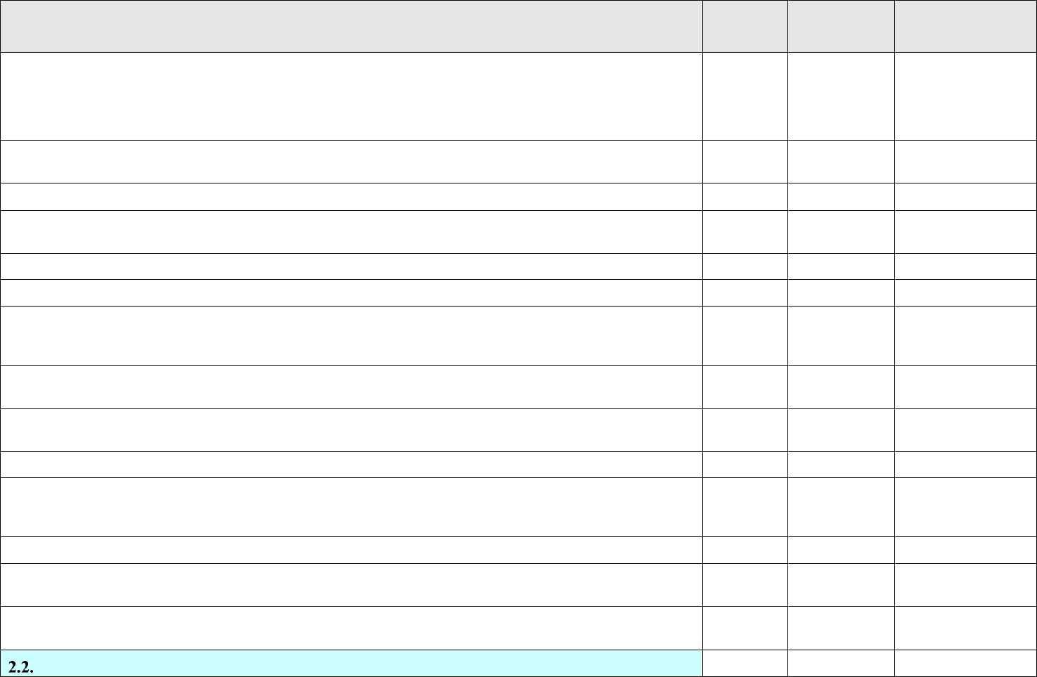
Annex to NASA-STD-8719.24B Payload Project Name Rev: Basic
I – Information/Title N/A – Not Applicable C – Compliant T – Tailored NC – Noncompliant
Page 297 of 455
VOLUME 6: GROUND AND LAUNCH PERSONNEL, EQUIPMENT, SYSTEMS AND
MATERIAL, GROUND OPERATIONS SAFETY REQUIREMENTS
STATUS
TAILORED
TEXT
RATIONALE/
COMMENTS
2.1.3.2.3. Ensure the number of personnel is kept to a minimum in designated safety clearance zones in accordance with
Range Safety approved procedures.
Note: Pad Safety shall be included in the maximum allowable manning level, unless Range Safety determines that adequate
support can be provided from a remote location.
Select Status
2.1.3.2.4. Ensure a comprehensive safety briefing is conducted and understood by participants prior to the start of a hazardous
operation.
Select Status
2.1.3.2.5. Control personnel access into safety clearance zones during hazardous operations.
Select Status
2.1.3.2.6. Advise the operation control authority on whether or not to stop operations when a hazardous condition or a safety
compromise exists.
Select Status
2.1.3.2.7. Allow operations to resume only after the imminent danger no longer exists and safety requirements are met.
Select Status
2.1.3.3. Notifications
I
2.1.3.3.1. Immediately notify the appropriate agency (Command Post at the SLD 30 and Range Safety at SLD 45) of any
launch vehicle or payload mishap, hazard, handling malfunction, or other incident creating or contributing to an unsafe
condition for personnel or critical hardware.
Select Status
2.1.3.3.2. Verbally notify Range Safety of any violation of this document as soon as possible. If requested by Range Safety,
a written report shall be provided to Range Safety within five calendar days of the violation.
Select Status
2.1.3.4. Flight Termination System (FTS) Installation, Checkout, and Status. Monitor and verify the installation, checkout,
and status of the FTS in accordance with Range Safety instructions at locations designated by Range Safety.
Select Status
2.1.3.5. Inspections
I
2.1.3.5.1. Inspect all explosive areas and facilities at least annually to determine compliance with the requirements of this
document and DESR 6055.09_AFMAN 91-201, Explosives Safety Standards. These duties are performed by Weapons Safety
Office (SEW).
Select Status
2.1.3.5.2. Inspect critical facilities prior to the start of a hazardous operation or as directed by Range Safety.
Select Status
2.1.3.5.3. Inspect new and modified critical facilities prior to the initial startup operation, prepare inspection reports on these
facilities, and submit the reports to Range Safety within 15 calendar days of the inspection.
Select Status
2.1.3.5.4. Audit the execution of procedures for handling ordnance, propellant material, and high pressure gases performed
on CCSFS and VSFB at least quarterly.
Select Status
Payload Project Responsibilities
I
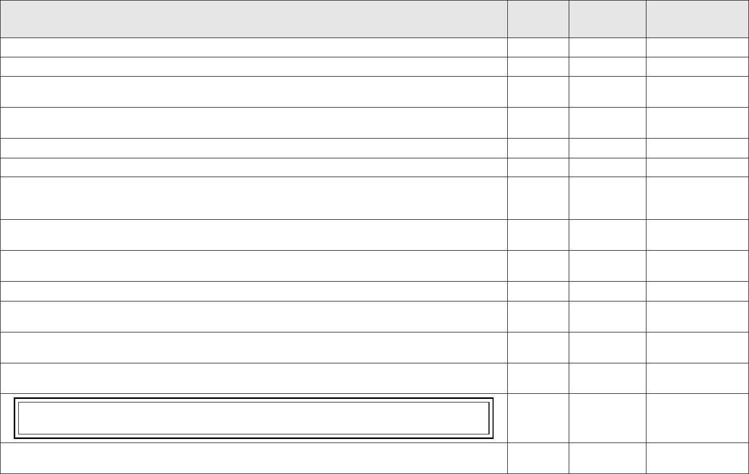
Annex to NASA-STD-8719.24B Payload Project Name Rev: Basic
I – Information/Title N/A – Not Applicable C – Compliant T – Tailored NC – Noncompliant
Page 298 of 455
VOLUME 6: GROUND AND LAUNCH PERSONNEL, EQUIPMENT, SYSTEMS AND
MATERIAL, GROUND OPERATIONS SAFETY REQUIREMENTS
STATUS
TAILORED
TEXT
RATIONALE/
COMMENTS
Payload projects are responsible for the following:
I
2.2.1. Conduct of Operations
I
2.2.2.1. Planning and conducting hazardous and safety critical operations in accordance with procedures approved by the
appropriate local safety authority.
Select Status
2.2.2.2. Planning and conducting operations in accordance with the current edition of the applicable OSP for the launch
complex, facility, or area in use, including ordnance and propellant operations and areas.
Select Status
2.2.2.3. Planning and conducting other operations in accordance with the current edition of other safety plans, as applicable.
Select Status
2.2.3. Notification of Hazardous and Safety Critical Operations to Range Agencies
I
2.2.3.1. Notifying Cape Support (321-853-5211) for the ER and Range Scheduling (805-606-8825) for the WR at least 24
hours before the start of any hazardous system operation while on the Range. The following information shall be provided:
date, time, nature of the operation, location, and procedure or task number.
Select Status
2.2.3.2. Notifying Range Safety and Pad Safety of all hazardous and safety critical operations and tests that are planned to
take place at the Range.
Select Status
2.2.3.3. Notifying Range Safety and Pad Safety at least 30 calendar days before the scheduled erection of a launch vehicle
and/or payload.
Select Status
2.2.4. Document Preparation and Maintenance
I
2.2.4.1. Developing and implementing a Ground Operations Plan (GOP) in accordance with Attachment 1 of this volume to
cover operations conducted on the payload processing facility and launch site area.
Select Status
2.2.4.2. Developing and implementing procedures and general instructions to cover all operations conducted at the payload
processing facility and launch site area.
Select Status
2.2.4.3. Developing, obtaining appropriate safety approval as determined by the PSWG and Range Safety, and implementing
procedures related to hazardous and safety critical operations.
Select Status
The designation of a procedure as "Hazardous" or "Non-Hazardous" is evaluated on a case-by-case basis and does not
necessarily result in mandatory Pad Safety coverage of the operation. The requirements for hazardous procedures may be found
in Attachment 2 of this volume.
I
2.2.4.4. Obtaining appropriate safety authority approval of new procedures or revisions to previously approved procedures
when there is an impact to the safe conduct of the procedure.
Select Status
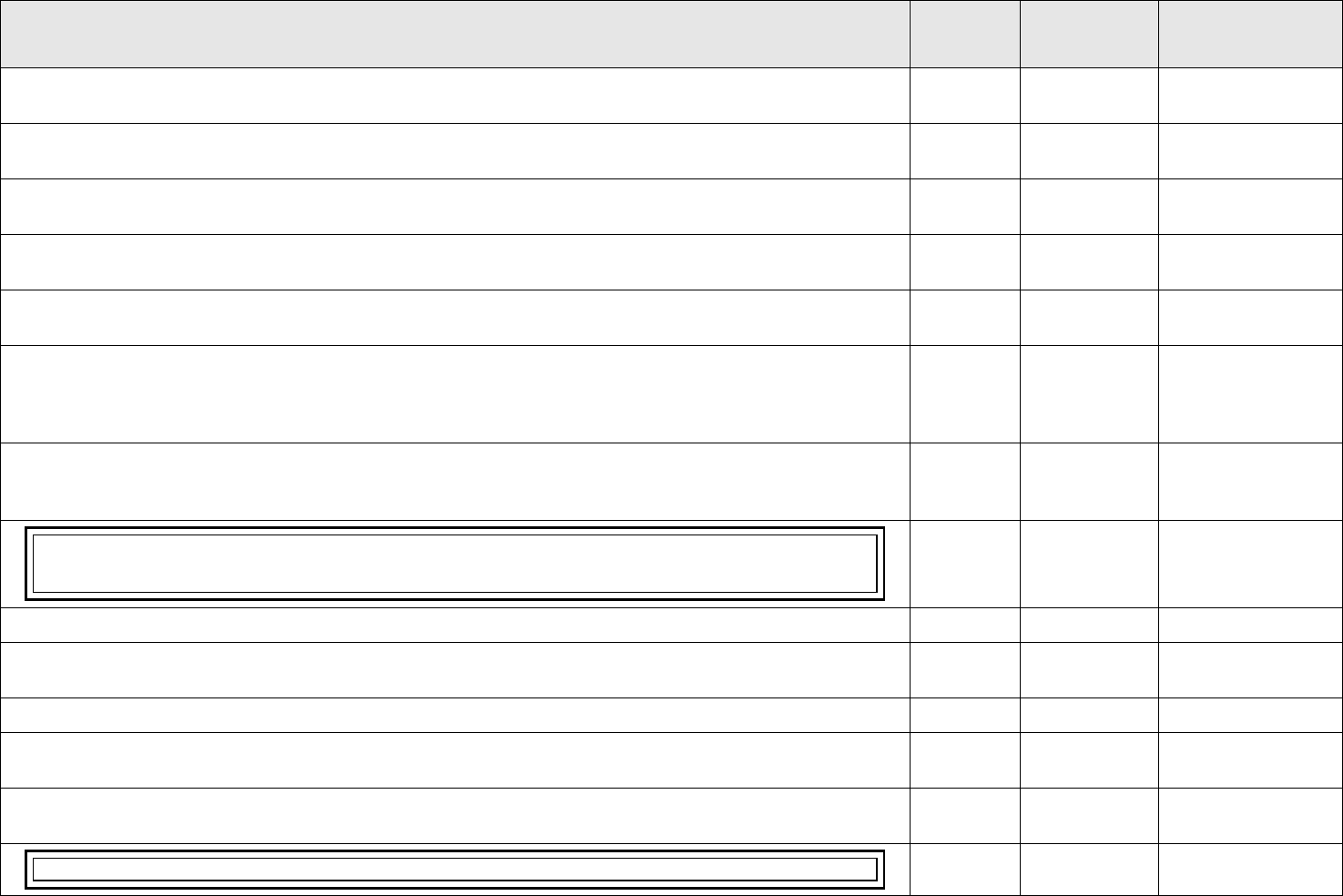
Annex to NASA-STD-8719.24B Payload Project Name Rev: Basic
I – Information/Title N/A – Not Applicable C – Compliant T – Tailored NC – Noncompliant
Page 299 of 455
VOLUME 6: GROUND AND LAUNCH PERSONNEL, EQUIPMENT, SYSTEMS AND
MATERIAL, GROUND OPERATIONS SAFETY REQUIREMENTS
STATUS
TAILORED
TEXT
RATIONALE/
COMMENTS
2.2.4.5. Developing and implementing a program to control hazardous energy sources by locking and tagging in accordance
with lockout/tagout approved procedures.
Select Status
2.2.4.6. Developing, obtaining appropriate safety approval as determined by the PSWG and Range Safety, and implementing
a propellant off-load plan and procedure.
Select Status
2.2.4.7. Developing, obtaining the PSWG and Range Safety approval, and implementing an Emergency Response Plan (ERP)
for graphite/epoxy composite overwrapped and Kevlar-wrapped pressure vessels.
Select Status
2.2.4.8. Developing, implementing, and maintaining records for an In-Service Inspection (ISI) Plan in accordance with the
requirements of this volume and Volume 3.
Select Status
2.2.4.9. Developing, implementing, and maintaining records for a Nondestructive Examination (NDE) Plan in accordance
with the requirements of this volume and Volume 3.
Select Status
2.2.4.14. Obtaining appropriate approval for procedures in accordance with KNPR 8715.3, Kennedy NASA Procedural
Requirements; AFI 40-201, 45TH Space Wing Supplement Radioactive Material (RAM) Management, AFMAN 91-110,
Nuclear Safety Review and Launch Approval for Space or Missile Use of Radioactive Material and Nuclear Systems; or other
local safety authorities and respective safety requirements, as required.
Select Status
2.2.4.17. Developing and implementing a training plan for all payload project personnel performing hazardous and safety
critical procedures and operations and submitting an outline of this training plan to the PSWG for the PSWG and Range Safety
for approval.
Select Status
The local safety authority responsible for review and approval of hazardous procedures should evaluate the training plan for
areas that could lead to a mishap caused by inadequate training and could affect workers of other employers, range assets, and
the general public.
I
2.2.4.18. Developing pathfinder requirements in coordination with the PSWG and Range Safety.
Select Status
2.2.4.19. At the WR, developing, obtaining SLD30/SE Range Safety approval and PSWG concurrence, and implementing a
SLD/SE 30 First Use Tag Program for lifting hardware at the WR.
Select Status
2.2.5. Operational Duties
I
2.2.5.1. Ensuring required support and emergency elements approved by the appropriate local safety authority have continuous
access to any area where hazardous conditions could occur.
Select Status
2.2.5.2. Obtaining concurrence to proceed from the appropriate local safety authority before starting any hazardous and safety
critical operations and before resuming any operation that has been interrupted resumes.
Select Status
Interruptions include such events as a safety hold, shift change, evacuation, or breaks.
I

Annex to NASA-STD-8719.24B Payload Project Name Rev: Basic
I – Information/Title N/A – Not Applicable C – Compliant T – Tailored NC – Noncompliant
Page 300 of 455
VOLUME 6: GROUND AND LAUNCH PERSONNEL, EQUIPMENT, SYSTEMS AND
MATERIAL, GROUND OPERATIONS SAFETY REQUIREMENTS
STATUS
TAILORED
TEXT
RATIONALE/
COMMENTS
2.2.5.3. Before initiating hazardous or safety critical operations, the following shall be accomplished:
Select Status
2.2.5.3.1. Pre-operation and shift change briefings.
Select Status
2.2.5.3.2. Pre-operation and shift change inspections to verify proper system, facility, and area configuration; personnel and
equipment support; and use of an approved procedure.
Select Status
2.2.5.5. Observing, evaluating, and enforcing compliance with applicable safety requirements by all personnel within launch
complexes, assembly, and checkout areas, propellant and ordnance storage areas, and other areas as deemed appropriate by
Range Safety or the appropriate local safety authority.
Select Status
2.2.5.6. Reviewing and providing comments on hazardous and safety critical procedures to Range Safety or the appropriate
local safety authority.
Select Status
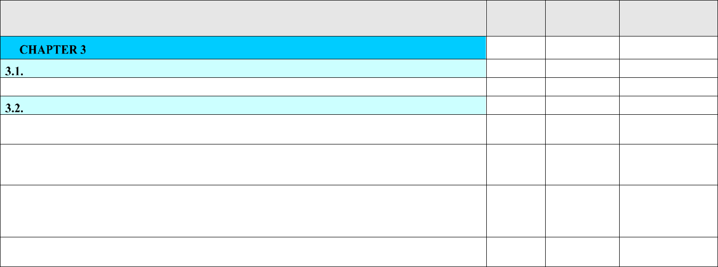
Annex to NASA-STD-8719.24B Payload Project Name Rev: Basic
I – Information/Title N/A – Not Applicable C – Compliant T – Tailored NC – Noncompliant
Page 301 of 455
VOLUME 6: GROUND AND LAUNCH PERSONNEL, EQUIPMENT, SYSTEMS AND
MATERIAL, GROUND OPERATIONS SAFETY REQUIREMENTS
STATUS
TAILORED
TEXT
RATIONALE/
COMMENTS
GROUND OPERATIONS POLICIES
I
Personnel Safety
I
3.1.1. All personnel shall be protected during the performance of operations.
Select Status
Stopping Unsafe Operations
I
3.2.1. All personnel shall have authority to stop immediately operations or practices that, if allowed to continue, could
reasonably be expected to result in death or serious physical harm to personnel or major system damage.
Select Status
3.2.2. All personnel are authorized to stop operations or practices when imminent danger cannot be eliminated through regular
channels. Personnel observing an unsafe operation or practice shall report their observations to a safety representative, an
operational supervisor, or any other appropriate authority.
Select Status
3.2.3. Notification of Action. Any action taken to stop an unsafe operation where imminent danger is involved shall be
followed by direct verbal, telephone, or radio communication and notification to the appropriate safety authority. For Space
Force Ranges notifications, include Pad Safety at the ER and Range Safety at the WR, the Squadron Commander, the Group
Commander, or their designated representative.
Select Status
3.2.4. Notification of Work Stoppage. The Contracting Officer or Administrator for an Space Force Construction Contract
shall be immediately notified of any work stoppage of their respective construction contract.
Select Status
Annex to NASA-STD-8719.24B Payload Project Name Rev: Basic
I – Information/Title N/A – Not Applicable C – Compliant T – Tailored NC – Noncompliant
Page 302 of 455
VOLUME 6: GROUND AND LAUNCH PERSONNEL, EQUIPMENT, SYSTEMS AND
MATERIAL, GROUND OPERATIONS SAFETY REQUIREMENTS
STATUS
TAILORED
TEXT
RATIONALE/
COMMENTS
DOCUMENTATION REQUIREMENTS
I
Ground Operations Plans
Select Status
GOPs shall be developed in accordance with the requirements in Attachment 1 of this volume and submitted to the PSWG
for PSWG and Range Safety review and approval.
Select Status
4.1.1. The GOP provides a detailed description of hazardous and safety critical operations for processing aerospace systems
and their associated ground support equipment (GSE). Along with the Safety Data Package (Missile System Prelaunch Safety
Package (MSPSP)), the GOP is the medium from which payload safety approval is obtained.
Select Status
4.1.2. A high level Ground Operations Flow Overview shall be provided at the Payload Safety Introduction Briefing. The
preliminary Draft GOP is due 30 days prior to project’s mission CDR for Safety Review II per NPR 8715.7. The Final GOP
shall be submitted 90 days prior to the payload shipment to the processing site per NPR 8715.7. The information from a GOP
may be part of the respective Safety Data Packages as an inclusion or may be a separate document. The level of detail provided
in the GOP data shall be commensurate with the level of data available at the time of submission.
Select Status
4.1.3. The final GOP shall be submitted no later than 60 days prior to the Safety Review III meeting and at least 90 days prior
to intended shipment of hardware to the prelaunch payload processing site per NPR 8715.7.
Select Status
4.1.4. The GOP shall be approved before the start of any hazardous operations.
Select Status
Test and Inspection Plans
Select Status
Test and inspection plans shall be developed to document the initial and recurring validation of component compliance and
assessment of hazards. Test and inspection plans shall be developed for the following items that include, but are not limited
to, material handling equipment, ground support pressure vessels, and ground support propellant systems. Specific
requirements for each of these systems are discussed in this volume.
Select Status
4.2.1. Equipment and System Logs and Test Records.
I
4.2.1.1. Unless otherwise specified in a separate part of this volume that addresses a particular class of system or equipment,
logs and test records shall be maintained on critical ground support systems and major fixed equipment. Logs and test records
shall comply with the following:
Select Status
4.2.1.1.1. Logs and test records shall contain chronological entries including:
Select Status
4.2.1.1.1.1. Records of use or running time.
Select Status
4.2.1.1.1.2. Maintenance.
Select Status
4.2.1.1.1.3. Modifications.
Select Status
4.2.1.1.1.4. Tests, inspections, acceptable parameters, and results.
Select Status
Annex to NASA-STD-8719.24B Payload Project Name Rev: Basic
I – Information/Title N/A – Not Applicable C – Compliant T – Tailored NC – Noncompliant
Page 303 of 455
VOLUME 6: GROUND AND LAUNCH PERSONNEL, EQUIPMENT, SYSTEMS AND
MATERIAL, GROUND OPERATIONS SAFETY REQUIREMENTS
STATUS
TAILORED
TEXT
RATIONALE/
COMMENTS
4.2.1.1.2. Discrepancies and out of specification results shall be clearly identified.
Select Status
4.2.1.1.3. Resolution of discrepancies and out of specification results shall be noted.
Select Status
4.2.1.2. Logs and test records shall be maintained for the life of the system/equipment.
Select Status
4.2.1.3. Logs and test records shall be available to the PSWG and Range Safety upon request.
Select Status
Safety and Emergency Plans
I
4.3.1. Operations Safety Plans and Danger Area Information Plans
Select Status
4.3.1.1. Payload project shall comply with and implement in their operations, applicable OSPs, and emergency plans.
Select Status
4.3.3. Emergency Evacuation Plans
I
4.3.3.1. EEPs detailing safety and emergency actions shall be developed by facility operators and posted in every building,
facility, and area.
I
4.3.3.2. EEPs shall include the following information:
I
4.3.3.2.1. Identification of exit/egress routes.
I
4.3.3.2.2. Identification of primary and alternate Emergency Evacuation Assembly Points (EEAPs); EEAPs shall be
designated by signs.
I
4.3.3.2.3. Responsibilities of supervisors and personnel for duties assigned in an emergency.
I
4.3.3.2.4. Actions to be taken to safe an operation.
I
4.3.3.2.5. Methods of communication including aural warning systems and public address (PA) announcements.
I
4.3.3.2.6. Location of fire alarm boxes and other emergency activation devices.
I
4.3.3.2.7. Required emergency equipment and PPE.
I
4.3.3.2.8. Required personnel training.
I
4.3.3.2.9. Reporting requirements such as, but not limited to, Squadron Commander or Command Post.
I
Procedures
I
4.4.1. General Requirements for Procedures
I
4.4.1.1. Procedures and general operating instructions for all operations shall be developed by the payload project and
reviewed by the appropriate local safety authority.
Select Status
Annex to NASA-STD-8719.24B Payload Project Name Rev: Basic
I – Information/Title N/A – Not Applicable C – Compliant T – Tailored NC – Noncompliant
Page 304 of 455
VOLUME 6: GROUND AND LAUNCH PERSONNEL, EQUIPMENT, SYSTEMS AND
MATERIAL, GROUND OPERATIONS SAFETY REQUIREMENTS
STATUS
TAILORED
TEXT
RATIONALE/
COMMENTS
4.4.1.2. All procedures shall be written in accordance with the requirements provided in Attachment 2 of this volume and
local safety requirements.
Select Status
When a procedure references another source (e.g., technical order, another procedure), it should be made available for review
upon request.
I
4.4.1.3. Brief summaries of all procedures shall be submitted as part of the GOP review and approval process. At that time,
the operating procedure summaries shall be designated as “Hazardous,” “Non-Hazardous,” or “Safety Critical.” These
designations shall be justified in the operating procedure summaries. Local safety authorities may designate additional
processes and operations as “Hazardous” or “Safety Critical.”
Select Status
4.4.1.4. Revisions to any procedures shall be submitted to the appropriate local safety authorities for review and approval
when there is a potential impact on the safe conduct of an operation.
Select Status
4.4.2. Hazardous and Safety Critical Procedures
I
4.4.2.1. Procedures for hazardous and safety critical operations shall be developed in accordance with the requirements in
Attachment 2 of this volume. Emergency actions shall be included in the procedures. Hazardous and safety critical procedures
shall be reviewed and approved by the appropriate local safety authority. Approval of hazardous and safety critical procedures
shall not be given until the pertinent data sections of the SDP (MSPSP) and GOP have been reviewed and approved.
Select Status
4.4.2.2. Disapproval of a formally submitted procedure may result in an additional 30 calendar day review time submittal and
possible delay of operations. The payload projects are encouraged to provide a draft of a typical procedure for early review by
all appropriate local safety authorities.
Select Status
Range User Training Plan
Select Status
A training plan listing all training courses used for personnel involved with hazardous or safety critical operations and
procedures shall be submitted to the PSWG in conjunction with Range Safety as part of the GOP.
Select Status
Mishap Reporting
Select Status
Mishap reporting shall be in accordance with NPR 8621.1, NASA Procedural Requirements for Mishap and Close Call
Reporting, and in accordance with local safety authorities’ procedures.
I
4.6.1. Mishaps Involving Space Force Personnel and Property. Reporting criteria for mishaps involving Space Force
personnel and property are established in AFI 91-204, Safety Investigations and Reports. Mishaps involving radioactive
materials shall be reported in accordance with AFMAN 91-110, Nuclear Safety Review and Launch Approval for Space or
Missile Use of Radioactive Material and Nuclear Systems.
Select Status
Annex to NASA-STD-8719.24B Payload Project Name Rev: Basic
I – Information/Title N/A – Not Applicable C – Compliant T – Tailored NC – Noncompliant
Page 305 of 455
VOLUME 6: GROUND AND LAUNCH PERSONNEL, EQUIPMENT, SYSTEMS AND
MATERIAL, GROUND OPERATIONS SAFETY REQUIREMENTS
STATUS
TAILORED
TEXT
RATIONALE/
COMMENTS
4.6.2. Accident Notification Plan. An Accident Notification Process complying with NPR 8621.1 and the Project’s Mishap
Preparedness and Contingency Plan, as well as local requirements, shall be included in the GOP to ensure proper notification
of personnel at the various stages and locations of payload processing. The PSWG Chairperson shall be notified immediately
of any payload project mishap (accident) or close call.
Select Status
4.6.3. Support to Investigations. The payload project will provide reasonable support for mishap investigations, including
providing access to all pertinent documents and personnel who may have relevant information.
Select Status
Safety for Return-to Earth Payloads or Sample Returns
I
4.7.1. Payload or Sample Return Recovery Safety Plan
I
4.7.1.1. The payload project shall prepare and implement a comprehensive Payload or Sample Return Recovery Safety
Plan to ensure safety during return-to-Earth payload or sample recovery.
Select Status
4.7.1.2. The Payload or Sample Return Recovery Safety Plan shall:
Select Status
4.7.1.2.1. Identify each organizational unit involved in the payload or sample recovery operations.
Select Status
4.7.1.2.2. Define in detail the roles, responsibilities, and authorities of each organizational unit, field team, and key
personnel for each task.
Select Status
4.7.1.2.3. Describe interfaces and communications between all organizational units and field teams to be used in payload
or sample recovery and transportation for both nominal and off-nominal recovery scenarios.
Select Status
4.7.1.3. A Recovery Command System similar to the Incident Command System process used by departments, agencies,
and private sector organizations shall be used in the execution of recovery operations.
Select Status
4.7.1.4. The local safety authority's plan for safe recovery operations shall be reviewed for adequacy as applicable.
Modifications for a particular mission or for a set of planned missions will be jointly coordinated and approved before the
scheduled launch date.
Select Status
4.7.1.5. Changes to the Recovery Safety Plan subsequent to the "final" edition will be expediently coordinated with the local
safety authorities.
Select Status
4.7.2. Recovery Hazard Analysis
I
4.7.2.1. The payload project shall perform and document an operations hazard analysis identifying and assessing hazards
associated with payload or sample recovery operations, nominal and off-nominal.
Select Status
4.7.2.2. Hazards identified shall be documented on the NF 1825 NASA Payload Safety Hazard Report found on the NASA
Payload Safety Program website at https://kscsma.ksc.nasa.gov/PayloadSafety or an equivalent form that contains all
information required on NF 1825.
Select Status
4.7.2.3. Hazard controls or elimination activities shall be incorporated into the payload, operations involving payload or
sample recovery, and related support equipment.
Select Status
4.7.3. Recovery Hazardous Operations
I

Annex to NASA-STD-8719.24B Payload Project Name Rev: Basic
I – Information/Title N/A – Not Applicable C – Compliant T – Tailored NC – Noncompliant
Page 306 of 455
VOLUME 6: GROUND AND LAUNCH PERSONNEL, EQUIPMENT, SYSTEMS AND
MATERIAL, GROUND OPERATIONS SAFETY REQUIREMENTS
STATUS
TAILORED
TEXT
RATIONALE/
COMMENTS
4.7.3.1. Hazardous recovery operations shall be performed in accordance with existing institutional and local safety
standards, national consensus standards (e.g., ANSI, NFPA), or special supplemental alternative standards when there are
no known suitable existing standards.
Select Status
4.7.3.2. Written procedures approved by the local safety authorities shall be provided in accordance with Attachment 2,
Hazardous and Safety Critical Procedures, of this Volume.
Select Status
4.7.4. Payload or Sample Return Recovery Operations Safety Training
I
4.7.4.1. The payload project shall develop safety training courses for personnel involved with hazardous or safety critical
operations during the payload or sample recovery operations. The training shall cover applicable local requirements,
various roles, responsibilities, and authorities.
Select Status
4.7.4.2. Safety training courses shall include information on hazards and preventing injury during payload or sample
recovery operations.
Select Status
4.7.5. Mishap Preparedness and Contingency Plan. The payload project is required by NPR 8621.1, NASA Procedural
Requirements for Mishap and Close Call Reporting, Investigating, and Recordkeeping, to ensure the project’s Mishap
Preparedness and Contingency Plan includes payload return or sample return contingencies.
Select Status
4.7.6. Safety Data Submittal, Schedule, Review, and Approval
I
4.7.6.1. Payload or Sample Recovery Safety Plan.
I
4.7.6.1.1. A draft Payload or Sample Recovery Safety Plan shall be submitted to appropriate local safety authorities and
the NASA project safety management for review prior to the project’s Preliminary Design Review (PDR).
Select Status
4.7.6.1.2. A baselined Payload or Sample Recovery Safety Plan shall be submitted to appropriate local safety authorities
and the NASA project safety management for review and approval prior to the project’s Critical Design Review (CDR).
Select Status
4.7.6.1.3. The Payload or Sample Recovery Safety Plan is a living document and shall be updated as design or operational
changes impact recovery operations.
Select Status
4.7.6.1.4. The final Payload or Sample Recovery Safety Plan shall be submitted for review and approval to the appropriate
local safety authorities and the NASA project safety management at least 180 days prior to payload or sample recovery.
Select Status
4.7.6.2. Recovery Hazard Reports
I
4.7.6.2.1. Preliminary Hazard Reports shall be submitted for review and approval to the appropriate local safety authorities
and the NASA project safety management prior to the project’s PDR.
Select Status
4.7.6.2.2. Updated Hazard Reports shall be submitted for review and approval to the local safety authorities and the NASA
project safety management prior to the project’s CDR.
Select Status
4.7.6.2.3. Updated Hazard Reports shall be submitted to the appropriate local safety authorities and the NASA project
safety management for review and approval prior to the project’s Operational Readiness Review (ORR).
Select Status
4.7.6.2.4. Final Hazard Reports shall be submitted for review and approval to the local safety authorities and the NASA
project safety management at least 180 days prior to payload or sample recovery.
Select Status
4.7.6.3. Hazardous Operations
I

Annex to NASA-STD-8719.24B Payload Project Name Rev: Basic
I – Information/Title N/A – Not Applicable C – Compliant T – Tailored NC – Noncompliant
Page 307 of 455
VOLUME 6: GROUND AND LAUNCH PERSONNEL, EQUIPMENT, SYSTEMS AND
MATERIAL, GROUND OPERATIONS SAFETY REQUIREMENTS
STATUS
TAILORED
TEXT
RATIONALE/
COMMENTS
4.7.6.3.1. Documented procedures for all hazardous operations shall be provided to the appropriate local safety authorities
and NASA project safety management for review and approval at least 180 days prior to payload or sample recovery.
Select Status
4.7.6.3.2. Finalized documented procedures for hazardous operations shall be made available to the local safety authorities,
the Recovery System Incident Commander, and all those performing and managing hazardous operations during payload
or sample recovery at least 60 days prior to payload or sample recovery.
Select Status
Annex to NASA-STD-8719.24B Payload Project Name Rev: Basic
I – Information/Title N/A – Not Applicable C – Compliant T – Tailored NC – Noncompliant
Page 308 of 455
VOLUME 6: GROUND AND LAUNCH PERSONNEL, EQUIPMENT, SYSTEMS AND
MATERIAL, GROUND OPERATIONS SAFETY REQUIREMENTS
STATUS
TAILORED
TEXT
RATIONALE/
COMMENTS
GROUND OPERATIONS SAFETY REQUIREMENTS
I
Ground Operations Personnel Requirements
I
5.1.1. Personnel Training, Certification and Experience. A list of personnel training, certification, and experience
requirements shall be available as part of the payload project’s training plan.
Select Status
5.1.2. Ground Operations Safety Orientation and Training
I
5.1.2.1. All payload projects shall ensure that their personnel receive formal safety, fire prevention, medical surveillance, and
occupational health orientation and training before receiving a controlled area badge. The employer is responsible to ensure
the training is adequate and complete.
Select Status
5.1.2.2. Unique personnel training and certification requirements for hazardous operations such as ordnance, crane operations,
forklift operations, PPE, and SCAPE shall be specified in the appropriate procedures.
Select Status
5.1.3. Personnel Conduct
Select Status
5.1.3.1. Food, Beverage, and Cigarette Consumption. The payload project shall ensure that eating, drinking, or smoking,
including the use of e-cigarettes, is authorized only in designated areas.
Select Status
5.1.3.2. Alcoholic Beverages and Narcotics
Select Status
5.1.3.2.1. The payload project shall ensure that the use of alcoholic beverages and narcotics while on duty is prohibited.
Select Status
5.1.3.2.2. The payload project shall require that their personnel taking prescription or non-prescription medications that could
affect performance notify their supervisor.
Select Status
5.1.3.3. Mischief. The payload project shall ensure that their personnel are prevented from indulgence in practical jokes,
horseplay, scuffling, and wrestling.
Select Status
5.1.4. Work Time Restrictions
I
5.1.4.1. The payload project supervisors at all levels shall ensure their personnel will not be assigned to, and will not participate
in, critical operations if it is evident that their physiological or psychological wellbeing is, or is likely to be, adversely affected
by immunizations, fatigue, blood donations, use of drugs, illness, consumption of alcohol, or other stress conditions. For
payload operations on NASA or NASA contracted facilities, the payload project or contractor shall adhere to the requirements
in NPR 1800.1, paragraph 2.14, and their Center’s or organizations maximum work time policies and requirements but in no
case shall an employee work in excess of 16 consecutive hours. For payload and launch operations on Space Force property
the following shall apply:
Select Status
5.1.4.2. Each duty period for mission ready (Category A) and mission support (Category B) personnel, including participation
in a launch or launch attempt activity, shall be preceded by an available rest period.
Select Status

Annex to NASA-STD-8719.24B Payload Project Name Rev: Basic
I – Information/Title N/A – Not Applicable C – Compliant T – Tailored NC – Noncompliant
Page 309 of 455
VOLUME 6: GROUND AND LAUNCH PERSONNEL, EQUIPMENT, SYSTEMS AND
MATERIAL, GROUND OPERATIONS SAFETY REQUIREMENTS
STATUS
TAILORED
TEXT
RATIONALE/
COMMENTS
5.1.4.3. Planned duty for personnel in either mission ready or mission support should normally be 8 hours, starting when the
individual reports for duty. Those personnel identified to support operational tests shall not be scheduled for duty during the
planned rest period.
Select Status
5.1.4.4. Hazardous Operations and Prelaunch Attempts. The following criteria shall be used for determining hours worked
versus rest time for all personnel who work with hazardous systems, materials, or components, or who accomplish prelaunch
functions that require a high degree of concentration:
Select Status
5.1.4.4.1. Maximum 12-hour shift, unless approved by Range Safety or a USAF Squadron Commander, with at least 8 hours
of rest after 12 hours of work.
Select Status
5.1.4.4.2. A maximum of 60 hours per week.
Select Status
5.1.4.4.3. A maximum of 14 consecutive days.
Select Status
5.1.4.5. Consecutive Launch Attempts
Select Status
5.1.4.5.1. When 12-hour shifts are required and launches are rescheduled on a 24-hour basis, consideration shall be given for
a 48-hour launch delay after 3 consecutive back-to-back launch attempts.
Select Status
5.1.4.5.2. In the event mission impacts or operational requirements necessitate 12-hour shifts, mission ready personnel shall
not be scheduled for more than 5 consecutive shifts without a 48-hour break and mission support personnel shall not be
scheduled for more than 6 consecutive shifts without a 24-hour break.
Select Status
5.1.4.6. SLD 30 Additional Work Restrictions
Select Status
5.1.4.6.1. In the event of a missile accident, emergency, or operational necessity, the duty time limits defined in this volume
may be exceeded with the expressed knowledge of the SLD 30 Commander or Vice Commander, commanders of tenant
organizations, or the SLD 30 Chief of Safety for personnel under their respective control.
Select Status
5.1.4.6.2. When mission requirements dictate, the duty period may be extended to 12 hours by the first level supervisor. Rest
periods and break periods shall be provided according to appropriate regulations and negotiated agreements.
Select Status
5.1.4.6.3. If, after a complete evaluation of the potential hazards involved, mission requirements dictate a duty period in excess
of 12 hours, the following criteria shall apply:
Select Status
5.1.4.6.3.1. For mission ready (Category A) personnel, the duty periods may be increased to 14 hours or rest periods may be
waived with the express knowledge of the SLD 30 Commander or Vice Commander, WR Commander, Operations Groups
Commander, or the Chief of Safety.
Select Status
5.1.4.6.3.2. For mission support (Category B) personnel, the duty period may be increased to 14 hours with the expressed
knowledge of the applicable division chief or equivalent level supervisor.
Select Status
Annex to NASA-STD-8719.24B Payload Project Name Rev: Basic
I – Information/Title N/A – Not Applicable C – Compliant T – Tailored NC – Noncompliant
Page 310 of 455
VOLUME 6: GROUND AND LAUNCH PERSONNEL, EQUIPMENT, SYSTEMS AND
MATERIAL, GROUND OPERATIONS SAFETY REQUIREMENTS
STATUS
TAILORED
TEXT
RATIONALE/
COMMENTS
Hazardous Ground Operations General Requirements
I
5.2.1. Pathfinder Requirements
I
5.2.1.1. The PSWG, Range Safety and payload project shall determine which procedures require a pathfinder and its necessary
fidelity.
Select Status
5.2.1.2. Before the first use of applicable hazardous procedures, including contingency, such as operations with live ordnance,
pressure systems, or propellant, pathfinder operations shall be conducted at the payload processing facility and launch site area
in a nonhazardous fashion by using inert or dummy ordnance, non-pressurized systems, or non-fueled systems.
Select Status
5.2.1.2.1. Handling operations shall be performed with inert or dummy equipment that simulates the flight unit in form, fit,
function, weight, and center of gravity.
Select Status
5.2.1.2.2. Pressure and propellant system operations shall be performed with equipment that simulates flight equipment valve
connections and operations.
Select Status
5.2.1.2.3. Pathfinder operations shall use GSE that will be used for flight operations.
Select Status
5.2.1.2.4. The project shall work with the local safety authority (who is responsible for the safety operations in the area) to
develop acceptance criteria for pathfinder operations and evaluate whether the acceptance criteria have been met.
Select Status
5.2.2. Control of Access to Hazardous Operations. A control area shall be established for each hazardous operation in
accordance with local safety requirements for the hazard(s). Man-loading shall be determined and implemented for each
hazardous control area. The appropriate safety authority as identified by the PSWG and Range Safety shall establish personnel
limits, entry control, and control areas for all hazardous operations.
Select Status
5.2.2.1. Personnel Limits for Hazardous Ground Operations
I
5.2.2.1.1. Personnel limits shall be established for all hazardous operations and tasks. Deviation from approved access list
numbers requires approval from the local safety authority.
Select Status
5.2.2.1.2. The supervisor in charge of the building or operation is responsible for maintaining personnel load limits for that
building or operation.
I
5.2.2.2. Control of Access to All Hazardous Operations
I
5.2.2.2.1. Hazardous areas shall be fenced, barricaded, or cordoned off and personnel access control maintained at a central
control point.
Select Status
5.2.2.2.2. Access roads shall be closed by barricades, guards, or signs during hazardous operations for positive control of
personnel and vehicles. Emergency vehicles shall not traverse the controlled area if another route is available.
Select Status

Annex to NASA-STD-8719.24B Payload Project Name Rev: Basic
I – Information/Title N/A – Not Applicable C – Compliant T – Tailored NC – Noncompliant
Page 311 of 455
VOLUME 6: GROUND AND LAUNCH PERSONNEL, EQUIPMENT, SYSTEMS AND
MATERIAL, GROUND OPERATIONS SAFETY REQUIREMENTS
STATUS
TAILORED
TEXT
RATIONALE/
COMMENTS
5.2.2.2.3. When hazardous operations are covered by Pad Safety, Pad Safety shall control access. When hazardous operations
are not covered by Pad Safety, the operation test conductor shall control access.
Select Status
5.2.2.3. Personnel Restrictions for Hazardous Ground Operations
I
5.2.2.3.1. Non-essential personnel shall leave hazardous areas (safety clearance zones) before the start of operations.
Select Status
5.2.2.3.2. Whenever a warning light status is changed or an audible signal is sounded, a PA announcement shall precede it
and identify the reason for the change.
Select Status
5.2.2.3.3. Each facility and/or area shall have instruction signs informing personnel of the area aural and warning light scheme
before entry.
Select Status
5.2.2.3.4. The buddy system shall be used in all hazardous operations.
Select Status
5.2.2.3.5. Area Warning Lights. Personnel with the appropriate badge and security clearance have access to areas in
accordance with the following:
Select Status
5.2.2.3.5.1. A flashing green light indicates the controlled area is open to normal work. Hazardous commodities may be
present in the area, but no hazardous operations are in progress. Access is controlled by Security/Hazardous Support
Operations (HOS).
Select Status
5.2.2.3.5.2. A flashing amber light indicates a hazardous operation is in progress in the controlled area. Non-essential
personnel shall be cleared from the controlled area. Personnel shall not enter without permission from Pad Safety or, in the
absence of Pad Safety, the entry control authority.
Select Status
5.2.2.3.5.3. A flashing red light indicates an emergency situation in the controlled area. All personnel shall evacuate the
controlled area to the EEAP. This signal shall be accompanied by the sounding of an audible alarm and a PA announcement.
This signal is also used to clear all personnel from a launch complex before a launch or for a hazardous operation that requires
clearing the complex, such as wet dress rehearsal or static fire. At the WR, a flashing red light also designates a dangerous
operation for ballistic missile operations [e.g., follow-on test and evaluation (FOT&E) where work is performed under the
strict control of technical orders (TOs)].
Select Status
5.2.3. Hot Work Operations
I
5.2.3.1. Hot Work Operating Standards. Hot work (open flame) operations including welding, soldering, cutting, brazing,
grinding, or heating of materials in such a manner as to cause a source of ignition shall be conducted in accordance with 29
CFR 1910.252, (Subpart Q, Welding, Cutting and Brazing), General Requirements, and American National Standards Institute
(ANSI) Z49.1, Safety in Welding, Cutting, and Allied Processes as well as local safety requirements. AFMAN 91-203
(Chapter 27, Welding, Cutting, and Brazing) applies for hot work operations on USAF properties.
Select Status
5.2.3.2. Hot Work Operations Training and Certification. All welders shall be trained and certified by competent authority to
standards no less than those established by the American Welding Society (AWS).
Select Status
Annex to NASA-STD-8719.24B Payload Project Name Rev: Basic
I – Information/Title N/A – Not Applicable C – Compliant T – Tailored NC – Noncompliant
Page 312 of 455
VOLUME 6: GROUND AND LAUNCH PERSONNEL, EQUIPMENT, SYSTEMS AND
MATERIAL, GROUND OPERATIONS SAFETY REQUIREMENTS
STATUS
TAILORED
TEXT
RATIONALE/
COMMENTS
5.2.3.3. Hot Work General Operating Requirements
I
5.2.3.3.1. A written permit shall be obtained from the Fire Marshall before performing hot work.
Select Status
5.2.3.3.2. Locations where hot work will be routinely performed may operate on an indefinite permit if that area is subject to
periodic Fire Department inspections.
Select Status
5.2.3.3.3. A fire watch shall be maintained during and after the hot work until such time the fire watch determines that the
combustion hazard no longer exists.
Select Status
5.2.3.3.4. The requirement for the Fire Department to perform the fire watch shall be determined on a case-by-case basis by
the Fire Marshall and the appropriate local safety authority.
Select Status
5.2.3.3.5. Proper housekeeping and protective shields and barriers shall be used to prevent inadvertent combustion.
Select Status
5.2.3.3.6. Combustibles shall be kept at least 35 feet away from the operation.
Select Status
5.2.3.3.7. A suitable fire extinguisher shall be available.
Select Status
5.2.3.4. Hot Work Within Ordnance or Propellant Areas. Hot work within ordnance or propellant areas shall be
coordinated with the local safety authority as well as the range Fire Department.
Select Status
Normally, fire watches are conducted by the Range User; however, there may be instances when, after consultation
with Range Safety on any unique hazards or operating environment considerations (such as a nearby fueled
spacecraft, ordnance, hypergolic propellants), the Fire Marshall determines a Fire Department engine crew on-site
is warranted.
I
5.2.3.3.5. Proper housekeeping and protective shields and barriers shall be used to prevent inadvertent combustion.
Select Status
5.2.3.3.6. Combustibles shall be kept at least 35 feet away from the operation.
Select Status
5.2.3.3.7. A suitable fire extinguisher shall be available.
Select Status
5.2.3.5. Hot Work on Containers and Lines That May Have Contained Explosives or Flammables. Hot work shall not
be performed on containers and lines that may have contained explosives or flammables and that have not been properly
cleaned and purged.
Select Status
5.2.4. Control of Hazardous Energy Sources
I
5.2.4.1. Hazardous energy sources shall be controlled through a lockout/tagout program that complies with the requirements
of 29 CFR 1910.147, The Control of Hazardous Energy (Lockout/Tagout), AFMAN 91-203 (Chapter 21, Hazardous Energy
Control), and ANSI Z244.1, Control of Hazardous Energy Lockout/Tagout and Alternative Methods, as well as local safety
requirements.
Select Status
Annex to NASA-STD-8719.24B Payload Project Name Rev: Basic
I – Information/Title N/A – Not Applicable C – Compliant T – Tailored NC – Noncompliant
Page 313 of 455
VOLUME 6: GROUND AND LAUNCH PERSONNEL, EQUIPMENT, SYSTEMS AND
MATERIAL, GROUND OPERATIONS SAFETY REQUIREMENTS
STATUS
TAILORED
TEXT
RATIONALE/
COMMENTS
5.2.4.2. Lockout/tagout procedures shall be developed by the payload project and approved by the appropriate local safety
authority.
Select Status
5.2.5. Confined Space, Tank Entry, and Tank Cleaning
I
5.2.5.1. Personnel who enter and work within permit-required confined spaces shall comply with appropriate controls as
defined in 29 CFR 1910.146, Permit-Required Confined Spaces; ANSI Z117.1, Safety Requirements for Entering Confined
Spaces, AFMAN 91-203 (Chapter 23, Confined Spaces), and local safety requirements.
Select Status
5.2.5.2. The payload projects, contractors, and subcontractors who will be entering confined spaces other than the contractor’s
equipment and flight hardware shall contact the appropriate local safety authority at the start of the project to obtain information
about the confined space.
Select Status
5.2.6. Tethering of Equipment
I
5.2.6.1. Hand-held tools, equipment, and personal belongings shall be tethered in any area where dropped objects could pose
a hazard to personnel.
Select Status
5.2.6.2. Falling Object Hazards to be considered in determining tethering requirements include direct contact with personnel
or the consequences of damaging critical hardware providing the potential of latent or immediate hazards to personnel from
damaged hardware.
Select Status
Personal Protective Equipment
I
5.3.1. Payload Project Responsibilities. The payload project shall provide the applicable PPE required for the work location
that meets the requirements established by 29 CFR 1910.132, (Subpart I-Personal Protective Equipment), General
Requirements; 29 CFR 1910.133, Eye and Face Protection; 29 CFR 1910.134, Respiratory Protection; 29 CFR 1910.135,
Head Protection; 29 CFR 1910.136, Foot Protection; California Occupational Safety and Health (CAL-OSHA) (WR only);
ANSI; and National Institute of Occupational Safety and Health (NIOSH). The PPE selected shall have been approved for
the planned usage by the appropriate local safety authorities, occupational health authorities, and other applicable approving
authorities as identified by the PSWG and Range Safety.
Select Status
5.3.2. PPE Compatibility. All PPE shall be compatible with the hazardous materials involved and shall be subject to approval
by the safety and occupational health authorities and other applicable approving authorities as identified by the PSWG and
Range Safety.
Select Status
5.3.2.1. Protective gear including coveralls shall be compatible with propellants involved and shall be fire resistant and non-
static producing as well.
Select Status
5.3.3. Clothing Requirements in Payload Processing Facility and Launch Site Areas
I
5.3.3.1. Complete upper and lower body attire shall be worn in industrial and missile operating areas. Lower arms, hands,
and head do not have to be covered unless otherwise stated.
Select Status

Annex to NASA-STD-8719.24B Payload Project Name Rev: Basic
I – Information/Title N/A – Not Applicable C – Compliant T – Tailored NC – Noncompliant
Page 314 of 455
VOLUME 6: GROUND AND LAUNCH PERSONNEL, EQUIPMENT, SYSTEMS AND
MATERIAL, GROUND OPERATIONS SAFETY REQUIREMENTS
STATUS
TAILORED
TEXT
RATIONALE/
COMMENTS
5.3.3.2. Open-toed and high-heeled shoes are prohibited.
Select Status
5.3.3.3. Canvas shoes are not permitted where liquid propellants or cryogenics are handled.
Select Status
5.3.3.4. Dresses and shorts shall not be worn on towers.
Select Status
5.3.3.5. The appropriate attire for hazardous and safety critical operations shall be identified in the operating procedure.
Select Status
5.3.3.6. Coveralls or other work clothes designated to be worn in toxic propellant areas shall not be worn in eating areas or
other facilities off site.
Select Status
5.3.3.7. Expended work clothes shall be clearly segregated from work clothes ready for use.
Select Status
5.3.3.8. Work clothes exposed to an oxygen-rich atmosphere shall be thoroughly aired before smoking is allowed.
Select Status
5.3.4. The operating procedure shall include a check for PPE training.
Select Status
Fall Protection
Select Status
The payload project shall observe and implement fall protection requirements in accordance with 29 CFR 1910.28 and NPR
8715.1, NASA Safety and Health Programs. Specific criteria for the equipment listed above can be found in ANSI Z359.1,
Personnel Fall Arrest Systems, Subsystems, and Components; (such as guard rails, lanyard anchorages, lanyards, snap hooks,
ladders, inspections) and 29 CFR 1910 Sub Part D.
Select Status
Annex to NASA-STD-8719.24B Payload Project Name Rev: Basic
I – Information/Title N/A – Not Applicable C – Compliant T – Tailored NC – Noncompliant
Page 315 of 455
VOLUME 6: GROUND AND LAUNCH PERSONNEL, EQUIPMENT, SYSTEMS AND
MATERIAL, GROUND OPERATIONS SAFETY REQUIREMENTS
STATUS
TAILORED
TEXT
RATIONALE/
COMMENTS
Fall Hazards: All open-sided floors or fall hazards 4 feet above the next lower level or any height where falls into hazards such as moving
machinery, impaling, or drowning hazards exist should be guarded by standard guard rails with mid-rails and toe boards.
Fall protective PPE should be used when installing guardrails, safety nets, and other fall protection.
Hazard Guards: If standard guard rails are not installed, PPE, in the order of preference listed below, should be used to protect personnel if
they are within 6 feet of the hazard:
(1) Full body harness (ANSI Class III).
(2) Chest harness (ANSI Class II).
(3) Safety nets (29 CFR 1926.105).
PPE Lanyards: PPE should be attached to anchorages by a lanyard that limits the length of a fall to no more than 6 feet. The order of
preference is as follows:
(1) Self-retracting lanyard (inertia reel).
(2) Shock absorbing lanyard.
(3) Nylon rope lanyard.
(4) Wire rope lanyard (for welders).
Lanyard Anchorages:
(1) Handrails should not be used for anchorages or lanyard tie-off points.
(2) Life-line (dog-run) style anchorages for lanyards require appropriate justification with analysis to be submitted and specific approval by
the PSWG, Range Safety or local safety authority for each application. Dog-runs are not an acceptable alternative to installed platforms
or walkways.
Installation of Permanent Anchorage Connectors:
(1) Visual inspection of installed permanently fixed anchorage connections and dog-runs should be accomplished annually by the payload
project. Documentation should be available for review by the PSWG and Range Safety.
(2) Suspect connections or anchorages should receive NDE as determined by the PSWG, Range Safety or local safety authority and should
be repaired or replaced as required.
Fall Protection Snap Hooks. Fall protection snap hooks used in fall protection systems should be sized to ensure proper connection.
Fall Protection Equipment Inspections:
(1) Each article of PPE should be visually inspected by the user before use.
(2) All PPE should be thoroughly inspected at least twice a year by a qualified person of the organization that owns the PPE.
Inspection Tags: Each piece of PPE should have a visible tag or other indication of inspection permanently attached with the following
information:
(1) The date inspected.
(2) The next inspection due date.
(3) The stamp or signature of the quality inspector.
Ladder Fall Protection:
(1) Ladder fall protection should be installed on all fixed ladders with a fall hazard of 20 feet or more.
Ladder safety devices with a full body harnesses shall be the preferred method of fall protection.
I
Smoking Areas
I
Annex to NASA-STD-8719.24B Payload Project Name Rev: Basic
I – Information/Title N/A – Not Applicable C – Compliant T – Tailored NC – Noncompliant
Page 316 of 455
VOLUME 6: GROUND AND LAUNCH PERSONNEL, EQUIPMENT, SYSTEMS AND
MATERIAL, GROUND OPERATIONS SAFETY REQUIREMENTS
STATUS
TAILORED
TEXT
RATIONALE/
COMMENTS
5.5.1. The payload project shall observe and use applicable industry standards for smoking areas. No smoking signs shall be
posted as directed by the local safety authority or Fire Department.
Select Status
Selection of designated smoking areas, their ash receptacles, and ventilation systems is subject to the review and approval of the
Fire Department. No smoking and smoking areas in the complex should be clearly designated by lines painted on the concrete
or asphalt surfaces and appropriately marked by signs.
I
5.5.2. Designated Non-Smoking Areas. Smoking, matches, open flames, e-cigarettes and spark-producing devices shall be
prohibited at all times within the following areas:
Select Status
5.5.2.1. Within 100 feet of any propellant storage tank.
Select Status
5.5.2.2. On gantries or service towers.
Select Status
5.5.2.3. Within 100 feet of the test stand while propellants are being transferred or during the time propellants are aboard the
launch vehicle and/or payload.
Select Status
5.5.2.4. Within 50Ft of the launch vehicle and/or payload during and after ordnance installation.
Select Status
5.5.2.5. In missile impact areas where radioactive contamination, ordnance, or fuels are present.
Select Status
5.5.2.6. In any area displaying NO SMOKING signs.
Select Status
5.5.2.7. In all propellant operating and storage areas except in specifically designated smoking areas.
Select Status
Operating Restrictions Due to Adverse Weather
I
5.6.1. General. Local adverse weather requirements for NASA, NASA contractors, Space Force Range Safety, and other
facilities where payload project operations take place shall be adhered to and specified in the OSP. The payload project shall
comply with OSP. Adverse weather conditions include but are not limited to lightning and thunderstorms, hurricanes, and
high wind conditions.
Select Status
5.6.2. ER Lightning Hazard Watches and Hazard Warnings
I
5.6.2.1. Operations that will be allowed during lightning watches and warnings shall be coordinated, reviewed, and approved
by SLD 45/SEA and documented in the specific OSP.
Select Status
5.6.2.2. Phase I Lightning Watch. For the five nautical miles lightning watch (Forecast for lightning within five nautical miles
of centroid of a specific lightning alert area, [Space Launch Complex (SLC) and/or facility], expected within some time,
usually 30 minutes), the following actions shall be taken:
I
5.6.2.2.1. SCAPE operations, propellant tanking and de-tanking, hoisting hazardous materials or 1.1 to 1.4 class ordnance,
and other hazardous operations that take 30 minutes or longer to secure shall not be started.
Select Status

Annex to NASA-STD-8719.24B Payload Project Name Rev: Basic
I – Information/Title N/A – Not Applicable C – Compliant T – Tailored NC – Noncompliant
Page 317 of 455
VOLUME 6: GROUND AND LAUNCH PERSONNEL, EQUIPMENT, SYSTEMS AND
MATERIAL, GROUND OPERATIONS SAFETY REQUIREMENTS
STATUS
TAILORED
TEXT
RATIONALE/
COMMENTS
5.6.2.2.2. If an operation is in progress, personnel shall begin safing the system so as to have the area secured and evacuated,
if required, before the forecasted five nautical miles lightning warning start time.
Select Status
5.6.2.3. Phase II Lightning Warning. For the lightning warning, lightning is imminent or occurring within the five nautical
mile boundary of a centroid of a specific lightning alert area (SLC and/or facility), the following actions shall be taken:
Select Status
5.6.2.3.1. All operations shall cease unless they are performed remotely and have been approved by either Range Safety or
are authorized in the specific OSP.
Select Status
5.6.2.3.2. If the Phase I lightning watch has not been previously announced or the five nautical mile lightning warning start
time is earlier than forecast, the operation shall be terminated at the safest step and the area secured and evacuated in accordance
with the specific OSP.
Select Status
5.6.2.4. Due to the differences between launch vehicle configurations and SLCs, evacuation requirements shall be specified
in each specific OSP. In general, the complex shall be cleared before the 5 nautical mile lightning warning start time whenever
a launch vehicle with payload, propellants, solid rocket motors, or Class 1.1 to 1.4 ordnance is present or EEDs are electrically
connected.
I
5.6.2.5. Additional information regarding lightning hazard watches and warnings may be found in the 45 SWI 15-101,
Weather Support instruction.
I
5.6.3. WR Lightning/Thunderstorm Watches and Warnings. The 30th Force Support Squadron (FSS) issues two
messages related to lightning/thunderstorms: A watch and a warning.
I
5.6.3.1. A Lightning/Thunderstorm Watch is a forecast issued when the potential for lightning/thunderstorms is expected to
occur within ten nautical miles of any location on VSFB. The desired lead time for this watch is two hours. The watch is
forecast for a period of time (valid time) that lightning/ thunderstorms are expected to be within ten nautical miles.
I
5.6.3.2. A Lightning/Thunderstorm Warning is issued when lightning is observed within 10 nautical miles of VSFB.
I
5.6.3.3. Meteorological and weather warning notification procedures are provided in 30SWI 15-101, Weather Support
instruction.
I
5.6.3.4. Upon issuance of the Lightning/Thunderstorm Watch, all operations involving propellant or ordnance activities shall
be completed before the start of the Lightning/Thunderstorm Watch “valid time.” All propellant or ordnance activities not
completed before the watch “valid time,” may continue if the facility has a certified lightning protection system and the
organization’s commander grants approval to continue. All other non-propellant or non-ordnance activities may continue in
the facility during the Lightning/Thunderstorm Watch.
Select Status
Annex to NASA-STD-8719.24B Payload Project Name Rev: Basic
I – Information/Title N/A – Not Applicable C – Compliant T – Tailored NC – Noncompliant
Page 318 of 455
VOLUME 6: GROUND AND LAUNCH PERSONNEL, EQUIPMENT, SYSTEMS AND
MATERIAL, GROUND OPERATIONS SAFETY REQUIREMENTS
STATUS
TAILORED
TEXT
RATIONALE/
COMMENTS
5.6.3.5. Upon issuance of the Lightning/Thunderstorm Warning, a space launch complex, explosive/missile processing
facility, launch facility, storage facility, or any other hazardous operating location that has a certified lightning protection
system does not require evacuation; and all non-propellant or non-ordnance activities may continue in the facility during the
Lightning/Thunderstorm Warning.
Exception: If either of the following conditions apply, all personnel shall evacuate to at least the public transportation route (PTR)
distance regardless of the lightning protection system: Condition 1: There is exposed solid propellant. Condition 2: There is an explosive
initiation device that cannot be placed in a safe configuration.
Select Status
The intent of 5.6.3.4 and 5.6.3.5 is to allow all non-ordnance and non-propellant activities to continue in facilities with certified
lightning protection systems during a Lightning/ Thunderstorm Watch or Warning. A ”certified” lightning protection system is
inspected and maintained in accordance with the National Fire Protection Association Standard 780. These are the minimum
lightning protection requirements imposed by SLD 30 Safety, Payload projects may be more conservative at their own discretion.
I
5.6.3.6. Upon issuance of the Lightning/Thunderstorm Warning, any operation involving propellant or ordnance activities in
a space launch complex, explosive/missile processing facility, launch facility, storage facility, or any other hazardous operating
location that does not have a certified lightning protection system shall evacuate to at least the PTR distance.
Select Status
5.6.3.7. If a Lightning/Thunderstorm Watch or Warning has not been previously issued or the Lightning/Thunderstorm Watch
or Warning “valid time” is earlier than forecast, the propellant or ordnance activities shall be terminated at the safest point and
the area secured.
Select Status
5.6.3.8. Lightning/Thunderstorm Watch and Warning notifications and payload project action requirements for propellant or
ordnance activities apply to both day-to-day and day-of-launch operations.
I
5.6.3.9. Range Users working an approved operation involving propellant or ordnance activities during a Lightning/
Thunderstorm Watch can call 30 WS (x6-8022) to get an update of the status of the watch. To ensure the consistent and
accurate relay of information, payload projects should designate a single point of contact to make these calls, preferably the
individual in charge of the operation.
I
Examples of approved activities are installation of electrical cables, mechanical components, flight hardware, stud standoff, and
wing installation. Examples of unapproved activities are handling of rocket motors or launch vehicles by lifting, mating, or roll
transfer; fuel transfer and pressurization; and ordnance installation and connection.
I
Operating Restrictions Due to High Winds
I
5.7.1. For Winds of 18-29 Knots as Measured on or Closest to Specific Facilities. No work shall be performed on the
exterior surface of umbilical or mobile service towers or other tall structures unless spider staging, or similar suspended work
devices are safely secured to the structure.
Select Status
5.7.2. For Winds of 30 Knots or More as Measured on or Closest to Specific Facilities
I
Annex to NASA-STD-8719.24B Payload Project Name Rev: Basic
I – Information/Title N/A – Not Applicable C – Compliant T – Tailored NC – Noncompliant
Page 319 of 455
VOLUME 6: GROUND AND LAUNCH PERSONNEL, EQUIPMENT, SYSTEMS AND
MATERIAL, GROUND OPERATIONS SAFETY REQUIREMENTS
STATUS
TAILORED
TEXT
RATIONALE/
COMMENTS
5.7.2.1. No work shall be performed on the exterior surfaces of umbilical or mobile service towers or other tall structures
except for emergency tasks.
Select Status
5.7.2.2. Work performed during emergency conditions shall be approved by Pad Safety or Range Safety and all suspended
work devices shall be secured to the structure.
Select Status
Facility Use
I
5.8.1. Facility Use General Requirements
I
5.8.1.1. Facilities shall be used within the limits of their design. If facilities are leased from the USAF, the payload project
shall coordinate with Range Safety and Civil Engineering for proper use within the limits of their design.
Select Status
5.8.1.2. Only those operations that are consistent with facility design, materials, equipment, and personnel shall be performed
in the facility.
Select Status
5.8.2. Hazardous Facility Use General Requirements
I
5.8.2.1. The use of facilities for hazardous storage or processing operations shall be approved by the appropriate local safety
authority.
Select Status
5.8.2.2. The OSP shall be developed by the facility operator in coordination with the appropriate safety authorities. Payload
projects will review and be familiar with the OSP as needed.
Select Status
5.8.2.3. Facilities used for hazardous activities shall have an FEOP and an Evacuation Plan developed by facility operators.
Select Status
5.8.2.4. Simultaneous hazardous operations within the same control area are prohibited.
Select Status
5.8.2.5. Non-hazardous operations within the same control area as an ongoing hazardous operation are prohibited unless a
safe distance approved by the appropriate safety authority can be maintained.
Select Status
5.8.3. Hazardous Facility Inspection
I
5.8.3.1. Facility Inspections
Note: These requirements are for the facility personnel and owners that potentially impact and involve the payload project.
I
5.8.3.1.1. Facilities shall be inspected before first use, upon modification, before operations, and at least annually, as
determined by the payload project and local safety authorities.
Select Status
5.8.3.1.2. Inspection reports shall be maintained in accordance with local safety requirements (NPR 8715.1 NASA Safety and
Health Programs for NASA facilities or for Space Force facilities in accordance with DESR 6055.09_AFMAN 91-201,
Explosive Safety Standards, and AFI 91-202.
Select Status
Annex to NASA-STD-8719.24B Payload Project Name Rev: Basic
I – Information/Title N/A – Not Applicable C – Compliant T – Tailored NC – Noncompliant
Page 320 of 455
VOLUME 6: GROUND AND LAUNCH PERSONNEL, EQUIPMENT, SYSTEMS AND
MATERIAL, GROUND OPERATIONS SAFETY REQUIREMENTS
STATUS
TAILORED
TEXT
RATIONALE/
COMMENTS
5.8.3.1.3. Actions shall be taken to correct discrepancies identified during inspections. Records of discrepancies and
discrepancy corrections shall be maintained for three years.
Select Status
5.8.3.1.4. A verbal report shall be made to the appropriate local authority within the same day of the inspection if discrepancies
are found that may delay a planned operation or endanger personnel or material handling equipment (MHE) used to handle
critical hardware, or the critical hardware itself.
Select Status
5.8.3.1.5. Written reports describing actions taken to correct discrepancies identified during inspections shall be submitted to
the local safety authority within 15 calendar days or less if deemed necessary by either group.
Select Status
5.8.3.2. Operations Safety Facility, Complex, and Area Inspections
I
5.8.3.2.1. A systematic visual examination of facilities, related GSE, and any work in progress that could cause accidental
damage to property or injury to people or affect the launch schedule shall be performed by the appropriate safety authority.
This inspection deals primarily with aerospace ground equipment (AGE), launch critical associated equipment, maintenance,
associated hardware, fire hazards, fall protection, and equipment on the complex.
Select Status
5.8.3.2.2. A safety inspection shall be performed on launch complexes, explosives storage and processing facilities and areas,
and in hazardous processing and checkout facilities according to the following schedule:
Select Status
5.8.3.2.2.1. At least two weeks before a launch vehicle or payload being brought to the pad or facility.
Select Status
5.8.3.2.2.2. Within 48 hours of the pad erection day.
Select Status
5.8.3.2.2.3. Immediately before the start of any hazardous or safety critical operation.
Select Status
5.8.3.2.2.4. After any major or safety-related modification has been made to facilities or equipment.
Select Status
5.8.3.2.3. Explosives storage and operating areas and facilities shall be inspected by the appropriate authority at least annually
to ensure compliance with explosives safety criteria. Area monthly records shall be reviewed during the annual inspection.
Select Status
5.8.3.3. Facility Operator Inspections. The facility operator shall inspect explosive storage and operating areas and facilities
at least once a month.
Select Status
5.8.3.4. Facility Spot-Checks. Spot-checks of processing facilities shall be performed to ensure compliance with this
publication.
Select Status
Hazardous Operation Support Requirements
I
5.9.1. Communication and Television Support
I
5.9.1.1. All hazardous operations shall require primary and backup communications between the operation’s control point
and the operation.
Select Status

Annex to NASA-STD-8719.24B Payload Project Name Rev: Basic
I – Information/Title N/A – Not Applicable C – Compliant T – Tailored NC – Noncompliant
Page 321 of 455
VOLUME 6: GROUND AND LAUNCH PERSONNEL, EQUIPMENT, SYSTEMS AND
MATERIAL, GROUND OPERATIONS SAFETY REQUIREMENTS
STATUS
TAILORED
TEXT
RATIONALE/
COMMENTS
5.9.1.2. Recorded voice communication and Operation Television (OTV) coverage shall be used for Self-Contained
Atmospheric Protective Ensemble (SCAPE) operations and whenever required by the safety authority or local safety
authorities.
Select Status
5.9.2. Safety Radio Net
I
5.9.2.1. Emergency forces supporting hazardous operations shall be required to maintain continuous monitoring on a safety
radio net. Verification of operational status shall be accomplished prior to each hazardous operation. Use of RT (Radio
Telephone) devices on USAF property shall conform to the requirements of DESR 6055.09_AFMAN 91-201, Explosive
Safety Standards, Volume 3, Chapter 8 and Volume 6, Chapter 8 of this standard.
Select Status
5.9.2.2. Safety Net shall be used during transit and when SCAPE personnel are off Operational Intercommunications System
(OIS).
Select Status
5.9.2.3. Telephones or other means of radio communications shall be available for summoning assistance in emergencies in
areas where hazardous operation are conducted.
I
5.9.3. Loss of support and equipment during any phase of the operation shall be reported immediately to the appropriate
payload project office authorities for assessment of necessary actions.
I
Annex to NASA-STD-8719.24B Payload Project Name Rev: Basic
I – Information/Title N/A – Not Applicable C – Compliant T – Tailored NC – Noncompliant
Page 322 of 455
VOLUME 6: GROUND AND LAUNCH PERSONNEL, EQUIPMENT, SYSTEMS AND
MATERIAL, GROUND OPERATIONS SAFETY REQUIREMENTS
STATUS
TAILORED
TEXT
RATIONALE/
COMMENTS
MATERIAL HANDLING EQUIPMENT, CRANE, HOIST, PERSONNEL
PLATFORM, POWERED INDUSTRIAL TRUCK, AND ELEVATOR
OPERATIONS
I
This chapter is applicable to the equipment that falls under the payload project’s responsibility. In addition to the requirements
listed herein, the requirements of NASA-STD-8719.9, Lifting Standard, apply in their entirety. Any local lifting equipment
requirements shall be adhered to when operating material handling equipment (MHE) related to or involving payload testing,
processing or integration. This chapter is divided into the following: 6.1. Material Handling Equipment (MHE) Operations;
6.2. Crane and Hoist Operations; 6.3. Personnel Platform Operations; 6.4. Powered Industrial Trucks (see ASME B56); and 6.5.
Elevator Usage. Requirements for vehicles used to transport hardware onto and off of NASA facilities or ranges are not governed
by this chapter.
I
Material Handling Equipment Operations
Select Status
The operations requirements for material handling equipment (MHE) used for handling (lifting, supporting, or manipulating)
critical and non-critical hardware are described below. These requirements are applicable to new or modified MHE. The
requirements are also applicable to permanent or short-term use MHE and apply whether the equipment is owned, rented, or
leased by the government, contractors, or commercial operators.
Select Status
MHE is comprised of below-the-hook lifting devices (BTHLD), handling structures, support structures, slings, load cells, (Hydra
Sets ®), load indicating devices (LID), and rigging hardware. Slings, BTHLDs, lifting assemblies, rigging hardware, and LIDs
are governed by industry standards, e.g., OSHA, ASME.
I
6.1.1. MHE Operating Standards
I
6.1.1.1. Existing equipment shall not be used in operations unless it meets all the requirements in Volume 3, Chapter 6 unless
otherwise agreed to by the appropriate local safety authority.
Select Status
6.1.1.2. All MHE shall be operated, tested, and maintained in accordance with the requirements of this publication, NASA-
STD-8719.9, Lifting Standard; OSHA; AFMAN 91-203; and applicable military and industry standards including, but not
limited to, ANSI, the American Society of Mechanical Engineers (ASME), and the National Fire Protection Association
(NFPA).
Select Status
6.1.1.4. All users of MHE used to handle the critical hardware covered in this publication shall have written and approved
procedures that cover selection, operation, maintenance, and testing of the MHE used.
Select Status
Annex to NASA-STD-8719.24B Payload Project Name Rev: Basic
I – Information/Title N/A – Not Applicable C – Compliant T – Tailored NC – Noncompliant
Page 323 of 455
VOLUME 6: GROUND AND LAUNCH PERSONNEL, EQUIPMENT, SYSTEMS AND
MATERIAL, GROUND OPERATIONS SAFETY REQUIREMENTS
STATUS
TAILORED
TEXT
RATIONALE/
COMMENTS
Operations that include maintenance of the MHE and use of these items with no safety critical or hazardous loads shall not be
considered safety critical operations. Those operations that involve MHE and safety critical or hazardous loads including direct
contact, such as supporting the load, or within the immediate vicinity, such as moving the MHE without a load over a hazardous
commodity, shall be considered hazardous operations. Moving or parking an empty hook over a hazardous/critical commodity
shall not be considered a hazardous operation.
I
6.1.2. MHE Operator Qualification and Training
I
6.1.2.1. MHE Operator Qualification Requirements
I
6.1.2.1.1. Operators shall be mentally and physically capable of safely operating the MHE.
Select Status
6.1.2.1.2. Operators shall be physically tested for vision and hearing before being assigned to operator duty and annually
thereafter.
Select Status
6.1.2.2. MHE Operator Training and Certification
I
6.1.2.2.1. Operators shall be trained in the safe operation of the MHE used and the hazards to which they are exposed.
Select Status
6.1.2.2.2. Operator training shall include, but not be limited to, the following topics:
Select Status
6.1.2.2.2.1. The requirements of the operator manual.
Select Status
6.1.2.2.2.2. The requirements of NASA-STD-8719.9, Lifting Standard; applicable parts of AFMAN 91-203, and ASME B30
series, Material Handling Equipment.
Select Status
6.1.2.2.2.3. The parts of 29 CFR 1910, Subpart N, Material Handling and Storage.
Select Status
6.1.2.2.2.4. The parts of ASME B30 and other industry standards.
Select Status
6.1.3. MHE Periodic Test and Inspection Requirements
I
6.1.3.1. MHE Test and Inspection General Requirements
I
6.1.3.1.1. MHE shall be tested initially and periodically in accordance with Volume 3, 6.2.1.3.
Select Status
6.1.3.1.2. All damaged MHE shall be removed from service until all discrepancies are corrected.
Select Status
6.1.3.1.3. All MHE shall be marked with the due date of next inspection.
Select Status
Annex to NASA-STD-8719.24B Payload Project Name Rev: Basic
I – Information/Title N/A – Not Applicable C – Compliant T – Tailored NC – Noncompliant
Page 324 of 455
VOLUME 6: GROUND AND LAUNCH PERSONNEL, EQUIPMENT, SYSTEMS AND
MATERIAL, GROUND OPERATIONS SAFETY REQUIREMENTS
STATUS
TAILORED
TEXT
RATIONALE/
COMMENTS
6.1.3.2. MHE General Data Requirements. All MHE data requirements and documentation (inspection, test, maintenance,
and modification reports, commercial-off-the-shelf (COTS) operating and maintenance manuals, etc.) shall be provided in
accordance with requirements of AFSPCMAN 91-710, Volume 3, Chapter 4, and Volume 3, Attachment A3.1 of this
publication and other standards referenced herein. This documentation shall be made available to PSWG and Range Safety
for audit upon request.
Select Status
6.1.4. MHE General Operations
I
6.1.4.1. All MHE to be used for hazardous operations and/or safety critical operations shall be identified to the appropriate
local safety authority as determined by the PSWG, Range Safety, and the center LDEM (NASA only).
Select Status
6.1.4.2. All MHE shall be verified as safe for its intended use by the payload project.
Select Status
6.1.4.3. MHE documentation (inspections, tests, maintenance, and modifications) shall be maintained by the payload project
for the life of the MHE. This documentation shall be made available to the PSWG, Range Safety, and local safety authority.
Select Status
6.1.5. Sling Operations
I
6.1.5.1. Sling Operating Standards. The NASA-STD-8719.9, Lifting Standard, requires all slings shall be operated,
maintained, and tested in accordance with; ASME B30.9, Slings; and ASME B30.26, Rigging Hardware.
Select Status
Synthetic web/rope slings should have an overload indicating device when used for safety critical operations.
I
6.1.5.1.1. For identification and onsite assurance purposes, sling assemblies shall have a periodic recertification tag containing
equipment identification, next required test date, and quality control stamp.
Select Status
6.1.5.1.2. Sling assemblies which have components that are normally disassembled shall be either marked, coded, or tethered
to assure proper assembly of verified hardware.
Select Status
6.1.5.1.3. Removable lifting lugs used on flight hardware or GSE shall be identified to ensure the lugs can be reinstalled in
the proper location if necessary.
Note: Components not marked, coded, or tethered will invalidate the proof or periodic load/certification of the whole
assembly.
Select Status
6.1.5.2. Sling Periodic Test and Inspection Requirements.
Select Status
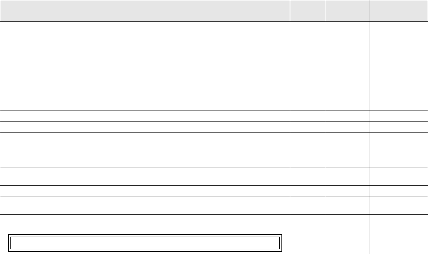
Annex to NASA-STD-8719.24B Payload Project Name Rev: Basic
I – Information/Title N/A – Not Applicable C – Compliant T – Tailored NC – Noncompliant
Page 325 of 455
VOLUME 6: GROUND AND LAUNCH PERSONNEL, EQUIPMENT, SYSTEMS AND
MATERIAL, GROUND OPERATIONS SAFETY REQUIREMENTS
STATUS
TAILORED
TEXT
RATIONALE/
COMMENTS
6.1.5.2.1 Periodic Test Requirements. Slings used to support critical operations shall be Periodic Load tested to 100% of the
manufacturer’s rated load within one year of intended use, unless the range user has proposed, with supporting risk analysis,
in accordance with PSWG and Range Safety approval, an alternate test interval. Following modifications and repairs, critical
slings shall be Proof load tested to the same level as new slings, in accordance with this standard Volume 3, Table 6.1, ASME
B30.9 and 29 CFR 1910.184. NDE shall be performed on load tested critical slings per, Volume 3, paragraph 6.2.1.3.2. MHE
NDE, requirements following a PSWG and Range Safety approved NDE plan.
Select Status
6.1.5.2.2 Periodic and Frequent Inspection Requirements. Sling assemblies used for critical lifts shall be periodically inspected
and inspected before each use. Sling assembly inspection shall be in accordance with periodic and frequent inspection
methodologies described in ASME B30.9 and ASME B30.26. Any sling or rigging hardware shall be removed from service
if any conditions are present, that are listed in ASME B30.9/ASME B30.26 Removal Criteria, for each sling/rigging hardware
type. Slings and rigging hardware shall not be returned to service until approved by a qualified person, the PSWG and Range
Safety.
Select Status
6.1.5.3. Sling Recurring Data Requirements. Recurring data is required in accordance with Volume 3, Chapter 4.
Select Status
6.1.6. Load Positioning and Load Measuring/Indicating Device Operations
I
6.1.6.1. Operator Training. LPD and LID operators shall be trained and certified in accordance with manufacturer
recommendations and NASA-STD-8719.9, Lifting Standard.
Select Status
6.1.6.2. LPD and LID Operating Standards. LPD and LID shall be operated, maintained, and tested in accordance with the
manufacturer instructions; NASA-STD-8719.9, Lifting Standard; and the additional requirements described below.
Select Status
6.1.6.3. LPD and LID Inspection and Periodic Test Requirements. LPD and LID shall be inspected and tested in accordance
with Volume 3, Section 6.2.6.2 of this publication and NASA-STD-8719.9, Lifting Standard.
Select Status
6.1.6.4. LPD and Recurring Data Requirements. Recurring data is required in accordance with Volume 3, Chapter 4.
Select Status
6.1.6.4.1. Before every use, LPDs and LIDs shall be inspected. LPDs and LIDs showing evidence of damage or rejectable
criteria shall not be used in operations.
Select Status
6.1.6.4.2. LIDs used to support critical operations shall be properly calibrated before use. If a wireless remote readout control
is used with the LID, it shall be calibrated and display the same weight as the LID.
Select Status
Remote control display devices are often used with LIDs when the LID is too high off the ground to be able to read its weight
display.
I

Annex to NASA-STD-8719.24B Payload Project Name Rev: Basic
I – Information/Title N/A – Not Applicable C – Compliant T – Tailored NC – Noncompliant
Page 326 of 455
VOLUME 6: GROUND AND LAUNCH PERSONNEL, EQUIPMENT, SYSTEMS AND
MATERIAL, GROUND OPERATIONS SAFETY REQUIREMENTS
STATUS
TAILORED
TEXT
RATIONALE/
COMMENTS
6.1.6.4.3. LPDs and LIDs used to support critical operations shall be inspected and periodic load tested to 100% of the rated
load within one year of intended use, unless the payload project has proposed, with supporting risk analysis, and PSWG and
Range Safety has approved, an alternate test interval. Following any modifications or repairs, critical LPDs and LIDs shall be
proof load tested to the same level as new LPDs or LIDs, to include calibration in accordance with manufacturer instructions.
After the proof load test, NDE shall be performed on critical LPDs or LIDs per a PSWG and Range Safety approved NDE
plan.
Select Status
6.1.7. Handling Structure Operations
I
6.1.7.1. Handling Structure Operating Standards. All structural lifting beam operations shall meet NASA-STD-8719.9 and
ASME B30.20, Below Hook Lifting Devices, for range operations.
Select Status
6.1.7.2. Handling Structure Inspection and Periodic Test Requirements. Handling structures shall be inspected and tested
in accordance with Volume 3, 6.2.4.2.
Select Status
6.1.7.2.1. Before every use, handling structures shall be visually inspected in accordance with applicable industry
methodology and the PSWG and Range Safety approved NDE plan. Structures showing evidence of damage or rejectable
criteria shall not be used in operations
Select Status
6.1.7.2.2. Handling structures used to support critical operations shall be inspected and load tested to 100% of the rated load
within one year of intended use, unless the payload project has proposed, with supporting risk analysis, and the PSWG and
Range Safety has approved, an alternate test interval. Following any modifications or repairs, critical handling structures shall
be proof load tested to the same level as new handling structures. After the proof load test, NDE shall be performed on critical
handling structures in accordance with a PSWG and Range Safety approved NDE plan.
Select Status
6.1.7.2.3. Handling structures fabricated (including fittings and attachment hardware) of ductile materials and exhibiting
ductile failure mode at the operating environmental conditions may be exempted by the PSWG and Range Safety from periodic
load testing on a case-by-case basis. Subject to PSWG and Range Safety review and approval, such structures may be verified
using an alternate approach, based on fracture mechanics and proof-test logic.
Select Status
6.1.7.3. Handling Structure Recurring Data Requirements. Recurring data is required in accordance with Volume 3, Chapter
4.
Select Status
6.1.8. BTHLD Operations.
I
6.1.8.1. BTHLD Operating Standards. BTHLDs shall be inspected, operated, maintained, and tested in accordance with
NASA-STD-8719.9, NASA Lifting Standard, ASME B30.20 and 29 CFR 1910.
Select Status
6.1.8.2. BTHLD Periodic Test and Inspection Requirements.
I

Annex to NASA-STD-8719.24B Payload Project Name Rev: Basic
I – Information/Title N/A – Not Applicable C – Compliant T – Tailored NC – Noncompliant
Page 327 of 455
VOLUME 6: GROUND AND LAUNCH PERSONNEL, EQUIPMENT, SYSTEMS AND
MATERIAL, GROUND OPERATIONS SAFETY REQUIREMENTS
STATUS
TAILORED
TEXT
RATIONALE/
COMMENTS
6.1.8.2.1. BTHLDs shall be visually inspected in accordance with frequent and periodic inspection methodologies described
in ASME B30.20 and shall follow the PSWG and Range Safety approved NDE plan. See volume 3 of this standard, paragraph
4.4.1 Nondestructive Examination Plan test requirements. BTHLDs showing evidence of damage or rejectable criteria shall
be removed from operational use.
Select Status
6.1.8.2.2. BTHLD’s, and associated rigging hardware, used to support critical operations shall be inspected and Periodic Load
tested to 100% of the rated load within one year of intended use in accordance with V3, Table 6.1 (5) and Note 2.
Select Status
6.1.8.2.3. BTHLD’s Proof Load tested to 125% of the rated load performed after modification or repairs, in accordance with
ASME B30.20 methodology, shall satisfy the Periodic Load test requirement for that interval periodic load test cycle in
accordance with V3, Table 6.1. After the Proof Load test, volumetric and surface NDE shall be performed on all SFP
components and welds on critical BTHLDs in accordance with a PSWG and Range Safety approved NDE plan.
Select Status
6.1.8.2.4. BTHLDs fabricated (including fittings and attachment hardware) of ductile materials and exhibiting ductile failure
mode at the operating environmental conditions may be exempted from periodic load testing by the LDEM (when on center),
the PSWG and Range Safety. on a case-by-case basis. Subject to PSWG and Range Safety review and approval, such structures
may be verified using an alternate approach based on fracture mechanics and proof-test logic.
Select Status
6.1.8.2.5. Periodic load test intervals may be extended by no more than 90 days from the original lifting device expiration
date due to programmatic or institutional needs, subject to the center LDEM, PSWG and Range approval. To extend the
periodic load test interval, the following conditions shall be met: a. The payload project provides documented rationale to the
LDEM, PSWG and Range Safety. b. The LDEM, PSWG and Range Safety determines there is no increase in risk.
Select Status
6.1.8.2.6. The payload project can implement, with supporting risk analysis, an alternate test interval plan for critical
BHTLD’s, and associated rigging hardware, performed in accordance with test criteria in V3, Table 6.1, with the center
LDEM, the PSWG and Range Safety concurrence.
Select Status
6.1.9. Support Structure Operations
I
6.1.9.1. Support Structure Periodic Test and Inspection Requirements.
I
6.1.9.1.1. Before every use, support structures shall be visually inspected in accordance with applicable industry methodology
and the PSWG and Range Safety approved NDE plan. Structures showing evidence of damage or rejectable criteria shall not
be used in operations.
Select Status
6.1.9.1.2. Support structures used to support critical operations shall be inspected and tested to 100% of the rated load within
one year of intended use, unless the payload project has proposed, with supporting risk analysis, and PSWG and Range Safety
has approved, an alternate test interval. Following any modifications or repairs, critical support structures shall be proof load
tested to the same levels as new critical support structures. After the proof load test, NDE shall be performed on critical support
structures in accordance with a PSWG and Range Safety approved NDE plan.
Select Status
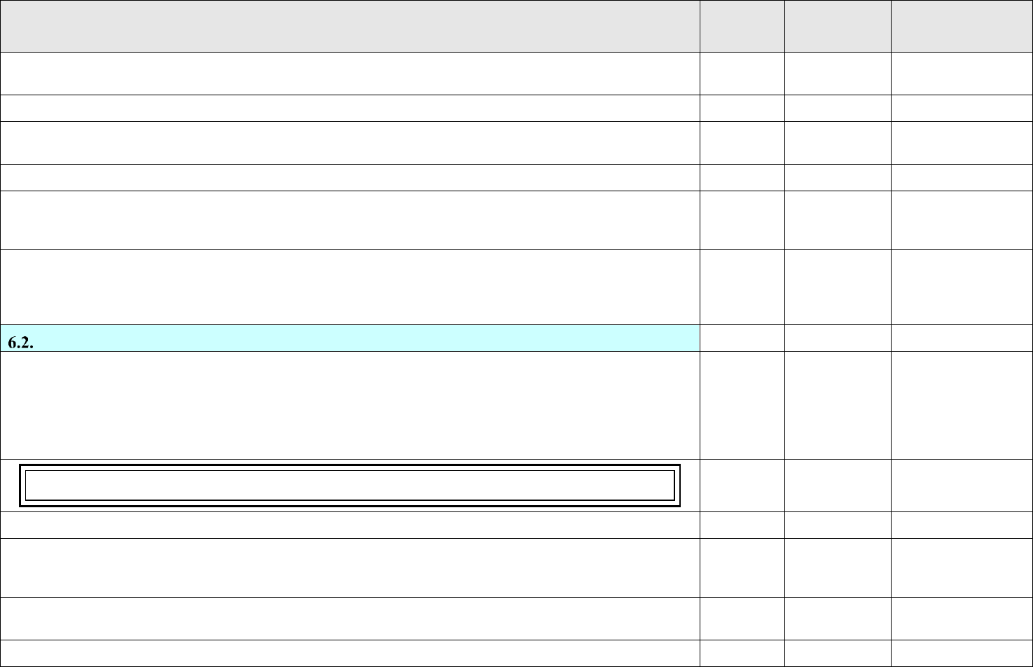
Annex to NASA-STD-8719.24B Payload Project Name Rev: Basic
I – Information/Title N/A – Not Applicable C – Compliant T – Tailored NC – Noncompliant
Page 328 of 455
VOLUME 6: GROUND AND LAUNCH PERSONNEL, EQUIPMENT, SYSTEMS AND
MATERIAL, GROUND OPERATIONS SAFETY REQUIREMENTS
STATUS
TAILORED
TEXT
RATIONALE/
COMMENTS
6.1.9.1.3. Support structures fabricated (including fittings and attachment hardware) of ductile materials at the operating
environmental conditions may be exempted by the PSWG and Safety from periodic load testing on a case-by-case basis.
Select Status
6.1.10. Rigging Hardware Operations.
I
6.1.10.1. Rigging Hardware Operating Standards. All rigging hardware shall be operated, maintained, and tested in
accordance with ASME B30.26.
Select Status
6.1.10.2. Rigging Hardware Periodic Test and Inspection Requirements.
I
6.1.10.2.1. Before every use, rigging hardware shall be visually inspected in accordance with ASME B30.26. Any rigging
hardware showing evidence of damage and meeting removal criteria as outlined in ASME B30.26 shall be removed from
service.
Select Status
6.1.10.2.2. Rigging hardware used to support critical operations shall be inspected and load tested to 100% of the rated load
within one year of use. Following any modifications or repairs, critical rigging hardware shall be proof load tested to the same
level as new critical rigging hardware in accordance with ASME B30.26. After the proof load test, NDE shall be performed
on critical rigging hardware in accordance with a PSWG and Range Safety approved NDE plan.
Select Status
Crane and Hoist Operations
I
6.2.1. Crane and Hoist Operating Standards. In addition to the requirements in 6.1, all cranes and hoists shall be operated
in accordance with ASME B30 series, CMAA 70, Specifications for Electric Overhead Traveling Cranes; and CMAA 74,
Specifications for Top Running and Under Running Single Girder Electric Overhead Traveling Cranes Utilizing Under
Running Trolley Hoist, MHI Standards, NASA-STD-8719.9, Lifting Standard; and NFPA 70, National Electric Code; and
AFMAN 91-203. The requirements are also applicable to permanent or short-term use equipment and apply whether the
equipment is owned, rented, or leased by the government, contractors, or commercial operators.
Select Status
At VSFB, cranes not on VSFB exclusive federal jurisdiction property also require inspection, testing, and certification in
accordance with CAL-OSHA requirements.
Select Status
6.2.2. Crane Operator Training and Certification
I
6.2.2.1. All operators of cranes shall be trained in accordance with NASA-STD-8719.9, Lifting Standard; Materials Handling
and Storage Equipment; AFMAN 91-203 (Chapter 12, Material Handling Equipment) and the qualifications stated in the
ASME B30 series, 29 CFR 1910.179, and 29 CFR 1910.180, as applicable.
Select Status
6.2.2.2. All operators of hoisting apparatus of over 1,000 pound capacity [hoists (fixed or traveling) or cranes (overhead or
mobile)] shall be trained and certified.
Select Status
6.2.2.3. All operators of cranes that are used to lift critical loads are subject to the requirements stated in ASME B30 series.
Select Status

Annex to NASA-STD-8719.24B Payload Project Name Rev: Basic
I – Information/Title N/A – Not Applicable C – Compliant T – Tailored NC – Noncompliant
Page 329 of 455
VOLUME 6: GROUND AND LAUNCH PERSONNEL, EQUIPMENT, SYSTEMS AND
MATERIAL, GROUND OPERATIONS SAFETY REQUIREMENTS
STATUS
TAILORED
TEXT
RATIONALE/
COMMENTS
6.2.2.4. Annual Crane Operator Certification. Annual crane operator certification is required and shall be conducted in
three parts:
Select Status
6.2.2.4.1. Classroom Training and Testing. Employers shall ensure their personnel receive classroom training as evidenced
by testing. Employers shall maintain records for each operator they employ. For the WR, the requirements in 6.2.2.1, 6.2.2.2,
and 6.2.2.3 apply.
Select Status
6.2.2.4.2. Physical Examination. The employer is responsible for obtaining a physical examination of the operator as required
by NPR 1800.1 NASA Occupational Health Program Procedures, AFMAN 91-203, ASME B30 series, and the local
requirements of the crane owner.
Select Status
6.2.2.4.3. Hands-On Training and Certification. The employer shall document hands-on training, evaluation, and certification
in the form of a card that includes the following:
Select Status
6.2.2.4.3.1. Name of operator.
Select Status
6.2.2.4.3.2. Certifying agency and certification expiration date.
Select Status
6.2.2.4.3.3. Other pertinent information such as the types of equipment the operator is certified to operate.
Select Status
6.2.2.5. Types of Operator Certification
I
6.2.2.5.1. Critical load (except for proof load) hands-on training and certification shall be conducted on the specific device to
be used for the lift.
Select Status
6.2.2.5.2. Non-critical load hands-on training and certification shall be conducted on a crane of the same type for which
personnel are to be certified such as mobile hydraulic, mobile mechanical (friction), overhead bridge, and overhead monorail.
Select Status
6.2.3. Crane and Hoist Inspection and Periodic Test Requirements
I
6.2.3.1. Daily Inspections
I
6.2.3.1.1. Using a pre-operational checklist, daily, or otherwise before first use, inspections shall be conducted as required by
OSHA and recommended by the manufacturer on the equipment to be used at the beginning of each shift.
Select Status
6.2.3.1.2. Daily inspections shall cover the following items:
Select Status
6.2.3.1.2.1. The function of all controls, brakes, and operating mechanisms for maladjustment interfering with proper
operations.
Select Status

Annex to NASA-STD-8719.24B Payload Project Name Rev: Basic
I – Information/Title N/A – Not Applicable C – Compliant T – Tailored NC – Noncompliant
Page 330 of 455
VOLUME 6: GROUND AND LAUNCH PERSONNEL, EQUIPMENT, SYSTEMS AND
MATERIAL, GROUND OPERATIONS SAFETY REQUIREMENTS
STATUS
TAILORED
TEXT
RATIONALE/
COMMENTS
6.2.3.1.2.2. The condition of all components that can be inspected without major disassembly and whose failure would cause
a safety hazard. This includes the deterioration or leakage in lines, tanks, valves, drain pumps, and other parts of air or
hydraulic systems; hooks with deformation or cracks; hoist chains and end connections for excessive wear, twist, distorted
links interfering with proper function, or stretch beyond manufacturer’s recommendations; control mechanisms; all chords
and lacing; tension in guys; and plumb of mast.
Select Status
6.2.3.2. Slack Rope Inspections. If a slack rope condition has occurred, inspectors shall be positioned to observe the rope
seating in the drum and sheave grooves as the load is reapplied, and concurrently inspect the rope for damage.
Select Status
6.2.5. Crane and Hoist Retest and Reinspection
I
6.2.5.3. If an accidental overload condition occurs, the equipment user shall notify the facility manager, the Center Lifting
Devices and Equipment Manager, payload project, and PSWG chairperson and follow up by submitting a written report.
Select Status
6.2.6. Dual Crane Lift Operating Requirements. Dual crane lifts are considered hazardous operations without regard to
the load. The following is required:
Select Status
6.2.6.1. The load shall be restricted to no more than 75 percent of rated capacity for each crane for non-critical lifts. The load
shall be restricted to no more than 50% of rated capacity for each crane for critical lifts.
Select Status
6.2.6.2. All mobile crane dual lifts shall require load cells and cab-installed load indicators.
Select Status
6.2.6.3. A dry run with a geometric/mass simulator shall be required for all critical hardware lifts.
Select Status
6.2.6.4. A Dual Crane Lift Plan addressing the following information shall be submitted to Range Safety for review and
approval:
Select Status
6.2.6.4.1. The exact weight (+/- 1 percent) of the total load including spreader bar/beam, hoist attachments, fixtures, and
slings.
Select Status
6.2.6.4.2. Any dynamic forces that affect the load.
Select Status
6.2.6.4.3. All crane movements, including trolley, bridge, boom up, down, extension, and swing, and crane travel.
Select Status
6.2.6.4.4. Center of gravity throughout the complete lift.
Select Status
6.2.6.4.5. Certification of cranes and crane operators.
Select Status
6.2.6.4.6. Operating surface capacity compatibility with mobile cranes (paved areas).
Select Status
6.2.6.4.7. Soil compaction compatibility with mobile cranes (unpaved areas).
Select Status
6.2.6.4.8. Provisions for a lift director, two-ways communication, and spotter(s).
Select Status
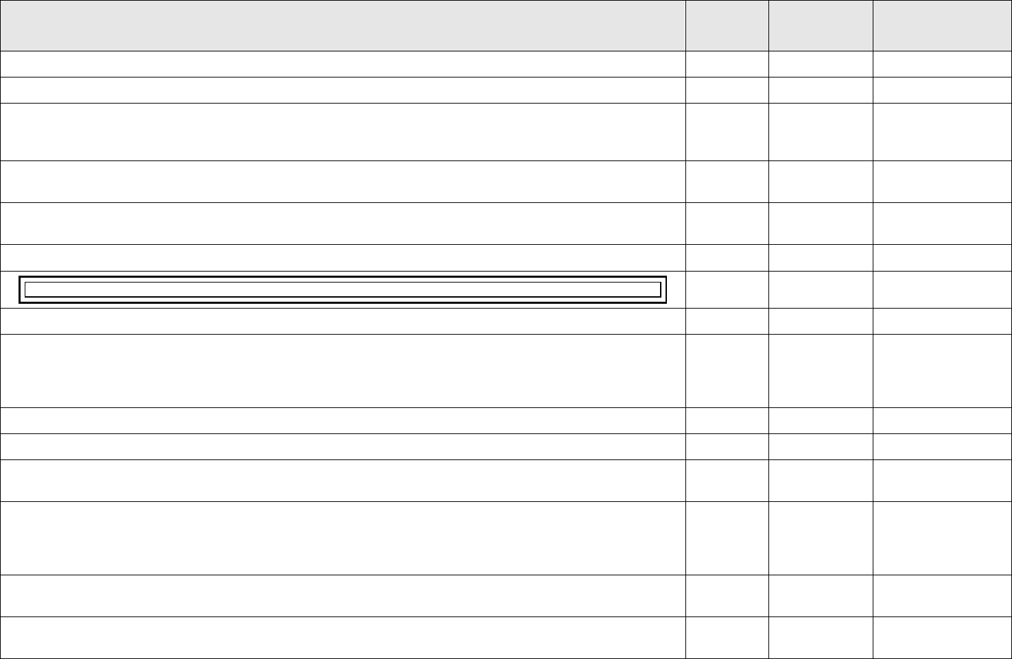
Annex to NASA-STD-8719.24B Payload Project Name Rev: Basic
I – Information/Title N/A – Not Applicable C – Compliant T – Tailored NC – Noncompliant
Page 331 of 455
VOLUME 6: GROUND AND LAUNCH PERSONNEL, EQUIPMENT, SYSTEMS AND
MATERIAL, GROUND OPERATIONS SAFETY REQUIREMENTS
STATUS
TAILORED
TEXT
RATIONALE/
COMMENTS
6.2.6.5. Operations involving offset lifts shall not exceed the crane's capability.
Select Status
6.2.7. WR First Use Tag Program
I
6.2.7.1. Payload projects requesting approval of a program in which specific equipment certification expiration date and time
do not start until the item is issued or installed or first used shall provide the following documentation to Range Safety for
review and approval with PSWG concurrence:
Select Status
6.2.7.1.1. A complete list of all items by nomenclature with identifying part numbers, rated load, maximum test load, and
operation where normally tested.
Select Status
6.2.7.1.2. An approved quality assurance program identifying controls, inspection points, and complete First Use Tag
information.
Select Status
6.2.7.1.3. Identification of shelf-life criteria.
Select Status
The shelf-life shall not exceed 5 years in an environmentally controlled location without retest.
Select Status
6.2.7.2. Range Safety shall withdraw approval upon any infraction of the program.
Select Status
6.2.8. Mobile Cranes. All mobile cranes to be used shall be properly inspected, functionally validated, and maintained
according to 29 CFR 1910; 29 CFR 1926; NASA-STD-8719.9, Lifting Standard; applicable ASME standards; applicable state
OSHA plans; and the requirements identified below. These requirements apply whether the equipment is government, payload
project, or contractor owned, rented, or leased.
Select Status
6.2.8.1. Mobile cranes shall be certified for operational use by the appropriate authorizing agency.
Select Status
6.2.8.2. Dual crane lift operations require Range Safety approved lift plans (See 6.2.6.4).
Select Status
6.2.8.3. The use of mobile cranes to lift critical hardware shall be justified to and approved by the PSWG and Range Safety
on a case-by-case basis.
Select Status
6.2.8.4. Prior to conducting a critical lift with a mobile crane, the upper limit switch shall be tested for proper functioning by
raising an empty hook to the upper limit, activating the upper limit switch, and verifying that the hoist stops. After the load is
hoisted a small distance, the load shall be left hanging for approximately three minutes (i.e., a holding brake test) to ensure the
winch holding brakes functions properly and that there is no load slippage.
Select Status
6.2.8.5. Mobile cranes used for critical lifts shall be de-rated to 50% of their original load capacity. The total weight of the
load shall not exceed 50% of the crane rated capacity for the given lift radius and load line reeving configuration of the crane.
Select Status
6.2.8.6. Load charts shall be used as the primary means for determining safe loads for various boom angles. Crane computers
shall not be used as a sole means for this determination.
Select Status
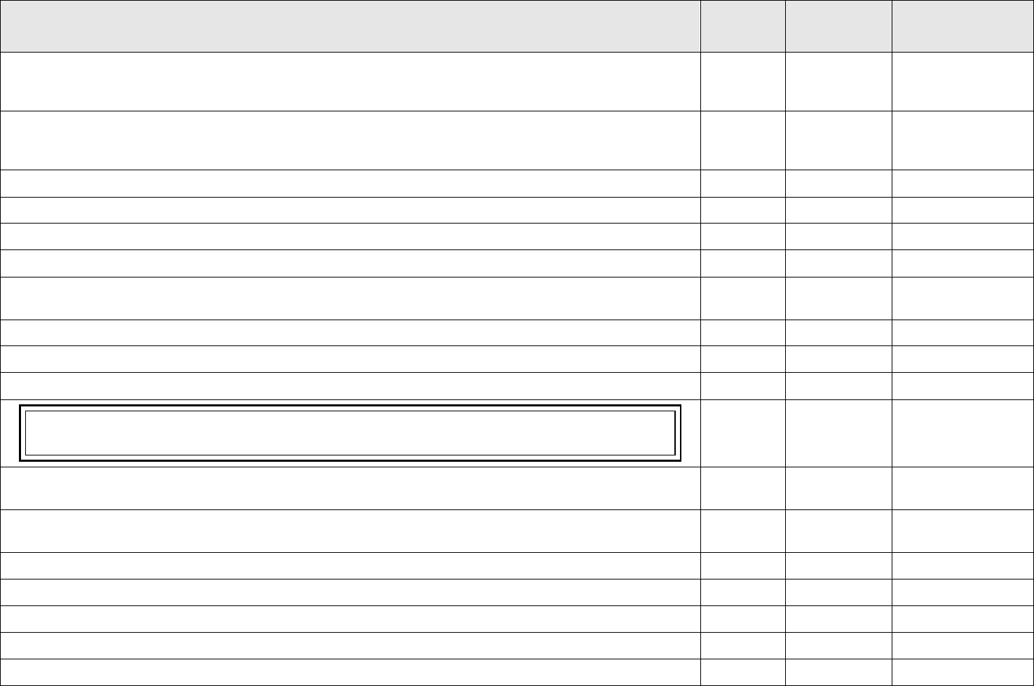
Annex to NASA-STD-8719.24B Payload Project Name Rev: Basic
I – Information/Title N/A – Not Applicable C – Compliant T – Tailored NC – Noncompliant
Page 332 of 455
VOLUME 6: GROUND AND LAUNCH PERSONNEL, EQUIPMENT, SYSTEMS AND
MATERIAL, GROUND OPERATIONS SAFETY REQUIREMENTS
STATUS
TAILORED
TEXT
RATIONALE/
COMMENTS
6.2.8.7. Evolutions that actually involve man-rated lifts shall also comply with operational requirements in this chapter and
ASME B30.23, Personnel Lifting Systems. For man-rated lifts, the total weight of the loaded personnel platform and related
rigging shall not exceed 50% of the rated capacity for the radius and configuration of the crane or derrick.
Select Status
6.2.8.8. Inspection and Test Requirements. Payload projects utilizing mobile cranes shall submit a data package to the
PSWG and Range Safety for review and approval that provides evidence that the mobile crane meets the following
requirements:
Select Status
6.2.8.8.1. Current maintenance documentation.
Select Status
6.2.8.8.2. Operator qualifications and certification documentation.
Select Status
6.2.8.8.3. Proof that operators have performed similar type lifts within one year of planned lift.
Select Status
6.2.9. Lifting Operations
I
6.2.9.1. Pre-Operational Lifting Requirements. The person responsible for supervising lifting operations shall ensure the
following:
Select Status
6.2.9.1.1. The crane has met all of its maintenance, test, and inspection requirements and is operated within its rated capacity.
Select Status
6.2.9.1.2. The operator is properly certified.
Select Status
6.2.9.1.3. The operator remains at the controls the entire time a load is suspended.
Select Status
Exceptions may be approved by the PSWG and Range Safety in the interest of operational efficiency to allow lifting hardware
such as slings, spreader bars, BTHLDs, load cells, and LPDs to remain suspended while unattended provided all of the
following conditions are met:
I
6.2.9.1.3.1. A procedure documenting such exceptions has been approved by the appropriate local safety authority as
determined by the PSWG and Range Safety.
Select Status
6.2.9.1.3.2. The lifting hardware suspended is connected to but not supporting the weight of the objective load (e.g., the launch
vehicle stage, motor segment, or payload).
Select Status
6.2.9.1.3.3. The load is scheduled to be lifted within 24 hours.
Select Status
6.2.9.1.3.4. The load and immediate vicinity are roped off or otherwise identified to prohibit unauthorized personnel entry.
Select Status
6.2.9.1.3.5. The crane controls are locked in the off position.
Select Status
6.2.9.1.3.6. The restrictions against people being under the suspended lifting hardware are enforced.
Select Status
6.2.9.1.4. The vicinity of the lift is controlled so that:
Select Status

Annex to NASA-STD-8719.24B Payload Project Name Rev: Basic
I – Information/Title N/A – Not Applicable C – Compliant T – Tailored NC – Noncompliant
Page 333 of 455
VOLUME 6: GROUND AND LAUNCH PERSONNEL, EQUIPMENT, SYSTEMS AND
MATERIAL, GROUND OPERATIONS SAFETY REQUIREMENTS
STATUS
TAILORED
TEXT
RATIONALE/
COMMENTS
6.2.9.1.4.1. Unauthorized personnel entry is precluded.
Select Status
6.2.9.1.4.2. Personnel or any part of their bodies are prevented from being under or in the way of the load.
Select Status
6.2.9.1.4.3. For cranes equipped with booms, the area is defined by the swing radius of the crane and includes all of the
rotating superstructure.
Select Status
6.2.9.1.4.4. A large enough area is cleared so as to protect against flying debris from a dropped object.
Select Status
6.2.9.1.5. All personnel within the controlled hoisting area wear suitable head and foot protection.
Select Status
6.2.9.1.6. Previously announced lightning advisories and lightning warnings will not cause the load to be in jeopardy.
Select Status
6.2.9.1.7. All personnel are knowledgeable of the operation to be performed, tasks to be done, route to be traveled, and safety
considerations.
Select Status
6.2.9.1.8. If using a mobile crane, the crane shall be level and the following criteria shall be met:
Select Status
6.2.9.1.8.1. The area shall be set up so that the lift is made within the shortest possible radius.
Select Status
6.2.9.1.8.2. The lift shall be made over the rear of the crane, if possible.
Select Status
6.2.9.1.8.3. When the load to be handled and the operating radius require the use of outriggers, or any time when outriggers
are used, the outrigger beams shall be fully extended or deployed per load rating chart specifications. Blocking under outrigger
beams is not permitted. Blocking under outrigger floats, when used, shall be strong enough to prevent crushing, bending, or
shear failure and of sufficient thickness, width, and length as to completely support the float, transmit the load to the supporting
surface, and prevent shifting or topping under load. Outrigger floats shall be made of 4 x 4 inch or cross-hatched 2 x 4 inch
lumber, a minimum of 4 x 4 feet square or equivalent support.
Select Status
6.2.9.1.8.4. When using outriggers, they shall be fully extended and raise the crane so that the wheels are off the ground unless
the crane is designed for partial outrigger use and has appropriate load rating charts.
Select Status
6.2.9.1.8.5. No part of the crane or load shall pass within 10 feet of an electrical power line unless the line is de-energized and
visibly grounded on both sides of the area of possible contact.
Select Status
6.2.9.1.8.6. Outriggers and outrigger floats shall be used on flat hard/compacted surfaces.
Select Status
6.2.9.1.8.7. Outrigger floats or cribbing is required in areas that do not have a hard surface such as concrete.
Select Status
6.2.9.1.8.8. Operators shall not exceed inclination angles specified by the mobile crane manufacturer when locating, then
leveling the mobile crane prior to lifting operations.
Select Status
6.2.9.1.8.9. Operators shall not operate mobile cranes upon unapproved, temporary foundations at unimproved surfaces or on
road bearing surfaces not rated for the lifting load.
Select Status
Annex to NASA-STD-8719.24B Payload Project Name Rev: Basic
I – Information/Title N/A – Not Applicable C – Compliant T – Tailored NC – Noncompliant
Page 334 of 455
VOLUME 6: GROUND AND LAUNCH PERSONNEL, EQUIPMENT, SYSTEMS AND
MATERIAL, GROUND OPERATIONS SAFETY REQUIREMENTS
STATUS
TAILORED
TEXT
RATIONALE/
COMMENTS
6.2.9.1.9. Systems shall have sufficient assistant operators or spotters to make sure that all sides of the system are clear for
operation.
Select Status
6.2.9.1.10. All operators or spotters shall have aural communications for coordination between themselves when power is on
the system.
Select Status
6.2.9.1.11. Tag lines shall be used when there is potential for load sway that could damage the article lifted, high value
equipment, or flight hardware.
Select Status
6.2.9.1.12. Tag line personnel shall not impart undesirable motion to the load.
Select Status
6.2.9.1.13. If the weight of the load to be lifted is not known, the weight shall be estimated with a reasonable degree of
accuracy before attempting to lift the load.
Select Status
6.2.9.1.14. Unattended suspended loads require local safety authority approval.
Select Status
6.2.9.2. Attaching the Load. To attach the load, the crane hook shall be positioned directly over the center of gravity of the
load before attachment unless authorized in a written procedure approved by the appropriate local safety authority.
Select Status
6.2.9.3. Lifting the Load
I
6.2.9.3.1. On the first lift of the day or shift, or on a critical lift, the load shall be raised a few inches, then held in place
momentarily, to verify that the brakes operate normally.
Select Status
6.2.9.3.2. The load shall be lifted to a height sufficient to clear all obstacles in its intended path.
Select Status
6.2.9.3.3. For hoist angles, cranes are designed to function with the load raised perpendicular with respect to the ground.
Cranes are normally designed for vertical lifts. Side angle pull lifts should not be attempted unless the crane is specifically
designed for this purpose in accordance with the requirements in Volume 3.
Select Status
6.2.9.3.3.1. Fleet (side) angles shall be kept as close to zero as possible. The appropriate local safety authority’s approval is
required for all anticipated fleet angles.
Select Status
Pulling the rope with a load component perpendicular to the drum or sheave grooves (fleet or side angle) may cause the rope to
jump out of the groove and become entangled on the drum or caught between the sheave and its mounting with possible
catastrophic results.
I
6.2.9.3.3.2. Lead (in-line) angles shall be kept as close to zero as possible. The appropriate local safety authority approval is
required for anticipated lead angles exceeding 5 degrees unless the hoist is specifically designed for greater angles. Increasing
the lead (in-line) angle increases the strain on the load line, brakes, bearings, sheaves, and other crane parts.
Select Status
6.2.9.3.3.3. When lifting a load, load lines shall not contact load girts, structural members, or any other obstructions.
Select Status
Annex to NASA-STD-8719.24B Payload Project Name Rev: Basic
I – Information/Title N/A – Not Applicable C – Compliant T – Tailored NC – Noncompliant
Page 335 of 455
VOLUME 6: GROUND AND LAUNCH PERSONNEL, EQUIPMENT, SYSTEMS AND
MATERIAL, GROUND OPERATIONS SAFETY REQUIREMENTS
STATUS
TAILORED
TEXT
RATIONALE/
COMMENTS
6.2.9.3.4. Loads may be lifted with the load line off-perpendicular for the purpose of rotating large pieces of hardware if all
of the following conditions are met:
Select Status
6.2.9.3.4.1. There is no safer way to accomplish the rotation.
Select Status
6.2.9.3.4.2. The angle on the load line shall not exceed five degrees unless the hoist was specifically designed for a greater
angle.
Select Status
This angle is sometimes referred to as the lead or draft angle; it is not to be confused with the fleet angle.
I
6.2.9.3.4.3. On an installed crane, the angle is pulled in line with the rotation of the rope onto the drum (lead angle) unless the
crane is equipped with a level wind device.
Select Status
6.2.9.3.4.4. The crane is inspected to ensure that the load line does not engage the load girts, structural members, or any other
obstructions at the angle to be used.
Select Status
6.2.9.3.4.5. Before the lift, the crane is checked to ensure that all rope parts are properly seated in the grooves of the drums or
sheaves.
Select Status
6.2.9.3.4.6. The load is prevented from swinging or otherwise inducing dynamic loads on the hoisting system.
Select Status
6.2.9.3.5. Mobile or boom-equipped cranes shall not be used for off-perpendicular lifting due to the severe hazard of tipping
the crane over or of collapsing the boom.
Select Status
6.2.9.3.6. Crane maintenance instructions or checklists shall include directions to look for evidence of apparent offset lift
damage during inspections.
Select Status
6.2.10. Suspended Load Operations
I
6.2.10.1. Moving a Suspended Load
I
6.2.10.1.1. Crane operations involving lifting of hazardous or explosive materials shall be limited to only those personnel
required to perform the task.
Select Status
6.2.10.1.2. A safety clearance zone shall be established in the vicinity around the load and all non-essential personnel cleared
to a safe distance.
Select Status
6.2.10.1.3. Horizontal and vertical travel speeds shall be kept at a safe level and shall be addressed, as appropriate, in
procedures.
Select Status
6.2.10.1.4. Each lift shall be planned so that the load is suspended for a minimum amount of time.
Select Status
6.2.10.1.5. The load shall not be lifted until immediately before intended travel.
Select Status

Annex to NASA-STD-8719.24B Payload Project Name Rev: Basic
I – Information/Title N/A – Not Applicable C – Compliant T – Tailored NC – Noncompliant
Page 336 of 455
VOLUME 6: GROUND AND LAUNCH PERSONNEL, EQUIPMENT, SYSTEMS AND
MATERIAL, GROUND OPERATIONS SAFETY REQUIREMENTS
STATUS
TAILORED
TEXT
RATIONALE/
COMMENTS
6.2.10.1.6. The most direct route of travel shall be used.
Select Status
6.2.10.1.7. Loads shall not be carried over critical hardware except when that load is being mated to the critical hardware.
Select Status
6.2.10.1.8. The landing area shall be prepared so that the load may be set down immediately at the end of travel.
Select Status
6.2.10.1.9. If the load remains suspended for any length of time, the safety clearance zone shall remain in force.
Select Status
6.2.10.1.10. The load shall not be carried over personnel nor shall personnel be allowed to place any part of their bodies under
any part of the load.
Select Status
6.2.10.1.11. The load shall be transported as low as possible but at a height sufficient to clear all obstacles that may be in its
path.
Select Status
6.2.10.1.12. Alarm device or spotter personnel accompanying the load shall be used to clear other persons out of the load
path.
Select Status
6.2.10.1.13. Tag lines shall be used to control movement of the load and not impart undesirable motion to the load.
Select Status
6.2.10.1.14. Tag lines shall be long enough to protect personnel from being struck by the load.
Select Status
6.2.10.1.15. Tag lines shall be used when there is potential for a load swing that could damage flight hardware, property, or
cause injury or death.
Select Status
6.2.10.1.16. Crane operators shall be instructed to stop motion should anyone be in the path of the load or if anyone signals
to stop.
Select Status
6.2.10.1.17. Two-way communication between the test conductor and crane operator shall be maintained.
Select Status
6.2.10.2. Crane-Suspended Personnel Platforms. Operations involving lifting suspended personnel platforms are
prohibited except as provided by NASA-STD-8719.9, Lifting Standard, AFMAN 91-203, and 29 CFR 1926.1431, Crane, or
Derrick Suspended Personnel Platforms, and specifically authorized by the appropriate local safety authority.
Select Status
6.2.10.3. Man-Rated Crane Criteria. All cranes used to suspend personnel platforms and work baskets shall meet the
following requirements:
Select Status
6.2.10.3.1. Crane free-fall features shall be deactivated.
Select Status
6.2.10.3.2. Load testing of the current configuration shall have been performed within past 12 months.
Select Status
6.2.10.3.3. Two-way communication shall be maintained between the crane operator and the person in the basket.
Select Status
6.2.10.3.4. The crane operator shall be appropriately qualified.
Select Status
Annex to NASA-STD-8719.24B Payload Project Name Rev: Basic
I – Information/Title N/A – Not Applicable C – Compliant T – Tailored NC – Noncompliant
Page 337 of 455
VOLUME 6: GROUND AND LAUNCH PERSONNEL, EQUIPMENT, SYSTEMS AND
MATERIAL, GROUND OPERATIONS SAFETY REQUIREMENTS
STATUS
TAILORED
TEXT
RATIONALE/
COMMENTS
6.2.10.3.5. The total weight of the loaded personnel platform and related rigging shall not exceed 50 percent of the crane
capacity rating.
Select Status
Personnel Work Platform Operations
I
6.3.1. Removable, Extendible, or Hinged Personnel Work Platforms
I
6.3.1.1. Removable, Extendible, or Hinged Work Platform Operating Standards. Personnel work platforms shall be
operated, maintained, and tested in accordance with the manufacturer instructions and the additional requirements listed
below.
Select Status
6.3.1.2. Removable, Extendible, or Hinged Work Platform Periodic Test Requirements. At a minimum, periodic tests
shall be performed on all personnel work platforms annually in accordance with Volume 3, 6.3.3.
Select Status
6.3.1.3. Removable, Extendible, or Hinged Work Platform Recurring Data Requirements. At a minimum, recurring data is
required in accordance with Volume 3, Chapter 4.
Select Status
6.3.2. Aerial Work Platforms
I
Aerial work platforms are commercial (whether or not modified) vehicle-mounted elevating and rotating aerial devices, manually
propelled elevating aerial platforms, boom-supported elevating work platforms, self-propelled elevating work platforms, and
airline ground support vehicle-mounted vertical-lift devices.
I
6.3.2.1. Aerial Work Platform Operating Standards. All aerial work platforms shall be verified to meet the design and
construction standards of NASA-STD-8719.9, Lifting Standard; ANSI/SIA A92.2, Vehicle Mounted Elevating and Rotating
Aerial Devices; A92.3, Manually Propelled Elevating Aerial Platforms; A92.5, Boom Supported Elevating Work Platforms;
and A92.6, Self-Propelled Elevating Work Platforms, and bear identifying mark(s) evidencing the same.
Select Status
6.3.2.2. Aerial Work Platform Designations. All aerial work platforms operated in a hazardous environment as defined by
NFPA 505, Fire Safety Standard for Powered Industrial Trucks Including Type Designations, Areas of Use, Conversions,
Maintenance, and Operation, shall be approved for fire safety purposes by a nationally recognized testing laboratory [for
example, Underwriters Laboratories, Inc. (UL), Factory Mutual Engineering Corp (FM)] using nationally recognized testing
standards, bear mark(s) evidencing testing, and bear the appropriate designation (i.e., D, DS, DY, E, ES, EE, EX, G, GS, LP,
LPS).
Select Status
6.3.2.3. Aerial Work Platform Operations
I
6.3.2.3.1. Only qualified and trained personnel shall operate aerial work platforms.
Select Status
Annex to NASA-STD-8719.24B Payload Project Name Rev: Basic
I – Information/Title N/A – Not Applicable C – Compliant T – Tailored NC – Noncompliant
Page 338 of 455
VOLUME 6: GROUND AND LAUNCH PERSONNEL, EQUIPMENT, SYSTEMS AND
MATERIAL, GROUND OPERATIONS SAFETY REQUIREMENTS
STATUS
TAILORED
TEXT
RATIONALE/
COMMENTS
6.3.2.3.2. Aerial work platforms shall be operated in accordance to this section, the manufacturer’s recommendations and the
applicable ANSI/SIA standard and with the safety rules and practices of NASA-STD-8719.9, Lifting Standard; ASME B56.2
Type Designated Area, Use Maintenance, Operator, and ASME B56.3, Electric Battery-Powered Industrial Trucks, safety
standards.
Select Status
6.3.2.3.3. Usage in NFPA 505 Hazardous Area Classifications shall be restricted to aerial work platforms with the appropriate
designation per UL 558, Standard for Safety, Industrial Trucks, Internal Combustion Engine Powered; UL 583, Standard for
Safety, Battery Powered Industrial Trucks; or comparable nationally recognized testing laboratory.
Select Status
6.3.2.3.4. Aerial work platforms shall not be used in proximity of critical hardware where inadvertent operation could result
in damage of same.
Select Status
6.3.2.3.5. Before each use, the operator shall perform a pre-operational check to demonstrate operational readiness, including
all limit switches and outrigger drift switches, if applicable, but excluding the tilt alarm/shutoff. If controls do not operate
properly, the operator is responsible for notifying the supervisor. Repairs and adjustments shall be made before operations
begin. The operator shall adhere to all tags on the controls.
Select Status
6.3.2.3.6. Before each use, the operator shall survey the area for applicable hazards such as overhead obstructions and high-
voltage conductors, debris, bumps and loose obstructions, drop-offs and holes, ditches, untamped earth fills, obstructed path
of travel, unstable footing, and other possible hazardous conditions. The operator shall establish appropriate safety zones
before initiating operations.
Select Status
In some cases, aerial work platforms are intentionally used in close proximity to critical hardware [e.g., to
disconnect the rigging from the top of solid rocket motor upgrade (SRMU) segments when they are placed vertically
in the stands]. A hazard analysis should be conducted on such aerial platforms and identified hazards mitigated.
Examples of mitigation include padded platform handrails, elimination of single point failures from the hydraulic
control system, and stabilization of the chassis to prevent sudden shifting of the platform in case of tire failure.
Lessons learned from the SRMU program are listed below:
(1) Do not use worn or dry rotted tires on aerial platform vehicles. Sudden tire failure may cause platform
translation and impact against sensitive flight hardware.
(2) Keep the hydraulic system clean and ensure adequate hydraulic hose chafing guards are installed in the boom
articulated joint areas. At least one hydraulic hose failure
occurred
on the SRMU program, spraying the entire
lift with hydraulic oil.
(3) Ensure that the hydraulic system components have no unacceptable failure modes. In case of an SRMU aerial
platform, reverse command resulted in the vehicle lurching forward and the platform impacting the doorframe.
This malfunction was attributed to contamination in the hydraulic system.
I
Powered Industrial Trucks
I
Annex to NASA-STD-8719.24B Payload Project Name Rev: Basic
I – Information/Title N/A – Not Applicable C – Compliant T – Tailored NC – Noncompliant
Page 339 of 455
VOLUME 6: GROUND AND LAUNCH PERSONNEL, EQUIPMENT, SYSTEMS AND
MATERIAL, GROUND OPERATIONS SAFETY REQUIREMENTS
STATUS
TAILORED
TEXT
RATIONALE/
COMMENTS
Powered industrial trucks are commercial (whether or not modified) fork trucks, platform lift trucks, crane trucks, tow tractors,
personnel and burden carriers, and other specialized industrial trucks powered by electric motors or internal combustion engines.
I
6.4.1. Powered Industrial Truck Standards. All powered industrial trucks shall be verified to meet the design and
construction standards of ASME B56 series safety standards and bear identifying mark(s) evidencing the same.
Select Status
6.4.2. Powered Industrial Truck Designations. All powered industrial trucks shall be approved for fire safety purposes by
a nationally recognized testing laboratory (for example, UL, FM) using nationally recognized testing standards, bear mark(s)
evidencing testing, and bear the appropriate designation (i.e., D, DS, DY, E, ES, EE, EX, G, GS, LP, LPS).
Select Status
6.4.3. Powered Industrial Truck Operations
I
6.4.3.1. Only qualified and trained personnel shall operate powered industrial trucks.
Select Status
6.4.3.2. Operations of all powered industrial trucks shall be operated in accordance with the safety rules and practices of
NASA-STD-8719.9, Lifting Standard; and ASME B56 series safety standards.
Select Status
6.4.3.3. Use in NFPA 505 Hazardous Area Classifications shall be restricted to powered industrial trucks with the appropriate
designation per UL 558, UL 583, or a comparable nationally recognized testing laboratory.
Select Status
6.4.3.4. Powered industrial trucks shall not be used in the proximity of critical hardware where inadvertent operation could
result in damage of the hardware.
Select Status
6.4.3.5. If external attachments, such as special lifting adaptors, are attached to the forks for lifting, the attachment components
shall have the proper load rating and meet the appropriate testing requirements in this publication.
Select Status
6.4.3.6. Lift trucks shall be de-rated to 75 percent of rated capacity for critical loads.
Select Status
Elevator Usage
I
6.5.1. Passenger elevators not designed in accordance with Volume 5 criteria for freight shall not be used for propellant or
other hazardous materials.
Select Status
6.5.2. Freight elevators used for the movement of ordnance that has been removed from the original shipping containers, toxic
propellants, or other hazardous materials shall be controlled remotely.
Select Status
6.5.3. Personnel shall not ride in elevators during movement of the materials listed in 6.5.2.
Select Status
Annex to NASA-STD-8719.24B Payload Project Name Rev: Basic
I – Information/Title N/A – Not Applicable C – Compliant T – Tailored NC – Noncompliant
Page 340 of 455
VOLUME 6: GROUND AND LAUNCH PERSONNEL, EQUIPMENT, SYSTEMS AND
MATERIAL, GROUND OPERATIONS SAFETY REQUIREMENTS
STATUS
TAILORED
TEXT
RATIONALE/
COMMENTS
ACOUSTIC HAZARD OPERATIONS
I
Acoustic Hazard Operating Standards
Select Status
Acoustic (noise) protection shall be provided in accordance with the requirements in NPR 1800.1, Occupational Health
Program Procedures, latest revision, Hearing Conservation Section. (See Volume 3, Section 7.1 for noise exposure limits and
related requirements.)
Select Status
Acoustic Hazard Operations Personnel Protection Requirements
I
7.2.1. Unprotected personnel shall not be exposed to hazardous noise levels.
Select Status
7.2.2. Approved hearing protection devices shall be worn as required.
Select Status
Acoustic Operations
I
7.3.1. All potential hazardous noise sources in the work environment that could expose personnel shall be identified to the
Bioenvironmental Engineer or approving authority (as determined by the PSWG and Range Safety) for hearing conservation.
Select Status
7.3.2. Identified noise sources shall be surveyed by the Bioenvironmental Engineer or a designated representative.
Select Status
7.3.3. A means of warning personnel before entering the noise hazard area shall be provided. A description of the hazard and
what measures are necessary to ensure the safety of personnel shall be included.
Select Status
1. Warning signs should be posted in a manner to be visible before entering the noise hazard area.
2. Warning signs should warn of the hazardous noise and indicate the requirement for hearing protection.
3. Any posting of hazardous noise areas should be coordinated with and approved by the Bioenvironmental
Engineer or the approving authority (as determined by the PSWG and Range Safety) for hearing conservation.
I
Annex to NASA-STD-8719.24B Payload Project Name Rev: Basic
I – Information/Title N/A – Not Applicable C – Compliant T – Tailored NC – Noncompliant
Page 341 of 455
VOLUME 6: GROUND AND LAUNCH PERSONNEL, EQUIPMENT, SYSTEMS AND
MATERIAL, GROUND OPERATIONS SAFETY REQUIREMENTS
STATUS
TAILORED
TEXT
RATIONALE/
COMMENTS
NON-IONIZING RADIATION OPERATIONS
I
Non-Ionizing Radiation Operating Standards
I
8.1.1. Personnel and electroexplosive devices (EEDs) shall not be exposed to hazardous levels of non-ionizing radiation.
Select Status
8.1.2. All non-ionizing radiation operation shall be conducted in accordance with the requirements of the following standards:
Select Status
8.1.2.1. NASA and NASA contractor personnel performing operations that utilize, transport, or dispose of, non-ionizing
radiation generating equipment, associated with payload processing, shall comply with NPR 1800.1, NASA Occupational
Health Program Procedures, Chapter 4.13, for operations on all NASA centers; and AFMAN 40-201, Radioactive Materials
(RAM) Management, and any SLD-specific supplements for personnel during payload processing and operations on USSF or
launch service providers facilities.
Select Status
8.1.2.2. NASA-STD-8719.12, Safety Standard for Explosives, Propellants, and Pyrotechnics; DESR 6055.09_AFMAN 91-
201, Explosive Safety Standards, and American Institute of Aeronautics and Astronautics (AIAA)-S-113, Criteria for
Explosive Systems and Devices on Space and Launch Vehicles for radiation limits for ordnance exposure.
Select Status
8.1.2.3. NASA-STD-8719.12, Safety Standard for Explosives, Propellants, and Pyrotechnics; DESR 6055.09/AFMAN 91-
201, Explosive Safety Standard; and American Institute of Aeronautics and Astronautics (AIAA)-S-113, Criteria for
Explosive Systems and Devices on Space and Launch Vehicles for guidance with respect to siting ordnance.
Select Status
Note: While Range Users do not site ordnance, they participate in the process and both design/operations may be
influenced by siting considerations.
I
8.1.3. The use and operating location of non-ionizing radiation producing devices shall be approved by the appropriate safety
authority and the RPO/RSO.
Select Status
Radio Frequency Procedures
Select Status
All Electromagnetic Frequency Radiation (EMFR) transmitters shall be operated using the appropriate safety authority and
RPO/RSO approved procedures with the appropriate controls established. The RPO/RSO shall specify minimum power
levels below which EMFR transmitters are exempt from controls.
Select Status
EMFR Operations
I
8.3.1. RF EMFR Operations General Requirements
I
Non-ionizing radiation operations involve EMFR transmitters in the range of 3 kHz to 300 GHz and optical devices
such as lasers.
I
Annex to NASA-STD-8719.24B Payload Project Name Rev: Basic
I – Information/Title N/A – Not Applicable C – Compliant T – Tailored NC – Noncompliant
Page 342 of 455
VOLUME 6: GROUND AND LAUNCH PERSONNEL, EQUIPMENT, SYSTEMS AND
MATERIAL, GROUND OPERATIONS SAFETY REQUIREMENTS
STATUS
TAILORED
TEXT
RATIONALE/
COMMENTS
8.3.1.1. Before transmitting, areas in which power density levels exceed permissible exposure limits shall be controlled to
restrict access.
Select Status
Area control may be accomplished using appropriate warning signs, lights, and access barriers.
I
8.3.1.2. The RPO/RSO shall survey EMFR transmitting devices as required.
Select Status
8.3.1.2.1. The payload project shall comply with the survey recommendations.
Select Status
8.3.1.2.2. Where applicable all safety devices shall be checked by site personnel before operation to ensure proper function.
If transmission is required while performing these checks, the tests shall be performed at low output power or with a dummy
load. Steps for performing these verifications shall be incorporated into procedures.
Note: A safety device (or feature) is levied on the system design to control the cause of an identified hazard or to mitigate the
effect of a hazard once the cause has been satisfied. As a result, the probability and/or severity of a hazard can be reduced to
an acceptable level. Safety devices (or features) can take numerous forms in a design. No matter what form a safety device (or
feature) takes, its purpose is to prevent an undesirable (hazardous) event from occurring. Safety devices (or features) may be
wholly or partly mechanical, electrical, or software in nature. A safety device (or feature) may inherently be part of the system
or be specifically added to a system. Safety devices (or features) may include the following:
1. Barriers - a physical means to keep personnel away from hazardous energy or to contain/deflect hazardous
energy if it were released.
2. Fail-safe design - a design feature in which a system reacts to a failure by switching to or maintaining a safe
operating mode that may include system shutdown.
3. Inhibit - a device that prevents system operation if a predetermined condition is not satisfied.
4. Interlock - a device that may be inserted into the system to prevent system operation (often used in
maintenance).
5. Interrupt - a device that disrupts system operation if a predetermined condition is violated.
6. Redundancy/failure tolerance - the built-in ability of a system to provide continued correct operation in the
presence of a specific number of failures.
7. Special system features - systems or devices, such as fire suppression and hazardous gas detection, that control
and/or warn of system hazards.
Select Status
8.3.1.3. All new, modified, or relocated EMFR transmitters shall be reported to the appropriate safety authority and the
RPO/RSO at least 30 days prior to hardware installation so that potential hazards can be evaluated.
Select Status
8.3.2. EMFR Transmission Operations for EEDs and Open Grain Solid Propellant
I
8.3.2.1. As determined by analyses and tests, local or range-wide EMFR silence is required during periods of EED installation,
removal, and electrical connection or disconnection. At a minimum, EMFR silence within the complex or area shall be
required.
Select Status
Annex to NASA-STD-8719.24B Payload Project Name Rev: Basic
I – Information/Title N/A – Not Applicable C – Compliant T – Tailored NC – Noncompliant
Page 343 of 455
VOLUME 6: GROUND AND LAUNCH PERSONNEL, EQUIPMENT, SYSTEMS AND
MATERIAL, GROUND OPERATIONS SAFETY REQUIREMENTS
STATUS
TAILORED
TEXT
RATIONALE/
COMMENTS
8.3.2.2. Radio transmitters shall be kept away from systems with installed EEDs in accordance with the guidance found in
AFI 91-208, Hazards of Electromagnetic Radiation to Ordnance (HERO) Certification and Management and NASA-STD-
8719.12, Safety Standard for Explosives, Propellants, and Pyrotechnics.
Select Status
The 25-foot radio transmission distance requirement is the minimum requirement; however, this requirement does not consider
situations where EEDs are EMFR sensitive and leads are unshielded. Based on the specific radio, ordnance, and area involved,
an EMFR analysis performed in accordance with (AIAA)-S-113, Criteria for Explosive Systems and Devices on Space and
Launch Vehicles, for radiation limits may be provided to the appropriate safety authority for consideration to reduce this
requirement.
I
8.3.2.3. Transmitting devices shall be kept a minimum of 50 feet from a fueling area unless they are intrinsically safe.
Select Status
Class 1M, 2M, 3B, and 4 Optical/Laser Operations
I
8.4.1. Optical/Laser Operating Standards. NASA and NASA contractor personnel performing operations that utilize,
transport, or dispose of, Laser and non-Laser optical generating equipment, associated with payload processing, shall do so
in accordance with NPR 1800.1, NASA Occupational Health Program Procedures, Chapter 4.16, for operations on all NASA
centers; and AFI 48-139, Laser and Optical Radiation Protection Program, and any SLD-specific supplements for personnel
during payload processing and operations on USSF or launch service providers facilities.
Select Status
8.4.2. Optical/Laser Operation Personnel Protection Requirements
I
8.4.2.1. NASA and NASA contractor personnel performing operations that utilize, transport, or dispose of laser and non-laser
optical generating equipment shall be appropriately trained in work practices commensurate with the degree of potential laser
hazards, both from laser radiation and non-beam hazards, in accordance with NPR 1800.1, NASA Occupational Health
Program Procedures, Chapter 4.16 paragraph 4.16.3.2. NASA and NASA contractor personnel performing optical/laser
operations on USSF property shall be trained and certified in accordance with AFMAN 40-201, Radioactive Materials (RAM)
Management, as applicable.
Select Status
8.4.2.2. Approved protective eye wear and other PPE shall be worn as required.
Select Status
8.4.3. Optical/Laser Procedures. All optical devices and lasers capable of exceeding allowable energy levels, as determined
by the appropriate local safety authority, shall be operated using the appropriate local safety authority and LSO, RPO/RSO
approved procedures with the appropriate controls established.
Select Status
8.4.4. Optical/Laser Inspection
I
8.4.4.1. Periodic inspections shall be conducted to ensure the laser and controls are in safe working condition and are properly
protected from potential damage.
Select Status
Annex to NASA-STD-8719.24B Payload Project Name Rev: Basic
I – Information/Title N/A – Not Applicable C – Compliant T – Tailored NC – Noncompliant
Page 344 of 455
VOLUME 6: GROUND AND LAUNCH PERSONNEL, EQUIPMENT, SYSTEMS AND
MATERIAL, GROUND OPERATIONS SAFETY REQUIREMENTS
STATUS
TAILORED
TEXT
RATIONALE/
COMMENTS
Conditions of concern include dangerous light radiation, temperature extremes, shatterable materials, contaminating gases,
cryogenics, high voltage, and X-rays.
I
8.4.4.2. Inspection records shall be maintained for the life of the program.
Select Status
8.4.4.3. Inspection records shall be available at the request of the appropriate local safety authority.
Select Status
8.4.5. Optical/Laser Operations
I
8.4.5.1. Alignment of targets, optics, filters, and other optical/laser items shall be accomplished following written procedures
and using non-hazardous low power (Class 1 or Class 2) lasers.
Select Status
8.4.5.2. Active beam or target viewing shall be accomplished with closed circuit television or an optical comparator with an
appropriate filter.
Select Status
8.4.5.3. Laser beams directed toward flammable or explosive materials, pressurized systems, any other system that may
become hazardous due to laser energy or directed toward sensitive components of FTSs shall not exceed allowable limits as
determined by the appropriate local safety authority.
Select Status
8.4.5.4. Activated lasers shall not be left unattended.
Select Status
8.4.5.5. Unattended lasers shall be locked out and otherwise safed.
Select Status
8.4.5.6. Operations involving laser systems with hazardous materials shall follow the requirements for hazardous materials
described in Chapter 10 of this volume.
Select Status
8.4.5.7. Operations involving laser systems with pressurized subsystems such as cryogenic fluids shall follow the requirements
described in Chapter 11 of this volume.
Select Status
8.4.5.8. Operations involving lasers with high voltage or capacitance shall follow the requirements in Chapter 14 of this
volume.
Select Status
8.4.5.9. All electrical and mechanical azimuth and elevation stops, and other safety devices shall be verified before performing
each laser operation. (See the bordered paragraph immediately after 8.3.1.2.2 for examples of safety devices.)
Select Status
8.4.5.10. Laser platforms shall comply with the requirements for mechanical ground support equipment used to handle critical
hardware as described in Chapter 6 of this volume.
Select Status
8.4.5.11. Laser operation conforms to the principles and requirements set forth in ANSI Z136.1, American National Standard
for Safe Use of Laser, and ANSI Z136.2, Safe Use of Optical Fiber Communication Systems Utilizing Laser Diode and LED
Sources.
Select Status

Annex to NASA-STD-8719.24B Payload Project Name Rev: Basic
I – Information/Title N/A – Not Applicable C – Compliant T – Tailored NC – Noncompliant
Page 345 of 455
VOLUME 6: GROUND AND LAUNCH PERSONNEL, EQUIPMENT, SYSTEMS AND
MATERIAL, GROUND OPERATIONS SAFETY REQUIREMENTS
STATUS
TAILORED
TEXT
RATIONALE/
COMMENTS
8.4.5.12. Requirements for the procurement and manufacture of laser products are provided in 21 CFR Part 1040.10, Laser
Products, and 21 CFR Part 1040.11, Specific Purpose Laser Products.
Select Status
8.4.5.13. All nominal hazardous procedural items shall be accomplished including, but not limited to, the following:
Select Status
8.4.5.13.1. 24-hour notification of Pad Safety.
Select Status
8.4.5.13.2. Pre-operational PA announcements.
Select Status
8.4.5.13.3. Clearance of safety clearance zones.
Select Status
8.4.5.13.4. Posting of applicable warning signs and operation of area warning lights.
Select Status
8.4.5.13.5. Pad Safety permission prior to start of the hazardous lasing activity.
Select Status
Annex to NASA-STD-8719.24B Payload Project Name Rev: Basic
I – Information/Title N/A – Not Applicable C – Compliant T – Tailored NC – Noncompliant
Page 346 of 455
VOLUME 6: GROUND AND LAUNCH PERSONNEL, EQUIPMENT, SYSTEMS AND
MATERIAL, GROUND OPERATIONS SAFETY REQUIREMENTS
STATUS
TAILORED
TEXT
RATIONALE/
COMMENTS
RADIOACTIVE (IONIZING) RADIATION SOURCES OPERATIONS
I
Launch approval of radioactive (ionizing radiation) sources is addressed in Volume 3, Chapter 9 of this publication.
I
9.1. Payload projects shall comply with NPR 1800.1, NASA Occupational Health Program Procedures, Chapter 4.13, General
Radiation Requirements and AFMAN 40-201, Radioactive Materials (RAM) Management, and any SLD specific supplements
or instructions, as applicable.
Select Status
9.2. All ionizing operations shall be planned and conducted in accordance with written procedures, approved by the
appropriate safety authority, or RPO/RSO, so that personnel exposure is as low as reasonably achievable (ALARA), but in no
case shall exceeded the maximum dose and exposure limits in 10 CFR 20, Standards for Protection Against Radiation, be
exceeded.
Select Status
9.3. Local safety authorities and the RPO/RSO shall be notified of the location of radioactive material spills, releases, and
incidents. Local radiation safety requirements shall be followed. CCSFS Cape Support (ER 321-853-5211) or VSFB
Command Post (WR 805-606-9961), Range Safety, and the RPO/RSO shall be notified of the location of radioactive material
if spilled, released, or dispensed either by design or accident when on Air Force and Space Force property. KNPR 1860.1
shall be followed for releases and spill on KSC property.
Select Status
9.4. Flight radioactive sources shall be installed as late in the countdown as practical.
Select Status
9.5. Mishaps involving radioactive materials shall be reported in accordance with NPR 8621.1, NASA Procedural
Requirements for Mishap and Close Call Reporting, Investigating, and Recordkeeping and appropriate local safety
organizations requirements as required above. AFMAN 91-110 and AFI 91-204 shall also apply for mishaps on Air Force
and Space Force property.
Select Status
Annex to NASA-STD-8719.24B Payload Project Name Rev: Basic
I – Information/Title N/A – Not Applicable C – Compliant T – Tailored NC – Noncompliant
Page 347 of 455
VOLUME 6: GROUND AND LAUNCH PERSONNEL, EQUIPMENT, SYSTEMS AND
MATERIAL, GROUND OPERATIONS SAFETY REQUIREMENTS
STATUS
TAILORED
TEXT
RATIONALE/
COMMENTS
HAZARDOUS MATERIALS OPERATIONS
I
Hazardous Materials Operating Standards
I
10.1.1. Hazardous materials shall be selected in accordance with 10.1 of Volume 3 of this publication and NPR 1800.1,
Chapter 4.
Select Status
10.1.2. An operation or process task that includes a solid, liquid, or gaseous material that, under foreseeable conditions, are
toxic, carcinogenic, cryogenic, explosive, flammable, pyrophoric, water-reactive, corrosive, an oxidizer, a compressed gas, a
combustible liquid, or are chemically unstable shall be conducted as a Hazardous Operation and performed in accordance with
the NASA-STD-8719.11, Fire Protection, NASA-STD-8719.12 Safety Standard for Explosives, Propellants, and
Pyrotechnics, NPR 8715.1, NASA Safety and Health Programs, AFI 90-821, Hazard Communication (HAZCOM) Program,
AFMAN 91-203, and any Wing-specific supplements or instructions, as directed by the PSWG and Range Safety for process
safety management (PSM) and risk management plan (RMP). See Attachment V6 A.23 Classification of Hazardous
Procedures.
Select Status
10.1.3. When threshold quantities of toxic chemicals as defined by OSHA, NASA, or Space Force requirements are being
used, the payload project shall comply with any local process safety requirements, the appropriate local safety and health
authorities, as identified by the PSWG and Range Safety, and the local Biomedical/Bioenvironmental Office, concerning
hazardous material selection, operation, storage, and disposal. At the ER the payload project shall comply with applicable ER
Requirements are the 45 SWI 91-101, Process Safety Management. The SLD 45 point of contact for process safety
management is System Safety (SLD 45/SE).
Select Status
Hazardous Materials Operations Personal Protective Equipment (PPE)
Select Status
Proper head, eye, hand, body, and respiratory protection shall be worn as required in accordance with 29 CFR 1910, NPR
1800.1, Chapter 4, and local requirements. The PPE shall be approved by the approved local safety/occupational health
authority and is subject to the approval of the Bioenvironmental Engineer as required.
Select Status
Hazardous Materials Procedures
Select Status
Hazardous materials procedures shall be established per local requirements. For operations taking place on Air Force or
Space Force property, hazardous material procedures shall be established per AFMAN 32-4013. Hazardous materials
procedures shall include, but not be limited to, the following topics:
Select Status
10.3.1. Emergency actions for unplanned events such as spills, fires, and personnel contamination.
Select Status
10.3.2. Actions for decontamination, neutralization, cleanup, and disposal.
Select Status
Hazardous Materials Operations
I
10.4.1. The use of any hazardous material is subject to the appropriate local safety and bioenvironmental authority’s approval.
Select Status
Annex to NASA-STD-8719.24B Payload Project Name Rev: Basic
I – Information/Title N/A – Not Applicable C – Compliant T – Tailored NC – Noncompliant
Page 348 of 455
VOLUME 6: GROUND AND LAUNCH PERSONNEL, EQUIPMENT, SYSTEMS AND
MATERIAL, GROUND OPERATIONS SAFETY REQUIREMENTS
STATUS
TAILORED
TEXT
RATIONALE/
COMMENTS
10.4.2. Appropriate control measures shall be established for the use of hazardous materials based on known properties. If
properties are unknown, testing shall be performed subject to approval by the appropriate local safety and bioenvironmental
authorities.
Select Status
10.4.3. Control measures for hazardous liquids include, but are not limited to, the following criteria:
Select Status
10.4.3.1. Approved containers shall be used.
Select Status
10.4.3.2. Containers shall remain capped (covered) when not in use.
Select Status
10.4.3.3. Quantities shall be limited as approved by the Fire Authority Having Jurisdiction (AHJ).
Select Status
10.4.3.4. Work areas shall contain no more than the quantity required for a single shift.
Select Status
10.4.3.5. Work areas shall not be used for storage unless approved storage cabinets and lockers are available.
Select Status
10.4.3.6. Local or general exhaust ventilation shall be used to control solvent vapors from reaching toxic levels or explosive
levels.
Select Status
10.4.3.7. Materials that are themselves not hazardous, but that can be hazardous in conjunction with other materials, shall be
controlled.
Select Status
10.4.3.8. The location and/or facility shall be compatible with the type and quantity of hazardous material.
Select Status
10.4.3.9. When personnel are in confined spaces, hazardous materials and chemicals shall only be used in accordance with
29 CFR 1910.146, Permit-Required Confined Spaces, compliant program. Proper ventilation shall be used to prevent buildup
and/or pocketing of hazardous materials and chemicals to hazardous levels. Due consideration shall be given to all potential
sources of toxic buildup, such as chemicals employed by workers within the confined space, from venting of systems, and
from off-gassing.
Select Status
10.4.3.10. Materials prone to electrostatic charge buildup shall not be used in the vicinity of ordnance or propellants.
Select Status
10.4.3.11. Glass containers shall not be used in the immediate vicinity of flight hardware or in elevated locations so that they
could fall and shattered pieces of glass strike hardware or personnel. In general, use of glass containers is discouraged.
Select Status
10.4.4. In the event of an unplanned toxic release local emergency response plans shall be followed.
Select Status
The following documents applicable at Space Force Ranges: IEMP, AFI 10-2501, Air Force Emergency Management Program,
and any SLD-specific supplements, instructions, or plans. At KSC: KNPR 8715.2, Comprehensive Emergency Management
Plan.
I
Restrictions on the Use of Plastic Films, Foams, and Adhesive Tapes (PFAs) and other
Static-Producing and Flammable Materials
I
Annex to NASA-STD-8719.24B Payload Project Name Rev: Basic
I – Information/Title N/A – Not Applicable C – Compliant T – Tailored NC – Noncompliant
Page 349 of 455
VOLUME 6: GROUND AND LAUNCH PERSONNEL, EQUIPMENT, SYSTEMS AND
MATERIAL, GROUND OPERATIONS SAFETY REQUIREMENTS
STATUS
TAILORED
TEXT
RATIONALE/
COMMENTS
10.5.1. General. The use of plastic films, foams, and adhesive tapes (PFAs) shall be kept to a minimum in all payload
processing and testing areas. Materials prone to electrostatic charge buildup shall not be used on or near ordnance items or in
the vicinity of flammable liquids or commodities such as propellants.
Select Status
10.5.1.1. Compliance with the restriction on static-producing materials is handled on a case-by-case basis; however, the
following criteria shall be used as a guideline:
Select Status
10.5.1.1.1. Materials shall not come into contact with a system having an installed EED or other ordnance.
Select Status
10.5.1.1.2. Materials shall not come within 10 feet of exposed solid propellant grain, which is defined as when the grain is
visible with no nozzle plug or cover.
Select Status
10.5.1.1.3. Materials shall not come within 50 feet of exposed flammable liquids.
Select Status
10.5.1.2. Compliance with the use of materials that could be flammable is handled on a case-by-case basis; however, all
materials that are used in the vicinity of ordnance or flammable liquids, such as hypergolic propellants, shall pass the material
tests described below.
Select Status
10.5.2. Material Tests
I
10.5.2.1. Materials such as contamination covers, thermal blankets, splash shields, Velcro, tape, and any other material located
in the vicinity of liquid propellant areas or ordnance areas shall be evaluated for compatibility with their intended use.
Select Status
10.5.2.2. The payload project shall supply a sample of materials to KSC testing laboratory or other approved laboratory for
testing, and the results shall be forwarded to the appropriate local safety authority. Materials passing KSC or approved
equivalent tests may be deemed acceptable by the appropriate local safety authority.
Select Status
Material properties may be obtained through NASA MAPTIS (Material and Process Technical Information System), from KSC
Materials Testing Labs, or other approved material database.
I
10.5.2.3. Testing shall consider the following material characteristics:
Select Status
10.5.2.3.1. Ability to build up a charge (triboelectric test).
Select Status
10.5.2.3.2. Ability of that charge to decay (triboelectric test).
Select Status
A material is considered to have good electrostatic dissipation properties if it can dissipate voltage down to 350 volts in 5 seconds
using the triboelectric test.
I
10.5.2.3.3. Flammability
Select Status
10.5.2.3.4. Compatibility with other materials and liquids the material may come into contact with.
Select Status
Annex to NASA-STD-8719.24B Payload Project Name Rev: Basic
I – Information/Title N/A – Not Applicable C – Compliant T – Tailored NC – Noncompliant
Page 350 of 455
VOLUME 6: GROUND AND LAUNCH PERSONNEL, EQUIPMENT, SYSTEMS AND
MATERIAL, GROUND OPERATIONS SAFETY REQUIREMENTS
STATUS
TAILORED
TEXT
RATIONALE/
COMMENTS
10.5.2.4. Material restrictions may also arise from other limitations such as being humidity dependent (for charge dissipation)
or degradable in sunlight (ultraviolet).
Select Status
10.5.2.5. The appropriate local safety authority shall approve the use of materials based on the test results.
Select Status
Materials that do not meet these criteria may be acceptable for a particular usage as determined by the appropriate local safety
authority.
I
10.5.2.6. Material deficiencies shall result in operational restrictions.
Select Status
Hazardous Commodity Lockers
I
10.6.1. Positioning and Use of Hazardous Commodity Lockers. Hazardous commodity lockers or cabinets shall be
positioned and used for the purpose of storing flammable and combustible liquids in accordance with 29 CFR 1910.106, NFPA
30, Flammable and Combustible Liquids Code; NASA-STD-8719.11, NASA Standard for Fire Protection; and local fire safety
requirements as applicable.
Select Status
10.6.2. Hazardous Commodity Locker Inspection. The payload project shall inspect hazardous commodity lockers at least
weekly.
Select Status
Disposal of Contaminated Liquid Propellant, Gas, or Other Regulated Wastes
I
10.7.1. On Space Force Ranges, the payload project shall notify CCSFS Cape Support (ER) (321-853-5211) or Range
Scheduling (WR) (805-606-8825) of any hazardous material requiring disposal on the respective Range location. For other
locations the payload project shall follow local policies.
Select Status
If required, additional guidance shall be obtained from Civil Engineering (Environmental Coordinator) or their designated
representative and Range Safety.
I
10.7.2. Disposal of toxic or contaminated liquid propellants, gases, or other wastes shall be performed using methods and
techniques approved by the safety and other local authorities, as well as all applicable federal, state, and local regulations.
Select Status
On USSF, the approval authority is Range Safety and Civil Engineering (Environmental Coordinator). Follow 45 and 30
Space Wing Operations Plan (SWOP) 19-14, Petroleum Products and Hazardous Waste Management Program.
I
10.7.3. Payload project shall notify the appropriate local safety authorities to obtain proper clearance and support to dispose
of wastes before the generation of such wastes. For Space Force Ranges, Civil Engineering shall be notified.
Select Status
10.7.4. As needed, those operations involving toxic propellants shall be conducted under the surveillance of Environmental
Health and Pad Safety for operations on the AF Range to ensure the safety of personnel involved in the operation and personnel
located in adjacent or downwind areas.
Select Status

Annex to NASA-STD-8719.24B Payload Project Name Rev: Basic
I – Information/Title N/A – Not Applicable C – Compliant T – Tailored NC – Noncompliant
Page 351 of 455
VOLUME 6: GROUND AND LAUNCH PERSONNEL, EQUIPMENT, SYSTEMS AND
MATERIAL, GROUND OPERATIONS SAFETY REQUIREMENTS
STATUS
TAILORED
TEXT
RATIONALE/
COMMENTS
10.7.5. Records of management and identification of wastes shall be maintained by the organization generating the waste.
Select Status
10.7.7. All spills or releases of hazardous substances, including petroleum products, shall be reported to the local authority
responsible for emergency response, in accordance with the facility safety plan and local requirements. For CCSFS Cape
Support (ER) (321-853-5211) or Range Scheduling (WR) (805-606-8825) and Pad Safety immediately and for KSC dial 911
(or 321-867-7911 from a cell phone).
Select Status
Annex to NASA-STD-8719.24B Payload Project Name Rev: Basic
I – Information/Title N/A – Not Applicable C – Compliant T – Tailored NC – Noncompliant
Page 352 of 455
VOLUME 6: GROUND AND LAUNCH PERSONNEL, EQUIPMENT, SYSTEMS AND
MATERIAL, GROUND OPERATIONS SAFETY REQUIREMENTS
STATUS
TAILORED
TEXT
RATIONALE/
COMMENTS
GROUND SUPPORT AND FLIGHT HARDWARE PRESSURE SYSTEMS
OPERATIONS
I
The minimum operational requirements for both ground support and flight hardware pressure systems operations
are described below. Operational requirements unique to either category are identified.
I
Pressure Systems Operating Standards
I
The degree of hazard in pressure systems is proportional to the amount of energy stored, which is a function of both the pressure
and the volume stored. As a result, low-pressure, high-volume systems can be as hazardous to personnel as high-pressure
systems.
I
11.1.1. Only pressure systems that meet the design requirements of Volume 3 as tailored for each specific project (mission)
shall be used.
Select Status
11.1.2. The handling and storage of propellants shall be in accordance with NASA-STD-8719.12, Safety Standard for
Explosive, Propellants, and Pyrotechnics; CPIA 394, Chemical Propulsion Information Agency-Hazards of Chemical Rockets
and Propellants; and DESR 6055.09_AFMAN 91-201, Explosive Safety Standards and NAVSEA OP 5, Ammunition and
Explosives Ashore: Safety Regulations for Handling, Storing, Production, Renovation and Shipping.
Select Status
11.1.3. Propellants shall be used and stored only in facilities designed and suited for that purpose and approved for specified
time periods of use by the appropriate local safety authorities.
Select Status
11.1.4. Propellants shall be used and stored only in systems that meet the design requirements of Volume 3, Chapter 11 and
Chapter 12 and shall be approved by the appropriate local safety authorities.
Select Status
11.1.5. Portable or mobile vessels and packaging used for transportation of pressurized or hazardous commodities shall be
maintained and recertified in accordance with applicable Department of Transportation (DOT) 49 CFR.
Select Status
Pressure Systems Personnel Requirements
I
11.2.1. Pressure Systems Training and Certification. All personnel who operate, test, and maintain pressure systems
shall be trained and certified.
Select Status
11.2.2. Pressure Systems PPE
Select Status
11.2.2.1. Selection of PPE. The PPE selected shall have been approved for the planned usage by the appropriate local safety
authorities, occupational health authorities, and other applicable approving authorities as identified by the PSWG and Range
Safety (see section 5.3).
Select Status
11.2.2.1.1. Approval shall be limited to a particular model number of protective equipment and a particular operation.
Select Status
Annex to NASA-STD-8719.24B Payload Project Name Rev: Basic
I – Information/Title N/A – Not Applicable C – Compliant T – Tailored NC – Noncompliant
Page 353 of 455
VOLUME 6: GROUND AND LAUNCH PERSONNEL, EQUIPMENT, SYSTEMS AND
MATERIAL, GROUND OPERATIONS SAFETY REQUIREMENTS
STATUS
TAILORED
TEXT
RATIONALE/
COMMENTS
11.2.2.1.2. Approval of PPE for an operation depends on the type and volume of propellants involved, the size of the lines,
flow rate, pressure, capability to deal with emergencies, and egress accessibility.
Select Status
11.2.2.1.3. Approvals are not transferable; approvals for similar operations require a reevaluation of the parameters stated
above.
Select Status
11.2.2.1.4. Protective gear shall be compatible with the propellants involved, shall be fire resistant, non-static producing, and
shall have been approved for the planned usage by the appropriate local safety authorities, occupational health authorities, and
other applicable approving authorities as identified by the PSWG and Range Safety (see section 5.3).
Select Status
11.2.2.1.5. If the protective gear has limitations, these limitations and subsequent protective actions shall be identified in the
operating procedure.
Select Status
For example, splash suits are not to be used when hydrazine concentrations can exceed 100 ppm.
I
11.2.2.2. SCAPE, Category I or IV
I
11.2.2.2.1. SCAPE, Category I or IV shall be used for propellant flow and pressurization during the following operations:
Select Status
11.2.2.2.1.1. Connection and disconnection of wet lines or contaminated (not purged and flushed) dry lines.
Select Status
11.2.2.2.1.2. Sampling operations.
Select Status
11.2.2.2.1.3. During propellant flow.
Select Status
11.2.2.2.1.4. During initial pressurization with propellants until system integrity has been verified (no leaks).
Select Status
11.2.2.2.1.5. Connections and disconnections of tanker load/off-load lines.
Select Status
11.2.2.2.1.6. Removal and replacement of components in a liquid line.
Select Status
11.2.2.2.1.7. Opening any liquid system that has not been drained, purged, and flushed with referee fluid.
Select Status
11.2.2.2.1.8. When the condition of the system is uncertain or unknown.
Select Status
11.2.2.2.2. The maximum operating time in a Category I SCAPE suit is 110 minutes; however, the appropriate local safety
authorities (including Pad Safety for AF Range facilities) can authorize on-station time not to exceed 120 minutes. In
extreme temperatures, the appropriate local safety authorities can restrict on-station times in Category I SCAPE suits to
less than 110 minutes. (ER Only). Personnel using Category I SCAPE suits shall observe a 60-minute rest period between
consecutive SCAPE operations: for example, no double-packing. All personnel required to wear Category 1 and Category
lV Self-Contained Atmospheric Protective Ensemble (SCAPE) shall be certified in accordance with KTI-1202, Propellant
Handlers Ensemble User’s Manual.
Select Status
Annex to NASA-STD-8719.24B Payload Project Name Rev: Basic
I – Information/Title N/A – Not Applicable C – Compliant T – Tailored NC – Noncompliant
Page 354 of 455
VOLUME 6: GROUND AND LAUNCH PERSONNEL, EQUIPMENT, SYSTEMS AND
MATERIAL, GROUND OPERATIONS SAFETY REQUIREMENTS
STATUS
TAILORED
TEXT
RATIONALE/
COMMENTS
SCAPE categories are defined as:
Category I - Propellant Handlers Ensemble (PHE) with environmental control unit (ECU).
Category IV - Propellant Handlers Ensemble (PHE) using remote breathing air supplied by hardline hose.
Category VI - 'Chemturion' Chemical Protection Suit (CPS) "blue suit" with hardline breathing hose.
Please refer to KTI-1202, Propellant Handlers Ensemble User’s Manual for Propellant Handlers Ensemble user requirements
and further explanation of categories.
I
11.2.2.2.3. For physiological purposes, the maximum operating time in a Category IV or VI SCAPE suit shall not exceed four
consecutive hours.
Select Status
11.2.2.3. Splash Suits. Splash suits, with self-contained breathing apparatus, shall only be used with systems that contain
residual vapors and only after the appropriate local safety authority’s approval. If any liquid is in the system, splash suits shall
not be used.
Select Status
11.2.2.3.1. Removal of full protective gear after system integrity verification shall require approval by the appropriate local
safety authorities.
Select Status
11.2.2.3.2. Emergency protective gear shall be available throughout operations to the crew and other personnel who might be
affected in the event of a spill.
Select Status
11.2.2.3.3. The following non-liquid operations shall require splash suits:
Select Status
11.2.2.3.3.1. Removal and replacement of components on purged and isolated liquid lines.
Select Status
11.2.2.3.3.2. Removal and replacement of components on vent lines.
Select Status
11.2.2.3.3.3. Connections and disconnections of drained, purged, and isolated lines.
Select Status
11.2.2.3.3.4. Pressure leak checks when required by procedure.
Select Status
11.2.2.3.4. With the appropriate local safety authority concurrence, the use of splash suits during propellant flow after integrity
has been established may be allowed at the WR.
Select Status
11.2.2.4. PPE for Cryogenic Systems
I
11.2.2.4.1. All personnel performing liquid oxygen and liquid hydrogen transfer operations, repairs, or adjustments to the
system shall wear PPE (flame-resistant treated, non-static producing overalls of liquid resistant material, cryogenic service
gloves, hoods or face shields, and non-absorbent shoes) in accordance with 29 CFR 1910, NPR 1800.1, Chapter 4, and local
requirements. The PPE shall be approved by the approved local safety/occupational health authority and is subject to the
approval of the Bioenvironmental Engineer as required.
Select Status
Annex to NASA-STD-8719.24B Payload Project Name Rev: Basic
I – Information/Title N/A – Not Applicable C – Compliant T – Tailored NC – Noncompliant
Page 355 of 455
VOLUME 6: GROUND AND LAUNCH PERSONNEL, EQUIPMENT, SYSTEMS AND
MATERIAL, GROUND OPERATIONS SAFETY REQUIREMENTS
STATUS
TAILORED
TEXT
RATIONALE/
COMMENTS
11.2.2.4.2. Personnel performing operations on other cryogenic systems shall be similarly protected, except that flame-
resistant treating of coveralls is not required for non-flammable commodities.
Select Status
11.2.2.5. PPE for Hydrogen Peroxide Transfers. Hydrogen peroxide transfers shall require PPE (boots, gloves, and face
shields) in accordance with 29 CFR 1910, NPR 1800.1, Chapter 4, and local requirements. The PPE shall be approved by the
approved local safety/occupational health authority and is subject to the approval of the Bioenvironmental Engineer as
required.
Select Status
11.2.2.6. If a DOT vessel is installed on a permanent basis, it shall fall under the recertification requirements for a fixed
system.
Select Status
Pressure Systems Procedures
I
11.3.1. Procedures shall be prepared governing the safe operation, testing, maintenance, and installation of pressurized systems
by the agency performing the specific task.
Select Status
11.3.2. Procedures shall be developed for all operations involving propellants and the checkout of propulsion systems.
Select Status
11.3.3. Off-loading procedures for payloads shall be made available at any time propellant is loaded in flight hardware. Off-
loading design as outlined in Volume 3, Chapter 11 and Chapter 12 of this publication addresses the complete system during
the complete processing flow. The off-loading procedures shall include integration of the following:
Select Status
11.3.3.1. Hardware:
Select Status
11.3.3.1.1. Launch vehicle.
Select Status
11.3.3.1.2. Launch vehicle fairing.
Select Status
11.3.3.1.3. Spacecraft.
Select Status
11.3.3.1.4. Launch complex.
Select Status
11.3.3.1.5. Process facility.
Select Status
11.3.3.1.6. Transport vehicle.
Select Status
11.3.3.1.7. Fixed GSE.
Select Status
11.3.3.1.8. Portable GSE.
Select Status
11.3.3.2. Software Command Capability:
Select Status
11.3.3.2.1. Flight Hardware.
Select Status
11.3.3.2.2. GSE:
Select Status
Annex to NASA-STD-8719.24B Payload Project Name Rev: Basic
I – Information/Title N/A – Not Applicable C – Compliant T – Tailored NC – Noncompliant
Page 356 of 455
VOLUME 6: GROUND AND LAUNCH PERSONNEL, EQUIPMENT, SYSTEMS AND
MATERIAL, GROUND OPERATIONS SAFETY REQUIREMENTS
STATUS
TAILORED
TEXT
RATIONALE/
COMMENTS
11.3.3.3. Personnel Capability:
Select Status
11.3.3.3.1. Remote.
Select Status
11.3.3.3.2. SCAPE.
Select Status
11.3.3.3.3. Combination of both.
Select Status
Pressure Systems Test, Inspection, and Maintenance Requirements
I
11.4.1. General Test Requirements
Select Status
11.4.1.1. Pressure systems shall be initially tested in accordance with Volume 3, Chapter 11 or Chapter 12.
Select Status
11.4.1.2. Any system that has been opened shall be leak tested at 100 percent maximum operating pressure (MOP) with an
inert medium.
Select Status
11.4.1.3. Pressure relief valves and flex hoses shall be retested within one year of intended use.
Select Status
11.4.1.4. Pressure gauges and transducers shall be calibrated annually.
Select Status
11.4.1.5. After any disconnection, modification, or repair of a system, the affected part of the system shall be leak tested.
Select Status
11.4.1.6. Any component that has been damaged, potentially damaged, repaired, replaced, or modified shall be proof tested
in accordance with Volume 3.
Select Status
11.4.1.7. After the component proof test, the system or subsystem shall be proof tested, functionally tested, and leak tested.
The determination for system proof testing shall be made on a case-by-case basis.
Select Status
11.4.1.8. New, modified, or repaired propellant systems shall be tested in accordance with Volume 3, Chapter 11, or Chapter
12.
Select Status
11.4.1.9. A log shall be kept on propellant systems to keep track of use, maintenance, modification, testing, and inspection.
Select Status
11.4.2. Ground Support Pressure Systems General Inspection Requirements
I
11.4.2.1. Before use and each operation, facilities and equipment shall be inspected by the payload project and the appropriate
local safety authority to ensure a safe configuration for the facilities, equipment, and propellants involved.
Select Status
11.4.2.2. Propellant transfer and storage areas shall be spot checked by the appropriate local safety authority, the Fire
Department, and Environmental Health. The appropriate area supervisor shall be advised of any discrepancies noted.
Select Status
11.4.2.3. Periodic inspections shall be performed on all ground pressure systems in accordance with applicable procedures.
Select Status

Annex to NASA-STD-8719.24B Payload Project Name Rev: Basic
I – Information/Title N/A – Not Applicable C – Compliant T – Tailored NC – Noncompliant
Page 357 of 455
VOLUME 6: GROUND AND LAUNCH PERSONNEL, EQUIPMENT, SYSTEMS AND
MATERIAL, GROUND OPERATIONS SAFETY REQUIREMENTS
STATUS
TAILORED
TEXT
RATIONALE/
COMMENTS
11.4.2.4. Periodic inspections shall be performed on ground based pressure vessels and liquid holding tanks in accordance
with the ISI Plan in Volume 3. These inspections shall be performed during the following periods:
Select Status
11.4.2.4.1. Certification Period. Period from the initial operational use of the vessel and/or system until the vessel and/or
system requires recertification.
Select Status
11.4.2.4.2. First Certification Period. Period from the first recertification effort until second recertification.
Select Status
11.4.2.4.3. All subsequent Recertification Periods.
Select Status
11.4.2.4.4. The hazardous pressure system operator shall retain all documentation generated as a result of the recertification
effort and place this documentation in the system ISI certification and recertification file.
Select Status
11.4.3. Pressure Systems General Maintenance
I
11.4.3.1. Before replacement, storage, or repair of hypergolic or toxic propellant or fluid system components, the system shall
be purged and flushed of all residual contaminants. System connections and removed components shall be appropriately
capped, bagged, and labeled before moving the component.
Select Status
11.4.3.2. A record shall be kept on the certification of system and component cleanliness.
Select Status
11.4.3.3. When it is necessary to remove flight hardware components from the system, all broken connections shall be bagged
and tagged to prevent moisture or particle contamination from outside sources.
Select Status
11.4.3.4. If DOT vessels are used in portable GSE, maintenance and operating procedures for periodic hydrostatic tests shall
be in accordance with DOT regulations.
Select Status
11.4.3.5. All maintenance procedures and training shall ensure that personnel performing visual inspections or other checks
shall not walk in front of any National Pipe Thread (NPT)-connected components but shall inspect/observe the NPT
connections from a side position to prevent exposure to possible high pressure projectiles.
Select Status
11.4.3.6. All rupture discs installed in hazardous fluid systems shall be replaced every two years.
Select Status
11.4.4. Pressure Systems Tests. Tests performed shall meet the requirements as outlined in Volume 3, Chapter 11 and
Chapter 12. The following requirements apply unless the payload project has proposed, with supporting risk analysis, and
PSWG and Range Safety has approved an alternative test interval for components:
Select Status
11.4.4.1. Periodic Test Requirements for Pressure System Components:
Select Status
11.4.4.1.1. Uninstalled Flexible Hose. Uninstalled flexible hoses shall be hydrostatically proof tested to 1.5 times their MAWP
within one year before use, or pneumatically tested to 1.1 times MAWP once every two years unless otherwise approved by
the PSWG or Range Safety.
Select Status
Annex to NASA-STD-8719.24B Payload Project Name Rev: Basic
I – Information/Title N/A – Not Applicable C – Compliant T – Tailored NC – Noncompliant
Page 358 of 455
VOLUME 6: GROUND AND LAUNCH PERSONNEL, EQUIPMENT, SYSTEMS AND
MATERIAL, GROUND OPERATIONS SAFETY REQUIREMENTS
STATUS
TAILORED
TEXT
RATIONALE/
COMMENTS
11.4.4.1.2. Installed Flexible Hose. Installed flexible hoses in functional use shall be hydrostatically tested to 1.5 times their
MAWP once a year. Exception: This requirement does not apply to flexible hoses that are permanently installed, located, and
operated in an environment that does not exceed the rated temperature, pressure, and shelf life of the hose.
Select Status
11.4.4.1.3. Prior to project use and at least annually, all flexible hoses shall be visually inspected over their entire length.
Those with damaged fittings, broken braid, kinks, flattened areas, or other evidence of degradation shall be removed from
service. A flexible hose exhibiting major defects as classified in SAE ARP 1658, shall be removed from service.
Select Status
Exception: This requirement does not apply to flexible hoses that are permanently installed, located, and operated in an
environment that does not exceed the rated temperature, pressure, and shelf life of the hose.
I
11.4.4.1.4. Pressure gauges and transducers shall be calibrated once a year.
Select Status
Hazardous pressure operations begin at 150 psig.
I
11.4.4.1.5. Pressure relief valves shall be tested for proper setting and operation once a year.
Select Status
11.4.4.2. Testing Modified and Repaired Pressure Systems. Tests performed shall meet the requirements as outlined in
Volume 3, Chapter 11, and Chapter 12.
Select Status
11.4.4.3. Pressure Systems Tagging
I
11.4.4.3.1. Post testing and inspection, pressure system components shall be tagged.
Select Status
11.4.4.3.2. Tags shall provide the date of the last inspection and proof-load test and the component MAWP.
Select Status
11.4.5. Ground Support Pressure Vessels and Liquid Holding Tanks Recertification. Recertification data shall be
submitted as part of the SDP (MSPSP) as required in Volume 3, Chapter 11, and Chapter 12.
Select Status
11.4.6. Pressure Vessel and Liquid Holding Tank Recertification Documentation. Documentation shall be recorded and
maintained in accordance with Volume 3. Chapter 11.
Select Status
Pressure Systems Operating Requirements
I
11.5.1. General Operating Requirements. Only pressure systems approved by the appropriate local safety authority shall
be used.
Select Status
11.5.1.1. Pressure Systems Marking
I
11.5.1.1.1. Warning signs shall be posted to keep personnel out of areas where pressurization is taking place.
Select Status
11.5.1.1.2. High and ultra-high pressure systems (systems equal to or greater than 3,000 psig) shall be marked with danger
signs indicating the maximum pressure that could be involved.
Select Status
Annex to NASA-STD-8719.24B Payload Project Name Rev: Basic
I – Information/Title N/A – Not Applicable C – Compliant T – Tailored NC – Noncompliant
Page 359 of 455
VOLUME 6: GROUND AND LAUNCH PERSONNEL, EQUIPMENT, SYSTEMS AND
MATERIAL, GROUND OPERATIONS SAFETY REQUIREMENTS
STATUS
TAILORED
TEXT
RATIONALE/
COMMENTS
11.5.1.1.3. Pressure relief valves that present a noise hazard on activation shall be marked with danger signs.
Select Status
11.5.1.2. Pressure Systems Remote Pressurization. Exception. For the, remote pressurization can be waived provided the
following is provided: (1) The assembled system has been proof tested at a pressure equal to 1.5 times the system MEOP/MOP
or to an agreed-upon level for tanks with less than 2:1 safety factor for burst; (2) system configuration has not been modified
or repaired before the above testing. Unwelded relief or sensing devices may be replaced after system proof testing; and (3)
Inspection of the pressure system at the launch site verifying damage has not been sustained during transportation or handling
before the above testing.
Select Status
11.5.1.2.1. Remote pressurization is required for the following conditions:
Select Status
11.5.1.2.1.1. Initial pressurization of any vessel or system with an inert medium.
Select Status
For metallic vessels/tanks or systems, initial pressurization at the ranges does not have to be done remotely and/or use blast
protection if initial pressurization was performed at off-range sites, such as factory acceptance testing, and followed-up by
acceptable post-test inspection.
I
11.5.1.2.1.2. Any pressurization that will exceed MOP/MEOP.
Select Status
11.5.1.2.1.3. Any system or vessel whose design or condition is considered unknown or questionable by the appropriate local
safety authority.
Select Status
11.5.1.2.2. All personnel shall be evacuated whenever pressure exceeds the MAWP.
Select Status
11.5.1.2.3. Suitable barriers shall be used to protect personnel. The payload project and the appropriate local safety authority
shall determine the adequacy of the blast shield for the pressure and volume of the system.
Select Status
11.5.1.3. Pressure Systems Pressurization Operations
I
11.5.1.3.1. Pressure systems shall be inspected upon arrival on the ranges or before first operation.
Select Status
11.5.1.3.1.1. Where there is evidence that systems have been damaged or overstressed, replacement or, at a minimum, remote
initial pressurization shall be required.
Select Status
11.5.1.3.1.2. Payload projects who do not perform initial pressurization remotely shall certify to the appropriate safety
authority that no evidence of damage or overstress exists.
Select Status
11.5.1.3.2. A system and/or facility check shall be made before the start of the pressurization operation.
Select Status
11.5.1.3.3. Personnel present during any pressurization shall be limited to those in direct support of the operation. During
dynamic pressurization of flight pressure vessels/tanks, personnel shall not be exposed any time vessel/tank pressure exceeds
50% of the vessel/tank’s design burst rating. Once the flight vessel/tank is in a static condition and verified to not leak,
personnel may return to the area as long as vessel/tank pressure does not exceed MOP.
Select Status

Annex to NASA-STD-8719.24B Payload Project Name Rev: Basic
I – Information/Title N/A – Not Applicable C – Compliant T – Tailored NC – Noncompliant
Page 360 of 455
VOLUME 6: GROUND AND LAUNCH PERSONNEL, EQUIPMENT, SYSTEMS AND
MATERIAL, GROUND OPERATIONS SAFETY REQUIREMENTS
STATUS
TAILORED
TEXT
RATIONALE/
COMMENTS
11.5.1.3.4. Personnel may be present in the area of ground pressure vessels/tanks at all times when pressurized to no greater
than MAWP.
Exception: During initial pressurization of ASME/DOT compliant vessels, personnel must evacuate when pressure exceeds
50% of MAWP during dynamic pressurization activity. After initial pressurization of a ground pressure vessel/tank, it is
acceptable for personnel to be present during subsequent pressurizations (static and dynamic states) provided the vessel is still
within its design and cycle life.
Select Status
11.5.1.3.5. If a leak occurs during pressurization, the system and/or subsystem shall be depressurized before adjusting any
fittings.
Select Status
11.5.1.3.6. Unless otherwise specified, hoses over 2 feet (0.6 meters) in length, and pressurized above 100 psig (1.03 MPa),
shall meet the following restraint requirements:
1) the flexible hose shall be properly secured at each end, unions, and every 6 feet along the length of the hose by an approved
stainless resistant device by securely attaching to the structure in a manner that in no way interferes with the hose flexibility.
2) If the hose cannot be securely attached to the structure every 6 feet, weighted bags (minimum of 50 pounds) sand or shot
bags (with approval of range safety), ingots, or other suitable weights shall be used as flexible hose anchors or anchoring
attach points at a minimum of 6 foot intervals.
Select Status
11.5.1.3.7. Bolts and fittings shall not be loosened or torqued while the system is under pressure.
Select Status
11.5.1.3.8. Any system that requires devices such as pressure regulators, pressure-reducing valves, safety valves, or pressure
relief valves shall not be activated unless the devices are in place and in operable condition. Only qualified and authorized
personnel shall change the setting of these valves and regulators.
Select Status
11.5.1.3.9. Flight hardware pressure vessels that exhibit a brittle fracture or hazardous leak-before-burst (LBB) failure mode
shall maintain a minimum safety factor of 1.5:1 during transport or ground handling operations unless otherwise specified and
approved by the PSWG and Range Safety.
Select Status
11.5.1.3.10. Flight hardware pressure vessels that have a non-hazardous LBB failure mode shall maintain a minimum safety
factor of 1.5:1 during transport or ground handling operations.
Select Status
11.5.1.4. Pressure Systems Entry, Maintenance, and Repair
I
11.5.1.4.1. Pressure Systems Entry and Repair Requirements
I
11.5.1.4.1.1. Before entry into or repair of a pressurized system, depressurization of that portion of the system is mandatory.
Select Status
11.5.1.4.1.2. The steps listed below shall be followed:
Select Status
11.5.1.4.1.2.1. A minimum of two block valves shall be closed between the portion of the system to be opened and the source
of pressure.
Select Status

Annex to NASA-STD-8719.24B Payload Project Name Rev: Basic
I – Information/Title N/A – Not Applicable C – Compliant T – Tailored NC – Noncompliant
Page 361 of 455
VOLUME 6: GROUND AND LAUNCH PERSONNEL, EQUIPMENT, SYSTEMS AND
MATERIAL, GROUND OPERATIONS SAFETY REQUIREMENTS
STATUS
TAILORED
TEXT
RATIONALE/
COMMENTS
11.5.1.4.1.2.2. The section of line to be opened and the section between the block valves in series shall be vented
(depressurized) to atmospheric pressure before the start of work and remain vented (depressurized) during all phases of work.
Select Status
11.5.1.4.1.2.3. Whenever operations permit, the entire system shall be depressurized before a portion of the system is isolated,
vented, and opened.
Select Status
11.5.1.4.1.2.4. Venting a pressure system shall be accomplished through vent valves. Regardless of pressure, venting shall
never be accomplished by loosening or removing a fitting.
Select Status
11.5.1.4.1.2.5. Lockout devices and warning tags shall be attached to the valves that are isolating the area where system entry
will be made.
Select Status
11.5.1.4.1.2.6. The isolated area shall be verified as being depressurized before opening.
Select Status
11.5.1.4.2. Open System Work Precautions
I
11.5.1.4.2.1. Whenever a depressurized section of a pressurized system is to be entered or there is disassembly of any system
components, it is considered open system work and the following precautions shall be observed:
Select Status
11.5.1.4.2.1.1. Authorization for entry or disassembly of any system components, is required from the responsible complex
or area supervisor.
Select Status
11.5.1.4.2.1.2. Personnel limits shall be established in a local safety authority approved procedure.
Select Status
11.5.1.4.2.2. When it is necessary to remove components from the system, due care shall be exercised to prevent moisture or
particle contamination from outside sources.
Select Status
11.5.1.4.2.3. Lockout devices and tagging shall be used to ensure systems or subsystems are not operated while work is being
performed on the system.
Select Status
11.5.1.4.2.4. Work requiring lockout and tagging includes the following:
Select Status
11.5.1.4.2.4.1. The system is depressurized for maintenance.
Select Status
11.5.1.4.2.4.2. The work to be performed extends to another shift, either same crew next day or a different crew the same day.
Select Status
11.5.1.4.2.4.3. The work site is left unattended.
Select Status
11.5.1.4.2.4.4. The valve is not visible at all times.
Select Status
11.5.1.4.2.4.5. Valves shall be rendered inoperative with a lockout device compatible with the valve material and the lockout
devices shall be approved by Range Safety or the local safety authority.
Select Status
Annex to NASA-STD-8719.24B Payload Project Name Rev: Basic
I – Information/Title N/A – Not Applicable C – Compliant T – Tailored NC – Noncompliant
Page 362 of 455
VOLUME 6: GROUND AND LAUNCH PERSONNEL, EQUIPMENT, SYSTEMS AND
MATERIAL, GROUND OPERATIONS SAFETY REQUIREMENTS
STATUS
TAILORED
TEXT
RATIONALE/
COMMENTS
Range Safety Approved Lockout Devices:
1. Passing a metal chain through the hand wheel and the valve yoke or around the bottom of the valve body or pipe, and then
locking the chain.
2. Making the valve inaccessible by locking the housing that encloses the valve, locking the cover of a valve pit, or removing or
locking the hand wheel extension of an underground valve or a valve that can- not be reached from the ground or a valve
platform.
3. Locking and tagging electrical controls of valves with electric motor actuators.
Select Status
11.5.1.4.2.5. The following criteria shall be observed when removing locks and tags and returning the system to service:
Select Status
11.5.1.4.2.5.1. Lockout devices used to render a valve inoperative shall be removed only by an authorized work crew after all
work has been accomplished and, when applicable, approved by the proper authority.
Select Status
11.5.1.4.2.5.2. Tags shall be removed only by the crew placing the tag.
Select Status
11.5.1.4.2.5.3. Removed tags shall be returned to the crew office and mated with the tear off portion of the tag.
Select Status
11.5.1.4.2.5.4. Both tag and tear off portion shall be filed or disposed of in accordance with current practice.
Select Status
11.5.2. Pressure Systems Containing Liquid Propellant. In addition to the requirements noted above, the following
requirements shall be adhered to when operating, testing, and maintaining pressure systems containing liquid propellants.
Select Status
11.5.2.1. General Operating Requirements for Pressure Systems Containing Liquid Propellants
Select Status
11.5.2.1.1. The Fire Department shall be notified of the presence of propellants in any facility as well as any specific
firefighting and spill handling support requirements.
Select Status
11.5.2.1.2. During Any Mishap or Incident. At the ER, the designated Operations Controller is the on-scene commander until
relieved by the 45MSG/DET 1 Commander or Fire Chief. Pad Safety advises, ensures control, and supports, as necessary, in
accordance with SLD 45 IEMP 10-2. At the WR, the Support Group Commander or Fire Chief serves as the incident
commander and Pad Safety advises, ensures control, and supports, as necessary. At KSC the Fire Chief serves as the incident
commander during any mishap or incident. For NASA contracted processing facilities, off of government property follow the
local processing facilities safety procedures.
Select Status
11.5.2.1.3. Simultaneous tanking of fuels and oxidizers aboard a launch vehicle/payload is prohibited.
Select Status
11.5.2.1.4. Vessels, lines, and propellant loading systems shall be properly bonded and commonly grounded.
Select Status
11.5.2.1.5. Vapor monitoring equipment shall be used for leak (sniff) checks and general atmosphere monitoring to determine
the necessity for PPE. Vapor monitoring equipment shall be approved by the appropriate local safety authority and is subject
to approval by Bioenvironmental Engineering.
Select Status

Annex to NASA-STD-8719.24B Payload Project Name Rev: Basic
I – Information/Title N/A – Not Applicable C – Compliant T – Tailored NC – Noncompliant
Page 363 of 455
VOLUME 6: GROUND AND LAUNCH PERSONNEL, EQUIPMENT, SYSTEMS AND
MATERIAL, GROUND OPERATIONS SAFETY REQUIREMENTS
STATUS
TAILORED
TEXT
RATIONALE/
COMMENTS
11.5.2.1.6. A toxic vapor check shall be conducted by the operations control authority when personnel are in a facility that
has toxic propellants contained in flight hardware and GSE at the start of each 8-hour shift and before entering a facility in
which toxic propellant has been left unattended for 8 hours or more.
Select Status
11.5.2.1.7. In locations where liquid propellants will be handled, water shall be available in the area in sufficient quantities
for fire, spill, and medical use. Skin or eye contact with toxic propellants shall be flushed with copious amounts of water. For
specified flush periods, consult the Safety Data Sheet (SDS) for the product being used. Appropriate medical attention shall
be sought as early as possible (during flushing if possible).
Select Status
11.5.2.1.8. The supervisor shall notify the appropriate local safety authority a Bioenvironmental Engineering of any injury
involving toxic or non-toxic propellants.
Select Status
11.5.2.1.9. Transport of more than five gallons of hypergolic propellants. in non-DOT approved containers, shall require a
Security or HOS escort as described in Chapter 16 of this volume. Transport of any quantity of hazardous commodities in
DOT approved containers does not require escort.
Select Status
11.5.2.2. Pre-Operational Requirements for Pressure Systems Containing Liquid Propellants
I
11.5.2.2.1. The payload project procedures, approved by the appropriate local safety authority, shall be used for all propellant
operations and the checkout of propulsion systems.
Select Status
11.5.2.2.2. As required by procedure, the appropriate local safety authority (Pad Safety on Space Force property) and other
required support shall be on hand before the conduct of operations.
Select Status
11.5.2.2.3. Appropriate local safety authority concurrence to proceed shall be obtained by the payload project before the
conduct of operations.
Select Status
11.5.2.2.4. Personnel qualification and training shall be verified by the respective supervisors.
Select Status
11.5.2.2.5. Before starting operations, the payload project and the appropriate local safety authority shall verify that the facility
and equipment are ready by performing the following checks:
Select Status
11.5.2.2.5.1. Wet check of safety showers and water lines before propellant transfer.
Select Status
11.5.2.2.5.2. Accessibility and operability of emergency exit doors.
Select Status
11.5.2.2.5.3. Operability of drain and sump systems and their capability for handling a worst case spill and wash down.
Select Status
11.5.2.2.5.4. Operability of vent systems.
Select Status
11.5.2.2.5.5. Availability of fire protection.
Select Status
11.5.2.2.5.6. Proper configuration and grounding of propellant systems.
Select Status
Annex to NASA-STD-8719.24B Payload Project Name Rev: Basic
I – Information/Title N/A – Not Applicable C – Compliant T – Tailored NC – Noncompliant
Page 364 of 455
VOLUME 6: GROUND AND LAUNCH PERSONNEL, EQUIPMENT, SYSTEMS AND
MATERIAL, GROUND OPERATIONS SAFETY REQUIREMENTS
STATUS
TAILORED
TEXT
RATIONALE/
COMMENTS
11.5.2.2.5.7. Weather conditions.
Select Status
11.5.2.2.5.8. PA announcements, warning lights, and barriers.
Select Status
11.5.2.2.5.9. Implementation of access control.
Select Status
11.5.2.2.5.10. All required support on hand.
Select Status
11.5.2.2.5.11. Availability of approved operating procedures and emergency procedures.
Select Status
11.5.2.2.5.12. Removal of ignition sources from the area.
Select Status
11.5.2.2.6. The appropriate local safety authority or security authority shall inform the Test/Launch Conductor that the
appropriate roadblocks have been established, the hazard area cleared, and propellant tanking can begin.
Select Status
11.5.2.2.7. Propellant transfer shall not start when the passage of an electrical storm is imminent (within 5 nautical miles). A
propellant transfer operation already in progress shall be interrupted or expeditiously concluded at the discretion of the
appropriate local safety authority or the supervisor in charge of the operation. The OSP for each facility shall detail the
procedure for this situation. At the WR, propellant operations shall not start when lightning is within 10 nautical miles. At
the WR, the guidance provided in 5.6.3 shall be followed.
Select Status
11.5.2.2.8. Emergency protective equipment shall be provided as required by the appropriate local safety authority.
Select Status
11.5.2.2.9. The payload project shall provide the maximum source strength based on quantity (gallon or pound) and surface
area. The worst case credible spill (quantity) shall be based on a failure analysis provided to the appropriate local safety
authority before the operation. This information shall be used to determine the downwind sector that shall be evacuated if a
large spill occurs.
Select Status
11.5.2.2.10. Where feasible, the payload project shall develop a means to minimize the surface area of spills by providing a
dike or other means of containment.
Select Status
11.5.2.3. Controls
I
Leaks, spills, and venting of toxic propellants may create a toxic cloud. This toxic cloud will diffuse through the atmosphere at
a rate that varies with meteorological conditions and spill size. The establishment of clearance zone controls helps mitigate
exposure to this hazard.
I
11.5.2.3.1. A localized safety clearance zone that limits personnel access to those individuals directly involved with the
operation and who have the proper protective equipment shall be established.
Select Status
11.5.2.3.2. A larger safety clearance zone that limits personnel access to those individuals directly or indirectly involved in
the operation or mission shall be established. The determination of the larger safety clearance zone shall include consideration
of the availability of fencing and Security or HOS check points and the TNT equivalency of the propellants involved.
Select Status

Annex to NASA-STD-8719.24B Payload Project Name Rev: Basic
I – Information/Title N/A – Not Applicable C – Compliant T – Tailored NC – Noncompliant
Page 365 of 455
VOLUME 6: GROUND AND LAUNCH PERSONNEL, EQUIPMENT, SYSTEMS AND
MATERIAL, GROUND OPERATIONS SAFETY REQUIREMENTS
STATUS
TAILORED
TEXT
RATIONALE/
COMMENTS
11.5.2.3.3. The minimum downwind sector that must be immediately evacuated in the event of a major spill shall be provided
to all personnel involved in the operation, and controls shall be in place to implement the control of this sector. The downwind
sector shall be defined in the OSP.
Select Status
11.5.2.4. Operating Requirements for Pressure Systems Containing Liquid Propellants
I
11.5.2.4.1. Concurrence from the appropriate local safety authorities (Pad Safety on Space Force property) shall be obtained
before starting propellant transfer operations and before pressurization.
Select Status
11.5.2.4.2. Portable vessels and systems containing incompatible fuels and oxidizers shall not be brought into closer proximity
than allowed for permanent systems unless otherwise agreed to in advance by the appropriate local safety authority.
Select Status
11.5.2.4.3. Fire Protection and Environmental Health shall be available as required by procedure.
Select Status
11.5.2.4.4. All persons and vehicles not absolutely essential to the operation shall be evacuated.
Select Status
11.5.2.4.5. Before opening a contaminated or toxic propellant system, the system shall be flushed or purged to concentration
levels coordinated with Bioenvironmental Engineering and approved by the appropriate local safety authority. At the ER,
Environmental Health shall monitor and report any levels exceeding health standard criteria to the Pad Safety Office. At the
WR, Bioenvironmental Engineering and Environmental Health monitor for AF operations only. Contractors are responsible
for monitoring their own systems.
Select Status
11.5.2.4.6. The handling and transfer of toxic materials and propellants shall be monitored by the appropriate local safety
authority to ensure the safety of personnel involved in the operation and personnel downwind of the operation.
Select Status
11.5.2.4.7. Vapor monitoring shall be continuous whenever personnel are in enclosed areas having toxic propellants present.
Select Status
11.5.2.4.8. At KSC and the ER, in the case of a lightning warning (lightning within 5 nautical miles), the system shall be
secured; the complex, storage, or operating area shall be cleared; and the required actions called for in procedures and OSPs
shall be taken (see Attachments 3, 4, and 5 of this volume). At the WR, work stop’s and systems shall be secured when
lightning is within 10 nautical miles. Buildings are evacuated when lightning approaches 5 miles.
Select Status
11.5.2.4.9. Reentry into the area of a launch vehicle and/or payload with fuel and oxidizer aboard shall be held to a minimum
and shall be subject to approval by the appropriate local safety authority.
Select Status
11.5.2.4.10. Reentry into the area of a launch vehicle and/or payload with only fuel aboard shall also be held to a minimum
and shall be subject to the approval of the task or area supervisor and local safety authorities.
Select Status
11.5.2.4.11. Tanking of toxic or cryogenic liquids aboard a launch vehicle or payload during launch countdown shall be
performed as late as possible. If tanking is required during launch processing before the countdown, tanking shall be performed
as late in the processing as is practical.
Select Status
11.5.2.4.12. The appropriate actions and evacuations shall take place in the event of an emergency such as a propellant spill.
Select Status

Annex to NASA-STD-8719.24B Payload Project Name Rev: Basic
I – Information/Title N/A – Not Applicable C – Compliant T – Tailored NC – Noncompliant
Page 366 of 455
VOLUME 6: GROUND AND LAUNCH PERSONNEL, EQUIPMENT, SYSTEMS AND
MATERIAL, GROUND OPERATIONS SAFETY REQUIREMENTS
STATUS
TAILORED
TEXT
RATIONALE/
COMMENTS
11.5.2.4.13. All appropriate local safety authorities including Cape Support (ER), Range Safety (WR), and Pad Safety (WR),
as well as the PSWG Chairperson, shall be notified of any propellant mishap and incidents, including near misses.
Select Status
11.5.3. Releases of Toxic Vapors
I
11.5.3.1. All releases of toxic vapors shall comply with NPR 8715.2, NASA Emergency Preparedness Plan Procedural
Requirements, and any local response requirements KNPR 8715.2, Comprehensive Emergency Management Plan for KSC;
SLD IEMP, AFI 10-2501, and any SLD-specific supplements, instructions, or plans.
Select Status
11.5.3.2. Any plans to vent toxic vapors shall be coordinated with the appropriate local safety authority and any other
approving authorities. At the ER, any plans to vent toxic vapors shall require coordination with the Civil Engineer –
Environmental Flight, Bioenvironmental Engineering, and Environmental Health and Range Safety approval. At the WR,
venting operations shall be conducted in accordance with 30SWI 91-106 and the applicable facility or operations plan.
Select Status
11.5.3.3. The actual venting operation shall not start without approval from the appropriate local safety authority.
Select Status
11.5.3.4. Venting restrictions and controls shall be identified in the appropriate OSP or operating procedure.
Select Status
11.5.3.5. Venting operations require that the appropriate downwind sector be evacuated.
Select Status
11.5.3.6. The operations control authority shall verify that Environmental Health or the local equivalent authority is present
to verify concentration levels at the control area boundary.
Select Status
11.5.3.7. The operations control authority shall verify that Security Police or HOS maintain the appropriate roadblocks.
Select Status
11.5.3.8. Planned releases shall be in accordance with permits maintained by the appropriate local safety authority (e.g., Civil
Engineering for Space Force Range Safety locations).
Select Status
11.5.4. Emergency Decontamination of Facilities and Personnel. Emergency decontamination of facilities and personnel
shall be accomplished under the direction of the appropriate local safety authority (Pad Safety on Space Force property) with
Environmental Health and the Fire Department performing the decontamination, if required.
Select Status
11.5.5. Handling Leaks and Spills of Liquid Propellant
I
11.5.5.1. PPE for Treating Spills. Personnel treating or flushing major spills of toxic and corrosive propellants shall wear
the proper protective clothing and equipment.
Select Status
11.5.5.2. Leak and Spill Procedures
I
Annex to NASA-STD-8719.24B Payload Project Name Rev: Basic
I – Information/Title N/A – Not Applicable C – Compliant T – Tailored NC – Noncompliant
Page 367 of 455
VOLUME 6: GROUND AND LAUNCH PERSONNEL, EQUIPMENT, SYSTEMS AND
MATERIAL, GROUND OPERATIONS SAFETY REQUIREMENTS
STATUS
TAILORED
TEXT
RATIONALE/
COMMENTS
11.5.5.2.1. The payload project and supporting agencies shall develop procedures for handling major and minor leaks and
spills. Notification shall be provided to the appropriate local hazardous spill response personnel, local safety authority, the
PSWG Chairperson, and others per NPR 8621.1. Additionally, CCSFS Cape Support (ER 321-853-5211) or VSFB Command
Post (WR 805-606-9961) shall be notified of any spill or release of hazardous material on their respective range and when the
spill takes place on KSC property dial 911 (or 321-867-7911 from a cell phone) to notify the Protective Services Control
Center and receive spill response assistance as needed.
Select Status
11.5.5.2.2. Each area that contains liquid propellants shall have a plan approved by the appropriate local safety authority for
evacuation based on spill size (quantity and surface area). At the ER, an evacuation zone for a small spill (for example, a
gallon of hypergolic propellant) is typically 700 feet downwind or more and approximately 200 feet radially if the spill is
allowed to spread out on a flat surface. At the WR, required evacuations are 2,000 feet upwind or as published in the OSPs
and Toxic Hazard Zones (THZs).
Select Status
11.5.5.2.2.1. The approved evacuation plan shall describe the localized safety clearance zone, the general support (larger)
safety clearance zone, and the minimum downwind sector to be evacuated in the case of a large spill.
Select Status
11.5.5.2.2.2. The downwind sector shall be based on the following factors:
Select Status
11.5.5.2.2.2.1. Maximum source strength based on quantity (gallon or pound) and surface area. The payload project shall
determine a worst case spill (quantity) based on a failure analysis.
Select Status
11.5.5.2.2.2.2. Maximum vapor concentration acceptable for personnel exposure.
Select Status
11.5.5.2.2.2.3. Average weather criteria, such as wind direction, wind speed, temperature, temperature lapse rate.
Select Status
Weather variables can be obtained from the local Weather Officer.
I
11.5.5.2.3. These procedures shall be in accordance with the applicable OSP and shall be submitted to the appropriate local
safety authority for review and approval.
Select Status
11.5.5.2.4. Procedures shall address the topics covered in 10.7.
Select Status
11.5.5.3. Handling Minor Leaks or Spills
I
11.5.5.3.1. Minor leaks or spills shall be cleaned up with absorbent material where possible.
Select Status
For safety and hardware protection reasons, certain spills may require the spill to be washed or flushed with water into collecting
tanks or holding basins and disposed of properly to prevent ecological or health hazards. See CPIA 394 for information on
treating spills.
I
11.5.5.3.2. The appropriate local safety authority shall be notified of minor leaks and spills and subsequent actions.
Select Status
Annex to NASA-STD-8719.24B Payload Project Name Rev: Basic
I – Information/Title N/A – Not Applicable C – Compliant T – Tailored NC – Noncompliant
Page 368 of 455
VOLUME 6: GROUND AND LAUNCH PERSONNEL, EQUIPMENT, SYSTEMS AND
MATERIAL, GROUND OPERATIONS SAFETY REQUIREMENTS
STATUS
TAILORED
TEXT
RATIONALE/
COMMENTS
See CPIA 394 and Range Safety for guidance on disposal of toxic or corrosive propellants.
Select Status
11.5.5.4. Handling Major Leaks or Spills
I
11.5.5.4.1. Major leaks or spills shall be handled according to the situation with the objective of minimizing injury to personnel
and damage to facilities and equipment in accordance with local procedures (KNPR 8715.2, Comprehensive Emergency
Management Plan; SLD IEMP, AFI 10-2501, and any SLD-specific supplements, instructions, or plans). If the requirements
described below are in conflict with these OPLANS, the OPLANS shall take precedence.
Select Status
11.5.5.4.2. The following actions shall be taken:
Select Status
11.5.5.4.2.1. Time and the situation permitting, the source of the propellant flow and pressure source shall be shut down.
Select Status
11.5.5.4.2.2. All personnel shall be evacuated out of the area including the minimum downwind sector. Travel shall be upwind
or crosswind to the minimum evacuation radius as defined in the Facility Operating Plan, Operations Safety and Area Safety
Plan, or the payload project emergency procedure, and away from the downwind sector.
Select Status
11.5.5.4.2.3. Injured or trapped personnel shall be rescued. Appropriate PPE shall be used.
Select Status
11.5.5.4.2.4. Adjacent areas shall be alerted.
Select Status
11.5.5.4.2.5. Personnel shall be available to direct emergency crews and to provide information to assist them.
Select Status
11.5.5.4.2.6. All personnel shall report to the supervisor at the designated assembly point for head count.
Select Status
11.5.5.5. Handling Cryogenic or Toxic Liquid Spills
I
11.5.5.5.1. Spills of cryogenic liquids shall be flushed with large amounts of water into the surrounding ground surface or a
holding basin.
Select Status
11.5.5.5.2. Spills of toxic or corrosive propellant, or those that could affect the public health or ecology, shall be flushed with
water or another neutralizing agent into a collecting tank to be disposed of in accordance with approved procedures.
Select Status
Refer to CPIA 394 Volume III, Liquid Propellants, the Medical Department, and the Florida Department of Environmental
Protection (ER) or the California Department of Environmental Protection (WR) for guidance.
I
11.5.5.6. Flight Graphite Epoxy Composite Overwrapped Pressure Vessel Operations. Only composite overwrapped
pressure vessels (COPVs) that meet the design, test, and inspection requirements described in Volume 3 of this publication
shall be used.
Select Status

Annex to NASA-STD-8719.24B Payload Project Name Rev: Basic
I – Information/Title N/A – Not Applicable C – Compliant T – Tailored NC – Noncompliant
Page 369 of 455
VOLUME 6: GROUND AND LAUNCH PERSONNEL, EQUIPMENT, SYSTEMS AND
MATERIAL, GROUND OPERATIONS SAFETY REQUIREMENTS
STATUS
TAILORED
TEXT
RATIONALE/
COMMENTS
11.5.5.6.1. If COPVs that contain inert pressurant are in close proximity to propellant tanks, the payload project office shall
provide test data proving that the composite overwrap is compatible with the propellant in terms of strength degradation,
flammability, and ignition/combustion requirements, when personnel are at risk. If this data is not available, the following
actions shall be accomplished:
Select Status
11.5.5.6.1.1. Verification that the COPV is not in a credible "drip zone" for liquid propellants during ground processing
operations.
Select Status
11.5.5.6.1.2. If the COPV is in a credible "drip zone," the COPV shall be protected with a coating and/or covers and/or splash
shields to guard against contact with potentially incompatible liquids.
Select Status
11.5.5.6.1.3. Hazardous vapor detectors shall be used to monitor the propellant tanks.
Select Status
11.5.5.6.2. If COPVs on AFSPC ranges will be pressurized to pressures greater than 1/3 of the COPV design burst pressure,
the pressurization shall be performed remotely, or a blast shield shall be used to protect personnel. If the vessel is to remain
pressurized, personnel access shall not be permitted for a minimum of 10 minutes after the pressurization is completed.
Select Status
11.5.5.6.3. Personnel limits for each operation on or near a pressurized COPV/spacecraft shall be established to minimize
personnel exposure to pressurized COPVs.
Select Status
11.5.5.6.4. The transport of pressurized COPVs shall only occur on routes approved by the local safety authority and that
minimize personnel and facility exposure. In addition, pressurized COPV transport shall utilize escorts and shall only occur
during time periods designated and approved by the appropriate local safety authority.
Select Status
11.5.5.6.5. COPVS shall be protected from damage due to impacts during manufacturing, handling, transportation, assembly,
and integration of COPVs into the payload project’s system(s).
Select Status
11.5.5.6.6. Except for the pressure test requirements of Volume 3 of this publication, pressure testing of systems with COPVs
shall not exceed the manufacturer MOP pressure limit without the manufacturer's approval and the PSWG and Range Safety's
agreement.
Select Status
11.5.5.6.7. The payload projects shall develop and provide to the appropriate local safety authority the Emergency Response
Plans (ERPs). These ERPs shall include contingency safing and back out plans for COPVs (taking into consideration leaks,
impacts, and exposure to incompatible chemical agents). If implemented, a real time assessment shall be accomplished and
contingency operations taken, as required. The ERP shall be approved by the appropriate local safety authority.
Select Status
11.5.5.6.7.1. The payload project shall provide the ERP to Range Safety at least 45 calendar days prior to the start of hazardous
operations involving COPVs.
Select Status
11.5.5.6.7.2. The payload project shall obtain approval by the by the appropriate local safety authority prior to the start of
hazardous operations.
Select Status

Annex to NASA-STD-8719.24B Payload Project Name Rev: Basic
I – Information/Title N/A – Not Applicable C – Compliant T – Tailored NC – Noncompliant
Page 370 of 455
VOLUME 6: GROUND AND LAUNCH PERSONNEL, EQUIPMENT, SYSTEMS AND
MATERIAL, GROUND OPERATIONS SAFETY REQUIREMENTS
STATUS
TAILORED
TEXT
RATIONALE/
COMMENTS
11.5.5.6.8. Prior to the first pressurization of Graphite/Epoxy (Gr/Ep) COPVs at the payload processing launch site, an
inspection of the vessel for visible damage shall be performed by a trained inspector. The trained inspector’s skills shall be
comparable to a Level II visual inspector, per the American Society of Nondestructive Testing (ASNT) Recommended Practice
No. SNT-TC-1A (see ANSI/AIAA-081). If this inspection is not possible at the payload processing launch site area (i.e., the
Gr/Ep COPV is not accessible), then it shall be conducted the last time the Gr/Ep COPV is accessible for inspection.
Select Status
11.5.5.6.9. After completing the visual inspection and determining that there is no evidence of critical damage to the Gr/Ep
COPV, initial pressurization of a COPV at the launch site COPVs shall be pressure tested to 100% of the maximum ground
operating pressure. The minimum hold time for this pressure test shall be 5 minutes. This pressurization shall be conducted
remotely, or a blast shield shall be used to protect personnel. Personnel will not approach the COPV for a minimum of 10
minutes following the pressurization.
Select Status
11.5.5.6.10. If Gr/Ep COPVs are to be pressurized to pressures greater than 1/3 of the Gr/Ep COPVs design burst pressure,
the pressurizations shall be performed remotely, or a blast shield shall be used to protect personnel. If the vessel is to remain
pressurized, personnel access shall not be permitted to the area for at least 10 minutes after pressurization is completed.
Select Status
11.5.5.6.11. Personnel limits for each operation on or near the Gr/Ep COPV/Spacecraft shall be established to minimize
personnel exposure to the pressurized tank when at pressures greater than one third design burst pressure.
Select Status
11.5.5.6.12. The transport of pressurized Gr/Ep COPVs at pressures greater than one third design burst pressure shall be along
routes that minimize exposure to personnel and facilities with escort during designated “off-shift” time periods.
Select Status
11.5.5.6.13. The Mechanical Damage Control Plan (MDCP) for the Gr/Ep COPVs shall be provided by the design agency
and made available for review by the applicable safety organization.
Select Status
11.6.13. COPV Test Data Requirements.
Select Status
11.6.13.1. Prelaunch inspection and pressure test reports.
Select Status
11.6.13.2. In-service inspection and recertification test reports for reusable flight COPVS.
Select Status
11.6.14. Testing Flight Hardware Pneumatic and Hydraulic Components. Pressure gauges and transducers shall be periodically
calibrated.
Select Status
11.6.15. COPVs with Brittle Fracture or Hazardous LBB Failure Mode Safe-Life Demonstration Requirements. The initial
report that documented the fracture mechanics safe-life analysis (for metal liners only) or safe-life testing shall be periodically
revised and updated during the life of the program.
Select Status
11.6.16. Flight Hardware Cryostats or Dewars with Brittle Fracture Failure Mode Safe-Life Demonstration Requirements. The
initial report that documented the fracture mechanics safe-life analysis or safe-life testing shall be periodically revised and
updated during the life of the program.
Select Status
Annex to NASA-STD-8719.24B Payload Project Name Rev: Basic
I – Information/Title N/A – Not Applicable C – Compliant T – Tailored NC – Noncompliant
Page 371 of 455
VOLUME 6: GROUND AND LAUNCH PERSONNEL, EQUIPMENT, SYSTEMS AND
MATERIAL, GROUND OPERATIONS SAFETY REQUIREMENTS
STATUS
TAILORED
TEXT
RATIONALE/
COMMENTS
RESERVED
I
ORDNANCE OPERATIONS
I
Ordnance Operations Procedure Requirements
I
13.1.1. All ordnance operations shall be covered by an appropriate local safety authority approved operating procedure.
Select Status
13.1.2. All operations conducted in ordnance facilities shall be specified in procedures and/or operating instructions approved
by the appropriate local safety authority.
Select Status
13.1.3. Procedures shall include transportation activity on-Center, all on-base or facility transportation.
Select Status
Ordnance Transportation, Receipt, and Storage
I
13.2.1. Ordnance Transportation, Receipt, and Storage Standards
I
13.2.1.1. All ordnance transportation, receipt, and storage shall be performed in accordance with, AFMAN 24-204, Preparing
Hazardous Materials for Military Air Shipments; NASA-STD-8719.12, Safety Standard for Explosives, Propellants, and
Pyrotechnics; 49 CFR, Transportation; DESR 6055.09_AFMAN 91-201, Explosive Safety Standards , and any Range/SLD-
specific supplements or instructions, as applicable.
Select Status
13.2.1.2. The transportation and shipment of explosives by rail, air, vessel, and public highway shall comply with the
Department of Transportation (DOT) Code of Federal Regulation (CFR) Title 49 Parts 172 through 179.
Select Status
Receipt inspection requires DOT violations to be reported (see 13.2.4).
I
13.2.1.3. To be acceptable for transportation by any mode, explosives shall have the following items provided to the PSWG
and Range Safety and verified by the payload project before shipment:
Select Status
13.2.1.3.1. Proper DOT classification for transport. For air transport, refer to AFMAN 24-204.
Select Status
13.2.1.3.2. An assigned hazard classification hazard class and/or division; storage compatibility group; DOT class, markings,
shipping name and label; and the United Nations (UN) serial number.
Select Status
13.2.1.3.3. The availability confirmation of adequate and suitable storage at the payload processing facility and on the launch
site area.
Select Status
Note: Availability of adequate and suitable storage space depends on the hazard classification, the size of the storage containers,
and temperature and humidity requirements.
I
Annex to NASA-STD-8719.24B Payload Project Name Rev: Basic
I – Information/Title N/A – Not Applicable C – Compliant T – Tailored NC – Noncompliant
Page 372 of 455
VOLUME 6: GROUND AND LAUNCH PERSONNEL, EQUIPMENT, SYSTEMS AND
MATERIAL, GROUND OPERATIONS SAFETY REQUIREMENTS
STATUS
TAILORED
TEXT
RATIONALE/
COMMENTS
13.2.1.3.4. The availability of proper connectors and cabling for ordnance checkout if local facilities and equipment are to be
used.
Select Status
For all hazardous ordnance, the presence of a convoy may be required.
I
13.2.2. Ordnance Transportation General Requirements
I
13.2.2.1. Transportation Restrictions. Payloads shall not be shipped to the payload processing facility and launch site area
with ordnance such as EEDs installed unless prior written approval has been obtained from the appropriate local safety
authority.
Select Status
13.2.2.2. Ordnance Services Coordination. Plans for shipment of ordnance to the payload processing facility and launch
site area must be coordinated with the local ordnance support entity.
Select Status
Note: Plans for shipment of ordnance to CCSFS shall be coordinated with CCSFS Ordnance Services. Plans for shipment of
ordnance to VSFB shall be coordinated with SLD30 /SEGW.
I
13.2.2.3. Ordnance Transportation Address for Space Force Range Deliveries. All ordnance shipments, including
EEDs, shall be addressed as shown in 13.2.2.3.1 or 132.2.3.2:
Select Status
13.2.2.3.1 Ordnance Transportation Address for Eastern Range Deliveries:
I
To: Transportation Officer
Patrick Space Force Base, FL 32925
Marked for: Manager, Ordnance Services
Bldg.72910 (Munitions Storage Area #2)
Cape Canaveral Air Force Station, FL
Special Markings: Name of Program
Name of Project Monitor or Office
Complete Address
From: Sender's Name and Address

Annex to NASA-STD-8719.24B Payload Project Name Rev: Basic
I – Information/Title N/A – Not Applicable C – Compliant T – Tailored NC – Noncompliant
Page 373 of 455
VOLUME 6: GROUND AND LAUNCH PERSONNEL, EQUIPMENT, SYSTEMS AND
MATERIAL, GROUND OPERATIONS SAFETY REQUIREMENTS
STATUS
TAILORED
TEXT
RATIONALE/
COMMENTS
13.2.2.3.2 Ordnance Transportation Address for Western Range Deliveries:
I
13.2.3. ER Ordnance Delivery and Receipt
I
13.2.3.1. The Range User must schedule ordnance deliveries by calling CCSFS Cape Support (321-853-5211). Once CCSFS
Ordnance Services has received an ordnance delivery, they are the only authorized transport service on the base. Ordnance
Services will only deliver to locations that have been licensed or sited for ordnance.
Select Status
13.2.3.2. The Range User shall notify Pad Safety of ordnance deliveries on CCSFS.
Select Status
13.2.3.3. After receipt at Munitions Storage Area #2 at CCSFS, all ordnance transportation shall be performed by CCSFS
Ordnance Services unless specifically approved by SLD45/SE Safety.
Select Status
13.2.4. Ordnance Shipment Inspection
I
13.2.4.1. As soon as possible after receipt, a receiving inspection shall be conducted by ER Contractor Ordnance Services or
30 LRS (WR), the appropriate local safety authority and the payload project to ensure that no damage has occurred during
shipment.
Select Status
13.2.4.2. Any shipment discrepancy or DOT violation shall be reported to the Ordnance Services (ER) or 30 LRS (WR) and
appropriate local safety authority.
Select Status
13.2.5. Ordnance Storage
I
13.2.5.1. Payload projects operating on the ER and WR shall store ordnance and propellants in facilities specifically designed
for that purpose and approved by PSWG, Range Safety and/or the Department of Defense Explosive Safety Board (DDESB)
and/or local safety authority. Processing facilities shall not be used for the storage of ordnance.
Select Status
13.2.5.2. The payload project shall plan to remove ordnance from the ranges when it is no longer needed or becomes defective.
Select Status
13.2.5.3. The payload project shall furnish instructions for the disposition of stored ordnance items to the storage provider
upon project termination or when ordnance items are no longer required.
Select Status
To: Transportation Officer
Vandenberg Space Force Base, CA 93437
Marked for: 30 LRS/LGRDDC
2010 New Mexico Street
Vandenberg Space Force Base, CA 93437
Name of Project Monitor and Office
Complete Address
From: Sender's Name and Address

Annex to NASA-STD-8719.24B Payload Project Name Rev: Basic
I – Information/Title N/A – Not Applicable C – Compliant T – Tailored NC – Noncompliant
Page 374 of 455
VOLUME 6: GROUND AND LAUNCH PERSONNEL, EQUIPMENT, SYSTEMS AND
MATERIAL, GROUND OPERATIONS SAFETY REQUIREMENTS
STATUS
TAILORED
TEXT
RATIONALE/
COMMENTS
Ordnance Systems Grounding
I
13.3.1. Ordnance Systems Grounding PPE
I
13.3.1.1. Personnel handling, installing, or electrically connecting ordnance or working within ten feet of exposed, solid
propellant grain shall wear appropriate local safety authority approved, flame-retardant, non-static producing, long-sleeve,
cuffless, full-body garments (coveralls, not smocks) with leg stats, or safety shoes with a Conductive (CD) or Static Dissipating
(SD) rating, and/or wrist stats. If required, the payload project shall submit a sample of the garment for testing.
Select Status
Note: The following is guidance for Ordnance Systems Grounding PPE Criteria:
I
(1) The two primary concerns in selecting garments to be worn by personnel handling, installing, or electrically connecting ordnance or working
within 10 feet of exposed, solid propellant grain are static and fire. The static concern is self-explanatory. Anti-static smocks may be approved by
the appropriate local safety authority if there is no significant fire hazard. Fire is a primary concern because of the potential for solid/liquid
propellant fires. This concern dates back to the X-248 solid motor mishap in the spin test facility at the ER in 1964. Although the most probable
cause for this mishap was static electricity, it was observed the survivors of the mishap would have fared much better had they been wearing full-
body protection, in other words, coveralls, rather than smocks. Another key piece of information is the fact that the inadvertent motor initiation
occurred during a non-hazardous operation.
I
(2) With the transition of the Space Force and NASA expendable launch programs to the Space Shuttle Program in the early 1980s, many activities
involved both agencies from a launch vehicle, facility, or personnel point of view. It became increasingly more difficult for safety personnel to
ascertain the acceptability of the coveralls being used, particularly with respect to Space Force operations in the Payload Changeout (clean) Room
on NASA/KSC's shuttle launch pad. For that reason, the ER Safety Office joined forces with the KSC Safety Office to develop common standards
and specifications for coveralls for both non-cleanroom and cleanroom environments. The standardized requirements were documented in the
KSC Ground Operations Safety Plan GP 1098, a publication that has since been superseded by other documents. The following guidance on the
selection of coveralls is provided for the payload projects:
I
(3) General Criteria for Coveralls:
I

Annex to NASA-STD-8719.24B Payload Project Name Rev: Basic
I – Information/Title N/A – Not Applicable C – Compliant T – Tailored NC – Noncompliant
Page 375 of 455
VOLUME 6: GROUND AND LAUNCH PERSONNEL, EQUIPMENT, SYSTEMS AND
MATERIAL, GROUND OPERATIONS SAFETY REQUIREMENTS
STATUS
TAILORED
TEXT
RATIONALE/
COMMENTS
a. Flame Retardant. Cotton garments meeting the appropriate local safety authority flame retardant requirements should meet the requirements
of MIL-C-43122G, Cloth, Sateen, Cotton, Flame Retardant Treated: "finished cloth shall have an average time of after-flame of not more than
2.0 seconds, and not more than 40 percent consumed both initially and following 15 launderings.
b. Thermal Protection. Garments used in solid rocket motor open grain and Category A ordnance operations should provide a measure of radiant
heat and flame contact protection where practical. See Aerospace Medicine, Volume 40, Number 11, Method and Rating System for Evaluation
of Thermal Protection, November 1969. NASA/KSC blue-collar garments have been tested for thermal protection (Naval Space Development
Center technical memorandum, 6 March 1979) and provide greater than 14 seconds radiation protection before skin blister at a brightness
temperature of 1900oC and greater than 3 seconds flame contact protection before skin blister at a flame temperature of 1220oC.
c. Static Dissipation. Garments meet the appropriate local safety authority static dissipation requirement when voltage drops below 350 volts in
5 seconds at 45 plus 5 percent relative humidity (maximum) and 75oF temperature (maximum). See NFPA 77, Recommended Practices on
Static Electricity or NASA KSC Materials Testing Branch Report MMA-1985-79, Standard Test Method for Evaluating Triboelectric Charge
Generation and Decay.
d. Rescue. Consideration should be given to rescue of personnel during hazardous operations. Rescue aids can usually be applied external to the
garments in general use applications. However, because of frequent confining work, rescue straps are mandatory for cleanroom garments used
for hazardous operations.
e. Sleeves/Legs. Coveralls should contain full-length sleeves and legs; frocks should contain full-length sleeves.
f. Pockets. Pockets, if any, should be lattice type, arranged not to trap hazardous fluids.
g. Cuffs. Garments should not have cuffs (hazardous fluids must not be trapped).
h. Fasteners. Fasteners should be protected from contact (burning) with the skin.
i. Color. Garments should be white or natural in color to take advantage of flame/heat reflectivity.
(4) Detailed Criteria for Non-Cleanroom Coveralls. In addition to meeting general criteria, non-cleanroom coveralls used in ordnance
facilities/operations should meet the following:
a. Garments should be readily identifiable as meeting the appropriate local safety authority requirements:
(1) Approved general-use, NASA/KSC hazardous operation coveralls are identified by blue collars.
(2) Aramid (NOMEX) garments containing 1 percent (minimum) filament wire "Brunsmet" or "Bekinox" or carbon thread in one-quarter
inch raised grid pattern (carbon grid suits) are approved (carbon thread garments are identified by green rescue straps per Paragraph.
2.16.1.3.d in MIL-C-43122F.).
(3) Aramid (NOMEX) garments (non-carbon grid suits) dipped with an appropriate local safety authority approved anti-static solution, such
as Ethoquad, subject to periodic checks to ensure the anti-static solution remains active, can be used and should be stenciled "KSC Safety
Approved." The payload project should acquire white blue-collar coveralls per the KSC specification because the coveralls are known to meet
requirements and are readily recognizable. Often the available data on other coveralls is insufficient to determine static resistant and/or fire
retardant acceptability. In these cases, a sample set of coveralls needs to be provided to the appropriate local safety authority for testing by the
KSC Materials Laboratory.
b. Coveralls should be properly cleaned to comply with the manufacturer instructions.
I
Annex to NASA-STD-8719.24B Payload Project Name Rev: Basic
I – Information/Title N/A – Not Applicable C – Compliant T – Tailored NC – Noncompliant
Page 376 of 455
VOLUME 6: GROUND AND LAUNCH PERSONNEL, EQUIPMENT, SYSTEMS AND
MATERIAL, GROUND OPERATIONS SAFETY REQUIREMENTS
STATUS
TAILORED
TEXT
RATIONALE/
COMMENTS
(5) Detailed Criteria for Cleanroom Coveralls. In addition to meeting the general criteria, cleanroom coveralls used in ordnance facilities/operations
should meet the following:
a. The maximum permissible concentration of particles and fibers should not exceed 2,000 particles per square foot of 5 microns and larger, with a
maximum of 25 fibers. See ASTM F51-68, Standard Method for Sizing and Counting Particulate Contaminant In and On Cleanroom Garments,
(1984), U.S. Air Force Technical Order T.O.-00-25-203, Contamination Control of Aerospace Facilities, and Johnson Space Center JSCM 5322,
Contamination Control Requirements Manual.
Blue-collar garments should not be used for cleanroom use.
b. Garments should be readily identifiable as meeting appropriate local safety authority requirements.
(1) Approved cleanroom coveralls used in hazardous operations are identifiable in that they are 99 percent continuous filament NOMEX with
approximately 1 percent conductive nylon filament yarn (carbon impregnated)arranged in a one-quarter inch raised grid pattern (carbon grid
suits).
(2) Continuous filament Aramid (NOMEX) garments dipped with an appropriate local safety authority approved anti-static solution such as
Ethoquad, subject to periodic checks to ensure the anti-static solution remains active, are approved by the appropriate local safety authority
and should be stenciled stating that the garments have been approved and by which appropriate local safety authority.
c. Non-metallic ("Delrin©" or equal) zippers should be used on garments in lieu of buttons/snaps in the vicinity of flight hardware where the loss
of a button/snap is a concern.
d. When rescue provisions are applicable, green NOMEX parachute grab straps suitable for rescue purposes should be provided on the legs,
shoulders, torso, and back of the garment. Straps should withstand a pull of 200 pounds. Grab straps should be tacked down by breakaway
stitching at the center of the strap length to prevent the strap catching on objects while the garment is being worn.
I
In NASA and Space Force contractor-operated cleanroom facilities, facility users are expected to use cleanroom coveralls
provided by the NASA facility operator, Space Force facility operator or Launch Site Integration Manager (LSIM). Besides the
fact that (1) it took a long time to develop the currently approved (carbon-grid) cleanroom coveralls and (2) gaining approval for
a new type of coverall could be difficult, logistical considerations are involved. For example, a facility evacuation typically
requires the facility user to exit the facility to the outside thereby invalidating the cleanroom garments that are worn. Additionally,
it is easier for a facility operator to maintain the necessary inventory for replacement garments rather than a facility user. It is
strongly recommended that non- NASA and Space Force contractor-managed cleanroom facilities use cleanroom garments that
meet the NASA/KSC specifications.
I
The appropriate local safety authority has the option to invoke more stringent controls regarding PPE when necessary to
enforce Range Safety policy. For example, all personnel entering a particular control area may be required to wear the
proper coveralls.
I
13.3.2. Ordnance Processing Restrictions on the Use of Static-Producing Materials
I
13.3.2.1. Materials prone to electrostatic charge buildup shall not be used in the vicinity of ordnance and propellants.
Select Status
13.3.2.2. Compliance with the restriction on static-producing materials is handled on a case-by-case basis; however, the
following criteria shall serve as a guideline:
Select Status
13.3.2.2.1. Static-producing materials shall not come into contact with a system having an installed EED or other ordnance.
Select Status
Annex to NASA-STD-8719.24B Payload Project Name Rev: Basic
I – Information/Title N/A – Not Applicable C – Compliant T – Tailored NC – Noncompliant
Page 377 of 455
VOLUME 6: GROUND AND LAUNCH PERSONNEL, EQUIPMENT, SYSTEMS AND
MATERIAL, GROUND OPERATIONS SAFETY REQUIREMENTS
STATUS
TAILORED
TEXT
RATIONALE/
COMMENTS
13.3.2.2.2. Static-producing materials shall not come within 10 feet of exposed solid propellant grain; for example, no nozzle
plug or cover.
Select Status
13.3.2.3. Further restrictions and testing requirements are provided in 10.5.
Select Status
13.3.3. Ordnance System Static Ground Point Test. Static ground points in all ordnance and propellant operating and
storage facilities shall be tested according to 14.4.1 of this volume.
Select Status
13.3.4. Ordnance Systems Grounding Operations
I
13.3.4.1. Ordnance Systems Grounding Operations General Requirements
I
13.3.4.1.1. Ordnance associated equipment such as handling fixtures and missile structures shall be connected to a common
ground to ensure that an electrostatic charge cannot build up to levels that can cause ignition of the ordnance.
Select Status
13.3.4.1.2. Platforms and ladders shall be grounded when used in conjunction with vehicles and/or payloads containing
ordnance.
Select Status
13.3.4.1.3. Launch complex service tower platforms are not necessarily good electrical conductors due to corrosion, paint,
and questionable bonding of work platforms to ground. Conductive mats that are grounded to the service tower ground shall
be used if proper grounds cannot be achieved by other means. Wrists stats shall be required if proper grounding cannot be
attained.
Select Status
13.3.4.1.4. Grounding system, Megger high-voltage checks shall not be performed after initiators are installed or electrically
connected unless proper fault protection is provided, as approved by the appropriate local safety authority.
Select Status
Proper fault protection for grounding system Megger high voltage checks can include fuses placed in the leads or other
measures, as approved by the appropriate local safety authority.
I
13.3.4.2. Ordnance Systems Grounding Pre-Operational Checks
I
13.3.4.2.1. When leg stats or conductive shoes, either CD or SD, are required, grounding of personnel shall be verified using
a conductive shoe tester before the start of an ordnance operation. Leg stat or conductive shoe resistance shall not exceed 1
megohm.
Select Status
13.3.4.2.2. When wrist stats are required, grounding of personnel shall be checked with an ohmmeter. Wrist stats are required
to have a resistance between 0.8 and 1.2 megaohms, in accordance with ANSI/Electrostatic Discharge (ESD) S1.1, The
Protection of Electrostatic Discharge Susceptible Items Wrist Straps.
Select Status
13.3.4.2.3. To ensure grounding of personnel, conductive floors shall be verified in all ordnance and propellant operating
facilities before operations.
Select Status
Annex to NASA-STD-8719.24B Payload Project Name Rev: Basic
I – Information/Title N/A – Not Applicable C – Compliant T – Tailored NC – Noncompliant
Page 378 of 455
VOLUME 6: GROUND AND LAUNCH PERSONNEL, EQUIPMENT, SYSTEMS AND
MATERIAL, GROUND OPERATIONS SAFETY REQUIREMENTS
STATUS
TAILORED
TEXT
RATIONALE/
COMMENTS
13.3.4.2.4. Conductive floors and terminals shall be verified to be electrically bonded to a grounding system common to the
ordnance device before operations.
Select Status
13.3.4.2.5. Static ground points shall be tested in accordance with AFI 32-1065, Grounding Systems.
Select Status
13.3.4.3. Ordnance Systems Grounding Operating Requirements
I
13.3.4.3.1. Touching a grounded surface is required before handling an EED or other static-sensitive ordnance device.
Select Status
13.3.4.3.2. When hoisting ordnance systems with a crane, a trailing ground connection to the facility ground shall be
maintained during the hoist.
Select Status
13.3.4.3.3. Metal shipping containers shall be grounded before opening the containers.
Select Status
13.3.4.3.4. Before removing an ordnance item from a shipping container, the specific ordnance item shall be grounded.
Select Status
13.3.4.3.5. When hoisting ordnance with a crane, the ordnance and/or container and the hook shall be commonly grounded
before connecting the hook to the ordnance and/or container.
Select Status
Ordnance Operations
I
13.4.1. Ordnance Operating Standards and Procedures Guidance
I
13.4.1.1. Ordnance operations performed on Space Force property shall be conducted in accordance with DESR
6055.09_AFMAN 91-201, Explosive Safety Standard. Ordnance operations on NASA property, shall be conducted in
accordance with the following general guidance from NASA STD 8719.12, Safety Standard for Explosives, Propellants, and
Pyrotechnics.
Select Status
13.4.1.2. All initiators are considered hazardous unless range safety concurs with a downgraded designation.
Select Status
13.4.2 Ordnance Facility Inspection
Select Status
13.4.2.1. All new or modified explosives and propellant facilities shall be inspected and approved by the PSWG and Range
Safety before first use.
Select Status
13.4.2.2 Range users shall support an annual explosive safety inspection by Range Safety to determine compliance with
explosives safety criteria as defined in this publication, other DoD, and USAF standards (for example, DESR
6055.09/AFMAN 91-201, Explosives Safety Standard, and the provisions of the Explosives Safety Plan.
Select Status
13.4.2.3.The annual inspection shall include, but not be limited to, the following explosives storage and operating areas:
Select Status
13.4.2.3.1. Launch complexes.
Select Status
13.4.2.3.2. Assembly area processing facilities.
Select Status

Annex to NASA-STD-8719.24B Payload Project Name Rev: Basic
I – Information/Title N/A – Not Applicable C – Compliant T – Tailored NC – Noncompliant
Page 379 of 455
VOLUME 6: GROUND AND LAUNCH PERSONNEL, EQUIPMENT, SYSTEMS AND
MATERIAL, GROUND OPERATIONS SAFETY REQUIREMENTS
STATUS
TAILORED
TEXT
RATIONALE/
COMMENTS
13.4.2.3.3. Support facilities.
Select Status
13.4.2.3.4. Solid and liquid propellant storage areas.
Select Status
13.4.2.4. The results of the annual explosives safety inspection shall be reported under the provisions of ESP 1.
Select Status
13.4.2.5. Ordnance facilities shall be inspected monthly by the facility manager.
Select Status
13.4.3. Ordnance Operations General Requirements
I
13.4.3.1. All hazardous ordnance operations on the ranges shall be monitored and approved by Pad Safety. Hazard division
1.4S ordnance and ordnance systems are not required to meet the design requirements of AFSPCMAN 91-710 Volume 3,
Chapter 13; however, all ordnance and ordnance systems shall comply with the operations requirements of this volume.
Examples of Pad Safety coverage during ordnance operations are as follows:
1. The receipt of ordnance at the assembly and/or processing area.
2. Resistance and continuity checks.
3. "No voltage" (stray voltage) checks.
4. Hazardous ordnance installation and electrical connection.
5. Solid propellant work involving open grain.
6. Handling of liquid and solid propellant motors, segments, stages, or payloads.
7. Cycling and checkout of safe and arm (S&A) or other safety devices.
8. Destruct system checks.
9. Any render-safe operations.
10. Ordnance removal.
11. Launch operations.
Select Status
13.4.3.2. Testing of any ordnance circuit or device that could result in personnel injury or death (if the ordnance should fire)
shall be conducted with no personnel exposed (remotely, in a test cell, or behind a barricade or shield). An appropriate local
safety authority (Pad Safety on Air Force or Space Force property) shall be present during on-site ordnance activities.
Select Status
13.4.3.3. An appropriate local safety representative (Pad Safety on Air Force or Space Force property) shall be present to
monitor all ordnance operations designated by the appropriate local safety authority and shall spot check all other ordnance
operations.
Select Status
13.4.3.4. Ordnance electrical continuity and resistance checkout shall not be conducted at a launch complex or vehicle or
payload assembly area without the written approval of the appropriate local safety authority.
Select Status

Annex to NASA-STD-8719.24B Payload Project Name Rev: Basic
I – Information/Title N/A – Not Applicable C – Compliant T – Tailored NC – Noncompliant
Page 380 of 455
VOLUME 6: GROUND AND LAUNCH PERSONNEL, EQUIPMENT, SYSTEMS AND
MATERIAL, GROUND OPERATIONS SAFETY REQUIREMENTS
STATUS
TAILORED
TEXT
RATIONALE/
COMMENTS
13.4.3.5. All test equipment used on the range or processing facility to check out ordnance shall be approved by the appropriate
local safety authority (on Air Force or Space Force property, Range Safety) before use. Maximum available applied current
shall not exceed 10 percent of the no-fire current of any EED in the circuit, or 50 mA, whichever is less. On Space Force
property, a list of currently approved instruments shall be maintained by the Range Safety offices.
Select Status
13.4.3.6. No current, voltage, power, energy, or other type of energy source shall be applied to any ordnance device outside
of an approved test facility or with personnel in the immediate vicinity of the ordnance device except under the following
conditions:
Select Status
13.4.3.6.1. The operation is covered by an approved procedure.
Select Status
13.4.3.6.2. Approved equipment is used.
Select Status
13.4.3.6.3. The system or subsystem is approved.
Select Status
13.4.3.7. Based upon the RF and EED susceptibility, RF silence is required during periods of ordnance installation, removal,
and electrical connection and disconnection aboard a payload and/or vehicle. Where practical, the RF control area shall include
the entire facility and/or complex. The periods of RF silence shall be requested by the payload project. The periods of RF
silence shall be identified by an approved Standard Operating Procedure (SOP). Radiating payloads are handled on an
individual basis.
Select Status
13.4.3.8. The appropriate local safety authority, with the assistance of the payload project, shall provide the local authority in
charge of explosive ordnance disposal with familiarization training on the payload ordnance systems upon request. Training
will entail (1) launch pad walkdown and (2) payload and launch vehicle familiarization that includes descriptions, locations,
and hazards associated with any ordnance. Additionally, payload project shall provide 8 x 10 inch color photographs of all
ordnance items. The photographs should be of sufficient detail to identify individual ordnance items as well as to show the
ordnance items in installed configurations on the payload and launch vehicle.
Select Status
13.4.3.9. For each electrically initiated ordnance device installed on the payload, the following tools and equipment shall be
supplied to the local authority (EOD for Space Force property) in the event of a malfunction that requires render-safe actions
or a mishap recovery effort:
Select Status
13.4.3.9.1. One complete set of shielding caps (current design).
Select Status
13.4.3.9.2. One set of safety pins.
Select Status
13.4.3.9.3. Special tools used in installing, removing, and safing the ordnance.
Select Status
13.4.4. Ordnance Operations Pre-Operational Requirements
I
13.4.4.1. Coordination between the Appropriate Local Safety Authority and the Payload Project. Before giving
concurrence for any ordnance operations to begin, the appropriate local safety authority and the payload project shall ensure
the following:
Select Status

Annex to NASA-STD-8719.24B Payload Project Name Rev: Basic
I – Information/Title N/A – Not Applicable C – Compliant T – Tailored NC – Noncompliant
Page 381 of 455
VOLUME 6: GROUND AND LAUNCH PERSONNEL, EQUIPMENT, SYSTEMS AND
MATERIAL, GROUND OPERATIONS SAFETY REQUIREMENTS
STATUS
TAILORED
TEXT
RATIONALE/
COMMENTS
13.4.4.1.1. All necessary controls are established.
Select Status
13.4.4.1.2. Test equipment and the system conform to a configuration approved by the appropriate local safety authority.
Select Status
13.4.4.1.3. For RF susceptible ordnance distance separation requirements, refer to DESR 6055.09_AFMAN 91-201,
Explosive Safety Standard and NASA-STD-8719.12, Safety Standard for Explosives, Propellants, and Pyrotechnics.
Select Status
13.4.4.1.4. All ordnance circuit control switches and firing line interrupt switches are in the off (open) position before electrical
connection of ordnance and thereafter when pad access is required.
Select Status
13.4.4.1.5. Personnel and explosives limits are enforced.
Select Status
13.4.4.1.6. Proper safety clearance zone has been established and cleared before starting the hazardous operation.
Select Status
13.4.4.1.7. Proper signs are posted, warning lights are operating, barricades are established, and Security/HOS is posted.
Select Status
13.4.4.1.8. Proper aural warnings and announcements have been made.
Select Status
13.4.4.1.9. All serial numbers, calibration dates, proof test dates, and other equipment requirements have been verified before
operations.
Select Status
13.4.4.2. Pre-Installation Checkout of Ordnance Items
I
13.4.4.2.1. The pre-installation checkout of all ordnance items shall be performed only at the appropriate local safety authority
approved test facilities.
Select Status
13.4.4.2.2. Requests to use alternate facilities shall be submitted in writing to the appropriate local safety authority.
Select Status
13.4.4.3. Ordnance No Voltage Checks
I
13.4.4.3.1. Before any ordnance electrical connection, no voltage (stray voltage) checks shall be performed on all launch
vehicle and payload ordnance electrical connectors.
Select Status
13.4.4.3.2. These checks shall be made first with power on, then with power off, and include all pin-to-pin and pin-to-case
combinations.
Select Status
13.4.4.3.3. The power on configuration requires the launch vehicle to be powered up in launch configuration. This
configuration also requires the payload and upper stage to be powered (along with the launch vehicle) unless the payload does
not have any electrical interfaces with the upper stage.
Select Status
13.4.4.3.4. The power on check shall be performed anytime in the launch.
Select Status
13.4.4.3.5. The power off configuration requires the launch vehicle and payload to be powered down.
Select Status
13.4.4.3.6. Power off checks shall be made immediately before ordnance electrical connection.
Select Status
Annex to NASA-STD-8719.24B Payload Project Name Rev: Basic
I – Information/Title N/A – Not Applicable C – Compliant T – Tailored NC – Noncompliant
Page 382 of 455
VOLUME 6: GROUND AND LAUNCH PERSONNEL, EQUIPMENT, SYSTEMS AND
MATERIAL, GROUND OPERATIONS SAFETY REQUIREMENTS
STATUS
TAILORED
TEXT
RATIONALE/
COMMENTS
13.4.4.3.7. If a number of connections must be made in the same general area of the launch vehicle and payload, power off
checks shall be made on all of the connectors before ordnance electrical connection. These connections shall be made before
any electrical configuration or system changes such as bringing power back up occur.
Select Status
13.4.4.3.8. Shielding caps shall not be removed from EEDs until electrical connection to the ordnance is to be made.
Select Status
13.4.4.3.9. The resulting measured signal (current, voltage, power, energy) from a no voltage check shall not be capable of
producing a current greater than 20 dB below the no-fire current of the EED. The no voltage test procedure shall specify the
maximum acceptable reading.
Select Status
13.4.4.3.10. Meters that are used for no voltage checks shall have a valid calibration seal.
Select Status
13.4.4.3.11. The integrity of the meter and test leads shall be verified before use. Fixed- or facility-test instrumentation that
is used in place of portable GSE shall have a procedure that verifies the integrity of the system. A copy of the completed
procedure shall be provided to the appropriate local safety authority.
Select Status
13.4.4.3.12. The use of computerized no-voltage meters is acceptable if proper current-limiting can be demonstrated.
Select Status
13.4.5. Ordnance Operating Requirements
I
13.4.5.1. Ordnance operations shall not be conducted when the relative humidity is less than 35 percent. Payload project shall
ensure relative humidity in the operational area is determined and recorded prior to the start and every 4 hours during operations
involving open grain, open flammable/combustible fluid systems, and Category A EEDs (when the Faraday cap is removed
or firing circuits to EEDs are exposed).
Select Status
13.4.5.1.1. At or below 50 percent relative humidity the following shall take place: (1) Bonding, grounding, nonconductive
materials, and personnel grounding devices shall be verified at less than 350 volts potential. (2) Electrostatic scanning, not to
exceed 1 hour intervals, shall be performed during the operation and at any time additional personnel, equipment, or hardware
are introduced into the immediate area, the relative humidity goes lower, or the handling of nonconductive materials is
required.
Select Status
Static Charge Risk Assessment. The static charge risk assessment should address the extent of low humidity conditions, any plastic or other
materials being used such as contamination covers, the propellant/ordnance that is part of the planned task, and the potential of the activity to
build up static electricity and create a hazardous electrostatic discharge situation. The risk assessment should also include a discussion of the
hazard controls used, such as equipment grounding, personnel grounding, static meter scans, and static dissipation methods. It should be noted
that "approved" plastic materials are considered "anti-static" based on testing at 30 percent humidity; therefore, the use of such materials where
the humidity is less than 30 percent is cause for concern.
I
13.4.5.2. Ordnance operations shall be conducted in facilities and/or locations specifically approved by the DDESB
(Department of Defense Explosive Safety Board) as applicable, and the appropriate local safety authority. Such approvals
shall be accomplished by explosives site plans or facility licenses.
Select Status
Annex to NASA-STD-8719.24B Payload Project Name Rev: Basic
I – Information/Title N/A – Not Applicable C – Compliant T – Tailored NC – Noncompliant
Page 383 of 455
VOLUME 6: GROUND AND LAUNCH PERSONNEL, EQUIPMENT, SYSTEMS AND
MATERIAL, GROUND OPERATIONS SAFETY REQUIREMENTS
STATUS
TAILORED
TEXT
RATIONALE/
COMMENTS
13.4.5.3. At the ER, ordnance items shall not be handled, installed, or electrically connected when the passage of an electrical
storm is imminent (within 5 nautical miles). Operations Safety Plans shall identify the procedures to be followed for different
configurations. At the WR, the guidance provided in 5.6.3 shall be followed.
Select Status
13.4.5.4. Ordnance items, particularly Category A initiators, shall be installed and electrically connected as late in processing
flow as practical.
Select Status
13.4.5.5. A rotation test shall be performed on all launch vehicle and/or payload safe and arm devices (S&As) after installation
and erection on the launch pad but before final connection to the ordnance train. This test shall be performed using the launch
day system configuration for cycling the S&A.
Select Status
Launch day system configuration for performing a rotation test on S&As includes items such as monitor circuitry, power sources,
and circuits for cycling the S&A.
I
13.4.5.6. The ordnance train shall be disconnected from the S&A output during all checkout operations except during the
following circumstances:
Select Status
13.4.5.6.1. Single complete rotation test (safe to arm to safe).
Select Status
13.4.5.6.2. Final rotation to arm on the last day of the count.
Select Status
13.4.5.7. When the S&A is rotated on the pad, all personnel shall be cleared to an area designated in the OSP.
Select Status
13.4.5.8. EMI testing shall not be conducted with initiators installed on the vehicle or payload without the appropriate local
safety authority’s approval.
Select Status
13.4.5.9. Launch day system configuration for performing a power-on-self-test (POST) on electronic safe-and-arm-devices
(ESADs) includes items such as monitor circuitry, power sources, and circuits for cycling the ESAD.
Select Status
13.4.5.10. The ordnance train shall be disconnected from the ESAD output during all checkout operations, except during final
arm on the last day of the count.
Select Status
13.4.5.11. When the ESAD is armed on the pad, all personnel shall be cleared to an area designated in the OSP.
Select Status
13.4.6. Laser Initiated Ordnance Operations Personnel Access Criteria
I
13.4.6.1. For laser initiated ordnance (LIO) systems, the following personnel access criteria are required:
Select Status
13.4.6.1.1. For unlimited personnel exposure during LIO tests - the system shall contain three independent verifiable circuit
inhibits (dual-failure tolerance).
Select Status
13.4.6.1.2. For essential personnel exposure during LIO tests - the system shall contain two independent circuit inhibits
(single-failure tolerance).
Select Status
Annex to NASA-STD-8719.24B Payload Project Name Rev: Basic
I – Information/Title N/A – Not Applicable C – Compliant T – Tailored NC – Noncompliant
Page 384 of 455
VOLUME 6: GROUND AND LAUNCH PERSONNEL, EQUIPMENT, SYSTEMS AND
MATERIAL, GROUND OPERATIONS SAFETY REQUIREMENTS
STATUS
TAILORED
TEXT
RATIONALE/
COMMENTS
13.4.6.1.3. For no personnel exposure during LIO tests - the system shall contain one circuit inhibit.
Select Status
13.4.6.2. One inhibit shall be a disconnection of the ordnance train at the LIO or the destruct charge/solid rocket motor igniter
(other ordnance end item).
Select Status
Explosive Ordnance Disposal
I
13.5.1. Rendered Safe Ordnance. All damaged ordnance shall be rendered safe by the local EOD (Explosive Ordnance
Disposal) Team unless otherwise approved by the appropriate local safety authority.
Select Status
13.5.2. Obtaining AF EOD Services. AF EOD services may be obtained by calling Cape Support (321-853-5211) or
PAFB Command Post (321-494-7001) on the ER or Range Scheduling (805-606-8825) on the WR.
Select Status
13.5.3. Appropriate Local Safety Authority Approval for Shipment of Damaged or Rendered Safe Ordnance
I
13.5.3.1. Shipments of damaged or rendered safe ordnance from the processing facility, ranges or the downrange stations
shall be approved in writing by the appropriate local safety authority.
Select Status
13.5.3.2. This approval and/or certification shall accompany the shipment.
Select Status
13.5.3.3. A DOT exception shall normally be obtained by the payload project before local explosive ordnance disposal team
will release damaged ordnance.
Select Status
Ordnance Facilities Operations
I
13.6.1. Ordnance items shall not be delivered to, placed in, or processed through facilities or locations on the ranges, or
downrange stations unless the facility or area has been approved for such operations by the appropriate local safety authority.
Select Status
13.6.2. Ordnance deliveries from storage to the payload project shall be coordinated with the appropriate local safety authority.
Select Status
13.6.3. All facilities in which ordnance operations are conducted or stored shall be properly equipped, display the correct
explosive safety markings, and otherwise meet the minimum explosives safety standards cited in NASA-STD-8719.12, Safety
Standard for Explosives, Propellants, and Pyrotechnics, and for Space Force facilities, DESR 6055.09_AFMAN 91-201,
Explosive Safety Standards , sub tier documents, and this publication.
Select Status
13.6.4. All operations and activities within an explosives sited facility shall be related and require the appropriate local
safety authority approval.
Select Status
Annex to NASA-STD-8719.24B Payload Project Name Rev: Basic
I – Information/Title N/A – Not Applicable C – Compliant T – Tailored NC – Noncompliant
Page 385 of 455
VOLUME 6: GROUND AND LAUNCH PERSONNEL, EQUIPMENT, SYSTEMS AND
MATERIAL, GROUND OPERATIONS SAFETY REQUIREMENTS
STATUS
TAILORED
TEXT
RATIONALE/
COMMENTS
ELECTRICAL SYSTEMS OPERATIONS
I
Electrical Systems Operating Standards and Definitions
I
14.1.1. Electrical Systems Operating Standards
I
14.1.1.1. ANSI C2, National Electric Safety Code, shall be followed in the conduct of electrical systems operations and
maintenance.
Select Status
14.1.1.2. Workplace electrical safety shall be in accordance with NFPA 70E, Electrical Safety Requirements for Employee
Workplaces; and AFI 32-1064, Electrical Safe Practices.
Select Status
14.1.1.3. Maintenance of AF owned electric power systems shall be in accordance with AFI 32-1062, Electrical Systems,
Power Plants and Generators. Non AF-owned electric power systems shall be maintained per relevant provisions found in 40
CFR, 29 CFR, National Electrical Code (NEC), NFPA, etc., and manufacturer’s written instructions or procedures.
Select Status
14.1.1.4. Maintenance of grounding systems for AF facilities or facilities regulated by the DDESB shall be in accordance
with AFI 32-1065, Grounding Systems. Maintenance of grounding systems for non-AF facilities shall be in accordance with
relevant provisions found in 7 CFR, 14 CFR, 29 CFR, NEC, NFPA, etc., and manufacturer’s written instructions or procedures.
Select Status
14.1.2. Electrical Equipment Operations in Hazardous (Classified) Locations
I
14.1.2.1. Definition of Hazardous (Classified) Locations for Electrical Equipment Operations. Hazardous (Classified)
locations are defined in NEC Article 500, Hazardous (Classified) Locations.
Select Status
14.1.2.2. Explosives and Propellants Not Covered in NEC Article 500. For government installations, the following
paragraphs define the minimum requirements to be applied in the definitions of locations in which explosives, pyrotechnics,
or propellants are present or are expected to be present. These requirements shall be followed unless less stringent
classifications are justified and approved as part of the design data submittal process. The responsible facility safety
organization and the local Fire Authority Having Jurisdiction (AHJ) or Fire Marshal shall approve all potential critical facility
hazardous location designations.
Select Status
14.1.2.2.1. Class I, Division 1. Complete definitions of classified locations are found in NFPA 70. These include the
following locations:
Select Status
14.1.2.2.1.1. Within 25 feet of any vent opening unless the discharge is normally incinerated or scrubbed to nonflammable
conditions [less than 25 percent of Lower Explosive Limit (LEL)]. This distance may be increased if the vent flow rate creates
a flammability concern at a distance greater than 25 feet.
Select Status
14.1.2.2.1.2. Below grade locations in a Class I, Division 2 area.
Select Status
14.1.2.2.1.3. Locations in which flammable liquids, vapors, or gases may be present in the air during normal operations.
Select Status
Annex to NASA-STD-8719.24B Payload Project Name Rev: Basic
I – Information/Title N/A – Not Applicable C – Compliant T – Tailored NC – Noncompliant
Page 386 of 455
VOLUME 6: GROUND AND LAUNCH PERSONNEL, EQUIPMENT, SYSTEMS AND
MATERIAL, GROUND OPERATIONS SAFETY REQUIREMENTS
STATUS
TAILORED
TEXT
RATIONALE/
COMMENTS
14.1.2.2.1.4. Locations in which there is a credible risk that ignitable concentrations of vapors or gases may be present in the
air during abnormal operations due to a failure, leakage, or maintenance/repair.
Select Status
14.1.2.2.2. Class I, Division 2. Complete definitions of classified locations are found in NFPA 70. These include the
following locations:
Select Status
Class I, Division 2 usually includes locations where volatile flammable liquids or flammable gases or vapors are used but, in the
judgment of the appropriate safety authority and the local AHJ or Fire Marshal, would become hazardous only in case of an
accident or of some unusual operating condition. The quantity of flammable material that might escape in case of an accident,
the adequacy of ventilating equipment, and the total area involved are all factors that merit consideration in determining the
classification and extent of each location.
I
14.1.2.2.2.1. Piping without valves, checks, meters, and similar devices would not ordinarily introduce a hazardous condition
even though used for flammable liquids or gases. Locations used for the storage of flammable liquids or of liquefied or
compressed gases in sealed containers would not normally be considered hazardous unless also subject to other hazardous
conditions.
Select Status
14.1.2.2.2.2. As determined by the appropriate safety authority and the AHJ or local Fire Marshal, locations may actively
change classification depending on the flammable fluid system activity and configuration. For these types of locations, fixed
or permanently installed electrical equipment shall be designed for the worst case hazardous environment.
Select Status
14.1.2.2.2.3. Portable electrical equipment shall be designed for the worst case hazardous environment in which it will be
used. Portable equipment that is not designed for use in a particular hazardous environment is not allowed in that environment.
Select Status
14.1.2.2.2.4. Class I, Division 2 locations include the following equipment or areas:
Select Status
14.1.2.2.2.4.1. Storage vessels (including carts and drums). 25 feet horizontally and below to grade and 4 feet vertically above
the vessel (25 feet in any direction for hydrogen).
Select Status
14.1.2.2.2.4.2. Transfer lines. 25 feet horizontally and below to grade and 4 feet above the line (25 feet in any direction for
hydrogen).
Select Status
14.1.2.2.2.4.3. Launch vehicle (liquid fueled vehicle, stage, or payload). 100 foot radius horizontally from and 25 feet
vertically above (100 feet for hydrogen) the highest leak or vent source and below the vehicle to grade.
Select Status
14.1.2.2.2.4.4. Enclosed locations such as rooms, work bays, and launch complex cleanrooms that are used to store and handle
flammable and combustible propellants when the concentration of vapors inside the room resulting from a release of all fluids
stored and handled equals or exceeds the LEL. The quantity of fluids used in the analysis to determine vapor concentration
shall be the maximum amount allowed in the explosives site plan.
Select Status

Annex to NASA-STD-8719.24B Payload Project Name Rev: Basic
I – Information/Title N/A – Not Applicable C – Compliant T – Tailored NC – Noncompliant
Page 387 of 455
VOLUME 6: GROUND AND LAUNCH PERSONNEL, EQUIPMENT, SYSTEMS AND
MATERIAL, GROUND OPERATIONS SAFETY REQUIREMENTS
STATUS
TAILORED
TEXT
RATIONALE/
COMMENTS
14.1.2.2.2.4.5. Locations adjacent to a Class I, Division 1 location into which ignitable concentrations of gases or vapors
might occasionally be communicated, unless communication is prevented by adequate positive pressure ventilation from a
source of clean air and effective safeguards against ventilation failure are provided.
Select Status
14.1.2.2.3. Hazardous Commodity Groups. Hazardous commodities are grouped by similar characteristics.
Select Status
14.1.2.2.3.1. These fuels shall be considered ignitable regardless of the ambient temperature.
Select Status
14.1.2.2.3.2. The following fuels shall be categorized as follows:
Select Status
14.1.2.2.3.2.1. Group B: Liquid or gaseous hydrogen.
Select Status
14.1.2.2.3.2.2. Group C: Hypergolic fuels such as N
2
H
4
, MMH, UDMH, A50.
Select Status
14.1.2.2.3.2.3. Group D: Hydrocarbon fuels (RP and JP).
Select Status
14.1.2.2.3.2.4. Group D: Oxidizers. Oxidizers shall be considered Group D hazardous substances in addition to the fluids
listed in NFPA 497, Recommended Practice for the Classification of Flammable Liquids, Gases, or Vapors and Hazardous
(Classified) Locations for Electrical Installations in Chemical Process Areas.
Select Status
14.1.2.2.3.2.5. Group D: Exposed Solid Propellants. The atmosphere within 10 feet horizontally and directly overhead of
exposed solid propellant shall be classified as a Class I, Division 2, Group D location. Solid rocket motors are considered
exposed in the following situations:
Select Status
14.1.2.2.3.2.5.1. The motor nozzle is not attached, and the aft end of the motor does not have a cover.
Select Status
14.1.2.2.3.2.5.2. The motor nozzle is attached but does not have a nozzle plug.
Select Status
14.1.2.2.3.2.5.3. The unassembled motor segments do not have front and rear covers.
Select Status
14.1.2.2.3.2.5.4. The igniter is removed from the motor and cover is not provided.
Select Status
14.1.2.3. Personnel wearing conductive grounding devices shall not operate electrically powered devices which could result
in a shock hazard.
Select Status
14.1.3. Photography
I
14.1.3.1. Photography General Requirements
I
14.1.3.1.1. Manual (with a photographer) photography shall not be allowed in a hazardous (Class I, Division 1) environment.
Select Status
14.1.3.1.2. Remotely operated, hazard-proofed cameras and UL listed lighting sources shall be used for Class I, Division 1
environments as well as for Class I, Division 2 environments that cannot be verified as non-hazardous.
Select Status

Annex to NASA-STD-8719.24B Payload Project Name Rev: Basic
I – Information/Title N/A – Not Applicable C – Compliant T – Tailored NC – Noncompliant
Page 388 of 455
VOLUME 6: GROUND AND LAUNCH PERSONNEL, EQUIPMENT, SYSTEMS AND
MATERIAL, GROUND OPERATIONS SAFETY REQUIREMENTS
STATUS
TAILORED
TEXT
RATIONALE/
COMMENTS
14.1.3.2. Class I, Division 2 Photography Requirements. Requirements for the use of cameras and camera flash attachments
in areas containing solid and liquid propellants that would normally be classified as Class I, Division 2 are listed below:
Select Status
14.1.3.2.1. Before and during the use of photography equipment within 100 feet of a flight vehicle propellant system or within
25 feet of propellant storage vessels, the operating environment of the photography equipment shall be verified to be free of
hazardous vapors.
Select Status
14.1.3.2.2. Before bringing photography equipment into an area, all ordnance installation and/or connection operations and
liquid propellant system operations that affect propellant systems within 100 feet of the photography equipment shall cease.
Select Status
14.1.3.2.3. The user of the photography equipment shall certify to the appropriate safety authority in writing that the camera
and/or flash attachments have no sparking/arcing capability. Information, including vendor specifications, shall be made
available to the appropriate safety authority upon request. The portable battery operated electrical equipment shall have a UL
certification or be purged in accordance with NFPA requirements, meet explosion proof requirements, or demonstrate by
analysis to be intrinsically safe. The details of the method of compliance shall be included in a safety assessment report.
Select Status
14.1.3.2.4. Camera batteries shall be securely installed in the camera or in a protective case. Battery replacement shall occur
outside the Class I, Division 2 area. No battery charging shall take place in a hazardous area.
Select Status
14.1.3.2.5. All equipment that is brought into the hazardous area and poses a drop hazard shall remain in the tethered
possession of the photographer or his/her assistant(s).
Select Status
14.1.3.2.6. The camera shall be tethered to the photographer.
Select Status
14.1.3.2.7. Photography using heat-producing, expendable flash bulbs such as flash cubes and sun guns shall not be used with
photography equipment and not permitted within 100 feet of hazardous liquid propellant systems or solid propellant grain.
Select Status
14.1.3.2.8. Cameras and/or flash attachments shall be enclosed or otherwise contained to prevent parts from falling into or
contacting flight hardware.
Select Status
14.1.3.2.9. The maximum operating temperature of the camera and/or flash attachment and portable battery operated electrical
equipment shall not exceed 80 percent of the ignition temperature for any vapor that may occur in the operating environment
of the photography equipment.
Select Status
14.1.3.2.10. Cameras and/or flash attachments to be used inside solid rocket motor bores shall be designed and specified for
that particular use.
Select Status
14.1.3.2.11. Photo equipment and portable battery operated electrical equipment shall not be stored in the Class I, Division 2
area.
Select Status
14.1.3.2.12. Photo equipment and portable battery operated electrical equipment shall be removed from the Class I, Division
2 area before any operation that could cause an increase in the hazardous environment.
Select Status
Annex to NASA-STD-8719.24B Payload Project Name Rev: Basic
I – Information/Title N/A – Not Applicable C – Compliant T – Tailored NC – Noncompliant
Page 389 of 455
VOLUME 6: GROUND AND LAUNCH PERSONNEL, EQUIPMENT, SYSTEMS AND
MATERIAL, GROUND OPERATIONS SAFETY REQUIREMENTS
STATUS
TAILORED
TEXT
RATIONALE/
COMMENTS
Electrical Systems Operations Personnel and Special Insulated Equipment
I
14.2.1. If live electrical maintenance or repair work must be performed, special insulated equipment shall be provided.
Select Status
14.2.2. Special insulated equipment includes, but is not limited to, the following:
Select Status
14.2.2.1. Insulated hook sticks for opening and closing disconnect switches.
Select Status
14.2.2.2. Insulated fuse sticks for removing and installing cartridge-type fuses.
Select Status
14.2.2.3. Rubber insulating sleeves and gloves.
Select Status
14.2.2.4. Rubber insulation floor mats.
Select Status
14.2.2.5. Rubber insulating line conductor hose.
Select Status
14.2.2.6. Dielectric hard hats.
Select Status
Electrical Systems Procedures
I
14.3.1. Procedures shall be written for all electrical maintenance and repair work.
Select Status
14.3.2. Procedures shall include, but not be limited to, the following topics:
Select Status
14.3.2.1. Tagging and locking out control switches.
Select Status
14.3.2.2. Use of approved non-conductive fuse pullers.
Select Status
14.3.2.3. Provision and use of PPE.
Select Status
14.3.2.4. Grounding of equipment and personnel.
Select Status
14.3.2.5. Use of the buddy system (mandatory when working on energized equipment and circuits).
Select Status
14.3.2.6. Safety precautions to be followed when working on energized equipment and circuits.
Select Status
14.3.2.7. Fire protection and equipment.
Select Status
14.3.2.8. Knowledge of resuscitation procedures.
Select Status
Electrical Equipment and Systems Test, Inspection, and Maintenance Requirements
I
14.4.1. Grounding Systems Tests
I
14.4.1.1. Grounding Systems General Test Requirements
I
Annex to NASA-STD-8719.24B Payload Project Name Rev: Basic
I – Information/Title N/A – Not Applicable C – Compliant T – Tailored NC – Noncompliant
Page 390 of 455
VOLUME 6: GROUND AND LAUNCH PERSONNEL, EQUIPMENT, SYSTEMS AND
MATERIAL, GROUND OPERATIONS SAFETY REQUIREMENTS
STATUS
TAILORED
TEXT
RATIONALE/
COMMENTS
14.4.1.1.1. Grounding system tests for lightning protection, electrical fault protection, and static protection systems shall be
performed for all facilities and/or locations (including launch complexes and integrated rocket checkout facilities) used to
store, handle, or process ordnance or liquid propellants.
Select Status
14.4.1.1.2. Facility operators and payload projects shall inspect their portable and movable equipment connections to ground
before starting operations each day the equipment is to be used.
Select Status
14.4.1.2. Ground Systems Test Plan and Test Frequency Criteria
I
14.4.1.2.1. A floor plan layout showing all grounding system test points shall be developed by the facility operator and/or the
payload project.
Select Status
14.4.1.2.2. Lightning and grounding systems shall be tested in accordance with the responsible facility’s approved procedure
and for Air Force facilities with AFI 32-1065.
Select Status
14.4.1.2.3. Based on the floor plan, the following tests shall be conducted:
Select Status
14.4.1.2.3.1. Lightning protection system resistance to ground shall be tested annually to the following criteria:
Select Status
14.4.1.2.3.1.1. Ten ohms or less for the counterpoise system.
Select Status
14.4.1.2.3.1.2. Ten milliohms from the terminal to the counterpoise system.
Select Status
14.4.1.2.3.2. The lightning protection system shall be inspected visually and mechanically twice a year.
Select Status
14.4.1.2.3.3. The facility static/electrical ground system resistance shall be tested annually to a criterion of 10 ohms or less
using the methods of measuring resistance to earth described in ANSI/IEEE-142.
Select Status
14.4.1.2.3.4. Portable and movable facility equipment connections to the facility ground system shall be visually inspected
before each use and tested every two months to a criterion of one ohm or less.
Select Status
Grounding Test Preparations. During the grounding test, ground support equipment and flight hardware containing
hazardous commodities may be disconnected but do not have to be removed from the facility.
I
14.4.1.2.3.5. Conductive floors shall be visually inspected and tested twice a year to the requirements of AFI 32-1065,
Paragraph 13.4. Hazardous commodities shall be removed before testing.
Select Status
14.4.1.2.3.6. All resistance measurements shall be taken with a currently calibrated instrument in accordance with a Range
Safety approved procedure.
Select Status
14.4.1.2.3.7. Measuring devices such as megohm meters (Megger’s) shall be current-limited by the use of fuses or equivalent
devices when the facility contains electrically connected EEDs.
Select Status
Annex to NASA-STD-8719.24B Payload Project Name Rev: Basic
I – Information/Title N/A – Not Applicable C – Compliant T – Tailored NC – Noncompliant
Page 391 of 455
VOLUME 6: GROUND AND LAUNCH PERSONNEL, EQUIPMENT, SYSTEMS AND
MATERIAL, GROUND OPERATIONS SAFETY REQUIREMENTS
STATUS
TAILORED
TEXT
RATIONALE/
COMMENTS
14.4.1.2.3.8. Test and inspection results shall be provided to the facility custodian and be available at the facility.
Select Status
14.4.2. Electrical Equipment Inspection. Before first use or first use after repair, electrical distribution equipment shall be
inspected for compliance with NFPA 70 and NFPA 70E.
Select Status
14.4.3. Electrical Equipment Maintenance and Testing
I
14.4.3.1. Electrical equipment shall be maintained in accordance with AFJMAN 32-1083, Facilities Engineering - Electrical
Interior Facilities, and NFPA 70E.
Select Status
14.4.3.2. Conductors with worn, abraded, or defective insulating material shall be repaired or replaced before the circuit being
energized.
Select Status
14.4.3.3. In addition to maintenance requirements in AFJMAN 32-1083, Chapter 15, electric motors shall be properly
maintained, and excess dust and oil shall be removed from motors by vacuum cleaning or wiping.
Select Status
14.4.3.4. Electrical system interior inspection and testing of wiring, power circuit breakers, and protective relaying shall be
accomplished in accordance with the NEC.
Select Status
Electrical Systems Operating Requirements
I
14.5.1. Electrical Systems General Operating Requirements. Personnel working with electrical equipment shall comply
with NFPA 70E; NPR 8715.1, NASA Safety and Health Program Requirements; and AFI 32-1064. Particular attention shall
be given to the following:
Select Status
Excessive humidity, wet areas, lack of protective matting, or equipment with exposed contacts to ground may require low or
lesser voltage to be designated as high voltage. If these conditions exist, they increase the hazards of the operation.
I
14.5.1.1. Personnel working with high voltage equipment shall wear appropriate non-conductive PPE.
Select Status
14.5.1.2. Supervisors shall be responsible for ensuring that safe working conditions are provided; the work is done in a safe
manner; and frequent inspections of equipment, materials, and the work site are conducted.
Select Status
14.5.1.3. Whenever maintenance or repair work is performed on potentially hazardous energized electrical equipment or
circuits, a minimum of two people shall be present (buddy system).
Select Status
14.5.1.4. Rescue and first aid equipment shall be readily available in areas where electrical maintenance and repair work is
being performed.
Select Status
14.5.1.5. Personnel exposed to energized electrical circuits shall not wear loose clothing, rings, watches, or other metallic
objects that can act as conductors of electricity.
Select Status

Annex to NASA-STD-8719.24B Payload Project Name Rev: Basic
I – Information/Title N/A – Not Applicable C – Compliant T – Tailored NC – Noncompliant
Page 392 of 455
VOLUME 6: GROUND AND LAUNCH PERSONNEL, EQUIPMENT, SYSTEMS AND
MATERIAL, GROUND OPERATIONS SAFETY REQUIREMENTS
STATUS
TAILORED
TEXT
RATIONALE/
COMMENTS
14.5.1.6. Only a nationally recognized testing laboratory such as UL or FM, or those accredited by OSHA under the Nationally
Recognized Testing Laboratory (NRTL) accreditation program, 29 CFR 1910.7, Definition and Requirements for a Nationally
Recognized Testing Laboratory, weather proof or water-tight test and maintenance equipment shall be used in areas subject to
excessive moisture.
Select Status
14.5.1.7. Only listed explosion and/or hazard-proofed test and maintenance equipment shall be used in potentially hazardous
atmospheres , unless otherwise approved on a case-by-case basis by the PSWG and Range Safety and documented in a safety
assessment report.
Select Status
14.5.1.8. Before working on capacitor circuitry, external power and short terminals shall be disconnected and discharged to
ground.
Select Status
14.5.1.9. If temporary power lines are required to extend across outside work areas, they shall be protected by a non-
conductive cover or elevated so as not to interfere with personnel, vehicles, or equipment traffic.
Select Status
14.5.1.10. Electrical equipment cords shall have an equipment grounding conductor and shall be grounded when in use.
Unless double insulated, the equipment exterior shall be securely bonded and grounded.
Select Status
14.5.1.11. Dead-end wires shall be completely insulated.
Select Status
14.5.1.12. Energized equipment will be manned or connected to the manned facility emergency power shut-off system. The
electrical equipment will be powered down during non-working hours.
Select Status
14.5.1.13. All electrical equipment located outside a hazardous processing area will be inhibited from supplying power to
electrical equipment located within the hazardous processing area during non-working hours.
Select Status
14.5.1.14. Electrical equipment that must remain energized for hazardous operations (i.e., maintaining spacecraft thruster’s
solenoid valves in an opened or closed state) shall be equipped with an uninterrupted power source such as a battery backup.
Select Status
14.5.2. Electrical Systems Pre-Operational Requirements
I
14.5.2.1. With the exception of test and checkout, all electrical equipment and circuits shall be de-energized before any work
is started on these circuits or equipment through a scheduled power outage.
Select Status
14.5.2.2. Power outages in facilities shall be coordinated with the affected parties.
Select Status
14.5.2.3. When work is being done on circuits, the line switch shall be locked out and tagged in accordance with NFPA 70E,
Part II.
Select Status
14.5.2.4. Electrical conductors shall be routed to eliminate tripping hazards or contact with energized lines.
Select Status
14.5.3. Electrical Systems Operating Requirements
I
Annex to NASA-STD-8719.24B Payload Project Name Rev: Basic
I – Information/Title N/A – Not Applicable C – Compliant T – Tailored NC – Noncompliant
Page 393 of 455
VOLUME 6: GROUND AND LAUNCH PERSONNEL, EQUIPMENT, SYSTEMS AND
MATERIAL, GROUND OPERATIONS SAFETY REQUIREMENTS
STATUS
TAILORED
TEXT
RATIONALE/
COMMENTS
14.5.3.1. During repair or maintenance, if panel covers are removed and panels left open to obtain power where none is
available, a DANGER HIGH VOLTAGE sign shall be placed next to the open panel and a temporary cover manufactured and
installed. When cable connections are made that require the removal of the panel cover, a suitable temporary cover with
openings to accommodate the temporary cables shall be used.
Select Status
14.5.3.2. Insulated fuse pullers shall be used for removal of fuses. Only fuses of proper rating shall be used in circuits. No
other material shall be used in place of a fuse.
Select Status
14.5.3.3. Personnel who are exposed to energized circuits for electrical activities such as troubleshooting, maintaining, or
repairing electrical equipment energized with 50 volts or more shall stand on non-conductive matting.
Select Status
14.5.3.4. Grounding or shorting sticks (or cables) shall be used on potentially “hot” circuits and shall not be removed until
repairs are completed.
Select Status
Battery Operations
I
14.6.1. Battery Operating Standards
I
14.6.1.1. An approved means of disposal or transportation to an off-site approved disposal site shall be in place before receipt
of the batteries on the ranges.
Select Status
14.6.1.2. The means of disposal shall be in accordance with DOT and EPA requirements and carry DOT and EPA approvals.
Select Status
14.6.2. Battery Operations Personnel Requirements
I
14.6.2.1. Battery Operations Training and Certification. A training program shall be generated and approved by the
payload project for all personnel handling batteries not listed or not intended for public use.
Select Status
14.6.2.2. Emergency First Aid and PPE Requirements
I
14.6.2.2.1. Emergency First Aid
I
14.6.2.2.1.1. An emergency eye wash and shower shall be provided in locations where batteries are present/installed and
serviced. They shall be installed in accordance with AFMAN 91-203, ANSI/International Safety Equipment Association
(ISEA) Z358.1, Emergency Eyewash and Shower Equipment, or 29 CFR 1910.151 as applicable.
Select Status
14.6.2.2.1.2. An emergency first aid kit, containing a burn neutralizer shall be provided.
Select Status
14.6.2.2.2. PPE
I
14.6.2.2.2.1. The following PPE shall be provided when servicing or handling batteries in accordance with the battery safety
data sheet (SDS), AFMAN 91-203, or ANSI/ISEA Z87.1, Occupational and Educational Personal Eye and Face Protection
Devices, as applicable:
Select Status
Annex to NASA-STD-8719.24B Payload Project Name Rev: Basic
I – Information/Title N/A – Not Applicable C – Compliant T – Tailored NC – Noncompliant
Page 394 of 455
VOLUME 6: GROUND AND LAUNCH PERSONNEL, EQUIPMENT, SYSTEMS AND
MATERIAL, GROUND OPERATIONS SAFETY REQUIREMENTS
STATUS
TAILORED
TEXT
RATIONALE/
COMMENTS
14.6.2.2.2.1.1. Front and side face and eye protection.
Select Status
14.6.2.2.2.1.2. Rubber gloves.
Select Status
14.6.2.2.2.1.3. Rubber apron.
Select Status
14.6.2.2.2.1.4. Foot protection.
Select Status
14.6.2.2.2.2. In addition, electrolyte/chemical spill containment/adsorption material shall be provided in the close vicinity of
the battery(s) for use by operating personnel in the event of an electrolyte spill.
Select Status
14.6.3. Battery Procedures
I
14.6.3.1. Procedures for battery receipt, transportation, checkout, handling, installation, safing, packing, storage, and disposal
shall be developed and submitted to the appropriate safety authority for review and approval.
Select Status
14.6.3.2. Specific safing operations of batteries shall be in battery handling and checkout procedures.
Select Status
14.6.3.3. Battery handling and checkout procedures shall include the following topics:
Select Status
14.6.3.3.1. A list of proper handling equipment.
Select Status
14.6.3.3.2. Identification of specific personnel qualified to safe batteries if in an unsafe condition.
Select Status
14.6.3.3.3. Identification of the exact location of the storage site of depleted or unsafe batteries.
Select Status
14.6.4. Lithium Batteries Special Requirements
I
Batteries that have a UL listing and are intended for public use are exempt from these requirements.
I
Lithium batteries are thermal batteries, also called molten salt batteries. Lithium batteries are different from lithium-ion
batteries, even though they both contain the element lithium. Lithium batteries are primary cell batteries, that is, batteries
where the electrochemical reaction is not reversible.
I
14.6.4.1. The appropriate safety authority shall approve temporary lithium battery storage and handling facilities. These
facilities shall be used only for lithium batteries and shall not be used for other purposes. Lithium batteries shall not be stored
permanently on the ranges.
Select Status
14.6.4.2. The payload project shall provide certification of lithium battery(s) conforming with all safety critical steps and
processes agreed to by the appropriate safety authority during the battery development phase.
Select Status
14.6.4.3. Before delivery of lithium batteries to the ranges, an approved off-site disposal contract shall be in place for the
batteries in any condition.
Select Status

Annex to NASA-STD-8719.24B Payload Project Name Rev: Basic
I – Information/Title N/A – Not Applicable C – Compliant T – Tailored NC – Noncompliant
Page 395 of 455
VOLUME 6: GROUND AND LAUNCH PERSONNEL, EQUIPMENT, SYSTEMS AND
MATERIAL, GROUND OPERATIONS SAFETY REQUIREMENTS
STATUS
TAILORED
TEXT
RATIONALE/
COMMENTS
14.6.5. Lithium Ion Battery/Cell Special Requirements.
I
14.6.5.1. Storage of the batteries (when not installed in GSE or the spacecraft) shall be in approved battery storage locations.
Select Status
14.6.5.2. Battery and cells shall be treated as always having a voltage potential; therefore, connection or disconnection of a
battery shall be considered an electrical personnel hazard and a ‘spark’ potential.
Select Status
14.6.5.3. Range users shall have an operational plan for battery/cell handling that includes emergency contingency operations
for physical abuse incident and battery installation/removal.
Select Status
14.6.5.4. Support equipment (ground or airborne) shall be verified to operate correctly prior to first operational use on the
range, including all fault tolerant devices or subsystems, prior to connecting battery. Verification shall include inducing
overvoltage/undervoltage/temperature extremes to the monitoring devices as intended when in use prior to connecting of the
battery.
Select Status
14.6.5.5. On-base transportation to the launch site should meet DOT requirements. Evidence of compliance with DOT
requirements for transportation shall be provided.
Select Status
14.6.5.6. External heating sources for battery/cell maintenance shall be dual fault tolerant and provide feedback monitoring
capability or be analyzed for failure modes on cell/battery heating.
Select Status
14.6.5.7. Charging and Discharging.
I
14.6.5.7.1. GSE/Flight hardware used for charging (shall prevent each cell from exceeding 4.4 volts) and discharging (driving
cells to less than 0 volts) shall be dual fault tolerant. Individual cells that have an internal design which provides high rate
discharge protection (e.g., positive temperature coefficient devices and internal fuses) may be considered to already have one
inhibit. The GSE shall provide at a minimum one inhibit for charging/discharging control.
Select Status
14.6.5.7.2. Discharging shall not take place below -20° C or above 60° C.
Select Status
14.6.5.8. Battery/Cell Monitoring.
Select Status
14.6.5.8.1. Battery/cell monitoring and recording is required during charging and discharging.
Select Status
14.6.5.8.2. Voltages shall be recorded at least every minute for charge rates that exceed the battery capacity (e.g., if capacity
is 1 amp-hour and charger is supplying greater than 1 amp of current). Record voltages every 10 seconds for charge rates
between 1 and 2 times battery capacity. Record voltages every second for charge rates that exceed 2 times battery capacity.
Select Status
14.6.5.8.3. Charging data shall be reviewed for anomalies and verification of voltage limits.
Select Status
14.6.5.8.4. Provisions shall be made for charging, monitoring, and recording each cell/cell pack with electronic ground support
equipment that prevents high heat, sparking and high charge/discharge current rates.
Select Status
14.6.6. Battery Maintenance, Storage, and Operations
I

Annex to NASA-STD-8719.24B Payload Project Name Rev: Basic
I – Information/Title N/A – Not Applicable C – Compliant T – Tailored NC – Noncompliant
Page 396 of 455
VOLUME 6: GROUND AND LAUNCH PERSONNEL, EQUIPMENT, SYSTEMS AND
MATERIAL, GROUND OPERATIONS SAFETY REQUIREMENTS
STATUS
TAILORED
TEXT
RATIONALE/
COMMENTS
14.6.6.1. Rechargeable storage batteries and batteries requiring activation shall be handled only in PSWG and Range Safety
approved, and designated battery shops and areas equipped for servicing and recharging.
Select Status
14.6.6.2. Separate areas shall be provided for servicing of batteries that have incompatible electrolytic solutions, for example,
acid and alkaline.
Select Status
Annex to NASA-STD-8719.24B Payload Project Name Rev: Basic
I – Information/Title N/A – Not Applicable C – Compliant T – Tailored NC – Noncompliant
Page 397 of 455
VOLUME 6: GROUND AND LAUNCH PERSONNEL, EQUIPMENT, SYSTEMS AND
MATERIAL, GROUND OPERATIONS SAFETY REQUIREMENTS
STATUS
TAILORED
TEXT
RATIONALE/
COMMENTS
MOTOR VEHICLE OPERATIONS
I
Motor Vehicle Operating Standards
Select Status
15.1.1. Motor vehicles that do not meet DOT public transportation requirements shall not be permitted to transport hazardous
materials on the range unless the vehicle is covered by a formal DOT exemption and is approved by PSWG and Range Safety.
Select Status
15.1.2. Special-purpose trailers for range use only shall conform to operational requirements in DESR
6055.09/AFMAN 91-201, Explosives Safety Standard.
Select Status
15.1.3. All vehicle operations shall comply with federal and state laws, and Space Force and range regulations, including, but
not limited to, the following criteria:
Select Status
15.1.3.1. Proper licensing of operators.
Select Status
15.1.3.2. The use of vehicle restraint devices such as seat belts.
Select Status
15.1.3.3. Restrictions on wearing headphones or ear speaker type radios while operating a vehicle.
Select Status
15.1.3.4. The use of spotters when backing with restricted rear vision vehicles.
Select Status
Motor Vehicle Operating Requirements
I
15.2.1. Operator Instructions
Select Status
15.2.1.1. Maneuvering in the vicinity of hazardous commodities requires the use of a spotter.
Select Status
15.2.1.2. When backing, chocks shall be used to prevent contact.
Select Status
15.2.2. Indoor Operations. Gasoline or diesel vehicle operations in buildings shall require the approval of the Industrial
Hygiene and/or Bioenvironmental Engineer.
Select Status
15.2.3. Ordnance and Propellant Area Parking
I
15.2.3.1. General Parking Requirements
I
15.2.3.1.1. Vehicle parking in areas sited and used for ordnance or propellants shall be in accordance with the applicable OSP.
(See Attachments 3, 4, and 5 of this volume.)
Select Status
15.2.3.1.2. These OSPs shall be developed using the criteria found in this document and shall also take into consideration the
criteria from NPR 8715.1, NASA Safety and Health Program Requirements; DESR 6055.09_AFMAN 91-201, Explosive
Safety Standards.
Select Status
15.2.3.2. General Parking Restrictions
Select Status

Annex to NASA-STD-8719.24B Payload Project Name Rev: Basic
I – Information/Title N/A – Not Applicable C – Compliant T – Tailored NC – Noncompliant
Page 398 of 455
VOLUME 6: GROUND AND LAUNCH PERSONNEL, EQUIPMENT, SYSTEMS AND
MATERIAL, GROUND OPERATIONS SAFETY REQUIREMENTS
STATUS
TAILORED
TEXT
RATIONALE/
COMMENTS
15.2.3.2.1. Designated parking areas shall be used.
Select Status
15.2.3.2.2. Privately owned vehicles shall not be parked within the fenced-in area of hazardous processing facilities.
Select Status
15.2.3.2.3. No vehicle shall be parked within 25 feet of lines containing liquid propellants.
Select Status
15.2.3.2.4. No vehicle shall be parked within 50 feet of storage tanks containing liquid propellants.
Select Status
15.2.3.2.5. When required, delivery vehicles are exempt from the preceding requirements during loading and off-loading but
they shall be removed immediately afterwards.
Select Status
15.2.3.2.6. While parked, the parking brake shall be engaged, and wheels shall be chocked.
Select Status
15.2.3.3. Restricted Parking Areas. All non-essential vehicles are prohibited from parking in the following areas under the
following conditions:
Select Status
15.2.3.3.1. Within the flight hazard area (FHA) once the FHA has been established.
Select Status
15.2.3.3.2. In the blast danger area (BDA) during wet dress rehearsal (cryogen tanking).
Select Status
15.2.3.3.3. Within the FHA during core vehicle tanking (other than cryogens that are tanked) after the BDA/FHA is
established.
Select Status
15.2.3.3.4. Within the launch complex fence line during fueled spacecraft/upper stage mating operations.
Select Status
15.2.4. Internal Combustion Engine Vehicles. Motor vehicles or equipment having internal combustion engines shall be
equipped with spark arresters and carburetor flame arresters as applicable:
Select Status
15.2.4.1. When transporting explosives that have exposed grain, scrap, waste or items visibly contaminated with explosives.
Select Status
15.2.4.2. When operating within the control area during propellant transfer operations or continuously within propellant off-
loading and/or propellant storage areas.
Select Status
15.2.5. Hazardous Commodities Vehicle Transportation Standards. Vehicles transporting hazardous commodities shall
meet DOT and DoD (for example, DESR 6055.09_AFMAN 91-201, Explosive Safety Standards) regulations unless
exempted or approved for use by Range Safety or for non-USSF, the appropriate local safety authority.
Select Status
15.2.6. Hazardous Location Restrictions. Vehicles shall not be operated in locations classified as hazardous by NEC Article
500 without the appropriate local safety authority approval.
Select Status
Special-Purpose Trailers Used to Transport Critical or Hazardous Loads.
I

Annex to NASA-STD-8719.24B Payload Project Name Rev: Basic
I – Information/Title N/A – Not Applicable C – Compliant T – Tailored NC – Noncompliant
Page 399 of 455
VOLUME 6: GROUND AND LAUNCH PERSONNEL, EQUIPMENT, SYSTEMS AND
MATERIAL, GROUND OPERATIONS SAFETY REQUIREMENTS
STATUS
TAILORED
TEXT
RATIONALE/
COMMENTS
15.3.1. Periodic Tests. A periodic road/load test at 100% rated load shall be performed at least every 4 years on trailers used
to transport hazardous hardware, with single failure point (SFP) weld inspection limited to surface NDE. Unless otherwise
agreed to by Range Safety, a road/load test shall also be performed after a trailer has experienced structural modification or
repair.
Select Status
15.3.2. Data Requirements. Recurring data requirements shall be submitted in accordance with AFSPCMAN 91-710 Volume
3, Attachment 1. Maintenance records shall be maintained by the operator and made available upon request.
Select Status
Annex to NASA-STD-8719.24B Payload Project Name Rev: Basic
I – Information/Title N/A – Not Applicable C – Compliant T – Tailored NC – Noncompliant
Page 400 of 455
VOLUME 6: GROUND AND LAUNCH PERSONNEL, EQUIPMENT, SYSTEMS AND
MATERIAL, GROUND OPERATIONS SAFETY REQUIREMENTS
STATUS
TAILORED
TEXT
RATIONALE/
COMMENTS
CONVOY OPERATIONS
I
General
I
16.1.1. A convoy is required for all transportation considered hazardous operations unless exempted by the appropriate local
safety authority. Convoy operations shall be conducted in accordance with federal, state, and any SLD-specific regulations or
policy memorandums.
Select Status
16.1.2. All transportation of over-sized loads (larger than 12 feet in width, 13.5 feet in height, or 55 feet in length); transport
of hypergolic fuels in non-DOT approved containers; transport operations that go against flow of traffic or that take up more
than one lane is considered a hazardous operation.
Select Status
16.1.3. All convoys shall be conducted in accordance with AFMAN 24-306, Operation of AF Government Motor Vehicles.
Select Status
16.1.4. All convoy and convoy operations shall be in accordance with DOT requirements.
Select Status
Convoy Operations Procedures
Select Status
A procedure for hazardous convoy operations shall be submitted to the appropriate local safety authority for review and
approval. This procedure should include a description of a pre-route survey.
Select Status
Convoy Operations Requirements
Select Status
The payload project and/or the agencies responsible for the transportation of a load shall ensure the following items are
performed:
Select Status
16.3.1. The hazardous load or commodity to be transported shall be identified.
Select Status
16.3.2. The convoy shall be scheduled through the appropriate local safety authority [CCSFS Cape Support (321-853-5211)
at the ER and through Range Scheduling (805-606-8825) at the WR].
Select Status
16.3.3. A convoy commander shall be designated.
Select Status
16.3.4. If flight hardware or hazardous commodities are involved, a Security/HOS escort shall be arranged.
Select Status
16.3.5. The appropriate local safety authority approval shall be obtained before the start of the convoy if hazardous
commodities or flight hardware are involved.
Select Status
16.3.6. When transporting hazardous commodities, the transfer route shall be chosen to minimize exposure to populated areas
and critical facilities. Transfer should occur during off-peak traffic and population hours.
Select Status
16.3.7. The selected route shall be identified, and the following items noted/documented:
Select Status
16.3.7.1. Horizontal and vertical clearances (i.e., bridges, construction, power lines, trees, signs, walls, railings, barriers, etc.).
Select Status
Annex to NASA-STD-8719.24B Payload Project Name Rev: Basic
I – Information/Title N/A – Not Applicable C – Compliant T – Tailored NC – Noncompliant
Page 401 of 455
VOLUME 6: GROUND AND LAUNCH PERSONNEL, EQUIPMENT, SYSTEMS AND
MATERIAL, GROUND OPERATIONS SAFETY REQUIREMENTS
STATUS
TAILORED
TEXT
RATIONALE/
COMMENTS
16.3.7.2. The hazardous commodity transported.
Select Status
16.3.7.3. Population along the route.
Select Status
16.3.7.4. Traffic that may be encountered.
Select Status
16.3.7.5. Condition of surface being traveled upon.
Select Status
16.3.7.6. Distance of route.
Select Status
16.3.8. Radio contact shall be maintained with the convoy commander for all elements of the convoy.
Select Status
16.3.9. At a minimum, the following items of equipment are required:
Select Status
16.3.9.1. Flashlights if transport occurs during periods of darkness.
Select Status
16.3.9.2. Emergency apparatus such as fire extinguishing equipment, reflectors, and flares.
Select Status
16.3.10. Proper environmental health required by the commodity transported shall be ensured.
Select Status
16.3.11. Areas shall be cordoned off as required by the appropriate local safety authority.
Select Status
16.3.12. Emergency actions shall be taken to secure the item being transported in the event of a mishap.
Select Status
16.3.13. A pre-operational check of the loaded vehicle and trailer shall be conducted.
Select Status
The prescribed tire air pressure should be verified.
I
16.3.14. A convoy commander pre-departure briefing guide and requirements shall be prepared and conducted. The briefing
guide includes such information as hazards, communication checks, and stop points.
Select Status
16.3.15. Convoys carrying liquid fuel, solid motors, or installed ordnance shall not commence when a local electrical storm
lightning watch or warning is in effect.
Select Status
Annex to NASA-STD-8719.24B Payload Project Name Rev: Basic
I – Information/Title N/A – Not Applicable C – Compliant T – Tailored NC – Noncompliant
Page 402 of 455
VOLUME 6: GROUND AND LAUNCH PERSONNEL, EQUIPMENT, SYSTEMS AND
MATERIAL, GROUND OPERATIONS SAFETY REQUIREMENTS
STATUS
TAILORED
TEXT
RATIONALE/
COMMENTS
LAUNCH OPERATIONS
I
To view Launch Operations criteria, please see USSF 91-710.
I
SOLID ROCKET MOTORS AND ROCKET, ROCKET MOTOR SEGMENTS, AND
ROCKET MOTOR OPERATIONS
I
Solid Rocket Motors and Rocket Motor Segments Operations General Requirements
Select Status
In addition to the requirements of Chapter 3 and Chapter 13 of this volume, the payload project shall comply with the
following requirements for operations involving solid rocket motors and rocket motor segments.
Select Status
Solid Rocket Motor and Rocket Motor Segment Transportation
I
18.2.1. Operational hazard analyses should be performed for all aspects of solid rocket segment and/or motor handling and
buildup.
Select Status
18.2.2. Solid rocket motor segments/motors transported on trailers or railroad cars shall be properly restrained to the trailer or
railroad car support structures to minimize possibility of loss of load in an accident scenario.
Select Status
18.2.3. For solid rocket motor/segment transporting trailers or railroad cars that use internal combustion engine powered
generators for the environmental control units, gasoline or liquid propane gas powered engines shall not be used. If internal
combustion engine generator equipped trailers or rail- road cars loaded with solid rocket motors/segments are brought inside
processing facilities, care shall be taken to minimize the quantity of fuel in the generator tanks. The fuel tanks shall be
reinforced and equipped with a protective shield to minimize possibility of tank rupture and fuel ignition during transport. An
insulation barrier shall be provided between the environmental control unit and the solid rocket motor or motor segment to
protect the motor from heat or possible fuel fire.
Select Status
Diesel powered generators are preferred due to much lower flammability of the diesel fuel.
I
18.2.4. If forced air heaters are used for environmental control on covered railroad cars or trailers transporting solid rocket
motors/segments, liquid propane gas heaters or gasoline heaters shall not be used. The effects of heater failures on the
trailer/railroad car shall be analyzed and reported in an analysis as required by Volume 3, 18.3.
Select Status
18.2.5. Canvas covers for solid rocket motor/segment transporting trailers or railroad cars shall not be used. If their use cannot
be avoided, the rubberized canvas material shall be subjected to triboelectric testing and meet the test requirements for plastic
materials used in solid rocket motor/segment processing. An operational hazard analysis shall be performed to demonstrate
that under the worst case conditions (for example, broken or loose canvas tie downs and canvas flapping and rubbing on the
segment or motor case), not enough static can be accumulated to cause a catastrophic event, such as propellant ignition).
Select Status
Annex to NASA-STD-8719.24B Payload Project Name Rev: Basic
I – Information/Title N/A – Not Applicable C – Compliant T – Tailored NC – Noncompliant
Page 403 of 455
VOLUME 6: GROUND AND LAUNCH PERSONNEL, EQUIPMENT, SYSTEMS AND
MATERIAL, GROUND OPERATIONS SAFETY REQUIREMENTS
STATUS
TAILORED
TEXT
RATIONALE/
COMMENTS
18.2.6. Solid rocket motor/segment transport trailers or railroad cars containing solid rocket motors/ segments shall be secured
to prevent inadvertent motion when parked; in other words, brakes set and wheels chocked.
Select Status
18.2.7. Locomotives and tractors that transport solid rocket motor/segment cars and trailers shall be removed from processing
facilities as soon as possible.
Select Status
18.2.8. If air pallets are used for transport of solid rocket motors/segments inside processing facilities, the structure of the air
pallet shall be rigid enough to minimize elastic deformation of the pallet under load and, thus, minimize stresses transferred to
the solid rocket motor/segment.
Select Status
Due to the strict requirements for floor surfaces required for such air pallet operation and the fact that such surfaces are easily
damaged, extensive use of air pallets for solid rocket motor/segment transport is not recommended.
I
Solid Rocket Motor and Rocket Motor Segment Inspections
I
18.3.1. Periodic NDE should be performed for all aerospace ground equipment used to handle rocket motors and segments,
in accordance with NDE plans.
Select Status
18.3.2. If wetting of a solid rocket motor/segment with water is required for ultrasonic inspections, adequate water intrusion
barriers shall be provided to prevent the propellant from getting wet.
Select Status
The wetting of propellant surfaces with water could result in precipitation of ammonium perchlorate crystals on the propellant
surface and possibly increase propellant sensitivity.
I
18.3.3. Solid rocket motors/segments with graphite epoxy casings, which are very sensitive to external damage, shall be
visually inspected for case damage at each major stage of processing and upon arrival at the launch pad.
Select Status
Protective measures, such as blankets, should be used to shield solid rocket motors/segments from damage during transport
and storage where practical.
I
18.3.4. For igniter uncrating and inspection operations of separately shipped igniters, corrosion protection coatings shall be
removed from the igniter metal flange before special lifting adapters are attached to the flange.
Select Status
Failure to remove the coatings may cause the lifting adapter to stick to the igniter flange, possibly resulting in the igniter being
lifted after the adaptor bolts have been removed when attempting to remove the unsecured adaptor. This may result in the
igniter being raised and dropped into its crate.
I
18.3.5. Extreme care shall be taken when inspecting and handling igniters.
Select Status
Annex to NASA-STD-8719.24B Payload Project Name Rev: Basic
I – Information/Title N/A – Not Applicable C – Compliant T – Tailored NC – Noncompliant
Page 404 of 455
VOLUME 6: GROUND AND LAUNCH PERSONNEL, EQUIPMENT, SYSTEMS AND
MATERIAL, GROUND OPERATIONS SAFETY REQUIREMENTS
STATUS
TAILORED
TEXT
RATIONALE/
COMMENTS
Igniter propellant may contain a higher percentage of oxidizer and have a higher burn rate than regular motor propellant and
may be very energetic.
I
18.3.6. Fixtures using cradles for the storage and handling of solid rocket motors/segments shall be inspected for cleanliness
and the absence of any objects that could damage the sensitive solid rocket motor/segment cases when they are lowered into
the cradles.
Select Status
18.3.7. For open grain inspections, wrist stats shall be used within five feet of the open grain.
Select Status
Solid Rocket Motor and Rocket Motor Segment Processing and Handling
I
18.4.1. Solid Rocket Motor and Rocket Motor Segment Processing and Handling General Requirements
I
18.4.1.1. Pathfinder operations using size and weight representative of inert solid rocket motors/ segments shall be conducted
before live/operational solid rocket motor/segment processing operations are conducted.
Select Status
18.4.1.2. For solid rocket motor/segment lifting operations, main processing facility overhead doors shall be kept at least
partially open, weather permitting, to provide additional exit routes, unless the doors are required to be closed to reduce
exposure of additional personnel.
Select Status
18.4.1.3. If rotating fixtures are used to rotate solid rocket motors/segments (for purposes of cork installation, for example),
the rotating fixture cradles shall be equipped with a means to restrain the solid rocket motors/segments during rotation.
Select Status
A hydraulic powered rotating mechanism is preferred.
I
18.4.1.4. If internal combustion powered vehicles, such as forklifts or man lifts, are required for support of solid rocket
motor/segment handling operations and are operated in close proximity of the solid rocket motors/segments, gasoline and
liquid propane gas powered equipment shall not be used. The equipment shall be located no less than 25 feet from the solid
rocket motors/segments and at least 100 feet away when being refueled. If a forklift is used as a hoist in close proximity of a
solid rocket motor/segment, OSHA approved fork lifting adapters shall be used.
Select Status
Battery powered equipment is preferred.
I
18.4.1.5. All tapes and plastic materials used around open grain areas of a solid rocket motor/segment shall be subjected to
triboelectric and flammability testing and be listed on NASA-STD-6001, Flammability, Offgassing, and Compatibility
Requirements and Test Procedures, and/or KTI-5212, Material Selection List for Plastic Films, Foams, and Adhesive Tapes.
Select Status
18.4.1.6. For joint cleaning operations where solid rocket motors/segments are placed on elevated adaptors, extreme care shall
be taken to ensure that such adaptors are properly attached to the support structures. If solid rocket motors/segments are
suspended from a crane during such operations, at least 50 percent of the solid rocket motor/segment weight shall be supported
by the crane.
Select Status
Annex to NASA-STD-8719.24B Payload Project Name Rev: Basic
I – Information/Title N/A – Not Applicable C – Compliant T – Tailored NC – Noncompliant
Page 405 of 455
VOLUME 6: GROUND AND LAUNCH PERSONNEL, EQUIPMENT, SYSTEMS AND
MATERIAL, GROUND OPERATIONS SAFETY REQUIREMENTS
STATUS
TAILORED
TEXT
RATIONALE/
COMMENTS
18.4.1.7. An operations safety plan shall be written for each solid rocket motor/segment processing facility. This plan shall
define the required clearance areas for all hazardous operations.
Select Status
18.4.1.8. Solid rocket motor/segment processing facilities shall be kept clean and uncluttered at all times. Separate facilities
for storage of support equipment and receiving and uncrating of flight hardware shall be used, as necessary, to maintain
unobstructed access to exit’s at all times. Shipping containers shall be removed from the processing facility immediately as
soon as possible after unpacking the hardware.
Select Status
18.4.1.9. Solid rocket motor/segment processing facilities shall not be used for storage of ground support equipment or flight
hardware belonging to other programs or not related or not needed for the solid rocket motor/segment handling operations.
Select Status
18.4.1.10. Solid rocket motor/segment processing and storage facilities containing ordnance shall not be used as emergency
garage facilities for motor vehicles; for example, storing these vehicles next to stored solid rocket motors/segments before an
earthquake, tropical storm, or a hurricane.
Select Status
18.4.1.11. An unobstructed access to at least two exits in the processing facility shall be maintained at all times during solid
rocket motor/segment handling operations.
Select Status
18.4.1.12. Breakout gates shall be provided in the processing facility perimeter fence to enable speedy evacuation in case of
emergency. The number and location of the gates shall be based on worst case conditions (facility population, facility
configuration, and meteorological conditions) and shall be approved by the appropriate local safety authority.
Select Status
18.4.1.13. Waste collection dumpsters shall not be located inside solid rocket motor/segment processing and storage facilities.
Select Status
18.4.1.14. Combustible materials, such as lumber and dunnage used in support of rocket segment/ motor handling operations,
shall be treated with flame retardant paint. Bulk stacks of combustible materials shall be no closer than 100 feet from the solid
rocket motors/segments and removed from the facility as soon as possible.
Select Status
18.4.1.15. Flammable materials needed for processing of solid rocket motors/segments shall be stored in appropriate local
safety authority approved lockers and used in minimum necessary quantities around the solid rocket motors/segments. Waste,
such as degreaser or oil soaked rags, shall be placed in closed appropriate local safety authority approved metal containers and
the containers shall be emptied at the end of every shift. Due to the possibility of spontaneous fires, contaminated waste
material shall be removed from the facility as soon as possible and, in no case, left unattended overnight. Waste collection
metal containers shall be placed no closer than 25 feet from the solid rocket motor segments/motors.
Select Status
18.4.1.16. Complete solid rocket motors that are capable of unguided flight upon ignition (as determined by analysis) that are
stored vertically or horizontally shall be restrained or thrust termination devices shall be provided to prevent fly-away.
Select Status
Vertical storage of built-up rocket motors is undesirable unless they are mated to the core vehicle.
I
Annex to NASA-STD-8719.24B Payload Project Name Rev: Basic
I – Information/Title N/A – Not Applicable C – Compliant T – Tailored NC – Noncompliant
Page 406 of 455
VOLUME 6: GROUND AND LAUNCH PERSONNEL, EQUIPMENT, SYSTEMS AND
MATERIAL, GROUND OPERATIONS SAFETY REQUIREMENTS
STATUS
TAILORED
TEXT
RATIONALE/
COMMENTS
18.4.1.17. When built-up solid rocket motors must be stored vertically in the stands, provisions shall be made to protect the
motor nozzles from external facility fires. The motors shall be restrained in the stands to ensure that they will not topple in
case of an earthquake, tornado, high winds, or a hurricane impacting the facility, or some other mishap in the facility.
Select Status
For example, a separation wall could be built between the processing area and the stand.
I
18.4.1.18. If desiccant cartridges are used in the stored solid rocket motor/segment covers, provisions shall be made for their
periodic replacement.
Select Status
18.4.1.19. For large vertically stacked solid rocket motor igniter installations, the bore opening on top of the motor shall be
guarded to prevent personnel from falling into the motor bore.
Select Status
18.4.2. Grounding and Open Grain Work
I
18.4.2.1. All solid rocket motors/segments and built-up motors shall be grounded at all times. When solid rocket motor
segments and built-up motors are in storage stands or fixtures, the resistance to ground shall not exceed 10 ohms. When
moving the solid rocket motors/segments, make-before-break technique shall be applied. The new ground wire shall be
connected to ground and the resistance verified.
Select Status
18.4.2.2. If a solid rocket motor/segment and/or built-up motor is found ungrounded for any reason (for example, the
grounding wire is disconnected), the ground wire shall be immediately reconnected, the ground verified, and a static meter
shall be used to measure the voltage on the case surface. The voltage shall be 1,000 V or less before the solid rocket
motor/segment can be worked on or moved from its storage stand or fixture. Grounding shall be accomplished in the manner
that attaches the grounding wire to the ordnance item first and then to the facility ground (away from the ordnance) last.
Select Status
18.4.2.3. For open grain work, wrist stats shall be used within five feet of the open grain. Electrically powered equipment
used within ten feet of the open grain shall be explosion proof or designed to be intrinsically safe.
Select Status
18.4.3. Solid Rocket Motor and Rocket Motor Segment Processing and Handling Crane Operations
I
18.4.3.1. If lifting of a rocket motor/segment with a crane is required, the height of such a lift shall be kept to the absolute
minimum required to accomplish the mission.
Select Status
18.4.3.1.1. The propellant ignition threshold shall be determined for each lift (i.e., the height from which if dropped, the
propellant would ignite upon impact with the ground or other surface).
Select Status
18.4.3.1.2. For each lift where the lift height must exceed the propellant ignition threshold, detailed justification data shall be
submitted to the appropriate local safety authority for review and approval.
Select Status
18.4.3.2. A clear area shall be established around each lift to ensure that the solid rocket motor/segment will not impact any
objects in case of crane or rigging failure.
Select Status
Annex to NASA-STD-8719.24B Payload Project Name Rev: Basic
I – Information/Title N/A – Not Applicable C – Compliant T – Tailored NC – Noncompliant
Page 407 of 455
VOLUME 6: GROUND AND LAUNCH PERSONNEL, EQUIPMENT, SYSTEMS AND
MATERIAL, GROUND OPERATIONS SAFETY REQUIREMENTS
STATUS
TAILORED
TEXT
RATIONALE/
COMMENTS
Sharp object impalement may reduce the ignition threshold of propellant by a factor of two.
I
18.4.3.3. Lifting of solid rocket motors/segments over other motors or flight hardware shall be avoided except where necessary
for stacking or storing operations.
Select Status
18.4.3.4. The number of spotters and personnel required to support the solid rocket motor/segment lift operations shall be
kept to the absolute minimum required. Remote cameras or similar devices shall be used in locations where NFPA 101, Life
Safety Code, requirements for evacuation of personnel from high hazard facilities cannot be met.
Select Status
18.4.3.5. Proposed breakover operations of solid rocket motors/segments shall be submitted to the appropriate local safety
authority with substantiation that there is no other practical means to accomplish the task. The data shall illustrate how risks
are minimized and managed. A detailed operational hazard analysis is required.
Select Status
The cranes shall be designed for breakover operations in accordance with section 3.6 and the heights of the lift kept to the
absolute minimum required.
Select Status
18.4.3.6. Crane hoisting operations that involve lifting large stacked solid rocket motors are not recommended due to the
extreme hazards involved. A detailed operational hazard analysis is required. Lifting heights shall be kept to the absolute
minimum required.
Select Status
Stacking on a transporter or on the launch pad is always a safer alternative.
I
18.4.3.7. If a crane operational fault occurs during a solid rocket motor/segment lifting operation that leaves the load
suspended, the crane power shall not be recycled to clear the fault until crane troubleshooting determines the nature of the
fault.
Select Status
Annex to NASA-STD-8719.24B Payload Project Name Rev: Basic
I – Information/Title N/A – Not Applicable C – Compliant T – Tailored NC – Noncompliant
Page 408 of 455
VOLUME 6: GROUND AND LAUNCH PERSONNEL, EQUIPMENT, SYSTEMS AND
MATERIAL, GROUND OPERATIONS SAFETY REQUIREMENTS
STATUS
TAILORED
TEXT
RATIONALE/
COMMENTS
ATTACHMENT 1 GROUND OPERATIONS PLAN
I
INTRODUCTION
I
A1.1.1. Purpose. The Ground Operations Plan (GOP) provides a detailed description of the hazardous and safety critical
operations associated with a payload (spacecraft) and its associated ground support equipment. It is the medium from which
payload safety approval is obtained from the PSWG in conjunction with Range Safety, along with the Safety Data Packages
[Missile Systems Prelaunch Safety Package (MSPSP)] required in NPR 8715.7 and Volume 3 of this document. The GOP
may be a stand-alone document or part of the Safety Data Package (MSPSP).
Select Status
A1.1.2. Content. This attachment contains the content preparation instructions for the data generated by the requirements
delineated in Volume 6.
Select Status
A1.1.3. Applicability. The requirements in this attachment are applicable to the payload projects activities in the payload
processing facility and the launch site.
Select Status
A1.1.4. Submittal Process. The GOP submittal periods are delineated in NPR 8715.7 and 4.1 of Volume 6.
Select Status
A1.1.5. Final Approval. The GOP shall be approved by the PSWG and Range Safety as delineated for Safety Data Packages
in NPR 8715.7 and in 4.1 and 4.1.4 of this volume.
Select Status
PREPARATION INSTRUCTIONS
I
A1.2.1. Content. This attachment contains the content preparation instructions for the data generated by the requirements
delineated in Volume 6. The GOP contains a description of planned operations (including back out) and the associated hazard
analysis of those operations. Where applicable, previously approved documentation may be referenced throughout the
package. The high level Ground Operations Flow Overview presented at the Payload Safety Introduction Briefing shall
provide an overview of the major payload activities and tasks, where these activities and tasks take place, and an operations
flow timeline for these activities and conform to Volume 6 and this Attachment. The Draft GOP is due 30 days prior to
project’s mission CDR for Safety Review II per NPR 8715.7. The Final GOP shall be submitted 90 days prior to the payload
shipment to the processing site per NPR 8715.7. The information from a GOP may be part of the respective Safety Data
Packages as an inclusion or may be a separate document. The level of detail provided in the GOP data shall be commensurate
with the level of data available at the time of submission.
Select Status
A1.2.2. Format. Payload project format is acceptable provided the information described below is provided.
Select Status
A1.2.2.1. Table of Contents and Glossary. The GOP shall contain a table of contents and a glossary.
Select Status
A1.2.2.2. Introduction. The “introduction” section shall address the purpose and scope of the GOP.
Select Status

Annex to NASA-STD-8719.24B Payload Project Name Rev: Basic
I – Information/Title N/A – Not Applicable C – Compliant T – Tailored NC – Noncompliant
Page 409 of 455
VOLUME 6: GROUND AND LAUNCH PERSONNEL, EQUIPMENT, SYSTEMS AND
MATERIAL, GROUND OPERATIONS SAFETY REQUIREMENTS
STATUS
TAILORED
TEXT
RATIONALE/
COMMENTS
A1.2.2.3. General Description. The “general description” section shall present an overview of the system and the general
processing flow as a prologue to the hazardous and safety critical operation descriptions. The following items are included in
this section:
Select Status
A1.2.2.3.1. General flow of system integration and testing.
Select Status
A1.2.2.3.2. Facilities to be used.
Select Status
A1.2.2.3.3. Generic timeline with sufficient granularity to identify the major hazardous and/or FTS operations.
Select Status
A1.2.2.4. Ground Operations. The “ground operations” section shall identify the ground processing flow including all
hazardous and safety critical operations. The following items are included in this section:
Select Status
A1.2.2.4.1. List of all non-hazardous, hazardous, and safety critical procedures by title and numerical designation with an
indication as to which have been designated as hazardous or related to FTS operation.
Select Status
A1.2.2.4.2. Procedure Descriptions. Procedure descriptions shall include separate listing of tasks so that hazardous tasks
within each procedure can be identified.
Select Status
A1.2.2.4.3. Procedure Task Summaries. Task summaries for each procedure shall include the following information:
Select Status
A1.2.2.4.3.1. Each separate task.
Select Status
A1.2.2.4.3.2. Responsible agency.
Select Status
A1.2.2.4.3.3. Objective.
Select Status
A1.2.2.4.3.4. Initial and final configuration.
Select Status
A1.2.2.4.3.5. Equipment and support required.
Select Status
A1.2.2.4.3.6. Description.
Select Status
A1.2.2.4.3.7. Hazards and precautions.
Select Status
A1.2.2.4.3.8. List of approved PPE and detection equipment used in ground operations.
Select Status
A1.2.2.4.4. Flow Chart Task Summary. A flow chart indicating expected time sequence and location of each individual
procedure and task shall be included. Each flow chart block used shall be assigned a maximum of one procedure and include
the following information:
Select Status
A1.2.2.4.4.1. Identifier for each procedure.
Select Status
A1.2.2.4.4.2. Procedure number.
Select Status

Annex to NASA-STD-8719.24B Payload Project Name Rev: Basic
I – Information/Title N/A – Not Applicable C – Compliant T – Tailored NC – Noncompliant
Page 410 of 455
VOLUME 6: GROUND AND LAUNCH PERSONNEL, EQUIPMENT, SYSTEMS AND
MATERIAL, GROUND OPERATIONS SAFETY REQUIREMENTS
STATUS
TAILORED
TEXT
RATIONALE/
COMMENTS
A1.2.2.4.4.3. Hazardous, non-hazardous, or safety critical designation.
Select Status
A1.2.2.4.4.4. Task summary number(s).
Select Status
A1.2.2.4.5. Identification of emergency and abort/back-out actions.
Select Status
A1.2.2.4.6. A list of personnel training certifications, medical certification examination (e.g., crane, propellant, ordnance) as
per NPR 1800.1, NASA, Occupational Health Procedures, and experience requirements for each type of hazardous operation
such as ordnance, crane, and propellant operations.
Select Status
A1.2.2.5. Off-Site Processing. The “off-site processing” section shall include the following information:
Select Status
A1.2.2.5.1. A detailed description of the off-site build-up and transport configuration of the payload that will be transported
to the Range or launch area.
Select Status
A1.2.2.5.2. A description of the tests performed on hazardous and safety critical systems such as rotation of S&A devices, no
voltage checks on ordnance systems, pressure checks of pressure and propellant vessels, RF radiation measurements, and
preliminary FTS checks.
Select Status
A1.2.2.6. Operating and Support Hazard Analysis. An Operating and Support Hazard Analysis (O&SHA) shall be performed
for each procedure and the results summarized in the GOP.
Select Status
A1.2.2.6.1. The O&SHA shall identify and evaluate the safety considerations associated with environments, personnel,
procedures, and equipment involved throughout the operational phase of the program and shall meet the intent of Volume 1,
Attachment 2, O&SHA requirements.
Select Status
A1.2.2.6.2. O&SHAs shall be conducted for activities such as testing, installation, maintenance, support, transportation,
storage, operations, and training.
Select Status
A1.2.2.6.3. O&SHAs shall coincide with the flow chart task summaries in A1.2.2.4.
Select Status
A1.2.2.6.4. O&SHAs shall incorporate a worksheet associated with each specific flow block in the flow chart and shall include
the following information:
Select Status
A1.2.2.6.4.1. The general hazard group.
Select Status
A1.2.2.6.4.2. The specific hazard condition.
Select Status
A1.2.2.6.4.3. The effect if the hazard is not controlled.
Select Status
A1.2.2.6.4.4. Hazard control hardware.
Select Status
A1.2.2.6.4.5. The hazard control procedure.
Select Status
Annex to NASA-STD-8719.24B Payload Project Name Rev: Basic
I – Information/Title N/A – Not Applicable C – Compliant T – Tailored NC – Noncompliant
Page 411 of 455
VOLUME 6: GROUND AND LAUNCH PERSONNEL, EQUIPMENT, SYSTEMS AND
MATERIAL, GROUND OPERATIONS SAFETY REQUIREMENTS
STATUS
TAILORED
TEXT
RATIONALE/
COMMENTS
A1.2.2.6.4.6. Hazard control personnel.
Select Status
A1.2.2.6.4.7. Reference to the flow block task number.
Select Status
NF 1825 The NASA Payload Safety Hazard Report Form found on the Payload Safety Program's website at:
https://kscsma.ksc.nasa.gov/PayloadSafety under the Payload Safety Forms button should be used to record all identified
hazards.
I
A1.2.2.7. Payload Project Plans. Payload project plans that include, but are not limited to, the following, shall be submitted
in or added as appendixes to the GOP as identified in 4.5 and 4.6.2 of this volume.
Select Status
A1.2.2.7.1. Payload Project Training Plan.
Select Status
A1.2.2.7.2. Accident Notification Plan.
Select Status
A1.2.2.7.3. Emergency Response Plans for Graphite Epoxy Composite Overwrapped Pressure Vessels.
Select Status
A1.2.2.8. Changes. The “change” section contains a summary of all changes to the latest edition of the GOP. All changes
shall be highlighted using change bars or similar means of identification.
Select Status
Annex to NASA-STD-8719.24B Payload Project Name Rev: Basic
I – Information/Title N/A – Not Applicable C – Compliant T – Tailored NC – Noncompliant
Page 412 of 455
VOLUME 6: GROUND AND LAUNCH PERSONNEL, EQUIPMENT, SYSTEMS AND
MATERIAL, GROUND OPERATIONS SAFETY REQUIREMENTS
STATUS
TAILORED
TEXT
RATIONALE/
COMMENTS
ATTACHMENT 2 HAZARDOUS AND SAFETY CRITICAL PROCEDURES
I
INTRODUCTION
I
A2.1.1. Determination of Non-Hazardous, Hazardous and Safety Critical Documented Procedures. The Ground
Operations Plan (GOP) (Attachment 1 of this volume) is the basic document used to initially determine the classification of a
procedure. Specifically, all documented procedures description and task summaries along with the associated Operating &
Support Hazard Analyses (O&SHAs) are reviewed. This review validates the payload project’s determination of documented
procedures as non-hazardous, hazardous, or safety critical. Once the classification of hazardous, non-hazardous, and safety
critical is determined, hazardous or safety critical procedures are submitted to the local safety authority for review and
approval. The PSWG and Range Safety shall determine if select local safety authority notification or attendance shall be
required during review of the initial draft of hazardous or safety critical documented procedures. During review of the initial
documented procedures draft that will take place on an Space Force range, Range Safety shall determine if Pad Safety
notification or attendance shall be required. The review of the draft documented procedure allows a second opportunity to
ensure the classification is appropriate.
Select Status
A2.1.2. Purpose. All documented procedures identified as hazardous or safety critical shall provide a detailed, step-by-step
description of the manner in which hazardous and safety critical operations will be accomplished. The procedures are the
medium from which approval to start any hazardous or safety critical operation is obtained from the appropriate safety
authority.
Select Status
A2.1.3. Content. This attachment contains the content preparation instructions for the data generated by the requirements
delineated in Volume 6.
Select Status
A2.1.4. Applicability. This attachment is applicable to the following:
Select Status
A2.1.4.1. All launch vehicle, payload, or service contractors performing hazardous or safety critical operations at the payload
processing facility and launch site area.
Select Status
A2.1.4.2. Construction and management contracts for hazardous facilities.
Select Status
A2.1.5. Submittal Process. All hazardous documented operational procedures submittal, review, and approval process is in
accordance with the safety requirements and processes of the specific operating location. For operations in areas under KSC
jurisdiction KNPR 8715.3 shall be followed. For Space Force Ranges, the hazardous procedure submittal process is as follows:
Select Status
A2.1.5.1. For operations on Space Force Ranges, one copy of the procedures shall be submitted to Range Safety and one copy
to Pad Safety for review and approval 55 days prior to the operation. The payload project shall review, approve, and sign the
final procedures to be submitted to Range Safety or the appropriate local safety authority for approval.
Select Status
A2.1.5.2. Final Pad Safety and Range Safety comments, reviews, and approvals shall be provided to the Range User 45
calendar days after receipt of all documented operational procedures.
Select Status
Annex to NASA-STD-8719.24B Payload Project Name Rev: Basic
I – Information/Title N/A – Not Applicable C – Compliant T – Tailored NC – Noncompliant
Page 413 of 455
VOLUME 6: GROUND AND LAUNCH PERSONNEL, EQUIPMENT, SYSTEMS AND
MATERIAL, GROUND OPERATIONS SAFETY REQUIREMENTS
STATUS
TAILORED
TEXT
RATIONALE/
COMMENTS
A2.1.6. Final Approval. Hazardous and safety critical documented operational procedures shall be approved before
starting any hazardous or safety critical operations at the payload processing facility and launch site area.
Select Status
PREPARATION INSTRUCTIONS
I
A2.2.1. Documented Procedures. Documented Procedures are a written communication that identifies, directs and
authorizes work to be performed and provides the detailed instructions necessary to successfully accomplish and verify task
completion.
Select Status
A2.2.2. Content. Documented procedural instructions of non-hazardous and hazardous documents shall consist of a set of
numerically listed steps, ranked sequentially, in the order of importance, to ensure the safe performance of task that involve
ground support equipment used to store, transport, handle, check-out, and control aircraft, launch vehicles, spacecraft, or
payloads, payload systems and facilities and processes used for servicing, operating, or test operations. Hazardous or safety
critical procedures shall be written in a logical format with clear instructions as to the tasks to be performed and hazards and
precautions involved. A decimal numbering system shall be used.
Select Status
A2.2.3. Criteria for Hazardous Documented Procedures. Any servicing, operation or test activity that has a high potential
to result in loss of life, serious injury to personnel or public, or damage to property due to the material or equipment involved
or the nature of the operation/activity itself shall be identified as Hazardous (Safety Critical). At a minimum, documented
procedures shall be classified as hazardous for activities listed in Attachment A2.3, Classification of Hazardous Operations.
Select Status
A2.2.4. Cover Page
I
A2.2.4.1. A cover page with the procedure title and required approval signatures, to include the Payload Organization Safety
Engineer date and revision level shall be provided. The signature page shall contain a block for signature approval by the
appropriate safety authority.
Select Status
A2.2.4.2. The words Draft or Preliminary shall appear on any signed procedure that does not have the required safety approval.
Select Status
A2.2.4.3. The cover sheet shall state, “This Document Does Not Contain Hazardous Operations” for non-hazardous
documented procedures and state “WARNING: This Procedure Contains Hazardous (or Safety Critical) Operations” and shall
be outlined with a border and marked in bold print for hazardous or safety critical operations or equivalent for electronic
documented procedures).
Select Status
A2.2.4.4. The cover sheet shall indicate revision level and date.
Select Status
A2.2.5. Purpose Section
I
A2.2.5.1. The “purpose” section shall provide a brief synopsis of all major tasks in each operating procedure.
Select Status
A2.2.5.2. The synopsis shall include the following information:
Select Status

Annex to NASA-STD-8719.24B Payload Project Name Rev: Basic
I – Information/Title N/A – Not Applicable C – Compliant T – Tailored NC – Noncompliant
Page 414 of 455
VOLUME 6: GROUND AND LAUNCH PERSONNEL, EQUIPMENT, SYSTEMS AND
MATERIAL, GROUND OPERATIONS SAFETY REQUIREMENTS
STATUS
TAILORED
TEXT
RATIONALE/
COMMENTS
A2.2.5.2.1. A brief description of the tasks, operations, tests, or checkouts to be performed. For hazardous or safety critical
task, all conditions that cause the documented procedure to be classified as hazardous or safety critical shall be identified.
Select Status
A2.2.5.2.2. The facility and area where the procedure is to take place.
Select Status
A2.2.5.2.3. The departure and arrival locations if transportation is required.
Select Status
A2.2.5.2.4. For launch vehicle and payload tests, when the test is normally performed in relation to launch day (for example,
L-5).
Select Status
A2.2.5.3. Revision Log
Select Status
A2.2.5.3.1. A revision log shall be maintained and used to identify the date, the step in the procedure where corrections,
technical modifications or changes made to previously submitted hazardous procedures. This would not apply to grammatical
changes unless it alters critical procedural steps or increases or reduces the hazard level of the documented procedure.
Select Status
A2.2.5.3.2. Changes to previously submitted hazardous procedures shall list the specific procedural steps revised in the
revision log and be noted with change bars or a similar method of marking.
Select Status
A2.2.6. Identification of Specific Hazards. The following specific hazards shall be identified in each procedure:
Select Status
A2.2.6.1. The quantity and hazard classification of ordnance and propellants involved.
Select Status
A2.2.6.2. The hazardous and non-hazardous configurations of the system before, during, and upon completion of the
operation.
Select Status
A2.2.7. Safety Precautions. As applicable, the following precautions shall be incorporated in each procedure at the beginning
of the procedure as well as at the applicable step in the body of the procedure:
Select Status
A2.2.7.1. Warnings: Warnings shall consist of (a) the word "WARNING" in upper case letters, enclosed in a border, and
centered on the page, and (b) the text of the warning shall include (a) a brief description of the hazard, (b) the likely result if
the warning is ignored, and (c) specific steps to take to avoid the hazard. Warnings shall precede the information to which they
apply.
Select Status
A2.2.7.2. Cautions: Cautions shall consist of (a) the word "CAUTION" in upper case letters and centered on the page, and
(b) the text of the caution shall include (a) a brief description of the hazard, (b) the likely result if the hazard is ignored, and
(c) specific steps to take to avoid the hazard. Cautions shall precede the information to which they apply.
Select Status
A2.2.7.3. Note inhibits.
Select Status
A2.2.7.4. Safety devices.
Select Status
A2.2.7.5. Control areas.
Select Status

Annex to NASA-STD-8719.24B Payload Project Name Rev: Basic
I – Information/Title N/A – Not Applicable C – Compliant T – Tailored NC – Noncompliant
Page 415 of 455
VOLUME 6: GROUND AND LAUNCH PERSONNEL, EQUIPMENT, SYSTEMS AND
MATERIAL, GROUND OPERATIONS SAFETY REQUIREMENTS
STATUS
TAILORED
TEXT
RATIONALE/
COMMENTS
A2.2.8. Facility Configuration Inspections. The procedure shall indicate the specific facility and safety clearance zone
control area to be used.
Select Status
A2.2.8.1. The requirements for the performance of facility configuration inspections shall be incorporated in the procedures.
Select Status
A2.2.8.2. The facility configuration inspection requirements shall address verification of the following:
Select Status
A2.2.8.2.1. Facility explosive limits.
Select Status
A2.2.8.2.2. Facility personnel limits.
Select Status
A2.2.8.3. Posting of fire symbols when ordnance and propellants are moved into or out of a facility.
Select Status
A2.2.9. PPE and Emergency Equipment
I
A2.2.9.1. PPE, fit testing, and emergency equipment requirements for each operation shall be incorporated in hazardous
procedures.
Select Status
A2.2.9.2. The PPE and emergency equipment shall address the following:
Select Status
A2.2.9.2.1. PPE requirements according to the manufacturer model number, MIL-SPEC, or standard for compliance.
Select Status
A2.2.9.2.2. The occasions for the use of PPE.
Select Status
A2.2.9.2.3. Types of emergency equipment required.
Select Status
A2.2.9.2.4. Location of the emergency equipment during the operation.
Select Status
A2.2.9.2.5. The number of emergency equipment units required. No substitution or configuration alteration of PPE shall be
allowed without specific appropriate local safety approval.
Select Status
A2.2.10. Pre-Operational Checklist of Required Tools and Equipment
I
A2.2.10.1. A pre-operational checklist of all tools and equipment required for safe operations shall be incorporated in the
procedures.
Select Status
A2.2.10.2. For safety critical equipment, the following information shall be included:
Select Status
A2.2.10.2.1. Manufacturer, model, and serial number.
Select Status
A2.2.10.2.2. Location of the equipment during the operation.
Select Status
A2.2.10.2.3. The number of units required.
Select Status
A2.2.10.2.4. The required monitoring devices and their alarm settings.
Select Status
Annex to NASA-STD-8719.24B Payload Project Name Rev: Basic
I – Information/Title N/A – Not Applicable C – Compliant T – Tailored NC – Noncompliant
Page 416 of 455
VOLUME 6: GROUND AND LAUNCH PERSONNEL, EQUIPMENT, SYSTEMS AND
MATERIAL, GROUND OPERATIONS SAFETY REQUIREMENTS
STATUS
TAILORED
TEXT
RATIONALE/
COMMENTS
A2.2.10.2.5. Proof test requirements.
Select Status
A2.2.10.2.6. Nondestructive examination requirements.
Select Status
A2.2.10.2.7. Calibration requirements.
Select Status
A2.2.11. Support Personnel Requirements
I
A2.2.11.1. Payload project and any support personnel requirements such as Pad Safety, Fire, Medical, and Security/HOS
personnel shall be incorporated in the procedures. In a multi-task procedure, the times these support personnel are needed
shall be stipulated.
Select Status
A2.2.11.2. The following support personnel requirements shall be addressed:
Select Status
A2.2.11.2.1. The hazardous periods when personnel limits shall be enforced.
Select Status
A2.2.11.2.2. The minimum essential personnel by functional title and number required.
Select Status
A2.2.11.2.3. The Pad Safety or local safety authority notification in all cases. In accordance with local safety requirements,
local safety authority or Pad Safety presence and concurrence is required before beginning all hazardous operations.
Select Status
A2.2.11.2.4. Special training, certifications, or experience requirements.
Select Status
A2.2.12. References to Applicable Documents
I
A2.2.12.1. All applicable documents, drawings, and specifications shall be referenced in the procedures.
Select Status
A2.2.12.2. If a specific operations safety plan or other safety plans apply to the procedure, they shall be listed in the procedure
reference section.
Select Status
A2.2.12.3. This document and USSF 91-710 shall be listed in the procedures.
Select Status
A2.2.12.4. Procedures shall not use excessive second tier references.
Select Status
NOTE: Use of excessive second tier references to incorporate references in such volume that the meaning is lost and use of the
procedure becomes confusing, unnecessarily complex, or irrelevant.
I
A2.2.13. CCSFS Cape Support and WR Range Scheduling Notification. Notification of the local safety authority at least
24 hours before the planned start of an operation is required to ensure appropriate support is provided and shall be incorporated
in the procedures. The PSWG shall provide the notification information. CCSFS Cape Support (321-853-5211) and Range
Scheduling (321-853-5941) on the ER and Range Scheduling (805-606-8825) on the WR.
Select Status

Annex to NASA-STD-8719.24B Payload Project Name Rev: Basic
I – Information/Title N/A – Not Applicable C – Compliant T – Tailored NC – Noncompliant
Page 417 of 455
VOLUME 6: GROUND AND LAUNCH PERSONNEL, EQUIPMENT, SYSTEMS AND
MATERIAL, GROUND OPERATIONS SAFETY REQUIREMENTS
STATUS
TAILORED
TEXT
RATIONALE/
COMMENTS
A2.2.14. Pre-Task Briefing
I
A2.2.14.1. A step for the conduct of a pre-task briefing shall be incorporated in the procedures.
Select Status
A2.2.14.2. The following topics shall be addressed:
Select Status
A2.2.14.2.1. Operational hazards.
Select Status
A2.2.14.2.2. Precautions.
Select Status
A2.2.14.2.3. Emergency actions.
Select Status
A2.2.14.2.4. Critical task items.
Select Status
A2.2.14.2.5. Procedure flow.
Select Status
A2.2.14.2.6. Operational discipline.
Select Status
A2.2.14.2.7. Communication discipline.
Select Status
A2.2.14.3 Specification that when a change of shift/personnel occurs the pre-task briefing shall be repeated.
Select Status
A2.2.15. Step-by-Step Directions
I
A2.2.15.1. A set of numerically listed, step-by-step directions, written in clear language, with sufficient detail to allow a
qualified technician or mechanic to clearly understand the tasks to be performed and hazards and precautions involved, shall
be incorporated.
Select Status
A2.2.15.2. The procedure shall contain applicable data sheets, figures, and schematics to document or clarify system
parameters and connect points.
Select Status
A2.2.16. Identification of Hazardous and Safety Critical Portions of Procedures
I
A2.2.16.1. The beginning and end of a hazardous or safety critical portion of a procedure shall be incorporated according to
the following criteria:
Select Status
A2.2.16.1.1. A “Warning” shall be used to identify hazards to personnel.
Select Status
A2.2.16.1.2. A “Caution” shall be used to identify hazards to equipment.
Select Status
A2.2.16.1.3. A “Note” shall be used to indicate an operating procedure of such importance that it must be emphasized.
Select Status
A2.2.16.2. The activation of warning lights, Public Address (PA) announcements, and notification to Security/HOS of any
controlled areas, if not accomplished as a pre-task item, shall be incorporated.
Select Status
Annex to NASA-STD-8719.24B Payload Project Name Rev: Basic
I – Information/Title N/A – Not Applicable C – Compliant T – Tailored NC – Noncompliant
Page 418 of 455
VOLUME 6: GROUND AND LAUNCH PERSONNEL, EQUIPMENT, SYSTEMS AND
MATERIAL, GROUND OPERATIONS SAFETY REQUIREMENTS
STATUS
TAILORED
TEXT
RATIONALE/
COMMENTS
A2.2.16.3. Safety highlights such as evacuations, safety clearance zones, clearances, activation of aural and visual warnings
shall be detailed before the hazardous sequence and in the applicable section of the procedure.
Select Status
A2.2.17. Emergency Shutdown and Backout Steps. Emergency shutdown and backout procedures or steps necessary to safe
the system or facility in the event of a mishap, incident, or abort shall be incorporated.
Select Status
A2.2.18. Transmittal of Procedures. For payloads launched via NASA’s Launch Services Program procedures shall be
forwarded to the NASA Launch Site Integration Manager (LSIM) unless otherwise agreed to go to the local safety authority.
The PSWG Chairperson is responsible for all safety coordination and the LSIM is responsible for all launch site coordination
and Launch Services Program coordination. Transmittal of procedures shall be made with a transmittal letter containing the
following information:
Select Status
A2.2.18.1. Need Date (minimum of 55 calendar days review time required).
Select Status
NOTE: Prior to use, final version of any new, changed, or revised hazardous procedure shall be reviewed and approved by the
appropriate safety authority.
I
A2.2.18.2. Procedure title and number.
Select Status
A2.2.18.3. Program identified or other identifier to ensure that the proper safety point of contact receives the procedure.
Select Status
A2.2.18.4. Special instructions for such items as review and comment and final copy for filing.
Select Status
A2.2.18.5. Pertinent information such as “procedure is non-hazardous,” “procedure change does not affect the hazardous
portion of the procedure nor otherwise have a safety impact,” or “all previous comments have been incorporated.”
Select Status
A2.2.18.6. If the procedure has been previously submitted as a draft or with a different revision number, clarification of the
extent of the changes shall be noted in the document revision log.
Select Status
CLASSIFICATION OF HAZARDOUS PROCEDURES
I
A2.3.1. Hazardous Operation (Hazardous Tasks): Documented Procedures that should be classified as hazardous include
but are not limited to operations involving or controlling activities that:
Select Status
A2.3.1.1. Require personnel to enter a work area with atmospheric conditions that could exceed occupational exposure
limits or contain an oxygen deficient or enriched environment, but which does not meet the NPR 8715.1, NASA Safety
and Health Programs, definition of a “confined space.”
Select Status
A2.3.1.2. Involve the handling, receipt, storage, transportation, installation, removal, checkout, or closeout of explosives
including solid propellants.
Select Status
A2.3.1.3. Involve liquid propellant loading, unloading or flow, venting, sampling, connecting, or disconnecting, moving
or storing of loaded storage units, or opening of contaminated systems.
Select Status
A2.3.1.4. Involve cryogenic loading, unloading or flow, venting, sampling, connecting, or disconnecting, moving, or
storing of loaded storage units, or repairing of a system containing cryogenics.
Select Status

Annex to NASA-STD-8719.24B Payload Project Name Rev: Basic
I – Information/Title N/A – Not Applicable C – Compliant T – Tailored NC – Noncompliant
Page 419 of 455
VOLUME 6: GROUND AND LAUNCH PERSONNEL, EQUIPMENT, SYSTEMS AND
MATERIAL, GROUND OPERATIONS SAFETY REQUIREMENTS
STATUS
TAILORED
TEXT
RATIONALE/
COMMENTS
A2.3.1.5. Involve the handling or transfer of hazardous fluids, hazardous gases, combustible/corrosive liquids, or other
hazardous materials when the given quantity of the gas/vapor or liquid, when mixed or unmixed with air, could result in
death or serious physical injury.
Select Status
A2.3.1.6. Involve “critical lift operations” as defined in NASA-STD-8719.9, Lifting Standard. The PSWG or Range Safety.
Select Status
A2.3.1.7. Involve the use of ionizing or non-ionizing radiation sources that have hazard controls specified in the approved
Radiation Use Authorization for that source as issued by the facility Radiation Safety Officer.
Select Status
A2.3.1.8. Involve energized electrical systems that may expose personnel to injury and/or death. Exposure to energized
electrical systems operating at voltages of less than 30 volts alternating current (AC) or 50 volts direct current (DC) may
be considered non-hazardous if an assessment has been performed to verify the current levels will not result in a shock.
Select Status
A2.3.1.9. Call up hazardous step(s) of subtask Documented Procedures. The controlling documented procedure shall be
classified as hazardous.
Select Status
A2.3.1.10. Involve the pressurization of systems or components and include at least one of the following cases:
Select Status
A2.3.1.10.1. Flight system pressure vessels controlled by fracture mechanics.
Select Status
A2.3.1.10.1.1. Any pressurization that exceeds any previously recorded pressurization in the pressure vessel operational
time/cycle log.
Select Status
A2.3.1.10.1.2. Any pressurization above the Maximum Allowable Working Pressure (MAWP).
Select Status
A2.3.1.10.1.3. Any pressurization greater than 25 percent of the MAWP when the vessel contains hazardous fluids.
Select Status
A2.3.1.10.2. Flight system pressure vessels not controlled by fracture mechanics with:
Select Status
A2.3.1.10.2.1. Any pressurization greater than 25 percent of the MAWP that exceeds any previously recorded
pressurization in the pressure vessel operational time/cycle record log.
Select Status
A2.3.1.10.2.2. Any pressurization above MAWP.
Select Status
A2.3.1.10.2.3. Any pressurization greater than 25 percent of the MAWP when the vessel contains hazardous fluids.
Select Status
A2.3.1.11. Involve the pressurization of ground-based pressure vessels/systems that include at least one of the following
cases:
Select Status
A2.3.1.11.1. Any pressurization above the MAWP/Design Pressure.
Select Status
A2.3.1.11.2. First time pressurization to rated pressure of any new vessel/system or the modified portion of an existing
vessel/system. This excludes pressurization after removal or replacement of a component with a like item that has been
pressure tested prior to installation. This also excludes pressurization of Flexible hoses up to rated operating pressure,
provided hose restraints IAW KSC specification 80K51846 Flexible Hose Handling and Installation Requirements are in
place.
Select Status
A2.3.1.11.3. In-place calibration at more than 80 percent of full scale for pressure gauges with scale range over 200 pounds
per square inch gauge (psig) unless the gauge has a solid front case with pressure relief back.
Select Status
A2.3.1.11.4. Involve procedures that manually control pressurization of systems where MAWP/Design Pressure can be
reached.
Select Status

Annex to NASA-STD-8719.24B Payload Project Name Rev: Basic
I – Information/Title N/A – Not Applicable C – Compliant T – Tailored NC – Noncompliant
Page 420 of 455
VOLUME 6: GROUND AND LAUNCH PERSONNEL, EQUIPMENT, SYSTEMS AND
MATERIAL, GROUND OPERATIONS SAFETY REQUIREMENTS
STATUS
TAILORED
TEXT
RATIONALE/
COMMENTS
A2.3.1.12. Involve the pressurization of Composite Overwrapped Pressure Vessel (COPV) to pressures greater than one-
third of the COPV design burst pressure.
Select Status
EASTERN AND WESTERN RANGE OPERATIONS/AREAS SAFETY PLANS
I
A2.4.1 Eastern and Western Range Operations Safety Plans for base or launch complex and payload processing facilities
covering launch vehicle and payload processing operations, may be requested by the PSWG, the eastern or western range
safety organizations or the launch vehicle service provider upon request.
Note: Additional plans shall be developed for facilities, systems, and operations as needed.
I
LAUNCH COMMIT CRITERIA
I
Note: To view Range Safety Launch Commit Criteria see USSF 91-710
I

Page 421 of 455
BAnnex to NASA-STD-8719.24 VOLUME 7 Revision Basic
VOLUME 7: INDEX OF APPLICABLE AND REFERENCE
DOCUMENTATION, TERMS AND SUPPORTING INFORMATION
Applicable Documents
Code of Federal Regulations (CFR)
10 CFR Energy
21 CFR 1040 Performance Standards for Light Emitting Products
29 CFR 1910 Occupational Safety and Health Standards – General Industry
29 CFR 1910, Subpart N Material Handling and Storage
29 CFR 1910.7 Definition and Requirements for a Nationally Recognized Testing Laboratory
29 CFR 1910.23 Guarding Floor and Wall Openings and Holes
29 CFR 1910.27 Fixed Ladders
29 CFR 1910, Subpart F Powered Platforms, Manlifts, and Vehicle-Mounted Work Platforms
29 CFR 1910.106 Flammable and Combustible liquids
29 CFR 1910.109 Explosives and Blasting Agents
29 CFR 1910.119 Process Safety Management of Highly Hazardous Chemicals
29 CFR 1910.132, Subpart I Personal Protective Equipment, General Requirements
29 CFR 1910.133 Eye and Face Protection
29 CFR 1910.134 Respiratory Protection
29 CFR 1910.135 Head Protection
29 CFR 1910.136 Foot Protection
29 CFR 1910.146 Permit-Required Confined Spaces
29 CFR 1910.147 The Control of Hazardous Energy (Lockout/Tagout)
29 CFR 1910.151 Medical Services and First Aid
29 CFR 1910.179 Overhead and Gantry Cranes
29 CFR 1910.180 Crawler Locomotive and Truck Cranes
29 CFR 1910.184 Slings
29 CFR 1910.252, Subpart Q Welding, Cutting and Brazing, General Requirements
29 CFR 1910.301, Subpart S Electrical
29 CFR 1926 Safety and Health Regulations for Construction
29 CFR 1926.550 Cranes and Derricks
29 CFR 1926.550 (g) Crane or Derrick Suspended Personnel Platforms
29 CFR 1926.1427 Operator Training, Certification, and Evaluation for All Lifts of Personnel
29 CFR 1926.1431 Crane or Derrick Suspended Personnel Platforms
40 CFR 68 Chemical Accident Prevention Provisions, Subpart G, Risk Management Plan
49 CFR 173.56 New Explosives – Definitions and Procedures for Classification and Approval
49 CFR 173.185 Lithium Batteries and Cells
49 CFR, Subpart 6 Surface Transportation Board, Department of Transportation, Parts 1000 through
1199

Page 422 of 455
BAnnex to NASA-STD-8719.24 VOLUME 7 Revision Basic
NASA Directives, Programs, Standards and Requirements
NASA NPR 1800.1 Occupational Health Program Procedures
NASA NPR 7120.5 Space Flight Program and Project Management Processes and Requirements
NASA NPR 7150.2 Software Engineering Requirements
NASA NPR 8000.4 Risk Management Procedural Requirements
NASA NPR 8621.1 Procedures and Guidelines for Mishap Reporting, Investigating and
Recordkeeping
NASA NPR 8715.1 Safety and Health Programs
NASA NPR 8715.2 NASA Emergency Preparedness Plan Procedural Requirements
NASA NPR 8715.3 General Safety Program Requirements
NASA NPR 8715.7 Payload Safety Program
NASA NPR 8715.26 Nuclear Flight Safety
NASA-STD-5005 Standard for the Design and Fabrication of Ground Support Equipment
NASA-STD-5006 General Fusion Welding Requirements for Aerospace Material Used in Flight
Hardware
NASA-STD-5008 Protective Coating of Carbon Steel, Stainless Steel, and Aluminum on Launch
Structures, Facilities, And Ground Support Equipment
NASA-STD-5009 Nondestructive Evaluation Requirements for Fracture Critical Metallic
Components
NASA-STD-6001 Flammability, Offgassing, and Compatibility Requirements and Test Procedures
NASA-STD-6016 Standard Materials and Processes Requirements for Spacecraft
NASA-STD-7001 Payload Vibroacoustic Test Criteria
NASA-STD-7002 Payload Test Requirements
NASA-STD-8719.9 Lifting Standard
NASA-STD-8719.11 Safety Standard for Fire Protection
NASA-STD-8719.12 Safety Standard for Explosives, Propellants, and Pyrotechnics
NASA-GB-8719.13 Software Safety Guidebook
NASA-STD-8719.14 Process for Limiting Orbital Debris
NASA-STD-8719.17 Requirements for Ground-based Pressure Vessels and Pressurized Systems (PV/S)
NASA-STD-8739.8 Software Assurance and Software Safety Standard
NASA-KNPR-1860.1 KSC Ionizing Radiation Protection Program
NASA-KNPR-1860.1 KSC Ionizing Radiation Protection Program
NASA-KNPR-1860.2 KSC Nonionizing Radiation Protection Program
NASA-KNPR-8715.2 Comprehensive Emergency Management Plan
NASA-KNPR-8715.3 KSC Safety Procedural Requirements
NASA KSC-C-123 Specification for Surface Cleanliness of Ground Support Equipment Fluid System
NASA KSC-DE-512-SM Facility, System and Equipment General Design Requirements
NASA KSC-GP-425 Fluid Engineering Standards
NASA KSC/MMA-1985-79 Standard Test Method for Evaluating Triboelectric Charge Generation and Decay
NASA KSC/MTB-175-88 Procedure for Casual Exposure of Materials to Hypergolic Fluids: Exothermic
Reaction Test Method

Page 423 of 455
BAnnex to NASA-STD-8719.24 VOLUME 7 Revision Basic
NASA KSC-SPEC-Z-0008 Fabrication and Installation of Flared Tube Assemblies and Installation of Fittings
and Fitting Assemblies
NASA KSC Specification
80K51846 Facility and GSE Flex Hose Handling and Installation Requirements
NASA FLAGRO JSC-22267 NASA Fatigue Crack Growth Computer Program
MSFC-STD-3029 NASA/MSFC Guidelines for the Selection of Metallic Materials for Stress
Corrosion Cracking Resistance in Sodium Chloride Environments
MSFC-SPEC-3746 Flow-Induced Vibration Assessment Requirements for Metal Bellows and
Flexible Hoses
NASA JPR 5322.1 Contamination Control Requirements Manual
PD/NSC 25 Presidential Directive/National Security Council 25Scientific or Technological
Experiments with possible Large-Scale Adverse Environmental Effects and
Launch of Nuclear Systems into Space
United States Air Force
AFPD 91-1 Nuclear Weapons and Systems Surety
AFPD 91-2 Safety Programs
USAF AFSPCI 91-701 Launch and Range Safety Program Policy and Requirements
USAF AFSPCMAN 91-710 Volume 1, Range Safety User Requirements Manual – Air Force Command
Range Safety Policies and Procedures
USAF AFSPCMAN 91-710 Volume 3, Range Safety User Requirements Manual – Launch Vehicles,
Payloads, and Ground Support Systems Requirements
AFJMAN 32-1083 Facilities Engineering - Electrical Interior Facilities
AFMAN 24-306 Operation of Air Force Government Vehicles
AFMAN 40-201 Radioactive Materials (RAM) Management
AFMAN 91-110 Nuclear Safety Review and Launch Approval for Space or Missile Use of
Radioactive Material and Nuclear Systems
AFMAN 91-203 Air Force Occupational Safety, Fire and Health Standards
DESR 6055.09_AFMAN 91-201 Explosives Safety Standards
AFI 40-201 45TH Space Wing Supplement Radioactive Materials Management (RAM)
AFI 48-109 Electromagnetic Field Radiation (EMFR) Occupational and Environmental Health
Program
AFI 48-139 Laser and Optical Radiation Protection Program
AFI 91-204 Safety Investigations and Reports
AFI 91-208 Hazards of Electromagnetic Radiation to Ordnance (HERO) Certification and
Management
30 SWI 10-119 Western Range Emergency Procedures Responsibilities
30 SWI 15-101 Weather Support
30 SWI 91-201 Launch Support Team Process
45 SWI 15-101 Weather Support
45 SWI 91-203 Process Safety Management (PSM) Plan
45 SW IEMP 10-2 Installation Emergency Management Plan

Page 424 of 455
BAnnex to NASA-STD-8719.24 VOLUME 7 Revision Basic
30/45 SWOP P19-14 Space Wing Operations Plan Petroleum Products and Hazardous Waste
Management Program
United States Space Force Space
USSF SPFCMAN 91-710 Volume 6 - Range Safety User Requirements Manual – Ground and Launch
Personnel, Equipment, Systems, and Material Operations Safety Requirements
USSF SPFCMAN 91-710 Volume 7 - Range Safety User Requirements Manual – Glossary of References,
Abbreviations and Acronyms, and Terms.
USSF Space Launch Delta Instructions (SLDI)
SLD30I91-106 Toxic Hazard Assessment
Department of Defense (DOD) Directives, Programs, Standards and Requirements
DODD 3100.10 Department of Defense Directive 3100.10 Space Policy
DOD (no designator) Joint Software Systems Safety Engineering Handbook
DOD JS-SSA Software System Safety Implementation Process and Tasks Supporting MIL-STD-
882
DOD T.O. 11A-1-47 DoD Ammunition and Explosives Hazard Classification Procedures
MIL-C-43122G Cloth, Sateen, Cotton, Flame Retardant Treated
MIL-HDBK-5 Metallic Materials and Elements for Aerospace Vehicle Structures
MIL-HDBK-454 Standard General Requirements for Electrical Equipment
MIL-HDBK-6870 Inspection Program Requirements Nondestructive for Aircraft and Missile
Materials and Parts
MIL-HDBK-729 Corrosion and Corrosion Prevention Metals
MIL-PRF-25567 Leak Detection Compound, Oxygen Systems
MIL-STD-461 Requirements for the Control of Electromagnetic Interference Characteristics of
Subsystems and Equipment
MIL-STD-464 Electromagnetic Environmental Effects Requirements for Systems
MIL-STD-810 Environmental Engineering Considerations and Laboratory Testing
MIL-STD-882 Standard for System Safety
ST/SG/AC.10/1 Recommendations on the Transport of Dangerous Goods - Model Regulations

Page 425 of 455
BAnnex to NASA-STD-8719.24 VOLUME 7 Revision Basic
Consensus Standards and Requirements
AIA/NAS 1514 Radiographic Standard for Classification of Fusion Weld Discontinuities
AIAA S-113A-2016 Criteria for Explosive Systems and Devices on Space and Launch Vehicles
ANSI/AIAA S-080-2018 Space Systems – Metallic Pressure Vessels, Pressurized Structures, and Pressure
Components
ANSI/AIAA S-081-2018 Space Systems Composite Overwrapped Pressure Vessels (COPVs)
ANSI/SIA A92.2 Vehicle Mounted Elevating and Rotating Aerial Devices
ANSI A10.14 Construction and Demolition Operations - Requirements for Safety Belts,
Harnesses, Lanyards and Lifelines for Construction and Demolition Use
ASME B30 Cranes, Hoists, and Lifting Devices
ASME B30.9 Slings
ASME B30.20 Below Hook Lifting Devices
ASME B30.23 Personnel Lifting Systems
ASME B56.2 Type Designated Area, Use Maintenance, Operator
ANSI C84.1 Electric Power Systems and Equipment - Voltage Ratings (60 Hz)
ANSI/ISEA Z87.1 Occupational and Educational Personal Eye and Face Protection Devices
ANSI Z117.1 Safety Requirements for Confined Spaces
ANSI Z136.1 Safe Use of Lasers
ANSI Z136.2 Safe Use of Optical Fiber Communication Systems Utilizing Laser Diode and
LED Sources
ANSI Z244.1 Safety Requirements for the Lockout/Tagout of Energy Sources
ASME B1.1 Unified Inch Screw Threads
ASME B16.21 Nonmetallic Flat Gaskets for Pipe Flange
ASME B16.5 Pipe Flanges and Flanged Fittings
ASME B16.9 Factory Made Wrought Steel Butt Welding Fittings
ASME B18.2.1 Square and Hex Bolts and Screw Inch Series
ASME B18.2.2 Square and Hex Nuts (Inch Series)
ASME B31.3 Process Piping
ASME B36.10M Welded and Seamless Wrought Steel Pipe
ASME B40.1 Gauges, Pressure Indicating Dial Type
ANSI/IEEE C95.1 Safety Levels with Respect to Human Exposure to Radio Frequency
Electromagnetic Fields, 3 Khz. to 300 Ghz.
ANSI Y32.2-1975 Graphic Symbols for Electrical & Electronics Diagrams
ASCE/SEI 7-10 Minimum Design Loads for Buildings and Other Structures
ASME-BPVC Section VIII, Pressure Vessels, Division 1 Appendix M, Installation and
Operations
ASTM A182 Forged or Rolled Alloy-Steel Pipe Flanges, Forged
ASTM A312 Standard Specifications for Seamless and Welding Austenitic Stainless-Steel Pipes
ASTM A403 Standard Specification for Wrought Austenitic Stainless-Steel Piping Fittings
ASTM E1417 Standard Practice for Liquid Penetrant Inspection
ASTM E1742 Radiographic Inspection

Page 426 of 455
BAnnex to NASA-STD-8719.24 VOLUME 7 Revision Basic
ASTM MNL 36 Safe Use of Oxygen and Oxygen Systems: Guidelines for Oxygen System Design,
Materials Selection, Operations, Storage, and Transportation
ASTM F51-68 Standard Method for Sizing and Counting Particulate Contaminant in and on
Clean- room Garments
AWS D17.1 Specification for Fusion Welding for Aerospace Applications
CPIA 394 Chemical Propulsion Information Agency, Hazards of Chemical Rockets and
Propellants
CPIA 394, Volume III Liquid Propellants
CMAA 70 Specifications for Electric Overhead Traveling Cranes
CMAA 74 Specifications for Top Running and Under Running Single Girder Electric
Overhead Traveling Cranes Utilizing Under Running Trolley Hoist
FEMA 74 Reducing the Risks of Nonstructural Earthquake Damage, A Practical Guide
Global Information Grid Technical Guidance Federation
International Civil Aviation
Organization (ICAO) Technical Instructions for the Safe Transport of Dangerous Goods by Air
International Air Transport
Association (IATA) Dangerous Goods Regulations
IEEE/EIA 12207 Standard for Information Technology
Consensus Standards
NEC Article 250-102 Bonding Jumpers
NEC Article 500 Hazardous (Classified) Locations
NEC Article 504 Intrinsically Safe Systems
NFPA 30 Flammable and Combustible Liquids Code
NFPA 70 National Electric Code
NFPA 70E Electrical Safety Requirements for Employee Workplaces
NFPA 77 Recommended Practices on Static Electricity
NFPA 101 Life Safety Code
NFPA 496 Purges and Pressurized Enclosures for Electrical Equipment
NFPA 497 Recommended Practice for the Classification of Flammable Liquids, Gases, or
Vapors and Hazardous Locations (Classified) for Electrical Installations in
Chemical Process Areas
NFPA 505 Fire Safety Standard for Powered Industrial Trucks Including Type Designations,
Areas of Use, Conversions, Maintenance, and Operation
RTCA DO-311 Minimum Operational Performance Standards for Rechargeable Lithium Batteries
and Battery Systems
SAE AS4330 Design Standard - Standard Dimensions for Flared Tubing
SVFISP MSS-SP-6 Standard Finishes for Contact Faces of Pipe Flanges and Connecting End Flanges
of Valves and Fittings
UL 558 Standard for Safety, Industrial Trucks, Internal Combustion Engine Powered
UL 583 Standard for Safety, Battery Powered Industrial Trucks

Page 427 of 455
BAnnex to NASA-STD-8719.24 VOLUME 7 Revision Basic
UL 913 Standard for Safety, Intrinsically Safe Apparatus and Associated Apparatus for
Use in Class I, II, and III, Divisions 1, Hazardous Areas
Reference Documents
29 CFR 1910.106 Flammable and Combustible liquids
29 CFR 1910.1200 Hazard Communication
29 CFR 1910, Subpart F Powered Platforms, Manlifts, and Vehicle-Mounted Work Platforms
30 SLD 30/SE Space Launch Delta 30/Chief of Safety
3008DOT/FAA/AR MMPDS Metallic Materials Properties Development and Standardization
30 SW OPLAN 32-40020A Hazardous Materials (HAZMAT) Emergency Response Plan
45 SWI 15-101 Weather Support
45 SWI 91-203 Process Safety Management (PSM) Plan
45 SPW/JOP 15E-3-50 Transportation of Oversized Loads
45 SW Range SOR 19 Range Safety Operations Requirements (SOR), Number 19, Toxic Hazard Control
Daily and Launch Operations
49 CFR Department of Transportation, Chapter 49, Code of Federal Regulation
ADA 086259 Joint Services Safety and Performance Manual for Qualification of Explosives for
Military Use
AFI 10-2501 Air Force Emergency Management Program
AFI 91-110 Nuclear Safety Review and Launch Approval for Space or Missile Use of
Radioactive Material and Nuclear Systems
AFI 91-202 The US Air Force Mishap Prevention Program
API 579-1/ASME FFS-1 Fitness-For-Service
ASME B1. Unified Inch Screw Threads
ASME B16.21 Nonmetallic Flat Gaskets for Pipe Flange
ASME B16.5 Pipe Flanges and Flanged Fittings
ASME B16.9 Factory Made Wrought Steel Butt Welding Fittings
ASME B56.3 Electric Battery-Powered Industrial Trucks
ASME-BPVC Section VIII, Pressure Vessels Division 1, Pressure Vessel Rules
ASME-BPVC Section VIII, Pressure Vessels, Division 1 Appendix G, Suggested Good Practice
Regarding Piping Reactions and Design of Supports and Attachments
ASME BPVC Section VIII, Pressure Vessels Division 2, Alternative Rules
ASME BPVC Section X, (ASME S001100), Fiber-Reinforced Plastic Pressure Vessels
ASTM A182 Standard Specification for Forged or Rolled Alloy and Stainless Steel Pipe
Flanges, Forged Fittings, and Valves and Parts for High-Temperature Service
ANSI/SIA A92.3 Manually Propelled Elevating Aerial Platforms
ANSI/SIA A92.5 Boom Supported Elevating Work Platforms
ANSI/SIA A92.6 Self-Propelled Elevating Work Platforms
ANSI/ASCE 7 Minimum Design Loads for Buildings and Other Structures
ANSI Z49.1 Safety in Welding and Cutting
ANSI Z358.1 Emergency Eyewash and Shower Equipment

Page 428 of 455
BAnnex to NASA-STD-8719.24 VOLUME 7 Revision Basic
ANSI Z359.1 Personnel Fall Arrest Systems, Subsystems, and Components
ASNT - SNT-TC-1A Recommended Practices for Personnel Qualifications and Certification in
Nondestructive Testing
CCEMP/JHB 2000 Cape Canaveral Spaceport Consolidated Comprehensive Emergency Management
Plan
CMH-17 Composite Materials Handbook
KNPR 1820.3 KSC Hearing Loss Prevention Program
KTI-5212 NASA/KSC Material Selection List for Plastic Films, Foams, and Adhesive Tapes
MIL-STD-1751 Safety and Performance Tests for Qualification of Explosives
NACE RP0285-95 Corrosion Control of Underground Storage Tank Systems by Cathodic Protection
NASA-STD-4003 Electrical Bonding for NASA Launch Vehicles, Spacecraft, Payloads, and Flight
Equipment
NASA-SPEC-5022 NASA Manufacturing and Test Requirements for Normally Closed Pyrovalves for
Hazardous Flight Systems Applications
NASA-KNPR-8715.3-1 Safety Procedural Requirements for Civil Servants NASA Contractors
NASA-KNPR-8715.3-2 Safety Procedural Requirements for Partner Orgs Operating in Joint use Facilities
NASA-KNPR-8715.3-3 Safety Procedural Requirements for Partners Operating in Exclusive Use Facilities
NASA-KSC-KTI-5212 NASA/KSC Material Selection List for Plastic Films, Foams, and Adhesive Tapes
NASA-KSC-KTI-1202 Propellant Handlers Ensemble User’s Manual
NASA/FLAGRO (JSC-22267) NASA Fatigue Crack Growth Computer Program
NEPA National Environmental Policy Act
NFPA 70 Article 501 Class I Locations
NFPA 70 Article 700 Emergency Systems
NFPA 70 Article 702 Optional Standby Systems
NPR 1800.1 NASA Occupational Health Program Procedures
T.O. 00-25-203 Contamination Control of Aerospace Facilities
T.O. 31Z-10-4 Electromagnetic Radiation Hazards
T.O. 42C-1-11 Cleaning and Inspection Procedures for Ballistic Missile Systems

Page 429 of 455
BAnnex to NASA-STD-8719.24 VOLUME 7 Revision Basic
Abbreviations and Acronyms
A-50 Aerozine 50 (UDMH)
AC Alternate Current
AF Air Force
AFI Air Force Instruction
AFJMAN Air Force Joint Manual
AFMAN Air Force Manual
AFPD Air Force Policy Directive
AFSPC Air Force Space Command
AFSPCI Air Force Space Command Instruction
AFSPCMAN Air Force Space Command Manual
AGE aerospace ground equipment
AHJ Authority Having Jurisdiction
AIA Aerospace Industries Association
AISC American Institute of Steel Construction
ANSI American National Standards Institute
ASIC Application Specific Integrated Circuit
ASME American Society of Mechanical Engineers
ASNT American Society for Nondestructive Testing
ASTM American Society for Testing and Materials
AVE aerospace vehicle equipment
BDA blast danger area
BPVC boiler and pressure vessel code
BTHLD below-the-hook-lifting-device
CAD cartridge-activated device
CAL-OSHA California Occupational Safety and Health Administration
CCSFS Cape Canaveral Space Force Station
CCCV constant current constant voltage
CDR critical design review (Note: Throughout this document, “CDR” refer to the project’s mission CDR).
CD ROM compact disc read only memory
CFR Code of Federal Regulations
CMAA Crane Manufacturers Association of America
COPV composite overwrapped pressure vessel
COTS commercial-off-the-shelf
CPIA Chemical Propulsion Information Agency
CPLD Complex Programmable Logic Devices
CPU central processing unit
CPS cycles per second
CW continuous wave
DAFMAN department of the air force manual
dB decibel
dBA decibels on the A scale

Page 430 of 455
BAnnex to NASA-STD-8719.24 VOLUME 7 Revision Basic
DFMR Design for Minimum Risk
DoD Department of Defense
DP Documented Procedure
DOT Department of Transportation
EBW exploding bridgewire
EBW-FU exploding bridgewire firing unit
ECP Engineering Change Proposal
EED electroexplosive device
EGSE electrical and electronic ground support equipment
ELS equivalent level of safety
ELV expendable launch vehicle
EMC electromagnetic compatibility
EMFR electromagnetic field radiation; electromagnetic frequency radiation
EMI electromagnetic interference
EOD explosive ordnance disposal
EPA Environmental Protection Agency
EPROM erasable programmable read only memory
ER Eastern Range
ERP emergency response plan
ESO explosives safety officer
ETA explosive transfer assembly
ETS explosive transfer system
FAA Federal Aviation Administration
FCDC flexible confined detonation cord
FHA flight hazard area
FM (1) Factory Mutual; (2) frequency modulation
FMECA failure modes, effects, and criticality analysis
FOC fiber optic cable
FPGA Field Programmable Gate Array
FSS Force Support Squadron
FTS flight termination system
GH
2
gaseous hydrogen
GHe gaseous helium
GHz gigahertz
GOP Ground Operations Plan
GOTS government off-the-shelf
GOX cryogenic oxygen
Gr/Ep graphite epoxy
GSE ground support equipment
GSS ground support system
HA Hazard Analysis
HAZMAT hazardous materials
HDBK handbook

Page 431 of 455
BAnnex to NASA-STD-8719.24 VOLUME 7 Revision Basic
HIF Horizontal Integration Facility
HMS Hazard Monitor System
HMX cyclotetramethylenetetranitramine
HNS hexanitrostilbene
HOS Hazardous Operations Support
Hz hertz
I importance factor
IATA International Air Transport Association
IAW in accordance with
IBC International Building Code
ICAO International Civil Aviation Organization
IEEE Institute of Electrical and Electronics Engineers
INSRB Interagency Nuclear Safety Review Board
IPF Integration Processing Facility
IRSO Installation Radiation Safety Officer
ISI in-service inspection
JP jet propellant
JTA Joint Technical Architecture
KHz kilohertz
KNPR Kennedy NASA Procedural Requirements
K1 stress intensity
KIc plane-strain fracture toughness
K Ie surface-crack tension specimen fracture toughness
KISCC stress-corrosion cracking threshold
Kmax maximum stress intensity factor
KSC Kennedy Space Center
KTI Kennedy Technical Instruction
kV kilovolts
LBB leak before burst
LED light emitting diode
LEL lower explosive limit
LFU laser firing unit
LH
2
liquid hydrogen
LHe liquid helium
LID laser initiated device
Li-Ion Lithium Ion
LIO laser initiated ordnance
LIOS laser initiated ordnance system
LN
2
liquid nitrogen
LO
2
liquid oxygen
LOX liquid oxygen
LSIM Launch Site Integration Manager
LSO Laser Safety Officer

Page 432 of 455
BAnnex to NASA-STD-8719.24 VOLUME 7 Revision Basic
LSRRR Launch Safety Requirements Relief Request
mA milliamps
MAC maximum allowable concentration
MAPTIS Material and Process Technical Information System
MAWP maximum allowable working pressure
MDCP Mechanical Damage Control Plan
MEOP Maximum Expected Operating Pressure
MHE material handling equipment
MIL-HDBK military handbook
Mil-Spec military specification
MIL-STD military standard
mm millimeters
MMH mono-methyl hydrazine
MOP maximum operating pressure
MPE maximum predicted environment; maximum permissible exposure
MRB Material Review Board
MSA Mine Safety Appliances
N
2
H
4
hydrazine
N
2
O
4
nitrogen tetroxide
NACE National Association of Corrosion Engineers
NASA/FLAGRO NASA Fatigue Crack Growth Computer Program
NDE nondestructive examination
NDI nondestructive inspection
NEC National Electric Code
NEI non-explosive initiator
NFPA National Fire Prevention Association
NFSO NASA Nuclear Flight Safety Officer
NIOSH National Institute of Occupational Safety and Health
NPT National Pipe Thread
NRC Nuclear Regulatory Commission
NRTL Nationally Recognized Testing Laboratory
O&M operating and maintenance
O&SHA operating and support hazard analysis
OIS Operational Information System
OPLAN operations plan
OSC Operations Safety Console
OSHA Occupational Safety and Health Administration
OSP operations safety plan
OTV Operation Television
PA public address
PAD percussion-activated device
PD Presidential Directive
PDR preliminary design review (Note: Throughout this document, “PDR” refer to the project’s mission PDR.)

Page 433 of 455
BAnnex to NASA-STD-8719.24 VOLUME 7 Revision Basic
PETN Pentaerythritol tetranitrate
PFA plastic films, foams, and adhesive tapes
PHA preliminary hazard analysis
PHE propellant handlers’ ensemble
PLC programmable logic controller
PLD Programmable Logic Devices
PM project manager
PPE personal protective equipment
PPF payload processing facility
PSI payload safety introduction
PSIB payload safety introduction briefing
psi pounds per square inch
psig pounds per square inch gauge
PSM process safety management
PSWG payload safety working group
PTFE polytetrafluoroethylene
PTR program trouble report; public traffic route
PV/S pressurized vessels and pressurized systems
QA quality assurance
RADSAFCOM Radiation Safety Committee (Western Range)
RDX cyclotrimethylenetrinitramine
RF radio frequency
RLV reusable launch vehicle
RMP risk management plan
RP rocket propellant
RPO Radiation Protection Officer
RSC Radiation Safety Committee (Eastern Range)
RSO Radiation Safety Officer
RT radiographic testing
S&A (1) safe and arm device; (2) status and alert
SAS Safety Analysis Summary
SCAPE self-contained atmospheric protective ensemble
SCCB Software Configuration Control Board
SCCSF safety critical computer system function
SCM software configuration management
SCN specification change notice
SDP safety data package formerly MSPSP
SDS Safety Data Sheet
sec second, seconds
SEE single event effects
SEU single event upset
SEW Weapons Safety Office
SFP single failure point

Page 434 of 455
BAnnex to NASA-STD-8719.24 VOLUME 7 Revision Basic
SGI service group I
SHA system hazard analysis
SLC space launch complex
SLD space launch delta
SLD30 space launch delta 30 (Formerly the 30
th
Space Wing)
SLD30/SE space launch delta 30 Safety (Formerly 30
th
Wing Safety)
SLD30I space launch delta 45 instruction (Formerly 30th Space Wing Instruction, SWI)
SLD45 space launch delta 45 (Formerly the 45
th
Space Wing)
SLD45/SE space launch delta 45 Safety (Formerly 45th Wing Safety)
SLD45I space launch delta 45 instruction (Formerly 45th Space Wing Instruction, SWI)
SMA safety and mission assurance
SNT-TC Society for Nondestructive Testing-Testing Certification
SNS space nuclear systems
SOC System on Chip
SOP standard operating procedures
SPFCMAN Space Force Command Manual
SPR software problem report
SR safety review
SSC United States Space Force Space Systems Command
SSHA subsystem hazard analysis
SSP System Safety Plan
STD software test description
STD Standard
STP standard temperature and pressure
STR software trouble reports
SVFISP Society of the Valve and Fittings Industry Standard Practice
SW Space Wing
SWI Space Wing Instruction
SWOP Space Wing Operation Plan
T.O. technical order
TBI through bulkhead initiator
THZ toxic hazard zone
TIM technical interchange meeting
TLV threshold limit value
TMO Transportation Management Office
TNT trinitrotoluene
TWA time weighted average
UDMH unsymmetrical dimethylhydrazine
UDS Universal Documentation System
UL Underwriters Laboratories
UN United Nations
UNO united nations organizations
US United States

Page 435 of 455
BAnnex to NASA-STD-8719.24 VOLUME 7 Revision Basic
USAF United States Air Force
USSF United States Space Force
UT ultrasonic test
VSFB Vandenberg Space Force Base
V Volt
Vac volts, alternating current
Vdc volts, direct current
Vrms volts, root mean square
WOCC Wing Operations Control Center
WR Western Range

Page 436 of 455
BAnnex to NASA-STD-8719.24 VOLUME 7 Revision Basic
Definitions
“A” Basis Allowables. The minimum mechanical strength values guaranteed by the material producers or suppliers
such that at least 99% of the material they produce, or supply will meet or exceed the specified values with a 95%
confidence level.
“B” Basis Allowables. The mechanical strength values specified by material producers and suppliers such that at
least 90% of the materials they produce, or supply will meet or exceed the specified values with a 95% confidence
level.
Abort. An action used to cut short or break-off an action, procedures or operation, in order to preserve the mission
for a future attempt. Aborts can fall into two categories: (1) Contingency abort: re-direction of vehicle flight during
ascent or descent in a manner that does not jeopardize public health and safety and the safety of property, in accordance
with mission rules and procedures. Contingency abort includes landing at an alternative location that has been
designated as a contingency abort location in advance of vehicle flight. (2) Emergency abort: redirection of vehicle
flight during ascent or descent in a manner that minimizes risk to public health and safety and the safety of property.
Emergency abort involves failure of a vehicle, safety-critical system, or flight safety system such that contingency
abort is not possible.
Acceptable hazard. Determination of the acceptability of any hazard imposed by a launch vehicle/missile or orbital
vehicle launched from or onto the range is solely the responsibility of the USSF SLD Commander; the acceptability
varies with operational requirements and/or national need and is determined by the USSF SLD Commander on a case-
by-case basis.
Acceptable launch risk. The allowable collective risk to the general public, without higher management review and
approval, is an aggregated (all hazards, all people including personnel on ships) expectation of casualty (Ec) of ≤ 100
x 10-6. The allowable individual public risk criterion is an aggregated Ec of ≤ 1 x 10⁻⁶.
Acceptance tests. The required formal tests conducted on hardware to ascertain that the materials, manufacturing
processes, and workmanship meet specifications and that the hardware is acceptable for its intended use; also the formal
required tests conducted on software to ascertain that the code meets specifications and is acceptable for its intended use.
Acceptable risk. A residual hazard that has been accepted by the Program Manager and the Space Wing Commander.
Accumulated risk. The combined collective risk to all individuals exposed to a particular hazard through all phases
of an operation.
Aggregated risk. The accumulated risk due to all hazards associated with a flight; see also accumulated risk.
Aerozine 50. A 50-50 blend of hydrazine and unsymmetrical dimethylhydrazine.
All-fire level. The minimum direct current or radio frequency energy that causes initiation of an electroexplosive initiator
or exploding bridgewire initiator or laser initiated device with a reliability of 0.999 at a confidence level of 95% as
determined by a Bruceton test. Recommended operating level is all-fire current, as determined by test, at ambient
temperature plus 150%of the minimum all-fire current.
Allowable load (stress). The maximum load (stress) that can be allowed in a material for a given operating environment
to prevent rupture or collapse or detrimental deformation; allowable load (stress) in these cases are ultimate load (stress),
buckling load (stress), or yield load (stress), respectively.
Allowable strength. The ratio of material strength to the specified factor of safety.

Page 437 of 455
BAnnex to NASA-STD-8719.24 VOLUME 7 Revision Basic
Antenna. A device capable of radiating or receiving radio frequency energy.
Apogee. The point of an object’s greatest distance from the center of the Earth, where the object’s velocity is lowest.
The apogee altitude is the distance of the apogee point above the surface of the Earth.
Applied load. The static or dynamic load applied to a structure, excluding load amplification factors.
Applied load (stress). The actual load (stress) imposed on the structure in the service environment.
Arm/Disarm device. An electrically or mechanically actuated switch that can make or break one or more ordnance
firing circuits; operate in a manner similar to safe and arm devices except they do not physically interrupt the explosive
train.
Arming plug. A removable device that provides electrical continuity when inserted in a firing circuit.
Automatic flight termination (destruct) system. A flight safety system that is installed on each propulsion system on
the launch vehicle, including stages, upper stages, and payload systems; this system functions autonomously during flight
to render the powered stage non-propulsive in the event of the inadvertent breakup of a vehicle.
Autonomous flight safety system. An onboard system that includes all hardware and software needed to make a
flight termination decision (or other safety decision) and initiate actions that end vehicle flight (or otherwise restrict
vehicle flight) without ground-based intervention. An Autonomous Flight Termination System (AFTS) is a type of
AFSS.
Auxiliary payload. A small satellite (e.g., CubeSats, Nanosatellites, Picosatellites) that does not interfere with the
primary payload mission.
Azimuth. The initial launch direction measured clockwise from zero degrees north.
Battery capacity. (1) Rated capacity: the capacity assigned by the battery manufacturer based on a set of specific
conditions such as discharge temperature, discharge current, end of discharge voltage, and state of charge at start of
discharge; (2) measured capacity: the capacity determined by the specific qualification tests, including any time the
battery is under load during qualification; the end of discharge voltage is the minimum voltage that flight termination
system components have been qualified to.
Below-the-hook lifting device. Structural and mechanical lifting devices and equipment (except for slings, load
positioning devices, and load cells) used to connect a crane/hoist hook and a load being lifted, including lifting beams
(and arms) and attachment hardware such as bolts and pins (lifting assemblies).
Blast danger area. A hazardous clear area; clearance prior to establishment of a major explosive hazard such as
vehicle fuel/oxidizer load and pressurization; the area subject to fragment and direct overpressure resulting from the
explosion of the booster/payload.
Brittle fracture. (1) A type of failure mode in structural materials that usually occurs without prior plastic
deformation and at extremely high speed, (2) a type of failure mode such that burst of the vessel is possible during
cycling [normally this mode of failure is a concern when cycling to the maximum expected operating pressure (MEOP)
or when the vessel is under sustained load at MEOP], and (3) a type of fracture that is characterized by a flat fracture
surface with little or no shear lips (slant fracture surface) and at average stress levels below those of general yielding.
Bruceton Test Method. A statistical method for determining the all-fire and no-fire characteristics of an electro-
explosive device using a small sample size, but with high reliability.

Page 438 of 455
BAnnex to NASA-STD-8719.24 VOLUME 7 Revision Basic
Burst factor. A multiplying factor applied to the MEOP to obtain the design burst pressure; synonymous with ultimate
pressure factor.
Casualty. A serious injury or worse, including death, to a human.
Casualty area. The area on the ground about the impact point of a fragment within which an exposed person would be
expected to become a casualty.
Catastrophic hazard. A hazardous condition causing a mishap that could result in one or more of the following: death,
permanent total disability, irreversible significant environmental impact or facility, ground, or flight equipment loss
greater than $10,000,000.00.
Cell. A single electrical energy or electrical charge-storing unit described by minimum voltage and minimum capacity.
Certified inspector. A person qualified and certified in nondestructive examination inspection techniques according
to the American Society for Nondestructive Testing, recommended practices (SNT-TC-1A).
Collective risk. The total combined risk to all individuals within a category (for example, launch-essential personnel,
general public) exposed to any hazard from an operation. Unless otherwise noted, collective risk is the mean number of
casualties (Ec) predicted to result from all hazards associated with an operation. Collective risk is specified as either for
a mission or per year. The collective risk should include the aggregated and accumulated risk.
Collision avoidance. A process designed to prevent collisions between on-orbit tracked objects or to prevent
collisions between on-orbit tracked objects and launched vehicles (including spent stages)/payloads by determining
and implementing courses of action through careful analysis of validated conjunction assessments and satellite health
and mission requirements. The process includes establishing launch wait periods in either the launch window or
spacecraft thrust firings based on validated conjunction assessments and accounts for uncertainties in spatial
dispersions, arrival time of orbiting objects and/or the launch vehicle/payload, and modeling accuracy.
Command control system. The portion of a flight safety system that includes all components needed to send a flight
termination control signal to an onboard vehicle flight termination system; a command control system starts with flight
termination activation switches at the mission flight control console and ends at each command-transmitting antenna;
it includes all intermediate equipment, linkages, and software and any auxiliary transmitter stations that ensure a
command signal will reach the onboard vehicle flight termination system from liftoff until the launch vehicle achieves
orbit or can no longer reach a populated or other protected area.
Command destruct. The process in which a sequence of commands are issued from a ground station or center that,
when executed by the flight system, causes the launch vehicle to be destroyed.
Command destruct system. A portion of a flight termination system that includes all components on board a launch
vehicle that receive a flight termination control signal and achieve destruction of the launch vehicle; a command
destruct system includes all receiving antennas, receiver decoders, explosive initiating and transmission devices, safe
and arm devices and ordnance necessary to achieving destruction of the launch vehicle upon receipt of a destruct
command; a command destruct system is one type of a command terminate system.
Command system. The portion of the flight safety system consisting of the airborne flight termination system and
the ground flight termination system command transmitter system that sends arm and terminate commands.
Command terminate system. A portion of a flight termination system that includes all components on board a launch
vehicle that receive a flight termination control signal and achieve termination of the flight of a launch vehicle; a

Page 439 of 455
BAnnex to NASA-STD-8719.24 VOLUME 7 Revision Basic
command terminate system includes all receiving antennas, receiver decoders, explosive initiating and transmission
devices, safe and arm devices and ordnance necessary to achieving destruction of the launch vehicle or other devices
to stop propulsion or otherwise terminate flight upon receipt of a terminate command.
Commercial/FAA-licensed launch. Activity licensed by the FAA. This includes activity required to prepare,
conduct, or recover from a launch action (to include such activity as a static fire, engine test, booster assembly, launch,
etc.) when requesting services, commodities, or resources from USSF under the provisions of 51 USC and/or 10 USC
§ 2276.
Compatibility. The ability of two or more materials or substances to come in contact without altering their structure or
causing an unwanted reaction in terms such as permeability, flammability, ignition, combustion, functional or material
degradation, contamination, toxicity, pressure, temperature, shock, oxidation, or corrosion.
Composite material. The combinations of materials differing in composition or form on macro scale. The
constituents retain their identities in the composite; normally, the constituents can be physically identified, and there is
an interface between them.
Composite material. The combinations of materials differing in composition or form on macro scale. The
constituents retain their identities in the composite; normally, the constituents can be physically identified, and there is
an interface between them.
Conflagration. A destructive fire, usually an extensive one.
Conjunction assessment. The process of determining the point of closest approach of two orbiting objects, or
between a launch vehicle and an orbiting object, in association with a specified miss-distance screening criterion or
the corresponding probability of collision. Associated with the closest approach assessment is the closest approach
distance, the times of launch or orbital firing that would result in the closest approach and meeting the miss-distance
or collision probability criteria.
Contamination. The introduction of impurities, undesirable material, suspect material, or material potentially out of
specification that may render the system or equipment unusable for its intended purpose or in such a state that special
measures need to be taken before the equipment or system can be restored to normal service.
Control area clears. A hazardous clear area: clearance of defined areas to protect personnel from hazardous
operations.
Conventional facility or structure. Office buildings, libraries, auditoriums, warehouses, cafeterias, utility buildings,
and other facilities whose structures are characterized by well-established design precedents and loading conditions
and whose function is non-hazardous.
Control authority. A single commercial user on-site director and/or manager, a full time government tenant director
and/or commander, or United States Space Force squadron/detachment commander responsible for the implementation
of launch complex safety requirements.
Countdown. The timed sequence of events that must take place to initiate flight of a launch vehicle.
Crew rest. That period of time immediately prior to the beginning of duty as assigned; for launch-essential personnel,
it is mandatory that the rest period include the time necessary for meals, transportation, and 8 hours of uninterrupted
rest prior to reporting for duty. In preparation for launch operations, rest periods start no earlier than 2 hours after the
assigned personnel are released from an earlier launch or range operation. Only the Chief of Safety or USSF SLD

Page 440 of 455
BAnnex to NASA-STD-8719.24 VOLUME 7 Revision Basic
Commander has the authority to waive the safety rest period requirements for Mission Ready (Category A) personnel;
see also rest period.
Critical condition. The most severe environmental condition in terms of loads, pressures, and temperatures, or
combination thereof imposed on structures, systems, subsystems, and components during service life.
Critical facility/structure. A hazardous facility or structure; a facility or structure used to store or process explosives,
fuels, or other hazardous materials; a facility or structure that contains or is used to process hazardous systems or critical
hardware; or a facility or structure determined to be critical.
Critical hardware. Any hazardous or safety critical equipment or system; non-hazardous DoD high value items such
as spacecraft, missiles, or any unique item identified by DoD as critical; non-hazardous, high value hardware owned by
Range Users other than the DoD may be identified as critical or non-critical by the authority having jurisdiction; see
also safety critical.
Critical hazard. A hazardous condition causing a mishap that could result in one or more of the following: permanent
partial disability, injuries or occupational illness that may result in hospitalization of at least three personnel, reversible
significant environmental impact or facility, ground, or flight equipment loss equal to or exceeding $1,000,000 but less
than $10,000,000.
Critical lift. Per the NASA-STD-8719.9 Lifting Standard, a critical-lifts are lifts, during which failure/loss of
control presents an elevated risk of serious injury, loss of life, or loss of one-of-a-kind articles, high dollar items or
major facility components whose loss would have serious programmatic or institutional impact. Lifts of high-value
flight hardware and/or non-routine lifts (e.g., lift point below center of gravity) are usually classified as critical lifts,
while lifts of small, improvised mini-satellites, for example, most likely would not be. Lifting and movement of
flight hardware components packaged per applicable shipment specifications are typically not classified as critical
lifts.
Critical load. A load consisting of critical hardware and/or any personnel.
Crossrange. The distance measured along a line whose direction is either 90° clockwise (right crossrange) or counter-
clockwise (left crossrange) to the projection of a launch vehicle’s planned nominal velocity vector azimuth onto a
horizontal plane tangent to the ellipsoidal earth model at the launch vehicle’s sub-vehicle point; the terms, right
crossrange and left crossrange, may also be used to indicate direction.
Crossrange direction. Measured along the Y axis of the X, Y, Z coordinate system. Left crossrange is measured in
the direction of the negative Y axis and right crossrange is measured in the direction of the positive Y axis.
Cryogen. A super cold liquid such as liquid nitrogen or oxygen.
Crystal salts. The formation of salt oxidation by the cathode/electrolyte process in batteries; the resulting salt can
inhibit the electrochemical process, be a corrosive to the metal plates, and affect the salt solubility that, in turn, affects
the passivation film.
Danger area information plan. An Eastern Range document prepared by Operations Safety specifying roadblocks and
the fallback area associated with hazardous areas for each launch complex during launch operations.
Decibel. A unit of relative power; the decibel ratio between power levels, P1 and P2, is defined by the relation dB = 10
log (P1/P2).

Page 441 of 455
BAnnex to NASA-STD-8719.24 VOLUME 7 Revision Basic
Dedicated. Serving a single function, such as a power source serving a single load.
Design burst pressure. The calculated pressure (the analytical value that was calculated using an acceptable industry
and/or government practice to determine its design pressure) that a component must withstand without rupture and/or
burst to demonstrate its design adequacy in a qualification test; during qualification testing, the actual burst pressure for
a tested component must demonstrate that the design burst pressure is less than the actual burst pressure; safety factors
are based on design burst pressure, not actual burst pressure of a particular component.
Design load. The value used by the manufacturer as the maximum load around which the device or equipment is
designed and built based on specified design factors and limits. This is also the load referred to as the “Manufacturer’s
Rated Load.” see also applied load.
Design safety factor. A factor used to account for uncertainties in material properties and analysis procedures; often
called design factor of safety or simply safety factor.
Design pressure. The pressure used in the design of a vessel or system for the purpose of determining minimum
permissible thickness or physical characteristics of the different parts. When applicable (for liquids), static head will
be added to the design pressure to determine the thickness of any specific part of a vessel. (Reference Appendix 3,
Paragraph 3-2, ASME Code, Section VIII, Division 1, and Paragraph 301.2, ASME B31.3).
Destabilizing pressure. A pressure that produces comprehensive stresses in a pressurized structure or pressure
component.
Detonating cord. A flexible fabric tube containing a filler of high explosive material intended to be initiated by an
electroexplosive device; often used in destruct and separation functions.
Detonation. A violent chemical reaction within a chemical compound or mechanical mixture evolving heat and pressure
that proceeds through the reacted material toward the unreacted material at a supersonic velocity; the result of the
chemical reaction is exertion of extremely high pressure on the surrounding medium forming a propagating shock wave
which is originally of supersonic velocity; a detonation, when the material is located on or near the surface of the ground,
is normally characterized by a crater.
Detonator. An explosive device (usually an electroexplosive device) that is the first device in an explosive train and is
designed to transform an input (usually electrical) into an explosive reaction.
Detrimental deformation. Includes all structural deformations, deflections, or displacements that prevent any portion
of the structure from performing its intended function or that reduces the probability of successful completion of the
mission.
Development test. A test to provide design information that may be used to check the validity of analytic technique and
assumed design parameters, to uncover unexpected system response characteristics, to evaluate design changes, to
determine interface compatibility, to prove qualification and acceptance procedures and techniques, or to establish accept
and reject criteria.
Downrange. The distance measured along a line whose direction is parallel to the projection of a launch vehicle’s
planned nominal velocity vector azimuth into a horizontal plane tangent to the ellipsoidal earth model at the launch
vehicle sub-vehicle point; may also be used to indicate direction.
Ductile failure. See failure, ductile.

Page 442 of 455
BAnnex to NASA-STD-8719.24 VOLUME 7 Revision Basic
Ductile fracture. A type of failure mode in structural materials generally preceded by large amounts of plastic
deformation and in which the fracture surface is inclined to the direction of the applied stress.
Ductile materials. See materials, ductile.
Ductility. The ability of a material to be plastically deformed without fracturing in tension or compression, respectively;
two commonly used indices of ductility are the ultimate elongation and the reduction of cross-sectional area; the usual
dividing line between ductility and brittleness is 5 percent elongation (See Metallurgy for Engineers, Mechanics of
Materials, and Mechanical Engineering and Design in References.).
Dudding. The process of permanently degrading an electroexplosive initiator to a state where it cannot perform its
designed function.
Duty time. The time personnel are at work from the time they arrive at their duty location until the end of the duty tour;
duty time begins on first arriving at the base or office for transportation to later launch support positions.
Eastern range. The Eastern Range (ER) is the National Launch Range that supports missile and rocket launches from
the two major launch facilities located at Cape Canaveral Space Force Station and the Kennedy Space Center (KSC),
Florida. The ER facilities are managed by the United States Space Force Space Lunch Delta 45 located at Patrick Space
Force Base and includes the operational launch and base support facilities located at Cape Canaveral Space Force Station,
and the downrange sites at Jonathan-Dickinson Missile Tracking Annex, Florida, in the Ascension Islands, and in the
context of launch operations, the Atlantic Ocean.
Electrical component. A component such as a switch, fuse, resistor, wire, capacitor, or diode in an electrical system.
Electromagnetic compatibility (EMC). Capability of a space system, etc., to perform its mission without degradation
due to electromagnetic interference between equipment and subsystems.
Electrically initiated devices (EIDs). Single unit, device, or subassembly that uses electrical energy to produce a non-
reversible explosive, pyrotechnic, thermal, or mechanical output.
Electromagnetic interference (EMI). Degradation of equipment/subsystem performance due to unintentional
electromagnetic interaction with another part of the space system.
Environmental health. On the Western Range, the Range User is responsible for performing the EH tasks described
in this document for contractor operations; on the Eastern Range, the responsible agency is 45 MG/SGPB and a range
contractor.
Equivalent level of safety. An approximately equal level of safety; may involve a change to the level of expected risk
that is not statistically or mathematically significant as determined by qualitative or quantitative risk analysis; equivalent
level of safety replaces the former “meets intent” certification process.
Expendable launch vehicle. A launch vehicle whose propulsive stages are flown only once.
Explosion proof apparatus. An enclosure that will withstand an internal explosion of gases or vapors and prevent those
gases or vapors from igniting the flammable atmosphere surrounding the enclosure, and whose external temperature will
not ignite the surrounding flammable atmosphere.
Explosives. Any chemical compound or mechanical mixture that, when subjected to heat, impact, friction, detonation,
or other suitable initiation, undergoes a very rapid chemical change with the evolution of large volumes of highly heated
gases that exert pressures in the surrounding medium; the term applies to materials that either detonate or deflagrate.

Page 443 of 455
BAnnex to NASA-STD-8719.24 VOLUME 7 Revision Basic
Factor of safety. The ratio of the yield or ultimate strength of the structure to the applied load; see factor of safety
(ultimate) and factor of safety (yield); ratio of the design condition to the maximum operating conditions specified during
design.
Fail-safe. A design feature in which a system reacts to a failure by switching to or maintaining a safe operating mode
that may include system shut down; ability to sustain a failure and retain the capability to safely terminate or control the
operation.
Failure. The inability of a system, subsystem, component, or part to perform a required function within specified limits.
Failure, ductile. Materials exhibiting a ductile failure mode are those that (1) have ductile behavior under the
environmental and operating conditions; i.e., ultimate strain of 20 percent elongation or greater, and appropriate notch
toughness, and (2) provide warning of an incoming failure via visually detectable (by eye and without magnification
aids) deformation of structural components; see also ductile behavior.
Fatigue. The progressive localized permanent structural change that occurs in a material subjected to constant or variable
amplitude loads at stresses having a maximum value less than the ultimate strength of the material.
Fatigue life. The number of cycles of stress or strain of a specified character that a given material sustains before failure
of a specified nature occurs.
Fault. The manifestation of an error in software that may cause a failure.
Fault tolerance. The built-in ability of a system to provide continued correct operation in the presence of a specified
number of faults or failures.
Firing circuit. The current path between the power source and the initiating device.
Firmware. Computer programs and data loaded in a class of memory that cannot be dynamically modified by the
computer during processing; for Systems Safety purposes, firmware is to be treated as software.
Fittings. Pressure components of a pressurized system initialized to connect lines, other pressure components, and/or
pressure vessels within the system.
Flaw. An imperfection or unintentional discontinuity that is detectable by nondestructive examination.
Flight hazard area. A hazardous launch area; the controlled surface area and airspace about the launch pad and flight
azimuth where individual risk from a malfunction during the early phase of flight exceeds 1 x 10
-5
; because the risk of
serious injury or death from blast overpressure or debris is so significant, only launch-essential personnel in approved
blast-hardened structures with adequate breathing protection are permitted in this area during launch.
Flight plan approval. An approval process that results from a written application by the Range User; a two-phase
approach stemming from a Preliminary Flight Plan Approval and a Final Flight Plan Approval.
Flight termination system. All components, onboard a launch vehicle, that provide the ability to terminate a launch
vehicle’s flight in a controlled manner; the flight termination system consists of all command terminate systems,
inadvertent separation destruct systems, or other systems or components that are onboard a launch vehicle and used to
terminate flight.
Foreign government agency or company. A Range User entity who is not a US citizen, not a US company, or not a
foreign-registered company with a majority holding by a US company or citizen.

Page 444 of 455
BAnnex to NASA-STD-8719.24 VOLUME 7 Revision Basic
Fracture, brittle. For the purpose of this document, those materials that exhibit a failure mode outside of ductile failure.
Fracture control. The application of design philosophy, analysis method, manufacturing technology, quality assurance,
and operating procedures to prevent premature structural failure due to the propagation of cracks or crack-like flaws
during fabrication, testing, transportation and handling, and service.
Fracture mechanics. An engineering concept used to predict flaw growth of materials and structures containing cracks
or crack-like flaws; an essential part of a fracture control plan to prevent structure failure due to flaw propagation.
Fracture toughness. A generic term for measures of resistance to extension of a crack.
Function. Any electronic commands, such as arm, destruct, safe, and test, issued by the Mission Flight Control Officer
and transmitted to the airborne elements of a flight termination system.
Fuse. A system used to initiate an explosive train.
General public. All persons who are not in the launch-essential personnel or neighboring operations personnel
categories; for a specific launch, the general public includes visitors, media, and other non-operations personnel at the
launch site as well as persons located outside the boundaries of the launch site who are not associated with the specified
launch; see also launch-essential personnel and neighboring operations personnel.
Handling structures. Structures such as beams, plates, channels, angles, and rods assembled with bolts, pins, and/or
welds; includes lifting, supporting and manipulating equipment such as lifting beams, support stands, spin tables, rotating
devices, and fixed and portable launch support frames.
Hardware (computer). Physical equipment used in processing; items made of a material substance but excluding
computer software and technical documentation.
Hazard, hazardous. A real or potential condition that could lead to an unplanned event or series of events (i.e. mishap)
resulting in death, injury, occupational illness, damage to or loss of equipment or property, or damage to the environment.
Hazard analysis. The identification and evaluation of existing and potential hazards and the recommended mitigation
for the hazard sources found; the process of identifying hazards and their potential casual factors.
Hazard area. An area where known products can cause harm to the on- and off-base public.
Hazard proof. A method of making electrical equipment safe for use in hazardous locations; these methods include
explosion proofing, intrinsically safe, purged, pressurized, and non-incendive and must be rated for the degree of hazard
present.
Hazard severity. The categorization of severity based on potential consequences and probabilities.
Hazardous facility or structure. A facility or structure used to store, handle, or process hazardous materials or systems
and/or perform hazardous operations.
Hazardous leak before burst. A pressure vessel that exhibits a leak before burst failure mode and contains a hazardous
material.
Hazardous materials. Defined by law as “a substance or materials in a quantity and form which may pose an
unreasonable risk to health and safety or property when transported in commerce” (49 U.S.C S 5102, Transportation of
Hazardous Materials; Definitions). The Secretary of Transportation has developed a list of materials that are hazardous

Page 445 of 455
BAnnex to NASA-STD-8719.24 VOLUME 7 Revision Basic
which may be found in 49 CFR Part 172.101. Typical hazardous materials are those that may be highly reactive,
poisonous, explosive, flammable, combustible, corrosive, radioactive, produce contamination or pollution of the
environment, or cause adverse health effects or unsafe conditions.
Hazardous operations. (Hazardous Tasks): Any operation or other work activity that has a high potential to result in
loss of life, serious injury to personnel or public, or damage to property due to the, commodity, material or equipment
involved or the nature of the operation/activity itself. Refer to Volume 6, attachment A2.3 for operations classified as
Hazardous.
Hazardous operations support. A Western Range contractor responsible for specific security operations.
Hazardous pressure systems. The systems used to store and transfer hazardous fluids such as cryogens, flammables,
combustibles, hypergols; systems with operating pressures that exceed 150 psig; systems with stored energy levels
exceeding 14,240 ft lb.; systems that are identified by Range Safety as safety critical; see also safety critical.
Hazardous procedure. A designation for a required documented procedure, with specific steps in sequential order,
applicable to hazardous operations, or any work activity, that has a high potential to result in loss of life, serious injury
to personnel or public, or damage to property due to the, commodity, material or equipment involved or the nature of
the operation/activity itself. Hazardous operational procedures have specific content requirements delineated in Volume
6, Attachment A2 and require Range Safety approval.
High voltage exploding bridgewire. An initiator in which the bridgewire is designed to be exploded (disintegrated) by
a high energy electrical discharge that causes the explosive charge to be initiated.
Hoist angle. An angle at which the load line is pulled during hoisting.
Hold. A temporary delay in the countdown, test, or practice sequence for any reason.
Holdfire. An interruption of the ignition circuit of a launch vehicle.
Hydra Set. The trade name for a closed circuit hydraulically operated instrument installed between a crane hook and
load that allows precise control of lifting operations and provides an indication of applied load, precision load positioning
device.
Hydraulic. Operated by water or any other liquid under pressure; includes all hazardous fluids as well as typical
hydraulic fluids that are normally petroleum-based.
Hydrogen embrittlement. A mechanical-environmental failure process that results from the initial presence or
absorption of excessive amounts of hydrogen in metals, usually in combination with residual or applied tensile stresses.
Hygroscopic. Absorbs moisture from the air.
Hydrostatic test. The test of a pressure vessel or system during which the vessel or system is filled with a liquid
(usually water) and pressurized to a designated level in a manner prescribed in the applicable code. (Reference
Paragraph UG-99, ASME Code, Section VIII, Division 1 or Part 8 Paragraph 8.2, ASME Code, Section VIII, Division
2., Paragraph 345.4, ASME B31.3)
Hypergolic propellants. Fluids that ignite spontaneously upon mixing for the purposes of propulsion and power, such
as certain rocket fuels and oxidizers, Self-igniting upon contact of a fuel and an oxidizer, without a spark or external aid.

Page 446 of 455
BAnnex to NASA-STD-8719.24 VOLUME 7 Revision Basic
Igniter. A device containing a specifically arranged charge of ready burning composition, usually black powder, used
to amplify the initiation of a primer.
Imminent danger. Any condition, operation, or situation that occurs on the range where a danger exists that could
reasonably be expected to cause death or serious physical harm, immediately or before the imminence of such danger
can be eliminated through control procedures; these situations also include health hazards where it is reasonably expected
that exposure to a toxic substance or other hazard will occur that will cause harm to such a degree as to shorten life or
cause a substantial reduction in physical or mental efficiency even though the resulting harm may not manifest itself
immediately.
Independent. Not capable of being influenced by other systems.
Indication. The response or evidence from the application of a nondestructive examination including visual inspection.
Inhibit. An independent and verifiable mechanical or electrical device that prevents a hazardous event from occurring;
device has direct control and is not the monitor of such a device. An inhibit is a physical interruption or barrier between
an energy source and the action or function that would take place if the energy source is released. Examples would be a
relay or transistor between a battery and a pyrotechnic initiator, or a latch valve between a pressurized propellant tank
and a thruster. Note: An inhibit control is a device or function that operates an inhibit. Controls do not satisfy the inhibit
or failure tolerance requirements for hazardous functions. An example, as stated in Volume 3 paragraph 3.2.8 of this
document, is software. Software is considered an inhibit operator control, not an inhibit.
Initial flaw. A flaw in a structural material before the application of load and/or environment.
Initiator. Includes low voltage electroexplosive devices and high voltage exploding bridgewire devices.
Interrupter. A mechanical barrier in a fuse that prevents transmission of an explosive effect to some elements beyond
the interrupter.
Intrinsically safe. Design is incapable of producing sufficient energy to ignite an explosive atmosphere.
Ionizing radiation. Gamma and X-rays, alpha and beta particles and neutrons.
Launch abort. The termination of a launch sequence in an unplanned manner or the failure of the launch vehicle to
liftoff for reasons not immediately known.
Launch area. The facility or location where launch vehicles and payloads are processed and launched; includes any
supporting sites; also known as launch head. The launch area extends to the over-water areas used during submarine-
launched ballistic missile intercontinental ballistic missile tests and launches where the range controls the launch for
countdown.
Launch area safety. Safety requirements involving risks limited to personnel and/or property located on the launch
base; involves multiple commercial users, government tenants, or United State Space Force SLD commanders; this is
the on-base component of public safety.
Launch complex. A defined area that supports launch vehicle or payload operations or storage; includes launch pads
and/or associated facilities.
Launch complex safety. Safety requirements involving risk that is limited to personnel and/or property located within
the well-defined confines of a launch complex, facility, or group of facilities; for example, within the fence line; involves

Page 447 of 455
BAnnex to NASA-STD-8719.24 VOLUME 7 Revision Basic
risk only to those personnel and/or property under the control of the control authority for the launch complex, facility, or
group of facilities.
Launch processing. All preflight preparation of a launch vehicle at a launch site, including buildup of the launch vehicle,
integration of the payload, and fueling.
Launch site. The specific geographical location from which a launch takes place.
Launch vehicle. A vehicle that carries and/or delivers a payload to a desired location; a generic term that applies to all
vehicles that may be launched from the Eastern and Western ranges, including but not limited to airplanes; all types of
space launch vehicles; manned space vehicles; missiles; rockets and their stages; probes, aerostats, and balloons; drones;
remotely piloted vehicles; unmanned aerial systems: projectiles, torpedoes, and air-dropped bodies.
Lifting device and equipment manager (LDEM). NASA person responsible for overall management of the installation
lifting devices and equipment program, coordinating with appropriate personnel at their installation on lifting issues and
providing their installation’s position on lifting devices and equipment safety issues.
Lead angle. An angle in which the load line is pulled during hoisting. Commonly used to refer to an angle in line with
the grooves in the drum or sheaves.
Lead time. The time between the beginning of a process or project and the appearance of its results.
Leak before burst. A failure mode in which it can be shown that any initial flaw will grow through the wall of a pressure
vessel or pressurized structure and cause leakage rather than brittle fracture/burst before leak; normally determined at or
below maximum operating pressure.
Limit load. The calculated maximum loads to which a structure may be subjected during its lifetime of service; i.e., the
applied load (static or dynamic) multiplied by applicable load amplification factors; see limit load (design load).
Lines. The tubular pressure components of a pressurized system provided as a means for transferring fluids between
components of the system.
Loading spectrum. A representation of the accumulated loadings anticipated for the structure under all expected
operating environments; significant transportation and handling loads are included.
Local safety authority. Approving organization designated and authorized to make safety decisions for a specific
facility or launch site (i.e., Range Safety, LSP S&MA, PPF Safety, etc.).
Major leak or spill. A leak or spill that could affect regions beyond the immediate work area, constitute a hazard to
personnel, or involve damage to facilities or equipment; a major leak or spill is more than one gallon.
Major mishap. An event or incident that has the potential of resulting in a fatality or major damage such as the loss of
a processing facility, launch complex, launch vehicle, or payload.
Mandatory (in reference to instrumentation or capability). A system that must be made operationally ready to
support Range Safety and be fully mission capable before entering the plus count. (in reference to instrumentation or
capability)
Margin of safety. The percentage by which the allowable load (stress) exceeds the limit load (stress) for specific design
conditions; Yield Margin of Safety = [(Yield Strength/Limit Load Stress) x (Yield Factor of Safety)] - 1; Ultimate Margin
of Safety = [(Ultimate Strength/Limit Load Strength) x (Ultimate Factor of Safety)] – 1.

Page 448 of 455
BAnnex to NASA-STD-8719.24 VOLUME 7 Revision Basic
Marginal hazard. A hazardous condition causing a mishap that results in one or more of the following: injury or
occupational illness resulting in one or more lost workday(s), reversible moderate environmental impact, or facility,
ground, or flight equipment loss equal to or exceeding $100,000 but less than $1,000,000.
Materials, brittle. Those materials that undergo little plastic tensile or shearing deformation before rupture; see also
ductile behavior.
Materials, ductile. Those materials that undergo considerable plastic tensile or shearing deformation before rupture and
have sufficient notch toughness to fracture in a ductile manner at operating temperatures and under impact loading; see
ductile behavior in this volume and Mechanics of Materials in References.
Maximum allowable working pressure (MAWP). The maximum gauge pressure permissible at the top of a
completed vessel in its operating position for a designated temperature. This pressure is based on calculations for
every element of the vessel using nominal thickness exclusive of allowances for corrosion and thickness required for
loading other than pressure. It is the same as the design pressure for all cases where separate calculations are not made
to determine MAWP. The MAWP is the basis for the pressure setting of the pressure relieving devices protecting the
vessel.
Maximum expected operating pressure (MEOP). Is synonymous with maximum operating pressure.
Maximum operating pressure (MOP) (MEOP). The maximum service pressure at which the system or component
actually operates in a particular application. MOP is synonymous with MEOP (Maximum Expected Operating Pressure)
or maximum working pressure. MOP includes the effects of temperature, transient peaks, vehicle acceleration, and relief
valve tolerance.
Megger. High voltage resistance meter.
Minor leak or spill. A leak or spill that does not affect regions beyond the immediate work area, constitute a hazard to
personnel, or involve damage to facilities or equipment; a minor leak or spill is less than one gallon.
Mishap. An unplanned event or series of events resulting in death, injury, occupational illness, or damage to or loss of
equipment or property or damage to the environment.
Mis-mating. The installation of incompatible connectors or non-compatible components.
Missile System Prelaunch Safety Package. A data package demonstrating compliance with the system safety
requirements of Volume 3, serves as a baseline for safety related information on the system throughout its life cycle; now
known as the Safety Data Package (SDP).
Monitor circuit. A circuit used to verify the status of a system, such as an inhibit directly; control circuits can be
monitored but they cannot serve as a monitor circuit.
Nationally recognized testing laboratory. See testing laboratory (nationally recognized).
Negligible hazard. A hazardous condition causing a mishap that results in one or more of the following: injury or
occupational illness not resulting in a lost workday, minimal environmental impact, or facility, ground, or flight
equipment loss less than $100,000.
No-fire current. The maximum direct current or radio frequency energy at which an electroexplosive initiator shall not
fire with a reliability of 0.999 at a confidence level of 95 percent as determined by a Bruceton test and shall be capable
of subsequent firing within the requirements of performance specifications.

Page 449 of 455
BAnnex to NASA-STD-8719.24 VOLUME 7 Revision Basic
Noncompliance. A noticeable or marked departure from requirements, standards, or procedures; includes equivalent
level of safety determinations (formerly meets intent certifications), and waivers.
Noncritical hardware. Equipment and systems used for standard industry use; equipment or systems that are determined
not to be hazardous, of high value, or safety critical.
Non-essential personnel. Those persons not deemed launch-essential or neighboring operations personnel; includes the
general public, visitors, the media, and any persons who can be excluded from Safety Clearance Zones with no effect on
the operation or parallel operations.
Non-incendive. Will not ignite group of gases or vapors for which it is rated. Similar to intrinsically safe but does not
include failure tolerance ratings; used in rating electrical products for Class I, Division 2 locations only.
Nuclear Flight Safety Officer (NFSO). The person in the Office of Safety and Mission Assurance responsible for
assisting the mission directorates and Centers in meeting the nuclear flight safety requirements.
Chief of Safety. The range office headed by the Chief of Safety; this office ensures that the Range Safety Program meets
range and Range User needs and does not impose undue or overly restrictive requirements on a program.
Operating environment. An environment that a launch vehicle component will experience during acceptance testing,
launch countdown, and flight; includes shock, vibration, thermal cycle, acceleration, humidity, and thermal vacuum.
Operation. A scheduled activity where range assets are necessary to support Range User requirements for a specified
time period.
Operations safety plan. The detailed safety procedures used for missile operations; these plans are written by the Range
Contractor and Operations Safety; includes Explosives Safety Plans, Facility Safety Plans, and Safety Operational Plans.
Optical coverage ratio. The percentage of the surface area of the cable core insulation covered by a shield.
Ordnance. All ammunition, demolition material, solid rocket motors, liquid propellants, pyrotechnics, and explosives
as defined within DESR 6055.09_AFMAN 91-201, Explosive Safety Standards.
Ordnance component. A component such as a squib, LOS, detonator, initiator, igniter, or linear shape charge in an
ordnance system.
Ordnance operation. Any operation consisting of shipping, receiving, transportation, handling, test, checkout,
installation and mating, electrical connection, render safe, removal and demating, disposal, and launch of ordnance.
Passive component. A flight termination system component that does not contain active electronic piece parts such as
microcircuits, transistors, and diodes: includes, but need not be limited to, radio frequency antennas, radio frequency
couplers, and cables and rechargeable batteries, such as nickel cadmium batteries.
Payload. The object(s) within a payload fairing carried or delivered by a launch vehicle to a desired location or orbit.
Payload processing facility and launch site area. The areas and support facilities (such as payload processing facilities
and launch pad) where the payload is processed, stored, or transported in support of final payload processing, payload to
launch vehicle integration, and launch.

Page 450 of 455
BAnnex to NASA-STD-8719.24 VOLUME 7 Revision Basic
Payload safety working group (PSWG). A working group formed for each NASA Payload with a primary purpose to
(1) ensure a project’s compliance with applicable safety requirements and (2) that the safety risk is identified, understood,
and adequately controlled.
Performance specification. A statement prescribing the particulars of how a component or part is expected to perform
in relation to the system that contains the component or part; includes specific values for range of operation, input, output,
or other parameters that define the component’s or part’s expected performance.
Personnel work platforms. Platforms used to provide personnel access to flight hardware at off-pad processing facilities
as well as at the launch pad; they may be removable, extendible, or hinged.
Pneumatic. Operated by air or other gases under pressure.
Pneumatic test. A test of a pressure vessel or system in which a gas is introduced and pressurized to a designated
level in a manner prescribed in the applicable code. (Reference Paragraph UG-100, ASME Code, Section VIII,
Division 1, or Part 8 Paragraph 8.3, ASME Code, Section VIII, Division 2, and Paragraph 345.5, ASME B31.3.)
Populated area. An outdoor location, structure, or cluster of structures that may be occupied by people; sections of
roadways and waterways that are frequented by automobile and boat traffic are populated areas; agricultural lands, if
routinely occupied by field workers, are also populated areas.
Positive control. The continuous capability to ensure acceptable risk to the public is not exceeded throughout each phase
of powered flight or until orbital insertion.
Power source. (1) A battery; (2) the point of direct current (DC) to alternating current (AC) conversion for capacitor
charged systems.
Pressure component. a component such as lines, fittings, valves, regulators, and transducers in a pressurized system;
normally pressure vessels or pressurized structures are excluded, because of the potential energy contained; they generally
require additional analysis, test and inspection.
Pressure system. Any system above 0 psig that is classified as follows: low pressure, 0 to 500 psi; medium pressure,
501 to 3000 psi; high pressure, 3001 to 10,000 psi; ultra-high pressure, above 10,000 psi. The degree of hazard of a
pressure system is proportional to the amount of energy stored, not the amount of pressure it contains; therefore, low
pressure, high volume systems can be as hazardous to personnel as high pressure systems; see pressurized system.
Pressure vessel. A container that stores pressurized fluids and (1) contains stored energy of 14,240 foot pounds (19,130
joules) or greater based on adiabatic expansion of a perfect gas; or (2) contains gas or liquid which will create a mishap
(accident) if released; or (3) will experience a MOP greater than 100 psia; excluded are special equipment including
batteries, cryostats (or dewars), heat pipes, and sealed containers; or (4) per the ASME definition, summarized briefly;
pressure containers that are integral pumps or compressors, hot water heaters and boilers, vessels pressurized in excess
of 15 psi (regardless of size), and vessels with a cross-sectional dimension greater than 6 inches (regardless of length of
the vessel or pressure).
Pressurized structure. A structure designed to carry both internal pressure and vehicle structural loads; the main
propellant tank of a launch vehicle is a typical example.
Pressurized system. A system that consists of pressure vessels or pressurized structures, or both, and other pressure
components such as lines, fittings, valves, and bellows that are exposed to and structurally designed largely by the acting
pressure; electrical or other control devices required for system operation are not included; a pressurized system is often
called a pressure system; see pressure system.

Page 451 of 455
BAnnex to NASA-STD-8719.24 VOLUME 7 Revision Basic
Program. The coordinated group of tasks associated with the concept, design, manufacture, preparation, checkout, and
launch of a launch vehicle and/or payload to or from, or otherwise supported by the Eastern or Western ranges and the
associated ground support equipment and facilities.
Proof factor. A multiplying factor applied to the limit load or maximum expected operating environment to obtain proof
load or proof pressure for use in the acceptance testing.
Proof pressure. The proof pressure is the test pressure that pressurized components shall sustain without detrimental
deformation. The proof pressure is used to give evidence of satisfactory workmanship and material quality, and/or
establish maximum initial flaw sizes. It is equal to the product of maximum expected operating pressure, proof pressure
design factor, and a factor accounting for the difference in material properties between test and design temperature.
Propellant storage tank. Any container of propellants greater than one gallon. Application of the requirements of this
document to storage tanks will normally vary with the size of the tank and associated hazards. Containers less than one
gallon will also be subject to operational controls, as appropriate, as would any container of flammable liquid.
Public. All persons not in the launch essential personnel category; see also neighboring operations personnel and
general public.
Public safety. Safety involving risks to the general public of the US or foreign countries and/or their property (both on-
and off-base); includes the safety of people and property that are not involved in supporting a launch along with those
that may be within the boundary of a launch site.
Qualification tests. The required tests conducted under specified conditions, by, or on behalf of the government, using
items representative of the production configuration in order to determine compliance with item design requirements as
a basis for production approval.
Radiation source. Materials, equipment, or devices that generate or are capable of generating ionizing radiation
including naturally occurring radioactive materials, by-product, source materials, special nuclear materials, fission
products, materials containing induced or deposited radioactivity, nuclear reactors, radiographic and fluoroscopic
equipment, particle generators and accelerators, radio frequency generators such as certain klystrons and magnetrons that
produce X-rays, and high voltage devices that produce X-rays.
Rf silence. A period of time where radio frequency (RF) transmitters/emitters, either fixed-in-place or transient, are
prohibited from emitting RF energy in a specified area. It is acceptable for approved RF transmitter/emitter to be located
outside of this zone and emit RF energy.
Radioactive material. Materials that generate, or are capable of generating, ionizing radiation including naturally
occurring radioactive materials, by-product materials, source materials, special nuclear materials, fission products,
materials containing induced or deposited radioactivity, and nuclear reactors.
Range or ranges. In this publication, range or ranges refers to the Eastern Range at Cape Canaveral Space Force Station,
Kennedy Space Center, and Patrick Space Force Base, and the Western Range at Vandenberg Space Force Base.
Range safety program. A program implemented to ensure that launch and flight of launch vehicles and payloads present
no greater risk to the general public than that imposed by the over-flight of conventional aircraft; such a program also
includes launch complex and launch area safety and protection of national resources.
Range safety representative. A government employee or member of the US Space Force assigned to the SLD 30/45
/Range Safety office or a contractor employee designated and authorized by SLD 30/45/Range Safety to act on behalf of
the organization.

Page 452 of 455
BAnnex to NASA-STD-8719.24 VOLUME 7 Revision Basic
Rated load. An assigned weight that is the maximum load the device or equipment shall operationally handle and
maintain. This value is marked on the device indicating maximum working capacity. This is also the load referred to as
“safe working load” or “working load limit.” If the device has never been downrated or uprated, this also is the
“manufacturer’s rated load.”
Recertification file. A file that contains data showing that a specific piece of material handling equipment/material
ground support equipment meets the periodic test and inspection requirements of this document.
Redundant. A situation in which two or more independent means exist to perform a function.
Referee fluid. A compatible fluid, other than that used during normal system operations, that is used for test purposes
because it is safer due to characteristics such as less (or non-) explosive, flammable, or toxic and/or easier to detect.
Remote control. Control of a system from a remote and safe location.
Render safe. An action to bring to a safe condition.
Required (in reference to instrumentation or capability). A system that must be made operationally ready to support
Range Safety.
Residual stress. The stress that remains in a structure after processing, fabrication, assembly, testing, or operation; for
example, welding induced residual stress.
Resource safety. The protection of facilities, support equipment, or other property from damage due to mishaps; also
known as resource protection.
Rest period. The period of time immediately prior to the beginning of the duty period; for launch-essential personnel,
it is mandatory that the rest period include the time necessary for meals, transportation, and 8 hours of uninterrupted rest
prior to reporting for duty. Rest periods in preparation for launch operations will start no earlier than 2 hours after the
assigned personnel are released from an earlier launch or range operations. Only the Chief of Safety or the SLD
Commander has the authority to waive the safety rest period requirements for Mission Ready (Category A) personnel;
see also crew rest.
Reusable launch vehicle. Launch vehicle that is designed to return to earth substantially intact and therefore may be
launched more than one time or that contains vehicle stages that may be recovered by a launch service provider for future
use in the operation of a substantially similar launch vehicle.
Risk. A measure that takes into consideration both the probability of occurrence and the consequence of a hazard to a
population or installation. Risk is measured in the same units as the consequence such as number of injuries, fatalities,
or dollar loss. For Range Safety, risk is expressed as casualty expectation or shown in a risk profile; see also collective
risk and individual risk.
Risk analysis. A study of potential risk.
Safe and arm device (S&A). A device that provides mechanical interruption (safe) or alignment (arm) of the explosive
train and electrical interruption (safe) or continuity (arm) of the firing circuit.
Safety clearance zones. The restricted areas designated for day-to-day prelaunch processing and launch operations to
protect the public, launch area, and launch complex personnel; these zones are established for each launch vehicle and
payload at specific processing facilities, including launch complexes; includes hazard clearance area and hazardous
launch area.

Page 453 of 455
BAnnex to NASA-STD-8719.24 VOLUME 7 Revision Basic
Safety critical. A term applied to a condition, event, operation, process, or item whose mishap severity consequence is
either Catastrophic or Critical (e.g., safety-critical function, safety-critical path, and safety-critical component).
Safety-critical function (SCF). A function whose failure to operate or incorrect operation will directly result in a mishap
of either Catastrophic or Critical severity.
Safety-critical item (SCI). A hardware or software item that has been determined through analysis to potentially
contribute to a hazard with Catastrophic or Critical mishap potential, or that may be implemented to mitigate a hazard
with Catastrophic or Critical mishap potential. The definition of the term "safety-critical item" in this Standard is
independent of the definition of the term "critical safety item" in Public Laws 108-136 and 109-364.
Safety critical procedure. A designation for a particular type of Range User procedure; a document containing steps in
sequential order used to reliably process safety critical systems or conduct safety critical operations; non-hazardous safety
critical procedures have no specific content requirements but do require Range Safety review and approval.
Safety critical software. Is defined, in accordance with NASA-STD-8739.8, NASA Software Assurance and Software
Safety Standard, as software that meets at least one of the following criteria: (a) causes or contributes to a system
hazardous condition/event, b) provides control or mitigation for a system hazardous condition/event, c) controls
safety-critical functions, d) mitigates damage if a hazardous condition/event occurs, e) detects, reports, and takes
corrective action if the system reaches a potentially hazardous state.
Safety factor. For pressure systems, the ratio of design burst pressure over the maximum allowable working pressure
or as design pressure; for mechanical systems, it can also be expressed as the ratio of tensile or yield strength over the
maximum allowable stress of the material.
Safety holds. The hold-fire capability, emergency voice procedures, or light indication system of each launch system
used to prevent launches in the event of loss of Range Safety critical systems or violations of mandatory Range Safety
launch commit criteria.
Safing procedures. The process of taking a system that is in a hazardous configuration and performing those tasks
necessary to bring it to a condition which is safe for further activities; safing procedures are part of the backout procedures
for a system.
Separate power source. A dedicated and independent source of power.
Service life. (1)The total life expectancy of a part or structure; service life starts with the manufacture of the structure
and continues through all acceptance testing, handling, storage, transportation, operations, refurbishment, retesting, and
retirement; (2) The period of time between the initial lot acceptance testing and the subsequent age surveillance testing
for ordnance.
Shall. as used in requirements documents, denotes a mandatory action.
Shield (RF). a metallic barrier that completely encloses a device for the purpose of preventing or reducing induced
energy.
Should. As used in requirements documents, denotes a good practice and is recommended, but not required.
Single failure point. An independent element of a system (hardware, software, or human) the failure of which would
result in loss of objectives, hardware, or crew; in general, a component that, if failed, could lead to the overall failure of
the system (for example, in a mechanical system, a component such as a lug, link, shackle, pin, bolt, rivet, or a weld that,
if failed, could cause a system inability to support a load using load path analysis).

Page 454 of 455
BAnnex to NASA-STD-8719.24 VOLUME 7 Revision Basic
Single point ground. The one interconnection for a grounded circuit with other circuits.
Single point of contact. The Range User’s one point of contact for range operations.
Sling. A lifting assembly and associated hardware used between the actual object being lifted (load) and the hoisting
device hook.
Soft goods. The nonmetal materials in a pressure system that are used to form a seal or seat for metal-to-metal contact
or between other hard surfaces.
Software design description. A representation of a software system created to facilitate analysis, planning,
implementation, and decision-making; a blueprint or model of the software system; used as the primary medium for
communicating software design information.
Space wing commander. In this document, the term Space Wing Commander refers exclusively to the commanders of
the 30th Space Wing, now Space Launch Delta 30 and the 45th Space Wing, now Space Launch Delta 45; the term Range
Commander refers to the commander of the Eastern or Western Range in accordance with Department of Defense
Directive 3200.11 and is the same individual as the Space Wing Commander; the terms Range Commander and Spacelift
Commander refer to tasks or functions performed by the Space Wing Commander; see AFSPCI 10-1202, Crew Force
Management, for further information.
Standard operating procedure (SOP). A procedure prepared for operation of a facility or performance of a task on a
routine basis.
Stress-corrosion cracking. A mechanical-environmental induced failure process in which sustained tensile stress and
chemical attack combine to initiate and propagate a crack or a crack-like flow in a metal part.
Stress intensity factor. A parameter that characterizes the stress-strain behavior at the tip of a crack contained in a linear
elastic, homogeneous, and isotropic body.
Structural component. A component such as a bolt, lug, hook, shackle, pin, rivet, or weld in a piece of material handling
equipment.
Surface inspection. A nondestructive examination method, other than visual, used for detection of surface and near
surface discontinuities.
Structural sling. A rigid or semi-rigid fixture that is used between the actual object being lifted and hoisting device
hook (e.g., spreader bars, equalizer bars, and lifting beams).
System hazard. A hazard associated with a hardware system and that generally exists even when no operation is
occurring; system hazards that may be found at a launch site include, but are not limited to, explosives and other ordnance,
solid and liquid propellants, toxic and radioactive materials, asphyxiants, cryogens, and high pressure.
System Safety Plan. A written plan defining the approach to accomplish the project safety activities, including safety
management, identification of safety tasks, roles and responsibilities, and the coordination and communication with
project/systems engineers and approving authorities. It is also known the System Safety Program Plan defined in
USSF 91-710, Range Safety User Requirements.
Telemetry. Vehicle systems measurements made available to ground based users via S-band downlinks.

Page 455 of 455
BAnnex to NASA-STD-8719.24 VOLUME 7 Revision Basic
Testing laboratory (nationally recognized). Laboratories such as Underwriters Laboratories, Inc., or Factory Mutual
Engineering Corporation, that use nationally recognized testing standards and provide bench mark(s) to certified products
as evidence of successful testing.
Threshold limit value. Time weighted average concentrations that must not be exceeded during any 8-hour work shift
of a 40-hour work week as determined the American Conference of Governmental Industrial Hygienists.
To safe. To bring to a safe condition.
Toxic hazard zone. A generic term that describes an area in which predicted concentration of propellant or toxic
byproduct vapors or aerosols may exceed acceptable tier levels; predictions are based on an analysis of potential source
strength, applicable exposure limit, and prevailing meteorological conditions; toxic hazard zones are plotted for potential,
planned, and unplanned propellant releases, and launch operations.
Ultimate load. The product of the limit load and the design ultimate load factor. It is the load that the structure must
withstand without rupture or collapse in the expected operating environment.
Ultimate strength. The maximum stress developed by the material before rupture, based on the original area, in tension,
compression, or shear; see Modern Steels and Their Properties, Carbon and Alloy Steel Bars and Rods in References.
Vehicle. Launch vehicle and/or payload.
Visible damage. For composite pressure vessels, Anomalies that are visible to the naked eye under not less than 15-foot
candles at a distance no greater than 24 inches and no less than a 30 degree angle. Lighting up to 50-foot candles may
be used for the detection or study of small anomalies.
Waiver. A variance that authorizes departure from a specific safety requirement where a certain level of risk has been
documented and accepted; a designation used when, through an error in the manufacturing process or for other reasons,
a hardware noncompliance is discovered after hardware production, or an operational noncompliance is discovered after
operations have begun at the Eastern or Western ranges.
Western range. Part of the National Launch Range facilities, operated by Space Launch Delta 30, part of Space Force
Space Command, and located at Vandenberg Space Force Base, California; the range includes the operational launch
and base support facilities located at Vandenberg Air Force Base and those radar tracking sites and ground stations
located on sites up-range and downrange along the Pacific Coast, including United States Navy facilities at Point Mugu.
Yield factor of safety. See factor of safety, yield.
Yield point. See yield strength.
Yield strength. The stress at which there is an appreciable increase in strain with no increase in stress; typically defined
as the stress that will induce a specified permanent set (yield point, usually 0.2 percent strain offset); see Mechanics of
Materials and Modern Steels and Their Properties, Carbon and Alloy Steel Bars and Rods in References.
